understanding and using q replication for high ... replication for high availability solutions on...
TRANSCRIPT

ibm.com/redbooks
IBM® Information Management Software
Understanding and UsingQ Replication for High AvailabilitySolutions on the IBM z/OS Platform
Chuck BallardJason ArnoldRich Briddell
Heverson CampeloCecile Madsen
Jayanti MahapatraEduardo Pingarilho
Selecting an appropriate replication deployment scenario
Managing replication in a DB2 environment
Achieving minimum replication latency
Front cover


Understanding and Using Q Replication for High Availability Solutions on the IBM z/OS Platform
January 2014
International Technical Support Organization
SG24-8154-00

© Copyright International Business Machines Corporation 2014. All rights reserved.Note to U.S. Government Users Restricted Rights -- Use, duplication or disclosure restricted by GSA ADPSchedule Contract with IBM Corp.
First Edition (January 2014)
This edition applies to Versions 10 and 10.2.1 of Q Replication, and versions 10 and 11 of DB2 for z/OS.
Note: Before using this information and the product it supports, read the information in “Notices” on page ix.

Contents
Notices . . . . . . . . . . . . . . . . . . . . . . . . . . . . . . . . . . . . . . . . . . . . . . . . . . . . . . . ixTrademarks . . . . . . . . . . . . . . . . . . . . . . . . . . . . . . . . . . . . . . . . . . . . . . . . . . . . x
Preface . . . . . . . . . . . . . . . . . . . . . . . . . . . . . . . . . . . . . . . . . . . . . . . . . . . . . . . xiAuthors . . . . . . . . . . . . . . . . . . . . . . . . . . . . . . . . . . . . . . . . . . . . . . . . . . . . . . . xiiNow you can become a published author, too! . . . . . . . . . . . . . . . . . . . . . . . . xvComments welcome. . . . . . . . . . . . . . . . . . . . . . . . . . . . . . . . . . . . . . . . . . . . . xvStay connected to IBM Redbooks . . . . . . . . . . . . . . . . . . . . . . . . . . . . . . . . . . xvi
Chapter 1. High Availability scenarios . . . . . . . . . . . . . . . . . . . . . . . . . . . . . 11.1 Introduction . . . . . . . . . . . . . . . . . . . . . . . . . . . . . . . . . . . . . . . . . . . . . . . . . 2
1.1.1 How the book is organized . . . . . . . . . . . . . . . . . . . . . . . . . . . . . . . . . 21.2 Terminology. . . . . . . . . . . . . . . . . . . . . . . . . . . . . . . . . . . . . . . . . . . . . . . . . 3
1.2.1 High availability . . . . . . . . . . . . . . . . . . . . . . . . . . . . . . . . . . . . . . . . . . 31.2.2 Data replication . . . . . . . . . . . . . . . . . . . . . . . . . . . . . . . . . . . . . . . . . . 4
1.3 Business challenges and solutions . . . . . . . . . . . . . . . . . . . . . . . . . . . . . . . 61.4 Business scenarios . . . . . . . . . . . . . . . . . . . . . . . . . . . . . . . . . . . . . . . . . . . 6
1.4.1 High Availability and Q Replication . . . . . . . . . . . . . . . . . . . . . . . . . . . 71.4.2 Q Replication at-a-glance . . . . . . . . . . . . . . . . . . . . . . . . . . . . . . . . . . 91.4.3 Conflict avoidance. . . . . . . . . . . . . . . . . . . . . . . . . . . . . . . . . . . . . . . 11
1.5 Four client implementation scenarios . . . . . . . . . . . . . . . . . . . . . . . . . . . . 121.5.1 The two-node scenario . . . . . . . . . . . . . . . . . . . . . . . . . . . . . . . . . . . 141.5.2 The advanced two-node scenario . . . . . . . . . . . . . . . . . . . . . . . . . . . 141.5.3 The partially connected three-node scenario . . . . . . . . . . . . . . . . . . 141.5.4 The fully connected three-node scenario . . . . . . . . . . . . . . . . . . . . . 151.5.5 Added Q Replication functionality . . . . . . . . . . . . . . . . . . . . . . . . . . . 151.5.6 Q Replication scenario environment . . . . . . . . . . . . . . . . . . . . . . . . . 16
Chapter 2. IIDR Q Replication overview . . . . . . . . . . . . . . . . . . . . . . . . . . . 192.1 Q Replication objects . . . . . . . . . . . . . . . . . . . . . . . . . . . . . . . . . . . . . . . . 20
2.1.1 Q Replication control tables and their architecture level . . . . . . . . . . 202.1.2 Q Replication queue maps and WebSphere MQ objects . . . . . . . . . 212.1.3 Q subscriptions and choosing a replication topology . . . . . . . . . . . . 25
2.2 The Q Capture program . . . . . . . . . . . . . . . . . . . . . . . . . . . . . . . . . . . . . . 282.2.1 The DB2 IFI Filtering option . . . . . . . . . . . . . . . . . . . . . . . . . . . . . . . 302.2.2 Heartbeat message and heartbeat interval . . . . . . . . . . . . . . . . . . . . 30
2.3 The Q Apply program . . . . . . . . . . . . . . . . . . . . . . . . . . . . . . . . . . . . . . . . 312.3.1 Conflict detection and conflict resolution. . . . . . . . . . . . . . . . . . . . . . 322.3.2 The Q Apply oldest committed transaction time for a queue . . . . . . 33
© Copyright IBM Corp. 2014. All rights reserved. iii

2.4 Administration tools . . . . . . . . . . . . . . . . . . . . . . . . . . . . . . . . . . . . . . . . . . 342.5 The Data Replication Dashboard . . . . . . . . . . . . . . . . . . . . . . . . . . . . . . . 342.6 Utilities. . . . . . . . . . . . . . . . . . . . . . . . . . . . . . . . . . . . . . . . . . . . . . . . . . . . 372.7 Load processing . . . . . . . . . . . . . . . . . . . . . . . . . . . . . . . . . . . . . . . . . . . . 37
2.7.1 Internal and external load options . . . . . . . . . . . . . . . . . . . . . . . . . . . 382.7.2 External load considerations . . . . . . . . . . . . . . . . . . . . . . . . . . . . . . . 382.7.3 Subscription State Transition during load . . . . . . . . . . . . . . . . . . . . . 392.7.4 Referential Integrity considerations. . . . . . . . . . . . . . . . . . . . . . . . . . 412.7.5 Spill queue considerations . . . . . . . . . . . . . . . . . . . . . . . . . . . . . . . . 42
Chapter 3. The two-node scenario. . . . . . . . . . . . . . . . . . . . . . . . . . . . . . . . 433.1 Introduction to Q Replication . . . . . . . . . . . . . . . . . . . . . . . . . . . . . . . . . . . 443.2 Scenario architecture and topology. . . . . . . . . . . . . . . . . . . . . . . . . . . . . . 443.3 Replicating simple tables. . . . . . . . . . . . . . . . . . . . . . . . . . . . . . . . . . . . . . 46
3.3.1 Preparing your environment . . . . . . . . . . . . . . . . . . . . . . . . . . . . . . . 463.3.2 Replicating DB2 Add Column automatically . . . . . . . . . . . . . . . . . . . 613.3.3 Configuring bidi for optimal performance . . . . . . . . . . . . . . . . . . . . . 613.3.4 Starting the Q Replication programs . . . . . . . . . . . . . . . . . . . . . . . . . 623.3.5 Checking the status of Q Replication . . . . . . . . . . . . . . . . . . . . . . . . 653.3.6 Replicating add column. . . . . . . . . . . . . . . . . . . . . . . . . . . . . . . . . . . 663.3.7 Replicating alter column set data type . . . . . . . . . . . . . . . . . . . . . . . 67
3.4 Using non-persistent queues. . . . . . . . . . . . . . . . . . . . . . . . . . . . . . . . . . . 683.4.1 Simulating a lost message . . . . . . . . . . . . . . . . . . . . . . . . . . . . . . . . 68
3.5 Replicating temporal tables . . . . . . . . . . . . . . . . . . . . . . . . . . . . . . . . . . . . 703.5.1 Creating temporal tables . . . . . . . . . . . . . . . . . . . . . . . . . . . . . . . . . . 703.5.2 Creating the stored procedure for Q Apply . . . . . . . . . . . . . . . . . . . . 723.5.3 Creating Q Subscriptions . . . . . . . . . . . . . . . . . . . . . . . . . . . . . . . . . 723.5.4 Starting Q Subscriptions . . . . . . . . . . . . . . . . . . . . . . . . . . . . . . . . . . 733.5.5 Checking the status of Q Replication . . . . . . . . . . . . . . . . . . . . . . . . 74
3.6 Using parallel send queues . . . . . . . . . . . . . . . . . . . . . . . . . . . . . . . . . . . . 763.6.1 Configuring WebSphere MQ for parallel send queues . . . . . . . . . . . 773.6.2 Starting WebSphere MQ communications . . . . . . . . . . . . . . . . . . . . 823.6.3 Creating Q Map for parallel send queues . . . . . . . . . . . . . . . . . . . . . 833.6.4 Reviewing SENDQ and RECVQ parallel send queue columns . . . . 843.6.5 Creating Q Subscriptions for parallel send queues. . . . . . . . . . . . . . 843.6.6 Activating new Q Maps/Q Subscriptions replication . . . . . . . . . . . . . 853.6.7 Replicating data . . . . . . . . . . . . . . . . . . . . . . . . . . . . . . . . . . . . . . . . 863.6.8 Checking the status of Q Replication . . . . . . . . . . . . . . . . . . . . . . . . 88
Chapter 4. The advanced two-node scenario . . . . . . . . . . . . . . . . . . . . . . . 894.1 Introduction to the advanced two-node scenario. . . . . . . . . . . . . . . . . . . . 904.2 Scenario architecture and topology. . . . . . . . . . . . . . . . . . . . . . . . . . . . . . 904.3 Replicating four simple tables . . . . . . . . . . . . . . . . . . . . . . . . . . . . . . . . . . 93
iv Understanding and Using Q Replication for High Availability Solutions on the IBM z/OS Platform

4.3.1 Preparing your environment . . . . . . . . . . . . . . . . . . . . . . . . . . . . . . . 934.3.2 Starting the replication programs . . . . . . . . . . . . . . . . . . . . . . . . . . 1114.3.3 Checking the status of Q Replication . . . . . . . . . . . . . . . . . . . . . . . 115
4.4 Altering a replication key . . . . . . . . . . . . . . . . . . . . . . . . . . . . . . . . . . . . . 117
Chapter 5. The three-node scenarios . . . . . . . . . . . . . . . . . . . . . . . . . . . . 1215.1 Introduction to three-site replication . . . . . . . . . . . . . . . . . . . . . . . . . . . . 1225.2 The three-node partially connected scenario . . . . . . . . . . . . . . . . . . . . . 122
5.2.1 Scenario architecture and topology. . . . . . . . . . . . . . . . . . . . . . . . . 1235.2.2 Q Replication V10.2.1 and DB2 for z/OS V10 NFM . . . . . . . . . . . . 1245.2.3 Conflict avoidance strategy using DB2 for z/OS . . . . . . . . . . . . . . . 1255.2.4 Recapturing of transactions at the primary node . . . . . . . . . . . . . . 1265.2.5 Filtering transactions by using the IBMQREP_IGNTRAN table . . . 1265.2.6 Managing exceptions and the IBMQREP_EXCEPTIONS table . . . 1275.2.7 Q Apply program exploiting DB2 for z/OS MRI function . . . . . . . . . 128
5.3 The three-node fully connected scenario . . . . . . . . . . . . . . . . . . . . . . . . 1305.3.1 Scenario architecture and topology. . . . . . . . . . . . . . . . . . . . . . . . . 1305.3.2 Application key partitioning . . . . . . . . . . . . . . . . . . . . . . . . . . . . . . . 1325.3.3 DDL replication and the fully connected topology . . . . . . . . . . . . . . 1355.3.4 Planned outages with the fully connected topology . . . . . . . . . . . . 1365.3.5 Unplanned outages with the fully connected topology . . . . . . . . . . 1365.3.6 Moving from bidi to multi-uni topologies . . . . . . . . . . . . . . . . . . . . . 137
Chapter 6. Latency analysis . . . . . . . . . . . . . . . . . . . . . . . . . . . . . . . . . . . . 1396.1 Overview . . . . . . . . . . . . . . . . . . . . . . . . . . . . . . . . . . . . . . . . . . . . . . . . . 140
6.1.1 How this chapter is organized . . . . . . . . . . . . . . . . . . . . . . . . . . . . . 1416.1.2 The end-to-end latency of a replicated transaction . . . . . . . . . . . . . 1426.1.3 The statistics and the monitor tables. . . . . . . . . . . . . . . . . . . . . . . . 143
6.2 Q Capture latency . . . . . . . . . . . . . . . . . . . . . . . . . . . . . . . . . . . . . . . . . . 1486.2.1 The Q Capture latency . . . . . . . . . . . . . . . . . . . . . . . . . . . . . . . . . . 1486.2.2 Determine if Q Capture is keeping up with the DB2 log activity . . . 1496.2.3 DB2 IFI time . . . . . . . . . . . . . . . . . . . . . . . . . . . . . . . . . . . . . . . . . . 1496.2.4 Determine why (what) Q Capture is waiting (on) . . . . . . . . . . . . . . 1506.2.5 WebSphere MQ PUT time and MQ COMMIT Time . . . . . . . . . . . . 1506.2.6 Determine if Q Capture spilled a transaction . . . . . . . . . . . . . . . . . 1516.2.7 Determine if the transmit queue is becoming a bottleneck . . . . . . . 1526.2.8 Tuning the Q Capture program . . . . . . . . . . . . . . . . . . . . . . . . . . . . 153
6.3 Q Apply latency . . . . . . . . . . . . . . . . . . . . . . . . . . . . . . . . . . . . . . . . . . . . 1546.3.1 The Q Apply latency . . . . . . . . . . . . . . . . . . . . . . . . . . . . . . . . . . . . 1556.3.2 Why Q Apply waits for transaction dependencies. . . . . . . . . . . . . . 1556.3.3 Determine why Q Apply is waiting for agents . . . . . . . . . . . . . . . . . 1566.3.4 Determine why Q Apply is retrying so many SQL statements . . . . 1566.3.5 DB2 DBMS Time. . . . . . . . . . . . . . . . . . . . . . . . . . . . . . . . . . . . . . . 158
Contents v

6.3.6 Monster transactions. . . . . . . . . . . . . . . . . . . . . . . . . . . . . . . . . . . . 1596.3.7 Tuning the Q Apply program . . . . . . . . . . . . . . . . . . . . . . . . . . . . . . 161
6.4 Queue latency . . . . . . . . . . . . . . . . . . . . . . . . . . . . . . . . . . . . . . . . . . . . . 1626.4.1 The Q Capture COMMIT_INTERVAL . . . . . . . . . . . . . . . . . . . . . . . 1656.4.2 The WebSphere MQ transport delay . . . . . . . . . . . . . . . . . . . . . . . 1656.4.3 The Q Apply MQGET_TIME . . . . . . . . . . . . . . . . . . . . . . . . . . . . . . 1666.4.4 Tuning WebSphere MQ . . . . . . . . . . . . . . . . . . . . . . . . . . . . . . . . . 168
6.5 Batch workloads . . . . . . . . . . . . . . . . . . . . . . . . . . . . . . . . . . . . . . . . . . . 1716.6 The Data Replication Dashboard . . . . . . . . . . . . . . . . . . . . . . . . . . . . . . 172
6.6.1 Live monitoring . . . . . . . . . . . . . . . . . . . . . . . . . . . . . . . . . . . . . . . . 1736.6.2 Generating a latency report. . . . . . . . . . . . . . . . . . . . . . . . . . . . . . . 175
Chapter 7. Managing Q Replication in the DB2 for z/OS Environment. . 1777.1 Introduction . . . . . . . . . . . . . . . . . . . . . . . . . . . . . . . . . . . . . . . . . . . . . . . 178
7.1.1 The Q Capture versioning tables and schema evolution . . . . . . . . 1787.2 DB2 utilities . . . . . . . . . . . . . . . . . . . . . . . . . . . . . . . . . . . . . . . . . . . . . . . 181
7.2.1 CAPSTARTing a subscription . . . . . . . . . . . . . . . . . . . . . . . . . . . . . 1827.2.2 Replicating DB2 utilities and the CAPTURE_LOAD option. . . . . . . 1837.2.3 The LOAD and CHECKDATA utilities and DB2 RI constraints . . . . 1847.2.4 DB2 utilities and the data compression dictionary . . . . . . . . . . . . . 185
7.3 DB2 commands and statements . . . . . . . . . . . . . . . . . . . . . . . . . . . . . . . 1867.3.1 An alternative to the TRUNCATE command. . . . . . . . . . . . . . . . . . 1877.3.2 Q Replication and the EXCHANGE statement . . . . . . . . . . . . . . . . 1877.3.3 The START tablespace RREPL option . . . . . . . . . . . . . . . . . . . . . . 1887.3.4 Replicating ARCHIVE tables. . . . . . . . . . . . . . . . . . . . . . . . . . . . . . 189
7.4 DB2 DDL Statements . . . . . . . . . . . . . . . . . . . . . . . . . . . . . . . . . . . . . . . 1907.4.1 ALTER ADD COLUMN . . . . . . . . . . . . . . . . . . . . . . . . . . . . . . . . . . 1927.4.2 RENAME COLUMN . . . . . . . . . . . . . . . . . . . . . . . . . . . . . . . . . . . . 1937.4.3 ALTER COLUMN SET DATA TYPE . . . . . . . . . . . . . . . . . . . . . . . . 1937.4.4 DROP COLUMN . . . . . . . . . . . . . . . . . . . . . . . . . . . . . . . . . . . . . . . 1937.4.5 DROP TABLE . . . . . . . . . . . . . . . . . . . . . . . . . . . . . . . . . . . . . . . . . 1957.4.6 Add a column to a replication index . . . . . . . . . . . . . . . . . . . . . . . . 1967.4.7 Add a unique index to a target table . . . . . . . . . . . . . . . . . . . . . . . . 1977.4.8 The ROTATE PARTITION DDL statement . . . . . . . . . . . . . . . . . . . 197
7.5 DB2 maintained tables and columns. . . . . . . . . . . . . . . . . . . . . . . . . . . . 198
Chapter 8. Recovery procedures . . . . . . . . . . . . . . . . . . . . . . . . . . . . . . . . 1998.1 Data that is needed to recover . . . . . . . . . . . . . . . . . . . . . . . . . . . . . . . . 200
8.1.1 The Q Capture start lsn and commit lsn values . . . . . . . . . . . . . . . 2018.1.2 The Q Capture restart file . . . . . . . . . . . . . . . . . . . . . . . . . . . . . . . . 202
8.2 Starting Q Capture from an earlier point in the DB2 log . . . . . . . . . . . . . 2028.2.1 Manually updating the Q Capture program restart file . . . . . . . . . . 2048.2.2 The Recovery Advisor of the Data Replication Dashboard. . . . . . . 205
vi Understanding and Using Q Replication for High Availability Solutions on the IBM z/OS Platform

8.3 Starting Q Capture from the current point of the DB2 log . . . . . . . . . . . . 2088.4 Stopping Q Capture (or a send queue) at a particular point in DB2 log . 2108.5 Recovering from LOAD spill queue full conditions . . . . . . . . . . . . . . . . . 212
8.5.1 Preventing spill queue full condition . . . . . . . . . . . . . . . . . . . . . . . . 2138.5.2 Recuperating from spill queue full condition . . . . . . . . . . . . . . . . . . 213
Appendix A. Using ASNCLP on z/OS . . . . . . . . . . . . . . . . . . . . . . . . . . . . 215A.1 ASNCLP on z/OS . . . . . . . . . . . . . . . . . . . . . . . . . . . . . . . . . . . . . . . . . . 216
A.1.1 History of ASNCLP . . . . . . . . . . . . . . . . . . . . . . . . . . . . . . . . . . . . . 216A.1.2 ASNCLP Technologies . . . . . . . . . . . . . . . . . . . . . . . . . . . . . . . . . . 216A.1.3 Configuring command-line ASNCLP . . . . . . . . . . . . . . . . . . . . . . . 217A.1.4 Configuring Batch JCL ASNCLP . . . . . . . . . . . . . . . . . . . . . . . . . . 221
Appendix B. Additional material . . . . . . . . . . . . . . . . . . . . . . . . . . . . . . . . 227Locating the Web material . . . . . . . . . . . . . . . . . . . . . . . . . . . . . . . . . . . . . . . 227Using the Web material . . . . . . . . . . . . . . . . . . . . . . . . . . . . . . . . . . . . . . . . . 228
Related publications . . . . . . . . . . . . . . . . . . . . . . . . . . . . . . . . . . . . . . . . . . 229IBM Redbooks . . . . . . . . . . . . . . . . . . . . . . . . . . . . . . . . . . . . . . . . . . . . . . . . 229Online resources . . . . . . . . . . . . . . . . . . . . . . . . . . . . . . . . . . . . . . . . . . . . . . 229Help from IBM . . . . . . . . . . . . . . . . . . . . . . . . . . . . . . . . . . . . . . . . . . . . . . . . 230
Contents vii

viii Understanding and Using Q Replication for High Availability Solutions on the IBM z/OS Platform

Notices
This information was developed for products and services offered in the U.S.A.
IBM may not offer the products, services, or features discussed in this document in other countries. Consult your local IBM representative for information on the products and services currently available in your area. Any reference to an IBM product, program, or service is not intended to state or imply that only that IBM product, program, or service may be used. Any functionally equivalent product, program, or service that does not infringe any IBM intellectual property right may be used instead. However, it is the user's responsibility to evaluate and verify the operation of any non-IBM product, program, or service.
IBM may have patents or pending patent applications covering subject matter described in this document. The furnishing of this document does not grant you any license to these patents. You can send license inquiries, in writing, to: IBM Director of Licensing, IBM Corporation, North Castle Drive, Armonk, NY 10504-1785 U.S.A.
The following paragraph does not apply to the United Kingdom or any other country where such provisions are inconsistent with local law: INTERNATIONAL BUSINESS MACHINES CORPORATION PROVIDES THIS PUBLICATION "AS IS" WITHOUT WARRANTY OF ANY KIND, EITHER EXPRESS OR IMPLIED, INCLUDING, BUT NOT LIMITED TO, THE IMPLIED WARRANTIES OF NON-INFRINGEMENT, MERCHANTABILITY OR FITNESS FOR A PARTICULAR PURPOSE. Some states do not allow disclaimer of express or implied warranties in certain transactions, therefore, this statement may not apply to you.
This information could include technical inaccuracies or typographical errors. Changes are periodically made to the information herein; these changes will be incorporated in new editions of the publication. IBM may make improvements and/or changes in the product(s) and/or the program(s) described in this publication at any time without notice.
Any references in this information to non-IBM websites are provided for convenience only and do not in any manner serve as an endorsement of those websites. The materials at those websites are not part of the materials for this IBM product and use of those websites is at your own risk.
IBM may use or distribute any of the information you supply in any way it believes appropriate without incurring any obligation to you.
Any performance data contained herein was determined in a controlled environment. Therefore, the results obtained in other operating environments may vary significantly. Some measurements may have been made on development-level systems and there is no guarantee that these measurements will be the same on generally available systems. Furthermore, some measurements may have been estimated through extrapolation. Actual results may vary. Users of this document should verify the applicable data for their specific environment.
Information concerning non-IBM products was obtained from the suppliers of those products, their published announcements or other publicly available sources. IBM has not tested those products and cannot confirm the accuracy of performance, compatibility or any other claims related to non-IBM products. Questions on the capabilities of non-IBM products should be addressed to the suppliers of those products.
This information contains examples of data and reports used in daily business operations. To illustrate them as completely as possible, the examples include the names of individuals, companies, brands, and products. All of these names are fictitious and any similarity to the names and addresses used by an actual business enterprise is entirely coincidental.
COPYRIGHT LICENSE:This information contains sample application programs in source language, which illustrate programming techniques on various operating platforms. You may copy, modify, and distribute these sample programs in any form without payment to IBM, for the purposes of developing, using, marketing or distributing application programs conforming to the application programming interface for the operating platform for which the sample programs are written. These examples have not been thoroughly tested under all conditions. IBM, therefore, cannot guarantee or imply reliability, serviceability, or function of these programs. You may copy, modify, and distribute these sample programs in any form without payment to IBM for the purposes of developing, using, marketing, or distributing application programs conforming to IBM's application programming interfaces.
© Copyright IBM Corp. 2014. All rights reserved. ix

Trademarks
IBM, the IBM logo, and ibm.com are trademarks or registered trademarks of International Business Machines Corporation in the United States, other countries, or both. These and other IBM trademarked terms are marked on their first occurrence in this information with the appropriate symbol (® or ™), indicating US registered or common law trademarks owned by IBM at the time this information was published. Such trademarks may also be registered or common law trademarks in other countries. A current list of IBM trademarks is available on the Web at http://www.ibm.com/legal/copytrade.shtml
The following terms are trademarks of the International Business Machines Corporation in the United States, other countries, or both:
DB2®GDPS®Geographically Dispersed
Parallel Sysplex™IBM®
IMS™Informix®InfoSphere®MVS™Parallel Sysplex®
Redbooks®Redbooks (logo) ®System z®WebSphere®z/OS®
The following terms are trademarks of other companies:
Evolution, and Kenexa device are trademarks or registered trademarks of Kenexa, an IBM Company.
Linux is a trademark of Linus Torvalds in the United States, other countries, or both.
Windows, and the Windows logo are trademarks of Microsoft Corporation in the United States, other countries, or both.
Java, and all Java-based trademarks and logos are trademarks or registered trademarks of Oracle and/or its affiliates.
UNIX is a registered trademark of The Open Group in the United States and other countries.
Other company, product, or service names may be trademarks or service marks of others.
x Understanding and Using Q Replication for High Availability Solutions on the IBM z/OS Platform

Preface
With ever-increasing workloads on production systems from transaction, batch, online query and reporting applications, the challenges of high availability and workload balancing are more important than ever.
This IBM® Redbooks® publication provides descriptions and scenarios for high availability solutions using the Q Replication technology of the IBM InfoSphere® Data Replication product on the IBM z/OS® platform. Also included are key considerations for designing, implementing, and managing solutions for the typical business scenarios that rely on Q Replication for their high availability solution.
This publication also includes sections on latency analysis, managing Q Replication in the IBM DB2® for z/OS environment, and recovery procedures. These are topics of particular interest to clients who implement the Q Replication solution on the z/OS platform.
Q Replication is a high-volume, low-latency replication solution that uses IBM WebSphere® MQ message queues to replicate transactions between source and target databases or subsystems. A major business benefit of the low latency and high throughput solution is timely availability of the data where the data is needed.
High availability solutions are implemented to minimize the impact of planned and unplanned disruptions of service to the applications. Disruption of service can be caused by software maintenance and upgrades or by software and hardware outages. As applications' high availability requirements evolve towards continuous availability, that is availability of the data 24 hours a day and 7 days a week, so does the Q Replication solution, to meet these challenges.
If you are interested in the Q Replication solution and how it can be used to implement some of the high availability requirements of your business scenarios, this book is for you.
© Copyright IBM Corp. 2014. All rights reserved. xi
Authors
This book was produced by a team of specialists from around the world working with the International Technical Support Organization, in San Jose, California.
Chuck Ballard is a Project Manager at the International Technical Support organization in San Jose, California. He has over 35 years of experience, holding positions in the areas of product engineering, sales, marketing, technical support, and management. His expertise is in the areas of database, data management, data warehousing, business intelligence, and process re-engineering. He writes extensively about these subjects, teaches classes, and presents at conferences and seminars worldwide. Chuck has both a Bachelor’s degree and a Master’s degree in Industrial Engineering from Purdue University.
Jason Arnold is an IBM Technical Specialist for InfoSphere software on IBM System z®. He has seven years of experience with data replication, including DB2 z/OS, IBM IMS™, and VSAM. He holds a Bachelor's degree in Mathematics from Northern Illinois University and is a PhD candidate in Computer Science at Illinois Institute of Technology. His interests include data replication, data integration, data warehousing, and exascale computing.
xii Understanding and Using Q Replication for High Availability Solutions on the IBM z/OS Platform

Rich Briddell is Senior Consulting IT Specialist and Application Architect with IBM Software Group, Silicon Valley Lab, specializing in mainframe and distributed DB2 replication, working out of St. Louis, MO. He has 24 years of experience in the DBMS field and has been a development team lead and independent consultant. He holds a Master of Arts degree in Operations Management from the University of Arkansas and a Master of Science from Webster University in Computer Resources and Information Management. He is an IBM Certified Solutions Expert for Informix® Dynamic Server, an IBM Certified Advanced Database Administrator for DB2 UDB database systems, an IBM Certified Application Developer for DB2 UDB Family, and an IBM Certified Specialist for WebSphere Application Server.
Heverson Campelo is a Senior IT Specialist at IBM Brasil with experience in DB2 for z/OS database administration, system administration, Data Replication solutions, and DB2 Analytics Accelerator. He is a member of the DB2 for z/OS support team, which provides analysis and solutions for clients exploring how to maximize data availability for their business with DB2 products. Those products are primarily InfoSphere Data Replication and the IBM DB2 Analytics Accelerator. Heverson provides assistance on the installation, configuration, and implementation of solutions for database availability, failover, and data warehousing issues.
Cecile Madsen is a Senior Software Engineer at the IBM Silicon Valley laboratory in San Jose, CA. She has extensive experience in the DB2 database replication solutions (over 15 years in the SQL Replication and Q Replication development organization) and DB2 database products (over five years in the DB2 for z/OS development organization). She holds a Master’s degree in Computer Science from the University of Southern California.
Preface xiii

Other contributorsWe want to thank others who contributed to this book, in the form of written content, subject expertise, and support.
From IBM Locations Worldwide
� M. Sueli Almeida: DB2 for z/OS Development, IBM Software Group, Information Management, Silicon Valley Lab, San Jose, CA
� Amy G Cho: DB2 for z/OS SVT; IBM Software Group, Information Management, Silicon Valley Lab, San Jose, CA
� Austin F. D'Costa: Software Designer, Data Replication Development; IBM Software Group, Information Management, Hillsboro, OR
� Carolyn Elkins: WebSphere MQ for z/OS; IBM ATS, Atlanta, GA
� Kevin Lau: Senior Development Manager; IBM Silicon Valley, San Jose, CA
� Anupama Mahajan: Software Developer, Q Apply component; IBM Silicon Valley, San Jose, CA
� Cesar Nadvorny: Software Developer, Data Replication Dashboard Development; IBM Software Group, Information Management, Silicon Valley Lab, San Jose, CA
Jayanti Mahapatra is Senior Software Engineer at the IBM Silicon Valley laboratory in San Jose, CA. She has extensive experience in deploying database replication solutions, provides analysis to help clients design and implement solutions for continuous availability, and supports clients worldwide to solve various large-scale database availability, failover, and data warehousing issues.
Eduardo Pingarilho is a Database Administrator at Banco Do Brasil with extensive experience in DB2 for z/OS, Database Utilities, and data replication in a mainframe environment. Eduardo also offers training and courses with an emphasis on DB2 for z/OS. Eduardo is a post-graduate from a Brasilia university.
xiv Understanding and Using Q Replication for High Availability Solutions on the IBM z/OS Platform

� Suzanne Phillips: Software Developer, DB2 Data Replication Development and Quality Assurance; IBM Software Group, Information Management, Silicon Valley Lab, San Jose, CA
� Pete Siddal: Senior Software Engineer, WebSphere MQ for z/OS development; IBM, Hursley Park, UK
� Jonathan Wierenga: Software Developer, InfoSphere Data Replication; IBM Research, Petone, Wellington NZ
� Percy Yu: Software Developer and Test Specialist; IBM Software Group, Information Management, Silicon Valley Lab, San Jose, CA
From the International Technical Support Organization
� Mary Comianos: Publications Management, San Jose, CA� Ella Buslovich: Graphics Support, Raleigh, NC� Ann Lund: Residency Administration, Poughkeepsie, NY
Now you can become a published author, too!
Here’s an opportunity to spotlight your skills, grow your career, and become a published author—all at the same time! Join an ITSO residency project and help write a book in your area of expertise, while honing your experience using leading-edge technologies. Your efforts will help to increase product acceptance and customer satisfaction, as you expand your network of technical contacts and relationships. Residencies run from two to six weeks in length, and you can participate either in person or as a remote resident working from your home base.
Find out more about the residency program, browse the residency index, and apply online at:
ibm.com/redbooks/residencies.html
Comments welcome
Your comments are important to us!
We want our books to be as helpful as possible. Send us your comments about this book or other IBM Redbooks publications in one of the following ways:
� Use the online Contact us review Redbooks form found at:
ibm.com/redbooks
Preface xv

� Send your comments in an email to:
� Mail your comments to:
IBM Corporation, International Technical Support OrganizationDept. HYTD Mail Station P0992455 South RoadPoughkeepsie, NY 12601-5400
Stay connected to IBM Redbooks
� Find us on Facebook:
http://www.facebook.com/IBMRedbooks
� Follow us on Twitter:
http://twitter.com/ibmredbooks
� Look for us on LinkedIn:
http://www.linkedin.com/groups?home=&gid=2130806
� Explore new Redbooks publications, residencies, and workshops with the IBM Redbooks weekly newsletter:
https://www.redbooks.ibm.com/Redbooks.nsf/subscribe?OpenForm
� Stay current on recent Redbooks publications with RSS Feeds:
http://www.redbooks.ibm.com/rss.html
xvi Understanding and Using Q Replication for High Availability Solutions on the IBM z/OS Platform

Chapter 1. High Availability scenarios
In this chapter, we define the terminology that is used in this book and review the high availability scenarios that have been deployed using the Q Replication technology of the IBM InfoSphere Data Replication product (IIDR).
We also list the key business requirements that are addressed when high availability scenarios are implemented and introduce the Q Replication feature of the IIDR product.
1
© Copyright IBM Corp. 2014. All rights reserved. 1
1.1 Introduction
This book describes some of the popular high availability scenarios on the z/OS platform using Q Replication and reviews how some of Q Replication key features enable it to deliver on the requirements.
The IBM Redbooks publication, SG24-7215, published in 2006 and named “IBM WebSphere Replication Server Using Q Replication High Availability Scenarios for the IBM z/OS Platform” introduced procedures and scripts to implement failover and switchback high availability scenarios in a bidirectional (bidi) Q Replication environment. Its procedures and scripts are not reproduced in this book.
The WebSphere Replication Server for z/OS product used in the 2006 Redbooks publication has since been replaced by the IBM InfoSphere Data Replication (IIDR) product and Q Replication technology in the IIDR product. Q Replication delivers a rich feature set that enables it to address the high availability requirements that IBM DB2 for z/OS clients require.
1.1.1 How the book is organized
You do not have to be an expert in the Q Replication technology of the IIDR product to take advantage of this book. However, some of the chapters of this book do describe more advanced topics that are targeted to existing Q Replication customers.
This book includes eight chapters and an appendix, organized as follows:
� Overview chapters
– Chapter 1, “High Availability scenarios” on page 1– Chapter 2, “IIDR Q Replication overview” on page 19
� Scenario chapters
– Chapter 3, “The two-node scenario” on page 43– Chapter 4, “The advanced two-node scenario” on page 89– Chapter 5, “The three-node scenarios” on page 121
� Q Replication detail chapters and appendix
– Chapter 6, “Latency analysis” on page 139– Chapter 7, “Managing Q Replication in the DB2 for z/OS Environment” on
page 177– Chapter 8, “Recovery procedures” on page 199– Appendix A.1, “ASNCLP on z/OS” on page 216
2 Understanding and Using Q Replication for High Availability Solutions on the IBM z/OS Platform

In this first chapter, we introduce the terminology that is used in the book, the business requirements that drive the scenarios documented in detail in later chapters, and we provide a high-level overview of Q Replication.
1.2 Terminology
The terms and abbreviations that are used in this book are segmented by high availability and data replication.
1.2.1 High availability
The following terms and abbreviations in this book are commonly used to describe high availability concepts:
Planned and unplanned disruption in service
Software maintenance/upgrade and software/hardware outages
Business Critical Applications Applications that cannot tolerate planned and unplanned disruption of service
Continuous Availability (CA) Undisrupted access to business critical applications 24 hours, 7 days a week
CA-enabled solution Solution that manages planned and unplanned outages
Note on software versus hardware replication solutions:
The focus of this book is the data replication software solution implemented by the Q Replication technology of the IIDR product. The book does not review hardware replication solutions or disk replication.
Disk replication is also deployed in z/OS client environments today to deliver a business resilient solution and deliver recovery from unplanned outages. This is enabled by procedures that are often implemented to synchronize the interaction of both software and hardware replication solutions.
For an overview of the IBM Geographically Dispersed Parallel Sysplex™ (IBM GDPS®) family of offerings and the role they play in delivering a business resilient solution, see the IBM Redbooks publication SG24-6374-08 entitled “GDPS Family An Introduction to Concepts and Facilities,” published in May 2013.
Chapter 1. High Availability scenarios 3

Business Resiliency Ability of business to recover from planned and unplanned disruption of service
CA-resilient applications Ability for the applications to recover from planned and unplanned disruption of underlying software and hardware services
Non-disruptive upgrades Ability to run particular variations of software and hardware without interrupting business needs, for example, the ability to apply maintenance or different versions of the software
Failover capabilities Attribute of a CA-enabled solution that allows workloads to be directed to a failover site during planned or unplanned disruption of service
1.2.2 Data replication
The following terms and abbreviations in this book are used to describe data replication concepts, components, and properties:
Site A server where applications run; includes key resources like DB2 for z/OS and WebSphere MQ for z/OS
Workload A group of related (DB2) tables and their transactions; the tables are related with RI relationships or application-specific dependencies
Update Workload A workload that generates SQL insert, update, delete statements, issues DB2 utilities jobs, and so forth; the workload may also include read-only transactions, such as SQL select statements
Read-only Workload A workload that generates only read-only transactions (SQL queries)
Workload balancing Ability to offload workloads from one DB2 to (an)other DB2(s) during normal operations
Query offloading A workload balancing strategy that offloads some of the query activity to a DB2 for z/OS that is separate from the online transaction processing DB2 for z/OS
4 Understanding and Using Q Replication for High Availability Solutions on the IBM z/OS Platform

Workload distribution Method to direct specific workloads to specific DB2 for z/OS databases during normal operations
Schema evolution Structural changes that occur over time to objects, such as DB2 tables
Transaction Consistency Attribute of replication solutions to guarantee that either all or none of the transaction row updates are replicated to the appropriate target tables
Eventual Consistency Attribute of asynchronous replication solutions that relies on distributed (or parallel) replication engines (or threads) to replicate data and may therefore only guarantee data convergence at the target when there are no more updates to replicate
Node A source or target DB2 for z/OS subsystem that participates in a replication configuration; changes made to tables at a source node are replicated to tables that reside at the target node
Primary node Node that executes update workloads
Unidirectional replication A replication configuration where tables at a source node are never the target of a replication configuration
Multidirectional replication A replication configuration where tables at a source node are also the target of a replication solution; this configuration is required when changes made to replicated tables can occur at more than one node and must be reflected at more than one node
Two-node replication topology A replication topology that is limited to two nodes
Three-node replication topology A replication topology that includes three nodes; the three nodes need not all be fully connected
Chapter 1. High Availability scenarios 5

1.3 Business challenges and solutions
Data replication clients on the z/OS platform might face some of the following challenges:
� Excessive load on the DB2 for z/OS production system (increased online transaction workloads, batch workloads, and query reporting applications)
� z/OS sysplexes with unbalanced workloads� High availability business requirements
To meet these challenges, the top four business requirements that clients expect today from a data replication solution when they implement their high availability scenarios on the z/OS platform are the following:
� Workload balancing � Non-disruptive upgrades � Business resiliency� Failover capabilities
The business benefits of the Q Replication solution include improved application and data availability, reduction of unplanned application outage, improved service-level agreements with the line of business, and an added focus on investments in infrastructure for critical business applications.
The cost benefits of the Q Replication solution include better sysplex utilization and minimum application redevelopment costs.
1.4 Business scenarios
The business scenarios that were mentioned in section 1.3, “Business challenges and solutions” on page 6, rely on Q Replication to address requirements such as the following:
� A company has a financial application running on DB2 for z/OS node A. Their current query workload is impacting the transactional workload resulting in slower stock trades. A subset of the production data is replicated from node A to node B to distribute the query workload resulting in faster reports at node B where reports are generated and less impact on the critical stock trading response time at node A.
� A company is a large company that runs its financial, CRM1 and HR2 applications on two large DB2 for z/OS nodes, node A and node B. The company’s critical applications execute at node A. The CPU resource of the
1 Customer Relationship Management2 Human Resources
6 Understanding and Using Q Replication for High Availability Solutions on the IBM z/OS Platform

system where node A resides is constrained, runs at almost full capacity, and is constantly monitored. The company identifies a subset of the (lesser critical) applications that run at node A because that is where the data they need resides and decides to run these applications at node B where the CPU resource is not as expensive and is less constrained. The relevant data is replicated from node A to node B allowing the company to offload some of its CPU cost from node A to node B, where it is less expensive.
� A company hosts a large IT department in-house, which carefully schedules the deployment of new versions of its applications, performs stringent test cycles of third-party vendor software, and plans temporary outages to complete both exercises successfully. The IT infrastructure includes two DB2 for z/OS nodes, node A and node B. Applications during normal operations run on node A. Data is replicated between node A and node B. To guarantee nondisruptive upgrades during the planned outages the following applies: 1) applications are redirected to the system where node B resides, 2) software upgrades and their testing are performed and completed on the system where node A resides, 3) data from node B is replicated to node A to bring node A up-to-date while applications are slowly quiesced on node B and finally, 4) applications are directed at node A once its data is up-to-date.
� A large bank keeps redundant data across three large data centers to implement its business resiliency and failover requirements. The data centers are located hundreds of miles apart in San Francisco, Atlanta, and New York and consist of DB2 for z/OS node A (San Francisco), node B (Atlanta), and node C (New York). If a situation impacts the San Francisco area causing a major unplanned outage at node A, applications will all be directed to nodes B and C. During normal operations, data is replicated across the three nodes to deliver the resiliency and failover capabilities across large distances and with low latency.
� A company has centralized its IT environment, which consists of two sysplexes. One sysplex includes two DB2 data sharing groups. The two data sharing group nodes are node A, tailored for online transactions, and node B, tailored for reporting and query processing. The configuration lets the company tailor each system specifically for that user set, control storage contention, and provide predictable levels of service for that set of users. Data is replicated from node A to node B. The low latency performance feature of the Q Replication solution allows the infrastructure to ensure that the appropriate level of service is delivered to node B (query reporting) users.
1.4.1 High Availability and Q Replication
The business scenarios that rely on Q Replication to address the requirements mentioned in section 1.3, “Business challenges and solutions” on page 6, all share similar characteristics, such as the following:
Chapter 1. High Availability scenarios 7

� They replicate data from and to one or more DB2 for z/OS nodes within a site or across sites
� They require a high throughput replication solution that keeps up with their source transactional and batch workloads
� They rely on a resilient solution that includes recovery procedures in case of outages
� They rely on conflict detection, resolution, and conflict avoidance strategies when conflicts are a possibility
� They choose a software-replication solution because it provides the following features:
– Can guarantee shorter recovery times. When replicated sites are separated by very large distances, some hardware solutions cannot match the low latency requirement. This requirement comes as the solution is shifting focus from a failover solution to a near continuous availability solution.
– Replicates only the necessary subset of the data. This option delivers tight control over access to critical data as data is available only where it needs to be.
– Supports application-level granularity. Critical workloads have access to their data immediately (at a primary site) while non-critical workloads can be routed to a replicated site.
– Supports read/write access at all replicated sites (with tight control over update of the data.
� They rely on their business rules to manage when and how it is necessary to restrict the type of (update versus read-only) workloads that run at each node during normal operations. The interesting point here is that implementing a data replication solution drives a review of, and an additional focus on, the overall IT infrastructure (and its investment) to fully support critical business operations.
Table 1-1 summarizes the configurations that have been implemented in client environments, using Q Replication to meet their high availability business requirements.
Table 1-1 High availability scenarios
Configuration Workload details Scenario comments
Two-nodes for failover
� Update workloads execute on a primary node
� Second node not available for any workload
Deployed for failover capabilities only.
8 Understanding and Using Q Replication for High Availability Solutions on the IBM z/OS Platform

1.4.2 Q Replication at-a-glance
Q Replication is a high-volume, low-latency replication solution that uses WebSphere MQ message queues to transmit transactions between source and target databases or subsystems.
Two-nodes with one read-only node for query offloading
� Update workloads execute on a primary node
� Read-only workloads are allowed on a second node
Most popular deployment of Q Replication as the solution delivers HA requirements without the complexity of managing conflicts.
Two-nodes with strict conflict rules
� Update workloads execute on two different nodes
� Conflicts are tightly managed if not outright avoided
Deployed only when conflicts can be carefully managed.
Three-nodes with at least one read-only node
� Update workloads execute on a primary node
� Read-only workloads execute on second and third nodes
� Conflicts are tightly managed
Another popular scenario as it delivers HA requirements while ensuring that conflicts can be tightly managed.
Three-nodes with strict conflict rules
� Update workloads execute on three different nodes
� Conflicts are tightly managed
Increasing in popularity as conflicts can be carefully managed using data partitioning, workload distribution, and sparsely connected topologies.
Configuration Workload details Scenario comments
Chapter 1. High Availability scenarios 9
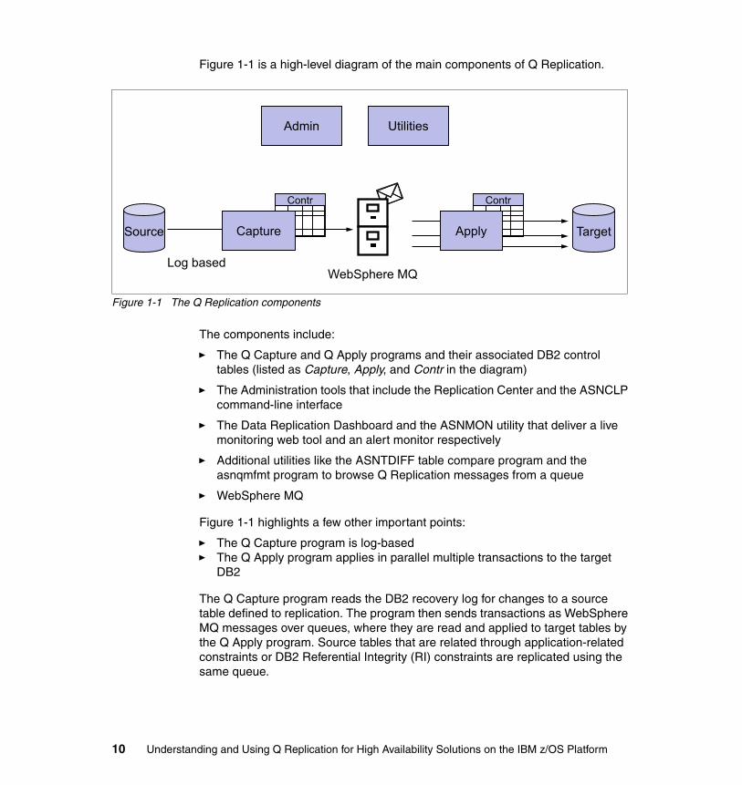
Figure 1-1 is a high-level diagram of the main components of Q Replication.
Figure 1-1 The Q Replication components
The components include:
� The Q Capture and Q Apply programs and their associated DB2 control tables (listed as Capture, Apply, and Contr in the diagram)
� The Administration tools that include the Replication Center and the ASNCLP command-line interface
� The Data Replication Dashboard and the ASNMON utility that deliver a live monitoring web tool and an alert monitor respectively
� Additional utilities like the ASNTDIFF table compare program and the asnqmfmt program to browse Q Replication messages from a queue
� WebSphere MQ
Figure 1-1 highlights a few other important points:
� The Q Capture program is log-based� The Q Apply program applies in parallel multiple transactions to the target
DB2
The Q Capture program reads the DB2 recovery log for changes to a source table defined to replication. The program then sends transactions as WebSphere MQ messages over queues, where they are read and applied to target tables by the Q Apply program. Source tables that are related through application-related constraints or DB2 Referential Integrity (RI) constraints are replicated using the same queue.
Admin Utilities
Source
Log based
Contr
Capture
WebSphere MQ
Target
Contr
Apply
10 Understanding and Using Q Replication for High Availability Solutions on the IBM z/OS Platform

Q Replication offers several advantages, such as the following:
� Minimum latency
Changes are sent as soon as they are committed at the source, read from the log and committed to a WebSphere MQ message queue.
� High-volume throughput
The Q Capture program can keep up with rapid changes at the source, and the multi-threaded Q Apply program can keep up with the speed of the communication channel.
� Minimum network traffic
Messages are sent using a compact format, and data-sending options enable you to transmit the minimum amount of data.
� Asynchronous delivery
The use of WebSphere MQ queues allows the Q Apply program to receive transactions without having to connect to the source database or subsystem. Both the Q Capture and Q Apply programs operate independently of each other—neither one requires the other to be operating. Of course, changes cannot be replicated unless they are captured by the Q Capture program and written to the message queues and retrieved and applied to the target by the Q Apply program. If the Q Apply program is stopped, messages remain on queues to be processed whenever the program is ready. If the Q Capture program is stopped, the Q Apply program continues to process messages on the queues. When the messages are persistent, they survive a system or device failure.
Q Replication allows many different configurations. You can replicate between remote servers or within a single server. Or you can replicate changes in a single direction or in multiple directions. Replicating in multiple directions, or multidirectional replication, is useful for managing read-only and failover sites as well as useful for synchronizing data between production sites.
1.4.3 Conflict avoidance
Updates of the same data from different nodes may create conflict, so careful planning is required when update workloads are allowed on multiple nodes as is the case for three scenarios of Table 1-1 on page 8. Q Replication detects conflicts and offers options on how to resolve these conflicts.
The options delivered by a data replication solution might not be enough to match business requirements. For example, the business rules of a financial institution might not allow any conflict at all. For that reason, clients today who
Chapter 1. High Availability scenarios 11

implement a high availability solution that involves update workloads at multiple nodes also implement strategies to avoid conflicts.
Conflict avoidance strategies include controlling which update workloads run at which node and which data is allowed to be updated at which node, both of which are described in scenarios that are included in this book. Another common strategy relies on defining SQL authorization roles to restrict workload access to data.
1.5 Four client implementation scenarios
In this section, we describe four high availability scenarios that are commonly implemented, or planning to be implemented, by businesses using Q Replication.
The scenarios include the following configurations:
� Two variations, one typical and one advanced, of the popular two-nodes with one-read only node for a query offloading scenario
� One variation of the three-nodes scenario with at least one-read only node
� One variation of the three-nodes scenario with strict conflict rules
The book does not cover the two-node for failover scenario for the following reasons:
� The Q Replication configuration tasks that are necessary to set up a failover site are the same as the configuration tasks required to set up any of the other configuration: Definitions of Q Replication subscriptions and replication queue maps, definitions of WebSphere MQ queues and channels
� When the replicated site is a failover site, no workload is allowed to run and the solution focuses on failover scenarios. These types of scenarios were the focus of IBM Redbooks publication SG24-7215, “IBM WebSphere Replication Server Using Q Replication High Availability Scenarios for the IBM z/OS
Important: The description in this chapter (and in the book) focuses on the z/OS platform. In many environments, some of the target platforms of the replication process also include Linux, UNIX, or Windows when the source platform of the replication process is z/OS. The rationale provided in this book applies to any Q Replication target platform unless specifically noted.
The scenarios are independent of each other. You may choose to analyze or implement one scenario without having to review any of the others.
12 Understanding and Using Q Replication for High Availability Solutions on the IBM z/OS Platform

Platform.” That book documented both failover and switchback procedures using Q Replication in a bidirectional environment in detail.
� Failover scenarios will typically have additional requirements, such as the need for enforcing a certain level of data synchronization between the software and the hardware data replication solutions, associated with disaster recovery, that are not the focus of this book.
The book does not describe the two-node with strict conflict rules scenario because that scenario is indirectly described in the fully connected three-node scenario.
Table 1-2 introduces the four scenarios, their names, and the scenario summary. It also adds a reference to their respective chapters. For a description of the Q Replication bidi (bidirectional) and multi-uni topology options, refer to “Choosing a multidirectional subscription” on page 27.
Table 1-2 The four scenarios that are described in this book
Name Scenario summary Chapter
Two-node scenario
� Workload distribution ensures that one node is limited to read-only workloads
� Q Replication bidi topology is implemented
Chapter 3, “The two-node scenario” on page 43
Advanced two-nodescenario
� Advanced setup to increase scalability of the solution with two Q Apply processes maintaining the read-only node
� Q Replication multi-uni topology is implemented
Chapter 4, “The advanced two-node scenario” on page 89
Partially connected three-nodescenario
� Workload distribution ensures that update workloads at the spoke nodes update a subset of the data
� Q Replication bidi topology is implemented
Chapter 5, “The three-node scenarios” on page 121
Fully connected three-nodescenario
� Workload distribution ensures that update workloads at each node are only allowed to update a subset of the data (data partitioning)
� Q Replication multi-uni topology is implemented
Chapter 5, “The three-node scenarios” on page 121
Chapter 1. High Availability scenarios 13
1.5.1 The two-node scenario
The two-node scenario consists of the following configuration, topology, and conflict avoidance strategy:
� Two-nodes with one read-only node for query offloading� Workload distribution ensures that one node is limited to read-only workloads � Q Replication bidi topology is implemented with the primary node defined as
the winner of conflicts (added safety measure as conflicts should never occur)
1.5.2 The advanced two-node scenario
The advanced two-node scenario consists of the following configuration, topology, and conflict avoidance strategy:
� Two-nodes with one read-only node
� Workload distribution ensures that one node processes read-only workloads
� Advanced setup to increase scalability of the solution with two Q Apply processes maintaining the read-only node. Each Q Apply runs on a different member of the same DB2 data sharing group (different logical partition (LPAR), different WebSphere MQ subsystem). This configuration enables very large workloads from the primary node to be replicated very efficiently on a typically lesser performing (CPU) environment of the read-only node
� Increased failover capability of the solution with two Q Apply processes at the primary node to support eventual replication from the read-only node to the primary node in the case of failover
� Q Replication multi-uni topology is implemented with a no-winner conflict resolution strategy (possibility of conflicts strictly avoided)
1.5.3 The partially connected three-node scenario
The partially connected three-node scenario consists of the following configuration, topology, and conflict avoidance strategy:
� Three-nodes with strict conflict rules� Hub-and-spoke topology, with the hub as the primary node and spokes are
mostly two read-only nodes with however some update activity allowed on the spoke nodes. Data is only replicated from and to hub and spoke nodes (no data replication across spoke nodes)
� Workload distribution ensures that update workloads at the spoke nodes are only allowed to update a subset of the data
14 Understanding and Using Q Replication for High Availability Solutions on the IBM z/OS Platform

� The DB2 for z/OS RREPL tablespace option is used to enforce that only a subset of partitions (partitioned table spaces) or tables (non-partitioned or partitioned tables) are allowed to be updated at the spoke nodes
� Q Replication bidi topology is implemented with the primary hub node defined as the winner in case of conflicts
1.5.4 The fully connected three-node scenario
The fully connected three-node scenario consists of the following configuration, topology, and conflict avoidance strategy:
� Three-nodes with strict conflict rules� All-connected topology� Workload distribution ensures that update workloads at each node are only
allowed to update a subset of the data (data partitioning)� Q Replication multi-uni topology is implemented (although again conflicts are
avoided as workloads tightly control how data is updated)
1.5.5 Added Q Replication functionality
Table 1-3 summarizes the Q Replication functionality that was tested and reviewed in detail with each scenario.
Table 1-3 Scenario details
Scenario name
Scenario added functionality
Two-node scenario
� Mix DB2 temporal and non-temporal tables� Replicate ADD COLUMN, ALTER DATATYPE DDL� Show how non-persistent queues can be used to lower latency
and increase throughput� Use parallel queues to minimize queue latency� Describe coexistence option with Q Capture v10.1 and Q
Apply v10.2.1
Advanced two-node scenario
� Change the replication key (add a column to an existing replication key)
Chapter 1. High Availability scenarios 15

1.5.6 Q Replication scenario environment
Two different collocated sysplexes were used for the tests. Each sysplex includes two DB2 for z/OS data sharing groups and two WebSphere MQ for z/OS address spaces that allow the multiple node configuration setup (each DB2 for z/OS data sharing group is a node).
Figure 1-2 on page 17 is a high-level picture of the environment that is shared by the four scenarios. The scenario chapters, Chapter 3, “The two-node scenario” on page 43, Chapter 4, “The advanced two-node scenario” on page 89, and Chapter 5, “The three-node scenarios” on page 121, include further details and figures that are related to their respective environments.
Partiallyconnected three-node scenario
� Configure a solution to support and differentiate between online and batch workloads
� Generate insert-only workloads to exploit DB2 for z/OS Multi-Row Insert functionality
� Use Data Replication Dashboard to show reports, manage exceptions, and analyze performance
� Make use of the DB2 for z/OS V11 RREPL tablespace option to enforce some of the read-only workloads at one node
� Come up with simple procedures to manage non-critical exceptions (like delete not found)
Fully connected three-node scenario
� Use high volume transactions� Evaluate impact of configuration options like load options to
the replication environment� Replicate schema evolution and evaluate impact on the
replication environment
Scenario name
Scenario added functionality
16 Understanding and Using Q Replication for High Availability Solutions on the IBM z/OS Platform

Figure 1-2 Test configuration
�
�����������
�������� ��
���������� ������
��������������
������
��������� ��
��������� �����
�������������
������������
�������� ��
������� �� ����
���������������
�� ���
������� ��
������ �� ���
�������������
Chapter 1. High Availability scenarios 17

18 Understanding and Using Q Replication for High Availability Solutions on the IBM z/OS Platform

Chapter 2. IIDR Q Replication overview
In this chapter, we provide an overview of the Q Replication technology of the IBM InfoSphere Data Replication product (IIDR), with a focus on describing the key components that deliver a Q Replication solution and how to choose between the replication options to best implement your high availability (HA) scenarios.
2
© Copyright IBM Corp. 2014. All rights reserved. 19

2.1 Q Replication objects
Q Replication is a high-volume, low-latency replication solution that uses WebSphere MQ message queues to transmit transactions between source and target databases or subsystems.
The following objects are required for Q Replication and described in this section:
� 2.1.1, “Q Replication control tables and their architecture level” on page 20� 2.1.2, “Q Replication queue maps and WebSphere MQ objects” on page 21 � 2.1.3, “Q subscriptions and choosing a replication topology” on page 25
The remainder of this chapter describes the main components of the Q Replication technology, as follows:
� 2.2, “The Q Capture program” on page 28� 2.3, “The Q Apply program” on page 31� 2.4, “Administration tools” on page 34� 2.5, “The Data Replication Dashboard” on page 34� 2.6, “Utilities” on page 37
This chapter ends with a description of 2.7, “Load processing” on page 37.
2.1.1 Q Replication control tables and their architecture level
Q Replication control tables store information about Q subscriptions, message queues, operational parameters, and user preferences. They are divided into the following tables:
1. Configuration tables: Their data defines the replication topology and the replication objects to the Q Replication processes. Tables such as the Q Capture IBMQREP_SENDQUEUES, IBMQREP_SUBS, IBMQREP_SRC_COLS, and the Q Apply IBMQREP_RECVQUEUES, IBMQREP_TARGETS and IBMQREP_TRG_COLS belong to that category.
2. Monitoring tables: Their data is queried by the Data Replication Dashboard and the alert monitor program called ASNMON. Tables such as the Q Capture IBMQREP_CAPMON, IBMQREP_CAPQMON, and the Q Apply IBMQREP_APPLYMON tables belong to that category.
3. Troubleshooting tables: Their data consists of status, error, warning, and informational messages. Tables such as the Q Capture IBMQREP_CAPTRACE and the Q Apply IBMQREP_APPLYTRACE and IBMQREP_EXCEPTIONS tables belong to that category.
The tables are read and updated by the Q Replication programs on a continual basis. The monitoring tables for example are updated at every monitor interval.
20 Understanding and Using Q Replication for High Availability Solutions on the IBM z/OS Platform

Table 2-1 is provided as an index to the appropriate sections of this book that query the control tables to analyze and describe the scenarios’ behaviors.
Table 2-1 The Q Replication Control Table Contents
2.1.2 Q Replication queue maps and WebSphere MQ objects
Q Replication queue maps identify the WebSphere MQ queues to be used for sending and receiving data.
WebSphere MQ is used to ensure that every message1 generated by the Q Capture program is transported to the target without loss and in the correct order. When the WebSphere MQ queues used by Q Replication are defined as being persistent, the messages in the queues can survive a WebSphere MQ failure.
Control table type Topics Reference section
Monitoring End-to-end latencyQ Capture latencyQ Apply latencyQueue latency
See Chapter 6, “Latency analysis” on page 139 and Figure 6-5 on page 173.
Monitoring Q Apply Serialization logic
See Chapter 6, “Latency analysis” on page 139 and Figure 6-5 on page 173.
Monitoring Load processing See Chapter 7, “Managing Q Replication in the DB2 for z/OS Environment” on page 177.
Monitoring DONEMSG table reorgs
See Chapter 6, “Latency analysis” on page 139.
Definition and Configuration
Replication and WebSphere MQ
See Chapter 6, “Latency analysis” on page 139.
Troubleshooting Exception Handling See Chapter 4, “The advanced two-node scenario” on page 89.
Note: The Q Capture IBMQREP_CAPPARMS table and the Q Apply IBMQREP_APPLYPARM table have a special column named ARCH_LEVEL. The value identifies the architecture level of the control tables as well as the architecture level of the Q Capture and Q Apply programs that use these tables.
In this book, we refer to this value as “architecture level”, “arch level” or “ARCH_LEVEL”, which is “1001” for IIDR v10 and “1021” for IIDR v10.2.1.
Chapter 2. IIDR Q Replication overview 21

The following is a summary of the WebSphere MQ objects that are required to replicate data from a Q Capture program on one node to a Q Apply program on another node in a unidirectional configuration, with a brief description of their usage:
� Queue manager is a program that manages queues for Q Capture programs, Q Apply programs, and user applications. One queue manager is required on each system where a Q Capture or Q Apply program runs.
� Send queue is a queue that directs data, control, and informational messages from a Q Capture program to a Q Apply program or user application. In remote configurations, this is defined as a remote queue on the source system corresponding to the receive queue on the target system. Each send queue should be used by only one Q Capture program but multiple send queues can be associated to the same receive queue on the target system (see Chapter 3, “The two-node scenario” on page 43, which describes how to set up “parallel send queues” topologies).
� Receive queue is a queue that receives data and informational messages from a Q Capture program to a Q Apply program. This is a local queue on the target system.
� Administration queue is a queue that receives control messages from a Q Apply program or a user application to the Q Capture program. This is a local queue on the system where the Q Capture program runs. There is a remote queue definition on the system where the Q Apply program or a user application runs, corresponding to the administration queue where the Q Capture program runs.
� Restart queue is a queue that holds a single message that tells the Q Capture program where to start reading in the DB2 (recovery) log after a restart. This is a local queue on the source system. Each Q Capture program must have its own restart queue.
� Spill queue is a model queue that you define on the target system to hold transaction messages from a Q Capture program while a target table is being loaded. The Q Apply program creates these dynamic queues during the loading process that is based on the model queue definition, and then deletes them. A spill queue (with any user-defined name) can be specified at the subscription level.
For multidirectional replication configurations, two sets of WebSphere MQ objects are defined for replicating data from and to each node.
The WebSphere MQ objects must be defined for Q Replication. Their definitions are stored in the Q Replication control tables.
1 Q Replication messages can be made persistent or non-persistent. See Chapter 3, “The two-node scenario” on page 43 for more details.
22 Understanding and Using Q Replication for High Availability Solutions on the IBM z/OS Platform

WebSphere MQ objects allow multiple settings to control their behavior. The queue manager, for instance, allows you to limit the maximum size (MAXMSGL parameter) of the messages on the queue, while the queues allow you to specify the maximum number of messages (MAXDEPTH) in the queue and whether they are to be persistent or not. The channels allow you to set the disconnect interval that specifies the duration that the channel is to remain open when there are no transactions to replicate. A detailed description of the WebSphere MQ recommended values for Q Replication is provided in 6.4.4, “Tuning WebSphere MQ” on page 168.
Replication queue maps include the WebSphere MQ send queue, receive queue, and administration queue that participate in a given replication configuration. When Q subscriptions are created, they are added to an existing replication queue map.
Figure 2-1 on page 24 shows the properties of a queue map as shown in the Replication Center, a graphical user interface (GUI) tool for Q Replication. The figure identifies the send queue, the receive queue, and the administration queue that are associated with the queue map named SRCDB_ASN_TO_TARDB_ASN_1.
Chapter 2. IIDR Q Replication overview 23

Figure 2-1 shows how the messages flow:
� Data messages flow from a send queue to a receive queue. The send queue names that are defined to the Q Capture program are listed in its IBMQREP_SENDQUEUES table (not shown in the diagram) and the receive queue names that are defined to the Q Apply program are listed in its IBMQREP_RECVQUEUES table (not shown in the diagram either).
� Administrative messages flow from a Q Apply program to a Q Capture program to allow the Q Apply program to communicate with the Q Capture program.
Figure 2-1 The replication queue map
24 Understanding and Using Q Replication for High Availability Solutions on the IBM z/OS Platform

2.1.3 Q subscriptions and choosing a replication topology
A Q subscription defines the source table and the target table as well as replication options such as the rows and columns to be replicated and the conflict options for resolving conflicts should they occur in multidirectional scenarios.
Q subscriptions can be defined for unidirectional replication or multidirectional replication. Figure 2-2 lists Q subscriptions with a subscription source table schema of DB2ADMIN (same as the subscription target table schema) and the subscription source schema table name the same as the subscription target table name.
The figure is a screen capture of the Subscription Summary View of the Data Replication Dashboard, which is introduced in section 2.5, “The Data Replication Dashboard” on page 34.
Figure 2-2 Six Q subscriptions
The replication keyTo allow the Q Apply program to locate rows that will be updated at the target, each target table must have some mechanism to enforce that rows are unique. This uniqueness is enforced in most cases using a DB2 unique index for the target table, which is referred to as the replication key.
Unidirectional versus multidirectional replicationUnidirectional replication is a configuration that includes only unidirectional subscriptions.
Note: In the case where the target table does not have a unique index, the Q Apply program will not be able to uniquely locate the row that is to be updated resulting in possibly multiple rows that are updated in the target table.
Chapter 2. IIDR Q Replication overview 25

Unidirectional replication has the following characteristics:
� Changes that occur at a source table are replicated to a target table but changes that occur at the target table are not replicated back to the source table. The target table should be updated by the Q Apply program only.
� One subscription is defined for each table participating in unidirectional replication.
� Conflict detection and resolution are supported.
� The source and target tables may be on the same server or different servers.
� Filtering of columns and rows is supported.
Multidirectional replication is a configuration that includes multidirectional subscriptions. It has the following characteristics:
� Changes that occur at a source table are replicated to a target table and changes that occur at the target table are replicated back to the source table
� Two subscriptions are defined for each table participating in multidirectional replication (one for each source to target direction).
� Conflict detection and resolution are supported.
� The source and target tables may be on the same server or different servers.
� Filtering of columns and rows is supported.
� Multiple directional subscriptions can be defined as one of the following:
– Bidirectional subscriptions, or bidi for short in the remainder of this book: A tightly coupled protocol that ties together the two subscriptions so that you need to start only one of the subscriptions to start the replication process for both. The protocol allows you to choose which sites win in case of conflicts.
– Multi-uni subscriptions: Two unidirectional subscriptions; you need to start each subscription to enable the pair to participate in multidirectional replication. You also identify which sites win in case of conflicts.
– Peer-to-peer subscriptions: A tightly coupled protocol that ties together the two subscriptions so that you need to start only one of the subscriptions to start the replication process for both. The protocol always ensures that the most recent update (change with the latest time stamp) wins in case of conflicts.
26 Understanding and Using Q Replication for High Availability Solutions on the IBM z/OS Platform

Choosing a multidirectional subscriptionStarting with IIDR v10 (product architecture level of “1001”), the difference between the bidi and multi-uni options of the multidirectional subscription becomes somewhat trivial in terms of their functionality. And the flexibility of the multi-uni solution renders it quite attractive over the other two options (bidi and peer-to-peer).
Table 2-2 reviews the pros and cons of the three available options in Q Replication in no particular order for the z/OS platform.
Table 2-2 Factors impacting the choice of a multidirectional topology
Note: High availability environments require multidirectional subscriptions. The scenarios of this book all use multidirectional subscriptions. For that reason, even though Q Replication unidirectional subscriptions are implemented in various environments such as data warehousing, the remainder of this book focuses on multidirectional subscriptions.
Factor Multi-uni Bidi Peer-peer
Conflict rule detection options
replication key, changed columns, all columns
replication key, changed columns, all columns
time-based
Conflict resolution options site-based site-based time-based
Number of Q Capture programs running at one site when two Q Apply programs are needed to keep up with the source workload
1 2 2
Impact to the switchback recovery procedure when outages occur
mediuma mediuma low
Impact to administration functions (defining and operating subscriptions)
mediumb low low
Cost of the solution on the z/OS platform (CPU)
low low high
Impact of adding a site to an existing configuration
low medium high
Chapter 2. IIDR Q Replication overview 27

2.2 The Q Capture program
The Q Capture program is a program that reads the DB2 recovery log for changes that occur in source tables, turns the changes into messages, and sends the messages over WebSphere MQ queues, where the messages are processed by a Q Apply program or user application.
As soon as a subscription is activated, Q Capture begins collecting changes for the source table identified in the subscription and writes them out to a WebSphere MQ queue at the transaction boundary.
Complexity of conflict resolution procedures
lowc high high
Column Exclusion Support yes yes yes
Q Capture Row Filtering option
yes yes yes
Q Apply Row Filtering option yes no no
Schema Evolution® support yes yes yes
Scalability of the solution high medium low
a. You might need to reset conflict rules.b. You have to avoid recapturing apply transactions and a capstart is required on
each node.c. The user has more control to recover from conflicts because controlling data flow
can be done one direction at a time.
None of the scenarios described in this book use the peer-peer option.
Note: The peer-to-peer option and the z/OS platform
The peer-to-peer implementation requires extra columns and triggers to be added to each table participating in replication. The columns and triggers are required to implement the conflict detection logic. In DB2 for z/OS, the cost of triggers renders the solution quite expensive and therefore prohibitive. The peer-peer protocol also assumes an all-connected topology that is not always appropriate for the business scenarios. For these reasons, most of the implementations of the peer-peer protocol are on the DB2 for Linux, UNIX, and Windows platforms.
Factor Multi-uni Bidi Peer-peer
28 Understanding and Using Q Replication for High Availability Solutions on the IBM z/OS Platform

The Q Capture program lets you specify the data to be replicated from the source table. For example, you can control which source changes are sent by specifying the source tables, or rows and columns within the source tables. Using a search condition (row filtering) is a trade-off between CPU consumption and latency. A dedicated log reader thread reads the log records, while a worker thread evaluates the predicate.
When a row changes in a source table, the Q Capture program reads the log record to see if the table is part of an active Q subscription. If so, the Q Capture program adds the row to the corresponding database transaction in memory until it reads the corresponding commit or abort record from the database log.
If a row change involves columns with large object (LOB) data, the Q Capture program copies the LOB data either directly from the source table or from the DB2 log (in-line LOB data) to the send queue.
The Q Capture program then puts the assembled messages on all send queues that were defined for the Q subscriptions.
A subscription’s default is to have the Q Capture program capture deletes from the log and publish or replicate them. You can, however, choose to have deletes suppressed for a given subscription. (You can also choose to suppress insert and update operations).
After the Q Capture program puts messages on one or more WebSphere MQ send queues, it issues a commit call to the WebSphere MQ queue manager instructing it to make the messages on the send queues available to the Q Apply program or user applications.
You can configure how often the Q Capture program commits messages. All of the DB2 transactions that are grouped within each commit are considered to be a single WebSphere MQ transaction. Typically, each WebSphere MQ transaction contains several DB2 transactions. You can adjust the time between commits by changing the value of the COMMIT_INTERVAL parameter of Q Capture. A shorter commit interval can lower end-to-end latency up to an equilibrium point—500 ms, which is the default (optimal result from performance studies). Q Capture configuration parameters govern how much memory the Q Capture program allocates for building transactions, the actions that it takes when starting, how often it deletes old data from its control tables, the monitor interval that specifies how often the Q Capture program writes to the trace tables, and many more Q Capture behaviors.
Chapter 2. IIDR Q Replication overview 29

2.2.1 The DB2 IFI Filtering option
DB2 for z/OS V11 and DB2 V10 with APAR PM90568 provide an instrumentation facility interface (IFI) filtering option that IIDR V10.2.1 takes advantage of. In IIDR V10.2.1, the Q Capture program qualifies the DB2 IFI 306 READS requests with a list of DB2 for z/OS dbid/psid pairs that is limited to the dbid/psid of the tables it is interested in. The DB2 IFI buffer will only contain log records associated with the tables that are subscribed to replication, resulting in DB2 IFI CPU cost reduction. Without IFI filtering, DB2 IFI 306 returns all the DML log records for all tables that have Data Capture Changes on. In addition, every DML log record of a compressed table space first needs to be decompressed (as part of the IFI 306 processing) before being returned to the Q Capture program. With IFI filtering, not only are log records filtered before they are handed to the Q Capture program but the processing associated with decompressing log records is also avoided which leads to potential CPU savings.
2.2.2 Heartbeat message and heartbeat interval
A heartbeat message is sent by the Q Capture program to the Q Apply program at every heartbeat interval, as defined by the user. The heartbeat message includes one of the two following values:
� The last commit time that the Q Capture program read from the DB2 log� The last end of log (or EOL) time read by the Q Capture program as it
reached the end of the DB2 log
If there were no transaction for any subscribed table during the heartbeat interval and the end of the DB2 log was not reached, the heartbeat messages include the last commit time that the Q Capture program read from the DB2 log.
To ensure that the Q Capture program sends regular heartbeat messages for a particular send queue, use a non-zero HEARTBEAT_INTERVAL column value in the IBMQREP_SENDQUEUES table for the corresponding send queue row of the IBMQREP_CAPQMON table.
Attention: In IIDR V10.2.1, the heartbeat interval granularity is moved from seconds to milliseconds. A migration job is provided in the product’s migration samples to update the appropriate column value in the Q Capture control table.
30 Understanding and Using Q Replication for High Availability Solutions on the IBM z/OS Platform

2.3 The Q Apply program
The Q Apply program takes messages from WebSphere MQ queues, rebuilds the transactions that the messages contain, and applies the transactions to target tables.
The Q Apply program is designed to keep up with rapid changes from multiple source tables by applying transactions to multiple target tables in parallel. The program can apply changes in parallel based on a transaction dependency analysis while maintaining referential integrity between related target tables.
A Q Apply program can process transactions from multiple receive queues. For each receive queue, the Q Apply program launches a single thread that is known as a browser thread. The browser thread gets transaction messages from the receive queue and keeps track of dependencies between transactions. The browser thread also tracks which transactions it has already applied.
Each browser thread launches one or more agent threads. The agent thread takes transaction messages from the browser thread, rebuilds the SQL statements for all row changes, applies the changes to targets, and issues the commit statement for transactions.
The Q Apply program takes special precautions when it applies transactions in parallel, since rows are not always applied in the same order in which the changes occurred at the source. Changes to the same row at the target are serialized according to the modification sequence at the source; the same applies to parent-child updates as well. If the Q Apply program is using multiple agents to apply transactions in parallel and parent-child inserts are part of the workload, the browser thread still performs the inserts in parallel. If the insert of the dependent row fails with a Referential Integrity (RI) violation, Q Apply just tries the insert again. This approach is optimistic in that it enforces serialization while enhancing performance through parallelism. Meanwhile, agent threads continue to apply other transactions in parallel.
When multiple unique key constraints are defined for a target table, the Q Apply program may perform unique key dependency analysis to prevent a row from failing with a unique constraint violation caused by a secondary unique key index (different from the Q Apply replication key). In some cases however, Q Apply chooses to bypass the unique key dependency analysis (it can be an expensive process based on user data) and so you might experience some unique constraint violations (-803 SQL code) tried by Q Apply again.
When the hardware capacity at the target site is constrained, two different Q Apply programs can be configured to process data replicated by a single Q Capture program at the source site.
Chapter 2. IIDR Q Replication overview 31

You can specify whether the Q Apply program applies transactions in parallel and resolves conflicts. You can also provide the number of apply agents, memory limit, and other parameters that determine how the Q Apply program processes a receive queue. Q Apply configuration parameters govern how much memory the Q Apply program allocates for applying transactions, the actions that it takes when starting, how often it deletes old data from its control tables, the monitor interval that specifies how often the Q Apply program writes to the trace tables, and many more Q Apply behaviors.
In IIDR V10.2.1, the Q Apply program takes advantage of the DB2 multi-row insert (MRI) feature to perform multiple continuous inserts into the same table as one operation instead of performing one insert at a time resulting in potential CPU savings for batch insert work loads.
2.3.1 Conflict detection and conflict resolution
When a change is replicated to the target and that row at the target has been modified by an application, thereby resulting in a mismatched column value, missing row, or duplicate row condition in Q Apply, a conflict is detected. The conflict is resolved based on the subscription options that determine which site wins.
Q replication provides different rules for detecting conflicts and resolving conflicts. A conflict is described as a duplicate row (SQLCODE -803) or a row not found (SQLCODE +100) for the replication key. An SQLCODE -803 on the secondary unique index is treated as error (thus follow error_action), not conflict.
Note the following considerations:
� If you manage updates to your data in each node with strict partitioning, you can choose the option CONFLICT_RULE of K (in the Q Apply IBMQREP_TARGETS table), which will be cheapest in terms for CPU and complexity. Q Capture will send the after values of all changed columns and after and before values for the replication key columns. Q Apply will only check the key columns for conflicts. This is commonly used in unidirectional and multi-uni scenarios, and the most common conflict resolution for this option is to ignore the new changes.
� If you update only some columns in each node or you can manage conflict, you can choose option CONFLICT_RULE of C. Q Capture will send the before and after value of all changed columns and key columns. With this option, a little more data will be sent, but if different columns were changed in different sites, the changes from both sides will be merged. They will not be reported as conflicts, which are commonly used for bidirectional replication.
32 Understanding and Using Q Replication for High Availability Solutions on the IBM z/OS Platform

� The most expensive option is option CONFLICT_RULE of A. Q Capture sends before and after values for all columns for the table. Q Apply checks all columns for conflicts.
The most common conflict actions (CONFLICT_ACTION column in the IBMQREP_TARGETS table) are “I” for ignore and “F” for force. If you do not expect conflicts or minimum conflicts, you can pick ignore. You can choose force if you want a particular site to win. Some clients choose conflict_action as Q, if they never expect any conflicts.
2.3.2 The Q Apply oldest committed transaction time for a queue
The Q Apply OLDEST_TRANS column value of the IBMQREP_APPLYMON table gives you the latency of the data for a particular receive queue. Its value is the source time stamp associated with the oldest transaction that the Q Apply program committed for the queue, as its name indicates. The value guarantees that all prior transactions have been applied to the relevant target tables.
In IIDR V10.2.1, the OLDEST_TRANS column value always increases over time as new monitor rows are inserted for each monitor interval. Its value is either the commit time of the oldest transaction that the Q Apply program applied for the queue or if there is no activity, its value depends on the contents of the Q Capture heartbeat message. The heartbeat message contents have been updated in IIDR v10.2.1 as described in 2.2.2, “Heartbeat message and heartbeat interval” on page 30.
In summary, the OLDEST_TRANS statistics allows you to track the progress of replication for a particular receive queue, as follows:
� If the Q Capture program is keeping up with a heavy DB2 transaction workload at the source site, the value is the commit time of the last transaction processed by the Q Capture program.
� If the Q Capture program is at the end of the DB2 log, the value is the time that is associated with the current log record.
� If the Q Capture program is not at the end of the DB2 log and there are no transactions for the Q Capture program to process (the tables in the DB2 log are not subscribed to Q Replication for example), the value is the time that is associated with the current log record read by the Q Capture program (note the behavior change with V10.2.1 because the value will always increase with time across two monitor intervals in that particular case).
Chapter 2. IIDR Q Replication overview 33

2.4 Administration tools
Q Replication includes a command-line interface, ASNCLP, which is used extensively in the scenarios of this book to define the Q Replication objects. See appendix section A.1, “ASNCLP on z/OS” on page 216 for more details about the ASNCLP command-line program.
Q Replication also includes the Replication Center, a GUI-based administration tool, that delivers similar functionality as the ASNCLP program. Figure 2-1 on page 24 is a screen capture of the Replication Center “Replication Queue Map properties” dialog.
2.5 The Data Replication Dashboard
The Data Replication Dashboard is a fully supported component of the IIDR product that monitors the health of your Q Replication environment. It is a rich, customizable web tool that summarizes information to help you quickly identify and troubleshoot problems, analyze performance, generate reports, and set up alerts.
The best way to appreciate the full functionality of the Data Replication Dashboard is to install and use it. We suggest the following steps:
� If you have not already installed it, download the latest image from the following site: http://www-01.ibm.com/support/docview.wss?uid=swg24023065.
� Once it is installed on one of your machines, create a simple configuration in the Data Replication Dashboard for one of the scenarios of this book.
� Use the Data Replication Dashboard to follow some of the steps that are described in Chapter 6, “Latency analysis” on page 139 to generate a latency report and Chapter 8, “Recovery procedures” on page 199 to invoke its recovery advisor.
The dashboard installation typically takes less than 10 minutes on any of the Windows, Linux, or UNIX platforms and you do not need a web server on the machine where you install the Data Replication Dashboard (it silently installs a light-weight web server by default on these platforms).
The dashboard issues queries against the Q Replication control tables on every dashboard refresh interval. By default, this interval is 10 seconds but can be set as low as 5 seconds or as high as 60 minutes. The queries retrieve monitoring data and the dashboard performs calculations and aggregations on this data and shows it in a visually rich format, making it easy to spot any problem or monitor
34 Understanding and Using Q Replication for High Availability Solutions on the IBM z/OS Platform

latency. The server where the dashboard is installed therefore needs SQL connectivity to the DB2 for z/OS subsystems that will be monitored.
The dashboard enables you to assign roles to users so that you can control who has access to the DB2 for z/OS subsystems that will be monitored through the dashboard.
Figure 2-3 is an overview of the Data Replication Dashboard architecture.
Figure 2-3 The Data Replication Dashboard architecture overview
DB2 for z/OS
DB2 for z/OS
Data replication dashboard
(Web server on workstation)
Source
Target
Monitor control tables
https requests
Data
Web browser
(workstation, smart phone)
Q replication
SQLqueries
SQLqueries
Monitor control tables
Web browser
Chapter 2. IIDR Q Replication overview 35

Figure 2-4 shows the dashboard Q subscription summary view that gathers details about your Q Replication environment all in one panel. Some of the available information includes the following features:
� At-a-glance status showing that Q Capture and Q Apply programs are running and that the send and receive queues are active (green diamond icons)
� At-a-glance status showing that all subscriptions are active (green diamond icons)
� Quick access to tabs: Health and Monitoring, Reports, Recovery Advisor, and so on
� The “Actions” (green) button that allows you to act on a particular subscription
Figure 2-4 Q Subscriptions Summary view
36 Understanding and Using Q Replication for High Availability Solutions on the IBM z/OS Platform

2.6 Utilities
Q Replication includes additional utilities to support your administrative and monitoring tasks. Some of these tools run native on z/OS, as follows:
� The ASNMON alert monitor program, which runs native on z/OS and sends email or pager alerts when thresholds that have been previously defined are exceeded
� The ASNTDIFF program, a table-compare utility
� The ASNQMFMT program, a message formatter program to browse and delete messages from a WebSphere MQ queue
2.7 Load processing
When a subscription is first activated, the replication process synchronizes the target table with the source table data based on the subscription properties associated with the load phase, which specifies how the target table is loaded:
� Automatically (or “internal”)� Manually (or “external”)� Or, none (the target table is already synchronized)
To obtain the subscription load option for your tables, query the Q Capture IBMQREP_SUBS.HAS_LOAD_PHASE column. A value of “E” is for external load, “I” for internal load, and “N” for no load.
This section reviews the following topics that are related to load processing:
� Internal and external load options� External load considerations� Subscription State Transition during load� RI considerations� Spill queue considerations
Note: In this book and in the product documentation and administration tools, the terms external and manual are used intermixed when they refer to how the load process is invoked in Q Replication.
Chapter 2. IIDR Q Replication overview 37

2.7.1 Internal and external load options
Internal loads imply that Q Apply automatically loads the target table by using the DB2 DSNUTILS stored procedure. In contrast, external loads imply that the load phase is performed outside of Q Apply (by the user).
Table 2-3 summarizes factors that impact the choice of a load option.
Table 2-3 Internal versus external load summary
2.7.2 External load considerations
When you use the external load option to synchronize a target table, you must be aware of the following:
� Before your start the unload phase of the load procedures, ensure that all your source table transactions are committed.
� Review the two options provided in Table 2-2 on page 27 and Table 2-3 to alert Q Capture or Q Apply when your load procedure is complete.
Functionality Internal load External load
Load Procedure IBM supplied DSNUTILS
Any vendor, including IBM
Option to perform load of partitions in parallel no yes (no restriction)
Option to perform multiple table loads in parallel yes yes
Option to use load restart option after earlier load failure
no yes
Load Procedure includes additional utility jobs, such as DSN1COPY
no yes (no restriction)
Ease of activation of a subscription using load high (no user intervention)
medium (user intervention required)
Automatic detection of table loads at source site yes yes
Automatic handling of loads at target yes no
38 Understanding and Using Q Replication for High Availability Solutions on the IBM z/OS Platform
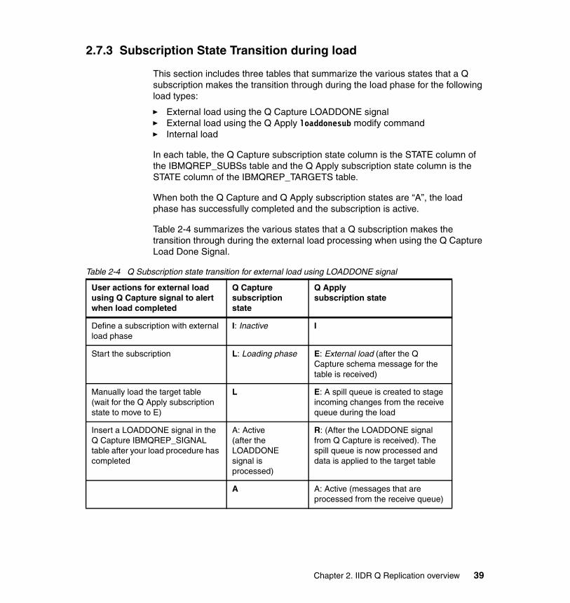
2.7.3 Subscription State Transition during load
This section includes three tables that summarize the various states that a Q subscription makes the transition through during the load phase for the following load types:
� External load using the Q Capture LOADDONE signal� External load using the Q Apply loaddonesub modify command� Internal load
In each table, the Q Capture subscription state column is the STATE column of the IBMQREP_SUBSs table and the Q Apply subscription state column is the STATE column of the IBMQREP_TARGETS table.
When both the Q Capture and Q Apply subscription states are “A”, the load phase has successfully completed and the subscription is active.
Table 2-4 summarizes the various states that a Q subscription makes the transition through during the external load processing when using the Q Capture Load Done Signal.
Table 2-4 Q Subscription state transition for external load using LOADDONE signal
User actions for external loadusing Q Capture signal to alert when load completed
Q Capturesubscriptionstate
Q Applysubscription state
Define a subscription with external load phase
I: Inactive I
Start the subscription L: Loading phase E: External load (after the Q Capture schema message for the table is received)
Manually load the target table (wait for the Q Apply subscription state to move to E)
L E: A spill queue is created to stage incoming changes from the receive queue during the load
Insert a LOADDONE signal in the Q Capture IBMQREP_SIGNAL table after your load procedure has completed
A: Active (after the LOADDONEsignal is processed)
R: (After the LOADDONE signal from Q Capture is received). The spill queue is now processed and data is applied to the target table
A A: Active (messages that are processed from the receive queue)
Chapter 2. IIDR Q Replication overview 39
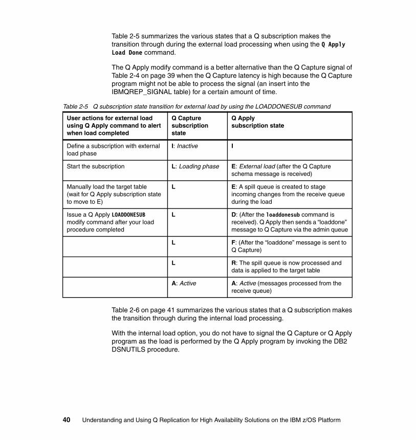
Table 2-5 summarizes the various states that a Q subscription makes the transition through during the external load processing when using the Q Apply Load Done command.
The Q Apply modify command is a better alternative than the Q Capture signal of Table 2-4 on page 39 when the Q Capture latency is high because the Q Capture program might not be able to process the signal (an insert into the IBMQREP_SIGNAL table) for a certain amount of time.
Table 2-5 Q subscription state transition for external load by using the LOADDONESUB command
Table 2-6 on page 41 summarizes the various states that a Q subscription makes the transition through during the internal load processing.
With the internal load option, you do not have to signal the Q Capture or Q Apply program as the load is performed by the Q Apply program by invoking the DB2 DSNUTILS procedure.
User actions for external load using Q Apply command to alert when load completed
Q Capture subscription state
Q Apply subscription state
Define a subscription with external load phase
I: Inactive I
Start the subscription L: Loading phase E: External load (after the Q Capture schema message is received)
Manually load the target table(wait for Q Apply subscription state to move to E)
L E: A spill queue is created to stage incoming changes from the receive queue during the load
Issue a Q Apply LOADDONESUB modify command after your load procedure completed
L D: (After the loaddonesub command is received). Q Apply then sends a “loaddone” message to Q Capture via the admin queue
L F: (After the “loaddone” message is sent to Q Capture)
L R: The spill queue is now processed and data is applied to the target table
A: Active A: Active (messages processed from the receive queue)
40 Understanding and Using Q Replication for High Availability Solutions on the IBM z/OS Platform
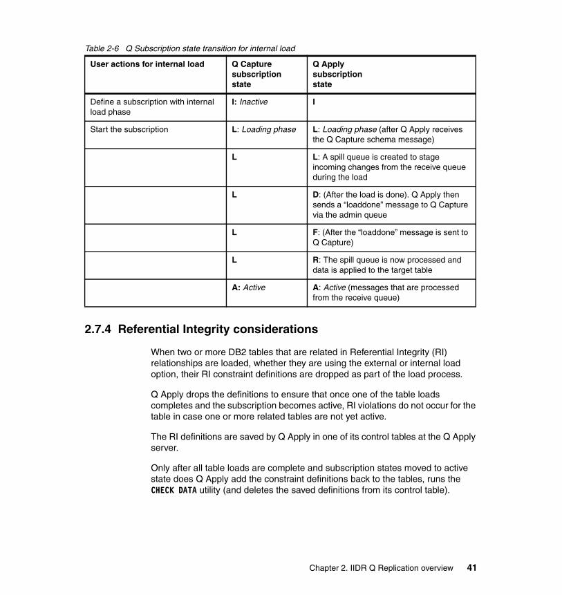
Table 2-6 Q Subscription state transition for internal load
2.7.4 Referential Integrity considerations
When two or more DB2 tables that are related in Referential Integrity (RI) relationships are loaded, whether they are using the external or internal load option, their RI constraint definitions are dropped as part of the load process.
Q Apply drops the definitions to ensure that once one of the table loads completes and the subscription becomes active, RI violations do not occur for the table in case one or more related tables are not yet active.
The RI definitions are saved by Q Apply in one of its control tables at the Q Apply server.
Only after all table loads are complete and subscription states moved to active state does Q Apply add the constraint definitions back to the tables, runs the CHECK DATA utility (and deletes the saved definitions from its control table).
User actions for internal load Q Capturesubscriptionstate
Q Applysubscriptionstate
Define a subscription with internal load phase
I: Inactive I
Start the subscription L: Loading phase L: Loading phase (after Q Apply receives the Q Capture schema message)
L L: A spill queue is created to stage incoming changes from the receive queue during the load
L D: (After the load is done). Q Apply then sends a “loaddone” message to Q Capture via the admin queue
L F: (After the “loaddone” message is sent to Q Capture)
L R: The spill queue is now processed and data is applied to the target table
A: Active A: Active (messages that are processed from the receive queue)
Chapter 2. IIDR Q Replication overview 41
2.7.5 Spill queue considerations
The spill queue that is associated with a target table might fill up during the load phase as source transactions are captured by Q Capture and inserted into the spill queue.
To prevent spill queue issues, perform the following functions:
� Monitor the WebSphere MQ MAXDEPTH attribute of the model spill queue that is used to define the appropriate spill queue (maximizing its value if possible)
� Allocate enough spill queue DASD taking into account that in the spill queue, there is one message per row (not one message per transaction)
� We do not suggest an index on the spill modelq
Preferred practice: The Q Apply program detects if you do not replicate all tables that participate in an RI relationship. Since the Q Apply has no way of knowing that the tables that are not being replicated will not cause issues in the future, it will not put the RI back until all tables in the RI relationship are loaded. For that reason, you might want to drop your RI definitions before Q Apply starts the load and put the RI definitions back after all the tables are loaded. This manual procedure also allows you to customize the CHECK DATA utility as needed.
42 Understanding and Using Q Replication for High Availability Solutions on the IBM z/OS Platform

Chapter 3. The two-node scenario
This chapter describes a Q Replication implementation of the most popular topology, namely bidirectional (bidi) replication between two nodes with one node configured as a read-only node for query offloading.
While examining bidirectional replication, some significant Q Replication features are highlighted and the following ones included in the chapter topics:
� Replicating tables in a mixed (Q Replication and DB2) version environment � Replicating DB2 ADD COLUMN, ALTER DATATYPE DDL statements� Using non-persistent queues and recovering lost messages� Replicating DB2 temporal tables� Using parallel send queues (for high throughput workloads)
3
© Copyright IBM Corp. 2014. All rights reserved. 43

3.1 Introduction to Q Replication
Q Replication, a component of IBM InfoSphere Data Replication (IIDR), is the preferred data replication product for high availability. Offering support for multiple topologies, immediate availability of the copy for failover, and unlimited distance between databases, it is the choice of DB2 clients implementing high availability solutions.
IIDR bidirectional replication using the bidi option has been used for years to implement highly available DB2 database configurations. It offers built-in conflict detection and resolution to meet the needs of varying client applications. The replication administration that is built into IIDR automatically pairs the subscriptions in one direction with those in the opposite direction for simplified administration. The bidi option of the bidirectional topology is highly suited to environments where the application can segregate the data to be updated at each node, minimizing or eliminating conflicts.
3.2 Scenario architecture and topology
Figure 3-1 shows the scenario environment.
Figure 3-1 The two-node scenario environment
The most common Q Replication deployment for high availability is the two-node bidi topology. The bidi topology is typical in client configurations implementing
Note: This is the first of three scenario chapters. It describes in detail the various steps and procedures that someone (new to Q Replication) will follow to successfully deploy and test their solution.
SYSPLEX 1: primary site
DB1A V10 MQ1A
STLABHB LPAR 1
SYSPLEX 2: query site
MQ1B DB1CV11
STLABHD LPAR 1
44 Understanding and Using Q Replication for High Availability Solutions on the IBM z/OS Platform
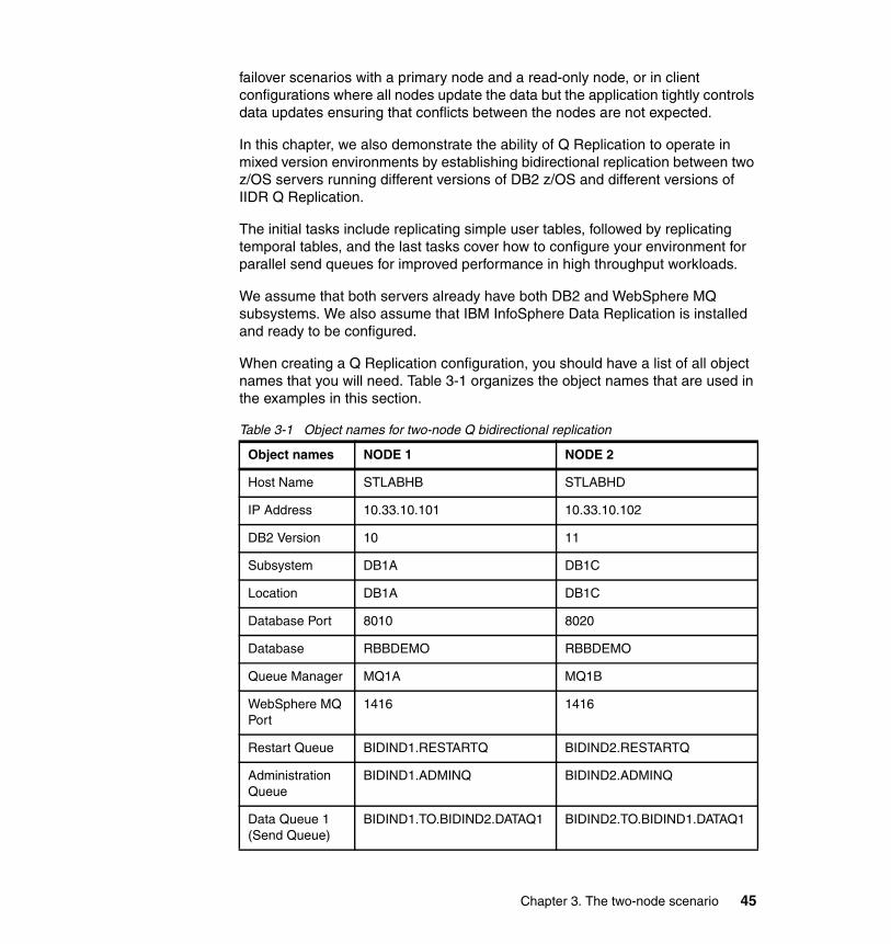
failover scenarios with a primary node and a read-only node, or in client configurations where all nodes update the data but the application tightly controls data updates ensuring that conflicts between the nodes are not expected.
In this chapter, we also demonstrate the ability of Q Replication to operate in mixed version environments by establishing bidirectional replication between two z/OS servers running different versions of DB2 z/OS and different versions of IIDR Q Replication.
The initial tasks include replicating simple user tables, followed by replicating temporal tables, and the last tasks cover how to configure your environment for parallel send queues for improved performance in high throughput workloads.
We assume that both servers already have both DB2 and WebSphere MQ subsystems. We also assume that IBM InfoSphere Data Replication is installed and ready to be configured.
When creating a Q Replication configuration, you should have a list of all object names that you will need. Table 3-1 organizes the object names that are used in the examples in this section.
Table 3-1 Object names for two-node Q bidirectional replication
Object names NODE 1 NODE 2
Host Name STLABHB STLABHD
IP Address 10.33.10.101 10.33.10.102
DB2 Version 10 11
Subsystem DB1A DB1C
Location DB1A DB1C
Database Port 8010 8020
Database RBBDEMO RBBDEMO
Queue Manager MQ1A MQ1B
WebSphere MQ Port
1416 1416
Restart Queue BIDIND1.RESTARTQ BIDIND2.RESTARTQ
Administration Queue
BIDIND1.ADMINQ BIDIND2.ADMINQ
Data Queue 1 (Send Queue)
BIDIND1.TO.BIDIND2.DATAQ1 BIDIND2.TO.BIDIND1.DATAQ1
Chapter 3. The two-node scenario 45

In this two-node configuration, we demonstrate the coexistence of different versions of DB2 and different versions of Q Replication. NODE 1 will be running DB2 V10 with IIDR V10 and NODE 2 will be running DB2 V11 and IIDR V10.2.1.
3.3 Replicating simple tables
Many of the configuration tasks for Q Replication can be completed by editing and submitting sample JCL or by using the ASNCLP utility. Instructions for using ASNCLP on z/OS are included in Appendix A, “Using ASNCLP on z/OS” on page 215.
Where applicable, both ASNCLP and JCL examples will be provided.
3.3.1 Preparing your environment
The following sections list the tasks that are necessary to run in your environment before starting replication.
Bind the replication programsA Sample bind job is provided with the IIDR product in the SASNSAMP library created during the SMP/E installation. Edit and submit SASNSAMP(ASNQBNDL) to bind the replication programs at both databases.
APF-Authorize the Q Capture-related librariesThe replication programs must be authorized program facility (APF)-authorized for Q Capture.
Enable data capture changes for DB2 system tablesTo enable the replication of DDL operations, several of the DB2 catalog tables must be altered for data capture changes. Example 3-1 on page 47 shows the SQL used to alter these catalogs.
Data Queue 2 (Send Queue)
BIDIND1.TO.BIDIND2.DATAQ2 BIDIND2.TO.BIDIND1.DATAQ2
Data Queue 3 (Send Queue)
BIDIND1.TO.BIDIND2.DATAQ3 BIDIND2.TO.BIDIND1.DATAQ3
Replication Schema
ASNB1 ASNB2
Object names NODE 1 NODE 2
46 Understanding and Using Q Replication for High Availability Solutions on the IBM z/OS Platform

Example 3-1 Preparing the databases
ALTER TABLE SYSIBM.SYSTABLES DATA CAPTURE CHANGES;ALTER TABLE SYSIBM.SYSTABLEPART DATA CAPTURE CHANGES;ALTER TABLE SYSIBM.SYSCOLUMNS DATA CAPTURE CHANGES;
Populate the DB2 communications databaseThe host where you will run ASNCLP needs to have communications database (CDB) entries for both the source and target databases.
CDB entries are also needed when replication is configured to perform initial loads of the target tables during the initialization of the replication environment. During this load phase, Q Apply needs to connect to the database containing the original data and load that data into tables at the new site. The CDB at the site where Q Apply runs (target) needs to have CDB entries for the remote database containing the original data (source). Example 3-2 provides SQL statements that populate the CDB at the source (NODE 1) and Example 3-3 provides the SQL statements for the target (NODE 2). In both cases, the first statement catalogs the local database and the last three statements catalog the remote database. Check your CDB before execution since it is common for the local database to already be cataloged.
Example 3-2 Populating the CDB at NODE 1
INSERT INTO SYSIBM.LOCATIONS(LOCATION, LINKNAME, PORT)VALUES ('DB1A', 'DB1A', '');
INSERT INTO SYSIBM.IPNAMES(LINKNAME, SECURITY_OUT, USERNAMES, IPADDR)VALUES ('DB1B', 'P', 'O', 'stlabhd.demo.ibm.com');INSERT INTO SYSIBM.USERNAMES(TYPE, LINKNAME, NEWAUTHID, PASSWORD)VALUES ('O', 'DB1B', 'BRIDDEL', 'XXXXXXXX');INSERT INTO SYSIBM.LOCATIONS(LOCATION, LINKNAME, PORT)VALUES ('DB1B', 'DB1B', '8020');
Example 3-3 Populating the CDB at NODE 2
INSERT INTO SYSIBM.LOCATIONS(LOCATION, LINKNAME, PORT)VALUES ('DB1B', 'DB1B', '');
INSERT INTO SYSIBM.IPNAMES(LINKNAME, SECURITY_OUT, USERNAMES, IPADDR)VALUES ('DB1A', 'P', 'O', 'stlhb.demo.ibm.com');INSERT INTO SYSIBM.USERNAMES(TYPE, LINKNAME, NEWAUTHID, PASSWORD)VALUES ('O', 'DB1A', 'BRIDDEL', 'XXXXXXXX');INSERT INTO SYSIBM.LOCATIONS(LOCATION, LINKNAME, PORT)VALUES ('DB1A', 'DB1A', '8010');
Chapter 3. The two-node scenario 47

Create user tablesThe user tables in Example 3-4 will be used in the replication project for basic bidirectional replication. The ASNCLP scripts that we used for configuration assume that the tables exist at both nodes. If using your own tables, manually create duplicates of all tables at NODE 2.
Using a DB2 client command window, or SQL Processor Using File Input (SPUFI), create the user tables.
Example 3-4 Create user tables at both nodes
CREATE DATABASE RBBDEMO CCSID EBCDIC;
CREATE TABLESPACE DEMOTSB1 IN RBBDEMO USING STOGROUP DB0AUSR CCSID EBCDIC;
CREATE TABLE DEMO.TABLE1 (ID INTEGER NOT NULL,OD INTEGER NOT NULL WITH DEFAULT 1,UD INTEGER NOT NULL WITH DEFAULT 1,S1 SMALLINT NOT NULL WITH DEFAULT,I1 INTEGER NOT NULL WITH DEFAULT,B1 BIGINT NOT NULL WITH DEFAULT,DEC1 DECIMAL(4,0) NOT NULL WITH DEFAULT,DF1 DECFLOAT(16) NOT NULL WITH DEFAULT,F1 FLOAT(21) NOT NULL WITH DEFAULT,C1 CHARACTER(10) NOT NULL WITH DEFAULT,V1 VARCHAR(20) NOT NULL WITH DEFAULT,RCTS NOT NULL GENERATED ALWAYS FOR EACH ROW ON UPDATE AS ROW CHANGE TIMESTAMP) IN RBBDEMO.DEMOTSB1;CREATE UNIQUE INDEX DEMO.TAB1UIX ON DEMO.TABLE1(ID,OD,UD);
CREATE TABLESPACE DEMOTSB2 IN RBBDEMO USING STOGROUP DB0AUSR CCSID EBCDIC;
CREATE TABLE DEMO.TABLE2 (ID INTEGER NOT NULL,OD INTEGER NOT NULL WITH DEFAULT 1,UD INTEGER NOT NULL WITH DEFAULT 1,C1 CHARACTER(10) NOT NULL WITH DEFAULT,V1 VARCHAR(20) NOT NULL WITH DEFAULT,DT DATE,RCTS NOT NULL GENERATED ALWAYS FOR EACH ROW ON UPDATE AS ROW CHANGE TIMESTAMP) IN RBBDEMO.DEMOTSB2;CREATE UNIQUE INDEX DEMO.TAB2UIX ON DEMO.TABLE2(ID,OD,UD);
CREATE TABLESPACE DEMOTSB3 IN RBBDEMO USING STOGROUP DB0AUSR CCSID EBCDIC;
48 Understanding and Using Q Replication for High Availability Solutions on the IBM z/OS Platform
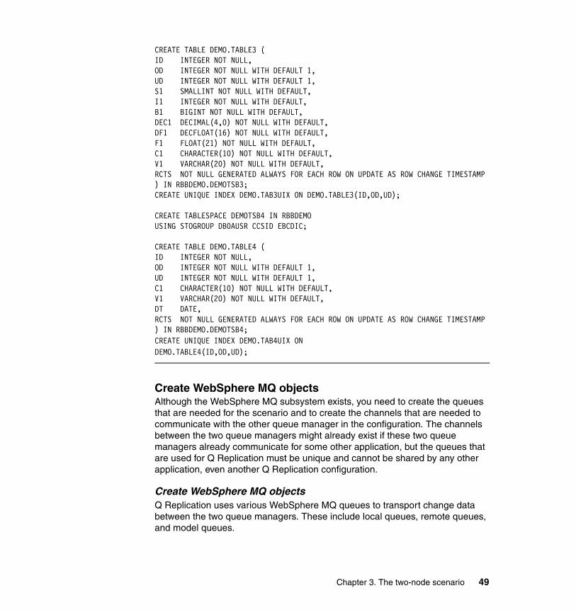
CREATE TABLE DEMO.TABLE3 (ID INTEGER NOT NULL,OD INTEGER NOT NULL WITH DEFAULT 1,UD INTEGER NOT NULL WITH DEFAULT 1,S1 SMALLINT NOT NULL WITH DEFAULT,I1 INTEGER NOT NULL WITH DEFAULT,B1 BIGINT NOT NULL WITH DEFAULT,DEC1 DECIMAL(4,0) NOT NULL WITH DEFAULT,DF1 DECFLOAT(16) NOT NULL WITH DEFAULT,F1 FLOAT(21) NOT NULL WITH DEFAULT,C1 CHARACTER(10) NOT NULL WITH DEFAULT,V1 VARCHAR(20) NOT NULL WITH DEFAULT,RCTS NOT NULL GENERATED ALWAYS FOR EACH ROW ON UPDATE AS ROW CHANGE TIMESTAMP) IN RBBDEMO.DEMOTSB3;CREATE UNIQUE INDEX DEMO.TAB3UIX ON DEMO.TABLE3(ID,OD,UD);
CREATE TABLESPACE DEMOTSB4 IN RBBDEMO USING STOGROUP DB0AUSR CCSID EBCDIC;
CREATE TABLE DEMO.TABLE4 (ID INTEGER NOT NULL,OD INTEGER NOT NULL WITH DEFAULT 1,UD INTEGER NOT NULL WITH DEFAULT 1,C1 CHARACTER(10) NOT NULL WITH DEFAULT,V1 VARCHAR(20) NOT NULL WITH DEFAULT,DT DATE,RCTS NOT NULL GENERATED ALWAYS FOR EACH ROW ON UPDATE AS ROW CHANGE TIMESTAMP) IN RBBDEMO.DEMOTSB4;CREATE UNIQUE INDEX DEMO.TAB4UIX ON DEMO.TABLE4(ID,OD,UD);
Create WebSphere MQ objectsAlthough the WebSphere MQ subsystem exists, you need to create the queues that are needed for the scenario and to create the channels that are needed to communicate with the other queue manager in the configuration. The channels between the two queue managers might already exist if these two queue managers already communicate for some other application, but the queues that are used for Q Replication must be unique and cannot be shared by any other application, even another Q Replication configuration.
Create WebSphere MQ objectsQ Replication uses various WebSphere MQ queues to transport change data between the two queue managers. These include local queues, remote queues, and model queues.
Chapter 3. The two-node scenario 49

The JCL in Example 3-5 will create all of the objects necessary for the bidirectional Q Replication on NODE 1. Example 3-6 on page 52 provides the objects for NODE 2.
Example 3-5 Creating WebSphere MQ objects at NODE 1
//UUUUQ JOB 'USER=','<USERNAME:JOBNAME>',CLASS=K,TIME=NOLIMIT,// MSGCLASS=Z,MSGLEVEL=(1,1),USER=UUUU,REGION=0M,// PASSWORD=PPPPPPPP/*ROUTE PRINT STLVM27.PMY//*****************************************************************//CRTQ EXEC PGM=CSQUTIL,PARM='MQ1A'//STEPLIB DD DSN=MQS.SCSQANLE,DISP=SHR// DD DSN=MQS.SCSQAUTH,DISP=SHR//SYSPRINT DD SYSOUT=*//SYSIN DD *COMMAND DDNAME(CMDINP)/*//CMDINP DD *SET SYSTEM IDFORE(600) IDBACK(600)DEFINE QLOCAL(BIDIND1.ADMINQ) REPLACE + DESCR('LOCAL ADMINQ FOR NODE 1 QCAP') + PUT(ENABLED) + GET(ENABLED) + SHARE + DEFSOPT(SHARED) + MAXDEPTH(1000) + DEFPSIST(YES)
DEFINE QLOCAL(BIDIND1.RESTARTQ) REPLACE + DESCR('LOCAL RESTARTQ FOR NODE 1 QCAP') + PUT(ENABLED) + GET(ENABLED) + SHARE + DEFSOPT(SHARED) + MAXDEPTH(1) + INDXTYPE(MSGID) + DEFPSIST(YES)
DEFINE QLOCAL(BIDIND2.TO.BIDIND1.DATAQ1) REPLACE + DESCR('LOCAL SEND-RECV QUEUE') + PUT(ENABLED) + GET(ENABLED) + SHARE + DEFSOPT(SHARED) + DEFPSIST(YES) + MAXDEPTH(999999999) + INDXTYPE(MSGID)
50 Understanding and Using Q Replication for High Availability Solutions on the IBM z/OS Platform

DEFINE QLOCAL(BIDIND2.TO.BIDIND1.DATAQ2) REPLACE + DESCR('LOCAL SEND-RECV QUEUE') + PUT(ENABLED) + GET(ENABLED) + SHARE + DEFSOPT(SHARED) + DEFPSIST(YES) + MAXDEPTH(999999999) + INDXTYPE(MSGID)
DEFINE QREMOTE('BIDIND2.ADMINQ') REPLACE +RNAME('BIDIND2.ADMINQ') RQMNAME('MQ1B') +XMITQ('MQ1B')
DEFINE QREMOTE('BIDIND1.TO.BIDIND2.DATAQ1') REPLACE +RNAME('BIDIND1.TO.BIDIND2.DATAQ1') RQMNAME('MQ1B') +XMITQ('MQ1B')
DEFINE QREMOTE('BIDIND1.TO.BIDIND2.DATAQ2') REPLACE +RNAME('BIDIND1.TO.BIDIND2.DATAQ2') RQMNAME('MQ1B') +XMITQ('MQ1B')
DEFINE QMODEL('IBMQREP.SPILL.MODELQ') REPLACE + DEFSOPT(SHARED) + MAXDEPTH(999999999) + MSGDLVSQ(FIFO) + DEFTYPE(PERMDYN)
DEFINE QLOCAL('MQ1B') REPLACE + DESCR('TRANSMISSION QUEUE TO MQ1B') + USAGE(XMITQ) + PUT(ENABLED) + GET(ENABLED) + MAXDEPTH(999999999)
DEFINE CHANNEL(MQ1A.TO.MQ1B) REPLACE + CHLTYPE(SDR) + TRPTYPE(TCP) + DISCINT(0) + DESCR('SENDER CHANNEL TO MQ1B') + XMITQ(MQ1B) + CONNAME('10.33.10.102(1416)')
DEFINE CHANNEL(MQ1B.TO.MQ1A) REPLACE + CHLTYPE(RCVR) + TRPTYPE(TCP) + DESCR('RECEIVER CHANNEL FROM MQ1B')
* DISPLAY QUEUE(*) ALL
Chapter 3. The two-node scenario 51

/*//
Example 3-6 Creating WebSphere MQ objects at NODE 2
//UUUUQ JOB 'USER=','<USERNAME:JOBNAME>',CLASS=K,TIME=NOLIMIT,// MSGCLASS=Z,MSGLEVEL=(1,1),REGION=0M,// PASSWORD=PPPPPPPP/*ROUTE PRINT STLVM27.PMY//*****************************************************************//CRTQ EXEC PGM=CSQUTIL,PARM='MQ1B'//STEPLIB DD DSN=MQS.SCSQANLE,DISP=SHR// DD DSN=MQS.SCSQAUTH,DISP=SHR//SYSPRINT DD SYSOUT=*//SYSIN DD * COMMAND DDNAME(CMDINP)/*//CMDINP DD *SET SYSTEM IDFORE(600) IDBACK(600)
DEFINE QLOCAL(BIDIND2.ADMINQ) REPLACE + DESCR('LOCAL ADMINQ FOR NODE 2 QCAP') + PUT(ENABLED) + GET(ENABLED) + SHARE + DEFSOPT(SHARED) + MAXDEPTH(1000) + DEFPSIST(YES)
DEFINE QLOCAL(BIDIND2.RESTARTQ) REPLACE + DESCR('LOCAL RESTARTQ FOR NODE 2 QCAP') + PUT(ENABLED) + GET(ENABLED) + SHARE + DEFSOPT(SHARED) + MAXDEPTH(1) + DEFPSIST(YES)
DEFINE QLOCAL(BIDIND1.TO.BIDIND2.DATAQ1) REPLACE + DESCR('LOCAL SEND-RECV QUEUE') + PUT(ENABLED) + GET(ENABLED) + SHARE + DEFSOPT(SHARED) + DEFPSIST(YES) + MAXDEPTH(999999999) + INDXTYPE(MSGID)
52 Understanding and Using Q Replication for High Availability Solutions on the IBM z/OS Platform

DEFINE QLOCAL(BIDIND1.TO.BIDIND2.DATAQ2) REPLACE + DESCR('LOCAL SEND-RECV QUEUE') + PUT(ENABLED) + GET(ENABLED) + SHARE + DEFSOPT(SHARED) + DEFPSIST(YES) + MAXDEPTH(999999999) + INDXTYPE(MSGID)
DEFINE QREMOTE('BIDIND1.ADMINQ') REPLACE +RNAME('BIDIND1.ADMINQ') RQMNAME('MQ1A') +XMITQ('MQ1A')
DEFINE QREMOTE('BIDIND2.TO.BIDIND1.DATAQ1') REPLACE +RNAME('BIDIND2.TO.BIDIND1.DATAQ1') RQMNAME('MQ1A') +XMITQ('MQ1A')
DEFINE QREMOTE('BIDIND2.TO.BIDIND1.DATAQ2') REPLACE +RNAME('BIDIND2.TO.BIDIND1.DATAQ2') RQMNAME('MQ1A') +XMITQ('MQ1A')
DEFINE QMODEL('IBMQREP.SPILL.MODELQ') REPLACE + DEFSOPT(SHARED) + MAXDEPTH(999999999) + MSGDLVSQ(FIFO) + DEFTYPE(PERMDYN)
DEFINE QLOCAL('MQ1A') REPLACE + DESCR('TRANSMISSION QUEUE TO MQ1A') + USAGE(XMITQ) + PUT(ENABLED) + GET(ENABLED) + MAXDEPTH(999999999)
DEFINE CHANNEL(MQ1B.TO.MQ1A) REPLACE + CHLTYPE(SDR) + TRPTYPE(TCP) + DISCINT(0) + DESCR('SENDER CHANNEL TO MQ1A') + XMITQ(MQ1A) + CONNAME('10.33.10.101(1416)')
DEFINE CHANNEL(MQ1A.TO.MQ1B) REPLACE + CHLTYPE(RCVR) + TRPTYPE(TCP) + DESCR('RECEIVER CHANNEL FROM MQ1A')
Chapter 3. The two-node scenario 53
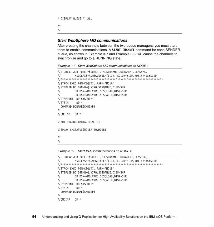
* DISPLAY QUEUE(*) ALL
/*//
Start WebSphere MQ communicationsAfter creating the channels between the two queue managers, you must start them to enable communications. A START CHANNEL command for each SENDER queue, as shown in Example 3-7 and Example 3-8, will cause the channels to synchronize and go to a RUNNING state.
Example 3-7 Start WebSphere MQ communications on NODE 1
//STCHLN1 JOB 'USER=$$USER','<USERNAME:JOBNAME>',CLASS=A,// MSGCLASS=A,MSGLEVEL=(1,1),REGION=512M,NOTIFY=&SYSUID//*****************************************************************//STRCH EXEC PGM=CSQUTIL,PARM='MQ1A'//STEPLIB DD DSN=WMQ.V7R0.SCSQANLE,DISP=SHR// DD DSN=WMQ.V7R0.SCSQLOAD,DISP=SHR// DD DSN=WMQ.V7R0.SCSQAUTH,DISP=SHR//SYSPRINT DD SYSOUT=*//SYSIN DD * COMMAND DDNAME(CMDINP)/*//CMDINP DD *
START CHANNEL(MQ1A.TO.MQ1B)
DISPLAY CHSTATUS(MQ1BA.TO.MQ1B)
/*//
Example 3-8 Start MQ Communications on NODE 2
//STCHLN2 JOB 'USER=$$USER','<USERNAME:JOBNAME>',CLASS=A,// MSGCLASS=A,MSGLEVEL=(1,1),REGION=512M,NOTIFY=&SYSUID//*****************************************************************//STRCH EXEC PGM=CSQUTIL,PARM='MQ1B'//STEPLIB DD DSN=WMQ.V7R0.SCSQANLE,DISP=SHR// DD DSN=WMQ.V7R0.SCSQLOAD,DISP=SHR// DD DSN=WMQ.V7R0.SCSQAUTH,DISP=SHR//SYSPRINT DD SYSOUT=*//SYSIN DD * COMMAND DDNAME(CMDINP)/*//CMDINP DD *
54 Understanding and Using Q Replication for High Availability Solutions on the IBM z/OS Platform

START CHANNEL(MQ1B.TO.MQ1A)
DISPLAY CHSTATUS(MQ1B.TO.MQ1A)
/*//
Create Q Replication control tablesEach Q Capture program and each Q Apply program requires a set of control tables located in their respective source or target database. In a bidirectional configuration, each database will have both Q Capture and Q Apply running, so each database will have both Q Capture and Q Apply control tables.
All control tables that are located on a node have to have the same schema, so both the Q Capture and Q Apply on NODE 1 will use the replication schema ASNB1 and all control tables on NODE 2 will use the schema ASNB2. This is necessary because of automation that is built into bidirectional replication. When you create a Q Subscription, you specify the source and target tables and ASNCLP automatically creates a subscription from NODE 1 to NODE 2 and a subscription from NODE 2 to NODE 1. Similarly, when you activate a subscription both of these paired subscriptions are activated together.
Using Sample JCLIncluded in the IBM InfoSphere Data Replication product distribution is a data set containing JCL samples for common tasks. One of these samples is the SQL that is necessary to create the control tables, SASNSAMP(ASNQCTLZ). Using this sample allows you to control placement of the tables better than the ASNCLP approach.
The JCL samples must be edited to match your environment prior to use.
Using ASNCLPThe script in Example 3-9 provides the ASNCLP commands that are necessary to create the control tables on both databases. In the example, ASNCLP uses two table spaces for all control tables, which might not give you the best performance in high volume configurations.
Example 3-9 Creating control tables via ASNCLP
ASNCLP SESSION SET TO Q REPLICATION;SET RUN SCRIPT NOW STOP ON SQL ERROR ON;
SET BIDI NODE 1 SERVER DBALIAS DB1A DBNAME DB1AID BRIDDEL PASSWORD "xxxxxxxx" SCHEMA ASNB1;SET BIDI NODE 2 SERVER DBALIAS DB1C DBNAME DB1CID BRIDDEL PASSWORD "xxxxxxxx" SCHEMA ASNB2;
Chapter 3. The two-node scenario 55

SET QMANAGER "MQ1A" FOR NODE 1;SET QMANAGER "MQ1B" FOR NODE 2;
CREATE CONTROL TABLES FOR NODE 1 USINGCAPPARMSRESTARTQ "BIDIND1.RESTARTQ" ADMINQ "BIDIND1.ADMINQ" MONITOR INTERVAL 10000APPPARMS IN ZOS PAGE LOCK DB RBBDEMO QCNTLAP CREATE ROW LOCK DB RBBDEMO QCNTLAR CREATE MONITOR INTERVAL 10000;
CREATE CONTROL TABLES FOR NODE 2 USINGCAPPARMS RESTARTQ "BIDIND2.RESTARTQ" ADMINQ "BIDIND2.ADMINQ" MONITOR INTERVAL 10000APPPARMS IN ZOS PAGE LOCK DB RBBDEMO QCNTLAP CREATE ROW LOCK DB RBBDEMO QCNTLAR CREATE MONITOR INTERVAL 10000;QUIT;
ARCH_LEVEL and COMPATIBILITY columnsBecause we are running in a mixed version environment, we must ensure that the control tables contain the appropriate setting to match the version of the programs running on each node. These settings are the ARCH_LEVEL and COMPATIBILITY columns in the IBMQREP_CAPPARMS table and the ARCH_LEVEL column in the IBMQREP_APPLYPARMS table.
Knowing what values to use for the ARCH_LEVEL is easy since a given Q Capture or Q Apply program will only operate with a setting that matches its version. For example, an IIDR version 10.2.1 Q Capture must have a setting of “1021”. You cannot change the ARCH_LEVEL to “1001” with the intent of telling Q Capture to behave as though it were an older V10 program.
The COMPATIBILITY column is slightly more difficult to determine. First, COMPATIBILITY cannot be set to a value higher than the ARCH_LEVEL in the same control table. Second, since a single Q Capture program can send data to any number of Q Apply programs in mixed topologies, you have to look at all Q Apply programs to which Q Capture is communicating and set COMPATIBILITY to a value supporting the lowest level in use. For example, if Q Capture and all Q Apply programs were running IIDR V10.2.1, COMPATIBILITY will be “1021”. But if any of the Q Apply programs are at a lower level, as in the project,
56 Understanding and Using Q Replication for High Availability Solutions on the IBM z/OS Platform
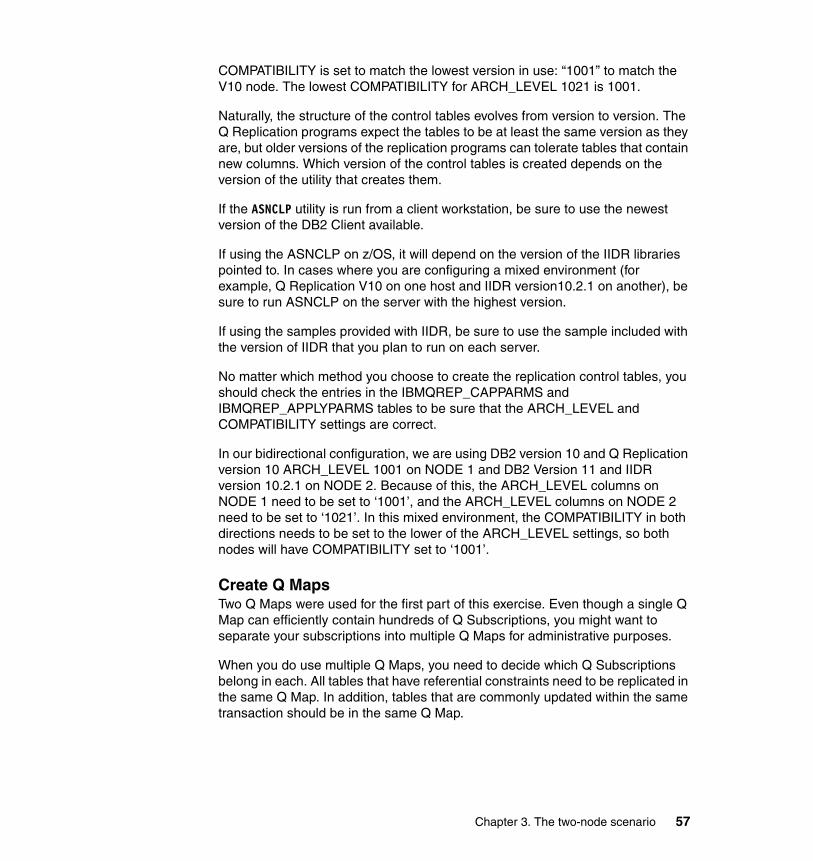
COMPATIBILITY is set to match the lowest version in use: “1001” to match the V10 node. The lowest COMPATIBILITY for ARCH_LEVEL 1021 is 1001.
Naturally, the structure of the control tables evolves from version to version. The Q Replication programs expect the tables to be at least the same version as they are, but older versions of the replication programs can tolerate tables that contain new columns. Which version of the control tables is created depends on the version of the utility that creates them.
If the ASNCLP utility is run from a client workstation, be sure to use the newest version of the DB2 Client available.
If using the ASNCLP on z/OS, it will depend on the version of the IIDR libraries pointed to. In cases where you are configuring a mixed environment (for example, Q Replication V10 on one host and IIDR version10.2.1 on another), be sure to run ASNCLP on the server with the highest version.
If using the samples provided with IIDR, be sure to use the sample included with the version of IIDR that you plan to run on each server.
No matter which method you choose to create the replication control tables, you should check the entries in the IBMQREP_CAPPARMS and IBMQREP_APPLYPARMS tables to be sure that the ARCH_LEVEL and COMPATIBILITY settings are correct.
In our bidirectional configuration, we are using DB2 version 10 and Q Replication version 10 ARCH_LEVEL 1001 on NODE 1 and DB2 Version 11 and IIDR version 10.2.1 on NODE 2. Because of this, the ARCH_LEVEL columns on NODE 1 need to be set to ‘1001’, and the ARCH_LEVEL columns on NODE 2 need to be set to ‘1021’. In this mixed environment, the COMPATIBILITY in both directions needs to be set to the lower of the ARCH_LEVEL settings, so both nodes will have COMPATIBILITY set to ‘1001’.
Create Q MapsTwo Q Maps were used for the first part of this exercise. Even though a single Q Map can efficiently contain hundreds of Q Subscriptions, you might want to separate your subscriptions into multiple Q Maps for administrative purposes.
When you do use multiple Q Maps, you need to decide which Q Subscriptions belong in each. All tables that have referential constraints need to be replicated in the same Q Map. In addition, tables that are commonly updated within the same transaction should be in the same Q Map.
Chapter 3. The two-node scenario 57

Example 3-10 provides the ANCLP commands to create the two Q Maps that we used in basic bidirectional replication.
Example 3-10 Creating Q Maps via ASNCLP
ASNCLP SESSION SET TO Q REPLICATION;SET RUN SCRIPT NOW STOP ON SQL ERROR ON;
SET BIDI NODE 1 SERVER DBALIAS DB1A DBNAME DB1AID BRIDDEL PASSWORD "xxxxxxxx" SCHEMA ASNB1;SET BIDI NODE 2 SERVER DBALIAS DB1C DBNAME DB1CID BRIDDEL PASSWORD "xxxxxxxx" SCHEMA ASNB2;
CREATE REPLQMAP BIDIND1_TO_BIDIND2_MAP1 ( NODE 1, NODE 2 ) USINGADMINQ "BIDIND1.ADMINQ"RECVQ "BIDIND1.TO.BIDIND2.DATAQ1"SENDQ "BIDIND1.TO.BIDIND2.DATAQ1"NUM APPLY AGENTS 2;
CREATE REPLQMAP BIDIND2_TO_BIDIND1_MAP1 ( NODE 2, NODE 1 ) USINGADMINQ "BIDIND2.ADMINQ"RECVQ "BIDIND2.TO.BIDIND1.DATAQ1"SENDQ "BIDIND2.TO.BIDIND1.DATAQ1"NUM APPLY AGENTS 2;
CREATE REPLQMAP BIDIND1_TO_BIDIND2_MAP2 ( NODE 1, NODE 2 ) USINGADMINQ "BIDIND1.ADMINQ"RECVQ "BIDIND1.TO.BIDIND2.DATAQ2"SENDQ "BIDIND1.TO.BIDIND2.DATAQ2"NUM APPLY AGENTS 2;
CREATE REPLQMAP BIDIND2_TO_BIDIND1_MAP2 ( NODE 2, NODE 1 ) USINGADMINQ "BIDIND2.ADMINQ"RECVQ "BIDIND2.TO.BIDIND1.DATAQ2"SENDQ "BIDIND2.TO.BIDIND1.DATAQ2"NUM APPLY AGENTS 2;
QUIT;
Create Q subscriptionsSince two Q Maps will be used, you must split the CREATE QSUB statements into two files. The Q Map is specified by using the SET CONNECTION statements and you can have only one pair of these statements per ASNCLP input file.
58 Understanding and Using Q Replication for High Availability Solutions on the IBM z/OS Platform

By default, ASNCLP defines NODE 1 as the primary node when creating subscriptions, but since we are defining a two-node bidirectional configuration with a read-only node, we want NODE 2 to be the primary. This is because there is no activity on NODE 2, so there is no chance of conflict. But in the event of a NODE 1 failure, you have the possibility of stranded data on NODE 1 and all of the newest data will be generated on NODE 2. When NODE 1 is recovered and replication is brought back online, you have the only chance of conflicts in this configuration. As the previously stranded data arrives at NODE 2, you want to ensure that the conflict resolves in favor of the newer data, thus NODE 2 is defined as the primary node.
To do this, include an instruction in the CREATE QSUB command to Ignore conflicts at NODE 2 and Force them at NODE 1.
Example 3-11 and Example 3-12 on page 60 provide the ASNCLP commands to create the subscriptions for the four tables.
Example 3-11 Creating Q subscriptions via ASNCLP, set 1
ASNCLP SESSION SET TO Q REPLICATION;SET RUN SCRIPT NOW STOP ON SQL ERROR ON;
SET BIDI NODE 1 SERVER DBALIAS DB1A DBNAME DB1AID BRIDDEL PASSWORD "xxxxxxxx" SCHEMA ASNB1;SET BIDI NODE 2 SERVER DBALIAS DB1C DBNAME DB1CID BRIDDEL PASSWORD "xxxxxxxx" SCHEMA ASNB2;
SET SUBGROUP "bidigroup1";
## Use MAP1 for TABLE1 and TABLE2#SET CONNECTION SOURCE DB1A.ASNB1 TARGET DB1C.ASNB2 REPLQMAP BIDIND1_TO_BIDIND2_MAP1 ;
SET CONNECTION SOURCE DB1C.ASNB2 TARGET DB1A.ASNB1 REPLQMAP BIDIND2_TO_BIDIND1_MAP1 ;
SET TABLES (DB1A.ASNB1.DEMO.TABLE1);CREATE QSUB SUBTYPE BFROM NODE DB1A.ASNB1 SOURCE HAS LOAD PHASE NTARGET CONFLICT ACTION IFROM NODE DB1C.ASNB2 SOURCE HAS LOAD PHASE NTARGET CONFLICT ACTION F;
SET TABLES (DB1A.ASNB1.DEMO.TABLE2);CREATE QSUB SUBTYPE BFROM NODE DB1A.ASNB1 SOURCE HAS LOAD PHASE N
Chapter 3. The two-node scenario 59

TARGET CONFLICT ACTION IFROM NODE DB1C.ASNB2 SOURCE HAS LOAD PHASE NTARGET CONFLICT ACTION F;
QUIT;
Example 3-12 Creating Q subscriptions via ASNCLP, set 2
ASNCLP SESSION SET TO Q REPLICATION;SET RUN SCRIPT NOW STOP ON SQL ERROR ON;
SET BIDI NODE 1 SERVER DBALIAS DB1A DBNAME DB1AID BRIDDEL PASSWORD "xxxxxxxx" SCHEMA ASNB1;SET BIDI NODE 2 SERVER DBALIAS DB1C DBNAME DB1CID BRIDDEL PASSWORD "xxxxxxxx" SCHEMA ASNB2;
SET SUBGROUP "bidigroup2";
## Use MAP2 for TABLE3 and TABLE4#SET CONNECTION SOURCE DB1A.ASNB1 TARGET DB1C.ASNB2 REPLQMAP BIDIND1_TO_BIDIND2_MAP2 ;
SET CONNECTION SOURCE DB1C.ASNB2 TARGET DB1A.ASNB1 REPLQMAP BIDIND2_TO_BIDIND1_MAP2 ;
SET TABLES (DB1A.ASNB1.DEMO.TABLE3);CREATE QSUB SUBTYPE BFROM NODE DB1A.ASNB1 SOURCE HAS LOAD PHASE NTARGET CONFLICT ACTION IFROM NODE DB1C.ASNB2 SOURCE HAS LOAD PHASE NTARGET CONFLICT ACTION F;
SET TABLES (DB1A.ASNB1.DEMO.TABLE4);CREATE QSUB SUBTYPE BFROM NODE DB1A.ASNB1 SOURCE HAS LOAD PHASE NTARGET CONFLICT ACTION IFROM NODE DB1C.ASNB2 SOURCE HAS LOAD PHASE NTARGET CONFLICT ACTION F;
QUIT;
60 Understanding and Using Q Replication for High Availability Solutions on the IBM z/OS Platform

3.3.2 Replicating DB2 Add Column automatically
Q Replication automates the process for adding a new column to the target table and subscriptions. If you set the value of the REPL_ADDCOL column in the IBMQREP_SUBS table to Y (yes), when you add new columns to a table, the columns are automatically added to the Q subscription, and added to the target table if they do not already exist. We demonstrate this capability with TABLE3 and TABLE4. Example 3-13 and Example 3-14 show the SQL statements to alter the subscriptions and enable the replication of add column.
Example 3-13 Update REPL_ADDCOL at NODE 1
UPDATE ASNB1.IBMQREP_SUBS SET REPL_ADDCOL = ‘Y’ WHERE SOURCE_OWNER = ‘DEMO’ and SOURCE_NAME IN (‘TABLE3’,’TABLE4’);
Example 3-14 Update REPL_ADDCOL at NODE 2
UPDATE ASNB2.IBMQREP_SUBS SET REPL_ADDCOL = ‘Y’ WHERE SOURCE_OWNER = ‘DEMO’ and SOURCE_NAME IN (‘TABLE3’,’TABLE4’);
3.3.3 Configuring bidi for optimal performance
By default, Q Replication prevents re-replication of data that is applied at a target by inserting signals into the IBMQREP_SIGNAL table. In that case, Q Apply writes to the IBMQREP_SIGNAL table for each transaction. This additional work adds to DB2 overhead (DB2 logging and related CPU). An alternative approach is to do the following steps:
1. Instruct Q Capture to ignore all data transactions performed by Q Apply. 2. Configure Q Apply to stop inserting the signals.
This reconfiguration is done on both bidirectional nodes using the SQL shown in Example 3-15 and Example 3-16 (for NODE 1), and in Example 3-17 on page 62 and Example 3-18 on page 62 (for NODE 2).
Example 3-15 Avoiding recapturing of Q Apply Transactions at NODE 1
INSERT INTO ASNB1.IBMQREP_IGNTRAN (PLANNAME, IGNTRANTRC) VALUES ('ASNQAPP','N');
Example 3-16 Disabling BiDi Signals at NODE 1
UPDATE ASNB1.IBMQREP_APPLYPARMS SET INSERT_BIDI_SIGNAL = ‘N’;
Chapter 3. The two-node scenario 61

Example 3-17 Ignoring Transactions at NODE 2
INSERT INTO ASNB2.IBMQREP_IGNTRAN (PLANNAME, IGNTRANTRC) VALUES ('ASNQAPP','N');
Example 3-18 Disabling BiDi Signals at NODE 2
UPDATE ASNB2.IBMQREP_APPLYPARMS SET INSERT_BIDI_SIGNAL = ‘N’;
The signals can also be disabled by adding the INSERT_BIDI_SIGNAL = N parameter to the JCL used to start Q Apply, but the better solution is to update the IBMQREP_APPLYPARMS table.
3.3.4 Starting the Q Replication programs
Included in the IBM InfoSphere Data Replication product distribution is a data set containing JCL samples for common tasks. Two of these samples are JCL samples that are necessary to start the replication programs. For ARCH_LEVEL 1001, the sample names are SASNSAMP(ASNQSTRC) and SASNSAMP(ASNQSTRA); and for ARCH_LEVEL 1021, the sample names are SASNSAMP(ASNQCAP) and SASNSAMP(ASNQAPP).
Clients run replication jobs as started tasks. But in the lab, all the tests are performed using JCL.
The structure of the JCL varies depending on your use. If the number of mandatory parameters is small, they can all be placed on the PARM line as shown in Example 3-19 on page 63.
You can also place the parameters in a SYSIN DD section, as shown in Example 3-20 on page 63.
Most commonly, clients use a separate data set to store the parameters and reference it using the SYSIN DD statement, as shown in Example 3-21 on page 64 and Example 3-22 on page 64.
Note: The replication programs can be started in any order, except the very first time you must start the Q Capture programs before starting the Q Apply programs on each node. This ensures that no signals can be ignored by the Q Capture program at NODE 2 if Q Subscriptions are defined to start automatically.
62 Understanding and Using Q Replication for High Availability Solutions on the IBM z/OS Platform

Sample JCL for starting the four replication programs is provided in Example 3-19, Example 3-20, Example 3-21 on page 64, and Example 3-23 on page 65.
Starting NODE 2 Q CaptureExample 3-19 JCL for NODE 2 Q Capture
//QREPADMC JOB 'USER=$$USER','<USERNAME:JOBNAME>',NOTIFY=&SYSUID,//MSGCLASS=H,MSGLEVEL=(1,0),REGION=0M,TIME=NOLIMIT//QCAPBIDI EXEC PGM=ASNQCAP,// PARM='/CAPTURE_SERVER=DB1C CAPTURE_SCHEMA=ASNB2'//STEPLIB DD DSN=DPROPR.V1021.BASE.SASNLOAD,DISP=SHR// DD DSN=WMQ.V7R0.SCSQAUTH,DISP=SHR// DD DSN=WMQ.V7R0.SCSQLOAD,DISP=SHR// DD DSN=DB1C.V10.SDSNLOAD,DISP=SHR// DD DSN=CEE.SCEERUN,DISP=SHR//MSGS DD '/usr/lpp/db2repl_10_02/msg/En_US/db2asn.cat'//CAPSPILL DD DSN=&&CAPSPL,DISP=(NEW,DELETE,DELETE),// UNIT=VIO,SPACE=(CYL,(50,100)),// DCB=(RECFM=VB,BLKSIZE=6404)//CEEDUMP DD SYSOUT=*//SYSPRINT DD SYSOUT=*//SYSUDUMP DD DUMMY//*SYSIN DD DSN=DPROPR.BIDI.CAP1PARM,DISP=SHR/*
Starting NODE 2 Q ApplyExample 3-20 JCL for NODE 2 Q Apply
//QREPADMA JOB 'USER=$$USER','<USERNAME:JOBNAME>',NOTIFY=&SYSUID, MSGCLASS=H,MSGLEVEL=(1,0),REGION=0M,TIME=NOLIMIT//QAPP2 EXEC PGM=ASNQAPP,// PARM='/APPLY_SERVER=DB1C APPLY_SCHEMA=ASNB2’ //STEPLIB DD DSN=DPROPR.V1021.BASE.SASNLOAD,DISP=SHR// DD DSN=WMQ.V7R0.SCSQAUTH,DISP=SHR// DD DSN=WMQ.V7R0.SCSQLOAD,DISP=SHR// DD DSN=DB1C.V10.SDSNLOAD,DISP=SHR// DD DSN=CEE.SCEERUN,DISP=SHR//MSGS DD '/usr/lpp/db2repl_10_02/msg/En_US/db2asn.cat'//CEEDUMP DD SYSOUT=*//SYSPRINT DD SYSOUT=*//SYSUDUMP DD DUMMY//*SYSIN DD DSN=DPROPR.BIDI.APP2PARM,DISP=SHR/*
Chapter 3. The two-node scenario 63

Starting NODE 1 Q ApplyExample 3-21 JCL for NODE 1 Q Apply
// DD DSN=CEE.SCEERUN,DISP=SHR//SYSIN DD DSN=QREPADM.BIDI.CAP1PARM,DISP=SHR//MSGS DD '/usr/lpp/db2repl_10_01/msg/En_US/db2asn.cat'
//QREPADMA JOB 'USER=$$USER','<USERNAME:JOBNAME>',NOTIFY=&SYSUID, MSGCLASS=H,MSGLEVEL=(1,0),REGION=0M,TIME=NOLIMIT//QAPP1 EXEC PGM=ASNQAPP,// PARM='/APPLY_SERVER=DB1A APPLY_SCHEMA=ASNB1'//STEPLIB DD DSN=DPROPR.V100.APAR.SASNLOAD,DISP=SHR// DD DSN=WMQ.V7R0.SCSQANLE,DISP=SHR// DD DSN=WMQ.V7R0.SCSQAUTH,DISP=SHR// DD DSN=WMQ.V7R0.SCSQLOAD,DISP=SHR// DD DSN=DB1A.V10.SDSNLOAD,DISP=SHR// DD DSN=XML.V1R3.SIXMMOD1,DISP=SHR// DD DSN=CEE.SCEERUN,DISP=SHR//SYSIN DD DSN=QREPADM.BIDI.CAP1PARM,DISP=SHR//MSGS DD '/usr/lpp/db2repl_10_01/msg/En_US/db2asn.cat'//CEEDUMP DD SYSOUT=*//SYSPRINT DD SYSOUT=*//SYSUDUMP DD DUMMY
//*SYSIN DD DSN=DPROPR.BIDI.APP1PARM,DISP=SHR
/*
Example 3-22 DPROPR.CAP1PARMS.SYSIN data set
CAPTURE_SERVER=DB1A CAPTURE_SCHEMA=ASNB1 STARTMODE=WARMSILOGSTDOUT=N
64 Understanding and Using Q Replication for High Availability Solutions on the IBM z/OS Platform

Starting NODE 1 Q CaptureExample 3-23 JCL for NODE 1 Q Capture
//QREPADMC JOB 'USER=$$USER','<USERNAME:JOBNAME>',NOTIFY=&SYSUID, MSGCLASS=H,MSGLEVEL=(1,0),REGION=0M,TIME=NOLIMIT//****************************************************************///QCAP1 EXEC PGM=ASNQCAP,// PARM='/'//STEPLIB DD DSN=DPROPR.V100.APAR.SASNLOAD,DISP=SHR// DD DSN=WMQ.V7R0.SCSQANLE,DISP=SHR// DD DSN=WMQ.V7R0.SCSQAUTH,DISP=SHR// DD DSN=WMQ.V7R0.SCSQLOAD,DISP=SHR// DD DSN=DB1A.V10.SDSNLOAD,DISP=SHR// DD DSN=XML.V1R3.SIXMMOD1,DISP=SHR// DD DSN=CEE.SCEERUN,DISP=SHR//MSGS DD '/usr/lpp/db2repl_10_01/msg/En_US/db2asn.cat'//CAPSPILL DD DSN=&&CAPSPL,DISP=(NEW,DELETE,DELETE),// UNIT=VIO,SPACE=(CYL,(50,100)),// DCB=(RECFM=VB,BLKSIZE=6404)//CEEDUMP DD SYSOUT=*//SYSPRINT DD SYSOUT=*//SYSUDUMP DD DUMMY//SYSIN DD DD DSN=DPROPR.CAP1PARM.SYSIN,DISP=SHR
/*
3.3.5 Checking the status of Q Replication
After all four replication programs have started, you can check that replication is functioning properly by one of two methods:
� Use the Data Replication Dashboard to visually monitor your Q Replication environment.
� Manually check the job logs of the Q Capture and Q Apply programs for any error messages and issue SQL statements to validate the state of the Q Subscriptions, sendqueues, and receivequeues at the appropriate nodes.
All Q Subscriptions should have a state of ‘A’ (active).
Using a DB2 client command window or SPUFI, execute the SQL statements in Example 3-24 and Example 3-25 at the appropriate node.
Example 3-24 Confirm state of queues at NODE 1
SELECT SUBNAME, STATE FROM ASNB1.IBMQREP_SUBS;SELECT SUBNAME, STATE FROM ASNB1.IBMQREP_TARGETS;
Example 3-25 Confirm state of queues at NODE 2
SELECT SUBNAME, STATE FROM ASNB2.IBMQREP_SUBS;SELECT SUBNAME, STATE FROM ASNB2.IBMQREP_TARGETS;
Chapter 3. The two-node scenario 65
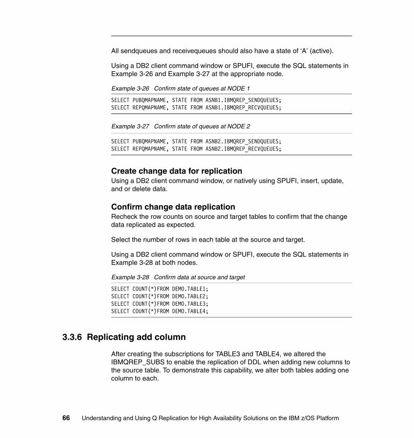
All sendqueues and receivequeues should also have a state of ‘A’ (active).
Using a DB2 client command window or SPUFI, execute the SQL statements in Example 3-26 and Example 3-27 at the appropriate node.
Example 3-26 Confirm state of queues at NODE 1
SELECT PUBQMAPNAME, STATE FROM ASNB1.IBMQREP_SENDQUEUES;SELECT REPQMAPNAME, STATE FROM ASNB1.IBMQREP_RECVQUEUES;
Example 3-27 Confirm state of queues at NODE 2
SELECT PUBQMAPNAME, STATE FROM ASNB2.IBMQREP_SENDQUEUES;SELECT REPQMAPNAME, STATE FROM ASNB2.IBMQREP_RECVQUEUES;
Create change data for replicationUsing a DB2 client command window, or natively using SPUFI, insert, update, and or delete data.
Confirm change data replicationRecheck the row counts on source and target tables to confirm that the change data replicated as expected.
Select the number of rows in each table at the source and target.
Using a DB2 client command window or SPUFI, execute the SQL statements in Example 3-28 at both nodes.
Example 3-28 Confirm data at source and target
SELECT COUNT(*)FROM DEMO.TABLE1;SELECT COUNT(*)FROM DEMO.TABLE2;SELECT COUNT(*)FROM DEMO.TABLE3;SELECT COUNT(*)FROM DEMO.TABLE4;
3.3.6 Replicating add column
After creating the subscriptions for TABLE3 and TABLE4, we altered the IBMQREP_SUBS to enable the replication of DDL when adding new columns to the source table. To demonstrate this capability, we alter both tables adding one column to each.
66 Understanding and Using Q Replication for High Availability Solutions on the IBM z/OS Platform

Using a DB2 client command window or SPUFI, execute the SQL statements in Example 3-29 at NODE 1.
Example 3-29 SQL commands to alter the source tables
ALTER TABLE DEMO.TABLE3 ADD COLUMN NEWCOL INTEGER;ALTER TABLE DEMO.TABLE4 ADD COLUMN NEWCOL INTEGER;
After altering the source tables, insert some data into the source tables, including data for the new columns, as shown in Example 3-30.
Example 3-30 Update new columns
UPDATE DEMO.TABLE3 SET NEWCOL = 98765;UPDATE DEMO.TABLE4 SET NEWCOL = 12345;
Confirm that the target tables at NODE 2 were altered by selecting data from them, including the new columns as shown in Example 3-31.
Example 3-31 Confirm columns that are added and populated at NODE 2
SELECT ID, NEWCOL FROM DEMO.TABLE3;SELECT ID, NEWCOL FROM DEMO.TABLE4;
3.3.7 Replicating alter column set data type
Another capability of Q Replication is the replication of DDL when the data type of a column is altered. Unlike the replication of added columns, the replication of the column alteration requires no changes to the subscription definition.
We altered TABLE1 and changed column V1, which is currently defined as VARCHAR(20) to VARCHAR(100), using the SQL command that is shown in Example 3-32.
Example 3-32 Alter data type of existing column
ALTER TABLE DEMO.TABLE1 ALTER COLUMN V1 SET DATA TYPE VARCHAR(100);
Update the data in the altered column of the source table at NODE 1 to a value longer than the original column length by using the SQL that is shown in Example 3-33.
Example 3-33 Update altered column
UPDATE DEMO.TABLE1 SET V1 = ‘A string of characters greater that 20’;
Chapter 3. The two-node scenario 67
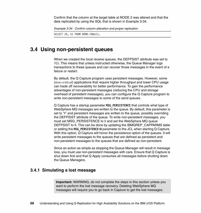
Confirm that the column at the target table at NODE 2 was altered and that the data replicated by using the SQL that is shown in Example 3-34.
Example 3-34 Confirm column alteration and proper replication
SELECT ID, V1 FROM DEMO.TABLE1;
3.4 Using non-persistent queues
When we created the local receive queues, the DEFPSIST attribute was set to YES. This means that unless instructed otherwise, the Queue Manager logs transactions to these queues and can recover those messages in the event of a failure or restart.
By default, the Q Capture program uses persistent messages. However, some (non-critical) applications that require higher throughput and lower CPU usage can trade off recoverability for better performance. To gain the performance advantages of non-persistent messages (reducing the CPU and storage overhead of persistent messages), you can configure the Q Capture program to write non-persistent messages to some of the send queues.
Q Capture has a startup parameter MSG_PERSISTENCE that controls what type of WebSphere MQ messages are written to the queue. By default, this parameter is set to ‘Y’ and persistent messages are written to the queue, possibly overriding the DEFPSIST attribute of the queue. To write non-persistent messages, you must set MSG_PERSISTENCE to D and set the WebSphere MQ queue DEFPSIST to N. This can be done by updating the IBMQREP_CAPPARMS table or adding the MSG_PERSISTENCE=D parameter to the JCL when starting Q Capture. With this option, Q Capture will honor the persistence option of the queues. It will write persistent messages to the queues that are defined as persistent and non-persistent messages to the queues that are defined as non-persistent.
Since an action as simple as stopping the Queue Manager will result in message loss, you must use non-persistent messages with care. Ensure that Q Capture is shut down first and that Q Apply consumes all messages before shutting down the Queue Managers.
3.4.1 Simulating a lost message
Important: WARNING, do not complete the steps in this section unless you want to perform the lost message recovery. Deleting WebSphere MQ messages will require you to go back in Capture to get the lost messages.
68 Understanding and Using Q Replication for High Availability Solutions on the IBM z/OS Platform

Q Replication can recover from the loss of a message by restarting Q Capture at a known point in the DB2 log before the transaction, which was contained in the missing message. One of the queues is defined as non-persistent. To demonstrate this capability, first reconfigure Q Capture to use non-persistent messages by altering the IBMQREP_CAPPARMS table as shown in Example 3-35.
Example 3-35 Configure Q Capture for non-persistent messages
UPDATE ASNB1.IBMQREP_CAPPARMS SET MSG_PERSISTENCE = ‘D’;
After performing this update, stop, then restart Q Capture for the setting to take effect.
Once running with non-persistent messages, you will not want to cause the loss of a message. There are several methods to accomplish this. The easiest is to stop the Queue Manager while it is storing non-persistent messages. You ensure that the target Queue Manager is storing messages by stopping Q Apply and replicating some data. This data will flow to the receive queue and wait for Q Apply to process it.
To stop Q Apply at NODE 2, issue the command that is shown in Example 3-36 using the System Display and Search Facility (SDSF) panel.
Example 3-36 Stop Q Apply command
/F QREPADMA,stop
Once stopped, insert some new data or modify existing data in DEMO.TABLE1 or DEMO.TABLE2 at the source database.
Confirm that the receive queue at NODE 2 contains the change data messages by examining the current depth of the queue using the MQ command in Example 3-37.
Example 3-37 Confirm current depth of receive queue
DISPLAY QLOCAL(BIDIND2.TO.BIDIND1.DATAQ1) CURDEPTH
After confirming that the messages reside in the receive queue, delete the message from the queue. To clear the messages, issue the command that is shown in Example 3-38.
Example 3-38 Clear the receive queue command
+MQ1B CLEAR QLOCAL(BIDIND2.TO.BIDIND1.DATAQ1)
Chapter 3. The two-node scenario 69
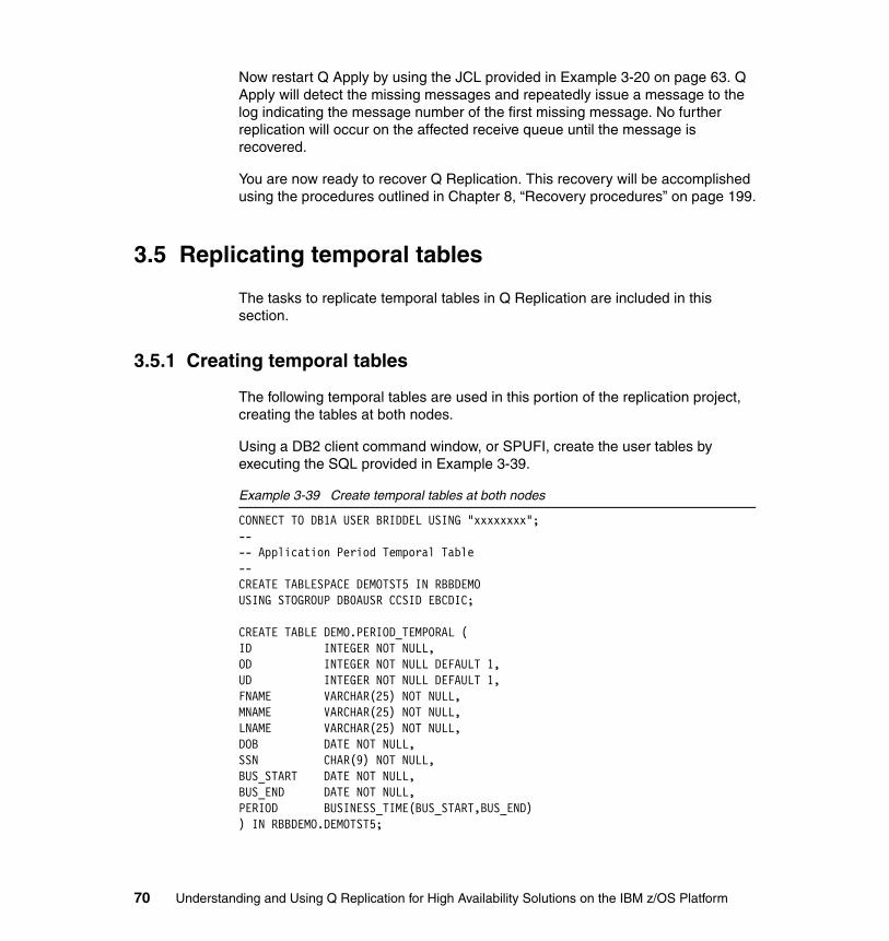
Now restart Q Apply by using the JCL provided in Example 3-20 on page 63. Q Apply will detect the missing messages and repeatedly issue a message to the log indicating the message number of the first missing message. No further replication will occur on the affected receive queue until the message is recovered.
You are now ready to recover Q Replication. This recovery will be accomplished using the procedures outlined in Chapter 8, “Recovery procedures” on page 199.
3.5 Replicating temporal tables
The tasks to replicate temporal tables in Q Replication are included in this section.
3.5.1 Creating temporal tables
The following temporal tables are used in this portion of the replication project, creating the tables at both nodes.
Using a DB2 client command window, or SPUFI, create the user tables by executing the SQL provided in Example 3-39.
Example 3-39 Create temporal tables at both nodes
CONNECT TO DB1A USER BRIDDEL USING "xxxxxxxx";---- Application Period Temporal Table--CREATE TABLESPACE DEMOTST5 IN RBBDEMO USING STOGROUP DB0AUSR CCSID EBCDIC;
CREATE TABLE DEMO.PERIOD_TEMPORAL (ID INTEGER NOT NULL,OD INTEGER NOT NULL DEFAULT 1,UD INTEGER NOT NULL DEFAULT 1,FNAME VARCHAR(25) NOT NULL,MNAME VARCHAR(25) NOT NULL,LNAME VARCHAR(25) NOT NULL,DOB DATE NOT NULL,SSN CHAR(9) NOT NULL,BUS_START DATE NOT NULL,BUS_END DATE NOT NULL,PERIOD BUSINESS_TIME(BUS_START,BUS_END)) IN RBBDEMO.DEMOTST5;
70 Understanding and Using Q Replication for High Availability Solutions on the IBM z/OS Platform

CREATE UNIQUE INDEX PTEMPUIX on DEMO.PERIOD_TEMPORAL(ID,OD,UD);
---- Bi-Temporal--CREATE TABLESPACE DEMOTST6 IN RBBDEMO USING STOGROUP DB0AUSR CCSID EBCDIC;CREATE TABLESPACE DEMOTS6H IN RBBDEMO USING STOGROUP DB0AUSR CCSID EBCDIC;
CREATE TABLE DEMO.BI_TEMPORAL (ID INTEGER NOT NULL,OD INTEGER NOT NULL DEFAULT 1,UD INTEGER NOT NULL DEFAULT 1,S1 SMALLINT NOT NULL WITH DEFAULT,I1 INTEGER NOT NULL WITH DEFAULT,C1 CHAR(10) NOT NULL WITH DEFAULT,V1 VARCHAR(20),BUS_START DATE NOT NULL,BUS_END DATE NOT NULL,SYSTEM_START TIMESTAMP(12) NOT NULL GENERATED ALWAYS AS ROW BEGIN,SYSTEM_END TIMESTAMP(12) NOT NULL GENERATED ALWAYS AS ROW END,TRANS_START TIMESTAMP(12) NOT NULL GENERATED ALWAYS AS TRANSACTION START ID,PERIOD BUSINESS_TIME(BUS_START,BUS_END),PERIOD SYSTEM_TIME(SYSTEM_START,SYSTEM_END)) IN RBBDEMO.DEMOTST6;
CREATE UNIQUE INDEX BTEMPUIX on DEMO.BI_TEMPORAL(ID,OD,UD);
CREATE TABLE DEMO.BI_TEMPORAL_HIST LIKE DEMO.BI_TEMPORAL IN RBBDEMO.DEMOTS6H;
ALTER TABLE DEMO.BI_TEMPORAL ADD VERSIONINGUSE HISTORY TABLE DEMO.BI_TEMPORAL_HIST;
---- System Period Temporal--CREATE TABLESPACE DEMOTST7 IN RBBDEMO USING STOGROUP DB0AUSR CCSID EBCDIC;CREATE TABLESPACE DEMOTS7H IN RBBDEMO USING STOGROUP DB0AUSR CCSID EBCDIC;
CREATE TABLE DEMO.SYS_TEMPORAL (ID INTEGER NOT NULL,OD INTEGER NOT NULL DEFAULT 1,UD INTEGER NOT NULL DEFAULT 1,S1 SMALLINT NOT NULL WITH DEFAULT,I1 INTEGER NOT NULL WITH DEFAULT,C1 CHAR(10) NOT NULL WITH DEFAULT,
Chapter 3. The two-node scenario 71
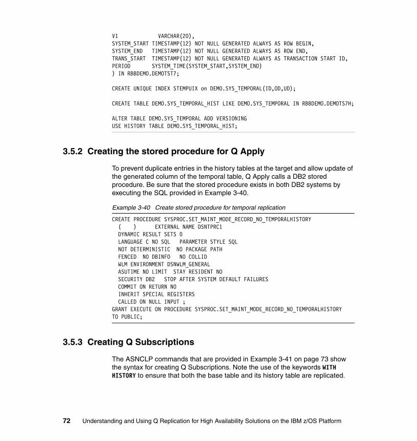
V1 VARCHAR(20),SYSTEM_START TIMESTAMP(12) NOT NULL GENERATED ALWAYS AS ROW BEGIN,SYSTEM_END TIMESTAMP(12) NOT NULL GENERATED ALWAYS AS ROW END,TRANS_START TIMESTAMP(12) NOT NULL GENERATED ALWAYS AS TRANSACTION START ID,PERIOD SYSTEM_TIME(SYSTEM_START,SYSTEM_END)) IN RBBDEMO.DEMOTST7;
CREATE UNIQUE INDEX STEMPUIX on DEMO.SYS_TEMPORAL(ID,OD,UD);
CREATE TABLE DEMO.SYS_TEMPORAL_HIST LIKE DEMO.SYS_TEMPORAL IN RBBDEMO.DEMOTS7H;
ALTER TABLE DEMO.SYS_TEMPORAL ADD VERSIONINGUSE HISTORY TABLE DEMO.SYS_TEMPORAL_HIST;
3.5.2 Creating the stored procedure for Q Apply
To prevent duplicate entries in the history tables at the target and allow update of the generated column of the temporal table, Q Apply calls a DB2 stored procedure. Be sure that the stored procedure exists in both DB2 systems by executing the SQL provided in Example 3-40.
Example 3-40 Create stored procedure for temporal replication
CREATE PROCEDURE SYSPROC.SET_MAINT_MODE_RECORD_NO_TEMPORALHISTORY ( ) EXTERNAL NAME DSNTPRC1 DYNAMIC RESULT SETS 0 LANGUAGE C NO SQL PARAMETER STYLE SQL NOT DETERMINISTIC NO PACKAGE PATH FENCED NO DBINFO NO COLLID WLM ENVIRONMENT DSNWLM_GENERAL ASUTIME NO LIMIT STAY RESIDENT NO SECURITY DB2 STOP AFTER SYSTEM DEFAULT FAILURES COMMIT ON RETURN NO INHERIT SPECIAL REGISTERS CALLED ON NULL INPUT ;GRANT EXECUTE ON PROCEDURE SYSPROC.SET_MAINT_MODE_RECORD_NO_TEMPORALHISTORYTO PUBLIC;
3.5.3 Creating Q Subscriptions
The ASNCLP commands that are provided in Example 3-41 on page 73 show the syntax for creating Q Subscriptions. Note the use of the keywords WITH HISTORY to ensure that both the base table and its history table are replicated.
72 Understanding and Using Q Replication for High Availability Solutions on the IBM z/OS Platform

Example 3-41 Creating Q Subscriptions via ASNCLP
ASNCLP SESSION SET TO Q REPLICATION;SET RUN SCRIPT NOW STOP ON SQL ERROR ON;
SET BIDI NODE 1 SERVER DBALIAS DB1A DBNAME DB1AID BRIDDEL PASSWORD "xxxxxxxx" SCHEMA ASNB1;SET BIDI NODE 2 SERVER DBALIAS DB1C DBNAME DB1CID BRIDDEL PASSWORD "xxxxxxxx" SCHEMA ASNB2;
SET SUBGROUP "bidigroup3";
SET CONNECTION SOURCE DB1A.ASNB1 TARGET DB1C.ASNB2 REPLQMAP BIDIND1_TO_BIDIND2_MAP1 ;
SET CONNECTION SOURCE DB1C.ASNB2 TARGET DB1A.ASNB1 REPLQMAP BIDIND2_TO_BIDIND1_MAP1 ;
SET TABLES (DB1A.ASNB1.DEMO.PERIOD_TEMPORAL);CREATE QSUB SUBTYPE B INCLUDE HISTORYFROM NODE DB1A.ASNB1 SOURCE HAS LOAD PHASE NTARGET CONFLICT ACTION IFROM NODE DB1C.ASNB2 SOURCE HAS LOAD PHASE NTARGET CONFLICT ACTION F;
SET TABLES (DB1A.ASNB1.DEMO.BI_TEMPORAL);CREATE QSUB SUBTYPE B INCLUDE HISTORYFROM NODE DB1A.ASNB1 SOURCE HAS LOAD PHASE NTARGET CONFLICT ACTION IFROM NODE DB1C.ASNB2 SOURCE HAS LOAD PHASE NTARGET CONFLICT ACTION F;
SET TABLES (DB1A.ASNB1.DEMO.SYS_TEMPORAL);CREATE QSUB SUBTYPE B INCLUDE HISTORYFROM NODE DB1A.ASNB1 SOURCE HAS LOAD PHASE NTARGET CONFLICT ACTION IFROM NODE DB1C.ASNB2 SOURCE HAS LOAD PHASE NTARGET CONFLICT ACTION F;
QUIT;
3.5.4 Starting Q Subscriptions
Since Q Capture is already running, the auto-activation will not be triggered unless you stop and start Q Capture or reinitialize the running program. Instead, there is another way to start a subscription, which is by sending Q Capture a CAPSTART signal.
Chapter 3. The two-node scenario 73
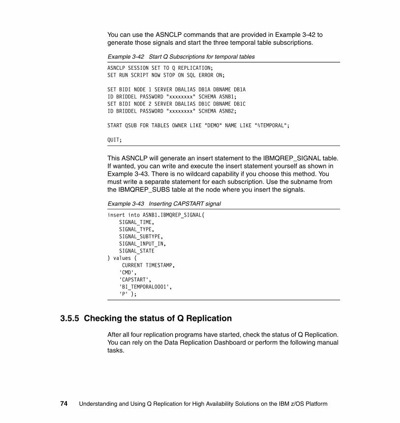
You can use the ASNCLP commands that are provided in Example 3-42 to generate those signals and start the three temporal table subscriptions.
Example 3-42 Start Q Subscriptions for temporal tables
ASNCLP SESSION SET TO Q REPLICATION;SET RUN SCRIPT NOW STOP ON SQL ERROR ON;
SET BIDI NODE 1 SERVER DBALIAS DB1A DBNAME DB1AID BRIDDEL PASSWORD "xxxxxxxx" SCHEMA ASNB1;SET BIDI NODE 2 SERVER DBALIAS DB1C DBNAME DB1CID BRIDDEL PASSWORD "xxxxxxxx" SCHEMA ASNB2;
START QSUB FOR TABLES OWNER LIKE "DEMO" NAME LIKE "%TEMPORAL";
QUIT;
This ASNCLP will generate an insert statement to the IBMQREP_SIGNAL table. If wanted, you can write and execute the insert statement yourself as shown in Example 3-43. There is no wildcard capability if you choose this method. You must write a separate statement for each subscription. Use the subname from the IBMQREP_SUBS table at the node where you insert the signals.
Example 3-43 Inserting CAPSTART signal
insert into ASNB1.IBMQREP_SIGNAL( SIGNAL_TIME, SIGNAL_TYPE, SIGNAL_SUBTYPE, SIGNAL_INPUT_IN, SIGNAL_STATE) values ( CURRENT TIMESTAMP, 'CMD', 'CAPSTART', 'BI_TEMPORAL0001', 'P' );
3.5.5 Checking the status of Q Replication
After all four replication programs have started, check the status of Q Replication. You can rely on the Data Replication Dashboard or perform the following manual tasks.
74 Understanding and Using Q Replication for High Availability Solutions on the IBM z/OS Platform

All five Q Subscriptions should have a state of ‘A’ (active). Using a DB2 client command window or SPUFI, execute the SQL statements in Example 3-44 and Example 3-45 at the appropriate node. Notice that the subscriptions for the history tables were automatically started even though we did not explicitly name them in the START QSUB command.
Example 3-44 Confirm state of subscriptions at NODE 1
SELECT SUBNAME, STATE FROM ASNB1.IBMQREP_SUBSWHERE SUBNAME LIKE ‘%TEMPORAL%’;SELECT SUBNAME, STATE FROM ASNB1.IBMQREP_TARGETSWHERE SUBNAME LIKE ‘%TEMPORAL%’;
Example 3-45 Confirm state of subscriptions at NODE 2
SELECT SUBNAME, STATE FROM ASNB2.IBMQREP_SUBSWHERE SUBNAME LIKE ‘%TEMPORAL%’;SELECT SUBNAME, STATE FROM ASNB2.IBMQREP_TARGETSWHERE SUBNAME LIKE ‘%TEMPORAL%’;
All Q Subscriptions should have a state of ‘A’ (active). Using a DB2 client command window or SPUFI, execute the SQL statements in Example 3-46 and Example 3-47 at the appropriate node.
Example 3-46 Confirm state of queues at NODE 1
SELECT PUBQMAPNAME, STATE FROM ASNB1.IBMQREP_SENDQUEUES;SELECT REPQMAPNAME, STATE FROM ASNB1.IBMQREP_RECVQUEUES;
Example 3-47 Confirm state of queues at NODE 2
SELECT PUBQMAPNAME, STATE FROM ASNB2.IBMQREP_SENDQUEUES;SELECT REPQMAPNAME, STATE FROM ASNB2.IBMQREP_RECVQUEUES;
Confirm the replication of change data by updating the tables at the source subsystem and then confirm replication by selecting the number of rows in each table at the source and target by using the SQL statements shown in Example 3-48 on page 76.
Chapter 3. The two-node scenario 75

Using a DB2 client command window or SPUFI, execute the following SQL statements at both nodes, as shown in Example 3-48.
Example 3-48 Confirm data at both nodes
SELECT COUNT(*)FROM DEMO.PERIOD_TEMPORAL;SELECT COUNT(*)FROM DEMO.BI_TEMPORAL;SELECT COUNT(*)FROM DEMO.BI_TEMPORAL_HIST;SELECT COUNT(*)FROM DEMO.SYS_TEMPORAL;SELECT COUNT(*)FROM DEMO.SYS_TEMPORAL_HIST;
3.6 Using parallel send queues
When Q Replication is replicating small transactions at very high rates, WebSphere MQ may encounter problems transporting messages from a single source transmission to the target queue fast enough to prevent a build-up of messages on the source Queue Manager. This shows up as a growing transmission queue depth at the Q Capture side in the XMITQDEPTH column and a high MQPUT_TIME relative to the MQ_MESSAGES as reported in the IBMQREP_CAPQMON table. At the Q Apply side, you will see growing QLATENCY but low QDEPTH column values in the IBMQREP_APPLYMON table.
To alleviate this condition, you can use multiple send queue, transmission queue, and sender channels for a single queue map. This is accomplished by the following steps:
1. Creating the appropriate WebSphere MQ objects2. Informing Q Capture that the parallel send queues exist
First, create two new tables that will be configured to use the parallel send queues by using the SQL statements that are shown in Example 3-49.
Example 3-49 Create new tables
CONNECT TO DB1A USER BRIDDEL USING "xxxxxxxx";
CREATE TABLESPACE DEMOTSP5 IN RBBDEMO USING STOGROUP DB0AUSR CCSID EBCDIC;
CREATE TABLE DEMO.TABLE5 (ID INTEGER NOT NULL,OD INTEGER NOT NULL DEFAULT 1,UD INTEGER NOT NULL DEFAULT 1,S1 SMALLINT NOT NULL WITH DEFAULT,I1 INTEGER NOT NULL WITH DEFAULT,B1 BIGINT NOT NULL WITH DEFAULT,
76 Understanding and Using Q Replication for High Availability Solutions on the IBM z/OS Platform

DEC1 DECIMAL(4,0) NOT NULL WITH DEFAULT,DF1 DECFLOAT(16) NOT NULL WITH DEFAULT,F1 FLOAT(21) NOT NULL WITH DEFAULT,RCTS NOT NULL GENERATED ALWAYS FOR EACH ROW ON UPDATE AS ROW CHANGE TIMESTAMP) IN RBBDEMO.DEMOTSP5;CREATE UNIQUE INDEX TAB5UIX ON DEMO.TABLE5(ID,OD,UD);
CREATE TABLESPACE DEMOTSP6 IN RBBDEMO USING STOGROUP DB0AUSR CCSID EBCDIC;
CREATE TABLE DEMO.TABLE6 (ID INTEGER NOT NULL,OD INTEGER NOT NULL DEFAULT 1,UD INTEGER NOT NULL DEFAULT 1,C1 CHARACTER(10) NOT NULL WITH DEFAULT,V1 VARCHAR(20) NOT NULL WITH DEFAULT,RCTS NOT NULL GENERATED ALWAYS FOR EACH ROW ON UPDATE AS ROW CHANGE TIMESTAMP) IN RBBDEMO.DEMOTSP6;CREATE UNIQUE INDEX TAB6UIX ON DEMO.TABLE6(ID,OD,UD);
3.6.1 Configuring WebSphere MQ for parallel send queues
To support this configuration, create multiple sets of WebSphere MQ objects so that there are multiple paths for the flow of data from Q Capture to the receive queue. Each set of objects will consist of a remote send queue, a transmission queue, and a channel (each channel with its own port). All of the send queues point to the same receive queue where the data is consolidated for processing by Q Apply.
In Example 3-50 on page 78, two remote send queues named BIDIND1.TO.BIDIND2.PDATAQ3.1 and BIDIND1.TO.BIDIND2.PDATAQ3.2 will be created. The numeric suffix must begin with 1 and increase by 1 for each parallel send queue created. Each of these remote send queues has a separate transmission queue (MQ1BP1 and MQ1BP2). Each transmission queue will in turn use a separate sender channel (MQ1A.TO.MQ1B.P1 and MQ1A.TO.MQ1B.P2).
Chapter 3. The two-node scenario 77

Use the commands in Example 3-50 to create the NODE 1 WebSphere MQ objects and the commands in Example 3-51 on page 80 to create the NODE 2 objects.
Example 3-50 Creating WebSphere MQ objects at NODE 1
//MQDEFQ JOB 'USER=$$USER','<USERNAME:JOBNAME>',TIME=20,// MSGCLASS=H,MSGLEVEL=(1,1),USER=&SYSUID,REGION=4096K/*JOBPARM S=HB//*****************************************************************//CRTQ EXEC PGM=CSQUTIL,PARM='MQ1A'//STEPLIB DD DSN=SYS1.MQ1A.EXITLIB,DISP=SHR// DD DSN=CEE.SCEERUN,DISP=SHR//SYSPRINT DD SYSOUT=*//SYSIN DD * COMMAND DDNAME(CMDINP)/*//CMDINP DD *
** Create two Send Queues all pointing to the same Receive Queue*DEFINE QREMOTE('BIDIND1.TO.BIDIND2.PDATAQ3.1') REPLACE +RNAME('BIDIND1.TO.BIDIND2.PDATAQ3') RQMNAME('MQ1B') +XMITQ('MQ1BP1')
DEFINE QREMOTE('BIDIND1.TO.BIDIND2.PDATAQ3.2') REPLACE +RNAME('BIDIND1.TO.BIDIND2.PDATAQ3') RQMNAME('MQ1B') +XMITQ('MQ1BP2')
* alias for access when no multiplexing is selectedDEFINE QALIAS('BIDIND1.TO.BIDIND2.PDATAQ3') TARGQ +('BIDIND1.TO.BIDIND2.PDATAQ3.1') REPLACE
** Create a new Receive Queue that will receive data from* two Send Queues on NODE 2*DEFINE QLOCAL(BIDIND2.TO.BIDIND1.PDATAQ3) REPLACE + DESCR('LOCAL RECV QUEUE') + PUT(ENABLED) + GET(ENABLED) + SHARE + DEFSOPT(SHARED) + DEFPSIST(YES) + MAXDEPTH(999999999) + INDXTYPE(MSGID)
78 Understanding and Using Q Replication for High Availability Solutions on the IBM z/OS Platform

** Create two new transmission Queues*DEFINE QLOCAL('MQ1BP1') REPLACE + DESCR('TRANSMISSION QUEUE TO MQ1B') + USAGE(XMITQ) + PUT(ENABLED) + GET(ENABLED) + MAXDEPTH(999999999)
DEFINE QLOCAL('MQ1BP2') REPLACE + DESCR('TRANSMISSION QUEUE TO MQ1B') + USAGE(XMITQ) + PUT(ENABLED) + GET(ENABLED) + MAXDEPTH(999999999)
** Create Four new channel pairs*DEFINE CHANNEL(MQ1A.TO.MQ1B.P1) REPLACE + CHLTYPE(SDR) + TRPTYPE(TCP) + DISCINT(0) + DESCR('SENDER CHANNEL TO MQ1B') + XMITQ(MQ1BP1) + CONNAME('10.33.10.102(1436)')
DEFINE CHANNEL(MQ1B.TO.MQ1A.P1) REPLACE + CHLTYPE(RCVR) + TRPTYPE(TCP) + DESCR('RECEIVER CHANNEL FROM MQ1A')
DEFINE CHANNEL(MQ1A.TO.MQ1B.P2) REPLACE + CHLTYPE(SDR) + TRPTYPE(TCP) + DISCINT(0) + DESCR('SENDER CHANNEL TO MQ1B') + XMITQ(MQ1BP2) + CONNAME('10.33.10.102(1435)')
DEFINE CHANNEL(MQ1B.TO.MQ1A.P1) REPLACE + CHLTYPE(RCVR) + TRPTYPE(TCP) + DESCR('RECEIVER CHANNEL FROM MQ1A')
* DISPLAY QUEUE(*) ALL
Chapter 3. The two-node scenario 79

/*//
Example 3-51 Creating WebSphere MQ objects at NODE 2
//MQDEFQ JOB 'USER=$$USER','<USERNAME:JOBNAME>',TIME=20,// MSGCLASS=H,MSGLEVEL=(1,1),USER=&SYSUID,REGION=4096K/*JOBPARM S=HB//*****************************************************************//CRTQ EXEC PGM=CSQUTIL,PARM='MQ1B'//STEPLIB DD DSN=SYS1.MQ1A.EXITLIB,DISP=SHR// DD DSN=CEE.SCEERUN,DISP=SHR//SYSPRINT DD SYSOUT=*//SYSIN DD * COMMAND DDNAME(CMDINP)/*//CMDINP DD *
** Create two Send Queues all pointing to the same Receive Queue*DEFINE QREMOTE('BIDIND2.TO.BIDIND1.PDATAQ3.1') REPLACE +RNAME('BIDIND2.TO.BIDIND1.PDATAQ3') RQMNAME('MQ1A') +XMITQ('MQ1AP1')
DEFINE QREMOTE('BIDIND2.TO.BIDIND1.PDATAQ3.2') REPLACE +RNAME('BIDIND2.TO.BIDIND1.PDATAQ3') RQMNAME('MQ1A') +XMITQ('MQ1AP2')
* alias for access when no parallel send queues is selectedDEFINE QALIAS('BIDIND2.TO.BIDIND1.PDATAQ3') TARGQ +('BIDIND2.TO.BIDIND1.PDATAQ3.1') REPLACE
** Create a new Receive Queue that will receive data from* two Send Queues on NODE 2*DEFINE QLOCAL(BIDIND1.TO.BIDIND2.PDATAQ3) REPLACE + DESCR('LOCAL RECV QUEUE') + PUT(ENABLED) + GET(ENABLED) + SHARE + DEFSOPT(SHARED) + DEFPSIST(YES) + MAXDEPTH(999999999) + INDXTYPE(MSGID)
** Create two new transmission Queues*
80 Understanding and Using Q Replication for High Availability Solutions on the IBM z/OS Platform

DEFINE QLOCAL('MQ1AP1') REPLACE + DESCR('TRANSMISSION QUEUE TO MQ1A') + USAGE(XMITQ) + PUT(ENABLED) + GET(ENABLED) + MAXDEPTH(999999999)
DEFINE QLOCAL('MQ1AP2') REPLACE + DESCR('TRANSMISSION QUEUE TO MQ1A') + USAGE(XMITQ) + PUT(ENABLED) + GET(ENABLED) + MAXDEPTH(999999999)
** Create Four new channel pairs*DEFINE CHANNEL(MQ1B.TO.MQ1A.P1) REPLACE + CHLTYPE(SDR) + TRPTYPE(TCP) + DISCINT(0) + DESCR('SENDER CHANNEL TO MQ1A') + XMITQ(MQ1AP1) + CONNAME('10.33.10.101(1436)')
DEFINE CHANNEL(MQ1A.TO.MQ1B.P1) REPLACE + CHLTYPE(RCVR) + TRPTYPE(TCP) + DESCR('RECEIVER CHANNEL FROM MQ1A')
DEFINE CHANNEL(MQ1B.TO.MQ1A.P2) REPLACE + CHLTYPE(SDR) + TRPTYPE(TCP) + DISCINT(0) + DESCR('SENDER CHANNEL TO MQ1A') + XMITQ(MQ1AP2) + CONNAME('10.33.10.101(1435)')
DEFINE CHANNEL(MQ1A.TO.MQ1B.P2) REPLACE + CHLTYPE(RCVR) + TRPTYPE(TCP) + DESCR('RECEIVER CHANNEL FROM MQ1A')
* DISPLAY QUEUE(*) ALL
/*//
Chapter 3. The two-node scenario 81

3.6.2 Starting WebSphere MQ communications
The JCL provided in Example 3-52 and Example 3-53 can be used to start the new channels.
Example 3-52 Start WebSphere MQ communications on NODE 1
//STCHLN1 JOB 'USER=$$USER','<USERNAME:JOBNAME>',CLASS=A,// MSGCLASS=A,MSGLEVEL=(1,1),REGION=512M,NOTIFY=&SYSUID//*****************************************************************//STRCH EXEC PGM=CSQUTIL,PARM='MQ1A'//STEPLIB DD DSN=WMQ.V7R0.SCSQANLE,DISP=SHR// DD DSN=WMQ.V7R0.SCSQLOAD,DISP=SHR// DD DSN=WMQ.V7R0.SCSQAUTH,DISP=SHR//SYSPRINT DD SYSOUT=*//SYSIN DD * COMMAND DDNAME(CMDINP)/*//CMDINP DD *
START CHANNEL(MQ1A.TO.MQ1B.P1)START CHANNEL(MQ1A.TO.MQ1B.P2)
DISPLAY CHSTATUS(MQ1A.TO.MQ1B.P1)DISPLAY CHSTATUS(MQ1A.TO.MQ1B.P2)
/*//
Example 3-53 Start WebSphere MQ communications on NODE 2
//STCHLN2 JOB 'USER=$$USER','<USERNAME:JOBNAME>',CLASS=A,// MSGCLASS=A,MSGLEVEL=(1,1),REGION=512M,NOTIFY=&SYSUID//*****************************************************************//STRCH EXEC PGM=CSQUTIL,PARM='MQ1B'//STEPLIB DD DSN=WMQ.V7R0.SCSQANLE,DISP=SHR// DD DSN=WMQ.V7R0.SCSQLOAD,DISP=SHR// DD DSN=WMQ.V7R0.SCSQAUTH,DISP=SHR//SYSPRINT DD SYSOUT=*//SYSIN DD * COMMAND DDNAME(CMDINP)/*//CMDINP DD *
START CHANNEL(MQ1B.TO.MQ1A.P1)START CHANNEL(MQ1B.TO.MQ1A.P2)
DISPLAY CHSTATUS(MQ1B.TO.MQ1A.P1)DISPLAY CHSTATUS(MQ1B.TO.MQ1A.P2)
82 Understanding and Using Q Replication for High Availability Solutions on the IBM z/OS Platform

/*//
3.6.3 Creating Q Map for parallel send queues
To take advantage of the parallel send queues, you must create a new set of Q Maps that specify the ASLNCLP clause ‘PARALLEL SENDQS 2’ so that Q Capture will know to alternately write messages to the two send queues (BIDIND2.TO.BIDIND1.PDATAQ3.1 and BIDIND2.TO.BIDIND1.PDATAQ3.2).
Note that BIDIND2.TO.BIDIND1.PDATAQ3 are specified as the send queues, not the queues that were created with the numeric suffix. Q Capture appends the suffix ‘.1’,‘.2’, up to the number provided in the ‘PARALLEL SENDQS’ clause.
Use the ASNCLP commands provided in Example 3-54 to create the Q Maps.
Example 3-54 Creating Q Map for parallel send queues via ASNCLP
ASNCLP SESSION SET TO Q REPLICATION;SET RUN SCRIPT NOW STOP ON SQL ERROR ON;
SET BIDI NODE 1 SERVER DBALIAS DB1A DBNAME DB1AID BRIDDEL PASSWORD "xxxxxxxx" SCHEMA ASNB1;SET BIDI NODE 2 SERVER DBALIAS DB1C DBNAME DB1CID BRIDDEL PASSWORD "xxxxxxxx" SCHEMA ASNB2;
CREATE REPLQMAP BIDIND1_TO_BIDIND2_MAP3 ( NODE 1, NODE 2 ) USINGADMINQ "BIDIND1.ADMINQ"RECVQ "BIDIND1.TO.BIDIND2.PDATAQ3"SENDQ "BIDIND1.TO.BIDIND2.PDATAQ3"PARALLEL SENDQS 2;
CREATE REPLQMAP BIDIND2_TO_BIDIND1_MAP3 ( NODE 2, NODE 1 ) USINGADMINQ "BIDIND2.ADMINQ"RECVQ "BIDIND2.TO.BIDIND1.PDATAQ3"SENDQ "BIDIND2.TO.BIDIND1.PDATAQ3"PARALLEL SENDQS 2;
QUIT;
Chapter 3. The two-node scenario 83

3.6.4 Reviewing SENDQ and RECVQ parallel send queue columns
Confirm that the Q Maps were created properly by examining the control table entries, shown in Example 3-55 and Example 3-56, at the appropriate node.
Example 3-55 Confirm state of queues at NODE 1
SELECT PUBQMAPNAME, NUM_PARALLEL_SENDQS FROM ASNB1.IBMQREP_SENDQUEUESWHERE PUBQMAPNAME = ‘BIDIND1_TO_BIDIND2_MAP3’;SELECT REPQMAPNAME, PARALLEL_SENDQS FROM ASNB1.IBMQREP_RECVQUEUESWHERE REPQMAPNAME = ‘BIDIND2_TO_BIDIND1_MAP3’;
Example 3-56 Confirm state of queues at NODE 2
SELECT PUBQMAPNAME, NUM_PARALLEL_SENDQS FROM ASNB2.IBMQREP_SENDQUEUESWHERE PUBQMAPNAME = ‘BIDIND2_TO_BIDIND1_MAP3’;SELECT REPQMAPNAME, PARALLEL_SENDQS FROM ASNB2.IBMQREP_RECVQUEUESWHERE REPQMAPNAME = ‘BIDIND1_TO_BIDIND2_MAP3’;
3.6.5 Creating Q Subscriptions for parallel send queues
The ASNCLP commands to create the new subscriptions for parallel send queues are provided in Example 3-57.
Example 3-57 Creating Q Subscriptions via ASNCLP
ASNCLP SESSION SET TO Q REPLICATION;SET RUN SCRIPT NOW STOP ON SQL ERROR ON;
SET BIDI NODE 1 SERVER DBALIAS DB1A DBNAME DB1AID BRIDDEL PASSWORD "xxxxxxxx" SCHEMA ASNB1;SET BIDI NODE 2 SERVER DBALIAS DB1C DBNAME DB1CID BRIDDEL PASSWORD "xxxxxxxx" SCHEMA ASNB2;
SET SUBGROUP "bidigroup4";
SET CONNECTION SOURCE DB1A.ASNB1 TARGET DB1C.ASNB2 REPLQMAP BIDIND1_TO_BIDIND2_MAP3 ;
SET CONNECTION SOURCE DB1C.ASNB2 TARGET DB1A.ASNB1 REPLQMAP BIDIND2_TO_BIDIND1_MAP3 ;
SET TABLES (DB1A.ASNB1.DEMO.TABLE5);
84 Understanding and Using Q Replication for High Availability Solutions on the IBM z/OS Platform

CREATE QSUB SUBTYPE BFROM NODE DB1A.ASNB1 SOURCE HAS LOAD PHASE NTARGET CONFLICT ACTION IFROM NODE DB1C.ASNB2 SOURCE HAS LOAD PHASE NTARGET CONFLICT ACTION F;
SET TABLES (DB1A.ASNB1.DEMO.TABLE6);CREATE QSUB SUBTYPE BFROM NODE DB1A.ASNB1 SOURCE HAS LOAD PHASE NTARGET CONFLICT ACTION IFROM NODE DB1C.ASNB2 SOURCE HAS LOAD PHASE NTARGET CONFLICT ACTION F;
QUIT;
3.6.6 Activating new Q Maps/Q Subscriptions replication
Although the Q Maps are created in an ‘A’ctive state, you need to activate them to make Q Apply aware that they exist. You can do so by using the IBM MVS™ MODIFY commands that are provided in Example 3-58 and Example 3-59. You do not need to activate the Send Queues this way because Q Capture will start processing them automatically when it receives a CAPSTART signal for one of the Q Subscriptions they contain.
Note that the MODIFY command in SDSF is used to get the Q Apply started task (jobname QREPADMA) to start the Receive Queues.
Example 3-58 Starting the new Receive Queue on NODE 1
/F QREPADMA,startq=BIDIND2_TO_BIDIND1.PDATAQ3
Example 3-59 Starting the new Receive Queue on NODE 2
/F QREPADMA,startq=BIDIND1_TO_BIDIND2.PDATAQ3
After the queues are being processed, you can start the new Q Subscription by sending a CAPSTART signal to the Q Capture on NODE 1 by using the ASNCLP command that is shown in Example 3-60.
Example 3-60 Start Q Subscriptions for parallel send queue tables
ASNCLP SESSION SET TO Q REPLICATION;SET RUN SCRIPT NOW STOP ON SQL ERROR ON;
SET BIDI NODE 1 SERVER DBALIAS DB1A DBNAME DB1A
Chapter 3. The two-node scenario 85

ID BRIDDEL PASSWORD "xxxxxxxx" SCHEMA ASNB1;SET BIDI NODE 2 SERVER DBALIAS DB1C DBNAME DB1CID BRIDDEL PASSWORD "xxxxxxxx" SCHEMA ASNB2;
START QSUB FOR TABLES OWNER LIKE "DEMO" NAME LIKE "%TABLE5";START QSUB FOR TABLES OWNER LIKE "DEMO" NAME LIKE "%TABLE6";
QUIT;
3.6.7 Replicating data
To demonstrate the use of both send queues, we replicate some change data.
But before updating the source table data, we want to stop the Sender (SDR) channels so that the data will build up in the transmit queues and we can observe the data written to each send/transmit queue pairs.
Stop the parallel channels by using the JCL provided in Example 3-61.
Example 3-61 Stop WebSphere MQ communications on NODE 2
//STCHLN2 JOB 'USER=$$USER','<USERNAME:JOBNAME>',CLASS=A,// MSGCLASS=A,MSGLEVEL=(1,1),REGION=512M,NOTIFY=&SYSUID//*****************************************************************//STRCH EXEC PGM=CSQUTIL,PARM='MQ1A'//STEPLIB DD DSN=WMQ.V7R0.SCSQANLE,DISP=SHR// DD DSN=WMQ.V7R0.SCSQLOAD,DISP=SHR// DD DSN=WMQ.V7R0.SCSQAUTH,DISP=SHR//SYSPRINT DD SYSOUT=*//SYSIN DD * COMMAND DDNAME(CMDINP)/*//CMDINP DD *
STOP CHANNEL(MQ1A.TO.MQ1B.P1)STOP CHANNEL(MQ1A.TO.MQ1B.P2)
DISPLAY CHSTATUS(MQ1A.TO.MQ1B.P1)DISPLAY CHSTATUS(MQ1A.TO.MQ1B.P2)
/*//
Create a series of small transactions by using the SQL commands, shown in Example 3-62 on page 87, at NODE 1.
86 Understanding and Using Q Replication for High Availability Solutions on the IBM z/OS Platform

Example 3-62 Perform some changes on NODE 1
insert into DEMO.TABLE5(ID,S1) values (1,1);insert into DEMO.TABLE6(ID,C1) values (1,’ChangeData’);commit;insert into DEMO.TABLE5(ID,S1) values (2,1);insert into DEMO.TABLE6(ID,C1) values (2,’ChangeData’);commit;insert into DEMO.TABLE5(ID,S1) values (3,1);insert into DEMO.TABLE6(ID,C1) values (3,’ChangeData’);commit;insert into DEMO.TABLE5(ID,S1) values (4,1);insert into DEMO.TABLE6(ID,C1) values (4,’ChangeData’);commit;insert into DEMO.TABLE5(ID,S1) values (5,1);insert into DEMO.TABLE6(ID,C1) values (5,’ChangeData’);commit;insert into DEMO.TABLE5(ID,S1) values (6,1);insert into DEMO.TABLE6(ID,C1) values (6,’ChangeData’);commit;insert into DEMO.TABLE5(ID,S1) values (7,1);insert into DEMO.TABLE6(ID,C1) values (7,’ChangeData’);commit;insert into DEMO.TABLE5(ID,S1) values (8,1);insert into DEMO.TABLE6(ID,C1) values (8,’ChangeData’);commit;insert into DEMO.TABLE5(ID,S1) values (9,1);insert into DEMO.TABLE6(ID,C1) values (9,’ChangeData’);commit;insert into DEMO.TABLE5(ID,S1) values (10,1);insert into DEMO.TABLE6(ID,C1) values (10,’ChangeData’);commit;insert into DEMO.TABLE5(ID,S1) values (11,1);insert into DEMO.TABLE6(ID,C1) values (11,’ChangeData’);commit;insert into DEMO.TABLE5(ID,S1) values (12,1);insert into DEMO.TABLE6(ID,C1) values (12,’ChangeData’);commit;insert into DEMO.TABLE5(ID,S1) values (13,1);insert into DEMO.TABLE6(ID,C1) values (13,’ChangeData’);commit;insert into DEMO.TABLE5(ID,S1) values (14,1);insert into DEMO.TABLE6(ID,C1) values (14,’ChangeData’);commit;insert into DEMO.TABLE5(ID,S1) values (15,1);insert into DEMO.TABLE6(ID,C1) values (15,’ChangeData’);commit;
Chapter 3. The two-node scenario 87

3.6.8 Checking the status of Q Replication
After inserting the new rows, examine the depth of the transmit queues on the NODE 1 Queue Manager (MQ1A).
You have two options:
� Query the Q Capture XMITQDEPTH column value of the IBMQREP_CAPQMON table. The XMITQDEPTH column saves the transmit queue depth value of a given send queue at the time a new row is added to the IBMQREP_CAPQMON table
� Issue a WebSphere MQ command
Since this is a simple WebSphere MQ command, you can use SDSF to query the Queue Manager by using the command provided in Example 3-63.
To perform this display command, you need to know the command prefix that is assigned to your Queue Manager. We used “+MQ1A” in the example, but you can determine your command prefix by issuing the command “/D OPDATA”.
You should see multiple messages in each of the four transmit queues (MQ1AP1, MQ1AP2, MQ1BP1, MQ1BP2).
Example 3-63 SDSF command to examine
/+MQ1A DISPLAY QLOCAL(MQ1BP1) CURDEPTH/+MQ1A DISPLAY QLOCAL(MQ1BP2) CURDEPTH
If you want to continue using this replication environment, you can restart the channels and compare the replication results.
88 Understanding and Using Q Replication for High Availability Solutions on the IBM z/OS Platform

Chapter 4. The advanced two-node scenario
This chapter describes another Q Replication implementation of the most popular topology, namely bidirectional (bidi) replication between two nodes with one node configured as a read-only node for query offloading. In this scenario, we describe the multi-uni option of the bidirectional topology, which consists of two unidirectional flows, accomplishing the same data flow as the bidi option with the advantage of using multiple Q Apply programs.
While examining the multi-uni option, some significant other Q Replication features are highlighted as well in the chapter topics, which include:
� Replicating four simple tables� Altering a replication key
4
© Copyright IBM Corp. 2014. All rights reserved. 89

4.1 Introduction to the advanced two-node scenario
Uni-directional replication can be used to create the same two-way data flow as the bidi option of the bidirectional topology, offering an alternative to users who need more flexibility in their replication configuration. One important difference between the two options is that the multi-uni option can run multiple Q Apply processes. This capability is described in the chapter examples.
Additional flexibility comes at a cost however because unlike the bidi option, the administration tools have no knowledge that the uni-directional subscriptions in one direction have any relationship with those in the other. Therefore, the setup and administration activities are just a little more involved.
4.2 Scenario architecture and topology
Figure 4-1 shows the scenario environment.
Figure 4-1 The advanced two-node scenario environment
Note: This scenario chapter is the second of three chapters. It also describes in details the various steps and procedures that even someone new to Q Replication can follow to successfully test and deploy the solution.
�
�������������������
��� ���������
����
���������������
����
���������������� ����
��� ���������
����
����
����������������������
������������������������
���������!"�����������
��� ���������
��� ���������
90 Understanding and Using Q Replication for High Availability Solutions on the IBM z/OS Platform

This scenario is called advanced because it demonstrates one possibility for increasing performance by increasing the number of Q Apply processes in each direction.
In this example, DB2 V11 and IIDR V10.2.1 are used on all hosts. There are a total of four nodes that are involved because our source and target are both in data sharing mode with two members on each sysplex. Nodes 1 and 3 form one sysplex that serves as the initial source of data and the primary host, while Nodes 2 and 4 serve as a read-only host.
Table 4-1 presents the object names that are used in this chapter.
Table 4-1 Object names for multi-unidirectional configuration
Object names SYSPLEX SYSPLEX
Node 1 Node 3 Node 2 Node 4
Hostname STLABHB STLABHC STLABHD STLABHD
DB2 Version 11 11 11 11
Database Alias DB1D DB2D DB1C DB2C
Location DB1D DB1D DB1C DB1C
Database Port 8020 8020 8030 8030
Database Name
RBUDEMO RBUDEMO RBUDEMO RBUDEMO
Queue Manager
MQ1A MQ2A MQ1B MQ2B
WebSphere MQ Port
1416 1416 1416 1416
Restart Queue UNIND1.RESTARTQ
UNIND2.RESTARTQ
Admin Queue UNIND1.ADMINQ UNIND2.ADMINQ
Data Queue UNIND1.TO.UNIND2A.DATAQ (send)
UNIND2.TO.UNIND2A.DATAQ(recv)
Data Queue UNIND1.TO.UNIND2B.DATAQ (send)
UNIND1.TO.UNIND2B.DATAQ(recv)
Data Queue UNIND2.TO.UNIND1A.DATAQ (recv)
UNIND2.TO.UNIND1A.DATAQ(send)
Chapter 4. The advanced two-node scenario 91

Typically, a single Q Capture is capable of keeping up with the log activity of a DB2 database. However, because Q Apply must not only translate the WebSphere MQ messages to SQL and replay all of the transactions, dealing with dependencies, table access, locks, and so forth, it is possible to see Q Apply fall behind in high volume environments. Q Apply reads from the WebSphere MQ queue and applies in parallel to the target and writes to the same IBMQREP_DONEMSG table (sometimes the DONEMSG table becomes a hot spot). There is only one DONEMSG table per Apply.
To alleviate possible bottlenecks in WebSphere MQ, DB2, or the host itself, we will replicate from a single Q Capture to two Q Apply programs in each direction. Each Q Apply program will run in separate logical partitions (LPARs) with its own DB2 data sharing member and its own WebSphere MQ Queue Manager.
Benefits and restrictions of the multi-uni and bidi optionsThere are several reasons for having both the multi-uni and bidi options. In earlier versions of Q Replication, bidirectional replication was more restrictive than the unidirectional replication. While most of the restrictions (such as no column subsetting) have been removed from the bidi option of bidirectional replication in recent versions of Q Replication, one that remains is that each end of the bidirectional configuration consists of one Q Capture and one Q Apply node at each site.
With the multi-uni option, you are able to use multiple Q Apply programs, each with its own WebSphere MQ Queue Manager and operating on a separate LPAR if desired. This separation of Apply processes allows you to employ more resources to keep up with large volume replication environments. Separate Q Apply programs also reduce contention for access to the IBMQREP_DONEMSG table (see Example 6-2 on page 159).
The slight cost that is associated with the multi-uni option is that unlike in the bidi option, the two unidirectional configurations are not aware of each other so the multi-uni option requires slightly more administrative effort. When creating subscriptions for example, you have to create the subscription from NODE 1 to NODE 2 and the subscription from NODE 2 back to NODE 1 separately. Other
Data Queue UNIND2.TO.UNIND1B.DATAQ (recv)
UNIND2.TO.UNIND1B.DATAQ (send)
Capture Schema
ASNU1 ASNU2
Apply Schema ASNU1A ASNU1B ASNU2A ASNU2B
Object names SYSPLEX SYSPLEX
92 Understanding and Using Q Replication for High Availability Solutions on the IBM z/OS Platform

administrative tasks such as starting the subscriptions will also require an additional action.
4.3 Replicating four simple tables
This section describes the steps necessary to configure, run, and test the scenario with four simple tables.
4.3.1 Preparing your environment
Do the following activities to prepare your environment.
Binding replication programsEdit and submit the sample JC in SASNSAMP(ASNQBNDL) to bind the replication programs at both databases.
Altering DB2 control tablesYou need to turn on the data capture changes (DCC) parameter for these system catalog tables if they are not already on. Example 4-1 shows how to alter the DB2 control tables.
Example 4-1 Preparing the databases
ALTER TABLE SYSIBM.SYSTABLES DATA CAPTURE CHANGES;ALTER TABLE SYSIBM.SYSTABLEPART DATA CAPTURE CHANGES;ALTER TABLE SYSIBM.SYSCOLUMNS DATA CAPTURE CHANGES;
Create user tablesThe user tables that are shown in Example 4-2 are used in the replication project. The examples assume that the tables exist at both nodes. If using your own tables, manually create duplicates of all tables at NODE 2. Using a DB2 client command window, or SQL Processor Using File Input (SPUFI), create the user tables.
Example 4-2 Create user tables at both servers
CONNECT TO DB1D USER BRIDDEL USING "xxxxxxxx";
DROP DATABASE RBUDEMO;CREATE DATABASE RBUDEMO CCSID EBCDIC;
CREATE TABLESPACE DEMOTSU1 IN RBUDEMO USING STOGROUP DB0DUSR CCSID EBCDIC;
Chapter 4. The advanced two-node scenario 93

CREATE TABLE DUAL.TABLE1 (ID INTEGER NOT NULL,OD INTEGER NOT NULL DEFAULT 1,UD INTEGER NOT NULL DEFAULT 1,S1 SMALLINT NOT NULL WITH DEFAULT,I1 INTEGER NOT NULL WITH DEFAULT,B1 BIGINT NOT NULL WITH DEFAULT,DEC1 DECIMAL(4,0) NOT NULL WITH DEFAULT,DF1 DECFLOAT(16) NOT NULL WITH DEFAULT,F1 FLOAT(21) NOT NULL WITH DEFAULT,RCTS NOT NULL GENERATED ALWAYS FOR EACH ROW ON UPDATE AS ROW CHANGE TIMESTAMP) IN RBUDEMO.DEMOTSU1;CREATE UNIQUE INDEX TAB1UIX ON DUAL.TABLE1(ID,OD,UD);
CREATE TABLESPACE DEMOTSU2 IN RBUDEMO USING STOGROUP DB0DUSR CCSID EBCDIC;
CREATE TABLE DUAL.TABLE2 (ID INTEGER NOT NULL,OD INTEGER NOT NULL DEFAULT 1,UD INTEGER NOT NULL DEFAULT 1,C1 CHARACTER(10) NOT NULL WITH DEFAULT,V1 VARCHAR(20) NOT NULL WITH DEFAULT,RCTS NOT NULL GENERATED ALWAYS FOR EACH ROW ON UPDATE AS ROW CHANGE TIMESTAMP) IN RBUDEMO.DEMOTSU2;CREATE UNIQUE INDEX TAB2UIX ON DUAL.TABLE2(ID,OD,UD);
CREATE TABLESPACE DEMOTSU3 IN RBUDEMO USING STOGROUP DB0DUSR CCSID EBCDIC;
CREATE TABLE DUAL.TABLE3 (OD INTEGER NOT NULL DEFAULT 1,UD INTEGER NOT NULL DEFAULT 1,ID INTEGER NOT NULL,S1 SMALLINT NOT NULL WITH DEFAULT,I1 INTEGER NOT NULL WITH DEFAULT,B1 BIGINT NOT NULL WITH DEFAULT,DEC1 DECIMAL(4,0) NOT NULL WITH DEFAULT,DF1 DECFLOAT(16) NOT NULL WITH DEFAULT,F1 FLOAT(21) NOT NULL WITH DEFAULT,RCTS NOT NULL GENERATED ALWAYS FOR EACH ROW ON UPDATE AS ROW CHANGE TIMESTAMP) IN RBUDEMO.DEMOTSU3;CREATE UNIQUE INDEX TAB3UIX ON DUAL.TABLE3(ID,OD,UD);
CREATE TABLESPACE DEMOTSU4 IN RBUDEMO USING STOGROUP DB0DUSR CCSID EBCDIC;
CREATE TABLE DUAL.TABLE4 (OD INTEGER NOT NULL DEFAULT 1,UD INTEGER NOT NULL DEFAULT 1,ID INTEGER NOT NULL,C1 CHARACTER(10) NOT NULL WITH DEFAULT,
94 Understanding and Using Q Replication for High Availability Solutions on the IBM z/OS Platform

V1 VARCHAR(20) NOT NULL WITH DEFAULT,RCTS NOT NULL GENERATED ALWAYS FOR EACH ROW ON UPDATE AS ROW CHANGE TIMESTAMP) IN RBUDEMO.DEMOTSU4;CREATE UNIQUE INDEX TAB4UIX ON DUAL.TABLE4(ID,OD,UD);
Preparing WebSphere MQIn this configuration, we are using four Queue Managers, so the configuration is a bit more complex than the simple two-node bidirectional, which only used two Queue Managers.
Create WebSphere MQ objectsBecause two of the Queue Managers will host both a Q Capture and a Q Apply program, the other two only host a Q Apply program. The configuration of WebSphere MQ objects will differ greatly between the nodes.
The JCL in Example 4-3 and Example 4-4 on page 98, Example 4-5 on page 100 and Example 4-6 on page 103 provide the commands to create the WebSphere MQ objects on the four nodes of our configuration. Although we are reusing two of the Queue Managers from the bidirectional configuration, we have included all channel and listener objects as though this is the first use of the Queue Manager. If some of the objects already exist from previous use, just delete or comment them out of the JCL before executing.
Example 4-3 Creating WebSphere MQ objects at NODE 1
//MQDEFQ JOB 'USER=$$USER','<USERNAME:JOBNAME>',TIME=20,// MSGCLASS=H,MSGLEVEL=(1,1),USER=&SYSUID,REGION=4096K/*JOBPARM S=HB//*****************************************************************//CRTQ EXEC PGM=CSQUTIL,PARM='MQ1A'//STEPLIB DD DSN=SYS1.MQ1A.EXITLIB,DISP=SHR// DD DSN=CEE.SCEERUN,DISP=SHR//SYSPRINT DD SYSOUT=*//SYSIN DD * COMMAND DDNAME(CMDINP)/*//CMDINP DD *
DEFINE QLOCAL(UNIND1.ADMINQ) REPLACE + DESCR('LOCAL ADMINQ FOR NODE 1 QCAP') + PUT(ENABLED) + GET(ENABLED) + SHARE + DEFSOPT(SHARED) + DEFPSIST(YES) + MAXDEPTH(1000)
Chapter 4. The advanced two-node scenario 95

DEFINE QLOCAL(UNIND1.RESTARTQ) REPLACE + DESCR('LOCAL RESTARTQ FOR NODE 1 QCAP') + PUT(ENABLED) + GET(ENABLED) + SHARE + DEFSOPT(SHARED) + DEFPSIST(YES) + MAXDEPTH(1)
DEFINE QREMOTE('UNIND1.TO.UNIND2A.DATAQ') REPLACE +RNAME('UNIND1.TO.UNIND2A.DATAQ') RQMNAME('MQ1B') +XMITQ('MQ1B')
DEFINE QREMOTE('UNIND1.TO.UNIND2B.DATAQ') REPLACE +RNAME('UNIND1.TO.UNIND2B.DATAQ') RQMNAME('MQ2B') +XMITQ('MQ2B')
DEFINE QLOCAL(UNIND2.TO.UNIND1A.DATAQ) REPLACE + DESCR('LOCAL SEND-RECV QUEUE') + PUT(ENABLED) + GET(ENABLED) + SHARE + DEFSOPT(SHARED) + DEFPSIST(YES) + MAXDEPTH(999999999) + INDXTYPE(MSGID)
DEFINE QREMOTE('UNIND2.ADMINQ') REPLACE +RNAME('UNIND2.ADMINQ') RQMNAME('MQ1B') +XMITQ('MQ1B')
DEFINE QMODEL('IBMQREP.SPILL.MODELQ') REPLACE + DEFSOPT(SHARED) + MAXDEPTH(500000) + MSGDLVSQ(FIFO) + DEFTYPE(PERMDYN)
** MQ2A*DEFINE QLOCAL('MQ2A') + DESCR('TRANSMISSION QUEUE TO MQ2A') + USAGE(XMITQ) + PUT(ENABLED) + GET(ENABLED) + MAXDEPTH(999999999)
DEFINE CHANNEL(MQ1A.TO.MQ2A) + CHLTYPE(SDR) +
96 Understanding and Using Q Replication for High Availability Solutions on the IBM z/OS Platform

TRPTYPE(TCP) + DISCINT(0) + DESCR('SENDER CHANNEL TO MQ2A') + XMITQ(MQ2A) + CONNAME('127.0.0.1(1413)')
DEFINE CHANNEL(MQ2A.TO.MQ1A) + CHLTYPE(RCVR) + TRPTYPE(TCP) + DESCR('RECEIVER CHANNEL FROM MQ2A')
** MQ1B*DEFINE QLOCAL('MQ1B') + DESCR('TRANSMISSION QUEUE TO MQ1B') + USAGE(XMITQ) + PUT(ENABLED) + GET(ENABLED) + MAXDEPTH(999999999)
DEFINE CHANNEL(MQ1A.TO.MQ1B) + CHLTYPE(SDR) + TRPTYPE(TCP) + DISCINT(0) + DESCR('SENDER CHANNEL TO MQ1B') + XMITQ(MQ1B) + CONNAME('127.0.0.1(1412)')
DEFINE CHANNEL(MQ1B.TO.MQ1A) + CHLTYPE(RCVR) + TRPTYPE(TCP) + DESCR('RECEIVER CHANNEL FROM MQ1B')
** MQ2B*DEFINE QLOCAL('MQ2B') + DESCR('TRANSMISSION QUEUE TO MQ2B') + USAGE(XMITQ) + PUT(ENABLED) + GET(ENABLED) + MAXDEPTH(999999999)
DEFINE CHANNEL(MQ1A.TO.MQ2B) + CHLTYPE(SDR) + TRPTYPE(TCP) + DISCINT(0) + DESCR('SENDER CHANNEL TO MQ2B') +
Chapter 4. The advanced two-node scenario 97

XMITQ(MQ2B) + CONNAME('127.0.0.1(1414)')
DEFINE CHANNEL(MQ2B.TO.MQ1A) + CHLTYPE(RCVR) + TRPTYPE(TCP) + DESCR('RECEIVER CHANNEL FROM MQ2B')
DEFINE LISTENER(Listen1411) +TRPTYPE(TCP) +IPADDR(127.0.0.1) +PORT(1411) +CONTROL(QMGR)
START LISTENER(Listen1411)START CHANNEL(MQ1A.TO.MQ2B)START CHANNEL(MQ1A.TO.MQ2A) START CHANNEL(MQ1A.TO.MQ1B)
/*//
Example 4-4 Creating WebSphere MQ objects at node 3
//MQDEFQ JOB 'USER=$$USER','<USERNAME:JOBNAME>',TIME=20,// MSGCLASS=H,MSGLEVEL=(1,1),USER=&SYSUID,REGION=4096K/*JOBPARM S=HD//*****************************************************************//CRTQ EXEC PGM=CSQUTIL,PARM='MQ2A'//STEPLIB DD DSN=SYS1.MQ1B.EXITLIB,DISP=SHR// DD DSN=CEE.SCEERUN,DISP=SHR//SYSPRINT DD SYSOUT=*//SYSIN DD * COMMAND DDNAME(CMDINP)/*//CMDINP DD *
DEFINE QLOCAL(UNIND2.TO.UNIND1B.DATAQ) REPLACE + DESCR('LOCAL SEND-RECV QUEUE') + PUT(ENABLED) + GET(ENABLED) + SHARE + DEFSOPT(SHARED) + DEFPSIST(YES) + MAXDEPTH(999999999) + INDXTYPE(MSGID)
DEFINE QREMOTE('UNIND2.ADMINQ') REPLACE +
98 Understanding and Using Q Replication for High Availability Solutions on the IBM z/OS Platform

RNAME('UNIND2.ADMINQ') RQMNAME('MQ1B') +XMITQ('MQ1B')
DEFINE QMODEL('IBMQREP.SPILL.MODELQ') REPLACE + DEFSOPT(SHARED) + MAXDEPTH(500000) + MSGDLVSQ(FIFO) + DEFTYPE(PERMDYN)
** MQ1A*DEFINE QLOCAL('MQ1A') + DESCR('TRANSMISSION QUEUE TO MQ1A') + USAGE(XMITQ) + PUT(ENABLED) + GET(ENABLED) + MAXDEPTH(999999999)
DEFINE CHANNEL(MQ2A.TO.MQ1A) + CHLTYPE(SDR) + TRPTYPE(TCP) + DISCINT(0) + DESCR('SENDER CHANNEL TO MQ1A') + XMITQ(MQ1A) + CONNAME('127.0.0.1(1411)')
DEFINE CHANNEL(MQ1A.TO.MQ2A) + CHLTYPE(RCVR) + TRPTYPE(TCP) + DESCR('RECEIVER CHANNEL FROM MQ1A')
** MQ2B*DEFINE QLOCAL('MQ2B') + DESCR('TRANSMISSION QUEUE TO MQ2A') + USAGE(XMITQ) + PUT(ENABLED) + GET(ENABLED) + MAXDEPTH(999999999)
DEFINE CHANNEL(MQ2A.TO.MQ2B) + CHLTYPE(SDR) + TRPTYPE(TCP) + DISCINT(0) + DESCR('SENDER CHANNEL TO MQ2B') + XMITQ(MQ2B) + CONNAME('127.0.0.1(1414)')
Chapter 4. The advanced two-node scenario 99

DEFINE CHANNEL(MQ2B.TO.MQ2A) + CHLTYPE(RCVR) + TRPTYPE(TCP) + DESCR('RECEIVER CHANNEL FROM MQ2B')
** MQ1B*DEFINE QLOCAL('MQ1B') + DESCR('TRANSMISSION QUEUE TO MQ1B') + USAGE(XMITQ) + PUT(ENABLED) + GET(ENABLED) + MAXDEPTH(999999999)
DEFINE CHANNEL(MQ2A.TO.MQ1B) + CHLTYPE(SDR) + TRPTYPE(TCP) + DISCINT(0) + DESCR('SENDER CHANNEL TO MQ1B') + XMITQ(MQ1B) + CONNAME('127.0.0.1(1412)')
DEFINE CHANNEL(MQ1B.TO.MQ2A) + CHLTYPE(RCVR) + TRPTYPE(TCP) + DESCR('RECEIVER CHANNEL FROM MQ1B')
DEFINE LISTENER(Listen1413) +TRPTYPE(TCP) +IPADDR(127.0.0.1) +PORT(1413) +CONTROL(QMGR)
START LISTENER(Listen1413)START CHANNEL(MQ2A.TO.MQ2B)START CHANNEL(MQ2A.TO.MQ1A) START CHANNEL(MQ2A.TO.MQ1B)
/*//
Example 4-5 Creating WebSphere MQ objects at NODE 2
//MQDEFQ JOB 'USER=$$USER','<USERNAME:JOBNAME>',TIME=20,// MSGCLASS=H,MSGLEVEL=(1,1),USER=&SYSUID,REGION=4096K/*JOBPARM S=HC
100 Understanding and Using Q Replication for High Availability Solutions on the IBM z/OS Platform

//*****************************************************************//CRTQ EXEC PGM=CSQUTIL,PARM='MQ1B'//STEPLIB DD DSN=SYS1.MQ2A.EXITLIB,DISP=SHR// DD DSN=CEE.SCEERUN,DISP=SHR//SYSPRINT DD SYSOUT=*//SYSIN DD * COMMAND DDNAME(CMDINP)/*//CMDINP DD *
DEFINE QLOCAL(UNIND2.ADMINQ) REPLACE + DESCR('LOCAL ADMINQ FOR NODE 2 QCAP') + PUT(ENABLED) + GET(ENABLED) + SHARE + DEFSOPT(SHARED) + MAXDEPTH(1000) + DEFPSIST(YES)
DEFINE QLOCAL(UNIND2.RESTARTQ) REPLACE + DESCR('LOCAL RESTARTQ FOR NODE 2 QCAP') + PUT(ENABLED) + GET(ENABLED) + SHARE + DEFSOPT(SHARED) + MAXDEPTH(1) + DEFPSIST(YES)
DEFINE QREMOTE('UNIND2.TO.UNIND1A.DATAQ') REPLACE +RNAME('UNIND2.TO.UNIND1A.DATAQ') RQMNAME('MQ1A') +XMITQ('MQ1A')
DEFINE QREMOTE('UNIND2.TO.UNIND1B.DATAQ') REPLACE +RNAME('UNIND2.TO.UNIND1B.DATAQ') RQMNAME('MQ2A') +XMITQ('MQ2A')
DEFINE QLOCAL(UNIND1.TO.UNIND2A.DATAQ) REPLACE + DESCR('LOCAL SEND-RECV QUEUE') + PUT(ENABLED) + GET(ENABLED) + SHARE + DEFSOPT(SHARED) + DEFPSIST(YES) + MAXDEPTH(999999999) + INDXTYPE(MSGID)
DEFINE QREMOTE('UNIND1.ADMINQ') REPLACE +RNAME('UNIND1.ADMINQ') RQMNAME('MQ1A') +XMITQ('MQ1A')
Chapter 4. The advanced two-node scenario 101

DEFINE QMODEL('IBMQREP.SPILL.MODELQ') + DEFSOPT(SHARED) + MAXDEPTH(500000) + MSGDLVSQ(FIFO) + DEFTYPE(PERMDYN)
** MQ1A*DEFINE QLOCAL('MQ1A') + DESCR('TRANSMISSION QUEUE TO MQ1A') + USAGE(XMITQ) + PUT(ENABLED) + GET(ENABLED) + MAXDEPTH(999999999)
DEFINE CHANNEL(MQ1B.TO.MQ1A) + CHLTYPE(SDR) + TRPTYPE(TCP) + DISCINT(0) + DESCR('SENDER CHANNEL TO MQ1A') + XMITQ(MQ1A) + CONNAME('127.0.0.1(1411)')
DEFINE CHANNEL(MQ1A.TO.MQ1B) + CHLTYPE(RCVR) + TRPTYPE(TCP) + DESCR('RECEIVER CHANNEL FROM MQ1A')
** MQ2A*DEFINE QLOCAL('MQ2A') + DESCR('TRANSMISSION QUEUE TO MQ2A') + USAGE(XMITQ) + PUT(ENABLED) + GET(ENABLED) + MAXDEPTH(999999999)
DEFINE CHANNEL(MQ1B.TO.MQ2A) + CHLTYPE(SDR) + TRPTYPE(TCP) + DISCINT(0) + DESCR('SENDER CHANNEL TO MQ1B') + XMITQ(MQ2A) + CONNAME('127.0.0.1(1413)')
DEFINE CHANNEL(MQ2A.TO.MQ1B) +
102 Understanding and Using Q Replication for High Availability Solutions on the IBM z/OS Platform

CHLTYPE(RCVR) + TRPTYPE(TCP) + DESCR('RECEIVER CHANNEL FROM MQ1B')
** MQ2B*DEFINE QLOCAL('MQ2B') + DESCR('TRANSMISSION QUEUE TO MQ2B') + USAGE(XMITQ) + PUT(ENABLED) + GET(ENABLED) + MAXDEPTH(999999999)
DEFINE CHANNEL(MQ1B.TO.MQ2B) + CHLTYPE(SDR) + TRPTYPE(TCP) + DISCINT(0) + DESCR('SENDER CHANNEL TO MQ2B') + XMITQ(MQ2B) + CONNAME('127.0.0.1(1414)')
DEFINE CHANNEL(MQ2B.TO.MQ1B) + CHLTYPE(RCVR) + TRPTYPE(TCP) + DESCR('RECEIVER CHANNEL FROM MQ2B')
DEFINE LISTENER(Listen1412) +TRPTYPE(TCP) +IPADDR(127.0.0.1) +PORT(1412) +CONTROL(QMGR)
START LISTENER(Listen1412)START CHANNEL(MQ1B.TO.MQ2B)START CHANNEL(MQ1B.TO.MQ1A) START CHANNEL(MQ1B.TO.MQ2A)
/*//
Example 4-6 Creating WebSphere MQ objects at node 4
//MQDEFQ JOB 'USER=$$USER','<USERNAME:JOBNAME>',TIME=20,// MSGCLASS=H,MSGLEVEL=(1,1),USER=&SYSUID,REGION=4096K/*JOBPARM S=HC//*****************************************************************//CRTQ EXEC PGM=CSQUTIL,PARM='MQ2B'//STEPLIB DD DSN=SYS1.MQ2A.EXITLIB,DISP=SHR
Chapter 4. The advanced two-node scenario 103

// DD DSN=CEE.SCEERUN,DISP=SHR//SYSPRINT DD SYSOUT=*//SYSIN DD * COMMAND DDNAME(CMDINP)/*//CMDINP DD *
DEFINE QLOCAL(UNIND1.TO.UNIND2B.DATAQ) REPLACE + DESCR('LOCAL SEND-RECV QUEUE') + PUT(ENABLED) + GET(ENABLED) + SHARE + DEFSOPT(SHARED) + DEFPSIST(YES) + MAXDEPTH(999999999) + INDXTYPE(MSGID)
DEFINE QREMOTE('UNIND1.ADMINQ') REPLACE +RNAME('UNIND2.ADMINQ') RQMNAME('MQ1A') +XMITQ('MQ1B')
DEFINE QMODEL('IBMQREP.SPILL.MODELQ') REPLACE + DEFSOPT(SHARED) + MAXDEPTH(500000) + MSGDLVSQ(FIFO) + DEFTYPE(PERMDYN)
** MQ1A*DEFINE QLOCAL('MQ1A') + DESCR('TRANSMISSION QUEUE TO MQ1A') + USAGE(XMITQ) + PUT(ENABLED) + GET(ENABLED) + MAXDEPTH(999999999)
DEFINE CHANNEL(MQ2B.TO.MQ1A) + CHLTYPE(SDR) + TRPTYPE(TCP) + DISCINT(0) + DESCR('SENDER CHANNEL TO MQ1A') + XMITQ(MQ1A) + CONNAME('127.0.0.1(1411)')
DEFINE CHANNEL(MQ1A.TO.MQ2B) + CHLTYPE(RCVR) + TRPTYPE(TCP) + DESCR('RECEIVER CHANNEL FROM MQ1A')
104 Understanding and Using Q Replication for High Availability Solutions on the IBM z/OS Platform

** MQ2A*DEFINE QLOCAL('MQ2A') + DESCR('TRANSMISSION QUEUE TO MQ2A') + USAGE(XMITQ) + PUT(ENABLED) + GET(ENABLED) + MAXDEPTH(999999999)
DEFINE CHANNEL(MQ2B.TO.MQ2A) + CHLTYPE(SDR) + TRPTYPE(TCP) + DISCINT(0) + DESCR('SENDER CHANNEL TO MQ2A') + XMITQ(MQ2A) + CONNAME('127.0.0.1(1413)')
DEFINE CHANNEL(MQ2A.TO.MQ2B) + CHLTYPE(RCVR) + TRPTYPE(TCP) + DESCR('RECEIVER CHANNEL FROM MQ2A')
** MQ1B*DEFINE QLOCAL('MQ1B') + DESCR('TRANSMISSION QUEUE TO MQ1B') + USAGE(XMITQ) + PUT(ENABLED) + GET(ENABLED) + MAXDEPTH(999999999)
DEFINE CHANNEL(MQ2B.TO.MQ1B) + CHLTYPE(SDR) + TRPTYPE(TCP) + DISCINT(0) + DESCR('SENDER CHANNEL TO MQ1B') + XMITQ(MQ1B) + CONNAME('127.0.0.1(1412)')
DEFINE CHANNEL(MQ1B.TO.MQ2B) + CHLTYPE(RCVR) + TRPTYPE(TCP) + DESCR('RECEIVER CHANNEL FROM MQ1B')
DEFINE LISTENER(Listen1414) +
Chapter 4. The advanced two-node scenario 105

TRPTYPE(TCP) +IPADDR(127.0.0.1) +PORT(1414) +CONTROL(QMGR)
START LISTENER(Listen1414)START CHANNEL(MQ2B.TO.MQ1B)START CHANNEL(MQ2B.TO.MQ2A) START CHANNEL(MQ2B.TO.MQ1A)
/*//
Be sure to start all sender channels as shown in 3.6.2, “Starting WebSphere MQ communications” on page 82.
Creating replication control tablesEach Q Capture program and each Q Apply program requires a set of control tables located in the respective source or target databases. In a bidirectional configuration, each database will have both Q Capture and Q Apply running, so each site will have both Q Capture and Q Apply control tables. But in our multi-unidirectional configuration, each site will contain a set of Q Capture control tables and two sets of Q Apply control tables.
Unlike bidirectional replication, which requires that all control tables on the same site must have matching schemas, unidirectional replication has no constraints on the selection of the control table schema. We could use any naming conventions that we choose, but it is good to select names that are meaningful and easy to interpret. We will use a schema of ASNU1 for Q Capture on NODE 1, and ASNU2 for the Q Capture control tables on NODE2. Since we have two sets of control tables at each database for our two Q Apply processes, we need a logical schema to identify each and we will use ASNU1A and ASNU1B on NODE 1, and ASNU2A and ASNU2B on NODE 2.
Using Sample JCLThe same sample used in the bidirectional project can be used to create the unidirectional control tables, but more sets of control tables need to be created. The sample includes all of the control tables for Q Capture and Q Apply. Edit the sample SASNSAMP(ASNQCTLZ) as you did for bidirectional, but be sure that you change all of the table space names so that you do not get errors for objects already existing. Also copy all of the statements for the Q Apply control tables and make two sets using the schemas previously identified.
106 Understanding and Using Q Replication for High Availability Solutions on the IBM z/OS Platform

Using ASNCLPExample 4-7 provides the ASNCLP commands that are necessary to create the six sets of control tables (two Q Capture and four Q Apply).
Example 4-7 Creating control tables via ASNCLP
ASNCLP SESSION SET TO Q REPLICATION;SET RUN SCRIPT NOW STOP ON SQL ERROR ON;
## Capture Control Tables for NODE 1#SET SERVER CAPTURE TO DBALIAS TB1D;SET CAPTURE SCHEMA SOURCE ASNU1;SET QMANAGER "MQ1A" FOR CAPTURE SCHEMA;
CREATE CONTROL TABLES FOR CAPTURE SERVER USINGRESTARTQ "UNIND1.RESTARTQ"ADMINQ "UNIND1.ADMINQ" IN ZOSPAGE LOCK DB RBUDEMO QCCNTLP CREATEROW LOCK DB RBUDEMO QCCNTLR CREATE;
## Apply Control Tables for NODE 1 and 2#SET SERVER TARGET TO DBALIAS TB1D;SET APPLY SCHEMA ASNU1A;SET QMANAGER "MQ1A" FOR APPLY SCHEMA;
CREATE CONTROL TABLES FOR APPLY SERVER IN ZOSPAGE LOCK DB RBUDEMO QAACNTLP CREATEROW LOCK DB RBUDEMO QAACNTLR CREATE;
SET SERVER TARGET TO DBALIAS TB1D;SET APPLY SCHEMA ASNU1B;SET QMANAGER "MQ2A" FOR APPLY SCHEMA;
CREATE CONTROL TABLES FOR APPLY SERVER IN ZOSPAGE LOCK DB RBUDEMO QABCNTLP CREATEROW LOCK DB RBUDEMO QABCNTLR CREATE;
## Capture Control Tables for Node 3#SET SERVER CAPTURE TO DBALIAS TB1C;SET CAPTURE SCHEMA SOURCE ASNU2;SET QMANAGER "MQ1B" FOR CAPTURE SCHEMA;
CREATE CONTROL TABLES FOR CAPTURE SERVER USING
Chapter 4. The advanced two-node scenario 107

RESTARTQ "UNIND2.RESTARTQ"ADMINQ "UNIND2.ADMINQ" IN ZOSPAGE LOCK DB RBUDEMO QCCNTLP CREATEROW LOCK DB RBUDEMO QCCNTLR CREATE;
## Apply Control Tables for Node 3 and 4#SET SERVER TARGET TO DBALIAS TB1C;SET APPLY SCHEMA ASNU2A;SET QMANAGER "MQ1B" FOR APPLY SCHEMA;
CREATE CONTROL TABLES FOR APPLY SERVER IN ZOSPAGE LOCK DB RBUDEMO QAACNTLP CREATEROW LOCK DB RBUDEMO QAACNTLR CREATE;
SET SERVER TARGET TO DBALIAS TB1C;SET APPLY SCHEMA ASNU2B;SET QMANAGER "MQ2B" FOR APPLY SCHEMA;
CREATE CONTROL TABLES FOR APPLY SERVER IN ZOSPAGE LOCK DB RBUDEMO QABCNTLP CREATEROW LOCK DB RBUDEMO QABCNTLR CREATE;
QUIT;
Creating Q MapsExample 4-8 provides the ASNCLP commands to create the Q Maps.
Example 4-8 Creating Q Maps via ASNCLP
ASNCLP SESSION SET TO Q REPLICATION;SET RUN SCRIPT NOW STOP ON SQL ERROR ON;
SET SERVER CAPTURE TO DB TB1D;SET CAPTURE SCHEMA SOURCE ASNU1;
SET SERVER TARGET TO DB TB1C;SET APPLY SCHEMA ASNU2A;
## From NODE 1 to Node 3#CREATE REPLQMAP UNIND1_TO_UNIND2A_QMAP USINGADMINQ "UNIND1.ADMINQ"RECVQ "UNIND1.TO.UNIND2A.DATAQ"SENDQ "UNIND1.TO.UNIND2A.DATAQ"NUM APPLY AGENTS 3
108 Understanding and Using Q Replication for High Availability Solutions on the IBM z/OS Platform

MEMORY LIMIT 10MAX MESSAGE SIZE 50;
SET SERVER TARGET TO DB TB1C;SET APPLY SCHEMA ASNU2B;
## From NODE 1 to Node 4#CREATE REPLQMAP UNIND1_TO_UNIND2B_QMAP USINGADMINQ "UNIND1.ADMINQ"RECVQ "UNIND1.TO.UNIND2B.DATAQ"SENDQ "UNIND1.TO.UNIND2B.DATAQ"NUM APPLY AGENTS 3MEMORY LIMIT 10MAX MESSAGE SIZE 50;
SET SERVER CAPTURE TO DB TB1C;SET CAPTURE SCHEMA SOURCE ASNU2;
SET SERVER TARGET TO DB TB1D;SET APPLY SCHEMA ASNU1A;
## From Node 3 to NODE 1#CREATE REPLQMAP UNIND2_TO_UNIND1A_QMAP USINGADMINQ "UNIND2.ADMINQ"RECVQ "UNIND2.TO.UNIND1A.DATAQ"SENDQ "UNIND2.TO.UNIND1A.DATAQ"NUM APPLY AGENTS 3MEMORY LIMIT 10MAX MESSAGE SIZE 50;
SET SERVER TARGET TO DB TB1D;SET APPLY SCHEMA ASNU1B;
## From Node 3 to NODE 2#CREATE REPLQMAP UNIND2_TO_UNIND1B_QMAP USINGADMINQ "UNIND2.ADMINQ"RECVQ "UNIND2.TO.UNIND1B.DATAQ"SENDQ "UNIND2.TO.UNIND1B.DATAQ"NUM APPLY AGENTS 3MEMORY LIMIT 10MAX MESSAGE SIZE 50;
Chapter 4. The advanced two-node scenario 109

QUIT;
Creating Q SubscriptionsThe ASNCLP commands to create the Q Subscriptions are provided in Example 4-9.
Example 4-9 Creating Q subscriptions via ASNCLP
ASNCLP SESSION SET TO Q REPLICATION;SET RUN SCRIPT NOW STOP ON SQL ERROR ON;
SET SERVER CAPTURE TO DB TB1D;SET CAPTURE SCHEMA SOURCE ASNU1;
SET SERVER TARGET TO DB TB1C;SET APPLY SCHEMA ASNU2A;
CREATE QSUB SUBTYPE U USING REPLQMAP UNIND1_TO_UNIND2A_QMAP(DUAL.TABLE1 OPTIONS HAS LOAD PHASE N START AUTOMATICALLY NOEXIST TARGET NAME DUAL.TABLE1 TYPE USERTABLE TRGCOLS ALLCONFLICT RULE C CONFLICT ACTION I ERROR ACTION Q);
CREATE QSUB SUBTYPE U USING REPLQMAP UNIND1_TO_UNIND2A_QMAP(DUAL.TABLE2 OPTIONS HAS LOAD PHASE N START AUTOMATICALLY NOEXIST TARGET NAME DUAL.TABLE2 TYPE USERTABLE TRGCOLS ALLCONFLICT RULE C CONFLICT ACTION I ERROR ACTION Q);
SET SERVER TARGET TO DB TB1C;SET APPLY SCHEMA ASNU2B;
CREATE QSUB SUBTYPE U USING REPLQMAP UNIND1_TO_UNIND2B_QMAP(DUAL.TABLE3 OPTIONS HAS LOAD PHASE N START AUTOMATICALLY NOEXIST TARGET NAME DUAL.TABLE3 TYPE USERTABLE TRGCOLS ALLCONFLICT RULE C CONFLICT ACTION I ERROR ACTION Q);
CREATE QSUB SUBTYPE U USING REPLQMAP UNIND1_TO_UNIND2B_QMAP(DUAL.TABLE4 OPTIONS HAS LOAD PHASE N START AUTOMATICALLY NOEXIST TARGET NAME DUAL.TABLE4 TYPE USERTABLE TRGCOLS ALLCONFLICT RULE C CONFLICT ACTION I ERROR ACTION Q);
SET SERVER CAPTURE TO DB TB1C;SET CAPTURE SCHEMA SOURCE ASNU2;
SET SERVER TARGET TO DB TB1D;SET APPLY SCHEMA ASNU1A;
110 Understanding and Using Q Replication for High Availability Solutions on the IBM z/OS Platform

CREATE QSUB SUBTYPE U USING REPLQMAP UNIND2_TO_UNIND1A_QMAP(DUAL.TABLE1 OPTIONS HAS LOAD PHASE N START AUTOMATICALLY NOEXIST TARGET NAME DUAL.TABLE1 TYPE USERTABLE TRGCOLS ALLCONFLICT RULE C CONFLICT ACTION F ERROR ACTION Q);
CREATE QSUB SUBTYPE U USING REPLQMAP UNIND2_TO_UNIND1A_QMAP(DUAL.TABLE2 OPTIONS HAS LOAD PHASE N START AUTOMATICALLY NOEXIST TARGET NAME DUAL.TABLE2 TYPE USERTABLE TRGCOLS ALLCONFLICT RULE C CONFLICT ACTION F ERROR ACTION Q);
SET SERVER TARGET TO DB TB1D;SET APPLY SCHEMA ASNU1B;
CREATE QSUB SUBTYPE U USING REPLQMAP UNIND2_TO_UNIND1B_QMAP(DUAL.TABLE3 OPTIONS HAS LOAD PHASE N START AUTOMATICALLY NOEXIST TARGET NAME DUAL.TABLE3 TYPE USERTABLE TRGCOLS ALLCONFLICT RULE C CONFLICT ACTION F ERROR ACTION Q);
CREATE QSUB SUBTYPE U USING REPLQMAP UNIND2_TO_UNIND1B_QMAP(DUAL.TABLE4 OPTIONS HAS LOAD PHASE N START AUTOMATICALLY NOEXIST TARGET NAME DUAL.TABLE4 TYPE USERTABLE TRGCOLS ALLCONFLICT RULE C CONFLICT ACTION F ERROR ACTION Q);
QUIT;
4.3.2 Starting the replication programs
Included in the IBM InfoSphere Data Replication product distribution library is a data set containing JCL samples for common tasks. Two of these samples start the replication programs, SASNSAMP(ASNQCAP) and ASNSAMP(ASNQAPP).
We have created Q Subscriptions to start automatically. This auto-start will occur when the Q Capture program at the data source (NODE 1) starts, but we will start all other programs first so that they are ready to process messages, and the start NODE 1 Q Capture last.
The JCL provided in Example 4-10 and Example 4-11 on page 112, Example 4-12 on page 113, Example 4-13 on page 113, and Example 4-14 on page 114 and Example 4-15 on page 114 will start our six replication programs.
Starting Q ApplyWe start the replication programs on the Standby host first.
Example 4-10 Start Q Apply on NODE 4
//QAPPDB2C JOB MSGLEVEL=(1,1),MSGCLASS=H,NOTIFY=&SYSUID,
Chapter 4. The advanced two-node scenario 111

// USER=&SYSUID,REGION=0M,TIME=1440/*JOBPARM S=*//DUCAPP EXEC PGM=ASNQAPP,// PARM='/'//STEPLIB DD DSN=DPROPR.V1021.BASE.SASNLOAD,DISP=SHR,// UNIT=SYSDA,VOL=SER=DRRSH1// DD DSN=SYS1.DB1C.SDSNLOAD,DISP=SHR// DD DSN=CEE.SCEERUN,DISP=SHR//MSGS DD PATH='/u/home/BRIDDEL/db2asn.new.cat'//CEEDUMP DD SYSOUT=*//SYSTERM DD SYSOUT=*//SYSPRINT DD SYSOUT=*//SYSTSPRT DD SYSOUT=*//SYSUDUMP DD SYSOUT=*//STDOUT DD SYSOUT=*//SYSIN DD *APPLY_SERVER=DB2CAPPLY_SCHEMA=ASNU2BLOGSTDOUT=Y/*
Example 4-11 Start Q Apply on NODE 2
//QAPPDB1C JOB MSGLEVEL=(1,1),MSGCLASS=H,NOTIFY=&SYSUID,// USER=&SYSUID,REGION=0M,TIME=1440/*JOBPARM S=*//DUCAPP EXEC PGM=ASNQAPP,// PARM='/'//STEPLIB DD DSN=DPROPR.V1021.BASE.SASNLOAD,DISP=SHR,// UNIT=SYSDA,VOL=SER=DRRSH1// DD DSN=SYS1.DB1C.SDSNLOAD,DISP=SHR// DD DSN=CEE.SCEERUN,DISP=SHR//MSGS DD PATH='/u/home/BRIDDEL/db2asn.new.cat'//CEEDUMP DD SYSOUT=*//SYSTERM DD SYSOUT=*//SYSPRINT DD SYSOUT=*//SYSTSPRT DD SYSOUT=*//SYSUDUMP DD SYSOUT=*//STDOUT DD SYSOUT=*//SYSIN DD *APPLY_SERVER=DB1CAPPLY_SCHEMA=ASNU2ALOGSTDOUT=Y/*
112 Understanding and Using Q Replication for High Availability Solutions on the IBM z/OS Platform

Starting Q CaptureExample 4-12 Start Q Capture on NODE 2
//QCAPDB1C JOB MSGLEVEL=(1,1),MSGCLASS=H,NOTIFY=&SYSUID,// USER=&SYSUID,REGION=0M,TIME=1440/*JOBPARM S=*//DUDCAP EXEC PGM=ASNQCAP,// PARM='STORAGE(00,00,00)/'//STEPLIB DD DSN=DPROPR.V1021.BASE.SASNLOAD,DISP=SHR,// UNIT=SYSDA,VOL=SER=DRRSH1// DD DSN=SYS1.DB1C.SDSNLOAD,DISP=SHR//CAPSPILL DD DSN=&&CAPSPL,DISP=(NEW,DELETE,DELETE),// UNIT=SYSVIO,SPACE=(CYL,(200,200)),// DCB=(RECFM=VS,BLKSIZE=6404)// DD DSN=CEE.SCEERUN,DISP=SHR//MSGS DD PATH='/u/home/BRIDDEL/db2asn.new.cat'//MYENV DD DSN=PMY1.MYENV,DISP=SHR//CEEDUMP DD SYSOUT=*//SYSTERM DD SYSOUT=*//SYSPRINT DD SYSOUT=*//SYSTSPRT DD SYSOUT=*//SYSUDUMP DD SYSOUT=*//STDOUT DD SYSOUT=*//SYSIN DD *CAPTURE_SERVER=DB1CCAPTURE_SCHEMA=ASNU2LOGSTDOUT=NLOGREUSE=Y/*
After starting all three replication programs on the Standby host, we will start the programs on the Active host, starting with the two Q Apply programs and then the Q Capture program.
Starting Q ApplyExample 4-13 Start Q Apply on NODE 3
//QAPPDB2D JOB MSGLEVEL=(1,1),MSGCLASS=H,NOTIFY=&SYSUID,// USER=&SYSUID,REGION=0M,TIME=1440/*JOBPARM S=*//DUCAPP EXEC PGM=ASNQAPP,// PARM='/'//STEPLIB DD DSN=DPROPR.V1021.BASE.SASNLOAD,DISP=SHR,// UNIT=SYSDA,VOL=SER=DRRSH1// DD DSN=SYS1.DB1D.SDSNLOAD,DISP=SHR// DD DSN=CEE.SCEERUN,DISP=SHR// DD DSN=CBC.SCLBDLL,DISP=SHR//MSGS DD PATH='/u/home/BRIDDEL/db2asn.new.cat'
Chapter 4. The advanced two-node scenario 113

//CEEDUMP DD SYSOUT=*//SYSTERM DD SYSOUT=*//SYSPRINT DD SYSOUT=*//SYSTSPRT DD SYSOUT=*//SYSUDUMP DD SYSOUT=*//STDOUT DD SYSOUT=*//SYSIN DD *APPLY_SERVER=DB2DAPPLY_SCHEMA=ASNU1BLOGSTDOUT=Y/*
Example 4-14 Start Q Apply on NODE 1
//QAPPDB1D JOB MSGLEVEL=(1,1),MSGCLASS=H,NOTIFY=&SYSUID,// USER=&SYSUID,REGION=0M,TIME=1440/*JOBPARM S=*//DUCAPP EXEC PGM=ASNQAPP,// PARM='/'//STEPLIB DD DSN=DPROPR.V1021.BASE.SASNLOAD,DISP=SHR,// UNIT=SYSDA,VOL=SER=DRRSH1// DD DSN=SYS1.DB1D.SDSNLOAD,DISP=SHR// DD DSN=CEE.SCEERUN,DISP=SHR// DD DSN=CBC.SCLBDLL,DISP=SHR//MSGS DD PATH='/u/home/BRIDDEL/db2asn.new.cat'//CEEDUMP DD SYSOUT=*//SYSTERM DD SYSOUT=*//SYSPRINT DD SYSOUT=*//SYSTSPRT DD SYSOUT=*//SYSUDUMP DD SYSOUT=*//STDOUT DD SYSOUT=*//SYSIN DD *APPLY_SERVER=DB1DAPPLY_SCHEMA=ASNU1ALOGSTDOUT=Y/*
Starting Q CaptureExample 4-15 Start Q Capture on NODE 1
//QCAPDB1D JOB MSGLEVEL=(1,1),MSGCLASS=H,NOTIFY=&SYSUID,// USER=&SYSUID,REGION=0M,TIME=1440/*JOBPARM S=*//DUDCAP EXEC PGM=ASNQCAP,// PARM='STORAGE(00,00,00)/'//STEPLIB DD DSN=DPROPR.V1021.BASE.SASNLOAD,DISP=SHR,// UNIT=SYSDA,VOL=SER=DRRSH1// DD DSN=SYS1.DB1D.SDSNLOAD,DISP=SHR
114 Understanding and Using Q Replication for High Availability Solutions on the IBM z/OS Platform

//CAPSPILL DD DSN=&&CAPSPL,DISP=(NEW,DELETE,DELETE),// UNIT=SYSVIO,SPACE=(CYL,(200,200)),// DCB=(RECFM=VS,BLKSIZE=6404)// DD DSN=CEE.SCEERUN,DISP=SHR// DD DSN=CBC.SCLBDLL,DISP=SHR//MSGS DD PATH='/u/home/BRIDDEL/db2asn.new.cat'//MYENV DD DSN=PMY1.MYENV,DISP=SHR//CEEDUMP DD SYSOUT=*//SYSTERM DD SYSOUT=*//SYSPRINT DD SYSOUT=*//SYSTSPRT DD SYSOUT=*//SYSUDUMP DD SYSOUT=*//STDOUT DD SYSOUT=*//SYSIN DD *CAPTURE_SERVER=DB1DCAPTURE_SCHEMA=ASNU1LOGSTDOUT=YLOGREUSE=Y/*
All subscriptions were created with auto activation. As soon as the Q Capture program starts, it will initiate the activation of subscriptions to each of the two Q Apply programs. Soon afterwards, all subscriptions should be active and replicating data.
4.3.3 Checking the status of Q Replication
After all six replication programs have started, confirm that replication is functioning properly by performing the following tasks:
1. Examine the job logs for any error messages.
2. Confirm the state of all Q Subscriptions.
All Q Subscriptions should have a state of ‘A’ (active).
Using a DB2 client command window or SPUFI, execute the SQL statements in Example 4-16 and Example 4-17 on page 116 at the appropriate node.
Example 4-16 Confirm state of subscriptions at NODE 1/3
CONNECT TO DB1D USER BRIDDEL USING xxxxxxxx;
SELECT CHAR(SUBNAME,45), STATE FROM ASNU1.IBMQREP_SUBS;SELECT CHAR(SUBNAME,45), STATE FROM ASNU1A.IBMQREP_TARGETS;
SELECT CHAR(SUBNAME,45), STATE FROM ASNU1B.IBMQREP_TARGETS;
Chapter 4. The advanced two-node scenario 115

Example 4-17 Confirm state of subscriptions at Nodes 2/4
CONNECT TO DB1C USER BRIDDEL USING xxxxxxxx;
SELECT CHAR(SUBNAME,45), STATE FROM ASNU2.IBMQREP_SUBS;SELECT CHAR(SUBNAME,45), STATE FROM ASNU2A.IBMQREP_TARGETS;
SELECT CHAR(SUBNAME,45), STATE FROM ASNU2A.IBMQREP_TARGETS;
3. Confirm the state of Sendqueues and Recvqueues.
All Q Subscriptions should have a state of ‘A’ (active).
Using a DB2 client command window or SPUFI, execute the SQL statements in Example 4-18 and Example 4-19 at the appropriate node.
Example 4-18 Confirm state of queues at Nodes 1/3
CONNECT TO DB1D USER BRIDDEL USING xxxxxxxx;
SELECT PUBQMAPNAME, STATE FROM ASNU1.IBMQREP_SENDQUEUES;SELECT REPQMAPNAME, STATE FROM ASNU1A.IBMQREP_RECVQUEUES;
SELECT REPQMAPNAME, STATE FROM ASNU1B.IBMQREP_RECVQUEUES;
Example 4-19 Confirm state of queues at Nodes 2/4
CONNECT TO DB1C USER BRIDDEL USING xxxxxxxx;
SELECT PUBQMAPNAME, STATE FROM ASNU2.IBMQREP_SENDQUEUES;SELECT REPQMAPNAME, STATE FROM ASNU2A.IBMQREP_RECVQUEUES;
SELECT REPQMAPNAME, STATE FROM ASNU2B.IBMQREP_RECVQUEUES;
4. Confirm data replication. First, insert some data into the source tables and then select the number of rows in each table at the source and target and confirm that they match.
Using a DB2 client command window or SPUFI, execute the SQL statements in Example 4-20 at both nodes.
Example 4-20 Confirm data rows at both nodes
SELECT COUNT(*)FROM DUAL.TABLE1;SELECT COUNT(*)FROM DUAL.TABLE2;SELECT COUNT(*)FROM DUAL.TABLE3;SELECT COUNT(*)FROM DUAL.TABLE4;
116 Understanding and Using Q Replication for High Availability Solutions on the IBM z/OS Platform

4.4 Altering a replication key
When a Q Subscription is created, the columns of the source table primary key or unique index are used to define the replication key (and marked as IS_KEY in the Q Capture IBMQREP_SRC_COLS and in the Q Apply IBMQREP_TARG_COLS tables). These columns are used by the Q Apply program to locate and update or delete target rows. If the DB2 table has no primary key or unique index, all columns are marked as IS_KEY columns.
When a new column is added to the source primary key or unique index used as the replication key, you might need to add the new column to the list of columns marked as IS_KEY columns. This is done using ASNCLP or an ‘alter key’ signal. These two methods prerequisite that the new column is already being replicated as they only update the IS_KEY column value of the relevant column in the Q Capture IBMQREP_SRC_COLS and in the Q Apply IBMQREP_TARG_COLS tables (there is no DDL operation performed at the target to add the column to the target index).
To illustrate, we use the existing subscription for DUAL.TABLE1. The key columns at the time that the subscription was created were the combination of ID, OD, and UD based on the table definition that is shown in Example 4-21.
Example 4-21 Original DUAL.TABLE1 definition
CREATE TABLE DUAL.TABLE1 (ID INTEGER NOT NULL,OD INTEGER NOT NULL DEFAULT 1,UD INTEGER NOT NULL DEFAULT 1,S1 SMALLINT NOT NULL WITH DEFAULT,I1 INTEGER NOT NULL WITH DEFAULT,B1 BIGINT NOT NULL WITH DEFAULT,DEC1 DECIMAL(4,0) NOT NULL WITH DEFAULT,DF1 DECFLOAT(16) NOT NULL WITH DEFAULT,F1 FLOAT(21) NOT NULL WITH DEFAULT,RCTS NOT NULL GENERATED ALWAYS FOR EACH ROW ON UPDATE AS ROW CHANGE TIMESTAMP) IN RBUDEMO.DEMOTSU1;CREATE UNIQUE INDEX TAB1UIX ON DUAL.TABLE1(ID,OD,UD);
Chapter 4. The advanced two-node scenario 117

The control tables that store the key definitions are the IBMQREP_SRC_COLS and IBMQREP_TRG_COLS. Example 4-22 and Example 4-23 show the command to examine these tables as well as the output showing the current definitions.
Example 4-22 Examine the IBMQREP_SRC_COLS
SELECT CHAR(SUBNAME,40) SUBNAME, CHAR(SRC_COLNAME,20) SRC_COLNAME, IS_KEY FROM ASNU1.IBMQREP_SRC_COLS WHERE SUBNAME = 'SUB-TABLE1' ORDER BY IS_KEY
SUBNAME SRC_COLNAME IS_KEY---------------------------------------- -------------------- ------SUB-TABLE1 B1 0SUB-TABLE1 DEC1 0SUB-TABLE1 DF1 0SUB-TABLE1 F1 0SUB-TABLE1 I1 0SUB-TABLE1 S1 0SUB-TABLE1 ID 1SUB-TABLE1 OD 2SUB-TABLE1 UD 3
9 record(s) selected
Example 4-23 Examine the IBMQREP_TRG_COLS
SELECT CHAR(SUBNAME,40) SUBNAME, CHAR(SOURCE_COLNAME,20) SOURCE_COLNAME, IS_KEY FROM ASNU2A.IBMQREP_TRG_COLS WHERE SUBNAME = 'SUB-TABLE1' ORDER BY IS_KEY
SUBNAME SOURCE_COLNAME IS_KEY---------------------------------------- -------------------- ------SUB-TABLE1 B1 NSUB-TABLE1 DEC1 NSUB-TABLE1 DF1 NSUB-TABLE1 F1 NSUB-TABLE1 I1 NSUB-TABLE1 S1 NSUB-TABLE1 ID YSUB-TABLE1 OD YSUB-TABLE1 UD Y
9 record(s) selected.
These queries prove that the subscription is defined with the IS_KEY columns set to the columns in the table unique index.
118 Understanding and Using Q Replication for High Availability Solutions on the IBM z/OS Platform

A client might want to add a column S1 to the replication key. This can be done in one of the following two ways:� Insert a signal in the Q Capture IBMQREP_SIGNAL table� Issue the ASNCLP ADD REPL KEY command
Example 4-24 lists the SQL INSERT statement.
Example 4-24 Insert statement into IBMQREP_SIGNAL table
insert into ASNU1.IBMQREP_SIGNAL( SIGNAL_TIME, SIGNAL_TYPE,SIGNAL_SUBTYPE, SIGNAL_INPUT_IN, SIGNAL_STATE) values (CURRENT TIMESTAMP, 'CMD', 'ADD_REPL_KEY_COL', 'SUB-TABLE1;S1', 'P' );
Example 4-25 lists the ASNCLP command.
Example 4-25 ASNCLP command to alter the replication key
ASNCLP SESSION SET TO Q REPLICATION;SET RUN SCRIPT NOW STOP ON SQL ERROR ON;
SET SERVER CAPTURE TO DB DB1D DBNAME DB1D ID BRIDDEL PASSWORD "xxxxxxxx";SET CAPTURE SCHEMA SOURCE ASNU1;
SET SERVER TARGET TO DB DB1C DBNAME DB1C ID BRIDDEL PASSWORD "xxxxxxxx";SET APPLY SCHEMA ASNU2A;
ADD REPL KEY COLUMN (S1) QSUB SUB-TABLE1;QUIT;
Review the Q Apply log for a message indicating that the column was added to the subscription, similar to Example 4-26.
Example 4-26 Q Apply messages
ASN7793I "Q Apply" : "QALLTYPE" : "BR00000" : Target column "S1"was added to the replication key as a result of adding thecorresponding source column to the key. Source column: "S1". Qsubscription: "SUB-TABLE1". Receive queue: "UNIND1.TO.UNIND2A.DATAQ".Replication queue map "UNIND1_TO_UNIND2A_QMAP".
The results of this command can be seen in the contents of the control tables as shown in Example 4-27 on page 120 and Example 4-28 on page 120.
Chapter 4. The advanced two-node scenario 119

Example 4-27 Examine the IBMQREP_SRC_COLS
SELECT CHAR(SUBNAME,40) SUBNAME, CHAR(SRC_COLNAME,20) SRC_COLNAME, IS_KEY FROM ASNU1.IBMQREP_SRC_COLS WHERE SUBNAME = 'SUB-TABLE1' ORDER BY IS_KEY
SUBNAME SRC_COLNAME IS_KEY---------------------------------------- -------------------- ------SUB-TABLE1 B1 0SUB-TABLE1 DEC1 0SUB-TABLE1 DF1 0SUB-TABLE1 F1 0SUB-TABLE1 I1 0SUB-TABLE1 ID 1SUB-TABLE1 OD 2SUB-TABLE1 UD 3SUB-TABLE1 S1 4
9 record(s) selected
Example 4-28 Examine the IBMQREP_TRG_COLS
SELECT CHAR(SUBNAME,40) SUBNAME, CHAR(SOURCE_COLNAME,20) SOURCE_COLNAME, IS_KEY FROM ASNU2A.IBMQREP_TRG_COLSWHERE SUBNAME = 'SUB-TABLE1' ORDER BY IS_KEY
SUBNAME SOURCE_COLNAME IS_KEY---------------------------------------- -------------------- ------SUB-TABLE1 B1 NSUB-TABLE1 DEC1 NSUB-TABLE1 DF1 NSUB-TABLE1 F1 NSUB-TABLE1 I1 NSUB-TABLE1 ID YSUB-TABLE1 OD YSUB-TABLE1 S1 YSUB-TABLE1 UD Y
9 record(s) selected.
To define or redefine a replication key for an existing subscription, for example when a unique index is newly created on the table where previously there was none, the subscription must be CAPSTOPed, dropped, re-created with the different replication columns for the replication key, and CAPSTARTed (which might require a full refresh of the target).
120 Understanding and Using Q Replication for High Availability Solutions on the IBM z/OS Platform

Chapter 5. The three-node scenarios
In this chapter, we show how Q Replication can be used to synchronize data between three sites. We describe different topology options, such as fully connected and not fully connected. We show various implementation options such as bidirectional (bidi) and multi-unidirectional (multi-uni). We also describe planned and unplanned outages with three sites.
While examining bidirectional replication, some significant Q Replication features are highlighted in the chapter topics, which include the following:
� Conflict avoidance, detection, and resolution� Planned and unplanned outages in fully connected topologies� Moving from bidi to multi-uni bidirectional topologies� The Q Apply IBMQREP_EXCEPTIONS table� Replicating DB2 DDL statements� The DB2 Multi-Row Insert (MRI) functionality
5
© Copyright IBM Corp. 2014. All rights reserved. 121

5.1 Introduction to three-site replication
There are many different reasons that three-site replication might be used. It could be that all three sites are always active, or it could be that one or two sites are active, and one or two sites are standby or query only. If you have more than one active site, would like to have a backup site, and need all data to be available at all sites, you would need to use three-site (or possibly more) replication. Likewise, if you have three or more active sites and need all sites to contain all of the data, you would need to use three+ site replication. Q Replication supports any of these types of use cases.
A multi-site configuration is called fully connected if every site replicates data to every other site. If there is not replication between every pair of sites in the configuration, the configuration is not fully connected. Not fully connected configurations are typically used when some sites are stand-by or query-only.
5.2 The three-node partially connected scenario
One of the strategies used to implement high performance, high availability, and disaster recovery features in an environment is to split all workloads across different DB2 for z/OS data sharing groups and possibly across different SYSPLEXes. To reach this goal in an environment that includes legacy systems as well as hardware replication, such as the Geographically Dispersed Parallel Sysplex (GDPS) Peer-to-Peer Remote Copy (PPRC) solution, clients choose the Q Replication data replication solution using a partially connected topology.
In this scenario, the following factors lead to the choice of the configuration:
� The replication process participates at all nodes where update workloads execute
� Most update workloads run at the primary node, although occasionally update workloads are executed at secondary nodes
� The primary node is set up as the predefined conflict “winner”; it is backed up by GDPS PPRC so data will always be available at the primary node. The
Note: This scenario is the third and last in the chapter. It focuses on three-node topologies and assumes that the reader is familiar with Q Replication. For that reason, the scripts to set up the scenarios are not included in this chapter. However, they are available for you to download. For information about how to download them from the International Technical Support Organization (ITSO) website, refer to Appendix B, “Additional material” on page 227.
122 Understanding and Using Q Replication for High Availability Solutions on the IBM z/OS Platform

primary node is therefore used to reload other nodes if the other nodes encounter an outage
The scenario delivers higher performance (work load can run in different sites), high availability of data (data is available for query at all sites), and disaster recovery sites (data is available at three sites).
5.2.1 Scenario architecture and topology
In this scenario, the primary node is defined as the conflict winner and all updates from one of the secondary nodes flow through the primary node before reaching the other secondary node. In a mismatch of data between the primary and secondary nodes (conflicts), the data can always be loaded from the primary node to the secondary nodes.
In this scenario, we show you how to prevent conflicts by restricting the update workloads at the secondary nodes. We also show you how to manage the conflict exceptions that are written by the Q Apply program when you expect a relatively large number of harmless conflicts, due to your application and topology designs.
Figure 5-1 summarizes the scenario environment at each node, and with the Q Capture and Q Apply schemas that are associated with the node. In this scenario, we are using the bidi topology.
Figure 5-1 The three-node partially connected scenario environment
DB1 A DB2 V10Primary
DB1C DB2 V11Query-Only 1
DB1D DB2 V11Query-Only 2
BBASNB1
BBASNB3 BBASNB2
Q Apply
Q ApplyQ Apply Q CaptureQ Capture
Q Capture
Chapter 5. The three-node scenarios 123

Table 5-1 lists the objects that are used in this scenario.
Table 5-1 Object names for three-node partially connected scenario
5.2.2 Q Replication V10.2.1 and DB2 for z/OS V10 NFM
As shown in Table 5-1, the level of the DB2 for z/OS server at the secondary nodes is V11 while the primary node is at the V10 NFM level.
V10.2.1 Q Replication allows you to replicate data from and to DB2 for z/OS that is at the V9 NFM or higher levels.
This scenario demonstrates how you can take advantage of the V10.2.1 functionality without having to migrate the DB2 server at the primary node.
Object NODE 1 NODE 2 NODE 3
LPAR STLABHB STLABHB STLABHD
DB2 Version 10 (NFM) 11 11
Subsystem DB1A DB1D DB1C
Location DB1A DB1D DB1C
Database Port 8010 8020 8030
Database BB1DATA BB1DATA BB1DATA
Queue Manager
MQ1A MQ1A MQ1B
WebSphere MQ Port
1416 1416 1416
Restart Queue BBASNB1.RESTARTQ
BBASNB2.RESTARTQ
BBASNB3.RESTARTQ
Administration Queue
BBASNB1.ADMINQ
BBASNB2.ADMINQ
BBASNB3.ADMINQ
Data Queue 1 (Send Queue)
BBASNB3.RQ.3.TO.1.DATA3
BBASNB2.QLOCAL
BBASNB1.LQ.1.TO.3.DATA3
Data Queue 2 (Send Queue)
BBASNB1.LQ.3.TO.1.DATA2
Replication Schema
BBASNB1 BBASNB2 BBASNB3
124 Understanding and Using Q Replication for High Availability Solutions on the IBM z/OS Platform
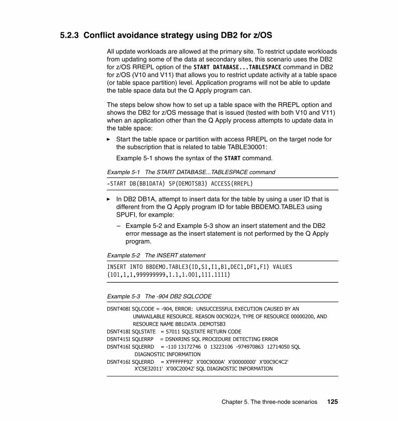
5.2.3 Conflict avoidance strategy using DB2 for z/OS
All update workloads are allowed at the primary site. To restrict update workloads from updating some of the data at secondary sites, this scenario uses the DB2 for z/OS RREPL option of the START DATABASE...TABLESPACE command in DB2 for z/OS (V10 and V11) that allows you to restrict update activity at a table space (or table space partition) level. Application programs will not be able to update the table space data but the Q Apply program can.
The steps below show how to set up a table space with the RREPL option and shows the DB2 for z/OS message that is issued (tested with both V10 and V11) when an application other than the Q Apply process attempts to update data in the table space:
� Start the table space or partition with access RREPL on the target node for the subscription that is related to table TABLE30001:
Example 5-1 shows the syntax of the START command.
Example 5-1 The START DATABASE...TABLESPACE command
-START DB(BB1DATA) SP(DEMOTSB3) ACCESS(RREPL)
� In DB2 DB1A, attempt to insert data for the table by using a user ID that is different from the Q Apply program ID for table BBDEMO.TABLE3 using SPUFI, for example:
– Example 5-2 and Example 5-3 show an insert statement and the DB2 error message as the insert statement is not performed by the Q Apply program.
Example 5-2 The INSERT statement
INSERT INTO BBDEMO.TABLE3(ID,S1,I1,B1,DEC1,DF1,F1) VALUES (101,1,1,999999999,1.1,1.001,111.1111)
Example 5-3 The -904 DB2 SQLCODE
DSNT408I SQLCODE = -904, ERROR: UNSUCCESSFUL EXECUTION CAUSED BY AN UNAVAILABLE RESOURCE. REASON 00C90224, TYPE OF RESOURCE 00000200, AND RESOURCE NAME BB1DATA .DEMOTSB3 DSNT418I SQLSTATE = 57011 SQLSTATE RETURN CODE DSNT415I SQLERRP = DSNXRINS SQL PROCEDURE DETECTING ERROR DSNT416I SQLERRD = -110 13172746 0 13223106 -974970863 12714050 SQL DIAGNOSTIC INFORMATION DSNT416I SQLERRD = X'FFFFFF92' X'00C9000A' X'00000000' X'00C9C4C2' X'C5E32011' X'00C20042' SQL DIAGNOSTIC INFORMATION
Chapter 5. The three-node scenarios 125

See section 7.3.3, “The START tablespace RREPL option” on page 188.
5.2.4 Recapturing of transactions at the primary node
In this scenario, since the Q Capture program feeds two different Q Apply programs, you have to ensure that the Q Capture program at the primary node publishes only query node 1 transactions to query node 2 and vice versa. This is to avoid recursion because SQL updates will always flow from one query node to the other query node via the primary node.
To enable the appropriate recapturing and publishing of transactions at the primary node, the scenario performed the following steps:
� Updated the INSERT_BIDI_SIGNAL column value with a ‘Y’ in the Q Apply IBMQREP_APPYPARMS at the primary node.
� With this option, the Q Apply program includes in each of its DBMS transactions an INSERT statement into the Q Capture IBMQREP_SIGNAL table to alert the Q Capture program that this is one of its transactions.
� With that information, the Q Capture program at the primary node detects which transaction comes from which Q Apply program and publishes only transactions to the appropriate (other) Q Apply server.
We could not rely on the IBMQREP_IGNTRAN table to filter transactions by the Q Apply plan names since transactions that have originated at one query node have to be recaptured and published to the other query node.
5.2.5 Filtering transactions by using the IBMQREP_IGNTRAN table
In some cases, you might want to let the Q Capture program know that some of the captured transactions should not be published. To do so, you can use the Q Capture IBMQREP_IGNTRAN table by using the following steps:
1. Populate the PLAN_NAME column value in the Q Capture IBMQREP_IGNTRAN table with one of the plan names that are associated with transactions that you want to ignore. (In some scenarios, this option is used to filter Q Apply transactions by inserting the Q Apply plan name in the table, ‘ASNQAPP’ or ‘ASNQA101’, based on the version of the Q Apply program that is running at that node).
2. The Q Capture program ignores all updates that come from the transactions that are associated with the plan name.
3. For this to occur, ensure that the INSERT_BIDI_SIGNAL column value is ‘N’ in the Q Apply IBMQREP_APPLYPARMS for the secondary nodes.
126 Understanding and Using Q Replication for High Availability Solutions on the IBM z/OS Platform
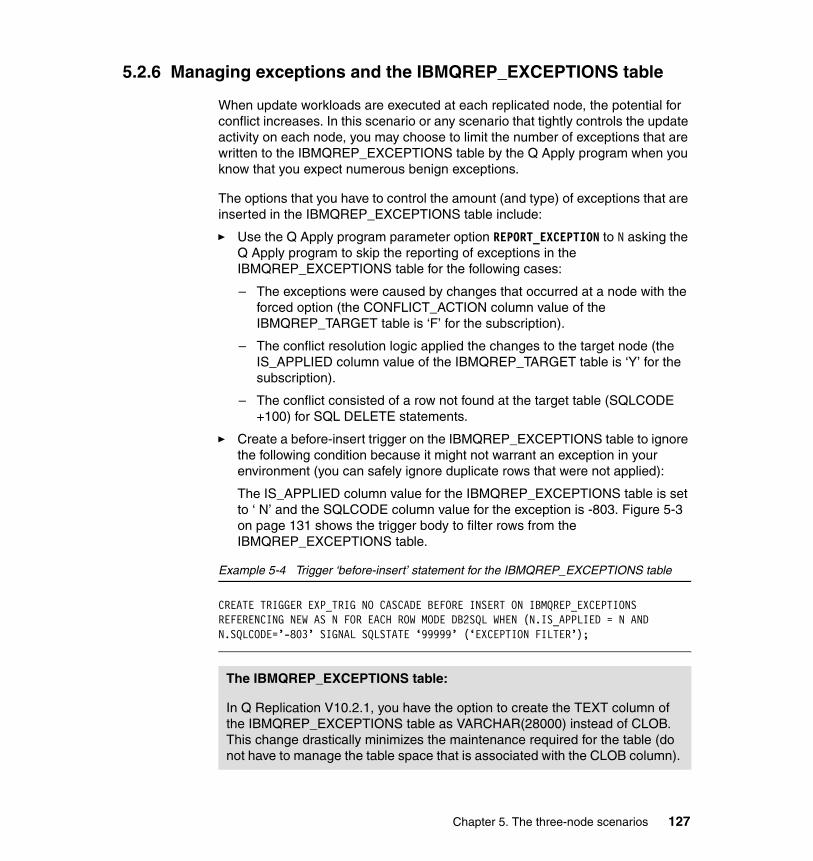
5.2.6 Managing exceptions and the IBMQREP_EXCEPTIONS table
When update workloads are executed at each replicated node, the potential for conflict increases. In this scenario or any scenario that tightly controls the update activity on each node, you may choose to limit the number of exceptions that are written to the IBMQREP_EXCEPTIONS table by the Q Apply program when you know that you expect numerous benign exceptions.
The options that you have to control the amount (and type) of exceptions that are inserted in the IBMQREP_EXCEPTIONS table include:
� Use the Q Apply program parameter option REPORT_EXCEPTION to N asking the Q Apply program to skip the reporting of exceptions in the IBMQREP_EXCEPTIONS table for the following cases:
– The exceptions were caused by changes that occurred at a node with the forced option (the CONFLICT_ACTION column value of the IBMQREP_TARGET table is ‘F’ for the subscription).
– The conflict resolution logic applied the changes to the target node (the IS_APPLIED column value of the IBMQREP_TARGET table is ‘Y’ for the subscription).
– The conflict consisted of a row not found at the target table (SQLCODE +100) for SQL DELETE statements.
� Create a before-insert trigger on the IBMQREP_EXCEPTIONS table to ignore the following condition because it might not warrant an exception in your environment (you can safely ignore duplicate rows that were not applied):
The IS_APPLIED column value for the IBMQREP_EXCEPTIONS table is set to ‘ N’ and the SQLCODE column value for the exception is -803. Figure 5-3 on page 131 shows the trigger body to filter rows from the IBMQREP_EXCEPTIONS table.
Example 5-4 Trigger ‘before-insert’ statement for the IBMQREP_EXCEPTIONS table
CREATE TRIGGER EXP_TRIG NO CASCADE BEFORE INSERT ON IBMQREP_EXCEPTIONS REFERENCING NEW AS N FOR EACH ROW MODE DB2SQL WHEN (N.IS_APPLIED = N AND N.SQLCODE=’-803’ SIGNAL SQLSTATE ‘99999’ (‘EXCEPTION FILTER’);
The IBMQREP_EXCEPTIONS table:
In Q Replication V10.2.1, you have the option to create the TEXT column of the IBMQREP_EXCEPTIONS table as VARCHAR(28000) instead of CLOB. This change drastically minimizes the maintenance required for the table (do not have to manage the table space that is associated with the CLOB column).
Chapter 5. The three-node scenarios 127

5.2.7 Q Apply program exploiting DB2 for z/OS MRI function
This section shows you how to detect whether the Q Apply program was able to exploit the DB2 for z/OS MRI function in your environment.
The MRI function is available in DB2 for z/OS V8 and above and exploited by the Q Replication feature of the IIDR product starting with the V10.2.1 version.
The DB2 feature improves the performance of the Q Apply program by allowing it to batch up to 100 insert rows into one DB2 operation. The obvious use-case for this function being batch programs that run at the source site and are replicated using Q Replication.
To enable the function in the Q Apply program, make sure that the MULTI_ROW-INSERT column value of the IBMQREP_APPLYPARMS table is set to ‘Y’. The default is ‘N’.
The following steps show how to perform a set of insert statements and verify how they were processed using the MRI feature:
� In DB2 DB1D, generate a ‘mass insert’ jobs for table BBDEMO.TABLE4. The related subscription name is TABLE400001 for Q Capture schema QASNBB2:
Example 5-5 shows the mass insert statements.
Example 5-5 The mass insert statements
insert into BBDEMO.TABLE4(ID,C1,V1) values (101,'Test Data','Initial Load');insert into BBDEMO.TABLE4(ID,C1,V1) values (102,'Test Data','Initial Load');insert into BBDEMO.TABLE4(ID,C1,V1) values (103,'Test Data','Initial Load');insert into BBDEMO.TABLE4(ID,C1,V1) values (104,'Test Data','Initial Load');
...insert into BBDEMO.TABLE4(ID,C1,V1) select ID + 100, C1, V1 from BBDEMO.table4 WHERE ID > 1000 order by 1;
� After the Q Apply program (schema BBASNB2) processed the mass insert, you can query its IBMQREP_APPLYMON table to analyze how the inserts were processed in DB2 DB1A, the replication target server:
Example 5-6 and Figure 5-2 on page 129 show the SQL query against the IBMQREP_APPLYMON table at DB1A and list the query result.
Example 5-6 The IBMQREP_APPLYMON query statement
SELECT ROWS_PROCESSED, STMTS_PREPARED,NUM_MRI_STMTS_EXECUTED, ROWS_PROCESSED_MRI FROM BBASNB1.IBMQREP_APPLYMON
128 Understanding and Using Q Replication for High Availability Solutions on the IBM z/OS Platform

WHERE RECVQ = 'BBASNB2.QLOCAL' AND ROWS_APPLIED > 0 ORDER BY 1 DESC FETCH FIRST 100 ROWS ONLY;
Figure 5-2 lists the query result of the select statement provided in Example 5-6 on page 128.
Figure 5-2 The MRI statistics
� The query result shows data for 12 different Q Apply program monitor intervals.
� Rows with a ROWS_PROCESSED column value that is equal to the ROWS_PROCESSED_MRI column value show that for the given monitor interval, all rows processed (insert statements) were indeed processed using MRI statements (this is the case for 9 of the 12 monitor intervals in our example) and that the batch or NUM_MRI_STMTS_EXECUTED reflects an average batch size of 100 (divide the ROWS_PROCESSED_MRI column value by the NUM_MRI_STMTS_EXECUTED column value).
Chapter 5. The three-node scenarios 129

� The three monitor intervals with a ROWS_PROCESSED_MRI of zero imply that the MRI function was not used to process the rows. In our example, it is because we issued insert statements on a table that is different from the BBDEMO.TABLE4 table in the same transaction, which disables the MRI processing (not shown in the mass insert example of Example 5-5 on page 128).
5.3 The three-node fully connected scenario
In this section, we present a scenario that we tested that shows fully connected three-site replication using unidirectional subscriptions. In the past, when replication has been needed in both directions between two sites, bidirectional subscriptions have been used. A bidirectional subscription causes data to be replicated in both directions, with identical tables at both sites. The subscription is started as a whole. This means that a start of replication in one direction automatically causes the start of replication in the other direction.
Now that Q Replication supports all conflict detection and resolution options for unidirectional subscriptions, the suggestion is to use separate unidirectional subscriptions for each direction. This is called a multi-uni configuration. In section 5.3.6, “Moving from bidi to multi-uni topologies” on page 137, we expand the two-site bidi configuration to a three-site multi-uni configuration. Multi-uni configurations support all of the same features that bidi configurations offer. All conflict detection and resolution options are available, DDL replication is available, parallel send queues are available, and so on. The only difference is that the two unidirectional subscriptions representing replication in each direction must both be started (CAPSTARTed) independently. A start of the subscription for one direction does not automatically start the subscription in the other direction.
5.3.1 Scenario architecture and topology
Figure 5-3 on page 131 is a diagram representing our fully connected three-site multi-unidirectional configuration. As you can see, this is a fully connected architecture, which means that a change that occurs at any site will be replicated to both of the other two sites. In this scenario, we are using the multi-uni topology.
130 Understanding and Using Q Replication for High Availability Solutions on the IBM z/OS Platform

Figure 5-3 The three-node fully connected scenario environment
Table 5-2 lists the objects that are used in this scenario.
Table 5-2 Object names for three-node fully connected scenario
Object NODE 1 NODE 2 NODE 3
LPAR STLABHB STLABHD STLABHC
DB2 Version 11 11 11
Subsystem DB1D DB1C DB2D
Location DB1D DB1C DB2D
Database Port 8010 8020 8030
Database BB1DATA BB1DATA BB1DATA
Queue Manager
MQ1A MQ1B MQ1B
WebSphere MQ Port
1416 1416 1416
Restart Queue JAASNU1.RESTARTQ
JAASNU2.RESTARTQ
JAASNU3.RESTARTQ
Administration Queue
JAASNU1.ADMINQ
JAASNU2.ADMINQ
JAASNU3.ADMINQ
DB1 D DB2 V11
DB1C DB2 V11 DB2D DB2 V11
JAASNU1
JAASNU2 JAASNU3
Q Capture Q Apply
Q ApplyQ Apply Q CaptureQ Capture
Chapter 5. The three-node scenarios 131
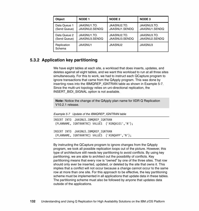
5.3.2 Application key partitioning
We have eight tables at each site, a workload that does inserts, updates, and deletes against all eight tables, and we want this workload to run at all three sites simultaneously. For this to work, we had to instruct each QCapture program to ignore transactions that came from the QApply program. This was done by inserting rows into the IBMQREP_IGNTRAN table as shown in Example 5-7. Since the multi-uni topology relies on uni-directional replication, the INSERT_BIDI_SIGNAL option is not available.
Example 5-7 Update of the IBMQREP_IGNTRAN table
INSERT INTO JAASNU3.IBMQREP_IGNTRAN (PLANNAME, IGNTRANTRC) VALUES ('ASNQA101','N'); INSERT INTO JAASNU3.IBMQREP_IGNTRAN (PLANNAME, IGNTRANTRC) VALUES ('ASNQAPP','N');
By instructing the QCapture program to ignore changes from the QApply program, we took all possible replication loops out of the picture. However, this type of architecture still needs key partitioning to avoid conflicts. By using key partitioning, we are able to architect out the possibility of conflicts. Key partitioning means that every row is “owned” by one of the three sites. That row should only ever be inserted, updated, or deleted by the site that owns it. This implies that a conflict will not occur because a change cannot occur to the same row at more than one site. For this approach to be effective, the key partitioning scheme must be implemented in all applications that update data in these tables. The partitioning scheme must also be followed by anyone that updates data outside of the applications.
Data Queue 1 (Send Queue)
JAASNU1.TO.JAASNU2.SENDQ
JAASNU2.TO.JAASNU1.SENDQ
JAASNU3.TO.JAASNU1.SENDQ
Data Queue 2 (Send Queue)
JAASNU1.TO.JAASNU3.SENDQ
JAASNU2.TO.JAASNU3.SENDQ
JAASNU3.TO.JAASNU2.SENDQ
Replication Schema
JAASNU1 JAASNU2 JAASNU3
Object NODE 1 NODE 2 NODE 3
Note: Notice the change of the QApply plan name for IIDR Q Replication V10.2.1 release.
132 Understanding and Using Q Replication for High Availability Solutions on the IBM z/OS Platform
For key partitioning to work, it is suggested that your primary key be an INTEGER or BIGINT value. If not, it is suggested that you first change your data model to use a surrogate key. Once you have a single integer column as a primary key on all of your tables, key partitioning is easy to implement.
If you have three sites, use the following scheme based on the modular arithmetic:
� Site 1 owns all rows that satisfy key % 3 == 0� Site 2 owns all rows that satisfy key % 3 == 1� Site 3 owns all rows that satisfy key % 3 == 2
For example, during the testing of this scenario, data from all eight tables was deleted and tests started from the beginning. To do this, the following statements were executed at each site:
� At site 1 - DELETE FROM table.schema WHERE MOD(key, 3) = 0;� At site 2 - DELETE FROM table.schema WHERE MOD(key, 3) = 1;� At site 3 - DELETE FROM table.schema WHERE MOD(key, 3) = 2;
After updating the application to follow the key partitioning scheme, it was possible to simultaneously run the update workload at all three sites with no conflicts. After every run, the ASNTDIFF utility was used to ensure that the data at all three sites was identical.
If the partitioning scheme explained in section 5.3.2, “Application key partitioning” on page 132 is followed without fail, there will not be any conflicts as long as there are no unplanned outages. If a user updates the data but does not follow the partitioning scheme, if an application is coded incorrectly, or if an unplanned outage occurs, data conflicts can still happen. This section describes the conflict detection and resolution options that are available and their usage with three-site replication.
Q Replication offers the following conflict detection options:
� Key columns only
As a refresher, the % represents modular arithmetic. The expression x % y results in the remainder after x is divided by y. For example:
� 6 % 3 == 0� 10 % 3 == 1� 5 % 3 == 2
Important: It is extremely important that all operations that change the data follow the key partitioning scheme.
Chapter 5. The three-node scenarios 133

� Changed columns only� All columns
Conflict detection works by comparing the before image captured from the source with the current data at the target, before applying the update. This implies that checking key columns will only detect the following conflicts:
� Row was inserted at the source but already existed at the target� Row was deleted at the source but did not exist at the target
Checking all columns will additionally catch the following conflicts:
� Row was updated at the source but the current value of the row at the target did not match the before image from the source
Using the conflict detection option of changed columns only has the interesting effect that it is capable of merging simultaneous updates. If the same row is updated at two sites at the same time, but the updates are to different columns, the result will be that both sites are in sync and the row at both sites will contain both of the updates. If the updates are to the same column, it will still be considered a conflict.
The choice of the correct conflict detection rule depends on your requirements. However, checking key columns only is considerably cheaper than the other two options and can potentially increase throughput.
If conflicts are detected, Q Replication also gives you two choices for how to resolve conflicts. Regardless of your choice of conflict resolution algorithm, all conflicts are logged in the IBMQREP_EXCEPTIONS table. The following two choices are available to resolve conflicts:
� Ignore conflicts� Force conflicts
If you choose to ignore conflicts, the conflict will be logged in the exceptions table, and the data at the target will be left unchanged. In other words, the conflicting operation will not be applied at the target. If you choose to force conflicts, Q Apply will force the row at the target to match the after image that was captured at the source. While the force option is extremely useful in scenarios where one site is designated as the master, its usefulness in this scenario is questionable. In this scenario, all three sites are active and are equal participants. No site is considered a master site.
The following steps illustrate a scenario where inconsistent data between two sites may happen if the force option is used:
� At site 2, user issues an UPDATE TBL001 SET COL1 = 1
134 Understanding and Using Q Replication for High Availability Solutions on the IBM z/OS Platform

� At site 3, another issues an update on the same column, with a different value: UPDATE TBL001 SET COL1 = 2
� After each update is replicated to the other site, we end up with the following scenarios:
– Site 2: TBL001.COL1 = 2– Site 1: TBL001.COL1 = 1
In this situation, two different rows with identical keys are inserted at two or the three sites simultaneously. Because the option was chosen to force conflicts, the end result is that site two has the version of the row that was actually inserted at site three, and site three has the version of the row that was actually inserted at site two.
As conflicts are architected out with key partitioning, they should be very rare. All conflicts are a serious business challenge and need to be manually reviewed and corrected. The fact that the force option reverses the value of the conflicting row across both sites only makes it harder to identify and resolve the situation so you need to be aware of the situation.
5.3.3 DDL replication and the fully connected topology
DB2 for z/OS DDL replication is fully supported in a fully connected three-site multi-uni directional scenario. Just as you have to designate an owner site for each row in all the tables, you should also designate an owner site for DDL operations.
Q Replication V10.2.1 supports automatic replication of ADD COLUMN, DROP COLUMN, and ALTER COLUMN DDL. All such DDL operations should be performed at the site designated as the DDL owner. This prevents DDL replication conflicts from occurring. Because we are using a fully connected topology, the DDL change that occurs at the owner site is replicated to both of the other two sites. In the scenario, site 1 was chosen as the DDL owner site.
All three ADD COLUMN, ALTER COLUMN, and DROP COLUMN DDL operations were tested as part of this scenario.
Inserting the Q Apply plan name in a row of the IBMQREP_IGNTRAN table does not affect the Q Apply DDL operations. The Q Capture program will not ignore the DDL operations done by the Q Apply program (DML operations will be ignored).
Chapter 5. The three-node scenarios 135

5.3.4 Planned outages with the fully connected topology
For a planned outage, move the portion of the workload running on one site to one of the other sites. As an example, assume that you are shutting down site 1, and plan to move site 1’s workload to site 2. To accomplish the planned outage, you must do the following steps:
� Quiesce tables at site 1.
� Wait for replication to complete to site 2 and site 3. For details, see section 8.4, “Stopping Q Capture (or a send queue) at a particular point in DB2 log” on page 210.
� Shut down site 1.
� Restart site 1 workload at site 2.
You will notice that the previous steps violate the key partitioning scheme. You now have workload running at site 2 that is updating the rows owned by both site 1 and site 2. This is alright because you allowed the changes from site 1 to complete replicating to site 2 before you allowed site 2 to run site 1’s workload. In this case, you will have no conflicts.
When you are ready to bring site 1 back up, you must do the following steps:
1. Stop the site 1 workload at site 2
2. Restart the Q Capture and Q Apply programs at site 1
3. Wait for replication from site 2 to site 3 to get past the point of stopping the site 1 workload at site 2
4. Allow replication from site 2 to site 1 to catch up past the point where the workload at site 2 was stopped
5. Restart site 1 workload at site 1
The described process can be used to perform a planned outage of any site and to move the workload from that site to any other site.
5.3.5 Unplanned outages with the fully connected topology
Unplanned outages differ from planned outages in that there might be stranded changes: There may be changes that have been picked up by the Q Capture program on the failed node, the changes might even have been written to WebSphere MQ but WebSphere MQ did not get a chance to send them from the transfer queue to the target. Additionally, there might be changes that occurred in DB2 that were not yet read by the Q Capture program.
136 Understanding and Using Q Replication for High Availability Solutions on the IBM z/OS Platform

Assume that an unplanned outage occurs on site 1. The process to move site 1’s workload to site 2 is very simple. Just restart site 1’s workload at site 2. However, when site 1 is ready to come back online, the process is more involved than in the case of a planned outage. Use the following process:
� Stop the site 1 workload at site 2
� Restart the QCapture and Q Apply programs at site 1
� Wait for replication from site 2 to site 3 to get past the point of stopping the site 1 workload at site 2
� Allow replication from site 1 to site 2 to complete
� Allow replication from site 2 to site 1 to catch up past the point where the workload at site 2 was stopped
� Look at the exceptions tables at site 1 and site 2 and manually fix any conflicts that were reported
� Restart site 1 workload at site 1
5.3.6 Moving from bidi to multi-uni topologies
The architecture described in section 5.3, “The three-node fully connected scenario” on page 130 is fine until the workload grows to the point where bottlenecks are reached. Following are the most common bottlenecks in Q Replication:
� Applying changes in the target DB2 DBMS� WebSphere MQ
Multi-uni replication can help with these bottlenecks. With multi-uni replication, you must partition your tables into consistency groups. These consistency groups should not have any RI between them. For example, if you have tables 1 - 6, and tables 1 - 3 are related, and tables 4 - 6 are related, you can break them into two consistency groups: 1 - 3 and 4 - 6.
Multi-uni replication uses data sharing and works by sending changes that are captured by a Q Capture program to multiple Q Apply programs. Each Q Apply program can run against a different member of the target data sharing group. All tables in the same consistency group get sent to the same Q Apply program. This process eliminates the bottlenecks listed above by:
� Splitting the apply of changes across multiple members of the target DB2 data sharing group
� Using separate WebSphere MQ managers at the target
Chapter 5. The three-node scenarios 137

When using the multi-uni topology with multiple active sites, this now means that you have two partitioning schemes:
� The first partitioning scheme creates sets of unrelated tables as distinct consistency groups. You must have at least as many consistency groups as the number of Q Apply programs that you plan to run at each site.
� Within these consistency groups, you then have application key partitioning so that the applications can be active simultaneously at all sites. The consistency groups are then divided across the Q Maps from the Q Capture program to the multiple Q Apply programs.
On a final note, each site still has only one Q Capture program. This is because a Q Capture program that is attached to any member of a data sharing group will capture changes occurring on all members of that data sharing group.
138 Understanding and Using Q Replication for High Availability Solutions on the IBM z/OS Platform

Chapter 6. Latency analysis
In this chapter, we show you how to analyze the latency of your Q Replication configurations and also review how to use the Data Replication Dashboard to generate latency reports.
6
© Copyright IBM Corp. 2014. All rights reserved. 139

6.1 Overview
Latency is one of the two metrics that evaluates the overall performance of a Q Replication environment, the other metric is throughput. End-to-end latency is defined as the measure of time that it takes to replicate a transaction from the time it is committed at the source site to the time it is committed at the target site.
The Q Capture and Q Apply programs save latency statistics and performance data in their monitor control tables, appending a new row at every monitor interval. In IIDR 10.2.1, the Q Apply monitor control table includes additional columns that break down the Q Apply latency into discrete metrics to help you pinpoint latency issues more specifically.
Latency analysis does not have to be a daunting task. The data in the monitor tables helps you pinpoint latency delays that occur at any stage of the replicated transaction. The delays depend on the underlying components that participate in the replication solution, more specifically:
� WebSphere MQ � DB2 for z/OS � The Q Capture or Q Apply program� The actual transaction behavior
This chapter helps you analyze latency and tune your Q Replication environment when you have the following scenarios:
� The latency of your replication configuration has exceeded a threshold value that you defined earlier.
� The latency of your replication configuration is slowly increasing and you want to address the issue.
� You just deployed a new replication configuration and want to identify areas that might need tuning.
Before proceeding with the remaining sections of this chapter, we review how this chapter is organized, define the end-to-end latency of a replicated transaction, and introduce the statistics upon which latency analysis is derived, in the following sections:
� “How this chapter is organized” on page 141� “The end-to-end latency of a replicated transaction” on page 142� “The statistics and the monitor tables” on page 143
140 Understanding and Using Q Replication for High Availability Solutions on the IBM z/OS Platform

6.1.1 How this chapter is organized
Figure 6-1 summarizes the options that you may take for latency analysis:
� For a deep-dive into end-to-end latency analysis, start with the Q Capture section 6.2, “Q Capture latency” on page 148, followed by the Q Apply section 6.3, “Q Apply latency” on page 154, and end with the Queue latency sections beginning with section 6.4, “Queue latency” on page 162.
� For a quick review of factors that are known to cause delays in the Q Capture, Q Apply, or Queue latency, start with the statistics beginning in section 6.1.3, “The statistics and the monitor tables” on page 143.
� For the review of a particular latency delay (if you already know which latency statistics that you want to analyze), start with the statistics sections (beginning with section 6.1.3, “The statistics and the monitor tables” on page 143), which also list all available statistics in the Q Capture and Q Apply monitor tables.
� For a review of batch workloads’ impact on latency, see section 6.5, “Batch workloads” on page 171.
� Finally, you can also decide to check out how the Data Replication Dashboard monitoring functions support latency analysis by going directly to section 6.6, “The Data Replication Dashboard” on page 172.
Figure 6-1 Latency analysis steps
Q Capture latency (section 6.2)
where do I start ?
top 10 statistics(section 6.1.3)
Q Apply latency (section 6.3)
Queue latency (section 6.4)
Batch workloads (section 6.5)
Data ReplicationDashboard(section 6.6)
Chapter 6. Latency analysis 141

We now define the end-to-end latency of a replicated transaction.
6.1.2 The end-to-end latency of a replicated transaction
Figure 6-2 shows three stages of the lifecycle of a replicated transaction from the time it is committed in the DB2 source log to the time it is committed by the Q Apply program at the target server: The Q Capture, Queue, and Q Apply stages.
As shown in the figure, each stage is associated with specific timestamps that are used to calculate the end-to-end latency statistics as follows:
� Given the following timeline:
– t1 = transaction committed at the source site– t2 = the Q Capture program read the transaction from the log – t3 = the Q Capture program committed the message to the send queue– t4 = the Q Apply program read the message from the receive queue– t5 = the Q Apply successfully committed the transaction at the target site
� The replicated transaction latency or end-to-end latency is defined by end-to-end latency = t5 - t1.
Figure 6-2 The Q Replication end-to-end latency
1 Time that the transaction committed2 Time that Q Capture read the transaction from the log 3 Time that Q Capture put the message to the Sendqueue4 Time that Q Apply received the message from the Recvqueue5 Time that Q Apply copied the transaction to the target tables
SOURCE3
SOURCE2
SOURCE1
DB2 Log Capture Apply
End-to-End Latency (5 – 1)
Q Capture Latency (3-1)
1
2
3
4
5
QueueLatency (4-3)
Q ApplyLatency (5-4)
TARGET1
TARGET2
TARGET3
142 Understanding and Using Q Replication for High Availability Solutions on the IBM z/OS Platform

Latency thresholds and alertsHigh performing replication environments may have a latency requirement of under a second or up to a few seconds, while other replication environments may live, or have to live, with latency requirements that include minutes.
In either case, you might want to monitor the end-to-end latency of your replication environment to determine whether it exceeds a particular threshold. A good practice to do so is to create an alert on the END2END_LATENCY column value of the IBMQREP_APPLYMON table (introduced in section 6.1.3, “The statistics and the monitor tables” on page 143). If the threshold value that you define in the alert is exceeded for a particular monitor interval, the alert is issued in the form of email and a row that is inserted in a Q Replication monitor table or a visual alert that is displayed in the Data Replication Dashboard. You can define an alert using either the Data Replication Dashboard or the Q Replication ASNMON alert monitor program.
If an alert is issued, you need to drill down to the statistics that are written by the Q Capture and Q Apply programs in their monitor tables to identify the components that are the cause of the latency value.
6.1.3 The statistics and the monitor tables
The following various statistics are saved in the monitor tables:
� “The four latency values and the monitor tables”� “The top 10 latency statistics” on page 144� “Additional statistics” on page 147
The four latency values and the monitor tablesThe Q Apply monitor table, the IBMQREP_APPLYMON table, includes among other performance statistics the four latency values that are shown in Table 6-2 on page 147 and saves their values in the following columns:
� The Q Capture latency is saved in the CAPTURE_LATENCY column.� The Queue latency is saved in the QUEUE_LATENCY column.� The Q Apply latency is saved in the APPLY_LATENCY column.� The end-to-end latency value is saved in the END2END_LATENCY column.
To derive the end-to-end latency value, the Q Apply program subtracts the time stamp associated with the DB2 transaction commit time of the original source transaction in the DB2 log from the DB2 transaction commit time of the Q Apply transaction that commits the change data to the target table.
Chapter 6. Latency analysis 143

In addition to the Q Apply IBMQREP_APPLYMON table, there are two Q Capture monitor tables that hold performance and monitoring data in Q Replication: The IBMQREP_CAPMON and IBMQREP_CAPQMON tables for the Q Capture program and send queues-related statistics respectively.
The Q Capture and Q Apply monitor intervalsThe statistics provided in the three monitor tables reflect aggregate values. The Q Capture and Q Apply programs aggregate the latency values and the time delays as they process the transactions during a given monitor interval. More specifically:
� The latency value is an average value over the transactions processed for the monitor interval (the four latency column values in the IBMQREP_APPLYMON table)
� The time delay is an average value over the transactions processed for the monitor interval that do not report WebSphere MQ time values
� The time delay is the sum value over the transactions processed for the monitor interval for all column values that report WebSphere MQ time values
The Q Capture and Q Apply monitor intervals are pre-defined values that are saved in the MONITOR_INTERVAL column of the IBMQREP_CAPPARMS and IBMQREP_APPLYPARMS tables respectively. These values also have an impact on the currency of the data in the live graphs and reports of the Data Replication Dashboard. Their default value is 60000 milliseconds for the z/OS platform.
The top 10 latency statistics Figure 6-3 on page 145 lists 10 factors that affect the overall end-to-end latency of a replicated transaction1. Table 6-1 on page 145 is a companion table that maps the 10 factors to their respective statistics in the Q Capture or Q Apply monitor tables. Column values in the monitor tables record latency increase (if any) in milliseconds.
Factors that are highlighed in blue (and depicted with arrows) in Figure 6-3 on page 145 are more sensitive to Q Replication configuration parameters and the SQL transaction itself, while the other factors of the figure typically remain more predictable and constant, assuming that the WebSphere MQ and DB2
Note: This chapter refers to the monitor tables by their names only and omits the Q Capture and Q Apply schema (ASN by default) that is required to access these tables, to ease the readability of the examples and sections.
1 Figure 6-3 on page 145 shows that the Q Apply agent applies the transactions at the target site; this is always the case unless the transaction is a ‘monster’ transaction, in which case the Q Apply browser itself applies the transaction at the target site.
144 Understanding and Using Q Replication for High Availability Solutions on the IBM z/OS Platform

subsystems are properly tuned for Q Replication. The latter topic is addressed in the respective Q Capture, Queue, and Q Apply latency analysis sections of this chapter.
Figure 6-3 Ten factors impacting the end-to-end latency of the replicated transaction
Table 6-1 also includes a link to the sections of this chapter that describe how each factor impacts the Q Capture, Queue, or Q Apply latency.
Table 6-1 Ten latency factors and the columns of the monitor tables
��������
�� �����
����������������������������������
��������
������������������������������
����������
� ��������
��������� ���
� ��������������
���� ���
� ������������
�����������������!���"���
�����������#����������$�%
����������$�&�����%
�������������������
�������� � ������� ������
�������� ����� ������
�������� � ����� ������
�� ������ �������� �� � �� ������
�� ���������
'
(
)
* + ,
- '.
/
���������"�&����0�����!������1�2�����������&�����2��������������������������$�2����������������%����������#��0��2������������������2�����"���$���&����3�"�2#������������� ������2��2�����&���%�
Factor impacting latency Relevant statistics Referenced section
1 Q Capture log latency IBMQREP_CAPMON: CURRENT_LOG_TIME,
6.2.2, “Determine if Q Capture is keeping up with the DB2 log activity” on page 149
2 Q Capture time reading DB2 log records (DB2 IFI calls)
IBMQREP_CAPMON:LOGREAD_API_TIME
6.2.5, “WebSphere MQ PUT time and MQ COMMIT Time” on page 150
Chapter 6. Latency analysis 145

3 Q Capture time waiting for memory
IBMQREP_CAPMON:LOGRDR_SLEEPTIME,NUM_END_OF_LOGS
6.2.4, “Determine why (what) Q Capture is waiting (on)” on page 150
4 Q Capture time to put WebSphere MQ messages in a send queue and Q Capture time to commitall WebSphere MQ transactions
IBMQREP_CAPQMON:MQPUT_TIME,QFULL_ERROR_COUNT
IBMQREP_CAPMON:MQCMIT_TIME
6.2.5, “WebSphere MQ PUT time and MQ COMMIT Time” on page 150
5 WebSphere MQ time sending and staging WebSphere MQ messages
N/Anot saved in monitor tables
6.4.2, “The WebSphere MQ transport delay” on page 165
6 Q Apply time to retrieve WebSphere MQ messages from a receive queue
IBMQREP_APPLYMON:MQGET_TIME
6.4.3, “The Q Apply MQGET_TIME” on page 166
7 Q Apply time waiting due to transaction dependencies
IBMQREP_APPLYMON:DEPENDENCY_DELAY
6.3.2, “Why Q Apply waits for transaction dependencies” on page 155
8 Q Apply waiting for agents to pick up DBMS transactions ready to be applied
IBMQREP_APPLYMON:WORKQ_WAIT_TIME
6.3.3, “Determine why Q Apply is waiting for agents” on page 156
9 Q Apply time retrying SQL due to RI, unique violation, or deadlock
IBMQREP_APPLYMON:RETRY_TIME
See 6.3.4, “Determine why Q Apply is retrying so many SQL statements” on page 156
10 Q Apply time in DB2 processing successful transactions
IBMQREP_APPLYMON:DBMS_TIME column
6.3.5, “DB2 DBMS Time” on page 158
Factor impacting latency Relevant statistics Referenced section
146 Understanding and Using Q Replication for High Availability Solutions on the IBM z/OS Platform
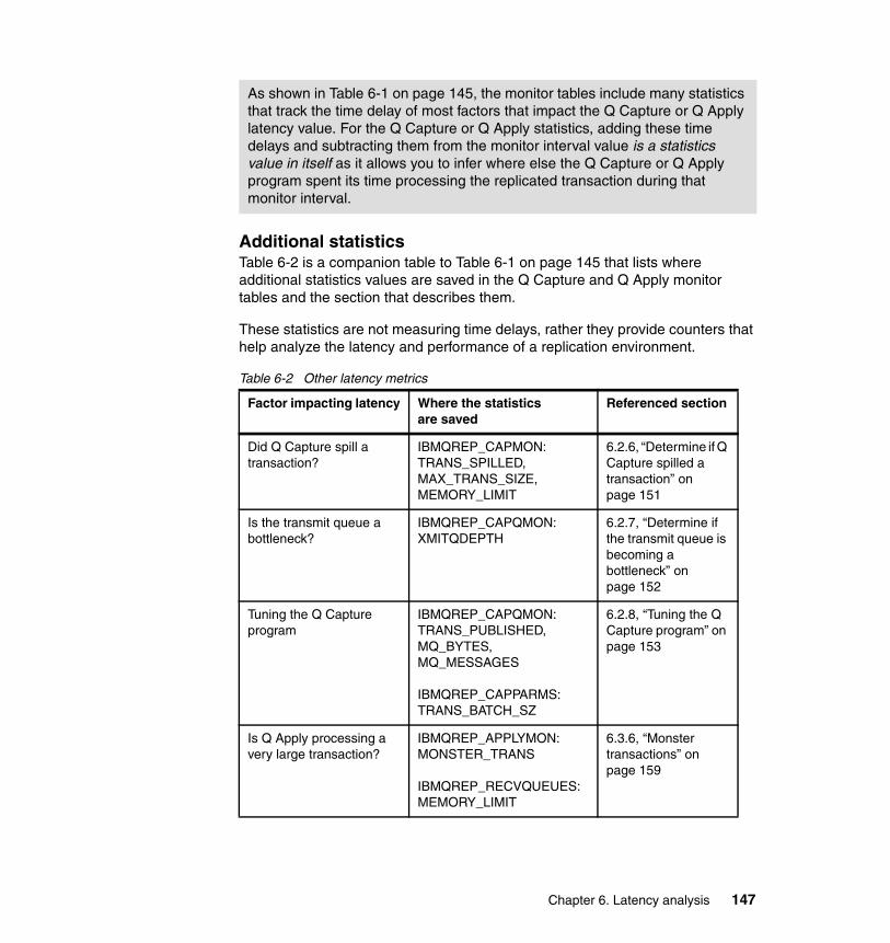
Additional statisticsTable 6-2 is a companion table to Table 6-1 on page 145 that lists where additional statistics values are saved in the Q Capture and Q Apply monitor tables and the section that describes them.
These statistics are not measuring time delays, rather they provide counters that help analyze the latency and performance of a replication environment.
Table 6-2 Other latency metrics
As shown in Table 6-1 on page 145, the monitor tables include many statistics that track the time delay of most factors that impact the Q Capture or Q Apply latency value. For the Q Capture or Q Apply statistics, adding these time delays and subtracting them from the monitor interval value is a statistics value in itself as it allows you to infer where else the Q Capture or Q Apply program spent its time processing the replicated transaction during that monitor interval.
Factor impacting latency Where the statistics are saved
Referenced section
Did Q Capture spill a transaction?
IBMQREP_CAPMON:TRANS_SPILLED,MAX_TRANS_SIZE, MEMORY_LIMIT
6.2.6, “Determine if Q Capture spilled a transaction” on page 151
Is the transmit queue a bottleneck?
IBMQREP_CAPQMON:XMITQDEPTH
6.2.7, “Determine if the transmit queue is becoming a bottleneck” on page 152
Tuning the Q Capture program
IBMQREP_CAPQMON:TRANS_PUBLISHED,MQ_BYTES,MQ_MESSAGES
IBMQREP_CAPPARMS:TRANS_BATCH_SZ
6.2.8, “Tuning the Q Capture program” on page 153
Is Q Apply processing a very large transaction?
IBMQREP_APPLYMON:MONSTER_TRANS
IBMQREP_RECVQUEUES:MEMORY_LIMIT
6.3.6, “Monster transactions” on page 159
Chapter 6. Latency analysis 147

6.2 Q Capture latency
This section starts with a review of the Q Capture latency, its main factors, and proceeds with the DB2 and WebSphere MQ statistics as well as particular events that can also cause the latency increase. The section ends with tuning preferred practices related to the Q Capture program for the z/OS platform. The following topics are included:
1. “The Q Capture latency”2. “Determine if Q Capture is keeping up with the DB2 log activity” on page 1493. “Determine why (what) Q Capture is waiting (on)” on page 1504. “WebSphere MQ PUT time and MQ COMMIT Time” on page 1505. “Determine if Q Capture spilled a transaction” on page 1516. “Determine if the transmit queue is becoming a bottleneck” on page 1527. “Tuning the Q Capture program” on page 153
6.2.1 The Q Capture latency
As mentioned in section “The four latency values and the monitor tables” on page 143, the Q Capture latency value is computed by the Q Apply program and saved in the CAPTURE_LATENCY column value of the IBMQREP_APPLYMON table.
To derive the Q Capture latency value, the Q Apply program subtracts the time stamp associated with the DB2 transaction commit time of the original source transaction in the DB2 log from the time stamp associated with the WebSphere MQ PUT time of the last message for the Q Capture transaction. The Q Apply program finds the latter commit value in the WebSphere MQ message. Remember also that the actual latency value is an aggregate over the transactions that are processed for the monitor interval.
Monitoring the Q Capture latency includes defining an alert on the CAPTURE_LATENCY column of the IBMQREP_APPLYMON table and assigning a threshold value to these statistics.
Tuning the Q Apply program
IBMQREP_APPLYMON:OLDEST_TRANS, OLDEST_INFLT_TRANS, ROWS_PROCESSED
6.3.7, “Tuning the Q Apply program” on page 161
Factor impacting latency Where the statistics are saved
Referenced section
148 Understanding and Using Q Replication for High Availability Solutions on the IBM z/OS Platform

6.2.2 Determine if Q Capture is keeping up with the DB2 log activity
The Q Capture log latency is computed by subtracting the Q Capture current log time in the IBMQREP_CAPMON from the current time stamp that was generated when the row was added to the IBMQREP_CAPMON monitor table, as follows:
A related statistic, the NUM_END_OF_LOGS column value of the IBMQREP_CAPMON table, lists the number of times that the Q Capture program reached the end of the DB2 log.
The Q Capture program might be:� Unable to publish changes as fast as it can read them from DB2, causing
itself to stall: See “WebSphere MQ PUT time and MQ COMMIT Time” on page 150.
� Unable to read log records fast enough through the DB2 instrumentation facility interface (IFI).
6.2.3 DB2 IFI time
The time spent in DB2 returning log records to Q Capture is saved in the IBMQREP_CAPMON table in the LOGREAD_API_TIME column value.
A value higher than expected may be due to additional DB2 data sharing members participating in the DB2 data sharing group that is associated with the Q Capture process. As multiple DB2 members update their own DB2 logs, the DB2 IFI incurs the extra cost of merging these log records before returning a buffer of log record data to the Q Capture program.
If in addition to the higher than expected value in the DB2 IFI time you also notice that the Q Capture log latency is increasing (see section 6.2.2, “Determine if Q Capture is keeping up with the DB2 log activity” on page 149), the Q Capture current memory is low (the CURRENT_MEMORY column value of the IBMQREP_CAPMON table), and the Q Capture program is waiting on the IFI log records (the LOGRDR_SLEEP_TIME column value in the IBMQREP_CAPMON
MONITOR_TIME - CURRENT_LOG_TIME
Note: If you are using IIDR 10.2.1 and DB2 for z/OS V10 or above, DB2 for z/OS filters log records that are not needed by Q Capture before returning any log record to Q Capture. The savings that are associated with Q Capture not processing extra log records and not having to decompress them is significant in CPU time and indirectly minimizes the latency that is associated with the Q Capture LOGREAD_API_TIME.
Chapter 6. Latency analysis 149

is low), you might need to contact your DB2 for z/OS system administrator because the DB2 IFI lag time is directly impacting your overall Q Capture and indirectly end-to-end latency values.
6.2.4 Determine why (what) Q Capture is waiting (on)
If the LOGRDR_SLEEPTIME column of the IBMQREP_CAPMON table does not remain in the subseconds range, either Q Capture is sleeping because there are no DB2 log records to read or because it reached its memory limit threshold.
Check the NUM_END_OF_LOGS column value of the IBMQREP_CAPMON table to find out how often Q Capture hit the end of the DB2 log during the particular monitor interval to verify that it has been sleeping because there has been no DB2 activity to process.
If the NUM_END_OF_LOGS column value is zero, Q Capture ran out of memory while processing transactions. As mentioned in section “The Q Capture MEMORY_LIMIT threshold” on page 152, if Q Capture runs out of memory, you do not have the luxury of simply increasing the z/OS memory that is allocated to Q Capture. What you might want to do however is ensure that the Q Capture publisher thread performs as optimally as possible since it is the thread that consumes transactions from the Q Capture memory. The following topics are added below as reference because they affect the publisher thread’s performance:
� “WebSphere MQ PUT time and MQ COMMIT Time”� “Determine if the transmit queue is becoming a bottleneck” on page 152
6.2.5 WebSphere MQ PUT time and MQ COMMIT Time
The time delay spent in WebSphere MQ to put new messages in the send queue is saved in the IBMQREP_CAPQMON table MQPUT_TIME column value for the relevant send queue. Higher values than expected may be caused by the following scenarios:
� The Q Capture program may have encountered WebSphere MQ errors when attempting to put new messages in a send queue if you see a non-zero value in the QFULL_ERROR_COUNT column of the IBMQREP_CAPQMON table for the appropriate send queue. In that case, the transmit queue associated with the send queue is probably full. See section “Determine if the transmit queue is becoming a bottleneck” on page 152. If that is not the case, select the WebSphere MQ error from the Q Capture IBMQREP_TRACE table, as shown in Example 6-1 on page 151:
150 Understanding and Using Q Replication for High Availability Solutions on the IBM z/OS Platform

Example 6-1 Select the MQ Error from the IBMQREP_CAPTRACE table
error time= SELECT MONITOR_TIME FROM IBMQREP_CAPQMON WHERE QFULL_ERROR_COUNT <> 0
SELECT OPERATION, MQ_CODE FROM IBMQREP_CAPTRACE WHERETRACE_TIME BETWEEN error time - 5 MINUTES AND error time + 5 MINUTES;
� The Q Capture program MQ PUT operations might be experiencing I/O contention in WebSphere MQ: The transmit queue depth may be very deep and the source MQ manager experiencing performance issues. Contact your WebSphere MQ system administrator.
The time delay spent in WebSphere MQ to commit the MQ transactions are saved in the IBMQREP_CAPMON table MQCMIT_TIME column value. Higher values than expected may be caused by the following scenarios:
� Workloads that include many relatively small transactions: If that is the case, the Q Capture program may benefit from the TRANS_BATCH_SZ column value of the IBMQREP_CAPPARMS table as described in section “Tuning the Q Capture program” on page 153 because it reduces the number of MQ commit statements that the Q Capture program issues to WebSphere MQ.
� MQ log I/O performance issues: If that is the case, contact your WebSphere MQ system administrator.
For WebSphere MQ performance issues, review the Tuning Guide of the WebSphere MQ performance pack support: Link to WebSphere MQ support, which is available at the following website:
http://www-01.ibm.com/support/docview.wss?uid=swg24007421
6.2.6 Determine if Q Capture spilled a transaction
The number of transactions that are spilled to a file when Q Capture exceeds the memory limit threshold is saved in the TRANS_SPILLED column of the IBMQREP_CAPMON table.
If you see a non-zero value in the TRANS_SPILLED column, query the MAX_TRANS_SIZE column value of the IBMQREP_CAPMON table to record the size of the largest transaction that Q Capture processed for that monitor interval and follow the guidelines below to identify why spilling occurred:
� If the MAX_TRANS_SIZE column value is high, Q Capture processed a very long running transaction and as explained in section “The Q Capture MEMORY_LIMIT threshold” on page 152, for z/OS platforms, you do not have the option to increase memory. See the options provided in this section.
Chapter 6. Latency analysis 151

� If the MAX_TRANS_SIZE column value is small, Q Capture processed many transactions and the Q Capture publisher thread (publishes messages to MQ) lags behind the Q Capture log reader thread, which typically does not occur (not one of the Q Capture latency hot spots). See section “Tuning the Q Capture program” on page 153.
The few options that you have to detect, plan for, and prevent large transactions from spilling in the future are the following:
� To detect very large transactions, use the Q Capture WARNTXSZ parameter that issues a message in the job log to warn you of a very large transaction.
� You may decide to create a job that prevents the large transaction from being captured by using the IBMQREP_IGNTRAN table. The table includes information about all transactions that the Q Capture program should ignore. Your procedure should also schedule a companion job at the target site to execute the skipped transaction as it is not replicated.
� See section “Batch workloads” on page 171 for additional options on how to manage long running transactions in a batch environment.
� Finally, review the topic named Storage requirements for when the Q Capture program exceeds its memory limit in the online product documentation.
The Q Capture MEMORY_LIMIT thresholdThe Q Capture memory limit threshold can be found in the MEMORY_LIMIT column value of the IBMQREP_CAPPARMS table.
6.2.7 Determine if the transmit queue is becoming a bottleneck
The transmit queue depth value is saved in the XMITQDEPTH column value of the IBMQREP_CAPQMON table and should remain extremely low if not zero. If you detect some relatively large values in the XMITQDEPTH, use the following action items:
� Ensure that there is no issue with the underlying WebSphere MQ channels by checking the status of the channels.
� If the transmit queue depth keeps growing and there is a lot of I/O to the physical pageset of the transmit queue, this means that the capacity of the MQ channel has been exceeded. Splitting the workload across two MQ
Note: The Q Capture MEMORY_LIMIT on z/OS should always be set to 0 to allow Q Capture to calculate its memory allocation based on the region size that is provided in its JCL or started task.
152 Understanding and Using Q Replication for High Availability Solutions on the IBM z/OS Platform
channels/transmit queues normally helps. See section “Tuning WebSphere MQ” on page 168 for more details about the option.
6.2.8 Tuning the Q Capture program
Additional Q Capture program, send queue, or subscription options can be modified to tune your environment as follows:
� For the Q Capture program, use the following guidelines:
– Keep the job priority for the Q Capture Program lower than the priority of both the DB2 and WebSphere MQ subsystems
– Use the data sharing group name rather than the member name for the CAPTURE_SERVER parameter
– The value of the CAPTURE_PATH should be a z/OS data set
� For environments with many small transactions:
Comparing the TRANS_PUBLISHED column value with the MQ_BYTES and MQ_MESSAGES column values of the IBMQREP_CAPQMON table, you might notice that many small transactions are published with many WebSphere MQ messages. If that is the case, you may consider telling Q Capture to publish transactions in batches by increasing the TRANS_BATCH_SZ column value of the IBMQREP_CAPPARMS table. This could result in fewer WebSphere MQ messages being published, lowering your overall latency.
� When replicating large transactions:
If the MQ_MESSAGES column value is much larger than the TRANS_PUBLISHED column value of the IBMQREP_CAPQMON table, many of the large transactions processed by the Q Capture program are larger than the MAX_MESSAGE_SIZE column value of the IBMQREP_SENDQUEUES table for that send queue and the Q Capture program splits or segments the transactions into multiple WebSphere MQ messages. Transactions are always broken down at row boundaries. You
Note: Changing the Q Capture TRANS_BATCH_SZ value has an impact on the time that it takes the Q Apply program to perform the dependency analysis and exception reporting because the individual source transactions are now batched. So there is a trade-off that you need to evaluate in your environment.
Also, increasing a TRANS_BATCH_SZ value may require an increase to the MAX_MESSAGE_SIZE column value of the IBMQREP_SENDQUEUES table for the appropriate send queue (default is 64 K with a maximum value of 2 M) and likewise, a possible increase to the WebSphere MQ MAXMSGL value.
Chapter 6. Latency analysis 153

need to increase the MAX_MESSAGE_SIZE column value if the transaction row size is larger than that value and you may increase the value if you determine that segmenting a transaction into multiple WebSphere MQ messages has too large an impact on your latency requirements.
In other situations, the default maximum message size of 64 KB is adequate.
� When replicating LOB columns:
If the LOB column is defined with the DB2 INLINE option, the Q Capture program will read the INLINE LOB data from the DB2 log. If the LOB column is not defined with the DB2 INLINE option, the Q Capture program selects the LOB data from the DB2 table.
The Q Capture program gives you the option to publish LOB column data as part of the transaction message if you set the LOB_SEND_OPTIONS column value to ‘I’ in the IBMQREP_CAPPARMS table. The ‘I’ option is the default that delivers better performance, however that option requires that the row that is published (which includes the LOB data) has a length that is less than the MAX_MESSAGE_SIZE column value in the IBMQREP_SENDQUEUES table for that send queue. If that is not the case, you have to use the ‘S’ option of the LOB_SEND_OPTIONS, which allows the Q Capture program to send separate messages for the LOB data.
� Including search conditions in the subscription:
This option has a high CPU cost and is not recommended. It will also affect the latency of your replicated transactions. Query the SEARCH_CONDITION column value of the Q Capture IBMQREP_SUBS table to find out how many subscriptions are using a search condition that consists of DB2 predicates that are applied to the log record data before publishing the WebSphere MQ message.
� The Q Capture program COMMIT_INTERVAL and SLEEP_INTERVAL values:
Start with the default value, which is 500 milliseconds for the z/OS platform. There is usually no need to tune these Q Capture parameters especially in high volume environments for which they have been tuned. Changing the COMMIT_INTERVAL and SLEEP_INTERVAL values is an exercise that balances the trade-off between reducing CPU cost and increasing latency or the reverse, increasing CPU cost and reducing latency. A COMMIT_INTERVAL value lower than 100 is not advised.
6.3 Q Apply latency
This section starts with a review of the Q Apply latency, its main factors, and proceeds with DB2 and WebSphere MQ statistics that impact Q Apply latency
154 Understanding and Using Q Replication for High Availability Solutions on the IBM z/OS Platform

values as well as particular transaction-specific characteristics that may also cause the latency increase. The section ends with preferred practices related to the Q Apply program for the z/OS platform. The topics of this section are listed below for quick reference:
1. “The Q Apply latency”2. “Why Q Apply waits for transaction dependencies” on page 1553. “Determine why Q Apply is waiting for agents” on page 1564. “Determine why Q Apply is retrying so many SQL statements” on page 1565. “DB2 DBMS Time” on page 1586. “Monster transactions” on page 1597. “Tuning the Q Apply program” on page 161
6.3.1 The Q Apply latency
As mentioned in section “The four latency values and the monitor tables” on page 143, the Q Apply latency value is computed by the Q Apply program and saved in the APPLY_LATENCY column value of the IBMQREP_APPLYMON table.
To derive the Q Apply latency value, the Q Apply program subtracts the time when the first WebSphere MQ message of the transaction is read from the receive queue from the DB2 transaction commit time of the Q Apply transaction that commits the change data to the target tables. So the time spent waiting for the WebSphere MQ message is not included in the Q Apply latency statistics.
Monitoring the Q Apply latency includes defining an alert on the APPLY_LATENCY column of the IBMQREP_APPLYMON table and assigning a threshold value to these statistics. Remember also that the actual latency value is an aggregate over the transactions that are processed for the monitor interval.
6.3.2 Why Q Apply waits for transaction dependencies
If the DEPENDENCY_DELAY column of the IBMQREP_APPLYMON table is over the subseconds range, the Q Apply browser for the particular receive queue is processing a number of transactions that depend on other transactions in the receive queue. This is necessary to ensure transaction consistency while maintaining a high degree of parallelism (across the Q Apply agent threads that will be applying the changed data).
This latency increase value is provided as FYI because you do not have many options to bring this value down: It is to a certain extent the price to pay for parallelism between Q Apply agents.
Chapter 6. Latency analysis 155

Reducing the number of agents will not alleviate the problem unless you bring down the number to one agent for the receive queue, disabling parallelism.
6.3.3 Determine why Q Apply is waiting for agents
The WORKQ_WAIT_TIME column of the IBMQREP_APPLYMON table tracks how long it takes transactions that are ready to be applied at the target site to be picked up by a Q Apply agent. If the value is over the subsecond range, you can consider adding new agents to the appropriate browser.
To add a new agent, use the following steps:
� Increase the NUM_APPLY_AGENTS column value of the IBMQREP_RECVQUEUES table
� Reinit the Q Apply receive queue (the Q Apply program REINITQ command)
6.3.4 Determine why Q Apply is retrying so many SQL statements
If the RETRY_TIME column value of the IBMQREP_APPLYMON table is over the subsecond range, Q Apply is retrying some of the SQL statements included in the replicated transactions.
Table 6-3 lists the three types of events that generate SQL errors and are retried by the Q Apply program when it attempts to execute a transaction in the DB2 target DBMS. The table also lists where the statistics are saved that record how often each type of retry occurs in the IBMQREP_APPLYMON table.
Table 6-3 Q Apply retry events
Note: Adding more agents might increase the lock contention on DB2 pages. You need to closely monitor the statistics because you may decide later to reduce the number of Q Apply agents if DB2 deadlocks occur (see section 6.3.4, “Determine why Q Apply is retrying so many SQL statements” on page 156).
Adding and removing agents of a Q Apply receive queue are administrative tasks that users need to closely manage.
DB2 event type Where the statistics are saved in the Q Apply IBMQREP_APPLYMON table
RI violations (SQL codes -530, -531 and -532 )
RI_RETRIES column
156 Understanding and Using Q Replication for High Availability Solutions on the IBM z/OS Platform
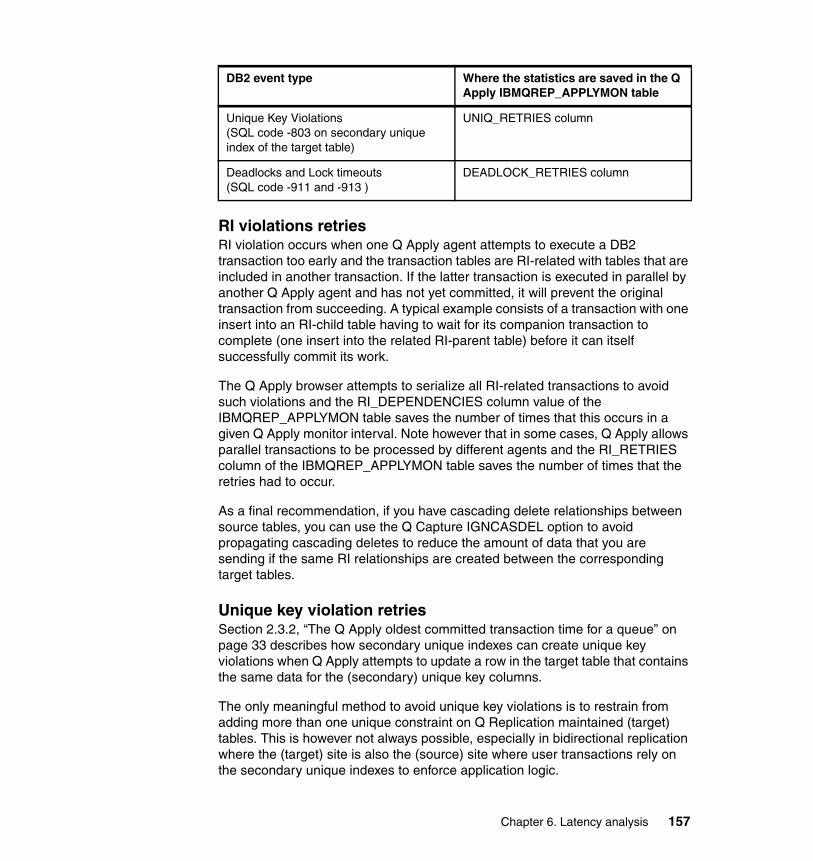
RI violations retriesRI violation occurs when one Q Apply agent attempts to execute a DB2 transaction too early and the transaction tables are RI-related with tables that are included in another transaction. If the latter transaction is executed in parallel by another Q Apply agent and has not yet committed, it will prevent the original transaction from succeeding. A typical example consists of a transaction with one insert into an RI-child table having to wait for its companion transaction to complete (one insert into the related RI-parent table) before it can itself successfully commit its work.
The Q Apply browser attempts to serialize all RI-related transactions to avoid such violations and the RI_DEPENDENCIES column value of the IBMQREP_APPLYMON table saves the number of times that this occurs in a given Q Apply monitor interval. Note however that in some cases, Q Apply allows parallel transactions to be processed by different agents and the RI_RETRIES column of the IBMQREP_APPLYMON table saves the number of times that the retries had to occur.
As a final recommendation, if you have cascading delete relationships between source tables, you can use the Q Capture IGNCASDEL option to avoid propagating cascading deletes to reduce the amount of data that you are sending if the same RI relationships are created between the corresponding target tables.
Unique key violation retriesSection 2.3.2, “The Q Apply oldest committed transaction time for a queue” on page 33 describes how secondary unique indexes can create unique key violations when Q Apply attempts to update a row in the target table that contains the same data for the (secondary) unique key columns.
The only meaningful method to avoid unique key violations is to restrain from adding more than one unique constraint on Q Replication maintained (target) tables. This is however not always possible, especially in bidirectional replication where the (target) site is also the (source) site where user transactions rely on the secondary unique indexes to enforce application logic.
Unique Key Violations (SQL code -803 on secondary unique index of the target table)
UNIQ_RETRIES column
Deadlocks and Lock timeouts(SQL code -911 and -913 )
DEADLOCK_RETRIES column
DB2 event type Where the statistics are saved in the Q Apply IBMQREP_APPLYMON table
Chapter 6. Latency analysis 157

For bidirectional scenarios, if you must preserve secondary unique indexes on tables that are replicated, the only option you have is to closely monitor the UNIQ_RETRIES column and its impact on the RETRY_TIME column value to evaluate the actual cost of unique retries onto your replication environment.
Deadlock retriesIt more than one Q Apply agent updates the same DB2 page, lock contention occurs. If the agents each lock part of the data that the other agents are waiting on, deadlock occurs. The general DB2 guideline to avoid deadlocks is to either change the application (in the Q Replication case, this implies reducing the number of Q Apply agents) or changing the DB2 tablespace locking scheme to a more granular option, such as row level locking. This might come with a cost because the DB2 logic can eventually end up in lock escalation mode.
The DEADLOCK_RETRIES is one of the statistics to monitor when evaluating whether it is time to reduce the number of Q Apply agents for a particular receive queue.
6.3.5 DB2 DBMS Time
The DBMS_TIME column value of the IBMQREP_APPLYMON table tracks the average time spent in DB2 applying the transactions for a given Q Apply monitor interval. The transactions include user tables (replicated tables) and Q Replication tables (control table data that tracks the Q Apply progress).
The three factors that negatively affect the DBMS_TIME value, which is typically a relatively large percentage of the overall Q Apply latency time, are shown in the following list of sections in this book, in decreasing order of impact:
� “Tuning the target DB2 for z/OS subsystem for Q Apply”� “The IBMQREP_DONEMSG table”� “The IBMQREP_EXCEPTIONS table” on page 159
Tuning the target DB2 for z/OS subsystem for Q ApplyIn DB2 for z/OS data sharing environments, the default locksize of a table space is ANY, which usually means PAGE locking. If many Q Apply agents are applying DB2 transactions in parallel, you may experience deadlock as multiple agents might need to update the same page. If that is the case, you can consider using row level locking for particular target tables. Note however that row level locking may introduce some lock escalation.
There might be an issue in DB2. Contact your DBA to evaluate whether a REORG or RUNSTATS job is required for the particular table space.
158 Understanding and Using Q Replication for High Availability Solutions on the IBM z/OS Platform

The IBMQREP_DONEMSG tableThe Q Apply table can become a hot spot as it is updated twice, one insert and one delete, for every replicated transaction.
The following preferred practices are for managing the volume of this table:
� Run DB2 for z/OS REORGs regularly� Use Example 6-2 as a template
Example 6-2 The IBMQREP_DONEMSG table (table space allocation)
CREATE TABLESPACE XXX IN XXX USING STOGROUP XXX USING PRIQTY 28800 SECQTY 8192 COMPRESS NO TRACKMOD NO SEGSIZE 64 APPEND NO BUFFERPOOL XXX LOCKSIZE ROW CLOSE NO CCSID EBCDIC
CREATE UNIQUE INDEX XXX ON schema.IBMQREP_DONEMSG (RECVQ, MQMSGID) USING STOGROUP XXX PRIQTY 28800 SECQTY 8192 ERASE NO BUFFERPOOL YYY CLOSE NO
The IBMQREP_EXCEPTIONS tableThe Q Apply table can become a hot spot in your environment if you expect numerous exceptions for particular workloads.
Preferred practices for managing the volume of this table include the following:
� See section 5.2.6, “Managing exceptions and the IBMQREP_EXCEPTIONS table” on page 127 for a description about how to use triggers on the table to avoid populating it for some specific scenarios
� Use SQL DELETE statements to regularly prune rows that contain exceptions that you already processed
6.3.6 Monster transactions
The MONSTER_TRANS column value of the IBMQREP_APPLYMON table records the number of very large transactions, monster transactions, that exceeded the memory limit for each receive queue at each monitor interval. The memory limit of a receive queue is described in detail in section “The Q Apply Receive Queue MEMORY_LIMIT threshold” on page 160.
When a monster transaction is detected, the Q Apply browser itself applies the transaction and does not dispatch it to any Q Apply agent.
If you see a non-zero value in the MONSTER_TRANS column, you have a few options to minimize the disruption due to monster transactions based on how regularly they will be executed and how large they will be in the future:
Chapter 6. Latency analysis 159

� Increase the memory limit value of the appropriate receive queue only if you expect these transactions to be executed somewhat regularly and their size did not exceed the memory limit by a large amount.
� If possible, dedicate a receive queue for tables of workloads that generate monster transactions that are exceedingly large. This allows you to tune the memory limit of the dedicated receive queues appropriately and it ensures that the remaining receive queues are fenced from the monster transactions’ impact on their latency.
The Q Apply Receive Queue MEMORY_LIMIT thresholdThe Q Apply memory limit threshold can be found in the MEMORY_LIMIT column value of the IBMQREP_RECVQUEUES table. This threshold can be tuned for each receive queue with a default of 64 Meg on the z/OS platform. The threshold value is the amount of memory that a Q Apply program can use to process transactions for a single receive queue.
You can detect that the memory limit threshold is exceeded for a receive queue by querying the MEM_FULL_TIME column of the IBMQREP_APPLYMON table. The memory limit threshold can be exceeded because a single, monster, transaction is larger than the memory limit or because the Q Apply program takes too long to apply transactions at the target DBMS and is not keeping up with the incoming message flow. To be exact, in the latter case, the stage of the replicated transaction is illustrated by stage 9 in Figure 6-3 on page 145 and its lag is due to the Q Apply agent or the DBMS itself taking too long to apply rows.
The time spent applying rows in the target DBMS is saved in the DBMS_TIME column of the IBMQREP_APPLYMON table and some of the causes of its lag are described in section 6.3.4, “Determine why Q Apply is retrying so many SQL statements” on page 156.
Determine when is it appropriate to increase the memory limit If you detect that the memory limit threshold is exceeded but also notice that the Q Apply agents are not busy applying (the APPLY_SLEEP_TIME column value in the IBMQREP_APPLYMON table has a high value) and that the DBMS_TIME is not exceedingly high, you can consider increasing the memory limit. However, a bigger memory limit doesn’t necessarily imply better performance (too many factors to take into account).
To update the memory limit, you can simply issue a SQL statement to update the MEMORY_LIMIT column value for the particular receive queue. The change can be done dynamically but will require a reinitq command of the Q Apply program for the particular queue for the Q Apply program to be aware of the change.
160 Understanding and Using Q Replication for High Availability Solutions on the IBM z/OS Platform

6.3.7 Tuning the Q Apply program
Table 6-4 summarizes some recommendations for tuning the Q Apply program on the z/OS platform.
Table 6-4 Q Apply preferred practices
Finally, as described in section 2.3.2, “The Q Apply oldest committed transaction time for a queue” on page 33, you can always track the oldest transaction that the
Topic Preferred practices and suggestions
Q Apply job � Use a job region size of 0.� Use job priority lower than the priority of DB2 and
WebSphere MQ subsystems.� APPLY_SERVER parameter should be the data sharing
group (not a DB2 member) name.� APPLY_PATH parameter should point to a DB2 for z/OS
path (not a uss path).� INSERT_BIDI_SIGNAL=N parameter should be used to
improve performance for two-server bidirectional replication configurations.
Q Apply browser memory allocation
� Default memory allocation of 32 MB for each Q Apply browser thread is adequate for most situations.
Q Apply browser � If you notice that the NUM_MQGETS column value is high while the TRANS_READ column value remains low in the IBMQREP_APPLYMON table and you do not expect transactions to span multiple messages, review section “The Q Apply MQGET_TIME” on page 166 because it might provide relief.
Number of Q Apply receive queues
� Stay below 30 receive queues for a target WebSphere MQ queue manager.
Number of Q Apply agents
� Lower the default number of agent threads per receive queue (16) if the APPLY_SLEEP_TIME column value of the IBMQREP_APPLYMON table shows that agents are idle while waiting for work. You can also lower the number if you detect contention at the target table.
Target table triggers � If the source and target tables have the same DB2 triggers defined on the tables, use the Q Capture IGNTRIG parameter to discard trigger-generated rows and rely on the DB2 target trigger to generate the necessary (trigger body) insert, update, or delete at the target table.
Chapter 6. Latency analysis 161

Q Apply program committed for a particular receive queue by querying the IBMQREP_APPLYMON OLDEST_TRANS column value. You can also include the OLDEST_INFLT_TRANS and ROWS_PROCESSED column values of the same row to track the Q Apply progress.
6.4 Queue latency
This section starts with a review of Queue latency and proceeds with descriptions about the impact of the Q Capture COMMIT_INTERVAL, the WebSphere MQ transport delay, and the Q Apply MQGET_TIME delay. The section ends with preferred practices related to WebSphere MQ for the z/OS platform.
As mentioned in “The four latency values and the monitor tables” on page 143, the Queue latency value is computed by the Q Apply program and saved in the QUEUE_LATENCY column value of the IBMQREP_APPLYMON table.
To derive the Queue latency value, the Q Apply program subtracts the Q Capture latency and Q Apply latency values from the end-to-end latency value that it is collecting during any given monitor interval. Example 6-3 provides its simple formula.
Example 6-3 The QUEUE_LATENCY calculation
QUEUE_LATENCY = END2END_LATENCY - CAPTURE_LATENCY - APPLY_LATENCY
Remember that the actual latency value is an aggregate over the transactions processed for the monitor interval.
Monitoring the Queue latency may include defining an alert on the QUEUE_LATENCY column of the IBMQREP_APPLYMON table and assigning a threshold value to these statistics.
The Queue latency can be segmented into three potential delays:
1. The time between the last MQ PUT and the MQ COMMIT for the Q Capture transaction.
2. The WebSphere MQ transport delay or delay from the time the Q Capture program WebSphere MQ commits the transaction at the source site up to the time the message is first read at the target site by the Q Apply program. There is no delay when the Q Apply queue manager is on the same system as the Q Capture queue manager.
162 Understanding and Using Q Replication for High Availability Solutions on the IBM z/OS Platform
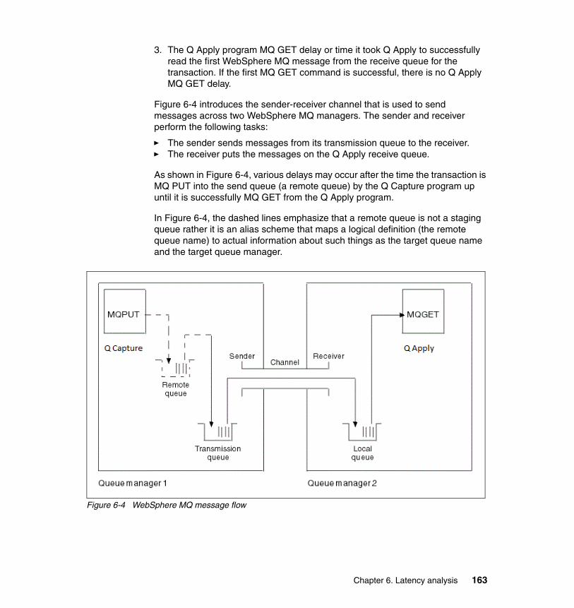
3. The Q Apply program MQ GET delay or time it took Q Apply to successfully read the first WebSphere MQ message from the receive queue for the transaction. If the first MQ GET command is successful, there is no Q Apply MQ GET delay.
Figure 6-4 introduces the sender-receiver channel that is used to send messages across two WebSphere MQ managers. The sender and receiver perform the following tasks:
� The sender sends messages from its transmission queue to the receiver.� The receiver puts the messages on the Q Apply receive queue.
As shown in Figure 6-4, various delays may occur after the time the transaction is MQ PUT into the send queue (a remote queue) by the Q Capture program up until it is successfully MQ GET from the Q Apply program.
In Figure 6-4, the dashed lines emphasize that a remote queue is not a staging queue rather it is an alias scheme that maps a logical definition (the remote queue name) to actual information about such things as the target queue name and the target queue manager.
Figure 6-4 WebSphere MQ message flow
Chapter 6. Latency analysis 163

Table 6-5 is a companion table to Figure 6-4 on page 163 and lists the various delays that may occur after the MQ PUT command and before a successful MQ GET command.
Table 6-5 The Queue latency delays
The table brings up a few interesting questions that are answered in the remainder of this Queue Latency section, such as the following:
� Does the sender channel wait for an acknowledgement from the receiver channel (after t5) before MQ GETting more messages from the transmit queue?
– Yes, if the (remote) receive queue is defined as persistent
Sequence of events Comments
t1 Q Capture MQ PUTs message in the send queue
Message is put in transmit queue. Delay might occur if the transmit queue is full.
t2 MQ COMMIT transaction time Delay may be impacted by MQ log (response time if I/O issue).
The t2 start time may be impacted by the Q Capture COMMIT_INTERVAL.
t3 Sender MQ GET messages from its transmit queue and sends them to the receiver
Delay may occur due to high queue depth (it takes time to process preceding messages)transport itself (TCP/IP and so on) as well as the MQ channel BATCHSZ and BATCHLIM values, which affect the frequency of commits and confirmation with the receiver that messages have arrived.
t4 Receiver puts WebSphere MQ message on the receive queue
Delay might occur if the receive queue is full.
t5 Receiver MQ COMMITs the messages on the receive queue
Delay might be impacted by MQ log (response time if I/O issue).
t6 Q Apply successfully MQ GETs the first message of the transaction
Delay spent waiting for WebSphere MQ messages is included in the Queue latency statistics.
164 Understanding and Using Q Replication for High Availability Solutions on the IBM z/OS Platform

– If the receive queue is defined as non-persistent, there is no t5 in itself (and no delay associated with t5); however, the sender channel will still wait for an acknowledgement from the receiver channel before MQ GETting more messages from the transmit queue
� How does the Q Capture COMMIT_INTERVAL impact the start time of t2?
– See “The Q Capture COMMIT_INTERVAL” on page 165
� What is the WebSphere MQ transport latency?
– It is defined as the sum of the delays at t3, t4, and t5. See “The WebSphere MQ transport delay” on page 165
� Why is Q Apply not successfully MQ GETting messages from the receive queue?
See 6.4.3, “The Q Apply MQGET_TIME” on page 166
� Are there any WebSphere specific MQ recommendations for Q Replication?
See 6.4.4, “Tuning WebSphere MQ” on page 168
6.4.1 The Q Capture COMMIT_INTERVAL
The default COMMIT_INTERVAL column value in the IBMQREP_CAPPARMS table is 500 milliseconds. Because the CAPTURE_LATENCY value in the IBMQREP_APPLYMON table does not include MQ Commit time, increasing the Q Capture COMMIT_INTERVAL value may increase the Queue latency.
6.4.2 The WebSphere MQ transport delay
Referring to Table 6-5 on page 164, the WebSphere MQ transport delay is defined as the delays at t3, t4, and t5.
There are no statistics that are specific to the WebSphere MQ transport delay in the monitor tables.
To check if the WebSphere MQ transport is an issue for the Queue latency, do the following:
� Query the IBMQREP_CAPQMON table XMITQ_DEPTH column to see how many messages are in the Q Capture transmit queue.
� If the transmit queue has many messages, query the Q Apply IBMQREP_APPLYQMON table APPLY_LATENCY and QUEUE_LATENCY columns that correspond to the same time as the XMITQ_DEPTH value. If the APPLY_LATENCY is relatively low and QUEUE_LATENCY relatively high, there is an issue with the WebSphere MQ transport.
Chapter 6. Latency analysis 165

– WebSphere MQ configuration issues might be slowing down the replication process, so you might want to review section 6.4.4, “Tuning WebSphere MQ” on page 168.
– If the issue is not related to the configuration of WebSphere MQ objects, you may be experiencing a bottleneck in the transmit queue, so you might want to review the next section called “The Q Apply MQGET_TIME” on page 166.
� If the transmit queue does not have many messages, query the QDEPTH column value of the IBMQREP_APPLYMON table to detect when, back in time, the value started increasing, if in fact it did.
– If you find a time range in the IBMQREP_APPLYMON table when the QDEPTH value started increasing, query the MEM_FULL_TIME column values of the same table around the same time range to identify whether the Q Apply program is experiencing memory full-time conditions preventing the Q Apply program from consuming messages from the queue:
• If the MEM_FULL_TIME is non-zero, review the Q Apply latency hot spots described in “Q Apply latency” on page 154.
• Else, the delay is not caused by the Q Apply program so you might want to contact your WebSphere MQ system administrator because the delay might be due to the network itself.
– If you did not find a noticeable increase in the QDEPTH value yet the transport delay is relatively high, contact your WebSphere MQ system administrator because the delay may be due to the network itself.
6.4.3 The Q Apply MQGET_TIME
This section reviews a few topics that are related to the Q Apply MQ GET time:
� “Avoiding unsuccessful MQ GET calls” on page 166� “The MQGET_TIME column of the IBMQREP_APPLYMON table” on
page 167� WebSphere MQ transport delays can also cause indirectly a high
MQGET_TIME column value in the IBMQREP_APPLYMON table as the browser is waiting on an empty queue due to the WebSphere MQ transport delay.
Avoiding unsuccessful MQ GET callsUnsuccessful MQ GET calls occur in the following scenarios:
1. The receive queue is empty so there are no messages to get
2. Q Apply encounters an MQ error
166 Understanding and Using Q Replication for High Availability Solutions on the IBM z/OS Platform
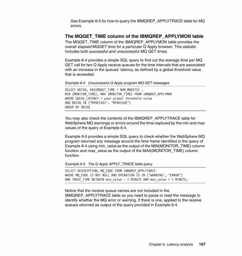
See Example 6-5 for how to query the IBMQREP_APPLYTRACE table for MQ errors.
The MQGET_TIME column of the IBMQREP_APPLYMON tableThe MQGET_TIME column of the IBMQREP_APPLYMON table provides the overall elapsed MQGET time for a particular Q Apply browser. This statistic includes both successful and unsuccessful MQ GET times.
Example 6-4 provides a simple SQL query to find out the average time per MQ GET call for two Q Apply receive queues for the time intervals that are associated with an increase in the queues’ latency, as defined by a global threshold value that is exceeded.
Example 6-4 Unsuccessful Q Apply program MQ GET messages
SELECT RECVQ, AVG(MQGET_TIME / NUM_MQGETS) ,MIN (MONITOR_TIME), MAX (MONITOR_TIME) FROM IBMQREP_APPLYMONWHERE QUEUE_LATENCY > your global threshold value AND RECVQ IN (‘MYRECVQ1‘, ‘MYRECVQ2’)GROUP BY RECVQ
You may also check the contents of the IBMQREP_APPLYTRACE table for WebSphere MQ warnings or errors around the time captured by the min and max values of the query of Example 6-4.
Example 6-5 provides a simple SQL query to check whether the WebSphere MQ program returned any message around the time frame identified in the query of Example 6-4 using min_value as the output of the MIN(MONITOR_TIME) column function and max_value as the output of the MAX(MONITOR_TIME) column function.
Example 6-5 The Q Apply APPLY_TRACE table query
SELECT DESCRIPTION, MQ_CODE FROM IBMQREP_APPLYTRACEWHERE MQ_CODE IS NOT NULL AND OPERATION IS IN (‘WARNING’, ‘ERROR’)AND TRACE_TIME BETWEEN min_value - 1 MINUTE AND max_value + 1 MINUTE;
Notice that the receive queue names are not included in the IBMQREP_APPLYTRACE table so you need to parse or read the message to identify whether the MQ error or warning, if there is one, applied to the receive queues returned as output of the query provided in Example 6-4.
Chapter 6. Latency analysis 167
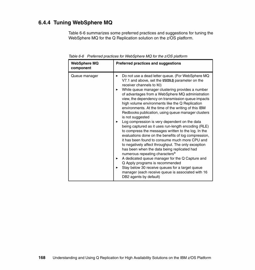
6.4.4 Tuning WebSphere MQ
Table 6-6 summarizes some preferred practices and suggestions for tuning the WebSphere MQ for the Q Replication solution on the z/OS platform.
Table 6-6 Preferred practices for WebSphere MQ for the z/OS platform
WebSphere MQ component
Preferred practices and suggestions
Queue manager � Do not use a dead letter queue. (For WebSphere MQ V7.1 and above, set the USEDLQ parameter on the receiver channels to NO)
� While queue manager clustering provides a number of advantages from a WebSphere MQ administration view, the dependency on transmission queue impacts high volume environments like the Q Replication environments. At the time of the writing of this IBM Redbooks publication, using queue manager clusters is not suggested
� Log compression is very dependent on the data being captured as it uses run-length encoding (RLE) to compress the messages written to the log. In the evaluations done on the benefits of log compression, it has been found to consume much more CPU and to negatively affect throughput. The only exception has been when the data being replicated had numerous repeating charactersa
� A dedicated queue manager for the Q Capture and Q Apply programs is recommended
� Stay below 30 receive queues for a target queue manager (each receive queue is associated with 16 DB2 agents by default)
168 Understanding and Using Q Replication for High Availability Solutions on the IBM z/OS Platform

Channel � Channel compression (COMPHDR SYSTEM) is recommended (COMPMSG is not recommended for the same reason log compression is not recommendedb
� The disconnect interval (DISCINT) should be 0 or lower than the Q Replication heartbeat intervals for the send queues
� Use the CONVERT(NO) option to specify no data conversion to ensure that conversion is under the Q Replication control
� Set the channel batch size (BATCHSZ) 50 - 200 and the batch limit (BATCHLIM) 5 - 10 MB. The two values complement each other in that WebSphere MQ will use the lesser value of the two to trigger when the sender stops getting messages from the transmit queue (if there are messages to read); usually the BATCHSZ triggers first (assuming you do not run large batch jobs often)
� Use a dedicated channel for each Q Apply receive queue
Transmission queue � Use a dedicated transmit queue for each Q Apply receive queue
� Use a dedicated storage class, pageset, and buffer pool for high volume environments (over 30 messages per secondc)
� Set the MAXDEPTH attribute of the queue as large as possible, that is, the maximum 999999999
Q Apply receive queue � Use a dedicated storage class, pageset, and buffer pool for each Q Apply receive queue (over 30 messages per secondd)
� Use a dedicated channel for each Q Apply receive queue
� Set the MAXDEPTH attribute of the queue as large as possible, that is, the maximum 999999999
� Use indexing, INDXTYPE(MSGID)
WebSphere MQ component
Preferred practices and suggestions
Chapter 6. Latency analysis 169

The following are some final considerations regarding WebSphere MQ tuning for Q Replication in the z/OS platform:
The description for queue sharing versus DASD sharing between z/OS LPARs was covered in the IBM Redbooks WebSphere Replication Server for z/OS Using Q Replication: High Availability Scenarios for the z/OS Platform, available at http://www.redbooks.ibm.com/abstracts/sg247215.html?Open. Therefore, it is not covered in this section.
Q Apply spill queue � The model queue that is used to create temporary spill queues must be a permanent dynamic queue, DEFTYPE(PERMDYN)
� Use a dedicated storage class for the model queue� If you plan to load the target tables for multiple Q
subscriptions simultaneously, consider creating separate model queue definitions for each Q subscription and customize the queues depending on the workload expected at the different source tables during the loading process
� Ensure that the maximum number of messages that the model queue holds, MAXDEPTH, is large enough to handle changes that are expected at the source table while the target table is being loaded. To evaluate the number of bytes needed, count about 400 bytes on the front of each MQ message (message header)
Messages � Default maximum message size of 4 MB is adequate in most situations and thus typically unchanged. It can be raised, but is only done so after careful evaluation of the replication configuration. Making messages too large, like making them too small, can result in higher CPU and lower throughput
� Use persistent messages (the default) unless low latency and low CPU usage are major requirements
a. RLE or run-length encoding, a simple form of data compression in which runs of data are stored as a single data value and count
b. RLE or run-length encoding, a simple form of data compression in which runs of data are stored as a single data value and count
c. High volume is based on size of message and actual message volume but ‘30’ is a good starting point
d. High volume is based on size of message and actual message volume but ‘30’ is a good starting point
WebSphere MQ component
Preferred practices and suggestions
170 Understanding and Using Q Replication for High Availability Solutions on the IBM z/OS Platform

� Two WebSphere MQ APARs, PM63802 (V7.0.1 included in V7.1) and PM81785 for V7.1 enable the buffer pool read ahead enhancement. The throughput increase depends on many factors but has been seen to be substantial in some high volume environments.
� An option is available for high volume environments with small transaction sizes that allows two or more send queues to be associated with a single receive queue, using the NUM_PARALLEL_SENDQS column value of the IBMQREP_SENDQUEUES table. Note that for this option to perform two transmit queues and two send channels are defined at the source site instead of one. The scenario was described in details in section 3.6, “Using parallel send queues” on page 76.
6.5 Batch workloads
Batch workloads create a spike in the latency metrics of your online environments due to the contention that they create on DB2 tables for the Q Apply program and due to the sheer size of the volume of data they update. To minimize their impact on your overall environment, you might want to consider the following options:
� Schedule the batch workloads during off-peak periods if that is at all possible (batch windows are disappearing so this might not be an option).
� Submit the batch jobs in smaller groups and stagger their start times, again if at all possible, because this minimizes their impact to your replication environment.
� Determine whether they create contention on the DB2 data and if so, minimize the parallelism degree for each batch job by performing the following steps:
a. Query the DEADLOCK_RETRIES column values of the IBMQREP_APPLYMON table
b. If the deadlock retry values are high around the time the batch job was replicated, query the JOB_DEPENDENCIES column values of the IBMQREP_APPLYMON table
c. If the job dependencies values are high as well, consider decreasing the MAXAGENTS_CORRELID column value of the IBMQREP_RECVQUEUES table for the appropriate receive queue. The Q Apply receive queue attribute may be changed dynamically in which case a Q Apply program reinitq command is necessary for the change to take effect
Chapter 6. Latency analysis 171

� If you have a job that includes the TRUNCATE command, consider the option proposed in section 7.3.1, “An alternative to the TRUNCATE command” on page 187.
� If you have a very large transaction (deletes, for example, gigabytes of data in a single DB2 transaction), consider excluding that transaction from the replication process by inserting its information into the Q Capture IBMQREP_IGNTRAN table.
� If you can encode preferred practices in your applications, implement a rule that a commit should be performed after at most a certain number of rows; it will also help you review and plan for the cases when the rule cannot be followed.
When the batch jobs are too large, a preferred practice is to run them outside of the replication process: Run the same job at the source and target sites of the replication process and prevent their data from being captured by the Q Capture process (using the Q Capture IBMQREP_IGNTRAN table).
You might also want to follow the suggestions provided in the WebSphere MQ support pack for capacity planning and tuning. There is more information about the support pack at the following URL:
http://www-01.ibm.com/support/docview.wss?uid=swg24007421
6.6 The Data Replication Dashboard
In this section, we include a few screen captures of the current Data Replication Dashboard to show you the following actions:
� How you can monitor Q Replication using a live monitor graphical tool� How you can be alerted when a latency threshold you pre-define is exceeded� How to get a visual representation of an alert, when the threshold is exceeded� How you can generate a latency report for the statistics that exist around the
time of the alert (you can provide the range that you are interested in)
You can also receive an email and it is configurable from the Data Replication Dashboard.
If you have not already installed the Data Replication Dashboard, you can do so by downloading its install image from the following url:
http://www-01.ibm.com/support/docview.wss?uid=swg24023065
172 Understanding and Using Q Replication for High Availability Solutions on the IBM z/OS Platform

6.6.1 Live monitoring
The following section shows three different screen captures for live monitoring:
� Figure 6-5 is a summary view that includes four different live graphs. The graphs are fully configurable. You can choose what you want to monitor. In the figure, the four graphs include the Q Capture log latency graph, the Q Capture throughput graph, the end-to-end latency graph (segmented into Q Capture, Queue, and Q Apply latency), and the Q Apply throughput graph. The receive queue depth graph is also overlaid on top of the Q Apply throughput data.
Figure 6-5 Data Replication Dashboard summary view
Chapter 6. Latency analysis 173

� Figure 6-6 is the same summary view as Figure 6-5 on page 173 with the addition of an end-to-end latency threshold as represented by a horizontal line in red color in its graph. All of the data points exceed the threshold for the time intervals that are shown in the figure.
Figure 6-6 Data Replication Dashboard summary view with latency threshold
174 Understanding and Using Q Replication for High Availability Solutions on the IBM z/OS Platform

� Figure 6-7 shows a visual alert for the latency threshold that was exceeded. The dialog gives you a few options that include generating a latency report for the alert, viewing historical data, or reviewing performance tuning recommendations.
Figure 6-7 Data Replication Dashboard latency alert
The report that is generated when an alert is issued is described next.
6.6.2 Generating a latency report
This section summarizes the contents of a latency report. Figure 6-8 on page 176 shows the contents of the latency report generated by the alert of Figure 6-7.
Chapter 6. Latency analysis 175

Figure 6-8 Data Replication Dashboard latency report
As shown in Figure 6-8, the latency report includes the following information:
� A break-down of the Q Capture, Queue, and Q Apply latencies along with Q Apply throughput and queue depth
� The threshold value that you have pre-defined� A summary of the highest, lowest, and average values for all latencies that
belong to the range that you pre-defined for the report� Latency values and their associated statistics in the Q Apply monitor table� A latency graph that allows you to quickly spot latency issues: For example, a
quick spike that is limited to a particular point in time or a consistently high latency for a period
The report includes links to additional data points. Therefore, it is recommended that you run a sample scenario, define a latency threshold, and generate a latency report using the Data Replication Dashboard to investigate its full functionality.
176 Understanding and Using Q Replication for High Availability Solutions on the IBM z/OS Platform

Chapter 7. Managing Q Replication in the DB2 for z/OS Environment
In this chapter, we document the DB2 for z/OS operational impact on Q Replication and describe the options that are available to manage, and if necessary, minimize their impact.
7
© Copyright IBM Corp. 2014. All rights reserved. 177

7.1 Introduction
Some DB2 for z/OS features affect the replication environment and this chapter helps you plan for or simply review these operational impacts on your replication environment. It includes the following topics:
� DB2 utilities� DB2 commands� DB2 Data Definition Language (DDL) statements � DB2 maintained tables and columns
Before moving to the DB2 components’ analysis and their impact to the Q Replication process, we recap how the Q Capture program relies on two versioning tables to keep up with DB2 schema evolution over time. The contents of the two tables determine how new subscriptions are initialized, a process that is defined as the CAPSTART of a subscription.
7.1.1 The Q Capture versioning tables and schema evolution
DB2 for z/OS describes the current version of the metadata of its tables and columns information in the SYSIBM.SYSTABLES and SYSIBM.SYSCOLUMNS tables respectively. Since the Q Capture program might need to decode log records of DB2 data at earlier versions than the version (and metadata) described in the DB2 for z/OS catalog tables, the Q Capture program relies on two versioning tables to track the evolution of DB2 metadata over time. The versioning tables allow the Q Capture process to decode older versions of before image column values found in a DB2 log record.
The two Q Capture versioning tables are the IBMQREP_TABVERSION and the IBMQREP_COLVERSION tables.
CAPSTART of a subscriptionA new Q subscription can be started automatically or by using a CAPSTART signal. The CAPSTART signal is an insert into the Q Capture IBMQREP_SIGNAL table to alert the Q Capture program that a new subscription is to be initialized. You can also define subscriptions to be started automatically in which case the subscription state (the STATE column) is new (or ‘N’) in the Q Capture IBMQREP_SUBS table. If you define a subscription to be automatically started (or if you update the STATE column value of the IBMQREP_SUBS table for a subscription to ‘N’), you can reinitialize the Q Capture program and it will initiate the initialization of these new subscriptions.
Regardless of the start option used (CAPSTART signal or automatic CAPSTART), the Q Capture program populates the IBMQREP_TABVERSION
178 Understanding and Using Q Replication for High Availability Solutions on the IBM z/OS Platform

table with metadata about the source table, which includes the DB2 dbid (TABLEID1 column), DB2 object identifier (obid) (TABLEID2 column), log sequence number (LSN) value (to track when the subscription was activated), and table DDL properties for the particular version.
The Q Capture program also populates the IBMQREP_COLVERSION table, one row for each column of the source table with the DB2 dbid (TABLEID1 column), DB2 obid (TABLEID2 column), LSN value (to track when the subscription was activated), and column DDL properties for the particular version.
When the subscription is first initialized, the Q Capture program looks up the DB2 for z/OS catalog to check that the subscription’s metadata in the Q Capture versioning tables match that of the DB2 for z/OS catalog. These startup checks are only performed when the subscription is initialized or CAPSTARTed. Active subscriptions bypass that logic.
After the checks are done, the versioning tables are updated if necessary. For BRF tables, if the Q Capture program detected that an alter add column was performed on the table but no REORG was done before the CAPSTART, if it does not have enough information about the previous versions of a table, it allows the CAPSTART of the subscription and (densely) populates the two versioning tables as follows:
� Populates the IBMQREP_TABVERSION with the latest version of the table (as it is now in SYSIBM.SYSTABLES) and populates all the previous versions of the table with the latest version: It writes multiple entries in the IBMQREP_TABVERSION table (one row for each version)
� Populates the IBMQREP_COLVERSION table with the latest version of the table (as it is now in SYSIBM.SYSCOLUMN) but in that case does not write multiple entries in the IBMQREP_COLVERSION table (inserts only columns for the present version)
The Q Capture program never prunes its versioning tables so you need to manage them, as documented in the product online documentation.
DB2 schema evolutionWhen the Q Capture program detects one of the following DB2 DDL operations for an active subscription:
� An alter add column� Alter column alter datatype� Drop column followed by a REORG
The Q Capture program inserts a new set of rows in the IBMQREP_TABVERSION and IBMQREP_COLVERSION tables for the new version of the table and column.
Chapter 7. Managing Q Replication in the DB2 for z/OS Environment 179

When the Q Capture program detects a DB2 DDL rename column operation, it simply updates the metadata in its IBMQREP_COLVERSION table for the appropriate row with the renamed column information.
If any schema change is performed on a table while its subscription is active (any of the DB2 alter add column, alter column, alter datatype, drop column or rename column), the Q Capture program simply updates its versioning tables with the pertinent information, keeping up with the DB2 schema changes as it processes them from the DB2 log records.
The CAPSTOP of a subscriptionWhen the Q Capture program sees a CAPSTOP signal for a subscription, it does not update nor delete rows from its IBMQREP_TABVERSION and IBMQREP_COLVERSION tables. The reason is that it relies on the versioning information to infer at subscription startup time how to process the subscription. This is to eliminate the requirement for a REORG of the table space before CAPSTARTing the subscription.
The Q Capture program looks for the pertinent versioning information in its versioning tables before attempting to start and activate a subscription for that table. If it cannot, it will have to request a REORG so that it can successfully process that table’s log records when the subscription is CAPSTARTed.
If you CAPSTOP and later CAPSTART a subscription, the Q Capture program rule is as follows:
� If none of the following DB2 schema changes were issued against the table while the subscription was inactive: alter add column, alter column alter datatype, drop column, or rename column, the Q Capture program restarts the subscription without requiring a REORG.
� If the only DB2 schema change that was issued against the table while the subscription was inactive is the alter add column and there has been no DB2 schema changes for that table when the subscription was previously active, the Q Capture program restarts the subscription without requiring a REORG if the table is in Basic Row Format (BRF).
� If the only DB2 schema change that was issued against the table while the subscription was inactive is the alter add column and there were DB2 schema changes for that table when the subscription was previously active, however, they were followed by a REORG, the Q Capture program restarts the subscription without requiring a REORG if the table is in BRF.
� All other cases require a REORG before you can CAPSTART the subscription.
180 Understanding and Using Q Replication for High Availability Solutions on the IBM z/OS Platform

7.2 DB2 utilities
The DB2 utilities change the contents of the DB2 tablespace data. Source or target table spaces that participate in the replication process are impacted by the execution of some of these utilities jobs.
Table 7-1 groups the DB2 utilities by the impact that they may have on a replication environment, describes the operational impact, and points to sections that include suggestions and preferred practices, when available.
Table 7-1 DB2 utilities and Q Replication
Note: In this book and in the product documentation, we use the terms compression and decompression interchangeably when they refer to the DB2 decompression dictionary (the official DB2 for z/OS terminology).
DB2 utilities Impact and user action
REORG and LOAD REPLACEwith the ROWFORMAT option
Executed at source site
� If the table space format is changed from BRF to RRF (Relative Row Format), the Q Capture process will need to decode log records for the affected tables using the new row format. DB2 default is to use RRF format with DB2 V9 NFM (New Function Mode) or higher and to use the BRF format for the previous DB2 versions.
� User intervention might be required for partitioned table spaces that have one of their partitions in a different row format than the other partitions (due to a REORG or LOAD REPLACE of the partition).
� Suggestions: 7.2.1, “CAPSTARTing a subscription” on page 182.
REORG DISCARD, LOAD REPLACE,LOAD RESUME SHARE LEVEL NONE,RECOVER PIT,CHECK DATA DELETE YES LOG NO
Executed at source site
� These utilities are detected by the Q Capture program but the changes made to the table spaces are not automatically replicated to the target table spaces. The corresponding target tables will not be synchronized with the source tables.
� User intervention might be required.
� Suggestions: See section 7.2.2, “Replicating DB2 utilities and the CAPTURE_LOAD option” on page 183.
Chapter 7. Managing Q Replication in the DB2 for z/OS Environment 181

7.2.1 CAPSTARTing a subscription
When a subscription is CAPSTARTed, the Q Capture program queries the DB2 for z/OS catalog to check the version of the subscription’s source table and the time the last REORG was performed on that table, and to retrieve the table metadata (such as datatype and length of its columns). In some cases however, the Q Capture program cannot retrieve enough information about the table and requires the user to run a REORG utility against the table space that holds the table before CAPSTARTing the subscription as the REORG utility updates the DB2 for z/OS catalog with up-to-date metadata.
BRF, RRF, and the CAPSTART prerequisiteDB2 for z/OS tablespaces use two different row formats: the older BRF (basic row) format and the RRF (relative row) format. The Q Capture program supports both formats. When a table space or a table space partition moves to the RRF format, DB2 requires a REORG for that table space or table space partition so that the Q Capture CAPSTART prerequisite is met indirectly for subscriptions that have source tables in RRF format. The same is not true for subscriptions that are associated with source tables in BRF format.
LOAD RESUME SHARE LEVEL CHANGE
Executed at source site
� The utility is not detected by the Q Capture program but the utility writes insert log records so Q Capture captures these insert log records. Changes made to the table space are automatically replicated to the target table space. The corresponding target table will be synchronized with the source table.
� No user intervention required.
LOAD
Executed at target site
� The utility has an impact to your RI definitions at the target and the timing of the CHECKDATA utility.
� User intervention might be required.
� Suggestions: See section 7.2.3, “The LOAD and CHECKDATA utilities and DB2 RI constraints” on page 184.
LOAD REPLACEREORGwithout the KEEPDICTIONARY option
Executed at target site
� The utilities have an impact to the DB2 IFI interface for certain versions of DB2 if older log records need to be retrieved and decoded.
� User intervention might be required
� Suggestions: See section 7.2.4, “DB2 utilities and the data compression dictionary” on page 185
DB2 utilities Impact and user action
182 Understanding and Using Q Replication for High Availability Solutions on the IBM z/OS Platform

When does Q Capture require a REORG of BRF tables?The following list summarizes the table space (or table space partition) properties that impact whether or not you need to issue a REORG of the table space (or table space part) before CAPSTARTing a subscription for the source table that resides in the table space (or table space part), as follows:
1. The table space is partitioned and all partitions are in BRF format and at least one partition is not in the basic row format (BRF) format (possibly due to the execution of a LOAD REPLACE or REORG utility against that partition that makes it RRF). Then, the Q Capture program assumes that all partitions follow the RRF rule for deciding whether to REORG the partition or not during CAPSTART.
2. The table space is not partitioned but there was at least one DB2 ALTER COLUMN ALTER DATATYPE DDL statement issued against the table before Q Capture attempted to initialize the subscription and there were no REORG utility executed after the DDL statement was encountered, to update the DB2 for z/OS catalog data. Note that DB2 ADD COLUMN DDL statements are not an issue because Q Capture can infer the metadata changes directly from the DB2 log records.
7.2.2 Replicating DB2 utilities and the CAPTURE_LOAD option
The Q Capture program detects the DB2 utilities that are listed in Table 7-1 on page 181 from the DB2 log and warns you that a DB2 utility was executed at the source site. You have the following options:
� Tell Q Capture to take action when it detects the utility job execution. Q Capture will send a schema message to Q Apply so that it initiates a load phase for the appropriate target table. This is done by updating the
Note: If you are running with DB2 V9 NFM or higher and your table spaces are in BRF, when you run a REORG or LOAD REPLACE on your existing table spaces, DB2 converts the table spaces to RRF by default.
Note: In this case, the REORG requirement comes from a DB2 ALTER COLUMN ALTER DATATYPE statement, a DDL statement (not a DB2 utility). Its impact to the Q Capture process is discussed in this (Utility) section to avoid duplicating similar information in section 7.4, “DB2 DDL Statements” on page 190. For the sake of completeness, section 7.4, “DB2 DDL Statements” on page 190 refers back to this section (when evaluating impact of some DDL statements to the Q Capture CAPSTART logic).
Chapter 7. Managing Q Replication in the DB2 for z/OS Environment 183

CAPTURE_LOAD column value to ‘R’ (‘Refresh’) in the Q Capture IBMQREP_SUBS control table. The option is at a subscription or table level.
� Manage the synchronization of your DB2 utility jobs yourself by scheduling these utility jobs at both the source and target sites of the replication process. This option constitutes a preferred practice as it gives you full flexibility as far as which parameters to use, and so forth.
Refer to section 2.7, “Load processing” on page 37 for more details about LOAD procedure options.
7.2.3 The LOAD and CHECKDATA utilities and DB2 RI constraints
Referential Integrity (RI) constraint definitions are dropped by Q Apply from the DB2 target tables that are loaded by Apply. When Q Apply gets the schema message to activate the subscription and initiate the load process, it first queries the DB2 catalog and saves the RI definitions of these tables to the IBMQREP_SAVERI table.
After the load process is completed for all tables that participate in the RI relationships, Q Apply adds the RI definitions back to the target tables and runs the CHECKDATA utility.
If you have many RI relationships between the target tables and do not want Q Apply to drop the RI definitions or run CHECK DATA, you can drop the RI definitions yourself before activating the subscriptions for the tables. That option allows you to control when to add back the RI definitions and run the CHECK DATA utility with the options that fit your environment.
Partitioned table spaces: If you change the CAPTURE_LOAD column value to ‘R’ for a given subscription, review the HAS_LOADPHASE column value for that subscription (same IBMQREP_SUBS table row) as follows:
� If the HAS_LOADPHASE column value is ‘I’ or internal: When Q Apply receives the schema message from Q Capture, it will initiate a (full) load even if only one partition was loaded at the source site.
� If the HAS_LOADPHASE column value is ‘E’ or external: When Q Apply receives the schema message from Q Capture, it will initiate the process that allows you to do your own load at the target, allowing you to only load one partition (!). For very large tables that re/load only one partition, it is suggested to use this (‘E’) option.
For small non-partitioned tables, the HAS_LOADPHASE option of ‘I’ is suggested (no user intervention required).
184 Understanding and Using Q Replication for High Availability Solutions on the IBM z/OS Platform
7.2.4 DB2 utilities and the data compression dictionary
In DB2 for z/OS, the DB2 compression dictionary is stored in the table space itself (or in each table space partition if it is a partitioned table space). This has an impact to the DB2 for z/OS IFI interface if the table space is REORGed without the KEEPDICTIONARY option (which as its name implies, creates a new compression dictionary in the table space) and log records that were encoded with the prior version of the compression dictionary need to be decoded.
The impact to the Q Capture program varies based on the version of DB2, as follows:
� In DB2 for z/OS V10 and before: The DB2 IFI interface might not be able to decode the previous log records and as a result, the Q Capture program deactivates the subscription associated with the table, forcing you to restart the subscription (and thus potentially forcing a new load process for the corresponding target table).
� Starting with DB2 for z/OS V11, when a new dictionary is built or if the table is altered with the COMPRESS NO option, the IBM LOAD REPLACE or REORG utility will store the prior decompression dictionary in the DB2 log itself and insert a new row in the SYSIBM.SYSCOPY table to record the position in the log that includes that information. This behavior is only available with the IBM DB2 utilities not with other vendor utilities.
In the first case, Q Capture returns error 00C90064 if the IFI interface cannot locate the old dictionary to decode a log record. Starting with DB2 for z/OS V11, Q Capture will no longer see the C90064 from the DB2 IFI interface if you use the IBM LOAD REPLACE or REORG utility.
The IBM REORG utility and compression dictionary backupDB2 V9 and above will maintain a copy of the prior version of the compression dictionary for the member where the REORG was done. If the Q Capture program is running in the same member where the REORG was last done, the IFCID log read API will locate and use this older dictionary if the current dictionary is newer than the log record being processed by the Q Capture program. Note that the dictionary is kept in the DB2 member memory so it is not accessible by other DB2 members and will be removed if the DB2 is taken down.
Note: You may still see a C90063 from Q Capture if a table space is not available (Q Capture cannot access the compression dictionary). This may occur if the table space is stopped or if a utility claim prevents its access temporarily. If that is the case, Q Capture stops with the C90063 error. You can then start it again when the table space is again available.
Chapter 7. Managing Q Replication in the DB2 for z/OS Environment 185

7.3 DB2 commands and statements
Table 7-2 groups the DB2 commands and statements by the impact that they may have on your replication environment. The table also describes the operational impact, and if available, points to sections that include some suggestions and preferred practices.
Table 7-2 DB2 commands, statements, and Q Replication
DB2 commands and statements
Impact and user action
TRUNCATE command
Executed at source site
� DB2 for z/OS logs the TRUNCATE operation as though it were a mass delete if the table has Data Capture Changes on. In that case, every single deleted row is logged. When the table is replicated, you might not want all the delete statements to be replicated automatically (the default behavior)
� User intervention might be required
� Suggestions: See section 7.3.1, “An alternative to the TRUNCATE command” on page 187
EXCHANGE statement
Executed at source or target site
� The DB2 EXCHANGE statement switches the content of a base table and its associated clone table. If the base and clone tables are replicated, the target site needs to be alerted of the exchange. The DB2 statement is detected by the Q Capture program
� User intervention is required
� See section 7.3.2, “Q Replication and the EXCHANGE statement” on page 187
START TABLESPACE command with the ACCESS RREPL option
Execute at target site
� This option is introduced in DB2 for z/OS V11 (with APAR PM9435) and DB2 for z/OS V10 (with APAR PM94353). It allows a Q Apply program to have write access to a table space even though all other applications are limited to read-only access
� No user intervention required
� For some basic information about the option, see section 7.3.3, “The START tablespace RREPL option” on page 188
186 Understanding and Using Q Replication for High Availability Solutions on the IBM z/OS Platform

7.3.1 An alternative to the TRUNCATE command
A preferred practice is to avoid if at all possible the execution of TRUNCATE commands against DB2 tables that are replicated. Rather, rely on the (cheaper) option to load the source table using a ‘dummy load’ with no input, as shown in Example 7-1.
Example 7-1 ‘Dummy load’ as an alternative to the TRUNCATE command
LOAD DATA LOG NO INDDN SYSREC COPYDDN SYSCOPY REPLACE INTO TABLE TB_OWNER.TB_NAME
using:
//SYSREC DD DUMMY
The LOAD invocation has the same effect as the TRUNCATE command without incurring the cost of replicating delete statements. The table TB_OWNER.TB_NAME is empty after the LOAD utility is invoked and Q Replication replicates the LOAD operation instead of replicating delete statements.
7.3.2 Q Replication and the EXCHANGE statement
Example 7-2 shows a sample invocation of the DB2 for z/OS EXCHANGE statement.
Example 7-2 The DB2 EXCHANGE statement
EXCHANGE DATA BETWEEN TABLE EMPCLONE AND EMPLOYEE;
The SQL statement is detected by the Q Capture process. The Q Capture process can capture changes to either the base table or its clone, and the Q
SET ENABLE ARCHIVE USE statement
Executed at source site
� This option is introduced in DB2 for z/OS V11 and allows applications to populate archive tables to store deleted rows of a companion base table.
� No user intervention required
� Suggestions: See section 7.3.4, “Replicating ARCHIVE tables” on page 189
DB2 commands and statements
Impact and user action
Chapter 7. Managing Q Replication in the DB2 for z/OS Environment 187

Apply process applies these changes so you can define subscriptions for clone tables.
Since the EXCHANGE statements may be embedded in an application program or dynamically prepared, you might need to synchronize the execution of EXCHANGE statements at the source and target sites. To do so, you can use the CAPTURE_LOAD option procedure that is defined for DB2 utilities, as described in 7.2.2, “Replicating DB2 utilities and the CAPTURE_LOAD option” on page 183. It will give you control to allow you to issue the necessary EXCHANGE statements at the target sites when the applications that issue these statements update a base and clone tables that are also defined as Q Replication sources.
7.3.3 The START tablespace RREPL option
Table spaces started with the ACCESS(RREPL) option allows the programs identified as replication programs (Q Apply is one of these programs) to update the table spaces.
The only requirement is that the program (Q Apply program) is APF-authorized to be able to use this option. Attempts by non-replication programs to write to the objects started with ACCESS(RREPL) will fail with a -904 RC 00C90224 error.
The START tablespace option called RREPL is available with a DB2 for z/OS V10 APAR (PM94353) and with a DB2 for z/OS V11 APAR (PM94354).
Example 7-3 lists the syntax of the command for a non-partitioned table space and for a partitioned table space.
Example 7-3 The START tablespace with the RREPL option
START DB(DB name) SP(tablespace) ACCESS(RREPL)START DB(DB name) SP(tablespace) ACCESS(RREPL) PART(nn)
Preferred practice (1): If you have implemented procedures to guarantee that tables at a target site are only updated by the Q Apply process and not by your applications, consider using this option that relies on DB2 for z/OS to enforce the proper access to DB2 tablespace data. This option may be particularly attractive if you relied on DB2 triggers to restrict the access to your target tables (DB2 triggers being somewhat expensive on the z/OS platform).
188 Understanding and Using Q Replication for High Availability Solutions on the IBM z/OS Platform

7.3.4 Replicating ARCHIVE tables
DB2 for z/OS V11 allows you to alter the definition of a base table to create an archive table for the base table. Archive tables are maintained by DB2 and populated with a new row every time a delete statement commits against the base table, provided that the SQL application issued the required SET command before the delete statements.
You can replicate base tables and archive tables (with archive table support in a V10.2.1 APAR), taking into consideration the following factors:
� If you replicate a base table, you do not have to replicate its archive table� If you replicate an archive table, you do not have to replicate its base table� If you enable the definition of a base table at a replication target site for
‘archive use’ (to create an archive table), you need to create a subscription for the archive table to replicate changes of the archive table from the source site to the target site.
Example 7-4 shows a SQL script that includes the following statements:
� The definition of a base table and the definition of its archive table� The DB2 ALTER TABLE statement to associate the archive table to the base
table� The SQL SET and DELETE statements that enable archiving of the delete
rows into the archive table.
Example 7-4 The DB2 archive table definition
CREATE TABLE APOLICY_INFOX (POLICY_ID CHAR(10) NOT NULL, COVERAGE INT NOT NULL) IN JSRCDB1.TST2ARB DATA CAPTURE CHANGES;
CREATE TABLE ARCH_APOLICY_INFOX (POLICY_ID CHAR(10) NOT NULL, COVERAGE INT NOT NULL) IN JSRCDB1.TST2ARA DATA CAPTURE CHANGES;
Preferred practice (2): You may also use the RREPL option of the START tablespace command to restrict access to target data by partition and rely on DB2 for z/OS to enforce the proper access to actual partitions. This option may be particularly attractive if you rely on data partitioning to avoid conflicts in your replication environment. See Chapter 5, “The three-node scenarios” on page 121, which implements this solution as one of its conflict avoidance strategies.
Chapter 7. Managing Q Replication in the DB2 for z/OS Environment 189
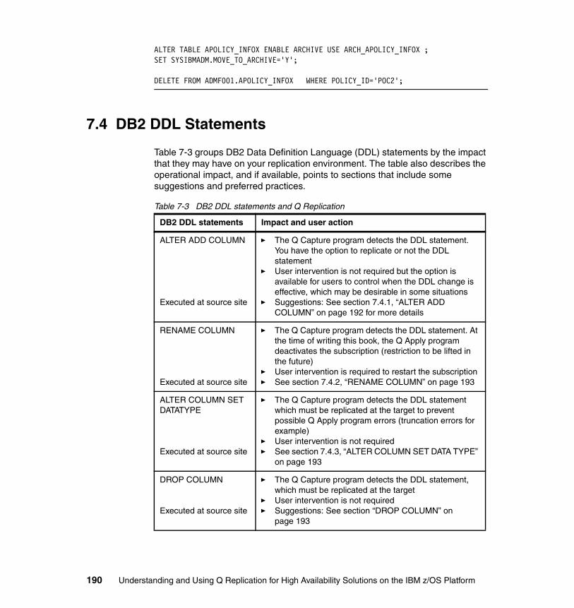
ALTER TABLE APOLICY_INFOX ENABLE ARCHIVE USE ARCH_APOLICY_INFOX ;SET SYSIBMADM.MOVE_TO_ARCHIVE='Y';
DELETE FROM ADMF001.APOLICY_INFOX WHERE POLICY_ID='POC2';
7.4 DB2 DDL Statements
Table 7-3 groups DB2 Data Definition Language (DDL) statements by the impact that they may have on your replication environment. The table also describes the operational impact, and if available, points to sections that include some suggestions and preferred practices.
Table 7-3 DB2 DDL statements and Q Replication
DB2 DDL statements Impact and user action
ALTER ADD COLUMN
Executed at source site
� The Q Capture program detects the DDL statement. You have the option to replicate or not the DDL statement
� User intervention is not required but the option is available for users to control when the DDL change is effective, which may be desirable in some situations
� Suggestions: See section 7.4.1, “ALTER ADD COLUMN” on page 192 for more details
RENAME COLUMN
Executed at source site
� The Q Capture program detects the DDL statement. At the time of writing this book, the Q Apply program deactivates the subscription (restriction to be lifted in the future)
� User intervention is required to restart the subscription � See section 7.4.2, “RENAME COLUMN” on page 193
ALTER COLUMN SET DATATYPE
Executed at source site
� The Q Capture program detects the DDL statement which must be replicated at the target to prevent possible Q Apply program errors (truncation errors for example)
� User intervention is not required � See section 7.4.3, “ALTER COLUMN SET DATA TYPE”
on page 193
DROP COLUMN
Executed at source site
� The Q Capture program detects the DDL statement, which must be replicated at the target
� User intervention is not required � Suggestions: See section “DROP COLUMN” on
page 193
190 Understanding and Using Q Replication for High Availability Solutions on the IBM z/OS Platform

DROP TABLE
Executed at source site
� The Q Capture program detects the DDL statement and issues a warning message
� User intervention may be required � Suggestions: See section 7.4.5, “DROP TABLE” on
page 195
ADD COLUMN to a replication INDEX
Executed at source site
� The Q Capture program does not detect the DDL statement. If the column is added to an index which uniqueness is also used for the Q Apply replication key, you must alert the replication programs of the change
� User intervention is required: You must alert the replication programs of the change
� Suggestions: See section “Add a column to a replication index” on page 196
Add new unique indexes for the target table
Executed at target site
� The Q Apply program does not detect new indexes on the target table after it has completed its initialization procedure.
� User intervention may be required as the new uniqueness may affect the Q Apply program unique key dependency logic
� Suggestions: See section 7.4.7, “Add a unique index to a target table” on page 197
ROTATE PARTITION
Executed at source site
� The DDL is not detected by the Q Capture program. Changes made to the table space are not automatically replicated to the target table space. The corresponding target table will not be synchronized with the source table.
� User intervention is required
� Suggestions: See section 7.4.8, “The ROTATE PARTITION DDL statement” on page 197
DROP TABLESPACE
Executed at source site
� Table spaces are dropped to update table space properties, rebalance partitions, and so on. When a table space is dropped, its underlying table is also dropped.
� User intervention may be required
� Suggestions: See section 7.4.5, “DROP TABLE” on page 195
Other � The DDL statement is not detected by the Q Capture or Q Apply program and ignored by the replication process. An example is the DB2 CREATE TABLE statement that is not automatically detected or replicated on the z/OS platform
DB2 DDL statements Impact and user action
Chapter 7. Managing Q Replication in the DB2 for z/OS Environment 191

7.4.1 ALTER ADD COLUMN
When you alter add new columns to a DB2 source table, the Q Capture program detects the metadata change in the DB2 log and inserts a new set of rows in the IBMQREP_TABVERSION and IBMQREP_COLVERSION tables to reflect the change for that particular table.
The Q Capture REPL_ADDCOL optionQ Capture will detect the alter add column from the DB2 log, and will insert new values in the IBMQREP_TABVERSION and IBMQREP_COLVERSION tables. Q Capture will insert rows for the new column to the IBMQREP_SRC_COLS table. Send a schema message to Apply for Apply to alter add the new column to the target (if it did not exist) and insert a row to the IBMQREP_TRG_COLS table. All changes to the new column will be captured by Capture and no changes for the column will be lost. This is a good option to have if you want the added columns to be part of replication.
The REPL_ADDCOL column value of the IBMQREP_SUBS table includes two values that you can set up as follows:
� ‘Y’, or automatically replicate the ALTER ADD COLUMN DDL statement: In that case, the Q Capture program adds the new column to its definitions (inserts a row in its IBMQREP_SRC_COLS table for the new column) and sends two messages to the Q Apply program. One message includes the ALTER ADD COLUMN information and the second message is a schema message alerting the Q Apply program of subscription (metadata) updates. The Q Apply program then processes the ALTER ADD message by issuing an ALTER statement against the target table to add the new column if it does not already exist in the target table and it also updates its target table definition (inserts a row in its IBMQREP_TRG_COLS table for the new column). If there are any issues with the ALTER ADD COLUMN processing, the Q Apply program follows its expected error recovery logic by following the error action provided in the ERROR_ACTION column value of the IBMQREP_TARGETS table for the subscription.
� ‘N’, or do not automatically replicate the DDL statement: In that case, the Q Capture program will not send the ALTER ADD COLUMN statement to the Q Apply program. You may want to use this option to control when the column is replicated. You can manually request Q Capture to add a column to a subscription by issuing an ADDCOL signal, that is, by inserting a new row in the
Note: Some DB2 DDL statements do have an impact on the Q Capture CAPSTART process as documented in section 7.2.1, “CAPSTARTing a subscription” on page 182. The description is not repeated in this section.
192 Understanding and Using Q Replication for High Availability Solutions on the IBM z/OS Platform

IBMQREP_SIGNAL table with the new column information. This may be desirable if you need more time for example to ensure that applications at the target site are ready for the new column.
7.4.2 RENAME COLUMN
When you rename a column of a source table that is maintained by Q Replication, the Q Capture process detects the metadata change in the DB2 log and updates the corresponding entry in the IBMQREP_COLVERSION table.
The Q Capture process sends a schema or metadata message to the Q Apply process with the renamed column information. The Q Apply program deactivates the subscription (because it currently does not support the rename functionality). A V10.2.1 APAR is planned to provide support for the rename function in Q Apply. A workaround is to drop and re-create the subscription.
7.4.3 ALTER COLUMN SET DATA TYPE
When you alter the data type of a column that is part of a source table that is maintained by Q Replication, the Q Capture process detects the metadata change in the DB2 log and inserts a new set of rows in the IBMQREP_TABVERSION and IBMQREP_COLVERSION tables for the metadata change.
The Q Capture program sends two messages to the Q Apply program. One message includes the SET DATA TYPE information and the second message is a schema message alerting the Q Apply program of subscription (metadata) updates. The Q Apply program then processes the SET DATA TYPE message by issuing an ALTER statement against the target table to set the data type of the appropriate column if it is not already set as such in the target table. If there are any issues with the ALTER COLUMN SET DATA TYPE processing, the Q Apply program follows its expected error recovery logic by following the error action provided in the ERROR_ACTION column value of the IBMQREP_TARGETS table for the subscription.
Note that DB2 for z/OS only supports altering data types from smaller to larger lengths.
7.4.4 DROP COLUMN
The Q Capture program detects the drop column in the DB2 log after the column is dropped and the REORG SHRLEVEL REFERENCE utility has been executed for the appropriate table space. In that case, the Q Capture program inserts a
Chapter 7. Managing Q Replication in the DB2 for z/OS Environment 193

new set of rows in the IBMQREP_TABVERSION and IBMQREP_COLVERSION tables.
The Q Capture program also sends two messages (the DDL drop column information and a schema or subscription change message) to the Q Apply program. The Q Apply program then drops the appropriate column from the target table if it exists and updates its subscription metadata in the IBMQREP_TRG_COLS (deletes the corresponding row). If there are any issues with the DROP COLUMN processing, the Q Apply program follows its expected error recovery logic by following the error action provided in the ERROR_ACTION column value of the IBMQREP_TARGETS table for the subscription.
The table is available even if you do not run the REORG utility but the column is not dropped, and therefore available until you run the REORG. The table is available even if you do not run the REORG utility but you will not be able to see the newly added column.
Note: The target column drop is fully effective only after you run a REORG SHRLEVEL REFERENCE utility for the target table space containing the target table.
Impact to unidirectional topologies: If you implement a unidirectional replication configuration and the (dropped) target column remains in the target table until the REORG utility is run for its table space, replicated rows from the source table will not include the (now dropped from the source table) column. If the target column was defined as NOT NULL, the Q Apply program populates the target column with DB2 defaults for that column, if the NOT NULL WITH DEFAULT clause is not specified.
Impact to bidirectional topologies: You have to be particularly careful if you implement a bidirectional replication configuration because the (dropped) target column remains in the target table until the REORG utility is run for its table space. What this means is that applications may still be updating a column at the target site that has been dropped from the source site. Another side-effect of the visibility of a dropped column is that the metadata is not being updated until the REORG completes at the target site, possibly impacting some applications.
194 Understanding and Using Q Replication for High Availability Solutions on the IBM z/OS Platform

7.4.5 DROP TABLE
The Q Capture program issues a warning message when it detects a DB2 DROP TABLE in the DB2 log for an active subscription.
As mentioned in section 7.1.1, “The Q Capture versioning tables and schema evolution” on page 178, the Q Capture program saves the DB2 dbid and obid values of a table in its versioning tables IBMQREP_TABVERSION and IBMQREP_COLVERSION when the subscription is activated.
When you drop a DB2 source table that is active in a replication configuration, if you do not deactivate the subscription, the table information remains in the Q Capture program memory. There are the following two scenarios to consider:
� The Q Capture program is running
– To clean the Q Capture memory, you must first deactivate the subscription before dropping the table. The DB2 database identifier (dbid) and page set identifier (psid) values for the dropped table may be reused by DB2 for z/OS for another table, creating more ambiguity as the Q Capture program memory structure will not match with the actual DB2 table structure. If the DB2 dbid and psid values of the re-created table are different from the original values for the table, the Q Capture program will not capture changes for the newly re-created table
� The Q Capture program is stopped before the table is dropped
– If you cannot deactivate the (active) subscription before dropping the table, you have to first check whether the new dbid and obid values in the DB2 catalog match the old values in the Q Capture versioning tables. If they do not match, you need to delete the rows from the Q Capture versioning tables IBMQREP_TABVERSION and IBMQREP_COLVERSION for the table that was dropped. The reason is that when the Q Capture program is started again, it will assume that the same dbid and obid for all tables it is capturing have not changed and therefore it will not be able to capture changes for the newly re-created table.
Preferred Practice: If you drop and re-create a DB2 table that is associated with an active subscription, you must first deactivate the subscription. Otherwise, you might experience an unexpected Q Capture program behavior if the Q Capture program is running.
Chapter 7. Managing Q Replication in the DB2 for z/OS Environment 195

– Example 7-5 shows you how to retrieve the old values of a table from the appropriate Q Capture versioning table and retrieve the new values from the appropriate DB2 catalog table. We will call the old values tableid1 and tableid2 and will call the new values dbid and obid.
Example 7-5 Comparing old and new obid and dbid values for a table
SELECT TABLEID1, TABLEID2 FROM IBMQREP_TABVERSION WHERE SOURCE_OWNER = ‘ADMF001’ AND SOURCE_NAME = ‘APOLICY_INFOX’;
SELECT DBID, OBID FROM SYSIBM.SYSTABLES WHERENAME = ‘ADMF001’ AND CREATOR = ‘APOLICY_INFOX’ WITH UR;
– Example 7-6 shows you how to use the result of Example 7-5 to delete the corresponding rows of the Q Capture versioning tables assuming that the tableid2 value is different from the obid value. The database values tableid1 and dbid can remain the same.
Example 7-6 Deleting information for the Q Capture versioning tables
DELETE FROM IBMQREP_TABVERSION WHERE TABLEID1 = ‘tableid1’ AND TABLEID2 = ‘tableid2’;
DELETE FROM IBMQREP_COLVERSION WHERE TABLEID1 = ‘tableid1’AND TABLEID2 = ‘tableid2’;
When you CAPSTOP a subscription followed by a CAPSTART of the subscription, the IBMQREP_TABVERSION and IBMQREP_COLVERSION entries for the subscription table will be updated.
7.4.6 Add a column to a replication index
The Q Capture program does not detect changes to DB2 indexes. So when you add a new column to a DB2 unique index that is also used as a replication key, you have the following option to alert the replication programs:
� Insert a row in the IBMQREP_SIGNAL table to alert the replication process to include a new column as part of the (Q Apply) replication key
� The signal type is identified as a ADD_REPL_KEY_COL signal
� The new column must be part of the subscription, whether it is a new column that was alter added to the subscription or an existing subscription column, before you can issue the ADD_REPL_KEY_COL signal
196 Understanding and Using Q Replication for High Availability Solutions on the IBM z/OS Platform

� The Q Capture program includes the new column as one of its key columns (IS_KEY column value greater than zero in the IBMQREP_SRC_COLS table) and send a schema message to the Q Apply program to alert it of the metadata change
� The Q Apply program updates its own definitions (IS_KEY column value set to ‘Y’ in the IBMQREP_TRG_COLS table)
7.4.7 Add a unique index to a target table
Adding a new unique index to a source table that is maintained by the Q Capture process does not affect the Q Capture program processing.
Adding a new unique index to a target table that is maintained by the Q Apply process affects the retry logic of the Q Apply process, especially if the Q Apply is not made aware of the change (which may happen if you create a new unique index for the target table after having initialized the Q Apply program). If that is the case, you have the following options:
� Reconsider whether you really need the index to enforce the uniqueness, or whether the applications can manage without the extra index. The reason is that the new unique index adds some cost to the Q Apply dependency check logic and the unique retry logic which may be necessary.
� If you have to define the new unique index for the target table, reinitialize the Q Apply program so that it can be made aware of the new unique constraints against the target table.
7.4.8 The ROTATE PARTITION DDL statement
The DB2 for z/OS RESET option of the ROTATE PARTITION DDL statement specifies that the existing data in the first logical partition is deleted. Example 7-7 provides a sample invocation of the DB2 ALTER TABLE statement and its RESET option.
Example 7-7 The RESET option of the ROTATE PARTITION Utility
ALTER TABLE TRANS ROTATE PARTITION FIRST TO LAST ENDING AT ('12/31/2014') RESET;
The RESET operation deletes all existing data for the particular partition.
Chapter 7. Managing Q Replication in the DB2 for z/OS Environment 197

When the partitioned table is also source to the Q Replication process and you use the RESET option of the ROTATE PARTITION utility, follow the preferred practices:
� Synchronize the execution of the utility jobs at the source and target sites to ensure that rows that were deleted at the source site are also deleted at the target site.
� Schedule the utility job at the target site first followed by the utility job at the source site to ensure that the increased limit value is defined for the target table before it is increased for the source table (and avoid issues that may rise if the source data is replicated before the target site’s limit value was increased).
7.5 DB2 maintained tables and columns
In some cases, DB2 for z/OS maintains automatically some DB2 objects that otherwise would be under the Q Apply program control. In most cases, the preferred practice is to ensure that the Q Apply program maintains these DB2 objects to ensure the synchronization between source and target DB2 objects. More specifically, see the following guidelines:
� DB2 temporal and history tables, DB2 period columns: All can be maintained by Q Replication. See Chapter 3, “The two-node scenario” on page 43 for more details about how to configure the Q Apply process to maintain temporal-related DB2 objects.
� DB2 base and archive tables: At the time of the writing of this book, Q Replication does not support the replication of archive tables. A V10.2.1 APAR is planned to lift that restriction in the future.
198 Understanding and Using Q Replication for High Availability Solutions on the IBM z/OS Platform

Chapter 8. Recovery procedures
In this chapter, we introduce and describe procedures for recovering data in the following cases:
� Loss of WebSphere MQ (non-persistent) messages � Data corruption at the target DBMS (not related to Q Replication)� Need to restart send queue from current point in the DB2 log� WebSphere MQ spill queue full during a LOAD phase
We also review the procedure that is available to sync up the Q Capture and Q Apply (planned outage) programs’ shutdown, in particular request the Q Capture program to stop at a particular point in the DB2 log.
8
© Copyright IBM Corp. 2014. All rights reserved. 199

8.1 Data that is needed to recover
You might need to recover data for the following reasons:
� You use non-persistent WebSphere MQ receive queues. The associated WebSphere MQ queue manager comes down and messages were left in the queue before Q Apply had a chance to process them. You have two options to recover lost messages in that case:
– Include in your WebSphere MQ procedures that manage taking down a queue manager the additional step described provided in section 8.4, “Stopping Q Capture (or a send queue) at a particular point in DB2 log” on page 210 to ensure that the Q Apply program has successfully applied all WebSphere MQ messages of the appropriate receive queues before taking a queue manager down
– If that is not an option, follow the procedure defined in section 8.2, “Starting Q Capture from an earlier point in the DB2 log” on page 202 that consists of generating the appropriate Q Capture start lsn and maximum lsn statistics that will be used as input to start the Q Capture process back in time
� You detect data corruption in the target DBMS, unrelated to the Q Replication process. So your source and target nodes are now out of sync. To resynchronize the necessary source/target nodes, do the following process:
Complete the procedure defined in section 8.2, “Starting Q Capture from an earlier point in the DB2 log” on page 202 that consists of generating the appropriate Q Capture start lsn and maximum lsn statistics that will be used as input to start the Q Capture process back in time
� You detect that one of the Q Capture program send queues is stopped because the target site has encountered a problem or was stopped. You decide to restart the send queue from the current LSN value at the Q Capture server site instead of where the Q Capture program left it at since the target somehow is caught up. To start the Q Capture program for a send queue forward in time, do the following process:
Complete the procedure defined in section 8.3, “Starting Q Capture from the current point of the DB2 log” on page 208 that consists of generating the appropriate Q Capture start lsn and maximum lsn statistics that will be used as input to start the Q Capture process forward in time
� Finally, you detect during the LOAD phase of a particular subscription that the Q Apply program WebSphere MQ spill queue has filled up. To recover from an interrupted load procedure, do the following process:
Complete the procedure that is defined in section 8.5, “Recovering from LOAD spill queue full conditions” on page 212.
200 Understanding and Using Q Replication for High Availability Solutions on the IBM z/OS Platform

This chapter also includes the steps to follow to synchronize the Q Capture and Q Apply program shutdowns during (planned outage) recovery procedures.
8.1.1 The Q Capture start lsn and commit lsn values
Figure 8-1 shows the two lsn (or log sequence) numbers that the Q Capture program relies on when it first starts reading the DB2 log:
� start lsn: lsn value from where it is safe to start reading the DB2 log� commit lsn: lsn value up to which it is safe to skip committed transactions as
Q Capture is reading the log records, because the transactions were previously published.
Figure 8-1 What are the start lsn and commit lsn Q Capture program values?
When the Q Capture program is restarted, it will rely on the start lsn value to identify where to start from in the DB2 log record, txB start point, since txB has not yet been published.
The Q Capture program will also skip txA and txC since their transaction commit time is before or at the commit lsn value recorded by the Q Capture program before it came down (txC in this case).
���
���
���
����������������������� ���������������������������������������
�������������� ��������������������� ���������������������������������
���������������������
��������� ����������
Chapter 8. Recovery procedures 201

8.1.2 The Q Capture restart file
Q Capture updates the content of the WebSphere MQ restart queue at each Q Capture commit interval with start lsn and commit lsn values for each appropriate send queue.
When the Q Capture program stops (gracefully), it updates its restart queue with start lsn and commit lsn values for all its send queues; it also writes that information to the job log (located in the capture path) and to a restart file. The restart file has a predefined name and path on the z/OS platform as follows:
� capture path.capture server name.capture schema.QCAP.QRESTART
Contents of the restart file consist of one entry for each send queue with the queue name, start lsn and commit lsn information for each queue.
When the Q Capture program restarts, it reads information from the restart queue and starts reading from the DB2 log using the restart queue information unless the Q Capture parameter value OVERRIDE_RESTARTQ=Y was specified.
When the Q Capture program is started with OVERRIDE_RESTARTQ=Y parameter value, the Q Capture program reads the information from the restart file and checks its queue names against the information in its restart queue. If the queue names are valid, the restart file information is used by the Q Capture program to restart. The Q Capture program merges the restart file information with that of its restart message and uses the minimum restart point value (start lsn) for each queue.
8.2 Starting Q Capture from an earlier point in the DB2 log
If you lose WebSphere MQ messages because the queue manager came down before the Q Apply program had a chance to consume the messages of a non-persistent receive queue for example, you can ask Q Capture to start reading that particular queue back in time by giving it an older value in the restart file.
The restart file only includes a subset of entries and does not need to include all the send queues defined to the Q Capture program. Its entries are limited to the send queues for which information needs to be overridden.
202 Understanding and Using Q Replication for High Availability Solutions on the IBM z/OS Platform

When you use the Q Capture OVERRIDE_RESTARTQ=Y parameter value, the Q Capture program reinitializes messages for that queue by sending the Q Apply program a message with the current time stamp and a message ID (msgid) of 1. The specific message alerts the Q Apply program to restart its numbering scheme for that queue and to start to apply the contents of the queue (from a point back in time). If however the WebSphere MQ message was lost, the Q Apply program issues a ‘gap’ message, ASN7551E, in its job log to alert you that it is waiting for a (lost) message; in that case, you first need to stop and restart the appropriate receive queue in order for the Q Apply program to start applying the contents of the queue (from the point back in time).
The procedure is as follows:
� Stop the receive queue� Delete all messages from the receive queue� Start Q Capture with the Q Capture override restart queue option� Restart the receive queue
Example 8-1 and Example 8-3 show two sample modify commands for stopping and starting a receive queue named PMYU.RQ.1.TO.2.DATAQ1 assuming that the Q Apply job name is ApplyJobName.
Example 8-1 Q Apply modify command to stop a receive queue
/F Applyjobname,STOPQ=PMYU.R1.1.TO.2.DATAQ1
Example 8-2 shows how to invoke the ASNQMFMT program to delete messages from receive queues.
Example 8-2 Q Apply asnqmfmt program invocation
//ASNQMFMT EXEC PGM=ASNQMFMT,REGION=0,TIME=NOLIMIT,//PARM=’PMYU.R1.1.TO.2.DATAQ1 MQ1A -delmsg’
Example 8-3 Q Apply modify command to start a receive queue
/F Applyjobname,STARTQ=PMYU.R1.1.TO.2.DATAQ1
The Q Capture program can restart from a different point in the log for each of its send queue, however since it includes only one log reader thread, it will temporarily stop publishing to active queues if any of its queues are restarted back in time and need to catch up with the active queues.
Chapter 8. Recovery procedures 203
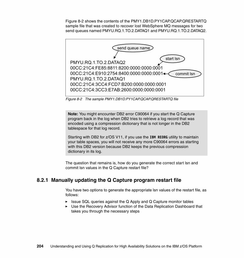
Figure 8-2 shows the contents of the PMY1.DB1D.PY1CAP.QCAP.QRESTARTQ sample file that was created to recover lost WebSphere MQ messages for two send queues named PMYU.RQ.1.TO.2.DATAQ1 and PMYU.RQ.1.TO.2.DATAQ2.
Figure 8-2 The sample PMY1.DB1D.PY1CAP.QCAP.QRESTARTQ file
The question that remains is, how do you generate the correct start lsn and commit lsn values in the Q Capture restart file?
8.2.1 Manually updating the Q Capture program restart file
You have two options to generate the appropriate lsn values of the restart file, as follows:
� Issue SQL queries against the Q Apply and Q Capture monitor tables � Use the Recovery Advisor function of the Data Replication Dashboard that
takes you through the necessary steps
Note: You might encounter DB2 error C90064 if you start the Q Capture program back in the log when DB2 tries to retrieve a log record that was encoded using a compression dictionary that is not longer in the DB2 tablespace for that log record.
Starting with DB2 for z/OS V11, if you use the IBM REORG utility to maintain your table spaces, you will not receive any more C90064 errors as starting with this DB2 version because DB2 keeps the previous compression dictionary in its log.
PMYU.RQ.1.TO.2.DATAQ2 00CC:21C4:FE85:8811:8200:0000:0000:0001 00CC:21C4:E910:2754:8400:0000:0000:0001PMYU.RQ.1.TO.2.DATAQ1 00CC:21C4:3CC4:FCD7:B200:0000:0000:0001 00CC:21C4:3CC3:E7AB:2600:0000:0000:0001
send queue name
start lsn
commit lsn
204 Understanding and Using Q Replication for High Availability Solutions on the IBM z/OS Platform

The Q Apply and Q Capture monitor table queriesYou need to issue two queries, as follows:
1. First, find the commit lsn value at the Q Apply site
Example 8-4 shows you how to find the maximum LSN value that has been committed at the Q Apply server for the appropriate receive queue.
Example 8-4 Generating the commit lsn value
commit lsn = SELECT RECVQ,HEX(MAX(OLDEST_COMMIT_LSN)) FROM IBMQREP_APPLYMON WHERE RECVQ=’RECVQNAME’;
2. Then, generate the start lsn value to restart the send queue from, using the commit lsn value generated in the previous step
Example 8-5 shows you how to generate the minimum lsn value for a particular send queue at the Q Capture site. To retrieve the minimum value across the multiple transactions that may not yet be applied at the related Q Apply site, you need to use the commit lsn value derived in Example 8-4.
Example 8-5 Generating the start lsn value
start lsn = SELECT HEX(MIN(RESTART_SEQ)) FROM IBMQREP.CAPQMON WHERE SENDQ=’SENDQ NAME’ AND RESTART_MAXCMTSEQ=(SELECT MAX(RESTART_MAXCMTSEQ) FROM IBMQREP.CAPQMON WHERE SENDQ=’SENDQ NAME’ AND RESTART_MAXCMTSEQ <= commit lsn);
8.2.2 The Recovery Advisor of the Data Replication Dashboard
You may also rely on the Data Replication Dashboard to recover lost WebSphere MQ messages as its Recovery Advisor steps you through the tasks necessary to generate the Q Capture program start lsn and commit lsn values introduced in section 8.1.2, “The Q Capture restart file” on page 202.
This section includes three screen captures to show you how to perform the following tasks in the Data Replication Dashboard:
� Locate the Recovery Advisor and choose a recovery scenario.� Select one or more receive queues to perform the recovery procedure.� Perform the actual steps of the recovery procedure.
Chapter 8. Recovery procedures 205
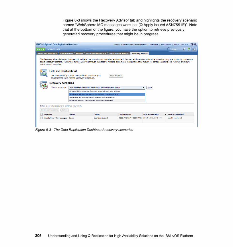
Figure 8-3 shows the Recovery Advisor tab and highlights the recovery scenario named “WebSphere MQ messages were lost (Q Apply issued ASN7551E)”. Note that at the bottom of the figure, you have the option to retrieve previously generated recovery procedures that might be in progress.
Figure 8-3 The Data Replication Dashboard recovery scenarios
206 Understanding and Using Q Replication for High Availability Solutions on the IBM z/OS Platform
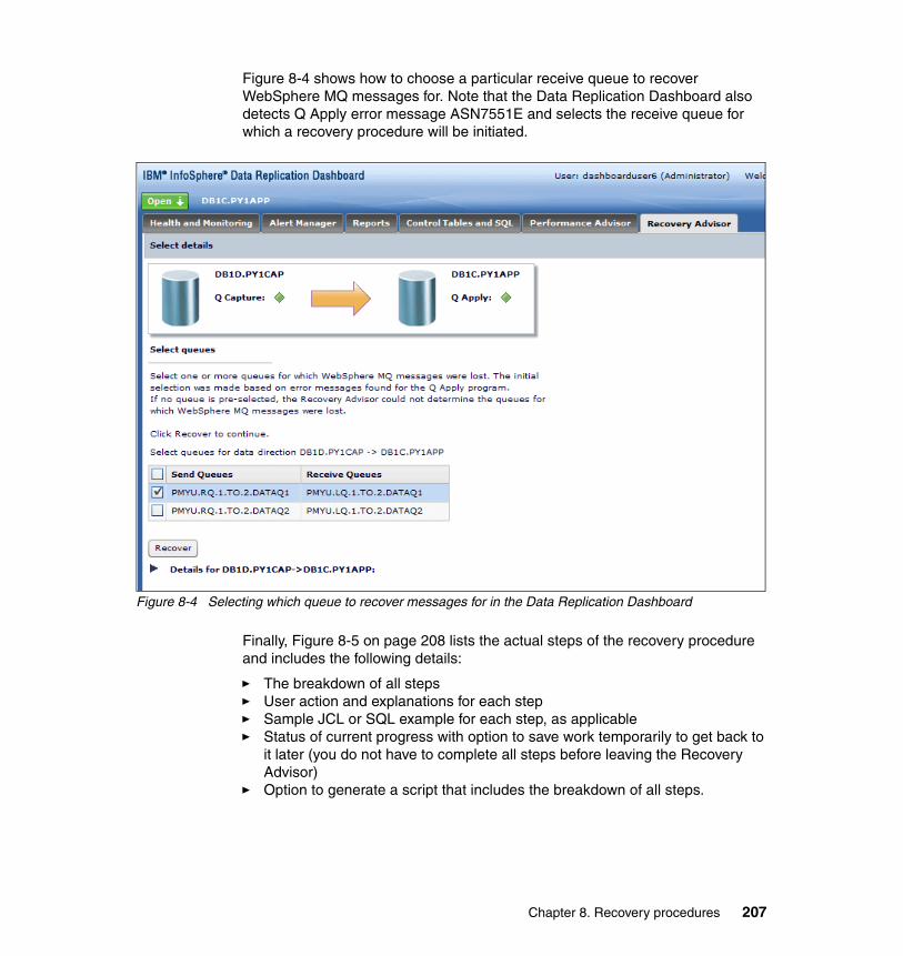
Figure 8-4 shows how to choose a particular receive queue to recover WebSphere MQ messages for. Note that the Data Replication Dashboard also detects Q Apply error message ASN7551E and selects the receive queue for which a recovery procedure will be initiated.
Figure 8-4 Selecting which queue to recover messages for in the Data Replication Dashboard
Finally, Figure 8-5 on page 208 lists the actual steps of the recovery procedure and includes the following details:
� The breakdown of all steps � User action and explanations for each step� Sample JCL or SQL example for each step, as applicable� Status of current progress with option to save work temporarily to get back to
it later (you do not have to complete all steps before leaving the Recovery Advisor)
� Option to generate a script that includes the breakdown of all steps.
Chapter 8. Recovery procedures 207

Figure 8-5 The Recovery Procedure of the Data Replication Dashboard
8.3 Starting Q Capture from the current point of the DB2 log
There are a few instances when restarting a send queue from the current point in the DB2 log might be necessary, even if it implies skipping over log records that have not been processed. The scenarios include the following:
� The send queue was stopped for a while because of an outage at the target site and when the outage is finally resolved, or the target ready for the incoming messages, the DB2 logs from when the queue was last stopped are not available at the source site anymore
208 Understanding and Using Q Replication for High Availability Solutions on the IBM z/OS Platform

� The send queue was stopped and it is time to start the queue again but you do not want to impact the active queues at the Q Capture server by going back in the log because they would be temporarily held back while the send queue that was stopped had a chance to catch up.
In either case, you can use OVERRIDE_RESTARTQ=Y Q Capture parameter value to restart the send queue using a current lsn value.
Note however that the changes from the time the send queue was stopped up to the time it will be restarted again will be lost. You will need to run the ASNTDIFF utility or another table compare utility to sync up the target table with the source table before restarting the particular send queue.
The following are the steps to start the send queue from the current point in the DB2 log:
� Stop the Q Capture program� Update the restart file with the current lsn values: use the same values as the
other active queues’ values in the restart file� Reset the send queue that was stopped to active by using a SQL UPDATE
statement as follows:
Assuming that the send queue name is ‘PMYU.RQ.1.TO.2.DATAQ1’, Example 8-6 displays the update statement to activate the send queue.
Example 8-6 Update of the IBMQREP_SENDQUEUES table
UPDATE IBMQREP_SENDQUEUES SET STATE = ‘A’ WHERE SENDQ=’PMYU.RQ.1.TO.2.DATAQ1’ ;
� Start the Q Capture program with the OVERRIDE_RESTARTQ=Y parameter value
� The Q Capture program will now start capturing log records for the tables of the send queue. As mentioned a few steps above, changes from the time the send queue was stopped up to the time it was restarted again are now lost.
As a final note, if you want to start the Q Capture program from the current point in the log for all send queues, you can give the Q Capture program values for the LSN and MASCMTSEQ input parameters. Example 8-7 shows you how to provide the two input lsn values to the Q Capture program since they need to be included in a SYSIN dataset as they will not fit in the Q Capture runtime parameter input string. The example uses the startlsn and commitlsn values of Figure 8-2 on page 204.
Example 8-7 The Q Capture start lsn runtime parameter
//* ... your Q Capture EXEC PGM=ASNQCAP JCL...//* and to start Capture from a known point in the log//* include a SYSIN data set that points to a file//* //SYSIN DD DSN=xxx,DISP=SHR
Chapter 8. Recovery procedures 209

//*//*
with SYSIN contents as follows:
LSN=00CC:21C4:FE85:8811:8200:0000:0000:0001MAXCMTSEQ=00CC:21C4:E910:2754:8400:0000:0000:0001
8.4 Stopping Q Capture (or a send queue) at a particular point in DB2 log
This section describes the procedures that are available in Q Replication to support planned outage scenarios that require the Q Capture program to come down after it read a particular DB2 lsn value. This is to ensure that the Q Apply program received or applied the corresponding updates up to that DB2 lsn value and guarantee that the two replicated sites are in sync before taking down these sites.
The procedure steps include two variations based on whether the acknowledgement between the Q Capture and Q Apply programs wait for data being sent to the Q Apply program or data being applied by the Q Apply program. In each variation, the scope of the synchronization/acknowledgment can be the Q Capture program itself or a single receive queue.
The following are the two variations:
� Stop the Q capture program at a particular point in the log, ensuring that the transmit queue is empty and therefore all data has been sent to the target WebSphere MQ queue manager. To do so, use the Q Capture ‘STOP’ signal:
– Example 8-8 displays in the INSERT signal into the IBMQREP_SIGNAL table.
Example 8-8 The IBMQREP_SIGNAL table (‘STOP with DATA_SENT’ signal)
INSERT INTO IBMQREP_SIGNAL (SIGNAL_TIME, SIGNAL_TYPE,SIGNAL_SUBTYPE,SIGNAL_INPUT_IN) VALUES (CURRENT TIMESATMP,’CMD’,’STOP’,’CURRENT TIMESTAMP;DATA_SENT’) ;
– Example 8-9 displays the equivalent Q Capture command.
Example 8-9 The Q Capture modify command (STOP with DATA_SENT option)
/F Capturejobname,STOP CAPTUREUPTO=CURRENT TIMESTAMP STOPAFTER=DATA_SENT
210 Understanding and Using Q Replication for High Availability Solutions on the IBM z/OS Platform

� Or, stop the Q Capture program after sending the data to the Q Apply program and receiving an acknowledgment from the Q Apply program that the data was successfully applied at the target site. The Q Capture program captures log data up to a certain point, stops capturing and commits the changes to the transmit queue. The Q Capture program then waits for acknowledgment from the Q Apply program that the changes have been applied and when it receives it (message in the Q Capture admin queue), it stops.
– Example 8-10 displays in the INSERT signal into the IBMQREP_SIGNAL table.
Example 8-10 The IBMQREP_SIGNAL table (‘STOP with DATA_APPLIED’ signal)
INSERT INTO IBMQREP_SIGNAL (SIGNAL_TIME, SIGNAL_TYPE,SIGNAL_SUBTYPE,SIGNAL_INPUT_IN) VALUES (CURRENT TIMESATMP,’CMD’,’STOP’,’CURRENT TIMESTAMP;DATA_APPLIED’) ;
– Example 8-11 displays the equivalent Q Capture command.
Example 8-11 The Q Capture modify command (STOP with DATA_APPLIED option)
/F Capturejobname,STOP CAPTUREUPTO=CURRENT TIMESTAMP STOPAFTER=DATA_APPLIED
� Those two options can be modified to use the STOPQ option instead of the STOP option to implement the acknowledgment procedure between the Q Capture and Q Apply programs for a given send queue only. In the four examples that follow, we reuse the PMYU.RQ.1.TO.2.DATAQ1 send queue name. In this case, the Q Capture program checks the transmit queue for messages that pertain to the particular send queue.
– Example 8-12 and Example 8-13 show the two ways to use the ‘DATA_SENT’ option providing a send queue name.
Example 8-12 The IBMQREP_SIGNAL table (‘STOPQ with DATA_SENT’ signal)
INSERT INTO IBMQREP_SIGNAL (SIGNAL_TIME, SIGNAL_TYPE,SIGNAL_SUBTYPE,SIGNAL_INPUT_IN) VALUES (CURRENT TIMESATMP,’CMD’,’STOPQ’,’PMYU.RQ.1.TO.2.DATAQ1’;CURRENT TIMESTAMP;DATA_SENT’) ;
Example 8-13 The Q Capture modify command (STOPQ with DATA_SENT option)
/F Capturejobname,STOPQ=PMYU.RQ.1.TO.2.DATAQ1 CAPTUREUPTO=CURRENT TIMESTAMP STOPAFTER=DATA_SENT
Chapter 8. Recovery procedures 211

– Example 8-14 and Example 8-15 show the two ways to use the ‘DATA_APPLIED’ option providing a send queue name.
Example 8-14 The IBMQREP_SIGNAL table (‘STOPQ with DATA_APPLIED’ signal)
INSERT INTO IBMQREP_SIGNAL (SIGNAL_TIME, SIGNAL_TYPE,SIGNAL_SUBTYPE,SIGNAL_INPUT_IN) VALUES (CURRENT TIMESATMP,’CMD’,’STOPQ’,’PMYU.RQ.1.TO.2.DATAQ1’;CURRENT TIMESTAMP;DATA_APPLIED’) ;
Example 8-15 The Q Capture modify command (STOPQ with DATA_APPLIED option)
/F Capturejobname,STOPQ=PMYU.RQ.1.TO.2.DATAQ1 CAPTUREUPTO=CURRENT TIMESTAMP STOPAFTER=DATA_APPLIED
8.5 Recovering from LOAD spill queue full conditions
The following steps review the different stages of a LOAD procedure:
� The Q Capture program receives the activation signal for a subscription (or its auto-activation).
� The Q Capture program starts capturing changes for the corresponding table and sends the changes to the Q Apply program (via the receive queue).
� If the subscription is defined with the manual load option as reflected by a HAS_LOADPHASE=E column value of the IBMQREP_SUBS table, user is responsible for the actual loading of the target data.
� If the subscription is defined with the internal load option as reflected by a HAS_LOADPHASE=I column value of the IBMQREP_SUBS table, the Q Apply program calls the DB2 for z/OS DSNUTILS stored procedure to load the target table.
� While the target table is being loaded by DB2, the Q Apply program reads the messages from the receive queue and for the table(s) being loaded, opens a spill queue (following the WebSphere MQ MODELQ definition) and spills the changes to the spill queue, every single row being written as an MQ message in the spill queue.
� As the DB2 LOAD task lasts longer, the spill queue full condition increases in probability.
� If any of the spill queue fills up, the Q Apply program stops the corresponding receive queue.
212 Understanding and Using Q Replication for High Availability Solutions on the IBM z/OS Platform

8.5.1 Preventing spill queue full condition
You have a few options to prevent the spill queue full condition as shown in the following list:
� Increase the WebSphere MQ spill queue MAXQDEPTH, if possible.
� Stop the send queue at the Q Capture side: this not only prevents the spill queue from filling up but also relieves the transmit queue at the Q Capture site.
8.5.2 Recuperating from spill queue full condition
To recuperate from a spill queue full condition, which is detected when the Q Apply program issues error message ASN7627E for a particular receive queue (and makes the receive queue inactive), use the following steps:
� Wait for the (internal or external) load procedure to complete
� Increase the size of the MAXDEPTH in WebSphere MQ for the spill queue
� If you used the internal load procedure:
– Start the receive queue by issuing the Q Apply startq modify command, as shown in Example 8-3 on page 203
– The Q Apply program then sends the ‘load done’ message to the Q Capture program, starts reading messages from the spill queue, processes the message and updates the target table accordingly
– After the spill queue is drained, when the WebSphere MQ CURDEPTH value for the spill queue is 0, you can start the send queue at the Q Capture site
� If you use the manual load procedure:
– Issue the Q Apply loaddonesub command to alert the Q Apply program that the load procedure has completed. Example 8-16 shows a sample modify command for the loaddonesub command for a receive queue named PMYU.RQ.1.TO.2.DATAQ1 assuming that the Q Apply job name is ApplyJobName.
Example 8-16 Q Apply modify command to stop a receive queue
/F Applyjobname,LOADDONESUB=PMYU.R1.1.TO.2.DATAQ1
– You do not want to use the ‘load done’ signal option as the corresponding INSERT statement in the Q Capture IBMQREP_SIGNAL table will be behind in the log and when the Q Capture program will see the signal in the log, it will be both too late and at an inappropriate time to process the signal.
Chapter 8. Recovery procedures 213

– Start the receive queue by issuing the Q Apply startq modify command, as shown in Example 8-3 on page 203.
– The Q Apply program then sends the ‘load done’ message to the Q Capture program, starts reading messages from the spill queue, processes the message, and updates the target table accordingly.
– After the spill queue is drained, when the WebSphere MQ CURDEPTH value for the spill queue is 0, you can start the send queue at the Q Capture site.
214 Understanding and Using Q Replication for High Availability Solutions on the IBM z/OS Platform

Appendix A. Using ASNCLP on z/OS
This appendix provides instructions for the configuration and use of the ANSNCLP utility on z/OS.
A
© Copyright IBM Corp. 2014. All rights reserved. 215
A.1 ASNCLP on z/OS
ASNCLP is a utility provided with IBM InfoSphere Replication Server for administration of SQL Replication, Q Replication, and Event Publishing. It generates SQL scripts that update the replication control tables used by the capture, apply, and replication alert monitor programs. The ‘CL’ in its name indicates ASNCLP is a command-line utility, but starting with the V10 release is now available on z/OS for batch JCL invocation.
The ASNCLP scripting language includes commands to set the replication environment, commands to create, modify list or remove replication objects, commands to validate the relationship and functioning of replication to WebSphere MQ and commands to promote a replication environment from one set of servers to another (such as development to test).
For additional information on enabling the ASNCLP program to run on z/OS, refer to the following URL:
http://publib.boulder.ibm.com/infocenter/dzichelp/v2r2/topic/com.ibm.swg.im.repl.zoscust.doc/topics/iiyrczosclpjclv10.html
A.1.1 History of ASNCLP
ASNCLP was introduced to the DB2 replication environment with the introduction of SQL Replication, known then as DPROPR. When Q Replication was introduced as an enhanced replicating technology the ASNCLP utility was expanded to incorporate new commands. But the ASNCLP utility was originally included only as a DB2 client utility, running on a workstation outside of the z/OS environment. In Version 9 of InfoSphere Replication Server a command-line version of ASNCLP was introduced that ran in the UNIX System Services environment of z/OS. With Version 10 (or APAR PM18565 for earlier versions) came a version of ASNCLP that could operate using batch JCL on z/OS.
A.1.2 ASNCLP Technologies
ASNCLP is a Java application and requires UNIX System Services and the installation of Java (SDK) and DB2 JDBC Drivers. Both of these products are installed in UNIX System Services. In addition, the Batch JCL version of ASNCLP requires the IBM JZOS Toolkit, which is distributed with the IBM Java software development kits (SDKs) for z/OS.
JZOS provides a native launcher for running Java applications directly as batch jobs and a set of Java methods that make access to traditional z/OS data and key
216 Understanding and Using Q Replication for High Availability Solutions on the IBM z/OS Platform

system services available to the Java application. In this way ASNCLP can read data sets containing script commands, save generated SQL to other data sets and access DB2 databases using JDBC to execute the SQL and populate control tables.
A.1.3 Configuring command-line ASNCLP
The ASNCLP command-line executable is installed in UNIX System Services as part of the SMP/E installation of IBM InfoSphere Replication Server. By default it is located in /usr/lpp/db2repl_10_02/asnzclp/bin, but consult your z/OS administrator for the exact location on your system.
The environmentSince ASNCLP is a Java application running from a UNIX System Services command line the environment must include information for the application to establish its operating environment. All of these commands are UNIX-style commands so be sure that all commands are entered using case sensitivity.
Environment information is defined in either the system profile (/etc/profile) or the users individual profile ($HOME/.profile). Key environment variables needed by ASNCLP are:
� PATH� CLASSPATH� LIBPATH� IBM_JAVA_OPTIONS
The PATH must include the full path to the Java distribution and to the ASNCLP executable.
The CLASSPATH must include the JAR files distributed with ASNCLP and the JDBC jars.
The LIBPATH must include paths to the lib subdirectories of the Java distribution and the JDBC distribution.
The IBM_JAVA_OPTIONS provides a way to set special command-line options that are passed to the Java virtual machine (JVM) to modify its runtime settings. This variable also can contain options that affect the JDBC driver (JCC). One such option is the DB2 JCC SSID setting (-Ddb2.jcc.ssid). This defines which DB2 subsystem ASNCLP will connect to by default.
The following sample, which is shown in Example A-1, includes PATHs on one of our test systems. Consult your z/OS Administrator for the correct values for your installation.
Appendix A. Using ASNCLP on z/OS 217

Example A-1 Typical .profile commands for ASNCLP
export STEPLIB=DSN.DSN9.SDSNLOADexport JAVA_HOME=/usr/lpp/java160/J6.0export ASNCLP_HOME=/usr/lpp/db2repl_10_01/asnzclpexport JCC_HOME=/usr/lpp/db2/deva10/jdbcexport HOME=/u/QREPADMPATH=/bin:"${JAVA_HOME}"/binPATH="$PATH":"${ASNCLP_HOME}"/bin# Add path to ASNCLP executablePATH="$PATH":"${HOME}"/binexport PATHLIBPATH=/lib:/usr/libLIBPATH="$LIBPATH":"${JCC_HOME}"/libLIBPATH="$LIBPATH":"${JAVA_HOME}"/lib/s390LIBPATH="$LIBPATH":"${JAVA_HOME}"/lib/s390/j9vmLIBPATH="$LIBPATH":"${JAVA_HOME}"/bin/classicexport LIBPATHCP=$APP_HOME:"${JAVA_HOME}"/lib:"${JAVA_HOME}"/lib/extCP="$CP":"${ASNCLP_HOME}"/classes/db2cmn.jarCP="$CP":"${ASNCLP_HOME}"/db2qreplapis.jarCP="$CP":"${ASNCLP_HOME}"/db2replapis.jarCP="$CP":"${ASNCLP_HOME}"/classes/db2replmsgs.jarCP="$CP":"${ASNCLP_HOME}"/classes/commonTrace.jarCP="$CP":"${ASNCLP_HOME}"/classes/common.jarCP="$CP":"${JCC_HOME}"/classes/db2jcc.jarCP="$CP":"${JCC_HOME}"/classes/db2jcc_javax.jarCP="$CP":"${JCC_HOME}"/classes/db2jcc_license_cisuz.jarCP="$CP":”${HOME}”/db2cmn.jarexport CLASSPATH="$CP"# Configure JVM optionsIJO="-Xms16m -Xmx128m"# Uncomment this to aid in debugging "Class Not Found" problems#IJO="$IJO -verbose:class"# Set the default DB2 subsystemIJO="$IJO -Ddb2.jcc.ssid=DB1A"export IBM_JAVA_OPTIONS="$IJO "export STEPLIB=SYS1.DB1A.SDSNLOD2:SYS1.DB1A.SDSNLOAD
The input and output filesThe command-line version of ASNCLP can operate in interactive mode or batch mode. In interactive mode, you simply enter the asnclp command and the window prompt changes to “Repl>” indicating that ASNCLP is ready for you to type in scripting language commands. Unfortunately, even the simplest ASNCLP commands require multiple lines of input and there is no facility for going back and editing previous lines. Therefore, the most popular method for invoking
218 Understanding and Using Q Replication for High Availability Solutions on the IBM z/OS Platform

ASNCLP is to place all scripting language commands in a file and pass that file to the ASNCLP utility. See the following example:
asnclp -f input_file.asn
The file containing the scripting language can contain commands to define what output file names will be used (SET LOG, SET OUTPUT). If no such commands are provided then default files names are used.
Database connectivityDepending on the JDBC Driver type that you want to use, ASNCLP can read the information needed to connect to the DB2 databases from either the communications database (CDB) (JDBC Type 2 connections) in the default DB2 instance or from a configuration file (JDBC Type 4 connections).
Communications databaseThe CDB used to store connectivity information is the default DB2 subsystem or the DB2 subsystem identified by the JCC SSID option (-Ddb2.jcc.ssid=DB1A in Example A-1 on page 218).
In our host, the DB2 subsystem is defined as DB1A. But if you examine the DDF output in the master job log you see that the location name is actually DB0A, as shown in Example A-2.
Example A-2 DDF output
-DB1A DDF START COMPLETE 522 LOCATION DB0A LU NATIVE.APPLDB1A GENERICLU -NONE DOMAIN STLABHB TCPPORT 8010 SECPORT 8110 RESPORT 8011 IPNAME -NONE OPTIONS: PKGREL = COMMIT
Because of this difference in names, we need to provide a DBALIAS when we create our entry in SYSIBM.LOCATIONS, shown in Example A-3.
Example A-3 Configuring the CDB
INSERT INTO SYSIBM.LOCATIONS(LOCATION, LINKNAME, PORT, DBALIAS)VALUES ('DB1A', 'DB1A', '8010', 'DB0A');INSERT INTO SYSIBM.IPNAMES(LINKNAME, SECURITY_OUT, USERNAMES, IPADDR)VALUES ('DB1A', 'P', 'O', '9.30.129.174') ;
Appendix A. Using ASNCLP on z/OS 219

INSERT INTO SYSIBM.USERNAMES(TYPE,LINKNAME,NEWAUTHID,PASSWORD)VALUES('O','DB1A','BRIDDEL','xxxxxxxx');
See the DB2 Information Center for details about populating the CDB:
http://pic.dhe.ibm.com/infocenter/dzichelp/v2r2/topic/com.ibm.db2z10.doc.inst/src/tpc/db2z_roleofcdb.htm
Configuration fileThe ASNCLP configuration file is a text file in the UNIX System Services file system that contains connectivity information in a specific format, as shown in Example A-4.
Example A-4 ASNCLP configuration file
[SOURCEDB]Type=db2Data source=sourcedbHost=csp01031.svl.ibm.comPort=18282
[VA1A]Type=DB2Data source=va1aHost=dproec8.vmec.svl.ibm.comPort=446
The configuration file has a default name of asnservers.ini and can be located anywhere on the UNIX System Services file system. Use the SET SERVER command in your ASNCLP script to indicate the full path and file name, as shown in Example A-5.
Example A-5 ASNCLP Script for command-line invocation
ASNCLP SESSION SET TO Q REPLICATION;SET RUN SCRIPT LATER;
SET SERVER CAPTURE TO CONFIG SERVER VA1A FILE"/u/qrepadm/asnclp_files/asnservers.ini" ID QREPADMPASSWORD "xxxxxxxx";SET CAPTURE SCHEMA SOURCE ASNC;SET QMANAGER "NRTZ" FOR CAPTURE SCHEMA;
CREATE CONTROL TABLES FOR CAPTURE SERVER USINGRESTARTQ "ASNS.RESTARTQ"ADMINQ "ASNS.ADMINQ" IN ZOS PAGE LOCK DB RBUDEMO QCCNTLP CREATEROW LOCK DB RBUDEMO QCCNTLR CREATE;
220 Understanding and Using Q Replication for High Availability Solutions on the IBM z/OS Platform

QUIT;
A.1.4 Configuring Batch JCL ASNCLP
In addition to the Java and DB2 JCC products that are needed for the command-line version of ASNCLP, JCL Batch invocation needs the JZOS toolkit (packaged Java classes) that is distributed as part of the IBM Java SDK. While JZOS includes samples to assist you in writing your own applications, we only need two parts of JZOS, the start procedure (proc) and the load module. The SMP/E install of the SDK will, by default, place a load module in SYS1.SIEALNKE, a sample PROC in SYS1.PROCLIB. For a private installation, copy the load module (for example, JVMLDM70) to a PDSE data set and copy the sample proc (JVMPRC70) to a PDS data set, as shown in Example A-6.
Example A-6 Example commands copy the load module to a private load library
cd /usr/lpp/java/J7.0/mvstoolscp -X JVMLDM70 “//’DPROPR.JZOS.LOADLIB(JVMLDM70)’”
The environmentThe environment variables used for the JCL batch invocation of ASNCLP are the same as those previously described for the command-line version. These variables can be provided to ASNCLP in several ways.
Sourcing your .profileIf you already have a UNIX System Services .profile containing your UNIX System Services environment variables, you can simply source that file from within your JCL. Observe that sourcing a file is done by placing a dot and a space in front of the file that you want to source. Doing so means to use the commands in the file to modify you current environment, as shown in Example A-7.
Example A-7 Using your .profile for environment variables
//STDENV DD *. /etc/profile. /u/DB2ADM/.profile/*
Environment data setIf you prefer to use MVS data sets, you can define your environment variables in a sequential data set or member, as shown in Example A-8.
Appendix A. Using ASNCLP on z/OS 221

Example A-8 Using a data set for environment variables
//STDENV DD DSN=QREPADM.ASNZCLP.ASNCLPEV,DISP=SHR
Embedded in the JCLYou can also define your environment variables in the JCL used to invoke ASNCLP, as shown in Example A-9.
Example A-9 Embedding the environment variables in the JCL
//STDENV DD *export JAVA_HOME=/usr/lpp/java160/J6.0export ASNCLP_HOME=/usr/lpp/db2repl_10_01/asnzclpexport JCC_HOME=/usr/lpp/db2/deva10/jdbcPATH=/bin:"${JAVA_HOME}"/binPATH="$PATH":"${ASNCLP_HOME}"/binexport PATHLIBPATH=/lib:/usr/libLIBPATH="$LIBPATH":"${JCC_HOME}"/libLIBPATH="$LIBPATH":"${JAVA_HOME}"/lib/s390LIBPATH="$LIBPATH":"${JAVA_HOME}"/lib/s390/j9vmLIBPATH="$LIBPATH":"${JAVA_HOME}"/bin/classicexport LIBPATHCP=$APP_HOME:"${JAVA_HOME}"/lib:"${JAVA_HOME}"/lib/extCP="$CP":"${ASNCLP_HOME}"/classes/db2cmn.jarCP="$CP":"${ASNCLP_HOME}"/db2qreplapis.jarCP="$CP":"${ASNCLP_HOME}"/db2replapis.jarCP="$CP":"${ASNCLP_HOME}"/classes/db2replmsgs.jarCP="$CP":"${ASNCLP_HOME}"/classes/commonTrace.jarCP="$CP":"${ASNCLP_HOME}"/classes/common.jarCP="$CP":"${JCC_HOME}"/classes/db2jcc.jarCP="$CP":"${JCC_HOME}"/classes/db2jcc_javax.jarCP="$CP":"${JCC_HOME}"/classes/db2jcc_license_cisuz.jarCP="$CP":/u/QREPADM/db2cmn.jarexport CLASSPATH="$CP"# Use this variable to specify encoding for DD STDOUT and STDERR#export JZOS_OUTPUT_ENCODING=Cp1047# Use this variable to prevent JZOS from handling MVS operator commands#export JZOS_ENABLE_MVS_COMMANDS=false# Configure JVM optionsIJO="-Xms16m -Xmx128m"# Uncomment the following to aid in debugging "Class Not Found" problems#IJO="$IJO -verbose:class"# Uncomment the following if you want to run with Ascii file encoding..#IJO="$IJO -Dfile.encoding=ISO8859-1"connect to the default DB2 subsystemIJO="$IJO -Ddb2.jcc.ssid=VA1A"export IBM_JAVA_OPTIONS="$IJO "
222 Understanding and Using Q Replication for High Availability Solutions on the IBM z/OS Platform

/*
The JCL to invoke ASNCLPThe JCL to invoke ASNCLP executes the JZOS procedure identified in this example as 'DPROPR.JZOS.PROCLIB'. The procedure (JVMPRC60) is called with two parameters, LOGLVL and JAVACLS. Setting the logging level to “+I” will dump the environment that is passed to the JVM. The trace level setting “+T” will produce many messages, some of which may be helpful in tracking down installation problems. The JAVACLS is the fully qualified name of the Java class that implements the ASNCLP. The JCL also defines all of the input and output data sets that are needed for ASNCLP execution.
Be sure to pay attention to the case sensitivity in the JCL. Those portions that are standard JCL are naturally all uppercase, but any portions that refer to UNIX System Services objects must use the mixed case as they are defined in UNIX System Services. For example, the JAVACLS refers to a Java class, which is defined in mixed case. Refer to Example A-10.
Example A-10 JCL to invoke ASNCLP
//QREPADM1 JOB 'USER=$$USER','<USERNAME:JOBNAME>',CLASS=A,// MSGCLASS=Z,MSGLEVEL=(1,1),USER=UUUU,REGION=512M//PROCLIB JCLLIB ORDER='DPROPR.JZOS.PROCLIB'//******************************************************************//JAVA EXEC PROC=JVMPRC60,LOGLVL='+T',// JAVACLS='com.ibm.db2.tools.repl.replapis.cmdline.Asnclp'//STEPLIB DD DSN=DPROPR.JZOS.LOADLIB.EC,DISP=SHR// DD DSN=DB2A.SDSNEXIT,DISP=SHR// DD DSN=DB2A.SDSNLOAD,DISP=SHR// DD DSN=DB2A.SDSNLOD2,DISP=SHR//******************************************************************//STDENV DD DSN=QREPADM.ASNZCLP.ASNCLPEV,DISP=SHR//INMAIN DD DSN=QREPADM.ASNZCLP.SCRIPT,DISP=SHR//OUTCAP DD DSN=QREPADM.ASNZCLP.OUTCAP,DISP=(MOD,CATLG,KEEP),// UNIT=SYSDA,SPACE=(TRK,(30,10))//OUTTRG DD DSN=QREPADM.ASNZCLP.OUTTRG,DISP=(MOD,CATLG,KEEP),// UNIT=SYSDA,SPACE=(TRK,(30,10))//OUTNOD1 DD DSN=QREPADM.ASNZCLP.OUTNOD1,DISP=(MOD,CATLG,KEEP),// UNIT=SYSDA,SPACE=(TRK,(30,10))//OUTNOD2 DD DSN=QREPADM.ASNZCLP.OUTNOD2,DISP=(MOD,CATLG,KEEP),// UNIT=SYSDA,SPACE=(TRK,(30,10))//OUTLOG DD DSN=QREPADM.ASNZCLP.OUTLOG,DISP=(MOD,CATLG,KEEP),// UNIT=SYSDA,SPACE=(TRK,(30,10))//OUTPROM DD DSN=QREPADM.ASNZCLP.OUTPROM,DISP=(MOD,CATLG,KEEP),// UNIT=SYSDA,SPACE=(TRK,(30,10))//OUTCTL DD DSN=QREPADM.ASNZCLP.OUTCTL,DISP=(MOD,CATLG,KEEP),// UNIT=SYSDA,SPACE=(TRK,(30,10))
Appendix A. Using ASNCLP on z/OS 223

//OUTMQCAP DD DSN=QREPADM.ASNZCLP.OUTMQCAP,DISP=(MOD,CATLG,KEEP),// UNIT=SYSDA,SPACE=(TRK,(30,10))//OUTMQTRG DD DSN=QREPADM.ASNZCLP.OUTMQTRG,DISP=(MOD,CATLG,KEEP),// UNIT=SYSDA,SPACE=(TRK,(30,10))//*
The ASNCLP ScriptThe INMAIN DD statement refers to the script of ASNCLP commands that you want to execute. The following example will create the Q Capture and Q Apply control tables for a simple Unidirectional configuration between two DB2 z/OS databases.
A full explanation of each command can be found in the ASNCLP documentation, and this script does the following:
1. Establishes the execution environment as Q Replication.
2. Instructs ASNCLP to not only generate the SQL but to also connect to the servers and run the SQL during this session, stopping if an error is encountered.
3. Provides connectivity information for the servers that will be the source and target of replication.
4. Defines the schemas that will be used to create the control tables.
5. Identifies the name of the Queue Managers at the source and target.
6. Creates the capture control tables in the databases/table spaces specified and names the queues that will be used by capture.
7. Creates the apply control tables in the databases/table spaces specified.
Areas of easy confusion are the references to databases. Just as the usage of terms differs in z/OS and distributed DB2, you will also see that the ASNCLP (which has to deal with both) uses a unique set of names.
224 Understanding and Using Q Replication for High Availability Solutions on the IBM z/OS Platform

Refer to Table A-1.
Table A-1 Explaining ‘Database’ references
In Example A-11, we show a sample script for creating Apply Control Tables.
Example A-11 Sample ASNCLP Script for creating Apply Control Tables
ASNCLP SESSION SET TO Q REPLICATION;SET RUN SCRIPT NOW STOP ON SQL ERROR ON;
SET SERVER TARGET TO DBALIAS DSN1 DBNAME DSN6;SET APPLY SCHEMA ASN1;SET QMANAGER "CSQ6" FOR APPLY SCHEMA;
CREATE CONTROL TABLES FOR APPLY SERVER IN ZOS PAGE LOCK DB RBUDEMO QACNTLP CREATEROW LOCK DB RBUDEMO QACNTLR CREATE;
QUIT;
ASNCLP Term DB2 Equivalent
DBALIAS in SET NODE or SET SERVER (can be abbreviated to DB)
DB2 ALIAS for the SUBSYSTEM NAME
DBNAME in SET NODE or SET SERVER LOCATION in DDF, that is@ DDF START COMPLETELOCATION STLEC1 LU USIBMSY.SYEC1DB2 GENERICLU -NONE DOMAIN DPROEC8.vmec.svl.ibm.com TCPPORT 446 SECPORT 0 RESPORT 5001 IPNAME -NONE
DB in CREATE CONTROL TABLES CREATE DATABASE
Appendix A. Using ASNCLP on z/OS 225

226 Understanding and Using Q Replication for High Availability Solutions on the IBM z/OS Platform

Appendix B. Additional material
This book refers to additional material that can be downloaded from the Internet as described in the following sections.
Locating the Web material
The Web material associated with this book is available in softcopy on the Internet from the IBM Redbooks Web server. Point your Web browser at:
ftp://www.redbooks.ibm.com/redbooks/SG248154
Alternatively, you can go to the IBM Redbooks website at:
ibm.com/redbooks
Select the Additional materials and open the directory that corresponds with the IBM Redbooks form number, SG248154.
B
© Copyright IBM Corp. 2014. All rights reserved. 227
Using the Web material
The additional Web material that accompanies this book includes the following files:
File name DescriptionCh05-Scenarios.zip This compressed file includes the scripts that are
necessary to set up some of the scenarios that are described in Chapter 5. It also includes a readme file that lists each file included in the compressed file, and a short description of each file.
228 Understanding and Using Q Replication for High Availability Solutions on the IBM z/OS Platform

Related publications
The publications listed in this section are considered particularly suitable for a more detailed discussion of the topics covered in this book.
IBM Redbooks
The following IBM Redbooks publications provide additional information about the topic in this document. Note that some publications referenced in this list might be available in softcopy only:
� WebSphere Replication Server for z/OS Using Q Replication: High Availability Scenarios for the z/OS Platform, SG24-7215
� WebSphere Replication Server Using Q Replication High Availability Scenarios for the AIX Platform, SG24-7216
You can search for, view, download or order these documents and other Redbooks, Redpapers, Web Docs, draft and additional materials, at the following website:
ibm.com/redbooks
Online resources
These websites are also relevant as further information sources:
� Link to the information center for z/OS, which includes sections for DB2 for z/OS v11 and the InfoSphere Data Replication product:
http://publib.boulder.ibm.com/infocenter/dzichelp/v2r2/topic/com.ibm.dzic.doc/dzhome.htm
� Link to the Q Replication roadmap:
http://www.ibm.com/developerworks/data/roadmaps/qrepl-roadmap.html
© Copyright IBM Corp. 2014. All rights reserved. 229

Help from IBM
IBM Support and downloads
ibm.com/support
IBM Global Services
ibm.com/services
230 Understanding and Using Q Replication for High Availability Solutions on the IBM z/OS Platform

(0.5” spine)0.475”<
->0.875”
250 <->
459 pages
Understanding and Using Q Replication for High Availability Solutions on the IBM z/OS Platform


®
SG24-8154-00 ISBN 0738439207
INTERNATIONAL TECHNICALSUPPORTORGANIZATION
BUILDING TECHNICALINFORMATION BASED ONPRACTICAL EXPERIENCE
IBM Redbooks are developed by the IBM International Technical Support Organization. Experts from IBM, Customers and Partners from around the world create timely technical information based on realistic scenarios. Specific recommendations are provided to help you implement IT solutions more effectively in your environment.
For more information:ibm.com/redbooks
®
Understanding and UsingQ Replication for High AvailabilitySolutions on the IBM z/OS Platform
Selecting an appropriate replication deployment scenario
Managing replication in a DB2 environment
Achieving minimum replication latency
With ever-increasing workloads on production systems from transaction, batch, online query and reporting applications, the challenges of high availability and workload balancing are more important than ever.
This IBM Redbooks publication provides descriptions and scenarios for high availability solutions using the Q Replication technology of the IBM InfoSphere Data Replication product on the IBM z/OS platform.
This publication also includes sections on latency analysis, managing Q Replication in the IBM DB2 for z/OS environment, and recovery procedures.
Q Replication is a high-volume, low-latency replication solution that uses IBM WebSphere MQ message queues to replicate transactions between source and target databases or subsystems. A major business benefit of the low latency and high throughput solution is timely availability of the data where the data is needed.
High availability solutions are implemented to minimize the impact of planned and unplanned disruptions of service to the applications.
If you are interested in the Q Replication solution and how it can be used to implement some of the high availability requirements of your business scenarios, this book is for you.
Back cover