understanding masterpact nt & nw nw breaker frame micrologic socket auxiliaries and accessories...
TRANSCRIPT
Understanding Masterpact NT & NW

NW breaker frame
Micrologic socket
Auxiliaries and accessories
Drawout installation
Fixed Installation
Range and performances

Understanding Masterpact NT & NW - 09/99 - DBTP213EN 3
ContentsNW breaker frame
Case
Moving contact
Current transformers
Power supply
Fixed contact
Assembly
Arc chamber
Opening of contacts
Return to contents
Understanding Masterpact NT & NW - 09/99 - DBTP213EN 4
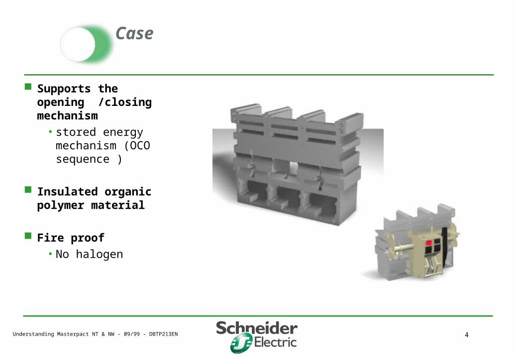
Case
Supports the opening /closing mechanism
• stored energy mechanism (OCO sequence )
Insulated organic polymer material
Fire proof
• No halogen

Understanding Masterpact NT & NW - 09/99 - DBTP213EN 5
Moving contact
Complete assembly
• fingers, braids, terminal
• no internal bolted joint
High electromechanical and
thermal withstand
• blow on
Specific limiter contact
assembly
• L1 performance
Direct link to
the OCO mechanism
Isolated compartments
Understanding Masterpact NT & NW - 09/99 - DBTP213EN 6
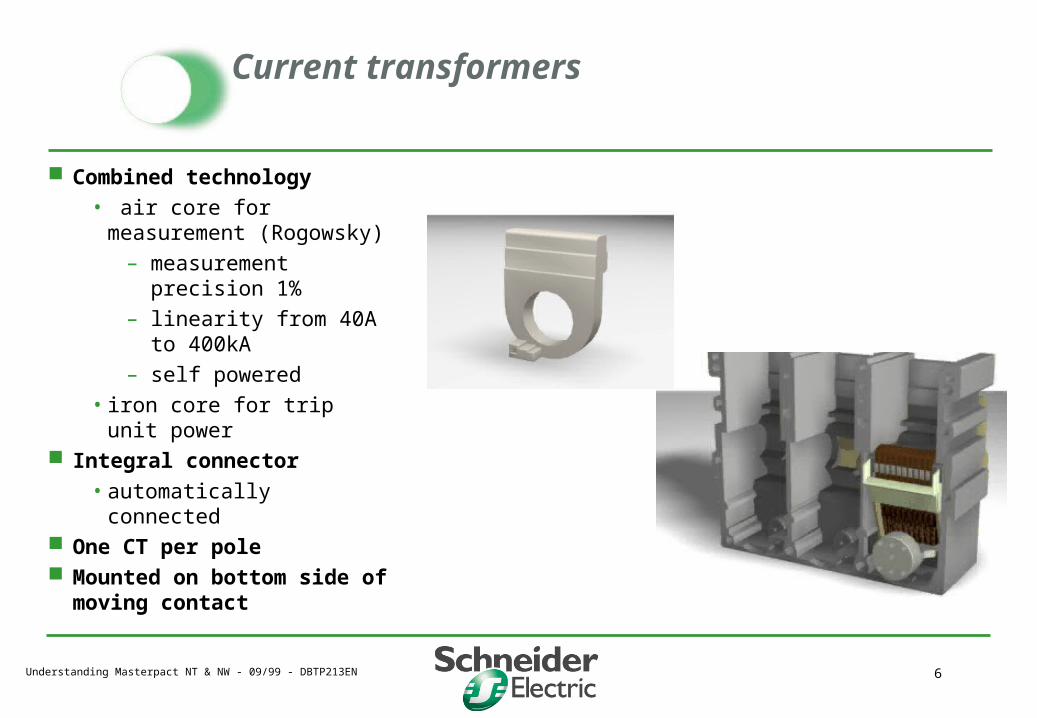
Current transformers
Combined technology
• air core for measurement (Rogowsky)
– measurement precision 1%
– linearity from 40A to 400kA
– self powered
• iron core for trip unit power Integral connector
• automatically connected One CT per pole Mounted on bottom side of
moving contact

Understanding Masterpact NT & NW - 09/99 - DBTP213EN 7
Micrologic trip unit power supply
Circuit breaker Micrologic Communication module
Basic protection
Trip unit power supply
Additionals functions (measurement,
analyses...)
Power supply
COM Module
Opticalcoupling
Optional external 24V DC power supply for :programmable contact power supply,when breaker is open :•Powers display, •Identification, adjustments through “Com” module
Iron CT
Air CT Isolation
Standard Internal voltage sensor oroptional external voltage sensor forµP power supply and measurement
ASIC Microprocesseur
BUS power supply

Understanding Masterpact NT & NW - 09/99 - DBTP213EN 8
Fixed Contact
Breaking the arc
• arcing contact protects main contacts against wear
• high number of electrical operation
• increased life expectation
Top terminal
• no internal joint
Understanding Masterpact NT & NW - 09/99 - DBTP213EN 9
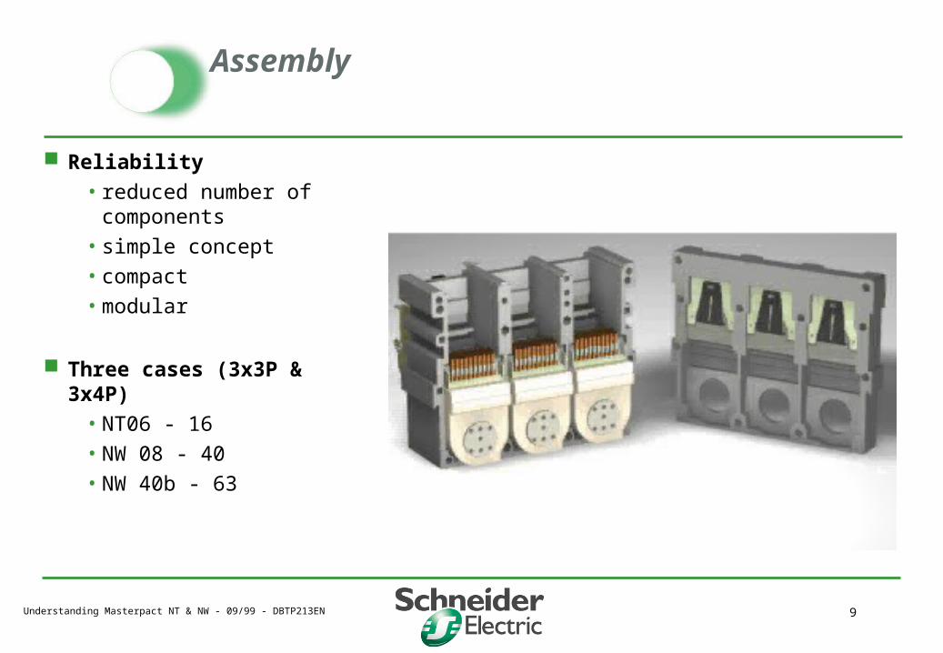
Assembly
Reliability
• reduced number of components
• simple concept
• compact
• modular
Three cases (3x3P & 3x4P)
• NT06 - 16
• NW 08 - 40
• NW 40b - 63

Understanding Masterpact NT & NW - 09/99 - DBTP213EN 10
Arc chamber
Increased arc impedance favors extinguishing properties
patented metallic filter • high porosity • energy and gas absorption
results in de-ionization of external gas
Reduced external projections Reduced enclosure pressure Safety clearance above arc
chamber• NW : not required• NT : D/O no, Fixed reduced
Removable for contact inspection
NT NW

Understanding Masterpact NT & NW - 09/99 - DBTP213EN 11
Opening of contacts
Commutation principle
Contact pads protected from the electric arc for better performance
Return to contents
Understanding Masterpact NT & NW - 09/99 - DBTP213EN 12
ContentsMicrologic socket
Mitop trip solenoid
Making current release (DINF)
NW Interface
Trip alarm contact
Remote reset
2 contacts module
Communication module
Return to contents

Understanding Masterpact NT & NW - 09/99 - DBTP213EN 13
Mitop trip solenoid
Transforms the trip command into a mechanical operation to open the breaker
Activate the alarm contact (SDE)
NW
Understanding Masterpact NT & NW - 09/99 - DBTP213EN 14
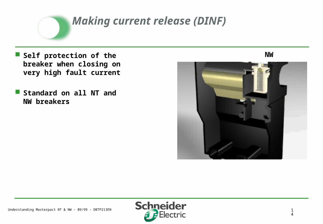
Making current release (DINF)
Self protection of the breaker when closing on very high fault current
Standard on all NT and NW breakers
NW

Understanding Masterpact NT & NW - 09/99 - DBTP213EN 15
NW Interface
Accessory fixture
• Trip alarm contact SDE 1
• communication module
Auto trip controller :
• Missing trip unit
• security feature
• identical on NT
NW
Understanding Masterpact NT & NW - 09/99 - DBTP213EN 16
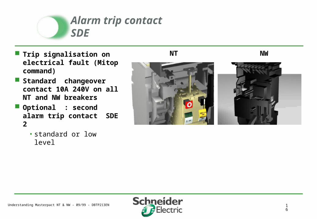
Alarm trip contactSDE
Trip signalisation on electrical fault (Mitop command)
Standard changeover contact 10A 240V on all NT and NW breakers
Optional : second alarm trip contact SDE 2
• standard or low level
NT NW
Understanding Masterpact NT & NW - 09/99 - DBTP213EN 17
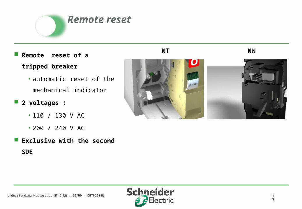
Remote reset
Remote reset of a tripped
breaker
• automatic reset of the
mechanical indicator
2 voltages :
• 110 / 130 V AC
• 200 / 240 V AC
Exclusive with the second SDE
NT NW

Understanding Masterpact NT & NW - 09/99 - DBTP213EN 18
2 contacts module M2C
programmable contacts :
• to energize bell or visual
alarms
• to shed and reconnect non
priority circuits …
2 closing contacts
10 A 240V AC
Monitored by
Micrologic P et H
M6C : 6 programmable
contacts in external DIN case
NT NW
Understanding Masterpact NT & NW - 09/99 - DBTP213EN 19
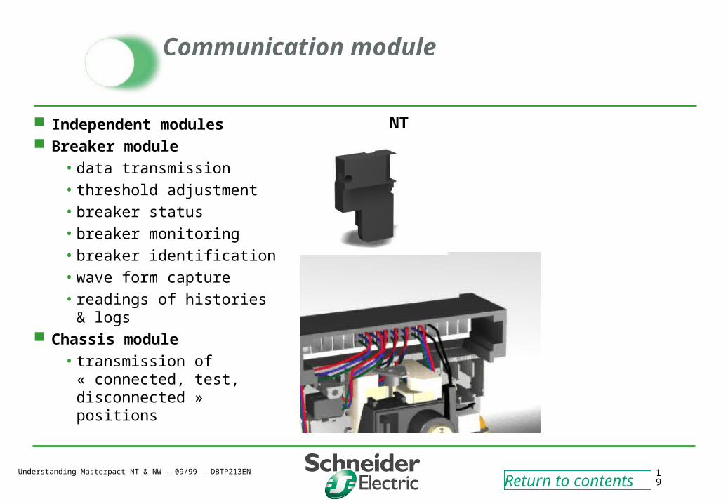
Communication module
Independent modules Breaker module
• data transmission
• threshold adjustment
• breaker status
• breaker monitoring
• breaker identification
• wave form capture
• readings of histories & logs Chassis module
• transmission of « connected, test, disconnected » positions
NT
Return to contents
Understanding Masterpact NT & NW - 09/99 - DBTP213EN 20
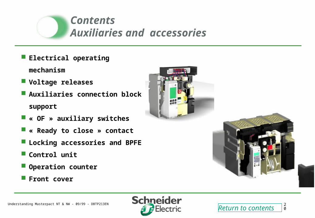
ContentsAuxiliaries and accessories
Electrical operating mechanism
Voltage releases
Auxiliaries connection block
support
« OF » auxiliary switches
« Ready to close » contact
Locking accessories and BPFE
Control unit
Operation counter
Front cover
Return to contents
Understanding Masterpact NT & NW - 09/99 - DBTP213EN 21
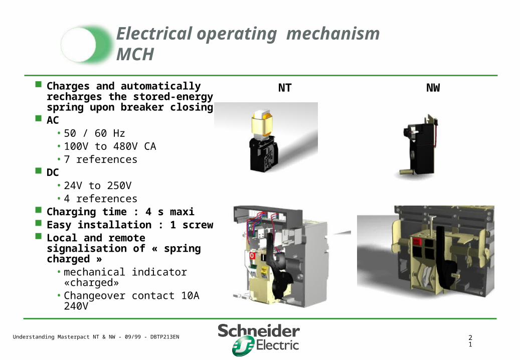
Electrical operating mechanism MCH
Charges and automatically recharges the stored-energy spring upon breaker closing
AC • 50 / 60 Hz• 100V to 480V CA• 7 references
DC• 24V to 250V • 4 references
Charging time : 4 s maxi Easy installation : 1 screw Local and remote signalisation
of « spring charged »• mechanical indicator
«charged»• Changeover contact 10A 240V
NT NW
Understanding Masterpact NT & NW - 09/99 - DBTP213EN 22
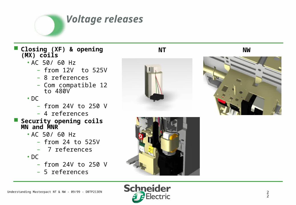
Voltage releases
Closing (XF) & opening (MX) coils
• AC 50/ 60 Hz– from 12V to 525V – 8 references – Com compatible 12 to
480V• DC
– from 24V to 250 V– 4 references
Security opening coils MN and MNR
• AC 50/ 60 Hz– from 24 to 525V – 7 references
• DC – from 24V to 250 V– 5 references
NT NW
Understanding Masterpact NT & NW - 09/99 - DBTP213EN 23
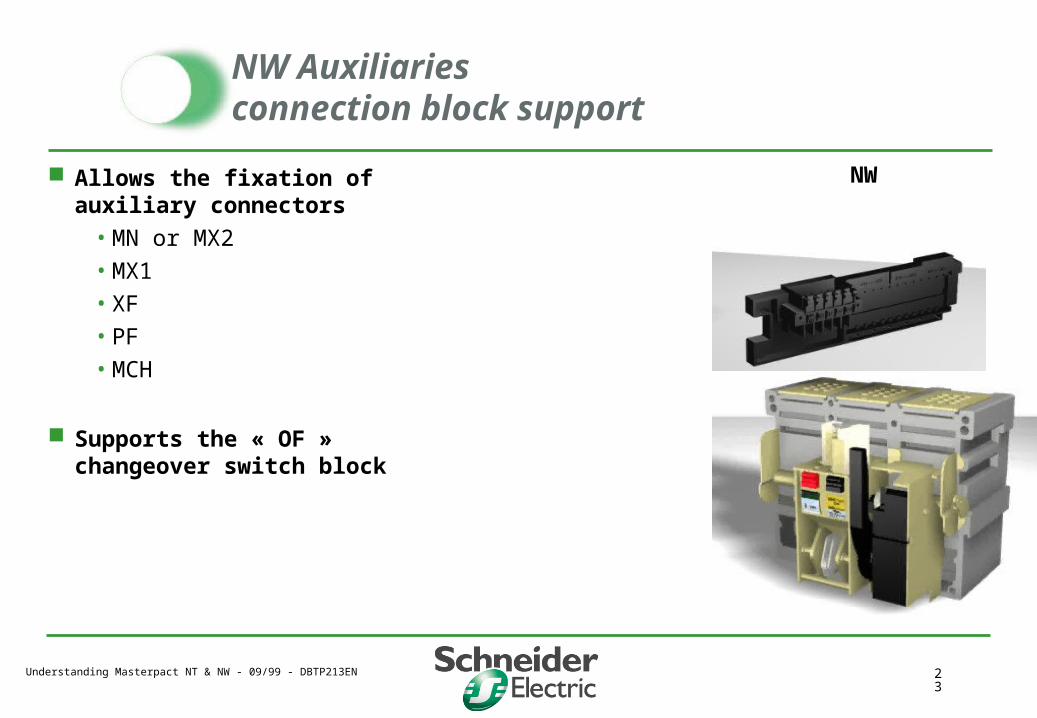
NW Auxiliaries connection block support
Allows the fixation of auxiliary connectors
• MN or MX2
• MX1
• XF
• PF
• MCH
Supports the « OF » changeover switch block
NW
Understanding Masterpact NT & NW - 09/99 - DBTP213EN 24
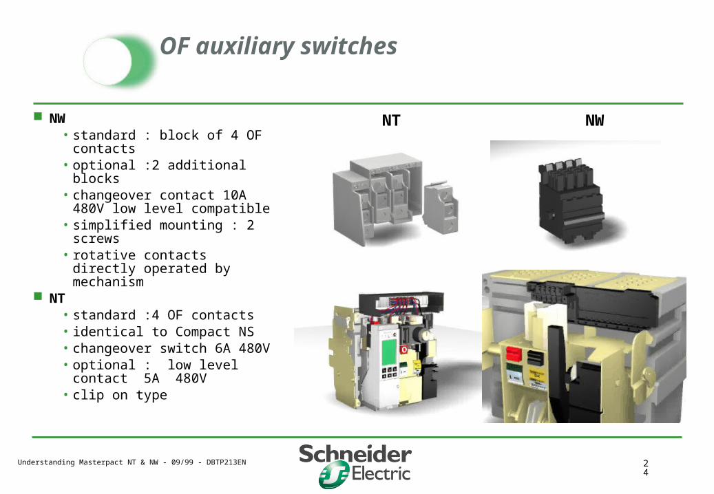
OF auxiliary switches
NW • standard : block of 4 OF
contacts• optional :2 additional blocks• changeover contact 10A 480V
low level compatible • simplified mounting : 2 screws• rotative contacts directly
operated by mechanism NT
• standard :4 OF contacts• identical to Compact NS• changeover switch 6A 480V• optional : low level contact
5A 480V• clip on type
NT NW

Understanding Masterpact NT & NW - 09/99 - DBTP213EN 25
Ready to close contact PF
Changeover contact 10A 240V
Indicates :
• the breaker is open
• the stored energy mechanism is charged
• the mechanism is correctly reset
• the breaker opening push button is not locked
• no opening order is present
NT

Understanding Masterpact NT & NW - 09/99 - DBTP213EN 26
Installation ofMicrologic socket
Left side
The socket supports
• communication module
• Micrologic control unit
NW
Understanding Masterpact NT & NW - 09/99 - DBTP213EN 27
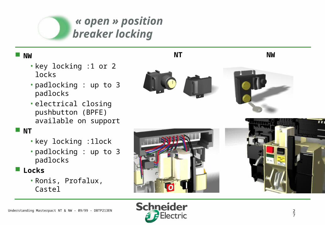
« open » position breaker locking
NW
• key locking :1 or 2 locks
• padlocking : up to 3 padlocks
• electrical closing pushbutton (BPFE) available on support
NT
• key locking :1lock
• padlocking : up to 3 padlocks
Locks
• Ronis, Profalux, Castel
NT NW
Understanding Masterpact NT & NW - 09/99 - DBTP213EN 28
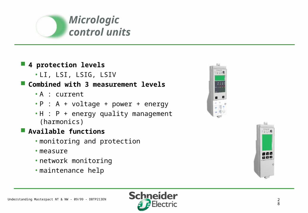
Micrologiccontrol units
4 protection levels
• LI, LSI, LSIG, LSIV Combined with 3 measurement levels
• A : current
• P : A + voltage + power + energy
• H : P + energy quality management (harmonics) Available functions
• monitoring and protection
• measure
• network monitoring
• maintenance help
Understanding Masterpact NT & NW - 09/99 - DBTP213EN 29
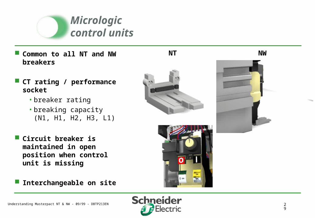
Micrologiccontrol units
Common to all NT and NW breakers
CT rating / performance socket
• breaker rating
• breaking capacity (N1, H1, H2, H3, L1)
Circuit breaker is maintained in open position when control unit is missing
Interchangeable on site
NT NW
Understanding Masterpact NT & NW - 09/99 - DBTP213EN 30
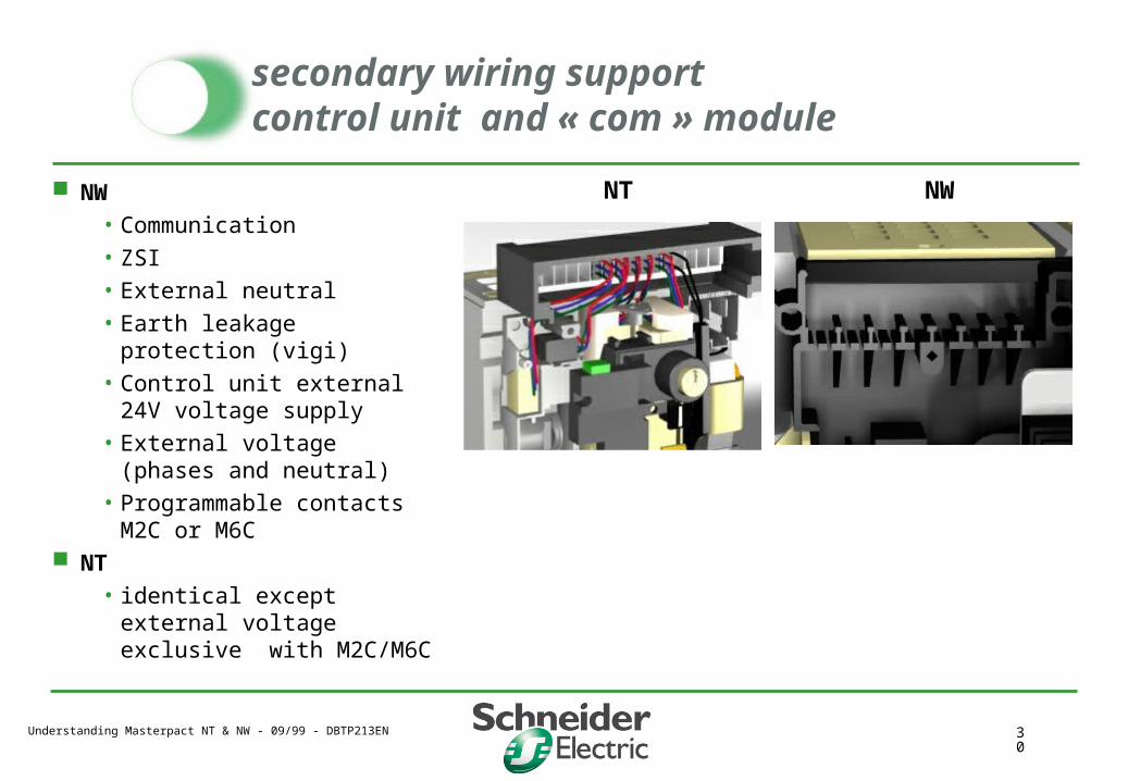
secondary wiring support control unit and « com » module
NW • Communication• ZSI• External neutral• Earth leakage protection (vigi)• Control unit external 24V
voltage supply• External voltage (phases and
neutral)• Programmable contacts M2C
or M6C NT
• identical except external voltage exclusive with M2C/M6C
NWNT

Understanding Masterpact NT & NW - 09/99 - DBTP213EN 31
Operation counter
Sums the number of
operating cycles
(closing /opening)
maintenance help
Easy installation
Visible on the front panel
NW
Understanding Masterpact NT & NW - 09/99 - DBTP213EN 32
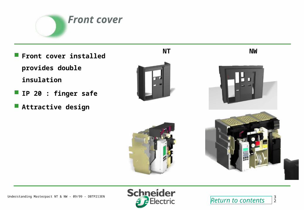
Front cover
Front cover installed
provides double insulation
IP 20 : finger safe
Attractive design
Return to contents
NT NW
Understanding Masterpact NT & NW - 09/99 - DBTP213EN 33
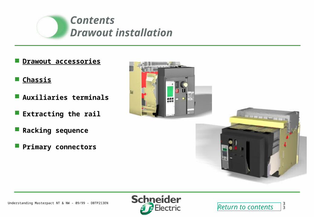
ContentsDrawout installation
Drawout accessories
Chassis
Auxiliaries terminals
Extracting the rail
Racking sequence
Primary connectors
Return to contents
Understanding Masterpact NT & NW - 09/99 - DBTP213EN 34
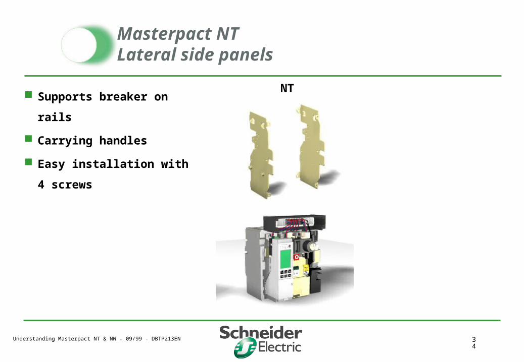
Masterpact NTLateral side panels
Supports breaker on rails
Carrying handles
Easy installation with 4
screws
NT
Understanding Masterpact NT & NW - 09/99 - DBTP213EN 35
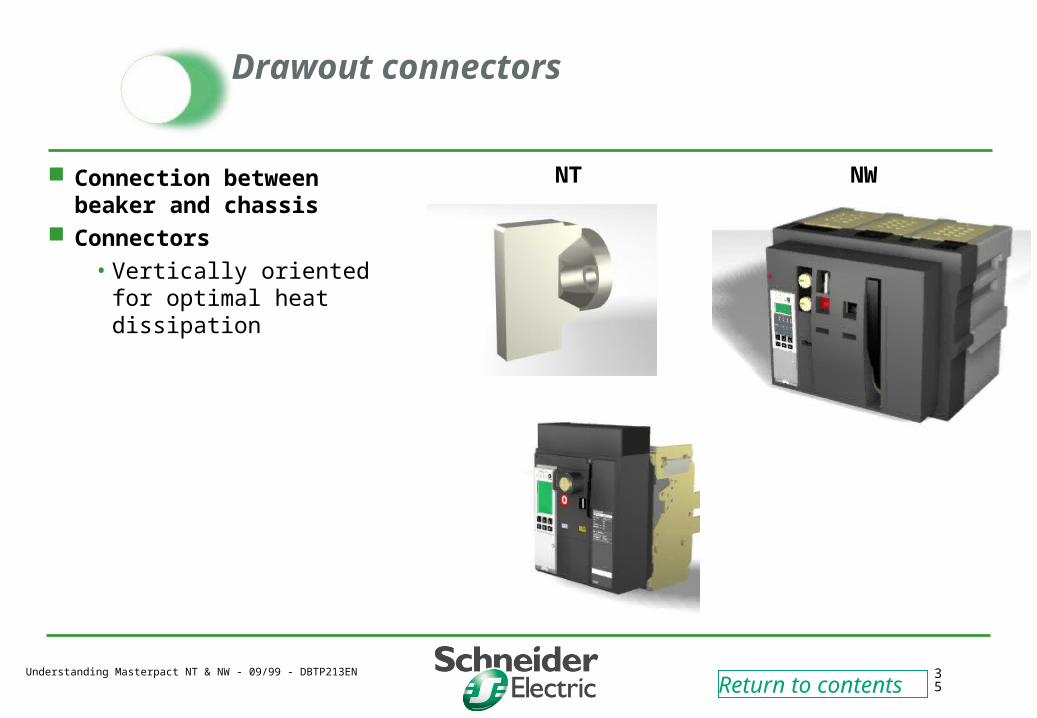
Drawout connectors
Connection between beaker and chassis
Connectors
• Vertically oriented for optimal heat dissipation
NT NW
Return to contents
Understanding Masterpact NT & NW - 09/99 - DBTP213EN 36
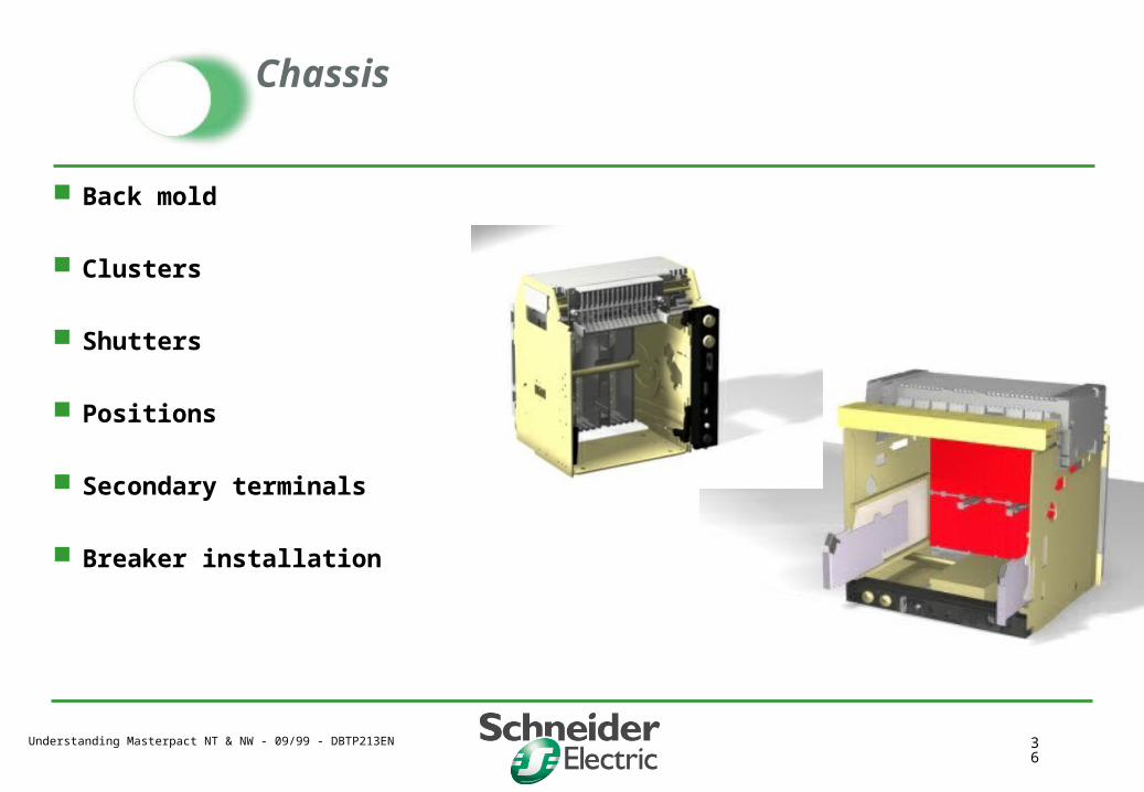
Chassis
Back mold
Clusters
Shutters
Positions
Secondary terminals
Breaker installation
Understanding Masterpact NT & NW - 09/99 - DBTP213EN 37
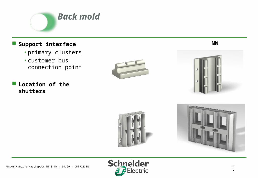
Back mold
Support interface
• primary clusters
• customer bus connection point
Location of the shutters
NW

Understanding Masterpact NT & NW - 09/99 - DBTP213EN 38
Chassis assembly
Arc chute cover installed as standard
2 sizes of chassis
• 800 A - 4000 A
• 4000 A - 6300 A
2 variants
• 3P
• 4P
NT NW

Understanding Masterpact NT & NW - 09/99 - DBTP213EN 39
Clusters
One fits all !
Vertical orientation for better heat dissipation
10 fingers on each cluster across the entire range
Clip on type
Number of clusters depends on breaker frame size
NT NW
Understanding Masterpact NT & NW - 09/99 - DBTP213EN 40
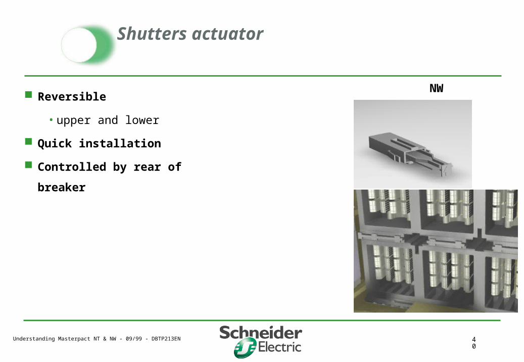
Shutters actuator
Reversible
• upper and lower
Quick installation
Controlled by rear of breaker
NW
Understanding Masterpact NT & NW - 09/99 - DBTP213EN 41
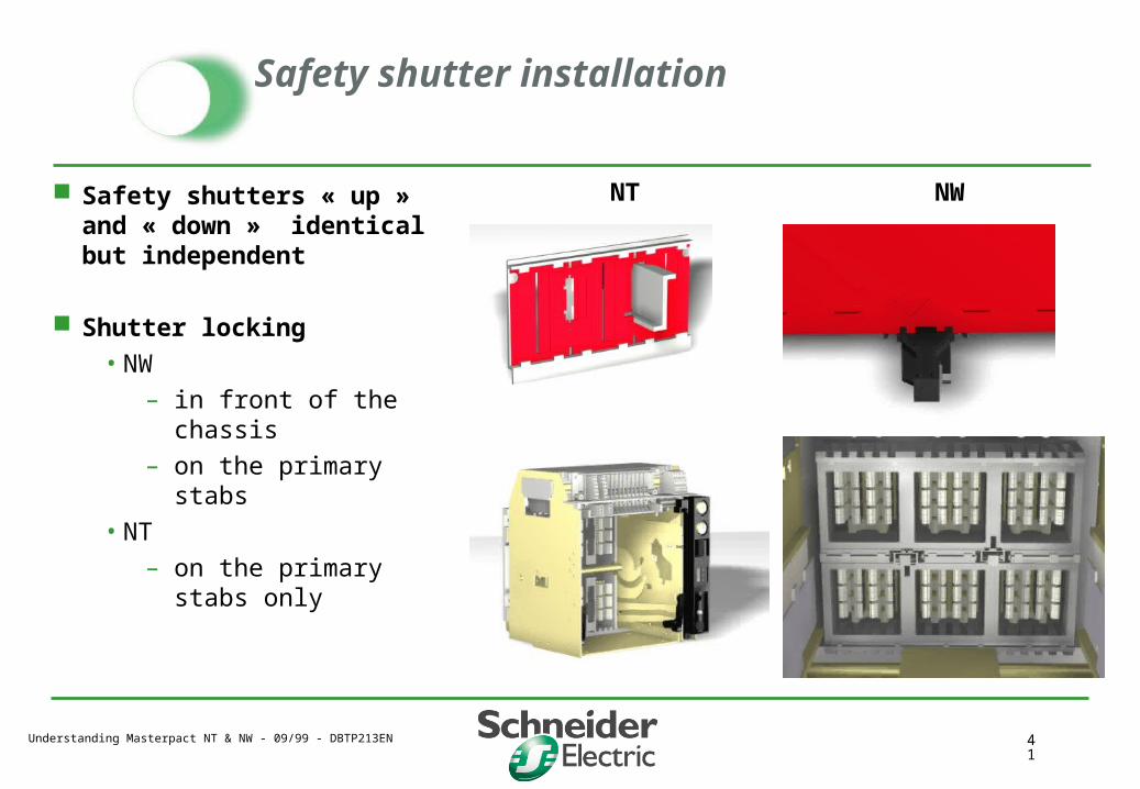
Safety shutter installation
Safety shutters « up » and « down » identical but independent
Shutter locking
• NW
– in front of the chassis
– on the primary stabs
• NT
– on the primary stabs only
NWNT
Understanding Masterpact NT & NW - 09/99 - DBTP213EN 42
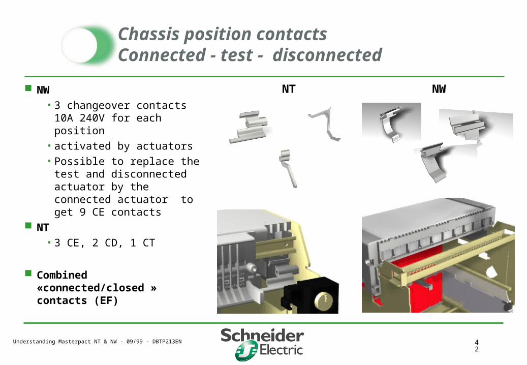
Chassis position contactsConnected - test - disconnected
NW
• 3 changeover contacts 10A 240V for each position
• activated by actuators
• Possible to replace the test and disconnected actuator by the connected actuator to get 9 CE contacts
NT
• 3 CE, 2 CD, 1 CT
Combined «connected/closed » contacts (EF)
NWNT
Understanding Masterpact NT & NW - 09/99 - DBTP213EN 43
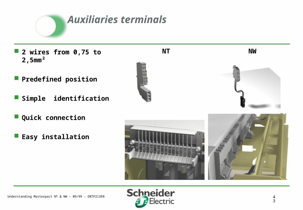
Auxiliaries terminals
2 wires from 0,75 to 2,5mm²
Predefined position
Simple identification
Quick connection
Easy installation
NT NW
Understanding Masterpact NT & NW - 09/99 - DBTP213EN 44
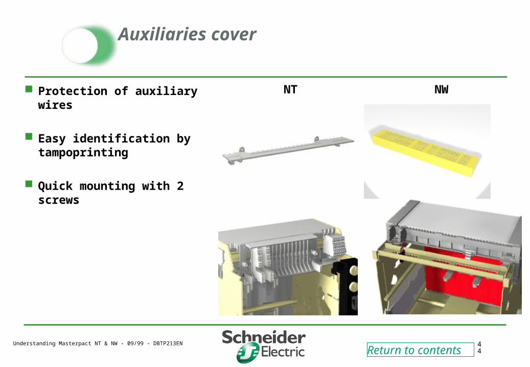
Auxiliaries cover
Protection of auxiliary wires
Easy identification by tampoprinting
Quick mounting with 2 screws
NT NW
Return to contents
Understanding Masterpact NT & NW - 09/99 - DBTP213EN 45
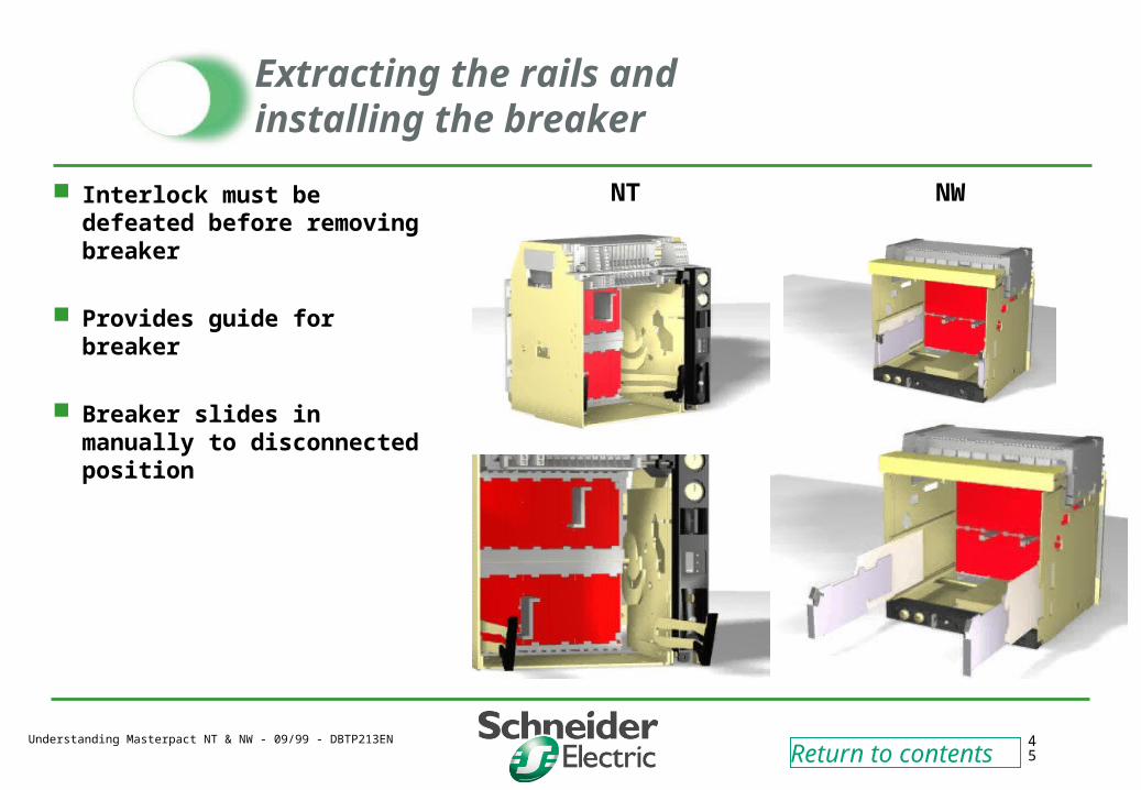
Extracting the rails and installing the breaker
Interlock must be defeated before removing breaker
Provides guide for breaker
Breaker slides in manually to disconnected position
NT NW
Return to contents
Understanding Masterpact NT & NW - 09/99 - DBTP213EN 46
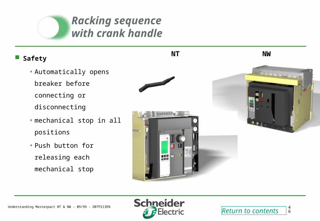
Racking sequencewith crank handle
Safety
• Automatically opens breaker
before connecting or
disconnecting
• mechanical stop in all
positions
• Push button for releasing
each mechanical stop
NT NW
Return to contents
Understanding Masterpact NT & NW - 09/99 - DBTP213EN 47
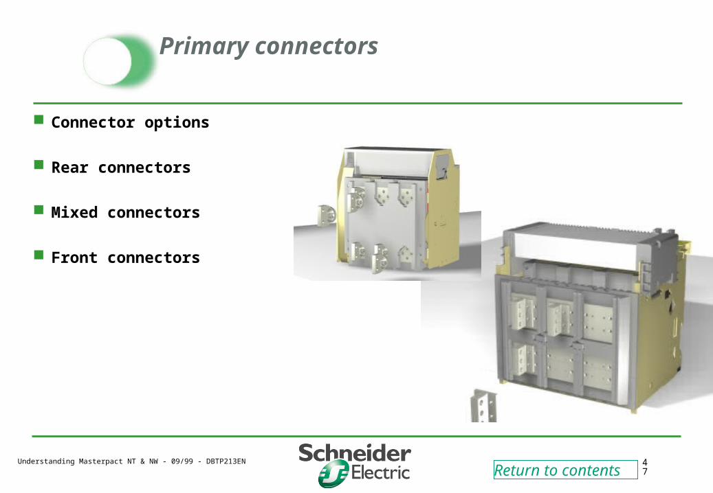
Primary connectors
Connector options
Rear connectors
Mixed connectors
Front connectors
Return to contents
Understanding Masterpact NT & NW - 09/99 - DBTP213EN 48
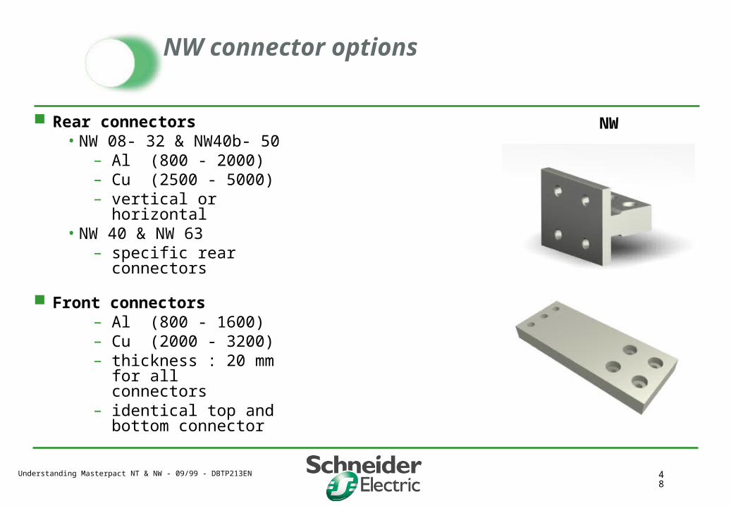
NW connector options
Rear connectors• NW 08- 32 & NW40b- 50
– Al (800 - 2000)– Cu (2500 - 5000)– vertical or horizontal
• NW 40 & NW 63– specific rear
connectors
Front connectors– Al (800 - 1600)– Cu (2000 - 3200)– thickness : 20 mm for
all connectors– identical top and
bottom connector
NW
Understanding Masterpact NT & NW - 09/99 - DBTP213EN 49
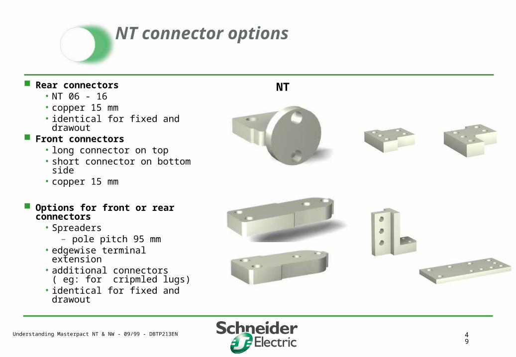
NT connector options
Rear connectors• NT 06 - 16• copper 15 mm• identical for fixed and drawout
Front connectors• long connector on top• short connector on bottom
side• copper 15 mm
Options for front or rear connectors
• Spreaders– pole pitch 95 mm
• edgewise terminal extension• additional connectors ( eg: for
cripmled lugs)• identical for fixed and drawout
NT

Understanding Masterpact NT & NW - 09/99 - DBTP213EN 50
Primary connectionVertical / horizontal rear
Connectors matched to
breaker size
• NT 06 - 16
• NW 08 - 32
• NW 40b - 63
• pole pitch :70, 115, 230 mm
Specific rear connectors for NW40
• Pole pitch :
– 150 mm horizontal
– 115 mm vertical identical for fixed and
drawout
NT NW
Understanding Masterpact NT & NW - 09/99 - DBTP213EN 51
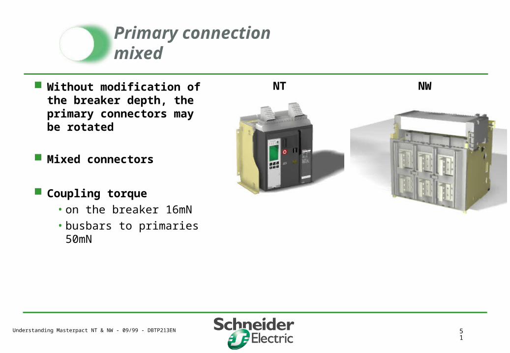
Primary connectionmixed
Without modification of the breaker depth, the primary connectors may be rotated
Mixed connectors
Coupling torque
• on the breaker 16mN
• busbars to primaries 50mN
NT NW
Understanding Masterpact NT & NW - 09/99 - DBTP213EN 52
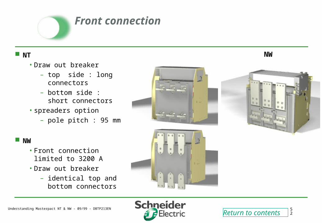
Front connection
NT
• Draw out breaker
– top side : long connectors
– bottom side : short connectors
• spreaders option
– pole pitch : 95 mm
NW
• Front connection limited to 3200 A
• Draw out breaker
– identical top and bottom connectors
Return to contents
NW
Understanding Masterpact NT & NW - 09/99 - DBTP213EN 53
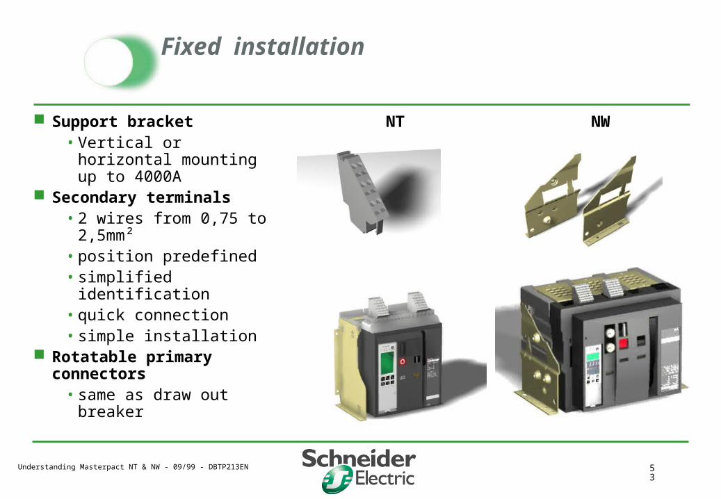
Fixed installation
Support bracket• Vertical or horizontal
mounting up to 4000A Secondary terminals
• 2 wires from 0,75 to 2,5mm²• position predefined• simplified identification • quick connection• simple installation
Rotatable primary connectors• same as draw out breaker
NT NW
Understanding Masterpact NT & NW - 09/99 - DBTP213EN 54
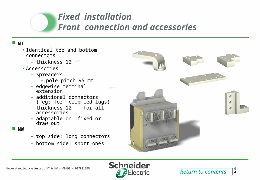
Fixed installationFront connection and accessories
NT• Identical top and bottom
connectors – thickness 12 mm
• Accessories – Spreaders
– pole pitch 95 mm– edgewise terminal extension– additional connectors ( eg:
for cripmled lugs)– thickness 12 mm for all
accessories– adaptable on fixed or draw
out NW
– top side: long connectors
– bottom side: short ones
Return to contents
Understanding Masterpact NT & NW - 09/99 - DBTP213EN 55
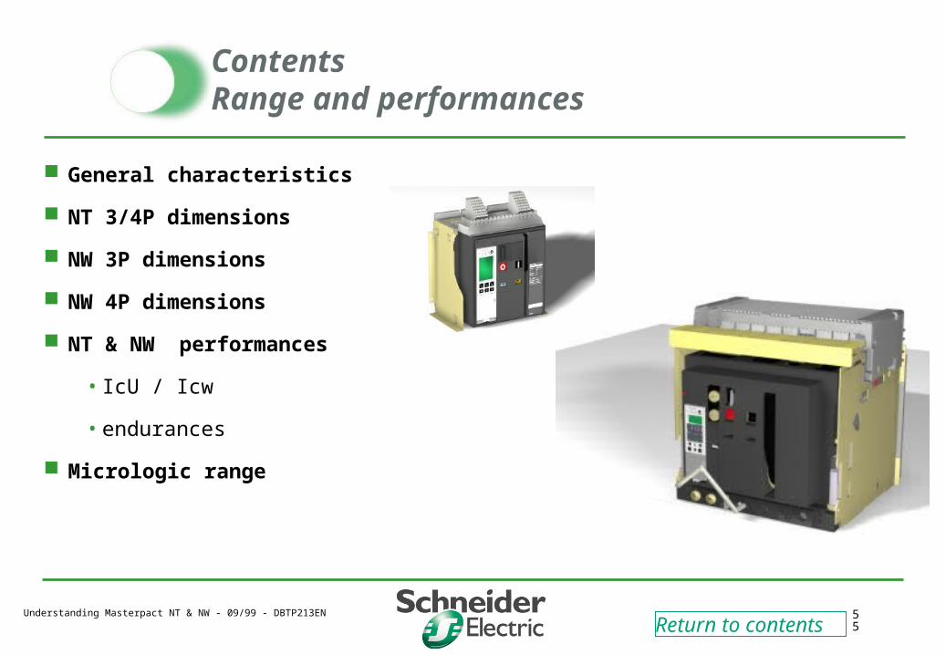
ContentsRange and performances
General characteristics
NT 3/4P dimensions
NW 3P dimensions
NW 4P dimensions
NT & NW performances
• IcU / Icw
• endurances
Micrologic range
Return to contents
Understanding Masterpact NT & NW - 09/99 - DBTP213EN 56
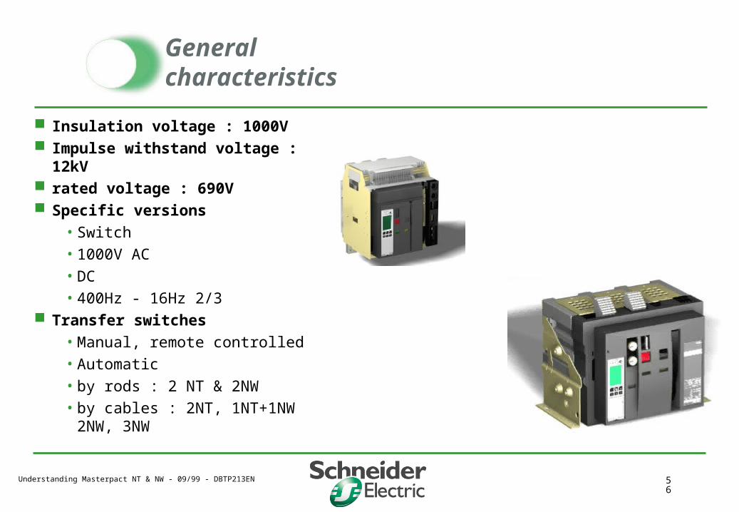
General characteristics
Insulation voltage : 1000V Impulse withstand voltage : 12kV rated voltage : 690V Specific versions
• Switch
• 1000V AC
• DC
• 400Hz - 16Hz 2/3 Transfer switches
• Manual, remote controlled
• Automatic
• by rods : 2 NT & 2NW
• by cables : 2NT, 1NT+1NW2NW, 3NW
Understanding Masterpact NT & NW - 09/99 - DBTP213EN 57
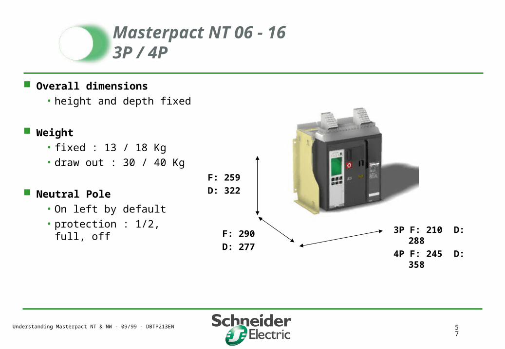
F: 259
D: 322
F: 290
D: 277
3P F: 210 D: 288
4P F: 245 D: 358
Masterpact NT 06 - 16 3P / 4P
Overall dimensions• height and depth fixed
Weight • fixed : 13 / 18 Kg• draw out : 30 / 40 Kg
Neutral Pole• On left by default• protection : 1/2, full, off
Understanding Masterpact NT & NW - 09/99 - DBTP213EN 58
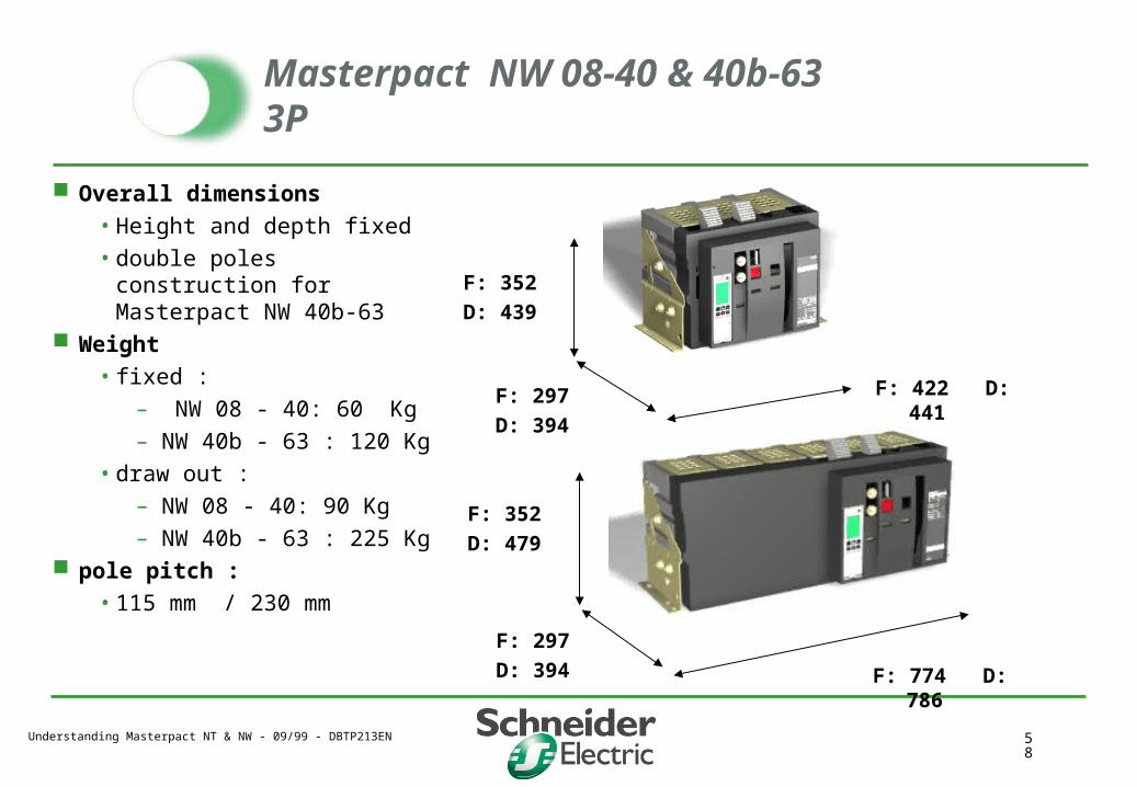
Masterpact NW 08-40 & 40b-63 3P
Overall dimensions
• Height and depth fixed
• double poles construction for Masterpact NW 40b-63
Weight
• fixed :
– NW 08 - 40: 60 Kg
– NW 40b - 63 : 120 Kg
• draw out :
– NW 08 - 40: 90 Kg
– NW 40b - 63 : 225 Kg pole pitch :
• 115 mm / 230 mm
F: 352
D: 439
F: 297
D: 394
F: 422 D: 441
F: 297
D: 394
F: 352
D: 479
F: 774 D: 786
Understanding Masterpact NT & NW - 09/99 - DBTP213EN 59
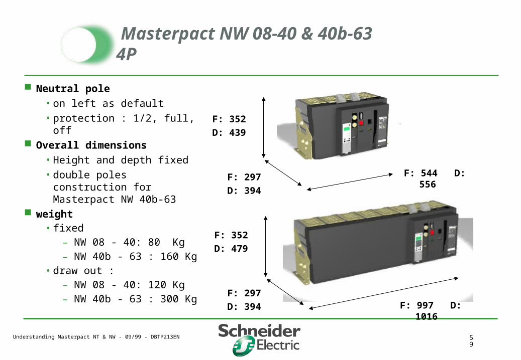
Masterpact NW 08-40 & 40b-63 4P
Neutral pole
• on left as default
• protection : 1/2, full, off Overall dimensions
• Height and depth fixed
• double poles construction for Masterpact NW 40b-63
weight • fixed
– NW 08 - 40: 80 Kg– NW 40b - 63 : 160 Kg
• draw out :– NW 08 - 40: 120 Kg– NW 40b - 63 : 300 Kg
F: 352
D: 439
F: 297
D: 394
F: 544 D: 556
F: 297
D: 394
F: 352
D: 479
F: 997 D: 1016
Understanding Masterpact NT & NW - 09/99 - DBTP213EN 60
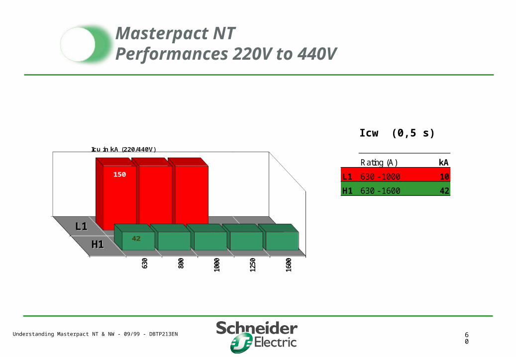
Icw (0,5 s)
Rating (A) kA
L1 630 - 1000 10
H1 630 - 1600 42
H1H1
L1L1
Masterpact NT Performances 220V to 440V
Understanding Masterpact NT & NW - 09/99 - DBTP213EN 61
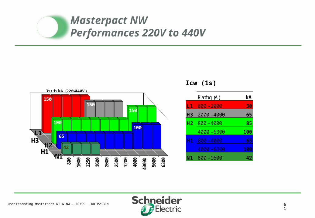
Icw (1s)
Rating (A) kA
L1 800 - 2000 30
H3 2000 - 4000 65
H2 800 - 4000 85
4000 - 6300 100
H1 800 - 4000 65
4000 - 6300 100
N1 800 - 1600 42N1N1H1H1
H2H2H3H3L1L1
Masterpact NW Performances 220V to 440V

Understanding Masterpact NT & NW - 09/99 - DBTP213EN 62
PerformancesNT & NW endurance
01
23
456
789
10
8 à16
20 25 32 40 40 50 63
NT NW
0
5
10
15
20
25
08 - 16 20 - 32 40 40b - 630
NTNW
0
2
4
6
8
10
12
14
08 - 16 20 - 32 40 40b - 630
NTNW
Mechanical endurance :
Electrical endurance :
With maintenance Without maintenance
Without maintenance N
bre
de
cycl
es (
x100
0)
Nb
re d
e cy
cle
(x10
00)
Understanding Masterpact NT & NW - 09/99 - DBTP213EN 63
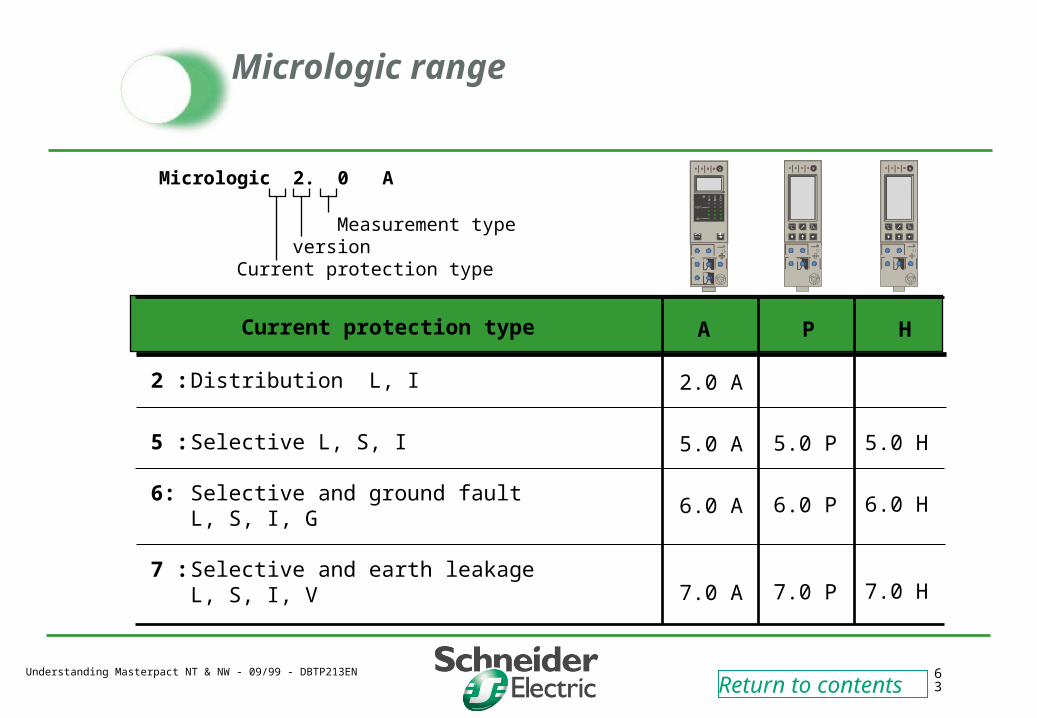
Micrologic range
Micrologic 2. 0 A
Measurement type versionCurrent protection type
ACurrent protection type
2 : Distribution L, I
5 : Selective L, S, I
6: Selective and ground fault L, S, I, G
7 : Selective and earth leakage L, S, I, V
P H
2.0 A
5.0 A
6.0 A
7.0 A
5.0 P
6.0 P
7.0 P
5.0 H
6.0 H
7.0 H
Return to contents

Understanding Masterpact NT & NW - 09/99 - DBTP213EN 64
Things will never be the same