understanding nena’s i3 architectural standard for …...understanding nena’s i3 architectural...
TRANSCRIPT

Understanding NENA’s i3 Architectural Standard for NG9-1-1
Today, NENA takes a significant step toward achieving the vision of Next Generation 9-1-1 service. As we adopt Version 1.0 of NENA Technical Standard 08-003, Detailed Functional and Interface Specification for the NENA i3 Solution – Stage 3, we consider it important to explain how this standard relates to long-term efforts to modernize our nation’s emergency communications systems.
This NENA standard intentionally describes an end-state NG9-1-1 architecture, rather than an immediate “build-to” specification for a complete NG9-1-1 system. Broadly speaking, 9-1-1 systems will reach the end-state envisioned by the i3 Standard only over the long term. In the interim, transitional steps must be taken to maintain support for legacy interfaces from originating service providers such as wireline and cellular telephone carriers, and to accommodate legacy PSAP equipment. At the same time, we recognize that state and local authorities will begin deploying ESInets and other core components of the i3 architecture as those components reach the market. Likewise, originating service providers and access network operators may begin deploying new network elements in support of longer-term NG9-1-1 services. The i3 architecture anticipates the existence of transitional states in origination services, access networks, and 9-1-1 systems and includes specifications for network elements that will be required to support a growing variety of “call” types as deployed systems evolve toward the end-state.
Critically, the i3 standard is not, by itself, the same thing as an NG9-1-1 system. The i3 standard describes only the network, components, and interfaces required to establish Next Generation 9-1-1 service. In order to deploy a fully-operational NG9-1-1 system, 9-1-1 authorities, equipment and software vendors, originating service providers, and access network providers will require detailed specifications for technical, operational, and human elements that are not described in the i3 standard. As the leading standards development organization for the 9-1-1 sector, NENA has already developed some of these specifications. Much work remains, however, and NENA is committed to developing the additional consensus standards needed to support fully-mature NG9-1-1 service systems.
It also will be necessary for NG9-1-1 systems to interwork with services and networks provided by the broader telecommunications and applications industries. NENA is aware of the evolution of the Internet Multimedia Subsystem (IMS) standard under development by ATIS, and our Technical Committee has designed the i3 architecture to support known characteristics of IMS. We are therefore pleased by the efforts of ATIS and others to develop detailed specifications for an interface between IMS-based originating services and the ESInets on which the i3 architecture operates. Version 1.0 of the i3 standard could not cover all aspects of the interface, however, because those efforts only recently began. Standards convergence in this area will be important to the success of NG9-1-1, and we look forward to more fully addressing the IMS/ESInet interface in concert with ATIS.

In addition to technical and operational standards, a detailed policy framework must be created to enable and support the transition to NG9-1-1. Critical policy decisions such as how NG9-1-1 deployments will be funded and how system costs should be allocated are beyond the scope of the i3 technical standard. Those decisions must be made, however, and NENA will support policymakers at all levels of government as they wrestle with these issues.
We also wish to emphasize that the i3 standard is not intended to fully address the issues involved in transitioning from legacy 9-1-1 and E9-1-1 systems to end-state NG9-1-1. In 2006, NENA created a working group focused on transitional matters, such as network, data, and operational issues. That group has since completed work on Version 1.0 of a transition plan, covering mostly network issues. That group is now working on Version 2.0, covering data and operational issues. As the group continues its work, we expect that it will soon produce an integrated, consensus-based plan covering all essential elements of the transition to NG9-1-1 with sufficient specificity to allow 9-1-1 system administrators, vendors, access network operators, and originating service providers to confidently deploy capital in support of the transition.
Much work remains to be done, but our adoption of the i3 standard establishes a clear vision for the future and a foundation on which successful transitions to Next Generation 9-1-1 service can be built. As work continues, NENA stands ready to lead the cooperative efforts needed to ensure smooth transitions and to achieve the ultimate vision of NG9-1-1 as a service accessible anytime, anywhere, on any device.
For the Executive Board,
Stephen F. O’Conor, ENP President

Detailed Functional and Interface Specification for
the NENA i3 Solution – Stage 3
NENA Detailed Functional and Interface Standards for the NENA i3 Solution (TSD) NENA 08-003 v1, June 14, 2011 Standards Advisory Board approval date, February 16, 2011 NENA Executive Board approval date, June 14, 2011 Prepared by: National Emergency Number Association (NENA) Technical Committee Chairs Published by NENA Printed in USA © Copyright 2011 NENA. All rights reserved.

Detailed Functional and Interface Specification for the NENA i3 Solution – Stage 3 NENA 08-003 Version 1, June 14, 2011
Version 1, June 14, 2011 Page 2 of 282
NENA TECHNICAL STANDARD DOCUMENT
NOTICE
The National Emergency Number Association (NENA) publishes this document as a guide for the designers and manufacturers of systems to utilize for the purpose of processing emergency calls. It is not intended to provide complete design specifications or to assure the quality of performance of such equipment.
NENA reserves the right to revise this TSD for any reason including, but not limited to:
conformity with criteria or standards promulgated by various agencies
utilization of advances in the state of the technical arts
or to reflect changes in the design of equipment or services described herein.
It is possible that certain advances in technology will precede these revisions. Therefore, this NENA TSD should not be the only source of information used. NENA recommends that readers contact their Telecommunications Carrier representative to ensure compatibility with the 9-1-1 network.
Patents may cover the specifications, techniques, or network interface/system characteristics disclosed herein. No license expressed or implied is hereby granted. This document shall not be construed as a suggestion to any manufacturer to modify or change any of its products, nor does this document represent any commitment by NENA or any affiliate thereof to purchase any product whether or not it provides the described characteristics.
This document has been prepared solely for the use of E9-1-1 Service System Providers, network interface and system vendors, participating telephone companies, etc.
By using this document, the user agrees that NENA will have no liability for any consequential, incidental, special, or punitive damages arising from use of the document.
NENA’s Technical Committee has developed this document. Recommendations for change to this document may be submitted to:
National Emergency Number Association
4350 N Fairfax Dr, Suite 750
Arlington, VA 22203-1695
800-332-3911

Detailed Functional and Interface Specification for the NENA i3 Solution – Stage 3 NENA 08-003 Version 1, June 14, 2011
Version 1, June 14, 2011 Page 3 of 282
Acknowledgments:
The National Emergency Number Association (NENA) VoIP/Packet Technical Committee Long Term Definition Working Group developed this document.
NENA recognizes the following industry experts and their companies for their contributions in development of this document.
Version 1, Approval Date, 06/14/2011
Members Company
Brian Rosen –Work Group Leader and Technical Editor
NeuStar
Nate Wilcox – VoIP/Packet Technical Chair microDATA
Richard Atkins Tarrant County 9-1-1 District
Delaine Arnold Arnold 9-1-1 Consulting
Wayne Ballantyne Motorola
Deborah Barclay Alcatel Lucent
Marc Berryman DDTI
Tom Breen AT&T
Gary Brown NENA Utah Chapter Member
Pete Eggimann Metropolitan Emergency Services Board
Randall Gellens Qualcomm
Casimer M (Duke) Kaczmarczyk Verizon
Marc Linsner Cisco
Roger Marshall TeleCommunication Systems, (TCS)
Kathy McMahon-Ruscitto APCO International
Theresa Reese Telcordia
Greg Schumacher Sprint
Robert Sherry Intrado
Michael Smith DSS
Hannes Tschofenig Nokia Siemens Networks
Mike Vislocky Network Orange
This committee would also thank Tom Breen, Technical Committee Chair and Roger Hixson, Technical Issues Director for their support and assistance.

Detailed Functional and Interface Specification for the NENA i3 Solution – Stage 3 NENA 08-003 Version 1, June 14, 2011
Version 1, June 14, 2011 Page 4 of 282
TABLE OF CONTENTS
1 EXECUTIVE OVERVIEW ............................................................................................................................... 14
2 INTRODUCTION .............................................................................................................................................. 17
2.1 OPERATIONAL IMPACTS SUMMARY .................................................................................................................... 17
2.2 SECURITY IMPACTS SUMMARY ........................................................................................................................... 17
2.3 DOCUMENT TERMINOLOGY ................................................................................................................................ 17
2.4 REASON FOR ISSUE/REISSUE ............................................................................................................................... 18
2.5 RECOMMENDATION FOR ADDITIONAL DEVELOPMENT WORK ............................................................................ 18
2.6 DATE COMPLIANCE ............................................................................................................................................ 20
2.7 ANTICIPATED TIMELINE ..................................................................................................................................... 21
2.8 COSTS FACTORS ................................................................................................................................................. 21
2.9 FUTURE PATH PLAN CRITERIA FOR TECHNICAL EVOLUTION .............................................................................. 21
2.10 COST RECOVERY CONSIDERATIONS ................................................................................................................. 22
2.11 ADDITIONAL IMPACTS (NON COST RELATED) .................................................................................................... 22
2.12 INTELLECTUAL PROPERTY RIGHTS POLICY ...................................................................................................... 22
2.13 ACRONYMS/ABBREVIATIONS/DEFINITIONS ...................................................................................................... 23
3 GENERAL CONCEPTS .................................................................................................................................... 38
3.1 IDENTIFIERS ........................................................................................................................................................ 38
3.1.1 Agency Identifier ........................................................................................................................................ 38
3.1.2 Agent Identifier .......................................................................................................................................... 38
3.1.3 Element Identifier ....................................................................................................................................... 38
3.1.4 Call Identifier ............................................................................................................................................. 38
3.1.5 Incident Tracking Identifier ....................................................................................................................... 38
3.2 TIMESTAMP ........................................................................................................................................................ 39
3.3 EVENTS COMMON TO MULTIPLE FUNCTIONAL ELEMENTS ................................................................................... 39
3.3.1 Security Posture ......................................................................................................................................... 39
3.3.2 Element State .............................................................................................................................................. 40
3.3.3 Service State ............................................................................................................................................... 42
3.4 LOCATION REPRESENTATION.............................................................................................................................. 43
3.5 VCARDS .............................................................................................................................................................. 44
3.6 EMERGENCY SERVICES IP NETWORKS ............................................................................................................... 44
4 INTERFACES ..................................................................................................................................................... 45
4.1 SIP CALL ............................................................................................................................................................ 45
4.1.1 Minimal Methods needed to handle a call ................................................................................................. 46
4.1.1.1 INVITE (initial call) ............................................................................................................................................. 46

Detailed Functional and Interface Specification for the NENA i3 Solution – Stage 3 NENA 08-003 Version 1, June 14, 2011
Version 1, June 14, 2011 Page 5 of 282
4.1.1.2 REFER (transfer) ................................................................................................................................................. 49
4.1.1.3 BYE (call termination) ......................................................................................................................................... 49
4.1.2 Methods allowed to be initiated by caller which must be supported by i3 elements .................................. 49
4.1.2.1 CANCEL (cancel call initiation) .......................................................................................................................... 49
4.1.2.2 UPDATE (update parameters) ............................................................................................................................. 50
4.1.2.3 OPTIONS (option negotiation) ............................................................................................................................ 50
4.1.2.4 ACK (acknowledgement) ..................................................................................................................................... 50
4.1.2.5 PRACK (reliable message acknowledgement) ..................................................................................................... 50
4.1.2.6 MESSAGE (text message) ................................................................................................................................... 50
4.1.2.7 INFO .................................................................................................................................................................... 51
4.1.3 Methods used within the ESInet ................................................................................................................. 51
4.1.3.1 REGISTER (Call Taker to PSAP “login”) ........................................................................................................... 51
4.1.3.2 SUBSCRIBE/NOTIFY (Events) .......................................................................................................................... 51
4.1.3.3 PUBLISH (update of presence information to presence server)........................................................................... 51
4.1.4 Headers assumed supported at the interface to the ESInet ........................................................................ 51
4.1.5 Headers Accepted and also used internally ............................................................................................... 53
4.1.6 Resource Priority ....................................................................................................................................... 54
4.1.7 History-Info and Reason ............................................................................................................................ 55
4.1.8 Media ......................................................................................................................................................... 55
4.1.8.1 Audio ................................................................................................................................................................... 55
4.1.8.2 Video .................................................................................................................................................................... 55
4.1.8.3 Real-Time Text .................................................................................................................................................... 55
4.1.8.4 TTY (Baudot tones) ............................................................................................................................................. 55
4.1.9 Instant Messaging ...................................................................................................................................... 56
4.1.10 Non-human-initiated calls ........................................................................................................................ 57
4.1.11 Bodies in messages. .................................................................................................................................. 58
4.1.12 Transport .................................................................................................................................................. 58
4.1.13 Routing ..................................................................................................................................................... 59
4.1.14 Originating network Interface .................................................................................................................. 59
4.1.15 PSAP Interface ......................................................................................................................................... 59
4.1.16 Element Overload..................................................................................................................................... 60
4.2 LOCATION........................................................................................................................................................... 60
4.3 PROVISIONING .................................................................................................................................................... 61
4.4 POLICY ............................................................................................................................................................... 62
4.4.1 Policy Store Web Service ........................................................................................................................... 62
4.4.2 Policy Syntax .............................................................................................................................................. 69

Detailed Functional and Interface Specification for the NENA i3 Solution – Stage 3 NENA 08-003 Version 1, June 14, 2011
Version 1, June 14, 2011 Page 6 of 282
4.4.2.1 Condition Elements .............................................................................................................................................. 69
4.4.2.2 Actions ................................................................................................................................................................. 72
4.4.2.3 LoSTServiceURN Action .................................................................................................................................... 72
4.4.2.4 Examples .............................................................................................................................................................. 72
4.4.2.5 Namespace ........................................................................................................................................................... 74
4.5 LOST .................................................................................................................................................................. 74
4.5.1 Emergency Call Routing using LoST ......................................................................................................... 75
4.5.1.1 LoST Call Routing Messages ............................................................................................................................... 75
4.5.1.2 Call Routing Scenarios ......................................................................................................................................... 93
4.5.2 Location Validation .................................................................................................................................... 95
4.6 EVENT NOTIFICATION ......................................................................................................................................... 95
4.7 SPATIAL INFORMATION FUNCTION LAYER REPLICATION ................................................................................... 96
4.7.1 Web Feature Service .................................................................................................................................. 96
4.7.2 Atom Protocol and GeoRSS ....................................................................................................................... 96
4.8 CAD ................................................................................................................................................................... 96
4.9 DISCREPANCY REPORTING ................................................................................................................................. 97
4.9.1 DiscrepancyReport ..................................................................................................................................... 98
4.9.2 StatusUpdate ............................................................................................................................................ 100
4.9.3 DiscrepancyResolution ............................................................................................................................ 101
4.9.4 LVF Discrepancy Report .......................................................................................................................... 102
4.9.5 Policy Discrepancy Report....................................................................................................................... 103
4.9.6 LoST Discrepancy Report ........................................................................................................................ 103
4.9.7 ECRF Discrepancy Report ....................................................................................................................... 104
4.9.8 BCF Discrepancy Report ......................................................................................................................... 104
4.9.9 Log Discrepancy Report .......................................................................................................................... 104
4.9.10 PSAP Call Taker Discrepancy Report ................................................................................................... 104
4.9.11 Permissions Discrepancy Report ........................................................................................................... 104
4.9.12 GIS Discrepancy Report ........................................................................................................................ 104
5 FUNCTIONS ..................................................................................................................................................... 104
5.1 BORDER CONTROL FUNCTION (BCF) ............................................................................................................... 104
5.1.1 Functional Description ............................................................................................................................ 104
5.1.2 Interface Description ............................................................................................................................... 108
5.1.2.1 CallSuspicion ..................................................................................................................................................... 109
5.1.3 Roles and Responsibilities ........................................................................................................................ 109
5.1.4 Operational Considerations ..................................................................................................................... 109
5.2 EMERGENCY SERVICE ROUTING PROXY (ESRP) .............................................................................................. 109

Detailed Functional and Interface Specification for the NENA i3 Solution – Stage 3 NENA 08-003 Version 1, June 14, 2011
Version 1, June 14, 2011 Page 7 of 282
5.2.1 Functional Description ............................................................................................................................ 109
5.2.1.1 Overview ............................................................................................................................................................ 109
5.2.1.2 Call Queuing ...................................................................................................................................................... 110
5.2.1.3 QueueState Event Package ................................................................................................................................. 111
5.2.1.4 DequeueRegistration Event Package .................................................................................................................. 113
5.2.1.5 Policy Routing Function .................................................................................................................................... 114
5.2.1.6 ESRPnotify Event Package ................................................................................................................................ 116
5.2.1.7 Processing of an INVITE transaction ................................................................................................................. 118
5.2.1.8 Processing a BYE Transaction ........................................................................................................................... 119
5.2.1.9 Processing a CANCEL transaction .................................................................................................................... 119
5.2.1.10 Processing an OPTIONS transaction ................................................................................................................ 119
5.2.2 Interface Description ............................................................................................................................... 119
5.2.2.1 Upstream Call Interface ..................................................................................................................................... 119
5.2.2.2 Downstream Call Interface ................................................................................................................................. 120
5.2.2.3 ECRF interface ................................................................................................................................................... 120
5.2.2.4 LIS Dereference Interface .................................................................................................................................. 121
5.2.2.5 Additional Data Interfaces ................................................................................................................................. 121
5.2.2.6 ESRP, PSAP and Call Taker State Notification and Subscriptions .................................................................... 121
5.2.2.7 Time Interface .................................................................................................................................................... 122
5.2.2.8 Logging Interface ............................................................................................................................................... 122
5.2.3 Data Structures ........................................................................................................................................ 122
5.2.4 Policy Elements ........................................................................................................................................ 122
5.2.5 Provisioning ............................................................................................................................................. 123
5.2.6 Roles and Responsibilities ........................................................................................................................ 123
5.2.7 Operational Considerations ..................................................................................................................... 123
5.3 EMERGENCY CALL ROUTING FUNCTION (ECRF) ............................................................................................. 123
5.3.1 Functional Description ............................................................................................................................ 124
5.3.2 Interface Description ............................................................................................................................... 124
5.3.2.1 Routing Query Interface ..................................................................................................................................... 124
5.3.2.2 Data Source Interface ......................................................................................................................................... 129
5.3.2.3 Time Interface .................................................................................................................................................... 129
5.3.3 Data Structures ........................................................................................................................................ 129
5.3.3.1 Data to Support Routing Based on Civic Location Information ......................................................................... 129
5.3.3.2 Service Boundaries ............................................................................................................................................ 132
5.3.3.3 Routing Data – URI Format ............................................................................................................................... 133
5.3.3.4 Other Data .......................................................................................................................................................... 133
5.3.4 Recursive and Iterative Query Resolution ................................................................................................ 134

Detailed Functional and Interface Specification for the NENA i3 Solution – Stage 3 NENA 08-003 Version 1, June 14, 2011
Version 1, June 14, 2011 Page 8 of 282
5.3.5 Coalescing Data and Gap/Overlap Processing ....................................................................................... 135
5.3.6 Replicas .................................................................................................................................................... 136
5.3.7 Provisioning ............................................................................................................................................. 137
5.3.8 Roles and Responsibilities ........................................................................................................................ 137
5.3.9 Operational Considerations ..................................................................................................................... 137
5.4 LOCATION VALIDATION FUNCTION .................................................................................................................. 138
5.4.1 Functional Description ............................................................................................................................ 139
5.4.2 Interface Description ............................................................................................................................... 139
5.4.2.1 User Endpoint interaction .................................................................................................................................. 139
5.4.2.2 LIS Interaction ................................................................................................................................................... 140
5.4.2.3 Provisioning Interaction ..................................................................................................................................... 140
5.4.3 Interface Description ............................................................................................................................... 140
5.4.3.1 Validation query interface: ................................................................................................................................. 140
5.4.3.2 Validation response interface ............................................................................................................................. 141
5.4.3.3 LVF Provisioning/synchronization .................................................................................................................... 142
5.4.3.4 Alternative Address Interface ............................................................................................................................. 142
5.4.3.5 Time Interface .................................................................................................................................................... 142
5.4.3.6 Logging Interface ............................................................................................................................................... 143
5.4.4 Data Structures ........................................................................................................................................ 144
5.4.5 Roles and Responsibilities ........................................................................................................................ 144
5.4.6 Operational Considerations ..................................................................................................................... 145
5.5 SPATIAL INFORMATION FUNCTION ................................................................................................................... 146
5.5.1 Layers ....................................................................................................................................................... 146
5.5.2 MSAG Conversion Service (MCS) ........................................................................................................... 147
5.5.3 Geocode Service (GCS) ............................................................................................................................ 149
5.5.4 Operational Considerations ..................................................................................................................... 150
5.6 PSAP ................................................................................................................................................................ 151
5.6.1 SIP Call interface ..................................................................................................................................... 151
5.6.2 LoST interface .......................................................................................................................................... 151
5.6.3 LIS Interfaces ........................................................................................................................................... 151
5.6.4 Bridge Interface ....................................................................................................................................... 152
5.6.5 ElementState ............................................................................................................................................. 152
5.6.6 SIF ............................................................................................................................................................ 152
5.6.7 Logging Service ........................................................................................................................................ 152
5.6.8 Security Posture ....................................................................................................................................... 153
5.6.9 Policy ....................................................................................................................................................... 153

Detailed Functional and Interface Specification for the NENA i3 Solution – Stage 3 NENA 08-003 Version 1, June 14, 2011
Version 1, June 14, 2011 Page 9 of 282
5.6.10 Additional Data dereference .................................................................................................................. 153
5.6.11 Time Interface ........................................................................................................................................ 153
5.6.12 Test Call ................................................................................................................................................. 153
5.6.13 Call Diversion ........................................................................................................................................ 153
5.6.14 Incidents ................................................................................................................................................. 154
5.7 BRIDGING ......................................................................................................................................................... 154
5.7.1 Bridge Call Flow ...................................................................................................................................... 154
5.7.1.1 Creation of a Conference Using SIP Ad-Hoc Methods ...................................................................................... 155
5.7.1.2 Primary PSAP Asks Bridge to Invite the Caller to the Conference .................................................................... 156
5.7.1.3 Secondary PSAP is Invited to the Conference ................................................................................................... 157
5.7.1.4 Primary PSAP Drops Out of Conference; Secondary PSAP Completes Transfer .............................................. 160
5.7.2 Passing data to Agencies via bridging ..................................................................................................... 161
5.8 TRANSFER INVOLVING CALLING DEVICES THAT DO NOT SUPPORT REPLACES ................................................ 161
5.8.1 B2BUA in the Border Control Function ................................................................................................... 162
5.8.2 Bridging at the PSAP Using Third Party Call Control in the Call Taker User Agent ............................. 166
5.8.2.1 Call Taker Creates a Conference ........................................................................................................................ 167
5.8.2.2 Call Taker Asks the Bridge to Invite the Transfer Target to the Conference ..................................................... 169
5.8.2.3 Primary PSAP Drops; Transfer Target Completes Transfer ............................................................................... 171
5.8.2.4 Transfer Target Terminates Session with Caller ................................................................................................ 173
5.8.3 Answer all calls at a bridge...................................................................................................................... 174
5.8.3.1 Call Established Between Caller and Primary PSAP Via Bridge; Primary PSAP Asks Bridge to Invite the Secondary PSAP to the Conference ..................................................................................................................................................... 174
5.8.3.2 Bridge Invites the Secondary PSAP to the Conference ...................................................................................... 176
5.8.3.3 Secondary PSAP Terminates the Call ................................................................................................................ 177
5.8.4 Recommendations .................................................................................................................................... 178
5.9 LOCATION INFORMATION SERVER (LIS) .......................................................................................................... 178
5.10 CALL INFORMATION DATABASE (CIDB) ........................................................................................................ 179
5.11 INTERACTIVE MEDIA RESPONSE SYSTEM (IMR) ............................................................................................. 180
5.12 LOGGING SERVICE .......................................................................................................................................... 180
5.12.1 Interfaces ................................................................................................................................................ 180
5.12.1.1 LogEvent .......................................................................................................................................................... 181
5.12.1.2 RetrieveLogEvent ............................................................................................................................................ 183
5.12.1.3 ListEventsByCallId .......................................................................................................................................... 183
5.12.1.4 ListEventsByIncidentId .................................................................................................................................... 183
5.12.1.5 ListCallsbyIncidentId ....................................................................................................................................... 184
5.12.1.6 List IncidentsByDateRange .............................................................................................................................. 184
5.12.1.7 ListIncidentsByLocation .................................................................................................................................. 184

Detailed Functional and Interface Specification for the NENA i3 Solution – Stage 3 NENA 08-003 Version 1, June 14, 2011
Version 1, June 14, 2011 Page 10 of 282
5.12.1.8 ListIncidentsByDateAndLocation .................................................................................................................... 184
5.12.1.9 ListCallsByDateRange ..................................................................................................................................... 185
5.12.1.10 ListAgenciesByCallId .................................................................................................................................... 185
5.12.1.11 ListAgenciesByIncidentId .............................................................................................................................. 185
5.12.2 Instant Recall Recorder .......................................................................................................................... 185
5.12.3 Roles and Responsibilities ...................................................................................................................... 186
5.12.4 Operational Considerations ................................................................................................................... 186
5.13 FOREST GUIDE ................................................................................................................................................ 186
5.13.1 Functional Description .......................................................................................................................... 186
5.13.2 Interface Description ............................................................................................................................. 187
5.13.3 Data Structures ...................................................................................................................................... 187
5.13.4 Roles and Responsibilities ...................................................................................................................... 187
5.13.5 Operational Considerations ................................................................................................................... 187
5.14 DNS ............................................................................................................................................................... 187
5.15 AGENCY LOCATOR ......................................................................................................................................... 188
5.16 POLICY STORE ................................................................................................................................................ 188
5.16.1 Functional Description .......................................................................................................................... 188
5.16.2 Interface Description ............................................................................................................................. 188
5.16.3 Roles and Responsibilities ...................................................................................................................... 188
5.17 TIME SERVER .................................................................................................................................................. 188
5.18 ORIGINATION NETWORKS AND DEVICES ........................................................................................................ 188
5.18.1 SIP Call Interface ................................................................................................................................... 188
5.18.2 Location by Reference ............................................................................................................................ 189
5.18.3 Call Information Database..................................................................................................................... 189
6 SECURITY ........................................................................................................................................................ 189
6.1 IDENTITY .......................................................................................................................................................... 189
6.2 PSAP CREDENTIALING AGENCY ...................................................................................................................... 189
6.3 ROLES ............................................................................................................................................................... 190
6.4 AUTHENTICATION ............................................................................................................................................. 191
6.4.1 Trusting Asserting and relying parties ..................................................................................................... 192
6.5 AUTHORIZATION ............................................................................................................................................... 193
6.6 INTEGRITY PROTECTION ................................................................................................................................... 193
6.7 PRIVACY ........................................................................................................................................................... 193
7 GATEWAYS ..................................................................................................................................................... 193
7.1 LEGACY NETWORK GATEWAY (LNG) .............................................................................................................. 194

Detailed Functional and Interface Specification for the NENA i3 Solution – Stage 3 NENA 08-003 Version 1, June 14, 2011
Version 1, June 14, 2011 Page 11 of 282
7.1.1 Protocol Interworking Function (PIF) ..................................................................................................... 196
7.1.1.1 MF Trunk Interface ............................................................................................................................................ 196
7.1.1.2 SS7 Interface ...................................................................................................................................................... 197
7.1.1.3 Internal Interface to the NIF Component ........................................................................................................... 199
7.1.2 NG9-1-1 specific Interwork Function (NIF) ............................................................................................ 201
7.1.2.1 1.1.2.1 NIF Handling of INVITE from PIF ........................................................................................................ 201
7.1.2.2 NIF Handling of Location Information from the LIF ......................................................................................... 202
7.1.2.3 SIP Interface to the ESInet ................................................................................................................................. 202
7.1.3 Location Interwork Function (LIF) .......................................................................................................... 204
7.2 LEGACY PSAP GATEWAY ................................................................................................................................ 206
7.2.1 Protocol Interworking Function (PIF) ..................................................................................................... 207
7.2.1.1 Traditional MF Interface .................................................................................................................................... 208
7.2.1.2 Enhanced MF (E-MF) Interface ......................................................................................................................... 211
7.2.2 NG9-1-1 Specific Interwork Function (NIF) ............................................................................................ 213
7.2.2.1 Handling of Emergency Calls with Non-NANP Callback Information .............................................................. 214
7.2.2.2 Special Handling Indication ............................................................................................................................... 214
7.2.2.3 Internal Interface to the PIF Component ............................................................................................................ 215
7.2.2.4 Support for Emergency Call Transfer ................................................................................................................ 219
7.2.2.5 Alternate Routing Invocation and Notification .................................................................................................. 224
7.2.3 Location Interwork Function (LIF) .......................................................................................................... 225
8 DATA ASSOCIATED WITH CALL/CALLER/LOCATION/PSAP ........................................................... 225
8.1 ADDITIONAL DATA ASSOCIATED WITH A CALL (NENA 71-001) ...................................................................... 226
8.2 ADDITIONAL DATA ASSOCIATED WITH A LOCATION (NENA 71-001) .............................................................. 226
8.3 ADDITIONAL DATA ASSOCIATED WITH A CALLER (NENA 71-001) .................................................................. 227
8.4 ADDITIONAL DATA ASSOCIATED WITH A PSAP (NENA 71-001) ..................................................................... 227
9 3RD PARTY ORIGINATION ......................................................................................................................... 227
9.1 3RD PARTY CLIENT IS REFERRED TO PSAP; PSAP ESTABLISHES CONFERENCE ................................................ 228
9.2 3RD PARTY CALL AGENT AND CALLER ADDED TO CONFERENCE ...................................................................... 232
10 PSAP MANAGEMENT ................................................................................................................................. 235
11 TEST CALLS .................................................................................................................................................. 235
12 NRS CONSIDERATION ............................................................................................................................... 236
12.1 URN REGISTRY ............................................................................................................................................... 236
12.1.1 Name ...................................................................................................................................................... 236
12.1.2 Information required to create a new value ........................................................................................... 236
12.1.3 Management Policy ................................................................................................................................ 237
12.1.4 Content ................................................................................................................................................... 237

Detailed Functional and Interface Specification for the NENA i3 Solution – Stage 3 NENA 08-003 Version 1, June 14, 2011
Version 1, June 14, 2011 Page 12 of 282
12.1.5 Initial Values .......................................................................................................................................... 237
12.2 “SERVICE” URN SUBREGISTRY ........................................................................................................................ 237
12.2.1 Name ...................................................................................................................................................... 237
12.2.2 Information required to create a new value ........................................................................................... 237
12.2.3 Management Policy ................................................................................................................................ 238
12.2.4 Content ................................................................................................................................................... 238
12.2.5 Initial Values .......................................................................................................................................... 238
12.3 URN:NENA:SERVICE:SOS ................................................................................................................................. 238
12.3.1 Name ...................................................................................................................................................... 238
12.3.2 Information required to create a new value ........................................................................................... 238
12.3.3 Management Policy ................................................................................................................................ 239
12.3.4 Content ................................................................................................................................................... 239
12.3.5 Initial Values .......................................................................................................................................... 239
12.4 URN:NENA:SERVICE:RESPONDER ..................................................................................................................... 239
12.4.1 Name ...................................................................................................................................................... 239
12.4.2 Information required to create a new value ........................................................................................... 240
12.4.3 Management Policy ................................................................................................................................ 240
12.4.4 Content ................................................................................................................................................... 240
12.4.5 Initial Values .......................................................................................................................................... 240
12.5 ELEMENTSTATE REGISTRY ............................................................................................................................. 240
12.5.1 Name ...................................................................................................................................................... 240
12.5.2 Information required to create a new value ........................................................................................... 240
12.5.3 Management Policy ................................................................................................................................ 241
12.5.4 Content ................................................................................................................................................... 241
12.5.5 Initial Values .......................................................................................................................................... 241
12.6 SERVICESTATE REGISTRY ............................................................................................................................... 241
12.6.1 Name ...................................................................................................................................................... 241
12.6.2 Information required to create a new value ........................................................................................... 241
12.6.3 Management Policy ................................................................................................................................ 241
12.6.4 Content ................................................................................................................................................... 241
12.6.5 Initial Values .......................................................................................................................................... 241
12.7 SECURITYPOSTURE ......................................................................................................................................... 241
12.7.1 Name ...................................................................................................................................................... 242
12.7.2 Information required to create a new value ........................................................................................... 242
12.7.3 Management Policy ................................................................................................................................ 242
Detailed Functional and Interface Specification for the NENA i3 Solution – Stage 3 NENA 08-003 Version 1, June 14, 2011
Version 1, June 14, 2011 Page 13 of 282
12.7.4 Content ................................................................................................................................................... 242
12.7.5 Initial Values .......................................................................................................................................... 242
12.8 EXTERNALEVENTCODES REGISTRY ............................................................................................................... 242
12.8.1 Name ...................................................................................................................................................... 242
12.8.2 Information required to create a new value ........................................................................................... 242
12.8.3 Management Policy ................................................................................................................................ 242
12.8.4 Content ................................................................................................................................................... 243
12.8.5 Initial Values .......................................................................................................................................... 243
12.9 ESRPNOTIFYEVENTCODES REGISTRY ............................................................................................................ 243
12.9.1 Name ...................................................................................................................................................... 243
12.9.2 Information required to create a new value ........................................................................................... 243
12.9.3 Management Policy ................................................................................................................................ 243
12.9.4 Content ................................................................................................................................................... 243
12.9.5 Initial Values .......................................................................................................................................... 244
12.10 ROUTECAUSE REGISTRY .............................................................................................................................. 244
12.10.1 Name .................................................................................................................................................... 244
12.10.2 Information required to create a new value ......................................................................................... 244
12.10.3 Management Policy .............................................................................................................................. 244
12.10.4 Content ................................................................................................................................................. 244
12.10.5 Initial Values ........................................................................................................................................ 245
12.11 LOGEVENT ................................................................................................................................................... 245
12.11.1 Name .................................................................................................................................................... 245
12.11.2 Information required to create a new value ......................................................................................... 245
12.11.3 Management Policy .............................................................................................................................. 245
12.11.4 Content ................................................................................................................................................. 245
12.11.5 Initial Values ........................................................................................................................................ 245
12.12 AGENCYROLES ............................................................................................................................................. 245
12.12.1 Name .................................................................................................................................................... 245
12.12.2 Information required to create a new value ......................................................................................... 245
12.12.3 Management Policy .............................................................................................................................. 246
12.12.4 Content ................................................................................................................................................. 246
12.12.5 Initial Values ........................................................................................................................................ 246
12.13 AGENTROLES ............................................................................................................................................... 246
12.13.1 Name .................................................................................................................................................... 246
12.13.2 Information required to create a new value ......................................................................................... 246
Detailed Functional and Interface Specification for the NENA i3 Solution – Stage 3 NENA 08-003 Version 1, June 14, 2011
Version 1, June 14, 2011 Page 14 of 282
12.13.3 Management Policy .............................................................................................................................. 246
12.13.4 Content ................................................................................................................................................. 246
12.13.5 Initial Values ........................................................................................................................................ 246
13 REFERENCES................................................................................................................................................ 247
APPENDIX A – MAPPING OF PIDF-LO TO LEGACY PSAP ALI ................................................................ 256
APPENDIX B – GIS LAYER DEFINITIONS ...................................................................................................... 265
LIST OF TABLES
Table 4-1 – LoST <findService> Message Attributes and Elements .................................................................................. 76
Table 4-3 – LoST <location> Element Attributes and Elements ........................................................................................ 79
Table 4-5 PIDF <civicAddress> Element Attributes and Elements ................................................................................... 82
Table 4-7 – LoST <findServiceResponse> Message Attributes and Elements .................................................................. 84
Table 4-9 LoST <mapping> Element Attributes and Elements .......................................................................................... 85
Table 4-11 – LoST <errors> Message Attributes and Elements ......................................................................................... 87
Table 4-12 – LoST "Error Type" Element Attributes ......................................................................................................... 89
Table 4-13 – LoST <redirect> Message Attributes and Elements ...................................................................................... 90
Table 4-14 – LoST Protocol Message Elements and xmlns Attribute Common Namespaces ........................................... 91
Table 4-16 - GML and geoShape Elements and srsName Attribute Common URNs ........................................................ 92
Table 5-1 LVF Specific Location Data Elements ............................................................................................................. 144
1 Executive Overview This specification builds upon prior NENA publications including i3 requirements [1] and architecture [101] documents. Familiarity with the concepts, terminology and functional elements described in these documents is a prerequisite. While the requirements and architecture documents describe high level concepts, the present document describes only the detailed functional and external interfaces to those functional elements. If there are discrepancies between the requirements or architecture documents and this document, this document takes precedence. This document provides a baseline to other NG9-1-1 related specifications.
The i3 solution supports end-to-end IP connectivity; gateways are used to accommodate legacy wireline and wireless origination networks that are non-IP. NENA i3 introduces the concept of an Emergency Services IP network (ESInet), which is designed as an IP-based inter-network (network of networks) that can be shared by all public safety agencies that may be involved in any emergency. The i3 Public Safety Answering Point (PSAP) is capable of receiving IP-based signaling and media for delivery of emergency calls conformant to the i3 standard.
Getting to the i3 solution from where we are today means that we will have to go through a transition from existing legacy originating network and 9-1-1 PSAP interconnections to next

Detailed Functional and Interface Specification for the NENA i3 Solution – Stage 3 NENA 08-003 Version 1, June 14, 2011
Version 1, June 14, 2011 Page 15 of 282
generation interconnections. This document describes how NG9-1-1 works after transition, including ongoing interworking requirements for IP-based and TDM-based PSAPs and origination networks1. It does not provide solutions for how PSAPs, origination networks, selective routers and ALI systems evolve. Rather, it describes the end point where conversion is complete. At that point, selective routers and existing ALI systems are decommissioned and all 9-1-1 calls are routed by the ECRF and arrive at the ESInet via SIP. The NENA NG9-1-1 Transition Planning Committee (NGTPC) will produce documents covering transition options and procedures.
This document supports IP-based and legacy TDM-based PSAPs.
TDM-based PSAPs are connected to the ESInet via a gateway (the Legacy PSAP Gateway). The definition of the Legacy PSAP Gateway is broad enough that both primary and secondary PSAPs that have not been upgraded may be served by this type of gateway.
Similarly, the scope includes gateways for legacy wireline and wireless origination networks (the Legacy Network Gateway) used by origination networks who cannot yet create call signaling matching the interfaces described in this document for the ESInet. It is not envisioned that legacy origination networks will evolve to IP interconnect in all cases, and thus the Legacy Network Gateways will be needed for a very long time. The document considers all wireline, wireless, and other types of networks with IP interfaces, including IMS [64] networks, although the document only describes the external interfaces to the ESInet, which a conforming network must support. This document describes a common interface to the ESInet, to be used by all types of origination networks or devices. How origination networks, or devices within them, conform is not visible to the ESInet and is out of scope. NENA has endeavored to define this interface to be sufficiently aligned with the major types of originating networks, as defined by the prevalent SDOs (such as 3GPP, 3GPP2, IETF), that they are able to conform without significant modification to their architectures. However, it is recognized that IMS design has evolved in parallel with development of this document, and that further SDO convergence work will be required to align the details between i3 and related origination network 9-1-1 interfaces. The results of this convergence work will be documented in a future edition of this document. Further, regulatory policies will affect how this standard will evolve.
This specification defines a number of Functional Elements (FEs), with their external interfaces. An implementation of one or more FEs in a single indivisible unit (such as a physical box, or software load for a server) is compliant with this specification if it implements the functions as defined, and the external interfaces as defined for the assembly of FEs. Internal interfaces between FEs which are not exposed outside the implementation are not required to meet the standards herein, although it is recommended that they do.
1 “Origination networks” include service providers who send calls to ESInets.

Detailed Functional and Interface Specification for the NENA i3 Solution – Stage 3 NENA 08-003 Version 1, June 14, 2011
Version 1, June 14, 2011 Page 16 of 282
This document describes the “end state” that has been reached after a migration from legacy TDM circuit-switched telephony, and the legacy E9-1-1 system built to support it, to an all IP-based telephony system with a corresponding IP-based Emergency Services IP network. To get to this “end state” it is critical to understand the following underlying assumptions:
1. All calls entering the ESInet are SIP based. Gateways, if needed, are outside of, or on the edge of, the ESInet. IP services that are not native SIP based, have protocol interworking to SIP prior to being presented to the ESInet.
2. Access Network Providers (e.g.: DSL providers, fiber network providers, WiMax providers, Long Term Evolution (LTE) wireless carriers, etc.) have installed, provisioned and operated some kind of location function for their networks. Location functions are critical for 9-1-1 calls originating on an IP network because it provides a 9-1-1 valid location to IP clients that bundle their location in the SIP signaling to the ESInet.
3. All calls entering the ESInet will normally have location (which might be coarse, e.g., cell site/sector) in the signaling with the call.
4. 9-1-1 authorities have transitioned from the tabular MSAG and ESNs to GIS based Location Validation Function (LVF) and Emergency Call Routing Function (ECRF).
5. 9-1-1 authorities have accurate and complete GIS systems, which are used to provision the LVF and ECRF. A change to the 9-1-1Authority’s GIS system automatically propagates to the ECRF and LVF and immediately affects routing.
6. Civic location will be validated by the access network against the LVF prior to an emergency call being placed. This is analogous to MSAG validation.
7. Periodic revalidation of civic location against the LVF is also needed to assure that location remains valid as changes in the GIS system that affect existing civic locations are made.
8. Since the legacy circuit-switched TDM network will very likely continue to be used for the foreseeable future (both wireline and wireless,) the i3 architecture defines a Legacy Network Gateway (LNG) to interface between the legacy network and the ESInet.
9. Transition to i3 is complete when the existing Selective Router and ALI are no longer used. Even after that time, some PSAPs may not have upgraded to i3. The i3 architecture describes a Legacy PSAP Gateway (LPG) to interface between the ESInet and a legacy PSAP. The LPG supports the origination of an emergency call through the ESInet to a legacy PSAP as well as the transfer of an emergency call from/to an i3 PSAP to/from a legacy PSAP.
10. Federal, State and local laws, regulations and rules may need to be modified to support NG9-1-1 system deployment.
11. While NG9-1-1 is based on protocols that are international, and are designed to allow visitors and equipment not of North American origin to work with NG9-1-1, the specific protocol mechanisms, especially interworking of legacy telecom and ESInet protocols is North American-specific and may not be applicable in other areas.

Detailed Functional and Interface Specification for the NENA i3 Solution – Stage 3 NENA 08-003 Version 1, June 14, 2011
Version 1, June 14, 2011 Page 17 of 282
2 Introduction
2.1 Operational Impacts Summary
This standard will have a profound impact on the operation of 9-1-1 services and PSAPs. New data formats, more rigid data structure requirements, new functions, new databases, new call sources, new media types, new security challenges and more will impact the operation of 9-1-1 systems, PSAPs, their contractors and access and origination networks.
Nevertheless, the basic function, and the fundamental processes used to process calls will not change substantially. NENA Operations committees are working diligently to provide appropriate procedures to match this specification.
2.2 Security Impacts Summary
This document introduces many new security mechanisms that will impact network and PSAP operations. The most significant changes to current practice are:
All transactions must be protected with authentication, authorization, integrity protection and privacy mechanisms specified by this document
Common authentication (single sign-on) and common rights management/authorization functions are used for ALL elements in the network.
Of necessity, PSAPs will be connected, indirectly through the ESInet, to the Internet to accept calls. This means that PSAPs will likely experience deliberate attack on their systems. The types of vulnerabilities that NG9-1-1 systems must manage and protect against will fundamentally change and will require constant vigilance to create a secure and reliable operating environment. NG9-1-1 systems must have robust detection and mitigation mechanisms to deal with such attacks.
2.3 Document Terminology
The terms "shall", "must" and "required" are used throughout this document to indicate required parameters and to differentiate from those parameters that are recommendations. Recommendations are identified by the words "desirable" or "preferably".
This document uses the word “call” to refer to a session established by signaling with two way real-time media and involves a human making a request for help. We sometimes use “voice call”, “video call” or “text call” when specific media is of primary importance. The term “non-human-initiated call” refers to a one-time notification or series of data exchanges established by signaling with at most one-way media, and typically does not involve a human at the “calling” end. Examples of non-human-originated calls include a burglar alarm, an automatically detected HAZMAT spill or a flooding sensor. The term “call” can also be used to refer to either a “Voice Call”, “Video Call”, “Text Call” or “Data–only call”, since they are handled the same way through most of NG9-1-1. The term “Incident” is used to refer to a real world occurrence for which one or more calls may be received.

Detailed Functional and Interface Specification for the NENA i3 Solution – Stage 3 NENA 08-003 Version 1, June 14, 2011
Version 1, June 14, 2011 Page 18 of 282
The term Location Information Server as listed in the NENA Master Glossary includes functions out of scope i3. This document only uses those functions of a LIS described in Sections 4.2 and 5.9.
2.4 Reason for Issue/Reissue
This document is issued to define a specification describing the functionality supported by elements associated with an ESInet and the interconnection of these functional elements. This version (Issue 1.0) of the Functional and Interface Standards for the NENA i3 Solution is intended to be used in SDO liaisons, and Request for Information (RFI)-like processes. The NENA LTD Working Group plans to release subsequent versions of the Standard as new work items are identified and resolved.
NENA reserves the right to modify this document. Upon revision, the reason(s) will be provided in the table below.
Version Approval Date Reason For Changes
Original [MM/DD/YYY] Initial Document
2.5 Recommendation for Additional Development Work
This is the first edition of this document. There are several sections where it is noted that further work is needed, and future editions will cover topics in more depth. The following table lists sections in this document that refer to possible future work.
Section Reference to future work
1 Further SDO convergence work will be required to align the details between i3 and related origination network 9-1-1 interfaces. The results of this convergence work will be documented in a future edition of this document.
4.1.1.3 There is a requirement to allow PSAPs to control disconnect. There are no standards, which describe how this is accomplished in SIP signaling, but discussion on the subject is ongoing in the IETF ecrit work group. A future edition of this document is expected to describe how PSAP control of disconnect is implemented.
4.1.9 There is considerable flux in standardized Instant Messaging protocols. It is anticipated that there may be additional IM protocols supported by NG9-1-1 in the future, specifically XMPP. If such protocols are adopted, a future edition of this document will describe the ESInet interface.
4.3 A future edition of this document will contain descriptions of the Provisioning Service Objects (PSOs) defined for standard functions.
4.5 A future edition of this document will remove some of the informative text on LoST and highlight the normative text.
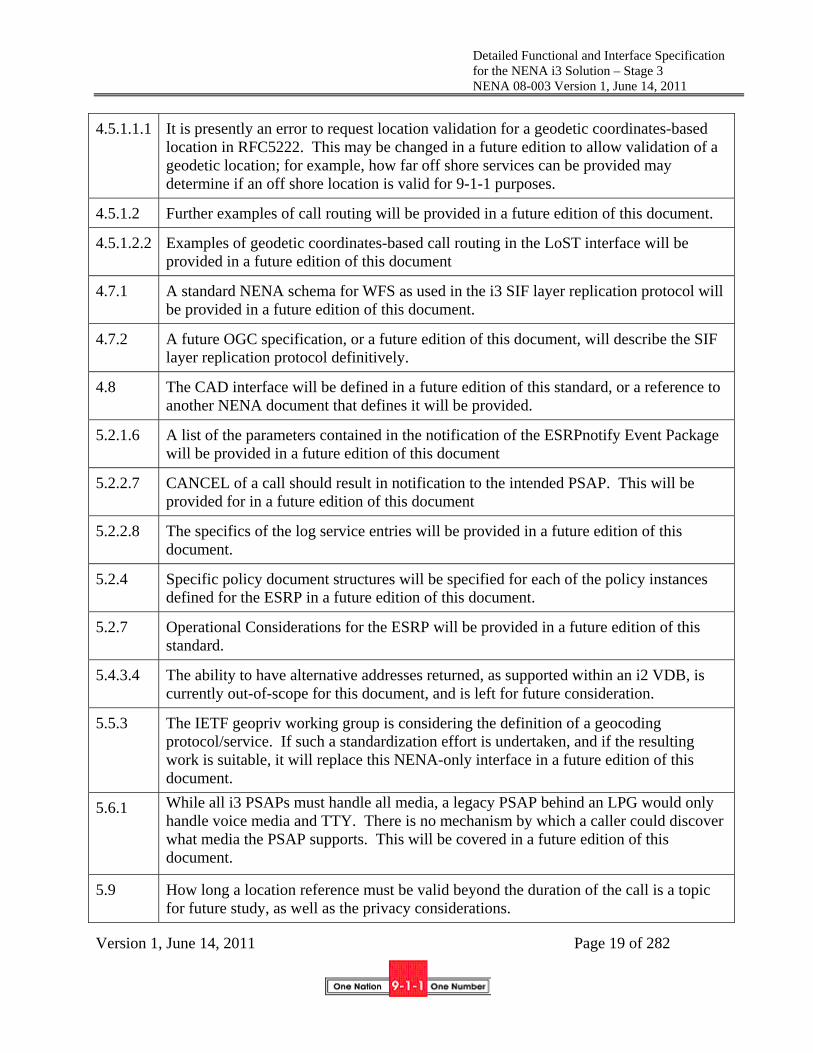
Detailed Functional and Interface Specification for the NENA i3 Solution – Stage 3 NENA 08-003 Version 1, June 14, 2011
Version 1, June 14, 2011 Page 19 of 282
4.5.1.1.1 It is presently an error to request location validation for a geodetic coordinates-based location in RFC5222. This may be changed in a future edition to allow validation of a geodetic location; for example, how far off shore services can be provided may determine if an off shore location is valid for 9-1-1 purposes.
4.5.1.2 Further examples of call routing will be provided in a future edition of this document.
4.5.1.2.2 Examples of geodetic coordinates-based call routing in the LoST interface will be provided in a future edition of this document
4.7.1 A standard NENA schema for WFS as used in the i3 SIF layer replication protocol will be provided in a future edition of this document.
4.7.2 A future OGC specification, or a future edition of this document, will describe the SIF layer replication protocol definitively.
4.8 The CAD interface will be defined in a future edition of this standard, or a reference to another NENA document that defines it will be provided.
5.2.1.6 A list of the parameters contained in the notification of the ESRPnotify Event Package will be provided in a future edition of this document
5.2.2.7 CANCEL of a call should result in notification to the intended PSAP. This will be provided for in a future edition of this document
5.2.2.8 The specifics of the log service entries will be provided in a future edition of this document.
5.2.4 Specific policy document structures will be specified for each of the policy instances defined for the ESRP in a future edition of this document.
5.2.7 Operational Considerations for the ESRP will be provided in a future edition of this standard.
5.4.3.4 The ability to have alternative addresses returned, as supported within an i2 VDB, is currently out-of-scope for this document, and is left for future consideration.
5.5.3 The IETF geopriv working group is considering the definition of a geocoding protocol/service. If such a standardization effort is undertaken, and if the resulting work is suitable, it will replace this NENA-only interface in a future edition of this document.
5.6.1 While all i3 PSAPs must handle all media, a legacy PSAP behind an LPG would only handle voice media and TTY. There is no mechanism by which a caller could discover what media the PSAP supports. This will be covered in a future edition of this document.
5.9 How long a location reference must be valid beyond the duration of the call is a topic for future study, as well as the privacy considerations.

Detailed Functional and Interface Specification for the NENA i3 Solution – Stage 3 NENA 08-003 Version 1, June 14, 2011
Version 1, June 14, 2011 Page 20 of 282
5.10 Extension of SIP to allow the data contained in an Additional Data about a Call structure to be included by value in the signaling is for future study.
5.12.1.1 A mechanism to discover the logger associated with an agency will be provided in a future edition of this document
5.12.1.1 It may be desirable to log other messages that are part of the INVITE transaction, such as the ACK. This will be covered in a future edition of this document.
5.12.4 Operational Considerations for the logging service will be supplied in a future edition of this standard.
5.15 The definition of an Agency Locator service will be provided in a future edition of this document.
6.2 The PCA CP/CPS must be in conformance with minimum standards to be provided in a future edition of this document.
6.3 Specific definitions of the roles enumerated in this section will be defined in an OID to be referenced in a future edition of this document.
6.7 A future edition of this standard will specify more precise key storage requirements to maintain privacy
7.1 Note: The LNG must log all significant events. Log record formats for this purpose will be provided in a future edition of this document.
7.1.2.3 This version does not describe interworking between SIP/HELD and E2/MLP for location conveyance and updates. This will be covered in a future edition of this document.
7.2 Note: The LPG must log all significant events. Log record formats for this purpose will be provided in a future edition of this document.
8.2 The xml data structure for Additional Data associated with a location will be defined in future work.
10 PSAP Management interface will be provided in a future edition of this document.
12.13 Roles will be defined in an OID to be referenced in a future edition of this document.
2.6 Date Compliance
All systems that are associated with the 9-1-1 process shall be designed and engineered to ensure that no detrimental, or other noticeable impact of any kind, will occur as a result of a date/time change up to 30 years subsequent to the manufacture of the system. This shall include embedded application, computer based or any other type application. To ensure true compliance, the

Detailed Functional and Interface Specification for the NENA i3 Solution – Stage 3 NENA 08-003 Version 1, June 14, 2011
Version 1, June 14, 2011 Page 21 of 282
manufacturer shall upon request, provide verifiable test results to an industry acceptable test plan such as Telcordia GR-2945 or equivalent.
2.7 Anticipated Timeline
As this is a major change to the 9-1-1 system, adoption of this standard will take several years and is also dependent on the pace of change and evolution of origination and access network providers. Experience with the immediately prior major change to 9-1-1 (i.e., Phase II wireless) suggests that unless consensus among government agencies at the local, state and federal levels, as well as network operators, vendors and other service providers is reached, implementation for the majority of PSAPs could take a decade. The Long Term Definition (LTD) Working Group chose technology commensurate with a 2-5 year implementation schedule.
2.8 Costs Factors
This is an all-new 9-1-1 system; the cost of everything will change. At this time it is difficult to predict the costs of the system and more work will be needed by vendors and service providers to determine the impact of the changes on their products and operations. If implemented at a regional (multi-county) or state level, the cost of the new system may be significantly less than the cost of the existing system, although in the transition from the existing system to the new one, duplicate elements and services will have to be maintained at a higher overall cost. It also may be that costs are not reduced, but the improved service to the public justifies these costs. Note that the charge to the LTD Working Group was to NOT make costs a primary consideration in making technical decisions. Nevertheless, due to the pragmatic experience of the participants, the document tended to consider cost as one of the variables in making choices. Estimating the cost to deploy the entire NG9-1-1 system is the purview of other groups within and outside NENA.
2.9 Future Path Plan Criteria for Technical Evolution
In present and future applications of all technologies used for 9-1-1 call and data delivery, it is a requirement to maintain the same level or improve on the reliability and service characteristics inherent in present 9-1-1 system design.
New methods or solutions for current and future service needs and options should meet the criteria below. This inherently requires knowledge of current 9-1-1 system design factors and concepts, in order to evaluate new proposed methods or solutions against the Path Plan criteria.
Criteria to meet the Definition/Requirement:
1. Reliability/dependability as governed by NENA’s technical standards and other generally accepted base characteristics of E9-1-1 service
2. Service parity for all potential 9-1-1 callers
3. Least complicated system design that results in fewest components to achieve needs (simplicity, maintainable)
4. Maximum probabilities for call and data delivery with least cost approach
Detailed Functional and Interface Specification for the NENA i3 Solution – Stage 3 NENA 08-003 Version 1, June 14, 2011
Version 1, June 14, 2011 Page 22 of 282
5. Documented procedures, practices, and processes to ensure adequate implementation and ongoing maintenance for 9-1-1 systems.
This basic technical policy is a guideline to focus technical development work on maintaining fundamental characteristics of E9-1-1 service by anyone providing equipment, software, or services.
2.10 Cost Recovery Considerations
Traditionally, much of the cost of the existing E9-1-1 Service Provider infrastructure has been supported through the collection of fees and surcharges on wireline and wireless telephone service. Changes in the telecommunications industry has caused the basis on which the fees and surcharges are collected to be modified, and the architecture described in this document further sunders the assumptions on which the current revenue streams are based. It should be noted that the costs associated with operating the 9-1-1 environment envisioned within this document are no longer accurately predicted by the number of originating network subscribers residing in a given service area. This document does not make recommendations on how funding should be changed. See the NG Partner Program Funding Policy paper [142] for more on this subject.
2.11 Additional Impacts (non cost related)
This effort is a part of the over-all Next Generation 9-1-1 project. There are far reaching impacts to the entire 9-1-1 system and public safety policies engendered by the changes in networks, databases, devices, interfaces and mechanisms this document describes. See the NG Partner Program Policy Guidelines documents for more on these areas [143]. It is expected that originating networks will ultimately evolve, but i3 assumes this evolution to take place over time and in stages by use of supporting gateways to allow existing interfaces from originating networks to be supported until such time as the originating network provider is ready to migrate to IP. Nearly all systems in a PSAP must (eventually) evolve. All databases change, some are eliminated, some new ones created, others are modified. New relationships between agencies must be established, for example, to facilitate answering of calls out of area.
Some of the more significant impacts are the methods and procedures to migrate the current 9-1-1 system to Next Generation 9-1-1. The NG9-1-1 Transition Planning Committee is developing documents that describe transition. This document only describes external interfaces to a PSAP. The internal PSAP subsystems and the interconnection between those subsystems must change. This is the responsibility of the NENA NG9-1-1 PSAP Working Group.
2.12 Intellectual Property Rights Policy
NENA takes no position regarding the validity or scope of any Intellectual Property Rights or other rights that might be claimed to pertain to the implementation or use of the technology described in this document or the extent to which any license under such rights might or might not be available; nor does it represent that it has made any independent effort to identify any such rights.
NENA invites any interested party to bring to its attention any copyrights, patents or patent applications, or other proprietary rights that may cover technology that may be required to implement this standard.
Please address the information to:

Detailed Functional and Interface Specification for the NENA i3 Solution – Stage 3 NENA 08-003 Version 1, June 14, 2011
Version 1, June 14, 2011 Page 23 of 282
National Emergency Number Association
4350 N Fairfax Dr, Suite 750
Arlington, VA 22203-1695
800-332-3911
2.13 Acronyms/Abbreviations/Definitions
This is not a glossary. See NENA 00-002 - NENA Master Glossary of 9-1-1 Terminology located on the NENA web site for a complete listing of terms used in NENA documents.
The following Acronyms are used in this document: Acronym Description **N)ew
(U)pdate
3GPP 3RD Generation Partner Project
3GPP2 3rd Generation Partnership Project 2
AAA Authorization, Admission and Accounting N
ABNF Augmented Backus-Naur Form N
ACK Acknowledgement N
ACM Address Complete Message N
AES Advanced Encryption Standard
AIP Access Infrastructure Provider
AMR Adaptive Multi Rate (codec) N
AMR-WB Adaptive Multi Rate (codec) – Wide Band N
ANI Automatic Number Identification
ANS American National Standard
ANSI American National Standards Institute
AoR Address of Record
APCO Association of Public Safety Communications Officials
ATIS Alliance for Telecommunications Industry Solutions
ATIS-ESIF Alliance for Telecommunications Industry Solutions – Emergency Services Interconnection Forum
N
B2BUA Back to Back User Agent
BCF Border Control Function
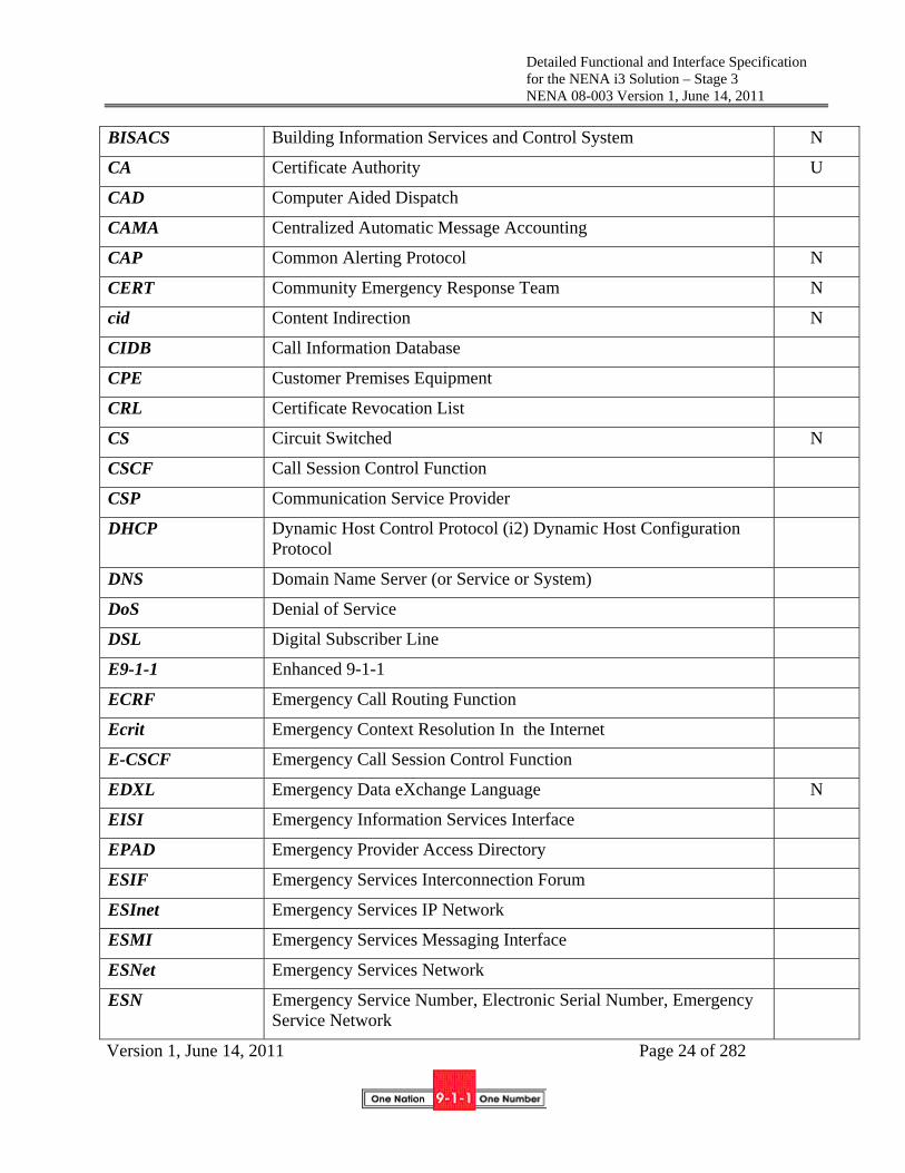
Detailed Functional and Interface Specification for the NENA i3 Solution – Stage 3 NENA 08-003 Version 1, June 14, 2011
Version 1, June 14, 2011 Page 24 of 282
BISACS Building Information Services and Control System N
CA Certificate Authority U
CAD Computer Aided Dispatch
CAMA Centralized Automatic Message Accounting
CAP Common Alerting Protocol N
CERT Community Emergency Response Team N
cid Content Indirection N
CIDB Call Information Database
CPE Customer Premises Equipment
CRL Certificate Revocation List
CS Circuit Switched N
CSCF Call Session Control Function
CSP Communication Service Provider
DHCP Dynamic Host Control Protocol (i2) Dynamic Host Configuration Protocol
DNS Domain Name Server (or Service or System)
DoS Denial of Service
DSL Digital Subscriber Line
E9-1-1 Enhanced 9-1-1
ECRF Emergency Call Routing Function
Ecrit Emergency Context Resolution In the Internet
E-CSCF Emergency Call Session Control Function
EDXL Emergency Data eXchange Language N
EISI Emergency Information Services Interface
EPAD Emergency Provider Access Directory
ESIF Emergency Services Interconnection Forum
ESInet Emergency Services IP Network
ESMI Emergency Services Messaging Interface
ESNet Emergency Services Network
ESN Emergency Service Number, Electronic Serial Number, Emergency Service Network

Detailed Functional and Interface Specification for the NENA i3 Solution – Stage 3 NENA 08-003 Version 1, June 14, 2011
Version 1, June 14, 2011 Page 25 of 282
ESNI Emergency Services Network Interfaces
ESQK Emergency Services Query Key
ESRK Emergency Services Routing Key
ESRP Emergency Services Routing Proxy
ESZ Emergency Services Zone (Same as ESN)
EVRC Enhanced Variable Rate Narrowband Codec
EVRC-WB Enhanced Variable Rate Wideband Codec
FCC Federal Communications Commission
GDP Generic Digit Parameter
Geopriv Geolocation and Privacy
GeoRSS Geodetic Really Simple Syndication N
Geoshape Geodetic Shape N
GML Geographic Markup Language
GSM Global Standard for Mobile Communication
GUID Globally Unique Identifier
HELD HTTP-Enabled Location Delivery Protocol
HSS Home Subscriber Server
IAM Initial Address Message
IANA Internet Assigned Numbers Authority
IDP Identity Provider N
IETF Internet Engineering Task Force
IM Instant Messaging
IMS IP Multimedia Subsystem
IP Internet Protocol
IP-CAN IP Connectivity Access Network
IP-PBX Internet Protocol Private Branch Exchange
IPsec Internet Protocol Security
ISDN Integrated Services Digital Network
ISUP Integrated Services Digital Network User Part N
ISP Internet Service Provider

Detailed Functional and Interface Specification for the NENA i3 Solution – Stage 3 NENA 08-003 Version 1, June 14, 2011
Version 1, June 14, 2011 Page 26 of 282
ISUP Integrated Services Digital Network User Part
KP Key Pulse
LAN Local Area Network
LDAP Lightweight Directory Access Protocol
LIF Location Interwork Function N
LIS Location Information Server
LO Location Object
LoST Location to Service Translation
LRF Location Retrieval Function
LTD Long Term Definition
LVF Location Validation Function
MDN Mobile Directory Number
MEP Message Exchange Pattern
MF Multi-Frequency
MIB Management Information Base
MPC/GMLC Mobile Positioning Center/ Gateway Mobile Location Center
MSC Mobile Switching Center
MPLS Multi-Protocol Label Switching
MSAG Master Street Address Guide
MSC Mobile Switching Center
MSRP Message Session Relay Protocol N
MTP Message Transfer Point
NAT Network Address Translation
NCIC National Crime Information Center, National Crime Enforcement Center
NENA National Emergency Number Association
NG9-1-1 Next Generation 9-1-1
NGES Next Generation Emergency Services
NGN Next Generation Network
NIF NG9-1-1 Specific Interwork Function N

Detailed Functional and Interface Specification for the NENA i3 Solution – Stage 3 NENA 08-003 Version 1, June 14, 2011
Version 1, June 14, 2011 Page 27 of 282
NMC 9-1-1 Malicious Content N
NPD Numbering Plan Digit
NRS NENA Registry System N
NTP Network Time Protocol
OASIS Organization for the Advancement of Structured Information Standards
OGC Open Geospatial Consortium N
OLIP Originating Line Information Parameter U
PAI P-Asserted-Identity N
P-CSCF Proxy Call Session Control Function
PCA PSAP Credentialing Agency
PDA Personal Digital Assistant
PHB Per Hop Behaviors N
PIDF Presence Information Data Format
PIDF-LO Presence Information Data Format – Location Objects
PIF Protocol Interworking Function N
PKI Public Key Infrastructure
PRF Policy Routing Function
PSP Provisioning Service Provider N
PSAP Public Safety Answering Point or Primary Public Safety Answering Point
PSO Provisioning Service Object N
PSTN Public Switched Telephone Network
PTSC Packet Technologies and Services Committee (ATIS Standards Committees)
QoS Quality of Service
RA Requesting Authority N
RBAC Role Based Access Control profile
RDF Routing Determination Function
REL Release (message) N
REST Representational State Transfer

Detailed Functional and Interface Specification for the NENA i3 Solution – Stage 3 NENA 08-003 Version 1, June 14, 2011
Version 1, June 14, 2011 Page 28 of 282
RFC Request for Comments
RG Response Gateway, Routing Gateway
RLC Release Complete (message) N
ROHC Robust Header Compression N
RTCP Real Time Control Protocol
RTP Real Time Transport Protocol
RTSP Real Time Streaming Protocol
RTT Real Time Text N
S-CSCF Serving Call Session Control Function
SAML Security Assertion Markup Language
SBC Session Border Control
SCTP Session Control Transport Protocol
SDES Session Description protocol Security Descriptions N
SDO Standards Development Organization
SDP Session Description Protocol
SHA Secure Hash Algorithm
SIF Spatial Information Function N
SIO Service Information Octet
SIP Session Initiation Protocol
SMS Short Message Service
SOA Service Oriented Architecture
SOAP Simple Object Access Protocol
SPML Service Provisioning Markup Language
SR Selective Routing, Selective Router [a.k.a., E9-1-1 Tandem, or Enhanced 9-1-1 (E9-1-1) Control Office]
SRTP Secure Real Time Protocol N
SRV Service (a DNS record type)
SS7 Signaling System 7
TCP Transport/Transmission Control Protocol
TDM Time Division Multiplexing

Detailed Functional and Interface Specification for the NENA i3 Solution – Stage 3 NENA 08-003 Version 1, June 14, 2011
Version 1, June 14, 2011 Page 29 of 282
TLS Transport Layer Security
TN Telephone Number
TOPS Technology and Operations Council N
TRD Technical Requirements Document
TTY Teletypewriter (a.k.a. TDD, Telecommunications Device for the Deaf and Hard-of-Hearing)
UA User Agent
UAC User Agent Client
UAS User Agent Service
UDDI Universal Description, Discovery and Integration
UDP User Datagram Protocol
UE User Element
URI Uniform Resource Identifier
URISA Urban and Regional Information Systems Association
URL Uniform Resource Locator (location sensitive)
URN Uniform Resource Name (location insensitive)
USPS United States Postal Service
UTC Universal Coordinated Time
VEDS Vehicle Emergency Data Sets
VF Validation Function
VoIP Voice over Internet Protocol
VPN Virtual Private Network
VSP VoIP Service Provider
WFS Web Feature Service
WSDL Web Service Definition Language
WSS Web Services Security
WTSC Wireless Technologies and Systems Committee
XACML eXtensible Access Control Markup Language
XML eXtensible Markup Language
XMPP eXtensible Messaging and Presence Protocol N

Detailed Functional and Interface Specification for the NENA i3 Solution – Stage 3 NENA 08-003 Version 1, June 14, 2011
Version 1, June 14, 2011 Page 30 of 282
The following Terms and Definitions are used in this document: Term Definition ** N)ew
(U)pdateg.711 a-law An ITU-T Recommendation for an audio codec for telephony
in non-North American regions N
g.711 mu-law An ITU-T Recommendation for an audio codec for telephony in the North American region
N
9-1-1 Authority The local agency responsible for overall operation of, and data for the 9-1-1 system
?
AdditionalAgency Event A log entry indicating another agency’s involvement with a call or incident, which may have log records for that call or event in their own log.
N
Additional Data Data associated with a call for which a URI is sent with the call or retrieved from the ECRF, for example, Additional Call Data, Additional Caller data and Additional Location Data
N
Agency Identifier A domain name for an agency used as a globally unique identifier.
N
Authentication A security term referring to the process of reliably identifying an entity requesting access to data or a service.
Authorization A security term referring to the process of making a decision what access rights an authenticated entity has to data or a service
B2BUA A back to back user agent is a SIP element that relays signaling mechanisms while performing some alteration or modification of the messages that would otherwise not be permitted by a proxy server.
N
Bridging Connecting two or more parties with a conference bridge N BYE transaction A SIP transaction used to terminate a session N
XSD W3C XML Schema Definition

Detailed Functional and Interface Specification for the NENA i3 Solution – Stage 3 NENA 08-003 Version 1, June 14, 2011
Version 1, June 14, 2011 Page 31 of 282
The following Terms and Definitions are used in this document: Term Definition ** N)ew
(U)pdateCall A session established by signaling with two way real-time
media and involves a human making a request for help. We sometimes use “voice call”, “video call” or “text call” when specific media is of primary importance. The term “non-human-initiated call” refers to a one-time notification or series of data exchanges established by signaling with at most one way media, and typically does not involve a human at the “calling” end. The term “call” can also be used to refer to either a “Voice Call”, “Video Call”, “Text Call” or “Data–only call”, since they are handled the same way through most of NG9-1-1.
Call Detail Record (CDR) A record stored in a database recording the details of a received or transmitted call
Call Identifier An identifier assigned by the first element in the first ESInet which handles a call. Call Identifiers are globally unique.
U
Call-Info Header A SIP header which contains a URI referring to some kind of data relevant to a call, and a “purpose” parameter describing what the URI refers to. Used to carry URIs to such entities as Additional Call and Caller data, and call/Incident Tracking Identifiers
N
CANCEL transaction A SIP transaction which is used to cancel an INVITE transaction which has not yet completed
N

Detailed Functional and Interface Specification for the NENA i3 Solution – Stage 3 NENA 08-003 Version 1, June 14, 2011
Version 1, June 14, 2011 Page 32 of 282
The following Terms and Definitions are used in this document: Term Definition ** N)ew
(U)pdateCAP MESSAGE A notification using the Common Alerting Protocol. CAP is
used within the ESInet to send alerts from automated systems to PSAPs, and is also used to communicate data between agencies without a call.
N
Catypes A component of a civic address in a PIDF-LO such as a Street Name or House Number, which has a code used to identify what kind of component.
N
Code Point A code for a requested QoS action used in the Diffserv QoS mechanism on an IP network. The code point is sent in the TOS field of an IP packet.
N
Denial of Service Attack A type of cyber attack intended to overwhelm the resources of the target and deny the ability of legitimate users of the target the normal service the target provides.
N
Dereference The act of exchanging a reference to an item by its value. Used primarily with a Location URI. The dereference operation uses a protocol such as SIP or HELD to obtain a location value (PIDF-LO).
N
Diffserv A quality of service mechanism for IP networks characterized by a code in a field of a Packet called a “Code Point” and a “Per hop Behavior”
N
Domain (or Domain Name)
The domain name (hostname) of an agency or element in an ESInet. See Domain Name System (DNS)
N
Element Identifier A logical name used to represent physical implementation of a functional element or set of functional elements as a single addressable unit. The form of an element identifier is a hostname.
N
Emergency Call Routing Function (ECRF)
A functional element in an ESInet which is a LoST protocol server where location information (either civic address or geo-coordinates) and a Service URN serve as input to a mapping function that returns a URI used to route an emergency call toward the appropriate PSAP for the caller’s location or towards a responder agency.
U

Detailed Functional and Interface Specification for the NENA i3 Solution – Stage 3 NENA 08-003 Version 1, June 14, 2011
Version 1, June 14, 2011 Page 33 of 282
The following Terms and Definitions are used in this document: Term Definition ** N)ew
(U)pdateEmergency Event An asynchronous communications notification which is a
single communication message to a PSAP that results in a defined action by a call taker but does not have a human at the origination end and where no two way media streams are established.
N
Emergency Services IP Network
An ESInet is a managed IP network that is used for emergency services communications, and which can be shared by all public safety agencies. It provides the IP transport infrastructure upon which independent application platforms and core functional processes can be deployed, including, but not restricted to, those necessary for providing NG9-1-1 services. ESInets may be constructed from a mix of dedicated and shared facilities. ESInets may be interconnected at local, regional, state, federal, national and international levels to form an IP-based inter-network (network of networks).
N
From Header A SIP header that describes the caller’s notion of its own identity (Address of Record). From is generally not treated as reliable unless it is protected by an Identity header
N
geoShape Element One of a list of shapes defined originally by the IETF and standardized by the Open Geospatial Consortium that can be found in a PIDF-LO. Includes point, circle, ellipse, arc band, polygon and 3D versions of same
N
H.264 A video codec, defined by ITU-T in common use today for real time two way video
N
HELD A protocol defined by the IETF to deliver location using HTTP transport
N
IANA Registry A registry maintained by the Internet Assigned Number Authority, usually at the behest of the IETF
N
Incident A real world occurrence such as a heart attack, car crash or a building fire for which one or more calls may be received.
N
Incident Tracking Identifier
An identifier assigned by the first element which declares an incident. Incident Tracking Identifiers are globally unique.
U
INFO A SIP transaction used to pass information from the caller to the called party
N
Instant Messaging (IM) A method of communication generally using text where more than a character at a time is sent between parties nearly instantaneously
N
INVITE A SIP transaction used to initiate a session N

Detailed Functional and Interface Specification for the NENA i3 Solution – Stage 3 NENA 08-003 Version 1, June 14, 2011
Version 1, June 14, 2011 Page 34 of 282
The following Terms and Definitions are used in this document: Term Definition ** N)ew
(U)pdateLegacy PSAP Gateway An NG9-1-1 Functional Element which provides an interface
between an ESInet and an un-upgraded PSAP N
Location In the context of location information to support IP-based emergency services: The physical position of an end-point expressed in either civic or geodetic form. A spot on the planet where something is; a particular place or position. Oxford Dictionary, Oxford University Press, 2009.
U
Location Interwork Function (LIF)
The functional component of a Legacy Network Gateway which is responsible for taking the appropriate information from the incoming signaling (i.e., calling number/ANI, ESRK, cell site/sector) and using it to acquire location information that can be used to route the emergency call and to provide location information to the PSAP. In a Legacy PSAP Gateway, this functional component takes the information from an ALI query and uses it to obtain location from a LIS.
N
Location URI A URI which, when dereferenced, yields a location value in the form of a PIDF-LO. Location-by-reference in NG9-1-1 is represented by a Location URI.
N
Mapping The act of determining a value in one domain from a value in another domain. For example, mapping a location to the URI of a PSAP that serves that location using the LoST protocol.
N
MESSAGE A SIP method which passes information, often an Instant Message, between endpoints in the body of the SIP message
N
NG9-1-1 Specific Interwork Function (NIF)
The functional component of a Legacy Network Gateway or Legacy PSAP Gateway which provides NG9-1-1-specific processing of the call not provided by an off-the-shelf protocol interwork gateway.
N
Next Hop The next element in a routing path. For example, the next router in an IP network, or the next SIP proxy server in a SIP signaling path.
N
Notifier An element in an asynchronous event notification mechanism that transmits events
N
NOTIFY A SIP method used to send a notification to a subscriber of the occurrence of an asynchronous event.
N
OPTIONS A SIP method used to request the SIP protocol options supported by an endpoint.
N

Detailed Functional and Interface Specification for the NENA i3 Solution – Stage 3 NENA 08-003 Version 1, June 14, 2011
Version 1, June 14, 2011 Page 35 of 282
The following Terms and Definitions are used in this document: Term Definition ** N)ew
(U)pdateOriginating ESRP The first routing element inside the ESInet. It receives calls
from the BCF at the edge of the ESInet.
N
Per Hop Behaviors (PHB) The action a router takes for a packet marked with a specific code point in the Diffserv QoS mechanism in IP networks
N
Policy Routing Function (PRF)
That functional component of an Emergency Services Routing Proxy that determines the next hop in the SIP signaling path using the policy of the nominal next element determined by querying the ECRF with the location of the caller.
U
Policy Store A functional element in the ESInet that stores policy documents.
N
PRACK A SIP message used to reliably acknowledge receipt of an otherwise unreliable message transmission.
N
Protocol Interworking Function (PIF)
That functional component of a Legacy Network Gateway or Legacy PSAP Gateway that interworks legacy PSTN signaling such as ISUP or CAMA with SIP signaling.
N
Provisioning Service provider (PSP)
The component in an ESInet functional element that implements the provider side of a SPML interface used for provisioning
N
PSAP Credentialing Agency (PCA)
The root authority designated to issue and revoke security credentials (in the form of an X.509 certificate) to authorized 9-1-1 agencies in an ESInet.
N
Real Time Text (RTT) Text transmission that is character at a time, as in TTY. N REFER A SIP method that is used as part of a transfer operation to
refer a call to another endpoint N
REFER/Replaces Use of the SIP REFER method together with a Replaces header as part of a transfer operation to indicate that a new leg is to be created that replaces an existing call leg.
N
REGISTER A SIP method that is used to communicate the availability and address of an endpoint to the proxy server that directs incoming calls.
N
reINVITE A SIP INVITE transaction within an established session used to change the parameters of a call.
N
RequestURI That part of a SIP message that indicates where the call is being routed towards. SIP Proxy servers commonly change the Request ID (“retargeting”) to route a call towards the intended recipient.
N
Resource Priority A header used on SIP calls to indicate priority that proxy servers give to specific calls.
N

Detailed Functional and Interface Specification for the NENA i3 Solution – Stage 3 NENA 08-003 Version 1, June 14, 2011
Version 1, June 14, 2011 Page 36 of 282
The following Terms and Definitions are used in this document: Term Definition ** N)ew
(U)pdateReverseGeocode The process of converting a geo form of location (X,Y) to a
civic (street address) form. N
Rights Management Specifying the access rights by an entity (agent or agency) to a particular document, data element, or service
N
Scheme The part of a URI that indicates the protocol. For example, the scheme in the URI sip:[email protected] is “sip”
N
Security Posture An event that represents a downstream entity’s current security state (normal, under attack, …).
N
Service Boundary A polygon in a GIS system, SIF, ECRF or other ESInet element that indicates the area a particular agency or element serves.
N
Service Uniform Resource Name (Service URN)
A URN with “service” as the first component supplied as an input in a LoST request to an ECRF to indicate which service boundaries to consider when determining a response. A service URN is also used to mark a call as an emergency call.
N
Session Border Control A commonly available functional element that provides security, NAT traversal, protocol repair and other functions to VoIP signaling such as SIP. A component of a Border Control Function
N
Smart Cards A credit-card-like object that contains a processor and memory, and is typically used to carry credentials for an agent in an authentication system. A smart card may be one factor in a 2 or 3 factor authentication system and is “something you have”
N
SOS URN A service URN starting with “urn:service:sos” which is used to mark calls as emergency calls as they traverse an IP network.
N
SUBSCRIBE/NOTIFY The two actions in an asynchronous event notification system. The subscription is the request to receive notifications of the events. The Notify is the notification of the event itself. Also refers to the SIP methods used for this purpose.
N
Subscriber Database (SDB)
A database operated by a carrier or other service provider which supplies the “Additional Call” data object. The SDB dereferences the URI passed in a Call-Info header and returns the AdditionalCall XML object.
N
SubjectAltName A field in an X.509c digital certificate which typically contains identifying information for the entity issued the certificate. In an ESInet, SubjectAltName contains an agent or agency ID
N

Detailed Functional and Interface Specification for the NENA i3 Solution – Stage 3 NENA 08-003 Version 1, June 14, 2011
Version 1, June 14, 2011 Page 37 of 282
The following Terms and Definitions are used in this document: Term Definition ** N)ew
(U)pdateTerminating ESRP The last ESRP for a call in an ESInet, and typically chooses a
queue of call takers to answer the call N
Token A physical device that displays a multidigit number used as part of an authentication system (“something you have”). Also, a set of bits that represent some data, permission or state which is meaningful to the recipient, but not necessarily the sender.
N
Transcoding Translating a media stream from one codec to another. For example, translating Baudot tones detected in a G.711 encoded audio stream to T.140 real time text
N
UPDATE A SIP method used to update parameters in a call not yet established
N

Detailed Functional and Interface Specification for the NENA i3 Solution – Stage 3 NENA 08-003 Version 1, June 14, 2011
Version 1, June 14, 2011 Page 38 of 282
3 General Concepts
3.1 Identifiers
To enable calls to be handled in an interconnected ESInet, identifiers are standardized as follows:
3.1.1 Agency Identifier
An Agency is an organization that is a client of a database or service, which is represented by a domain name (hostname from STD013 [106]). Agencies must use one domain name consistently in order to correlate actions across a wide range of calls and incidents. Any domain name in the public DNS is acceptable so long as each distinct agency uses a different domain name. This implies that each agency ID is globally unique. An example of an agency identifier is psap.allegheny.pa.us.
3.1.2 Agent Identifier
An agent is a person employed by or contracted by an agency. An agent identifier is a user name, using the syntax for “Dot-string” in RFC2821 (that is, the user part of an email address, without the possibility of a “Quoted-String”). Usernames must be unique within the domain of the agency, which implies that the combination Agent and Agency IDs is globally unique. Examples of this include [email protected] and [email protected].
3.1.3 Element Identifier
A logical name used to represent physical implementation of a functional element or set of functional elements as a single addressable unit. (Section 4.1.2) The external interfaces of the element must adhere to the standards in this document. Elements are addressable via a hostname that must be globally unique. An example of an element identifier is esrp.state.pa.us.
3.1.4 Call Identifier
The term “call” is defined in Section 2.3 and includes voice calls, video calls, text calls and non-human-initiated calls. The first element in the first ESInet which handles a call assigns the Call Identifier. The form of a Call Identifier is a URI consisting of the string “_CI_”, a unique string, the “@” character, and the domain name of the element that first handled the call. For example: “[email protected]”. The unique string must be unique for each call the element handles over time. The length of the unique string must be between 10 and 30 characters. One way to create the unique string is to use a timestamp with a suffix that differentiates multiple calls if they could be created by the element in the same instant. Implementations using multiple physical devices to implement a redundant element may need an additional component to guarantee uniqueness.
3.1.5 Incident Tracking Identifier
A real world occurrence such as a heart attack, car crash or a building fire for which one or more calls may be received is an Incident. Examples include a traffic accident (including subsequent secondary crashes), a hazardous material spill, etc. Multiple Calls may be associated with an Incident. An Incident may include other Incidents in a hierarchical fashion. The form of an Incident

Detailed Functional and Interface Specification for the NENA i3 Solution – Stage 3 NENA 08-003 Version 1, June 14, 2011
Version 1, June 14, 2011 Page 39 of 282
Tracking Identifier is a URI consisting of the string “_II_”, a unique string, the “@” character, and the domain name of the entity that first declared the incident. For example: “[email protected]”. The unique string must be unique for each Incident the element handles over time. One way to create the unique string is to use a timestamp with a suffix that differentiates multiple Incidents if they could be created by an element in the same instant. Implementations using multiple physical devices to implement a redundant element may need an additional component to guarantee uniqueness. Incident Tracking Identifiers are globally unique. By definition, there is an Incident associated with every call. As a practical matter, there is at least one call associated with every Incident, except those incidents declared by an agent (such as a policeman observing a traffic incident). Incident Tracking Identifiers may be assigned to a call prior to determining what real world incident it actually belongs to. See Section 5.2.2.2
3.2 Timestamp
Any record that must be marked with when it occurred (especially a log record, see Section5.12) includes a timestamp. A timestamp is represented by an ISO 8601 [115] time point. Time must include seconds, and, if two or more timestamps could be generated by the same element within one second where the order of events matter, the seconds element must include sufficient decimal places in the seconds field to differentiate the time stamps. An example of a timestamp is 2015-08-21T12:58.03.01+05. All time within the ESInet is represented as local time with offset to UTC. The offset is a required component of a timestamp.
3.3 Events common to multiple functional elements
Events are described in Section 4.1.3.2. The following events may be implemented in any functional element. Also see the Logging service interface in Section 5.12, which is implemented by any element that handles a call.
3.3.1 Security Posture
SecurityPosture is an event that represents a downstream entity’s current security state. This document creates a NENA Registry System (NRS) registry of allowed values. The initial defined values are:
Green – The entity is operating normally
Yellow – The entity is receiving suspicious activity, but is able to operate normally
Orange – The entity is receiving fraudulent calls/events, is stressed, but is able to continue most operations
Red – The entity is under active attack and is overwhelmed
Event Package Name: nena-SecurityPosture
Event Package Parameters: None
SUBSCRIBE Bodies: standard RFC4661 + extensions filter specification may be present
Subscription Duration Default 1 hour. 1 minute to 24 hours is reasonable.
NOTIFY Bodies: MIME type application/vnd,nena.SecurityPosture+xml

Detailed Functional and Interface Specification for the NENA i3 Solution – Stage 3 NENA 08-003 Version 1, June 14, 2011
Version 1, June 14, 2011 Page 40 of 282
Parameter Condition Description
Posture Mandatory Enumeration of current security posture from NRS SecurityPosture registry
Notifier Processing of SUBSCRIBE Requests
The notifier consults the policy (securityPosture) to determine if the requester is permitted to subscribe. It returns 603 (Decline) if not acceptable. If the request is acceptable, it returns 202 (Accepted).
Notifier Generation of NOTIFY Requests
When the security posture of the element changes, a new NOTIFY is generated, adhering to the filter requests.
Subscriber Processing of NOTIFY Requests
No specific action required.
Handling of Forked Requests
Forking is not expected to be used with this package
Rate of Notification
Posture state normally does not change rapidly. Changes may occur in minutes if attacks start and stop sporadically.
State Agents
No special handling is required.
3.3.2 Element State
ElementState is an event that indicates the state of an element either automatically determined, or as determined by management. This document creates an NRS registry (ElementState) of allowed values with initial defined states of:
Normal: The element is operating normally, accepting calls and events
Unmanned: (applies to PSAPs only) The PSAP has indicated that it is not currently answering calls.
ScheduledMaintenance: The element is undergoing maintenance activities and is not processing calls
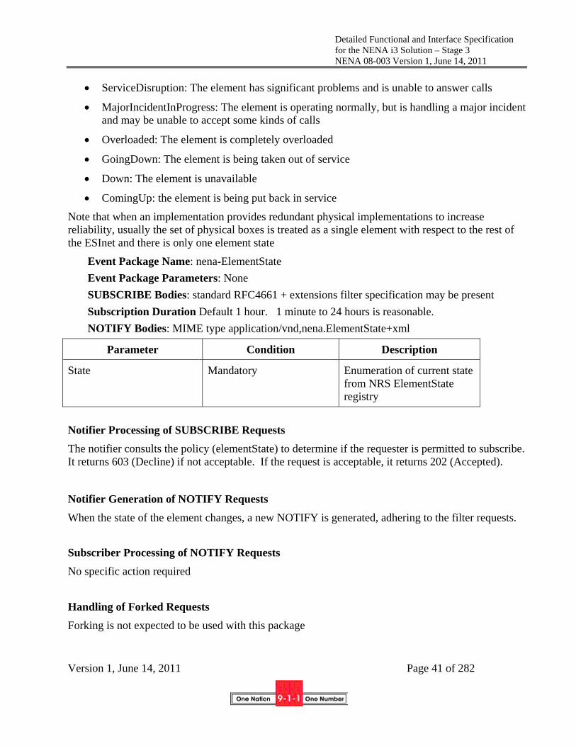
Detailed Functional and Interface Specification for the NENA i3 Solution – Stage 3 NENA 08-003 Version 1, June 14, 2011
Version 1, June 14, 2011 Page 41 of 282
ServiceDisruption: The element has significant problems and is unable to answer calls
MajorIncidentInProgress: The element is operating normally, but is handling a major incident and may be unable to accept some kinds of calls
Overloaded: The element is completely overloaded
GoingDown: The element is being taken out of service
Down: The element is unavailable
ComingUp: the element is being put back in service
Note that when an implementation provides redundant physical implementations to increase reliability, usually the set of physical boxes is treated as a single element with respect to the rest of the ESInet and there is only one element state
Event Package Name: nena-ElementState
Event Package Parameters: None
SUBSCRIBE Bodies: standard RFC4661 + extensions filter specification may be present
Subscription Duration Default 1 hour. 1 minute to 24 hours is reasonable.
NOTIFY Bodies: MIME type application/vnd,nena.ElementState+xml
Parameter Condition Description
State Mandatory Enumeration of current state from NRS ElementState registry
Notifier Processing of SUBSCRIBE Requests
The notifier consults the policy (elementState) to determine if the requester is permitted to subscribe. It returns 603 (Decline) if not acceptable. If the request is acceptable, it returns 202 (Accepted).
Notifier Generation of NOTIFY Requests
When the state of the element changes, a new NOTIFY is generated, adhering to the filter requests.
Subscriber Processing of NOTIFY Requests
No specific action required
Handling of Forked Requests
Forking is not expected to be used with this package

Detailed Functional and Interface Specification for the NENA i3 Solution – Stage 3 NENA 08-003 Version 1, June 14, 2011
Version 1, June 14, 2011 Page 42 of 282
Rate of Notification
State normally does not change rapidly. Changes may occur in tens of seconds if the network or systems are unstable.
State Agents
No special handling is required.
3.3.3 Service State
ServiceState is an event that indicates the state of service either automatically determined, or as determined by management. This document creates an NRS registry (ServiceState) of allowed values with initial defined states of:
Normal: The service is operating normally
ScheduledMaintenance (down): The service is undergoing maintenance activities and is not accepting service requests
ScheduledMaintenance (available): The service is undergoing maintenance activities, but will respond to service requests, possibly with reduced reliability
ServiceDisruption: The service has significant problems and is unable to respond
Slow: The service is operating normally, but is handling a larger than normal number of requests, responses may be slow.
GoingDown: The service is being taken out of service
Down: The service is unavailable
ComingUp: The service is being put back in service
Note that one or more elements may implement a service. Each element would have its own element state, the service would have an independent state.
Event Package Name: nena-ServiceState
Event Package Parameters: None
SUBSCRIBE Bodies: standard RFC4661 + extensions filter specification may be present
Subscription Duration Default 1 hour. 1 minute to 24 hours is reasonable.
NOTIFY Bodies: MIME type application/vnd,nena.ServiceState+xml
Parameter Condition Description
Service Mandatory Name of Service
State Mandatory Enumeration of current state from NRS ServiceState registry

Detailed Functional and Interface Specification for the NENA i3 Solution – Stage 3 NENA 08-003 Version 1, June 14, 2011
Version 1, June 14, 2011 Page 43 of 282
Notifier Processing of SUBSCRIBE Requests
The notifier consults the policy (serviceState) to determine if the requester is permitted to subscribe. It returns 603 (Decline) if not acceptable. If the request is acceptable, it returns 202 (Accepted).
Notifier Generation of NOTIFY Requests
When the state of the service changes, a new NOTIFY is generated, adhering to the filter requests.
Subscriber Processing of NOTIFY Requests
No specific action required.
Handling of Forked Requests
Forking is not expected to be used with this package.
Rate of Notification
State normally does not change rapidly. Changes may occur in tens of seconds if the network or systems are unstable.
State Agents
No special handling is required.
3.4 Location Representation
Location in NG9-1-1 is represented by validated content in the PIDF-LO2 (RFC4119, updated by RFC5139 and RFC5491) with field use for the United States as documented in the NENA Civic Location Exchange Format [109]. Fields in the PIDF-LO must be used as defined; no local variation is permitted. A service (PIDFLOtoMSAG) is provided in this document for translating PIDF-LO to
2 In the IETF, location information is a subset of Presence information. While NG9-1-1 uses PIDF and the IETF mechanisms that are described in the Presence service, no other parts of presence are used.

Detailed Functional and Interface Specification for the NENA i3 Solution – Stage 3 NENA 08-003 Version 1, June 14, 2011
Version 1, June 14, 2011 Page 44 of 282
a NENA standard MSAG representation for backwards compatibility. All geodetic data in i3 uses WGS84 as the datum.
3.5 vCards
In many interfaces defined in this and related NG9-1-1 documents, a common need is to provide contact information. For example, in the Additional Caller Data, the identity and contact information is part of the data structure. When contact data is needed, i3 specifies the use of a vCard as defined in RFC2426 [124]. It is recognized that an XML format of this information would be desirable, but until one is standardized, it is felt using the recognized RFC2425 standard is appropriate.
3.6 Emergency Services IP Networks
ESInets are private, managed, and routed IP networks. An ESInet serves a set of PSAPs, a region, a state, or a set of states. The ESInet has a service area, defined by a (set of) polygon(s). ESInets are interconnected to neighboring ESInets so that traffic can be routed from any point in the ESInet to any point in any other ESInet. States may have a backbone ESInet either directly connecting to all PSAPs in the state, or interconnected to all county or regional ESInets. Neighboring states or regions may interconnect their ESInets. It is desirable to have a backbone national ESInet to optimize routing of traffic between distant state ESInets. Each PSAP must be connected to an ESInet, possibly through a Legacy PSAP Gateway.
ESInets must accept and route IPv4 and IPv6 packets. All services must support IPv4 and IPv6 interfaces. IPv6 is recommended for use throughout the ESInet, but cannot be assumed.
The ESInet must be connected to the Internet through the Border Control Function (BCF) to accept calls. This Internet interconnect is recommended at the state ESInet level. Origination networks should be connected to any ESInet they regularly deliver volume traffic to via a private connection, through the BCF of that ESInet. Connection through the Internet is acceptable, preferably through a VPN.
Access to ESInets must be controlled. Only public safety agencies, their contractors and service providers should be connected directly to the ESInet. However, for security reasons, the ESInet should not be assumed to be a “walled garden”.
For QoS reasons, IP traffic within an ESInet must implement DiffServ (RFC2475). Routers must respect code points, functional elements must mark packets they create with appropriate code points. The BCF must police code points for packets entering the ESInet. The following code points and Per Hop Behaviors (PHB) must be used on ESInets:
DSCP Use PHB
0 Routine Traffic Default
1 9-1-1 Signaling AF12
2 9-1-1 Text Media AF12

Detailed Functional and Interface Specification for the NENA i3 Solution – Stage 3 NENA 08-003 Version 1, June 14, 2011
Version 1, June 14, 2011 Page 45 of 282
3 9-1-1 Audio Media EF
4 9-1-1 Video Media AF11
5 9-1-1 Non-human-initiated Call AF21
6 Intra ESInet Events AF21
7 Intra ESInet Other 9-1-1 Traffic AF22
All elements in an ESInet should have a publicly addressable IP address. Network Address Translations (NATs) should not be used within an ESInet. Although NAT use within an ESInet is not recommended, NATs may be needed in specific deployments, and therefore all network elements must operate in the presence of NATs.
It is recommended that elements connected to the ESInet not be referred to by their IP address but rather through a hostname using DNS. Use of statically assigned IP addresses should be limited, and should never be used with IPv6 addresses. DHCP must be implemented on all network elements to obtain IP address, gateway, and other services. Many ESInet services depend on discovery of services via DHCP.
There must be no single point of failure for any critical service or function on the ESInet. Certain services designated as non-critical may be exempt from this requirement. These must not include the BCF, internal ECRF, ESRP, logging service and security services. Services must be deployed to survive disaster, deliberate attack and massive failure.
4 Interfaces
4.1 SIP Call
The i3 call interface is SIP [12]. All calls presented to the ESInet must be SIP signaled. Calls are potentially multimedia, and can include one or more forms of media (audio, video and/or text3). See Section 4.6 for a discussion of "non-human-initiated calls" which can be used for non-human-initiated requests for help where there is no human caller. SIP is also the protocol used to call a 9-1-1 caller back, and for calls between agents within the ESInet.
SIP is a complex protocol defined in a large number of standards documents. All NG9-1-1 elements which process calls must implement all of the standards listed in Section 3 (Core Standards) in the
3 All ESInet elements support all forms of media described in this document. Any given origination network or device may not support all media types, and support of specific media types by origination networks and devices may be subject to regulation.

Detailed Functional and Interface Specification for the NENA i3 Solution – Stage 3 NENA 08-003 Version 1, June 14, 2011
Version 1, June 14, 2011 Page 46 of 282
"Hitchhiker's Guide to SIP" [11]. Implementations are cautioned to be "strict in what you send, and liberal in what you accept" with respect to such standards. It is generally unacceptable to drop a 9-1-1 call just because it doesn't meet some standard detail if it's reasonably possible to process the call anyway.
There are three primary entities in a SIP protocol exchange:
1. The User Agent Client, which is the initiator of a “transaction” within SIP. In the origination of a 9-1-1 call, the calling party’s end device is the UAC
2. The User Agent Server, which is the target of a transaction within SIP. In the origination of a 9-1-1 call, the call taker’s end device is the UAS.
3. A Proxy Server, which is an intermediary that assists in the routing of a call. Proxy servers are in the signaling path of a call, but not in the media path. A call may traverse several proxies. In a typical 9-1-1 call, the calling party’s carrier may have two or more proxies. The ESInet has at least one proxy (an Emergency Services Routing Proxy) and typically has more than one.
SIP message exchanges are defined in transactions, which are explicit sequences of messages. The transaction is named by the “method” in the SIP message that starts the transaction. For example, the SIP transaction that creates a call (termed a “session” in SIP) is the INVITE transaction.
4.1.1 Minimal Methods needed to handle a call
The only method absolutely required to handle a 9-1-1 call is the INVITE. The REFER method (defined in [23]) should also be supported to conference and transfer calls. Call takers (and thus bridges that they use) must be able to generate the BYE transaction to terminate the call.
NG9-1-1 elements that process 9-1-1 calls must accept calls that do not strictly follow the SIP standards. So long as the messages can be parsed, and the method discerned, at least the first SIP element (the BCF) must be able to accept the call and forward the call onward (see Section 5.1).
4.1.1.1 INVITE (initial call)
The INVITE method is used to initiate a call. The standard INVITE/OK/ACK sequence must be followed, with allowance for intermediate (1XX) responses. It is generally unacceptable to refuse an INVITE request unless the PSAP is under active attack and cannot respond.
An emergency call has a Route header obtained from the ECRF based on the location of the call, and a Request URI containing a Service URN. Nominally, the Service URN should be urn:service:sos. In most jurisdictions, urn:service:sos.police, urn:service:sos.fire and urn:service:sos.ambulance would route to the primary PSAP.
The external (outside the ESInet) ECRF returns a “PSAP URI” which would be the Route header when the call enters the ESInet. The content of this URI can vary depending on the policy of the 9-1-1 Authority. One strategy is simply to use a general URI that leads to a state level ESRP, for example [email protected]. The state ESRP would query the internal (within the ESInet) ECRF with a mapped (from the incoming service URN in the Request URI) service urn, for example urn:nena:service:sos.psap and would receive the next hop route for the call. Alternatively, the

Detailed Functional and Interface Specification for the NENA i3 Solution – Stage 3 NENA 08-003 Version 1, June 14, 2011
Version 1, June 14, 2011 Page 47 of 282
external ECRF could return a more specific URI, for example, [email protected]. This URI would still route to the same state-level ESRP, which would perform the same ECRF query. However, failures at the state ESRP (for example, a failure to obtain a route from the ECRF) may be able to be mitigated by using the information in the Route header.
Every call received by the ESInet gets some form of "call treatment". Minimal call treatments defined include:
1. Queue a call for answering by a call taker
2. Return Busy (600 Busy Everywhere)
3. Answer at an Interactive Multimedia Response system
4. Divert to another PSAP.
The ESRP determines, by evaluating PSAP policy, which treatment a call gets.
All calls that will go to a call taker are queued; however, the time in queue may be negligible.
The PSAP should normally only return a 183 In Progress intermediate response when a 9-1-1 call is queued for answer. It is recommended that no other 1XX response be used due to uneven implementations of these responses. 183 In Progress should be repeated at approximately 3 second intervals if the call is not answered. When placing a call back, elements must accept any 1XX intermediate response and provide an appropriate indication to the caller. UACs within the ESInet must generate an appropriate audible and in most cases a visual ring indication.
The normal response to an answered call is 200 OK.
9-1-1 calls are usually not redirected, and thus 3XX responses are normally not used; however 3XX may be used for calls within the ESInet. NG9-1-1 elements that initiate calls within the ESInet should appropriately respond as defined in RFC 3261 [12]. A 9-1-1 call may be so malformed that the BCF cannot parse the message.
Errors typically encountered in a SIP call should be handled as follows:
SIP INVITE Response Codes from ESRP
Description
183
(Ringing)
A 9-1-1 call is queued for answer. It is recommended that no other 1XX response be used due to uneven implementations of these responses. 183 Ringing should be repeated at approximately 3 second intervals if the call is not answered.
200
(OK)
Normal response to an answered call
3XX 9-1-1 calls are usually not redirected, and thus 3XX responses are normally not used. 3XX may be used for calls within the ESInet. NG9-1-1 elements that initiate calls within the ESInet should appropriately respond as defined in RFC 3261 [12].

Detailed Functional and Interface Specification for the NENA i3 Solution – Stage 3 NENA 08-003 Version 1, June 14, 2011
Version 1, June 14, 2011 Page 48 of 282
400
(Bad Request)
A 9-1-1 call is so malformed that the BCF cannot parse the message.
401 Should never occur for a 9-1-1 call, but proxy authorization is required for all calls originated by entities within an ESInet.
402 Should never occur for a 9-1-1 call or an internal call
403
(Forbidden)
Normally, 403 (Forbidden) should not occur, but if the BCF passes a malformed INVITE which downstream devices cannot handle, they may have no choice but to return 403.
404
(Not Found)
404 (Not Found) would normally not occur for a 9-1-1 call, but may be used within the ESInet.
406
(Not Acceptable)
The 406 (Not Acceptable) should not occur for a 9-1-1 call because the INVITE should not have an Accept header that is unacceptable to the PSAP. If it does, 406 is the correct response.
408
(Request Timeout)
May be issued in an unplanned circumstance. Normally, this should never happen to a 9-1-1 call.
413
(Request Entity too Large)
The BCF should accept any Request URI, but downstream elements may return 413 (Request Entity Too Large).
414
(Request-URI Too Long)
The BCF should accept any Request URI, but downstream elements may return 414 (Request-URI Too Long).
416 (Unsupported URI Scheme)
The BCF should accept any Request URI, but downstream elements may return 416 (Unsupported URI Scheme).
486
(Busy Here)
PSAPs may limit the number of test calls, and if that limit is exceeded, the response shall be 486 Busy Here.
600
(Busy Everywhere)
If the BCF detects an active attack, it should respond with 600 (Busy Everywhere), rather than another 4XX response.
Once a call is established, it may be necessary to modify some of the parameters of the call. For example, it may be necessary to change the media session parameters. In this case, an INVITE transaction on an existing session is used. This is termed a “reINVITE” in SIP. Re-INVITEs may be used on any call within the ESInet, including a 9-1-1 call. ReINVITE may be initiated from

Detailed Functional and Interface Specification for the NENA i3 Solution – Stage 3 NENA 08-003 Version 1, June 14, 2011
Version 1, June 14, 2011 Page 49 of 282
either end of the call. Note that when the reINVITE is initiated by the called party, it becomes the UAC and the calling party becomes the UAS.
4.1.1.2 REFER (transfer)
The REFER method is used with the ESInet for two purposes:
to transfer a call
to conference additional parties to a call.
Actually, these two use cases are related, because the ESInet transfer operation involves a bridge so that the caller is never put on hold.
REFER is defined in [23]. The REFER method indicates that the recipient (identified by the Request-URI) should contact a third party using the contact information provided in the Refer-To header of the request. The recipient of the REFER request sends an INVITE to the URI in the Refer-To header.
REFER creates an implicit subscription [17] to a REFER event package. As with all SIP subscriptions the recipient of the REFER sends an immediate notify confirming instantiation of the subscription. When the INVITE is answered or fails, another NOTIFY is sent with success or failure of the REFER operation.
REFER is sometimes used with the Replaces header, which is dubbed “REFER/Replaces”. This is used to replace a call leg with another call leg, an example being replacing a two way call between the caller and call taker with a leg between the caller and the bridge, with another transaction used to create the leg between the call taker and the bridge.
If the calling device supports REFER, the REFER can be sent to the calling device to transfer a call. Section 5.8 discusses the problem of a calling device that is unable to support a REFER transaction.
4.1.1.3 BYE (call termination)
The BYE method is used to terminate a call. BYE may be initiated from either end. PSAPs must accept a BYE request and honor it.
Note: There is a requirement to allow PSAPs to optionally control disconnect. There are no standards that describe how this is accomplished in SIP signaling, but discussion on the subject is ongoing in the IETF ecrit work group and appropriate work in other SDOs will be required. A future edition of this document is expected to describe how PSAP control of disconnect is implemented.
4.1.2 Methods allowed to be initiated by caller which must be supported by i3 elements
4.1.2.1 CANCEL (cancel call initiation)
An attempt to create a call with INVITE may be cancelled before it is completed with a CANCEL method. CANCEL is used before the session is created (call establishment), BYE is used after the session is created. Of course, race conditions exist between the signaling of the session and the attempt to cancel it. These conditions are discussed in RFC 3261 [12]. CANCEL would be the

Detailed Functional and Interface Specification for the NENA i3 Solution – Stage 3 NENA 08-003 Version 1, June 14, 2011
Version 1, June 14, 2011 Page 50 of 282
signaling used to abandon a call, and ESInet elements must treat a CANCELled call as such, including logging requirements.
4.1.2.2 UPDATE (update parameters)
UPDATE is defined in RFC3311 [18] and is sometimes used during call establishment if needed to change the parameters of the call. UPDATE is usually not used on calls that are already established, which typically requires a reINVITE. UPDATE may be used on any call within an ESInet (including 9-1-1 calls).
4.1.2.3 OPTIONS (option negotiation)
Options may be used by an external caller, or inside the ESInet to determine the capabilities of the destination UA. All endpoints within the ESInet must be capable of responding to an OPTIONS request, as defined in RFC3261. It would be unusual, but not improper, for an external caller to query the PSAP with OPTIONS before placing an emergency call.
An OPTIONS transaction is the preferred mechanism for maintaining a “keep alive” between two SIP elements. Periodic OPTIONS transactions must be used between ESRPs which normally pass calls between themselves, between the ESRP and the PSAPs and LPGs it normally serves, and between the PSAP and the bridge it normally uses. The period between OPTIONs used for keep-alive should be provisioned, and default to 1 minute (which must be less than the TLS timeout period) intervals during periods of inactivity. Since OPTIONs requires an exchange of messages, only one member of a pair of “adjacent” SIP elements need initiate OPTIONS towards the other.
4.1.2.4 ACK (acknowledgement)
The ACK request is used to acknowledge completion of a request. Strictly speaking, there are two cases of ACK, one used for a 2XX series response (which is actually part of a three way handshake, typically INVITE/200 (OK)/ACK) and a non-2XX response, which is a separate transaction. All endpoints in an ESInet will use ACK.
4.1.2.5 PRACK (reliable message acknowledgement)
The PRACK method is used within systems that need reliable provisional responses (non 100). “Provisional” responses are part of the 1XX series responses, except the general 100 (Trying) response. As an example of when an ESInet SIP element may see a PRACK, see the example in RFC3311 [21] where PRACK is sent by the UAS to reliably send an SDP “offer” to a UAC in an 18X response.
4.1.2.6 MESSAGE (text message)
The MESSAGE method, an extension to SIP, allows the transfer of Instant Messages and is also used to carry a Common Alerting Protocol (CAP) message. Since the MESSAGE request is an extension to SIP, it inherits all the request routing and security features of that protocol. MESSAGE requests carry the content in the form of MIME body parts. MESSAGE requests do not themselves initiate a SIP dialog; under normal usage each Instant Message stands alone, much like pager messages. MESSAGE requests may also be sent in the context of a dialog initiated by some other

Detailed Functional and Interface Specification for the NENA i3 Solution – Stage 3 NENA 08-003 Version 1, June 14, 2011
Version 1, June 14, 2011 Page 51 of 282
SIP request, for example in a multi-media call. For more information on MESSAGE please refer to RFC 3428 [21]. MESSAGE is part of the SIP/SIMPLE presence and messaging system.
4.1.2.7 INFO
The INFO method is used for communicating mid-session signaling information along the signaling path for a call. INFO is not recommended for use within the ESInet.
4.1.3 Methods used within the ESInet
4.1.3.1 REGISTER (Call Taker to PSAP “login”)
As defined in RFC 3261 [12], any PSAP UA must register with a SIP registrar server within their domain to ensure that emergency calls can be delivered to them.
4.1.3.2 SUBSCRIBE/NOTIFY (Events)
Subscribe/Notify is a mechanism to implement asynchronous events notification between two elements. The mechanism is used in i3, for example, to request current state and updates to state from a remote element. SUBSCRIBE requests should contain an "Expires" header. This “Expires” value indicates the duration of the subscription. In order to keep subscriptions effective beyond the duration communicated in the "Expires" header, subscribers need to refresh subscriptions on a periodic basis using a new SUBSCRIBE message on the same dialog. The subscription also expires in the origination network when the associated SIP dialogue is terminated with a BYE
NOTIFY messages are sent to inform subscribers of changes in state to which the subscriber has a subscription. Subscriptions are typically put in place using the SUBSCRIBE method; however, it is possible for other means to be used. A NOTIFY message does not terminate its corresponding subscription. A single SUBSCRIBE request may trigger several NOTIFY requests.
For further information refer to RFC3265 [17] Section 7.1
4.1.3.3 PUBLISH (update of presence information to presence server)
PUBLISH is a SIP method for publishing event state. The PUBLISH method allows the user to create, modify and remove state in another entity which manages this state on behalf of the user. The request URI of a PUBLISH request is populated with the address of the resource for which the user wishes to publish event state. The body of a PUBLISH request carries the PUBLISH event state. For more information refer to RFC 3911 [41].
4.1.4 Headers assumed supported at the interface to the ESInet
All SIP elements within an ESInet should support Robust Header Compression (ROHC) [145]. BCF’s must support ROHC.
Note: The phoneBCP document referenced in this section contains text normative on devices and service providers. The i3 document considers only the interface between an origination network and the ESInet. References to phoneBCP in this document are limited to requirement ED-63, the details of signaling for an emergency call. Accordingly, it shall be explicitly understood that all requirements referenced from the IETF phoneBCP document, regardless of wording and context in that document, shall apply only to the ESInet interface and shall in no way constrain or limit the

Detailed Functional and Interface Specification for the NENA i3 Solution – Stage 3 NENA 08-003 Version 1, June 14, 2011
Version 1, June 14, 2011 Page 52 of 282
signaling and procedures used by end devices, access networks, and originating networks when not interacting with the ESInet.
Header Defined In See Section (or Phonebcp)
Notes
To RFC3261 Section 8.1.1.2 & 20.39
ED63 2. Usually sip:911 or urn:service:sos
From RFC3261 Section 8.1.1.3 & 20.20
ED63 3. Content cannot be trusted unless protected by an Identity header
Via RFC3261 Section 8.1.1.7 & 20.42
ED63 4. Occurs multiple times, once for each SIP element in the path
CSeq RFC3261 Section 8.1.1.5 & 20.16
Defines the order of transactions in a session
Call-Id RFC3261 Section 8.1.1.4 & 20.8
NOT the NG9-1-1 call id
Contact RFC3261 Section 8.1.1.8 & 20.10
ED63 6. Usually a “globally routable user agent URI” (gruu)
Content-Length
RFC3261 Section 20.14
Content-Type RFC3261 Section 8.2.3 & 20.15
Used in, for example, in RFC4119 and RFC45664
Geolocation draft-sipcore-location-conveyence
ED63 9.
History-Info RFC4244 Indicates call has been retargeted
P-Asserted-Identity
RFC3325 When present, overrides From
Reason RFC3326 Used with History Info to specify why a call was retargeted
Route RFC3261 Section 20.34 ED63 5. Usually ESRP/PSAP URI Supported RFC3261 Section 8.1.1.9 & ED63 8.
4 Examples may include application/pidf+xml to indicate a PIDF-LO in the body of the message and application/sdp to indicate use of Session Description Protocol (SDP) in the body of the message.

Detailed Functional and Interface Specification for the NENA i3 Solution – Stage 3 NENA 08-003 Version 1, June 14, 2011
Version 1, June 14, 2011 Page 53 of 282
20.37 Replaces
RFC3891 5.7 Used with transfer
4.1.5 Headers Accepted and also used internally
Header Defined In Section Notes Max-Forwards RFC3261 20.22 Specifies the maximum number of SIP
elements that may be traversed before assuming a routing loop has occurred
Accept RFC3261 20.1 Content-Encoding
RFC3261 20.12
Accept-Encoding
RFC3261 20.2
Content-Language
RFC3261 20.13
Accept-Language
RFC3261 20.3
Content-Disposition
RFC3261 20.11
Record-Route RFC3261 20.30 Allow RFC3261 20.5 Unsupported RFC3261 20.40 Require RFC3261 20.32 Proxy Require RFC3261 20.29 Expires RFC3261 20.19 Min-expires RFC3261 20.23 Subject RFC3261 20.36 Priority RFC3261 20.26 Date RFC3261 20.17 Timestamp RFC3261 20.38 Organization RFC3261 20.25 User-Agent RFC3261 20.41 Server RFC3261 20.35 Authorization RFC3261 20.7 Authentication-Info
RFC3261 20.6
Proxy-Authenticate
RFC3261 20.27
Proxy-Authorization
RFC3261 20.28
WWW-Authenticate
RFC3261 20.44
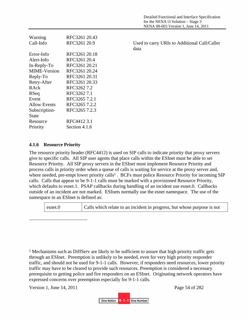
Detailed Functional and Interface Specification for the NENA i3 Solution – Stage 3 NENA 08-003 Version 1, June 14, 2011
Version 1, June 14, 2011 Page 54 of 282
Warning RFC3261 20.43 Call-Info RFC3261 20.9 Used to carry URIs to Additional Call/Caller
data Error-Info RFC3261 20.18 Alert-Info RFC3261 20.4 In-Reply-To RFC3261 20.21 MIME-Version RFC3261 20.24 Reply-To RFC3261 20.31 Retry-After RFC3261 20.33 RAck RFC3262 7.2 RSeq RFC3262 7.1 Event RFC3265 7.2.1 Allow Events RFC3265 7.2.2 Subscription-State
RFC3265 7.2.3
Resource Priority
RFC4412 3.1 Section 4.1.6
4.1.6 Resource Priority
The resource priority header (RFC4412) is used on SIP calls to indicate priority that proxy servers give to specific calls. All SIP user agents that place calls within the ESInet must be able to set Resource Priority. All SIP proxy servers in the ESInet must implement Resource Priority and process calls in priority order when a queue of calls is waiting for service at the proxy server and, where needed, pre-empt lower priority calls5 . BCFs must police Resource Priority for incoming SIP calls. Calls that appear to be 9-1-1 calls must be marked with a provisioned Resource Priority, which defaults to esnet.1. PSAP callbacks during handling of an incident use esnet.0. Callbacks outside of an incident are not marked. ESInets normally use the esnet namespace. The use of the namespace in an ESInet is defined as:
esnet.0 Calls which relate to an incident in progress, but whose purpose is not
5 Mechanisms such as DiffServ are likely to be sufficient to assure that high priority traffic gets through an ESInet. Preemption is unlikely to be needed, even for very high priority responder traffic, and should not be used for 9-1-1 calls. However, if responders need resources, lower priority traffic may have to be cleared to provide such resources. Preemption is considered a necessary prerequisite to getting police and fire responders on an ESInet. Originating network operators have expressed concerns over preemption especially for 9-1-1 calls.

Detailed Functional and Interface Specification for the NENA i3 Solution – Stage 3 NENA 08-003 Version 1, June 14, 2011
Version 1, June 14, 2011 Page 55 of 282
critical
esnet.1 9-1-1 calls traversing the ESInet
esnet.2 Calls related to an incident in progress which are deemed critical
esnet.3- esnet.7 not defined
4.1.7 History-Info and Reason
When a call is not sent to the originally intended destination: for example, when it is diverted by the ESRP to another PSAP, the final destination must have the ability to know why it got the call. For this reason, SIP elements in the ESInet must support the History-Info header (RFC4244 [44]) and the associated Reason header (RFC3326 [22]). Elements which retarget a call must add a History-Info header indicating the original intended recipient, and the reason why the call was retargeted. ESInet elements must be prepared to handle a History-Info (and its associated Reason header) added by an element outside the ESInet before presentment to the 9-1-1 system.
4.1.8 Media
All call handling elements must support media using RTP (RFC3550 [13]). Each SIP session initiation message or response should describe the media the User Agent is capable of supporting using Session Description Protocol (SDP) (RFC4566 [14]) in the body of the message. Support of any type of media (e.g., voice, video, text) in originating networks is based on regulatory requirements or business decisions. All elements in the ESInet support all media if offered, except that a legacy PSAP on a Legacy PSAP Gateway may only support audio and TTY.
4.1.8.1 Audio
All User Agents in the ESInet must support g.711 mu-law and a-law. A-law support is required in the case that devices manufactured primarily for non-North American markets is used within North America. It is recommended that AMR, AMR-WB, EVRC[138], EVRC-B[139], EVRC-WB[140], and EVRC-NW[141] also be supported.
4.1.8.2 Video
All User Agents in the ESInet must support H.264/MPEG-4 Version 10 video. The Baseline profile must be supported. Scalable baseline profile support is recommended. At least levels 1-3 must be supported.
4.1.8.3 Real-Time Text
All call handling elements in the ESInet must support Framework for Real-Time Text over IP Using the Session Initiation Protocol (SIP) (RFC5194 [117]).
4.1.8.4 TTY (Baudot tones)
NG9-1-1 anticipates that deaf and hard of hearing callers will migrate from TTY to other forms of communication including real time text devices and various forms of relay. Although use of TTY is

Detailed Functional and Interface Specification for the NENA i3 Solution – Stage 3 NENA 08-003 Version 1, June 14, 2011
Version 1, June 14, 2011 Page 56 of 282
expected to decline, it cannot be assumed that TTY will be completely gone by the time transition to NG9-1-1 is complete. Therefore, PSAPs must be capable of receiving calls from TTYs.
It is possible to have a transcoder in the path of every voice call which would recognize baudot tones, and replace them with RFC4103 [118] real time text on incoming (with respect to the ESInet) RTP media, and terminate RFC4103 real time text and synthesize baudot tones for outgoing RTP. If an ESInet can assure that ALL calls, including diverted calls, calls transferred from another ESInet and all calls from any origination network will pass through the transcoder, such an architecture is acceptable. The transcoder must be compliant with RFC5369 [119]. Where all calls are answered at a bridge, the bridge can provide the transcode service. It may be practical to place a transcoder at the edge of a PSAP to serve all endpoints inside that PSAP.
For ESInets where it cannot be assured that all audio calls will transit such a transcoder, the PSAP User Agents, conference bridges, Interactive Media Response units, etc. will need to recognize baudot tones and display text, as well as accept typed text and generate baudot tones.
4.1.9 Instant Messaging
Text-based communications for NG9-1-1 by all call handling elements of an NG9-1-1 system, is supported in two ways: Real-Time Text (RTT) and Instant Messages (IM) with location and the ability to support location updates.
Note: there is considerable flux in standardized Instant Messaging protocols. It is anticipated that there may be additional IM protocols supported by NG9-1-1 in the future, specifically XMPP. At this time, the only standardized IM protocol fully specified for supporting emergency IMs within or presented to an ESInet is SIP/SIMPLE.
All call handling elements within the ESInet must support Session Initiation Protocol (SIP) Extension for Instant Messaging (RFC3428 [21]), Indication of Message Composition for Instant Messaging (RFC3994 [120]), The Message Session Relay Protocol (MSRP) (RFC4975 [121]) and Relay Extension for the Message Session Relay Protocol (MSRP) (RFC4976 [122])6. PSAPs must be prepared to handle IM as a series of individual MESSAGE transactions as well as a message session via MSRP. MESSAGEs received from the same caller within a configurable time (2-3 minutes nominally) should be considered part of the same “call”, and must be routed to the same PSAP (and the same call taker), regardless of movement of the caller while texting. If the origination network/device supports non session mode IM to NG9-1-1, it must assure that all messages from the same caller within this time frame is sent to the same ESInet (same ECRF query results). If the network/device cannot guarantee this, it must use session mode. The ESRP in the
6 All ESInet elements support instant messaging using the specifications in this document. Any given origination network or device may not support instant messaging, and support of instant messaging by origination networks and devices may be subject to regulation.

Detailed Functional and Interface Specification for the NENA i3 Solution – Stage 3 NENA 08-003 Version 1, June 14, 2011
Version 1, June 14, 2011 Page 57 of 282
ESInet will also maintain a timer for this function and assure that all messages from the same caller that route to an ESInet will route to the same PSAP.
Location must be included in a geolocation header in the MESSAGE method or the initiation of the MSRP session as with any other “call” to 9-1-1.
Other Instant Messaging protocols such as XMPP may be supported by an originating network, but must be interworked to SIP IM for presentation to the ESInet. For example, draft-saintandre-sip-xmpp-im-01 [110] describes interwork between XMPP and SIP IM.
4.1.10 Non-human-initiated calls
Non-human-initiated calls presented to an ESInet are signaled with a SIP MESSAGE method containing a Common Alerting Protocol (CAP) [95] message, possibly wrapped in an Emergency Data eXchange Language – Distribution Element (EDXL-DE) [111] wrapper7. The <area> element of the CAP message is copied, in PIDF-LO form, in a Geolocation header in the MESSAGE container. The CAP message is in the body of the MESSAGE, with MIMEtype application/common-alerting-protocol+xml.
The MESSAGE should contain a Call-Info header with a URI of an Additional Data about a Call object.
The <identifier> in the CAP message is not the same as the Call Identifier assigned in the ESInet, but the log contains the record that relates the two.
The <sender> should be the same as the From header in the MESSAGE.
If included, the <addresses> element should contain “urn:service:sos”, the same as the Route header for the Message.
An <info> element must be included. The element must contain an <event code>. The <valueName> may be some externally defined namespace, but in many cases is expected to be “NENA”. This document defines a NRS registry of allowed values for “NENA- ExternalEventCodes” which registers values that may be used in an <event code> where <valueName> is “NENA”. The initially defined values in the registry (which become the <value> contents in the <event code> element) are VEDS and BISACS, representing the standard Vehicle Emergency DataSet, and the NIST Building Information and Control System messages.
If an <area> element is included, at least one <polygon> or <circle> element must be included. Any <areaDesc> and <geocode> elements will not be used by the routing elements, although destination
7 All ESInet elements support non-human-initiated calls using the specifications in this document. Any given origination network or device may not support non-human-initiated calls, and support of non-human-initiated calls by origination networks and devices may be subject to regulation.

Detailed Functional and Interface Specification for the NENA i3 Solution – Stage 3 NENA 08-003 Version 1, June 14, 2011
Version 1, June 14, 2011 Page 58 of 282
agencies may be able to make use of them. The Geolocation header in the MESSAGE must have the PIDF-LO equivalent of the <polygon> or <circle> element(s). If <altitude> and <ceiling> is provided, they will be used for routing if the ECRF is provisioned with 3D data.
A digital signature should be included in the CAP message. The CAP message should not be encrypted. Transport Layer Security (TLS) may be used on the SIP MESSAGE transmission to encrypt the message.
The CAP message may be enclosed in an EDXL-DE wrapper. If it is, the body of the SIP MESSAGE will contain a section application/emergency-data-exchange-language+xml.
Non-human-initiated calls are routed and handled the same as voice, video or text calls throughout the NG9-1-1 system. The routing mechanisms can route non-human-initiated calls differently from voice calls in the same way they can route video calls differently from voice calls. The parameters in the CAP message are available to the routing function as inputs to direct calls with specified characteristics to specific entities.
Note that in this edition, there is no mechanism specified to handle an APCO/CSAA 2.101.1-2008 Alarm within the ESInet, although a PSAP could have an interface to such an alarm.
4.1.11 Bodies in messages.
All SIP elements in an ESInet must support multipart MIME as defined in RFC2046 [123]. For example, location and SDP may be present in a message body. All SIP elements must allow additional body content (for example, images, vcards, etc) to pass to the PSAP. Note that the typical length of a SIP INVITE is around 1300 bytes including around 200 bytes for the SIP Header overhead. If, for example, a SIP INVITE contains a complete header, and a body containing both an SDP and a civic PIDF-LO, it is likely this SIP message may be too big for UDP; and may require the use of TCP.
4.1.12 Transport
SIP signaling within the ESInet must be TCP with TLS. Fallback to UDP is allowed. However emergency call messages have many large elements, for example, a PIDF-LO, and are more likely to be fragmented when carried in UDP. Fragmentation and reassembly must be supported by all ESInet elements. If TLS establishment fails, fallback to TCP/UDP without TLS is allowed. If fallback with TLS is allowed, additional security weaknesses occur, and implementations must be prepared to deal with the security risks engendered when TLS protection is not available. Known attacks on incomplete fragmentation/reassembly implementations are another concern which must be addressed by all elements in the ESInet. Persistent TLS connections between elements that frequently exchange SIP transactions should be deployed. Media streams for voice, video and text must be carried on RTP over UDP. All endpoints in an ESInet must implement media security with SRTP as defined in RFC3711 [125] and SDES as defined in RFC4568 [126]. SRTP Security must be requested in all calls originated within an ESInet. Since media is routinely logged, the logger must be given the keys to enable it to decode the SRTP. RTCP as defined in RFC3550 [13] and SRTCP as defined in RFC3711 [125] must be supported within the ESInet and it is highly recommended that all calls presented to the ESInet provide RTCP.

Detailed Functional and Interface Specification for the NENA i3 Solution – Stage 3 NENA 08-003 Version 1, June 14, 2011
Version 1, June 14, 2011 Page 59 of 282
PSAPs must detect the presence of RTP streams so they can distinguish RTP failure from real silence by the caller. User Agents who detect the loss of RTP should attempt to reestablish the streams by reINVITING the other party. If that fails, the device should indicate a failure and require the user (call taker in most cases) to take action such as initiating disconnect. In no circumstances should a call be automatically taken down just because RTP streams fail. For example a multimedia stream which loses one of several streams would not be terminated, except by call taker action.
PSAPs should supply audible ring as (early) media for devices that do not perform local audible ring or its equivalent.
4.1.13 Routing
All SIP elements must support routing of SIP messages per RFC3261 [12] and RFC3263 [15]. Note particularly that URIs will often have the domain of the destination following the ‘@’ rather than the hostname of a sip server, and thus SRV records [107] will need to be consulted to determine the hostname of the sip server for that domain.
4.1.14 Originating network Interface
The originating call interface to the ESInet is a SIP call interface as described above in section 4.1. All calls are presented to the correct ESInet by routing via an ECRF or equivalent as described in Section 5.3. Location must be included in the Geolocation header, civic or geo, by reference or value. The location used to query the routing function must be included in the Geolocation header of the outgoing INVITE message. The call must be routed, using normal RFC 3261 [12] procedures to the URI obtained from the routing function using the “urn:service:sos” service URN. A callback address must be included in the outgoing INVITE message, with an immediate device callback in the Contact header and an address of record for later callback in either the From header (protected by the Identity header) or a P-Asserted-Identity.
A call from an unauthenticated device shall populate the P-Preferred-Identity header field in the INVITE request with an equipment identifier as a SIP URI and no P-Asserted-Identity shall be provided.
A Call-Info header must be included in the incoming INVITE message to the ESInet that contains a URI that refers to an Additional Data associated with a Call ([127][144]) structure, and marked with an “emergencyCallData” purpose. A Call-Info header may be included which contains a URI which refers to an Additional Data associated with a Caller (NENA 71-001) structure, marked with an “emergencyCallerData” purpose.
4.1.15 PSAP Interface
The PSAP call interface is a SIP call interface as described in section 4.1. All calls will be presented to the PSAP based on the terminating ESRP’s Policy Routing Function (Section 5.2.1.5). Geolocation header, Call-Info headers and other headers should be the same as above (Section 4.1.14). The call will be routed, using normal RFC 3261 [12] procedures to the URI obtained from the ESRP’s PRF. See Section 5.6.1 for other information on the PSAP interface.

Detailed Functional and Interface Specification for the NENA i3 Solution – Stage 3 NENA 08-003 Version 1, June 14, 2011
Version 1, June 14, 2011 Page 60 of 282
4.1.16 Element Overload
Any SIP element may encounter a condition in which it is asked to process more calls than it can handle. SIP element overload has been extensively studied [114]. Simple mechanisms to handle overload are insufficient. Elements must not return 503 Busy Here unless it is certain, by design and configuration that the upstream element can reliably cope with the error. This standard specifies specific methods to avoid overload of calls to specific agencies using the routing rule and queue mechanisms, but a given SIP element may still encounter overload. To cope with such overload, all SIP elements must implement the overload control mechanisms described in [79]
4.2 Location
Location is fundamental to the operation of the 9-1-1 system. Location is provided outside the ESInet, and the generic functional entity which provides location is a Location Information Server (LIS). Since the LIS is external to the ESInet, and not provided by the 9-1-1 Authority, the LIS is out of scope for i3. However, the entities inside the ESInet must interact with a source of location and thus the interfaces to that function are in scope. For the purposes of this document, the only functions a LIS provides that are relevant to i3 are:
a) A dereference function defined below for location by reference b) A validation function which uses the i3 LVF for civic addresses
Any element that provides either or both of these two functions is considered a LIS within i3. Although a LIS is defined as a “server”, as with all elements defined in this document, there may not be a physical server, and indeed, a LIS for some networks may only be a protocol interwork function to some other element in the network.
The NG9-1-1 system supports location included by value in a Geolocation header [10] of a SIP message. It also supports location by reference. All elements in an ESInet that use location by reference must implement SIP and HTTP Enabled Location Delivery (HELD) dereferencing protocol. A Location Information Servers (LIS)8 must implement one or both of these protocols.
Location by reference using SIP is an implied subscription to Presence (RFC3856). An element needing location that has a SIP location URI must issue a SIP SUBSCRIBE (RFC3265) to the location URI. The use of filters (RFC4661 [128], rate control [113] and loc-filters [129]) may be used to control notification.
An element needing location that has a HELD URI must dereference per draft-winterbottom-geopriv-deref-protocol [78].
8 A LIS, if it implementes the SIP Subscribe/Notify mechanisms for location dereferencing, implements these portions of Presence server as defined in the IETF for the purposes of returning the location information only.

Detailed Functional and Interface Specification for the NENA i3 Solution – Stage 3 NENA 08-003 Version 1, June 14, 2011
Version 1, June 14, 2011 Page 61 of 282
An access network that provides location by reference must supply either a SIP or a HELD location reference URI per section 4.2. Networks that use other protocols must interwork to SIP or HELD. Elements in the ESInet which receive a location reference and forward location in SIP signaling to another element must pass the reference, and not any value it determines by dereferencing (although the value should be logged). Each element must do its own dereference operation, supplying its credentials to the LIS. It is recommended that LISs cache location values and supply the cached values if multiple dereferences occur in quick succession, such as when a call is being routed.
The LIS must accept the ESRP and PSAP credentials traceable to the PSAP Credentialing Authority (PCA) to deliver location with the required confidence/uncertainty.
Other than the above, the implementation used within the origination and access networks for support of location is out of scope of i39.
4.3 Provisioning
The i3 standard provisioning mechanism is Service Provisioning Markup Language, Version 2.0 (SPML 2.0 [91]).
In i3, the SPML roles and definitions are applied and associated with functional entities as follows:
Target: Each i3 service (including each BCF, ESRP, ECRF and LVF) would be a Provisioning Service Target (PST or Target) and is identified by a TargetID.
Provider: the software component included by each service on an ESInet that is responsible for processing SPML requests.
Requesting Authority (RA): the requestor in i3 is typically controlled by a PSAP, 9-1-1 Authority or state/county authority) that issues a SPML request to a Provisioning Service Provider (PSP).
Provisioning Service Provider (PSP): controlled by functional entity service provider and listens for a well-formed SPML request, processes the request, and returns the results to the RA. It provisions Targets.
Provisioning Service Object: A data entity or an information object on a target.
Note: A future edition of this document will contain descriptions of the Provisioning Service Objects (PSOs) defined for standard functions.
The transport for SPML is SOAP/XML. PSOs are identified by PSOIdentifiers.
9 The roles of the access and origination networks in obtaining location for routing and delivery with an emergency call, and interactions between such networks is out of scope and subject to SDO work outside NENA as well as regulatory policy.

Detailed Functional and Interface Specification for the NENA i3 Solution – Stage 3 NENA 08-003 Version 1, June 14, 2011
Version 1, June 14, 2011 Page 62 of 282
Most Providers are expected to use the SPMLv2 XSD Profile. Providers and Requestors must be capable of handling synchronous and asynchronous operations. Batch capability must be supported on all Providers and Requestors.
In SPML, RequestID sent from Requestor to Provider is optional for a synchronous request using transports such as SOAP/XML who have mechanisms to match requests with responses. However, for NG9-1-1, most provisioning requests will be logged, and the RequestID is used in the log entry. Therefore, all requests must contain a unique RequestID.
TargetIDs and PSOIdentifiers must use a Globally Unique IDs (GUIDs).
4.4 Policy
Policy is stored into and retrieved from the Policy Store using a web service. This section describes the "Policy Store Web Service" in Section 4.4.1 that allows to upload and to retrieve policies. Policies are named by the function that defines the policy, i.e., the DownstreamRoutingPolicy for an ESRP. A specific policy set is known by that name and the agency whose policy is being stored or retrieved. The authentication to the web service identifies the agency storing or retrieving policy sets in the store. The store only accepts or delivers complete policy sets, not individual rules within a policy set. The policy store may reduce the size of the chunk returned if it us unable or unwilling (by local policy) to serve a chunk as large as the requester specifies. The policy retrieved is valid until the expiration time. If the policy is needed for use after expiration, it must be retrieved again from the policy store. The response may not return the policy requested. Instead, it may return a referral to another policy store that may have the policy.
The standard i3 data rights management system can limit which agencies, agents or functions are permitted to retrieve policies for another agency. The rights management policy can also allow an agency to store policies on behalf of another agency. The interface includes a chunking mechanism that can be used by either the client or the server to limit the size of an individual transaction.
4.4.1 Policy Store Web Service
This web service has the following functions:
RetrievePolicy: retrieves a policy set from the common policy store. The function’s parameters include the policy name, the identity of the agency whose policy is needed, and an indication of the maximum size of the return. The response is the policy set, if it is smaller than the indicated maximum size, or the first chunk of the policy set if it is large, plus an identifier that can be used with MoreRetrievePolicy to obtain more chunks of a large policy set if the policy is too large to send in the response, and an expiration time. The policy store may reduce the size of the chunk returned if it us unable or unwilling (by local policy) to serve a chunk as large as the requester specifies. The policy retrieved is valid until the expiration time. If the policy is needed for use after expiration, it must be retrieved again from the policy store. The response may not return the policy requested. Instead, it may return a referral to another policy store that may have the policy.

Detailed Functional and Interface Specification for the NENA i3 Solution – Stage 3 NENA 08-003 Version 1, June 14, 2011
Version 1, June 14, 2011 Page 63 of 282
RetrievePolicyRequest
Parameter Condition Description
policyName Mandatory The name of the policy
agency Mandatory The agency whose policy is requested. Must be a domain name or URI that contains a domain name
maxChunkSize Optional Maximum size of a chunk accepted, in bytes. If not specified, responder may choose the size.
RetrievePolicyResponse
Parameter Condition Description
policyDataChunk Optional All or part of a policy, limited to the maxChunkSize, or smaller
TTL Optional The expiration time of the policy
nextChunkId Optional Id to be used with MoreRetrievePolicy. Must be present if policyDataChunk is returned, but is not the complete policy
Referral Optional URI of another policy store that may have this policy.
errorCode Optional Error Code if no policy or referral is returned
Error Codes
100 Okay No error (optional to return)
501 Unknown or bad Policy Name
502 Unknown or bad Agency Name
503 Not available here, no referral available

Detailed Functional and Interface Specification for the NENA i3 Solution – Stage 3 NENA 08-003 Version 1, June 14, 2011
Version 1, June 14, 2011 Page 64 of 282
504 Unspecified Error
MoreRetrievePolicy: retrieves another chunk of a large policy set. The request includes the identifier returned to the requester in a RetrievePolicy or prior MoreRetrievePolicy operation and an indication of the maximum size of the return. The response is the next chunk of the policy set, plus an identifier that can be used on a subsequent invocation of MoreRetrievePolicy. The policy store may reduce the size of the chunk returned if it is unable or unwilling (by local policy) to serve a chunk as large as the requester specifies. The policy store must be able to accept and respond to a request it has already sent (that is, the identifiers may be used repeatedly, in case of error). The identifiers can be expired in a reasonable time period (perhaps 30 minutes).
MoreRetrievePolicyRequest
Parameter Condition Description
nextChunkId Mandatory ChunkId returned from RetrievePolicy
maxChunkSize Optional Maximum size of a chunk accepted, in bytes. If not specified, but maxChunkSize was specified in RetrievePolicy, use that size. If neither specified, responder may choose size.
MoreRetrievePolicyResponse
Parameter Condition Description
policyDataChunk Mandatory Remainder or part of a policy, limited to the maxChunkSize, or smaller
nextChunkId Optional Id to be used with MoreRetrievePolicy if not the last chunk
errorCode Optional Error Code if no policy or referral is returned
Error Codes
100 Okay No error (optional to return)
504 Unspecified Error
505 Bad chunkId

Detailed Functional and Interface Specification for the NENA i3 Solution – Stage 3 NENA 08-003 Version 1, June 14, 2011
Version 1, June 14, 2011 Page 65 of 282
StorePolicy: initiates the storage of a policy set in the policy store. This function’s parameters include the name of the policy, the agency whose policy is being stored, the size of the entire policy set, the expiration time, and the maximum chunk size the sender is willing to send. If the name of the agency is omitted, the sender’s identity is used. The response contains the maximum size of the initial chunk, which must be no larger than the sender’s maximum chunk size, and an identifier to be used with the MoreStorePolicy function.
StorePolicyRequest
Parameter Condition Description
policyName Mandatory The name of the policy
agency Mandatory The agency whose policy is being stored. Must be a domain name or URI that contains a domain name
policySize Mandatory Size of the entire policy in bytes
TTL Mandatory The expiration time of the policy
maxChunkSize Optional Maximum size of a chunk to be sent, in bytes. If not specified, responder may choose the size.
StorePolicyResponse
Parameter Condition Description
maxChunkSize Optional Maximum size of a chunk accepted, in bytes. If not specified, sender may choose the size up to the maxChunksize specified in the request.
nextChunkId Optional Id to be used with MoreStorePolicy.
errorCode Optional Error Code
Error Codes
100 Okay No error (optional to return)
501 Unknown or bad Policy Name
502 Unknown or bad Agency Name

Detailed Functional and Interface Specification for the NENA i3 Solution – Stage 3 NENA 08-003 Version 1, June 14, 2011
Version 1, June 14, 2011 Page 66 of 282
504 Unspecified Error
506 Policy Too Large
507 Bad TTL
MoreStorePolicy: sends a chunk of the policy set to the store. Its parameters include the identifier returned from StorePolicy or a prior invocation of MoreStorePolicy, and a chunk of the policy set. The response contains the maximum size of the next chunk (which must be no larger than the maximum chunk size indicated by the sender on the original StorePolicy invocation) and an identifier to be used on a subsequent MoreStorePolicy to send the next chunk. Identifiers may be reused, but if they are, any later chunks are discarded by the store and must be re-sent. Identifiers may be expired in a reasonable time (perhaps 30 minutes).
MoreStorePolicyRequest
Parameter Condition Description
nextChunkId Mandatory ChunkId returned from RetrievePolicy
policyDataChunk Mandatory All or part of a policy, limited to the maxChunkSize, or smaller
MoreStorePolicyResponse
Parameter Condition Description
maxChunkSize Optional Maximum size of a chunk accepted, in bytes. If not specified, but maxChunkSize was specified in the StorePolicyRequest, use that size. If neither is specified, responder may choose size.
nextChunkId Optional Id to be used with MoreRetrievePolicy if not the last chunk
errorCode Optional Error Code if no policy or referral is returned
Error Codes
100 Okay No error (optional to return)

Detailed Functional and Interface Specification for the NENA i3 Solution – Stage 3 NENA 08-003 Version 1, June 14, 2011
Version 1, June 14, 2011 Page 67 of 282
504 Unspecified Error
505 Bad chunkId
508 Chunk Too Big
EnumeratePolicies: returns a list of policy names available in the store for a specific agency. The parameters of the request include the name of the policy set and the name of the agency. The response includes a list of the policy names in the store, the last date they were stored, expiration time, and the size of the policy. The enumeration includes only those policies that are actually stored in this specific instance of the policy store.
EnumeratePoliciesRequest
Parameter Condition Description
policyName Mandatory The name of the policy. May be “*” for all policy names
Agency Mandatory The agency of interest. Must be a domain name or URI that contains a domain name or “*” for all agencies
EnumeratePoliciesResponse (may be repeated for each policy)
Parameter Condition Description
policyName Mandatory The name of the policy.
Agency Mandatory The agency of interest. Must be a domain name or URI that contains a domain name
policySize Mandatory Size of the entire policy in bytes
TTL Mandatory The expiration time of the policy
lastModification Mandatory Date/Time of last modification
errorCode Optional Error Code if no policy
Error Codes
100 Okay No error (optional to return)

Detailed Functional and Interface Specification for the NENA i3 Solution – Stage 3 NENA 08-003 Version 1, June 14, 2011
Version 1, June 14, 2011 Page 68 of 282
501 Unknown or bad Policy Name
502 Unknown or bad Agency Name
504 Unspecified Error
The policy store is replicated and distributed. There is a single authoritative master store for a given policy, and there may be one or more replicas of that policy in other policy stores. To create a replica, the master policy store is provisioned with a list of replicas that are authorized. The replica uses the RetrievePolicy function to get policies from the master policy store, and refreshes them automatically when they expire. EnumeratePolicies can be used to determine which agency’s policies are stored in the policy store.
As an optimization, the replica can make use of the UpdatedPolicy function:
UpdatedPolicies: returns a list of policies updated in the Policy Store since a given time. The request includes a timestamp. The response is a list of policy names and agencies whose policy has been updated since the timestamp in the request.
UpdatedPoliciesRequest
Parameter Condition Description
policyName Mandatory The name of the policy. May be “*” for all policy names
agency Mandatory The agency of interest. Must be a domain name or URI that contains a domain name or “*” for all agencies
updatesSince Mandatory Earliest time desired in the response
UpdatedPoliciesResponse (may be repeated for each policy)
Parameter Condition Description
policyName Mandatory The name of the policy.
agency Mandatory The agency of interest. Must be a domain name or URI that contains a domain name
policySize Mandatory Size of the entire policy in bytes
TTL Mandatory The expiration time of the policy

Detailed Functional and Interface Specification for the NENA i3 Solution – Stage 3 NENA 08-003 Version 1, June 14, 2011
Version 1, June 14, 2011 Page 69 of 282
lastModification Mandatory Date/Time of last modification
errorCode Optional Error Code if no policy
Error Codes
100 Okay No error (optional to return)
501 Unknown or bad Policy Name
502 Unknown or bad Agency Name
504 Unspecified Error
UpdatedPolicies can be used as a poll to keep a more up to date replica, rather than waiting for expiration times. Use of UpdatedPolicies is recommended for replicas of policies that may reasonably be changed unexpectedly, such as in a disaster situation.
The EnumerateAgencies function is also useful to maintain a referral service to distribute the policy store. Policy stores may refer queries to another policy store. To do so, they maintain a map of which policy stores have what policies. The mapping may be provisioned or learned via the EnumerateAgencies function (with a list of other policy stores provisioned in a specific policy store).
4.4.2 Policy Syntax
This section summarizes the syntax and semantic of the policy language used for making call routing decisions. Policy is represented in an RFC4745 [147] compliant common policy schema. A policy document is an XML document, formatted according to the schema defined in RFC 4745. This document inherits the MIME type of common policy documents, namely application/auth-policy+xml. As described in RFC4745, this document is composed of rules that contain three parts - conditions, actions, and transformations. The condition statement may either evaluate to 'true' or 'false'. If it evaluates to 'true' then the action, and the transformation part of the rule is executed. In order to deal with the case where multiple condition parts evaluate to 'true' a conflict resolution mechanism is described to avoid conflicting actions to be executed. Common Policy described a conflict resolution and this document extends Common Policy with a priority based mechanism whereby each rules has a priority value associated that indicates the relative importance of the specific rule with the semantic that a higher value gets precedence over a rule with a lower value. The transformations part of a rule is not used by this application.
4.4.2.1 Condition Elements
This section describes the additional enhancements of the conditions-part of the rule. This document inherits the Common Policy functionality, including <validity>. The <identity> and <sphere> condition is not used by this version of the document.
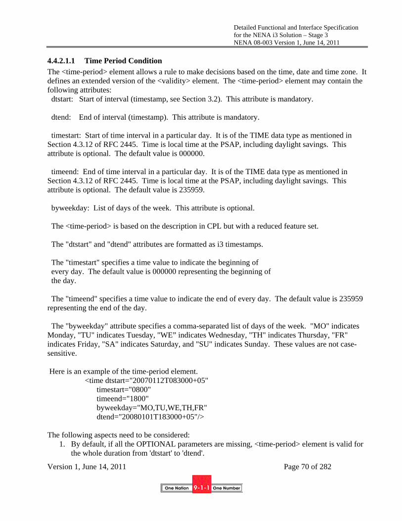
Detailed Functional and Interface Specification for the NENA i3 Solution – Stage 3 NENA 08-003 Version 1, June 14, 2011
Version 1, June 14, 2011 Page 70 of 282
4.4.2.1.1 Time Period Condition
The <time-period> element allows a rule to make decisions based on the time, date and time zone. It defines an extended version of the <validity> element. The <time-period> element may contain the following attributes: dtstart: Start of interval (timestamp, see Section 3.2). This attribute is mandatory. dtend: End of interval (timestamp). This attribute is mandatory. timestart: Start of time interval in a particular day. It is of the TIME data type as mentioned in Section 4.3.12 of RFC 2445. Time is local time at the PSAP, including daylight savings. This attribute is optional. The default value is 000000. timeend: End of time interval in a particular day. It is of the TIME data type as mentioned in Section 4.3.12 of RFC 2445. Time is local time at the PSAP, including daylight savings. This attribute is optional. The default value is 235959. byweekday: List of days of the week. This attribute is optional. The <time-period> is based on the description in CPL but with a reduced feature set. The "dtstart" and "dtend" attributes are formatted as i3 timestamps. The "timestart" specifies a time value to indicate the beginning of every day. The default value is 000000 representing the beginning of the day. The "timeend" specifies a time value to indicate the end of every day. The default value is 235959 representing the end of the day. The "byweekday" attribute specifies a comma-separated list of days of the week. "MO" indicates Monday, "TU" indicates Tuesday, "WE” indicates Wednesday, "TH" indicates Thursday, "FR" indicates Friday, "SA" indicates Saturday, and "SU" indicates Sunday. These values are not case-sensitive. Here is an example of the time-period element. <time dtstart="20070112T083000+05" timestart="0800" timeend="1800" byweekday="MO,TU,WE,TH,FR" dtend="20080101T183000+05"/> The following aspects need to be considered:
1. By default, if all the OPTIONAL parameters are missing, <time-period> element is valid for the whole duration from 'dtstart' to 'dtend'.

Detailed Functional and Interface Specification for the NENA i3 Solution – Stage 3 NENA 08-003 Version 1, June 14, 2011
Version 1, June 14, 2011 Page 71 of 282
2. The 'byweekday' attribute comes into effect only if the period from 'dtstart' till 'dtstart' is long enough to accommodate the specified values, else they are just neglected.
3. If the values of the 'byweekday' attribute values do not correspond to the expected domain, they are simply ignored.
4. Only a single 'byweekday' attribute MUST be listed in a <time> element.
4.4.2.1.2 SIPHeader Element
Any header in a SIP message, such as the From, To, Contact etc., can be used to perform actions on incoming messages. The <SIPHeader> element has three child elements, namely <header>, <operator> and <content>. Currently, only a single operator is defined, namely an equality match. The defined value is "equal" in the <operator> element. The semantic of this field is to compare the content of a specific header field with a pre-defined content.
4.4.2.1.3 MIME Body List Condition
The <mime-list> element contains one or more child <mime> child elements. Any mime type listed in the <mime> element is compared with the content of the incoming message. The <mime-list> condition element evaluates to TRUE if any of its child elements evaluate to TRUE, i.e., the results of the individual child element are combined using a logical OR.
4.4.2.1.4 Location Conditions
This document re-uses the location-based condition elements from ietf-geopriv-policy [146].
4.4.2.1.5 Call Suspicion Condition
This document allows the spam-score header of the SIP message to be evaluated. The <callsuspicion> element has one child element, <score>: which indicates the spam score in the attributes "from" and "to".
4.4.2.1.6 SecurityPosture Condition
The <SecurityPosture> element expressed carries a "domain" attribute where "domain" is a hostname, or a URI. If a URI is specified, the domain function is used to extract the domain from the URI. The domain must be that of an agency or element that the ESRP can subscribe to the SecurityPosture package for.
4.4.2.1.7 QueueState Condition
The <QueueState> element carries a "queue" attribute, where "queue" is the name of a queue. The value of the <QueueState> element can either be:
Active: one or more entities are actively available or are currently handling calls being enqueued
DiversionRequested: a queue designated for diversion (i.e., not the normal call path) is having calls enqueued on it.

Detailed Functional and Interface Specification for the NENA i3 Solution – Stage 3 NENA 08-003 Version 1, June 14, 2011
Version 1, June 14, 2011 Page 72 of 282
Inactive: no entity is available or actively handling calls being enqueued Disabled: The queue is disabled by management action and no calls may be enqueued
4.4.2.2 Actions
As stated in [RFC4474], conditions are the 'if'-part of rules, whereas actions and transformations form their 'then'-part. The actions and transformations parts of a rule determine which operations the proxy server MUST execute on receiving a connection request attempt that matches all conditions of this rule. Actions and transformations permit certain operations to be executed.
4.4.2.2.1 Priority
Each rule has to contain an unsigned integer value to indicate its priority in the <priority> element. When the conditions of two rules evaluate to 'true' then the rule with the higher priority value wins, i.e., the actions of that rule will be executed. Every rule MUST have a unique priority value.
4.4.2.2.2 Route Action
The action supported in this section is forwarding of SIP messages to a specific URL. The <route> element contains two child elements namely <recipient> and <causes>, where <recipient> contains a URI that will become the Route header for the outgoing SIP message (the Request URI is normally a service urn), and the <causes> contains the value used with the Reason header associated with a History-Info header. The <recipient> element is mandatory, and the <causes> element is optional.
4.4.2.3 LoSTServiceURN Action
The <LoSTServiceURN> element carries the Service URN (either urn:service:... or urn:nena:service:...) as the value. The resulting URI is a variable called "NormalNextHop", available to the rule evaluation system.
4.4.2.3.1 Busy Action
The <busy> element returns 600 Busy Everywhere to the caller.
4.4.2.3.2 Notify Action
The <notify> element has several child elements (<recipient>, <eventCode>, <urgency>, <severity>, and <certainty>) and sends a NOTIFY message containing a CAP message to any entity subscribing to the Normal-NextHop's ESRPnotify event for that reason code. This may be used, for example, to advise other entities that calls are being diverted, etc. If the <recipient> is a service urn, the CAP message is wrapped in a SIP MESSAGE and is routed via the ECRF to the proper recipients. All indicated child elements provide information on how to populate the CAP message.
4.4.2.4 Examples
<?xml version="1.0" encoding="UTF-8"?> <ruleset xmlns="urn:ietf:params:xml:ns:common-policy" xmlns:nena="urn:nena:policy-v1" xmlns:xsi="http://www.w3.org/2001/XMLSchema-instance">

Detailed Functional and Interface Specification for the NENA i3 Solution – Stage 3 NENA 08-003 Version 1, June 14, 2011
Version 1, June 14, 2011 Page 73 of 282
; Call is probably spam. <rule id="AA56i12"> <conditions> <nena:callsuspicion> <nena:score from="70" to="100"/> </nena:callsuspicion> </conditions> <actions> <priority>7</priority> <nena:route> <nena:recipient>sip:[email protected] </nena:recipient> </nena:route> </actions> <transformations/> </rule> ; Rule for handling a SIP msg contain a CAP payload. <rule id="AA56i11"> <conditions> <nena:mime-list> <nena:mime>application/common-alerting-protocol+xml</nena:mime> </nena:mime-list> </conditions> <actions> <priority>6</priority> <nena:route> <nena:recipient>sip:[email protected] </nena:recipient> </nena:route> </actions> <transformations/> </rule> ; Rule consider time and queue state. <rule id="AA56i10"> <conditions> <nena:QueueState>Active</nena:QueueState>

Detailed Functional and Interface Specification for the NENA i3 Solution – Stage 3 NENA 08-003 Version 1, June 14, 2011
Version 1, June 14, 2011 Page 74 of 282
<nena:time-period> <time dtstart="19970105T083000" timestart="2200" timeend="0800" byweekday="MO,TU,WE,TH,FR" dtend="19991230T183000"/> </nena:time-period> </conditions> <actions> <priority>5</priority> <nena:route> <nena:recipient>sip:[email protected] </nena:recipient> </nena:route> </actions> <transformations/> </rule> </ruleset>
4.4.2.5 Namespace
This document uses the NENA URN namespace "urn:nena:policy-v1".
4.5 LoST
LoST is the protocol that is used for two functions: call routing and location validation.
Call routing: LoST is used by the ECRF as the protocol to route all emergency calls both to10 and within the ESInet.
Location validation: LoST is used by the LVF as the protocol to validate location information for every call origination end device prior to any potential use for emergency call routing.
Each LoST message is an XML-based document. The root element within each LoST message has the same name as the LoST message name and contains attributes and other elements. In section
10 LoST must be used within an ESInet to route calls. It is recommended that originating networks also use LoST to route calls to the entry ESRP, but they may use appropriate local functions provided calls are routed to the same ESRP as would the use of LoST to the ECRF.
Detailed Functional and Interface Specification for the NENA i3 Solution – Stage 3 NENA 08-003 Version 1, June 14, 2011
Version 1, June 14, 2011 Page 75 of 282
4.5.1 and its sub-sections, XML attributes are denoted by “attributeName” and XML elements by “<elementName>” (e.g., sourceId and <displayName>).
In the following sections, there is text that explains how LoST works. The normative reference that defines the protocol is RFC5222 [61]. The text in this section that defines LoST protocol operations should be considered informative, and any discrepancies are resolved by RFC5222 text. The text below does contain limitations and specific application of LoST operations that are normative. A future edition of this document will remove some of the informative text and highlight the normative text.
4.5.1 Emergency Call Routing using LoST
All SIP-based emergency calls pass location information either by value (PIDF-LO) or by reference (Location URI) plus a "Service URN" to an Emergency Services Routing Proxy (ESRP) to support routing of emergency calls. The ESRP passes the Service URN and location information11 via the LoST interface to an Emergency Call Routing Function (ECRF), which determines the next hop in routing a call to the requested service. The ECRF performs the mapping of the call's location information and requested Service URN to a “PSAP URI” by querying its data and then returning the URI provided. Using the returned URI and other information (time-of-day, PSAP state, etc.), the ESRP then applies policy from a Policy-based Routing Function (PRF) to determine the appropriate routing URI. This URI is the address for the "next hop" in the call's routing path that could be an ESRP URI (intermediate hop), a PSAP URI (final hop), or even a call-taker (see section 5.3 for a more detailed functional explanation of the i3 ECRF).
A single emergency call can be routed by one or more ESRPs within the ESInet, resulting in use of the LoST interface once per hop as well as once by the terminating PSAP.
Note that the term “PSAP URI” is used within the LoST protocol definition to refer to the URI returned from the service URN urn:service:sos. In NG9-1-1, the URI returned may not be that of a PSAP, but instead may route to an ESRP.
4.5.1.1 LoST Call Routing Messages
The LoST interface message used to query for the next hop within the ESInet is the <findService> message. The LoST interface message used to return the result of processing a <findService> request message is the <findServiceResponse> message. The ECRF receiving the <findService> message translates the Service URN and location information in the message into a next-hop URI, which is returned in the <findServiceResponse> message to the querying entity. If the ECRF cannot
11 If an element using LoST receives location by reference, it must dereference the URI to obtain the value prior to querying the LoST server. The LoST server does not accept location by reference.

Detailed Functional and Interface Specification for the NENA i3 Solution – Stage 3 NENA 08-003 Version 1, June 14, 2011
Version 1, June 14, 2011 Page 76 of 282
successfully process a <findService> message, it returns an <error> message. The following three sections describe these messages.
4.5.1.1.1 LoST <findService> Request Message
A querying entity (e.g., ESRP, VoIP-based endpoint, Legacy Network Gateway, Legacy PSAP Gateway, PSAP) uses the <findService> message to retrieve one or more contact URIs from an ECRF given a Service URN and a location. This message contains elements and attributes specified in Table 4-1. Note the "Name" column contains the actual <findService> message's attribute and element names as defined by the LoST protocol.
Table 4-1 – LoST <findService> Message Attributes and Elements
Name Condition Purpose
xmlns Mandatory This attribute specifies the LoST protocol's XML namespace.
<location> Mandatory This element contains either civic address- or geodetic coordinates-based location information.
recursive Optional This attribute indicates a preference for a recursive or iterative query.
<service> Mandatory This element contains the URN of the requested service.
<path> Conditional This element indicates the path the message has taken through ESRPs within the ESInet.
serviceBoundary Optional This attribute indicates how the service boundary should be returned to the requestor.
validateLocation Conditional This attribute indicates whether the civic address location should be validated.
The LoST <findService> message attributes and elements specified in Table 4-1 are described in greater detail below.
xmlns Attribute
This required attribute must specify the LoST protocol XML namespace and is coded as follows.
xmlns="urn:ietf:params:xml:ns:lost1"
<location> Element
This required element carries the location information used to query for routing information and has the format specified in [61]. The location information can be in the form of a civic address or geodetic coordinates. The civic address-based location information format is specified in RF4119 [6] updated by RFC5139 [76] and RFC5491 [75]. The geodetic coordinates-based location information format is specified in [75] and the supported

Detailed Functional and Interface Specification for the NENA i3 Solution – Stage 3 NENA 08-003 Version 1, June 14, 2011
Version 1, June 14, 2011 Page 77 of 282
geographic shapes are point, polygon, circle, ellipse, and arc band. See Section 8.2 in [61] for examples of civic and geodetic-2d location information encodings.
There must be one and only one <location> element. Although the LoST protocol permits multiple <location> elements with one per unique location profile based on the same baseline location profile in a single LoST <findService> message, i3 limits the number of <location> elements to exactly one. For maximum client/server interoperability, there should be only one <location> element based on a baseline location profile in a <findService> message sent to an i3 ECRF. See Section 12 in [61] for more information about baseline and derived location profiles.
The "location" element contains many elements and attributes, some of which are described in Table 4-2.
recursive Attribute
LoST servers can operate in recursive mode or iterative mode if a mapping is not found based on the coding of this attribute.
- The use of recursion by the ECRF initiates a query on behalf of the requestor that propagates through other ECRFs to an authoritative ECRF that returns the PSAP URI back through the intervening ECRFs to the requesting ECRF.
- The use of iteration by the ECRF simply returns a domain name of the next ECRF to contact.
This optional attribute is coded “true” to indicate recursive mode or “false” or not coded to indicate iterative mode.
The ECRF may operate in a recursive mode or an iterative mode, depending on local implementation.
<service> Element
This required element identifies the service requested by the client. Valid service names are specified in [58] and must be "sos" or one of its sub-services for ECRFs and LVFs used by originating networks or devices. For internal ECRFs used by entities within the ESInet to route calls, the <service> element may be a service URN beginning “urn:nena”.
<path> Element
This conditional element contains <via> elements indicating the ECRFs (LoST servers) that have handled the <findService> request as a recursive query. This element is used by ECRFs to detect a recursive query routing "loop" during recursive query processing. See Section 6 in [61] for detailed information about the <path> element.
The order of <via> elements within the <path> element is significant. The first <via> element always indicates the ECRF that received the initial <findService> message query from the requesting ESRP. The last <via> element indicates the ECRF that sent the <findService> request to the current ECRF. All <via> elements indicate the path from the initiating ECRF to the current ECRF.

Detailed Functional and Interface Specification for the NENA i3 Solution – Stage 3 NENA 08-003 Version 1, June 14, 2011
Version 1, June 14, 2011 Page 78 of 282
The originating ESRP that sends the <findService> message to the initial ECRF does not include this element in the message; i.e., it is an error for the <path> element to exist within the <findService> message sent by any element except an ECRF.
When an ECRF receives a <findService> message, it appends its own domain name as a new last <via> element to the <path> element before forwarding the <findService> message to another ECRF or returning a <findServiceResponse> message (which contains the <path> element).
serviceBoundary Attribute
A requesting entity can obtain the boundary of the jurisdiction or service area handled by the requested service. This is most useful for mobile devices that use geodetic coordinates since they can track their location. When they leave the jurisdictional area, they can send another <findService> request to determine the proper jurisdiction for their new location.
This optional attribute indicates whether a service boundary value or reference is preferred in the <findServiceResponse> message. The query originator can express a preference for a value or a reference using this attribute, but the ECRF makes the final decision as to whether to return a reference, a value, or even nothing.
This attribute is coded “value” to indicate the preference for returning the service boundary as a value or is omitted or coded "reference" to indicate the preference for returning the service boundary as a reference. The <serviceBoundary> element returns the service boundary "value" and the <serviceBoundaryReference> element returns the "reference".
Note that returning the service boundary as a reference passes less data in a message, using less network bandwidth, but requires later dereferencing via a LoST <getServiceBoundary> message to obtain the value, thus later using more server time and increasing call delay. Returning the service boundary as a value passes more data in a message, using more network bandwidth, but does not require later dereferencing, thus saving server time and minimizing call delay. In addition, a service boundary may require many data points to accurately identify the boundary of a jurisdiction or service area, possibly making the service boundary dataset very large.
According to [61], a LoST server may decide, based on local policy, to return the service boundary as a value or a reference, or even not to return the service boundary information by omitting both the <serviceBoundary> and <serviceBoundaryReference> elements in the <findServiceResponse> message. This means the requesting entity must handle a returned value, a returned reference, or nothing regardless of the "value" or "reference" coding or the omission of the serviceBoundary attribute in the <findService> message. ECRFs should return a service boundary if the request included the attribute.
validateLocation Attribute
Location validation is the validation of civic address-based location information against an authoritative GIS database containing only valid civic addresses obtained from 9-1-1 Authorities.
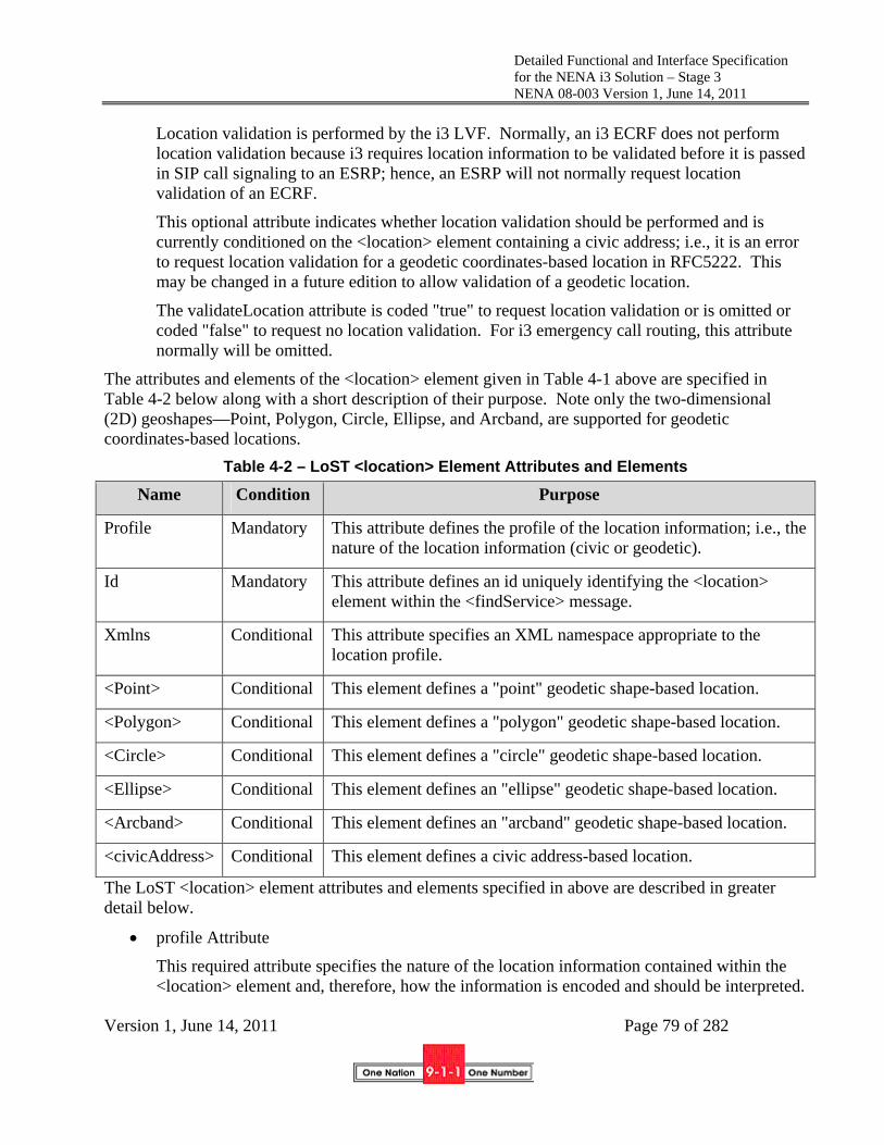
Detailed Functional and Interface Specification for the NENA i3 Solution – Stage 3 NENA 08-003 Version 1, June 14, 2011
Version 1, June 14, 2011 Page 79 of 282
Location validation is performed by the i3 LVF. Normally, an i3 ECRF does not perform location validation because i3 requires location information to be validated before it is passed in SIP call signaling to an ESRP; hence, an ESRP will not normally request location validation of an ECRF.
This optional attribute indicates whether location validation should be performed and is currently conditioned on the <location> element containing a civic address; i.e., it is an error to request location validation for a geodetic coordinates-based location in RFC5222. This may be changed in a future edition to allow validation of a geodetic location.
The validateLocation attribute is coded "true" to request location validation or is omitted or coded "false" to request no location validation. For i3 emergency call routing, this attribute normally will be omitted.
The attributes and elements of the <location> element given in Table 4-1 above are specified in Table 4-2 below along with a short description of their purpose. Note only the two-dimensional (2D) geoshapes—Point, Polygon, Circle, Ellipse, and Arcband, are supported for geodetic coordinates-based locations.
Table 4-2 – LoST <location> Element Attributes and Elements
Name Condition Purpose
Profile Mandatory This attribute defines the profile of the location information; i.e., the nature of the location information (civic or geodetic).
Id Mandatory This attribute defines an id uniquely identifying the <location> element within the <findService> message.
Xmlns Conditional This attribute specifies an XML namespace appropriate to the location profile.
<Point> Conditional This element defines a "point" geodetic shape-based location.
<Polygon> Conditional This element defines a "polygon" geodetic shape-based location.
<Circle> Conditional This element defines a "circle" geodetic shape-based location.
<Ellipse> Conditional This element defines an "ellipse" geodetic shape-based location.
<Arcband> Conditional This element defines an "arcband" geodetic shape-based location.
<civicAddress> Conditional This element defines a civic address-based location.
The LoST <location> element attributes and elements specified in above are described in greater detail below.
profile Attribute
This required attribute specifies the nature of the location information contained within the <location> element and, therefore, how the information is encoded and should be interpreted.
Detailed Functional and Interface Specification for the NENA i3 Solution – Stage 3 NENA 08-003 Version 1, June 14, 2011
Version 1, June 14, 2011 Page 80 of 282
This attribute is coded "civic" for a civic address-based location profile and "geodetic-2d" for a geodetic coordinates, shape-based location profile.
The "civic" and "geodetic-2d" profiles are baseline profiles defined by section 12 in [61]. In order to obtain maximum interoperability for emergency call routing, the ESRP and ECRF should use only "baseline" profiles for location information encoding.
id Attribute
This required attribute uniquely identifies its <location> element within the <findService> message. If multiple <location> elements were to be present within the message, this attribute must have a unique value for each <location> element. However, i3 limits the query to only have one <location> element.
When the ECRF determines a route, it indicates which <location> element was successfully used to determine the route by copying the value of this attribute to the id attribute of the <locationUsed> element in the <findServiceResponse> message; thus permitting the requesting entity to identify the <location> element successfully used by the ECRF.
This attribute can be coded with any value. Since LoST permits only profiles based on a single baseline profile in a <findService> request and i3 permits only baseline profiles in the request, there will be only one <location> element, which makes this attribute somewhat superfluous. Notwithstanding, LoST requires it.
xmlns Attribute
This attribute specifies an XML namespace that defines the markup language for the specified location profile. It will specify the PIDF-LO civic address XML namespace that defines the elements and their attributes for civic address-based location information, or the PIDF-LO geodetic shapes XML namespace that defines the elements (described below) and their attributes used for geodetic coordinates-based location information.
When the profile attribute is coded "civic", this attribute must be coded for the PIDF-LO civic address (see [76]) namespace. For example:
xmlns:ca="urn:ietf:params:xml:ns:pidf:geopriv10:civicAddr"
When the profile attribute is coded "geodetic-2d", this required attribute must be multiply-coded with the namespaces for generic GML shapes and specific PIDF-LO geodetic shapes (see sections 4 and 5 of [75] and [100]). The geoShapes namespace defines a subset of the GML namespace shapes in a manner appropriate to PIDF-LO, but does not redefine all shapes or attributes; hence the need to reference the GML namespace as well.
The example below shows XML namespace prefixes of "gml" and "gs". Since both namespaces define mutually named shapes, the appropriate geographic and geoshape element names would be qualified with the appropriate prefixes (e.g., <gml:Point> and <gml:pos>).
xmlns:gml="http://www.opengis.net/gml"
xmlns:gs="http://www.opengis.net/pidflo/1.0” "

Detailed Functional and Interface Specification for the NENA i3 Solution – Stage 3 NENA 08-003 Version 1, June 14, 2011
Version 1, June 14, 2011 Page 81 of 282
Typically, the xmlns would not appear in the <location> element, but rather would appear in the location profile element (e.g., <civic address>). If an xmlns for a location profile is found in the <location> element, it must declare a prefix.
<Point> Element
This conditional element specifies point shape-based, geodetic coordinates location information (e.g., <gml:Point>). Use of this element is described in section 12.2 of [61] and the element is described in section 5.2.1 of [75] and in [100]. <Point> is part of the http://www.opengis.net/gml namespace.
This attribute is conditioned on the profile attribute coded "geodetic-2d"; i.e., it is an error to specify this element when the profile attribute is not coded "geodetic-2d".
<Polygon> Element
This conditional element specifies polygon shape-based, geodetic coordinates location information (e.g., <gml:Polygon>). Use of this element is described in section 12.2 of [61] and the element is described in section 5.2.2 of [75] and in [100]. <Polygon> is part of the http://www.opengis.net/gml namespace.
This attribute is conditioned on the profile attribute coded "geodetic-2d"; i.e., it is an error to specify this element when the profile attribute is not coded "geodetic-2d".
<Circle> Element
This conditional element specifies circle shape-based, geodetic coordinates location information (e.g., <gs:Circle>). Use of this element is described in section 12.2 of [61] and the element is described in section 5.2.3 of [75] and in [100]. <Circle> is part of the http://www.opengis.net/pidflo/1.0 namespace
This attribute is conditioned on the profile attribute coded "geodetic-2d"; i.e., it is an error to specify this element when the profile attribute is not coded "geodetic-2d".
<Ellipse> Element
This conditional element specifies ellipse shape-based, geodetic coordinates location information (e.g., <gs:Ellipse>). Use of this element is described in section 12.2 of [61] and the element is described in section 5.2.4 of [75] and in [100]. <Ellipse> is part of the http://www.opengis.net/pidflo/1.0 namespace
This attribute is conditioned on the profile attribute coded "geodetic-2d"; i.e., it is an error to specify this element when the profile attribute is not coded "geodetic-2d".
<Arcband> Element
This conditional element specifies arcband shape-based, geodetic coordinates location information (e.g., <gs:Arcband>). Use of this element is described in section 12.2 of [61] and the element is described in section 5.2.5 of [75] and in [100]. <Arcband> is part of the http://www.opengis.net/pidflo/1.0 namespace.

Detailed Functional and Interface Specification for the NENA i3 Solution – Stage 3 NENA 08-003 Version 1, June 14, 2011
Version 1, June 14, 2011 Page 82 of 282
This attribute is conditioned on the profile attribute coded "geodetic-2d"; i.e., it is an error to specify this element when the profile attribute is not coded "geodetic-2d".
<civicAddress> Element
This conditional element specifies civic address-based location information. Section 12.3 of [61] describes use of this element and [6] and [76] describe the element and its attributes. <civicAddress> is part of the urn:ietf:params:xml:ns:pidf:geopriv10:civicAddr namespace.
Table 4-3 gives a short description of many child elements used to specify civic address information. Note that the LoST request does not include a PIDF-LO, but rather has some of the same elements as the PIDF-LO. The requestor copies those elements from the PIDF-LO to the LoST request.
This attribute is conditioned on the profile attribute coded "civic"; i.e., it is an error to specify this element when the profile attribute is not coded "civic".
Table 4-3 PIDF <civicAddress> Element Attributes and Elements
Name Description Example
<country> 2-letter ISO code US
<A1> national subdivision (e.g., state) NY
<A2> county, parish King’s County
<A3> city, township New York
<A4> city division, borough Manhattan
<A5> neighborhood Morningside Heights
<A6>12 street name (deprecated)
<RD> primary road name Broadway
<PRD> leading street direction N
<POD> trailing street suffix SW
<STS> street suffix Ave
12 RD must be used instead of A6. ESInet elements should accept A6 and treat as RD. If both are present and they are not the same value, it should be treated as an error.
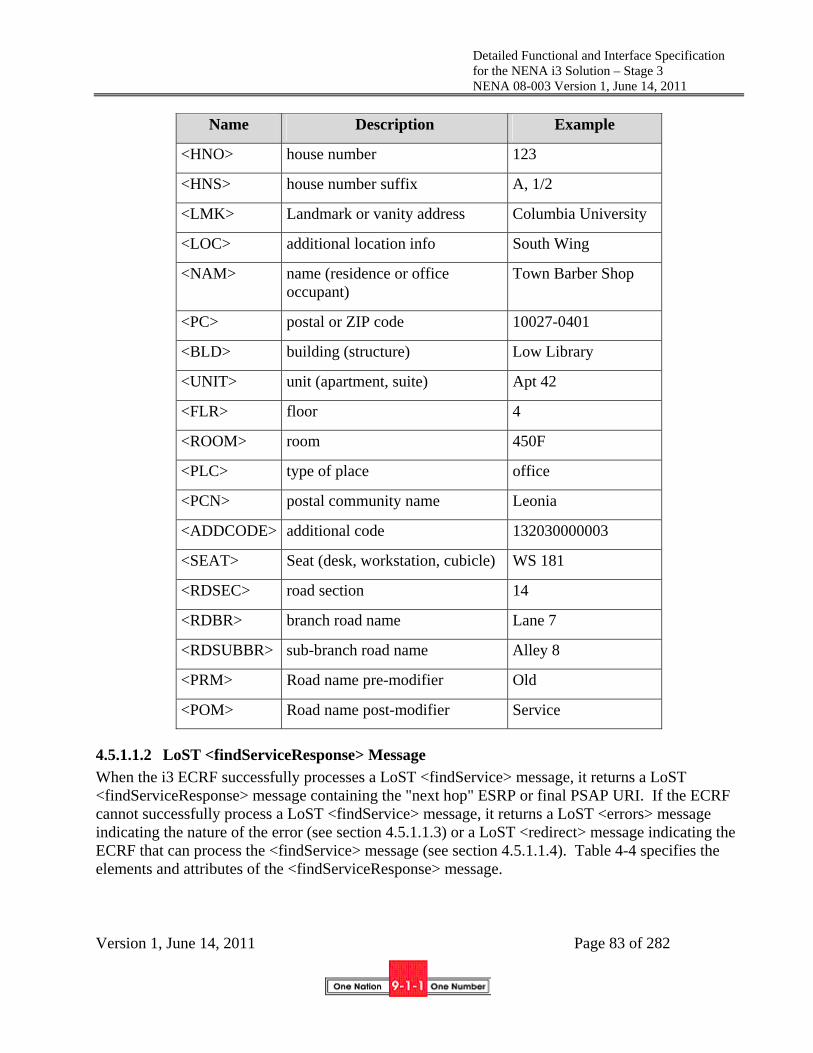
Detailed Functional and Interface Specification for the NENA i3 Solution – Stage 3 NENA 08-003 Version 1, June 14, 2011
Version 1, June 14, 2011 Page 83 of 282
Name Description Example
<HNO> house number 123
<HNS> house number suffix A, 1/2
<LMK> Landmark or vanity address Columbia University
<LOC> additional location info South Wing
<NAM> name (residence or office occupant)
Town Barber Shop
<PC> postal or ZIP code 10027-0401
<BLD> building (structure) Low Library
<UNIT> unit (apartment, suite) Apt 42
<FLR> floor 4
<ROOM> room 450F
<PLC> type of place office
<PCN> postal community name Leonia
<ADDCODE> additional code 132030000003
<SEAT> Seat (desk, workstation, cubicle) WS 181
<RDSEC> road section 14
<RDBR> branch road name Lane 7
<RDSUBBR> sub-branch road name Alley 8
<PRM> Road name pre-modifier Old
<POM> Road name post-modifier Service
4.5.1.1.2 LoST <findServiceResponse> Message
When the i3 ECRF successfully processes a LoST <findService> message, it returns a LoST <findServiceResponse> message containing the "next hop" ESRP or final PSAP URI. If the ECRF cannot successfully process a LoST <findService> message, it returns a LoST <errors> message indicating the nature of the error (see section 4.5.1.1.3) or a LoST <redirect> message indicating the ECRF that can process the <findService> message (see section 4.5.1.1.4). Table 4-4 specifies the elements and attributes of the <findServiceResponse> message.
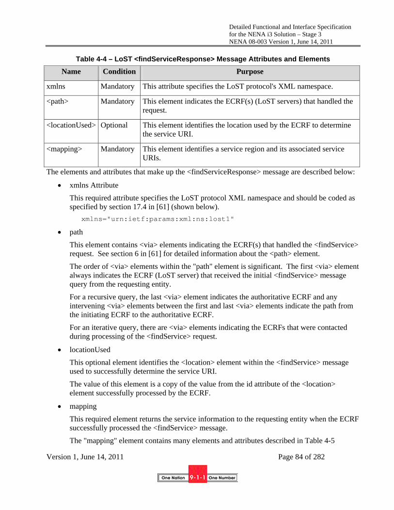
Detailed Functional and Interface Specification for the NENA i3 Solution – Stage 3 NENA 08-003 Version 1, June 14, 2011
Version 1, June 14, 2011 Page 84 of 282
Table 4-4 – LoST <findServiceResponse> Message Attributes and Elements
Name Condition Purpose
xmlns Mandatory This attribute specifies the LoST protocol's XML namespace.
<path> Mandatory This element indicates the ECRF(s) (LoST servers) that handled the request.
<locationUsed> Optional This element identifies the location used by the ECRF to determine the service URI.
<mapping> Mandatory This element identifies a service region and its associated service URIs.
The elements and attributes that make up the <findServiceResponse> message are described below:
xmlns Attribute
This required attribute specifies the LoST protocol XML namespace and should be coded as specified by section 17.4 in [61] (shown below).
xmlns="urn:ietf:params:xml:ns:lost1"
path
This element contains <via> elements indicating the ECRF(s) that handled the <findService> request. See section 6 in [61] for detailed information about the <path> element.
The order of <via> elements within the "path" element is significant. The first <via> element always indicates the ECRF (LoST server) that received the initial <findService> message query from the requesting entity.
For a recursive query, the last <via> element indicates the authoritative ECRF and any intervening <via> elements between the first and last <via> elements indicate the path from the initiating ECRF to the authoritative ECRF.
For an iterative query, there are <via> elements indicating the ECRFs that were contacted during processing of the <findService> request.
locationUsed
This optional element identifies the <location> element within the <findService> message used to successfully determine the service URI.
The value of this element is a copy of the value from the id attribute of the <location> element successfully processed by the ECRF.
mapping
This required element returns the service information to the requesting entity when the ECRF successfully processed the <findService> message.
The "mapping" element contains many elements and attributes described in Table 4-5

Detailed Functional and Interface Specification for the NENA i3 Solution – Stage 3 NENA 08-003 Version 1, June 14, 2011
Version 1, June 14, 2011 Page 85 of 282
Table 4-5 LoST <mapping> Element Attributes and Elements
Element/Attribute Condition Purpose
source Mandatory Identifies the authoritative generator of the mapping
sourceId Mandatory Identifies a particular mapping
lastUpdated Mandatory Describes when a mapping identified by the source and sourceId was last updated
expires Mandatory Identifies the absolute time when the mapping becomes invalid
displayName Optional Describes a human readable display name, e.g., the name of the PSAP serving the location (may be repeated)
service Mandatory Identifies the service for which the mapping applies
serviceBoundary Optional Identifies the area where the URI returned would be valid
serviceBoundaryReference Optional Identifies the reference that can be used to access the service boundary for which the URI returned is valid
serviceNumber Optional Provides the emergency services dial string that is appropriate for the location provided in the query
uri Conditional13 Contains the appropriate contact URI for the requested service. May be repeated when multiple protocols are accepted at the destination. Not intended to support multiple destinations.
locationValidation Optional Indicates which elements of the civic location were “valid” and used for mapping, which elements were “invalid” and which elements were “unchecked”
The attributes and elements that make up the LoST "mapping" element specified in Table 4-5 above are described below:
13 The ECRF includes one or more URIs in a <findServiceResponse> message if one can be determined. Absence of a URI indicates a mapping exists, but no URI is provided in that mapping. This should not occur.

Detailed Functional and Interface Specification for the NENA i3 Solution – Stage 3 NENA 08-003 Version 1, June 14, 2011
Version 1, June 14, 2011 Page 86 of 282
source Attribute
This element identifies the authoritative generator of the mapping (the LoST server that generated the mapping). LoST servers are identified by U-NAPTR/DDDS application unique strings, in the form of DNS name (e.g., lostserver.notreal.com).
sourceId Attribute
This element identifies a particular mapping at the LoST server and is unique among all the mappings maintained by the LoST server.
lastUpdated Attribute
This element describes the date and time when this specific instance of mapping was updated. The date and time is represented in UTC format.
expires Attribute
This element describes the date and time when a particular mapping becomes obsolete. The date and time are described using a timezoned XML type datetime. This element may optionally contain the values of “NO-CACHE” indicating that the mapping should not be cached and “NO-EXPIRATION” indicating that the mapping has no expiration instead of the date and time.
<displayName> Element
The display name is a text string that provides an indication of the serving agency(ies) for the location provided in the query. This information might be useful to PSAPs that query an ECRF. This capability could be used to provide English Language Translation (ELT)-type information that PSAPs receive from ALI databases today.
<service>
The <service> element identifies the service for which this mapping is valid. The ECRF is required to support the "sos" service. Support for other services will depend on local implementation.
<serviceBoundary>
The <serviceBoundary> element identifies the geographical area where the returned mapping is valid. The intent of this parameter is to allow a mobile endpoint to realize that it is moved out of the area where a stored mapping is valid and trigger it to query for a new valid mapping. This element may be supported by the ECRF depending on local implementation.
<serviceBoundaryReference>
The <serviceBoundaryReference> element identifies a reference that could be used to access the service boundary for the requested mapping. This parameter may be supported by the ECRF depending on local implementation.

Detailed Functional and Interface Specification for the NENA i3 Solution – Stage 3 NENA 08-003 Version 1, June 14, 2011
Version 1, June 14, 2011 Page 87 of 282
<serviceNumber>
The <serviceNumber> element contains the emergency services number appropriate for the location provided in the query. This allows a foreign end device to recognize a dialed emergency number.
Uniform Resource Identifier (<uri>)
The URI specifies either the address of the PSAP or the ESRP that is appropriate for the location sent in the query message. The decision of whether to send the PSAP URI or the ESRP URI is based on
a) whether the query is made by the end user, VSP Routing Proxy, i3 PSAP, or the ESRP (which would be determined by the credentials presented in the establishment of a TLS connection to the ECRF) and/or
b) the service urn presented in the query.
<locationValidation>
The <locationValidation> element identifies which elements of the received civic address were “valid” and used for mapping, which were “invalid” and which were unchecked. Since the ECRF is not responsible for performing validation, this parameter may not be returned, subject to local implementations.
4.5.1.1.3 LoST <errors> Message
If the ECRF cannot successfully process a <findService> message, it returns the <errors> message instead of the <findServiceResponse> message. The <errors> message contains information indicating the nature and source of the error.
Table 4-6 – LoST <errors> Message Attributes and Elements
Name Condition Purpose
xmlns Mandatory This attribute specifies the LoST protocol's XML namespace.
source Mandatory This attribute specifies the source of the error.

Detailed Functional and Interface Specification for the NENA i3 Solution – Stage 3 NENA 08-003 Version 1, June 14, 2011
Version 1, June 14, 2011 Page 88 of 282
Name Condition Purpose
<badRequest>
<forbidden>
<internalError>
<locationProfileUnrecognized>
<locationInvalid> <SRSInvalid>
<loop>
<notFound>
<serverError>
<serverTimeout>
<serviceNotImplemented>
Mandatory These elements specify error types.
The LoST <errors> message attributes and elements specified in Table 4-6 are described in greater detail below.
xmlns Attribute
This required attribute must specify the LoST protocol XML namespace and is coded as follows.
xmlns="urn:ietf:params:xml:ns:lost1"
source Attribute
This required attribute identifies the source of the error, which will be in the form of a DNS name (e.g., ecrf.example.com).
The following LoST <errors> message child elements describe the types of errors encountered or detected by the ECRF. They give the requesting entity a limited set of "error types", each of which is likely to be handled in a particular manner by the requesting entity regardless of the nature of the actual error (see message attribute below). One or more "error type" elements can be returned in the <errors> message. See section 13.1 of [61] for an explanation of each error type.
<badRequest> Element
This element indicates the ECRF could not parse or otherwise understand the request sent by the requesting entity (e.g., the XML is malformed).
<forbidden> Element
This element indicates an ECRF refused to send an answer. This generally only occurs for recursive queries, namely, if the client tried to contact the authoritative server and was refused.

Detailed Functional and Interface Specification for the NENA i3 Solution – Stage 3 NENA 08-003 Version 1, June 14, 2011
Version 1, June 14, 2011 Page 89 of 282
<internalError> Element
This element indicates the ECRF could not satisfy a request due to a bad configuration or some other operational and non-LoST protocol-related reason.
<locationProfileUnrecognized> Element
This element indicates the ECRF did not recognize the value of the profile attribute sent with the <findService> request; i.e., it was not coded with "civic" or "geodetic-2d".
<locationInvalid> Element
This element indicates the ECRF determined the geodetic or civic location is invalid (e.g., geodetic latitude or longitude value is outside the acceptable range).
<SRSInvalid> Element
This element indicates the ECRF does not recognize the spatial reference system (SRS) specified in the <location> element or it does not match the SRS specified in the profile attribute (e.g., profile="geodetic-2d" and <civicAddress> element present).
<loop> Element
This element indicates an ECRF detected a loop during a recursive query; i.e., an ECRF finds the "next hop" URL is already in a <via> element within the <path> element of the <findService> request.
<notFound> Element
This element indicates the ECRF could not find an answer to the query.
<serverError> Element
This element indicates the ECRF received a response from another ECRF for a recursive query but could not parse or understand the response.
<serverTimeout> Element
This element indicates the ECRF timed out waiting for a response (e.g., another ECRF for a recursive query, the SIF server, etc.).
<serviceNotImplemented> Element
This element indicates the ECRF detected the requested service URN is not implemented and it found no substitute for it.
Each of the preceding "error type" elements can have the following attributes.
Table 4-7 – LoST "Error Type" Element Attributes
Name Condition Purpose
message Optional This attribute specifies additional human-readable information about an error.

Detailed Functional and Interface Specification for the NENA i3 Solution – Stage 3 NENA 08-003 Version 1, June 14, 2011
Version 1, June 14, 2011 Page 90 of 282
Name Condition Purpose
xml:lang Conditional This attribute specifies the language in which the message attribute's value is written.
The LoST <errors> message "error type" element's attributes specified in Table 4-7 are described in greater detail below.
message Attribute
This optional attribute specifies human-readable text indicating a more particular or specific reason for the error (e.g., message="LoST server encountered a software bug.").
xml:lang Attribute
This conditional attribute specifies the language in which the message text is written (e.g., xml:lang="en" indicates English). This attribute is conditioned on the message attribute; i.e., this attribute should not be present if the message attribute is not present. Further, if the message attribute is present, this attribute should be present so the text of a message can be properly displayed, logged and/or interpreted.
4.5.1.1.4 LoST <redirect> Message
If the ECRF cannot or should not handle a <findService> message for any reason (e.g., failover, etc.) but does know the ECRF that can, it returns the <redirect> message to the requesting entity instead of the <findServiceResponse> or <errors> message. This message returns information indicating the source of and reason for the redirection and the URL of the ECRF to which the requesting entity should redirect its <findService> message.
Table 4-8 – LoST <redirect> Message Attributes and Elements
Name Condition Purpose
xmlns Mandatory This attribute specifies the LoST protocol's XML namespace.
target Mandatory This attribute specifies the target of the redirection.
source Mandatory This attribute specifies the source of the redirection.
message Optional This attribute specifies additional human-readable information about the redirection.
xml:lang Conditional This attribute specifies the language in which the message attribute's value is written.
The LoST <redirect> message attributes and elements specified in Table 4-8 are described in greater detail below.

Detailed Functional and Interface Specification for the NENA i3 Solution – Stage 3 NENA 08-003 Version 1, June 14, 2011
Version 1, June 14, 2011 Page 91 of 282
xmlns Attribute
This required attribute must specify the LoST protocol XML namespace and is coded as follows.
xmlns="urn:ietf:params:xml:ns:lost1"
target Attribute
This required attribute identifies the target of the redirection, i.e., the domain name of the ECRF to which the requesting entity should send its <findService> message.
source Attribute
This required attribute identifies the source of the redirection, which will be in the form of a DNS name (e.g., ecrf.example.com).
message Attribute
This optional attribute specifies human-readable text indicating a more particular or specific reason for the redirection (e.g., message="LoST server has temporarily failed over to another system.").
xml:lang Attribute
This conditional attribute specifies the language in which the message text is written (e.g., xml:lang="en" indicates English). This attribute is conditioned on the message attribute; i.e., this attribute should not be present if the message attribute is not present. Further, if the message attribute is present, this attribute should be present so the text of a message can be properly displayed, logged and/or interpreted.
4.5.1.1.5 LoST Common XML Namespaces Summary
All LoST messages have root and other elements that require specification of XML namespaces for their proper interpretation. Table 4-9 shows LoST elements that require specification of the xmlns attribute to define their appropriate XML namespace. Some elements may require more than one xmlns attribute since their sub-elements contain elements defined by more than one namespace.
Table 4-9 – LoST Protocol Message Elements and xmlns Attribute Common Namespaces
Name xmlns Attribute Value Defines
<findService>
<findServiceResponse>
<errors>
<redirect>
urn:ietf:params:xml:ns:lost1 LoST protocol elements

Detailed Functional and Interface Specification for the NENA i3 Solution – Stage 3 NENA 08-003 Version 1, June 14, 2011
Version 1, June 14, 2011 Page 92 of 282
Name xmlns Attribute Value Defines
<location> urn:ietf:params:xml:ns:lost1 urn:ietf:params:xml:ns:pidf:geopriv10:civicAddr
http://www.opengis.net/pidflo/1.0
http://www.opengis.net/gml
LoST protocol elements Civic address elements
Geoshape elements
GML elements
<serviceBoundary> urn:ietf:params:xml:ns:lost1 urn:ietf:params:xml:ns:pidf:geopriv10:civicAddr http://www.opengis.net/pidflo/1.0 http://www.opengis.net/gml
LoST protocol elements Civic address elements Geoshape elements
GML elements
4.5.1.1.6 LoST srsName Attribute Common URNs Summary
GML and geoshape elements require an srsName attribute to specify a URN that defines their interpretation. Table 4-10 shows GML and geoShape elements that require specification of the srsName attribute and their possible URN value(s). Some elements may require more than one srsName attribute since their child elements contain elements defined by more than one URN.
Table 4-10 - GML and geoShape Elements and srsName Attribute Common URNs
Name srsName Attribute Value Defines
<gs:Point>
<gs:Polygon>
<gs:Circle>
<gs:Ellipse>
<gs:Arcband>
urn:ogc:def:crs:EPSG::4326
Two-dimensional (2D) shapes
<gs:height> urn:ogc:def:uom:EPSG::9001 Distance Unit of Measure in meters
urn:ogc:def:uom:EPSG::9101 Angular Unit of Measure in radians
urn:ogc:def:uom:EPSG::9102 Angular Unit of Measure in degrees

Detailed Functional and Interface Specification for the NENA i3 Solution – Stage 3 NENA 08-003 Version 1, June 14, 2011
Version 1, June 14, 2011 Page 93 of 282
Name srsName Attribute Value Defines
<gml:pos> Latitude and Longitude in decimal degrees
4.5.1.2 Call Routing Scenarios
The following examples are preliminary. Further examples will be provided in a future edition of this document
4.5.1.2.1 Civic Address-based Call Routing LoST Interface Example Scenario <?xml version="1.0" encoding="UTF-8"?>
<findService xmlns="urn:ietf:params:xml:ns:lost1"
recursive="true" serviceBoundary="value">
<location id="627b8bf819d0bcd4d" profile="civic">
<civicAddress
xmlns="urn:ietf:params:xml:ns:pidf:geopriv10:civicAddr">
<country>US</country>
<A1>OH</A1>
<A3>Columbus</A3>
<RD>Airport</RD>
<STS>DR</STS>
<HNO>2901</HNO>
<NAM>Courtyard Marriott</NAM>
<RM>Board Room B</RM>
<PC>43219</PC>
</civicAddress>
</location>
<service>urn:service:sos</service>
</findService>
A <findService> well-formed civic address query
<?xml version="1.0" encoding="UTF-8"?>
<findServiceResponse xmlns="urn:ietf:params:xml:ns:lost1">

Detailed Functional and Interface Specification for the NENA i3 Solution – Stage 3 NENA 08-003 Version 1, June 14, 2011
Version 1, June 14, 2011 Page 94 of 282
<mapping
expires="2010-01-01T01:44:33Z"
lastUpdated="2009-09-01T01:00:00Z"
source="esrp.state.oh.us.example"
sourceId="e8b05a41d8d1415b80f2cdbb96ccf109">
<displayName xml:lang="en">
Columbus PSAP
</displayName>
<service>urn:service:sos</service>
<serviceBoundary
profile="civic">
<civicAddress
xmlns="urn:ietf:params:xml:ns:pidf:geopriv10:civicAddr">
<country>US</country>
<A1>OH</A1>
<A3>Columbus</A3>
</civicAddress>
</serviceBoundary>
<uri>sip:[email protected]</uri>
<serviceNumber>911</serviceNumber>
</mapping>
<path>
<via source="ecrf.state.oh.us"/>
<locationUsed id="627b8bf819d0bcd4d"/>
</findServiceResponse>
A <findServiceResponse> Response to Well-formed query
<?xml version="1.0" encoding="UTF-8"?>
<findService xmlns="urn:ietf:params:xml:ns:lost1"
recursive="true" serviceBoundary="value">
<location id="627b8bf819d0bcd4d" profile="civic">
<civicAddress
xmlns="urn:ietf:params:xml:ns:pidf:geopriv10:civicAddr">

Detailed Functional and Interface Specification for the NENA i3 Solution – Stage 3 NENA 08-003 Version 1, June 14, 2011
Version 1, June 14, 2011 Page 95 of 282
<country>US</country>
<A3>Columbus</A3>
<RD>Airport</RD>
<STS>DR</STS>
<HNO>2901</HNO>
</civicAddress>
</location>
<service>urn:service:sos</service>
</findService>
A <findService> civic address query with partial info
<?xml version="1.0" encoding="UTF-8"?>
<errors xmlns="urn:ietf:params:xml:ns:lost1"
source="ecrf.state.oh.us">
<internalError message="notFound" xml:lang="en"/>
</errors>
A <error> Response to partial-formed query
This response scenario indicates an error that the server cannot find an answer to the query.
4.5.1.2.2 Geodetic Coordinates-based Call Routing LoST Interface Scenario
To be provided in a future edition of this document
4.5.2 Location Validation
“Validating” a location in NG9-1-1 means querying the Location Validation Function (Section 5.4) to determine if the location is suitable for use (specifically, if the location can be used to accurately route the call and dispatch responders). The LVF uses the same LoST interface as routing as defined above, with the validateLocation option in the <findservice> request set to true.
4.6 Event Notification
Events are communicated within and between ESInets using the SIP Subscribe/Notify mechanism RFC3265 [17]. ESInet functional elements may need to accept or generate events to outside elements using different asynchronous event notification mechanisms, which would need to be interworked to SIP Subscribe/Notify at the ESInet boundary.

Detailed Functional and Interface Specification for the NENA i3 Solution – Stage 3 NENA 08-003 Version 1, June 14, 2011
Version 1, June 14, 2011 Page 96 of 282
NG9-1-1 events are defined by an event package which includes the name of the event, the subscription parameters, the conditions under which NOTIFYs are issued and the content of the NOTIFY, as described in RFC 3265.
4.7 Spatial Information Function Layer Replication
A SIF layer replication interface is used within the ESInet to maintain copies of layers of the master SIF that drive routing and display of maps throughout the system. A “master” SIF maintains the authoritative copy of the data. One or more copies of that data can be maintained on other services using the layer replication protocol. A change to the master SIF will be reflected in the copies nearly immediately.
The SIF layer replication is built on the OGC Web Feature Service.
4.7.1 Web Feature Service
The SIF must implement an OGC Web Feature Service (WFS) OGC04-094 [130]. As a practical matter all systems using the layer replication service must implement both a client and a server WFS.
<conformanceClass> must be “modify”
<interfaceProtocol> must be “SOAP” and may also include “REST”
<dataLanguage> must be “GML”
<schemaLanguage> must be “XML Schema”
The Data Maintenance extension (Lock, Insert, Update, Delete) must be implemented.
Note: A standard NENA schema for the WFS will be provided in a future edition of this document.
4.7.2 Atom Protocol and GeoRSS
OGC Document OGC 08-001 [131] describes loosely-coupled synchronization of geospatial databases using WFS and the Atom protocol (RFC4287 [132] and RFC5023 [133]). Essentially, the changes in the database are expressed in WFS Insert/Update/Delete actions and ATOM is used to move the edits from the master to the copy. GeoRSS (http://www.georss.org) is a very simple mechanism used to encode the GML in RSS feeds for use with ATOM. OGC 08-001 describes two formats for the edits: GeoRSS Simple and GML. NG9-1-1 uses GML. The “Feedback Feed” service defined in Chapter 7 is not used.
Note: OGC 08-001 is not a standard. It is a description of a pilot program. Nevertheless, the content of the document is believed to be sufficient to describe how to build interoperable implementations of the layer sync protocol. A future OGC specification or a future edition of this document will describe the protocol definitively.
4.8 CAD
To be defined in a future edition of this standard.

Detailed Functional and Interface Specification for the NENA i3 Solution – Stage 3 NENA 08-003 Version 1, June 14, 2011
Version 1, June 14, 2011 Page 97 of 282
4.9 Discrepancy Reporting
Any time there is a database, errors or discrepancies may occur in the data. There must be a discrepancy report (DR) function to notify agencies and services (including BCF, ESRP, ECRF, Policy Store and LVF) when any discrepancy is found. The discrepancy reporting audience is anyone who is using the data and finds a problem. Some of the places discrepancies could occur include:
The LIS needs to file a Discrepancy Report on the LVF The ECRF/LVF may be receiving data from another ECRF/LVF and thus will file a DR on
its upstream provider The ECRF/LVF needs to file a DR on the GIS The ESRP needs to file a DR on the owner of a routing policy (PSAP, ESRP) that has a
problem The PSAP needs to file a DR on an ESRP if a call is misrouted The PSAP needs to file a DR on the GIS when issues found in a map display Any client of an ECRF needs to file a DR on the routing data (which could be a GIS layer problem or something else)
A PSAP or ESRP needs to file a DR on a LIS or a Service Database Provider
A PSAP or ESRP needs to file a DR on a CIDB, or AdditionalLocationData building owner/tenant
A BCF, ESRP or PSAP needs to file a DR on a originating network sending it a malformed call
Any client may need to file a DR on the ESInet operator One PSAP needs to file a DR on another PSAP that transferred a call to it A data user may need to file a DR on a data owner due to rights management issues. A log client (logging entry or query) may need to file a DR on the log service Any entity may have to file a DR on another entity due to authentication issues (bad
certificate, unknown entity, …) An ESRP or PSAP may need to file a DR on a Border Control Function Any Policy Enforcement Point may need to file a DR on a Policy owner due to formatting,
syntax or other errors in the policy Next Generation 9-1-1 provides a standardized Discrepancy Reporting mechanism in the form of a web service. Each database or service agency must provide a Discrepancy Reporting web service.
A Discrepancy Report (DR) is sent by the agency reporting the discrepancy to a responding agency and will pass through several phases:
The reporting agency creates the DR and forwards it to the responding agency The responding agency acknowledges the DR report and provides and estimates when it will
be resolved The reporting agency may request a status update and receive a response The responding agency resolves the DR and reports its resolution to the reporting agency

Detailed Functional and Interface Specification for the NENA i3 Solution – Stage 3 NENA 08-003 Version 1, June 14, 2011
Version 1, June 14, 2011 Page 98 of 282
All DRs must contain common data elements (a prolog) that includes:
Time Stamp of Discrepancy Submittal Discrepancy Report ID Discrepancy reporting agency domain name Discrepancy reporting agent user ID Discrepancy reporting contact info Service or Instance in which the discrepancy exists Additional notes/comments Reporting Agency’s assessment of severity Discrepancy Service or Database specifics*
For each type of Discrepancy Report there is a specific database or service where the discrepancy originated or occurred. Within the database or service there is a defined block of data specific to the database or service that will be included in the DR and must include:
Query that generated the discrepancy Full response of the query that generated the discrepancy (Message ID, Result Code, etc.) What the reporting agency thinks is wrong What the reporting agency thinks is the correct response, if available
4.9.1 Discrepancy Report
The Discrepancy Reporting web service is used by a reporting agency to initiate a Discrepancy Report and includes the following functions:
DiscrepancyReportRequest
Parameter Condition Description
TimeStamp Mandatory Timestamp of Discrepancy Report Submittal
ReportId Mandatory Unique (to reporting agency) ID of report
ReportingAgency Mandatory Domain name of agency creating the report
ReportingAgent Optional UserId of agent creating the report
ReportingContact Mandatory vCard of contact about this report
Service1 Conditional Name of service or instance

Detailed Functional and Interface Specification for the NENA i3 Solution – Stage 3 NENA 08-003 Version 1, June 14, 2011
Version 1, June 14, 2011 Page 99 of 282
where discrepancy exist
Severity Mandatory Enumeration of reporting agency’s opinion of discrepancy’s severity
Comment Optional Text comment
Discrepancy2 Mandatory Database/Service-specific block
1 Each database/service description denotes whether the “Service” parameter is required for that database/service or not, and provides an XML description of the “Discrepancy” parameter content 2 In cases of routing discrepancies the PIDF-Lo would be included
The response to the Discrepancy Report includes the following;
DiscrepancyReportResponse
Parameter Condition Description
RespondingAgency Mandatory Domain name of agency responding to the report
RespondingAgent Optional UserId of agent responding to the report
RespondingContact Mandatory vCard of contact about this report
EstimatedResponseTimeStamp Mandatory Estimated date/time when response will be returned to reporting agency
Comment Optional Text comment
errorCode Optional Error Code
Error Codes
100 Okay No error
520 Unknown Service/Database (“not ours”)
521 Unauthorized Reporter
504 Unspecified Error

Detailed Functional and Interface Specification for the NENA i3 Solution – Stage 3 NENA 08-003 Version 1, June 14, 2011
Version 1, June 14, 2011 Page 100 of 282
4.9.2 Status Update
A reporting agency may request a status update, the update report includes:
StatusUpdateRequest
Parameter Condition Description
ReportId Mandatory Unique (to reporting agency) ID of report
ReportingAgency Mandatory Domain name of agency creating the report
ReportingAgent Optional UserId of agent creating the report
ReportingContact Mandatory vCard of contact about this report
Comment Optional Text Comment
The status report update includes:
StatusUpdateResponse
Parameter Condition Description
RespondingAgency Mandatory Domain name of agency responding to the report
RespondingAgent Optional UserId of agent responding to the report
RespondingContact Mandatory vCard of contact about this report
EstimatedResponseTimeStamp Mandatory Estimated date/time when response will be returned to reporting agency
Comment Optional Text Comment
errorCode Optional Error Code
Error Codes
100 Okay No error

Detailed Functional and Interface Specification for the NENA i3 Solution – Stage 3 NENA 08-003 Version 1, June 14, 2011
Version 1, June 14, 2011 Page 101 of 282
522 Unknown ReportId
521 Unauthorized Reporter
504 Unspecified Error
4.9.3 Discrepancy Resolution
The reporting agency can query for resolution to any of its outstanding reports. If any responses are available, they will be returned. A query key is passed in the request, and an updated one is returned in the response. The returned query key is used in a subsequent request.
DiscrepancyResolutionRequest is defined as:
Parameter Condition Description
QueryKey Mandatory Key value returned on previous response
ReportingAgency Mandatory Domain name of agency creating the report
DiscrepancyResolutionResponse is defined as:
Parameter Condition Description
QueryKey Mandatory Key value to be used on next request
ResolutionReport Conditional Resolution Report, if available. May be repeated
errorCode Optional Error Code
Error Codes
100 Okay No error
524 Bad Query Key
504 Unspecified Error
ResolutionReport is defined as:
Element Type Description
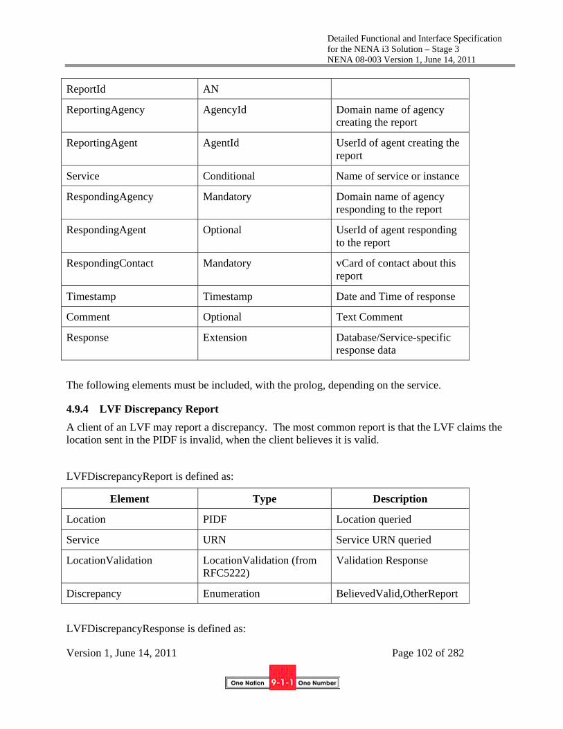
Detailed Functional and Interface Specification for the NENA i3 Solution – Stage 3 NENA 08-003 Version 1, June 14, 2011
Version 1, June 14, 2011 Page 102 of 282
ReportId AN
ReportingAgency AgencyId Domain name of agency creating the report
ReportingAgent AgentId UserId of agent creating the report
Service Conditional Name of service or instance
RespondingAgency Mandatory Domain name of agency responding to the report
RespondingAgent Optional UserId of agent responding to the report
RespondingContact Mandatory vCard of contact about this report
Timestamp Timestamp Date and Time of response
Comment Optional Text Comment
Response Extension Database/Service-specific response data
The following elements must be included, with the prolog, depending on the service.
4.9.4 LVF Discrepancy Report
A client of an LVF may report a discrepancy. The most common report is that the LVF claims the location sent in the PIDF is invalid, when the client believes it is valid.
LVFDiscrepancyReport is defined as:
Element Type Description
Location PIDF Location queried
Service URN Service URN queried
LocationValidation LocationValidation (from RFC5222)
Validation Response
Discrepancy Enumeration BelievedValid,OtherReport
LVFDiscrepancyResponse is defined as:

Detailed Functional and Interface Specification for the NENA i3 Solution – Stage 3 NENA 08-003 Version 1, June 14, 2011
Version 1, June 14, 2011 Page 103 of 282
Element Type Description
ValidationResponse Enumeration EntryAdded, NoSuchLocation, OtherResponse
4.9.5 Policy Discrepancy Report
A client of a Policy may report a discrepancy. The most common report is that the Policy Query returns an invalid Policy from the Policy Store.
PolicyDiscrepancyReport is defined as:
Element Type Description
policyName Mandatory The name of the policy
Agency Mandatory The agency whose policy is requested. Must be a domain name or URI that contains a domain name
RetreivePolicyResponse Mandatory The Response received from the Policy Retrieve Request as shown in 4.4.1
The PolicyDiscrepancyResponse is defined as:
Element Type Description
ValidationResponse Enumeration Policy Added, Policy Updated, No Such Policy, Other Response
4.9.6 LoST Discrepancy Report

Detailed Functional and Interface Specification for the NENA i3 Solution – Stage 3 NENA 08-003 Version 1, June 14, 2011
Version 1, June 14, 2011 Page 104 of 282
4.9.7 ECRF Discrepancy Report
4.9.8 BCF Discrepancy Report
4.9.9 Log Discrepancy Report
4.9.10 PSAP Call Taker Discrepancy Report
4.9.11 Permissions Discrepancy Report
4.9.12 GIS Discrepancy Report
5 Functions
5.1 Border Control Function (BCF)
A BCF sits between external networks and the ESInet and between the ESInet and agency networks. All traffic from external networks transits a BCF.
5.1.1 Functional Description
The Border Control Function comprises several distinct elements pertaining to network edge control and SIP message handling. These include:
‐ Border Firewall ‐ Session Border Control
It is imperative that the border control function support the following security related techniques:
‐ Prevention ‐ Detection ‐ Reaction
Additionally, the entirety of the functional element may include aspects of the following:
‐ B2BUA ‐ Media anchoring ‐ Stateful Firewall

Detailed Functional and Interface Specification for the NENA i3 Solution – Stage 3 NENA 08-003 Version 1, June 14, 2011
Version 1, June 14, 2011 Page 105 of 282
Border Firewall — This functional component of the BCF inspects ingress and egress traffic running through it. It is a dedicated appliance or software running on a computer. There are a variety of different roles a firewall can take however, the typical roles are application layer and network layer firewalls:
1) Application layer – these scan and eliminate known malware attacks from extranet and intranet sources at layer 7 before they ever reach a user’s workstation or a production server or another end point located inside the ESInet. These act as the primary layer of defense for most Internet originated malware attacks that are protocol specific.
2) Network layer — these manage access on the Internet perimeter and between network
segments. Typically they do not provide active scanning at the application layer and provide access control through the use of access control lists and port based permission/denial management (UDP, TCP etc.). They also mitigate attacks on lower layer protocol layers (e.g., SYN Flooding).
Firewalls deployed on the ESInet shall meet the following specifications:
1) Provide both application and network layer protection and scanning. 2) Denial of service (DoS) detection and protection
a. Detection of unusual incoming IP packets that may then be blocked to protect the intended receiving user or network.
b. To prevent distributed denial of service (DDoS) attack, destination specific monitoring, regardless of the source address, may be necessary.
3) Provide a mechanism such that malware definitions and patterns can be easily and quickly updated by a national 9-1-1 CERT or other managing authority
4) Capability to receive and update 9-1-1 Malicious Content (NMC) filtering automatically for use by federated firewalls in protecting multiple disparate ESInets
5) Adhere to the default deny principle.
Please refer to NENA 04-503 [102] for more information on firewall requirements.
Session Border Control — The session border controller functional element of the BCF plays a role in VoIP services by controlling borders to resolve multiple VoIP-related problems such as Network Address Translation (NAT) or firewall traversal. Session Border Controllers (SBCs) are already being extensively used in existing VoIP service networks.
The following primary functions are related to the SBC within a BCF:
‐ Identification of emergency call/session and priority handling for the IP flows of emergency
call/session traffic. Use of the BCF, or any other ESInet element for non-emergency calls that enter an ESInet is not described herein except for calls to an administrative number in

Detailed Functional and Interface Specification for the NENA i3 Solution – Stage 3 NENA 08-003 Version 1, June 14, 2011
Version 1, June 14, 2011 Page 106 of 282
the PSAP. Such non-emergency calls are beyond the scope of this document.
‐ Conformance checking and mapping (if applicable) of priority marking based on policy for emergency calls/sessions
‐ Facilitate forwarding of an emergency call/session to an ESRP (and only an ESRP)
‐ Protection against DDoS attacks: The SBC component of the BCF shall protect against VoIP specific and general DDoS attacks on VoIP network elements.
‐ SIP Protocol Normalization: The SBC component of the BCF shall support SIP/SDP protocol normalization and/or repair, including adjustments of encodings to a core network profile. This may be done in order to facilitate backward compatibility with older devices that may support a deprecated version of SIP/SDP.
‐ NAT and NAPT Traversal: The SBC component of the BCF shall perform NAT traversal for authorized calls/sessions using SIP protocol. The SBC component must be able to recognize that a NAT or NAPT has been performed on Layer 3 but not above and correct the signaling messages for SIP.
‐ IPv4/IPv6 Interworking: The SBC component of the BCF shall enable interworking between networks utilizing IPv4 and networks using IPv6 through the use of dual stacks, selectable for each BCF interface. All valid IPv4 addresses and parameters shall be translated to/from the equivalent IPv6 values.
‐ Signaling Transport Protocol Support: The SBC component of the BCF shall support SIP over the following protocols: TCP, UDP, TLS-over-TCP, and SCTP. Protocols supported must be selectable for each BCF interface to external systems. These transport layer protocols are generated and terminated at each interface to external systems (i.e., there is no "pass-thru" of transport layer information).
‐ VPN Bridging or Mediation: The SBC component of the BCF shall support terminating the IP signaling received from a foreign carrier onto the ESInet address space. The SBC component of the BCF shall support Back to Back User Agent functions to enable VPN bridging if needed.
‐ QoS/Priority Packet Markings: The SBC component of the BCF shall be capable of populating the layer 2 and layer 3 headers/fields, based on call/session type (e.g., 9-1-1 calls) in order to facilitate priority routing of the packets.

Detailed Functional and Interface Specification for the NENA i3 Solution – Stage 3 NENA 08-003 Version 1, June 14, 2011
Version 1, June 14, 2011 Page 107 of 282
‐ Call Detail Recording - The SBC component of the SBC shall be capable of producing CDRs based on call/session control information (e.g., SIP/SDP). These CDRs can be used to manage the network and for SLA auditing.
‐ Transcoding: The SBC component of the BCF shall optionally support transcoding. For example, the SBC component may transcode baudot tones to RFC4103 real time text. See Section 4.1.8.3.
‐ Encryption: The SBC component of the BCF shall support encryption (AES on TLS) for calls that are not protected entering the ESInet.
Additionally, the SBC component of the BCF performs the following functions:
Opening and closing of a pinhole (firewall)
‐ Triggered by signaling packets, a target IP flow is identified by "5-tuples" (i.e., source/destination IP addresses, source/destination port number and protocol identifier) and the corresponding pinhole is opened to pass through the IP flow.
Resource and admission control
‐ For links directly connected to the element, and optionally networks behind the element, resource availability is managed and admission control is performed for the target call/session.
IP payload processing
‐ Transcoding (e.g., between G.711 and G.729) and DTMF interworking.
Performance measurement
‐ Quality monitoring for the target IP flow in terms of determined performance parameters, such as delay, jitter and packet loss. Performance results may need to be collected for aggregated IP flows.
Media encryption and decryption
‐ Encryption and decryption of media streamed (e.g., IPsec).
B2BUA for UAs that do not support Replaces
‐ The SBC component may include a B2BUA function for 9-1-1
calls where the caller does not indicate support for the Replaces
operation. See section 5.8.1.
Typically, the firewall passes traffic for inbound SIP protocol to the Session Border Controller, which acts as an Application Layer Gateway for SIP. Primary non SIP protection is accomplished by the Firewall functions of the BCF. Primary SIP protection is accomplished by the SBC component of the BCF.

Detailed Functional and Interface Specification for the NENA i3 Solution – Stage 3 NENA 08-003 Version 1, June 14, 2011
Version 1, June 14, 2011 Page 108 of 282
5.1.2 Interface Description
The BCF supports SIP interfaces upstream and downstream per Section 4.1. BCFs must support ROHC [145]. The BCF shall support an automated interface that allows a downstream element to mark a particular source of a call as a “bad actor” (usually due to receipt of a call that appears to be part of a deliberate attack on the system) and send a message to the BCF notifying it of this marking. To facilitate this notification, the BCF shall include a “NENA-source” parameter in the Via header that it inserts in the outgoing INVITE message associated with every call. Because the SBC component of the BCF may rewrite addresses, calls must be marked by the SBC component in a way that allows the recipient to identify the BCF that processed the call. The NENA-source parameter is formatted as follows: <unique source-id>@<domain name of BCF> (e.g., [email protected]).
When the downstream element identifies a source as a “bad actor”, it signals the BCF which source is misbehaving by sending it a BadActorRequest that contains the sourceId from the NENA-source parameter that was included in the Via header of the incoming INVITE message. The BCF responds by returning a BadActorResponse message which indicates whether or not an error was detected in the BadActorRequest message.
Upon receiving the BadActorRequest, the SBC component of the BCF should filter out subsequent calls from that source until the attack subsides.
The bad actor request/response is a webservice operated on the domain mentioned in the parameter.
.
The bad actor report is a webservice operated on the domain mentioned in the parameter.
BadActorRequest
Parameter Condition Description
sourceId Mandatory sourceId from a NENA-source parameter
BadActorResponse
Parameter Condition Description
errorCode Mandatory Error Code
Error Codes
100 Okay No error
101 Already reported
512 No such sourceId
513 Unauthorized
504 Unspecified Error

Detailed Functional and Interface Specification for the NENA i3 Solution – Stage 3 NENA 08-003 Version 1, June 14, 2011
Version 1, June 14, 2011 Page 109 of 282
5.1.2.1 CallSuspicion
The BCF may be able to identify calls that may be part of a deliberate attack on the system. However, under normal conditions, we allow suspicious calls in, preferring to have a bad call show up to having a good call dropped. The behavior of downstream elements (ESRPs for example) may be affected by the determination of the BCF. For this purpose, the BCF attaches a parameter to the VIA it inserts on the call. The parameter: NENA-CallSuspicion is an enumeration having the following values:
Legit: Call appears to be legitimate
Suspicious: Call may fit a known attack, but the BCF is unsure
Bad: Call fits a known attack pattern and is considered fraudulent.
5.1.3 Roles and Responsibilities
The ESInet operator is responsible for the BCF at the edge of the ESInet. PSAP or other agency is responsible for a BCF between its network and the ESInet.
5.1.4 Operational Considerations
In order to withstand the kinds of attacks anticipated, BCFs at the edge of the ESInet should be provisioned with capacity, both aggregate uplink bandwidth and BCF processing capacity larger than the largest feasible DDoS attack. As of this edition, that capacity is approximately 6-8 Gigabits of mitigation.
Creation of a Public Safety Computer Emergency Response Team (CERT) is anticipated, and all BCF operators must arrange to receive alerts from the CERT and respond. It is essential that all BCF support organizations have trained staff available 24 x 7 x 365 to immediately respond to attacks and have the capability and training to be able to adjust the BCF to mitigate such attacks.
5.2 Emergency Service Routing Proxy (ESRP)
5.2.1 Functional Description
5.2.1.1 Overview
The Emergency Service Routing Proxy (ESRP) is the base routing function for emergency calls for i3. As described in NENA 08-002, ESRPs are used in several positions within the ESInet:
The "Originating ESRP" is the first routing element inside the ESInet. It receives calls from the BCF at the edge of the ESInet
One or more "Intermediate ESRPs" which exist at various hierarchical levels in the ESInet. For example, the Originating ESRP may be a state-level function, and an intermediate ESRP may be operated by a county agency.
The "Terminating ESRP" is typically at the edge of a PSAP, just past the PSAP BCF.

Detailed Functional and Interface Specification for the NENA i3 Solution – Stage 3 NENA 08-003 Version 1, June 14, 2011
Version 1, June 14, 2011 Page 110 of 282
The function of the ESRP is to route a call to the next hop. The Originating ESRP routes to the appropriate intermediate ESRPs (if they exist), intermediate ESRPs route to the next level intermediate ESRP or to the Terminating ESRP, i.e., the appropriate PSAP. The Terminating ESRP routes to a call taker or set of call takers.
ESRPs typically receive calls from upstream routing proxies. For the originating ESRP, this is typically a carrier routing proxy. For an intermediate or terminating ESRP, this is the upstream ESRP. The destination of the call on the output of the ESRP is conceptually a queue, represented by a URI. In most cases, the queue is maintained on a downstream ESRP, and is most often empty. However, when the network gets busy for any reason, it is possible for more than one downstream element to "pull" calls from the queue. The queue is most often First In First Out, but in some cases there can be out-of-order selections from the queue.
The primary input to an ESRP is a SIP message. The output is a SIP message with a Route header (possibly) rewritten, a Via header added, and in some cases, additional manipulation of the SIP messages. To do its job, the ESRP has interfaces to the ECRF for location based routing information, as well as various event notification sources to gather state, which is used by its Policy Routing Function (PRF).
For typical l 9-1-1 calls received by an ESRP it;
1. Evaluates a policy “rule set” for the queue the call arrives on 2. Queries the location-based routing function (ECRF) with the location included with the call
to determine the "normal" next hop (smaller political or network subdivision, PSAP or call taker group) URI.
3. Evaluate a policy rule set for that URI using other inputs available to it such as headers in the SIP message, time of day, PSAP state, etc.
The result of the policy rule evaluation is a URI. The ESRP forwards the call to the URI (which is a queue as above).
The ESRP may also handle calls to what used to be called “administrative lines,” meaning calls directed to a 10-digit number listed for a particular PSAP. It is recommended that such calls route through the BCF to an ESRP and be subject to the same security and policy routing as regular 9-1-1 calls. Such calls would not have a Geolocation header and the ESRP would not query an ECRF, but would use the 10-digit number to map to a PSAP URI (the same URI which the ECRF would yield), and use that URI as the “normal next hop” used to select the policy rule set to evaluate.
An ESRP is usually the “outgoing proxy server” for calls originated by the PSAP. The ESRP would route calls within the ESInet, and would route calls to destinations outside the ESInet through an appropriate gateway or SIP trunk to a PSTN or other carrier connection. Call backs to the original caller are an example of such outgoing calls to external destinations. No policy rule set evaluation is used for outgoing calls. While an ESRP could be an incoming proxy server for non-emergency calls, such use is beyond the scope of this standard.
5.2.1.2 Call Queuing
The destination of every routing decision is conceptually a queue of calls. The queue can be large or small, it can have one or many sources entering calls on a queue, it can have one or many sources

Detailed Functional and Interface Specification for the NENA i3 Solution – Stage 3 NENA 08-003 Version 1, June 14, 2011
Version 1, June 14, 2011 Page 111 of 282
taking calls off the queue. All queues defined in this document are normally First In First Out. A queue is identified by a unique SIP URI. A queue is managed by an ESRP. A call sent to the queue URI must route to the ESRP that manages it. Calls are enqueued by forwarding them to the URI (which is usually obtained by policy rule evaluation of an upstream ESRP). Calls are dequeued by the ESRP sending the call to a downstream entity (ESRP or endpoint such as a call taker or IMR).
ESRPs may, and often will, manage multiple queues. For example, an ESRP may manage a queue that is used for normal 9-1-1 calls routed to the local ESInet, and one or more queues for calls that are diverted to it by ESRPs from other areas which are overloaded. Each queue must have a unique URI that routes to the ESRP.
In practice, some proxy servers may be simple RFC 3261 [12] compliant servers making simple routing decisions per RFC3264. In such cases, the queue is considered to have a length of 1 and its existence can be ignored.
The ESRP managing a queue may have policy that controls which entities may enqueue and dequeue calls to the queue. The dequeueing entity registers (DequeueRegistration) to receive calls from the queue. The ESRP would return a call from an entity not in its policy with a 404 error.
The ESRP will maintain a QueueState notifier, and track the number of calls in queue for the queues that it manages.
5.2.1.3 QueueState Event Package
QueueState is an event that indicates to an upstream entity the state of a queue. The SIP Notify mechanism described in RFC 3265 is used to report QueueState. The event includes the URI of the queue, the current queue length, allowed maximum length and a state enumeration including:
Active: one or more entities are actively available or are currently handling calls being enqueued
Inactive: no entity is available or actively handling calls being enqueued
Disabled: The queue is disabled by management action and no calls may be enqueued
Full: The queue is full and no new calls can be enqueued on it.
Standby: the queue has one or more entities that are available to take calls, but the queue is not presently in use. When a call is enqueued, the state changes to “Active”.
QueueState need not be implemented on simple routing proxy or when queue length is 1 and only one dequeuer is permitted.
Event Package Name: nena-QueueState
Event Package Parameters: None
SUBSCRIBE Bodies: standard RFC4661 + extensions filter specification may be present
Subscription Duration Default 1 hour. 1 minute to 24 hours is reasonable.
NOTIFY Bodies: MIME type application/vnd,nena.queuestate+xml
Parameter Condition Description
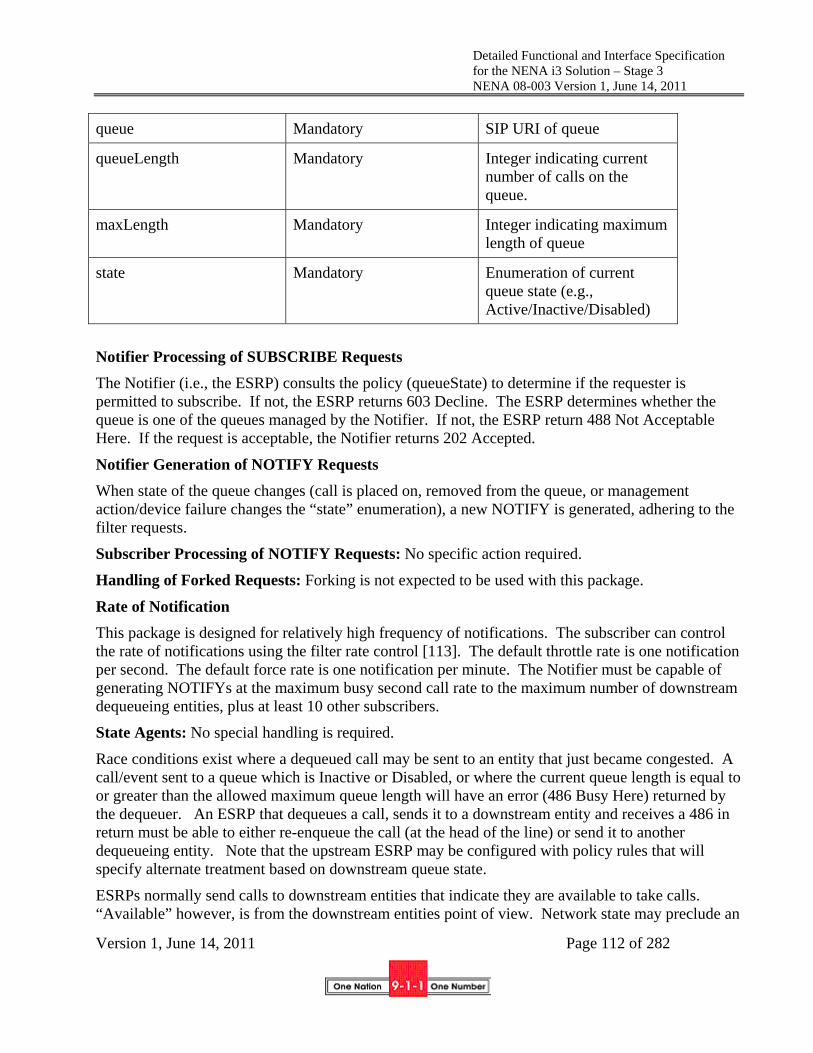
Detailed Functional and Interface Specification for the NENA i3 Solution – Stage 3 NENA 08-003 Version 1, June 14, 2011
Version 1, June 14, 2011 Page 112 of 282
queue Mandatory SIP URI of queue
queueLength Mandatory Integer indicating current number of calls on the queue.
maxLength Mandatory Integer indicating maximum length of queue
state Mandatory Enumeration of current queue state (e.g., Active/Inactive/Disabled)
Notifier Processing of SUBSCRIBE Requests
The Notifier (i.e., the ESRP) consults the policy (queueState) to determine if the requester is permitted to subscribe. If not, the ESRP returns 603 Decline. The ESRP determines whether the queue is one of the queues managed by the Notifier. If not, the ESRP return 488 Not Acceptable Here. If the request is acceptable, the Notifier returns 202 Accepted.
Notifier Generation of NOTIFY Requests
When state of the queue changes (call is placed on, removed from the queue, or management action/device failure changes the “state” enumeration), a new NOTIFY is generated, adhering to the filter requests.
Subscriber Processing of NOTIFY Requests: No specific action required.
Handling of Forked Requests: Forking is not expected to be used with this package.
Rate of Notification
This package is designed for relatively high frequency of notifications. The subscriber can control the rate of notifications using the filter rate control [113]. The default throttle rate is one notification per second. The default force rate is one notification per minute. The Notifier must be capable of generating NOTIFYs at the maximum busy second call rate to the maximum number of downstream dequeueing entities, plus at least 10 other subscribers.
State Agents: No special handling is required.
Race conditions exist where a dequeued call may be sent to an entity that just became congested. A call/event sent to a queue which is Inactive or Disabled, or where the current queue length is equal to or greater than the allowed maximum queue length will have an error (486 Busy Here) returned by the dequeuer. An ESRP that dequeues a call, sends it to a downstream entity and receives a 486 in return must be able to either re-enqueue the call (at the head of the line) or send it to another dequeueing entity. Note that the upstream ESRP may be configured with policy rules that will specify alternate treatment based on downstream queue state.
ESRPs normally send calls to downstream entities that indicate they are available to take calls. “Available” however, is from the downstream entities point of view. Network state may preclude an

Detailed Functional and Interface Specification for the NENA i3 Solution – Stage 3 NENA 08-003 Version 1, June 14, 2011
Version 1, June 14, 2011 Page 113 of 282
upstream entity from sending calls downstream. Normal SIP processing would eventually result in timeouts if calls are sent to an entity that never responds because the packets never arrive. Timeouts are long however, and a more responsive mechanism is desirable to ensure that rapid response to changing network conditions route calls optimally.
If active calls are being handled, the upstream entity knows the downstream entity is connected. However, some routes are seldom used, and a mechanism must be provided that ensures the connectedness of each entity remains known.
For this purpose, we ensure relatively frequent NOTIFYs of the QueueState event. Successful completion of the NOTIFY is indication to the upstream entity that calls sent to the downstream entity should succeed. The subscription may include a “force” and/or “throttle” filter [113] to control the rate of Notification.
5.2.1.4 DequeueRegistration Event Package
DequeueRegistration is web service whereby the registering entity becomes one of the dequeueing entities, and the ESRP managing the queue will begin to send calls to it. The registration includes a value for DequeuePreference which is an integer from 1-5. When dequeueing calls, the ESRP will send calls to the highest DequeuePreference entity available to take the call when it reaches the head of the queue. If more than one entity has the same DequeuePreference, the ESRP will attempt to fairly distribute calls to the set of entities with the same DequeuePreference measured over tens of minutes.
DequeueRegistrationRequest
Parameter Condition Description
queue Mandatory SIP URI of queue
dequeuePreference Optional Integer from 1-5 indicating queuing preference.
DequeueRegistrationResponse
Parameter Condition Description
errorCode Optional Error Code
Error Codes
100 Okay No error
506 Bad queue
507 Bad dequeuePreference
508 Policy Violation
504 Unspecified Error

Detailed Functional and Interface Specification for the NENA i3 Solution – Stage 3 NENA 08-003 Version 1, June 14, 2011
Version 1, June 14, 2011 Page 114 of 282
The ESRP will subscribe to the QueueState event for each dequeueing entity to determine its availability to take calls. Normally, a dequeueing entity is another queue maintained at the downstream entity, although the queue maintained at the terminating ESRP, which is normally the PSAP, would use call taker state rather than queue state to determine availability to dequeue calls from its upstream ESRP.
5.2.1.5 Policy Routing Function
Policy Routing refers to the determination of the next hop a call or event is forwarded to by an ESRP. The PRF evaluates two or more policy rulesets: one set determined by the queue the call arrives on, the other determined by the result of an ECRF query with the location of the caller.
The PRF in an ESRP accepts calls directed to a specific queue URI. From that URI, it extracts its own “OriginationPolicy” from its policy store for that URI and executes the ruleset. The rules normally include at least one action LoSTServiceURN(<urn>) where urn is a service urn (either urn:service:… or urn:nena:service:…). Upon encountering the LoSTServiceURN action, the PRF queries its (configured) ECRF with the location received in the call using the urn parameter in the action. The resulting URI is a variable called “NormalNextHop”. The PRF extracts a “TerminationPolicy” from its policy store associated with the domain of NormalNextHop and executes the ruleset associated with that policy. The rules normally include the action “Route”. The PRF forwards the call to the route. It would be common for the route of a 9-1-1 call intended for a PSAP in a normal state to be identical to the “NormalNextHop” URI, that is, if the ECRF query returned sip:[email protected], then the TerminationPolicy ruleset for sip:[email protected] would have a Route(sip:[email protected]) or a Route(NormalNextHop), which is equivalent, if the state of psap1 is nominal. If the policy store the ESRP uses does not contain a TerminationPolicy rule set for the NormalNextHop URI, the ESRP will route the call directly to that URI.
The destination of a Route action is usually the URI of a queue, but a simple proxy server can be the next hop. The PRF has access to queue state of downstream entities and can use that state in evaluating rules. Rules normally have a Route action that sends the call to a queue that is Available and not full. A Route may also be a URI that routes to an Interactive Multimedia Response system, conforming to RFC4240 [43], that plays an announcement (in the media negotiated by the caller) and potentially accepts responses via DTMF, KPML or other interaction styles.
The syntax is Route(<recipient>, <cause>), where recipient is a URI which will become the Request URI for the outgoing SIP message, and the <cause> is a value used with the Reason header associated with a History-Info header. The <cause> values are defined in a Registry which this document establishes.
Other Actions that may occur in a Termination-Policy include:
Busy() which returns 600 Busy Everywhere to the caller
Notify(<recipient>, <eventCode>,<urgency>, <severity>,<certainty>), which sends a NOTIFY containing a CAP message to any entity subscribing to the Normal-NextHop’s ESRPnotify event for that reason code. This may be used, for example, to advise other

Detailed Functional and Interface Specification for the NENA i3 Solution – Stage 3 NENA 08-003 Version 1, June 14, 2011
Version 1, June 14, 2011 Page 115 of 282
entities that calls are being diverted, etc. If the <recipient> is a service urn, the CAP message is wrapped in a SIP MESSAGE and is routed via the ECRF to the proper recipients.
By using these mechanisms, the full range of call treatments can be applied to any class of call for any circumstance based on the PRF ruleset.
Rules may make use of the following variables. Several require the ESRP to use the SIP-based notification mechanism described in RFC 3265 to obtain the value of the variable.
1. ElementState, expressed as Elementstate.<domain> where <domain> is a hostname, or a URI. If a URI is specified, the Domain function is used to extract the domain from the URI. The domain must be that of a PSAP that the ESRP can subscribe to the ElementState package for.
2. QueueState (and implied “Not Reachable” state), expressed as QueueState.<queue> where <queue> is the name of a queue
3. SecurityPosture , expressed as SecurityPosture.<domain> where <domain> is a hostname, or a URI. If a URI is specified, the Domain function is used to extract the domain from the URI. The domain must be that of an agency or element that the ESRP can subscribe to the SecurityPosture package for.
4. CallSuspicion, the BCF’s opinion of the call, expressed as CallSuspicion.<suspicionLevel>. See Section 5.1.2.1.
5. Call Source (as defined in the Via headers of the INVITE), interpreted by the ESRP to ignore intra ESInet Vias, and other intermediaries. CallSource should be the ESRP’s best determination of the domain of the originating network that handled the call. If there is more than one, the last SP prior to the ESInet should be returned. If there are no originating networks, CallSource returns the domain of the caller.
6. Any header in the call INVITE message, expressed as Invite.<header name>. Even though a call may be initiated with a sip Message, Invite.<header name> is used to specify the headers
7. Any element in a body that is included in the message which is XML encoded, expressed as Body <mimetype><element tag>. If a body contains more than one part (of a multipart) with the same mimetype, only the first part with that mimetype can be used. This capability may be used to route on parameters in a CAP message.
8. The location used for routing, expressed as PIDF.<element name>
9. Any element in the Additional Data about a call or caller or location structures if available, expressed as AcallData.<element name>, AcallerData.<element name> or AlocationData.<element name>. See Sections 5.10 and 8.
10. Time of Day, expressed as TimeOfDay or DayOfWeek, where TimeOfDay is wall clock time (0000 to 2359) and DayOfWeek is Mon, Tue, Wed, Thu, Fri, Sat, Sun.
11. RequestURI (URI call was sent to ESRP with)
12. ECRF query results (Normal-NextHop).

Detailed Functional and Interface Specification for the NENA i3 Solution – Stage 3 NENA 08-003 Version 1, June 14, 2011
Version 1, June 14, 2011 Page 116 of 282
13. The queue the call was received on (IncomingQueue)
Rules have a priority. If more than one rule yields a value for NextHop, the rule with the highest priority prevails. If more than one rule with the same priority yields a value for NextHop, the ESRP chooses randomly from the results with approximately uniform distribution.
Usually, there is a “default” rule for use when everything is in normal status. Most calls will route via this rule. For example IF True THEN Route(NormalNextHop) {10}; Other rules exist for unusual circumstances.
In congestion for typical transient overload, a specific PSAP would be delegated to take diverted calls (via a rule other than the default rule). A call is said to be diverted when it is sent to a PSAP other than the one serving the location of the caller, usually due to some failure or overload condition. A queue is established for that route, with one dequeueing PSAP. Such a diversion PSAP would be accepting calls on its normal queue as well as the diversion queue. Its rules can differentiate such calls from the queue they arrive on.
For more extensive overload, a group of PSAPs would subscribe to take calls from a designated queue. For example, all PSAPs in neighboring counties might subscribe to a low priority rule for overload for a county PSAP. Similarly, all NG9-1-1 PSAPs in a state might dequeue for a “Denial of Service Attack” queue, or interstate queues may be established that have a “ripple” effect (using priority) to spread calls out when the state queue becomes busy.
ESRPs managing a queue may become a dequeuer for one or more upstream queues. Origination rules at the ESRP can govern how such calls are handled, as the URI used to get the call to the ESRP (which could be the name of a queue maintained at the ESRP) is an input to the PRF. When handling diverted calls, no ECRF dip may be needed (and thus no termination policy ruleset is used). In such a case, the origination policy ruleset would determine NextHop. Rules can determine the priority of multiple queues feeding calls to the ESRP. PSAP ESRPs may dequeue for multiple call queues, placing them on internal queues for call takers.
5.2.1.6 ESRPnotify Event Package
The ESRP sends a Notify for this event when the PRF encounters a Notify action. It is used to inform other agencies or elements about conditions in an incoming call they may be interested in. For example, a call that contains an AdditionalCallData record may have a telematics dataset that indicates a severe injury. The ruleset may issue the ESRPnotify event to a helicopter rescue unit to inform them that their services may be needed. The ESRPnotify event is defined as follows:
Event Package Name: nena-ESRPnotify
Event Package Parameters:
Parameter Condition Description
Normal-NextHop Mandatory URI of downstream entity occurring in a Termination-Policy
ESRPEventCode Mandatory Enumeration of event codes.
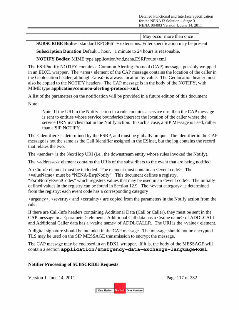
Detailed Functional and Interface Specification for the NENA i3 Solution – Stage 3 NENA 08-003 Version 1, June 14, 2011
Version 1, June 14, 2011 Page 117 of 282
May occur more than once
SUBSCRIBE Bodies: standard RFC4661 + extensions. Filter specification may be present
Subscription Duration Default 1 hour. 1 minute to 24 hours is reasonable.
NOTIFY Bodies: MIME type application/vnd,nena.ESRProute+xml
The ESRPnotify NOTIFY contains a Common Alerting Protocol (CAP) message, possibly wrapped in an EDXL wrapper. The <area> element of the CAP message contains the location of the caller in the Geolocation header, although <area> is always location by value. The Geolocation header must also be copied to the NOTIFY headers. The CAP message is in the body of the NOTIFY, with MIME type application/common-alerting-protocol+xml.
A list of the parameters on the notification will be provided in a future edition of this document
Note:
Note: If the URI in the Notify action in a rule contains a service urn, then the CAP message is sent to entities whose service boundaries intersect the location of the caller where the service URN matches that in the Notify action. In such a case, a SIP Message is used, rather than a SIP NOTIFY.
The <identifier> is determined by the ESRP, and must be globally unique. The identifier in the CAP message is not the same as the Call Identifier assigned in the ESInet, but the log contains the record that relates the two.
The <sender> is the NextHop URI (i.e., the downstream entity whose rules invoked the Notify).
The <addresses> element contains the URIs of the subscribers to the event that are being notified.
An <info> element must be included. The element must contain an <event code>. The <valueName> must be “NENA-EsrpNotify”. This document defines a registry, “EsrpNotifyEventCodes” which registers values that may be used in an <event code>. The initially defined values in the registry can be found in Section 12.9. The <event category> is determined from the registry: each event code has a corresponding category
<urgency>, <severity> and <certainty> are copied from the parameters in the Notify action from the rule.
If there are Call-Info headers containing Additional Data (Call or Caller), they must be sent in the CAP message in a <parameter> element. Additional Call data has a <value name> of ADDLCALL and Additional Caller data has a <value name> of ADDLCALLR. The URI is the <value> element.
A digital signature should be included in the CAP message. The message should not be encrypted. TLS may be used on the SIP MESSAGE transmission to encrypt the message.
The CAP message may be enclosed in an EDXL wrapper. If it is, the body of the MESSAGE will contain a section application/emergency-data-exchange-language+xml.
Notifier Processing of SUBSCRIBE Requests

Detailed Functional and Interface Specification for the NENA i3 Solution – Stage 3 NENA 08-003 Version 1, June 14, 2011
Version 1, June 14, 2011 Page 118 of 282
The Notifier (the ESRP) consults the policy (NotifyPermissions) for Normal-NextHop to determine if the requester is permitted to subscribe. If not permitted, the ESRP returns 603 Decline. The ESRP determines if at least one policy it uses contains a Notify action with that event code. If not, the ESRP returns a 488 Not Acceptable Here. If the request is acceptable, the ESRP returns 202 Accepted.
Notifier Generation of NOTIFY Requests
When the Notify(ESRProuteEventCode) action is present in the rule that determines routing, send NOTIFY to any subscriber requesting that notification (based on the Normal-NextHop whose policy is being evaluated and the ESRProuteEventCode present in the action.
Subscriber Processing of NOTIFY Requests: No specific action required.
Handling of Forked Requests: Forking is not expected to be used with this package.
Rate of Notification
A notification for each call/event handled by the ESRP could be sent. Rate controls [113] may be used to limit Notifications.
State Agents: No special handling is required.
5.2.1.7 Processing of an INVITE transaction
When the ESRP receives an INVITE transaction it first evaluates the Origination ruleset for the queue the call arrived on. If a LoSTServiceURN action is encountered it looks for the presence of a Geolocation header. If present the ESRP evaluates the header and extracts the location in the Geolocation header [10]. Each ESRP must be capable of receiving location as a value or a reference, and must be provisioned with credentials suitable to present to all LISs in its service area to be able to dereference a location reference using either SIP or HELD.
The ESRP must be able to handle calls with problems in location. This can occur if the call is originated by an element outside the ESInet, the call is to an emergency service URN, and there is no Geolocation header. This also occurs if the location contents are malformed, the LIS cannot be contacted, the LIS refuses to dereference, the LIS returns a malformed location value or the ESRP encounters another error that results in no location. In all such cases the ESRP must make a best effort to determine a suitable default location to use to route the call. The call source, IP address of the caller or other information from the INVITE may be used to determine the best possible default location. It is felt that the earlier in call processing that bad or missing location is determined, the more likely the ESRP will have information needed to get the best possible default location, and downstream entities will be in a worse position to do that.
The ESRP then queries its local (provisioned) ECRF with the location, using the service urn specified and the value of the Route header in the LoSTServiceURN action parameter. For example, the originating ESRP receiving an emergency call from outside the ESInet where there are no intermediary ESRPs in its service area (meaning the originating ESRP routes calls directly to the PSAP) may use the service "urn:nena:service.sos.psap ". The ECRF returns a URI for that service.

Detailed Functional and Interface Specification for the NENA i3 Solution – Stage 3 NENA 08-003 Version 1, June 14, 2011
Version 1, June 14, 2011 Page 119 of 282
Calls to an administrative number do not have location and are mapped by a provisioned table in the ESRP from the called number to a URI.
The ESRP retrieves the terminating policy ruleset for the URI The PRF evaluates the ruleset using the facts available to it such as PSAP state, time of day, queue state, information extracted from the INVITE, etc. The result is a URI of a queue. The ESRP attempts to forward the call to the URI, using the DNS to evaluate the URI into an IP address. DNS may provide alternate IP addresses to resolve the URI. Normal SIP and DNS processing is used to try these alternate IP addresses. Should no entity respond, the ESRP must provide the call with a provisioned treatment such as returning busy. Note that normally, the state of the downstream elements that would appear in the URI report their state to the ESRP and the ruleset would use that state to specify an alternate route for the call.
Calls that are received by an ESRP which originate inside the ESInet are routed per normal SIP routing mechanisms. Calls to E.164 telephone numbers not otherwise provided for in the ESRP provisioning must be routed to a provisioned gateway or SIP Trunk interconnected to the PSTN.
5.2.1.8 Processing a BYE Transaction
An ESRP processes BYEs per RFC3261.
5.2.1.9 Processing a CANCEL transaction
An ESRP processes CANCELs per RFC3261.
Note: The ESRP should have a way to notify a PSAP that a call arrived at the ESRP, but was CANCELled before the INVITE was sent to the PSAP. This would be one case of abandoned call. This will be covered in a future edition of this standard.
5.2.1.10 Processing an OPTIONS transaction
An ESRP processes OPTIONS transactions per RFC3261. OPTIONS is often used as a “keep alive” mechanism. During periods of inactivity, the ESRP should periodically send OPTIONS towards its upstream entities and expect to see OPTIONS transactions from its downstream dequeueing entities.
5.2.2 Interface Description
5.2.2.1 Upstream Call Interface
The ESRP has an upstream SIP interface that typically faces a BCF for the originating ESRP or an upstream ESRP for an intermediate or terminating ESRP. The upstream SIP call interface for the originating ESRP must only assume the minimal methods and headers as define in Section 4.1.1 but must handle any valid SIP transaction. All other ESRPs must handle all methods and SIP headers. The ESRP must respond to the URI returned by the ECRF and/or specified in a Route action for a rule for the upstream service the ESRP receives calls from. The ESRP must assure that pager mode Instant Messages route to the same PSAP per Section 4.1.9
The upstream SIP interface is also used for calls originated inside the ESInet, where the ESRP is the outgoing proxy for a PSAP. Calls originated in the ESInet and destined for agencies within the ESInet are routed by the ESRP using normal SIP routing methods. Calls originated in the ESInet

Detailed Functional and Interface Specification for the NENA i3 Solution – Stage 3 NENA 08-003 Version 1, June 14, 2011
Version 1, June 14, 2011 Page 120 of 282
and destined for external termination (such as call backs) are routed to gateways or SIP trunks terminated by a carrier.
The upstream interface on the originating ESRP must support UDP, TCP, and TCP/TLS and may support SCTP transports. The upstream interface on other ESRPs must implement TCP/TLS but must be capable of fall-back to UDP. SCTP support is optional. The ESRP should maintain persistent TCP and TLS connections to downstream ESRPs or UAs that it serves.
5.2.2.2 Downstream Call Interface
The ESRP downstream call interface typically faces a downstream ESRP for all but the terminating ESRP, which typically faces user agents. The downstream SIP call interface must implement all SIP methods to be able to propagate any method invoked on the upstream call interface. The downstream interface may add any headers noted in section 4.1.2 permitted by the relevant RFCs to be added by proxy servers. The INVITE transaction exiting the ESRP must include a Via header specifying the ESRP. It may include a Route header. The Request URI remains urn:service:sos (although the ESRP may not depend on that) and it replaces the top Route header with the next hop URI (this is described in -phonebcp [59]). The ESRP adds a History-Info and Reason headers per Section 4.1.7 using the cause code specified in the Route action if cause is specified (which it would be for a diverted call).
A call entering the ESInet is initially assumed to be a new Incident. Thus, the first ESRP in the path adds a Call-Info header with a purpose parameter of “nena-IncidentId” and a new Incident Tracking Identifier per Section 3.1.5. The ESRP also creates a new Call identifier (Section 3.1.4) and adds a Call-Info header with a purpose parameter of “nena-CallId”.
The downstream interface must implement TCP/TLS towards downstream elements, but must be capable of fall-back to UDP. SCTP support is optional. No ESRP may remove headers received in the upstream call interface; all headers in the upstream message must be copied to the downstream interface except as required in the relevant RFCs. The ESRP should maintain persistent TCP and TLS connections to downstream ESRPs.
The downstream SIP interface may also accept calls originating within the ESInet.
5.2.2.3 ECRF interface
The ESRP must implement a LoST interface towards a (provisioned) ECRF. The ESRP must use a TCP/TLS transport and must be provisioned with the credentials for the ECRF. The ESRP should maintain persistent TCP and TLS connections to the ECRF.
The ESRP must use the ECRF interface with the "urn:nena:service:AdditionalLocationData" service URN when the relevant ruleset specifies an element in that structure. The same location used for the location-based route is used for the AdditionalLocationData query.

Detailed Functional and Interface Specification for the NENA i3 Solution – Stage 3 NENA 08-003 Version 1, June 14, 2011
Version 1, June 14, 2011 Page 121 of 282
5.2.2.4 LIS Dereference Interface
The ESRP must implement both SIP Presence Event Package and HELD dereference interfaces. When the ESRP receives a location (in a Geolocation header on the upstream SIP interface) it uses the LIS dereference interface to obtain a location value to use in its ECRF query. The ESRP uses its PCA issued credentials to authenticate to the LIS14. The ESRP must use TCP/TLS for the LIS Dereference Interface, with fallback to TCP (without TLS) on failure to establish a TLS connection. The ESRP should maintain persistent TCP and TLS connections to LISs that it has frequent transactions with. A suggested value for "frequent" is more than one transaction per day.
5.2.2.5 Additional Data Interfaces
The ESRP must implement https clients for the AdditionalCallData services. These services may be invoked when the ESRP receives a call with a CallInfo [12] header with a “purpose” of "emergencyCallData", “emergencyCallerData” or “emergencyPSAPdata”. The resulting data structure is an input to the Policy Routing Function. The ESRP must be able to accommodate multiple additional data services and structures for the same call.
Note: Multiple CallInfo headers with "emergencyCallData" may occur when more than one originating network handles the call and/or the device itself reports data. For example, a call may have additional data provided by a wireless carrier as well as a telematics service. The call may have more than one Call-Info header with emergencyCallerData when, for example, the call is from a residence wireline telephony service where there is more than one resident. When used in a routing rule, the PRF merges multiple AdditionalCall or AdditionalCaller data. If the merge results in conflicting information, the information derived earlier encountered Call-Info headers shall take precedence over information derived from subsequent Call-Info headers.
The ESRP should only invoke the web service when the relevant ruleset specifies an input from the AdditionalCallData/AdditionalCallerData/AdditionalPSAPdata structure.
The ESRP must also be able to query the ECRF for AdditionalLocationData when the policy rules are dependent on that data.
5.2.2.6 ESRP, PSAP and Call Taker State Notification and Subscriptions
The ESRP must implement the client side of the ElementState event notification packages. The ESRP must maintain Subscriptions for this package on every downstream element it serves. These state interfaces supply inputs to the Policy Routing Function.
14 The LIS must accept credentials issued to the ESRP traceable to the PCA. If a call is diverted to an alternate PSAP, it could be any willing PSAP, anywhere. The alternate PSAP must be able to retrieve location.

Detailed Functional and Interface Specification for the NENA i3 Solution – Stage 3 NENA 08-003 Version 1, June 14, 2011
Version 1, June 14, 2011 Page 122 of 282
The ESRP must implement the server side of the ElementState event notification package and accept Subscriptions for all upstream ESRPs it expects to receive calls from. The ESRP must promptly report changes in its state to its subscribed elements. Any change in state which affects its ability to receive calls must be reported.
5.2.2.7 Time Interface
The ESRP must implement an NTP client interface for time-of-day information. The ESRP may also provide an interface to a hardware clock. The time of day information is an input to the Policy Routing Function as well as the logging interface
5.2.2.8 Logging Interface
The ESRP must implement a logging interface per Section Error! Reference source not found. The ESRP must be capable of logging every transaction and every message received and sent on its call interfaces, every query to the ECRF and every state change it receives or sends. It must be capable of logging the ruleset it consulted, the rules found to be relevant to the route, and the route decision it made.
Note: The specifics of the log entries will be provided in a future edition of this document.
5.2.3 Data Structures
The ESRP maintains an ElementState structure for its own state, and an ElementState structure for every downstream element it serves.
If the ESRP manages queues, it maintains a QueueState structure for each queues it manages, including the states of the entities registered to dequeue calls from the queue, the overall queue state, the number of calls in queue, the max number of calls allowed, and the current queue state.
The ESRP constructs AdditionalCallData, AdditionalCallerData and AdditionalLocationData structures when the relevant ruleset mentions elements from these structures and, in the case of call and caller data, the upstream Call Interface receives the appropriate CallInfo header with a URI for the AdditionalCallData/AdditionalCallerData dereferencing services.
5.2.4 Policy Elements
The ESRP uses an Origination-Policy ruleset for each queue it manages. For every URI the ECRF can return for the service query the ESRP makes (Normal-NextHop), it must have access to the appropriate Termination-Policy ruleset.
The ESRProuteEvent Policy determines which entities may subscribe to the ESRProute Event (see Section 5.2.1.6).
The queueState policy determines which entities may subscribe to the queueState event
The ElementState policy determines which entities may subscribe it its ElementState event
The DequeueRegistration policy determines which entities may subscribe to the DequeueRegistration event

Detailed Functional and Interface Specification for the NENA i3 Solution – Stage 3 NENA 08-003 Version 1, June 14, 2011
Version 1, June 14, 2011 Page 123 of 282
The takeCallsOnQueues policy determines which queues this ESRP will dequeue from (that is, which queues it will subscribe to the dequeueRegistration and queueState events for)
Note: Specific policy document structures will be specified for each of the above in a future edition of this document.
5.2.5 Provisioning
The ESRP is provisioned with:
The queues it manages
The queues it dequeues from
The default locations it uses, including (potentially) one for each origination domain, and an overall default location
The ECRF it uses
The Logging service it uses
Mappings from 10-digit PSAP telephone numbers to URIs (if the ESRP handles 10 digit calls on behalf of PSAPs)
The URI of a default route PSAP that takes calls when a route cannot be determined.
5.2.6 Roles and Responsibilities
An ESRP may be operated by a State, Regional or local 9-1-1 Authority. A terminating ESRP may be operated by a PSAP. The ESRP for non-originating ESRPs must supply a ruleset for the upstream ESRP.
5.2.7 Operational Considerations
To be provided in a future edition of this standard.
5.3 Emergency Call Routing Function (ECRF)
In i3, emergency calls will be routed to the appropriate PSAP based on the location of the caller. In addition, PSAPs may utilize the same routing functionality to determine how to route emergency calls to the correct responder. The NG9-1-1 functional element responsible for providing routing information to the various querying entities is the Emergency Call Routing Function (ECRF). An ECRF provided by a 9-1-1 Authority and accessible from outside the ESInet must permit querying by an IP client/endpoint, an IP routing proxy belonging to a VSP, a Legacy Network Gateway, an Emergency Services Routing Proxy (ESRP) in a next generation Emergency Services network, or by some combination of these. An ECRF accessible inside an ESInet must permit querying from any entity inside the ESInet. ECRFs provided by other entities may have their own policies on who may query them. An origination network may use an ECRF, or a similar function within its own network, to determine an appropriate route, equivalent to what would be determined by the authoritative ECRF, to the correct ESInet for the emergency call. The ECRF must be used within

Detailed Functional and Interface Specification for the NENA i3 Solution – Stage 3 NENA 08-003 Version 1, June 14, 2011
Version 1, June 14, 2011 Page 124 of 282
the ESInet to route calls to the correct PSAP, and by the PSAP to route calls to the correct responders.
5.3.1 Functional Description
The ECRF supports a mechanism by which location information (either civic address or geo-coordinates) and a Service URN serve as input to a mapping function that returns a URI used to route an emergency call toward the appropriate PSAP for the caller’s location. Depending on the identity and credentials of the entity requesting the routing information, the response may identify the PSAP or an Emergency Services Routing Proxy (ESRP) that acts on behalf of the PSAP to provide final routing to the PSAP itself. The same database used to route a call to the correct PSAP may also be used to subsequently route the call to the correct responder, e.g., to support selective transfer capabilities. Depending on the type of routing function requested, the response may identify a secondary agency.
5.3.2 Interface Description
5.3.2.1 Routing Query Interface
The ECRF shall support a routing query interface that can be used by an endpoint, ESRP, or PSAP to request location-based routing information from the ECRF. The ECRF takes the location information and Service URN received in a routing query and maps it to the destination URI for the call. The LoST protocol supports this functional interface in NG9-1-1.
When an ECRF receives a LoST query, the ECRF determines whether an authenticated user (e.g., an ESRP) originated the query and the type of service requested (i.e., emergency services). Authentication must apply for ESRPs and i3 PSAPs that initiate queries to the ECRF. TLS is used by all ECRFs within the ESInet, and credentials issued to the entity querying that are traceable to the PCA must be accepted. Devices and carriers outside the ESInet may not have credentials, TLS is not required, and the ECRF should assume a common public identity for such queries. Based on the identity and credentials of the query originator and the service requested, the ECRF determines which URI is returned in the LoST response, which could be a URI of a PSAP or a downstream ESRP. The same database used to route a call to the correct PSAP may also be used to subsequently route the call to the correct responder, e.g., to support selective transfer capabilities.
The LoST protocol is a query/response protocol defined by [61]. The client seeking routing information sends a LoST <findService> query to the server (in this case the ECRF). The ECRF responds to the query with a response message that contains the requested information (see <findServiceResponse> in section 4.5.1.1.2), an error indication (see <errors> in section 4.5.1.1.3), or a redirect to another ECRF (see <redirect> in section 4.5.1.1.4). The LoST protocol is a flexible protocol and is defined with many options. Many of the options provided in the LoST protocol are not specifically required to support emergency call routing.
5.3.2.1.1 Routing Query
The LoST protocol specifies the following query messages:
<findService>
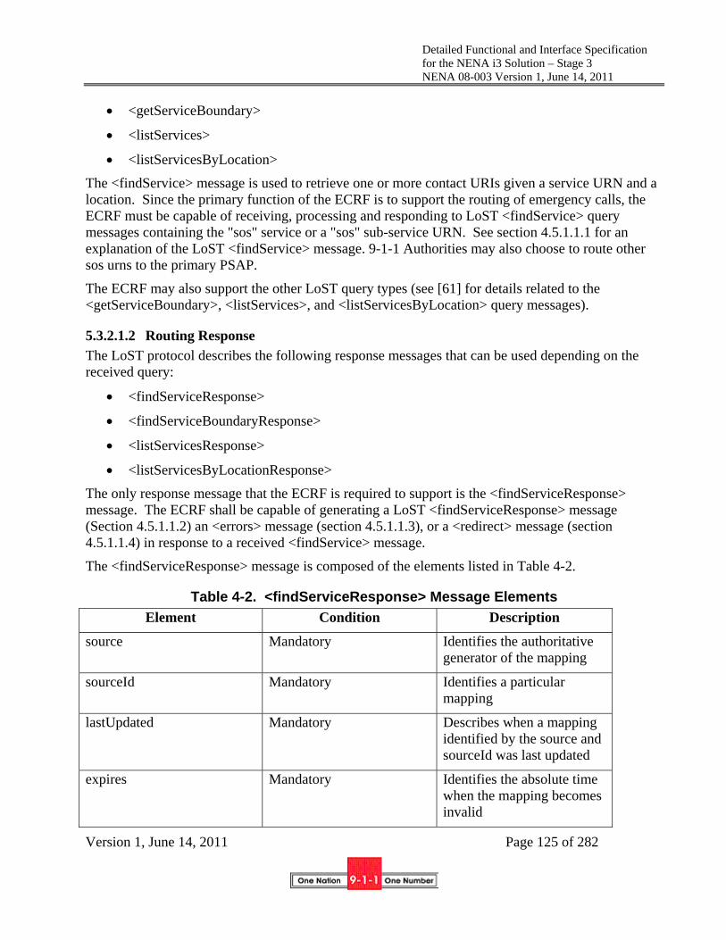
Detailed Functional and Interface Specification for the NENA i3 Solution – Stage 3 NENA 08-003 Version 1, June 14, 2011
Version 1, June 14, 2011 Page 125 of 282
<getServiceBoundary>
<listServices>
<listServicesByLocation>
The <findService> message is used to retrieve one or more contact URIs given a service URN and a location. Since the primary function of the ECRF is to support the routing of emergency calls, the ECRF must be capable of receiving, processing and responding to LoST <findService> query messages containing the "sos" service or a "sos" sub-service URN. See section 4.5.1.1.1 for an explanation of the LoST <findService> message. 9-1-1 Authorities may also choose to route other sos urns to the primary PSAP.
The ECRF may also support the other LoST query types (see [61] for details related to the <getServiceBoundary>, <listServices>, and <listServicesByLocation> query messages).
5.3.2.1.2 Routing Response
The LoST protocol describes the following response messages that can be used depending on the received query:
<findServiceResponse>
<findServiceBoundaryResponse>
<listServicesResponse>
<listServicesByLocationResponse>
The only response message that the ECRF is required to support is the <findServiceResponse> message. The ECRF shall be capable of generating a LoST <findServiceResponse> message (Section 4.5.1.1.2) an <errors> message (section 4.5.1.1.3), or a <redirect> message (section 4.5.1.1.4) in response to a received <findService> message.
The <findServiceResponse> message is composed of the elements listed in Table 4-2.
Table 4-2. <findServiceResponse> Message Elements
Element Condition Description
source Mandatory Identifies the authoritative generator of the mapping
sourceId Mandatory Identifies a particular mapping
lastUpdated Mandatory Describes when a mapping identified by the source and sourceId was last updated
expires Mandatory Identifies the absolute time when the mapping becomes invalid

Detailed Functional and Interface Specification for the NENA i3 Solution – Stage 3 NENA 08-003 Version 1, June 14, 2011
Version 1, June 14, 2011 Page 126 of 282
<displayName> Optional Describes a human readable display name, e.g., the name of the PSAP serving the location
<service> Mandatory Identifies the service for which the mapping applies
<serviceBoundary> Optional Identifies the area where the URI returned would be valid
<serviceBoundaryReference> Optional Identifies the reference which could be used to access the service boundary for which the URI returned is valid
<serviceNumber> Optional Provides the emergency services dial string that is appropriate for the location provided in the query
<uri> Conditional15 Contains the appropriate contact URI for the service being requested
<path> Mandatory Contains the Via elements indicating the LoST servers that handled the request. Used for recursive operation.
<locationUsed> Optional Identifies the location used to determine the URI
15 The ECRF shall include a URI in a <findServiceResponse> message if one can be determined.

Detailed Functional and Interface Specification for the NENA i3 Solution – Stage 3 NENA 08-003 Version 1, June 14, 2011
Version 1, June 14, 2011 Page 127 of 282
<locationValidation> Optional Indicates which elements of the civic location were “valid” and used for mapping, which elements were “invalid” and which elements were “unchecked”
The elements that make up the <findServiceResponse> message are described below:
source - This element identifies the authoritative generator of the mapping (the LoST server that generated the mapping). LoST servers are identified by U-NAPTR/DDDS application unique strings, in the form of DNS name. For example, lostserver.notreal.com.
sourceId - This element identifies a particular mapping at the LoST server and is unique among all the mappings maintained by the LoST server.
lastUpdated - This element describes the date and time when this specific instance of mapping was updated. The date and time is represented in UTC format.
expires - This element describes the date and time when a particular mapping becomes obsolete. The date and time are described using a timezoned XML type datetime. This element may optionally contain the values of “NO-CACHE” indicating that the mapping should not be cached and “NO-EXPIRATION” indicating that the mapping has no expiration instead of the date and time.
<displayName> Element - The display name is a text string that provides an indication of the serving agency(ies) for the location provided in the query. This information might be useful to PSAPs that query an ECRF. This capability could be used to provide English Language Translation (ELT)-type information that PSAPs receive from ALI databases today.
<service> Element - The <service> element identifies the service for which this mapping is valid. The ECRF is required to support the sos service. Support for other services will depend on local implementation.
<serviceBoundary> - The <serviceBoundary> element identifies the geographical area where the returned mapping is valid. The intent of this parameter is to allow a mobile endpoint to realize that it is moved out of the area where a stored mapping is valid and trigger it to query for a new valid mapping. This element may be supported by the ECRF depending on local implementation.
<serviceBoundaryReference> - The <serviceBoundaryReference> element identifies a reference that could be used to access the service boundary for the requested mapping. This parameter may be supported by the ECRF depending on local implementation.
<serviceNumber> - The <serviceNumber> element contains the emergency services number that is appropriate for the location provided in the query. This will allow a foreign end device to recognize that an emergency number is being dialed.

Detailed Functional and Interface Specification for the NENA i3 Solution – Stage 3 NENA 08-003 Version 1, June 14, 2011
Version 1, June 14, 2011 Page 128 of 282
Uniform Resource Identifier (<uri>) - The <uri> specifies either the address of the PSAP or the ESRP that is appropriate for the location sent in the query message. The decision of whether to send the PSAP <uri> or the ESRP <uri> is based on whether the query is made by the end user, VSP Routing Proxy, i3 PSAP, or the ESRP. In i3, the end point and VSP Routing Proxy will receive an ESRP <uri>. Only authorized ESRPs and i3 PSAPs are entitled to receive a PSAP <uri>. Lower layer authorization procedures are used to identify the query originator.
<path> - The <path> contains via elements indicating the ECRF(s) that handled the request.
<locationUsed> - The <locationUsed> element identifies the location used to determine the URI.
<locationValidation> - The <locationValidation> element identifies which elements of the received civic address were “valid” and used for mapping, which were “invalid” and which were unchecked. Since the ECRF is not responsible for performing validation, this parameter may not be returned, subject to local implementations.
If the proffered location is not specified as a point (that is the location in the query is a shape) and the shape intersects more than one service boundary with a given service URN, the response is the URI of the service boundary with the greatest area of overlap (with a tie breaking policy for the case of equal area of overlap).
If more than one service boundary for the same service URN at a given location exists in the ECRF, two <mapping>s will be returned. The querier (for example, a PSAP), must have local policy to determine how to handle the call. In some cases, the ECRF can use the identity of the querier, or a distinguished Service URN to return the URI of the correct agency. This condition only occurs for queries to an ECRF from within an ESInet. External queries will only return one (PSAP) URI.
The service boundary returned from an ECRF may not be the actual service boundary of the PSAP, or even that of the ESRP that will handle an emergency call from the location in the query. Instead, it may be a simpler shape chosen to have only a few points. For example, the polygon may be the largest rectangle that completely fits in the actual boundary measured from the location in the query. The service boundary returned at a point near a service boundary may represent a portion of the agency’s service boundary near the edge where the location exited the original boundary, and may be somewhat more complex, but still an approximation of the actual boundary. As the location sent in the query gets closer and closer to the actual service boundary, the area represented by the returned service boundary may be smaller, the number of points may be somewhat larger, and the fidelity to the actual service boundary may be greater. This minimizes the network bandwidth and compute load on the device.
5.3.2.1.3 Error and Warning Messages
If the ECRF is unable to completely fulfill a request, it shall return either an error or a warning message, depending on the severity of the problem.
If no useful response can be returned for the query, the ECRF shall return a LoST <errors> message with the appropriate "error type" element(s) as described in section 4.5.1.1.3 and section 13.1 of [61].

Detailed Functional and Interface Specification for the NENA i3 Solution – Stage 3 NENA 08-003 Version 1, June 14, 2011
Version 1, June 14, 2011 Page 129 of 282
If the ECRF is able to respond to a query in part, it shall return a <warnings> element as part of another response element as described in section 13.2 of [61] and in section 4.5.1.1.3 for the Lost <findServiceResponse> message.
In both cases, the source attribute of the "error type" and "warning type" element(s) identifies the server that originally generated the error or warning (e.g., the authoritative server). When possible, the ECRF should populate the message and xml:lang attributes of the "warning type" and "error type" elements to more specifically identify the nature of the warning or error for logging and possible later troubleshooting purposes.
5.3.2.2 Data Source Interface
The ECRF’s data source is a map, specifically, a set of layers from one or more source SIFs. A SIF layer replication interface, as described in Section 4.7, is used to maintain copies of the required layers. The ECRF is provisioned with the URI and layer names of its data sources. It has layers that define the locations (state/county/municipality/street/address), as well as service boundary polygons.
A resulting location-based URI associated with a routing request may undergo further modification at an ESRP due to policies related to such things as time of day, current congestion conditions, etc. (See Section 4.2.4 for further discussion.)
5.3.2.3 Time Interface
The ECRF must implement an NTP client interface for time-of-day information. The ECRF may also provide an interface to a hardware clock. The time of day information is an input to the mapping expiration time as well as the logging interface.
5.3.3 Data Structures
5.3.3.1 Data to Support Routing Based on Civic Location Information
The ECRF must be able to provide routing information based on location information represented by a civic address. To do so, it is expected the ECRF will represent the geographic service boundary in a manner that allows the association of a given address with the service boundary it is located within. Theoretically, the ECRF maintains the civic address data as the SIF layers used to provision it, using a geocode followed by point-in-polygon algorithms to determine the service boundary the civic address is located within. The ECRF may internally compute a tabular civic address form of data representation with the associated URI resulting from the point-in-polygon operation. This would reduce the LoST query resolution for a civic address to a table lookup. However, if the provisioning data changes, the ECRF must respond immediately to the change, which may invalidate (for at least some time) the precalculated tabular data.
The ECRF shall be capable of receiving the following data elements that may be present in the civic location information received in a routing query from an NG9-1-1 element (i.e., VoIP endpoint, VSP Routing Proxy, ESRP, i3 PSAP), identifying the service boundary the civic location described by the data elements lies within, and performing a mapping to determine the associated routing data. RFC 4776 ([8]) provides a full set of parameters that may be used to describe a civic location. Specifically, RFC 5139 ([76]) lists several civic address types (CAtypes) that require support in the formal PIDF-LO definition that are not in RFC 4119 ([6]).

Detailed Functional and Interface Specification for the NENA i3 Solution – Stage 3 NENA 08-003 Version 1, June 14, 2011
Version 1, June 14, 2011 Page 130 of 282
Table 4-3. Civic Location Data Elements
Label Description Type Example
country 2-letter ISO code alpha US
A1 national subdivision (e.g., state)
alpha NY
A2 county, parish alpha King’s County
A3 city, township alpha New York
A4 city division, borough
alpha Manhattan
A5 neighborhood alpha Morningside Heights
A616 street alphanumeric Broadway
PRD leading street direction
alpha N
POD trailing street suffix
alpha SW
STS street suffix alpha Ave
HNO house number alphanumeric 123
HNS house number suffix
alphanumeric A, 1/2
LMK Landmark or vanity address
alphanumeric Columbia University
LOC additional location info
alphanumeric South Wing
NAM name (residence or office occupant)
alphanumeric Town Barber Shop
PC/ZIP postal/ZIP code alphanumeric 10027-0401
16 RD should be used in preference to A6. A6 must be accepted by the ECRF

Detailed Functional and Interface Specification for the NENA i3 Solution – Stage 3 NENA 08-003 Version 1, June 14, 2011
Version 1, June 14, 2011 Page 131 of 282
BLD building (structure)
alphanumeric Low Library
UNIT unit (apartment, suite)
alphanumeric Apt 42
FLR floor alphanumeric 4
ROOM room alphanumeric 450F
PLC type of place alpha
PCN postal community name
alpha Leonia
POBOX post office box (P.O. box)
numeric 12345
ADDCODE additional code alphanumeric 132030000003
SEAT Seat (desk, workstation, cubicle)
alphanumeric WS 181
RD primary road name
alphanumeric Broadway
RDSEC road section alphanumeric 14
RDBR branch road name
alphanumeric Lane 7
RDSUBBR sub-branch road name
alphanumeric Alley 8
PRM Road name pre-modifier
alphanumeric Old
POM Road name post-modifier
alphanumeric Service
No individual element in a civic address stored in the ECRF shall be longer than 256 bytes.
To provide this data, the ECRF uses layer replication of one or more SIFs that cover the ECRF’s service area. The source SIF may be provided by 9-1-1 Authorities, other government agencies with GIS responsibility such as a county mapping agency and/or responders who define their own service areas. The ECRF mapping data is provided by:
Table 4-4. Civic Location Data Elements
PIDF Element
Layer Name Geometry or

Detailed Functional and Interface Specification for the NENA i3 Solution – Stage 3 NENA 08-003 Version 1, June 14, 2011
Version 1, June 14, 2011 Page 132 of 282
Attribute
country None, provisioned
None
A1 State Name
A2 County Name
A3 Municipality Name
A4 City Division Name
A5 Neighborhood Name
A6 Street Centerline or Street Geometry
Name
PRD Same as A6 PRD
POD Same as A6 POD
STS Same as A6 STS
HNO Address Point or Parcel or sub parcel
HNO
HNS Same as HNO HNS
LMK Same as HNO LMK
LOC Same as HNO LOC
NAM Same as HNO NAM
PC/ZIP ZIP code Name
PCN ZIP code Post Office
RD Same as A6 Name
PRM Same as A6 PRM
POM Same as A6 POM
5.3.3.2 Service Boundaries
Location represented by geodetic coordinates provides data that corresponds to a specific geographic location point. It is possible to represent a larger geographic area, such as a PSAP serving area as a polygon set. More than one polygon may occur in the set when the service area has holes or non-contiguous regions.
For each service urn supported by an ECRF, one or more layers will provide polygon sets associated with URIs. Two attributes are used on these polygons:

Detailed Functional and Interface Specification for the NENA i3 Solution – Stage 3 NENA 08-003 Version 1, June 14, 2011
Version 1, June 14, 2011 Page 133 of 282
URN: The service URN this boundary is associated with
URI: The URI returned if the location is within the boundary
The ECRF computes a response to a LoST query by finding the polygon with the service URN attribute matching that provided in the LoST query containing the location, and returning the URI attribute of that polygon set.
5.3.3.3 Routing Data – URI Format
For an end-to-end IP network where the caller is an IP endpoint and the PSAP is accessed over an IP network, routing information will be in the form of a URI. The URI may identify a PSAP, or an ESRP that will forward calls to the appropriate PSAP. The source of the query determines which URI is returned. Therefore, it will be necessary to be able to associate multiple URIs with a service boundary. URI format is described in IETF RFC 3986, Uniform Resource Identifier (URI): Generic Syntax. URIs can be of variable length. It is suggested that the length allowed for a URI be as compact as possible, not exceeding 1.3 K, which is the maximum size of a packet on the ESInet, less any header information.
5.3.3.4 Other Data
ECRF Identifier - contains a LoST application unique string identifying the authoritative generator of the mapping
ECRF mapping identifier - identifies a particular mapping and contains an opaque token that must be unique among all different mappings maintained by the authoritative source for that particular service. For example, a Universally Unique Identifier (UUID) is a suitable format.
Date and time mapping was last updated – contains the XML data type dateTime in its timezoned form, using canonical UTC representation with the letter ‘Z’ as the time zone indicator.
Date and time of mapping expiration – contains a timezoned XML type dateTime, in canonical representation. Optionally, this attribute may contain the values of 'NO-CACHE' and 'NO-EXPIRATION' instead of a dateTime value. The value 'NO-CACHE' is an indication that the mapping should not be cached. The value of 'NO-EXPIRATION' is an indication that the mapping does not expire.
Display name – contains a description of the service using a string that is suitable for display to human users, which may be annotated with the 'xml:lang' attribute that contains a language tag to aid in the rendering of text. The display name is used as the “English Language Translation” (ELT) and must be provided for all responder URIs.
Service identifier for which mapping is valid
Service boundary definition – Service boundaries must be defined using exactly one of the two baseline profiles (i.e., geodetic-2d, civic), in addition to zero or more additional profiles. A location profile MUST define:
- The token identifying it in the LoST location profile registry;

Detailed Functional and Interface Specification for the NENA i3 Solution – Stage 3 NENA 08-003 Version 1, June 14, 2011
Version 1, June 14, 2011 Page 134 of 282
- The formal definition of the XML to be used in requests, i.e., an enumeration and definition of the XML child elements of the <location> element;
- The formal definition of the XML to be used in responses, i.e., an enumeration and definition of the XML child elements of the <serviceBoundary> element;
- The declaration of whether geodetic-2d or civic is to be used as the baseline profile. It is necessary to explicitly declare the baseline profile as future profiles may be combinations of geodetic and civic location information.
To support the delivery of service boundary information using the geodetic 2d profile in a response to a client, the ECRF must support the following location shapes:
- Point
- Polygon
- Circle
- Ellipse
- Arcband
To support civic service boundaries, each service boundary consists of the set of civic addresses that fall within the service boundary, namely all the addresses that textually match the civic address elements provided, regardless of the value of the other address elements. A location falls within the mapping’s service boundary if it matches any of the service boundary elements.
Note that the provisioning interface to the ECRF is the SIF layer replication protocol, and thus always delivers a geodetic service boundary definition to the ECRF. The ECRF may compute a civic representation of the boundaries internally. A trivial example is a service boundary polygon exactly matching a state, county or municipality boundary.
Service boundary reference definition - The identifier must be globally unique. It uniquely references a particular boundary. It could be a locally unique token and the hostname of the source of the boundary separated by an ‘@’
Service number - contains a string of digits, * and # that a user on a device with a 12-key dial pad could use to reach that particular service.
5.3.4 Recursive and Iterative Query Resolution
An ECRF may receive a query for a location that is not within its internal database. For such queries, it may redirect the querier to another ECRF (iteration), or it may query the other ECRF and return the result to the querier (recursion). Which action it takes is primarily determined by a query parameter, but may be limited by provisioning and may depend on the location in the query. For example, it may allow recursive resolution for any in-state queries but insist on redirecting an out-of state query to the national forest guide, see section 5.13.
Each state should have an ECRF and/or forest guide which can resolve, by iteration or recursion, any query. The State ECRF should have boundaries for every authoritative ECRF in the state as well as

Detailed Functional and Interface Specification for the NENA i3 Solution – Stage 3 NENA 08-003 Version 1, June 14, 2011
Version 1, June 14, 2011 Page 135 of 282
the ability to redirect out of state queries to the national forest guide. It may have knowledge of adjacent state ECRFs. Any lower level ECRF can refer or redirect any query it cannot handle to its state ECRF, which can refer or redirect to another ECRF in the state or can consult the national forest guide. It is recommended that ECRFs handle in-state queries via recursion.
All ECRFs must provide the proper <path> element as described in RFC5222.
5.3.5 Coalescing Data and Gap/Overlap Processing
ECRFs may coalesce data from several 9-1-1 Authorities. The resulting database appears to be a seamless route database for the union of the service areas of each 9-1-1 authority. Such ECRFs are provisioned to accept data from multiple SIFs.
In some local SIFs, for convenience, some area beyond the service boundary of the PSAPs the 9-1-1 Authority provides data for may be present. If so, this area must be marked with an “Informative” attribute, and the ECRF will ignore it.
When the data is coalesced, boundaries may have gaps and overlaps. The relevant 9-1-1 Authorities should endeavor to address such issues early, but despite best efforts, the ECRF may encounter a gap or overlap. The ECRF must have a provisionable threshold parameter that indicates the maximum gap/overlap that is ignored by the ECRF. This threshold is expressed in square meters. Gaps or overlaps that are smaller that this parameter must be handled by the ECRF using an algorithm of its choice. For example, it may split the gap/overlap roughly in half and consider the halves as belonging to one of the constituent source SIFs.
The ECRF must report gaps and overlaps larger than the provisioned threshold. To do so, it makes uses of the GapOverlap event. All 9-1-1 Authorities who provide source GIS data to an ECRF must subscribe to its GapOverlap event. The event notifies both agencies when it receives data that shows a gap or overlap larger than the threshold. The notification includes the layer(s) where the gap/overlap occurs, whether it is a gap or an overlap, and a polygon that represents the gap or overlap area.
The response of the agencies must be updates to the data that address the gap/overlap. The ECRF will repeat the notification at least daily until it is resolved (by changing the SIF data so the gap/overlap is eliminated or at least smaller than the threshold parameter). During the period when the gap/overlap exists, notifications have been issued, and queries arrive (which could be at call time) with a location in the gap/overlap, the ECRF must resolve the query using an algorithm of its choice. For example, it may split the gap/overlap roughly in half and consider the halves as belonging to one of the constituent source SIFs.
The GapOverlap event is defined as follows:
Event Package Name: nena-GapOverlap
Event Package Parameters: none
SUBSCRIBE Bodies: standard RFC4661 + extensions filter specification may be present
Subscription Duration Default 24 hour. 1 hour to 96 hours is reasonable.
NOTIFY Bodies: MIME type application/vnd,nena.GapOverlap+xml

Detailed Functional and Interface Specification for the NENA i3 Solution – Stage 3 NENA 08-003 Version 1, June 14, 2011
Version 1, June 14, 2011 Page 136 of 282
Parameter Condition Description
Agency Mandatory URI of Agency with gap/overlap. Will be repeated at least twice
Layer Mandatory Enumeration of layer where gap/overlap exists. May occur multiple times
Gap Mandatory Boolean, True if gap, false if overlap
Area Mandatory GML Polygon area of gap/overlap
Notifier Processing of SUBSCRIBE Requests
The Notifier consults the policy (NotifyPermissions) for GapOverlap to determine if the requester is permitted to subscribe; agencies allowed to provide authoritative data to the ECRF are permitted by default. If the requester is not permitted, the Notifier returns 603 Decline. Otherwise, the Notifier returns 202 Accepted.
Notifier Generation of NOTIFY Requests
When the provisioning GIS data creates a gap or overlap whose area is above the GapOverlapThreshold parameter, the Notifier generates a Notify to all subscribers. The Notifier repeats the Notification at least once per 24 hours as long as the gap/overlap remains.
Subscriber Processing of NOTIFY Requests: No specific action required.
Handling of Forked Requests: Forking is not expected to be used with this package.
Rate of Notification
Notifies normally only occur when the provisioning data changes. Throttle may be used to limit Notifications.
State Agents: No special handling is required.
5.3.6 Replicas
An ECRF is essentially a replica of a subset of the layers of one or more SIFs. The ECRF in turn, may provide a feed to other ECRFs who wish to maintain a copy of the data in an ECRF. As the ECRF is not the data owner, the source SIF must have a policy that permits the ECRF to do so, and the policy may restrict which entities the ECRF may provide replication data to. The ECRF also has a policy that defines who it will provide data to. If the ECRF provides a replica service, the interface

Detailed Functional and Interface Specification for the NENA i3 Solution – Stage 3 NENA 08-003 Version 1, June 14, 2011
Version 1, June 14, 2011 Page 137 of 282
is the layer replication service as described in Section 4.7. In this case, the ECRF is the server side, as opposed to the client interface it must provide towards the SIF(s) it receives data from.
5.3.7 Provisioning
The ECRF is provisioned with
a set of layers from one or more SIFs.
the domains it may accept queries from, if its use is restricted.
To maximize the probability of getting help for any kind of emergency by foreign visitors who may have separate dial strings for different types of emergencies, the ECRF should be provisioned with every sos urn in the IANA registry17. All sos service URNs that represent services provided by the PSAP return the dial string ‘9-1-1’ and the PSAP URI. Other services available in the area would typically return a tel uri with the proper PSTN telephone number.
5.3.8 Roles and Responsibilities
The ECRF plays a critical role in the location-based routing of emergency calls. Therefore, it is crucial that the data in the ECRF be accurate and authorized. NENA therefore expects that 9-1-1 Authorities will be responsible for inputting the authoritative data for their jurisdiction in the ECRF. The data may be aggregated at a regional or state level, and the ECRF system provided at that level may be the responsibility of the associated state or regional emergency communications agency. In addition, replicas of the ECRF may be maintained by access or calling network operators. Thus the operation and maintenance of individual ECRFs may be the responsibility of the provider of the network in which they physically reside, but it is the 9-1-1 Authority that is responsible for maintaining the integrity of the source data housed within those systems. The 9-1-1 Authority will also provide input to the definition of the policy which dictates the granularity of the routing data returned by the ECRF (i.e., ESRP URIs vs. PSAP URIs), based on the identity of the query originator.
5.3.9 Operational Considerations
The NG9-1-1 architecture allows for a hierarchy of ESInets, with replicas of ECRFs at different levels of the hierarchy as well as in access/origination networks. It is expected that ECRFs that are provided as local copies to network operators will only have the layers necessary to route to the correct originating ESRP, whereas ECRFs that are inside the ESInet(s) will have all available layers and use authorization to control who has access to what information. Since it is not possible that all
17 While there is only one dialstring, 9-1-1, for emergencies in North America, all services in the sos tree should return a valid route when queried. For services the PSAP is responsible for, such as sos.police, the same URI used for urn:service:sos should be returned.

Detailed Functional and Interface Specification for the NENA i3 Solution – Stage 3 NENA 08-003 Version 1, June 14, 2011
Version 1, June 14, 2011 Page 138 of 282
entities that need to access an ECRF will have one in their local domain, an ECRF for each 9-1-1 Authority must be accessible from the Internet18. .Consideration needs to be given to the operational impacts of maintaining different levels of data in the various copies of the ECRF. In addition, tradeoffs between the aggregation of data in higher level ECRFs versus the use of Forest Guides to refer requests between ECRFs that possess different levels of ECRF data must be considered. Provisioning of data within appropriate ECRF systems for use in overload and backup routing scenarios must also be supported.
5.4 Location Validation Function
The NENA NG9-1-1 solution must properly route incoming IP packet-based emergency calls to the appropriate PSAP, as well as support the dispatch of responders to the right location. The location information used, when provided in civic form, must be proved sufficient for routing and dispatch prior to the call being placed. We refer to this as having a “valid” location for the call19. The i3 architecture defines a function called the LVF (Location Validation Function) for this purpose. The LVF is generally only used for civic location validation. Geo coordinate validation has some limited use, in extreme cases, including national boundary routing scenarios, over coastal waters, etc. The primary validation is accomplished as locations are placed in a LIS. Validation may also be done by an endpoint if it is manually configured with location, or if it retrieves location from the LIS (via a location configuration protocol [4]). Periodic re-validation of stored location is also recommended [59]20. For fixed endpoints, location must be validated when the device is deployed, at each boot-up (power-cycle), and periodically, in order to reach the level of assurance required for acceptable route quality. For Nomadic devices, an LVF request must be invoked as in the fixed case, and in addition, whenever an end device changes its location. Mobile location differs in that it is expected to use only geo-coordinates (e.g., lat/lon), and therefore does not require the same level of LVF interaction and may not require any LVF interaction.
18 The Internet accessible ECRF may be a state or regional ECRF containing the local ECRF data of all 9-1-1 Authorities within the state or region
19 We note that RFC5222, which describes the LoST protocol used by the LVF validates against the service urn provided in the query, which for an outside (the ESInet) entity would be urn:service:sos. Strictly speaking, this is a call routing validation. NG9-1-1 requires validation for dispatch purposes. The LVF will validate to a level suitable for both routing and dispatch when the urn:service:sos is specified in the query.
20 Short periods (days or a few weeks) allows errors that arise due to changes in underyling data the LVF uses to validate to show up sooner. However, the more often a LIS validates, the more load this places on the LIS and the LVF. A period of 30 days is recommended. LIS operators may wish to consult with the LVF operator to determine an optimal revalidation period.

Detailed Functional and Interface Specification for the NENA i3 Solution – Stage 3 NENA 08-003 Version 1, June 14, 2011
Version 1, June 14, 2011 Page 139 of 282
5.4.1 Functional Description
The Location Validation Function (LVF) should be engineered to respond to LVF clients within a few seconds. The LVF data and interfaces are similar to those used by an ECRF representing the same geographic area(s). As a result, the LVF shares the same SIF data layer information as the ECRF, and reuses the same LoST protocol that is used by the ECRF, yet with a few additional data elements. The LVF supports an input query mechanism requiring civic location, a service URN, and a validation flag. This validation flag is an xml parameter setting, and is the main difference between a LoST query intended for an LVF and a LoST query used for routing, that is issued to an ECRF.
Messaging that is returned from an LVF contains all the same data as is returned from an ECRF query. In addition, an LVF validation query response also includes an indication of which data elements were found within the LVF itself. It’s this address field matched data that enables the LVF client to determine if the civic location provided in the input is considered valid, and to what level of granularity.
Many other aspects of the LVF, its interfaces, and the data it contains are identical to the ECRF. Please refer to those sections for more detail.
5.4.2 Interface Description
The LVF supports two interfaces: a query/response interface, and a provisioning interface. Since the LVF is based on the LoST server architecture, the validation query/response interface is defined as the LoST protocol, per RFC5222 [61].
RFC5222 section 8.4.2 states that the inclusion of location validation is optional, and subject to local policy. NENA i3 requires that all LoST server implementations, deployed as an LVF, must support the inclusion of location validation information in the “findServiceResponse” message.
Local LVF policy is also responsible for determining which elements are given priority in determining which URI and which associated location data element tokens are deemed valid. Sometimes different data elements are in conflict with each other. As in the example message, the findServiceResponse message returns the Postal Code (value of 45054) as <invalid>, showing that the A1 & A3 (State & City) data elements in combination – in this case - are given preference over Postal Code that doesn’t exist. Whereas the decision to prefer real data over non-existent data makes good sense, it is possible to have cases where all data elements are real, but not consistent with each other. In this case, NENA and local policy will determine which elements are used, and are shown as valid.
LVF interaction at emergency call time may be performed by a PSAP.
5.4.2.1 User Endpoint interaction
Any user endpoint (i.e., UE, device, handset, client application, etc.) that will perform a location validation directly, must implement the LVF (LoST) interface to be able to access an LVF. The endpoint must use the LVF interface with the same service URN as would be used for a routing query to the ECRF, viz "urn:service:sos”, along with location information.

Detailed Functional and Interface Specification for the NENA i3 Solution – Stage 3 NENA 08-003 Version 1, June 14, 2011
Version 1, June 14, 2011 Page 140 of 282
5.4.2.2 LIS Interaction
The LVF may receive a location validation request from the LIS in order to assure that the location information along with a particular service URN, used in the LVF query, will be deemed “valid”, that is, that there exists an appropriate route URI (e.g., PSAP URI) to match the query. The LVF must return the same URI that the ECRF would have returned (and subsequently will return at emergency call time), based on the same inputs used for the LVF.
5.4.2.3 Provisioning Interaction
The LVF requires the same type of data as required with the ECRF, and is expected to be provisioned through an xml provisioning interface either manually or via a machine-to-machine implementation. This includes synchronization between redundant and tiered LVF elements.
5.4.3 Interface Description
Currently, the LVF supports several interfaces, including the following:
validation query interface
validation response interface
provisioning interface
time interface
logging interface
SIF layer replication protocol, see section 4.7.
5.4.3.1 Validation query interface:
Examples taken from Figures 5 & 6 of RFC 5222.
Example of a validation request message: <?xml version="1.0" encoding="UTF-8"?>
<findService
xmlns="urn:ietf:params:xml:ns:lost1"
recursive="true"
validateLocation="true"
serviceBoundary="value">
<location id="627b8bf819d0bad4d" profile="civic">
<civicAddress
xmlns="urn:ietf:params:xml:ns:pidf:geopriv10:civicAddr">
<country>US</country>
<A1>OH</A1>
<A3>Middletown</A3>
<RD>Main</RD>

Detailed Functional and Interface Specification for the NENA i3 Solution – Stage 3 NENA 08-003 Version 1, June 14, 2011
Version 1, June 14, 2011 Page 141 of 282
<STS>ST</STS>
<HNO>123</HNO>
<PC>45054</PC>
</civicAddress>
</location>
<service>urn:service:sos </service>
</findService>
5.4.3.2 Validation response interface
The LVF, for validation, only supports the “findServiceResponse” message. In the following example of a validation response message, note the bolded elements that indicate the validation:
<?xml version="1.0" encoding="UTF-8"?>
<findServiceResponse xmlns="urn:ietf:params:xml:ns:lost1">
<mapping
expires="2010-01-01T01:44:33Z"
lastUpdated="2009-11-01T01:00:00Z"
source="authoritative.example"
sourceId="4db898df52b84edfa9b6445ea8a0328e">
<displayName xml:lang="en">
Middleton PSAP
</displayName>
<service>urn:service:sos</service>
<serviceBoundary profile="civic">
<civicAddress
xmlns="urn:ietf:params:xml:ns:pidf:geopriv10:civicAddr">
<country>US</country>
<A1>Ohio</A1>
<A3>Middelton</A3>
<PC>45054</PC>
</civicAddress>
</serviceBoundary>
<uri>sip:[email protected]</uri>

Detailed Functional and Interface Specification for the NENA i3 Solution – Stage 3 NENA 08-003 Version 1, June 14, 2011
Version 1, June 14, 2011 Page 142 of 282
<uri>xmpp:[email protected]</uri>
<serviceNumber>911</serviceNumber>
</mapping>
<locationValidation>
<valid>country A1 A3 A6 STS</valid>
<invalid>PC</invalid>
<unchecked>HNO</unchecked>
</locationValidation>
<path>
<via source="resolver.example"/>
<via source="authoritative.example"/>
</path>
<locationUsed id="627b8bf819d0bad4d"/>
</findServiceResponse>
The basis of a validation response is the inclusion of the data element, “validateLocation” being set to “true” in the validation query. In addition to the regular default inputs being returned, the validateLocation=true attribute setting will result in a response using the xml element “findServiceResponse” containing sub-element “locationValidation”, with attributes and tokens relating to which input elements were checked and shown as valid (or invalid).
The ECRF supports the <locationValidationUnavailable> warning element when an LVF server seeks to notify a client that it cannot fulfill a location validation request. This warning allows a server to return mapping information while signaling this exception state [RFC5222, sect. 13.2].
5.4.3.3 LVF Provisioning/synchronization
The LVF provisioning interface the same as that of the ECRF and uses the SIF Layer Replication protocol defined in Section 4.7
5.4.3.4 Alternative Address Interface
The ability to have alternative addresses returned, as supported within an i2 VDB, is currently out-of-scope for this document, and is left for future consideration.
5.4.3.5 Time Interface
The LVF must implement an NTP client interface in order to maintain current, accurate time-of-day information. The time of day information is an input to the LVF validation response information, as well as each transaction to the logging interface.

Detailed Functional and Interface Specification for the NENA i3 Solution – Stage 3 NENA 08-003 Version 1, June 14, 2011
Version 1, June 14, 2011 Page 143 of 282
5.4.3.6 Logging Interface
The LVF must implement a logging interface per section 5.12.1.1. The LVF must be capable of logging every incoming validation request along with every recursive request and all response messages. In addition, the LVF must log all provisioning and synchronization messages and actions. In addition to the requirement for logging all the same data elements currently defined for logging by the ECRF, we have additional specific data logging requirements.
5.4.3.6.1 Validation query logging
The LVF logging mechanism must be capable of logging all input data elements for a validation query, including the specific input location and service URN. All logging transactions must be stored in the form of transaction detail records, and must be made external when warranted by implementation policy. The data elements logged include the following:
Date & Time of transaction
Request message type
Type of location received
Location elements received
Service URN received.
5.4.3.6.2 Validation response logging
The LVF logging mechanism must be capable of logging all output data elements provided in the validation response message, including the validation response status of each location element. All logging transactions must be stored in the form of transaction detail records, and must be made external when warranted by implementation policy. The data elements logged include the following:
Date & Time of transaction
Response message type
Validation attributes
Location element tokens
“Error Code” values.
5.4.3.6.3 Provisioning/Synchronization logging
The LVF logging mechanism must be capable of logging all provisioning input and output messages from an individual provisioning client or another LVF. All logging transactions must be stored in the form of transaction detail records, and must be made external when warranted by implementation policy. The data elements logged include the following:
Date & Time of transaction
Transaction type (e.g., Add, Delete, Modify)
Record information
Response acknowledgement.

Detailed Functional and Interface Specification for the NENA i3 Solution – Stage 3 NENA 08-003 Version 1, June 14, 2011
Version 1, June 14, 2011 Page 144 of 282
5.4.4 Data Structures
The data structures for the LVF include those defined for the ECRF. In addition to those used for the ECRF, the following LVF specific data structures are included:
Table 5-1 LVF Specific Location Data Elements
Label Description Type Example
validateLocation Xml attribute for findService elementvalidation (see notes 1 & 2)
Boolean true
locationValidation Xml attribute for findServiceResponse element
n/a (see note 3) n/a
valid Xml attribute to list those input element tokens that were successfully validated
n/a (see note 3) A1
invalid xml attribute to list those input element tokens that were unsuccessfully validated
n/a (see note 3) RD
unchecked Xml attribute to list those input element tokens that were not checked for validation (see note 3)
n/a (see notes 3 & 4)
HNO
Note 1. If the validateLocation is not included, it is treated as “false”.
Note 2. The attribute is ignored if the input contains a geodetic form of location.
Note 3. RFC5222 states only that the presence of each element token is optional, subject to local policy.
Note 4. Any input element tokens not included in the locationValidation response, belong to the “unchecked” category.
5.4.5 Roles and Responsibilities
PSAPs are directly responsible for LVF data, though a PSAP may contract data maintenance over to a third-party if they choose to. The LVF provisioning interface is the SIF layer replication protocol defined in Section 4.7.
The ECRF and the LVF are provisioned, directly or indirectly, from an authoritative SIF, using the layer replication protocol. A change in the SIF will be propagated to any ECRFs and LVFs

Detailed Functional and Interface Specification for the NENA i3 Solution – Stage 3 NENA 08-003 Version 1, June 14, 2011
Version 1, June 14, 2011 Page 145 of 282
connected to that SIF system. Thus the ECRF and LVF do not have to be provided by, or operated by the same entity, although it will be common for them to be so connected. Indeed, it may be common for the ECRF and LVF to be collocated in the same box.
5.4.6 Operational Considerations
The placement of LVF elements in the IP-enabled network varies with implementation. Since both end devices as well as LIS elements need to validate location, it is recommended that LVF elements are within the local domain or adjacent to it. Given that NG9-1-1 elements will also need to validate civic locations that either come with an emergency call, or are conveyed over the voice path, it is also a requirement that LVF elements are reachable from within any ESInet. Finally, since it is not possible that all entities that need to access a LVF will have one in their local domain, a LVF must be accessible from the Internet21.
LVF elements are based on the LoST server architecture and use the LoST protocol [61]. The LVF is a logical function that may share the physical platform of an ECRF, and must share the same data for a given jurisdiction as the ECRF. The justification for shared data is rooted in the idea of consistency – expecting a similar result from the same, or matching data. The LVF is used during a provisioning process (loading data into a LIS for example), while an ECRF is in the real time call flow. Separating the functions may make more sense. The Service Level Agreements for the two functions may dictate whether they can be combined or not.
An LVF, wherever deployed, whether within an Access network, or in some other type of Origination network, needs to be able to reach out to other LVFs in case of missing data, or in the case where the requested location is outside its local jurisdiction. If the LVF doesn’t know the answer, based on configuration, it will either recurse (refer) a request for validation to one or more other LVFs, or it will iterate the request to some other LVF, providing the other LVF’s URL in the original LVF response.
Redundant LVF elements are recommended, similar to DNS server deployments (the LVF shares some of the same replication characteristics with DNS), by example, in order to maintain a high level of availability and transaction performance.
As with the ECRF, and given the close association between the LVF and ECRF elements, LVFs should be deployed hierarchically and with “n” number of replicas at each level of the hierarchy. The same redundancy/replica considerations apply to access/calling/origination networks that use an LVF. This level of redundancy aids in maintaining high levels of availability during unexpected system outages, scheduled maintenance windows, data backup intervals, etc.
21 The Internet accessible LVF may be a state or regional LVF containing the local LVF data of all PSAPs within the state or region

Detailed Functional and Interface Specification for the NENA i3 Solution – Stage 3 NENA 08-003 Version 1, June 14, 2011
Version 1, June 14, 2011 Page 146 of 282
Similar to ECRF deployments, localized LVF elements may have limited data, sufficient to provide location validation within its defined boundaries, but must rely on other LVFs for validation of a location outside its local area.
LVFs within the ESInet will likely have considerably more data than those LVFs in origination networks, providing aggregation for many local access areas as well as PSAP jurisdictions. Even the level of data that an LVF might contain will vary depending on the hierarchy of the ESInet that it supports. An ESInet serving a local PSAP may have within its LVF, only base civic location data for its described jurisdiction, whereas a State-level or County-level LVF may aggregate all of the local PSAP data within that level of hierarchy.
5.5 Spatial Information Function
The Spatial Information Function (SIF) is the base database for NG9-1-1. Nearly all location related data is ultimately derived from the SIF. If a datum is somehow associated with location, the base data will reside in the SIF. The SIF supplies data for:
1. The ECRF/LVF
2. Map views for alternate PSAPs.
The SIF is a specialized form of a Geospatial Information System, and may be implemented on a conventional GIS with the appropriate interfaces. The SIF itself is not standardized in i3. What is standardized is a method of replicating layers from the master SIF to external databases. The ECRF and LVF provisioning interfaces use this mechanism. When calls are answered at an alternate PSAP, map views are generated from off-site replicas of layers in the SIF system, which are maintained by this interface.
5.5.1 Layers
In order to be useful, i3 standardizes certain layers in the SIF system so that interchange between SIF systems is practical. Appendix B defines the layers and the required attributes those layers must implement. The NG9-1-1 system is dependent on all SIF systems having common definitions for these layers. All attributes listed in Appendix B must be implemented as specified. The layers defined include:
Layers with polygon features o State (PIDF A1) o County (PIDF A2) o Municipality (PIDF A3) o Division (PIDF A4) o Sub-Division (PIDF A5) o Parcels (Can be PIDF HNO and components) o Sub-Parcels (Can be PIDF HNO and components) o PSAP Service Boundary o Responding Agency Services Boundary – Law Enforcement, EMS, Fire, Highway
Patrol, etc… Layers with line features

Detailed Functional and Interface Specification for the NENA i3 Solution – Stage 3 NENA 08-003 Version 1, June 14, 2011
Version 1, June 14, 2011 Page 147 of 282
o Road Centerlines (PIDF RD and components) Layers with point features
o Site / Structure Locations (address points) (PIDF HNO and components)
5.5.2 MSAG Conversion Service (MCS)
The MSAG Conversion Service provides a convenient way to provide data to, or get data from, an un-upgraded system that still uses MSAG data. The service provides conversion between PIDF-LO and MSAG data. Two functions are defined:
PIDFLOtoMSAG: which takes a PIDF-LO as described in RFC4119 updated by RFC5139 and RFC5491 and returns an MSAG address as an XML object conforming to NENA 02-010 Version 4, XML Format for Data Exchange
MSAGtoPIDFLO: which takes an MSAG address as an XML object conforming to NENA 02-010 Version 4, XML Format for Data Exchange and returns a PIDF-LO as described in RFC4119 updated by RFC5139 and RFC5491
MSAG Conversion Service is provisioned using the same mechanism as is used to provision the ECRF and LVF: layer replication from the master SIF. The layers include all of the layers to create a PIDF as described above, plus any layers needed to construct the MSAG for the local jurisdiction. These would typically include an MSAG Community Name, often includes the County ID, and for many jurisdictions where prefix/suffix and/or directionals are included in the Street Name would include a Street Name layer. Where the content of the MSAG is the same (for all addresses in the jurisdiction) as the equivalent PIDF-LO field, the layer need not be present.
MCS uses a forest guide referral mechanism identical to the ECRF. If the input address is not within the service boundary of the local MCS, it can consult a forest guide to refer the query to the appropriate MCS.
The PIDFLOtoMSAG function locates the point in the database represented by the input PIDF-LO and retrieves the MSAG layers associated with that point. It constructs an MSAG address using any MSAG layers available, and the PIDF-LO layers where MSAG and PIDF-LO are the same. The functions return Version 4 XML data exchange, but the client can convert to any other MSAG version from the XML representation.
PIDFtoMSAGRequest
Parameter Condition Description
pidflo Mandatory PIDF-LO to be converted
PIDFtoMSAGResponse
Parameter Condition Description
msag Conditional MSAG resulting from conversion

Detailed Functional and Interface Specification for the NENA i3 Solution – Stage 3 NENA 08-003 Version 1, June 14, 2011
Version 1, June 14, 2011 Page 148 of 282
referral Conditional URI of another MCS
errorCode Mandatory Error response, see below
Either msag or referral must be present in the response
Error Codes
100 Okay No error
508 NoAddressFound: the input appears to be within the service boundary of the MCS, but no point matching the input was located
509 Unknown MCS: the input is not in the service boundary of the MCS and the local MCS could not locate an MCS who served that location.
504 Unspecified Error
The MSAGtoPIDFLO function works in the same manner, locating the point in the database the MSAG address refers to, and composing a PIDF-LO from the PIDF-LO layers.
MSAGtoPIDFRequest
Parameter Condition Description
msag Mandatory msag to be converted
MSAGtoPIDFResponse
Parameter Condition Description
pidflo Conditional PIDF-LO resulting from conversion
referral Conditional URI of another MCS
errorCode Mandatory Error response, see below
Either pidf or referral must be present in the response
Error Codes
100 Okay No error (optional to return)
508 NoAddressFound: the input appears to be within the service boundary of the MCS, but no point matching the input was located
509 Unknown MCS: the input is not in the service boundary of the MCS and the local MCS could not locate an MCS who served that location.
504 Unspecified Error
The service logs the invocation of the function, as well as the input and output objects.

Detailed Functional and Interface Specification for the NENA i3 Solution – Stage 3 NENA 08-003 Version 1, June 14, 2011
Version 1, June 14, 2011 Page 149 of 282
5.5.3 Geocode Service (GCS)
The Geocode service provides geocoding and reverse geocoding. Two functions are defined:
Geocode: which takes a PIDF-LO as described in RFC4119 updated by RFC5139 and RFC5491 containing a civic address and returns a PIDF-LO containing a geo for the same location.
ReverseGeocode: which takes a PIDF-LO as described in RFC4119 updated by RFC5139 and RFC5491 containing a geo and returns a PIDF-LO containing a civic address for the same location.
The Geocode Service is provisioned using the same mechanism as is used to provision the ECRF and LVF: layer replication from the master SIF. The layers include all of the layers to create a PIDF-LO as described above.
Any conversion, and specifically geocoding and reverse geocoding can introduce errors. Unless the underlying SIF has very accurate polygons to represent all civic locations precisely, the conversion is complicated by the inherent uncertainty of the measurements and the “nearest” point algorithm employed. Users of these transformation services should be aware of the limitations of the geocoding and reverse geocoding mechanisms. Reverse geocode is typically less accurate than geocoding, although some error, and unquantified uncertainty is inherent in both.
The GCS uses a forest guide referral mechanism identical to the ECRF. If the input address is not within the service boundary of the local GCS, it can consult a forest guide to refer the query to the appropriate GCS.
The Geocode function locates the point in the database represented by the input PIDF-LO and retrieves the geo associated with that location. It constructs a PIDF-LO with the geo. If the PIDF-LO in the request contains more than one location, the return must contain only one result, which is the conversion of the first location in the PIDF.
GeocodeRequest
Parameter Condition Description
pidflo Mandatory PIDF-LO with civic to be converted
GeocodeResponse
Parameter Condition Description
pidflo Conditional PIDF-LO resulting from conversion
referral Conditional URI of another GCS
errorCode Mandatory Error response, see below
Either pidf or referral must be present in the response
Error Codes
100 Okay No error

Detailed Functional and Interface Specification for the NENA i3 Solution – Stage 3 NENA 08-003 Version 1, June 14, 2011
Version 1, June 14, 2011 Page 150 of 282
508 NoAddressFound: the input appears to be within the service boundary of the GCS, but no point matching the input was located
509 Unknown MCS: the input is not in the service boundary of the GCS and the local GCS could not locate a GCS who served that location.
504 Unspecified Error
The ReverseGeocode function works in the same manner, locating the location in the database the input geo refers to, and composing a PIDF-LO from the PIDF-LO layers.
ReverseGeocodeRequest
Parameter Condition Description
pidflo Mandatory PIDF-LO with geo to be converted
ReverseGeocodeResponse
Parameter Condition Description
pidflo Conditional PIDF-LO resulting from conversion
referral Conditional URI of another GCS
errorCode Mandatory Error response, see below
Either pidflo or referral must be present in the response
Error Codes
100 Okay No error
508 NoAddressFound: the input appears to be within the service boundary of the GCS, but no point matching the input was located
509 Unknown MCS: the input is not in the service boundary of the GCS and the local GCS could not locate a GCS who served that location.
504 Unspecified Error
The service logs the invocation of the function, as well as the input and output objects.
Note: The IETF geopriv working group is considering the definition of a geocoding protocol/service. If such a standardization effort is undertaken, and if the resulting work is suitable, it will replace this NENA-only interface in a future edition of this document.
5.5.4 Operational Considerations
The SIF is not used directly in call processing, although its data is critical to achieving proper routing. For that reason, a single SIF system, with frequent backup operations is sufficient. However, since calls may be answered by other PSAPs, and the originally intended PSAP may be

Detailed Functional and Interface Specification for the NENA i3 Solution – Stage 3 NENA 08-003 Version 1, June 14, 2011
Version 1, June 14, 2011 Page 151 of 282
unavailable, copies of the layers sufficient for display should be made available, using the layer replication mechanism defined in Section 4.7.
5.6 PSAP
A PSAP provides the following interfaces towards the ESInet
5.6.1 SIP Call interface
The PSAP must deploy the SIP call interface as defined in Section 4.1 including the multimedia capability, and the non-human-initiated call (emergency event) capability. PSAPs must recognize calls to their administrative numbers received from the ESInet (and distinguishable from normal 9-1-1 calls by the presence of the number in a sip or tel URI in the To: field and the absence of the sos service URN in a Route header). The SIP call interface may also be used to place non 9-1-1 calls (including call backs) from the PSAP using normal SIP Trunking mechanisms as specified in sipConnect V1.0 [108].
Note: while all i3 PSAPs must handle all media, a legacy PSAP behind an LPG would only handle voice media and TTY. There is no mechanism by which a caller could discover what media the PSAP supports. This will be covered in a future edition of this document.
5.6.2 LoST interface
The PSAP must provide a LoST client interface as defined in Section 4.5. The PSAP uses the ECRF and LVF to handle calls that must be dispatched and calls that must be transferred based on the actual location of the incident. The ECRF and LVF use the LoST interface.
5.6.3 LIS Interfaces
The PSAP must implement both SIP Presence Event Package and HELD dereference interfaces to any LIS function as described in Section 5.9. When the PSAP receives a location reference (in a Geolocation header on the upstream SIP interface) it uses the LIS dereference interface to obtain a location value. The PSAP must be provisioned with credentials for every LIS in its service area22. The PSAP must use TCP with either TLS or IPsec for the LIS Dereference Interface, with fallback to TCP (without TLS) on failure to establish a TLS connection when TLS is used. The PSAP should maintain persistent TCP (and TLS where used) connections to LISs that it has frequent transactions with. A suggested value for "frequent" is more than one transaction per day.
22 This document specifies that the LIS accept credentials issued to the PSAP traceable to the PCA. Not withstanding that requirement, ESInet elements needing location, including PSAPs, must be able to be provisioned with credentials acceptable to LIS’s that do not accept the PCA credential.

Detailed Functional and Interface Specification for the NENA i3 Solution – Stage 3 NENA 08-003 Version 1, June 14, 2011
Version 1, June 14, 2011 Page 152 of 282
For HELD location URIs, specifying responseTime = emergencyDispatch will result in a location meeting regulated accuracy requirements. If the PSAP wishes an immediate location, it can specify a short responseTime (perhaps 250 ms), and get the best location quality available in that time. Location updates for location URIs using HELD may be obtained by repeating the dereference.
PSAPs receiving SIP location URIs should subscribe to the Presence event per RFC 3856 [31]. The PSAP receives an immediate location report, which may reflect the best available location at the time of the subscription. A subsequent location update is sent when more accurate location is available. By setting the expiration time of the subscription, the PSAP is able to control what updates it receives. PSAPs that wish to track the motion of a caller could use the location filter and event rate control mechanisms in loc-filters [103] and rate-control [113] to control updates.
Note that because the PSAP will not have an identity of an arbitrary device with which it could query a LIS to get the device's location, the “manual query” function in an E9-1-1 ALI has no equivalence in NG9-1-1.
5.6.4 Bridge Interface
A PSAP may deploy a bridge (as described in Section 5.7) inside the PSAP, in which case it must provide the bridge controller interfaces. PSAPs must be able to accept calls from, and utilize the features of outside bridges.
5.6.5 ElementState
The PSAP must deploy an ElementState notifier as described in Section 3.3.2. Note that the terminating ESRP may route to a (queue of) call taker(s). Each call taker should implement an element state notifier.
5.6.6 SIF
The PSAP may provide23 a GIS server interface as described in Section 5.5for the ECRF, GIS Replica, and other interfaces. The PSAP may provide the MSAG conversion service (server side) or may use an ESInet service (client side).
5.6.7 Logging Service
The PSAP may deploy a logging service (as described in Section 5.12) inside the PSAP, in which case it must provide the logging service retrieval functions. A PSAP may use a logging service in the ESInet, in which case it must deploy the logging service insert functions.
23 The GIS system may be provided by a 9-1-1 Authority
Detailed Functional and Interface Specification for the NENA i3 Solution – Stage 3 NENA 08-003 Version 1, June 14, 2011
Version 1, June 14, 2011 Page 153 of 282
5.6.8 Security Posture
The PSAP must provide a Security Posture notifier as described in Section 3.3.1.
5.6.9 Policy
The PSAP may provide a policy store as described in Section 4.4.1, in which case it must implement the server side of the policy retrieval functions, and may provide the server side of the policy storage function. The PSAP may provide a Policy Editor, in which case it must deploy the client side of the policy retrieval and storage functions. If the PSAP uses a policy store outside the PSAP to control functions inside the PSAP, it must deploy the client side of the policy retrieval functions.
PSAPs must provide a Termination-Policy for the queue(s) its calls are sent to.
PSAPs must provide a takeCallsOnQueues policy to determine which queues the PSAP will dequeue from (that is, which queues it will subscribe to the dequeueRegistration and queueState events for).
5.6.10 Additional Data dereference
The PSAP must deploy a dereference (HTTP Get) interface for additional data as described in Section 8.
5.6.11 Time Interface
The PSAP must implement an NTP client interface for time-of-day information. The PSAP may also provide an interface to a hardware clock.
5.6.12 Test Call
The PSAP may deploy the test call function as described in Section 11.
5.6.13 Call Diversion
A PSAP may be overloaded and be unable to answer every call by a call taker. Overload is determined by exceeding the size of the primary queue that its calls are sent to. Routing rules for the PSAP would then cause calls to receive an alternate call treatment:
Calls can be sent a “Busy” indication
Calls can be diverted to an Interactive Multimedia Response unit
Calls can be diverted to one or more alternate PSAPs.
The latter is mechanized by sending the call to queues which other PSAPS dequeue from. Since the diverted-to PSAP(s) have to explicitly register to dequeue (DequeueRegistration, see Section 5.2.1.2), no calls can be sent to a PSAP that hasn’t explicitly asked for them.
PSAPs that agree to take calls from other PSAPs may require explicit management approval at the time the calls are sent. Effectively, such PSAPs are agreeing to take calls on a standby basis only, and explicit management action is required before the calls will actually be accepted.
To accomplish this, the diverted-to PSAP subscribes to the DequeueRegistration event of the diverted-from PSAP with the “Standby” parameter set to “true”. The diverted-to PSAP also
Detailed Functional and Interface Specification for the NENA i3 Solution – Stage 3 NENA 08-003 Version 1, June 14, 2011
Version 1, June 14, 2011 Page 154 of 282
subscribes to the queueState event for the diversion queue. It may specify a filter that limits notifications to those setting queueState to “DiversionRequested”. When the queueState event notification occurs with “DiversionRequested” state, the diverted-to PSAP management would be alerted. If it agrees to accept calls, it would resubscribe to the DequeueRegistration event with Standby set to “false”, and calls would subsequently be sent to it. When the diverted-to PSAP determines that its services are no longer needed, it can reinstate the <standby>true</standby>.
5.6.14 Incidents
A new call arrives with a new Incident Tracking Identifier assigned by the first ESRP in the ESInet. The ESRP assumes each call is a new Incident. The call taker may determine that the call is actually part of another Incident, usually reported in a prior call. The PSAP must merge the IncidentTrackingID assigned by the ESRP with the actual IncidentTrackingID. It does so with the MergeIncident log record. The actual IncidentTrackingID would be part of the AdditionalPSAPData object passed to a secondary PSAP or responder and part of the INVITE if the call is transferred. When the PSAP completes processing of an Incident, it logs a ClearIncident record.
5.7 Bridging
Bridging is used in NG9-1-1 to transfer calls and conduct conferences. Bridges have a (SIP) signaling interface to create and maintain conferences and media mixing capability. Bridges must be multimedia (voice, video, text). A bridge is necessary to transfer a call because IP-based devices normally cannot mix media, and transferring always adds the new party (for example, a call taker at a secondary PSAP) to the call before the transferor (for example, the original call taker at the PSAP which initially answered the call) drops off the call. The rough transfer sequence, based on the procedures defined in RFC4579 [51], is:
1. PSAP creates a conference on the bridge
2. PSAP REFERs the caller to the bridge
3. PSAP tears down the original PSAP-Caller leg
4. PSAP REFERs transfer target (secondary PSAP for example) to the conference
5. PSAP tears down its leg to the conference, the secondary PSAP and the caller remain
6. Secondary PSAP REFERs the caller to it
7. Secondary PSAP terminates the conference.
5.7.1 Bridge Call Flow
Conferencing procedures are documented in RFC4579. This document includes definition of an Event package that allows conference participants to manage the conference. In the message sequences below, all participants are conference aware (that is, they implement the event package). It is not necessary for the caller to be conference aware, and if it were not, its SUBSCRIBE to the conference package would not occur. It is required that the caller, or some element in the path, implement the Replaces header, see Section 5.8

Detailed Functional and Interface Specification for the NENA i3 Solution – Stage 3 NENA 08-003 Version 1, June 14, 2011
Version 1, June 14, 2011 Page 155 of 282
5.7.1.1 Creation of a Conference Using SIP Ad-Hoc Methods
This scenario described in the call flow depicted below follows Section 5.4 of RFC4579.
1. The Primary PSAP creates a conference by first sending an INVITE to a conference
application, using a URI that is known by/provisioned at the Primary PSAP.
2. The Conference Application responds by sending a 302 Moved message which redirects the Primary PSAP to the conference bridge, and provides the Conference-ID that should be used for the conference.
3. The Primary PSAP acknowledges the receipt of the 302 Moved message.
4. The Primary PSAP generates an INVITE to establish a session with the conference bridge.24
24 Note that, based on RFC 4579, the messages sent in Steps 2, 3 and 4 are optional and may not be exchanged if the conference application and the media server are the same.
Primary PSAP
7. ACK
4. INVITE sip:Conf‐ID
6. 200 OK Contact:sip:Conf‐ID; isfocus
8. SUBSCRIBE sip:Conf‐ID
9. 200 OK
10. NOTIFY
11. 200 OK
Primary PSAP creates a conference.
Conf. App.Caller
SecondaryPSAP Bridge
3. ACK
1. INVITE sip:Conf App
2. 302 Moved Contact:sip:Conf‐ID; isfocus
5. 180 Ringing
RTP
Normal call established between caller and primary PSAP.
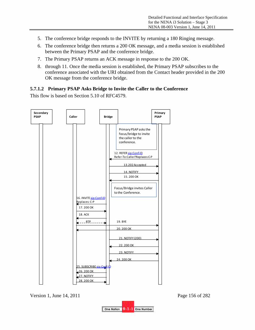
Detailed Functional and Interface Specification for the NENA i3 Solution – Stage 3 NENA 08-003 Version 1, June 14, 2011
Version 1, June 14, 2011 Page 156 of 282
5. The conference bridge responds to the INVITE by returning a 180 Ringing message.
6. The conference bridge then returns a 200 OK message, and a media session is established between the Primary PSAP and the conference bridge.
7. The Primary PSAP returns an ACK message in response to the 200 OK.
8. through 11. Once the media session is established, the Primary PSAP subscribes to the conference associated with the URI obtained from the Contact header provided in the 200 OK message from the conference bridge.
5.7.1.2 Primary PSAP Asks Bridge to Invite the Caller to the Conference
This flow is based on Section 5.10 of RFC4579.
Primary PSAP
14. NOTIFY
12. REFER sip:Conf‐IDRefer‐To:Caller?Replaces:C‐P
13.202 Accepted
15. 200 OK
16. INVITE sip:Conf‐IDReplaces: C‐P
Focus/Bridge invites Caller
to the Conference.
20. 200 OK
Primary PSAP asks the focus/bridge to invite the caller to the conference.
19. BYERTP
18. ACK
17. 200 OK
BridgeCallerSecondaryPSAP
21. NOTIFY (200)
22. 200 OK
24. 200 OK
23. NOTIFY
27. NOTIFY
26. 200 OK
28. 200 OK
25. SUBSCRIBE sip:Conf‐ID

Detailed Functional and Interface Specification for the NENA i3 Solution – Stage 3 NENA 08-003 Version 1, June 14, 2011
Version 1, June 14, 2011 Page 157 of 282
12. After the Primary PSAP establishes the conference, it sends a REFER method to the conference bridge asking it to invite the caller to the conference. The REFER method contains an escaped Replaces header field in the URI included in the Refer-To header field.
13. The bridge returns a 202 Accepted message to the Primary PSAP.
14. The bridge then returns a NOTIFY message, indicating the subscription state of the REFER request (i.e., active).
15. The Primary PSAP returns a 200 OK in response to the NOTIFY message.
16. The bridge invites the caller to the conference by sending an INVITE method containing the Conf-ID and a Replaces header that references the leg between the caller and the Primary PSAP.
17. The caller accepts the invitation by returning a 200 OK message.
18. The bridge acknowledges receipt of the 200 OK message by returning an ACK.
A media session is established between the caller and the bridge.
19. The caller releases the connection to the Primary PSAP by sending a BYE message.
20. The Primary PSAP responds by returning a 200 OK message.
21. The bridge sends a NOTIFY message to the Primary PSAP to provide REFER processing status.
22. The Primary PSAP responds by returning a 200 OK message.
23. The bridge sends a NOTIFY message to the Primary PSAP to provide updated status associated with the conference state.
24. The Primary PSAP responds by returning a 200 OK message.
25. The caller subscribes to the conference associated with the Conference ID provided in the INVITE message from the bridge by sending a SUBSCRIBE message to the bridge. (Optional)
26. The bridge acknowledges the subscription request by sending a 200 OK message back to the caller. (Optional)
27. The bridge then returns a NOTIFY message to the caller to provide subscription status information. (Optional)
28. The caller responds by returning a 200 OK message. (Optional)
5.7.1.3 Secondary PSAP is Invited to the Conference
This flow is based on Section 5.5 of RFC4579.

Detailed Functional and Interface Specification for the NENA i3 Solution – Stage 3 NENA 08-003 Version 1, June 14, 2011
Version 1, June 14, 2011 Page 158 of 282
29. The Primary PSAP sends a REFER method to the conference bridge asking it to invite the
Secondary PSAP to the conference. The REFER method contains the Conf-ID and a Refer-To header that contains the URI of the Secondary PSAP. The REFER method also contains an escaped Call-Info header field containing a reference URI that points to the “Additional Data Associated with a PSAP” data structure.
30. The bridge returns a 202 Accepted message to the Primary PSAP.
31. The bridge then returns a NOTIFY message, indicating that subscription state of the REFER request (i.e., active).
32. The Primary PSAP returns a 200 OK in response to the NOTIFY message.
33. The bridge invites the Secondary PSAP to the conference by sending an INVITE method containing the Conf-ID and Contact header that contains the conference URI and the isfocus feature parameter. The INVITE contains the Call-Info header field containing a reference URI that points to the “Additional Data Associated with a PSAP” data structure.
Primary PSAP
BridgeCallerSecondaryPSAP
37. NOTIFY
38. 200 OK
Bridge invites Secondary PSAP to the conference. 33. INVITE Contact:Conf‐ID;
isfocus
34. 180 Ringing
35. 200 OK
36. ACK
RTP
39. SUBSCRIBE Contact:Conf‐ID;
40. 200 OK
42. 200 OK
41. NOTIFY
43. NOTIFY
44. 200 OK
31. NOTIFY
29. REFER sip:Conf‐ID Refer‐To:SecPSAP
30. 202 Accepted
32. 200 OK
Primary PSAP asks the bridge to invite the secondary PSAP to the conference.
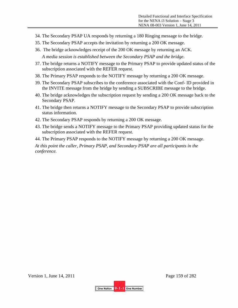
Detailed Functional and Interface Specification for the NENA i3 Solution – Stage 3 NENA 08-003 Version 1, June 14, 2011
Version 1, June 14, 2011 Page 159 of 282
34. The Secondary PSAP UA responds by returning a 180 Ringing message to the bridge.
35. The Secondary PSAP accepts the invitation by returning a 200 OK message.
36. The bridge acknowledges receipt of the 200 OK message by returning an ACK.
A media session is established between the Secondary PSAP and the bridge.
37. The bridge returns a NOTIFY message to the Primary PSAP to provide updated status of the subscription associated with the REFER request.
38. The Primary PSAP responds to the NOTIFY message by returning a 200 OK message.
39. The Secondary PSAP subscribes to the conference associated with the Conf- ID provided in the INVITE message from the bridge by sending a SUBSCRIBE message to the bridge.
40. The bridge acknowledges the subscription request by sending a 200 OK message back to the Secondary PSAP.
41. The bridge then returns a NOTIFY message to the Secondary PSAP to provide subscription status information.
42. The Secondary PSAP responds by returning a 200 OK message.
43. The bridge sends a NOTIFY message to the Primary PSAP providing updated status for the subscription associated with the REFER request.
44. The Primary PSAP responds to the NOTIFY message by returning a 200 OK message.
At this point the caller, Primary PSAP, and Secondary PSAP are all participants in the conference.

Detailed Functional and Interface Specification for the NENA i3 Solution – Stage 3 NENA 08-003 Version 1, June 14, 2011
Version 1, June 14, 2011 Page 160 of 282
5.7.1.4 Primary PSAP Drops Out of Conference; Secondary PSAP Completes Transfer
45. Upon determining that the emergency call transfer should be completed, the Primary PSAP
disconnects from the call by sending a BYE message to the bridge. 46. The conference bridge responds by returning a 200 OK message. 47. The bridge then returns a NOTIFY message indicating that the subscription to the conference
has been terminated. 48. The Primary PSAP returns a 200 OK in response to the NOTIFY. 49. The bridge then returns a NOTIFY message to the caller indicating that there has been a
change to the subscription state. (Optional) 50. The caller returns a 200 OK in response to the NOTIFY. (Optional) 51. The bridge returns a NOTIFY message to the Secondary PSAP indicating that there has been
a change to the subscription state. 52. The Secondary PSAP returns a 200 OK in response to the NOTIFY.
Secondary PSAP
completes transfer.
Primary PSAP
47.NOTIFY Subscription –State: terminated
48. 200 OK
Primary PSAP drops out of the conference.
BridgeCallerSecondaryPSAP
45. BYE
46. 200 OK
62. NOTIFY Subscription –State: terminated
53. INVITE sip:sec Replaces C‐B
58. BYE
59. 200 OK
61. 200 OK
63. 200 OK
60. NOTIFY Subscription –State: terminated
54. 200 OK
56. BYE
57. 200 OK
49. NOTIFY
51. NOTIFY50. 200 OK
52. 200 OK
55. ACK

Detailed Functional and Interface Specification for the NENA i3 Solution – Stage 3 NENA 08-003 Version 1, June 14, 2011
Version 1, June 14, 2011 Page 161 of 282
53. Upon recognizing that the caller and the Secondary PSAP are the only remaining participants in the conference, the Secondary PSAP completes the transfer by sending an INVITE to the caller requesting that they replace their connection to the bridge with a direct connection to the secondary PSAP. The secondary PSAP learns the URI of the caller through the “Additional Data Associated with a PSAP” data structure
54. The caller responds by returning a 200 OK message to the Secondary PSAP. 55. The Secondary PSAP returns an ACK in response to the 200 OK. 56. The caller then sends a BYE to the bridge to terminate the session. 57. The bridge responds by sending the caller a 200 OK message. 58. The Secondary PSAP also terminates its session with the bridge by sending a BYE message
to the bridge. 59. The bridge responds by sending a 200 OK message to the Secondary PSAP. 60. The bridge then returns a NOTIFY message to the Secondary PSAP indicating that the
subscription to the conference has been terminated. 61. The Secondary PSAP returns a 200 OK in response to the NOTIFY message. 62. The bridge sends a NOTIFY message to the caller indicating that the subscription to the
conference has been terminated. (Optional) 63. The caller responds with a 200 OK message. (Optional) At this point, the transfer is complete, and the caller and the Secondary PSAP are involved in a two-way call.
5.7.2 Passing data to Agencies via bridging
When another PSAP is bridged to a 9-1-1 call there are separate “legs” for each participant in the bridge. The 9-1-1 call itself terminates at the bridge, with the call taker and the transfer target having separate legs into the bridge. When the transfer target receives the initial SIP transaction it is an INVITE from the bridge to a conference. It is critical that the transfer target receive (or have access to) the location of the original caller, as well as any “Additional Data” that the primary PSAP call taker may have accessed or generated during the processing of the emergency call. Caller location information received by the primary PSAP in the Geolocation header of the INVITE message, along with any additional data that the primary PSAP call taker may have obtained when the call was delivered (i.e., “Additional Data Associated with a Call” and/or “Additional Data Associated with a Caller”) or that was generated by the call taker as a result of processing the incoming emergency call, should be populated in the “Additional Data Associated with a PSAP” structure. (See Section 8 for further discussion of Additional Data structures.) When an emergency call is transferred, the primary PSAP will request that the bridge insert by embedded header, a Call-Info header with a URI that points to the “Additional Data Associated with a PSAP” data structure in the REFER method sent to the bridge. The bridge must subsequently include this Call-Info header in the INVITE it sends to the transfer target.
5.8 Transfer Involving Calling Devices that Do Not Support Replaces
As discussed in Section 5.7 of NENA 08-002, there is a problem that some devices that could originate 9-1-1 calls do not support the Replaces header. If a PSAP needs to transfer a call originated by such a device, it cannot use the standardized SIP signaling to the caller as described above. Section 5.7 of NENA 08-002 describes three solutions to this problem.

Detailed Functional and Interface Specification for the NENA i3 Solution – Stage 3 NENA 08-003 Version 1, June 14, 2011
Version 1, June 14, 2011 Page 162 of 282
Each of these solutions is specified in more detail in the sections below.
5.8.1 B2BUA in the Border Control Function
When this solution is implemented, the BCF must include a B2BUA function as described in RFC3261. All calls are relayed through the B2BUA. The B2BUA is transparent to signaling with the following exceptions:
1. Media endpoints towards both the caller and the PSAP are rewritten to be contained within the BCF
2. The REFER method, when executed on the PSAP side to a conference bridge, causes the bridge to invite the B2BUA to the conference, and the B2BUA to respond as illustrated below. The leg between the caller and the B2BUA sees no transaction.
3. If the BCF receives an INVITE from a caller that does not include a Supported header containing the replaces option-tag it must include a Supported header containing the replaces option-tag in the INVITE forwarded to the ESInet and provide the functionality described in this section.
Note that the following flow assumes that the Primary PSAP has already created a conference using SIP Ad Hoc methods, as described in Section 5.7.1.1.

Detailed Functional and Interface Specification for the NENA i3 Solution – Stage 3 NENA 08-003 Version 1, June 14, 2011
Version 1, June 14, 2011 Page 163 of 282
1. The caller initiates an emergency session request by sending an INVITE message to the B2BUA. The INVITE contains a Geolocation header with caller location information.
2. The B2BUA sends a corresponding INVITE message via the i3 ESInet toward the Primary PSAP. (Elements and signaling involved in routing the emergency call within the i3 ESInet are not shown in this flow.) The INVITE would contain a Supported header indicating support for Replaces.
3. The Primary PSAP responds by returning a 200 OK message to the B2BUA. 4. The B2BUA responds to the receipt of the 200 OK from the Primary PSAP by sending a 200
OK message to the caller’s device.
Primary PSAP
9. NOTIFY
7. REFER sip:Conf‐IDRefer‐To:B2BUA?Replaces:B‐P
8.202 Accepted
10. 200 OK
Primary PSAP asks the bridge to invite the B2BUA to the conference.
BridgeBCF/B2BUACaller
1. INVITE
4. 200 OK
2. INVITE
5. ACK
RTP
11. INVITE sip:Conf‐IDReplaces: B‐P
Bridge invites B2BUA to the Conference.
15. 200 OK
14. BYERTP
13. ACK
12. 200 OK
16. NOTIFY (200)
17.200 OK
19. 200 OK
18. NOTIFY (200)
Normal call established between caller and primary PSAP via a B2BUA at the BCF
RTP
3. 200 OK
6. ACK

Detailed Functional and Interface Specification for the NENA i3 Solution – Stage 3 NENA 08-003 Version 1, June 14, 2011
Version 1, June 14, 2011 Page 164 of 282
5. The caller’s device responds by sending an ACK to the B2BUA. A media session is established between the caller and the B2BUA. Depending on the design of the
ESInet, the B2BUA may cross connect media from the caller to the Primary PSAP
6. The B2BUA sends an ACK to the Primary PSAP in response to receiving an ACK from the caller’s device.
A media session is established between the B2BUA and the Primary PSAP.
7. The Primary PSAP sends a REFER method to the conference bridge asking it to invite the B2BUA to the conference. The REFER method contains an escaped Replaces header field in the URI included in the Refer-To header field.
8. The bridge returns a 202 Accepted message to the Primary PSAP.
9. The bridge then returns a NOTIFY message, indicating that subscription state of the REFER request (i.e., active).
10. The Primary PSAP returns a 200 OK in response to the NOTIFY message.
11. The bridge invites the B2BUA to the conference by sending an INVITE method containing the Conf-ID and a Replaces header that references the leg between the B2BUA and the Primary PSAP.
12. The B2BUA accepts the invitation by returning a 200 OK message.
13. The bridge acknowledges receipt of the 200 OK message by returning an ACK.
A media session is established between the B2BUA and the bridge. Note that the media session between the B2BUA and the Primary PSAP still exists at this time. Note also that the media session between the caller and the B2BUA is undisturbed. As above, the B2BUA may cross connect media from the caller to the bridge
14. The B2BUA releases the connection to the Primary PSAP by sending a BYE message.
15. The Primary PSAP responds by returning a 200 OK message.
At this point, the media session between the B2BUA and the Primary PSAP is torn down.
16. The bridge sends a NOTIFY message to the Primary PSAP to provide updated status of the subscription associated with the REFER request.
17. The Primary PSAP responds by returning a 200 OK message.
18. The bridge sends a NOTIFY message to the Primary PSAP to provide updated status of the subscription associated with the REFER request.
19. The Primary PSAP responds by returning a 200 OK message.
At this point, the Primary PSAP requests that the bridge add the Secondary PSAP to the conference, following the flow described in Section 5.7.1.3. Once the Primary PSAP determines that the transfer can be completed, it drops off the call, following the flow described in Section 5.7.1.4. The Secondary PSAP then completes the transfer as illustrated below. Note that the connection between the caller and the B2BUA is unaffected by the Primary PSAP disconnecting or the completion of the transfer by the Secondary PSAP. The following flow also illustrates termination of the emergency call initiated by the Secondary PSAP.

Detailed Functional and Interface Specification for the NENA i3 Solution – Stage 3 NENA 08-003 Version 1, June 14, 2011
Version 1, June 14, 2011 Page 165 of 282
1. The Secondary PSAP completes the transfer by sending an INVITE to the B2BUA requesting that it replaces its connection to the bridge with a direct connection to the Secondary PSAP. The Secondary PSAP learns the URI of the B2BUA from the “Additional Data associated with a PSAP” data structure.
2. The B2BUA responds by returning a 200 OK message to the Secondary PSAP. 3. The Secondary PSAP returns an ACK in response to the 200 OK.
Bridge
11. 200 OK
Secondary PSAP
BCF/B2BUACaller
2. 200 OK
4. BYE
RTP
RTP
3. ACK
9. 200 OK
15. 200 OK14. 200 OK
RTP
Secondary PSAP completes transfer.
RTP
1. INVITE sip:sec Replaces B‐B
5. 200 OK
6. BYE
7. 200 OK
8. NOTIFY Subscription –State: terminated
10. NOTIFY Subscription –State: terminated
Secondary PSAP terminates call.
12. BYE13. BYE
Primary PSAP has dropped off; B2BUA and Secondary PSAP connected to bridge.

Detailed Functional and Interface Specification for the NENA i3 Solution – Stage 3 NENA 08-003 Version 1, June 14, 2011
Version 1, June 14, 2011 Page 166 of 282
At this point, a media session is established between the B2BUA and the Secondary PSAP. The media session between the B2BUA and the bridge also still exists at this time. The B2BUA may cross connect media as per above
4. The B2BUA then sends a BYE to the bridge to terminate the session. 5. The bridge responds by sending the B2BUA a 200 OK message.
At this time the media session between the B2BUA and the bridge is torn down.
6. The Secondary PSAP also terminates its session with the bridge by sending a BYE message to the bridge.
7. The bridge responds by sending a 200 OK message to the Secondary PSAP. At this point, the media session between the Secondary PSAP and the bridge is torn down.
8. The bridge then returns a NOTIFY message to the B2BUA indicating that the subscription to the conference has been terminated.
9. The B2BUA responds with a 200 OK message. 10. The bridge then returns a NOTIFY message to the Secondary PSAP indicating that the
subscription to the conference has been terminated. 11. The Secondary PSAP responds with a 200 OK message.
At this point, the transfer is complete, and the caller and the Secondary PSAP are involved in a two-way call.
12. The Secondary PSAP determines that the call should be terminated and sends a BYE message to the B2BUA.
13. The B2BUA sends a BYE message to the caller to terminate the session. 14. The caller sends a 200 OK message to the B2BUA in response to the BYE. 15. The B2BUA sends a 200 OK to the Secondary PSAP in response to receiving the 200 OK
from the caller. At this point the emergency session is terminated. The B2BUA may act as a media relay for all media. All media packets on all negotiated media streams are relayed from one side of the B2BUA to the other.
Characteristics of this solution are:
The solution is deployed at the edge of the ESInet; the rest of the ESInet can assume Replaces works
Media is anchored at the BCF regardless of what happens to the call The B2BUA is call stateful. The B2BUA is in the path regardless of whether the device implements Replaces or not.
5.8.2 Bridging at the PSAP Using Third Party Call Control in the Call Taker User Agent
RFC 3725 [35] describes a technique in which the initial answering UAC becomes a signaling B2BUA. If this method is chosen in an ESInet, a call taker UA receiving a call which does not contain a Supported header indicating support for Replaces must take the actions described in this section. Unlike the examples in RFC 3725, the caller has a call established with the call taker (which takes on the role of the “controller” in RFC 3725). The call sequence (based on RFC 3725 Flow IV) is described in the following subsections.

Detailed Functional and Interface Specification for the NENA i3 Solution – Stage 3 NENA 08-003 Version 1, June 14, 2011
Version 1, June 14, 2011 Page 167 of 282
5.8.2.1 Call Taker Creates a Conference
1. The caller initiates an emergency session request by sending an INVITE message via the i3 ESInet to the Primary PSAP call taker. The INVITE contains a Geolocation header with caller location information. (Elements and signaling involved in routing the emergency call within the i3 ESInet are not shown in this flow.)
2. The Primary PSAP responds by returning a 200 OK message to the caller’s device. 3. The caller’s device responds by sending an ACK to the Primary PSAP.
A media session is established between the caller and the Primary PSAP. The Primary PSAP determines that a transfer is necessary and uses SIP signaling to create a conference with a conference bridge, having previously received a Conference ID from a conference application (as described in Section 5.7.1.1).
BridgeCaller
1. INVITE
2. 200 OK
RTP
Call Taker
3. ACK
Call Taker determines that transfer is necessary; creates two sessions with conference bridge and re‐invites caller to session with bridge
4. INVITE Contact:Conf‐ID;
5. 180 Ringing
6. 200 OK Contact sip:Conf‐ID;isfocus
7. ACK
RTP
8. SUBSCRIBE Contact:Conf‐ID;
9. 200 OK
10.NOTIFY
11. 200 OK
Transfer Target
12. INVITE (no SDP)
13. 200 OK (offer 2)
14. INVITE (offer 2’)
RTP
15. 200 OK (answer 2’)
17. ACK
16. ACK(answer 2)

Detailed Functional and Interface Specification for the NENA i3 Solution – Stage 3 NENA 08-003 Version 1, June 14, 2011
Version 1, June 14, 2011 Page 168 of 282
4. The Primary PSAP initiates its first session with the bridge (with media) by sending it an INVITE message containing the Conf-ID.
5. The conference bridge responds to the INVITE by returning a 180 Ringing message.
6. The conference bridge then returns a 200 OK message, and a media session is established between the Primary PSAP and the conference bridge.
7. The Primary PSAP returns an ACK message in response to the 200 OK.
8. The Primary PSAP subscribes to the conference associated with the Conf-ID by sending a SUBSCRIBE message to the bridge.
9. The bridge responds by returning a 200 OK message.
10. The bridge then sends a NOTIFY message to the Primary PSAP providing the status of the subscription.
11. The Primary PSAP responds to the NOTIFY by returning 200 OK message to the bridge.
12. The Primary PSAP initiates its second session with the bridge (without media) by sending it an INVITE message with no SDP.
13. The bridge responds with a 200 OK that contains an offer (i.e., “offer 2”).
14. The Primary PSAP sends a re-INVITE to the caller’s device with the new offer.
15. The caller’s device responds by sending a 200 OK (providing an answer to the offer) to the Primary PSAP.
16. The Primary PSAP conveys the answer in an ACK sent to the bridge.
17. The Primary PSAP also sends an ACK to the caller’s device.
At this time, a media session is established directly between the caller and the bridge.

Detailed Functional and Interface Specification for the NENA i3 Solution – Stage 3 NENA 08-003 Version 1, June 14, 2011
Version 1, June 14, 2011 Page 169 of 282
5.8.2.2 Call Taker Asks the Bridge to Invite the Transfer Target to the Conference
18. The Primary PSAP sends a REFER method to the conference bridge asking it to invite the Transfer Target (i.e., Secondary PSAP) to the conference. The REFER method contains the Conf-ID and a Refer-To header that contains the URI of the Transfer Target. The REFER method also contains an escaped Call-Info header field containing a reference URI that points to the “Additional Data Associated with a PSAP” data structure.
19. The bridge returns a 202 Accepted message to the Primary PSAP.
20. The bridge then returns a NOTIFY message to the Primary PSAP, indicating that subscription state of the REFER request (i.e., active).
21. The Primary PSAP responds by returning a 200 OK message.
BridgeCaller Call Taker
Bridge invites Transfer Target to the conference.
Call Taker asks bridge to invite Transfer Target to the conference
Transfer Target
21. 200 OK
20.NOTIFY
18. REFER sip:Conf‐ID Refer‐To:TT
19.202 Accepted
22. INVITE Contact:Conf‐ID; isfocus
23. 180 Ringing
24. 200 OK Contact sip:Conf‐ID;isfocus
25. ACK
RTP
28. SUBSCRIBE Contact:Conf‐ID;
29. 200 OK
30.NOTIFY
31. 200 OK
26.NOTIFY
33.200 OK
32.NOTIFY
27. 200 OK
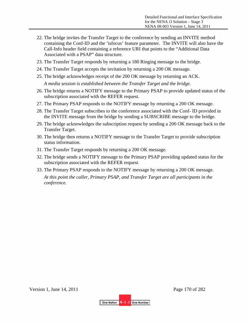
Detailed Functional and Interface Specification for the NENA i3 Solution – Stage 3 NENA 08-003 Version 1, June 14, 2011
Version 1, June 14, 2011 Page 170 of 282
22. The bridge invites the Transfer Target to the conference by sending an INVITE method containing the Conf-ID and the ‘isfocus’ feature parameter. The INVITE will also have the Call-Info header field containing a reference URI that points to the “Additional Data Associated with a PSAP” data structure.
23. The Transfer Target responds by returning a 180 Ringing message to the bridge.
24. The Transfer Target accepts the invitation by returning a 200 OK message.
25. The bridge acknowledges receipt of the 200 OK message by returning an ACK.
A media session is established between the Transfer Target and the bridge.
26. The bridge returns a NOTIFY message to the Primary PSAP to provide updated status of the subscription associated with the REFER request.
27. The Primary PSAP responds to the NOTIFY message by returning a 200 OK message.
28. The Transfer Target subscribes to the conference associated with the Conf- ID provided in the INVITE message from the bridge by sending a SUBSCRIBE message to the bridge.
29. The bridge acknowledges the subscription request by sending a 200 OK message back to the Transfer Target.
30. The bridge then returns a NOTIFY message to the Transfer Target to provide subscription status information.
31. The Transfer Target responds by returning a 200 OK message.
32. The bridge sends a NOTIFY message to the Primary PSAP providing updated status for the subscription associated with the REFER request.
33. The Primary PSAP responds to the NOTIFY message by returning a 200 OK message.
At this point the caller, Primary PSAP, and Transfer Target are all participants in the conference.

Detailed Functional and Interface Specification for the NENA i3 Solution – Stage 3 NENA 08-003 Version 1, June 14, 2011
Version 1, June 14, 2011 Page 171 of 282
5.8.2.3 Primary PSAP Drops; Transfer Target Completes Transfer
34. The Primary PSAP initiates termination of its media session with the bridge by sending the bridge a BYE message.
35. The bridge responds by sending the Primary PSAP a 200 OK message. At this time the media session between the Primary PSAP and the bridge is torn down.
36. The bridge sends a NOTIFY message to the Primary PSAP indicating that the subscription has been terminated.
37. The Primary PSAP responds by returning a 200 OK message.
BridgeCaller Call Taker
34. BYE
35. 200 OK
37. 200 OK
Call Taker at Primary PSAP drops from the call; media session between call taker and PSAP is terminated
Transfer Target
36. NOTIFY Subscription –State: terminated
Transfer Target completes transfer
48.NOTIFY Subscription –State: terminated
52. BYE
49. 200 OK
38. NOTIFY
39. OK
40. INVITE sip:sec Replaces C‐B (offer 3)
41. INVITE (offer 3’)
42. 200 OK (answer 3’)43. OK (answer 3)
44. ACK45. ACK
RTP
53.200 OK
46. BYE
47. 200 OK
54.NOTIFY Subscription –State: terminated
55. 200 OK
50. NOTIFY
51. 200 OK

Detailed Functional and Interface Specification for the NENA i3 Solution – Stage 3 NENA 08-003 Version 1, June 14, 2011
Version 1, June 14, 2011 Page 172 of 282
38. The bridge sends a NOTIFY message to the Transfer Target to provide it updated status information.
39. The Transfer Target replies by returning a 200 OK message. 40. The Transfer Target completes the transfer by sending an INVITE to the Primary PSAP
(acting as the B2BUA for the caller) asking it to replace its connection to the bridge (i.e., the media session between the caller and the bridge) with a direct connection to the Transfer Target (with offer 3). Note that the Transfer Target must be aware that it is the Primary PSAP that receives the INVITE.
41. The Primary PSAP sends a re-INVITE to the caller’s device asking it to move the media from the bridge to the Transfer Target (with offer 3)
42. The caller’s device responds by sending a 200 OK message back to the Primary PSAP (with answer 3).
43. The Primary PSAP sends a 200 OK message to the Transfer Target (with answer 3). 44. The Transfer Target acknowledges the 200 OK message by returning an ACK to the Primary
PSAP. 45. The Primary PSAP acknowledges the 200 OK message by returning an ACK to the caller’s
device. At this point, a media session is established directly between the caller and the Transfer Target.
46. The Primary PSAP sends a BYE to the bridge to terminate the session with the bridge. 47. The bridge responds by sending a 200 OK message to the Primary PSAP.
At this time the media session between the caller and the bridge is terminated.
48. The bridge sends the Primary PSAP a NOTIFY message indicating that the subscription has been terminated.
49. The Primary PSAP responds by sending a 200 OK message. 50. The bridge sends the Transfer Target a NOTIFY message to provide it updated information
on the status of the conference. 51. The Transfer Target responds by returning a 200 OK message. 52. The Transfer Target sends a BYE to the bridge to terminate the session with the bridge. 53. The bridge responds by sending a 200 OK message to the Transfer Target.
At this point, the media session between the Transfer Target and the bridge is terminated.
54. The bridge sends the Transfer Target a NOTIFY message indicating that its subscription has been terminated.
55. The Transfer Target responds by sending a 200 OK message.

Detailed Functional and Interface Specification for the NENA i3 Solution – Stage 3 NENA 08-003 Version 1, June 14, 2011
Version 1, June 14, 2011 Page 173 of 282
5.8.2.4 Transfer Target Terminates Session with Caller
56. The Transfer Target initiates call termination by sending the Primary PSAP a BYE message. 57. The Primary PSAP sends a BYE message to the caller’s device to initiate request termination
of the session. 58. The caller’s device responds by returning a 200 OK message to the Primary PSAP. 59. The Primary PSAP responds by returning a 200 OK message to the Transfer Target.
At this time the media session between the caller and the Transfer Target is terminated.
In this transfer scenario, the Call Taker UA remains in the signaling path for the duration of the call. The media flows directly (via any BCF firewall of course) between the caller and the Transfer Target. Any further transfers would be accomplished in a similar manner, with the Call Taker UA accepting an INVITE with a Replaces header, and initiating a re-INVITE towards the caller to establish the correct media path.
This sequence is only necessary when the device does not implement Replaces. The Call Taker UA can notice the presence of the Supported header, and if Replaces is supported, it can just initiate a transfer using standard SIP methods, as described in Section 5.7. It could, optionally, attempt the Replaces even if a Supported header was not found, detect an error and initiate the re-INVITE as above in response.
The characteristics of this solution are:
Transfer Target
Caller Call Taker
Transfer Target initiates call termination
56. BYE
59. 200 OK
57. BYE
58. 200 OK

Detailed Functional and Interface Specification for the NENA i3 Solution – Stage 3 NENA 08-003 Version 1, June 14, 2011
Version 1, June 14, 2011 Page 174 of 282
No additional network signaling elements in the path unless necessary Media goes direct between endpoints Caller UA receives multiple Re-INVITE messages
5.8.3 Answer all calls at a bridge
All incoming 9-1-1 calls are answered at a bridge. When the bridge receives a call for the URI specified in the last hop LoST route, the bridge creates the caller to bridge leg, and initiates an INVITE to the PSAP/Call Taker (depending on configuration and where the bridge is located: in the network or in the PSAP). The caller remains on the bridge where it was first answered. The call taker can add other parties to the bridge, other parties can add additional parties, parties can drop off the bridge, and the caller to bridge leg remains stable.
5.8.3.1 Call Established Between Caller and Primary PSAP Via Bridge; Primary PSAP Asks Bridge to Invite the Secondary PSAP to the Conference
Primary PSAP asks the
bridge to invite the Secondary PSAP to the conference.
Secondary PSAP
13. NOTIFY
12.202 Accepted
14. 200 OK
BridgeCaller
1. INVITE
2. 200 OK
4. INVITE isfocus
10. 200 OK
3. ACK
RTP
Primary PSAP
6. ACK
RTP
11. REFER sip:Conf‐IDRefer‐To:Sec PSAP
7. SUBSCRIBE sip:Conf‐ID
8. 200 OK
5. 200 OK
9. NOTIFY

Detailed Functional and Interface Specification for the NENA i3 Solution – Stage 3 NENA 08-003 Version 1, June 14, 2011
Version 1, June 14, 2011 Page 175 of 282
1. The caller initiates an emergency session request by sending an INVITE message into the i3 ESInet. The INVITE contains a Geolocation header with caller location information. (Elements and signaling involved in routing the emergency call within the i3 ESInet are not shown in this flow.) The call is routed using i3 mechanisms, and the URI of the target Primary PSAP is determined. The call is delivered to a bridge in the i3 ESInet.
2. Upon receiving the INVITE from the caller, the bridge responds by returning a 200 OK to the caller.
3. The caller returns an ACK in response to the 200 OK from the bridge. A media session is established between the caller and the bridge.
4. Upon receiving the call at the bridge, the bridge initiates a call to the Primary PSAP by sending an INVITE message. The INVITE message generated by the bridge must include a Geolocation header that contains the caller location information received in the Geolocation header of the INVITE message from the caller, as well as any Call-Info headers that were received in the incoming INVITE message.
5. The Primary PSAP responds by returning a 200 OK message to the bridge. 6. The bridge responds by sending an ACK to the Primary PSAP.
A media session is established between the bridge and the Primary PSAP.
7. Once the media session is established, the Primary PSAP sends a SUBSCRIBE message to the bridge to subscribe to the conference associated with the Conf-ID identified when the conference was initially established with the bridge.
8. The bridge responds to the SUBSCRIBE message by returning a 200 OK message to the Primary PSAP.
9. The bridge then returns a NOTIFY message to the Primary PSAP to provide it with status information regarding the conference.
10. The Primary PSAP responds to the NOTIFY message by returning a 200 OK message.
11. The Primary PSAP sends a REFER method to the bridge asking it to invite the Secondary PSAP to the conference. The REFER method contains the Conf-ID and a Refer-To header that contains the URI of the Secondary PSAP. The REFER method also contains an escaped Call-Info header field containing a reference URI that points to the “Additional Data Associated with a PSAP” data structure.
12. The bridge returns a 202 Accepted message to the Primary PSAP.
13. The bridge then returns a NOTIFY message, indicating that subscription state of the REFER request (i.e., active).
14. The Primary PSAP returns a 200 OK in response to the NOTIFY message.

Detailed Functional and Interface Specification for the NENA i3 Solution – Stage 3 NENA 08-003 Version 1, June 14, 2011
Version 1, June 14, 2011 Page 176 of 282
5.8.3.2 Bridge Invites the Secondary PSAP to the Conference
15. The bridge invites the Secondary PSAP to the conference by sending an INVITE method containing the Conf-ID and the isfocus feature parameter. The INVITE also contains a Call-Info header containing a reference URI that points to the “Additional Data Associated with a PSAP” data structure.
16. The Secondary PSAP UA responds by returning a 180 Ringing message to the bridge.
17. The Secondary PSAP accepts the invitation by returning a 200 OK message.
18. The bridge acknowledges receipt of the 200 OK message by returning an ACK.
A media session is established between the Secondary PSAP and the bridge.
19. The Secondary PSAP subscribes to the conference associated with the Conf- ID provided in the INVITE message from the bridge by sending a SUBSCRIBE message to the bridge.
20. The bridge acknowledges the subscription request by sending a 200 OK message back to the Secondary PSAP.
21. The bridge then returns a NOTIFY message to the Secondary PSAP to provide subscription status information.
Secondary PSAPBridgeCaller Primary
PSAP
15. INVITE Contact:Conf‐ID; isfocus
16. 180 Ringing
17. 200 OK
18. ACK
RTP
19. SUBSCRIBE Contact:Conf‐ID;
20. 200 OK
22. 200 OK
21.NOTIFY
Bridge invites
Secondary PSAP to the conference.
24. 200 OK
23.NOTIFY

Detailed Functional and Interface Specification for the NENA i3 Solution – Stage 3 NENA 08-003 Version 1, June 14, 2011
Version 1, June 14, 2011 Page 177 of 282
22. The Secondary PSAP responds by returning a 200 OK message.
23. The bridge sends a NOTIFY message to the Primary PSAP providing updated status for the subscription associated with the REFER request.
24. The Primary PSAP responds to the NOTIFY message by returning a 200 OK message.
At this point the caller, Primary PSAP, and Secondary PSAP are all participants in the conference.
5.8.3.3 Secondary PSAP Terminates the Call
When the Primary PSAP determines that it can drop from the bridge, it will follow the flow described in Section 5.7.1.4. When the Secondary PSAP determines that the call should be terminated, it will follow the flow illustrated below.
25. Secondary PSAP initiates call termination by sending a BYE message to the bridge. 26. The bridge responds by returning a 200 OK message.
At this point, the session between the bridge and the Secondary PSAP is torn down.
27. The bridge sends a BYE message to the caller’s device. 28. The caller’s device responds by returning a 200 message to the bridge.
At this point, the session between the caller and the bridge is torn down.
The characteristics of this solution are:
Media is anchored at the bridge regardless of what happens to the call.
Secondary PSAP
initiates call termination
BridgeCaller
25. BYE
27. BYE
28. 200 OK
RTP
SecondaryPSAP
26. 200 OK
RTP

Detailed Functional and Interface Specification for the NENA i3 Solution – Stage 3 NENA 08-003 Version 1, June 14, 2011
Version 1, June 14, 2011 Page 178 of 282
The bridge is always in the path regardless of whether the device implements Replaces or not.
The original bridge is always in the path whether the Primary PSAP subsequently transfers the call or not. Receipt of the call on the bridge must trigger dial out of the call to the Primary PSAP/call taker.
The bridge must populate the (original) caller location information received in the Geolocation header of the incoming INVITE message in the Geolocation header of the outgoing INVITE message to the Primary PSAP.
The bridge must populate any Call-Info headers received in the incoming INVITE message in the outgoing INVITE message to the Primary PSAP.
Termination of the Secondary PSAP leg causes the bridge to (automatically) terminate the leg to the caller.
Note that call taker’s system behaves differently in this scenario in that the initial call is received with an ‘isfocus’ feature parameter; call taker need not establish a bridge if it determines that a transfer is necessary
5.8.4 Recommendations
BCFs should support option 1. This is the most likely scenario for most networks and has no impact or dependency on other elements. PSAP CPE may support option 2, which has no impact or dependency on other elements. PSAP CPE may support option 3 if the bridge support is available. Bridges may support Option 3. ESInet designers must decide which mechanism will be used on their network and all appropriate elements must support that mechanism. Consideration must be given to how calls will be transferred to or accepted from ESInets making different choices. Only ONE mechanism should be enabled. Other methods are acceptable provided that they do not assume/require support of Replaces by calling devices. Selection of a method to handle the lack of Replaces implementations in calling devices must take into account how overall system reliability goals are to be met, and specifically, how failures of various elements in the solution affect call reliability.
5.9 Location Information Server (LIS)
A Location Information Server supplies location, in the form of a PIDF-LO (location by value) or a location URI (location by reference). The LIS also provides a “dereference” service for a location URI it supplies: given the URI, the LIS provides the location value as a PIDF-LO. A LIS may be a database, or may be a protocol interworking function to an access network specific protocol.
In NG9-1-1, the LIS supplies location (by value or reference) to the endpoint, or proxy operating on behalf of (OBO) the endpoint. The ESInet is not directly involved in that transaction: the resulting PIDF-LO or location URI must appear in the initial SIP message in a Geolocation header. If the LIS supplies location by reference, it must also provide dereferencing service for that location URI. Elements in the ESInet, including the ESRP and PSAP may dereference a location URI as part of processing a call.
If the LIS supplies location by reference, it must support HELD [9] and/or SIP Presence Event Package [31]. The SIP Presence Subscribe/Notify mechanism can control repeated dereferencing,

Detailed Functional and Interface Specification for the NENA i3 Solution – Stage 3 NENA 08-003 Version 1, June 14, 2011
Version 1, June 14, 2011 Page 179 of 282
especially when tracking of the caller is needed. However, HELD is acceptable on any location URI. LISs supporting SIP must support location filters [103] and event rate control [113].
LISs queried by Legacy Network Gateways during the processing of a wireline emergency call would typically use HELD with the identity extension [104] using a telephone number as the identity and supply location by value in return.
LISs queried by Legacy Network Gateways during the processing of wireless emergency calls are usually protocol interwork functions between SIP or HELD and the legacy network’s location determination subsystem. Typically they would supply location by reference.
If the broadband network supports true mobility, it should supply location by reference. If the broadband network is a fixed network like a cable modem network or DSL, location by value is preferred, but location by reference is acceptable.
A LIS must validate locations prior to entering them in to the LIS using the LVF (Section 5.4).
A LIS must accept credentials traceable to the PCA for authenticating queries for a location dereference. Since calls may be diverted to any available PSAP, the LIS cannot rely on any other credential source to authorize location dereferencing.
When location is provided by reference there is a need for the reference to be valid at least for the length of the call. Whether the reference should remain valid for some time beyond the duration of the call is a topic for future study as are the privacy considerations of such access.
5.10 Call Information Database (CIDB)
A call that passes through an origination network or service provider of any kind must have a Call info header with a URI that resolves to an AdditionalCall Data structure. The database that dereferences this URI is a Call Information Database. There is a minimum amount of information listed as Mandatory in NENA 71-001 that mirrors the information currently provided by all origination networks in the ALI.
Important Note: The version of 71-001 that was in effect as of the release of this document requires the <list of fields> as mandatory elements. Within a CIDB, these elements are optional, and a future edition of 71-001 will correct this and only <list of fields> are the minimum fields that must be provided.
All origination networks and service providers (where a service provider here is a 3rd party in the path of a call which is not the originating network presenting the call to the ESInet) are required to provide at least this minimum set of information which must be populated in a CIDB. The CIDB is queried with the URI obtained from the Call-Info header with a purpose of emergencyCallData, and returns the Additional Call Data structure NENA 71-001 Section 8.1 [105]. The query is an HTTPS GET with the URI obtained from the Call-Info header. The return is the XML data structure as defined in NENA 71-001. It is important that ALL service providers handling the call add a Call-Info header and supply a CIDB to dereference it. The transaction to dereference the Additional Call Data URI must be protected with TLS. The dereferencing entity, which may be an ESRP, PSAP or responding agency uses its credentials (traceable to the PCA for NG9-1-1 entities). The service

Detailed Functional and Interface Specification for the NENA i3 Solution – Stage 3 NENA 08-003 Version 1, June 14, 2011
Version 1, June 14, 2011 Page 180 of 282
provider can use any credential, as long as the domain listed in the URI is the domain of the SubjectAltName in the cert.
Call Information Database servers are not required to be able to serve a query more than 5 minutes after an emergency call is terminated.
Devices such as telematics equipped vehicles and medical monitoring devices that can place emergency calls should have the capability to respond to a CIDB query, which includes the reference to the device data (telematics, health monitoring, …). A service provider (such as a telematics service provider) may provide the CIDB instead of the device. Other devices may also provide a CIDB for use in an emergency call.
The CIDB could be provided by the origination network or service provider. For service providers and origination networks that only provide the minimal data called for in NENA 71-001, the CIDB could be provided by a third party. Extension of SIP to allow the data to be included by value in the signaling is for future study.
5.11 Interactive Media Response system (IMR)
The IMR is similar to an Interactive Voice Response (IVR) unit, but handles audio, video and text media. It may be used to answer calls when the PSAP is receiving more calls than it has call takers to answer them. It offers interaction with the caller (“Press 1 if this about the car crash on Fourth and Main, Press 2 if this is about some other problem”).
IMRs must implement RFC4240 [43], and VXML V2.0 [134]. VXML <audio> tags must specify multiple MIME types with appropriate types for the media. Synthesis scripts must render text for text media. The IMR must implement at least the codecs listed in Section 4.1.8
The syntax for specifying a URI to route to a specific VXML script is defined in RFC4240.
Calls may be queued within the IMR waiting for available call takers. The queue of calls must be a queue as defined in 5.2.1.2 and maintain the specified queueState and DequeRegistration events so that PSAP management can monitor and control the queue as it does all other queues.
IMRs must interpret an IM, RTT or other text received consisting the digits 0-9, ‘#’ or ‘*’ immediately following a prompt for input as equivalent to DTMF key presses.
5.12 Logging service
The logging service in NG9-1-1 is a standardized functional element used by all elements in an ESInet to log all significant events; logging is not restricted to events within a PSAP. All significant steps in processing a call are logged. NG9-1-1 defines an external logging service interface so that the logging function can be provided in the ESInet. Logging includes external events, internal events, media and messages.
5.12.1 Interfaces
The log service is primarily a web service. In addition to the web service interface, logging services that record media provide an RTSP (RFC2326 [135]) interface to play back the media. The web service includes the following functions.

Detailed Functional and Interface Specification for the NENA i3 Solution – Stage 3 NENA 08-003 Version 1, June 14, 2011
Version 1, June 14, 2011 Page 181 of 282
5.12.1.1 LogEvent
LogEvent logs an event into the logging service. The LogEvent includes parameters:
Parameter Type Description
timestamp String A timestamp as defined in Section 3.2
agencyOrElement String agencyID or hostname of an element which logged the event
agent String The agentId (Section 3.1.1) of an agent at the agency listed in the agentOrElement tag, see Section 3.1.2
callId String The call identifier of a call, see Section 3.1.4
incidentId String The Incident Tracking Identifier associated with the call, see Section 3.1.5
eventType Enumeration Type of log record
Each EventType contains additional data specific to the EventType.
The following EventTypes are defined in this document
CallProcess: Each element which is not call stateful, but handles a call logs the fact that it saw the call pass through by logging a CallProcess event. There are no parameters to “Call Process”
StartCall/EndCall: Each element which is call stateful logs the beginning and end of its processing of a call with Start Call and End Call events. StartCall includes a copy of the headers in the INVITE message, encoded in <header> tags. EndCall includes the response code that ended the call (200 OK in the case of a successful call), encoded in a <responseCode> tag.
Note: it may be desirable to log other messages that are part of the INVITE transaction, such as the ACK. This will be covered in a future edition of this document.
TransferCall: When a call is transferred, the transfer is logged by the transferor (the PSAP which had the call prior to transferring it. The transfer target URI is logged in a <transferTarget> tag.
Route: Proxy servers that make routing decisions (ESRPs or other SIP proxy servers in the path of the call) log the route it selected with the Route EventType. The URI where it decided to send the call (encoded in a <uri> tag, plus a text string <reason> for choosing that

Detailed Functional and Interface Specification for the NENA i3 Solution – Stage 3 NENA 08-003 Version 1, June 14, 2011
Version 1, June 14, 2011 Page 182 of 282
route are included in the LogEvent. For ESRPs, the name of the rule is included in a <rule> tag.
Media: Media is the log of call media (voice, video and interactive text). The media event includes a text string <udp> tag that contains an RFC2327 Session Description Protocol [55] description of the media. The SDP must include SDES keys if the RTP stream is protected with SRTP. Each independent stream must include an RFC4574 [136] label to identify each stream and the label must be logged with a <mediaLabel> tag. More than one Media event can occur for a call. Recorded media streams include integral time reference data within the stream.
EndMedia. EndMedia causes the logging service to terminate recording of media. The EndMedia event includes one or more <mediaLabel> tags which must match the SDP labels in the corresponding Media event. More than one EndMedia (with different <mediaLabel>s) may occur for a call.
Message: An SIP Message (Instant Message) is logged with a Message log event. The text of the message is included as a <text> parameter.
AdditionalAgency: When an agency becomes aware that another agency may be involved, in any way, with a call, it must log an AdditionalAgency event. The AdditionalAgency event includes an <agency> tag which is an Agency Identifier (see Section 3.1.1). Among other uses, this event is used by PSAP management to query all logging services that may have records about a call or incident.
Note: a mechanism to discover the logger associated with an agency will be provided in a future edition of this document
MergeIncident: at some point in processing, an agency may determine that a call marked with an IncidentId may in fact be part of another, previously determined Incident. When it is determined that two IncidentIds have been assigned for the same real world Incident, the Ids are merged with MergeIncident. The MergeIncident record contains the IncidentId of the incorrectly assigned incident in the <incidentId> tag in the header of the log record, and the Incident Id of the actual Incident in an <actualIncident> tag. Note that other agencies may not know that the Incidents are being merged, and therefore could log events against the originally assigned IncidentId.
ClearIncident: When an agency finishes its handling of an Incident, it logs a ClearIncident record. Other agencies may still be processing the Incident.
ECRFquery: any element that queries the ECRF and the ECRF itself generate an ECRFquery LogEvent. The LogEvent includes the PIDF-LO (and only the Location Object) using the RFC4119 tags and the service URN in a <service-urn> tag.
ECRFresponse: Both the elements that query the ECRF and the ECRF generate the ECRFresponse. The entire response is logged using the LoST tags.
This document creates a registry for LogEvents. See Section 12.11.

Detailed Functional and Interface Specification for the NENA i3 Solution – Stage 3 NENA 08-003 Version 1, June 14, 2011
Version 1, June 14, 2011 Page 183 of 282
LogEvent function assigns a globally unique LogIdentifier to each LogEvent and returns the LogIdentifier in its response. The form of a LogIdentifier is a URI consisting of the string “_LI_, a unique string, the “@” character and the domain name of the logging service. The unique string must be between 10 and 35 characters long and unique to the logging service. An example LogIdentifier is [email protected]. The domain specified must be the domain of the logging service to which the appropriate RetrieveLogEvent can be sent.
5.12.1.2 RetrieveLogEvent
To retrieve a logged event from the logging service, RetrieveLogEvent will return the log record for all events. The request to RetrieveLogEvent includes a <logIdentifer> parameter, as returned by the original LogEvent.
When the event is a Media event, the returned event from RetrieveLogEvent will not have the SDP parameter, but will instead have an <rtsp> parameter that must be an RTSP URL. The RTSP URL can be used to play back the media stream(s).
An <errorCode> is also returned from RetrieveLogEvent that can include:
Error Codes
100 Okay No error
517 No such logIdentifier
504 Unspecified Error
Policy controls who can retrieve logged events from the logging service. The policy of the element/agency which logged the event governs.
5.12.1.3 ListEventsByCallId
Returns a list of LogIdentifiers that have a specified Call Identifier. The request includes the <callIdentifier>. The response includes zero or more <logIdentifier>(s). An <errorCode> is also returned that can include:
100 Okay No error
518 No such callIdentifier
504 Unspecified Error
5.12.1.4 ListEventsByIncidentId
Returns a list of LogEvents that have a specified Incident Tracking Identifier. The request includes the <incidentIdentifier>. The response includes zero or more <logIdentier>(s). An <errorCode> is also returned that can include:
100 Okay No error
519 No such incidentIdentifier
504 Unspecified Error

Detailed Functional and Interface Specification for the NENA i3 Solution – Stage 3 NENA 08-003 Version 1, June 14, 2011
Version 1, June 14, 2011 Page 184 of 282
5.12.1.5 ListCallsbyIncidentId
Returns a list of Call Identifiers associated with a specific Incident Tracking Identifier. The request includes the <incidentIdentifier>. The response includes zero or more <callIdentifier>(s). An <errorCode> is also returned that can include:
100 Okay No error
519 No such incidentIdentifier
504 Unspecified Error
5.12.1.6 List IncidentsByDateRange
Returns a list of Incident Tracking Identifiers occurring within a time/date range. The request includes a <startTime> timestamp and an <endTime> timestamp. The response includes zero or more <incidentIdentifier>(s). An <errorCode> is also returned that can include:
100 Okay No error
519 Bad Timestamp
520 EndTime occurs before StartTime
504 Unspecified Error
5.12.1.7 ListIncidentsByLocation
Returns a list of Incidents that occurred within a specified geographic region. The request includes a GML shape in a <areaOfInterest> tag. The response includes zero or more <incidentIdentifier>(s). An <errorCode> is also returned that can include:
100 Okay No error
521 Bad Geoshape
504 Unspecified Error
5.12.1.8 ListIncidentsByDateAndLocation
A combination of ListIncidentsbyDateRange and ListIncidentsByLocation, the request includes a <startTime>, <endTime> and <areaOfInterest>. The response includes zero or more <incidentIdentifier>(s). ). An <errorCode> is also returned that can include:
100 Okay No error
519 Bad Timestamp
520 EndTime occurs before StartTime
521 Bad Geoshape
504 Unspecified Error

Detailed Functional and Interface Specification for the NENA i3 Solution – Stage 3 NENA 08-003 Version 1, June 14, 2011
Version 1, June 14, 2011 Page 185 of 282
5.12.1.9 ListCallsByDateRange
Returns a list of Call Identifiers occurring within a time/date range. The request includes a <startTime> timestamp and an <endTime> timestamp. The response includes zero or more <callIdentifier>(s). An <errorCode> is also returned that can include:
100 Okay No error
519 Bad Timestamp
520 EndTime occurs before StartTime
504 Unspecified Error
5.12.1.10 ListAgenciesByCallId
Returns a list of agencies that recorded AdditionalAgency events about a call. The request includes a <callIdentifier>. The response includes zero or more <agencyIdentifier>(s). An <errorCode> is also returned that can include:
100 Okay No error
518 No such callIdentifier
504 Unspecified Error
5.12.1.11 ListAgenciesByIncidentId
Returns a list of agencies that recorded AdditionalAgency events about an Incident. The request includes an <incidentIdentifier>. The response includes zero or more <agencyIdentifier>(s). An <errorCode> is also returned that can include:
100 Okay No error
519 No such incidentIdentifier
504 Unspecified Error
5.12.2 Instant Recall Recorder
The ability to quickly review current or recent emergency communications content must be provided. The Logging service’s Web Service interface supports this capability with the query, retrieval and streaming media functions described in section 5.12. This interface supports recall of all defined media types. A client application may use these functions to retrieve media for display or playback. The client is expected to impose any additional limitations required by local policy, such as limiting recall to communications the user has handled, to specific communications types, and/or limiting the time period from which recent communications can be recalled. The client is also responsible for providing functionality that allows the user to navigate within and between recalled communications. Access to media for instant recall is subject to the same security restraints as all log records. The PSAP may impose additional constraints on which agents may access media.

Detailed Functional and Interface Specification for the NENA i3 Solution – Stage 3 NENA 08-003 Version 1, June 14, 2011
Version 1, June 14, 2011 Page 186 of 282
5.12.3 Roles and Responsibilities
Any agency including a PSAP may run its own logging service. The ESInet may have one or more logging services. All agencies and NG9-1-1 functional elements must have access to a conformant logging service and log all relevant events in it. Media is recorded by the entity answering the call, and by any bridge in the path. Recording of media at the BCF can be substituted for recording of media at the endpoints if the BCF is always in the path of all media.
5.12.4 Operational Considerations
To be supplied in a future edition of this standard.
5.13 Forest Guide
The ECRF and LVF infrastructure make use of Forest Guides as defined in RFC5582 [60]. A server that does not answer the query can refer to a Forest Guide to determine the response.
5.13.1 Functional Description
The following definitions are adapted from those in RFC5582 used with permission of the authors:
authoritative ECRF/LVF: A LoST server that can provide the authoritative answer to a particular set of queries, e.g., covering a set of civic labels or a particular region described by a geometric shape. An authoritative ECRF/LVF may redirect or forward a query to another authoritative ECRF/LVF within the tree.
child: An ECRF/LVF which is authoritative for a subregion of another authoritative ECRF/LVF. A child can in turn be parent for another authoritative ECRF/LVF.
(tree node) cluster: A node cluster is a group of ECRFs that all share the same mapping information and return the same results for queries. Clusters provide redundancy and share query load. Clusters are fully-meshed, i.e., they all exchange updates with each other.
coverage region: The coverage region of an authoritative ECRF/LVF is the geographic region within which the ECRF/LVF is able to authoritatively answer mapping queries. Coverage regions are generally, but not necessarily, contiguous and may be represented as either a subset of a civic address or a geometric object.
forest guide (FG): A forest guide has knowledge of the coverage region of trees for a particular top-level service.
parent: A LoST server that covers the region of all of its children. A LoST server without a parent is a root authoritative ECRF/LVF.
tree: A self-contained hierarchy of authoritative mapping servers for a particular service. Each tree exports its coverage region to the forest guide.
Given a query to an area outside its coverage area, an ECRF/LVF may have the coverage regions of other ECRF/LVFs to which it could refer a query, or it would refer to a Forest Guide. In NG9-1-1, each state is a tree, with local ECRF/LVFs as the children. The top of the tree is a state ECRF/LVF. There is a national forest guide that has knowledge of the state trees. The national forest guide exchanges mappings with other national forest guides. A state mapping, exported to the national

Detailed Functional and Interface Specification for the NENA i3 Solution – Stage 3 NENA 08-003 Version 1, June 14, 2011
Version 1, June 14, 2011 Page 187 of 282
forest guide is the civic state element, and a polygon representing the state boundary (or more precisely, the union of the coverage regions of all PSAPs in the state).
5.13.2 Interface Description
The national forest guide maintains a LoST interface, as described in Section 4.5, for query resolution. It also maintains a LoST-sync interface defined in draft-ietf-lost-sync [112] for updating its coverage regions. The LoST-sync interface is used for both state ECRF/LVF interfaces and other national forest guides. The national forest guide only serves urn:service:sos, urn:nena:service:sos and urn:nena:service:responder. It may be able to refer to other forest guides for services other than these.
5.13.3 Data Structures
The Forest Guide has a civic data structure (PIDF-LO down to the A2 level) and a GML polygon (set) representing the state coverage region. It also maintains mappings for other countries in a similar manner (civic A1 level, plus a polygon set for the country coverage region).
5.13.4 Roles and Responsibilities
The Forest Guide must be managed nationally (agency not yet identified) and may evolve to an entity more representative of all public safety agencies. State ECRF and LVF operators are responsible to arrange for their mappings to be provisioned in the national forest guide. The national forest guide operator will maintain well known contact information so that other national forest guides can arrange to exchange their coverage regions and mappings.
5.13.5 Operational Considerations
While the national forest guide is only authoritative for the service urns listed above, it may refer other queries to other forest guides if it knows the forest guide for that service. The forest guide idea is specifically designed so that there is no global “root” forest guide. This means that the national forest guide will have to develop policies for its own operation when deciding what is an authoritative forest guide for another country or area. Specifically, it can be expected to have to deal with disputed territory, where more than one national forest guide claims they are authoritative for the same area.
5.14 DNS
All elements identified by hostnames must have corresponding Domain Name Service (DNS) records STD13 [106] in the global public DNS. All elements connected to the ESInet must have local DNS resolvers to translate hostnames they receive to IP addresses. Since the ESInet must continue to work in the face of disasters, DNS servers must be highly redundant, and resolvers must be able to use cached records even if they have expired if they lose connections to authoritative DNS servers to resolve names.
A domain that has SIP elements within the domain must have an SRV record RFC2782 [107] for a SIP service for the domain, and any of its subdomain which may appear in a URI.

Detailed Functional and Interface Specification for the NENA i3 Solution – Stage 3 NENA 08-003 Version 1, June 14, 2011
Version 1, June 14, 2011 Page 188 of 282
5.15 Agency Locator
To be provided in a future edition of this document.
5.16 Policy Store
5.16.1 Functional Description
A policy store holds policies created by an agency and used by a functional element such as an ESRP. The policy store is a simple repository; it does not manipulate the policy.
5.16.2 Interface Description
A policy store implements the policy storage and retrieval functions defined in section 4.4.1. Policy store replicas can be maintained by having one policy store retrieve policies from another policy store and subsequently accept requests to retrieve such policies. Replicas normally do not allow a policy store operation for a policy that they replicate. There is always one (possibly redundant) authoritative policy store for a given policy.
5.16.3 Roles and Responsibilities
Any agency may operate a policy store. While it is permissible for an element to contain a policy store that it uses, it normally is not authoritative, but rather a replica of the policy, and the element must have a mechanism to not use the internally stored replica, but rather retrieve the policy from the authoritative source if provisioned to do so.
5.17 Time Server
The ESInet must provide an NTP service for time-of-day information. The service may have a hardware clock, or may be synchronized to another NTP time service provided that there are sufficient backups so that if the ESInet is isolated from its time source, it can provide local time. Time accuracy must be within 1 ms of true time. Agencies may have their own time server, which may have a hardware clock if it is more accurate than syncing the server to the ESInet time server.
5.18 Origination Networks and Devices
A device, network or service provider presenting calls to an ESInet must support the following interfaces. How the origination network, device or service arranges its emergency calling services to meet this standard is beyond the scope of this document.
5.18.1 SIP Call Interface
The origination network must present calls to the ESInet meeting the ESInet SIP interface specified in Section 4.1. All calls must be signaled with SIP, must contain a geolocation header, except if they are calls to an administrative number, and must be routed by the ECRF, or an equivalent function that produces the same result, using the location contained in, or referenced by the Geolocation header.

Detailed Functional and Interface Specification for the NENA i3 Solution – Stage 3 NENA 08-003 Version 1, June 14, 2011
Version 1, June 14, 2011 Page 189 of 282
5.18.2 Location by Reference
Origination networks that are also access networks must also provide a Location Information Server function (that is, location dereference, and location validation if applicable) meeting the requirements of section 5.9 if they supply location by reference.
5.18.3 Call Information Database
Origination networks and devices presenting calls to ESInets must provide a Call Information Database interface meeting the requirements of section 5.10.
6 Security
6.1 Identity
Each agency and each agent in an agency are issued credentials that allow them to be identified to all services in the ESInet. An agency identifier is a globally unique domain name (such as erie.psap.ny.us), which appears in the SubjectAltName of an X.509 certificate issued to the agency. The agency assigns identities to an agent. The identity for an agent is a string containing a userpart which is unique to the agent within the agency, an “@” and the domain name of the agency. For example: [email protected]. This string appears in the SubjectAltName of an X.509 certificate issued to the agent. See Identifiers in Section 3.1
For PSAPs and 9-1-1 Authorities, the root Certificate Authority for agent and agency certificates is the PSAP Credentialing Agency. The certificate can be issued directly by the PCA, or the PCA can issue a certificate to an agency which, in turn, issues certificates to other agencies or agents. It is recommended that a state PCA be created for each state, with the national PCA signing the state PCA certificate, and the state PCA signing 9-1-1 Authority and PSAP certificates. 9-1-1 Authorities or PSAPs may sign the certificate of their agents.
Operating a CA requires creation of, and strict adherence to a Certificate Policy and Practice Statement (CP/CPS) CP/CPS includes strict specifications for vetting: who gets a certificate, under what conditions they get a certificate, and what proof of identity is needed before a certificate can be issued. If an agency cannot reasonably control its certificate issuing mechanisms it should contract to an entity which can provide strong controls and strict adherence to a suitable CP/CPS. NENA foresees that other agencies such as police, fire and EMS agencies will need a similar Public Key Infrastructure (PKI), and it may be that, for an example, a county level agency provides the Certificate Authority for all agents in the county.
The identities, and the credentials, must be presented to gain access to ALL services and data in the ESInet.
6.2 PSAP Credentialing Agency
NENA will contract to operate the PCA. The PCA CP/CPS must be in conformance with the minimum standards to be provided in a future edition of this document. Any agency or agent may obtain a certificate from the PCA directly. As this is a similar function to the VESA in i2, it is expected that the VESA and the PCA are the same entity.

Detailed Functional and Interface Specification for the NENA i3 Solution – Stage 3 NENA 08-003 Version 1, June 14, 2011
Version 1, June 14, 2011 Page 190 of 282
6.3 Roles
When authenticating within the ESInet, an agent or agency assumes one or more roles. The roles which an agent or agency may assume are limited by policy of the immediately superior agency.
Agency Roles defined within this specification are:
PSAP
Local 9-1-1 Authority
State 9-1-1 Authority
ESInet operator
ESRP operator
ECRF/LVF operator
LIS operator.
This document creates a new registry to be managed by NRS for agency roles. See section 12.12. While ESInet implementations may define other roles for agencies, it is recommended that the policies of the ESInet provide 100% functionality without additional roles so that availability of resources is maximized when disaster situations occur and other ESInets and agencies are providing services to the PSAPs. In the same vein, all ESInets must have agencies that assume all of the above roles.
Agent roles defined in this specification are:
PSAP Manager
Assist Manager
Shift Supervisor (to include Dispatch, Call Taking or a combination of both\
Dispatcher
Call taker
GIS Specialist
GIS Supervisor
Maintenance Supervisor
Maintenance Technician
Temporary Technician
ESInet Network Operator
ESInet Network Operations Supervisor

Detailed Functional and Interface Specification for the NENA i3 Solution – Stage 3 NENA 08-003 Version 1, June 14, 2011
Version 1, June 14, 2011 Page 191 of 282
9-1-1 Authority Director
9-1-1 Authority Agent
Database Administrator
IT Systems Analyst.
Specific definitions of these roles will be defined in an OID to be referenced in a future edition of this document. This document creates a registry of roles to be managed by NRS. See Section 12.13.
6.4 Authentication
Most services within the ESInet implement a Single Sign On paradigm. The mechanism used is OASIS SAML (Security Assertion Markup Language). There are two entities: an Identity Provider (IDP) which authenticates users, and supplies services with a “token” that can be used in subsequent operations to refer to an authorized user and a Relying party which uses the token. SAML is used by a Relying Party to ask if an operation should be permitted by the user.
For applications that depend upon interactions with authorized browsers of web-based applications, several profiles of the Security Assertion Markup Language version 2 [SAML2CORE] as amended by errata shall be used. SAMLv2, is an XML-based framework for creating and exchanging security information. [SAML2OV] and [SAML2TECH] provide non-normative overviews of SAMLv2. The SAMLv2 specification set is normatively defined by [SAML2C].
SAMLv2 consists of a suite of core specifications, which outline schema and protocols [SAML2CORE], transport bindings [SAML2BIND], and a set of concrete profiles [SAML2PROF], which carefully orchestrate bindings and message patterns for SAML processors to discover SAML authorities and relying parties, as well as request, produce, send, and receive SAML assertions. Also specified are the publication and discovery mechanisms for entity metadata [SAML2META] necessary for bootstrapping interactions between parties, and for the description of federations [SAML2METAI].
For HTTP-bound NG9-1-1 web applications, the following existing SAML2 profiles must be supported by both asserting parties (aka IDP) and relying parties (aka RP), as specified in [SAML2PROF]:
Web Browser SSO Profile
Identity Provider Discovery Profile
Single Logout Profile.
In addition, the following profiles may be supported:
Enhanced Client or Proxy (ECP) Profile
Artifact Resolution Profile.

Detailed Functional and Interface Specification for the NENA i3 Solution – Stage 3 NENA 08-003 Version 1, June 14, 2011
Version 1, June 14, 2011 Page 192 of 282
The Web Browser SSO Profile outline the exchanges for requesting and producing SAML2 assertions, in the presence of a web browser based user-agent, which is used as the intermediary transport agent for these request, via orchestrated HTTP 302 redirects. For systems that use a client application to authenticate a user, the X500 profile of [REF] is used.
The Identity Provider Discovery Profile provides a mechanism for enabling the discovery of authentication authorities by means of a shared HTTP cookie, which carries an enumeration of IDPs for which the client is capable of authenticating to. It is recommended that this be the primary means for IDP discovery for an actor. Providers are identified by a URI as defined above.
6.4.1 Trusting Asserting and relying parties
In order for entities within the NENA infrastructure to be strongly identified in this federated authentication architecture, and for the proper run-time provisioning of new entities within the infrastructure, SAML metadata XML instances, as defined by [SAML2META] of each entity should be aggregated into a single XML instance using the <EntitiesDescriptor/> container. This aggregated metadata document MUST be signed (via XML Signature) by an identified administrative body, using a well-known signing certificate. Thus any entity (and the encryption and signing keys contained within the <EntityDescriptor> element are identified as an authorized party to the infrastructure.
Within this framework, each identity provider must insist on two factor authentication of agents. The factors defined are:
Passwords, which must conform to local password policy
Tokens (RSA SecureID)
Smart Cards conforming to ISO/IEC-7816 (1-15)
Biometrics, including fingerprints, palm prints, retina scans, face recognition and voice recognition.
It is recommended that all authentication services enroll agents with as many factors as practical, and allow any specific authentication to use any two. At present, there are no widely accepted standards for biometric information. Consequently, biometric authentication would only work where the authentication server and enrollment server use the same brand of scanner. Further if network access to the authentication data is lost, biometric authentication may not work. All agencies should have backup mechanisms (such as smart cards) available for local authentication when network access is unavailable.
Protocol operations use RSA-1024 with the credentials rooted in the PCA, typically over TLS or IPsec. All elements in the ESInet must accept RSA-1024 with a certificate rooted in the PCA. They may accept alternate authentication cryptosystems as long as they are at least as strong as RSA-1024.
ALL protocol exchanges across the ESInet should be authenticated.

Detailed Functional and Interface Specification for the NENA i3 Solution – Stage 3 NENA 08-003 Version 1, June 14, 2011
Version 1, June 14, 2011 Page 193 of 282
6.5 Authorization
Authorization in NG9-1-1 is based on XACML 1.0 [87]. Each XACML policy defines: a “target”, which describes what the policy applies to (by referring to attributes of users, roles, operations, objects, dates, and more), and one or more "rules" to permit or deny access. Access is defined to mean some combination of:
Read – the ability to retrieve a data object
Update – the ability to modify an existing data object
Create – the ability to create a new data object
Delete – the ability to remove an existing data object
Execute – the ability to execute one or more functions from a service.
Rules may “permit” or “deny” access.
XACML policies are stored in a policy store. The XACML “Policy Decision Point” can be inside the element or agency that has the “Policy Enforcement Point”, or may be external to it.
6.6 Integrity Protection
All protocol operations must be integrity-protected (via TLS or IPsec), preferably using SHA-256. Systems currently using SHA-1 are acceptable but upgrades to SHA-256 should be completed by January 2011. Alternate integrity protection algorithms are acceptable as long as they are at least as strong as SHA-256.
6.7 Privacy
All protocol operations must be privacy protected (via TLS or IPsec), preferably using AES. Systems currently using DES or triple DES must be upgraded to at least AES. Alternate encryption algorithms are acceptable as long as they are at least as strong as AES.
Stored data which contains confidential information must be stored encrypted, using AES or an equivalently strong algorithm. Encryption key storage must be protected.
Note: a future edition of this standard will specify more precise key storage requirements
7 Gateways While NG9-1-1 is defined to utilize an end-to-end IP architecture, there will continue to be wireline and wireless (circuit switched) originating networks and legacy PSAPs deployed after emergency service networks and a significant number of PSAPs have evolved to support the i3 Solution. Since any i3 PSAP will need to be able to receive emergency calls that originate on these legacy networks, and legacy PSAPs will need to process voice emergency call originations that traverse ESInets, it is clear that gateways will be a required part of the i3 Solution architecture. The Legacy Network Gateway is an i3 functional element that supports the interconnection of legacy originating networks and the ESInet. The Legacy PSAP Gateway is a functional element that supports the interconnection of the ESInet with legacy PSAPs. Each of these gateways is comprised of a set of functional components. The placement of the gateways in the i3 Solution architecture, and the functional components that make up the Legacy Network Gateway and the Legacy PSAP Gateway are

Detailed Functional and Interface Specification for the NENA i3 Solution – Stage 3 NENA 08-003 Version 1, June 14, 2011
Version 1, June 14, 2011 Page 194 of 282
illustrated in Figure 7-1. The following subsections provide a detailed description of the functional components and interfaces that must be supported by a Legacy Network Gateway and a Legacy PSAP Gateway.
Note: Another component, a Legacy Selective Router Gateway, is used as part of transition to i3. The LSRG is described in a separate document [].
Figure 7-1 i3 Gateways - Functional Architecture
7.1 Legacy Network Gateway (LNG)
A Legacy Network Gateway is a signaling and media interconnection point between callers in legacy wireline/wireless originating networks and the i3 architecture. The Legacy Network Gateway logically resides between the originating network and the ESInet and allows i3 PSAPs to receive emergency calls from legacy originating networks. Calls originating in legacy wireline or wireless networks must undergo signaling interworking to convert the incoming Multi-Frequency (MF) or Signaling System Number 7 (SS7) signaling to the IP-based signaling supported by the ESInet. Thus, the Legacy Network Gateway supports a physical SS7 or MF interface on the side of the originating network, and an IP interface which produces SIP signaling towards the ESInet, and must provide the protocol interworking functionality from the SS7 or MF signaling that it receives from the legacy originating network to the SIP signaling used in the ESInet.
Legacy PSAP CPE
Signaling
ALI Interface
In Scope of i3 Signal Path
Location RetrievalOut of Scope
LPG (Legacy PSAP GW)NIF (NG 9‐1‐1 Interwork Func)
LIF (Location Interwork Fn)
PIF (Protocol Interwork Func) LIS (Location Info Server)
PIF
LIF
LPG
ECRF
ESRP SIPSignaling
LNG
PIF
NIF
ESInet
LegacyOriginationNetwork
IP OriginationNetwork
LIFLocal Location Server/Database
LNG (Legacy Network GW)
MF/SS7
E2/PAM/MLP
i3 PSAP CPE
LIS
LegacyPSAP
Network
IP PSAPNetwork
NIF
Routing Query
SIPSignaling
MF/E‐MF/DTMF

Detailed Functional and Interface Specification for the NENA i3 Solution – Stage 3 NENA 08-003 Version 1, June 14, 2011
Version 1, June 14, 2011 Page 195 of 282
The Legacy Network Gateway is also responsible for routing emergency calls to the appropriate ESRP in the ESInet. To support this routing, the Legacy Network Gateway must apply specific interwork functionality to legacy emergency calls that will allow the information provided in the call setup signaling by the wireline switch or MSC (e.g., calling number/ANI, ESRK, cell site/sector represented by an ESRD) to be used as input to the retrieval of location information from an associated location server/database. The Legacy Network Gateway uses this location information to query an ECRF to obtain routing information in the form of a URI. The Legacy Network Gateway must then forward the call/session request to an ESRP in the ESInet, using the URI provided by the ECRF, and include callback and location information in the outgoing signaling.
The Legacy Network Gateway functional element contains three functional components, as illustrated in Error! Reference source not found..25 These functional components are described below:
1. (MF/SS7 to SIP) Protocol Interworking Function. This functional component performs a standard interworking function that converts the incoming MF signaling or SS7 protocol from the legacy network to the SIP protocol expected by the i3 ESInet and also converts the incoming TDM voice to the RTP data required by the i3 ESInet. It is assumed that the PIF functional component does not require specialized hardware, and can therefore be implemented using commercially available hardware. (See Section Error! Reference source not found.. for further details.)
2. NG9-1-1 specific Interwork Function (NIF). This functional component provides NG9-1-1-specific processing of the incoming call signaling, which includes identification of the 10-digit key(s) (e.g., calling number/ANI, ESRK, ESRD) that will be used as input to location retrieval. (See below for further information regarding the Location Interwork Function [LIF] functional component of the Legacy Network Gateway.) Having received the location information from the LIF, the NIF functional component provides the means by which the address of the target ESRP is identified (i.e., via a query to the ECRF), and the route to that ESRP is selected. This functional component also includes the ability to select a default route if necessary. Having identified the route to the ESRP, the NIF is also responsible for forwarding the request to the ESRP and including location and callback information in the outgoing SIP signaling. The NIF is also responsible for taking any non-location call information provided by the LIF and generating a data structure that contains additional data about the call, along with a pointer/reference to that data structure. (See Section 7.1.2 for further details.)
25 Note that the functional decomposition of the Legacy Network Gateway described in this section is provided to assist the reader in understanding the functions and external interfaces that a Legacy Network Gateway must support. Actual implementations may distribute the functionality required of the Legacy Network Gateway differently among functional components, as long as all of the functions and external interfaces described herein are supported.

Detailed Functional and Interface Specification for the NENA i3 Solution – Stage 3 NENA 08-003 Version 1, June 14, 2011
Version 1, June 14, 2011 Page 196 of 282
3. Location Interwork Function (LIF). This functional component is responsible for taking the appropriate key(s) from the incoming signaling (e.g., calling number/ANI, ESRK, ESRD), provided to it by the NIF, and using it (them) to retrieve location information via an associated location server/database.26 The location information is provided to the NIF for use in determining the route for the emergency call, and for populating the outgoing SIP INVITE message. Other non-location information associated with the call that is known or obtained by the LIF will be passed to the NIF for population in an “Additional Data Associated with a Call” data structure. (See Section 7.1.3 for further details.)
The following subsections describe each of the functional components of the Legacy Network Gateway in detail.
Note: The LNG must log all significant events. Log record formats for this purpose will be provided in a future edition of this document.
7.1.1 Protocol Interworking Function (PIF)
To receive emergency calls from legacy originating networks, the Legacy Network Gateway is expected to support MF and SS7 trunking arrangements. Flexibility is required to accommodate different implementations for each type of interface.
7.1.1.1 MF Trunk Interface
If legacy wireline or wireless emergency calls are routed via MF trunks from the wireline end office or wireless MSC to the Legacy Network Gateway, the PIF component of the Legacy Network Gateway shall be capable of receiving and processing the following MF signaling:
The PIF component of the Legacy Network Gateway shall be capable of recognizing a trunk seizure and returning a wink back to the wireline switch or MSC.
The PIF component of the Legacy Network Gateway shall be capable of receiving and processing the appropriate ANI sequence. If CAMA-type signaling is used on the MF trunk from a wireline end office to the Legacy Network Gateway, the PIF component of the Legacy Network Gateway shall be capable of receiving and processing an ANI sequence that consists of “I + 7-digit ANI.”
If Feature Group D operator-type signaling is used on the MF trunk from a wireline end office to the PIF component of the Legacy Network Gateway, the PIF component shall be capable of receiving and processing an ANI sequence consisting of “II + 7/10-digit ANI.”
26 Note that, in the case of certain legacy wireless emergency call originations, the location server/database will need to query an element in the legacy wireless network (i.e., an MPC/GMLC) to obtain location information associated with the emergency call.

Detailed Functional and Interface Specification for the NENA i3 Solution – Stage 3 NENA 08-003 Version 1, June 14, 2011
Version 1, June 14, 2011 Page 197 of 282
If the Legacy Network Gateway receives an emergency call that originates in a wireless network and is routed over an MF trunk group from an MSC, the PIF component of the Legacy Network Gateway shall be capable of receiving and processing Feature Group D signaling as described below:
- If an emergency call originates in a wireless network and is routed from an MSC to the Legacy Network Gateway over an MF trunk group, and ESRD is outpulsed with the ANI, the PIF component of the Legacy Network Gateway shall be capable of receiving and processing “II+7/10-digit+10-digit” Feature Group D-type signaling, where ANI is outpulsed as the first 7/10 digit number, and ESRD is outpulsed as the second 10-digit number (i.e., the called party number).
- If an emergency call originates in a Commercial Mobile Radio Service (CMRS)-type wireless network and is routed from an MSC to the Legacy Network Gateway over an MF trunk group, and the wireless network uses the Wireline Compatibility Mode approach (i.e., only the ESRK is signaled), the PIF component of the Legacy Network Gateway shall be capable of receiving and processing an ESRK following the “II” (i.e., as ANI), and the digits “9-1-1,” “1-1,” or “1” as the called number.
The PIF component of the Legacy Network Gateway shall be capable of receiving and processing an on-hook indication from a wireline switch or MSC, and shall generate a SIP BYE message toward the NIF, as described in Section 7.1.1.3.
7.1.1.2 SS7 Interface
When a wireline end office or MSC determines that an SS7 Initial Address Message (IAM) associated with a 9-1-1 call is to be generated, it will also need to generate and pass some Message Transfer Part (MTP)-level information, along with the Integrated Services Digital Network User Part (ISUP) information, to the Legacy Network Gateway.
7.1.1.2.1 SS7 Message Transfer Part (MTP) Signaling for 9-1-1 Call Setup
The wireline end office/MSC will be responsible for generating information that will be populated in the MTP Signaling Information Field (SIF) and the Service Information Octet (SIO) portions of the IAM sent to the Legacy Network Gateway.
The SIO contains the service indicator that identifies the MTP user involved in the message. In the case of a call setup message generated by a wireline end office or MSC, the service indicator will identify the ISDN User Part as the MTP user. The subservice field will indicate that the message is a national network message and will identify the MTP message priority. In the case of IAMs related to 9-1-1 calls, the message priority will have the value “1” (where priority 3 is the highest priority

Detailed Functional and Interface Specification for the NENA i3 Solution – Stage 3 NENA 08-003 Version 1, June 14, 2011
Version 1, June 14, 2011 Page 198 of 282
assigned to SS7 messages).27 Therefore, the PIF component of the Legacy Network Gateway shall be capable of receiving and processing an IAM that contains MTP information that includes a Service Information Octet (SIO) that contains the following information:
The service indicator shall identify the ISDN User Part as the MTP user
The subservice field shall indicate that the message is a national network message and that the message priority has a value of “1.”
The SIF contains a routing label, consisting of the Originating and Destination Point Codes, as well as the Signaling Link Selection value for the message, a Circuit Identification Code associated with the trunk selected for the call, a Message Type Code identifying the message as an Initial Address Message (IAM), and the content of the IAM itself. The PIF component of the Legacy Network Gateway shall be capable of receiving and processing an IAM that contains MTP information that includes a Signaling Information Field (SIF) containing the following information:
A routing label that contains the point code of the wireline end office or MSC in the Originating Point Code field, the point code of the Legacy Network Gateway in the Destination Point Code field, and an SLS code assigned by the wireline end office/MSC.
A Circuit Identification Code assigned by the wireline end office/MSC and associated with the trunk selected for the call.
A Message Type code identifying the message as an IAM.
The content of the IAM itself.
Further details related to MTP message structure can be found in GR-246-CORE, Chapter T1.110.1, Section 5.1 and Chapter T1.111.3, Section 2.
7.1.1.2.2 SS7 ISUP Signaling for 9-1-1 Call Setup
This subsection describes requirements on the Legacy Network Gateway for processing ISUP signaling related to the receipt of emergency calls originated by legacy wireline and wireless customers over an SS7-controlled trunk. It is assumed that the trunk group from the wireline end office or MSC to the Legacy Network Gateway is a dedicated trunk group per carrier.
If the incoming trunk to the Legacy Network Gateway is an SS7-controlled dedicated trunk selected by a wireline end office or wireless MSC, the PIF component of the Legacy Network Gateway shall be capable of receiving and processing an ISUP IAM containing parameters populated as described in GR-2956-CORE, CCS/SS7 Generic Requirements in Support of E9-1-1 Service, Sections 5.2.1.2.1, R2956-77 and 5.2.1.4.1, R2956-82, respectively.
27 Note that the MTP message priority does not determine which messages are processed first when received at a node, but is used instead to determine which messages should be discarded if the SS7 network experiences congestion.

Detailed Functional and Interface Specification for the NENA i3 Solution – Stage 3 NENA 08-003 Version 1, June 14, 2011
Version 1, June 14, 2011 Page 199 of 282
The PIF component of the Legacy Network Gateway shall also be capable of receiving and processing an ISUP Release (REL) message from a wireline end office or MSC, formatted as described in Table A-5 of GR-317-CORE, and generating a Release Complete Message (RLC) formatted as described in Table A-6 of GR-317-CORE in response. The PIF component of the Legacy Network Gateway will also generate a SIP BYE message toward the NIF, as described in Section 7.1.1.3.
The PIF component of the Legacy Network Gateway shall be capable of receiving and processing supervisory ISUP messages sent by wireline end offices and MSCs (e.g., Blocking, Blocking Acknowledgement). The PIF component shall follow the procedures described in Section 3.1.4 of GR-317-CORE for processing these messages.
7.1.1.3 Internal Interface to the NIF Component
The PIF component of the Legacy Network Gateway must have the capability to use standard interworking procedures, as defined in ATIS T1.679-2004 , IETF Internet Draft draft-patel-dispatch-cpc-oli-parameter-02, and IETF Internet Draft draft-york-sipping-p-charge-info-08, to generate a SIP INVITE message based on incoming MF or SS7 signaling, and pass that INVITE message to the NIF component of the Legacy Network Gateway.28
The SIP INVITE generated by the PIF will consist of the following information:
A Request-URI that contains the information signaled in the SS7 Called Party Number parameter (per T1.679-2004) or as the MF called number
A To header that contains the information signaled in the SS7 Called Party Number parameter (per T1.679-2004) or as the MF called number
A From header that contains the information signaled in an SS7 Generic Digits Parameter [GDP], if present.
If a GDP is not received in incoming signaling, the From header will be populated with the information signaled in the SS7 Calling Party Number parameter (if present).
A P-Asserted-Identity (PAI) header that is populated with the information contained in the SS7 Calling Party Number parameter (per T1.679-2004). In addition, the PAI header will also contain the content of the SS7 Calling Party Category (CPC) parameter and the Originating Line Information (OLI) parameter, if present in the received SS7 Initial Address Message (IAM), (per draft-patel-dispatch-cpc-oli-parameter-02)
28 Note that interworking of the ISUP Generic Digits Parameter (GDP) is based on existing implementations where the principles described in ITU-T Q.1912.5 for interworking the ISUP Generic Number parameter (i.e., the ITU-T equivalent of the ANSI Generic Name parameter) with the SIP From header are also applied to the ISUP GDP.

Detailed Functional and Interface Specification for the NENA i3 Solution – Stage 3 NENA 08-003 Version 1, June 14, 2011
Version 1, June 14, 2011 Page 200 of 282
A P-Charge-Info header that is populated with the information that was contained in the SS7 Charge Number parameter (per draft-york-sipping-p-charge-info-08) or was signaled as the MF ANI
A Contact header that contains the trunk group parameters that identify the ingress trunk group to the Legacy Network Gateway, as defined in RFC 4904
A Via header that is populated with the element identifier (see Section 3.1.3) for the Legacy Network Gateway
An SDP offer that includes the G.711 codec.
The PIF component of the Legacy Network Gateway shall be capable of receiving and processing a SIP Trying (100) message passed to it by the NIF component, acknowledging receipt of the INVITE that was previously generated by the PIF component.
The PIF component of the Legacy Network Gateway shall also be capable of receiving and processing a 180 Ringing message. If the incoming trunk group to the Legacy Network Gateway is an SS7 trunk group, then upon receiving the 180 Ringing message, the PIF component of the Legacy Network Gateway shall generate an ISUP Address Complete Message (ACM) formatted as described in Section 7.2.1.1 of T1.679-2004 and Section 3.1.1.5 of GR-317-CORE, LSSGR: Switching System Generic Requirements for Call Control Using the Integrated Services Digital Network User Part (ISDNUP), with the following clarification. It is expected that bits DC of the Backward Call Indicator parameter should be set to “01” indicating “subscriber free,” bits HG of the Backward Call Indicator parameter should be set to “00” indicating “no end-to-end method available,” bit I shall be set to “1” indicating “interworking encountered,” bit K shall be set to “0” indicating “ISDN User Part not used all the way,” and bit M shall be set to “0” indicating “terminating access non-ISDN.”
The PIF component of the Legacy Network Gateway shall be capable of receiving and processing a 200 OK message, indicating that the call has been answered. If the incoming trunk to the Legacy Network Gateway is an SS7 trunk, then upon receiving the 200 OK message, the PIF shall generate an ISUP Answer Message (ANM) formatted as described in Section 3.1.1.6 of GR-317-CORE. If ANM is the first backward message sent by the Legacy Network Gateway (i.e., no ACM is sent previously due to the 200 OK being the first SIP message received), the Legacy Network Gateway will follow the procedures specified in Section 7.5.1 of T1.679-2004. Specifically, the Called Party’s Status indicator (Bit DC) of the Backward Call Indicators parameter will be set to “no indication,” bit I shall be set to “1” indicating “interworking encountered,” bit K shall be set to “0” indicating “ISDN User Part not used all the way,” and bit M shall be set to “0” indicating “terminating access non-ISDN.”
If the incoming trunk to the Legacy Network Gateway is an MF trunk, then upon receiving the 200 OK message, the PIF shall generate an answer signal to the wireline switch or MSC.
The PIF component of the Legacy Network Gateway shall be capable of receiving and processing a SIP BYE message, and acknowledging the BYE by returning a 200 OK message to the NIF. If the incoming trunk to the Legacy Network Gateway is an SS7 trunk, then upon receipt of the BYE message, the PIF shall generate an ISUP REL message, and be capable of receiving and processing

Detailed Functional and Interface Specification for the NENA i3 Solution – Stage 3 NENA 08-003 Version 1, June 14, 2011
Version 1, June 14, 2011 Page 201 of 282
an ISUP RLC sent in response. If the incoming trunk to the Legacy Network Gateway is an MF trunk, then upon receipt of the BYE message, the PIF shall generate an on-hook signal to the wireline switch or MSC.
The PIF shall also be capable of generating a BYE message and sending it to the NIF if an ISUP REL is received from the wireline switch or MSC, and receiving and processing a 200 OK message from the NIF sent in acknowledgement.
If the PIF component receives other SIP messages from the NIF component, it shall process them per RFC 3261.
7.1.2 NG9-1-1 specific Interwork Function (NIF)
7.1.2.1 1.1.2.1 NIF Handling of INVITE from PIF
The NIF component of the Legacy Network Gateway functional element is expected to provide special processing of the information received in the incoming INVITE message from the PIF component to facilitate call delivery to an i3 ESInet. The NIF will determine based on the incoming trunk group and/or the incoming signaling, whether the call is a wireline or wireless emergency call. If the call is received over an MF trunk group, the NIF will make this determination based on the incoming trunk group parameters included in the Contact header of the INVITE message from the PIF. If the call is received over an SS7 trunk group, the NIF will make this determination based on the coding of the cpc and oli parameters in the PAI header of the INVITE message from the PIF and/or the ingress trunk group parameters in the Contact header of the INVITE message from the PIF. Based on this determination, the NIF will extract the appropriate information (i.e., calling party number, charge number, and/or ESRD) from the incoming signaling to be used as the location key and shall pass it to the Location Interwork Function (LIF) for use in obtaining caller location information. (See Section 7.1.3 for further discussion of LIF functionality and interfaces.)
If the NIF determines that the incoming call is a legacy wireline emergency call, and only one 10-digit number is received in incoming signaling as the Calling Party Number (CPN)/ANI (i.e., the URI in the From, PAI, and P-Charge-Info headers of the INVITE message received from the PIF contains the same 10-digit CPN/ANI), the NIF will pass this number to the LIF to use in retrieving the location for the call.29 If the NIF determines that the incoming call is a legacy wireline emergency call and two different 10-digit numbers are received in incoming signaling (i.e., the INVITE message from the PIF contains a URI associated with the Charge Number in the P-Charge-Info header and a different URI associated with the CPN in the PAI header) the NIF must support a configuration option to tell it which 10-digit number to send to the LIF as input to location retrieval.
29 Note that this processing will also apply to wireless Wireline Compatibility Mode calls, since these are marked as wireline in incoming signaling and contain a single 10-digit number, the ESRK, which is signaled as the SS7 CPN or MF ANI.

Detailed Functional and Interface Specification for the NENA i3 Solution – Stage 3 NENA 08-003 Version 1, June 14, 2011
Version 1, June 14, 2011 Page 202 of 282
If the NIF determines (based on the oli parameter in the PAI header or the trunk group information in the Contact header) that the incoming call is a legacy wireless emergency call, and both a callback number (i.e., Mobile Directory Number [MDN]) and an ESRD are received in incoming signaling, the NIF will send both numbers to the LIF since both are required to uniquely identify the call. The NIF will determine, based on configured information associated with the trunk group identified in the trunk group parameters within the Contact header of the received INVITE, where to extract the callback information and ESRD from. The ESRD may be populated in the Request URI/To headers or in the From header. The MDN may be populated in the From header or the PAI header.
(See Section 7.1.3 for further discussion of what the LIF does with this information.)
7.1.2.2 NIF Handling of Location Information from the LIF
Once the NIF receives location information from the LIF in geo or civic format, the NIF must be capable of generating a routing request to an ECRF. The NIF shall generate a LoST query, which includes the location information provided by the LIF and an appropriate service URN (i.e., urn:service:sos), following the procedures described in Section 4.5.
Upon receiving the response from the ECRF, the NIF will determine the outgoing route for the call using the URI of the target ESRP received in the LoST response. If the NIF component of the Legacy Network Gateway does not receive a response to a LoST query within a provisioned time period, or receives an error indication from the ECRF, it shall log the event and route the call based on a provisioned default ESRP URI.
In addition to determining the outgoing route, the NIF may generate a data structure that contains additional data about the call, along with a pointer/reference to that data structure. The data structure shall contain the mandatory information identified in Section 3.1 of NENA 71-001, as well as any other non-location information associated with the call that is provided to the NIF by the LIF, formatted according to NENA 71-001. The pointer will contain the URI of the database where the additional information is stored. The URI generated by the NIF should include the callback number. If there is only static information and no per-call information, the NIF may include a reference URI to a static database that may be maintained at the NIF or elsewhere if maintained by the 9-1-1 Authority. The NIF will include the reference URI in the Call-Info header of the INVITE message sent to the ESRP.
7.1.2.3 SIP Interface to the ESInet
The NIF is expected to behave as a B2BUA and generate a SIP INVITE message to be sent to the ESRP. This INVITE message will contain information received in the INVITE message from the PIF component, as well as location and callback information received from the LIF component, and the reference URI for the additional data structure generated by the NIF. Specifically, the INVITE message will contain the following information:
A Request-URI that contains a service URN in the “sos” tree, i.e., urn:service:sos
A To header that contains the digits “911”
A From header that contains the callback number (or Originating TN for legacy wireline emergency call originations) retrieved by the LIF component. If the call was originated by a

Detailed Functional and Interface Specification for the NENA i3 Solution – Stage 3 NENA 08-003 Version 1, June 14, 2011
Version 1, June 14, 2011 Page 203 of 282
non-initialized mobile caller (i.e., the callback number is of the form 911+ “last 7 digits of the ESN or IMEI expressed as a decimal”) the From header will contain a value of “Anonymous.”
A P-Asserted-Identity (PAI) header that contains the callback number retrieved by the LIF component or received in incoming signaling (for legacy wireline emergency call originations). If the call was originated by a non-initialized mobile caller, the PAI header will be omitted.
A Via header that is populated with the element identifier (see Section 3.1.3) for the Legacy Network Gateway
A Route header that contains the ESRP URI obtained from the ECRF
A Contact header that contains a SIP URI or tel URI identifying the user to facilitate an immediate call back to the device that placed the emergency call. The Legacy Network Gateway constructs this URI, which can be anything that leads back to the Legacy Network Gateway and identifies the device which placed the call. In this case, the Contact header is expected to include the callback number that was retrieved by the LIF.
A Supported header that contains the “geolocation” option tag.
A Geolocation header that either:
- Points to the message body (using a “Content Identification (cid)” URI, as defined in RFC 2392) where a PIDF-LO containing the location value retrieved by the LIF is coded (see Section 7.1.3), 30 or
- Contains a location-by-reference URI.31
An SDP offer that includes the G.711 codec.
A Call Info header that contains a URI associated with the database that contains the “Additional Data Associated a Call” data structure created by the Legacy Network Gateway which, when de-referenced, would yield additional information about the call
A P-Preferred-Identity header populated with 911 + “last 7 digits of the ESN or IMEI expressed as a decimal” if the call was originated by a non-initialized mobile caller.
After sending the SIP INVITE to the ESInet, the NIF shall return a SIP Trying (100) message to the PIF.
30 This method will be used for wireline emergency calls and may also be used for emergency calls that originate in wireless networks that are only Phase 1 capable. 31 This method will be used for wireless Phase 2 calls to allow the PSAP to query for initial location and location updates.

Detailed Functional and Interface Specification for the NENA i3 Solution – Stage 3 NENA 08-003 Version 1, June 14, 2011
Version 1, June 14, 2011 Page 204 of 282
The NIF component shall be capable of receiving and processing a 180 Ringing message from the ESInet in response to the SIP INVITE. If the NIF component receives a 180 Ringing message, is shall send a 180 Ringing message to the PIF component.
The NIF component shall also be capable of receiving and processing a 200 OK message from the ESInet. If the NIF component receives a 200 OK message from the ESInet, it shall send it to the PIF component. The NIF component shall be capable of receiving and processing an ACK message from the PIF component in response to the 200 OK message. The NIF component shall subsequently send an ACK message to the ESInet.
The NIF component shall be capable of receiving and processing a BYE message from the ESInet. If the NIF component receives a BYE message from the ESInet, it shall pass it to the PIF component. The NIF component shall be capable of receiving and processing a 200 OK message from the PIF component in response to the BYE message, and shall subsequently send a 200 OK message to the ESInet.
If the NIF component receives other SIP messages from the ESInet, it shall validate them and if necessary, apply the appropriate error handling per RFC 3261. If the messages pass the validity checks, the NIF component shall pass them to the PIF component.
The NIF component shall be capable of receiving and processing a BYE message from the PIF component. If the NIF component receives a BYE message from the PIF component, it shall send a BYE message to the ESInet. Upon receiving a 200 OK message from the ESInet in response to the BYE message, the NIF component shall return a 200 OK message to the PIF component.
7.1.3 Location Interwork Function (LIF)
At the request of the NIF, the LIF will invoke location retrieval functionality to obtain the location information that will be used as the basis for call routing and that will be delivered to the PSAP. Specifically the LIF will query an associated location server/database. If the call is a wireline emergency call, the associated database will contain location information in the form of a location value. This may also be the case for Phase 1 wireless emergency calls, depending on the implementation. If the call is a wireless Phase 2 emergency call (or a Phase 1 wireless emergency call using this implementation), the associated database will query an MPC/GMLC for location information.
The data in the internal location server/database may be provisioned using proprietary mechanisms/interfaces (e.g., using the existing provisioning flows, systems and interfaces that are used for provisioning legacy ALI databases today), or using a standard provisioning interface, as specified in a subsequent NENA standard, depending on the business agreements that exist between the Legacy Network Gateway provider and the data owners.
The LIF may receive one or two 10-digit numbers/keys from the NIF to be used for location retrieval/acquisition. Upon receiving the key(s), the LIF will consult “steering” data to determine whether another system must be queried to obtain the location information. If the key(s) is (are) not present in the steering data, the LIF will retrieve location data from its associated database. Specifically, if the LIF receives only a single 10-digit key (i.e., CPN/ANI or ESRK) from the NIF, it will determine whether this number is contained in its steering data. If it is, it will generate an E2,

Detailed Functional and Interface Specification for the NENA i3 Solution – Stage 3 NENA 08-003 Version 1, June 14, 2011
Version 1, June 14, 2011 Page 205 of 282
PAM, or MLP query to the system identified in the steering data to obtain the location information. If it is not contained in the steering data, it will retrieve the location information from its associated location database. If the LIF receives two 10-digit numbers (i.e., callback number and ESRD), the LIF shall again search for these numbers in its steering data. If it finds them, it will generate an E2 or MLP query to the system identified in the steering data. If not, it will utilize internally-defined procedures/protocols to retrieve the location information from an associated location server/database. .
If the call is from a legacy wireline originating network, it is expected that the LIF will map the CPN/ANI to a location value (in the form of a civic address) and other non-location call-related information (e.g., callback number, class of service). The location value and any non-location information will be returned to the NIF.
If the call originated in a legacy wireless network using Wireline Compatibility Mode, the LIF will interrogate its steering data with the ESRK. The steering data will contain the address of the MPC/GMLC in the legacy wireless network that should be queried for initial/updated location information. The LIF will generate an E2, PAM, or MLP query containing the ESRK to the MPC/GMLC and must be capable of processing an E2/PAM/MLP response. The LIF will return the location value returned by the MPC/GMLC (which is initially expected to convey information about the location of the cell site/sector) to the NIF, along with a SIP or HELD location reference that contains the ESRK and the URI of the Legacy Network Gateway and any other non-location information, including the callback number.
If the call originated in a legacy wireless network which supports the signaling of callback number and ESRD, the LIF will consult its steering data using the ESRD. The steering data includes the address of the MPC/GMLC in the legacy wireless network that should be queried for initial/updated location information. If the LIF finds steering data corresponding to the ESRD, it will generate an E2/MLP query containing the callback number and ESRD to the MPC/GMLC and must be capable of processing an E2/MLP response. If the legacy wireless network is only Phase I-capable, the LIF may not find steering data that corresponds to the ESRD and instead retrieve from its local database a static location value that is associated with the cell site/sector, along with any other non-location information associated with the call and return it to the NIF.
If the call originated in a wireless network which supports the signaling of callback number and ESRD, and the originating legacy wireless network is Phase II capable, the steering data in the associated location server/database associated with callback number and ESRD should include the address of the MPC/GMLC in the legacy wireless network to which an E2/MLP query for initial/updated location information should be sent. The LIF will pass the location value returned by the MPC/GMLC (which is initially expected to convey the location of the cell site/sector) to the NIF for use in querying the ECRF. The LIF will also pass a SIP or HELD location reference that uniquely identifies the location record and the Legacy Network Gateway to the NIF, along with any other non-location information received in the E2 response.
Since the Legacy Network Gateway may provide a location reference (e.g., associated with a legacy wireless emergency call origination) in the INVITE that it sends to the ESRP, the LIF must also support the dereferencing of location references by external elements (e.g., ESRPs, PSAPs). The interface used by a LIF for dereferencing is the same as the interface used by a LIS for

Detailed Functional and Interface Specification for the NENA i3 Solution – Stage 3 NENA 08-003 Version 1, June 14, 2011
Version 1, June 14, 2011 Page 206 of 282
dereferencing, as described in Section 4.2. Specifically, the LIF must support SIP and/or HELD de-referencing protocols, and must be capable of applying the appropriate one based on the format of the location reference provided as output from the location retrieval process.
Note: This version does not describe interworking between SIP/HELD and E2/MLP/… for location conveyance and updates. This will be covered in a future edition of this document.
7.2 Legacy PSAP Gateway
The Legacy PSAP Gateway is a signaling and media interconnection point between an ESInet and a legacy PSAP. It plays a role in the delivery of emergency calls that traverse an i3 ESInet to get to a legacy PSAP, as well as in the transfer and alternate routing of emergency calls between legacy PSAPs and i3 PSAPs. The Legacy PSAP Gateway supports an IP (i.e., SIP) interface towards the ESInet on one side, and a traditional MF or Enhanced MF interface (comparable to the interface between a traditional Selective Router and a legacy PSAP) on the other. The Legacy PSAP Gateway also includes an ALI interface (as defined in NENA 04-001 or NENA 04-005) which can accept an ALI query from the legacy PSAP. The legacy PSAP controller supplies an appropriate ALI query key (i.e., “ANI”) for the call. When queried with this key, the Legacy PSAP Gateway responds with the location. If the emergency call routed via the ESInet contains a location by value, the Legacy PSAP Gateway responds with that value. If the ESInet provides a location by reference, the ALI query to the Legacy PSAP Gateway results in a dereference operation from the gateway to the LIS or Legacy Network Gateway. The results of the dereference operation are returned to the Legacy PSAP Gateway, and subsequently passed from the Legacy PSAP Gateway to the legacy PSAP. The ALI response generated by the Legacy PSAP Gateway will also contain additional information that may be obtained from a variety of sources. See Section 7.2.3 for further discussion.
The Legacy PSAP Gateway functional element contains three functional components, as illustrated in Figure 7-132:
1. (SIP -MF/E-MF/DTMF) Protocol Interworking Function (PIF). This functional component interworks the SIP protocol to traditional MF, Enhanced MF, or ISDN, or other protocols, as appropriate for the interconnected PSAP33. It is assumed that the PIF functional component does not require specialized hardware, and can therefore be implemented using commercially available hardware. (See Section 7.2.1 for further details.)
32 Note that the functional decomposition of the Legacy PSAP Gateway described in this section is provided to assist the reader in understanding the functions and external interfaces that a Legacy PSAP Gateway must support. Actual implementations may distribute the functionality required of the Legacy PSAP Gateway differently among functional components, as long as all of the functions and external interfaces described herein are supported. 33 Note that only interworking between SIP and traditional MF, E-MF and DTMF signaling are addressed in this specification. Interworking with custom ISDN and other protocols that may be used by legacy PSAPs is outside the scope of this specification.

Detailed Functional and Interface Specification for the NENA i3 Solution – Stage 3 NENA 08-003 Version 1, June 14, 2011
Version 1, June 14, 2011 Page 207 of 282
2. NG9-1-1 specific Interwork Function (NIF). This functional component provides NG9-1-1-specific processing of the call signaling, which includes special handling of attached location, selection of trunk groups, and callback number mapping, etc. The NIF associates one form of identifier with another, which includes mapping any combination of identifiers, such as 10 digit NANP numbers, non-NANP identifiers (pANIs), E.164 (International 11-15 digit) identifiers, and SIP URIs. For example, when a call is received with location and a SIP URI and it is destined for a legacy PSAP, the NIF maps the attached location and callback identifier information to a pANI that is then delivered to the PSAP with the call and used by the PSAP as a key for subsequent location and callback information retrieval. In addition, the NIF includes functionality to support transfer requests and, optionally, requests for the invocation of alternate routing (e.g., in cases of PSAP evacuation.) This functional component should be viewed as a Back to Back User Agent (B2BUA) in front of the PIF. (See Section 7.2.2 for further details.)
3. Location Interwork Function (LIF). This functional component supports standard ALI query/response interface protocols, as well as the interworking of NG9-1-1 relevant data elements to a standardized ALI format for population in ALI response messages. (See Section 7.2.3 for further details.)
The following subsections describe each of these functional components of the Legacy PSAP Gateway in detail.
Note: The LPG must log all significant events. Log record formats for this purpose will be provided in a future edition of this document.
7.2.1 Protocol Interworking Function (PIF)
The PIF component of the Legacy PSAP Gateway will be responsible for interworking the SIP signaling received from the NIF component with the traditional or Enhanced MF signaling sent over the interface to the destination PSAP. The PIF will also be responsible for accepting Dual Tone Multi Frequency (DTMF) signaling (e.g., associated with transfer requests) from the legacy PSAP and sending it to the NIF component in RTP packets, per RFC 2833.
The PIF component of the Legacy PSAP Gateway must be capable of accepting a SIP INVITE message generated by the NIF component (see Section 7.2.2.3).
Upon receiving the INVITE method, the PIF component of the Legacy PSAP Gateway will identify the destination PSAP based on the information in the Request URI and select an outgoing trunk to that PSAP based on the outgoing trunk group information in the Contact header. Based on the information received in incoming signaling from the NIF component, the PIF component will generate either traditional MF (i.e., 8-digit CAMA) or Enhanced MF (E-MF) call signaling. In both cases, the MF signaling sequences used in delivering emergency calls to legacy PSAPs include a

Detailed Functional and Interface Specification for the NENA i3 Solution – Stage 3 NENA 08-003 Version 1, June 14, 2011
Version 1, June 14, 2011 Page 208 of 282
“Special Handling” indication along with the ANI34. (See Section 7.2.2.2 for further information.) Legacy PSAPs that support E-MF interfaces may support the delivery of a 10-digit key or pANI which serves as a reference to the caller’s location information in addition to a 10-digit callback number and “Special Handling” indication. The traditional MF and E-MF signaling interfaces that may be supported by a legacy PSAP are described below.
7.2.1.1 Traditional MF Interface
If a traditional MF interface is supported by the legacy PSAP, the signaling interworking provided by the Legacy PSAP Gateway will be as depicted below:
Figure 7-2. Call Delivery with Traditional MF Interface to PSAP
The emergency call delivery flow illustrated above begins when the ESRP determines that a call is to be delivered to a particular PSAP, and that the route to that PSAP is via the Legacy PSAP Gateway.
34 The “ANI” may contain the caller’s callback information or a query key (i.e., a pANI).
ESRPLegacy PSAP Gateway
Legacy PSAP
2.Off‐Hook
10. 200 OK
9. Answer (Off‐Hook)
1. INVITE (location info, callback number)
3. Trying
4.Wink
5.183 Session Progress
6.KP+NPD+ NXX‐XXXX+ST
8. EarlyMedia: Audible Ringing Delivered
7. Audible Ringing
11. ACK
12. On‐Hook13. BYE
14. 200 OK

Detailed Functional and Interface Specification for the NENA i3 Solution – Stage 3 NENA 08-003 Version 1, June 14, 2011
Version 1, June 14, 2011 Page 209 of 282
1. The ESRP constructs a SIP INVITE and sends it to the Legacy PSAP Gateway. The SIP INVITE is populated as described in RFC 3261 [12], with the clarifications provided in Sections 4.1 and 7.2.2.
2. When the NIF component of the Legacy PSAP Gateway receives the INVITE message, it follows the procedures described in RFC 3261 [12] for processing the INVITE, with the following clarifications. The NIF component of the Legacy PSAP Gateway uses the content of the INVITE to determine that the call is an emergency call, and to determine the information that will be signaled to the PSAP CPE to support such functions as display of ANI and queries for ALI information (i.e., the Numbering Plan Digit (NPD)35 and ANI digits to be signaled via MF to the legacy PSAP).
If the INVITE contains both callback information and location information, the NIF component will be provisioned to determine, on a per-PSAP basis, whether the information signaled as the ANI will be associated with the callback information or the location information.
It is desirable that a callback number be delivered to the PSAP as the “ANI” for emergency calls that traverse an i3 ESInet, whenever possible. This will give the PSAP the ability to call back the emergency caller even if attempts to access ALI information are unsuccessful.
If, based on provisioning, the PSAP should receive callback information, the ANI will usually be based on the callback number/address included in the PAI (if available) or the From header of the incoming INVITE message.
If the PAI or the From header contains callback information that is in the form of a 10-digit NANP number, and the NPA portion of that number is appropriate for the target PSAP (i.e., can be associated with an appropriate NPD value), the NIF will identify an NPD associated with the NPA and will signal the NPD-NXX-XXXX in the From header of the INVITE message sent to the PIF component. The PIF component will then prepare to signal that NPD along with the NXX-XXXX portion of the callback number received in the incoming INVITE message in the ANI sequence.
If the PAI or the From header in the INVITE message received by the NIF contains callback information that is either not in the form of a 10-digit NANP number, or is in the form of a 10-digit NANP number, but the NPA portion of that number is not appropriate for the target PSAP, the NIF will identify an NPD associated with an NPA that is appropriate for the target PSAP, and will generate a 7-digit pANI that consists of the following:
An NXX of “511”
35 See Section Error! Reference source not found. for further discussion of NPD digits.

Detailed Functional and Interface Specification for the NENA i3 Solution – Stage 3 NENA 08-003 Version 1, June 14, 2011
Version 1, June 14, 2011 Page 210 of 282
An XXXX consisting of a sequential number from 0000 to 9999 with wrap around36.
The NIF will signal the pANI in the From header of the INVITE message it sends to the PIF.
If, based on provisioning, the PSAP should only receive a location key, the NIF will signal that information to the PIF in a From header that consists of an NPD associated with an NPA that is appropriate for the target PSAP and a 7-digit pANI of the form 511-XXXX.
The PIF component of the Legacy Network Gateway creates connectivity (i.e., seizes an MF trunk) to the PSAP CPE for the emergency call.
3. After sending the INVITE message to the PIF component, the NIF component sends a SIP 100 Trying message to the ESRP. The PIF also sends a SIP 100 Trying message to the NIF component (not shown).
4. The PSAP CPE responds with a “wink” indicating that it is ready to receive further signaling related to the emergency call.
5. The PIF component signals a SIP 183 Session Progress back to the NIF (not shown), and the NIF signals a SIP 183 Session Progress message back to the ESRP indicating that connectivity should be established in the backward direction to support call progress signaling (i.e., early media/audible ringing) provided by PSAP CPE.
6. The PIF signals an MF digit string consisting of a Key Pulse (KP) signal followed by the NPD and seven NXX-XXXX digits derived in Step 2. The MF signaling sequence ends with the Start (ST) signal. (See GR-350-CORE or NENA 04-001 for further discussion of signaling sequences associated with traditional MF interfaces.)
7. Upon receiving complete ANI information, the PSAP signals the attendant and returns audible ringing to the calling party.
8. Early media/audible ringing is delivered via the ESRP to the calling UA.
9. The PSAP call taker answers the call and the off-hook signal is conveyed to the PIF.
10. The PIF component sends a SIP 200 OK message to the NIF component (not shown) and the NIF component sends a SIP 200 OK message to the ESRP.
11. The ESRP forwards the SIP ACK generated by the calling UA to the NIF component of the Legacy PSAP Gateway to confirm acceptance of the answer indication. The NIF component forwards the SIP ACK to the PIF component (not shown).
The media streams are established. The caller and the PSAP call taker can now communicate.
36 Because the pANI is only sent by the Legacy PSAP Gateway to the legacy PSAP, and is not sent onward to any other entity, there is no significance beyond the gateway and the legacy PSAP.

Detailed Functional and Interface Specification for the NENA i3 Solution – Stage 3 NENA 08-003 Version 1, June 14, 2011
Version 1, June 14, 2011 Page 211 of 282
12. In this example flow, the PSAP initiates the release of the call by sending an on-hook signal to the Legacy PSAP Gateway.
13. In response to receiving the on-hook signal from the legacy PSAP CPE, the PIF component sends a SIP BYE message to the NIF (not shown) and the NIF component sends a BYE message to the ESRP.
14. The ESRP forwards the 200 OK message generated by the calling UA, confirming the call termination.
7.2.1.2 Enhanced MF (E-MF) Interface
As described in Section 7.2.2.3, the use of E-MF signaling on an interface to a legacy PSAP will be selectable on a trunk group basis by the Legacy PSAP Gateway. A legacy PSAP that supports an E-MF interface may be capable of receiving one or two MF signaling sequences. If a PSAP supports the delivery of only one 10-digit number, and only the callback number, referred to in E-MF as the Calling Station Number, is available, the PIF component of the Legacy PSAP Gateway shall signal the following:
KP + II + NPA NXX XXXX ST’,
where NPA NXX XXXX is the Calling Station Number obtained from the From header of the incoming INVITE message sent by the NIF and the ST’ denotes the omission of the second 10-digit number sequence. The value to be signaled forward in the II digits will be obtained from the oli parameter in the From header of the INVITE message from the NIF. (See Section 7.2.2.3 for further discussion of encoding of the II digits.) Today, this scenario is typically associated with the delivery of wireline emergency calls to legacy PSAPs.
Where the PSAP supports delivery of two 10-digit numbers via the E-MF interface, the PIF component of the Legacy PSAP Gateway shall signal the following:
KP + II + NPA NXX XXXX ST KP NPA NXX XXXX ST
where the first NPA NXX XXXX is the callback/Calling Station Number received in the PAI header of the INVITE from the NIF and the second NPA NXX XXXX contains a location key/reference formatted as a 10-digit NANP number obtained from the From header of the INVITE message from the NIF. The value to be signaled forward in the II digits will be obtained from the oli parameter in the PAI header of the INVITE message from the NIF. (See Section Error! Reference source not found. for further discussion of the encoding of the II digits.) 37 Today, this scenario is typically associated with the delivery of wireless emergency calls to legacy PSAPs.
37 See GR-2953-CORE or NENA 03-002 for further discussion of MF signaling sequences associated with E-MF interfaces.

Detailed Functional and Interface Specification for the NENA i3 Solution – Stage 3 NENA 08-003 Version 1, June 14, 2011
Version 1, June 14, 2011 Page 212 of 282
With respect to legacy emergency call originations, if a PSAP is capable of receiving only one 10-digit number, and both the callback number/Calling Station Number and location reference are available at the SR, the SR is provisioned to determine, on a per-PSAP basis, whether to signal the Calling Station Number or the location reference. For VoIP emergency call originations, if the PSAP is only capable of receiving one 10-digit number, and both callback information and location information are received by the Legacy PSAP Gateway in the incoming INVITE, the NIF component of the Legacy PSAP Gateway will determine, on a per-PSAP basis, whether to signal the callback information or location information to the legacy PSAP. In either case the PIF component of the Legacy PSAP Gateway shall signal the following:
KP + II + NPA NXX XXXX + ST’
where NPA NXX XXXX is the one 10-digit number specified by the PSAP and provided in the From header of the incoming INVITE message from the NIF. The II value to signal forward will be determined based on the information in the oli parameter in the From header of the received INVITE message.
(See Section 7.2.2.2 for a discussion of the encoding of the II digits under the above scenarios.)
The call flow for a legacy PSAP that utilizes an E-MF interface is the same as depicted in Error! Reference source not found. for a PSAP that utilizes a traditional MF interface, with the following modifications.
In Step 3, the NIF component of the Legacy PSAP Gateway will determine, via provisioning, whether one or two 10-digit numbers are to be signaled to the destination PSAP, and will populate that information accordingly in the INVITE message it sends to the PIF (see Section 7.2.2.3.1). The PIF will determine the information to be populated in that/those signaling sequence(s) based on the information received in the INVITE from the NIF.
If, based on provisioning, the PSAP is supposed to receive two 10-digit numbers, the NIF will include a PAI header containing callback information and a From header containing location information in the INVITE message it sends to the PIF. The PIF will use the callback information in the PAI to populate the first MF sequence, and the location key/reference from the From header to populate the second MF sequence.
The PIF will populate the II digits based on the oli parameter in the PAI header of the INVITE from the NIF.
If, based on provisioning, the PSAP is supposed to receive only a single 10-digit number, the NIF will populate the associated information in the From header of the INVITE message it sends to the PIF. The PIF will take the information from the From header of the received INVITE to populate the single outgoing MF sequence. The PIF will populate the II digits based on the oli parameter in the From header of the INVITE from the NIF.
In Step 6, the signaling sequence generated by the PIF shall either consist of KP + II + NPA NXX XXXX ST’ or KP + II + NPA NXX XXXX ST KP NPA NXX XXXX ST. If the PIF only receives a From header in the INVITE message from the NIF, it shall populate the MF signaling sequence KP + NPA NXX XXXX + ST’ based on this information. If the PIF receives both a From header and a PAI header in the INVITE message from the NIF, it shall

Detailed Functional and Interface Specification for the NENA i3 Solution – Stage 3 NENA 08-003 Version 1, June 14, 2011
Version 1, June 14, 2011 Page 213 of 282
populate the first MF sequence based on the content of the PAI header, and the second MF sequence based on the content of the From header.
If the PIF receives a From header and no PAI header in the INVITE message from the NIF, it will populate the II digits based on the oli parameter in the From header. If the PIF receives both a From header and a PAI header in the INVITE message from the NIF, it will populate the II digits based on the oli parameter in the PAI header.
7.2.2 NG9-1-1 Specific Interwork Function (NIF)
The NIF component of the Legacy PSAP Gateway functional element is expected to provide special processing of the information received in incoming call setup signaling to facilitate call delivery to legacy PSAPs, to assist legacy PSAPs in obtaining the necessary callback and location information, and to support feature functionality currently available to legacy PSAPs, such as call transfer and requests for alternate routing.
The NIF component of the Legacy PSAP Gateway must be capable of accepting SIP signaling associated with emergency call originations, as described in Section 4.1. Specifically, the NIF component of the Legacy Network Gateway must be capable of receiving and processing an INVITE that includes the following information:
Request URI = PSAP URI resolving at the gateway38
Max Forwards <70
Record Route = ESRP URI
Route header = urn:service:sos
From = Callback Number/Address or “Anonymous,” if unavailable
To: sip:[email protected]
PAI = the callback number/address or omitted if call is from a non-initialized mobile caller (i.e., P-Preferred-Identity containing 911 + last 7 digits of the ESN or IMEI expressed as a decimal” is present)
P-Preferred-Identity = 911 + “last 7 digits of the ESN or IMEI expressed as a decimal” (if present for emergency calls originated by non-initialized mobile callers)
Via = ESRP (added to other Via headers present in INVITE received by the terminating ESRP)
38 A Legacy PSAP gateway could support more than one legacy PSAP. Each legacy PSAP would have a separate URI, but they would all resolve to the gateway. As an example, the PSAP URI for PSAP “A” might be [email protected],net and the PSAP URI for PSAP “B” might be [email protected]. The domain of the gateway in this example would be gateway1.esinet.net.

Detailed Functional and Interface Specification for the NENA i3 Solution – Stage 3 NENA 08-003 Version 1, June 14, 2011
Version 1, June 14, 2011 Page 214 of 282
Contact = SIP URI or tel URI identifying the user to facilitate an immediate call back to the device that placed the emergency call
Supported = as received by the terminating ESRP
SDP = as received by the terminating ESRP
Geolocation = content id URI or location reference
Call Info = a URI which, when de-referenced, would yield additional information about the call
History-Info = as specified in RFC 4244 (will be present if call has undergone diversion)
Reason – as specified in RFC 3326 (will be present if call has undergone diversion).
Upon receiving an INVITE message from an ESRP, the NIF component will analyze the signaled information and apply NG9-1-1-specific processing to ensure that the information delivered to the PSAP is in an acceptable format.
7.2.2.1 Handling of Emergency Calls with Non-NANP Callback Information
Traditional MF and E-MF interfaces to legacy PSAPs assume that callback information signaled to a PSAP will be in the form of a 10-digit NANP number. There are specific non-NANP number strings defined for use in scenarios where the callback number is either missing or garbled. It is possible that VoIP emergency call originations will contain callback information that is not in the form of (or easily converted to) a 10-digit NANP number. To address this situation, the NIF component of the Legacy PSAP Gateway will perform a mapping from the non-NANP callback information to a locally-significant digit string that can be delivered to the legacy PSAP via traditional MF or E-MF signaling. As described in Sections 7.2.1.1 and 7.2.1.2, the locally-significant digit string delivered to the PSAP will be of the form “NPD/NPA-511-XXXX.” If a pANI of the form NPD/NPA-511-XXXX is sent in the MF sequence corresponding to the callback number, the same digit string can be generated by the Legacy PSAP Gateway and delivered to the legacy PSAP as a pANI that represents location information received by the Legacy PSAP Gateway in incoming signaling.
Note that legacy PSAPs will not be able to initiate a callback if the callback information associated with the emergency call is not in the form of a NANP number.
7.2.2.2 Special Handling Indication
Whether a legacy PSAP supports a traditional MF interface or an E-MF interface, it is possible for the information that appears at the PSAP CPE display to “flash” if the call has first been default-routed or alternate-routed. Today, in a legacy E9-1-1 environment, the decision about whether or not to flash the display at the PSAP depends upon local administration of Emergency Services Number (ESN) information.
In a legacy E9-1-1 environment, default routing occurs when the initial Selective Routing process at the first E9-1-1 tandem fails, due to a valid ESN not being produced, or no valid Calling Station Information being available on a wireline call, or no valid cell site and sector information being available on a wireless call. Under these circumstances, the call is sent to the default ESN associated with the incoming trunk group for that call.

Detailed Functional and Interface Specification for the NENA i3 Solution – Stage 3 NENA 08-003 Version 1, June 14, 2011
Version 1, June 14, 2011 Page 215 of 282
Alternate routing occurs when the interface to a selected PSAP is found to be busy for any of these conditions: traffic busy (all trunks in use), night transfer (make-busy key operated), or upon detection of a failure condition (all trunks out of service). The alternate PSAP (or other destination) to which the call is routed may be on the same E9-1-1 tandem as the first PSAP or it may be served by a different E9-1-1 tandem.
In a legacy environment, whether flashing will occur depends on the particular ESN used to point the call to the PSAP. Each Selective Router has a list of ESNs that indicate that flashing should occur when calls are directed to the associated PSAP. ESN definitions are under local control. An incoming call could be mapped to a flashing ESN at one tandem, and the same call could be mapped to a non-flashing ESN at the second tandem.
An E9-1-1 tandem indicates to the PSAP CPE that a flashing display should be provided by the NPD value or the “II” value signaled to the legacy PSAP in the MF signaling sequence. For PSAPs that support traditional MF interfaces, an NPD digit with a value of 0- 3 represents a steady ANI display. An NPD digit with a value of 4-7 represents a flashing ANI display (an NPD value of “8” is used for test calls.) For PSAPs that support an E-MF interface, an II value of “40” indicates a steady display, and a value of “44” represents a flashing display. (An II value of “48” is used for test calls.)
One other scenario in which the II digits are used to communicate “special handling” is where a PSAP supports the delivery of a single 10-digit number over an E-MF interface and expects the Calling Station Number to be delivered, but a 10-digit location reference is signaled instead because the Calling Station Number is not available.
In the current i3 architecture, the ESRP interacts with a PRF to identify alternate routing addresses based on policy information associated with the next hop in the signaling path. The i3 Solution must support a means of signaling forward an indication that alternate/default routing has been applied to an emergency call so that the Legacy PSAP Gateway can determine when to include a Special Handling Indication in the MF signaling it sends to the legacy PSAP.39 The ESRP shall use the History-Info header (RFC4244 [44]) and the associated Reason header (RFC3326 [22]) to communicate an indication of alternate/default routing. The NIF component of the Legacy Network Gateway will determine the appropriate coding of the NPD or II based on the content of received History-Info and Reason headers and provisioning associated with the destination PSAP.
7.2.2.3 Internal Interface to the PIF Component
The NIF component will generate an INVITE message to be sent to the PIF component. This message will contain information from the incoming INVITE message associated with the emergency call, as well as any pANIs mapped by the NIF component. The NIF must determine,
39 It is not currently assumed that a Legacy PSAP Gateway will have the intelligence to autonomously determine (e.g., via provisioning) an alternate PSAP based on detection of a busy or failure condition on the trunk to the primary PSAP.

Detailed Functional and Interface Specification for the NENA i3 Solution – Stage 3 NENA 08-003 Version 1, June 14, 2011
Version 1, June 14, 2011 Page 216 of 282
based on provisioning, whether the interface to the target PSAP is a traditional or Enhanced MF interface so that it can populate the callback and location information correctly in the INVITE that it sends to the PIF component. The NIF will obtain callback information from the incoming INVITE message in the following way. If the incoming INVITE message contains a PAI header, it will use the information in this header as callback information. If the incoming INVITE message does not contain a PAI header, the NIF will look in the From header. If the From header contains a value other than “Anonymous,” the NIF will use the content of the From header as the callback information. If the From header contains the value “Anonymous” and a P-Preferred-Identity header is present in the message, the NIF will use the content of the P-Preferred-Identity as the callback information. The NIF will obtain location information from the Geolocation header of the incoming INVITE message.
If the PSAP supports a traditional MF interface, then the NIF will determine, based on provisioning associated with the destination PSAP, whether to populate the From header of the INVITE message that it sends to the PIF with an NPD + 7-digit number that is associated with callback information or with an NPD + 7-digit number that is associated with the location information.
If the PSAP expects callback information to be delivered but the callback information is unavailable or is of the form 911+ “last 7 digits of the ESN or IMEI expressed as a decimal,” and location information is available, the NIF should signal the location information in the From header. If the PSAP expects location information to be delivered and location information is not available, or if neither callback information nor location information is available, the digits “0-911-0TTT” shall be signaled in the From header. In a legacy environment, the “TTT” represents an end office identifier associated with the incoming trunk group to the E9-1-1 tandem. Further study is needed to determine what should be populated as the “TTT” value for calls originating from VoIP customers.
A legacy PSAP that supports an E-MF interface may be capable of receiving one or two MF signaling sequences. If a PSAP supports the delivery of only one 10-digit number, the NIF will determine, based on per-PSAP provisioning, whether callback information or location information should be populated in the From header of the INVITE message it sends to the PIF. If the expected 10-digit number (e.g., Calling Station Number) is unavailable, but the second number (e.g., corresponding to the caller’s location) is available, the available 10-digit number should be signaled in the From header. If neither 10-digit number is available, and only one 10-digit number is expected to be signaled over the E-MF interface, the digits “000-911-0TTT” shall be signaled in the From header.
If the legacy PSAP supports an E-MF interface and is capable of receiving two MF signaling sequences, the NIF will populate a 10-digit number that represents location in the From header and a 10-digit number that represents callback information in the PAI header of the INVITE it sends to the PIF.
If the legacy PSAP supports and an Enhanced MF interface in which two 10-digit sequences are expected, and either the Calling Station Number or the location reference is unavailable, the NIF should substitute the digits “000-911-0TTT” for the missing information in the PAI or From header. If neither 10-digit number is available, and two 10-digit numbers are expected to be signaled over E-MF interface, the NIF shall substitute the digits “000-911-0TTT” for both the Calling Station Number and the location reference. Further study is needed to determine what should be populated as the ‘TTT’ value for calls originating from VoIP customers.

Detailed Functional and Interface Specification for the NENA i3 Solution – Stage 3 NENA 08-003 Version 1, June 14, 2011
Version 1, June 14, 2011 Page 217 of 282
7.2.2.3.1 INVITE Message Sent from NIF Component to PIF Component
The INVITE message sent by the NIF component to the PIF component will contain the following information:
Request URI = PSAP URI resolving at the gateway
Max Forwards <70
Record Route = ESRP URI
Route header = urn:service:sos
From = See Table 7-1
To = sip:[email protected]
PAI = See Table 7-1
Via = an identifier for the Legacy PSAP Gateway
Contact = as received by the NIF component
Supported = as received by the NIF component
SDP = as received by the NIF component
Geolocation = as received by the NIF component
Call Info = as received by the NIF component
History-Info = as received (if present in the INVITE message received by the NIF component
Reason = as received (if present in the INVITE message received by the NIF component
A Contact header that contains the trunk group parameters that identify the outgoing trunk group to the destination PSAP, as defined in RFC 4904.
Table 7-1. Population of From and PAI Headers in INVITE Message Sent to PIF
PSAP Interface Supported
Scenario From Header Content
PAI Header Content
Traditional MF Callback information expected and available
NPD-NXX-XXXX or NPD-511-XXXX (associated with callback information)
Not present
Traditional MF Location information expected and available
NPD-511-XXXX (associated with location information)
Not present
Traditional MF Callback information desired; only location information available or
NPD-511-XXXX (associated with location information)
Not present
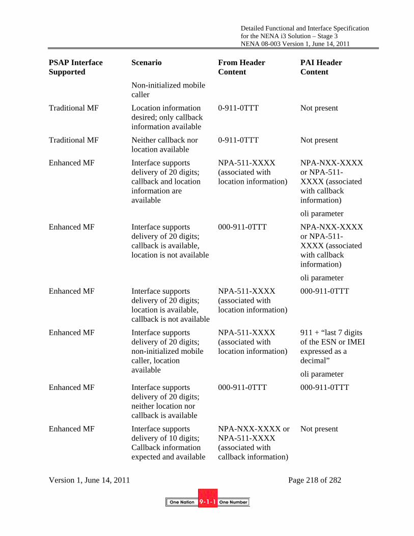
Detailed Functional and Interface Specification for the NENA i3 Solution – Stage 3 NENA 08-003 Version 1, June 14, 2011
Version 1, June 14, 2011 Page 218 of 282
PSAP Interface Supported
Scenario From Header Content
PAI Header Content
Non-initialized mobile caller
Traditional MF Location information desired; only callback information available
0-911-0TTT Not present
Traditional MF Neither callback nor location available
0-911-0TTT Not present
Enhanced MF Interface supports delivery of 20 digits; callback and location information are available
NPA-511-XXXX (associated with location information)
NPA-NXX-XXXX or NPA-511-XXXX (associated with callback information)
oli parameter
Enhanced MF Interface supports delivery of 20 digits; callback is available, location is not available
000-911-0TTT NPA-NXX-XXXX or NPA-511-XXXX (associated with callback information)
oli parameter
Enhanced MF Interface supports delivery of 20 digits; location is available, callback is not available
NPA-511-XXXX (associated with location information)
000-911-0TTT
Enhanced MF Interface supports delivery of 20 digits; non-initialized mobile caller, location available
NPA-511-XXXX (associated with location information)
911 + “last 7 digits of the ESN or IMEI expressed as a decimal”
oli parameter
Enhanced MF Interface supports delivery of 20 digits; neither location nor callback is available
000-911-0TTT
000-911-0TTT
Enhanced MF Interface supports delivery of 10 digits; Callback information expected and available
NPA-NXX-XXXX or NPA-511-XXXX (associated with callback information)
Not present

Detailed Functional and Interface Specification for the NENA i3 Solution – Stage 3 NENA 08-003 Version 1, June 14, 2011
Version 1, June 14, 2011 Page 219 of 282
PSAP Interface Supported
Scenario From Header Content
PAI Header Content
oli parameter
Enhanced MF Interface supports delivery of 10 digits; Location information expected and available
NPD-511-XXXX (associated with location information)
oli parameter
Not present
Enhanced MF Interface supports delivery of 10 digits; Callback information desired; only location information available
NPD-511-XXXX (associated with location information)
oli parameter
Not present
Enhanced MF Interface supports delivery of 10 digits; Location information desired; only callback information available
NPA-NXX-XXXX or NPA-511-XXXX (associated with callback information)
oli parameter
Not present
Enhanced MF Interface supports delivery of 10 digits; Neither callback nor location available
000-911-0TTT Not present
Enhanced MF Interface supports delivery of 10 digits; Callback information desired; call is from a non-initialized mobile
911 + “last 7 digits of the ESN or IMEI expressed as a decimal”
oli parameter
Not present
7.2.2.4 Support for Emergency Call Transfer
When a legacy PSAP determines that it is necessary to transfer an emergency call, it sends a “flash” signal and waits for dial tone. Once the dial tone is received, the PSAP requests the transfer either by operating a key associated with a particular type of secondary PSAP (e.g., fire department) or a particular PSAP destination (e.g., using a speed calling feature), or by manually dialing the number of the desired destination.
When the PIF component of the Legacy PSAP Gateway detects a flash, it will follow the procedures defined in RFC 2833 for passing the “flash” signal to the NIF component of the Legacy PSAP

Detailed Functional and Interface Specification for the NENA i3 Solution – Stage 3 NENA 08-003 Version 1, June 14, 2011
Version 1, June 14, 2011 Page 220 of 282
Gateway and provide dial tone to the legacy PSAP. The NIF component will interpret receipt of the flash as a request from a legacy PSAP to initiate a call transfer. In response to the dial tone, the PSAP will provide DTMF signaling in the form of a *XX code, “# + 4 digits” or a 7/10-digit directory number. Upon receiving the “*XX” code, “# + 4 digits,” or the 7/10-digit directory number of the destination party, the PIF component of the Legacy PSAP Gateway will pass the information to the NIF component using the mechanisms defined in RFC 2833. The NIF will interpret the DTMF information received from the NIF and request that a conference be created. The NIF will then generate a SIP REFER method to request that the caller (or B2BUA, depending on the architecture being used by the ESInet to support call transfer) be invited to the conference. The NIF component of the Legacy PSAP Gateway will subsequently generate another SIP REFER method to request that the conference bridge invite the transfer-to party to the conference. This latter REFER method will include an indication of the transfer-to party in the Refer-To header. The NIF will determine the transfer-to party in one of the following ways:
If the PIF receives a 7/10-digit destination number in the transfer request signaling from the legacy PSAP and passes this information to the NIF using the mechanisms defined in RFC 2833, the NIF shall use this information to populate the URI in the Refer-To header of the outgoing REFER method.
If the PIF receives a “# + 4-digits” in the transfer request signaling from the legacy PSAP and passes this information to the NIF using the mechanisms defined in RFC 2833, the NIF shall add the appropriate NPA-NXX digits at the beginning of the 4-digit string, and use this information to populate the URI in the Refer-To header of the outgoing REFER method.
If the PIF receives a code of the form “*XX” in the transfer request signaling from the legacy PSAP and passes this information to the NIF using the mechanisms defined in RFC 2833, the NIF shall do one of the following, based on trunk group provisioning:
- The NIF shall map the received *XX code to a static URI, and populate this URI in the Refer-To header of the outgoing REFER method
- The NIF shall map the received *XX code to a service URN, and query an ECRF using this service URN and the location information received with the call. The NIF will then use the URI returned in the response from the ECRF to populate the Refer-To header of the outgoing REFER method.40
Figure 7-3 and Figure 7-1 provide an example of an emergency call transfer flow to illustrate different aspects of an emergency call transfer that has been requested by a legacy PSAP. Figure 7-3 shows the establishment of a conference by the Legacy PSAP Gateway in response to a transfer request from a legacy PSAP. Error! Reference source not found. shows the completion of the
40 This will require that the Legacy PSAP Gateway be able to map of all the *XX codes supported by each PSAP that it serves to an appropriate service URN value that it can use to obtain the associated transfer-to destination address from the ECRF.

Detailed Functional and Interface Specification for the NENA i3 Solution – Stage 3 NENA 08-003 Version 1, June 14, 2011
Version 1, June 14, 2011 Page 221 of 282
transfer of the emergency call to the secondary PSAP. Section 4.1.1.2 provides a more complete discussion of the REFER method, and Sections 5.7 and 5.8 provide detail flows describing the alternatives for supporting bridging and transfer in an i3 environment.
Figure 7-3. Emergency Call Transfer Request from Legacy PSAP – Conference Established
The emergency call transfer flow illustrated above begins when the legacy PSAP determines that an emergency call needs to be transferred.
1. Upon determining that an emergency call needs to be transferred, the legacy PSAP initiates a transfer request by sending a flash signal to the Legacy PSAP Gateway.
2. When the Legacy PSAP Gateway receives the flash signal, it returns dial tone to the legacy PSAP and prepares to receive DTMF signaling.
3. The legacy PSAP provides a “*XX code,” a string consisting of “# + 4-digits” or the directory number associated with the transfer-to PSAP/public safety agency.
Legacy PSAP Gateway
Legacy PSAP
1. Flash
10. ACK
7. INVITE sip:Conf‐ID
2. Dial Tone
9. 200 OK Contact:sip:Conf‐ID; isfocus
3. *XX or #+4D or destination PSAP DN
11. SUBSCRIBE sip:Conf‐ID
12. 200 OK
13. NOTIFY
14. 200 OK
Legacy PSAP Gateway creates a conference.
Conf. App.
Caller/B2BUA
SecondaryPSAP Bridge
6. ACK
4. INVITE sip:Conf App
5. 302 Moved Contact:sip:Conf‐ID; isfocus
8. 180 Ringing
RTP
.
.
.

Detailed Functional and Interface Specification for the NENA i3 Solution – Stage 3 NENA 08-003 Version 1, June 14, 2011
Version 1, June 14, 2011 Page 222 of 282
4. The Legacy PSAP Gateway creates a conference by first sending an INVITE to a conference application, using a URI that is known or provisioned at the Legacy PSAP Gateway.
5. The Conference Application responds by sending a 302 Moved message which redirects the Legacy PSAP Gateway to the conference bridge, and provides the Conference-ID that should be used for the conference.
6. The Legacy PSAP Gateway acknowledges the receipt of the 302 Moved message.
7. The Legacy PSAP Gateway generates an INVITE to establish a session with the conference bridge.
8. The conference bridge responds to the INVITE by returning a 180 Ringing message.
9. The conference bridge then returns a 200 OK message, and a media session is established between the Legacy PSAP Gateway and the conference bridge.
10. The Legacy PSAP Gateway returns an ACK message in response to the 200 OK.
11. – 14. Once the media session is established, the Legacy PSAP Gateway subscribes to the conference URI obtained from the Contact URI provided in the 200 OK message from the conference bridge.
After the Legacy PSAP Gateway establishes the conference, it sends a REFER method to the conference bridge asking it to invite the caller/B2BUA to the conference, following the procedures described in Section 5.7. Once the conference bridge has done so, the Legacy PSAP Gateway asks the conference bridge to invite the transfer-to party to the conference. It does this by generating a REFER method with a Refer-To header that contains the URI of the transfer-to PSAP/agency, determined using one of the methods described above. The REFER should include any location information associated with the original caller that was received in the initial INVITE message. The Legacy PSAP Gateway will populate the remaining fields of the REFER based on RFC 3515.
As described in Section 5.7, the Legacy PSAP Gateway shall be capable of receiving a 202 Accepted message in response to the REFER, followed by a NOTIFY that contains the status of the REFER request. The Legacy PSAP Gateway then returns a 200 OK in response to the NOTIFY.
When the call to the secondary PSAP is answered, the Legacy PSAP Gateway will receive a NOTIFY message indicating this event. The Legacy PSAP Gateway will respond to the NOTIFY by returning a 200 OK message.
The Legacy PSAP Gateway will create an AdditionalPSAPData structure (which contains the AdditionalCallData and AdditionalCallerData if present in the call) to pass to the secondary PSAP as an escaped Call-Info header (as described in Section 5.7.1.3). While the Legacy PSAP Gateway does not know all of the information the primary PSAP developed in its handling of the call, it should pass what it does know to the secondary PSAP using this mechanism.
When the primary PSAP determines that it should drop off the conference and complete the transfer, it will follow the steps illustrated in Figure 7-4.

Detailed Functional and Interface Specification for the NENA i3 Solution – Stage 3 NENA 08-003 Version 1, June 14, 2011
Version 1, June 14, 2011 Page 223 of 282
Figure 7-4. Emergency Call Transfer Request from Legacy PSAP – Transfer Completed
The emergency call transfer flow illustrated above begins when the legacy PSAP determines that it can drop off the conference with the caller and the secondary PSAP, and complete the transfer.
15. Upon determining that the emergency call transfer should be completed, the legacy PSAP disconnects from the call by sending an on-hook signal to the Legacy PSAP Gateway.
16. When the Legacy PSAP Gateway receives the on-hook signal, it sends a BYE message to the conference bridge.
17. The conference bridge responds by returning a 200 OK message.
18. The conference bridge then returns a NOTIFY message indicating that the subscription to the conference has been terminated.
19. The Legacy PSAP Gateway returns a 200 OK in response to the NOTIFY.
20. The secondary PSAP completes the transfer by sending an INVITE to the caller/B2BUA requesting that they replace their connection to the bridge with a direct connection to the secondary PSAP.
Legacy PSAP Gateway
Legacy PSAP
18.NOTIFY Subscription –State: terminated
19. 200 OK
Primary PSAP drops out of the conference.
BridgeCaller/B2BUA
SecondaryPSAP
25. BYE
26. 200 OK
28. 200 OK
15. On‐hook
16. BYE
17. 200 OK
30. 200 OK
29. NOTIFY Subscription –State: terminated
27. NOTIFY Subscription –State: terminated
Secondary PSAP completes transfer. 20. INVITE sip:sec Replaces C‐S
21. 200 OK
23. BYE
24. 200 OK
22. ACK

Detailed Functional and Interface Specification for the NENA i3 Solution – Stage 3 NENA 08-003 Version 1, June 14, 2011
Version 1, June 14, 2011 Page 224 of 282
21. The caller/B2BUA responds by returning a 200 OK message.
22. The secondary PSAP responds by returning an ACK to the caller/B2BUA.
23. The caller/B2BUA then sends a BYE to the conference bridge to terminate the session.
24. The conference bridge responds by sending the caller/B2BUA a 200 OK message.
25. The secondary PSAP also terminates its session with the conference bridge by sending a BYE message.
26. The conference bridge responds by sending a 200 OK message to the secondary PSAP.
27. The conference bridge then returns a NOTIFY message to the secondary PSAP indicating that the subscription to the conference has been terminated.
28. The secondary PSAP responds with a 200 OK message.
29. The conference bridge sends a NOTIFY message to the caller/B2BUA indicating that the subscription to the conference has been terminated.
30. The caller/B2BUA responds with a 200 OK message.
7.2.2.5 Alternate Routing Invocation and Notification
Alternate routing allows a network to temporarily re-route calls to a different PSAP when the primary PSAP is unavailable to answer the call, or when connectivity to the primary PSAP is not available due to network failure.
In a legacy environment, when a PSAP determines that alternate routing needs to be manually invoked (e.g., the PSAP needs to evacuate), it calls the alternate PSAP to inform them of the situation, so they are prepared to begin to receive all of the primary PSAP’s calls. Today, the capability to manually invoke/cancel alternate routing is controlled by the primary PSAP. Typically, when alternate routing is to be invoked, the primary PSAP manually activates a switch or other control item to change the state of a control circuit connected to a scan point or other sensing device at the SR. When the state of the circuit is changed (e.g., by “shorting out” the circuit or closing a relay on a Network Control Module [NCM]), the scan points get saturated and, from the perspective of the SR, it appears as an “all circuits busy” condition on the trunk group. This causes the E9-1-1 tandem to route calls intended for the primary PSAP to the alternate PSAP. To remove alternate routing, the primary PSAP restores the normal state of the control circuit (or re-opens the relay(s) at the NCM). In some cases manual alternate routing is invoked when the primary PSAP places a call to their E9-1-1 System Service Provider to request that action. This is also something a Legacy PSAP Gateway will need to be able to replicate.
In an i3 Solution environment, a Legacy PSAP Gateway needs to be capable of recognizing a request to activate alternate routing. This request may come in the form of a physical switch, or it may be made via a GUI or web server. Upon detecting the alternate routing request, the Legacy PSAP Gateway will return an event notification back to the ESRP to inform it of the change in PSAP state. Note that, using this event notification mechanism, the ESRP will be able to distinguish between alternate routing that is due to traffic volumes (i.e., events related to queue state) and “make busy” scenarios, where the PSAP is experiencing some type of failure or evacuation situation (i.e.,

Detailed Functional and Interface Specification for the NENA i3 Solution – Stage 3 NENA 08-003 Version 1, June 14, 2011
Version 1, June 14, 2011 Page 225 of 282
events related to PSAP state). It is assumed that the policy rules associated with alternate routing requests related to a specific PSAP will have been previously populated in the PRF.
7.2.3 Location Interwork Function (LIF)
As described in Section Figure 7-2 the Legacy PSAP Gateway must support an ALI interface which can accept an ALI query from the legacy PSAP and return location information based on the formats specified in NENA 04-001 and NENA 04-005. There is additional information beyond just callback number and location information that may be included in an ALI response. There are various ways that ALI data may be obtained by the Legacy PSAP Gateway so that it can be returned to the legacy PSAP in the expected format.
If the Legacy PSAP Gateway receives callback information (i.e., in the form of a 10-digit NANP number) and location-by-value in the incoming INVITE message from the ESRP, the Legacy PSAP Gateway can use this information to populate the callback number and location fields of the ALI response. The Legacy PSAP Gateway can also generate an appropriate Class of Service for the call. If location-by-reference is received in the incoming INVITE message from the ESRP, the Legacy PSAP Gateway will have to support the ability to query other elements (i.e., LISs, Legacy Network Gateways) using an appropriate dereferencing protocol, as specified in Section 4.2.
The Legacy PSAP Gateway will need to access “Additional Data” structures to populate other fields in the ALI response. To do this, the Legacy PSAP Gateway will need to support the HTTP GET method described in IETF RFC 2616. The Legacy PSAP Gateway will use the information contained in the Call Info header of the received INVITE to identify the address of the target subscriber database to which the GET will be directed. The Legacy PSAP Gateway shall be capable of receiving and processing the XML-formatted data in the response from the subscriber data, and using it to populate the appropriate fields of the ALI response message.
See Appendix A for a detailed description of where the Legacy PSAP Gateway will obtain the necessary information to populate ALI response messages.
8 Data Associated with call/caller/location/PSAP With the implementation of NG9-1-1 there will be many forms of additional data available to emergency responders: data associated with a call, a location, a caller and a PSAP. Together with the SIP Invite and PIDF-LO, Additional Data associated with a Call (NENA 71-001) [254] has the ability to look at other data sources; for example, Vehicle Emergency Data Set (VEDS) to assist in determining the appropriate call routing and handling.
NENA defined the use of supportive and supplemental data in the Future Path Plan, and USDOT included it in their documentation. Supportive data is data used during the 9-1-1 call flow to provide proper routing instructions such as Vehicle Emergency Data Set (VEDS). Supplemental data is retrieved after the call reaches the PSAP or the responding emergency agency such as building data or medical records. It is not easy to separate additional data into these two categories because some additional data may be used either with the call flow or upon response thus all data not in the SIP Invite or PIDF-LO is called Additional Data. Supportive and supplemental data are often indistinguishable and inter-changeable. NENA NG9-1-1 documents do not differentiate.

Detailed Functional and Interface Specification for the NENA i3 Solution – Stage 3 NENA 08-003 Version 1, June 14, 2011
Version 1, June 14, 2011 Page 226 of 282
Additional Data is defined as data that is associated with a call, a caller, a location or PSAP. Any of the additional data elements in NENA 71-001, NENA Standard for NG9-1-1 Additional Data, or data available from an external data source may be used by PSAP management to establish business rules/policies for call handling and routing.
Additional Data is usually signaled with a URI. Dereferencing the URI is accomplished with an HTTPS Get (with fallback to HTTP if appropriate). ESInet elements use credentials traceable to the PCA, which must be accepted by the entity holding the data.
8.1 Additional Data associated with a Call (NENA 71-001)
The Additional Data Associated with a Call is defined in detail in NENA Specification 71-001, section 3.1 [107].
Additional data may be associated with a specific 9-1-1 call. This data may be provided by the device which places the call, or any intermediary, such as a carrier, telematics provider, alarm company or video relay, which handles the call. Devices may provide additional data; any intermediary handling the call must provide additional data, when available. The data is in the form of an XML data structure, retrieved by a simple HTTPS GET operation. The call includes a Call-Info header as in RFC 3261 [12]. The “purpose” parameter is set to “emergencyCallData”. The XML data structure is defined by NENA 71-001 [105]. The data is supplied by a Call Information Database (see section 5.10). The data addressed via these URIs may be accessed by the ESRP, Primary PSAP, Secondary PSAP, or responders.
More than one Call-Info header with an emergencyCallData purpose can be expected. The device may insert one, and an intermediary may insert its own. When there are multiple intermediaries each intermediary may each insert one. For example, a telematics service provider may provide one and the mobile carrier handling the call may provide one.
8.2 Additional Data associated with a location (NENA 71-001)
The Additional Data Associated with a Location is defined in detail through NENA Specification 71-001, section 3.2 [107].
Data associated with a location is provided in an xml data structure retrieved from a web service. The ECRF has an “additionalData” service (urn:nena:service:additionalLocationData) that returns the URI for the data associated with a location to authorized entities. This URI will allow the Additional Data associated with a Location to be retrieved from any number of sources, including distributed databases containing further information about the location. This will allow the ESRP, Primary or Secondary PSAP’s or Responders to access this data as needed. The xml data structure returned will be defined in future work. This structure must be able to be broken into sections, or separate XML documents for building owner and multiple instances of tenant information. The additional location data structure includes building owner and /or tenant contact information whereas the additional call data includes subscriber contact and AdditionalCallerData includes caller contact. Either can be used to determine which tenant the call originates from. NENA is working with other agencies/associations to establish additional data streams for Additional Data associated with a location/building.

Detailed Functional and Interface Specification for the NENA i3 Solution – Stage 3 NENA 08-003 Version 1, June 14, 2011
Version 1, June 14, 2011 Page 227 of 282
8.3 Additional Data Associated with a caller (NENA 71-001)
The Additional Data Associated with a Caller is defined in detail through NENA Specification 71-001, section 3.3 [105].
Data associated with a caller is provided in an xml data structure retrieved from a web server. The call may include a header containing the URI for the data associated with the caller. The data is in the form of an XML data structure, retrieved by a simple HTTPS GET operation. This query may be executed by the ESRP, Primary PSAP, Secondary PSAP, or the Responders. To protect the privacy of the caller, the amount of information returned by this query may vary depending on the credentials of the entity dereferencing the URI used in establishing the TLS session. PSAPs will have credentials traceable to the PCA which must be accepted by the data provider. The call includes a Call-Info header as in RFC 3261 [12]. The “purpose” parameter is set to “emergencyCallerData”. The web service may be operated by an independent service provider trusted by the user, who would offer a URI for the data associated with the caller to every carrier the caller uses. The entity operating the domain must construct the URI to maintain the privacy of the caller. The entity may provide each carrier, if the caller has more than one carrier, with a different URI, any of which would return the same data. The caller-data URI must be provided automatically on emergency calls. There may be multiple URIs and each will lead to one or more instances of the XML data elements defined in the NENA 71-001 specification. If the URI is used to retrieve the data subsequent to the call, the data may have changed; therefore, if this data must be kept, it must be retrieved while the call is in progress and stored by the PSAP. NENA is working with other agencies/associations to establish additional data streams for Additional Data associated with a Caller (NENA 71-001), specifically medical data.
8.4 Additional Data associated with a PSAP (NENA 71-001)
A preliminary definition of Additional Data Associated with a PSAP is defined in NENA Specification 71-001, section 3.4 [107].
When a PSAP handles a call it develops information about the call, which must be passed to subsequent PSAPs, dispatchers and/or responders. This structure or a reference to it will be passed with a transferred call or as part of a CAD interface.
The Additional Data associated with a PSAP is a placeholder pending the definition of the Emergency Incident Data Document (EIDD). Once the EIDD is defined, additional PSAP data will be added as necessary, and the EIDD definition will replace this section.
The SIP headers and non-SDP bodies for the original call must be retained as part of the Additional Data associated with a PSAP. SIP headers and non-SDP bodies may be repeated to support multiple calls per incident. This will allow Secondary PSAPs to access the information associated with the Primary PSAP’s handling of the call, as these headers include previously retrieved Location information, URIs for Additional Call data, and Additional Caller data.
9 3rd Party Origination Service providers who operate call centers and wish to facilitate emergency calls from their subscribers with the call center agent remaining on the line (i.e., initially a three way call with the caller, the call agent and the PSAP call taker) may use 3rd Party Origination.

Detailed Functional and Interface Specification for the NENA i3 Solution – Stage 3 NENA 08-003 Version 1, June 14, 2011
Version 1, June 14, 2011 Page 228 of 282
The caller is assumed to have a two way SIP call between the caller and the call agent. Service providers who do not use SIP between the call and the call agent may use a gateway to interwork the call signaling from the caller to SIP, and must similarly use a gateway to interwork the call agent signaling to SIP. In such cases, the following signaling description applies, even though the call starts without a SIP call between the caller and call agent.
9.1 3rd Party Client is Referred to PSAP; PSAP Establishes Conference
In the first portion of the flow, the 3rd party client has encountered an emergency situation and a call is placed to the 3rd party call agent. The 3rd party call agent requests that the caller initiate an emergency call. Upon receiving an emergency session request that contains an indication of referral by a 3rd party agency, the PSAP establishes a session with a conference bridge and requests that the bridge refer the 3rd party call agent to the conference.

Detailed Functional and Interface Specification for the NENA i3 Solution – Stage 3 NENA 08-003 Version 1, June 14, 2011
Version 1, June 14, 2011 Page 229 of 282
Bridge
6. NOTIFY
4. REFER Ref‐To: urn:service:sos
5. 202 Accepted
7. 200 OK
8. INVITE Ref‐By :3rd
13. INVITE
15. ACK
RTP
10. ACK
9. 200 OK
PSAP
3rd
Party
Caller/3rd
Party Client

Detailed Functional and Interface Specification for the NENA i3 Solution – Stage 3 NENA 08-003 Version 1, June 14, 2011
Version 1, June 14, 2011 Page 230 of 282
1. Upon encountering an emergency situation, an INVITE message is sent by a 3rd party client
requesting that a session be established with a 3rd party call agent. 2. The 3rd party call agent responds to the INVITE message by returning a 200 OK message. 3. The caller/3rd party client returns an ACK to the 3rd party call agent in response. At this point a session is established between the caller/3rd party client and the 3rd party call agent. The agent determines that a 9-1-1 call is required.
4. The 3rd party call agent sends a REFER message to the caller/3rd party client with a Refer-To header containing the destination urn:service:sos, that indicates that an emergency session request should be initiated. Note that the call agent includes an AdditionalCallData URI in an escaped Call-Info header in the REFER.
5. The caller/3rd party client responds by returning a 202 Accepted message to the 3rd party call agent.
Bridge
6. NOTIFY
4. REFER Ref‐To: e911
5. 202 Accepted
7. 200 OK (Trying)
8. INVITE Ref‐By :3rd Party
13. INVITE
15. ACK
RTP
10. ACK
9. 200 OK
PSAP3rd PartyCaller/3rd
Party Client
11. NOTIFY (200)
12. 200 OK (Success)
14. 200 OK
18. NOTIFY
19. 200 OK
1. INVITE
2. 200 OK
3. ACK
RTP
RTP
16. REFER
17. 202 Accepted

Detailed Functional and Interface Specification for the NENA i3 Solution – Stage 3 NENA 08-003 Version 1, June 14, 2011
Version 1, June 14, 2011 Page 231 of 282
6. The caller/3rd party client also returns a NOTIFY message, indicating the subscription state of the REFER request (i.e., active).
7. The 3rd party call agent returns a 200 OK message in response to the NOTIFY message. 8. The caller/3rd party client then initiates an emergency call by sending an INVITE message to
urn:service:sos. This INVITE is a normal 9-1-1 call, and has all of the content specified by [59]. This INVITE message contains a Referred-by header indicating that this emergency session request is associated with a REFER that was generated by a 3rd party call agent. It also includes the AdditionalCallData URI that it received in the escaped Call-Info header in the REFER from the 3rd party call agent.
9. When the PSAP receives the emergency session request with the Referred-By header, it returns a 200 OK message to the caller/3rd party client.
10. The caller/3rd party client responds by returning an ACK to the PSAP. At this point, a session is established between the caller/3rd party client and the PSAP.
11. The caller/3rd party client sends a NOTIFY message to the 3rd party call agent updating the status of the REFER request.
12. The 3rd party call agent responds by returning a 200 OK confirming the success of the REFER.
13. Based on receipt of the Referred-By header in the INVITE message from the caller/3rd party client indicating a need for a bridge to handle a 3 way call, the PSAP sends an INVITE to its conference bridge to establish a session with the bridge.
14. The bridge responds by returning a 200 OK message to the PSAP. 15. The PSAP responds by sending an ACK to the bridge. 16. The PSAP sends a REFER message to the bridge requesting that it invite the 3rd party call
agent to the conference. 17. The bridge responds by sending a 202 Accepted message to the PSAP. 18. The bridge then sends a NOTIFY message indicating the status of the REFER request. 19. The PSAP responds to the NOTIFY by returning a 200 OK message to the bridge.

Detailed Functional and Interface Specification for the NENA i3 Solution – Stage 3 NENA 08-003 Version 1, June 14, 2011
Version 1, June 14, 2011 Page 232 of 282
9.2 3rd Party Call Agent and Caller Added to Conference

Detailed Functional and Interface Specification for the NENA i3 Solution – Stage 3 NENA 08-003 Version 1, June 14, 2011
Version 1, June 14, 2011 Page 233 of 282
11. NOTIFY (200)
12. 200 OK (Success)
14. 200 OK
18. NOTIFY
19. 200 OK
1. INVITE
2. 200 OK 3. ACK
RTP
RTP
16. REFER
17. 202 Accepted
Bridge
27. NOTIFY
25. REFER

Detailed Functional and Interface Specification for the NENA i3 Solution – Stage 3 NENA 08-003 Version 1, June 14, 2011
Version 1, June 14, 2011 Page 234 of 282
20. The bridge sends an INVITE message to the 3rd party call agent. The INVITE contains an
indication in a Referred-by header that it is related to a REFER initiated by the PSAP. 21. The 3rd party call agent responds by returning an 200 OK message to the bridge. 22. The bridge returns an ACK to the 3rd party call agent. At this point a session is established between the 3rd party call agent and the bridge.
23. The bridge sends a NOTIFY message to the PSAP indicating the status of the REFER request.
24. The PSAP responds by returning a 200 OK message. 25. The PSAP then sends a REFER message to the bridge requesting that it invite the caller/3rd
party client to the conference. The REFER includes a Replaces header to indicate to the caller/3rd party that the session with the bridge replaces its existing session with the PSAP.
26. The bridge responds by sending a 202 Accepted message to the PSAP.
Bridge
27. NOTIFY
25. REFER
28. 200 OK
32. BYE
31. ACK
RTP
30. 200 OK
24. 200 OK
PSAP3rd PartyCaller/3rd
Party Client
23. NOTIFY
33. 200 OK
21. ACK
RTP
35. 200 OK
37. 200 OK
20. INVITE Ref‐By: PSAP
22. ACK
26. 202 Accepted
29. INVITE Ref‐By: PSAP Replaces C‐P
34. NOTIFY
36. BYE

Detailed Functional and Interface Specification for the NENA i3 Solution – Stage 3 NENA 08-003 Version 1, June 14, 2011
Version 1, June 14, 2011 Page 235 of 282
27. The bridge then sends a NOTIFY message to the PSAP indicating the status of the REFER request.
28. The PSAP responds by returning a 200 OK message. 29. The bridge then sends an INVITE message to the caller/3rd party client asking that they
replace their connection to the PSAP with a connection to the bridge. 30. The caller/3rd party client responds by returning a 200 OK message to the bridge. 31. The bridge responds by returning an ACK to the caller/3rd party client. At this point the caller/3rd party client has established a session with the bridge.
32. The caller/3rd party client then sends a BYE message to the PSAP to terminate its session with the PSAP.
33. The PSAP responds by sending a 200 OK message to the caller/3rd party client. 34. The bridge sends a NOTIFY message to the PSAP indicating the status of the REFER
request. 35. The PSAP responds by sending a 200 OK message to the bridge. 36. The 3rd party call agent sends a BYE message to the caller/3rd party client to terminate the
session it had with the caller/3rd party client. 37. The caller/3rd party client responds by returning a 200 OK to the 3rd party call agent.
The above sequence assumes that the caller/3rd party client has the most accurate location information to route and dispatch the call. In some circumstances, the 3rd party call agent may have better location. It can supply the location in the Additional Call Data, or it can arrange to have the caller/3rd party client send its emergency call INVITE (step 8) through the 3rd party call agent and add the more accurate location to the call. Either the 3rd party client or the caller can initiate the disconnect of the original session between them (step 36).
10 PSAP Management To be provided in a future edition of this document.
11 Test Calls PSAPs must implement the test function described in [59]. As the function is designed to test if a 9-1-1 call was placed from the test-initiating device, the test mechanism should mimic the entire actual 9-1-1 call path as closely as practical. The test mechanism is completely automatic, with no manual intervention required.
An INVITE message with the Service URN (found in a Route header) of “urn:service:sos.test” shall be interpreted as a request to initiate a test call. The PSAP should return a 200 OK response in normal conditions, indicating that it will complete the test function. The PSAP may limit the number of test calls. If that limit is exceeded, the response must be 486 Busy Here. PSAPs may accept requests for secondary services such as urn:service:sos.fire.test and complete a test call, or the PSAP may reject the call and return 404 Not Found. PSAP management may disable the test function (using PSAP policy).
If the PSAP accepts the test, it should return a body with MIME type text/plain consisting of the following contents:
Detailed Functional and Interface Specification for the NENA i3 Solution – Stage 3 NENA 08-003 Version 1, June 14, 2011
Version 1, June 14, 2011 Page 236 of 282
a. The name of the PSAP, terminated by a CR and LF
b. The string “urn:service:sos.test” terminated by a CR and LF
c. The location reported with the call (in the geolocation header). If the location was provided by value, the response would be a natural text version of the received location. If the location was provided by reference, the PSAP should dereference the location, using credentials acceptable to the LIS issued specifically for test purposes. Credentials issued by a PCA-rooted CA must have the token “test” as the agent name or the first token in the domain name. The location returned may not be the same as the LIS would issue for an actual emergency call.
The PSAP should insert its identity in the Contact header field of the response. To provide authentication, the Identity header field (RFC 4474 [86]) should be inserted, signed by an entity in the path (such as an ESRP) with a certificate traceable to the PCA.
A PSAP accepting a test call should accept a media loopback test [137] and should support the "rtp-pkt-loopback" and "rtp-start-loopback" options. The PSAP user agent would specify a loopback attribute of "loopback-source", the PSAP being the mirror. The PSAP should loop back no more than 3 packets of each media type accepted (voice, video, text), after which the PSAP should send BYE.
PSAP CPE should refuse repeated requests for test from the same device (same Contact URI or source IP address/port) in a short period of time (within 2 minutes). Any refusal is signaled with a 486 Busy Here.
12 NRS Consideration This document requests NRS to create several registries.
12.1 URN Registry
The IETF has delegated to NRS the urn:nena namespace. NRS is requested to create a registry for urn:nena. The urn:nena namespace will have a “top level” (to NRS) label, which in many cases will refer to a sub registry. For example, this document creates the “service” sub registry for urn:nena:service. The separator between the “nena” label and the urn subtype (urn:nena registry name) is a colon “:”.
12.1.1 Name
The name of this registry is urn:nena.
12.1.2 Information required to create a new value
A new entry to urn:nena requires an explanation of when the urn will be used, and how the new label is distinguished in its use from other urns. It should describe who creates urns with the label, and who uses such urns.

Detailed Functional and Interface Specification for the NENA i3 Solution – Stage 3 NENA 08-003 Version 1, June 14, 2011
Version 1, June 14, 2011 Page 237 of 282
12.1.3 Management Policy
A NENA Technical Standard is required to add a new entry into the registry. Sub registries under urn:nena may not be delegated outside the control of the NRS.
12.1.4 Content
This registry contains:
The UTF-8 “Name” of the “top level” label (a short string)
The UTF-8 “Purpose” of the label (explanatory text)
A “Reference” to a sub registry if appropriate (name of sub registry)
A reference (URI) to the NENA Technical Standard that defines the label.
12.1.5 Initial Values
See Section 12.2 below defining the “service” label.
12.2 “service” urn Sub Registry
When calls are routed within an ESInet, the routing element (PSAP or ESRP) queries the ECRF for the (nominal) route. It does so with a service urn. External routing is accomplished with urn:service:sos, as defined by the IETF. Within the ESInet, NENA defined service urns are used.
This document requests NRS to add a new entry to the urn:nena registry. The name of this entry is “service”. The purpose of this entry is “Routing 9-1-1 calls within an ESInet”. The “Reference” should refer to the registry created by this section, urn:nena:service. The separator between the “service” label and the service (urn:nena:service registry name) is a colon “:”.
Service URNs as defined here begin with urn:nena:service. The sub-namespace defined by this registry may be further subdivided (potentially several times), by sub-registries under this sub-registry. A new entry starting with urn:nena:service should denote a new type of route, which must be distinguished by the PSAP or ESRP from other uses. For example, 9-1-1 calls being routed within the ESInet use urn:nena:service:sos (or a subspace of it). Calls routed by a PSAP to a responder use urn:nena:service:responder (actually, the type of responders is also included, e.g., urn:nena:service:responder.police). A PSAP or ESRP specifies the urn in a LoST query, the ECRF uses it to choose a (nominal) route. In this entry in the urn:nena registry, “service” means a path towards a service, as it does for urn:service as defined by the IETF.
12.2.1 Name
The name of this sub registry is urn:nena:service.
12.2.2 Information required to create a new value
A new entry to urn:nena;service requires an explanation of when the urn will be used, and how the new label is distinguished in its use from other urns. It should describe who creates urns with the label, and who uses such urns.

Detailed Functional and Interface Specification for the NENA i3 Solution – Stage 3 NENA 08-003 Version 1, June 14, 2011
Version 1, June 14, 2011 Page 238 of 282
12.2.3 Management Policy
A NENA Technical Standard is required to add a new entry into the registry.
12.2.4 Content
This registry contains:
The UTF-8 “Name” of the label (a short string)
The UTF-8 “Purpose” of the label (explanatory text)
A reference to a “Subregistry” if appropriate (name of subregistry)
A reference (URI) to the NENA Technical Standard that defines the label.
12.2.5 Initial Values
This document defines the “AdditionalLocationData” name, with the purpose “Return a URI to an Additional Location Data structure as defined in NENA 71-001”. There is no reference. An entity such as a PSAP wishing to obtain additional data about a location queries the ECRF with this urn. The ECRF returns the URI to the AdditionalLocationData structure if one is available.
See section 12.3 and section 12.4 below for two initial additional values of this registry.
12.3 urn:nena:service:sos Registry
Routing of emergency calls within the ESInet is a primary function of this specification. When ESRPs must route calls within the ESInet, they query the ECRF for the route. Routing for emergency calls may involve multiple levels of ESRPs. Each level may need a different urn to distinguish them (it is also possible for the ECRF to distinguish by the identity of the ESRP that queries it). Routing of emergency calls, including instant messages and non-human-initiated calls, is accomplished with a urn beginning with urn:nena:service:sos.
NRS is requested to create an entry in the urn:nena:service registry with the name “sos” and with the purpose noted as “routing emergency calls within the ESInet towards a primary PSAP call taker”. The reference will be to the registry created by this section, urn:service:sos. The separator between the “sos” label and the service (urn:nena:service:sos registry name) is a period “.”.
The urn:nena:service:sos registry contains label values appropriate for the various levels of routing within the ESInet.
12.3.1 Name
The name of this registry is urn:nena:service:sos.
12.3.2 Information required to create a new value
A new entry to urn:nena:service:sos requires an explanation of when the urn will be used, and how the new label is distinguished in its use from other urns. It should describe who creates urns with the label, and who uses such urns.

Detailed Functional and Interface Specification for the NENA i3 Solution – Stage 3 NENA 08-003 Version 1, June 14, 2011
Version 1, June 14, 2011 Page 239 of 282
12.3.3 Management Policy
A NENA document is required to add a new entry into the registry.
12.3.4 Content
This registry contains:
The UTF-8 “Name” of the label (a short string)
The UTF-8 “Purpose” of the label (explanatory text)
A reference (URI) to the NENA Technical Standard that defines the label.
12.3.5 Initial Values
Name Purpose Reference psap Route calls to primary PSAP <insert reference to this document> level_2_esrp Route calls to a second level ESRP
(for an example, a state ESRP routing towards a county ESRP)
<insert reference to this document>
level_3_esrp Route calls to a third level ESRP (for example, a regional ESRP that received a call from a state ESRP and in turn routes towards a county ESRP).
<insert reference to this document>
call_taker Route calls to a call taker within a PSAP
<insert reference to this document>
12.4 urn:nena:service:responder Registry
Once a PSAP gets a call, they may have to transfer the call to a secondary PSAP. The secondary PSAP is chosen based on the type of responder, and the location of the caller. Routing of emergency calls from a PSAP towards a responder, including instant messages and non-human-initiated calls, is accomplished with a urn beginning with urn:nena:service:responder.
NRS is requested to create an entry in the urn:nena:service registry with the name “responder” and with the purpose noted as “routing emergency calls within the ESInet towards a responder”. The reference will be to the registry created by this section, urn:nena:service:responder.
The urn:nena:service:responder registry contains label values appropriate for the types of responders within the ESInet. The separator between the “responder” label and the type of responder (urn:nena:service:responder registry name) is a period “.”.
12.4.1 Name
The name of this registry is urn:nena:service:responder.

Detailed Functional and Interface Specification for the NENA i3 Solution – Stage 3 NENA 08-003 Version 1, June 14, 2011
Version 1, June 14, 2011 Page 240 of 282
12.4.2 Information required to create a new value
A new entry to urn:nena:service:responder requires an explanation of the type of responder, and how it is distinguished from other responder types already in the registry.
12.4.3 Management Policy
A NENA document is required to add a new entry into the registry.
12.4.4 Content
This registry contains:
The UTF-8 “Name” of the label (a short string)
The UTF-8 “Purpose” of the label (explanatory text)
A reference (URI) to the NENA Technical Standard that defines the label.
12.4.5 Initial Values
Name Purpose Reference police Route calls to Police Agency <insert reference to this document> fire Route calls to a Fire Department <insert reference to this document> ems Route calls to a Emergency Medical
Service <insert reference to this document>
poison_control Route calls to a Poison Control Center <insert reference to this document> mountain_rescue Route calls to a Mountain Rescue
Service <insert reference to this document>
fbi Route calls to the appropriate FBI field office
<insert reference to this document>
sheriff Route calls to a Sheriff‘s office, when both a police and Sheriff dispatch may be possible
<insert reference to this document>
state_police Route calls to a state police office <insert reference to this document> coast guard Route calls to a Coast Guard station <insert reference to this document>
12.5 elementState Registry
The elementState event returns an enumerated value of the current state of an agency or element as defined in Section 3.3.2. A registry is needed to enumerate the possible values returned.
12.5.1 Name
The name of this registry is elementState.
12.5.2 Information required to create a new value
A new entry to elementState requires an explanation of when value will be returned and how it is differentiated from other values in the registry.

Detailed Functional and Interface Specification for the NENA i3 Solution – Stage 3 NENA 08-003 Version 1, June 14, 2011
Version 1, June 14, 2011 Page 241 of 282
12.5.3 Management Policy
A NENA Technical Document required to add a new entry into the registry.
12.5.4 Content
This registry contains:
The UTF-8 “Value” of the entry
The UTF-8 “Purpose” of the entry and when it should be used
A reference (URI) to the NENA Technical Standard that defines the label.
12.5.5 Initial Values
The initial value and purposes of the registry are found in Section 3.3.2.
12.6 serviceState Registry
The serviceState event returns an enumerated value of the current state of a service as defined in Section 3.3.3. A registry is needed to enumerate the possible values returned.
12.6.1 Name
The name of this registry is serviceState
12.6.2 Information required to create a new value
A new entry to serviceState requires an explanation of when value will be returned and how it is differentiated from other values in the registry.
12.6.3 Management Policy
A NENA Technical Document is required to add a new entry into the registry.
12.6.4 Content
This registry contains:
The UTF-8 “Value” of the entry
The UTF-8 “Purpose” of the entry and when it should be used
A reference (URI) to the NENA Technical Document that defines the label.
12.6.5 Initial Values
The initial value and purposes of the registry are found in Section 3.3.3.
12.7 securityPosture Registry
The SecurityPosture event returns an enumerated value of the current security posture of an agency or element as defined in Section 3.3.1. A registry is needed to enumerate the possible values returned.

Detailed Functional and Interface Specification for the NENA i3 Solution – Stage 3 NENA 08-003 Version 1, June 14, 2011
Version 1, June 14, 2011 Page 242 of 282
12.7.1 Name
The name of this registry is securityPosture.
12.7.2 Information required to create a new value
A new entry to securityPosture requires an explanation of when value will be returned and how it is differentiated from other values in the registry.
12.7.3 Management Policy
A NENA Technical Document is required to add a new entry into the registry.
12.7.4 Content
This registry contains:
The UTF-8 “Value” of the entry
The UTF-8 “Purpose” of the entry and when it should be used
A reference (URI) to the NENA Technical Document that defines the label.
12.7.5 Initial Values
The initial value and purposes of the registry are found in Section 3.3.1. The reference is this document.
12.8 ExternalEventCodes Registry
CAP messages are used for events sent to, and within an ESInet. CAP messages have an <event code> tag. For use within ESInets, elements sending or receiving CAP messages must have a common understanding of what kind of an event is being sent, primarily to use in routing decisions. A registry is needed for event codes defined by NENA as outlines in Section 4.1.10.
12.8.1 Name
The name of this registry is ExternalEventCode.
12.8.2 Information required to create a new value
A new entry to ExternalEventCode requires an explanation of the use of the new code how it is differentiated from other values in the registry.
12.8.3 Management Policy
Expert Review is required to add a new entry into the registry. The Expert should consider whether the new proposed code is needed to differentiate a CAP message with that code from existing values. A proliferation of codes is not helpful because the routing mechanisms may get cumbersome. On the other hand, there are many possible sources of alerts, which may well need to be routed differentially, and thus the barrier for a new code should be modest.

Detailed Functional and Interface Specification for the NENA i3 Solution – Stage 3 NENA 08-003 Version 1, June 14, 2011
Version 1, June 14, 2011 Page 243 of 282
12.8.4 Content
This registry contains:
The UTF-8 “Value” of the entry
The UTF-8 “Purpose” of the entry and when it should be used
A reference to the person or document requesting the entry.
12.8.5 Initial Values
The registry should have the following entries:
Value Purpose Reference VEDS A message from an automatic vehicle
alert system containing a VEDS dataset<insert reference to this document>
BISACS A message from an intelligent building or a building central alarm monitoring service containing a BISACS alert message
<insert reference to this document>
12.9 EsrpNotifyEventCodes Registry
CAP messages are used for events sent to, and within an ESInet. CAP messages have an <event code> tag. For use the ESRPnotify event, CAP event code definitions are needed so that the recipient of the message knows why it received the message. A registry is needed for event codes defined by NENA as outlined in Section 5.2.1.5
12.9.1 Name
The name of this registry is EsrpNotifyEventCode.
12.9.2 Information required to create a new value
A new entry to EsrpNotifyEventCode requires an explanation of the use of the new code how it is differentiated from other values in the registry.
12.9.3 Management Policy
Expert Review is required to add a new entry into the registry. The Expert should consider whether the new proposed code is needed to differentiate a CAP message with that code from existing values. A proliferation of codes is not helpful because interoperable implementations may get cumbersome. On the other hand, there are many possible reasons for sending these messages, which may well need to be differentiated, and thus the barrier for a new code should be modest.
12.9.4 Content
This registry contains:
The UTF-8 “Value” of the entry
The UTF-8 “Purpose” of the entry and when it should be used

Detailed Functional and Interface Specification for the NENA i3 Solution – Stage 3 NENA 08-003 Version 1, June 14, 2011
Version 1, June 14, 2011 Page 244 of 282
The UTF-8 “Category” that will be included in the CAP message when this event code is used
A reference to the person who created the entry.
12.9.5 Initial Values
The registry should have the following entries:
Value Purpose Category Reference
12.10 RouteCause Registry
The ESRP routes calls using its Policy Routing Function. The result of evaluating a ruleset is a Route action which routes the call towards a PSAP (or responder). The Route action includes a cause value, which is placed in a Reason header associated with a History-Info header that informs the recipient why it got the call. A registry is needed for the values in the cause. The Route action cause is an enumeration, but the Reason header has a numeric cause value and a text string.
12.10.1Name
The name of this registry is RouteCause.
12.10.2Information required to create a new value
A new entry to RouteCause requires an explanation of the use of the new cause and how it is differentiated from other values in the registry.
12.10.3Management Policy
Expert Review is required to add a new entry into the registry. There is little reason to constrain the number of entries in the Registry as long as the value definitions are distinct enough for recipients to understand why the call was received. The Expert should therefore grant new requests for values as long as the value is clearly differentiateable from existing values. There should not be proprietary values, i.e., values that are expressly created for a particular implementation and generally not intended to be used by other implementations. Rather the values should have wide applicability to any implementation.
12.10.4Content
This registry contains:
The UTF-8 “Value” of the entry
The integer “Code” of the entry for the Reason header
The UTF-8 “Text” of the entry for the Reason header
A reference to the person or document that created the entry.

Detailed Functional and Interface Specification for the NENA i3 Solution – Stage 3 NENA 08-003 Version 1, June 14, 2011
Version 1, June 14, 2011 Page 245 of 282
12.10.5 Initial Values
The registry should have the following entries:
Value Code Text Reference NormalNextHop 200 Normal Next Hop <insert reference to this document> TimeOfDay 401 Time of Day <insert reference to this document> 402 <insert reference to this document>
12.11 LogEvent Registry
Log entries have a LogEvent which specifies what kind of log record the entry contains. Log entries are defined in Section 5.12.1.1.
12.11.1Name
The name of this registry is LogEvent.
12.11.2Information required to create a new value
A new entry to LogEvent requires an explanation of the new value, when it would be used, and the parameters required in the log record.
12.11.3Management Policy
A NENA Technical Document is required to add a new entry into the registry
12.11.4Content
This registry contains:
The UTF-8 “Value” of the entry
The UTF-8 “Purpose” of the entry and when it should be used
A reference (URI) to the NENA Technical Document that defines the LogEvent.
12.11.5Initial Values
The initial value and purposes of the registry are found in Section 5.12.1.1. The reference is this document.
12.12 AgencyRoles Registry
Agencies are classified by a role in the ESInet.
12.12.1Name
The name of this registry is AgencyRoles.
12.12.2Information required to create a new value
A new entry to AgencyRole requires a definition of the role, and must be suitably explicit to differentiate the role from existing roles.

Detailed Functional and Interface Specification for the NENA i3 Solution – Stage 3 NENA 08-003 Version 1, June 14, 2011
Version 1, June 14, 2011 Page 246 of 282
12.12.3Management Policy
A NENA Technical Document is required to add a new entry into the registry.
12.12.4Content
This registry contains:
The UTF-8 “role” of the entry
A reference (URI) to the NENA Document that defines the role.
12.12.5Initial Values
The initial roles are found in Section 6.3. The role entry in the registry should be in “camelCase”, thus “ESInet Operator” as listed in Section 6.3 should be “ESInetOperator” in the registry. The reference is this document.
12.13 AgentRoles Registry
Agents authenticate to the ESInet in one or more roles. The roles are defined in an OID to be referenced in a future edition of this document.
12.13.1Name
The name of this registry is AgentRoles.
12.13.2Information required to create a new value
A new entry to AgentRoles requires a definition of the role, and must be suitably explicit to differentiate the role from existing roles.
12.13.3Management Policy
A NENA Document is required to add a new entry into the registry. Normally, this will be a revision to a specific OID (to be created) that defines all NG9-1-1 agent roles.
12.13.4Content
This registry contains:
The UTF-8 “role” of the entry
A reference (URI) to the NENA Document that defines the role.
12.13.5Initial Values
The initial roles are found in Section 6.3. The role entry in the registry should be in “camelCase”, thus “Shift Supervisor” as listed in Section 6.3 should be “shiftSupervisor” in the registry. The reference is this document.

Detailed Functional and Interface Specification for the NENA i3 Solution – Stage 3 NENA 08-003 Version 1, June 14, 2011
Version 1, June 14, 2011 Page 247 of 282
13 References Note that this version of the document contains many references to documents that are works in progress at the IETF and other organizations. As such this document may be revised as these references stabilize.
1. i3 Technical Requirements Document, National Emergency Number Association, NENA 08-751
2. NENA Master Glossary of 9-1-1 Terminology, National Emergency Number Association, NENA 00-001
3. Interim VoIP Architecture for Enhanced 9-1-1 Services (i2), National Emergency Number Association, NENA 08-001
4. Framework for Emergency Calling in Internet Multimedia, B. Rosen, J. Polk, H. Schulzrinne, A. Newton, Internet Engineering Task Force, draft-ietf-ecrit-framework (work in progress)
5. Geopriv Requirements, J.Cueller et. al, Internet Engineering Task Force, RFC 3693
6. A Presence-based GEOPRIV Location Object Format, J. Peterson, Internet Engineering Task Force, RFC 4119
7. Dynamic Host Configuration Protocol Option for Coordinate-based Location Configuration Information, J. Polk, J. Schnizlein, M. Linsner, Internet Engineering Task Force, RFC 3825
8. Dynamic Host Configuration Protocol (DHCPv4 and DHCPv6) Option for Civic Addresses Configuration Information, H. Schulzrinne, Internet Engineering Task Force, RFC 4776
9. HTTP Enabled Location Delivery (HELD) M. Barnes, ed., Internet Engineering Task Force, RFC 5985
10. Session Initiation Protocol Location Conveyance, J. Polk, B. Rosen, Internet Engineering Task Force, draft-ietf-sipcore-location-conveyance (work in progress)
11. A Hitchhikers Guide to the Session Initiation Protocol (SIP), J. Rosenberg, Internet Engineering Task Force, RFC 5411
12. Session Initiation Protocol, J, Rosenberg et. al., Internet Engineering Task Force, RFC 3261
13. RTP: A Transport Protocol for Real-Time Applications, H. Schulzrinne et. al., Internet Engineering Task Force, RFC 3550
14. SDP: Session Description Protocol, J. Handley, V. Jacobson, Internet Engineering Task Force, RFC 4566
15. Session Initiation Protocol (SIP): Locating SIP Servers, J. Rosenberg, H. Schulzrinne, Internet Engineering Task Force, RFC 3263
16. An Offer/Answer Model with the Session Description Protocol (SDP), J. Rosenberg, H. Schulzrinne, Internet Engineering Task Force, RFC 3264

Detailed Functional and Interface Specification for the NENA i3 Solution – Stage 3 NENA 08-003 Version 1, June 14, 2011
Version 1, June 14, 2011 Page 248 of 282
17. Session Initiation Protocol (SIP)-Specific Event Notification, A. Roach, Internet Engineering Task Force, RFC 3265
18. The Session Initiation Protocol UPDATE Method, J. Rosenberg, Internet Engineering Task Force, RFC 3311
19. A Privacy Mechanism for the Session Initiation Protocol (SIP), J. Peterson, RFC 3323
20. Private Extensions to the Session Initiation Protocol (SIP) for Asserted Identity within Trusted Networks, C. Jennings, J. Peterson, M. Watson, Internet Engineering Task Force, RFC 3325
21. Session Initiation Protocol (SIP) Extension for Instant Messaging, B. Campbell et. al., Internet Engineering Task Force, RFC 3428
22. The Reason Header Field for the Session Initiation Protocol (SIP), H. Schulzrinne, D. Oran, G. Camarillo, Internet Engineering Task Force, RFC 3326
23. The Session Initiation Protocol (SIP) Refer Method, R. Sparks, Internet Engineering Task Force, RFC 3515
24. Grouping of Media Lines in the Session Description Protocol (SDP), G. Camarillo et. al., Internet Engineering Task Force, RFC 3388
25. An Extension to the Session Initiation Protocol (SIP) for Symmetric Response Routing, J. Rosenberg, H. Schulzrinne, Internet Engineering Task Force, RFC 3581
26. Real Time Control Protocol (RTCP) attribute in Session Description Protocol (SDP), C. Huitema, Internet Engineering Task Force, RFC 3605
27. Control of Service Context using SIP Request-URI, B. Campbell, R. Sparks, Internet Engineering Task Force, RFC 3087
28. Connected Identity in the Session Initiation Protocol (SIP), J. Elwell, Internet Engineering Task Force, RFC 4916
29. Indicating User Agent Capabilities in the Session Initiation Protocol (SIP), J. Rosenberg, H. Schulzrinne, P. Kyzivat, Internet Engineering Task Force, RFC 3840
30. Caller Preferences for the Session Initiation Protocol (SIP), J. Rosenberg, H. Schulzrinne, P. Kyzivat, Internet Engineering Task Force, RFC 3841
31. A Presence Event Package for the Session Initiation Protocol (SIP), J. Rosenberg, Internet Engineering Task Force, RFC 3856
32. A Watcher Information Event Template-Package for the Session Initiation Protocol (SIP), J. Rosenberg, Internet Engineering Task Force, RFC 3857
33. The Session Initiation Protocol (SIP) "Replaces" Header, R. Mahy, B. Biggs, R. Dean, Internet Engineering Task Force, RFC 3891
34. The Session Initiation Protocol (SIP) Referred-By Mechanism, R. Sparks, Internet Engineering Task Force, RFC 3892

Detailed Functional and Interface Specification for the NENA i3 Solution – Stage 3 NENA 08-003 Version 1, June 14, 2011
Version 1, June 14, 2011 Page 249 of 282
35. Best Current Practices for Third Party Call Control (3pcc) in the Session Initiation Protocol (SIP), J. Rosenberg et. al., Internet Engineering Task Force, RFC 3725
36. Using E.164 numbers with the Session Initiation Protocol (SIP), J. Peterson et. al., Internet Engineering Task Force, RFC 3824
37. Early Media and Ringing Tone Generation in the Session Initiation Protocol (SIP), G. Camarillo, H. Schulzrinne, Internet Engineering Task Force, RFC 3960
38. Presence Information Data Format (PIDF), H. Sugano, Internet Engineering Task Force, RFC 3863
39. Session Timers in the Session Initiation Protocol (SIP), S. Donovan, J. Rosenberg, Internet Engineering Task Force, RFC 4028
40. Internet Media Type message/sipfrag, R. Sparks, Internet Engineering Task Force, RFC 3420
41. The Session Initiation Protocol (SIP) "Join" Header, R. Mahy, D. Petrie, Internet Engineering Task Force, RFC 3911
42. Transcoding Services Invocation in the Session Initiation Protocol (SIP) Using Third Party Call Control (3pcc), G. Camarillo et. al., Internet Engineering Task Force, RFC 4117
43. Basic Network Media Services with SIP, J. Berger et. al., Internet Engineering Task Force, RFC 4240
44. An Extension to the Session Initiation Protocol (SIP) for Request History Information, M. Barnes et. al., Internet Engineering Task Force, RFC 4244
45. Actions Addressing Identified Issues with the Session Initiation Protocol's (SIP) Non-INVITE Transaction, R. Sparks, Internet Engineering Task Force, RFC 4320
46. Extending the Session Initiation Protocol (SIP) Reason Header for Preemption Events, J. Polk, Internet Engineering Task Force, RFC 4411
47. Communications Resource Priority for the Session Initiation Protocol (SIP), H. Schulzrinne, J. Polk, Internet Engineering Task Force, RFC 4412
48. Suppression of Session Initiation Protocol (SIP) REFER Method Implicit Subscription, O. Levin, Internet Engineering Task Force, RFC 4488
49. Conveying Feature Tags with the Session Initiation Protocol (SIP) REFER Method, O. Levin, A. Johnston, Internet Engineering Task Force, RFC 4508
50. Addressing an Amplification Vulnerability in Session Initiation Protocol (SIP) Forking Proxies, R. Sparks et. al., RFC 5393
51. Session Initiation Protocol Call Control - Conferencing for User Agents, A. Johnston, O. Levin, Internet Engineering Task Force, RFC 4579
52. A Session Initiation Protocol (SIP) Event Package for Conference State, R. Rosenberg, H. Schulzrinne, O. Levin, Internet Engineering Task Force, RFC 4575

Detailed Functional and Interface Specification for the NENA i3 Solution – Stage 3 NENA 08-003 Version 1, June 14, 2011
Version 1, June 14, 2011 Page 250 of 282
53. Obtaining and Using Globally Routable User Agent (UA) URIs (GRUU) in the Session Initiation Protocol (SIP), J. Rosenberg, Internet Engineering Task Force, RFC 5627
54. Managing Client Initiated Connections in the Session Initiation Protocol (SIP), C. Jennings et. al., Internet Engineering Task Force, RFC 5626
55. SDP: Session Description Protocol, M. Handley et. al, Internet Engineering Task Force, RFC 4566
56. Session Initiation Protocol Package for Voice Quality Reporting Event, A. Pendleton et. al., Internet Engineering Task Force, draft-ietf-sipping-rtcp-summary (work in progress)
57. Interactive Connectivity Establishment (ICE): A Methodology for Network Address Translator (NAT) Traversal for Offer/Answer Protocols, J. Rosenberg, Internet Engineering Task Force, RFC 5245
58. A Uniform Resource Name (URN) for Emergency and Other Well-Known Services, H. Schulzrinne, Internet Engineering Task Force, RFC 5031
59. Best Current Practice for Communications Services in support of Emergency Calling, B. Rosen, J. Polk, Internet Engineering Task Force, draft-ietf-ecrit-phonebcp (work in progress)
60. Location-to-URL Mapping Architecture and Framework, H. Schulzrinne, Internet Engineering Task Force, RFC5582
61. LoST: A Location-to-Service Translation Protocol, T. Hardie et. al., Internet Engineering Task Force, RFC 5222
62. A Framework for Centralized Conferencing, M. Barnes, C. Boulton, O. Levin, Internet Engineering Task Force, RFC 5239
63. Conference Information Data Model for Centralized Conferencing (XCON), O. Novo, G. Camarillo, D. Morgan, E. Even, Internet Engineering Task Force, draft-ietf-xcon-common-data-model (work in progress)
64. IP Multimedia Subsystem (IMS) emergency sessions, 3rd Generation Partnership Project, 3GPP TS 23.167
65. General Packet Radio Service (GPRS); Service description; Stage 2, 3rd Generation Partnership Project, 3GPP TS 23.060
66. IP multimedia call control protocol based on Session Initiation Protocol (SIP) and Session Description Protocol (SDP); Stage 3, 3rd Generation Partnership Project, 3GPP TS 23.229
67. ATIS Next Generation Network (NGN) Framework, Part III: Standards Gap Analysis, Alliance for Telecommunications Industry Solutions, May 2006
68. IP Network-to-Network Interface (NNI) Standard for VoIP, Alliance for Telecommunications Industry Solutions, ATIS-PP-1000009.2006
69. Enhanced Wireless 9-1-1 Phase 2, Telecommunications Industry Association and Alliance for Telecommunications Industry Solutions, J-STD-036-B

Detailed Functional and Interface Specification for the NENA i3 Solution – Stage 3 NENA 08-003 Version 1, June 14, 2011
Version 1, June 14, 2011 Page 251 of 282
70. Universal Description, Discovery and Integration (UDDI) Version 3.0, Organization for the Advancement of Structured Information Standards (OASIS), UDDI V3.0
71. OASIS UDDI Specifications TC - Committee Best Practices, Organization for the Advancement of Structured Information Standards (OASIS), UDDI Best Practices
72. OASIS UDDI Specifications TC - Committee Technical Notes, Organization for the Advancement of Structured Information Standards (OASIS), UDDI Technical Notes
73. NENA Technical Requirements Document for Location Information to Support IP-Based Emergency Services, NENA 08-752, Issue 1
74. NENA Recommended Method(s) for Location Determination to Support IP-Based Emergency Services - Technical Information Document, NENA 08-505, Issue 1
75. GEOPRIV Presence Information Data Format Location Object (PIDF-LO) Usage Clarification, Considerations, and Recommendations, J. Winterbottom, M. Thomson, H. Tschofenig, Internet Engineering Task Force, RFC5491
76. Revised Civic Location Format for Presence Information Data Format Location Object (PIDF-LO), M. Thomson, J. Winterbottom, Internet Engineering Task Force, RFC 5139
77. Requirements for a Location-by-Reference Mechanism used in Location Configuration and Conveyance, R. Marshall, Internet Engineering Task Force, RFC 5808
78. A Location Dereferencing Protocol Using HELD, J. Winterbottom, et al, Internet Engineering Task Force, draft-ietf-geopriv-deref-protocol (work in progress)
79. Session Initiation Protocol (SIP) Overload Control, V. Hilt, D. Malas, H. Schulzrinne, Internet Engineering Task Force, draft-gurbani-soc-overload-control-01 (work in progress)
80. Lightweight Directory Access Protocol (v3), M. Wahl, T. Howes, S. Kille, Internet Engineering Task Force, RFC 2251
81. Lightweight Directory Access Protocol (v3) Extension for Transport Layer Security, J. Hodges, R. Morgan, M. Wahl, Internet Engineering Task Force, RFC 2830
82. Real Time Streaming Protocol (RTSP), H. Schulzrinne, A. Rao, M. Lanphier, Internet Engineering Task Force, RFC 2326
83. The Transport Layer Security (TLS) Protocol Version 1.1, T. Dierks, E. Rescola, Internet Engineering Task Force, RFC 4346
84. Assertions and Protocols for the OASIS Security Assertion Markup Language (SAML) V2.0, Organization for the Advancement of Structured Information Standards (OASIS), saml-core-2.0-os
85. Internet X.509 Public Key Infrastructure Certificate Policy and Certification Practices Framework, S. Chokani et. al., Internet Engineering Task Force, RFC 3647
86. Enhancements for Authenticated Identity Management in the Session Initiation Protocol (SIP), J. Peterson, C. Jennings, Internet Engineering Task Force, RFC 4474

Detailed Functional and Interface Specification for the NENA i3 Solution – Stage 3 NENA 08-003 Version 1, June 14, 2011
Version 1, June 14, 2011 Page 252 of 282
87. eXtensible Access Control Markup Language (XACML) Version 2.0, Organization for the Advancement of Structured Information Standards (OASIS), XACML 2.0
88. The Secure Hash Algorithm, Federal Information Processing Standards Publication 180-2, National Institute of Standards and Technology, FIPS-PUB-180-2
89. Advanced Encryption Standard, Federal Information Processing Standards Publication 197, National Institute of Standards and Technology, FIPS-PUB-197
90. (Extensible Markup Language) XML-Signature Syntax and Processing, D. Eastlake, J. Reagle, D. Solo, Internet Engineering Task Force, RFC 3275
91. OASIS Service Provisioning Markup Language (SPML) Version 2, Organization for the Advancement of Structured Information Standards (OASIS), pstc-spml-2.0-os
92. Simple Network Management Protocol, Version 3 (SNMPv3), J. Case, et. al., Internet Engineering Task Force, RFC 3410 through RFC 3418
93. RTP Control Protocol Extended Reports (RTCP XR), T. Friedman ed., Internet Engineering Task Force. RFC 3611
94. XML Path Language (XPath) Version 1.0, J. Clark, S. Derose, World Wide Web Consortium (W3C), TR/1999/REC-xpath-19991116
95. Common Alerting Protocol V1.0, A. Botterell, Organization for the Advancement of Structured Information Standards (OASIS), oasis-200402-cap-core-1.0
96. Emergency Provider Access Directory (EPAD) Technical Implementation Guide, J. Rowland, J. Lawton, COMCARE, EPAD TIG
97. Security Requirements for Cryptographic Modules, Federal Information Processing Standards Publication 140-3, National Institute of Standards and Technology, FIPS-PUB-140-3
98. Report from the Special Joint LTD/PONGI Tech/Ops team on Congestion Control in NG9-1-1 Technical Information Document, National Emergency Number Association, work in progress
99. An INVITE-Initiated Dialog Event Package for the Session Initiation Protocol (SIP), J. Rosenberg, H. Schulzrinne, R. Mahy, Internet Engineering Task Force, RFC 4235
100. GML 3.1.1 PIDF-LO Shape Application Schema for Use by the Internet Engineering Task Force (IETF), M. Thomson and C. Reed, Candidate OpenGIS Implementation Specification 06-142r1, Version 1.0, April 2007
101. NENA Functional and Interface Standards for Next Generation 9-1-1 Version 1.0 (i3), National Emergency Number Association, NENA 08-002
102. NENA Technical Information Document Network/System Access Security, National Emergency Number Association, NENA 04-503
103. Filtering Location Notifications in the Session Initiation Protocol (SIP), R. Mahy, B. Rosen, H. Tschofenig, draft-ietf-geopriv-loc-filters (work in progress)

Detailed Functional and Interface Specification for the NENA i3 Solution – Stage 3 NENA 08-003 Version 1, June 14, 2011
Version 1, June 14, 2011 Page 253 of 282
104. Use of Device Identity in HTTP-Enabled Location Delivery (HELD) J. Winterbottom, M. Thomson, H. Tschofenig, R. Barnes, draft-ietf-geopriv-held-identity-extensions (work in progress)
105. NG9-1-1 Additional Data, National Emergency Number Association, NENA 71-001
106. Domain Names -- Concepts And Facilities, P. Mockapetris, STD13
107. A DNS RR for specifying the location of services (DNS SRV), A. Gulbrandsen, P. Vixie, L. Esibov, RFC2782
108. SIPconnect Technical Recommendation V1.0, C. Sibley, C. Gatch, SIPforum, sf-adopted-twg-IP_PBX_SP_Interop-sibley-sipconnect
109. NENA Civic Location Exchange Format, National Emergency Number Association, work in progress
110. Interworking between the Session Initiation Protocol (SIP) and the Extensible Messaging and Presence Protocol (XMPP): Instant Messaging, P. Saint-Andre, draft-saintandre-sip-xmpp-im (work in progress)
111. Emergency Data Exchange Language Distribution Element (EDXL-DE) 1.0, M. Raymond, S. Webb, P. Aymond, Organization for the Advancement of Structured Information Standards, OASIS EDXL-DE v1.0
112. Synchronizing Location-to-Service Translation (LoST) Protocol based Service Boundaries and Mapping Elements, H. Schulzrinne, H. Tschofenig, draft-ietf-ecrit-lost-sync (work in progress)
113. Session Initiation Protocol (SIP) Event Notification Extension for Notification Rate Control, A. Niemi, K. Kiss, S. Loreto, draft-ietf-sipcore-event-rate-control (work in progress)
114. Design Considerations for Session Initiation Protocol (SIP) Overload Control, V. Hilt, E. Noel, C. Shen, A. Abdelai, draft-hilt-soc-overload-design-00 (work in progress)
115. Data elements and interchange formats -- Information interchange -- Representation of dates and times, International Organization for Standardization, ISO 8601:2004
116. Session Traversal Utilities for NAT (STUN), J. Rosenberg, R. Mahy, P. Matthews, D. Wing, Internet Engineering Task Force, RFC5389
117. Framework for Real-Time Text over IP Using the Session Initiation Protocol (SIP), A. van Wijk, G. Gybels, Internet Engineering Task Force, RFC5194
118. RTP Payload for Text Conversation, G. Hellstrom, P. Jones, Internet Engineering Task Force, RFC4103
119. Framework for Transcoding with the Session Initiation Protocol (SIP), G. Camarillo, Internet Engineering Task Force, RFC5369
120. Indication of Message Composition for Instant Messaging, H. Schulzrinne, Internet Engineering Task Force, RFC3994

Detailed Functional and Interface Specification for the NENA i3 Solution – Stage 3 NENA 08-003 Version 1, June 14, 2011
Version 1, June 14, 2011 Page 254 of 282
121. The Message Session Relay Protocol (MSRP), B. Campbell, R. Mahy, C. Jennings, Internet Engineering Task Force, RFC4975
122. Relay Extensions for the Message Session Relay Protocol (MSRP), C. Jennings, R. Mahy, A.B. Roach, Internet Engineering Task Force, RFC4976
123. Multipurpose Internet Mail Extensions (MIME) Part Two: Media Types, N. Freed, N. Borenstein, Internet Engineering Task Force, RFC2046
124. vCard MIME Directory Profile, F. Dawson, T. Howes, Internet Engineering Task Force, RFC2426
125. The Secure Real-time Transport Protocol (SRTP), M. Baugher, et. al., Internet Engineering Task Force, RFC3711
126. Session Description Protocol (SDP) Security Descriptions for Media Streams, F. Andreasen, M. Baugher, D. Wing, Internet Engineering Task Force, RFC4568
127. NG9-1-1 Additional Data, National Emergency Number Association, NENA 71-001
128. An Extensible Markup Language (XML)-Based Format for Event Notification Filters, H. Khartabil, E. Leppanen, M. Lonnfors, J. Costa-Requena, Internet Engineering Task Force, RFC4661
129. Filtering Location Notifications in the Session Initiation Protocol (SIP), R. Mahy, B. Rosen, H. Tschofenig, Internet Engineering Task Force, draft-ietf-geopriv-loc-filters (work in progress)
130. OGC Web Feature Service Implementation Specification Version 1.1.0, P. Vretanos, Open Geospatical Consortium, OGC04-094
131. OGC Loosely Coupled Synchronization of Geographic Databases in the Canadian Geospatial Data Infrastructure Pilot Version 0.0.9, R. Singh, Open Geospatial Consortium, OGC 08-001
132. The Atom Syndication Format, M. Nottingham, R. Sayre, Internet Engineering Task Force, RFC4287
133. The ATOM Publishing Protocol, J. Gregorio, B. de hOra, Internet Engineering Task Force, RFC5023
134. Voice Extensible Markup Language (VoiceXML) Version 2.0, S. McGlashan et. al., World Wide Web Consortium, REC-voicexml20-20040316
135. Real Time Streaming Protocol (RTSP), H. Shulzrinne, A. Rao, R. Lanphier, Internet Engineering Task Force, RFC2326
136. The Session Description Protocol (SDP) Label Attribute, O. Levin, G. Camarillo, Internet Engineering Task Force, RFC4574
137. An Extension to the Session Description Protocol (SDP) for Media Loopback, K. Heyadat et. al., Internet Engineering Task Force, draft-ietf-mmusic-media-loopback (work in progress)
138. "Enhanced Variable Rate Codec, Speech Service Option 3 for Wideband Spread Spectrum Digital Systems", 3GPP2 TSGC-CC.S0014-A V1.0, TIA/EIA/IS-27-A; and also "RTP

Detailed Functional and Interface Specification for the NENA i3 Solution – Stage 3 NENA 08-003 Version 1, June 14, 2011
Version 1, June 14, 2011 Page 255 of 282
Payload Format for Enhanced Variable Rate Codecs (EVRC) and Selectable Mode Vocoders (SMV)", A. Li, RFC3558.
139. "Enhanced Variable Rate Codec, Speech Service Option 3 and 68 for Wideband Spread Spectrum Digital Systems", 3GPP2 TSGC-C C.S0014-B V1.0, TIA/EIA/IS-127-B; and also "Enhancements to RTP Payload Formats for EVRC Family Codecs", Q.Xie, R. Kapoor, RFC 4788.
140. "Enhanced Variable Rate Codec, Speech Service Options 3, 68, and 70 for Wideband Spread Spectrum Digital Systems", 3GPP2 TSGC-C C.S0014-C V1.0, TIA/EIA/IS-127-C; and also "RTP Payload Format for the Enhanced Variable Rate Wideband Codec (EVRC-WB) and the Media Subtype Updates for EVRC-B Codec", H. Desineni, Q. Xie, RFC 5188.
141. "Enhanced Variable Rate Codec, Speech Service Options 3, 68, 70, and 73 for Wideband Spread Spectrum Digital Systems" 3GPP2 TSGC-C C.S0014-D V1.0 TIA/EIA/IS-127-D; and also "RTP payload format for Enhanced Variable Rate Narrowband-Wideband Codec(EVRC-NW)", draft-zfang-avt-rtp-evrc-nw (work in progress).
142. “NG Partner Program 9-1-1 Funding Report”, NENA, NGFundingReport
143. “Next Generation 9-1-1 Transition Policy Implementation Handbook: A Guide for Identifying and Implementing Policies to Enable NG9-1-1”, NENA, NG911 Transition Policy Handbook
144. “Additional Data related to a Call for Emergency Call Purposes”, B. Rosen, H. Tschofenig, Internet Engineering Task Force, draft-rosen-ecrit-additional-data (work in progress)
145. “RObust Header Compression (ROHC): Framework and four profiles: RTP, UDP, ESP, and uncompressed”, C. Bormann et. al., Internet Engineering Task Force, RFC 3095
146. “Geolocation Policy: A Document Format for Expressing Privacy Preferences for Location Information”, H. Schulzrinne, H. Tschofenig et. al, Internet Engineering Task Force, draft-ietf-geopriv-policy (work in progress)
147. “Common Policy: A Document Format for Expressing Privacy Preferences”, H. Schulzrinne et. al., Internet Engineering Task Force, RFC 4745
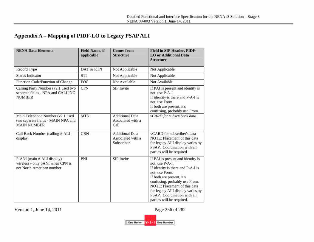
Detailed Functional and Interface Specification for the NENA i3 Solution – Stage 3 NENA 08-003 Version 1, June 14, 2011
Version 1, June 14, 2011 Page 256 of 282
Appendix A – Mapping of PIDF-LO to Legacy PSAP ALI
NENA Data Elements Field Name, if applicable
Comes from Structure
Field in SIP Header, PIDF-LO or Additional Data Structure
Record Type DAT or RTN Not Applicable Not Applicable
Status Indicator STI Not Applicable Not Applicable
Function Code/Function of Change FOC Not Available Not Available
Calling Party Number (v2.1 used two separate fields - NPA and CALLING NUMBER
CPN SIP Invite If PAI is present and identity is not, use P-A-I. If identity is there and P-A-I is not, use From. If both are present, it's confusing, probably use From.
Main Telephone Number (v2.1 used two separate fields - MAIN NPA and MAIN NUMBER
MTN Additional Data Associated with a Call
vCARD for subscriber's data
Call Back Number (calling #-ALI display
CBN Additional Data Associated with a Subscriber
vCARD for subscriber's data NOTE: Placement of this data for legacy ALI display varies by PSAP. Coordination with all parties will be required
P-ANI (main #-ALI display) - wireless - only pANI when CPN is not North American number
PNI SIP Invite If PAI is present and identity is not, use P-A-I. If identity is there and P-A-I is not, use From. If both are present, it's confusing, probably use From. NOTE: Placement of this data for legacy ALI display varies by PSAP. Coordination with all parties will be required.

Detailed Functional and Interface Specification for the NENA i3 Solution – Stage 3 NENA 08-003 Version 1, June 14, 2011
Version 1, June 14, 2011 Page 257 of 282
NENA Data Elements Field Name, if applicable
Comes from Structure
Field in SIP Header, PIDF-LO or Additional Data Structure
House Number PIDF HNO
House Number Suffix PIDF HNS
Prefix Directional PIDF PRD
Street Name PIDF RD
Street Suffix PIDF STS
Post Directional PIDF POD
MSAG Community Name PIDF A3 - if not available use PCN (mapped by PIDF TO MSAG CONVERSION FUNCTION and returns an MSAG valid address from the current MSAG)
Postal Community Name PCN PIDF PCN
State/Province PIDF A1
Country PIDF Country
Location / Location Description PIDF LOC (This could be a combination of FLR, UNIT, ROOM, SEAT. Most CPE only displays 20 characters.)
Building PIDF BLD
Floor PIDF FLR
UnitNum PIDF ROOM
UnitType PIDF UNIT
Landmark Address LMK PIDF LMK
Also Rings At Address ARA Not Applicable Not Applicable
Customer Name Additional Data Caller Contact (vCARD)

Detailed Functional and Interface Specification for the NENA i3 Solution – Stage 3 NENA 08-003 Version 1, June 14, 2011
Version 1, June 14, 2011 Page 258 of 282
NENA Data Elements Field Name, if applicable
Comes from Structure
Field in SIP Header, PIDF-LO or Additional Data Structure
Class of Service Valid Entries: 1 = Residence 2 = Business 3 = Residence PBX 4 = Business PBX 5 = Centrex 6 = Coin 1 way out 7 = Coin 2 way 8 = Mobile 9 = Residence OPX 0 = Business OPX A = Customer owned Coin Telephone (COCOT) B = Not Available (used locally by a few to represent ESCO failure) G = Wireless Phase I H = Wireless Phase II I = Wireless Phase II returning Phase I V = Voice Over IP Default COS C = VoIP Residence D = VoIP Business E = VoIP Coin/Pay Phone F = VoIP Wireless J = VoIP Nomadic K = VoIP Enterprise Services - Centrex & PBX
Additional Data INCLUDE THE METHOD FIELD OF THE PIDF
Service Environment (Business or Residence) PLUS Service Delivered by Provider to End User. (This defines the type of service the end user has subscribed to. The implied mobility of this service cannot be relied upon.) • Mobile Telephone Service: Includes Satellite, CDMA, GSM, Wi-Fi, WiMAX, LTE (Long Term Evolution) • Fixed Public Pay/Coin telephones: Any coin or credit card operated device. CONVERT BACK TO: 7 • One way outbound service CONVERT BACK TO: 6 • Inmate call/service CONVERT BACK TO: 6 • Soft dial tone/quick service/warm disconnect/suspended CONVERT BACK TO: 1 • Multi-line telephone system (MLTS): Includes all PBX, Centrex, key systems,

Detailed Functional and Interface Specification for the NENA i3 Solution – Stage 3 NENA 08-003 Version 1, June 14, 2011
Version 1, June 14, 2011 Page 259 of 282
NENA Data Elements Field Name, if applicable
Comes from Structure
Field in SIP Header, PIDF-LO or Additional Data Structure
Shared Tenant Service. (ask operations if they want analog and digital identified for calling back caller) CONVERT BACK TO: 4 • Sensor, unattended: Includes devices that generate DATA ONLY. This is one-way information exchange and there will be no other form of communication. NOT AVAILABLE • Sensor, attended: Includes devices that are supported by a monitoring service provider or automatically open a two-way communication path. NOT AVAILABLE • Wireline: Plain Old Telephone Service (POTS). CONVERT BACK TO: 1 OR 2, DEPENDING ON SERVICE ENVIRONMENT • VoIP Telephone Service: A type of service that offers communication over internet protocol. Includes fixed, nomadic, mobile, unknown. CONVERT BACK TO: V

Detailed Functional and Interface Specification for the NENA i3 Solution – Stage 3 NENA 08-003 Version 1, June 14, 2011
Version 1, June 14, 2011 Page 260 of 282
NENA Data Elements Field Name, if applicable
Comes from Structure
Field in SIP Header, PIDF-LO or Additional Data Structure
• Unknown NOT AVAILABLE

Detailed Functional and Interface Specification for the NENA i3 Solution – Stage 3 NENA 08-003 Version 1, June 14, 2011
Version 1, June 14, 2011 Page 261 of 282
NENA Data Elements Field Name, if applicable
Comes from Structure
Field in SIP Header, PIDF-LO or Additional Data Structure
Type of Service Valid entries: 0 = Not FX nor Non-Published 1 = FX in 911 serving area 2 = FX outside 911 serving area 3 = Non-Published 4 = Non-Published FX in serving area 5 = Non-Published FX outside 911 serving area 6 = Local Ported Number (LNP) 7 = Interim Ported Number
" " Additional Data Telephone Number Privacy Indicator (Allowable Values: Published or Non-Published) Published converts back to 0 Non-Published converts back to 3
ESN The MSAG Conversion function can convert a PIDF to an MSAG data format, which contains the ESN.
Agencies:Police:Name ECRF Display name for urn:nena:service:sos.police
Agencies:Police:TN ECRF AoR (Address of Record) for urn:nena:service:sos.police
Agencies:Fire:Name ECRF Display name for urn:nena:service:sos.fire
Agencies:Fire:TN ECRF AoR (Address of Record) for urn:nena:service:sos.fire
Agencies:EMS:Name ECRF Display name for urn:nena:service:sos.ems
Agencies:EMS:TN ECRF AoR (Address of Record) for urn:nena:service:sos.ems
Agencies:OtherAgencies:Name ECRF Display name for the appropriate nena service urn
Agencies:OtherAgencies:TN ECRF AoR (Address of Record) for the appropriate nena service urn
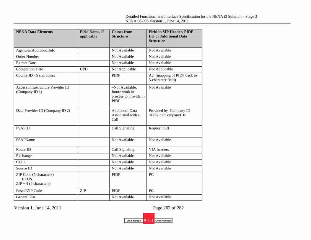
Detailed Functional and Interface Specification for the NENA i3 Solution – Stage 3 NENA 08-003 Version 1, June 14, 2011
Version 1, June 14, 2011 Page 262 of 282
NENA Data Elements Field Name, if applicable
Comes from Structure
Field in SIP Header, PIDF-LO or Additional Data Structure
Agencies:AdditionalInfo Not Available Not Available
Order Number Not Available Not Available
Extract Date Not Available Not Available
Completion Date CPD Not Applicable Not Applicable
County ID - 5 characters PIDF A2 (mapping of PIDF back to 5-character field)
Access Infrastructure Provider ID (Company ID 1)
–Not Available, future work in process to provide in PIDF
Not Available
Data Provider ID (Company ID 2) Additional Data Associated with a Call
Provided by Company ID <ProviderCompanyID>
PSAPID Call Signaling Request URI
PSAPName Not Available Not Available
RouterID Call Signaling VIA headers
Exchange Not Available Not Available
CLLI Not Available Not Available
Source ID Not Available Not Available
ZIP Code (5 characters) PLUS ZIP + 4 (4 characters)
PIDF PC
Postal/ZIP Code ZIP PIDF PC
General Use Not Available Not Available

Detailed Functional and Interface Specification for the NENA i3 Solution – Stage 3 NENA 08-003 Version 1, June 14, 2011
Version 1, June 14, 2011 Page 263 of 282
NENA Data Elements Field Name, if applicable
Comes from Structure
Field in SIP Header, PIDF-LO or Additional Data Structure
Customer Code Not Available Not Available
Comments Not Available Not Available
X Coordinate / Longitude PIDF via GML Schema
Longitude
Y Coordinate / Latitude PIDF via GML Schema
Latitude
Z Coordinate / Elevation PIDF via GML Elevation
Cell Site:Cell ID Call Signaling P-Access Info
Cell Site:Sector ID Call Signaling P-Access Info
Cell Site:LocationDescription Not Available Not Available
Datum Fixed Always WGS-84
Heading Not Available Not Available
Speed (in KPH/MPH) Not Available Not Available
PositionSource Not Available Not Available
Uncertainty PIDF via GML Schema
Uncertainty - determined by the size of the shape
Confidence Fixed Confidence - fixed
DateStamp PIDF via GML Schema
TimeStamp
Comment Not Available Not Available
TAR Code Not Available Not Available
Reserved Not Available Not Available
General Use 1 GU1 Not Applicable Not Applicable
General Use 2 GU2 Not Applicable Not Applicable
General Use 3 GU3 Not Applicable Not Applicable
General Use 4 GU4 Not Applicable Not Applicable
General Use 5 GU5 Not Applicable Not Applicable

Detailed Functional and Interface Specification for the NENA i3 Solution – Stage 3 NENA 08-003 Version 1, June 14, 2011
Version 1, June 14, 2011 Page 264 of 282
NENA Data Elements Field Name, if applicable
Comes from Structure
Field in SIP Header, PIDF-LO or Additional Data Structure
General Use 6 GU6 Not Applicable Not Applicable
General Use 7 GU7 Not Applicable Not Applicable
General Use 8 GU8 Not Applicable Not Applicable
ALT # Not Available Not Available
Alternate Telephone Number (used for interim number portability - probably no longer used)
ALT Not Applicable Not Applicable
Return Code Number RCN Not Applicable Not Applicable
Special Attention Indicator 1 = TTY call 2 = ACN, Automatic Crash/Collision Notification
SAI Not Applicable Not Applicable
Common Language Location Indicator (CLLI)
CLI Not Applicable Not Applicable
Expanded Extract Date Not Available Not Available
NENA Reserved Not Available Not Available
Reserved Not Available Not Available
Field Separator | Not Applicable Not Available
End of Record NL NL Not Applicable Not Available
End of Record {always an asterisk (*)}
* Not Available Not Available

Detailed Functional and Interface Specification for the NENA i3 Solution – Stage 3 NENA 08-003 Version 1, June 14, 2011
Version 1, June 14, 2011 Page 265 of 282
Appendix – B GIS Layer Definitions The Model below is for use in the interface between the SIF and the ECRF/LVF.
The USE R / O is an indication that the field is Required or Optional. If the field is Required, the individual attribute information in the field may be blank if they are not present.
ATTRIBUTE NAME USE R/O
TYPE DATA DESCRIPTION
Centerlines Source of Data R A Agency that last updated the record – usually
the name of the 9-1-1 Authority Data Updated R AN Date of last update using ISO 8501 format
Ex. 2010-08-30T15:52+05 Effective Date R AN Date the new information goes into effect using
ISO 8601 format Ex. 2010-10-12T01:01+05
Unique_ID R AN Unique ID for each Road Segment, with domain of agency included. ID’s not to be re-used when road is split or deleted. Ex. [email protected]
Country R A The name of a country represented by its two-letter ISO 3166-1 English country alpha-2 code elements in capital ASCII letters. Ex. US (country in RFC 5139)
State Left R A The name of a state, province or equivalent, represented by the two-letter abbreviation given in ISO 3166-2 on the left side of the road. A state/province is a primary governmental division of the United States/Canada. Ex. TX (A1 in RFC 5139)
State Right R A The name of a state, province or equivalent, represented by the two-letter abbreviation given

Detailed Functional and Interface Specification for the NENA i3 Solution – Stage 3 NENA 08-003 Version 1, June 14, 2011
Version 1, June 14, 2011 Page 266 of 282
ATTRIBUTE NAME USE R/O
TYPE DATA DESCRIPTION
in ISO 3166-2 on the right side of the road. A state/province is a primary governmental division of the United States/Canada. Ex. TX (A1 in RFC 5139)
County Left R AN The completely spelled out name of county or county-equivalent on the left side of where the road is located, as given in FIPS 6-4 1. A county (or its equivalent) is the primary legal division of a state, province or territory Ex. Harris (A2 in RFC 5139)
County Right R AN The completely spelled out name of county or county-equivalent on the right side of where the road is located, as given in FIPS 6-4 1. A county (or its equivalent) is the primary legal division of a state, province or territory Ex. Harris (A2 in RFC 5139)
Municipality Left O A The name of the incorporated municipality or other general-purpose local governmental unit (if any) on the left side of the road
Ex. Chicago, (A3 in RFC 5139) Municipality Right O A The name of the incorporated municipality or
other general-purpose local governmental unit (if any) on the right side of the road
Ex. Chicago, (A3 in RFC 5139) Unincorporated Community Right
O A The name of an unincorporated community, either within an incorporated municipality or in an unincorporated portion of a county, where the address is located. The area must have a definite boundary - on the Right side of the

Detailed Functional and Interface Specification for the NENA i3 Solution – Stage 3 NENA 08-003 Version 1, June 14, 2011
Version 1, June 14, 2011 Page 267 of 282
ATTRIBUTE NAME USE R/O
TYPE DATA DESCRIPTION
road (A4 in RFC 5139). Unincorporated Community Left
O A The name of an unincorporated community, either within an incorporated municipality or in an unincorporated portion of a county, where the address is located. The area must have a definite boundary - on the Left side of the road (A4 in RFC 5139)
Neighborhood Community Right
O A Neighborhood or other informal designation for a part of a city - on the Right side of the road (A5 in RFC 5139)
Neighborhood Community Left
O A Neighborhood or other informal designation for a part of a city - on the Left side of the road (A5 in RFC 5139)
Street Segment R S StreetSegment
Alias Street Segment O S StreetSegment, may occur more than once
Road Class R A Interstate Primary – Other Freeways and
Expressways Secondary – Other Principal Arterial or
Collector Local – Neighborhood Road, Rural
Road, City Street Ramp – Typically unaddressed access
to adjacent roads Alley – usually unnamed and
unaddressed Private – may be unnamed and/or
unnumbered
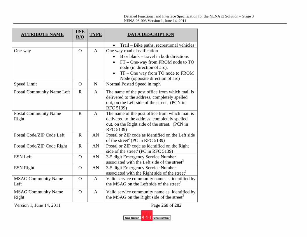
Detailed Functional and Interface Specification for the NENA i3 Solution – Stage 3 NENA 08-003 Version 1, June 14, 2011
Version 1, June 14, 2011 Page 268 of 282
ATTRIBUTE NAME USE R/O
TYPE DATA DESCRIPTION
Trail – Bike paths, recreational vehicles One-way O A One way road classification
B or blank – travel in both directions FT – One-way from FROM node to TO
node (in direction of arc); TF – One way from TO node to FROM
Node (opposite direction of arc) Speed Limit O N Normal Posted Speed in mph
Postal Community Name Left R A The name of the post office from which mail is delivered to the address, completely spelled out, on the Left side of the street. (PCN in RFC 5139)
Postal Community Name Right
R A The name of the post office from which mail is delivered to the address, completely spelled out, on the Right side of the street. (PCN in RFC 5139)
Postal Code/ZIP Code Left R AN Postal or ZIP code as identified on the Left side of the street2 (PC in RFC 5139)
Postal Code/ZIP Code Right R AN Postal or ZIP code as identified on the Right side of the street2 (PC in RFC 5139)
ESN Left O AN 3-5 digit Emergency Service Number associated with the Left side of the street3
ESN Right O AN 3-5 digit Emergency Service Number associated with the Right side of the street3
MSAG Community Name Left
O A Valid service community name as identified by the MSAG on the Left side of the street3
MSAG Community Name Right
O A Valid service community name as identified by the MSAG on the Right side of the street3

Detailed Functional and Interface Specification for the NENA i3 Solution – Stage 3 NENA 08-003 Version 1, June 14, 2011
Version 1, June 14, 2011 Page 269 of 282
ATTRIBUTE NAME USE R/O
TYPE DATA DESCRIPTION
CompleteStreetName Street Pre-Modifier O A A word or phrase that precedes the primary
street name and is not a leading street direction (PRM in RFC 5139). Street Pre-Modifier is only used when the Street Prefix Directional is also used. Examples: Alternate, Business, Bypass, Extended, Historic, Loop, Old, Private, Public, Spur, etc.
Leading Street Direction O A Leading street direction prefix. Valid Entries: N S E W NE NW SE SW (PRD in RFC 5139)
Street Type Prefix O A The type of street preceding the street name element. Must always be spelled out. (STP, proposed)
Street Name R A The Legal street name as assigned by local addressing authority (RD in RFC 5139)
Street Type Suffix O A The type of street following the street name. Abbreviations listed in USPS Publication 28 Appendix C1 may be used, or Street Type Suffix may be spelled out. All other street types are permitted, but must be spelled out completely. (STS in RFC 5139)
Trailing Street Direction O A Trailing street direction suffix. Valid Entries: N S E W NE NW SE SW (POD in RFC 5139)
Street Post-Modifier O A A word or phrase that follows the street name and is not a street suffix or trailing street direction. (POM in RFC 5139). Valid Entries include, but are not limited to: Access, Alternate, Business, Bypass, Connector, Extended, Extension, Loop, Private, Public,

Detailed Functional and Interface Specification for the NENA i3 Solution – Stage 3 NENA 08-003 Version 1, June 14, 2011
Version 1, June 14, 2011 Page 270 of 282
ATTRIBUTE NAME USE R/O
TYPE DATA DESCRIPTION
Scenic, Spur, Ramp, Underpass, Overpass. MSAG Street Name O A The street name as it appears in the MSAG
MSAG Suffix O A The suffix as it appears in the MSAG
CompleteAddressNumber Address Number Prefix O AN An extension of the address number that
precedes it and further identifies a location along a thoroughfare or within a defined area (HNP, proposed)
Address Number R N The numeric identifier of a location along a thoroughfare or within a defined community. (HNO in RFC5139)
Address Number Suffix O AN An extension of the address number that follows it and further identifies a location along a thoroughfare or within a defined area.
StreetSegment Complete Street Name R S CompleteStreetName
Left From Address R N The address on the Left side of the road, which corresponds to the "Left FROM Node" of the arc segment. It is quite possible that this address be higher than the "Left TO Node" ex. 399
Left To Address R N The address on the Left side of the road, which corresponds to the "Left TO Node" of the arc segment. It is quite possible that this address be lower than the "Left From Address" ex. 199
Parity Left R A A single character code that explicitly defines the allowable addresses on the Left side of the road. Valid values include "O", "E", or "B" for

Detailed Functional and Interface Specification for the NENA i3 Solution – Stage 3 NENA 08-003 Version 1, June 14, 2011
Version 1, June 14, 2011 Page 271 of 282
ATTRIBUTE NAME USE R/O
TYPE DATA DESCRIPTION
odd, even or both respectively. Validation Left R A Indicates House Number MUST be validated
against the Site / Structure layer on left side of street. Valid entries are SSVAL - to validate against Site Structure layer, SSNR – to allow House Number validation with centerlines.6
Right From Address R N The address on the Right side of the arc which corresponds to the Right "From Node" of the arc segment. It is quite possible that this address is higher than the "Right To Address" ex. 398
Right To Address R N The address on the Right side of the road, which corresponds to the "To Node" end of the arc segment. It is quite possible that this address be lower than the "Low Address Right" ex. 198
Parity Right R A A single character code that explicitly defines the allowable addresses on the Right side of the road. Valid values include "O", "E", or "B" for odd, even or both respectively.
Validation Right R A Indicates House Number MUST be validated against the Site / Structure layer on right side of street. Valid entries are SSVAL - to validate against Site Structure layer or SSNR – to allow House Number validation with centerlines and SSEXP to validate against Site Structure as exceptions.6
CompleteAddress Complete Street Name R S CompleteStreetName

Detailed Functional and Interface Specification for the NENA i3 Solution – Stage 3 NENA 08-003 Version 1, June 14, 2011
Version 1, June 14, 2011 Page 272 of 282
ATTRIBUTE NAME USE R/O
TYPE DATA DESCRIPTION
Complete Address Number R S CompleteAddressNumber
Site / Structure Location point Site/Structure Location Layer Source of Data R A Agency that last updated the record – Agency
ID e.g., the domain name of the 9-1-1 Authority
Date Updated R AN Date of last update using ISO 8106 format ex. 2010-08-30T15:52+05
Effective Date R AN Date the new layer information goes into effect using ISO 8106 format Ex. 2010-10-12T01:01+05
Unique_ID R AN Unique ID for each record
Country R A The name of a country represented by its two-letter ISO 3166-1 English country alpha-2 code elements in capital ASCII letters.
State R A The name of a state, province or equivalent, represented by the two-letter abbreviation given in ISO 3166-2. A state/province is a primary governmental division of the United States/Canada. ex. TX (A1 in RFC 5139)
County R A The completely spelled out name of county or county-equivalent where the road is located, as given in FIPS 6-4 1. A county (or its equivalent) is the primary legal division of a state, province or territory (A2 in RFC 5139)
Municipality O A The name of the incorporated municipality or other general-purpose local governmental unit (if any) where the address is4 (A3 in RFC 5139)

Detailed Functional and Interface Specification for the NENA i3 Solution – Stage 3 NENA 08-003 Version 1, June 14, 2011
Version 1, June 14, 2011 Page 273 of 282
ATTRIBUTE NAME USE R/O
TYPE DATA DESCRIPTION
Unincorporated Community O A The name of an unincorporated community, division, or area, either within an incorporated municipality or in an unincorporated portion of a county, where the address is located. The area must have a definite boundary (A4 in RFC 5139)
Neighborhood Community O A Neighborhood or other informal designation for a part of a municipality (A5 in RFC 5139)
Address R S CompleteAddress
Alias Address O S CompleteAddress. May occur more than once.
ESN3 O AN Emergency Service Number associated with this House Number, Street Name and Community Name3
Postal Community Name R A The name of the post office from which mail is delivered to the address, completely spelled out. (PCN in RFC 5139)
Postal Code/ZIP Code R AN Postal or ZIP code ex. 05421 Format: ANANAN (PC in RFC 5139)
Building O AN Building Name e.g., DuPont Hotel, Shiloh Church (BLD in RFC 5139)
Floor O AN The Floor the location is associated with (FLR in RFC 5139)
Unit O AN Unit, apartment, suite designation (UNIT in RFC 5139)
Room O AN Room designation (ROOM in RFC 5139)
Seat O AN Seat, cubicle, etc… (SEAT in RFC 5139)
Landmark O AN Landmark or Vanity address (LMK in RFC
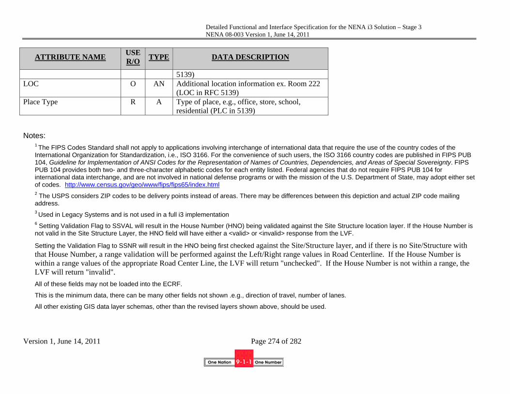
Detailed Functional and Interface Specification for the NENA i3 Solution – Stage 3 NENA 08-003 Version 1, June 14, 2011
Version 1, June 14, 2011 Page 274 of 282
ATTRIBUTE NAME USE R/O
TYPE DATA DESCRIPTION
5139) LOC O AN Additional location information ex. Room 222
(LOC in RFC 5139) Place Type R A Type of place, e.g., office, store, school,
residential (PLC in 5139)
Notes:
1 The FIPS Codes Standard shall not apply to applications involving interchange of international data that require the use of the country codes of the International Organization for Standardization, i.e., ISO 3166. For the convenience of such users, the ISO 3166 country codes are published in FIPS PUB 104, Guideline for Implementation of ANSI Codes for the Representation of Names of Countries, Dependencies, and Areas of Special Sovereignty. FIPS PUB 104 provides both two- and three-character alphabetic codes for each entity listed. Federal agencies that do not require FIPS PUB 104 for international data interchange, and are not involved in national defense programs or with the mission of the U.S. Department of State, may adopt either set of codes. http://www.census.gov/geo/www/fips/fips65/index.html 2 The USPS considers ZIP codes to be delivery points instead of areas. There may be differences between this depiction and actual ZIP code mailing address. 3 Used in Legacy Systems and is not used in a full i3 implementation 6 Setting Validation Flag to SSVAL will result in the House Number (HNO) being validated against the Site Structure location layer. If the House Number is not valid in the Site Structure Layer, the HNO field will have either a <valid> or <invalid> response from the LVF.
Setting the Validation Flag to SSNR will result in the HNO being first checked against the Site/Structure layer, and if there is no Site/Structure with that House Number, a range validation will be performed against the Left/Right range values in Road Centerline. If the House Number is within a range values of the appropriate Road Center Line, the LVF will return "unchecked". If the House Number is not within a range, the LVF will return "invalid".
All of these fields may not be loaded into the ECRF.
This is the minimum data, there can be many other fields not shown .e.g., direction of travel, number of lanes.
All other existing GIS data layer schemas, other than the revised layers shown above, should be used.

Detailed Functional and Interface Specification for the NENA i3 Solution – Stage 3 NENA 08-003 Version 1, June 14, 2011
Version 1, June 14, 2011 Page 275 of 282
ATTRIBUTE NAME USE R/O
TYPE DATA DESCRIPTION
National Subdivisions (State Boundary) Source of Data R A Agency that last updated the record – Agency
ID e.g., the domain name of the 9-1-1 Authority
Date Updated R AN Date of last update using ISO 8601 format Ex. 2010-08-30T15:52+05
Effective Date R AN Date the new layer information goes into effect using ISO 8601 format Ex. 2010-10-12T01:01+05
Unique_ID R AN Unique ID for each record
Country R A The name of a country represented by its two-letter ISO 3166-1 English country alpha-2 code elements in capital ASCII letters.
State R A The name of a state, province or equivalent, represented by the two-letter abbreviation given in ISO 3166-2. A state/province is a primary governmental division of the United States/Canada. ex. TX (A1 in RFC 5139)
County Boundary Source of Data R A Agency that last updated the record – Agency
ID e.g., the domain name of the 9-1-1 Authority
Date Updated R AN Date of last update using ISO 8601 format Ex. 2010-08-30T15:52+05
Effective Date R AN Date the new layer information goes into effect using ISO 8601 format Ex. 2010-10-12T01:01+05
Unique_ID R AN Unique ID for each record

Detailed Functional and Interface Specification for the NENA i3 Solution – Stage 3 NENA 08-003 Version 1, June 14, 2011
Version 1, June 14, 2011 Page 276 of 282
ATTRIBUTE NAME USE R/O
TYPE DATA DESCRIPTION
Country R A The name of a country represented by its two-letter ISO 3166-1 English country alpha-2 code elements in capital ASCII letters.
State R A The name of a state, province or equivalent, represented by the two-letter abbreviation given in ISO 3166-2. A state/province is a primary governmental division of the United States/Canada. ex. TX (A1 in RFC 5139)
County R A The completely spelled out name of county or county-equivalent as given in FIPS 6-4 1. A county (or its equivalent) is the primary legal division of a state, province or territory
Emergency Services Boundary Source of Data R A Agency that last updated the record – Agency
ID e.g., the domain name of the 9-1-1 Authority
Date Updated R AN Date of last update using ISO 8601 format Ex. 2010-08-30T15:52+05
Effective Date R AN Date the new layer information goes into effect using ISO 8601 format Ex. 2010-10-12T01:01+05
Unique_ID R AN Unique ID for each record
Country R A The name of a country represented by its two-letter ISO 3166-1 English country alpha-2 code elements in capital ASCII letters.
State R A The name of a state, province or equivalent, represented by the two-letter abbreviation given in ISO 3166-2. A state/province is a primary governmental division of the United

Detailed Functional and Interface Specification for the NENA i3 Solution – Stage 3 NENA 08-003 Version 1, June 14, 2011
Version 1, June 14, 2011 Page 277 of 282
ATTRIBUTE NAME USE R/O
TYPE DATA DESCRIPTION
States/Canada. ex. TX (A1 in RFC 5139) AgencyId R AN Unique domain name for the Service.
ServiceResponse R S Service supplied for this boundary. May occur more than once.
Service Response Route R URI URN/URL for Routing ex.
sip:[email protected] Service URN R URN The URN/URL for the Emergency Service or
other Well-Known Service (e.g., "urn:service:sos" for a PSAP or "urn:service:sos.ambulance" for an ambulance service. Per RFC 5031.
Service Number O AN The emergency services number appropriate for the location provided in the query.
Agency vCard URI R URI URI for the vCARD of contact information.
Display Name O A Display Name of the Service ex. Houston FD
Municipal Boundary Source of Data R A Agency that last updated the record – Agency
ID e.g., the domain name of the 9-1-1 Authority
Date Updated R AN Date of last update using ISO 8106 format Ex. 2010-08-30T15:52+05
Effective Date R AN Date the new layer information goes into effect using ISO 8106 format Ex. 2010-10-12T01:01+05
Unique_ID R AN Unique ID for each record
Country R AN The name of a country represented by its two-

Detailed Functional and Interface Specification for the NENA i3 Solution – Stage 3 NENA 08-003 Version 1, June 14, 2011
Version 1, June 14, 2011 Page 278 of 282
ATTRIBUTE NAME USE R/O
TYPE DATA DESCRIPTION
letter ISO 3166-1 English country alpha-2 code elements in capital ASCII letters.
State R A The name of a state, province or equivalent, represented by the two-letter abbreviation given in ISO 3166-2. A state/province is a primary governmental division of the United States/Canada. Example: TX (A1 in RFC 5139)
County R A The completely spelled out name of county or county-equivalent where the road is located, as given in FIPS 6-4 1. A county (or its equivalent) is the primary legal division of a state, province or territory (A2 in RFC 5139)
Municipality R A The name of the incorporated municipality or other general-purpose local governmental unit (if any)
Unincorporated Community Boundary Source of Data R A Agency that last updated the record – Agency
ID e.g., the domain name of the 9-1-1 Authority
Date Updated R AN Date of last update using ISO 8106 format Ex. 2010-08-30T15:52+05
Effective Date R AN Date the new layer information goes into effect using ISO 8106 format Ex. 2010-10-12T01:01+05
Unique_ID R AN Unique ID for each record
Country R AN The name of a country represented by its two-letter ISO 3166-1 English country alpha-2 code elements in capital ASCII letters.

Detailed Functional and Interface Specification for the NENA i3 Solution – Stage 3 NENA 08-003 Version 1, June 14, 2011
Version 1, June 14, 2011 Page 279 of 282
ATTRIBUTE NAME USE R/O
TYPE DATA DESCRIPTION
State R A The name of a state, province or equivalent, represented by the two-letter abbreviation given in ISO 3166-2. A state/province is a primary governmental division of the United States/Canada. Example: TX (A1 in RFC 5139)
County R A The completely spelled out name of county or county-equivalent where the road is located, as given in FIPS 6-4 1. A county (or its equivalent) is the primary legal division of a state, province or territory (A2 in RFC 5139)
Municipality R A The name of the incorporated municipality or other general-purpose local governmental unit (if any)
Unincorporated Community R A The name of an unincorporated community, either within an incorporated municipality or in an unincorporated portion of a county, where the address is located. The area must have a definite boundary (A4 in RFC 5139).
Neighborhood Boundary Source of Data R A Agency that last updated the record – Agency
ID e.g., the domain name of the 9-1-1 Authority
Date Updated R AN Date of last update using ISO 8106 format Ex. 2010-08-30T15:52+05
Effective Date R AN Date the new layer information goes into effect using ISO 8106 format Ex. 2010-10-12T01:01+05
Unique_ID R AN Unique ID for each record

Detailed Functional and Interface Specification for the NENA i3 Solution – Stage 3 NENA 08-003 Version 1, June 14, 2011
Version 1, June 14, 2011 Page 280 of 282
ATTRIBUTE NAME USE R/O
TYPE DATA DESCRIPTION
Country R AN The name of a country represented by its two-letter ISO 3166-1 English country alpha-2 code elements in capital ASCII letters.
State R A The name of a state, province or equivalent, represented by the two-letter abbreviation given in ISO 3166-2. A state/province is a primary governmental division of the United States/Canada.Example: TX (A1 in RFC 5139)
County R A The completely spelled out name of county or county-equivalent where the road is located, as given in FIPS 6-4 1. A county (or its equivalent) is the primary legal division of a state, province or territory (A2 in RFC 5139)
Municipality O A The name of the incorporated municipality or other general-purpose local governmental unit (if any)
Unincorporated Community O A The name of an unincorporated community, either within an incorporated municipality or in an unincorporated portion of a county, where the address is located. The area must have a definite boundary (A4 in RFC 5139).
Neighborhood Community R A Neighborhood or other informal designation for a part of a city (A5 in RFC 5139).