understanding overcurrent circuit protectors - ieee
TRANSCRIPT
Understanding Overcurrent Circuit
Protectors
Carl E.LindquistVP New Product DevelopmentSan-O Industrial Corporation
SOC®
Introduction to Overcurrent Circuit Protectors
Overcurrent (Series)vs.
Overvoltage (Shunt) Type Protectors
We will be limiting our discussion to Overcurrent (Series) Type Protectors
Current Cutoffsvs.
Current Limiters
• Current Cutoff Protectors reduce current in the circuit to zero.
• Current Limiting Protectors reduce current in the circuit to some “acceptable” safe level.
Types of Overcurrent Protectors
• Current CutoffsFusesCircuit Breakers
• Current LimitersPolymer Positive Temperature Coefficient (PPTC’s)Ceramic Positive Temperature Coefficient (CPTC’s)Line Feed Resistors (LFR’s)Electronic Current Limiters (ECL’s)
Current Cutoffs• Circuit Breakers
Fully resettableThermal vs. Magnetic vs. Thermal-Magnetic Interrupting current at rated voltage is not the same as for a fuse. Never intended for use as a switch unless specifically noted
• Fuses “Weak Links” and are not resettable.Element vs. Thin/Thick FilmProvide the highest current and voltage ratings in smallest space
Thermal Circuit Breaker
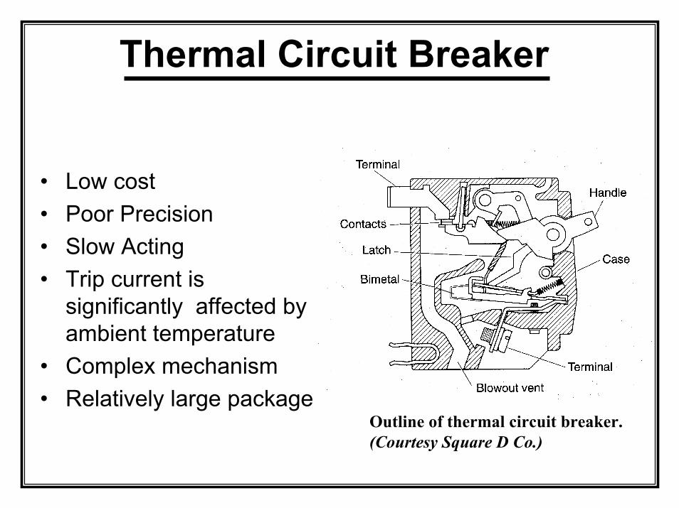
• Low cost• Poor Precision• Slow Acting• Trip current is
significantly affected by ambient temperature
• Complex mechanism• Relatively large package
Outline of thermal circuit breaker. (Courtesy Square D Co.)
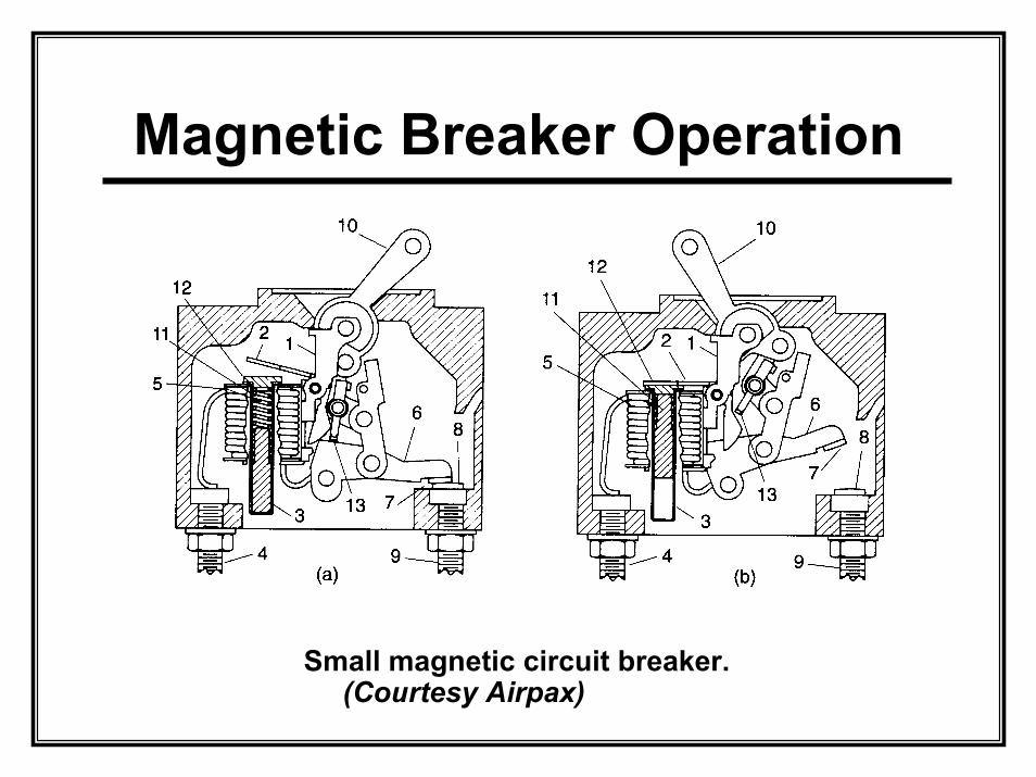
Magnetic Breaker Operation
Small magnetic circuit breaker. (Courtesy Airpax)
Magnetic Breaker Detail
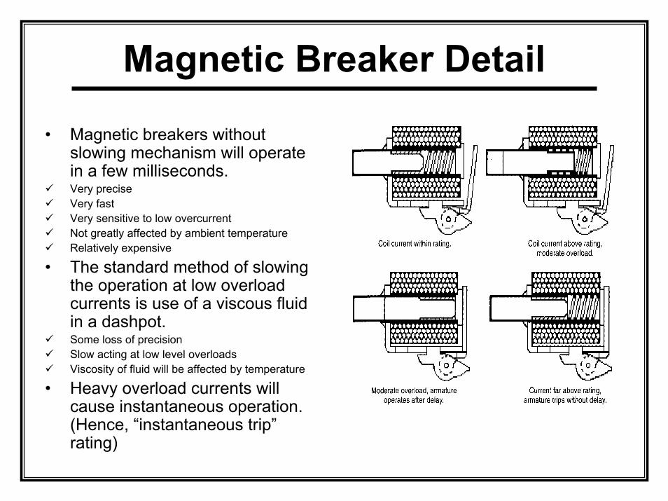
• Magnetic breakers without slowing mechanism will operate in a few milliseconds.Very preciseVery fastVery sensitive to low overcurrentNot greatly affected by ambient temperatureRelatively expensive
• The standard method of slowing the operation at low overload currents is use of a viscous fluid in a dashpot.Some loss of precisionSlow acting at low level overloadsViscosity of fluid will be affected by temperature
• Heavy overload currents will cause instantaneous operation. (Hence, “instantaneous trip” rating)
Thermal-Magnetic Breaker
• Thermal-Magnetic breakers are hybrids of the two previously discussed devices.
• These breakers act as a thermal breaker for low level overloads and act as magnetic breaker for instantaneous trip at high level current faults
• Most standard house service entrance breakers are thermal-magnetic.
Current Limiters• PTC’s
Resettable Passive DevicesBoth Polymer and Ceramic are somewhat ambient temperature sensitive for tripping point.Some “drift” in nominal limiting after first reset
• LFR’sResettable Passive DevicesUsually limited to telecommunicationsThese devices can completely open the circuit if fault is heavy enough or long term low level overload.
• ECL’sResettable Active DevicesSpeed of operation can be adjustedCan be made very preciseSome limitations on maximum voltage levels
Protector Selection• Agency Approvals• Physical Area Available• Required Nominal Continuous Current Level• Clearing Time• Surge Withstand Requirements (Inrush, Lightning, etc.)• Maximum Interrupting Current at Rated Voltage• Open Circuit Voltage (AC, DC or Both)• Single Event vs. Resettable
Ease of ReplacementEffect of Nuisance OperationLong Term Availability of Replacements
• Environmental ParametersTemperature Range (Room Temperature vs. Microclimate)HumidityMechanical shockHazardous Environments (Corrosive, Explosive, etc.)
• High Reliability ApplicationsMedicalMilitaryAerospaceTelecommunications
Agency Approvals
• North AmericaUL / CSA
Listing / Certified vs. Recognition
• European (IEC 60127)SEMKODEMKOBSI
• Japanese<PS>E JET
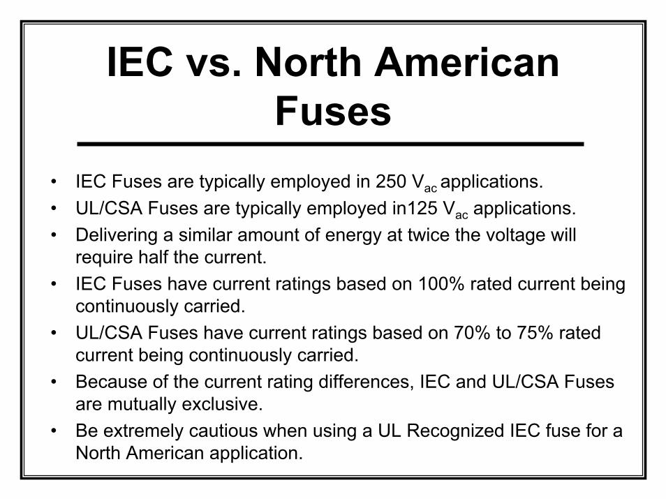
IEC vs. North American Fuses
• IEC Fuses are typically employed in 250 Vac applications.• UL/CSA Fuses are typically employed in125 Vac applications.• Delivering a similar amount of energy at twice the voltage will
require half the current.• IEC Fuses have current ratings based on 100% rated current being
continuously carried.• UL/CSA Fuses have current ratings based on 70% to 75% rated
current being continuously carried.• Because of the current rating differences, IEC and UL/CSA Fuses
are mutually exclusive.• Be extremely cautious when using a UL Recognized IEC fuse for a
North American application.
Component Qualification
• Industry Standards (Non-Safety)EIA/ECA 962 “Low Voltage Supplemental Fuse Qualification Specification”EIA/ECA 932 “Surge Withstand Telecommunications Fuse Qualification Specification”
• Purchasing Standards (Non-Safety)Each user may generate minimum operational parameters for products to be purchased. Even if these are simply replicating tests and limits taken from the suppliers’ data sheets, they become binding for future orders.
Details of Fuse Design
• Now we can begin to discuss construction, parameters, and operation of element Type fuses.
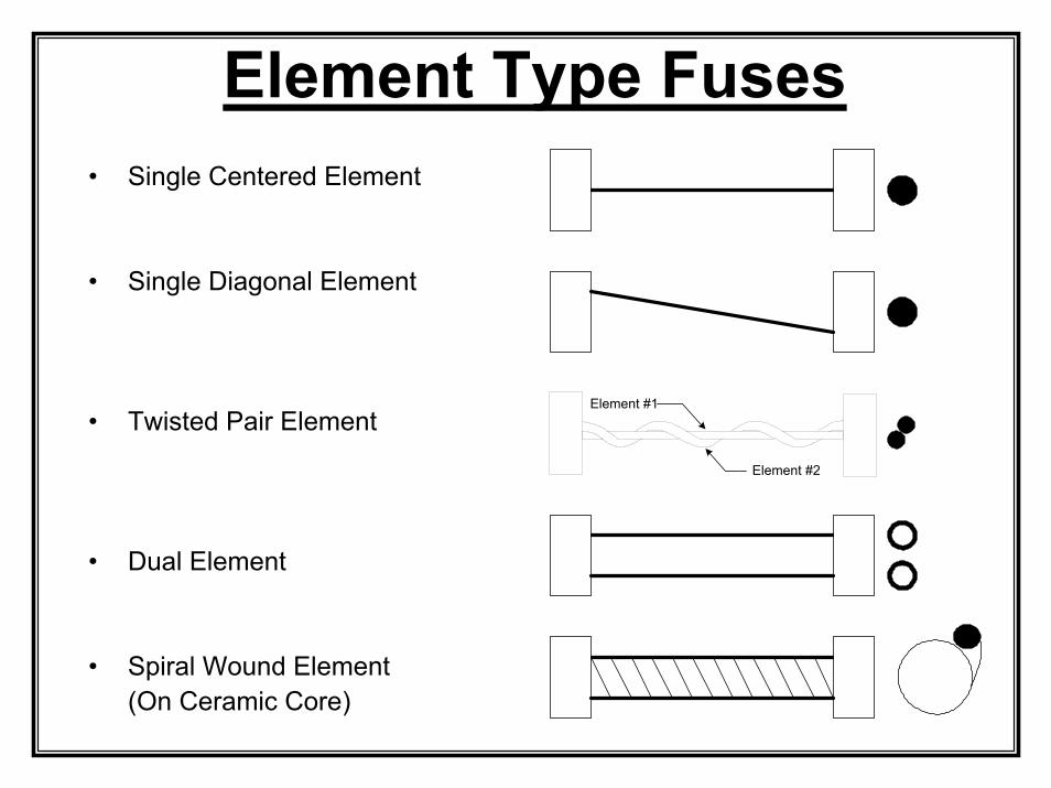
Element Type Fuses• Single Centered Element
• Single Diagonal Element
• Twisted Pair Element
• Dual Element
• Spiral Wound Element (On Ceramic Core)
Element #1
Element #2
Materials• Bodies can be glass, ceramic or plastic• End caps are typically tin plated copper or brass• Fuse clips are not high reliability connections
Base materials can be brass, phosphor bronze or beryllium copperBrass must have a nickel or equivalent barrier between base metal and final platingPlating of fuse should match plating of clip
• Element materials vary greatly – Pure silver to stainless steel• Extremely small amounts of an alloy metal can significantly
change element operating characteristics.• Elements are typically bonded to the end caps by soldering or
welding.• Leads, if provided, should be tin plated copper and of
appropriate cross section to easily carry fault current.• Fillers are often employed for higher current and/or voltage
devicesAdded variables
Fuse Package• Fuse body / end cap assemblies are normally
“vented” to accommodate for the expanding solid element as it heats and vaporizes with heavy fault currents. Without such venting, pressure related to the vaporization can result in rupture of the fuse enclosure.
• For applications where the fuse will be encapsulated or otherwise sealed, it is important to discuss the application with the fuse company engineers.
• Always insure that leaded fuses have adequate diameter copper leads to withstand the worst case fault condition rating.
Element Loading Properties• At heavy short circuit currents and full rated voltage, the element
material vaporizes – goes from a solid to a gas – during the arcing phase and is plated out on the relatively cool inside surface of the fuse body. If there is excessive volume of metalin the element, the plated out metal can potentially bridge the fuse, providing a new current path.
• Elements can be subjected to mechanical fatigue with repeated surges or off/on cycling.
• The unique metal alloys employed for elements are extremely difficult to assess directly due to the very small quantities ofdifferent material needed to significantly change the element characteristics.
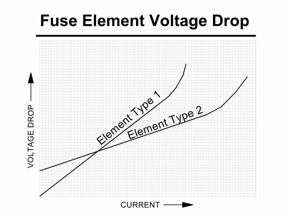
• Every unique metal alloy will have a specific slope for voltage drop (hot resistance) vs. current.
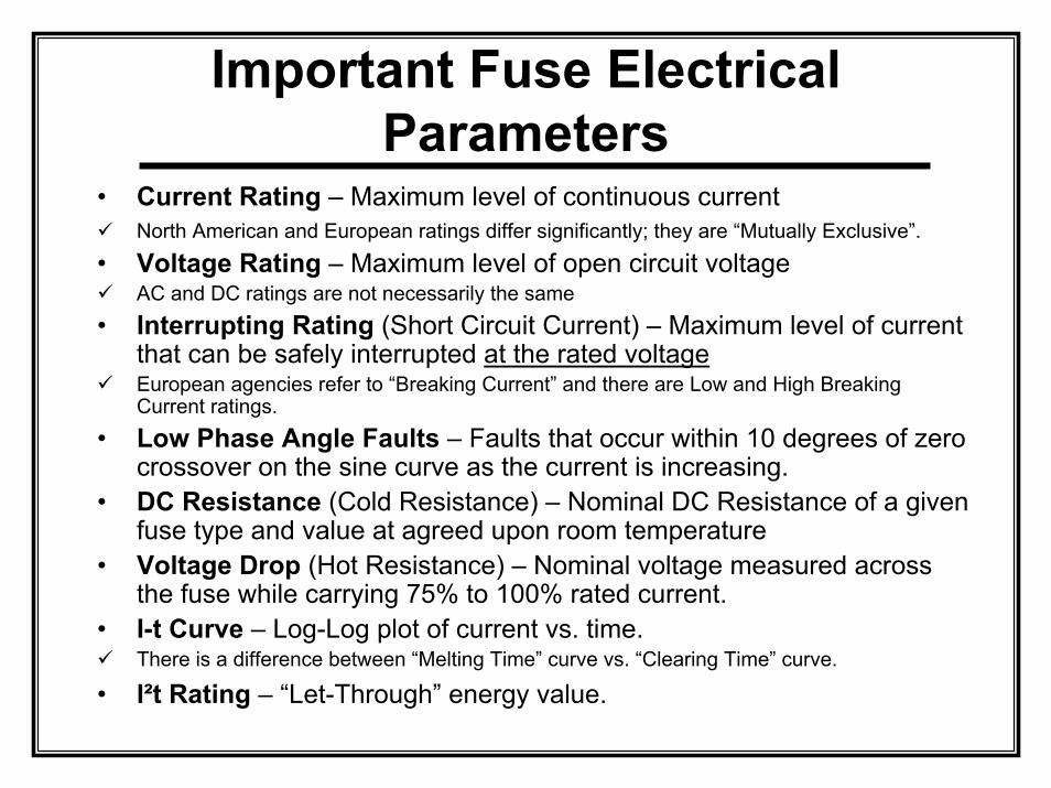
Important Fuse Electrical Parameters
• Current Rating – Maximum level of continuous currentNorth American and European ratings differ significantly; they are “Mutually Exclusive”.
• Voltage Rating – Maximum level of open circuit voltageAC and DC ratings are not necessarily the same
• Interrupting Rating (Short Circuit Current) – Maximum level of current that can be safely interrupted at the rated voltageEuropean agencies refer to “Breaking Current” and there are Low and High Breaking Current ratings.
• Low Phase Angle Faults – Faults that occur within 10 degrees of zero crossover on the sine curve as the current is increasing.
• DC Resistance (Cold Resistance) – Nominal DC Resistance of a given fuse type and value at agreed upon room temperature
• Voltage Drop (Hot Resistance) – Nominal voltage measured across the fuse while carrying 75% to 100% rated current.
• I-t Curve – Log-Log plot of current vs. time.There is a difference between “Melting Time” curve vs. “Clearing Time” curve.
• I²t Rating – “Let-Through” energy value.
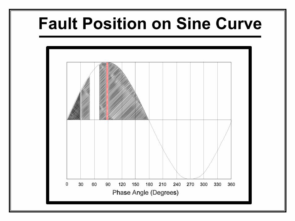
Fault Position on Sine Curve
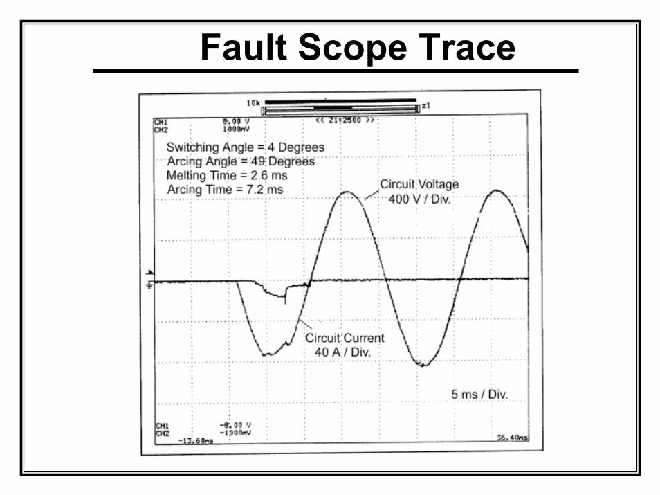
Fault Scope Trace
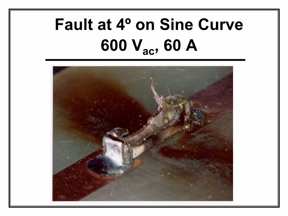
Fault at 4º on Sine Curve 600 Vac, 60 A
Important Fuse Mechanical Parameters
• Fuse physical size is important when selecting “equivalents” forsecond – or alternate – sourcing.
• Soldered connections are preferred over mechanical connections for reliability purposes.
• Fuse lead diameters vary considerably for “equivalent” products.• All mechanical contacts must be studied carefully for plating
compatibility.• Soldered connections are never intended to provide mechanical
support.• Reflow solder process is typically required for surface mount
fuses. Wave solder process is normally never recommended for surface mount fuses.
• Fuses are not normally sealed. If a sealed device is required, speak with the manufacturer’s engineering staff.
Element Selection
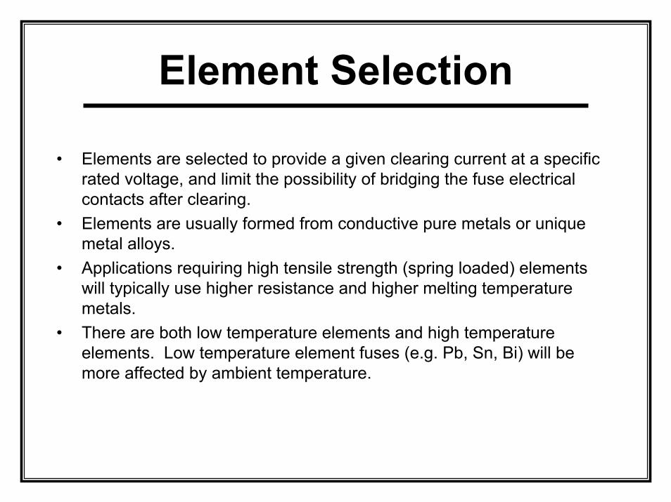
• Elements are selected to provide a given clearing current at a specific rated voltage, and limit the possibility of bridging the fuse electrical contacts after clearing.
• Elements are usually formed from conductive pure metals or unique metal alloys.
• Applications requiring high tensile strength (spring loaded) elements will typically use higher resistance and higher melting temperature metals.
• There are both low temperature elements and high temperature elements. Low temperature element fuses (e.g. Pb, Sn, Bi) will be more affected by ambient temperature.
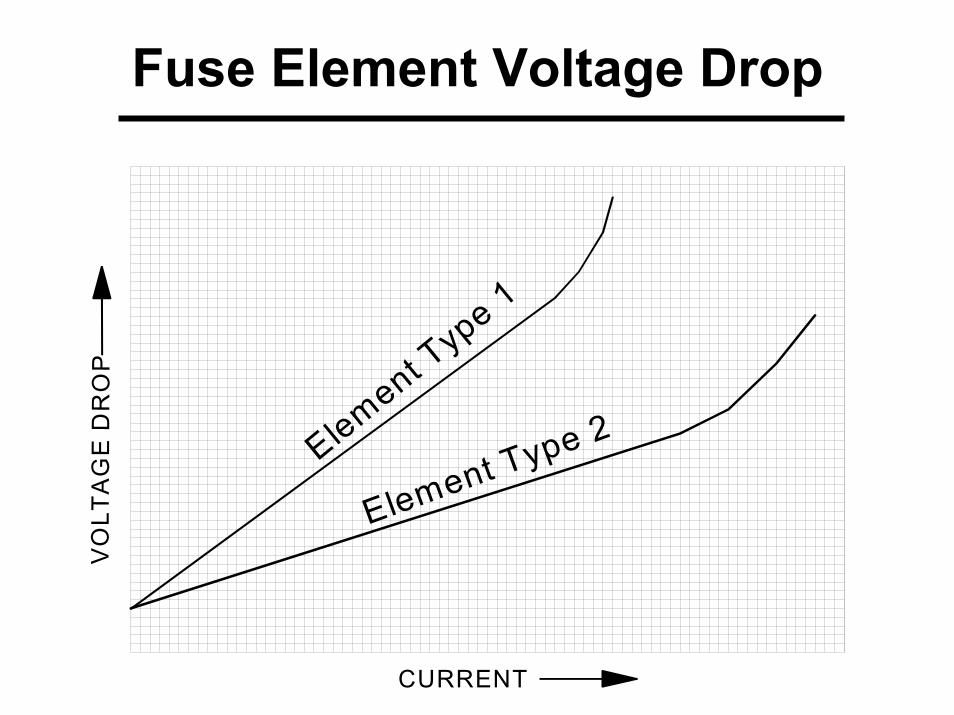
Fuse Element Voltage Drop
CURRENT
VO
LTA
GE
DR
OP
Element Type 1
Element Type 2
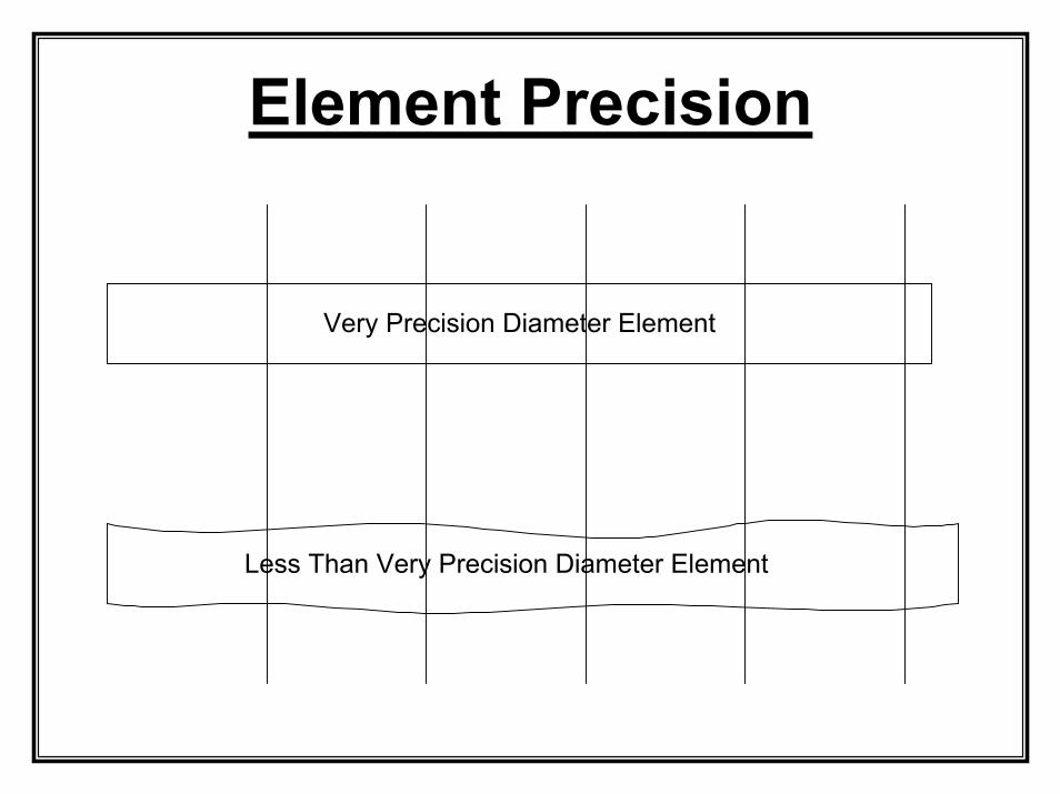
Element Precision
Very Precision Diameter Element
Less Than Very Precision Diameter Element
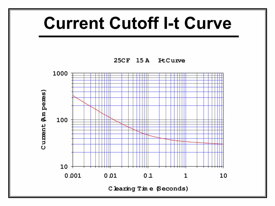
Current Cutoff I-t Curve
25CF 15 A I-t Curve
Clearing Tim e (Seconds)
0.001 0.01 0.1 1 10
Current (Amperes)
10
100
1000
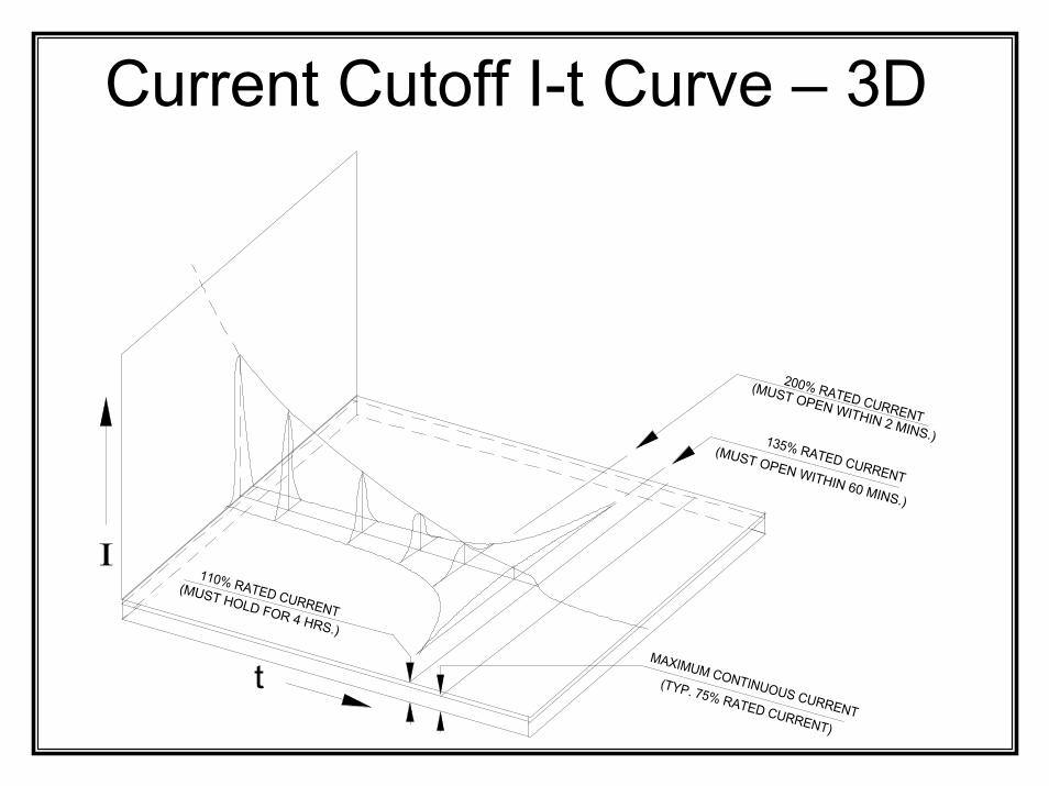
135% RATED CURRENT
110% RATED CURRENT
(MUST OPEN WITHIN 60 MINS.)
(MUST HOLD FOR 4 HRS.)
MAXIMUM CONTINUOUS CURRENT
(TYP. 75% RATED CURRENT)
(MUST OPEN WITHIN 2 MINS.)
t
I
200% RATED CURRENT
Current Cutoff I-t Curve – 3D
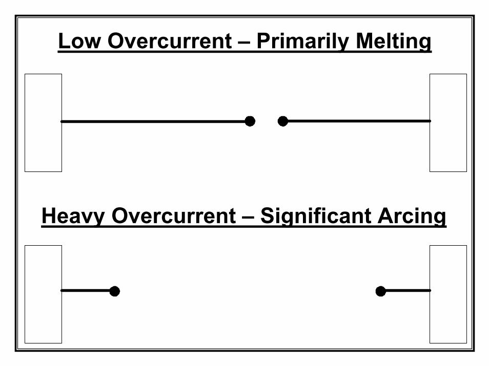
Low Overcurrent – Primarily Melting
Heavy Overcurrent – Significant Arcing

Current Cutoff I-t Curve
25CF 15 A I-t Curve
Clearing Tim e (Seconds)
0.001 0.01 0.1 1 10
Current (Amperes)
10
100
1000
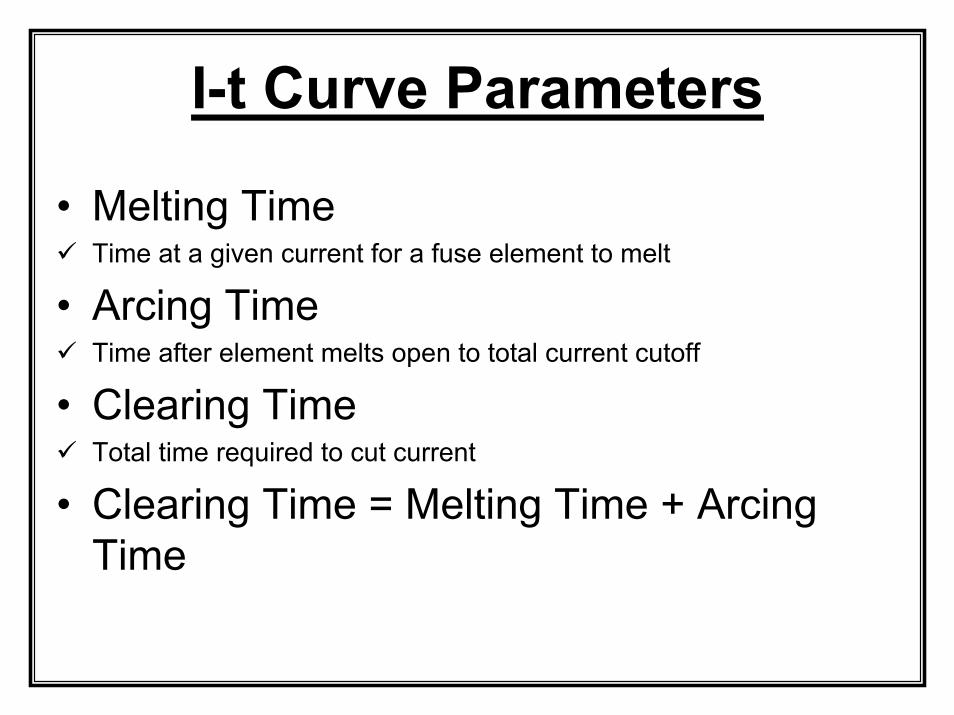
I-t Curve Parameters
• Melting TimeTime at a given current for a fuse element to melt
• Arcing TimeTime after element melts open to total current cutoff
• Clearing TimeTotal time required to cut current
• Clearing Time = Melting Time + Arcing Time
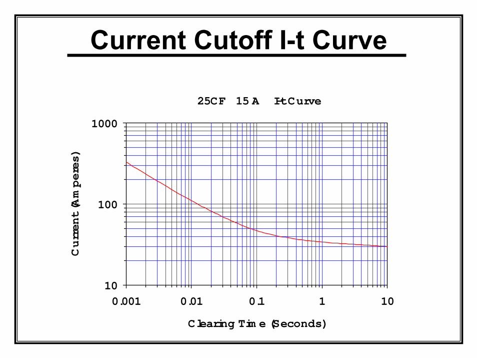
Current Cutoff I-t Curve
25CF 15 A I-t Curve
Clearing Tim e (Seconds)
0.001 0.01 0.1 1 10
Current (Amperes)
10
100
1000
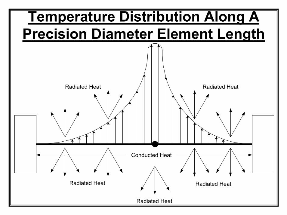
Temperature Distribution Along A Precision Diameter Element Length
Conducted Heat
Radiated Heat Radiated Heat
Radiated Heat
Radiated Heat Radiated Heat
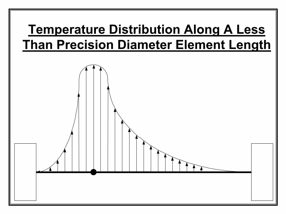
Temperature Distribution Along A Less Than Precision Diameter Element Length
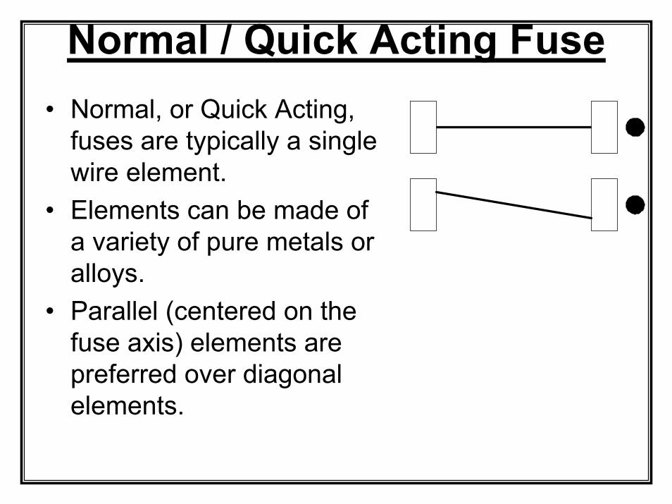
Normal / Quick Acting Fuse• Normal, or Quick Acting,
fuses are typically a single wire element.
• Elements can be made of a variety of pure metals or alloys.
• Parallel (centered on the fuse axis) elements are preferred over diagonal elements.
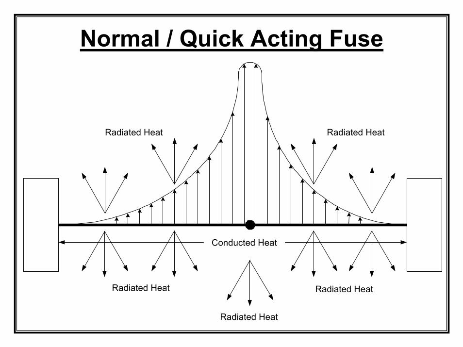
Normal / Quick Acting Fuse
Conducted Heat
Radiated Heat Radiated Heat
Radiated Heat
Radiated Heat Radiated Heat
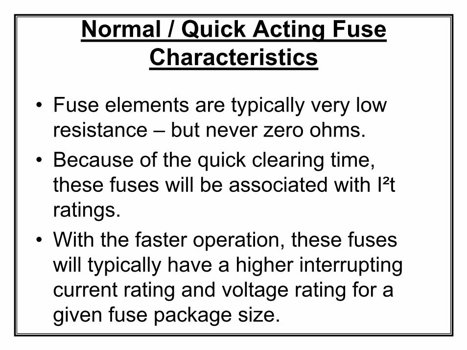
Normal / Quick Acting Fuse Characteristics
• Fuse elements are typically very low resistance – but never zero ohms.
• Because of the quick clearing time, these fuses will be associated with I²t ratings.
• With the faster operation, these fuses will typically have a higher interrupting current rating and voltage rating for a given fuse package size.
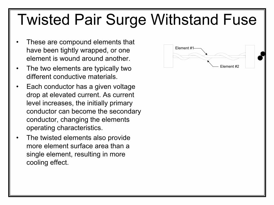
Twisted Pair Surge Withstand Fuse• These are compound elements that
have been tightly wrapped, or one element is wound around another.
• The two elements are typically two different conductive materials.
• Each conductor has a given voltage drop at elevated current. As current level increases, the initially primary conductor can become the secondary conductor, changing the elements operating characteristics.
• The twisted elements also provide more element surface area than a single element, resulting in more cooling effect.
Element #1
Element #2
Fuse Element Voltage Drop
CURRENT
VOLTAGE DROP El ement T
ype 1El ement Type 2
CURRENT
VO
LTA
GE
DR
OP
Element Typ
e 1
Element Type 2
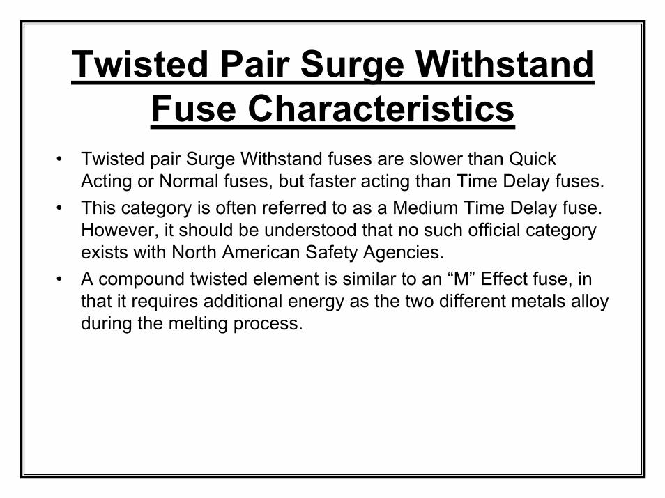
Twisted Pair Surge Withstand Fuse Characteristics
• Twisted pair Surge Withstand fuses are slower than Quick Acting or Normal fuses, but faster acting than Time Delay fuses.
• This category is often referred to as a Medium Time Delay fuse. However, it should be understood that no such official category exists with North American Safety Agencies.
• A compound twisted element is similar to an “M” Effect fuse, in that it requires additional energy as the two different metals alloy during the melting process.
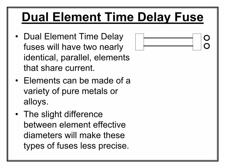
• Dual Element Time Delay fuses will have two nearly identical, parallel, elements that share current.
• Elements can be made of a variety of pure metals or alloys.
• The slight difference between element effective diameters will make these types of fuses less precise.
Dual Element Time Delay Fuse
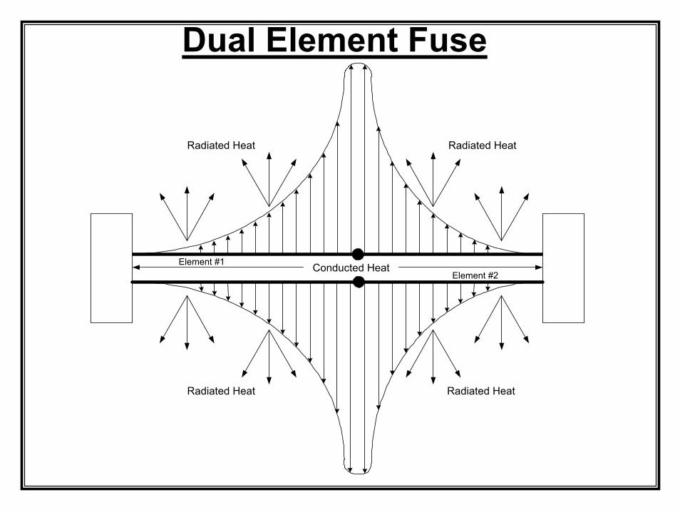
Dual Element Fuse
Conducted Heat
Radiated Heat Radiated Heat
Radiated Heat Radiated Heat
Element #1Element #2
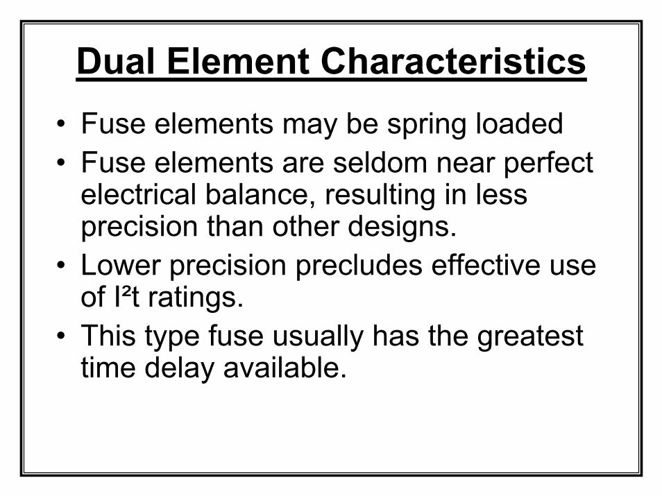
Dual Element Characteristics• Fuse elements may be spring loaded• Fuse elements are seldom near perfect
electrical balance, resulting in less precision than other designs.
• Lower precision precludes effective use of I²t ratings.
• This type fuse usually has the greatest time delay available.
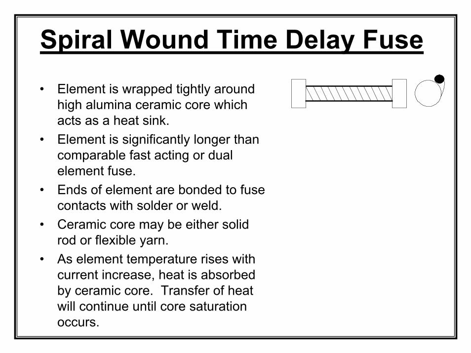
Spiral Wound Time Delay Fuse• Element is wrapped tightly around
high alumina ceramic core which acts as a heat sink.
• Element is significantly longer than comparable fast acting or dual element fuse.
• Ends of element are bonded to fuse contacts with solder or weld.
• Ceramic core may be either solid rod or flexible yarn.
• As element temperature rises with current increase, heat is absorbed by ceramic core. Transfer of heat will continue until core saturation occurs.
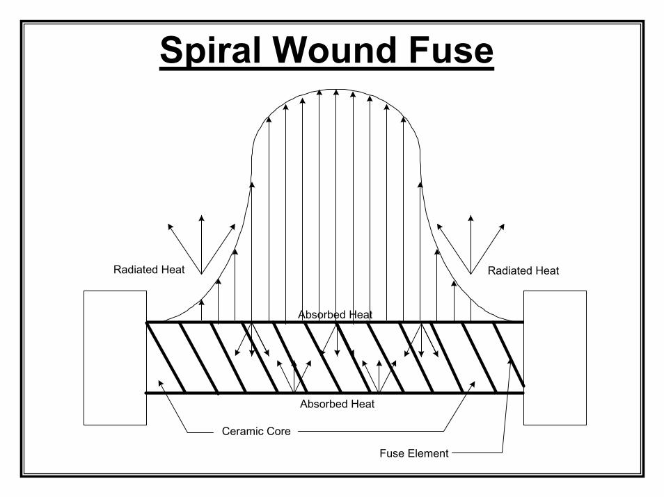
Spiral Wound Fuse
Radiated Heat Radiated Heat
Absorbed Heat
Absorbed Heat
Ceramic Core
Fuse Element
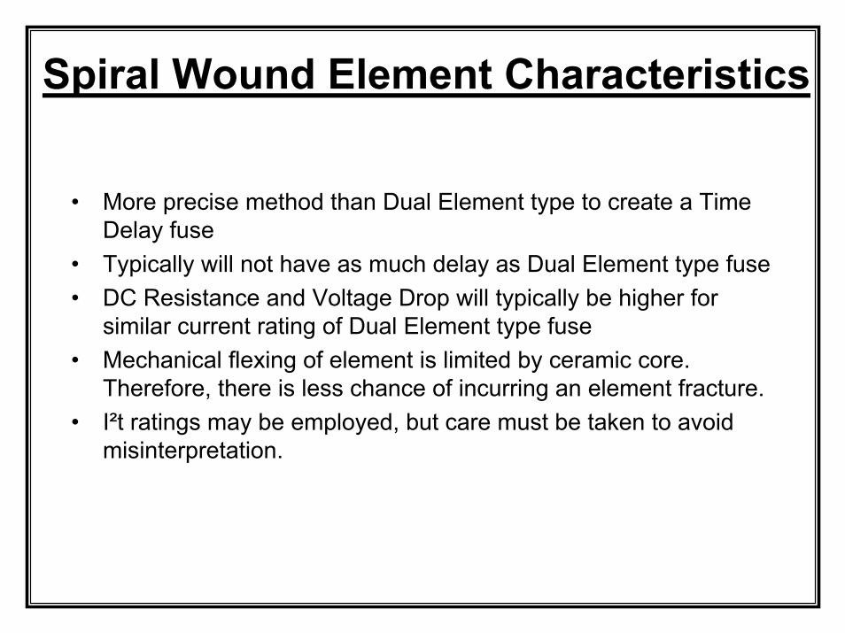
Spiral Wound Element Characteristics
• More precise method than Dual Element type to create a Time Delay fuse
• Typically will not have as much delay as Dual Element type fuse• DC Resistance and Voltage Drop will typically be higher for
similar current rating of Dual Element type fuse• Mechanical flexing of element is limited by ceramic core.
Therefore, there is less chance of incurring an element fracture.• I²t ratings may be employed, but care must be taken to avoid
misinterpretation.
Low Overload Current Fuse Operation
• Low level current overloads are very dangerous because of the large amount of heat generated over extended time periods.
• Typical source for such overload condition is a “sneak current” caused by gradual breakdown of insulation.
• Any arcing during the fuse operation will be a function of the open circuit voltage level – arcing time is usually minimal.
• Surface mounted fuses may reflow the solder, leaving them free to move on the circuit board.
• Mechanical contacts suffer during low level overloads due to high temperature annealing of spring clips and chemical / metallurgical changes.
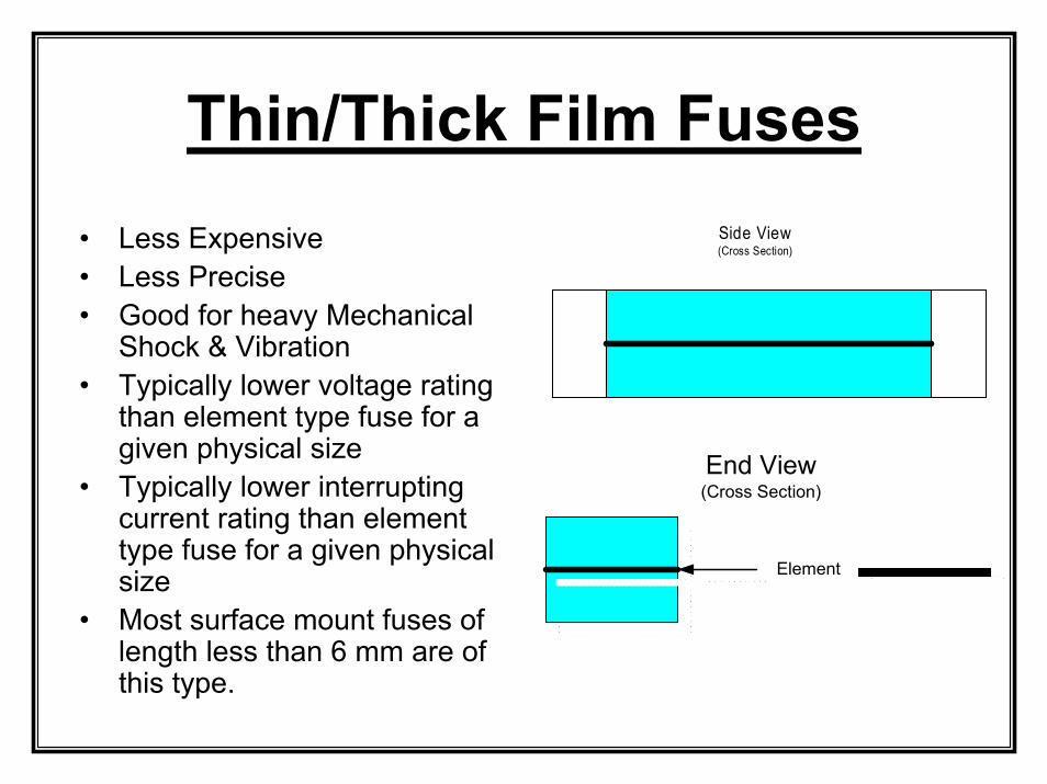
Thin/Thick Film Fuses
���������������������������������������������������������������������������������������������������������������������
���������������������������������������������������������������������������������������������������������������������
���������������������������������������������������������������������������������������������������������������������
������������������������������������������������������������������������������������������������������������������������������������������������������������������������������������������������������������������������������������������
���������������������������������������������������������������������������������������������������������������������
���������������������������������������������������������������������������������������������������������������������
���������������������������������������������������������������������������������������������������������������������
• Less Expensive• Less Precise• Good for heavy Mechanical
Shock & Vibration• Typically lower voltage rating
than element type fuse for a given physical size
• Typically lower interrupting current rating than element type fuse for a given physical size
• Most surface mount fuses of length less than 6 mm are of this type.
������������������������������������������������
������������������������������������������������
������������������������������������������������
������������������������������������������������
������������������������������������������������
������������������������������������������������
������������������������������������������������
������������������������������������������������
��������������������������������������������������
��
��
��
����������
����������
����������
����������������������������������������������������������
�����������������������������������������������
�����������������������������������������������
�����������������������������������������������
�����������������������������������������������
�����������������������������������������������
�����������������������������������������������
�����������������������������������������������
�����������������������������������������������
��������������������������������������������������
�������������������������������������������������� ElementElement��������������������������������
�������
������������������������������������������������������������������������������������������������� �����������������������������������������������������������������������������������������������������
End View(Cross Section)
End View(Cross Section)
Side View(Cross Section)
Side View(Cross Section)
Manufacturing Techniques
• Stocking and WarehousingUsually safe to stock in unheated facilitiesShelf Life is typically 1 year – Longer Shelf Life can be confirmed with some measurements
• Assembly AlternativesWave Solder vs. Reflow SolderUse of Fuse Clips and Holders – AVOID IF POSSIBLE
• Production VariablesHand assembly vs. Automatic assembly
• Final TestingTest results of component vs. Test results of component in circuit
• Product ShippingWith or Without Fuse
Finished Product
• Second Sourcing of ProtectorsNot all “equivalent” fuses are the sameDemand Electrical and Mechanical Data Sheets.Surface Mount fuses are generally sold by length and width (e.g. 1206). Height may be just as important!Try to use component Data Sheets to generate a User Specification
• Customer SupportYour customers expect support; You should expect support from your vendors
• Maintenance Manuals Include specifics in any equipment maintenance manuals to permitreplacement with tested equivalent fuses

Thank You