understanding storage media and file system
TRANSCRIPT

Page 1 of 39
Understanding Storage Media and File System
MODULE 4

Page 2 of 39
Contents 4.1 LEARNING OBJECTIVES ...................................................................................................................... 4
4.2 Hard Disk Drive .................................................................................................................................. 4
4.2.1 Working of HDD .......................................................................................................................... 4
4.2.2 Interface ..................................................................................................................................... 6
4.3 Details of Internal structure of HDD .................................................................................................. 8
4.3.1 Low-Level Formatting ................................................................................................................. 8
4.3.2 High-level formatting ............................................................................................................... 10
4.3.3 Glossary of some important terms ........................................................................................... 11
4.3.3.1 Slack space ......................................................................................................................... 11
4.3.3.2 Lost Cluster ........................................................................................................................ 11
4.3.3.3 Bad Sector.......................................................................................................................... 12
4.3.3.4 Master Boot Record .......................................................................................................... 12
4.4 The Booting Process ........................................................................................................................ 12
4.4.1 Linux Boot Process .................................................................................................................... 15
4.4.2 Mac OS Boot Sequence ............................................................................................................ 18
4.4.3 Boot Sequence in Windows 7 ................................................................................................... 20
4.5 File system ....................................................................................................................................... 22
4.5.1 Some Common File systems ..................................................................................................... 24
4.5.1.1 FAT ..................................................................................................................................... 24
4.5.1.2 NTFS ................................................................................................................................... 24
4.5.1.3 ext2, ext3 and ext4 ............................................................................................................ 25
4.5.1.4 XFS ..................................................................................................................................... 25
4.5.1.5 ZFS ..................................................................................................................................... 25
4.5.1.6 BTRFS ................................................................................................................................. 25
4.5.2 Types of file systems ................................................................................................................ 26
4.5.2.1 Disk file systems ................................................................................................................ 26
4.5.2.2 Flash file systems ............................................................................................................... 27
4.5.2.3 Tape file systems ............................................................................................................... 27
4.5.2.4 Database file systems ........................................................................................................ 28
4.5.2.5 Transactional file systems ................................................................................................. 28
4.5.2.6 Network file systems ......................................................................................................... 29
4.5.2.7 Shared disk file systems..................................................................................................... 29
4.5.2.8 Special file systems ............................................................................................................ 30
Page 3 of 39
4.5.2.9 Minimal file system / audio-cassette storage ................................................................... 30
4.5.2.10 Flat file systems ............................................................................................................... 30
4.6 SUMMARY ....................................................................................................................................... 31
4.7 Check your progress ........................................................................................................................ 32
4.8 Answers to Check your progress ..................................................................................................... 33
4.9 FURTHUR READING ......................................................................................................................... 34
Carrier, B. File System Forensic Analysis. .............................................................................................. 34
4.10 MODEL QUESTIONS ....................................................................................................................... 35
References, Article Source & Contributors ........................................................................................... 35

Page 4 of 39
Understanding Storage Media and File System
4.1 LEARNING OBJECTIVES
After going through this unit, you will be able to:
• Know about Hard Disk Drive(HDD)
• Explain the working of HDD
• Identify various types of interfaces
• Recognise internal structure of HDD
• List different type of formatting
• Explain booting process
• Discover the boot sequence of Windows, Mac and Linux OS
• Explain different type of file systems\
4.2 HARD DISK DRIVE
A hard disk drive (HDD)1, hard disk, hard drive or fixed disk is a data storage device used for
storing and retrieving digital information using one or more rigid ("hard") rapidly rotating disks
(platters) coated with magnetic material. The platters are paired with magnetic heads arranged
on a moving actuator arm, which read and write data to the platter surfaces. Data is accessed in
a random-access manner, meaning that individual blocks of data can be stored or retrieved in
any order rather than sequentially. HDDs retain stored data even when powered off.
The primary characteristics of an HDD are its capacity and performance. Capacity is specified
in unit prefixes corresponding to powers of 1000: a 1-terabyte (TB) drive has a capacity of
1,000 gigabytes (GB; where 1 gigabyte = 1 billion bytes). Typically, some of an HDD's capacity
is unavailable to the user because it is used by the file system and the computer operating
system, and possibly inbuilt redundancy for error correction and recovery. Performance is
specified by the time required to move the heads to a track or cylinder (average access time)
plus the time it takes for the desired sector to move under the head (average latency, which is a
function of the physical rotational speed in revolutions per minute), and finally the speed at
which the data is transmitted (data rate).
4.2.1 Working of HDD
An HDD records data by magnetizing a thin film of ferromagnetic material on a disk. Sequential
changes in the direction of magnetization represent binary data bits. The data is read from the
disk by detecting the transitions in magnetization. User data is encoded using an encoding
scheme, such as run-length limited encoding, which determines how the data is represented by
the magnetic transitions.
A typical HDD design consists of a spindle that holds flat circular disks, also called platters,
which hold the recorded data. The platters are made from a non-magnetic material, usually
1 https://en.wikipedia.org/wiki/Hard_disk_drive

Page 5 of 39
aluminum alloy, glass, or ceramic, and are coated with a shallow layer of magnetic material
typically 10–20 nm in depth, with an outer layer of carbon for protection.
Figure 1: Hard disk drive of a computer2
The platters in contemporary HDDs are spun at speeds varying from 4,200 rpm in energy-
efficient portable devices, to 15,000 rpm for high-performance servers. Information is written
to and read from a platter as it rotates past devices called read-and-write heads that are
positioned to operate very close to the magnetic surface, with their flying height often in the
range of tens of nanometers. The read-and-write head is used to detect and modify the
magnetization of the material passing immediately under it.
In modern drives there is one head for each magnetic platter surface on the spindle, mounted
on a common arm. An actuator arm (or access arm) moves the heads on an arc (roughly radially)
across the platters as they spin, allowing each head to access almost the entire surface of the
platter as it spins. The arm is moved using a voice coil actuator or in some older designs a
stepper motor. Early hard disk drives wrote data at some constant bits per second, resulting in
all tracks having the same amount of data per track but modern drives (since the 1990s) use
zone bit recording—increasing the write speed from inner to outer zone and thereby storing
more data per track in the outer zones.
The two most common form factors for modern HDDs are 3.5-inch, for desktop computers, and
2.5-inch, primarily for laptops. HDDs are connected to systems by standard interface cables
2 https://en.wikipedia.org/wiki/Hard_disk_drive#/media/File:Hard_drive-en.svg
Page 6 of 39
such as PATA (Parallel ATA), SATA (Serial ATA), USB or SAS (Serial attached SCSI) cables.
The details of various types of HDD interfaces are discussed in the next section.
4.2.2 Interface
HDDs are accessed over one of a number of bus types, parallel ATA (PATA, also called IDE
or EIDE; described before the introduction of SATA as ATA), Serial
ATA (SATA), SCSI, Serial Attached SCSI (SAS), and Fibre Channel. Bridge circuitry is
sometimes used to connect HDDs to buses with which they cannot communicate natively, such
as IEEE 1394, USB and SCSI.
Modern interfaces connect an HDD to a host bus interface adapter with one data/control cable.
Each drive also has an additional power cable, usually direct to the power supply unit. Now let
us discuss various types of HDD interfaces in detail.
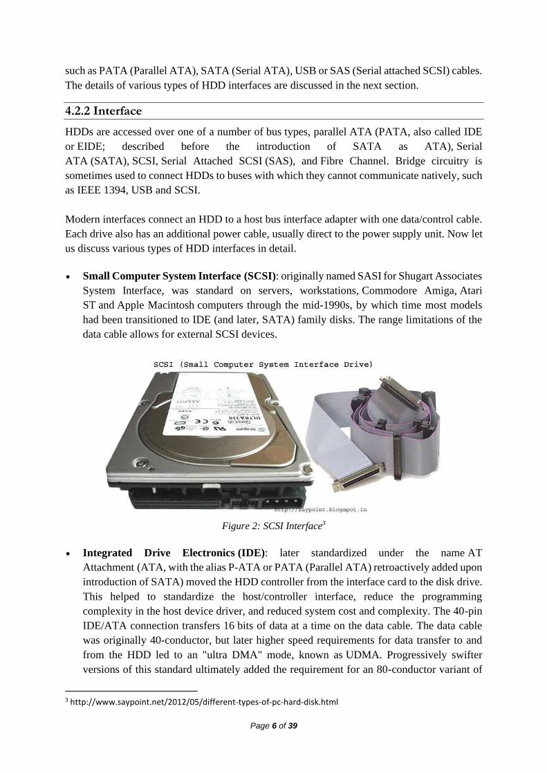
• Small Computer System Interface (SCSI): originally named SASI for Shugart Associates
System Interface, was standard on servers, workstations, Commodore Amiga, Atari
ST and Apple Macintosh computers through the mid-1990s, by which time most models
had been transitioned to IDE (and later, SATA) family disks. The range limitations of the
data cable allows for external SCSI devices.
Figure 2: SCSI Interface3
• Integrated Drive Electronics (IDE): later standardized under the name AT
Attachment (ATA, with the alias P-ATA or PATA (Parallel ATA) retroactively added upon
introduction of SATA) moved the HDD controller from the interface card to the disk drive.
This helped to standardize the host/controller interface, reduce the programming
complexity in the host device driver, and reduced system cost and complexity. The 40-pin
IDE/ATA connection transfers 16 bits of data at a time on the data cable. The data cable
was originally 40-conductor, but later higher speed requirements for data transfer to and
from the HDD led to an "ultra DMA" mode, known as UDMA. Progressively swifter
versions of this standard ultimately added the requirement for an 80-conductor variant of
3 http://www.saypoint.net/2012/05/different-types-of-pc-hard-disk.html

Page 7 of 39
the same cable, where half of the conductors provide grounding necessary for enhanced
high-speed signal quality by reducing cross talk.
Figure 3: Parallel ATA4
• EIDE: was an unofficial update (by Western Digital) to the original IDE standard, with the
key improvement being the use of direct memory access (DMA) to transfer data between
the disk and the computer without the involvement of the CPU, an improvement later
adopted by the official ATA standards. By directly transferring data between memory and
disk, DMA eliminates the need for the CPU to copy byte per byte, therefore allowing it to
process other tasks while the data transfer occurs.
• Fibre Channel (FC): is a successor to parallel SCSI interface on enterprise market. It is a
serial protocol. In disk drives usually the Fibre Channel Arbitrated Loop(FC-AL)
connection topology is used. FC has much broader usage than mere disk interfaces, and it
is the cornerstone of storage area networks (SANs). Recently other protocols for this field,
like iSCSI and ATA over Ethernet have been developed as well. Confusingly, drives
usually use copper twisted-pair cables for Fibre Channel, not fibre optics. The latter are
traditionally reserved for larger devices, such as servers or disk array controllers.
• Serial Attached SCSI (SAS): The SAS is a new generation serial communication protocol
for devices designed to allow for much higher speed data transfers and is compatible with
SATA. SAS uses a mechanically identical data and power connector to standard 3.5-inch
SATA1/SATA2 HDDs, and many server-oriented SAS RAID controllers are also capable
of addressing SATA HDDs. SAS uses serial communication instead of the parallel method
found in traditional SCSI devices but still uses SCSI commands.
• Serial ATA (SATA): The SATA data cable has one data pair for differential transmission
of data to the device, and one pair for differential receiving from the device, just like EIA-
422. It requires that data be transmitted serially. A similar differential signalling system is
used in RS485, LocalTalk, USB, FireWire, and differential SCSI.
4 http://www.saypoint.net/2012/05/different-types-of-pc-hard-disk.html

Page 8 of 39
Figure 4: SATA5
4.3 DETAILS OF INTERNAL STRUCTURE OF HDD
Before6 trying to understand formatting, you first need to understand how a hard drive works.
Let’s start with the detailed description of physical formatting (or low-level formatting) and
logical formatting (or high-level formatting). Even though hard drives can be very small, they
still contain millions of bits and therefore need to be organized so that information can be
located. This is the purpose of the file system.
4.3.1 Low-Level Formatting
The purpose of low-level formatting is to divide the disk surface into basic elements:
➢ tracks
➢ sectors
➢ cylinders
Remember that a hard drive consists of several circular platters rotating around an axis and
covered on either side by a magnetic oxide which, since it is polarised, can be used to store
data.
Figure 5: Platters in a HDD
The tracks are the concentric areas written on both sides of a platter.
5 http://www.saypoint.net/2012/05/different-types-of-pc-hard-disk.html 6 http://ccm.net/contents/626-formatting-formatting-a-hard-drive

Page 9 of 39
Figure 6: Tracks in a platter of HDD
Finally, these tracks are divided into pieces called sectors. There are millions of tracks and
each has around 60 to 120 sectors.
Figure 7: Tracks and sectors in a HDD
A cylinder refers to all the data located on the same track of different platters (i.e. vertically on
top of each other) as this forms a "cylinder" of data in space.
Figure 8: Cylinder in a HDD

Page 10 of 39
Physical formatting therefore consists in organizing the surface of each platter into entities
called trackers and sectors, by polarising the disk areas using the write heads. Tracks are
numbered starting from 0, then the heads polarise concentrically the surface of the platters.
When the head goes from one track to the next, it leaves a gap. Each track is itself organized
into sectors (numbered starting from 1) and separated by gaps. Each of these sectors starts with
an area reserved for system information called a prefix and ends with an area called a suffix.
The purpose of low-level formatting is therefore to prepare the disk surface to receive data and
to mark "defective sectors" using tests performed by the manufacturer. When you buy a hard
drive, it has already undergone low-level formatting. SO YOU DO NOT NEED TO PERFORM
LOW-LEVEL FORMATTING!
During the formatting, check tests (algorithms allowing the validity of sectors to be tested using
checksums) are performed and each time a sector is considered defective, the (invalid)
checksum is written in the prefix. It can no longer be used thereafter and is said to be "marked
defective". When the disk reads the data, it sends a value that depends on the content of the sent
packet, and which is initially stored with the data. The system calculates this value based on the
data received, and then it compares it with the one that is stored with the data. If these two
values are different, the data are no longer valid and there is probably a problem with the disk
surface. The cyclic redundancy check (CRC), is based on the same principle to check the
integrity of a file. Analysis utilities such as scandisk or chkdsk operate differently:
they write data on sectors considered to be valid, and then read them and compare them. If they
are the same, the utility goes on to the next sector, otherwise it marks the sector as defective.
4.3.2 High-level formatting
Logical formatting occurs after the low-level formatting. It creates a file system on the disks
that will allow an operating system (DOS, Windows 95, Linux, OS/2, Windows NT, etc.) to
use the disk space to store and access files. Operating systems use different file systems, so the
type of logical formatting will depend on the operating system you install. So, if you format
your disk with a single file system, this naturally limits the number and type of operating
systems that you can install (in fact, you can only install operating systems that use the same
file system). Fortunately, there is a solution to this problem which is to create partitions. Each
of the partitions can effectively have its own file system, and you can therefore install different
types of operating systems.
What is a partition?
Partitioning is the process of writing the sectors that will make up the partition table (which
contains information on the partition: size in sectors, position with respect to the primary
partition, types of partitions present, operating systems installed, etc.). When a partition is
created, it is given a volume name which allows it to be easily identified.
The partitioning of a hard drive occurs after the drive has been physically formatted but before
it is logically formatted. It involves creating areas on the disk where data will not be mixed. It
can be used, for example, to install different operating systems that do not use the same file
system. There will therefore be at least as many partitions as there are operating systems using

Page 11 of 39
different file systems. If you are using just one operating system, a single partition the full size
of the disk is sufficient, unless you want create several partitions so as to have, for example,
several drives on which data are kept separate.
There are three types of partitions: primary partitions, extended partitions and logical
drives. A disk may contain up to four primary partitions (only one of which can be active), or
three primary partitions and one extended partition. In the extended partition, the user can create
logical drives (i.e. "simulate" several smaller-sized hard drives).
Let's look at an example where the disk contains one primary partition and one extended
partition made up of three logical drives (later we will look at multiple primary partitions):
Figure 9: Partitining of HDD
For DOS systems (DOS, Windows 9x), only the primary partition is bootable, and is therefore
the only one on which the operating system can be started.
4.3.3 Glossary of some important terms
4.3.3.1 Slack space
The unused space at the end of a file in a file system that uses fixed size clusters (so if the file
is smaller than the fixed block size then the unused space is simply left). Often contains deleted
information from previous uses of the block7.
4.3.3.2 Lost Cluster
A lost cluster is a series of clusters on the hard disk drive that are not associated with a particular
file. Data is there but it's unknown as to what file that data belongs to. Error checking tool looks
for those and tries to repair them. Usually it can repair them, but sometimes it can't. If we're in
a situation where we can't repair lost clusters that usually means we've got some serious disk
errors and we're going to be losing some data8.
7 https://en.wikipedia.org/wiki/Glossary_of_digital_forensics_terms 8 http://www.utilizewindows.com/pc-fundamentals/storage/333-hardware-and-software-disk-optimization

Page 12 of 39
4.3.3.3 Bad Sector
A bad sector is a sector on a computer's disk drive or flash memory that is either inaccessible
or unwriteable due to permanent damage, such as physical damage to the disk surface or failed
flash memory transistors9.
4.3.3.4 Master Boot Record
The boot sector10 (called the Master Boot Record or MBR) is the first sector of a hard drive
(cylinder 0, head 0, sector 1), it contains the main partition table and the code, called the boot
loader, which, when loaded into memory, will allow the system to boot up.
After it is loaded into memory, this programme will determine from which system partition to
boot, and will start the programme (called the bootstrap) which will start up the operating
system present on that partition. This disk sector also contains all information concerning the
hard drive (manufacturer, serial number, number of bytes per sector, number of sectors per
cluster, number of sectors, etc.). This sector is therefore the most important one on the hard
drive and is also used by the BIOS setup to recognize the hard drive. In other words, without it
your hard drive is useless, which makes it a favourite target for viruses.
4.4 THE BOOTING PROCESS
The boot process11 of a modern system involves multiple phases. The following components
are involved in the boot process. They are each executed in this order:
➢ Power Supply Unit
➢ BIOS and CMOS
➢ POST tests
➢ Reading the Partition Table
➢ The Bootloader
➢ The Kernel
➢ OS Kernel
1. Power Supply Unit: When the power button is pressed, an electric circuit is closed
which causes the power supply unit to perform a self test. In order for the boot process
to continue, this self test has to complete successfully. If the power supply cannot
confirm the self test, there will usually be no output at all. Most modern x86 computers,
especially those using the ATX standard, will have two main connectors to the
motherboard: a 4-pin connector to power the CPU, and a 24-pin connector to power
other motherboard components. If the self test passes successfully, the PSU will send a
signal to the CPU on the 4-pin connector to indicate that it should power on.
9 https://en.wikipedia.org/wiki/Bad_sector 10 http://ccm.net/contents/626-formatting-formatting-a-hard-drive 11 http://ops-school.readthedocs.org/en/latest/boot_process_101.html

Page 13 of 39
2. BIOS and CMOS: At its core, the Basic Input/Output System (BIOS) is an integrated
circuit located on the computer’s motherboard that can be programmed with firmware.
This firmware facilitates the boot process so that an operating system can load.
Let’s examine each of these in more detail:
a. Firmware is the software that is programmed into Electrically Erasable
Programmable Read-Only Memory (EEPROM). In this case, the firmware
facilitates booting an operating system and configuring basic hardware settings.
b. An integrated circuit (IC) is what you would likely think of as a stereotypical
“computer chip” - a thin wafer that is packaged and has metal traces sticking out
from it that can be mounted onto a printed circuit board.
Your BIOS is the lowest level interface you’ll get to the hardware in your computer.
The BIOS also performs the Power-On Self Test, or POST. Once the CPU has powered
up, the first call made is to the BIOS. The first step then taken by the BIOS is to ensure
that the minimum required hardware exists:
➢ CPU
➢ Memory
➢ Video card
Once the existence of the hardware has been confirmed, it must be configured. The
BIOS has its own memory storage known as the CMOS (Complimentary Metal Oxide
Semiconductor). The CMOS contains all of the settings the BIOS needs to save, such
as the memory speed, CPU frequency multiplier, and the location and configuration of
the hard drives and other devices.
The BIOS first takes the memory frequency and attempts to set that on the memory
controller. Next the BIOS multiply the memory frequency by the CPU frequency
multiplier. This is the speed at which the CPU is set to run. Sometimes it is possible to
“overclock” a CPU, by telling it to run at a higher multiplier than it was designed to,
effectively making it run faster. There can be benefits and risks to doing this, including
the potential for damaging your CPU.
3. POST tests: Once the memory and CPU frequencies have been set, the BIOS begins
the Power-On Self Test (POST). The POST will perform basic checks on many system
components, including:
➢ Check that the memory is working
➢ Check that hard drives and other devices are all responding
➢ Check that the keyboard and mouse are connected (this check can usually be
disabled)
➢ Initialise any additional BIOSes which may be installed (e.g. RAID cards)
4. Reading the Partition Table: The next major function of the BIOS is to determine
which device to use to start an operating system. A typical BIOS can read boot
information from the devices below, and will boot from the first device that provides a
successful response. The order of devices to scan can be set in the BIOS:
➢ Floppy disks

Page 14 of 39
➢ CD-ROMs
➢ USB flash drives
➢ Hard drives
➢ A network
We’ll cover the first four options here. For booting over the network, please refer to
http://networkboot.org/fundamentals/.
There are two separate partition table formats: Master Boot Record (MBR) and the
GUID Partition Table (GPT). We’ll illustrate how both store data about what’s on the
drive, and how they’re used to boot the operating system.
a. Master Boot Record (the old way): Once the BIOS have identified which drive it
should attempt to boot from, it looks at the first sector on that drive. These sectors
should contain the Master Boot Record.
The MBR has two component parts:
• The boot loader information block (448 bytes)
• The partition table (64 bytes)
The boot loader information block is where the first program the computer can run
is stored. The partition table stores information about how the drive is logically laid
out.
The MBR has been heavily limited in its design, as it can only occupy the first 512
bytes of space on the drive (which is the size of one physical sector). This limits the
tasks the boot loader program is able to do. The execution of the boot loader literally
starts from the first byte. As the complexity of systems grew, it became necessary
to add “chain boot loading”. This allows the MBR to load an another program from
elsewhere on the drive into memory. The new program is then executed and
continues the boot process.
If you’re familiar with Windows, you may have seen drives labelled as “C:” and
“D:” - these represent different logical “partitions” on the drive. These represent
partitions defined in that 64-byte partition table.
b. GPT - The GUID Partition Table (the new way): The design of the IBM-
Compatible BIOS is an old design and has limitations in today’s world of hardware.
To address this, the United Extensible Firmware Interface (UEFI) was created, along
with GPT, a new partition format.
There are a few advantages to the GPT format, specifically:
➢ A Globally-Unique ID that references a partition, rather than a partition
number. The MBR only has 64 bytes to store partition information - and each
partition definition is 16 bytes. This design allows for unlimited partitions.

Page 15 of 39
➢ The ability to boot from storage devices that are greater than 2 TBs, due to
a larger address space to identify sectors on the disk. The MBR simply had
no way to address disks greater than 2 TB.
➢ A backup copy of the table that can be used in the event that the primary
copy is corrupted. This copy is stored at the ‘end’ of the disk.
There is some compatibility maintained to allow standard PCs that are using old BIOS
to boot from a drive that has a GPT on it.
5. The Bootloader: The purpose of a bootloader is to load the initial kernel and supporting
modules into memory.
6. Kernel: The kernel is the main component of any operating system. The kernel acts as
the lowest-level intermediary between the hardware on your computer and the
applications running on your computer. The kernel abstracts away such resource
management tasks as memory and processor allocation. The kernel and other software
can access peripherals such as disk drives by way of device drivers. Let us examine the
booting process of some popular Operating Systems.
VIDEO LECTURE
4.4.1 Linux Boot Process

Page 16 of 39
The following are the 6 high level stages of a typical Linux boot process12.
Figure 10: Linux boot process
Setp1: BIOS
• BIOS stands for Basic Input/Output System
• Performs some system integrity checks
• Searches, loads, and executes the boot loader program.
• It looks for boot loader in floppy, cd-rom, or hard drive. You can press a key (typically
F12 of F2, but it depends on your system) during the BIOS startup to change the boot
sequence.
• Once the boot loader program is detected and loaded into the memory, BIOS gives the
control to it.
• So, in simple terms BIOS loads and executes the MBR boot loader.
Step 2: MBR
• MBR stands for Master Boot Record.
• It is located in the 1st sector of the bootable disk. Typically /dev/hda, or /dev/sda
• MBR is less than 512 bytes in size. This has three components 1) primary boot loader
info in 1st 446 bytes 2) partition table info in next 64 bytes 3) mbr validation check in
last 2 bytes.
• It contains information about GRUB (or LILO in old systems).
• So, in simple terms MBR loads and executes the GRUB boot loader.
Step3: GRUB
• GRUB stands for Grand Unified Bootloader.
12 https://pacesettergraam.wordpress.com/2012/08/11/stages-of-linux-boot-process/

Page 17 of 39
• If you have multiple kernel images installed on your system, you can choose which one
to be executed.
• GRUB displays a splash screen, waits for few seconds, if you don’t enter anything, it
loads the default kernel image as specified in the grub configuration file.
• GRUB has the knowledge of the filesystem (the older Linux loader LILO didn’t
understand filesystem).
• Grub configuration file is /boot/grub/grub.conf (/etc/grub.conf is a link to this).
• GRUB just loads and executes Kernel and initrd images.
Step 4: Kernel
• Mounts the root file system as specified in the “root=” in grub.conf
• Kernel executes the /sbin/init program
• Since init was the 1st program to be executed by Linux Kernel, it has the process id (PID)
of 1. Do a ‘ps -ef | grep init’ and check the pid.
• initrd stands for Initial RAM Disk.
• initrd is used by kernel as temporary root file system until kernel is booted and the real
root file system is mounted. It also contains necessary drivers compiled inside, which
helps it to access the hard drive partitions, and other hardware.
Step 5: Init
• Looks at the /etc/inittab file to decide the Linux run level.
• Following are the available run levels
➢ 0 – halt
➢ 1 – Single user mode
➢ 2 – Multiuser, without NFS
➢ 3 – Full multiuser mode
➢ 4 – unused
➢ 5 – X11
➢ 6 – reboot
• Init identifies the default initlevel from /etc/inittab and uses that to load all appropriate
program.
• Execute ‘grep initdefault /etc/inittab’ on your system to identify the default run level
• If you want to get into trouble, you can set the default run level to 0 or 6. Since you know
what 0 and 6 means, probably you might not do that.
• Typically you would set the default run level to either 3 or 5.
Step 6: Runlevel programs
• When the Linux system is booting up, you might see various services getting started. For
example, it might say “starting sendmail …. OK”. Those are the runlevel programs, executed
from the run level directory as defined by your run level.
• Depending on your default init level setting, the system will execute the programs from
one of the following directories.
➢ Run level 0 – /etc/rc.d/rc0.d/
➢ Run level 1 – /etc/rc.d/rc1.d/

Page 18 of 39
➢ Run level 2 – /etc/rc.d/rc2.d/
➢ Run level 3 – /etc/rc.d/rc3.d/
➢ Run level 4 – /etc/rc.d/rc4.d/
➢ Run level 5 – /etc/rc.d/rc5.d/
➢ Run level 6 – /etc/rc.d/rc6.d/
• Please note that there are also symbolic links available for these directory under /etc
directly. So, /etc/rc0.d is linked to /etc/rc.d/rc0.d.
• Under the /etc/rc.d/rc*.d/ directories, you would see programs that start with S and K.
• Programs starts with S are used during startup. S for startup.
• Programs starts with K are used during shutdown. K for kill.
• There are numbers right next to S and K in the program names. Those are the sequence
number in which the programs should be started or killed.
• For example, S12syslog is to start the syslog deamon, which has the sequence number of
12. S80sendmail is to start the sendmail daemon, which has the sequence number of 80.
So, syslog program will be started before sendmail.
VIDEO LECTURE
4.4.2 Mac OS Boot Sequence
The boot process starts with the activation of BootROM, the basic Macintosh ROM, which
performs a Power On Self Test to test hardware essential to startup13. On the passing of this
13 https://en.wikipedia.org/wiki/BootX_(Apple)

Page 19 of 39
test, the startup chime is played and control of the computer is passed to OpenFirmware.
OpenFirmware initializes the Random Access Memory, Memory Management Unit and
hardware necessary for the ROM's operation. The OpenFirmware then checks settings, stored
in NVRAM, and builds a list of all devices on a device tree by gathering their stored FCode
information.
On the completion of this task, BootX takes over the startup process configuring the keyboard
and display, claiming and reserving memory for various purposes and checking to see if various
key combinations are being pressed. After this process has been completed BootX displays the
grey Apple logo, spins the spinning wait cursor, and proceeds to load the kernel and some kernel
extensions and start the kernel.
VIDEO LECTURE
The detailed description of the above is as follows:
• BootROM: As the name suggest, BootROM is a ROM (Read only Memory) which
contains boot programmes viz. POST and Open Firmware.
o POST: Power-On Self Test is the initial process which check the functionality
of the basic hardware attached to the computer including RAM.

Page 20 of 39
o Open Firmware: The remaining hardware is initialized by Open Firmware. It
also checks all the hardware associated with the systems and builds the initial
device tree.
• BootX: The BootX initialize the kernel and the drivers required to boot the system from
the cached set of device drivers. In case it is not present, it is loaded for
/System/Library/Extensions for the same.
• Kernel: Once the Kernel is loaded, it initialises the I/O kit which is used to control
Input/Output devices. After this, the kernel initiates the launched process.
• Launchd: it is process used for bootstrapping and is responsible for starting every
system process. It also manages system initialization and starts
the loginwindow process. During system initialization the system launchd process
automatically starts /System/Library/LaunchDaemons, /Library/LaunchDaemons,
/Library/StartupItems, and /etc/rc.local. The launch also manages daemons, a program
who manages service request.
• Startup Scripts and Startup Item: As soon as /etc/rc.local is executed, it initialises
the basic system by performing file-system consistency check and initiating
SystemStarter process, a process used for launching startup items. For system
configuration related information, it refers to /etc/hostconfig.
• The loginwindow Process: this process displays the login screen that allows the user
to authenticate, and then sets up and manages the graphical interface user environment
based on the account preferences.
• User Enviroment Setup: After the user’s credentials are authenticated, the user
environment setup is performed based on the user’s preference.
4.4.3 Boot Sequence in Windows 7
Figure 11: Window 7 boot sequence
Power-On Self Test
Initial Startup Phase
Windows Bootmanager Phase
Windows Bootloader Phase
Kernel
Login

Page 21 of 39
1. In the first step, when the system is powered-on the Basic Input Output System (BIOS)
and RAM is loaded and BIOS performs the hardware diagnostics based by initiating
Power-On Self Test(POST).
2. In the second step, the BIOS locates MBR(Master Boot Record), which is located at the
first sector of the first hard drive, to find the active drive, bootable partition and reads
boot sector.
3. The boot sector loads bootmgr, which looks for the active partition on the drive and load
Boot Configuration Data(BCD) data store. The information stored in BCD to find and
load the selected operating system.
4. When the Windows 7 OS is selected, bootmgr executes a program called winload.exe,
which takes the charge of the further process of loading windows. The following screen
will appear in the monitor:
Figure 12: Windows login screen
5. The winload.exe starts ntoskrnl.exe which initiates all the necessary files needed to load
and run Windows 7 OS.
6. The OS is loaded and winlogon is executed to provide the login interface. After
authentication, the system settings are loaded based on the users credential and
preferences.

Page 22 of 39
VIDEO LECTURE
4.5 FILE SYSTEM
Even though hard drives can be very small, they still contain millions of bits and therefore need
to be organized so that information can be located14. This is the purpose of the file system.
Remember that a hard drive is made up of several circular platters rotating around an axis. The
tracks (concentric areas written to on either side of the platter) are divided into pieces called
sectors (each 512 bytes in size). Logical formatting of a disk allows a file system to be created
on the disk, which in turn will allow an operating system (DOS, Windows 9x, UNIX, etc) to
use the disk space to store and use files. The file system is based on management of clusters,
the smallest disk unit that the operating system is able to manage.
A cluster consists of one or more sectors, so the larger the cluster size, the fewer entities the
operating system will have to manage. On the other hand, since an operating system only knows
how to manage whole allocation units (i.e. a file occupies a whole number of clusters), the more
sectors per cluster, the more wasted space there will be. This is why the choice of file system is
important.
Files systems and the operating system: In reality, the choice of file system depends first of
all on the operating system that you are using. In general, the more recent the operating system,
the greater the number of files it will support. So, under DOS and on the first versions of
Windows 95, FAT16 is required. Starting with Windows 95 OSR2, you have the choice
14 http://ccm.net/contents/624-the-file-system
Page 23 of 39
between FAT16 and FAT32 file systems. If the partition size is greater than 2GB, then FAT
file systems are excluded and you need to use the FAT32 system (or modify the size of the
partition). Below this limit, FAT16 is recommended for partitions with a capacity of less than
500Mb, otherwise it is preferable to use FAT32.
VIDEO LECTURE
In the case of Windows NT (up until version 4) you have the choice between the FAT16 system
and NTFS, FAT32 is not supported. In general, the NTFS system is recommended as it provides
higher security and better performance than the FAT system. Microsoft actually recommends
using a small FAT-type partition (of between 250 and 500MB) for the operating system, so as
to be able to boot from a bootable DOS floppy disk in case of a catastrophe, and to use a second
partition for storing your data.
Under Windows NT5, there are more choices as it accepts FAT16, FAT32 and NTFS partitions.
Once again, the more recent file system (NTFS 5) is recommended, as it offers many more
features than the FAT systems. For the same reasons given above, you can still choose to have
a FAT-type partition.
Table 1: Operating system and choice of file system
Operation system File system types supported
Dos FAT16
Windows 95 FAT16
Windows 95 OSR2 FAT16, FAT32

Page 24 of 39
Windows 98 FAT16, FAT32
Windows NT4 FAT, NTFS (version 4)
Windows 2000/XP FAT, FAT16, FAT32, NTFS (versions 4 and 5)
Linux Ext2, Ext3, ReiserFS, Linux Swap(, FAT16, FAT32, NTFS)
MacOS HFS (Hierarchical File System), MFS (Macintosh File System)
OS/2 HPFS (High Performance File System)
SGI IRIX XFS
FreeBSD, OpenBSD UFS (Unix File System)
Sun Solaris UFS (Unix File System)
IBM AIX JFS (Journaled File System)
Coexistence of several file systems: When several operating systems coexist on the same
machine, the problem of choosing a file system is at its worse. Since the file system is tightly
coupled to the operating system, when there are several operating systems you must choose a
file system for each, bearing in mind that it is possible that data from one operating system may
be accessed from another. One solution would be to use FAT partitions for all the systems,
making sure that the partitions are no larger than 2 GB. The most appropriate solution would
be to use for each OS a partition whose file system is best suited to it, and to use a dedicated
FAT16 partition for data to be shared by the different operating systems.
4.5.1 Some Common File systems
File systems are your interface to store your data15. Modern file systems offer a hierarchical
view of your data, though historical file systems have been flat.
4.5.1.1 FAT
FAT stands for File Allocation Table, it is a relatively old file system, files are limited to 4GB
in size and file names are case insensitive. It has the benefit of being widely portable, being
available on many platforms. For this reason storage devices are often pre-formatted as FAT,
just so less technical users don't assume the device is broken and return it. Its portability makes
it useful for USB flash drives and the partition you use for /boot. It would be a poor choice for
your root file system.
4.5.1.2 NTFS
This is Microsoft's primary file system. Its data structures don't limit the maximum file size to
4GB. As a commenter pointed out, NTFS is case sensitive, but not through the Windows API,
which maintains case insensitivity for compatibility with older software that assumed
insensitivity, since it was dealing with FAT.
15 https://yakking.branchable.com/posts/filesystems/

Page 25 of 39
On Windows it is case preserving, so if you create a file called "Foo", you can read it as "foo",
but when you list the contents of the directory, it is shown as "Foo", rather than "FOO", as FAT
traditionally does. This makes it a better choice for storage media, as Linux is also able to read
it. It is still inadvisable to use NTFS as your root file system on Linux, since it's primary use is
reading disks that are also used by Windows machines, rather than being an installation's root
file system.
4.5.1.3 ext2, ext3 and ext4
The ext file systems are Linux's primary file systems and are usually the default option when
installing Linux distributions. Despite having a similar name, they are different beasts. ext2 is
rather primitive, only really useful with old bootloaders. ext3 is more advanced, though active
development has moved on to ext4. ext4 supports journalling, uses extents for its storage and
supports extended attributes, where additional metadata can be assigned to a file. There are
third-party tools to read ext file systems from Windows, but NTFS support in Linux is better
than ext support in Windows.
4.5.1.4 XFS
XFS is a development from Silicon Graphics. It exceeds ext4's features, including the ability to
take snapshots of the logical state of the file system, and was the source of extended attributes.
It is available on IRIX and Linux, so portability is not its strong point, hence would not be
useful on a USB flash drive, but it is an excellent choice for your root file system.
4.5.1.5 ZFS
ZFS is a product of Sun Microsystems, later bought by Oracle. It is a very advanced file system,
offering all the features mentioned above plus more. This is a copy-on-write file system, unlike
the above, which were either journalling, or wrote to the blocks directly. Being copy-on-write
allows for deduplication, since if multiple files have the same data, the file system can point
both files to the same data, since if it's changed in one file, the other one won't have its data
changed. Live file system checking is possible with the scrub command, so downtime is not
needed to perform maintenance. It can use multiple physical devices as its storage pool. Its
license is incompatible with the Linux kernel, so kernel support is provided by a third-party
module, which makes it possible that a kernel update could leave your file system unreadable,
since the ZFS kernel module is un-readable. Loading an external kernel module is slower than
it being built in, so this impacts boot speed. Despite its complexity, ZFS is also available on the
Solaris and BSD unices.
4.5.1.6 BTRFS
Work on BTRFS was initiated by Oracle to be a competitor to ZFS, this is no longer the
motivating factor, since Oracle acquired Sun, but BTRFS is likely to become the default Linux
file system in the future. It is nearly as featureful as ZFS, only missing the online deduplication,
which the BTRFS developers expect to complete in a couple of Linux kernel releases. Its design
allows for a transition between ext and btrfs with the btrfs-convert tool, by saving the ext

Page 26 of 39
metadata elsewhere and re-mapping ext's data to btrfs extents. It still offers the original file
system's data as a read-only disk image that can be mounted. Reverting back to ext is done by
reinstating the ext metadata. Unfortunately, it has a reputation of being unstable, corrupting
your data and becoming unusable. This is a natural stage of file system maturity though, and
BTRFS is my preferred root file system.
4.5.2 Types of file systems
File system types can be classified into disk/tape file systems, network file systems and special-
purpose file systems16.
VIDEO LECTURE
4.5.2.1 Disk file systems
A disk file system takes advantages of the ability of disk storage media to randomly address
data in a short amount of time. Additional considerations include the speed of accessing data
following that initially requested and the anticipation that the following data may also be
requested. This permits multiple users (or processes) access to various data on the disk without
regard to the sequential location of the data. Examples
include FAT (FAT12, FAT16, FAT32), exFAT, NTFS,HFS and HFS+, HPFS, UFS, ext2, ext
3, ext4, XFS, btrfs, ISO 9660, Files-11,Veritas File System, VMFS, ZFS, ReiserFS and UDF.
Some disk file systems are journaling file systems or versioning file systems.
16 https://en.wikipedia.org/wiki/File_system
Page 27 of 39
Optical discs: ISO 9660 and Universal Disk Format (UDF) are two common formats that
target Compact Discs, DVDs and Blu-ray discs. Mount Rainier is an extension to UDF
supported since 2.6 series of the Linux kernel and since Windows Vista that facilitates rewriting
to DVDs.
4.5.2.2 Flash file systems
A flash file system considers the special abilities, performance and restrictions of flash
memory devices. Frequently a disk file system can use a flash memory device as the underlying
storage media but it is much better to use a file system specifically designed for a flash device.
4.5.2.3 Tape file systems
A tape file system is a file system and tape format designed to store files on tape in a self-
describing form. Magnetic tapes are sequential storage media with significantly longer random
data access times than disks, posing challenges to the creation and efficient management of a
general-purpose file system.
In a disk file system, there is typically a master file directory, and a map of used and free data
regions. Any file additions, changes, or removals require updating the directory and the
used/free maps. Random access to data regions is measured in milliseconds so this system
works well for disks. Tape requires linear motion to wind and unwind potentially very long
reels of media. This tape motion may take several seconds to several minutes to move the
read/write head from one end of the tape to the other. Consequently, a master file directory and
usage map can be extremely slow and inefficient with tape. Writing typically involves reading
the block usage map to find free blocks for writing, updating the usage map and directory to
add the data, and then advancing the tape to write the data in the correct spot. Each additional
file write requires updating the map and directory and writing the data, which may take several
seconds to occur for each file.
Tape file systems instead typically allow for the file directory to be spread across the tape
intermixed with the data, referred to as streaming, so that time-consuming and repeated tape
motions are not required to write new data. However, a side effect of this design is that reading
the file directory of a tape usually requires scanning the entire tape to read all the scattered
directory entries. Most data archiving software that works with tape storage will store a local
copy of the tape catalogue on a disk file system, so that adding files to a tape can be done
quickly without having to rescan the tape media. The local tape catalogue copy is usually
discarded if not used for a specified period of time, at which point the tape must be re-scanned
if it is to be used in the future.
IBM has developed a file system for tape called the Linear Tape File System. The IBM
implementation of this file system has been released as the open-source IBM Linear Tape File
System — Single Drive Edition (LTFS-SDE) product. The Linear Tape File System uses a
separate partition on the tape to record the index meta-data, thereby avoiding the problems
associated with scattering directory entries across the entire tape.
Tape formatting
Page 28 of 39
Writing data to a tape is often a significantly time-consuming process that may take several
hours. Similarly, completely erasing or formatting a tape can also take several hours. With many
data tape technologies it is not necessary to format the tape before over-writing new data to the
tape. This is due to the inherently destructive nature of overwriting data on sequential media.
Because of the time it can take to format a tape, typically tapes are pre-formatted so that the
tape user does not need to spend time preparing each new tape for use. All that is usually
necessary is to write an identifying media label to the tape before use, and even this can be
automatically written by software when a new tape is used for the first time.
4.5.2.4 Database file systems
Another concept for file management is the idea of a database-based file system. Instead of, or
in addition to, hierarchical structured management, files are identified by their characteristics,
like type of file, topic, author, or similar rich metadata.
IBM DB2 for i (formerly known as DB2/400 and DB2 for i5/OS) is a database file system as
part of the object based IBM i operating system (formerly known as OS/400 and i5/OS),
incorporating a single level store and running on IBM Power Systems (formerly known as
AS/400 and iSeries), designed by Frank G. Soltis IBM's former chief scientist for IBM i.
Around 1978 to 1988 Frank G. Soltis and his team at IBM Rochester have successfully designed
and applied technologies like the database file system where others like Microsoft later failed
to accomplish. These technologies are informally known as 'Fortress Rochester' and were in
few basic aspects extended from early Mainframe technologies but in many ways more
advanced from a technological perspective.
Some other projects that aren't "pure" database file systems but that use some aspects of a
database file system:
• Many Web content management systems use a relational DBMS to store and retrieve files.
For example, XHTML files are stored as XML or text fields, while image files are stored
as blob fields; SQL SELECT (with optional XPath) statements retrieve the files, and allow
the use of a sophisticated logic and more rich information associations than "usual file
systems". Many CMSs also have the option of storing only metadata within the database,
with the standard filesystem used to store the content of files.
• Very large file systems, embodied by applications like Apache Hadoop and Google File
System, use some database file system concepts.
4.5.2.5 Transactional file systems
Some programs need to update multiple files "all at once". For example, a software installation
may write program binaries, libraries, and configuration files. If the software installation fails,
the program may be unusable. If the installation is upgrading a key system utility, such as the
command shell, the entire system may be left in an unusable state.
Transaction processing introduces the isolation guarantee, which states that operations within a
transaction are hidden from other threads on the system until the transaction commits, and that
Page 29 of 39
interfering operations on the system will be properly serialized with the transaction.
Transactions also provide the atomicity guarantee, ensuring that operations inside of a
transaction are either all committed or the transaction can be aborted and the system discards
all of its partial results. This means that if there is a crash or power failure, after recovery, the
stored state will be consistent. Either the software will be completely installed or the failed
installation will be completely rolled back, but an unusable partial install will not be left on the
system.
Windows, beginning with Vista, added transaction support to NTFS, in a feature
called Transactional NTFS, but its use is now discouraged. There are a number of research
prototypes of transactional file systems for UNIX systems, including the Valor file
system, Amino, LFS, and a transactional ext3 file system on the TxOS kernel, as well as
transactional file systems targeting embedded systems, such as TFFS.
Ensuring consistency across multiple file system operations is difficult, if not impossible,
without file system transactions. File locking can be used as a concurrency control mechanism
for individual files, but it typically does not protect the directory structure or file metadata. For
instance, file locking cannot prevent TOCTTOU race conditions on symbolic links. File locking
also cannot automatically roll back a failed operation, such as a software upgrade; this requires
atomicity.
Journaling file systems are one technique used to introduce transaction-level consistency to file
system structures. Journal transactions are not exposed to programs as part of the OS API; they
are only used internally to ensure consistency at the granularity of a single system call.
Data backup systems typically do not provide support for direct backup of data stored in a
transactional manner, which makes recovery of reliable and consistent data sets difficult. Most
backup software simply notes what files have changed since a certain time, regardless of the
transactional state shared across multiple files in the overall dataset. As a workaround, some
database systems simply produce an archived state file containing all data up to that point, and
the backup software only backs that up and does not interact directly with the active
transactional databases at all. Recovery requires separate recreation of the database from the
state file, after the file has been restored by the backup software.
4.5.2.6 Network file systems
A network file system is a file system that acts as a client for a remote file access protocol,
providing access to files on a server. Programs using local interfaces can transparently create,
manage and access hierarchical directories and files in remote network-connected computers.
Examples of network file systems include clients for the NFS, AFS, SMB protocols, and file-
system-like clients for FTP and WebDAV.
4.5.2.7 Shared disk file systems
A shared disk file system is one in which a number of machines (usually servers) all have access
to the same external disk subsystem (usually a SAN). The file system arbitrates access to that
Page 30 of 39
subsystem, preventing write collisions. Examples include GFS2 from Red Hat, GPFS from
IBM, SFS from DataPlow, CXFS from SGI and StorNext from Quantum Corporation.
4.5.2.8 Special file systems
A special file system presents non-file elements of an operating system as files so they can be
acted on using file system APIs. This is most commonly done in Unix-like operating systems,
but devices are given file names in some non-Unix-like operating systems as well.
Device file systems
A device file system represents I/O devices and pseudo-devices as files, called device files.
Examples in Unix-like systems include devfs and, in Linux 2.6 systems, udev. In non-Unix-
like systems, such as TOPS-10 and other operating systems influenced by it, where the full
filename or pathname of a file can include a device prefix, devices other than those containing
file systems are referred to by a device prefix specifying the device, without anything following
it.
Other special file systems
• In the Linux kernel, configfs and sysfs provide files that can be used to query the kernel
for information and configure entities in the kernel.
• procfs maps processes and, on Linux, other operating system structures into a filespace.
4.5.2.9 Minimal file system / audio-cassette storage
The late 1970s saw the development of the microcomputer. Disk and digital tape devices were
too expensive for hobbyists. An inexpensive basic data storage system was devised that used
common audio cassette tape. When the system needed to write data, the user was notified to
press "RECORD" on the cassette recorder, then press "RETURN" on the keyboard to notify the
system that the cassette recorder was recording. The system wrote a sound to provide time
synchronization, then modulated sounds that encoded a prefix, the data, a checksum and a
suffix. When the system needed to read data, the user was instructed to press "PLAY" on the
cassette recorder. The system would listen to the sounds on the tape waiting until a burst of
sound could be recognized as the synchronization. The system would then interpret subsequent
sounds as data. When the data read was complete, the system would notify the user to press
"STOP" on the cassette recorder. It was primitive, but it worked (a lot of the time). Data was
stored sequentially, usually in an unnamed format, although some systems (such as
the Commodore PET series of computers) did allow the files to be named. Multiple sets of data
could be written and located by fast-forwarding the tape and observing at the tape counter to
find the approximate start of the next data region on the tape. The user might have to listen to
the sounds to find the right spot to begin playing the next data region. Some implementations
even included audible sounds interspersed with the data.
4.5.2.10 Flat file systems
In a flat file system, there are no subdirectories. When floppy disk media was first available this
type of file system was adequate due to the relatively small amount of data space

Page 31 of 39
available. CP/M machines featured a flat file system, where files could be assigned to one of
16 user areas and generic file operations narrowed to work on one instead of defaulting to work
on all of them. These user areas were no more than special attributes associated with the files,
that is, it was not necessary to define specific quota for each of these areas and files could be
added to groups for as long as there was still free storage space on the disk. The early Apple
Macintosh also featured a flat file system, the Macintosh File System. It was unusual in that the
file management program (Macintosh Finder) created the illusion of a partially hierarchical
filing system on top of EMFS. This structure required every file to have a unique name, even if
it appeared to be in a separate folder. While simple, flat file systems become awkward as the
number of files grows and makes it difficult to organize data into related groups of files.
A recent addition to the flat file system family is Amazon's S3, a remote storage service, which
is intentionally simplistic to allow users the ability to customize how their data is stored. The
only constructs are buckets (imagine a disk drive of unlimited size) and objects (similar, but not
identical to the standard concept of a file). Advanced file management is allowed by being able
to use nearly any character (including '/') in the object's name, and the ability to select subsets
of the bucket's content based on identical prefixes
4.6 SUMMARY
1. A hard disk drive (HDD), hard disk, hard drive or fixed disk is a data storage device
used for storing and retrieving digital information using one or more rigid rapidly
rotating disks (platters) coated with magnetic material.
2. Data is accessed in a random-access manner, meaning that individual blocks of data can
be stored or retrieved in any order rather than sequentially. HDDs retain stored data
even when powered off.
3. The primary characteristics of an HDD are its capacity and performance.
4. An HDD records data by magnetizing a thin film of ferromagnetic material on a disk.
5. A typical HDD design consists of a spindle that holds flat circular disks, also called
platters, which hold the recorded data.
6. The two most common form factors for modern HDDs are 3.5-inch, for desktop
computers, and 2.5-inch, primarily for laptops.
7. HDDs are connected to systems by standard interface cables such as PATA (Parallel
ATA), SATA (Serial ATA), USB or SAS (Serial attached SCSI) cables.
8. The purpose of low-level formatting is to divide the disk surface into basic elements
viz. tracks, sectors and cylinders.
9. Operating systems use different file systems, so the type of logical formatting will
depend on the operating system you install.
10. The partitioning of a hard drive occurs after the drive has been physically formatted but
before it is logically formatted.
11. There are three types of partitions: primary partitions, extended partitions and logical
drives.
12. Partitioning is the process of writing the sectors that will make up the partition table.
13. The unused space at the end of a file in a file system that uses fixed size.

Page 32 of 39
14. A lost cluster is a series of clusters on the hard disk drive that are not associated with a
particular file.
15. A bad sector is a sector on a computer's disk drive or flash memory that is either
inaccessible or unwriteable due to permanent damage, such as physical damage to the
disk surface or failed flash memory transistors.
16. The boot sector is the first sector of a hard drive (cylinder 0, head 0, sector 1), it contains
the main partition table and the code, called the boot loader, which, when loaded into
memory, will allow the system to boot up.
17. Firmware is the software that is programmed into Electrically Erasable Programmable
Read-Only Memory (EEPROM).
18. The purpose of a bootloader is to load the initial kernel and supporting modules into
memory.
19. The kernel is the main component of any operating system. The kernel acts as the
lowest-level intermediary between the hardware on your computer and the applications
running on your computer.
4.7 CHECK YOUR PROGRESS
1. Fill in the blanks
i. The primary characteristics of an HDD are its ___________ and ___________.
ii. An HDD records data by magnetizing a thin film of ___________ material on a
disk.
iii. SCSI stands for ______________________.
iv. A ___________ refers to all the data located on the same track of different platters.
v. ___________ is the process of writing the sectors that will make up the partition
table.
vi. BIOS stands for ______________________.
vii. ___________is the software that is programmed into Electrically Erasable
Programmable Read-Only Memory.
viii. CMOS stands for ______________________.
ix. The purpose of a ___________ is to load the initial kernel and supporting modules
into memory.
x. ___________ is a development from Silicon Graphics.
xi. IBM has developed a file system for tape called the ______________________.
xii. A ______________________ is a file system that acts as a client for a remote file
access protocol, providing access to files on a server.
2. State True or False
i. The data is read from the disk by detecting the transitions in magnetization. True
ii. The platters are made from a non-magnetic material, usually aluminum alloy, glass, or
ceramic.
iii. The 40-pin IDE/ATA connection transfers 32 bits of data at a time on the data cable.
Page 33 of 39
iv. EIDE was an unofficial update (by Western Digital) to the original IDE standard.
v. EIDE have DMA transfer functionality.
vi. Physical level formatting is also known as high level formatting.
vii. The tracks are the concentric areas written on both sides of a platter.
viii. The partitioning of a hard drive occurs after the drive has been physically formatted but
before it is logically formatted.
ix. The partition table stores information about how the drive is logically laid out.
x. The file system is based on management of clusters.
xi. The choice of file system does not depends on the operating system that you are using.
xii. NTFS system provides higher security and better performance than the FAT system.
xiii. Several operating systems coexist on the same machine.
xiv. The BIOS does not have its own memory storage.
4.8 ANSWERS TO CHECK YOUR PROGRESS
1. Fill in the blanks
i. capacity , performance.
ii. ferromagnetic
iii. Small Computer System Interface.
iv. cylinder
v. Partitioning
vi. Basic Input/Output System.
vii. Firmware .
viii. Complimentary Metal Oxide Semiconductor.
ix. bootloader
x. XFS
xi. Linear Tape File System.
xii. network file system
2. State True or False
i. True
ii. True
iii. False
iv. True
v. True
vi. False
vii. True
viii. True

Page 34 of 39
ix. True
x. True
xi. False
xii. True
xiii. True
xiv. False
4.9 FURTHUR READING
CARRIER, B. FILE SYSTEM FORENSIC ANALYSIS.
Computer Storage. (n.d.). Retrieved Sep. 21, 2015, from http://www.utilizewindows.com/:
http://www.utilizewindows.com/pc-fundamentals/storage/333-hardware-and-software-disk-
optimization
Cooper, M. (2014, March). General overview of the Linux file system. Retrieved Oct. 22, 2015, from
Linux Documentation Project : http://www.tldp.org/LDP/intro-linux/html/sect_03_01.html
Different Types Of PC Hard Disk Drives (HDD). (n.d.). Retrieved Oct. 21, 2015, from SAYPOINT:
http://www.saypoint.net/2012/05/different-types-of-pc-hard-disk.html
File Systems: FAT, NTFS, and HFS+. (n.d.). Retrieved Oct. 22, 2015, from www.study.com:
http://study.com/academy/lesson/files-systems-fat-ntfs-hfs-and-ffs.html
Hagen, W. V. (2002). Linux Filesystems. SAMS.
How Things Work/Hard Drive. (2012, April 2012). Retrieved Oct. 22, 2015, from Wikibooks:
https://en.wikibooks.org/wiki/Wikijunior:How_Things_Work/Hard_Drive
Silberschatz, Galvin, & Gagne. (2006). Operating System Principles. Wiley.
Singh, A. (2006). Mac OS X Internals: A Systems Approach.
Smidsrød, R. (n.d.). The fundamentals of network booting. Retrieved Oct. 22, 2015, from
Networkboot: http://networkboot.org/fundamentals/.
Stages of linux boot process. (2012, Aug. 11). Retrieved Oct. 21, 2015, from
https://pacesettergraam.wordpress.com: https://pacesettergraam.wordpress.com/2012/08/11/stages-of-
linux-boot-process/
Thakur, D. (n.d.). What is Booting? Type of Booting. Retrieved Oct. 22, 2015, from Computer Notes:
http://ecomputernotes.com/fundamental/disk-operating-system/what-is-booting-type-of-booting
Windows Disk File Systems. (2010). General Books LLC.
Witjes, C., & Stremlau, A. (n.d.). The Windows 7 Boot Process (sbsl). Retrieved Oct. 22, 2015, from
http://social.technet.microsoft.com/:
http://social.technet.microsoft.com/wiki/contents/articles/11341.the-windows-7-boot-process-sbsl.aspx
Page 35 of 39
4.10 MODEL QUESTIONS
1. What is Hard Disk Drive? What are its main characteristics?
2. Explain the working of HDD.
3. Explain various interfaces of HDD in detail.
4. Differentiate between high level formatting and low level formatting.
5. What is cyclic redundancy check (CRC)?
6. Define the terms:
a. Slack space
b. Lost cluster
c. Bad sector
7. What is master boot record?
8. What is booting? Explain the booting process of Window 7 in detail.
9. What is a file system? Why it is used?
10. Give the details of file systems that different Operating System supports.
11. What is journaling?
12. What are different types of File Systems? Explain in detail.
13. What is flat file system?
REFERENCES, ARTICLE SOURCE & CONTRIBUTORS
Bad Sector. (2015, Sep. 26). Retrieved Oct. 21, 2015, from Wikipedia:
https://en.wikipedia.org/wiki/Bad_sector
BootX (Apple). (2015, May 25). Retrieved Oct. 21, 2015, from Wikipedia:
https://en.wikipedia.org/wiki/BootX_(Apple)
Computer Storage. (n.d.). Retrieved Sep. 21, 2015, from http://www.utilizewindows.com/:
http://www.utilizewindows.com/pc-fundamentals/storage/333-hardware-and-software-disk-
optimization
Different Types Of PC Hard Disk Drives (HDD). (n.d.). Retrieved Oct. 21, 2015, from SAYPOINT:
http://www.saypoint.net/2012/05/different-types-of-pc-hard-disk.html
File system. (2015, Oct. 18). Retrieved Oct. 21, 2015, from Wikipedia:
https://en.wikipedia.org/wiki/File_system
File systems. (2014, Jan.). Retrieved Oct. 21, 2015, from https://yakking.branchable.com/:
https://yakking.branchable.com/posts/filesystems/
Formatting - Formatting a hard drive. (2015, Oct. 01). Retrieved Oct. 21, 2015, from ccm.net:
http://ccm.net/contents/626-formatting-formatting-a-hard-drive
Formatting - Formatting a hard drive. (2015, Sep.). Retrieved Oct. 21, 2015, from ccm.net:
http://ccm.net/contents/626-formatting-formatting-a-hard-drive

Page 36 of 39
Glossary of digital forensics terms. (2015, Sep. 09). Retrieved Oct. 21, 2015, from Wikipedia:
https://en.wikipedia.org/wiki/Glossary_of_digital_forensics_terms
Hard disk drive. (2015, Oct. 16). Retrieved Oct. 21, 2015, from Wikipedia:
https://en.wikipedia.org/wiki/Hard_disk_drive
Stages of linux boot process. (2012, Aug. 11). Retrieved Oct. 21, 2015, from
https://pacesettergraam.wordpress.com: https://pacesettergraam.wordpress.com/2012/08/11/stages-of-
linux-boot-process/
The file system. (2015). Retrieved Oct. 21, 2015, from ccm.net: http://ccm.net/contents/624-the-file-
system
Vig, A. (2013). The boot process. Retrieved Oct. 21, 2015, from http://ops-school.readthedocs.org:
http://ops-school.readthedocs.org/en/latest/boot_process_101.html

Page 37 of 39
EXPERT PANEL
Dr. Jeetendra Pande, Associate Professor- Computer Science, School of Computer Science & IT, Uttarakhand Open University, Haldwani
Dr. Ajay Prasad, Sr. Associate Professor, University of Petroleum and Energy Studies, Dehradun
Dr. Akashdeep Bharadwaj, Professor, University of Petroleum and Energy Studies, Dehradun
Mr. Sridhar Chandramohan Iyer, Assistant Professor- Universal College of Engineering, Kaman, Vasai, University of Mumbai

Page 38 of 39
Mr. Rishikesh Ojha, Digital Forensics and eDiscovery Expert
Ms. Priyanka Tewari, IT Consultant
Mr. Ketan Joglekar, Assistant Professor, GJ College, Maharastra
Dr. Ashutosh Kumar Bhatt, Associate Professor, Uttarakhand Open University, Haldwani
Dr. Sangram Panigrahi, Assistant Professor, Siksha 'O' Anusandhan, Bhubaneswar

Page 39 of 39
This MOOC has been prepared with the support of
© Commonwealth Educational Media Centre for Asia , 2021. Available in
Creative Commons Attribution-ShareAlike 4.0 International license
to copy, remix and redistribute with attribution to the original source
(copyright holder), and the derivative is also shared with similar license.