understanding the sfd graphic generator - susana.org · graphic as ‘fsnot contained’(f10) and...
TRANSCRIPT
Understanding the SFD
Graphic Generator
Interactive tool for estimating the proportion of the contents of any tank or pit which is faecal sludge
Go to
introduction
Introduction
www.sfd.susana.org 04 Dec 20182
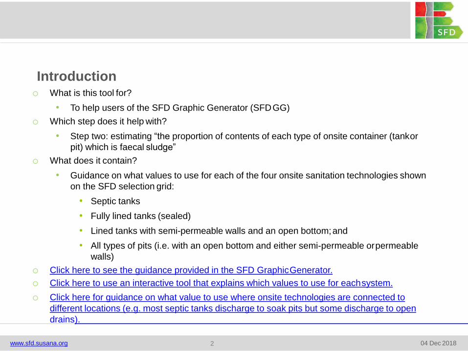
o What is this tool for?
• To help users of the SFD Graphic Generator (SFDGG)
o Which step does it help with?
• Step two: estimating “the proportion of contents of each type of onsite container (tankor
pit) which is faecal sludge”
o What does it contain?
• Guidance on what values to use for each of the four onsite sanitation technologies shown
on the SFD selection grid:
• Septic tanks
• Fully lined tanks (sealed)
• Lined tanks with semi-permeable walls and an open bottom;and
• All types of pits (i.e. with an open bottom and either semi-permeable orpermeable
walls)
o Click here to see the guidance provided in the SFD GraphicGenerator.
o Click here to use an interactive tool that explains which values to use for eachsystem.
o Click here for guidance on what value to use where onsite technologies are connected to
different locations (e.g. most septic tanks discharge to soak pits but some discharge to open
drains).
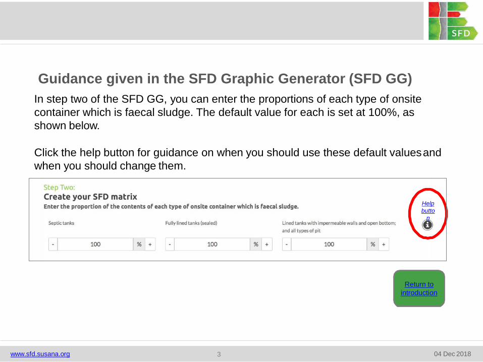
In step two of the SFD GG, you can enter the proportions of each type of onsite
container which is faecal sludge. The default value for each is set at 100%, as
shown below.
Click the help button for guidance on when you should use these default valuesand
when you should change them.
Return to
introduction
Help
butto
n
www.sfd.susana.org 04 Dec 20183
Guidance given in the SFD Graphic Generator (SFD GG)
in step two of the SFDWhat guidance is given in the help button
GG?
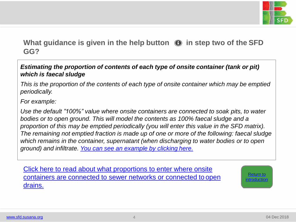
Estimating the proportion of contents of each type of onsite container (tank or pit)
which is faecal sludge
This is the proportion of the contents of each type of onsite container which may be emptied
periodically.
For example:
Use the default ”100%” value where onsite containers are connected to soak pits, to water
bodies or to open ground. This will model the contents as 100% faecal sludge and a
proportion of this may be emptied periodically (you will enter this value in the SFD matrix).
The remaining not emptied fraction is made up of one or more of the following: faecal sludge
which remains in the container, supernatant (when discharging to water bodies or to open
ground) and infiltrate. You can see an example by clicking here.
Return to
introduction
Click here to read about what proportions to enter where onsite
containers are connected to sewer networks or connected to open
drains.
www.sfd.susana.org 04 Dec 20184
What guidance is given in the help button on the SFD GG where onsite
containers are connected to sewers or to open drains?
Where onsite containers are connected to a sewer network or to open drains, using a value
of “50%” means that half the contents are modelled as faecal sludge; a proportion of this may
be emptied periodically (you will enter this value in the SFD matrix). The remaining fraction
will comprise faecal sludge which remains in the container and, in the case of open-bottomed
tanks, infiltrate. The other half of the contents is modelled as supernatant discharging into the
sewer network or to open drains. You can see an example by clicking here.
Refer to the Definitions of terms and the Sanitation Containment Systems: Schematics in the
Glossary for further details.
Return to
introduction
www.sfd.susana.org 04 Dec 20185
o For example, what values should be used on the SFD GG where 60% of the
population use septic tanks connected to soak pits (where there is a low risk of
groundwater pollution), but 10% of the population use septic tanks connected
directly to open drains?
o You can either:
1. Adjust the systems chosen on the SFD selection grid. Click here for an
example; or
2. Adjust the default percentage based on the proportion of the population using
the two systems. Click here for an example.
www.sfd.susana.org 04 Dec 20186
What values to use in cities where onsite technologies discharge to
different locations?
The simplest way is to adjust the type of system used by the smaller proportion of the population to
an unused but nevertheless similar system on the SFD selection grid. For instance, the ‘fully lined
tanks connected to open drains’ are similar to ‘septic tanks connected to open drains’.
Therefore, if you estimate that none of the population of your city uses ‘fully lined tanks’, then:
o Assign the smaller proportion of the population (the 10% given in example) using ‘septic tanks
connected to open drains’ (T1A2C5) to ‘fully lined tanks connected to open drains’ (T1A3C6).
Do this by selecting T1A3C6 in place of T1A2C5 on the selection grid, and assign 10% to this
on the SFD matrix. (Always to remember to explain this substitution and the reason your
report).
o Keep the larger proportion assigned to T1A2C5 on the selection grid (i.e. the 60% of the
population using ‘septic tanks connected to soak pits’ (where there is a low risk of groundwater
pollution)).
o As per the guidance note on the SFD GG:
• Set the proportion of the contents of ‘fully lined tanks (sealed)’ which is faecal sludgeto
50%.
• Use the default 100% for the proportion of ‘septic tank’ contents which is faecalsludge.
o Click here to see the SFD selection grid and the data inputs on step two of the SFD GG, before
and after making these changes.
www.sfd.susana.org 04 Dec 20187
Example of how to adjust systems on the SFD selection grid
o In this example, 70% of the population use septic tanks; comprising 60% using
septic tanks that are connected to soak pits and 10% using septic tanks that are
connected to open drains.
o As per the guidance note on the SFD GG. The default values for the proportion of
the contents which is faecal sludge are: 100% when septic tanks are connected to
soak pits, and 50% when septic tanks are connected to open drains.
o You can pro rata the data to revise the default percentage and find an appropriate
composite value, as follows:
• Proportion of contents which are faecal sludge = 60/70 x 100% = 85%
o Set the proportion of ‘septic tank’ contents which is faecal sludge to 85%.
o Click here to see the SFD selection grid and the resulting SFD matrix before and
after making this change.
www.sfd.susana.org 04 Dec 20188
Example of how to adjust the default percentage
Return to
introduction
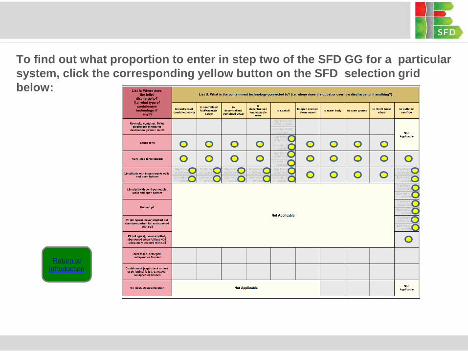
To find out what proportion to enter in step two of the SFD GG for a particular
system, click the corresponding yellow button on the SFD selection grid
below:
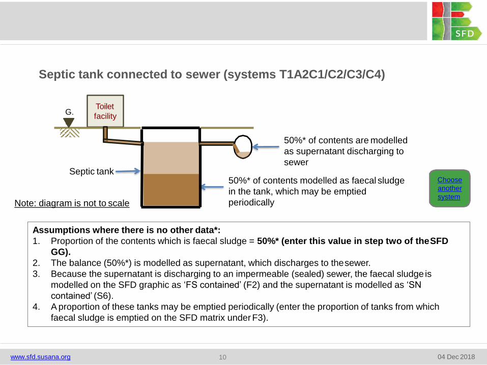
Septic tank connected to sewer (systems T1A2C1/C2/C3/C4)
G.
L.
Toilet
facility
50%* of contents are modelled
as supernatant discharging to
sewer
50%* of contents modelled as faecal sludge
in the tank, which may be emptied
periodically
Septic tankChoose
another
systemNote: diagram is not to scale
Assumptions where there is no other data*:
1. Proportion of the contents which is faecal sludge = 50%* (enter this value in step two of theSFD
GG).
2. The balance (50%*) is modelled as supernatant, which discharges to thesewer.
3. Because the supernatant is discharging to an impermeable (sealed) sewer, the faecal sludge is
modelled on the SFD graphic as ‘FS contained’ (F2) and the supernatant is modelled as ‘SN
contained’ (S6).
4. A proportion of these tanks may be emptied periodically (enter the proportion of tanks from which
faecal sludge is emptied on the SFD matrix under F3).
www.sfd.susana.org 04 Dec 201810
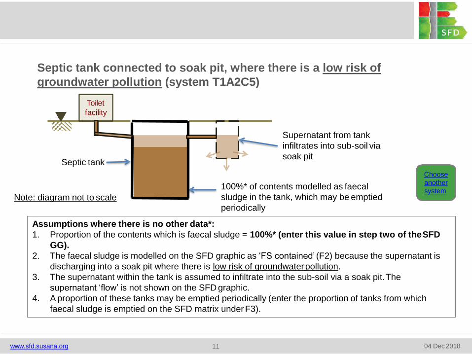
Septic tank connected to soak pit, where there is a low risk of
groundwater pollution (system T1A2C5)
Toilet
facility
Supernatant from tank
infiltrates into sub-soil via
soak pit
100%* of contents modelled as faecal
sludge in the tank, which may be emptied
periodically
Septic tank
Choose
another
systemNote: diagram not to scale
Assumptions where there is no other data*:
1. Proportion of the contents which is faecal sludge = 100%* (enter this value in step two of theSFD
GG).
2. The faecal sludge is modelled on the SFD graphic as ‘FS contained’ (F2) because the supernatant is
discharging into a soak pit where there is low risk of groundwaterpollution.
3. The supernatant within the tank is assumed to infiltrate into the sub-soil via a soak pit.The
supernatant ‘flow’ is not shown on the SFD graphic.
4. A proportion of these tanks may be emptied periodically (enter the proportion of tanks from which
faecal sludge is emptied on the SFD matrix underF3).
www.sfd.susana.org 04 Dec 201811
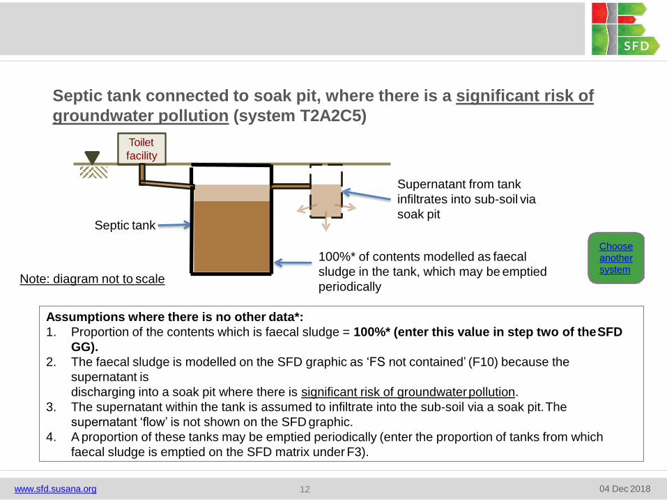
Septic tank connected to soak pit, where there is a significant risk of
groundwater pollution (system T2A2C5)
Toilet
facility
Supernatant from tank
infiltrates into sub-soil via
soak pit
100%* of contents modelled as faecal
sludge in the tank, which may be emptied
periodically
Septic tank
Choose
another
system
Assumptions where there is no other data*:
1. Proportion of the contents which is faecal sludge = 100%* (enter this value in step two of theSFD
GG).
2. The faecal sludge is modelled on the SFD graphic as ‘FS not contained’ (F10) because the
supernatant is
discharging into a soak pit where there is significant risk of groundwaterpollution.
3. The supernatant within the tank is assumed to infiltrate into the sub-soil via a soak pit.The
supernatant ‘flow’ is not shown on the SFD graphic.
4. A proportion of these tanks may be emptied periodically (enter the proportion of tanks from which
faecal sludge is emptied on the SFD matrix under F3).
Note: diagram not to scale
www.sfd.susana.org 04 Dec 201812
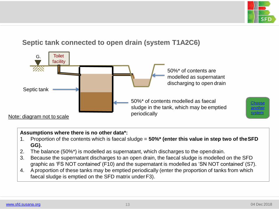
Septic tank connected to open drain (system T1A2C6)
G.
L.
Toilet
facility
50%* of contents are
modelled as supernatant
discharging to open drain
50%* of contents modelled as faecal
sludge in the tank, which may be emptied
periodically
Septic tank
Choose
another
system
Assumptions where there is no other data*:
1. Proportion of the contents which is faecal sludge = 50%* (enter this value in step two of theSFD
GG).
2. The balance (50%*) is modelled as supernatant, which discharges to the opendrain.
3. Because the supernatant discharges to an open drain, the faecal sludge is modelled on the SFD
graphic as ‘FS NOT contained’ (F10) and the supernatant is modelled as ‘SN NOT contained’ (S7).
4. A proportion of these tanks may be emptied periodically (enter the proportion of tanks from which
faecal sludge is emptied on the SFD matrix under F3).
Note: diagram not to scale
www.sfd.susana.org 04 Dec 201813
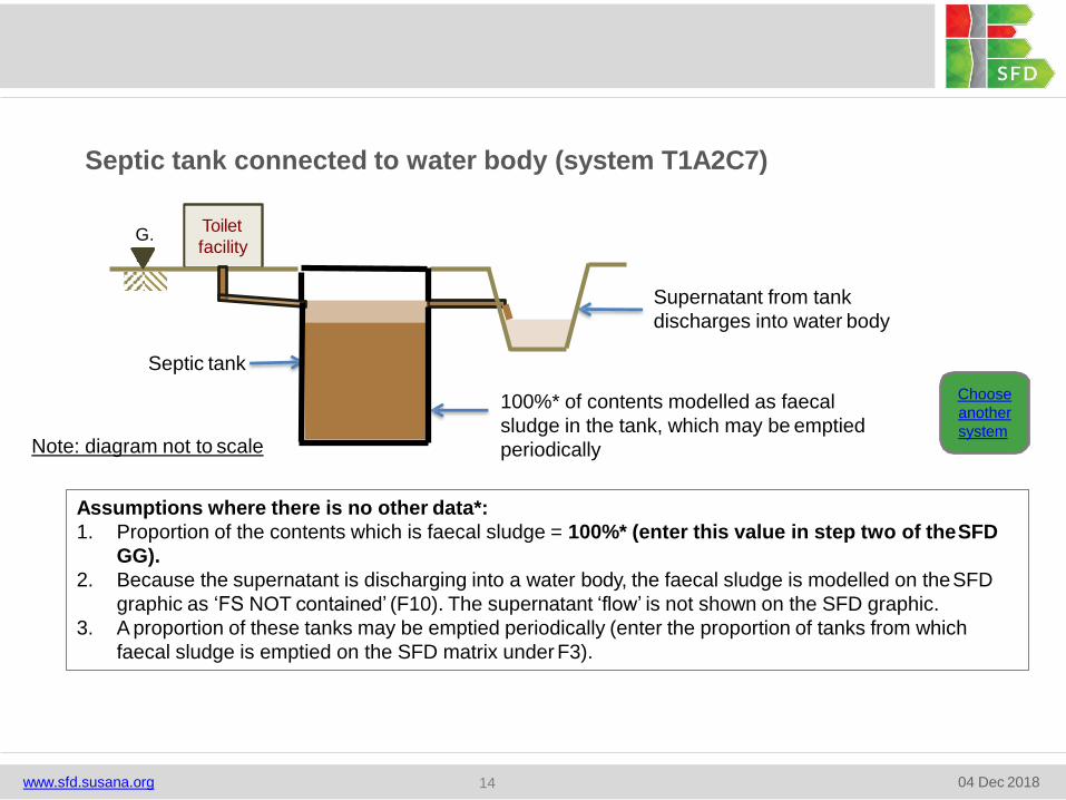
Septic tank connected to water body (system T1A2C7)
G.
L.
Toilet
facility
100%* of contents modelled as faecal
sludge in the tank, which may be emptied
periodically
Septic tank
Supernatant from tank
discharges into water body
Choose
another
system
Assumptions where there is no other data*:
1. Proportion of the contents which is faecal sludge = 100%* (enter this value in step two of theSFD
GG).
2. Because the supernatant is discharging into a water body, the faecal sludge is modelled on theSFD
graphic as ‘FS NOT contained’ (F10). The supernatant ‘flow’ is not shown on the SFD graphic.
3. A proportion of these tanks may be emptied periodically (enter the proportion of tanks from which
faecal sludge is emptied on the SFD matrix under F3).
Note: diagram not to scale
www.sfd.susana.org 04 Dec 201814
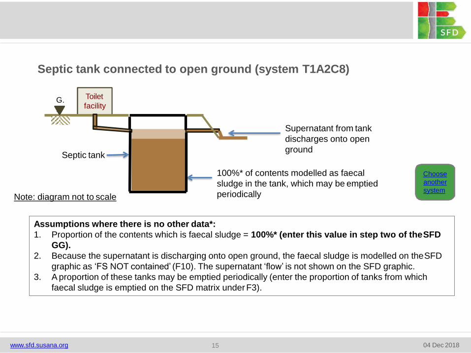
Septic tank connected to open ground (system T1A2C8)
G.
L.
Toilet
facility
Septic tank
Supernatant from tank
discharges onto open
ground
100%* of contents modelled as faecal
sludge in the tank, which may be emptied
periodically
Choose
another
system
Assumptions where there is no other data*:
1. Proportion of the contents which is faecal sludge = 100%* (enter this value in step two of theSFD
GG).
2. Because the supernatant is discharging onto open ground, the faecal sludge is modelled on theSFD
graphic as ‘FS NOT contained’ (F10). The supernatant ‘flow’ is not shown on the SFD graphic.
3. A proportion of these tanks may be emptied periodically (enter the proportion of tanks from which
faecal sludge is emptied on the SFD matrix under F3).
Note: diagram not to scale
www.sfd.susana.org 04 Dec 201815
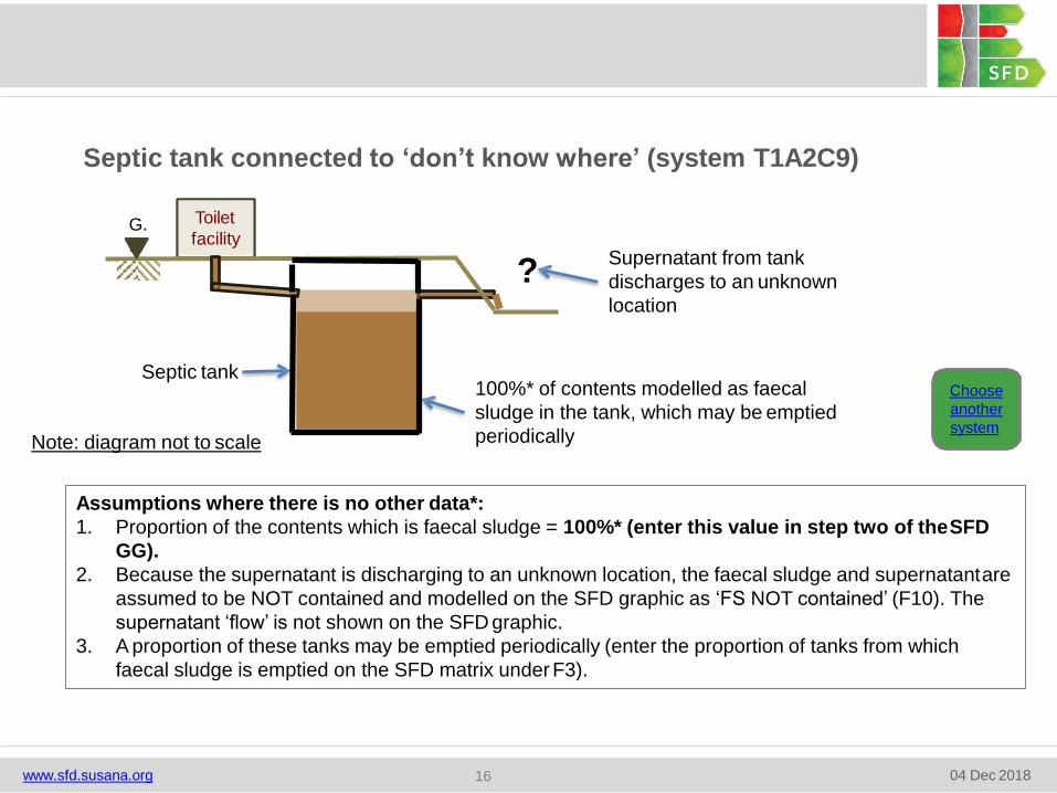
Septic tank connected to ‘don’t know where’ (system T1A2C9)
G.
L.
Toilet
facility
Septic tank
Supernatant from tank
discharges to an unknown
location
?
100%* of contents modelled as faecal
sludge in the tank, which may be emptied
periodically
Choose
another
system
Assumptions where there is no other data*:
1. Proportion of the contents which is faecal sludge = 100%* (enter this value in step two of theSFD
GG).
2. Because the supernatant is discharging to an unknown location, the faecal sludge and supernatantare
assumed to be NOT contained and modelled on the SFD graphic as ‘FS NOT contained’ (F10). The
supernatant ‘flow’ is not shown on the SFD graphic.
3. A proportion of these tanks may be emptied periodically (enter the proportion of tanks from which
faecal sludge is emptied on the SFD matrix under F3).
Note: diagram not to scale
www.sfd.susana.org 04 Dec 201816
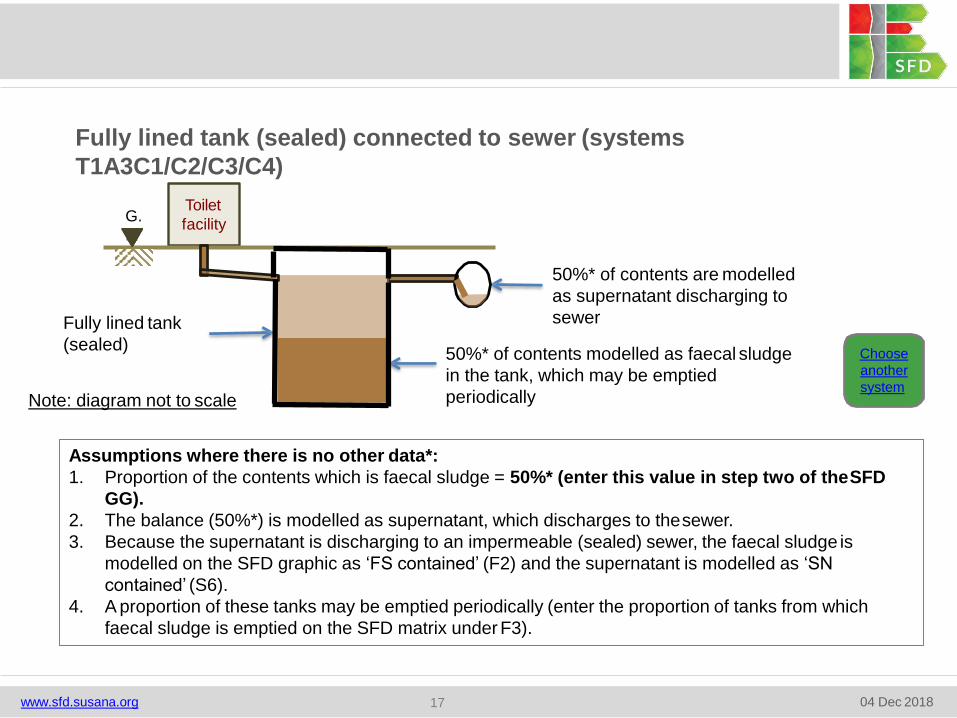
Fully lined tank (sealed) connected to sewer (systems
T1A3C1/C2/C3/C4)
G.
L.
Toilet
facility
50%* of contents are modelled
as supernatant discharging to
sewer
50%* of contents modelled as faecal sludge
in the tank, which may be emptied
periodically
Fully lined tank
(sealed)Choose
another
system
Assumptions where there is no other data*:
1. Proportion of the contents which is faecal sludge = 50%* (enter this value in step two of theSFD
GG).
2. The balance (50%*) is modelled as supernatant, which discharges to thesewer.
3. Because the supernatant is discharging to an impermeable (sealed) sewer, the faecal sludge is
modelled on the SFD graphic as ‘FS contained’ (F2) and the supernatant is modelled as ‘SN
contained’ (S6).
4. A proportion of these tanks may be emptied periodically (enter the proportion of tanks from which
faecal sludge is emptied on the SFD matrix under F3).
Note: diagram not to scale
www.sfd.susana.org 04 Dec 201817
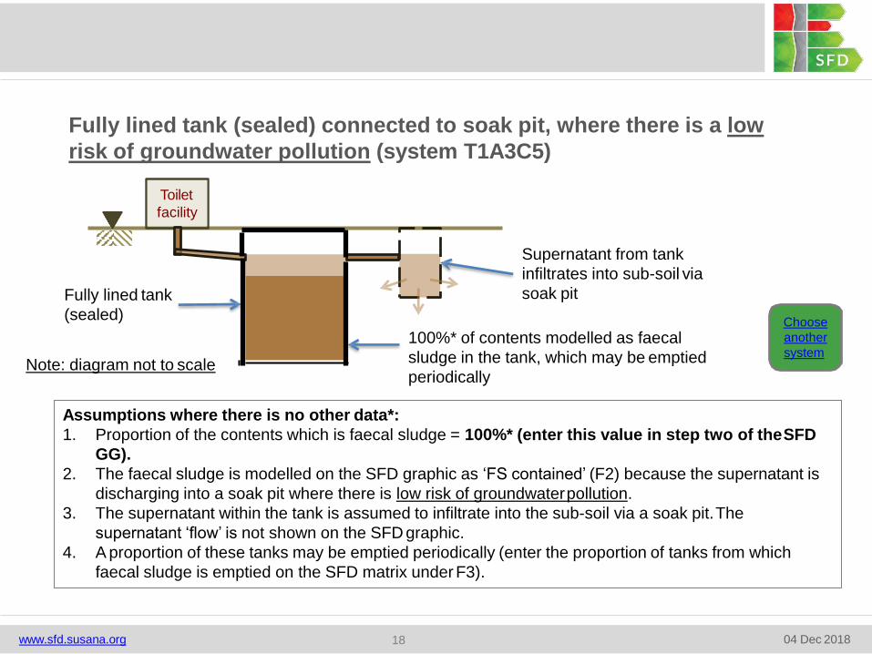
Fully lined tank (sealed) connected to soak pit, where there is a low
risk of groundwater pollution (system T1A3C5)
Choose
another
system
Assumptions where there is no other data*:
1. Proportion of the contents which is faecal sludge = 100%* (enter this value in step two of theSFD
GG).
2. The faecal sludge is modelled on the SFD graphic as ‘FS contained’ (F2) because the supernatant is
discharging into a soak pit where there is low risk of groundwaterpollution.
3. The supernatant within the tank is assumed to infiltrate into the sub-soil via a soak pit.The
supernatant ‘flow’ is not shown on the SFD graphic.
4. A proportion of these tanks may be emptied periodically (enter the proportion of tanks from which
faecal sludge is emptied on the SFD matrix under F3).
Toilet
facility
Supernatant from tank
infiltrates into sub-soil via
soak pit
100%* of contents modelled as faecal
sludge in the tank, which may be emptied
periodically
Fully lined tank
(sealed)
Note: diagram not to scale
www.sfd.susana.org 04 Dec 201818
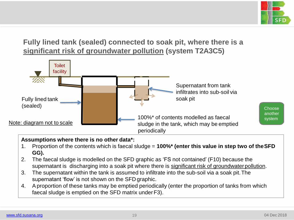
Fully lined tank (sealed) connected to soak pit, where there is a
significant risk of groundwater pollution (system T2A3C5)
Choose
another
system
1. Proportion of the contents which is faecal sludge = 100%* (enter this value in step two of theSFD
GG).
2. The faecal sludge is modelled on the SFD graphic as ‘FS not contained’ (F10) because the
supernatant is discharging into a soak pit where there is significant risk of groundwaterpollution.
3. The supernatant within the tank is assumed to infiltrate into the sub-soil via a soak pit.The
supernatant ‘flow’ is not shown on the SFD graphic.
4. A proportion of these tanks may be emptied periodically (enter the proportion of tanks from which
faecal sludge is emptied on the SFD matrix under F3).
Toilet
facility
Supernatant from tank
infiltrates into sub-soil via
soak pit
100%* of contents modelled as faecal
sludge in the tank, which may be emptied
periodically
Assumptions where there is no other data*:
Fully lined tank
(sealed)
Note: diagram not to scale
www.sfd.susana.org 04 Dec 201819
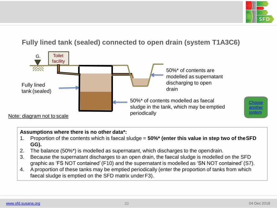
Fully lined tank (sealed) connected to open drain (system T1A3C6)
Assumptions where there is no other data*:
1. Proportion of the contents which is faecal sludge = 50%* (enter this value in step two of theSFD
GG).
2. The balance (50%*) is modelled as supernatant, which discharges to the opendrain.
3. Because the supernatant discharges to an open drain, the faecal sludge is modelled on the SFD
graphic as ‘FS NOT contained’ (F10) and the supernatant is modelled as ‘SN NOT contained’ (S7).
4. A proportion of these tanks may be emptied periodically (enter the proportion of tanks from which
faecal sludge is emptied on the SFD matrix under F3).
Fully lined
tank (sealed)
G.
L.
Toilet
facility
50%* of contents are
modelled as supernatant
discharging to open
drain
50%* of contents modelled as faecal
sludge in the tank, which may be emptied
periodically
Choose
another
systemNote: diagram not to scale
www.sfd.susana.org 04 Dec 201820
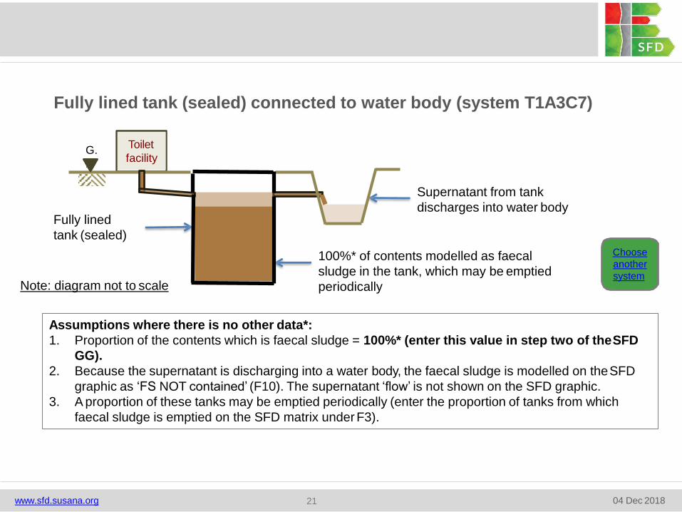
Fully lined tank (sealed) connected to water body (system T1A3C7)
G.
L.
Toilet
facility
100%* of contents modelled as faecal
sludge in the tank, which may be emptied
periodically
Supernatant from tank
discharges into water body
Choose
another
system
Assumptions where there is no other data*:
1. Proportion of the contents which is faecal sludge = 100%* (enter this value in step two of theSFD
GG).
2. Because the supernatant is discharging into a water body, the faecal sludge is modelled on theSFD
graphic as ‘FS NOT contained’ (F10). The supernatant ‘flow’ is not shown on the SFD graphic.
3. A proportion of these tanks may be emptied periodically (enter the proportion of tanks from which
faecal sludge is emptied on the SFD matrix under F3).
Fully lined
tank (sealed)
Note: diagram not to scale
www.sfd.susana.org 04 Dec 201821
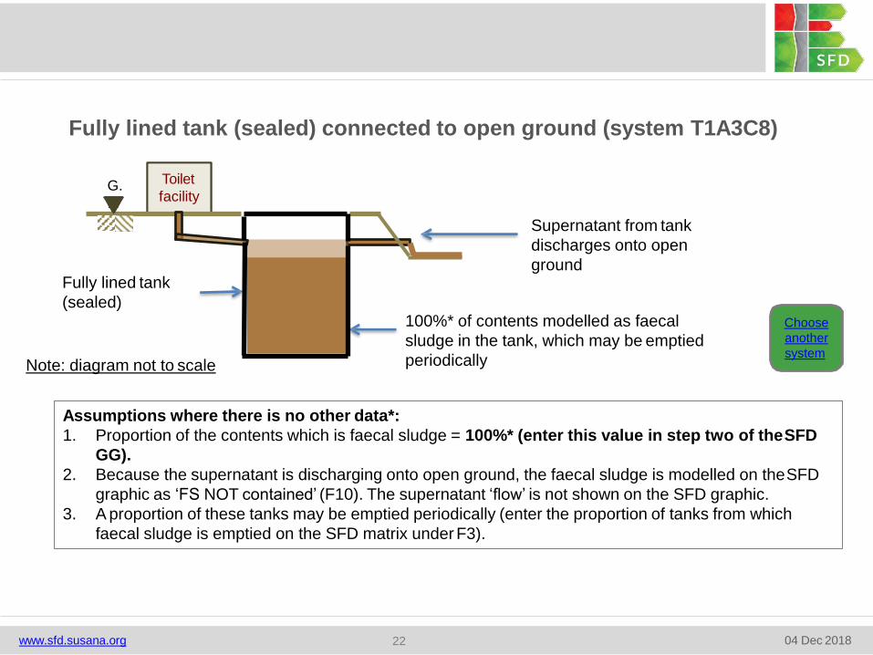
Fully lined tank (sealed) connected to open ground (system T1A3C8)
G.
L.
Toilet
facility
Supernatant from tank
discharges onto open
ground
100%* of contents modelled as faecal
sludge in the tank, which may be emptied
periodically
Choose
another
system
Assumptions where there is no other data*:
1. Proportion of the contents which is faecal sludge = 100%* (enter this value in step two of theSFD
GG).
2. Because the supernatant is discharging onto open ground, the faecal sludge is modelled on theSFD
graphic as ‘FS NOT contained’ (F10). The supernatant ‘flow’ is not shown on the SFD graphic.
3. A proportion of these tanks may be emptied periodically (enter the proportion of tanks from which
faecal sludge is emptied on the SFD matrix under F3).
Fully lined tank
(sealed)
Note: diagram not to scale
www.sfd.susana.org 04 Dec 201822
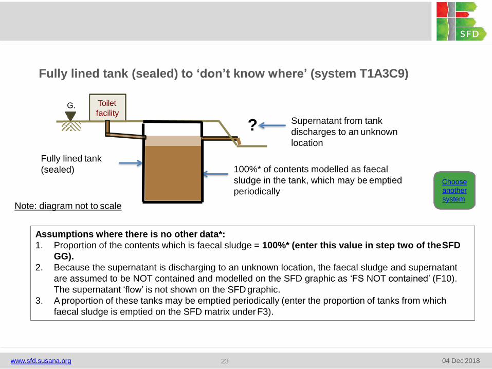
Fully lined tank (sealed) to ‘don’t know where’ (system T1A3C9)
G.
L.
Toilet
facilitySupernatant from tank
discharges to an unknown
location
?
100%* of contents modelled as faecal
sludge in the tank, which may be emptied
periodicallyChoose
another
system
Assumptions where there is no other data*:
1. Proportion of the contents which is faecal sludge = 100%* (enter this value in step two of theSFD
GG).
2. Because the supernatant is discharging to an unknown location, the faecal sludge and supernatant
are assumed to be NOT contained and modelled on the SFD graphic as ‘FS NOT contained’ (F10).
The supernatant ‘flow’ is not shown on the SFD graphic.
3. A proportion of these tanks may be emptied periodically (enter the proportion of tanks from which
faecal sludge is emptied on the SFD matrix under F3).
Fully lined tank
(sealed)
Note: diagram not to scale
www.sfd.susana.org 04 Dec 201823
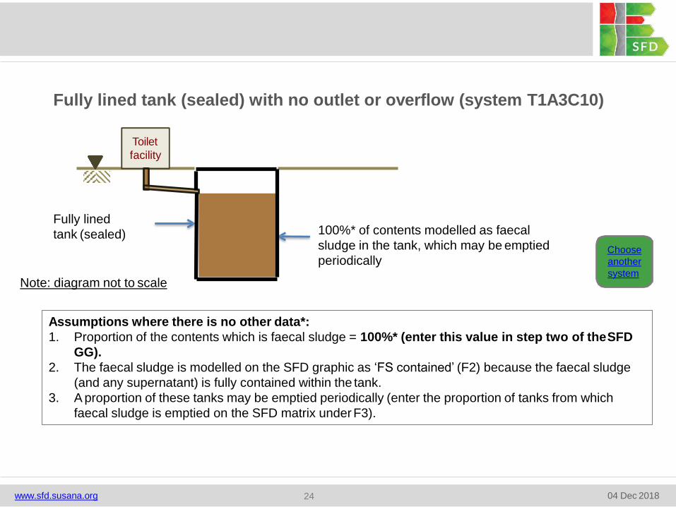
Fully lined tank (sealed) with no outlet or overflow (system T1A3C10)
Toilet
facility
Fully lined
tank (sealed) 100%* of contents modelled as faecal
sludge in the tank, which may be emptied
periodicallyChoose
another
system
Assumptions where there is no other data*:
1. Proportion of the contents which is faecal sludge = 100%* (enter this value in step two of theSFD
GG).
2. The faecal sludge is modelled on the SFD graphic as ‘FS contained’ (F2) because the faecal sludge
(and any supernatant) is fully contained within the tank.
3. A proportion of these tanks may be emptied periodically (enter the proportion of tanks from which
faecal sludge is emptied on the SFD matrix under F3).
Note: diagram not to scale
www.sfd.susana.org 04 Dec 201824
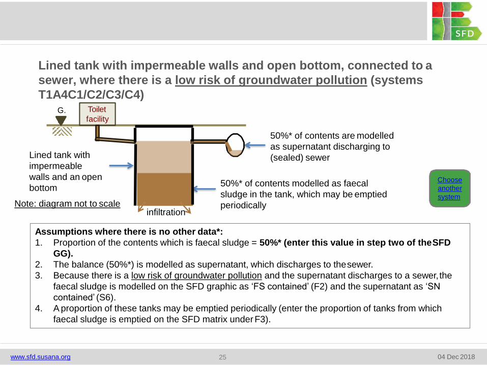
Lined tank with impermeable walls and open bottom, connected to a
sewer, where there is a low risk of groundwater pollution (systems
T1A4C1/C2/C3/C4)
Choose
another
system
Assumptions where there is no other data*:
1. Proportion of the contents which is faecal sludge = 50%* (enter this value in step two of theSFD
GG).
2. The balance (50%*) is modelled as supernatant, which discharges to thesewer.
3. Because there is a low risk of groundwater pollution and the supernatant discharges to a sewer, the
faecal sludge is modelled on the SFD graphic as ‘FS contained’ (F2) and the supernatant as ‘SN
contained’ (S6).
4. A proportion of these tanks may be emptied periodically (enter the proportion of tanks from which
faecal sludge is emptied on the SFD matrix under F3).
50%* of contents are modelled
as supernatant discharging to
(sealed) sewer
50%* of contents modelled as faecal
sludge in the tank, which may be emptied
periodically
G.
L.
Toilet
facility
infiltration
www.sfd.susana.org 04 Dec 201825
Lined tank with
impermeable
walls and an open
bottom
Note: diagram not to scale
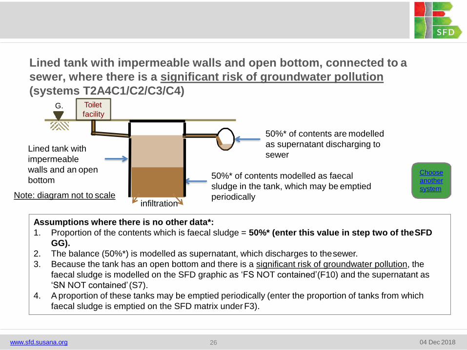
Lined tank with impermeable walls and open bottom, connected to a
sewer, where there is a significant risk of groundwater pollution
(systems T2A4C1/C2/C3/C4)
Choose
another
system
Assumptions where there is no other data*:
1. Proportion of the contents which is faecal sludge = 50%* (enter this value in step two of theSFD
GG).
2. The balance (50%*) is modelled as supernatant, which discharges to thesewer.
3. Because the tank has an open bottom and there is a significant risk of groundwater pollution, the
faecal sludge is modelled on the SFD graphic as ‘FS NOT contained’(F10) and the supernatant as
‘SN NOT contained’ (S7).
4. A proportion of these tanks may be emptied periodically (enter the proportion of tanks from which
faecal sludge is emptied on the SFD matrix under F3).
50%* of contents are modelled
as supernatant discharging to
sewer
50%* of contents modelled as faecal
sludge in the tank, which may be emptied
periodically
G.
L.
Toilet
facility
infiltration
www.sfd.susana.org 04 Dec 201826
Lined tank with
impermeable
walls and an open
bottom
Note: diagram not to scale
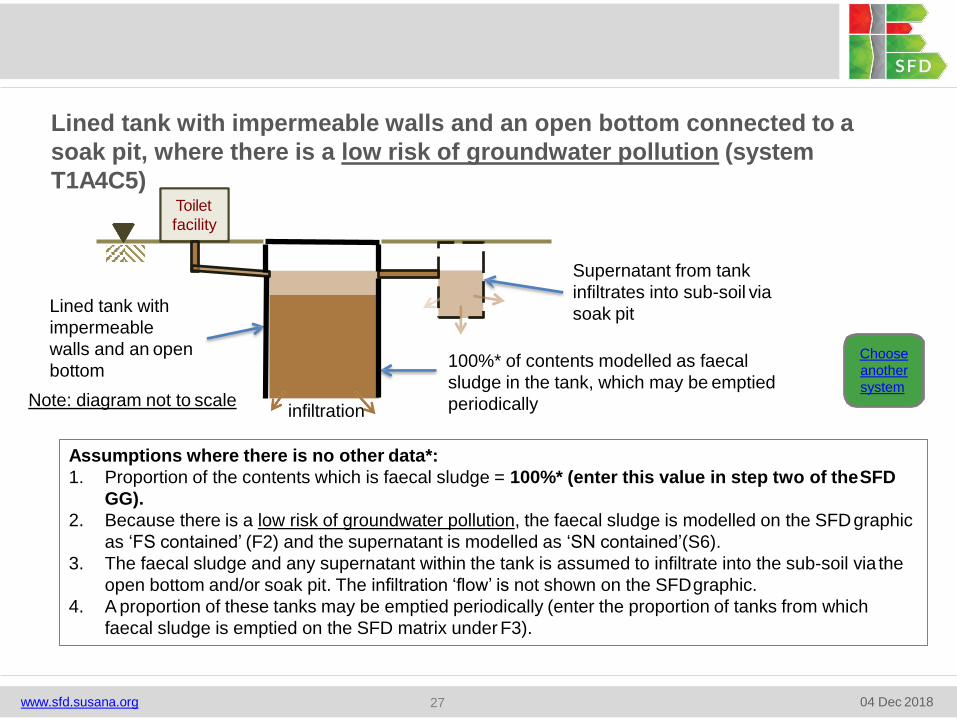
Lined tank with impermeable walls and an open bottom connected to a
soak pit, where there is a low risk of groundwater pollution (system
T1A4C5)
Choose
another
system
Assumptions where there is no other data*:
1. Proportion of the contents which is faecal sludge = 100%* (enter this value in step two of theSFD
GG).
2. Because there is a low risk of groundwater pollution, the faecal sludge is modelled on the SFDgraphic
as ‘FS contained’ (F2) and the supernatant is modelled as ‘SN contained’(S6).
3. The faecal sludge and any supernatant within the tank is assumed to infiltrate into the sub-soil via the
open bottom and/or soak pit. The infiltration ‘flow’ is not shown on the SFDgraphic.
4. A proportion of these tanks may be emptied periodically (enter the proportion of tanks from which
faecal sludge is emptied on the SFD matrix under F3).
Toilet
facility
Supernatant from tank
infiltrates into sub-soil via
soak pit
100%* of contents modelled as faecal
sludge in the tank, which may be emptied
periodicallyinfiltration
www.sfd.susana.org 04 Dec 201827
Lined tank with
impermeable
walls and an open
bottom
Note: diagram not to scale
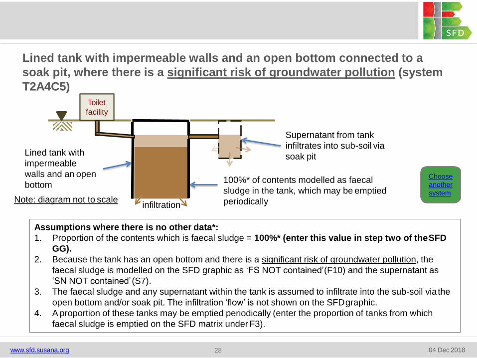
Lined tank with impermeable walls and an open bottom connected to a
soak pit, where there is a significant risk of groundwater pollution (system
T2A4C5)
Choose
another
system
Assumptions where there is no other data*:
1. Proportion of the contents which is faecal sludge = 100%* (enter this value in step two of theSFD
GG).
2. Because the tank has an open bottom and there is a significant risk of groundwater pollution, the
faecal sludge is modelled on the SFD graphic as ‘FS NOT contained’(F10) and the supernatant as
‘SN NOT contained’ (S7).
3. The faecal sludge and any supernatant within the tank is assumed to infiltrate into the sub-soil via the
open bottom and/or soak pit. The infiltration ‘flow’ is not shown on the SFDgraphic.
4. A proportion of these tanks may be emptied periodically (enter the proportion of tanks from which
faecal sludge is emptied on the SFD matrix underF3).
Toilet
facility
Supernatant from tank
infiltrates into sub-soil via
soak pit
100%* of contents modelled as faecal
sludge in the tank, which may be emptied
periodicallyinfiltration
www.sfd.susana.org 04 Dec 201828
Lined tank with
impermeable
walls and an open
bottom
Note: diagram not to scale
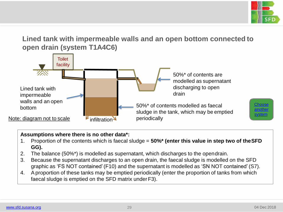
Lined tank with impermeable walls and an open bottom connected to
open drain (system T1A4C6)
Assumptions where there is no other data*:
1. Proportion of the contents which is faecal sludge = 50%* (enter this value in step two of theSFD
GG).
2. The balance (50%*) is modelled as supernatant, which discharges to the opendrain.
3. Because the supernatant discharges to an open drain, the faecal sludge is modelled on the SFD
graphic as ‘FS NOT contained’ (F10) and the supernatant is modelled as ‘SN NOT contained’ (S7).
4. A proportion of these tanks may be emptied periodically (enter the proportion of tanks from which
faecal sludge is emptied on the SFD matrix under F3).
50%* of contents are
modelled as supernatant
discharging to open
drain
50%* of contents modelled as faecal
sludge in the tank, which may be emptied
periodically
Choose
another
system
Toilet
facility
infiltration
www.sfd.susana.org 04 Dec 201829
Lined tank with
impermeable
walls and an open
bottom
Note: diagram not to scale
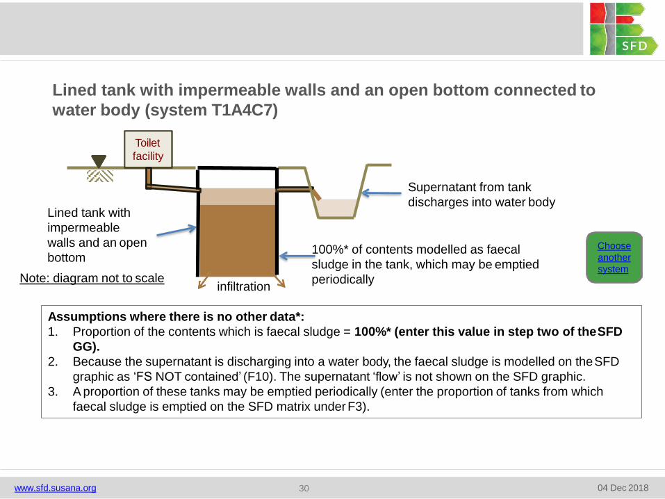
Lined tank with impermeable walls and an open bottom connected to
water body (system T1A4C7)
100%* of contents modelled as faecal
sludge in the tank, which may be emptied
periodically
Supernatant from tank
discharges into water body
Choose
another
system
Assumptions where there is no other data*:
1. Proportion of the contents which is faecal sludge = 100%* (enter this value in step two of theSFD
GG).
2. Because the supernatant is discharging into a water body, the faecal sludge is modelled on theSFD
graphic as ‘FS NOT contained’ (F10). The supernatant ‘flow’ is not shown on the SFD graphic.
3. A proportion of these tanks may be emptied periodically (enter the proportion of tanks from which
faecal sludge is emptied on the SFD matrix under F3).
Toilet
facility
infiltration
www.sfd.susana.org 04 Dec 201830
Lined tank with
impermeable
walls and an open
bottom
Note: diagram not to scale
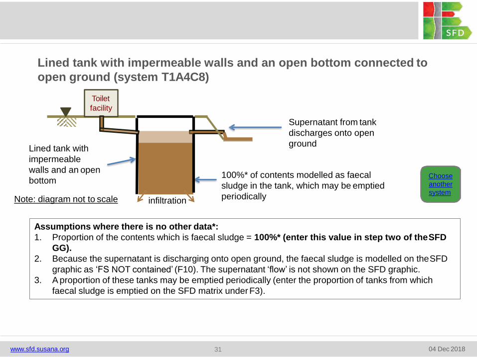
Lined tank with impermeable walls and an open bottom connected to
open ground (system T1A4C8)
Supernatant from tank
discharges onto open
ground
100%* of contents modelled as faecal
sludge in the tank, which may be emptied
periodically
Choose
another
system
Assumptions where there is no other data*:
1. Proportion of the contents which is faecal sludge = 100%* (enter this value in step two of theSFD
GG).
2. Because the supernatant is discharging onto open ground, the faecal sludge is modelled on theSFD
graphic as ‘FS NOT contained’ (F10). The supernatant ‘flow’ is not shown on the SFD graphic.
3. A proportion of these tanks may be emptied periodically (enter the proportion of tanks from which
faecal sludge is emptied on the SFD matrix under F3).
Lined tank with
impermeable
walls and an open
bottom
Toilet
facility
infiltration
www.sfd.susana.org 04 Dec 201831
Note: diagram not to scale
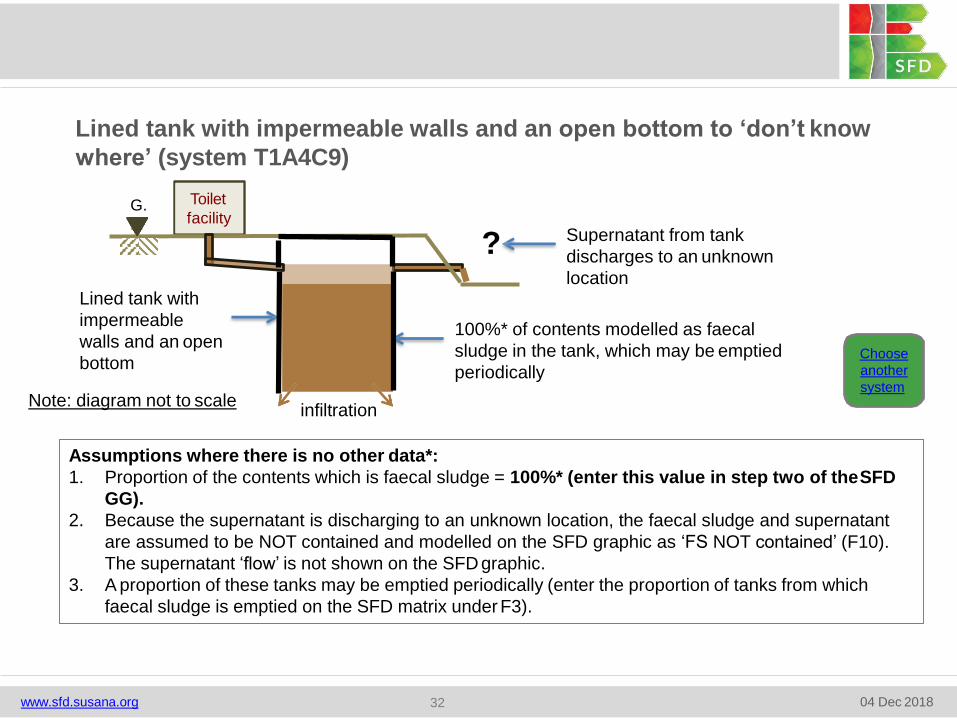
Lined tank with impermeable walls and an open bottom to ‘don’t know
where’ (system T1A4C9)
G.
L.
Toilet
facilitySupernatant from tank
discharges to an unknown
location
?
100%* of contents modelled as faecal
sludge in the tank, which may be emptied
periodicallyChoose
another
system
Assumptions where there is no other data*:
1. Proportion of the contents which is faecal sludge = 100%* (enter this value in step two of theSFD
GG).
2. Because the supernatant is discharging to an unknown location, the faecal sludge and supernatant
are assumed to be NOT contained and modelled on the SFD graphic as ‘FS NOT contained’ (F10).
The supernatant ‘flow’ is not shown on the SFD graphic.
3. A proportion of these tanks may be emptied periodically (enter the proportion of tanks from which
faecal sludge is emptied on the SFD matrix under F3).
infiltration
www.sfd.susana.org 04 Dec 201832
Lined tank with
impermeable
walls and an open
bottom
Note: diagram not to scale
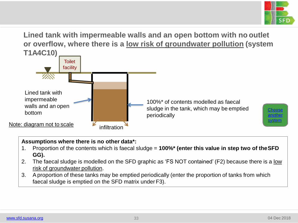
Lined tank with impermeable walls and an open bottom with no outlet
or overflow, where there is a low risk of groundwater pollution (system
T1A4C10)
Choose
another
system
Assumptions where there is no other data*:
1. Proportion of the contents which is faecal sludge = 100%* (enter this value in step two of theSFD
GG).
2. The faecal sludge is modelled on the SFD graphic as ‘FS NOT contained’ (F2) because there is a low
risk of groundwater pollution.
3. A proportion of these tanks may be emptied periodically (enter the proportion of tanks from which
faecal sludge is emptied on the SFD matrix under F3).
Lined tank with
impermeable
walls and an open
bottom
Toilet
facility
infiltration
100%* of contents modelled as faecal
sludge in the tank, which may be emptied
periodically
www.sfd.susana.org 04 Dec 201833
Note: diagram not to scale
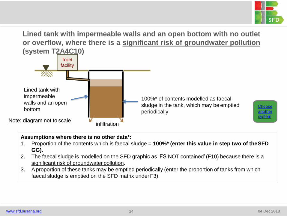
Lined tank with impermeable walls and an open bottom with no outlet
or overflow, where there is a significant risk of groundwater pollution
(system T2A4C10)
Choose
another
system
Assumptions where there is no other data*:
1. Proportion of the contents which is faecal sludge = 100%* (enter this value in step two of theSFD
GG).
2. The faecal sludge is modelled on the SFD graphic as ‘FS NOT contained’ (F10) because there is a
significant risk of groundwater pollution.
3. A proportion of these tanks may be emptied periodically (enter the proportion of tanks from which
faecal sludge is emptied on the SFD matrix under F3).
Lined tank with
impermeable
walls and an open
bottom
Toilet
facility
infiltration
100%* of contents modelled as faecal
sludge in the tank, which may be emptied
periodically
www.sfd.susana.org 04 Dec 201834
Note: diagram not to scale
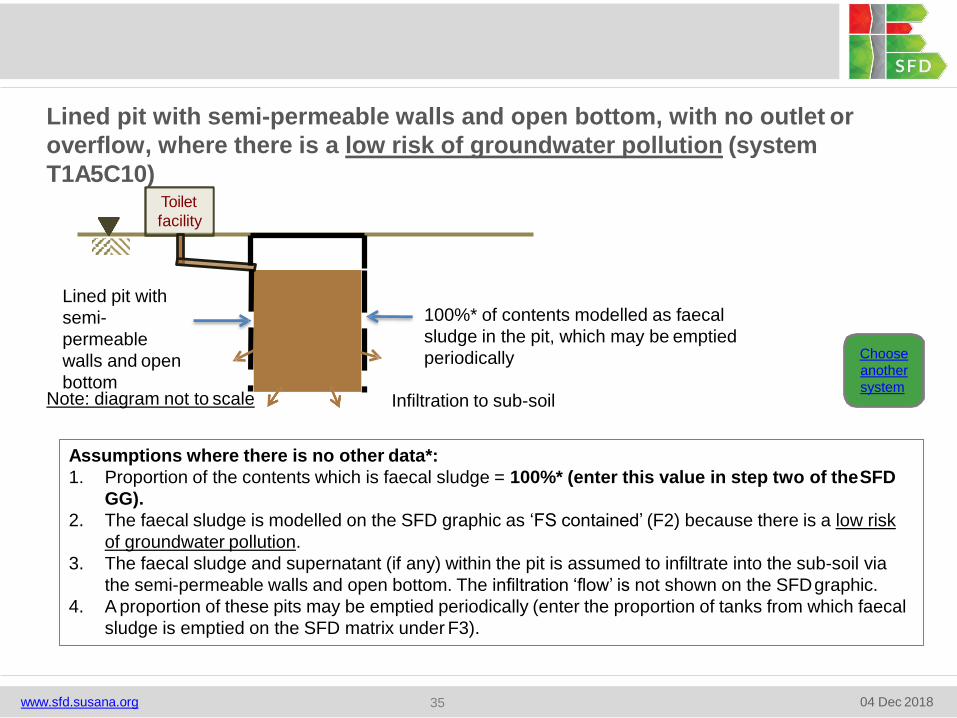
Lined pit with semi-permeable walls and open bottom, with no outlet or
overflow, where there is a low risk of groundwater pollution (system
T1A5C10)Toilet
facility
Lined pit with
semi-
permeable
walls and open
bottom
100%* of contents modelled as faecal
sludge in the pit, which may be emptied
periodically
Infiltration to sub-soilNote: diagram not to scale
Choose
another
system
Assumptions where there is no other data*:
1. Proportion of the contents which is faecal sludge = 100%* (enter this value in step two of theSFD
GG).
2. The faecal sludge is modelled on the SFD graphic as ‘FS contained’ (F2) because there is a low risk
of groundwater pollution.
3. The faecal sludge and supernatant (if any) within the pit is assumed to infiltrate into the sub-soil via
the semi-permeable walls and open bottom. The infiltration ‘flow’ is not shown on the SFDgraphic.
4. A proportion of these pits may be emptied periodically (enter the proportion of tanks from which faecal
sludge is emptied on the SFD matrix under F3).
www.sfd.susana.org 04 Dec 201835

Lined pit with semi-permeable walls and open bottom, with no outlet or
overflow, where there is a significant risk of groundwater pollution (system
T2A5C10)
Choose
another
system
Assumptions where there is no other data*:
1. Proportion of the contents which is faecal sludge = 100%* (enter this value in step two of theSFD
GG).
2. The faecal sludge is modelled on the SFD graphic as ‘FS NOT contained’ (F10) because there is a
significant risk of groundwater pollution.
3. The faecal sludge and supernatant (if any) within the pit is assumed to infiltrate into the sub-soil via
the semi-permeable walls and open bottom. The infiltration ‘flow’ is not shown on the SFDgraphic.
4. A proportion of these pits may be emptied periodically (enter the proportion of tanks from which
faecal sludge is emptied on the SFD matrix under F3).
Toilet
facility
Lined pit with
semi-permeable
walls and open
bottom
100%* of contents modelled as faecal
sludge in the pit, which may be emptied
periodically
Infiltration to sub-soilNote: diagram not to scale
www.sfd.susana.org 04 Dec 201836

Unlined pit, with no outlet or overflow, where there is a low risk of
groundwater pollution (system T1A6C10)
Choose
another
system
Assumptions where there is no other data*:
1. Proportion of the contents which is faecal sludge = 100%* (enter this value in step two of theSFD
GG).
2. The faecal sludge is modelled on the SFD graphic as ‘FS contained’ (F2) because there is a low risk
of groundwater pollution.
3. The faecal sludge and supernatant (if any) within the pit is assumed to infiltrate into the sub-soil via
the unlined walls and open bottom. The infiltration ‘flow’ is not shown on the SFDgraphic.
4. A proportion of these pits may be emptied periodically (enter the proportion of tanks from which faecal
sludge is emptied on the SFD matrix under F3).
Toilet
facility
100%* of contents modelled as faecal
sludge in the pit, which may be emptied
periodically
Infiltration to sub-soil
Unlined pit
Note: diagram not to scale
www.sfd.susana.org 04 Dec 201837
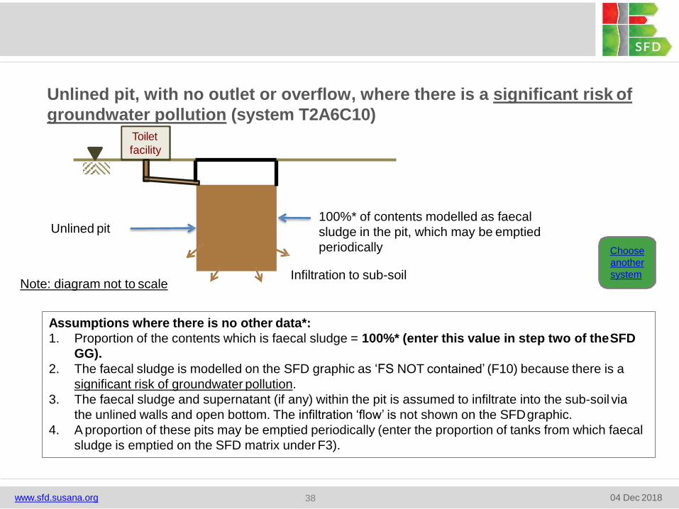
Unlined pit, with no outlet or overflow, where there is a significant risk of
groundwater pollution (system T2A6C10)
Choose
another
system
Assumptions where there is no other data*:
1. Proportion of the contents which is faecal sludge = 100%* (enter this value in step two of theSFD
GG).
2. The faecal sludge is modelled on the SFD graphic as ‘FS NOT contained’ (F10) because there is a
significant risk of groundwater pollution.
3. The faecal sludge and supernatant (if any) within the pit is assumed to infiltrate into the sub-soil via
the unlined walls and open bottom. The infiltration ‘flow’ is not shown on the SFDgraphic.
4. A proportion of these pits may be emptied periodically (enter the proportion of tanks from which faecal
sludge is emptied on the SFD matrix under F3).
Toilet
facility
100%* of contents modelled as faecal
sludge in the pit, which may be emptied
periodically
Infiltration to sub-soil
Unlined pit
Note: diagram not to scale
www.sfd.susana.org 04 Dec 201838
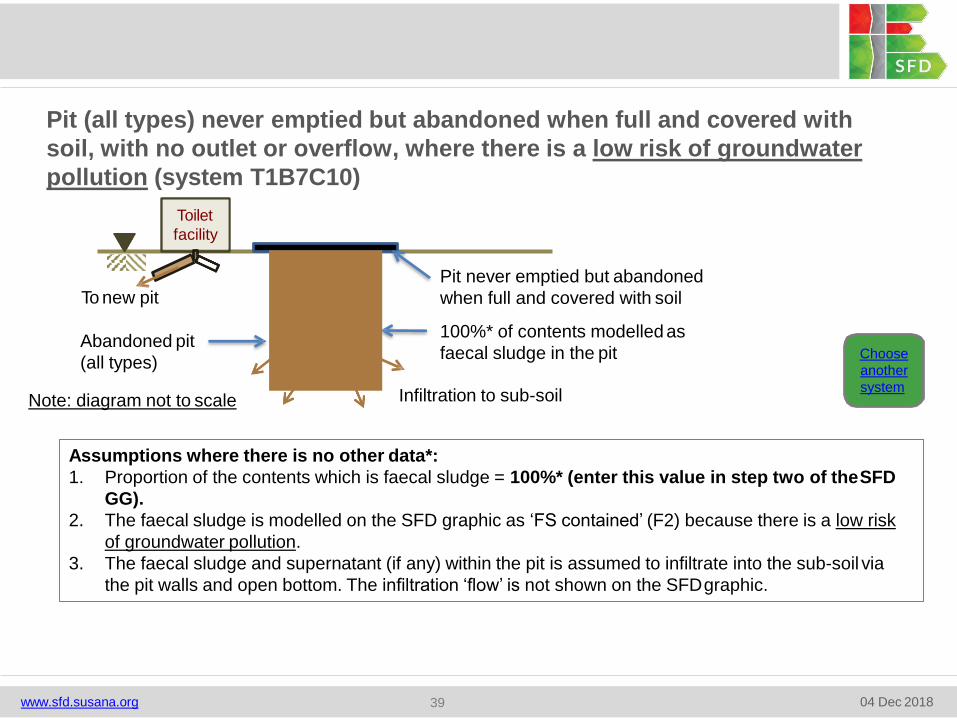
Pit (all types) never emptied but abandoned when full and covered with
soil, with no outlet or overflow, where there is a low risk of groundwater
pollution (system T1B7C10)
Toilet
facility
Pit never emptied but abandoned
when full and covered with soil
100%* of contents modelled as
faecal sludge in the pit
Infiltration to sub-soil
Abandoned pit
(all types)
To new pit
Choose
another
system
Assumptions where there is no other data*:
1. Proportion of the contents which is faecal sludge = 100%* (enter this value in step two of theSFD
GG).
2. The faecal sludge is modelled on the SFD graphic as ‘FS contained’ (F2) because there is a low risk
of groundwater pollution.
3. The faecal sludge and supernatant (if any) within the pit is assumed to infiltrate into the sub-soil via
the pit walls and open bottom. The infiltration ‘flow’ is not shown on the SFDgraphic.
Note: diagram not to scale
www.sfd.susana.org 04 Dec 201839
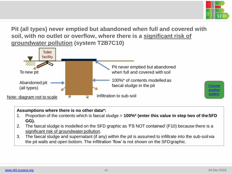
Pit (all types) never emptied but abandoned when full and covered with
soil, with no outlet or overflow, where there is a significant risk of
groundwater pollution (system T2B7C10)
Choose
another
system
Assumptions where there is no other data*:
1. Proportion of the contents which is faecal sludge = 100%* (enter this value in step two of theSFD
GG).
2. The faecal sludge is modelled on the SFD graphic as ‘FS NOT contained’ (F10) because there is a
significant risk of groundwater pollution.
3. The faecal sludge and supernatant (if any) within the pit is assumed to infiltrate into the sub-soil via
the pit walls and open bottom. The infiltration ‘flow’ is not shown on the SFDgraphic.
Toilet
facility
Pit never emptied but abandoned
when full and covered with soil
100%* of contents modelled as
faecal sludge in the pit
Infiltration to sub-soil
Abandoned pit
(all types)
To new pit
Note: diagram not to scale
www.sfd.susana.org 04 Dec 201840
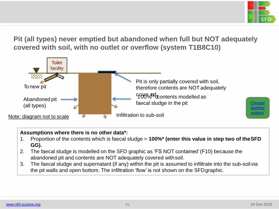
Pit (all types) never emptied but abandoned when full but NOT adequately
covered with soil, with no outlet or overflow (system T1B8C10)
Choose
another
system
Assumptions where there is no other data*:
1. Proportion of the contents which is faecal sludge = 100%* (enter this value in step two of theSFD
GG).
2. The faecal sludge is modelled on the SFD graphic as ‘FS NOT contained’ (F10) because the
abandoned pit and contents are NOT adequately covered withsoil.
3. The faecal sludge and supernatant (if any) within the pit is assumed to infiltrate into the sub-soil via
the pit walls and open bottom. The infiltration ‘flow’ is not shown on the SFDgraphic.
Toilet
facility
Pit is only partially covered with soil,
therefore contents are NOTadequately
c1o0v0e%re*dof contents modelled as
faecal sludge in the pit
Infiltration to sub-soil
Abandoned pit
(all types)
To new pit
Note: diagram not to scale
www.sfd.susana.org 04 Dec 201841
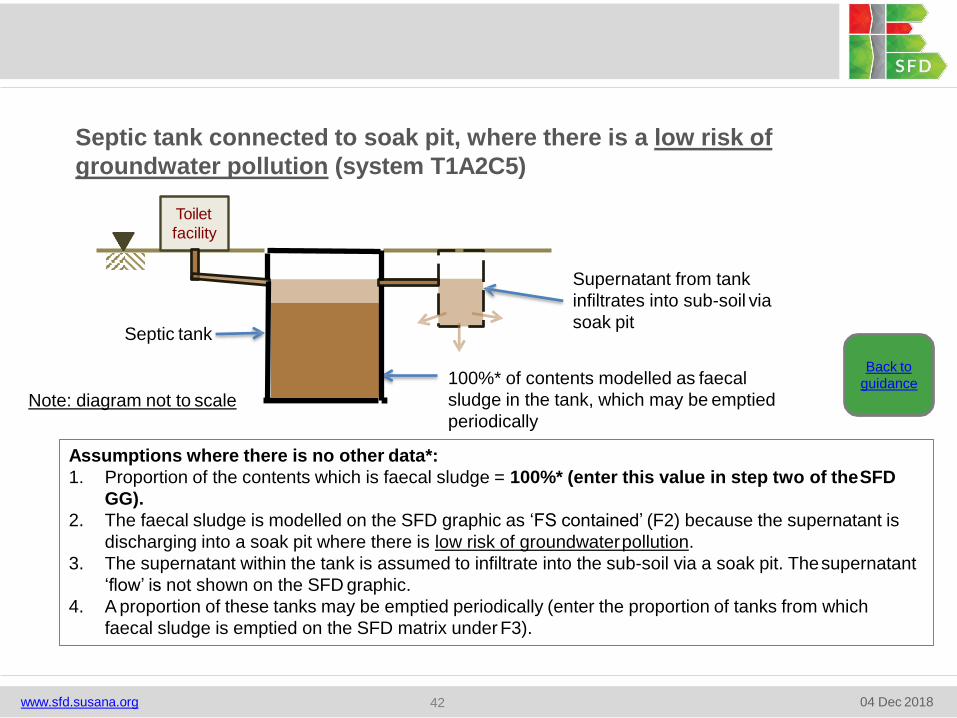
Septic tank connected to soak pit, where there is a low risk of
groundwater pollution (system T1A2C5)
Toilet
facility
Supernatant from tank
infiltrates into sub-soil via
soak pit
100%* of contents modelled as faecal
sludge in the tank, which may be emptied
periodically
Septic tank
Back to
guidance
Assumptions where there is no other data*:
1. Proportion of the contents which is faecal sludge = 100%* (enter this value in step two of theSFD
GG).
2. The faecal sludge is modelled on the SFD graphic as ‘FS contained’ (F2) because the supernatant is
discharging into a soak pit where there is low risk of groundwaterpollution.
3. The supernatant within the tank is assumed to infiltrate into the sub-soil via a soak pit. Thesupernatant
‘flow’ is not shown on the SFD graphic.
4. A proportion of these tanks may be emptied periodically (enter the proportion of tanks from which
faecal sludge is emptied on the SFD matrix under F3).
Note: diagram not to scale
www.sfd.susana.org 04 Dec 201842
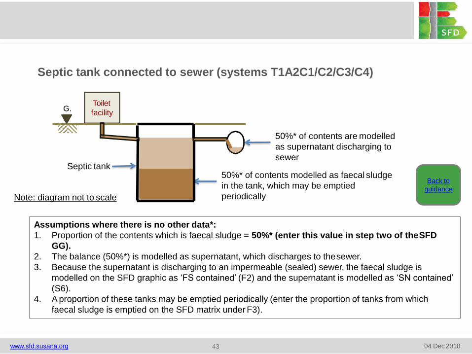
Septic tank connected to sewer (systems T1A2C1/C2/C3/C4)
G.
L.
Toilet
facility
50%* of contents are modelled
as supernatant discharging to
sewer
50%* of contents modelled as faecal sludge
in the tank, which may be emptied
periodically
Septic tank
Assumptions where there is no other data*:
1. Proportion of the contents which is faecal sludge = 50%* (enter this value in step two of theSFD
GG).
2. The balance (50%*) is modelled as supernatant, which discharges to thesewer.
3. Because the supernatant is discharging to an impermeable (sealed) sewer, the faecal sludge is
modelled on the SFD graphic as ‘FS contained’ (F2) and the supernatant is modelled as ‘SN contained’
(S6).
4. A proportion of these tanks may be emptied periodically (enter the proportion of tanks from which
faecal sludge is emptied on the SFD matrix under F3).
Note: diagram not to scale
Back to
guidance
www.sfd.susana.org 04 Dec 201843

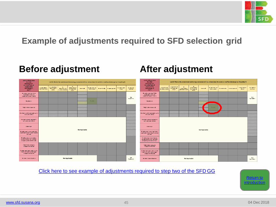
Example of adjustments required to SFD selection grid
Before adjustment After adjustment
Click here to see example of adjustments required to step two of the SFD GG
Return to
introduction
www.sfd.susana.org 04 Dec 201845
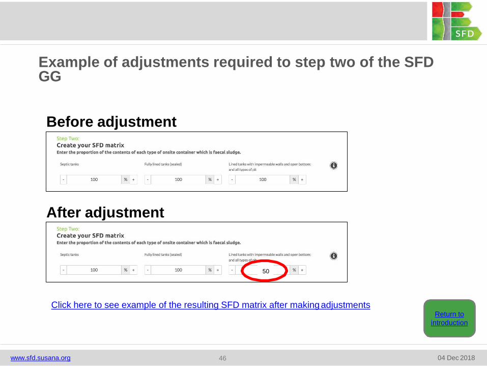
Before adjustment
After adjustment
50
Click here to see example of the resulting SFD matrix after making adjustments
Example of adjustments required to step two of the SFD GG
Return to
introduction
www.sfd.susana.org 04 Dec 201846
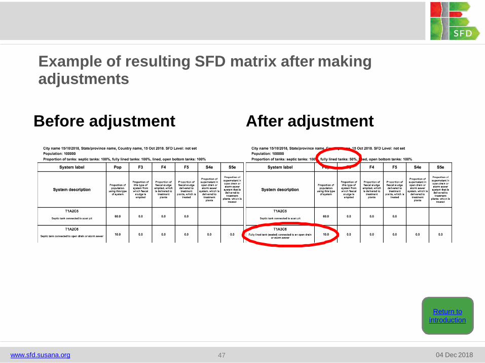
Before adjustment After adjustment
Example of resulting SFD matrix after makingadjustments
Return to
introduction
www.sfd.susana.org 04 Dec 201847
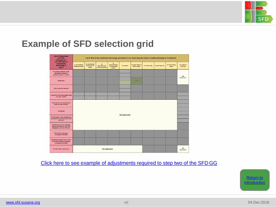
Example of SFD selection grid
Click here to see example of adjustments required to step two of the SFD GG
Return to
introduction
www.sfd.susana.org 04 Dec 201848
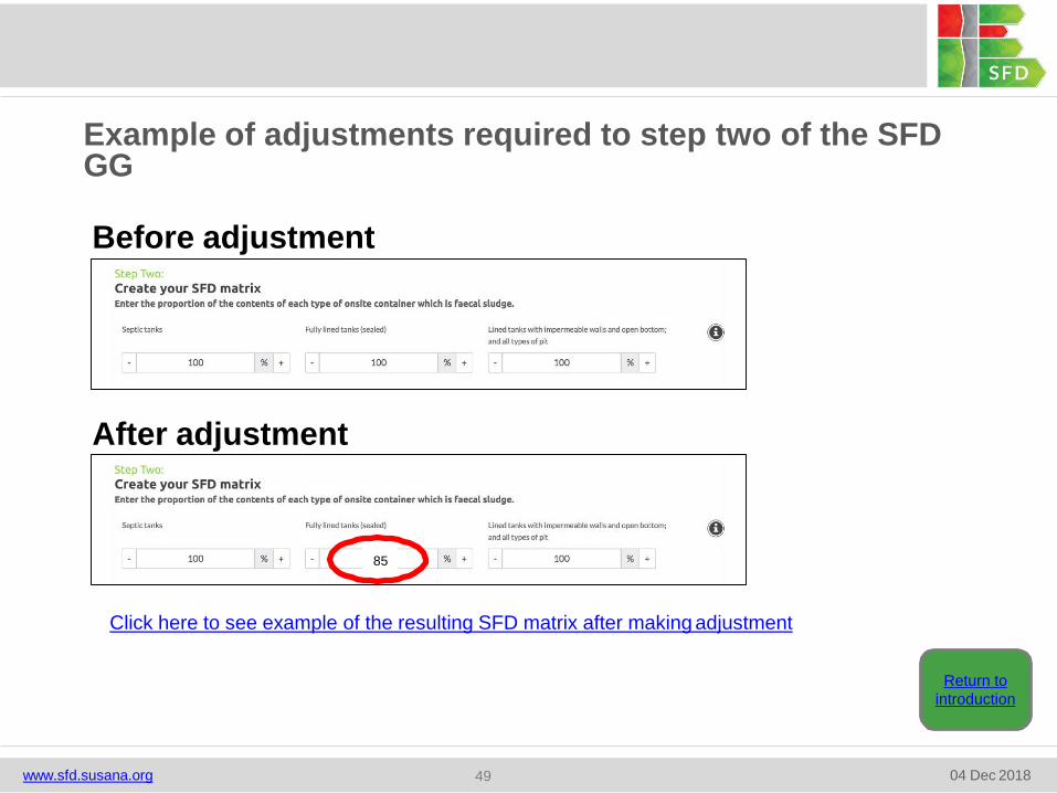
Before adjustment
After adjustment
85
Click here to see example of the resulting SFD matrix after making adjustment
Example of adjustments required to step two of the SFD GG
Return to
introduction
www.sfd.susana.org 04 Dec 201849
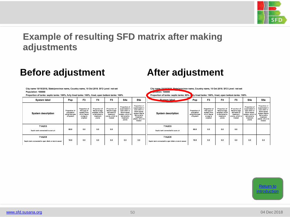
Before adjustment After adjustment
Example of resulting SFD matrix after makingadjustments
Return to
introduction
www.sfd.susana.org 04 Dec 201850