understandingorganizational style and … style 2 ... place demands.virtual enterprises use networks...
TRANSCRIPT
2UNDERSTANDINGORGANIZATIONAL STYLEAND ITS IMPACT ONINFORMATION SYSTEMS
LEARNING OBJECTIVES
Once you have mastered the material in this chapter you will be able to:
1. Understand that organizations and their members are systems and that analysts need to take a systems perspective.
2. Depict systems graphically using context-level data flow diagrams, entity-relationship models, anduse cases and use case scenarios.
3. Recognize that different levels of management require different systems.
4. Comprehend that organizational culture impacts the design of information systems.
To analyze and design appropriate information systems, systems analysts need tocomprehend the organizations they work in as systems shaped through the inter-actions of three main forces: the levels of management, design of organizations,and organizational cultures.
Organizations are large systems composed of interrelated subsystems.The sub-systems are influenced by three broad levels of management decision makers(operations, middle management, and strategic management) that cut horizontallyacross the organizational system. Organizational cultures and subcultures all influ-ence the way people in subsystems interrelate. These topics and their implicationsfor information systems development are considered in this chapter.
ORGANIZATIONS AS SYSTEMSOrganizations and their members are usefully conceptualized as systems designedto accomplish predetermined goals and objectives through people and otherresources that they employ. Organizations are composed of smaller, interrelatedsystems (departments, units, divisions, etc.) serving specialized functions. Typicalfunctions include accounting, marketing, production, data processing, and man-agement. Specialized functions (smaller systems) are eventually reintegratedthrough various mechanisms to form an effective organizational whole.
The significance of conceptualizing organizations as complex systems is thatsystems principles allow insight into how organizations work. To ascertain infor-mation requirements properly and to design appropriate information systems, it is
27
KENDMC02_0132240858.QXD 2/7/07 5:13 PM Page 27

28 P A R T I SYSTEMS ANALYSIS FUNDAMENTALS
of primary importance to understand the organization as a whole. All systems arecomposed of subsystems (which include information systems); therefore, whenstudying an organization, we also examine how smaller systems are involved andhow they function.
INTERRELATEDNESS AND INTERDEPENDENCE OF SYSTEMS
All systems and subsystems are interrelated and interdependent. This fact hasimportant implications both for organizations and for those systems analysts whoseek to help them better achieve their goals. When any element of a system ischanged or eliminated, the rest of the system’s elements and subsystems are alsosignificantly affected.
For example, suppose that the administrators of an organization decide not tohire personal secretaries any longer and to replace their functions with networkedPCs. This decision has the potential to significantly affect not only the secretariesand the administrators but also all the organizational members who built up com-munications networks with the now departed secretaries.
All systems process inputs from their environments. By definition, processeschange or transform inputs into outputs. Whenever you examine a system, checkto see what is being changed or processed. If nothing is changed, you may not beidentifying a process. Typical processes in systems include verifying, updating, andprinting.
Another aspect of organizations as systems is that all systems are contained byboundaries separating them from their environments. Organizational boundariesexist on a continuum ranging from extremely permeable to almost impermeable.Tocontinue to adapt and survive, organizations must be able first to import people, rawmaterials, and information through their boundaries (inputs), and then to exchangetheir finished products, services, or information with the outside world (outputs).
Feedback is one form of system control. As systems, all organizations use plan-ning and control to manage their resources effectively. Figure 2.1 shows how sys-tem outputs are used as feedback that compares performance with goals. Thiscomparison in turn helps administrators formulate more specific goals as inputs.An example is a manufacturing company that produces red-white-and-blueweight-training sets as well as gun-metal gray sets. The company finds that oneyear after the Olympics, very few red-white-and-blue sets are purchased.Production managers use that information as feedback to make decisions aboutwhat quantities of each color to produce. Feedback in this instance is useful forplanning and control.
The ideal system, however, is one that self-corrects or self-regulates in sucha way that decisions on typical occurrences are not required. An example is acomputerized information system for production planning that takes into accountcurrent and projected demand and formulates a proposed solution as output. AnItalian knitwear manufacturer that markets its clothing in the United States has just
Goals
System
OutputsInputs
FIGURE 2.1System outputs serve as feedback that compares performance with goals.
KENDMC02_0132240858.QXD 2/7/07 5:13 PM Page 28

UNDERSTANDING ORGANIZATIONAL STYLE AND ITS IMPACT ON INFORMATION SYSTEMS C H A P T E R 2 29
such a system. This company produces most of its sweaters in white, uses its com-puterized inventory information system to find out what colors are selling best, andthen dyes sweaters in hot-selling colors immediately before shipping them.
Feedback is received from within the organization and from the outside envi-ronments around it.Anything external to an organization’s boundaries is consideredto be an environment. Numerous environments, with varying degrees of stability,constitute the milieu in which organizations exist.
Among these environments are (1) the environment of the community inwhich the organization is physically located, which is shaped by the size of itspopulation and its demographic profile, including factors such as education andaverage income; (2) the economic environment, influenced by market factors,including competition; and (3) the political environment, controlled through stateand local governments. Although changes in environmental status can be plannedfor, they often cannot be directly controlled by the organization.
Related and similar to the concept of external boundary permeability is theconcept of internal openness or closedness of organizations. Openness and closed-ness also exist on a continuum, because there is no such thing as an absolutelyopen or completely closed organization.
Openness refers to the free flow of information within the organization.Subsystems such as creative or art departments often are characterized as open,with a free flow of ideas among participants and very few restrictions on who getswhat information at what time when a creative project is in its infancy.
At the opposite end of the continuum might be a defense department unitassigned to work on top-secret defense planning affecting national security. Eachperson needs to receive clearance, timely information is a necessity, and access toinformation is only on a “need to know” basis. This sort of unit is limited bynumerous rules.
Using a systems overlay to understand organizations allows us to acknowledgethe idea of systems composed of subsystems; their interrelatedness and their inter-dependence; the existence of boundaries that allow or prevent interaction betweenvarious departments and elements of other subsystems and environments; and theexistence of internal environments characterized by degrees of openness andclosedness, which might differ across departments, units, or even projects.
VIRTUAL ORGANIZATIONS AND VIRTUAL TEAMS
Not all organizations or parts of organizations are visible in a physical location.Entire organizations or units of organizations can now possess virtual componentsthat permit them to change configurations to adapt to changing project or market-place demands.Virtual enterprises use networks of computers and communicationstechnology to bring people with specific skills together electronically to work onprojects that are not physically located in the same place. Information technologyenables coordination of these remote team members. Often virtual teams spring upin already-established organizations; in some instances, however, organizations ofremote workers have been able to succeed without the traditional investment ininfrastructure.
There are several potential benefits to virtual organizations, such as the pos-sibility of reducing costs of physical facilities, more rapid response to customerneeds, and helping virtual employees to fulfill their familial obligations to childrenor aging parents. Just how important it will be to meet the social needs of virtualworkers is still open to research and debate. One example of a need for tangibleidentification with a culture arose when students who were enrolled in an onlinevirtual university, with no physical campus (or sports teams), kept requesting
KENDMC02_0132240858.QXD 2/7/07 5:13 PM Page 29

30 P A R T I SYSTEMS ANALYSIS FUNDAMENTALS
C O N S U L T I N G O P P O R T U N I T Y 2 . 1
“Our retail shops and mail-order division are quite healthy,” saysBill Berry, one of the owners of Marathon Vitamin Shops, “but to becompetitive, we must establish an ecommerce Web site.” His father,and coowner, exclaims, “I agree, but where do we start?” The elderBerry knew, of course, that it wasn’t a case of setting up a Web siteand asking customers to email their orders to the retail store. Heidentified eight different parts to ecommerce and realized that theywere all part of a larger system. In other words, all the parts had towork together to create a strong package. His list of elements essen-tial to ecommerce included the following:
1. Attracting customers to an ecommerce Web site.2. Informing customers about products and services offered.3. Allowing customers to customize products online.4. Completing transactions with customers.5. Accepting payment from customers in a variety of forms.6. Supporting customers after the sale via the Web site.7. Arranging for the delivery of goods and services.8. Personalizing the look and feel of the Web site for different
customers.
Bill Berry read the list and contemplated it for a while. “It is obvi-ous that ecommerce is more complex than I thought,” he says. Youcan help the owners of Marathon Vitamin Shops in the followingways:
1. Make a list of the elements that are interrelated or interdependent.Then write a paragraph stating why it is critical to monitor theseelements closely.
2. Decide on the boundaries of the system. That is, write a para-graph expressing an opinion on which elements are critical forMarathon Vitamin Shops and which elements can be explored ata later date.
3. Suggest which elements should be handled in-house andwhich should be outsourced to another company that may bebetter able to handle the job. Justify your suggestions in twoparagraphs, one for the in-house jobs and one for the out-sourced tasks.
THE E IN VITAMIN E STANDS FOR ECOMMERCE
items such as sweatshirts, coffee mugs, and pennants with the virtual university’slogo imprinted on them. These items are meaningful cultural artifacts that tra-ditional brick-and-mortar schools have long provided.
Many systems analysis and design teams are now able to work virtually, and infact, many of them marked the path for other types of employees to follow inaccomplishing work virtually. Some applications permit analysts who are providingtechnical assistance over the Web to “see” the software and hardware configurationof the user requesting help, in this way creating an ad hoc virtual team composedof the analyst and user.
TAKING A SYSTEMS PERSPECTIVE
Taking a systems perspective allows systems analysts to start broadly clarifying andunderstanding the various businesses with which they will come into contact. It isimportant that members of subsystems realize that their work is interrelated.Notice in Figure 2.2 that the outputs from the production subsystems serve asinputs for marketing and that the outputs of marketing serve as new inputs for pro-duction. Neither subsystem can properly accomplish its goals without the other.
Problems occur when each manager possesses a different picture of the impor-tance of his or her own functional subsystem. In Figure 2.3 you can see that themarketing manager’s personal perspective shows the business as driven by market-ing, with all other functional areas interrelated but not of central importance. Bythe same token, the perspective of a production manager positions production atthe center of the business, with all other functional areas driven by it.
The relative importance of functional areas as revealed in the personal per-spectives of managers takes on added significance when managers rise to the top
KENDMC02_0132240858.QXD 2/7/07 5:13 PM Page 30

UNDERSTANDING ORGANIZATIONAL STYLE AND ITS IMPACT ON INFORMATION SYSTEMS C H A P T E R 2 31
Di
stributionProduction
Marketing
Purchasing
How a Marketing Manager May View the Organization
Marketing
Finance
Production
Di
stribution
How a Production Manager May See the Organization
Finance
Purchasing
FIGURE 2.3A depiction of the personalperspective of functional man-agers shows that they featuretheir own functional area ascentral to the organization.
Outputs from
marketingbecome the inputs
for production.
Outputs from
production
become the inputs
for marketing.
Marketing
Production
FIGURE 2.2Outputs from one departmentserve as inputs for anothersuch that subsystems areinterrelated.
through the ranks, becoming strategic managers. They can create problems if theyoveremphasize their prior functional information requirements in relation to thebroader needs of the strategic manager.
For example, if a production manager is promoted but continues to stressproduction scheduling and performance of line workers, the broader aspects offorecasting and policy making may suffer. This tendency is a danger in all sorts of
KENDMC02_0132240858.QXD 2/7/07 5:13 PM Page 31

32 P A R T I SYSTEMS ANALYSIS FUNDAMENTALS
businesses: where engineers work their way up to become administrators ofaerospace firms, college professors move from their departments to become deans,or programmers advance to become executives of software firms. Their tunnelvision often creates problems for the systems analyst trying to separate actualinformation requirements from desires for a particular kind of information.
ENTERPRISE RESOURCE PLANNING: VIEWING THE ORGANIZATION AS A SYSTEM
An enterprise resource planning (ERP) system is a term used to describe an inte-grated organizational (enterprise) information system. ERP is software that helpsthe f low of information between the functional areas in the organization. It is acustomized system that, rather than being developed in-house, is usually purchasedfrom one of the software development companies well-known for its ERP packages,such as SAP or Oracle. The product is then customized to fit the requirements of aparticular company. Typically, the vendor requires an organizational commitmentin terms of specialized user or analyst training. Many ERP packages are designedto run on the Web. ERP, although growing in popularity, is also being viewed withsome skepticism.
ERP evolved from materials requirements planning (MRP), the informationsystems designed to improve manufacturing in general and assembly in particular.ERP systems now include manufacturing components and thus help with capacityplanning, material production scheduling, and forecasting. Beyond manufacturing(and its service counterpart), ERP includes sales and operations planning, distribu-tion, procurement, and managing the supply chain. It therefore significantly affectsall the areas in the organization, including accounting, finance, management, mar-keting, and information systems.
Implementing an ERP solution may be frustrating because it is difficult toanalyze a system currently in use and then fit the ERP model to that system.Furthermore, companies tend to design their business processes before ERP isimplemented. Unfortunately, this process is often rushed and the proposed busi-ness model does not always match the ERP functionality. The result is further cus-tomizations, extended implementation time frames, higher costs, and often the lossof user confidence. Analysts need to be aware of the magnitude of the problemthey are tackling when trying to implement ERP packages.
DEPICTING SYSTEMS GRAPHICALLYA system or subsystem as it exists within the corporate organization may be gra-phically depicted in several ways.The various graphical models show the boundariesof the system and the information used in the system.
SYSTEMS AND THE CONTEXT-LEVEL DATA FLOW DIAGRAM
The first model is the context-level data flow diagram (also called an environmentalmodel). Data f low diagrams focus on the data f lowing into and out of the systemand the processing of the data. These basic components of every computer pro-gram can be described in detail and used to analyze the system for accuracy andcompleteness.
As shown in Figure 2.4, the context-level data f low diagram employs onlythree symbols: (1) a rectangle with rounded corners, (2) a square with two shadededges, and (3) an arrow. Processes transform incoming data into outgoing informa-tion, and the content level has only one process, representing the entire system.The external entity represents any entity that supplies or receives information
KENDMC02_0132240858.QXD 2/7/07 5:13 PM Page 32

UNDERSTANDING ORGANIZATIONAL STYLE AND ITS IMPACT ON INFORMATION SYSTEMS C H A P T E R 2 33
A process means that some actionor group of actions take place.
An entity is a person, group,department, or any system thateither receives or originatesinformation or data.
A data flow shows that informationis being passed from or to a process.
FIGURE 2.4The basic symbols of a dataflow diagram.
0
Airline
Travel Request Ticketing Information
TravelAgent
Preferences andAvailable Flights
AirlineReservation
System
PassengerReservation
Passenger
FIGURE 2.5A context-level data flow dia-gram for an airline reservationsystem.
from the system but is not a part of the system. This entity may be a person, agroup of people, a corporate position or department, or other systems. The linesthat connect the external entities to the process are called data f lows, and they rep-resent data.
An example of a context-level data f low diagram is found in Figure 2.5. In thisexample, the most basic elements of an airline reservation system are represented.The passenger (an entity) initiates a travel request (data f low). The context-leveldiagram doesn’t show enough detail to indicate exactly what happens (it isn’t sup-posed to), but we can see that the passenger’s preferences and the available f lightsare sent to the travel agent, who sends ticketing information back to the process.We can also see that the passenger reservation is sent to the airline.
In Chapter 7 we see that a data f low contains much information. For example,the passenger reservation contains the passenger’s name, airline, f light number(s),date(s) of travel, price, seating preference, and so on. For now, however, we are
KENDMC02_0132240858.QXD 2/7/07 5:13 PM Page 33

34 P A R T I SYSTEMS ANALYSIS FUNDAMENTALS
concerned mainly with how a context level defines the boundaries of the system.In the preceding example, only reservations are part of the process. Other deci-sions that the airline would make (for example, purchasing airplanes, changingschedules, pricing) are not part of this system.
SYSTEMS AND THE ENTITY-RELATIONSHIP MODEL
One way a systems analyst can define proper system boundaries is to use an entity-relationship model. The elements that make up an organizational system can bereferred to as entities. An entity may be a person, a place, or a thing, such as a pas-senger on an airline, a destination, or a plane. Alternatively, an entity may be anevent, such as the end of the month, a sales period, or a machine breakdown. Arelationship is the association that describes the interaction among the entities.
There are many different conventions for drawing entity-relationship, or E-R,diagrams (with names like crow’s foot,Arrow,or Bachman notation). In this book,weuse crow’s foot notation.For now,we assume that an entity is a plain rectangular box.
Figure 2.6 shows a simple entity-relationship diagram. Two entities are linkedtogether by a line. In this example, the end of the line is marked with two shortparallel marks (||), signifying that this relationship is one-to-one. Thus, exactly oneemployee is assigned to one phone extension. No one shares the same phoneextension in this office.
The red arrows are not part of the entity-relationship diagram.They are presentto demonstrate how to read the entity-relationship diagram.The phrase on the rightside of the line is read from top to bottom as follows: “One EMPLOYEE is assignedto one PHONE EXTENSION.” On the left side, as you read from bottom to top,the arrow says, “One PHONE EXTENSION is listed for one EMPLOYEE.”
Similarly, Figure 2.7 shows another relationship. The crow’s foot notation (>—+)is obvious on this diagram, and this particular example is a many-to-one example.As you read from left to right, the arrow signifies, “Many EMPLOYEES are mem-bers of a DEPARTMENT.” As you read from right to left, it implies, “OneDEPARTMENT contains many EMPLOYEES.”
Notice that when a many-to-one relationship is present, the grammar changesfrom “is” to “are” even though the singular “is” is written on the line. The crow’sfoot and the single mark do not literally mean that this end of the relationshipmust be a mandatory “many.” Instead, they imply that this end could be anythingfrom one to many.
Figure 2.8 elaborates on this scheme. Here we have listed a number of typicalentity relationships. The first, “An EMPLOYEE is assigned to an OFFICE,” is a
Employee
Phone Extension
One
EMPLOYEE
is assigned
to one
PHONE
EXTENSION.
One
PHONE
EXTENSION
islisted
for one
EMPLOYEE.
islistedfor
isassignedto
FIGURE 2.6An entity-relationship diagramshowing a one-to-one relationship.
KENDMC02_0132240858.QXD 2/7/07 5:13 PM Page 34

UNDERSTANDING ORGANIZATIONAL STYLE AND ITS IMPACT ON INFORMATION SYSTEMS C H A P T E R 2 35
Departmentis a member of
containsEmployee
Many EMPLOYEES
are members of a
DEPARTMENT.
One DEPARTMENT
contains many
EMPLOYEES.
craft
Passenger Destination
is assigned tois occupied by
is assigned towill be developed by
is undergoingis being done to
is assigned tois called on by
hasis assigned to
is flying towill be visited by
will serveis served by
Employee Office
Systems Analyst
Distribution Center
Salesperson Customer
Home Office Employee
Machine
Project
Cargo Aircraft
ScheduledMaintenance
FIGURE 2.8Examples of different types ofrelationships in E-R diagrams.
FIGURE 2.7An entity-relationship diagramshowing a many-to-onerelationship.
KENDMC02_0132240858.QXD 2/7/07 5:13 PM Page 35

36 P A R T I SYSTEMS ANALYSIS FUNDAMENTALS
FundamentalEntity
AssociativeEntity
Usually a real entity: a person, place, or thing
Something created that joins two entities
Something useful in describingattributes, especially repeatinggroups
AttributiveEntity
FIGURE 2.9Three different types of entitiesused in E-R diagrams.
one-to-one relationship. The second one is a one-to-many relationship: “OneCARGO AIRCRAFT will serve one or more DISTRIBUTION CENTERs.” Thethird one is slightly different because it has a circle at one end. It can be read as “ASYSTEMS ANALYST may be assigned to MANY PROJECTS,” meaning that theanalyst can be assigned to no projects [that is what the circle (O), for zero, is for], one,or many projects. Likewise, the circle (O) indicates that none is possible in the nextrelationship. Recall that the short mark means one. Therefore, we can read it as fol-lows: “A MACHINE may or may not be undergoing SCHEDULED MAINTE-NANCE.” Notice that the line is written as “is undergoing,” but the end marks on theline indicate that either no maintenance (O) or maintenance (I) is actually going on.
The next relationship states, “One or many SALESPEOPLE (plural of SALES-PERSON) are assigned to one or more CUSTOMERs.” It is the classic many-to-many relationship. The next relationship can be read as follows: “The HOMEOFFICE can have one or many EMPLOYEEs,” or “One or more EMPLOYEEs mayor may not be assigned to the HOME OFFICE.” Once again, the I and O togetherimply a Boolean situation, in other words, one or zero.
The final relationship shown here can be read as, “Many PASSENGERs are f ly-ing to many DESTINATIONs.” This symbol [ <—] is preferred by some to indicate amandatory “many” condition. (Would it ever be possible to have only one passengeror only one destination?) Even so, some CASE tools such as Visible Analyst do notoffer this possibility, because the optional one-or-many condition as shown in theSALESPERSON-CUSTOMER relationship will do.
Up to now we have modeled all our relationships using just one simple rec-tangle and a line.This method works well when we are examining the relationshipsof real things such as real people, places, and things. Sometimes, though, we createnew items in the process of developing an information system. Some examples areinvoices, receipts, files, and databases. When we want to describe how a personrelates to a receipt, for example, it becomes convenient to indicate the receipt in adifferent way, as shown in Figure 2.9 as an associative entity.
An associative entity can only exist if it is connected to at least two other enti-ties. For that reason, some call it a gerund, a junction, an intersection, or a concate-nated entity. This wording makes sense because a receipt wouldn’t be necessaryunless there were a customer and a salesperson making the transaction.
Another type of entity is the attributive. When an analyst wants to show datathat are completely dependent on the existence of a fundamental entity, anattributive entity should be used. For example, if a video store had multiplecopies of the same DVD title, an attributive entity could be used to designatewhich copy of the DVD is being checked out. The attributive entity is useful for
KENDMC02_0132240858.QXD 2/7/07 5:13 PM Page 36

UNDERSTANDING ORGANIZATIONAL STYLE AND ITS IMPACT ON INFORMATION SYSTEMS C H A P T E R 2 37
Patron
Concert/Show
makes areservationfor
makesabookingfor
Here is
my first
attempt.
K
en
FIGURE 2.10The first attempt at drawing anE-R diagram.
showing repeating groups of data. For example, suppose we are going to model therelationships that exist when a patron gets tickets to a concert or show. The enti-ties seem obvious at first: “a PATRON and a CONCERT/SHOW,” as shown inFigure 2.10. What sort of relationship exists? At first glance the PATRON gets areservation for a CONCERT/SHOW, and the CONCERT/SHOW can be said tohave made a booking for a PATRON.
The process isn’t that simple, of course, and the E-R diagram need not bethat simple either. The PATRON actually makes a RESERVATION, as shown inFigure 2.11. The RESERVATION is for a CONCERT/SHOW. The CONCERT/SHOW holds the RESERVATION, and the RESERVATION is in the name of
Concert/Show
makes
Patron
is inthenameof
is fora
I’ve added
an associative
entity.
J
ulie
has
Reservation
FIGURE 2.11Improving the E-R diagram byadding an associative entrycalled RESERVATION.
KENDMC02_0132240858.QXD 2/7/07 5:13 PM Page 37

38 P A R T I SYSTEMS ANALYSIS FUNDAMENTALS
Concert/Show
has
has belongs to
Performance
makes
Patron
Reservation
is inthenameof
ismadefor
Patron-namePatron-addressPatron-phonePatron-credit-card
Reservation-numberPatron-namePerformance-numberConcert/showDateTimeLocationPrice
Performance-numberConcert/showDateTimeLocationPrice-options
Concert/showConcert-detailsDates-of-eventLocation
FIGURE 2.12A more complete E-R diagramshowing data attributes of theentities.
the PATRON. We added an associative entity here because a RESERVATIONwas created due to the information system required to relate the PATRON andthe CONCERT/SHOW.
Again this process is quite simple, but because concerts and shows have manyperformances, the entity-relationship diagram is drawn once more in Figure 2.12.Here we add an attributive entity to handle the many performances of theCONCERT/SHOW. In this case the RESERVATION is made for a particularPERFORMANCE, and the PERFORMANCE is one of many that belong to a spe-cific CONCERT/SHOW. In turn the CONCERT/SHOW has many performances,and one PERFORMANCE has a RESERVATION that is in the name of a particu-lar PATRON.
To the right of this E-R diagram is a set of data attributes that make up each ofthe entities. Some entities may have attributes in common. The attributes that areunderlined can be searched for. The attributes are referred to as keys and are dis-cussed in Chapter 13.
KENDMC02_0132240858.QXD 2/7/07 5:13 PM Page 38

UNDERSTANDING ORGANIZATIONAL STYLE AND ITS IMPACT ON INFORMATION SYSTEMS C H A P T E R 2 39
Entity-relationship diagrams are often used by systems designers to help modelthe file or database. It is even more important, however, that the systems analystunderstand early both the entities and relationships in the organizational system.In sketching out some basic E-R diagrams, the analyst needs to:
1. List the entities in the organization to gain a better understanding of theorganization.
2. Choose key entities to narrow the scope of the problem to a manageable andmeaningful dimension.
3. Identify what the primary entity should be.4. Confirm the results of steps 1 through 3 through other data-gathering meth-
ods (investigation, interviewing, administering questionnaires, observation, andprototyping), as discussed in Chapters 4 through 6.
It is critical that the systems analyst begin to draw E-R diagrams upon enteringthe organization rather than waiting until the database needs to be designed,because E-R diagrams help the analyst understand what business the organizationis actually in, determine the size of the problem, and discern whether the rightproblem is being addressed. The E-R diagrams need to be confirmed or revised asthe data-gathering process takes place.
USE CASE MODELINGOriginally introduced as a diagram for use in the object-oriented UML, use casesare now being used regardless of the approach to systems development. It can beused as part of the SDLC or in agile modeling. The word use is pronounced as anoun (yoos) rather than a verb (yooz). A use case model describes what a systemdoes without describing how the system does it; that is, it is a logical model of thesystem. (Logical or conceptual models will be further discussed in Chapter 7.) Theuse case model reflects the view of the system from the perspective of a user out-side of the system (i.e., the system requirements).
An analyst develops use cases in a cooperative effort with the business expertswho help define the requirements of the system. The use case model provides aneffective means of communication between the business team and the developmentteam.A use case model partitions the way the system works into behaviors, services,and responses (the use cases) that are significant to the users of the system.
From the perspective of an actor (or user), a use case should produce some-thing that is of value. Therefore, the analyst must determine what is important tothe user, and remember to include it in the use case diagram. For example, is enteringa password something of value to the user? It may be included if the user has aconcern about security or if it is critical to the success of the project.
USE CASE SYMBOLS
A use case diagram contains the actor and use case symbols, along with con-necting lines. Actors are similar to external entities; they exist outside of the sys-tem. The term actor refers to a particular role of a user of the system. For example,an actor may be an employee, but also may be a customer at the company store.Even though it is the same person in the real world, it is represented as two dif-ferent symbols on a use case diagram, because the person interacts with thesystem in different roles. The actor exists outside of the system and interactswith the system in a specific way. An actor can be a human, another system, ora device such as a keyboard or Web connection. Actors can initiate an instance
KENDMC02_0132240858.QXD 2/7/07 5:13 PM Page 39

40 P A R T I SYSTEMS ANALYSIS FUNDAMENTALS
of a use case. An actor may interact with one or more use cases, and a use casemay involve one or more actors.
Actors may be divided into two groups. Primary actors supply data or receiveinformation from the system. Some users directly interact with the system (systemactors), but primary actors may also be businesspeople who do not directly interactwith the system but have a stake in it. Primary actors are important because they arethe people who use the system and can provide details on what the use case shoulddo.They can also provide a list of goals and priorities. Supporting actors (also calledsecondary actors) help to keep the system running or provide other services. Theseare the people who run the help desk, the analysts, programmers, and so on.
Sometimes it is useful to create an actor profile that lists the actors, their back-ground, and their skills in a simple table format. This may be useful to understandhow the actor interacts with the system. An example is an Order ProcessingSpecialist. The profile would be, “A regular user of the software, familiar withminor features, order exceptions, and order customization.”
A use case provides developers with a view of what the users want. It is free of technical or implementation details. We can think of a use case as a sequence oftransactions in a system. The use case model is based on the interactions and rela-tionships of individual use cases.
A use case always describes three things: an actor that initiates an event; theevent that triggers a use case; and the use case that performs the actions triggeredby the event. In a use case, an actor using the system initiates an event that beginsa related series of interactions in the system. Use cases are used to document a sin-gle transaction or event. An event is an input to the system that happens at a spe-cific time and place and causes the system to do something.
It is better to create fewer use cases rather than more. Often queries andreports are not included; 20 use cases (and no more than 40 or 50) are sufficientfor a large system. Use cases may also be nested, if needed. You can include a usecase on several diagrams, but the actual use case is defined only once in the rep-ository. A use case is named with a verb and a noun.
USE CASE RELATIONSHIPS
Active relationships are referred to as behavioral relationships and are used pri-marily in use case diagrams. There are four basic types of behavioral relationships:communicates, includes, extends, and generalizes. Notice that all these terms areaction verbs. Figure 2.13 shows the arrows and lines used to diagram each of thefour types of behavioral relationships. The four relationships are describedbelow.
Relationship
Communicates
Includes
Symbol
An actor is connected to a use case using a line withno arrowheads.
A use case contains a behavior that is common to more than oneother use case. The arrow points to the common use case.
GeneralizesOne UML “thing” is more general than another “thing.”The arrow points to the general “thing.”
ExtendsA different use case handles exceptions from the basic use case.The arrow points from the extended to the basic use case.
Meaning
<< include >>
<< extend >>
FIGURE 2.13Some components of use casediagrams showing actors, usecases, and relationships for astudent enrollment example.
KENDMC02_0132240858.QXD 2/7/07 5:13 PM Page 40

UNDERSTANDING ORGANIZATIONAL STYLE AND ITS IMPACT ON INFORMATION SYSTEMS C H A P T E R 2 41
<< include >>
<< include >>
Enrollin Course
IncludesRelationship
ArrangeHousing
Pay StudentFees
<< extend >> Pay StudentFees
ExtendsRelationship
student statesamount of coverage
Student HealthInsurance
CommunicatesRelationship
Enrollin Course
Student
Part-timeStudent
Student
GeneralizesRelationship
FIGURE 2.14Examples of use cases andbehavioral relationships forstudent enrollment.
Communicates The behavioral relationship communicates is used to connect anactor to a use case. Remember that the task of the use case is to give some sort ofresult that is beneficial to the actor in the system. Therefore, it is important todocument these relationships between actors and use cases. In our first example, aStudent communicates with Enroll in Course. Examples of some components of astudent enrollment example are shown in the use case diagrams in Figure 2.14.
Includes The includes relationship (also called uses relationship) describes thesituation in which a use case contains behavior that is common to more than one usecase. In other words, the common use case is included in the other use cases.A dottedarrow that points to the common use case indicates the includes relationship. Anexample would be a use case Pay Student Fees that is included in Enroll in Courseand Arrange Housing, because in both cases students must pay their fees. This maybe used by several use cases.The arrow points toward the common use case.
Extends The extends relationship describes the situation in which one use casepossesses the behavior that allows the new use case to handle a variation or exceptionfrom the basic use case. For example, the extended use case Student HealthInsurance extends the basic use case Pay Student Fees. The arrow goes from theextended to the basic use case.
Generalizes The generalizes relationship implies that one thing is more typicalthan the other thing. This relationship may exist between two actors or two use
KENDMC02_0132240858.QXD 2/7/07 5:13 PM Page 41
42 P A R T I SYSTEMS ANALYSIS FUNDAMENTALS
cases. For example, a Part-Time Student generalizes a Student. Similarly, some ofthe university employees are professors. The arrow points to the general thing.
DEVELOPING USE CASE DIAGRAMS
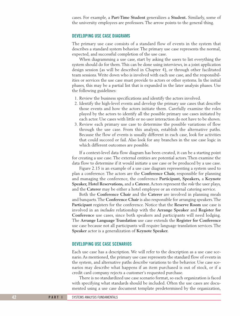
The primary use case consists of a standard flow of events in the system thatdescribes a standard system behavior. The primary use case represents the normal,expected, and successful completion of the use case.
When diagramming a use case, start by asking the users to list everything thesystem should do for them. This can be done using interviews, in a joint applicationdesign session (as will be described in Chapter 4), or through other facilitatedteam sessions. Write down who is involved with each use case, and the responsibil-ities or services the use case must provide to actors or other systems. In the initialphases, this may be a partial list that is expanded in the later analysis phases. Usethe following guidelines:
1. Review the business specifications and identify the actors involved.2. Identify the high-level events and develop the primary use cases that describe
those events and how the actors initiate them. Carefully examine the rolesplayed by the actors to identify all the possible primary use cases initiated byeach actor. Use cases with little or no user interaction do not have to be shown.
3. Review each primary use case to determine the possible variations of flowthrough the use case. From this analysis, establish the alternative paths.Because the flow of events is usually different in each case, look for activitiesthat could succeed or fail. Also look for any branches in the use case logic inwhich different outcomes are possible.
If a context-level data flow diagram has been created, it can be a starting pointfor creating a use case. The external entities are potential actors. Then examine thedata flow to determine if it would initiate a use case or be produced by a use case.
Figure 2.15 is an example of a use case diagram representing a system used toplan a conference. The actors are the Conference Chair, responsible for planningand managing the conference, the conference Participant, Speakers, a KeynoteSpeaker, Hotel Reservations, and a Caterer. Actors represent the role the user plays,and the Caterer may be either a hotel employee or an external catering service.
Both the Conference Chair and the Caterer are involved in planning mealsand banquets.The Conference Chair is also responsible for arranging speakers.TheParticipant registers for the conference. Notice that the Reserve Room use case isinvolved in an includes relationship with the Arrange Speaker and Register forConference use cases, since both speakers and participants will need lodging.The Arrange Language Translation use case extends the Register for Conferenceuse case because not all participants will require language translation services. TheSpeaker actor is a generalization of Keynote Speaker.
DEVELOPING USE CASE SCENARIOS
Each use case has a description. We will refer to the description as a use case sce-nario.As mentioned, the primary use case represents the standard flow of events inthe system, and alternative paths describe variations to the behavior. Use case sce-narios may describe what happens if an item purchased is out of stock, or if acredit card company rejects a customer’s requested purchase.
There is no standardized use case scenario format, so each organization is facedwith specifying what standards should be included. Often the use cases are docu-mented using a use case document template predetermined by the organization,
KENDMC02_0132240858.QXD 2/7/07 5:13 PM Page 42

UNDERSTANDING ORGANIZATIONAL STYLE AND ITS IMPACT ON INFORMATION SYSTEMS C H A P T E R 2 43
Caterer
ConferenceChair
HotelReservations
ArrangeSpeaker
PlanCatering
<<
incl
ude
>>
ReserveRoom
<<
incl
ude
>>
<< extend >>
Participant
Register forConference
KeynoteSpeaker
Speaker
Arrange LanguageTranslation
FIGURE 2.15A use case diagram represent-ing a system used to plan aconference.
which makes the use cases easier to read and provides standardized informationfor each use case in the model.
A use case scenario example is shown in Figure 2.16. Some of the areasincluded are optional, and may not be used by all organizations. The three mainareas are:
1. Use case identifiers and initiators.2. Steps performed.3. Conditions, assumptions, and questions.
The first area, use case identifiers and initiators, orients the reader and containsthe use case name and a unique ID; the application area or system that this usecase belongs to; the actors involved in the use case; a brief description of what theuse case accomplishes; and the initiating (triggering) event, that is, what causedthe use case to start, and the type of trigger, either external or temporal. Externalevents are those started by an actor, either a person or another system requestinginformation, such as an airline reservation system requesting flight informationfrom an airline system. Temporal events are those that are triggered or started bytime. Events occur at a specific time, such as sending an email about special offersonce a week on a Sunday evening, sending bills on a specific day, or generating
KENDMC02_0132240858.QXD 2/7/07 5:13 PM Page 43

44 P A R T I SYSTEMS ANALYSIS FUNDAMENTALS
Use case name: Register for ConferenceUniqueID: Conf RG 003Area:
Actor(s):
Description:
Triggering Event:
Preconditions:
Postconditions:
Assumptions:
Steps Performed (Main Path)
Conference Planning
Participant has already registered and has created a user account.
Participant has a browser and a valid userID and password.
Participant has successfully registered for the conference.
Requirements Met: Allow conference participants to be able to register for the conference using a secure Web site.Outstanding Issues: How should a rejected credit card be handled?Priority: HighRisk: Medium
Participant uses Conference Registration Web site, enters userID and password, and clicks the logon button.
1. Participant logs in using the secure Web server. 2. Participant record is read and password is verified. 3. Participant and session information is displayed on the Registration Web page.
4. Participant enters information on the Registration Web form and clicks Submit button.
5. Registration information is validated on the Web server. 6. Registration Confirmation page is displayed to confirm registration information.
7. Credit card is charged for registration fees. 8. Add Registration Journal record is written.
userID, Password
Participant Record, userID, PasswordParticipant Record, Session Record
Registration Web Form
Registration Web Form
Confirmation Web Page
Secure Credit Card Web Page
Confirmation Web Page 9. Registration record is updated on the Registration Master. Confirmation Web Page, Registration Record10. Session record is updated for each selected session on the Session Master. Confirmation Web Page, Session Record11. Participant record is updated for the participant on the Participant Master. Confirmation Web Page, Participant Record12. Successful Registration Confirmation Web page is sent to the participant. Registration Record Confirmation Number
Trigger type:
Participant
Allow conference participant to register online for the conference using a secure Web site.
Information for Steps
External Temporal
FIGURE 2.16A use case scenario is dividedinto three sections: identifica-tion and initiation; steps per-formed; and conditions,assumptions, and questions.
government statistics on a specified date every quarter. In addition to actors, a usecase may list stakeholders and their interest in the use case. Stakeholders are indi-viduals or organizations that are not actors but have some vested interest in thebehavior of the use case.
The second area of the use case includes the steps performed, and the infor-mation required for each of the steps. These statements represent the standard
KENDMC02_0132240858.QXD 2/7/07 5:13 PM Page 44

UNDERSTANDING ORGANIZATIONAL STYLE AND ITS IMPACT ON INFORMATION SYSTEMS C H A P T E R 2 45
flow of events and the steps taken for the successful completion of the use case. Itis desirable to write up a use case for the main path, and then to write up one foreach of the alternative paths separately, rather than using IF . . . THEN . . . state-ments.The steps may come from a detailed interview with users or may be derivedfrom agile modeling stories (as described in Chapter 6). These steps should bereviewed with the users for clarification. The analyst should examine each of thesteps and determine the information required for each step. If the analyst cannotdetermine the information, he or she should schedule a follow-up interview withthe user. Some use case descriptions include the exceptions as additional sectionsfollowing the standard flow of events.
The third area of the use case includes:
• Preconditions, or the condition of the system before the use case may beperformed, which may be another use case.
• Postconditions, or the state of the system after the use case has finished,including output people have received, transmissions to other systems, anddata that have been created or updated.
• Assumptions made that would affect the method of the use case and thatcould stipulate required technology, such as the minimum technologyrequirements in a browser or even a specific or higher version of a browser.
• Any outstanding issues or questions that must be answered before imple-mentation of the use case.
• An optional statement of priority of the use case, which may come fromthe problem definition.
• An optional statement of risk involved in creating the use case.
The “requirements met” area links the use case to user requirements or objec-tives from a problem definition. Once you develop the use case scenarios, be sureto review your results with the business experts to verify and refine the use cases ifneeded.
In this particular use case scenario, called Register for Conference, is the onlyactor involved is the Participant. The overall area is Conference Planning, and theuse case is triggered by the participant logging on to the Registration Web page.The Steps Performed area lists the sequence of events that must occur for a suc-cessful conference registration. Notice that the information needed to performeach of the steps is listed on the right. This may include Web pages and forms, aswell as database tables and records.
The Preconditions area in the footer section of the use case scenario lists whatmust occur before the participant can register for a conference. In this example, theparticipant must have already signed up as a member of the society and have a validuserID and password. The Postconditions area lists what has been accomplished bythe use case. The Assumptions area lists any basic premises the analyst assumes arefulfilled by the actor beforehand. The Requirements Met area shows why this usecase is important and necessary for the business area to be successful. Priority is anindication of which use cases should be developed first and which may be delayed.Risk is a rough assessment of whether there may be problems or difficulties devel-oping the use case. In this case, the risk is medium because the registration use caserequires a secure server and is accepting credit card information.
WHY USE CASE DIAGRAMS ARE HELPFUL
No matter what method you use to develop your system (traditional SDLCmethods, agile methods, or object-oriented methods), you will find that usecases are very valuable. The use case diagrams identify all of the actors in the
KENDMC02_0132240858.QXD 2/7/07 5:13 PM Page 45

46 P A R T I SYSTEMS ANALYSIS FUNDAMENTALS
Operational Control
ManagerialPlanning and Control
StrategicManagement
FIGURE 2.18Management in organizationsexists on three horizontallevels: operational control,managerial planning andcontrol, and strategicmanagement.
• Use cases effectively communicate systems requirements because the diagrams are kept simple.• Use cases allow people to tell stories.• Use case stories make sense to nontechnical people.• Use cases do not depend on a special language.• Use cases can describe most functional requirements (such as interactions between actors and applications).• Use cases can describe nonfunctional requirements (such as performance and maintainability) through the use of stereotypes.• Use cases help analysts define boundaries.• Use cases can be traceable, allowing analysts to identify links between use cases and other design and documentation tools.
FIGURE 2.17The main reasons for writinguse cases are their effective-ness in communicating withusers and their capturing ofuser stories.
problem domain and a systems analyst can concentrate on what humans wantand need to use the system, extend their capabilities, and enjoy their interactionwith technology.
The actions that need to be completed are also clearly shown on the use casediagram.This not only makes it easy for the analyst to identify processes, but it alsoaids in communication with other analysts on the team and business executives.
The use case scenario is also worthwhile. Since a lot of the information theusers impart to the analyst already takes the form of stories, it is easy to capturethe stories on a use case scenario form. The use case scenario always documentsthe triggering event so that an analyst can always trace the steps that led to otheruse cases. Since the steps performed are noted, it is possible to employ use casescenarios to write logical processes.
Use case diagrams are becoming popular because of their simplicity and lack oftechnical detail. They are used to show the scope of a system, along with the majorfeatures of the system and the actors who work with those major features. Themain reasons for writing use cases are shown in Figure 2.17.
LEVELS OF MANAGEMENTManagement in organizations exists on three broad, horizontal levels: operationalcontrol, managerial planning and control (middle management), and strategic man-agement, as shown in Figure 2.18. Each level carries its own responsibilities, and allwork toward achieving organizational goals and objectives in their own ways.
KENDMC02_0132240858.QXD 2/7/07 5:13 PM Page 46

UNDERSTANDING ORGANIZATIONAL STYLE AND ITS IMPACT ON INFORMATION SYSTEMS C H A P T E R 2 47
C O N S U L T I N G O P P O R T U N I T Y 2 . 2
WHERE THERE’S CARBON, THERE’S A COPY“I don’t know what we do with the pink ones yet,” Richard Russell
admitted. “They’re part of a quadruplicate form that rips apart. All Iknow is that we keep them for the filing clerk, and he files them whenhe has time.”
Richard is a newly hired junior account executive for Carbon,Carbon & Rippy, a brokerage house. You are walking through thesteps he takes in making a stock purchase “official” because hisboss has asked you to streamline the process whereby stock pur-chase information is stored in the computer and retrieved.
After you leave, Richard continues thinking about the pink forms.He tells his clerk, Harry Schultz, “In my two months here, I haven’tseen anyone use those. They take up my time and yours, not to men-tion all the filing space. Let’s pitch them.”
Richard and Harry proceed to open all the old files kept byRichard’s predecessor and throw out the filed pink forms, along withthose accumulated but not yet filed. It takes hours, but they make alot of room. “Definitely worth the time,” Richard reassures Harry.
Three weeks later, an assistant to Richard’s boss, Carol Vaness,appears. Richard is happy to see a familiar face, greeting her with,“Hi, Carol. What’s new?”
“Same old thing,” Carol sighs. “Well, I guess it isn’t old to you,because you’re the newcomer. But I need all those pesky pink forms.”
Almost in shock, Richard exchanges looks with Harry, then mum-bles, “You’re kidding, of course.”
Carol looks more serious than Richard ever thought possible,replying, “No joke. I summarize all the pink forms from all the bro-kers, and then my totals are compared with computerized stock pur-chase information. It’s part of our routine, three-month audit fortransaction accuracy. My work depends on yours. Didn’t Ms. McCueexplain that to you when you started?”
What systems concept did Richard and Harry ignore when tossingout the pink forms? What are the possible ramifications for systemsanalysts if general systems concepts are ignored?
Operational control forms the bottom tier of three-tiered management.Operations managers make decisions using predetermined rules that have pre-dictable outcomes when implemented correctly.
They make decisions that affect implementation in work scheduling, inventorycontrol, shipping, receiving, and control of processes such as production. Operationsmanagers oversee the operating details of the organization.
Middle management forms the second, or intermediate, tier of the three-tiered management system. Middle managers make short-term planning andcontrol decisions about how resources may best be allocated to meet organiza-tional objectives.
Their decisions range all the way from forecasting future resource require-ments to solving employee problems that threaten productivity. The decision-making domain of middle managers can usefully be characterized as partly operational and partly strategic, with constant fluctuations.
Strategic management is the third level of three-tiered management control.Strategic managers look outward from the organization to the future, making deci-sions that will guide middle and operations managers in the months and years ahead.
Strategic managers work in a highly uncertain decision-making environment.Through statements of goals and the determination of strategies and policies toachieve them, strategic managers actually define the organization as a whole.Theirs is the broad picture, wherein the company decides to develop new productlines, divest itself of unprofitable ventures, acquire other compatible companies, oreven allow itself to be sold.
There are sharp contrasts among the decision makers on many dimensions. Forinstance, strategic managers have multiple decision objectives, whereas operationsmanagers have single ones. It is often difficult for high-level managers to identifyproblems, but it is easy for operations managers to do so. Strategic managers arefaced with semistructured problems, whereas lower-level managers deal mostlywith structured problems.
KENDMC02_0132240858.QXD 2/7/07 5:13 PM Page 47
48 P A R T I SYSTEMS ANALYSIS FUNDAMENTALS
C O N S U L T I N G O P P O R T U N I T Y 2 . 3
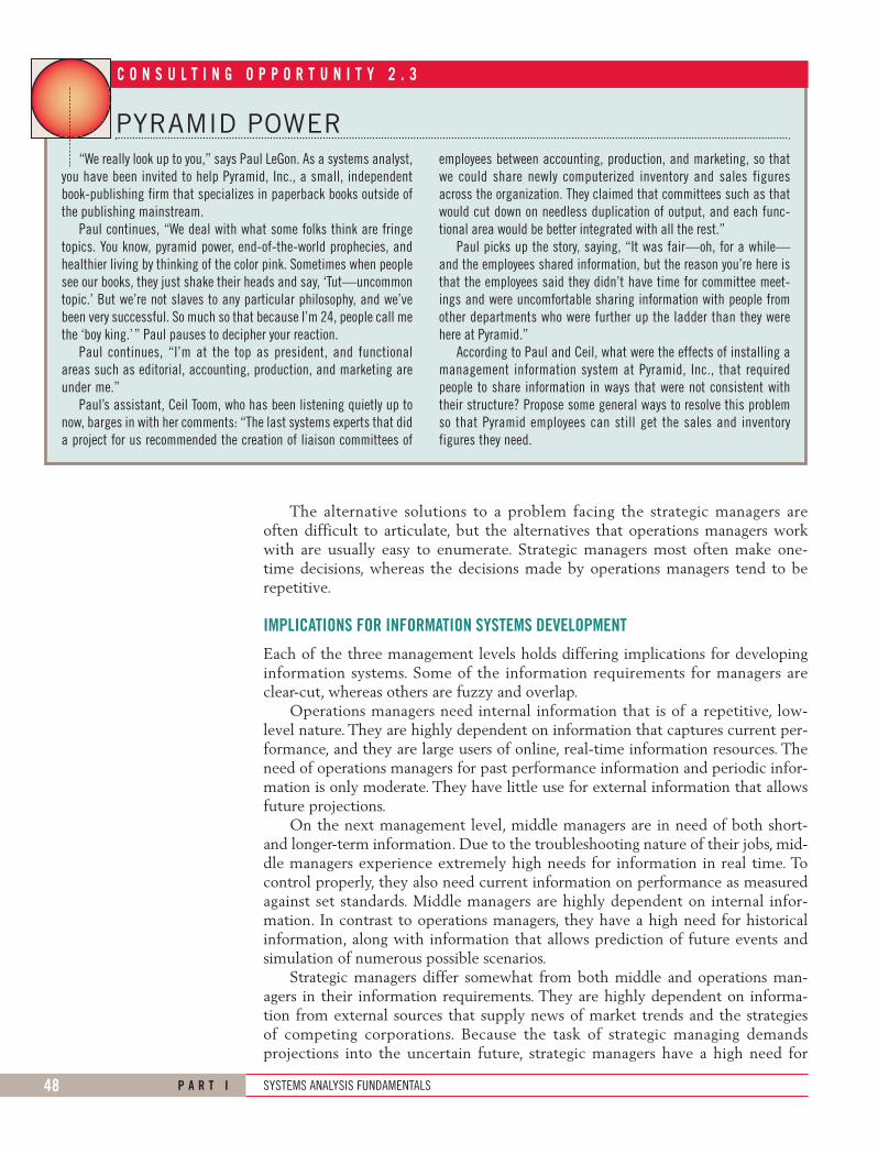
PYRAMID POWER“We really look up to you,” says Paul LeGon. As a systems analyst,
you have been invited to help Pyramid, Inc., a small, independentbook-publishing firm that specializes in paperback books outside ofthe publishing mainstream.
Paul continues, “We deal with what some folks think are fringetopics. You know, pyramid power, end-of-the-world prophecies, andhealthier living by thinking of the color pink. Sometimes when peoplesee our books, they just shake their heads and say, ‘Tut—uncommontopic.’ But we’re not slaves to any particular philosophy, and we’vebeen very successful. So much so that because I’m 24, people call methe ‘boy king.’ ” Paul pauses to decipher your reaction.
Paul continues, “I’m at the top as president, and functionalareas such as editorial, accounting, production, and marketing areunder me.”
Paul’s assistant, Ceil Toom, who has been listening quietly up tonow, barges in with her comments: “The last systems experts that dida project for us recommended the creation of liaison committees of
employees between accounting, production, and marketing, so thatwe could share newly computerized inventory and sales figuresacross the organization. They claimed that committees such as thatwould cut down on needless duplication of output, and each func-tional area would be better integrated with all the rest.”
Paul picks up the story, saying, “It was fair—oh, for a while—and the employees shared information, but the reason you’re here isthat the employees said they didn’t have time for committee meet-ings and were uncomfortable sharing information with people fromother departments who were further up the ladder than they werehere at Pyramid.”
According to Paul and Ceil, what were the effects of installing amanagement information system at Pyramid, Inc., that requiredpeople to share information in ways that were not consistent withtheir structure? Propose some general ways to resolve this problemso that Pyramid employees can still get the sales and inventoryfigures they need.
The alternative solutions to a problem facing the strategic managers areoften difficult to articulate, but the alternatives that operations managers workwith are usually easy to enumerate. Strategic managers most often make one-time decisions, whereas the decisions made by operations managers tend to berepetitive.
IMPLICATIONS FOR INFORMATION SYSTEMS DEVELOPMENT
Each of the three management levels holds differing implications for developinginformation systems. Some of the information requirements for managers areclear-cut, whereas others are fuzzy and overlap.
Operations managers need internal information that is of a repetitive, low-level nature. They are highly dependent on information that captures current per-formance, and they are large users of online, real-time information resources. Theneed of operations managers for past performance information and periodic infor-mation is only moderate. They have little use for external information that allowsfuture projections.
On the next management level, middle managers are in need of both short-and longer-term information. Due to the troubleshooting nature of their jobs, mid-dle managers experience extremely high needs for information in real time. Tocontrol properly, they also need current information on performance as measuredagainst set standards. Middle managers are highly dependent on internal infor-mation. In contrast to operations managers, they have a high need for historicalinformation, along with information that allows prediction of future events andsimulation of numerous possible scenarios.
Strategic managers differ somewhat from both middle and operations man-agers in their information requirements. They are highly dependent on informa-tion from external sources that supply news of market trends and the strategiesof competing corporations. Because the task of strategic managing demandsprojections into the uncertain future, strategic managers have a high need for
KENDMC02_0132240858.QXD 2/7/07 5:13 PM Page 48

UNDERSTANDING ORGANIZATIONAL STYLE AND ITS IMPACT ON INFORMATION SYSTEMS C H A P T E R 2 49
information of a predictive nature and information that allows creation of manydifferent what-if scenarios. Strategic managers also exhibit strong needs forperiodically reported information as they seek to adapt to fast-moving changes.
ORGANIZATIONAL CULTUREOrganizational culture is an established area of research that has grown remark-ably in the last generation. Just as it is appropriate to think of organizations asincluding many technologies, it is similarly appropriate to see them as hosts tomultiple, often competing subcultures.
There is still little agreement on what precisely constitutes an organizationalsubculture. It is agreed, however, that competing subcultures may be in conflict,attempting to gain adherents to their vision of what the organization should be.Research is in progress to determine the effects of virtual organizations and virtualteams on the creation of subcultures when members do not share a physical work-space but share tasks.
Rather than thinking about culture as a whole, it is more useful to think aboutthe researchable determinants of subcultures, such as shared verbal and nonverbalsymbolism. Verbal symbolism includes shared language used to construct, convey,and preserve subcultural myths, metaphors, visions, and humor. Nonverbal sym-bolism includes shared artifacts, rites, and ceremonies; clothing of decision makersand workers; the use, placement, and decoration of offices; and rituals for celebrat-ing members’ birthdays, promotions, and retirements.
Subcultures coexist within “official” organizational cultures. The officiallysanctioned culture may prescribe a dress code, suitable ways to address superiorsand coworkers, and proper ways to deal with the outside public. Subcultures maybe powerful determinants of information requirements, availability, and use.
Organizational members may belong to one or more subcultures in the organi-zation. Subcultures may exert a powerful influence on member behavior, includ-ing sanctions for or against the use of information systems.
Understanding and recognizing predominant organizational subcultures mayhelp the systems analyst overcome the resistance to change that arises when a newinformation system is installed. For example, the analyst might devise user trainingto address specific concerns of organizational subcultures. Identifying subculturesmay also help in the design of decision support systems that are tailored for inter-action with specific user groups.
SUMMARYThere are three broad organizational fundamentals to consider when analyzingand designing information systems: the concept of organizations as systems, thevarious levels of management, and the overall organizational culture.
Organizations are complex systems composed of interrelated and interdepen-dent subsystems. In addition, systems and subsystems are characterized by theirinternal environments on a continuum from open to closed. An open systemallows free passage of resources (people, information, materials) through its bound-aries; closed systems do not permit free flow of input or output. Organizationsand teams can also be organized virtually with remote members connectedelectronically who are not in the same physical workspace. Enterprise resourceplanning systems are integrated organizational (enterprise) information systems
KENDMC02_0132240858.QXD 2/7/07 5:13 PM Page 49

50 P A R T I SYSTEMS ANALYSIS FUNDAMENTALS
2 “You seem to have already made a good start at MRE. Even though I can tell you a lotabout the company, remember that there are a number of ways to orient yourselfwithin it. You will want to interview users, observe their decision-making settings, andlook at archival reports, charts, and diagrams. To do so, you can click on the telephonedirectory to get an appointment with an interviewee, click on the building map to viewthe layout of the building, or click on organizational charts that show you the func-tional areas and formal hierarchical relationships at MRE.
“Many of the rules of corporate life apply in the MRE HyperCase. For instance,there are many public areas in which you are free to walk. If you want to tour a privatecorporate office, however, you must first book an appointment with one of ouremployees. Some secure areas are strictly off limits to you, just because you are an out-sider and could pose a security risk.
“I don’t think you’ll find us excessively secretive, however, because you mayassume that any employee who grants you an interview will also grant you access tothe archival material in his or her files as well as to current work. You’ll be able to goabout your consulting freely in most cases. If you get too curious or invade our privacyin some way, we’ll let you know. We’re not afraid to tell you what the limits are.
“Unfortunately, some people in the company never seem to make themselvesavailable to consultants. If you need to know more about these hard-to-get intervie-wees, I suggest you be persistent. There are lots of ways to find out about the peopleand the systems of MRE, but much of the time creativity is what pays off. You willnotice that the systems consultants who follow their hunches, sharpen their technicalskills, and never stop thinking about piecing together the puzzles here at MRE are theones who are the best.
H Y P E R C A S E ® E X P E R I E N C E
FIGURE 2.HC1
KENDMC02_0132240858.QXD 2/7/07 7:02 PM Page 50

UNDERSTANDING ORGANIZATIONAL STYLE AND ITS IMPACT ON INFORMATION SYSTEMS C H A P T E R 2 51
developed with customized, proprietary software that help the flow of informa-tion between the functional areas in the organization. They support a systems viewof the organization.
There are many ways to graphically depict the system. The analyst shouldchoose among these tools early on to get an overview of the system. Theseapproaches include drawing context-level data flow diagrams, capturing relation-ships early on with entity-relationship diagrams; drawing use case diagrams or writ-ing use case scenarios based on user stories. Using these diagrams and techniquesat the beginning of analysis can help the analyst define the boundaries of the sys-tem, and can help bring into focus which people and systems are external to thesystem being developed.
Entity-relationship diagrams help the systems analyst understand the entitiesand relationships that comprise the organizational system. E-R diagrams candepict a one-to-one relationship, a one-to-many relationship, a many-to-one rela-tionship, and a many-to-many relationship.
The three levels of managerial control are operational, middle management,and strategic. The time horizon of decision making is different for each level.
Organizational cultures and subcultures are important determinants of howpeople use information and information systems. By grounding information systemsin the context of the organization as a larger system, it is possible to realize thatnumerous factors are important and should be taken into account when ascertaininginformation requirements and designing and implementing information systems.
KEYWORDS AND PHRASESactorassociative entityattributive entityclosedness
context-level data flow diagramcrow’s foot notationenterprise resource planning (ERP)entity (fundamental entity)
“Remember to use multiple methods—interviewing, observation, and investiga-tion—to understand what we at MRE are trying to tell you. Sometimes actions, docu-ments, and offices actually speak louder than words!”
HYPERCASE QUESTIONS
1. What major organizational change recently took place at MRE? What depart-ment(s) was involved, and why was the change made?
2. What does the Management Systems Unit at MRE do? Who are its clients?3. What are the goals and strategies of the Engineering and Systems Division at
MRE? What are the goals of the Training and Management Systems Department?4. Would you categorize MRE as a service industry, a manufacturer, or both? What
kind of “products” does MRE “produce” (i.e., does it offer material goods, services,or both)? Suggest how the type of industry MRE is in affects the information sys-tems it uses.
5. What type of organizational structure does MRE have? What are the implicationsof this structure for MIS?
6. Describe in a paragraph the “politics” of the Training and Management SystemsDepartment at MRE. Who is involved, and what are some of the main issues?
KENDMC02_0132240858.QXD 2/7/07 5:13 PM Page 51
52 P A R T I SYSTEMS ANALYSIS FUNDAMENTALS
entity-relationship (E-R) diagramsenvironmentfeedbackinterdependentinterrelatednessmiddle managementopennessoperations managementorganizational boundaries
organizational culturestrategic managementsystemsuse caseuse case diagramuse case scenariovirtual enterprisevirtual organizationvirtual team
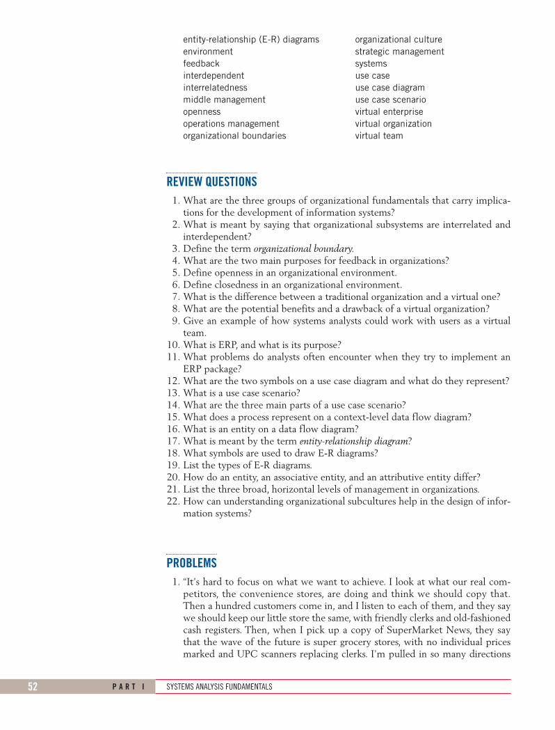
REVIEW QUESTIONS1. What are the three groups of organizational fundamentals that carry implica-
tions for the development of information systems?2. What is meant by saying that organizational subsystems are interrelated and
interdependent?3. Define the term organizational boundary.4. What are the two main purposes for feedback in organizations?5. Define openness in an organizational environment.6. Define closedness in an organizational environment.7. What is the difference between a traditional organization and a virtual one?8. What are the potential benefits and a drawback of a virtual organization?9. Give an example of how systems analysts could work with users as a virtual
team.10. What is ERP, and what is its purpose?11. What problems do analysts often encounter when they try to implement an
ERP package?12. What are the two symbols on a use case diagram and what do they represent?13. What is a use case scenario?14. What are the three main parts of a use case scenario?15. What does a process represent on a context-level data flow diagram?16. What is an entity on a data flow diagram?17. What is meant by the term entity-relationship diagram?18. What symbols are used to draw E-R diagrams?19. List the types of E-R diagrams.20. How do an entity, an associative entity, and an attributive entity differ?21. List the three broad, horizontal levels of management in organizations.22. How can understanding organizational subcultures help in the design of infor-
mation systems?
PROBLEMS1. “It’s hard to focus on what we want to achieve. I look at what our real com-
petitors, the convenience stores, are doing and think we should copy that.Then a hundred customers come in, and I listen to each of them, and they saywe should keep our little store the same, with friendly clerks and old-fashionedcash registers. Then, when I pick up a copy of SuperMarket News, they saythat the wave of the future is super grocery stores, with no individual pricesmarked and UPC scanners replacing clerks. I’m pulled in so many directions
KENDMC02_0132240858.QXD 2/7/07 5:13 PM Page 52

UNDERSTANDING ORGANIZATIONAL STYLE AND ITS IMPACT ON INFORMATION SYSTEMS C H A P T E R 2 53
I can’t really settle on a strategy for our grocery store,” admits Geoff Walsham,owner and manager of Jiffy Geoff’s Grocery Store.
In a paragraph, apply the concept of permeable organizational boundariesto analyze Geoff’s problem in focusing on organizational objectives.
2. Write seven sentences explaining the right-to-left relationships in Figure 2.8.3. Draw an entity-relationship diagram of a patient–doctor relationship.
a. Which of the types of E-R diagrams is it?b. In a sentence or two, explain why the patient–doctor relationship is
diagrammed in this way.4. You began drawing E-R diagrams soon after your entry into the health mainte-
nance organization for which you’re designing a system. Your team member isskeptical about using E-R diagrams before the design of the database is begun.In a paragraph, persuade your team member that early use of E-R diagrams isworthwhile.
5. Neil is an decision maker for Pepe’s Atlantic Sausage Company. Because thereare several suppliers of ingredients and their prices fluctuate, he has come upwith several different formulations for the various sausages that he makes,depending on the availability of particular ingredients from particular sup-pliers. He then orders ingredients accordingly twice a week. Even though hecannot predict when ingredients will become available at a particular price, hisordering of supplies can be considered routine.
a. On what level of management is Neil working? Explain in a paragraph.b. What attributes of his job would have to change before you would catego-
rize him as working on a different level of management? List them.6. Many of the people who work at Pepe’s (Problem 5) are extremely dedicated
to Pepe’s and have devoted their lives to the company. Others feel thatcompany is behind the times and should use more sophisticated productionsystems, information systems, and supply chain management to make the com-pany more competitive. Members of a third group feel that what they do isunappreciated. Describe the various subculture in words. Assign them a namebased on their emotions.
7. Alice in the human resources department at the Cho Manufacturing plant isconstantly being asked by employees how much is taken out of their pay-checks for insurance, taxes, medical, manadatory retirement, and voluntaryretirement. “It takes up to a few hours every day,” says Alice.
She would like a Web system that would allow employees to use asecure logon to view the information. Alice wants the system to interfacewith health and dental insurance companies to obtain the amount remainingin the employee’s account for the year. She would also like to obtain retire-ment amounts saved along with investment results. Alice has a high regardfor privacy and wants the system to have employees register and give per-mission to obtain financial amounts from the dental insurance and retire-ment companies. Draw a use case diagram representing the activities of theEmployee Benefit system.
8. Write up a use case scenario for the use case diagram you constructed for ChoManufacturing.
9. Create a context-level data flow diagram for the Employee Benefit system inProblem 7. Make any assumptions about the data to and from the centralprocess. Do you find this to be better or not as good at explaining the systemto Alice than the use case and use case scenarios?
10. Draw a use case and write up a use case scenario for getting two or three emailaccounts. Think about the steps that are needed to ensure security.
KENDMC02_0132240858.QXD 2/7/07 5:13 PM Page 53

54 P A R T I SYSTEMS ANALYSIS FUNDAMENTALS
GROUP PROJECTS1. Break up into groups of five. Assign one person to act as the Web site designer,
one to write copy for a company’s product, one to keep track of customer pay-ments, one to monitor distribution, and one to satisfy customers who havequestions about using the product. Then select a simple product (one thatdoes not have too many versions). Good examples are a digital camera, a DVDplayer, a GPS, a box of candy, or a specialty travel hat (rainproof or sun-blocker). Now spend 20 minutes trying to explain to the Web site designerwhat to include on the Web site. Describe in about three paragraphs whatexperience your group had in coordination. Elaborate on the interrelatednessof subsystems in the organization (your group).
2. In a small group, develop a use case and a use case scenario for making air,hotel, and car reservations for domestic travel.
3. Change your answer in Group Project 2 to include foreign travel. How doesthe use case and use case scenario change?
4. With your group, draw a context-level data flow diagram of your school’s oruniversity’s registration system. Label each entity and process. Discuss whythere appear to be different ways to draw the diagram. Reach consensus asa group about the best way to draw the diagram and defend your choice ina paragraph. Now, working with your group’s members, follow the appro-priate steps for developing an E-R diagram and create one for your schoolor university registration system. Make sure your group indicates whetherthe relationship you depict is one-to-one, one-to-many, many-to-one, ormany-to-many.
SELECTED BIBLIOGRAPHYBleeker, S. E. “The Virtual Organization.” Futurist, Vol. 28, No. 2, 1994, pp. 9–14.Chen, P. “The Entity-Relationship Model—Towards a Unified View of Data.” ACM
Transactions on Database Systems, Vol. 1, March 1976, pp. 9–36.Ching, C., C. W. Holsapple, and A. B. Whinston. “Toward IT Support for Coordination
in Network Organizations.” Information Management, Vol. 30, No. 4, 1996,pp. 179–199.
Davis, G. B., and M. H. Olson. Management Information Systems, ConceptualFoundations, Structure, and Development, 2d ed. New York: McGraw-Hill, 1985.
Galbraith, J. R. Organizational Design. Reading, MA: Addison-Wesley, 1977.Kendall, K. E., J. R. Buffington, and J. E. Kendall. “The Relationship of Organizational
Subcultures to DSS User Satisfaction.” Human Systems Management, March1987, pp. 31–39.
Kulak, D., and E. Guiney. Use Cases: Requirement in Context, 2d ed. Boston: PearsonEducation, 2004.
PeopleSoft. Available at: www.peoplesoft.com/corplen/public_index.jsp. AccessedJune 3, 2003.
Warkentin, M., L. Sayeed, and R. Hightower. “Virtual Teams versus Face-to-FaceTeams; An Exploratory Study of a Web-Based Conference System.” In EmergingInformation Technologies: Improving Decisions, Cooperation, and Infrastructure.Edited by K. E. Kendall, pp. 241–262. Thousand Oaks, CA: Sage Publications,1999.
Yager, S. E. “Everything’s Coming Up Virtual.” Available at: www.acm.org/crossroads/xrds4-1/organ.html. Accessed June 3, 2003.
KENDMC02_0132240858.QXD 2/7/07 5:13 PM Page 54

UNDERSTANDING ORGANIZATIONAL STYLE AND ITS IMPACT ON INFORMATION SYSTEMS C H A P T E R 2 55
ALLEN SCHMIDT, JULIE E. KENDALL, AND KENNETH E. KENDALL
PICTURING THE RELATIONSHIPS
“So the project involves more than simply performing maintenance work on the cur-rent programs,” Chip says. “Are we using a formal methodology for analyzing anddesigning the new system?”
“Yes,” replies Anna. “We are also using a CASE tool, Visible Analyst, to analyze anddesign the system.1 We’ve recently installed the product on our PC in the office.”
With a few easy mouse clicks Anna comes to a context-level data flow diagram(see Figure E2.1). “It’s very useful to begin thinking of the system this way,” Anna saysas they look at the diagram on the screen.
Chip agrees, saying, “I can very easily see what you think is happening with the sys-tem. For instance, I see that the external entity Management supplies hardware andsoftware inquiries and receives the corresponding responses in return. It shows the sys-tem within the larger organization.”
2C P U C A S E E P I S O D E
New Computer Form
Software Received
Repaired Computer
Hardware Master Report
Software Master Report
EE 4
Context
Hardware Inquiry Response
Software Inquiry Response
Hardware Inquiry
Software Inquiry
Software Inquiry Inquiry Response
EE 1
Management
EE 2
Faculty
ComputerInventorySystem
ClericalSupport
EE 5
EE 3
Maintenance
EE 1
Management
EE 2
Faculty
Shipping/Receiving
Dept.
FIGURE E2.1
1For more details on how to begin using Visible Analyst, see Allen Schmidt, Working with Visible Analyst,2d ed. (Upper Saddle River, NJ: Prentice Hall, 2004).
The Central Pacific University case can be adapted to other CASE tools. Other tools include Microsoft Visio.Alternatively, many of the exercises can be accomplished manually if CASE tools are unavailable.
KENDMC02_0132240858.QXD 2/7/07 5:13 PM Page 55

56 P A R T I SYSTEMS ANALYSIS FUNDAMENTALS
E P I S O D E C P U C A S E
2
“I’ve also drawn an E-R diagram of the system,” Anna says as she brings up theentity-relationship diagram on the screen (see Figure E2.2).
“Yes, the many-to-many and one-to-many relationships are very clear when youlook at this,” Chip says, viewing the screen. “You’ve got a good start here,” Chip contin-ues. “Let’s get to work and see what needs to be done next.”
EXERCISES
E-1. Use Visible Analyst to view and print the context-level data flow diagram for thecomputer inventory system, as Chip and Anna did.
E-2. Use the Repository feature to view the entry for the central process.E-3. Use Visible Analyst to view and print the entity-relationship diagram for the
computer inventory system.E-4. Explain why the external entities on the context-level diagram are not found on
the entity-relationship diagram.E-5. Explain why the entities MANAGEMENT and FACULTY are found on both
sides of the process on the context-level diagram.
installed inside provides warranty for
performedon
connectedwith
has
V
locatedin
isfor
SoftwarePeripheralEquipment
ComputerMaintenance Computer
VendorComponent Board
Hardware-Software
Relationship
ComponentBoard
Room
FIGURE E2.2
The exercises preceded by a Web icon indicate value-added material is available from the Web site atwww.prenhall.com/kendall. Students can download a sample Visible Analyst Project and a MicrosoftAccess database that can be used to complete the exercises. Visible Analyst software can be packagedwith this text for an additional fee.
KENDMC02_0132240858.QXD 2/7/07 5:13 PM Page 56