underwater complete single sheets - metstrade
TRANSCRIPT

X8Underwater
1
www.underwaterlights.com
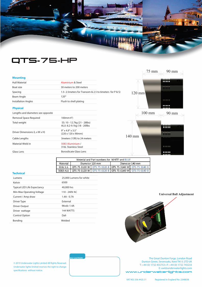
Mounting
1 0
to shell plating
Technical
Physical
a a
QT -75
Your Local Dealer
120 mm
75 mm 90 mm
140 mm
90 mm100 mm

QTS-75 INSTALLATION
For sales telephone numbers visit www.underwaterlights.comTHE QT-LED RANGE IS DESIGNED AND MANUFACTURED BY
UNDERWATER LIGHTS LTD IN THE U.K.
QTS-75
*DRIVER INSTALLATION INSTRUCTION - The driver must be located at least 60 cm above tank top with good ventilation andthe maximum ambient temperature should not exceed 40C. The underwater light is fi tted with six meters of cable and a IP 68 plugthat fi ts into the driver enclosure socket. For cabinet installation see separate sheets.
Installation information*DESCRIPTION - The QTS-75 range is a submersible through hull marine light with a universal 30 degree ball adjustment. Thereare two types of insert which have been machined so they can be welded fl ush to the hull plating at the appropiate locations. Finaladjustment of the beam angle to the horizontal is carried out from inside the hull. See instructional picture below.
* LENS FITTING INSTRUCTIONS-Remove the blanking plate and check the insert (1) lens landing surfaces are clean andapply a suitable silicone grease to the gaskets (2). Fit the lens (3), gaskets (2) and lens retaining ring (4) . Hand tighten the cap headbolts (6) and spring washers (S.S only 5) making sure the lens retaining ring (4)is square. Torque the bolts to 7 Nm (4.5ft/lbs) in thesequence shown above. Check the ring again and re-torque the screws again to the same setting.
* LED PROJECTOR FITTING INSTRUCTIONS-The LED heat sink (8) withthe ‘O’ring (7) fi tted is inserted into the insert (1) and loosly held in place by abolt (10) so the LED ball can be adjusted. The cover (9) with the ‘O’ ring fi tted isinserted to the LED heat sink (8) and bolted up securing all parts to the insert (1).
QTS-75
For sales telephone numbers visit www.underwaterlights.comTHE QT-LED RANGE IS DESIGNED AND MANUFACTURED BY UNDERWATER LIGHTS LTD IN THE U.K.
QTS-75 INSERT
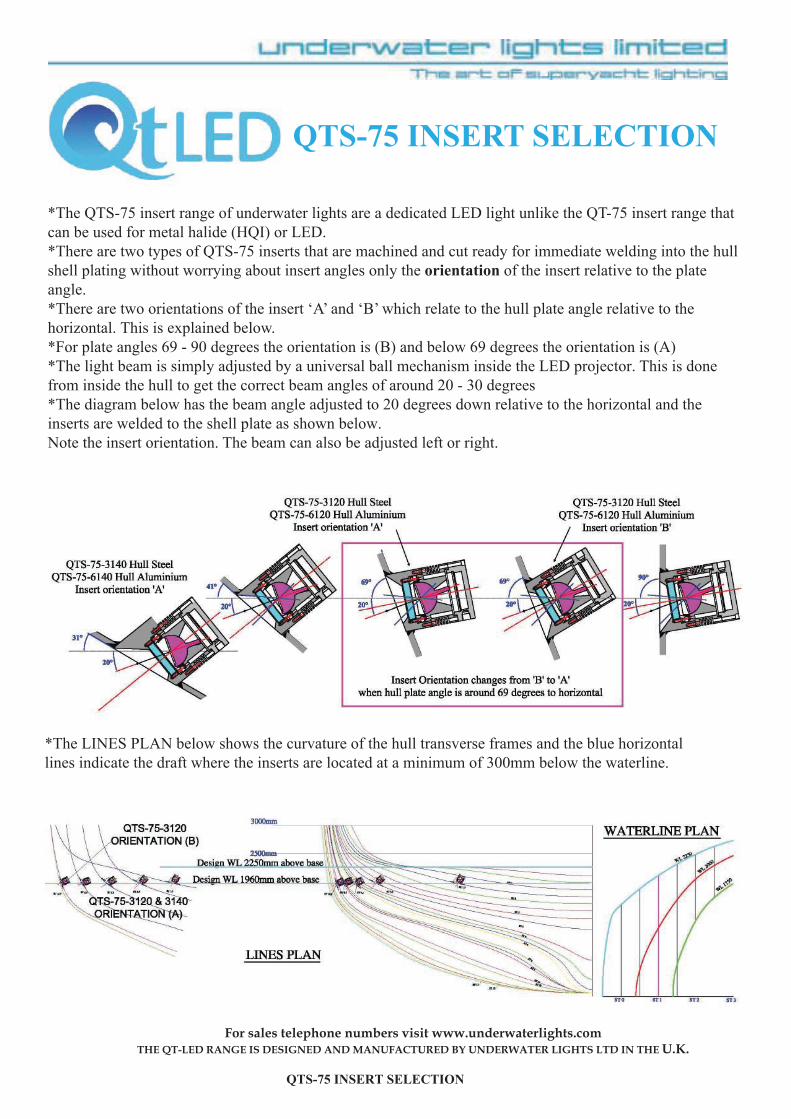
*The QTS-75 insert range of underwater lights are a dedicated LED light unlike the QT-75 insert range thatc be used for metal halide (HQI) or LED.*There are two types of QTS-75 inserts that are machined and cut ready for immediate welding into the hullshell plating without worrying about insert angles only the orientation of the insert relative to the plateangle.*There are two orientations of the insert ‘A’ and ‘B’ which relate to the hull plate angle
his is explained below.*For plate angles 69 - 90 degrees the orientation is (B) and below 69 degree the orientation is (A)*The light beam is simply adjusted by a universal ball mechanism inside the LED projector. This is from inside the hull to get the correct beam angles of around 20 - degrees*The diagram below has the beam angle adjusted to 20 degrees down and theinserts are welded to the shell plateNote the insert orientation The beam can also be adjusted left or right.
*The LINES PLAN below shows the curvature of the hull transverse frames and the horizontallines indicate the dra t where the inserts are located at a minimum of 300mm below the waterline.

RUN PROCESSSIZE OF
FILLER METALCURRENT
AVOLTAGE
VTYPE OF
CURRENT/POLARITYWIRE FEED
m/minTRAVEL SPEED*
mm/sHEAT
INPUT*kJ/mm
1 -5 MIG 1.2 160 - 180 20 - 21 DC positive ± 10.0 10 - 15 -
Welding procedure Ref.No:Joint type:Preparation & cleaning:Parent material spec:
Material thickness (mm):Outside diameter (mm):Filler metal classification:Filler metal tradename:
UL-AL-TB-01Full penetration butt with filletCut, grind, wirebrush & degreaseBS 1474:5083:0 (Bulleyt) to BS1470:5083:0 (plate)4-20 (Bulleyt) to 6mm plate100mmBS 2901:pt 4:5356INCO ALLOYS 5356
Welding position:
Gas flux shielding:Gas flow rate - shield-ing:Details of back gouging:Preheat temperature:
Butt: Horizontal (PC) and verticalup (PF)Fillet: Overhead |(PD), vertical up(PF) and horizontal vertical (PB)Argon gas20 LPMBack grind root of butt10°C min.
Welding procedure Ref.No:Joint type:Preparation & cleaning:Parent material spec:
Material thickness (mm):Outside diameter (mm):Filler metal classification:Filler metal tradename:
UL-CSSS-TB-01Full penetration butt with filletThermal cut and grindASTM A276:316L stainless toBS 4360:43A carbon steel4-20 (Bulleyt) to 8mm plate100mmAWS A5.4:E309MOL-17ESAB OK 67.70
Welding position:
Gas flux shielding:Details of back gouging:Preheat temperature:Interpass temperature:Temperature control:
Butt: Horizontal (PC) and verticalup (PF)Fillet: Overhead |(PD), vertical up(PF) and horizontal vertical (PB)Acid rutile fluxBack grind root of butt10°C min.240°C max.Thermal indicating crayon
316L SS WELDING PROCEDURE
5083 WELDING PROCEDURE
RUN PROCESSSIZE OF
FILLER METALCURRENT
AVOLTAGE
VTYPE OF
CURRENT/POLARITYWIRE FEED
m/minTRAVEL SPEED*
mm/sHEAT
INPUT*kJ/mm
1-7 MMA 3.2 100-115 ≥ 55 OCV AC - -
The 75 welding procedures shown are typical for most installations and are for guidance purposes only. A ways use a certified welder and a fire watch when welding. Protect all threads against welding, grinding and painting.
1=Cover
2=Blank Disc
For sales telephone numbers visit www. .comTHE QT-LED RANGE IS DESIGNED AND MANUFACTURED BY
UNDERWATER LIGHTS LTD IN THE U.K.QT LED - CONNECTION
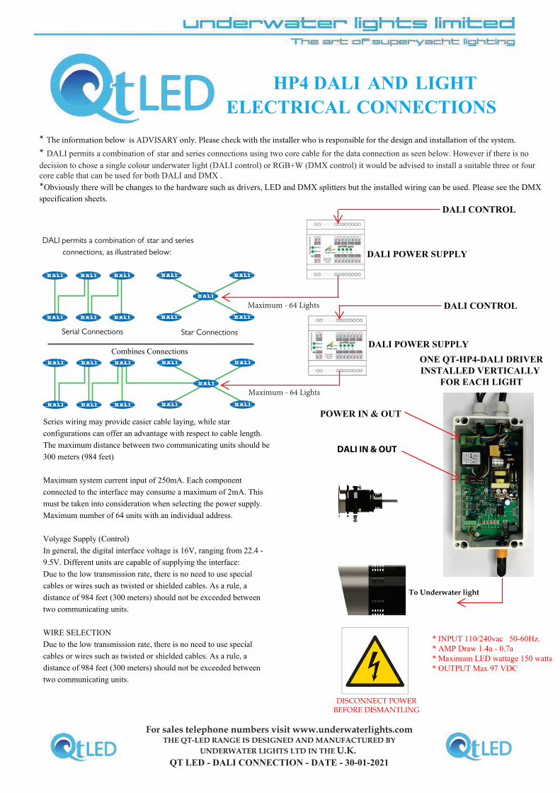
HP4 AND LIGHT
INSTALLED VERTICALLY
FOR
DALI permits a combination of star and series connections, as illustrated below:
Serial Connections Star Connections
DISCONNECT POWER BEFORE DISMANTLING
* INPUT 110/240vac 50-60Hz.* AMP Draw 1.4a - 0.7a* Maximum LED wattage 150 watts* OUTPUT Max 97 VDC