underwater thrust and power generation using flexible ... thrust and electricity generation are...
TRANSCRIPT
IOP PUBLISHING SMART MATERIALS AND STRUCTURES
Smart Mater. Struct. 20 (2011) 125013 (11pp) doi:10.1088/0964-1726/20/12/125013
Underwater thrust and power generationusing flexible piezoelectric composites: anexperimental investigation towardself-powered swimmer-sensor platformsAlper Erturk1 and Ghislain Delporte2
1 G W Woodruff School of Mechanical Engineering, Georgia Institute of Technology, Atlanta,GA 30332-0405, USA2 Institut Catholique d’Arts et Metiers, 59800 Lille, France
E-mail: [email protected]
Received 19 June 2011, in final form 21 October 2011Published 28 November 2011Online at stacks.iop.org/SMS/20/125013
AbstractFiber-based flexible piezoelectric composites offer several advantages to use in energyharvesting and biomimetic locomotion. These advantages include ease of application, highpower density, effective bending actuation, silent operation over a range of frequencies, andlight weight. Piezoelectric materials exhibit the well-known direct and converse piezoelectriceffects. The direct piezoelectric effect has received growing attention for low-power generationto use in wireless electronic applications while the converse piezoelectric effect constitutes analternative to replace the conventional actuators used in biomimetic locomotion. In this paper,underwater thrust and electricity generation are investigated experimentally by focusing onbiomimetic structures with macro-fiber composite piezoelectrics. Fish-like bimorphconfigurations with and without a passive caudal fin (tail) are fabricated and compared. Thefavorable effect of having a passive caudal fin on the frequency bandwidth is reported. Thepresence of a passive caudal fin is observed to bring the second bending mode close to the firstone, yielding a wideband behavior in thrust generation. The same smart fish configuration istested for underwater piezoelectric power generation in response to harmonic excitation from itshead. Resonant piezohydroelastic actuation is reported to generate milli-newton levelhydrodynamic thrust using milli-watt level actuation power input. The average actuation powerrequirement for generating a mean thrust of 19 mN at 6 Hz using a 10 g piezoelastic fish with acaudal fin is measured as 120 mW. This work also discusses the feasibility of thrust generationusing the harvested energy toward enabling self-powered swimmer-sensor platforms withcomparisons based on the capacity levels of structural thin-film battery layers as well asharvested solar and vibrational energy.
(Some figures may appear in colour only in the online journal)
1. Introduction
The interdisciplinary research fields of biomimetic locomotionand energy harvesting have independently received growingattention over the last decade. Some of the end applicationsof aquatic locomotion using biomimetic systems includevarious autonomous underwater vehicle missions, underwaterexploration for sustainable ecology, mining, archeology, drug
delivery, and disease screening in medicine [1–17]. The goalin the field of vibration-based energy harvesting is to enableself-powered electronic components, such as wireless sensornetworks, by converting the waste vibrational energy availablein their environment into electricity so that the need for anexternal power source and the chemical waste of conventionalbatteries can be minimized [18–32].
0964-1726/11/125013+11$33.00 © 2011 IOP Publishing Ltd Printed in the UK & the USA1
Smart Mater. Struct. 20 (2011) 125013 A Erturk and G Delporte
In 1926, Breder [33] divided the basic swimming modesof fish into two parts based on the propulsive structurebeing used: body and/or caudal fin (BCF) locomotionand median and/or paired fin (MPF) locomotion. MPFlocomotion is generally employed at slow speeds, offeringgreater maneuverability and propulsive efficiency while BCFlocomotion can achieve greater thrust and accelerations [33].For its ease of realization and effectiveness in thrust generation,BCF locomotion [33–35] has been heavily researched inaquatic biorobotics [1–17]. Due to their silent operation,ease of fabrication, ease of application, and scalability,smart materials such as ionic polymer–metal composites(IPMCs) [4–7], shape-memory alloys (SMAs) [8–10], andfiber-based piezoelectric composites [11, 12] have attractedgrowing interest for biomimetic locomotion (as compared tothe use of conventional actuators [13–17], such as hydraulicactuators or servomotors combined with gear trains, cranks, ormechanisms). As pointed out by Lauder et al [36] in a recentarticle, smart materials can be used for testing the hypothesesof experimental biologists [36–40], such as the effect of activestiffness in undulatory self-propulsion [36] or the contributionof various fins and body parts to thrust generation [37].
As proposed by Williams and Yates [18] in theirearly paper on vibration-based energy harvesting, the basictransduction mechanisms that can be used for vibration-to-electricity conversion are the electromagnetic [18–20],electrostatic [21, 22], and piezoelectric [23–25] transductionmethods. Other techniques of vibration-based energyharvesting include magnetostriction [26, 27] and the useof electroactive polymers (EAPs) [28–30]. Among thesealternatives, piezoelectric materials have been most widelystudied over the past decade [23, 24] due to their largepower density and ease of application. Voltage outputsin electromagnetic, magnetostrictive, and EAP-based energyharvesting methods are typically very low and often multi-stage post-processing is required in order to reach a voltagelevel that can charge a storage component. In piezoelectricenergy harvesting, however, usable voltage outputs can beobtained directly from the piezoelectric material itself. Whenit comes to electrostatic energy harvesting, an input voltageor charge needs to be applied so that the relative vibratorymotion of the capacitor elements creates an alternatingelectrical output. The voltage output in piezoelectric energyharvesting emerges from the constitutive behavior of thematerial, which eliminates the requirement of an externalvoltage input. Moreover, unlike electromagnetic devices,piezoelectric devices can be fabricated both in macro-scale andmicro-scale due to the well-established thick-film and thin-film fabrication techniques [31, 32]. Poor properties of planarmagnets and the limited number of turns that can be achievedusing planar coils are some of the main practical limitations inenabling micro-scale electromagnetic energy harvesters [24].
Based on the existing literature, it can be inferredthat piezoelectric materials offer many advantages to usein bio-inspired robotics and energy harvesting as well asin their combined future applications, such as the ultimateconcept of self-powered swimmer-sensor platforms. Fiber-based piezoelectric composites, particularly the macro-fiber
Table 1. Main advantages of flexible MFC piezoelectric structuresfor underwater thrust and power generation.
Advantages for thrust generation Advantages for power generation
• Ease of fabricationand application
• Ease of fabricationand application
• Efficient bendingactuation (33-mode)
• High power density
• Silent operation • No external biasvoltage inputrequirement
• Both low-frequency andhigh-frequency operation
• No voltage multiplierrequirement (high voltage isextracted directly)
composites (MFCs) [41, 42] developed at NASA within thepast decade, constitute a structurally flexible option as aneffective bending actuator and power generator. Althoughthe advantages of piezoelectric transduction over some of thealternatives (such as conventional servomotors) are evident,it is worth highlighting that piezoelectric materials havecertain advantages over the closest alternatives as well.For instance, as another type of smart material, IPMCsare very convenient for low-frequency thrust generationusing low-voltage inputs [4–7]; however, they are not aseffective power generators as piezoelectric materials (withreported power outputs below nano-watts [30]). Usingpiezoelectric transduction, both low-frequency and high-frequency actuation are possible in biomimetic locomotion(through the converse piezoelectric effect) and high powerdensity levels are obtained in energy harvesting (through thedirect piezoelectric effect). Table 1 summarizes the advantagesof MFC piezoelectric structures for underwater thrust andpower generation. Possibly the only disadvantage of MFCsis their relatively high-voltage requirement in actuation, whichis associated with very low current and which becomes anadvantage in reverse operation for energy harvesting to chargea storage device (high-voltage output is obtained without anyvoltage multiplier circuit). Moreover, small-size amplifiers (forconverting battery voltage levels to kV level) are available offthe shelf for actuation.
This paper aims to combine the research fields ofbiomimetic locomotion and energy harvesting through theconcept of piezohydroelasticity toward enabling a powergenerator—swimmer smart fish for underwater robotics andsensing applications. As far as the thrust generationmechanism is concerned, carangiform-type BCF locomotionis considered for its simplicity and effectiveness in thrustgeneration. In the following, the focus is first placedon thrust generation by underwater piezoelectric actuation.Details of the experimental setup and its calibration forthrust measurement are presented. Two bimorph fish samplesare fabricated (with and without a passive caudal fin) andcompared in terms of their thrust frequency response functions(FRFs). The configuration with a passive caudal fin is furtherinvestigated for its power generation performance. Finally, thefeasibility of thrust generation using the harvested solar andvibrational energy is discussed.
2
Smart Mater. Struct. 20 (2011) 125013 A Erturk and G Delporte
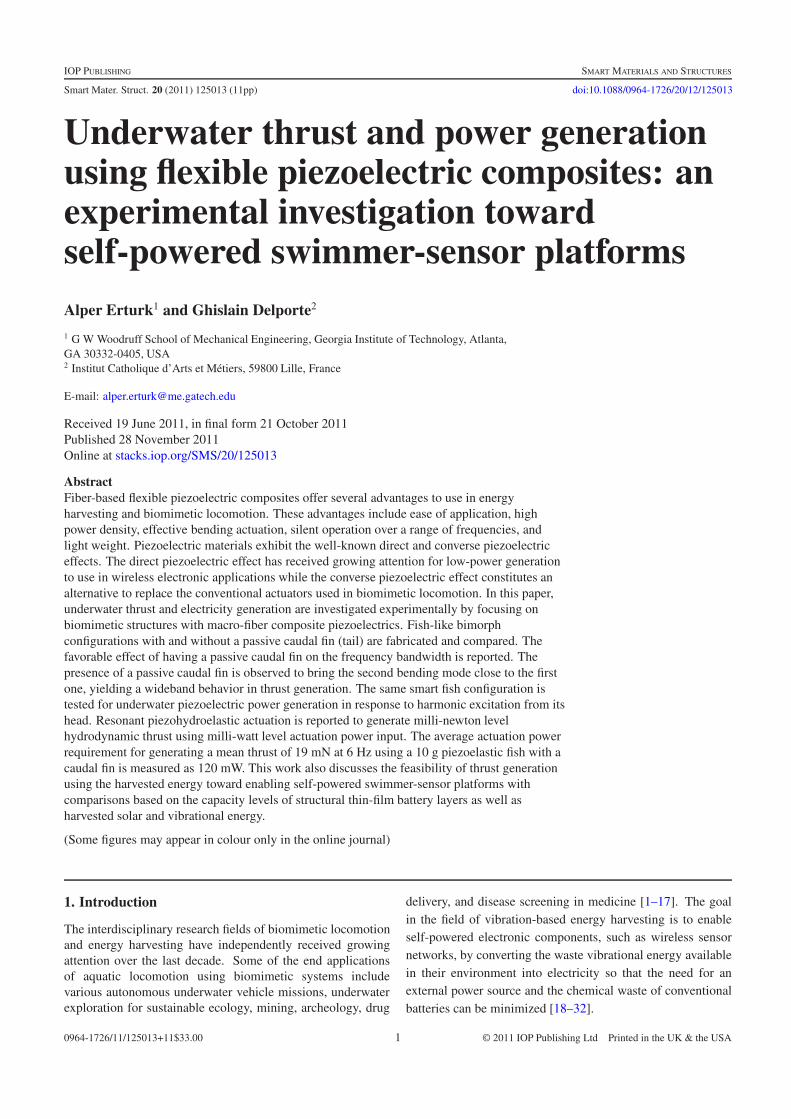
Figure 1. (a) Calibration of the setup to obtain the force–deflectionrelation in the presence of a fish sample and its clamp; (b) close-upview showing the point of applied calibration loads (F) at the headof the fish and the point of deflection (δ) measurement; (c) linearcalibration curve with the identified linear stiffness (F/δ) value.
2. Underwater thrust generation by piezoelectricactuation
2.1. Calibration of the thrust measurement setup
Hydrodynamic thrust measurement under piezoelectric actu-ation is a more involved task as compared to measurementsof the dynamic kinematic variables, such as velocity andacceleration. The reason is that the thrust output is a one-directional force resultant achieved during the oscillatoryactuation of the piezoelastic structure at steady state. A254 mm × 25.4 mm × 6.35 mm aluminum cantilever iscombined with a laser sensor to obtain an elastic transducerfor this purpose. The fish sample with its plexiglass clampis attached to the tip of the horizontally located transducercantilever as shown in figure 1(a). A set of small massesare then gradually located at the center of the fish head toemulate the force (thrust) by the help of gravity. The resultingdeflection is recorded by the laser sensor (figure 1(b)) andeventually the linear calibration curve shown in figure 1(c) isobtained. Note that the transducer cantilever responds linearlyup to several hundreds of milli-newtons and the decoder ofthe laser sensor is sensitive enough to capture the resultingdeflection amplitudes.
2.2. Underwater actuation and thrust measurement
After the calibration curve of the transducer cantilever isobtained in air, the transducer cantilever with a clamped fishsample is immersed in water for the hydrodynamic thrustmeasurements using the experimental setup shown in figure 2.
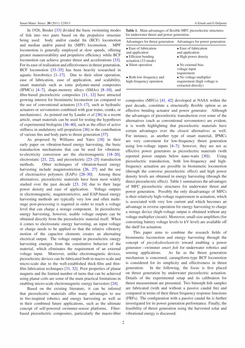
Figure 2. Experimental setup used for underwater thrustmeasurement after the transducer cantilever with a clamped fishsample is immersed in water. Laser A is used for obtaining thetransverse tail velocity-to-actuation voltage input FRFs whereaslaser B is used to measure the mean head displacement during themanual frequency sweep for evaluating the hydrodynamic thrust.
It is important to note that the dimensions of the transducercantilever are such that its underwater fundamental resonancefrequency is sufficiently higher than the underwater actuationfrequencies of interest (this is checked by impact hammertesting of the transducer cantilever). Hence, one is in thequasi-static region of the transducer cantilever in the thrustgeneration experiments and the tip deflection of the cantileveris due to the dynamics of the fish sample only (i.e. there is nointeraction with the dynamics of the transducer cantilever). Inaddition, the hydrostatic pressure distributions on both facesof the transducer cantilever cancel each other so that the in-airthrust–deflection calibration is valid.
In figure 2, the laser vibrometer pointing from thetransverse direction of the fish sample (laser A) is employedfor extracting the modal frequencies of the fish sample(in bending) through the tail velocity-to-actuation voltageFRFs. The second laser vibrometer (laser B) measures thedisplacement of the transducer cantilever (as in figure 1(a)) inthe perpendicular direction so that the mean displacement canbe converted to thrust using the calibration curve (figure 1(c)).
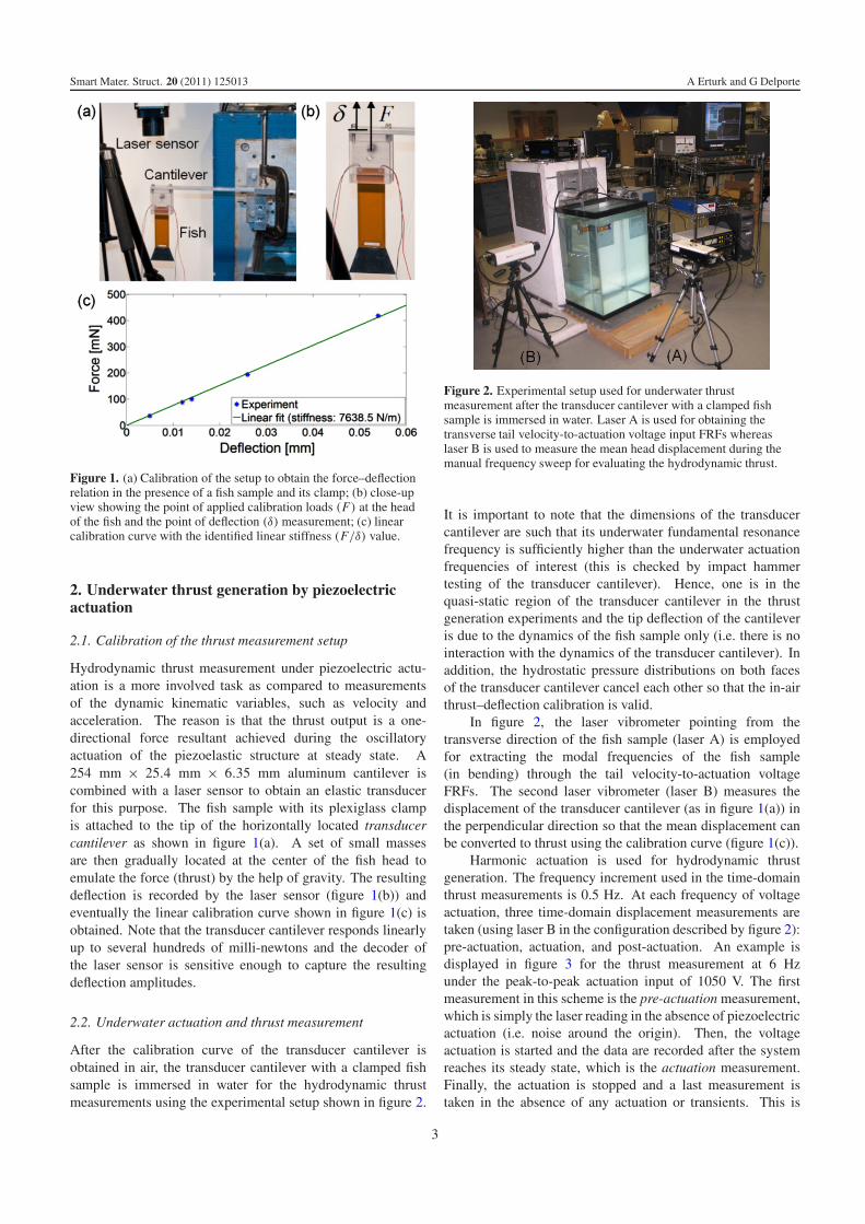
Harmonic actuation is used for hydrodynamic thrustgeneration. The frequency increment used in the time-domainthrust measurements is 0.5 Hz. At each frequency of voltageactuation, three time-domain displacement measurements aretaken (using laser B in the configuration described by figure 2):pre-actuation, actuation, and post-actuation. An example isdisplayed in figure 3 for the thrust measurement at 6 Hzunder the peak-to-peak actuation input of 1050 V. The firstmeasurement in this scheme is the pre-actuation measurement,which is simply the laser reading in the absence of piezoelectricactuation (i.e. noise around the origin). Then, the voltageactuation is started and the data are recorded after the systemreaches its steady state, which is the actuation measurement.Finally, the actuation is stopped and a last measurement istaken in the absence of any actuation or transients. This is
3
Smart Mater. Struct. 20 (2011) 125013 A Erturk and G Delporte
Figure 3. Displacement measurements at the head of the fish sample(in the direction of positive thrust) during pre-actuation,post-actuation, and actuation (along with the average of thepre-actuation and post-actuation histories, which defines theaveraged origin).
the post-actuation measurement. The origin is defined as theaverage of the pre-actuation and post-actuation measurements.The mean displacement caused by the thrust is the differencebetween the mean value of the actuation measurement and themean value of the averaged origin measurement. This meandisplacement reading is then used in figure 1(c) to give themean thrust at the frequency of measurement. Note that thelaser signal amplitude is divided by the refractive index ofwater (n = 1.333) in the underwater experiments and thevalidity of this signal correction is checked through anotherset of experiments not discussed here. Another importantoptical consideration when taking laser measurements througha transparent but reflective interface (clean glass in this case)is to make sure that the reflection from the interface is not onthe lens. This is easy to realize with laser vibrometers of lownumerical aperture by angling the laser sensor head slightly.
2.3. The effect of caudal fin on the thrust frequency response
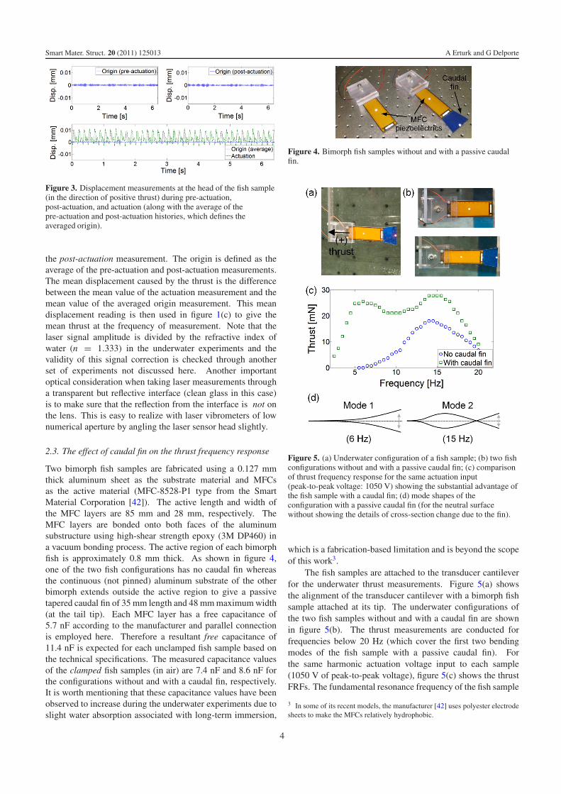
Two bimorph fish samples are fabricated using a 0.127 mmthick aluminum sheet as the substrate material and MFCsas the active material (MFC-8528-P1 type from the SmartMaterial Corporation [42]). The active length and width ofthe MFC layers are 85 mm and 28 mm, respectively. TheMFC layers are bonded onto both faces of the aluminumsubstructure using high-shear strength epoxy (3M DP460) ina vacuum bonding process. The active region of each bimorphfish is approximately 0.8 mm thick. As shown in figure 4,one of the two fish configurations has no caudal fin whereasthe continuous (not pinned) aluminum substrate of the otherbimorph extends outside the active region to give a passivetapered caudal fin of 35 mm length and 48 mm maximum width(at the tail tip). Each MFC layer has a free capacitance of5.7 nF according to the manufacturer and parallel connectionis employed here. Therefore a resultant free capacitance of11.4 nF is expected for each unclamped fish sample based onthe technical specifications. The measured capacitance valuesof the clamped fish samples (in air) are 7.4 nF and 8.6 nF forthe configurations without and with a caudal fin, respectively.It is worth mentioning that these capacitance values have beenobserved to increase during the underwater experiments due toslight water absorption associated with long-term immersion,
Figure 4. Bimorph fish samples without and with a passive caudalfin.
Figure 5. (a) Underwater configuration of a fish sample; (b) two fishconfigurations without and with a passive caudal fin; (c) comparisonof thrust frequency response for the same actuation input(peak-to-peak voltage: 1050 V) showing the substantial advantage ofthe fish sample with a caudal fin; (d) mode shapes of theconfiguration with a passive caudal fin (for the neutral surfacewithout showing the details of cross-section change due to the fin).
which is a fabrication-based limitation and is beyond the scopeof this work3.
The fish samples are attached to the transducer cantileverfor the underwater thrust measurements. Figure 5(a) showsthe alignment of the transducer cantilever with a bimorph fishsample attached at its tip. The underwater configurations ofthe two fish samples without and with a caudal fin are shownin figure 5(b). The thrust measurements are conducted forfrequencies below 20 Hz (which cover the first two bendingmodes of the fish sample with a passive caudal fin). Forthe same harmonic actuation voltage input to each sample(1050 V of peak-to-peak voltage), figure 5(c) shows the thrustFRFs. The fundamental resonance frequency of the fish sample
3 In some of its recent models, the manufacturer [42] uses polyester electrodesheets to make the MFCs relatively hydrophobic.
4
Smart Mater. Struct. 20 (2011) 125013 A Erturk and G Delporte
with no caudal fin is around 14.5 Hz and the mean thrustat this frequency is 18 mN. Remarkably, the fish samplewith a tapered passive caudal fin exhibits two peaks in thefrequency range of 0–20 Hz with much larger thrust output.In addition to its fundamental vibration mode around 6 Hz(the first bending mode), the fish with a passive caudal fin hasits second vibration mode around 15 Hz (the second bendingmode). The mean thrust readings for the sample with a passivecaudal fin in figure 5(c) are 26 mN at 6 Hz (mode 1) and28 mN at 15 Hz (mode 2). The mode shapes of this favorableconfiguration are shown in figure 5(d). Note that the secondmode shape (at 15 Hz) has a node near the root of the caudalfin, hence an inflection point close to the head of the fish.It can be concluded from figure 5(c) that the configurationwith a passive caudal fin is a wideband thrust generator withsubstantially larger and relatively flat thrust output as comparedto the configuration with no caudal fin for the same dynamicactuation input. This is in agreement with the single-hinge anddouble-hinge analogies given by Azuma [28] in his book andtheir effect on the frequency range of optimal performance.
It is worth mentioning that the actuation performance forthe second vibration mode can be improved by optimizing thesurface coverage of the piezoelectric layers. It is known that thesecond mode shape (in figure 5(d)) has a strain node (whichis simply an inflection point for a thin cantilever) near theroot [43, 44]. Therefore, a significant portion of the actuationinput cancels itself with the present surface coverage of thepiezoelectric layers since the strain distributions on two sidesof the strain node are 180◦ out of phase. Using segmentedpiezoelectric fibers and segmented electrodes [44] can improveactuation performance dramatically for swimming with thesecond mode shape.
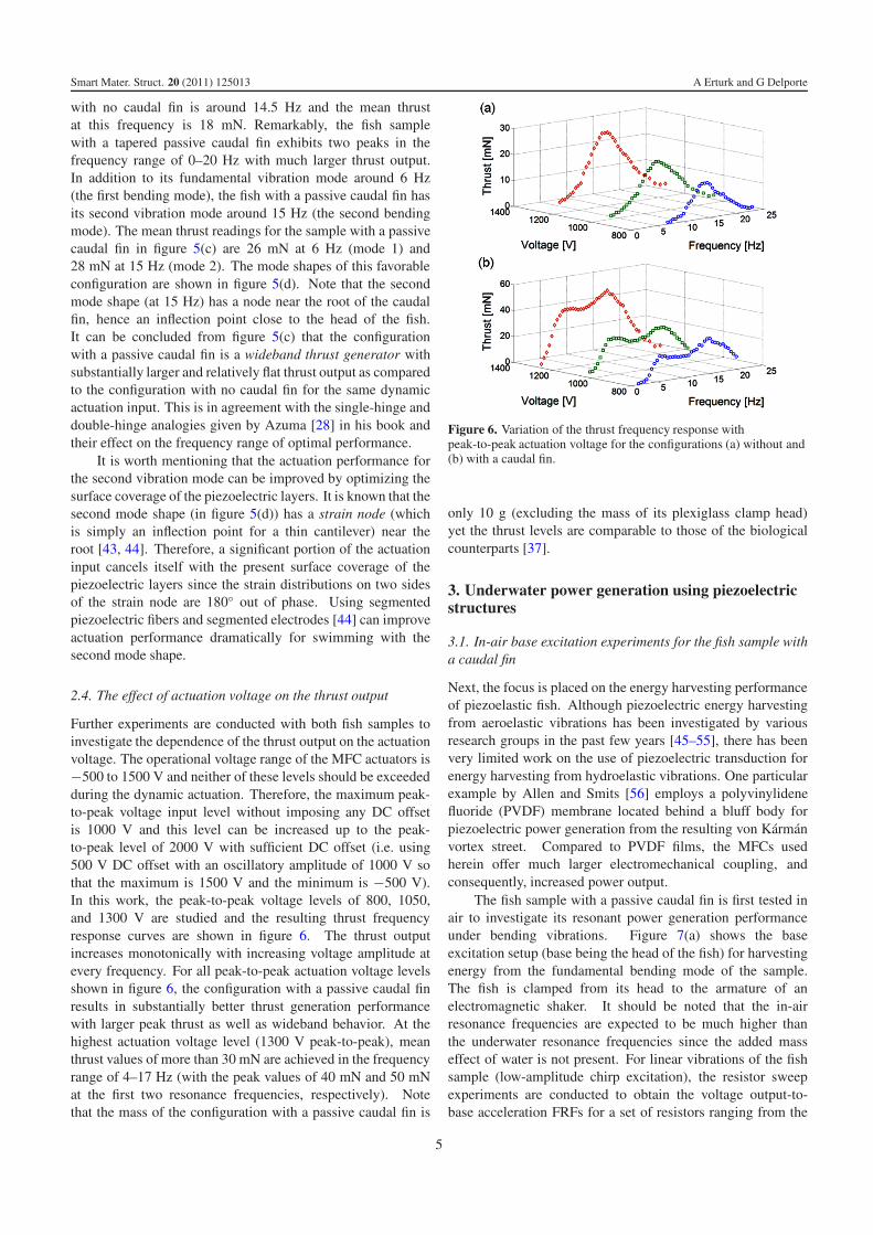
2.4. The effect of actuation voltage on the thrust output
Further experiments are conducted with both fish samples toinvestigate the dependence of the thrust output on the actuationvoltage. The operational voltage range of the MFC actuators is−500 to 1500 V and neither of these levels should be exceededduring the dynamic actuation. Therefore, the maximum peak-to-peak voltage input level without imposing any DC offsetis 1000 V and this level can be increased up to the peak-to-peak level of 2000 V with sufficient DC offset (i.e. using500 V DC offset with an oscillatory amplitude of 1000 V sothat the maximum is 1500 V and the minimum is −500 V).In this work, the peak-to-peak voltage levels of 800, 1050,and 1300 V are studied and the resulting thrust frequencyresponse curves are shown in figure 6. The thrust outputincreases monotonically with increasing voltage amplitude atevery frequency. For all peak-to-peak actuation voltage levelsshown in figure 6, the configuration with a passive caudal finresults in substantially better thrust generation performancewith larger peak thrust as well as wideband behavior. At thehighest actuation voltage level (1300 V peak-to-peak), meanthrust values of more than 30 mN are achieved in the frequencyrange of 4–17 Hz (with the peak values of 40 mN and 50 mNat the first two resonance frequencies, respectively). Notethat the mass of the configuration with a passive caudal fin is
Figure 6. Variation of the thrust frequency response withpeak-to-peak actuation voltage for the configurations (a) without and(b) with a caudal fin.
only 10 g (excluding the mass of its plexiglass clamp head)yet the thrust levels are comparable to those of the biologicalcounterparts [37].
3. Underwater power generation using piezoelectricstructures
3.1. In-air base excitation experiments for the fish sample witha caudal fin
Next, the focus is placed on the energy harvesting performanceof piezoelastic fish. Although piezoelectric energy harvestingfrom aeroelastic vibrations has been investigated by variousresearch groups in the past few years [45–55], there has beenvery limited work on the use of piezoelectric transduction forenergy harvesting from hydroelastic vibrations. One particularexample by Allen and Smits [56] employs a polyvinylidenefluoride (PVDF) membrane located behind a bluff body forpiezoelectric power generation from the resulting von Karmanvortex street. Compared to PVDF films, the MFCs usedherein offer much larger electromechanical coupling, andconsequently, increased power output.
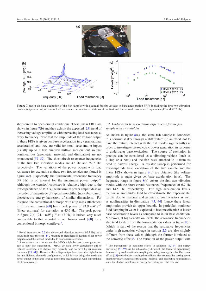
The fish sample with a passive caudal fin is first tested inair to investigate its resonant power generation performanceunder bending vibrations. Figure 7(a) shows the baseexcitation setup (base being the head of the fish) for harvestingenergy from the fundamental bending mode of the sample.The fish is clamped from its head to the armature of anelectromagnetic shaker. It should be noted that the in-airresonance frequencies are expected to be much higher thanthe underwater resonance frequencies since the added masseffect of water is not present. For linear vibrations of the fishsample (low-amplitude chirp excitation), the resistor sweepexperiments are conducted to obtain the voltage output-to-base acceleration FRFs for a set of resistors ranging from the
5
Smart Mater. Struct. 20 (2011) 125013 A Erturk and G Delporte
Figure 7. (a) In-air base excitation of the fish sample with a caudal fin; (b) voltage-to-base acceleration FRFs including the first two vibrationmodes; (c) power output versus load resistance curves for excitations at the first and the second resonance frequencies (47 and 92.7 Hz).
short-circuit to open-circuit conditions. These linear FRFs areshown in figure 7(b) and they exhibit the expected [25] trend ofincreasing voltage amplitude with increasing load resistance atevery frequency. Note that the amplitude of the voltage outputin these FRFs is given per base acceleration in g (gravitationalacceleration) and they are valid for small acceleration inputs(usually up to a few hundred milli-g acceleration) so thatnonlinearities (geometric, material, and dissipative) are notpronounced [57–59]. The short-circuit resonance frequenciesof the first two vibration modes are 47 Hz and 92.7 Hz,respectively. The variations of the power output with loadresistance for excitation at these two frequencies are plotted infigure 7(c). Expectedly, the fundamental resonance frequency(47 Hz) is of interest for the maximum power output4.Although the matched resistance is relatively high due to thelow capacitance of MFCs, the maximum power amplitude is onthe order of magnitude of typical monolithic (non-fiber-based)piezoelectric energy harvesters of similar dimensions. Forinstance, the conventional bimorph with a tip mass attachmentin Erturk and Inman [60] has a peak power of 23.9 mW g−2
(linear estimate) for excitation at 45.6 Hz. The peak powerin figure 7(c) (24.1 mW g−2 at 47 Hz) is indeed very muchcomparable to that reported in our former work [60] for aconventional bimorph cantilever5.
4 Recall from section 2.3 that the second vibration mode (at 92.7 Hz) has astrain node near the root [44], resulting in significant reduction of the poweroutput around the second mode due to continuous electrodes.5 A common error is to assume that MFCs might be poor power generatorsdue to their low capacitance. MFCs do have lower capacitance due toreduced electrode area (hence they typically tend to have higher matchedresistance [25, 61]). However, the voltage output levels are also high due tothe interdigitated electrode configuration, which is what brings the maximumpower output to the same level as monolithic piezoceramics with conventionalelectrode coverage.
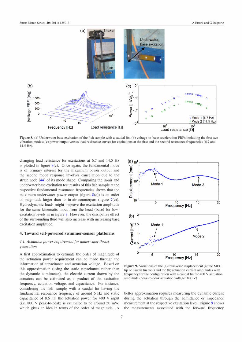
3.2. Underwater base excitation experiments for the fishsample with a caudal fin
As shown in figure 8(a), the same fish sample is connectedto a seismic shaker through a stiff fixture (in an effort not tohave the fixture interact with the fish modes significantly) inorder to investigate piezoelectric power generation in responseto underwater base excitation. The source of excitation inpractice can be considered as a vibrating vehicle (such asa ship or a boat) and the fish rests attached to it from itshead to harvest energy. A resistor sweep is performed forlow-amplitude base excitation of the fish sample and thelinear FRFs shown in figure 8(b) are obtained (the voltageamplitude is again given per base acceleration in g). Thefrequency range in figure 8(b) covers the first two vibrationmodes with the short-circuit resonance frequencies of 6.7 Hzand 14.5 Hz, respectively. For high acceleration levels,the linear amplitudes tend to overestimate the experimentalresults due to material and geometric nonlinearities as wellas nonlinearities in dissipation [43, 44] (hence these linearamplitudes provide an upper bound). In particular, nonlinearfluid damping in water is expected to become effective at lowerbase acceleration levels as compared to in-air base excitation.Moreover, at high-excitation levels, the resonance frequenciesalso tend to shift from the low-excitation values in figure 8(b)(which is part of the reason that the resonance frequenciesunder high actuation voltage in section 2.3 are also slightlydifferent from these values although the former is related tothe converse effect)6. The variation of the power output with
6 The mechanisms of nonlinear effects in actuation [62–64] and energyharvesting [57–59] can be substantially different (the former is significantlydominated by nonlinearities in coupling due to high-voltage levels). Our recentefforts [59] toward understanding the nonlinearities in energy harvesting revealthat the primary sources are the elastic (material) and dissipative nonlinearitiessince the electric field levels in energy harvesting are relatively low.
6
Smart Mater. Struct. 20 (2011) 125013 A Erturk and G Delporte
Figure 8. (a) Underwater base excitation of the fish sample with a caudal fin; (b) voltage-to-base acceleration FRFs including the first twovibration modes; (c) power output versus load resistance curves for excitations at the first and the second resonance frequencies (6.7 and14.5 Hz).
changing load resistance for excitations at 6.7 and 14.5 Hzis plotted in figure 8(c). Once again, the fundamental modeis of primary interest for the maximum power output andthe second mode response involves cancelation due to thestrain node [44] of its mode shape. Comparing the in-air andunderwater base excitation test results of this fish sample at therespective fundamental resonance frequencies shows that themaximum underwater power output (figure 8(c)) is an orderof magnitude larger than its in-air counterpart (figure 7(c)).Hydrodynamic loads might improve the excitation amplitudefor the same kinematic input from the head (base) for low-excitation levels as in figure 8. However, the dissipative effectof the surrounding fluid will also increase with increasing baseexcitation amplitude.
4. Toward self-powered swimmer-sensor platforms
4.1. Actuation power requirement for underwater thrustgeneration
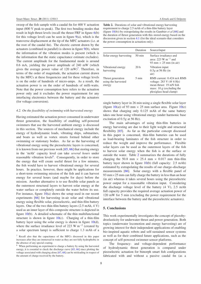
A first approximation to estimate the order of magnitude ofthe actuation power requirement can be made through theinformation of capacitance and actuation voltage. Based onthis approximation (using the static capacitance rather thanthe dynamic admittance), the electric current drawn by theactuators can be estimated as a product of the excitationfrequency, actuation voltage, and capacitance. For instance,considering the fish sample with a caudal fin having thefundamental resonance frequency of around 6 Hz and staticcapacitance of 8.6 nF, the actuation power for 400 V input(i.e. 800 V peak-to-peak) is estimated to be around 50 mW,which gives an idea in terms of the order of magnitude. A
Figure 9. Variations of the (a) transverse displacement (at the MFCtip or caudal fin root) and the (b) actuation current amplitudes withfrequency for the configuration with a caudal fin for 400 V actuationamplitude (peak-to-peak actuation voltage: 800 V).
better approximation requires measuring the dynamic currentduring the actuation through the admittance or impedancemeasurement at the respective excitation level. Figure 9 showsthe measurements associated with the forward frequency
7
Smart Mater. Struct. 20 (2011) 125013 A Erturk and G Delporte
sweep of the fish sample with a caudal fin for 400 V actuationinput (800 V peak-to-peak). The first two bending modes thatresult in high thrust levels (recall the thrust FRF in figure 6(b)for this voltage level) can be seen in figure 9(a), which is thetransverse displacement at the tip of the MFC actuators (i.e. atthe root of the caudal fin). The electric current drawn by theactuators (combined in parallel) is shown in figure 9(b), wherethe information of the vibration modes is present (which isthe information that the static capacitance estimate excludes).The current amplitude for the fundamental mode is around0.6 mA, yielding the power amplitude of 240 mW (whichgives the average power value of 120 mW)7. Therefore, interms of the order of magnitude, the actuation current drawnby the MFCs at these frequencies and for these voltage levelsis on the order of hundreds of micro-amps. As a result, theactuation power is on the order of hundreds of milli-watts.Note that the power consumption here refers to the actuationpower only and it excludes the power requirement for anyinterfacing electronics between the battery and the actuators(for voltage conversion).
4.2. On the feasibility of swimming with harvested energy
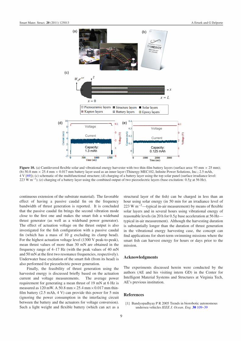
Having estimated the actuation power consumed in underwaterthrust generation, the feasibility of enabling self-poweredswimmers that use the harvested ambient energy is discussedin this section. The sources of mechanical energy include theenergy of hydrodynamic loads, vibrating ships, submarines,and boats as well as vortex streets formed behind otherswimming or stationary bodies. As far as the harvesting ofvibrational energy using the piezoelectric layers is concerned,it is known from our previous work [65, 66] that storing energyin the ‘mAh’ capacity level can take several hours underreasonable vibration levels8. Consequently, in order to storethe energy that will create useful thrust for a few minutes,the fish would have to harvest vibrational energy for severalhours. In practice, however, there might be applications fora short-term swimming mission of the fish and it can harvestenergy for several hours (and maybe for days) before themission. Another alternative is to use flexible solar panels asthe outermost structural layers to harvest solar energy at thewater surface or completely outside the water before its use.For instance, figure 10(a) shows the setup used in our recentexperiments [66] for harvesting in-air solar and vibrationalenergy using flexible solar, piezoelectric, and thin-film batterylayers. One of the two thin-film battery layers (2.5 mAh, 4 V)used as an inner layer of this composite structure is depicted infigure 10(b). A detailed schematic of the thin multifunctionalstructure is shown in figure 10(c). Charging of a thin-filmbattery layer using the solar energy is shown in figure 10(d),where the surface irradiance level of 223 W m−2 (created bya solar spectrum lamp) is sufficient to charge 1.3 mAh of a
7 Recall also that the capacitance of the MFCs discussed in this paperincreases after they are immersed in water as they are not fully hydrophobic inthe absence of any special coating.8 When performing an experiment to charge a battery by using the harvestedenergy, it is essential to check the discharge curve [65, 66] since plotting thevoltage associated with charging alone [67, 68] can be misleading in respect ofthe amount of charge received by the battery.
Table 2. Durations of solar and vibrational energy harvestingrequirement to charge 2.5 mAh of a thin-film battery layer(figure 10(b)) by extrapolating the results in Gambier et al [66] andthe duration of thrust generation with this stored energy based on thediscussion given in section 4.1 (for the ideal scenario that considersthe power consumption in actuation only).
Duration Source/input
Solar energy harvesting 50 min Surface irradiance andarea: 223 W m−2 and93 mm × 25 mm (in air)
Vibrational energyharvesting
20 h Vibration input:0.5g at 56 Hz (inair)
Thrust generationusing the harvestedenergy
5 min RMS current: 0.424 mA RMSvoltage: 283 V (@ 6 Hz)mean thrust: 19 mN fishmass: 10 g (excluding theplexiglass head clamp)
single battery layer in 26 min using a single flexible solar layer(figure 10(a)) of 93 mm × 25 mm surface area. Figure 10(e)shows that charging only 0.125 mAh of the same batterytakes one hour using vibrational energy (under harmonic baseexcitation of 0.5g at 56 Hz).
The main advantages of using thin-film batteries inenergy harvesting are due to their light weight and structuralflexibility [65]. As far as the particular concept discussedin this paper is concerned, thin-film batteries can be usedas load-bearing laminates of the fish structure in order toreduce the weight and improve the performance. Flexiblesolar layers can be used as the outermost layers of the fishto harvest solar energy when the fish is at the surface oroutside the water. Table 2 summarizes the durations of fullycharging the 50.8 mm × 25.4 mm × 0.017 mm thin-filmbattery layer shown in figure 10(b) (full capacity: 2.5 mAh)estimated by extrapolating the results of our charge–dischargemeasurements [66]. Solar energy with a flexible panel of93 mm×25 mm can fully charge the battery in less than an hour(in air) whereas it takes several hours using the piezoelectricpower output for a reasonable vibration input. Consideringthe discharge voltage level of the battery (4 V), 2.5 mAhfull capacity provides the required average actuation power of120 mW for 5 min (excluding the power requirement for theinterface between the battery and the piezoelectric actuators).
5. Conclusions
This work experimentally investigates the concept of piezohy-droelasticity for underwater thrust and power generation. Bothtopics (underwater locomotion and energy harvesting) are ofgrowing interest for their independent applications of enablingbio-inspired aquatic robots and self-sustained sensor systemsas well as for their combined future applications, such as theconcept of self-powered swimmer-sensor platforms.
The frequency- and voltage-dependent performanceof hydrodynamic thrust generation is compared underpiezoelectric actuation for bimorph smart fish configurationsfabricated with and without a passive caudal fin (as a
8
Smart Mater. Struct. 20 (2011) 125013 A Erturk and G Delporte
Figure 10. (a) Cantilevered flexible solar and vibrational energy harvester with two thin-film battery layers (surface area: 93 mm × 25 mm);(b) 50.8 mm × 25.4 mm × 0.017 mm battery layer used as an inner layer (Thinergy MEC102, Infinite Power Solutions, Inc.; 2.5 mAh,4 V [69]); (c) schematic of the multifunctional structure; (d) charging of a battery layer using the top solar panel (surface irradiance level:223 W m−2); (e) charging of a battery layer using the combined output of two piezoelectric layers (base excitation: 0.5g at 56 Hz).
continuous extension of the substrate material). The favorableeffect of having a passive caudal fin on the frequencybandwidth of thrust generation is reported. It is concludedthat the passive caudal fin brings the second vibration modeclose to the first one and makes the smart fish a widebandthrust generator (as well as a wideband power generator).The effect of actuation voltage on the thrust output is alsoinvestigated for the fish configuration with a passive caudalfin (which has a mass of 10 g excluding its clamp head).For the highest actuation voltage level (1300 V peak-to-peak),mean thrust values of more than 30 mN are obtained in thefrequency range of 4–17 Hz (with the peak values of 40 mNand 50 mN at the first two resonance frequencies, respectively).Underwater base excitation of the smart fish (from its head) isalso performed for piezoelectric power generation.
Finally, the feasibility of thrust generation using theharvested energy is discussed briefly based on the actuationcurrent and voltage measurements. The average powerrequirement for generating a mean thrust of 19 mN at 6 Hz ismeasured as 120 mW. A 50.8 mm×25.4 mm×0.017 mm thin-film battery (2.5 mAh, 4 V) can provide this power for 5 min(ignoring the power consumption in the interfacing circuitbetween the battery and the actuators for voltage conversion).Such a light weight and flexible battery (which can act as a
structural layer of the fish) can be charged in less than anhour using solar energy (in 50 min for an irradiance level of223 W m−2—typical in-air measurement) by means of flexiblesolar layers and in several hours using vibrational energy ofreasonable levels (in 20 h for 0.5g base acceleration at 56 Hz—typical in-air measurement). Although the harvesting durationis substantially longer than the duration of thrust generationin the vibrational energy harvesting case, the concept canfind applications for short-term swimming missions where thesmart fish can harvest energy for hours or days prior to themission.
Acknowledgments
The experiments discussed herein were conducted by theauthors (AE and his visiting intern GD) in the Center forIntelligent Material Systems and Structures at Virginia Tech,AE’s previous institution.
References
[1] Bandyopadhyay P R 2005 Trends in biorobotic autonomousundersea vehicles IEEE J. Ocean. Eng. 30 109–39
9
Smart Mater. Struct. 20 (2011) 125013 A Erturk and G Delporte
[2] Roper D T, Sharma S, Sutton R and Culverhouse P 2011A review of developments towards biologically inspiredpropulsion Proc. Inst. Mech. Eng. E 255 77–96
[3] Zhang Z G, Gondo M, Yamashita N, Yamamoto A andHiguchi T 2007 Design and control of a fish-like robot usingand electrostatic motor Proc. 2007 IEEE Int. Conf. onRobotics and Automation (Rome, April 2007)
[4] Guo S, Ge Y, Li L and Liu S 2006 Underwater swimmingmicro robot using IPMC actuator Proc. 2006 IEEE Int. Conf.on Mechatronics and Automation (Luoyang, June 2006)
[5] Peng H, Ding Q and Li H 2009 Fabrication of ionicpolymer—metal composites and robot design Front. Mech.Eng. China 4 332–8
[6] Chen Z, Shatara S and Tan X 2010 Modeling of biomimeticrobotic fish propelled by an ionic polymer—metal compositecaudal fin IEEE/ASME Trans. Mechatronics 15 448–59
[7] Aureli M, Kopman V and Porfiri M 2010 Free-locomotion ofunderwater vehicles actuated by ionic metal polymercomposites IEEE/ASME Trans. Mechatronics 15 603–14
[8] Shinjo N 2005 Investigations into the use of shape memoryalloy for biomimetic propulsion of underwater vehicles PhDThesis Department of Marine and Environmental Systems,Florida Institute of Technology, Melbourne, FL, 260 pp
[9] Cho K, Hawkes E, Quinn C and Wood R J 2008 Design,fabrication and analysis of a body-caudal fin propulsionsystem for a microrobotic fish Proc. 2008 IEEE Int. Conf. onRobotics and Automation (Pasadena, CA, May 2008)
[10] Wang Z, Hang G, Li J, Wang Y and Xiao K 2008 Amicro-robot fish with embedded SMA wire actuated flexiblebiomimetic fin Sensors Actuators A 144 354–60
[11] Nagata Y, Park S, Ming S and Shimojo M 2008 Developmentof underwater robot using macro fiber composite Proc. 2008IEEE/ASME Int. Conf. on Advanced IntelligentMechatronics (Xi’an, July 2008)
[12] Ming S, Park S, Nagata Y and Shimojo M 2009 Developmentof underwater robots using piezoelectric fiber compositeProc. 2009 IEEE Int. Conf. on Robotics and Automation(Kobe, May 2009)
[13] Barrett D S 1994 The design of a flexible hull undersea vehiclepropelled by an oscillator foil MS Thesis Department ofOcean Engineering, Massachusetts Institute of Technology,Boston, MA, 177 pp
[14] Barrett D S 1996 Propulsive efficiency of a flexible hullunderwater vehicle PhD Thesis Department of OceanEngineering, Massachusetts Institute of Technology, Boston,MA, 215 pp
[15] Anderson J M and Chhabra N K 2002 Maneuvering andstability performance of a robotic tuna Integr. Compar. Biol.42 118–26
[16] Low K H and Willy A 2006 Biomimetic motion planning of anundulating robotic fish fin J. Vib. Control 12 1337–59
[17] Crespi A, Lachat D, Pasquier A and Ijspeert A J 2008Controlling swimming and crawling in a fish robot using acentral pattern generator Auton. Robots 25 3–13
[18] Williams C B and Yates R B 1996 Analysis of a micro-electricgenerator for microsystems Sensors Actuators A 52 8–11
[19] Glynne-Jones P, Tudor M J, Beeby S P and White N M 2004An electromagnetic, vibration-powered generator forintelligent sensor systems Sensors Actuators A 110 344–9
[20] Elvin N and Elvin A 2011 An experimentally validatedelectromagnetic energy harvesters J. Sound Vib.330 2314–24
[21] Mitcheson P, Miao P, Start B, Yeatman E, Holmes A andGreen T 2004 MEMS electrostatic micro-power generatorfor low frequency operation Sensors Actuators A115 523–9
[22] Sheu G J, Yang S M and Lee T 2011 Development of a lowfrequency electrostatic comb-drive energy harvester
compatible to SoC design by COMS process SensorsActuators A 167 70–6
[23] Anton S R and Sodano H A 2007 A review of power harvestingusing piezoelectric materials (2003-2006) Smart Mater.Struct. 16 R1–21
[24] Cook-Chennault K A, Thambi N and Sastry A M 2008Powering MEMS portable devices—a review ofnon-regenerative and regenerative power supply systemswith emphasis on piezoelectric energy harvesting systemsSmart Mater. Struct. 17 043001
[25] Erturk A and Inman D J 2011 Piezoelectric Energy Harvesting(Chichester: Wiley)
[26] Wang L and Yuan F G 2008 Vibration energy harvesting bymagnetostrictive material Smart Mater. Struct. 17 045009
[27] Dai X, Wen Y, Li P, Yang J and Zhang G 2009 Modeling,characterization, and fabrication of vibration energyharvester using Terfenol-D/PZT/Terfenol-D compositetransducer Sensors Actuators A 156 350–8
[28] Koh S J A, Zhao X and Suo Z 2009 Maximal energy that can beconverted by a dielectric elastomer generator Appl. Phys.Lett. 94 262902
[29] Aureli M, Prince C, Porfiri M and Peterson S D 2010 Energyharvesting from base excitation of ionic polymer metalcomposites in fluid environments Smart Mater. Struct.19 015003
[30] Giacomello A and Porfiri M 2011 Underwater energyharvesting from a heavy flag hosting ionic polymer metalcomposites J. Appl. Phys. 109 084903
[31] Jeon Y B, Sood R, Jeong J H and Kim S 2005 MEMS powergenerator with transverse mode thin film PZT SensorsActuators A 122 16–22
[32] Shen D, Park J H, Noh J H, Choe S Y, Kim S Y, Wikle H C andKim D J 2009 Micromachined PZT cantilever based on SOIstructure for low frequency vibration energy harvestingSensors Actuators A 154 103–8
[33] Breder C M 1926 The locomotion of fishes Zoologica 4159–256
[34] Sfakiotakis M, Lane D M and Davies J B C 1999 Review offish swimming modes for aquatic locomotion IEEE J.Ocean. Eng. 24 237–52
[35] Azuma A 2006 The Biokinetics of Flying and Swimming(Reston, VA: AIAA)
[36] Lauder G V, Madden P G A, Tangorra J L, Anderson E andBaker T V 2011 Bioinspiration from fish for smart materialdesign and function Smart Mater. Struct. 20 094014
[37] Lauder G V and Drucker E G 2002 Forces, fishes, and fluids:hydrodynamic mechanisms of aquatic locomotion NewsPhysiol. Sci. 17 235–40
[38] Lauder G V and Drucker E G 2004 Morphology andexperimental hydrodynamics of fish sin control surfacesIEEE J. Ocean. Eng. 29 556–71
[39] Fish F F and Lauder G V 2006 Passive and active flow controlby swimming fishes and mammals Annu. Rev. Fluid Mech.38 193–224
[40] Lauder G V, Anderson E, Tangorra J L and Madden P G A2007 Fish biorobotics: kinematics and hydrodynamics ofself-propulsion J. Exp. Biol. 210 2767–80
[41] High J W and Wilkie W K 2003 Method of fabricatingNASA-standard macro-fiber composite piezoelectricactuators NASA/TM-2003-212427, ARL-TR-2833
[42] Smart Material Corp. (MFC supplier with the NASA standard):www.smart-material.com
[43] Crawley E F and de Luis J 1987 Use of piezoelectric actuatorsas elements of intelligent structures AIAA J. 25 1373–85
[44] Erturk A, Tarazaga P A, Farmer J R and Inman D J 2009 Effectof strain nodes and electrode configuration on piezoelectricenergy harvesting from cantilevered beams ASME J. Vib.Acoust. 131 011010
10
Smart Mater. Struct. 20 (2011) 125013 A Erturk and G Delporte
[45] Bryant M and Garcia E 2009 Development of an aeroelasticvibration power harvester Proc. SPIE 7288 728812
[46] Erturk A, Vieira W G R, De Marqui C Jr and Inman D J 2010On the energy harvesting potential of piezoaeroelasticsystems Appl. Phys. Lett. 96 184103
[47] De Marqui C Jr, Erturk A and Inman D J 2010 Piezoaeroelasticmodeling and analysis of a generator wing with continuousand segmented electrodes J. Intell. Mater. Syst. Struct.21 983–93
[48] De Marqui C Jr, Vieira W G R, Erturk A and Inman D J 2010Modeling and analysis of piezoelectric energy harvestingfrom aeroelastic vibrations using the doublet-lattice methodASME J. Vib. Acoust. 133 011003
[49] St Clair D, Bibo A, Sennakesavababu V R, Daqaq M F andLi G 2010 A scalable concept for micropower generationusing flow-induced self-excited oscillations Appl. Phys. Lett.96 144103
[50] Tang L, Paidoussis M and Jiang J 2009 Cantilevered flexibleplates in axial flow: energy transfer and the concept offlutter-mill J. Sound Vib. 326 263–76
[51] Robbins W P, Morris D, Marusic I and Novak T O 2006Wind-generated electrical energy using flexible piezoelectricmaterials Proc. ASME IMECE 2006 (Chicago, IL)
[52] Pobering S, Ebermeyer S and Schwesinger N 2009 Generationof electrical energy using short piezoelectric cantilevers inflowing media Proc. SPIE 7288 728807
[53] Akaydin H D, Elvin N and Andreopoulos Y 2010 Wake of acylinder: a paradigm for energy harvesting withpiezoelectric materials Exp. Fluids 49 291–304
[54] Abdelkefi A, Nayfeh A H and Hajj M R 2011 Modeling andanalysis of piezoaeroelastic energy harvesters NonlinearDyn. at press (doi:10.1007/s11071-011-0035-1)
[55] Sousa V C, Anicezio M M, De Marqui C Jr and Erturk A 2011Enhanced aeroelastic energy harvesting by exploitingcombined nonlinearities: theory and experiment SmartMater. Struct. 20 094007
[56] Allen J J and Smits A J 2001 Energy harvesting eel J. FluidsStruct. 15 629–40
[57] Stanton S C, Erturk A, Mann B P and Inman D J 2010Nonlinear piezoelectricity in electroelastic energy
harvesters: modeling and experimental identification J. Appl.Phys. 108 074903
[58] Stanton S C, Erturk A, Mann B P and Inman D J 2010 Resonantmanifestation of intrinsic nonlinearity within electroelasticmicropower generators Appl. Phys. Lett. 97 254101
[59] Stanton S C, Erturk A, Mann B P, Dowell E H andInman D J 2011 Nonlinear nonconservative behavior andmodeling of piezoelectric energy harvesters including proofmass effects J. Intell. Mater. Syst. Struct. at press
[60] Erturk A and Inman D J 2009 An experimentally validatedbimorph cantilever model for piezoelectric energy harvestingfrom base excitations Smart Mater. Struct. 18 025009
[61] Kong N, Ha D S, Erturk A and Inman D J 2010 Resistiveimpedance matching circuit for piezoelectric energyharvesting J. Intell. Mater. Syst. Struct. 21 1293–302
[62] Crawley E and Anderson E 1990 Detailed models forpiezoelectric actuation of beams J. Intell. Mater. Syst. Struct.1 4–25
[63] Crawley E and Lazarus K 1991 Induced strain actuation ofisotropic and anisotropic plates AIAA J. 29 944–51
[64] Tiersten H F 1993 Electroelastic equations for electrodedd thinplates subject to large driving voltages J. Appl. Phys.74 3389
[65] Anton S R, Erturk A and Inman D J 2010 Multifunctionalself-charging structures using piezoceramics and thin-filmbatteries Smart Mater. Struct. 19 115021
[66] Gambier P, Anton S R, Kong N, Erturk A and Inman D J 2010Combined piezoelectric, solar and thermal energy harvestingfor multifunctional structures with thin-film batteries Proc.21st Int. Conf. on Adaptive Structures and Technologies(State College, PA, October 2010)
[67] Sodano H A, Inman D J and Park G 2005 Generation andstorage of electricity from power harvesting devicesJ. Intell. Mater. Syst. Struct. 16 67–75
[68] Sodano H A, Inman D J and Park G 2005 Comparison ofpiezoelectric energy harvesting devices for rechargingbatteries J. Intell. Mater. Syst. Struct. 16 799–807
[69] Infinite Power Solutions, Inc. www.infinitepowersolutions.com
11