unf drive & alumni drive milling & resurfacing ... 15-12 geotechnical... · report of...
TRANSCRIPT
Report of Geotechnical Exploration For
UNF Drive & Alumni Drive Milling & Resurfacing Jacksonville, Florida
MAE Project No. 0016-0020A
January 5, 2015
Prepared for:
Prepared by:
8936 Western Way, Suite 12 Jacksonville, Florida 32256
Phone (904) 519-6990 Fax (904) 519-6992

8936 Western Way, Suite 12 Jacksonville, Florida 32256 Phone: (904)519-6990 Fax: (904)519-6992
January 5, 2015
Mr. Sam E. Mousa, P.E. JBC Planning & Engineering, LLC 1301 Riverplace Boulevard, Suite 950 Jacksonville, Florida 32207
Reference: Report of Geotechnical Exploration UNF Drive & Alumni Drive Milling & Resurfacing Jacksonville, Florida MAE Project No. 0016-0020A
Dear Mr. Mousa:
Meskel & Associates Engineering, PLLC (MAE) has completed a geotechnical exploration for the subject project. Our work was performed in general accordance with our updated proposal dated November 5, 2014. Additional exploration of the UNF Drive location was authorized on December 15, 2014. The purpose of this geotechnical exploration was to explore the existing pavement thickness along Alumni Drive and the shallow pavement subgrade soils within an existing depression along UNF drive, and to provide recommendations for reducing future pavement settlement of UNF Drive. This report incorporates comments made on previous draft versions, and supersedes all previous versions.
In summary, the pavement cores along Alumni Drive encountered a surficial asphalt course, ranging from 2-1/4 to 3 inches in thickness. The initial soil boring along UNF Drive encountered a 12-inch surficial asphalt section underlain by 2.5 feet of apparent asphalt milling to a depth of approximately 3.5 feet. Beneath the asphalt section and millings, the boring encountered sandy soils with organic material and muck consisting of root material to the boring termination depth of 6 feet. The hand auger boring could not be advanced further due to the inability to penetrate the root material encountered at a depth of 6 feet below the existing roadway surface. Additional auger borings, using ATV-mounted drilling equipment, encountered similar subsurface conditions within and outside the observed pavement settlement area.
Based on our findings within the settled pavement area along UNF drive, it appears that the pavement has settled due to unknown causes unrelated to the encountered subsurface conditions and not solely due to compression/decay of the organic materials as encountered. Therefore, to stabilize this area and reduce the potential for further settlement of the roadway, we recommend excavation of the existing millings and replacement with Flowable Fill as discussed in this report.
We appreciate this opportunity to be of service as your geotechnical consultant on this phase of the project. If you have any questions, or if we may be of any further service, please contact us.
Sincerely, MESKEL & ASSOCIATES ENGINEERING, PLLC MAE FL Certificate of Authorization No. 28142
_______________________________________ _______________________________________ Kevin C. Martin, E.I. P. Rodney Mank, P.E. Project Engineer Principal Engineer Licensed, Florida No. 41986
Distribution: Mr. Sam E. Mousa, P.E. – JBC Planning & Engineering, LLC 2 copies; 1 pdf

UNF Drive & Alumni Drive Milling & Resurfacing MAE Report No. 0016-0020A
8936 Western Way, Suite 12 Jacksonville, Florida 32256
Phone: (904)519-6990 Fax: (904)519-6992
Page | i
TABLE OF CONTENTS
Subject Page No. 1.0 PROJECT INFORMATION ................................................................................................................ 1
1.1 Project Description & Site Conditions ................................................................................................. 1
2.0 FIELD EXPLORATION ...................................................................................................................... 2
2.1 Auger Borings ............................................................................................................................................... 2
2.2 Pavement Cores ............................................................................................................................................ 2
3.0 LABORATORY TESTING .................................................................................................................. 2
4.0 GENERAL SUBSURFACE CONDITIONS ........................................................................................ 3
4.1 General Soil Profile ..................................................................................................................................... 3
4.2 Pavement Core Samples ........................................................................................................................... 3
4.3 Groundwater Level ..................................................................................................................................... 4
5.0 PAVEMENT DESIGN & CONSTRUCTION RECOMMENDATIONS ......................................... 5
5.1 General ............................................................................................................................................................. 5
5.2 Pavement Considerations ........................................................................................................................ 5
6.0 REPORT LIMITATIONS .................................................................................................................... 6
FIGURES
Figure 1. Site Location Plan
Figure 2. Core and Boring Location Plan
Figure 2A. Boring Location Plan
Figures 3-4. Generalized Soil Profiles
APPENDICES
Appendix A. Soil Boring Logs
Field Exploration Procedures
Key to Boring Logs
Key to Soil Classification
Appendix B. Summary of Laboratory Test Results
Laboratory Test Procedures
Appendix C. Pavement Core Photographs

UNF Drive & Alumni Drive Milling & Resurfacing MAE Report No. 0016-0020A
8936 Western Way, Suite 12 Jacksonville, Florida 32256
Phone: (904)519-6990 Fax: (904)519-6992
Page | 1
1.0 PROJECT INFORMATION
1.1 Project Description & Site Conditions
Project information was provided to us by Mr. Sam Mousa, P.E. with JBC Planning & Engineering, Inc. Our scope of work for this project was divided between two sites. The first site is a portion of UNF Drive just south of the UNF Parking Building, or about 600 feet south of the UNF Drive/Eco Road intersection, in the southbound lane near an existing light pole. The second site of the project is along Alumni Drive from Kernan Boulevard to UNF Drive. The project is on the University of North Florida campus, which is north of JTB Boulevard and east of I-295 in Jacksonville, Duval County, Florida. The general site location is shown on Figure 1.
1.1.1 UNF Drive
The project area along UNF Drive has experienced settlement of the pavement surface resulting in a depression of the roadway. It was observed that the affected area was about 20 feet in length, extending from the west curb to near the centerline of the roadway. It also appeared that a section of the concrete curb-and-gutter had been replaced. Therefore, it is possible that the settlement continued under the curb to near the adjacent light pole.
We were provided with several previous geotechnical reports written by Ellis & Associates, Inc. (E&A) including:
Report of Geotechnical Exploration, UNF Drive Roadway Project (E&A Project No. 1637-0020), dated February 13, 2008
Report of Asphalt Evaluation and Recommendations, UNF Drive CEI Services (E&A Project No. 1637-0024), dated June 18, 2009
Report of Supplemental Asphalt Evaluation and Recommendations, UNF Drive CEI Services (E&A Project No. 1637-0024), dated June 19, 2009
Pavement Recommendations, UNF Drive CEI Services (E&A Project No. 1637-0024), dated June 25, 2009
Based on a review of these reports, we understand that muck soils had been previously encountered, and that the recommended remedial methods included partial removal of the muck soils, backfilling with either compacted asphalt millings or compacted sand backfill in combination with placement of a geogrid or geofabric reinforcement, and placement of an asphalt surface course. We also understand that the muck removal operations extended beyond the apparent limits of the project area.
1.1.2 Alumni Drive
We understand the existing Alumni Drive will be milled and resurfaced along its entire alignment of approximately 2,300 ft. The milling and resurfacing along Alumni Drive will begin at the crosswalk at the Kernan Boulevard intersection and continue to the crosswalk at the intersection with UNF Drive. Alligator-type cracking of the pavement surface was observed throughout the Alumni Drive roadway. However, no apparent signs of groundwater seeping through cracks in the pavement were observed during our site visits.

UNF Drive & Alumni Drive Milling & Resurfacing MAE Report No. 0016-0020A
8936 Western Way, Suite 12 Jacksonville, Florida 32256
Phone: (904)519-6990 Fax: (904)519-6992
Page | 2
2.0 FIELD EXPLORATION
A field exploration consisting of asphalt core samples and a hand auger boring that was performed on November 25, 2014. An aerial photograph was used to locate the soil boring along UNF Drive and the core sample locations along Alumni Drive. These locations were determined by us and were located in the field by a MAE representative referencing the existing features as shown on the aerial. These locations were spray-painted onto the pavement surface for the surveyor to locate on his survey. The attached Core and Boring Location Plan, Figure 2, is a copy of the aerial photograph showing the approximate soil boring/core locations.
Based on the results of the hand auger boring on UNF Drive, additional auger borings were requested and drilled on December 18, 2014. These auger borings were advanced using a machine-driven flight auger to advance through any organic materials that would restrict progress with hand-held equipment. The attached Boring Location Plan, Figure 2A, is a copy of the aerial photograph showing the approximate auger boring locations.
2.1 Auger Borings
One (1) hand auger boring was located within the existing asphalt roadway area along UNF Drive within the existing depression to explore the subsurface conditions. A coring machine was used to core through the surficial asphalt and underlying pavement materials. Once the borehole got through the pavement materials, a hand-held bucket auger was used to advance the boring through the subgrade soils to the termination depth of 6 feet below the pavement surface. However, the boring was terminated earlier than planned due to an obstruction, apparently organic, that prevented the hand-held equipment from advancing the borehole.
The subsequent field exploration included four auger borings that were advanced with a flight auger attached to a drill rig. These borings were advanced to a depth of 10 feet below the pavement surface.
All of the borings were advanced in general accordance with the methodology outlined in ASTM D 1452. Representative soil samples recovered from the auger borings were returned to our laboratory for classification and testing. A summary of the field procedures used for the hand auger and flight auger borings is included in Appendix A.
2.2 Pavement Cores
Six (6) core samples of the surficial asphalt layer were located along Alumni Drive. A coring machine was used to obtain a core sample for measuring the thickness and observing the condition of the existing asphalt pavement section. Each core location was initially drilled with a 4-inch diameter diamond coated core barrel connected to free standing mechanical drill equipment. Water was used during core sampling to limit dust and debris from coring through the existing asphalt pavement section. Samples recovered from the core sampler were measured in the field by the field crew, and the core samples were transported to our laboratory. Photographs of the recovered core samples from each asphalt core location are included in Appendix C.
3.0 LABORATORY TESTING
Representative soil samples obtained during our field exploration were visually classified by a geotechnical engineer using the AASHTO Soil Classification System in general accordance with ASTM D 3282. A Key to the Soil Classification System is included in Appendix A.
UNF Drive & Alumni Drive Milling & Resurfacing MAE Report No. 0016-0020A
8936 Western Way, Suite 12 Jacksonville, Florida 32256
Phone: (904)519-6990 Fax: (904)519-6992
Page | 3
Quantitative laboratory testing was performed on selected samples of the soils encountered during the field exploration to better define the composition of the soils encountered and to provide data for correlation to their anticipated strength and compressibility characteristics. The laboratory testing determined the percent fines, natural moisture content, and the organic content of selected soil samples. The results of the laboratory testing are shown in the Summary of Laboratory Test Data included in Appendix B. Also, these results are shown on the Generalized Soil Profile sheet, Figure 3, and on the Log of Boring record at the respective depths from which the tested samples were recovered.
4.0 GENERAL SUBSURFACE CONDITIONS
4.1 General Soil Profile
Graphical presentation of the generalized subsurface conditions encountered at the auger boring locations is presented on the Generalized Soil Profile(s) sheets, Figures 3 and 4. Detailed boring records are included in Appendix A. When reviewing these records, it should be understood that the soil conditions will vary between the boring locations.
Generally, the borings encountered a surficial layer of asphalt pavement, 8 to 12 inches in thickness. The recovered asphalt core at the hand auger location (B-1) appeared to have multiple discernible layers of asphalt. The asphalt pavement at the flight auger boring locations (A-1 through A-4) were drilled with the auger and did not produce a sample of the asphalt. This asphalt section was underlain by an apparent mixture of asphalt millings and sand, approximately 2 to 3 feet thick. No typical limerock base or stabilized subgrade sections were encountered.
Below the surficial bituminous materials, the borings encountered silty fine sands with organic materials (A-2-4) and muck soils (A-8) to depths of 5.5 to 6 feet below the pavement surface. Beneath these organic soils, the borings encountered fine sands with silt (A-3) and silty fine sands (A-2-4) to the boring termination depth of 10 feet below the pavement surface at Borings A-1 through A-4. The hand auger boring (B-1) was terminated at a depth of 6 feet as the boring could not be advanced further due to the large root material encountered at this depth.
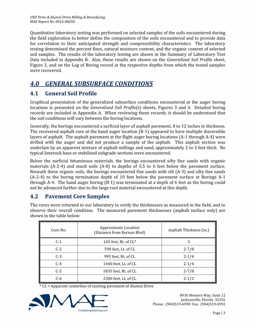
4.2 Pavement Core Samples
The cores were returned to our laboratory to verify the thicknesses as measured in the field, and to observe their overall condition. The measured pavement thicknesses (asphalt surface only) are shown in the table below:
Core No. Approximate Location
(Distance from Kernan Blvd) Asphalt Thickness (in.)
C-1 165 feet, Rt. of CL* 3
C-2 590 feet, Lt. of CL 2-7/8
C-3 995 feet, Rt. of CL 2-1/4
C-4 1440 feet, Lt. of CL 2-1/4
C-5 1835 feet, Rt. of CL 2-7/8
C-6 2300 feet, Lt. of CL 2-1/2
* CL = Apparent centerline of existing pavement of Alumni Drive

UNF Drive & Alumni Drive Milling & Resurfacing MAE Report No. 0016-0020A
8936 Western Way, Suite 12 Jacksonville, Florida 32256
Phone: (904)519-6990 Fax: (904)519-6992
Page | 4
Comments as to the condition of the cores are provided as follows:
Core Comments
C-1
Core consisted of 3 distinct layers of asphalt. Surface and intermediate layers measured 3/4-inch each, and contained fine aggregate. The bottom layer measured 1-1/2 inches in thickness and contained coarse aggregate. No cracks were observed at top, bottom and sides of core.
C-2
Core consisted of 2 distinct layers of asphalt. Surface layer measured 1 inch in thickness and contained fine aggregate. Bottom layer measured 1-7/8 inches and contained coarse aggregate. No cracks were observed at top, bottom and sides of core. However, small void spaces observed within the bottom layer at surface of core sides (perhaps a result of poor compaction at time of placement).
C-3
Core consisted of 2 distinct layers of asphalt. Surface layer measured 3/4-inch in thickness and contained fine aggregate. Bottom layer measured 1-1/2 inches and contained coarse aggregate. No cracks were observed at top, bottom and sides of core. However, small void spaces observed within the bottom layer at surface of core sides, though less than observed at C-2.
C-4
Core consisted of 2 distinct layers of asphalt. Surface layer measured 3/4-inch in thickness and contained fine aggregate. Bottom layer measured 1-1/2 inches and contained coarse aggregate. No cracks were observed at top, bottom and sides of core.
C-5 Core consisted of 2 distinct layers of asphalt. Surface layer measured 7/8-inch in thickness and contained fine aggregate. Bottom layer measured 2 inches and contained coarse aggregate. No cracks were observed at top, bottom and sides of core.
C-6 Core consisted of 2 distinct layers of asphalt. Surface layer measured 7/8-inch in thickness and contained fine aggregate. Bottom layer measured 1-5/8 inches and contained coarse aggregate. No cracks were observed at top, bottom and sides of core.
Although coring operations were not advanced through the existing base section, a typical limerock base section was observed at the bottom of the core at all of the core locations along Alumni Drive.
4.3 Groundwater Level
The machine-driven flight auger borings (A-1 through A-4) encountered the groundwater level at depths of about 5 to 6.5 feet below the pavement surface at the time of drilling. However, it should be anticipated that the groundwater levels will fluctuate seasonally and with changes in climate. The measured groundwater levels are shown on the Generalized Soil Profiles sheet (Figure 4) and on the soil boring logs.
The hand auger boring (B-1) along UNF Drive did not encounter groundwater and is noted as “GNE” (Groundwater Not Encountered) on the Generalized Soil Profile sheet, Figure 3, and on the boring log. However, this does not mean that groundwater does not exist at this location, only that groundwater was not encountered at this location to the depth explored on the date of drilling. It is possible that groundwater may be encountered at this location within the depth explored at a later date. As such, we recommend that the water table be measured prior to any remediation construction.

UNF Drive & Alumni Drive Milling & Resurfacing MAE Report No. 0016-0020A
8936 Western Way, Suite 12 Jacksonville, Florida 32256
Phone: (904)519-6990 Fax: (904)519-6992
Page | 5
5.0 PAVEMENT DESIGN & CONSTRUCTION RECOMMENDATIONS
5.1 General
The following evaluation and recommendations are based on the provided project information as presented in this report, the results of the field exploration and laboratory testing performed, and the construction techniques recommended. If the described project conditions are incorrect or changed after this report, or if subsurface conditions encountered during construction are different from those reported, MAE should be notified so these recommendations can be re-evaluated and revised, if necessary. We recommend that MAE review the plans and specifications to verify that the recommendations in this report have been properly interpreted and implemented.
5.2 Pavement Considerations
As discussed above, evidence of settlement was observed in the immediate area surrounding boring location B-1. A confirmation boring (A-1) was located near Boring B-1 to confirm the presence of organic materials, and to continue that boring to the original termination depth of 10 feet below the pavement surface. Additional borings were located outside the observed settlement area to determine if the subsurface conditions outside the area of pavement settlement were similar. Based on our findings, it appears that subsurface conditions are similar inside and outside the area of pavement settlement. Therefore, it is our opinion that the pavement settlement is due to unknown causes unrelated to the encountered subsurface conditions and not solely due to compression/decay of the organic materials as encountered. As a result, removal of the organic materials, as recommended in our previous draft report before the additional work was performed, is not recommended. However, void spaces within the organic soils within the project area may still remain and lead to additional settlement in the future. Furthermore, it is desired to bring the asphalt surface within the area of pavement settlement to the same grade as the adjacent pavement areas.
As an alternative to removing the organic soils, we recommend the use of Flowable Fill to replace the existing mixture of asphalt millings and sand. The benefit of this material is that it will bridge over any remaining shallow voids within the underlying organic soils, and it has a Unit Weight equivalent to that of clean sand, thus not adding significant load to the underlying organic soils that may cause future settlement of the pavement.
We recommend that the existing bituminous materials (pavement surface and sand/asphalt millings mix) be excavated to a depth of 3 feet below the existing pavement surface. The limits of this excavation should be within the existing pavement settlement area, plus an additional 10 feet in both travel directions along UNF Drive and an additional 5 feet beyond the settlement area towards the east edge of pavement (east curb). In addition, the excavation should continue below the western curb within the settlement area plus the same 10-foot margin.
Once excavation is complete, the area should be backfilled with 2’-5” of excavatable Flowable Fill. The Flowable Fill should be mixed and placed in accordance with the latest edition of the FDOT’s Standard Specification for Road and Bridge Construction. Once the Flowable Fill has been allowed to cure, the western curb should be constructed. Once the curb has been constructed, the asphalt pavement layer should consist of 5.5 inches of Type S-1 structural asphalt mix, followed by a surface course of 1.5 inches of Type S-III structural asphalt mix. Both structural mixes should be mixed and placed in accordance with the latest edition of the FDOT’s Standard Specification for Road and Bridge Construction and City of Jacksonville standard specifications.

UNF Drive & Alumni Drive Milling & Resurfacing MAE Report No. 0016-0020A
8936 Western Way, Suite 12 Jacksonville, Florida 32256
Phone: (904)519-6990 Fax: (904)519-6992
Page | 6
6.0 REPORT LIMITATIONS
This report has been prepared for the exclusive use of JBC Planning & Engineering, Inc. for specific application to the design and construction of the UNF Drive & Alumni Drive Resurfacing project. Our work for this project was performed in accordance with generally accepted geotechnical engineering practice. No warranty, express or implied, is made.
The evaluation and recommendations contained in this report are based on the data obtained from the pavement cores, hand auger and flight auger borings, and laboratory testing performed for the project. The pavement and subsurface conditions provided in this report are based only on those conditions encountered at the specific locations and times as reported, and only to the depths explored. These results do not reflect pavement and subsurface variations that may exist away from the core/boring locations, and/or variations in subsurface conditions at depths below the boring termination depth. Subsurface conditions and groundwater levels at other locations may differ from conditions encountered at the tested locations. In addition, it should be understood that the passage of time may result in a change in the subsurface conditions at the tested locations. If variations in pavement or subsurface conditions from those described in this report are observed during construction, the recommendations in this report must be re-evaluated.
The scope of our services does not include any environmental assessment or testing for the presence or absence of hazardous or toxic materials in the soil, groundwater, or surface water within or beyond the subject site. Any statements made in this report, and/or notations made on the generalized soil profiles or soil boring logs, regarding odors or other potential environmental concerns are based on observations made during execution of our scope of services and as such are strictly for the information of our client. No opinion of any environmental concern of such observations is made or implied. Unless complete environmental information regarding the site is already available, an environmental assessment is recommended.
If changes in the design or location of the project occur, the conclusions and recommendations contained in this report may need to be modified. We recommend that these changes be provided to us for our consideration. MAE is not responsible for conclusions, interpretations, opinions or recommendations made by others based on the data contained in this report.

Figures _____________________________________________________________________________________
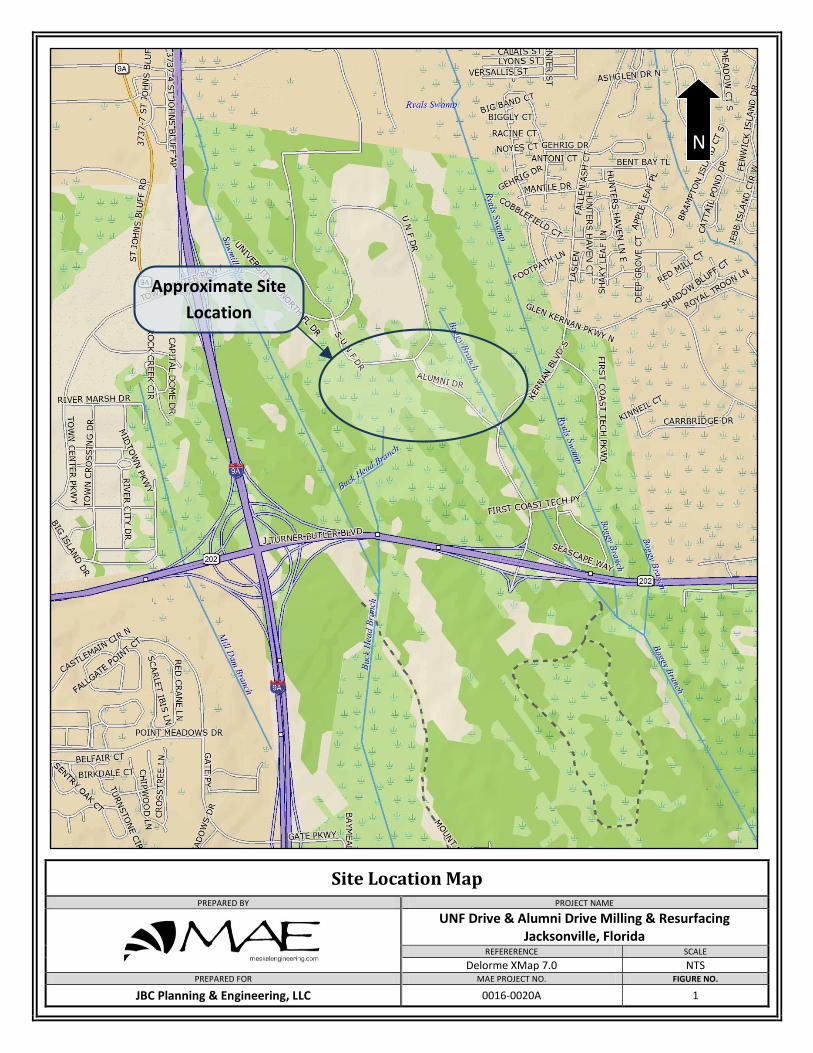
Site Location Map
PREPARED BY PROJECT NAME
UNF Drive & Alumni Drive Milling & Resurfacing Jacksonville, Florida
REFERERENCE SCALE
Delorme XMap 7.0 NTS PREPARED FOR MAE PROJECT NO. FIGURE NO.
JBC Planning & Engineering, LLC 0016-0020A 1
Approximate Site
Location
N

Core and Boring Location Plan
PREPARED BY PROJECT NAME
UNF Drive & Alumni Drive Milling & Resurfacing Jacksonville, Florida
REFERERENCE SCALE
Google Earth NTS PREPARED FOR MAE PROJECT NO. FIGURE NO.
JBC Planning & Engineering, LLC 0016-0020A 2
N
B-1
C-1
C-2
C-3
C-4
C-5
C-6

Boring Location Plan
PREPARED BY PROJECT NAME
UNF Drive & Alumni Drive Milling & Resurfacing Jacksonville, Florida
REFERERENCE SCALE
Google Earth NTS PREPARED FOR MAE PROJECT NO. FIGURE NO.
JBC Planning & Engineering, LLC 0016-0020A 2A
N
A-2
B-1
A-4
A-1
A-3

0
0.5
1.0
1.5
2.0
2.5
3.0
3.5
4.0
4.5
5.0
5.5
6.0
6.5
0
0.5
1.0
1.5
2.0
2.5
3.0
3.5
4.0
4.5
5.0
5.5
6.0
6.5
0016-0020AJacksonville, Florida
Depth (ft)D
epth
(ft)
Asphalt
Silty Fine Sand
Fine Sand with Silt
3
LOCATION
Natural Moisture Content (%)Asphalt Milling
(A-3)
Groundwater Level Not Encounteredat Time of Drilling
SHEET TITLE:
Meskel & Associates Engineering, PLLCMAE PROJECT NO.
PROJECT NAME: FIGURE NO.
Legend
N
-200
w
BT
Standard Penetration Resistance,Blows/Foot
Boring Terminated at Depth Below Grade
AASHTO Soil Classification System% Passing No. 200 U.S. StandardSieve
GNE
JBC Planning & Engineering, LLC
Muck
BT @ 6.0'.Date Drilled: 11/25/2014
GNE
Asphalt Millings
Gray fine SAND with silt, poorly graded withorganic material. (A-3)
Asphalt (12")
Gray silty fine SAND, poorly graded with organicmaterial. (A-2-4)
Muck with large root. (A-8)
Note: Boring terminated at 6' due to large root.
Generalized Soil Profile
UNF Drive & Alumni Drive Milling & Resurfacing
N
B-1
FL Certificate of Authorization No. 281428936 Western Way, Suite 12 | Jacksonville, FL 32256
P. RODNEY MANK, P.E. P.E. NO.: 41986
w = 36-200 = 12OC = 9.4
w = 29-200 = 7OC = 7.1

0
1
2
3
4
5
6
7
8
9
10
11
0
1
2
3
4
5
6
7
8
9
10
11
JBC Planning & Engineering, LLC
MAE PROJECT NO.
(A-3) Depth to Groundwater at Time of Drilling
BY DESCRIPTION DATE BY DESCRIPTION
SHEET TITLE:
PROJECT NAME:
DATE
12/19/2014 0016-0020AFIGURE NO.
Generalized Soil Profiles
4
Depth (ft)D
epth
(ft
)
Boring Terminated at Depth Below GradeBT
AASHTO Soil Classification System
DATE:
Legend
Asphalt Silty Fine Sand
Fine Sand with Silt
UNF Drive & Alumni Drive Milling & ResurfacingJacksonville, FloridaFL Certificate of Authorization No. 28142
8936 Western Way, Suite 12, Jacksonville, FL 32256
BT @ 10.0'.Date Drilled: 12/18/2014
Asphalt (12")
Dark brown SAND and asphalt millingsmix, trace gravel.
Dark gray-brown silty fine SAND, poorlygraded, few root fragments. (A-2-4)
Dark brown fine SAND with silt, poorlygraded, (slight organic odor). (A-3)
BT @ 10.0'.Date Drilled: 12/18/2014
Asphalt (11")
Dark brown SAND and asphalt millingsmix, trace gravel.
Dark brown organic silty sand and roots.(A-8)
Dark brown silty fine SAND, poorlygraded. (A-2-4)
Brown fine SAND with silt, poorlygraded. (A-3)
BT @ 10.0'.Date Drilled: 12/18/2014
Asphalt (12")
Dark brown SAND and asphalt millingsmix, trace gravel.
LIght brown to dark brown fine SANDwith silt, poorly graded. (A-3)
BT @ 10.0'.Date Drilled: 12/18/2014
Asphalt (8")
Dark gray organic silty sand. (A-8)
Sand/Millings Mix
Dark brown SAND and asphalt millingsmix, trace gravel.
Dark brown silty fine SAND, poorlygraded with organic fines and few roots.(A-2-4)
Brown fine SAND with silt, poorlygraded. (A-3)
Dark gray silty fine SAND, poorly gradedwith organic fines and few rootfragments. (A-2-4)
Organic Silty Sands & Roots
A-1 A-2 A-3 A-4
P. RODNEY MANK, P.E. P.E. NO.: 41986
Meskel & Associates Engineering, PLLC

Appendix A _____________________________________________________________________________________

1
2
3
4
5 29
A-2-4
A-8
A-3 7
Asphalt (12")
Asphalt Millings
Gray silty fine SAND, poorly graded with organicmaterial.
Muck with large root.
Gray fine SAND with silt, poorly graded withorganic material.
Bottom of borehole at 6.0 feet.
COMPLETED 11/25/14DATE STARTED 11/25/14
DRILLING CONTRACTOR MAE, PLLC
LOGGED BY P.R.Young CHECKED BY K.Martin GROUND ELEVATION HAMMER TYPE
DRILLING METHOD Hand Auger
BORING LOCATION See Boring Location Plan
MO
IST
UR
EC
ON
TE
NT
(%
)
PLA
ST
ICIT
YIN
DE
X
GR
AP
HIC
LOG
7.1
N-V
ALU
E
BLO
W C
OU
NT
S
REMARKS
SA
MP
LE D
EP
TH
NU
MB
ER
PO
CK
ET
PE
N.
(tsf
)R
EC
OV
ER
Y %
(RQ
D)
FIN
ES
CO
NT
EN
T (
%)
LIQ
UID
LIM
IT
US
CS
MATERIAL DESCRIPTION
DE
PT
H (
ft)
0
1
2
3
4
5
6
OR
GA
NIC
CO
NT
EN
T (
%)
BORING B-1PAGE 1 OF 1
GROUND WATER LEVELSNOTES
AFTER DRILLING ---AT TIME OF DRILLING --- GNE
PROJECT LOCATION Jacksonville, Florida CLIENT JBC Planning & Engineering, LLC
PROJECT NO. 0016-0020A
NE
W M
AE
LO
G U
SC
S B
OR
ING
LO
CA
TIO
N -
NE
W T
EM
PLA
TE
7-3
0-12
.GD
T -
12/
5/14
09
:36
- F
:\GIN
T\G
INT
FIL
ES
\PR
OJE
CT
S\0
016
-002
0A\U
NF
DR
IVE
AT
PA
RK
ING
BU
ILD
ING
& A
LIU
MN
I DR
IVE
RE
SU
RF
AC
ING
.GP
JMeskel & Associates Engineering, PLLCFL Certificate of Authorization No. 281428936 Western Way, Suite 12Jacksonville, FL 32256P: (904)519-6990 F: (904)519-6992
36 12 9.4
PROJECT NAME UNF Drive & Alumni Drive Milling & Resurfacing
Boring terminated at 6' due to large root.

1
2
3
4
A-2-4
A-3
Asphalt (12")
Dark brown SAND and asphalt millings mix, tracegravel.
Dark gray-brown silty fine SAND, poorly graded,few root fragments.
Dark brown fine SAND with silt, poorly graded,(slight organic odor).
Bottom of borehole at 10.0 feet.
COMPLETED 12/18/14DATE STARTED 12/18/14
DRILLING CONTRACTOR MAE, PLLC
LOGGED BY P.R.Young CHECKED BY K.Martin GROUND ELEVATION HAMMER TYPE
DRILLING METHOD Machine Auger
BORING LOCATION See Boring Location Plan
MO
IST
UR
EC
ON
TE
NT
(%
)
PLA
ST
ICIT
YIN
DE
X
GR
AP
HIC
LOG
N-V
ALU
E
BLO
W C
OU
NT
S
REMARKS
SA
MP
LE D
EP
TH
NU
MB
ER
PO
CK
ET
PE
N.
(tsf
)R
EC
OV
ER
Y %
(RQ
D)
FIN
ES
CO
NT
EN
T (
%)
LIQ
UID
LIM
IT
US
CS
MATERIAL DESCRIPTION
DE
PT
H (
ft)
0.0
2.5
5.0
7.5
10.0
OR
GA
NIC
CO
NT
EN
T (
%)
BORING A-1PAGE 1 OF 1
GROUND WATER LEVELSNOTES
AFTER DRILLING ---
PROJECT NAME UNF Drive & Alumni Drive Milling & Resurfacing
PROJECT LOCATION Jacksonville, Florida CLIENT JBC Planning & Engineering, LLC
PROJECT NO. 0016-0020A
NE
W M
AE
LO
G U
SC
S B
OR
ING
LO
CA
TIO
N -
NE
W T
EM
PLA
TE
7-3
0-12
.GD
T -
12/
19/1
4 1
2:48
- F
:\GIN
T\G
INT
FIL
ES
\PR
OJE
CT
S\0
016
-002
0A\U
NF
DR
IVE
AT
PA
RK
ING
BU
ILD
ING
& A
LIU
MN
I DR
IVE
RE
SU
RF
AC
ING
.GP
JMeskel & Associates Engineering, PLLCFL Certificate of Authorization No. 281428936 Western Way, Suite 12Jacksonville, FL 32256P: (904)519-6990 F: (904)519-6992
AT TIME OF DRILLING 5.1 ft

1
2
3
4
5
6
A-8
A-2-4
A-3
Asphalt (11")
Dark brown SAND and asphalt millings mix, tracegravel.
Dark brown organic silty sand and roots.
Dark brown silty fine SAND, poorly graded.
Brown fine SAND with silt, poorly graded.
Bottom of borehole at 10.0 feet.
COMPLETED 12/18/14DATE STARTED 12/18/14
DRILLING CONTRACTOR MAE, PLLC
LOGGED BY P.R.Young CHECKED BY K.Martin GROUND ELEVATION HAMMER TYPE
DRILLING METHOD Machine Auger
BORING LOCATION See Boring Location Plan
MO
IST
UR
EC
ON
TE
NT
(%
)
PLA
ST
ICIT
YIN
DE
X
GR
AP
HIC
LOG
N-V
ALU
E
BLO
W C
OU
NT
S
REMARKS
SA
MP
LE D
EP
TH
NU
MB
ER
PO
CK
ET
PE
N.
(tsf
)R
EC
OV
ER
Y %
(RQ
D)
FIN
ES
CO
NT
EN
T (
%)
LIQ
UID
LIM
IT
US
CS
MATERIAL DESCRIPTION
DE
PT
H (
ft)
0.0
2.5
5.0
7.5
10.0
OR
GA
NIC
CO
NT
EN
T (
%)
BORING A-2PAGE 1 OF 1
GROUND WATER LEVELSNOTES
AFTER DRILLING ---
PROJECT NAME UNF Drive & Alumni Drive Milling & Resurfacing
PROJECT LOCATION Jacksonville, Florida CLIENT JBC Planning & Engineering, LLC
PROJECT NO. 0016-0020A
NE
W M
AE
LO
G U
SC
S B
OR
ING
LO
CA
TIO
N -
NE
W T
EM
PLA
TE
7-3
0-12
.GD
T -
12/
19/1
4 1
2:48
- F
:\GIN
T\G
INT
FIL
ES
\PR
OJE
CT
S\0
016
-002
0A\U
NF
DR
IVE
AT
PA
RK
ING
BU
ILD
ING
& A
LIU
MN
I DR
IVE
RE
SU
RF
AC
ING
.GP
JMeskel & Associates Engineering, PLLCFL Certificate of Authorization No. 281428936 Western Way, Suite 12Jacksonville, FL 32256P: (904)519-6990 F: (904)519-6992
AT TIME OF DRILLING 6.2 ft

1
2
3
4
5
6
7
A-2-4
A-3
Asphalt (12")
Dark brown SAND and asphalt millings mix, tracegravel.
Dark gray silty fine SAND, poorly graded withorganic fines and few root fragments.
LIght brown to dark brown fine SAND with silt,poorly graded.
Bottom of borehole at 10.0 feet.
COMPLETED 12/18/14DATE STARTED 12/18/14
DRILLING CONTRACTOR MAE, PLLC
LOGGED BY P.R.Young CHECKED BY K.Martin GROUND ELEVATION HAMMER TYPE
DRILLING METHOD Machine Auger
BORING LOCATION See Boring Location Plan
MO
IST
UR
EC
ON
TE
NT
(%
)
PLA
ST
ICIT
YIN
DE
X
GR
AP
HIC
LOG
N-V
ALU
E
BLO
W C
OU
NT
S
REMARKS
SA
MP
LE D
EP
TH
NU
MB
ER
PO
CK
ET
PE
N.
(tsf
)R
EC
OV
ER
Y %
(RQ
D)
FIN
ES
CO
NT
EN
T (
%)
LIQ
UID
LIM
IT
US
CS
MATERIAL DESCRIPTION
DE
PT
H (
ft)
0.0
2.5
5.0
7.5
10.0
OR
GA
NIC
CO
NT
EN
T (
%)
BORING A-3PAGE 1 OF 1
GROUND WATER LEVELSNOTES
AFTER DRILLING ---
PROJECT NAME UNF Drive & Alumni Drive Milling & Resurfacing
PROJECT LOCATION Jacksonville, Florida CLIENT JBC Planning & Engineering, LLC
PROJECT NO. 0016-0020A
NE
W M
AE
LO
G U
SC
S B
OR
ING
LO
CA
TIO
N -
NE
W T
EM
PLA
TE
7-3
0-12
.GD
T -
12/
19/1
4 1
2:48
- F
:\GIN
T\G
INT
FIL
ES
\PR
OJE
CT
S\0
016
-002
0A\U
NF
DR
IVE
AT
PA
RK
ING
BU
ILD
ING
& A
LIU
MN
I DR
IVE
RE
SU
RF
AC
ING
.GP
JMeskel & Associates Engineering, PLLCFL Certificate of Authorization No. 281428936 Western Way, Suite 12Jacksonville, FL 32256P: (904)519-6990 F: (904)519-6992
AT TIME OF DRILLING 6.3 ft

1
2
3
4
5
A-8
A-2-4
A-3
Asphalt (8")
Dark brown SAND and asphalt millings mix, tracegravel.
Dark gray organic silty sand.
Dark brown silty fine SAND, poorly graded withorganic fines and few roots.
Brown fine SAND with silt, poorly graded.
Bottom of borehole at 10.0 feet.
COMPLETED 12/18/14DATE STARTED 12/18/14
DRILLING CONTRACTOR MAE, PLLC
LOGGED BY P.R.Young CHECKED BY K.Martin GROUND ELEVATION HAMMER TYPE
DRILLING METHOD Machine Auger
BORING LOCATION See Boring Location Plan
MO
IST
UR
EC
ON
TE
NT
(%
)
PLA
ST
ICIT
YIN
DE
X
GR
AP
HIC
LOG
N-V
ALU
E
BLO
W C
OU
NT
S
REMARKS
SA
MP
LE D
EP
TH
NU
MB
ER
PO
CK
ET
PE
N.
(tsf
)R
EC
OV
ER
Y %
(RQ
D)
FIN
ES
CO
NT
EN
T (
%)
LIQ
UID
LIM
IT
US
CS
MATERIAL DESCRIPTION
DE
PT
H (
ft)
0.0
2.5
5.0
7.5
10.0
OR
GA
NIC
CO
NT
EN
T (
%)
BORING A-4PAGE 1 OF 1
GROUND WATER LEVELSNOTES
AFTER DRILLING ---
PROJECT NAME UNF Drive & Alumni Drive Milling & Resurfacing
PROJECT LOCATION Jacksonville, Florida CLIENT JBC Planning & Engineering, LLC
PROJECT NO. 0016-0020A
NE
W M
AE
LO
G U
SC
S B
OR
ING
LO
CA
TIO
N -
NE
W T
EM
PLA
TE
7-3
0-12
.GD
T -
12/
19/1
4 1
2:48
- F
:\GIN
T\G
INT
FIL
ES
\PR
OJE
CT
S\0
016
-002
0A\U
NF
DR
IVE
AT
PA
RK
ING
BU
ILD
ING
& A
LIU
MN
I DR
IVE
RE
SU
RF
AC
ING
.GP
JMeskel & Associates Engineering, PLLCFL Certificate of Authorization No. 281428936 Western Way, Suite 12Jacksonville, FL 32256P: (904)519-6990 F: (904)519-6992
AT TIME OF DRILLING 5 ft
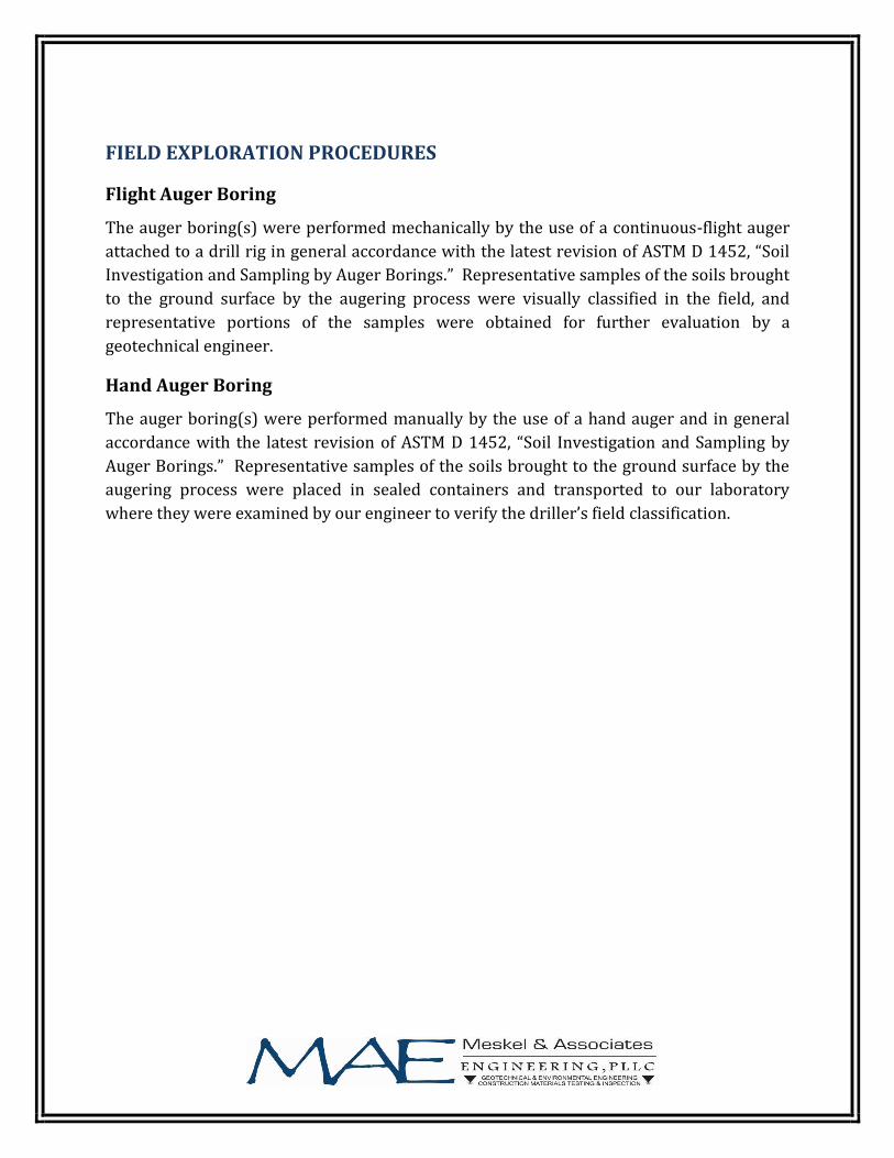
FIELD EXPLORATION PROCEDURES
Flight Auger Boring
The auger boring(s) were performed mechanically by the use of a continuous-flight auger
attached to a drill rig in general accordance with the latest revision of ASTM D 1452, “Soil
Investigation and Sampling by Auger Borings.” Representative samples of the soils brought
to the ground surface by the augering process were visually classified in the field, and
representative portions of the samples were obtained for further evaluation by a
geotechnical engineer.
Hand Auger Boring
The auger boring(s) were performed manually by the use of a hand auger and in general
accordance with the latest revision of ASTM D 1452, “Soil Investigation and Sampling by
Auger Borings.” Representative samples of the soils brought to the ground surface by the
augering process were placed in sealed containers and transported to our laboratory
where they were examined by our engineer to verify the driller’s field classification.
K E Y T O B O R I N G L O G S
S o i l C l a s s i f i c a t i o n
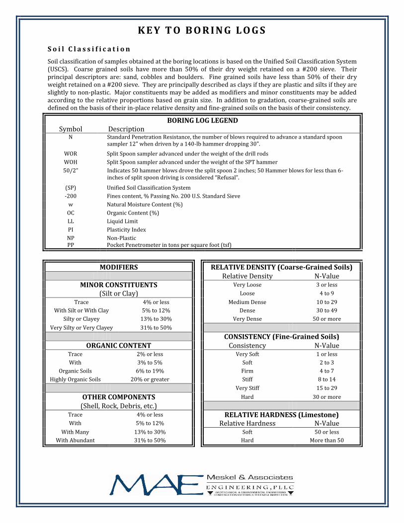
Soil classification of samples obtained at the boring locations is based on the Unified Soil Classification System (USCS). Coarse grained soils have more than 50% of their dry weight retained on a #200 sieve. Their principal descriptors are: sand, cobbles and boulders. Fine grained soils have less than 50% of their dry weight retained on a #200 sieve. They are principally described as clays if they are plastic and silts if they are slightly to non-plastic. Major constituents may be added as modifiers and minor constituents may be added according to the relative proportions based on grain size. In addition to gradation, coarse-grained soils are defined on the basis of their in-place relative density and fine-grained soils on the basis of their consistency.
BORING LOG LEGEND Symbol Description
N Standard Penetration Resistance, the number of blows required to advance a standard spoon sampler 12" when driven by a 140-lb hammer dropping 30".
WOR Split Spoon sampler advanced under the weight of the drill rods
WOH Split Spoon sampler advanced under the weight of the SPT hammer
50/2” Indicates 50 hammer blows drove the split spoon 2 inches; 50 Hammer blows for less than 6-inches of split spoon driving is considered “Refusal”.
(SP) Unified Soil Classification System
-200 Fines content, % Passing No. 200 U.S. Standard Sieve
w Natural Moisture Content (%)
OC Organic Content (%)
LL Liquid Limit
PI Plasticity Index
NP PP
Non-Plastic Pocket Penetrometer in tons per square foot (tsf)
MODIFIERS
RELATIVE DENSITY (Coarse-Grained Soils)
Relative Density N-Value MINOR CONSTITUENTS
Very Loose 3 or less
(Silt or Clay)
Loose 4 to 9
Trace 4% or less
Medium Dense 10 to 29
With Silt or With Clay 5% to 12%
Dense 30 to 49
Silty or Clayey 13% to 30%
Very Dense 50 or more
Very Silty or Very Clayey 31% to 50%
CONSISTENCY (Fine-Grained Soils)
ORGANIC CONTENT
Consistency N-Value Trace 2% or less
Very Soft 1 or less
With 3% to 5%
Soft 2 to 3
Organic Soils 6% to 19%
Firm 4 to 7
Highly Organic Soils 20% or greater
Stiff 8 to 14
Very Stiff 15 to 29
OTHER COMPONENTS
Hard 30 or more
(Shell, Rock, Debris, etc.)
Trace 4% or less
RELATIVE HARDNESS (Limestone)
With 5% to 12%
Relative Hardness N-Value With Many 13% to 30%
Soft 50 or less
With Abundant 31% to 50%
Hard More than 50
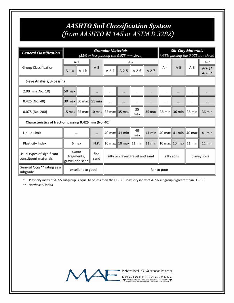
* Plasticity index of A-7-5 subgroup is equal to or less than the LL - 30. Plasticity index of A-7-6 subgroup is greater than LL – 30
** Northeast Florida
AASHTO Soil Classification System (from AASHTO M 145 or ASTM D 3282)
General Classification Granular Materials
(35% or less passing the 0.075 mm sieve) Silt-Clay Materials
(>35% passing the 0.075 mm sieve)
Group Classification
A-1
A-3
A-2
A-4 A-5 A-6
A-7
A-1-a A-1-b A-2-4 A-2-5 A-2-6 A-2-7 A-7-5* A-7-6*
Sieve Analysis, % passing:
2.00 mm (No. 10) 50 max … … … … … … … … … …
0.425 (No. 40) 30 max 50 max 51 min … … … … … … … …
0.075 (No. 200) 15 max 25 max 10 max 35 max 35 max 35
max 35 max 36 min 36 min 36 min 36 min
Characteristics of fraction passing 0.425 mm (No. 40):
Liquid Limit … … 40 max 41 min 40
max 41 min 40 max 41 min 40 max 41 min
Plasticity Index 6 max N.P. 10 max 10 max 11 min 11 min 10 max 10 max 11 min 11 min
Usual types of significant constituent materials
stone fragments,
gravel and sand
fine sand
silty or clayey gravel and sand silty soils clayey soils
General local** rating as a subgrade
excellent to good fair to poor

Appendix B _____________________________________________________________________________________

B-1 3 3.5 A-2-4 12 36 9.4
B-1 5 5.5 A-3 7 29 7.1
Natural Moisture Content
(%)
% Passing No. 200
Sieve
Boring No.
Approx Sample Depth
(ft.)
Organic Content
(%)
AASHTO Classification
Sample No.
Summary of Laboratory Test Results
UNF Drive & Alumni Drive Milling & Resurfacing
Jacksonville, Florida
MAE Project No.: 0016-0020A

LABORATORY TEST PROCEDURES
Percent Fines Content
The percent fines or material passing the No. 200 mesh sieve of the sample tested was
determined in general accordance with the latest revision of ASTM D 1140. The percent
fines are the soil particles in the silt and clay size range.
Natural Moisture Content
The water content of the tested sample was determined in general accordance with the
latest revision of ASTM D 2216. The water content is defined as the ratio of “pore” or “free”
water in a given mass of material to the mass of solid material particles.
Organic Loss on Ignition (Percent Organics)
The organic loss on ignition or percent organic material in the sample tested was
determined in general accordance with ASTM D 2974. The percent organics is the material,
expressed as a percentage, which is burned off in a muffle furnace at 455±10 degrees
Celsius.

Appendix C _____________________________________________________________________________________


Core #B1