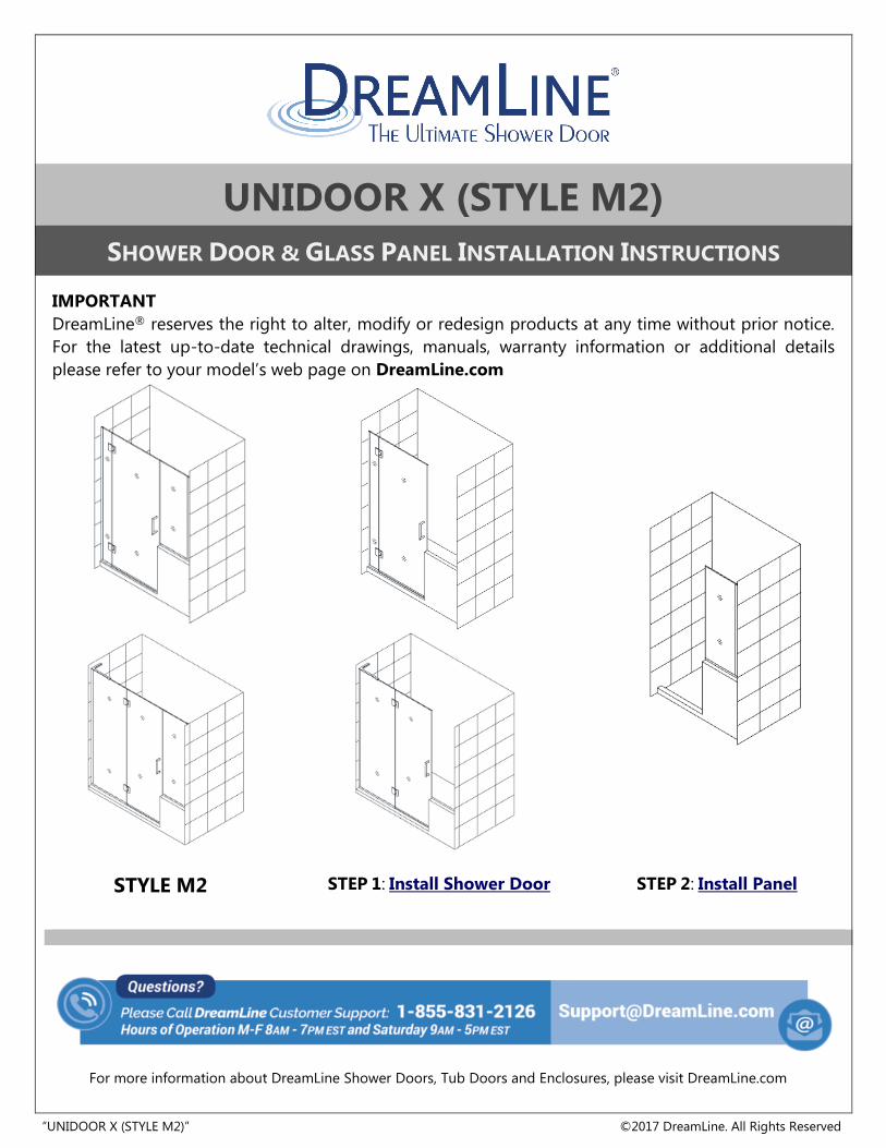
unidoor x (style m2)
TRANSCRIPT
“UNIDOOR X (STYLE M2)” ©2017 DreamLine. All Rights Reserved
UNIDOOR X (STYLE M2)
SHOWER DOOR & GLASS PANEL INSTALLATION INSTRUCTIONS
IMPORTANT
DreamLine® reserves the right to alter, modify or redesign products at any time without prior notice.
For the latest up-to-date technical drawings, manuals, warranty information or additional details
please refer to your model’s web page on DreamLine.com
STEP 1: Install Shower Door STEP 2: Install Panel
STYLE M2
For more information about DreamLine Shower Doors, Tub Doors and Enclosures, please visit DreamLine.com
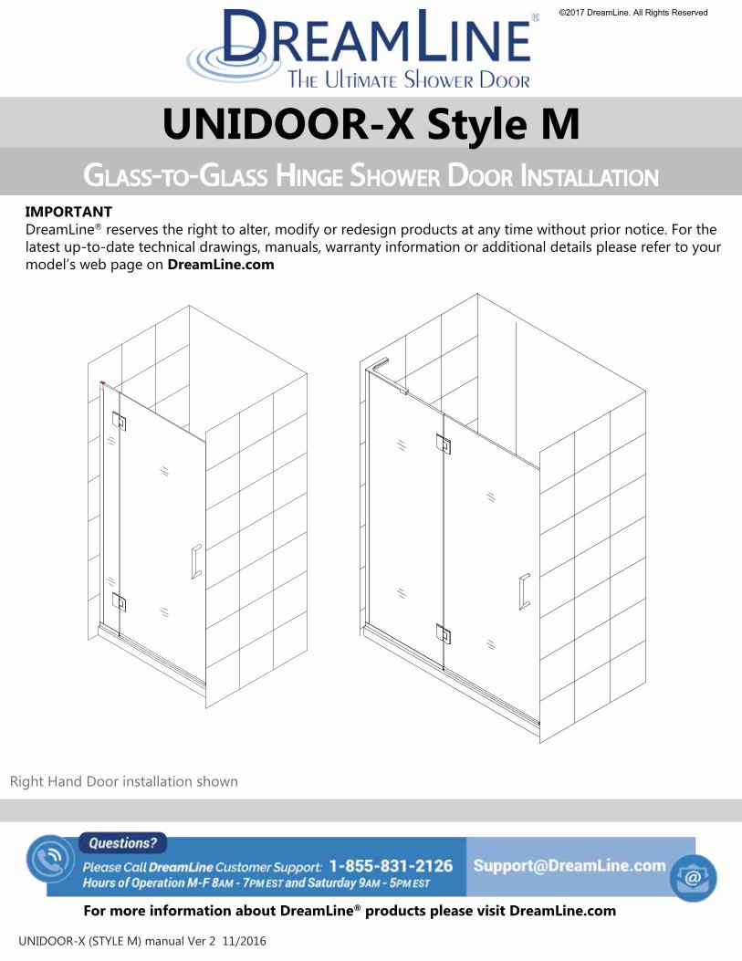
UNIDOOR-X Style MGLASS-TO-GLASS HINGE SHOWER DOOR INSTALLATION
IMPORTANTDreamLine® reserves the right to alter, modify or redesign products at any time without prior notice. For the latest up-to-date technical drawings, manuals, warranty information or additional details please refer to yourmodel’s web page on DreamLine.com
For more information about DreamLine® products please visit DreamLine.com
UNIDOOR-X (STYLE M) manual Ver 2 11/2016
Right Hand Door installation shown
©2017 DreamLine. All Rights Reserved
This model is treated with DreamLine’s exclusive ClearMaxTM Glass technology. This is a specially-formulated coating that prevents the build up of soap and water spots.
Install the surface with the ClearMaxTM label towards the inside of the shower.Please note that depending on the model, the glass may be coated on either one or both surfaces.
For best results, squeegee the glass after each use and dry with a soft cloth.
2UNIDOOR-X (STYLE M) manual Ver 2 11/2016
©2017 DreamLine. All Rights Reserved
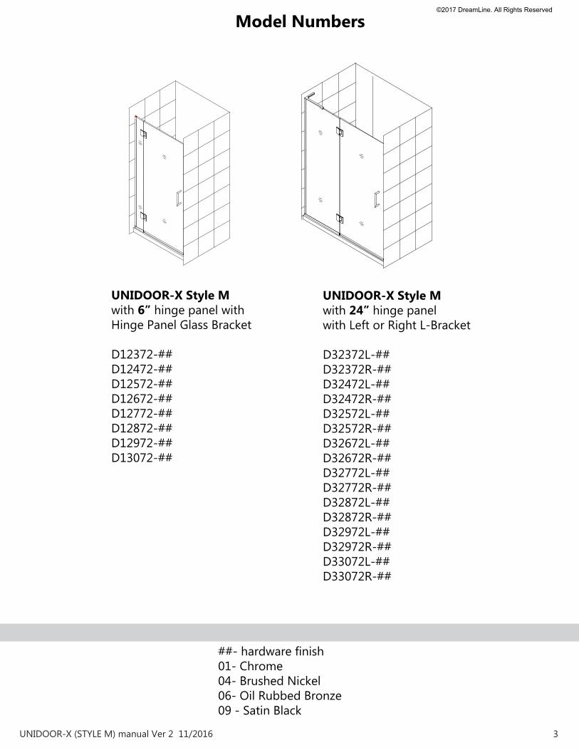
UNIDOOR-X Style M with 24” hinge panelwith Left or Right L-Bracket
D32372L-##D32372R-##D32472L-##D32472R-##D32572L-##D32572R-##D32672L-##D32672R-##D32772L-##D32772R-##D32872L-##D32872R-##D32972L-##D32972R-##D33072L-##D33072R-##
##- hardware finish01- Chrome04- Brushed Nickel06- Oil Rubbed Bronze09 - Satin Black
UNIDOOR-X Style M with 6” hinge panel with Hinge Panel Glass Bracket
D12372-##D12472-##D12572-##D12672-##D12772-##D12872-##D12972-##D13072-##
Model Numbers
3 UNIDOOR-X (STYLE M) manual Ver 2 11/2016
©2017 DreamLine. All Rights Reserved
!
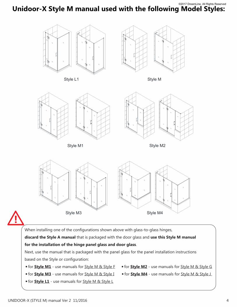
Unidoor-X Style M manual used with the following Model Styles:
When installing one of the configurations shown above with glass-to-glass hinges,
discard the Style A manual that is packaged with the door glass and use this Style M manual
for the installation of the hinge panel glass and door glass.
Next, use the manual that is packaged with the panel glass for the panel installation instructions
based on the Style or configuration:
◾for Style M1 - use manuals for Style M & Style F ◾for Style M2 - use manuals for Style M & Style G
◾for Style M3 - use manuals for Style M & Style I ◾for Style M4 - use manuals for Style M & Style J
◾for Style L1 - use manuals for Style M & Style L
4UNIDOOR-X (STYLE M) manual Ver 2 11/2016
Style M
Style M1
Style M4
Style M2
Style L1
Style M3
©2017 DreamLine. All Rights Reserved
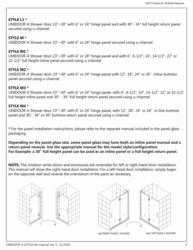
STYLE L1 *UNIDOOR-X Shower door 23”~30” with 6” or 24” hinge panel and with 30”- 34” full height return panel secured using u-channel
STYLE M *UNIDOOR-X Shower door 23”~30” with 6” or 24” hinge panel secured using u-channel
STYLE M1 *UNIDOOR-X Shower door 23”~30” with 6” or 24” hinge panel and with 6”, 6-1/2”, 14”, 14-1/2”, 22” or 22-1/2” full height inline panel secured using u-channel
STYLE M2 *UNIDOOR-X Shower door 23”~30” with 6” or 24” hinge panel with 12”, 18”, 24” or 26” inline buttress panel secured using u-channel
STYLE M3 * UNIDOOR-X Shower door 23”~30” with 6” or 24” hinge panel, with 6”, 6-1/2”, 14”, 14-1/2”, 22” or 22-1/2” full height inline panel and 30” - 34” full height return panel secured using u-channel
STYLE M4 *UNIDOOR-X Shower door 23”~30” with 6” or 24” hinge panel, with 12”, 18”, 24” or 26” in-line buttress panel and 30”, 36” or 40” buttress return panel secured using u-channel
* For the panel installation instructions, please refer to the separate manual included in the panel glass packaging.
Depending on the panel glass size, some panel glass may have both an inline panel manual and a return panel manual. Use the appropriate manual for the model style/configuration. For Example: a 30” full height panel can be used as an inline panel or a full height return panel.
NOTE: The Unidoor series doors and enclosures are reversible for left or right-hand door installation. This manual will show the right-hand door installation. For a left-hand door installation, simply begin on the opposite wall and reverse the orientation of the parts as necessary.
5UNIDOOR-X (STYLE M) manual Ver 2 11/2016
use Right-hand L-bracket use Left-hand L-bracket
©2017 DreamLine. All Rights Reserved
Preparation
NOTE: DO NOT install the handle onto the door glass until instructed to do so. DO NOT attempt to lift the glass using the handle. This could result in damage to the glass and/or serious personal injury. Always use an assistant or a professional grade glass suction cup when handling heavy glass.
1. Prior to installation, examine all boxes and packages for shipping damage and compare the piece count with your packing slip. After opening all boxes and packages read this introduction carefully. Check that all of the needed parts are included in the package by checking off the components on the “Detailed Diagram of Shower Door Components”. If the unit has been damaged, has a finishing defect, or has missing parts, please contact our customer support department within 3 business days of the delivery date. Please note that DreamLine® will not replace any damaged products or missing parts free of charge after 3 business days or if the product has been installed. Feel free to contact DreamLine® if you have any questions, and please provide an order number, job name or other proof of purchase to help us identify your original order.
2. Please note that you should consult your local building codes with questions on installation compliance standards. Building and plumbing codes may vary by location, and DreamLine® is not responsible for code compliance standards for your project and will not accept any returns.
3. If this unit is going to be installed in a new construction, please install all of the required plumbing and drainage before installing the shower. Use a competent and licensed (if required by local code) plumber for all plumbing installation.
4. Please make sure that prior to beginning the installation, the surfaces are leveled and solid and will be able to support the total weight of the unit. Also make sure the walls are at right angles. Irregular installation surface level, radius corners or improper angle of side walls will result in serious problems for your installation. Note that some adjustments and drilling will be necessary during the installation process.
5. Please protect all primary surfaces of the product during installation. Never set the glass down directly onto a tile floor. Leave corner protectors in place until it is necessary to remove them. Always use a piece of wood or cardboard to protect the bottom edge and corners of the glass prior to and during installation.
6. This unit must be installed upon a finished threshold and against finished walls.
7. The hinge panel glass for this model should not be adjusted more than 1/4” for out-of-plumb within the U-channel. This model does NOT have any adjustment for overall width. Verify that the model size ordered will fit the finished opening before begining installation.
8. This model requires that you drill into the threshold for proper installation.
9. It is recommended to install the hinge-side U-channel into a stud.
10. This model requires minimum 5/8” of flat threshold space for installation.
Professional installation recommended
6UNIDOOR-X (STYLE M) manual Ver 2 11/2016
!
©2017 DreamLine. All Rights Reserved
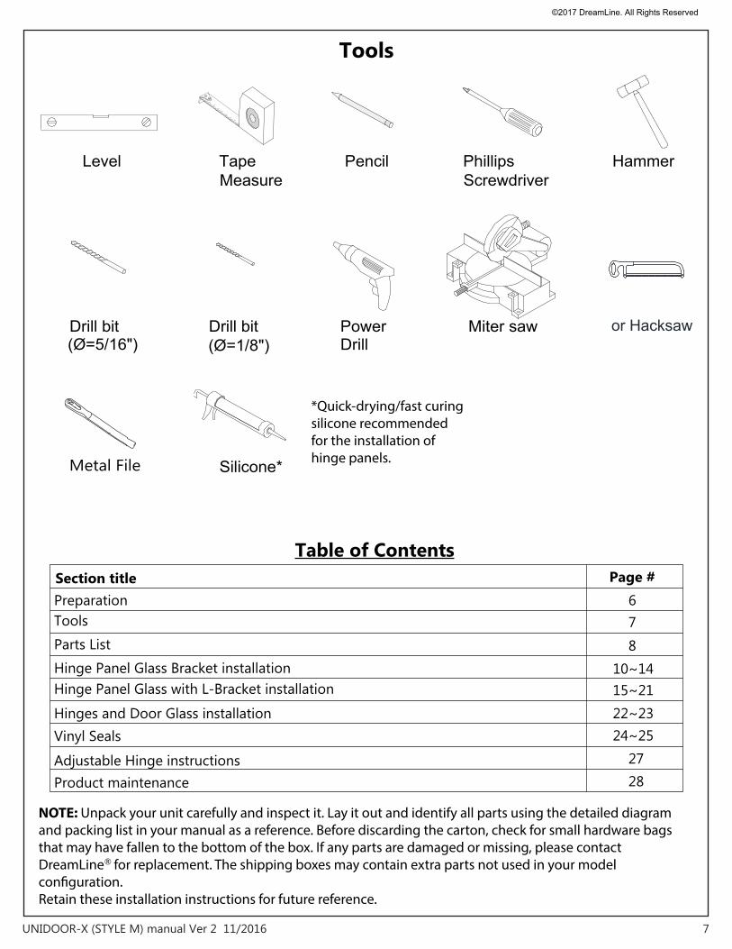
Tools
Parts List
Table of ContentsSection title Page #
ToolsPreparation
Hinge Panel Glass Bracket installationHinge Panel Glass with L-Bracket installation
Hinges and Door Glass installationVinyl Seals
Product maintenanceAdjustable Hinge instructions
10~14876
2724~25
15~2122~23
28
NOTE: Unpack your unit carefully and inspect it. Lay it out and identify all parts using the detailed diagram and packing list in your manual as a reference. Before discarding the carton, check for small hardware bags that may have fallen to the bottom of the box. If any parts are damaged or missing, please contact DreamLine® for replacement. The shipping boxes may contain extra parts not used in your model con�guration.Retain these installation instructions for future reference.
7UNIDOOR-X (STYLE M) manual Ver 2 11/2016
Tape Phillips
(Ø=1/8")Miter saw
Measure
Drill bitDrill
PencilLevel
Drill bit Power
Silicone*
Screwdriver
(Ø=5/16")
Hammer
*Quick-drying/fast curing silicone recommended for the installation of hinge panels.Metal File
or Hacksaw
©2017 DreamLine. All Rights Reserved
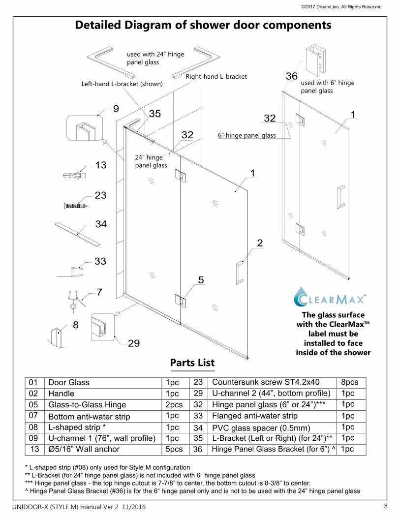
Detailed Diagram of shower door components
The glass surface with the ClearMax™
label must be installed to face
inside of the shower
* L-shaped strip (#08) only used for Style M configuration** L-Bracket (for 24” hinge panel glass) is not included with 6” hinge panel glass*** Hinge panel glass - the top hinge cutout is 7-7/8” to center, the bottom cutout is 8-3/8” to center. ^ Hinge Panel Glass Bracket (#36) is for the 6“ hinge panel only and is not to be used with the 24” hinge panel glass
L-Bracket (Left or Right) (for 24”)**35
01 Door Glass 1pc
13 Ø5/16” Wall anchor 5pcs
02 Handle 1pc23 Countersunk screw ST4.2x40 8pcs
05 Glass-to-Glass Hinge 2pcs29 U-channel 2 (44”, bottom profile) 1pc
07 Bottom anti-water strip 1pc32 Hinge panel glass (6” or 24”)*** 1pc
08 L-shaped strip * 1pc33 Flanged anti-water strip 1pc
09 U-channel 1 (76”, wall profile) 1pc34 PVC glass spacer (0.5mm)
1pc1pc
36 1pcHinge Panel Glass Bracket (for 6”) ^
8UNIDOOR-X (STYLE M) manual Ver 2 11/2016
Right-hand L-bracket Left-hand L-bracket (shown)
Parts List
34
1
33
7
8
23
9
29
13
5
2
1
35
32
36used with 6” hinge panel glass
used with 24” hinge panel glass
24” hinge panel glass
6” hinge panel glass
32
©2017 DreamLine. All Rights Reserved
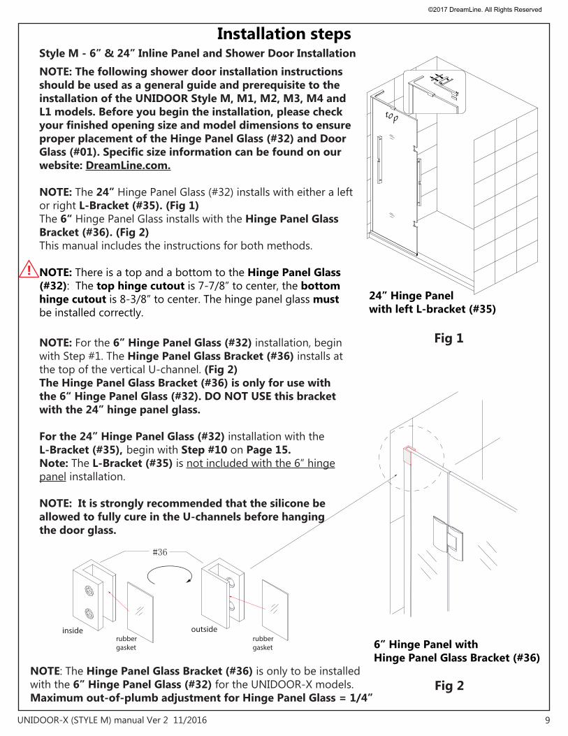
Installation steps
9UNIDOOR-X (STYLE M) manual Ver 2 11/2016
Fig 1
#36
inside outsiderubber gasket
Fig 2
6” Hinge Panel with Hinge Panel Glass Bracket (#36)
rubber gasket
top
NOTE: The following shower door installation instructions should be used as a general guide and prerequisite to the installation of the UNIDOOR Style M, M1, M2, M3, M4 and L1 models. Before you begin the installation, please check your finished opening size and model dimensions to ensure proper placement of the Hinge Panel Glass (#32) and Door Glass (#01). Specific size information can be found on our website: DreamLine.com.
NOTE: The 24” Hinge Panel Glass (#32) installs with either a left or right L-Bracket (#35). (Fig 1)The 6“ Hinge Panel Glass installs with the Hinge Panel Glass Bracket (#36). (Fig 2)This manual includes the instructions for both methods.
NOTE: There is a top and a bottom to the Hinge Panel Glass (#32): The top hinge cutout is 7-7/8” to center, the bottom hinge cutout is 8-3/8” to center. The hinge panel glass must be installed correctly.
Style M - 6” & 24” Inline Panel and Shower Door Installation
NOTE: For the 6” Hinge Panel Glass (#32) installation, begin with Step #1. The Hinge Panel Glass Bracket (#36) installs at the top of the vertical U-channel. (Fig 2) The Hinge Panel Glass Bracket (#36) is only for use with the 6“ Hinge Panel Glass (#32). DO NOT USE this bracket with the 24” hinge panel glass.
For the 24” Hinge Panel Glass (#32) installation with the L-Bracket (#35), begin with Step #10 on Page 15.Note: The L-Bracket (#35) is not included with the 6” hinge panel installation.
NOTE: It is strongly recommended that the silicone be allowed to fully cure in the U-channels before hanging the door glass.
24” Hinge Panel with left L-bracket (#35)
NOTE: The Hinge Panel Glass Bracket (#36) is only to be installed with the 6” Hinge Panel Glass (#32) for the UNIDOOR-X models. Maximum out-of-plumb adjustment for Hinge Panel Glass = 1/4”
!
©2017 DreamLine. All Rights Reserved
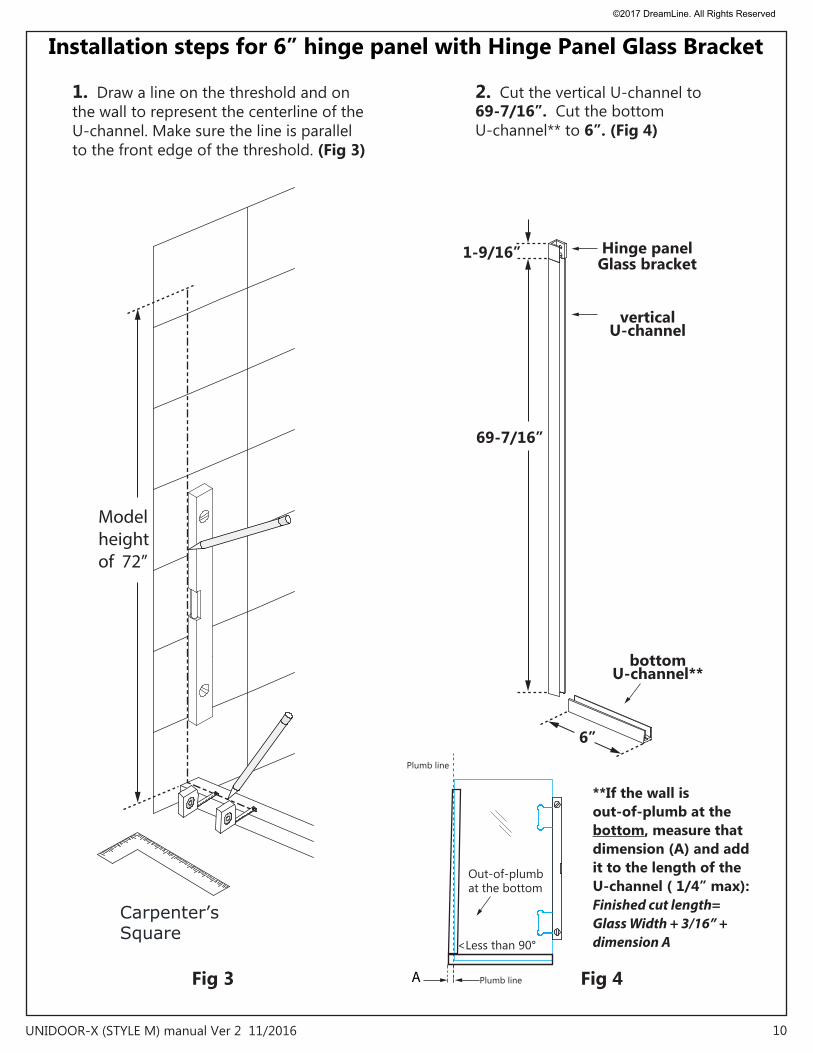
Installation steps for 6” hinge panel with Hinge Panel Glass Bracket
10UNIDOOR-X (STYLE M) manual Ver 2 11/2016
Plumb line
Out-of-plumb at the bottom
<Less than 90°
A Plumb line
**If the wall is out-of-plumb at the bottom, measure that dimension (A) and addit to the length of the U-channel ( 1/4” max):Finished cut length=Glass Width + 3/16” + dimension A
vertical U-channel
Hinge panelGlass bracket
1-9/16”
69-7/16”
6”
bottom U-channel**
Fig 4
Carpenter’sSquare
Model height of 72”
Fig 3
2. Cut the vertical U-channel to 69-7/16”. Cut the bottom U-channel** to 6”. (Fig 4)
1. Draw a line on the threshold and on the wall to represent the centerline of the U-channel. Make sure the line is parallel to the front edge of the threshold. (Fig 3)
©2017 DreamLine. All Rights Reserved
11UNIDOOR-X (STYLE M) manual Ver 2 11/2016
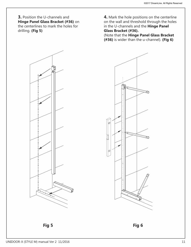
Fig 6Fig 5
3. Position the U-channels and Hinge Panel Glass Bracket (#36) on the centerlines to mark the holes for drilling. (Fig 5)
4. Mark the hole positions on the centerline on the wall and threshold through the holes in the U-channels and the Hinge Panel Glass Bracket (#36). (Note that the Hinge Panel Glass Bracket (#36) is wider than the u-channel). (Fig 6)
©2017 DreamLine. All Rights Reserved
12UNIDOOR-X (STYLE M) manual Ver 2 11/2016
Fig 8
Ø5/16"
(or Ø5/16" & anchor for tile)
Ø1/8"
Fig 7
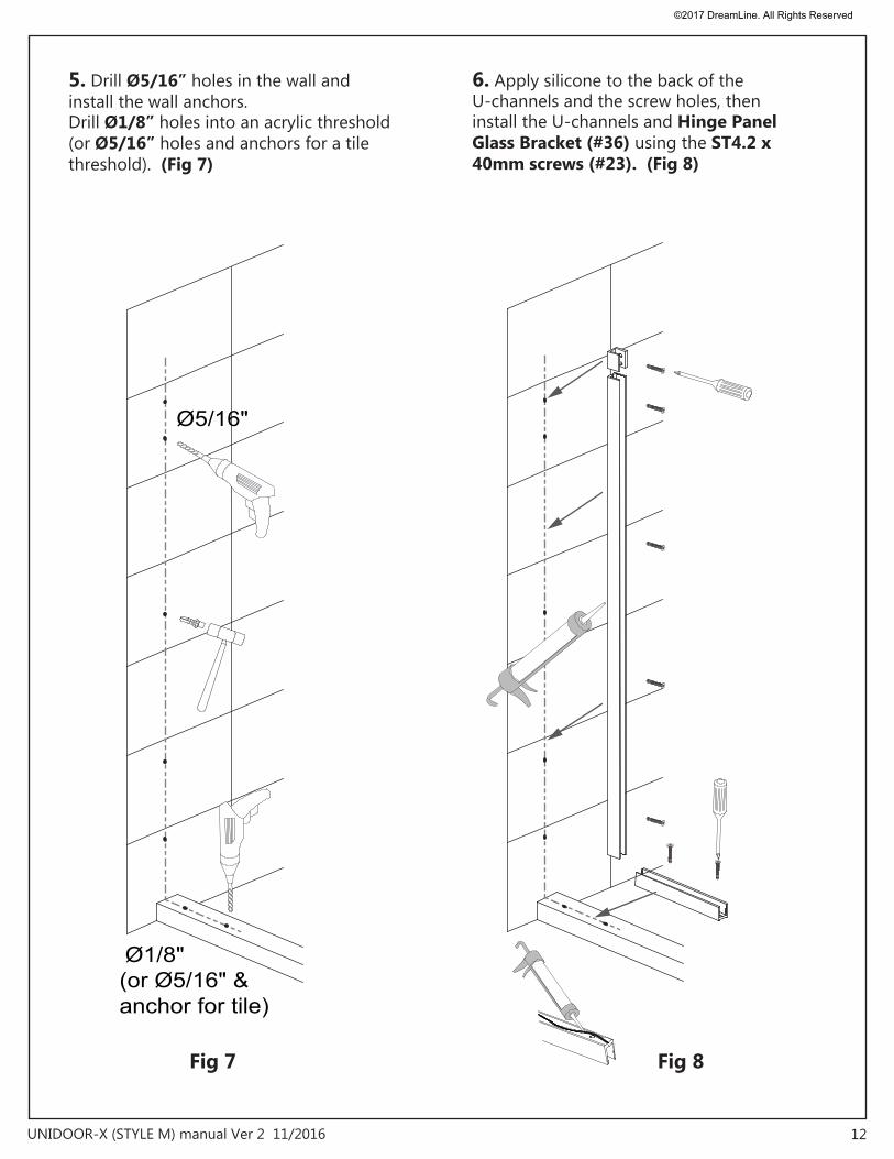
5. Drill Ø5/16” holes in the wall and install the wall anchors. Drill Ø1/8” holes into an acrylic threshold (or Ø5/16” holes and anchors for a tile threshold). (Fig 7)
6. Apply silicone to the back of the U-channels and the screw holes, then install the U-channels and Hinge Panel Glass Bracket (#36) using the ST4.2 x 40mm screws (#23). (Fig 8)
©2017 DreamLine. All Rights Reserved
13UNIDOOR-X (STYLE M) manual Ver 2 11/2016
Quick-drying/fast curing silicone isrecommended for the installation of hinge panel glass into u-channels.
Fig 10
Hinge PanelGlass Bracketwith gasket
8-3/8”
7-7/8”
top
bottom
Cut and install two 2”pcs of the 0.5 mm shims (#34)into the bottom U-channelto protect the corners of the glass
Fig 9
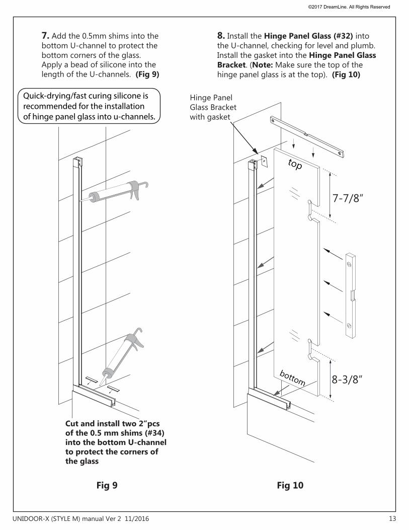
7. Add the 0.5mm shims into the bottom U-channel to protect the bottom corners of the glass. Apply a bead of silicone into the length of the U-channels. (Fig 9)
8. Install the Hinge Panel Glass (#32) into the U-channel, checking for level and plumb. Install the gasket into the Hinge Panel Glass Bracket. (Note: Make sure the top of the hinge panel glass is at the top). (Fig 10)
©2017 DreamLine. All Rights Reserved
14UNIDOOR-X (STYLE M) manual Ver 2 11/2016
Fig 12
Fig 11
inside
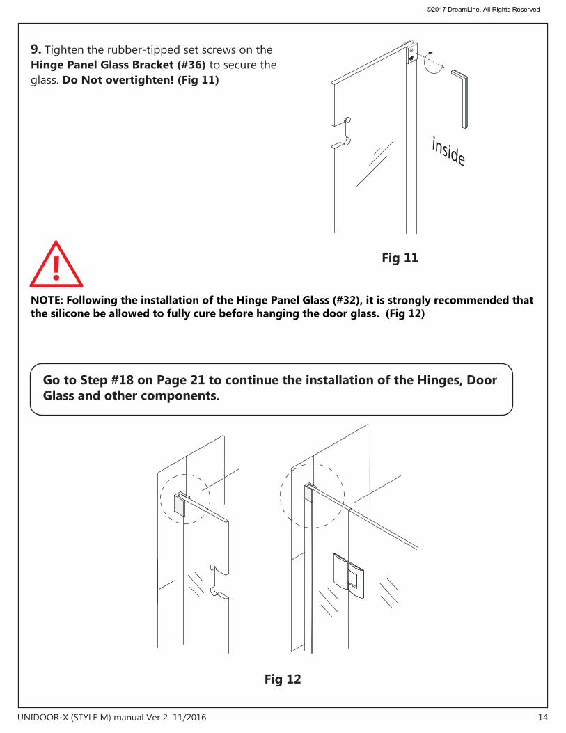
9. Tighten the rubber-tipped set screws on the Hinge Panel Glass Bracket (#36) to secure the glass. Do Not overtighten! (Fig 11)
NOTE: Following the installation of the Hinge Panel Glass (#32), it is strongly recommended that the silicone be allowed to fully cure before hanging the door glass. (Fig 12)
!
Go to Step #18 on Page 21 to continue the installation of the Hinges, Door Glass and other components.
©2017 DreamLine. All Rights Reserved
15UNIDOOR-X (STYLE M) manual Ver 2 11/2016
Fig 13
Fig 14
Metal File
Plumb line
Out-of-plumb at the bottom
<Less than 90°
A Plumb line
**If the wall is out-of-plumb at the bottom, measure that dimension as (A) and addit to the length of the U-channel ( +1/4” max):Finished cut length= 24” + A ORGlass Width + 3/16” + dimension A= Finished cut length
U-Channel 1
U-Channel 2
L
L
Installation steps for 24” hinge panel glass with L-Bracket
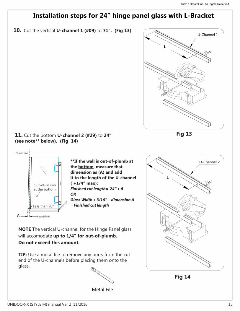
10. Cut the vertical U-channel 1 (#09) to 71”. (Fig 13)
TIP: Use a metal file to remove any burrs from the cut end of the U-channels before placing them onto the glass.
NOTE The vertical U-channel for the Hinge Panel glass will accomodate up to 1/4” for out-of-plumb. Do not exceed this amount.
11. Cut the bottom U-channel 2 (#29) to 24” (see note** below). (Fig 14)
©2017 DreamLine. All Rights Reserved

16UNIDOOR-X (STYLE M) manual Ver 2 11/2016
inside
wall
inside
wall
inside
wall
inside
wall
0 1/8”
1 2
3 4
5
(or Ø5/16" & anchor for tile)
Fig 15
Install the bottom U-channel parallel to the outside edgeof the threshold
NOTE: If installing this hinge panel and door for one of the Unidoor-X enclosure configurations, it is important that the hinge panel is installed at the correct dimension for the enclosure model size. Refer to panel installation manual packaged with the panel glass for details and dimensions.
12. Position the U-channel 2 (bottom profile) (#29) onto the threshold, parallel to the outside edge. Mark the position of the U-channel and mark the position of the holes for drilling. You need to use at least 3 holes for the U-channel 2 (bottom profile) (#29): one near each end and one near the center.• Drill the holes into the threshold using an Ø1/8” drill bit. (Or use a Ø5/16” bit and anchor for tile) • Apply a bead of silicone to the bottom of the U-channel 2 (bottom profile) (#29) and attach it to the threshold using the ST4.2 x 40mm screws (#23)(Fig. 15)
©2017 DreamLine. All Rights Reserved
17UNIDOOR-X (STYLE M) manual Ver 2 11/2016
waterproofsilicone2
3
1
inside
Fig 16
Fig 17
waterproofsilicone
5 6
1
4
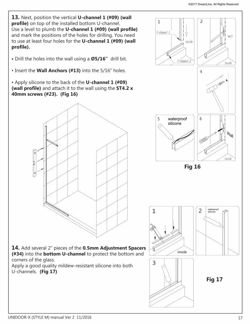
213. Next, position the vertical U-channel 1 (#09) (wall profile) on top of the installed bottom U-channel. Use a level to plumb the U-channel 1 (#09) (wall profile) and mark the positions of the holes for drilling. You need to use at least four holes for the U-channel 1 (#09) (wall profile).
• Drill the holes into the wall using a Ø5/16” drill bit.
• Insert the Wall Anchors (#13) into the 5/16” holes.
• Apply silicone to the back of the U-channel 1 (#09) (wall profile) and attach it to the wall using the ST4.2 x 40mm screws (#23). (Fig 16)
14. Add several 2” pieces of the 0.5mm Adjustment Spacers (#34) into the bottom U-channel to protect the bottom and corners of the glass. Apply a good quality mildew-resistant silicone into both U-channels. (Fig 17)
©2017 DreamLine. All Rights Reserved
18 UNIDOOR-X (STYLE M) manual Ver 2 11/2016
top
2
3 4
inside
wall
1
Fig 18
Fig 19
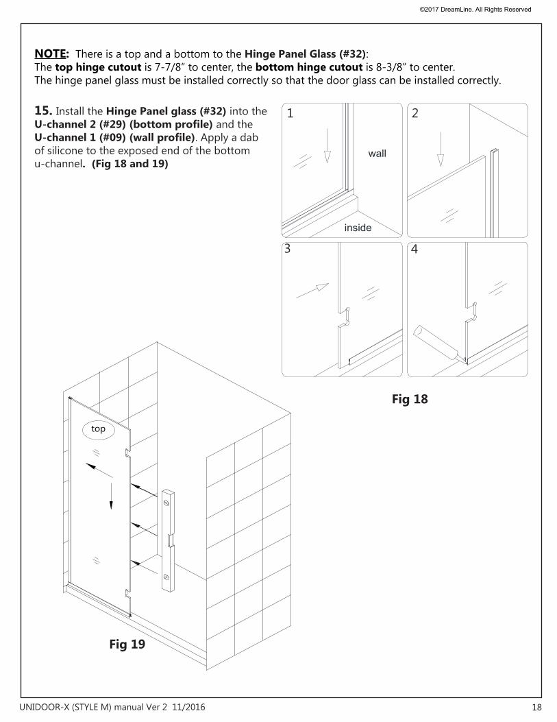
NOTE: There is a top and a bottom to the Hinge Panel Glass (#32): The top hinge cutout is 7-7/8” to center, the bottom hinge cutout is 8-3/8” to center. The hinge panel glass must be installed correctly so that the door glass can be installed correctly.
15. Install the Hinge Panel glass (#32) into the U-channel 2 (#29) (bottom profile) and the U-channel 1 (#09) (wall profile). Apply a dab of silicone to the exposed end of the bottom u-channel. (Fig 18 and 19)
©2017 DreamLine. All Rights Reserved
19 UNIDOOR-X (STYLE M) manual Ver 2 11/2016
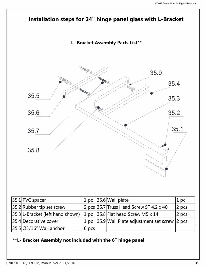
L- Bracket Assembly Parts List**
35.1 PVC spacer 1 pc 35.6 Wall plate 1 pc35.2 Rubber tip set screw 2 pcs 35.7 Truss Head Screw ST 4.2 x 40 2 pcs35.3 L-Bracket (left hand shown) 1 pc 35.8 Flat head Screw M5 x 14 2 pcs35.4 Decorative cover 1 pc 35.9 Wall Plate adjustment set screw 2 pcs35.5 Ø5/16” Wall anchor 6 pcs
35.9
35.1
35.2
35.3
35.4
35.8
35.7
35.6
35.5
**L- Bracket Assembly not included with the 6” hinge panel
Installation steps for 24” hinge panel glass with L-Bracket
©2017 DreamLine. All Rights Reserved
20UNIDOOR-X (STYLE M) manual Ver 2 11/2016
87Max 3/16”(4mm)
Max 3/16”(4mm)
5 6
2 31
Ø5/16"(8mm)
4
Fig 20
Fig 21
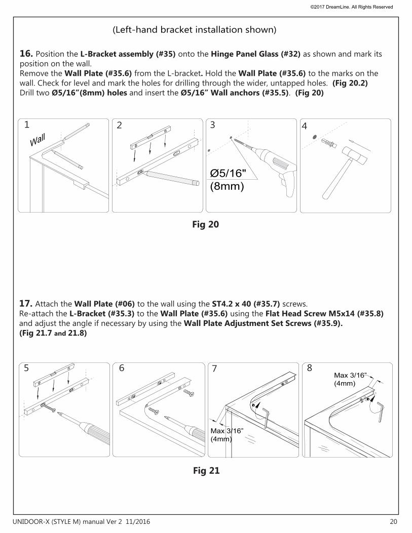
(Left-hand bracket installation shown)
16. Position the L-Bracket assembly (#35) onto the Hinge Panel Glass (#32) as shown and mark its position on the wall. Remove the Wall Plate (#35.6) from the L-bracket. Hold the Wall Plate (#35.6) to the marks on the wall. Check for level and mark the holes for drilling through the wider, untapped holes. (Fig 20.2) Drill two Ø5/16”(8mm) holes and insert the Ø5/16” Wall anchors (#35.5). (Fig 20)
17. Attach the Wall Plate (#06) to the wall using the ST4.2 x 40 (#35.7) screws.Re-attach the L-Bracket (#35.3) to the Wall Plate (#35.6) using the Flat Head Screw M5x14 (#35.8) and adjust the angle if necessary by using the Wall Plate Adjustment Set Screws (#35.9).(Fig 21.7 and 21.8)
©2017 DreamLine. All Rights Reserved
21UNIDOOR-X (STYLE M) manual Ver 2 11/2016
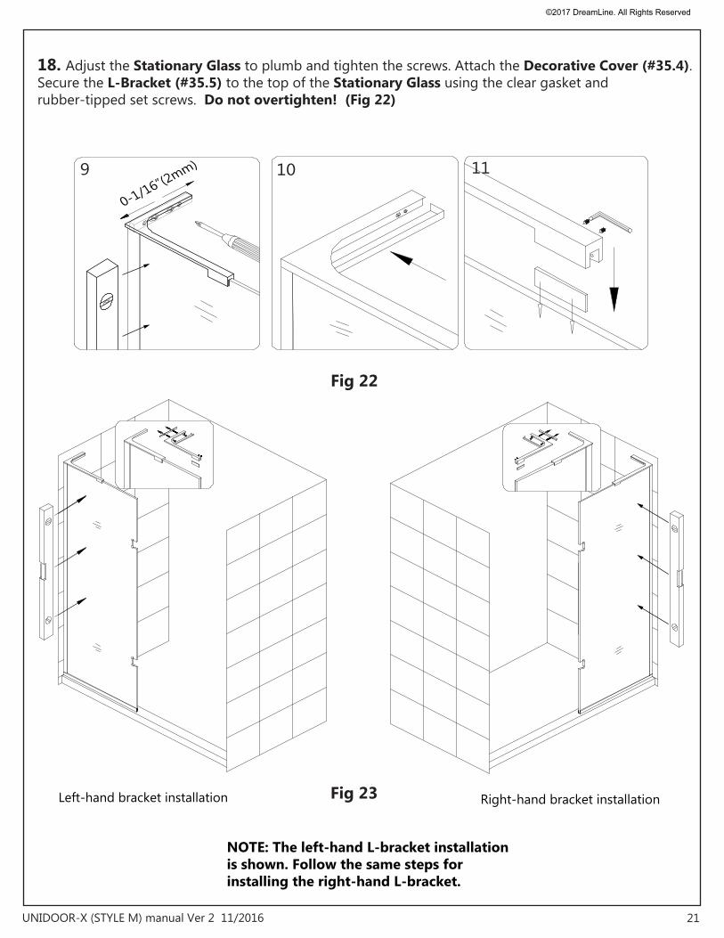
Fig 22
Fig 23
1110
Right-hand bracket installation Left-hand bracket installation
9
0-1/16”(2mm)
NOTE: The left-hand L-bracket installation is shown. Follow the same steps forinstalling the right-hand L-bracket.
18. Adjust the Stationary Glass to plumb and tighten the screws. Attach the Decorative Cover (#35.4). Secure the L-Bracket (#35.5) to the top of the Stationary Glass using the clear gasket and rubber-tipped set screws. Do not overtighten! (Fig 22)
©2017 DreamLine. All Rights Reserved
22UNIDOOR-X (STYLE M) manual Ver 2 11/2016
1
hinge panel
Fig 24
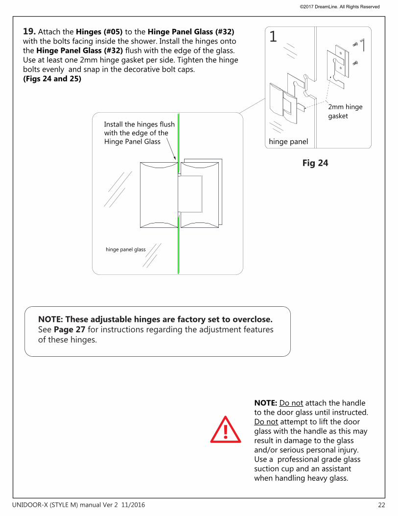
Install the hinges flush with the edge of the Hinge Panel Glass
hinge panel glass
2mm hinge gasket
19. Attach the Hinges (#05) to the Hinge Panel Glass (#32) with the bolts facing inside the shower. Install the hinges onto the Hinge Panel Glass (#32) flush with the edge of the glass. Use at least one 2mm hinge gasket per side. Tighten the hinge bolts evenly and snap in the decorative bolt caps. (Figs 24 and 25)
!
NOTE: Do not attach the handle to the door glass until instructed.Do not attempt to lift the door glass with the handle as this may result in damage to the glass and/or serious personal injury. Use a professional grade glass suction cup and an assistant when handling heavy glass.
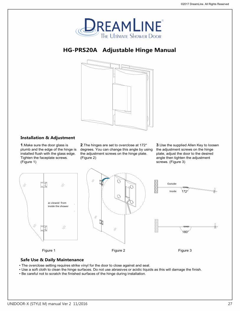
NOTE: These adjustable hinges are factory set to overclose. See Page 27 for instructions regarding the adjustment features of these hinges.
©2017 DreamLine. All Rights Reserved
23UNIDOOR-X (STYLE M) manual Ver 2 11/2016
Use the 5/8” spacers includedwith the door glass
5/8"
5/8” spacer
Fig 26
Fig 25
Door Glass
3
doorglass
2 doorglass
2mm hinge gasket
inside
outside
1
5/8”
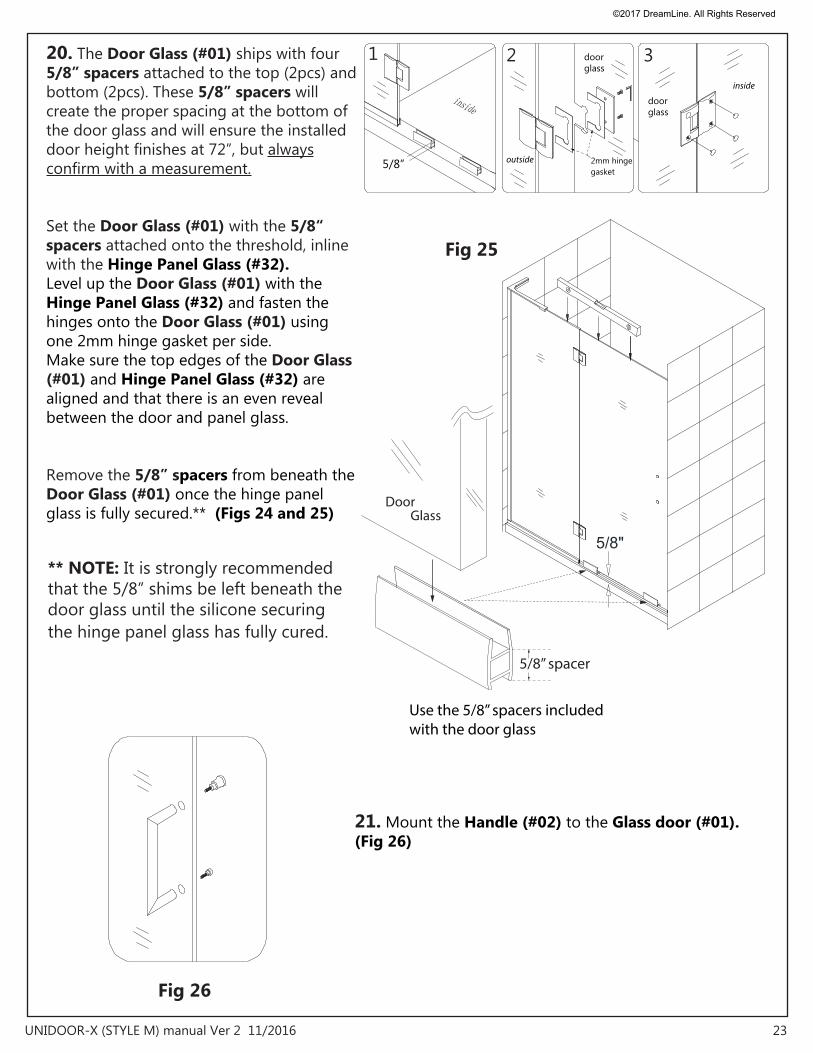
21. Mount the Handle (#02) to the Glass door (#01).(Fig 26)
** NOTE: It is strongly recommended that the 5/8” shims be left beneath the door glass until the silicone securing the hinge panel glass has fully cured.
20. The Door Glass (#01) ships with four 5/8” spacers attached to the top (2pcs) and bottom (2pcs). These 5/8” spacers will create the proper spacing at the bottom of the door glass and will ensure the installed door height finishes at 72”, but always confirm with a measurement.
Set the Door Glass (#01) with the 5/8“ spacers attached onto the threshold, inline with the Hinge Panel Glass (#32).Level up the Door Glass (#01) with the Hinge Panel Glass (#32) and fasten the hinges onto the Door Glass (#01) using one 2mm hinge gasket per side. Make sure the top edges of the Door Glass (#01) and Hinge Panel Glass (#32) are aligned and that there is an even reveal between the door and panel glass.
Remove the 5/8” spacers from beneath the Door Glass (#01) once the hinge panel glass is fully secured.** (Figs 24 and 25)
©2017 DreamLine. All Rights Reserved
24UNIDOOR-X (STYLE M) manual Ver 2 11/2016
2
4
Door
1”
1 2 3 4
5 6 7 8
Around Bottom sweep
measure
measure
1Handle side of door
Fig 28
Fig 27
3
Panel
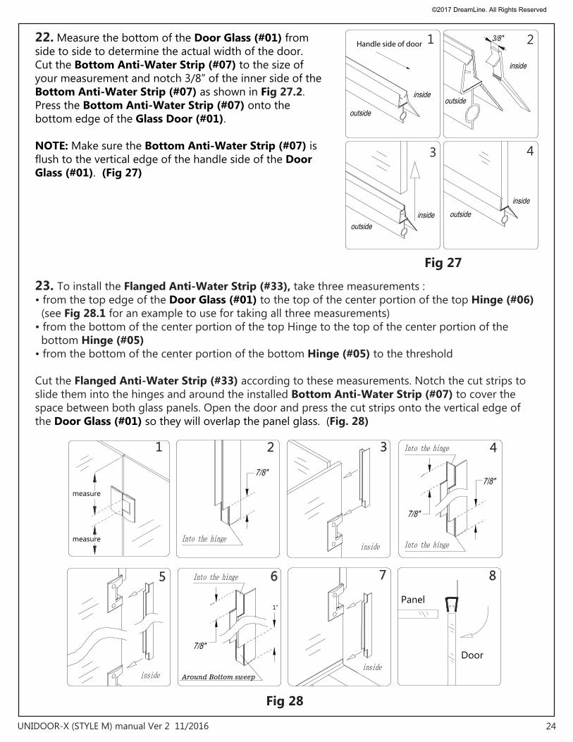
22. Measure the bottom of the Door Glass (#01) from side to side to determine the actual width of the door. Cut the Bottom Anti-Water Strip (#07) to the size of your measurement and notch 3/8” of the inner side of the Bottom Anti-Water Strip (#07) as shown in Fig 27.2.Press the Bottom Anti-Water Strip (#07) onto the bottom edge of the Glass Door (#01).
NOTE: Make sure the Bottom Anti-Water Strip (#07) is flush to the vertical edge of the handle side of the Door Glass (#01). (Fig 27)
23. To install the Flanged Anti-Water Strip (#33), take three measurements :• from the top edge of the Door Glass (#01) to the top of the center portion of the top Hinge (#06) (see Fig 28.1 for an example to use for taking all three measurements)• from the bottom of the center portion of the top Hinge to the top of the center portion of the bottom Hinge (#05) • from the bottom of the center portion of the bottom Hinge (#05) to the threshold
Cut the Flanged Anti-Water Strip (#33) according to these measurements. Notch the cut strips to slide them into the hinges and around the installed Bottom Anti-Water Strip (#07) to cover the space between both glass panels. Open the door and press the cut strips onto the vertical edge of the Door Glass (#01) so they will overlap the panel glass. (Fig. 28)
©2017 DreamLine. All Rights Reserved
25UNIDOOR-X (STYLE M) manual Ver 2 11/2016
2
1
Fig 30
Fig 29
Inside shower
Inside shower
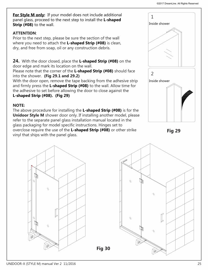
For Style M only: If your model does not include additional panel glass, proceed to the next step to install the L-shaped Strip (#08) to the wall.
24. With the door closed, place the L-shaped Strip (#08) on the door edge and mark its location on the wall.Please note that the corner of the L-shaped Strip (#08) should face into the shower. (Fig 29.1 and 29.2)With the door open, remove the tape backing from the adhesive strip and firmly press the L-shaped Strip (#08) to the wall. Allow time for the adhesive to set before allowing the door to close against the L-shaped Strip (#08). (Fig 29)
NOTE:The above procedure for installing the L-shaped Strip (#08) is for the Unidoor Style M shower door only. If installing another model, please refer to the separate panel glass installation manual located in the glass packaging for model specific instructions. Hinges set to overclose require the use of the L-shaped Strip (#08) or other strike vinyl that ships with the panel glass.
ATTENTION: Prior to the next step, please be sure the section of the wall where you need to attach the L-shaped Strip (#08) is clean, dry, and free from soap, oil or any construction debris.
©2017 DreamLine. All Rights Reserved
26UNIDOOR-X (STYLE M) manual Ver 2 11/2016
Fig 31
24Hours
NOTE: If your model includes additional panel glass, please find the manual for the panel glass installation in the panel glass packaging. (See page 4 for details)
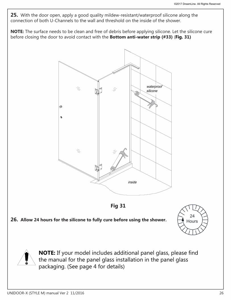
25. With the door open, apply a good quality mildew-resistant/waterproof silicone along the connection of both U-Channels to the wall and threshold on the inside of the shower.
NOTE: The surface needs to be clean and free of debris before applying silicone. Let the silicone cure before closing the door to avoid contact with the Bottom anti-water strip (#33) (Fig. 31)
26. Allow 24 hours for the silicone to fully cure before using the shower.
©2017 DreamLine. All Rights Reserved
27UNIDOOR-X (STYLE M) manual Ver 2 11/2016
©2017 DreamLine. All Rights Reserved
NOTE: To maximize the life of your door, it is important to regularly inspect the glass and other hardware for misalignment, proper attachment, and/or damage. Contact DreamLine with any questions or concerns.
Product Maintenance
BASES and BACKWALLS: To ensure long lasting life for your acrylic back walls: wipe them off after each use with a soft cloth. To clean the acrylic back walls use non-abrasive sprays or cream based cleaners. Avoid the use of aerosol spray cleaners. Never use abrasive cleansers, metal brushes or scrapers that could scratch or dull the surface.
GLASS: To ensure long lasting life for your glass shower products: wipe them off after each use with a soft cloth. Rinse and wipe off the glass using either a soft cloth or a squeegee to prevent soap buildup and water spots (Hard water can etch the surface of the glass over time if left to dry). To prevent scratching the surface: never use abrasive cleaners or cleaning products that contain scouring agents. Never use bristle brushes or abrasive sponges that may scratch the surface.
HARDWARE: To ensure a long lasting finish: wipe off the metal parts after each use with a soft cloth. Do not use abrasive cleaners or cleaning products containing ammonia, bleach or acid. If accidentally used, rinse the surface as soon as possible to prevent damage to the finish (peeling or corrosion). After cleaning the polished finishes, rinse thoroughly and wipe dry with soft cloth. Clean stainless steel surfaces at least once a week. When applying stainless steel cleaner or polish to stainless steel hardware, work with (not across) the grain. Never use an abrasive sponge or cloth, steel wool or wired brush as these may permanently scratch the surfaces.
28
©2017 DreamLine. All Rights Reserved
TEL: 866-731-2244FAX: 866-857-3638DREAMLINE.COM
For more information on DreamLine® Shower Doors and Enclosures please visit DreamLine.com
©2017 DreamLine. All Rights Reserved
“UNIDOOR (STYLE G)” Ver 1 Rev 6 09/2016 1
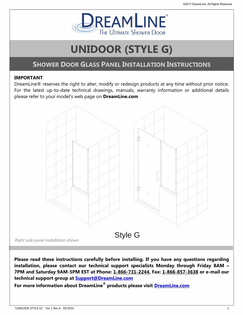
UNIDOOR (STYLE G)
SHOWER DOOR GLASS PANEL INSTALLATION INSTRUCTIONS
IMPORTANT
DreamLine® reserves the right to alter, modify or redesign products at any time without prior notice.
For the latest up-to-date technical drawings, manuals, warranty information or additional details
please refer to your model’s web page on DreamLine.com
Please read these instructions carefully before installing. If you have any questions regarding
installation, please contact our technical support specialists Monday through Friday 8AM –
7PM and Saturday 9AM-5PM EST at Phone: 1-866-731-2244, Fax: 1-866-857-3638 or e-mail our
technical support group at [email protected]
For more information about DreamLine®
products please visit DreamLine.com
Style G Right side panel installation shown
©2017 DreamLine. All Rights Reserved
“UNIDOOR (STYLE G)” Ver 1 Rev 6 09/2016 2
Style G
Model #s
SHDR-24232434-##
SHDR-24232436-##
SHDR-24233634-##
SHDR-24233636-##
SHDR-24242434-##
SHDR-24242436-##
SHDR-24243634-##
SHDR-24243636-##
SHDR-24273034-##
SHDR-24273036-##
SHDR-24273634-##
SHDR-24273636-##
SHDR-24283034-##
SHDR-24283036-##
SHDR-24283634-##
SHDR-24283636-##
SHDR-24293034-##
SHDR-24293036-##
SHDR-24293634-##
SHDR-24293636-##
SHDR-24303034-##
SHDR-24303036-##
SHDR-24303634-##
SHDR-24303636-##
## = finish 01 – Chrome 04 – Brushed Nickel 06 – Oil Rubbed Bronze 09 – Satin Black
©2017 DreamLine. All Rights Reserved
“UNIDOOR (STYLE G)” Ver 1 Rev 6 09/2016 3
D1263036
D1263034
D1262436
D1262434
D1253636
D1253634
D1253036
D1253034
D1252436
D1252434
D1243636
D1243634
D1243036
D1243034
D1242436
D1242434
D1233636
D1233634
D1233036
D1233034
D1232436
D1232434
Model #s
D3242436R-##
D3242436L
D3242434R
D3242434L
D3232436R
D3232436L
D3232434R
D3232434L
D1303636
D1303634
D1303036
D1303034
D1302436
D1302434
D1293636
D1293634
D1293036
D1293034
D1292436
D1292434
D1283636
D1283634
D1283036
D1283034
D1282436
D1282434
D1273636
D1273634
D1273036
D1273034
D1272436
D1272434
D1263636
D1263634
ADDITIONAL MODEL CONFIGURATIONS for UNIDOOR- X GLASS-TO-GLASS HINGE DOORS
## = finish 01 – Chrome 04 – Brushed Nickel 06 – Oil Rubbed Bronze 09 – Satin Black
©2017 DreamLine. All Rights Reserved
“UNIDOOR (STYLE G)” Ver 1 Rev 6 09/2016 4
Preparation
1. Prior to installation, examine all boxes and packages for shipping damage and compare the piece
count with your packing slip. After opening all boxes and packages read this introduction carefully.
Check that all of the needed parts are included in the package by checking off the components on
the “Detailed Diagram of Shower Door Components”. If the unit has been damaged, has a
finishing defect, or has missing parts, please contact our customer support department within
3 business days of the delivery date. Please note that DreamLine® will not replace any
damaged products or missing parts free of charge after 3 business days or if the product has
been installed. Feel free to contact DreamLine® if you have any questions and please provide an
order number, job name or other proof of purchase to help us identify your original order.
2. If this unit is going to be installed in a new construction, install all of the required plumbing and
drainage before installing the shower. Use a competent and licensed (if required by local code)
plumber for all plumbing installation.
3. Please note that you should consult your local building codes with questions about
installation compliance standards. Building and plumbing codes may vary by location, and
DreamLine® is not responsible for code compliance standards for your project and will not
accept any returns.
4. Please make sure that prior to beginning the installation, the surfaces are leveled and solid and will
be able to support the total weight of the unit. Also make sure the walls are at right angles.
Irregular installation surface level, radius corners or improper angle of side walls will result in
serious problems for your installation. Please note that some adjustments and drilling may be
necessary during the installation process.
5. Please protect all primary surfaces of the product during installation. Never set your glass down
directly onto a tile floor. Leave corner protectors in place until necessary to remove them. Always
use a piece of wood or cardboard to protect the bottom edge and corners of the glass prior to
and during installation.
6. This unit must be installed upon a finished threshold and against finished walls.
7. This model requires that you drill into the threshold for proper installation.
8. This model has 1/2” of adjustment within the u-channel for out-of-plumb wall conditions and
overall width within the model size. Confirm the finished opening conditions before proceeding
with the installation.
9. This model requires a minimum 5/8” of flat threshold space for installation.
10. Professional installation is recommended for this heavy glass frameless shower door.
NOTE: This door is reversible for right or left side panel installation. The right side panel installation is
shown as an example throughout this manual. For the left side panel installation, simply begin on the
opposite wall and reverse the orientation of the steps shown.
©2017 DreamLine. All Rights Reserved
“UNIDOOR (STYLE G)” Ver 1 Rev 6 09/2016 5
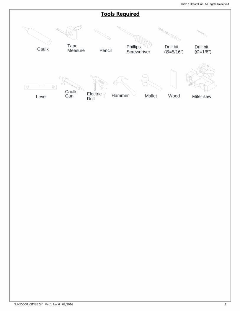
Tools Required
CaulkTapeMeasure Pencil Screwdriver
Phillips Drill bit
Level GunCaulk
DrillElectric Hammer
Drill bit(Ø=5/16") (Ø=1/8")
Miter sawMallet Wood
©2017 DreamLine. All Rights Reserved
“UNIDOOR (STYLE G)” Ver 1 Rev 6 09/2016 6
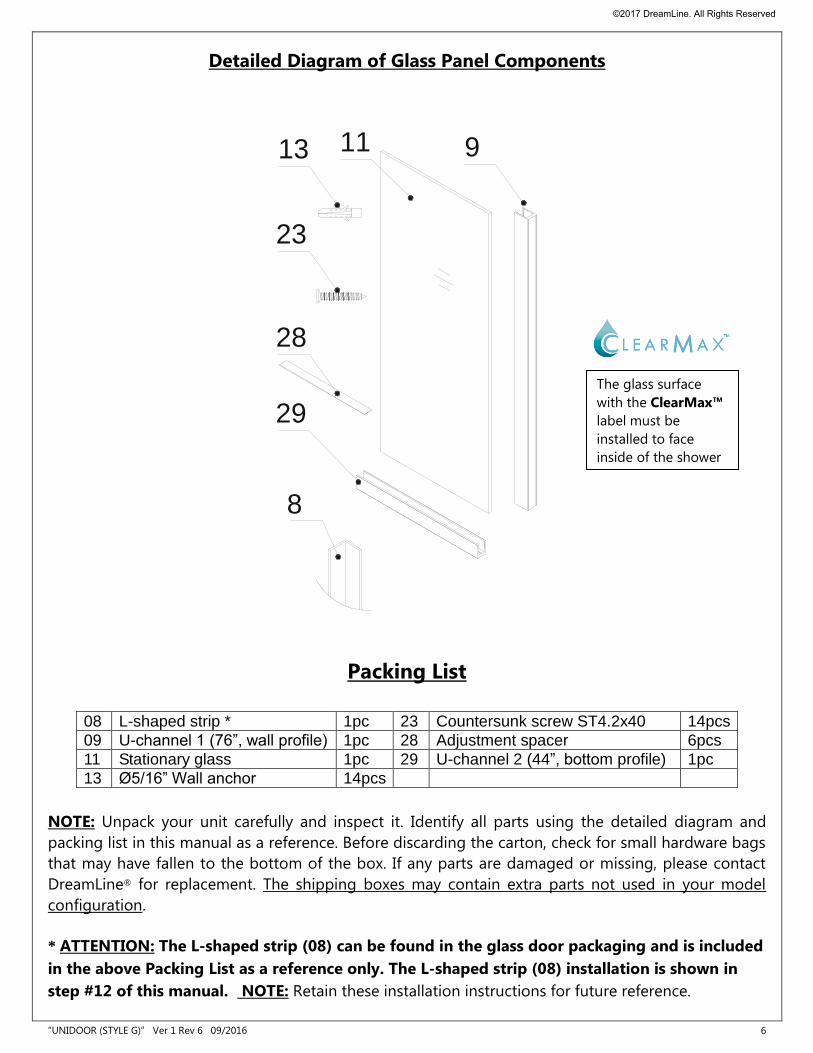
Detailed Diagram of Glass Panel Components
Packing List
08 L-shaped strip * 1pc 23 Countersunk screw ST4.2x40 14pcs
09 U-channel 1 (76”, wall profile) 1pc 28 Adjustment spacer 6pcs
11 Stationary glass 1pc 29 U-channel 2 (44”, bottom profile) 1pc
13 Ø5/16” Wall anchor 14pcs
NOTE: Unpack your unit carefully and inspect it. Identify all parts using the detailed diagram and
packing list in this manual as a reference. Before discarding the carton, check for small hardware bags
that may have fallen to the bottom of the box. If any parts are damaged or missing, please contact
DreamLine® for replacement. The shipping boxes may contain extra parts not used in your model
configuration.
* ATTENTION: The L-shaped strip (08) can be found in the glass door packaging and is included
in the above Packing List as a reference only. The L-shaped strip (08) installation is shown in
step #12 of this manual. NOTE: Retain these installation instructions for future reference.
91113
23
28
29
8
The glass surface
with the ClearMax™
label must be
installed to face
inside of the shower
©2017 DreamLine. All Rights Reserved
“UNIDOOR (STYLE G)” Ver 1 Rev 6 09/2016 7
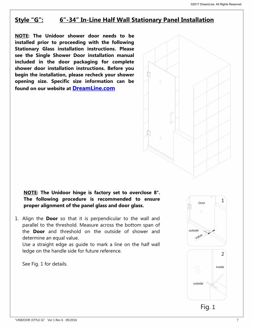
Style “G”: 6”-34” In-Line Half Wall Stationary Panel Installation
NOTE: The Unidoor shower door needs to be
installed prior to proceeding with the following
Stationary Glass installation instructions. Please
see the Single Shower Door installation manual
included in the door packaging for complete
shower door installation instructions. Before you
begin the installation, please recheck your shower
opening size. Specific size information can be
found on our website at DreamLine.com
NOTE: The Unidoor hinge is factory set to overclose 8°.
The following procedure is recommended to ensure
proper alignment of the panel glass and door glass.
1. Align the Door so that it is perpendicular to the wall and
parallel to the threshold. Measure across the bottom span of
the Door and threshold on the outside of shower and
determine an equal value.
Use a straight edge as guide to mark a line on the half wall
ledge on the handle side for future reference.
See Fig. 1 for details.
outside
Door
Value
outside
inside
Fig. 1
2
1
©2017 DreamLine. All Rights Reserved
“UNIDOOR (STYLE G)” Ver 1 Rev 6 09/2016 8
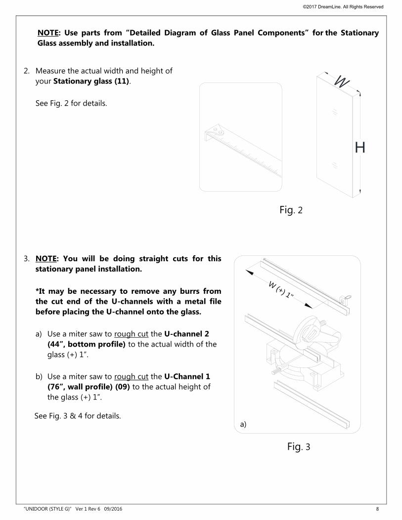
NOTE: Use parts from “Detailed Diagram of Glass Panel Components” for the Stationary
Glass assembly and installation.
2. Measure the actual width and height of
your Stationary glass (11).
See Fig. 2 for details.
3. NOTE: You will be doing straight cuts for this
stationary panel installation.
*It may be necessary to remove any burrs from
the cut end of the U-channels with a metal file
before placing the U-channel onto the glass.
a) Use a miter saw to rough cut the U-channel 2
(44”, bottom profile) to the actual width of the
glass (+) 1”.
b) Use a miter saw to rough cut the U-Channel 1
(76”, wall profile) (09) to the actual height of
the glass (+) 1”.
See Fig. 3 & 4 for details.
W (+) 1"
Fig. 3
H
Fig. 2
a)
©2017 DreamLine. All Rights Reserved
“UNIDOOR (STYLE G)” Ver 1 Rev 6 09/2016 9
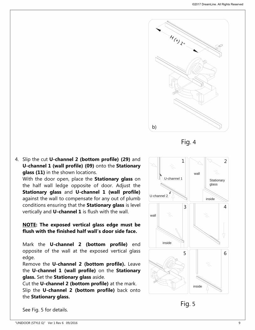
4. Slip the cut U-channel 2 (bottom profile) (29) and
U-channel 1 (wall profile) (09) onto the Stationary
glass (11) in the shown locations.
With the door open, place the Stationary glass on
the half wall ledge opposite of door. Adjust the
Stationary glass and U-channel 1 (wall profile)
against the wall to compensate for any out of plumb
conditions ensuring that the Stationary glass is level
vertically and U-channel 1 is flush with the wall.
NOTE: The exposed vertical glass edge must be
flush with the finished half wall’s door side face.
Mark the U-channel 2 (bottom profile) end
opposite of the wall at the exposed vertical glass
edge.
Remove the U-channel 2 (bottom profile). Leave
the U-channel 1 (wall profile) on the Stationary
glass. Set the Stationary glass aside.
Cut the U-channel 2 (bottom profile) at the mark.
Slip the U-channel 2 (bottom profile) back onto
the Stationary glass.
See Fig. 5 for details.
wall
inside
inside
Stationary
glass
U-channel 2
U-channel 1
wall
inside
Fig. 5
1
3
5
2
4
6
H (+) 1"
b)
Fig. 4
©2017 DreamLine. All Rights Reserved
“UNIDOOR (STYLE G)” Ver 1 Rev 6 09/2016 10
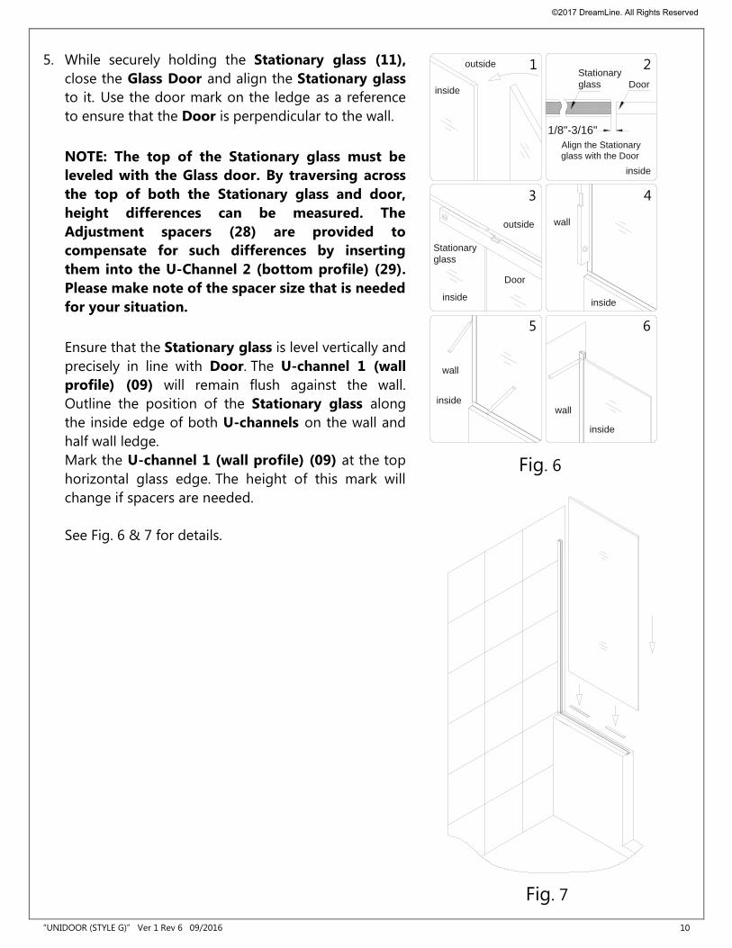
5. While securely holding the Stationary glass (11),
close the Glass Door and align the Stationary glass
to it. Use the door mark on the ledge as a reference
to ensure that the Door is perpendicular to the wall.
NOTE: The top of the Stationary glass must be
leveled with the Glass door. By traversing across
the top of both the Stationary glass and door,
height differences can be measured. The
Adjustment spacers (28) are provided to
compensate for such differences by inserting
them into the U-Channel 2 (bottom profile) (29).
Please make note of the spacer size that is needed
for your situation.
Ensure that the Stationary glass is level vertically and
precisely in line with Door. The U-channel 1 (wall
profile) (09) will remain flush against the wall.
Outline the position of the Stationary glass along
the inside edge of both U-channels on the wall and
half wall ledge.
Mark the U-channel 1 (wall profile) (09) at the top
horizontal glass edge. The height of this mark will
change if spacers are needed.
See Fig. 6 & 7 for details.
outside
inside
inside
wall
inside
wall
inside
outside
Door
Stationary
glass
inside
wall
1/8"-3/16"
Align the Stationary
glass with the Door
inside
Door
Stationary
glass
1
3
5
2
4
6
Fig. 6
Fig. 7
©2017 DreamLine. All Rights Reserved
“UNIDOOR (STYLE G)” Ver 1 Rev 6 09/2016 11
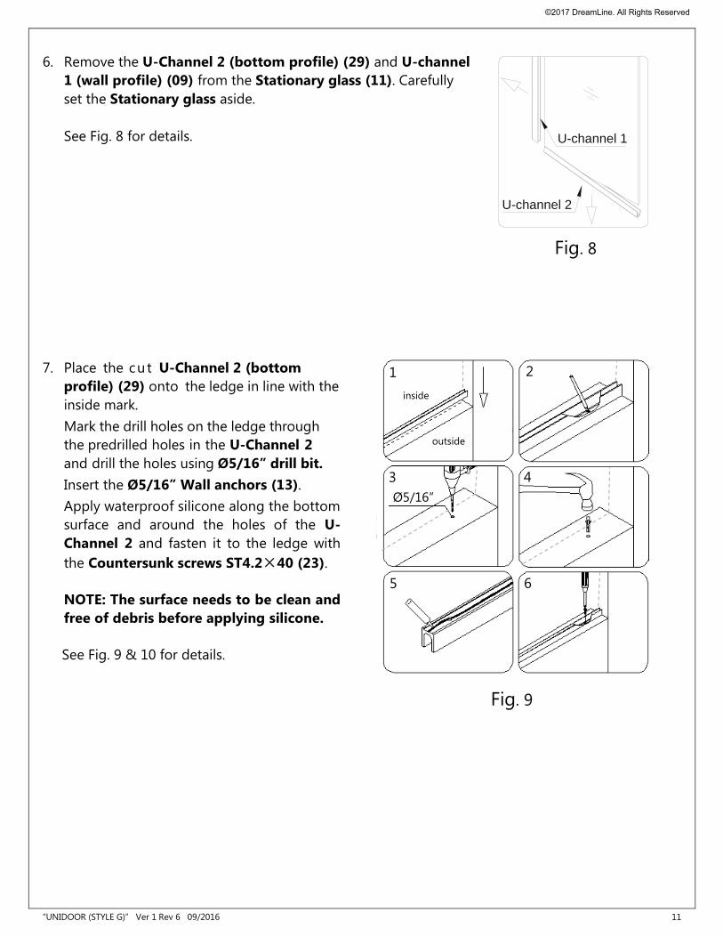
6. Remove the U-Channel 2 (bottom profile) (29) and U-channel
1 (wall profile) (09) from the Stationary glass (11). Carefully
set the Stationary glass aside.
See Fig. 8 for details.
7. Place the cut U-Channel 2 (bottom
profile) (29) onto the ledge in line with the
inside mark.
Mark the drill holes on the ledge through
the predrilled holes in the U-Channel 2
and drill the holes using Ø5/16” drill bit.
Insert the Ø5/16” Wall anchors (13).
Apply waterproof silicone along the bottom
surface and around the holes of the U-
Channel 2 and fasten it to the ledge with
the Countersunk screws ST4.2×40 (23).
NOTE: The surface needs to be clean and
free of debris before applying silicone.
See Fig. 9 & 10 for details.
U-channel 2
U-channel 1
Fig. 8
Fig. 9
Ø5/16”
1
3
5
2
4
6
inside
outside
©2017 DreamLine. All Rights Reserved
“UNIDOOR (STYLE G)” Ver 1 Rev 6 09/2016 12
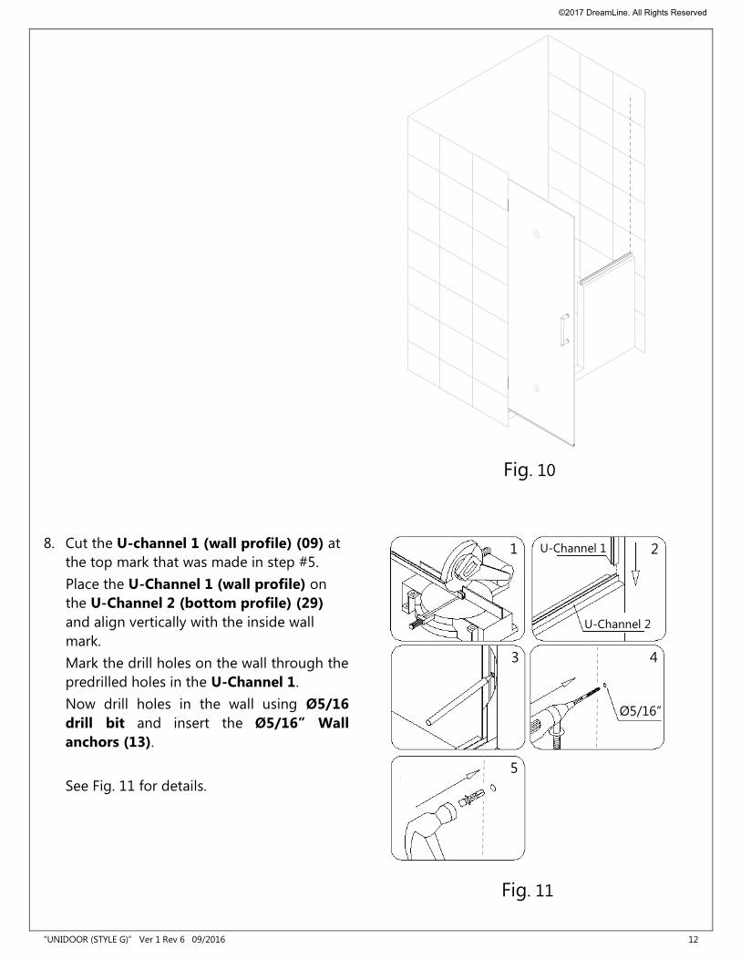
8. Cut the U-channel 1 (wall profile) (09) at
the top mark that was made in step #5.
Place the U-Channel 1 (wall profile) on
the U-Channel 2 (bottom profile) (29)
and align vertically with the inside wall
mark.
Mark the drill holes on the wall through the
predrilled holes in the U-Channel 1.
Now drill holes in the wall using Ø5/16
drill bit and insert the Ø5/16” Wall
anchors (13).
See Fig. 11 for details.
Fig. 11
Ø5/16”
1
3
5
2
4
U-Channel 1
U-Channel 2
Fig. 10
©2017 DreamLine. All Rights Reserved
“UNIDOOR (STYLE G)” Ver 1 Rev 6 09/2016 13
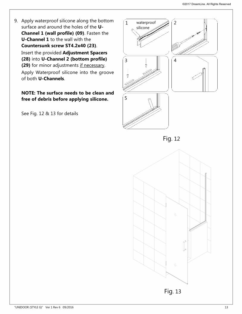
9. Apply waterproof silicone along the bottom
surface and around the holes of the U-
Channel 1 (wall profile) (09). Fasten the
U-Channel 1 to the wall with the
Countersunk screw ST4.2x40 (23).
Insert the provided Adjustment Spacers
(28) into U-Channel 2 (bottom profile)
(29) for minor adjustments if necessary.
Apply Waterproof silicone into the groove
of both U-Channels.
NOTE: The surface needs to be clean and
free of debris before applying silicone.
See Fig. 12 & 13 for details
waterproof
silicone
Fig. 12
1
3
2
4
5
Fig. 13
©2017 DreamLine. All Rights Reserved
“UNIDOOR (STYLE G)” Ver 1 Rev 6 09/2016 14
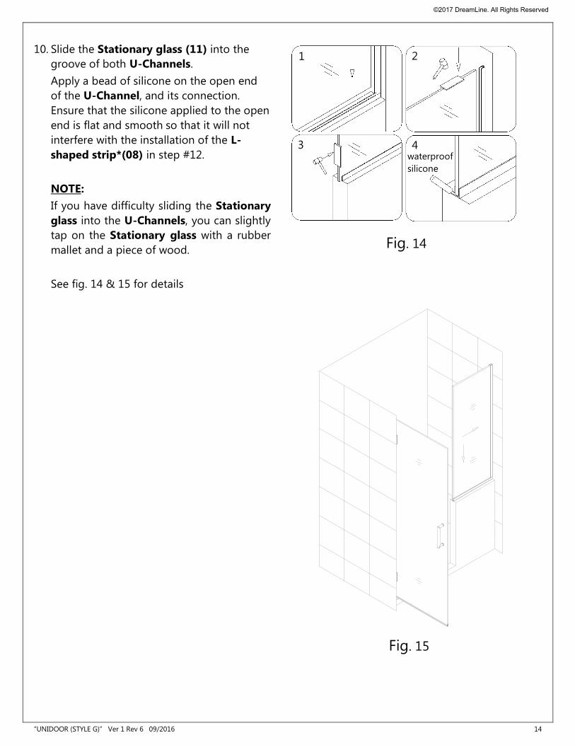
10. Slide the Stationary glass (11) into the
groove of both U-Channels.
Apply a bead of silicone on the open end
of the U-Channel, and its connection.
Ensure that the silicone applied to the open
end is flat and smooth so that it will not
interfere with the installation of the L-
shaped strip*(08) in step #12.
NOTE:
If you have difficulty sliding the Stationary
glass into the U-Channels, you can slightly
tap on the Stationary glass with a rubber
mallet and a piece of wood.
See fig. 14 & 15 for details
Fig. 14
1
3
2
4 waterproof
silicone
Fig. 15
©2017 DreamLine. All Rights Reserved
“UNIDOOR (STYLE G)” Ver 1 Rev 6 09/2016 15
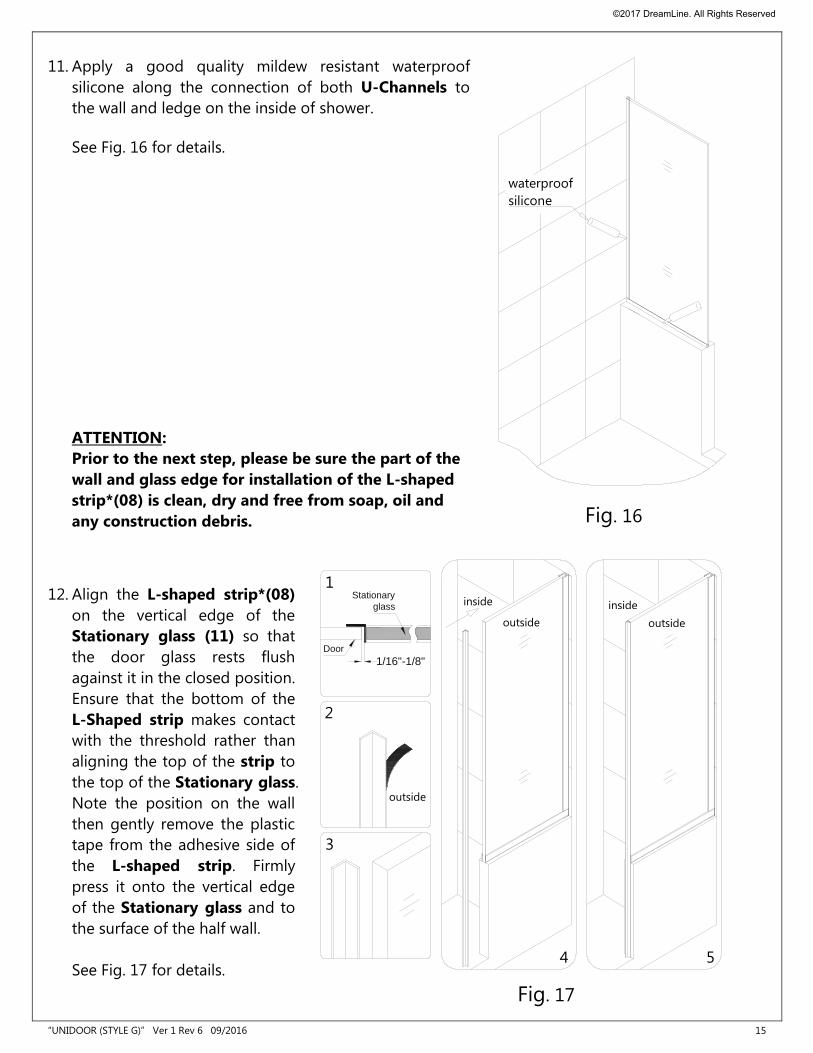
11. Apply a good quality mildew resistant waterproof
silicone along the connection of both U-Channels to
the wall and ledge on the inside of shower.
See Fig. 16 for details.
ATTENTION:
Prior to the next step, please be sure the part of the
wall and glass edge for installation of the L-shaped
strip*(08) is clean, dry and free from soap, oil and
any construction debris.
12. Align the L-shaped strip*(08)
on the vertical edge of the
Stationary glass (11) so that
the door glass rests flush
against it in the closed position.
Ensure that the bottom of the
L-Shaped strip makes contact
with the threshold rather than
aligning the top of the strip to
the top of the Stationary glass.
Note the position on the wall
then gently remove the plastic
tape from the adhesive side of
the L-shaped strip. Firmly
press it onto the vertical edge
of the Stationary glass and to
the surface of the half wall.
See Fig. 17 for details.
Door
Stationary
glass
1/16"-1/8"
Fig. 17
inside
outside
inside
outside
1
4 5
2
3
outside
waterproof
silicone
Fig. 16
©2017 DreamLine. All Rights Reserved
“UNIDOOR (STYLE G)” Ver 1 Rev 6 09/2016 16
Product Maintenance
BASES and BACKWALLS: To ensure long lasting life for your acrylic back walls: wipe them off
after each use with a soft cloth. To clean the acrylic back walls use non-abrasive sprays or cream
based cleaners. Avoid the use of aerosol spray cleaners. Never use abrasive cleansers, metal
brushes or scrapers that could scratch or dull the surface.
GLASS: To ensure long lasting life for your glass shower products: wipe them off after each use
with a soft cloth. Rinse and wipe off the glass using either a soft cloth or a squeegee to prevent
soap buildup and water spots (Hard water can etch the surface of the glass over time if left to dry).
To prevent scratching the surface: never use abrasive cleaners or cleaning products that contain
scouring agents. Never use bristle brushes or abrasive sponges that may scratch the surface.
HARDWARE: To ensure a long lasting finish: wipe off the metal parts after each use with a soft
cloth. Do not use abrasive cleaners or cleaning products containing ammonia, bleach or acid. If
accidentally used, rinse the surface as soon as possible to prevent damage to the finish (peeling or
corrosion). After cleaning the polished finishes, rinse thoroughly and wipe dry with soft cloth.
Clean stainless steel surfaces at least once a week. When applying stainless steel cleaner or polish
to stainless steel hardware, work with (not across) the grain. Never use an abrasive sponge or cloth,
steel wool or wired brush as these may permanently scratch the surfaces.
NOTE: To maximize the life of your door, it is important to regularly inspect the glass and
other hardware for misalignment, proper attachment, and/or damage. Contact DreamLine
with any questions or concerns.
©2017 DreamLine. All Rights Reserved
“UNIDOOR (STYLE G)” Ver 1 Rev 6 09/2016
TEL: 866-731-2244
FAX: 866-857-3638
DREAMLINE.COM
For more information on DreamLine® Shower Doors and Enclosures please visit DreamLine.com
©2017 DreamLine. All Rights Reserved