unified facilities criteria (ufc) - pickens county
TRANSCRIPT
CHAPTER 1
INTRODUCTION TO LID AND MANUAL OVERVIEW
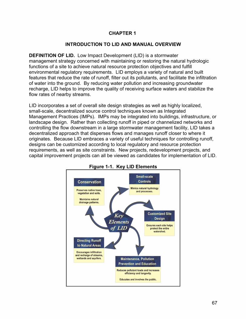
DEFINITION OF LID. Low Impact Development (LID) is a stormwater management strategy concerned with maintaining or restoring the natural hydrologic functions of a site to achieve natural resource protection objectives and fulfill environmental regulatory requirements. LID employs a variety of natural and built features that reduce the rate of runoff, filter out its pollutants, and facilitate the infiltration of water into the ground. By reducing water pollution and increasing groundwater recharge, LID helps to improve the quality of receiving surface waters and stabilize the flow rates of nearby streams. LID incorporates a set of overall site design strategies as well as highly localized, small-scale, decentralized source control techniques known as Integrated Management Practices (IMPs). IMPs may be integrated into buildings, infrastructure, or landscape design. Rather than collecting runoff in piped or channelized networks and controlling the flow downstream in a large stormwater management facility, LID takes a decentralized approach that disperses flows and manages runoff closer to where it originates. Because LID embraces a variety of useful techniques for controlling runoff, designs can be customized according to local regulatory and resource protection requirements, as well as site constraints. New projects, redevelopment projects, and capital improvement projects can all be viewed as candidates for implementation of LID.
Figure 1-1. Key LID Elements
67

BASIC LIST OF IMPs. Here is a basic list of IMPs that are available. Bioretention: Vegetated depressions that collect runoff and facilitate its infiltration into the ground. Dry Wells: Gravel- or stone-filled pits that are located to catch water from roof downspouts or paved areas. Filter Strips: Bands of dense vegetation planted immediately downstream of a runoff source designed to filter runoff before entering a receiving structure or water body. Grassed Swales: Shallow channels lined with grass and used to convey and store runoff. Infiltration Trenches: Trenches filled with porous media such as bioretention material, sand, or aggregate that collect runoff and exfiltrate it into the ground. Inlet Pollution Removal Devices: Small stormwater treatment systems that are installed below grade at the edge of paved areas and trap or filter pollutants in runoff before it enters the storm drain. Permeable Pavement: Asphalt or concrete rendered porous by the aggregate structure. Permeable Pavers: Manufactured paving stones containing spaces where water can penetrate into the porous media placed underneath. Rain Barrels and Cisterns: Containers of various sizes that store the runoff delivered through building downspouts. Rain barrels are generally smaller structures, located above ground. Cisterns are larger, are often buried underground, and may be connected to the building’s plumbing or irrigation system. Soil amendments: Minerals and organic material added to soil to increase its capacity for absorbing moisture and sustaining vegetation. Tree Box Filters: Curbside containers placed below grade, covered with a grate, filled with filter media and planted with a tree in the center. Vegetated Buffers: Natural or man-made vegetated areas adjacent to a water body, providing erosion control, filtering capability, and habitat. Vegetated Roofs: Impermeable roof membranes overlaid with a lightweight planting mix with a high infiltration rate and vegetated with plants tolerant of heat, drought, and periodic inundation.
68
CHAPTER 2
STORMWATER MANAGEMENT USING THE HYDROLOGIC CYCLE APPROACH
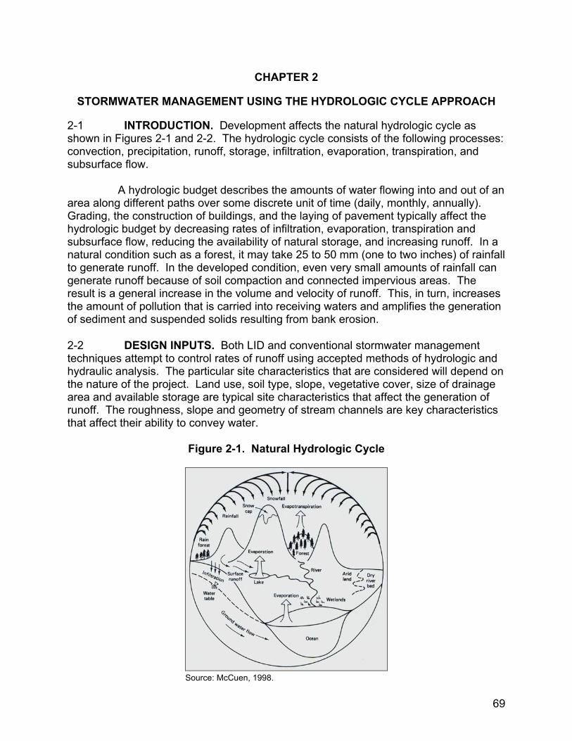
2-1 INTRODUCTION. Development affects the natural hydrologic cycle as shown in Figures 2-1 and 2-2. The hydrologic cycle consists of the following processes: convection, precipitation, runoff, storage, infiltration, evaporation, transpiration, and subsurface flow. A hydrologic budget describes the amounts of water flowing into and out of an area along different paths over some discrete unit of time (daily, monthly, annually). Grading, the construction of buildings, and the laying of pavement typically affect the hydrologic budget by decreasing rates of infiltration, evaporation, transpiration and subsurface flow, reducing the availability of natural storage, and increasing runoff. In a natural condition such as a forest, it may take 25 to 50 mm (one to two inches) of rainfall to generate runoff. In the developed condition, even very small amounts of rainfall can generate runoff because of soil compaction and connected impervious areas. The result is a general increase in the volume and velocity of runoff. This, in turn, increases the amount of pollution that is carried into receiving waters and amplifies the generation of sediment and suspended solids resulting from bank erosion. 2-2 DESIGN INPUTS. Both LID and conventional stormwater management techniques attempt to control rates of runoff using accepted methods of hydrologic and hydraulic analysis. The particular site characteristics that are considered will depend on the nature of the project. Land use, soil type, slope, vegetative cover, size of drainage area and available storage are typical site characteristics that affect the generation of runoff. The roughness, slope and geometry of stream channels are key characteristics that affect their ability to convey water.
Figure 2-1. Natural Hydrologic Cycle
Source: McCuen, 1998.
69

Figure 2-2. Hydrologic Cycle of a Developed Environment
Source: McCuen, 1998.
While conventional approaches to stormwater management design typically include only the hydrologic components of precipitation, runoff conveyance and storage capacity within their scopes, LID design recognizes the significance of other components of the hydrologic cycle as well. How these other components are actually taken into account will depend on the information available and purpose of the design. One LID design objective, for example, may be to maintain a natural groundwater recharge rate for a given site. Determining the appropriate number, size, and location of infiltration devices can require an extensive atmospheric data set (temperature and precipitation) to calculate evapotranspiration rates, along with measures of soil hydraulic conductivity. The following section describes how LID design can make use of precipitation, storage, infiltration, evaporation, and transpiration data. The discussion includes a brief description of each of these types of data, and compares the use of these data from LID and conventional stormwater management perspectives. 2-3 PRECIPITATION DATA. Precipitation data is often analyzed in terms of the frequency at which storm events of different magnitudes and durations occur at a given location. Stormwater management designs may take into account the total annual depths or the volume generated by a storm of a specific frequency and duration (e.g. 2-year 24-hour storm event). Hydrologic models may use precipitation data to develop a synthetic design storm that reflects the pattern and intensity of precipitation for the project location region or use actual gage data from a given storm event. The level of detail and accuracy of data used is dependent on the requirements of the hydrologic model. For example, to develop a simple water balance for on-site irrigation only a few years of annual rainfall totals may be required. Some advanced urban
70
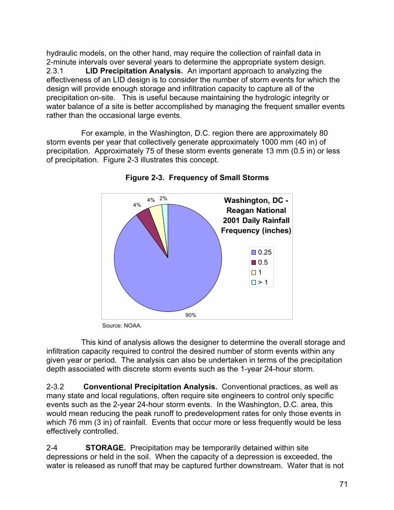
hydraulic models, on the other hand, may require the collection of rainfall data in 2-minute intervals over several years to determine the appropriate system design.2.3.1 LID Precipitation Analysis. An important approach to analyzing the effectiveness of an LID design is to consider the number of storm events for which the design will provide enough storage and infiltration capacity to capture all of the precipitation on-site. This is useful because maintaining the hydrologic integrity or water balance of a site is better accomplished by managing the frequent smaller events rather than the occasional large events. For example, in the Washington, D.C. region there are approximately 80 storm events per year that collectively generate approximately 1000 mm (40 in) of precipitation. Approximately 75 of these storm events generate 13 mm (0.5 in) or less of precipitation. Figure 2-3 illustrates this concept.
Figure 2-3. Frequency of Small Storms
Washington, DC - Reagan National
2001 Daily RainfallFrequency (inches)
90%
4%4% 2%
0.250.51> 1
Source: NOAA. This kind of analysis allows the designer to determine the overall storage and infiltration capacity required to control the desired number of storm events within any given year or period. The analysis can also be undertaken in terms of the precipitation depth associated with discrete storm events such as the 1-year 24-hour storm. 2-3.2 Conventional Precipitation Analysis. Conventional practices, as well as many state and local regulations, often require site engineers to control only specific events such as the 2-year 24-hour storm events. In the Washington, D.C. area, this would mean reducing the peak runoff to predevelopment rates for only those events in which 76 mm (3 in) of rainfall. Events that occur more or less frequently would be less effectively controlled.
2-4 STORAGE. Precipitation may be temporarily detained within site depressions or held in the soil. When the capacity of a depression is exceeded, the water is released as runoff that may be captured further downstream. Water that is not
71
released as runoff will be infiltrated into the soil, taken up by plants, or evaporated back into the atmosphere. Natural land cover often provides depression storage in small undulations in the topography. Greater storage capacity is provided in ponds or lakes.
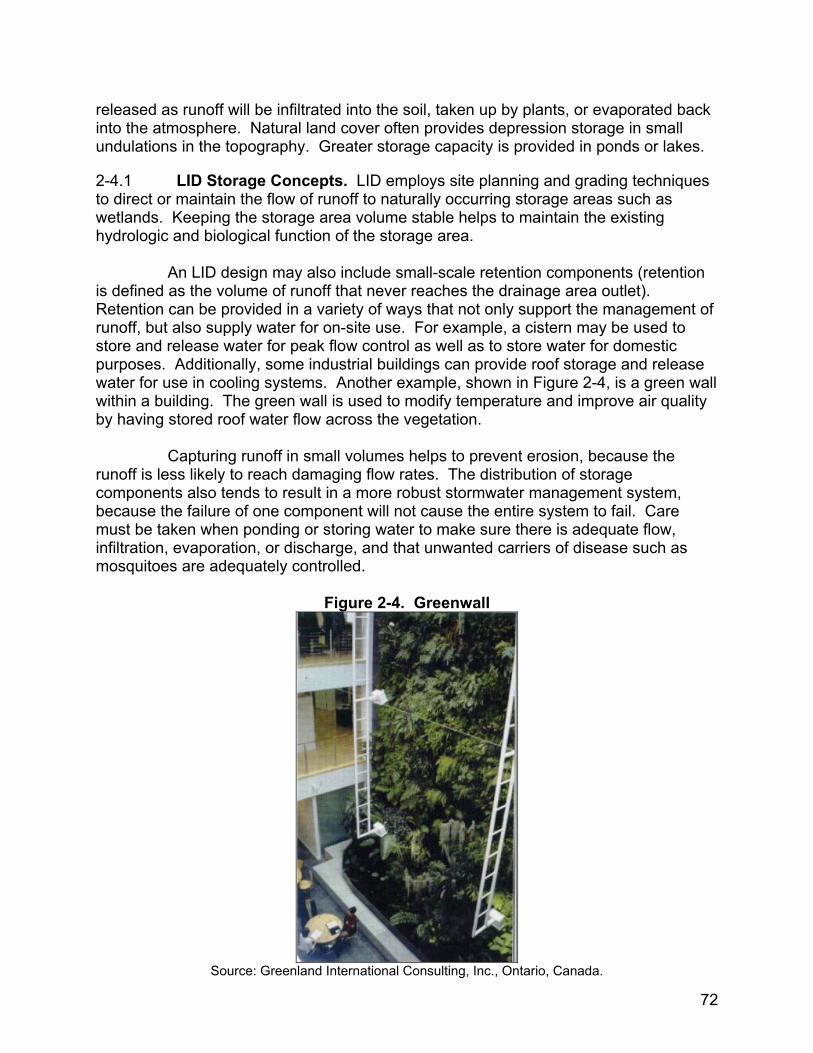
2-4.1 LID Storage Concepts. LID employs site planning and grading techniques to direct or maintain the flow of runoff to naturally occurring storage areas such as wetlands. Keeping the storage area volume stable helps to maintain the existing hydrologic and biological function of the storage area. An LID design may also include small-scale retention components (retention is defined as the volume of runoff that never reaches the drainage area outlet). Retention can be provided in a variety of ways that not only support the management of runoff, but also supply water for on-site use. For example, a cistern may be used to store and release water for peak flow control as well as to store water for domestic purposes. Additionally, some industrial buildings can provide roof storage and release water for use in cooling systems. Another example, shown in Figure 2-4, is a green wall within a building. The green wall is used to modify temperature and improve air quality by having stored roof water flow across the vegetation. Capturing runoff in small volumes helps to prevent erosion, because the runoff is less likely to reach damaging flow rates. The distribution of storage components also tends to result in a more robust stormwater management system, because the failure of one component will not cause the entire system to fail. Care must be taken when ponding or storing water to make sure there is adequate flow, infiltration, evaporation, or discharge, and that unwanted carriers of disease such as mosquitoes are adequately controlled.
Figure 2-4. Greenwall
Source: Greenland International Consulting, Inc., Ontario, Canada.
72
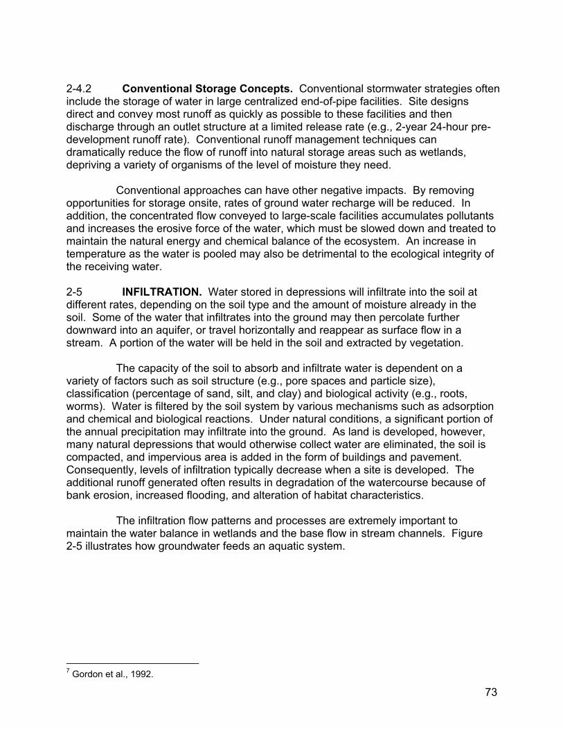
2-4.2 Conventional Storage Concepts. Conventional stormwater strategies often include the storage of water in large centralized end-of-pipe facilities. Site designs direct and convey most runoff as quickly as possible to these facilities and then discharge through an outlet structure at a limited release rate (e.g., 2-year 24-hour pre-development runoff rate). Conventional runoff management techniques can dramatically reduce the flow of runoff into natural storage areas such as wetlands, depriving a variety of organisms of the level of moisture they need. Conventional approaches can have other negative impacts. By removing opportunities for storage onsite, rates of ground water recharge will be reduced. In addition, the concentrated flow conveyed to large-scale facilities accumulates pollutants and increases the erosive force of the water, which must be slowed down and treated to maintain the natural energy and chemical balance of the ecosystem. An increase in temperature as the water is pooled may also be detrimental to the ecological integrity of the receiving water. 2-5 INFILTRATION. Water stored in depressions will infiltrate into the soil at different rates, depending on the soil type and the amount of moisture already in the soil. Some of the water that infiltrates into the ground may then percolate further downward into an aquifer, or travel horizontally and reappear as surface flow in a stream. A portion of the water will be held in the soil and extracted by vegetation. The capacity of the soil to absorb and infiltrate water is dependent on a variety of factors such as soil structure (e.g., pore spaces and particle size), classification (percentage of sand, silt, and clay) and biological activity (e.g., roots, worms). Water is filtered by the soil system by various mechanisms such as adsorption and chemical and biological reactions. Under natural conditions, a significant portion of the annual precipitation may infiltrate into the ground. As land is developed, however, many natural depressions that would otherwise collect water are eliminated, the soil is compacted, and impervious area is added in the form of buildings and pavement. Consequently, levels of infiltration typically decrease when a site is developed. The additional runoff generated often results in degradation of the watercourse because of bank erosion, increased flooding, and alteration of habitat characteristics. The infiltration flow patterns and processes are extremely important to maintain the water balance in wetlands and the base flow in stream channels. Figure 2-5 illustrates how groundwater feeds an aquatic system.
7 Gordon et al., 1992.
73
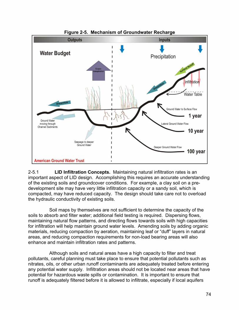
Figure 2-5. Mechanism of Groundwater Recharge
2-5.1 LID Infiltration Concepts. Maintaining natural infiltration rates is an important aspect of LID design. Accomplishing this requires an accurate understanding of the existing soils and groundcover conditions. For example, a clay soil on a pre-development site may have very little infiltration capacity or a sandy soil, which is compacted, may have reduced capacity. The design should take care not to overload the hydraulic conductivity of existing soils. Soil maps by themselves are not sufficient to determine the capacity of the soils to absorb and filter water; additional field testing is required. Dispersing flows, maintaining natural flow patterns, and directing flows towards soils with high capacities for infiltration will help maintain ground water levels. Amending soils by adding organic materials, reducing compaction by aeration, maintaining leaf or “duff” layers in natural areas, and reducing compaction requirements for non-load bearing areas will also enhance and maintain infiltration rates and patterns. Although soils and natural areas have a high capacity to filter and treat pollutants, careful planning must take place to ensure that potential pollutants such as nitrates, oils, or other urban runoff contaminants are adequately treated before entering any potential water supply. Infiltration areas should not be located near areas that have potential for hazardous waste spills or contamination. It is important to ensure that runoff is adequately filtered before it is allowed to infiltrate, especially if local aquifers
74
are particularly shallow. In cases where the water table is very high, it is often advisable to avoid infiltration altogether. 2-5.2 Conventional Infiltration Concepts. Conventional approaches concentrate on the infiltration capacity of a single end-of-pipe management facility such as a pond. Infiltration potential elsewhere on the site is often discounted or only analyzed for its effect on the flow of runoff into the facility. The conventional infiltration objective is to concentrate flows in one area and then utilize the infiltration capacity of the natural soil or conduits such as gravel. Natural groundwater flow patterns and recharge are often not considered. Conventional approaches may result in the elimination of critical volumes of flows to sensitive areas such as wetlands. Additionally, in many urban areas, the high loads of fine sediments to centralized facilities and the impacts of construction compaction can severely limit the infiltration capacity of the facility. 2-6 EVAPOTRANSPIRATION. Evapotranspiration is the loss of water from the ground by evaporation and transpiration. Evaporation is the return of moisture to the atmosphere from depressions, pond areas, or other surfaces. Transpiration is the return of water to the atmosphere through plants; moisture is absorbed by the roots and released through the leaves. The rate of evapotranspiration is dependent on air temperature, humidity, wind speed, sunlight intensity, vegetation type, and soil conditions. 2-6.1 LID Evapotranspiration Concepts. LID designs use open areas and vegetation to promote evapotranspiration. Larger areas used for evaporation, such as ponds, should have a flow regime that controls mosquito breeding. LID designs should not pond water for more than 72 hours as it may provide an opportunity for mosquitoes to breed. By keeping surface areas small and shallow, water can quickly evaporate and pollutants volatilize through plant uptake or evaporation. LID designs also employ the capacity of vegetated areas to absorb, process, volatilize, and treat non-point source pollution as well as atmospheric pollution. Interception by leaves can significantly reduce the requirement for storage and infiltration. A mature canopy can intercept a significant number of small-volume, frequently occurring storms, absorbing precipitation into the plant leaves or evaporating precipitation from the leaf surface.8 Additionally, uptake of soil moisture by plants helps to maintain the soil’s capacity to absorb rainfall. 2-6.2 Conventional Evaporation Concepts. Conventional stormwater approaches are based on peak flow control over a short duration (usually 24 hours or less). For these single event designs, the evaporation process is often discounted or not considered.
8 Sanders, 1986.
75
CHAPTER 3
LID DESIGN GOALS AND OBJECTIVES
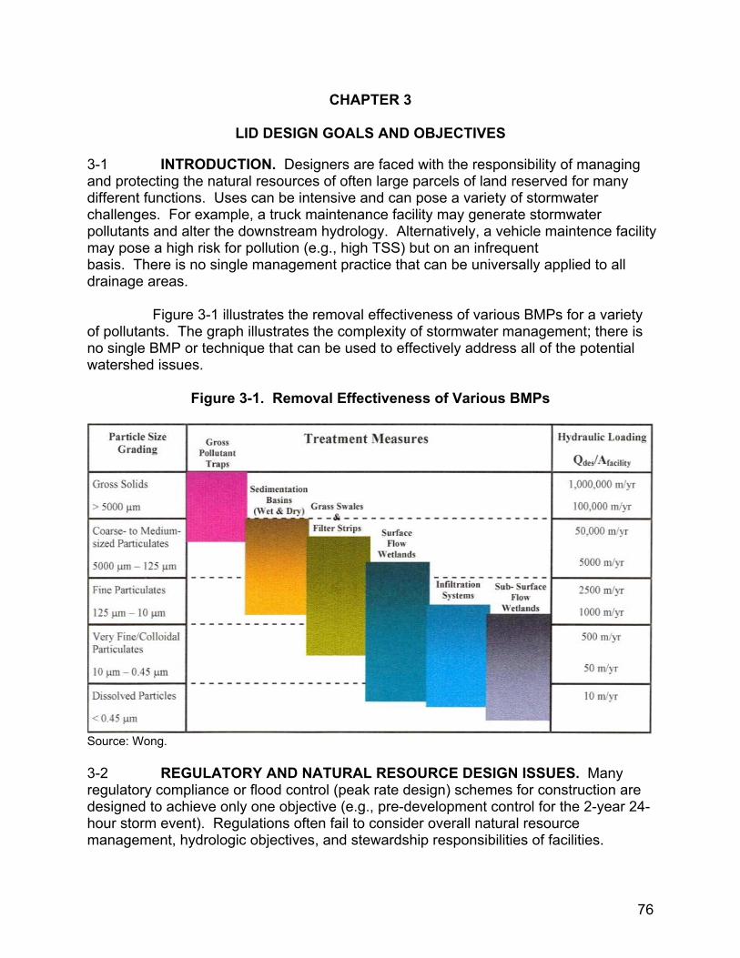
3-1 INTRODUCTION. Designers are faced with the responsibility of managing and protecting the natural resources of often large parcels of land reserved for many different functions. Uses can be intensive and can pose a variety of stormwater challenges. For example, a truck maintenance facility may generate stormwater pollutants and alter the downstream hydrology. Alternatively, a vehicle maintence facilitymay pose a high risk for pollution (e.g., high TSS) but on an infrequent basis. There is no single management practice that can be universally applied to all drainage areas. Figure 3-1 illustrates the removal effectiveness of various BMPs for a variety of pollutants. The graph illustrates the complexity of stormwater management; there is no single BMP or technique that can be used to effectively address all of the potential watershed issues.
Figure 3-1. Removal Effectiveness of Various BMPs
Source: Wong.
3-2 REGULATORY AND NATURAL RESOURCE DESIGN ISSUES. Many regulatory compliance or flood control (peak rate design) schemes for construction are designed to achieve only one objective (e.g., pre-development control for the 2-year 24-hour storm event). Regulations often fail to consider overall natural resource management, hydrologic objectives, and stewardship responsibilities of facilities.
76
Budget constraints often limit construction funding to that necessary for conveyance or flood control requirements. The limited framework may create situations where regulatory requirements are met but the design results in degradation of the natural resources. LID principles use hydrology as the integrating framework of design, and protect the overall ecology of the watershed. LID allows facilities to meet the regulatory requirement for flood control (by storing and infiltrating a sufficient volume) while sufficiently filtering targeted pollutants through natural and man-made systems. 3-3 FUNDAMENTAL SITE PLANNING CONCEPTS. The goal of LID site planning is to allow for full development and function of the intended site activity while maintaining the site’s essential natural or existing hydrologic function. The LID site design process is sequential and iterative, and embraces the following five concepts:9
Hydrology is the Integrating Framework for the Design
Distribute Controls through Micromanagement
Stormwater is Controlled at the Source
Utilize Non-structural Systems Where Possible
Create Multifunctional Landscape, Buildings and Infrastructures
3-3.1 Hydrology is the Integrating Framework for the Design. LID designs have the goal of mimicking the natural site drainage processes and functions. Techniques are used to modify hydrologic processes, such as infiltration or storage, to meet the specific water quality, water quantity, and natural resource objectives. LID designs create an effective drainage process for stormwater on the site. A stormwater management system will come closest to mimicking natural flow patterns when storage and infiltration components are distributed across the site. 3-3.2 Distribute Controls Through Micromanagement. In order to emulate natural processes, it is imperative to view the site as a series of interconnected small- scale design controls. Such a structure creates opportunities for redundancy in treatment and control, the development of a “treatment train” for water quality control, and the opportunity to strategically locate LID components. 3-3.3 Stormwater is Controlled at the Source. Controlling and treating runoff as it is being generated reduces or eliminates the risks associated with transporting pollutants further downstream through pipes and channels. Management of stormwater at the source is especially valuable if remediation is required, such as in the case of an accidental spill of pollutants, because the problem can be easily isolated or the treatment system adjusted. 3-3.4 Incorporate Non-Structural Systems. LID designs recognize the potential of natural systems to intercept and filter pollutants. Phytoremediation techniques that
9 PGDER, 2000a.
77
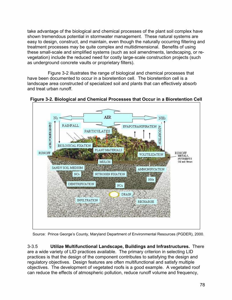
take advantage of the biological and chemical processes of the plant soil complex have shown tremendous potential in stormwater management. These natural systems are easy to design, construct, and maintain, even though the naturally occurring filtering and treatment processes may be quite complex and multidimensional. Benefits of using these small-scale and simplified systems (such as soil amendments, landscaping, or re-vegetation) include the reduced need for costly large-scale construction projects (such as underground concrete vaults or proprietary filters). Figure 3-2 illustrates the range of biological and chemical processes that have been documented to occur in a bioretention cell. The bioretention cell is a landscape area constructed of specialized soil and plants that can effectively absorb and treat urban runoff.
Figure 3-2. Biological and Chemical Processes that Occur in a Bioretention Cell
Source: Prince George’s County, Maryland Department of Environmental Resources (PGDER), 2000.
3-3.5 Utilize Multifunctional Landscape, Buildings and Infrastructures. There are a wide variety of LID practices available. The primary criterion in selecting LID practices is that the design of the component contributes to satisfying the design and regulatory objectives. Design features are often multifunctional and satisfy multiple objectives. The development of vegetated roofs is a good example. A vegetated roof can reduce the effects of atmospheric pollution, reduce runoff volume and frequency,
78
reduce energy costs, create an attractive environment, and have reduced replacement and maintenance, and longer life cycle costs. There are many types of vegetated roofs that can be developed including pre-made grids, or cells, or whole systems. 3-4 LID MANAGEMENT AND DESIGN STRATEGIES. LID design is an iterative process that requires a thorough understanding of the management objectives, a detailed understanding of the physical and natural resources of the site, a conceptual site design that can be refined to achieve the goal of a hydrologically functional landscape, and a long-term maintenance plan. 3-4.1 LID Site Planning Components. This section presents the aims of LID site planning and, in light of existing site development requirements, describes how LID site design can be best approached to manage runoff. 3-4.1.1 Hydrologic and Hydraulic Objectives. The purpose of LID site planning is to significantly maintain the predevelopment runoff volume and flow rate. Ideally, and where site conditions allow, this will be achieved in a way that replicates the site’s predevelopment hydrologic functions. Sites that are characterized before development by porous soils, substantial vegetative ground cover, and ungraded topography naturally perform several important hydrologic functions:
Facilitate infiltration, evapotranspiration, retention and detention of runoff
Limit runoff flow rates because of ground surface roughness
Help control water quality through surface and subsurface filtering of pollutants and sediments
On a developed site, these hydrologic functions can continue to be provided by the preservation of natural features or construction of a variety of man-made feature.Taken together, the utilization of these features comprises a distrubuted source contolstrategy that is designed to not only meet regulatory requirements but also to provide superior natural resource protection. Maintaining areas with high soil porosity, vegetative ground cover, and shallow ponding will help meet the following objectives:
Flood control. Facilitating the infiltration of runoff and decreasing overland flow rates reduces the risk of flooding in receiving waters. To meet design objectives and regulatory requirements completely, supplemental controls may still be required.
Volume Control. The overall volume of runoff that leaves a site is kept as close as possible to predevelopment levels.
Peak Control. The peak runoff rate does not increase above predevelopment levels, and the entire runoff hydrograph emulates the predevelopment hydrograph.
79
Filtering and Treatment of Pollutants. Runoff is directed across vegetated areas and through porous media to provide significant reductions in the concentration of sediments and pollutants in the water.
Groundwater Recharge. Infiltration is expedited to enhance groundwater recharge rates and help sustain base flows in nearby streams.
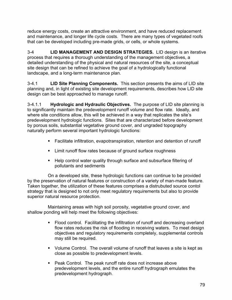
3-4.2 LID Design Approach. The LID approach to site design seeks to maintain or restore the hydrologic impacts of site development using a combination of runoff management strategies, site design techniques, and distributed source controls (IMPs). LID design requires that site plans address the overall natural resource and compliance issues within the watershed. The long-term success of this approach requires an understanding of the maintenance requirements and life-cycle effectiveness of the LID practices and the development of an appropriate maintenance and pollution prevention plan for the facility. While the influence of each of the components of the design process varies from site to site, a general process has been developed to ensure that all of these components are considered. Although the preference in LID design is to reduce the hydrologic impacts on the site and to retain naturally effective hydrologic features, it is recognized that significant impacts may occur because of the nature of these activities. When compensating features are required, LID emphasizes the use of integrated site features that control runoff as close as possible to the source, rather than transporting pollutants and attempting to mitigate for lost functions elsewhere. Figure 3-3 illustrates the general flow of the design process.
Figure 3-3. LID Design Process
Conserve Natural Areas ↓
Minimize Development Impacts ↓
Maintain Watershed Timing ↓
Provide IMPs ↓
Manage for Pollution Prevention
Source: PGDER. This approach is often an iterative process that requires several attempts to balance all of the design components in the most economical and environmentally effective way. Described below are the individual design components. 3-4.2.1 Conservation of Natural Areas. LID is a stormwater management strategy that addresses the overall regulatory and resource protection goals of a site in a watershed context. Because development typically occurs incrementally, this approach will allow for adjustments or modifications to site design strategies and techniques to
80
reflect dynamic resource protection and regulatory issues. Communities often have extensive watershed management and natural resources conservation goals; master plans identify sensitive environmental areas and preservation areas such as wetlands, mature woods, and habitats. The LID site design should address any potential impacts to these areas and encourage conservation of these areas within the site. Examples of conservation include:
Preserving a forest corridor that connects with an existing stream valley
Maintaining flow volume and discharge rates to offsite wetlands
Incorporating buffers around sensitive habitat areas
3-4.3 Minimization of Development Impacts. Within the portion of the site selected for the placement of roads, buildings, and other development activities, minimal disturbance techniques (site fingerprinting) can be used to avoid soil compaction, retain mature trees, and limit the environmental impact of staging areas. Examples of minimal disturbance techniques include:
Delineating and flagging the smallest site disturbance area possible
Minimizing the size of construction impacts or offsite easements and property acquisition
Minimizing the size of material storage areas during and after construction
Maintaining flow patterns
3-4.4 Control of Watershed Timing and Runoff Patterns. Maintaining the site’s natural runoff control areas and restricting building over the site’s more pervious soils will help keep the infiltration capacity of the site close to predevelopment levels. Maintaining the watershed timing of a site is also important. The cumulative effects of decreasing the post-development watershed times of concentration of several sites can have a significant impact on downstream habitat. It is also desirable to maintain natural vegetation in steeply sloped areas and to retain natural drainage divides. This will encourage dispersed flow paths and, consequently, help reduce the development of channels that lead to erosion and flooding problems. Adequate drainage from buildings, walkways, and roads must be provided. Traditional designs often create a drainage system that has the effect of increasing the rate at which runoff moves into receiving waters during storm events. In turn, this produces a higher volume of runoff, a higher peak rate of flow, and an earlier runoff event than would occur under less developed conditions. The opportunity for groundwater recharge is eliminated, because infiltration into swales and grassed areas cannot effectively occur if runoff passes through quickly. The overall grading objective for LID is to provide a surface landform that will distribute flows in a shallow and slow moving pattern toward areas where the infiltration
81

capacity is highest. Examples of LID techniques to control rates of runoff and watershed timing include:
Use flatter rather than steeper grades, provided that adequate drainage for buildings and traffic is maintained
Reduce the height of slopes, to prevent runoff from gaining speed as it moves downhill
Where flow begins to accumulate, increase the length of flow paths, diverting and redirecting the flow, preferably with vegetated features
Minimize use of curb and gutter systems and piped drainage systems in favor of grassed swales
Minimize the amount of impervious area used for pavement
Disconnect impervious areas by directing runoff from buildings and pavements onto lawns or other vegetated areas, keeping flow velocities at a level that will not cause erosion
Preserve naturally vegetated areas and existing topography in places where these help slow runoff and encourage infiltration
Use weirs and check dams in swales
3-4.5 Use of Integrated Management Practices (IMPs). Once all of the design strategies and techniques have been implemented, IMPs are selected to achieve the site water quality and quantity objectives. IMPs are distributed, multifunctional, small-scale controls, selected based on their ability to achieve the site design water quality and quantity objectives in a cost effective manner. IMPs are not a “one-size-fits-all” approach. For example, using amended soils to filter and store runoff may be appropriate for a rural road section with high traffic but inappropriate next to a parking area that may be subjected to compaction from overflow parking or vehicle movement. More details on IMPs and their selection are found in Chapter 8. 3-4.6 Pollution Prevention. The goal of pollution prevention is to reduce, reuse and recycle a variety of pollutants before they become environmental problems. The final step of the LID design approach is to incorporate programs that keep pollution out of runoff in the first place and, consequently, to increase the longevity of the IMPs. Reduction of fertilizer, pesticide and herbicide use and the implementation of regular street sweeping are some common pollution prevention activities.
82
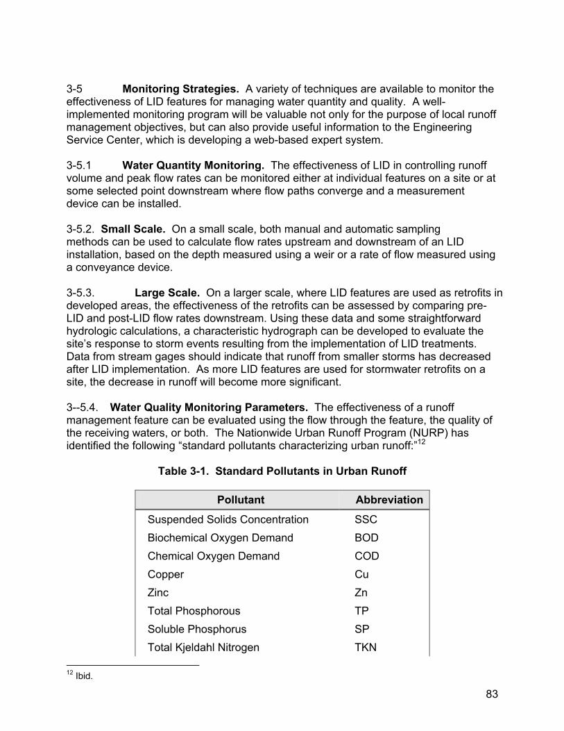
3-5 Monitoring Strategies. A variety of techniques are available to monitor the effectiveness of LID features for managing water quantity and quality. A well-implemented monitoring program will be valuable not only for the purpose of local runoff management objectives, but can also provide useful information to the Engineering Service Center, which is developing a web-based expert system. 3-5.1 Water Quantity Monitoring. The effectiveness of LID in controlling runoff volume and peak flow rates can be monitored either at individual features on a site or at some selected point downstream where flow paths converge and a measurement device can be installed. 3-5.2. Small Scale. On a small scale, both manual and automatic sampling methods can be used to calculate flow rates upstream and downstream of an LID installation, based on the depth measured using a weir or a rate of flow measured using a conveyance device. 3-5.3. Large Scale. On a larger scale, where LID features are used as retrofits in developed areas, the effectiveness of the retrofits can be assessed by comparing pre-LID and post-LID flow rates downstream. Using these data and some straightforward hydrologic calculations, a characteristic hydrograph can be developed to evaluate the site’s response to storm events resulting from the implementation of LID treatments. Data from stream gages should indicate that runoff from smaller storms has decreased after LID implementation. As more LID features are used for stormwater retrofits on a site, the decrease in runoff will become more significant. 3--5.4. Water Quality Monitoring Parameters. The effectiveness of a runoff management feature can be evaluated using the flow through the feature, the quality of the receiving waters, or both. The Nationwide Urban Runoff Program (NURP) has identified the following “standard pollutants characterizing urban runoff:”12
Table 3-1. Standard Pollutants in Urban Runoff
Pollutant Abbreviation
Suspended Solids Concentration SSC Biochemical Oxygen Demand BOD Chemical Oxygen Demand COD Copper Cu Zinc Zn Total Phosphorous TP Soluble Phosphorus SP Total Kjeldahl Nitrogen TKN
12 Ibid.
83

3-5.5. Sampling Protocols. Monitoring protocols vary depending on the expected chemical composition of the runoff, the pollutant of concern, the desirability of monitoring the effectiveness of a device at a given location, and the importance of assessing water quality at points downstream. As sampling data is collected over time, trends in the water quality become apparent. Adjustments in the monitoring plan may be appropriate to ensure that across the site samples are not taken any more or less frequently than necessary to ensure that a desirable level of water quality is maintained.
84
CHAPTER 4
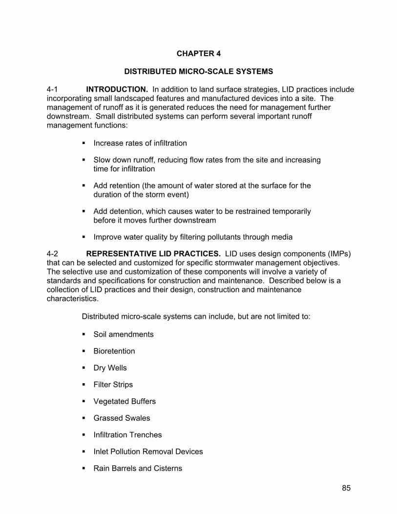
DISTRIBUTED MICRO-SCALE SYSTEMS 4-1 INTRODUCTION. In addition to land surface strategies, LID practices include incorporating small landscaped features and manufactured devices into a site. The management of runoff as it is generated reduces the need for management further downstream. Small distributed systems can perform several important runoff management functions:
Increase rates of infiltration
Slow down runoff, reducing flow rates from the site and increasing time for infiltration
Add retention (the amount of water stored at the surface for the duration of the storm event)
Add detention, which causes water to be restrained temporarily before it moves further downstream
Improve water quality by filtering pollutants through media
4-2 REPRESENTATIVE LID PRACTICES. LID uses design components (IMPs) that can be selected and customized for specific stormwater management objectives. The selective use and customization of these components will involve a variety of standards and specifications for construction and maintenance. Described below is a collection of LID practices and their design, construction and maintenance characteristics. Distributed micro-scale systems can include, but are not limited to:
Soil amendments
Bioretention
Dry Wells
Filter Strips
Vegetated Buffers
Grassed Swales
Infiltration Trenches
Inlet Pollution Removal Devices
Rain Barrels and Cisterns
85
Tree Box Filters
Vegetated Roofs
Permeable Pavers
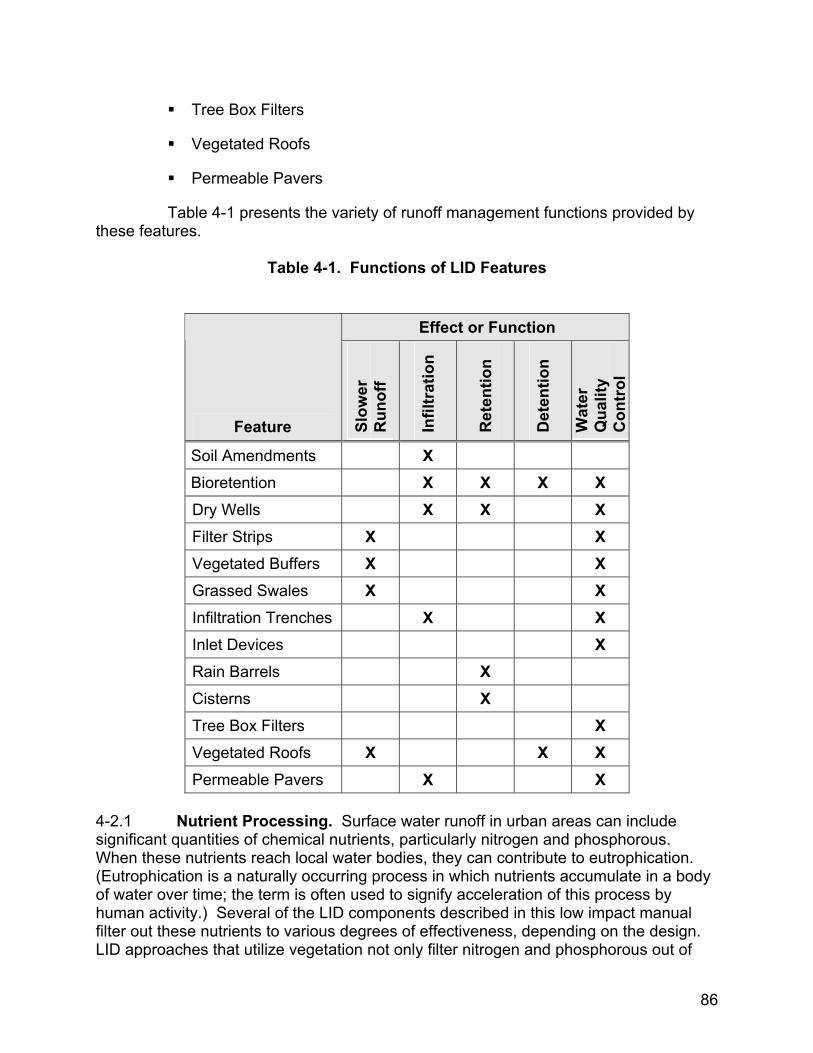
Table 4-1 presents the variety of runoff management functions provided by these features.
Table 4-1. Functions of LID Features
Effect or Function
Feature Slow
er
Run
off
Infil
trat
ion
Ret
entio
n
Det
entio
n
Wat
er
Qua
lity
Con
trol
Soil Amendments X Bioretention X X X X Dry Wells X X X Filter Strips X X Vegetated Buffers X X Grassed Swales X X Infiltration Trenches X X Inlet Devices X Rain Barrels X Cisterns X Tree Box Filters X Vegetated Roofs X X X Permeable Pavers X X
4-2.1 Nutrient Processing. Surface water runoff in urban areas can include significant quantities of chemical nutrients, particularly nitrogen and phosphorous. When these nutrients reach local water bodies, they can contribute to eutrophication. (Eutrophication is a naturally occurring process in which nutrients accumulate in a body of water over time; the term is often used to signify acceleration of this process by human activity.) Several of the LID components described in this low impact manual filter out these nutrients to various degrees of effectiveness, depending on the design. LID approaches that utilize vegetation not only filter nitrogen and phosphorous out of
86
1.
2.
3.
4.
5.
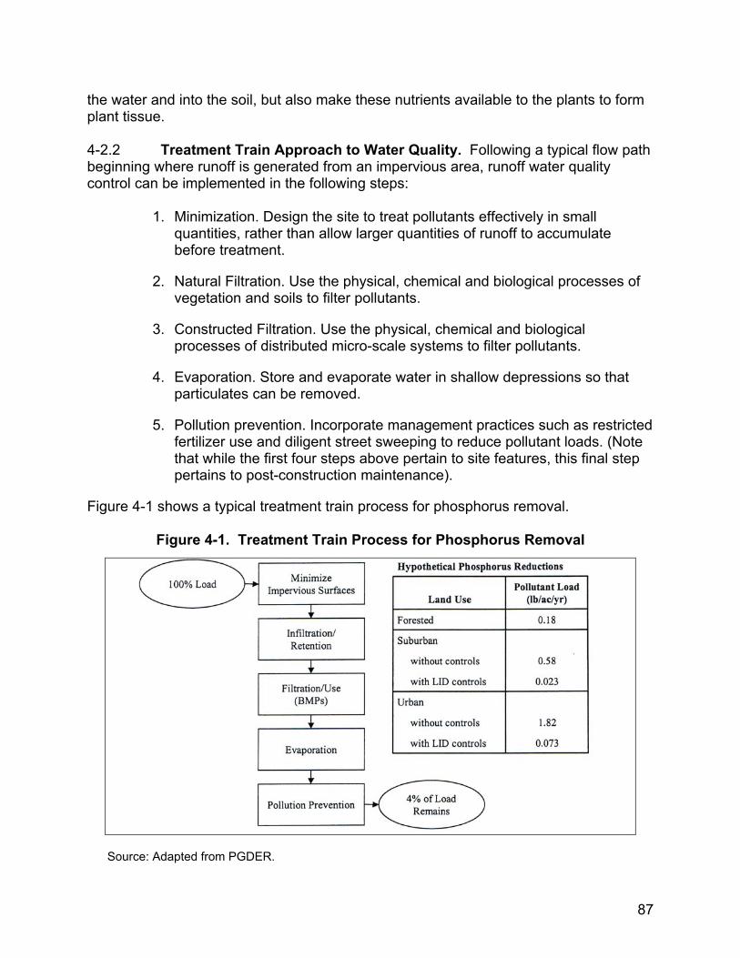
the water and into the soil, but also make these nutrients available to the plants to form plant tissue. 4-2.2 Treatment Train Approach to Water Quality. Following a typical flow path beginning where runoff is generated from an impervious area, runoff water quality control can be implemented in the following steps:
Minimization. Design the site to treat pollutants effectively in small quantities, rather than allow larger quantities of runoff to accumulate before treatment.
Natural Filtration. Use the physical, chemical and biological processes of vegetation and soils to filter pollutants.
Constructed Filtration. Use the physical, chemical and biological processes of distributed micro-scale systems to filter pollutants.
Evaporation. Store and evaporate water in shallow depressions so that particulates can be removed.
Pollution prevention. Incorporate management practices such as restricted fertilizer use and diligent street sweeping to reduce pollutant loads. (Note that while the first four steps above pertain to site features, this final step pertains to post-construction maintenance).
Figure 4-1 shows a typical treatment train process for phosphorus removal.
Figure 4-1. Treatment Train Process for Phosphorus Removal
Source: Adapted from PGDER.
87

4-2.3 Energy Processing. LID features that incorporate vegetation can help to moderate high ambient air temperatures. Even on a small scale, vegetation will have a local cooling effect. Vegetation can be selected and placed to improve shading, or to provide a buffer against winds. Using vegetated roofs can result in significant energy savings in the operation of a building’s air conditioning system. 4-2.4 Multifunctional Infrastructure and Buildings. Some LID features can simultaneously provide a variety of hydrologic functions. A bioretention area, for example, can filter runoff for quality control, detain it, and infiltrate the stormwater into the ground. Similarly, vegetated roofs on buildings reduce runoff, reduce pollutants in both the water and the air, and moderate the internal building temperature. 4-2.5 Ancillary Benefits. LID runoff management strategies can also contribute to an aesthetically pleasing landscape, increasing the value of the property where these strategies are employed. In a variety of completed projects, micro-scale runoff management features have provided architectural interest in various forms, such as employing berms in otherwise open spaces, rainwater channels along pedestrian streets, fountains fed by intermittent stormwater, and bioretention areas that attractively subdivide large parking lots. The visibility of these features also provides opportunities for citizens and property owners to become more aware of the importance of stormwater in our urban environment.
88

CHAPTER5 5
COMPARISON OF LID TO CONVENTIONAL PRACTICES 5-1 INTRODUCTION. Conventional stormwater management practices focus on providing an efficient site drainage system that rapidly conveys runoff away from buildings and off pavement, and then attenuates the peak runoff rate at a large stormwater management facility downstream. In contrast, LID provides runoff management as far upstream as possible – where it originates – and if necessary, also at multiple points along each flow path. LID and conventional practices can be further compared in a variety of ways: 5-2 COMPLIANCE VS. WATER RESOURCE OBJECTIVES. While conventional stormwater management is primarily concerned with attenuating the peak runoff rate from a developed site, the principal goal of LID is to ensure maximum protection of the ecological integrity of the receiving waters by maintaining the watershed’s hydrologic regime. 5-3 WATER QUANTITY CONTROL. Conventional drainage practices effectively reduce peak runoff rates, but do not reduce runoff volume. Instead, conventional drainage practices increase runoff volume by not mitigating the effects of the increased impervious area. The LID features that facilitate infiltration, by comparison, help to reduce runoff volume directly. Runoff volume reductions using LID features can be significant when infiltration is increased over a sufficiently large area. Conventional drainage reduces the amount of subsurface water available to the base flow in nearby streams. LID features that enhance infiltration can have the beneficial effect of helping to maintain those base flows. Other LID features allow the strategic use of stormwater on-site, while conventional drainage designs focus on moving the water rapidly off-site. A conventional stormwater management facility has a limited ability to manage water quality because it is limited to removal by settlement of pollutants. An LID approach, by comparison, takes advantage of a variety of mechanisms that filter water either overland or via infiltration to the subsurface. 5-4 CONSTRUCTION COSTS. Construction costs for LID will vary depending on the characteristics of predevelopment site features, the density of development, the particular LID features selected, and their size and design. For example, the cost of bioretention areas will be a function of the depth of porous backfill and the degree to which underdrains are utilized. Case studies for commercial, townhouse, and detached home residential areas in Prince George’s County, Maryland, have demonstrated that LID site design costs can compare favorably with conventional approaches.17 Costs are not simple to generalize. The scale of the project, availability of materials, and skills and training of staff are all factors. IMPs involving landscaped areas are often simple to maintain because work can often be performed by landscaping crews or residents; hard
17 Greenhorne and O’Mara, 1998.
89
structures, such as permeable paving systems with underdrains, may require more specialized maintenance. 5-5 OPERATION AND MAINTENANCE. Regular inspections of conventional stormwater management facilities are required to ensure that the storage volume has not been reduced by sediment, outlets are not clogged by debris, and structural features maintain their integrity. For a site designed using an LID approach, runoff management features will tend to be higher in number and several types of features (e.g., bioretention areas) need to be maintained by the property owner. The maintenance of these LID features is straightforward and can easily be performed as part of regular landscaping. Other LID features typically employed along public streets (such as tree filters) require more specialized maintenance to ensure that the filter media are not clogged and toxic materials such as heavy metals do not accumulate to a level at which they become a health hazard. 5-6 RETROFIT POTENTIAL. Retrofitting an already developed area with a conventional stormwater management system requires a considerable amount of space and is likely to involve extensive site disturbance. The LID micro-scale systems listed in the previous chapter require less site disturbance for each installment. LID retrofits may be much easier than conventional retrofits on sites where intensive development has already occurred. Locating sites for installing small devices is far easier than finding a large site for a stormwater management facility. LID retrofits can be customized to pollutant loads, allowing more complete control over pollutant removal.
90
CHAPTER 6
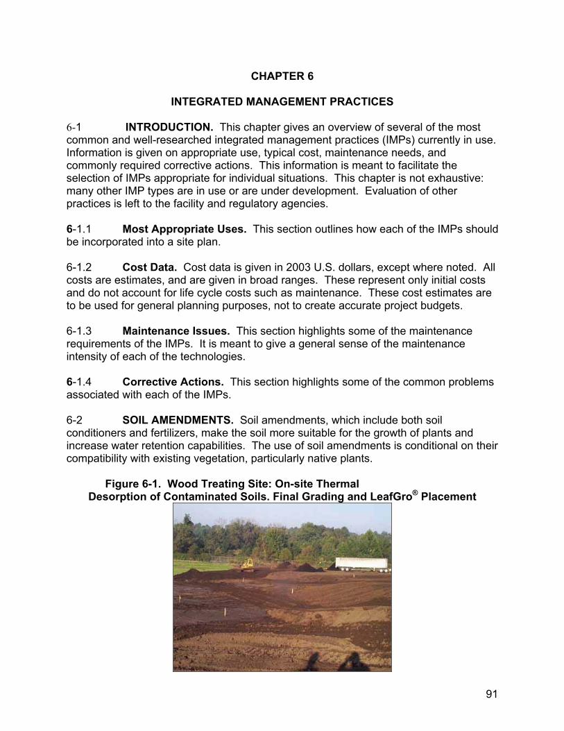
INTEGRATED MANAGEMENT PRACTICES 6-1 INTRODUCTION. This chapter gives an overview of several of the most common and well-researched integrated management practices (IMPs) currently in use. Information is given on appropriate use, typical cost, maintenance needs, and commonly required corrective actions. This information is meant to facilitate the selection of IMPs appropriate for individual situations. This chapter is not exhaustive: many other IMP types are in use or are under development. Evaluation of other practices is left to the facility and regulatory agencies. 6-1.1 Most Appropriate Uses. This section outlines how each of the IMPs should be incorporated into a site plan. 6-1.2 Cost Data. Cost data is given in 2003 U.S. dollars, except where noted. All costs are estimates, and are given in broad ranges. These represent only initial costs and do not account for life cycle costs such as maintenance. These cost estimates are to be used for general planning purposes, not to create accurate project budgets. 6-1.3 Maintenance Issues. This section highlights some of the maintenance requirements of the IMPs. It is meant to give a general sense of the maintenance intensity of each of the technologies. 6-1.4 Corrective Actions. This section highlights some of the common problems associated with each of the IMPs. 6-2 SOIL AMENDMENTS. Soil amendments, which include both soil conditioners and fertilizers, make the soil more suitable for the growth of plants and increase water retention capabilities. The use of soil amendments is conditional on their compatibility with existing vegetation, particularly native plants.
Figure 6-1. Wood Treating Site: On-site Thermal
Desorption of Contaminated Soils. Final Grading and LeafGro® Placement
91
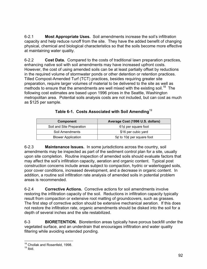
6-2.1 Most Appropriate Uses. Soil amendments increase the soil’s infiltration capacity and help reduce runoff from the site. They have the added benefit of changing physical, chemical and biological characteristics so that the soils become more effective at maintaining water quality. 6-2.2 Cost Data. Compared to the costs of traditional lawn preparation practices, enhancing native soil with soil amendments may have increased upfront costs. However, the cost of using amended soils can be at least partially offset by reductions in the required volume of stormwater ponds or other detention or retention practices. Tilled Compost-Amended Turf (TCT) practices, besides requiring greater site preparation, require larger volumes of material to be delivered to the site as well as methods to ensure that the amendments are well mixed with the existing soil.18 The following cost estimates are based upon 1996 prices in the Seattle, Washington metropolitan area. Potential soils analysis costs are not included, but can cost as much as $125 per sample.
Table 6-1. Costs Associated with Soil Amending19
Component Average Cost (1996 U.S. dollars) Soil and Site Preparation 61¢ per square foot
Soil Amendments $16 per cubic yard Blower Application 5¢ to 10¢ per square foot
6-2.3 Maintenance Issues. In some jurisdictions across the country, soil amendments may be inspected as part of the sediment control plan for a site, usually upon site completion. Routine inspection of amended soils should evaluate factors that may affect the soil’s infiltration capacity, aeration and organic content. Typical post construction concerns include areas subject to compaction, hydric or waterlogged soils, poor cover conditions, increased development, and a decrease in organic content. In addition, a routine soil infiltration rate analysis of amended soils in potential problem areas is recommended. 6-2.4 Corrective Actions. Corrective actions for soil amendments involve restoring the infiltration capacity of the soil. Reductions in infiltration capacity typically result from compaction or extensive root matting of groundcovers, such as grasses. The first step of corrective action should be extensive mechanical aeration. If this does not restore the infiltration rate, organic amendments should be disked into the soil for a depth of several inches and the site restabilized. 6-3 BIORETENTION. Bioretention areas typically have porous backfill under the vegetated surface, and an underdrain that encourages infiltration and water quality filtering while avoiding extended ponding.
18 Chollak and Rosenfeld, 1998. 19 Ibid.
92
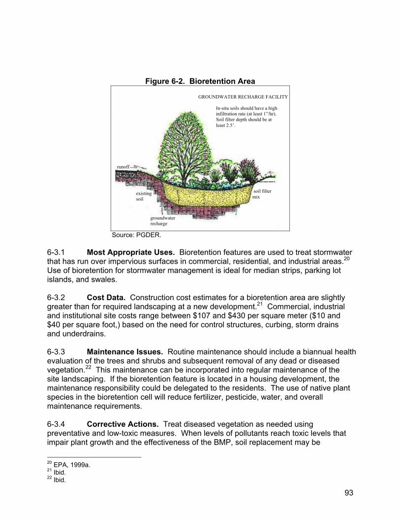
Figure 6-2. Bioretention Area
GROUNDWATER RECHARGE FACILITY
In-situ soils should have a high infiltration rate (at least 1”/hr). Soil filter depth should be at least 2.5’.
r f
So 6-3.1 Most Apthat has run over impUse of bioretention fislands, and swales. 6-3.2 Cost Datgreater than for requand institutional site $40 per square foot,and underdrains. 6-3.3 Maintenaevaluation of the treevegetation.22 This msite landscaping. If tmaintenance responspecies in the bioretemaintenance require 6-3.4 Correctivpreventative and lowimpair plant growth a
20 EPA, 1999a. 21 Ibid. 22 Ibid.
unof
soil filter mix
urce:
proprervio
or sto
a. Coired lacosts) base
nce s andaintehe biosibilityntion
ment
e Ac-toxicnd th
existing soil
gr
PGDE
iateus srmw
nstnds
rangd on
Issu shr
nancrete cou cels.
tion mee ef
roundwaterecharge
R.
Uses. Bioretention features are used to treat stormwater urfaces in commercial, residential, and industrial areas.20 ater management is ideal for median strips, parking lot
ruction cost estimates for a bioretention area are slightly caping at a new development.21 Commercial, industrial e between $107 and $430 per square meter ($10 and the need for control structures, curbing, storm drains
es. Routine maintenance should include a biannual health ubs and subsequent removal of any dead or diseased e can be incorporated into regular maintenance of the ntion feature is located in a housing development, the ld be delegated to the residents. The use of native plant
l will reduce fertilizer, pesticide, water, and overall
s. Treat diseased vegetation as needed using asures. When levels of pollutants reach toxic levels that fectiveness of the BMP, soil replacement may be
93
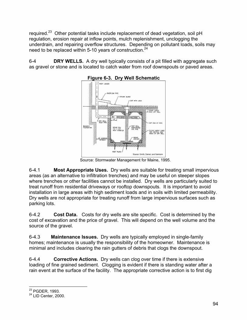
required.23 Other potential tasks include replacement of dead vegetation, soil pH regulation, erosion repair at inflow points, mulch replenishment, unclogging the underdrain, and repairing overflow structures. Depending on pollutant loads, soils may need to be replaced within 5-10 years of construction.24 6-4 DRY WELLS. A dry well typically consists of a pit filled with aggregate such as gravel or stone and is located to catch water from roof downspouts or paved areas.
Figure 6-3. Dry Well Schematic
Source: Stormwater Management for Maine, 1995.
6-4.1 Most Appropriate Uses. Dry wells are suitable for treating small impervious areas (as an alternative to infiltration trenches) and may be useful on steeper slopes where trenches or other facilities cannot be installed. Dry wells are particularly suited to treat runoff from residential driveways or rooftop downspouts. It is important to avoid installation in large areas with high sediment loads and in soils with limited permeability. Dry wells are not appropriate for treating runoff from large impervious surfaces such as parking lots. 6-4.2 Cost Data. Costs for dry wells are site specific. Cost is determined by the cost of excavation and the price of gravel. This will depend on the well volume and the source of the gravel. 6-4.3 Maintenance Issues. Dry wells are typically employed in single-family homes; maintenance is usually the responsibility of the homeowner. Maintenance is minimal and includes clearing the rain gutters of debris that clogs the downspout. 6-4.4 Corrective Actions. Dry wells can clog over time if there is extensive loading of fine grained sediment. Clogging is evident if there is standing water after a rain event at the surface of the facility. The appropriate corrective action is to first dig
23 PGDER, 1993. 24 LID Center, 2000.
94
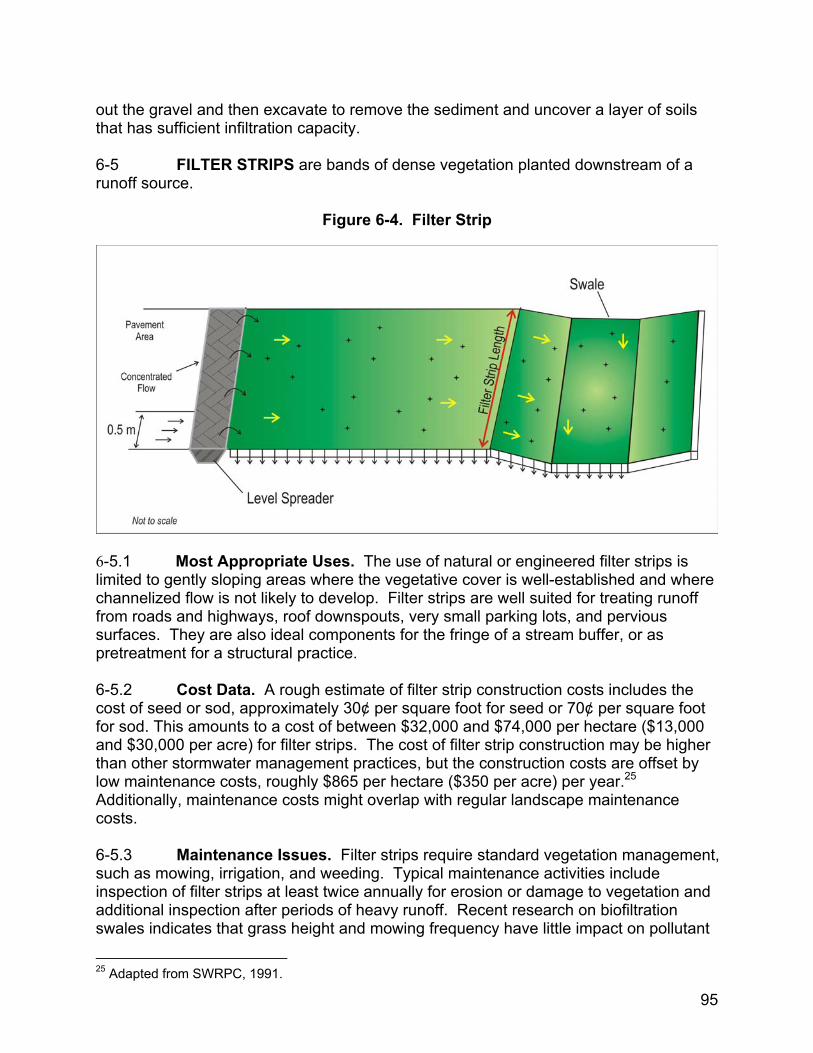
out the gravel and then excavate to remove the sediment and uncover a layer of soils that has sufficient infiltration capacity. 6-5 FILTER STRIPS are bands of dense vegetation planted downstream of a runoff source.
Figure 6-4. Filter Strip
6-5.1 Most Appropriate Uses. The use of natural or engineered filter strips is limited to gently sloping areas where the vegetative cover is well-established and where channelized flow is not likely to develop. Filter strips are well suited for treating runoff from roads and highways, roof downspouts, very small parking lots, and pervious surfaces. They are also ideal components for the fringe of a stream buffer, or as pretreatment for a structural practice. 6-5.2 Cost Data. A rough estimate of filter strip construction costs includes the cost of seed or sod, approximately 30¢ per square foot for seed or 70¢ per square foot for sod. This amounts to a cost of between $32,000 and $74,000 per hectare ($13,000 and $30,000 per acre) for filter strips. The cost of filter strip construction may be higher than other stormwater management practices, but the construction costs are offset by low maintenance costs, roughly $865 per hectare ($350 per acre) per year.25 Additionally, maintenance costs might overlap with regular landscape maintenance costs. 6-5.3 Maintenance Issues. Filter strips require standard vegetation management, such as mowing, irrigation, and weeding. Typical maintenance activities include inspection of filter strips at least twice annually for erosion or damage to vegetation and additional inspection after periods of heavy runoff. Recent research on biofiltration swales indicates that grass height and mowing frequency have little impact on pollutant
25 Adapted from SWRPC, 1991.
95
removal rates.26 Therefore, mowing may only be necessary once or twice a year for safety and aesthetics or to suppress weeds and woody vegetation. 6-5.4 Corrective Actions. Trash tends to accumulate in filter strip areas, particularly along highways. The need for litter removal should be determined through periodic inspection, but litter should always be removed prior to mowing. 6.6 VEGETATED BUFFERS. Vegetated buffers trap and filter sediments, nutrients, and chemicals from surface runoff and shallow groundwater.
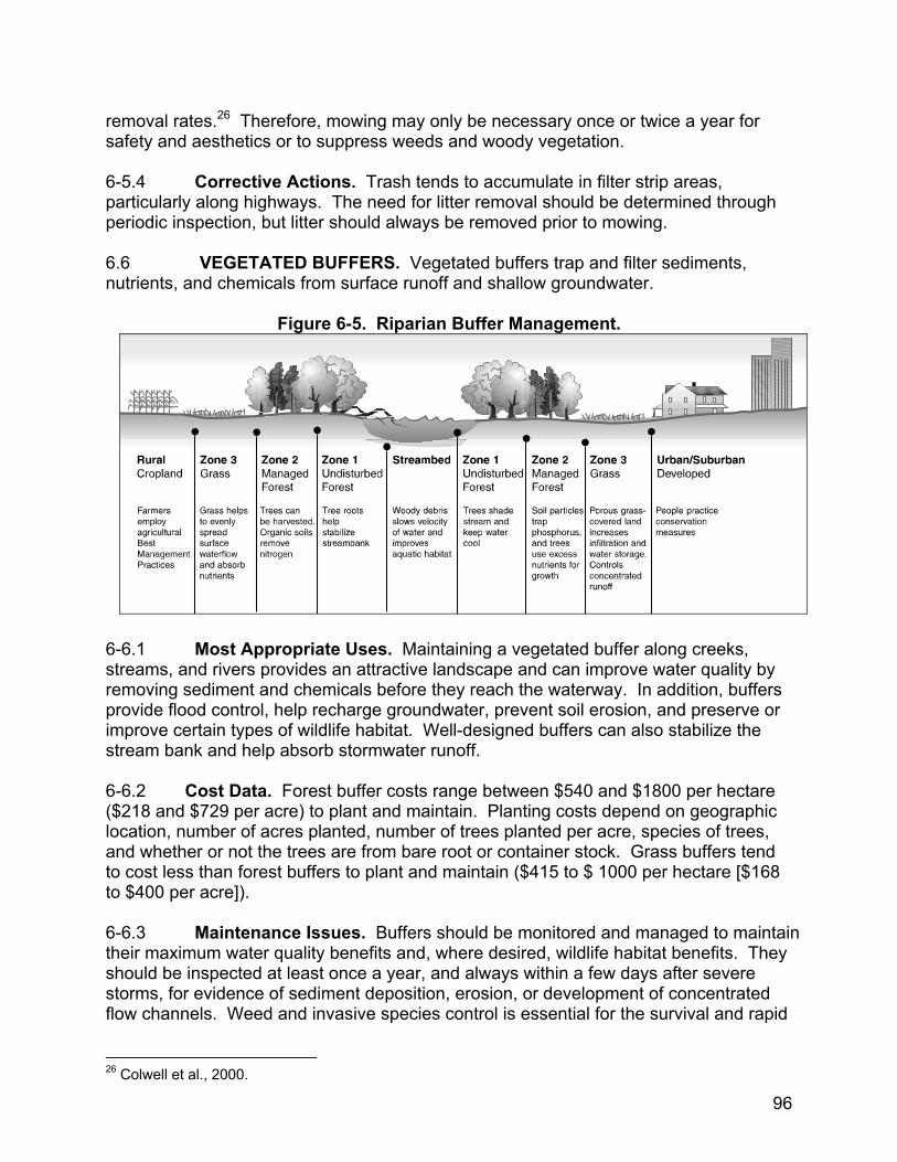
Figure 6-5. Riparian Buffer Management.
6-6.1 Most Appropriate Uses. Maintaining a vegetated buffer along creeks, streams, and rivers provides an attractive landscape and can improve water quality by removing sediment and chemicals before they reach the waterway. In addition, buffers provide flood control, help recharge groundwater, prevent soil erosion, and preserve or improve certain types of wildlife habitat. Well-designed buffers can also stabilize the stream bank and help absorb stormwater runoff. 6-6.2 Cost Data. Forest buffer costs range between $540 and $1800 per hectare ($218 and $729 per acre) to plant and maintain. Planting costs depend on geographic location, number of acres planted, number of trees planted per acre, species of trees, and whether or not the trees are from bare root or container stock. Grass buffers tend to cost less than forest buffers to plant and maintain ($415 to $ 1000 per hectare [$168 to $400 per acre]). 6-6.3 Maintenance Issues. Buffers should be monitored and managed to maintain their maximum water quality benefits and, where desired, wildlife habitat benefits. They should be inspected at least once a year, and always within a few days after severe storms, for evidence of sediment deposition, erosion, or development of concentrated flow channels. Weed and invasive species control is essential for the survival and rapid
26 Colwell et al., 2000.
96
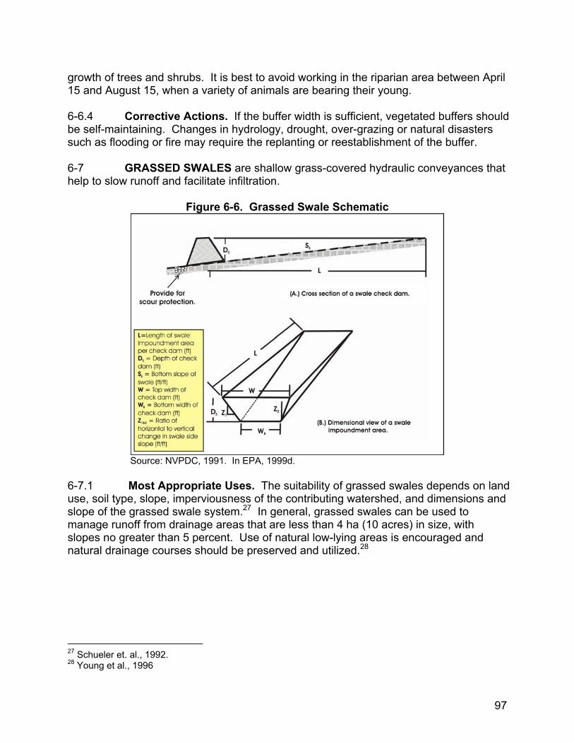
growth of trees and shrubs. It is best to avoid working in the riparian area between April 15 and August 15, when a variety of animals are bearing their young. 6-6.4 Corrective Actions. If the buffer width is sufficient, vegetated buffers should be self-maintaining. Changes in hydrology, drought, over-grazing or natural disasters such as flooding or fire may require the replanting or reestablishment of the buffer. 6-7 GRASSED SWALES are shallow grass-covered hydraulic conveyances that help to slow runoff and facilitate infiltration.
Figure 6-6. Grassed Swale Schematic
Source: NVPDC, 1991. In EPA, 1999d. 6-7.1 Most Appropriate Uses. The suitability of grassed swales depends on land use, soil type, slope, imperviousness of the contributing watershed, and dimensions and slope of the grassed swale system.27 In general, grassed swales can be used to manage runoff from drainage areas that are less than 4 ha (10 acres) in size, with slopes no greater than 5 percent. Use of natural low-lying areas is encouraged and natural drainage courses should be preserved and utilized.28
27 Schueler et. al., 1992. 28 Young et al., 1996
97
6-7.2 Cost Data. Grassed swale construction costs are estimated at approximately $2.70 per square meter ($0.25 per square foot.)29 These costs, however, do not include design costs, raising the total cost to approximately $5.40 per square meter ($0.50 per square foot.) Grassed swale costs compare favorably with other stormwater management practices.30 6-7.3 Maintenance Issues. The maintenance objectives include keeping up the hydraulic and removal efficiency of the channel and maintaining a dense, healthy grass cover. Maintenance activities should include periodic mowing (with grass never cut shorter than the design flow depth), weed control, watering during drought conditions, reseeding of bare areas, and clearing of debris and blockages. 6-7.4 Corrective Actions. Cuttings should be removed from the channel. Accumulated sediment should also be removed manually to avoid concentrated flows in the swale. Avoid applying fertilizers and pesticides. The grass cover should be thick and reseeded as necessary. Any standing water removed during the maintenance operation must be properly disposed of at an approved discharge location. 6-8 INFILTRATION TRENCHES. Infiltration trenches are trenches that have been back-filled with stone. These trenches collect runoff during a storm event and release it into the soil by infiltration.
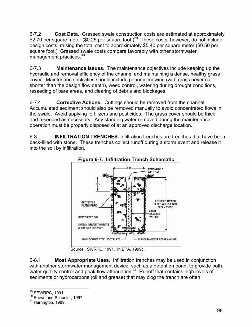
Figure 6-7. Infiltration Trench Schematic
Source: SWRPC, 1991. In EPA, 1999c.
6-8.1 Most Appropriate Uses. Infiltration trenches may be used in conjunction with another stormwater management device, such as a detention pond, to provide both water quality control and peak flow attenuation.31 Runoff that contains high levels of sediments or hydrocarbons (oil and grease) that may clog the trench are often
29 SEWRPC, 1991. 30 Brown and Schueler, 1997. 31 Harrington, 1989.
98

pretreated with other devices such as grit chambers, water quality inlets, sediment traps, swales, and vegetated filter strips.32 6-8.2 Cost Data. Construction costs include clearing, excavation, placement of the filter fabric and stone, installation of the monitoring well and, where desired, establishment of a vegetated buffer strip. The 1993 construction cost for a large infiltration trench (1.8 m (6 ft) deep, 1.2 m (4 ft) wide, and with a 68 m3 (2,400 ft3) volume) ranges from $8,000 to $19,000. A smaller trench (0.9 m (3 ft) deep, 1.2 m (4 ft) wide, and with a 34 m3 (1,200 ft3) volume) is estimated to cost from $3,000 to $8,500. 6-8.3 Maintenance Issues. The principal maintenance objective is to prevent clogging, which may lead to trench failure. Infiltration trenches should be inspected after large storm events and any accumulated debris or material should be removed. A thorough annual inspection should include monitoring of the observation well to confirm that the trench is draining properly. Trenches with filter fabric should be inspected for sediment deposits by removing a small section of the top layer and examining the material in the trench itself. When vegetated buffer strips are used, they should be mowed regularly and inspected for erosion or other damage after each major storm event. 6-8.4 Corrective Actions. The corrective action for infiltration trench failure is to remove the stone and sediment that has clogged the system. The trench should be over excavated and scarified to ensure that the infiltration capacity of the soil is sufficient. The stone is washed to remove any sediment and then replaced. It is critical that any surrounding areas be stabilized to eliminate the potential for sediment clogging. 6-9 INLET DEVICES (a.k.a. hydrodynamic separators). Inlet devices are flow-through structures with a settling or separation unit to remove sediments and other stormwater pollutants.
32 SEWRPC, 1991; Harrington, 1989.
99
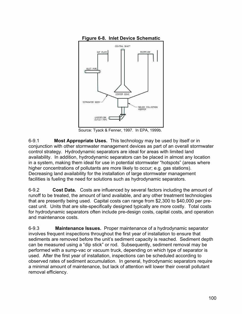
Figure 6-8. Inlet Device Schematic
Source: Tyack & Fenner, 1997. In EPA, 1999b.
6-9.1 Most Appropriate Uses. This technology may be used by itself or in conjunction with other stormwater management devices as part of an overall stormwater control strategy. Hydrodynamic separators are ideal for areas with limited land availability. In addition, hydrodynamic separators can be placed in almost any location in a system, making them ideal for use in potential stormwater “hotspots” (areas where higher concentrations of pollutants are more likely to occur; e.g. gas stations). Decreasing land availability for the installation of large stormwater management facilities is fueling the need for solutions such as hydrodynamic separators. 6-9.2 Cost Data. Costs are influenced by several factors including the amount of runoff to be treated, the amount of land available, and any other treatment technologies that are presently being used. Capital costs can range from $2,300 to $40,000 per pre-cast unit. Units that are site-specifically designed typically are more costly. Total costs for hydrodynamic separators often include pre-design costs, capital costs, and operation and maintenance costs. 6-9.3 Maintenance Issues. Proper maintenance of a hydrodynamic separator involves frequent inspections throughout the first year of installation to ensure that sediments are removed before the unit’s sediment capacity is reached. Sediment depth can be measured using a “dip stick” or rod. Subsequently, sediment removal may be performed with a sump-vac or vacuum truck, depending on which type of separator is used. After the first year of installation, inspections can be scheduled according to observed rates of sediment accumulation. In general, hydrodynamic separators require a minimal amount of maintenance, but lack of attention will lower their overall pollutant removal efficiency.
100
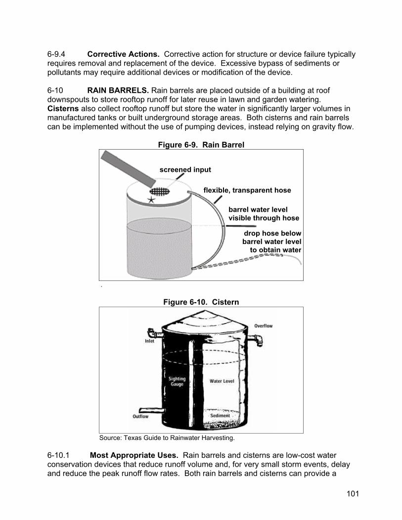
6-9.4 Corrective Actions. Corrective action for structure or device failure typically requires removal and replacement of the device. Excessive bypass of sediments or pollutants may require additional devices or modification of the device. 6-10 RAIN BARRELS. Rain barrels are placed outside of a building at roof downspouts to store rooftop runoff for later reuse in lawn and garden watering. Cisterns also collect rooftop runoff but store the water in significantly larger volumes in manufactured tanks or built underground storage areas. Both cisterns and rain barrels can be implemented without the use of pumping devices, instead relying on gravity flow.
Figure 6-9. Rain Barrel
screened input
flexible, transparent hose
barrel water level visible through hose
db
.
Figure 6-10. Cistern
Source: Texas Guide to Rainwater Harvesting. 6-10.1 Most Appropriate Uses. Rain barrels and cconservation devices that reduce runoff volume and, for vand reduce the peak runoff flow rates. Both rain barrels
rop hose belowarrel water levelto obtain water
isterns are low-cost water ery small storm events, delay
and cisterns can provide a
101
source of chemically untreated 'soft water' for gardens and compost, free of most sediment and dissolved salts. 6-10.2 Cost Data. The cost of a single rain barrel without any other attachments or accessories is typically around $120. The cost of constructing cisterns can vary greatly depending upon their size, material, location (above- or below-ground), and whether they are prefabricated. Pre-manufactured tanks utilized as cisterns can vary in price from hundreds to tens of thousands of dollars. Sizes can vary from hundreds of gallons for residential use to tens of thousands of gallons for commercial and industrial uses. The use of water stored in rain barrels or cisterns for non-potable applications such as landscaping or toilets, or for potable applications if properly treated, may reduce potable water supply costs in areas where water costs are at a premium. 6-10.3 Maintenance Issues. Maintenance requirements for rain barrels are minimal and consist only of regular inspection of the unit as a whole and any of its constituent parts and accessories. All components should be inspected at least twice a year and repaired or replaced as needed. If cisterns are used to provide a supplemental supply of irrigation water, maintenance requirements for cisterns are often low. Cisterns designed for drinking water supply have much higher maintenance requirements, including biannual testing for water quality and filtering systems. Cisterns, along with all their components and accessories, should undergo regular inspection at least twice a year. Replacement or repair of the unit as a whole, and any of its constituent parts and accessories should be completed as necessary. 6-10.4 Corrective Actions. There are few mechanical parts on cisterns or rain barrels. Items such as screens or valves may fail, but are easily replaced. Large cisterns constructed out of materials such as metal or concrete may need repairs to walls by parging (for concrete) or welding (for metal).
102
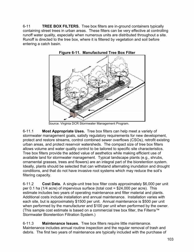
6-11 TREE BOX FILTERS. Tree box filters are in-ground containers typically containing street trees in urban areas. These filters can be very effective at controlling runoff water quality, especially when numerous units are distributed throughout a site. Runoff is directed to the tree box, where it is filtered by vegetation and soil before entering a catch basin.
Figure 6-11. Manufactured Tree Box Filter
Source: Virginia DCR Stormwater Management Program.
6-11.1 Most Appropriate Uses. Tree box filters can help meet a variety of stormwater management goals, satisfy regulatory requirements for new development, protect and restore streams, control combined sewer overflows (CSOs), retrofit existing urban areas, and protect reservoir watersheds. The compact size of tree box filters allows volume and water quality control to be tailored to specific site characteristics. Tree box filters provide the added value of aesthetics while making efficient use of available land for stormwater management. Typical landscape plants (e.g., shrubs, ornamental grasses, trees and flowers) are an integral part of the bioretention system. Ideally, plants should be selected that can withstand alternating inundation and drought conditions, and that do not have invasive root systems which may reduce the soil’s filtering capacity. 6-11.2 Cost Data. A single-unit tree box filter costs approximately $6,000 per unit per 0.1 ha (1/4 acre) of impervious surface (total cost = $24,000 per acre). This estimate includes two years of operating maintenance and filter material and plants. Additional costs include installation and annual maintenance. Installation varies with each site, but is approximately $1500 per unit. Annual maintenance is $500 per unit when performed by the manufacturer and $100 per unit when performed by the owner. (This sample cost estimate is based on a commercial tree box filter, the Filterra™ Stormwater Bioretention Filtration System.) 6-11.3 Maintenance Issues. Tree box filters require little maintenance. Maintenance includes annual routine inspection and the regular removal of trash and debris. The first two years of maintenance are typically included with the purchase of 103
single and multiple-unit tree box filters. These would include removal of trash, debris
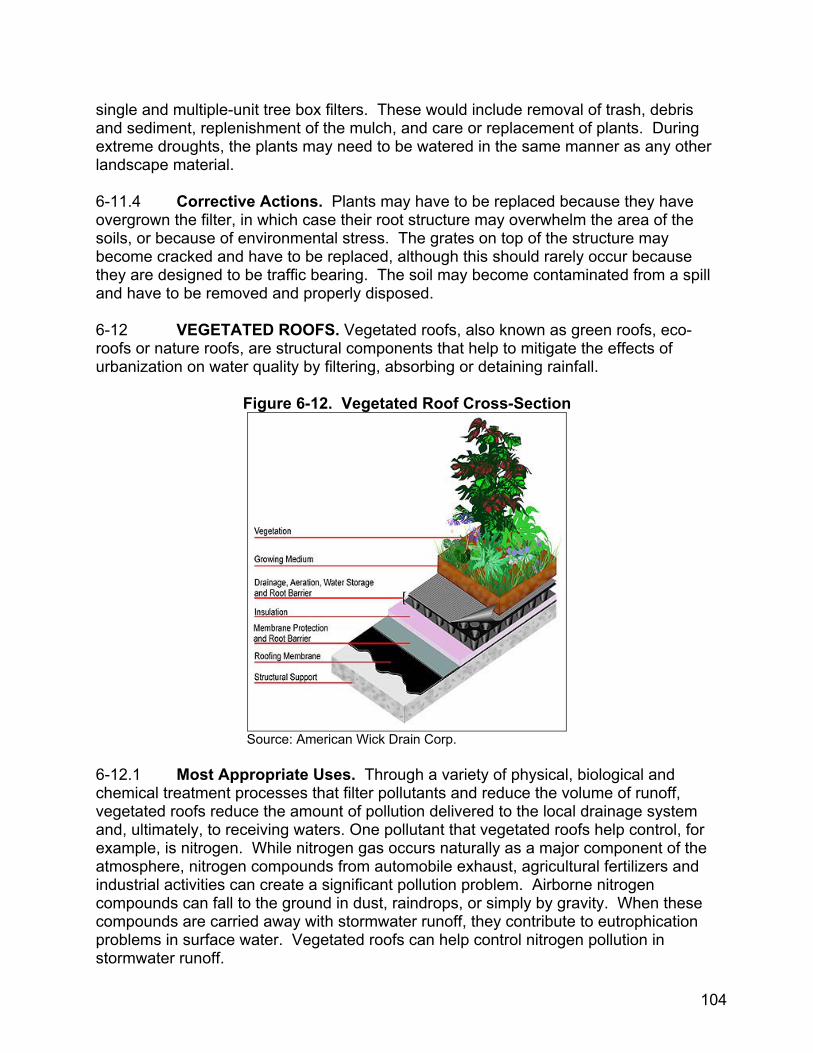
and sediment, replenishment of the mulch, and care or replacement of plants. During extreme droughts, the plants may need to be watered in the same manner as any other landscape material. 6-11.4 Corrective Actions. Plants may have to be replaced because they have overgrown the filter, in which case their root structure may overwhelm the area of the soils, or because of environmental stress. The grates on top of the structure may become cracked and have to be replaced, although this should rarely occur because they are designed to be traffic bearing. The soil may become contaminated from a spill and have to be removed and properly disposed. 6-12 VEGETATED ROOFS. Vegetated roofs, also known as green roofs, eco-roofs or nature roofs, are structural components that help to mitigate the effects of urbanization on water quality by filtering, absorbing or detaining rainfall.
Figure 6-12. Vegetated Roof Cross-Section
Source: American Wick Drain Corp. 6-12.1 Most Appropriate Uses. Through a variety of physical, biological and chemical treatment processes that filter pollutants and reduce the volume of runoff, vegetated roofs reduce the amount of pollution delivered to the local drainage system and, ultimately, to receiving waters. One pollutant that vegetated roofs help control, for example, is nitrogen. While nitrogen gas occurs naturally as a major component of the atmosphere, nitrogen compounds from automobile exhaust, agricultural fertilizers and industrial activities can create a significant pollution problem. Airborne nitrogen compounds can fall to the ground in dust, raindrops, or simply by gravity. When these compounds are carried away with stormwater runoff, they contribute to eutrophication problems in surface water. Vegetated roofs can help control nitrogen pollution in stormwater runoff.
104
6-12.2 Cost Data. Costs for vegetated roofs in the United States are estimated to average between $161 and $215 per square meter ($15 and $20 per square foot) for all use types (i.e., high density residential, commercial, or industrial).33 These costs include all aspects of vegetated roof installation, from the waterproofing membrane to soil substrate creation to planting. By far the highest costs associated with vegetated roof creation are the soil substrate and growth medium and the associated plant components. Vegetated roof retrofit projects may have increased cost associated with traffic and resource scheduling concerns as well as the on-site availability of equipment and materials. Planting costs are higher if plants are placed individually rather than pre-grown on vegetation mats. 6-12.3 Maintenance Issues. Once a properly installed vegetated roof is well established, its maintenance requirements are usually minimal. There are two basic types of vegetated roofing systems: extensive and intensive. Extensive roofs form a thin vegetated sheath of self-sufficient mosses, sedums, and small shrubs. Their low profile allows them to be added to existing buildings, including those with sloping roofs. By contrast, intensive roofs are integral to the roof structure, permitting the use of trees and walkways. A greater depth of media may be required to accommodate larger vegetation and surface features. Intensive roofs require more structural as well as horticultural maintenance, similar to a conventional garden, because plantings tend to be both heavier and more elaborate than on extensive roofs. For both types of roofs, maintenance requirements typically include inspection of the roof membrane, the most crucial element of a vegetated roof, as well as inspection and preventive maintenance of the drainage layer flow paths. 6-12.4 Corrective Actions. Corrective actions for vegetated roofs are generally to repair localized problems. More complex systems may have monitoring devices incorporated into the membrane. Leak detection systems can be brought to the site to locate breaches in the membrane. The soil media can be removed and the membrane repaired. Long periods of drought or loss of soil to high winds may require replacement of the media or replanting. If drought becomes an issue, corrective actions include installing an irrigation system or scheduling supplemental watering. 6-13 PERMEABLE PAVERS. Permeable pavers allow water to seep through regularly interspersed void areas in order to reduce runoff and associated pollutants.
33 Scholz-Barth, 2001.
105
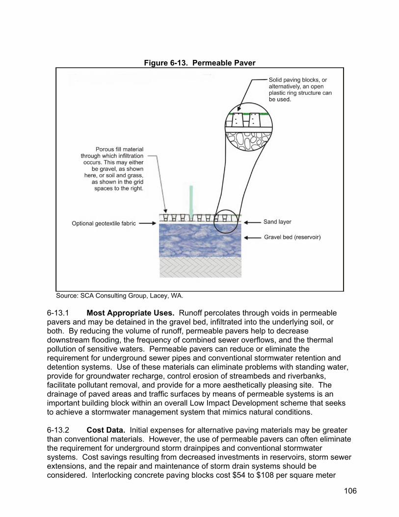
Figure 6-13. Permeable Paver
Source: SCA Consulting Group, Lacey, WA. 6-13.1 Most Appropriate Uses. Runoff percolates through voids in permeable pavers and may be detained in the gravel bed, infiltrated into the underlying soil, or both. By reducing the volume of runoff, permeable pavers help to decrease downstream flooding, the frequency of combined sewer overflows, and the thermal pollution of sensitive waters. Permeable pavers can reduce or eliminate the requirement for underground sewer pipes and conventional stormwater retention and detention systems. Use of these materials can eliminate problems with standing water, provide for groundwater recharge, control erosion of streambeds and riverbanks, facilitate pollutant removal, and provide for a more aesthetically pleasing site. The drainage of paved areas and traffic surfaces by means of permeable systems is an important building block within an overall Low Impact Development scheme that seeks to achieve a stormwater management system that mimics natural conditions. 6-13.2 Cost Data. Initial expenses for alternative paving materials may be greater than conventional materials. However, the use of permeable pavers can often eliminate the requirement for underground storm drainpipes and conventional stormwater systems. Cost savings resulting from decreased investments in reservoirs, storm sewer extensions, and the repair and maintenance of storm drain systems should be considered. Interlocking concrete paving blocks cost $54 to $108 per square meter
106
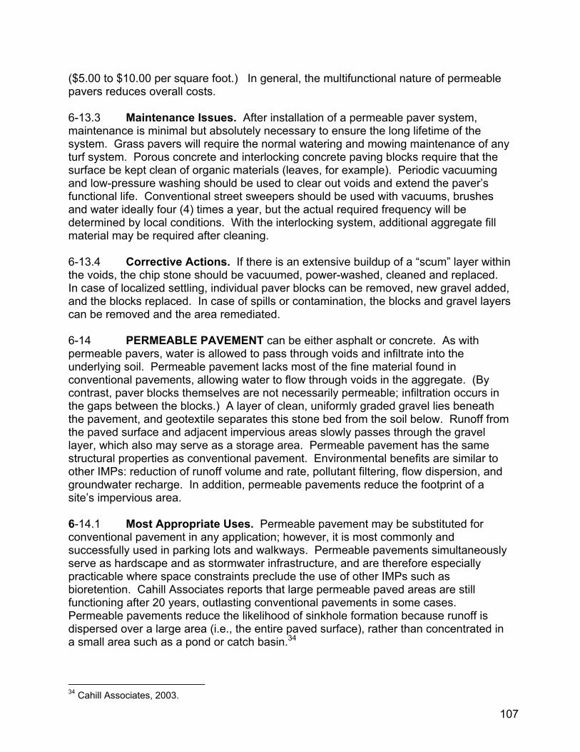
($5.00 to $10.00 per square foot.) In general, the multifunctional nature of permeable pavers reduces overall costs. 6-13.3 Maintenance Issues. After installation of a permeable paver system, maintenance is minimal but absolutely necessary to ensure the long lifetime of the system. Grass pavers will require the normal watering and mowing maintenance of any turf system. Porous concrete and interlocking concrete paving blocks require that the surface be kept clean of organic materials (leaves, for example). Periodic vacuuming and low-pressure washing should be used to clear out voids and extend the paver’s functional life. Conventional street sweepers should be used with vacuums, brushes and water ideally four (4) times a year, but the actual required frequency will be determined by local conditions. With the interlocking system, additional aggregate fill material may be required after cleaning. 6-13.4 Corrective Actions. If there is an extensive buildup of a “scum” layer within the voids, the chip stone should be vacuumed, power-washed, cleaned and replaced. In case of localized settling, individual paver blocks can be removed, new gravel added, and the blocks replaced. In case of spills or contamination, the blocks and gravel layers can be removed and the area remediated. 6-14 PERMEABLE PAVEMENT can be either asphalt or concrete. As with permeable pavers, water is allowed to pass through voids and infiltrate into the underlying soil. Permeable pavement lacks most of the fine material found in conventional pavements, allowing water to flow through voids in the aggregate. (By contrast, paver blocks themselves are not necessarily permeable; infiltration occurs in the gaps between the blocks.) A layer of clean, uniformly graded gravel lies beneath the pavement, and geotextile separates this stone bed from the soil below. Runoff from the paved surface and adjacent impervious areas slowly passes through the gravel layer, which also may serve as a storage area. Permeable pavement has the same structural properties as conventional pavement. Environmental benefits are similar to other IMPs: reduction of runoff volume and rate, pollutant filtering, flow dispersion, and groundwater recharge. In addition, permeable pavements reduce the footprint of a site’s impervious area. 6-14.1 Most Appropriate Uses. Permeable pavement may be substituted for conventional pavement in any application; however, it is most commonly and successfully used in parking lots and walkways. Permeable pavements simultaneously serve as hardscape and as stormwater infrastructure, and are therefore especially practicable where space constraints preclude the use of other IMPs such as bioretention. Cahill Associates reports that large permeable paved areas are still functioning after 20 years, outlasting conventional pavements in some cases. Permeable pavements reduce the likelihood of sinkhole formation because runoff is dispersed over a large area (i.e., the entire paved surface), rather than concentrated in a small area such as a pond or catch basin.34
34 Cahill Associates, 2003.
107
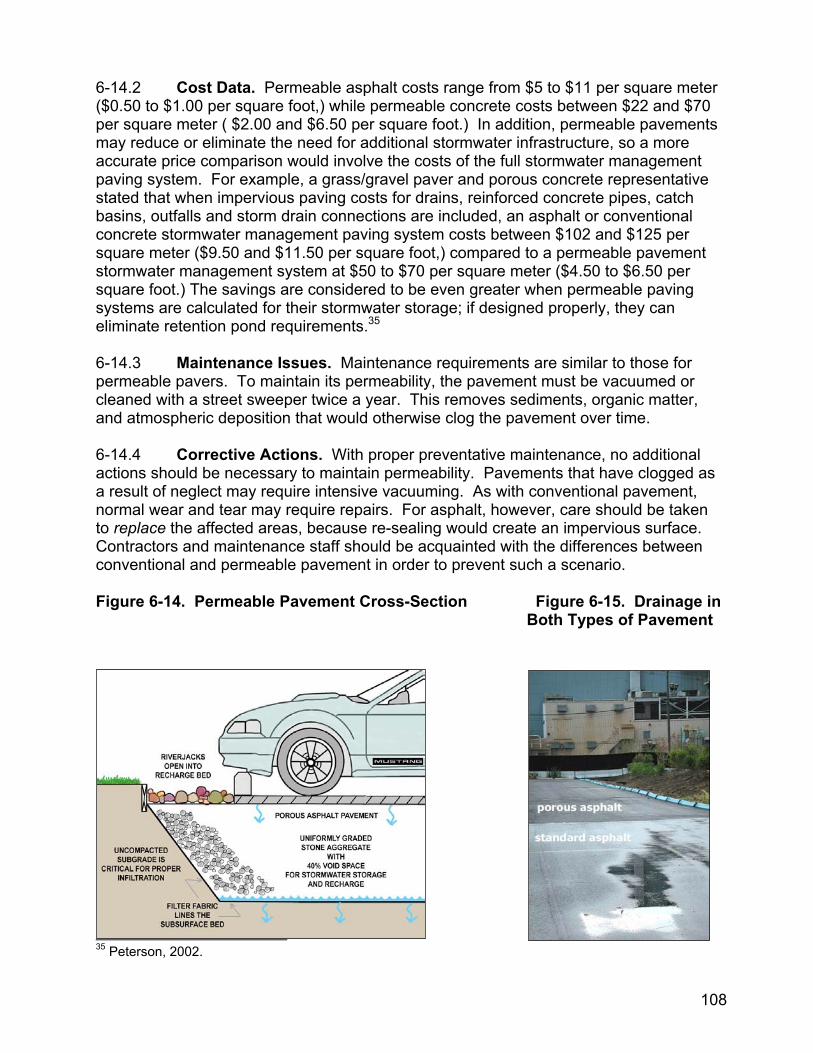
6-14.2 Cost Data. Permeable asphalt costs range from $5 to $11 per square meter ($0.50 to $1.00 per square foot,) while permeable concrete costs between $22 and $70 per square meter ( $2.00 and $6.50 per square foot.) In addition, permeable pavements may reduce or eliminate the need for additional stormwater infrastructure, so a more accurate price comparison would involve the costs of the full stormwater management paving system. For example, a grass/gravel paver and porous concrete representative stated that when impervious paving costs for drains, reinforced concrete pipes, catch basins, outfalls and storm drain connections are included, an asphalt or conventional concrete stormwater management paving system costs between $102 and $125 per square meter ($9.50 and $11.50 per square foot,) compared to a permeable pavement stormwater management system at $50 to $70 per square meter ($4.50 to $6.50 per square foot.) The savings are considered to be even greater when permeable paving systems are calculated for their stormwater storage; if designed properly, they can eliminate retention pond requirements.35 6-14.3 Maintenance Issues. Maintenance requirements are similar to those for permeable pavers. To maintain its permeability, the pavement must be vacuumed or cleaned with a street sweeper twice a year. This removes sediments, organic matter, and atmospheric deposition that would otherwise clog the pavement over time. 6-14.4 Corrective Actions. With proper preventative maintenance, no additional actions should be necessary to maintain permeability. Pavements that have clogged as a result of neglect may require intensive vacuuming. As with conventional pavement, normal wear and tear may require repairs. For asphalt, however, care should be taken to replace the affected areas, because re-sealing would create an impervious surface. Contractors and maintenance staff should be acquainted with the differences between conventional and permeable pavement in order to prevent such a scenario. Figure 6-14. Permeable Pavement Cross-Section Figure 6-15. Drainage in Both Types of Pavement
35 Peterson, 2002.
108

6-15 TECHNICAL CONSULTATION. With the possible exception of dry wells, infiltration trenches, and inlet devices, the vegetated IMPs described here are integral to a site’s landscape design. Accordingly, they should be designed by, or under the direct supervision of, an appropriate licensed professional such as a landscape architect. 6-16 DEVELOPMENT AND EVALUATION OF ADDITIONAL PRACTICES. Additional practices not discussed in this manual may also be appropriate for use as IMPs. The practice’s applicability, effectiveness, cost and maintenance requirements must be considered in order to evaluate its potential use as an IMP.
109
CHAPTER 7
LID SITE PLANNING PROCESS
7-1 INTRODUCTION. This is a representative process for planning LID retrofits. Individual facilities will have unique needs and should adapt this process accordingly.
7-2 MODEL PLANNING PROCESS.
Step 1: Define project objectives and goals 1. Identify the LID objectives for the project. Consider these four
fundamental aspects of stormwater control:36 Runoff volume Peak runoff rate Flow frequency and duration Water quality
2. Evaluate existing stormwater infrastructure in terms of how well it
functions with respect to each of these aspects.
3. Determine the goals and feasibility for control of runoff volume, flow frequency and duration, and water quality; as well as on-site use of stormwater (e.g. irrigation).
4. Prioritize and rank basic objectives.
5. Define hydrologic controls required to meet objectives (i.e. infiltration,
filtration, discharge frequency, volume of discharges, groundwater recharge).
Step 2: Perform site evaluation and analysis A site evaluation will facilitate LID design development by providing site details that will assist in the development of an LID program.
1. Conduct a detailed investigation of the site using available documents
such as drainage maps, utilities information, soils maps, land use plans, and aerial photographs.
2. Perform an on-site evaluation highlighting opportunities, such as pollutant-
generating areas, potential disconnects from combined sewer systems, and potential green corridors. Note potential LID practices and areas where water quality and quantity controls could be installed.
36 PGDER, 2000b.
110
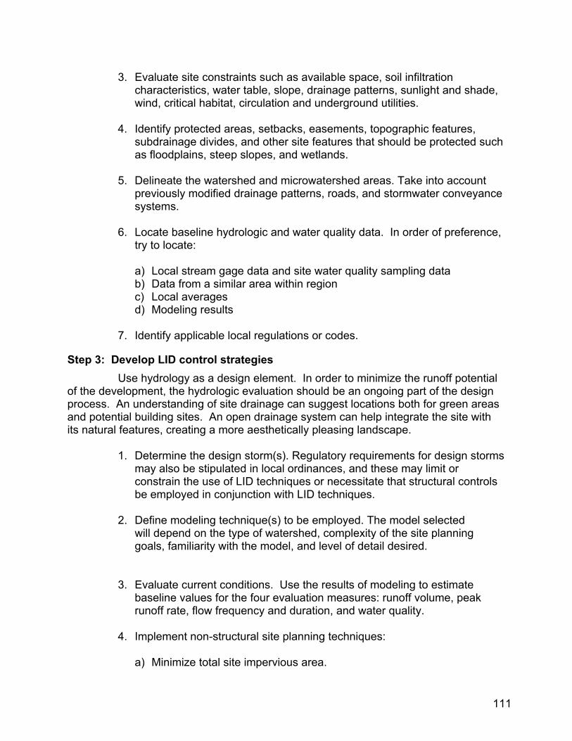
3. Evaluate site constraints such as available space, soil infiltration characteristics, water table, slope, drainage patterns, sunlight and shade, wind, critical habitat, circulation and underground utilities.
4. Identify protected areas, setbacks, easements, topographic features,
subdrainage divides, and other site features that should be protected such as floodplains, steep slopes, and wetlands.
5. Delineate the watershed and microwatershed areas. Take into account
previously modified drainage patterns, roads, and stormwater conveyance systems.
6. Locate baseline hydrologic and water quality data. In order of preference,
try to locate:
a) Local stream gage data and site water quality sampling data b) Data from a similar area within region c) Local averages d) Modeling results
7. Identify applicable local regulations or codes.
Step 3: Develop LID control strategies Use hydrology as a design element. In order to minimize the runoff potential of the development, the hydrologic evaluation should be an ongoing part of the design process. An understanding of site drainage can suggest locations both for green areas and potential building sites. An open drainage system can help integrate the site with its natural features, creating a more aesthetically pleasing landscape.
1. Determine the design storm(s). Regulatory requirements for design storms
may also be stipulated in local ordinances, and these may limit or constrain the use of LID techniques or necessitate that structural controls be employed in conjunction with LID techniques.
2. Define modeling technique(s) to be employed. The model selected
will depend on the type of watershed, complexity of the site planning goals, familiarity with the model, and level of detail desired.
3. Evaluate current conditions. Use the results of modeling to estimate
baseline values for the four evaluation measures: runoff volume, peak runoff rate, flow frequency and duration, and water quality.
4. Implement non-structural site planning techniques:
a) Minimize total site impervious area.
111
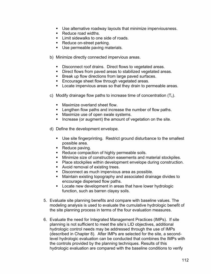
Use alternative roadway layouts that minimize imperviousness. Reduce road widths. Limit sidewalks to one side of roads. Reduce on-street parking. Use permeable paving materials.
b) Minimize directly connected impervious areas.
Disconnect roof drains. Direct flows to vegetated areas. Direct flows from paved areas to stabilized vegetated areas. Break up flow directions from large paved surfaces. Encourage sheet flow through vegetated areas. Locate impervious areas so that they drain to permeable areas.
c) Modify drainage flow paths to increase time of concentration (Tc).
Maximize overland sheet flow. Lengthen flow paths and increase the number of flow paths. Maximize use of open swale systems. Increase (or augment) the amount of vegetation on the site.
d) Define the development envelope.
Use site fingerprinting. Restrict ground disturbance to the smallest
possible area. Reduce paving. Reduce compaction of highly permeable soils. Minimize size of construction easements and material stockpiles. Place stockpiles within development envelope during construction. Avoid removal of existing trees. Disconnect as much impervious area as possible. Maintain existing topography and associated drainage divides to
encourage dispersed flow paths. Locate new development in areas that have lower hydrologic
function, such as barren clayey soils. 5. Evaluate site planning benefits and compare with baseline values. The
modeling analysis is used to evaluate the cumulative hydrologic benefit of the site planning process in terms of the four evaluation measures.
6. Evaluate the need for Integrated Management Practices (IMPs). If site
planning is not sufficient to meet the site’s LID objectives, additional hydrologic control needs may be addressed through the use of IMPs (described in Chapter 8). After IMPs are selected for the site, a second-level hydrologic evaluation can be conducted that combines the IMPs with the controls provided by the planning techniques. Results of this hydrologic evaluation are compared with the baseline conditions to verify
112
that the site LID objectives have been achieved. If not, additional IMPs are located on the site to achieve the optimal condition.
7. Evaluate supplemental needs. If supplemental control for either volume or
peak flow is still needed after the use of IMPs, selection and listing of additional management techniques should be considered. For example, where flood control or flooding problems are key design objectives, or where site conditions, such as poor soils or a high water table, limit the use of IMPs, additional conventional end-of-pipe methods, such as large detention ponds or constructed wetlands, should be considered. In some cases their capacity can be reduced significantly by the use of LID upstream. It may be helpful to evaluate several combinations of LID features and conventional stormwater facilities to determine which combination best meets the stated objectives. Use of hydrologic evaluations can assist in identifying the alternative solutions prior to detailed design and construction costs.
For residential areas, Prince George’s County, Maryland, has developed a detailed illustration of an approach for conducting a hydrologic evaluation based on the NRCS TR-55 method. Where NRCS methods (TR-20, TR-55) are accepted for hydrologic evaluation, the effect of LID features should be reflected in the curve numbers and times of concentration selected for the analysis. A full description of this process is available from Prince George’s County.37
Step 4: Design LID Site or Master Plan 1. Sketch a design concept that distributes the LID practices appropriately
around the project site. Try to use all surface types (built, hardscape, and landscape). Keep in mind the multifunctional capability of LID technologies (i.e., parking lot with detention facility underground).
2. Develop a master plan that identifies all key control issues (water quality,
water quantity, water conservation) and implementation areas. Specify specific LID technologies and any connections they have to stormwater overflow units and sub-surface detention facilities.
Step 5: Develop Operation and Maintenance Procedures Develop operation and maintenance procedures for each of the LID practices implemented in the site plan. Different types of IMPs will have different maintenance requirements, but some general principles will apply:
Keep IMPs and flow paths clear of debris. Water vegetation regularly during dry periods. Grassed areas should be mowed regularly. Plantings should be pruned as needed.
37 PGDER, 2000b. 113
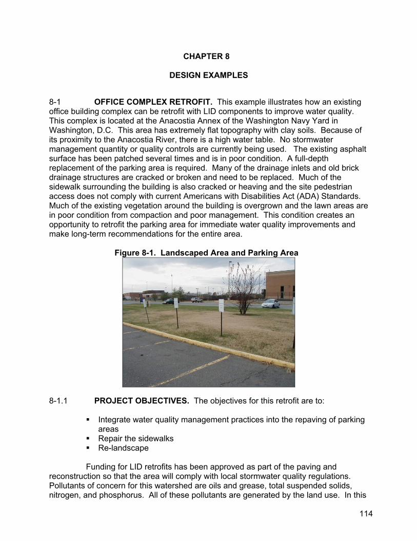
CHAPTER 8
DESIGN EXAMPLES 8-1 OFFICE COMPLEX RETROFIT. This example illustrates how an existing office building complex can be retrofit with LID components to improve water quality. This complex is located at the Anacostia Annex of the Washington Navy Yard in Washington, D.C. This area has extremely flat topography with clay soils. Because of its proximity to the Anacostia River, there is a high water table. No stormwater management quantity or quality controls are currently being used. The existing asphalt surface has been patched several times and is in poor condition. A full-depth replacement of the parking area is required. Many of the drainage inlets and old brick drainage structures are cracked or broken and need to be replaced. Much of the sidewalk surrounding the building is also cracked or heaving and the site pedestrian access does not comply with current Americans with Disabilities Act (ADA) Standards. Much of the existing vegetation around the building is overgrown and the lawn areas are in poor condition from compaction and poor management. This condition creates an opportunity to retrofit the parking area for immediate water quality improvements and make long-term recommendations for the entire area.
Figure 8-1. Landscaped Area and Parking Area
8-1.1 PROJECT OBJECTIVES. The objectives for this retrofit are to:
Integrate water quality management practices into the repaving of parking areas
Repair the sidewalks Re-landscape
Funding for LID retrofits has been approved as part of the paving and reconstruction so that the area will comply with local stormwater quality regulations. Pollutants of concern for this watershed are oils and grease, total suspended solids, nitrogen, and phosphorus. All of these pollutants are generated by the land use. In this
114
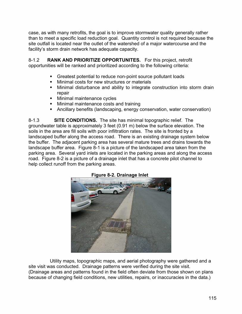
case, as with many retrofits, the goal is to improve stormwater quality generally rather than to meet a specific load reduction goal. Quantity control is not required because the site outfall is located near the outlet of the watershed of a major watercourse and the facility’s storm drain network has adequate capacity. 8-1.2 RANK AND PRIORITIZE OPPORTUNITES. For this project, retrofit opportunities will be ranked and prioritized according to the following criteria:
Greatest potential to reduce non-point source pollutant loads Minimal costs for new structures or materials Minimal disturbance and ability to integrate construction into storm drain
repair Minimal maintenance cycles Minimal maintenance costs and training Ancillary benefits (landscaping, energy conservation, water conservation)
8-1.3 SITE CONDITIONS. The site has minimal topographic relief. The groundwater table is approximately 3 feet (0.91 m) below the surface elevation. The soils in the area are fill soils with poor infiltration rates. The site is fronted by a landscaped buffer along the access road. There is an existing drainage system below the buffer. The adjacent parking area has several mature trees and drains towards the landscape buffer area. Figure 8-1 is a picture of the landscaped area taken from the parking area. Several yard inlets are located in the parking areas and along the access road. Figure 8-2 is a picture of a drainage inlet that has a concrete pilot channel to help collect runoff from the parking areas.
Figure 8-2. Drainage Inlet
Utility maps, topographic maps, and aerial photography were gathered and a site visit was conducted. Drainage patterns were verified during the site visit. (Drainage areas and patterns found in the field often deviate from those shown on plans because of changing field conditions, new utilities, repairs, or inaccuracies in the data.)
115
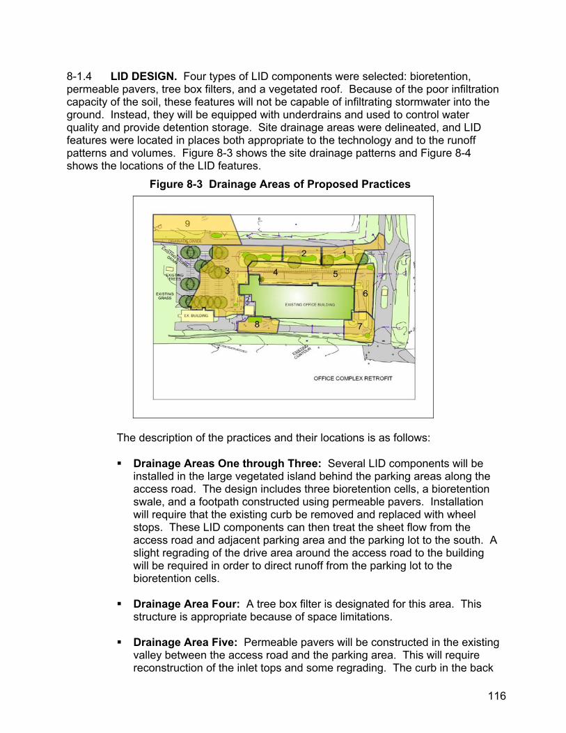
8-1.4 LID DESIGN. Four types of LID components were selected: bioretention, permeable pavers, tree box filters, and a vegetated roof. Because of the poor infiltration capacity of the soil, these features will not be capable of infiltrating stormwater into the ground. Instead, they will be equipped with underdrains and used to control water quality and provide detention storage. Site drainage areas were delineated, and LID features were located in places both appropriate to the technology and to the runoff patterns and volumes. Figure 8-3 shows the site drainage patterns and Figure 8-4 shows the locations of the LID features.
Figure 8-3 Drainage Areas of Proposed Practices
The description of the practices and their locations is as follows:
Drainage Areas One through Three: Several LID components will be installed in the large vegetated island behind the parking areas along the access road. The design includes three bioretention cells, a bioretention swale, and a footpath constructed using permeable pavers. Installation will require that the existing curb be removed and replaced with wheel stops. These LID components can then treat the sheet flow from the access road and adjacent parking area and the parking lot to the south. A slight regrading of the drive area around the access road to the building will be required in order to direct runoff from the parking lot to the bioretention cells.
Drainage Area Four: A tree box filter is designated for this area. This structure is appropriate because of space limitations. Drainage Area Five: Permeable pavers will be constructed in the existing valley between the access road and the parking area. This will require reconstruction of the inlet tops and some regrading. The curb in the back
116
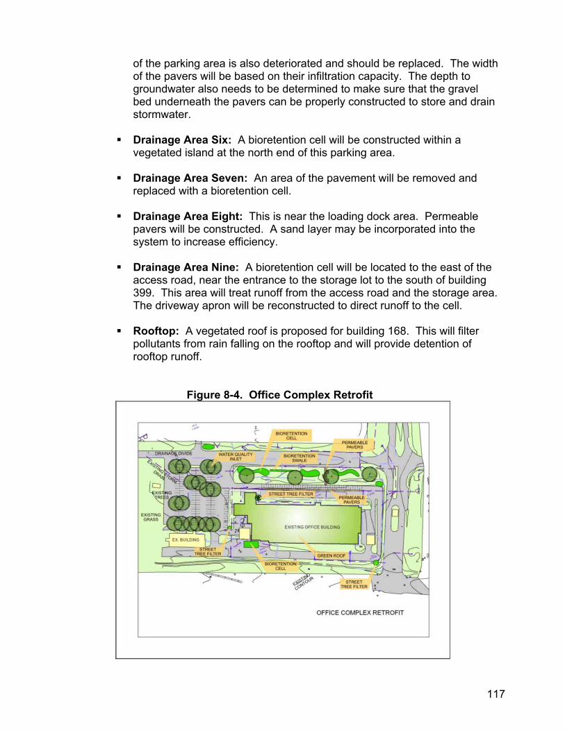
of the parking area is also deteriorated and should be replaced. The width of the pavers will be based on their infiltration capacity. The depth to groundwater also needs to be determined to make sure that the gravel bed underneath the pavers can be properly constructed to store and drain stormwater. Drainage Area Six: A bioretention cell will be constructed within a vegetated island at the north end of this parking area. Drainage Area Seven: An area of the pavement will be removed and replaced with a bioretention cell. Drainage Area Eight: This is near the loading dock area. Permeable pavers will be constructed. A sand layer may be incorporated into the system to increase efficiency. Drainage Area Nine: A bioretention cell will be located to the east of the access road, near the entrance to the storage lot to the south of building 399. This area will treat runoff from the access road and the storage area. The driveway apron will be reconstructed to direct runoff to the cell. Rooftop: A vegetated roof is proposed for building 168. This will filter pollutants from rain falling on the rooftop and will provide detention of rooftop runoff.
Figure 8-4. Office Complex Retrofit
117
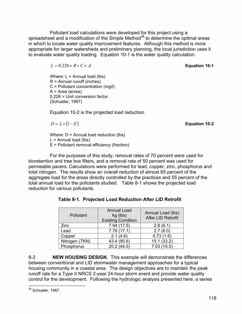
Pollutant load calculations were developed for this project using a spreadsheet and a modification of the Simple Method38 to determine the optimal areas in which to locate water quality improvement features. Although this method is more appropriate for larger watersheds and preliminary planning, the local jurisdiction uses it to evaluate water quality loading. Equation 10-1 is the water quality calculation.
Equation 10-1 ACRL ×××= 226.0
Where: L = Annual load (lbs) R = Annual runoff (inches) C = Pollutant concentration (mg/l) A = Area (acres) 0.226 = Unit conversion factor (Schueler, 1987)
Equation 10-2 is the projected load reduction. Equation 10-2 ( )ELD −×= 1 Where: D = Annual load reduction (lbs) L = Annual load (lbs) E = Pollutant removal efficiency (fraction) For the purposes of this study, removal rates of 70 percent were used for bioretention and tree box filters, and a removal rate of 50 percent was used for permeable pavers. Calculations were performed for lead, copper, zinc, phosphorus and total nitrogen. The results show an overall reduction of almost 65 percent of the aggregate load for the areas directly controlled by the practices and 55 percent of the total annual load for the pollutants studied. Table 8-1 shows the projected load reduction for various pollutants.
Table 8-1. Projected Load Reduction After LID Retrofit
Pollutant Annual Load
kg (lbs) Existing Condition
Annual Load (lbs) After LID Retrofit
Zinc 7.94 (17.5) 2.8 (6.1) Lead 7.76 (17.1) 2.7 (6.0) Copper 2.1 (4.6) 0.73 (1.6) Nitrogen (TKN) 43.4 (95.6) 15.1 (33.2) Phosphorus 20.2 (44.5) 7.03 (15.5)
8-2 NEW HOUSING DESIGN. This example will demonstrate the differences between conventional and LID stormwater management approaches for a typical housing community in a coastal area. The design objectives are to maintain the peak runoff rate for a Type II NRCS 2-year 24-hour storm event and provide water quality control for the development. Following the hydrologic analysis presented here, a series 38 Schueler, 1987.
118

of pictures are presented to illustrate how selected LID components would look in a recently constructed housing development. 8-2.1 Curve Number Calculations For Existing Site Condition. The site being evaluated has a 2.6 ha (6.5 acre) drainage area. The land is relatively flat and drains to a small channel with wetlands at the outfall of the drainage area. The slopes are gentle, averaging 2 percent. The soils are classified as belonging to NRCS Hydrologic Soils Group (HSG) B. These soils have moderate infiltration rates and moderately fine to moderately coarse textures. They generally have a moderate rate of water transmission (0.15 to 0.30 in/hr), and the textures may be classified as a silt loam or loam.39 Approximately 1.5 ha (3.6 acres) near the outfall is classified hydrologically as “Woods in Fair Condition”. The upper portion of the property is classified as “Brush in Poor Condition”. Figure 8-5 is a map of the existing condition. The procedures from Worksheet 2, Figure 2-5 from TR-5540 are used to calculate the composite curve number (CN) for the site. The resulting CN from Equation 10-3 is 63 for the 2.6 ha (6.5 acres.) Table 8-2 is a summary of those calculations. Weighted CN = Sum of Products ÷ Drainage Area Equation 10-3
Table 8-2. Composite Curve Number Calculation for Existing Condition
Hydrologic Soils Group Cover Description CN (Table
2-2 TR-55) Area
(Acres) Product of CN
x Area B Brush, Poor Condition 67 2.9 194.3B Woods, Fair 60 3.6 216.0
Sum of Products 410.3÷ Drainage Area 6.5
Weighted CN 63
39 NRCS, 1986. 40 Ibid.
119

Figure 8-5. Map of Existing Conditions
8-2.2 Post Development Curve Number Calculations. The conventional method for assigning a curve number to a residential development is to choose a single curve number for the entire site from a source such as Table 2-2a of TR-55.41 Figure 8-6 is a picture of the proposed housing type, which can be classified as “Townhouse Residential District”. For this land use, the CN from Table 2-2a of TR-55 is 85. The LID method allows for the calculation of a “customized” CN that reflects the actual field conditions rather than a broad estimation. For this example, the amounts of impervious cover and other land covers were calculated directly from Figure 8-7. Table 8-3 is a summary of the proposed condition’s “customized” CN using the LID calculation method.
Table 8-3. Composite Curve Number Calculation for Proposed Condition
Hydrologic Soils Group Cover Description CN (Table
2-2 TR-55) Area
(Acres) Product of CN
x Area B Lawn (fair condition) 69 3.2 220.8B Woods, Fair 60 0.7 42.0B Impervious 98 2.6 254.8
Sum of Products 517.6÷ Drainage Area 6.5
Weighted CN 80
41 Ibid.
120
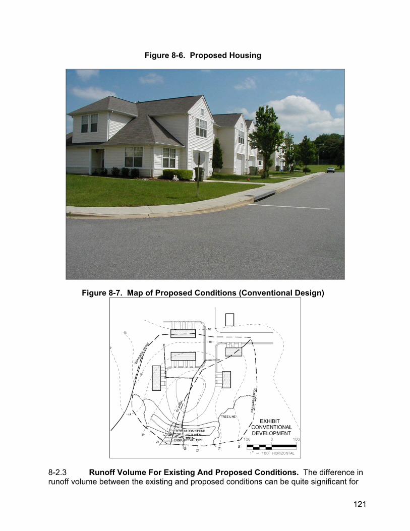
Figure 8-6. Proposed Housing
Figure 8-7. Map of Proposed Conditions (Conventional Design)
8-2.3 Runoff Volume For Existing And Proposed Conditions. The difference in runoff volume between the existing and proposed conditions can be quite significant for
121
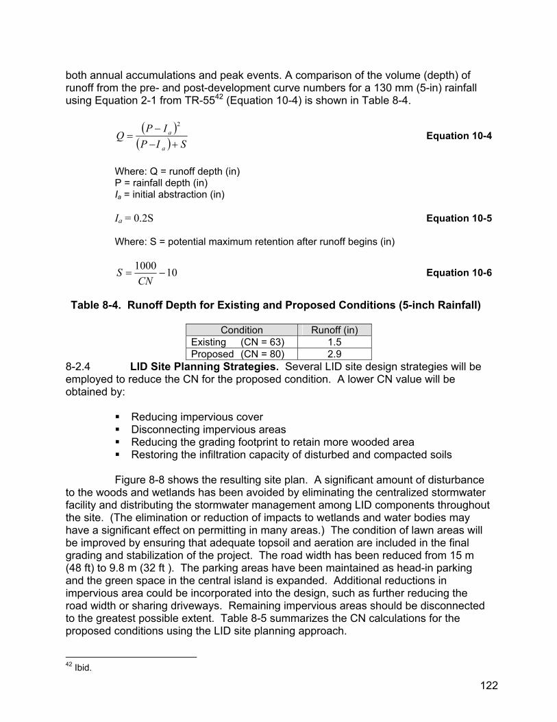
both annual accumulations and peak events. A comparison of the volume (depth) of runoff from the pre- and post-development curve numbers for a 130 mm (5-in) rainfall using Equation 2-1 from TR-5542 (Equation 10-4) is shown in Table 8-4.
( )( ) SIP
IPQa
a
+−−
=2
Equation 10-4
Where: Q = runoff depth (in) P = rainfall depth (in)
Ia = initial abstraction (in) Ia = 0.2S Equation 10-5
Where: S = potential maximum retention after runoff begins (in)
101000−=
CNS Equation 10-6
Table 8-4. Runoff Depth for Existing and Proposed Conditions (5-inch Rainfall)
Condition Runoff (in)
Existing (CN = 63) 1.5 Proposed (CN = 80) 2.9
8-2.4 LID Site Planning Strategies. Several LID site design strategies will be employed to reduce the CN for the proposed condition. A lower CN value will be obtained by:
Reducing impervious cover Disconnecting impervious areas Reducing the grading footprint to retain more wooded area Restoring the infiltration capacity of disturbed and compacted soils
Figure 8-8 shows the resulting site plan. A significant amount of disturbance to the woods and wetlands has been avoided by eliminating the centralized stormwater facility and distributing the stormwater management among LID components throughout the site. (The elimination or reduction of impacts to wetlands and water bodies may have a significant effect on permitting in many areas.) The condition of lawn areas will be improved by ensuring that adequate topsoil and aeration are included in the final grading and stabilization of the project. The road width has been reduced from 15 m (48 ft) to 9.8 m (32 ft ). The parking areas have been maintained as head-in parking and the green space in the central island is expanded. Additional reductions in impervious area could be incorporated into the design, such as further reducing the road width or sharing driveways. Remaining impervious areas should be disconnected to the greatest possible extent. Table 8-5 summarizes the CN calculations for the proposed conditions using the LID site planning approach. 42 Ibid.
122
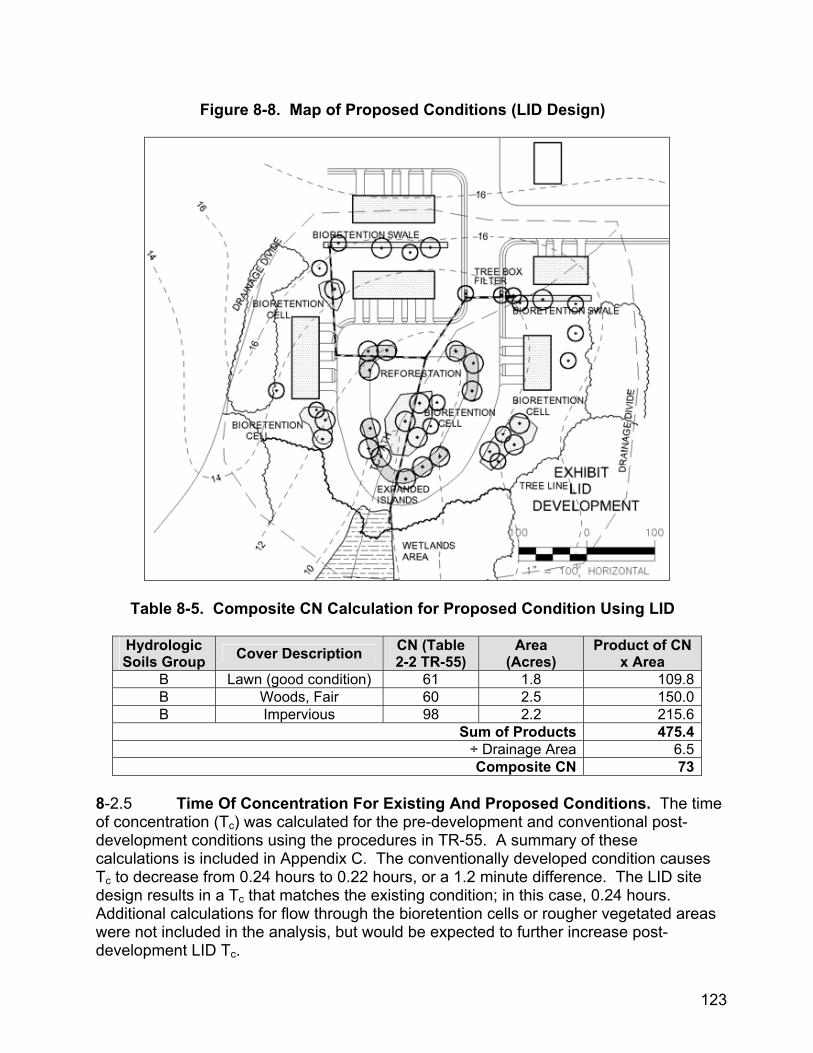
Figure 8-8. Map of Proposed Conditions (LID Design)
Table 8-5. Composite CN Calculation for Proposed Condition Using LID
Hydrologic Soils Group Cover Description CN (Table
2-2 TR-55) Area
(Acres) Product of CN
x Area B Lawn (good condition) 61 1.8 109.8B Woods, Fair 60 2.5 150.0B Impervious 98 2.2 215.6
Sum of Products 475.4÷ Drainage Area 6.5Composite CN 73
8-2.5 Time Of Concentration For Existing And Proposed Conditions. The time of concentration (Tc) was calculated for the pre-development and conventional post-development conditions using the procedures in TR-55. A summary of these calculations is included in Appendix C. The conventionally developed condition causes Tc to decrease from 0.24 hours to 0.22 hours, or a 1.2 minute difference. The LID site design results in a Tc that matches the existing condition; in this case, 0.24 hours. Additional calculations for flow through the bioretention cells or rougher vegetated areas were not included in the analysis, but would be expected to further increase post-development LID Tc.
123
8-2.6 Storage Volume Comparison. A comparison of the storage volumes required for the conventional and LID site designs is given below. The 2-year 24-hour and the 10-year 24-hour storms are often used as the design storms for channel protection and adequate conveyance. Although the design objective here is to maintain the peak runoff rate for the 2-year 24-hour storm, the 10-year 24-hour storm is also used to further illustrate the differences in peak runoff rate and volume between the two approaches. In order to determine the storage volume required to maintain the pre-development peak runoff rate for these design storms, the runoff depths and peak runoff rates for the existing condition and both proposed conditions were first calculated using the Graphical Peak Discharge Method from TR-55. Table 8-6 is a summary of those calculations.
Table 8-6. Summary of Graphical Peak Discharge Results
Peak Discharge (CFS) Runoff depth (in.) Condition CN Tc
2-year storm (3” depth)
10-year storm (5” depth)
2-year storm
10-year storm
Existing Condition 63 0.24 2 10 0.4 1.5
Proposed Condition – conventional CN 80 0.22 9 23 1.3 2.9
Proposed Condition using LID site design 73 0.24 6 17 0.9 2.3
The TR-5543 computer program was used to estimate the post-development storage volume required to maintain the 2-year 24-hour pre-development peak runoff rate for both the conventional and LID site designs. As shown in Table 8-6 above, the target (existing) 2-year 24-hour peak outflow is 2 cfs and the target 10-year 24-hour peak outflow is 10 cfs. (It is purely coincidental that the values of the return periods match the values of the discharges.) The results are given in Table 8-7.
Table 8-7. Post-Development Storage Volumes
Conventional site design LID site design Design storm
Depth, inches (mm)* Volume, ac-ft (m3) Depth, inches (mm)* Volume, ac-ft (m3) 2-year 24-hour 0.52 (13) 0.28 (347) 0.28 (7) 0.15 (187) 10-year 24-hour 0.85 (22) 0.46 (568) 0.53 (13) 0.29 (354)
* depth of runoff distributed across the 6.5 acre (2.6 ha) area For the 2-year 24-hour storm, the LID site design results in a 46% reduction in required storage volume as compared to the conventional site design, and for the 10-year 24-hour storm, the volume reduction is 38%. The pond shown in Figure 8-7 was sized using the computed 2-year conventional detention basin storage volume. Appendix C shows a summary of the computer program results. 43 Ibid.
124
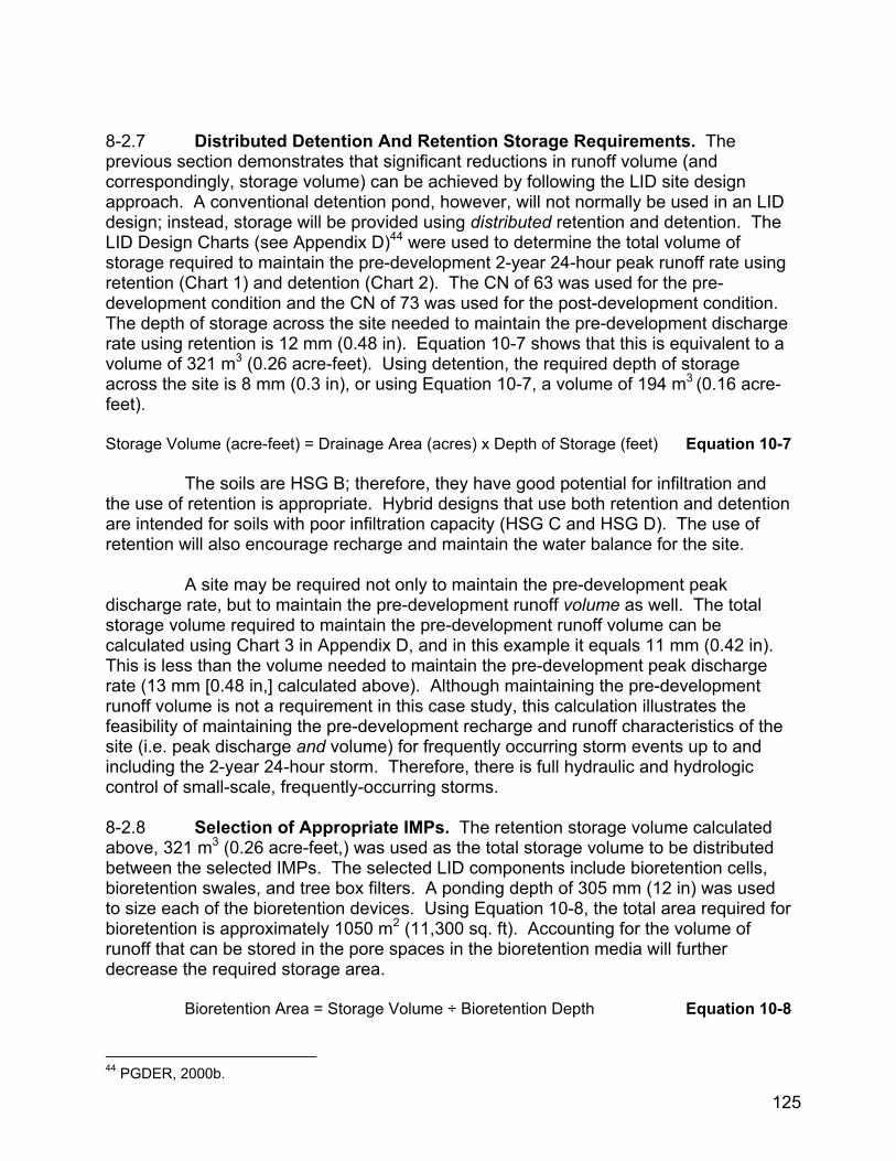
8-2.7 Distributed Detention And Retention Storage Requirements. The previous section demonstrates that significant reductions in runoff volume (and correspondingly, storage volume) can be achieved by following the LID site design approach. A conventional detention pond, however, will not normally be used in an LID design; instead, storage will be provided using distributed retention and detention. The LID Design Charts (see Appendix D)44 were used to determine the total volume of storage required to maintain the pre-development 2-year 24-hour peak runoff rate using retention (Chart 1) and detention (Chart 2). The CN of 63 was used for the pre-development condition and the CN of 73 was used for the post-development condition. The depth of storage across the site needed to maintain the pre-development discharge rate using retention is 12 mm (0.48 in). Equation 10-7 shows that this is equivalent to a volume of 321 m3 (0.26 acre-feet). Using detention, the required depth of storage across the site is 8 mm (0.3 in), or using Equation 10-7, a volume of 194 m3 (0.16 acre-feet). Storage Volume (acre-feet) = Drainage Area (acres) x Depth of Storage (feet) Equation 10-7 The soils are HSG B; therefore, they have good potential for infiltration and the use of retention is appropriate. Hybrid designs that use both retention and detention are intended for soils with poor infiltration capacity (HSG C and HSG D). The use of retention will also encourage recharge and maintain the water balance for the site. A site may be required not only to maintain the pre-development peak discharge rate, but to maintain the pre-development runoff volume as well. The total storage volume required to maintain the pre-development runoff volume can be calculated using Chart 3 in Appendix D, and in this example it equals 11 mm (0.42 in). This is less than the volume needed to maintain the pre-development peak discharge rate (13 mm [0.48 in,] calculated above). Although maintaining the pre-development runoff volume is not a requirement in this case study, this calculation illustrates the feasibility of maintaining the pre-development recharge and runoff characteristics of the site (i.e. peak discharge and volume) for frequently occurring storm events up to and including the 2-year 24-hour storm. Therefore, there is full hydraulic and hydrologic control of small-scale, frequently-occurring storms. 8-2.8 Selection of Appropriate IMPs. The retention storage volume calculated above, 321 m3 (0.26 acre-feet,) was used as the total storage volume to be distributed between the selected IMPs. The selected LID components include bioretention cells, bioretention swales, and tree box filters. A ponding depth of 305 mm (12 in) was used to size each of the bioretention devices. Using Equation 10-8, the total area required for bioretention is approximately 1050 m2 (11,300 sq. ft). Accounting for the volume of runoff that can be stored in the pore spaces in the bioretention media will further decrease the required storage area.
Bioretention Area = Storage Volume ÷ Bioretention Depth Equation 10-8
44 PGDER, 2000b.
125

These features have been located to intercept and manage the stormwater drainage in small areas. The storm drain pattern remains the same as in the conventional system and provides adequate conveyance. Because of the runoff volume and peak reductions achieved by the LID site design and IMPs, a smaller storm drain diameter can be used if desired. Figure 8-8 illustrates that the storage volume required to maintain the pre-development 2-year 24-hour peak discharge can be met by using distributed stormwater management. These components can be maintained by the residents, with the exception of the tree box filter. All of the facilities can be maintained by landscape maintenance crews, with minimal training. Figures 8-9 to 8-14 illustrate how the LID features can be incorporated into a residential development.
126
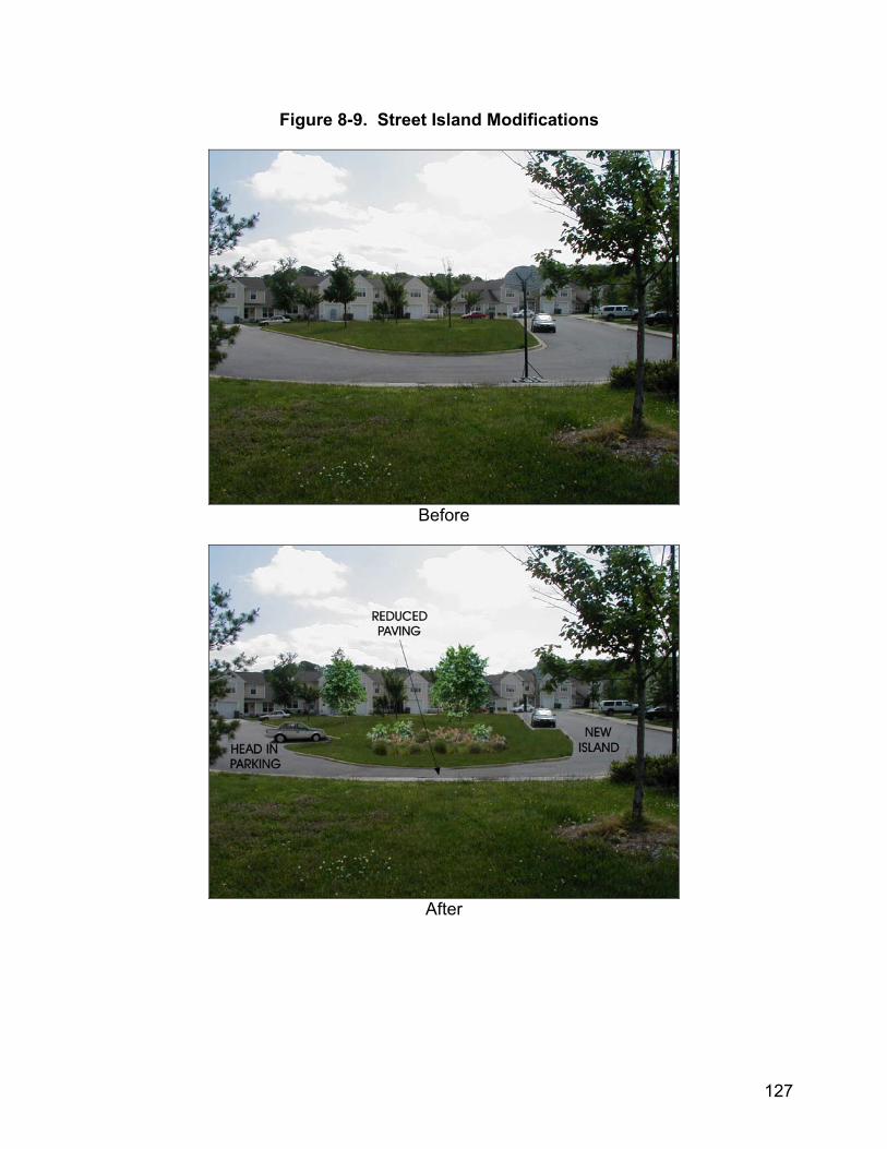
Figure 8-9. Street Island Modifications
Before
After
127
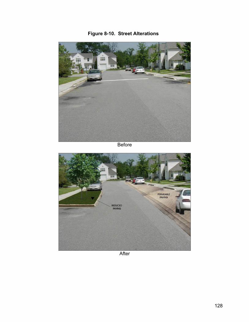
Figure 8-10. Street Alterations
Before
After
128

Figure 8-11. Trash Rack
Before
After
129

Figure 8-12. Tree Box Filter
Before
After
130
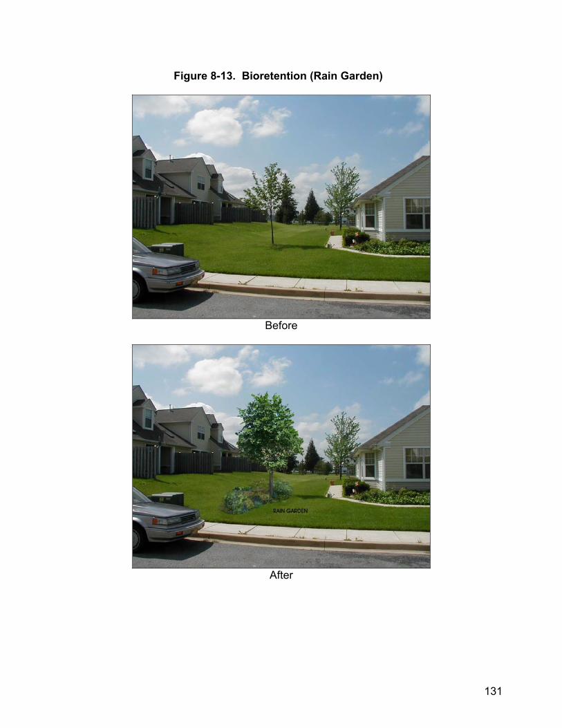
Figure 8-13. Bioretention (Rain Garden)
Before
After
131
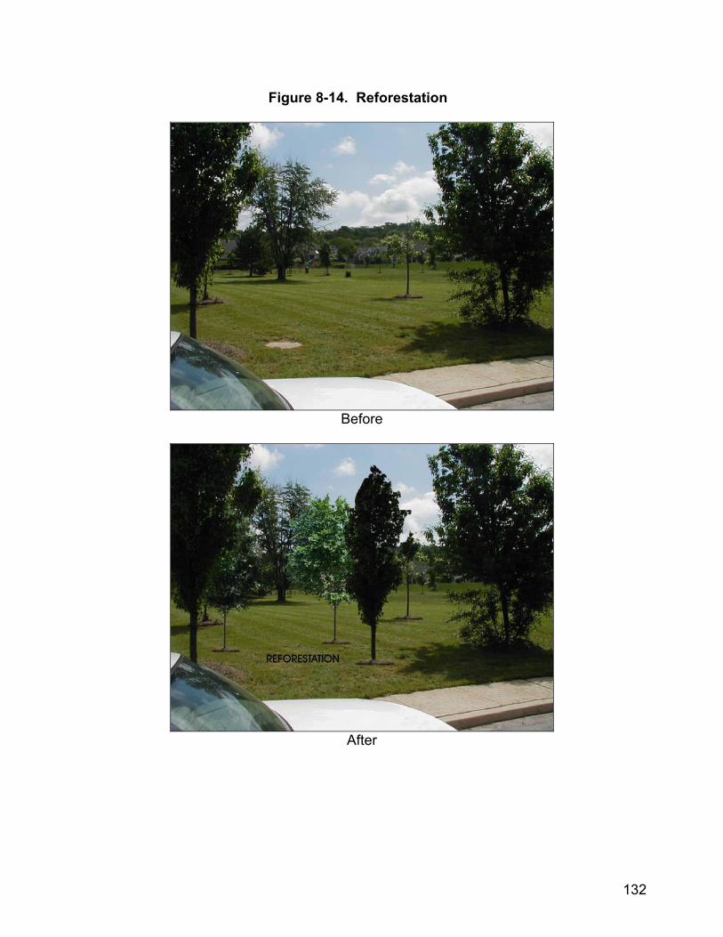
Figure 8-14. Reforestation
Before
After
132

8
8-2.9 WATER QUALITY CALCULATIONS. There are a variety of strategies and methods available to provide water quality control. One conventional approach is to capture a certain volume of runoff and hold it in a detention pond to allow pollutants to settle out of the water. A common regulatory requirement is to store the first 13 mm (0.5 in) of runoff from impervious areas (e.g. roofs, pavement or walks).45 Based on this requirement and the fact that there are 0.85 ha (2.1 acres) of impervious area in the proposed development, 111 m3 (0.09 acre-feet) of water quality storage is needed. Since this is less than the total retention storage requirement of 321 m2 (0.26 acre-feet,) the water quality storage volume is already contained in the proposed design. Many LID components use the biological, chemical and physical processes of plant and soil interactions to filter and treat pollutants. The effectiveness of these components can be measured in terms of a relative reduction in pollutant concentration or a reduction in the total mass of the pollutant that reaches the receiving waters annually. For this method, the reduction is based on the removal efficiency and flow rates rather than a storage volume. A detailed analysis of the combined effectiveness of the LID components will demonstrate, in some cases, that a storage volume for water quality is not necessary. 8-2.10 CONCLUSION. This case study has shown how LID can be incorporated into the design of a residential housing development. The use of LID practices has eliminated the need for a traditional stormwater detention pond, thereby reducing the disturbance to existing forested area. The retention of this forested buffer will in turn reduce impacts to the wetland and receiving waters. The need for piped stormwater conveyances has been eliminated. The LID approach has the added benefit of improving the aesthetics of the development and can provide opportunities for community involvement in the protection and maintenance of the local environment.
45 Novotny and Olem, 1994. 133
APPENDIX A
REFERENCES
GOVERNMENT PUBLICATIONS:
1. City of Portland Bureau of Environmental Services 1120 SW Fifth Avenue, Room 1000 Portland, OR 97204 (503) 823-7740
Stormwater management manual. Revision 2. 2000.
m.htm
2. Department of the Air Force Directorate of Environmental Quality 1260 Air Force Pentagon Washington, DC 20330-1260
Air Force Instruction 32-7080, Civil engineering: pollution prevention program. www.e-publishing.af.mil
3. Maine Dept. of Environmental ProtectionNonpoint Source Training and Resource Center 17 State House Station Augusta, ME 04333 (207) 287-7726
Stormwater management for Maine: best management practices. 1995.
www.state.me.us/dep/blwq/training/npspubl.htm
4. Prince George’s County Department of Environmental Resources (PGDER) Programs and Planning Division 9400 Peppercorn Place, Suite 500 Largo, MD 20774 (301) 883-5810
Design manual for use of bioretention in stormwater management. 1993. Low-impact development design strategies: an integrated design approach. 2000a.
www.epa.gov/owow/nps/lidnatl.pdf Low-impact development hydrologic analysis. 2000b.
www.epa.gov/owow/nps/lid/lid_hydr.pdf
5. U.S. Department of Agriculture Natural Resources Conservation Svc. (formerly Soil Conservation Service) National Water and Climate Center
www.cleanrivers-pdx.org/tech_resources/2002_swm
134
101 SW Main Street, Suite 1600 Portland, OR 97204 (503) 414-3031
Technical release 55 (TR-55), urban hydrology for small watersheds. 1986.
www.wcc.nrcs.usda.gov/hydro/hydro-tools-models-tr55.html
6. U.S. Department of Transportation Federal Highway Administration Planning, Environment, & Realty (HEP) 400 Seventh Street SW Washington, DC 20590 (202) 366-0116
Young, G. Kenneth et al. 1996. Evaluation and management of highway runoff water quality. FHWA-PD-96-032.
www.fhwa.dot.gov/environment/h2o_abs.htm Stormwater best management practices in an ultra-urban setting: selection and monitoring. 2000. FHWA-EP-00-002.
www.fhwa.dot.gov/environment/ultraurb
7.
U.S. Environmental Protection Agency Office of Water (4101M) 1200 Pennsylvania Avenue NW Washington, DC 20460 (800) 438-2474
Barbour, Michael T., Jeroen Gerritsen, Blaine D. Snyder, and James B. Stribling. 1999. Rapid bioassessment protocols for use in streams and wadeable rivers: periphyton, benthic macroinvertebrates, and fish. Second edition. EPA 841-B-99-002.
www.epa.gov/owow/monitoring/rbp Low Impact Development Center. 2000.
135

Low impact development (LID): a literature review. EPA-841-B-00-005.
www.epa.gov/owow/nps/lid/lid.pdf Results of the nationwide urban runoff program. 1983. NTIS#PB84-185552.
www.ntis.gov/pdf/ordrform.pdf Storm water technology fact sheet: bio- retention. 1999a. EPA-832-F-99-012.
www.epa.gov/owm/mtb/biortn.pdf Storm water technology fact sheet: hydrodynamic separators. 1999b. EPA-832-F-99-017.
www.epa.gov/owm/mtb/hydro.pdf Storm water technology fact sheet: infiltration trench. 1999c. EPA-832-F-99-019.
www.epa.gov/owm/mtb/infltrenc.pdf Storm water technology fact sheet: vegetated swales. 1999d. EPA-832-F-99-006.
www.epa.gov/owm/mtb/vegswale.pdf Urban stormwater BMP performance monitoring. 2002. EPA-821-B-02-001.
www.epa.gov/waterscience/stormwater/monitor.htm
NON-GOVERNMENT PUBLICATIONS:
1. American Society of Civil Engineers
136

Publications Marketing Department 1801 Alexander Bell Drive Reston, VA 20191 (800) 548-2723 ext. 6251
Coffman, Larry S., Robert Goo, and Rod Frederick. 1999. Low impact development: an innovative alternative approach to stormwater management. In Water Resources Planning and Management Conference ’99 - Preparing for the 21st Century ed. by Erin M. Wilson. Reston, VA: ASCE.
www.pubs.asce.org/WWWdisplaybn.cgi?0784404305 Harrington, Bruce W. 1989. Design and construction of infiltration trenches. In Design of Urban Runoff Quality Controls ed. by Larry A. Roesner, 290-306. New York: ASCE.
www.pubs.asce.org/BOOKdisplay.cgi?8902820
2. Cahill Associates 104 South High Street West Chester, PA 19382 (610) 696-4150
Cahill Associates. 2003. Porous pavement. West Chester: Cahill Associates.
3. Chesapeake Research Consortium 645 Contees Wharf Road Edgewater, MD 21037 (410)798-1283
Brown, Whitney E., and Thomas R. Schueler. 1997. The economics of stormwater BMPs in the Mid-Atlantic region. Prepared for the Chesapeake Research Consortium. Ellicott City, MD: Center for Watershed Protection.
4. Elsevier Scientific Publishing Company Science Direct Customer Service 360 Park Avenue South New York, NY 10010 USA (888) 437-4636
Sanders, R.A. 1986. Urban vegetation impacts on the hydrology of Dayton, Ohio. Urban Ecology 9: 361-376.
www.sciencedirect.com/science/journal/03044009
5. Engineers Australia National Committee on Water Engineering (NCWE) Engineering House 11 National Circuit Barton ACT 2600 +61 (02) 6270 6555
Wong, Tony. 2003. Introduction. In Australian Runoff Quality ed. by NCWE, 1-1 – 1-8. Barton: NCWE.
rambler.newcastle.edu.au/~ncwe/ncweARQ/ARQ.pd
137
6. Government Institutes 4 Research Place, Suite 200 Rockville, MD 20850 (301) 921-2300
Lee, C. C. 1998. Environmental engineering dictionary. Third edition. Rockville: Government Institutes.
7. Greenhorne and O’Mara (G&O) 9001 Edmonston Road Greenbelt, MD 20770 (866) 322-8905
G&O. 1998. Case studies in low impact development: stormwater management comparison and economics evaluation. Greenbelt: G&O.
8. Low Impact Development Center 5010 Sunnyside Avenue, Suite 200 Beltsville, MD 20910 (301) 982-5559
LID Center. 2002. Feasibility study for the use of low impact development to manage and control wet weather flows in urban areas. Beltsville: LID Center.
9. Metropolitan Washington Council of Governments (MWCOG) Information Center 777 North Capitol Street NE, Suite 300 Washington, DC 20002 (202) 962-3356
Schueler, Thomas R. 1992. A current assessment of urban best management practices. Washington: MWCOG. Publication Number 92705. Schueler, Thomas R. 1987. Controlling urban runoff: a practical manual for planning and designing urban BMPs. Washington: MWCOG. Publication Number 87703.
10. Peterson, Chere
Personal interview. 2002.
11. Prentice Hall 1 Lake Street Upper Saddle River, NJ 07458 (800) 282-0693
McCuen, Richard H. 1998. Hydrologic analysis and design. Second edition. Upper Saddle River: Prentice Hall.
12. Southeastern Wisconsin Regional Planning Commission (SEWRPC) P.O. Box 1607 Waukesha, WI 53187
SEWPRC. 1991. Costs of urban nonpoint source water pollution control measures.
138
(262) 547-6721
Technical Report 31. Waukesha: SEWPRC.Out of print; available at SEWPRC library.
13. University of Washington College of Forest Resources (CFR) Box 352100 Seattle, WA 98195 (206) 543-2730
Chollak, Tracy, and Paul Rosenfeld. 1998. Guidelines for landscaping with compost-amended soils. Seattle: CFR.
www.ci.redmond.wa.us/insidecityhall/publicworks/environment/pdfs/compostamendedsoils.pdf
14. University of Washington Dept. of Civil and Enviro. Engineering Center for Water and Watershed Studies (CWWP) 21 Winkenwerder Hall Box 352100 Seattle, WA 98195 (206) 543-6920
Colwell, Shanti R., Richard R. Horner, and Derek B. Booth. 2000. Characterization of performance predictors and evaluation of mowing practices in biofiltration swales. Seattle: CWWP.
depts.washington.edu/cwws/Research/Reports/swale%20mowing.pdf
15. Urban Land Institute 1025 Thomas Jefferson Street NW Suite 500 West Washington, DC 20007 (800) 321-5011
Scholz-Barth, Katrin. 2001. Green on top. Urban Land, June, 82.
16. John Wiley & Sons 111 River Street Hoboken, NJ 07030 (877) 762-2974
Gordon, Nancy D., Thomas A. McMahon, and Brian L. Finlayson. 1992. Stream hydrology: an introduction for ecologists. Chichester, England: John Wiley & Sons. Novotny, Vladimir, and Harvey Olem. 1994. Water quality: prevention, identification, and management of diffuse pollution. New York: John Wiley & Sons.
139

APPENDIX B
GLOSSARY: ACRONYMS AND ABBREVIATIONS ADA Americans with Disabilities Act BMP Best Management Practice CN Curve Number CSO Combined Sewer Overflow CWA Clean Water Act DoD Department of Defense EO Executive Order EPA Environmental Protection Agency EQI Environmental Quality Initiative FHWA Federal Highway Administration HEC Hydraulic Engineering Center IMP Integrated Management Practice LEED Leadership in Energy and Environmental Design LID Low Impact Development NPDES National Pollutant Discharge Elimination System NRCS Natural Resources Conservation Service NURP Nationwide Urban Runoff Program P2 Pollution Prevention PGDER Prince George’s County Department of Environmental Resources RBP Rapid Bioassessment Protocols SCS Soil Conservation Service SPCC Spill Prevention, Control, and Countermeasures SWMM Storm Water Management Model Tc Time of concentration TCT Tilled Compost-Amended Turf TMDL Total Maximum Daily Load TSS Total Suspended Solids
140

APPENDIX C
SUPPORTING CALCULATIONS FOR SECTION 8-2
141
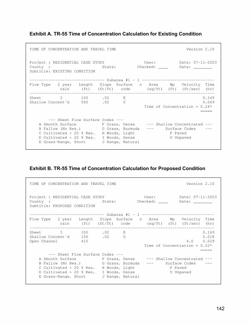
Exhibit A. TR-55 Time of Concentration Calculation for Existing Condition TIME OF CONCENTRATION AND TRAVEL TIME Version 2.10 Project : RESIDENTIAL CASE STUDY User: Date: 07-11-2003 County : State: Checked: ____ Date: ________ Subtitle: EXISTING CONDITION -------------------------------- Subarea #1 - 1 ------------------------------- Flow Type 2 year Length Slope Surface n Area Wp Velocity Time rain (ft) (ft/ft) code (sq/ft) (ft) (ft/sec) (hr) ------------------------------------------------------------------------------- Sheet 3 100 .02 E 0.169 Shallow Concent'd 565 .02 U 0.069 Time of Concentration = 0.24* ===== --- Sheet Flow Surface Codes --- A Smooth Surface F Grass, Dense --- Shallow Concentrated --- B Fallow (No Res.) G Grass, Burmuda --- Surface Codes --- C Cultivated < 20 % Res. H Woods, Light P Paved D Cultivated > 20 % Res. I Woods, Dense U Unpaved E Grass-Range, Short J Range, Natural
Exhibit B. TR-55 Time of Concentration Calculation for Proposed Condition TIME OF CONCENTRATION AND TRAVEL TIME Version 2.10 Project : RESIDENTIAL CASE STUDY User: Date: 07-11-2003 County : State: Checked: ____ Date: ________ Subtitle: PROPOSED CONDITION -------------------------------- Subarea #1 - 1 ------------------------------- Flow Type 2 year Length Slope Surface n Area Wp Velocity Time rain (ft) (ft/ft) code (sq/ft) (ft) (ft/sec) (hr) ------------------------------------------------------------------------------- Sheet 3 100 .02 E 0.169 Shallow Concent'd 150 .02 U 0.018 Open Channel 415 4.0 0.029 Time of Concentration = 0.22* ===== --- Sheet Flow Surface Codes --- A Smooth Surface F Grass, Dense --- Shallow Concentrated --- B Fallow (No Res.) G Grass, Burmuda --- Surface Codes --- C Cultivated < 20 % Res. H Woods, Light P Paved D Cultivated > 20 % Res. I Woods, Dense U Unpaved E Grass-Range, Short J Range, Natural
142
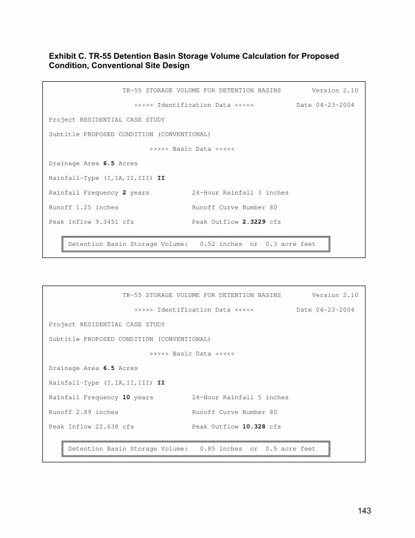
Exhibit C. TR-55 Detention Basin Storage Volume Calculation for Proposed Condition, Conventional Site Design TR-55 STORAGE VOLUME FOR DETENTION BASINS Version 2.10 >>>>> Identification Data <<<<< Date 04-23-2004 Project RESIDENTIAL CASE STUDY Subtitle PROPOSED CONDITION (CONVENTIONAL) >>>>> Basic Data <<<<< Drainage Area 6.5 Acres Rainfall-Type (I,IA,II,III) II Rainfall Frequency 2 years 24-Hour Rainfall 3 inches Runoff 1.25 inches Runoff Curve Number 80 Peak Inflow 9.3451 cfs Peak Outflow 2.3229 cfs ╔════════════════════════════════════════════════════════════════════╗ ║ Detention Basin Storage Volume: 0.52 inches or 0.3 acre feet ║ ╚════════════════════════════════════════════════════════════════════╝ TR-55 STORAGE VOLUME FOR DETENTION BASINS Version 2.10 >>>>> Identification Data <<<<< Date 04-23-2004 Project RESIDENTIAL CASE STUDY Subtitle PROPOSED CONDITION (CONVENTIONAL) >>>>> Basic Data <<<<< Drainage Area 6.5 Acres Rainfall-Type (I,IA,II,III) II Rainfall Frequency 10 years 24-Hour Rainfall 5 inches Runoff 2.89 inches Runoff Curve Number 80 Peak Inflow 22.638 cfs Peak Outflow 10.328 cfs ╔════════════════════════════════════════════════════════════════════╗ ║ Detention Basin Storage Volume: 0.85 inches or 0.5 acre feet ║ ╚════════════════════════════════════════════════════════════════════╝
143
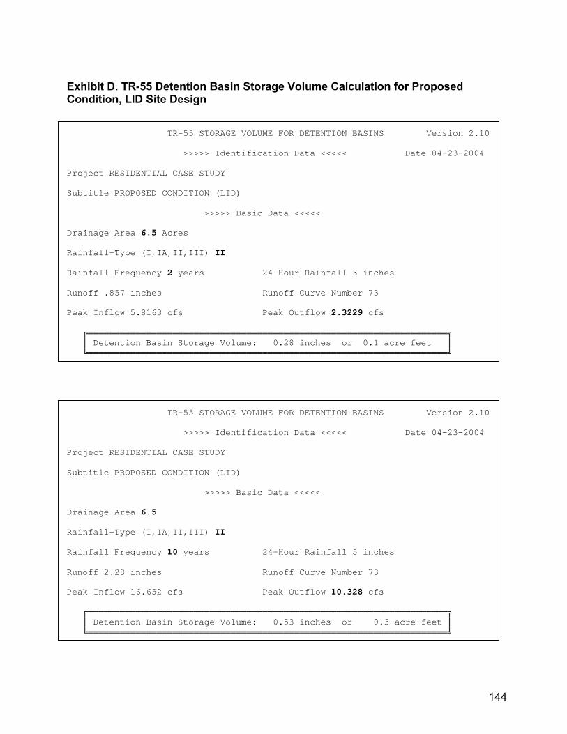
Exhibit D. TR-55 Detention Basin Storage Volume Calculation for Proposed Condition, LID Site Design TR-55 STORAGE VOLUME FOR DETENTION BASINS Version 2.10 >>>>> Identification Data <<<<< Date 04-23-2004 Project RESIDENTIAL CASE STUDY Subtitle PROPOSED CONDITION (LID) >>>>> Basic Data <<<<< Drainage Area 6.5 Acres Rainfall-Type (I,IA,II,III) II Rainfall Frequency 2 years 24-Hour Rainfall 3 inches Runoff .857 inches Runoff Curve Number 73 Peak Inflow 5.8163 cfs Peak Outflow 2.3229 cfs ╔════════════════════════════════════════════════════════════════════╗ ║ Detention Basin Storage Volume: 0.28 inches or 0.1 acre feet ║ ╚════════════════════════════════════════════════════════════════════╝ TR-55 STORAGE VOLUME FOR DETENTION BASINS Version 2.10 >>>>> Identification Data <<<<< Date 04-23-2004 Project RESIDENTIAL CASE STUDY Subtitle PROPOSED CONDITION (LID) >>>>> Basic Data <<<<< Drainage Area 6.5 Rainfall-Type (I,IA,II,III) II Rainfall Frequency 10 years 24-Hour Rainfall 5 inches Runoff 2.28 inches Runoff Curve Number 73 Peak Inflow 16.652 cfs Peak Outflow 10.328 cfs ╔════════════════════════════════════════════════════════════════════╗ ║ Detention Basin Storage Volume: 0.53 inches or 0.3 acre feet ║ ╚════════════════════════════════════════════════════════════════════╝
144

APPENDIX D
LID DESIGN CHARTS
145

Chart 1
Source: PGDER, 2000b.
146
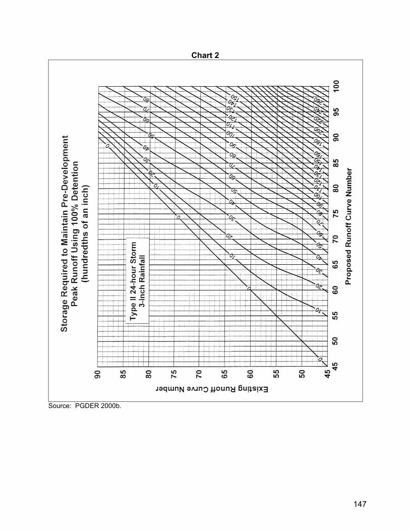
Chart 2
Source: PGDER 2000b.
147
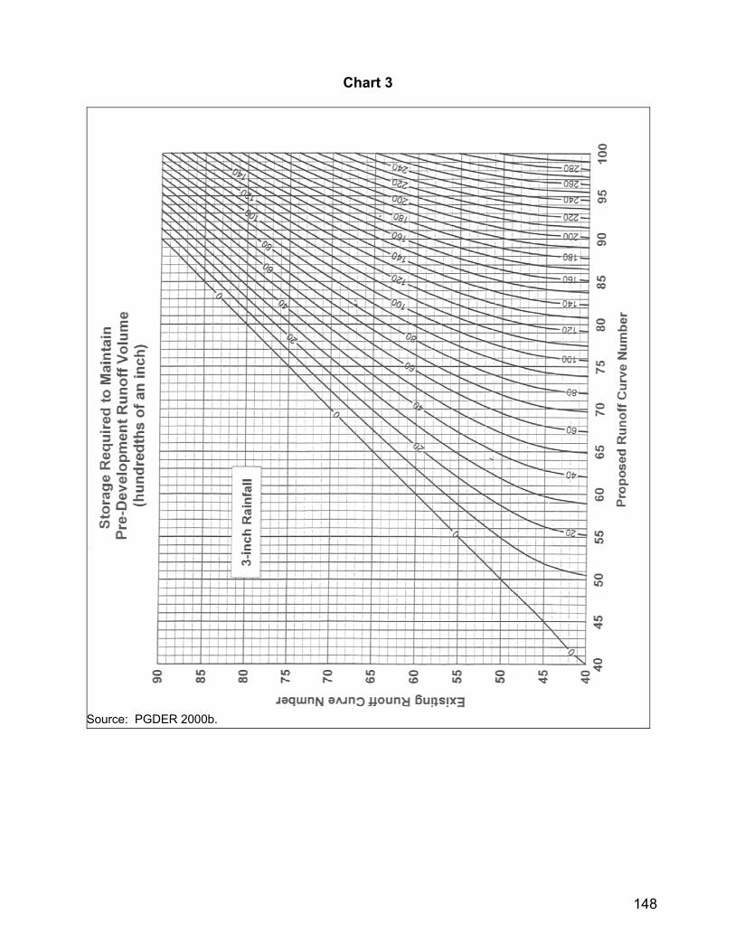
Chart 3
Source: PGDER 2000b.
148