unit 06 circuit simulation and manufacture - ocr · for electrical and electronic devices to...
TRANSCRIPT

ocr.org.uk/engineering
2016 Suite
Cambridge TECHNICALS LEVEL 3
ENGINEERINGUnit 6
Circuit simulation and manufacture
D/506/7272
Guided learning hours: 60 VERSION 4 - June 2017 black line indicates updated content

© OCR 2017 Unit 6: Circuit simulation and manufacture
LEVEL 3
UNIT 6: CIRCUIT SIMULATION AND MANUFACTURE
D/506/7272
Guided learning hours: 60
Essential resources required for this unit: circuit schematic design and simulation software, PCB design software, PCB manufacturing facilities, PCB/circuit construction tools (see specification), electrical/electronic components, suitable PPE, physical test equipment (assessment guidance)
This unit is internally assessed and externally moderated by OCR.
UNIT AIM For electrical and electronic devices to function, they depend on their circuits operating normally. Circuit simulation and safe, effective manufacture of circuit boards is therefore a key function within electrical engineering companies.
The aim of this unit is for learners to develop the ability to make working printed circuit boards (PCBs).
Learners will develop the ability to use computer aided design (CAD) software to design and simulate electronic circuits, and then to design PCBs. They will go on to be able to safely manufacture and construct PCBs.
Learners will also develop their fault-finding techniques for PCBs, to test and rectify, where possible, faults on circuits. They will also gain knowledge on the commercial manufacture of circuits, including manufacturing process methods and quality assurance techniques.

© OCR 2017 Unit 6: Circuit simulation and manufacture
TEACHING CONTENT The teaching content in every unit states what has to be taught to ensure that learners are able to access the highest grades. Anything which follows an i.e. details what must be taught as part of that area of content. Anything which follows an e.g. is illustrative, it should be noted that where e.g. is used, learners must know and be able to apply relevant examples in their work, though these do not need to be the same ones specified in the unit content. For internally assessed units you need to ensure that any assignments you create, or any modifications you make to an assignment, do not expect the learner to do more than they have been taught, but they must enable them to access the full range of grades as described in the grading criteria. Please note – if learners are completing this unit as part of the Extended Diploma qualification they will be required to complete the synoptic unit 25: Promoting continuous improvement. Before your learners complete the assessment of this unit, you must refer to the specification and model assignment requirements for unit 25, so if applicable you can ensure learners gather the appropriate feedback on their own performance and performance of the system, process or artefact that they may have produced in this unit.

© OCR 2017 Unit 6: Circuit simulation and manufacture
Learning outcomes Teaching content
The Learner will: Learners must be taught:
1. Be able to use Computer Aided Design (CAD) for circuit design and simulation
1.1 circuit schematic diagram drawing using CAD software i.e. • schematic capture / schematic design • component library • connection or interconnection • grid
1.2 circuit simulation and test using CAD software i.e. • design checking, design rule checking • SPICE (Simulation Program with Integrated Circuit Emphasis) • setting and adjusting component parameters • netlist/node list • circuit analysis using virtual instruments
2. Be able to use Computer Aided Design (CAD) to design printed circuit boards (PCBs)
2.1 printed circuit board (PCB) layout production to include both track and component views i.e. • parts and component libraries • manual component placement • automatic component placement • manual and automatic routing of PCB tracks • correct track and pad sizing • requirements for double-sided or multiple circuit boards (e.g.
mother and daughter boards) • design constraints (e.g. size of PCB) • incorporation of test points or test indicators • inclusion of mounting holes • inclusion of component and pin identification (e.g. labels, pin 1
identification) • export files (e.g. Gerber, DXF, IDF, csv, txt) • bill of material (BOM) production
© OCR 2017 Unit 6: Circuit simulation and manufacture
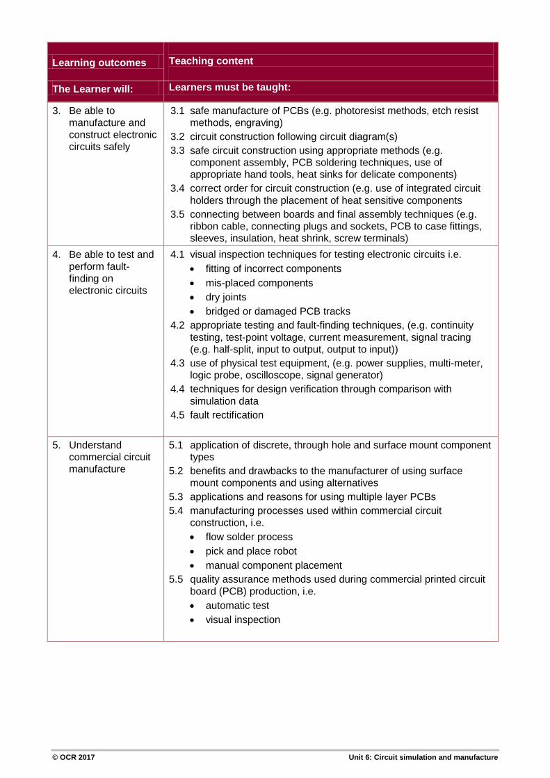
3. Be able to manufacture and construct electronic circuits safely
3.1 safe manufacture of PCBs (e.g. photoresist methods, etch resist methods, engraving)
3.2 circuit construction following circuit diagram(s) 3.3 safe circuit construction using appropriate methods (e.g.
component assembly, PCB soldering techniques, use of appropriate hand tools, heat sinks for delicate components)
3.4 correct order for circuit construction (e.g. use of integrated circuit holders through the placement of heat sensitive components
3.5 connecting between boards and final assembly techniques (e.g. ribbon cable, connecting plugs and sockets, PCB to case fittings, sleeves, insulation, heat shrink, screw terminals)
4. Be able to test and perform fault-finding on electronic circuits
4.1 visual inspection techniques for testing electronic circuits i.e. • fitting of incorrect components • mis-placed components • dry joints • bridged or damaged PCB tracks
4.2 appropriate testing and fault-finding techniques, (e.g. continuity testing, test-point voltage, current measurement, signal tracing (e.g. half-split, input to output, output to input))
4.3 use of physical test equipment, (e.g. power supplies, multi-meter, logic probe, oscilloscope, signal generator)
4.4 techniques for design verification through comparison with simulation data
4.5 fault rectification
5. Understand commercial circuit manufacture
5.1 application of discrete, through hole and surface mount component types
5.2 benefits and drawbacks to the manufacturer of using surface mount components and using alternatives
5.3 applications and reasons for using multiple layer PCBs 5.4 manufacturing processes used within commercial circuit
construction, i.e. • flow solder process • pick and place robot • manual component placement
5.5 quality assurance methods used during commercial printed circuit board (PCB) production, i.e. • automatic test • visual inspection
Learning outcomes Teaching content
The Learner will: Learners must be taught:

© OCR 2017 Unit 6: Circuit simulation and manufacture
GRADING CRITERIA LO Pass Merit Distinction The assessment criteria are the Pass
requirements for this unit.
To achieve a Merit the evidence must show that, in addition to the Pass criteria, the candidate is able to:
To achieve a Distinction the evidence must show that, in addition to the pass and merit criteria, the candidate is able to:
1. Be able to use Computer Aided Design (CAD) for circuit design and simulation
P1: Produce circuit schematic diagram drawings using CAD software.
M1: Perform circuit analysis including the use of virtual instrumentation.
D1: Evaluate circuit operation and associated printed circuit board layout using CAD software, implementing appropriate design modifications.
P2: Carry out circuit simulation using CAD software. *Synoptic link to Unit 4 Principles of electrical and electronic engineering
2. Be able to use Computer Aided Design (CAD) to design printed circuit boards (PCBs)
P3: Produce PCB layouts using CAD software to include track and component views.
M2: Analyse functionality of printed circuit board layout using CAD software.
3. Be able to manufacture and construct electronic circuits safely
P4: Interpret circuit diagram to construct printed circuit board.
D2: Safely manufacture, test and verify a fully working electronic circuit, to include identification and rectification of faults, using a variety of construction methods.
P5: Safely manufacture a printed circuit board using appropriate techniques. P6: Safely assemble components to printed circuit board. *Synoptic link to Unit 2 Science for engineering

© OCR 2017 Unit 6: Circuit simulation and manufacture
LO Pass Merit Distinction
4. Be able to test and perform fault-finding on electronic circuits
P7 Perform testing of an electronic circuit using a multimeter. *Synoptic link to Unit 4 Principles of electrical and electronic engineering
M3: Undertake testing of the operation of an electronic circuit using different physical test equipment and fault finding techniques.
D2: Safely manufacture, test and verify a fully working electronic circuit, to include identification and rectification of faults, using a variety of construction methods.
5. Understand commercial circuit manufacture
P8: Identify applications of different component types used in commercial circuit construction.
M4: Compare manufacturing processes and quality assurance methods used in commercial circuit construction.
P9: Explain the benefits and drawbacks to manufacturers of using surface mount components and alternatives. P10: Explain the use of multiple layer PCBs in commercial circuit manufacture.
© OCR 2017 Unit 6: Circuit simulation and manufacture
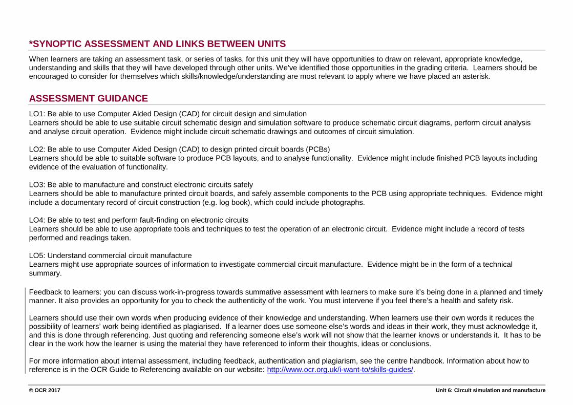
*SYNOPTIC ASSESSMENT AND LINKS BETWEEN UNITS When learners are taking an assessment task, or series of tasks, for this unit they will have opportunities to draw on relevant, appropriate knowledge, understanding and skills that they will have developed through other units. We’ve identified those opportunities in the grading criteria. Learners should be encouraged to consider for themselves which skills/knowledge/understanding are most relevant to apply where we have placed an asterisk.
ASSESSMENT GUIDANCE LO1: Be able to use Computer Aided Design (CAD) for circuit design and simulation Learners should be able to use suitable circuit schematic design and simulation software to produce schematic circuit diagrams, perform circuit analysis and analyse circuit operation. Evidence might include circuit schematic drawings and outcomes of circuit simulation. LO2: Be able to use Computer Aided Design (CAD) to design printed circuit boards (PCBs) Learners should be able to suitable software to produce PCB layouts, and to analyse functionality. Evidence might include finished PCB layouts including evidence of the evaluation of functionality. LO3: Be able to manufacture and construct electronic circuits safely Learners should be able to manufacture printed circuit boards, and safely assemble components to the PCB using appropriate techniques. Evidence might include a documentary record of circuit construction (e.g. log book), which could include photographs. LO4: Be able to test and perform fault-finding on electronic circuits Learners should be able to use appropriate tools and techniques to test the operation of an electronic circuit. Evidence might include a record of tests performed and readings taken. LO5: Understand commercial circuit manufacture Learners might use appropriate sources of information to investigate commercial circuit manufacture. Evidence might be in the form of a technical summary. Feedback to learners: you can discuss work-in-progress towards summative assessment with learners to make sure it’s being done in a planned and timely manner. It also provides an opportunity for you to check the authenticity of the work. You must intervene if you feel there’s a health and safety risk. Learners should use their own words when producing evidence of their knowledge and understanding. When learners use their own words it reduces the possibility of learners’ work being identified as plagiarised. If a learner does use someone else’s words and ideas in their work, they must acknowledge it, and this is done through referencing. Just quoting and referencing someone else’s work will not show that the learner knows or understands it. It has to be clear in the work how the learner is using the material they have referenced to inform their thoughts, ideas or conclusions. For more information about internal assessment, including feedback, authentication and plagiarism, see the centre handbook. Information about how to reference is in the OCR Guide to Referencing available on our website: http://www.ocr.org.uk/i-want-to/skills-guides/.

© OCR 2017 Unit 6: Circuit simulation and manufacture
MEANINGFUL EMPLOYER INVOLVEMENT - a requirement for the Foundation Diploma, Diploma and Extended Diploma (tech level) qualifications The ‘Diploma’ qualifications have been designed to be recognised as Tech Levels in performance tables in England. It is a requirement of these qualifications for centres to secure for every learner employer involvement through delivery and/or assessment of these qualifications. The minimum amount of employer involvement must relate to at least one or more of the elements of the mandatory content (this unit is a mandatory unit in the Electrical and Electronic Engineering pathway). Eligible activities and suggestions/ideas that may help you in securing meaningful employer involvement for this unit are given in the table below. Please refer to the Qualification Handbook for further information including a list of activities that are not considered to meet this requirement.
Meaningful employer engagement Suggestion/ideas for centres when delivering this unit 1. Learners undertake structured work-experience or
work-placements that develop skills and knowledge relevant to the qualification.
Placements with working with engineering electrical/electronic design departments of businesses involved in circuit manufacture, researching the CAD software used, and system standards used to check conformity of manufacture.
2. Learners undertake project(s), exercises(s) and/or assessments/examination(s) set with input from industry practitioner(s).
Task set to use CAD to design and simulate electrical circuits using industry standard equipment and standards, to determine if the design of the circuit is suitable for a given application.
3. Learners take one or more units delivered or co-delivered by an industry practitioner(s). This could take the form of master classes or guest lectures.
Lecture from practicing electrical/electronic design engineers involved in product circuit design, development and commercial testing. Content to include examples of electrical/ electronic CAD simulation methods (e.g. SPICE) and the processes involved in commercial circuit manufacture, including testing.
4. Industry practitioners operating as ‘expert witnesses’ that contribute to the assessment of a learner’s work or practice, operating within a specified assessment framework. This may be a specific project(s), exercise(s) or examination(s), or all assessments for a qualification.
Review by practicing electrical engineers relating to the accuracy of learners’ PCB designs, and/or a review of the manufactured circuit with relation to the design produced and its fitness for purpose.

OCR is part of Cambridge Assessment, a department of the University of Cambridge.
For staff training purposes and as part of our quality assurance programme your call may be recorded or monitored. ©OCR 2015 Oxford Cambridge and RSA Examinations is a Company Limited by Guarantee. Registered in England. Registered office 1 Hills Road, Cambridge CB1 2EU. Registered company number 3484466. OCR is an exempt charity.
Oxford Cambridge and RSA
To find out moreocr.org.uk/engineering or call our Customer Contact Centre on 02476 851509Alternatively, you can email us on [email protected]