unit 8 - vtu notes€¦ · unit 8 (a) interfacing ... and perform computations and decisions on the...
TRANSCRIPT

UNIT 8
(a) Interfacing resistive transducers to electronic circuits. Introduction to data
acquisition systems. 2 Hours
(b) Display Devices and Signal Generators: X-Y recorders. Nixie tubes. LCD
and LED display. Signal generators and function generators. 4 Hours
UNIT 8a:
Interfacing resistive transducers to electronic circuits.
Introduction to data acquisition systems.
Interfacing resistive transducers to electronic circuits
The major problem with resistive transducers, which includes strain gages,
temperature transducers is that the resistance change is very small. As an
example, consider measuring the current through a resistance transducer such as
an RTD. A simple panel meter is used as an Indicator to provide a remote reading
of temperature. The change in the meter Indication is very small for small
temperature changes. As an example, the change in resistance of a platinum
resistance thermometer is 0.385 per cent per degree Celsius. In this case, a 1-
degree change in temperature will produce a 0.385 Per cent change in the
indicating meter, which will be hardly visible.
A solution to this Problem is to connect the resistance transducer in a bridge
circuit as shown in Fig.1
www.bookspar.com | VTU NOTES | QUESTION PAPERS | NEWS | RESULTS | FORUMS
www.bookspar.com | VTU NOTES | QUESTION PAPERS | NEWS | RESULTS | FORUMS
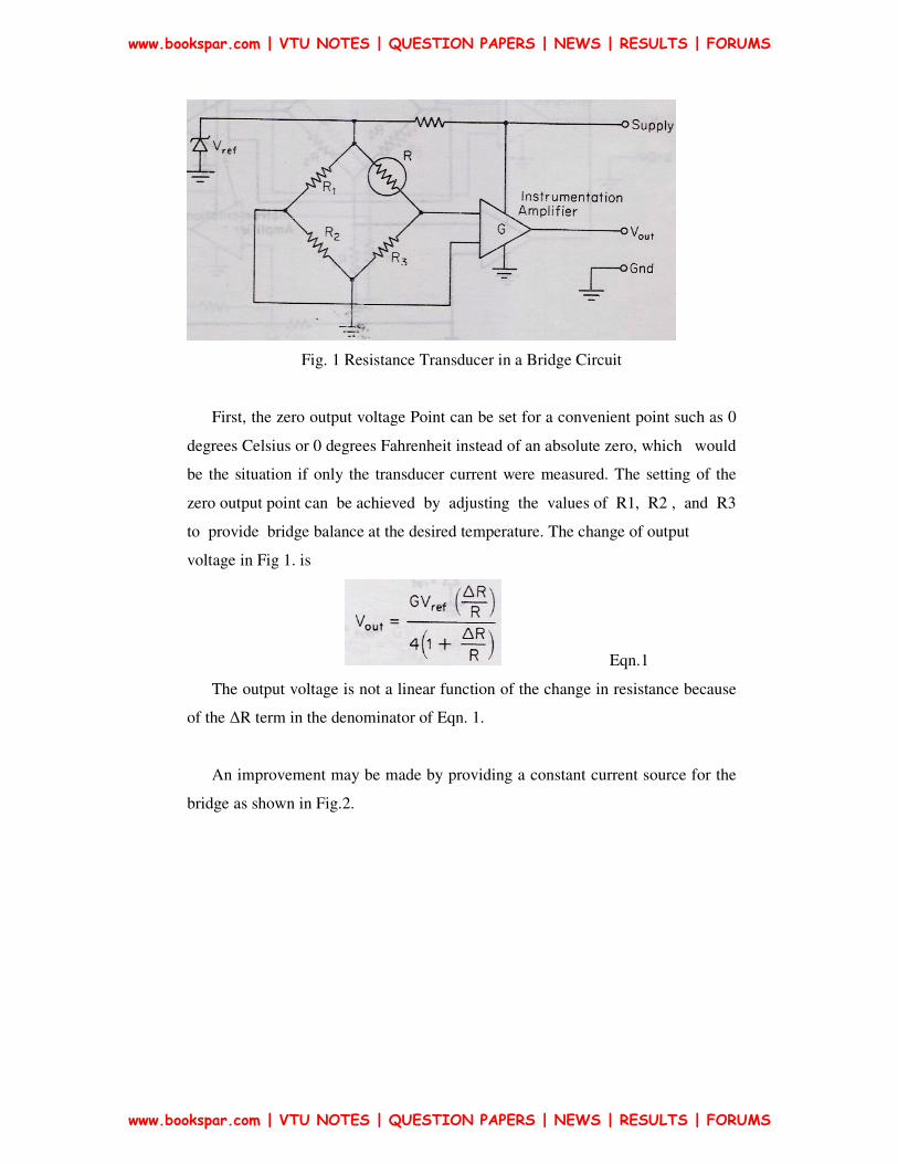
Fig. 1 Resistance Transducer in a Bridge Circuit
First, the zero output voltage Point can be set for a convenient point such as 0
degrees Celsius or 0 degrees Fahrenheit instead of an absolute zero, which would
be the situation if only the transducer current were measured. The setting of the
zero output point can be achieved by adjusting the values of R1, R2 , and R3
to provide bridge balance at the desired temperature. The change of output
voltage in Fig 1. is
Eqn.1
The output voltage is not a linear function of the change in resistance because
of the ∆R term in the denominator of Eqn. 1.
An improvement may be made by providing a constant current source for the
bridge as shown in Fig.2.
www.bookspar.com | VTU NOTES | QUESTION PAPERS | NEWS | RESULTS | FORUMS
www.bookspar.com | VTU NOTES | QUESTION PAPERS | NEWS | RESULTS | FORUMS
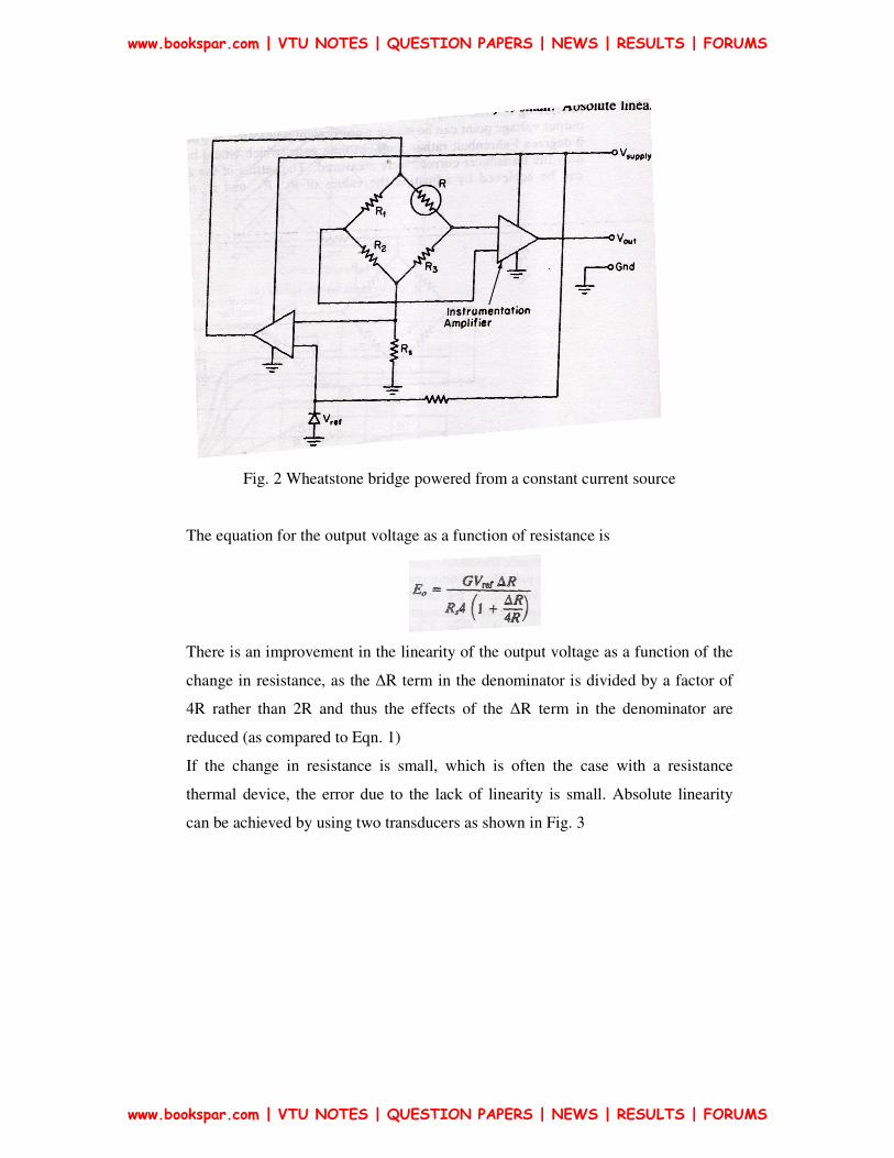
Fig. 2 Wheatstone bridge powered from a constant current source
The equation for the output voltage as a function of resistance is
There is an improvement in the linearity of the output voltage as a function of the
change in resistance, as the ∆R term in the denominator is divided by a factor of
4R rather than 2R and thus the effects of the ∆R term in the denominator are
reduced (as compared to Eqn. 1)
If the change in resistance is small, which is often the case with a resistance
thermal device, the error due to the lack of linearity is small. Absolute linearity
can be achieved by using two transducers as shown in Fig. 3
www.bookspar.com | VTU NOTES | QUESTION PAPERS | NEWS | RESULTS | FORUMS
www.bookspar.com | VTU NOTES | QUESTION PAPERS | NEWS | RESULTS | FORUMS
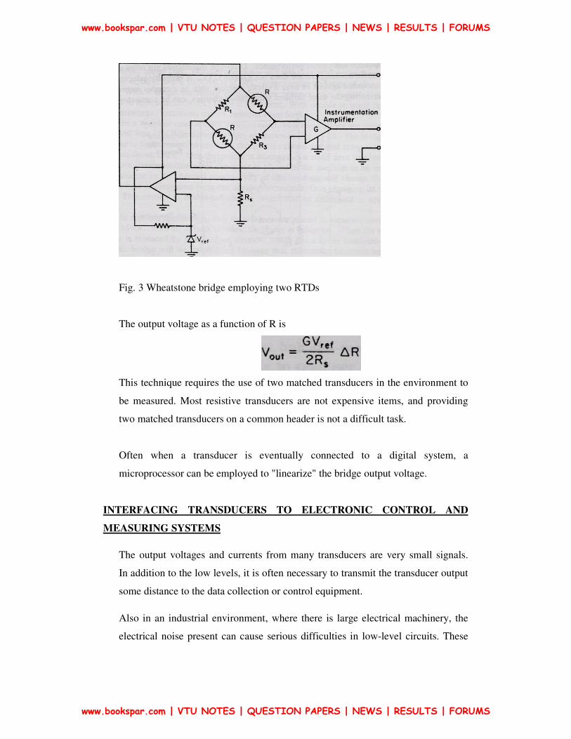
Fig. 3 Wheatstone bridge employing two RTDs
The output voltage as a function of R is
This technique requires the use of two matched transducers in the environment to
be measured. Most resistive transducers are not expensive items, and providing
two matched transducers on a common header is not a difficult task.
Often when a transducer is eventually connected to a digital system, a
microprocessor can be employed to "linearize" the bridge output voltage.
INTERFACING TRANSDUCERS TO ELECTRONIC CONTROL AND
MEASURING SYSTEMS
The output voltages and currents from many transducers are very small signals.
In addition to the low levels, it is often necessary to transmit the transducer output
some distance to the data collection or control equipment.
Also in an industrial environment, where there is large electrical machinery, the
electrical noise present can cause serious difficulties in low-level circuits. These
www.bookspar.com | VTU NOTES | QUESTION PAPERS | NEWS | RESULTS | FORUMS
www.bookspar.com | VTU NOTES | QUESTION PAPERS | NEWS | RESULTS | FORUMS
noises can be either radiated as an electromagnetic field or induce in the wiring of
the plant as ground loops, and induced spikes on the ac power supply.
Regardless of the source of noise, low-level signals must be transmitted from place to
place with care. One effective method of combating noise is to increase the strength of
low level signals before transmission through wires. This is often done with an
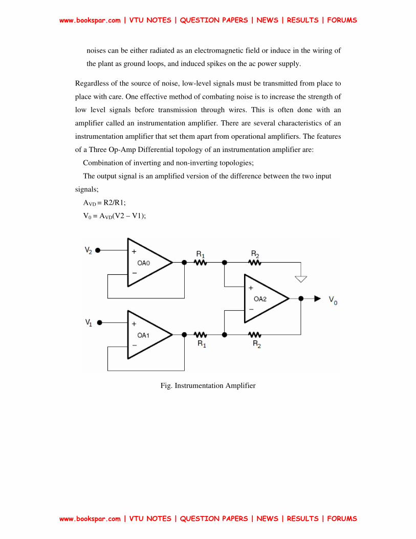
amplifier called an instrumentation amplifier. There are several characteristics of an
instrumentation amplifier that set them apart from operational amplifiers. The features
of a Three Op-Amp Differential topology of an instrumentation amplifier are:
Combination of inverting and non-inverting topologies;
The output signal is an amplified version of the difference between the two input
signals;
AVD = R2/R1;
V0 = AVD(V2 – V1);
Fig. Instrumentation Amplifier
www.bookspar.com | VTU NOTES | QUESTION PAPERS | NEWS | RESULTS | FORUMS
www.bookspar.com | VTU NOTES | QUESTION PAPERS | NEWS | RESULTS | FORUMS
Data acquisition systems
Data acquisition systems are used to measure and record signals obtained in
basically two ways:
1. Signals originating from direct measurement of electrical quantities; these
may include dc and ac voltages, frequency , or resistance, and are typically
found in such areas as electronic component testing, environmental
studies, and quality analysis work.
2. Signals originating from transducers, such as strain gages and
thermocouples
Instrumentation systems can be categorized into two major classes: analog
systems and digital systems.
Analog systems deal with measurement information in analog form.
An analog signal may be defined as a continuous function, such as a plot of
voltage versus time, or displacement versus pressure.
Digital systems handle information in digital form.
A digital quantity may consist of a number of discrete and discontinuous pulses
whose time relationship contains information about the magnitude or the nature of
the quantity.
Data acquisition systems are used in a large and ever-increasing number of
applications in a variety of industrial and scientific areas, such as the biomedical,
aerospace, and telemetry industries. The type of data acquisition system, whether
analog or digital, depends largely on the intended use of the recorded input data.
In general, analog data systems are used when wide bandwidth is required or
when lower accuracy can be tolerated.
Digital systems are used when the physical process being monitored is slowly
varying (narrow bandwidth) and when high accuracy and low per-channel cost is
required.
www.bookspar.com | VTU NOTES | QUESTION PAPERS | NEWS | RESULTS | FORUMS
www.bookspar.com | VTU NOTES | QUESTION PAPERS | NEWS | RESULTS | FORUMS
Digital systems range in complexity from single-channel dc voltage measuring
and recording systems to sophisticated automatic multichannel systems that
measure a large number of input parameters, compare against preset limits or
conditions, and perform computations and decisions on the input signal.
Digital data acquisition systems are in general more complex than analog systems,
both in terms of the instrumentation involved and the volume and complexity of
input data they can handle. Digital systems require converters to change analog
voltages into discrete digital quantities or numbers. Conversely, digital
information may have to be converted back into analog form, such as a voltage or
a current, which can then be used as a feedback quantity controlling an industrial
process.
Analog Data Acquisition System
An analog data acquisition system typically consists of some or all of the
following elements:
1. Transducers for translating physical parameters into electrical signals.
2. Signal conditioners for amplifying, modifying, or selecting certain
portions of these signals.
3. Visual display devices for continuous monitoring of the input signals.
These devices may include single- or multichannel oscilloscopes, storage
oscilloscopes, panel meters, numerical displays, and so on.
4. Graphic recording instruments for obtaining permanent records of the
input data. These instruments include stylus-and-ink recorders to provide
continuous records on paper charts, optical recording systems such as
mirror galvanometer recorders, and ultraviolet recorders.
5. Magnetic tape instrumentation for acquiring input data, preserving their
original electrical form, and reproducing them at a later date for more
detailed analysis.
www.bookspar.com | VTU NOTES | QUESTION PAPERS | NEWS | RESULTS | FORUMS
www.bookspar.com | VTU NOTES | QUESTION PAPERS | NEWS | RESULTS | FORUMS

Digital Data Acquisition System
A digital data acquisition system may include some or all of the elements
shown in Fig. 4
The essential functional operations within a digital system include handling
analog signals, making the measurement, converting and handling digital data, and
internal programming and control.
Fig. 4 Elements of a digital data-acquisition system
1. Transducer
Translates physical parameters to electrical signals acceptable by the acquisition
system. Some typical parameters include temperature, pressure, acceleration,
weight displacement, and velocity. Electrical quantities, such as voltage,
resistance, or frequency, also may be measured directly.
2. Signal conditioner
Generally includes the supporting circuitry for the transducer. This circuitry may
provide excitation power, balancing circuits and calibration elements. An example
of a signal conditioner is a strain-gage bridge balance and power supply unit.
3. Scanner, or multiplexer.
Accepts multiple analog inputs and sequentially connects them to one measuring
instrument
4. Signal converter.
www.bookspar.com | VTU NOTES | QUESTION PAPERS | NEWS | RESULTS | FORUMS
www.bookspar.com | VTU NOTES | QUESTION PAPERS | NEWS | RESULTS | FORUMS
Translates the analog signal to a form acceptable by the analog-to-digital
converter. An example of a signal converter is an amplifier for amplifying low-
level voltages generated by thermocouples or strain gages.
5. Analog-to-digital (AID) converter.
Converts the analog voltage to its equivalent digital form. The output of the
converter may be displayed visually and is also available as voltage outputs in
discrete steps for further processing or recording on a digital recorder.
6. Auxiliary equipment
This section contains instruments for system programming functions and digital
data processing. Typical auxiliary functions include linearizing and limit
comparison. These functions may be performed by individual instruments or by a
digital computer.
7. Digital recorder
Records digital information on punched cards, perforated paper tape, magnetic
tape, typewritten pages, or a combination of these systems. The digital recorder
may be preceded by a coupling unit that translates the digital information to the
proper form for entry into the particular digital recorder selected.
www.bookspar.com | VTU NOTES | QUESTION PAPERS | NEWS | RESULTS | FORUMS
www.bookspar.com | VTU NOTES | QUESTION PAPERS | NEWS | RESULTS | FORUMS
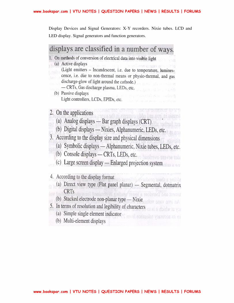
Display Devices and Signal Generators: X-Y recorders. Nixie tubes. LCD and
LED display. Signal generators and function generators.
www.bookspar.com | VTU NOTES | QUESTION PAPERS | NEWS | RESULTS | FORUMS
www.bookspar.com | VTU NOTES | QUESTION PAPERS | NEWS | RESULTS | FORUMS

Some Popular Display Devices their Applications, Advantages & Disadvantages
are given below.
CRTs
• Large display, small and large group viewing, console display.
• Bright, efficient, uniform, planar display, all colours, high reliability
• Bulky, high voltage, non-digital address, high initial cost.
LEDs
• Indicators and small displays, individual viewing, flat panel
• Bright, efficient,
• Available in different colours such as red, yellow, amber, green colours,
• compatible with ICs,
• small size
• High cost per element, limited reliability, low switching speed,
LCDs
• Indicators and small displays, individual viewing, flat panel
• Good contrast in bright ambient light, low power, compatible with ICs
• Limited temperature range (0 - 60oC), Limited reliability, ac operation
NIXIEs
• Indicators, small, medium & large displays, Small group viewing
• Bright, range of colors,
• low cost element,
• Compatible with ICs
• High drive power
www.bookspar.com | VTU NOTES | QUESTION PAPERS | NEWS | RESULTS | FORUMS
www.bookspar.com | VTU NOTES | QUESTION PAPERS | NEWS | RESULTS | FORUMS
ELs
• Indicators & small displays, flat panel
• Low cost element
• Many colors
• Not compatible with ICs
www.bookspar.com | VTU NOTES | QUESTION PAPERS | NEWS | RESULTS | FORUMS
www.bookspar.com | VTU NOTES | QUESTION PAPERS | NEWS | RESULTS | FORUMS

Display Devices in detail
X-Y recorders
A strip chart recorder records the variations of a quantity with respect to time
while a X-Y Recorder is an instrument which gives a graphic record of the
relationship between two variables. In strip chart recorders, usually self-balancing
potentiometers are used. These self-balancing potentiometers plot the emf as a
function of time.
In X-Y Recorders, an emf is plotted as a function of another emf. This is done by
having one self-balancing potentiometer control the position of the rolls (i.e., the
paper) while another self-balancing potentiometer controls the position of the
recording pen (stylus). In some X-Y recorders, one self- balancing potentiometer
circuit moves a recording pen (stylus) in the X direction while another self-
balancing potentiometer, circuit moves the recording pen (stylus) in the Y
direction at right angles to the X direction while the paper remains stationary.
Hence a X-Y Recorder consists of a pair of servo systems, driving a recording pen
in two axes through a proper sliding pen and moving arm arrangement as shown
in Fig. 5.
There are many variations of X-Y recorders. The emf used for operation of X-Y
recorders, may not necessarily measure only voltages. The measured emf may be
the output of a transducer that measure displacement force, pressure, light
intensity or any other physical quantity.
www.bookspar.com | VTU NOTES | QUESTION PAPERS | NEWS | RESULTS | FORUMS
www.bookspar.com | VTU NOTES | QUESTION PAPERS | NEWS | RESULTS | FORUMS

Fig.5
www.bookspar.com | VTU NOTES | QUESTION PAPERS | NEWS | RESULTS | FORUMS
www.bookspar.com | VTU NOTES | QUESTION PAPERS | NEWS | RESULTS | FORUMS
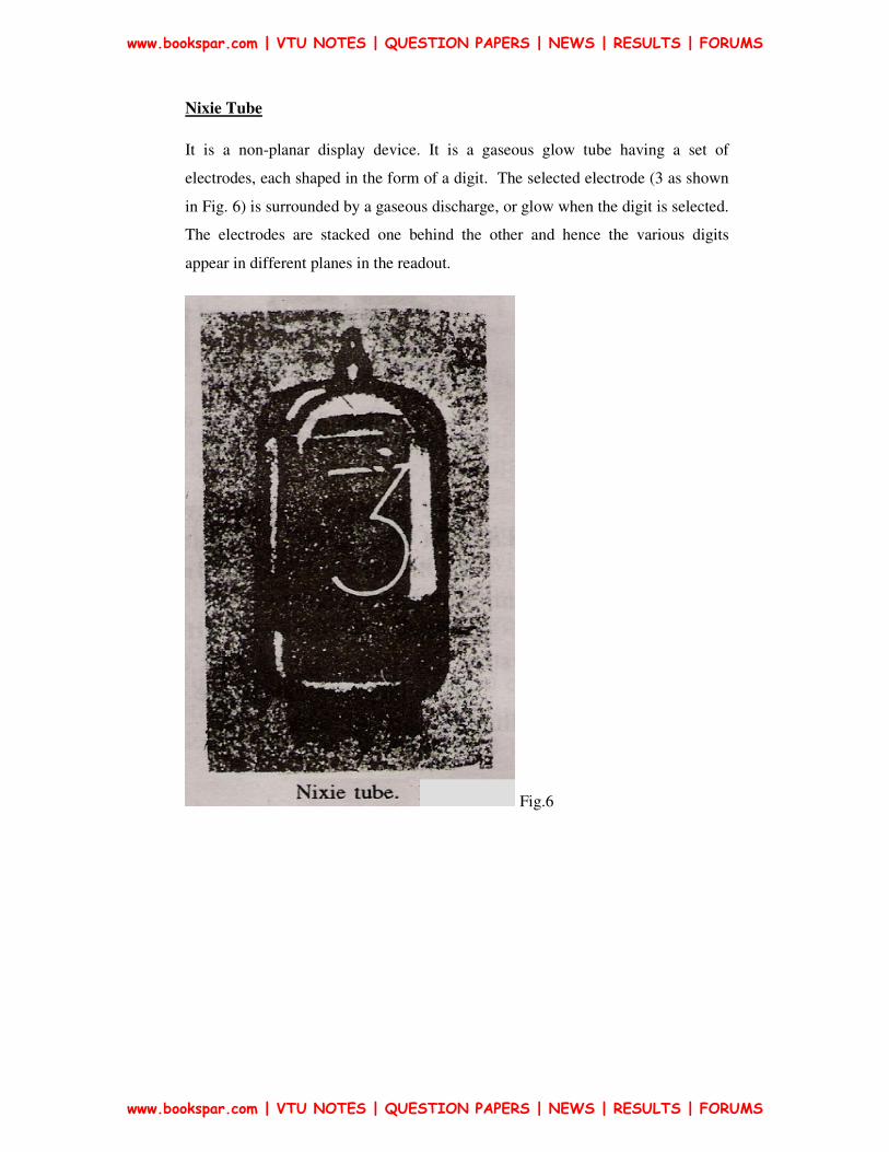
Nixie Tube
It is a non-planar display device. It is a gaseous glow tube having a set of
electrodes, each shaped in the form of a digit. The selected electrode (3 as shown
in Fig. 6) is surrounded by a gaseous discharge, or glow when the digit is selected.
The electrodes are stacked one behind the other and hence the various digits
appear in different planes in the readout.
Fig.6
www.bookspar.com | VTU NOTES | QUESTION PAPERS | NEWS | RESULTS | FORUMS
www.bookspar.com | VTU NOTES | QUESTION PAPERS | NEWS | RESULTS | FORUMS

Fig.7
In summary the Nixie Tube is a cold cathode glow discharge tube, popularly
known as Nixie which is the trade mark of M/s Burrough' s Corporation U.S.A.
Working: The display works on the principle that when a gas breaks down, a
glow discharge is produced. A gauze electrode with a positive voltage supply
functions as an anode, and there are 10 separate wire cathodes, each in the shape
www.bookspar.com | VTU NOTES | QUESTION PAPERS | NEWS | RESULTS | FORUMS
www.bookspar.com | VTU NOTES | QUESTION PAPERS | NEWS | RESULTS | FORUMS

of a numeral from 0 to 9 (see Fig. 7). The electrodes are enclosed in a glass filled
envelope with connecting pins at the bottom. Neon gas is usually employed and it
gives an orange-red glow when activated. However, other colours are available
when different gases are used.
There is one anode and 10 cathodes. After a negative voltage is applied to the
selected cathode, a simple gas discharge diode is formed which lights the selected
digit. A transistor gate is usually employed at each cathode so that the desired
numeral can be switched on.
The circuitry driving the nixie tubes is simpler than that for seven segment
displays. However, high voltages (150 - 220 V) are required to produce glow
discharge.The current required is of the order of 1- 5 mA. The Nixie tubes are
bulkier in size than the seven segmental displays.
Modern Nixies vary in construction. The original Nixie had 10 cathodes
representing numerals 0 - 9 but additional cathodes displaying decimal symbol
and + and - signs are being used. Special Nixies (shown in Fig. 8) have 15
cathodes constituting 15 segments that be used to produce numeric as well as
alphanumeric characters.
Fig.8
www.bookspar.com | VTU NOTES | QUESTION PAPERS | NEWS | RESULTS | FORUMS
www.bookspar.com | VTU NOTES | QUESTION PAPERS | NEWS | RESULTS | FORUMS

Digital Display Methods
In digital instruments, the output devices indicate the value of measured quantity
in decimal digits. This is done by using a Digital display device. A digital display
device may receive digital information in any form but it converts that information
to decimal form.
The basic element in a digital display device is the display for a single digit
because a multiple digit display is nothing but a group of single digit displays. A
single digit display is capable of indicating the numbers from 0 to 9. There is also
usually provision for a decimal point between each of the numerals. Generally
Seven & Fourteen Segmental Display or Dot matrices 3 x5 & 27 dots, 5 x 7
methods are used to display the character. LEDs (Light emitting diodes) and
LCDs (Liquid crystal diodes) are used widely for segmental displays and dot
matrix displays.
www.bookspar.com | VTU NOTES | QUESTION PAPERS | NEWS | RESULTS | FORUMS
www.bookspar.com | VTU NOTES | QUESTION PAPERS | NEWS | RESULTS | FORUMS

Liquid crystal Diodes (LCD)
Liquid crystal cell displays (LCDs) are used in similar applications where
LEDs are used. These applications are display of numeric and alphanumeric
characters in dot matrix and segmental displays.
The LCDs are of two types : Dynamic scattering type and Field effect type.
The construction of a dynamic scattering liquid crystal cell is shown in Fig. 9
Fig. 9
The liquid crystal material may be one of the several organic compounds which
exhibit optical properties of a crystal though they remain In liquid form. Liquid
crystal is layered between glass sheets with transparent electrodes deposited on the
inside faces. When a potential is applied across the cell, charge carriers
flowing through the liquid disrupt the molecular arrangement and produce
turbulence. When the liquid is not activated, it is transparent. When the liquid is
activated the molecular turbulence causes light to be scattered in all directions and
the cell appears to be bright. The phenomenon is called dynamic scattering.
The construction of a field effect liquid crystal display is similar to that of the
dynamic scattering type, with the exception that two thin polarizing optical filters
are placed at the inside of each glass sheet. The liquid crystal material in the field
effect cell is also of different type from that employed in the dynamic scattering
cell. The material used is twisted nematic type and actually twists the light passing
through the cell when the latter is not energized. This allows the light to pass
www.bookspar.com | VTU NOTES | QUESTION PAPERS | NEWS | RESULTS | FORUMS
www.bookspar.com | VTU NOTES | QUESTION PAPERS | NEWS | RESULTS | FORUMS

through the optical filters and the cell appears bright. When the cell is energized,
no twisting of light takes place and the cell appears dull
Liquid crystal cells are of two types. (i) Transmittive type and (ii) Reflective type.
In the Transmittive type cell, both glass sheets are transparent, so that light from a
rear source is scattered in the forward direction when the cell is activated. The
reflective type cell has a reflecting surface on one side of glass sheets. The
incident light on the front surface of the cell is dynamically scattered by an
activated cell.
Both types of cells appear quite bright when activated even under ambient light
conditions.
The liquid crystals are light reflectors or transmitters and therefore they consume
small amounts of energy (unlike light generators).
Unlike LEDs which can work on d.c. the LCDs require a.c. voltage supply. A
typical voltage supply to dynamic scattering LCD is 30 V peak to peak with 50
Hz.
www.bookspar.com | VTU NOTES | QUESTION PAPERS | NEWS | RESULTS | FORUMS
www.bookspar.com | VTU NOTES | QUESTION PAPERS | NEWS | RESULTS | FORUMS
LED
The LED is basically a semiconductor PN junction diode capable of emitting
electromagnetic radiation under forward conductions. The radiation emitted by
LEDs can be either in the visible spectrum or in the infrared region,
depending on the type of the semiconductor material used. Generally, infra-red
emitting LEDs are coated with Phosphor so that, by the excitation of phosphor
vislible light can be produced. LEDs are useful for electronics display and
instrumentation.
The advantage of using LEDs in electronic displays are as follows.
1. LEDs are very small devices, and can be considered as point sources of light.
They can therefore be stacked in a high-density matrix to serve as a numeric
and alphanumeric display. (have a character density of several thousand per
square metre).
2. The light output from an LED is function of the current flowing through it. An
LED can therefore, be smoothly controlled by varying the current.
This is particularly useful for operating LED displays under different ambient
lighting conditions.
3. LEDs are highly efficient emitters of EM radiation.
4. LEDs with light output of different colours, i.e. red. amber, green and yellow
are commonly available.
5. LEDs are very fast devices, having a turn ON-OFF time of less than 1 us.
6. The low supply voltage and current requirements of LEDs make them
compatible with DTL and TTL, ICs.
www.bookspar.com | VTU NOTES | QUESTION PAPERS | NEWS | RESULTS | FORUMS
www.bookspar.com | VTU NOTES | QUESTION PAPERS | NEWS | RESULTS | FORUMS
Signal Generators
A signal generator is a vital component in a test setup, and in electronic
troubleshooting and development, whether on a service bench or in a research
laboratory. Signal generators have a variety of applications, such as checking the
stage gain, frequency response, and alignment in receivers and in a wide range of
other electronic equipment.They provide a variety of waveforms for testing
electronic circuits, usually at low powers.
The term oscillator is used to describe an instrument that provides only a
sinusoidal output signal, and the term generator to describe an instrument that
provides several output waveforms, including sine wave, square- wave, triangular
wave and pulse trains, as well as an amplitude modulated waveform.
When we say that the oscillator generates a signal, it is important to note that no
energy is created; it is simply converted from a DC source into AC energy at some
specific frequency.
There are various types of signal generator but several requirements are
common to all types.
• The frequency of the signal should be known and stable.
• The amplitude should be controllable from very small to relatively large
values.
• Finally, the signal should be distortion-free
The above mentioned requirements vary for special generators, such as function
generators, pulse, and sweep generators.
Various kinds of signals, at both audio and radio frequencies, are required at
various times in an instrumentation system. In most cases a particular signal
required by the instrument is internally generated by a self-contained oscillator.
www.bookspar.com | VTU NOTES | QUESTION PAPERS | NEWS | RESULTS | FORUMS
www.bookspar.com | VTU NOTES | QUESTION PAPERS | NEWS | RESULTS | FORUMS
The oscillator circuit commonly appears in a fixed frequency form. (e.g. when it
provides a 1000 Hz excitation source for an ac bridge). In other cases, such as in a
Q-meter, oscillators in the form of a variable frequency arrangement for covering
Q-measurements over a wide range of frequencies, from a few
100 kHz to the MHz range, are used.
In contrast with self-contained oscillators that generate only the specific
signals required by the instrument, the class of generators that are available as
separate instruments to provide signals for general test purposes are usually
designated as signal generators.
These AF and RF generators are designed to provide extensive and continuous
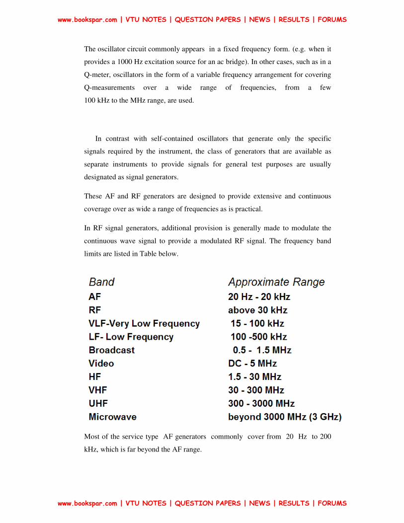
coverage over as wide a range of frequencies as is practical.
In RF signal generators, additional provision is generally made to modulate the
continuous wave signal to provide a modulated RF signal. The frequency band
limits are listed in Table below.
Most of the service type AF generators commonly cover from 20 Hz to 200
kHz, which is far beyond the AF range.
www.bookspar.com | VTU NOTES | QUESTION PAPERS | NEWS | RESULTS | FORUMS
www.bookspar.com | VTU NOTES | QUESTION PAPERS | NEWS | RESULTS | FORUMS

In more advanced laboratory types of AF generators, the frequency range
extends quite a bit further e.g. a Hewlett Packard model covers 5 Hz - 600 kHz
and a Marconi model generates both sine and square waves and has a very wide
range of 10Hz – 100 MHz.
FIXED FREQUENCY AF OSCILLATOR
In many cases, a self-contained oscillator circuit is an integral part of the
instrument circuitry and is used to generate a signal at some specified audio
frequency. Such a fixed frequency might be a 400 Hz signal used for audio testing
or a 1000 Hz signal for exciting a bridge circuit. Oscillations at specified audio
frequencies are easily generated by the use of an iron core transformer to obtain
positive feedback through inductive coupling between the primary and secondary
windings.
Variable AF Oscillator
Variable AF Oscillators used for general lab purpose should cover at least full
audio range i.e., from 20 Hz to 20kHz and have a constant pure sine wave output.
They are of RC feedback oscillator type or Beat Frequency Oscillator type (BFO)
BASIC STANDARD SIGNAL GENERATOR (SINEWAVE)
The sine wave generator represents the largest single category of signal
generator. This instrument covers a frequency range from a few Hertz to many
Giga-Hertz. The sine wave generator in its simplest form is given in Fig. 10
Fig. 10 Basic Sine Wave Generator
www.bookspar.com | VTU NOTES | QUESTION PAPERS | NEWS | RESULTS | FORUMS
www.bookspar.com | VTU NOTES | QUESTION PAPERS | NEWS | RESULTS | FORUMS
The simple sine wave generator consists of two basic blocks, an oscillator and an
attenuator. The accuracy of the frequency, stability, and freedom from
distortion depend on the design of the oscillator, while the amplitude depends
on the design of the attenuator.
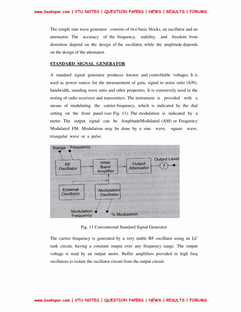
STANDARD SIGNAL GENERATOR
A standard signal generator produces known and controllable voltages. It is
used as power source for the measurement of gain, signal to noise ratio (S/N),
bandwidth, standing wave ratio and other properties. It is extensively used in the
testing of radio receivers and transmitters. The instrument is provided with a
means of modulating the carrier frequency, which is indicated by the dial
setting on the front panel (see Fig. 11). The modulation is indicated by a
meter. The output signal can be AmplitudeModulated (AM) or Frequency
Modulated FM. Modulation may be done by a sine wave, square wave,
triangular wave or a pulse.
Fig. 11 Conventional Standard Signal Generator
The carrier frequency is generated by a very stable RF oscillator using an LC
tank circuit, having a constant output over any frequency range. The output
voltage is read by an output meter. Buffer amplifiers provided in high freq
oscillators to isolate the oscillator circuit from the output circuit.
www.bookspar.com | VTU NOTES | QUESTION PAPERS | NEWS | RESULTS | FORUMS
www.bookspar.com | VTU NOTES | QUESTION PAPERS | NEWS | RESULTS | FORUMS

Modern Signal Generator
In a modern signal generator (see Fig. 12) to improve freq stability, a single
master oscillator is used with freq dividers for lower ranges. The master oscillator
is insensitive to temperature variations, design of succeeding stages, etc. The other
components are B1 –Untuned buffer amplifier; B2, B3 additional buffers for
isolation of master oscillator from power amplifier to avoid loading effects. The
master oscillator is fine tuned by a motor driven variable capacitor –
programmable automatic frequency control circuits.
Fig. 12
www.bookspar.com | VTU NOTES | QUESTION PAPERS | NEWS | RESULTS | FORUMS
www.bookspar.com | VTU NOTES | QUESTION PAPERS | NEWS | RESULTS | FORUMS

AF Sine and Square Wave Generator
A wien bridge oscillator (suitable for AF range) is used in this generator (refer
Fig. 13). The frequency of the oscillations can be changed by varying the
capacitance in the oscillator or in steps by switching in resistors of different
values.
The output of the oscillator goes to a function switch which directs the
oscillator output to either sine wave amplifier or to the square wave shaper. The
attenuator varies the amplitude of the output which is taken through a push-pull
amplifier.
Fig. 13
The front panel of the signal generator consists of the following:
Frequency selector :It selects the frequency in different ranges and varies it
continuously in a ratio of 1 : 10. The scale is non-linear.
Frequency multiplier It selects the frequency range over 5 decades, from 10 Hz to
1 MHz.
Amplitude multiplier: It attenuates the sine wave in 3 decades, x 1, x 0.1 and x
0.01.
Variable amplitude It attenuates the sine wave amplitude continuously.
www.bookspar.com | VTU NOTES | QUESTION PAPERS | NEWS | RESULTS | FORUMS
www.bookspar.com | VTU NOTES | QUESTION PAPERS | NEWS | RESULTS | FORUMS

Symmetry control It varies the symmetry of the square wave from 30% to 70%.
Amplitude It attenuates the square wave output continuously.
Function switch It selects either sine wave or square wave output.
Output available This provides sine wave or square wave output.
Sync This terminal is used to provide synchronization of the internal signal with
an external signal.
On-Off Switch
www.bookspar.com | VTU NOTES | QUESTION PAPERS | NEWS | RESULTS | FORUMS
www.bookspar.com | VTU NOTES | QUESTION PAPERS | NEWS | RESULTS | FORUMS

FUNCTION GENERATOR
A function generator (refer Fig. 14) produces different waveforms of adjustable
frequency. The common output waveforms are the sine, square, triangular and
sawtooth
waves. The frequency may be adjusted, from a fraction of a Hertz to several
hundred kHz. The various outputs of the generator can be made available at the
same time. For example, the generator can provide a square wave to test the
linearity of an amplifier and simultaneously provide a sawtooth to drive the
horizontal deflection amplifier of the CRO to provide a visual display.
Fig. 14
Generally freq is varied by either L or C. Here it is done by varying the current
supplied to the integrator. The freq controlled voltage regulates the 2 current
sources. The upper current source controls the integrator whose output is
.
The voltage comparator multivibrator changes states at a pre-determined
maximum level of the integrator output voltage. This change cuts off the upper
current supply and switches on the lower current supply. The lower current source
supplies a reverse current to the integrator, so that
its output decreases linearly with time. When the output reaches a pre- determined
minimum level, the voltage comparator again changes state and switches on the
upper current source. The output of the integrator is a triangular waveform whose
frequency is determined by the magnitude of the current supplied by the constant
current sources.
www.bookspar.com | VTU NOTES | QUESTION PAPERS | NEWS | RESULTS | FORUMS
www.bookspar.com | VTU NOTES | QUESTION PAPERS | NEWS | RESULTS | FORUMS

The comparator output delivers a square wave voltage of the same frequency. The
resistance diode network alters the slope of the triangular wave as its
amplitude changes and produces a sine wave with less than 1% distortion.
Pulse Generator & a Square Wave Generator
These generators are used as measuring devices in combination with a CRO. They
provide both quantitative and qualitative information of the system under test.
They are made use of in transient response testing of amplifiers. The fundamental
difference between a pulse generator and a square wave generator is in the duty
cycle.
www.bookspar.com | VTU NOTES | QUESTION PAPERS | NEWS | RESULTS | FORUMS
www.bookspar.com | VTU NOTES | QUESTION PAPERS | NEWS | RESULTS | FORUMS