unit – i energy principles theorem. two marks … · unit – i energy principles ... two marks...
TRANSCRIPT
UNIT – I
ENERGY PRINCIPLES
Strain energy and strain energy density- strain energy in traction, shear in flexure andtorsion- Castigliano’s theorem – Principle of virtual work – application of energytheorems for computing deflections in beams and trusses – Maxwell’s reciprocaltheorem.
Two Marks Questions and Answers 1. Define strain energy and Proof stress.
Strain energy Whenever a body is strained, the energy is absorbed in the body. The energy which is
absorbed in the body due to straining effect is known as strain energy. The strain energy storedin the body is equal to the work done by the applied load in stretching the body
Proof stress The stress induced in an elastic body when it possesses maximum strain energy is termed
as its proof stress.
3. Define Resilience, Proof Resilience and Modulus of Resilience.
ResilienceThe resilience is defined as the capacity of a strained body for doing work on the
removal of the straining force. The total strain energy stored in a body is commonly known asresilience.
Proof Resilience The proof resilience is defined as the quantity of strain energy stored in a body when strained up to elastic limit. The maximum strain energy stored in a body is known as proof resilience.
Modulus of ResilienceIt is defined as the proof resilience of a material per unit volume.
Proof resilienceModulus of resilience = ------------------- Volume of the body
4. State the two methods for analyzing the statically indeterminate structures.
a.Displacement method (equilibrium method (or) stiffness coefficient method
b. Force method (compatibility method (or) flexibility coefficient method)
5. Define Castigliano’s first theorem second Theorem.

First Theorem. It states that the deflection caused by any external force is equal to the partial derivative of the strain energy with respect to that force.Second Theorem
It states that “If U is the total strain energy stored up in a frame work in equilibrium under an external force; its magnitude is always a minimum.
6. State the Principle of Virtual work. It states that the workdone on a structure by external loads is equal to the internal energy
stored in a structure (Ue = Ui)
Work of external loads = work of internal loads
7. What is the strain energy stored in a rod of length l and axial rigidity AE to an axial force P? Strain energy stored P2 L
U= -------- 2AE
8. State the various methods for computing the joint deflection of a perfect frame.
1. The Unit Load method2. Deflection by Castigliano’s First Theorem3. Graphical method : Willot – Mohr Diagram
9. State the deflection of the joint due to linear deformation. n
δv = Σ U x ∆ 1 n
δH = Σ U’ x ∆ 1
PL ∆ = --------- Ae
U= vertical deflection U’= horizontal deflection
10. State the deflection of joint due to temperature variation. n δ = Σ U X A
1= U1∆1 + U2 ∆2 + …………+ Un ∆n
If the change in length (∆) of certain member is zero, the product U.∆ for those members will be substituted as zero in the above equation.
11. State the deflection of a joint due to lack of fit.

n δ = Σ U ∆
1= U1∆1 + U2 ∆2 + …………+ Un ∆n
If there is only one member having lack of fit ∆1, the deflection of a particular joint willbe equal to U1∆1.
12. What is the effect of change in temperature in a particular member of a redundant frame?
When any member of the redundant frame is subjected to a change in temperature, it will cause a change in length of that particular member, which in turn will cause lack of fit stresses inall other members of the redundant frame.
13. State the difference between unit load and strain energy method in the determination of structures.
In strain energy method, an imaginary load P is applied at the point where the deflection isdesired to be determined. P is equated to zero in the final step and the deflection is obtained.
In the Unit Load method, a unit load (instead of P) is applied at the point where thedeflection is desired.
14. State the assumptions made in the Unit Load method.
1. The external and internal forces are in equilibrium2. Supports are rigid and no movement is possible3. The material is strained well within the elastic limit.
15. State the comparison of Castigliano’s first theorem and unit load method. The deflection by the unit load method is given by
n PUL δ = Σ -------
1 AE n PL
δ = Σ ------- x U 1 AE
n = Σ ∆ x U ----- (i) 1
The deflection by castigliano’s theorem is given by
δ=∑1
nPLAE
∂ P∂W
--------- (ii)
By comparing (i) & (ii)
∂P∂W
=U

16. State Maxwell’s Reciprocal Theorem. The Maxwell’s Reciprocal theorem states as “ The work done by the first system of loads due to displacements caused by a second system of loads equals the work done by the second system of loads due to displacements caused by the first system of loads.
17. Define degree of redundancy. A frame is said to be statically indeterminate when the no of unknown reactions or stress
components exceed the total number of condition equations of equilibrium.
20. Define Perfect Frame.
If the number of unknowns is equal to the number of conditions equations available, the frame is said to be a perfect frame.
21. State the two types of strain energies.a.strain energy of distortion (shear strain energy)b. strain energy of uniform compression (or) tension (volumetric strain energy)
22. State in which cases, Castigliano’s theorem can be used. 1. To determine the displacements of complicated structures. 2. To find the deflection of beams due to shearing (or) bending forces (or)
bending moments are unknown. 3. To find the deflections of curved beams springs etc.
23. Define Proof stress. The stress induced in an elastic body when it possesses maximum strain energy is termed as
its proof stress.
16 Marks Questions And Answers
1. Derive the expression for strain energy in Linear Elastic Systems for the following cases. (i) Axial loading (ii) Flexural Loading (moment (or) couple)
(i)Axial Loading
Let us consider a straight bar of Length L, having uniform cross- sectional area A. If an axial load P is applied gradually, and if the bar undergoes a deformation ∆, the work done, stored as strain energy (U) in the body, will be equal to average force (1/2 P) multiplied by the deformation ∆.
Thus U = ½ P. ∆ But ∆ = PL / AE U = ½ P. PL/AE = P2 L / 2AE ---------- (i)If, however the bar has variable area of cross section, consider a small of length dx and area of cross section Ax. The strain energy dU stored in this small element of length dx will be, from equation (i)
P2 dx

dU = --------- 2Ax E The total strain energy U can be obtained by integrating the above expression over the length of the bar.
U = ∫0
LP2dx2A x E
(ii) Flexural Loading (Moment or couple )
Let us now consider a member of length L subjected to uniform bending moment M. Consider an element of length dx and let di be the change in the slope of the element due to applied moment M. If M is applied gradually, the strain energy stored in the small element will be
dU = ½ Mdi
But di d
------ = ----- (dy/dx) = d2y/d2x = M/EIdx dx
Mdi = ------- dx
EI
Hence dU = ½ M (M/EI) dx
= (M2/2EI) dx
Integrating
U =
M 2dx2EI
∫0
L
¿ ¿¿¿
2. State and prove the expression for castigliano’s first theorem.
Castigliano’s first theorem:It states that the deflection caused by any external force is equal to the partial
derivative of the strain energy with respect to that force. A generalized statement of thetheorem is as follows:
“ If there is any elastic system in equilibrium under the action of a set of a forcesW1 , W2, W3 ………….Wn and corresponding displacements δ1 , δ2, δ3…………. δn and aset of moments M1 , M2, M3………Mn and corresponding rotations Φ1 , Φ2, Φ3,…….. Φn
, then the partial derivative of the total strain energy U with respect to any one of the

forces or moments taken individually would yield its corresponding displacements in itsdirection of actions.”
Expressed mathematically,∂U∂W 1
=δ1 ------------- (i)
∂U∂M 1
=φ1 ------------- (ii)
Proof:
Consider an elastic body as show in fig subjected to loads W1, W2, W3 ………etc. each applied independently. Let the body be supported at A, B etc. The reactions RA
,RB etc do not work while the body deforms because the hinge reaction is fixed andcannot move (and therefore the work done is zero) and the roller reaction is perpendicularto the displacements of the roller. Assuming that the material follows the Hooke’s law,the displacements of the points of loading will be linear functions of the loads and theprinciples of superposition will hold.
Let δ1, δ2, δ3……… etc be the deflections of points 1, 2, 3, etc in the direction of the loads at these points. The total strain energy U is then given by
U = ½ (W1δ1 + W2 δ2 + ……….) --------- (iii)
Let the load W1 be increased by an amount dW1, after the loads have been applied.Due to this, there will be small changes in the deformation of the body, and the strainenergy will be increased slightly by an amount dU. expressing this small increase as therate of change of U with respect to W1 times dW1, the new strain energy will be
U +
∂U∂W 1
xdW
1
¿¿¿¿¿¿
--------- (iv)
On the assumption that the principle of superposition applies, the final strain energydoes not depend upon the order in which the forces are applied. Hence assuming that dW1
is acting on the body, prior to the application of W1, W2, W3 ………etc, the deflectionswill be infinitely small and the corresponding strain energy of the second order can beneglected. Now when W1, W2, W3 ………etc, are applied (with dW1 still acting initially),the points 1, 2, 3 etc will move through δ1, δ2, δ3……… etc. in the direction of theseforces and the strain energy will be given as above. Due to the application of W1, ridesthrough a distance δ1 and produces the external work increment dU = dW1 . δ1. Hence thestrain energy, when the loads are applied is
U+dW1.δ1 ----------- (v)
Since the final strain energy is by equating (iv) & (v).
U+dW1.δ1= U +
∂U∂W 1
xdW
1
¿¿¿¿¿¿
δ1=
1
∂U∂Walignl ¿¿¿
¿
Which proves the proportion. Similarly it can be proved that Φ1=∂U∂M 1
.
Deflection of beams by castigliano’s first theorem:
If a member carries an axial force the energies stored is given by
U = ∫0
LP2dx2A x E
In the above expression, P is the axial force in the member and is the function of externalload W1, W2,W3 etc. To compute the deflection δ1 in the direction of W1
δ1=
1
∂U∂Walignl ¿¿¿
¿= ∫
0
LPAE
∂ p∂W 1
dx
If the strain energy is due to bending and not due to axial load
U = ∫0
LM 2dx2 EI
δ1=
1
∂U∂Walignl ¿¿¿
¿= ∫
0
L
M∂ M∂W 1
dxEI
If no load is acting at the point where deflection is desired, fictitious load W is applied at the point in the direction where the deflection is required. Then after differentiating but before integrating the fictitious load is set to zero. This method is sometimes known as the fictitious load method. If the rotation Φ1 is required in the direction of M1.
Φ1=∂U∂M 1
= ∫0
L
M∂M∂M 1
dxEI
3. Calculate the central deflection and the slope at ends of a simply supported beam carrying a UDL w/ unit length over the whole span.
Solution:
a) Central deflection:Since no point load is acting at the center where the deflection is required, apply the
fictitious load W, then the reaction at A and B will (WL/2 + W/2)↑ each.
δc=∂U∂W
= ∫0
L∂ M∂W
dxEI
Consider a section at a distance x from A.Bending moment at x,
M= (wL2 +W2 ) x−wx2
2
∂M∂ x
=x2
δ c=2EI∫
0
l2
((wL2 +W2 )x−wx2
2 ) x2 dx
Putting W=0,
δ c=2EI∫
0
l2
((wL2 x )−wx2
2 ) x2 dx
=2EI ((wLx
3
12−wx4
16 ))0
l2
δ c=5
384wl4
EIb) Slope at ends
To obtain the slope at the end A, say apply a frictions moment A as shown in fig. The
reactions at A and B will be (wl2 −ml ) and (wl2 +
ml )
Measuring x from b, we get
φ A =
∂ u∂m
=1
EI∫0
l
Mx ∂Mx∂M
.Dx -------------------------------- 2
Where Mx is the moment at a point distant x from the origin (ie, B) is a function of M.
Mx = (wl2 +ml ) x -
Wx 22
∂Mx∂m
=xlin 2
φA =
1EI
∫0
l
(wl2 +ml ) x -
Wx 22 X/2 Dx
Putting M=0
φa=1Ei∫0
lwl2x−
WX 22
xldx
φA=1EI [wx6
3
−wx4
8L ]0
L
φA=wL3
24 EI
4. State and prove the Castigliano’s second Theorem.
Castigliano’s second theorem:
It states that the strain energy of a linearly elastic system that is initiallyunstrained will have less strain energy stored in it when subjected to a total load systemthan it would have if it were self-strained.
∂u∂ t
= 0
For example, if λ is small strain (or) displacement, within the elastic limit in the directionof the redundant force T,
∂u∂ t
= λ
λ =0 when the redundant supports do not yield (or) when there is no initial lack of fit in theredundant members.
Proof:
Consider a redundant frame as shown in fig.in which Fc is a redundant member ofgeometrical length L.Let the actual length of the member Fc be (L- λ ), λ being the initiallack of fit.F2 C represents thus the actual length (L- λ ) of the member. When it is fitted tothe truss, the member will have to be pulled such that F2 and F coincide.

According to Hooke’s law
F2 F1 = Deformation =T ( l−λ )
AE=
TLAE
(approx )
Where T is the force (tensile) induced in the member.
Hence FF1=FF2-F1 F2
λ =TLAE
------------------------------------ ( i )
Let the member Fc be removed and consider a tensile force T applied at the corners F and C as shown in fig.
FF1 = relative deflection of F and C
= ∂u1∂T
------------------------------------------ ( ii )
According to castigliano’s first theorem where U1 is the strain energy of the whole frame except that of the member Fc.
Equating (i) and (ii) we get ∂u1∂T
= λ --TLAE
(or) ∂u1∂T
+ TLAE
= λ ----------------------- ( iii )
To strain energy stored in the member Fc due to a force T is
UFC = ½ T. TLAE
= T2L2 AE
∂U FC
∂T=
TLAE
Substitute the value of TLAE
in (iii) we get

∂u '∂T
+∂U FC
∂T=λ (or)
∂U∂T
=λ
When U= U1 + U Fc.If there is no initial lack of fit, λ =0 and hence ∂U∂T
=0
Note:
i) Castigliano’s theorem of minimum strain energy is used for the for analysis ofstatically indeterminate beam ands portal tranes,if the degree of redundancy is not more thantwo. ii) If the degree of redundancy is more than two, the slope deflection method or themoment distribution method is more convenient.
5) A beam AB of span 3mis fixed at both the ends and carries a point load of 9 KN at C distant1m from A. The M.O.I. of the portion AC of the beam is 2I and that of portion CB is I.calculate the fixed end moments and reactions.
Solution: There are four unknowns Ma, Ra, Mb and Rb.Only two equations of static are
available (ie) ∑ v=0 and ∑M=0
This problem is of second degree indeterminacy.
First choose MA and MB as redundant.
δA=
MxEI
∂M x
∂R A
dx
∂U AB
∂RA
=0=¿∫¿¿∫ ¿
-----------(1)
θA=∂U AB
∂ M A
=0=∫A
B M x
EI
∂ M x
∂M A
dx -------------(2)
1) For portion AC:
Taking A as the origin
Mx = -MA + RA x
∂M x
∂RA
= x;∂M x
∂M A
=−1

M .O . I=2I Limits of x: 0 to 1m
Hence ∫A
C M x
EI
∂ M x
∂ RA
dx=∫0
1 (-MA+ R A x ) x2 EI
dx
=12 EI (−M A (1 )2
2+R A (1 )3
3 )¿
12EI (R A
3−M A
2 )
And ∫A
C M x
EI
∂M x
∂RA
dx=∫0
1 (-MA+ R A x ) (−1 )
2 EIdx
=12 EI (M A (1 )−
RA (1 )2
2 )=12 EI (M A−
R A
2 )For portion CB, Taking A as the origin we have
M x = −M A+R A X−9 (X−1 )
∂M x
∂R A
= x ;∂M x
∂M A
=−1
M.O.I = I Limits of x : 1 to 3 m
Hence
∫C
B M x
EI
∂M x
∂ RA
dx=∫1
3 (-MA+ R A x-9 (x-1 )) xEI
dx
=1EI [−4MA+
263R A−42]
And
∫C
B M x
EI
∂M x
∂M A
dx=∫1
3 ( -MA+ RA x-9 (x-1)) -1EI
dx
=1EI [2MA−4RA+18 ]
Subs these values in (1) & (2) we get

∂U AB
∂R A
=0
⇒1EI [RA
3−M A
2 ]+1EI [−4MA+
263
RA−42]=0
2.08 – MA = 9.88 __________ (3)
∂U AB
∂ M A
=0
⇒12 EI [M A
1−RA
2 ]+1EI [2MA−4RA+18 ]=0
MA – 1.7RA = -7.2 -------------- (4)
Solving (3) & (4)
MA = 4.8 KN – M (assumed direction is correct)RA = 7.05 KN
To find MB, take moments at B, and apply the condition ∑M=0 there. Takingclockwise moment as positive and anticlockwise moment as negative. Taking MB clockwise,we have
MB – MA =RA (3) – 9x2 = 0
MB – 4.8 + (7.05x 3) -18 = 0MB = 1.65 KN – m (assumed direction is correct)
To find RB Apply ∑V=0 for the whole frame.
RB = 9 – RA = 9-7.05 = 1.95 KN
6.Using Castigliano’s First Theorem, determine the deflection and rotation of the overhanging end A of the beam loaded as shown in Fig.
Sol:Rotation of A:
RB x L = -M
RB = -M/L
RB = M/L ( ↓ )

& RC = M/L ( ↑ )
θA=∂U∂ M
=1EI
∫A
B
M x .∂M x
∂Mdx+
1EI
∫C
B
M x .∂M x
∂M.dx ____________ (1)
For any point distant x from A, between A and B (i.e.) x = 0 to x = L/3
Mx = M ; and ∂M x
∂ M=1 ________ (2)
For any point distant x from C, between C and B (i.e.) x = 0 to x = L
Mx = (M/L) x ; and ∂M x
∂ M=
xL
________ (3)
Subs (2) & (3) in (1)
θA=∂U∂ M
=1EI
∫0
L/3
M (1 ).dx+1EI
∫0
L
( ML x) xL dx
=ML3 EI
+ML3 EI
=2ML3 EI
(clockwise )
b) Deflection of A:To find the deflection at A, apply a fictitious load W at A, in upward direction
as shown in fig.
RB xL=−(M +43WL )
1L
RB=−(M+43WL )¿ ¿
¿
¿ ¿¿
1L
RB=(M+43WL)¿ ¿
¿(↓)
¿ ¿¿
RC=(M+13WL )
1L
(↑ )
δ A=∂U∂W
=1EI
∫A
B
M x
∂M x
∂W+
1EI
∫C
B
M x
∂ M x
∂W.dx
For the portion AB, x = 0 at A and x = L/3 at B
Mx = M + Wx
∂M x
∂W= x
For the portion CB, x = 0 at C and x = L at B
M x=(M+18WL) 1
L. x
∂M x
∂W=x3
δ A=1EI
∫0
L /3
(M+Wx ) x+1EI
∫0
L
(M+13WL) xL .
x3dx
Putting W = 0
δ A=1EI
∫0
L /3
(Mx )dx+1EI
∫0
L
(Mx2
3L )dx
δ A=MEI
(x2
2)0L /3+
M3 EI
(x3
3)0L
δ A=ML2
18 EI+ML2
9 EI
δ A=ML2
6 EI
7. Determine the vertical and horizontal displacements of the point C of the pin-jointed frame shown in fig. The cross sectional area of AB is 100 sqmm and of AC and BC 150 mm2 each. E= 2 x 10 5 N/mm2. (By unit load method)Sol:
The vertical and horizontal deflections of the joint C are given byPuLAE
δH=∑Pu ' LAE
δV=∑ ¿ ¿¿¿
A) Stresses due to External Loading:AC = √32+42=5m
Reaction: RA = -3/4RB = 3/4
Sin θ = 3/5 = 0.6; Cos θ = 4/5 = 0.8

Resolving vertically at the joint C, we get6 = PAC cos θ + PBC sin θ
Resolving horizontally at the joint C, we getPAC cos θ = PBC sin θ; PAC = PBC PAC sin θ + PBC sin θ = 6 2 PAC sin θ = 6
PAC = 6/sin θ = 6/2 x 0.6 = 5 KN (tension)
PAC = PBC = 5 KN (tension)
Resolving horizontally at the joint C, we getPAB = PAC cos θPAB = 5 cos θ ; PAB = 5 x 0.8
PAB = 4 KN (comp)B) Stresses due to unit vertical load at C:
Apply unit vertical load at C. The Stresses in each member will be 1/6 than of those obtained due to external load.
uAC=uBC=5 /6uAB=−4 /6=−2/3
C) Stresses due to unit horizontal load at C:Assume the horizontal load towards left as shown in fig.
Resolving vertically at the joint C, we get(uCA ) 'sinθ=(uCB ) 'sin θ
∴(uCA )'=(uCB ) '
Resolving horizontally at the joint C, we get
(uCB ) 'cosθ+ (uCA ) 'cosθ=1
(uCB ) 'cosθ+ (uCB ) 'cosθ=1
2uCB 'cosθ=1
uCB '=12cosθ
=12x0 .8
=5/8 KN ( tension)
∴uCA '=−5/8 KNuCA '=5/8 KN (comp)
Resolving horizontally at the joint B, we getuAB '=−uBC 'cosθ
uAB '=−5 /8x0 .8=−0 .5 KN
uAB '=0 .5KN (comp )

Member Length(L)mm
Area (mm)2
P(KN) U (kN) PUL/A U’(KN) PU’L/A
AB 8000 100 -4 -2/3 640/3 -1/2 160BC 5000 150 5 5/6 2500/18 5/8 2500/24CA 5000 150 5 5/6 2500/18 -5/8 2500/24
E = 2 X 10⁵ n/mm2= 200 KN/m2
δv= ∑PulAE
=491200
=2 .45mm
δh=∑pu' lAE
=160200
=0 .8mm
8) The frame shown in fig. Consists of four panels each 25m wide, and the crosssectional areas of the member are such that, when the frame carries equal loads at thepanel points of the lower chord, the stress in all the tension members is f n/mm2 and thestress in all the comparison members of 0.8 f N/mm2.Determine the values of f if theratio of the maximum deflection to span is 1/900 Take E= 2.0 x 10⁵ N/mm2.
Sol:The top chord members will be in compression and the bottom chord members,
verticals, and diagonals will be in tension. Due to symmetrical loading, the maximumdeflection occurs at C. Apply unit load at C to find u in all the members. All the membershave been numbered 1, 2, 3….. etc., by the rule u8 = u10 = u12 = 0.
Reaction RA = RB = 1/2
θ = 45º ; cos θ = sin θ = 1
√2
∴u7=R A
sinθ=
√22
( comp)
u3=u7 cos θ=√22
.1√2
=12=u4( tension )
u9=u4
cosθ=
√22
( tension )
Also, u7cosθ+u9 cosθ=u1

u1=
√22
x1√2
+√22
x1√2
=1.0( comp)
Member Length (L) mm P (N/mm2) U PUL1 2500 -0.8 F -1.0 +2000F3 2500 +F +1/2 +1250F4 2500 +F +1/2 +1250F7 2500 (2)0.5 -0.8F -(2)0.5/2 +2000F8 2500 +F 0 09 2500(2)0.5 +F +(2)0.5/2 +2500F
Sum: +9000F
δC = ∑1
nPULE
=9000+22x105
=0.09 F mm
δC=1
900xspan=
1900
x10000=100
9 mm
Hence 0.09 F = 100/9 (or) F = 100/(9 x 0.09) = 123.5 N/mm2.
9. Determine the vertical deflection of the joint C of the frame shown in fig. due totemperature rise of 60º F in the upper chords only. The coefficient of expansion = 6.0 x10⁻⁶ per 1º F and E = 2 x 10 6 kg /cm2.
Sol:Increase in length of each member of the upper chord = L α t
= 400 x 6x 10-6 x 60 = 0.144 cm
The vertical deflection of C is given byδ=∑ uΔ
To find u, apply unit vertical load at C. Since the change in length (∆) occurs only in the three top chord members, stresses in these members only need be found out.
Reaction at A = 4/12 = 1/3Reaction at B = 8/12 = 2/3
Passing a section cutting members 1 and 4, and taking moments at D, we get
U1 = (1/3 x 4) 1/3 = 4/9 (comp)
Similarly, passing a section cutting members 3 and 9 and taking moments at C, we get
Also
u3=(23x4)13 =
89
(comp)
u2=u1=49
(comp )
δC=u1Δ1+u2Δ2+u3Δ3
δC={(−49 )+(−4
9 )+(−89 )}x (+0. 144 )
δC=−0.256 cm
10) Using the principle of least work, analyze the portal frame shown in Fig. Also plot the B.M.D.
Sol:The support is hinged. Since there are two equations at each supports. They are HA, VA,
HD, and VD. The available equilibrium equation is three. (i.e.) ∑M=0,∑H=0,∑ V=0 . ∴ The structure is statically indeterminate to first degree. Let us treat the horizontal H ( ←) at A as redundant. The horizontal reaction at D will evidently be = (3-H) ( ← ). By takingmoments at D, we get
(VA x 3) + H (3-2) + (3 x 1) (2 – 1.5) – (6 x 2) = 0VA = 3.5 – H/3VD = 6 – VA = 2.5 + H/3
By the theorem of minimum strain energy,∂U∂H
=0
∂U AB
∂H+∂UBE
∂ H+∂UCE
∂H+∂U DC
∂H=0
(1)For member AB:Taking A as the origin.
M=−1. x2
2+H .x
∂M∂H
=x
∂U AB
∂H=
1EI
∫0
3
M∂M∂H
dx
¿3
=1EI
∫0
3
(−x2
2+Hx)x dx
¿1EI [Hx
3
3−x4
8 ]0
¿¿¿¿ ¿=
1EI
[ 9H−10 .12 ] ¿¿
(2) For the member BE:Taking B as the origin.
M=(Hx3 )−(3x11 .5 )+(3 .5H3 ) x
M=3H−4 .5+3 .5x−Hx3
∂M∂H
=3−x3
∂U BE
∂H=
1EI
∫0
1
M∂M∂H
dx
=1EI
∫0
1
(3H−4 .5+3 .5x−Hx3 )(3−
x3 )dx
=1EI
∫0
1
(9H−13 .5+10.5x−Hx−Hx+1 .5x−1 .67 x2+Hx2
9 )dx
=1EI
∫0
1
(9H−13 . 5+12x−2 Hx−1. 67 x2+Hx2
9 )dx
=1EI (9Hx−13 .5x+6x2−Hx2−0 .389x3+
Hx3
27 )0
1
=1EI (9H−13.5+62−H−0 .389+
H27 )
=1EI
[ 9H−7 .9 ]
(3) For the member CE:
Taking C as the origin
M=−(3−H ) x2+(2.5+H3
)x
M=−6+2H+2 .5x+Hx3
3∂U CE
∂H=
1EI
∫0
2
M∂M∂H
=1EI
∫0
2
[(−6+2H+2.5x+Hx3 )(2+
x3 )]
=1EI
∫0
2
[−12+4H+5x+6 .67Hx−2x+6 .67Hx+0 .833 x2+Hx2
9 ]dx
=1EI
∫0
2
[−12+4H+3x+13 .34Hx−2x+0 .833 x2+Hx2
9 ]dx
= 1EI
(10.96H - 15.78)
(4) For the member DC:Taking D as the origin
M=−(3−H ) x=−3x+Hx∂M∂ x
=x
∂U DC
∂H=
1EI
∫0
2
M∂M∂H
dx
=1EI
∫0
2
(−3x+Hx ) ( x )dx =1EI
∫0
2
(−3x2+Hx2)dx
=1EI (
−3x3
3+Hx3
3 )0
2
dx =1EI (−x3+
Hx3
3 )0
2
dx
= 1EI
(2.67H -8)
Subs the values∂U∂H
=0
1/EI (9-10.2) + (8.04H-7.9) + (10.96H-15.78) + (-8+2.67H) = 0 30.67H = 41.80
H = 1.36 KNHence
VA = 3.5 - H/3 = 3.5 - 1.36/3 = 3.05 KNVD = 2.5 + H/3 = 2.5 + 1.36/3 = 2.95 KN

MA= MD =0MB = (-1 x 32)/2 + (1.36 x 3) = -0.42 KN –mMC = - (3-H) 2 = - (3-1.36)2 =-3.28KNm
Bending moment Diagram:
11) A simply supported beam of span 6m is subjected to a concentrated load of 45 KN at 2m from the left support. Calculate the deflection under the load point. Take E = 200x 106 KN/m2 and I = 14 x 10-6 m4.
Solution:Taking moments about B.
VA x 6 – 45 x 4=0VA x 6 -180 = 0
VA = 30 KNVB = Total Load – VA = 15 KN
Virtual work equation:
(δ c )V=∫0
LmMdxEI
Apply unit vertical load at c instead of 45 KN
RA x 6-1 x 4 =0RA = 2/3 KNRB = Total load –RA = 1/3 KN
Virtual Moment:
Consider section between AC
M1 = 2/3 X1 [limit 0 to 2]Section between CB
M2 = 2/3 X2-1 (X2-2 ) [limit 2 to 6 ]
Real Moment:
The internal moment due to given loading
M1= 30 x X1
M2 = 30 x X2 -45 (X2 -2)
(δ c )V=∫0
2 m1 M 1dx1EI
+∫2
6 m2M 2dx 2
EI
=∫0
2 ( 2x1
3 ) (30 x1)
EIdx1+∫
2
6 ( 23x2−(x2−2 )) (30 x2−45 ( x−2 ) )
EIdx2
(23x2−x2+2)(30x2−45 x2+90)dx
2
¿1EI
∫0
2
20 x12+∫
2
6
¿¿¿¿
¿ ¿¿
=1EI
∫0
2
20 x12+∫
2
6
(−x2
3+2) (−15 x2+90)dx 2
=1EI
∫0
2
20 x12+∫
2
6
5x22−30 x2−30x2+180dx2
=1EI [
20 x1
3 ]0
3
+[ 5x23
3−
60x23
2+180 x2 ]
2
6
=20EI (
83 )+ 1
EI (53
(63−23 )−30 (62−22)+180 (6−21 ))
=
1EI
[53 .33+346 .67−960+720 ]
=160EI
=160200 x106 x 14 x10−6
=0.0571m(or )57 .1mm
The deflection under the load = 57.1 mm
12) Define and prove the Maxwell’s reciprocal theorem.
The Maxwell’s reciprocal theorem stated as “ The work done by the first system loadsdue to displacements caused by a second system of loads equals the work done by the secondsystem of loads due to displacements caused by the first system of loads”.
Maxwell’s theorem of reciprocal deflections has the following three versions:

1. The deflection at A due to unit force at B is equal to deflection at B due to unit force at A.
δAB = δBA
2. The slope at A due to unit couple at B is equal to the slope at B due to unit coupleA
ΦAB = ΦBA
3. The slope at A due to unit load at B is equal to deflection at B due to unit couple.φ' AB=δAB
'
Proof:
By unit load method,
δ=∫MmdxEI
Where,
M= bending moment at any point x due to external load.m= bending moment at any point x due to unit load applied at the point where
deflection is required.
Let mXA=bending moment at any point x due to unit load at ALet mXB = bending moment at any point x due to unit load at B.
When unit load (external load) is applied at A,

M=mXA
To find deflection at B due to unit load at A, apply unit load at B.Then m= mXB
Hence,
δBA=∫ MmdxEI
=∫mXA .mXB
EIdx ____________ (i)
Similarly,
When unit load (external load) is applied at B, M=mXB
To find the deflection at A due to unit load at B, apply unit load at A.then m= mXA
δ AB=∫ MmdxEI
=∫mB .mXA
EIdx ____________ (ii)
Comparing (i) & (ii) we get
δAB = δBA
13. Using Castigliano’s theorem, determine the deflection of the free end of the cantilever beam shown in the fig. Take EI = 4.9 MN/m2. (NOV / DEC – 2003)
Solution:
Apply dummy load W at B. Since we have to determine the deflection of the free end. Consider a section xx at a distance x from B. Then
M x=Wx+30 ( x−1 )+20∗1∗( x−1 .5 )+16 (x−2 )
δ=∫MEI
∂M∂W
dx
1EI [∫0
1
Wx∗xdx+∫1
2
{{Wx∗x+30( x−1 )x+20( x−1)(x−1
2) x}dx+∫
2
3
Wx∗x+30( x−1 )x {20∗1( x−1 .5 )∗x+16 (x−2)}}dx]
=1EI [W (x
3
3 )0
1
+[Wx333
+30 (x3
3−x2
2 )+10(x4
4−
2x3
3+x2
2 )]12
]+[Wx3
3+30 (x
3
2−x2
2 )+20(x3
3−0 .75 x2)+16( x
3
3−x2)
2
3
]
Putting W =0
δ=1EI [30(73 −
32 )+10(15
4−
143
+32 )+30(19
3−
52 )20 (19
3−3.75)+16(19
3−5)]
δ=1EI [30
56
+1072
+30236
+20∗2 .58+1643 ]
δ=1x10³
4 .9x 106(25+5 .83+115+51 .6+21.33 )
δ=0 .446m(or )44 .64 mm
14. Fig shows a cantilever, 8m long, carrying a point loads 5 KN at the center and anudl of 2 KN/m for a length 4m from the end B. If EI is the flexural rigidity of thecantilever find the reaction at the prop. (NOV/DEC – 2004)
Solution:
To find Reaction at the prop, R (in KN)
Portion AC: ( origin at A )
U1=∫0
4(Rx )2 dx
2 EI=[ R
2 x3
6 EI ]0
4
=64 R2
6 EI=
32 R2
3 EI
Portion CB: ( origin at C )Bending moment Mx = R (x+4) – 5x – 2x2/2
= R (x+4) – 5x –x2
U2=∫0
4 (M x )2 dx
2 EI
Total strain energy = U1 +U2
At the propped end ∂U∂R
=0
∂U∂R
=64 R3EI
+∫0
4
(M x
EIxdM x
dR )dx =
64 R3 EI
+1EI
∫0
4
[R ( x−4 )−5x2−x2]( x+4 )dx
=64 R3 EI
+1EI
∫0
4
[R (x−4 )2−5x ( x+4 )−x2( x+4 )]dx
=64 R3 EI
+1EI
∫0
4
[R (x2+8x+16 )−5 ( x2+4x )−( x3+4x2)]dx
0 =64 R3 EI
+1EI [R( x
3
3+4x2+16 x )−5 (
x3
3+2x2)−(
x4
4−
4x3
3)]
0
4
=64R
3+[R(64
3+64+64)−5(
643
+32)−(256
4+
2563
)]= 21.33 R + (149.33R – 266.67 – 149.33)= 21.33 R + (149.33 R – 416)
21.33 R +149.33 R – 416 =0R = 2.347 KN
15. A simply supported beam of span L is carrying a concentrated load W at the centre and a uniformly distributed load of intensity of w per unit length. Show that Maxwell’s reciprocal theorem holds good at the centre of the beam.Solution:
Let the load W is applied first and then the uniformly distributed load w. Deflection due to load W at the centre of the beam is given by
δW=5Wl4
384 EIHence work done by W due to w is given by:
5wl4
384 EI
U A , B=Wx ¿ ¿¿ ¿¿¿¿
Deflection at a distance x from the left end due to W is given by

δW (x )
=W
48 EI(3l2 x−4x2 )
Work done by w per unit length due to W,
UB ,A=2∫0
l /2
wxW
48EI(3l2 x−4x2)dx
UB ,A=Ww
24 EI [3l2
2l2
2−( l2 )
4
]
UB ,A=Ww
24 EI [3l4
8−( l
4
16 )]U A , B=
5384
Wwl4
EI
Hence proved.

Strength of Materials
(FOR IV – SEMESTER)
Question bankUNIT – II
INDETERMINATE BEAMS
Compiled by,
K.DIVYA
ASSISTANT PROFESSOR
DEPARTMENT OF CIVIL ENGINEERING
FATIMA MICHAEL COLLEGE OF ENGINEERING AND TECHNOLOGY
MADURAI - 20
UNIT – II
INDETERMINATE BEAMSPropped Cantilever and fixed end moments and reactions for concentrated
load (central, non central), uniformly distributed load, triangular load (maximum atcentre and maximum at end) – Theorem of three moments – analysis of continuousbeams – shear force and bending moment diagrams for continuous beams(qualitative study only)
Two Marks Questions and Answers
1. Define statically indeterminate beams.If the numbers of reaction components are more than the conditions equations, the
structure is defined as statically indeterminate beams.E = R – r
E = Degree of external redundancyR = Total number of reaction componentsr = Total number of condition equations available.
A continuous beam is a typical example of externally indeterminate structure.
2. State the degree of indeterminacy in propped cantilever.
For a general loading, the total reaction components (R) are equal to (3+2) =5, While the total number of condition equations (r) are equal to 3. The beam is statically indeterminate, externally to second degree. For vertical loading, the beam is statically determinate to single degree.
E = R – r = 5 – 3 = 2
3. State the degree of indeterminacy in a fixed beam.
For a general system of loading, a fixed beam is statically indeterminate to third degree. For vertical loading, a fixed beam is statically indeterminate to second degree.
E = R – rFor general system of loading:
R = 3 + 3 and r = 3E = 6-3 = 3
For vertical loading:R = 2+2 and r = 2E = 4 – 2 = 2
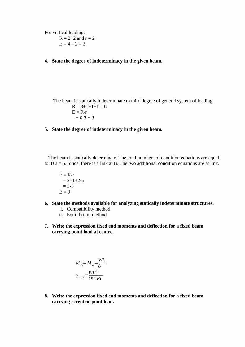
4. State the degree of indeterminacy in the given beam.
The beam is statically indeterminate to third degree of general system of loading.R = 3+1+1+1 = 6E = R-r = 6-3 = 3
5. State the degree of indeterminacy in the given beam.
The beam is statically determinate. The total numbers of condition equations are equal to 3+2 = 5. Since, there is a link at B. The two additional condition equations are at link.
E = R-r = 2+1+2-5 = 5-5E = 0
6. State the methods available for analyzing statically indeterminate structures.
i. Compatibility methodii. Equilibrium method
7. Write the expression fixed end moments and deflection for a fixed beam carrying point load at centre.
M A=M B=WL8
ymax=WL3
192 EI
8. Write the expression fixed end moments and deflection for a fixed beam carrying eccentric point load.

M A=Wab2
L2
MB=Wa2 b
L2
ymax=Wa3 b3
3 EIL3(under theload )
9. Write the expression fixed end moments for a fixed due to sinking of support.
M A=M B=6 EI δ
L2
10. State the Theorem of three moments.
Theorem of three moments:
It states that “If BC and CD are only two consecutive span of a continuous beam subjected to an external loading, then the moments MB, MC and MD at the supports B, C and D are given by
MBL1+2MC (L1+L2 )=M D . L2=6a1 x
¿
1
L1
+6a2 x2
¿
L2
WhereMB = Bending Moment at B due to external loadingMC = Bending Moment at C due to external loadingMD = Bending Moment at D due to external loadingL1 = length of span ABL2 = length of span BCa1 = area of B.M.D due to vertical loads on span BCa2 = area of B.M.D due to vertical loads on span CD
x¿
1 = Distance of C.G of the B.M.D due to vertical loads on BC from B
x¿
2 = Distance of C.G of the B.M.D due to vertical loads on CD from D.
11. Draw the shape of the BMD for a fixed beam having end moments –M in one support and +M in the other. (NOV/DEC 2003)
12. What are the fixed end moments for a fixed beam of length ‘L’ subjected to a concentrated load ‘w’ at a distance ‘a’ from left end? (Nov/Dec – 2004)
Fixed End Moment:
M A=Wab2
L2
MB=Wab2
L2
13. Explain the effect of settlement of supports in a continuous beam. (Nov/Dec 2003)
Due to the settlement of supports in a continuous beam, the bending stresses will alters appreciably. The maximum bending moment in case of continuous beam is less when compare to the simply supported beam.
14. What are the advantages of Continuous beams over Simply Supported beams?(i)The maximum bending moment in case of a continuous beam is much less than in caseof a simply supported beam of same span carrying same loads.(ii) In case of a continuous beam, the average B.M is lesser and hence lighter materials ofconstruction can be used it resist the bending moment.
15. A fixed beam of length 5m carries a uniformly distributed load of 9 kN/m run over the entire span. If I = 4.5x10⁻⁴ m4 and E = 1x10⁷ kN/m2, find the fixing moments at the ends and deflection at the centre.
Solution:Given:
L = 5mW = 9 kN/m2 , I = 4.5x10⁻⁴ m4 and E = 1x10⁷ kN/m2
(i) The fixed end moment for the beam carrying udl:
MA = MB = WL2
12
= 9x(5 )
2
12=18 .75 KNm
(ii) The deflection at the centre due to udl:

yc=WL4
384 EI
yc=9x (5 )
4
384 x1x107 x4 .5x 10−4=3 .254mm
Deflection is in downward direction.
16. A fixed beam AB, 6m long is carrying a point load of 40 kN at its center. The
M.O.I of the beam is 78 x 106 mm4 and value of E for beam material is 2.1x10⁵ N/mm2. Determine (i) Fixed end moments at A and B.
Solution:
Fixed end moments:
M A=M B=WL8
M A=M B=50x6
8=37 .5 kNm
17. A fixed beam AB of length 3m is having M.O.I I = 3 x 106 mm4 and value of E forbeam material is 2x10⁵ N/mm2. The support B sinks down by 3mm. Determine (i)fixed end moments at A and B.
Solution:Given:
L = 3m = 3000mm I = 3 x 106 mm4
E = 2x10⁵ N/mm2
δ = 3mm
M A=M B=6 EI δ
L2
=6x2x 105 x3x106 x3
(3000 )2
=12x105 N mm = 12 kN m.
18. A fixed beam AB, 3m long is carrying a point load of 45 kN at a distance of 2m from A. If the flexural rigidity (i.e) EI of the beam is 1x10⁴kNm2. Determine (i) Deflection under the Load.
Solution:Given:

L = 3mW = 45 kNEI = 1x10⁴ kNm2
Deflection under the load:In fixed beam, deflection under the load due to eccentric load
Wa3b3
3 EIL3
yC=¿ ¿¿¿
yC=45 x (2)3 x (1 )3
3x1x 104 x (3)2
yC=0 .000444myC=0 .444mm
The deflection is in downward direction.
19. A fixed beam of 5m span carries a gradually varying load from zero at end A to 10 kN/m at end B. Find the fixing moment and reaction at the fixed ends.
Solution:Given:
L = 5mW = 10 kN/m
(i) Fixing Moment:
M A=WL2
30andMB=
WL2
20
MA = 10(5 )
2
30=
25030
=8 .33 kNm
MB=10 (5 )
2
20=
25020
=12.5kNm
(ii) Reaction at support:
RA=3WL20
and RB=7WL20
RA=3∗10∗520
=15020
=7 . 5kN
RB=7∗10∗520
=35020
=17 .5kN
20. A cantilever beam AB of span 6m is fixed at A and propped at B. The beam carries a udl of 2kN/m over its whole length. Find the reaction at propped end.
Solution:Given:
L=6m, w =2 kN/m
Downward deflection at B due to the udl neglecting prop reaction P,
yB=wl4
8 EIUpward deflection at B due to the prop reaction P at B neglecting the udl,
yB=Pl3
3 EI
Upward deflection = Downward deflection
Pl3
3 EI=
wl 4
8EI
P = 3WL/8 = 3*2*6/8 =4.5 kN
16 Marks Questions And Answers

1. A fixed beam AB of length 6m carries point load of 160 kN and 120 kN at a distance of 2m and 4m from the left end A. Find the fixed end moments and the reactions at the supports. Draw B.M and S.F diagrams.
Solution: Given:
L = 6mLoad at C, WC = 160 kNLoad at D, WC = 120 kNDistance AC = 2mDistance AD =4m
First calculate the fixed end moments due to loads at C and D separately and then add up the moments.
Fixed End Moments:For the load at C, a=2m and b=4m
M A1=WC ab
2
L2
M A1=160 x2x (4 )
2
(6 )2=142.22kNm
MB1=W Ca
2b
L2
MB1=160 x22 x( 4 )
(6)2=71 .11kNm
For the load at D, a = 4m and b = 2m
M A2=W Dab
2
L2
M A2=120 x22 x( 4 )
(6 )2=53 .33kNm
MB2=W Da
2b
L2
MB2=160x2x ( 4 )2
(6 )2=106.66kNm
Total fixing moment at A,MA = MA1 + MA2
= 142.22 + 53.33MA = 195.55 kNm

Total fixing moment at B,MB =MB1 + MB2
= 71.11 + 106.66= 177.77 kN m
B.M diagram due to vertical loads:Consider the beam AB as simply supported. Let RA
* and RB* are the
reactions at A and B due to simply supported beam. Taking moments about A, we getRB
¿ x6=160 x2+120 x4
RB¿=8006
=133 .33kN
RA* = Total load - RB
*=(160 +120) – 133.33 = 146.67 kNB.M at A = 0B.M at C = RA
* x 2 = 146.67 x 2 = 293.34 kN mB.M at D = 133.33 x 2 = 266.66 kN mB.M at B= 0
S.F Diagram:Let RA = Resultant reaction at A due to fixed end moments and vertical
loadsRB = Resultant reaction at BEquating the clockwise moments and anti-clockwise moments about A,
RB x 6 + MA = 160 x 2 + 120 x 4 + MB
RB= 130.37 kNRA = total load – RB = 149.63 kN
S.F at A = RA = 149.63 kNS.F at C = 149.63- 160 = -10.37 kNS.F at D = -10.37 – 120 = -130.37 kN
S.F at B= 130.37 KN

2. A fixed beam AB of length 6m carries two point loads of 30 kN each at a distance of 2m from the both ends. Determine the fixed end moments and draw the B.M diagram.
Sloution:Given:
Length L = 6mPoint load at C = W1 = 30 kNPoint load at D = W2= 30 kN
Fixed end moments:MA = Fixing moment due to load at C + Fixing moment due to load at D
=W 1a1b12
L2+W 2a2b22
L2
¿30 x2x42
62+
30 x4x22
62=40kN m
Since the beam is symmetrical, MA = MB = 40 kNm
B.M Diagram:To draw the B.M diagram due to vertical loads, consider the beam AB as simply
supported. The reactions at A and B is equal to 30kN.B.M at A and B = 0B.M at C =30 x 2 = 60 kNmB.M at D = 30 x 2 = 60 kNm
3. Find the fixing moments and support reactions of a fixed beam AB of length 6m, carrying a uniformly distributed load of 4kN/m over the left half of the span.
Solution:
Macaulay’s method can be used and directly the fixing moments and end reactions can be calculated. This method is used where the areas of B.M diagrams cannot be determined conveniently. For this method it is necessary that UDL should be extended up to B and then compensated for upward UDL for length BC as shown in fig.
The bending at any section at a distance x from A is given by,
EId2 ydx2
=R A x−M A−wxx2
+w*(x-3)( x−3 )
2
=RAx – MA- (4x22
) +4(x−3)
2
2)
= RAx – MA- 2x2 +2(x-3)2
Integrating, we get
EIdydx
=RAx2
2-MAx - 2 x3
3+C1 +
2( x−3)3
3-------(1)
When x=0, dydx
=0.
Substituting this value in the above equation up to dotted line,C1 = 0
Therefore equation (1) becomes
EIdydx
=RAx2
2-MAx - 2 x3
3 +
2( x−3)3
3Integrating we get
EI y=R Ax3
6−M A x
2
2−
2x4
12+C2+
2( x−3 )4
12When x = 0 , y = 0
By substituting these boundary conditions upto the dotted line,C2 = 0
EI y=RA x
3
6−M A x
2
2−x6
4
+1( x−3 )4
6________(ii)
By subs x =6 & y = 0 in equation (ii)

0=RA 63
6−M A62
2−
66
4
+1(6−3 )4
6
=36 RA−18 M A−216+13. 5
18RA – 9 MA = 101.25 ------------- (iii)
At x =6, dydx
=0 in equation (i)
0=R A x62
2−M A x6−
23x (6 )3+
23
(6−3 )3
18R A−M A x6−144+18=018R A−6MA=126
By solving (iii) & (iv)
MA = 8.25 kNmBy substituting MA in (iv) 126 = 18 RA – 6 (8.25) RA = 9.75 kN RB = Total load – RA RB = 2.25 kNBy equating the clockwise moments and anticlockwise moments about B MB + RA x 6 = MA + 4x3 (4.5) MB = 3.75 kNm
Result: MA = 8.25 kNm
MB = 3.75 kNmRA = 9.75 kNRB = 2.25 KN
4. A continuous beam ABC covers two consecutive span AB and BC of lengths 4m and 6m, carrying uniformly distributed loads of 6kN/m and 10kN/m respectively. If the ends A and C are simply supported, find the support moments at A,B and C. draw also B.M.D and S.F.D.
Solution:Given Data:
Length AB, L1=4m.Length BC, L2=6mUDL on AB, w1=6kN/mUDL on BC, w2=10kN/m

(i) Support Moments:Since the ends A and C are simply supported, the support moments at A and Cwill be zero.
By using cleyperon’s equation of three moments, to find the support moments at B (ie) MB.
MAL1 + 2MB(L1+L2) + MCL2 = −6a1 x1
4−
6a2 x2
6
0 + 2MB(4+6) + 0 = −6a1 x1
4−
6a2 x2
6
20MB = −3a1 x1
2−a2 x2
The B.M.D on a simply supported beam is carrying UDL is a parabola having an
attitude of wL2
8.
Area of B.M.D = 23
*L*h
= 23
* Span * wL2
8
The distance of C.G of this area from one end, = span
2. a1=Area of B.M.D due to UDL on AB,
= 23
*4*6 (42
)
8 =32
x1=L1
2 = 4/2 = 2 m. a2= Area of B.M.D due to UDL on BC,
= 23
*6*10(62
)
8 = 180m. x2=L2 / 2 = 6 / 2 =3m
Substitute these values in equation(i).We get,
20MB = 3∗32∗2
2+(180∗3 )
= 96+540MB =31.8 kNm.
(ii) B.M.D

The B.M.D due to vertical loads (UDL) on span AB and span BC.Span AB:
=w1L12
8
= 6∗42
8=12kNm
Span BC: =w2L22
8
= 10∗62
8=45kNm
(iii) S.F.D:To calculate Reactions,For span AB, taking moments about B, we get(RA*4)-(6*4*2) – MB=04RA – 48 = 31.8 (MB=31.8, -ve sign is due to hogging moment.
RA=4.05kNSimilarly,For span BC, taking moment about B,(Rc*6)-(6*10*3) – MB=06RC – 180=-31.8
RC=24.7kN.RB=Total load on ABC –(RA+RB)
=(6*4*(10*6))-(4.05+24.7)=55.25kN.
RESULT:
MA=MC=0MB=31.8kNmRA=4.05kNRB=55.25kNRC=24.7kN
5. A continuous beam ABCD of length 15m rests on four supports covering 3 equal spans and carries a uniformly distributed load of 1.5 kN/m length .Calculate the moments and reactions at the supports. Draw The S.F.D and B.M.D.
Solution: Given: Length AB = L1 = 5m Length BC = L2 = 5m Length CD = L3 = 5m u.d.l w1 = w2 = w3 = 1.5 kN/m
Since the ends A and D are simply supported, the support moments at A and D will be Zero.MA=0 and MD=0For symmetry MB=0

(i)To calculate support moments:To find the support moments at B and C, by using claperon’s equations of three momentsfor ABC and BCD.For ABC,
MAL1+[2MB(L1+L2)]+MCL2=−6a1 x1
L1
−6a2 x2
L2
0+[2MB(5+5)]+[MC(5)]= −6a1 x1
5−
6a2 x2
5
20MB+5MC=65( a1 x1+a2 x2 ) --------------------------------------(i)
a1=Area of BMD due to UDL on AB when AB is considered as simply supported beam.
=23∗AB∗¿
¿Altitude of parabola (Altitude of parabola=
w1L1
8
)
= 23∗5∗
1.5∗(5 )2
8 =15.625x1=L1/2 =5/2=2.5mDue to symmetry .a2=a1=15.625 x2=x1=2.5 subs these values in eqn(i)
20MB+5MC =65
[(15 .625∗2 .5)+(15 .625∗2.5) ]
=93.75Due to symmetry MB=MC
20MB+5MB=93.75 MB=3.75kNm. MB=MC=3.75kNm.
(ii) To calculate BM due to vertical loads: The BMD due to vertical loads(here UDL) on span AB, BC and CD (considering each span as simply supported ) are shown by parabolas of altitude
w1L12
8=
1 .5∗1 .52
8=4 . 6875 kNm each.
(iii)To calculate support Reactions:
Let RA,RB,RC and RD are the support reactions at A,B,C and D.Due to symmetry RA=RD
RB=RC
For span AB, Taking moments about B,We getMB=(RA*5)-(1.5*5*2.5)-3.75=(RA*5)-18.75
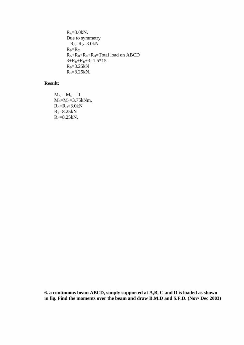
RA=3.0kN.Due to symmetry RA=RD=3.0kNRB=RC
RA+RB+RC+RD=Total load on ABCD3+RB+RB+3=1.5*15RB=8.25kNRC=8.25kN.
Result:
MA = MD = 0 MB=MC=3.75kNm. RA=RD=3.0kN RB=8.25kN RC=8.25kN.
6. a continuous beam ABCD, simply supported at A,B, C and D is loaded as shown in fig. Find the moments over the beam and draw B.M.D and S.F.D. (Nov/ Dec 2003)
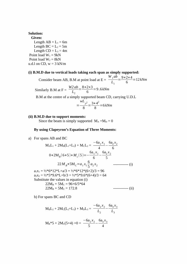
Solution: Given: Length AB = L1 = 6m Length BC = L2 = 5m Length CD = L3 = 4m Point load W1 = 9kN Point load W2 = 8kNu.d.l on CD, w = 3 kN/m
(i) B.M.D due to vertical loads taking each span as simply supported:
Consider beam AB, B.M at point load at E = W 1ab
L1
=9∗2∗4
6=12kNm
Similarly B.M at F = W2abL2
=8∗2∗3
6=9 .6kNm
B.M at the centre of a simply supported beam CD, carrying U.D.L
=wL
32
8=
3∗42
8=6kNm
(ii) B.M.D due to support moments: Since the beam is simply supported MA =MD = 0
By using Clapeyron’s Equation of Three Moments:
a) For spans AB and BC
MAL1 + 2MB(L1+L2) + MCL2 = −6a1 x1
4−
6a2 x2
6
0+2MB(6+5 )+M c(5 )=−6a1 x1
6−
6a2 x2
5
22M B+5MC=a1 x165a2 x2 ------------ (i)
a1x1 = ½*6*12*L+a/3 = ½*6*12*(6+2)/3 = 96a2x2 = ½*5*9.6*L+b/3 = ½*5*9.6*(6+4)/3 = 64Substitute the values in equation (i)
22MB + 5MC = 96+6/5*6422MB + 5MC = 172.8 ------------ (ii)
b) For spans BC and CD
MBL2 + 2MC(L2+L3) + MDL3 = −6a2 x2
L2
−6a3 x3
L3
MB*5 + 2MC(5+4) +0 = −6a2 x2
5−
6a3 x3
4

5MB+18MC=6ax 2
5+
6a3 x3
4----------- (iii)
a2x2 = ½ * 5 * 9.6 *(L+a)/3 =1/2 * 5 * 9.6 *(5+2)/3 = 56a3x3 = 2/3 * 4*6*4/2 =32Substitute these values in equation (iii)
5MB+18MC=6∗56
5+
6∗324
5MB+18MC=115 .2
By solving equations (ii) &(iv)MB = 6.84 kNm and MC = 4.48 kNm
(iii) Support Reactions:
For the span AB, Taking moment about B,MB = RA * 6 – 9*4 = 6RA−36
RA =36−6 .84
6=4 .86 KN
For the span CD, taking moments about C
MC=RD×4−3×4×42
(MC=−4 .48)
RD = 4.88KNFor ABC taking moment about CMc = RA∗(6+5 )−9 (5+4 )+RB∗5−8∗35RB=81+24−4 .86∗11
RB = 9.41 kNRC = Total load on ABCD – (RA +RB+RD)RC = (9+8+4*3) – (4.86+9.41+4.88)RC = 9.85 kN
Result:MA = MD = 0MB = 6.84 kNm and MC = 4.48 kNmRA = 4.86kNRB = 9.41kNRC = 9.85 kNRD = 4.88KN

7. Using the theorem of three moments draw the shear force and bending moment diagrams for the following continuous beam. (April / May 2003)
Solution:Given:
Length AB, L1=4m. Length BC, L2=3m. Length CD, L3=4m. UDL on AB, w=4 kN/m Point load in BC, W1=4kN/m Point load in CD, W1=6kN
(i) Bending Moment to Vertical Loads:
Consider beam AB, B.M= wL2
8=
4∗42
8=8kNm.
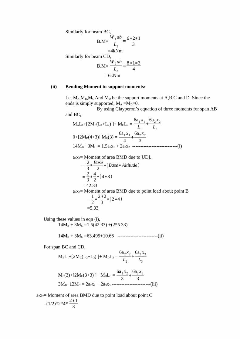
Similarly for beam BC,
B.M=W 1ab
L2
=6∗2∗1
3 =4kNm
Similarly for beam CD,
B.M=W 2ab
L3
=8∗1∗3
4 =6kNm
(ii) Bending Moment to support moments:
Let MA,MB,MC And MD be the support moments at A,B,C and D. Since the ends is simply supported, MA =MD=0.
By using Clayperon’s equation of three moments for span ABand BC,
MAL1+[2MB(L1+L2) ]+ MCL2 =6a1 x1
L1
+6a2 x2
L2
0+[2MB(4+3)] MC(3) =6a1 x1
4+
6a2 x2
314MB+ 3MC = 1.5a1x1 + 2a2x2 ----------------------------(i)
a1x1= Moment of area BMD due to UDL
= 23∗Base
2∗(Base∗Altitude)
=23∗
42∗(4∗8 )
=42.33a2x2= Moment of area BMD due to point load about point B
=12∗
2∗23
∗(2∗4 )
=5.33
Using these values in eqn (i),14MB + 3MC =1.5(42.33) +(2*5.33)
14MB + 3MC =63.495+10.66 -------------------------(ii)
For span BC and CD,
MBL1+[2MC(L2+L3) ]+ MDL3 =6a2 x2
L2
+6a3 x3
L3
MB(3)+[2MC(3+3) ]+ MDL3 =6a2 x2
3+
6a3 x3
33MB+12MC = 2a2x2 + 2a3x3 ------------------------(iii)
a2x2= Moment of area BMD due to point load about point C
=(1/2)*2*4*2∗1
3
=2.66
a3x3= Moment of area BMD due to point load about point D
= 12∗1∗6∗
2∗33
=6
Using these values in Eqn(iii),
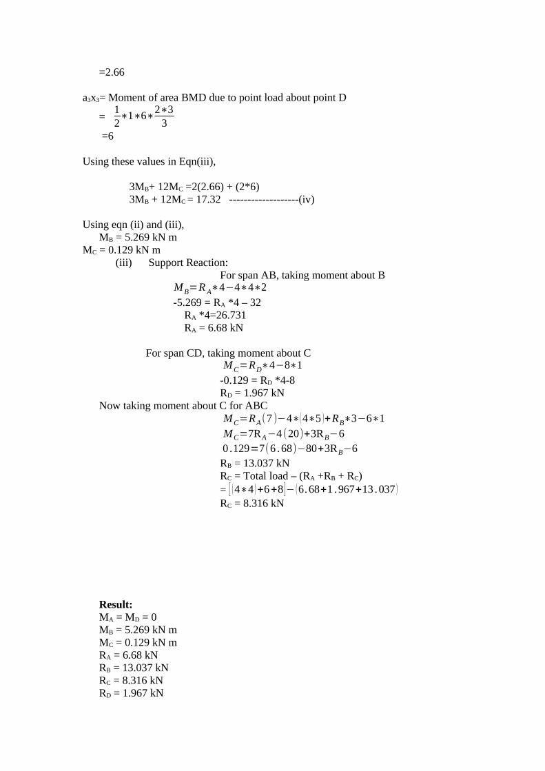
3MB+ 12MC =2(2.66) + (2*6) 3MB + 12MC = 17.32 -------------------(iv)
Using eqn (ii) and (iii), MB = 5.269 kN mMC = 0.129 kN m
(iii) Support Reaction:For span AB, taking moment about B
MB=R A∗4−4∗4∗2
-5.269 = RA *4 – 32 RA *4=26.731 RA = 6.68 kN
For span CD, taking moment about CMC=RD∗4−8∗1
-0.129 = RD *4-8RD = 1.967 kN
Now taking moment about C for ABCMC=RA(7 )−4∗(4∗5 )+RB∗3−6∗1
MC=7RA−4 (20)+3RB−60 .129=7(6 .68)−80+3RB−6RB = 13.037 kNRC = Total load – (RA +RB + RC)= [ (4∗4 )+6+8 ]− (6.68+1 .967+13 .037 )
RC = 8.316 kN
Result:MA = MD = 0
MB = 5.269 kN m MC = 0.129 kN m
RA = 6.68 kNRB = 13.037 kNRC = 8.316 kNRD = 1.967 kN

8. A beam AB of 4m span is simply supported at the ends and is loaded as shown in fig. Determine (i) Deflection at C (ii) Maximum deflection (iii) Slope at the end A. E= 200 x 106 kN/m2 and I = 20 x 10-6 m4
Solution:Given:L = 4mE= 200 x 106 kN/m2 and I = 20 x 10-6 m4
To calculate Reaction: Taking moment about A
RB∗4=20∗1+10∗2(22+1+1)
RB *4 = 20 + 20(3) RB = 80/4 = 20 kN RA = Total load - RB
= (10*2+20) -20 RA = 20 kN

By using Macaulay’s method:
MX=EId2 ydx2
=20 x−20( x−1 )−10( x−2 )
2
2Integrating we get
EIdydx
=10x2+C1−10( x−1 )2−5( x−2)3
3Integrating we get
EIy=10 x3
3+C1 x+C2−
10( x−1 )3
3−
5( x−2)4
12---------- (ii)
When x = 0, y = 0 in equation (ii) we get C2 = 0When x = 4m, y = 0 in equation (ii)
0=103
(4 )3+4C1−103
(4−1 )3−5
12( 4−2 )4
= 213.33 +4C1 – 90 -6.67C1 = -29.16
Hence the slope and deflection equations are
Slope Equation:
EIdydx
=10x2−29 .16−10( x−1 )2−5( x−2 )3
3
Deflection Equation:
EIy=10 x3
3−29 .16 x−
10( x−1 )3
3−
5 ( x−2)4
12
(i) Deflection at C, yC :
Putting x = 2m in the deflection equation, we get
EIy=10(2 )
3
3−29 .16(2 )−
10(2−1)3
3= 26.67 -58.32 -3.33= -34.98yc = 8.74 (downward)
(ii) Maximum Deflection , ymax :
The maximum deflection will be very near to mid-point C. Let us assume that it occurs in the sections between D and C. For maximum deflection equating the slope at the section to zero, we get
EIdydx
=10x2−29 .16−10( x−1 )2

10x2 -29.16 -10(x-1)2 = 010x2 -29.16 -10 (x2 -2x+1) = 0
x = 39.16/20 =1.958 m
EIy=10(1 . 958)
3
3−29 .16(1.958 )−
10(1 .958−1 )3
3ymax = -35/EIymax = 8.75 mm (downward)
(iii) Slope at the end A, θA:
Putting x = 0 in the slope equation,
EIdydx
=−29 .16
θA = dy/dx = -29.16/EIθA = -0.00729 radiansθA = -0.417º
Result:(i) Deflection at C = 8.74 mm(ii) Maximum deflection = 8.75 mm(iii) Slope at the end A, θA = -0.417º
9. A continuous beam is shown in fig. Draw the BMD indicating salient points.(Nov/Dec 2004)
Solution:Given:Length L1 = 4mLength L2 = 8mLength L3 = 6mUdl on BC w = 10 kN/mPoint load W1 = 40 kNPoint load W2 = 40 kN
(i) B.M due to vertical loads:
Consider beam AB, B.M = W 1ab
L1
=40∗3∗1
4=30kNm
For beam BC,
B.M = wL2
8=
10 (8)2
8=80 kNm
For beam CD,
B.M = W 2L3
4=
40∗64
60 kNm
(ii) B.M due to support moments:

Let MA, MB, MC, MD be the support moments at A, B, C, D. Since the end A and D are simply supported MA = MD = 0
By using Clapeyron’s Equation of Three moments.
For Span AB and BC:
M AL1+2MB(L1+L2 )+MC L2=−6a1 x1
L1
−6a2 x2
L2
0+2MB(4+8 )+MC(8 )=−6a1 x1
4−
6a2 x2
82MB (12) +8 MC = -1.5a1x1 – 0.75 a2 x2
24 MB +8 MC = -1.5a1x1 – 0.75 a2 x2 ----------- (i)a1x1 = Moment of area of B.M.D due to point load = ½*4*30*2/3*3 = 120a2x2 = Moment of area of B.M.D due to udl = 2/3 (Base x Altitude) x Base/2 = 2/3 (8*80)*8/2 = 1706.67Using these values in equation (i)
24 MB +8 MC = -1.5(120) – 0.75 (1706.67) 24 MB +8 MC = -1460.0025 ---------------- (ii)
For Span BC and CD:
MBL2+2MC (L2+L3)+M DL3=−6a2 x2
L2
−6a3 x3
L3
MB(8 )+2MC (8+6 )+0=−6a2 x2
8−
6a3 x3
68 MB + 28 MC = - 0.75 a2x2 - a3x3 -------------- (iii)
a2x2 = Moment of area of B.M.D due to udl = 2/3 (Base x Altitude) x Base/2 = 2/3 (8*80)*8/2 = 1706.67 a3 x3 = Moment of area of B.M.D due to point load = ½ * b*h*L/3 = ½ * 6*60*6/3 = 360 Using these values in equation (iii)
8 MB + 28 MC = - 0.75 (1706.67) – 3608 MB + 28 MC = - 1640.0025 ------------------ (iv)
From (ii) & (iv) MC = 45.526 kNmMB = 45.657 kNm
Result: MA = MD = 0 MC = 45.526 kNm MB = 45.657 kNm

10. For the fixed beam shown in fig. draw BMD and SFD. (Nov / Dec 2004)
Solution:
(i) B.M.D due to vertical loads taking each span as simply supported:
Consider beam AB as simply supported. The B.M at the centre of AB
=wL
12
8=
2∗(3 )2
8=2.25kNm

(ii) B.M.D due to support moments:
As beam is fixed at A and B, therefore introduce an imaginaryzero span AA1 and BB1 to the left of A and to the right of B. The support moments at A1 and B1 arezero. Let M0 = Support moment at A1 and B1 and it is zero. MA = Fixing moment at A MB = Fixing moment at B MC = Support moment at C
To find MA, MB and MC, Theorem of three moments is used.
(a) For the span A1A and AC,
M 0∗0+2MA(0+L1)+MC L1=−6a0 x0
L0
−6a1x1
L1
2MA(3)+MC (3)=−6a1 x1
L1
6 MA + 3MC = - 2a1x1 ------------- (i)a1x1 = moment of area of B.M.D due to udl on AB when it is considered as simply supported beam about B = 2/3 * Base * Altitude * L1/2 = 2/3 * 3 * 2.25 * 3/2a1x1 = 6.75subs this values in equation (i) we get
6 MA + 3 MC = -13.50 ------------ (ii)
(b) For the span AC and CB:
M AL1+2MC (L1+L2 )+MB L2=−6a1 x1
L1
−6a2 x2
L2
M A(3)+2MC (3+3 )+M B(3 )=−6a1 x1
3−
6a2 x2
33 MA + 12 MC + 3 MB = 2a1x1 + 2a2x2
a1x1 = moment of area of B.M.D due to udl on AB when it is considered as simply supported beam about B = 2/3 * Base * Altitude * L1/2 = 2/3 * 3 * 2.25 * 3/2a1x1 = 6.75
a2x2 = 0 3 MA + 12 MC + 3 MB = 13.5 ----------- (ii)

( c ) For the span CB and BB1
MC L2+2MB(L2+L0 )+M 0∗0=−6a2 x2
L2
−6a0 x0
L0
3MC+2MB(3 )=6a2 x2
33MC + 6MB = 2a2x2
a2x2 = 0
3MC + 6MB = 0
By solving (iii), (iv), (ii)
MC = 1.125 kNmMA = 0.5625 kNmMB = -0.5625 kNm
(iii) Support Reactions:
Let RA, RB , and RC are the support reactions at A, B and C.
For the span AC, taking moment about C, we get RA x 3 – 2 x 3 x 1.5 + MA = MC RA x 3 – 9 + 0.5625 = 1.125RA = 3.1875 kN
For the span CB, taking moment about C, we get
RB x 3 + MC = MB
RB x 3 + 1.125 = 0.5625RB = 0.1875 kNRC = Total load – (RA + RB ) = 2*3*1.5 – (3.1875 + 0.1875)RC = 5.625 kN
Result:
MC = 1.125 kNmMA = 0.5625 kNmMB = -0.5625 kNm
RA = 3.1875 kN RB = 0.1875 kN
RC = 5.625 kN


Strength of Materials
(FOR IV – SEMESTER)
Question bank
UNIT – III
COLUMNS
Compiled by,
K.DIVYA
ASSISTANT PROFESSOR
DEPARTMENT OF CIVIL ENGINEERING
FATIMA MICHAEL COLLEGE OF ENGINEERING AND TECHNOLOGY
MADURAI - 20
UNIT – III
COLUMNS
Eccentrically loaded short columns - middle third role – core section –Columns of unsymmetrical sections-(angle channel sections) - Euler’s theory oflong columns – critical loads for prismatic columns with different end conditions;Rankine –Gordon formula for eccentrically loaded columns – thick cylinder –compound cylinder.
TWO MARKS QUESTIONS AND ANSWERS
1. Define columnsIf the member of the structure is vertical and both of its ends are fixed rigidly
while subjected to axial compressive load, the member is known as column.
Example: A vertical pillar between the roof and floor.
2. Define struts.If the member of the structure is not vertical and one (or) both of its ends is
Linged (or) pin jointed, the bar is known as strut.
Example: Connecting rods, piston rods etc,
3. Mention the stresses which are responsible for column failure.
i. Direct compressive stressesii. Buckling stressesiii. Combined of direct compressive and buckling stresses.
4. State the assumptions made in the Euler’s column theory.
1. The column is initially perfectly straight and the load is applied axially.2. The cross-section of the column is uniform throughout its length.3. The column material is perfectly elastic, homogeneous and isotropic and
obeys Hooke’s law.4. The self weight of column is negligible.
5. What are the important end conditions of columns?

1. Both the ends of the column are linged (or pinned)2. One end is fixed and the other end is free.3. Both the ends of the column are fixed.4. One end is fixed and the other is pinned.
6. Write the expression for crippling load when the both ends of the columnare hinged.
P=π2EIl2
P = Crippling loadE = Young’s ModulusI = Moment of inertia l = Length of column
7. Write the expression for buckling load (or) Crippling load when both endsof the column are fixed?
P=4π2EIL2
P = Crippling loadE = Young’s ModulusI = Moment of inertia l = Length of column
8. Write the expression for crippling load when column with one end fixedand other end linged.
P=2π2EIl2
P = Crippling loadE = Young’s ModulusI = Moment of inertia l = Length of column
9. Write the expression for buckling load for the column with one fixed and other end free.
P=π2EI4l2
P = Crippling loadE = Young’s ModulusI = Moment of inertia l = Length of column
10. Explain equivalent length (or) Effective length.
If l is actual length of a column, then its equivalent length (or) effective lengthL may be obtained by multiplying it with some constant factor C, which depends onthe end fixation of the column (ie) L = C x l.
11. Write the Equivalent length (L) of the column in which both ends hingedand write the crippling load.
Crippling Load P=π2EIL2
Equivalent length (L) = Actual length (l)
P = Crippling loadE = Young’s ModulusI = Moment of inertia L= Length of column
12. Write the relation between Equivalent length and actual length for all endconditions of column.
Both ends linged L = l Constant = 1
Both ends fixed L=l2
Constant = 12
One end fixed and otherend hinged
L=l
√2 Constant =
1
√2One end fixed and other
end freeL=2l Constant = 2
13. Define core (or) Kernel of a section. (April/May 2003)
When a load acts in such a way on a region around the CG of the section Sothat in that region stress everywhere is compressive and no tension is developedanywhere, then that area is called the core (or) Kernal of a section. The kernel of thesection is the area within which the line of action of the eccentric load P must cut thecross-section if the stress is not to become tensile.
14. Derive the expression for core of a rectangular section.(Nov/Dec 2003)The limit of eccentricity of a rectangular section b x d on either side of XX axis
(or) YY axis is d/6 to avoid tension at the base core of the rectangular section.
Core of the rectangular section = Area of the shaded portion
=2×12×b3×d6
=bd18
15. Derive the expression for core of a solid circular section of diameter D.

The limit of eccentricity on either side of both XX (or) YY axis = D/8 to avoidtension of the base.
Core of the circular section = Area of the shaded portion=π (D /8 )2
=πD2
64
16. A steel column is of length 8m and diameter 600 mm with both endshinged. Determine the crippling load by Euler’s formula. TakeE=2.1×10⁵ N/mm2.
I=π
64(d )4=
π64
(600 )4=6 .36×109mm4
Since the column is hinged at the both ends,
∴ Equivalent length L = l
Pcr=π2EIL2
=π2
×2.1×105×6 .36×109
(8000 )2
=2 .06×108N
17. Define Slenderness ratio.
It is defined as the ratio of the effective length of the column (L) to the least
radius of gyration of its cross –section (K) (i.e) the ratio of LK
is known as
slenderness ratio.
Slenderness ratio = LK
18. State the Limitations of Euler’s formula.(April /May 2005)
a. Euler’s formula is applicable when the slenderness ratio is greater than orequal to 80
b. Euler’s formula is applicable only for long columnc. Euler’s formula is thus unsuitable when the slenderness ratio is less than a
certain value.
19. Write the Rankine’s formula for columns.
P=f c×A
1+α ( LK )2

K = Least radius of gyration =√ IAP = Crippling loadA = Area of the columnfc = Constant value depends upon the material.
α = Rankine’s constant =f cπ2E
20. Write the Rankine’s formula for eccentric column.
P=f c×A
(1+eyck2 )[1+α( Lk )
2
]K = Least radius of gyration =√ IAP = Crippling loadA = Area of the columnfc = Constant value depends upon the material.
α = Rankine’s constant =f cπ2E
21. Define thick cylinder.If the ratio of thickness of the internal diameter of a cylindrical or spherical
shell exceeds 1/20, it is termed as a thick shell.The hoop stress developed in a thick shell varies from a maximum value at the
inner circumference to a minimum value at the outer circumference.Thickness > 1/20
22. State the assumptions involved in Lame’s Theory
i. The material of the shell is Homogeneous and isotropic. ii. Plane section normal to the longitudinal axis of the cylinder remains
plane after the application of internal pressure.iii. All the fibers of the material expand (or) contact independently without
being constrained by there adjacent fibers.
23. What is the middle third rule? (Nov/Dec 2003)In rectangular sections, the eccentricity ‘e’ must be less than or equal to b/6.
Hence the greatest eccentricity of the load is b/6 form the axis Y-Y and with respect toaxis X –X1 the eccentricity does not exceed d/6. Hence the load may be applied with inthe middle third of the base (or) Middle d/3.

16 MARKS QUESTIONS AND ANSWERS
1. Explain the failure of long column.Solution:A long column of uniform cross-sectional area A and of length l, subjected to
an axial compressive load P, as shown in fig. A column is known as long column ifthe length of the column in comparison to its lateral dimensions is very large. Suchcolumns do not fail y crushing alone, but also by bending (also known buckling)
The load, at which the column just buckles, is known as buckling load and it isless than the crushing load is less than the crushing load for a long column.
Buckling load is also known as critical just (or) crippling load. The value ofbuckling load for long columns are long columns is low whereas for short columns thevalue of buckling load is high.
Let
l = length of the long columnp = Load (compressive) at which the column has jus
buckled.A = Cross-sectional area of he columne = Maximum bending of the column at the centre.
σ0 = Stress due to direct load =PA
σb = Stress due to bending at the centre of the column
= P×eZ
Where Z = Section modulus about the axis of bending.
The extreme stresses on the mid-section are given by
Maximum stress = σ0 + σbMinimum stress = σ0 - σb

The column will fail when maximum stress (i.e) σ0 + σb is more the crushingstress fc. In case of long column, the direct compressive stresses are negligible ascompared to buckling stresses. Hence very long columns are subjected to bucklingstresses.
2. State the assumptions made in the Euler’s column Theory. And explainthe sign conventions considered in columns. (April/May2003)
The following are the assumptions made in the Euler’s column theory:
1. The column is initially perfectly straight and the load is appliedaxially
2. The cross-section of the column is uniform throughout itslength.
3. The column material is perfectly elastic, homogeneous andisotropic and obeys Hooke’s law.
4. The length of the column is very large as compared to its lateraldimensions
5. The direct stress is very small as compared to the bending stress6. The column will fail by buckling alone.7. The self-weight of column is negligible.
The following are the sign conventions considered in columns:
1. A moment which will tend to bend the column with its convexitytowards its initial centre line is taken as positive.
2. A moment which will tend to bend the column with its concavitytowards its initial center line is taken as negative.
3. Derive the expression for crippling load when the both ends of the columnare hinged.

Solution:Consider a column AB of length L hinged at both its ends A and B carries an
axial crippling load at A.
Consider any section X-X at a distance of x from B.
Let the deflection at X-X is y.
∴ The bending moment at X-X due to the load P, M = −P . y
d2 ydx2
=−PyEI
=−k2 y
Where k2=pEI
∴`d2 ydx2
+k 2 y=0
Solution of this differential equation is
y=A cos kx+B sin kx
∴ y=A cos x (√ pEI )+B sin x (√ pEI )By using Boundary conditions,
At B, x = 0, y = 0 ⇒ A = 0At A, x = l, y = 0
∴ 0=B sin l√ pEISinl √ pEI=0
l×√ pEI =0,π ,2π ,3π . . .. ..
Now taking the lest significant value (i.e) π
l √ pEI=π ; l2( pEI )=π2
p=π2EIl2
∴`The Euler’s crippling load for long column with both ends hinged.

p=π2EIl2
4. Derive the expression for buckling load (or) crippling load when both ends ofthe column are fixed.
Solution:Consider a column AB of length l fixed at both the ends A and B and caries an
axial crippling load P at A due to which buckling occurs. Under the action of the loadP the column will deflect as shown in fig.
Consider any section X-X at a distance x from B.Let the deflection at X-X is y.
Due to fixity at the ends, let the moment at A or B is M.
∴ Total moment at XX = M – P.yDifferential equation of the elastic curve is
EId2 ydx2
=M−Py
d2 ydx2
+pyEI
=MIE
d2 ydx2
+pyEI
=MIE
×pp
d2 ydx2
+pyEI
=PEI
×MP
The general solution of the above differential equation is
y=A cos x (√P /EI )+B sin x (√P/EI )+MP
(i)
Where A and B are the integration constant
At, N. x = 0 and y = 0
∴ From (i)
0=A×1+B×0+Mp
A=−Mp
Differentiating the equation (i) with respect to x,

dydx
=−A√ PEI Sin (x .√P/EI )+B√ PEI Cos(x .√ PEI )+0
At the fixed end B, x = 0 and dydx
=0
∴ B √ PEI=0
Either B = 0 (or) √ PEI =0
Since √ PEI ≠0 as p ¿ 0
B = 0
Subs A=−Mp
and B = 0 in equation (i)
y=−MP
cos(x .√ PEI )+MPy=MP [1−cos(x ..√ PEI )]
Again at the fixed end A, x = l, y = 0
0=MP
[1−Cos (l .√P /EI ) ]
l .√P /EI=0,2π ,4π ,6π . . .. .. . .Now take the least significant value 2π
l .√ PEI =2π
l .2×PEI
=4π2
P=4π2EIl2
∴ The crippling load for long column when both the ends of the column are fixed
P=4π2EIL2
5. Derive the expression for crippling load when column with one end fixedand other end hinged. (April/May 2003)
Solution:
Consider a column AB of length l fixed at B and hinged at A. It carries anaxial crippling load P at A for which the column just buckles.
As here the column AB is fixed at B, there will be some fixed end moment atB. Let it be M. To balance this fixing moment M, a horizontal push H will be exertedat A.
Consider any section X-X at a distance x from the fixed end B. Let thedeflection at xx is y.
Bending moment at xx = H (l-x) - Py
∴Differential equation of the elastic curve is,
EId2 ydx2
=H (l−x )−Py
d2 ydx2
+PEIy=
14 (l−x )
EI
d2 ydx2
+PEIy=H ( l−x )
EI×pP
d2 ydx2
+PEIy=H ( l−x )
EI×pEI
The general solution of the above different equation is
y=A cos (x .√ pEI )+B sin(x .√ pEI )+ H (l−x )
PWhere A and B are the constants of integration. (i)
At B, x = 0, y = 0
∴From (i) A=−HlP
B √ PEI=HPB=
HP
×√ EIpAgain at the end A, x = l, y=0. ∴ substitute these values of x, y, A and B in
equation (i)

0=−HlPCos (l .√P/EI )+
HP √ EIP Sin (l .√P/EI )
HP (√ EIp Sin . (l .√P /EI ))=HlP Cos (l .√P/EI )
tan (l .√P/EI . l )=√P/EI .l
The value of tan (√P/EI . l ) in radians has to be such that its tangent is equal to itself.The only angle whose tangent is equal to itself, is about 4.49 radians.
√P /EI .l=4 .49
PEIl2=(4 .49 )2
PEIl2=2π2 (approx)
P=2π2EIl2
∴The crippling load (or) buckling load for the column with one end fixed and one endhinged.
6. Derive the expression for buckling load for the column with one end fixedand other end free. (April/May 2003)
Solution:
Consider a column AB of length l, fixed at B and free at A, carrying an axialrippling load P at D de to which it just buckles. The deflected form of the column ABis shown in fig. Let the new position of A is A1.
Let a be the deflection at the free end. Consider any section X-X at a distancex from B.
Let the deflection at xx is y.
Bending moment due to critical load P at xx,
M=EId2 ydx2
=P (a− y )
EId2 ydx2
=Pa−py
P=2π2EIl2

d2 ydx2
+pyEI
=pqEI
The solution of the above differential equation is,
y=A cos (x .√ PEI )+B sin(x .√ PEI )+a Where A and B are constants of
integration.
At B, x = 0, y = 0
∴ From (i), A = 0
Differentiating the equation (I w.r. to x
dydx
=−A√ PEI Sin(x .√ PEI )+B√ PEI Cos(x .√ PEI )At the fixed end B, x = 0 and 0=
dx
dy
0=B√ PEIAs √ PEI≠0 (∴ p≠0 )
Substitute A = -a and B = 0 in equation (i) we get,
y=−acos (x .√ PEI )+a
y=a[1−cos (x . .√ PEI )] (ii)
At the free end A, x = l, y = a, substitute these values in equation (ii)
a=a[1−cos(1 . .√ PEI )]cos(1. .√ PEI )=0
1√ PEI= π2 , 3π2,
5π2
Now taking the least significant value,
1√ PEI=π2
12 PEI
=π2
4
P=π2EI4l2
∴The crippling load for the columns with one end fixed and other end free.
7. A steel column is of length 8 m and diameter 600 mm with both ends hinged. Determine the crippling load by Euler’s formula. Take E =2.1 x 10⁵ N/mm2
Solution:
Given,Actual length of the column, l = 8m = 8000 mm
Diameter of the column d= 600 mm
E = 2.1 x 10⁵ N/mm2
I=π
64(d )4
=π
64(600 )4
I=6 .36×109mm4
Since the column is hinged at the both ends,
∴ Equivalent length L =l
∴Euler’s crippling load,
Pcr=π2EIL2
=π2
×2×2 .1×105×6 .36×109
(8000 )2
= 2.06 x 10⁸ N
8. A mild steel tube 4m long, 3cm internal diameter and 4mm thick is used asa strut with both ends hinged. Find the collapsing load, what will be thecrippling load if
i. Both ends are built in?ii. One end is built –in and one end is free?
P=π2EI4l2

Solution:
Given:Actual length of the mild steel tube, l = 4m = 400 cmInternal diameter of the tube, d = 3 cmThickness of the tube, t = 4mm = 0.4cm.
∴ External diameter of the tube, D = d + 2t = 3+2(0.4) = 3.8 cm.
Assuming E for steel = 2 x 10⁶ Kg/cm2
M.O.I of the column section,
I=π
64[D4−d4 ]
=π
64[ (3 .8 )4−(3 )2 ]
I = 6.26 cm 4
i. Since the both ends of the tube are hinged, the effective length of the columnwhen both ends are hinged.
L = l = 400 cm
∴ Euler’s crippling load ⇒ Pcr=π2EIL2
=π2
×2×106×6 .26
(400 )2
Pcr=772. 30Kg .
∴ The required collapsed load = 772.30 Kg.
ii. When both ends of the column are built –in ,then effective length of the column,
L=l2=
4002
=200 cm
∴Euler’s crippling load,
Pcr=π2EIL2
=π2
×2×106×6 .26
(200 )2
Pcr = 3089.19 Kg.
iii. When one end of the column is built in and the other end is free,

effective length of the column, L = 2l = 2 x 400 = 800 cm
∴Euler’s crippling load,
Pcr=π2EIL2
=π2
×2×106×6 .26
(800 )2
Pcr = 193.07 Kg.
9. A column having a T section with a flange 120 mm x 16 mm and web 150mm x 16 mm is 3m long. Assuming the column to be hinged at both ends,find the crippling load by using Euler’s formula. E = 2 x 10⁶ Kg/cm2.
Solution:
Given:Flange width = 120 mm = 12 cmFlange thickness = 16 mm = 1.6 cmLength of the web = 150 mm = 15cmWidth of the web = 16mm = 1.6cm
E = 2 106 Kg/cm2
Length of the column, l = 3m = 300 cm.
Since the column is hinged at both ends, effective length of the column.
L = l = 300 cm.
From the fig. Y-Y is the axis of symmetry. ∴ The C.G of the whole sectionlies on Y-Y axis.
Let the distance of the C.G from the 16 mm topmost fiber of the section = Y
∴Y=
12×1.6×1 .62
+15×1.6(1.6+152 )
12×1.6+15×1.6
Y=5 .41 cm
Distance of C.G from bottom fibre = (15+1.6) - 5.41 = 11.19cm
Now M.O.I of the whole section about X-X axis.
IXX=[12×(1 .6 )3
12+ (12×1.6 )(5.41−
1 .62 )
2
]+[ 1.6× (15 )3
12+(1.6×15 )(11 .19−
152 )
2
]IXX=1188.92cm4
M.I of the whole section about Y-Y axis
I yy=1.6×(12 )3
12+
15× (106 )3
12=235 .52cm4
∴ Imin=235 .52 cm4
∴ Euler’s Crippling load,
Pcr=π2EIL2
=π2
×2×106×235 .52
(300 )2; Pcr=51655 .32Kg .
10. A steel bar of solid circular cross-section is 50 mm in diameter. The bar ispinned at both ends and subjected to axial compression. If the limit ofproportionality of the material is 210 MPa and E = 200 GPa, determine the mminimum length to which Euler’s formula is valid. Also determine the value ofEuler’s buckling load if the column has this minimum length.
Solution:
Given,Dia of solid circular cross-section, d = 50 mm
Stress at proportional limit, f = 210 Mpa= 210 N/mm2
Young’s Modulus, E = 200 GPa = 200 x 10 3 N/mm2
Area of cross –section, A=π4×(50 )2=1963 .49mm2
Least moment of inertia of the column section,
I=π
64×(50 )4=3.6 . 79×103mm4
Least radius of gyration,
k2=IA
=306 .79×103
1963 .49×(50 )4=156 .25mm2
∵ The bar is pinned at both ends,

∴ Effective length, L = Actual length, l
∴ Euler’s buckling load,
Pcr=π2EIL2
PcrA
=π2E
(L/K )2
For Euler’s formula to be valid, value of its minimum effective length L maybe found out by equating the buckling stress to f
π2E
( LK )2=210
L2=π2E×k2
210L2=
π2×2×105
×156 .25210
L = 1211.89 mm = 1212 mm = 1.212 m
∴The required minimum actual length l =L = 1.212 m
For this value of minimum length,
Euler’s buckling load =π2EIL2
=π2
×2×105×306 .75×103
(1212 )2
= 412254 N = 412.254 KNResult:
Minimum actual length l = L = 1.212 mEuler’s buckling Load =412.254 KN
11. Explain Rankine’s Formula and Derive the Rankine’s formula for bothshort and long column.
Solution:
Rankine’s Formula:
Euler’s formula gives correct results only for long columns, which fail mainlydue to buckling. Whereas Rankine’s devised an empirical formula base don practicalexperiments for determining the crippling or critical load which is applicable to allcolumns irrespective of whether they a short or long.
If P is the crippling load by Rankine’s formula.

Pc is the crushing load of the column materialPE is the crippling load by Euler’s formula.
Then the Empirical formula devised by Rankine known as Rankine’s formula stand as:
1P
=1Pe
+1PE
For a short column, if the effective length is small, the value of PE will be very
high and the value of 1PE
will be very small as compared to 1PC
and is negligible.
For the short column, (i.e) P = PC
Thus for the short column, value of crippling load by Rankine is more or lessequal to the value of crushing load:
For long column having higher effective length, the value of PE is small and1PE
will be large enough in comparison to 1PC
. So 1PC
is ignored.
∴ For the long column, 1PC
≈1PE
(i.e) p ≈ PE
Thus for the long column the value of crippling load by Rankine is more or lessequal to the value of crippling load by Euler.
1P
=1Pc
+1PE
1P
=PE×PcPc×PE
p=Pc×PEPE×Pc
;p=
Pc
1+PcPE
Substitute the value of Pc = fc A and PE=π2EIL2 in the above equation,
p=f c×A
1+f c×A
π2EI /L2
Where, fc = Ultimate crushing stress of the column material.
A = Cross-sectional are of the column
L = Effective length of the column
I = Ak2
Where k = Least radius of gyration.
1P
=1Pc

p=f c×A
1+f c×A
π2EI /L2
=f c×A
1+f c×A×L2
π2EAk 2
p=f c×A
1+α ( LK )2
where α = Rankine’s constant =f cπ2E
P = CrushingLoad
1+α (L/k )2
When Rankine’s constant is not given then find
α=f cπ 2E
The following table shows the value of fc and α for different materials.
Material fc N/mm2 α=f cπ 2E
Wrought iron 2501
9000
Cast iron 5501
1600
Mild steel 3201
7500
Timber 501
750
12. A rolled steel joist ISMB 300 is to be used a column of 3 meters length withboth ends fixed. Find the safe axial load on the column. Take factor of
safety 3, fc = 320 N/mm2 and α=1
7500. Properties of the column section.
Area = 5626 mm2, IXX = 8.603 x 107 mm4
Iyy =4.539 x 107 mm4
Solution:Given:
Length of the column, l = 3m = 3000 mmFactor of safety = 3
fc = 320 N/mm2, α=1
7500
Area, A = 5626 mm2

IXX = 8.603 x 107 mm4
Iyy =4.539 x 107 mm4
The column is fixed at both the ends,
∴Effective length, L=l2=
30002
=1500mm
Since Iyy is less then Ixx, ∴The column section,
I=Imin=I yy=4 .539×107mm4
∴Least radius of gyration of the column section,
K=√ IA=√ 4 .539×107
5626=89 .82mm
Crippling load as given by Rakine’s formula,
pcr=f c×A
1+α( LK )2=
320×5626
1+1
7500 (150089 .82 )
2
Pcr = 1343522.38 N
Allowing factor of safety 3,
Safe load = CripplingLoadFactorofsafety
=1343522 .38
3=447840 .79N
Result:
i. Crippling Load (Pcr) = 1343522.38 Nii. Safe load =447840.79N
13. A built up column consisting of rolled steel beam ISWB 300 with two plates 200 mm x 10 mm connected at the top and bottom flanges. Calculate the safe load the column carry, if the length is 3m and both ends
are fixed. Take factor of safety 3 fc = 320 N/mm2 and α=1
7500
Take properties of joist: A = 6133 mm2
IXX = 9821.6 x 104 mm4 ; Iyy = 990.1 x 104 mm4

Solution:
Given:
Length of the built up column, l = 3m = 3000 mmFactor of safety = 3
fc =320 N/mm2
α=1
7500Sectional area of the built up column,
A=6133+2 (200×10 )=10133mm2
Moment of inertia of the built up column section abut xx axis,
IXX=9821.6×104+2[200×103
12+(200×10 ) (155 )2]
= 1.94 x 108 mm4
Moment of inertia of the built up column section abut YY axis,
IYY=990 .1×104+2(10×2003
12 ) = 0.23 x 108 mm4
Since Iyy is less than Ixx , The column will tend to buckle about Y-Y axis.
Least moment of inertia of the column section,
I=Imin=IYY=0. 23×108mm4
The column is fixed at both ends.
∴Effective length,
L=l2=
30002
=1500mm
∴ Least radius of gyration o the column section,
K=√ JA=√ 0 .23×108
10133=47 .64mm
Crippling load as given by Rankine’s formula,
pcr=f c×A
1+α( LK )2=
320×10133
1+1
7500 (150047 .64 )
2
= 2864023.3 N

Safe load = =2864023 .3
3=954674 .43N
Result:
i. Crippling load = 2864023.3 Nii. Safe load = 954674.43 N
14. Derive Rankine’s and Euler formula for long columns under long columnsunder Eccentric Loading?
i. Rankine’s formula:
Consider a short column subjected to an eccentric load P with an eccentricity eform the axis.
Maximum stress = Direct Stress + Bending stress
f c=PA
+MZ
Z=Iy
=PA
+p . e . ycAk2
I=Ak 2
k=√ IAwhere
A = Sectional are of the column Z = Sectional modulus of the columnyc = Distance of extreme fibre from N.Ak = Least radius of gyration.
f c=PA (1+
eyck2 )
∴
Where (1+eyck2 ) is the reduction factor for eccentricity of loading.
For long column, loaded with axial loading, the crippling load,
Crippling load
Factor of safety
Eccentric load, P=
f c×A
1+eyck2

P=f c×A
1+α ( LK )2
Where (1+α ( LK )2
) is the reduction factor for buckling of long column.
Hence for a long column loaded with eccentric loading, the safe load,
ii. Euler’s formula
Maximum stress n the column = Direct stress + Bending stress
=PA
+
P×esec √P /EIl2
ZHence, the maximum stress induced in the column having both ends hinged
and an eccentricity of e is PA
+PeZ
sec(√P/EIl2 )
The maximum stress induced in the column with other end conditions aredetermined by changing the length in terms of effective length.
15. A column of circular section has 150 mm dia and 3m length. Both ends ofthe column are fixed. The column carries a load of 100 KN at aneccentricity of 15 mm from the geometrical axis of the column. Find themaximum compressive stress in the column section. Find also themaximum permissible eccentricity to avoid tension in the column section.E = 1 x 10⁵ N/mm2
Solution:Given,
Diameter of the column, D = 150 mmActual length of the column, l = 3m = 3000 mmLoad on the column, P = 100 KN = 1000 x 103 N
E = 1 x 10⁵ N/mm2
Eccentricity, e = 15 mm
Area of the column section A=π×D2
4
P=f c×A
(1+eycK2 )[1+α( LK )
2
]
=π4
(150 )2
= 17671 mm2
Moment of inertia of the column section N.A.,
I=π
64×D4=
π64
×(150 )4
= 24.85 x 106 mm4
Section modulus,
Z=Iy=ID /2
= 24 .85×106
1502
=331339mm3
Both the ends of the column 2 are fixed.
Effective length of the column, L=l2=
30002
=1500mm
Now, the angle
√P /EI×L2=√100×103
1×105×24 . 85×106×
15002
= 0.1504 rad = 8.61 o
Maximum compressive stress,
=PA
+P×eZ (sec √P /EI
L2 )
=100×103
17671+
100×103×15×sec8 . 61o
331339
= 10.22 N/mm2
To avoid tension we know,
PA
=MZ
⇒ PA
=p×e×sec.8 .61o
Z
100×103
17671=
100×103×e×sec.8.61o
331339
e = 18.50 mm

Result:i. Maximum compressive stress = 10.22 N/mm2
ii. Maximum eccentricity = 18.50 mm
16. State the assumptions and derive Lame’s Theory?
1. The assumptions involved in Lame’s Theory.
i. The material of the shell is homogenous and isotropicii. Plane sections normal to the longitudinal axis of the cylinder remain
plane after the application of internal pressure.iii. All the fibres of the material expand (or) contract independently
without being constrained by their adjacent fibres.
2 Derivation of Lame’s Theory
Consider a thick cylinderLet
rc = Inner radius of the cylinderr0 = Outer radius of the cylinderPi = Internal radial pressurePo = External radial pressure
L = Length of the cylinderf2 = Longitudinal stress.
Lame’s Equation:
f x=px+2a
Px=b
x2−a ¿
¿
∴ f x=b
x2−a+2a
f x=b
x2+a
wherefx = hoop stress induced in the ring.px = Internal radial pressure in the fig.
Px + dPx = External radial pressure in the ring.
The values of the two constants a and to b are found out using the followingboundary conditions:
i. Since the internal radial pressure is Pi,
At x = ri, Px = Pi
ii. Since the external radial pressure is P0,

At x = r0, Px = P0
17. A thick steel cylinder having an internal diameter of 100 mm an externaldiameter of 200 mm is subjected to an internal pressure of 55 M pa and anexternal pressure of 7 Mpa. Find the maximum hoop stress.
Solution:
Given,
Inner radius of the cylinder, ri=100
2=50mm
Outer radius of the cylinder, ro=200
2=100mm
Internal pressure, Pi = 55 MpaExternal pressure, P0 = 7 Mpa
In the hoop stress and radial stress in the cylinder at a distance of x from thecentre is fx and px respectively, using Lame’s equations,
f x=b
x2+a (i)
Px=b
x2−a (ii)
where a and b are constants,
Now by equation, at x = 50 mm, Px = 55 MPa (Boundary condition)
Using these boundary condition in equation (ii)
Px=b
x2−a
55=b
(50 )2−a (iii)
Then x = 100 mm, px = 7 Mpa
Using these boundary condition is equation (ii)
7=b
1002−a (iv)
Solving (iii) & (iv)
b/ (100 )2−a=7 b/ (50 )2−a=55(- ) (+)
−3b
10000= - 48

Substitute a & b in equation (i)
f x=160000
x2+9
The value of fx is maximum when x is minimumThus fx is maximum for x = ri = 50 mm
∴ Maximum hoop stress =160000
(50 )2+9
= 73 Mpa (tensile)Result:
Maximum hoop stress = 73 MPa (tensile)
18. A cast iron pipe has 200 mm internal diameter and 50 mm metalthickness. It carries water under a pressure of 5 N/mm2. Find the maximum andminimum intensities of circumferential stress. Also sketch the distribution ofcircumferential stress and radial stress across the section.
Solution:
Given:
Internal diameter, di = 200 mmWall thickness, t = 50 mmInternal pressure, Pi = 5 N/mm2
External pressure, P0 = 0.
∴ Internal radius ri=di2
=200
2=100mm
External radius r0=ri+ t=100+50=150mm
Let fx and Px be the circumferential stress and radial stress at a distance of x from thecentre of the pipe respectively.
∴Using Lame’s equations,
f x=b
x2+a (i)
px=b
x2−a (ii)
where, a & b are arbitrary constants.
Now at x = 100 mm, Px = 5 N/mm2
At x = 150 mm, Px = 0
b = 160000
a = 9

Using boundary condition is (ii)
5=b
(100 )2−a (ii)
0=b
(150 )2−a (iv)
By solving (iii) & (iv) a = 4 ; b = 90000
∴ f x=90000
x2+4, Px=
90000
x2−4,
Putting x = 100 mm, maxi circumferential stress.
f x=90000
(100 )2+4=13N /mm2 ( tensile )
Putting x = 150 mm, mini circumferential stress.
f x=90000
(150 )2+4=8N /mm2 (tensile )
19. Explain the stresses in compound thick cylinders.
Solution:Consider a compound thick cylinder as shown in fig.Let,
r1 = Inner radius of the compound cylinder
r2 = Radius at the junction of the two cylinders
r3 = Outer radius of the compound cylinderWhen one cylinder is shrunk over the other, thinner cylinder is under
compression and the outer cylinder is under tension. Due to fluid pressure inside thecylinder, hoop stress will develop. The resultant hoop stress in the compound stress isthat algebraic sum of the hoop stress due to initial shrinkage and that due to fluidpressure.
a. Stresses due to initial shrinkage:Applying Lame’s Equations for the outer cylinder,
Px=b1
x2−a1
f x=b1
x2+a1
At x = r3, Px = 0 and at x = r2, px = p

Applying Lame’s Equations for the inner cylinder
Px=b2
x2−a2
f x=b2
x2+a2
At x = r2, Px = p and at x = r3, px = 0
b. Stresses due to Internal fluid pressure.
To find the stress in the compound cylinder due to internal fluid pressure alone,the inner and outer cylinders will be considered together as one thick shell. Nowapplying Lame’s Equation,
Px=B
x2−A
f x=B
x2+A
At x = r1, Px = pf ( Pf being the internal fluid pressure)
At x = r3, px = 0
The resultant hoop stress is the algebraic sum of the hoop stress due toshrinking and due internal fluid pressure.
20. A compound cylinder is composed of a tube of 250 mm internal diameterat 25 mm wall thickness. It is shrunk on to a tube of 200 mm internaldiameter. The radial pressure at the junction is 8 N/mm2. Find thevariation of hoop stress across the wall of the compound cylinder, if it isunder an internal fluid pressure of 60 N/mm2
Solution:Given:Internal diameter of the outer tube, d1 = 250 mmWall thickness of the outer tuber , t = 25 mmInternal diameter of the inner tube , d2 = 200 mmRadial pressure at the junction P = 8 N/mm2
Internal fluid pressure within the cylinder Pf = 60 N/mm2
∴External radius of the compound cylinder,
r2=d1+2t
2
=12
(250+2×25 )=150mm
Internal radius of the compound cylinder,

r1=d2
2=
2002
=100mm
Radius at the junction, r1=d1
2=
2502
=125mm
Let the radial stress and hoop stress at a distance of x from the centre of thecylinder be px and fx respectively.
i. Hoop stresses due to shrinking of the outer and inner cylinders before fluid pressure is admitted.
a. Four outer cylinder:
Applying Lame’s Equation
Px=b1
x2−a1 (i)
f x=b1
x2+a1 (ii)
Where a1 and b1 are arbitrary constants for the outer cylinder.
Now at x = 150 mm, Px = 0 X = 125 mm, Px = 8 N/mm2
∴ o=b1
(150 )2−a1 (iii)
8=b1
(125 )2+a1 (iv)
Solving equation (iii) & (iv) a1 = 18 ; b1 = 409091
f x=409091
x2+18 (v)
Putting x = 150 mm in the above equation stress at the outer surface,
f x=409091
(150 )2+18=36N /mm2 (tensile)
Again putting x = 125 mm in equation (v), stress at junction,
f x=409091
(125 )2+18=44N /mm2 (tensile)
b). For inner cylinder:Applying Lame’s Equation with usual Notations.
Px=b2
x2−a2 (iv)

f x=b2
x2+a2 (v)
Now at x = 125 mm, Px = 8 N/mm2
x =100 mm, Px = 0
∴ 8=b2
(125 )2−a2 (vi)
o=b2
(100 )2−a2 (vii)
By solving (vi) & (vii) a2 = -22b2 = -222222
∴ f x=−222222
(100 )2−22=−44 .2N /mm2 (comp)
f x=−222222
(125 )2−22=−36 .2N /mm2 (comp)
iii. Hoop stresses due to internal fluid pressure alone for the compound cylinder:
In this case, the two tubes will be taken as a single thick cylinder. ApplyingLame’s equations with usual notations.
Px=B
x2−A (viii)
f x=B
x2+A (ix)
At x = 150 mm, Px = 0 x = 100 mm, Px = pf = 60 N/mm2
∴ From Equation (viii)
∴ O=B
(150 )2−A (x)
60=B
(100 )2−A (xi)
By solving (x) & (xi)
A = 133, B = 3 x 10⁶
∴ f x=3×106
x2+133
Putting x = 150 mm, hoop stress at the outer surface

f x=3×10⁶
(150 )2+133=266N /mm2 (Tensile)
Again putting x = 125 mm, hoop stress at the junction
f x=3×10⁶
(125 )2+133=325N /mm2 (Tensile )
Putting x = 100 mm, hoop stress at the inner surface
f x=3×10⁶
(100 )2+133=433N /mm2 (Tensile )
iii. Resultant hoop stress (shrinkage +Fluid pressure):
a. Outer cylinder Resultant hoop stress at the outer surface = 36 + 266
= 302 N/ mm2 (Tensile)
Resultant hoop stress at the junction = 44 + 325 = 369 N/mm2 (tensile)
b. Inner cylinder;
Resultant hoop stress at the inner face = - 44.2 + 433 = 388.8 N/mm2 (Tensile)
Resultant hoop stress at the junction = - 36.2 + 325= 288.8 N/mm2 (Tensile)
21. A column with alone end hinged and the other end fixed has a length of5m and a hollow circular cross section of outer diameter 100 mm and wallthickness 10 mm. If E = 1.60 x 10⁵ N/mm2 and crushing strengthσ0=350N /mm2 , Find the load that the column may carry with a factor ofsafety of 2.5 according to Euler theory and Rankine – Gordon theory. If thecolumn is hinged on both ends, find the safe load according to the two theories.(April/May 2003)Solution:
Given: L = 5 m = 5000 mmOuter diameter D = 100 mmInner diameter d = D-2t = 100 – 2 (10) = 80 mmThickness = 10 mm
I = 1.60 x 10⁵ N/mm2
σ0=350N /mm2
f = 2.5

i. Calculation of load by Euler’s Theory:
Column with one end fixed and other end hinged.
P=2π2EIL2
L=l
√2=
5000
√2=3536 .06mm
P=2×(3 .14 )2×1 .60×105×I
(3536 .06 )2
I=π
64(D4−d4 )
=π
64(1004−804 )
=π
64(100000000−40960000 )
I = 28.96 x 105 mm4
P=2×(3 .14 )2×1 .60×105×28 .96×105
12503716 .14p = 73.074 x 10³ N
ii. Calculation of load by Rankine-Gordon Theory:
Rankine’s Constant a=1
7500(assume the column material is mild steel.)
∴ p=
f c×A
1+a( LK )2
K = lest radius of Gyration
=√ IA=√28. 96×105
2826=32 . 01
A=π4
(1002−802)
=π4
(10000−6400 ) fc = σ c
= 2826 mm2
P=350×28 .26
1+1
7500 (3536 .0632 .01 )
2
P=989100
1.33×10−4×12203 .036
P=60 .94×104 N
iii. Both ends are hingedEuler’s theory
P=π2EIL2 L = l
=(3 .14 )2×1.60×105×28 . 96×105
(5000 )2
P = 18.274 x 10⁴ N ; Safe Load = 18 .274×104
2.5 = 73096 N
Rankine’s Theory
p=f c×A
1+a( LK )2
=350×2826
1+1
7500 (500032 .01 )
2
=989100
1.33×10−4×24398 .81Safe load =
30 . 480×104
2 .5 = 121920 N
P = 30.480 x 10⁴
Result:i. Euler’s Theory
One end fixed & one end hinged P = 73.074 x 10³ NBoth ends hinged P = 18.274 x 10⁴ N
ii. Rankine’s TheoryOne end fixed & one end hinged P = 60.94 x 10⁴ NBoth ends hinged P = 30.480 x 10⁴ N
iii. Safe LoadEuler’s Theory = 73096 NRankine’s theory = 121920 N
22. A column is made up of two channel ISJC 200 mm and two 25 cm x 1 cmflange plate as shown in fig. Determine by Rankine’s formula the safeload, the column of 6m length, with both ends fixed, can carry with afactor of safety 4. The properties of one channel are A = 17.77 cm2, Ixx =1,161.2 cm4 and Iyy = 84.2 cm4. Distance of centroid from back of web =
1.97 cm. Take fc = 0.32 KN/mm2 and Rankine’s Constant =1
7500(April /May 2003)
Solution:
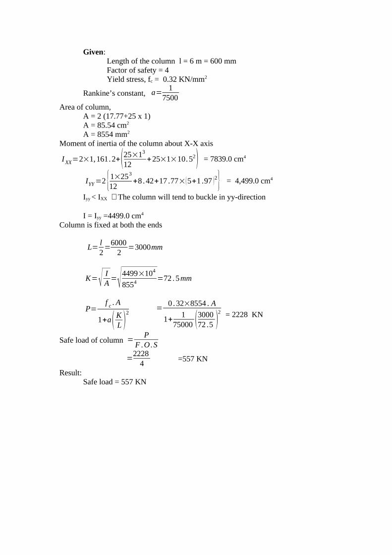
Given:Length of the column l = 6 m = 600 mmFactor of safety = 4 Yield stress, fc = 0.32 KN/mm2
Rankine’s constant, a=1
7500Area of column,
A = 2 (17.77+25 x 1)A = 85.54 cm2
A = 8554 mm2
Moment of inertia of the column about X-X axis
IXX=2×1,161.2+(25×13
12+25×1×10.52) = 7839.0 cm4
IYY=2 {1×253
12+8 .42+17 .77×(5+1 .97 )2} = 4,499.0 cm4
Iyy < IXX ∴The column will tend to buckle in yy-direction
I = Iyy =4499.0 cm4
Column is fixed at both the ends
L=l2=
60002
=3000mm
K=√ IA=√4499×104
8554=72 . 5mm
P=f c . A
1+a( KL )2
=0 .32×8554 . A
1+1
75000 (300072 .5 )
2 = 2228 KN
Safe load of column =P
F .O .S
=2228
4=557 KN
Result:Safe load = 557 KN

1
Strength of Materials
(FOR IV – SEMESTER)
Question bankUnit IV
STATE OF STRESS IN THREE DIMENSIONS
Compiled by,
K.DIVYA
ASSISTANT PROFESSOR
DEPARTMENT OF CIVIL ENGINEERING
FATIMA MICHAEL COLLEGE OF ENGINEERING AND TECHNOLOGY
MADURAI - 20

2
UNIT – IV
STATE OF STRESS IN THREE DIMENSIONS
Spherical and deviatory components of stress tensor- determination ofprincipal of principal stresses and principal planes – volumetric strain- dilationand distortion – Theories of failure – principal stress dilatation. Principal strain– shear stress - strain energy and distortion energy theories - application inanalysis of stress. Load carrying capacity and design of members – interactionproblems and interaction curves – residual stresses.
UNIT – IV
TWO MARKS QUESTIONS AND ANSWERS1. Define stress
When a certain system of external forces act on a body then the body offersresistance to these forces. This internal resistance offered by the body per unit area iscalled the stress induced in the body.
2. Define principal planes.The plane in which the shear stress is zero is called principal planes. The plane
which is independent of shear stress is known as principal plane.
3. Define spherical tensor.
τ ijii=¿
[ σm
[ 0[ 0
[0σm
0
mσ0
0
It is also known as hydrostatic stress tensor
σm=13 (σ x+σ y+σ z)
σm is the mean stress.
4. Define Deviator stress tensor
τ ij1=¿
[ σ x−σm
[τ xy
[ τxz
[
lxy]σ y−σm
] l yz¿
]
τ xz
]τ yz
]σ z−σm
¿
]
5. Define volumetric strainIt is defined as the ratio between change in volume and original volume of the
body and is denoted by e v

3
6. State the principal theories of failure.
1. Maximum principal stress theory2. Maximum shear stress (or) stress difference theory 3. Strain energy theory4. Shear strain energy theory5. Maximum principal strain theory 6. Mohr’s Theory
7. State the Limitations of Maximum principal stress theory
1. On a mild steel specimen when spiel tension test is carried out sliding occursapproximately 45o to the axis of the specimen; this shows that the failure inthis case is due to maximum shear stress rather than the direct tensile stress.
2. It has been found that a material which is even though weak in simplecompression yet can sustain hydrostatic pressure for in excess of the elasticlimit in simple compression.
8. Explain maximum principal stress theory.According to this theory failure will occur when the maximum principle tensile
stress (σ1) in the complex system reaches the value of the maximum stress at theelastic limit (σet) in the simple tension.
9. Define maximum shear stress theoryThis theory implies that failure will occur when the maximum shear stress
τ maximum in the complex system reaches the value of the maximum shear stress insimple tension at elastic limit (i.e)
lmax=σ1−σ 3
2=
σet
2(or) σ1−σ 3=σet
10. State the limitations of maximum shear stress theory.
i. The theory does not give accurate results for the state of stress of pure shearin which the maximum amount of shear is developed (i.e) Torsion test.
ii. The theory does not give us close results as found by experiments onductile materials. However, it gives safe results.
11. Explain shear strain Energy theory.
This theory is also called “ Distortion energy Theory” or “Von Mises - HenkyTheory.”
Change in volume δve v =
Original volume v

4
According to this theory the elastic failure occurs where the shear strain energyper unit volume in the stressed material reaches a value equal to the shear strain energyper unit volume at the elastic limit point in the simple tension test.
12. State the limitations of Distortion energy theory.
1. The theory does to agree the experiment results for the material for whichσ at is quite different etc.
2. This theory is regarded as one to which conform most of the ductilematerial under the action of various types of loading.
13. Explain Maximum principal strain theoryThe theory states that the failure of a material occurs when the principal tensile
strain in the material reaches the strain at the elastic limit in simple tension (or) whenthe min minimum principal strain (ie ) maximum principal compressive strain reachesthe elastic limit in simple compression.
14. State the Limitations in maximum principal strain theory
i. The theory overestimates the behaviour of ductile materials.ii. The theory does no fit well with the experimental results except for
brittle materials for biaxial tension.
15. State the stress tensor in Cartesian components
τ ij' =¿
[ σ x .[ τxy[ τ xz
[ τ xy
σ y
τ yz
τ xz
]τ yz
]σ z
¿
]
16. Explain the three stress invariants.
The principal stresses are the roots of the cubic equation,
σ3−I 1σ
2+ I2 σ−I 3=0
where
I1=σ x+σ y+σ z
I2=σσ y+σ y σz+σ x σ z−τ2 xy−τy2z−τ2 xz
I3=σ xσ y σZ−σx τ2xy−σ y τ
2xz−σz τ
2xy+2τ xy τ yz τxz
17. State the two types of strain energy
i. Strain energy of distortion (shear strain energy)ii. Strain energy of dilatation.
18. Explain Mohr’s Theory

5
Let τ=f (σ )
The enveloping curve τ=f (σ ) must represent in this abscissa σ and ordinatese, the normal and shearing stresses in the plane of slip.
(σ−σ1+σ3
2 )2
+τ 2=( σ1−σ3
2 )2
Let P=12 (σ1+σ3)
τm=12 (σ 1−σ3)
(σ−p )2+τ2=lm2
19. State the total strain energy theory.
The total strain energy of deformation is given by
U=1
2 E
σ12+σ2
2+σ32−2v (σ1 σ2+σ2σ3+σ3 σ1)
¿righ¿¿¿
[ ¿ ] [¿ ] ¿¿¿
and strain energy in simple tension is
U=σ 0
2
2 E
20. State the shear strain energy per unit volume
σs=1
12C
(σ 1−σ2)2+(σ2−σ3 )
2+(σ3−σ 1)2
¿righ¿¿¿
[ ¿ ] [¿ ] ¿¿¿

6
where C=
E
2(1+1m )
21. Explain the concept of stress?When certain system of external forces act on a body then the body offers
resistance to these forces. This internal resistance offered by the body per unit area iscalled the stress induced in the body.
The stress σ may be resolved into two components. The first one is the normalstress σn, which is the perpendicular to the section under examination and the secondone is the shear stress τ , which is operating in the plane of the section.
22. State the Theories of failure.
The principal theories are:1. Maximum principal stress theory2. Maximum shear stress (or) stress difference theory 3. Strain energy theory4. Shear strain energy theory5. Maximum principal strain theory6. Mohr’s Theory
SIXTEEN MARKS QUESTIONS AND ANSWERS:
1. The stress components at a point are given by the following array.
[10[5[6
[ 5810
6]10]6¿
] Mpa
Calculate the principal stress and principal planes.
Solution:
The principal stresses are the roots of the cubic equation
σ3−I 1σ
2+ I2 σ−I 3=0 (1)
where,
I1=σ x+σ y+σ z
I2=σx σ y+σ y σ z+σ z σ x−τxy2−τ yz
2−τ xz
2

7
I3=σ xσ y σz−σ x τ yz2−σ y τ xz
2−σ z τ xy
2+2τ xy τ yz τxz
are three stress invariantsThe stress tensor
τ ij=¿
[ σ x .[τ yx
[ τ zx
[ σ xy
σ y
τ zy
τ xz
]τ yz
]σ z
¿
]
By comparing stress tensor and the given away,I1=σ x+σ y+σ z
= 10 + 8 +6 =24
I2=σx σ y+σ y σ z+σ z σ x−τ2xy−τ
2yz−τ
2xz
= (10 x 8) + (8 x 6) + (6 x 10) - (5)2 – (10)2 – (6)2
=80 + 48 + 60 - 25 – 100 -36=27
I3=σ xσ y σz−σ x τ2yz−σ y τ
2xz−σ z τ
2xy+2τ xy τ yz τ xz
= 10 x 8 x 6 -10 (10)2 -8 (6 )2 - 6 (5)2 + 2(5) (10) (6)=480 -1000-288-150+600=-358
Substitute these values in (1) equationσ3
−24 σ2+27 σ+358=0 (2)
We know that
From this
4Cos3θ=Cos 3θ+3Cosθ
Cos3θ=14Cos3θ−
34Cosθ=0 (3)
put,
σ=rCosθ+I1
3
=rCosθ+243
σ=rCos θ+8
∴Equation (2) becomes r3Cos3θ+512+24 r2Cos2 θ+192rCosθ−24 ( r2Cos2 θ+64+2rCosθ×8 )+
27 (r cos θ + 8) + 358 =0
Cos3θ=4Cos3θ−3Cosθ
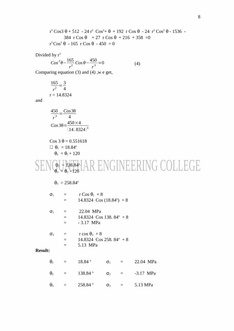
8
r3 Cos3 θ + 512 - 24 r2 Cos2+ θ + 192 r Cos θ - 24 r2 Cos2 θ - 1536 - 384 r Cos θ + 27 r Cos θ + 216 + 358 =0
r3 Cos3 θ - 165 r Cos θ - 450 = 0
Divided by r3
Cos3θ−165
r2Cosθ−
450
r 3=0 (4)
Comparing equation (3) and (4) ,w e get,
165
r2=
34
r = 14.8324and
450
r 3=
Cos3θ4
Cos3θ=450×4
(14 . 8324 )3
Cos 3 θ = 0.551618∴ θ1 = 18.84o
θ2 = θ1 + 120
θ2 = 138.84o
θ3 = θ2 +120
θ3 = 258.84o
σ1 = r Cos θ1 + 8= 14.8324 Cos (18.84o) + 8
σ1 = 22.04 MPa= 14.8324 Cos 138. 84o + 8= - 3.17 MPa
σ3 = r cos θ3 + 8= 14.8324 Cos 258. 84o + 8= 5.13 MPa
Result:
θ1 = 18.84 o σ1 = 22.04 MPa
θ2 = 138.84 o σ2 = -3.17 MPa
θ3 = 258.84 o σ3 = 5.13 MPa
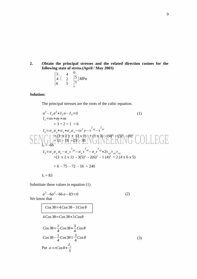
9
2. Obtain the principal stresses and the related direction cosines for thefollowing state of stress.(April / May 2003)
[3 .[ 4[6
[ 425
6]5]1¿
]MPa
Solution:
The principal stresses are the roots of the cubic equation.
σ3−I 1σ
2+ I2 σ−I 3=0 (1)
I1=σx+σy+σz
= 3 + 2 + 1 = 6
I2=σx σ y+σ y+σ zσ x−τx2 y−τ2yz−τ
2xz
= (3 x 2 ) + (2 x 1) + (1 x 3) - (4)2 - (5)2 - (6)2
= 11 – 16 - 25 - 36I2 = -66
I3=σ xσ y σz−σ x τ2yz−σ y τ
2xz−σ z τ
2xy+2τ xy τ yz τ xz
=(3 x 2 x 1) - 3(5)2 - 2(6)2 - 1 (4)3 + 2 (4 x 6 x 5)
= 6 - 75 - 72 - 16 + 240
I3 = 83
Substitute these values in equation (1)
σ3−6σ2
−66 σ−83=0 (2)We know that
4Cos3θ=Cos 3θ+3Cosθ
Cos3θ=14Cos3θ+
34Cos θ
Cos3θ−14Cos3θ∓
34Cos θ (3)
Put σ=rCosθ+I1
3
Cos3θ=4Cos3θ−3Cosθ
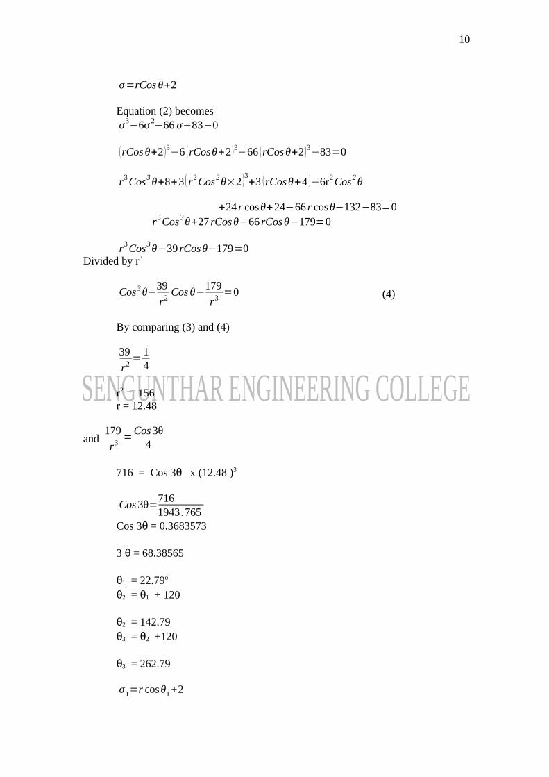
10
σ=rCos θ+2
Equation (2) becomesσ3
−6σ2−66 σ−83−0
(rCosθ+2 )3−6 (rCosθ+2 )3−66 (rCosθ+2 )3−83=0
r3Cos3θ+8+3 ( r2Cos2θ×2 )3+3 (rCosθ+4 )−6r2Cos2θ
+24 r cosθ+24−66 r cosθ−132−83=0r3Cos3θ+27 rCosθ−66 rCosθ−179=0
r3Cos3θ−39 rCosθ−179=0Divided by r3
Cos3θ−39
r2Cosθ−
179
r3=0 (4)
By comparing (3) and (4)
39
r2=
14
r2 = 156r = 12.48
and 179
r3=
Cos3θ4
716 = Cos 3θ x (12.48 )3
Cos3θ=7161943.765
Cos 3θ = 0.3683573
3 θ = 68.38565
θ1 = 22.79o
θ2 = θ1 + 120
θ2 = 142.79θ3 = θ2 +120
θ3 = 262.79
σ1=r cosθ1+2
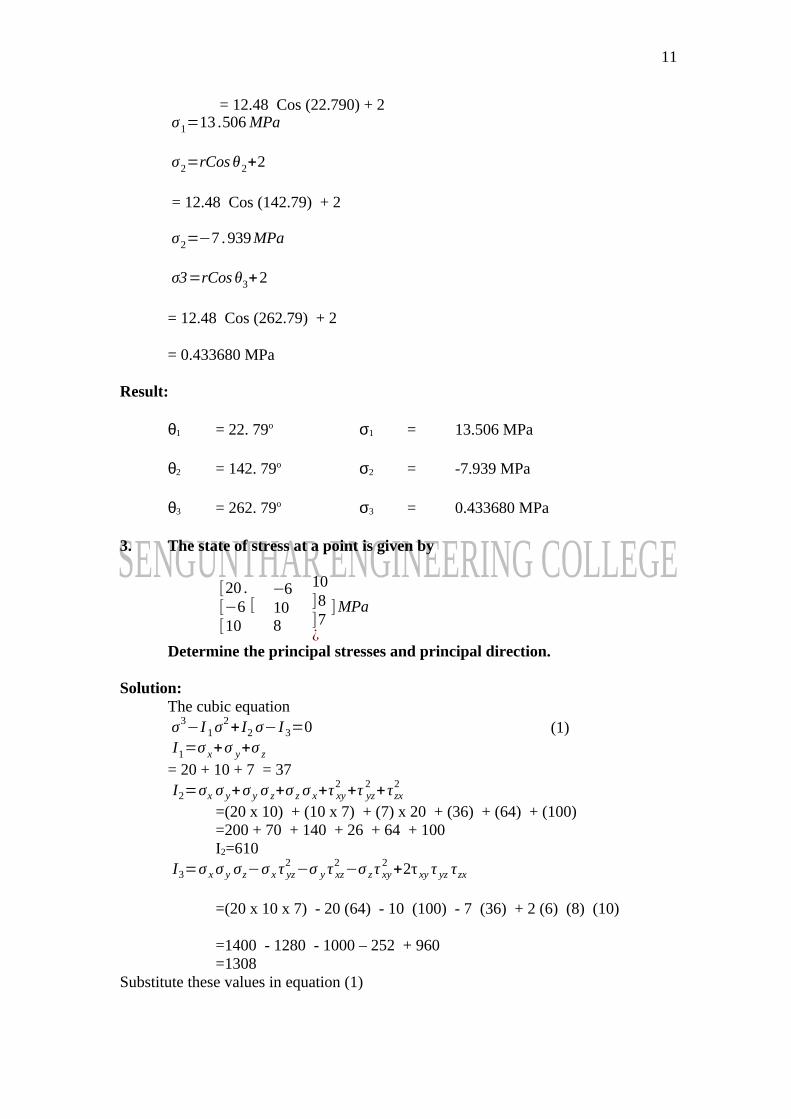
11
= 12.48 Cos (22.790) + 2σ1=13 .506 MPa
σ2=rCos θ2+2
= 12.48 Cos (142.79) + 2
σ2=−7 .939MPa
σ3=rCos θ3+2
= 12.48 Cos (262.79) + 2
= 0.433680 MPa
Result:
θ1 = 22. 79o σ1 = 13.506 MPa
θ2 = 142. 79o σ2 = -7.939 MPa
θ3 = 262. 79o σ3 = 0.433680 MPa
3. The state of stress at a point is given by
[20 .[−6[10
[ −6108
10]8]7¿
]MPa
Determine the principal stresses and principal direction.
Solution:The cubic equationσ3
−I 1σ2+ I2 σ−I 3=0 (1)
I1=σ x+σ y+σ z
= 20 + 10 + 7 = 37I2=σx σ y+σ y σ z+σ z σ x+τ xy
2+τ yz
2+τ zx
2
=(20 x 10) + (10 x 7) + (7) x 20 + (36) + (64) + (100)=200 + 70 + 140 + 26 + 64 + 100I2=610
I3=σ xσ y σz−σ x τ yz2−σ y τ xz
2−σ z τ xy
2+2τ xy τ yz τzx
=(20 x 10 x 7) - 20 (64) - 10 (100) - 7 (36) + 2 (6) (8) (10)
=1400 - 1280 - 1000 – 252 + 960=1308
Substitute these values in equation (1)
12
σ3−37 σ2
+610σ−1308=0 (2)
We know that
4Cos3θ=Cos 3+3Cosθ
Cos3θ=14Cos3θ+
34Cosθ
Cos3θ−14Cos3θ−
34Cosθ (3)
Put σ=rCosθ+I1
3
σ=rCosθ+12 .33
Equation (2) becomes
σ3−37 σ2
+610σ−1308=0
(rCos θ+12 .33 )3−37 (rCosθ+12. 33 )2+610 (rCosθ+12. 33 )−1308=0
r3Cos3θ+1874 .516+r 2Cos2θ (36 .99 )+456 .087 rCosθ−[37 (r 2Cos2θ )+24 . 66rCosθ+152 .0289 ]+160 r Cosθ + 1972.80 - 1308 = 0
r3Cos3θ+1874 .516+36 .99 r2Cos2θ+456 .087 rCosθ−37 r22Cos2 θ−9.12 r2Cos2−5625 .0693+
160 r Cosθ + 1972.80 - 1308 = 0
r3Cos3θ−295−4960.2693=0¿ r3
Cos3θ−295
r2Cosθ−
4960 .2693
r3=0 (4)
By comparing (3) & (4)
14=
295
r2
r2 = 1180r = 34.35
and
Cos3θ=4Cos3θ−3Cosθ

13
Cos3θ4
=4960 .2693
r3
Cos3θ4
=4960 .269340534 . 331
3θ = 60.6930
θ1 = 20.231o
θ2 = θ1 + 120
θ2 = 140 .23 o
θ3 = 26.231 o
σ1=rCosθ1+12. 33
= 34.35 Cos (140.23o) + 12.33
σ1=44 .530 MPaσ2=rCosθ2+12. 33
= 34.35 Cos (140.231o) + 12.33σ2=−14 .217MPaσ3=rCosθ3+12 .33
= 34.35 Cos (260.231o) + 12.33σ3=6 . 5016
Result:θ1 = 20.231o θ3 = 260.231o σ2 = - 14.217 MPa
θ2 = 140.23o σ1 = 44.530 MPa σ3 = 6.5016 MPa
4. Explain the Energy of Distortion ( shear strain energy ) and Dilatation
The strain energy can be split up on the following two strain energies.i. Strain energy of distortion (shear strain energy)
14
ii. Strain energy of Dilatation (Strain energy of uniform compression (or))tension (or) volumetric strain energy )
Let e1 e2 an d e3 be the principal strain in the directions of principal stresses σ1,σ2 and σ3.
Then
e1=1E [σ1−μ (σ 2+σ 3) ]
e2=1E [σ2−μ (σ 3+σ1) ]
e3=1E [σ3−μ (σ1+σ2) ]
Adding the above equation we get,
e1+e2+e3=1E [(σ1+σ2+σ3)−2μ (σ1+σ2+σ3 )]
=σ1+σ2+σ3
E(1−2μ )
But e1 + e2 + e3 = e v (Volumetric strain)
ev=1−2μ
E (σ1+σ2+σ3 )
If σ1+σ2+σ3=0, ev=0 . This means that if sum of the three principal stress iszero there is no volumetric change, but only the distortion occurs.
From the above discussion,
1. When the sum of three principal stresses is zero, there is no volumetricchange but only the distortion occurs.
2. When the three principal stresses are equal to one another there is nodistortion but only volumetric change occurs.
Note:
In the above six theories,σet , σ ec = Tensile stress at the elastic limit in simple tension and
compression;
σ1, σ2, σ3 = Principal stresses in any complex system (such that e1 > e2 > e3 )

15
It may be assumed that the loading is gradual (or) static (and there is no cyclic(or) impact load.)
5. Explain the Maximum Principal stress Theory: ( Rankine’s Theory)− This is the simplest and the oldest theory of failure
− According to this theory failure will occur when the maximum principletensile stress (σ1) in the complex system reaches the value of themaximum stress at the elastic limit (σet) in the simple tension (or) theminimum principal stress (that is, the maximum principal compressivestress), reaches the elastic limit stress (σ) in simple compression.
(ie.) σ1 = σet (in simple tension)
∣σ 3∣=σac (In simple compression)
∣σ 3∣ Means numerical value of σ3
− If the maximum principal stress is the design criterion, the maximumprincipal stress must not exceed the working σ for the material. Hence,
σ1≤σ
− This theory disregards the effect of other principal stresses and of theshearing stresses on other plane through the element. For brittle materialswhich do not fail by yielding but fail by brittle fracture, the maximumprincipal stress theory is considered to be reasonably satisfactory.
This theory appears to be approximately correct for ordinary cast – irons andbrittle metals.
The maximum principal stress theory is contradicted in the following cases:
1. On a mild steel specimen when simple tension test is carried out slidingoccurs approximately 45o to the axis of the specimen; this shows thatthe failure in the case is due to maximum shear stress rather than thedirect tensile stress.
2. It has been found that a material which is even though weak in simplecompression yet can sustain hydrostatic pressure for in excess of theelastic limit in simple compression.
6. Explain the Maximum shear stress (or) Stress Difference theory (April / May 2003)
− This theory is also called Guesti’s (or) Tresca’s theory.− This theory implies that failure will occur when the maximum shear
stress maximum in the complex system reaches the value of themaximum shear stress in simple tension at the elastic limit i.e.
16
τmax=σ1−σ3
2=
σet
2 in simple tension.
(or) σ1−σ 3=σet
In actual design σet in the above equation is replaced by the safe stress.
− This theory gives good correlation with results of experiments on ductilematerials. In the case of two dimensional tensile stress and then themaximum stress difference calculated to equate it to σet.
Limitations of this theory:
i. The theory does not give accurate results for the state of stress of pureshear in which the maximum amount of shear is developed (ie) Torsiontest.
ii. The theory is not applicable in the case where the state of stress consistsof triaxial tensile stresses of nearly equal magnitude reducing, theshearing stress to a small magnitude, so that failure would be by brittlefacture rather than by yielding.
iii. The theory does not give as close results as found by experiments onductile materials. However, it gives safe results.
7. Explain the Shear strain Energy Theory (April / May 2003)
This theory is also called “Distortion Energy Theory”: (or) “Von Mises –Henky Theory”
− According to this theory the elastic failure occurs where the shear strainenergy per unit volume in the stressed material reaches a value equal tothe shear strain energy per unit volume at the elastic limit point in thesimple tension test.
Shear strain energy due to the principal stresses σ 1, σ 2, and σ 3 per unitvolume of the stress material.
U S=1
12C
(σ 1−σ2)2+(σ2−σ3 )
2+(σ3−σ 1)2
¿righ¿¿¿
[ ¿ ] [¿ ] ¿¿¿
But for the simple tension test at the elastic limit point where there is only oneprincipal stress (ie) σ et we have the shear strain energy per unit volume which isgiven by
17
U s1=
112C
(σ et−0 )2+(0−0 )2+(0−σat )
2
¿righ¿¿¿
[ ¿ ] [¿ ] ¿¿¿
Equating the two energies, we get
[∵σ1=σ et
σ 2=0σ 3=0 ]
(σ 1−σ2)2+(σ2−σ3 )
2+(σ3−σ1)
2=2σet
2
The above theory has been found to give best results for ductile material for whichσ et=σec approximately.
Limitations of Distortion energy theory:1. Te theory does to agree with the experimental results for the material for
which σet is quite different from σec.2. The theory gives σ et=0 for hydrostatic pressure (or) tension, which means
that the material will never fail under any hydrostatic pressure (or) tension.When three equal tensions are applied in three principal directions, brittlefacture occurs and as such maximum principal stress will give reliableresults in this case.
3. This theory is regarded as one to which conform most of the ductilematerial under the action of various types of loading.
8. Explain the Maximum principal strain Theory?
− This theory associated with St Venent− The theory states that the failure of a material occurs when the principal
tensile strain in the material reaches the strain at the elastic limit insimple tension (or) when the minimum principal strain (ie) maximumprincipal compressive strain reaches the elastic limit in simplecompression.
Principal strain in the direction of principal stress σ1,
e1=1E [σ1−
1m (σ 2+σ3 )]
Principal strain in the direction of the principal stress σ3,

18
e3=1E [σ3−
1m (σ1+σ 2)]
The conditions to cause failure according to eh maximum principal straintheory are:
e1>σet
E (e1 must be +Ve)
and
∣e3∣>σ ec
E (e3 must be -Ve)
1E [σ 1−
1m (σ2+σ3) ]> σet
E
1E [σ 3−
1m (σ1+σ2) ]> σet
E
σ1−1m [σ1+σ3 ]>σ et
σ3−1m [σ 1+σ3 ]>σ ec
To prevent failure:
σ1−1m (σ 2+σ 3)<σet
σ3−1m (σ1+σ 2)<σec
At the point of elastic failure:
σ1−1m (σ 2+σ 3)=σet
and ∣σ 3−1m (σ1+σ2)∣=σ ec
For design purposes,
σ3−1m (σ1+σ 2)=σ t
∣σ 3−1m (σ1+σ2)∣=σ c
(where, σt and σc are the safe stresses)
Limitations:
i. The theory overestimates the behavior of ductile materials.ii. Te theory does not fit well with the experimental results except for brittle
materials for biaxial tension.
9. Explain the Strain energy theory?The total stain energy of deformation is given by

19
U=1
2 E [σ12+σ2
2+σ32=2v (σ1σ 2+σ 2σ3+σ3 σ1) ]
and the strain energy under simple tension is
U=σ e
2
2 E
Hence for the material to yield,
σ12+σ2
2+σ3
2−2v (σ1 σ2+σ2σ3+σ3 σ1)
The total elastic energy stored in a material before it reaches the plastic statecan have no significance as a limiting condition, since under high hydrostatic pressure,large amount of strain energy ma be stored without causing either fracture (or)permanent deformation.
10. Explain Mohr’s Theory?A material may fail either through plastic slip (or) by fracture when either the
shearing stress τ in the planes of slip has increased.Let τ=f (σ )
The enveloping curve τ=f (σ ) must represent in their abscissa σ and ordinatesτ , the normal and shearing stresses in the plane of slip. Now
(σ−σ1+σ3
2 )2
+τ 2=( σ1+σ3
2 )2
Let P=12 (σ1+σ3)
τm=12 (σ1−σ 3)
then (σ−p )2+ τ2=τm2
This equation represents the family of major principal stress circles inparameter form. The equation of this envelope is obtained by partially differentiatingwith respect to P
(σ−P )2+ τ2=τm2 σ2−2pσ+P2
+τ2=m2
σ=p+τm .dτmdp
τ=τm .√1−(dτm )
2
dpThis is to equation of Mohr’s envelope of the major
principal stress in parameter form.
11. In a steel member, at a point the major principal stress is 180 MN/m2 andthe minor principal stresses is compressive. If the tensile yield point of thesteel is 225 MN/m2, find the value of the minor principal stress at whichyielding will commence, according to each of the following criteria offailure.
i. Maximum shearing stress

20
ii. Maximum total strain energyiii. Maximum shear strain energy
Take Poisson’s ratio = 0.26Solution:
Major principal stress, σ1=180 MN /m2
Yield point stress σ2=225 MN /m2
μ=1m
=0 .26
To calculate minor principal stress (σ2)
(i) Maximum shearing stress criterion
σ2=σ 1−σe
= 180 - 225
σ2 = - 45 MN/m2
σ2 = 45 MN/m2 (comp)
ii. Maximum total strain energy criterion:
σ12+σ2
2+σ32−
2m (σ 1σ2+σ2σ 3+σ 3σ1 )=σe
2
∴ σ 3 = 0
(180)2 + σ22 - 2 x 0.26 x 180 σ2 = (225)2
32400 + σ22 -93.6 σ 2 = 50625
σ22 - 93.6 σ2 - 18225 = 0
σ2=9 .36−√ (93 .6 )2+4×18225
2
=9 .36−285 .76
2=−96 .08 MN /m2
(Only –Ve sign is taken as σ2 is compressive)
σ2 = 96.08 MN/ m2 (compressive)
σ1−σ 2=σe
σ12+σ2
2−2m (σ 1σ2)=σe
2
21
iii. Maximum shear strain energy criterion:
putting σ3 = 0
(σ 1−σ2)2+(σ2)
2+(σ1)
2=2σ e
2
(σ 1)2+ (σ 2)
2−2σ1 σ2+2 (σ 1)
2=(σe )
2
(180.2 + (σ2)2+ - 180 σ2 = (225)2
(σ2)2 - 180 σ2 - 18225 = 0
σ2=180−√ (180 )2+4×18225
2
σ2=180−324 .5
2=−72.25 MN /m2
σ 2 = 72.25 MN/m2 (Compressive)
12. In a material the principal stresses are 60 MN/m2, 48 MN/m2 and - 36MN/m2. Calculate
i. Total strain energy ii. Volumetric strain energyiii. Shear strain energy iv. Factor of safety on the total strain energy criteria if the
material yields at 120 MN/m2.
Take E = 200 GN/m2+ and 1/m = 0.3
Solution:Given Data:Principal stresses:
σ 1 = + 60 MN/m2
σ 2 = + 48 MN/m2
σ 3 = - 36 MN/m2
Yield stress, σ e = 120 MN /m2
E = 200 GN/m2, 1/m = 0.3
i. Total strain energy per unit volume:
(σ 1−σ2)2+(σ2−σ3 )
2+(σ3−σ1)
2=2σe
2

22
U=1
2 E [(σ1 )2+(σ2 )
2+(σ3 )2−
2m (σ1σ 2+σ 2σ3+σ3 σ1)]
U=1012
2×200×109[ (60 )2+(48 )2+(36 )2−2×0.3 (60×48−48×36×60 ) ]
U=2 .5 [3600+2304+1296−0 .6 (2880−1728−2160 ) ]׿¿
U = 19.51 KNm/m3
ii. Volumetric strain energy per unit volume:
ev=13
(60+48−36 )2×10¹²[ 1−2×0 .3
2×200×109 ]×10−3
e v = 1.728 KN/m3
iii. shear strain energy per unit volume
Where, C=
E
2(1+1m )
=2002 (1+0.3 )
=76 .923GN /m2
es=1×10¹²
12×76 .923×109[ (60−48 )2+ (48+36 )2+(−36−60 )2 ]
es=1.083 (144+7056+9216 )×10−3
es=17 .78 KNm/m3
iv. Factor of safety (F.O.S)
Strain energy per unit volume under uniaxial loading is
=σe2
2 E=
( 120×106 )2
2×200×109×10−3=36 KNm/m3
F.O.S =3619 .51
=1 .845
ev=13 (σ 1+σ2+σ3 )
2 [1−2 /m2E ]
es=1
12c [ (σ1−σ 2)2+(σ 2−σ3 )
2+(σ3−σ 1)2 ]
23
13. In a material the principal stresses are 50 N/mm2, 40 N/mm2 and - 30N/mm2, calculate:
i. Total strain energy ii. Volumetric strain energy iii. Shear strain energy and iv. Factor of safety on the total strain energy criterion if the
material yield at 100 N/mm2.
Take E = 200 x 103 N/mm2 and poission ratio = 0 .28Solution:
Given,Principal stresses:
σ1=+50 N /mm2
σ2=+ 40 N /mm2
σ3=−30 N /mm2
Yield stress, σ e=100 N /mm2
i. Total strain energy per unit volume:
U=1
2 E [(σ1 )2+(σ2 )
2+(σ3 )2−
2m (σ1σ 2+σ 2σ3+σ3 σ1)]
=1
2×200×103[ (50 )2+( 40 )2+ (30 )2−2 (0 .3 ) [50×40−40×30−30×50 ]]
=1
400×103[2500+1600+900−0 .6 [ 2000−1200−1500 ]]
=1
400×103[5000−0 .6 (−700 ) ]
=1
400×103[5420 ]
U = 13.55 KNm/m3
ii)Volumetric strain energy per unit volume:
ev=13 (σ 1+σ2+σ2 )
2 [ 1−2 /m2E ]

24
ev=13
(50+40−30 )2(1−2×0 .3 )
2×200×103
=13
(60 )2( 0 .4
400×103 )
ev=13
(3600 )( 0 .001
103 )ev = 1.2 K N m / m3
iii. Shear strain energy
es=1
12C [(σ1−σ2 )2+(σ2−σ 3)
2+(σ 3−σ1)2]
where C=E
2 (1+1/m )=
200×103
2 (1+0 .3 )=76 .923×103 N /mm2
es=1
12 (76 .923 )×103[ (50−40 )2+(40+30 )2+(−30−50 )2]
es=1
923 .076×103[ 100+4900+6400 ]
es=12.35 KNn/m3
iv. Factor of safety (F.O.S)
Strain energy per unit volume under uniaxial loading is
=σe2
2E=
(100 )2
2×200×103=254 KNm /m3
F .O .S=2513 .55
=1 .845
14. In a material the principal stresses are 50 N/mm2, 40 N/mm2 and - 30N/mm2, calculate:
v. Total strain energy vi. Volumetric strain energy vii. Shear strain energy and viii. Factor of safety on the total strain energy criterion if the
material yield at 100 N/mm2.
Take E = 200 x 103 N/mm2 and poission ratio = 0 .28Solution:
25
Given,Principal stresses:
σ1=+50 N /mm2
σ2=+ 40 N /mm2
σ3=−30 N /mm2
Yield stress, σ e=100 N /mm2
i. Total strain energy per unit volume:
U=1
2 E [(σ1 )2+(σ2 )
2+(σ3 )2−
2m (σ1σ 2+σ 2σ3+σ3 σ1)]
=1
2×200×103[ (50 )2+( 40 )2+ (30 )2−2 (0 .3 ) [50×40−40×30−30×50 ]]
=1
400×103[2500+1600+900−0 .6 [ 2000−1200−1500 ]]
=1
400×103[5000−0 .6 (−700 ) ]
=1
400×103[5420 ]
U = 13.55 KNm/m3
ii)Volumetric strain energy per unit volume:
ev=13 (σ 1+σ2+σ2 )
2 [ 1−2 /m2E ]
ev=13
(50+40−30 )2(1−2×0 .3 )
2×200×103
=13
(60 )2( 0 .4
400×103 )
ev=13
(3600 )( 0 .001
103 )ev = 1.2 K N m / m3

26
iii. Shear strain energy
es=1
12C [(σ1−σ2 )2+(σ2−σ 3)
2+(σ 3−σ1)2]
where C=E
2 (1+1/m )=
200×103
2 (1+0 .3 )=76 .923×103 N /mm2
es=1
12 (76 .923 )×103[ (50−40 )2+(40+30 )2+(−30−50 )2]
es=1
923 .076×103[ 100+4900+6400 ]
es=12.35 KNn/m3
iv. Factor of safety (F.O.S)
Strain energy per unit volume under uniaxial loading is
=σe2
2E=
(100 )2
2×200×103=254 KNm /m3
F .O .S=2513 .55
=1 .845

1
Strength of Materials
(FOR IV – SEMESTER)
Question bankUNIT – V
ADVANCED TOPICS IN BENDING OF BEAMS
Compiled by,
K.DIVYA
ASSISTANT PROFESSOR
DEPARTMENT OF CIVIL ENGINEERING
FATIMA MICHAEL COLLEGE OF ENGINEERING AND TECHNOLOGY
MADURAI - 20
UNIT – V
ADVANCED TOPICS IN BENDING OF BEAMS

2
Unsymmetrical bending of beams of symmetrical and unsymmetricalsections- curved beams- Winkler Bach formula- stress concentration- fatigue andfracture.
TWO MARKS QUESTIONS AND ANSWERS
1.Define Unsymmetrical bendingThe plane of loading (or) that of bending does not lie in (or) a plane that
contains the principle centroidal axis of the cross- section; the bending is calledUnsymmetrical bending.
2. State the two reasons for unsymmetrical bending.(i) The section is symmetrical (viz. Rectangular, circular, I section) but the load line is inclined to both the principal axes.(ii) The section is unsymmetrical (viz. Angle section (or) channel section vertical web) and the load line is along any centroidal axes.
3. Define shear centre.The shear centre (for any transverse section of the beam) is the point of
intersection of the bending axis and the plane of the transverse section. Shear centre is also known as “centre of twist”
4. Write the shear centre equation for channel section.
e=3b
6+Aw
A f
e = Distance of the shear centre (SC ) from the web along the symmetric axis XXAw = Area of the webAf = Area of the flange
5. A channel Section has flanges 12 cm x 2 cm and web 16 cm x 1 cm. Determine the shear centre of the channel.
Solution:b= 12-0.5 = 11.5 cmt1 = 2cm, t2 = 1cm, h= 18 cmAf = bt1 = 11.5 x 2 = 23 cm2
Aw = ht2 = 18 x 1= 18 cm2
e=
3b
6+Aw
A f
e=3(11.5 )
6+1823
=5 . 086 cm
6. Write the shear centre equation for unsymmetrical I section.
e=t1h2
(b2−b1)2
4I xx

3
e = Distance of the shear centre (SC) from the web along the symmetricaxis XXt1 = thickness of the flangeh = height of the webb1 = width of the flange in right portion.b2 = width of the flange in left portion.Ixx = M.O.I of the section about XX axis.
7. State the assumptions made in Winkler’s Bach Theory.(1) Plane sections (transverse) remain plane during bending.(2) The material obeys Hooke’s law (limit state of proportionality is notexceeded)(3) Radial strain is negligible.(4) The fibres are free to expand (or) contract without any constraining effect from the adjacent fibres.
8. State the parallel Axes and Principal Moment of inertia.If the two axes about which the product of inertia is found, are such ,
that the product of inertia becomes zero, the two axes are then called the principle axes. The moment of inertia about a principal axes is called the principal moment of inertia.
9. Define stress concentration.The term stress gradient is used to indicate the rate of increase of stress
as a stress raiser is approached. These localized stresses are called stress concentration.
10. Define stress – concentration factor.It is defined as the ratio of the maximum stress to the nominal stress.
K t=σ max
σ nom
σ max = maximum stressσ nom = nominal stress
11. Define fatigue stress concentration factor.The fatigue stress – concentration factor (Kf ) is defined as the ratio of
flange limit of unnotched specimen to the fatigue limit of notched specimen under axial (or) bending loads.
K f=1+q( K t−1 )
Value of q ranges from zero to one.
12. Define shear flow.Shear flow is defined as the ratio of horizontal shear force H over
length of the beam x. Shear flow is acting along the longitudinal surface located at discharge y1.Shear flow is defined by q.
q=Hx
=V y
Q z
I z
H = horizontal shear force

4
13. Explain the position of shear centre in various sections.(i) In case of a beam having two axes of symmetry, the shear centre
coincides with the centroid. (ii) In case of sections having one axis of symmetry, the shear centre
does not coincide with the centroid but lies on the axis of symmetry.
14. State the principles involved in locating the shear centre.The principle involved in locating the shear centre for a cross – section
of a beam is that the loads acting on the beam must lie in a plane which contains the resultant shear force on each cross-section of the beam as computed from the shearing stresses.
15. Determine the position of shear centre of the section of the beam shownin fig.
Solution:t1 = 4 cm, b1 = 6 cm, b2 = 8 cmh1 = 30 – 4 = 26 cm
e=t1h2
(b2−b1)2
4I xx
Ixx = 2[14 x43
12+14 x4 (13)3 ]+2x 223
12=20852 cm4
e=4x 262
(8−6 )2
4(20852=0 .9077 cm
16. State the stresses due to unsymmetrical bending.
σb=M [ v cosθIUU
+u sin θ
IVV ]σb = bending stress in the curved barM = moment due to the load appliedIUU = Principal moment of inertia in the principal axes UUIVV = Principal moment of inertia in the principal axes VV
17. Define the term Fatigue.Fatigue is defined as the failure of a material under varying loads, well
below the ultimate static load, after a finite number of cycles of loading and unloading.
18. State the types of fatigue stress.(i) Direct stress (ii) Plane bending(iii) Rotating bending

5
(iv) Torsion(v) Combined stresses
(a) Fluctuating or alternating stress(b) Reversed stress.
19. State the reasons for stress- concentration.When a large stress gradient occurs in a small, localized area of a
structure, the high stress is referred to as a stress concentration. The reasons forstress concentration are (i) discontinuities in continuum (ii) contact forces.
20. Define creep.Creep can be defined as the slow and progressive deformation of a
material with time under a constant stress.
SIXTEEN MARKS QUESTIONS AND ANSWERS
1. Explain the stresses induced due to unsymmetrical bending. Fig. shows the cross-section of a beam under the action of a bending moment M acting in plane YY.
Also G = centroid of the section,XX, YY = Co-ordinate axes passing through G,UU, VV = Principal axes inclined at an angle θ to XX and YY axes respectivelyThe moment M in the plane YY can be resolved into its components in
the planes UU and VV as follows:Moment in the plane UU, M’ = M sinθMoment in the plane VV, M’ = M cosθ
The components M’ and M” have their axes along VV and UU respectively.The resultant bending stress at the point (u,v) is given by,
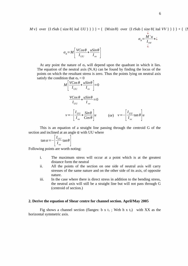
6
M v} over {I rSub { size 8{ ital UU } } } } = { {Msin θ} over {I rSub { size 8{ ital VV } } } } + { {Mcos θ} over {I rSub { size 8{ ital UU } } } } } {}¿
σb=M ' uIVV
+¿
¿
σb=M [ VCosθIUU
+uSinθ
I vv ]At any point the nature of σb will depend upon the quadrant in which it lies.
The equation of the neutral axis (N.A) can be found by finding the locus of thepoints on which the resultant stress is zero. Thus the points lying on neutral axissatisfy the condition that σb = 0
M [VCos θIUU
+uSinθ
I vv ]=0
VCos θ
IUU
+uSinθ
I vv
=0
v=−[ IUU
I vv
+SinθCosθ ]u (or) v=−[ IUU
I vv
tan θ]uThis is an equation of a straight line passing through the centroid G of the
section and inclined at an angle α with UU where
tan α=−[ IUU
I vv
tanθ ]Following points are worth noting:
i. The maximum stress will occur at a point which is at the greatestdistance form the neutral
ii. All the points of the section on one side of neutral axis will carrystresses of the same nature and on the other side of its axis, of oppositenature.
iii. In the case where there is direct stress in addition to the bending stress,the neutral axis will still be a straight line but will not pass through G(centroid of section.)
2. Derive the equation of Shear centre for channel section. April/May 2005
Fig shows a channel section (flanges: b x t1 ; Web h x t2) with XX as thehorizontal symmetric axis.
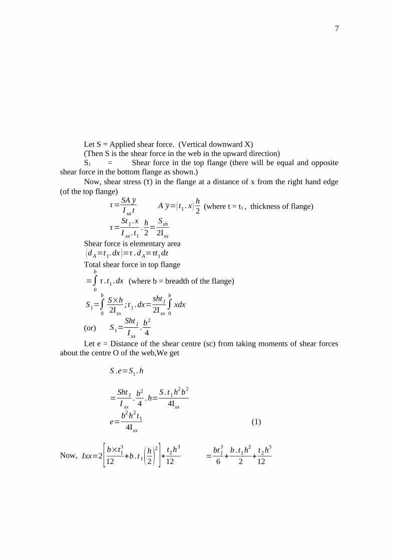
7
Let S = Applied shear force. (Vertical downward X)(Then S is the shear force in the web in the upward direction)S1 = Shear force in the top flange (there will be equal and opposite
shear force in the bottom flange as shown.)Now, shear stress (τ) in the flange at a distance of x from the right hand edge
(of the top flange)
τ=SA yI xa t
A y=( t1 . x)h2
(where t = t1 , thickness of flange)
τ=St 1 .x
I xx . t1
.h2=
Sxh
2Ixx
Shear force is elementary area(d A=t1.dx )=τ .d A=τt1dz
Total shear force in top flange
=∫0
b
τ . t1 .dx (where b = breadth of the flange)
S1=∫0
bS×h2Ixx
; t1 .dx=sht1
2I xx∫0
b
xdx
(or) S1=Sht1
I xx
.b2
4Let e = Distance of the shear centre (sc) from taking moments of shear forces
about the centre O of the web,We get
S .e=S1 . h
=Sht 1
I xx
.b2
4.h=
S . t1h2b2
4Ixx
e=b2h2 t1
4Ixx
(1)
Now, Ixx=2[ b×t13
12+b . t1(h
2 )2
]+ t2h3
12=
bt13
6+
b . t1h2
2+
t2h3
12

8
=bt1h2
2++
t2 h3
12(neglecting the term
bt13
3, being negligible in comparison to
other terms)(or) I xx=h2
12( t2h+bbt1 )
Substitute the value of Ixx in equation (1) we get,
e=b2 h2 t1
4×
12
h2( t2 h+6bt 1)
=3b2 t1
(t2 h+6 ht1)Let bt1 = Af (area of the flange)
ht2 = Aω (area of the web)Then
e=3bA f
Aw+6A f
=3b
6+Aw
A f
i.e
3. Derive the equation of Shear center for unequal I-sectionSolution:
Fig. shows an unequal I – section which is symmetrical about XX axis.
Shear stress in any layer,
e=3b
6+Aw
A f

9
τ=SA y
−
It
where I = IXX = 2[ (b1+b2 )t
13
12+(b1+b2) t1 x
h3
12 ]Shear force S1 :
dA=t1dx . A y−
=t1 .x .h2
S1 = ∫0
b1
τ dA=S .x .t1
I XX t1
h2
xt1 dx
= ∫0
b1S . x .IXX
h2
t1 dx = Sht1
2IXX[ x2
2 ]0
b1
=Sht 1b1
2
4I XX
Similarly the shear force (S2) in the other part of the flange,
S2 =Sht1b2
2
4IXX
Taking moments of the shear forces about the centre of the web O, we getS2. h = S1. h + S .e (S3 = S for equilibrium)
(where, e = distance of shear centre from the centre of the web)or, (S2 – S1) h = S.e
Sh2 t1(b22−b1
2)
4IXX
=S .e
4. Derive the stresses in curved bars using Winkler – Bach Theory.
The simple bending formula, however, is not applicable for deeply curvedbeams where the neutral and centroidal axes do not coincide. To deal with such casesWinkler – Bach Theory is used.
Fig shows a bar ABCD initially; in its unstrained state. Let AB’CD’ be thestrained position of the bar.
e=t1h2(b2
2−b12)
4Ixx
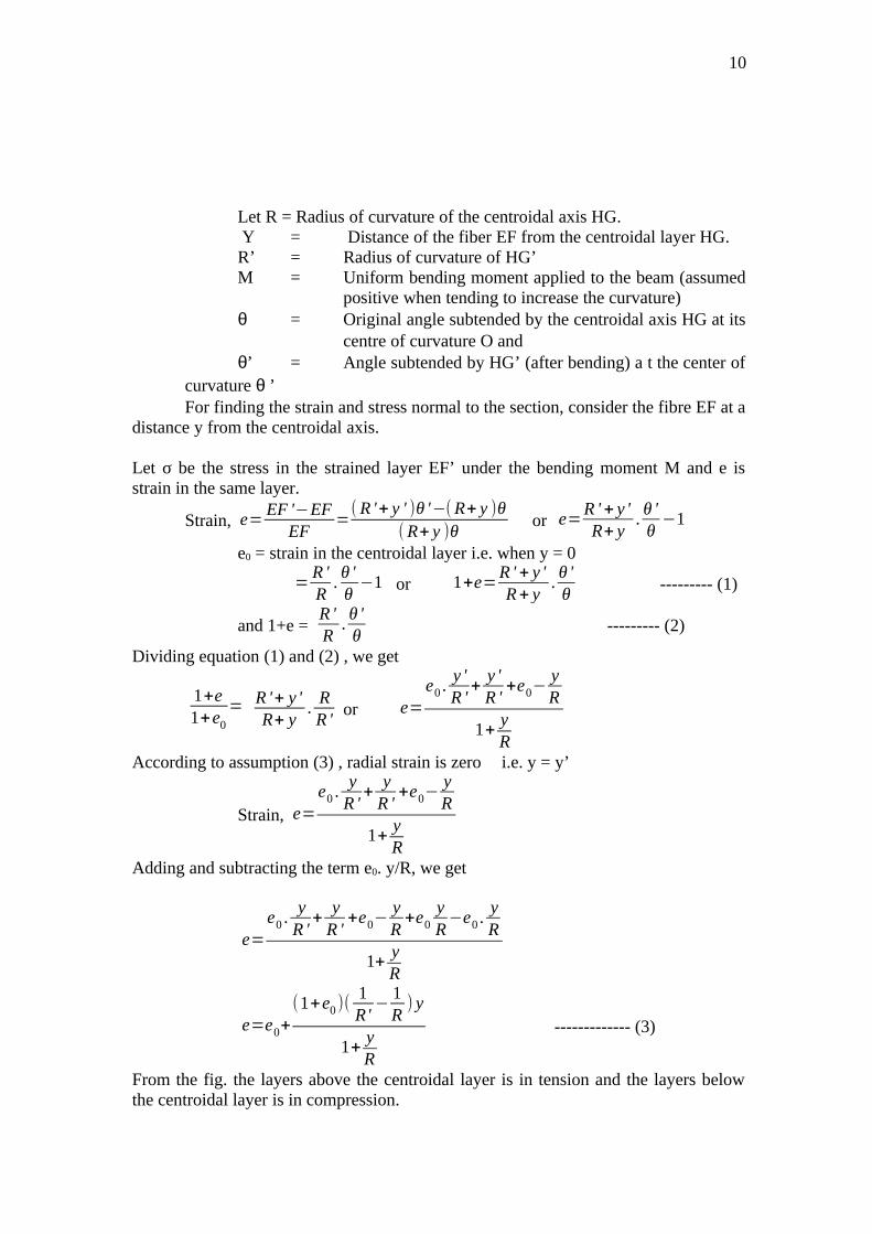
10
Let R = Radius of curvature of the centroidal axis HG. Y = Distance of the fiber EF from the centroidal layer HG.R’ = Radius of curvature of HG’M = Uniform bending moment applied to the beam (assumed
positive when tending to increase the curvature)θ = Original angle subtended by the centroidal axis HG at its
centre of curvature O and θ’ = Angle subtended by HG’ (after bending) a t the center of
curvature θ ’For finding the strain and stress normal to the section, consider the fibre EF at a
distance y from the centroidal axis.
Let σ be the stress in the strained layer EF’ under the bending moment M and e isstrain in the same layer.
Strain, e=EF '−EF
EF=
( R '+ y ' )θ '−(R+ y )θ( R+ y )θ
or e=R ' + y 'R+ y
.θ 'θ
−1
e0 = strain in the centroidal layer i.e. when y = 0
=R 'R
.θ 'θ
−1 or 1+e=R ' + y 'R+ y
.θ 'θ
--------- (1)
and 1+e = R 'R
.θ 'θ
--------- (2)
Dividing equation (1) and (2) , we get
1+e1+e0
= R '+ y 'R+ y
.RR '
or e=e0 .
y 'R '
+y 'R '
+e0−yR
1+yR
According to assumption (3) , radial strain is zero i.e. y = y’
Strain, e=e0 .
yR '
+y
R '+e0−
yR
1+yR
Adding and subtracting the term e0. y/R, we get
e=e0 .
yR '
+y
R '+e0−
yR
+e0yR
−e0 .yR
1+yR
e=e0+(1+e0 )(
1R'
−1R
) y
1+yR
------------- (3)
From the fig. the layers above the centroidal layer is in tension and the layers belowthe centroidal layer is in compression.
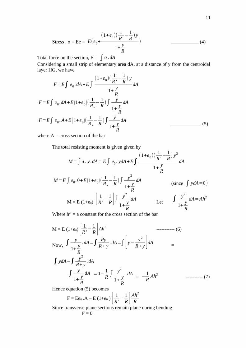
11
Stress , σ = Ee = E(e0+
(1+e0 )(1R'
−1R
) y
1+yR
) ___________ (4)
Total force on the section, F = ∫σ .dA
Considering a small strip of elementary area dA, at a distance of y from the centroidallayer HG, we have
F=E∫ e0 .dA+E∫(1+e0 )(
1R '
−1R
) y
1+yR
dA
F=E∫ e0 .dA+E (1+e0 )(1R ,
−1R
)∫y
1+yR
dA
F=E∫ e0 . A+E (1+e0)(1R ,
−1R
)∫y
1+yR
dA____________ (5)
where A = cross section of the bar
The total resisting moment is given given by
M=∫σ . y .dA= E∫ e0 . ydA+E∫(1+e0)(
1R '
−1R
) y2
1+yR
dA
M=E∫e0 . 0+E (1+e0) (1R ,
−1R
)∫ y2
1+yR
dA(since ∫ ydA=0 )
M = E (1+e0) [1R '
−1R ]∫ y2
1+yR
dALet ∫ y2
1+yR
dA=Ah2
Where h2 = a constant for the cross section of the bar
M = E (1+e0) [ 1R '
−1R ]Ah2 ----------- (6)
Now, ∫y
1+yR
.dA=∫ RyR+ y
.dA=∫ [ y−y 2
R+ y ]dA =
∫ ydA−∫ y2
R+ y.dA
∫y
1+yR
dA =0−1R∫ y2
1+yR
.dA = −
1R
Ah2 ---------- (7)
Hence equation (5) becomes
F = Ee0 .A – E (1+e0 ) [ 1R '
−1R ] Ah2
RSince transverse plane sections remain plane during bending
F = 0
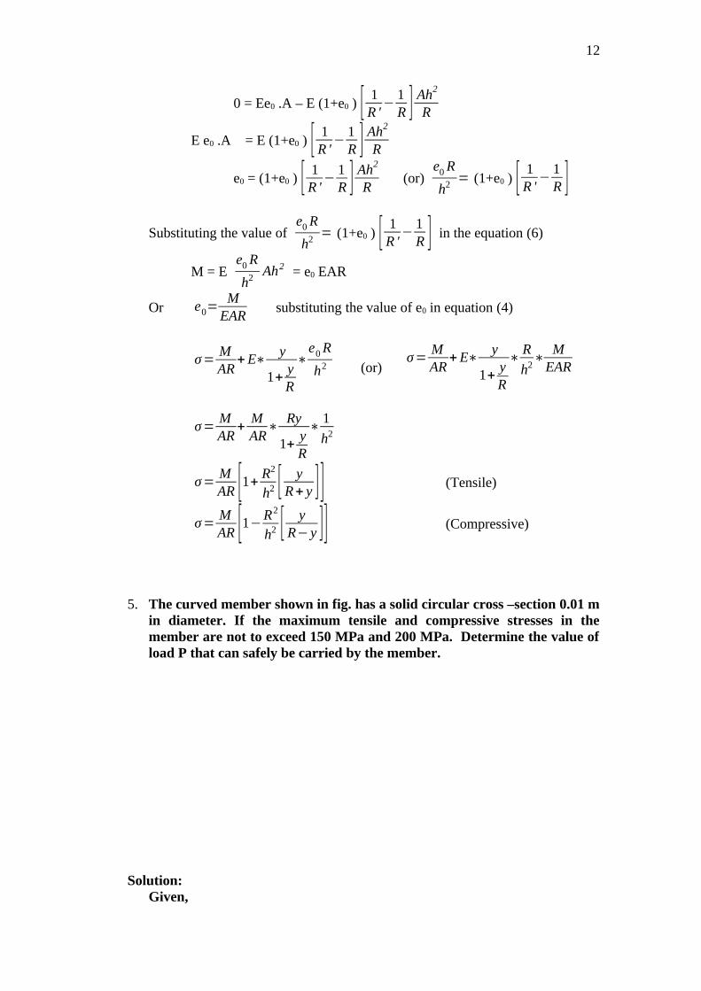
12
0 = Ee0 .A – E (1+e0 ) [ 1R '
−1R ] Ah2
R
E e0 .A = E (1+e0 ) [ 1R '
−1R ] Ah2
R
e0 = (1+e0 ) [ 1R '
−1R ] Ah2
R (or)
e0 R
h2= (1+e0 ) [ 1
R '−
1R ]
Substituting the value of e0 R
h2= (1+e0 ) [ 1
R '−
1R ] in the equation (6)
M = E e0 R
h2Ah2 = e0 EAR
Or e0=M
EARsubstituting the value of e0 in equation (4)
σ=MAR
+ E∗y
1+yR
∗e0 R
h2 (or)σ=
MAR
+ E∗y
1+yR
∗R
h2∗
MEAR
σ=MAR
+MAR
∗Ry
1+yR
∗1
h2
σ=MAR [1+
R2
h2 [ yR+ y ] ] (Tensile)
σ=MAR [1−
R2
h2 [ yR− y ]] (Compressive)
5. The curved member shown in fig. has a solid circular cross –section 0.01 min diameter. If the maximum tensile and compressive stresses in themember are not to exceed 150 MPa and 200 MPa. Determine the value ofload P that can safely be carried by the member.
Solution:Given,

13
d = 0.10 m; R = 0.10 m; G = 150 MPa = 150 MN / m2 (tensile )
σ2 = 200 MPa = 200 MN / m2 (Compressive)
Load P:
Refer to the fig . Area of cross section,
A=πd2
4=
π4× (0.10 )2=7 .854×10−3m2
Bending moment, m = P (0.15 + 0.10) =0.25 P
h2=d2
16+
1128
.(0.10 )4
(0 .10 )2 = 7.031 x 10⁻⁴ m2
Direct stress, σ d=pA
(comp )
Bending stress at point 1 due to M:
σb1=MAR [1+
R2
h2×
yR+ y ] (tensile)
Total stress at point 1,σ1=σ d+σb1
150=−PA
+MAR [1+
R2
h2×
yR+ y ] (tensile)
150=−P
7 .854×10−3+
0 . 25P7 . 854×10−3×0 .10 [1+
0 .102
7 .031×10−4×
0 .050 .10+0 .05 ]
= -127.32 P + 318.31 P x 5. 74= 1699.78 P
P=150×103
1699 .78=88 .25KN (i)
Bending stress at point 2 due to M:
σb2=MAR [ R2
h2×
yR− y
−1] (comp)
Total stress at point 2,σ2=σ d+σb2
200=PA
+MAR [ R2
h2×
yR− y
−1]=
P7 .854×10−3
+0 .25P
7 .854×10−3×0 .10 [ 0 .102
7 .031×10−4×
0.050 .10−0 .05
−1]=127.32 P + 318. 31 P x 13.22= 4335.38 P
P=2004335.38
MN
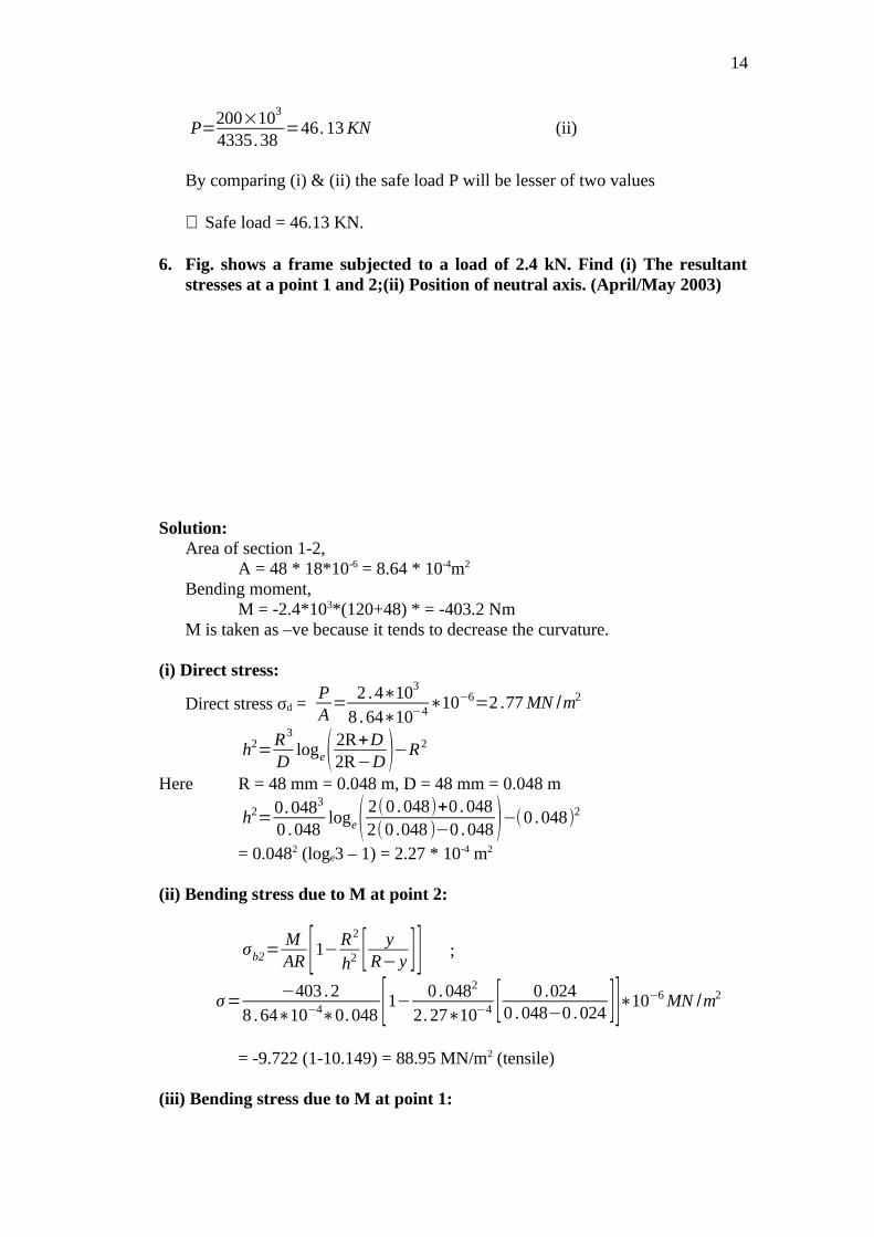
14
P=200×103
4335.38=46.13 KN (ii)
By comparing (i) & (ii) the safe load P will be lesser of two values
∴ Safe load = 46.13 KN.
6. Fig. shows a frame subjected to a load of 2.4 kN. Find (i) The resultantstresses at a point 1 and 2;(ii) Position of neutral axis. (April/May 2003)
Solution:Area of section 1-2,
A = 48 * 18*10-6 = 8.64 * 10-4m2
Bending moment,M = -2.4*103*(120+48) * = -403.2 Nm
M is taken as –ve because it tends to decrease the curvature.
(i) Direct stress:
Direct stress σd = PA
=2 .4∗103
8 .64∗10−4∗10−6=2 .77 MN /m2
h2=R3
Dloge( 2R+D
2R−D )−R2
Here R = 48 mm = 0.048 m, D = 48 mm = 0.048 m
h2=0.0483
0 .048loge( 2(0 .048)+0 . 048
2(0 .048 )−0 .048 )−(0 .048)2
= 0.0482 (loge3 – 1) = 2.27 * 10-4 m2
(ii) Bending stress due to M at point 2:
σb2=MAR [1−R2
h2 [ yR− y ] ] ;
σ=−403 .2
8 .64∗10−4∗0.048 [1− 0 .0482
2.27∗10−4 [ 0 .0240 . 048−0 .024 ]]∗10−6 MN /m2
= -9.722 (1-10.149) = 88.95 MN/m2 (tensile)
(iii) Bending stress due to M at point 1:
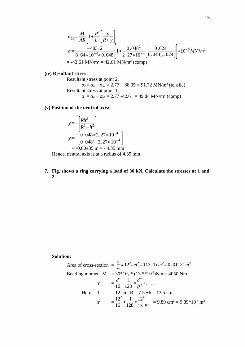
15
σb1=MAR [1+
R2
h2 [ yR+ y ]]
σ=−403 .2
8 .64∗10−4∗0.048 [1+0 .0482
2 .27∗10−4 [ 0 .0240.048+0 . 024 ]]∗10−6 MN /m2
= -42.61 MN/m2 = 42.61 MN/m2 (comp)
(iv) Resultant stress:Resultant stress at point 2,
σ2 = σd + σb2 = 2.77 + 88.95 = 91.72 MN/m2 (tensile)Resultant stress at point 1,
σ1 = σd + σb1 = 2.77 -42.61 = 39.84 MN/m2 (comp)
(v) Position of the neutral axis:
y=−[Rh2
R2−h2 ]y=−[0 .048∗2.27∗10−4
0 .0482+2.27∗10−4 ] = -0.00435 m = - 4.35 mm
Hence, neutral axis is at a radius of 4.35 mm
7. Fig. shows a ring carrying a load of 30 kN. Calculate the stresses at 1 and2.
Solution:
Area of cross-section = π4
x 122cm2=113 .1cm2=0 .01131m2
Bending moment M = 30*103 * (13.5*10-2)Nm = 4050 Nm
h2 =d2
16+
1128
∗d4
R2+.. . .. .
Here d = 12 cm, R = 7.5 +6 = 13.5 cm
h2 =122
16+
1128
∗124
13 .52 = 9.89 cm2 = 9.89*10-4 m2

16
Direct Stress σd = −PA
=30∗103
0 .01131∗10−6=2 .65 MN /m2
Bending stress at point 1 due to M,
σb1=MAR [1+
R2
h2 [ yR+ y ]]
σb1=40500 .01131∗0 .135 [1+
0.1352
9 . 89∗10−4 [ 0 .060 .135+0 .06 ]]∗10−6
2.65*6.67 = 17.675 MN/m2 (tensile)
Bending stress at point 2 due to M,
σb2=MAR [1−R2
h2 [ yR− y ] ]
σb1=40500 .01131∗0 .135 [1−
0 .1352
9. 89∗10−4 [ 0 .060 .135−0 .06 ] ]∗10−6
2.65*13.74 = 36.41 MN/m2 (comp)Hence σ1 = σd + σb1 = -2.65 + 17.675
= 15.05 MN /m2 (tensile)and σ2 = σd + σb2 = -2.65 – 36.41
= 39.06 MN/m2 (comp)
8. A curved bar is formed of a tube of 120 mm outside diameter and 7.5 mm thickness. The centre line of this is a circular arc of radius 225 mm. The bending moment of 3 kNm tending to increase curvature of the bar is applied. Calculate the maximum tensile and compressive stresses set up in the bar.
Solution:
Outside diameter of the tube, d2 = 120 mm = 0.12 mThickness of the tube = 7.5 mmInside diameter of the tube, d1 = 120-2*7.5 = 105 mm = 0.105mArea of cross-section,
A=π4
[0 .122−0.152 ]=0 .00265 m2
Bending moment M = 3 kNmArea of inner circle,
A1=π4
[0.1052 ]=0 .00866 m2
Area of outer circle,
A2=π4
[0.122 ]=0 .01131m2
For circular section,
h2 =d2
16+
1128
∗d4
R2+.. . .. .
For inner circle,

17
h2 =d
12
16+
1128
∗d
14
R2+. .. . ..
h2 =0.1052
16+
1128
∗0.1054
0 .2252=7 . 08∗10−4
For outer circle,
h2 =d
22
16+
1128
∗d
24
R2+. . .. .. ; h2=
0.122
16+
1128
∗0 .124
0 .2252=9.32∗10−4
Ah2=A2h2
2−A1h1
2
0.00265 h2 = 0.01131*9.32*10-4 – 0.00866*7.078*10-4
h2 = 0.00166 m2, and R2/h2 = 0.2252/0.00166 = 30.49Maximum stress at A,
σ A=MAR [1+ R2
h2 [ yR+ y ]] (where, y = 60 mm = 0.06 m)
σ A=3∗103
0 .00265∗0 .225 [1+30 . 49[ 0 .060.225+0 .06 ]]∗10−6 MN /m2
σA = 37.32 MN/m2 (tensile)Maximum stress at B,
σ B=MAR [−1+
R2
h2 [ yR− y ]]
σ B=3∗103
0 .00265∗0 .225 [−1+30 . 49[ 0 .060 .225−0.06 ]]∗10−6 MN /m2
σB = 50.75 MN/m2 (comp)
9. A curved beam has a T-section (shown in fig.). The inner radius is 300 mm. what is the eccentricity of the section?
Solution:

18
Area of T-section, = b1t1 + b2t2
= 60*20 + 80*20 = 2800 mm2 To find c.g of T- section, taking moments about the edge LL, we get
x−
=A1 x1+ A2 x2
A1+ A2
x−
=
(60∗20)(602
+20)+(80∗20)(80∗20∗10)
(60∗20 )+(80∗20 )=27.14 mm
Now R1 = 300 mm; R2 = 320 mm; R= 327.14 mm; R3 = 380 mm
Using the Relation:
h2=R3
A [b2 . loge
R2
R1
+t1 . loge
R3
R2]−R2
h2=(327 .14 )
3
2800 [80*loge(320300
)+20*loge(380320
)]−(327.14 )2
= 12503.8(5.16+3.44) – 107020.6 = 512.08
y = −[ Rh2
R2+h2 ]=327 .14∗512 .08(327 .14 )2+512 .08
=1.56 mm(−)
where y = e (eccentricity) = distance of the neutral axis from the centroidal axis.Negative sign indicates that neutral axis is locates below the centroidal axis.
10. Fig. shows a C- frame subjected to a load of 120 kN. Determine the stresses at A and B.

19
Solution:Load (P) = 120 kN
Area of cross – section = b1t1 +b2t2+ b3t3
= 120*30 + 150*30 +180*30 = 0.0135 mm2
To find c.g of the section about the edge LL,
x−
=A1 x1+ A2 x2
A1+ A2
y1=(120∗20∗225)+(150∗30∗15 )+(180∗30∗120 )
(120∗30 )+(150∗30)+(180∗30 )=113 mm=0.113
my2
= 240 – 113 = 127 mm = 0.127 mR1 = 225 mm = 0.225 mR2 = 225 + 30 = 255 mm = 0.255 mR = 225 + 113 = 338 mm = 0.338 mR3 = 225 +210 = 435 mm = 0.435 mR4= 225 + 240 = 465 mm = 0.465 m
h2=R3
A [b2 loge(R2
R1)+t3 loge(
R3
R2)+b1 log e(
R4
R3)]−R2
h2=(0 .338 )3
0 .0135 [0 .15 loge( 0 .2550 .225 )+0 .03 loge(0 .435
0 .255 )+0 .12 loge( 0 .4650 .435 )]−0 .3382
= 2.86 (0.01877 +0.016 +0.008) – 0.1142 = 0.008122 m2
Direct stress, σd = PA
=120∗103
0.0135∗10−6=8 .89 MN /m2 (comp)
Bending moment, M = P*RBending stress at A due to the bending moment,
(σb )A=MAR [1+ R2
h2 [ y2
R+ y2]]
(σb)A=P∗RAR [1+ 0 .3382
0 .0081222 [ 0.1270 . 338+0 .127 ] ]
= 8.89 (1+3.842) = 43.04 MN/m2 (tensile)
Bending stress at B due to the bending moment:
(σb )A=MAR [1+ R2
h2 [ y1
R− y1] ]
(σb )A=P∗RAR [1+ 0.3382
0 .008122 [ 0.1130 .338−0 .113 ]]
= 8.89 ( 1- 7.064)= -53.9 MN /m2 = 53.9 MN/m2 (comp)

20
Stress at A, σA = σd + (σb)A = -8.89 + 43.04 = 34.15 MN/m2 (tensile)
Stress at B, σB = σd + (σb)B
= -8.89 – 53.9 = 62.79 MN/m2 (comp)
11. Derive the formula for the deflection of beams due to unsymmetrical bending.Solution:
Fig. shows the transverse section of the beam with centroid G. XX and YY are two rectangular co-ordinate axes and UU and VV are the principal axes inclined at an angle θ to the XY set of co-ordinates axes. W is the load acting along theline YY on the section of the beam. The load W can be resolved into the following twocomponents:
(i) W sin θ …… along UG(ii) W cos θ …… along VG
Let, δu = Deflection caused by the component W sin θ along the line GU for its bending about VV axis, and Δv = Deflection caused by the component W cos θ along the line GV due to bending abodt UU axis.Then depending upon the end conditions of the beam, the values of δu and δv are given by
δ u
K (W sin θ ) l3
EIVV
δ v
K (W cosθ )l3
EI UU
where, K = A constant depending on the end conditions of the beam and position of the load along the beam, and
l = length of the beamThe total or resultant deflection δ can then be found as follows:
δ=√ (δ u)2+(δ v )
2

21
δ=Kl3
E √(W sin θIVV
)2
+(W cosθIUU
)2
δ=Kl3
E √(sin2θ
I2VV )+(cos2θ
I2UU )
The inclination β of the deflection δ, with the line GV is given by:
tan β=δuδv
=IUU
IVV tanθ
12. A 80 mm x 80 mm x 10 mm angle section shown in fig. is used as a simplysupported beam over a span of 2.4 m. It carries a load of 400 kN along the lineYG, where G is the centroid of the section. Calculate (i) Stresses at the points A, Band C of the mid – section of the beam (ii) Deflection of the beam at themid-section and its direction with the load line (iii) Position of the neutral axis.Take E = 200 GN/m2
Solution:Let (X,Y) be the co-ordinate of centroid G, with respect to the
rectangular axes BX1 and BY1.
Now X = Y = 80∗10∗40+70∗10∗580∗10+70∗10
=32000+3500800+700
23 .66mm
Moment of inertia about XX axis:
IXX=[80∗103
12+80∗10∗(23 .66−5)2]+[10∗703
12+70∗10∗( 45−23 .66)2 ]
= (6666.66 + 278556) + (285833.33 + 318777) = 889833 mm4
= 8.898 * 105 mm4 = IYY (since it is an equal angle section)Co-ordinates of G1 = + (40-23.66), - (23.66-5) = (16.34,- 18.66)Co-ordinates of G2 = -(23.66-5). + (45 – 23.66) = (-18.66, + 21.34)
(Product of inertia about the centroid axes is zero because portions 1 and 2 arerectangular strips)
22
If θ is the inclination of principal axes with GX, passing through G then,
tan 2θ=2IXY
IXY −IXX
=∞=tan 90ο (since Ixx =Iyy)
2θ = 90ºi.e. θ1 = 45º and θ2 = 90º + 45º = 135º are the inclinations of the principal axes GU
and GV respectively.Principal moment of inertia:
IUU = 12( IXX+ IYY )+√(
IYY −I XX
2)2+( IXY )
2
=
12(8 . 895∗105+8 .898∗105 )+√(
8 .895∗105−8.898∗105
2)2+(−5 .226∗105)2
= (8.898 + 5.2266) *105 = 14.1245*105 mm4 IUU + IVV = IXX + IYY
IVV = IXX IYY – IUU = 2*8.898 x 105 – 14.1246 x 105 = 3.67 x 105 mm4
(i) Stresses at the points A, B and C:Bending moment at the mid-section,
M=Wl4
=400∗2. 4∗103
4=2. 4∗105 Nmm
The components of the bending moments are;M’ = M sin θ = 2.4 x 10⁵ sin 45º = 1.697 x 10⁵ Nmm
M’’ = M cos θ = 2.4 x 10⁵ cos 45º = 1.697 x 10⁵ Nmmu,v co-ordinates:Point A: x = -23.66, y = 80-23.66 = 56.34 mm
u = x cos θ + y sin θ= -23.66 x cos 45º + 56.34 x sin 45º = 23.1 mm
v = y cosθ + x sin θ= 56.34 cos 45º - (-23.66 x sin 45º) = 56.56 mm
Point B:
x = -23.66, y = -23.66 u = x cos θ + y sin θ
= -23.66 x cos 45º + (-23.66 x sin 45º ) = - 33.45 mmv = y cosθ + x sin θ
= -23.66 cos 45º - (-23.66 x sin 45º) = 0Point C ; x = 80 – 23.66 = 56.34, y = -23.66
u = x cos θ + y sin θ= 56.34 cos 45º -23.66 x sin 45º = 23.1 mm
v = y cosθ + x sin θ= -23.66 cos 45º - 56.34 sin 45º) =- 56.56 mm

23
M v} over {I rSub { size 8{ ital UU } } } } } {}¿
σ A=M ' uIVV
+¿
¿
σ A=1.697∗105
(23 .1)
3.67 x10⁵+
1 .697∗105(56 .56 )
14 .1246 x105=17 .47 N /mm2
σ B=1.697∗105
(−33 .45 )
3 .67 x 105+
014 .1246 x105
=−15 .47 N /mm2
σ B=1.697∗105
(23 .1)
3.67 x10⁵+
56.5614 .1246 x105
=3 .788 N /mm2
(ii) Deflection of the beam, δ:The deflection δ is given by:
δ=KWl3
E √(sin2 θ
I2VV )+(cos2 θ
I2UU )
where K = 1/48 for a beam with simply supported ends and carrying apoint load at the centre.
Load , W = 400 NLength l = 2.4 m
E = 200 x 103 N/mm2 IUU = 14.1246 x 105 mm4 IVV = 3.67 x 105 mm4
Substituting the values, we get
δ=1
48400 x(2 .4x103)3
E √(sin2 45ο
(3 .67 x 105)2)+(cos245ο
(14 .1246 x 105)2 )
δ = 1.1466 mmThe deflection δ will be inclined at an angle β clockwise with the kine GV, given by
tan β=IUU
IVV
tanθ=14 .1246 x105
3 .67 x 105tan 45ο3 .848
β = 75.43º - 45º = 30.43º clockwise with the load line GY’.(iii) Position of the neutral axis:
The neutral axis will be at 90º - 30.43º = 59.57º anti-clockwise with theload line, because the neutral axis is perpendicular to the line of deflection.