unit-ii fluid machinery 1. what is hydraulic … year/ftm/unit 2.pdfunit-ii fluid machinery 1. what...
TRANSCRIPT
UNIT-II
FLUID MACHINERY
1. What is Hydraulic Turbines? Write its Classifications?
The hydraulic turbine is a prime mover that uses the energy of flowing water and converts is
into the mechanical energy in the form of rotation of the runner. (A prime mover is a machine
which uses the raw energy of a substance and converts it into the mechanical energy.) Since the
fluid medium is water, these turbines are also known as the „water turbines‟. Hydraulic
turbines coupled with hydro – generators form the so – called „hydro units‟ which are widely
used now days for generating electrical power.
Classification of Turbines
Hydraulic turbines may be classified in the following ways:
i) According to the type of energy at inlet.
a) Impulse turbine b) Reaction turbine.
ii) According to the direction of flow through runners.
a) Tangential flow b) Radial flow c) Axial flow d) Mixed flow
turbines.
iii) According to the head and quantity of water
a) High head turbines – which work under high heads (above 250m) but with less
quantity of water. Example: Pelton wheel
b) Medium head turbines – work under medium heads (60m to 250m)-they require
relatively large quantity of water. Example: Francis turbines
c) Low head turbines – work under heads less than 60m – they require a very large
quantity of water. Example: Kaplan turbine
iv) According to position of shaft
a) Horizontal turbines – These turbines have horizontal shafts.
Example: Pelton wheel
b) Vertical turbines – These turbines have vertical shafts.
Example: Francis and Kaplan turbines.
2. Explain Head and Efficiencies of Hydraulic Turbines.
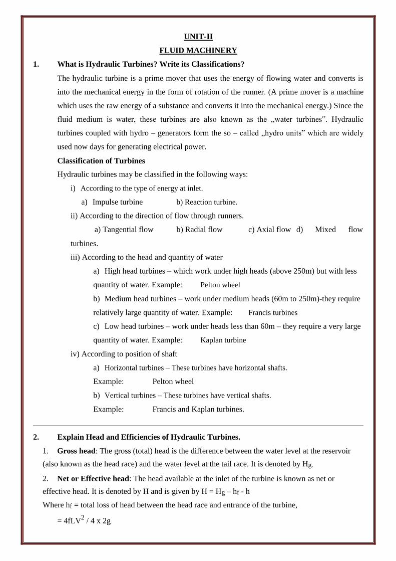
1. Gross head: The gross (total) head is the difference between the water level at the reservoir
(also known as the head race) and the water level at the tail race. It is denoted by Hg.
2. Net or Effective head: The head available at the inlet of the turbine is known as net or
effective head. It is denoted by H and is given by H = Hg – hf - h
Where hf = total loss of head between the head race and entrance of the turbine,
= 4fLV2 / 4 x 2g
Where L = Length of penstock, D = Diameter of penstock, V = Velocity of flow in penstock, h =
Height of nozzle above the tail race.
3. Efficiencies: The following are the importance efficiencies of a turbine.
i) Hydraulic efficiency (h):
It is defined as the ratio of power developed by the runner to the power supplied by the jet at
entrance to the turbine.
Mathematically, h = Power developed by the runner / Power supplied at the inlet of Turbine
= pQa (Vw Vw1) u / wQaH = (w/g) Qa (Vw Vw1) u / wQaH
= (VwVw1) u / gH = Hr / H
Where Vw, Ww1 = Velocities of whirl at inlet and outlet
respectively u = Tangential velocity of vane
H = Net head on the turbine
Qa = Actual flow rate to turbine runner (bucket)
The parameter H = 1/g = (Vw + Vw1) u represents the energy transfer per unit weight of water and
is referred to as the „Runner head‟ of „Euler head‟
H – Hr = H = hydraulic losses within the turbine.
ii) Mechanical Efficiency (m):
It is defined as the ratio of the power obtained from the shaft of the turbine to the power developed
by the runner. These two powers differ by the amount of mechanical losses, viz., bearing friction
etc.
Mathematically,
m = Power developed at the turbine shaft / Power developed by turbine
runner = Shaft power / Bucket power
Values of mechanical efficiency for a Pelton wheel usually lie between 97 to 99 percent depending
on size and capacity of the unit.
iii) Volumetric Efficiency (h)
The volumetric efficiency is the ratio of the volume of water actually striking the runner to the
volume of water supplied by the jet to the turbine.
That is, r = Volume of water actually striking the runner (Qa) / Total water supplied by the jet to
the turbine (Q)
For Pelton turbines, r = 0.97 to 0.99
iv) Overall Efficiency (ho)
It is defined as the ratio of power available at the turbine shaft to the power supplied by the water
jet.
That is,
o = Power available at the turbine shaft / Power available from the water jet
= Shaft Power / Water Power = P / wQH
where Q = the total discharge in m3 / s supplied by the jet
The values of overall efficiency for a Pelton wheel lie between 0.85 to 0.90.
The individual efficiencies may be combined to give
o = h × m × v
= Hr / H × P / wQaHr × Qa / Q = P / wQH
which is the same as defined wide equation.
If g is the efficiency of a generator, then power output of the hydrounit (turbine +
hydrogenerators).
= (wQH) × o x g
The product o × g is known as hydro-electric plant efficiency.
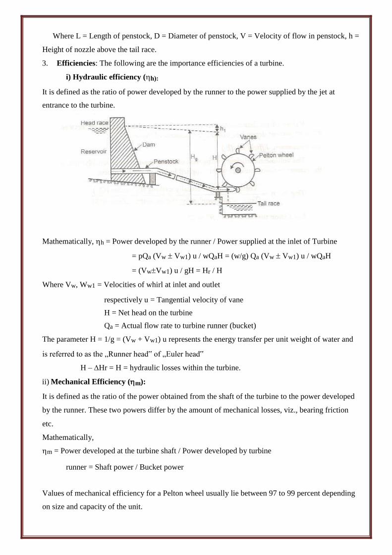
3. Explain Parts and working Principle of Francis Turbine with neat sketch.
Francis Turbine
The Francis turbine is mixed flow reaction turbine. This turbine is used for medium heads with
medium discharge. Water enters the runner and flows towards the center of wheel in the radical
direction and leaves parallel to the axis of the turbine. Description of main parts
Francis turbine consists mainly of the following parts
a) Spiral or scroll casing
b) Guide mechanism
c) Runner and turbine main shaft
d) Draft tube
(a) Spiral casing of scroll casing
The casing of the Francis turbine is designed in a spiral form with a gradually
increasing area. The advantages of this design are
i) Smooth and even distribution of water around the runner.
ii) Loss of head due to the formation of eddies is avoided.
iii) Efficiency of flow of water to the turbine is increased.
In big units stay vanes are provided which direct and water to the guide vanes. The casing is
also provided with inspection holes and pressure gauge connection. The selection of material
for the casing depends upon the head of water to be supplied
For a head – up to 30 meters – concrete is used.
For a head – from 30 to 60 meters – welded rolled steel plates are used.
For a head of above 90 meters – cast steel is used.
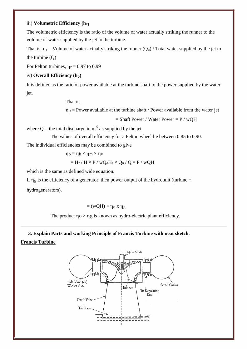
(b) Guide mechanism
The guide vanes of wicket gates are fixed between two rings. This arrangement is in the
form of a wheel and called guide wheel. Each vane can be rotated about its pivot center.
The opening between the vanes can be increased or decreased by adjusting the guide wheel.
The guide wheel is adjusted by the regulating shaft which is operated by a governor.
The guide mechanism provides the required quantity of water to the runner depending upon the
load conditions. The guide vanes are in general made of cast steel.
(c) Runner and turbine main shaft
The flow in the runner of a modern Francis turbine is partly radial and partly axial. The runners
may be classified as
i) Slow ii) Medium iii) Fast
The runner may be cast in one piece or made of separate steel plates welded together.
The runners are made of CI for small output, cast steel or stainless steel or bronze for large
output. The runner blades should be carefully finished with high degree of accuracy.
The runner may be keyed to the shaft which may be vertical or horizontal. The shaft is
made of steel and is forged it is provided with a collar for transmitting the axial thrust.
(d) Draft tube
The water after doing work on the runner passes on to the tail race through a tube called
draft tube. It is made of riveted steel plate or pipe or a concrete tunner. The cross – section of
the tube increases gradually towards the outlet. The draft tube connects the runner exit to the
tail race. This tube should be drowned approximately 1 meter below the tail race water level. Working Principles of Francis Turbine
The water is admitted to the runner through guide vanes or wicket gates. The opening between
the vanes can be adjusted to vary the quantity of water admitted to the turbine. This is done to
suit the load conditions.
The water enters the runner with a low velocity but with a considerable pressure. As the water
flows over the vanes the pressure head is gradually converted into velocity head. This kinetic
energy is utilized in rotating the wheel. Thus the hydraulic energy is converted into mechanical
energy. The out going water enters the tail race after passing through the draft tube. The draft
tube enlarges gradually and the enlarged end is submerged deeply in the tail race water. Due to
this arrangement a suction head is created at the exit of the runner. Advantages:
Variation in the operating load can be more easily controlled.
The ratio of maximum and minimum operating heads can be even two.
The operating head can be utilized even when the variation in the tail water level is relatively
large when compared to the total head.
The mechanical efficiency of Pelton wheel decreases faster with wear than Francis turbine.
The size of the runner, generator and power house required is small and economical if the
Francis turbine is used instead of Pelton wheel for same power generation. Disadvantages:
Water which is not clean can cause very rapid wear in high head Francis turbine.
The overhaul and inspection is much more difficult comparatively.
Cavitation is an ever present danger.
The water hammer effect is more troublesome with Francis turbine.
If Francis turbine is run below 50 percent head for a long period it will not only lose its
efficiency but also the cavitation danger will become more serious
4. Explain Parts and working Principle of Pelton Turbine with neat sketch.
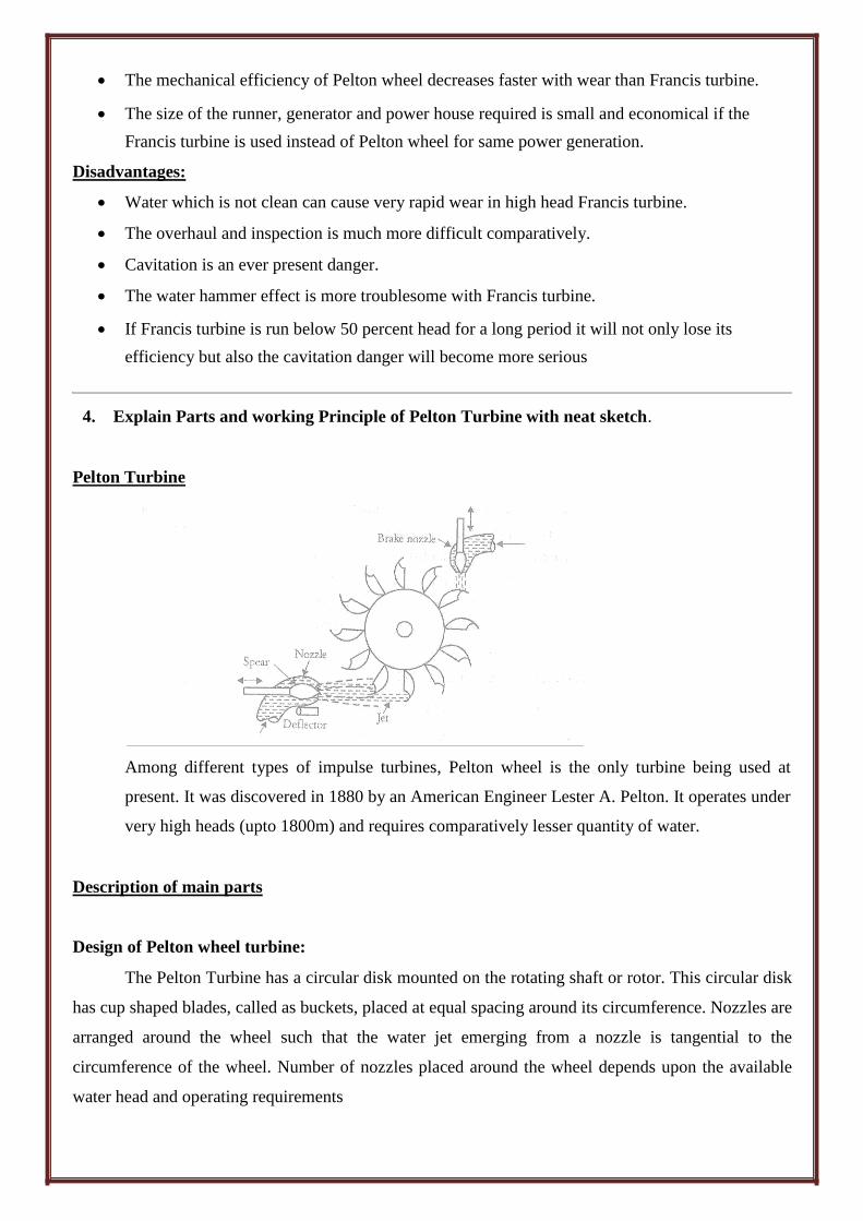
Pelton Turbine
Among different types of impulse turbines, Pelton wheel is the only turbine being used at
present. It was discovered in 1880 by an American Engineer Lester A. Pelton. It operates under
very high heads (upto 1800m) and requires comparatively lesser quantity of water.
Description of main parts
Design of Pelton wheel turbine:
The Pelton Turbine has a circular disk mounted on the rotating shaft or rotor. This circular disk
has cup shaped blades, called as buckets, placed at equal spacing around its circumference. Nozzles are
arranged around the wheel such that the water jet emerging from a nozzle is tangential to the
circumference of the wheel. Number of nozzles placed around the wheel depends upon the available
water head and operating requirements
Penstock:
It is a large sized conduit which conveys water from high level reservoir to the turbine. It is
made up of wood, concrete or steel. Penstock is provided with control valves to regulate the water
flow. Trash racks are provided at inlet to prevent debris from entering into it.
Spear and nozzle:
At the downstream end, penstock is fitted with nozzle that converts hydraulic energy into high
speed jet. Spear is provided at the nozzle to regulate water flow and obtain a good jet of water at all
loads. Spear is so arranged that it can move forward or backward thereby decreasing or increasing the
annular area of the nozzle flow passage. The movement of spear is controlled either manually by a
hand wheel or automatically by governing mechanism.
Runner with buckets:
The runner is a circular disk carrying number of cup-shaped buckets which are placed at equal
spacing around its circumference. Runner is generally mounted on the horizontal shaft with bearings
and the buckets are either casted integrally with the disk or fastened separately. Buckets are made up
of cast iron, bronze or stainless steel. Inner surface of the buckets are polished to reduce frictional
resistance to the water jet.
Each bucket has a splitter which distributes the striking jet equally into two halves of
hemispherical bucket. There is a cut in the outer rim (notch) of each bucket. This notch is provided to
make the jet face the bucket only when it has come into proper position with respect to the jet. This
position occurs when face of the bucket and axis of the jet are approximately at 90 degree to each
other. Maximum driving force will be exerted on the disk when the jet gets deflected through 180
degree. But it practice angular deflection is limited to about 165-170 degree. This is to ensure that the
water jet while leaving one bucket does not strike the back of the succeeding bucket.
Casing:
Outflow from the buckets is in the form of strong splash which scatters in all direction. To
prevent this and guide water to tail race, a casing is provided around the runner.
Governing mechanism:
Speed of turbine runner is required to be maintained constant so that the electric generator
coupled to the turbine shaft runs at constant speed under varying load condition. This task is
accomplished by a governing mechanism that automatically regulates the quantity of water flowing
through the runner in accordance with any variation in the load.
Working Principle of Pelton turbines
From the head race in the mountains water is conveyed to the turbines installed in the power
house through the penstocks. The lower end of the penstock is joined with a nozzle in the turbine
casing. Water is delivered by the nozzle at a high velocity on the buckets. These buckets are mounted
on the periphery of a circular wheel (also known as runner) which is generally mounted on a horizontal
shaft. The quantity of water coming out of the nozzle or nozzles can be controlled by regulators
(governing arrangement) in case of big installations and by hand wheels in case of small installations.
The impact of water on the buckets causes the runner to rotate, thus develops mechanical
energy. After doing work on the buckets water is discharged in the tail race. Being impulse turbine it
must run at atmosphere pressure and therefore, these are located above the tail race. The buckets are so
shaped that water enters tangentially in the middle and discharges backward and flows again
tangentially in both the direction to avoid thrust on the wheel (as shown in the line sketch). Actually
the jet is deflected by 160 degree. To produce electric energy these are coupled with the electric
generators.
5. What is governing of Turbine? Explain the Governing of Turbine.
Governing Mechanism of Turbines
Usually hydraulic turbines are coupled to the generators. The power output of the
generator is actually the load on the turbine. When the load changes the speed of the turbine
also change.
The governing of a turbine is the operation by which the speed of the turbine is kept constant
by controlling the discharge irrespective of the fluctuations of load on the turbine. Functions of governor
The main functions of a governor are
i) Noticing the speed variations quickly.
ii) Operating the different components rapidly and effectively.
iii) Controlling the discharge to maintain constant speed.
iv) Matching the speed of the turbine and generator.
v) Setting the amount of load to the turbine unit.
vi) To alert the operator under extreme conditions.
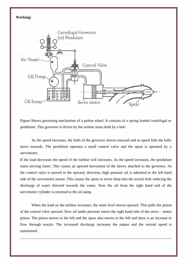
Working:
Figure Shows governing mechanism of a pelton wheel. It consists of a spring loaded centrifugal or
pendulum. This governor is driven by the turbine main shaft by a belt.
As the speed increases, the balls of the governor moves outward and as speed falls the balls
move inwards. The pendulum operates a small control valve and the spear is operated by a
servomotor.
If the load decreases the speed of the turbine will increases. As the speed increases, the pendulum
starts moving faster. This causes an upward movement of the sleeve attached to the governor. As
the control valve is moved in the upward, direction, high pressure oil is admitted to the left hand
side of the servomotor piston. This causes the spear to move deep into the nozzle hole reducing the
discharge of water directed towards the vanes. Now the oil from the right hand end of the
servomotor cylinder is returned to the oil sump.
When the load on the turbine increases, the main level moves upward. This pulls the piston
of the control valve upward. Now oil under pressure enters the right hand side of the servo – motor
piston. The piston moves to the left and the spear also moves to the left and there is an increase in
flow through nozzle. The increased discharge increases the output and the normal speed is
maintained.
6. What is Centrifugal Pump? Explain Parts and Working Principle of Centrifugal Pump
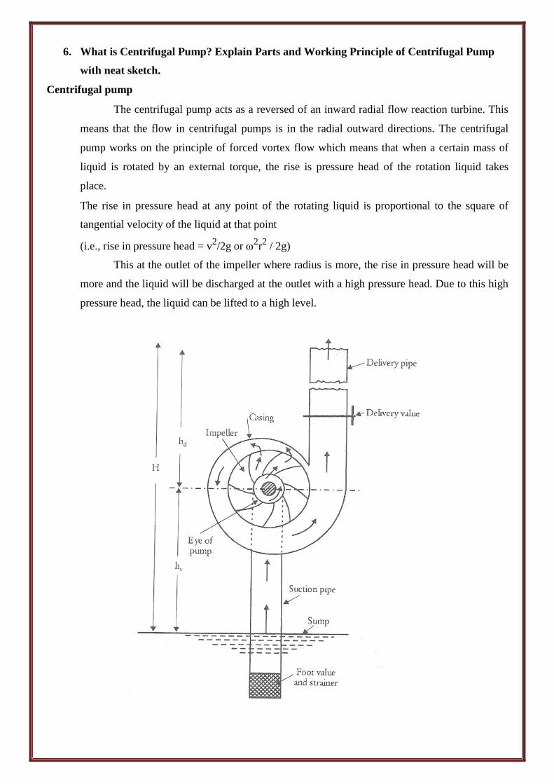
with neat sketch. Centrifugal pump
The centrifugal pump acts as a reversed of an inward radial flow reaction turbine. This
means that the flow in centrifugal pumps is in the radial outward directions. The centrifugal
pump works on the principle of forced vortex flow which means that when a certain mass of
liquid is rotated by an external torque, the rise is pressure head of the rotation liquid takes
place.
The rise in pressure head at any point of the rotating liquid is proportional to the square of
tangential velocity of the liquid at that point
(i.e., rise in pressure head = v2/2g or
2r2 / 2g)
This at the outlet of the impeller where radius is more, the rise in pressure head will be
more and the liquid will be discharged at the outlet with a high pressure head. Due to this high
pressure head, the liquid can be lifted to a high level.
Classification of Centrifugal Pumps
a) Single stage
b) Multi stage
Description of Centrifugal Pump
The following are the main parts of a centrifugal pump:
1. Impeller
2. Casing
3. Suction pipe with a foot valve and a strainer
4. Delivery pipe
All the main parts of the centrifugal pump
1. Impeller
The rotating part of a centrifugal pump is called „impeller‟. It consists of a series of backward curved
vanes. The impeller is mounted on a shaft which is connected to the shaft of an electric motor. 2. Casing
The casing of a centrifugal pump is similar to the casing of a reaction turbine. It is an air – tight
passage surrounding the impeller and is designed in such a way that the kinetic energy of the water
discharged at the outlet of the impeller is converted into pressure energy before the water leaves the
casing and enters the delivery pipe. The following three types of the casings are commonly adopted:
a) Volute casing
b) Vortex casing
c) Casing with guide blades. a) Volute casing
Shows the volute casing which surrounds the impeller. It is of spiral type in which area of
flow increases gradually. The increase in area of flow decreases the velocity of flow. The decrease
in velocity increases the pressure of the water flowing through the casing. It has been observed that
in case of volute casing, the efficiency of the pump increases slightly as a large amount of energy is
lost due to the formation of eddies in this type of casing.
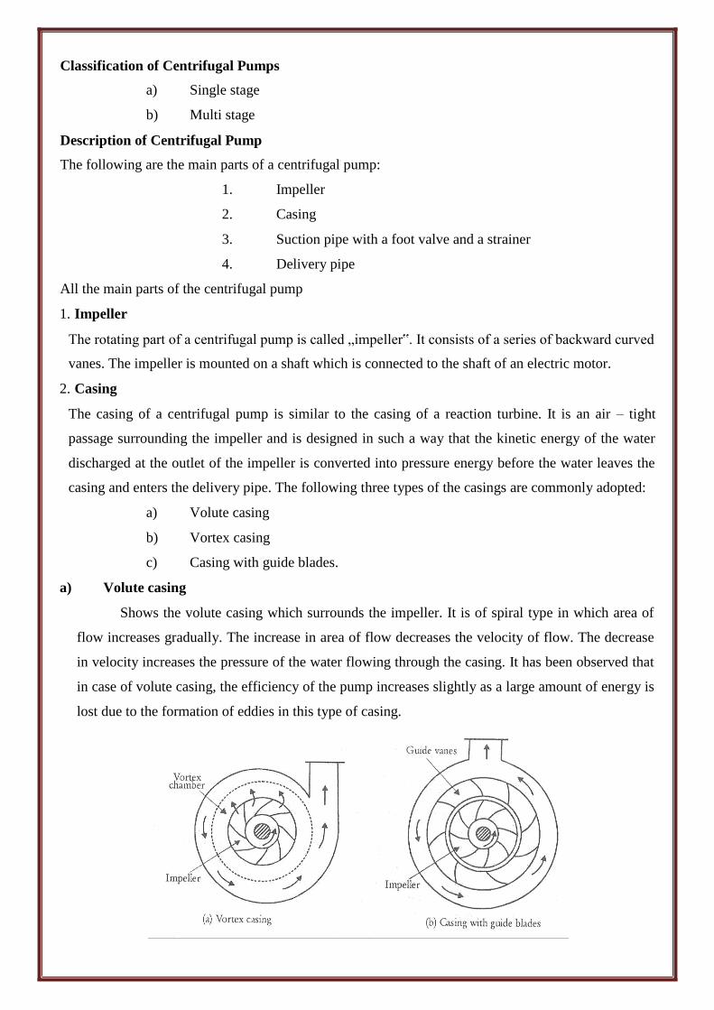
b) Vortex casing
If a circular chamber is introduced between the casing and the impeller, the casing is known as
Vortex casing. By introducing the circular chamber, the loss of energy due to the formation of
eddies is reduced to a considerable extent. Thus the efficiency of the pump is more than the
efficiency when only volute casing is provided. c) Casing with guide blades
This casing is in which the impeller is surrounded by a series of guide blades mounted on a ring
which is known as diffuser. The guide vanes are designed in which a way that the water from
the impeller enters the guide vanes without stock. Also the area of the guide vanes increases,
thus reducing the velocity of flow through guide vanes and consequently increasing the
pressure of water. The water from the guide vanes then passes through the surrounding casing
which is in most of the cases concentric with the impeller. 3. Suction pipe with a foot – valve and a strainer
A pipe whose one end is connected to the inlet of the pump and other end dips into water in a
sump is known as suction pipe. A foot valve which is a non – return valve or one – way type of
valve is fitted at the lower end of the suction pipe. The foot valve opens only in the upward
direction. A strainer is also fitted at the lower end of the suction pipe. 4. Delivery pipe
A pipe whose one end is connected to the outlet of the pump and other end delivers the water at
a required height is known as delivery pipe.
7. What is Reciprocating Pump? Explain Working Principle of Reciprocating Pump.
The pumps are the hydraulic machines which convert the mechanical energy into hydraulic
energy which is mainly in the form of pressure energy. If the mechanical energy is converted
into hydraulic energy, by means of centrifugal force acting on the liquid, the pump is known as
centrifugal pump. But if the mechanical energy is converted into hydraulic energy (or pressure
energy) by sucking the liquid into a cylinder in which a piston is reciprocating (moving
backwards and forwards), which exerts the thrust on the liquid and increases its hydraulic
energy (pressure energy), the pump is known as reciprocating pump.
Classification of Reciprocation Pumps
The reciprocating pumps may be classified as:
1. According to the water being in contact with one side or both sides of the piston
2. According to the number of cylinders provided.
If the water is in contact with one side of the piston, the pump is known as single – acting. On
the other hand, if the water is in contact with both sides of the piston, the pump is called double
– acting. Hence, classification according to the contact of water is:
i) Single- acting pump ii) Double – acting pump.
According to the number of cylinder provided, the pumps are classified as:
i) Single cylinder pump ii) Double cylinder pump iii) Triple cylinder pump.
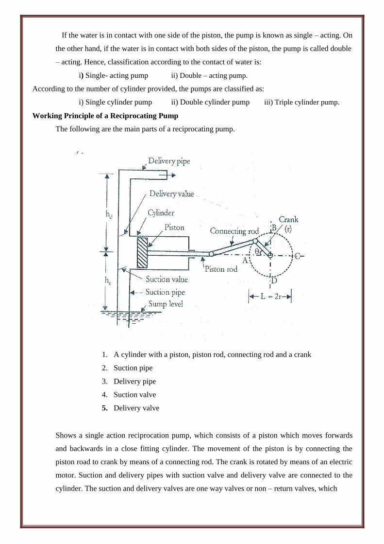
Working Principle of a Reciprocating Pump
The following are the main parts of a reciprocating pump.
1. A cylinder with a piston, piston rod, connecting rod and a crank
2. Suction pipe
3. Delivery pipe
4. Suction valve
5. Delivery valve
Shows a single action reciprocation pump, which consists of a piston which moves forwards
and backwards in a close fitting cylinder. The movement of the piston is by connecting the
piston road to crank by means of a connecting rod. The crank is rotated by means of an electric
motor. Suction and delivery pipes with suction valve and delivery valve are connected to the
cylinder. The suction and delivery valves are one way valves or non – return valves, which
allow the water to flow in one direction only. Suction valve allows water from suction pipe to
the cylinder which delivery valve allows water from cylinder to delivery pipe only.
When crank starts rotating, the piston moves top and pro in the cylinder. When crank is at A,
the piston is at the extreme left position in the cylinder. As the crank is rotating from A to C,
(i.e., from θ = 0 to θ = 180 degree), the piston is moving towards right in the cylinder. The
movement of the piston towards right creates a partial vacuum in the cylinder. But on the
surface of the liquid in the sump atmospheric pressure is acting, which is more than the
pressure inside the cylinder. Thus the liquid if forced in the suction pipe from the sump. This
liquid opens the suction valve and enters the cylinder.
When crank is rotating from C to A (i.e., from θ = 180 degree to θ = 360 degree), the
piston from its extreme right position starts moving towards left in the cylinder. The movement
of the piston towards left increases the pressure of the liquid inside the cylinder more than
atmospheric pressure. Hence suction valve closes and delivery valve closes and delivery valve
opens. The liquid is forced into the delivery pipe and is raised to a required height.
8. What is Indicator Diagram? Explain effect of acceleration on Indicator Diagram.
The indicator diagram for a reciprocating pump is defined as the graph between the pressure
head in the cylinder and the distance traveled by piston from inner dead centre for one
complete revolution of the crank. As the maximum distance traveled by the piston is equal to
the stroke length and hence the indicator diagram is a graph between pressure head and stroke
length of the piston for one complete revolution. The pressure head is taken as ordinate and
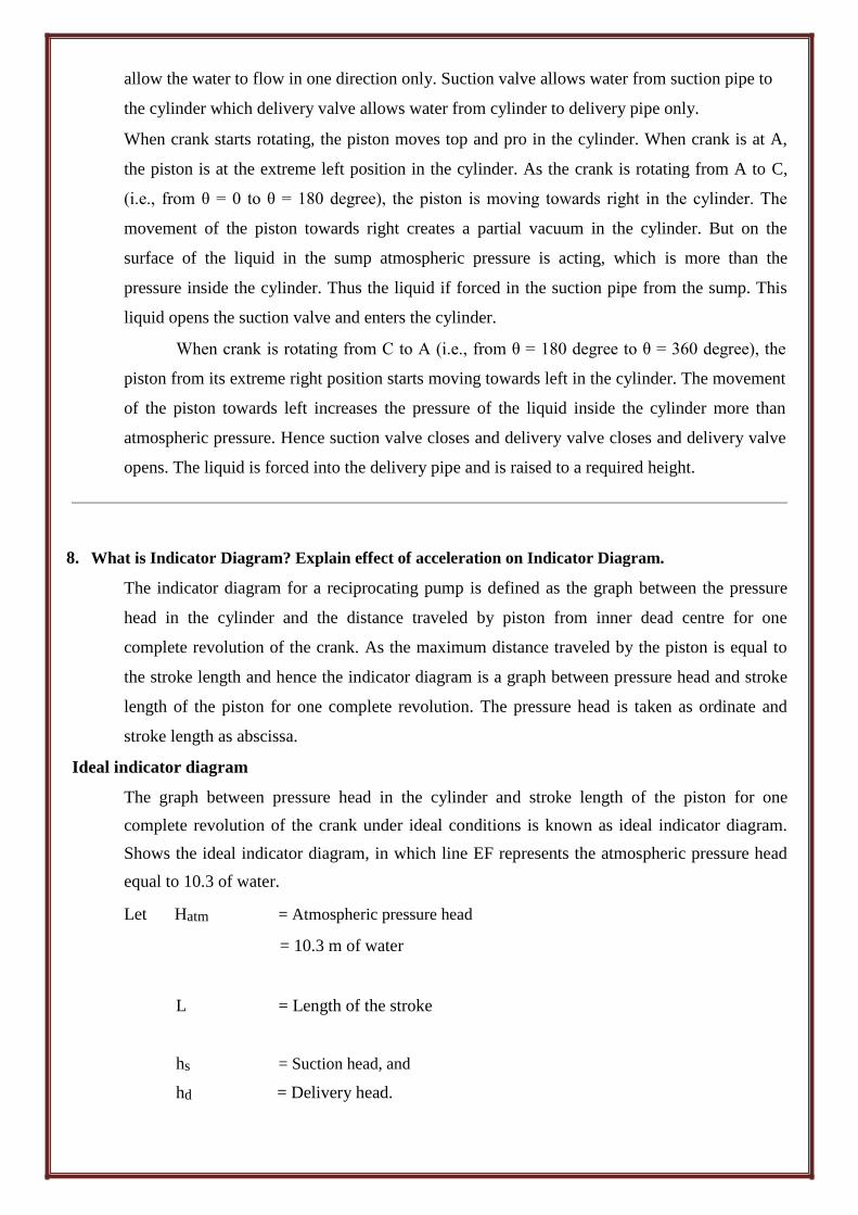
stroke length as abscissa. Ideal indicator diagram
The graph between pressure head in the cylinder and stroke length of the piston for one
complete revolution of the crank under ideal conditions is known as ideal indicator diagram.
Shows the ideal indicator diagram, in which line EF represents the atmospheric pressure head
equal to 10.3 of water.
Let Hatm = Atmospheric pressure head
= 10.3 m of water
L = Length of the stroke
hs = Suction head, and
hd = Delivery head.
During suction stroke, the pressure head in the cylinder is constant and equal to suction (hs),
which is below the atmospheric pressure head (Hatm) by a height of hs.
The pressure head during suction stroke is represented by a horizontal line AB which is below
the line EF by a height of „hs‟.
During delivery stroke, the pressure head in the cylinder is constant and equal to delivery head
(hd), which is above the atmospheric head by a height of (hd). Thus, the pressure head during
delivery stroke is represented by a horizontal line CD which is above the line EF by a height of
hd. thus, for one complete revolution of the crank, the pressure head in the cylinder is
represented by the diagram A – B – C – D.
Now, we know that the done by the pump per second
= p × g × ALN / 60 × (hs + hd)
= K × L (hs + hd)
[where K = pgAN / 60 = Constant]
W.D ∞ L × (hs + hd) … (i)
But from figure, area of indicator diagram
= AB × BC = AB × (BF + FC) = L × (hs + hd)
Substituting this value in equation (i), we get
Work done by pump ∞ Area of indicator diagram
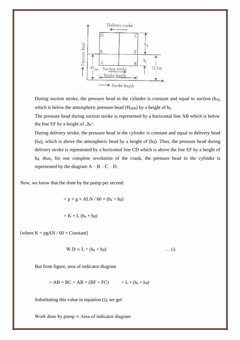
Effect of acceleration in suction and delivery pipes on indicator diagram
The pressure head due to acceleration in the suction pipe is given by
has = 1s / g × A / as ω2rcosθ
When θ = 0˚. Cosθ = 1, and has = 1s / g × A / as ω2r
When θ = 90˚, cosθ = 0, and has = 0
When θ = 180˚, cosθ = -1 and has = - 1s / g × A / as ω2r
Thus, the pressure head inside the cylinder during suction stroke will not be equal to „hs‟ as
was the case for ideal indicator diagram, but it will be equal to the sum of „hs‟ and „has‟. As
the beginning of suction stroke θ = 0˚, „has‟ is + ve and hence the pressure head in the cylinder
will be (hs + hd) below the atmospheric pressure head. At the middle of suction stroke θ = 90˚
and has = 0 and hence pressure head in the cylinder will be hs below the atmospheric pressure
head. All the end of suction stroke, θ = 180˚ and has is –ve and hence the pressure head in the
cylinder will be (hs - hd) below the atmospheric pressure head. For suction stroke, the indicator
diagram will be shown by A „GB‟. Also the area of A‟ AG = Area of BGB‟.
Similarly, the indicator diagram for the delivery stroke can be drawn. At the beginning of
delivery stroke, had is + ve and hence the pressure head in the cylinder will be (hd + had) above
the atmospheric pressure head. At the middle of the delivery stroke, had = 0 and hence pressure
head in the cylinder is equal hd above the atmospheric pressure head. At the end of the delivery
stroke, hd is –ve and hence pressure in the cylinder will be (hd + had) above the atmospheric
pressure head. And thus the indicator diagram for delivery stroke is represented by the line
C‟HD‟. Also the area of CC‟H = Area of DD‟H.
From figure, it is now clear that due to acceleration is suction and delivery pipe, the indicator
diagram has changed from ABCD to A‟B‟C‟D‟. But the area of indicator diagram ABCD =
Area A‟B‟C‟D‟. Now from equation (s.22), work done, by pump is proportional to the area of
indicator diagram. Hence the work has done by the pump on the water remains same.
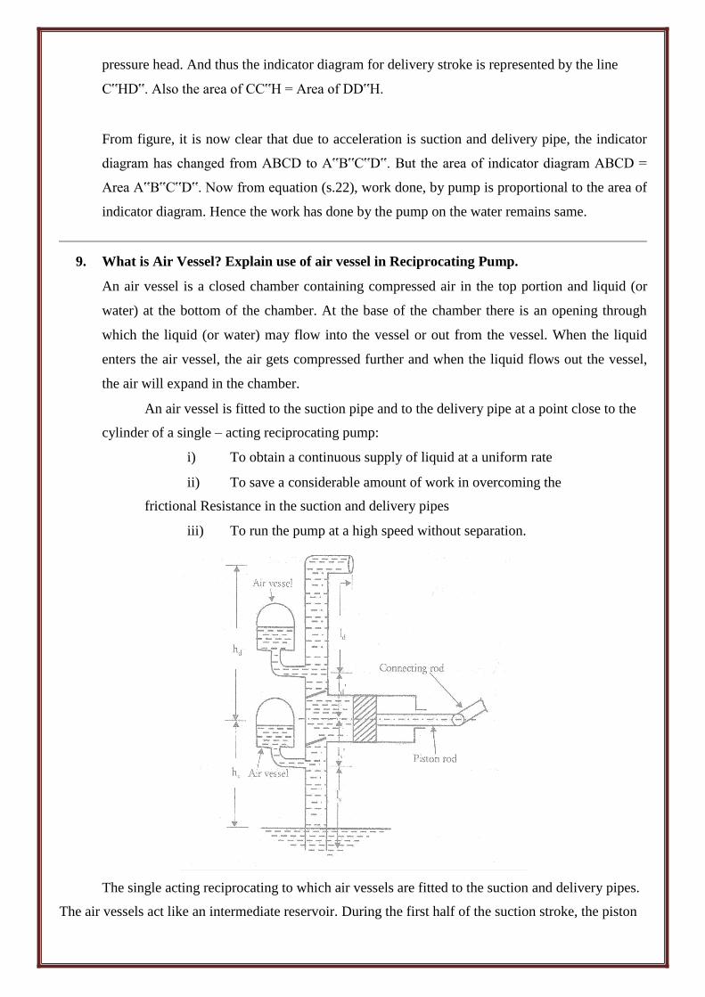
9. What is Air Vessel? Explain use of air vessel in Reciprocating Pump.
An air vessel is a closed chamber containing compressed air in the top portion and liquid (or
water) at the bottom of the chamber. At the base of the chamber there is an opening through
which the liquid (or water) may flow into the vessel or out from the vessel. When the liquid
enters the air vessel, the air gets compressed further and when the liquid flows out the vessel,
the air will expand in the chamber.
An air vessel is fitted to the suction pipe and to the delivery pipe at a point close to the
cylinder of a single – acting reciprocating pump:
i) To obtain a continuous supply of liquid at a uniform rate
ii) To save a considerable amount of work in overcoming the
frictional Resistance in the suction and delivery pipes
iii) To run the pump at a high speed without separation.
The single acting reciprocating to which air vessels are fitted to the suction and delivery pipes.
The air vessels act like an intermediate reservoir. During the first half of the suction stroke, the piston
moves with acceleration, which means the velocity of water in the suction pipe is more than the mean
velocity and hence the discharge of water entering the cylinder will be more than the mean discharge.
This excess quantity of water will be supplied from the air vessel to the cylinder in such a way that the
velocity in the suction pipe below the air vessel is equal to mean velocity of flow.
During the second half of the suction pipe is less than the mean velocity of flow. Thus the
discharge entering the cylinder will be less than the mean discharge. The velocity of water in the
suction pipe due to air vessel is equal to mean velocity of flow and discharge required in cylinder is
less than the mean discharge. Thus the excess water flowing in suction pipe will be stored in to air
vessel, which will be supplied during the first half of the next suction stroke.
When the air vessel if fitted to the delivery pipe, during the first half of delivery stroke the
piston moves with acceleration and forces the water into the delivery pipe with a velocity more than
the mean velocity. The quantity of water in excess of the mean discharge will flow into the air vessel.
This will compress the air inside the vessel. During the second half of the delivery stroke, the piston
moves with retardation and the velocity of water in the delivery pipe will be less than the mean
velocity. The water already stored into the air vessel will start flowing into the delivery pipe and the
velocity of flow in the delivery pipe beyond the point to which air vessel is fitted will become equal to
the mean velocity. Hence the rate of flow of water in the delivery pipe will be uniform.
10. Explain the types of gear pump with neat sketch?
GEAR PUMPS
• A Gear pump uses the meshing of gears to pump the fluid by displacement.
• The gear pump is a rotary pump in which two gears mesh to provide the pumping action.
• The flow of liquid to be pumped is continuous and uniform.
TYPES OF GEAR PUMPS:
i. External Gear Pump
ii. Internal Gear Pump
EXTERNAL GEAR PUMP
• External Gear pumps are a popular pumping principle and are often used as lubrication pumps
in machine tools, in fluid power transfer units, and as oil pumps in engines.
• Large- capacity external gear pumps typically use helical or herringbone gears.
• Small external gear pumps usually operate at 1750 to 3450 rpm and larger modes operate at
speeds up to 640 rpm.
• External gear pumps have close tolerances and shaft support on both sides of the gears.
• Because of this, external gear pumps are popular for precise transfer and metering
applications involving polymers, fuels, and chemical additives.
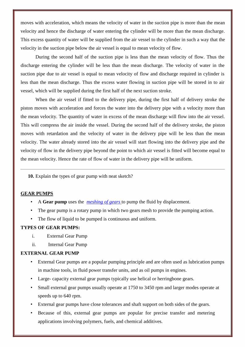
EXTERNAL GEAR PUMPS WORKING
• In External gear pump two gears come into and out of mesh to produce flow.
• The external gear pump uses two identical gears rotating against each other. One gear is
driven by a motor and it in turn drives the other gear.
• Liquid travels around the interior of the casing in the pockets between the teeth and the
casing.
• Liquid flows into the cavity and is trapped by the gear teeth as they rotate.
• Finally, gears forces liquid through the outlet port under pressure
•
ADVANTAGES:
1. High speed
2. High pressure
3. No overhung bearing loads
4. Relatively quiet operation
5. Design accommodates wide variety of materials. 6.
DISADVANTAGES:
1. Four bushings in liquid area
2. No solids allowed
3. Fixed End Clearances
APPLICATIONS:
1. Various fuel oils and lube oils
2. Chemical additive and polymer metering
3. Industrial and mobile hydraulic applications (log splitters, lifts, etc.)
4. Acids and caustic(Stainless Steel)
5. Low volume transfer or application.
INTERNAL GEAR PUMPS
Internal gear pumps which use an external and an internal spur gear.
Gear pumps are positive displacement (or fixed displacement), meaning they pump a constant
amount of fluid for each revolution.
Some gear pumps are designed to function as either a motor or a pump.
The useful viscosity range of an internal gear pump is from 1cPs to over 1,00,000 Cps
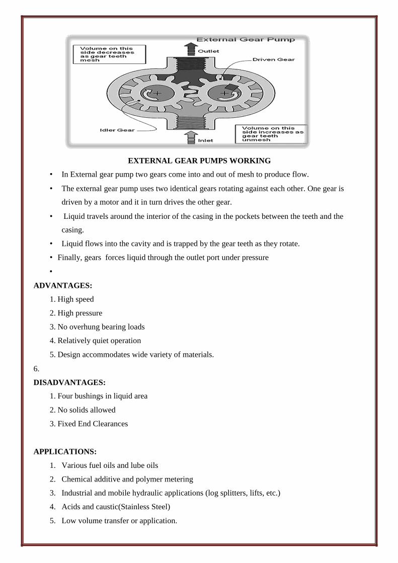
INTERNAL GEAR PUMP WORKING
1. Liquid enters the suction port between the rotor(large exterior gear) and idler(small interior
gear) teeth. The arrows indicate the direction of the pump and liquid.
2. Liquid travels through the pump between the teeth of the “gear-within-a-gear” principle.
The crescent shape divides the liquid and acts as a seal between the liquid and acts as a seal
between the suction and discharge ports.
3. The pump head is now nearly flooded, just prior to forcing the liquid out of the discharge port.
Intermeshing gears of the idler and rotor form locked pockets for the liquid which assures
volume control.
4. Rotor and idler teeth mesh completely to form a seal equidistant from the discharge and
suction ports. This seal forces the liquid out of the discharge port.
5. ADVANTAGES:
1. Only two moving parts
2. Only one stuffing box
3. Non – pulsating discharge
4. Excellent for high viscosity liquids
5. Constant and even discharge regardless of pressure conditions.
DISADVANTAGES:
1. Usually requires moderate speeds
2. Medium pressure limitations
3. One bearing runs in the product pumped
4. Overhung load on shaft bearing.
APPLICATION:
1. All varieties of fuel oil and lube oil
2. Resins and Polymers
3. Alcohols and solvents
4. Asphalt, Bitumen and Tar.
Gear pumps are generally used for:
1. PETROCHEMICALS: Pure or filled bitumen, pitch, diesel oil, crude oil, lube oil, etc.
2. CHEMICALS: Sodium silicate, acids, plastics, mixed chemicals, isocyanides, etc.
3. PAINT & INK.
4. RESINS & ADHESIVES
5. PUPL & PAPER: Acid, soap, lye, black liquor, kaolin, lime, latex, sludge, etc.
6. FOOD: Chocolates, fillers, sugar, vegetable fats and oils, molasses, animal food, etc.
UNIT – II
FLUID MACHINERY
Two marks question and answers:
1. What is the basis of classification of turbines?
The turbines are classified according to the following basis,
a) According to the action of the water flowing.
b) According to the main direction of flow of water.
c) According to head and quantity of water required.
d) According to the specific speed.
2. Classify the different types of turbine.
Action of the water flowing: Head and quantity basis:
a. Impulse turbine. i) High head turbine.
b. Reaction turbine. ii) Medium head turbine
Main direction of water flow: iii) Low head turbine.
i) Tangential flow turbine. Specific speed basis:
ii) Radial flow turbine. i) Low specific speed.
iii) Axial flow turbine. ii) Medium specific speed.
iv) Mixed flow turbine. iii) High specific speed.
3. Give an example for a low head turbine, a medium head turbine and a high head turbine
a. High head turbine (above 250m). e.g. Pelton
b. Medium head turbine (60m to 250m). e.g. Modern Francis turbine.
c. Low head turbine (less than 60m). e.g. Kaplan turbine. 4. What is impulse turbine? Given an example?
In impulse turbines, all the energies are converted into kinetic energy. From these, the turbine will
develop high kinetic energy power. This turbine is called impulse turbine. 5. What are reaction turbines? Give examples.
In a reaction turbine, the runner utilizes both potential and kinetic energies.
Here, portion of potential energy is converted in to kinetic energy before entering in to the turbine.
Example: Francis and Kaplan turbine.
6. What is Radial flow turbine?
In the turbine, water flows along the radial direction and mainly in the plane normal to the axis of
the rotation as it passes through the runner. It may be either inward radial flow type or outward
radial flow type. 7. What is axial flow turbine? Give an example.
In axial flow turbines, water flows parallel to the axis of the turbine shaft.
Example: Kaplan turbine, propeller turbine.
8. What is mixed flow turbine?
In mixed flow turbines, water enters the blades radially and comes out axially, parallel to the
turbine shaft.
Example: Modern Francis turbine.
9. What are the main parts of pelton wheel?
Pelton wheel consists of the following main parts
1. Penstock.
2. Spear and nozzle.
3. Runner with buckets.
4. Break nozzle.
5. Outer casing.
6. Governing mechanism. 10. What is the function of governing mechanism in pelton wheel?
Governing mechanism is used to regulate the water flow to the turbine at constant level so that
the speed of the turbine kept constant. This automatically regulates the quantity of water flowing
through the runner in accordance with any variation of load.
11. Explain the gross head and effective or net
head. Gross head:
The gross head is the difference between the water level at the reservoir and the level at
the tailstock.
Effective head:
It is the head available at the inlet of the turbine.
12. Define hydraulic efficiency.
It is defined as the ratio of power developed by the runner to the power supplied by te water jet.
Powerdevelopedbyther unnerh
Power sup pliedbythe waterjet
13. Define Mechanical efficiency.
It is defined as the ratio of the power available at the turbine shaft to the power developed by the
turbine runner.
h
Poweravailablethetur bineshaft
Powerdevelopedbythet urbinerunner
ShaftPower
WaterPower
14. Define volumetric efficiency.
It is defined as the volume of water actually striking the buckets to the total water supplied by
the jet.
v Qa Q q
Q Q
vliesbetween0.97to0.99.
15. Define overall efficiency.
It is defined as the ratio of power available at the turbine shaft to the power available from the
water jet.
ShaftPower Po
WaterPower wQH 16. What is draft tube and explain its function?
After passing through the runner, the water is discharged to the tailrace through a gradually
expanding tube called draft tube.
The pressure at the exit of the runner of a reaction turbine is generally less than atmospheric
pressure. By passing reduced through draft tube, the outer velocity of water is reduced and gain in
useful pressure head is achieved to increase the output of turbine.
17. What are the significant of unit quantities and specific quantities?
1. To predict the behavior of a turbine working under different conditions.
2. Make comparison between the performances of turbine of same types of different sizes.
18. Define the specific speed of a turbine.
Specific speed is the speed of a geometrically similar turbine (i.e., a turbine identical in
shape, dimensions, blade angles and gate opening etc), which will develop unit power when
working under unit head. 19 . Classify pumps on the basis of transfer of mechanical energy.
i) Single stage centrifugal pumps.
ii) Multi-stage centrifugal pumps 20. List out the various components of a centrifugal
pump. a) Impeller
b) Casing
c) Suction pipe, strainer and foot valve
d) Delivery pipe and delivery valve
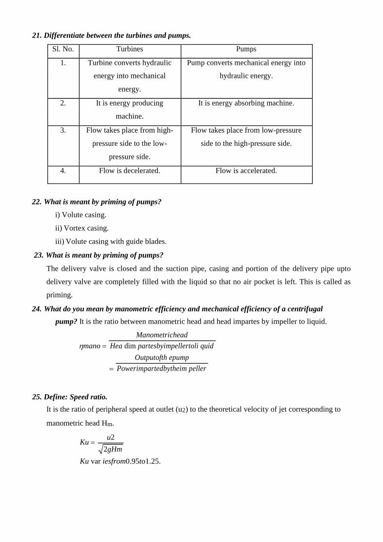
21. Differentiate between the turbines and pumps.
Sl. No. Turbines Pumps
1. Turbine converts hydraulic Pump converts mechanical energy into
energy into mechanical hydraulic energy.
energy.
2. It is energy producing It is energy absorbing machine.
machine.
3. Flow takes place from high- Flow takes place from low-pressure
pressure side to the low- side to the high-pressure side.
pressure side.
4. Flow is decelerated. Flow is accelerated.
22. What is meant by priming of pumps?
i) Volute casing.
ii) Vortex casing.
iii) Volute casing with guide blades. 23. What is meant by priming of pumps?
The delivery valve is closed and the suction pipe, casing and portion of the delivery pipe upto
delivery valve are completely filled with the liquid so that no air pocket is left. This is called as
priming.
24. What do you mean by manometric efficiency and mechanical efficiency of a centrifugal
pump? It is the ratio between manometric head and head impartes by impeller to liquid.
mano
Manometrichead
Hea dim partesbyimpellertoli quid
Outputofth epump
Powerimpartedbytheim peller
25. Define: Speed ratio.
It is the ratio of peripheral speed at outlet (u2) to the theoretical velocity of jet corresponding to
manometric head Hm.
Ku u2
2gHm
Ku var iesfrom0.95to1.25.