unit iii classification of printing...
TRANSCRIPT

Printing Processes Classification of Printing Machines
27
Unit III
CLASSIFICATION OF PRINTING MACHINES 3.1. CLASSIFICATION AND TYPES OF OFFSET MACHINES
An offset lithographic press is a mechanical device that dampens and inks the printing plate and transfers the inked image to the blanket and then to the printing substrate.
A sheetfed offset lithographic press is a printing press that feeds and prints on individual sheets of paper (or other substrate) using the offset lithographic printing method.
A web, or webfed offset lithographic press is a press that prints on a continuous web, of paper fed from a roll and threaded through the press.
A modern sheetfed press reaches speeds of 10,000‐12,000 impressions per hour (i.p.h.), whereas a web press reaches speeds three or four times greater. Both types of presses are increasingly being controlled from remote consoles, from which the operator can adjust inking, dampening, and circumferential and lateral register; control ink density; and monitor dot gain.
Sheetfed Presses Web Presses
Substrates ‐ Paper, Foil, Film, Thin Metal Substrates ‐ Mostly Paper
Ink Vehicle Class Oxidative ‐ Neutral or synthetic drying oils.
Ink Vehicle Class Oxidative ‐ Drying oil varnish
Penetrating ‐ Soluble resins, hydrocarbon oils & solvents, drying and semidrying oils
and varnishes.
Penetrating ‐ Hydrocarbons, oils & solvents, soluble resins, drying oil
varnishes, and plasticizers.
Quickset ‐ Hard soluble resin, hydrocarbon oils and solvents, minimal drying oils and
plasticizers.
UV Curing ‐ Highly reactive, cross‐linking proprietary systems that dry by UV
radiation.

Printing Processes Classification of Printing Machines
28
UV Curing ‐ Highly reactive, cross‐linking proprietary systems that dry by UV (ultra
violet) radiation.
Thermal Curing ‐ Dry by application of heat and use of special cross linking catalysts.
Gloss ‐ Drying oils, very hard resins, minimal hydrocarbon solvents.
SHEETFED OFFSET PRINTING PRESS:
A sheetfed press consists of a feeder, one or more printing units, transfer devices to move the paper through the press, a delivery, and various auxiliary devices (such as a control console).
The printing unit of a sheetfed offset lithographic press generally consists of three primary cylinders and systems for dampening and inking the plate:
1. Plate cylinder, a cylinder that carries the printing plate, flexible image carrier with ink‐receptive image areas and, when moistened with a water‐based solution, ink‐repellent nonimage areas.
2. Blanket cylinder, a cylinder that carries the offset blanket a fabric coated with synthetic rubber that transfers the image from the printing plate to the substrate.
3. Impression cylinder, a cylinder running in contact with the blanket cylinder that transports the paper or other substrate.
4. Dampening system, a series of rollers that dampen the printing plate with a water‐based dampening solution that contains additives such as acid, gum arabic, and isopropyl alcohol or other wetting agents.
5. Inking system, a series of rollers that apply a metered film of ink to a printing plate.

Printing Processes Classification of Printing Machines
29
In addition to one or more printing units, a press also includes the following:
1. Feeder, which lifts and forwards the sheets of paper or other substrate from a pile to the first printing unit.
2. Transfer devices (often auxiliary cylinders with sheet grippers), which facilitate sheet transport through the press.
3. Delivery, which receives and stacks the printed sheet.
UNITS OF SHEET ‐ FED OFFSET PRINTING MACHINES
There are five main units present in Sheet‐fed offset printing machines :
1. Feeding unit
2. Inking unit
3. Dampening unit
4. Printing unit
5. Delivery unit
1. FEEDING UNIT :
Feeder section, where paper is removed from the top of a pile table, forwarded on a feed board to front stops, laterally positioned on the feed board, and fed into the first printing unit. Feeder section can be divided into two categories, (I). Single‐sheet feeder, (ii) Stream feeder.
Sheet handling :
Proper adjustment and timing of all sheet handling elements must be maintained. Poor sheet control can necessitate frequent press stops. Plate problems can stem from press down‐ time, and getting the press back into balance can result in paper waste.
a. Feeder section, where paper is removed from the top of a pile table, forwarded on a feed board to front stops, laterally positioned on the feed board, and fed into the first printing unit.
b. Infeed section, where the sheet is transferred from the registering devices of the feed board to the first impression cylinder of the printing press.
c. Sheet transfer section, where the sheet is moved between impression cylinders of a multicolor press.

Printing Processes Classification of Printing Machines
30
d. Delivery section, where printed sheets are jogged and stocked one on top of another.
Single‐ sheet feeder where only one sheet of paper (traveling at press speed) is on the feed board at any instant.
Stream feeder where a number of sheets of paper traveling slower than press speed overlap on the feed board. The stream feeder, being more widely used, is discussed first. However, much of the information pertaining to “the stream feeder” is also applicable to the single sheet feeder.
Stream sheet feeder parts:
1. Lifting suckers
2. Blowers
3. Slow down foot or Pile height
4. Combers
5. Flip spring
6. Side gauge
7. Back gauge
8. Forwarding suckers.
a) Lifting suckers :
Air‐blast nozzles force air beneath the top five or six sheets of the pile. Rear pickup suckers then lift the top sheet. The feeder pressure foot drops down on to the pile, where it steadies the top sheets of the pile while the air‐blast nozzles below a cusion of air beneath the lifted sheet.
b) Forwarding suckers :
This suckers transferred the sheet to the forwarding rollers (On smaller presses a single set of suckers is used to pick up and forward the sheet). While this is happening, the rear pickup suckers are already lifting another sheet of the top of the pile.
c) Pile height :
A critical factor for trouble‐free sheet feeding is correct pile height, which is usually 3/ 16 inch (5 mm) below the forwarding flaps, at the front of the pile. If the pile height is not correct, the sheet separation unit may not be able to separate the topmost sheet from the pile, or it may feed two (or) more sheets to the feed board.
d) Flip spring :
It is a thin blade position in linewise. It is used to control more than one sheet. Low pressure is applied in flip spring.
e) Combers :
It is a brush. Separator brushes or fingers prevent the suckers from picking up more than one sheet at a time.

Printing Processes Classification of Printing Machines
31
f) Side gauge :
It is used for forwarding the paper in correct direction. It is not fit in closely paper set between even with 1 mm difference.
g) Blowers
Separate the paper in pressed air by combined paper.
2. INKING UNIT:
Inking system, a series of rollers that apply a metered film of ink to a printing plate. In addition to one or more printing units, a press also includes the following,
• Ink fountain ‐ a pan that contains the ink supply
• Ductor or ductor roller ‐ a transfer roller that alternately contacts the ink fountain roller and the first roller of the ink train, often an oscillating drum
INKING SYSTEM
• Oscillating drums, oscillators ‐ driven rollers that not only rotate but oscillate from side to side, distributing and smoothing out the ink film and erasing image patterns from the form rollers.
• Intermediate rollers ‐ friction or gravity driven rollers between the ductor and form roller that transfer and condition the ink; often called distributor rollers if they contact two rollersm, and rider rollers if they contact a single oscillating drum.
• Form rollers ‐ a series of three to five rollers that contact the printing plate and transfer ink to the cylinder.

Printing Processes Classification of Printing Machines
32
As the fountain roller turns, the majority of the ink in the fountain is held back by the fountain blade, which is set very close to the fountain roller. The distance between the blade and the roller is adjusted by the means of fountain keys, a series of thumb screws or motor ‐driven screws or cams behind the blade. This adjustment varies the ink feed across the press according to the demands of the plate.
3) DAMPENING SYSTEM :
This is a system with a series of rollers that dampen the printing plate with a water based dampening solution that contains additives such as acid, gum arabic, and isopropyl alcohol or other wetting agents. Dampening system used for sheet‐fed offset lithography are classified into two categories ‐ the intermittent‐flow (ductor or conventional) and continuous flow. The intermittent‐flow dampening system, usually referred to as a conventional dampening system, consist of the following:
• Water pan, or fountain which holds the dampening solution to be fed to the plate.
• Fountain pan roller which rotates in the fountain and carries dampening solution on its metal surface.
• Ductor roller which intermittently contacts the fountain roller and an oscillator roller, transferring the Dampening solutions.
• Oscillator roller which oscillates from side to side to even out dampening across the press.
• Form roller which transfers dampening solution from the oscillator roller to the printing plate.
4) PRINTING UNIT :
The printing unit of a sheet fed offset lithographic press generally consists of a three primary cylinders and systems for dampening and inking the plate. The three primary cylin‐ders are
a) Plate cylinder,
b) Blanket cylinder,
c) Impression cylinder
As in detail,

Printing Processes Classification of Printing Machines
33
A) PLATE CYLINDER :
An aluminium, or bimetal plate is mounted over this cylinder. The plate causes the image to be printed. Dampening and inking rollers are set in contact with the plate cylinder. The plate cylinder revolves along with the dampeners and inking rollers. Water layer is applied onto the non‐printing areas of the plate by dampening form rollers. Similarly ink layer is applied onto the printing areas of the plate by inking form rollers.
The plate cylinder, which is usefully the upper most cylinder of the three cylinders, carries the printing plate.
The plate cylinder has four primary functions:
Plate Cylinder
• To hold the lithographic printing plate tightly and in register.
• To carry the plate into contact with the dampening rollers that wet the non‐image area.
• To bring the plate into contact with the inking rollers that ink the image area.
• To transfer the inked image to the blanket carried by the blanket cylinder.
Bearer, at each end of the plate cylinder bearer, a hardened metal ring attached to the cylinder body or journal. On many presses, the bearers of the plate cylinder run in contact with the bearers of the blanket cylinder during printing.
Undercut, the body of the plate cylinder is smaller in diameter than the bearers. The difference between the radius of the body surface and that of the bearers is called the undercut. A plate clamp is a device designed to first grip to edge of the plate and then pull it tight against the cylinder body. Gutter, narrow gap between body of the plate cylinder and the bearers is called gutter.
Gears :
The plate cylinder is driven by this gear, which is, in turn, driven by a similar gear on the blanket cylinder. The cylinder gear may be spur (on older presses) or helical. A spur gear has teeth cut straight across the gear, and a helical gear has teeth cut at an angle. A spur gear used as a plate cylinder gear

Printing Processes Classification of Printing Machines
34
nearly always has a backlash gear, a thin second gear bolted to it to reduce play‐ free or unimpeded movement between gears.
BLANKET CYLINDER
This is called second cylinder. The tooth of the gears on both side of the plate cylinder and blanket cylinder mesh and cause both cylinders to rotate together. The ink applied on the image on the plate, gets transferred to the blanket(rubber) cylinder because the ink has the ability to get printed on rubber (blanket) surface. The image printed on blanket cylinder becomes opposite (indirect) to the plate cylinder.
The blanket cylinder has two primary functions:
• To carry the offset rubber blanket into contact with the inked image on the plate cylinder.
• To transfer, or offset, the ink film image to the paper (or other substrate) carried by the impression cylinder.
It is very similar to the plate cylinder because it has a gap, gutters, bearers, a gear, and bearings. However, it does not have clamps like a plate cylinder does. Instead, It has one or two reels for holding and stretching the blanket tighter. With some presses, the blanket ends are attached to bars, which, in turn, are mounted to reels.
The position of the blanket cylinder in relation to the other cylinder must be adjustable for two reasons: to bring it in and out of contact with them, and to compensate for variations in substrate and packing thicknesses. The distance between the blanket cylinder and the impression cylinder must also be adjusted to accommodate different thicknesses of substrate, and blanket packing. This distance is adjusted by another pair of eccentric bushings. Adjusting the position of the blanket cylinder related to the impression cylinder does not affected the relationship between plate and blanket cylinders.
IMPRESSION CYLINDER :
Impression cylinder carries the paper into the printing unit, and contact pressure from blanket cylinder transfers the print to the paper. Impression cylinder too has a gear and gap. The gap accommodates the gripper shaft on which are mounted the gripper fingers that hold the sheet during

Printing Processes Classification of Printing Machines
35
printing. The grippers hold the unprinted paper in register as the cylinder turns and presses it against the inked image on the blanket cylinder.
The body of the impression cylinder is not undercut but is approximately the diameters of the bearers of the other two cylinders. The impression cylinder bearers are, in fact, undercut and are used only as paralleling devices when setting up the press.
There are two basic mechanical designs for varying the clearance between the blanket and impression cylinder to accommodate different thicknesses of stock.
• In the first design, the impression cylinder is mounted on a set of eccentrics. A shift of the eccentrics by an impression lever moves the impression cylinders toward or away from the blanket cylinder.
• The second method uses two sets of eccentrics, but these are on the blanket cylinder. The inner set adjusts the blanket ‐ to ‐ plate bearer pressure and actuates automatic on ‐ and – off printing contact. The outer set moves the blanket cylinder only in relation to the impression cylinder.
5) DELIVERY UNIT :
The delivery section begins as the sheet leaves the final impression cylinder. Delivery grippers take the printed sheet from impression cylinder grippers and transport it to the delivery pile (or) table. The grippers typically travel on gripper bars.

Printing Processes Classification of Printing Machines
36
Delivery section is the section where printed sheets are jogged and stacked one on top of another. The first portion of the sheet control system that the press operator is concerned with is the feeder section.
The following parts are included in delivery unit
a) Sheet decurler
b) Skeleton wheels
c) Suction slow‐down rollers
d) Side joggers
e) Front guide
f) Wedge
a) Sheet decurler :
Often located between the last press unit and the delivery is a sheet decurler, a device that is designed to take troublesome curl out of press sheets.
b) Skeleton wheels :
Skeleton wheels are movable wheels that are positioned in non‐printing areas of the press sheet. Properly positioned skeleton wheels evenly support and help to peel the sheet from the last impression cylinder.
c) Slow down rollers :
Suction rollers slow down and steady the sheet as it enter the delivery. They are usually positioned just behind the rear sheet guide and beneath the chain delivery.
d) Blowdown :
Near the top of the delivery are the blow downs, a series of air holes that assist in dropping the sheet on to the delivery table. Air is blown on the top side of the sheet, forcing it downwards.
e) Wedges :
Wooden or plastic wedges are used at starting to produce a neat pile. By holing up the rear (trailing or tail) edge of the sheet, wedges help to counter tail end hook (a sharp curl at the back edge of the sheet) edges can cause marking. Therefore, they must be carefully used.
f) Side joggers :
It is movable device and jog the sheet into a pile, but the neatness of the pile depends on the proper positioning of the devices.
Blankets:
Offset press blankets are made of supporting fabric and a rubber composite. Various rubber materials are used for the transfer of the image from the plate to the blanket. Blankets come in compressible to hard finishes along with smooth to rough surfaces. The majority of printers today use compressible type blankets. These blankets give good compression which eliminates many smashed

Printing Processes Classification of Printing Machines
37
blankets. Slightly rough blankets are also preferred as they have less contact with the paper surface thus reducing blanket contamination.
Types of Blankets:
The blankets are classified into two types.
1. Conventional (or) Non‐compressible blankets
2. Compressible blankets
These two types are classified according to the behavior during squeezing action of printing nips.
1. Conventional blanket (or) Non‐compressible blankets:
These blankets are used in olden days. These blankets do not have compressible nature because these blankets only have fabrics at its underside. The conventional blanket is squeezed in a nip, it bulges either in one (or) both sides of the nip. Due to this formation of bulge the problem like slurring may be caused. These blankets are used for printing line works, solid tints etc. The disadvantage of these blankets is
that these are not use for fine halftone woks.
2. Compressible blankets:
These blankets are nowadays used in offset printing machines. These blankets consist of compressible layer along with the fabrics layer in its underside. Due to this while printing when the compressible blanket is squeeze in a nip. These blanket bulges very low, which does not, affects the printing quality. These blankets are used for printing any type of solid works, fine halftone works.
Various offset printing machine Configurations:
A variety of sheetfed printing presses are available. These presses can best be classified according to their offset press cylinder configurations (arrangements), although the placement of the feeder and delivery are also important considerations in the design of a press. For sheetfed printing, the printing unit cylinders are arranged in three basic ways.
• Single‐colour sheetfed press, in which there is one set of printing cylinders arranged to print only one color on one side of each sheet as it passes through the press.
• Multicolor sheetfed press, in which more than one color is printed on one side of a sheet during a single pass through the press because there is more than one printing unit .
Printing Processes Classification of Printing Machines
38
• Perfecting sheetfed press, in which sheets are printed on both sides during one pass through the press.
I. Single Color Sheetfed Offset Press:
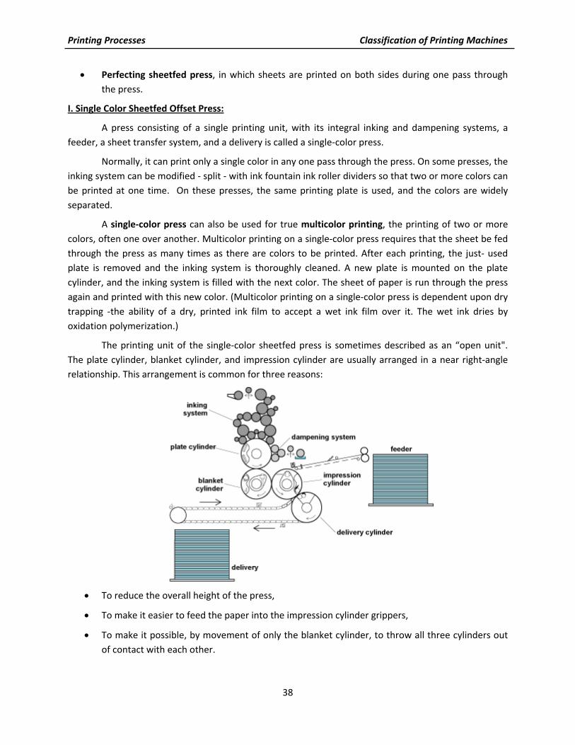
A press consisting of a single printing unit, with its integral inking and dampening systems, a feeder, a sheet transfer system, and a delivery is called a single‐color press.
Normally, it can print only a single color in any one pass through the press. On some presses, the inking system can be modified ‐ split ‐ with ink fountain ink roller dividers so that two or more colors can be printed at one time. On these presses, the same printing plate is used, and the colors are widely separated.
A single‐color press can also be used for true multicolor printing, the printing of two or more colors, often one over another. Multicolor printing on a single‐color press requires that the sheet be fed through the press as many times as there are colors to be printed. After each printing, the just‐ used plate is removed and the inking system is thoroughly cleaned. A new plate is mounted on the plate cylinder, and the inking system is filled with the next color. The sheet of paper is run through the press again and printed with this new color. (Multicolor printing on a single‐color press is dependent upon dry trapping ‐the ability of a dry, printed ink film to accept a wet ink film over it. The wet ink dries by oxidation polymerization.)
The printing unit of the single‐color sheetfed press is sometimes described as an “open unit". The plate cylinder, blanket cylinder, and impression cylinder are usually arranged in a near right‐angle relationship. This arrangement is common for three reasons:
• To reduce the overall height of the press,
• To make it easier to feed the paper into the impression cylinder grippers,
• To make it possible, by movement of only the blanket cylinder, to throw all three cylinders out of contact with each other.

Printing Processes Classification of Printing Machines
39
There are exceptions to this nearly right‐angle (L‐shaped) arrangement of cylinders. With one type of metal decorating press, the cylinders are stacked directly above each other so that the rigid metal sheets can pass through the printing nip (the line of contact between the blanket and impression cylinders) without being bent around the impression cylinder. Another exception is a press that has a single, oversized cylinder that is used as both the plate and impression cylinder. Yet another exception is a press that has a single oversized cylinder functioning as the impression cylinder for two printing units.
II. Multicolor Sheetfed Press:
A press consisting of several printing units (each with its own inking and dampening system), a feeder, a sheet transfer system, and a delivery is called a multicolor, or multiunit press. A multicolor press can have two, three, four, five, six, or more printing units. Multicolor presses are capable of wet trapping, the ability of a wet, printed ink film to accept another wet ink film printed over it.
In the larger press sizes, the printing units are almost identical and are arranged in tandem. With some of the other two‐and four‐color presses, one printing unit may be higher than the other to obtain better accessibility.
Schematic diagram of a multicolor sheet‐fed press
When placed in tandem, the open‐unit type of single‐color sheetfed press becomes a multicolor press, capable of printing a different color on each unit. One or more transfer cylinders are placed between units to transport the sheet from one printing unit to the next. Some presses have three transfer cylinders between units, while other presses have a single, double‐size transfer cylinder. An odd number of transfer cylinders is needed between units so that the side of the sheet to be printed faces away from the impression cylinder.
In another multicolour sheetfed press design, sometimes called the “semiopen design,” a single (common) impression cylinder serves two pairs of plate and blanket cylinders. The printed sheet is held by the common impression cylinder and successively brought into contact with each blanket. A press consisting of two semiopen units, then, would be capable of printing four colors on one side of the press sheet in a single pass.
III. Offset Perfecting Press :

Printing Processes Classification of Printing Machines
40
Most sheetfed presses can print on only one side of the sheet in a single pass. For the other side to be printed, the entire paper pile must be turned over and the paper run through the press a second time. There is, however, a type of sheetfed press that can print on both sides of the sheet in a single pass. The printing of at least one color on both sides of a sheet in a single pass
through a press is called perfecting; any press that can do so is called a perfecting press, or perfector.
The most common sheetfed perfecting press is called a convertible perfector. Special transfer cylinders tumble the paper end for end between printing units so that the other side of the sheet is printed by the second unit. This type of press usually has the capability, through transfer cylinder adjustment, to print either two colors on one side of the sheet or one color on each side in a single pass through the press. (Other color combinations are also possible.)
With another type of sheetfed perfecting press, the blankets from two printing units are in contact, with the paper passing between the two blankets. This type of press is called a blanket‐to‐blanket press, because the two blankets are in contact. No
impression cylinder is needed; each blanket acts as the impression cylinder for the other. (Most web offset presses print blanket‐to‐blanket.)
Proofing Press:
A proof press is a printing machine used for making a proof, a trial print from a plate, film negative or film positive to verify correctness and quality. It usually has most of the elements of a production machine, but not the automatic features for sustained production.
The most commonly used proofing presses have a flat bed for holding the plate and paper and a rollable blanket cylinder. The blanket cylinder rolls over both, picking up the image from the inked plate and laying it down on the paper.
In the older types, the plate was dampened and rolled up (inked) by hand. The blanket cylinder rolled on bearers and gear racks. The cylinder was necessarily heavy in order to apply sufficient pressure, and on larger presses, it took two people to roll one. Later, this cylinder was put in a carriage that enabled additional pressure to be put on it, and a gear reduction crank made it easier to roll. Next, the carriage became power‐driven. Still later, automatic dampening and inking systems were installed.
Proof presses are used less and less. Some proofing is done using a press similar to the one used for production, or even the same one. Most proofing is done photomechanically using light‐sensitive

Printing Processes Classification of Printing Machines
41
papers (principally to proof single‐color printing), colored films or photopolymers. This procedure is called off press proofing. There are two basic types of proofs used for multicolor or process‐color proofing:
Single‐sheet proof: Where the printing colors are built up on a base through lamination and toning or other processing.
Overlay, or multiple‐sheet proof: Where pigmented or dyed sheets of plastic are registered to each other and taped or pin‐registered to a base.
Small Offset Press:
Generally, any press smaller than 11 x 17 inch (279 x 432 mm) without bearers is called a small offset press or more often, a duplicator. Duplicators started out as office machines using the offset principle. They are extremely simple, but they have developed into efficient offset presses that fill many printing needs. Many are being used for multicolor work.
The gap between “duplicators” and the more heavily built offset presses is being filled by some new presses. These have the simplicity of the duplicator plus many of the quality features of the larger presses.
WEBFED OFFSET PRESSES
Over the years, several terms have come into common use in web offset pressrooms, some borrowed from sheetfed printing, others used only in web offset work.
Lithography is the printing process by which ink and water transfer an image from a level‐surfaced plate (planography surface) onto another surface. Image and nonimage areas are chemically separated.
Offset describes image transfer from the image carrier to an intermediate surface, then to the paper or other substrate. Offset does not really mean lithography. It is common, however, to interchangeably use the two words.
Web offset is the process by which presses print on continuous webs of paper. This is the basic difference between web and sheetfed presses. Compared to sheetfed presses, web presses have much smaller gaps on the plate and blanket cylinders, which means that ink and water flow much more continuously. Blanket‐to‐blanket offset presses lack a hard impression cylinder, which is inherent in sheetfed press designs.

Printing Processes Classification of Printing Machines
42
Direct lithography is the process of printing directly from a printing plate to a substrate. It is accomplished in web offset by running paper through a blanket‐to‐blanket unit so that the paper contacts one plate and takes ink from it. In this case, the blanket cylinder of the couple acts as an impression cylinder.
The web offset press consisting of several sections. The infeed of the press is where the unprinted rolls of paper are mounted. The delivery is where the final printed material comes out. Going from the infeed to the delivery, the elements of a heatset web offset press are, in order, infeed, printing units (press), dryer, chill rolls, and delivery (either a folder, sheeter, or rewinder). A nonheatset web press does not have a dryer or chill rolls.
A folder delivers folded signatures ready for mailing or for binding with other signatures to form a magazine or book. A sheeter cuts the web and delivers flat, printed sheets. A rewinder, as the name implies, rewinds the printed web back into roll form. A folder produces signatures; a rewinder produces rolls. The bulk of web offset work involves folding and producing signatures.
The ends of the press are referred to as the infeed and delivery. The sides also have specific designations. One side of the press houses the driveshaft and gears that power the press. This side of the press is called the gear side. The crew always works on the other side, because this is where all of the press controls are located. This is the operator side.
Web offset presses are available in a variety of special configurations or arrangements of printing couples within the printing units. A printing couple is an assembly that includes an inking system, a dampening system, a plate cylinder, a blanket cylinder, and an impression cylinder, all of which are required to apply one color of ink to one side of a substrate. If another color is to be printed, the paper has to go through another printing couple.
A printing unit is a single physical structure in which a number of printing couples are mounted. The exact definition of the term, however, depends on the press.
Perfecting is the process by which a sheet or web is printed on both sides during one run through the press or unit. A blanket‐to‐blanket unit is therefore a perfecting unit, while a forms press may or may not be a perfecting press.
DIFFERENT TYPES OF WEB‐OFFSET PRESSES

Printing Processes Classification of Printing Machines
43
There are three classifications of web offset presses in use today,
1. In‐line web‐offset presses :
In‐line describes a press with printing units that consist of a single printing couple: an inking system, a dampening system, a plate cylinder, a blanket cylinder, and an impression cylinder. The printing units on an in‐line press are no perfecting; that is, they can print only one side of the web at a time.
Most business forms are printed on in‐line presses. Such presses are generally small and equipped with auxiliary devices like imprinters, numbering devices, perforators, and punches.
2. Blanket ‐ to ‐ Blanket web‐offset presses
The blanket‐to‐blanket press consists of printing couples that are usually stacked in pairs, one on top of the other. The blanket of one couple is next to the blanket of the other couple and the web runs between them. In other words, these presses have no impression cylinders; the blanket cylinder of the top couple acts as the impression cylinder for the bottom couple, and vice versa. Since these units can print both sides of the web at once, a blanket‐to‐blanket press is perfecting.
On a blanket‐to‐blanket press, the printing units are usually arranged one after the other an arrangement that offers a great deal of flexibility. With four units, one web can be run and four colors printed on each side. Or the press can be set up so that four webs are run and only one color printed per side. Anything in between is possible.

Printing Processes Classification of Printing Machines
44
Blanket‐to‐blanket press units come in two basic configurations. The most common arrangement is horizontal blanket ‐ to ‐ blanket presses, in which the web run through the printing units in a horizontal plane; the printing unit cylinders are therefore stacked vertically, one on top of the other. Vertical blanket‐to‐blanket presses have the web running vertically between blankets with the cylinders laid out horizontally. This arrangement allows or symmetrical design of the printing units and provides easier access to the printing couples.
3. common impression (Satelite) type web‐offset presses
Each printing unit of a common ‐ impression ‐ cylinder (CIC) press has one very large impression cylinder with four or five printing couples radially arranged around it. Because of the arrangement of the couples and the size of the impression cylinder, these presses are also called satellite presses.
The paper wraps around the surface of the impression cylinder. Large size diameter of the impression cylinder is the disadvantage in the design of CIC presses. Their speed, however, is higher than that of blanket ‐ to ‐ blanket presses.
3.2. CLASSIFICATION AND TYPES OF FLEXO MACHINES Flexographic Printing Process:
Flexography is a process in which the printing image stands up in relief. A liquid is used which may be solvent‐based, and dries mainly by solvent evaporation. Water‐based inks are also widely used, and UV‐cured systems are being introduced.
A low printing pressure is essential to the process because of the combination of very fluid inks and soft, flexible printing plates that are used. The process has several distinctive features.
‐ Liquid inks are used that dry rapidly by solvent evaporation, thus enabling fast printing speeds to be achieved on non‐absorbent materials such as films and foils.

Printing Processes Classification of Printing Machines
45
‐ ‘Soft’ and flexible relief printing plates are employed that can be mounted and registered on a plate cylinder and proofs can also be obtained. Individual plates can easily be changed or repaired, and a portion of a plate can be removed to enable items such as price or expiry date to be changed.
‐ The application of ink to the surface of the printing plate is by means of a screened (Anilox) roller. The result is a simple ink feed system that consists of not more than two rollers, or perhaps a single roller and doctor blade (s).
‐ Although most flexographic printing is reel to reel, the machines enable changes in the print repeat length to be made simply.
flexographic printing unit
The printing unit consists of three basic parts
‐ the inking unit;
‐ the plate cylinder;
‐ the impression cylinder.
INKING UNIT :
The function of the inking system is to meter out a fine and controlled film of liquid ink, and apply this to the surface of the printing plate. It typically consists of an ink trough, a rubber‐covered fountain roller, and a screened (Anilox) inking roller into which cells of uniform size and depth are engraved. The fountain roller lifts ink to the nip position, where it is squeezed into the cells in the screened inking roller and by a shearing action is removed from the roller surface. The ink in the cells is then transferred to the surface of

Printing Processes Classification of Printing Machines
46
the printing plates. To regulate ink film thickness in printing, screened ink rollers are available which have screens of from 40 to 200 cells/cm. These may be engraved or etched metal or ceramic. The engraved cells are generally square in shape (although many other shapes are available now) with sloping side walls.
When printing halftones, the cells per centimetre of the anilox roller needs to be about 3.5 times the halftone screen ruling. The number of cells and their size regulate the volume of ink transferred. Further regulation of the ink is achieved by varying the surface speed of the fountain roller, altering the pressure between the fountain roller and screened roller, and also altering the hardness of the rubber covering on the fountain roller. Despite these controllable factors it is still the basic
characteristic of the anilox roller which determines the ink supply to the plate. The anilox roller is a crucial factor in achieving good‐quality flexo printing.
For high‐quality flexographic printing, reverse angle doctoring of the anilox roller has been introduced (Fig.). Steel blades were originally used but have largely given way to nylon, polyester or ultra‐high molecular weight polyethylene (of thickness 0.004‐0.012 in) which give less anilox wear. On some presses an ink chamber formed by a double doctor system is used which has the benefit of providing a totally enclosed inking system (Fig.). Reverse angle doctoring is not speed dependent to the same extent as the other methods, which is a distinct advantage.
PLATE CYLINDER :
The plate cylinder is usually made from steel. The printing plates, which have a thickness of up to a few millimetres are secured to the cylinder with two‐sided self ‐adhesive material.
IMPRESSION CYLINDER :
The impression cylinder is also made from steel. The substrate passes between the plate and impression cylinders, which generate light printing pressure. The ink is transferred from the cells in the screened ink roller to the plate surface, and then to the substrate, during which it reaches virtually a uniform film. For high‐quality flexographic printing the components of the printing unit must be engineered to very tight tolerances (measured in tenths of thousandths of an inch). The ability to manufacture to these standards is one of the factors which has contributed to the growth in flexographic printing, and its use for higher‐quality products than was previously possible.
FLEXOGRAPHY PRINTING PRESS

Printing Processes Classification of Printing Machines
47
All flexographic presses are made up of four basic sections typically mounted in succession between study side frames.
1) Unwind section
2) Printing section
3) Drying section
4) Rewind section
UNWIND SECTION :
Most of the substrates come in the form of roll or webs. Firstly they are fed through infeed draw rolls. Which pulls the web in to press section. Now the speed of the web and press speed should be synchronized ‘to provide correct tension & register control. If the speed is more in unwind section, it is controlled by unwind breaking. An unwind section may also include a nest of internally heated steel rolls, or the rolls used for infeed tension control may be heated for a secondary purpose. This purpose is to ‘open’ the surface of heavily glazed or ‘tight’ papers by preheating, thus rendering the surface more receptive to printing ink. Preheating in this manner is also beneficial with some plastic materials, as it ‘normalizes’ the web, making it flatter and reducing the tendency to wrinkle.
PRINTING SECTION:
A single color station with the four essential rolls‐fountain, inking, printing plate and impression‐is sufficient to constitute a press. The majority of printing presses are multi‐colour; from two to eight colors in printing section. In some presses these color units are arranged horizontally, in‐line, similar to a rotogravure press. Much over common is an arrangement, unique of flexography, in one or more ‘stacks’ ,with a single stack of two to four color units, each color unit arranged vertically one above another. An arrangement of color units similar to a rotary letterpress, around a single, large, common impression roller is also common. This later is called a central impression (CI) press.
DRYING SECTION:
The Drying section require an after drier to remove the remaining solvent from all the colours before the web can be wound in to a roll, and may require between color driers between printing units on multi color presses to permit the necessary printing of color on color. The removal of solvents can be accomplished in several ways, hot air current being the most common. However revolutionary method of drying or being investigated.
An exhaust system conjunction with the after dryer prevents a build of solvent laden air that might become on explosive hazard: In between color hot air dryers it is essential that the exhaust exist the warm air supply, otherwise the location of these dryers in the very minimal space between color units would result in warm air being blown on to the inking rollers and plate cylinders. Premature ink drying would seriously interfere with the inking of the plates and printing of their image on to the web.

Printing Processes Classification of Printing Machines
48
REWIND SECTION:
This section is identical to the unwind section in most respects but with some significant differences. It need be nothing more than a shaft in plain bearings holding the winding role by means of core chucks. However, their is one important difference. The unwind shaft is braked to add necessary tension as the press pulls the web off the roll. The rewind shaft must be driven. Also some means must be provided to let the drive slip so that lightest tension suitable for the particular material.
TYPES OF FLEXOGRAPHIC PRINTING PRESSES:
Flexographic presses are usually rotary web presses equipped for the printing of one or more colors. To meet high production speeds with consistent printing quality, flexographic presses are now rigidly constructed with sufficient weight and strength to withstand stresses and strain at high speeds from vibration. The modern flexographic press is provided with means of registering the printing both vertically and horizontally while the press is in motion. The settings are so arranged that plate cylinder or inking rollers can be altered in any sequence without upsetting the position of others. Printing adjustments consist of moving the plate cylinde to the impression cylinder and the inking rollers to the plate cylinders. Plate cylinders are made easily removable.
If the presses are used for package printing, they print only one side of the web; but they can also be made to print both sides of the web. Web widths varry from 4" to 99". The paper or plastic to be printed and converted into package material is normally supplied in rolls; it is first printed, and may therefore be sheeted, slitted, die cut, etc., in production line.
In addition to the variety of accessories available, presses vary in their basic design, with three different press types for the variety of applications. They are:
‐ In‐line type press,
‐ Stack type press, and
‐ Satellite (Common impression cylinder) type press.
IN‐LINE TYPE PRESS :
In this type of presses, the printing unit consist of an impression cylinder and a plate cylinder in separate and the remaining printing units also have similar structure. The web travels from one unit to another unit in a straight line. This arrangement takes up more floor space and requires elaborate register control systems for multi colour printing.

Printing Processes Classification of Printing Machines
49
This press configuration offers plenty of drying space between printing units as well as easy accessability to all units for working. Generally this type presses are suitable for high speed printing on heavy kraft and light weight board.
STACK TYPE PRESS :
The stack type press has two or more printing and inking units vertically arranged on one or both ends of the main press structure. The inking units and impression units are mounted on each side of the central side frames, so that on a four colour machine the first and second colour units are on one side of the frames and the third and fourth units are on the other side of the frames. The closeness of the printing units in this press design provides satisfactory register and will produce excellent result on highly absorbent surfaces which do not require special drying.
SATELLITE TYPE PRESS:
The common impression or central impression press has one central impression cylinder with the plate and inking units grouped around it. The central impression cylinder may be as large as five or six feet diameter. The central impression cylinder will give better registration than the stack type press. But there is more difficulty in drying of inks between the units, where over printing is necessary. High speed web printing in several colours requires equipment for
the forced drying of inks. Such equipment must be supplemented by cooling or chilling units, particularly if the printed web is to be rewound.
This press is highly suitable for non ‐ absorbent substrates which requires precise web tension control and web stability between printing units. The stocks to be printed are cloth, papers, plastic films and foils, thin stocks. A six colour common impression press is capable of speeds of upto 100 feet/per minute.
DRYING SYSTEMS
The most common type dryer is the forced hot air system. There are various sources for heating the air but usually it is natural gas. Steam and electric heat exchangers are also used. It is important to define ink drying in order to better understand the function of a drying system. The drying of ink on any substrate is basically the process of attempting to eliminate the solvents from the ink.

Printing Processes Classification of Printing Machines
50
Water or solvent molecules are held together by their potential energy bond. These molecules are not static but are always moving at a high speed and colliding with each other.
The higher the temperature of these molecules, the greater their kinetic energy, and the faster their speed of travel. If these molecules can absorb sufficient energy from hot air or other heat sources, it is, possible for them to break their potential energy bond and at this point start to evaporate. Once evaporation has started, a new set of conditions arise. The molecules now in a gaseous state, must pass through a laminar layer of air that is present with a moving web. These gas molecules must be removed quickly to prevent their return to the ink surface; and heat and
fresh air must be continually fed to the surface to continue the evaporation process. The basic purpose of most drying systems is to induce a faster evaporation rate of the solvents by first heating the solvents, and secondly by continuously supplying a fresh supply of non solvent laden air to the ink surface in order to absorb the evaporating solvents.
Whether the flexographic press be a stack central impression cylinder, or in‐line type, all drying systems are designed to dry the ink between each color station as completely as possible before the next layer of ink is applied. After the web has been print it travels to a final drying oven to complete the solvent removal. On earlier drying systems, is was common to use one heat source for heating the supply air, one fan source for blowing the supplying the air to both the between‐color and final oven, and one exhaust fan to exhaust the solvent laden air from both the between‐color and final oven. Today, dual drying systems are generally used. This is a separate burner, control, and supply fan for both the between‐color and the final oven drying section. The advantage of the dual drying system becomes apparent when printing is done cellophanes after the initial trapping at the color station the final oven must perform the added function of providing ink adhesion by fusing they ink to the cellophane coating. This can be accomplished readily in the dual systems by increasing the final the oven heat.
There are many different styles of between color drying hoods, but all aim at delivering the maximum amount of air with the highest possible jet velocity over the longest web travel possible. There is, however, an optimum goal for designing a jet in order to get the maximum heat transfer with high velocity air. This relation is between the air velocity, the jet opening, jet spacing, and the distance of the jets to the web. High velocity air can be defined as air movement that is always higher than 10,000 FPM when measured at a sufficient
distance from the jet orifice to simulate the position of the web.
Many presses combine different drying methods. For instance, in the after‐oven vari‐ous temperature and velocity zones may be combined. Also, different heat sources can be combined for different drying applications. Chill rolls are used to cool the printed web back to room temperature to

Printing Processes Classification of Printing Machines
51
prevent blocking. Single or multiple rolls in either single wall or double wall construction are presently used. It is also common to cool the non‐printed side of the web first.
TYPES OF FLEXO INKS
Flexography inks are grouped in following ways,
a) Dye based inks,
b) Water based inks,
c) Pigments or Solvent based inks.
A) DYE BASED INKS:
These have been developed from the original aniline inks. Dye based inks are manu‐factured by making solutions of the dye and lacking agent in the solvent, either by cold or hot blending on high speed stirring equipment. Dye based inks are usually used for printing on paper, general purpose bags, wrappings, waxed bread wrappers and sweet wrappers. Dye based inks have low viscosity and high color strength, and can be used in high speed machines due to the penetration of the ink in to the paper stock. Dye based inks are rarely used on plastic film due to dye stiff migration on film surface.
Drying rate of the dye based ink is slow, you can increase it by adding acetone getting higher speed of production or you can slow down by adding glycol ether but you will get good result with bad odours.
B) WATER BASED INKS:
In this type of ink water is used as a solvent. Where resins are mixed well with water. For EX; Shellac is used as a main resin. This water based inks mainly dry by absorption. So it is best suitable to print on paper, paper boards, kraft, news print and corrugated. Nowadays, this water based inks are widely used in news paper printing because they do not rub off on readers hand and has less show through. The wax compound is added in water based inks for rub resistance and anti‐foaming agent.
The advantage of water based inks is cheaper and produce very good quality print also no odour as there is no solvent. Use of water based inks reduces the press down time, waste and they are easily washed on press.
The disadvantage of this water based ink is poor level of “gloss” and the slow drying. Now developments are going in drying of water based ink if printed plastic films and foils.
C) SOLVENT BASED INKS :
Solvent based ink mainly dry by evaporation and highly suited print on plastic films, aluminium foils and glass ink. In this ink many types of resins and solvents used. Before using any type, you must consider the substrate on which it would be printed. So it is important to select a solvent based ink to be used for printing on wide range of materials.
Following are the solvents used in inks are (1) alcohol, (2) esters, (3) aliphatic hydro carbons and (4) glycol ethers. Solvents are classified as normal, slow, fast according to their drying nature.
3.3 Classification and Types of Gravure Machines
Printing Processes Classification of Printing Machines
52
GRAVURE PRINTING:
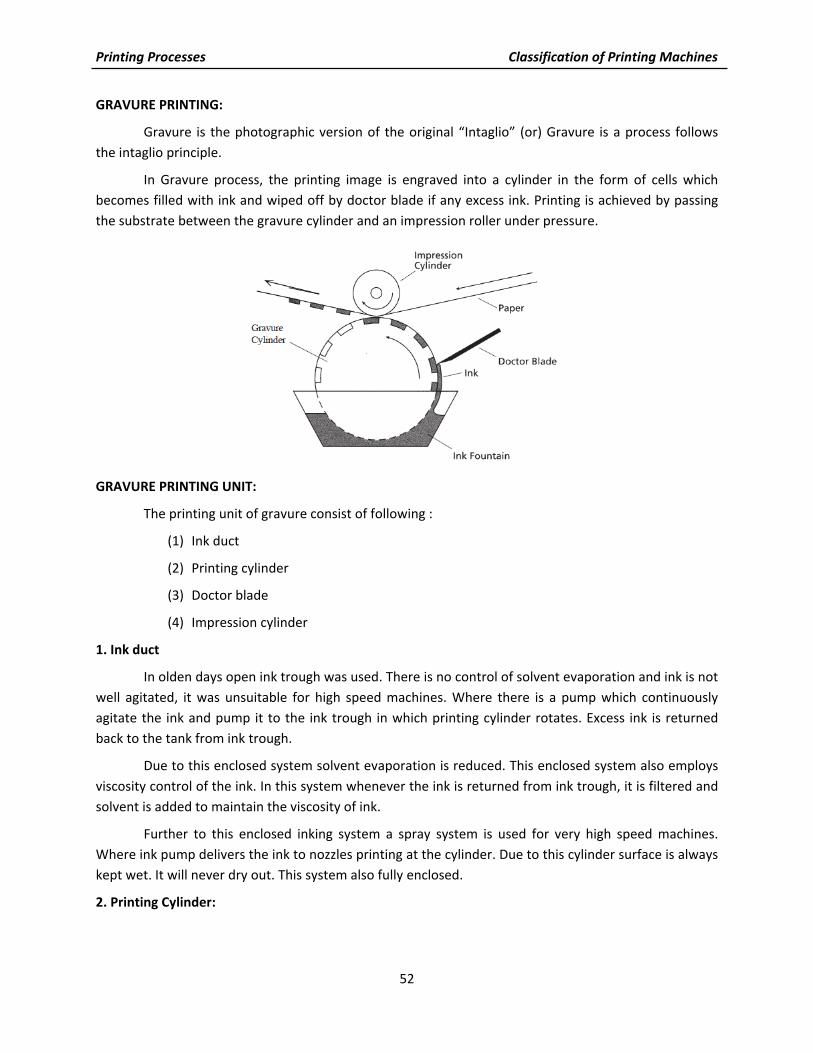
Gravure is the photographic version of the original “Intaglio” (or) Gravure is a process follows the intaglio principle.
In Gravure process, the printing image is engraved into a cylinder in the form of cells which becomes filled with ink and wiped off by doctor blade if any excess ink. Printing is achieved by passing the substrate between the gravure cylinder and an impression roller under pressure.
GRAVURE PRINTING UNIT:
The printing unit of gravure consist of following :
(1) Ink duct
(2) Printing cylinder
(3) Doctor blade
(4) Impression cylinder
1. Ink duct
In olden days open ink trough was used. There is no control of solvent evaporation and ink is not well agitated, it was unsuitable for high speed machines. Where there is a pump which continuously agitate the ink and pump it to the ink trough in which printing cylinder rotates. Excess ink is returned back to the tank from ink trough.
Due to this enclosed system solvent evaporation is reduced. This enclosed system also employs viscosity control of the ink. In this system whenever the ink is returned from ink trough, it is filtered and solvent is added to maintain the viscosity of ink.
Further to this enclosed inking system a spray system is used for very high speed machines. Where ink pump delivers the ink to nozzles printing at the cylinder. Due to this cylinder surface is always kept wet. It will never dry out. This system also fully enclosed.
2. Printing Cylinder:

Printing Processes Classification of Printing Machines
53
Basically, a gravure press is still the simplest of the printing machines. Publication presses have cylinders as big as 102" with a diameter of about of 17". Generally publication presses are not built to permit inserting of cylinders varying in the diameter.
Presses for package printing can handle cylinder varying in their diameter within a given range. When variable diameter cylinders are customary, the nature of the jobs controls the dimension. Cylinders for packaging vary greatly in size from the very small, about 7" long by 2 or 3 inches diameter up to massive cylinder
80" or more long with a diameter of about 17".
Presses with a printing width of 200"(5 meters) and above are used for speciality printing, like printing of vinyl floor covering.
3. Doctor blade :
The printing cylinder is flooded with ink and before impression is made on the paper, the excess ink from the cells and on the non‐printing surface of the cylinder is removed by the scraping action of a flexible sheet blade, known as “Doctor Blade”. As the cylinder turns, and just before the paper makes contact with it, this doctor blade, made of fine Swedish steel (.008 inch thick)wipes of all the excess ink. The doctor blade, precision ground and hand coned (after use), is held against the cylinder under pressure, and scrapes the surface absolutely dry.
This doctor blade is assemble in such a way to ride on the surface of the cylinder and remove the surplus ink, without damaging the surface of the printing image are cell. This doctor blade is assemble as near as possible to the nip pressure, to avoid any ink evaporation and drying of ink in cells. Usually the thickness of the blade is 0.15mm to 0.25mm. The main blade is supported by backing blade of 0.76mm thick.
The doctor blade is usually set in such a angle that must wipe excess ink from the non‐image areas. If the blade angle is more steep, it gives cleaner wipe. If the blade angle is shallow it wipes less ink. Blades are ground with a bevel edge and the angle of bevel is one of the factor influencing the printing result. Doctor blades are normally made to reciprocate up to 6cm. The reciprocate action of blade makes better wiping of ink and disperse the paper fibers and any foreign particles.
High speed presses are equipped with pre‐doctoring blade. This allows an ink film of 0.5mm to final doctor blade. Due to this pre‐doctoring blade pressure on the second (final) doctor blade is reduced and cylinder wear is less, printed results are less affected by speed.

Printing Processes Classification of Printing Machines
54
4. Impression roller:
This has a steel core with hard rubber covering to bear the heavy pressure. The rubber covering is us of 12‐20 mm thickness. Its hardness is from 60 to 100 shore. If the substrate is too rough and more compressible then hard rubber is used. Plastic films are normally printed with soft roll and with low impression pressure.
In general the pressure applied between impression roller and printing cylinder is higher than any other processes. The impression roller is oftenly supported with third roller called “BACK UP” to overcome the impression roller deflection and give sufficient pressure in the center. Another technique is “flexible” roll which can be adjusted to even out the pressure across the width of the web.
Now a days impression rollers are employed with electrostatically assisted ink transfer. To overcome the printing problem “speckle” (individual cells not printing on rough papers and non‐ compressible papers even if it is coated one). In this special roller during the turning (rotation) high voltage is generated. This electric field encourages the ink to leave the cells and transfer to the paper even the contact is imperfect.
Fig. Schematic illustration of a gravure printing unit
GRAVURE PRINTING SURFACE
Gravure plates are made from rolled copper. The ends of the plate must be carefully bent to fit in to the clamps on the cylinder. The plate covers only parts of the cylinder circumference since the plate cylinder must house the clamping system. This uncovered section must be filled in with a “gap cover” or “segment” to provide a bearing surface for the doctor blade. These type of presses (using a gravure plate) are fast becoming absolete.
Cylinders can be made of iron, steel, copper or aluminium. Ends are usually fabricated of steel bar and plate, or steel shaft pressed through the cylinder body. Sleeves cylinders are metal tubes housed in the machine on
Printing Processes Classification of Printing Machines
55
mandrels. It is only necessary to produce a sleeve or tube with this system, for subsequent mounting on a machine mandrel. The sleeve is generally made of steel base and deposited with copper, to a diameter slightly larger than the required size. It is than turned and polished in a lath to obtain the correct diameter and perfect stage. This system is not recommended for multi‐unit web‐fed presses and for
large‐run package printing.
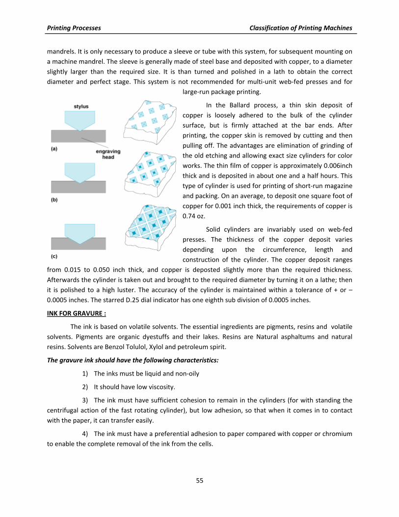
In the Ballard process, a thin skin deposit of copper is loosely adhered to the bulk of the cylinder surface, but is firmly attached at the bar ends. After printing, the copper skin is removed by cutting and then pulling off. The advantages are elimination of grinding of the old etching and allowing exact size cylinders for color works. The thin film of copper is approximately 0.006inch thick and is deposited in about one and a half hours. This type of cylinder is used for printing of short‐run magazine and packing. On an average, to deposit one square foot of copper for 0.001 inch thick, the requirements of copper is 0.74 oz.
Solid cylinders are invariably used on web‐fed presses. The thickness of the copper deposit varies depending upon the circumference, length and construction of the cylinder. The copper deposit ranges
from 0.015 to 0.050 inch thick, and copper is deposted slightly more than the required thickness. Afterwards the cylinder is taken out and brought to the required diameter by turning it on a lathe; then it is polished to a high luster. The accuracy of the cylinder is maintained within a tolerance of + or – 0.0005 inches. The starred D.25 dial indicator has one eighth sub division of 0.0005 inches.
INK FOR GRAVURE :
The ink is based on volatile solvents. The essential ingredients are pigments, resins and volatile solvents. Pigments are organic dyestuffs and their lakes. Resins are Natural asphaltums and natural resins. Solvents are Benzol Tolulol, Xylol and petroleum spirit.
The gravure ink should have the following characteristics:
1) The inks must be liquid and non‐oily
2) It should have low viscosity.
3) The ink must have sufficient cohesion to remain in the cylinders (for with standing the centrifugal action of the fast rotating cylinder), but low adhesion, so that when it comes in to contact with the paper, it can transfer easily.
4) The ink must have a preferential adhesion to paper compared with copper or chromium to enable the complete removal of the ink from the cells.

Printing Processes Classification of Printing Machines
56
5) The ink must not dry on the machine, nor in the cylinder cells, but it must dry quickly after printing on the stock.
The gravure print makes the highlight areas give one color, by permitting light to be reflected from the paper beneath, while the thick films in the dense areas do not reflect light from the paper and give a different shade as well as a different color strength.
GRAVURE PRINTING MACHINE CLASSIFICATIONS
1. Packaging Gravure Presses :
Gravure packaging and product presses are divided into two groups according to the substrates used as light weight and heavy weight substrates. Light weight substrates include, flexible packaging, gift wraps, paper and foil labels and decorative films: Heavy weight substrates include folding cartons, floor covering, vinyl sheet, shower curtains, plate mates and outdoor furniture. Some of the common in‐line operations performed on these process are die cutting, sheeting, punching, perforating, trimming, stripping.
2. Flexible Packaging Presses :
Flexible packaging presses typically have 8 or 11 printing units. Web width range from under 12 inches to 63 inches, with variable repeat (cut‐off). These presses are designed to print light weight materials like film, foil, paper etc.
Flexible packaging presses require unwinding reel stand with very sophisticated tension control devices, to stabilize light weight extensible materials prior to entering the first unit. Most flexible packaging presses are designed for roll to roll operation.
3. Gravure Publication Presses :
Publication presses are designed for high speed printing of high quality color publications. Typical products include magazines, newspaper, catalogs & advertising printing. Publication presses have 8 or 10 printing units and web width range from 96 to 108 inches. Because of the speed and width of the presses, gravure publication plants use large amount of paper. This requires automation in reel loading and splicing.
Publication Gravure presses often add a cloth covered pre‐wipe roller to the ink fountain to improve ink application to the print cylinder. Modern gravure Publication presses are generally equipped with only one un‐winder for eight printing units. Web pre‐conditioning units are used to maintain the paper temperature.
Publication presses are connected to wide variety of In‐line operations like folding, stitching, auto stacking, inserting, gluing, perforating, etc,.
4. Folding Carton Presses :
Folding carton presses typically have 6 to 8 units and available in either narrow web (under 36inches) or wide web (up to 55inches) with variable repeat (cut‐off). This folding carton presses can be used to print paper as low as 60 lb. per ream. Their reel stand should adopt maximum outside diameter and weight (upto 84inches diameter) because of thick board.

Printing Processes Classification of Printing Machines
57
Folding carton presses offer a wide variety of in‐line converting operations like Cutting, rewinding, rotary die cutting, rotary embossing. Following pre‐conditioning systems installed at unwinder exit are heat drum followed by chill roller, blower (hot air), a decurling device, a web cleaner etc,.
5. Label Presses :
This is a typical application for gravure package printing. This requires some special application. These presses have 6 to 8 printing units, web width in the range of 36" and variable repeat length (cut off) from as low as 10" maximum 36":
The weight and size demands of substrates rolls are less extends than in folding cartons and packaging presses. The typical label roll is 40" in diameter. Dryers are similar to those on flexible packaging presses. Dryers are attached for drying of waterbased inks and coatings. Label presses are equipped with following in‐line converting equipments like Sheeter, jogger, stocker, trimmer, coating unit, rewinder, slitter etc,.
Pre‐conditioning systems are similar to flexible packaging presses are.
1. A heated drum, followed by a chill roller.
2. A hot air blower.
6. Narrow Web Presses :
Narrow web is generally defined in the flexography rather than gravure. As any web, less than 24" width is called web presses. Narrow presses differ from their wide web counter parts in a variety of ways. A primary distinction, is the ability to do multiple converting operations, along with printing in the same pass. The major of narrow‐web presses are generally built in‐line configurations through some are C.I stack press.
There is tremendous variety of product that are capable of being produced on narrow web equipment. Any product between 0.001" and 0.020" in thickness is used in narrow press.
Eg : Business forms, small folding cartons, tags, tickets, multiple layer coupons etc,.
PHOTOGRAVURE :
Photogravure is an intaglio process. Image areas are deeply etched below the surface of the copperised surface of printing cylinder. Liquid ink is filled in the recessed image areas and a doctor blade wipes the surface clean free from superfluous ink. The cylinder is pressed on paper or other material for transferring the inked image. Gravure processes has a much wider application than letterpress or offset as it prints, from a low
viscosity liquid. Ink, coating, varnish, adhesive, hot carbon or anything that will flow on a cylinder can be

Printing Processes Classification of Printing Machines
58
printed by gra‐vure. Plastic sheeting, curtains, linoleum, upholstery metallic foils, paper and boards can be printed. The finished materials can be passed through in‐line machines for punching, cutting, folding, etc. Gravure has advantages in carton making.
Thick film of gold ink can be printed. Deep brilliant glossy solids by the slide of delicate tones of postal shades can be laid down by gravure. 100, 120, 150, 175, 225, 300 lines screens are used. 175 line screen is popular. The greatest etching depth is 1 to 2 / 1,000 of an inch or 25 / 1000 to 50 / 1000 mm. The ratio of wall thickness to width 1:2.25 or 1:2.5 for paper and board and 1:3 for solid areas on foil and plastic. Width increases with cell depth and cell wall becomes thinner. Ink from deep cell spreads more. The dense areas merge into one another screen pattern largely missing. Highlight cells have little ink. No contact is made with paper.
Gravure is popular for picture reproduction. Small type printing is a problem. For type matter rinco process of gravure is popular and plates prepared from a white ink, is printed on glossy black paper. This gives type in the negative. Paper negatives are then made for illustrations sheets are pasted up in position and re‐exposed to give a complete positive page.
Advantages of Gravure:
1) The final printed images are of excellent visual quality. Due to its intaglio character, the closeness of the printing areas and different thickness of ink, Gravure print displays the pleasing effect of a continuous tone image.
2) Photogravure is an exceptionally fast printing method on almost all kinds of paper and materials. Press speed attainable‐web‐fed paper: 1,000 fpm (Feet Per Minute) ; Film and foil: 300 to 600 fpm. Sheet‐fed: 3000 sheets per hour.
3) The printed sheet is usually dried, when it leaves the press, due to the volatility of the fluid ink.
4) Gravure cylinders yield very large number of impressions and under proper handling, several millions. Chrome‐plated copper cylinder can print 1.5 millions revolutions without re‐chroming; and can print 12 to 20 million revolutions before making new cylinders, depending on material printed.
5) Rotogravure ink, based on, fluid ink can be formulated for printing on a, variety of printing stocks‐ paper, paperboard, plastic films, metal foils, textiles, etc.
6) The supplementary operations like cutting, punching, creasing and stripping are done
“In‐line”, fabricated the end product at the same speed at which presswork progresses.
7) Cheaper paper stock can be used on gravure presses compared with other processes.
8) Quality reproductions at low cost is possible.
9) Large presses with a web width of 144inch are used for printing of vinyl floor covering.
10) Virtually, there is no make‐ready involved while printing on a Gravure press.
Limitations of Gravure :

Printing Processes Classification of Printing Machines
59
1) Length of time to prepare and etch a cylinder. Generally, it required between three and four hours from the time resist has been applied to the copper surface until the printing form is ready to be proofed.
2) The high initial cost incurred in the cylinder preparation.
3) Type, Text matter and fine line illustrations does not reproduce as sharply in gravure as it does in letterpress and offset chiefly because the rotogravure screen gives a “sawtooth” edge to vertical lines and horizontal lines.
4) Minimum economical run is said to be 50,000.
5) Once the cylinder has been prepared, very limited alterations or revisions alone can be made without having to prepare a new cylinder.
6) Air conditioning of the plant is necessary due to the inherent nature of the process.
Characteristics :
1) All gravure copy‐ reading matter as well as pictures‐must be screened.
2) Generally the gravure cylinder itself is etched and acts as the image carrier.
3) Gravure prints from a design below the surface of the plate or cylinder.
4) Gradations of tone are obtained by etched cells to different depths, so that more or less ink is carried by the cells and transferred to the paper according to their depth.
5) The use of the “Doctor blade” in the printing press (to remove ink from non‐printing areas).
6) An interesting possibility of gravure press is the fact that a simple basic principle allows the use of cylinders of different diameters, without complicate changes in the unit gearings.
7) A continuous tone positive is used for exposing on the carbon tissue.
3.5 Classification and Types of Screen Printing Machines Screen printing (formerly called silk‐screen printing) is a stencil process whereby ink is
transferred to the substrate through a stencil supported by a fine fabric mesh of silk, synthetic fibres or metal threads stretched tightly on a frame. The pores of the mesh are ‘blocked‐up’ in the non‐image areas and left open in the image area. This image carrier is called the screen.
During printing the frame is supplied with ink which is flooded over the screen. A squeegee is then drawn across it, forcing the ink through the open pores of the screen. At the same time the substrate is held in contact with the screen and the ink is transferred to it. The principle is shown in Fig.

Printing Processes Classification of Printing Machines
60
Because of their simplicity, screens can be produced cheaply and this makes it an attractive process for short‐run work. Furthermore, since the image is produced through a screen rather than from a surface the impression pressure is very low. This makes it ideal for printing on fragile boxes or awkward shapes.
Irrespective of the type of machine the printing procedure is generally the same. A working supply of ink is placed at one end of the screen and the screen is then raised so that the stock may be fed to register guides or grippers on a base. The screen is then lowered and a rubber or plastic squeegee drawn across the stencil to produce the print. Ink replenishment is undertaken as necessary.
On most flat‐bed machines the base to which the substrate is applied is of a vacuum type. This prevents the stock sticking to the screen and being lifted by tacky inks.
To a certain extent the thickness of the ink film printed can be controlled by the pressure, sharpness and angle of the squeegee blade.
The more upright the blade the thinner the deposit of ink. Thus, in general, fine work requires a more upright blade. However, the type of ink, stock and machine govern the blade setting also.
SCREEN PRINTING PRESSES (MACHINES)
The screen process is one of the major printing methods used by graphic arts industry. In screen process, printing is done by forcing ink through openings in a stencil or photogravure stencil that has been attached to a fabric screen is called screen process printing. Screen Printing process is carried either by hand or manual and power operated presses.
Following are the parts of a screen printing press of hand operated one:
1. Frame
2. Base
3. Screen fabric
4. squeegee
(1) Frame:
The frame serves as a support for the screen fabric. It can be made from wood, metal or any other rigid material.
a) Wooden frame:
Wood used for screen printing should be soft, straight grained, should resist the moisture and temperature. Wooden frame are easy to handle and assemble. The cost of the wooden frame is less than metal frame. Leveling is also important for wooden frames. A two‐component lacquer protects the wood from water and solvent.

Printing Processes Classification of Printing Machines
61
Pine or popular wood is usually used for making frames. Before making a frame, wood is seasoned. The corners of the frame is joined by miter, end lap, or spline joints. Angle and corner irons are sometimes used to reinforce the corners of a large screen printing frame.
(b) Metal frames:
Steel is used for screen frames as its rigidity, life is more by comparing the wooden frames. For corrosion production, steel frames are galvanized or coated with lacquer, sometime with stored varnish. These steel frames are available in rectangular or square section. For easier handling of large frames, steel is replaced by aluminium alloy, but care must be taken in providing rigidity. Also aluminium frames are corrosion – proof while comparing steel frames.
Leveling of metal frame is very important. This leveling is done on a special leveling slab. Twisted or warped frames can cause great trouble in printing and in registering. Before mounting the fabric, sharp edges and pointed comers should be well rounded to avoid the tearing of fabric. Metal frames should be roughened on the adhesive surface or sand – blasted, also it should be throughly de‐greased with a suitable solvent after roughening.
(2) Base :
This is the surface upon which the substrate to be printed is positioned and held. It is usually made from a thin sheet of plywood or hardboard or table. This is longer than the frame used. Loose‐pin built hinges serve to hold the frame and base together.
(3) Screen Fabric :
The screen fabric is a woven material. It is a tightly stretched across the frame. This Screen fabric serves as a carrier for stencil. The selection of fabric for particular work plays a major role. Following are the types of fabrics.
a) Silk:
Silk is a natural fiber produced by the silk worm. Hand cut and indirect stencils adhere well to silk fabrics. However this silk is not dimensionally stable. Size variation can occur due to change in temperature and humidity. Therefore silk is unsuitable for jobs requiring critical registration.
(b) Polyesters:
Polyesters such as darcon, Terital and polylast are man made synthetic materials containing cellulose, resins and hydrocarbons. Polyesters fabrics are woven very uniformly and good in dimension stability. They are extremely strong and used for long runs. A major disadvantage is that indirect photographic stencil will not adhere so good as like in silk.
(c) Nylon:
Nylon is also a man made synthetic material having uniformly woven fabrics. This fabric is strong and durable and can be used for long run jobs. Unlike polyesters, nylon fabrics lack dimensional stability. Nylon fabrics will go on stretched and react to temperature & humidity changes. So before mounting a nylon fabric on frames, it should be wet firstly and stretched very taut, to maintain the good registration.

Printing Processes Classification of Printing Machines
62
d) Metal fabrics:
These types of fabrics are used for only special application. Unlike the synthetic fabric, it does not absorb moisture and is therefore unaffected by changes in humidity. Also it is unaffected by temperature. As it has very good dimensional stability it is used for very preci‐sion printing like printed circuit board or very specialized application. Usually “Stainless Steel wire” is used as a metal fabric.
Stainless steel will retain its tension almost indefinitely, where as all synthetic meshes‐show a tendency to loose tension with use. Also stainless steel mesh allow more volume of ink to pass through. As it is electrically conductive it can be used for printing thermoplastic inks. Stainless steel screen printing fabrics are more expensive than synthetic material.
(4) Squeegee :
The squeegee performs a very important function in screen printing. It is used to force the ink through the screen mesh and stencil on to the printing stock below. Squeegee blades are made from high quality natural rubbers and synthetic material. Polyurethane squeegee blades are now‐ a‐days used widely due to their resistance property to abrasion so there is no need for sharpening or reshaping.
Blades are normally supplied in three grades : Hard, Medium, Soft. The hard and medium grades are used for printing thin film inks, the soft grade is used for printing on to non‐absorbent materials such as metal & glass. During the printing action the squeegee is moved across the screen and force the ink to pass through the mesh opening.
SCREEN PRINTING MACHINES CLASSIFICATIONS
Following are the various types of screen printing machines :
a) Flat‐bed hinged frame machines
b) Flat‐bed vertical lift machines
c) Cylinder bed presses machines
d) Container printing machines
e) Rotary screen machines
f) Carousel machines

Printing Processes Classification of Printing Machines
63
a) Flat‐ bed hinged frame machines
Machines designed on this principle are mostly semi‐ automatic. Here the screen and squeegee action is mechanized, but the stock is handled manually. A cam mechanism makes the screen open & close that is synchronized with squeegee and flo‐coater. When printing cycle begins the screen opens and printing stock is fed in to the lay stops (three fixed guide). By vacuum suction the printing stock is held firmly.
When the screen closes, squeegee forces the ink to pass through the screen on to the stock beneath. At the end of the squeegee the screen lifts up and flo‐coater is dropped on the screen surface. This flo‐coater .now scrapes the ink back to its preprint position. The screen is ready for its next operation.
(b) Flat‐bed vertical lift
Here the screen lifts vertically from the printing base and remains in the horizontal Attitude throughout the printing cycle. In most of the machines the printing base has reciprocating motion. Firstly it slides to receive the stock, back again for printing and out again for the delivery of the print to the dryer.
In some machines the printing base remains stationary. Where grippers are used to take the stock from a “pre‐register” table and to the printing section, then it is transferred to the delivery

Printing Processes Classification of Printing Machines
64
section. The advantages of the “pre‐register” system is its speed does not rely on operator speed. These machines are made in a wide range of sizes and formats. The speed ranges around 2500 iph.
(c) Cylinder bed presses
Here squeegee and flo‐coater remain in a stationary position and screen frame has reciprocating motion. Also a large cylinder with vacuum holes carries stock from a pile board with the help of grippers. When the printed stock is hold firmly on the cylinder surface the screen carriage comes to the same printing position and the stationary squeegee, its forces the ink pass on to the stock. At the end of this print sequence the stock is released by grippers. As well as the screen carriage moves away. Now the cylinder returns to pickup the next sheet. Maxi‐mum speed of the machine is 6000 iph.
This types of machines are suitable for printing paper & board which are flexible enough to wrap on the printing cylinder.
(d) Container printing machines
These machines are designed on the cylinder‐bed principle. The curved surface of the printing cylinder is replaced by the curved surface of the container, which is supported by two roller bearings. The printing action is exactly the same as on the cylinder press; the screen reciprocates over the rotating container while the stationary squeegee forces the ink through the screen. These machines are made in a range of sizes to print the smallest perfume or large oil drums.

Printing Processes Classification of Printing Machines
65
(e) Rotary screen
This machines are specially used for high volume production of printed textiles and floor and wall coverings. The functional principles are entirely different from conventional screen printing. Here the screen is in the form of seamless perforated cylinder, made of light metal foil. The squeegee is hollow and run inside the perforated cylinder. Through the hollow squeegee, ink is pumped to the screen.
As the screen (cylinder) rotates the ink is passed on the web (stock). The screens are made in various grades according to the ink thickness required on the stock. In this method stencil are formed by direct photoemulsion method, but it requires specialized coating and exposing technique.
(f) Carousel machines
This machines is based upon the hinged frame principle. These machines mostly used for printing multicolour on T‐Shirts and sportswear. These machines are consist of multiple Printing bases which can be rotated on a central pivot ‐(so it is called carousel machines).

Printing Processes Classification of Printing Machines
66
Fig. Screen printing technologies.
a. Flatbed;
b. Flat‐to‐round/”body printing”;
c. Rotary printing