unit iii tcsc and applications - rmd engineering college · based on the tcsc design so that the...
TRANSCRIPT

Unit III
TCSC AND APPLICATIONS

TCSC Controller
Fig. A Basic Module
It provides smooth variable series capacitive reactance
The cost of series capacitor is lower
Basic Module

Practical Module
Fig. Practical module CB-Circuit Breaker
G-Spark gap
MOV-Multi oxide varistor
UHSC-Ultra high speed contact

MOV
•To prevent the occurrence of high capacitor voltages
•It improves transient stability
Spark Gap is used to divert transient over voltages safely to earth without
affecting Capacitor.
Circuit breakers controls the insertion in line also by pass during faults.
UHSC is to minimize conduction losses
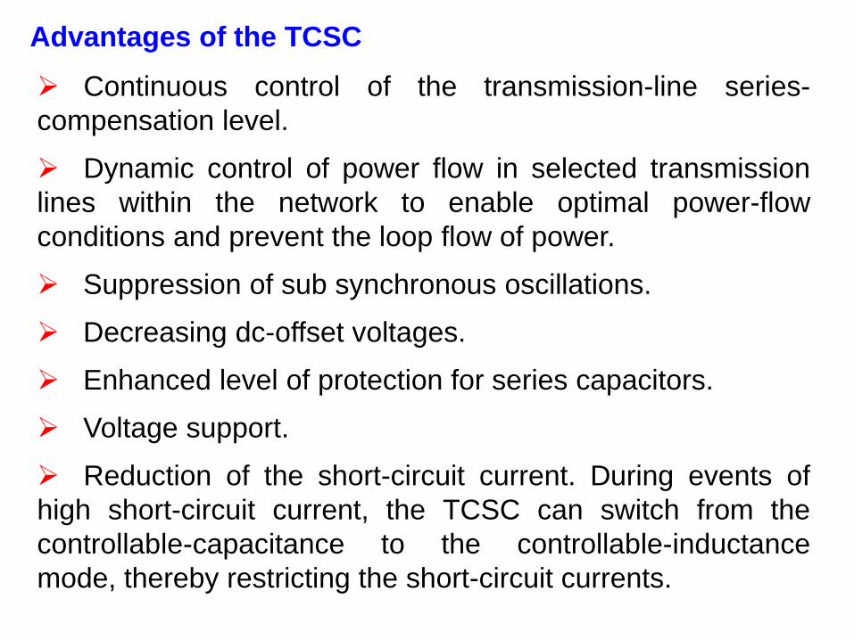
Advantages of the TCSC
Continuous control of the transmission-line series-
compensation level.
Dynamic control of power flow in selected transmission
lines within the network to enable optimal power-flow
conditions and prevent the loop flow of power.
Suppression of sub synchronous oscillations.
Decreasing dc-offset voltages.
Enhanced level of protection for series capacitors.
Voltage support.
Reduction of the short-circuit current. During events of
high short-circuit current, the TCSC can switch from the
controllable-capacitance to the controllable-inductance
mode, thereby restricting the short-circuit currents.

Variable-Series Compensation
1. Enhanced base-power flow and loadability of the
series-compensated line.
2. Additional losses in the compensated line from the
enhanced power flow.
3. Increased responsiveness of power flow in the series-
compensated line from the outage of other lines in the
system.
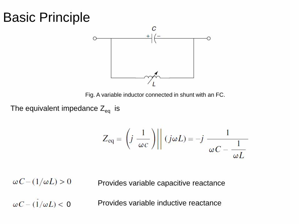
Basic Principle
Fig. A variable inductor connected in shunt with an FC.
The equivalent impedance Zeq is
Provides variable capacitive reactance
Provides variable inductive reactance 0
The behavior of the TCSC is similar to that of the parallel LC
combination. The difference is that the LC-combination analysis is
based on the presence of pure sinusoidal voltage and current in the
circuit, whereas in the TCSC, because of the voltage and current in
the FC and thyristor-controlled reactor (TCR) are not sinusoidal
because of thyristor switching.
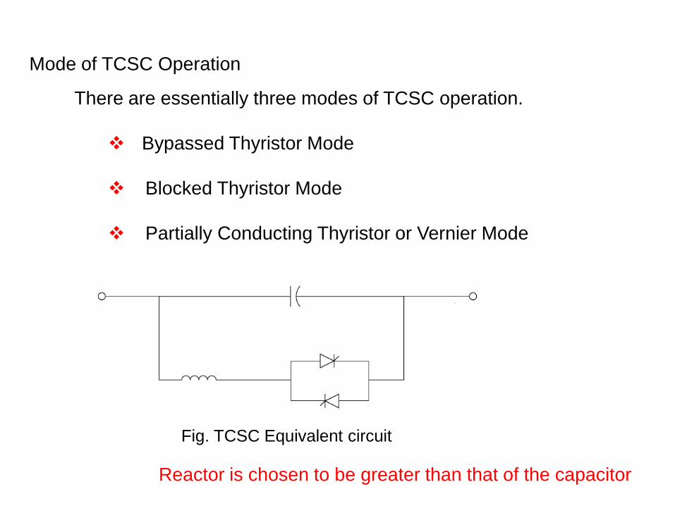
Mode of TCSC Operation
There are essentially three modes of TCSC operation.
Bypassed Thyristor Mode
Blocked Thyristor Mode
Partially Conducting Thyristor or Vernier Mode
Fig. TCSC Equivalent circuit
Reactor is chosen to be greater than that of the capacitor

Bypassed Thyristor Mode
The thyristors are made to fully conduct
In this bypassed mode, the thyristors are made to fully conduct with a conduction
angle of 180 degree. Gate pulses are applied as soon as the voltage across the
thyristors reaches zero and becomes positive, resulting in a continuous
sinusoidal of flow current through the thyristors valves.
The TCSC module behaves like a parallel capacitor–inductor combination.
However, the net current through the module is inductive, for the susceptance of
the reactor is chosen to be greater than that of the capacitor.

Blocked Thyristor Mode
In this mode, also known as the waiting mode, the firing pulses to the thyristor
valves are blocked. If the thyristors are conducting and a blocking command is
given, the thyristors turn off as soon as the current through them reaches a zero
crossing.
The TCSC module is thus reduced to a fixed-series capacitor, and the net
TCSC reactance is capacitive.
In this mode, the dc-offset voltages of the capacitors are monitored and quickly
discharged using a dc-offset control without causing any harm to the transmission-
system transformers.
Partially Conducting Thyristor or Vernier Mode
This mode allows the TCSC to behave either as a continuously controllable
capacitive reactance or as a continuously controllable inductive reactance. It is
achieved by varying the thyristor-pair firing angle in an appropriate range.
A smooth transition from the capacitive to inductive mode is not permitted
because of the resonant region between the two modes.
Capacitive-vernier-control mode
inductive-vernier mode

Capacitive-vernier-control mode, in which the thyristors are fired when the
capacitor voltage and capacitor current have opposite polarity.
This condition causes a TCR current that has a direction opposite that of the
capacitor current, thereby resulting in a loop-current flow in the TCSC controller.
This loop current increases the voltage across the FC, effectively enhancing
the series compensation level.
The maximum TCSC reactance permissible with α=αmin is typically two-and-a-
half to three times the capacitor reactance at fundamental frequency.

Another variant is the inductive-vernier mode, in which the TCSC can
be operated by having a high level of thyristor conduction. In this mode,
the direction of the circulating current is reversed and the controller
presents a net inductive impedance.
V-I capability characteristics of TCSC

Fig. The V-I capability characteristics for a single-module TCSC
V-I capability characteristics for a single-module TCSC

In the capacitive region, the maximum apparent capacitive reactance is chosen
based on the TCSC design so that the TCSC does not venture close to or into the
inherently unstable resonant point. The maximum XTCSC is typically
2–3 pu, as expressed in per units of XC.
The minimum TCSC capacitive reactance is obtained when the thyristors are
blocked, corresponding to alpha=180 and the absence of thyristor-current flows and
relating to XTCSC =1 pu.
As the line current increases, the TCSC voltage increases until the maximum voltage
limit of the TCSC is reached.
In the inductive-reactance zone, the maximum reactance limit is also selected to
prevent the TCSC from operating in the resonant region. This limit is attained at low
line currents and is expressed in terms of the maximum firing-delay angle.
A maximum inductive reactance of 2 pu is typical;
the minimum inductive reactance limit is reached when the thyristors are fully
conducting, corresponding to alpha=90 degree.

X-I capability characteristic for a single-module TCSC.
the TCSC capability can be expressed in a reactance–line-current plane

Fig. The V-I capability characteristics
for a two-module TCSC.
The V-I capability characteristics for a two-module TCSC.
A smooth variation in the line reactance
is desirable that can be achieved by
splitting a single TCSC into multiple
modules and operating them independently
in the inductive and capacitive modes.
Splitting a single TCSC into two
modules, each with a half-MVA rating,
results in a V-I capability curve with both
similar and dissimilar operation, as noted in
Fig

Fig. The V-I capability characteristic for a multimodule TCSC.
The V-I capability characteristic for a multimodule TCSC.

Fig. The X-I capability characteristic for a multimodule TCSC.
The X-I capability characteristic for a multimodule TCSC.

MODELING OF THE TCSC

MODELING OF THE TCSC
A TCSC involves continuous-time dynamics, relating to voltages
and currents in the capacitor and reactor, and nonlinear, discrete
switching behavior of thyristors.
Variable-Reactance Model
Firing angle Model
The transmission system operates in a sinusoidal steady state, with
the only dynamics associated with generators and PSS.
The variable-reactance TCSC model assumes the availability of a
continuous-reactance range and is therefore applicable for multi module
TCSC configurations.
Assumption:

Fig. A block diagram of the variable-reactance model of the TCSC
The variable-reactance model of the TCSC for Transient Stability
Studies
Xref - Power scheduling controller based on power flow specification
Xmod – Modulation controller for damping enhancement
Xaux – External power flow controller
Xdes – Desired magnitude of TCSC
TTcsc – Time constant
Xfixed – reactance of TCSC installation's FC component
where

• Xref, is generated from a power-scheduling controller based on the
power-flow specification in the transmission line. The reference Xref
value may also be set directly by manual control in response to an order
from an energy-control center, and it essentially represents the initial
operating point of the TCSC; it does not include the reactance of FCs (if
any).
• The reference value is modified by an additional input, Xmod, from a
modulation controller for such purposes as damping enhancement.
• Xaux, which can be obtained from an external power-flow controller.
• A desired magnitude of TCSC reactance, Xdes, is obtained that is
implemented after a finite delay caused by the firing controls and the
natural response of the TCSC. This delay is modeled by a lag circuit
having a time constant, TTCSC, of typically 15–20 ms.
• The resulting XTCSC is added to the Xfixed, which is the reactance
of the TCSC installation’s FC component.
• To obtain per-unit values, the TCSC reactance is divided by the
TCSC base reactance, Zbase, given as

X-I Char
The Simplified X-I capability characteristic for a multimodule TCSC
Irated

Where

In the Capacitive region, there are three different TCSC reactance constraints
which are given below
The limit of TCSC firing angle, represented by constant reactance limit
Xmax 0
The limit on the TCSC voltage VCtran. The corresponding reactance
constraint is given by
Limit on the line current (ILtrans), beyond which the TCSC enter in to
protective bypass mode.
The effective capacitive-reactance limit is finally obtained as a minimum of the
following limits:

In the inductive region, the TCSC operation is restricted by
the following limits:
The limit on the firing angle, represented by a constant-reactance limit, Xmin 0
The harmonics-imposed limit, represented by a constant-TCSC-voltage limit VLtran.
The equivalent-reactance constraint is given by
The limit on the fundamental component of current that is permitted to flow through
the thyristors in the bypassed-thyristor mode during a transient. This current limit is also
expressed as a minimum-reactance limit:
The final inductive-reactance limit in the inductive-vernier operation is
obtained as a maximum of the foregoing constraints:

Long Term Stability Model:
Capability curves of TCSC depends on the duration of V and I operating conditions
Two time limited regions are
Transient Over load region
Temporary Overload region
Both are followed by continuous region

APPLICATIONS OF TCSC

Voltage Collapse Prevention
An application of the TCSC is tested on European power system.
The system faces voltage collapse or a maximum loading point
corresponding to a 2120-MW increase in the net load.
If a TCSC is installed to provide 50% compensation of the line
experiencing the highest increase in power at the point of collapse, the
maximum loadability will be enhanced to 3534 MW.
Fig. The voltage profile of the critical bus
employing 50% TCSC compensation
sin21
x
VVP
x
V
x
VVQ
2221 cos

Performance factor, Fp -Indicates the maximum increase in loadability, for a
given percent of line compensation
This index can be gainfully employed to obtain the best location of the TCSC in
a system.
= System loadability (MW)

Fig. The loading margin

Fig. The performance measure, f p.
It is suggested that TCSC reactance-modulation schemes based on line current or
line power, or on the angular difference across lines, may prove unsuccessful for
voltage-stability enhancement. The reason is that these controls constrain any
variation in the corresponding variables that may be necessary with changing
loads, thereby limiting any power-flow enhancement on the line.

ENHANCEMENT OF SYSTEM DAMPING
Generally, the damping control of a TCSC or any other FACTS controller should
generally do the following:
1. Stabilize both post disturbance oscillations and spontaneously growing
oscillations during normal operation
2. Prevent the adverse interaction with high-frequency phenomena in power
systems, such as network resonances
3. Prevent local instabilities within the controller bandwidth
4. Robust, reliable

Principle of Damping
Let the speed and rotor angle of machine
SM1 be denoted by η1 and Φ1, respectively;
of machine SM2, denoted by η2 and Φ2,
respectively
When the receiving end–machine speed is lower than the sending end–
machine speed, that is, η (= η2− η1) is negative, the TCSC should increase
power flow in the line. In other words, while the sending-end machine
accelerates, the TCSC control should attempt to draw more power from the
machine, thereby reducing the kinetic energy responsible for its acceleration.
On the other hand, when η is positive, the TCSC must decrease the
power transmission in the line.

The incremental variation of the line-power flow P, given in megawatts
(MW), with respect to QTCSC, given in MVAR, is as follows
Thus the TCSC action is based on the variation of line-current magnitude
and is irrespective of its location.
The required series compensation in a line is therefore usually split into a
fixed-capacitor component and a controllable TCSC component.
