unit v refrigeration and air conditioning
TRANSCRIPT
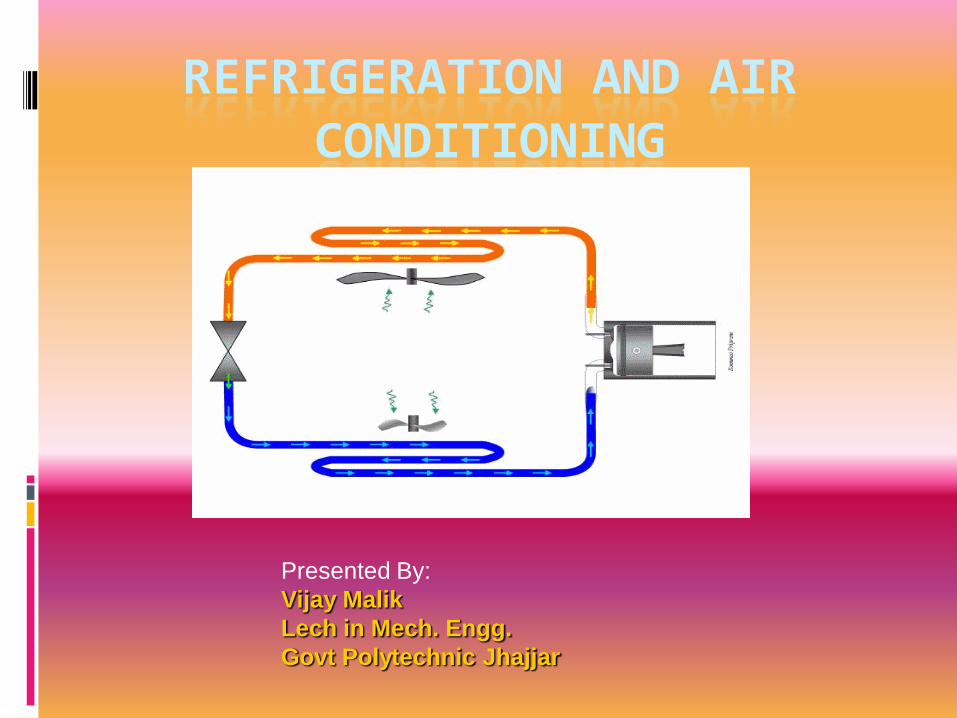
REFRIGERATION AND AIR CONDITIONING
Presented By:
Vijay Malik
Lech in Mech. Engg.
Govt Polytechnic Jhajjar

Refrigeration
It is defined as the process of providing and maintaining a temperature well below that of surrounding atmosphere.
In other words refrigeration is the process of cooling substance.

Refrigerators and heat pumps
If the main purpose of the machine is to cool some object, the machine is named as refrigerator.
If the main purpose of machine is to heat a medium warmer than the surroundings, the machine is termed as heat pump.

Refrigerator and Heat pump
Heat Pump
Warm Space
Cold Space
Refrigerator
Work Input
QR
Work Input
QR

Terminologies of Refrigeration
Refrigerating Effect (N): It is defined as the quantity of heat extracted from a cold body or space to be cooled in a given time.
N= Heat extracted from the cold space
Time taken
Specific Heat of water and ice : It is the quantity of heat required to raise or lower the temperature of one kg of water (or ice), through one kelvin or (10 c) in one second.
Specific heat of water, Cpw = 4.19 kJ/kg K
Specific heat of ice, Cpice = 2.1 kJ/kg K.

Terminologies of Refrigeration
Capacity of a Refrigeration Unit :
Capacity of a refrigerating machines are expressed by their cooling capacity.
The standard unit used for expressing the capacity of refrigerating machine is ton of refrigeration.
One ton of refrigeration is defined as, “the quantity of heat abstracted (refrigerating effect) to freeze one ton of water into one ton of ice in a duration of 24 hours at 0o c”.
Heat extracted from at 0o c = latent heat of ice
Latent heat of ice = 336 kJ/kg
i.e., 336 kJ of heat should be extracted from one kg of water at 0o C to convert it into ice.

Terminologies of Refrigeration
One ton of refrigeration = 336x1000 kJ/24 hrs.
= 336x1000 kJ/min
24x60
One ton of refrigeration = 233.333 kJ/min
= 3.8889 kJ/sec

Terminologies of Refrigeration
Co efficient of Performance: It is defined as the ratio of heat extracted in a given time (refrigerating effect) to the work input.
Co efficient of performance = Heat extracted in evaporator
Work Input
Co efficient of performance = Refrigerating Effect
Work Input
Co efficient of performance = N
W
The COP is always greater than 1 and known as theoretical coefficient of performance.

Refrigerants
Refrigerant: Any substance that absorbs heat through expansion and vaporisation process and loses heat due to condensation is a refrigeration process is called refrigerant. Some examples of refrigerants are, Air Ammonia (NH3) Carbon dioxide (CO2) Sulphur dioxide (SO2) Freon – 12 Methyl Chloride Methylene chloride.

Classification of Refrigerants
Refrigerants are classified as,
(a) Primary Refrigerants: It is a working medium which is used for cooling the substance by absorption of latent heat.
E.G Ammonia (NH3), Carbon dioxide (CO2), Sulphur dioxide (SO2), Freon 12, etc.,
(b) Secondary Refrigerants: Secondary refrigerant is a substance already cooled by primary refrigerant and then employed for cooling purposes.
E.g Ice, solid carbon dioxide.
These refrigerants cool the substance by absorption of their sensible heat.
Types of Refrigerators
Ice Refrigerators : Ice is kept in the cabinet of refrigerators and this acts as the refrigerating means.
Air Refrigerators : Air is used as working agent in these types of refrigerators.
E.g., Bell Coleman Cycle.
Vapour Refrigerators: The working agents employed in this type of refrigerators are ammonia, CO2, SO2, freons etc.,

Applications of Refrigeration
In chemical industries, for separating and liquefying the gases.
In manufacturing and storing ice.
For the preservation of perishable food items in cold storages.
For cooling water.
For controlling humidity of air manufacture and heat treatment of steels.
For chilling the oil to remove wax in oil refineries.
For the preservation of tablets and medicines in pharmaceutical industries.
For the preservation of blood tissues etc.,
For comfort air conditioning the hospitals, theatres, etc.,

Properties of Refrigeration
A good refrigerant should have high latent heat of vapourisation.
It should have low boiling and low freezing point.
It should be non toxic and should non corrosiveness
It should be non flammable and non explosive.
It should have high thermal conductivity
It should be easy to handle
It should have low specific volume of vapour.
It should have high co efficient of performance
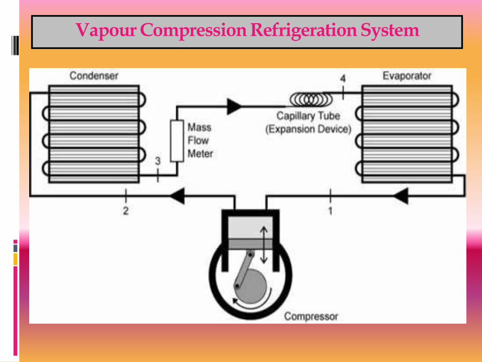
Vapour Compression Refrigeration System


S – entropy means transformation, increases with increase in temperature
and decreases with decrease in temperature
ᵹ Q = T ds

Vapour Compression Refrigeration System - Construction
This system consists of a compressor, condenser, a receiver tank, an expansion valve and an evaporator.
Compressor : Reciprocating
compressors generally used.
For very big plants centrifugal
compressors directly coupled
with high speed rotating
engines (gas turbine) are used.

Vapour Compression Refrigeration System - Construction
Compressor: For very big plants
Centrifugal compressors
directly coupled with high
speed rotating engines
(gas turbine) are used

Vapour Compression Refrigeration System - Construction
Condenser : It is a coil of tubes made of copper.
Receiver tank: It is the reservoir of liquid refrigerant.
Expansion Valve: This is a throttle valve. High pressure refrigerant is made to flow at a controlled rate through this valve.
Evaporator : It is the actual cooler and kept in the space to be cooled. The evaporator is a coil of tubes made of copper
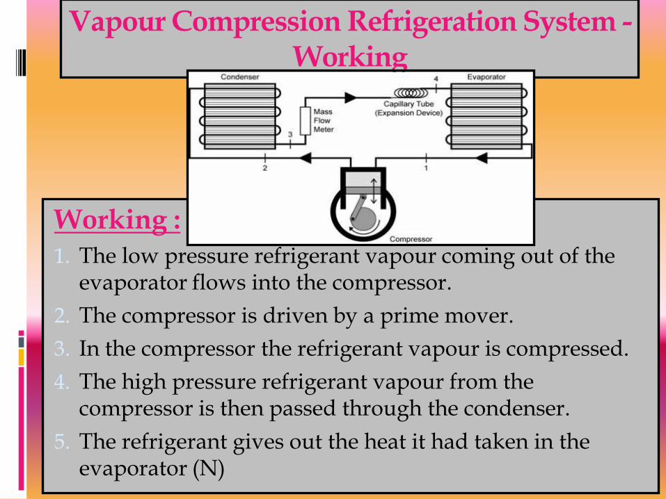
Vapour Compression Refrigeration System - Working
Working : 1. The low pressure refrigerant vapour coming out of the
evaporator flows into the compressor.
2. The compressor is driven by a prime mover.
3. In the compressor the refrigerant vapour is compressed.
4. The high pressure refrigerant vapour from the compressor is then passed through the condenser.
5. The refrigerant gives out the heat it had taken in the evaporator (N)

Vapour Compression Refrigeration System - Working
Working : 6. The heat equivalent of work done on it (w) on the
compressor.
7. This heat is carried by condenser medium which may be air or water.
8. The high pressure liquid refrigerant then enters the expansion valve.
9. This valve allows the high pressure liquid refrigerant to flow at a controlled rate into the evaporator.
10. While passing though this valve the liquid partially evaporates.

Vapour Compression Refrigeration System - Working
Working :
11.Most of the refrigerant is vapourised only in the evaporator, at a low pressure.
12. In the evaporator the liquid refrigerant absorbs its latent heat of vapourisation from the material which is to be cooled.
13. Thus the refrigerating effect (N) is obtained.
14. Then the low pressure refrigerant enters the compressor and the cycle is repeated.

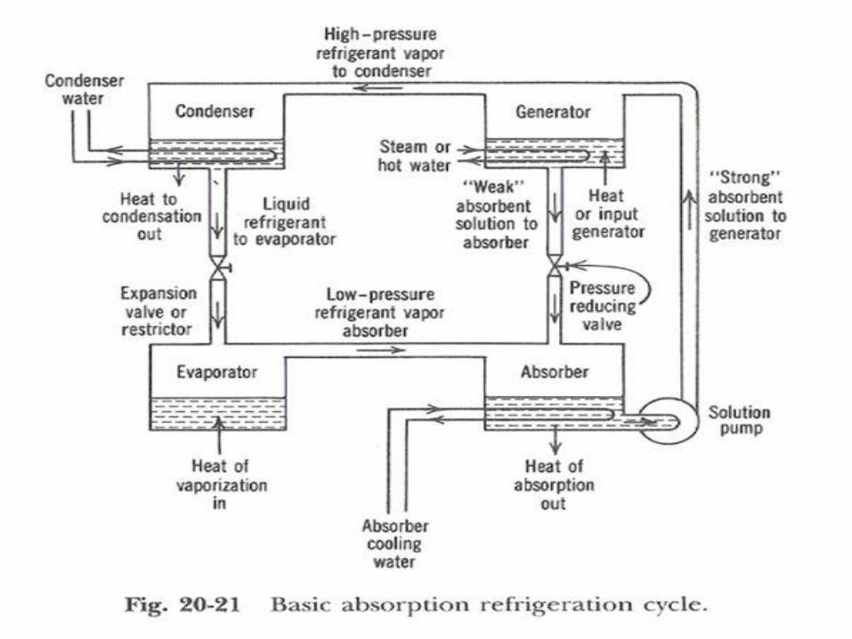
Vapour Absorption Refrigeration system
In this system compression process of vapour compression cycle is eliminated. Instead of that the following three processes are carried out.
1. Absorbing ammonia vapour into water.
2. Pumping this solution to a high pressure cycle
3. Producing ammonia vapours from ammonia solution by heating.

Vapour Absorption Refrigeration system
Vapour Absorption Refrigeration system - Construction
Construction:
The vapour absorption system consists of a condenser, an expansion valve and an evaporator.
They perform the same as they do in vapour compression method.
In addition to these, this system has an absorber, a heat exchanger, an analyser and a rectifier.

Vapour Absorption Refrigeration system – Working
Working:
1. Dry ammonia vapor at low pressure passes in to the absorber from the evaporator.
2. In the absorber the dry ammonia vapor is dissolved in cold water and strong solution of ammonia is formed.
3. Heat evolved during the absorption of ammonia is removed by circulating cold water through the coils kept in the absorber.
4. The highly concentrated ammonia (known as Aqua Ammonia) is then pumped by a pump to generator through a heat exchanger.

Vapour Absorption Refrigeration system - Construction
Working:
5. In the heat exchanger the strong ammonia solution is heated by the hot weak solution returning from the generator to the absorber.
6. In the generator the warm solution is further heated by steam coils, gas or electricity and the ammonia vapour is driven out of solution.
7. The boiling point of ammonia is less than that of water.
8. Hence the vapours leaving the generator are mainly of ammonia.
Vapour Absorption Refrigeration system - Construction
Working:
9. The weak ammonia solution is left in the generator is called weak aqua.
10. This weak solution is returned to the absorber through the heat exchanger.
11. Ammonia vapours leaving the generator may contain some water vapour.
12. If this water vapour is allowed to the condenser and expansion valve, it may freeze resulting in chocked flow.
13. Analyser and rectifiers are incorporated in the system before condenser.

Vapour Absorption Refrigeration system - Construction
Working:
14. The ammonia vapour from the generator passes through a series of trays in the analyser and ammonia is separated from water vapour.
15. The separated water vapour returned to generator.
16. Then the ammonia vapour passes through a rectifier.
17. The rectifier resembles a condenser and water vapour still present in ammonia vapour condenses and the condensate is returned to analyser.
18. The virtually pure ammonia vapour then passes through the condenser.

Vapour Absorption Refrigeration system - Construction
Working:
19. The latent heat of ammonia vapour is rejected to the cooling water circulated through the condenser and the ammonia vapour is condensed to liquid ammonia.
20. The high pressure liquid ammonia is throttled by an expansion valve or throttle valve.
21. This reduces the high temperature of the liquid ammonia to a low value and liquid ammonia partly evaporates.
22. Then this is led to the evaporator.
23. In the evaporator the liquid fully vaporizes.

Vapour Absorption Refrigeration system - Construction
Working:
24. The latent heat of evaporation is obtained from the brine or other body which is being cooled.
25. The low pressure ammonia vapour leaving the evaporator again enters the absorber and the cycle is completed.
26. This cycle is repeated again to provide the refrigerating effect.

Applications of refrigeration system
Preservation of food items like vegetables, milk and eggs.
Preservation of medicines.
Preservation of blood, tissues, etc.,
Preservation and cooling of cool drinks.
Preservation of chemicals (Chemical industries)
Cooling of water.
Industrial and comfort airconditioning.
Processing of dairy products.

Comparison between Vapour compression & Vapour Absorption refrigeration systems
S.No. Vapour Compression System Vapour Absorption System
1 This system has more wear and tear and produces more noise due to the moving parts of the compressor.
Only moving part in this system is an aqua pump. Hence the quieter in operation and less wear and tear
2. Electric power is needed to drive the system
Waste of exhaust steam may be used. No need of electric power
3. COP is more COP is less
4. At partial loads performance is poor.
At partial loads performance is not affected.
5. Mechanical energy is supplied through compressor
Heat energy is utilised
6. Energy supplied is ¼ to ½ of the refrigerating effect (less)
Energy supplied is about one and half times the refrigerating effect (more)
Comparison between Vapour compression & Vapour Absorption refrigeration systems
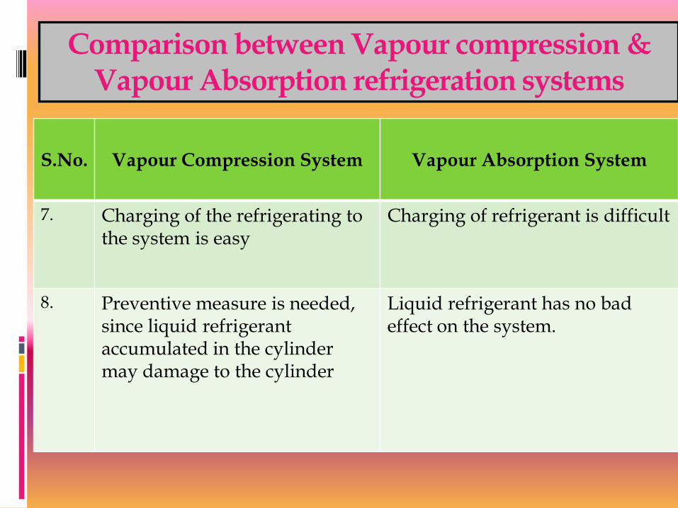
S.No. Vapour Compression System Vapour Absorption System
7. Charging of the refrigerating to the system is easy
Charging of refrigerant is difficult
8. Preventive measure is needed, since liquid refrigerant accumulated in the cylinder may damage to the cylinder
Liquid refrigerant has no bad effect on the system.

Layout of Domestic Refrigerator

Layout of Domestic refrigerator

Domestic refrigerator……
House hold refrigerators use vapor compression cycle
Less energy: (90 W to 600 W)
Due to small and high efficiency motors and compressors,
better insulation materials,
large coil surface area,
better door seals
Designed to maintain:
Freezer section -18 °C
Refrigeration section at 3°C

Domestic refrigerator……
Insulation materials:
Fiber glass, k= 0.032 W/m °C
Urethane foam, k= 0.019 W/m °C
Wall thickness for foam
For freezer section reduced from 90 to 48 mm
For refrigeration section reduced from 70 to 40 mm
Works better up to the environment of 43°C
Ice maker (2 to 3 kg/day)
Vapor absorption is more expensive and less efficient

Domestic refrigerator……
Energy consumption can be minimized for practicing good measures
Open the refrigeration doors fewest times possible
Cool the hot foods to room temperature
Clean the condenser coil behind the refrigerator
Check the door gaskets for air leaks
Avoid unnecessary low temperature settings
Avoid excessive ice build up
Use the power saver switch
Do not block the air flow passages to and from the condenser coil.

AIR CONDITIONING
AIR CONDITIONING:
Air Conditioning is the process of conditioning the air according to the human comfort, irrespective of external conditions.

AIR CONDITIONING
Applications of Air Conditioning
Used in offices, hotels, buses, cars.,etc
Used in industries having tool room machines.
Used in textile industries to control moisture.
Used in printing press.
Used in Food industries, Chemical plants.

CLASSIFICATION OF AIR CONDITIONING
Air conditioning systems are classified as
1) According to the purpose
a) Comfort Air conditioning.
b) Industrial Air conditioning.
2) According to Season of the year
a) Summer Air conditioning.
b) Winter Air conditioning.
c) Year round Air conditioning.

AIR CONDITIONING
Types of Air conditioners
a) Room Air conditioners
b) Winter Air conditioners
c) Central Air conditioners
Functions of Air conditioners
a) Cleaning air.
b) Controlling the temp of air.
c) Controlling the moisture content.
d) Circulating the air.

TERMINOLOGIES
1) Dry air: The atmospheric air which no water vapour is called dry air.
2) Psychrometry: Psychrometry is the study of the properties of atmospheric air.
3) Temperature: The degree of hotness (or) Coldness is called the temperature.
4) Moisture: Moisture is the water vapour present in the air.

TERMINOLOGIES
Humidity: mass of water vapor present in 1kg of dry air
Absolute humidity: mass of water vapor present in 1cu.m of dry air
5)Relative humidity: Relative humidity is the ratio of actual mass of water vapour in a given volume to the mass of water vapour actually can withhold by the same volume.
6) Dry bulb temperature: The temperature of air measured by the ordinary thermometer is called dry bulb temperature:

TERMINOLOGIES
7) Wet bulb Temperature: The temperature of air measured by the thermometer when it is covered by the wet cloth is known as wet bulb Temperature.
8) Dew point Temperature: The temperature at which the water vapour starts condensing is called dew point Temperature
9) Wet bulb depression: (DBT- WBT) indicates relative humidity
10) Dew point depression: (DBT- DPT)
Window Type Air Conditioner

Window Type Air Conditioner
Window Type Air Conditioner
Window Type Air Conditioner - Working
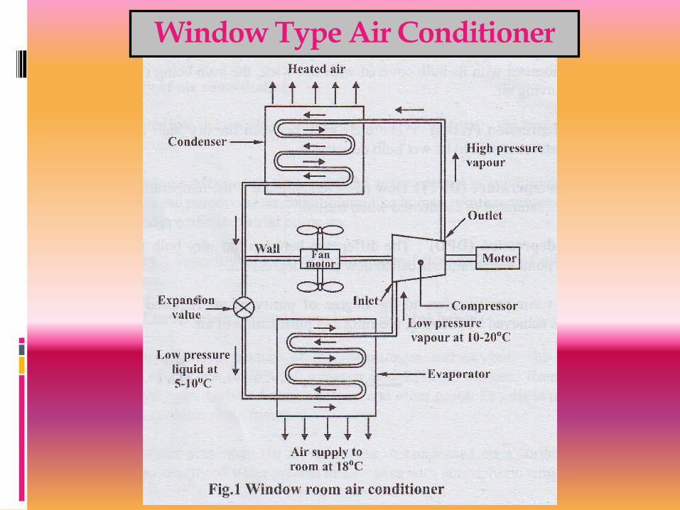
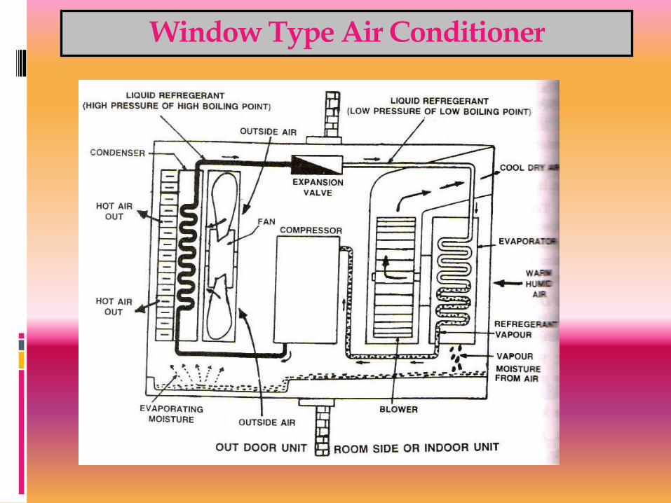
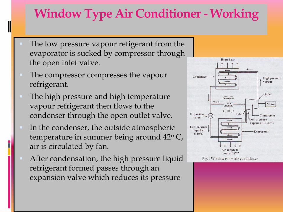
The low pressure vapour refigerant from the evaporator is sucked by compressor through the open inlet valve.
The compressor compresses the vapour refrigerant.
The high pressure and high temperature vapour refrigerant then flows to the condenser through the open outlet valve.
In the condenser, the outside atmospheric temperature in summer being around 42o C, air is circulated by fan.
After condensation, the high pressure liquid refrigerant formed passes through an expansion valve which reduces its pressure
Window Type Air Conditioner - Working
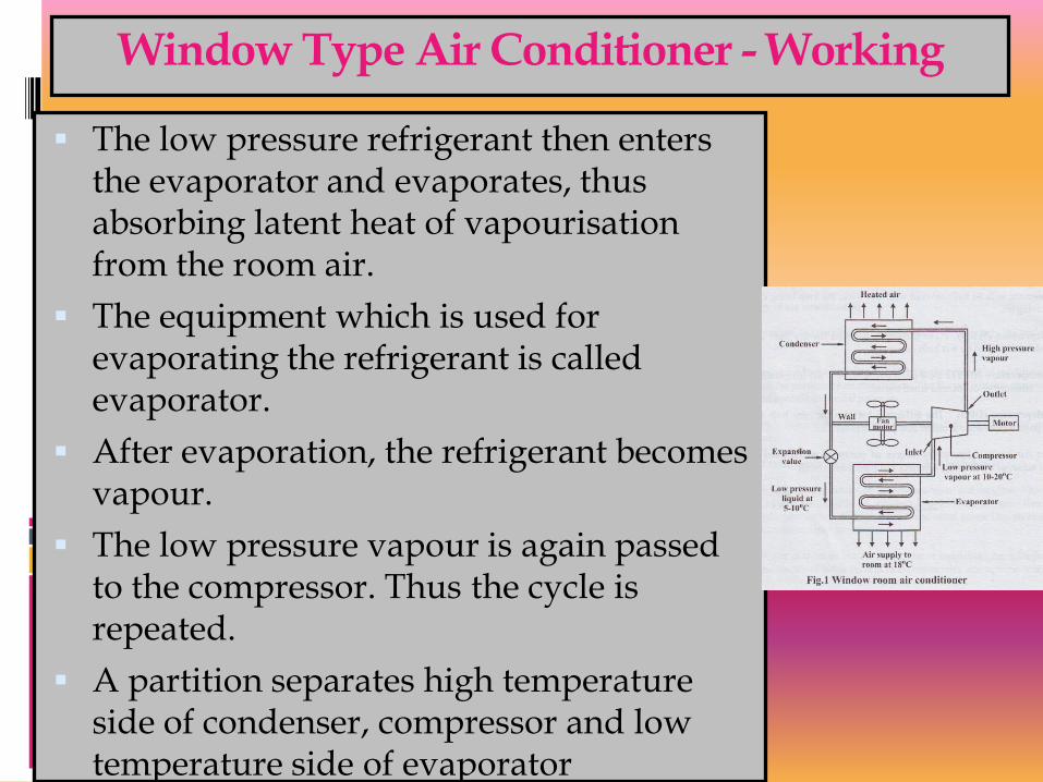
The low pressure refrigerant then enters the evaporator and evaporates, thus absorbing latent heat of vapourisation from the room air.
The equipment which is used for evaporating the refrigerant is called evaporator.
After evaporation, the refrigerant becomes vapour.
The low pressure vapour is again passed to the compressor. Thus the cycle is repeated.
A partition separates high temperature side of condenser, compressor and low temperature side of evaporator

Window Type Air Conditioner - Working
The quantity of air circulated can be controlled by the dampers.
The moisture in the air passing over the evaporator coil is dehumidified and drips into the trays.
The unit automatically stops when the required temperature is reached in the room. This is accomplished by the thermostat and control panel.
Generally, the refrigerant monochloro difluro methane (CHCLF2) is used in air conditioner. It is called Freon 22.

Merits and Demerits of Window type air conditioner
Merits :
A separate temperature control is provided in each room.
Ducts are not required for distribution.
Cost is less.
Skilled technician is required for installation.
Demerits:
It makes noise.
Large hole is made in the external wall or a large opening to be created in the window panel. This leads to insecurity to inmates.
Air quantity cannot be varied.

Split Type Air Conditioner - Construction

Split Type Air Conditioner - Layout

Split Type Air Conditioner - Layout

Split Type Air Conditioner - Layout
In split air type air conditioner noise making components like compressor and condenser are mounted outside or away from room.
Split type air conditioning system has two main components.
(i) Outdoor Unit (ii) Indoor unit.
The outdoor unit consists of compressor and condenser.
The indoor unit consists of power cables, refrigerant tube and an evaporator mounted inside the room.

Split Type Air Conditioner - Working
Compressor is used to compress the refrigerant.
The refrigerant moves between the evaporator and condenser through the circuit of tubing and fins in the coils.
The evaporator and condenser are usually made of coil of copper tubes and surrounded by aluminium fins.
The liquid refrigerant coming from the condenser evaporates in the indoor evaporator coil.
During this process the heat is removed from the indoor unit air and thus, the room is cooled.
Air return grid takes in the indoor air.
Water is dehumidified out of air is drained through the drain pipe.

Split Type Air Conditioner - Working
The hot refrigerant vapour is passed to the compressor and then to the condenser where it becomes liquid.
Thus the cycle is repeated.
A thermostat is used to keep the room at a constant, comfortable temperature avoiding the frequent turning on off.

Merits and Demerits of Split type air conditioner
Merits :
It is compact
It is energy and money saving.
Duct is not used.
Easier to install.
It is noiseless, because rotary air compressor used is, kept outside.
It is more efficient and powerful.
It has the flexibility for zoning.

Merits and Demerits of Split type air conditioner
DeMerits :
Initial cost is higher than window air conditioner
Skilled technician is required for installation.
Each zone or room requires thermostat to control the air cooling.

Applications of air conditioning
Used in houses, hospitals, offices, computer centres, theatres, departmental stores etc.,
Air-conditioning of transport media such as buses, cars trains, aeroplanes and ships.
Wide application in food processing, printing, chemical, pharmaceutical and machine tool, etc.,

References
www.phac-aspc.gc.ca/.../section3-eng.php
Shanmugam G and Palanichamy M S, “Basic Civil and Mechanical Engineering”,Tata McGraw Hill Publishing Co., New Delhi, (1996).
Ramamrutham. S, “Basic Civil Engineering”, Dhanpat Rai Publishing Co. (P) Ltd. (1999).
Seetharaman S. “Basic Civil Engineering”, Anuradha Agencies, (2005).
Venugopal K and Prabu Raja V, “Basic Mechanical Engineering”, Anuradha Publishers, Kumbakonam, (2000).

Refrigeration
Presented By:
Vijay Malik
Lech in Mech. Engg.
Govt Polytechnic Jhajjar

Vapor-Compression
Refrigeration Cycle
►There are four principal
control volumes involving
these components:
►Evaporator
►Compressor
►Condenser
►Expansion valve
►Most common refrigeration cycle in use today
All energy transfers by work and heat are taken as positive in
the directions of the arrows on the schematic and energy
balances are written accordingly.
Two-phase
liquid-vapor mixture

The Vapor-Compression
Refrigeration Cycle
Process 4-1: two-phase liquid-vapor
mixture of refrigerant is evaporated
through heat transfer from the
refrigerated space.
Process 1-2: vapor refrigerant is
compressed to a relatively high
temperature and pressure requiring
work input.
Process 2-3: vapor refrigerant
condenses to liquid through heat
transfer to the cooler surroundings.
Process 3-4: liquid refrigerant
expands to the evaporator pressure.
►The processes of this cycle are
Two-phase
liquid-vapor mixture

The Vapor-Compression
Refrigeration Cycle
►Engineering model:
►Each component is analyzed as a control
volume at steady state.
►Dry compression is presumed: the
refrigerant is a vapor.
►The compressor operates adiabatically.
►The refrigerant expanding through the
valve undergoes a throttling process.
►Kinetic and potential energy changes are
ignored.
Evaporator
The Vapor-Compression
Refrigeration Cycle
(Eq. 10.3)
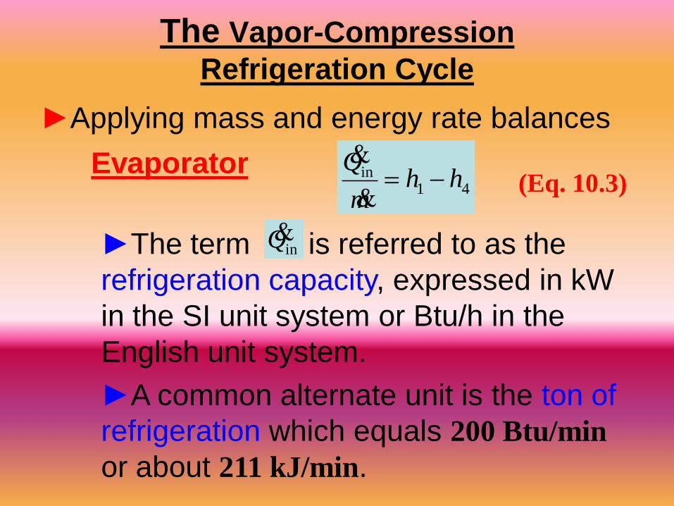
►Applying mass and energy rate balances
►The term is referred to as the
refrigeration capacity, expressed in kW
in the SI unit system or Btu/h in the
English unit system.
►A common alternate unit is the ton of
refrigeration which equals 200 Btu/min
or about 211 kJ/min.
41in hh
m
Q
inQ
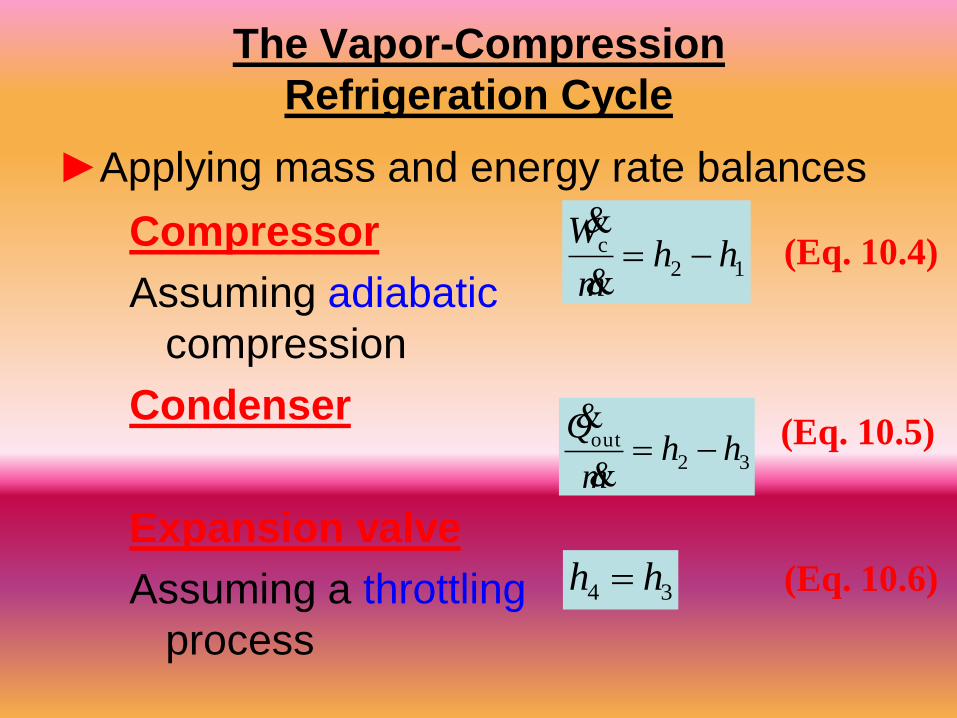
Compressor
Assuming adiabatic
compression
Condenser
Expansion valve
Assuming a throttling
process
The Vapor-Compression
Refrigeration Cycle
12c hh
m
W
34 hh
(Eq. 10.5)
(Eq. 10.6)
(Eq. 10.4)
►Applying mass and energy rate balances
32out hhm
Q

Coefficient of Performance (COP)
The Vapor-Compression
Refrigeration Cycle
►Performance parameters
Carnot Coefficient of Performance
This equation represents the maximum theoretical
coefficient of performance of any refrigeration cycle
operating between cold and hot regions at TC and TH,
respectively.

8
Example 11-1
Refrigerant-134a is the working fluid in an ideal compression refrigeration cycle. The
refrigerant leaves the evaporator at -20oC and has a condenser pressure of 0.9 MPa.
The mass flow rate is 3 kg/min. Find COPR and COPR, Carnot for the same Tmax and
Tmin , and the tons of refrigeration.
Using the Refrigerant-134a Tables, we have
12
2 2
11 2
2 11
3
3
21
238.41278.23
90020
0.9456 43.790.94561.0
3
900
0
s
so
o
s
s
StateState kJ
kJh Compressor exithCompressor inlet kg
kgP P kPakJT C
s T CkJkg K s sx
kg K
State
Condenser exit
P kPa
x
3 4
44 13
4 3
4101.61 0.358
0.4053200.3738
.0
o
StatekJh x
Throttle exitkgkJ
skJ T T Cs kg K
kg K h h

9
1 4 1 4
, 2 1 2 1
( )
( )
(238.41 101.61)
(278.23 238.41)
3.44
LR
net in
Q m h h h hCOP
W m h h h h
kJ
kg
kJ
kg
& &
& &
The tons of refrigeration, often called the cooling load or refrigeration effect, are
1 4( )
13 (238.41 101.61)
min211
min
1.94
LQ m h h
kg kJ Ton
kJkg
Ton
& &
,
( 20 273)
(43.79 ( 20))
3.97
LR Carnot
H L
TCOP
T T
K
K

10
Another measure of the effectiveness of the refrigeration cycle is how much input
power to the compressor, in horsepower, is required for each ton of cooling.
The unit conversion is 4.715 hp per ton of cooling.
, 4.715
4.715
3.44
1.37
net in
L R
W
Q COP
hp
Ton
hp
Ton
&
&

Features of
Actual Vapor-Compression Cycle
►Heat transfers between refrigerant and cold and
warm regions are not reversible.
►Refrigerant temperature
in evaporator is less than
TC.
►Refrigerant temperature
in condenser is greater
than TH.
►Irreversible heat
transfers have negative
effect on performance.

Features of
Actual Vapor-Compression Cycle
►The COP decreases – primarily due to increasing
compressor work input – as the
►temperature of the
refrigerant passing
through the evaporator is
reduced relative to the
temperature of the cold
region, TC.
►temperature of the
refrigerant passing
through the condenser is increased relative to the
temperature of the warm region, TH.
Trefrigerant ↓
Trefrigerant ↑

Features of
Actual Vapor-Compression Cycle
►Irreversibilities during the compression process are
suggested by dashed line from state 1 to state 2.
►An increase in specific
entropy accompanies an
adiabatic irreversible
compression process. The
work input for compression
process 1-2 is greater than
for the counterpart isentropic
compression process 1-2s.
►Since process 4-1, and thus the refrigeration capacity,
is the same for cycles 1-2-3-4-1 and 1-2s-3-4-1, cycle
1-2-3-4-1 has the lower COP.

Isentropic Compressor Efficiency
►The isentropic compressor efficiency is the ratio of
the minimum theoretical work input to the actual
work input, each per unit of mass flowing:
(Eq. 6.48)
work required in an actual
compression from compressor
inlet state to exit pressure
work required in an isentropic
compression from compressor inlet
state to the exit pressure

Actual Vapor-Compression Cycle
(a) compressor power, in kW,
(b) refrigeration capacity, in tons,
(c) coefficient of performance,
(d) isentropic compressor efficiency.
Example: The table provides steady-state operating
data for a vapor-compression refrigeration cycle
using R-134a as the working fluid. For a refrigerant
mass flow rate of 0.08 kg/s, determine the
State
h (kJ/kg)
1
241.35
2s
272.39
2
280.15
3
91.49
4
91.49

Actual Vapor-Compression Cycle
(a) The compressor power is
)( 12c hhmW
kJ/s 1
kW 1
kg
kJ)35.24115.280(
s
kg08.0cW 3.1 kW
(b) The refrigeration capacity is
)( 41in hhmQ
min
s 60
kJ/min 211
ton1
kg
kJ)49.9135.241(
s
kg08.0inQ 3.41 tons
State
h (kJ/kg)
1
241.35
2s
272.39
2
280.15
3
91.49
4
91.49
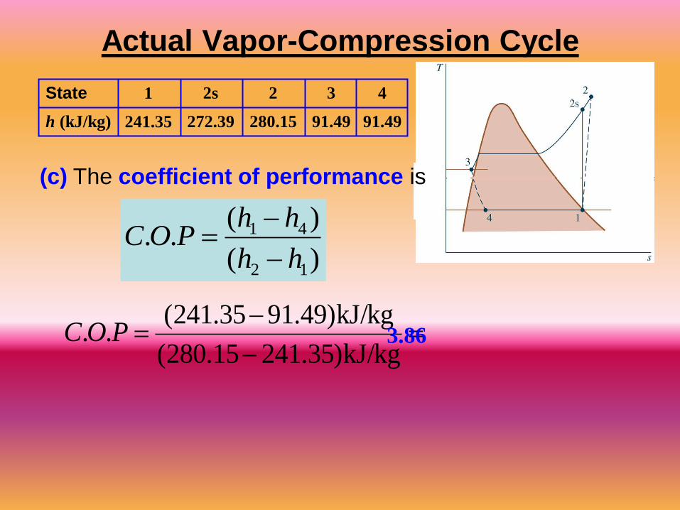
Actual Vapor-Compression Cycle
(c) The coefficient of performance is
)(
)(..
12
41
hh
hhPOC
kJ/kg)35.24115.280(
kJ/kg)49.9135.241(.. POC 3.86
State
h (kJ/kg)
1
241.35
2s
272.39
2
280.15
3
91.49
4
91.49

Actual Vapor-Compression Cycle
(d) The isentropic compressor
)(
)(
/
/
12
12
c
scc
hh
hh
mW
mW s
kJ/kg)35.24115.280(
kJ/kg)35.24139.272(c 0.8 = 80%
State
h (kJ/kg)
1
241.35
2s
272.39
2
280.15
3
91.49
4
91.49
efficiency is

p-h Diagram
►The pressure-enthalpy (p-h) diagram is a
thermodynamic property diagram commonly used
in the refrigeration field.

20
Other Refrigeration Cycles
Cascade refrigeration systems
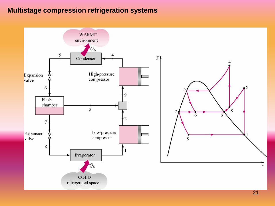
Very low temperatures can be achieved by operating two or more vapor-compression
systems in series, called cascading. The COP of a refrigeration system also
increases as a result of cascading.
21
Multistage compression refrigeration systems

22
Multipurpose refrigeration systems
A refrigerator with a single compressor can provide refrigeration at several
temperatures by throttling the refrigerant in stages.

23
Liquefaction of gases
Another way of improving the performance of a vapor-compression refrigeration
system is by using multistage compression with regenerative cooling. The vapor-
compression refrigeration cycle can also be used to liquefy gases after some
modifications.

Selecting Refrigerants
►Refrigerant selection is based on several
factors:
►Performance: provides adequate cooling
capacity cost-effectively.
►Safety: avoids hazards (i.e., toxicity).
►Environmental impact: minimizes harm to
stratospheric ozone layer and reduces
negative impact to global climate change.

Refrigerant Types and Characteristics
Global Warming Potential (GWP) is a simplified index that estimates the potential
future influence on global warming associated with different gases when released
to the atmosphere.

Refrigerant Types and Characteristics
►Chlorofluorocarbons (CFCs) and Hydrochlorofluorocarbons
(HCFCs) are early synthetic refrigerants each containing chlorine.
Because of the adverse effect of chlorine on Earth’s stratospheric
ozone layer, use of these refrigerants is regulated by international
agreement.
►Hydrofluorocarbons (HFCs) and HFC blends are chlorine-free
refrigerants. Blends combine two or more HFCs. While these
chlorine-free refrigerants do not contribute to ozone depletion, with
the exception of R-1234yf, they have high GWP levels.
►Natural refrigerants are nonsynthetic, naturally occurring
substances which serve as refrigerants. These include carbon
dioxide, ammonia, and hydrocarbons. These refrigerants feature
low GWP values; still, concerns have been raised over the toxicity
of NH3 and the safety of the hydrocarbons.
Vapour Absorption System
Presented By:
Vijay Malik
Lech in Mech. Engg.
Govt Polytechnic Jhajjar


COP for Ideal Vapor Absorption Refrigeration System

Practical Vapor – Absorption Refrigeration System
•

Practical vapor – absorption refrigeration system
Generator: The strong solution
of ammonia refrigerant and
water absorbent are heated by
the external source of heat
such as steam or hot water. It
can also be heated by other
sources like natural gas, electric
heater, waste exhaust heat etc.
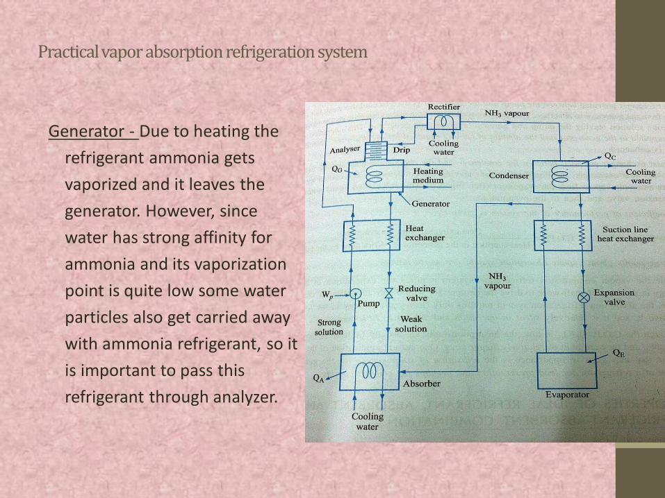
Practical vapor absorption refrigeration system
Generator - Due to heating the
refrigerant ammonia gets
vaporized and it leaves the
generator. However, since
water has strong affinity for
ammonia and its vaporization
point is quite low some water
particles also get carried away
with ammonia refrigerant, so it
is important to pass this
refrigerant through analyzer.

Vapour Absorption Refrigeration Systems Based On Water-Lithium Bromide Pair

VARS based on H2O – LiBr Pair
• Vapour absorption refrigeration systems using water-lithium bromide pair are extensively used in large capacity air conditioning systems.
• In these systems water is used as refrigerant and a solution of lithium bromide in water is used as absorbent.
• Since water is used as refrigerant, using these systems it is not possible to provide refrigeration at sub-zero temperatures. Hence it is used only in applications requiring refrigeration at temperatures above 0oC.

• Hence these systems are used for air conditioning applications. The analysis of this system is relatively easy as the vapour generated in the generator is almost pure refrigerant (water), unlike ammonia-water systems where both ammonia and water vapour are generated in the generator.
VARS based on H2O – LiBr Pair


Sample Problem in Simple VARS
9. The operating temperatures of a single stage vapour absorption refrigeration system are: generator: 90oC; condenser and absorber: 40oC; evaporator: 0oC. The system has a refrigeration capacity of 100 kW and the heat input to the system is 160 kW. The solution pump work is negligible.
• a) Find the COP of the system and the total heat rejection rate from the system.
• b) An inventor claims that by improving the design of all the components of the system he could reduce the heat input to the system to 80 kW while keeping the refrigeration capacity and operating temperatures same as before. Examine the validity of the claim.

• Solution:
Sample Problem in Simple VARS