unit v: smart grid applications smes-super … year/smart grid/unit 5.pdf · 2017-09-27 · unit v:...
TRANSCRIPT

UNIT V: SMART GRID APPLICATIONS
Overview and concept of renewable integration - role of protective relaying in smart grid-
House Area Network- Advanced Energy Storage Technology - Flow battery- Fuel cell-
SMES-Super capacitors-Plug-in Hybrid electric Vehicles- Cyber Security requirements-
Smart grid information model
OVERVIEW AND CONCEPT OF RENEWABLE ENERGY INTEGRATION
Renewable Energy Integration focuses on incorporating renewable energy, distributed
generation, energy storage, thermally activated technologies, and demand response into the
electric distribution and transmission system. A systems approach is being used to conduct
integration development and demonstrations to address technical, economic, regulatory, and
institutional barriers for using renewable and distributed systems. In addition to fully addressing
operational issues, the integration also establishes viable business models for incorporating these
technologies into capacity planning, grid operations, and demand-side management.
The goal of Renewable energy integration is to advance system design, planning, and
operation of the electric grid to:
Reduce carbon emissions and emissions of other air pollutants through increased use of
renewable energy and other clean distributed generation.
Increase asset use through integration of distributed systems and customer loads to reduce
peak load and thus lower the costs of electricity.
Support achievement of renewable portfolio standards for renewable energy and energy
efficiency.
113

Enhance reliability, security, and resiliency from Micro-grid applications in critical
infrastructure protection and highly constrained areas of the electric grid.
Support reductions in oil use by enabling Plug-In Electric Vehicle (PHEV) operations
with the grid.
CONCEPTS OF PROTECTION RELAY SYSTEM FOR SMART GRID
In recent years, trends toward electricity liberalization and the increased importance of
environmental issues have led to diversification of power system configurations
and characteristics, through the installation of distributed power sources based on photovoltaic
and wind power generation technologies. Under these circumstances, there is concern regarding
the effect on the reliability of power networks with respect to aspects such as overload,
frequency variation, and harmonic content. Against this back ground, there has been increased
focus on the concept of Smart Grid, which has the capability of collecting wide-area power system
information on a real-time basis from intelligent power grids using Information
and Communication Technology (ICT).
Although the setting values of protection relays in power systems are currently decided
based on the power system conditions assumed in advance, instances of unnecessary or missed
operations might occur in future due to unexpected power system phenomena or operations. In
this paper, the concepts of protection relay systems for Smart Grid are suggested as follows:
(a) Protection relay operation suitable for actual power system characteristics
114
Evaluation of relay setting values can be performed by means of supervising the operating
and non-operating margins of each relay characteristic quantitatively an detecting variations of
power system characteristics precisely on a real-time basis utilizing analogue input data under
normal and faulted conditions. This approach leads to benefits such as modifications to the
setting values suitable for actual power system characteristics, coordination check for each
protection relay element based on wide-area data, and critical point detection for system
operations.
(b) Intelligent collection of device data
Each protection relay device is provided with the aforementioned function and carries out
first-stage evaluation, before transmitting only the data necessary for analysis. In addition, an
agent system is applied, which has the capability of collecting protection relay data
intelligently and evaluating data from wide-area protection relays without having any effect on
protection functions. This approach can realize updating of applications executed in protection
relays without needing to take equipment out of service.
Examples of the Protective Relay Applications
This section contains the examples of the protective relay applications that make use of
the communication infrastructure provided by the Smart Grid.
A) Dynamic Settings based on Smart Grid Measured Factors:
Load, Voltage Based
Feeder Configuration based
Seasonal Changes / Temperature
Distributed Generation / Variable In-feed
B) Reclosing Supervision based on Smart Grid data:
Based on pre-fault load (cold load pickup)
Based on Fault Magnitude
Based on computed fault location
Based on FCI data (1st section inhibit)
Based on Feeder Configuration
C) Conservation Voltage Reduction Supervision based on Smart Grid data:
Metering data from Relays
D) Fault Locating:
115

Pre-fault location using FCIs
Branch Fault location using FCIs
Cable/Overhead, Location refinement using FCIs
E) Power Quality Data:
“Fault Anticipation”. Location using Power Quality from Meters
Loose terminations
F) Time:
Local and wide-area
G) Application using Synchrophasors:
Wide-area situational awareness
Wide-area protection
H) Application using GOOSE:
Local and wide-area over a fiber optic network
I) Load Curtailment (Shedding):
At the feeder level from the substation based on real-time loading
On specific feeder subsections based on real time loading and distributed generation
J) System Integrity Protection Schemes
Wide-area or regional coordinated protection using communication infrastructure
HOME-AREA NETWORK
A home area network (HAN) is a network that is deployed and operated within a small
boundary, typically a house or small office/home office (SOHO). It enables the communication
and sharing of resources (like the Internet) between computers, mobile and other devices over a
network connection.
A Home-Area Network (HAN) is an integrated system of smart meter, in-home display,
micro generation, smart appliances, smart sockets, HVAC (Heating, Ventilation, Air
Conditioning)facilities and plug-in hybrid/electric vehicles. A HAN uses wired or wireless
communications and networking protocols to ensure the interoperability of networked appliances
and the interface to a smart meter. It also includes security mechanisms to protect consumer data
and the metering system.
116
A HAN enables centralized energy management and services as well as providing
different facilities for the convenience and comfort of the household. Energy management
functions provided by HAN include energy monitoring and display, controlling the HVAC
system and controlling smart appliances and smart plugs. The services provided by HAN for the
convenience of the household can include scheduling and remote operation of
household appliances as well as household security systems. Home-based multimedia
applications such as media centres for listening to music, viewing television and movies require
broadband Internet access across the HAN. A separate HAN used for energy services can coexist
with the broadband Internet system but there is some expectation that the systems will be
merged in the future.
A home area network is a dedicated network connecting devices in the home such as
displays, load control devices and ultimately “smart appliances” seamlessly into the overall
smart metering system. It also contains turnkey reference designs of systems to monitor and
control these networks. Most of our high energy use today comes from heating /cooling,
cooking, lighting, washing and drying. These home appliances are beginning to become smart
with connectivity features that allow them to be automated in order to reap benefits that smart
metering and variable tariffs bring. The utility companies are beginning to be able to better
manage the energy demand and perform load balancing more efficiently.
Realizing long-term potential savings in a typical home environment through the smart
grid means that technology, legislation and mindset must come together to drive a permanent
change in the way that energy consumption is perceived by consumers. Figure 1 demonstrates
how smart appliances are interconnected within a
117

HAN.
118

Advantages:
Hardware and software can be shared.
All the users work can be stored in a central place.
Data can be shared because database files stored in the server are available to users
around the network.
Disadvantages:
Printing can be slow, long print queues may develop.
A virus can spread more easily.
As data is shared there is a greater need for security.
119
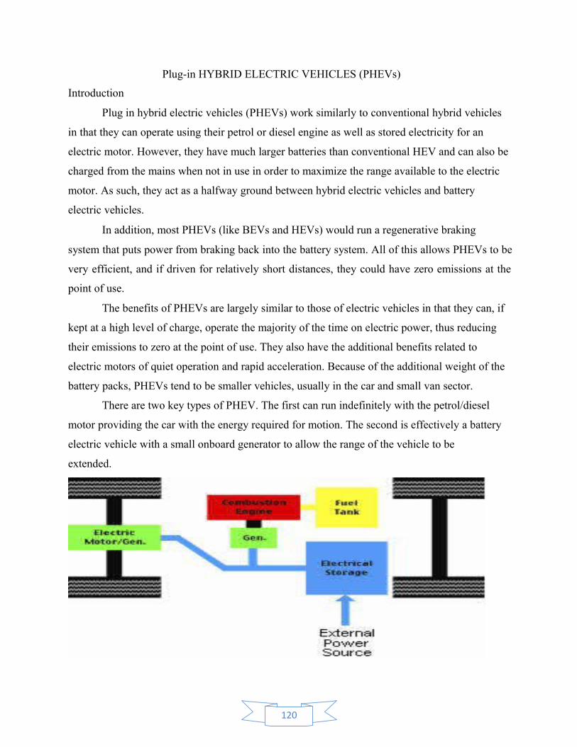
Plug-in HYBRID ELECTRIC VEHICLES (PHEVs)
Introduction
Plug in hybrid electric vehicles (PHEVs) work similarly to conventional hybrid vehicles
in that they can operate using their petrol or diesel engine as well as stored electricity for an
electric motor. However, they have much larger batteries than conventional HEV and can also be
charged from the mains when not in use in order to maximize the range available to the electric
motor. As such, they act as a halfway ground between hybrid electric vehicles and battery
electric vehicles.
In addition, most PHEVs (like BEVs and HEVs) would run a regenerative braking
system that puts power from braking back into the battery system. All of this allows PHEVs to be
very efficient, and if driven for relatively short distances, they could have zero emissions at the
point of use.
The benefits of PHEVs are largely similar to those of electric vehicles in that they can, if
kept at a high level of charge, operate the majority of the time on electric power, thus reducing
their emissions to zero at the point of use. They also have the additional benefits related to
electric motors of quiet operation and rapid acceleration. Because of the additional weight of the
battery packs, PHEVs tend to be smaller vehicles, usually in the car and small van sector.
There are two key types of PHEV. The first can run indefinitely with the petrol/diesel
motor providing the car with the energy required for motion. The second is effectively a battery
electric vehicle with a small onboard generator to allow the range of the vehicle to be
extended.
120
Types by nature of the power source
1. Electric-internal combustion engine hybrid
2. Fuel cell hybrid
3. Human power and environmental power hybrids
4. Pneumatic hybrid
5. Hydraulic hybrid
Advantages
• Improvements in fuel consumption
• Reduction of in-use emissions - potentially to zero
• Cheap to run
Disadvantages
• High capital cost
• Lack of availability
• Limited range in some types
• Emissions can simply be transferred to production sources
Technology details
It is very similar to that of a series hybrid but with a larger electrical storage capacity.
This enables the greater range available to these types of vehicles before the combustion engine
has to kick in. The type of PHEV which cannot operate independently of recharging would have a
very similar layout, the only difference being the combustion engine and generator would be
insufficient to keep the electrical storage topped up under normal driving conditions but would
slow the rate of depletion of the power stored in the batteries.
PHEVs also usually incorporate other technologies to aid their day-to-day operation. For
example, regenerative braking allows energy that would otherwise be wasted as heat during
braking to be recycled back into the electrical storage system. This improves the overall
efficiency of the vehicle and can significantly improve the range.
1. Battery charging
PHEVs typically require deeper charging and discharging than conventional hybrids. As
the number of full cycles affects battery lifetime, battery life may be less than for conventional
hybrids which do not deplete their batteries as often.
121

2. Vehicle availability
There are no plug-in hybrid electric cars or buses currently available for sale in Ireland. It
is envisaged that they will be available for purchase in the next few years.
A variety of companies are currently producing Plug-in hybrid vans such as Mercedes-
Benz/DaimlerChrysler (Germany/USA), UQM Technologies.
3.Emissions performance
The combination of the internal combustion engine and the electric motor helps hybrid cars
perform more efficiently, cutting down on fuel use. Plug-in hybrids have the additional
advantage that they can operate purely on electricity from the grid for short distances, so reducing
net emissions significantly over regular hybrids.
4.Capital and operating costs
As with regular hybrid electric vehicles, the introduction by manufacturers of more mass-
market plug-in hybrid electric vehicles is expected to rapidly drive down the cost of electric
drive components. At present however, plug-in hybrids have greater total ownership costs than
Conventional vehicles. This is due to the much greater capital costs involved when purchasing
plug-in hybrids.
ComparisionBetween PHEVs and Evs
Sl.No Description PHEVs EVs
1 Infrastructure:
• Home recharging will be a
prerequisite for most consumers;
public recharge infrastructure may
be relatively unimportant.
• Greater need for public
infrastructure to increase daily
driving range; quick recharge for
longer trips and short stops
2Economies of
scale:
• Mass production levels needed to
achieve economies of scale may be
lower than those needed for EVs.
• Mass production level of 50 000
to 100 000 vehicles per year, per
model will be needed to achieve
reasonable scale economies.
3 Vehicle range:
• PHEV optimal battery capacity
(and range on grid-derived
electricity) may vary by market
and consumer group.
• Minimum necessary range may
vary by region - possibly
significantly lower in Europe and
Japan than in North America.
122
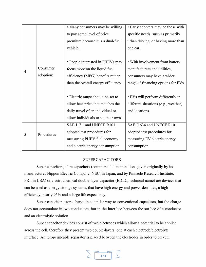
4Consumer
adoption:
• Many consumers may be willing
to pay some level of price
premium because it is a dual-fuel
vehicle.
• People interested in PHEVs may
focus more on the liquid fuel
efficiency (MPG) benefits rather
than the overall energy efficiency.
• Electric range should be set to
allow best price that matches the
daily travel of an individual or
allow individuals to set their own.
• Early adopters may be those with
specific needs, such as primarily
urban driving, or having more than
one car.
• With involvement from battery
manufacturers and utilities,
consumers may have a wider
range of financing options for EVs
• EVs will perform differently in
different situations (e.g., weather)
and locations.
5 Procedures
SAE J1711and UNECE R101
adopted test procedures for
measuring PHEV fuel economy
and electric energy consumption
SAE J1634 and UNECE R101
adopted test procedures for
measuring EV electric energy
consumption.
SUPERCAPACITORS
Super capacitors, ultra capacitors (commercial denominations given originally by its
manufactures Nippon Electric Company, NEC, in Japan, and by Pinnacle Research Institute,
PRI, in USA) or electrochemical double-layer capacitor (EDLC, technical name) are devices that
can be used as energy storage systems, that have high energy and power densities, a high
efficiency, nearly 95% and a large life expectancy.
Super capacitors store charge in a similar way to conventional capacitors, but the charge
does not accumulate in two conductors, but in the interface between the surface of a conductor
and an electrolytic solution.
Super capacitor devices consist of two electrodes which allow a potential to be applied
across the cell, therefore they present two double-layers, one at each electrode/electrolyte
interface. An ion-permeable separator is placed between the electrodes in order to prevent
123

electrical contact, but still allows ions from the electrolyte to pass through. The electrodes are
made with high effective surface materials, such as porous carbon or carbon aerogel. Two
principal technologies are used: aqueous (maximum voltage of 1.2 V and work voltage of 0.9 V)
and organic (voltage near 3 V but with a much higher series resistance).
The principal super capacitor characteristic that makes it suitable for using in ESS, is the
possibility of fast charge and discharge without loss of efficiency, for thousands of cycles. This is
because they store electrical energy directly. Super capacitors can recharge in a very short time
having a great facility to supply high and frequent power demand peaks.
Super capacitor can be manufactured in any size because they do not need a dielectric,
form high capacitance Super capacitors for hybrid vehicles, to small capacitance ones to be used
in low power applications such as wireless systems.
Double-layer capacitors - with carbon electrodes or derivate with much higher static double-
layer capacitance than the faradaic pseudo-capacitance
Pseudo-capacitors - with electrodes out of metal oxides or conducting polymers with a high
amount of faradaic pseudo-capacitance
Hybrid capacitors - capacitors with special and asymmetric electrodes that exhibit both
significant double-layer capacitance and pseudo-capacitance, such as lithium-ion capacitors
Super capacitors principles and models
Super capacitors are based on the same physical principles as conventional capacitors, but
the first ones present a higher area and thinner electrodes (with lower electrodes distances) than
the second ones. This increases the capacitance values and the energy that can store. An
estimation of the capacitance value can be obtained from the double-layer model proposed by
124

Helmholtz in 1853, considering the double-layer charge as two charge mono layers. The specific
capacitance of such a double-layer is given by
Where C is the capacitance, ε0 the dielectric constant of free space, εr the dielectric constant of themedium between the two layers, A the surface area, and D is the distance between the two layers (the distance from the electrode surface to the centre of the ion layer). This approximation is roughly correct for concentrated electrolytic solutions.
The energy stored in a super capacitor, as in a conventional capacitor, is
Where V is the super capacitor voltage.
The simplest equivalent circuit to model a super capacitor is a capacitor, C, with an
equivalent series resistance (ESR), R, which represents the Joule losses. More detailed
super capacitor RC models are various parallel RC branches (Fig. (a)); RC series-parallel branches
(Fig. (b)); and transmission line model (Fig. (c))
Advantages Over Batteries
Power density
Recycle ability
Environmentally friendly
Safe
Light weight
Applications for Super capacitors
Computer systems - Power generators
UPS systems - Battery assist
Power conditioners - Smart meters
125

Welders - Energy harvesting
Inverters - Medical systems
Automobile braking systems - Audio systems
Power supplies - Emergency lighting
Cooking equipment - Electric valves/ solenoids
SUPER CONDUCTING MAGNETIC ENERGY STORAGE (SMES)
In this system, a magnetic field is created by direct current passing through a
superconducting coil. A typical SMES system includes three parts: superconducting coil, power
conditioning system and cryogenically cooled refrigerator. Once the superconducting coil is
charged, the current will not decay and the magnetic energy can be stored indefinitely. In a
superconducting coil, resistive losses are negligible and so the energy stored in the magnetic
field does not reduce in time. In order to maintain the superconductivity of the SMES coil, a
cryostat which can keep the temperature of the coil below the superconductor temperature limit
is required. The optimum operating temperature of high temperature superconductors that are
favoured for energy storage applications is around 50-70K. Further, as the magnetic field
produced by a SMES is large, a strong supporting structure is needed to contain the
electromagnetic forces. The stored energy in the SMES is retrieved when required by a power
conditioning system that is connected to the AC network. SMES loses the least amount of
electricity in the energy storage process compared to other methods of storing energy.
Fig :Superconducting Magnet Energy Storage (SMES) System with Direct Power
Electronics Interface for GRIDS
126
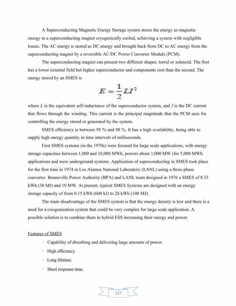
A Superconducting Magnetic Energy Storage system stores the energy as magnetic
energy in a superconducting magnet cryogenically cooled, achieving a system with negligible
losses. The AC energy is stored as DC energy and brought back from DC to AC energy from the
superconducting magnet by a reversible AC/DC Power Converter Module (PCM).
The superconducting magnet can present two different shapes: torrid or solenoid. The first
has a lower external field but higher superconductor and components cost than the second. The
energy stored by an SMES is
where L is the equivalent self-inductance of the superconductor system, and I is the DC current
that flows through the winding. This current is the principal magnitude that the PCM uses for
controlling the energy stored or generated by the system.
SMES efficiency is between 95 % and 98 %. It has a high availability, being able to
supply high energy quantity in time intervals of milliseconds.
First SMES systems (in the 1970s) were focused for large scale applications, with energy
storage capacities between 1,000 and 10,000 MWh, powers about 1,000 MW (for 5,000 MWh
applications and were underground systems. Application of superconducting in SMES took place
for the first time in 1974 in Los Alamos National Laboratory (LANL) using a three-phase
converter. Bonneville Power Authority (BPA) and LANL team designed in 1976 a SMES of 8.33
kWh (30 MJ) and 10 MW. At present, typical SMES Systems are designed with an energy
storage capacity of from 0.15 kWh (600 kJ) to 28 kWh (100 MJ).
The main disadvantage of the SMES system is that the energy density is low and there is a
need for a criogenization system that could be very complex for large scale application. A
possible solution is to combine them in hybrid ESS increasing their energy and power.
Features of SMES
• Capability of absorbing and delivering large amounts of power.
• High efficiency.
• Long lifetime.
• Short response time.
127

• Completely static construction, low maintenance.
• All electric energy storage
ADVANCED ENERGY STORAGE TECHNOLOGY
Humanity is demanding a bigger quantity of energy as its level of development is
growing. Conventional energy resources are limited, so authorities and governments are
promoting energy savings and energetic efficiency. Also, renewable energies have been
sustained and promoted by these authorities and governments as an alternative to limited
conventional energy resources.
Nowadays, the most relevant renewable energies used in generation plants are solar
(photovoltaic or thermal) and wind energy. The main disadvantage of these kinds of renewable
energy is its generation discontinuity, as well as the fact that its energy generation is not
controlled by the system operator thus making it more difficult to integrate these plants in the
generation pool than in the case of conventional plants.
Energy storage becomes a critical factor that can solve the problems described above. A
renewable energy generation plant with its corresponding energy storage system can behave as a
constant power generation plant (following the reference power generation given by the
regulator), at least for time intervals in the order of half an hour to a day, depending on the
energy storage capacity.
Large quantity of electrical energy can be stored using pumped hydro or underground
compressed air facilities. Similarly quantities of energy can be stored in batteries, fly wheels and
Superconducting Magnetic Energy Storage (SMES) devices. Fuel cells convert a continuous
source of chemical energy into electricity but have a similar impact on the power network as some
energy storage systems. A comprehensive comparison and assessment of all storage
technologies is given in Figure 3-1.
Energy Storage Systems
The principal energy storage systems (ESS) are summarized in Fig. 1, where these
systems are classified according to their application. We will focus this paper on the systems
classified into the Large Scale (>50 kW) in this figure.
128
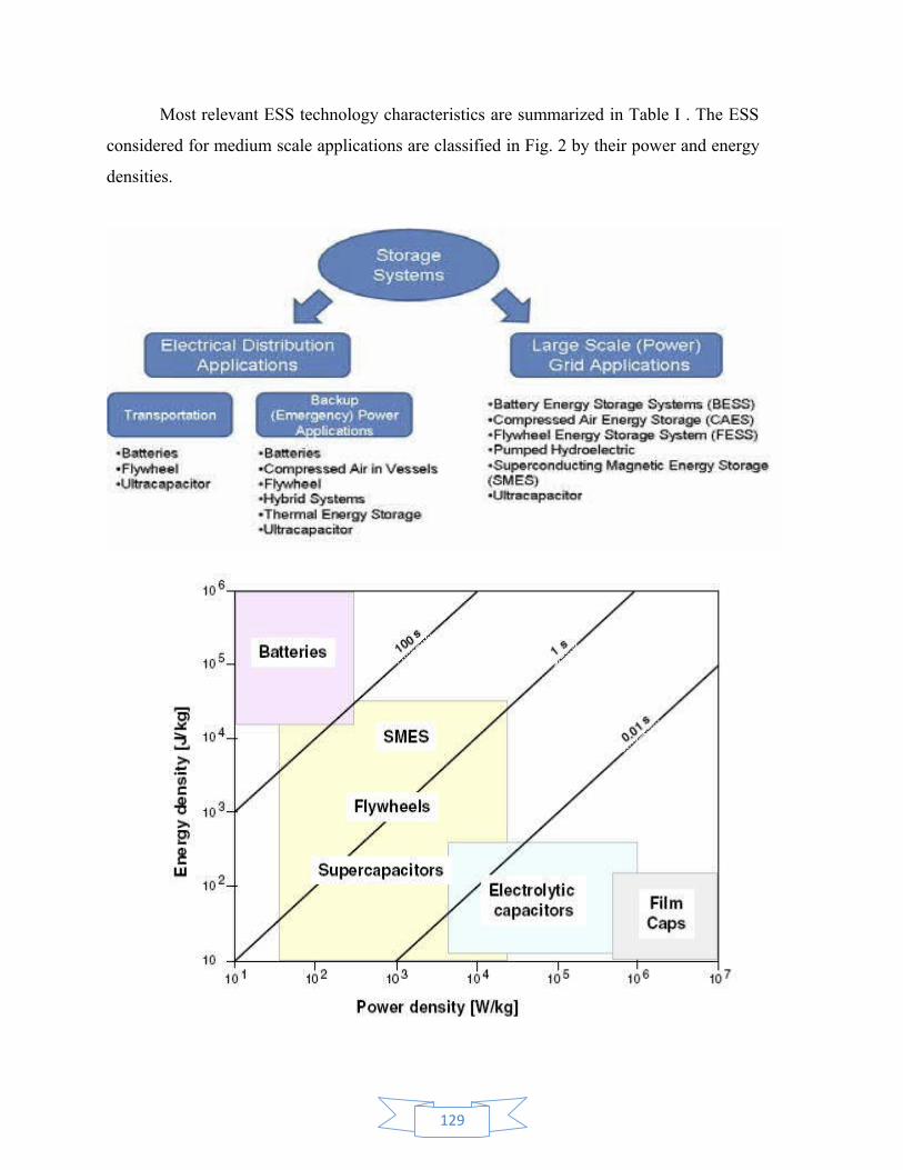
Most relevant ESS technology characteristics are summarized in Table I . The ESS
considered for medium scale applications are classified in Fig. 2 by their power and energy
densities.
129
Some of the applications of energy storage are as follows:
• Power Quality: Battery energy storage is used in Un-interruptible Power Supplies to
mitigate short-term loss of power and power fluctuations. Energy storage can also be used to
mitigate voltage fluctuations and improve some other power quality issues such as harmonics.
• Service provision to renewable generation: Energy storage could be a support for
integration of renewable energy sources that is having intermittent supply and lack of
controllability as their inherent characteristics. Energy storage can smooth the output of
renewable energy sources and matches the energy demand. Battery energy storage can also
smooth the output power of wind farms.
• Electrical Energy time shifting: Energy can be stored when demand is low or at times
when the price is low and discharging the energy when demand is high or at times when the price
is high. It also supports distribution networks by relieving congestion during peak demand
periods by supplying locally.
• End use energy management: Energy storage could provide benefits to end users who are
on time-of-use tariff through electrical energy time shifting or who have micro generation.
• Voltage Support: In distribution network, both active and reactive power needs to be used
for voltage control due to low X/R ratio of the network. Distributed energy storage may be
attractive as it can provide both active and reactive power and control voltage while reducing the
reactive power flows in the network.
• Reserve: Energy storage as an ancillary service can be used to maintain system stability
under unexpected connection/disconnection of load/generation.
• Load following: The energy storage can be used as a good ancillary service for the
utilities experiencing frequently changing power demand as their response is quick with a high
efficiency.
Batteries
Batteries store energy in chemical form during charging and discharge electrical energy
when connected to a load. In its simplest form, a battery consists of two electrodes, a positive

and a negative placed in an electrolyte. The electrodes exchange ions with the electrolyte and
electrons with external circuit. Structure of a typical lead acid-battery is shown in Figure 3-2.
130
Lead acid and Sodium Sulfur (NaS) batteries are used at present for large utility
applications in compatible numbers. Lithium Ion (Li-ion), Nickel Cadmium (NiCd) and Nickel
metal hydrides (NiMH) are also thought to be promising future options. Lead acid batteries have
been used for many years in utility applications, providing excitation for synchronous machines
and acting as backup auxiliary power supplies. They are cheap but need significant maintenance
and their lifetime becomes short when discharged deeply.
NaS batteries operate at 300-400°C and have large energy capacity per unit volume and
weight. A NaS battery is a molten-metal battery with molten sulfur as the positive electrode and
molten sodium as the negative. The electrodes are separated by a solid ceramic, sodium alumina,
served as the electrolyte. Figure 3-3 shows a 34MW NaS Battery installation in Japan. Mainly
they are used for electrical energy time shifting, wind farm support, and to smooth the output of
PV generators.
Li-ion batteries are taking its place as a distributed energy storage system, in particular
with the developing use of Li-ion batteries in electric vehicles and for energy storage with
renewable generation. These have a graphite negative electrode and lithium cobalt oxide, lithium
iron phosphate or lithium manganese oxide positive electrode. The electrolytes generally use
lithium salt in an organic solvent. A 5MW Li-ion battery Storage system typical installation is
shown at Figure 3-4. The life cycle of the Li-ion batteries are comparatively much higher than
that of lead acid batteries.
Nickel Cadmium (NiCd) batteries are extensively used for power tools, mobile phones
and laptops. The robust nature of technology, combined with its energy density, gives it
advantages over lead acid.
FLOW BATTERY
A flow battery uses two electrolytes, often different kinds of the same chemical
compound. Both the positive and negative electrolytes are stored separately and are pumped
through a cell. Inside the cell, the two electrolytes are kept separate. The electrochemical reaction
takes place by transferring ions across a membrane as shown in Figure. The electrodes do
not take part in the chemical reaction and thus do not deteriorate from repeated cycling.
131

Fig : A NaS Battery
The amount of energy stored in a flow battery depends on the volume of the electrolyte in
the tanks whereas the power output depends on the speed of ion transfer across the
membrane. Flow batteries using Zinc Bromide (ZBB) and Vanadium Redox (VRB) are available.
A ZBB consists of a zinc negative electrode and a bromine positive electrode separated by a
micro porous membrane. An aqueous solution of zinc bromide (ZnBr) is circulated through the
two compartments of the cell from two separate reservoirs as shown in Figure. On discharge, the
zinc is oxidised, giving zinc ions, and the bromine is reduced to bromide ions. During charging,
zinc is electroplated on the negative electrode and bromine is evolved at the positive electrode;
this is stored as a chemically complex organic phase at the bottom of the positive electrolyte
tank. A third pump is used for recirculation of the organic phase during the discharge cycle.
132

The reactions that occur at the two electrodes during charge and discharge are:
In VRB, V2/V3 and V4/V5 Redox couples in sulphuric acid are stored in electrolytic tanks
with an ion exchange membrane. The reactions that occur in the battery during charging and
discharging are:
There have been a number of demonstration projects with flow batteries of capacities
ranging from a few kW to several MW with storage up to 10 hours at full output.
Applications
Load balancing
Storing energy from renewable sources
Peak shaving, where spikes of demand are met by the battery.
UPS, where the battery is used if the main power fails to provide an uninterrupted supply.
Power conversion - because all cells share the same electrolyte/s.
Electric vehicles - Because flow batteries can be rapidly "recharged"
Stand-alone power system.
FUEL CELL
Similar to a battery, a fuel cell is a device that converts chemical energy directly into
electrical energy. However, unlike batteries, with non-stop supply of fuels, fuel cell can run
forever and produce steady supply of electrical energy. The two basic components used to run a
fuel cell are hydrogen and oxygen. They react inside the fuel cell to generate electricity heat and
water. This new energy source will never be used up as we have unlimited supply of oxygen on
Earth. Hydrogen can be produced from water, gasoline, natural gas, landfill gas, coal based gas,
methane, methanol and ethanol.
133

Most of the fuel cells use hydrogen and oxygen as their main fuel. At the negative
electrode hydrogen is oxidized to form proton and electron. The electrons flow through the
external electrical circuit whereas the hydrogen ions move towards the positive electrode through
the electrolyte. The positive electrode is made from a porous material coated with a catalyst. At
that electrode, the hydrogen ions combine with oxygen to produce water.
Fig : Fuel Cell
Working
A fuel cell consists of two electrodes, the anode and the cathode, separated by an
electrolyte. Thin layer of platinum or other metals, depending on the type of the fuel cell, is
coated on each electrode to activate the reaction between oxygen and hydrogen when they pass
through the electrodes. The overall reaction is shown by the equation below:
H2(g) + 1/2 O2 (g) → H2O(l) Δ H=-287 kJ mol-1
134

TYPES
There are five major types of fuel cells being known or used in the market..
♦ Alkaline Fuel Cell (AFC)
♦ Phosphoric Acid Fuel Cell (PAFC)
♦ Molten Carbonate Fuel Cell (MCFC)
♦ Solid Oxide Fuel Cell (SOFC)
♦ Proton Exchange Membrane Fuel Cell (PEMFC)
APPLICATIONS
Space Exploration
Transportation
Stationary and Residential Applications
Portable Power for Electronics
Distributed generation
Emergency power systems
Hybrid vehicles,
Smart phones, laptops and tablets.
Fig : Hydrogen energy storage system
Hydrogen based energy storage systems consist of an electrolyser, hydrogen storage and
a fuel cell. The electrolyser uses electrical energy to produce H2 from water. One of the potential
applications of this device is to store H2 from water when there is excess wind energy generation
and then use the stored H2 to support the power system during peak demand periods.
Regenerative fuel cells which consume electricity and act as an electrolyser (to produce H2) have
also been developed.
135
FLY WHEELS
Flywheels store kinetic energy in a rotating mass and release it by slowing the rotation
when electrical energy is required. Their application to date has mainly been for power quality
and to provide energy for UPS. The majority of installations are on consumers' premises with a
very few applications in demonstration micro-grids. Flywheels are not as adversely affected by
temperature changes, can operate at a much wider temperature range, and are not subject to
many of the common failures of chemical rechargeable batteries. They are also less potentially
damaging to the environment, being largely made of inert or benign materials.
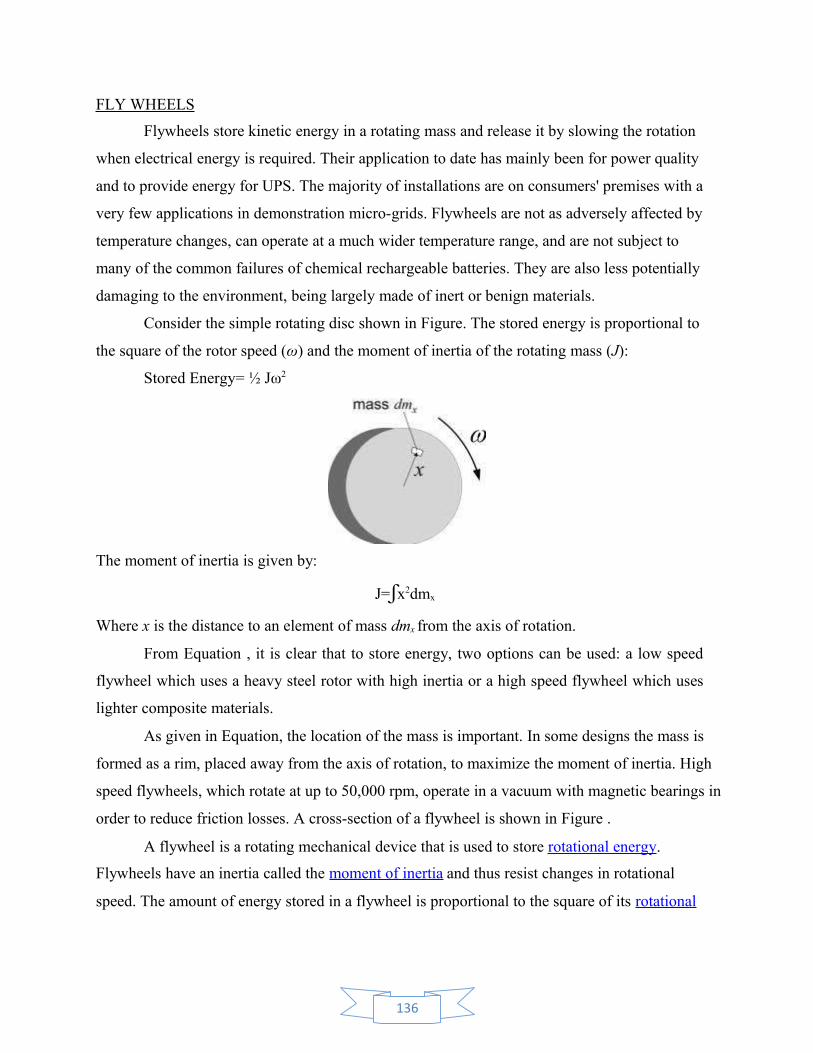
Consider the simple rotating disc shown in Figure. The stored energy is proportional to
the square of the rotor speed (ω) and the moment of inertia of the rotating mass (J):
Stored Energy= ½ Jω2
The moment of inertia is given by:
J=ʃx2dmx
Where x is the distance to an element of mass dmx from the axis of rotation.
From Equation , it is clear that to store energy, two options can be used: a low speed
flywheel which uses a heavy steel rotor with high inertia or a high speed flywheel which uses
lighter composite materials.
As given in Equation, the location of the mass is important. In some designs the mass is
formed as a rim, placed away from the axis of rotation, to maximize the moment of inertia. High
speed flywheels, which rotate at up to 50,000 rpm, operate in a vacuum with magnetic bearings in
order to reduce friction losses. A cross-section of a flywheel is shown in Figure .
A flywheel is a rotating mechanical device that is used to store rotational energy.
Flywheels have an inertia called the moment of inertia and thus resist changes in rotational
speed. The amount of energy stored in a flywheel is proportional to the square of its rotational
136

speed . Energy is transferred to a flywheel by the application of a torque to it, thereby increasing
its rotational speed, and hence its stored energy.
Fig : Cross Section of Flywheel
APPLICATIONS
Flywheels are used in Buses, Cars, Container Cranes, Construction Machines, Garbage
Trucks, Charging Stations, Train Stations, Trams, Micro-Grid Stabilization and Power Quality.
Case study 1: Energy storage for wind power
The BES system uses a multi-modular converter shown in Figure 12.14a. The switches in
each bridge are switched to obtain a step-wise output as shown Figure 12.14b.
During the positive half cycle, all the upper switches on the first arm of the bridges (S1 to
S6) were on; whereas during the negative half cycle, all the lower switches on the first arm ( ̄
S1 to ̄ S6) were on.
Within a half-cycle, staircase modulation was achieved by switching the switches of the
second arm. In order to obtain a step of Vdc, one lower switch of the second arm was turned on.
For example, when S11 was on and all the other lower switches of the second arm (that is, S21,
S31, S41, S51 and S61) were off, the output, Vo, was equal to Vdc. To obtain a step of 2Vdc,two
lower switches of the second arm were turned on. Finally, to obtain 6Vdc, all the lower switches
of the second arm of the bridges were turned on.
Table 12.2 shows one possible combination of switching status during the positive and
negative half cycles. The switches which were turned on were cyclically varied so as to extract
137

equal amounts of energy from each battery. That is, during the first cycle, Bridge 1 was used
to obtain Vdc; whereas during the second cycle, Bridge 2 was used to obtain Vdc. Turn-on
times (β1, β2, and so on) were obtained by an optimisation routine where the error between
the waveform shown in Figure 12.14(b) and a sinusoidal waveform was minimised.
Figure 12.14 Inverters and Waveforms
138

Using the BES shown in Figure 12.14a, the system shown in Figure 12.13 was simulated.
As shown in Figure 12.15a, a varying wind speed was applied to the fixed speed wind turbine. The
simulations started at 6 a.m. and finished at 6 a.m. on the next day. From 6 a.m. to 10 p.m. the
BES was controlled to maintain the total power supplied to the grid at 2 MW as shown in Figure
12.15d. From 10 p.m. to 6 a.m. the following day, the load was set to zero and the wind power
was used to charge the BES. Figure 12.15e shows the State Of Charge (SOC) of each battery
bank of the six-level converter. As can be seen, the SOC reduced from 6 a.m. to 10 p.m. and then
increased. The SOC in each bridge (SOC1 is the state of charge of the battery in Bridge 1, and so
on) was balanced by the cyclic modulation technique.
139
12.4 Case study 2: Agent-based control of electrical vehicle battery charging
Many countries are promoting Electric Vehicles (EV) as a means of de-carbonizing their
transport sectors. From the power system point of view, EVs can be viewed not only as loads but
also as distributed energy storage devices. It is anticipated that EVs will communicate with the
Smart Grid to provide electrical energy demand-shifting services such as reducing their charging
rate or delivering electricity to the grid.
In this case study, two charging regimes, uncontrolled EV charging (where all the
consumers charge their EVs just after returning home) and controlled EV charging, were
investigated. A Multi Agent System (MAS) was used for controlled EV charging. More
information about MAS can be found in.
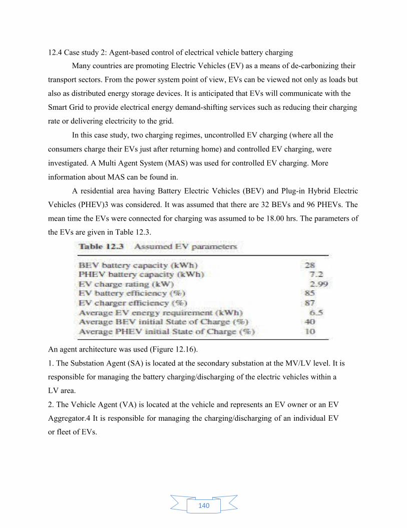
A residential area having Battery Electric Vehicles (BEV) and Plug-in Hybrid Electric
Vehicles (PHEV)3 was considered. It was assumed that there are 32 BEVs and 96 PHEVs. The
mean time the EVs were connected for charging was assumed to be 18.00 hrs. The parameters of
the EVs are given in Table 12.3.
An agent architecture was used (Figure 12.16).
1. The Substation Agent (SA) is located at the secondary substation at the MV/LV level. It is
responsible for managing the battery charging/discharging of the electric vehicles within a
LV area.
2. The Vehicle Agent (VA) is located at the vehicle and represents an EV owner or an EV
Aggregator.4 It is responsible for managing the charging/discharging of an individual EV
or fleet of EVs.
140

Figure 12.16 Multi Agent-based Electrical Vehicle charging and discharging architecture
Figure 12.17 UML diagram of agent communication
141

The case study considers the case when the SA detects an overload on the transformer of
the MV/LV substation. The policy examined is to avoid the violation of the loading limit which
is assumed to be 700 kVA. The procedure followed is based on the FIPA Request Interaction
Protocol and is shown in Unified Modeling Language (UML) notation in Figure 12.17.
The SA initiates requests to the VAs.
The VAs respond to the requests providing a number of possible charging schedules
based on the EV owner preferences and the EV equipment characteristics.
The SA evaluates the responses based on the loading limit and decides the charging
profiles that need to be followed.
CYBER SECURITY
Cyber Security is vital to protect electrical infrastructure from cyber intrusion.
Generation, Transmission and Distribution automation system collects operational information
from dispersed locations on centrally located servers. This information exchange between
centrally located servers and field equipment is achieved through various communications
medium on open standards. These systems are also connected to corporate network for sharing
energy information to different business model .The use of open standard and connectivity to
public networks has exposed systems to cyber-attack. Cyber security is an important part of
Smart Grid
With the introduction of information and communication technology in power sector and
also applying the concepts of smart grid, the whole power sector is now available in the cyber
space. This has exposed electricity sector to cyber-attacks.
Due to the interconnection of information networks increased number of entry points and
paths are now available for potential adversaries and unauthorized users to disrupt electricity
services. Power sector application like SCADA, WAMS , AMI , OMS that are using these
information networks becomes vulnerable to the attack. Any attack on AMI, SCADA, and OMS
may lead to commercial loss apart from breach of important information and jeopardize of
controlling and monitoring operation of grid. For example any attack on centralized distribution
monitoring system can cause power supply failure. A disruption to critical
infrastructure/customers like Hospitals, Metro, and Railways etc. is of strategic concern.
142

Cyber Security Requirements
To address cyber threats, security measures in smart grid are classified into following five
(5) Categories:
Availability: - Availability means information network are available for use by the appropriate
parties in the manner intended. Availability of system is ensured by monitoring the ICT network
at device level, communication level and at control centre end.
Authorization: Authorization is a security service that ensures that a party may only perform the
actions that they're allowed to perform
Integrity: - Integrity assures that data/information cannot be altered in an unauthorized or
malicious manner. Strong Point to point communication schemes are used to prevent spoofing
and injection of false data.
Confidentiality:-means data/information is being protected from being disclosed to third party.
Confidentiality of data and information is achieved by providing role based access at both data &
information level and device level.
Authentication: - Authentication provides assurance that a party in data communication is who or
what they claim to be.
Table 3: Comparison of security requirements between the Smart Grid and the Internet
Security Functions Smart Grid Communication Network The Internet
AuthenticationAnd access control
Strictly enforced for allCommunication flows throughout thesystem
Mostly free end-to-end withoutaccess control
Attack detection andcountermeasures
Essential and widely-Deployed everywhere
Mainly for critical routers andservers
Every node Basic cryptographic functions No specification
Security for networkprotocols
From MAC-layer to application-layerSecurity
From network-layer toapplication Layer Security
143
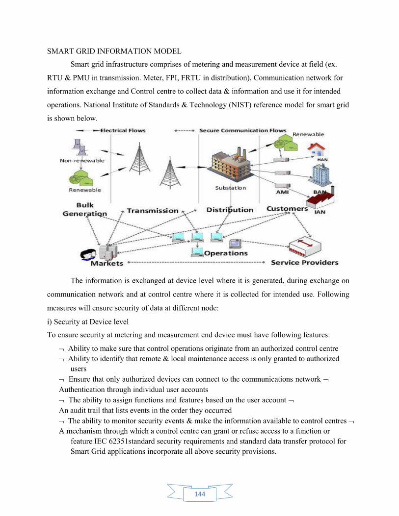
SMART GRID INFORMATION MODEL
Smart grid infrastructure comprises of metering and measurement device at field (ex.
RTU & PMU in transmission. Meter, FPI, FRTU in distribution), Communication network for
information exchange and Control centre to collect data & information and use it for intended
operations. National Institute of Standards & Technology (NIST) reference model for smart grid
is shown below.
The information is exchanged at device level where it is generated, during exchange on
communication network and at control centre where it is collected for intended use. Following
measures will ensure security of data at different node:
i) Security at Device level
To ensure security at metering and measurement end device must have following features:
Ability to make sure that control operations originate from an authorized control centre Ability to identify that remote & local maintenance access is only granted to authorized
users Ensure that only authorized devices can connect to the communications network Authentication through individual user accounts The ability to assign functions and features based on the user account An audit trail that lists events in the order they occurred The ability to monitor security events & make the information available to control centres A mechanism through which a control centre can grant or refuse access to a function or
feature IEC 62351standard security requirements and standard data transfer protocol for Smart Grid applications incorporate all above security provisions.
144

ii) Securing the communication link:
On communication link, connections are generally established on TCP/IP link using standard Point to Point (PPP) protocol with Hand shake Authentication (CHAP) authentication. Communication link can also be secured by setting up Virtual Private Network (VPN) to ensure the authenticity of both networks endpoints and the confidentiality of the data.
iii) Securing control centreAt control Centre end, the customer information is protected, with only authorized
systems being allowed to access specific sets of data. Following standard ITsecurity measures are used for ensuring security at control centre:-Firewall Protection for Network:
A technological barrier designed to prevent unauthorized access or unwanted communications between sections of a computer network. A firewall is a dedicated appliance or software running on a computer/ dedicated Hardware, which inspects network traffic passing through it, and denies or permits passage based on a set of rules. It is placed between a protected network (Control centre) and an unprotected network (users and field devices used to provide information) access and acts like a gate to protect assets to ensure that nothing private goes out and nothing malicious comes in.
Antivirus Protection: Anti-virus software keeps Viruses away from the system. They prevent the
attack from several types of viruses such as Spyware, Adware, Trojans, Malware,and Worms. Without anti-virus protection, system are vulnerable to virus attacklike changing registry settings to make all programs unusable, corrupting orremoving vital system files to make the system unbootable, and change the userpassword to make it almost-impossible to login to your computer.
Apart from implementing required measures at all levelfollowing security checks should be carried out regularly to ensure that ITinfrastructure is Cyber Secured. Regular third-party external and internal security audits Controlling endpoints
Segment sensitive systems and information Auditing networks protection (policy, rules ofnetwork devices) Auditing web applications Searching for bad passwords Integrating security intoevery project plan