united states army fm 5-250 - 15 june 1992 explosives
TRANSCRIPT

8/14/2019 United States Army Fm 5-250 - 15 June 1992 Explosives
http://slidepdf.com/reader/full/united-states-army-fm-5-250-15-june-1992-explosives 1/275
FM 5-250DEPARTMENT OF THE ARMY FIELD MANUAL
EXPLOSIVES
AND
DEMOLITIONS
HEADQUARTERS DEPARTMENT OF THE ARMY
Washington, DC, 15 June 1992
8/14/2019 United States Army Fm 5-250 - 15 June 1992 Explosives
http://slidepdf.com/reader/full/united-states-army-fm-5-250-15-june-1992-explosives 2/275
FM 5-250
Field Manual5-250
HEADQUARTERSDEPARTMENT OF THE ARMY
Washington, DC, 15 June 1992
i

8/14/2019 United States Army Fm 5-250 - 15 June 1992 Explosives
http://slidepdf.com/reader/full/united-states-army-fm-5-250-15-june-1992-explosives 3/275
FM 5-250
ii

8/14/2019 United States Army Fm 5-250 - 15 June 1992 Explosives
http://slidepdf.com/reader/full/united-states-army-fm-5-250-15-june-1992-explosives 4/275
FM 5-250
i i i
8/14/2019 United States Army Fm 5-250 - 15 June 1992 Explosives
http://slidepdf.com/reader/full/united-states-army-fm-5-250-15-june-1992-explosives 5/275
FM 5-250
i v
8/14/2019 United States Army Fm 5-250 - 15 June 1992 Explosives
http://slidepdf.com/reader/full/united-states-army-fm-5-250-15-june-1992-explosives 6/275
FM 5-250
v

8/14/2019 United States Army Fm 5-250 - 15 June 1992 Explosives
http://slidepdf.com/reader/full/united-states-army-fm-5-250-15-june-1992-explosives 7/275
FM 5-250
vi
8/14/2019 United States Army Fm 5-250 - 15 June 1992 Explosives
http://slidepdf.com/reader/full/united-states-army-fm-5-250-15-june-1992-explosives 8/275
FM 5-250
v i i

8/14/2019 United States Army Fm 5-250 - 15 June 1992 Explosives
http://slidepdf.com/reader/full/united-states-army-fm-5-250-15-june-1992-explosives 9/275
FM 5-250
viii
8/14/2019 United States Army Fm 5-250 - 15 June 1992 Explosives
http://slidepdf.com/reader/full/united-states-army-fm-5-250-15-june-1992-explosives 10/275
FM 5-250
i x

8/14/2019 United States Army Fm 5-250 - 15 June 1992 Explosives
http://slidepdf.com/reader/full/united-states-army-fm-5-250-15-june-1992-explosives 11/275
FM 5-250
x
8/14/2019 United States Army Fm 5-250 - 15 June 1992 Explosives
http://slidepdf.com/reader/full/united-states-army-fm-5-250-15-june-1992-explosives 12/275
FM 5-250
x i

8/14/2019 United States Army Fm 5-250 - 15 June 1992 Explosives
http://slidepdf.com/reader/full/united-states-army-fm-5-250-15-june-1992-explosives 13/275
FM 5-250
xi i

8/14/2019 United States Army Fm 5-250 - 15 June 1992 Explosives
http://slidepdf.com/reader/full/united-states-army-fm-5-250-15-june-1992-explosives 14/275
FM 5-250
xiii
8/14/2019 United States Army Fm 5-250 - 15 June 1992 Explosives
http://slidepdf.com/reader/full/united-states-army-fm-5-250-15-june-1992-explosives 15/275
FM 5-250
x i v
8/14/2019 United States Army Fm 5-250 - 15 June 1992 Explosives
http://slidepdf.com/reader/full/united-states-army-fm-5-250-15-june-1992-explosives 16/275
FM 5-250
x v

8/14/2019 United States Army Fm 5-250 - 15 June 1992 Explosives
http://slidepdf.com/reader/full/united-states-army-fm-5-250-15-june-1992-explosives 17/275
FM 5-250
x v i
8/14/2019 United States Army Fm 5-250 - 15 June 1992 Explosives
http://slidepdf.com/reader/full/united-states-army-fm-5-250-15-june-1992-explosives 18/275
FM 5-250
xvii

8/14/2019 United States Army Fm 5-250 - 15 June 1992 Explosives
http://slidepdf.com/reader/full/united-states-army-fm-5-250-15-june-1992-explosives 19/275
FM 5-250
x v i i i

8/14/2019 United States Army Fm 5-250 - 15 June 1992 Explosives
http://slidepdf.com/reader/full/united-states-army-fm-5-250-15-june-1992-explosives 20/275
FM 5-250
xix
8/14/2019 United States Army Fm 5-250 - 15 June 1992 Explosives
http://slidepdf.com/reader/full/united-states-army-fm-5-250-15-june-1992-explosives 21/275
FM 5-250
x x

8/14/2019 United States Army Fm 5-250 - 15 June 1992 Explosives
http://slidepdf.com/reader/full/united-states-army-fm-5-250-15-june-1992-explosives 22/275
FM 5-250
x x i i

8/14/2019 United States Army Fm 5-250 - 15 June 1992 Explosives
http://slidepdf.com/reader/full/united-states-army-fm-5-250-15-june-1992-explosives 23/275
FM 5-250
x x i
8/14/2019 United States Army Fm 5-250 - 15 June 1992 Explosives
http://slidepdf.com/reader/full/united-states-army-fm-5-250-15-june-1992-explosives 24/275
FM 5-250
x x i v
8/14/2019 United States Army Fm 5-250 - 15 June 1992 Explosives
http://slidepdf.com/reader/full/united-states-army-fm-5-250-15-june-1992-explosives 25/275
FM 5-250
xxiii
8/14/2019 United States Army Fm 5-250 - 15 June 1992 Explosives
http://slidepdf.com/reader/full/united-states-army-fm-5-250-15-june-1992-explosives 26/275
FM 5-250
xxv

8/14/2019 United States Army Fm 5-250 - 15 June 1992 Explosives
http://slidepdf.com/reader/full/united-states-army-fm-5-250-15-june-1992-explosives 27/275
FM 5-250
xxvi
8/14/2019 United States Army Fm 5-250 - 15 June 1992 Explosives
http://slidepdf.com/reader/full/united-states-army-fm-5-250-15-june-1992-explosives 28/275
FM 5-250
xxvii

8/14/2019 United States Army Fm 5-250 - 15 June 1992 Explosives
http://slidepdf.com/reader/full/united-states-army-fm-5-250-15-june-1992-explosives 29/275
FM 5-250
Preface
The pu rpose of this manual is to prov ide techn ical information on explosives used by Un itedStates military forces and their m ost frequent ap plications. This m anu al does n ot d iscuss allapplications but presents the most current information on demolition procedures used in most
situations.
If used properly, explosives serve as a combat mu ltiplier to deny man euverability to the enemy.Focusing m ainly on these countermobility op erations, this man ual p rovides a basic theory of explosives, their characteristics and common uses, formulas for calculating various types of charges,and standard methods of priming and placing these charges.
When faced with unusual situations, the responsible engineer must either adapt one of therecommended demolition methods or design the demolition from basic principles presented in thisand other m anu als. The officer in charge mu st maintain u ltimate responsibility for the demolitiondesign, ensu ring th e safe and efficient ap plication of explosives.
Acknowledgment
Acknowledgm ent is gratefully mad e to the British Ministry of Defence for perm itting th ereprod uction of p ortions of the "Royal Engineers Training Notes No. 35 (Special) – An Imp rovedGuide to Bridge Demolitions," 1976.
The proponent for th is publication is HQ, TRADOC. Submit changes for improving this p ublicationon DA Form 2028 and forward it to Commandant, US Army Engineer School, ATTN:ATSE-TDM-P, Fort Leon ard Wood , Missou ri 65473-6650.
The provisions of this pu blication are th e subject of intern ational agreem ents: STANAG 2017(ENGR), Orders to the Demolition Guard Commander and Demolition Firing Party Commander
(Non-Nuclear):STANAG 2123 (ENGR), Obstacle Folder; QSTAG 508, Orders to the DemolitionGuard Commander and Demolition Firing Party Commander; and QSTAG 743, Obstacle Target Folder.
Unless this publication states otherwise, masculine nouns and pronouns do not refer exclusively tomen.
This publication contains copyrighted material.
xxix
8/14/2019 United States Army Fm 5-250 - 15 June 1992 Explosives
http://slidepdf.com/reader/full/united-states-army-fm-5-250-15-june-1992-explosives 30/275
FM 5-250
Chapter 1
Military Explosives
Section I. Dem olition Materials
1-1. Characteristics. To be suitable for use in military operations, explosives must have certainproperties. Military explosives—
Shou ld be inexpensive to man ufacture and capable of being p rod uced from read ilyavailable raw materials.
Must be relatively insensitive to shock or friction, yet be able to positively detonate byeasily prepared initiators.
Must be capable of shattering and mu st have the potential energy (high energy outpu tper u nit volume) adequate for the purp ose of demolitions.
Must be stable enough to retain usefulness for a reasonable time when stored intemperatures between -80 and +165 degrees Fahrenheit.
Should be composed of high-density materials (weight per unit volume).
Should be suitable for use un derwater or in dam p climates.
Should be minimally toxic when stored, handled, and detonated.
1-2. Selection of Explosives. Select explosives that fit the particular p ur pose, based on theirrelative power. Consider all characteristics when selecting an explosive for a particular demolitionproject. See Technical Manual (TM) 9-1300-214 for detailed information on military explosives.Table 1-1 (page 1-2) contains significant information regard ing m any of the explosives describedbelow.
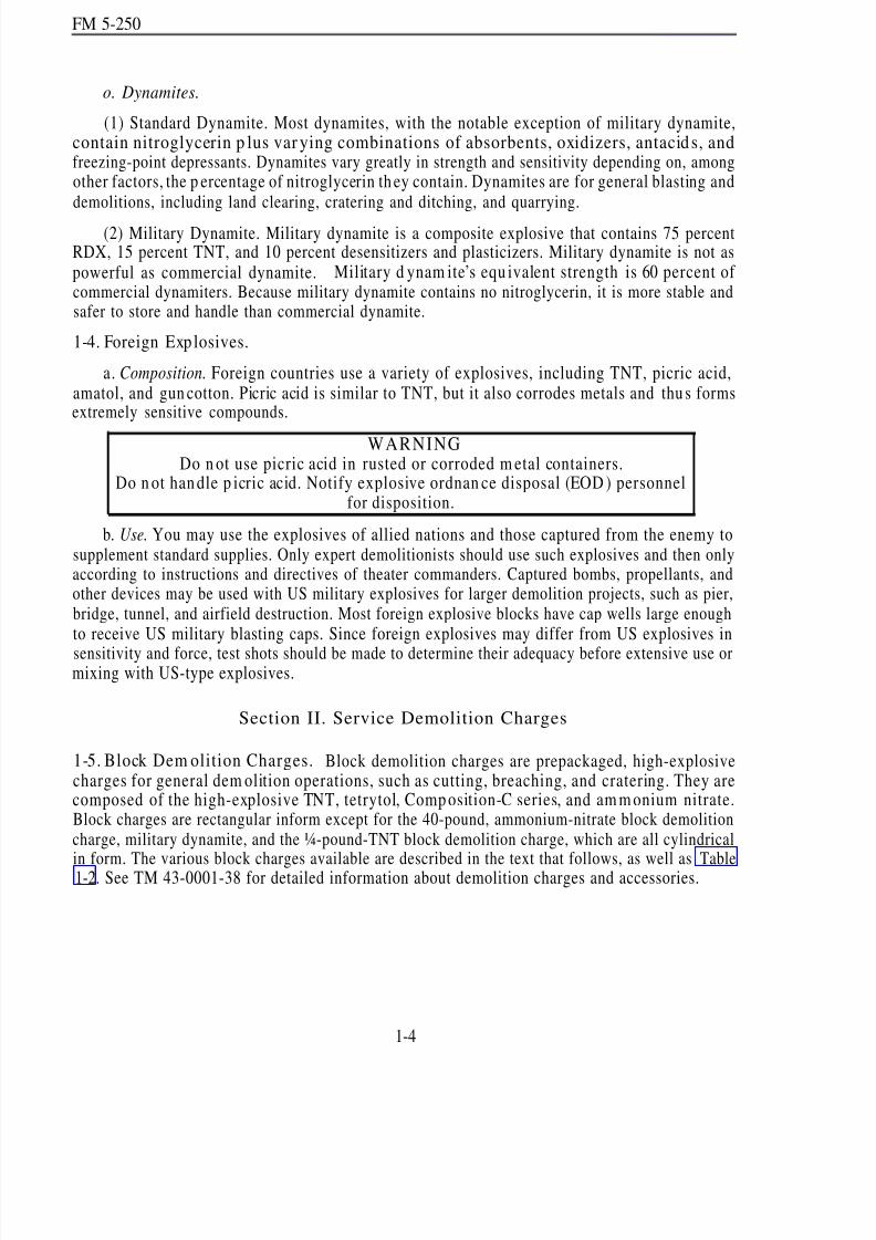
1-3. Domestic Explosives.
a. Ammonium Nitrate. Ammonium nitrate is the least sensitive of the military explosives. Itrequ ires a booster charge to successfully initiate detonation. Because of its low sensitivity,ammonium nitrate is a component of many composite explosives (combined with a more sensitiveexplosive). Ammonium nitrate is not suitable for cutting or breaching charges because it has a lowdetonating velocity. How ever, because of its excellent cratering affects and low cost, amm oniumnitrate is a comp onent of most cratering and d itching charges. Commercial quarrying op erationsuse ammonium nitrate demolitions extensively. Pack ammonium nitrate in an airtight containerbecause it is extremely hydroscopic (absorbs hu midity). Ammonium nitrate or compositeexplosives containing ammonium nitrate are not suitable for underwater use unless packed in
waterproof containers or detonated immediately after placement.
b. Pentaerythrite Tetranitrate (PETN). PETN is a highly sensitive and very powerful militaryexplosive. Its explosive potential is comparable to cyclonite (RDX) and nitroglycerin. Boosters,detonating cord, and some blasting caps contain PETN. It is also used in composite explosives withtrinitrotolu ene (TN T) or w ith nitrocellulose. A PETN-nitrocellulose comp osite (Ml 18 sheetexplosive) is a demolition charge.it is almost insoluble in water.
The PETN explosive is a good un derw ater-demolition because
1-1

8/14/2019 United States Army Fm 5-250 - 15 June 1992 Explosives
http://slidepdf.com/reader/full/united-states-army-fm-5-250-15-june-1992-explosives 31/275
FM 5-250
c. Cyclotrimethlenetrinitramine (RDX). RDX is also a highly sensitive and very powerfulmilitary explosive. It forms the base charge in the M6 electric and M7 nonelectric blasting caps.When RDX is desensitized, it serves as a subbooster, booster, bursting charge, or demolition charge.The principal use for RDX is in composite explosives, such as Composition A, B, and C explosives.RDX is available commercially under the name cyclonite.
1-2

8/14/2019 United States Army Fm 5-250 - 15 June 1992 Explosives
http://slidepdf.com/reader/full/united-states-army-fm-5-250-15-june-1992-explosives 32/275
FM 5-250
d. Trinitrotoluene. TNT is the most common military explosive. It m aybe in comp osite form,such as a booster, a bursting, or a dem olition charge, or in a noncomp osite form. Since TNT is astandard explosive, it is used to rate other military explosives.
e. Tetryl. Tetryl is an effective booster charge in its noncomp osite form and a bu rsting or ademolition charge in composite forms. Tetryl is more sensitive and powerful than TNT. However,
RDX- and PETN-based explosives, which have increased power an d shattering effects, are replacingtetryl and composite explosives containing tetryl.
f. Nitroglycerin. N itroglycerin is one of the most powerful high exp losives. Its explosivepotential is comp arable to RDX and PETN. Nitroglycerin is the explosive base for commercialdynamites. Nitroglycerine is highly sensitive and extremely temperature-sensitive. Militaryexplosives do not use nitroglycerin because of its sensitivity. Do not use commercial dynamites incombat areas.
g. Black Powder. Black powd er is the oldest-known explosive and prop ellant. It is a comp ositeof potassium or sod ium n itrate, charcoal, and su lfur . Time fuses, some igniters, and some detonatorscontain black p owder.
h. Amatol. Amatol is a mixture of ammonium nitrate and TNT. It is a substitute for TNT inbursting charges. Some older bangalore torpedoes use 80-20 amatol (80 percent ammonium nitrateand 20 percent TNT). Because am atol contains am monium nitrate, it is a hyd roscopic comp oun d.Keep any explosives containing amatol in airtight containers. If properly packaged, amatol remainsviable for long periods of time, with no change in sensitivity, power, or stability.
i. Composition A 3. Composition A3 is a composite explosive containing 91 percent RDX and9 percent wax. The purp ose of the wax is to coat, desensitize, and bind the RDX particles.Composition A3 is the booster charge in some newer shaped charges and bangalore torpedoes.High-explosive plastic (HEP) projectiles may also contain Composition A3 as a main charge.
j. Composition B. Com position B is a comp osite explosive contain ing ap pr oximately 60
per cent RDX, 39 percent TNT, and 1 percent wax. It is more sensitive th an TNT. Because of itsshattering power and high rate of detonation, Composition B is the main charge in shaped charges.
k. Composition B4. Composition B4 contains 60 percent RDX, 39.5 percent TNT, and 0.5percent calcium silicate. Comp osition B4 is the main charge in newer mod els of bangaloretorpedoes and shap ed charges.
l. Composition C4 (C4). C4 is a composite explosive containing 91 percent RDX and 9 percentnonexplosive plasticizers. Bur ster charges are comp osed of C4. C4 is effective in tem peratu resbetween -70 to+ 170 degrees Fahrenheit; however, C4 loses its p lasticity in the colder tem peratu res.
m. Tetrytol. Tetrytol is a composite explosive containing 75 percent tetryl and 25 percent TNT.
It is the explosive comp onent in d emolition charges. Booster charges require d ifferent m ixtures of tetryl and TNT. Tetrytol is more powerful than its ind ividual components, is better at shatteringthan TNT, and is less sensitive than tetryl.
n. Pentolite. Pentolite is a m ixture of PETN an d TNT. Because of its high p ower anddetonating rate, a mixtur e of 50-50 pen tolite (50 percent PETN and 50 percent TNT) ma kes aneffective booster charge in certain m odels of shap ed charges.
1-3
8/14/2019 United States Army Fm 5-250 - 15 June 1992 Explosives
http://slidepdf.com/reader/full/united-states-army-fm-5-250-15-june-1992-explosives 33/275
FM 5-250
o. Dynamites.
(1) Standard Dynamite. Most dynamites, with the notable exception of military dynamite,contain nitroglycerin p lus var ying combinations of absorbents, oxidizers, antacid s, andfreezing-point depressants. Dynamites vary greatly in strength and sensitivity depending on, amongother factors, the p ercentage of nitroglycerin th ey contain. Dynamites are for general blasting anddemolitions, including land clearing, cratering and ditching, and quarrying.
(2) Military Dynamite. Military dynamite is a composite explosive that contains 75 percentRDX, 15 percent TNT, and 10 percent desensitizers and plasticizers. Military dynamite is not aspowerful as commercial dynamite. Military d ynam ite’s equ ivalent strength is 60 percent of commercial dynamiters. Because military dynamite contains no nitroglycerin, it is more stable andsafer to store and handle than commercial dynamite.
1-4. Foreign Explosives.
a. Composition. Foreign countries use a variety of explosives, including TNT, picric acid,amatol, and gun cotton. Picric acid is similar to TNT, but it also corrodes metals and thu s formsextremely sensitive compounds.
WARNINGDo n ot use picric acid in rusted or corroded m etal containers.
Do n ot han dle p icric acid. Notify explosive ordnan ce disposal (EOD ) personnelfor disposition.
b. Use. You may use the explosives of allied nations and those captured from the enemy tosupplement standard supplies. Only expert demolitionists should use such explosives and then onlyaccording to instructions and directives of theater commanders. Captured bombs, propellants, andother devices may be used with US military explosives for larger demolition projects, such as pier,bridge, tunnel, and airfield destruction. Most foreign explosive blocks have cap wells large enoughto receive US military blasting caps. Since foreign explosives may differ from US explosives in
sensitivity and force, test shots should be made to determine their adequacy before extensive use ormixing with US-type explosives.
Section II. Service Demolition Charges
1-5. Block Dem olition Charges. Block demolition charges are prepackaged, high-explosivecharges for general dem olition operations, such as cutting, breaching, and cratering. They arecomposed of the high-explosive TNT, tetrytol, Comp osition-C series, and am m onium nitrate.Block charges are rectangular inform except for the 40-pound, ammonium-nitrate block demolitioncharge, military dynamite, and the ¼-pound-TNT block demolition charge, which are all cylindricalin form. The various block charges available are described in the text that follows, as well as Table1-2. See TM 43-0001-38 for detailed information about demolition charges and accessories.
1-4
8/14/2019 United States Army Fm 5-250 - 15 June 1992 Explosives
http://slidepdf.com/reader/full/united-states-army-fm-5-250-15-june-1992-explosives 34/275
FM 5-250
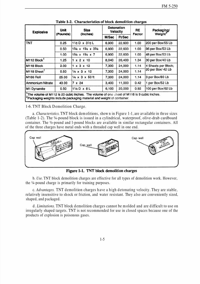
1-6. TNT Block D emolition Charge.
a. Characteristics. TNT block dem olitions, show n in Figur e 1-1, are available in thr ee sizes(Table 1-2). The ¼-pound block is issued in a cylindrical, waterproof, olive-drab cardboardcontainer. The ½-pound and l-pound blocks are available in similar rectangular containers. Allof the three charges have metal ends with a threaded cap well in one end.
b. Use. TNT block demolition charges are effective for all types of demolition work. However,the ¼-pound charge is primarily for training purposes.
c. Advantages. TNT d emolition charges h ave a h igh d etonating velocity. They are stable,relatively insensitive to sh ock or friction, and water resistant. They a lso are conveniently sized,
shaped, and p ackaged.
d . Limitations. TNT block d emolition charges cannot be m olded and are d ifficult to use onirregularly shaped targets. TNT is not recommended for use in closed spaces because one of theproducts of explosion is poisonous gases.
1-5
8/14/2019 United States Army Fm 5-250 - 15 June 1992 Explosives
http://slidepdf.com/reader/full/united-states-army-fm-5-250-15-june-1992-explosives 35/275
FM 5-250
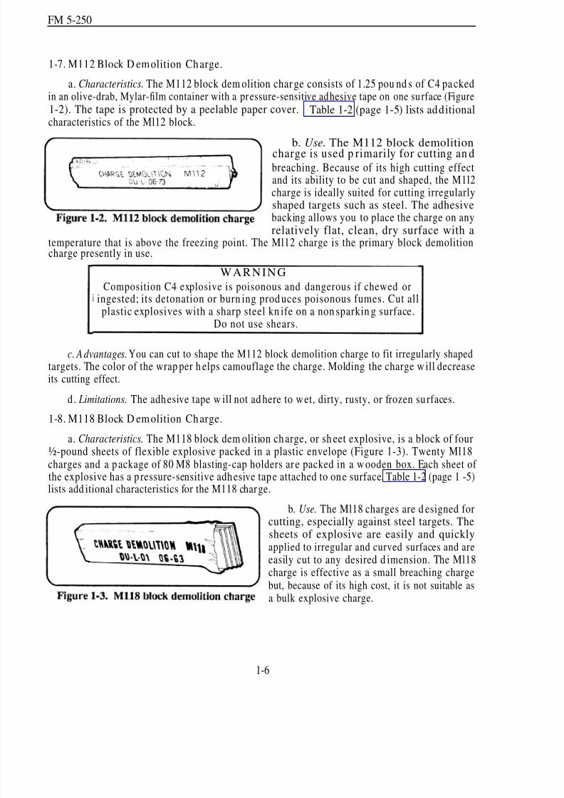
1-7. M112 Block D emolition Charge.
a. Characteristics. The M112 block dem olition char ge consists of 1.25 pou nd s of C4 pa ckedin an olive-drab, Mylar-film container with a pressure-sensitive adhesive tape on one surface (Figure1-2). The tape is protected by a peelable paper cover. Table 1-2 (page 1-5) lists additionalcharacteristics of the Ml12 block.
b. Use. The M112 block demolitioncharge is used p rimarily for cutting an d
breaching. Because of its high cutting effectand its ability to be cut and shaped, the M1l2charge is ideally suited for cutting irregularlyshaped targets such as steel. The adhesivebacking allows you to place the charge on anyrelatively flat, clean, dry surface with a
temperature that is above the freezing point. The Ml12 charge is the primary block demolitioncharge presently in use.
WARNING
Composition C4 explosive is poisonous and dangerous if chewed oringested; its detonation or burn ing prod uces poisonous fumes. Cut allplastic explosives with a sharp steel kn ife on a non sparkin g surface.
Do not use shears.
c. Advantages. You can cut to shape the M112 block demolition charge to fit irregularly shapedtargets. The color of the wrap per h elps camouflage the charge. Molding the charge w ill decreaseits cutting effect.
d. Limitations. The adhesive tape w ill not ad here to w et, dirty, rusty, or frozen su rfaces.
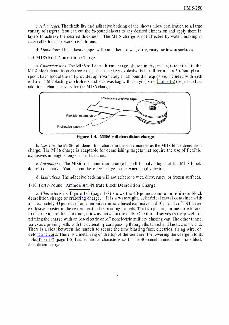
1-8. M118 Block D emolition Charge.
a. Characteristics. The M118 block dem olition ch arge, or sh eet explosive, is a block of four½-pound sheets of flexible explosive packed in a plastic envelope (Figure 1-3). Twenty Ml18charges and a package of 80 M8 blasting-cap holders ar e packed in a w ooden box. Each sheet of the explosive has a p ressure-sensitive adhesive tape attached to one surface. Table 1-2 (page 1 -5)lists add itional characteristics for the M118 charge.
1-6
b. Use. The Ml18 charges are d esigned forcutting, especially against steel targets. Thesheets of explosive are easily and quicklyapplied to irregular and curved surfaces and are
easily cut to any desired d imension. The Ml18charge is effective as a small breaching chargebut, because of its high cost, it is not suitable asa bulk explosive charge.
8/14/2019 United States Army Fm 5-250 - 15 June 1992 Explosives
http://slidepdf.com/reader/full/united-states-army-fm-5-250-15-june-1992-explosives 36/275
FM 5-250
c. Advantages. The flexibility and adh esive backing of the sheets allow ap plication to a largevariety of targets. You can cut the ½-pound sheets to any desired dimension and apply them inlayers to achieve the desired thickness. The Ml18 charge is not affected by water, making itacceptable for underwater demolitions.
d. Limitations. The adhesive tape will not adhere to wet, dirty, rusty, or frozen surfaces.
1-9. M186 Roll Dem olition Charge.
a. Characteristics. The Ml86 roll dem olition char ge, show n in Figu re 1-4, is iden tical to theMl18 block demolition charge except that the sheet explosive is in roll form on a 50-foot, plasticspool. Each foot of the roll provid es app roximately a half poun d of explosive. Included with eachroll are 15 M8 blasting cap h olders and a canvas bag with carrying strap. Table 1-2 (page 1-5) listsadditional characteristics for the M186 charge.
b. Use. Use the M186 roll demolition charge in the same manner as the Ml18 block demolitioncharge. The Ml86 charge is adaptable for demolishing targets that require the use of flexibleexplosives in lengths longer than 12 inches.
c. Advantages. The Ml86 roll demolition charge has all the advantages of the Ml18 block
dem olition charge. You can cut the M186 charge to the exact lengths desired.d . Limitations. The adhesive backing w ill not ad here to w et, dirty, rusty, or frozen surfaces.
1-10. Forty-Pound , Ammon ium -Nitrate Block D emolition Charge
a. Characteristics. Figure 1-5 (page 1-8) shows the 40-pound, ammonium-nitrate block dem olition charge or cratering charge. It is a w atertight, cylindrical metal container w ithapp roximately 30 poun ds of an amm onium -nitrate-based explosive and 10 pou nd s of TNT-basedexplosive booster in the center, next to the p riming tu nnels. The tw o pr iming tu nnels are locatedto the outside of the container, midw ay between th e ends. One tun nel serves as a cap w ell forprim ing the charge w ith an M6 electric or M7 nonelectric military blasting cap. The other tun nelseries as a priming path, with the detonating cord passing through the tunn el and knotted at the end.
There is a cleat between the tunnels to secure the time blasting fuse, electrical firing wire, ordetonating cord. There is a metal ring on th e top of the container for lowering the charge into itshole. Table 1-2 (page 1-5) lists additional characteristics for the 40-pound, ammonium-nitrate blockdemolition charge.
1-7
8/14/2019 United States Army Fm 5-250 - 15 June 1992 Explosives
http://slidepdf.com/reader/full/united-states-army-fm-5-250-15-june-1992-explosives 37/275
FM 5-250
b. Use. This charge is suitable for cratering and ditching operations. Its primary use is as acratering charge, but it also is effective for destroying bu ildings, fortifications, and bridge abutm ents.
c. Advantages. The size and sh ape of this charge m ake it ideal for cratering op erations. It isinexpensive to produce compared to other explosives.
d. Limitations. Ammonium nitrate is hydroscopic. When wet, it will not detonate. To ensuredetonation, use metal containers show ing no evidence of water damage. Detonate all charges placedin wet or damp boreholes as soon as possible.
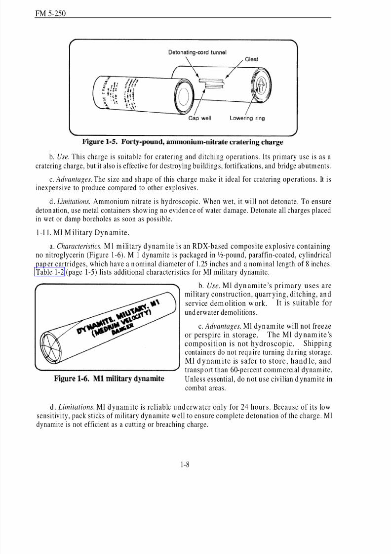
1-11. Ml M ilitary Dyn amite.
a. Characteristics. M1 m ilitary d ynam ite is an RDX-based composite explosive containingno nitroglycerin (Figure 1-6). M 1 dynamite is packaged in ½-pound, paraffin-coated, cylindricalpap er cartridges, which have a n ominal d iameter of 1.25 inches and a nom inal length of 8 inches.Table 1-2 (page 1-5) lists additional characteristics for Ml military dynamite.
b. Use. Ml dyn amite’s primary uses aremilitary construction, quarr ying, ditching, an dservice dem olition work. It is suitable forund erwater demolitions.
c. Advantages. Ml dyn am ite will not freezeor perspire in storage. The Ml dy nam ite’scomposition is not hydroscopic. Shippingcontainers do not requ ire turning du ring storage.Ml d ynam ite is safer to store, hand le, andtransp ort than 60-percent comm ercial dynam ite.Unless essential, do not u se civilian d ynam ite in
combat areas.
d . Limitations. Ml d ynam ite is reliable u nd erw ater only for 24 hour s. Because of its lowsensitivity, pack sticks of military dynamite w ell to ensure complete detonation of the charge. Mldynamite is not efficient as a cutting or breaching charge.
1-8

8/14/2019 United States Army Fm 5-250 - 15 June 1992 Explosives
http://slidepdf.com/reader/full/united-states-army-fm-5-250-15-june-1992-explosives 38/275
FM 5-250
Section III . Special Dem olit ion Ch arges and Assemb lies
1-12. Shap ed Dem olition Charge. The shaped demolition charge used in military operations isa cylind rical block of high explosive. It has a conical cavity in one end that d irects the cone-liningmaterial into a narrow jet to p enetrate m aterials (Figure 1-7). This charge is not effective underwater,since any water in the conical cavity will prevent the high-velocity jet from forming. To obtain
maximu m effectiveness, place the cavity at the specified stand off distance from the target, anddetonate the charge from the exact rear center, using only the prim ing well provided . Never du alprime a shaped charge.
,
a. Characteristics.
(1) Fifteen-Pound, M2A4 Shaped Demolition Charge. The M2A4 charge contains a0.1 l-pou nd (50 gram) booster of Composition A3 and a 11.5-poun d main charge of Comp ositionB. It is packaged three charges per w ooden box (total weight is 65 pou nd s). This charge has amoisture-resisting, molded-fiber container. A cylindrical fiber base slips onto the end of the chargeto pr ovide a 6-inch stand off distance. The cavity liner is a cone o f glass. The charge is 14
15 / 16
inches high and 7 inches in diameter, including the standoff.
(2) Forty-Pound, M3A1 Shap ed Dem olition Charge. The M3A1 char ge contains a 0.1 l-pound(50 gram ) booster of Comp osition A3 and a 29.5-pou nd main charge of Comp osition B. It ispackaged one charge per box (total weight is 65 poun ds). The charge is in a m etal container. Thecone liner also is mad e of metal. A metal tripod prov ides a 15-inch stand off distance. The chargeis 15 ½ inches high and 9 inches in d iameter, not includ ing stand off.
1-9

8/14/2019 United States Army Fm 5-250 - 15 June 1992 Explosives
http://slidepdf.com/reader/full/united-states-army-fm-5-250-15-june-1992-explosives 39/275
FM 5-250
b. Use. A shaped demolition charge’s primary use is for boring holes in earth, metal, masonry,concrete, and paved and unpaved roads. Its effectiveness depend s largely on its shape, composition,and placement. Table 1-3, lists the penetrating capabilities of various materials and the properstandoff distances for these charges.
c. Special Precautions. To achieve the ma ximu m effectiveness of shap ed charges—Center the charge over the target point.
Align the axis of the charge w ith the d irection of the desired h ole.
Use the pedestal to obtain the proper standoff distance.
1-10

8/14/2019 United States Army Fm 5-250 - 15 June 1992 Explosives
http://slidepdf.com/reader/full/united-states-army-fm-5-250-15-june-1992-explosives 40/275
FM 5-250
Susp end th e charge at the p roper h eight on pickets or tripods, if the ped estal does notprovide the proper standoff distance.
Remove any obstruction in the cavity liner or between the charge and the target.
1-13. M183 Demolition Charge Assembly.
a. Characteristics. The Ml83 demolition charge assembly or satchel charge consists of 16M112 (C4) dem olition blocks and 4 priming assemblies. It has a total explosive w eight of 20pou nd s. The d emolition blocks come in tw o bags, eight blocks per bag. The tw o bags come in anM85 canvas carrying case. Tw o M85 cases come in a w ood en box 17 1/ 8 by 11½ by 12½ inches.Each priming assembly consists of a 5-foot length of detonating cord with an RDX booster crimpedto each end and a p air of Ml detonating-cord clips for attaching the pr iming assembly to a detonatingcord ring or line main.
b. Use. The M183 assembly is used primarily forereaching obstacles or demolishing structureswhen large demolition charges are required (Figure 1-8). The M183 charge also is effective againstsmaller obstacles, such as small dragon’s teeth.
c. Detonation. Detonate the Ml83 demolition charge assembly with a priming assembly andan electric or a nonelectric blasting cap or by using a detonating-cord ring main attached bydetonating cord clips.
1-14. M1A2 Bangtlore-Torpedo Demolition Kit.
a. Characteristics. Each k it consists of 10 loading assemb lies, 10 connecting sleeves, and 1nose sleeve. The loading assemblies, or torp edoes, are steel tubes 5 feet long an d 2 1/ 8 inches indiameter, grooved, and capped at each end (Figure 1-9, page 1-12). The torpedoes have a 4-inch,Composition A3 booster (½ pound each) at both ends of each 5-foot section. The main explosivecharge is 10½ pou nd s of Composition B4. The kit is packaged in a 60¾- by 13¾- by 4 9 / 16-inchwooden box and w eighs 198 pound s.
1-11

8/14/2019 United States Army Fm 5-250 - 15 June 1992 Explosives
http://slidepdf.com/reader/full/united-states-army-fm-5-250-15-june-1992-explosives 41/275
FM 5-250
b. Use. The primary u se of the torped o is clearing p aths throu gh w ire obstacles and h eavyun dergrow th. It will clear a 3- to 4-meter-wide path throu gh w ire obstacles.
WARNINGThe Bangalore torpedo may d etonate a live mine w hen being placed.
To prevent detonation of the torpedo during placement, attach the nose sleeveto a fabricated dummy section (approximately the same dimensions
as a single Bangalore section) and p lace the d um my section onto the front endof the torpedo.
c. Assembly. All sections of the torpedo have th readed cap w ells at each end. To assembletwo or m ore sections, press a nose sleeve onto one end of one tube, and th en connect successivetubes, using the connecting sleeves provided until you have the desired length. The connectingsleeves make rigid joints. The nose sleeve allows the u ser to push the torpedo through en tanglementsand across the ground.
d . Detonation. The recommended method to detonate the torpedo is to prime the torpedo witheight wrap s of detonating cord and attach two initiation systems for detonation. Another methodfor prim ing the Bangalore torp edo is by inserting an electric or a nonelectric blasting cap d irectlyinto the cap well. Do not move the torpedo after it has been prepared for detonation. You maywrap the end w ith detonating cord p rior to placing it, but d o not attach the blasting caps un til thetorpedo is in place.
1-15. M180 Dem olition Kit (Craterin g).
a. Characteristics. This kit consists of an M2A4 shaped charge, a modified M57 electricalfiring device, a warh ead, a rocket motor, a tripod, and a d emolition circuit (Figure 1- 10). The shap edcharge, firing device, and war head are perm anently attached to the launch leg of the tripod . Therocket motor and the demolition circuit (packed in a wooden subpack) are shipped separately. The
1-12

8/14/2019 United States Army Fm 5-250 - 15 June 1992 Explosives
http://slidepdf.com/reader/full/united-states-army-fm-5-250-15-june-1992-explosives 42/275
FM 5-250
kit weighs ap proximately 165 pound s (74.25 kilogram s). TM 9-1375-213-12-1 provides theassembly procedures, operational description, and maintenance instructions for the Ml80 kit.
b. Use. The M180 is designed to p rod uce a large crater in comp acted soil or road surfaces,but not in r einforced concrete, arctic tund ra, bedrock, or sand y soil. The charge p rodu ces a craterin tw o stages. The shap ed charge b lows a p ilot hole in th e surface. Then, the rocket-propelledwarhead enters the h ole and d etonates, enlarging the p ilot hole. Up to five kits can be set up closetogether and fired simultaneously to p rodu ce an exceptionally large crater. Up to 15 kits can be
widely spaced and freed simultaneously for airfield pocketing.
WARNINGRegardless of the nu mb er of kits used, the m inimu m safe distances for the
M180 cratering k it are 1,200 meters for u np rotected personn el an d150 meters for personnel u nd er overhead cover.
c. Detonation. When firing the M180, use the M34 50-cap blasting m achine.
Section IV. Dem olition A ccessories
1-16. Time Blastin g Fuse. The time blasting fuse transmits a delayed spit of flame to a nonelectricblasting cap. The d elay allows th e soldier to initiate a charge and get to a safe distance before theexplosion. There are two types of fuses: the M700 time fuse and safety fuse. Althou gh safety fuseis not often employed, it is still available.
1-13

8/14/2019 United States Army Fm 5-250 - 15 June 1992 Explosives
http://slidepdf.com/reader/full/united-states-army-fm-5-250-15-june-1992-explosives 43/275
FM 5-250
a. M700 Time Fuse. The M700 fuse is adar k green cord, 0.2 inches in d iameter, with aplastic cover (Figure 1-1 1). The M700 bum s atan ap proximate r ate of 40 seconds p er foot.However, test the burning rate as outlined inChapter 2 (paragrap h 2-lb(l), page 2-2).Depend ing on the date of manufacture, thecover may be sm ooth or ha ve single yellowband s aroun d the outside at 12- or 18-inchintervals and dou ble yellow ban ds at 60- or90-inch interv als. These band s accommod atehasty measuring. The outside coveringbecomes br ittle and cracks easily in arctic
temperatures. The M700 time fuse is p ackaged in 50-foot coils, two coils per package, five packagesper sealed container, and eight containers (4,000 feet) per wooden box (30 1/ 8 by 15 1/ 8 by 14 7/ 8
inches). The total p ackage weighs 94 pou nd s.
b. Safety Fuse. Safety fuse consists of
black pow der tightly w rapp ed w ith severallayers of fiber and waterproofing material. Theoutside covering becomes brittle and crackseasily in ar ctic temperatu res. The bu rning ratemay vary for the same or different rolls (30 to45 seconds per foot) under differentatmospheric and climatic conditions. This fusemay be any color, but orange is the mostcommon (Figure 1-12). Test each roll in th earea wh ere the charge will be placed (paragraph2-lb(l), page 2-2). Since safety fuse burns
significantly faster u nd erwater, test it un derw ater before preparing an un derw ater charge. Safety
fuse is packaged in 50-foot coils, two coils per package, and 30 packages (3,000 feet) per woodenbox (24¾ by 15¾ by 12 ½ inches). The total p ackage w eighs 93.6 pou nd s.
1-17. Deton atin g Cord.
a. Characteristics. The American, British, Canadian, and Australian (ABCA) StandardizationProgram recognizes this Type 1 detonating cord as the standard detonating cord. Detonating cord(Figure 1-13) consists of a core of high explosive (6.4 pou nd s of PETN p er 1,000 feet) wrap ped ina reinforced and waterp roof olive-drab p lastic coating. This d etonating cord is app roximately 0.2inches in diameter, weighs approximately 18 pounds per 1,000 feet, and has a breaking strength of 175 poun ds. Detonating cord is functional in the sam e temp eratur e range as p lastic explosive,although the cover becomes brittle at lower temperatures. Moisture can penetrate the explosive
filling to a m aximum distance of 6 inches from an y cut or break in th e coating. Water-soakeddetonating cord w ill detonate if there is a dr y end to allow initiation. For this reason, cut off anddiscard th e first 6 inches of any new or u sed d etonating cord tha t nonelectric blasting caps arecrimp ed to. Also, leave a 6-inch overhan g w hen m aking connections or w hen p riming charges.
1-14

8/14/2019 United States Army Fm 5-250 - 15 June 1992 Explosives
http://slidepdf.com/reader/full/united-states-army-fm-5-250-15-june-1992-explosives 44/275
FM 5-250
b. Use. Use detonating cord to p rime and detonate other explosive charges. When thedetonating cord’s explosive core is initiated by a blasting cap, the core will transmit the detonationwav e to an unlimited nu mber of explosive charges. Chapter 2 explains the u se of detonating cordfor these purposes.
c. Precautions. Seal the ends of detonating cord with a waterproof sealant when used to fire
und erwater charges or when charges a re left in place several hours before firing. If left for no longerthan 24 hour s, a 6-inch overlap w ill protect the rema inder of a line from m oisture. Avoid kinks orsharp bends in priming, as they may interrupt or change the direction of detonation and causemisfires. Avoid un intended cross-overs of the d etonating cord w here no explosive connection isintended . To avoid internal cracking d o not step on the d etonating cord.
1-18. Blasting Caps. Blasting caps a re for detonating high explosives. There are two ty pes of blasting caps: electric and nonelectric. They are designed for insertion into cap wells and are alsothe detonating element in certain firing systems and devices. Blasting caps are rated in power,according to the size of their m ain charge. Commercial blasting caps are norm ally Num ber 6 or 8and are for detonating the more sensitive explosives, such as commercial dynamite and tetryl.Special military blasting caps (M6 electric and M7 nonelectric) ensure positive detonation of thegenerally less sensitive military explosives. Their main charge is approximately double that of commercial Num ber 8 blasting caps. Never carry blasting caps loose or in un iform pockets wherethey are subject to shock. Separate blasting caps prop erly. Never store blasting caps w ith otherexplosives. Do not carry blasting caps and other explosives in the sam e truck except in an emergency(paragraph 6-11, page 6-10).
WARNINGHan dle m ilitary and comm ercial blasting caps carefully, as both are
extremely sensitive and may explode if hand led imp roperly.Do n ot tamper w ith b lasting caps. Protect them from shock and extreme heat.
a.Electric Blasting Caps.
Use electric blasting caps when a source of electricity, such as ablasting m achine or a ba ttery, is available. Both m ilitary and comm ercial caps m ay be used .Military caps (Figure 1-14, page 1-6) operate instantan eously. Comm ercial caps m ay op erateinstantaneou sly or have a delay feature. The delay time of commercial caps for military app licationsran ges from 1 to 1.53 seconds. Electric caps have lead w ires of various lengths. The most comm onlead length is 12 feet. Electric caps require 1.5 amperes of power to initiate. The standard-issue cap
1-15

8/14/2019 United States Army Fm 5-250 - 15 June 1992 Explosives
http://slidepdf.com/reader/full/united-states-army-fm-5-250-15-june-1992-explosives 45/275
FM 5-250
is the M6 sp ecial electric blasting cap. TM 43-0001-38 gives ad d itional inform ation on b lastingcaps.
WARNINGDo not remove the short-circuiting shu nt un til ready to test the cap.
Doing this p revents accidental initiation b y static electricity.If the cap has n o shun t, twist the lead’s bare en ds together w ith at least
three 180-degree turn s to provide a sh un ting action.
b. Nonelectric Blasting Caps. Initiate thesecaps with time-blasting fuse, a firing device, ordetonating cord (Figure 1-15). Avoid usingnonelectric blasting caps to p rime u nd erwater
charges because the caps are hard to waterproof.If necessary, waterproof nonelectric blastingcaps with a sealing compound. The M7 specialnonelectric blasting cap is th e stand ard issue.The open end of the M7 special non electricblasting cap is flared to allow easy insertion of the t ime fu se. TM 43-0001-38 gives ad d itionalinformation on blasting caps.
1-19. M lA4 Primin g Ad ap ter. The MIA4priming adapter is a plastic, hexagonal-shapeddevice, threaded to fit threaded cap wells. The
shoulder inside the threaded end will allow time blasting fuse and detonating cord to pass, but theshou lder is too sm all to pass a m ilitary blasting cap. To accomm odate electric blasting caps, theadapter has a lengthwise slot that permits blasting cap lead wires to be quickly and easily installedin the adapter (Figure 1-16).
1-16
8/14/2019 United States Army Fm 5-250 - 15 June 1992 Explosives
http://slidepdf.com/reader/full/united-states-army-fm-5-250-15-june-1992-explosives 46/275
FM 5-250
1-20. M8 Blasting Cap Hold er. The M8blasting cap holder is a m etal clip designedto attach a blasting cap to a sheet explosive(Figure 1-17). These clips are suppliedwith Ml18 sheet demolition charges an dMl86 roll demolition charges. The M8blasting cap h older is also available as aseparate-issue item in quant ities of 4,000.
1-21. Ml D etonating-Cord Clip . TheMl detonating-cord clip is a device for hold ing tw o strand s of detonating cord together, either
parallel or at right angles (Figure 1-18, diagram 1). Using these clips is faster and more efficientthan using knots. Knots, if left for extended p eriods, may loosen and fail to function prop erly.
a. Branch Lines. Connect a detonating cord branch line by p assing it throu gh the trou gh of the Ml detonating cord clip and through the hole in the tongue of the clip. Next, place the line/ ringmain into the tongue of the clip so that it crosses over the branch line at a 90-degree angle and ensure
1-17
8/14/2019 United States Army Fm 5-250 - 15 June 1992 Explosives
http://slidepdf.com/reader/full/united-states-army-fm-5-250-15-june-1992-explosives 47/275
FM 5-250
the crossover is held secure by the tongue; it may be necessary to bend or form the tongue w hiledoing th is. (Figure 1-18, diagram 2, page 1-17).
b. Splices. Splice the end s of detonating cords by first overlapp ing them app roximately 12inches. Then secure each loose end to the other cord by using a clip. Finally, bend the tongu es of the clips firmly over both strands. Make the connection stronger by bending the trough end of the
clip back over the tongue (Figure 1-18, diagr am 3, page 1-17).
1-22. Ml Adhesive Paste. Ml adhesive paste is a sticky, pu tty-like substance that is u sed to attachcharges to flat, overhead or vertical sur faces. Adhesive paste is u seful for hold ing charges w hiletying them in place or, under some conditions, for holding without ties. This paste does not adheresatisfactorily to d irty, du sty, wet, or oily sur faces. Ml adh esive paste becomes useless wh ensoftened by water.
1-23. Pressure-Sensitive Adhesive Tape.
a. Characteristics. Pressure-sensitive tape is replacing Ml ad hesive pa ste. Pressure-sensitivetape has better hold ing prop erties and is more easily and quickly app lied. This tape is coated onboth sides with pressure-sensitive adhesive and requires no solvent or heat to apply. It is availablein 2-inch-wide rolls , 72 yard s long.
b. Use. This tape is effective for holding charges to dry, clean wood, steel, or concrete.
c. Limitations. This tape does not ad here to d irty, wet, oily, or frozen su rfaces.
1-24. Supp lemen tary Adhesive for D emolition Ch arges.
a. Characteristics. Thisadhesive is used to holddemolition charges when thetarget su rface is below freezing,wet, or un derwater. The adhesivecomes in tubes packed inwater-resistant, cardboard slideboxes, with w ooden ap plicators(Figure 1-19).
b. Use. App ly the adhesiveto the target surface and thedemolition block with a woodenapp licator and press the twotogether.
1-25. Waterproof Sealing Comp oun d.This sealant is for w aterp roofing connections between
time blasting fuses or d etonating cords and nonelectric blasting caps. The sealing compou nd willnot make a perman ent waterp roof seal. Since this sealant is not p ermanent, fire und erwaterdemolitions as soon as possible after placing them.
1-26. M2 Cap Crim p er. Use the M2 cap crimper (Figure 1-20) for squeezing the shell of anonelectric blasting cap arou nd a time blasting fuse, standar d coup ling base, or detonating cord .
1-18
8/14/2019 United States Army Fm 5-250 - 15 June 1992 Explosives
http://slidepdf.com/reader/full/united-states-army-fm-5-250-15-june-1992-explosives 48/275
FM 5-250
Crimp the shell securely enough to keep the fuse,base, or cord from being p ulled off, but n ot sotightly that it interferes with the operation of theinitiating device. A stop on the han dle helps tolimit the amount of crimp applied. The M2crimper forms a water-resistant groovecompletely around the blasting cap. Apply asealing compound to the crimped end of theblasting cap to waterproof it. The rear portion of each jaw is shaped and sharpen ed for cuttingfuses and d etonating cords. One leg of thehan dle is pointed for pu nching cap w ells in explosive materials. The other leg has a screwdr iverend. Cap crimpers are made of a soft, nonsparking metal that conducts electricity. Do not use themas pliers because such use damages the crimping su rface. Ensure crimp hole is round (not elongated)and the cutting jaws are not jagged. Keep the cutting jaws clean, and use them only for cutting fusesand detonating cords.
1-27. M51 Blastin g-Cap Test Set.a. Characteristics.The test set is a self-contained u nit with a magn eto-type impu lse generator,
an indicator lamp, a handle to activate the generator, and two binding posts for attaching firing leads.The test set is waterproof and capable of operation at temperatures as low as -40 degrees Fahrenheit(Figure 1-21).
b. Use. Check the continuity of firing w ire,blasting caps, and firing circuits by connectingthe leads to the test-set binding posts and thendep ressing th e hand le sharply. If there is acontinuous (intact) circuit, even one created by a
short circuit, the ind icator lamp will flash. Whenthe circuit is open, the indicator lamp w ill notflash.
c. Maintenance. Handle the test setcarefully and keep it dry to assure optimum use.Before using, ensure th e test set is operatingproperly by using the following procedure:
(1) Hold apiece of bare w ire or the legs of the M2 crimp ers between the bind ing posts.
(2) Depress the handle sharply while observing the indicator lamp. The indicator lamp should
flash.
(3) Remove th e bare w ire or crimper legs from the bind ing posts.
(4) Depress the handle sharply while observing the indicator lamp. This time the indicatorlamp should not flash.
(5) Perform both tests to ensure th e test set is operating p roperly.
1-19

8/14/2019 United States Army Fm 5-250 - 15 June 1992 Explosives
http://slidepdf.com/reader/full/united-states-army-fm-5-250-15-june-1992-explosives 49/275
`FM 5-250
1-28. Blasting M achin es. Blasting machines provide the electric impulse needed to initiate electric
blasting-cap operations. When operated, the M32 and M34 models use an alternator and a capacitorto energize the circuit.
a. M32 10-Cap Blasting Machine. This small, lightw eight blasting machine (Figure 1-22)produces adequate current to initiate 10 electrical caps connected in series using 500 feet of WD-l
cable. To operate the m achine, use the following p rocedure:(1) Check the m achine for p roper operation. Release the blasting m achine hand le by rotating
the retaining ring downward while pushing in on the handle. The handle will automatically springoutward from the body of the machine.
(2) Activate the machine by dep ressing the hand le rapidly three or four times u ntil the neonindicator lamp flashes. The lamp is located between th e w ire terminal posts and cannot be seenuntil it flashes, since it is covered by green plastic.
(3) Insert the firing wire leads into theterminals by pu shing dow n on each terminalpost and inserting the leads into the metal jaws.
(4) Hold the machine upright (terminalsup ) in either hand, so the plunger end of thehand le rests in the base of the palm an d thefingers gra sp th e machine’s bod y. Be sure tohold the m achine correctly, as the hand les areeasily broken.
(5) Squ eeze the hand grip sh arply severaltimes until the charge fires. Normally, no morethan three or four strokes are required.
b. M34 50-Cap Blasting M achine. Thissmall, lightw eight machine produ ces adequ atecurrent to initiate 50 electrical caps connected ina series. It looks like the M32 blasting machine(Figure 1-22) except for a black ban d aroun d thebase and a steel-reinforced a ctuating han dle.Test and operate the M34 in the same manner as
the M32.
1-29. Firin g Wire an d Reels.
a. Types of Firing Wire. Wire for firing electric charges is available in 200- and 500-foot coils.
The two-condu ctor AWG Nu mber 18 is a plastic-covered o r ru bber-covered wire available in500-foot rolls. This wire is wound on an RL39A reel unit. The single-conductor. AWG Number20 annunciator w ire is available in 200-foot coils and is used to make connections between blastingcaps and firing w ire. The WD- l/ TT commu nication w ire will also work, but it requires a greaterpow er source if more than 500 feet are used (blasting machines will not initiate the full-rated nu mber
1-20

8/14/2019 United States Army Fm 5-250 - 15 June 1992 Explosives
http://slidepdf.com/reader/full/united-states-army-fm-5-250-15-june-1992-explosives 50/275
FM 5-250
of caps connected with mor e than 500 feet of WD-l/ TT wire). As a ru le of thu mb, use 10 less capsthan the m achine’s rating for each add itional 1,000 feet of WD-1/ TT wire employed.
b. Reel. The RL39A reel, with sp ool, accomm od ates 500 feet of wire. The reel has a ha nd leassembly, a crank, an axle, and tw o carrying strap s (Figure 1-23). The fixed end of the wire extendsfrom the spool through a hole in the side of the drum and fastens to two brass thumb-out terminals.
The carrying handles are two U-shaped steel rods. A loop at each end encircles a bearing assemblyto accomm odate the axle. The crank is riveted to one end of the axle, and a cotter p in holds the axlein place on the opp osite end.
1-30. Fir ing D evices an d O ther Accessory Equ ipm ent
a. M60 Weatherproof Fuze Igniter. This device is for igniting timed blasting fuse in all weatherconditions, even un derw ater, if properly w aterproofed. Insert the fuse throu gh a ru bber sealinggromm et and into a split collet. This procedure secures the fuse w hen the end capon the igniter istightened (Figure 1-24, page 1-22). Pulling the pull ring releases the striker assembly, allowing the
firing pin to initiate the primer, igniting the fuse.Chapter 2 (page 2-4) gives detailed operating
instru ctions for the M60 igniter.
b. Demolition Equipment Set. This set (Electric and Nonelectric Explosive InitiatingDemolition Equipment Set) is an assembly of tools necessary for performing demolition operations(Table 1-4, page 1-22).
1-21

8/14/2019 United States Army Fm 5-250 - 15 June 1992 Explosives
http://slidepdf.com/reader/full/united-states-army-fm-5-250-15-june-1992-explosives 51/275
FM 5-250
1-22

8/14/2019 United States Army Fm 5-250 - 15 June 1992 Explosives
http://slidepdf.com/reader/full/united-states-army-fm-5-250-15-june-1992-explosives 52/275
FM 5-250
Chapter 2
Initiating Sets, Priming,
and Firing Systems
Section I. Initiating Sets
WARNINGRefer to the safety procedures in Chapter 6
before und ertaking an y dem olitions m ission.
2-1. Nonelectric Initiation Sets.
a. Components Assembly. A nonelectric system uses a nonelectric blasting cap as the initiator.The initiation set consists of a fuse igniter (produces flame that lights the time fuse), the time blastingfuse (transmits the flame that fires the blasting cap), and a nonelectric blasting cap (provides shockadequ ate to d etonate the explosive) (Figur e 2-1). When combined with detonating cord, a singleinitiation set can fire multiple charges.
b. Preparation Sequence. Prep aring d emolitions for nonelectric initiation follows a sp ecifiedprocess. This process includes—
Step 1.
Step 2.
Step 3.
Step 4.
Step 5.
Checking the time fuse.
Preparing the time fuse.
Attaching the fuse igniter.
Installing the primer adapter.
Placing the blasting cap.
2-1

8/14/2019 United States Army Fm 5-250 - 15 June 1992 Explosives
http://slidepdf.com/reader/full/united-states-army-fm-5-250-15-june-1992-explosives 53/275
FM 5-250
(1) Checking Time Fuse. Testevery coil of fuse, or rem nan t of a coil,using the burning-rate test prior to use.One test p er day per coil is sufficient.Never u se the first and last 6 inches of a
coil because moisture may have
penetrated the coil to this length. Usingan M2 crimper, cut and discard a 6-inchlength from th e free end of the fuse(Figure 2-2). Cut off and use a 3-footlength of the fuse to check the burningrate. Ignite the fuse and note the time ittakes for the fuse to burn . Compu te theburning rate per foot by dividing the bumtime in second s by the length in feet. If the test bum does not fall within ± 5seconds of a 40-second-per-foot burnrate, perform another test to verify you rresults.
WARNINGTest burn a 3-foot length of time b lasting fuse
to determin e the exact rate prior to use.
(2) Preparing Time Fuse. Cut the fuse long enou gh to allow th e person d etonating the chargeto reach safety (walking at a norm al pace) before the explosion. Walk and time this d istance pr iorto cutting the fuse to length. The formula for determining the length of time fuse requ ired is—
(2-1)
Make your cut squar ely across the fuse. Do not cut the fuse too far in advance, since the fusemay absorb moisture into the open ends. Do not allow the time fuse to bend sharply, as you maycrack the b lack powd er core, resulting in a misfire.
(3) Attaching Fuze Igniter. To attach an M60 weatherproof fuze igniter, unscrew the fuseholder cap two or three turns, but do not remove the cap. Press the shipping plug into the igniter torelease the split collet (Figure 1-24, page 1-22). Rotate and remove the plug from the igniter. Insertthe free end of the time fuse as far as possible into the space left by the removed shipp ing plu g.Sufficiently tighten the holder cap to hold the fuse and weatherproof the joint.
(4) Installing Priming Adapter. If you use a priming adapter to hold a nonelectric blasting cap,place the time fuse through the adapter before installing (crimping) the blasting cap onto the fuse.Ensure the adapter th reads are pointing to the end of the time fuse that will receive the blasting cap.
(5) Preparing Blasting Caps.
2-2
8/14/2019 United States Army Fm 5-250 - 15 June 1992 Explosives
http://slidepdf.com/reader/full/united-states-army-fm-5-250-15-june-1992-explosives 54/275
FM 5-250
(a) Inspection. Hold th e cap between the th umb and ring finger of one hand , with the forefingerof the same hand on the closed end of the blasting cap. Inspect the blasting cap by looking into theopen end. You should see a yellow-colored ignition charge. If dirt or any foreign matter is present,
do the following:
Aim the open end of the cap at the palm of the second hand .Gently bump the wrist of the cap-holding hand against the wrist of the other hand.
If the foreign m atter does not d islodge, do not u se the cap.
(b) Placing and crimp ing. Use this procedu re for installing blasting caps onto fuse. Using th isprocedure will allow accurate crimping, even in darkness, because finger placement guides thecrimp ers to the open end of the blasting cap. Use the following procedu res to attach a nonelectricblasting cap onto time fuse:
Hold the time blasting fuse vertically with the square-cut end up , and slip the blastingcap gently down over the fuse so the flash charge in the cap touches the fuse.
WARNINGIf the charge in th e cap is n ot in contact with the fu se, the fu se may n ot ignite the cap
(misfire). Never force a time fu se into a blasting cap,for examp le, by twistin g or any other meth od. If the fuse end is flat
or too large to enter th e blasting cap freely, roll the fu se betweenthe thumb and fingers until it will freely enter the cap. A rough, jagged-cut fuse
inserted in a blasting cap can cause a misfire. If the cutting jaw s of the M 2 crimperare unserviceable, use a sharp knife to cut the fuse. When using a knife to cut fuse
squ arely, cut the fuse against a solid, non spark ing surface such as wood.
While applying slight pressure with th e forefinger on the closed end of the cap, grasp th efuse with the thumb and ring finger.
Using the opposite hand, grasp the crimpers. Place the crimping jaws around the cap ata point 1 / 8 to ¼ inch from the open end. The thumb and ring finger that hold the fuse
will be below the crimpers. Rest the second finger of the han d h olding th e fuse on topof the crimpers to prevent the crimpers from sliding up the cap (Figure 2-3, page 2-4).
2-3

8/14/2019 United States Army Fm 5-250 - 15 June 1992 Explosives
http://slidepdf.com/reader/full/united-states-army-fm-5-250-15-june-1992-explosives 55/275
FM 5-250
Extend both arms straight ou t wh ile rotating the h and s so that the closed end of the blastingcap is pointing aw ay from the body and from other personnel.
Crimp th e blasting cap by firmly squeezing the M2 crimper hand les together, maintainingeye contact with the blasting cap. Inspect the crimp after you have finished. Ensure thatthe fuse and cap are properly joined by gently trying to p ull them apart
NOTE: Attach the M60 fuze igniter to the time fuse before crimping a blasting cap to the oppositeend. Do not remove the safety pin until you are ready to d etonate the charge.
WARNINGDo n ot crimp too close to the explosive end of the b lasting cap;
doing th is may cause the cap to detonate.Point the cap out and away from the body d uring crimping.
NOTE: If the cap is to remain in p lace several days before firing, protect the joint betw een the capand the timed blasting fuse with a coat of sealing compound or similar substance. This sealingcompound will not make a waterproof seal; therefore, fire submerged charges immediately.
NOTE: See paragraph 6-8 (page 6-8) for procedures on handling nonelectric misfires.c. Fuse Initiation. To fire the assembly, hold th e M60 igniter in one h and and remov e the
safety pin with the other. Grasp the pull ring and give it a quick, hard p ull. In the event of a misfire,reset the M60 by push ing the plu nger all the way in, rotate it left and right, and attem pt to fire asbefore.
WARNINGWater can enter throu gh the vent h ole in the pu ll rod
when attempting to reset the igniter under water.
This will prevent the fuse igniter from work ing after resetting.
2-4
8/14/2019 United States Army Fm 5-250 - 15 June 1992 Explosives
http://slidepdf.com/reader/full/united-states-army-fm-5-250-15-june-1992-explosives 56/275
FM 5-250
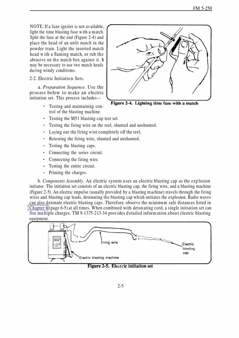
NOTE: If a fuze ign iter is not available,light the time blasting fuse w ith a match.Split the fuse at the end (Figure 2-4) andplace the head of an unlit match in thepowder train. Light the inserted matchhead w ith a flaming match, or rub th e
abrasive on th e match box against it. Itmay be necessary to use two match headsdu ring windy conditions.
2-2. Electric Initiation Sets.
a. Preparation Sequence. Use thepr ocess below to m ake an electricinitiation set. This process includes—
Testing and maintaining con-trol of the blasting machine.
Testing the M51 blasting-cap test set.Testing the firing wire on the reel, shunted and unshunted.
Laying out the firing w ire completely off the reel.
Retesting the firing wire, shunted and unshunted.
Testing the blasting caps.
Connecting the series circuit.
Connecting the firing wire.
Testing the entire circuit.
Priming the charges.
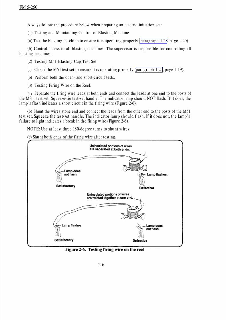
b. Components Assembly. An electric system u ses an electric blasting cap as the exp losioninitiator. The initiation set consists of an electric blasting cap, the firing wire, and a blasting machine
(Figure 2-5). An electric impulse (usually provided by a blasting m achine) travels through the firingwires and blasting cap leads, detonating the blasting cap wh ich initiates the explosion. Radio wavescan also detonate electric blasting caps. Therefore, observe the m inimum safe distances listed inChapter 6 (page 6-5) at all times. When combined with detonating cord, a single initiation set canfire mu ltiple charges. TM 9-1375-213-34 prov ides d etailed inform ation a bou t electric blastingequipment.
2-5
8/14/2019 United States Army Fm 5-250 - 15 June 1992 Explosives
http://slidepdf.com/reader/full/united-states-army-fm-5-250-15-june-1992-explosives 57/275
FM 5-250
Always follow the procedure below when preparing an electric initiation set:
(1) Testing and Maintaining Control of Blasting Machine.
(a) Test the blasting ma chine to ensure it is operating p roperly (paragr aph 1-28, page 1-20).
(b) Control access to all blasting machines. The supervisor is responsible for controlling all
blasting machines.(2)
(a)
(b)
(3)
(a)
Testing M51 Blasting-Cap Test Set.
Check the M51 test set to ensure it is operating p roperly (parag raph 1-27, pa ge 1-19).
Perform both the open- and short-circuit tests.
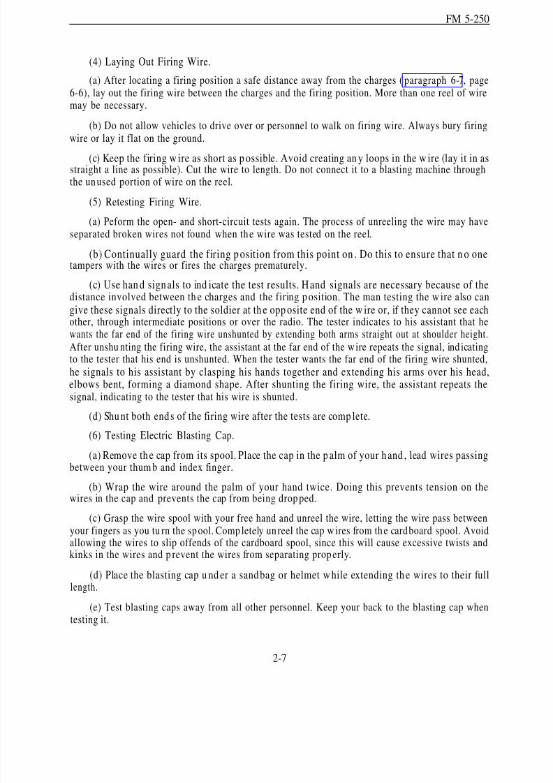
Testing Firing Wire on the Reel.
Separate the firing wire leads at both ends and connect the leads at one end to the posts of the MS 1 test set. Squeeze-tie test-set handle. The indicator lamp should NOT flash. If it does, thelamp ’s flash ind icates a short circuit in the firing w ire (Figure 2-6).
(b) Shunt the wires atone end and connect the leads from the other end to the posts of the M51test set. Squ eeze the test-set han dle. The ind icator lam p sh ou ld flash. If it does not, the lamp ’sfailur e to light ind icates a break in th e firing w ire (Figur e 2-6).
NOTE: Use at least three 180-degree turn s to shunt w ires.
(c) Shu nt both ends of the firing wire after testing.
2-6
8/14/2019 United States Army Fm 5-250 - 15 June 1992 Explosives
http://slidepdf.com/reader/full/united-states-army-fm-5-250-15-june-1992-explosives 58/275
FM 5-250
(4) Laying Out Firing Wire.
(a) After locating a firing position a safe distance away from the charges ( paragraph 6-7, page6-6), lay out the firing wire between the charges and the firing position. More than one reel of wiremay be necessary.
(b) Do not allow vehicles to drive over or personnel to walk on firing wire. Always bury firing
wire or lay it flat on the ground.
(c) Keep the firing w ire as short as p ossible. Avoid creating an y loops in the w ire (lay it in asstraight a line as possible). Cut the wire to length. Do not connect it to a blasting machine throughthe unused portion of wire on the reel.
(5) Retesting Firing Wire.
(a) Peform the open- and short-circuit tests again. The process of unreeling the wire may haveseparated broken wires not found when the wire was tested on the reel.
(b) Continually guard the firing p osition from this point on . Do this to ensure that n o onetampers with the wires or fires the charges prematurely.
(c) Use han d signals to ind icate the test results. Hand signals are necessary because of thedistance involved between th e charges and the firing p osition. The man testing the w ire also cangive these signals directly to the soldier at th e opp osite end of the w ire or, if they cannot see eachother, through intermediate positions or over the radio. The tester indicates to his assistant that hewants the far end of the firing wire unshunted by extending both arms straight out at shoulder height.After unshu nting the firing wire, the assistant at the far end of the wire repeats the signal, ind icatingto the tester that his end is unshunted. When the tester wants the far end of the firing wire shunted,
he signals to his assistant by clasping his hands together and extending his arms over his head,elbows bent, forming a diamond shape. After shunting the firing wire, the assistant repeats thesignal, indicating to the tester that his wire is shunted.
(d) Shu nt both ends of the firing wire after the tests are comp lete.
(6) Testing Electric Blasting Cap.
(a) Remove th e cap from its spool. Place the cap in the p alm of your hand , lead wires passingbetween your thum b and index finger.
(b) Wrap the wire around the palm of your hand twice. Doing this prevents tension on thewires in the cap and prevents the cap from being drop ped.
(c) Grasp the wire spool with your free hand and unreel the wire, letting the wire pass betweenyour fingers as you tu rn the spool. Comp letely un reel the cap w ires from the cardboard spool. Avoidallowing the wires to slip offends of the cardboard spool, since this will cause excessive twists andkinks in the wires and p revent the wires from separating prop erly.
(d) Place the blasting cap u nd er a sandbag or helmet w hile extending th e wires to their fulllength.
(e) Test blasting caps away from all other personnel. Keep your back to the blasting cap whentesting it.
2-7

8/14/2019 United States Army Fm 5-250 - 15 June 1992 Explosives
http://slidepdf.com/reader/full/united-states-army-fm-5-250-15-june-1992-explosives 59/275
FM 5-250
(f) Remove th e short-circuit shu nt from the lead wires.
(g) Hold or attach one lead w ire to one of the M51‘s binding posts. Hold or attach the secondlead w ire to the other binding p ost and squeeze the test-set hand le. The blasting cap is good if theindicator lamp flashes. If the lamp does n ot flash, the cap is defective; do not u se it.
(h) Always keep the cap wires shunted when not testing them.
(7) Connecting a Series Circuit. When two or more blasting caps are required for a demolitionoperation. you may use one of the series circuits illustrated in Figure 2-7.
Use the following procedure:
(a) Test all blasting caps (parag raph 2-2b(6), page 2-7) separately before connecting them ina circuit.
(b) Join blasting cap wires together using the Western Union pigtail splice (Figure 2-8). Protectall joints in the circuit with electrical insu lation tape. Do not use th e cardboard spool that comeswith the blasting cap to insulate these connections.
2-8

8/14/2019 United States Army Fm 5-250 - 15 June 1992 Explosives
http://slidepdf.com/reader/full/united-states-army-fm-5-250-15-june-1992-explosives 60/275
FM 5-250
(c) Test the entire circuit. After the series is completed, connect the two free blasting cap wiresto the M51 test set. The indicator lamp should flash to indicate a good circuit. If the lamp does notflash, check your connections and blasting caps again.
(d )connect
(8)
(a)taping a
(b)
(c)
After testing the cap circuit, shun t the tw o free blasting cap w ires until you are read y tothem to the firing wire.
Connecting the Firing Wire.
Connect the free leads of blasting caps to the firing w ire before pr iming the charges orblasting cap to a detonating-cord ring main.
Use a Western Un ion p igtail splice to connect the firing wire to the blasting cap w ires.
Insulate the connections with tape. Never use the cardboard spool that comes with theblasting cap to insu late this connection. The firing w ire is likely to break wh en bent to fit into thespool.
(9) Testing the Entire Firing Circuit. Before priming the charges or connecting blasting capsto ring mains, test the circuit from the firing p oint. Use the following p rocedu re:
(a) Ensure the blasting caps are under protective sandbags while performing this test.
(b) Conn ect the end s of the firing w ire to the M51 test set. Squeeze th e firing h and le. Theindicator lamp should flash, indicating a proper circuit.
(c) Shunt the ends of the firing wire.
WARNINGDo not p rime charges or connect electric blasting caps to detonating cord
un til all other steps of the preparation sequen ce have been completed.
(10) Priming th e Charges. Prime th e charges and return to the firing p oint. This is the laststep prior to actually returning to the firing point and firing the circuit.
WARNINGPrime charges when th ere is a minimum of personnel on site.
c. Circuit Initiation. At this point th e initiation set is com plete. Do not connect the blastingmachine un til all personnel are accoun ted for and the charge is ready to fire. When all personn elare clear, install the blasting m achine and initiate the d emolition. Chapter 6 (page 6-9) coversprocedures for electric misfires.
d. Splicing Electric Wires.(1) Preparation. Strip th e insulating m aterial from the end of insulated w ires before splicing.
Remove approximately 1 ½ inches of insulation from the end of each wire (Figure 2-8, diagram 1).Also remove any coating on the wire, such as enamel, by carefully scraping the wire with the backof a knife blad e or other suitable tool. Do not nick, cut, or weaken th e bare w ire. Twistmultiple-strand wires lightly after scraping.
2-9

8/14/2019 United States Army Fm 5-250 - 15 June 1992 Explosives
http://slidepdf.com/reader/full/united-states-army-fm-5-250-15-june-1992-explosives 61/275
FM 5-250
(2) Method. Use the Western Union pigtail splice (Figure 2-8, page 2-8) to splice two wires.Splice two pairs of wires in the same way as the two-wire splice (Figure 2-9). Use the followingprocedure:
(a) Protect the splices from tension d amage by tying the ends in an overhand or square knot(tension knot), allowing sufficient length for each splice (Figure 2-8, diagram 2, page 2-8).
(b) Make three wr aps w ith each wire (Figure 2-8, diagram 3, page 2-8).
(c) Twist the end s together with th ree turns (Figure 2-8, diagram 4, page 2-8).
(d) Flatten the splice, but not so far that the wire crimps itself and breaks ( Figure 2-8, diagram5, page 2-8).
(3) Precautions. A short circuit may occur at a splice if you do not practice some caution. Forexample, when you splice pairs of wires, stagger the sp lices and place a tie between them (Figure2-9, diagram 1). Another meth od of preventing a short circuit in a sp lice is using th e alternatemethod (Figure 2-9, diagram 2). In th e alternate method , separate the sp lices rather th an staggerthem. Insulate the splices from the ground or other conductors by wrapping them with friction tape
or other electric insulating tape. Always insulate splices.
e. Series Circuits.
(1) Common. Use this circuit to conn ect two or m ore electric blasting caps to a sing le blastingmachine (Figure 2-7, diagram 1, page 2-8). Prepare a comm on series circuit by connecting oneblasting cap to another until only two end wires are free. Shun t the two end wires until you areready to proceed w ith the next step. Connect the free ends of the cap lead w ires to the ends of thefiring w ire. Use connecting wires (usually annun ciator w ire) wh en the distance between blastingcaps is greater than the length of the usual cap lead wires.
2-10
8/14/2019 United States Army Fm 5-250 - 15 June 1992 Explosives
http://slidepdf.com/reader/full/united-states-army-fm-5-250-15-june-1992-explosives 62/275
FM 5-250
(2) Leapfrog. The leapfrog method of connecting caps in a series is useful for firing any longline of charges (Figure 2-7, diagram 2, page 2-8). This method is performed by starting at one endof a row of charges and priming alternate charges to the opposite end and then priming the remainingcharges on the retu rn leg of the series. This method eliminates the necessity for a long r eturn leadfrom the far end of the line of charges. Appendix E has ad ditional information on series circuits.
There is seldom a need for this type of circuit, since detonating cord, when combined with a single
blasting cap, will fire multiple charges.
Section II. Priming Systems
2-3. Methods. The three methods of priming charges are nonelectric, electric, and detonating-cord.Nonelectric and electric priming involves directly inserting blasting caps into the charges. Use thedirect-insertion method only when employing shaped charges. Detonating-cord priming is theprefered method for priming all other charges since it involves fewer blasting caps, makes primingand misfire investigation safer, and a llows charges to be p rimed at State of Readiness 1 (safe) whenin place on a reserved demolition.
NOTE: You can crimp nonelectric blasting caps to detonating cord as well as time fuse. Thiscapability permits simultaneous firing of multiple charges primed with a blasting cap.
2-4. Priming TNT Demolition Blocks.
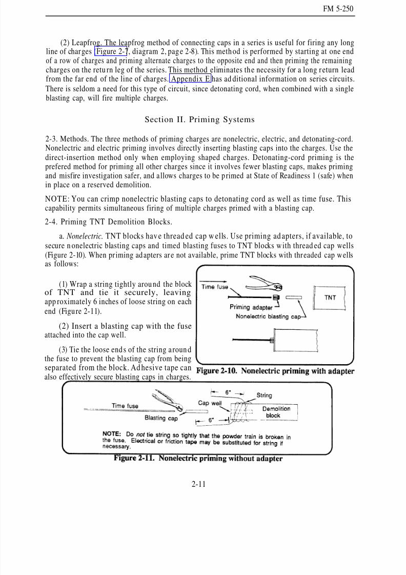
a. Nonelectric. TNT blocks hav e thread ed cap w ells. Use priming ad apters, if available, tosecure n onelectric blasting caps and timed blasting fuses to TNT blocks w ith thread ed cap wells(Figure 2-10). When pr iming ad apters ar e not available, prime TNT blocks with threaded cap wellsas follows:
(1) Wrap a string tightly around the blockof TNT and tie it securely, leaving
app roximately 6 inches of loose string on eachend (Figure 2-11).
(2) Insert a blasting cap with the fuseattached into the cap well.
(3) Tie the loose ends of the string a roun dthe fuse to prevent the blasting cap from beingseparated from the block. Ad hesive tape canalso effectively secure blasting caps in charges.
2-11

8/14/2019 United States Army Fm 5-250 - 15 June 1992 Explosives
http://slidepdf.com/reader/full/united-states-army-fm-5-250-15-june-1992-explosives 63/275
FM 5-250
b. Electric.
(1)priming
(a)
(b)
With Priming Adapter. Use the following procedure for priming TNT block, using theadapter:
Prepare the electric initiation set before priming.
Pass the lead w ires through the slot of the adap ter, and pu ll the cap into place in the adapter(Figure 2-12). Ensure the blasting cap protrudes from the threaded end of the adapter.
(c) Insert the blasting cap into the thread ed cap w ell of the TNT block and screw th e adap terinto p lace.
(2) Without Priming Adapter. If a p riming ad apter is not available, use the followingprocedure:
(a) Prepare the electric initiation set before priming.
(b) Insert the electric blasting cap into the cap well. Tie the lead wires arou nd the block, using
two half hitches or a girth hitch (Figure 2- 13). Allow some slack in the wires between the blastingcap and the tie to prevent any tension on the blasting-cap lead wires.
2-12

8/14/2019 United States Army Fm 5-250 - 15 June 1992 Explosives
http://slidepdf.com/reader/full/united-states-army-fm-5-250-15-june-1992-explosives 64/275
FM 5-250
c. Detonating Cord. Use the following methods to prime TNT blocks with detonating cord:
NOTE: A 6-inch length of detonating cord equals the power output of a blasting cap. However,detonat ing cord w ill not d etonate explosives as reliably as a blasting cap because its pow er is notas concentrated . Therefore, always u se several turn s or a knot of detonating cord for p rimingcharges.
(1) Method 1 (Figure 2-14). Lay one end (l-foot length) of detonating cord at an angle acrossthe explosive. Then, wrap the running end around the block three turns, laying the wraps over thestanding end. On the fourth wrap , slip the run ning end und er all wraps, parallel to the standing endand draw the wraps tight. Doing this forms a clove hitch with two extra turns.
(2) Method 2 (Figure 2-14). Tie the detonating cord around the explosive block with a clovehitch and two extra turns. Fit the cord snugly against the block, and push the loops close together.
(3) Method 3 (Figure 2-14). Place a loop of deton ating cordon th e explosive, leaving su fficientlength on the end to m ake four tu rns around the block and loop w ith the remaining end of thedetonating cord. When starting the first wrap, ensure that you immediately cross over the standing
end of the loop, working your way to the closed end of the loop. Pass the free end of the detonatingcord through the loop and pull it tight. This forms a knot around the outside of the block.
2-5. Prim ing M112 (C4) Demolition Blocks .
a. Nonelectric and Electric. C4 blocks do not have a cap well; therefore, you w ill have to m ake
one. Use the following p rocedu re:(1) With th e M2 crimpers or other nonspark ing tool, make a hole in the end or on the side (at
the midpoint) large enough to hold the blasting cap.
(2) Insert the blasting cap into the hole or cut. If the blasting cap does not fit the hole or cut,do not force the cap, make the hole larger.
2-13
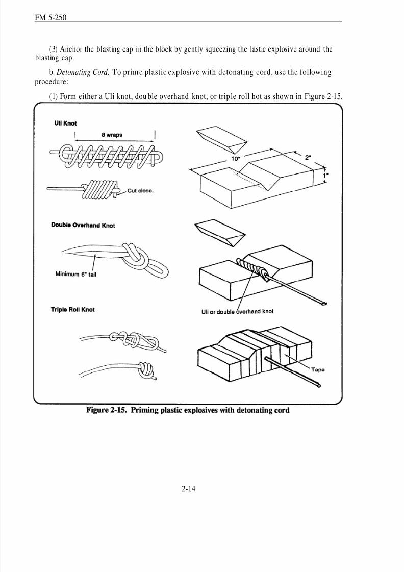
8/14/2019 United States Army Fm 5-250 - 15 June 1992 Explosives
http://slidepdf.com/reader/full/united-states-army-fm-5-250-15-june-1992-explosives 65/275
FM 5-250
(3) Anchor the blasting cap in the block by gently squeezing the lastic explosive around theblasting cap.
b. Detonating Cord. To prim e plastic explosive with detonating cord, use the followingprocedure:
(1) Form either a Uli knot, dou ble overhand knot, or trip le roll hot as show n in Figur e 2-15.
2-14
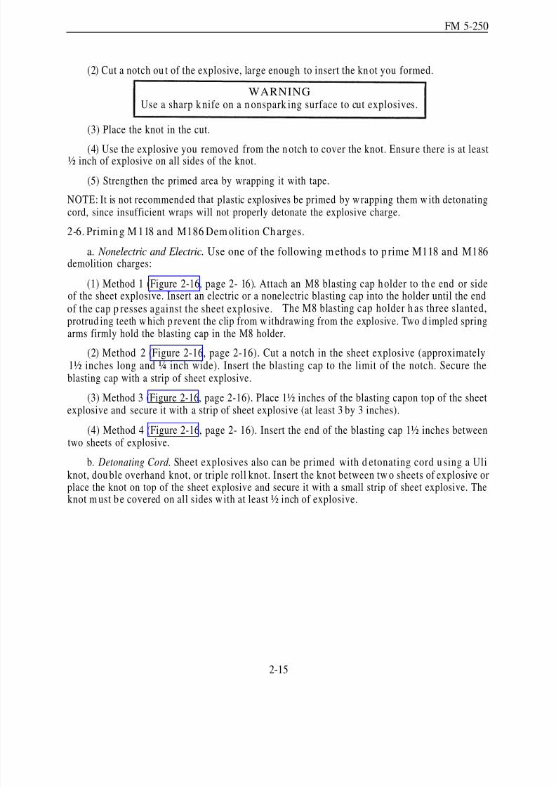
8/14/2019 United States Army Fm 5-250 - 15 June 1992 Explosives
http://slidepdf.com/reader/full/united-states-army-fm-5-250-15-june-1992-explosives 66/275
FM 5-250
(2) Cut a notch ou t of the explosive, large enough to insert the knot you formed.
WARNINGUse a sharp k nife on a n onspark ing surface to cut explosives.
(3) Place the knot in the cut.
(4) Use the explosive you removed from the n otch to cover the knot. Ensur e there is at least½ inch of explosive on all sides of the knot.
(5) Strengthen the primed area by wrapping it with tape.
NOTE: It is not recommended that plastic explosives be primed by w rapping them w ith detonatingcord, since insufficient wraps will not properly detonate the explosive charge.
2-6. Primin g M 118 and M186 Dem olition Ch arges.
a. Nonelectric and Electric. Use one of the following m ethods to p rime M118 and M186demolition charges:
(1) Method 1 (Figure 2-16, page 2- 16). Attach an M8 blasting cap holder to th e end or sideof the sheet explosive. Insert an electric or a nonelectric blasting cap into the holder until the endof the cap p resses against the sheet explosive. The M8 blasting cap holder h as three slanted,protrud ing teeth w hich p revent the clip from w ithdrawing from the explosive. Two d impled springarms firmly hold the blasting cap in the M8 holder.
(2) Method 2 (Figure 2-16, page 2-16). Cut a notch in the sheet explosive (approximately1½ inches long and ¼ inch wide). Insert the blasting cap to the limit of the notch. Secure theblasting cap with a strip of sheet explosive.
(3) Method 3 (Figure 2-16, page 2-16). Place 1½ inches of the blasting capon top of the sheet
explosive and secure it with a strip of sheet explosive (at least 3 by 3 inches).(4) Method 4 (Figure 2-16, page 2- 16). Insert the end of the blasting cap 1½ inches between
two sheets of explosive.
b. Detonating Cord. Sheet explosives also can be primed with d etonating cord u sing a Uliknot, dou ble overhand knot, or triple roll knot. Insert the knot between tw o sheets of explosive orplace the knot on top of the sheet explosive and secure it with a small strip of sheet explosive. Theknot m ust be covered on all sides w ith at least ½ inch of explosive.
2-15
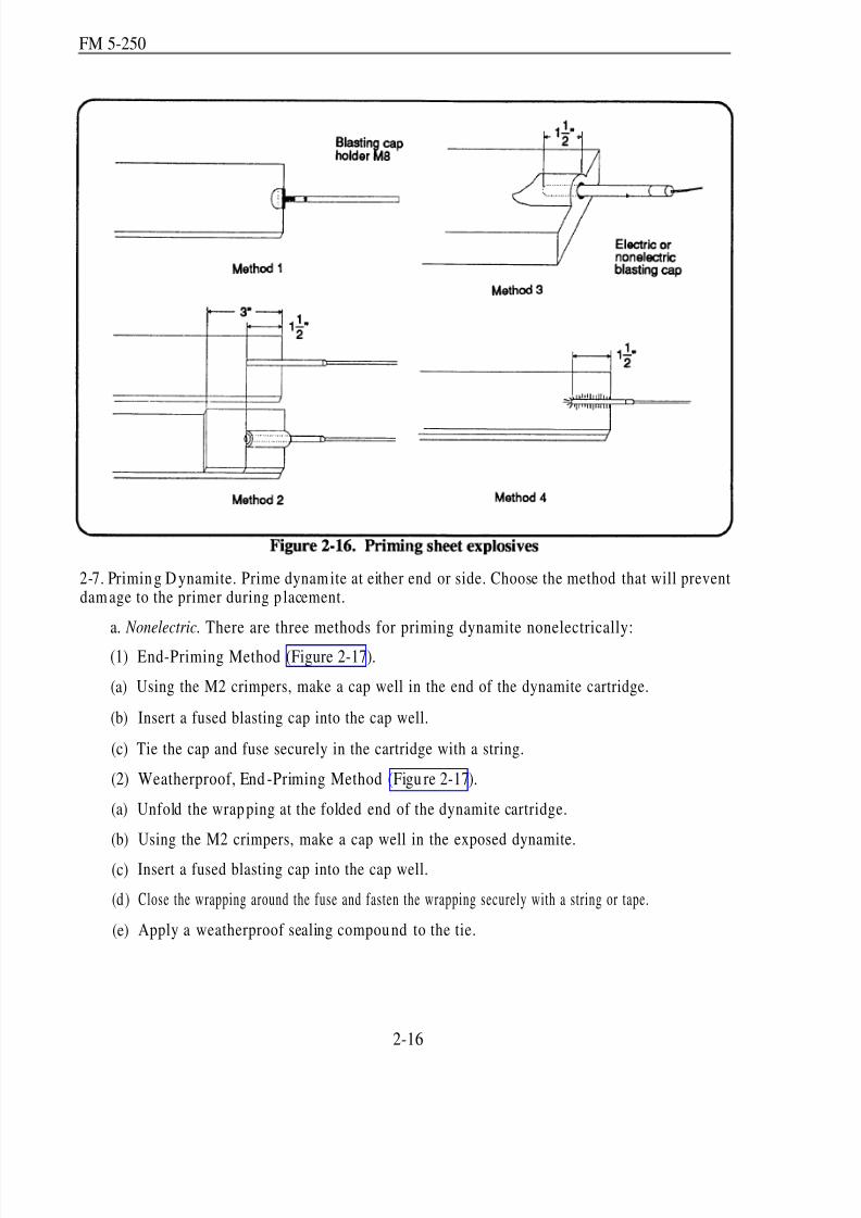
8/14/2019 United States Army Fm 5-250 - 15 June 1992 Explosives
http://slidepdf.com/reader/full/united-states-army-fm-5-250-15-june-1992-explosives 67/275
FM 5-250
2-7. Priming D ynamite. Prime dynam ite at either end or side. Choose the method that will preventdam age to the primer during p lacement.
a. Nonelectric. There are three methods for priming dynamite nonelectrically:
(1)
(a)
(b)
(c)
(2)
(a)
(b)
(c)
(d )
(e)
End-Priming Method (Figure 2-17).
Using the M2 crimpers, make a cap well in the end of the dynamite cartridge.
Insert a fused blasting cap into the cap well.
Tie the cap and fuse securely in the cartridge with a string.
Weatherproof, End -Priming Method (Figu re 2-17).
Unfold the wrapping at the folded end of the dynamite cartridge.
Using the M2 crimpers, make a cap well in the exposed dynamite.
Insert a fused blasting cap into the cap well.
Close the wrapping around the fuse and fasten the wrapping securely with a string or tape.
Apply a weatherproof sealing compound to the tie.
2-16
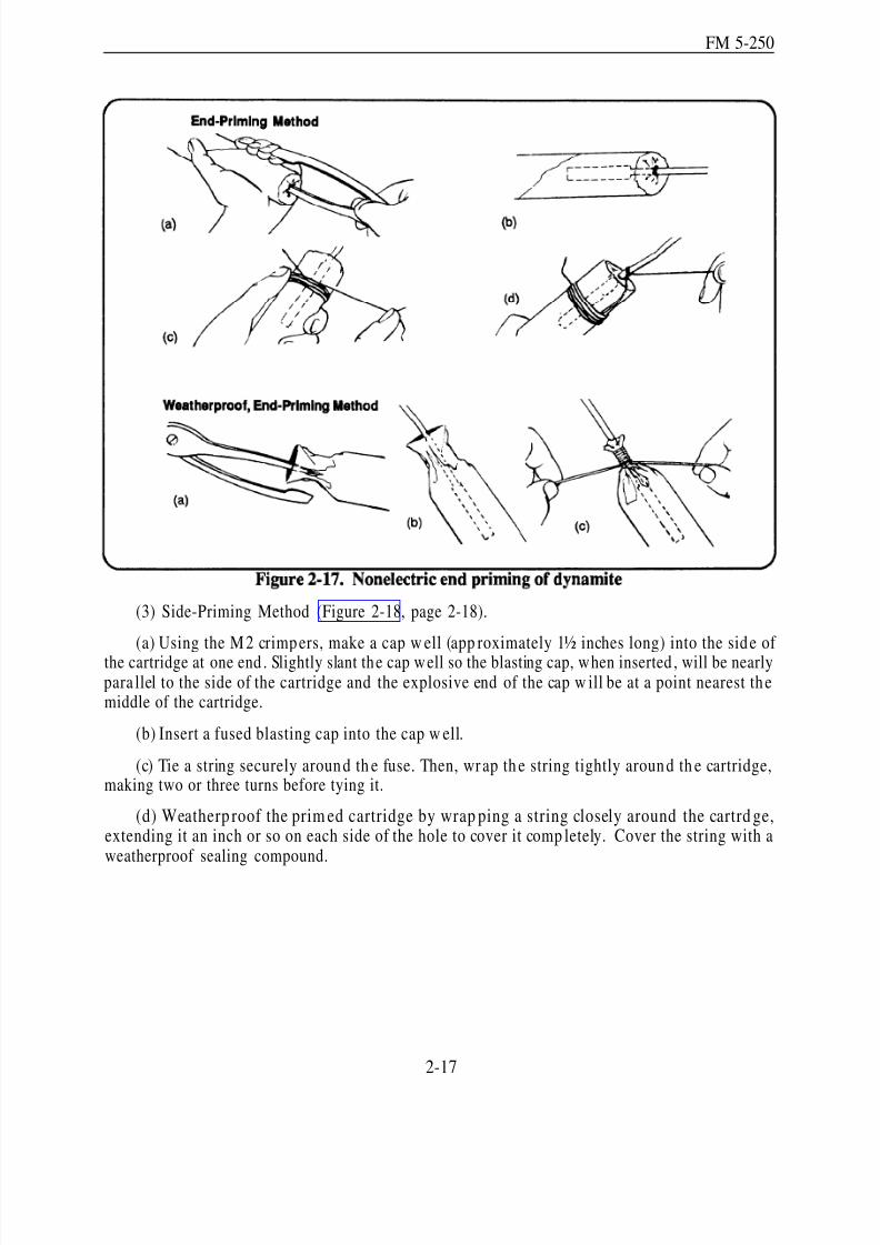
8/14/2019 United States Army Fm 5-250 - 15 June 1992 Explosives
http://slidepdf.com/reader/full/united-states-army-fm-5-250-15-june-1992-explosives 68/275
FM 5-250
(3) Side-Priming Method (Figure 2-18, page 2-18).
(a) Using the M2 crimpers, make a cap w ell (app roximately 1½ inches long) into the side of the cartridge at one end . Slightly slant the cap well so the blasting cap, when inserted , will be nearlypara llel to the side of the cartridge and the explosive end of the cap w ill be at a point nearest themiddle of the cartridge.
(b) Insert a fused blasting cap into the cap w ell.
(c) Tie a string securely around th e fuse. Then, wr ap th e string tightly around th e cartridge,making two or three turns before tying it.
(d) Weatherp roof the prim ed cartridge by wrap ping a string closely around the cartrd ge,extending it an inch or so on each side of the hole to cover it comp letely. Cover the string with aweatherproof sealing compound.
2-17
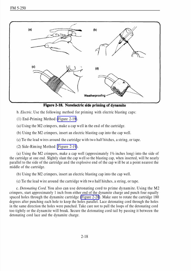
8/14/2019 United States Army Fm 5-250 - 15 June 1992 Explosives
http://slidepdf.com/reader/full/united-states-army-fm-5-250-15-june-1992-explosives 69/275
FM 5-250
b. Electric. Use the following method for priming with electric blasting caps:
(1) End-Priming Method (Figure 2-19).
(a) Using the M2 crimp ers, make a cap w ell in the en d of the cartridge.
(b) Using the M2 crimpers, insert an electric blasting cap into the cap well.
(c) Tie the lead w ires around the cartridge w ith two half hitches, a string, or tape.
(2) Side-Rim ing M ethod (Figure 2-19).
(a) Using the M2 crimpers, make a cap well (approximately 1½ inches long) into the side of the cartridge at one end . Slightly slant the cap w ell so the blasting cap, when inserted, will be nearlyparallel to the side of the cartridge an d the explosive end of the cap w ill be at a point n earest themiddle of the cartridge.
(b) Using the M2 crimpers, insert an electric blasting cap into the cap well.
(c) Tie the lead w ire around the cartridge with two half hitches, a string, or tape.
c. Detonating Cord. You also can u se detonating cord to p rime dynamite. Using the M2crimpers, start approximately 1 inch from either end of the dynamite charge and punch four equallyspaced holes through the dynamite cartridge (Figure 2-20). Make sure to rotate the cartridge 180degrees after punching each hole to keep the holes parallel. Lace detonating cord through the holesin the same direction the holes were punched. Take care not to pull the loops of the detonating cordtoo tightly or the d ynam ite will break. Secure the d etonating cord tail by passing it between thedetonating cord lace and the dynamite charge.
2-18

8/14/2019 United States Army Fm 5-250 - 15 June 1992 Explosives
http://slidepdf.com/reader/full/united-states-army-fm-5-250-15-june-1992-explosives 70/275
FM 5-250
2-8. Priming 40-Poun d, Am mon ium -Nitrate Cratering Charges. Because the cratering chargeis primarily an underground charge, prime it only with detonating cord. Use dual priming to protectagainst misfires (Figure 2-21, diagram 2, page 2-20). Use the following procedure:
2-19

8/14/2019 United States Army Fm 5-250 - 15 June 1992 Explosives
http://slidepdf.com/reader/full/united-states-army-fm-5-250-15-june-1992-explosives 71/275
FM 5-250
a. Tie an overhand knot, with a 6-inch overhan g, at one end of the length of detonating cord .
b. Pass the opposite end of the detonating cord up through the detonating cord tunnel (Figure2-21, diagram 1) of the crater ing charge.
Ammonium nitrate is hydroscopic. When wet, ammonium nitrate is ineffective.WARNING
Therefore, inspect the m etal container for d amage or rust. Do n ot usedamaged or rusty charges.
c. When dual pr iming a single 40-pound cratering charge, use a minimum of one pound of explosive.Prime a block of TNT or p ackage of C4 with detonating cord (paragraph s 2-4c, page 2-13, and 2-5b,pa ge 2-14, respectively) and tap e this charge to th e center o f the cratering charge (Figur e 2-21,diagram 2). The detonating cord branch lines must be long enough to reach the detonating-cordring mains after the cratering charge is in the ground . Twelve-foot branch lines should be ad equate.When placing two cratering charges in the same borehole, prime only the detonating cord tunnelsof each charge. In this mann er, the borehole is du al-prim ed an d extra explosives are not required ,as show n in Figure 2-21, diagram 3.
2-9. Primin g M2A4 and M3A1 Shaped Charges. The M2A4 and M3A1 are primed only withelectric or nonelectric blasting caps. These charges have a threaded cap well at the top of the cone.
Prime them with a blasting cap as shown in Figure 2-22. Use a piece of string, cloth, or tape to holdthe cap if a prim ing adap ter is not available. Simu ltaneously detonate mu ltiple shaped charges tocreate a line of boreholes for cratering charges by connecting each charge into a detonating-cordring or line main. Use the following p rocedure for priming shaped charges:
2-20

8/14/2019 United States Army Fm 5-250 - 15 June 1992 Explosives
http://slidepdf.com/reader/full/united-states-army-fm-5-250-15-june-1992-explosives 72/275
FM 5-250
an y
a.
b.
c.
d.
WARNINGDo not dual prime shaped charges. Prime them only with
a blasting cap in the b lasting cap w ell.
Crimp a nonelectric blasting cap to a branch line.
Connect the branch line to the ring main.
Insert the blasting cap into the blasting cap well of the shaped charge.
When detonating multiple shaped charges, make all branch-line connections before primingshaped charges.
2-10. Priming the Bangalore Torp edo.
a. Nonelectric. Insert the blasting cap of a nonelectric initiation set directly into the cap wellof a torpedo section. If a priming adapter is not available, use tape or string to hold the blasting capin p lace (Figure 2-23, diagram 1, page 2-22).
2-21

8/14/2019 United States Army Fm 5-250 - 15 June 1992 Explosives
http://slidepdf.com/reader/full/united-states-army-fm-5-250-15-june-1992-explosives 73/275
FM 5-250
b. Electric. Insert the blasting cap o f an electric initiation set into the cap w ell of a torped o
section. If a priming ad apter is not available, hold the cap in p lace by taping or tying (with two half hitches) the lead w ires to the end of the torpedo. Allow some slack in the wires between th e blastingcap and the tie to prevent tension on the blasting cap leads.
c. Detonating Cord. Prime the torpedo by wrap ping d etonating cord eight times around theend of the section, just below the bevel (Figur e 2-24). After p ulling the knot tight, insert the shortend of the detonating cord into the cap well and secure it with tape. Never use the short end (tail)of the detonating cord to initiate the torpedo. Initiation must come from the running end of thedetonating cord.
WARNINGDo not use more than or less than eight wraps to prime the Bangalore torpedo.
Too many wraps will extend the detonating cord past the booster charge housing,possibly causing the torpedo to be cut without d etonating. Too few wraps
may cause the torped o to only be crimp ed, without d etonating.
2-22

8/14/2019 United States Army Fm 5-250 - 15 June 1992 Explosives
http://slidepdf.com/reader/full/united-states-army-fm-5-250-15-june-1992-explosives 74/275
FM 5-250
Section III. Firing Systems
2-11. Types of Firing System s. There are two types of firing systems: single and dual. Chapter5 covers the tactical applications for these systems.
a. Single. Figure 2-25 shows a
single-firing system Each charge is singlyprim ed w ith a branch line. The branch lineis tied to the line main or ring main. (Tyingto the ring main is preferred but constructionof a ring main may not be possible becauseof the amoun t of detonating cord. The ringmain d ecreases the chances of a m issfireshould a break or cut occur anywhere withinthe ring main.) The electric, nonelectric, orcombination initiation systems are thentaped onto the firing system. When using a
combination initiation system, the electricinitiation system is always the primarymeans of initiation. When using dual,non electric initiation system s, the shortertime fuse is the primary initiation system(Figure 2-26).
b. Dual. Figure 2-27 (page 2-24) shows a du al-firing system. Each charge is du al-prim ed w ithtw o branch lines (Figure 2-28, page 2-24). One bran ch line is tied to on e firing system , and theother branch line is tied to an ind epend ent firing system. Line mains or ring mains m ay be used;however, they should not be mixed. To help prevent misfires, use detonating-cord crossovers.
Crossovers are u sed to tie both firing systems together at the ends. The initiation systems are tapedin—the primary initiation system goes to one firing system, the secondary goes to the other.
2-23
8/14/2019 United States Army Fm 5-250 - 15 June 1992 Explosives
http://slidepdf.com/reader/full/united-states-army-fm-5-250-15-june-1992-explosives 75/275
FM 5-250
Figure 2-29 shows a dual-firing system using horizontal and vertical ring mains. Thecomplexity
simultaneous detonation. These will be referred to as horizontal and vertical lines or ring mains.
of a target or obstacle may n ecessitate using m ultiple line m ains or ring mains for
2-24
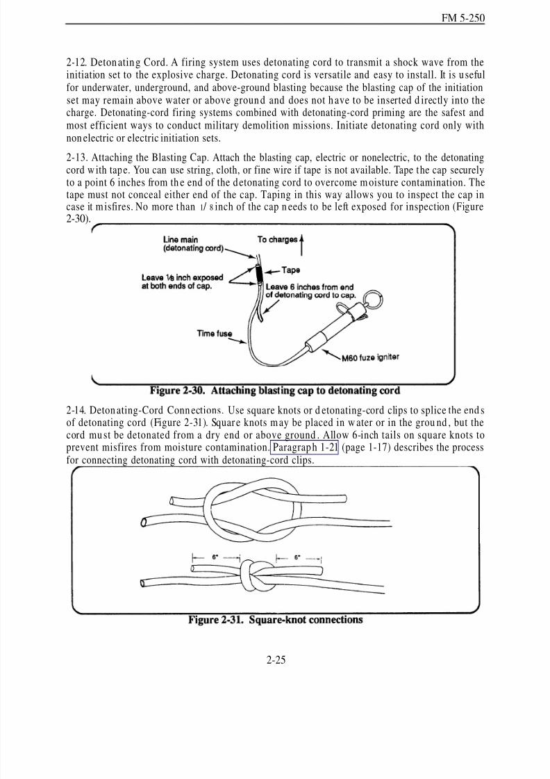
8/14/2019 United States Army Fm 5-250 - 15 June 1992 Explosives
http://slidepdf.com/reader/full/united-states-army-fm-5-250-15-june-1992-explosives 76/275
FM 5-250
2-12. Detonating Cord. A firing system uses detonating cord to transmit a shock wave from theinitiation set to the explosive charge. Detonating cord is versatile and easy to install. It is u sefulfor underwater, underground, and above-ground blasting because the blasting cap of the initiationset may remain above water or above groun d and does not h ave to be inserted d irectly into thecharge. Detonating-cord firing systems combined with detonating-cord priming are the safest andmost efficient ways to conduct military demolition missions. Initiate detonating cord only with
non electric or electric initiation sets.
2-13. Attaching the Blasting Cap. Attach the blasting cap, electric or nonelectric, to the detonatingcord w ith tape. You can use string, cloth, or fine wire if tape is not available. Tape the cap securelyto a point 6 inches from th e end of the detonating cord to overcome m oisture contamination. Thetape must not conceal either end of the cap. Taping in this way allows you to inspect the cap incase it m isfires. No more than 1 / 8 inch of the cap n eeds to be left exposed for inspection (Figure2-30).
2-14. Deton ating-Cord Conn ections. Use square knots or d etonating-cord clips to splice the end sof detonating cord (Figure 2-31). Squar e knots m ay be placed in w ater or in the grou nd , but thecord mu st be detonated from a dry end or above ground . Allow 6-inch tails on square knots toprevent misfires from moisture contamination. Paragrap h 1-21 (page 1-17) describes the processfor connecting detonating cord with detonating-cord clips.
2-25
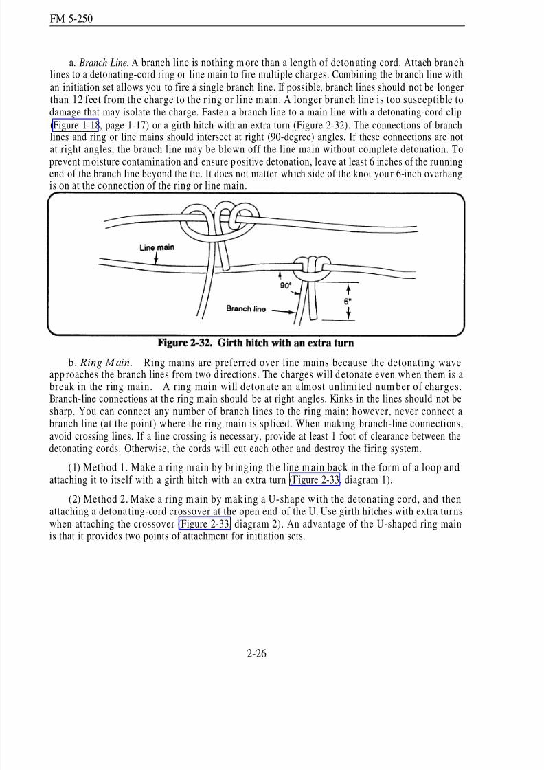
8/14/2019 United States Army Fm 5-250 - 15 June 1992 Explosives
http://slidepdf.com/reader/full/united-states-army-fm-5-250-15-june-1992-explosives 77/275
FM 5-250
a. Branch Line. A branch line is nothing m ore than a length of detonating cord. Attach branchlines to a detonating-cord ring or line main to fire multiple charges. Combining the branch line withan initiation set allows you to fire a single branch line. If possible, branch lines should not be longerthan 12 feet from th e charge to the r ing or line m ain. A longer bran ch line is too susceptible todamage that may isolate the charge. Fasten a branch line to a main line with a detonating-cord clip
(Figure 1-18, page 1-17) or a girth hitch with an extra turn (Figure 2-32). The connections of branch
lines and ring or line mains should intersect at right (90-degree) angles. If these connections are notat right angles, the branch line may be blown off the line main without complete detonation. Toprevent m oisture contamination and ensure p ositive detonation, leave at least 6 inches of the runningend of the branch line beyond the tie. It does not matter which side of the knot you r 6-inch overhangis on at the connection of the ring or line main.
b. Ring Main. Ring mains are preferred over line mains because the detonating waveapp roaches the branch lines from two d irections. The charges will detonate even wh en them is abreak in the ring main. A ring main will detonate an almost unlimited num ber of charges.Branch-line connections at th e ring main should be at right angles. Kinks in the lines should not besharp. You can connect any number of branch lines to the ring main; however, never connect abranch line (at the point) w here the ring main is sp liced. When making branch-line connections,avoid crossing lines. If a line crossing is necessary, provide at least 1 foot of clearance between thedetonating cords. Otherwise, the cords will cut each other and destroy the firing system.
(1) Method 1. Make a ring m ain by bringing th e line m ain back in th e form of a loop andattaching it to itself with a girth hitch with an extra turn (Figure 2-33, diagram 1).
(2) Method 2. Make a ring m ain by mak ing a U-shape w ith the detonating cord, and thenattaching a detona ting-cord crossover at the open end of the U. Use girth hitches with extra tur nswhen attaching the crossover (Figure 2-33, diagram 2). An advantage of the U-shaped ring main
is that it provides two points of attachment for initiation sets.
2-26

8/14/2019 United States Army Fm 5-250 - 15 June 1992 Explosives
http://slidepdf.com/reader/full/united-states-army-fm-5-250-15-june-1992-explosives 78/275
FM 5-250
c. Line M ain. A line main will firemultip le charges (Figure 2-34), but if abreak in the line occurs, the detonatingwav e will stop at the break. When therisk of having a line main cut isun acceptable, use a ring main. Use linemains only when sp eed is essential and a
risk of failure is acceptable. You canconnect any num ber of branch lines to aline m ain. How ever, connect only onebranch line at any one point unless youuse a junction box (Figure 2-35, page2-28).
2-15. Initiating Lines an d Main s.
a. Line Main and Branch Line. Whenever p ossible, du al initiate a line main or a br anch line(Figure 2-36, page 2-28). Place the blasting cap that w ill detonate first closest to the end of thedetonating cord (for example, the electric cap of a combination of initiation sets). Doing this willensure the integrity of the backup system when the first cap detonates and fails to initiate the linemain. Do not try to get both caps to d etonate at the sam e time. This is virtually imp ossible to dowith t ime fuse. Stagger the d etonations a minim um of 10 seconds.
b. Ring Main. Initiate ring mains as shown in Figures 2-33. The blasting caps are still connectedas shown in Figure 2-36 (page 2-28), but by having one on each side of the ring main, the chancesof both caps becoming isolated from the ring are greatly reduced.
2-27
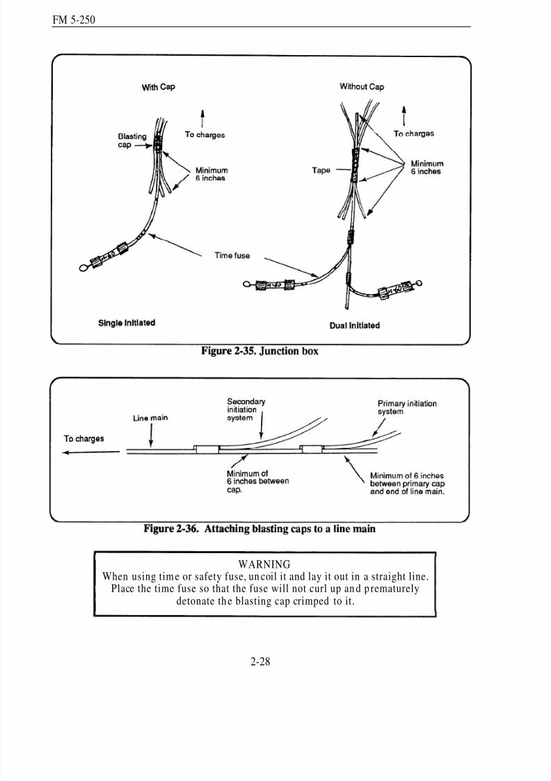
8/14/2019 United States Army Fm 5-250 - 15 June 1992 Explosives
http://slidepdf.com/reader/full/united-states-army-fm-5-250-15-june-1992-explosives 79/275
FM 5-250
WARNINGWhen using tim e or safety fuse, un coil it and lay it out in a straight line.
Place the time fuse so that the fuse will not curl up an d p rematurelydetonate th e blasting cap crimped to it.
2-28
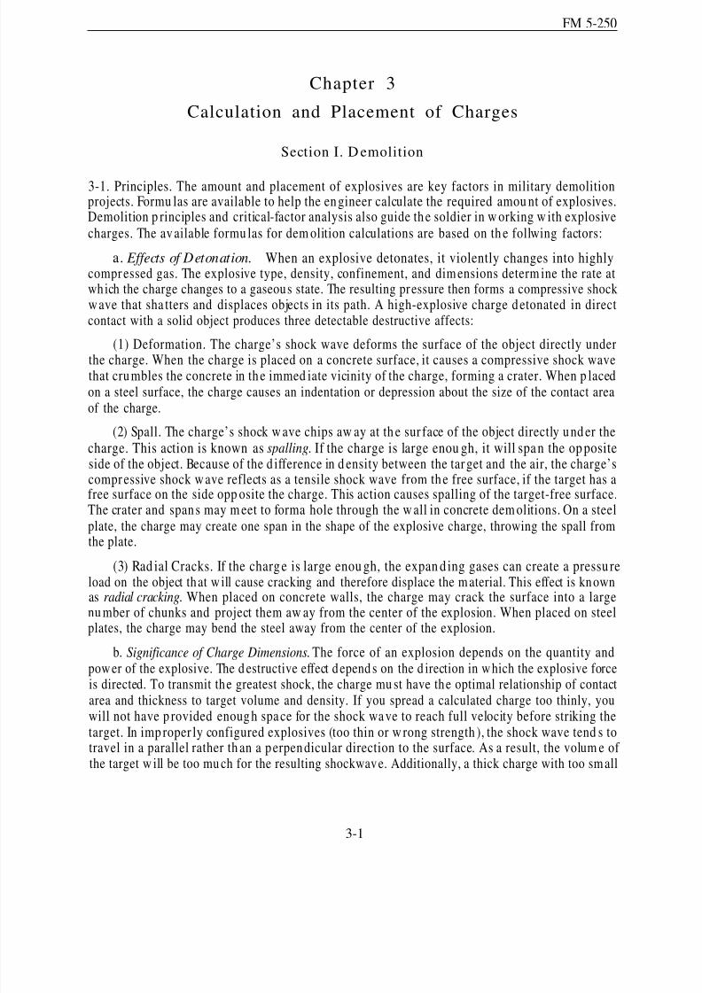
8/14/2019 United States Army Fm 5-250 - 15 June 1992 Explosives
http://slidepdf.com/reader/full/united-states-army-fm-5-250-15-june-1992-explosives 80/275
FM 5-250
Chapter 3
Calculation and Placement of Charges
Section I. D emolition
3-1. Principles. The amount and placement of explosives are key factors in military demolitionprojects. Formu las are available to help the en gineer calculate the required amou nt of explosives.Demolition p rinciples and critical-factor analysis also guide th e soldier in w orking w ith explosivecharges. The av ailable formu las for dem olition calculations are based on th e follwing factors:
a. Effects of Detonation. When an explosive detonates, it violently changes into highlycompressed gas. The explosive type, density, confinement, and dim ensions determ ine the rate atwhich the charge changes to a gaseous state. The resulting pressure then forms a compressive shockwave that sha tters and displaces objects in its path. A high-explosive charge d etonated in directcontact with a solid object produces three detectable destructive affects:
(1) Deformation. The charge’s shock wave deforms the surface of the object directly underthe charge. When the charge is placed on a concrete surface, it causes a compressive shock wavethat cru mbles the concrete in th e immed iate vicinity of the charge, forming a crater. When p lacedon a steel surface, the charge causes an indentation or depression about the size of the contact areaof the charge.
(2) Spall. The charge’s shock w ave chips aw ay at th e sur face of the object directly u nd er thecharge. This action is known as spalling. If the charge is large enou gh, it will span the op positeside of the object. Because of the d ifference in d ensity between the target and the air, the charge’scompressive shock wave reflects as a tensile shock wave from th e free surface, if the target has afree surface on the side opp osite the charge. This action causes spalling of the target-free surface.The crater and span s may m eet to forma hole through the w all in concrete dem olitions. On a steel
plate, the charge may create one span in the shape of the explosive charge, throwing the spall fromthe plate.
(3) Rad ial Cracks. If the charg e is large enou gh, the expan d ing gases can create a pressu reload on the object that w ill cause cracking and therefore displace the m aterial. This effect is knownas radial cracking. When placed on concrete walls, the charge may crack the surface into a largenu mber of chunks and project them aw ay from the center of the explosion. When placed on steelplates, the charge may bend the steel away from the center of the explosion.
b. Significance of Charge Dimensions. The force of an explosion depends on the quantity andpow er of the explosive. The d estructive effect depend s on the d irection in w hich the explosive forceis directed. To transmit the greatest shock, the charge mu st have the optimal relationship of contact
area and thickness to target volume and density. If you spread a calculated charge too thinly, youwill not have p rovided enoug h space for the shock wave to reach full velocity before striking thetarget. In imp roper ly configured explosives (too thin or w rong strength ), the shock wave tend s totravel in a parallel rather th an a p erpen dicular direction to the surface. As a result, the volum e of the target w ill be too mu ch for the resulting shockwave. Additionally, a thick charge with too sm all
3-1

8/14/2019 United States Army Fm 5-250 - 15 June 1992 Explosives
http://slidepdf.com/reader/full/united-states-army-fm-5-250-15-june-1992-explosives 81/275
FM 5-250
a contact area will transmit a shock wave over too small a target area, with much lateral loss of energy.
c. Significance of Charge Placement. The d estru ctive effect of an explosive charge a lsodep end s on the location of the charge in relation to the target size, shap e, and configuration. Forthe m ost destru ctive effect, deton ate an explosive of the p roper size and shap e for the size, shap e,
and configuration of the target. Any significant air or w ater gap betw een the target and explosive
will lessen the force of the shock wave. Cut explosives (such as sheet or plastic explosives) to fitodd-shaped targets. Whenever possible, place explosive charges to act through the smallest part of the target. Use internal charges to achieve maximum destruction with minimum explosives expense.Tamping external charges increases their destructive effect.
3-2. Types of Charges.
a. Internal Charges. Place internal charges in boreholes in the target. Confine the chargeswith tightly packed sand , wet clay, or other material (stemming). Stemming is the process of packingmat erial on top of an internal borehole or crater charge. Fill and tam p stemm ing material againstthe explosive to fill the borehole to the surface. In d rill holes, tamp the explosive as it is loaded intothe hole. Tamp stemming material only with nonsparking equipment.
b. External Charges. Place external charges on the surface of the target. Cover and tamp thecharges with tightly p acked sand , clay, or other d ense material. Stemm ing material may be looseor in san dbag s. To be most effective, make the th ickness of the tam ping m aterial at least equal tothe breaching rad ius. Tamp small breaching charges on horizontal surfaces with several inches of wet clay or mud .
3-3. Charge Calculations. Determine the amount of explosives required for any demolitionproject by calculation, based on the following critical factors:
a. Type and Strength of Materials in Targets. A target may be timber, steel, or other material.Concrete may be reinforced with steel, thereby increasing the concrete’s strength.
b. Size, Shape, and Configuration of Target. These characteristics all influence the requiredtype an d amou nt of explosives. For examp le, large or odd -shaped targets, such as concrete piersand steel beams, are more economically demolished with m ultiple charges than with a single charge.
c. Desired Demolition Effect. Consider the extent of the demolition p roject and the otherdesired effects, such as the direction trees will fall when constructing an abatis.
d . Type of Explosive. The characteristics of each type of explosive determ ine its app licationfor demolition purposes. Tables 1-1 an d 1-2 (pages 1-2 and 1-5) list these characteristics.
e. Size and Placement of Charge. When using external charges without considering placementtechniques, use a flat, square charge w ith a thickness-to-width ratio of 1:3. In g eneral, charges of
less than 5 pounds should be at least 1 inch thick. Charges from 5 to 40 pounds should be 2 inchesthick. Charges of 40 pou nd s or m ore should be 4 inches thick. Fasten charges to th e target u singwire, adhesive compound, tape, or string. Prop charges against targets with wooden or metal framesmade of scrap or other available materials or place the charges in boreholes.
f.ensure
Method of Tamping. If you do not comp letely seal or confine the charge or if you d o notthe m aterial surrou nd ing the explosive is balanced on all sides, the explosive’s force will
3-2
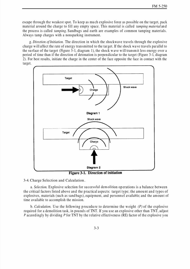
8/14/2019 United States Army Fm 5-250 - 15 June 1992 Explosives
http://slidepdf.com/reader/full/united-states-army-fm-5-250-15-june-1992-explosives 82/275
FM 5-250
escape th rough the weakest spot. To keep as mu ch explosive force as possible on the target, packmaterial around the charge to fill any empty space. This material is called tamping material an dthe process is called tamping. Sandbags and earth are examples of common tamping materials.Always tamp charges with a nonsparking instrument.
g. Direction of Initiation. The direction in which the shockwave travels through the explosive
charge w ill affect the rate of energy transmitted to the tar get. If the shock wa ve travels par allel tothe su rface of the target (Figure 3-1, diagram 1), the shock w ave w ill transm it less energy over aperiod of time than if the direction of detonation is perpendicular to the ta rget (Figure 3-1, diagram2). For best results, initiate the charge in the center of the face opposite the face in contact with thetarget.
3-4. Charge Selection and Calculation .
a. Selection. Explosive selection for su ccessful dem olition op erations is a balance betweenthe critical factors listed above an d the p ractical aspects: target type; the amou nt an d types of explosives, materials (such as sand bags), equipment, and personn el available; and the am oun t of time available to accomplish the mission.
b. Calculation. Use the following p rocedu re to determine the w eight (P) of the explosiverequired for a demolition task, in pou nd s of TNT. If you use an explosive other than TNT, ad justP accord ingly by dividing P for TNT by the relative effectiveness (RE) factor of the explosive you
3-3
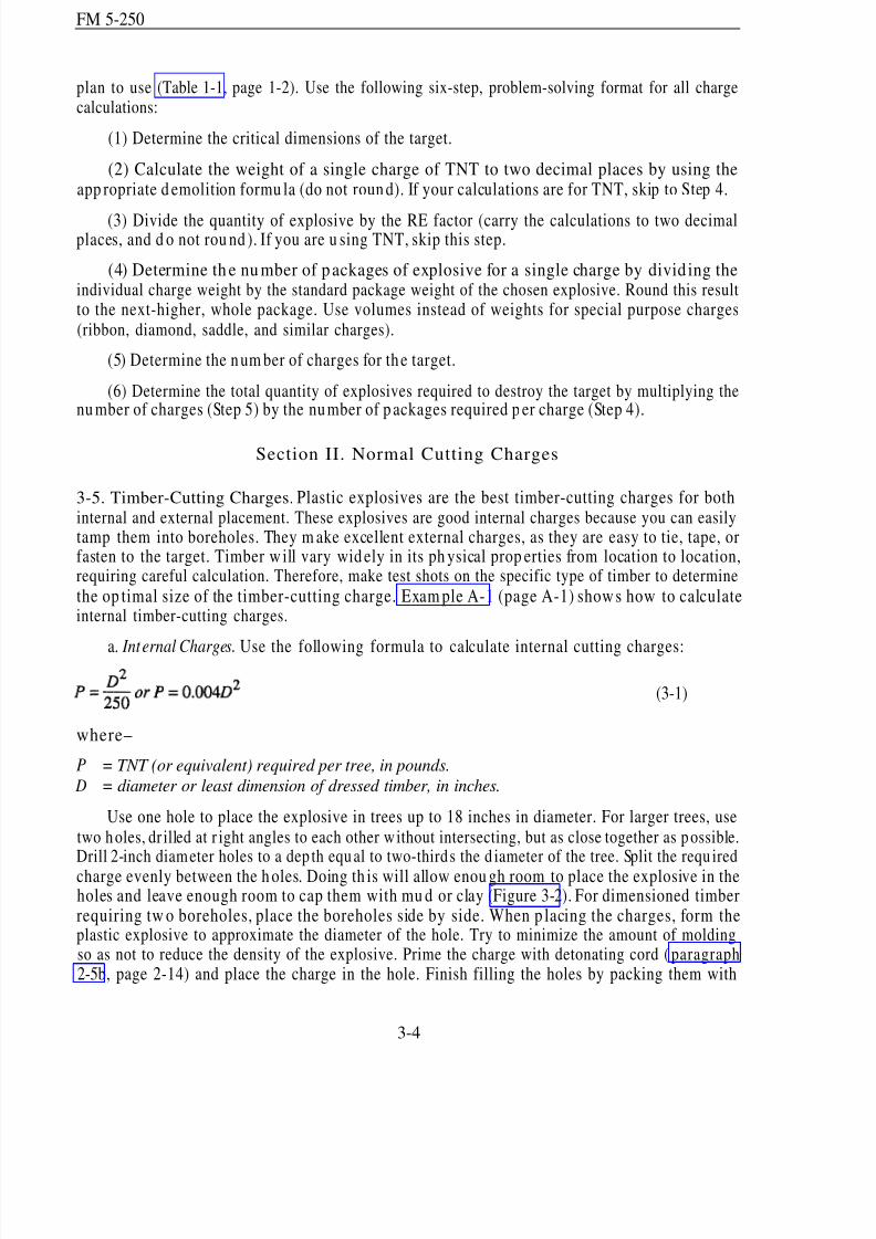
8/14/2019 United States Army Fm 5-250 - 15 June 1992 Explosives
http://slidepdf.com/reader/full/united-states-army-fm-5-250-15-june-1992-explosives 83/275
FM 5-250
plan to use (Table 1-1, page 1-2). Use the following six-step, problem-solving format for all chargecalculations:
(1) Determine the critical dimensions of the target.
(2) Calculate the weight of a single charge of TNT to two decimal places by using theapp ropriate d emolition formu la (do not roun d). If your calculations are for TNT, skip to Step 4.
(3) Divide the quantity of explosive by the RE factor (carry the calculations to two decimalplaces, and d o not rou nd ). If you are u sing TNT, skip this step.
(4) Determine th e nu mber of packages of explosive for a single charge by divid ing theindividual charge weight by the standard package weight of the chosen explosive. Round this resultto the next-higher, whole package. Use volumes instead of weights for special purpose charges(ribbon, diamond, saddle, and similar charges).
(5) Determine the num ber of charges for the target.
(6) Determine the total quantity of explosives required to destroy the target by multiplying thenu mber of charges (Step 5) by the number of p ackages required p er charge (Step 4).
Section II. Normal Cutting Charges
3-5. Timber-Cutting Charges. Plastic explosives are the best timber-cutting charges for bothinternal and external placement. These explosives are good internal charges because you can easilytamp them into boreholes. They m ake excellent external charges, as they are easy to tie, tape, orfasten to the target. Timber w ill vary wid ely in its ph ysical prop erties from location to location,requiring careful calculation. Therefore, make test shots on the specific type of timber to determine
the op timal size of the timber-cutting charge. Exam ple A-1 (page A-1) show s how to calculateinternal timber-cutting charges.
a. Internal Charges. Use the following formula to calculate internal cutting charges:
(3-1)
where–
P = TNT (or equivalent) required per tree, in pounds.
D = diameter or least dimension of dressed timber, in inches.
Use one hole to place the explosive in trees up to 18 inches in diameter. For larger trees, usetwo holes, dr illed at r ight angles to each other w ithout intersecting, but as close together as possible.Drill 2-inch diameter holes to a dep th equal to two-thirds the d iameter of the tree. Split the requ iredcharge evenly between the h oles. Doing th is will allow enou gh room to place the explosive in theholes and leave enough room to cap them with mu d or clay (Figure 3-2). For dimensioned timberrequiring tw o boreholes, place the boreholes side by side. When p lacing the charges, form theplastic explosive to approximate the diameter of the hole. Try to minimize the amount of moldingso as not to reduce the density of the explosive. Prime the charge with detonating cord (paragraph2-5b, page 2-14) and place the charge in the hole. Finish filling the holes by packing them with
3-4
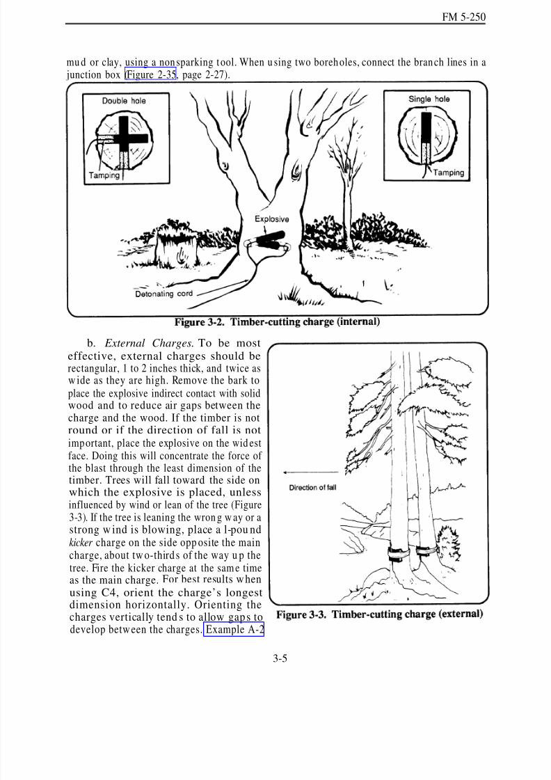
8/14/2019 United States Army Fm 5-250 - 15 June 1992 Explosives
http://slidepdf.com/reader/full/united-states-army-fm-5-250-15-june-1992-explosives 84/275
FM 5-250
mu d or clay, using a nonsparking tool. When u sing two boreholes, connect the branch lines in a junction box (Figure 2-35, page 2-27).
b. External Charges. To be mosteffective, external charges should berectangular, 1 to 2 inches thick, and twice asw ide as they are high. Remove the bark toplace the explosive indirect contact with solid
wood and to reduce air gaps between thecharge and the wood. If the timber is notround or if the direction of fall is notimportant, place the explosive on the wid estface. Doing this will concentrate the force of the blast through the least dimension of thetimber. Trees will fall toward the side onwhich the explosive is placed, unlessinfluenced by wind or lean of the tree (Figure3-3). If the tree is leaning the wron g w ay or astrong w ind is blowing, place a l-pou nd
kicker charge on the side opp osite the maincharge, about tw o-third s of the way u p thetree. Fire the kicker charge at the sam e timeas the main charge. For best results w hen
using C4, orient the charge’s longestdimension horizontally. Orienting thecharges vertically tend s to allow gaps todevelop betw een the charges. Example A-2
3-5

8/14/2019 United States Army Fm 5-250 - 15 June 1992 Explosives
http://slidepdf.com/reader/full/united-states-army-fm-5-250-15-june-1992-explosives 85/275
FM 5-250
(page A-2) shows how to calculate external timber-cutting charges. Use the following formu la todeterm ine the amou nt of explosive needed for cutting trees, posts, beams, or other timber, usinguntamped external charges:
where–
P = TNT required per target, in pounds. D = diameter or least dimension of dimensioned timber, in inches.
using the external-charge formula. Prime the ring charge in two opposing places with branch lines.Connect the branch lines in a junction box (Figure 2-35, page 2-27).
(3-2)
c. Ring Charge. The ringcharge is a band of explosivescompletely circling the tree(Figur e 3-4). The exp losive bandshould be as wide as possible andat least 1/ 2 inch thick for
small-d iameter trees (up to 10inches in d iameter) and 1 inchthick for med ium - andlarge-d iameter trees (up to 30inches in diameter). Use thistechnique when stum p eliminationis imp ortant and the direction of fall is not. For example, removingstumps would be important whenclearing timber for a helicopterlanding zone. Determine the
amou nt of explosive necessary by
d . Underwater Charge. To cut a timber pile underwater, use a method similar to the oneillustrated in Figure 3-5. Determine the size of the charge using the external-charge formula. Placethe charge on the upstream side of the pile and as deep as possible. The stream flow on this part of the pile will maximize the tamping effect on the explosive.
e. Abatis. Fallen-tree obstacles (Figure 3-6) are made by cutting trees that remain attached totheir stum ps. Since trees vary in their ph ysical prop erties, a test shot is required. Use the followingformula to compute the amount of TNT required for the test shot:
where—
P = D =
TNT required per tree, in pounds.
diameter or least dimension of dimensioned timber, in inches.
3-6
(3-3)

8/14/2019 United States Army Fm 5-250 - 15 June 1992 Explosives
http://slidepdf.com/reader/full/united-states-army-fm-5-250-15-june-1992-explosives 86/275
FM 5-250
(1) Placemen t. Place abatis charges in the sam eway as external timber charges except place thecharges 5 feet above ground level. The tree w ill falltoward the side where the explosive is attachedunless influenced by the lean of the tree or wind.
(2) Special Consid erations. Consider th efollowing when creating an abatis:
Make sure the obstacle will cover at least75 meters from end to end.
Make sure the ind ividual trees are at least
24 inches in d iameter . Smaller trees arenot effective obstacles against trackedvehicles.
Fell trees 3 to 4 meters apart. Doing thiscreates a condition that p revents trackedvehicles from driving over the top of the obstacle.
Fell the trees at a 45-degree angle toward the enemy.
Simultaneously detonate the charges on the trees on one side of the road at a time. Then,fell the trees on the other side of the road. Delay blasting of the trees on the other sideof the road unt il the frost trees have completely fallen.
To make obstacles hard er to remove, place mines, booby trap s, or barbed or concertinawire in the obstacle, and cover the obstacle with d irector ind irect fire.
f. Hasty Timber Calculations. Table 3-1 (page 3-8) lists the requ ired n um ber of C4 packagesfor cutting timber with internal, external, and abatis charges.
3-7

8/14/2019 United States Army Fm 5-250 - 15 June 1992 Explosives
http://slidepdf.com/reader/full/united-states-army-fm-5-250-15-june-1992-explosives 87/275
FM 5-250
3-6. Steel-Cuttin g Ch arges.
WARNINGSteel-cutting charges prod uce metal fragmen ts.Proper precautions should be taken to protect
personnel. Refer to Table 6-3, page 6-7.
a. Target Factors. The following ta rget factors are critical in steel-structur e d emolitions, more
so than with other materials:
(1) Target Configuration. The configura tion of the steel in the stru cture d etermines th e typeand amount of charge necessary for successful demolition. Examples of structured steel are I-beams,wid e-flange beams, chann els, angle sections, structural tees, and steel plates used in building orbridge construction. Example A-3 (page A-3) show s how to calculate steel-cutt ing charges forwide-flange beams and girders.
(2) Target Materials. In ad dition to its configuration, steel also has varied composition:
High-carbon steel. Metal-working dies and rolls are normally composed of high-carbonsteel and are very dense.
Alloy steel. Gears, shafts, tools, and plowshares are usually composed of alloy steel.Chains and cables are often made from alloy steel; however, some chains and cables are composedof high-carbon steel. Alloy steel is not as dense as high-carbon steel.
Cast iron. Some steel comp onents (such as railroad rails and p ipes) are composed of castiron. Cast iron is very br ittle and easily broken.
Nickel-molybdenum steel. This type of steel cannot be cut easily by conventionalsteel-cutting charges. The jet from a shap ed charge w ill penetrate it, but cutting requires m ultiplecharges or linear-shaped charges. Nickel-molybdenu m steel shafts can be cut w ith a diam ondcharge. However, the sadd le charge w ill not cut nickel-molybdenu m sh afts. Therefore, use somemethod other than explosives to cut nickel-molybdenum steel, such as thermite or acetylene or
electrical cutting tools.
b. Explosives Factors. In steel-cutting charges, the typ e, placement, and size of the explosiveare important. Confining or tamp ing the charge is rarely practical or possible. The following factorsare important when selecting steel-cutting charges:
(a)
(b)
(c)
(d )
3-8
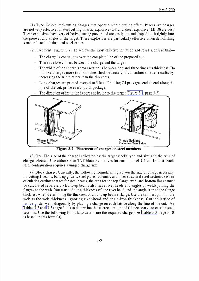
8/14/2019 United States Army Fm 5-250 - 15 June 1992 Explosives
http://slidepdf.com/reader/full/united-states-army-fm-5-250-15-june-1992-explosives 88/275
FM 5-250
(1) Type. Select steel-cutting charges that operate with a cutting effect. Percussive chargesare not very effective for steel cut ting. Plastic explosive (C4) and sheet exp losive (Ml 18) are best.These explosives have very effective cutting power and are easily cut and shaped to fit tightly intothe grooves and angles of the target. These explosives are particularly effective when demolishingstructural steel, chains, and steel cables.
(2) Placement (Figure 3-7). To achieve the most effective initiation and resu lts, ensu re that—
The charge is continuous over the complete line of the proposed cut.
There is close contact between the charge and the target.
The wid th of the charge’s cross section is between on e and three times its thickness. Donot u se charges more th an 6 inches thick because you can achieve better results byincreasing the width rather than the thickness.
Long charges are primed every 4 to 5 feet. If butting C4 packages end to end along theline of the cut, prime every fourth package.
The direction of initiation is perp end icular to th e target (Figure 3-1, page 3-3).
(3) Size. The size of the charge is d ictated by the target steel’s type and size and the typ e of charge selected. Use either C4 or TNT block exp losives for cutting steel. C4 works best. Eachsteel configuration requires a unique charge size.
(a) Block charge. Generally, the following formula will give you the size of charge necessaryfor cutting I-beams, built-up girders, steel plates, columns, and other structural steel sections. (Whencalculating cutting charges for steel beams, the area for th e top flange, web, and bottom flange mustbe calculated separately.) Built-up beams also have rivet heads and angles or welds joining theflanges to the w eb. You m ust ad d th e thickness of one rivet head and the angle iron to the flangethickness wh en d etermining the thickness of a built-up beam’s flange. Use the th innest point of theweb as the web thickness, ignoring rivet-head and angle-iron thickness. Cut the lattice of lattice-girder webs diagonally by placing a charge on each lattice along the line of the cut. UseTables 3-2 an d 3-3 (page 3-10) to determ ine the correct am oun t of C4 necessary for cutt ing steelsections. Use the following formu la to determ ine the requ ired charge size (Table 3-3, pa ge 3-10,is based on this formula):
3-9
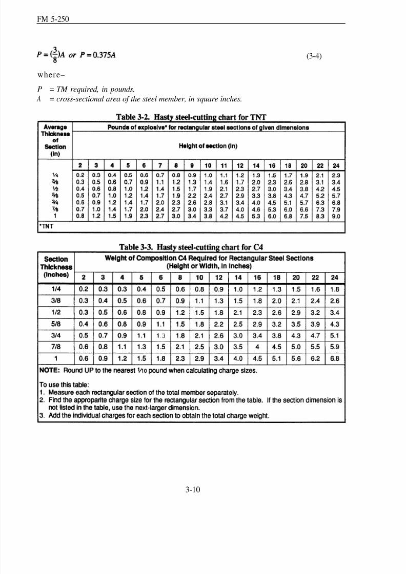
8/14/2019 United States Army Fm 5-250 - 15 June 1992 Explosives
http://slidepdf.com/reader/full/united-states-army-fm-5-250-15-june-1992-explosives 89/275
FM 5-250
(3-4)
where–
P = TM required, in pounds.
A = cross-sectional area of the steel member, in square inches.
3-10

8/14/2019 United States Army Fm 5-250 - 15 June 1992 Explosives
http://slidepdf.com/reader/full/united-states-army-fm-5-250-15-june-1992-explosives 90/275
FM 5-250
(b) High-carbon or alloy steel. Use the following formula to determine the required chargefor cutting high-carbon or alloy steel:
P = D2
(3-5)
where–
P = TNT required, in pounds. D = diameter or thickness of section to be cut, in inches.
(c) Steel bars, rod s, chains, and cables(up to 2 inches). The size of these materialsmakes p roper charge placement d ifficult. Forexample, Figure 3-8 shows charge placementon a chain. If the explosive is long enou gh tobridge both sides of the link or is large enoughto fit snugly between the two links, use onecharge. If the explosive is not large enough to
bridge both sides, use tw o charges. Use thefollowing amount of explosive:
For materials up to 1 inch indiameter or thickness, use 1 poundof explosive.
For materials between 1 and 2 in-ches in diameter or thickness, use 2pounds of explosive.
(d) Steel bars, rods, chains, and cables
(over 2 inches). When th e target d iameter orthickness is 2 inches or greater, use equation 3-4.When the thickness or diam eter is 3 inches orgreater, place half of the charge on each side of,the target and stagger the placement to producethe m aximu m shearing effect (Figure 3-9).
(e) Railroad rails. The height of therailroad rail is the critical dimension fordeterm ining the amoun t of explosive required.For rails 5 inches or more in height, crossovers,
and switches, use 1 pou nd of C4 or TNT. For rails less than 5 inches high, use 1/ 2 poun d of C4 orTNT (Figur e 3-10, pa ge 3-12). Railroad frogs requ ire 2 pou nd s of C4 or TNT. Place the chargesat vu lnerable points, such as frogs, curves, switches, and crossovers, if possible. Place the chargesat altern ate ra il splices for a d istance of 500 feet.
3-11
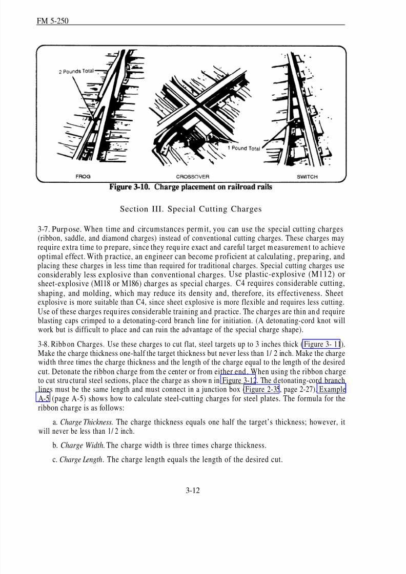
8/14/2019 United States Army Fm 5-250 - 15 June 1992 Explosives
http://slidepdf.com/reader/full/united-states-army-fm-5-250-15-june-1992-explosives 91/275
FM 5-250
Section III. Special Cutting Charges
3-7. Purpose. When time and circumstances perm it, you can use the special cutting charges(ribbon, saddle, and diamond charges) instead of conventional cutting charges. These charges mayrequire extra time to p repare, since they requ ire exact and careful target m easuremen t to achieveop timal effect. With p ractice, an engineer can become p roficient at calculating , prep aring, andplacing these charges in less time than required for traditional charges. Special cutting charges useconsiderably less explosive than conventional charges. Use plastic-explosive (M112) orsheet-explosive (Ml18 or M l86) charges as special charges. C4 requires considerable cutting,
shaping, and molding, which may reduce its density and, therefore, its effectiveness. Sheet
explosive is more suitable than C4, since sheet explosive is more flexible and requires less cutting.Use of these charges requ ires considerable training and practice. The charges are thin an d requireblasting caps crimped to a detonating-cord branch line for initiation. (A detonating-cord knot willwork but is difficult to place and can ruin the advantage of the special charge shape).
3-8. Ribb on Charges. Use these charges to cut flat, steel targets up to 3 inches thick (Figure 3- 11).Make the charge thickness one-half the target thickness but never less than 1/ 2 inch. Make the chargewidth three times the charge thickness and the length of the charge equal to the length of the desired
cut. Detonate the ribbon charge from th e center or from either end . When using th e ribbon chargeto cut stru ctural steel sections, place the charge as show n in Figure 3-12. The detonating-cord branchlines must be the same length and must connect in a junction box (Figure 2-35, page 2-27). Example
A-5 (page A-5) shows how to calculate steel-cutting charges for steel plates. The formula for theribbon charge is as follows:
a. Charge Thickness. The charge thickness equals one half the target’s thickness; however, itwill never be less than 1/ 2 inch.
b. Charge Width. The charge width is three times charge thickness.
c. Charge Length. The charge length equals the length of the desired cut.
3-12
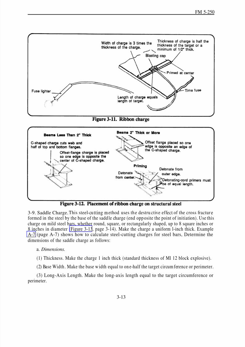
8/14/2019 United States Army Fm 5-250 - 15 June 1992 Explosives
http://slidepdf.com/reader/full/united-states-army-fm-5-250-15-june-1992-explosives 92/275
FM 5-250
3-9. Saddle Charge. This steel-cu tting m ethod uses th e destru ctive effect of the cross fractur eformed in the steel by the base of the sadd le charge (end opp osite the point of initiation). Use thischarge on mild steel bars, whether round, square, or rectangularly shaped, up to 8 square inches or8 inches in diameter (Figure 3-13, page 3-14). Make the charge a uniform l-inch thick. ExampleA-7 (page A-7) shows how to calculate steel-cutting charges for steel bars, Determine thedimensions of the saddle charge as follows:
a. Dimensions.
(1) Thickness. Make the charge 1 inch thick (standard thickness of Ml 12 block explosive).
(2) Base Width . Make the base w idth equal to on e-half the target circum ference or perimeter.
(3) Long-Axis Length. Make the long-axis length equal to the target circumference orperimeter.
3-13
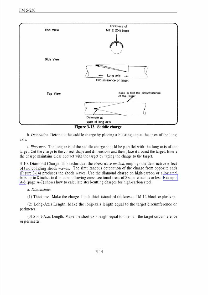
8/14/2019 United States Army Fm 5-250 - 15 June 1992 Explosives
http://slidepdf.com/reader/full/united-states-army-fm-5-250-15-june-1992-explosives 93/275
FM 5-250
b. Detonation. Detonate the sadd le charge by placing a blasting cap at the ap ex of the longaxis.
c. Placement. The long axis of the sad dle charge shou ld be p arallel with the long axis of thetarget. Cut the charge to the correct shape and d imensions and then p lace it around the target. Ensu re
the charge maintains close contact with the target by taping the charge to the target.
3-10. Diamond Charge. This techn ique, the stress-wave method, employs the destructive effectof two colliding shock wav es. The simultaneous detonation of the charge from opposite ends
(Figure 3-14) produces the shock waves. Use the diamond charge on high-carbon or alloy steelbars up to 8 inches in d iameter or h aving cross-sectional areas of 8 square inches or less. ExampleA-8 (page A-7) shows how to calculate steel-cutting charges for high-carbon steel.
a. Dimensions.
(1) Thickness. Make the charge 1 inch thick (standard thickness of Ml12 block explosive).
(2) Long-Axis Length. Make the long-axis length equal to the target circumference orperimeter.
(3) Short-Axis Length. Make the short-axis length equal to one-half the target circumferenceor p erimeter.
3-14
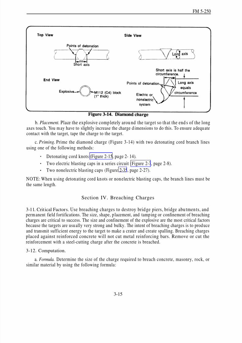
8/14/2019 United States Army Fm 5-250 - 15 June 1992 Explosives
http://slidepdf.com/reader/full/united-states-army-fm-5-250-15-june-1992-explosives 94/275
FM 5-250
b. Placement. Place the explosive comp letely arou nd the target so th at the end s of the longaxes touch. You m ay have to slightly increase the charge d imensions to do this. To ensure adequatecontact with the target, tape the charge to the target.
c. Priming. Prime the diamond charge (Figure 3-14) with two detonating cord branch linesusing one of the following methods:
Detonating cord knots (Figure 2-15, page 2- 14).
Two electric blasting caps in a series circuit (Figure 2-7, page 2-8).
Two nonelectric blasting caps (Figure 2-35, page 2-27).
NOTE: When u sing detonating cord knots or nonelectric blasting caps, the branch lines must bethe same length.
Section IV. Breaching Charges
3-11. Critical Factors. Use breaching charges to destroy brid ge piers, bridge abu tmen ts, andperm anent field fortifications. The size, shape, p lacement, and tamp ing or confinement of breachingcharges are critical to success. The size and confinement of the explosive are the most critical factorsbecause the targets are usu ally very strong and bulky. The intent of breaching charges is to prod uceand transmit sufficient energy to the target to make a crater and create spalling. Breaching chargesplaced against reinforced concrete will not cut metal reinforcing bars. Remove or cut the
reinforcement with a steel-cutting charge after the concrete is breached.
3-12. Computation.
a. Formula. Determine the size of the charge required to breach concrete, masonry, rock, orsimilar material by using the following formula:
3-15

8/14/2019 United States Army Fm 5-250 - 15 June 1992 Explosives
http://slidepdf.com/reader/full/united-states-army-fm-5-250-15-june-1992-explosives 95/275
FM 5-250
P = R3KC (3-6)
where—
P = TNT required, in pounds.
R = breaching radius, in feet.
K = material factor, which reflects the strength, hardness, and mass of thematerial to be demolished, (Table 3-4).
C = tamping factor, which depends on the location and tamping of the charge (Figure 3-15).
3-16

8/14/2019 United States Army Fm 5-250 - 15 June 1992 Explosives
http://slidepdf.com/reader/full/united-states-army-fm-5-250-15-june-1992-explosives 96/275
FM 5-250
b. Breaching Radius (R). The breaching rad ius for external charges is equ al to the thicknessof the target being breached . For intern al char ges placed in the center of the target’s mass, thebreaching rad ius is one half the thickness of the target. If the charge is p laced at less than h alf themass th ickness, the breaching rad ius is the longer of the d istances from the center of the charge tothe outside surfaces of the target. For example, when breaching a 4-foot wall with an internal chargeplaced 1 foot into the wall, the breaching radius is 3 feet (the longest distance from the center of theexplosive to an outside target surface). If placed at the center of the wall’s mass, the explosive’sbreaching radius is 2 feet (one-half the thickness of the target). The breaching radius is 4 feet foran external charge on this w all. Round values of R to the next-higher ¼-foot distance for internalcharges and to the next-higher ½-foot distance for external charges.
c. Material Factor (K). K represents the strength an d h ard ness of the target material. Table3-4 gives values for K for various typ es and thicknesses of material. When y ou are un able topositively identify the target m aterial, assume the target consists of the strongest type of m aterial inthe general grou p. Always assum e concrete is reinforced and masonry is first-class unless you knowthe exact condition and construction of the target materials.
d . Tamping Factor (C). C dep end s on the charge location and m aterials used for tamp ing.Figure 3-15 illustrates m ethod s for placing charges and gives the values of C for both tam ped andun tamp ed charges. When selecting a value for C from Figure 3-15, do not consider a charge tampedwith a solid material (such as sand or earth) as fully tamped unless you cover the charge to a depthequal to or greater than the breaching radius.
3-13. Breachin g Reinforced Concrete.Table 3-5 (page 3-18) gives the nu mber of C4 pa ckagesrequired for breaching reinforced-concrete targets. Example A-9 (page A-8) shows how to calculatethe breaching charge for a reinforced-concrete pier. The am oun ts of C4 in th e table are based onequation 3-6. To u se the table, do the following :
a. Measure th e concrete thickness.
b. Decide how the charge will be placed against the target. Compare the method of placementwith the d iagrams at the top of the Table 3-5 (page 3-18). If in doubt about wh ich colum n to u se,always use the column that lists the greatest amount of explosive.
c. Using the column directly under the chosen placement method, select the amount of explosive required , based on tar get thickness. For examp le, 200 packages of C4 are requ ired tobreach a 7-foot reinforced-concrete wall with an untamped charge placed 7 feet above ground.
3-17
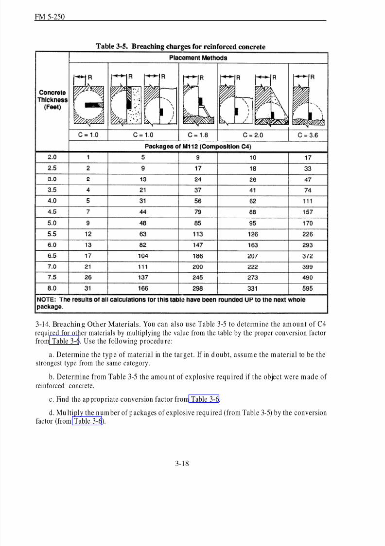
8/14/2019 United States Army Fm 5-250 - 15 June 1992 Explosives
http://slidepdf.com/reader/full/united-states-army-fm-5-250-15-june-1992-explosives 97/275
FM 5-250
3-14. Breaching Other Materials. You can also use Table 3-5 to determ ine the am oun t of C4required for other materials by multiplying the value from the table by the proper conversion factorfrom Table 3-6. Use the following p rocedu re:
a. Determine the typ e of material in the tar get. If in d oubt, assum e the m aterial to be thestrongest type from the same category.
b. Determine from Table 3-5 the amou nt of explosive requ ired if the object were m ad e of reinforced concrete.
c. Find the ap prop riate conversion factor from Table 3-6.
d. Mu ltiply the n um ber of packages of explosive requ ired (from Table 3-5) by the conversionfactor (from Table 3-6).
3-18
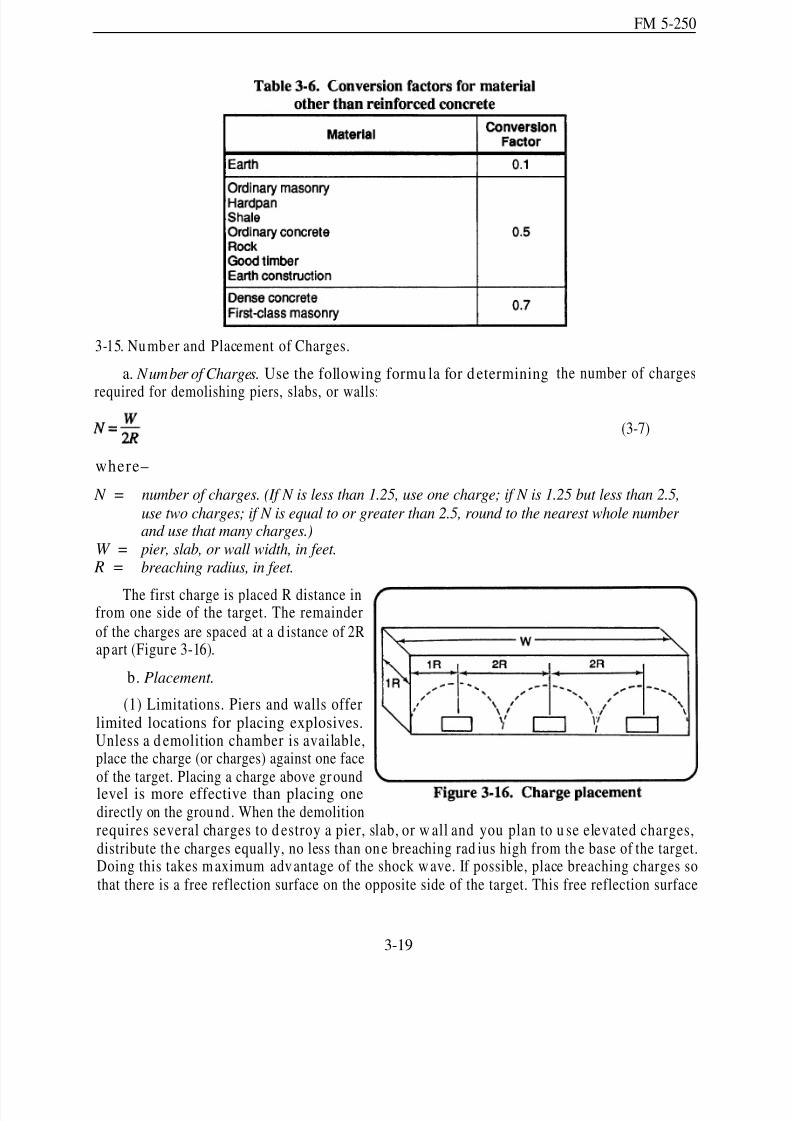
8/14/2019 United States Army Fm 5-250 - 15 June 1992 Explosives
http://slidepdf.com/reader/full/united-states-army-fm-5-250-15-june-1992-explosives 98/275
FM 5-250
3-15. Number and Placement of Charges.
a. Number of Charges. Use the following formu la for determining
required for demolishing piers, slabs, or walls:
the number of charges
(3-7)
where–
N = number of charges. (If N is less than 1.25, use one charge; if N is 1.25 but less than 2.5,
use two charges; if N is equal to or greater than 2.5, round to the nearest whole number and use that many charges.)
W = pier, slab, or wall width, in feet. R = breaching radius, in feet.
The first charge is placed R distance infrom one side of the target. The remainder
of the charges are spaced at a d istance of 2Rapart (Figure 3-16).
b. Placement.
(1) Limitations. Piers and walls offerlimited locations for placing explosives.Unless a d emolition chamber is available,place the charge (or charges) against one faceof the target. Placing a charge above groundlevel is more effective than placing onedirectly on the ground . When the demolitionrequires several charges to d estroy a pier, slab, or w all and you plan to u se elevated charges,distribute the charges equally, no less than one breaching rad ius high from the base of the target.Doing this takes m aximum advantage of the shock w ave. If possible, place breaching charges sothat there is a free reflection surface on the opposite side of the target. This free reflection surface
3-19

8/14/2019 United States Army Fm 5-250 - 15 June 1992 Explosives
http://slidepdf.com/reader/full/united-states-army-fm-5-250-15-june-1992-explosives 99/275
FM 5-250
allows spalling to occur. If time permits, tamp all charges thoroughly with soil or filled sandbags.The tamped area m ust be equa l to or greater than the breaching rad ius. For piers, slabs, or walls
partially submerged in water, place charges equal to or greater than the breaching radius below thewater line, if possible (Figure 3-15, page 3-16).
(2) Configuration. For maximum effectiveness, place the explosive charge in the shape of aflat squar e. The charge w idth sh ould be app roximately three times the charge th ickness. Thethickness of the charge d epend s on th e amou nt of explosive required (Table 3-7).
3-16. Counterforce Charge.
a. Use. This special breaching technique is effective against rectangu lar ma sonry or concretecolumns 4 feet thick or less. It is not effective against walls, piers, or long obstacles. The obstaclealso must have at least three free faces or be freestanding. If constructed of plastic explosives (C4)and properly placed and detonated, counterforce charges produce excellent results with a relativelysmall amount of explosive. Their effectiveness results from the simultaneous detonation of twocharges placed directly opposite each other and as near the center of the target as possible (Figure3-17).
b. Calculation. The thickness or diameter of the target determines the amount of plasticexplosive required. The amount of plastic explosive equals 1½ times the thickness of the target, infeet (1 ½ pounds of explosive per feet). Round fractional measurements to the next higher half foot
3-20
8/14/2019 United States Army Fm 5-250 - 15 June 1992 Explosives
http://slidepdf.com/reader/full/united-states-army-fm-5-250-15-june-1992-explosives 100/275
FM 5-250
before multiplying. For example, a concrete target measuring 3 feet 9 inches thick requires 6 poundsof plastic explosive (1.5 lb/ foot x 4 feet).
c. Placement. Split the charge in half. Place the tw o halves d irectly opposite each oth er onthe target. This method requires accessibility to both sides of the target so the charges will fit flushagainst their respective target sides.
d. Priming. Prime both charges on the face farthest from the target. Join the ends of thedetonating-cord branch lines in a jun ction box (Figure 3- 17). The length of the branch lines fromboth charges must be equal to ensure simultaneous detonation.
Section V. Cratering and Ditching Ch arges
3-17. Factors.
a. Sizes. To be effective obstacles, road craters must be too wide for track vehicles to span andtoo deep and steep-sided for any vehicle to pass through. Blasted road craters will not stop moderntanks indefinitely. A tank, making repeated attempts to traverse the crater, will pu ll soil loose from
the slopes of the crater, filling the bottom and reducing both the crater’s depth and angle of slope.Road craters are effective antitank obstacles if a tank requ ires three or m ore passes to trav erse thecrater, thereby prov iding enou gh time for antitank weapons to stop the tank. Road craters shouldbe large enough to tie into natu ral or constructed obstacles at each end. Imp rove the effectivenessof blasted road craters by placing log hurd les on either side, digging the face of the hu rdle verticallyon the friend ly side, mining the site with antitank an d an tipersonnel mines, filling the crater withwa ter, or by using other means to further d elay enemy ar mor. Cut road craters across the desiredgap at a 45-degree angle from the d irection of app roach. This angled cut w ill increase the tank’stendency to slip sideways an d ride off its track. To achieve sufficient obstacle dep th, place cratersin m ultiple or single rows, enhancing some oth er obstacle, such as a bridge d emolition. Whencreating more than one row of craters, space them far enou gh apart so that a single armored vehicle
launch br idge (AVLB) will not span them.
b. Explosives. All military explosives can create antitank craters. When available, use the40-poun d, amm onium -nitrate cratering charge (Figure 1-5, page 1-8) for blasting craters.
c. Charge Confinement. Place cratering charges in boreholes and tam p them.
3-18. Breaching Hard-Surfaced Pavements. Breach hard-surfaced pavements so that holes canbe du g for the cratering charges. This can be done by exploding tam ped charges on the pavem entsu rface. Use a l-poun d char ge of explosive for each 2 inches of pavem ent th ickness. Tamp th echarges twice as deep as the p avement thickness. Shap ed charges also are effective for breachinghard -surfaced p avements. A shaped charge will readily blast a small-diam eter borehole throu gh
the pavement and into the subgrade. Blasting the boreholes with shaped charges will speed up thecratering task by first, eliminating the need to breach the pavement w ith explosive charges and thendigging the hole for the cratering charge. Do not breach concrete at an expansion joint because theconcrete will shatter irregularly. Table 1-3 (page 1-10) lists hole dep ths and optimu m standoff distances when using the 15- or 40-pound shaped charges against various types of material, Shapedcharges do not always p roduce open boreholes capable of accepting a 7-inch diameter crateringcharge. You may need to remove some earth or widen narrow areas to accommodate the cratering
3-21

8/14/2019 United States Army Fm 5-250 - 15 June 1992 Explosives
http://slidepdf.com/reader/full/united-states-army-fm-5-250-15-june-1992-explosives 101/275
FM 5-250
charge. Widen deep, narrow boreholes by knocking material from the constricted areas with a poleor rod or by breaking off the shattered concrete on the surface with a pick or crowbar.
3-19. Hasty Crater. This meth od takes the least amoun t of time to construct, based u pon thenu mber an d dep th of the boreholes. How ever, it p rodu ces the least effective barrier because of itsdep th an d shape (Figure 3-1 8). The hasty m ethod forms a V-shaped crater about 6 to 7 feet deepand 20 to 25 feet wide, extending approximately 8 feet beyond each end borehole. The sides of thecrater slope 25 to 35 degrees. Modern US tanks require an average of four attemp ts to breach ahasty crater. To forma crater that is effective against tanks, boreholes must be at least 5 feet deepwith at least 50 pou nd s of explosive in each hole. Use the following p rocedu re to create a roadcrater:
a. Boreholes. Dig all boreholes to the sam e dep th (5 feet or deeper recommend ed). Space the
boreholes at 5-foot intervals, center to center, across the r oad. Use the following formu la to compu tethe number of boreholes:
(3-8)
where–
N = L =
16 =5 =
1 =
number of boreholes; round fractional numbers to next higher whole number.length of the crater, in feet. (Measure across the area to be cut. Round fractionalmeasurements to the next higher foot).
combined blowout of 8 feet each side.5-foot spacing.
factor to convert from spaces to holes.
b. Charge Size. Load the boreholes with 10 pounds of explosive per foot of borehole depth.When using standard cratering charges, sup plement each charge with add itional explosives to obtainthe required amount. For example, a 6-foot hole would require one 40-pound cratering charge and20 pou nd s of TNT or C4.
3-22
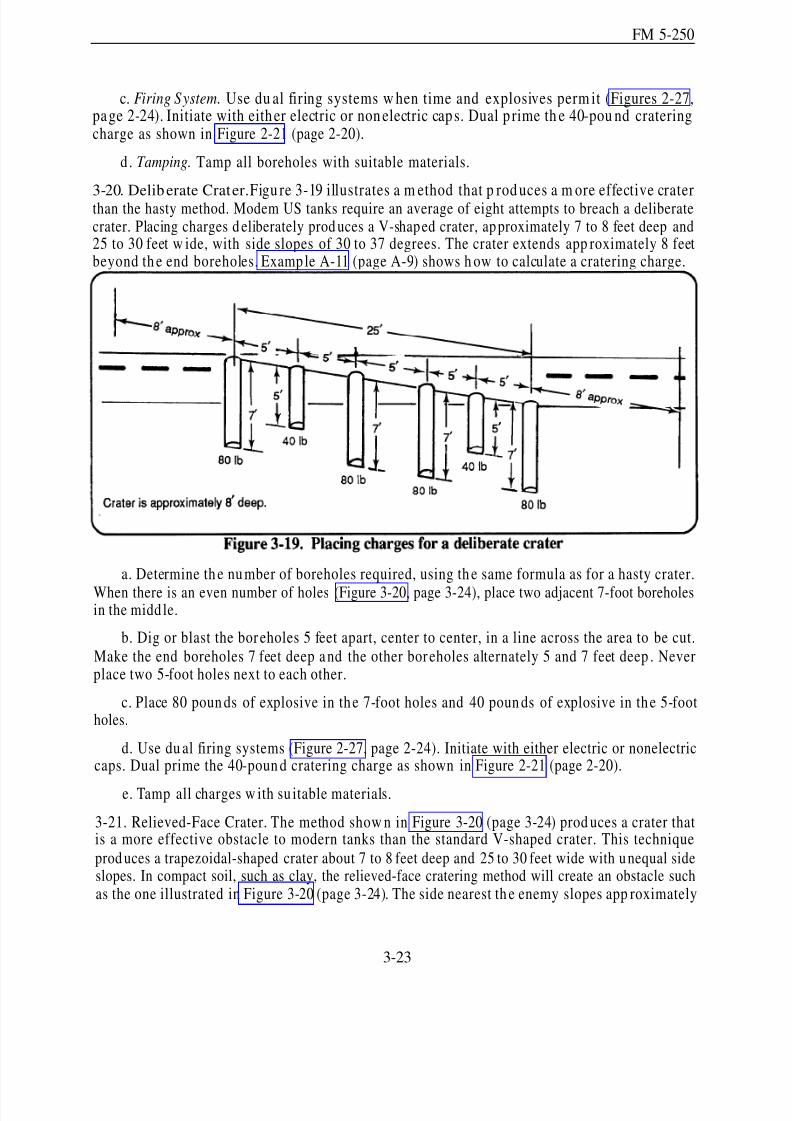
8/14/2019 United States Army Fm 5-250 - 15 June 1992 Explosives
http://slidepdf.com/reader/full/united-states-army-fm-5-250-15-june-1992-explosives 102/275
FM 5-250
c. Firing System. Use du al firing systems w hen time and explosives perm it (Figures 2-27,pa ge 2-24). Initiate with either electric or non electric caps. Dual p rime th e 40-pou nd crateringcharge as shown in Figure 2-21 (page 2-20).
d . Tamping. Tamp all boreholes with suitable materials.
3-20. Deliberate Crater.Figu re 3-19 illustrates a m ethod that p rod uces a m ore effective craterthan the hasty method. Modem US tanks require an average of eight attempts to breach a deliberatecrater. Placing charges d eliberately prod uces a V-shaped crater, ap proximately 7 to 8 feet deep and25 to 30 feet w ide, with side slopes of 30 to 37 degrees. The crater extends app roximately 8 feetbeyond th e end boreholes. Example A-11 (page A-9) shows h ow to calculate a cratering charge.
a. Determine th e number of boreholes required, using th e same formula as for a hasty crater.
When there is an even number of holes (Figure 3-20, page 3-24), place two adjacent 7-foot boreholesin the midd le.
b. Dig or blast the bor eholes 5 feet apart, center to center, in a line across the area to be cut.Make the end boreholes 7 feet deep a nd the other bor eholes alternately 5 and 7 feet deep . Neverplace two 5-foot holes next to each other.
c. Place 80 poun ds of explosive in the 7-foot holes and 40 poun ds of explosive in the 5-footholes.
d. Use du al firing systems (Figure 2-27, page 2-24). Initiate with either electric or nonelectriccaps. Dual prime the 40-poun d cratering charge as shown in Figure 2-21 (page 2-20).
e. Tamp all charges w ith su itable materials.
3-21. Relieved-Face Crater. The method show n in Figure 3-20 (page 3-24) prod uces a crater thatis a more effective obstacle to modern tanks than the standard V-shaped crater. This technique
prod uces a trapezoidal-shaped crater about 7 to 8 feet deep and 25 to 30 feet wide with u nequal sideslopes. In compact soil, such as clay, the relieved-face cratering method will create an obstacle suchas the one illustrated in Figure 3-20 (page 3-24). The side nearest th e enemy slopes app roximately
3-23
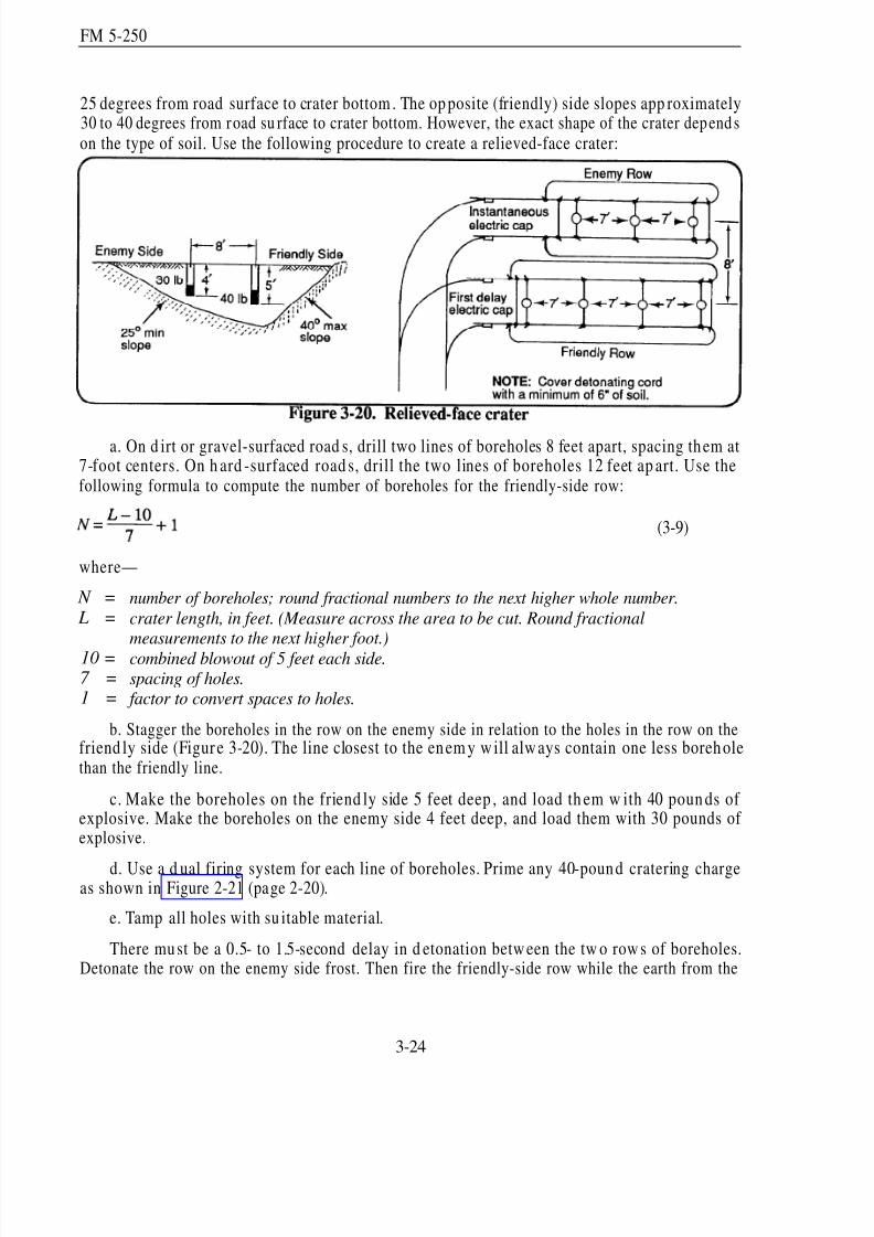
8/14/2019 United States Army Fm 5-250 - 15 June 1992 Explosives
http://slidepdf.com/reader/full/united-states-army-fm-5-250-15-june-1992-explosives 103/275
FM 5-250
25 degrees from road surface to crater bottom . The op posite (friendly) side slopes app roximately30 to 40 degrees from road su rface to crater bottom. However, the exact shape of the crater depends
on the type of soil. Use the following procedure to create a relieved-face crater:
a. On d irt or gravel-surfaced road s, drill two lines of boreholes 8 feet apart, spacing them at7-foot centers. On h ard -surfaced road s, drill the two lines of boreholes 12 feet ap art. Use thefollowing formula to compute the number of boreholes for the friendly-side row:
(3-9)
where—
N = number of boreholes; round fractional numbers to the next higher whole number.
L = crater length, in feet. (Measure across the area to be cut. Round fractionalmeasurements to the next higher foot.)
10 = combined blowout of 5 feet each side.7 = spacing of holes.1 = factor to convert spaces to holes.
b. Stagger the boreholes in the row on the enemy side in relation to the holes in the row on thefriend ly side (Figure 3-20). The line closest to the en em y w ill alw ays contain one less boreh olethan the friendly line.
c. Make the boreholes on the friend ly side 5 feet deep , and load th em w ith 40 poun ds of explosive. Make the boreholes on the enemy side 4 feet deep, and load them with 30 pounds of explosive.
d. Use a d ual firing system for each line of boreholes. Prime any 40-pound cratering chargeas shown in Figure 2-21 (page 2-20).
e. Tamp all holes with su itable material.
There must be a 0.5- to 1.5-second delay in d etonation betw een the tw o row s of boreholes.Detonate the row on the enemy side frost. Then fire the friendly-side row while the earth from the
3-24
8/14/2019 United States Army Fm 5-250 - 15 June 1992 Explosives
http://slidepdf.com/reader/full/united-states-army-fm-5-250-15-june-1992-explosives 104/275
FM 5-250
enemy-side detonation is still in the air. Use standard delay caps. If the firings cannot be staggered,fire both rows simultaneously. However, the crater produced by a simultaneous detonation will nothave the same depth and trapezoidal shape as a relieved-face crater.
3-22. Misfire Preven tion. The shock and blast of the first row of charges m ay affect the d elayeddetonation of the friendly-side charges. To prevent misfires of the friendly-side charges, protect its
detonating-cord lines by covering them with approximately 6 inches of earth.
3-23. Creating Craters in Permafrost and Ice.
a. Blasting in Permafrost. Permafrost can be as har d as solid r ock. Therefore, you mu st adap tthe procedures for blasting or cratering to accommodate permafrost conditions. In permafrost,blasting requires approximately twice as many boreholes and larger charges than for crateringoperations in moderate climates. Blasted, frozen soil breaks into clods 12 to 18 inches thick and 6to 8 inches in diameter. Because normal charges have insufficient force to blow these clods clearof the boreholes, the span falls back into the crater when the blast subsides.
(1) Boreholes. Before conducting extensive blasting, perform a test on the soil in the area todeterm ine the num ber of boreholes needed . Dig the boreholes with stand ard d rilling equipm ent,steam-point drilling equipment, or shaped charges. Standard drilling equipment has one seriousdefect—the air holes in the d rill bits freeze. There is no kn own method to p revent th is freezing.Steam-point drilling is effective for drilling boreholes in sand, silt, or clay, but not in gravel. Placethe charges immediately after withdrawing the steam point; otherwise, the area around the borehole
thaw s and collapses. Shaped charges also are effective for prod ucing boreholes, especially w henforming craters. Table 1-3 (page 1-10) lists borehole sizes made by shaped charges in perm afrostand ice.
(2) Explosives. If available, use low -velocity explosives, such as am moniu m n itrate, forblasting holes in arctic climates. The d isplacing q uality of low -velocity explosives will moreeffectively clear large bou lders from the crater. If only high-velocity explosives are available, tamp
the charges with water and let them freeze before detonating. Unless thoroughly tamped,high-velocity explosives tend to blow out of the boreholes.
b. Blasting in Ice. Access holes in ice are required for obtaining w ater and determ ining thecapacity of the ice for bearing aircraft and vehicles. To accommodate rapid forward movements,
you must be capable of quickly determining ice capacities. Blasting operations provide this ability.
(1) Boreholes. Make sm all-d iameter a ccess holes using sh aped char ges. The M2A4 chargewill penetrate ice as thick as 7 feet; the M3A1 char ge w ill penetrate over 12 feet of ice (Table 1-3,page 1-10). The M3A1 can penetrate deeper, but it h as only been tested on ice app roximately 12feet thick. If placed at the norm al stand off distance, the charge forms a large crater at the surface,requiring you to do considerable probing to find the actual borehole. Use a standoff distance of 42
inches or mor e w ith the M 2A4 shap ed charge to avoid excessive crater formation. The M2A4creates an average borehole diam eter of 3 ½ inches. An M3A1 borehole has an average diam eterof 6 inches. In late w inter, ice grows w eaker and changes color from blue to wh ite. Although thestructure and strength of ice vary, the crater effect is similar, regardless of the standoff distance.
(2)blocks.
Craters. Make surface craters with ammonium-nitrate cratering charges or demolitionFor the best results, place the charges on th e surface of cleared ice and tamp them with
3-25
8/14/2019 United States Army Fm 5-250 - 15 June 1992 Explosives
http://slidepdf.com/reader/full/united-states-army-fm-5-250-15-june-1992-explosives 105/275
FM 5-250
snow. When determining charge size, keep in mind that ice has a tendency to shatter more readilythan soil, and this tendency will decrease the charge’s size.
c. Making Vehicle Obstacles.Create a vehicle obstacle in ice by first making two or morerow s of boreholes. Space the boreholes 9 feet apar t and stagger them in relation to the holes in theother rows. Suspend Ml12 charges about 2 feet below the bottom surface of the ice with cords tiedto sticks, bridging the sticks over the top of the holes. The size of the charge depends on the thickness
and cond ition of the ice. Use test shots to find the op timu m amoun t. This type of obstacle canretard or halt enemy vehicles for ap proximately 24 hours at temp eratures near -24 degreesFahrenheit.
3-24. Craters as Culverts. Destroying a culvert not more than 15 feet deep may also produce aneffective crater. Prime the charges for simultaneou s detonation, and thorou ghly tamp all chargeswith sand bags. Destroy culverts that are no d eeper than 5 feet by placing explosive charges in thesame w ay as for hasty road craters. Space th e boreholes at 5-foot intervals in th e fill above an dalongside the culvert. In each hole place 10 poun ds of explosives per foot of depth
3-25. Craters as Antitank Ditches. Excavate antitank ditches by either the hasty or deliberatecratering method (paragraphs 3-19 an d 3-20, pages 3-22 and 3-23).
3-26. Ditching Methods. Explosives can create d itches rapid ly. Slope d itches at a rate of 2 to 4feet of depth per 100 feet of run. Place ditches in areas where natural erosion will aid in producingthe correct grade. If you cannot place a ditch in an area aided by erosion, make the ditch deep er,increasing th e dep th as th e length increases. Use the following m ethods for creating ditches:
a. Single Line. The single-line method (Figure 3-21) is the most common ditching method.Detonate a single row of charges along the centerline of the pr oposed d itch, leaving any furtherwid ening for subsequent lines of charges. Table 3-8 gives charge configurations for the single-linemethod.
3-26
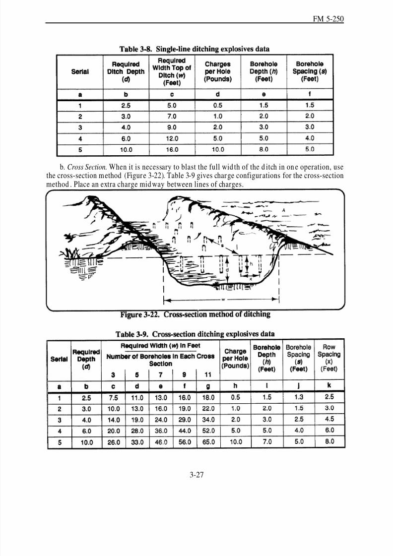
8/14/2019 United States Army Fm 5-250 - 15 June 1992 Explosives
http://slidepdf.com/reader/full/united-states-army-fm-5-250-15-june-1992-explosives 106/275
FM 5-250
b. Cross Section. When it is necessary to blast the full wid th of the d itch in on e operation, usethe cross-section method (Figure 3-22). Table 3-9 gives charge configurations for the cross-sectionmethod . Place an extra charge mid way between lines of charges.
3-27

8/14/2019 United States Army Fm 5-250 - 15 June 1992 Explosives
http://slidepdf.com/reader/full/united-states-army-fm-5-250-15-june-1992-explosives 107/275
FM 5-250
Section VI. Land-Clearing Charges
3-27. Stump Removal. Stum ps h ave tw o general root typ es: tapr oot and lateral root (Figur e 3-23).Measure the stump diam eter 12 to 18 inches above ground level. Round the d iameter to the nexthigher ½ foot. Use 1 pound of explosive per foot of diameter for dead stumps and 2 pounds of explosive per foot of diameter for live stumps. If removing the complete tree, increase the amountof explosive by 50 percent. If you cannot ident ify the root type, assum e the tree has a lateral rootstructure and proceed accordingly.
a. Taprooted S tumps. Two methods are common for removing taprooted stump s. One methodis to drill a hole in the taproot and place the charge in the hole. Another method is to place chargeson both sid es of the tap root, creating a sh earing effect (Figure 3-23). If possible, place the char gesin contact with the root and at a d epth approximately equal to the diameter of the stump .
b. Laterally Rooted Stumps. When blasting laterally rooted stum ps, dr ill sloping holes betweenthe roots (Figure 3-23). Drill the holes and place the charges as closely to the center of the stumpas possible, at a depth equal to the radius of the stump base. Trees with large lateral roots mayrequire additional charges. Place the additional charges directly underneath the lame lateral roots.
3-28. Boulder Removal. Blasting is an effective w ay to r emove bould ers. The m ost pra cticalmethods are snake-hole, mud-cap, and block-hole:
a. Snake-Hole Method. This method involves digging a hole beneath the boulder large enoughto hold the charge. Pack the charge und er and against the boulder as show n in Figure 3-24. Table3-10 lists the required charge sizes.
3-28
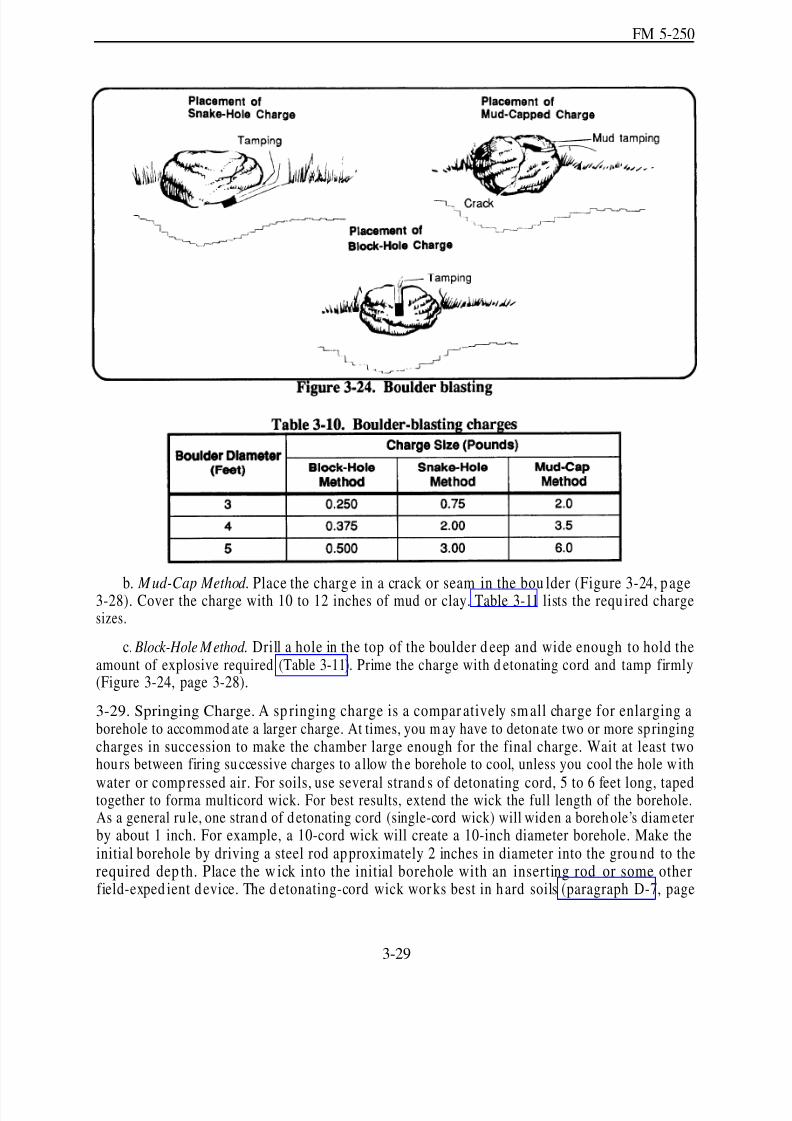
8/14/2019 United States Army Fm 5-250 - 15 June 1992 Explosives
http://slidepdf.com/reader/full/united-states-army-fm-5-250-15-june-1992-explosives 108/275
FM 5-250
b. Mud-Cap Method. Place the charge in a crack or seam in the bou lder (Figure 3-24, page3-28). Cover the charge with 10 to 12 inches of mud or clay. Table 3-11 lists the requ ired chargesizes.
c. Block-Hole Method. Drill a hole in the top of the boulder d eep and wide enough to hold theamount of explosive required (Table 3-11). Prime the charge with d etonating cord and tamp firmly(Figure 3-24, page 3-28).
3-29. Springing Charge. A sp ringing charge is a compar atively sm all charge for enlarging aborehole to accommod ate a larger charge. At times, you m ay have to detonate two or more springingcharges in succession to make the chamber large enough for the final charge. Wait at least twohours between firing successive charges to a llow th e borehole to cool, unless you cool the hole with
water or compressed air. For soils, use several strand s of detonating cord, 5 to 6 feet long, tapedtogether to forma multicord wick. For best results, extend the wick the full length of the borehole.As a general ru le, one strand of detonating cord (single-cord wick) will widen a borehole’s diam eterby about 1 inch. For example, a 10-cord wick will create a 10-inch diameter borehole. Make theinitial borehole by driving a steel rod approximately 2 inches in diameter into the grou nd to therequired dep th. Place the w ick into the initial borehole with an inserting rod or some otherfield-exped ient device. The d etonating-cord wick wor ks best in hard soils (paragraph D-7, page
3-29
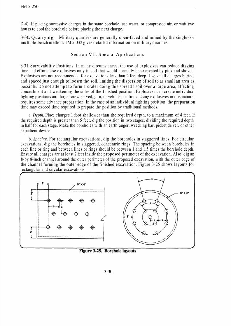
8/14/2019 United States Army Fm 5-250 - 15 June 1992 Explosives
http://slidepdf.com/reader/full/united-states-army-fm-5-250-15-june-1992-explosives 109/275
FM 5-250
D-4). If placing successive charges in the same borehole, use water, or compressed air, or wait twohou rs to cool the boreh ole before placing the next charge.
3-30. Quarrying. Military quarries are generally open-faced and mined by the single- ormu ltiple-bench m ethod. TM 5-332 gives detailed information on military quarr ies.
Section VII. Special App lications
3-31. Survivability Positions. In many circumstances, the use of explosives can reduce diggingtime and effort. Use explosives only in soil that would normally be excavated by pick and shovel.Explosives are not recommended for excavations less than 2 feet deep. Use small charges buriedand spaced just enough to loosen the soil, limiting th e dispersion of soil to as small an area aspossible. Do not attemp t to form a crater doing this spread s soil over a large area, affectingconcealment and weakening the sides of the finished position. Explosives can create ind ividualfighting p ositions and larger crew-served, gun, or vehicle positions. Using explosives in this mannerrequires some advance preparation. In the case of an individu al fighting position, the prepar ationtime may exceed time required to prepare the position by traditional methods.
a. Depth. Place charges 1 foot shallower than the requ ired d epth, to a maximum of 4 feet. If the required depth is greater than 5 feet, dig the position in two stages, dividing the required depthin half for each stage. Make the boreholes with an earth auger, wr ecking bar, picket driver, or otherexpedient device.
b. Spacing. For rectangular excavations, dig the boreholes in staggered lines. For circularexcavations, dig the boreholes in staggered, concentric rings. The spacing between boreholes ineach line or ring and between lines or rings should be between 1 and 1.5 times the borehole depth.Ensure all charges are at least 2 feet inside the p roposed perimeter of the excavation. Also, dig an8-by 8-inch channel around the outer perimeter of the proposed excavation, with the outer edge of the channel forming the outer edge of the finished excavation. Figure 3-25 shows layouts for
rectangular and circular excavations.
3-30

8/14/2019 United States Army Fm 5-250 - 15 June 1992 Explosives
http://slidepdf.com/reader/full/united-states-army-fm-5-250-15-june-1992-explosives 110/275
FM 5-250
c. Charge Size. Use ¼-pou nd charges of plastic explosive to d ig foxholes. For largeexcavations, use charges between ½ and 1 ½ pounds, depend ing on spacing and soil characteristics.A test shot is usually necessary to determine the correct charge size.
d . Concealment. Redu ce explosion n oise and sp oil scatter by leaving any sod in place andcovering the site with a b lasting m at. Imp rovise blasting mats by ty ing tires together with natural
or synthetic rope (steel-wire rope is unacceptable) or by using a heavy tarpaulin.3-32. Equipment Destruction.
WARNINGSteel-cutting charges produ ce metal fragments.
Proper precautions should be taken to protect personnel.Refer to Table 6-3, page 6-7.
a. Guns. Destroy gun barrels with explosives or their own ammunition. Also be sure to removeor destroy the small components, such as sights and other mechanisms.
(1) Explosive Method.
(a) To prep are a gun for dem olition, first block the barrel just above the breach. Forsmall-caliber guns that u se combined projectile-propellant m un itions, solidly tam p the first meterof the bore with earth. For heavier guns that use projectiles separate from propellants, simply loada projectile and aim the tube to minimize damage should the round be ejected.
(b) Charge Size. Table 3-11 (page 3-32) details the charge size required for stand ard barrelsizes. If necessary, determine the required charge size using the following formu la:
(3-l0)
where–
P = quantity of explosive (any high explosive), in pounds. D = bore size of the barrel, in millimeters.
(c) Placement. Pack the explosive, p referably C4, into the breach, immediately behin d th etamp ing. Place the plastic explosive in close contact w ith th e chamber. Close the breach block asfar as possible, leaving only enough space for the detonating cord to pass without being bent orbroken. If time permits, place 15-pound charges on the drive wheels of tracked guns and on thewheels and axles of towed guns. Connect the branch lines in a junction box or use a ring main.Simultaneously detonate all charges.
3-31
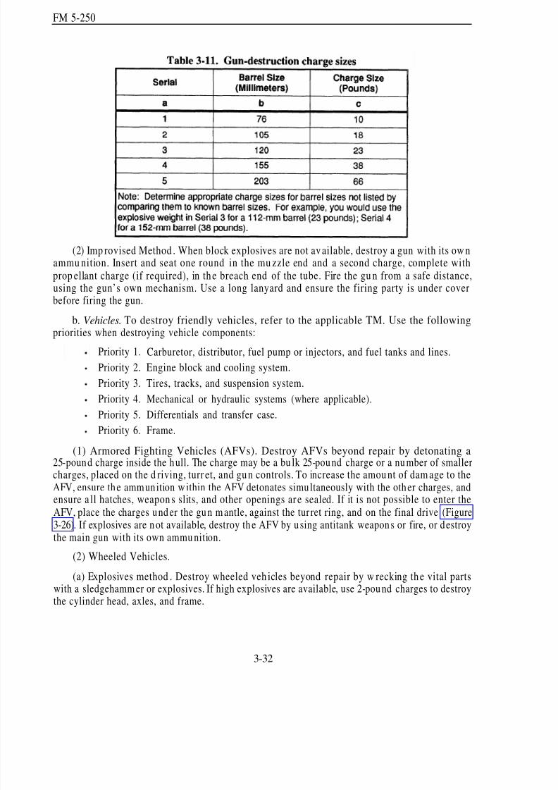
8/14/2019 United States Army Fm 5-250 - 15 June 1992 Explosives
http://slidepdf.com/reader/full/united-states-army-fm-5-250-15-june-1992-explosives 111/275
FM 5-250
(2) Imp rovised Method . When block explosives are not av ailable, destroy a gun with its ow nammu nition. Insert and seat one round in the mu zzle end and a second charge, complete with
prop ellant charge (if required), in th e breach end of the tube. Fire the gu n from a safe distance,using the gun’s own mechanism. Use a long lanyard and ensure the firing party is under coverbefore firing the gun.
b. Vehicles. To destroy friendly vehicles, refer to the applicable TM. Use the followingpriorities when destroying vehicle components:
Priority 1.
Priority 2.
Priority 3.
Priority 4.
Priority 5.Priority 6.
Carburetor, distributor, fuel pump or injectors, and fuel tanks and lines.
Engine block and cooling system.
Tires, tracks, and suspension system.
Mechanical or hydraulic systems (where applicable).
Differentials and transfer case.Frame.
(1) Armored Fighting Vehicles (AFVs). Destroy AFVs beyond repair by detonating a25-pound charge inside the hull. The charge may be a bu lk 25-pound charge or a number of smallercharges, placed on the d riving, turr et, and gu n controls. To increase the amou nt of dam age to theAFV, ensure the ammunition w ithin the AFV detonates simultaneously with the other charges, andensure a ll hatches, weapon s slits, and other openings are sealed. If it is not possible to enter theAFV, place the charges under the gun m antle, against the tur ret ring, and on the final drive (Figure3-26). If explosives are not available, destroy the AFV by u sing antitank weapons or fire, or destroythe main gun with its own ammu nition.
(2) Wheeled Vehicles.
(a) Explosives method . Destroy wheeled veh icles beyond repair by w recking th e vital partswith a sledgehamm er or explosives. If high explosives are available, use 2-pound charges to destroythe cylinder head, axles, and frame.
3-32

8/14/2019 United States Army Fm 5-250 - 15 June 1992 Explosives
http://slidepdf.com/reader/full/united-states-army-fm-5-250-15-june-1992-explosives 112/275
FM 5-250
(b) Improvised method. Drain the engine oil and coolant and run the engine at full throttleun til it siezes. Finish the d estruction by bu rning the vehicle (ignite the fuel in the tank).
3-33
8/14/2019 United States Army Fm 5-250 - 15 June 1992 Explosives
http://slidepdf.com/reader/full/united-states-army-fm-5-250-15-june-1992-explosives 113/275
FM 5-250
Chapter 4
Bridge Demolition
Section I. Requirement
4-1. Purp ose of Bridge D emolition. The purpose of bridge demolitions is to create gaps in bridgesby attacking key comp onents of the bridge. This makes gap s large enough to make repairuneconomical and to force the enemy to construct other bridges on other sites. The minimum gaprequired must exceed the enemy’s assault bridging capability by 5 meters. For planning purposes,use 25 meters as the m inimum gap size, but 35 meters is better. The gap may be less than 25 metersif enemy forces must depend on the demolished bridge components to bear their assault bridgingand there is insufficient bearing capacity in the rem ains to carry the loads.
4-2. Degree of Destruction. The comp lete dem olition of a bridge u sually involves the d estructionof all the comp onents (spans, piers, and abutm ents). Complete dem olition may be justified w hen
the terrain forces the enemy to r econstruct a brid ge on the same site. However, complete destru ctionis not normally required to meet the tactical objective. Select the method of attack that achieves thetactical goal, with a minimum expenditure of resources.
4-3. Debris. Debris may cause enem y forces serious d elays if it obstructs the gap (Figure 4-l).Debris also provides excellent concealment for mines and booby traps. Whenever possible,demolish bridges in such a way that the resulting debris hinders reconstruction.
4-1

8/14/2019 United States Army Fm 5-250 - 15 June 1992 Explosives
http://slidepdf.com/reader/full/united-states-army-fm-5-250-15-june-1992-explosives 114/275
FM 5-250
Section II. Consid erations
4-4. Bridge Categories. The first step in an y efficient brid ge demolition is to categorize the brid gecorrectly. The term categorization has been adopted to avoid confusion with classification, whichis concerned w ith the load -carryin g capacity of brid ges. The correct categorization of bridges,
coupled with an elementary know ledge of bridge d esign, allows y ou to select a su itable attackmeth od . All bridges fit into one of three categories:
a. Simply Supported. In simp ly sup ported bridges, the ends of each span rest on the supp orts;there are n o intermed iate supp orts. The free-bearing conditions shown in Figure 4-2 represent an ybearing that allows some horizontal m ovement (for examp le, roller bearings, sliding bearings, andrubber bearing pads).
b. Miscellaneous. Miscellaneou s bridges form a sm all proportion of bridge stru ctures. Thetheoretical principles governing these bridges determ ine the app ropriate meth ods of attack.Examples of bridges in this category are suspension, lift, and cable-stayed bridges.
c. Continuous. If a bridge does not fit the miscellaneous category and is not simply supported,categorize it as a continuous bridge. Hence, continuous has a wider meaning than multispan,
continuous-beam bridges, as is norm ally imp lied.
4-5. Stages of Destruction. When designing a bridge d emolition, the first pr iority is to create agap. Accomplishing this may require one or two attacks. Further actions that improve the obstaclemay follow, if the situation permits.
4-2
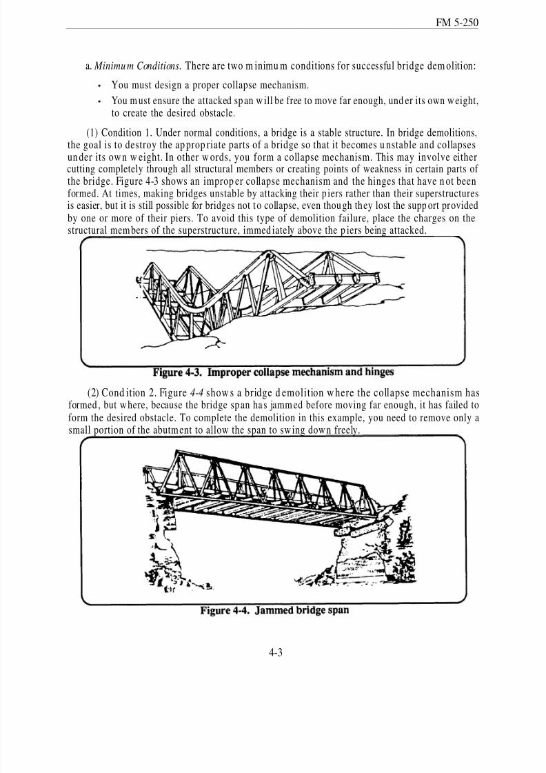
8/14/2019 United States Army Fm 5-250 - 15 June 1992 Explosives
http://slidepdf.com/reader/full/united-states-army-fm-5-250-15-june-1992-explosives 115/275
FM 5-250
a. Minimum Conditions. There are two m inimu m conditions for successful bridge dem olition:
You must design a proper collapse mechanism.
You m ust ensure the attacked sp an w ill be free to move far enough, und er its own w eight,to create the desired obstacle.
(1) Condition 1. Under normal conditions, a bridge is a stable structure. In bridge demolitions,the goal is to destroy the ap prop riate parts of a bridge so that it becomes u nstable and collapsesun der its ow n w eight. In other w ords, you form a collapse mechanism. This may involve eithercutting completely through all structural members or creating points of weakness in certain parts of the bridge. Figure 4-3 shows an improp er collapse mechanism and the hinges that have n ot beenformed. At times, making bridges unstable by attacking their p iers rather than their superstructuresis easier, but it is still possible for bridges not to collapse, even thou gh they lost the supp ort providedby one or more of their piers. To avoid this type of demolition failure, place the charges on thestructural mem bers of the superstructure, immed iately above the p iers being attacked.
(2) Cond ition 2. Figure 4-4 show s a bridge d emolition w here the collapse mechanism has
formed , but w here, because the bridge sp an ha s jamm ed before moving far enough, it has failed toform the desired obstacle. To complete the demolition in this example, you need to remove only asmall portion of the abutm ent to allow the span to sw ing dow n freely.
4-3
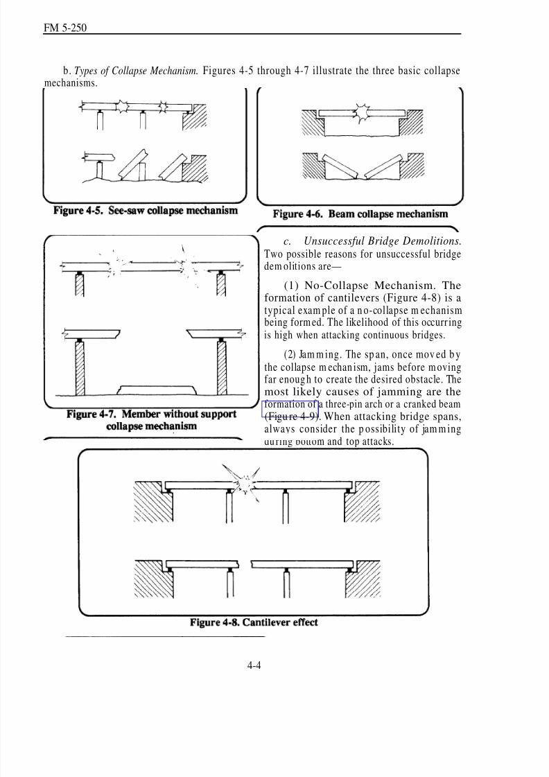
8/14/2019 United States Army Fm 5-250 - 15 June 1992 Explosives
http://slidepdf.com/reader/full/united-states-army-fm-5-250-15-june-1992-explosives 116/275
FM 5-250
b. Types of Collapse Mechanism. Figures 4-5 through 4-7 illustrate the three basic collapsemechanisms.
c. Unsuccessful Bridge Demolitions.Two possible reasons for unsuccessful bridge
dem olitions are—(1) No-Collapse Mechanism. The
formation of cantilevers (Figure 4-8) is atypical exam ple of a n o-collapse m echanismbeing form ed. The likelihood of this occurr ingis high when attacking continuous bridges.
(2) Jam m ing. The sp an, once mov ed b ythe collapse m echan ism, jams before m ovingfar enoug h to create the desired obstacle. Themost likely causes of jamming are the
formation of a three-pin arch or a cranked beam(Figu re 4-9). When attacking bridge spans,always consider the p ossibility of jam m ingdu ring bottom and top attacks.
4-4
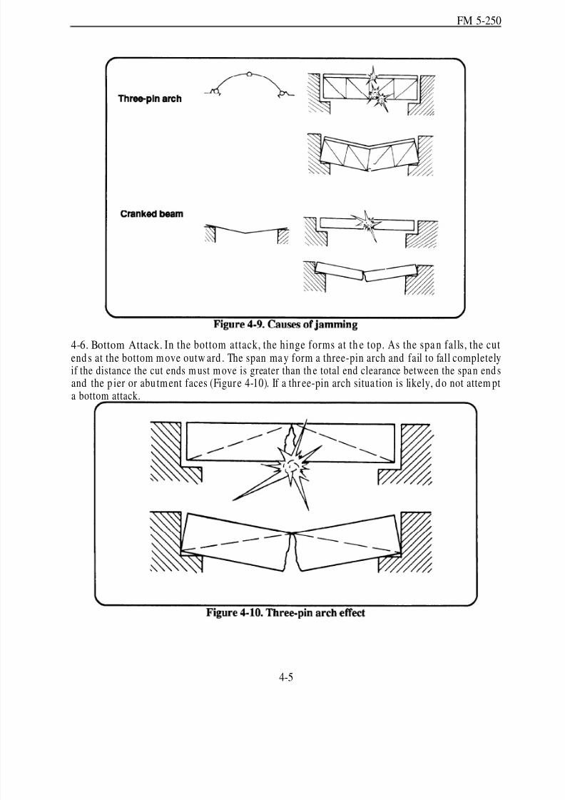
8/14/2019 United States Army Fm 5-250 - 15 June 1992 Explosives
http://slidepdf.com/reader/full/united-states-army-fm-5-250-15-june-1992-explosives 117/275
FM 5-250
4-6. Bottom Attack. In the bottom attack, the hinge forms at th e top. As the spa n falls, the cutend s at the bottom m ove outw ard . The span ma y form a three-pin arch and fail to fall completelyif the distance the cut ends m ust m ove is greater than th e total end clearance between the spa n end sand the p ier or abu tment faces (Figure 4-10). If a thr ee-pin arch situa tion is likely, do not attem pta bottom attack.
4-5

8/14/2019 United States Army Fm 5-250 - 15 June 1992 Explosives
http://slidepdf.com/reader/full/united-states-army-fm-5-250-15-june-1992-explosives 118/275
FM 5-250
4-7. Top Attack. In a top attack, thehinge forms at the bottom. As the spanfalls, the cut en d s at the top m oveinward . Some bridges m ay jam alongthe faces of the cut before the ends of thespan have fallen off the abutments,forming a cranked beam (Figure 4-11).Ensure the length of span removed (LC )at the top is sufficient to prevent theformation of a cranked beam.
4-8. Efficient Dem olition M ethod s.To ensure that a demolition achievescollapse w ith reasonable economy,consider the factors requ ired to achievean efficient demolition. The bestbalance between these factors will
depend on the particular d emolitionunder consideration. An efficientdemolition should—
a. Achieve the desired effect.
b. Use the m inimum amou nt of resources (time, man pow er, and explosives).
c. Observe the prop er p riorities. The d emolition r econn aissance report mu st clearly state thepriorities and separately list the requ irements for Priority 1 actions an d Priority 2 imp rovemen ts(priorities are explained below). If a sufficient gap will result by attacking bridge spans, do notperform the Priority 2 improvements unless the report specifies complete destruction or an
excessively long gap . If the total gap sp ann ed by a brid ge is too small to defeat enemy assaultbridging, consider the site an u nsuitable obstacle unless the gap can be increased. Your engineereffort may be better applied elsewhere. Alternatively, to improve an obstacle, it may be necessaryto increase the gap by dem olishing the abutm ents and bu ilding craters on the immed iate approaches.In this case, you should also attack nearby bypass sites (place mines and craters).
(1) Priority One. Create the desired obstacle. The m inimu m gap required is 5 meters greaterthan the enem y’s assault bridging capability. Ideally, accomp lish the dem olition w ith the firstattemp t. How ever, many r einforced- or p restressed-concrete bridges may requ ire two-stage attacks.Attacking th e friend ly side of spans w ill perm it econom ical reconstruction of the bridge at a laterdate, if necessary.
(2) Priority Two. Make improvements to the gap . Perform th is activity only wh en it isspecified on the demolition reconnaissance report. When no reconnaissance report has been issuedand time perm its, perform im prov emen ts in the sequ ence specified below . Deviate from th issequence only un d er exceptional circum stances or when d irected to d o so by the responsiblecommander. The standard sequence of demolition is to-
4-6
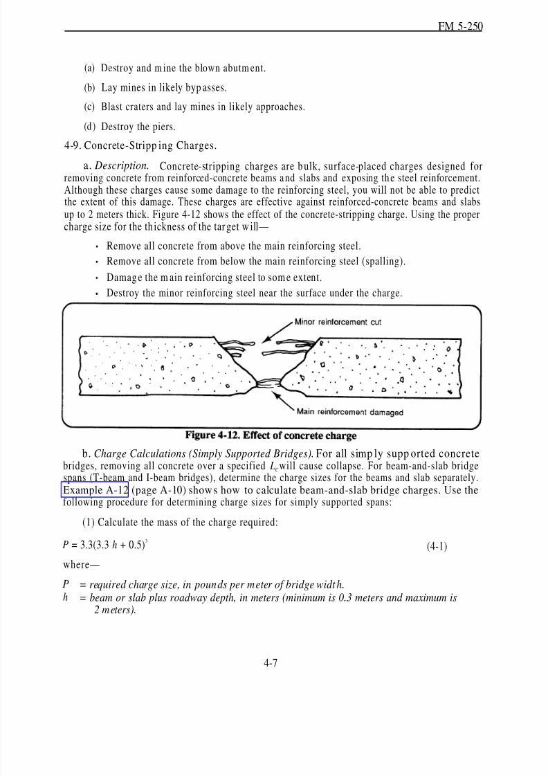
8/14/2019 United States Army Fm 5-250 - 15 June 1992 Explosives
http://slidepdf.com/reader/full/united-states-army-fm-5-250-15-june-1992-explosives 119/275
FM 5-250
(a)
(b)
(c)
(d )
Destroy and m ine the blown abutm ent.
Lay mines in likely byp asses.
Blast craters and lay mines in likely approaches.
Destroy the piers.
4-9. Concrete-Stripp ing Charges.
a. Description. Concrete-stripping charges are b ulk, surface-placed charges designed forremoving concrete from reinforced-concrete beams a nd slabs and exposing th e steel reinforcement.Although these charges cause some damage to the reinforcing steel, you will not be able to predictthe extent of this damage. These charges are effective against reinforced-concrete beams and slabsup to 2 meters thick. Figure 4-12 shows the effect of the concrete-stripping charge. Using the propercharge size for the th ickness of the tar get w ill—
—
Remove all concrete from above the main reinforcing steel.
Remove all concrete from below the main reinforcing steel (spalling).
Damag e the m ain reinforcing steel to som e extent.
Destroy the minor reinforcing steel near the surface under the charge.
b. Charge Calculations (Simply Supported Bridges). For all simp ly supp orted concretebridges, removing all concrete over a specified LC will cause collapse. For beam-and-slab bridgespans (T-beam and I-beam bridges), determine the charge sizes for the beams and slab separately.Example A-12 (page A-10) show s how to calculate beam-and-slab bridge charges. Use thefollowing procedure for determining charge sizes for simply supported spans:
(1) Calculate the mass of the charge required:
P = 3.3(3.3 h + 0.5)3
where—
P = required charge size, in pounds per meter of bridge widt h.h = beam or slab plus roadway depth, in meters (minimum is 0.3 meters and maximum is
2 meters).
(4-1)
4-7
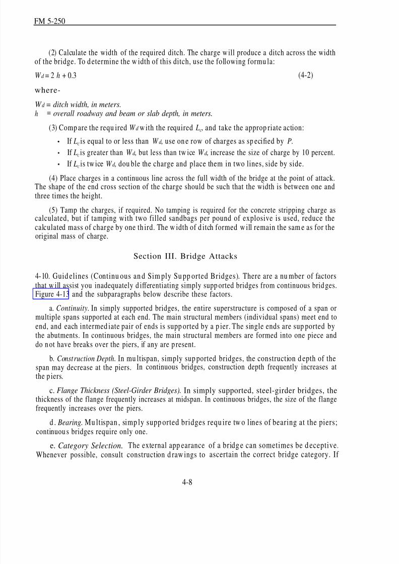
8/14/2019 United States Army Fm 5-250 - 15 June 1992 Explosives
http://slidepdf.com/reader/full/united-states-army-fm-5-250-15-june-1992-explosives 120/275
FM 5-250
(2) Calculate the width of the required ditch. The charge w ill produce a ditch across the widthof the bridge. To d etermine the w idth of this ditch, use the following formu la:
W d = 2 h + 0.3 (4-2)
where-
W d = ditch width, in meters.h = overall roadway and beam or slab depth, in meters.
(3) Comp are the requ ired W d w ith the required LC , and take the approp riate action:
If LC is equal to or less than W d , use on e row of charges as sp ecified by P.
If LC is greater than W d , but less than tw ice W d , increase the size of charge by 10 percent.
If LC is tw ice W d , dou ble the charge and place them in two lines, side by side.
(4) Place charges in a continuous line across the full width of the bridge at the point of attack.The shape of the end cross section of the charge should be such that the width is between one and
three times the height.(5) Tamp the charges, if required. No tamping is required for the concrete stripping charge as
calculated, but if tamping with two filled sandbags per pound of explosive is used, reduce thecalculated mass of charge by one th ird. The w idth of d itch formed w ill remain the sam e as for theoriginal mass of charge.
Section III. Bridge Attacks
4-10. Guid elines (Continu ous an d Sim ply Su pp orted Bridges). There are a nu mber of factorsthat w ill assist you inadequately d ifferentiating simply supp orted bridges from continuous brid ges.
Figure 4-13 and the subparagraphs below describe these factors.a. Continuity. In simply supported bridges, the entire superstructure is composed of a span or
multiple spans supported at each end. The main structural members (individual spans) meet end toend, and each intermed iate pair of ends is supp orted by a p ier. The single ends are sup ported bythe abutments. In continuous bridges, the main structural members are formed into one piece anddo n ot have breaks over the piers, if any are p resent.
b. Construction Depth. In mu ltispan, simply sup ported bridges, the construction d epth of thespan may decrease at the piers. In continuous bridges, construction depth frequently increases atthe p iers.
c. Flange Thickness (Steel-Girder Bridges). In simply supported, steel-girder bridges, thethickness of the flange frequently increases at midspan. In continuous bridges, the size of the flangefrequently increases over the piers.
d . Bearing. Mu ltispan , simp ly supp orted bridges requ ire tw o lines of bearing at the piers;continuou s bridges require only one.
e. Category Selection.Whenever possible, consult
The external app earanceconstruction d raw ings to
4-8
of a bridg e can sometimes be d eceptive.ascertain the correct bridge category. If

8/14/2019 United States Army Fm 5-250 - 15 June 1992 Explosives
http://slidepdf.com/reader/full/united-states-army-fm-5-250-15-june-1992-explosives 121/275
FM 5-250
drawings are not available and there is any uncertainty about the category to which the bridgebelongs, assume the bridge is of continuous construction. Since more explosive is necessary todemolish a continuous bridge, assuming a continuous construction will provide more than enoughexplosive to demolish a bridge of unknown construction.
f. Reconnaissance Procedures. To correctly use the tables in Appendix H, decide w hether the
bridge is in the simp ly supp orted, continuous, or miscellaneous category, and follow th e procedu resoutlined in the app ropriate paragraph.
4-9
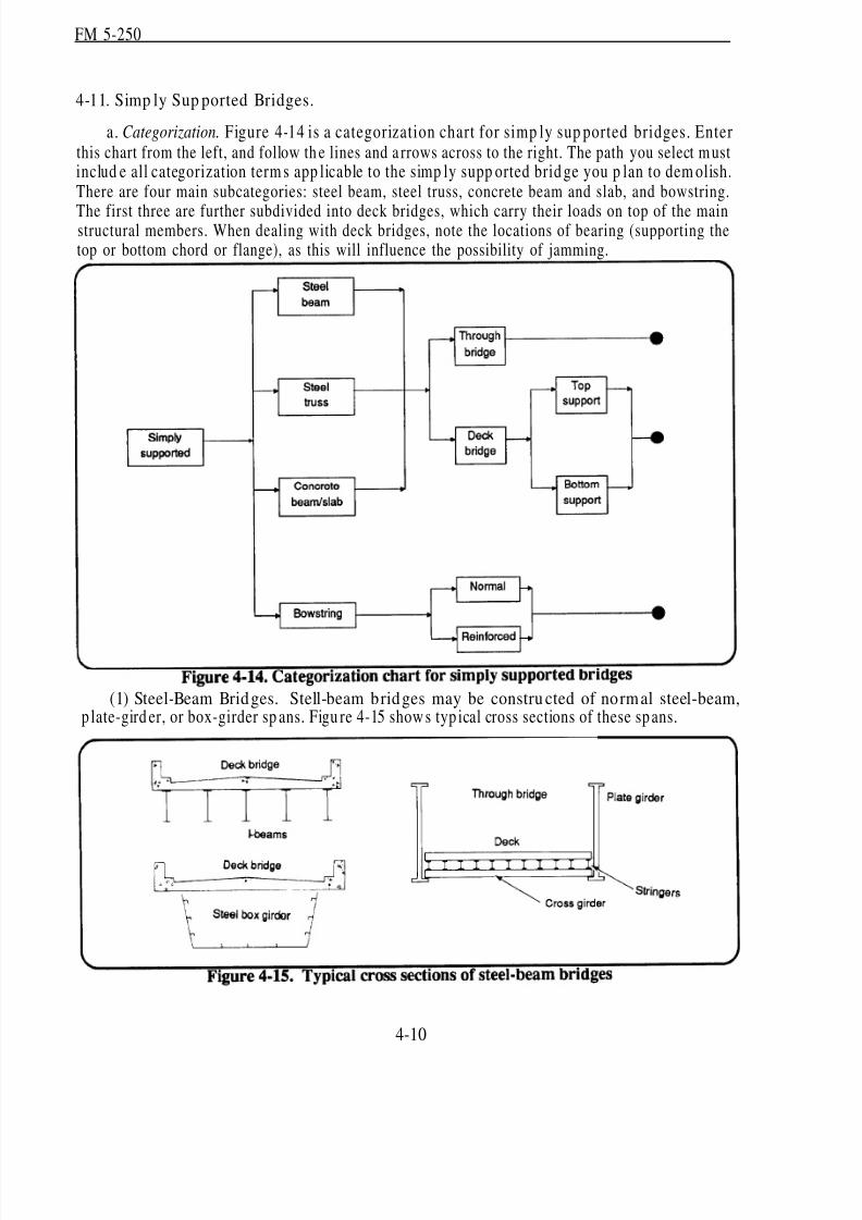
8/14/2019 United States Army Fm 5-250 - 15 June 1992 Explosives
http://slidepdf.com/reader/full/united-states-army-fm-5-250-15-june-1992-explosives 122/275
FM 5-250
4-11. Simp ly Sup ported Bridges.
a. Categorization. Figure 4-14 is a categorization chart for simp ly sup ported bridges. Enterthis chart from the left, and follow th e lines and a rrows across to the right. The path you select m ustinclud e all categorization term s app licable to the simp ly supp orted brid ge you p lan to dem olish.There are four main subcategories: steel beam, steel truss, concrete beam and slab, and bowstring.
The first three are further subdivided into deck bridges, which carry their loads on top of the mainstructural members. When dealing with deck bridges, note the locations of bearing (supporting thetop or bottom chord or flange), as this will influence the possibility of jamming.
(1) Steel-Beam Bridges. Stell-beam bridges may be constru cted of normal steel-beam,p late-gird er, or box-girder sp ans. Figu re 4-15 show s typ ical cross sections of these spans.
4-10
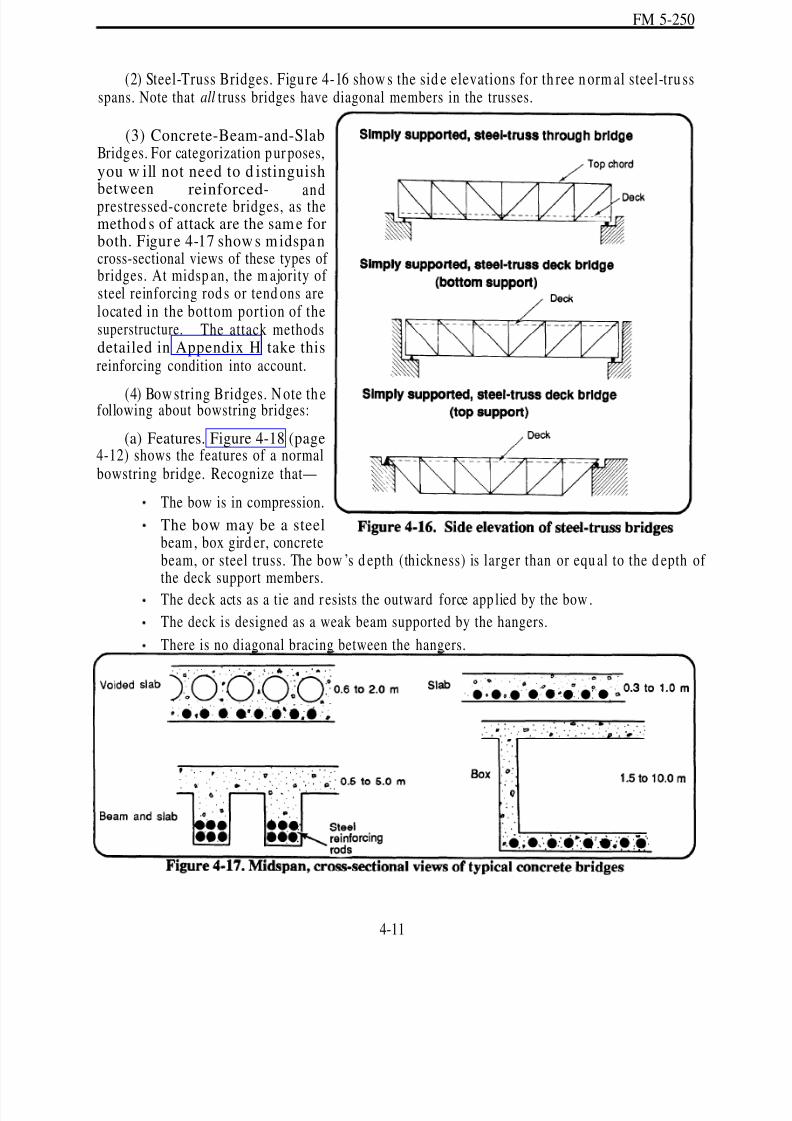
8/14/2019 United States Army Fm 5-250 - 15 June 1992 Explosives
http://slidepdf.com/reader/full/united-states-army-fm-5-250-15-june-1992-explosives 123/275
FM 5-250
(2) Steel-Truss Bridges. Figu re 4-16 show s the sid e elevations for th ree n orm al steel-tru ssspans. Note that all truss bridges have diagonal members in the trusses.
(3) Concrete-Beam-and-SlabBridg es. For categorization p ur poses,you w ill not need to d istinguish
between reinforced- andprestressed-concrete bridges, as themethod s of attack are the sam e forboth. Figure 4-17 show s midspa ncross-sectional views of these types of bridges. At midsp an, the m ajority of steel reinforcing rod s or tend ons arelocated in the bottom portion of thesuperstructure. The attack methodsdetailed in Appendix H take thisreinforcing condition into account.
(4) Bow string Bridges. N ote th efollowing about bowstring bridges:
(a) Features. Figure 4-18 (page4-12) shows the features of a normalbowstring bridge. Recognize that—
The bow is in compression.
The bow may be a steelbeam , box gird er, concretebeam, or steel truss. The bow ’s d epth (thickness) is larger than or equ al to the d epth of the deck support members.
The deck acts as a tie and r esists the outward force app lied by the bow .
The deck is designed as a weak beam supported by the hangers.
There is no diagonal bracing between the hangers.
4-11
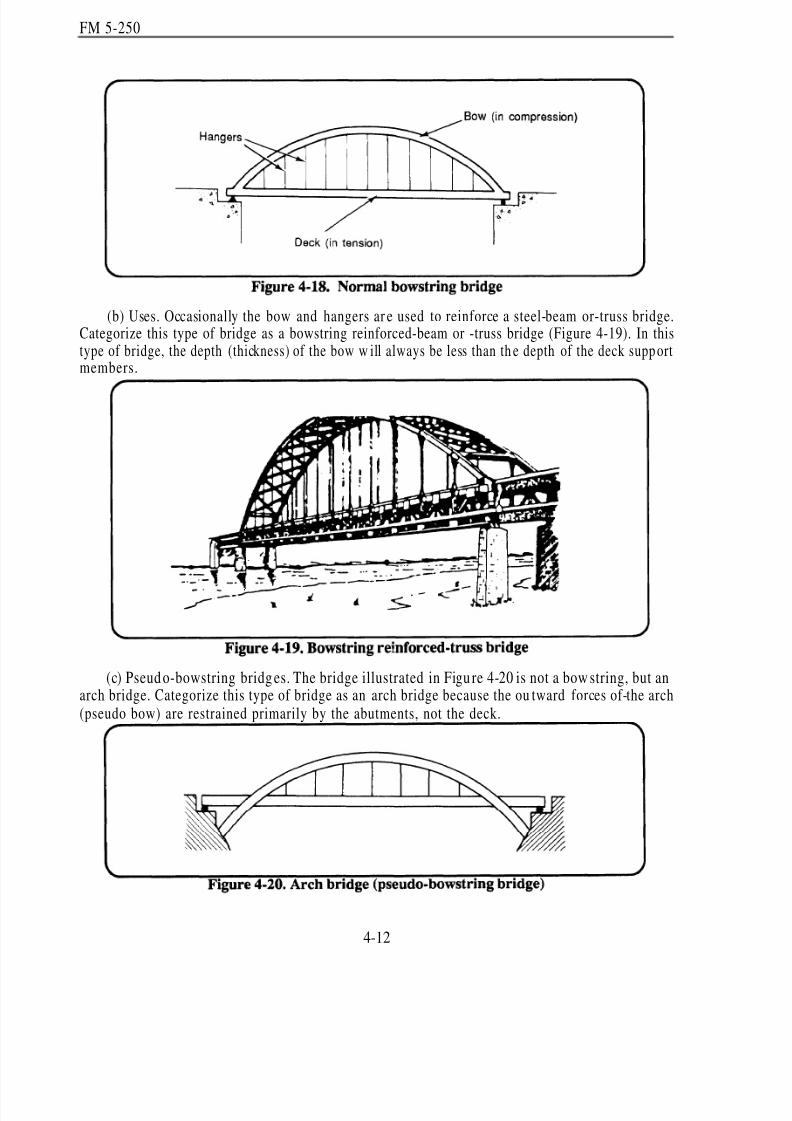
8/14/2019 United States Army Fm 5-250 - 15 June 1992 Explosives
http://slidepdf.com/reader/full/united-states-army-fm-5-250-15-june-1992-explosives 124/275
FM 5-250
(b) Uses. Occasionally the bow and hangers ar e used to reinforce a steel-beam or-truss bridge.Categorize this type of bridge as a bowstring reinforced-beam or -truss bridge (Figure 4-19). In thistype of bridge, the depth (thickness) of the bow w ill always be less than th e depth of the deck supp ortmembers.
.
(c) Pseud o-bowstring bridg es. The bridge illustrated in Figu re 4-20 is not a bow string, but anarch bridge. Categorize this type of bridge as an arch bridge because the ou tward forces of-the arch(pseudo bow) are restrained primarily by the abutments, not the deck.
4-12

8/14/2019 United States Army Fm 5-250 - 15 June 1992 Explosives
http://slidepdf.com/reader/full/united-states-army-fm-5-250-15-june-1992-explosives 125/275
FM 5-250
b. Reconnaissance. For simp ly supported bridges, use the following reconnaissanceprocedure:
(1) Categorize the bridge.
(2) Measure the br idge
(Figure 4-21):
(a) Length (L). Measurethe length of the span to beattacked, in meters.
NOTE: This distance is notthe clear gap, but the length of the longitudinal members thatsupp ort the deck from end toend.
(b) Depth (H). Measure the depth of the beam, truss, or bow, in meters (include the deck withthe beam or tru ss measurement).
(c) Total end clearance (E). Total the am oun t of end clearance at both end s of the span, inmeters.
(d) Average length of the bearing supp orts (LS). Measure the average length of the bearingsupports from the ends of the spans to the faces of the abutments or piers, in meters.
(3) Determine the attack m ethod (Append ix H).
(4) Determine the critical dim ensions of the sp an req uired for char ge calculations.
c. Attack. Two considerations app ly when attacking a simply supp orted span:
(1) Point of Attack. Attack simply su pp orted bridg es at or near m idspan, because—
Bending moments are maximum at midspan.
The likelihood of jamming d uring collapse is redu ced if the bridge is attacked at midsp an.
(2) Line of Attack. Make the lineof attack parallel to the lines of theabutments (Figure 4-22). Doing thisreduces the risk that the two parts of thespan will slew in opposite directions and
jam. Do n ot emp loy any technique thatind uces tw ist in th e bridg e. If the line of attack involves cutting across transversebeams, reposition the line of attack to cutbetween the transverse beams.
4-13
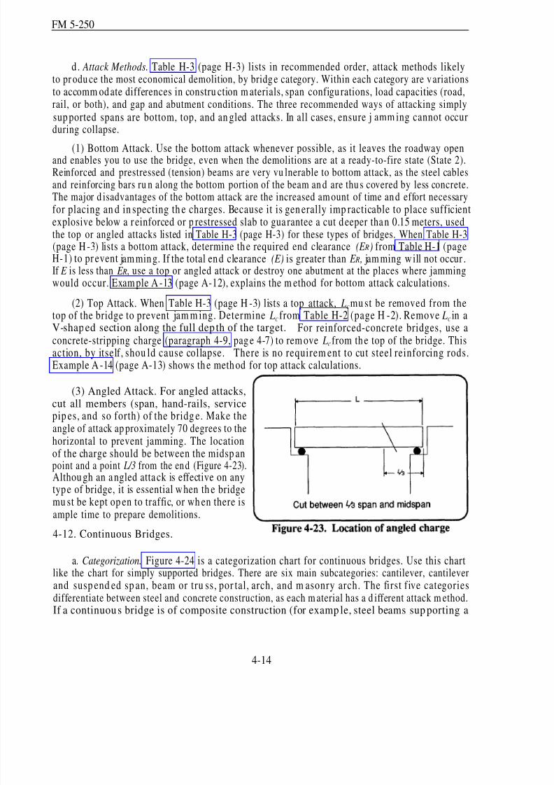
8/14/2019 United States Army Fm 5-250 - 15 June 1992 Explosives
http://slidepdf.com/reader/full/united-states-army-fm-5-250-15-june-1992-explosives 126/275
FM 5-250
d . Attack Methods. Table H-3 (page H-3) lists in recommended order, attack methods likelyto pr odu ce the most economical demolition, by bridg e category. Within each category are v ariationsto accomm od ate differences in constru ction m aterials, span configu rations, load capacities (road,rail, or both), and gap and abutment conditions. The three recommended ways of attacking simplysup ported spans are bottom, top, and an gled attacks. In all cases, ensure jamm ing cannot occurduring collapse.
(1) Bottom Attack. Use the bottom attack whenever possible, as it leaves the roadway openand enables you to use the bridge, even when the demolitions are at a ready-to-fire state (State 2).Reinforced and prestressed (tension) beams ar e very vu lnerable to bottom attack, as the steel cablesand reinforcing bars ru n along the bottom portion of the beam an d are thu s covered by less concrete.The major d isadvantages of the bottom attack are the increased am ount of time an d effort necessaryfor placing an d in specting th e charges. Because it is gen erally imp racticable to place sufficientexplosive below a r einforced or p restressed slab to gua rantee a cut d eeper tha n 0.15 meters, usedthe top or angled attacks listed in Table H-3 (page H-3) for these types of bridges. When Table H-3(page H -3) lists a bottom attack, determine th e required end clearance (E R) from Table H-1 (pageH-1) to pr event jam min g. If the total en d clearance (E) is greater than E R , jam ming w ill not occur .
If E is less than E R , use a top or angled attack or destroy one abutment at the places where jammingwould occur. Exam ple A -13 (page A-12), explains the m ethod for bottom attack calculations.
(2) Top Attack. When Table H-3 (page H -3) lists a top attack, LC mu st be removed from thetop of the bridge to prevent jam m ing. Determine LC from Table H-2 (page H -2). Remove LC in aV-shaped section along the full dep th of the target. For reinforced-concrete bridges, use aconcrete-stripping charge (paragraph 4-9, pag e 4-7) to rem ove LC from th e top of the bridge. Thisaction, by itself, shou ld cause collapse. There is no requirem ent to cut steel reinforcing rods.Example A -14 (page A-13) shows th e meth od for top attack calculations.
(3) Angled Attack. For angled attacks,cut all members (span, hand-rails, service
pip es, and so forth) of the bridg e. Make theangle of attack ap proximately 70 degrees to thehorizontal to prevent jamming. The locationof the charge should be between the midsp anpoint and a point L/3 from the en d (Figure 4-23).Althou gh an a ngled atta ck is effective on anytyp e of bridge, it is essential when th e bridgemu st be kept op en to traffic, or wh en there isample time to prepare demolitions.
4-12. Continuous Bridges.
a. Categorization. Figure 4-24 is a categorization chart for continuous bridges. Use this chartlike the chart for simply supported bridges. There are six main subcategories: cantilever, cantileverand susp end ed sp an, beam or tru ss, por tal, arch, and m asonry arch. The first five categoriesdifferentiate between steel and concrete construction, as each m aterial has a d ifferent attack m ethod.If a continuou s bridge is of composite construction (for examp le, steel beams sup porting a
4-14

8/14/2019 United States Army Fm 5-250 - 15 June 1992 Explosives
http://slidepdf.com/reader/full/united-states-army-fm-5-250-15-june-1992-explosives 127/275
FM 5-250
reinforced-concrete d eck), the material that comp rises the m ain, longitudinal load-bearing mem berswill determine the attack method.
(1) Cantilever Bridges. A cantilever bridge (Figure 4-25, page 4-16) has a midspan shear joint.Note that the full lengths of the anchor spans m ay be built into the abutm ents, making the cantileverdifficult to identify.
(2) Cantilever and Susp end ed-Span Bridges. If a cantilever bridge incorpor ates a susp end edspan (Figu re 4-26, pag e 4-16) that is at least 5 meters longer than the enem y assault bridgingcapability, attack this section of the bridge; attacking this section requires less preparation. Because
4-15

8/14/2019 United States Army Fm 5-250 - 15 June 1992 Explosives
http://slidepdf.com/reader/full/united-states-army-fm-5-250-15-june-1992-explosives 128/275
FM 5-250
suspended spans are simply supported, use the attack method described for simply supported bridges(Table H-3, page H-3).
(3) Beam or Truss Bridges. For beam or truss bridges (Figures 4-27 through 4-29), differentiatebetween those bridges w ith spans of similar lengths an d th ose with short side spans because thisaffects the attack method . A short side span is one that is less than three qu arters of the length of the next ad jacent span.
4-16

8/14/2019 United States Army Fm 5-250 - 15 June 1992 Explosives
http://slidepdf.com/reader/full/united-states-army-fm-5-250-15-june-1992-explosives 129/275
FM 5-250
(4) Portal Bridg es. For p ortal brid ges (Figu re 4-30), differentiate betw een th ose w ith fixedfootings and those with pinned footings, as this affects the attack method . If you cannot determinethe type of footing, assume fixed footings. Portal bridges, as opposed to arch bridges, lack a smoothcurve between the bearing point of the span and the span itself.
4-17

8/14/2019 United States Army Fm 5-250 - 15 June 1992 Explosives
http://slidepdf.com/reader/full/united-states-army-fm-5-250-15-june-1992-explosives 130/275
FM 5-250
(5) Arch Bridges. In arch bridg es (Figure 4-31), determine wh ether the bridge has an open orsolid spandrel and fixed or pinned footings. Again, when in doubt, assume fixed footings.
(6) Masonry Arch Bridges. Identify masonry arch bridges (Figure 4-32) by their segmentalarch ring. How ever, it is easy to mistake a reinforced-concrete bridge for a m asonry-arch bridge
because many reinforced-concrete bridges have masonry faces. Always check the underside of thearch. The un dersid e is rarely faced on reinforced-concrete bridges.
4-18
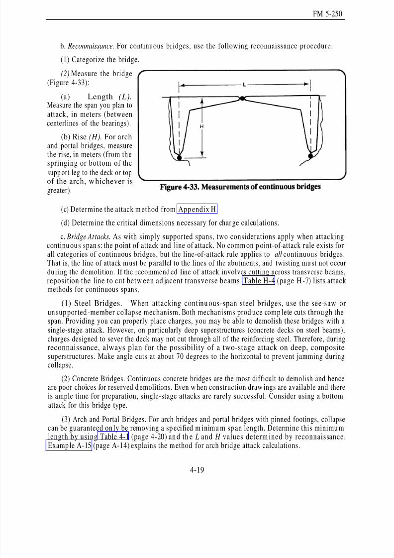
8/14/2019 United States Army Fm 5-250 - 15 June 1992 Explosives
http://slidepdf.com/reader/full/united-states-army-fm-5-250-15-june-1992-explosives 131/275
FM 5-250
b. Reconnaissance. For continuous bridges, use the following reconnaissance procedure:
(1) Categorize the bridge.
(2) Measure the bridge(Figure 4-33):
(a) Length (L).Measure the span you plan toattack, in meters (betweencenterlines of the bearings).
(b) Rise (H). For archand portal bridges, measurethe rise, in meters (from th espringing or bottom of thesupp ort leg to the deck or topof the arch, whichever isgreater).
(c) Determine the attack m ethod from App endix H.
(d) Determ ine the critical dim ensions n ecessary for char ge calcu lations.
c. Bridge Attacks. As with simply supported spans, two considerations apply when attackingcontinu ou s span s: the p oint of attack and line of attack. No comm on p oint-of-attack rule exists forall categories of continuous bridges, but the line-of-attack rule applies to all continuous bridges.That is, the line of attack m ust be p arallel to the lines of the abutments, and twisting mu st not occurdu ring the d emolition. If the recommend ed line of attack involves cutting across transverse beams,reposition the line to cut betw een ad jacent transverse beams. Table H-4 (page H -7) lists attack
methods for continuous spans.(1) Steel Bridges. When attacking continu ous-span steel bridges, use the see-saw or
un sup ported -member collapse mechanism. Both mechanisms prod uce comp lete cuts throu gh thespan. Providing you can properly place charges, you may be able to demolish these bridges with asingle-stage attack. However, on particularly deep superstructures (concrete decks on steel beams),charges designed to sever the deck may not cut through all of the reinforcing steel. Therefore, duringreconnaissance, always plan for the possibility of a two-stage attack on deep, compositesuperstructures. Make angle cuts at about 70 degrees to the horizontal to prevent jamming duringcollapse.
(2) Concrete Bridges. Continuous concrete bridges are the most difficult to demolish and hence
are poor choices for reserved d emolitions. Even w hen construction draw ings are available and thereis ample time for preparation, single-stage attacks are rarely successful. Consider using a bottomattack for this bridge type.
(3) Arch and Portal Bridges. For arch bridges and portal bridges with pinned footings, collapsecan be guaranteed on ly be removing a sp ecified m inimu m sp an length. Determine this minimu mlength by using Table 4-1 (page 4-20) an d th e L and H values determ ined by reconnaissance.Examp le A-15 (page A-14) explains the m ethod for arch bridge attack calculations.
4-19
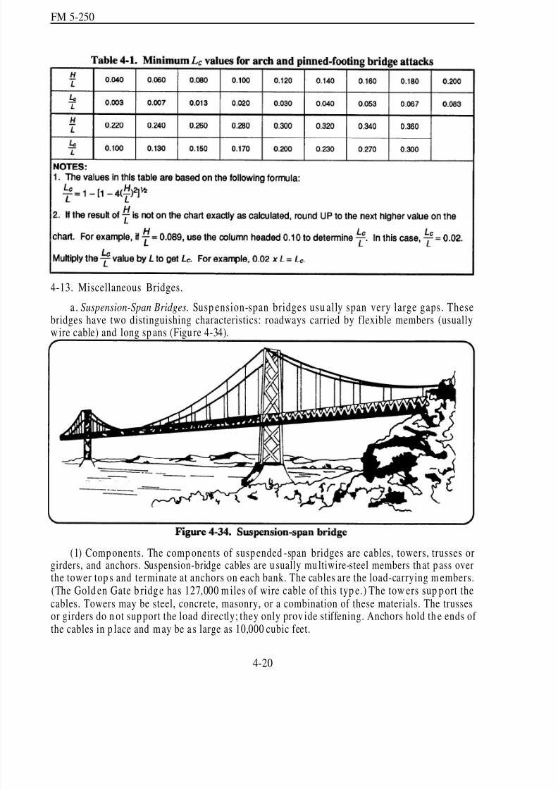
8/14/2019 United States Army Fm 5-250 - 15 June 1992 Explosives
http://slidepdf.com/reader/full/united-states-army-fm-5-250-15-june-1992-explosives 132/275
FM 5-250
4-13. Miscellaneous Bridges.
a. Suspension-Span Bridges. Susp ension-span bridges usu ally span very large gaps. Thesebridges have two distinguishing characteristics: roadways carried by flexible members (usuallyw ire cable) and long sp ans (Figu re 4-34).
(1) Comp onents. The comp onents of susp ended -span bridges are cables, towers, trusses orgirders, and anchors. Suspension-bridge cables are u sually mu ltiwire-steel members th at p ass overthe tower top s and terminate at anchors on each bank. The cables are the load-carrying m embers.(The Gold en Gate b ridg e has 127,000 m iles of wire cable of this typ e.) The tow ers sup p ort thecables. Towers may be steel, concrete, masonry, or a combination of these materials. The trussesor girders do n ot sup port the load directly; they only prov ide stiffening. Anchors hold th e ends of the cables in p lace and may be a s large as 10,000 cubic feet.
4-20

8/14/2019 United States Army Fm 5-250 - 15 June 1992 Explosives
http://slidepdf.com/reader/full/united-states-army-fm-5-250-15-june-1992-explosives 133/275
FM 5-250
(2) Demolishing Methods.
(a) Major bridges. Anchors for major suspension bridges are u sually too massive to bedemolished. The cables are usually too thick to be effectively cut with explosives. The mosteconom ical demolition m ethod is to drop the app roach span or a road way section by cutting thesuspend ers of the m ain or load-bearing cables. The enem y’s repair a nd tactical bridging capabilities
determine the length of the target section. When reinforced-concrete towers are present, it may befeasible to breach the concrete and cut the steel of the towers.
(b) Minor bridges. The two vulnerable points on minor suspension bridges are towers andcables. Use the following methods:
Towers. Destroy towers by p lacing tower charges slightly above the level of the road way.Cut a section out of each side of each tower. Place the charges so that they force the endsof the cut sections to move in opposite directions, twisting the tower. Doing this willpreven t the end of a single cut from rem aining intact. Demolition chambers, providedin some of the newer bridges, make blasting easier, quicker, and more effective.
Cables. Destroy the cables by placing charges as close as possible to anchor points, such
as the top of towers. Cables are difficult to cut because of the air space between theindividua l wires in the cable. Ensure th e charge extend s no m ore than one half the cable’scircumference. These charges are usually bulky, exposed, and difficult to place. Shapedcharges ar e very effective for cable cutting.
b. Movable Bridges. These bridges hav e one or more span s that open to provid e increasedclearan ce for waterw ay traffic. The th ree basic typ es of movable brid ges are swing -span, bascule,and vertical-lift. The characteristics of these bridges are described in th e next par agrap hs.
(1) Sw ing-Spa n Bridg es.
(a) Characteristics. A swing span is a continuous span capable of rotating on a central pier.
The arms of a swing-span bridge m ay not be of equal length. If the arm s are not of equal length,weights are ad ded to balance them . Rollers that ru n on a circular track on top of the central piercarry the span’s weight. The swing sp an is independ ent from any other sp an in the bridge. Identifya swing-span bridge by its wide, central pier. This central pier is much wider than the one under acontinuous-span bridge that accommodates the rollers and turning mechanism (Figure 4-35).
4-21
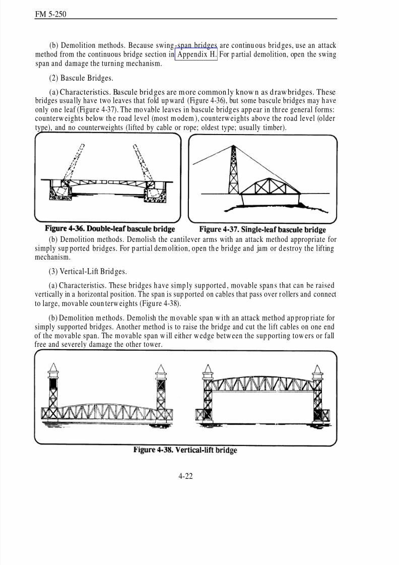
8/14/2019 United States Army Fm 5-250 - 15 June 1992 Explosives
http://slidepdf.com/reader/full/united-states-army-fm-5-250-15-june-1992-explosives 134/275
FM 5-250
(b) Demolition methods. Because swing-span bridges are continu ous brid ges, use an attackmethod from the continuous bridge section in Appendix H. For p artial demolition, open the swingspan and damage the turning mechanism.
(2) Bascule Bridges.
(a) Characteristics. Bascule bridges are more common ly know n as d rawbridges. These
bridges usua lly have two leaves that fold up ward (Figure 4-36), but some bascule bridges may h aveonly on e leaf (Figur e 4-37). The mo vable leaves in bascule bridg es app ear in thr ee general forms:counterw eights below th e road level (most m odem ), counterw eights above the road level (oldertype), and no counterweights (lifted by cable or rope; oldest type; usually timber).
(b) Demolition methods. Demolish the cantilever arms with an attack method appropriate forsimply sup ported bridges. For p artial dem olition, open th e bridge and jam or d estroy the liftingmechanism.
(3) Vertical-Lift Brid ges.
(a) Characteristics. These bridges h ave simp ly sup ported , movable span s that can be raised
vertically in a horizontal position. The span is sup ported on cables that pass over r ollers and connectto large, mova ble coun terw eights (Figu re 4-38).
(b) Demolition m ethods. Demolish the m ovable span w ith an attack method ap prop riate forsimply supported bridges. Another method is to raise the bridge and cut the lift cables on one endof the movable span. The m ovable span w ill either w edge betw een the sup porting tow ers or fallfree and severely damage the other tower.
4-22

8/14/2019 United States Army Fm 5-250 - 15 June 1992 Explosives
http://slidepdf.com/reader/full/united-states-army-fm-5-250-15-june-1992-explosives 135/275
FM 5-250
(4) Floating Bridg es. Floating b ridg esconsist of a continu ous m etal or woodroadw ay supp orted by floats or pon toons(Figure 4-39).
(a) Pneum atic floats. Pneu m atic floats
are airtight compartments of rubberizedfabric inflated w ith air. For h asty attack of these bridges, cut the anchor cables and bridlelines with axes and the steel cables withexplosives. Also, pu nctu re the floats withsmall-arms or m achine-gun fire. Usingweapons to destroy the floats requires aconsiderable volume of fire because each
—
float has a large num ber of watertight comp artments. Another m ethod is to make a clean cut th roughthe float, using detonating cord stretched snugly across the surface of the pontoon compartments.One strand of cord is enough to cut most fabrics, but two stran ds m ay be necessary for heavier
materials. Also, place one turn of a branch-line cord around each inflation valve. This will preventthe raft from being reinflated if it is repaired. Do not use main-line cords to cut valves because theblast wave may fail to continue p ast any sharp tu rn in the cord.
b) Rigid p ontoons. Rigid p ontoons are m ade of various materials: wood , plastic, or m etal. Todestroy these bridges, place a ½-pound charge on the up stream end of each p ontoon at w ater level.Detonate all charges simultaneously. If the current is rapid, cut the anchor cables so that the bridgewill be carried d ownstream . Another m ethod is to cut the bridge into r afts. Place ½-pou nd chargesat each end of each pontoon and detonate them simultaneously. To destroy metal treadways onfloating bridges, use the steel-cutting formula (paragraph 3-6, page 3-8). The placement and sizeof the charges depend on bridge type. Typically, placing cutting charges at every other joint in thetreadway will damage the bridge beyond use.
(5) Bailey Bridges. To destroy these bridges, place l-pound charges between the channels of the up per and lower chords. Use ½-pou nd charges for cutting diagonals and l-pou nd charges forcutting sw ay br acing (Figur e 4-40).
4-23

8/14/2019 United States Army Fm 5-250 - 15 June 1992 Explosives
http://slidepdf.com/reader/full/united-states-army-fm-5-250-15-june-1992-explosives 136/275
FM 5-250
(a) In-place demolitions. Cut the bridge in several sections by attacking the panels on eachside, including th e sway bracing. The angle of attack should be 10 degrees to the horizontal toprevent jamm ing. In dou ble-story or trip le-story bridges, increase the charges on the chords at thestory-junction line. For further destruction, place charges on the transoms and stringers.
(b) In-storage or-stockpile d emolition. When aband oning brid ges in storage, do not leave anycomponent th e enemy can u se as a unit or for improvised construction. Do this by destroying the
essential components that the enemy cannot easily replace or manufacture. Panel sections fulfillthe role of essential components. To render the p anel useless, remove or distort the female lug inthe lower ten sion chord . Destroy all panels before d estroying other components.
Section III. Abutm ents and Intermediate Supp orts
4-14. Abu tments. To dem olish abu tmen ts, place charges in th e fill behind the abu tmen t. Thismethod uses less explosive than external breaching charges and also conceals the charges from theenemy. The disadvan tage is the difficulty in p lacing the charges. When speed is required, do notplace charges behind abutments if you know the fill contains large rocks.
a. Abutments (5 Feet Thick or Less). Demolish these abutm ents by p lacing a line of 40-poundcratering cha rges, on 5-foot centers, in boreh oles 5 feet d eep, located 5 feet behind the face of theabutment (triple-nickel-forty method). Place the first hole 5 feet from either end of the abu tm entand continue this spacing u ntil a d istance of 5 feet or less remains between th e last borehole and theother end of the abutment (Figure 4-41). If the bridge approach is steep, place the breaching chargesagainst the rear of the abutment. Determine the number of 40-pound cratering charges as follows:
(4-3)
where—
N = number of charges; round UP to next higher whole number.W = abutment width, in feet.
b. Abutments (0ver 5 Feet Thick). Destroy these abutm ents w ith breaching charges in contactwith th e back of the abu tment. Calculate the amoun t of each charge u sing the breaching formu lain equation 3-6 (page 3-16). Use the abutment thickness as the breaching radius. Determine thenumber of charges and their spacing using equation 3-7 (page 3-19). Place charg es at least threefeet below the bridge seat (where the bridge superstructure sits on the abutment) (Figure 4-42).
c. Abutments (Over 20 Feet High).Demolish these abutments by placing a row of breachingcharges at the base of the abutment on the gap side, in addition to the charges specified in paragraphs4-14a or 4-14b above. Fire all charges simultaneously. This method tends to overturn andcompletely destroy the abutment.
d . Wing Walls. If the wing w alls can supp ort a rebuilt or temporary bridge, destroy the wingwalls by placing charges behind them in th e same mann er as for abutments (Figures 4-41 an d 4-42).
4-24

8/14/2019 United States Army Fm 5-250 - 15 June 1992 Explosives
http://slidepdf.com/reader/full/united-states-army-fm-5-250-15-june-1992-explosives 137/275
FM 5-250
4-25

8/14/2019 United States Army Fm 5-250 - 15 June 1992 Explosives
http://slidepdf.com/reader/full/united-states-army-fm-5-250-15-june-1992-explosives 138/275
FM 5-250
4-15. Interm ediate Sup ports. Demolish concrete and m asonry p iers w ith internal or externalcharges (Figure 4-43).
a. Internal Charges. These charges require less explosive than do external charges. However,unless the support has built-in demolition chambers, this method requires an excessive amount of equipm ent an d prepara tion time. Use equation 3-6 (page 3-16) to d etermine the a mou nt of eachcharge. Ml12 (C4) is ideal for internal charges. Thorou ghly tam p a ll charges of this typ e w ithnonsparking tools (blunt, wooden tamping sticks or similar tools). If the support has demolitionchambers, place the charges in boreholes created with shaped charges or drilled with pneumatic orhan d tools. A 2-inch-diam eter borehole holds app roximately 2 pou nd s of explosive per foot of
dep th. The steel reinforcing bars, how ever, make drilling in heavily reinforced concrete impr actical.
b. External Charges. Place these charges at the base of the p ier or h igher, and do not sp acethe charges by more than twice the breaching radius. Stagger the charges to leave a jagged surfaceto hind er future u se. Thoroughly tam p all external charges with earth an d sandbags, if time, size,shape, and location of the target perm it.
4-26

8/14/2019 United States Army Fm 5-250 - 15 June 1992 Explosives
http://slidepdf.com/reader/full/united-states-army-fm-5-250-15-june-1992-explosives 139/275
FM 5-250
Chapter 5
Demolition Operations
This chapter implements STANAG 2017 (ENGR),
STANAG 2123 (ENG R), QSTAG 508, and QSTAG 743.
Section I. Demolition Plan
5-1. Dem olition O bstacles. Although engineers use explosives for quarrying, land clearing, andother projects, their most important military application is creating demolition obstacles. Engineersuse demolition obstacles in conjunction with many other types of obstacles, including mines. Theyalso use explosives to destroy materiel and facilities that must be abandoned (denial operations).
5-2. Barriers and Denial Operations. Division or high er-echelon comm and ers norm ally d irectthe use of extensive barriers and denial operations. Commanders must carefully prepare and closely
coordinate these operations with all tactical plans. Engineer units provide technical advice andsup ervision, estimate th e resour ces necessary for obstacle construction, construct barriers orobstacles, and recommend allocation of engineer resources. They usu ally construct d emolition
obstacles because they have the special skills and equipment to accomplish these tasks.
5-3. Demolition Plann ing. Base any dem olition project on careful p lanning and reconnaissance.Use the following factors as a basis for selecting and planning demolition projects:
Mission.
Limitations and instructions from higher authority.
Current tactical and strategic situation and future plans (conditions that indicate the lengthof time you mu st delay the enem y, the time available for demolition, and the extent of
den ial objectives).
Enemy capabilities and limitations, as well as the effect our d enial operations have onenem y forces, strateg ically and tactically.
Likelihood that friendly forces may reoccupy the area, requiring obstacle neutralization.
Econom y of effort.
Time, material, labor, and equipment available.
Effect on the local pop ulation .
Target protection required.
5-1

8/14/2019 United States Army Fm 5-250 - 15 June 1992 Explosives
http://slidepdf.com/reader/full/united-states-army-fm-5-250-15-june-1992-explosives 140/275
FM 5-250
Section II. Types of M ilitary D em olitions
5-4. Dem olition O rders.The authorized command ers use the Orders for the Demolition to passtheir orders to d emolition gu ards and dem olition firing parties. The Orders for the Demolition, asoutlined in STANAG 2017 and QSTAG 508, is a stand ard four-page form u sed by North AtlanticTreaty Organization (NATO) and ABCA countries. Use this form for preparing all reserved an dpreliminary d emolitions. Page one of the form contains the instructions, du ties, and responsibilitiesof demolition personnel. A sample of the orders is includ ed in the samp le target folder in AppendixF (page F-4).
5-5. Prelimin ary D emolitions.
a. Purpose. Provided you have prior authority, detonate a preliminary demolition immediatelyafter preparation. These demolitions present fewer difficulties to both commanders and engineersthan do reserved demolitions. Command ers may restrict preliminary dem olitions for tactical,political, or geographical reasons.
b. Advantages. The advantages of a preliminary demolitions are—
Engineers normally complete each task and move to the next without having to leavedemolition guard s or firing p arties at the site.
Preparation efforts are less subject to interference by enemy or friendly troops.
Elaborate precautions against failure ar e not requ ired; preliminary dem olitions requireonly single-firing systems.
Engineers can p erform the d emolition op erations for a particular target in stages ratherthan all at once.
c. Progressive Preparation. When p reparation time is limited, engineers prepare thedemolition in progressive stages. Doing this gives engineers the ability to create effective obstacleseven if preparations m ust stop at any stage. For examp le, in the case of a bridg e dem olition,engineers wou ld make one span the top p riority, completely prep aring it before continu ing withother spans, piers, or abu tments. As they complete other stages, engineers incorpor ate them intothe firing system.
5-6. Reserved Demolitions.
a. Purpose. The responsible commander must carefully control a reserved demolition targetbecause the target m ay be a vital par t of the tactical or strategical plan or because the d emolitionwill be performed in the face of the enemy.
b. Considerations. Occasionally, errors in orders, control, or timing cause seriousconsequences during demolition operations. In addition, engineers may encounter special problems
when dealing with reserved demolition targets:
Engineers must usually keep traffic lanes open until the last moment. This normallymeans they cannot use the simp lest and quickest demolition techniques to accomp lishthe m ission.
5-2
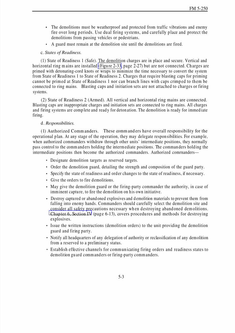
8/14/2019 United States Army Fm 5-250 - 15 June 1992 Explosives
http://slidepdf.com/reader/full/united-states-army-fm-5-250-15-june-1992-explosives 141/275
FM 5-250
The demolitions must be weatherproof and protected from traffic vibrations and enemyfire over long p eriods. Use du al firing systems, and carefully p lace and protect thedemolitions from passing vehicles or pedestrians.
A guard must remain at the demolition site until the demolitions are fired.
c. States of Readiness.
(1) State of Readiness 1 (Safe). The demolition charges are in place and secure. Vertical andhorizontal ring m ains are installed (Figu re 2-33, page 2-27) but are not connected. Ch arges areprimed with detonating-cord knots or wraps to minimize the time necessary to convert the systemfrom State of Readiness 1 to State of Readiness 2. Charges that requ ire blasting caps for p rimingcannot be prim ed at State of Readiness 1 nor can branch lines with caps crimp ed to th em beconnected to ring mains. Blasting caps and initiation sets are not attached to charges or firingsystems.
(2) State of Readiness 2 (Armed). All vertical and horizontal ring mains are connected.Blasting caps are inappropriate charges and initiation sets are connected to ring mains. All chargesand firing systems are comp lete and ready for deton ation. The demolition is ready for immed iate
firing.d . Responsibilities.
(1) Authorized Comm anders. These comm and ers have overall responsibility for theoperational p lan. At any stage of the op eration, they may delegate responsibilities. For examp le,when authorized commanders withdraw through other units’ intermediate positions, they normallypass control to the comm and ers holding the interm ediate positions. The comman ders hold ing theintermediate positions then become the authorized commanders. Authorized comrnanders—
Designate demolition targets as reserved targets.
Order the demolition guard, detailing the strength and composition of the guard party.
Specify the state of readiness and ord er changes to the state of read iness, if necessary.Give the orders to fire demolitions.
May give the demolition guard or the firing-party commander the authority, in case of imm inent captu re, to fire the dem olition on h is own initiative.
Destroy captu red or aband oned explosives and d emolition materials to prevent them fromfalling into enemy hands. Commanders should carefully select the demolition site andconsider all safety precautions necessary wh en d estroying aband oned dem olitions.Chap ter 6, Section IV (page 6-13), covers p rocedures and methods for destroyingexplosives.
Issue the written instructions (demolition orders) to the unit providing the demolition
guard and firing party.Notify all headquarters of any delegation of authority or reclassification of any demolitionfrom a reserved to a preliminar y status.
Establish effective channels for comm un icating firing orders and readiness states todemolition gu ard comm and ers or firing-party comm anders.
5-3

8/14/2019 United States Army Fm 5-250 - 15 June 1992 Explosives
http://slidepdf.com/reader/full/united-states-army-fm-5-250-15-june-1992-explosives 142/275
FM 5-250
(2) Demolition Guard Commanders. These commanders are normally the infantry or armortask-force comm and ers who control the target area. These comm and ers—
Command all troops and firing parties at reserved demolitions.
Provide protection for reserved demolitions, firing parties, and targets.
Control all traffic over or thr ough targets.
Pass written state-of-readiness ord ers to commanders of demolition firing p arties, includ-ing changes to these orders.
Keep authorized commanders informed of the status of preparations, targets, and opera-tional situations at sites.
Pass written firing orders to demolition firing-party commanders to fire demolitions.
Report results of demolitions to authorized commanders.
Maintain succession (chain of comm and ) lists for ap pointm ent to d emolition gu ardcommander and demolition firing-party commander.
(3) Firing-Party Com man ders. These comman ders are norm ally officers or noncommissioned
officers (NCOs) from the engineer unit that prepared the demolitions. They sup ervise the preparing,charging, and firing of the dem olition. Firing-par ty comman ders—
Maintain the state of readiness specified by authorized commanders and advise demoli-tion guard commanders of the time requirements for changing states of readiness andcompleting obstacles.
Fire dem olitions w hen ord ered by the au thorized comm ander, and ensure d emolitionsare successful and complete.
Report the results of demolitions to demolition guard commanders or, if none, to theauthorized commanders.
Report the results of demolitions up the engineer chain of command and complete Section
5, pages 33 through 36, of the obstacle folder, if issued.Maintain succession (chain of command) lists for appointment as demolition firing-partycommander should the initial commander become injured.
e. Command and Control of Reserved Demolitions.
(1) Command Post. Ideally, the demolition guard commander should place his command postwhere he can best control the defense of the demolition target from the friendly side. This locationmay conflict with th e requirements of the d emolition firing p oint, which shou ld be close to orcollocated w ith the comm and post. Usually, some comp romise is necessary.
(2) Firing Poin t. The firing p oint is norm ally as close to the target as safety allows. The firingpoint must protect the firing party from the effects of blast and falling debris and be positioned sothat the demolition firing-party commander is—
Easily accessible to the demolition gu ard comman der for receiving ord ers.
In close contact w ith the firing par ty.
Able to see the entire target.
5-4

8/14/2019 United States Army Fm 5-250 - 15 June 1992 Explosives
http://slidepdf.com/reader/full/united-states-army-fm-5-250-15-june-1992-explosives 143/275
FM 5-250
(3) Alternate Positions. The demolition gu ard comm ander should d esignate an alternatecommand post an d firing point, if possible. The firing party should be able to fire the d emolitionsfrom either the primary or alternate firing points.
(4) Check Point. When u nits are w ithdraw ing from a enemy advance, identification can be aproblem. Withdraw ing troops are respon sible for iden tifying themselves to the demolition gu ard .
The dem olition guard mu st always establish an d operate a check point. The d emolition guardcommander may use military police to perform this duty. Good communication is essential betweenthe check point and the demolition guard commander. Each un it withd rawing through thedem olition target shou ld send a liaison officer to the checkpoint, well in ad vance of the withd rawingun it’s arrival.
(5) Refugee Control Points. The demolition guard commander may need to establish andoperate a refugee control point for civilian traffic. He should place a check point on the enemy bankand a release point on the friendly bank to control refugees. The comm and er may u se military orlocal police to operate the control points. The personnel operating the check points should haltrefugees off the route and then escort them, in grou ps, across the target to the release point. Refugeesmust not interfere with the movement of withdrawing forces or demolition preparations.
Section III. Dem olition Reconn aissance
5-7. Reconnaissance Orders. Thorough reconnaissance is necessary before plann ing a dem olitionoperation. Reconnaissance provid es detailed informa tion in all areas related to the p roject. Priorto condu cting any reconnaissance, the reconnaissance-party comman der mu st receive clearobjectives. The reconnaissance order specifies these objectives. This information helps thereconnaissance party to determine the best method of destroying the target and to estimate thepreparation time required. For example, if the reconnaissance party knows that manpower and timeare limited but explosives are plentiful, they may design demolitions requiring few men and little
time bu t large quan tities of explosives.These orders should detail the reconnaissance party to
determine the following:
Location and nature of the target.
Purp ose of the demolition op eration (for examp le, to delay an enemy infantry battalionfor three hours).
Proposed classification of the demolition (reserved or preliminary).
Type of firing system desired (dual or single).
Economy of effort (wheth er the d emolition m ust be completed in one stage or m ultiplestages).
Utility of the target during demolition operations (whether the target must remain open
to traffic during demolition preparations).
Amou nt of time allowed or expected between prep aration and execution of the dem olitionoperation.
Amount of time allowed for changing the state of readiness (Safe to Armed).
Labor and equipment available for preparing the demolitions.
5-5

8/14/2019 United States Army Fm 5-250 - 15 June 1992 Explosives
http://slidepdf.com/reader/full/united-states-army-fm-5-250-15-june-1992-explosives 144/275
FM 5-250
Types and quantities of explosives available.
5-8. Reconn aissance Record. The reconnaissance par ty rep orts the r esults of their reconnaissanceon DA Form 2203-R. Use the form w ith appr opr iate sketches, to record and repor t thereconna issance of military d emolition p rojects. Append ix F conta ins a samp le of DA Form 2203-R
(Figure F-2, pages F-38 through F-42) and instructions to complete it. For sketches, use available
pap er and attach to the completed DA Form 2203-R.
a. Purpose. When time an d cond itions perm it, use this report as the source document forpreparing the obstacle folder. If the obstacle folder is not available, use this report in its place. Incertain instances the report may require a security classification.
b. Information Required. DA Form 2203-R shou ld contain th e following:
A bill of explosives that shows the quantities and types required.
A list of all equipment, including transportation, required for the demolition operation.
An estimate of time and labor required for preparing the demolitions and placing thecharges.
A time and labor estimate for arming and firing the charges.
A time, labor, and equ ipment estimate to complete any r equired byp ass. Specify thebypass location and method. Include details for any supplementary obstacles required.
A situation sketch showing the relative position of the target, terrain features, andcoordinates of the target.
A list of all unusual site characteristics. Indicate the location of these unusual charac-teristics on the situation sketch.
Plan and elevation (side-view) sketches of the target, showing overall dimensions, linesof cut, and dem olition chambers.
Plan and elevation sketches of each mem ber targeted , detailing d imensions, cham bers,
quantity of explosives, lines of cut, charge locations, and p riming an d initiation meth ods.
A sketch showing firing circuits and firing p oints.
Section IV. Obstacle Folder
5-9. Purpose. The obstacle folder, as ou tlined in STANAG 2123 and QSTAG 743, prov ides allof the information necessary to complete a specific demolition operation. NATO and ABCApersonnel use this booklet to collect information and to conduct demolition operations. Theresponsible commander should prepare an obstacle folder during peacetime for all preplannedtargets to allow for efficient d emolition operations. Prepare obstacle folders for reserved and
preliminary demolitions. The obstacle folder is not normally used in tactical situations because thedetailed information in the obstacle folder, includ ing m ultiple languages, is not easily completedun der field or ta ctical cond itions. A samp le obstacle folder is includ ed in the sam ple target folderin Append ix F (page F-4).
5-10. Language. Since not all NA TO and A BCA per sonn el speak the same langu age, obstaclefolders must be multilingual. The preparing unit may speak a different language than the unit
5-6

8/14/2019 United States Army Fm 5-250 - 15 June 1992 Explosives
http://slidepdf.com/reader/full/united-states-army-fm-5-250-15-june-1992-explosives 145/275
FM 5-250
actually conducting the dem olition operation. Therefore, it is essential to prepar e the obstacle folderin more than one language. How ever, prepare m ap n otes, plans, sketches, and so forth, in onelanguage, and provide translations for the other languages in the available space. Use the following
guidelines when determining the languages necessary in an obstacle folder:
Languages of the units involved in the dem olitions.
Language of the host nation.
One of the two official NATO languages (English or French).
5-11. Contents. The obstacle folder contains six parts for recording information. Additionalinformation may be noted in the ap prop riate place within the obstacle folder and then inserted asan additional page immediately following the notation (for example, “see page 4a”). The six partsof the obstacle folder are—
Location of target (pages 1-5).
Supply of explosives and equipment (pages 6-17).
Ord ers for pr eparing and firing (pages 18-28).
Han d-over and take-over instructions (pages 29-32).Demolition rep ort (p ages 33-37).
Official signature (page 38).
5-12. Special Instructions. The list of explosives, stores, and mines requ ired (paragraph 2d, pages14 and 16 of the obstacle folder) does not cover every possible situation. However, it does indicatea logical order for recording or determining the requ ired materials. Mark only the materials requiredfor your p articular target. The tran sport team leader u ses the first list. For m ajor opera tions, notethe size, comp osition, and m ission of the various w ork p arties participating in pa ragraph 3a,subp aragrap h 5. Paragraph 3a, subparagraph 6 concerns only nuisance or protective mine fieldslaid to protect the dem olition target and does not app ly to tactical (barrier) mine fields. Comp lete
paragraph 5 of the Demolition Report up on comp letion of the d emolition. The firing partycomman der m ay d etach the first copy of the demolition report (pages 33-37) and forward it to ahigher-echelon engineer headquarters.
5-7
8/14/2019 United States Army Fm 5-250 - 15 June 1992 Explosives
http://slidepdf.com/reader/full/united-states-army-fm-5-250-15-june-1992-explosives 146/275
FM 5-250
Chapter 6
Demolition Safety
Section I. General Safety
6-1. Considerations.
Do not attemp t to cond uct a dem olitions mission if you are u nsure of dem olitionprocedures; review references or obtain assistance.
Prevent inexperienced personnel from handling explosives.
Avoid dividing responsibility for demolition operations.
Use the minimu m n um ber of personnel necessary to accomp lish the d emolitions mission.
Take your time when working with explosives; make your actions deliberate.
Always post guards to prevent access inside the danger radius.
Always maintain control of the blasting machine or initiation source.
Use the minim um am oun t of explosives necessary to accomp lish the m ission wh ilekeeping su fficient explosives in reserve to h and le any p ossible misfires.
Maintain accurate accountability of all explosives and accessories. Always store blastingcaps separately and at a safe distance from other explosives.
Ensure all personnel and equipment are accounted for prior to detonating a charge.
Ensure you give warnings before initiating demolitions; give the warning “Free in thehole!” three times.
Always guard firing points.
Assign a comp etent safety officer for every d emolition mission.Dual initiate all demolitions, regardless of whether they are single-or dual-primed.
Avoid using deteriorated or damaged explosives.
Do not dismantle or alter the contents of any explosive material.
Avoid mixing live and inert (dummy) explosives.
WARNINGDo not use blasting caps un derground.
Use detonating cord to prime u nd ergroun d charges.
6-2. Explosive M ateria ls.a. Blasting Caps. Both m ilitary and comm ercial blasting cap s are extremely sensitive and can
explode u nless hand led carefully. Blasting caps can deton ate if exposed to extreme heat (cook off).Military blasting caps are more powerful and often more sensitive than their commercialcounterparts. When using commercial blasting caps to detonate military explosives, ensure theyare powerful enough to detonate the explosives,
6-1
thus, avoiding misfires. Because power
8/14/2019 United States Army Fm 5-250 - 15 June 1992 Explosives
http://slidepdf.com/reader/full/united-states-army-fm-5-250-15-june-1992-explosives 147/275
FM 5-250
requirements for caps from different manufacturers vary, never mix caps from differentmanufacturers; mixing caps could result in rnisfires. When installing caps in explosives, never forcethem into an explosive or a cap well; use an app ropriate tool for making or enlarging the cap w ell.Ensure 1/ 8 to 1/ 4 inch of the cap is clearly visible at both ends wh en taping onto d etonation cord. Donot connect blasting-cap initiation sets to ring or line mains or charges when nonessential personnel
are on site. N ever leave blasting caps u nattend ed before or after attaching th em to th e charges orfiring system.
(1) Nonelectric.
Use only authorized equipm ent and procedures w hen crimping nonelectric blasting capsto time fuse or detonating cord.
Maintain blasting caps in th e app ropriate cap box until needed . Never store blasting capswith explosives.
Never carry loose blasting caps in your pocket or place loose blasting caps in a container;secure them.
Do not blow into a nonelectric cap or attempt to remove any obstructions from the blastingcap well. Remove obstructions that w ill dislodge by using th e wr ist-to-wrist tap method .
Never insert anything bu t time fuse or d etonation cord into a n onelectric blasting cap.Do not twist time fuse or detonating cord while attempting to insert into a blasting cap.
Never attempt to crimp a blasting cap installed in an explosive. If the blasting cap hascome loose from the time fuse or d etonating cord, remove th e blasting cap from thecharge, recrimp the cap, and then reinstall the cap in the charge.
Avoid striking, pinching, and mashing nonelectric caps during crimping activities. Useonly the M2 crimp ers for all crimp ing oper ations.
When using nonelectric caps to dual prime demolitions, cut the fuse to allow an interval
of not less than 10 second s between firings.(2) Electric.
Do not remove the short-circuiting shunt unless testing or connecting the cap. The shuntpr events accidental initiation by static electricity. If the blasting cap ha s no sh un t, twistthe bare end s of the lead w ires together at least three times (180-degree turns) to providea proper shunt.
Use prop er groun ding p rocedu res wh en static electricity is present, see paragraph 6-5b(page 6-4).
When transporting electric blasting caps near vehicles (including aircraft) equipped witha transm itter, protect the blasting caps by p lacing them in a m etal can with a snug-fittingcover (½ inch or m ore of cover overlap). Do not remove blasting caps from theircontainers near an operating transmitter unless the hazard has been judged acceptable.
Keep electric blasting caps at least 155 m eters from en ergized pow er lines. If usingelectric blasting caps near p ower lines, temporarily cut the p ow er to the lines d uringblasting operations.
Always use at least the minimum current required to fire electric blasting caps.
6-2
8/14/2019 United States Army Fm 5-250 - 15 June 1992 Explosives
http://slidepdf.com/reader/full/united-states-army-fm-5-250-15-june-1992-explosives 148/275

8/14/2019 United States Army Fm 5-250 - 15 June 1992 Explosives
http://slidepdf.com/reader/full/united-states-army-fm-5-250-15-june-1992-explosives 149/275
FM 5-250
dy nam ite containing nitroglycerin requires special han dling an d storage. Rotate comm ercialdynamite in storage to prevent the nitroglycerin from settling to the bottom of the explosive.
6-3. Boreholes. Do n ot leave any void spaces in boreholes, especially in qu arrying op erations. Asecond ary explosion can result from a borehole with v oids between loaded explosives. After thefirst blast, it may take u p to 15 minutes for such an explosion to occur. Tam p all voids w ithapp ropriate m aterial. When u sing sp ringing charges to d ig boreholes, allow at least 2 hours forboreholes to cool between placing and firing successive springing charges, or cool the boreholeswith water or compressed air to save time.
6-4. Toxicity. Most military explosives are p oisonou s if ingested an d will prod uce lethal gases if detonated in confined areas such as tun nels, caves, bun kers, and buildings. Allow sufficient timefor blast fumes, dust, and mists to clear before inspecting or occupying a blasting area. TNT isextremely p oisonou s; avoid u sing TNT to blast in enclosed areas. Avoid tou ching sensitive areasof your body, such as around the face and groin, when working with explosives. Wash your handsafter working with explosives, especially before consuming food.
6-5. Natu ral and Physical Properties.
a. Lightning. Lightning is a ha zard to both electric and nonelectric blasting charges. Alightning strike or nearby miss is almost certain to initiate either type of system. If lightning strikesoccur, even far away from the blasting site, electrical firing circuits could be initiated by high, localearth currents and shock waves resulting from the strikes. These effects are increased w hen lightningstrikes occur near cond ucting elements, such as fences, railroads, bridges, streams, un dergrou ndcables or condu its, and in or n ear bu ildings. The only safe procedure is to suspend all blastingactivities during electrical storms or when an electrical storm is imminent.
b. Static Electricity . Though rare, electric blasting caps can possibly be initiated by staticelectricity. If possible, avoid using electric blasting caps if static electricity is a problem. Exerciseextreme caution when working with explosives in cold, dry climates or when wearing clothing andequipm ent th at p rodu ce static electricity, such as clothing m ade of nylon or w ool. Before han dlingan electric blasting cap, always remove the static electricity from your body by touching the earthor a grou nd ed object. It may be necessary to perform this grou nd ing procedu re often in an areawhere static electricity is a constant problem.
c. Induced Current s. Radio signals can induce a current in electric blasting caps an dprematu rely d etonate them. Table 6-1 lists the m inimum safe d istances from transm itters for safeelectrical blasting . This table app lies to operating rad io, radar, microwave, and televisiontransmitting equip ment. Keep mobile transmitters and portable transmitters at least 50 meters fromany electric blasting cap or electrical firing system. Do not use electric blasting caps within 155meters of energized power transmission lines.
d . Blast Effects. Personnel in close proximity to explosions m ay experience perm anent hearingloss or other injury from the p ressure wave caused by an explosion. Hearing p rotection should beworn during all blasting operations. Personnel observing minimum safe distances for bare charges(see Table 6-1 and Arm y Regu lation (AR) 385-63) generally w ill not be affected by b last effects.Refer to AR 385-63, Chap ter 18, for ad d itional inform ation on blast effect.
6-4

8/14/2019 United States Army Fm 5-250 - 15 June 1992 Explosives
http://slidepdf.com/reader/full/united-states-army-fm-5-250-15-june-1992-explosives 150/275
FM 5-250
e. Missile Hazards. Explosives can propel lethal missiles great distances. The distances thesemissiles will travel in air depen d primarily on th e relationship betw een the m issiles’ weight, shape,density, initial angle of pr ojection, and initial speed . Under n orm al cond itions, the m issile-haza rdarea of steel-cutting charges is greater than that of cratering, quarrying, and surface charges.
6-6. Und erwater Op erations.
a. Explosives. Explosives are subject to erosion by water. Unprotected explosives willdeteriorate rapidly, reducing their effectiveness. Ensure all exposed explosives are ad equatelyprotected when used in water, especially running water.
b. Nonelectric Caps. Non electric caps depend on combu stion to w ork prop erly. Any m oistureinside a n onelectric cap m ay cau se a m isfire. Because n onelectric blasting cap s are d ifficult towaterproof, aviod using them to prime underwater charges or charges placed in wet boreholes.
c. Time Fuse. Time fuse depends on combustion to burn properly. Time fuse burnssignificantly faster und erwater d ue to w ater pressure. Waterproof sealing compou nd s will not makea p erma nent w aterproof seal between the fuse and a non electric blasting cap. Place the fuseunderwater at the last possible moment before firing.
NOTE: If the mission requires using time fuse underwater, then do the test burn underwater.
d . Detonating Cord. Seal the ends of detona ting cord w ith a waterp roof sealing comp oun dwhen using detonating cord for initiating underwater charges or charges that will remain in place
6-5

8/14/2019 United States Army Fm 5-250 - 15 June 1992 Explosives
http://slidepdf.com/reader/full/united-states-army-fm-5-250-15-june-1992-explosives 151/275
FM 5-250
several hours before firing. Leaving a 6-inch overhan g in d etonating cord n ormally w ill protect theremaining line from moisture for 24 hours.
e. M60 Fuze Igniter. The M60 depend s on combustion to w ork prop erly. Water can p enetratethe fuze igniter th rou gh th e vent h ole located in th e pu ll rod. Therefore, if the igniter fails to fireon the initial attempt, it probably will fail on any subsequent attempt after reset. Always use a
backup initiation set for underwater demolitions.
6-7. Safe D istan ces. The following criteria give distances at w hich personn el in th e open arerelatively safe from m issiles created by b are charges placed on th e groun d , regard less of the typeor cond ition of the soil (AR 385-63). Table 6-2 lists safe distances for selected charg e weights . Thefollowing general rules apply:
Char ges of Less Than 27 Pou nd s. The m inimu m m issile hazard distance is 300 meters.
Charges of More Than 27 Pounds But Less Than 500 Pounds. Use the distances in Table6-2.
Charges More Than 500 Pounds. Use the following formulas:
Missile-Proof Shelters. A m issile-pr oof shelter can be as close as 100 meters from thedetonation site provided it is strong enou gh to withstand the heaviest possible missileresulting from the demolition.
Charges Fixed to Targets. When charges are fixed to targets and not simply placed onthe grou nd , use the safe d istances specified in Tables 6-2 or 6-3, whichever is farthest.Note that these distances depend on the target configuration, not quantity of explosive.
6-6
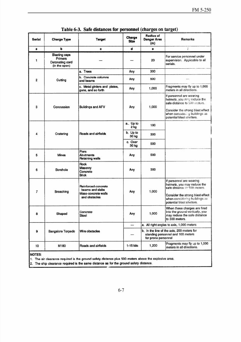
8/14/2019 United States Army Fm 5-250 - 15 June 1992 Explosives
http://slidepdf.com/reader/full/united-states-army-fm-5-250-15-june-1992-explosives 152/275
FM 5-250
6-7

8/14/2019 United States Army Fm 5-250 - 15 June 1992 Explosives
http://slidepdf.com/reader/full/united-states-army-fm-5-250-15-june-1992-explosives 153/275
FM 5-250
Section II. Misfire Procedures
6-8. Nonelectric Misfires.
a. Causes.
Moisture in the time fuse, detonating cord, or explosives.Time fuse not seated com pletely in blasting cap o r in fuse igniter.
Breaks in time fuse or detonating cord.
Jagged or uneven ends on time fuse.
Blasting caps no t seated secur ely in cap w ell or explosive.
Loose or improper detonating-cord installation.
Debris in the blasting cap.
Commercial blasting caps were not strong enough to detonate military explosives.
b. Prevention. You can minimize nonelectric misfires by taking the following precautions:
Prepare and place all primers properly.
Load a ll char ges carefully.
Detonate charges with the proper techniques.
Use dual-initiation systems and, if possible, dual firing systems.
Use detonating cord for underground demolitions. Do not bury caps!
Perform tamping operations with care to avoid damaging prepared charges.
Avoid crimp ing blasting caps on to time fuse in the rain; seek a covered area ou t of therain.
Ensure you completely seat time fuse when installing it into a blasting cap or fuse igniter.c. Clearing Procedure.
The soldier w ho p laced th e charges should investigate and correct any problems w ith thedemolition.
After attempting to fire the d emolition, delay investigating any d etonation problem forat least 30 minu tes plus the time rem aining on the secondary. Tactical cond itions m ayrequire investigation prior to the 30-minute limit.
For above-ground misfires of charges prim ed with blasting caps, place a p rimed, l-poundcharge next to the m isfired charge and detonate th e new charge. Each misfired chargeor charge separated from the firing circuit that contains a blasting cap requires a 1-poundcharge for detonation. Do not touch scattered charges that contain blasting caps; destroytherein place. For charges primed w ith detonating cord, use the procedures in p aragraph6-10 (pa ge 6-10).
For a non electric cap that h as d etonated bu t failed to initiate a d etonating-cord branchline, line main, or ring main, attach a new cap to the detonating cord, and then move toa safe place.
6 - 8
8/14/2019 United States Army Fm 5-250 - 15 June 1992 Explosives
http://slidepdf.com/reader/full/united-states-army-fm-5-250-15-june-1992-explosives 154/275
FM 5-250
For buried charges, remove the tam ping to w ithin one foot of the m isfired charge.Constantly check dep th w hile digging to av oid striking th e charge. When within 1 footof the misfired charge, place a p rimed, 2-pou nd charge on top of the original charge anddetonate th e new charge. If digging over th e original charge is impractical, dig a newborehole of the same d epth beside the original hole, l-foot awa y. Place a primed , 2-poun dcharge in the new hole and detonate the new charge.
6-9. Electric Misfires.
a. Causes.
Inoperable or weak blasting machine or power source.
Improper operation of blasting machine or power source.
Defective or damaged connections. (Short circuits, breaks in the circuit, or too muchresistance in th e electrical wiring a re comm on cond itions resu lting in m isfires.)
Faulty blasting caps.
Blasting caps made by different manufacturers in the same circuit.
Power sou rce inad equate for the nu mber of blasting caps in th e circuit (too man y caps,too small a blasting machine).
b. Prevention. Assign one ind ividual the responsibility for all the electrical wiring in adem olition circuit. This individu al should do the following:
Perform all splicing.
Install all blasting caps in the firing circuit. Do not bury caps!
Make all of the connections between blasting cap wires, connecting wires, and firingwires.
Inspect system for short circuits.
Avoid grounding out the system.
Ensure the n um ber of blasting caps in any circuit d oes not exceed the r ated capacity of the power source.
c. Clearing Procedure. Use the following p roced ur es to clear electric m isfires:
Make another attempt to fire.
Use the secondary firing system, when present.
Check the wire connections, blasting machine, or pow er-source termina ls.
Disconnect the blasting machine or pow er source and test the blasting circuit. Check the
continuity of the firing wire with a circuit tester.Use another blasting machine or power source and attempt to fire the demolition again,or change operators.
When employing only one electrical initiation system, disconnect the b lasting machine,shun t the w ires, and investigate imm ediately. When emp loying more than one electricalinitiation system, wait 30 minutes before inspecting. Tactical conditions may requireinvestigation prior to the 30-minute limit.
6-9
8/14/2019 United States Army Fm 5-250 - 15 June 1992 Explosives
http://slidepdf.com/reader/full/united-states-army-fm-5-250-15-june-1992-explosives 155/275
FM 5-250
Inspect the entire circuit for w ire breaks or sh ort circuits.
If you su spect an electric blasting cap is the problem, do n ot attemp t to remove or hand leit. Place a p rimed, 1-pou nd charge next to the misfired charge an d detonate the n ewcharge.
6-10. Deton ating-Cord Misfires.
a. Detonating Cord. If detonating cord fails to function properly, take the following action:
Attach a new blasting cap to the rem aining deton ating cord, taking care to fasten itproperly, and detonate the new blasting cap.
Treat branch lines in the same manner as noted above.
b. Detonating-Cord Priming. If the d etonating cord leading toto explode th e charge, take the follow ing action:
Do not investigate un til the charges have stopped burn ing.is underground.
Reprime and attempt to detonate the charge.
the charge detonates but fails
Wait 30 minutes if the charge
Scattered char ges that do n ot contain blasting caps ma y be collected an d deton atedtogether.
For underground charges, dig to within one foot of the charge; place a primed, 2-poundcharge on top or to the side of the charge; and detonate the new charge.
Section III. Transportation and Storage Safety
6-11. Transpo rtation .
a. Regulations. Both m ilitary and comm ercial carriers are su bject to regu lations w hen
transporting m ilitary explosives and other d angerous military m aterials within the U nited States.AR 55-355 cover s the tran spo rtation o f exp losives. When tran sporting explosives outside theUn ited States, follow the reg u lations from the h ost coun tries as well. TM 9-1300-206 containsminimum safety requirements for handling and transporting military explosives and ammunition.All explosives transport personnel must learn the local procedures and safety requirements.
b. Safety Procedures. The command er should assign a primary an d assistant operator to eachvehicle transp orting explosives on p ub lic highw ays, roads, or streets. Wh enever tran sportingexplosives locally, operators must observe the following safety rules:
(1) Vehicles.
Ensure vehicles are in good condition. Inspect all vehicles intend ed for hau ling ex-plosives before loading any explosives. Pay par ticular atten tion to p rotecting a gainst anyshort circuits in the electrical system.
When using vehicles with steel or p artial-steel bodies, install fire-resistant and nonsp ark-ing cushioning to separate the explosives from the metal truck components.
Do not load vehicles beyond their rated capacities when transporting explosives.
6-10

8/14/2019 United States Army Fm 5-250 - 15 June 1992 Explosives
http://slidepdf.com/reader/full/united-states-army-fm-5-250-15-june-1992-explosives 156/275
FM 5-250
Cover open-body vehicles hauling explosives with a fire-resistant tarpaulin.
Mark all vehicles transp orting explosives w ith reflective placard s indicating the typ e of explosives carried (TM 9-1300-206, Chapter 6).
Use demolition transports for explosives only. Do not carry metal tools, carbides, oils,ma tches, firearm s, electric storage b atteries, flamm able sub stances, acid s, or oxidizing
or corrosive compounds in the bed or body of any vehicle transporting explosives.Equip vehicles transp orting exp losives with n ot less than tw o Class 1-BC fire extin-guishers for on-post shipments. Place the extinguishers at strategic points, ready forimmediate use.
Keep v ehicles away from congested areas. Consider congestion wh en p arking.
Op erate vehicles transporting explosives w ith extreme cam . Do not drive at a sp eedgreater than 35 miles per hou r. Make full stops at ap proaches to all railroad crossingsand main highways. This does not apply to convoys or crossings protected by guards orhighway workers (flaggers).
Keep flames at least 50 feet from veh icles or storage p oints containing exp losives.
(2) Car go (Explosives).
Never leave explosives unattended.
Never mix live and inert (dummy) explosives.
Secure th e load of explosives in th e transport to prevent shifting du ring transport.
Transport blasting caps separately from other explosives. Do not transport blasting capsor other initiators in the same vehicles carrying explosives. If both blasting caps andexplosives m ust be carried in the sam e vehicle, separate blasting caps from th e otherexplosives by carrying the caps in a closed metal container in the cab of the transport.
No p ersons other than the p rimary and the assistant operators w ill ride on or in a tru ck
transporting explosives. Do not refuel a vehicle while carrying explosives except in anemergency.
(3) Fire. If fire break s out in a veh icle transp orting exp losives, take the following actions:
Try to stop the vehicle away from any populated areas.
Stop traffic from both d irections. Warn vehicle d rivers and passengers and occup ants of near by bu ildings to keep at least 2,000 feet aw ay from th e fire.
Inform police, fire fighters, and other emergency-response personnel that the cargo isexplosives.
If the fire involves only the engine, cab, chassis, or tires, make an effort to extinguish the
fire with fire extinguishers, sand, dirt, or water. If the fire spreads to the body of thetran spo rt or the cargo, stop fighting the fire and ev acuate to a distan ce of at least 2,000feet.
Do not attempt to extinguish burning explosives without expert advice and assistance.
6-11
8/14/2019 United States Army Fm 5-250 - 15 June 1992 Explosives
http://slidepdf.com/reader/full/united-states-army-fm-5-250-15-june-1992-explosives 157/275
FM 5-250
6-12. Storage Safety.
a. Magazines. There are two types of magazines: perm anent and temporary. Althoughperm anent m agazines are preferred, temporary or emergency magazines are frequently requiredw hen p erm an ent constru ction is not p ossible. Field Ma nu al (FM) 9-6 an d TM 9-1300-206 gived etails on maga zine storage of explosives. Consid er the follow ing wh en constructing mag azines:
(1) Permanent.
(a) Placement. Consider acceptability of magazine locations based on safety requirements,accessibility, d ryness, and dr ainage. Safety an d accessibility are the m ost imp ortant. An ideallocation is a hilly area where the height of the ground above the magazine provides a natural wallor barrier to bu ildings, centers of comm un ication, and other magazines in the area. Hillside bu nkersare not desirable because adequate ventilation and drainage are often difficult to achieve. Clearbrush and tall grass from the site to lessen th e dan ger of fire.
(b) Lightning p rotection. All magazines mu st have a groun ded , overhead lightning-rod system.Connect all metal parts (d oors, ventilator, wind ow sashes, reinforcing steel, and so forth) to bur iedconduits of copperplate or graphite rods in several places.
(c) Barricades. Install barricades around magazines; that is, there must be a substantial obstaclebetween m agazines an d inhabited bu ild ings. For certain explosives, effective natu ral or artificialbarricades reduce the required safe distance between magazines and railways and highways by onehalf. The use of barricades permits the storage of larger quantities of explosives in any given area.Although barricades help protect magazines against explosives and bomb or shell fragments, theydo not safeguard against pressure damage. TM 9-1300-206 gives more specific guidance onbarricades.
(d) Security. Place guards at all magazines to prevent un authorized personnel from gainingaccess to magazine facilities.
(2) Temp orary.(a) Placemen t. Wh en p erma nent m agazine construction is not p ossible, create temp orary
m agazines by placing explosives on pallets to accomm od ate ventilation. Store the p allets in awell-drained bunker. Excavate the bunker in a dry area and revet the bunker with timber to preventcollapse. Alternatives are an isolated building or a light, wooden-frame hou se w ith a w edge-typeroof covered with corrugated iron or tent canvas.
(b) Id entification. Mar k field -exped ient storag e facilities on all fou r sides w ith signs (TM9-1300-206).
b. Temporary Storage. When necessary, store lim ited sup plies of explosives in coveredammunition shelters. Ensure the temporary facilities are separated adequately to prevent fire orexplosion from being transm itted between shelters. Piles of temp orarily stored explosives shouldcontain no m ore than 500 pou nd s each an d be spaced n o closer than 140 feet. Pile explosivecomponents separately. Keep explosives, caps, and other demolition materials stored in trainingareas in covered ammunition shelters and under guard at all times. Local safety standing operatingpr ocedu res (SOPS) and TM 9-1300-206, Chapter 4, are guid es for temp orary stor age op erations.
6-12

8/14/2019 United States Army Fm 5-250 - 15 June 1992 Explosives
http://slidepdf.com/reader/full/united-states-army-fm-5-250-15-june-1992-explosives 158/275
FM 5-250
Section IV. Destruction of M ilitary Explosives
6-13. Con cept. Destruction of demolition m aterials is a un it comm and er’s d ecision. The pu rposeof this intentional destruction is to prevent the enemy from capturing stockpiles of explosives.Whenever the comm and er orders d estruction, two p rimary considerations are site selection an d
safety precautions. EOD units are responsible for destroying damaged or unserviceable explosivesand d emolition m aterials (AR 75-14, TM 43-0001-38, and FM 9- 16). Comp letely d estroy explosiveand nonexplosive d emolition m aterials in a combat zone. Damage essential comp onents of sets andkits to prevent complete assembly by cannibalizing from un dam aged compon ents. Such d estructionis a com m and decision based on th e tactical situ ation, secur ity classification of the d em olitionm aterials, their qu antity an d location, facilities for accom plishing d estruction, and time ava ilable.In general, burn ing and detonating or a combination of both are the m ost effective means of destruction.
6-14. Site Se lection . Select the site for its ability to provid e the gr eatest obstru ction to enem ymovem ent bu t prevent hazard s to friend ly troops. Even in th e fastest-paced op erations, safety isimportant, and you shou ld ad here to app ropriate safety precautions, if possible.
6-15. Method s. Burning a nd detonating, in that order, are considered the m ost satisfactory method sfor destroyin g d em olition m aterials to preven t enem y u se. TM 9-1300-206 (Chap ter 9) and TM9-1300-214 (Chapter 15) cover procedures for explosives and ammunition destruction in greaterdetail.
a. Burning. Destroy packed an d un packed h igh-explosive items by burn ing. These explosivesinclud e linear d em olition charges, shap ed d em olition charg es, block d em olition charges, stickdyn amite, detonating cord, firing d evices, timed blasting fuse, and similar items. Do n ot attemp tto destroy blasting caps by burning them since they will detonate from extreme heat. Separate themfrom other explosives and destroy them by detonation. Personnel should not attempt to extinguishburning explosives w ithout expert ad vice and assistance. Use the following p rocedu re for burning
explosives:
Place blasting caps in p iles separate from explosives and destroy by detonation. Ensureblasting caps are stored far enough aw ay from the other explosives being burned toprevent th e burn ing explosives from d etonating the blasting caps or vice versa.
Stack explosives in a p ile over a layer of combu stible material. Piles should not exceed2,000 pou nd s or be more th an 3 inches thick.
Ignite the pile with a combustible train (excelsior or slow-burning propellant) of suitablelength, and take cover immediately. Calculate the safe distance from the pile using Table6-1 (page 6-5). This d istance is never less than 300 meters.
Do not try to extinguish burning explosives. Burning explosives cannot be extinguishedby smothering them or drenching them. In fact, smot hering w ill probably cause anexplosion. Personnel should not attem pt to extinguish bu rning explosives without expertadvice and assistance.
b. Detonation. The tactical situa tion, the comm and er’s intent, the lack of time, the typ e of explosive, or the safety considerations m ay require an explosive to be d etonated instead of burned.Use the following procedures for detonating explosives:
6-13

8/14/2019 United States Army Fm 5-250 - 15 June 1992 Explosives
http://slidepdf.com/reader/full/united-states-army-fm-5-250-15-june-1992-explosives 159/275
FM 5-250
Establish a safety zone for missile and blast effect by computing the safe distance requiredfor the amou nt of explosives to be d etonated (Table 6-1, page 6-5).
Do not exceed the limitations of the disposal site, Instead of detonating one large pile of explosives, it may be necessary to m ake several smaller piles of explosives and staggertheir detonating times.
Use a minimum of two initiation systems to detonate a pile of explosives.Prime explosives every 4 to 5 feet wh en p lacing exp losives in long row s or lines.
Ensure positive contact between primed charges and other explosives in the pile or row.
6-14
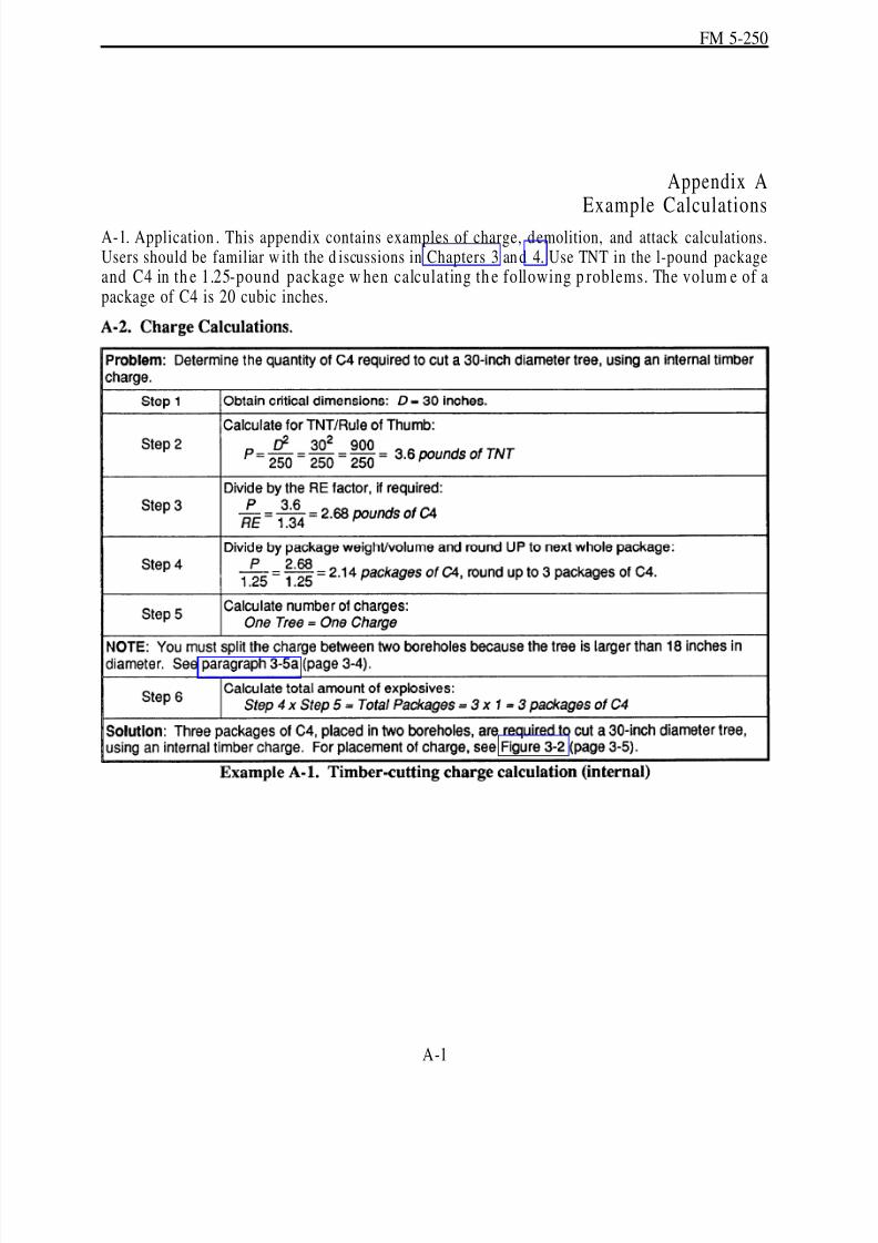
8/14/2019 United States Army Fm 5-250 - 15 June 1992 Explosives
http://slidepdf.com/reader/full/united-states-army-fm-5-250-15-june-1992-explosives 160/275
FM 5-250
Appendix AExample Calculations
A-1. Application . This appendix contains examples of charge, demolition, and attack calculations.Users should be familiar w ith the d iscussions in Chapters 3 an d 4. Use TNT in the l-pound packageand C4 in th e 1.25-pound package w hen calculating th e following p roblems. The volum e of apackage of C4 is 20 cubic inches.
A-1

8/14/2019 United States Army Fm 5-250 - 15 June 1992 Explosives
http://slidepdf.com/reader/full/united-states-army-fm-5-250-15-june-1992-explosives 161/275
FM 5-250
A-2

8/14/2019 United States Army Fm 5-250 - 15 June 1992 Explosives
http://slidepdf.com/reader/full/united-states-army-fm-5-250-15-june-1992-explosives 162/275
FM 5-250
A-3

8/14/2019 United States Army Fm 5-250 - 15 June 1992 Explosives
http://slidepdf.com/reader/full/united-states-army-fm-5-250-15-june-1992-explosives 163/275
FM 5-250
A-4

8/14/2019 United States Army Fm 5-250 - 15 June 1992 Explosives
http://slidepdf.com/reader/full/united-states-army-fm-5-250-15-june-1992-explosives 164/275
FM 5-250
A-5
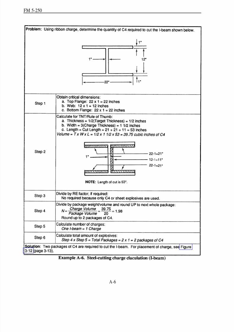
8/14/2019 United States Army Fm 5-250 - 15 June 1992 Explosives
http://slidepdf.com/reader/full/united-states-army-fm-5-250-15-june-1992-explosives 165/275
FM 5-250
A-6

8/14/2019 United States Army Fm 5-250 - 15 June 1992 Explosives
http://slidepdf.com/reader/full/united-states-army-fm-5-250-15-june-1992-explosives 166/275
FM 5-250
A-7
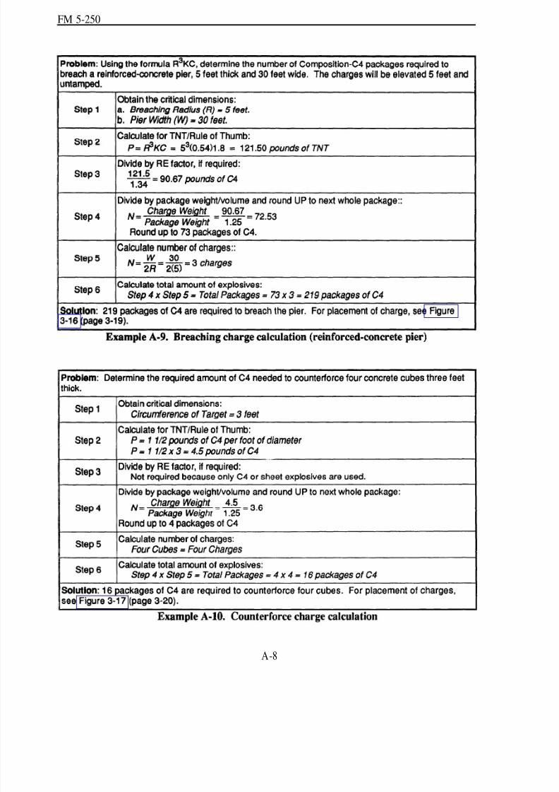
8/14/2019 United States Army Fm 5-250 - 15 June 1992 Explosives
http://slidepdf.com/reader/full/united-states-army-fm-5-250-15-june-1992-explosives 167/275
FM 5-250
A-8
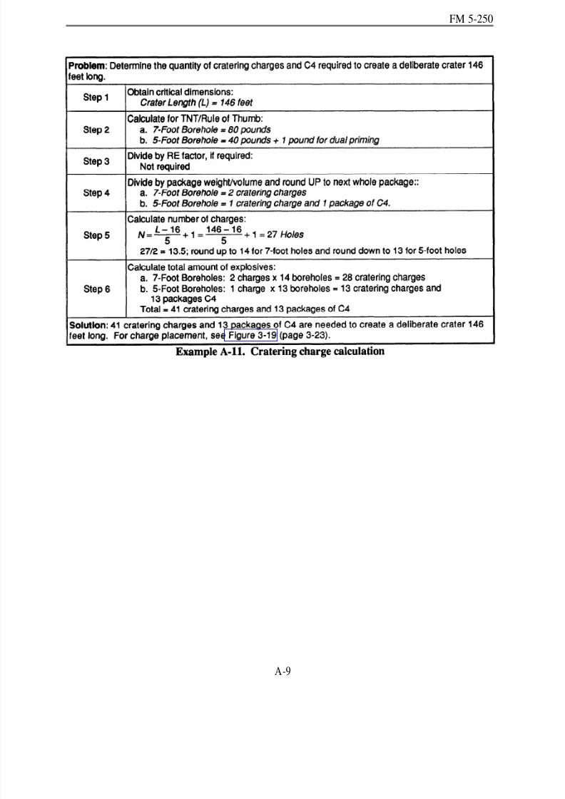
8/14/2019 United States Army Fm 5-250 - 15 June 1992 Explosives
http://slidepdf.com/reader/full/united-states-army-fm-5-250-15-june-1992-explosives 168/275
FM 5-250
A-9
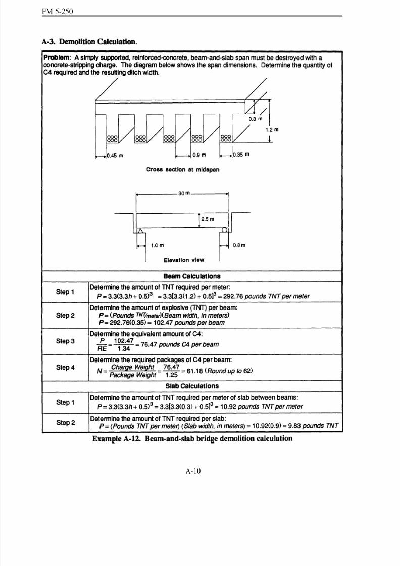
8/14/2019 United States Army Fm 5-250 - 15 June 1992 Explosives
http://slidepdf.com/reader/full/united-states-army-fm-5-250-15-june-1992-explosives 169/275
FM 5-250
A-10

8/14/2019 United States Army Fm 5-250 - 15 June 1992 Explosives
http://slidepdf.com/reader/full/united-states-army-fm-5-250-15-june-1992-explosives 170/275
FM 5-250
A-11
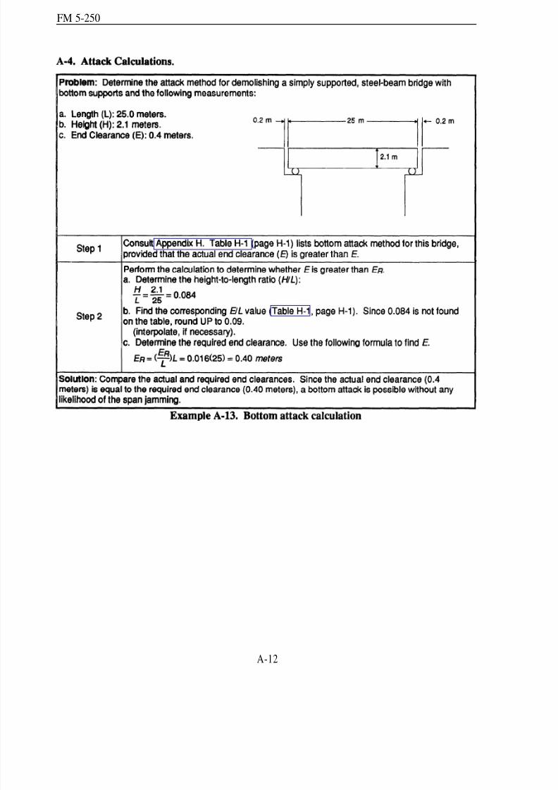
8/14/2019 United States Army Fm 5-250 - 15 June 1992 Explosives
http://slidepdf.com/reader/full/united-states-army-fm-5-250-15-june-1992-explosives 171/275
FM 5-250
A-12

8/14/2019 United States Army Fm 5-250 - 15 June 1992 Explosives
http://slidepdf.com/reader/full/united-states-army-fm-5-250-15-june-1992-explosives 172/275
FM 5-250
A-13
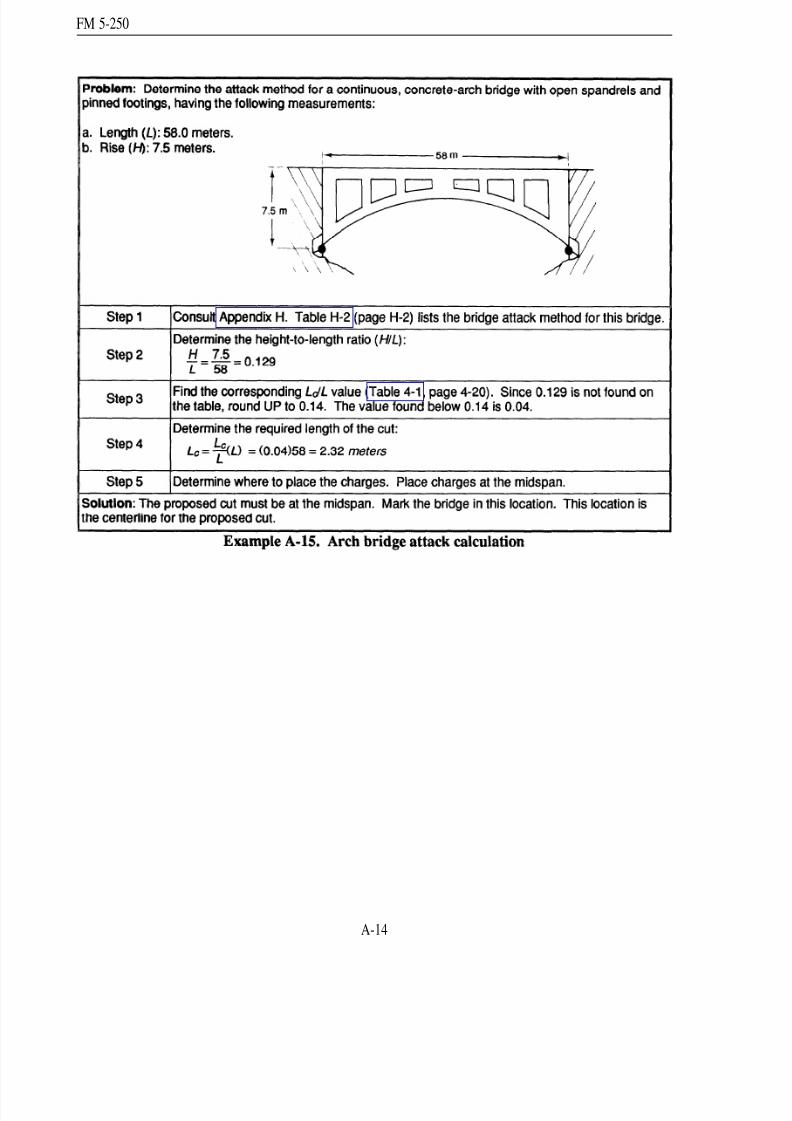
8/14/2019 United States Army Fm 5-250 - 15 June 1992 Explosives
http://slidepdf.com/reader/full/united-states-army-fm-5-250-15-june-1992-explosives 173/275
FM 5-250
A-14

8/14/2019 United States Army Fm 5-250 - 15 June 1992 Explosives
http://slidepdf.com/reader/full/united-states-army-fm-5-250-15-june-1992-explosives 174/275
FM 5-250
Appendix BMetric Charge Calculations
B-1. Equ ivalent Metric Weights for Stand ard Explosives. NATO requirements make m etricconversions necessary. The following formu las are m etric equ ivalents for charge calculations.Table B-1 lists the metric equivalents for standar d US Army demolition charges.
B-2. Timber-Cutting Formulas. The formulas on th e following p ages are examp les of chargecalculations converted to their metric equivalents.
B-1
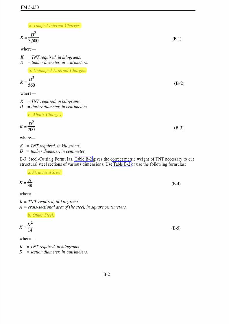
8/14/2019 United States Army Fm 5-250 - 15 June 1992 Explosives
http://slidepdf.com/reader/full/united-states-army-fm-5-250-15-june-1992-explosives 175/275
FM 5-250
a. Tamped Internal Charges.
where—
K = TNT required, in kilograms. D = timber diameter, in cent imeters.
b. Untamped External Charges.
where—
K = TNT required, in kilograms. D = timber diameter, in centimeters.
c. Abatis Charges.
(B-1)
(B-2)
(B-3)
where—
K = TNT required, in kilograms. D = timber diameter, in centimeter.
B-3. Steel-Cuttin g Formu las. Table B-2 gives the correct metric weight of TNT necessary to cutstructural steel sections of various dimensions. Use Table B-2 or use the following formulas:
a. Structural Steel.
where—
K = TN T required, in kilograms. A = cross-sectional area of the steel, in square centimeters.
b. Other Steel.
where—
(B-4)
(B-5)
K = TNT required, in kilograms. D = section diameter, in cent imeters.
B-2
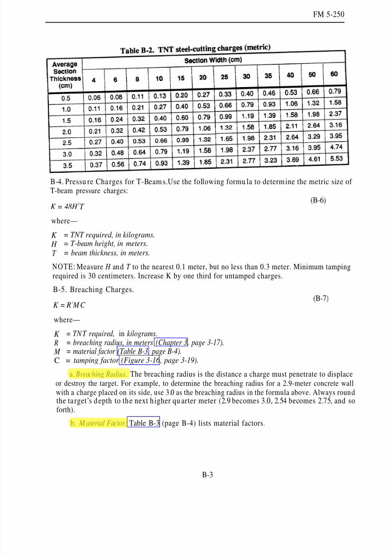
8/14/2019 United States Army Fm 5-250 - 15 June 1992 Explosives
http://slidepdf.com/reader/full/united-states-army-fm-5-250-15-june-1992-explosives 176/275
FM 5-250
B-4. Pressu re Cha rges for T-Beam s.Use the following formu la to determine the metric size of
T-beam pressure charges:
K = 48H 2T
where—
K = TNT required, in kilograms.
H = T-beam height, in meters.
T = beam thickness, in meters.
NOTE: Measure H and T to the nearest 0.1 meter, but no less than 0.3 meter. Minimum tampingrequired is 30 centimeters. Increase K by one third for untamped charges.
B-5. Breaching Charges.
K = R3 MC
(B-6)
(B-7)
where—
K = TNT required, in kilograms. R = breaching radius, in meters (Chapter 3, page 3-17). M = material factor (Table B-3, page B-4).C = tamping factor (Figure 3-16 , page 3-19).
a. Breaching Radius. The breaching radius is the distance a charge must penetrate to displaceor destroy the target. For example, to determine the breaching radius for a 2.9-meter concrete wall
with a charge placed on its side, use 3.0 as the breaching radius in the formula above. Always roundthe ta rget’s d epth to the next h igher qu arter meter (2.9 becomes 3.0, 2.54 becomes 2.75, and soforth).
b. M aterial Factor. Table B-3 (page B-4) lists material factors.
B-3

8/14/2019 United States Army Fm 5-250 - 15 June 1992 Explosives
http://slidepdf.com/reader/full/united-states-army-fm-5-250-15-june-1992-explosives 177/275
FM 5-250
c. Tamping Factor. The value of the tamping factor depends on the location and tamping of the charge. A charge is not adequately tamp ed unless the tamping material’s depth equals or exceedsthe breaching radius. Figure 3-16 (page 3-19) gives values for the tamping factor.
B-4

8/14/2019 United States Army Fm 5-250 - 15 June 1992 Explosives
http://slidepdf.com/reader/full/united-states-army-fm-5-250-15-june-1992-explosives 178/275
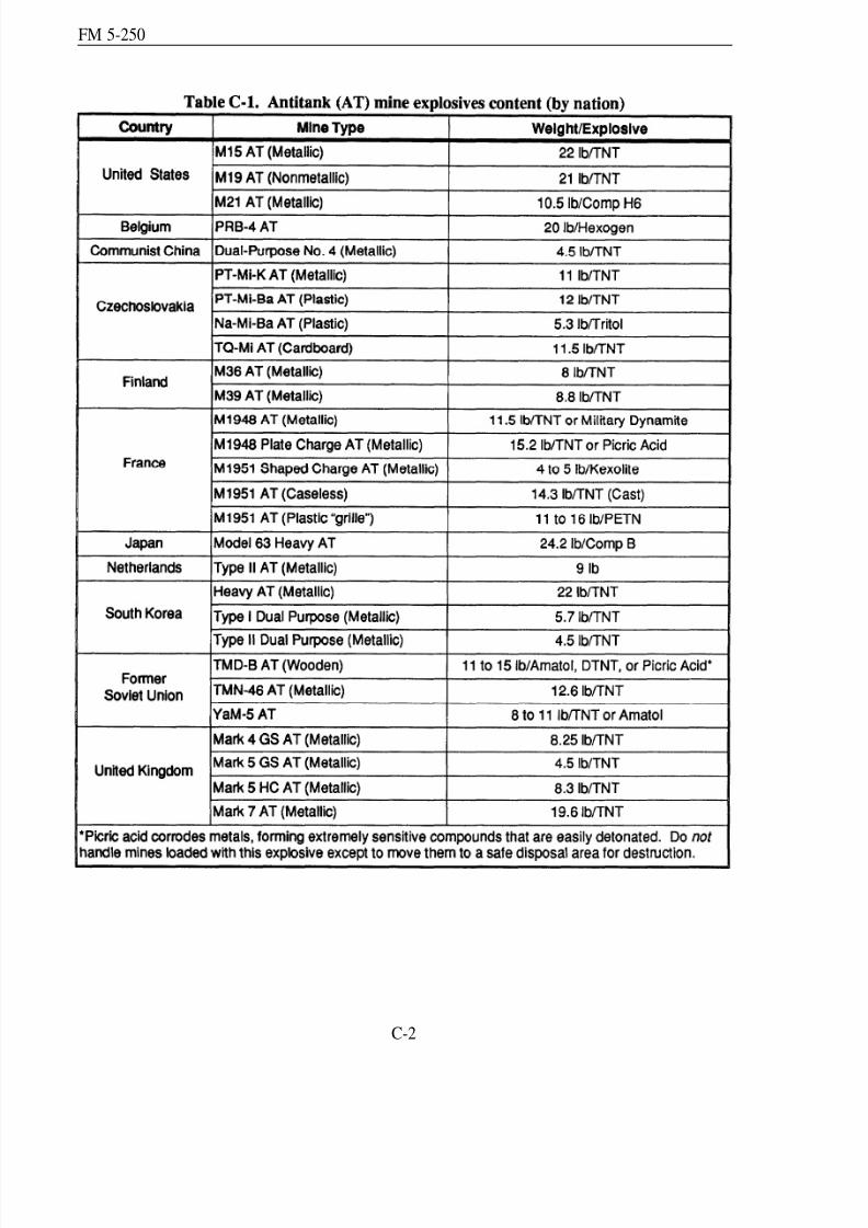
8/14/2019 United States Army Fm 5-250 - 15 June 1992 Explosives
http://slidepdf.com/reader/full/united-states-army-fm-5-250-15-june-1992-explosives 179/275
FM 5-250
C-2
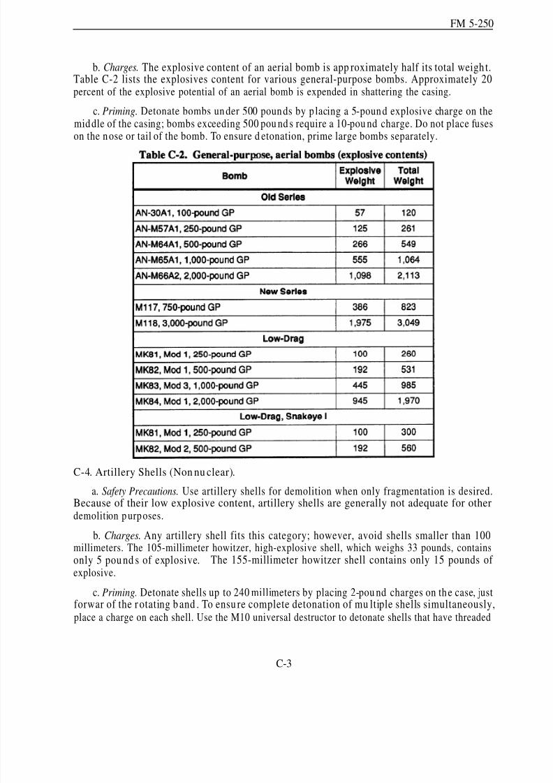
8/14/2019 United States Army Fm 5-250 - 15 June 1992 Explosives
http://slidepdf.com/reader/full/united-states-army-fm-5-250-15-june-1992-explosives 180/275
FM 5-250
b. Charges. The explosive content of an aerial bomb is app roximately half its total weigh t.Table C-2 lists the explosives content for various general-purpose bombs. Approximately 20percent of the explosive potential of an aerial bomb is expended in shattering the casing.
c. Priming. Detonate bombs un der 500 pounds by p lacing a 5-pound explosive charge on themiddle of the casing; bombs exceeding 500 pou nd s require a 10-pou nd charge. Do not place fuses
on the nose or tail of the bomb. To ensure d etonation, prime large bombs separately.
C-4. Artillery Shells (Non nu clear).
a. Safety Precautions. Use artillery shells for demolition when only fragmentation is desired.Because of their low explosive content, artillery shells are generally not adequate for otherdemolition p urposes.
b. Charges. Any artillery shell fits this category; however, avoid shells smaller than 100
millimeters. The 105-millimeter howitzer, high-explosive shell, which weighs 33 pounds, containsonly 5 pou nd s of explosive. The 155-millimeter howitzer shell contains only 15 pounds of explosive.
c. Priming. Detonate shells up to 240 millimeters by placing 2-pou nd charges on the case, justforwar of the r otating b and . To ensu re complete detonation of mu ltiple shells simultaneously,place a charge on each shell. Use the M10 universal destructor to detonate shells that have threaded
C-3

8/14/2019 United States Army Fm 5-250 - 15 June 1992 Explosives
http://slidepdf.com/reader/full/united-states-army-fm-5-250-15-june-1992-explosives 181/275
FM 5-250
fuse wells of 1.7- or 2-inch diam eters. Fill the booster cavities of bom bs and large p rojectiles fullyby adding booster cups to the M10 destructor, as required.
C-5. Foreign Explosives.
a. Safety Precautions. Use foreign explosives to sup plemen t stand ard US charges or, in certaincases, instead of US charges. How ever, only experienced d emolition p ersonnel should work withsuch explosives and then on ly according to instructions and directives issued by the th eatercommander. TM 9-1300-214 lists the most common foreign explosives.
b. Priming. Most foreign explosive blocks have cap w ells large enou gh to receive US militaryblasting caps. H owever, test fire these charges w ith US military blasting caps to en sure p ositivedeton ation. In certain instan ces, you may find it necessary to initiate the explosives by u sing astandard US demolition block primed with a blasting cap.
C-4
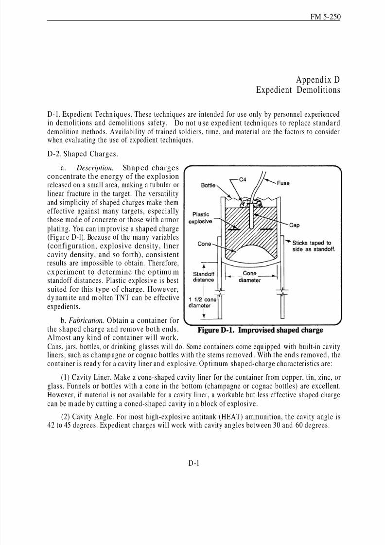
8/14/2019 United States Army Fm 5-250 - 15 June 1992 Explosives
http://slidepdf.com/reader/full/united-states-army-fm-5-250-15-june-1992-explosives 182/275
FM 5-250
Append ix DExpedient Demolitions
D-1. Expedient Techn iqu es. These techniques are intended for use only by personnel experiencedin demolitions and demolitions safety. Do not u se exped ient techn iques to replace standa rddemolition methods. Availability of trained soldiers, time, and material are the factors to considerwhen evaluating the use of expedient techniques.
D-2. Shaped Charges.
a. Description. Shaped chargesconcentrate th e energy of the explosionreleased on a small area, making a tu bular or
linear fracture in the target. The versatilityand simplicity of shaped charges make themeffective against many targets, especiallythose mad e of concrete or those with armorplating. You can im prov ise a shap ed charge(Figur e D-l). Because of the ma ny variables(configuration, explosive density, linercavity density, and so forth), consistentresults are impossible to obtain. Therefore,experiment to d etermine the op timu mstandoff distances. Plastic explosive is bestsuited for this type of charge. However,dy nam ite and m olten TNT can be effectiveexpedients.
b. Fabrication. Obtain a container forthe shaped charge and remove both ends.Almost any kind of container will work.Cans, jars, bottles, or drinking glasses w ill do. Some containers come equ ipped with built-in cavityliners, such as champ agne or cognac bottles with the stems removed . With the end s removed , thecontainer is read y for a cavity liner an d explosive. Op timum shap ed-charge characteristics are:
(1) Cavity Liner. Make a cone-shaped cavity liner for the container from copper, tin, zinc, orglass. Funnels or bottles with a cone in the bottom (champagne or cognac bottles) are excellent.However, if material is not available for a cavity liner, a workable but less effective shaped chargecan be m ad e by cutting a coned-shaped cavity in a block of explosive.
(2) Cavity Angle. For most high-explosive antitank (HEAT) ammunition, the cavity angle is42 to 45 degrees. Expedient charges will work with cavity an gles between 30 and 60 degrees.
D-1
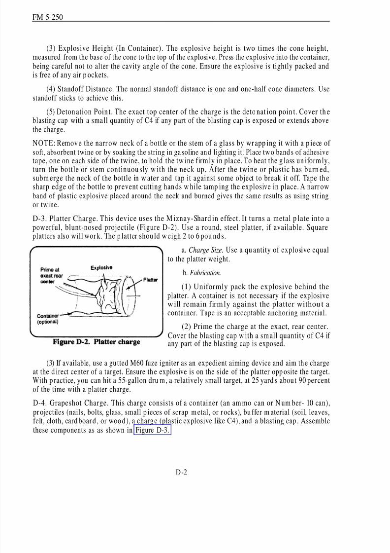
8/14/2019 United States Army Fm 5-250 - 15 June 1992 Explosives
http://slidepdf.com/reader/full/united-states-army-fm-5-250-15-june-1992-explosives 183/275
FM 5-250
(3) Explosive Height (In Container). The explosive height is two times the cone height,measured from the base of the cone to th e top of the explosive. Press the explosive into the container,being careful not to alter the cavity angle of the cone. Ensure the explosive is tightly packed andis free of any air p ockets.
(4) Standoff Distance. The normal standoff distance is one and one-half cone diameters. Use
standoff sticks to achieve this.
(5) Deton ation Poin t. The exact top center of the charge is the deto nat ion poin t. Cover th eblasting cap with a sma ll quantity of C4 if any p art of the blasting cap is exposed or extends abovethe charge.
NOTE: Remov e the narr ow neck of a bottle or the stem of a glass by wr app ing it with a p iece of soft, absorbent twine or by soaking the string in ga soline an d lighting it. Place tw o band s of adhesivetape, one on each side of the twine, to hold the tw ine firm ly in place. To heat the g lass un iform ly,turn the bottle or stem continuou sly w ith the neck up. After the twine or plastic has burn ed,subm erge the neck of the bottle in w ater and tap it against some object to break it off. Tape th esharp edge of the bottle to pr event cutting han ds w hile tamp ing the explosive in place. A narr ow
band of plastic explosive placed around the neck and burned gives the same results as using stringor twine.
D-3. Platter Charge. This device uses the M iznay-Shard in effect. It turns a metal p late into apowerful, blunt-nosed projectile (Figure D-2). Use a round, steel platter, if available. Squareplatters also will wor k. The p latter shou ld w eigh 2 to 6 pou nd s.
a. Charge Size. Use a qu antity of explosive equalto the platter weight.
b. Fabrication.
(1) Uniformly pack the explosive behind theplatter. A container is not necessary if the explosivewill remain firmly against the platter withou t acontainer. Tape is an acceptable anchoring material.
(2) Prime the charge at the exact, rear center.Cover the blasting cap w ith a sm all quantity of C4 if any part of the blasting cap is exposed.
(3) If available, use a gu tted M60 fuze igniter as an expedient aiming device and aim th e chargeat the d irect center of a target. Ensure th e explosive is on the side of the platter opp osite the target.With p ractice, you can hit a 55-gallon dru m, a relatively small target, at 25 yard s abou t 90 percent
of the time with a platter charge.
D-4. Grapeshot Charge. This charge consists of a container (an am mo can or N um ber- 10 can),pr ojectiles (nails, bolts, glass, small p ieces of scrap metal, or r ocks), bu ffer m aterial (soil, leaves,felt, cloth, card board , or wood), a charge (plastic explosive like C4), and a blasting cap . Assemblethese components as as shown in Figure D-3.
D-2

8/14/2019 United States Army Fm 5-250 - 15 June 1992 Explosives
http://slidepdf.com/reader/full/united-states-army-fm-5-250-15-june-1992-explosives 184/275
FM 5-250
a. Charge Size. Use a quan tity of explosive equal to one quarter theprojectile weight.
b. Fabrication.
(1) Make a hole in the center of the bottom of the container largeenough to accept a blasting cap.
(2) Place the comp onents in thecontainer in the following sequence:
(a) Explosive. Place the p lasticexplosive un iform ity in th e bottom of the container, remove a ll voids or airspaces by tamp ing with a nonsparkinginstrument.
(b) Buffer. Place 2 inches of buffer material directly on top of the explosive.
(c) Projectiles. Place the projectiles on top of the buffer material, and place a covering overthe projectiles to prevent them nom spilling out when handling the charge.
(3) Make a cap w ell in the p lastic-explosive charge th rough the h ole in th e bottom of thecontainer and insert the blasting cap of the initiation set. Cover the blasting cap w ith a small qua ntityof C4 if any pa rt of the blasting cap is exposed
(4) Aim th e charge at th e center of the target from app roximately 100 feet.
D-5. Dust Initiator. Dust-initiator charges u se small quan tities of explosives with larger am oun ts
of powd ered m aterials (du st or cover) to destroy thin-walled, wood en buildings or railroad boxcars.These charges work best in an enclosed area w ith few w indow s. At detonation, the du st or coveris distributed in the air w ithin the target and ignited by an explosive-incend iary charge. Thedu st-initiator charge consists of an explosive, mixed w ith equal p arts of incendiary mix, and a coverof finely divided organic material.
a. Charge Computations.
(1) Charge Size. One pound of explosive-incendiary mixture will effectively detonate up to40 pou nd s of cover. To make a l-poun d explosive-incendiary m ixture, combine 1/ 2 poun d of crushed TNT or C3 and 1/ 2 pound of incendiary mix (two parts aluminum powd er or magnesiumpow der and three par ts ferric oxide). Do not u se C4 because the explosive comp onent in C4 w ill
not combine properly with the incendiary mixture.
(2) Cover (Dust) Size. Use 3 to 5 pou nd s of cover for ea ch 1,000 cubic feet of target (3 pound sfor enclosed buildings, 5 pounds for partially enclosed buildings). The cover can consist of coaldu st, cocoa, powd ered coffee, confectioners sugar, tap ioca, wh eat flour, corn starch, har d-ru bberdust, aluminum powder, magnesium powder, powdered soap, or a volatile fuel such as gasoline.
D-3

8/14/2019 United States Army Fm 5-250 - 15 June 1992 Explosives
http://slidepdf.com/reader/full/united-states-army-fm-5-250-15-june-1992-explosives 185/275
FM 5-250
b. Fabrication. Place the TNT or C3 explosive in a canvas bag and crush it into a pow der w itha wooden mallet. In the same bag that contains the crushed explosive, add an equal amount of incendiary mixture and mix thoroughly. Prime this explosive-incendiary charge with adetonating-cord knot. Place the primed charge in the center of the target and pou r or place the coveron top of it, forming a pyramid. When using gasoline as the cover, do not use more than 3 gallons,
since greater quantities will not evenly disperse in the air, giving poor results.c. Detonation. The charge can be d etonated by attaching initation sets to the d etonating cord.
D-6. Imp rovised Cratering Charge. This charge consists of a mixture of ammonium nitratefertilizer (at least 33.33 percent nitrogen) and diesel fuel, motor oil, or gasoline. The ratio of fertilizerand fuel is 25 pou nd s to 1 quart. The fertilizer mu st not be d amp . You m ay fabricate almost anysize of imp rovised charge from this mixture. Proceed as follows:
a. Measure the fertilizer and fuel for the size charge you require.
b. Add the fuel to the fertilizer and mix thorou ghly.
c. Allow the fuel to soak into the fertilizer for an hou r.
d. Place half of the ammonium nitrate charge in the borehole. Then, place two l-pound primedblocks of explosives in the borehole and add the remainder of the ammonium nitrate charge. Neverleave the charge in th e borehole for a long p eriod, since the charge w ill accum ulate m oisture,reducing its effectiveness.
NOTE: Boreholes should receive 10 pound s of explosives for every foot of depth and mu st be du alprimed.
e. Detonate th e charge.
D-7. Improvised Borehole M ethod (Detonatin g-Cord Wick). This method (Figure D-4) is used
to enlarge boreholes in soil. The best results are obtained in h ard soil. Use the following p rocedu re:a. Tape together several stran ds of detonating cord 5 to 6 feet long. Generally, one strand
enlarges the diam eter of the hole by about one inch. Tape or tie the strand s together into a w ick foroptimum results.
b. Make a hole by driving a steel rod app roximately 2 inches in diameter into the grou nd tothe d epth requ ired. According to the ru le of thu mb, a hole 10 inches in d iameter requires 10 strandsof detonating cord.
c. Place the detonating-cord w ick into the h ole using an inserting rod or som e other fieldexpedient. The strand s mu st extend the full length of the h ole.
d. Fire the cord either electrically or nonelectrically. An unlimited number of wicks can befired atone time by connecting them with the detonating cord ring main or line main. If successive
charges are p laced in the holes, blow ou t excess gases and insp ect the hole for excessive heat.
D-4
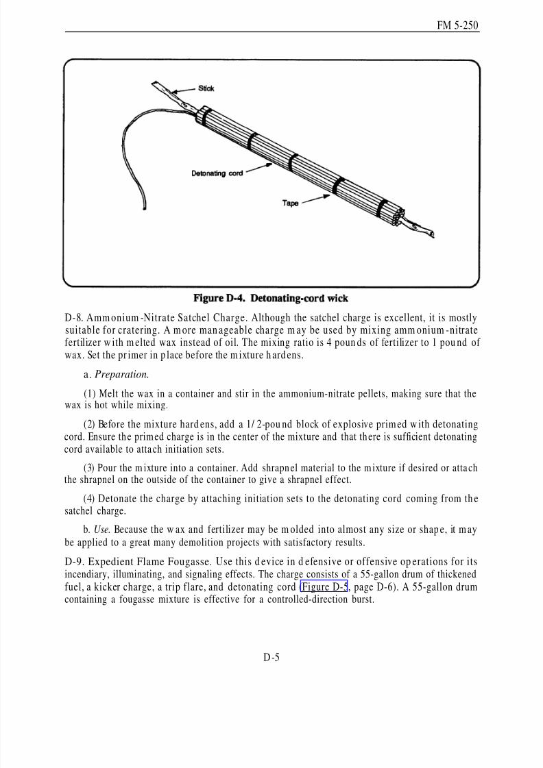
8/14/2019 United States Army Fm 5-250 - 15 June 1992 Explosives
http://slidepdf.com/reader/full/united-states-army-fm-5-250-15-june-1992-explosives 186/275
FM 5-250
D-8. Amm onium -Nitrate Satchel Charge. Although the satchel charge is excellent, it is mostlysuitable for cratering. A m ore man ageable charge m ay be used by mixing amm onium -nitratefertilizer w ith m elted wax instead of oil. The mixing ratio is 4 poun ds of fertilizer to 1 pou nd of wax. Set the pr imer in p lace before the m ixture h ard ens.
a. Preparation.
(1) Melt the wax in a container and stir in the ammonium-nitrate pellets, making sure that the
wax is hot while mixing.
(2) Before the mixture hard ens, add a 1/ 2-pou nd block of explosive prim ed w ith detonatingcord. Ensure th e prim ed charge is in the center of the mixture and that th ere is sufficient detonatingcord available to atta ch initiation sets.
(3) Pour the m ixture into a container. Add shrapn el material to the m ixture if desired or atta chthe shrapnel on the outside of the container to give a shrapnel effect.
(4) Detonate the charge by attaching initiation sets to the detonating cord coming from th esatchel charge.
b. Use. Because the w ax and fertilizer may be m olded into almost any size or shap e, it m aybe applied to a great many demolition projects with satisfactory results.
D-9. Expedient Flame Fougasse. Use this d evice in d efensive or offensive op erations for itsincendiary, illuminating, and signaling effects. The charge consists of a 55-gallon drum of thickenedfuel, a kicker charge, a trip flare, and detonating cord (Figure D-5, page D-6). A 55-gallon drumcontaining a fougasse mixture is effective for a controlled-direction burst.
D-5
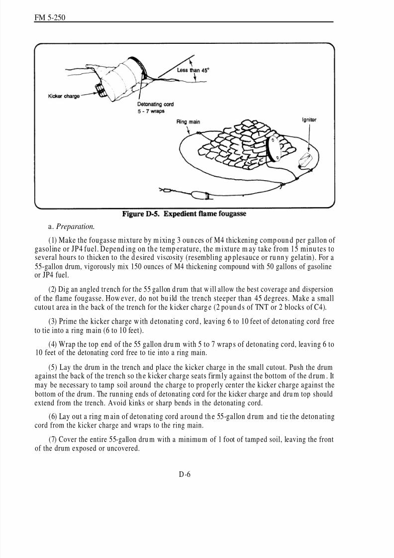
8/14/2019 United States Army Fm 5-250 - 15 June 1992 Explosives
http://slidepdf.com/reader/full/united-states-army-fm-5-250-15-june-1992-explosives 187/275
FM 5-250
a. Preparation.
(1) Make the fougasse mixture by m ixing 3 oun ces of M4 thickening comp oun d per gallon of gasoline or JP4 fuel. Depend ing on th e temp erature, the m ixture m ay take from 15 minu tes toseveral hours to thicken to the d esired viscosity (resembling ap plesauce or ru nn y gelatin). For a55-gallon drum, vigorously mix 150 ounces of M4 thickening compound with 50 gallons of gasolineor JP4 fuel.
(2) Dig an angled tr ench for the 55 gallon d rum that w ill allow the best coverage and dispersionof the flame fougasse. How ever, do not bu ild the trench steeper than 45 degrees. Make a smallcutou t area in the back of the trench for the k icker charg e (2 poun ds of TNT or 2 blocks of C4).
(3) Prime the kicker charge w ith detonating cord , leaving 6 to 10 feet of deton ating cord freeto tie into a ring main (6 to 10 feet).
(4) Wrap the top end of the 55 gallon dru m with 5 to 7 wrap s of detonating cord, leaving 6 to10 feet of the detonating cord free to tie into a ring main.
(5) Lay the drum in the trench and place the kicker charge in the small cutout. Push the drumagainst the back of the trench so th e kicker charge seats firm ly against the bottom of the d rum . Itmay be necessary to tamp soil around the charge to prop erly center the kicker charge against thebottom of the drum . The run ning ends of detonating cord for the kicker charge and dru m top shouldextend from the trench. Avoid kinks or sharp bends in the detonating cord.
(6) Lay out a ring m ain of deton ating cord a roun d th e 55-gallon d rum and tie the deton atingcord from the kicker charge and wraps to the ring main.
(7) Cover the entire 55-gallon dru m with a minimu m of 1 foot of tamp ed soil, leaving the frontof the drum exposed or uncovered.
D-6

8/14/2019 United States Army Fm 5-250 - 15 June 1992 Explosives
http://slidepdf.com/reader/full/united-states-army-fm-5-250-15-june-1992-explosives 188/275
FM 5-250
(8) Using a length of detonating cord, tape one end un der th e spoon h and le of an igniter tripflare (M49). Tape the spoon handle down securely, attach the trip flare to a stake, and position thestake 3 to 4 feet in front of the dru m. Attach the free end of the detonating cord secured to the tripflare to the ring main. During combat, a WP grenade (M34) will work in place of the trip flare. If trip flares are not available, do th e following:
Take a 2-liter plastic bottle and fill it half full with raw gasoline or JP4 (unth ickened ).Punch a hole in the cap of the bottle and thread one end of a detonating cord through thehole.
Tie a single overhand knot in the d etonating cord to preven t it from being pu lled backout of the cap.
Place the detonating cord with the single overhand knot inside the bottle and secure thecap onto the bottle.
Take the opposite end of the detonating cord and attach it to the ring main.
(9) Attach initiation sets to the ring m ain.
b. Function. When initiated, the ring main initiates the detonating cord to th e trip flare, thedrum top, and the kicker charge. The wraps cut the top of the drum off, the kicker charge propellsthe thickened fuel outward , and th e trip flare ignites the thickened fuel as it travels down range. Theresult is a flash of flame that spr eads d own range for ap proximately 100 meters.
D-7
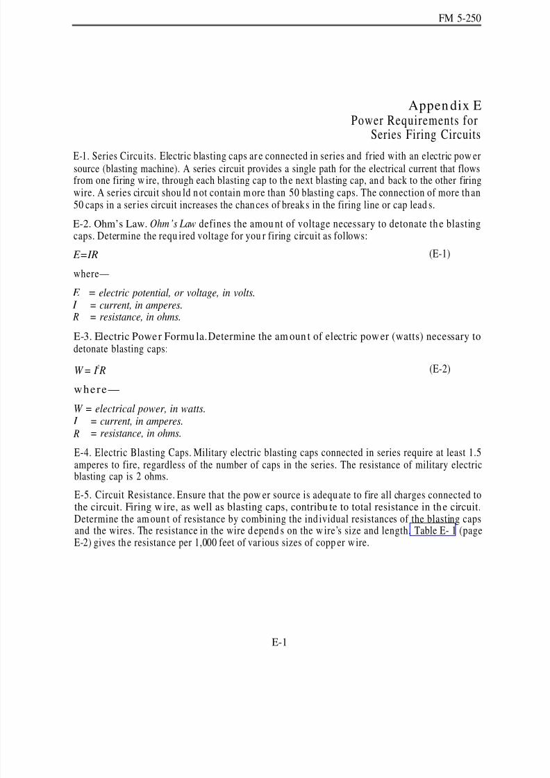
8/14/2019 United States Army Fm 5-250 - 15 June 1992 Explosives
http://slidepdf.com/reader/full/united-states-army-fm-5-250-15-june-1992-explosives 189/275
FM 5-250
Appen dix EPower Requirements for
Series Firing CircuitsE-1. Series Circu its. Electric blasting caps ar e connected in series and fried with an electric pow ersource (blasting machine). A series circuit provides a single path for the electrical current that flowsfrom one firing w ire, through each blasting cap to th e next blasting cap, and back to the other firingwire. A series circuit shou ld not contain m ore than 50 blasting caps. The connection of more th an50 caps in a ser ies circuit increases the chan ces of breaks in the firing line or cap lead s.
E-2. Ohm’s Law. Ohm’s Law defines the amou nt of voltage necessary to detonate th e blastingcaps. Determine the requ ired voltage for you r firing circuit as follows:
E=IR (E-1)
where—
E = electric potential, or voltage, in volts. I = current, in amperes. R = resistance, in ohms.
E-3. Electric Power Formu la.Determine the am oun t of electric pow er (watts) necessary todetonate blasting caps:
W= I 2 R (E-2)
where—
W = electrical power, in watts. I = current, in amperes. R = resistance, in ohms.
E-4. Electric Blasting Caps. Military electric blasting caps connected in series require at least 1.5amperes to fire, regardless of the number of caps in the series. The resistance of military electricblasting cap is 2 ohms.
E-5. Circuit Resistance. Ensure that the pow er source is adequate to fire all charges connected tothe circuit. Firing w ire, as well as blasting caps, contribu te to total resistance in the circuit.Determine the am oun t of resistance by combining the ind ividual resistances of the blasting capsand the wires. The resistance in the wire d epend s on the w ire’s size and length. Table E- 1 (page
E-2) gives the resistance per 1,000 feet of var ious sizes of copp er wire.
E-1

8/14/2019 United States Army Fm 5-250 - 15 June 1992 Explosives
http://slidepdf.com/reader/full/united-states-army-fm-5-250-15-june-1992-explosives 190/275
FM 5-250
E-6. Series Circuit Calculations. Complete calculations for any series circuit involved indetermining the amount of current (amperes), voltage (volts), and power (watts) needed to fire thecircuit. Use the following procedu re:
a. Current. The current requ ired for a series circuit of electric blasting cap s is 1.5 am per es,regardless of the number of blasting caps in the circuit.
b. Resistance. Determ ine the resistance in the circu it (parag raph E-5, pa ge E-l).
c. Voltage. Determine the r equired voltage for the circuit (paragrap h E-2, page E- 1).
d . Power. Determine the required power for the circuit (paragraph E-3, pa ge E-l).
e. Example. Determine the current, voltage, and power required to detonate a 20-cap seriescircuit consisting of special electric blasting caps and 500 feet of standard, 2-conductor, 18-gaugefiring w ire.
(1) Curren t. The amou nt of curr ent requ ired to detonate this circuit is 1.5 amp eres
(2) Resistan ce.
Cap s: 2.0 ohms (20 caps)= 40.0 ohm s
Wire: 500 feet (2 strands)= 1,000 feet= 6.4 ohms (Table E-1)
Total Resistance: 46.4 ohms
NOTE: Number-18 wire consists of two strands. The example specifies a 500-foot piece of wire,so u se 1,000 feet as th e total w ire length for determ ining resistance (500 x 2 = 1,000).
E-2

8/14/2019 United States Army Fm 5-250 - 15 June 1992 Explosives
http://slidepdf.com/reader/full/united-states-army-fm-5-250-15-june-1992-explosives 191/275
FM 5-250
(3) Voltage.
E = IR = 1.5(46.4)= 69.6 volts (E-3)
where-
E = voltage, in volts I = current, in amperes
R = resistance, in ohms(4) Pow er.
W= 12(R)= 1.5
2(46.4)= 104.4 WattS (E-4)
where—
W = power, in watts I = current, in amperes R = resistance, in ohms
E-7. Voltage D rop . Ohm’s Law allows you to determine the amount of voltage required (voltaged rop ) for a blasting circuit. In p ractice, the voltage drop shou ld nev er exceed 90 percent of the
available voltage; if it does, decrease the resistance or increase the voltage in th e circuit to ensu rethat proper detonation occurs.
E-8. Blasting M achine s. The name plate on power sour ces normally states the amp erage and thevoltage ratings. Before u sing any pow er source, determine w hether it is su itable for your firingcircuit. Generally, you can d etermine the adequacy of a pow er source by consulting Table E-2 (pageE-4). This table lists the sizes of circuits that power sources can support. If you must determinethe power source’s capabilities from the name plate, use the following procedure:
a. Determining Circuit Capacity.
Step 1. Multiply the power source’s voltage rating by 90 percent to get an adjustedvoltage rating.
Step 2. Divide th e adjusted voltage ratin g (Step 1) by the circuit’s amperage ratin g (1.5amp eres). At this point you have th e maximu m allowable resistance in the circuit, inohms.
Step 3. Determine the total resistance from the firing wire (Table E-l).
Step 4. Subtract the wire’s resistance from the maximum allowable circuit resistance(Step 2) to determine the maximum allowable resistance of the blasting caps in the circuit.
Step 5. Determine the maximu m nu mber of blasting caps the circuit will supp ort bydividing the allowable resistance for caps (Step 4) by the resistance in one cap (2 ohms).
E-3

8/14/2019 United States Army Fm 5-250 - 15 June 1992 Explosives
http://slidepdf.com/reader/full/united-states-army-fm-5-250-15-june-1992-explosives 192/275
FM 5-250
b. Example. Determine the m axim um nu m ber of electric blasting caps allowed in a seriescircuit fired by a 220-volt, 13.5-amp ere genera tor and 250 feet of dou ble-strand , 20-gau ge wire (atotal of 500 feet of wire).
(1) Allowable Resistance.
0.90(220 volts) = 132 ohms1.5 amperes
(2) Resistan ce in Firing Wire.
10.2 ohms (500 feet)
1,000= 5.2 ohms
(E-5)
(E-6)
(3) Allowable Resistance in Blasting Caps.
132 ohms – 5.2 Ohms = 126.8 Ohms (E-7)(4) Number of Blasting Caps.
126.8 ohms
2 ohms= 63.4 caps (Round down to 63 caps) (E-8)
E-9. Batteries an d Dry Cells.Use the procedu re in paragrap h E-8 (page E-3) to determ ine thesize of a circuit supported by a battery or dry cell.
E-4
8/14/2019 United States Army Fm 5-250 - 15 June 1992 Explosives
http://slidepdf.com/reader/full/united-states-army-fm-5-250-15-june-1992-explosives 193/275
FM 5-250
Appendix FInstructions for Completing
Demolitions-Related Reports
F-1. Target Folder. A completed target folder contains demolition orders and an obstacle folder.A samp le target folder is show n in Figure F-1 (page F-4). Refer to Cha pter 5, Section III (page5-2), for a d iscussion of the d emolition ord ers. Refer to Chapter 5, Section IV (page 5-6) for adiscussion of the obstacle folder.
F-2. Instru ctions fo r D A Form 2203-R. Use the following instructions and the sample formshown in Figure F-2 (pages F-38 through F-42) to complete DA Form 2203-R. A blank DA Form2203-R is at the end of this manu al. It may be locally reproduced on 8 1/ 2-by 11-inch paper.
a. Block 1 (FILE NO.). Leave blank unless a higher headquarters provides this number. Higherheadquarters provides this number or enters it after you submit the form.
b. Block 2 (DML RECON RPT NO.). Leave blank unless a higher headquarters provides thisnum ber. Higher headqu arters provides this number or enters it after you submit the form. CompanySOP may specify the procedures for determining this number.
c. Block 3 (DATE). Enter the date the reconnaissance was performed.
d. Block 4 (TIME). Enter the time the reconnaissance par ty arrived at the target site (local orZULU time).
e. Block 5 (RECON ORDERED BY ). Enter the command authority authorizing thereconnaissance action.
f. Block 6 (PAR TY LEAD ER).Enter the name of NCOIC or OIC of the reconnaissance partywho was p hysically at the site when the reconnaissance was performed.
g. Block 7 (MA P NA M E, SCALE, SHEET #, and SERIES #). Obtain this information from amap of the reconnaissance area and enter the information in this block.
h. Block 8 (TARGET AN D LOCATION). Enter a brief description of the target and the distanceand direction from an identifiable landmark (railroad brid ge, crossroad, hilltop, and so forth). Forexample, “Target is 275 degrees, 300 meters from the railroad br idge, 2 miles east of Han esville,on Route 2.”
i. Block 9 (TIME OBSERVED). Enter the time you last saw th e target as you dep arted th e site. j. Block 10 (COORDINATES). Enter the complete 8-digit map coordinates of the target.
k. Block 11 (GENERA L DESCRIPTION (attach sketches)).When ap plicable, includ e the typeof construction, width of the roadway, number of lanes or tracks, type of pavement, number of spans, condition of spans or entire bridge, and bridge categorization and classification. For example,
F-1
8/14/2019 United States Army Fm 5-250 - 15 June 1992 Explosives
http://slidepdf.com/reader/full/united-states-army-fm-5-250-15-june-1992-explosives 194/275
FM 5-250
"Prestressed-concrete T-beam bridge, four simple spans supported by six concrete columns, twolanes; total bridge length is 140 feet; roadway width is 30 feet; overall bridge width is 36 feet; height
is 16 feet; Class 80; very good condition.”
l. Block 12 (NATURE OF PROPOSED DEMOLITION (attach sketches)). State the expectedamount of destruction and the priority for placing charges, if feasible. Provide a sketch showing
the number and type of charges to use (tamped or u ntamped), where the charges should be placed,and the type of firing system required.
m. Block 13 (UNU SUAL FEAT URES OF SITE).Includ e any sp ecial features of the target orsite that might affect the meth od of dem olition (high-tension lines, rad ar installation, underwaterblasting, and so forth). Give any details that may affect the security of the target and the demolitionwork party.
n. Block 14 (EXPLOSIVES REQUIRED). Indicate the types, quantities, caps, detonators, and
so forth proposed for the demolition.
o. Block 15 (EQUIPMENT AND TRANSPORT REQUIRED). Specify the amount an d type of transportation required (for example, two 5-ton dump trucks, one ram set with 50 cartridges, two
post-hole diggers, two demolition sets, 10 pou nd s of 16d nails, twelve 8-foot 2 by 4s). Comm entsmay be continued on the reverse side of the form.
NOTE: Troops may n ot ride in veh icles transporting explosives.
p. Block 16 (PERSONNEL AND TIME REQUIRED FOR:). Complete subsections a and b,indicating the number of personnel and amount of time necessary for placing the demolitions. Thedistance between the firing points and firing systems will be a consideration for determining theamount of time necessary to arm and fire the explosives.
q. Block 17 (TIME, LABOR, AND EQUIPMENT REQUIRED FOR BYPASS; SPECIFY LOCATION A ND METHOD). Specify the equ ipment necessary to clear the site after demolition
and the available bypasses that allow un its to bypass the site. Comments may be continued on thereverse side of the form.
r. Block 18 (REMARKS). Includ e any appropriate remarks that ar e not covered in Blocks 1through 17. Comments may be continued on the r everse side of the form.
s. Block 19 (ADDITIONA L COMMENTS). Use this block as a continuation for Blocks 1throu gh 18. Identify the block being continued .
F-3. Instructions for Sketches. Use the following instru ctions and the samp le form shown inFigure F-2 (pages F-38 through F-42) to complete the necessary sketches for DA Form 2203-R.
a. General Description Sketch. This sketch should include—
The avenues of approach to the target and possible bypasses in the vicinity of the target.Indicate route numbers and the direction of cities or towns.
Rivers or stream s includ ing nam e, direction of flow, and velocity in meters per second.
Terrain features, including observation points, cover and concealment, swampy areas,deep valleys, and so forth.
F-2

8/14/2019 United States Army Fm 5-250 - 15 June 1992 Explosives
http://slidepdf.com/reader/full/united-states-army-fm-5-250-15-june-1992-explosives 195/275
FM 5-250
A compass arrow indicating north (indicate grid or magnetic).
Dimensions of the proposed target.
Number and length of bridge spans.
Height of the bridge from the ground or water.
b. Nature of Proposed Demolition Sketch. This sketch should include-Dimensions of members to be cut.
Placement of charges
Charge calculations. Use either the formula or table method , but show you r work.
Priming of charges.
Branch lines.
Ring mains.
Firing systems.
Firing points.
F-3

8/14/2019 United States Army Fm 5-250 - 15 June 1992 Explosives
http://slidepdf.com/reader/full/united-states-army-fm-5-250-15-june-1992-explosives 196/275
FM 5-250
F-4
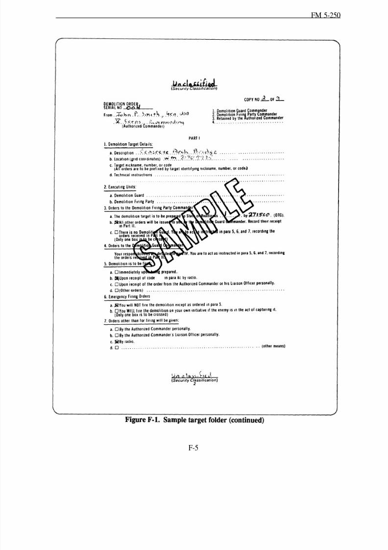
8/14/2019 United States Army Fm 5-250 - 15 June 1992 Explosives
http://slidepdf.com/reader/full/united-states-army-fm-5-250-15-june-1992-explosives 197/275
FM 5-250
F-5

8/14/2019 United States Army Fm 5-250 - 15 June 1992 Explosives
http://slidepdf.com/reader/full/united-states-army-fm-5-250-15-june-1992-explosives 198/275
FM 5-250
F-6
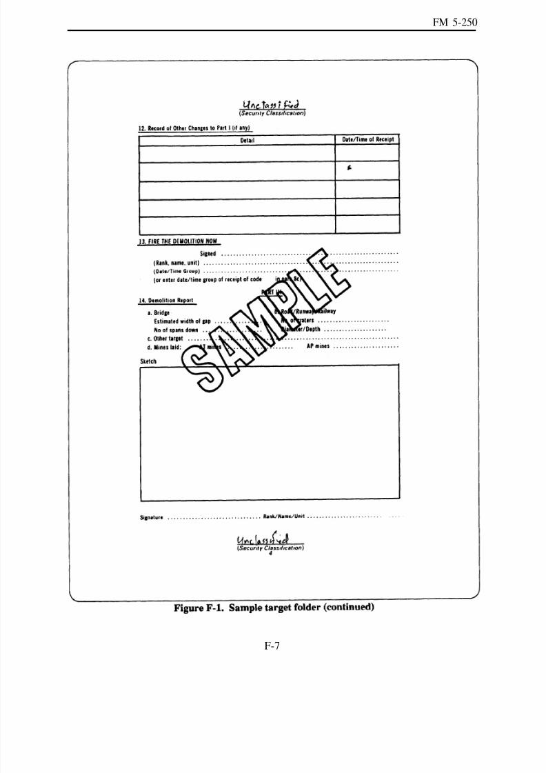
8/14/2019 United States Army Fm 5-250 - 15 June 1992 Explosives
http://slidepdf.com/reader/full/united-states-army-fm-5-250-15-june-1992-explosives 199/275
FM 5-250
F-7

8/14/2019 United States Army Fm 5-250 - 15 June 1992 Explosives
http://slidepdf.com/reader/full/united-states-army-fm-5-250-15-june-1992-explosives 200/275
FM 5-250
F-8
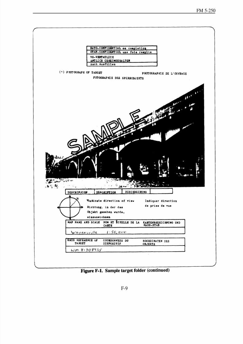
8/14/2019 United States Army Fm 5-250 - 15 June 1992 Explosives
http://slidepdf.com/reader/full/united-states-army-fm-5-250-15-june-1992-explosives 201/275
FM 5-250
F-9
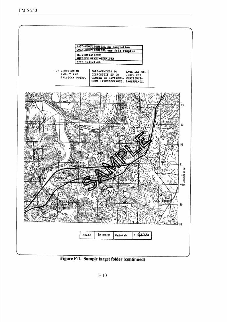
8/14/2019 United States Army Fm 5-250 - 15 June 1992 Explosives
http://slidepdf.com/reader/full/united-states-army-fm-5-250-15-june-1992-explosives 202/275
FM 5-250
F-10
8/14/2019 United States Army Fm 5-250 - 15 June 1992 Explosives
http://slidepdf.com/reader/full/united-states-army-fm-5-250-15-june-1992-explosives 203/275
FM 5-250
F-11

8/14/2019 United States Army Fm 5-250 - 15 June 1992 Explosives
http://slidepdf.com/reader/full/united-states-army-fm-5-250-15-june-1992-explosives 204/275
FM 5-250
F-12

8/14/2019 United States Army Fm 5-250 - 15 June 1992 Explosives
http://slidepdf.com/reader/full/united-states-army-fm-5-250-15-june-1992-explosives 205/275
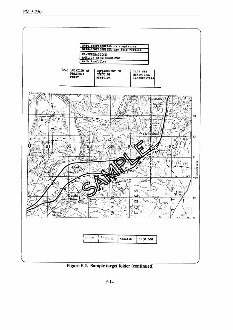
8/14/2019 United States Army Fm 5-250 - 15 June 1992 Explosives
http://slidepdf.com/reader/full/united-states-army-fm-5-250-15-june-1992-explosives 206/275
FM 5-250
F-14
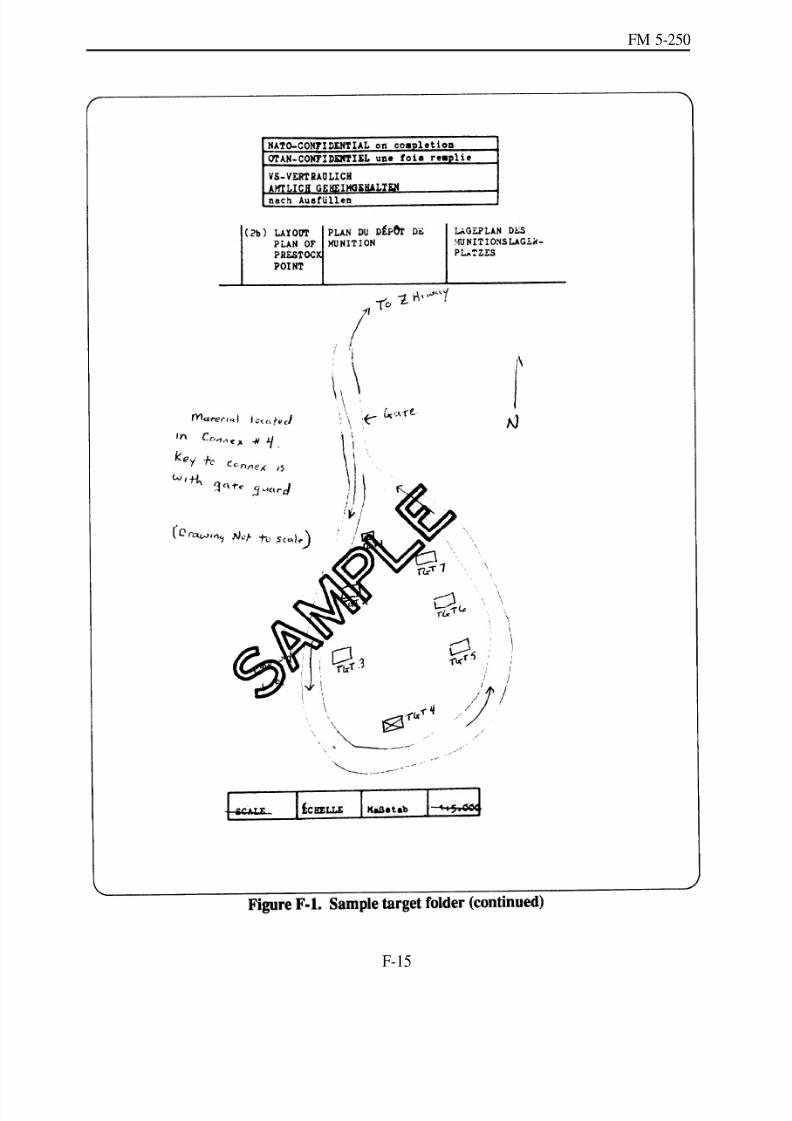
8/14/2019 United States Army Fm 5-250 - 15 June 1992 Explosives
http://slidepdf.com/reader/full/united-states-army-fm-5-250-15-june-1992-explosives 207/275
FM 5-250
F-15
8/14/2019 United States Army Fm 5-250 - 15 June 1992 Explosives
http://slidepdf.com/reader/full/united-states-army-fm-5-250-15-june-1992-explosives 208/275
FM 5-250
F-16
8/14/2019 United States Army Fm 5-250 - 15 June 1992 Explosives
http://slidepdf.com/reader/full/united-states-army-fm-5-250-15-june-1992-explosives 209/275
FM 5-250
F-17
8/14/2019 United States Army Fm 5-250 - 15 June 1992 Explosives
http://slidepdf.com/reader/full/united-states-army-fm-5-250-15-june-1992-explosives 210/275
FM 5-250
F-18

8/14/2019 United States Army Fm 5-250 - 15 June 1992 Explosives
http://slidepdf.com/reader/full/united-states-army-fm-5-250-15-june-1992-explosives 211/275
FM 5-250
F-19
8/14/2019 United States Army Fm 5-250 - 15 June 1992 Explosives
http://slidepdf.com/reader/full/united-states-army-fm-5-250-15-june-1992-explosives 212/275
FM 5-250
F-20

8/14/2019 United States Army Fm 5-250 - 15 June 1992 Explosives
http://slidepdf.com/reader/full/united-states-army-fm-5-250-15-june-1992-explosives 213/275
FM 5-250
F-21

8/14/2019 United States Army Fm 5-250 - 15 June 1992 Explosives
http://slidepdf.com/reader/full/united-states-army-fm-5-250-15-june-1992-explosives 214/275
FM 5-250
F-22
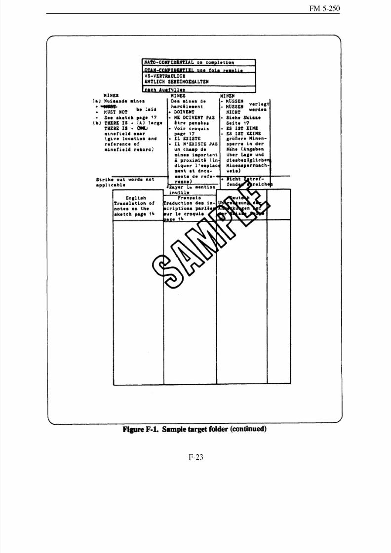
8/14/2019 United States Army Fm 5-250 - 15 June 1992 Explosives
http://slidepdf.com/reader/full/united-states-army-fm-5-250-15-june-1992-explosives 215/275
FM 5-250
F-23

8/14/2019 United States Army Fm 5-250 - 15 June 1992 Explosives
http://slidepdf.com/reader/full/united-states-army-fm-5-250-15-june-1992-explosives 216/275
FM 5-250
F-24

8/14/2019 United States Army Fm 5-250 - 15 June 1992 Explosives
http://slidepdf.com/reader/full/united-states-army-fm-5-250-15-june-1992-explosives 217/275
FM 5-250
F-25
8/14/2019 United States Army Fm 5-250 - 15 June 1992 Explosives
http://slidepdf.com/reader/full/united-states-army-fm-5-250-15-june-1992-explosives 218/275
FM 5-250
F-26

8/14/2019 United States Army Fm 5-250 - 15 June 1992 Explosives
http://slidepdf.com/reader/full/united-states-army-fm-5-250-15-june-1992-explosives 219/275
FM 5-250
F-27
8/14/2019 United States Army Fm 5-250 - 15 June 1992 Explosives
http://slidepdf.com/reader/full/united-states-army-fm-5-250-15-june-1992-explosives 220/275
FM 5-250
F-28
8/14/2019 United States Army Fm 5-250 - 15 June 1992 Explosives
http://slidepdf.com/reader/full/united-states-army-fm-5-250-15-june-1992-explosives 221/275
FM 5-250
F-29

8/14/2019 United States Army Fm 5-250 - 15 June 1992 Explosives
http://slidepdf.com/reader/full/united-states-army-fm-5-250-15-june-1992-explosives 222/275
FM 5-250
F-30
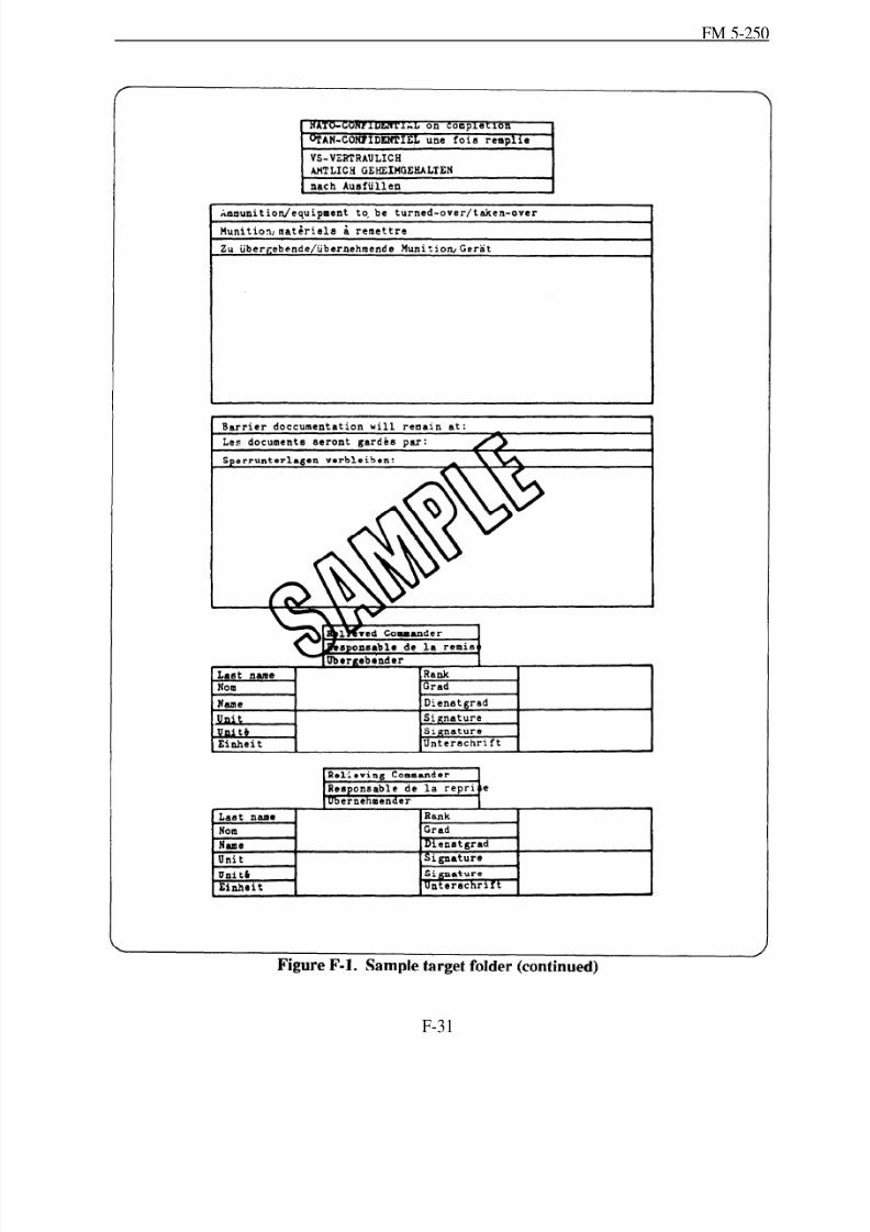
8/14/2019 United States Army Fm 5-250 - 15 June 1992 Explosives
http://slidepdf.com/reader/full/united-states-army-fm-5-250-15-june-1992-explosives 223/275
FM 5-250
F-31
8/14/2019 United States Army Fm 5-250 - 15 June 1992 Explosives
http://slidepdf.com/reader/full/united-states-army-fm-5-250-15-june-1992-explosives 224/275
FM 5-250
F-33
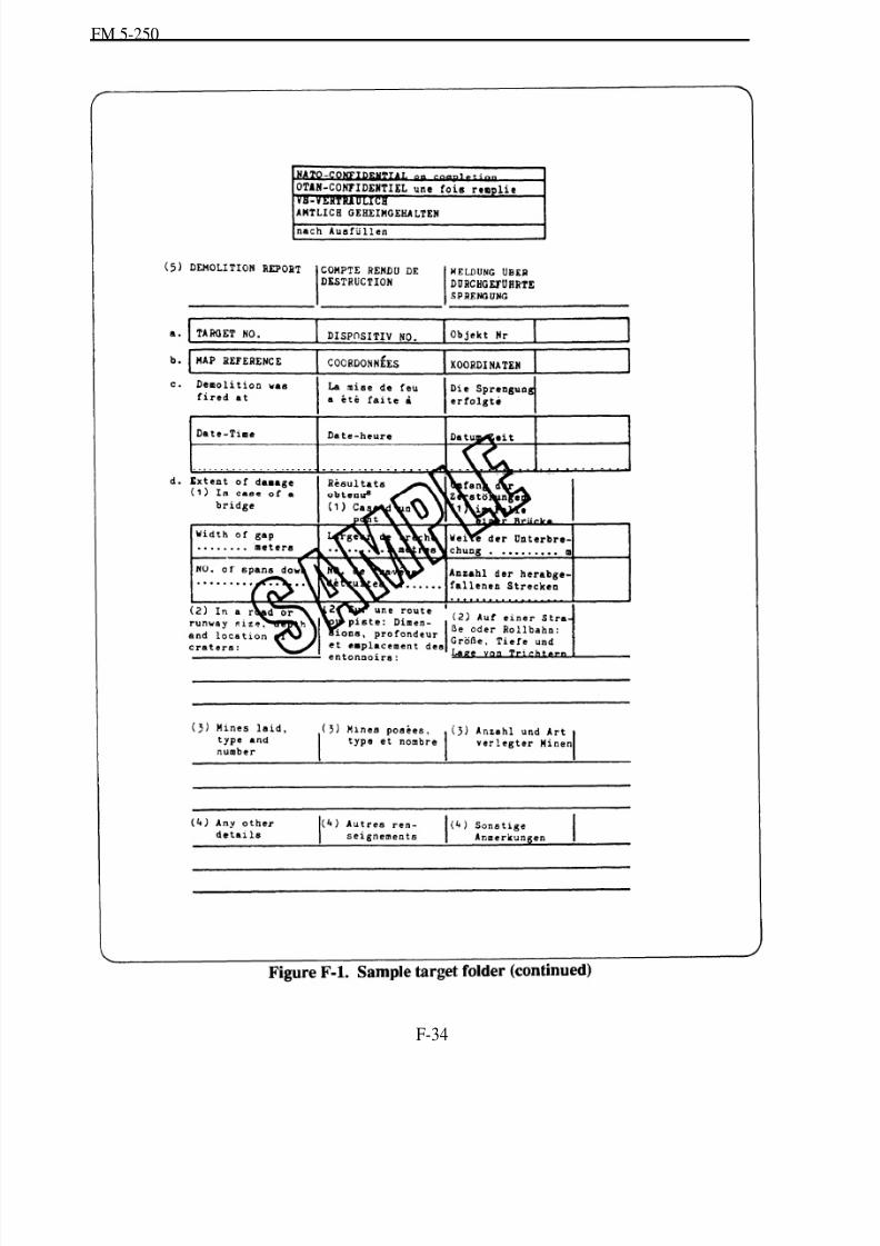
8/14/2019 United States Army Fm 5-250 - 15 June 1992 Explosives
http://slidepdf.com/reader/full/united-states-army-fm-5-250-15-june-1992-explosives 225/275
FM 5-250
F-34

8/14/2019 United States Army Fm 5-250 - 15 June 1992 Explosives
http://slidepdf.com/reader/full/united-states-army-fm-5-250-15-june-1992-explosives 226/275
FM 5-250
F-35
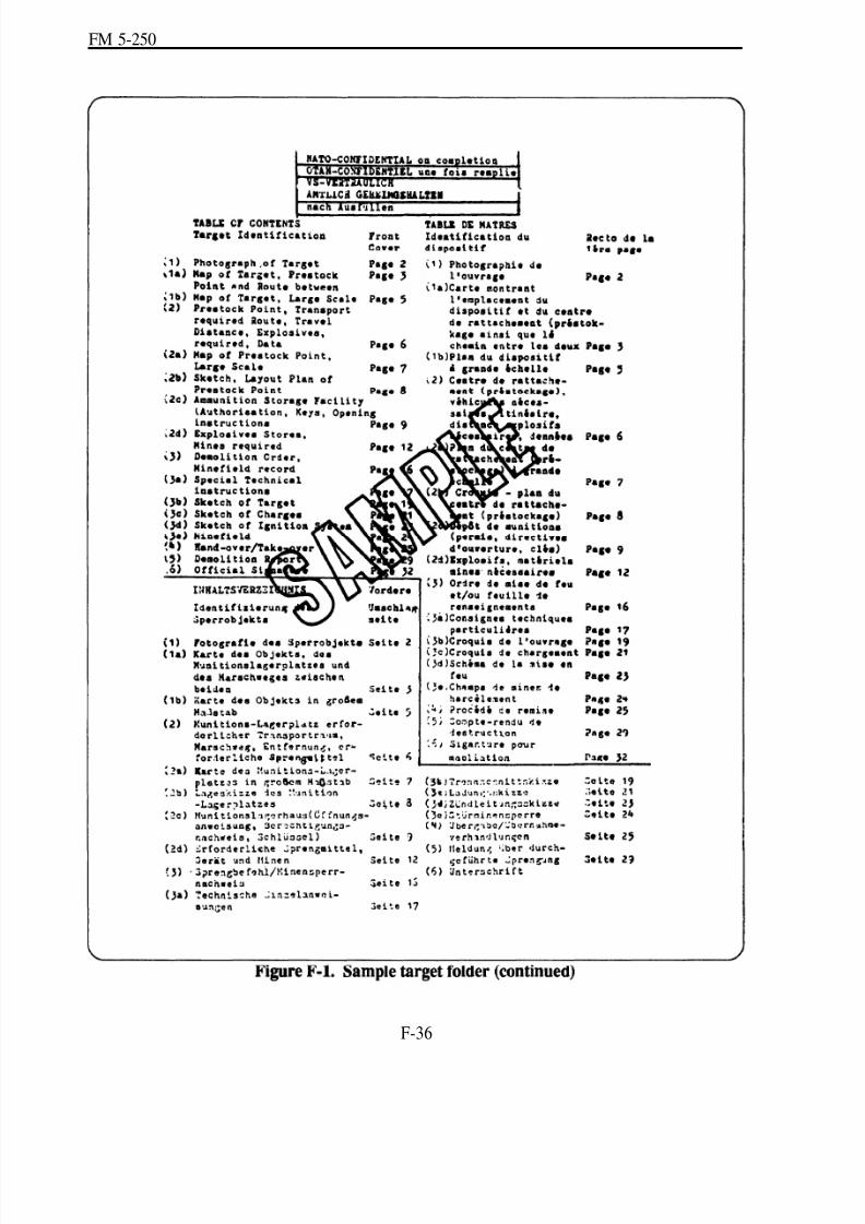
8/14/2019 United States Army Fm 5-250 - 15 June 1992 Explosives
http://slidepdf.com/reader/full/united-states-army-fm-5-250-15-june-1992-explosives 227/275
FM 5-250
F-36

8/14/2019 United States Army Fm 5-250 - 15 June 1992 Explosives
http://slidepdf.com/reader/full/united-states-army-fm-5-250-15-june-1992-explosives 228/275
FM 5-250
F-37
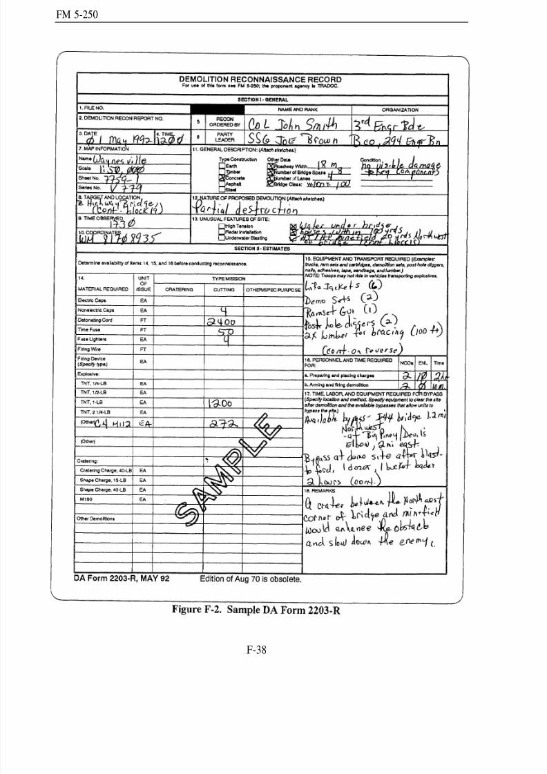
8/14/2019 United States Army Fm 5-250 - 15 June 1992 Explosives
http://slidepdf.com/reader/full/united-states-army-fm-5-250-15-june-1992-explosives 229/275
FM 5-250
F-38
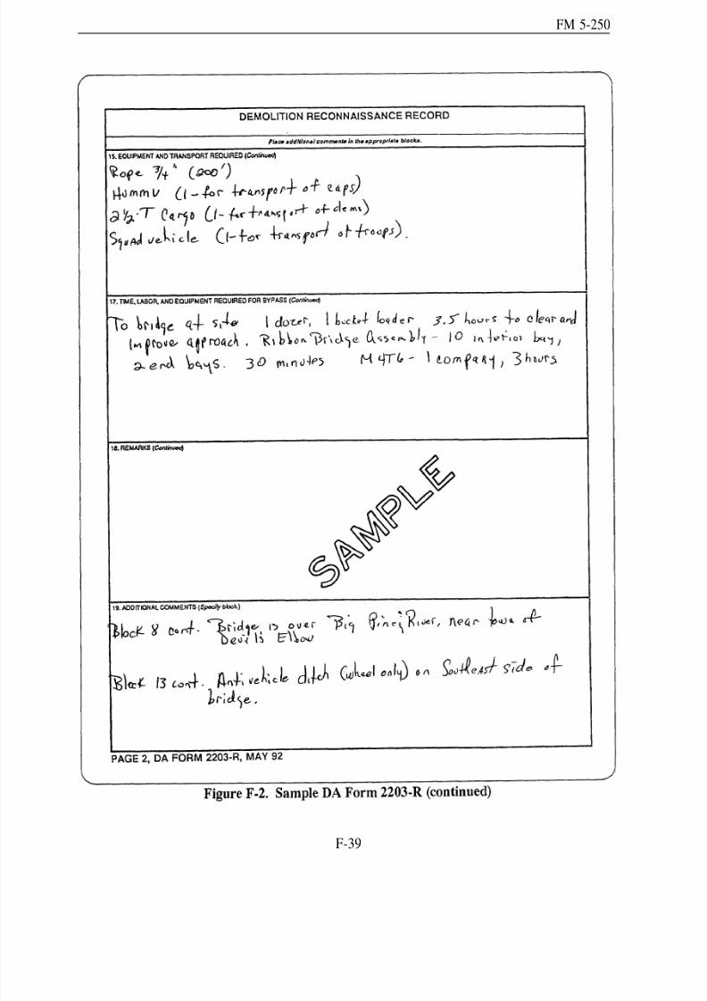
8/14/2019 United States Army Fm 5-250 - 15 June 1992 Explosives
http://slidepdf.com/reader/full/united-states-army-fm-5-250-15-june-1992-explosives 230/275
FM 5-250
F-39
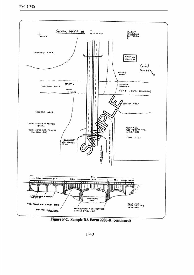
8/14/2019 United States Army Fm 5-250 - 15 June 1992 Explosives
http://slidepdf.com/reader/full/united-states-army-fm-5-250-15-june-1992-explosives 231/275
FM 5-250
F-40
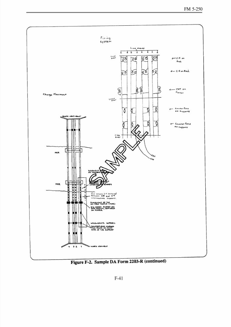
8/14/2019 United States Army Fm 5-250 - 15 June 1992 Explosives
http://slidepdf.com/reader/full/united-states-army-fm-5-250-15-june-1992-explosives 232/275
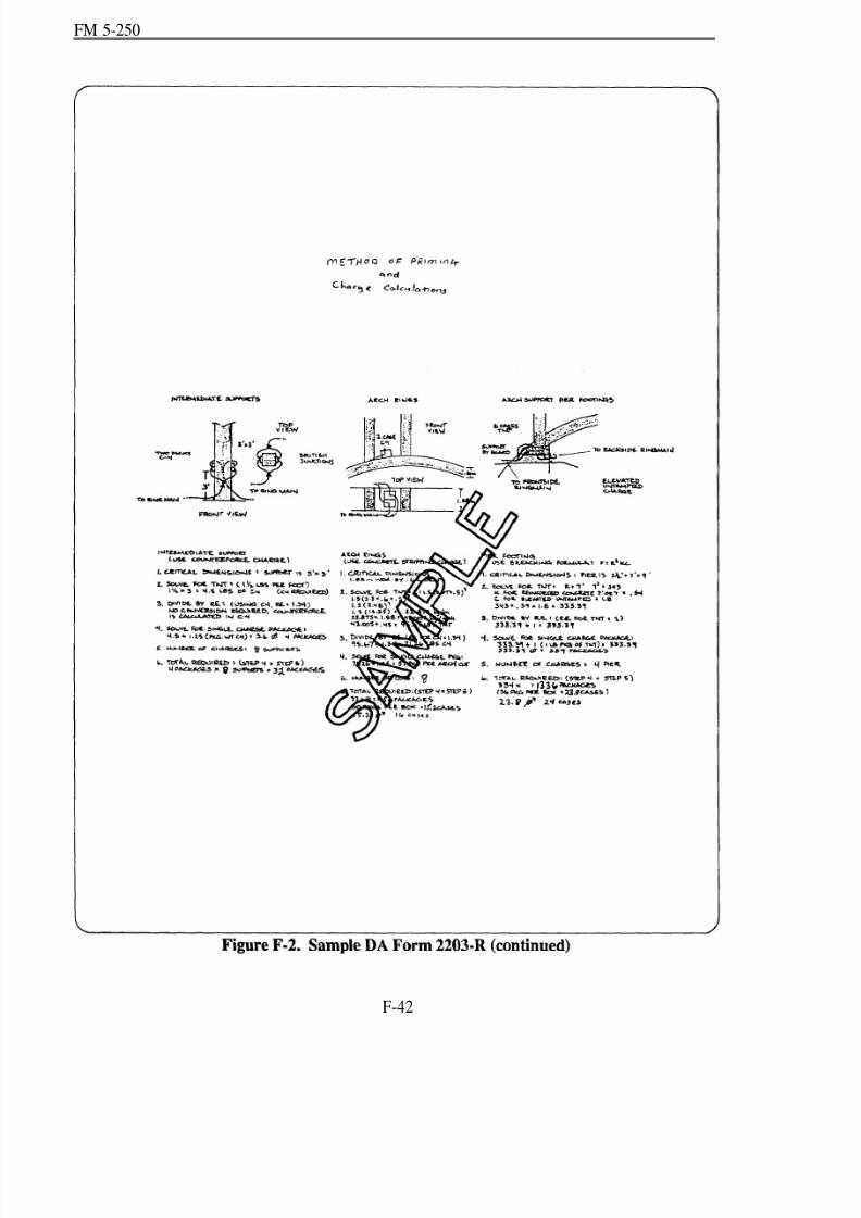
8/14/2019 United States Army Fm 5-250 - 15 June 1992 Explosives
http://slidepdf.com/reader/full/united-states-army-fm-5-250-15-june-1992-explosives 233/275
FM 5-250
F-42
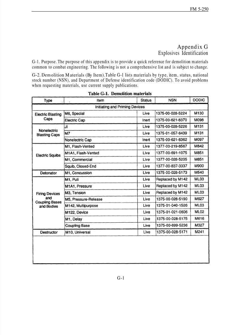
8/14/2019 United States Army Fm 5-250 - 15 June 1992 Explosives
http://slidepdf.com/reader/full/united-states-army-fm-5-250-15-june-1992-explosives 234/275
FM 5-250
Append ix GExplosives Identification
G-1. Purpose. The pu rpose of this app endix is to provide a quick reference for demolition m aterialscommon to combat engineering. The following is not a comp rehensive list an d is subject to change.
G-2. Dem olition M aterials (By Item).Table G-1 lists ma terials by typ e, item , status, nationalstock number (NSN), and Department of Defense identification code (DODIC). To avoid problemswhen requesting materials, use current supply publications.
G-1
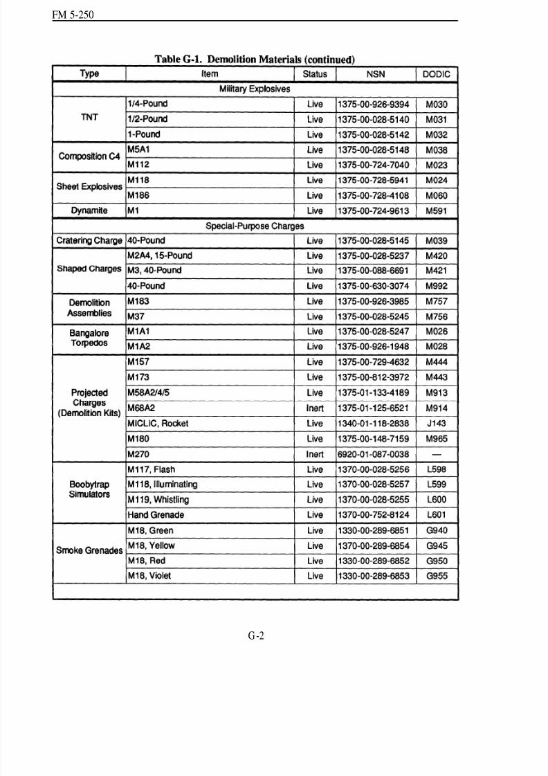
8/14/2019 United States Army Fm 5-250 - 15 June 1992 Explosives
http://slidepdf.com/reader/full/united-states-army-fm-5-250-15-june-1992-explosives 235/275
FM 5-250
G -2

8/14/2019 United States Army Fm 5-250 - 15 June 1992 Explosives
http://slidepdf.com/reader/full/united-states-army-fm-5-250-15-june-1992-explosives 236/275
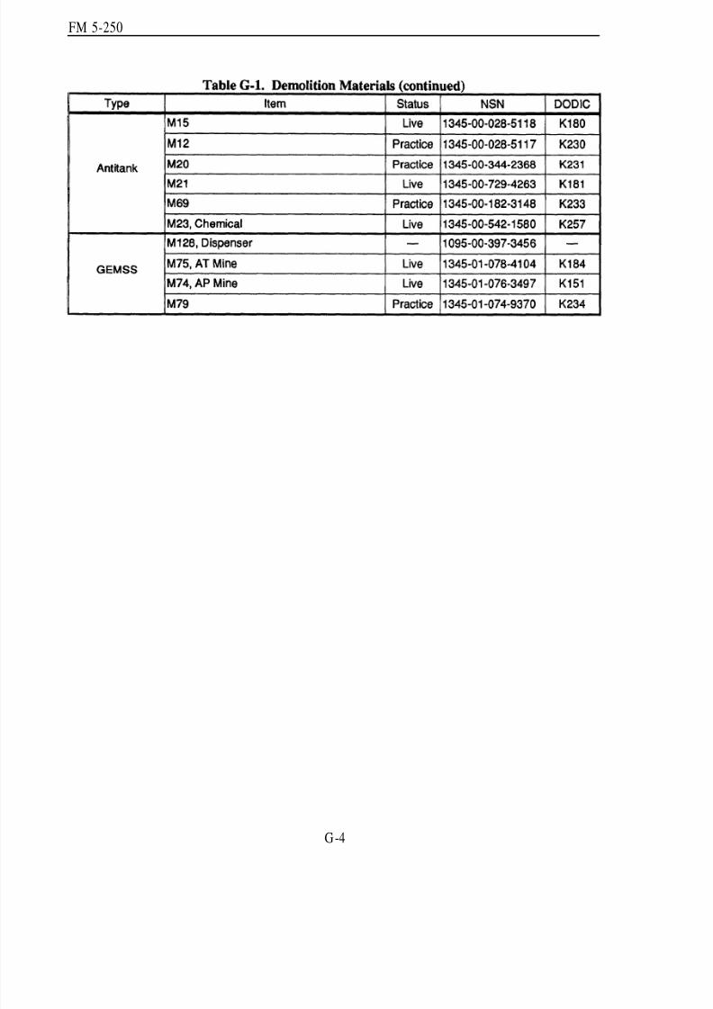
8/14/2019 United States Army Fm 5-250 - 15 June 1992 Explosives
http://slidepdf.com/reader/full/united-states-army-fm-5-250-15-june-1992-explosives 237/275
FM 5-250
G-4
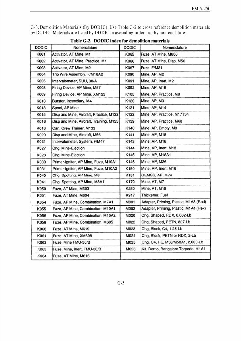
8/14/2019 United States Army Fm 5-250 - 15 June 1992 Explosives
http://slidepdf.com/reader/full/united-states-army-fm-5-250-15-june-1992-explosives 238/275
FM 5-250
G-3. Dem olition M aterials (By DOD IC). Use Table G-2 to cross reference demolition materialsby DODIC. Materials are listed by DO DIC in ascending order an d by nom enclature:
G-5
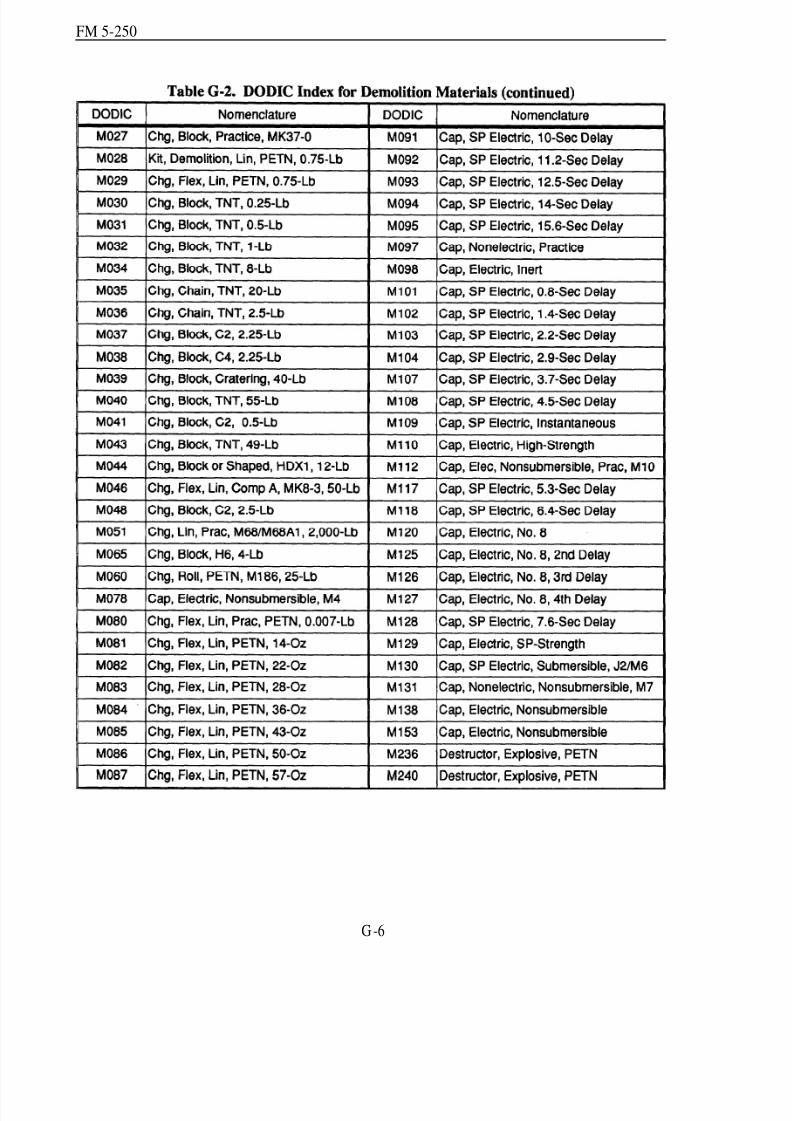
8/14/2019 United States Army Fm 5-250 - 15 June 1992 Explosives
http://slidepdf.com/reader/full/united-states-army-fm-5-250-15-june-1992-explosives 239/275
FM 5-250
G -6
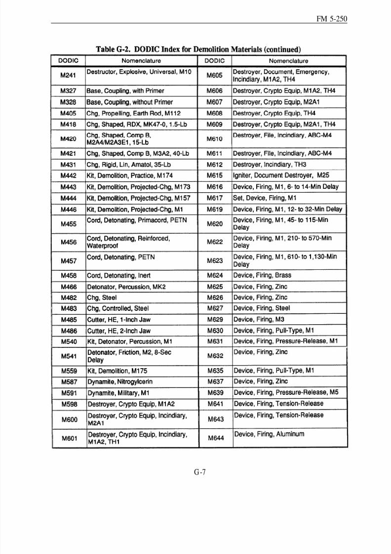
8/14/2019 United States Army Fm 5-250 - 15 June 1992 Explosives
http://slidepdf.com/reader/full/united-states-army-fm-5-250-15-june-1992-explosives 240/275
FM 5-250
G-7
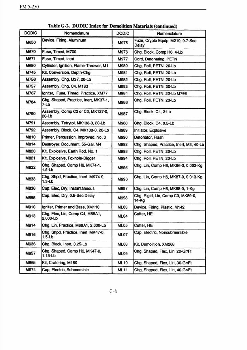
8/14/2019 United States Army Fm 5-250 - 15 June 1992 Explosives
http://slidepdf.com/reader/full/united-states-army-fm-5-250-15-june-1992-explosives 241/275
FM 5-250
G -8
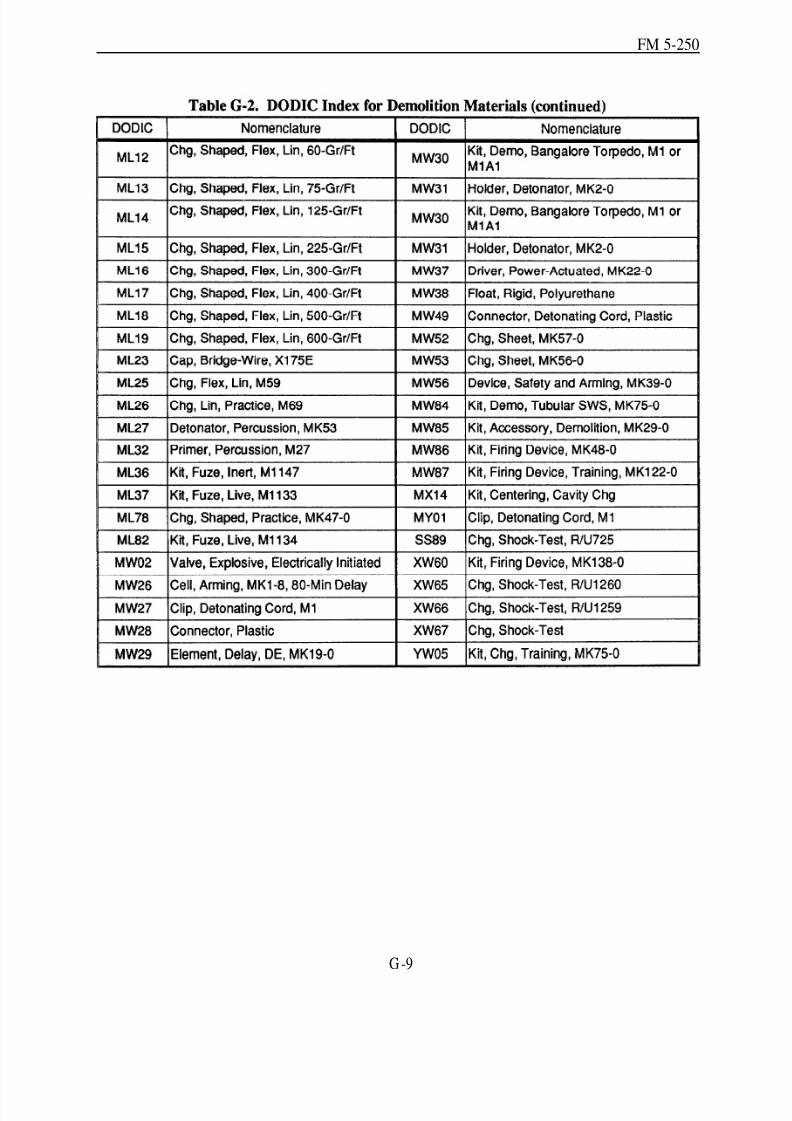
8/14/2019 United States Army Fm 5-250 - 15 June 1992 Explosives
http://slidepdf.com/reader/full/united-states-army-fm-5-250-15-june-1992-explosives 242/275
FM 5-250
G -9

8/14/2019 United States Army Fm 5-250 - 15 June 1992 Explosives
http://slidepdf.com/reader/full/united-states-army-fm-5-250-15-june-1992-explosives 243/275
FM 5-250
Appendix HMeth ods of Attackin g Bridges
with Demolitions
The method s of attack in this app end ix are for the most common typ es of bridges; how ever,they are not all inclusive. When faced with u nusual construction method s or materials (for example,Hayricks which are linear-shaped charges used by host NATO countries), the responsible engineershouId ad apt one the of the recomm ended methods or recategorize the bridge as a miscellaneousbridge and design the demolition using the principles in Chapter 4.
H -1

8/14/2019 United States Army Fm 5-250 - 15 June 1992 Explosives
http://slidepdf.com/reader/full/united-states-army-fm-5-250-15-june-1992-explosives 244/275
FM 5-250
H -2

8/14/2019 United States Army Fm 5-250 - 15 June 1992 Explosives
http://slidepdf.com/reader/full/united-states-army-fm-5-250-15-june-1992-explosives 245/275
FM 5-250
H -3
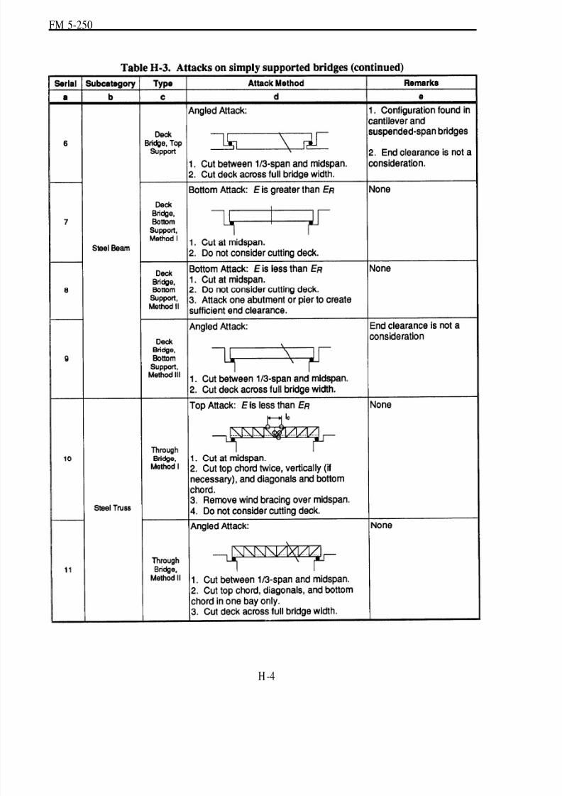
8/14/2019 United States Army Fm 5-250 - 15 June 1992 Explosives
http://slidepdf.com/reader/full/united-states-army-fm-5-250-15-june-1992-explosives 246/275

8/14/2019 United States Army Fm 5-250 - 15 June 1992 Explosives
http://slidepdf.com/reader/full/united-states-army-fm-5-250-15-june-1992-explosives 247/275
FM 5-250
H -5

8/14/2019 United States Army Fm 5-250 - 15 June 1992 Explosives
http://slidepdf.com/reader/full/united-states-army-fm-5-250-15-june-1992-explosives 248/275
FM 5-250
H -6

8/14/2019 United States Army Fm 5-250 - 15 June 1992 Explosives
http://slidepdf.com/reader/full/united-states-army-fm-5-250-15-june-1992-explosives 249/275
FM 5-250
H -7
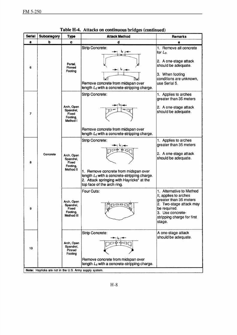
8/14/2019 United States Army Fm 5-250 - 15 June 1992 Explosives
http://slidepdf.com/reader/full/united-states-army-fm-5-250-15-june-1992-explosives 250/275
FM 5-250
H-8

8/14/2019 United States Army Fm 5-250 - 15 June 1992 Explosives
http://slidepdf.com/reader/full/united-states-army-fm-5-250-15-june-1992-explosives 251/275
FM 5-250
H-9
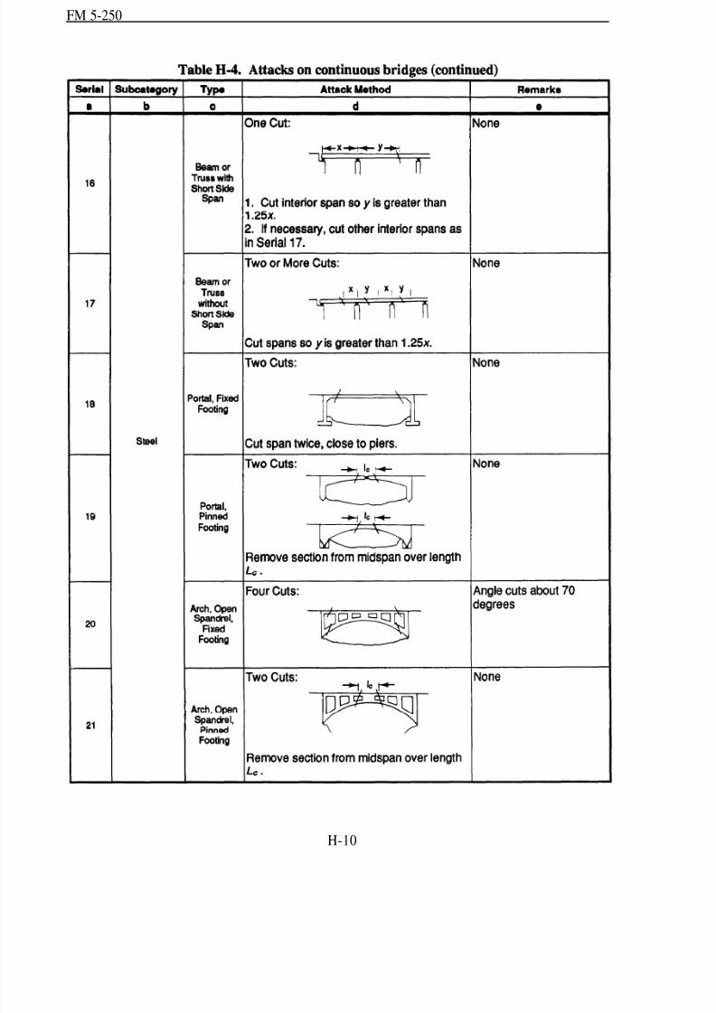
8/14/2019 United States Army Fm 5-250 - 15 June 1992 Explosives
http://slidepdf.com/reader/full/united-states-army-fm-5-250-15-june-1992-explosives 252/275
FM 5-250
H-10

8/14/2019 United States Army Fm 5-250 - 15 June 1992 Explosives
http://slidepdf.com/reader/full/united-states-army-fm-5-250-15-june-1992-explosives 253/275

8/14/2019 United States Army Fm 5-250 - 15 June 1992 Explosives
http://slidepdf.com/reader/full/united-states-army-fm-5-250-15-june-1992-explosives 254/275
FM 5-250
G l o s s a r y
A total area
abatis Fallen-tree obstacles mad e by cutting treesthat remain attached to their stum ps.
ABCA American, British, Canadian, a ndAustralian
AFV armored fighting vehicle
amatol A mixture of ammonium nitrate andtrinitrotoluene (TNT); a substitute for TNT inbursting charges.
ammonium nitrate The least sensitive of themilitary explosives; it requires a booster chargeto successfully initiate detonation; a componentinmost cratering and ditching charges.
ammonium-nitrate satchel charge A mixture of ammonium-nitrate fertilizer and melted wax; themixing ratio is 4 pounds of fertilizer to 1 poundof wax.
angled attack A method of attack used in bridgedemolitions.
AT antitank
Attn attention
AP antipersonnel
approx approximately
ARNG Army N ational Guard
ASP ammunition supply point
AVLB armored vehicle launch bridge
beam collapse mechanism A method of allowingabridge to collapse under its own weight.
black powder The oldest-known explosive andpropellant; a composite of potassium or sodiumnitrate, charcoal, and sulfur.
blasting cap Used to d etonate high explosives;there are two typ es: electric and nonelectric.
blasting machine Provides th e electric imp ulseneeded to initiate electric blasting-capoperations there ar e two mod els: M32 10-cap
blasting machine an d M34 50-cap blastingmachine.
block demolition charge Prepackaged,high-explosive charges for general demolitionoperations, such as cutting, breaching, andcratering; comp osed of high-explosive TNT,tetrytol, Composition-C series, and ammoniumnitrate.
block-hole method Away of removing boulders;a hole is drilled in the top of the boulder deep
and wide enough to hold the required amount of explosive.
bottom attack Forms a hinge at the top of thespan; as the span falls, the cut ends at the bottommove outward.
branch line A length of detonating cord.
breaching charges Used to destroy concrete-slabbridges, bridge beams, bridge piers, bridgeabutments, and permanent field fortifications;the size, shape, placement, and tamping orconfinemen t of breaching char ges are critical tosuccess.
breaching radiu s (R) For external charges, it isequal to the thickness of the target beingbreached; for internal charges placed in thecenter of the targ et’s ma ss, R is one h alf thethickness of the target; for internal chargesplaced at less than half the mass thickness, R isthe longer of the distances from the center of thecharge to the outside surfaces of the target.
C See tamping factor (C).
C4 See Comp osition C4 (C4).
categorization To put into any of severalfundamental and distinct classes to whichentities or concepts belong; a division within asystem of classification.
chg charge
class classification
Glossary-l
8/14/2019 United States Army Fm 5-250 - 15 June 1992 Explosives
http://slidepdf.com/reader/full/united-states-army-fm-5-250-15-june-1992-explosives 255/275
FM 5-250
classification (class) The systematic arrangementin groups based on the load-carrying capacity of bridges.
cm centimeter(s)
command post Located w here the d emolitionguard can best control the defense of the
demolition target from the friendly side.common series circuit Used to connect two or
more electric blasting caps to a single blastingmachine.
Composition A3 A comp osite explosivecontaining 91 percent cyclonite (RDX) and 9percent wax.
Composition B A comp osite explosivecontaining approximately 60 percent RDX, 39percent TNT, and 1 percent wax.
Composition B4 A comp osite explosivecontaining 60 percent RDX, 39.5 percent TNT,
and 0.5 percent calcium silicate.Composition C4 (C4) A comp osite explosive
containing 91 percent RDX and 9 percentnonexplosive plasticizers; it is effective intemperatures between -70 and + 170 degreesFahrenheit but looses its plasticity in coldertemperatures.
concrete-stripping charge Bulk, surface-placedcharges designed to remove concrete fromreinforced-concrete beams and slabs, exposingthe steel reinforcement.
continuous b ridge A bridge that d oes not fit themiscellaneous or simply supported bridgecategory.
cook off When blasting caps are detonatedbecause of exposure to extreme heat.
counterforce charge A special breachingtechnique that is effective against rectangularmasonry or concrete columns 4 feet thick or less.
cratering charge A calculated amount of explosives placed to create a crater.
cratering effect The cratering effect of highexplosives depends on their total energy content,which determines the amount of energyavailable to throw the broken material from thecrater. Because a shattering effect is notrequired to form a crater, low-velocityexplosives are generally more effective forcratering pu rposes. Therefore, a relativeeffectiveness factor is not considered in
determining the effect of a cratering charge.Blasting road craters or ditches normallyrequires large amounts of explosives. Because itis effective and inexpensive, an ammoniumnitrate-based cratering charge is used as astandard cratering charge.
cross-section ditching method Used when it is
necessary to blast the full wid th of the d itch inone operation.
cyclonite (RDX) A highly sensitive and verypowerful military explosive; it forms the basecharge in the M6 electric and M7 nonelectricblasting caps; when desensitized, it serves as asubbooster, booster, bursting charge, ordemolition charge; used in composite explosives.
d required depth
D depth
DA Department of the Army
deliberate road crater A V-shaped craterapproximately 7 to 8 feet deep and 25 to 30 feetwide with side slopes of 30 to 37 degrees;extends about 8 feet beyond the end boreholes.
demolition equ ipment setAn assem bly of toolsnecessary to perform demolition operations.
detonatin g cord Transmits a shock wave fromthe initiation set to the explosive charge; usefulfor underwater, underground, and above-groundblasting because the blasting cap of the initiation
set does not have to be inserted directly into thecharge.
detonating-cord priming Involves fewerblasting caps, makes priming and misfireinvestigation safer, and allows charges to beprimed at State of Readiness 1 (Safe) when inplaced on a reserved demolition.
diamond charge Used on high-carbon or alloysteel bars up to 12 inches in diameter or having across-sectional area of 12 square inches or less.See also stress-wave method.
direction of initiation The direction in w hich the
shock wave travels through the explosive; maybe parallel to the su rface of the target orperpendicular to the target; determines the rateof energy transmitted to the target.
ditching charge A calculated amount of explosives placed to create a ditch.
Glossary-2
8/14/2019 United States Army Fm 5-250 - 15 June 1992 Explosives
http://slidepdf.com/reader/full/united-states-army-fm-5-250-15-june-1992-explosives 256/275
FM 5-250
DODIC Departm ent of Defense id entificationcode
du st initiator charge Uses small quantities of explosives with larger amounts of powderedmaterials to destroy thin-walled, woodenbuildings or railroad boxcars; works best in an
enclosed area with few windows.dynamite Seestandard d ynamite, military
dynamite.
E total end clearance
ER required end clearance
elec electric
electric primin g The insertion of an electricblasting cap directly into the charge.
end-priming method Priming exp losives from
the extreme end.engr engineer
EN L enlisted
EOD explosive ordnance disposal
equip equipment
expedient flame fougasse Consists of a 55-gallondrum of thickened fuel, a kicker charge, a tripflare, and detonating cord; used in defensive andoffensive operations for its incendiary,illuminating, and signaling effects.
explosives Substances that, through chemicalreaction, violently change to a gaseous form . Indoing so, they release pressure and heat equallyin all directions. They are classified as low orhigh according to the detonating velocity orspeed (in meters or feet per second) at which thischange takes place and other characteristics suchas their shattering effect. See also lowexplosives and high explosives.
external charge Placed on the surface of thetarget.
firing point Located a s close to the tar get assafety allows; must protect the firing party fromthe effects of blast and falling debris; should beclose to or collocated with the command post.
firing system The system placed between theinitiation system and the charge.
firing wire The electric wire used between theinitiation set and the electric blasting cap.
FM field manual
ft foot, feet
forty-pound, ammonium -nitrate b lock
demolition charge A standard US Armymunition consisting of 30 pounds of ammoniumnitrate with a 10-pound TNT border.
fp s foot/ feet per second
GEMSS Ground Emplaced Mine ScatteringSystem
GP general purpose
grapeshot charge Consists of a container,projectiles, buffer material, a charge, and ablasting cap.
H borehole depth
H depth, rise, height
hasty road crater Forms a V-shaped crater about6 to 7 feet deep and 20 to 25 feet wide,extending approximately 8 feet beyond each endborehole. While it takes the least amou nt of time to construct, it is also the least effectivebarrier because of its depth and shape.
HE high explosive
HEAT high-explosive antitank (ammunition)HEP high-explosive plastic
high explosives Change to a gaseou s state almostinstantaneously at 1,000 meters (3,280 feet) persecond to 8,500 meters (27,888 feet) per second,prod ucing a shattering effect on the tar get. Usehigh explosives when a shattering effect, orbrisance, is required.
HQ headquarters
hydroscopic Material that readily takes up andretains moisture.
imp rovised cratering charge Consists of amixture of ammonium nitrate fertilizer anddiesel fuel, motor oil, or gasoline; the ratio of fertilizer and fuel is 25 pounds to 1 quart.
in inch(es)
Glossary-3
8/14/2019 United States Army Fm 5-250 - 15 June 1992 Explosives
http://slidepdf.com/reader/full/united-states-army-fm-5-250-15-june-1992-explosives 257/275
FM 5-250
internal charge Placed in boreholes in the targ et.
jamming Failure to comp letely collapse the sp an.
K See material factor (K).
kg kilogram(s)
kicker charge A l-pound charge of explosiveplaced high on a tree used to influence thedirection of fall when employing timber charges.
kw kilowatt
L length
lb pound(s)
LCrequired length of span removed
leapfrog series circuit Useful for firing an y longline of charges; starts at one end of a row of charges and primes alternate charges to theopposite end and then primes the remainingcharges on the return leg of the series; eliminatesthe need for along return lead from the far endof the line of charges.
li n line
line main Will fire mu ltiple charges, bu t if abreak in the line occurs, the detonating wavewill stop at the break; use only when speed isessential and the risk of failure is acceptable.
low explosives Change from a solid to a gaseousstate slowly over a sustained period (up to 400meters or 1,300 feet per second). Thischaracteristic makes them ideal when a pushingor sh oving effect is requ ired. Examples of lowexplosives are smokeless and black powders.
Ls average length of the bearing supports.
m meter(s)
mm millimeter(s)
Ml adh esive paste A sticky, putty-like substancethat is used to attach charges to flat, overhead orvertical surfaces.
Ml detonating-cord clip A device for holdingtwo strands of detonating cord together, eitherparallel or at right angles.
Ml military dynamite An RDX-basedcomposite explosive containing no nitroglycerin;packaged in 1/ 2-pound , paraffin-coated,cylindrical paper cartridges that have a nominaldiam eter of 1.25 inches and a nom inal length o f 8 inches.
M10 universal explosive destructor A
high-explosive charge in an assembled metaldevice; used to destroy amm unition and toconvert loaded projectiles and bombs intoimprovised demolition charges.
M112 block demolition charge A l¼-poundblock of C4 packed in a p lastic envelope.
M118 block d emolition charge A block of four1/ 2-pou nd sheets of flexible explosive packed ina plastic envelope.
M180 dem olition k it, cratering Consists of anM2A4 shaped charge, a mo dified M57 electricalfiring device, a warhead, a rocket motor, atripod, and a demolition circuit.
M183 demolition charge assembly Consists of 16 Ml 12 (C4) dem olition b locks and 4 primingassemblies; is used primarily for breachingobstacles or demolishing structures when largedemolition charges are required.
M186 roll dem olition charge A 50-foot r oll of sheet explosive.
M1A2 Bangalore-torpedo demolition kitConsists of 10 loading assemblies, 10connecting sleeves, and 1 nose sleeve.
M1A4 priming adapter A p lastic,hexagonal-shaped device, threaded to fitthreaded cap wells.
M2 cap crimp er Used to squeeze the shell of anonelectric blasting cap around a time blastingfuse, standard coupling base, or detonating cord.
M51 blasting-cap test set A seIf-contained unitwith a magneto-type impulse generator, anindicator lamp, a handle to activate thegenerator, and two binding posts for attachingfiring leads; the set is waterproof and capable of operating at temperatures as low as -40 degrees
Fahrenheit.M60 weatherproof fuze igniter Used to ignite
time blasting fuse in all weather conditions, evenund erwater, if properly waterproofed.
M700 time fu se A d ark gr een cord, 0.2 inches indiameter, with a plastic cover; burns atapproximately 40 seconds per foot.
Glossary-4
8/14/2019 United States Army Fm 5-250 - 15 June 1992 Explosives
http://slidepdf.com/reader/full/united-states-army-fm-5-250-15-june-1992-explosives 258/275
FM 5-250
M8 blasting cap hold er A metal clip d esigned toattach a blasting cap to a sheet explosive.
max maximum
mate rial factor (K) Represents the strength andhardness of the target material.
military demolition The destru ction b y fire,water, explosive, mechanical, or other means of area structures, facilities, or materials toaccomplish a military objective. Demolitionsare explosives used for such purposes.Demolitions have offensive and defensive uses.Examples are the removal of enemy barriers tofacilitate the advance and the construction of friendly barriers to delay or restrict enemymovement.
military d ynamite A comp osite explosive thatcontains 75 percent RDX, 15 percent TNT, and10 percent desensitizers and plasticizers.
min minute(s), minimummiscellaneous brid ge Represents a small portion
of bridge structures; examples includesuspension, lift, and cable-stayed bridges.
mud -cap method Away of removing boulders inwhich the charge is placed in a crack or seam inthe boulder and covered with 10 to 12 inches of mud or clay.
NA not applicable
NATO Nor th Atlantic Treaty Organ ization
NCO noncommissioned officer
nitroglycerin Highly sensitive and extremelytemperature-sensitive; the explosive base forcommercial dynamites; not used in militaryexplosives because of its sensitivity.
No. number
nonelectric priming The insertion of anonelectric blasting cap directly into the charge.
NSN national stock num ber
obstacle folder Provides all the informationnecessary to complete a specific demolitionoperation.
Ohm’s Law Defines the amount of voltagenecessary to detonate the blasting caps.
oz ounce(s)
P weight of the explosive
pentaerythrite tetranitrate (PETN)A highlysensitive and very powerful military explosive;its explosive potential is comparable to RDXand nitroglycerin; insoluble in water.
pen tolite (PETN-TNT) A mixture of PETN and
TNT.PETN See pen taerythrite tetranitrate (PETN).
PETN-TNT See pen tolite (PETN-TNT).
platter charge Uses the Miznay-Shard in effect toturn a metal plate into a powerful, blunt-nosedprojectile.
Plt platoon
pneu matic floats Airtight compartment of rubberized fabric inflated with air.
prac practice
pressure-sensitive adhesive tape Effective forholding charges to dry, clean wood, steel, orconcrete; has better holding properties and ismore easily and quickly applied than Mladhesive paste.
QSTAG Quadripartite Standardization Agreement
qty quantity
R See breaching rad ius (R).
radial crackin g. If the charge is large enough,the expanding gases can create a pressure loadon the object that will cause cracking andtherefore displace the material.
RD X cyclotrimethylenetrinitramine. See alsocyclonite (RDX).
RE See relative effe ctiveness (RE) factor.
recon reconnaissance
reconnaissance order Specifies th e objectives of the reconnaissance party commander.
relative effectiveness (RE) factor The amount of explosive used is adjusted by a relative effective(RE) factor which is based on the shatteringeffect of the explosive in relation to that of TNT.The shattering effect of a high explosive isrelated to its d etonating velocity. For example,TNT with a detonating velocity of 6,900 metersper second has an RE factor of 1,00, while
Glossary-5

8/14/2019 United States Army Fm 5-250 - 15 June 1992 Explosives
http://slidepdf.com/reader/full/united-states-army-fm-5-250-15-june-1992-explosives 259/275
FM 5-250
Composition C4 with a detonating velocity of 8,040 meters per second h as an RE factor of 1.34.
relieved -face crater A trapezoidal-shaped craterabout 7 to 8 feet deep and 25 to 30 feet widewith u nequal side slopes.
ribbon charge A special cutting charge used tocut flat, steel targets up to 3 inches thick.
ring charge A band of explosives completelycircling the tree; it should be as wide as possibleand u p to 1-inch thick depending on thediameter of the tree.
ring main Will detonate an almost unlimitednumber of charges; preferred over the line mainbecause the d etonating w ave approaches thebranch lines from two directions.
rq r required
s borehole spacing
sadd le charge A special cutting charge that usesthe destructive effect of the cross fractureformed in the steel by the base of the charge;used on mild steel bars up to 8 square inches or8 inches in diameter.
safety fuse Consists of black pow&r tightlywrapped with several layers of fiber andwaterproofing material; burn rate varies withatmospheric and climatic conditions; burnssignificantly faster underwater.
satchel charge See M183 demolition chargeassembly.
sec second(s)
see-saw collapse m echanism A method of allowing abridge to collapse und er its ownweight.
shaped charge Concentrates the energy of theexplosion released on a small area, making atubular or linear fracture in the target.
sheet explosive See M118 block d emolitioncharge.
side-priming method A method of primingcertain types of explosive, for example,dynam ite and 40-pound cratering charge.
simply supported bridge Abridge in which theends of each span rest on the supports; there areno intermediate supports.
single-line ditching method The most comm onditching method; detonates a single row of charges along the centerline of the proposedditch, leaving further widening for subsequentlines of charges.
shpd Shaped
snake-hole method Removing boulders bydigging a hole large enough to hold the chargebeneath the boulder.
SO P standing operating procedure
spalling Occurs when the charge’s shock wavechips away at the surface of the object directlyunder the charge; if the charge is large enough, itwill span the opposite side of the object.
springing charge A comparatively small chargefor enlarging a borehole to accommodate alarger charge.
special cutting charge Uses considerably lessexplosive than conventional charges; however, itrequires exact and careful target measurement toachieve optimal effect; examples include ribbon,saddle, and diamond charges.
STANAG Standardization Agreement
standard dynamite Does not include militarydynamite; contains nitroglycerin plus varyingcombinations of absorbents, oxidizers, antacids,and freezing-point depressants.
State of Readiness 1 (safe) When the demolitioncharges are in place and secure; vertical and
horizontal ring m ains are installed but are notconnected.
State of Readiness 2 (armed) When all chargesand firing systems are complete and ready fordetonation; all vertical and horizontal ring mainsare connected.
stemming The process of packing material on topof an internal borehole or crater charge.
stress-wave method Employs the destructiveeffect of two colliding shock wav es, which areprodu ced by simultaneously detonating thecharge from opposite ends.
supplementary adh esive Used to holddemolition charges when the target surface isbelow freezing, is wet, or is underwater.
T tracked
Glossary-6
8/14/2019 United States Army Fm 5-250 - 15 June 1992 Explosives
http://slidepdf.com/reader/full/united-states-army-fm-5-250-15-june-1992-explosives 260/275
FM 5-250
tamping Placing a calculated quan tity of material Wd required ditch w idthon or around a charge to increase itseffectiveness.
tamp ing factor (C) Depends on the charge x row spacing
location and materials used for tamping; do notconsider a charge tamped with a solid material
as fully tamped unless the charge is covered to adepth equal to or greater than the breachingradius.
tamping m aterial Dirt, mud, sand, sandbags,water, or other available materials.
tetryl An effective booster charge in itsnoncomposite form and a bursting or demolitioncharge in composite forms; more sensitive andpowerful than TNT.
tetrytol A comp osite explosive containing 75percent tetryl and 25 percent TNT; the explosivecomponent in demolition charges.
three-pin arch effect The result of anunsuccessful collapse mechanism.
time blasting fuse Transmits a delayed sp it of flame to a nonelectric blasting cap; there are twotypes: M700 time fuse and safety fuse.
TN T See trinitrotoluene (TNT).
TNT block dem olition charge Standard militarymunitions packaged in ¼-, ½-, and l-poundblocks.
TM technical manual
top attack Forms a hinge at the bottom ; as thespan falls, the cut ends at the top move outward.
TRADOC United States Army Training andDoctrine Command
trinitrotoluene (TNT) ‘The most comm onmilitary explosive; may be in a composite ornoncomposite form; as a standard explosive, it isused to rate other military explosives.
US United States (of Am erica)
USAR United States Army Reserve
v volt(s)
w required width
W wheeled
Glossary-7

8/14/2019 United States Army Fm 5-250 - 15 June 1992 Explosives
http://slidepdf.com/reader/full/united-states-army-fm-5-250-15-june-1992-explosives 261/275
FM 5-250
References
S o u r c e s U s e d
These publications are the sources quoted or paraphrased in this publication.
International Standardization Agreements
STAN AG 2017 (ENGR), Edit ion 3. Orders to the Demolition Guard Commander and Demolition Firing Party Commander (Non-Nuclear). April 1988.
STAN AG 2123 (ENGR), Edition 2. Obstacle Folder. November 1984.
QSTAG 508, Orders to the Demolition Guard Commander and Demolition Firing PartyCommander. February 1988.
QSTAG 743. Obstacle Target Folder. October 1985.
Army Publications
AR 55-355. Defense Traffic Management Regulation. July 1986.
AR 75-14. Interservice Responsibilities for Explosive Ordnance Disposal. June 1981.
AR 385-63. Policies and Procedures for Firing Ammunition for Training, Target Practice and Combat. October 1983.
FM 9-6. Munitions Support in Theater of Operations. September 1989.
TM 5-332. Pits and Quarries. 15 December 1967.
TM 9-1300-206. Ammunition and Explosive Standards. August 1973.
TM 9-1300-214. Military Explosives. September 1984,
TM 9-1375-213-12-1. Operator’s and Organizational Maintenance Manual (Including Repair Parts and Special Tools List) for Demolition Materials; Demolition Kit, Cratering; M180 and
Demolition Kit, Cratering, Training: M270 (Inert). September 1980.
TM 9-1375-213-34. Direct Support and General Support M aintenance Manual (Including Repair Parts and Special Tools List) for Demolition Materials. March 1973.
TM 43-0001-38. Army Ammunition Data Sheets for Demolition Materials. June 1981.
Nonm ilitary Pu blications
Royal Engineers Training Notes No. 35 (Special) - An Improved Guide to Bridge Demolitions.British M inistry of Defence. 1976.
References-1

8/14/2019 United States Army Fm 5-250 - 15 June 1992 Explosives
http://slidepdf.com/reader/full/united-states-army-fm-5-250-15-june-1992-explosives 262/275
FM 5-250
D o c u m e n t N e e d e d
This document must be available to the intended users of this publication.
Army Publications
DA Form 2203-R Demolition Reconnaissance Record.xxxx 1992.
References-2
8/14/2019 United States Army Fm 5-250 - 15 June 1992 Explosives
http://slidepdf.com/reader/full/united-states-army-fm-5-250-15-june-1992-explosives 263/275
FM 5-250
Index-1

8/14/2019 United States Army Fm 5-250 - 15 June 1992 Explosives
http://slidepdf.com/reader/full/united-states-army-fm-5-250-15-june-1992-explosives 264/275
FM 5-250
Index-2
8/14/2019 United States Army Fm 5-250 - 15 June 1992 Explosives
http://slidepdf.com/reader/full/united-states-army-fm-5-250-15-june-1992-explosives 265/275
FM 5-250
Index-3
8/14/2019 United States Army Fm 5-250 - 15 June 1992 Explosives
http://slidepdf.com/reader/full/united-states-army-fm-5-250-15-june-1992-explosives 266/275
FM 5-250
Index-4

8/14/2019 United States Army Fm 5-250 - 15 June 1992 Explosives
http://slidepdf.com/reader/full/united-states-army-fm-5-250-15-june-1992-explosives 267/275
FM 5-250
Index-5

8/14/2019 United States Army Fm 5-250 - 15 June 1992 Explosives
http://slidepdf.com/reader/full/united-states-army-fm-5-250-15-june-1992-explosives 268/275
FM 5-250
Index-6
8/14/2019 United States Army Fm 5-250 - 15 June 1992 Explosives
http://slidepdf.com/reader/full/united-states-army-fm-5-250-15-june-1992-explosives 269/275
FM 5-250
Index-7

8/14/2019 United States Army Fm 5-250 - 15 June 1992 Explosives
http://slidepdf.com/reader/full/united-states-army-fm-5-250-15-june-1992-explosives 270/275
FM 5-250
Index-8
8/14/2019 United States Army Fm 5-250 - 15 June 1992 Explosives
http://slidepdf.com/reader/full/united-states-army-fm-5-250-15-june-1992-explosives 271/275
FM 5-250
Index-9

8/14/2019 United States Army Fm 5-250 - 15 June 1992 Explosives
http://slidepdf.com/reader/full/united-states-army-fm-5-250-15-june-1992-explosives 272/275
FM 5-250
Index-10

8/14/2019 United States Army Fm 5-250 - 15 June 1992 Explosives
http://slidepdf.com/reader/full/united-states-army-fm-5-250-15-june-1992-explosives 273/275

8/14/2019 United States Army Fm 5-250 - 15 June 1992 Explosives
http://slidepdf.com/reader/full/united-states-army-fm-5-250-15-june-1992-explosives 274/275

8/14/2019 United States Army Fm 5-250 - 15 June 1992 Explosives
http://slidepdf.com/reader/full/united-states-army-fm-5-250-15-june-1992-explosives 275/275