united states patent (lo) patent us 7,875,867 b2 - nasa · 6,805,779 b2 10/2004 chistyakov...
TRANSCRIPT

mu uuuu ui iiui iiui mil uui mil lull uui iuu mui uu uii mi
(12) United States PatentHershkowitz et al.
(54) NON-AMBIPOLAR RADIO-FREQUENCYPLASMA ELECTRON SOURCE ANDSYSTEMS AND METHODS FORGENERATING ELECTRON BEAMS
(75) Inventors: Noah Hershkowitz, Madison, WI (US);Benjamin Longmier, Madison, WI(US); Scott Baalrud, Madison, WI (US)
(73) Assignee: Wisconsin Alumni ResearchFoundation, Madison, WI (US)
(*) Notice: Subject to any disclaimer, the term of thispatent is extended or adjusted under 35U.S.C. 154(b) by 243 days.
This patent is subject to a terminal dis-claimer.
(21) Appl. No.: 12/327,639
(22) Filed: Dec. 3, 2008
(65) Prior Publication Data
US 2009/0140176 Al Jun. 4, 2009
Related U.S. Application Data
(63) Continuation of application No. 11/427,273, filed onJun. 28, 2006, now Pat. No. 7,498,592.
(51) Int. Cl.HOIJ27102 (2006.01)H05H1124 (2006.01)
(52) U.S. Cl . ................. 250/492.3; 250/382; 250/385.1;250/387; 315/111.31; 315/111.21; 313/231.31;
313/363(58) Field of Classification Search ......... 250/281-283,
250/374, 382, 385.1, 387, 423 R, 424, 492.3;315/111.01, 111.21, 111.31, 111.71, 111.81,
315/111.91; 313/306,307,230,231.61,313/231.31, 363.1
See application file for complete search history.
130 110
(lo) Patent No.: US 7,875,867 B2(45) Date of Patent: *Jan. 25, 2011
(56) References Cited
U.S. PATENT DOCUMENTS
2,826,708 A 3/1958 Foster, Jr.4,517,495 A 5/1985 Piepmeier4,549,082 A 10/1985 McMillan4,910,436 A * 3/1990 Collins et al. .......... 315/111.814,977,352 A 12/1990 Williamson
(Continued)
OTHER PUBLICATIONS
Veeco, Product Specification: RFN-300 (RF Neutralizer) ExternalSpecification Manual #425430 Rev. A.
(Continued)
Primary Examiner Bernard E Souw(74) Attorney, Agent, or Firm Bell & Manning, LLC
(57) ABSTRACT
An electron generating device extracts electrons, through anelectron sheath, from plasma produced using RE fields. Theelectron sheath is located near a grounded ring at one end ofa negatively biased conducting surface, which is normally acylinder. Extracted electrons pass through the grounded ringin the presence of a steady state axial magnetic field. Suffi-ciently large magnetic fields and/or RE power into the plasmaallow for helicon plasma generation. The ion loss area issufficiently large compared to the electron loss area to allowfor total non-ambipolar extraction of all electrons leaving theplasma. Voids in the negatively-biased conducting surfaceallow the time-varying magnetic fields provided by theantenna to inductively couple to the plasma within the con-ducting surface. The conducting surface acts as a Faradayshield, which reduces any time-varying electric fields fromentering the conductive surface, i.e. blocks capacitive cou-pling between the antenna and the plasma.
17 Claims, 15 Drawing Sheets
https://ntrs.nasa.gov/search.jsp?R=20110004225 2020-01-13T16:58:18+00:00Z

US 7,875,867 B2Page 2
U.S. PATENT DOCUMENTS OTHER PUBLICATIONS
5,081,398 A 1/1992 Asmussen et al. Veeco Product RFN-300 Product Manual (excerpts) 2005.
5,107,170 A 4/1992 Ishikawa et al. "Helicons The Early Years," Rod W. Boswell and Francis F. Chen,
5,198,718 A 3/1993 Davis et al.IEEE Transactions on Plasma Science, vol. 25, No. 6, pp. 1229-1244,
5,241,244 A 8/1993 CirriDec. 1997."Helicons The Past Decade," Francis F. Chen and Rod W. Boswell,
5,468,955 A 11/1995 Chen et al. IEEE Transactions on Plasma Science, vol. 25, No. 6, pp. 1244-1257,5,663,971 A 9/1997 Carlsten Dec. 1997.5,874,807 A 2/1999 Neger et al. "Sheaths: More complicated than you think," Noah Hershkowitz,6,014,387 A 1/2000 Carlsten Physics of Plasma 12, 052502, pp. 1-11(2005), American Institute of6,060,718 A 5/2000 Brailove et al. Physics.6,100,536 A 8/2000 Ito et al. "Steady-state ion pumping of a potential dip near an electron collect-6,150,755 A 11/2000 Druz et al. ing anode," Cary Forest and Noah Hershkowitz, J. Appl. Phys. 60(4),6,184,623 B1 2/2001 Sugai et al. pp. 1295-1299, Aug. 15, 1986, American Institute of Physics.6,211,622 B1 * 4/2001 Ryoji et al . ............ 315/111.21 "Neutral pumping in a helicon discharge," J. Gilland, R. Breun, and6,417,111 B2 7/2002 Nishikawa et al. N. Hershkowitz, Plasma Sources Sci. Technol. 7, pp. 416-422,6,512,333 B2 1/2003 Chen (1998).6,661,165 B2 12/2003 Closs et al. High Density Plasma Sources, Design, Physics and Performance,
6,768,120 B2 7/2004 Leung et al. Preface and Chapters 1-3 and 7, Oleg A. Popov (Ed.) (1995).
6,805,779 B2 10/2004 Chistyakov "Non-Ambipolar Electron Extraction from a Weakly Magnetized RF
6,809,310 B2 10/2004 Chen Plasma," Noah Hershkowitz and Ben W. Longmier, Powerpoint pre-sentation, IEEE International Conference on Plasma Science, Uni-
6,849,857 B2 2/2005 Ichiki et al. versity Wisconsin Madison, Jun. 4-8, 2006.6,870,321 B2 3/2005 Schartner et al. "`Electrodeless' Plasma Cathode for Neutralization of Ion Thrust-6,967,334 B2 11/2005 Suzuki et al. ers," Ben Longmier and Noah Hershkowitz, Powerpoint Presenta-7,012,263 B2 3/2006 Murata et al. lion, 41" AIAA/ASME/SAE/ASEE Joint Propulsion Conference &7,064,491 B2 6/2006 Horsky et al. Exhibit, Tuscon, AZ, Jul. 10-13, 2005.7,078,862 B2 * 7/2006 Fukuda et al. ......... 315/111.21 "`Electrodeless' Plasma Cathode for Neutralization of Ion Thrust-
7,087,912 B2 8/2006 Hamamoto ers," Ben Longmier and Noah Hershkowitz, 41" AIAA/ASME/SAE/
7,326,937 B2 2/2008 Mehta et al. ASEE Joint Propulsion Conference & Exhibit, pp. 1-7, Tuscon, AZ,
7,498,592 B2 * 3/2009 Hershkowitz et al. .... 250A92.3 Jul. 10-13, 2005."Nonambipolar Electron Source for Neutralization of Ion and Hall
2001/0015173 Al 8/2001 Matsumoto et al. Thrusters," Ben W. Longmier and Noah Hershkowitz, 29h Imerna-
2003/0209430 Al 11/2003 Hamamoto tional Electric Propulsion Conference, pp. 1-9, Princeton University,2004/0036032 Al 2/2004 Leung et al. Oct. 31-Nov. 4, 2005.2004/0221815 Al * 11/2004 Fukuda et al . ............ 118/7231 "Nonambipolar Electron Source for Neutralization of Ion and Hall2005/0194361 Al 9/2005 Yeom et al. Thrusters," Ben W. Longmier and Noah Hershkowitz, Poster pre-2007/0018562 Al 1/2007 Adamec et al. sented at the 29 th International Electric Propulsion Conference,
2008/0067430 Al* 3/2008 Hershkowitz et al. .... 250A92.3 Princeton University, Oct. 31-Nov. 4, 2005.
2010/0032587 Al * 2/2010 Hosch et al . ............. 250A92.3 * cited by examiner
N
CiOV-
U.S. Patent Jan. 25, 2011 Sheet 1 of 15 US 7,875,867 B2
O CV m

N
- ri
N
U.S. Patent Jan. 25, 2011 Sheet 2 of 15 US 7,875,867 B2
00
OY'7
00r-
•
N
00
U.S. Patent Jan. 25, 2011 Sheet 3 of 15 US 7,875,867 B2

CON9-
Or.
00
V_
iz
OOr
N1i!
U.S. Patent Jan. 25, 2011 Sheet 4 of 15 US 7,875,867 B2
NA
coW—N!2
CO
L r ccW
CN
Wr
^I
j I
qu
n
^I
U.S. Patent Jan. 25, 2011 Sheet 5 of 15 US 7,875,867 B2
mO
I I 1 1 1
1 1 1 11 1 1
1 1
(^ I 1 1 I1 1 1 1
1 1 I 1
1 1 1 1
I' I 1 1 1 ^
(^ 1 1 1 1 1I
I I I I I I I1 1 I 11 1 1 1
I( 1 11 1 1
( I I I i 1 1 I
I 1 1 1 I
I 1 1 1 1 I
1 11 I I I
^ 1 1 1 1 1I 1 I
1 1 I I 1
1 1 1 I I I
I ^ 1 1 1 ^ 11 ^
1 1 1 1 1 1 1
' ^ I I 1^ 1 1 ^
I ^ 1 1 1 ^ 11 ,► I
I I 1 ^ ^ I I y I1 1 ^ I I .^ I
I( 1 1 1 1 1 1 ^ I^^ 1 1 1 I ^
^ , I
C2•.-
Nr
M
Mr ^
O
oco
Q
M
NCD
1O ccco
OC-2•--
I i II I II I I II
I I
III
II
I
II
II
^I^I oII
II
II
NMr
M
Nr
U.S. Patent Jan. 25, 2011 Sheet 6 of 15 US 7,875,867 B2
0Mr
r^^ I I ' II I I I I
I I I^ I IoI I I II
I I I
I
II I II ^I
I III II
I III II
I III II
I III II
I III II
I III II
I III III I I it
I II
I II
I IIII
N
ieII ^-
II
n7M
ccO 'ti
r
COr r
U.S. Patent ,Tan. 25, 2011 Sheet 7 of 15 US 7,875,867 B2
NV-
MI-
Nr
O
r
OMr
CIDO
el .a. coO ^ ca
/-t2 ( 1
om
^In
&n
./
I ^ I
I --- I
I ^ 11 liI1 1 I
I ,1 1
I li I N
1 ii 1Ln I
Opo
I 11m 'i I d
I i^ a i' II I I I ^
1 1 1 II I I I ^ ^ II 1 1 I I II 1^ I^ I
I 1 I ^
I I 1 j I ^ I1 1 I I
I 1 I j j^ ^ II I I 11 1 II 1 1 I
I I I I 1' ^ (I 1 1 1 1 1 I ( ^
I I 1 1 N CDco
FviiI 1 1 1 I I 1 ( ^11 1 I I I 1 I
1 1 ( 1
11 1 1 1 1 I I I1 1 ' 1 1
1 1 1 1 1 1 ^ ^ I
11 1 i t I I 1 ( M
1 1 1
c o1 1 I CD
11 1 I I 1 1 I ICC
1 1 '1 I I 1I ^ I ' 1 1 1 I
^` I I I I
OC7r.
CO •
wMr

OWN
00
(6it
NO
C%lLO L .1- 44
U.S. Patent Jan. 25, 2011 Sheet 8 of 15 US 7,875,867 B2
N
U.S. Patent Jan. 25, 2011 Sheet 9 of 15 US 7,875,867 B2
NcaV-CM
m
•it
O
NON
U.S. Patent Jan. 25, 2011 Sheet 10 of 15 US 7,875,867 B2
OWco
NMM co
CaM
mM
U.S. Patent Jan. 25, 2011 Sheet 11 of 15 US 7,875,867 B2
02M
OitiCh
HI 1T`^Cl I I IN
lk-^
MMccCV2
A
0
OOM
coCIDM
co
Or.-
MOO
mc=Lica l a w oW
1W Q Qv` O LL.
OCDM
qwC"co
Vft
•
MVft Vft
diz
N
0it
v
U.S. Patent Jan. 25, 2011 Sheet 12 of 15 US 7,875,867 B2

U.S. Patent Jan. 25, 2011 Sheet 13 of 15
US 7,875,867 B2
START S100
INTRODUCE GAS INTO VACUUM I ^ 5200CHAMBER AT VERY LOW
PRESSURE AND FLOW RAT
INDUCTIVELY EXCITE INTRODUCEDGAS TO FORM PLASMA S300
APPLY ION POTENTIAL 4l TO IONCOLLECTION CYLINDER AND 5400
GROUND (OR COMMON) POTENTIALTO ELECTRON EXTRACTION RING
ESTABLISH NON-AMBIPOLAR FLOW S500OF IONS TOWARD ION COLLECTION
CYLINDER AND ELECTRONS TOWAR DELECTRON EXTRACTION RING
ELECT ELECTRONS THROUGHELECTRON EXTRACTION RING WHILEPASSING NEUTRAL GAS THROUGHELECTRON EXTRACTION RING 5600
COMBINE EXTRACTED ELECTRONSWITH POSITIVE ION STREAM TO
5700NEUTRALIZE CHARGE OF POSITIVEIONS IN ION STREAM
/ CONTINUE \INTRODUCING GAS
INTO VACUUMCHAMBER?
NO
SB00
FIG. 16
STOP
S900
YES
U.S. Patent Jan. 25, 2011 Sheet 14 of 15 US 7,875,867 B2
Gas Ufilization*12 OW*SCOW
100 1 1 1 I 1 1 ♦ 10OW♦ 60OW
1 I I 1 1 I I 1 I 1 1 I ®50OW
1 I I 1 I I I I I 1 1 1
1 I I I I I I I I I 1 I 040OW
♦ 1 I I 1 I I I I 1 1 1 1 030OW
c1 ^ I♦ I I I I I 1 1 I I
10 - _ 1 1 - -L----^^------ --^--- L -- 1 ---^--- ---♦ 1 - ^- I I I ^- I ♦ 1 I 1 1 1 I
^ ^ ♦ i i♦ i ♦ i 1 i i ^ i♦ i ♦C^
1 ^ I I I I I 1♦ I ♦ I 1
1 1 I I I I 1® 1 1 I^ I ^1 I I 1 1 1 1^ v 1 ^ I® 1 I I I 1 1 ^ I 1CD CO 1
1 I I I I ^/ 1 Q 1 1_ I 1 11 -- J--- L - 1 - L-- ---1- - L -- --L - 1 - 91--- 1 -I
O t I I 1 I I 1 1 I 1 I I 1
1 1 I I I 1 I I I I I I 1
I 1 I I 1 1 I I I 1 1 1 1
1 I I I I 1 I I I 1 I I 1
0.12 4 6 8 10 12 14 16 18 20 22 24 26 28 30
FIG. 17Flow Rate (sccm)
3.5
3
2.5aC 2e>v
1.5
1
0.5
I I 1 I II I 1 I I1 1 1 ♦ I ♦ ^-I 1 I ♦ 1 - - I-1 1 1 } I^_ 1
- 1 1
1 ♦ I ♦ I I t
---_----I--- ---1 -_A-A-L --------I-------- 1 ---♦ I^ 1 I 1
j^ - i i i ♦ I_iA Le
♦A 1 • I ring`V---,- ---- ; --------I --------,---- --- 1 1 1 1 1
I 1 1 1 1•--------I--------4--------I---------I--------a---
I 1 1 1
20 40 60 80 100
B-field [Gauss]
FIG. 18
U.S. Patent Jan. 25, 2011 Sheet 15 of 15 US 7,875,867 B2
Emissive Probe, Plasma Potential
10 - - - ---- ------ ------------- -------I 1 1 1 1
0I I 1 i 1
I 1 1 1 1
- I 1 1 1 1•`° -10 -------1-------t-------4----------------^.----C I I 1 1 1
+^+ 1 I t 1Io------.4------------- - - - - ♦Ocm ---4-------
-30 ----- -J-------L------J-------1-------;---- Ion Cylinder
Extractor ' Wall°- -40 RingI.DJ2 -----L ------ J-------L ------ A---- --
1 I I I
-50 '0 0.5 1 1.5 2 2.5 3
Radius [cm]
FIG. 19
US 7,875,867 B21
NON-AMBIPOLAR RADIO-FREQUENCYPLASMA ELECTRON SOURCE AND
SYSTEMS AND METHODS FORGENERATING ELECTRON BEAMS
CROSS REFERENCE TO RELATEDAPPLICATIONS
This application is a continuation of U.S. patent applica-tion Ser. No. 11/427,273, now U.S. Pat. No. 7,498,592 filedJun. 28, 2006, the disclosure of which is incorporated hereinby reference in its entirety.
This invention was made with United States governmentsupport awarded by the following agencies:
DOE DE-FG02-97ER5NASA NNC04GA82G and T302-9700The United States government has certain rights in this
invention.
BACKGROUND OF THE INVENTION
1. Field of the InventionThis invention is directed to systems, methods and devices
for generating an electron beam.2. Related ArtElectron beam sources are widely used in a variety of
applications. Electron beam generators are used both assources for the electron beams themselves, as charge neutral-izers for charged ion beams, to produce protective thermalspacecraft coatings, to form plasma-assisted thin films, and todeposit optical coatings, such as, for example, for large mir-rors, in forming metallized packaging films and in electronbeam evaporation, electron beam surface modification, thinfilm growth, plasma-assisted chemical vapor deposition,plasma vapor deposition, electron beam curing, waste han-dling, and electron beam reactive deposition.
Ion beams are used both in the semiconductor manufactur-ing industry and many other industries, as well as in manysatellites and other spacecraft, and other applications. In suchsatellites and other spacecraft, ion beams are used as thrustersto maneuver the satellites or other spacecraft. In the semicon-ductor industry, ion beams are used for a variety of purposes,including etching, ion implantation, doping, sputtering, andthe like.
In both semiconductor manufacturing and spacecraft/sat-ellite maneuvering embodiments, it is highly desirable, if notabsolutely necessary, that the plasma stream, i.e., the ionbeam, be electrically neutral. The ion beams are typicallygenerated by stripping electrons off of atoms of the desiredmaterial to create positively-charged ions. These positively-charged ions are accelerated by an electric field and formedinto a beam. Typically, the positively-charged ions originatein a plasma.
However, due to space-charge limitations within the ionbeams, the charged ions in the ion beams tend not to staytightly packed in the beam. Rather, the ion beam tends to"blow apart" due to the repulsive force between the similarly-charged ions. Furthermore, positively-charged ion beams areattracted to negatively-charged surfaces. For example, in thespacecraft/satellite embodiments, if the beam remains posi-tively-charged, two problems arise. First, the spacecraft/sat-ellite itself becomes negatively charged when the positivecharge is emitted. Second, because the ion beam is positivelycharged, it becomes attracted to the negatively-chargedspacecraft/satellite, and thus does not travel in a straight lineaway from the spacecraft or satellite, or, in a worst-case leavethe spacecraft environment at all. Rather, the positively-
2charged ions move within the electric field formed by thenegatively-charged spacecraft/satellite and return toward thespacecraft/satellite due to the electrostatic attraction betweenthe negatively-charged spacecraft/satellite and the positively-
5 charged ions. As a result, a positively-charged ion beam doesnot provide the proper thrust to appropriately maneuver thesatellite or spacecraft.
Typically, to avoid these problems, the positively-chargedion beam is neutralized shortly after it leaves the ion beam
10 generating device by combining the positively-charged ionbeam with a beam of (negatively-charged) electrons. Thecombination of the electrons and positively-charged ions ren-ders the net plasma stream neutrally charged. However,because of the relatively light weight of the electrons, relative
15 to the ions, the electrons do not significantly affect the thrustprovided by the ion beam. Moreover, by extracting equalcurrents of ions and electrons, no net charge accumulates inand/or on the spacecraft/satellite. Because the ions in theplasma stream are now balanced by electrons, a net electric
20 field does not arise on the spacecraft or satellite. Thus, theplasma stream moves in a straight line away from the satelliteor spacecraft, providing the desired thrust.
SUMMARY OF THE DISCLOSED25 EMBODIMENTS
Conventionally, electron beams associated with spacecraftare generated by hollow cathodes. However, hollow cathodesare problematic for a number of reasons. First, as the hollow
30 cathodes are used to generate the desired electron beam, theyare slowly consumed. Typical maximum lifetimes for com-mercial hollow electrodes are on the order of only three tofour years. Additionally, the present generation of hollowcathodes employ barium oxide-tungsten (BaO W) inserts
35 as their emitting surface. However, this emitting surface dete-riorates over time. Once the hollow cathode becomes inoper-able, it is no longer possible to use the electron generatingdevice. Additionally, hollow cathodes are difficult to ignite,either initially or if they should go out during use, and can
40 become contaminated, thus reducing their efficiency.One proposed solution for this limited lifetime is to provide
multiple hollow-cathode electron generating devices and/orto provide multiple hollow cathodes within a single hollow-
45 cathode electron generating device. However, these solutionsare problematic for a number of reasons. First, for weight-limited devices such as satellites and spacecraft, providingtwo electron generating devices consumes valuable and lim-ited weight and space within the spacecraft/satellite. Second,even when two such hollow-cathode electron generating
So devices are provided, it has not always been easy to ignite thehollow cathode in the second hollow-cathode electron gener-ating device. This is also true when multiple hollow cathodesare provided in the same hollow-cathode electron generatingdevice.
55While hollow cathode-electron generating devices have
limited useful lifespans and the other problems outlinedabove, they are generally well-understood devices that reli-ably provide electron beams over their lifetimes. Any com-
60 peting technology should be at least as useful, reliable, andefficient or long-lived as hollow cathode devices to be com-mercially successful.
This invention provides an electrode-less electron beamgenerating device.
65 This invention separately provides systems and methodsfor providing non-ambipolar electron flow in an electron gen-erating device.

US 7,875,867 B23
This invention separately provides systems and methodsfor providing total non-ambipolar electron flow in an electrongenerating device.
This invention separately provides systems and methodsfor creating an electron-generating plasma using magneticinduction to generate currents in the plasma.
This invention separately provides systems and methodsfor creating an electron-generating plasma using helicon-wave induction fields to generate currents in the plasma.
This invention separately provides systems and methodsfor improving electron extraction in an electron beam gener-ating device.
This invention separately provides systems and methodsfor gridless non-ambipolar electron extraction of electronsfrom an electron beam generating device.
This invention separately provides systems and methodsfor extracting electrons from an electron beam generatingdevice through an electron sheath.
In various exemplary embodiments of systems, methodsand/or devices according to this invention, an electron beamgenerating device produces electron beams from a plasma,where the plasma is produced using radio-frequency (RF)fields and electron extraction occurs through electron sheaths.In various exemplary embodiments, an ion loss area isselected based on an electron extraction area, the ion mass andthe electron mass. In various exemplary embodiments, the ionloss area is sufficiently large to allow for total non-ambipolarelectron extraction. In various exemplary embodiments, theions are lost to a negatively-biased conducting surface. Invarious exemplary embodiments, the negatively-biased con-ducting surface is a cylinder. In various exemplary embodi-ments, electrons are extracted through a grounded ring that ismounted in or behind an insulating boundary provided at oneend of the conducting cylinder. In various exemplary embodi-ments, the electrons extracted from the plasma pass to orthrough the grounded ring, while the ions are lost to thenegatively-biased conducting surface. In various exemplaryembodiments, an axial magnetic field that is parallel to theaxis of the ring is used to enhance electron extraction throughthe ring. In various exemplary embodiments, the axial mag-netic field also reduces the electron current to the ring itself.
In various exemplary embodiments, an antenna locatedoutside of the negatively-biased conducting surface generatesa varying RE electromagnetic field around the electron beamgenerating device. The antenna can be capacitively coupled tothe plasma, inductively driving currents in the plasma orinductively exciting helicon waves, provided in the nega-tively-biased conducting cylinder depending on the structureof the device and the plasma density. In various exemplaryembodiments, slots or other voids in a negatively-biased con-ducting cylinder to allow the time-varying magnetic fieldsprovided by the antenna to extend into the interior of thenegatively-biased conducting cylinder to inductively coupleto the gas within the negatively-biased conducting cylinder.In various exemplary embodiments, the negatively-biasedconducting cylinder acts as Faraday shield to reduce, andpossibly eliminate, any capacitive coupling of electric fieldsbetween the antenna and the plasma. In various exemplaryembodiments, a simple antenna is used In various other exem-plary embodiments, the antenna is configured to allow induc-tive or helicon coupling to the plasma.
In various exemplary embodiments, a non-conductingclosed surface is placed around the negatively-biased con-ducting cylinder to confine the plasma and a source gas. Invarious exemplary embodiments, electron extraction aperturedimensions of the grounded electron extraction ring and thegas flow rate into the chamber determine the appropriate
4neutral gas pressure within the electron beam generatingdevice. In various exemplary embodiments, any neutral gascan be used.
In various exemplary embodiments, the device can be5 operated with a variety of non-time-varying (DC) magnetic
field configurations. Given sufficient RE power, such steady-state or DC magnetic fields allow helicon waves to be excitedwithin the plasma in the interior of the electron beam gener-ating device. Helicon waves allow the extracted electron cur-
io rent to be increased due to increases in the plasma density. Invarious exemplary embodiments, the steady-state or DCmagnetic fields are aligned axially. In various exemplaryembodiments, the steady-state or DC axial magnetic fields areproduced by permanent magnets and/or by electromagnets.
15 These and other features and advantages of various exem-plary embodiments of systems and methods according to thisinvention are described in, or are apparent from, the followingdetailed descriptions of various exemplary embodiments ofvarious devices, structures and/or methods according to this
20 invention.
BRIEF DESCRIPTION OF DRAWINGS
Various exemplary embodiments of the systems and meth-25 ods according to this invention will be described in detail,
with reference to the following figures, wherein:FIG. 1 is a side-cross sectional view of a first exemplary
embodiment of an electronbeam generating device accordingto this invention;
30 FIG. 2 is a plan end view of a first end of the first exemplaryembodiment of the electron beam generating device shown inFIG. 1;
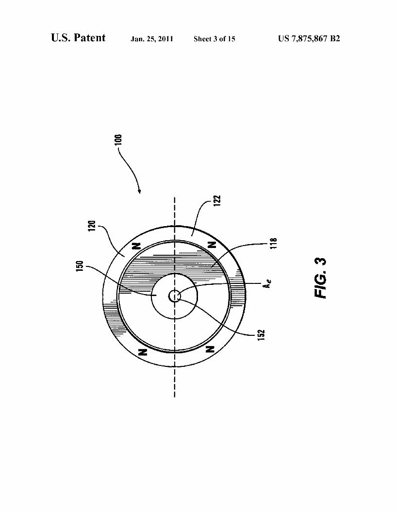
FIG. 3 is a plan view of the other end of the first exemplaryembodiment of the electron beam generating device shown in
3s FIG. 1;FIG. 4 is side perspective view of the first exemplary
embodiment of the electron beam generating device shown inFIG. 1;
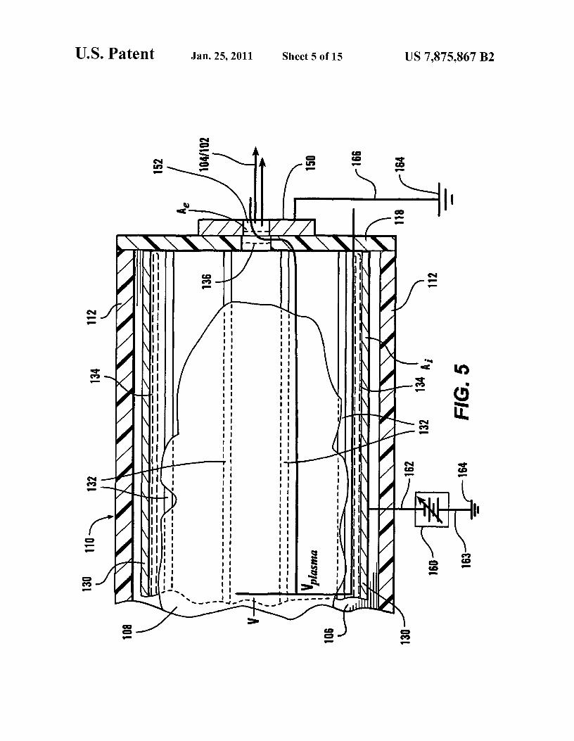
FIG. 5 is a side-cross sectional view showing in greater40 detail a first exemplary embodiment of the extraction end of
the first exemplary embodiment of the electron beam gener-ating device shown in FIG. 1;
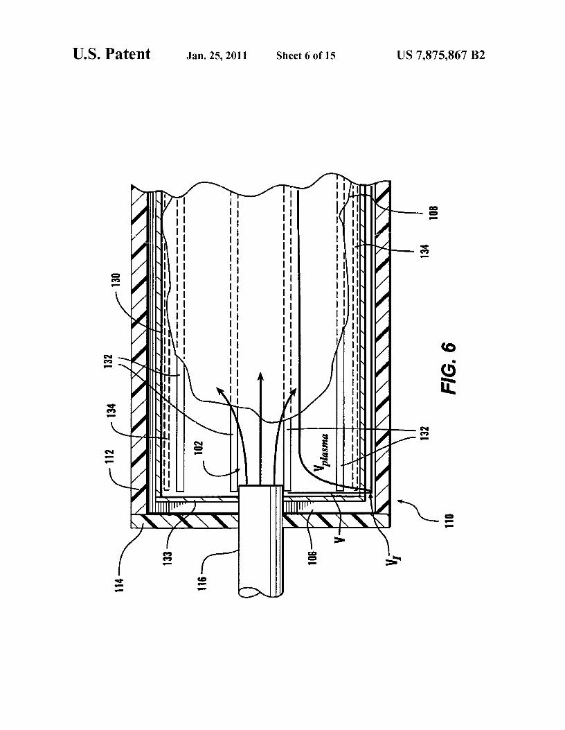
FIG. 6 is a side cross-sectional view showing in greaterdetail one exemplary embodiment of the supply end of the
45 first exemplary embodiment of the electron beam generatingdevice shown in FIG. 1;
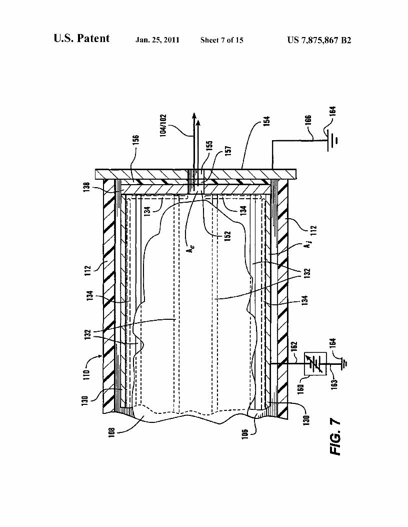
FIG. 7 is a side cross-sectional view showing in greaterdetail a second exemplary embodiment of the extraction end
50 of the first exemplary embodiment of the electron-beam gen-erating device shown in FIG. 1;
FIG. 8 is side-cross sectional view of a second exemplaryembodiment of an electronbeam generating device accordingto this invention;
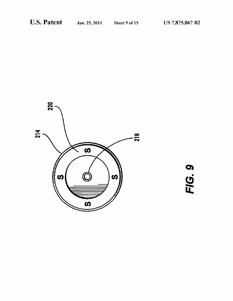
55 FIG. 9 is an end plan view of one end of the secondexemplary embodiment of the electron beam generatingdevice shown in FIG. 8;
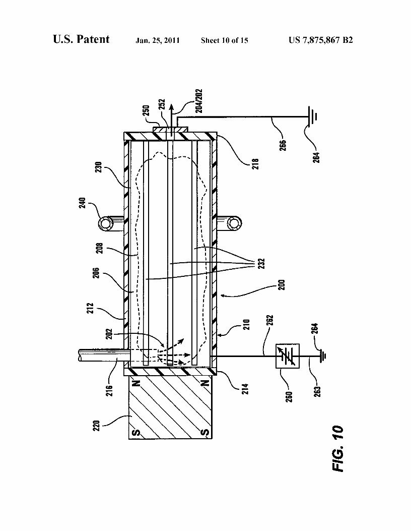
FIG. 10 is a side cross-sectional view of a third exemplaryembodiment of an electron-beam generating device accord-
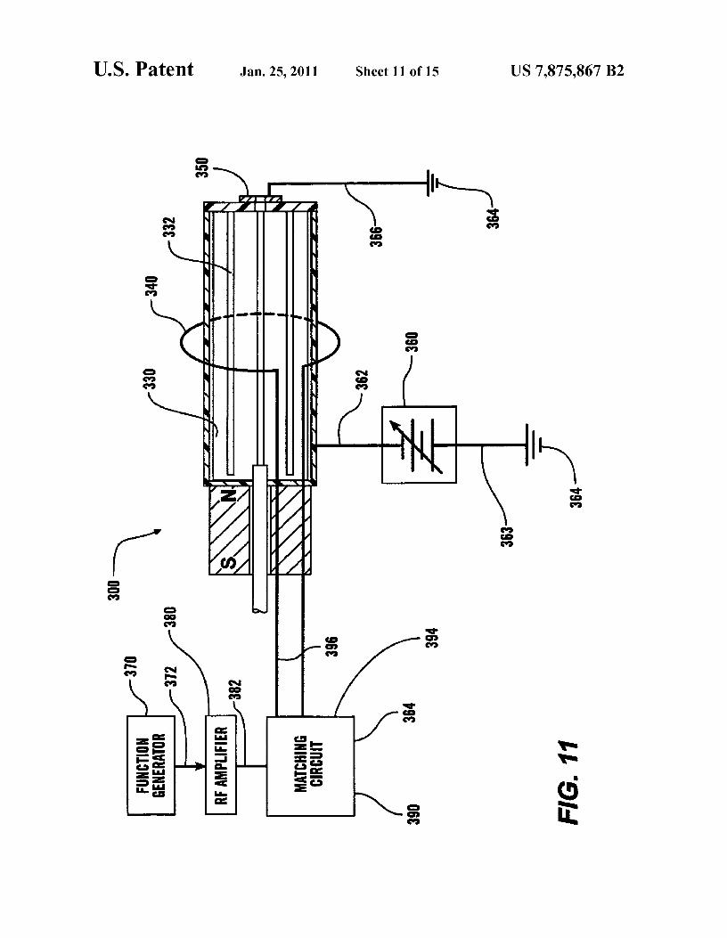
60 ing to this invention;FIG. 11 is a schematic view of one exemplary embodiment
of an electron beam generating device and antenna drivecircuit according to this invention;
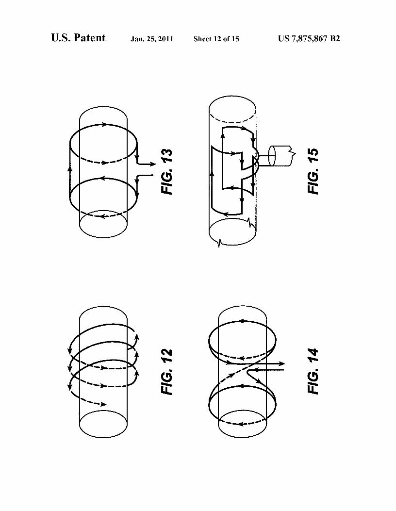
FIGS. 12-15 show a plurality of different antenna designs65 useable to create a plasma within the first and second exem-
plary electron beam generating devices shown in FIGS. 1, 8and 10;

US 7,875,867 B25
FIG. 16 is a flowchart outlining one exemplary embodi-ment of a method for generating and extracting an electronbeam according to this invention.
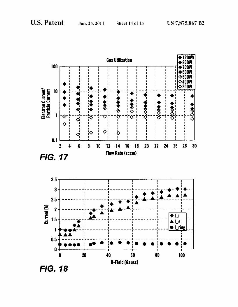
FIG. 17 is a graph of the electron/particle current ratio as afunction of radio-frequency power and gas flow rate;
FIG. 18 is a graph of the generated currents as a function ofmagnetic field strength; and
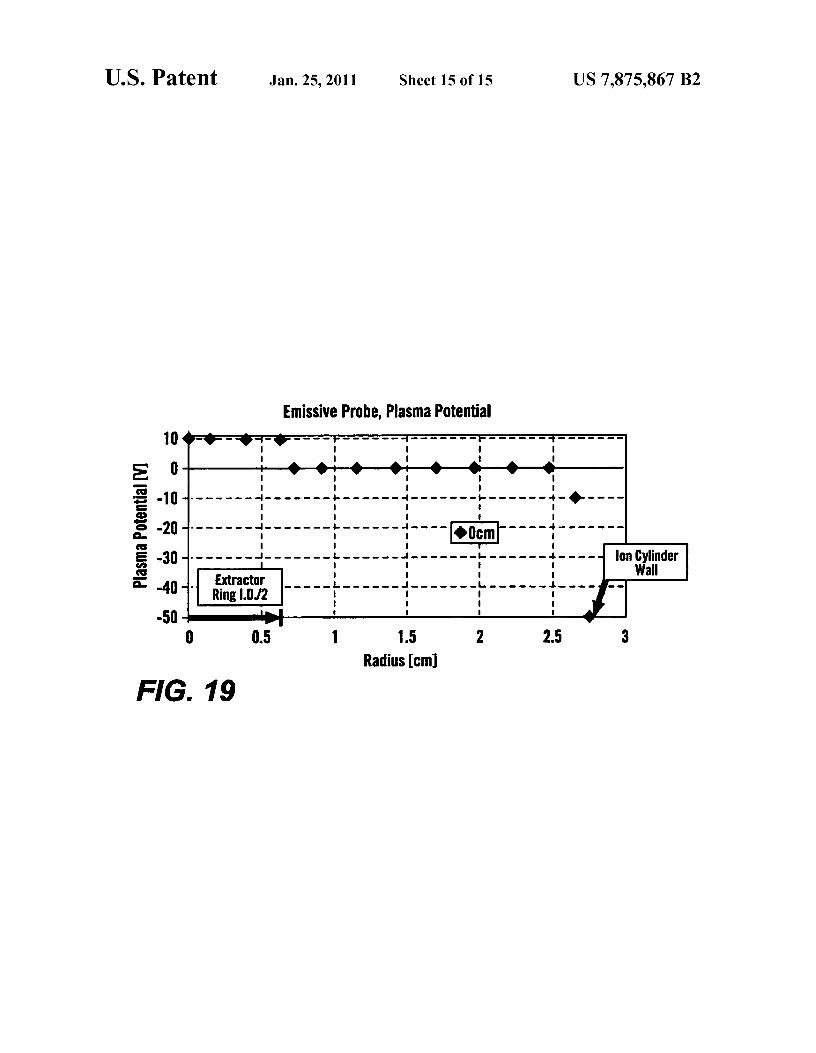
FIG. 19 is a graph of the plasma potential as a function ofradial distance from the axis of the ion collection surface.
DETAILED DESCRIPTION OF EXEMPLARYEMBODIMENTS
Ion and Hall thrusters use beams of positively-charged ionsfor propul Sion. As discussed above, electrons or negative ionsshould be introduced into the positively-charged ion beam asit leaves the thruster. This is done to prevent the spacecraftfrom becoming negatively charged and thus attracting theemitted positively-charged ion beam.
Traditionally, hollow cathodes have been used as neutral-izing sources because of their high electron current densityand relatively low power requirements. However, the opera-tional lifetime of such hollow cathodes is limited by cathodedeterioration, cathode contamination, and other effects. Thislimited operational lifetime for hollow cathodes renders hol-low cathodes less suitable for sustained use or where main-taining such hollow cathodes is difficult or impossible.
Longer duration spacecraft missions that use ion propul-sion, such as the proposed Jupiter Icy Moons Mission(JIMO), will take 6-10 years for the total orbital transfer time.While using ion propulsion for such longer duration missionsis very beneficial relative to impulsive chemical rocket burns,due to the savings in fuel mass and time, the lifetime for someoperating components for ion propulsion, such as the hollowcathodes, may be limited to no more than 3 to 4 years. Thehollow cathode neutralizer and plasma sources that were usedfor the highly successful Deep space 1 and SMART-1 mis-sions were limited to no more than 3 to 4 years of operationallifetime due to significant erosion, sputtering and re-deposi-tion of material within the keeper region and surrounding areaof such devices.
The inventors have determined that radio-frequency (RF)plasmas are attractive as sources for neutralizing charge car-riers for electric propulsion devices, such as Hall and ionthrusters. Such radio-frequency plasmas allow for an elec-trode-less design and provide high efficiency and long opera-tional lifetimes. Radio-frequency plasma sources provide analternative neutralizing approach that does not consume elec-trode material, while providing electrons, allowing for alonger operational lifetime.
There are a variety of radio-frequency plasma sources,including capacitive and inductive sources, that operate with-out magnetic fields, and electron cyclotron resonance (ECR)sources andhelicon sources that require axial magnetic fields.Helicon sources can produce the highest plasma densities,which can be greater than 10 13/cm3 , for a given radio-fre-quency power. However, helicon sources also require mag-netic fields. Lower RE power emitted by the excitationantenna into the plasma requires higher magnetic fieldstrengths. For example, a 10 W radio-frequency signal typi-cally requires a 2000 Gauss magnetic field. In contrast, lowermagnetic field strengths require higher RE power into theplasma. For example, a 300 Gauss magnetic field typicallyrequires the excitation antenna to emit 600 W. If sufficientpower is not available, helicon sources will operate as induc-tive sources. Inductively coupled plasmas can achieve signifi-
6cant plasma densities, such as, for example, 10 10/cm3 to 1012/cm3 and allow for a large total electron extraction current.
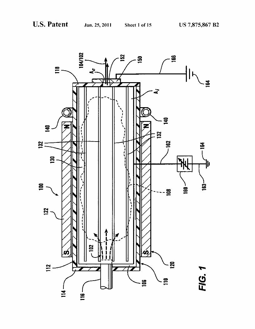
FIG.1 shows a first exemplary embodiment of an electronbeam generating device according to this invention that is
5 useable to generate a radio-frequency plasma that provides abeam of electrons without an electrode. As shown in FIG. 1,in various exemplary embodiments, the electron beam gen-erating device 100 comprises a generally non-conductiveexterior chamber 110, one or more steady-state magnets 120,
io a conductive ion-collection surface 130, a radio-frequencyantenna 140, an electron extraction ring 150, and connections162 and 166 to a negative voltage source 160 and a referenceground voltage 164, respectively. FIGS. 2 and 3 show exteriorplan views of supply and extraction end walls 114 and 118,
15 respectively, of the non-conductive exterior chamber of theelectron beam generating device 100. FIG. 4 shows a sideperspective view of the electron beam generating device 100.
As shown in FIG. 1, the non-conductive exterior chamber110 comprises a non-conductive chamber surface 112, a non-
20 conductive supply end wall 114, and a non-conductive extrac-tion end wall 118. A gas supply tube 116 extends through thesupply end wall 114 and into an interior of the conductiveion-collection chamber 130. The gas supply tube 116 suppliesa feed gas 102 at least into an interior space 106 that is
25 enclosed by the non-conductive exterior chamber 110. Dur-ing operation, the electron beam generating device 100 formsa plasma 108 within in the interior space 106 such that anelectron beam 104 passes, along with the feed gas 102,through a central aperture, hole or passageway 152 in the
30 electron extraction ring 150. The electron extraction ring 150is located in, and extends through, the extraction end wall 118into the interior space 106.
As shown in FIG. 1, in various exemplary embodiments,the one or more steady-state magnets 120, such as the cylin-
35 drical steady-state magnet 122, are arranged such that thesouth (or north) poles of the one or more steady-state magnets120 face the supply end wall 114, while the north (or south)poles of the one or more steady-state magnets 120 face theextraction end wall 118. It should be appreciated that it is not
40 important that the north end faces the extraction side. How-ever, the one or more steady-state magnets 120 should pro-duce a magnetic field that is aligned with the axis of the centerextraction aperture or passageway 152. As shown in FIG. 1, invarious exemplary embodiments, the at least one steady-state
45 magnet 120 can be located outside of and surrounding thenon-conductive exterior chamber 110.
It should be appreciated that, in various exemplary embodi-ments, the non-conductive exterior chamber 110 is cylindri-cal in cross section. Accordingly, in such exemplary embodi-
50 ments, the at least one steady-state magnet 120 has acorresponding cylindrical central opening through which thenon-conductive exterior chamber 110 extends. However, itshould be appreciated that, in various other exemplaryembodiments, the non-conductive exterior chamber 110 can
55 have any desired cross-sectional shape that defines a simpleclosed curve, suchas a circle, a regular or irregular polygon orthe like. Typically, the one or more steady-state magnets 120will be placed around the non-conductive exterior chamber110 such that the central passageway formed within the at
60 least one steady-state magnet 120 will closely follow thesurface of the non-conductive exterior chamber 110.
The one or more steady-state magnets 120 generate a gen-erally solenoidal magnetic field that extends along the axialdirection of the non-conductive exterior chamber 110. In
65 various exemplary embodiments, such as that shown in FIG.1, the at least one steady-state magnet 120 comprises only afirst steady-state magnet 122. In various exemplary embodi-
US 7,875,867 B2
7ments, the first steady-state magnet 122 is a permanent mag-net. However, in various other exemplary embodiments, theone or more steady-state magnets 120 can be electromagnetsprovided with a steady-state or DC electric current.
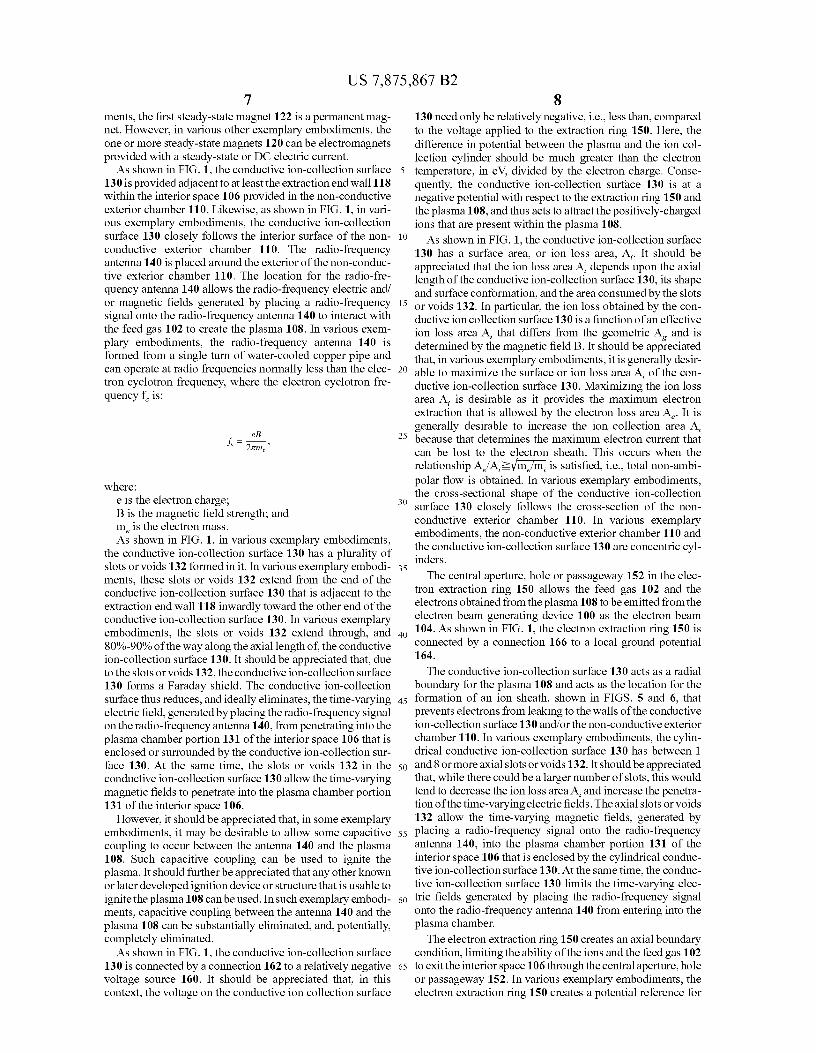
As shown in FIG. 1, the conductive ion-collection surface130 is provided adjacent to at least the extraction end wall 118within the interior space 106 provided in the non-conductiveexterior chamber 110. Likewise, as shown in FIG. 1, in vari-ous exemplary embodiments, the conductive ion-collectionsurface 130 closely follows the interior surface of the non-conductive exterior chamber 110. The radio-frequencyantenna 140 is placed around the exterior of the non-conduc-tive exterior chamber 110. The location for the radio-fre-quency antenna 140 allows the radio-frequency electric and/or magnetic fields generated by placing a radio-frequencysignal onto the radio-frequency antenna 140 to interact withthe feed gas 102 to create the plasma 108. In various exem-plary embodiments, the radio-frequency antenna 140 isformed from a single turn of water-cooled copper pipe andcan operate at radio frequencies normally less than the elec-tron cyclotron frequency, where the electron cyclotron fre-quency f is:
eaf
= 27rm,
where:e is the electron charge;B is the magnetic field strength; andme is the electron mass.As shown in FIG. 1, in various exemplary embodiments,
the conductive ion-collection surface 130 has a plurality ofslots or voids 132 formed in it. In various exemplary embodi-ments, these slots or voids 132 extend from the end of theconductive ion-collection surface 130 that is adjacent to theextraction end wall 118 inwardly toward the other end of theconductive ion-collection surface 130. In various exemplaryembodiments, the slots or voids 132 extend through, and80%-90% of the way along the axial length of, the conductiveion-collection surface 130. It should be appreciated that, dueto the slots or voids 132, the conductive ion-collection surface130 forms a Faraday shield. The conductive ion-collectionsurface thus reduces, and ideally eliminates, the time-varyingelectric field, generated by placing the radio-frequency signalon the radio-frequency antenna 140, from penetrating into theplasma chamber portion 131 of the interior space 106 that isenclosed or surrounded by the conductive ion-collection sur-face 130. At the same time, the slots or voids 132 in theconductive ion-collection surface 130 allow the time-varyingmagnetic fields to penetrate into the plasma chamber portion131 of the interior space 106.
However, it should be appreciated that, in some exemplaryembodiments, it may be desirable to allow some capacitivecoupling to occur between the antenna 140 and the plasma108. Such capacitive coupling can be used to ignite theplasma. It should further be appreciated that any other knownor later developed ignition device or structure that is usable toignite the plasma 108 can be used. In such exemplary embodi-ments, capacitive coupling between the antenna 140 and theplasma 108 can be substantially eliminated, and, potentially,completely eliminated.
As shown in FIG. 1, the conductive ion-collection surface130 is connected by a connection 162 to a relatively negativevoltage source 160. It should be appreciated that, in thiscontext, the voltage on the conductive ion collection surface
8130 need only be relatively negative, i.e., less than, comparedto the voltage applied to the extraction ring 150. Here, thedifference in potential between the plasma and the ion col-lection cylinder should be much greater than the electron
5 temperature, in eV, divided by the electron charge. Conse-quently, the conductive ion-collection surface 130 is at anegative potential with respect to the extraction ring 150 andthe plasma 108, and thus acts to attract the positively-chargedions that are present within the plasma 108.
10 As shown in FIG. 1, the conductive ion-collection surface130 has a surface area, or ion loss area, A,. It should beappreciated that the ion loss area A, depends upon the axiallength of the conductive ion-collection surface 130, its shapeand surface conformation, and the area consumed by the slots
15 or voids 132. In particular, the ion loss obtained by the con-ductive ion collection surface 130 is a function of an effectiveion loss area A, that differs from the geometric Ag and isdetermined by the magnetic field B. It should be appreciatedthat, in various exemplary embodiments, it is generally desir-
e able to maximize the surface or ion loss area A, of the con-ductive ion-collection surface 130. Maximizing the ion lossarea A, is desirable as it provides the maximum electronextraction that is allowed by the electron loss area A e . It isgenerally desirable to increase the ion collection area A,
25 because that determines the maximum electron current thatcan be lost to the electron sheath. This occurs when therelationship Ae/A,?l/_m_,7m, is satisfied, i.e., total non-ambi-polar flow is obtained. In various exemplary embodiments,the cross-sectional shape of the conductive ion-collection
3o surface 130 closely follows the cross-section of the non-conductive exterior chamber 110. In various exemplaryembodiments, the non-conductive exterior chamber 110 andthe conductive ion-collection surface 130 are concentric cyl-inders.
35The central aperture, hole or passageway 152 in the elec-
tron extraction ring 150 allows the feed gas 102 and theelectrons obtained from the plasma 108 to be emitted from theelectron beam generating device 100 as the electron beam
40 104. As shown in FIG. 1, the electron extraction ring 150 isconnected by a connection 166 to a local ground potential164.
The conductive ion-collection surface 130 acts as a radialboundary for the plasma 108 and acts as the location for the
45 formation of an ion sheath, shown in FIGS. 5 and 6, thatprevents electrons from leaking to the walls of the conductiveion-collection surface 130 and/or the non-conductive exteriorchamber 110. In various exemplary embodiments, the cylin-drical conductive ion-collection surface 130 has between 1
50 and 8 or more axial slots or voids 132. It should be appreciatedthat, while there could be a larger number of slots, this wouldtend to decrease the ion loss area A, and increase the penetra-tion of the time-varying electric fields. The axial slots or voids132 allow the time-varying magnetic fields, generated by
55 placing a radio-frequency signal onto the radio-frequencyantenna 140, into the plasma chamber portion 131 of theinterior space 106 that is enclosed by the cylindrical conduc-tive ion-collection surface 130. At the same time, the conduc-tive ion-collection surface 130 limits the time-varying elec-
60 tric fields generated by placing the radio-frequency signalonto the radio-frequency antenna 140 from entering into theplasma chamber.
The electron extraction ring 150 creates an axial boundarycondition, limiting the ability of the ions and the feed gas 102
65 to exit the interior space 106 through the central aperture, holeor passageway 152. In various exemplary embodiments, theelectron extraction ring 150 creates a potential reference for
US 7,875,867 B29
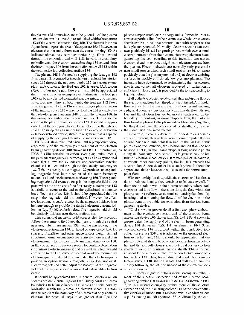
10the plasma 108 somewhere near the potential of the plasma plasma temperature/electron charge ratio), formed in order to108. An electron loss area Ae i s established within the aperture conserve particle flux for the plasma as a whole. An electron152 of the electron extractionring 150. The electron loss area sheath exhibits a positive potential step with respect to theAe can be as large as the area of the aperture 152. However, an
bulk plasma potential. Normally, electron sheaths can exist
electron sheath usually forms near the extraction ring 150. As 5 near positively-biased Langmuir probes, which extract smallindicated above, the electron extraction ring 150 can extend
electron currents from the plasma. However, electron beam
through the extraction end wall 118. In various exemplary generating devices according to this invention can use anembodiments, the electron extraction ring 150 extends into electron sheath to extract a significant electron current fromthe interior space 106 from the extraction end wall 118 within the plasma. Electron sheaths are normally only present 1)the conductive ion-collection surface 130. io near small probes when such small probes are biased more
The plasma 108 is formed by supplying the feed gas 102
positively than the plasma potential or 2) at electron emittingfrom a mass flow controller (not shown) to at least the interior surfaces in weakly-collisional, low-pressure plasmas. Thespace 106 through the gas supply tube 116. In various exem- inventors have determined, experimentally, that an electronplary embodiments, the feed gas 102 is argon (Ar), xenon sheath can collect all electrons produced by ionization if(Xe), or other noble gas. However, it should be appreciated 15 sufficient ion loss areaA, is provided for the ions, according tothat, in various other exemplary embodiments, the feed gas
Eq. (4), below.
102 can be any desired elemental gas, gas mixture or the like. If all of the boundaries are identical, then ambipolar flow ofIn various exemplary embodiments, the feed gas 102 flows the electrons and ions from the plasma is obtained. Ambipolarfrom the gas supply tube 116 into a source, or plasma, region
flow refers to both the ions and electrons flowing and reaching
of the interior space 106 where the feed gas 102 is excited by 20 a physical boundary together. In such ambipolar flows, the ionthe radio-frequency antenna 140 to form the plasma 108. In
loss and the electron loss are balanced at each point on the
the exemplary embodiment shown in FIG. 1, this source
boundary. In contrast, in non-ambipolar flow, the particlesregion is the plasma chamber portion 131. It should be appre- flow from the plasma to the plasma-sheath boundary together,ciated that the feed gas 102 can be supplied into the interior
but they do not leave the other end of the sheath, i.e., traverse
space 106 using the gas supply tube 116 or any other known 25 the sheath, with the same current.or later-developed device, structure or system that is capable
In contrast, if several different (i.e., non-identical) bound-
of supplying the feed gas 102 into the interior space 106. aries are present, then at least some non-ambipolar flow isFIGS. 2-4 show plan end views and a perspective view, created. Such non-ambipolar flow implies that, at least some
respectively of the exemplary embodiment of the electron points along the boundary, the electron and ion flows do notbeam generating device 100 shown in FIG. 1. In particular, 3o balance. That is, in such non-ambipolar flow, at some pointsFIGS. 2-4 illustrate that, in various exemplary embodiments, along the boundary, the electron flux is greater than the ionthe permanent magnet or electromagnet 122 has a cylindrical
flux. An electron sheath may exist at such points. In contrast,
space that allows the cylindrical non-conductive exterior at various other boundary points, the ion flux exceeds thechamber 110 to extend through the first steady-state magnet electron flux. An ion sheath exists at such points. It should be122. This first steady-state magnet 122 produces an expand- 35 appreciated that an ion sheath will also exist for normal ambi-ing magnetic field in the region of the radio-frequency polar flow.antenna 140 and the electron extraction ring 150. The expand- With non-ambipolar flow, while the electron and ion fluxesing magnetic field creates a cusp in the magnetic field at the
do not balance locally, they continue to balance overall. If
point where the north end of the first steady-state magnet 122
there are no points within the plasma boundary where bothis axially adjacent to the end of the cylindrical conductive 40 electrons and ions flow at the same time, the flow within theion-collection surface 130. It should be appreciated that the plasma can be referred to as total non-ambipolar flow. Bycusp in the magnetic field is not critical. However, the effec- insuring total non-ambipolar flow, all of the electrons in thetive ion contact area, A,, created by the magnetic field needs to plasma remain available for extraction from the ion beambe large enough to provide the desired electron current, fol- generating device.lowing Eqs. (3)-(6) set forth below. The magnetic field should 45 FIG. 5 shows in greater detail a first exemplary embodi-be relatively uniform near the extraction ring. ment of the electron extraction end of the electron beam
This solenoidal magnetic field ensures that the electrons generating device 100 shown in FIGS. 1-4. FIG. 6 shows infollow the magnetic field lines that pass through the central
greater detail the supply end of the electron beam generating
aperture, hole or passageway 152, i.e., the exit region, of the
device 100 shown in FIGS. 1-4. As shown in FIG. 5, anelectron extraction ring 150. It should be appreciated that, for 50 electron sheath 136 is formed within the conductive ion-spacecraft/satellites and other space and/or weight limited
collection surface 130 that is adjacent to the grounded elec-
structures, permanent magnets are relatively more useful than tron extraction ring 150. It should be appreciated that theelectromagnets for the electron beam generating device 100, plasma potential should be between the extraction ring poten-as they do not require a power source for continued operation tial and the ion collection surface potential for an electron(in contrast to electromagnets) and are relatively light weight 55 sheath to exist. In contrast, an ion sheath 134 is formedcompared to the DC power source that would be required by adjacent to the interior surface of the conductive ion-collec-electromagnets. It should be appreciated that electromagnets tion surface 130. Thus, for a cylindrical conductive ion-col-provide an option where a magnetic cusp does not exist. lection surface 130, the ion sheath 134 will be an annulusElectromagnets can better adjust the strength of the magnetic closely following the interior surface of the conductive ion-field, which may increase the amount of extractable electron 60 collection surface 130.current. FIG. 7 shows in greater detail a second exemplary embodi-
It should be appreciated that, in general, electron or ion ment of the electron extraction end of the electron beamsheaths are non-neutral regions that usually form at plasma generating device 100 shown in FIGS. 1-4. As shown in FIG.boundaries to balance losses of electrons and ions born by
7, in this second exemplary embodiment of the electron
ionization within the plasma. An electron sheath is a non- 65 extraction end, the insulating end cap 118 of the non-conduc-neutral region at the boundary of a plasma that only contains tive exterior chamber 100 is replaced with a conductive endelectrons for potential steps much greater than T e/e (the cap 154 having an exit aperture 155. Additionally, the con-
US 7,875,867 B211
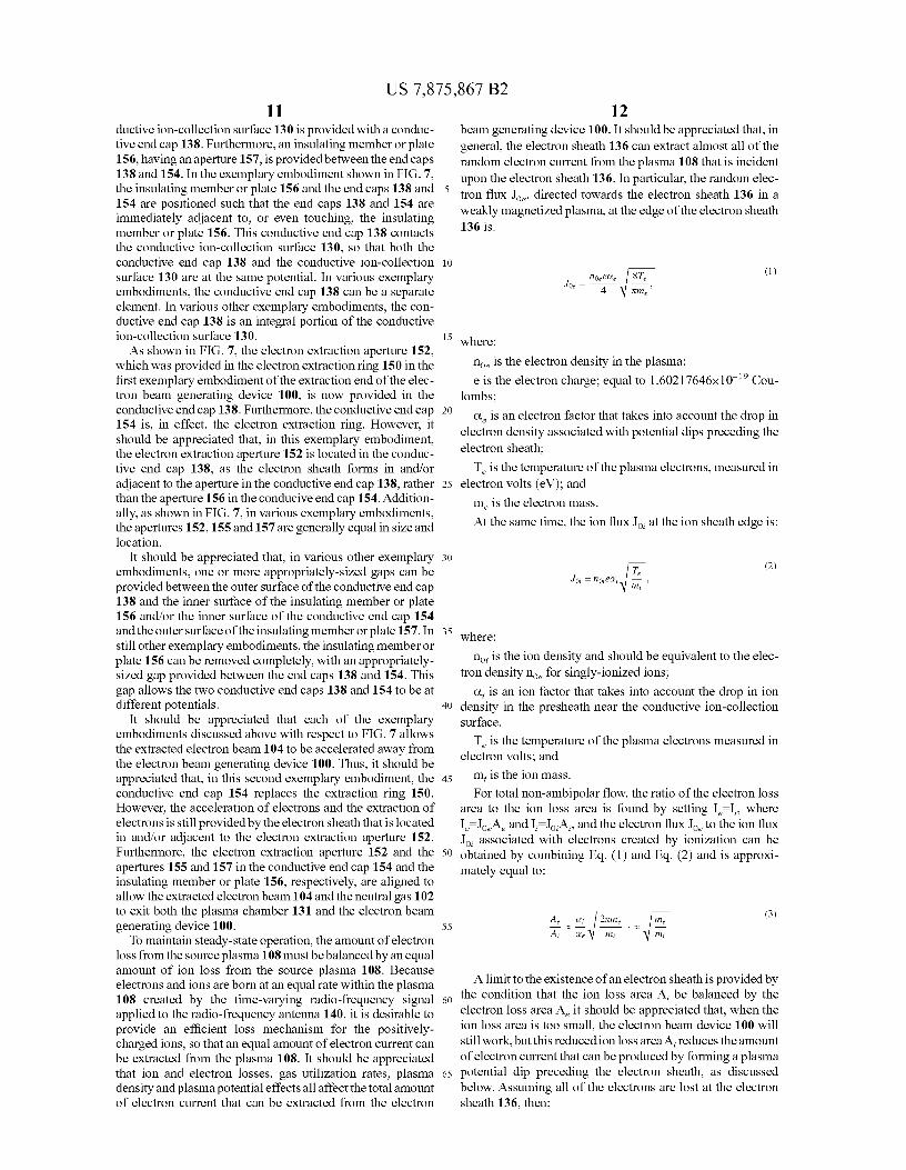
ductive ion-collection surface 130 is provided with a conduc-tive end cap 138. Furthermore, an insulating member or plate156, having an aperture 157, is providedbetween the end caps138 and 154. In the exemplary embodiment shown in FIG. 7,the insulating member or plate 156 and the end caps 138 and154 are positioned such that the end caps 138 and 154 areimmediately adjacent to, or even touching, the insulatingmember or plate 156. This conductive end cap 138 contactsthe conductive ion-collection surface 130, so that both theconductive end cap 138 and the conductive ion-collectionsurface 130 are at the same potential. In various exemplaryembodiments, the conductive end cap 138 can be a separateelement. In various other exemplary embodiments, the con-ductive end cap 138 is an integral portion of the conductiveion-collection surface 130.
As shown in FIG. 7, the electron extraction aperture 152,which was provided in the electron extraction ring 150 in thefirst exemplary embodiment of the extraction end of the elec-tron beam generating device 100, is now provided in theconductive end cap 138. Furthermore, the conductive end cap154 is, in effect, the electron extraction ring. However, itshould be appreciated that, in this exemplary embodiment,the electron extraction aperture 152 is located in the conduc-tive end cap 138, as the electron sheath forms in and/oradjacent to the aperture in the conductive end cap 138, ratherthan the aperture 156 in the conducive end cap 154. Addition-ally, as shown in FIG. 7, in various exemplary embodiments,the apertures 152,155 and 157 are generally equal in size andlocation.
It should be appreciated that, in various other exemplaryembodiments, one or more appropriately-sized gaps can beprovided between the outer surface of the conductive end cap138 and the inner surface of the insulating member or plate156 and/or the inner surface of the conductive end cap 154and the outer surface of the insulating member or plate 157. Instill other exemplary embodiments, the insulating member orplate 156 can be removed completely, with an appropriately-sized gap provided between the end caps 138 and 154. Thisgap allows the two conductive end caps 138 and 154 to be atdifferent potentials.
It should be appreciated that each of the exemplaryembodiments discussed above with respect to FIG. 7 allowsthe extracted electron beam 104 to be accelerated away fromthe electron beam generating device 100. Thus, it should beappreciated that, in this second exemplary embodiment, theconductive end cap 154 replaces the extraction ring 150.
However, the acceleration of electrons and the extraction ofelectrons is still provided by the electron sheath that is locatedin and/or adjacent to the electron extraction aperture 152.Furthermore, the electron extraction aperture 152 and theapertures 155 and 157 in the conductive end cap 154 and theinsulating member or plate 156, respectively, are aligned toallow the extracted electron beam 104 and the neutral gas 102to exit both the plasma chamber 131 and the electron beamgenerating device 100.
To maintain steady-state operation, the amount of electronloss from the source plasma 108 must bebalancedby an equalamount of ion loss from the source plasma 108. Becauseelectrons and ions are born at an equal rate within the plasma108 created by the time-varying radio-frequency signalapplied to the radio-frequency antenna 140, it is desirable toprovide an efficient loss mechanism for the positively-charged ions, so that an equal amount of electron current canbe extracted from the plasma 108. It should be appreciatedthat ion and electron losses, gas utilization rates, plasmadensity andplasma potential effects all affect the total amountof electron current that can be extracted from the electron
12beam generating device 100. It should be appreciated that, ingeneral, the electron sheath 136 can extract almost all of therandom electron current from the plasma 108 that is incidentupon the electron sheath 136. In particular, the random elec-
5 tron flux Joe, directed towards the electron sheath 136 in aweakly magnetized plasma, at the edge of the electron sheath136 is:
Lo
noeeae ST, (1)
3oe 4 7
15 where:
noe is the electron density in the plasma;
e is the electron charge; equal to 1.60217646x10 -19 Cou-lombs;
20 ae is an electron factor that takes into account the drop inelectron density associated with potential dips preceding theelectron sheath;
Te is the temperature of the plasma electrons, measured in25 electron volts (eV); and
me is the electron mass.
At the same time, the ion flux Joy at the ion sheath edge is:
30
3o; =no;ea; F;T^'i , (2)
35 where:
nog is the ion density and should be equivalent to the elec-tron density noe for singly-ionized ions;
a, is an ion factor that takes into account the drop in ion40 density in the presheath near the conductive ion-collection
surface.Te is the temperature of the plasma electrons measured in
electron volts; and45 m, is the ion mass.
For total non-ambipolar flow, the ratio of the electron lossarea to the ion loss area is found by setting 1, —I,, where1,— JoeAe and 1,—J,,A,, and the electron flux J oe to the ion fluxJoy associated with electrons created by ionization can be
50 obtained by combining Eq. (1) and Eq. (2) and is approxi-mately equal to:
AQ a . ^e me (3)55 z
A; ae v1 m; ^I m;
A limit to the existence of an electron sheath is provided by60 the condition that the ion loss area A, be balanced by the
electron loss area Ae it should be appreciated that, when theion loss area is too small, the electron beam device 100 willstill work, but this reduced ion loss area A, reduces the amountof electron current that can be produced by forming a plasma
65 potential dip preceding the electron sheath, as discussedbelow. Assuming all of the electrons are lost at the electronsheath 136, then:

US 7,875,867 B2
13
q e—
me C4)A' z .
assuming the electrons are radially confined. It should beappreciated that an electron sheath will form without a poten-tial dip if:
M, (5)A Q < A; i
However, an electron sheath will form with a potential dip infront of it if:
FLT (6)
Ae>A; im
It should be appreciated that, for large electron loss areasA,, the electron sheath 136 is no longer a viable solution. Forsuch sufficiently large electron loss areas A,, only a plasmapotential more positive than the grounded electrode potential,combined with an ion sheath 134, can provide the necessarybalance of electron and ion losses.
It should be appreciated that the net electron loss in tradi-tional devices, such as hollow cathodes, equals the sum of theelectrons born by ionization within the plasma, and electronsinjected into the plasma by thermionic emission at cathodes,secondary electron emission and the like. However, electronloss within the electron beam generating device 100 onlycomes from electrons that are born by ionization and perhapssecondary emission. It should also be appreciated that if theelectron loss area, A,, is too large, as defined in Eq. (6), thenthe electron sheath will have a potential dip that reduces theextracted electron current to balance that of the extracted ioncurrent in the device 100. As outlined above, such potentialdips occur when the electron extraction area Ae is too large,i.e., the relationship defined in Eq. (6).
In one exemplary electron beam generating device builtaccording to the above-outlined discussion of various exem-plary embodiments of electron beam generating devicesaccording to this invention, a cylindrical pyrex chamber has adiameter of 7.5 centimeters and a length of 60 centimeters andwas placed within ferrite permanent magnets. A hollowgraphite cylinder 7.5 centimeters in diameter and 19 centi-meters long was placed within the pyrex chamber and biasedat a value between —5V to about —200V compared to thepotential on the extraction ring. An electrically grounded 1.25centimeter diameter graphite ring was placed inside an insu-lating boron nitride disc and mounted in one end of the cylin-drical pyrex chamber. The hollow graphite cylinder wasplaced adjacent to the electron extraction ring. A single-turn,0.25-inch-diameter, water-cooled copper pipe was placed, asthe radio-frequency antenna, around the pyrex chambertoward the extraction end of the pyrex chamber. In this exem-plary embodiment, the grounded electron extraction ringexperienced a magnetic field of 72 Gauss.
In this exemplary operating electron beam generatingdevice, ions are lost to the 7.5 centimeter diameter graphitecylinder, which has an ion loss area of 425 cm 2 . In contrast,the electron loss area Ae is restricted to the central aperture,
14
hole or passageway in the 1.25 centimeter-diameter graphiteextraction ring, which has an area of 1.23 cm 2 . The 1.23 cm2electron loss area Ae implies that an ion loss area of at leastabout 350 cm2 for argon (Ar) and at least about 640 cm2 for
5 xenon (Xe) (assuming the electron and ion factors have valuesof a,-1, and a,-0.5) would be needed. When the plasma inthis exemplary operating electron beam generating device isoperated with an argon feed gas and a plasma density of5 x10 12/cm3 , a 15 A electron current can be extracted through
io the central aperture, hole or passageway having an electronloss area of 1.23 cm2 . The 15 A current was extracted with thefollowing parameters: 1000 W RE power at a frequency of13.56 MHz, —50V bias on the ion collection cylinder, OV bias(grounded) on the extraction ring, an electron loss area of 1.23
15 cm2, and an Ar neutral gas flow rate of 15 sccm with analuminum ion-collection cylinder. 10 A electron extractioncurrent was obtained with a graphite ion-collection cylinderwith somewhat different dimensions.
A positively-charged ion born within an electron beam20 generating device according to this invention is transported
from the bulk plasma through a presheath and then to the ionsheath, where it contacts the conductive ion-collection sur-face and picks up an electron, converting the positively-charged ion into a neutral atom. The neutral atom is then free
25 to travel back into the bulk plasma within the plasma chamberportion to be re-ionized. At any one time, only a small frac-tion, on the order of about 1 atom out of 1000, of the neutralgas is ionized. However, as described above, each neutralatom may be recycled many times, such as, for example, up to
30 20 times or more, before that neutral atom finally exits theelectron beam generating device according to this invention.
Typically, the neutral atoms will exit through the aperturein the electron extraction ring. However, in contrast to theneutral atoms, the positively-charged ions see a potential
35 barrier at the aperture in the electron extraction ring of theelectron beam generating device so that only neutrals andelectrons can leave the interior chamber. Reusing the neutralgas atoms in this way is possible because the positively-charged ions, in contrast to ion thrusters, are not being
40 extracted through the exit aperture. That is, when extractingions, as in an ion thruster, the ion outflow rate can neverexceed the neutral inflow rate. However, because the electronbeam generating device according to this invention is anelectron source that extracts electrons, the electron outflow
45 rate can be many times the neutral gas inflow rate. In general,the ratio of extracted electrons to the amount of neutral gasexiting the electron beam generating device depends on theplasma density, the electron temperature, the flow rate ofneutral gas into the interior chamber, and the size of the
50 electron extraction aperture.It should be appreciated that, if higher plasma densities are
obtained, a higher electron current can be extracted from theelectron beam generating device or a correspondingly smallerelectron loss area Ae can be used. Of course, it should be
55 appreciated that, by using a smaller electron loss area A,, acorrespondingly smaller ion loss area A for the conductiveion-collection surface can be used. It should be appreciatedthat the electron extraction current cannot exceed the ionextraction current that is controlled by the ion loss area A,. It
60 should be appreciated that using a smaller electron loss areaAe has the advantage of lower neutral gas losses.
For electron beam generating devices that are used ascharge neutralizers in satellite and/or spacecraft applications,it is beneficial to produce the plasma 108 using a method that
65 creates the largest fraction of ionization possible, so that theneutral feed gas 102 is not wasted. For example, if the plasmasource were 100% efficient in ionizing a neutral gas 102, as it

US 7,875,867 B215
flows through the interior space 106, and each neutral atom isused only once before it touches the ion collection cylinder, afeed gas flow rate of 1 sccm (standard cubic centimeter perminute) of argon allows obtaining (is equivalent to) 0.072 Aof extraction current. 5
However, the inventors have experimentally determinedthat, when the feed gas 102 is neutral argon, the neutral argonfeed gas 102 is more efficiently utilized to create extractioncurrent at flow rates between about 2.5 sccm and about 15sccm. At these flow rates, the amount of extraction current 10
that can be obtained corresponds to using every atom approxi-mately 14 times as it passes from the gas supply tube 116,through the plasma 108 and out through the central aperture,hole or passageway 152 into a target region. In conventionalplasma-based electron sources, plasma ions and electrons are 15
both extracted. As indicated above, in various electron beamgenerating devices according to this invention, any ions thatencounter the electron sheath are reflected. Furthermore, allions encounter the ion-collection walls and are re-circulatedas neutrals. As set forth in Eqs. (1) and (2), the amount of 20
extractable current is linear with the plasma density, which, inturn, increases with radio-frequency power applied to theradio-frequency antenna 140.
FIG. 17 is a graph showing the results of an experimentusing the above-outlined exemplary embodiment of an elec- 25
tron beam generating device according to this invention. Asshown in FIG. 17, when the radio-frequency power is at orabove about 400 W, for most neutral gas supply flow rates intothe electron beam generating device, at least about 1 electronis extracted for each neutral atom lost from the electron beam 30
generating device through the aperture in the electron extrac-tion ring. Additionally, as the radio-frequency powerincreases, for any flow rate, the electron current-particle cur-rent ratio increases. As indicated above, at an RE power of1000 W and flow rates between about 3 sccm and about 15 35
sccm, ratios of about 10 to about 20 were obtained.FIG. 8 shows a second exemplary embodiment of an elec-
tron beam generating device 200 according to this invention.As shown in FIG. 8, in this second exemplary embodiment,the electron beam generating device 200 includes a non- 40
conductive exterior chamber 210, at least one steady-statemagnet 220, a conductive ion-collection surface 230, a radio-frequency antenna 240, an electron extraction ring 250, and anegative voltage source 260. However, in contrast to the firstexemplary embodiment of an electron beam generating 45
device 100 shown in FIGS. 1-7, in the second exemplaryembodiment of the electron beam generating device 200shown in FIG. 8, the at least one steady-state magnet 220 isplaced at the rear of the device, rather than around the non-conductive exterior chamber 210. 50
As shown in FIG. 8, the non-conductive exterior chamber210 includes a non-conductive chamber surface 212, supplyand extraction end walls 214 and 218, respectively and the gassupply tube 216. As in the first exemplary embodiment, thegas supply tube 216 passes through the interior of the at least 55
one steady-state magnet 220 and extends through the supplyend wall 214, while the electron extraction ring 250 isattached to the extraction end wall 218. The gas supply tube216 supplies a feed gas 202 to an interior space 206 within thenon-conductive exterior chamber 210. The feed gas 202 is 60
converted into a plasma 208 within the conductive ion-col-lection surface 230. Electrons extracted from the plasma 208are ejected from the electron beam generating device 200through the central aperture, hole or passageway 252 in theelectron extraction ring 250. 65
A radio-frequency signal is applied to the radio-frequencyantenna 240. The electromagnetic field generated in response
16to placing this RE signal on the radio-frequency antenna 240is inductively coupled to inductive or helicon modes throughthe slots or voids 232 formed in the conductive ion-collectionsurface 230 to the plasma 208 within the conductive ion-collection surface 230. The negative voltage source 260 isconnected by a conductor 262 to the conductive ion-collec-tion surface 230. The electron extraction ring 250 is con-nected by a conductor 266 to a local reference ground poten-tial 264.
FIG. 9 shows a plan exterior view of the supply end wall214, the at least one steady-state magnet 220 and the gassupply tube 216 of the electron beam generating device 200.As shown in FIG. 9, the at least one steady-state magnet 220is a single, annularly-shaped permanent magnet. However, itshould be appreciated that an electromagnet could be used asthe steady-state magnet 220. Additionally, two or more sepa-rate magnet segments could be used to implement the annularsteady-state magnet 220.
As shown in FIGS. 8 and 9, in various exemplary embodi-ments, the annular steady-state magnet 220 is relatively thin,with a central void that is substantially larger than the gassupply tube 216. In such exemplary embodiments, the gassupply tube 216 can be placed along the axis of the magnet220 and the non-conductive exterior chamber 210. However,the gas supply tube 216 could be placed anywhere within theinterior of the magnet 220. In various other exemplaryembodiments, the annular steady-state magnet 220 is thick,with a central passageway that is only slightly larger than thegas supply tube 216. In such exemplary embodiments, the gassupply tube 216 is typically placed along the axis of themagnet 220 and the non-conductive exterior chamber 210.
FIG. 10 shows a variation of the second exemplaryembodiment of the electron beam generating device 200according to this invention, where the steady-state magnet220 is a solid cylinder or other solid shape and the gas supplytube 216 extends through the sidewall 212 of the non-con-ductive exterior chamber 210 rather than the end wall 214. Inthis exemplary embodiment, the gas supply tube 216 alsoextends through the side wall, rather than the end wall, of theconductive ion-collection surface 230. It should be appreci-ated that the gas supply tube 216 can be located anywherealong the axial length of the non-conductive exterior chamber210.
One advantage provided by the magnetic field generated bythe one or more steady state magnets 120 or 220 is that itincreases the plasma density. The magnetic field also reducesthe relative electron losses to the extraction ring, while allow-ing the electron sheath to form at or near the extraction aper-ture. This makes the electron beam extraction device moreefficient and increases the maximum current that can be pro-duced by the electron beam extraction device.
FIG. 18 is a graph showing the results of an experimentusing the exemplary embodiment of an electron beam gener-ating device 100 according to this invention. The graph shownin FIG. 18 demonstrates the importance of the presence of themagnetic field at the exit aperture of the electron beam extrac-tion device. As shown in FIG. 18, as the magnetic fieldstrength increases, the extraction current I e increases. Thisoccurs because the plasma density increases as the magneticfield strength increases. At the same time, as shown in FIG.18, the current I ng that is lost to the electron extraction ringstays substantially constant even as the magnetic fieldstrength increases. As a consequence, the fraction of theextraction current that is lost to the electron extraction ringIy,ing decreases significantly with increasing magnetic fieldstrength.
US 7,875,867 B217
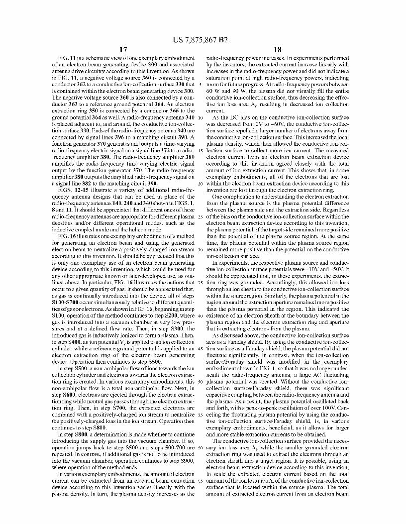
18FIG. 11 is a schematic view of one exemplary embodiment radio-frequency power increases. In experiments performed
of an electron beam generating device 300 and associated
by the inventors, the extracted current increase linearly withantenna drive circuitry according to this invention. As shown
increases in the radio-frequency power and did not indicate a
in FIG. 11, a negative voltage source 360 is connected by a saturation point at high radio-frequency powers, indicatingconductor 362 to a conductive ion-collection surface 330 that 5 room for future progress. At radio-frequency powers betweenis contained within the electron beam generating device 300. 60 W and 90 W, the plasma did not visually fill the entireThe negative voltage source 360 is also connected by a con- conductive ion-collection surface, thus decreasing the effec-ductor 363 to a reference ground potential 364. An electron tive ion loss area A, resulting in decreased ion collectionextraction ring 350 is connected by a conductor 366 to the current.ground potential 364 as well. A radio-frequency antenna 340 10 As the DC bias on the conductive ion-collection surfaceis placed adjacent to, and around, the conductive ion-collec- was decreased from OV to —60V, the conductive ion-collec-tion surface 330. Ends of the radio-frequency antenna 340 are tion surface repelled a larger number of electrons away fromconnected by signal lines 396 to a matching circuit 390. A
the conductive ion-collection surface. This increased the local
function generator 370 generates and outputs a time-varying plasma density, which then allowed the conductive ion-col-radio-frequency electric signal on a signal line 372 to a radio- 15 lection surface to collect more ion current. The measuredfrequency amplifier 380. The radio-frequency amplifier 380 electron current from an electron beam extraction deviceamplifies the radio-frequency time-varying electric signal
according to this invention agreed closely with the total
output by the function generator 370. The radio-frequency amount of ion extraction current. This shows that, in someamplifier 380 outputs the amplified radio-frequency signal on exemplary embodiments, all of the electrons that are losta signal line 382 to the matching circuit 390. 20 within the electron beam extraction device according to this
FIGS. 12-15 illustrate a variety of additional radio-fre- invention are lost through the electron extraction ring.quency antenna designs that can be used in place of the
One complication to understanding the electron extraction
radio-frequency antennas 140,240 and 340 shown in FIGS. 1, from the plasma source is the plasma potential difference8 and 11. It should be appreciated that different ones of these
between the plasma side and the extraction side. Regardless
radio-frequency antennas are appropriate for different plasma 25 of the bias on the conductive ion-collection surface within thedensities and/or different operational modes, such as the electron beam extraction device according to this invention,inductive coupled mode and the helicon mode. the plasma potential of the target side remained more positive
FIG. 16 illustrates one exemplary embodiment of a method
than the potential of the plasma source region. At the samefor generating an electron beam and using the generated
time, the plasma potential within the plasma source region
electron beam to neutralize a positively-charged ion stream so remained more positive than the potential on the conductiveaccording to this invention. It should be appreciated that this
ion-collection surface.
is only one exemplary use of an electron beam generating
In experiments, the respective plasma source and conduc-device according to this invention, which could be used for tive ion-collection surface potentials were —10V and —50V. Itany other appropriate known or later-developed use, as out- should be appreciated that, in these experiments, the extrac-lined above. In particular, FIG. 16 illustrates the actions that 35 tion ring was grounded. Accordingly, this allowed ion lossoccur to a given quantity of gas. It should be appreciated that, through an ion sheath to the conductive ion-collection surfaceas gas is continually introduced into the device, all of steps within the source region. Similarly, the plasma potential in theS100-S700 occur simultaneously relative to different quanti- region around the extraction aperture remained more positiveties of gas or electrons. As shown in FIG. 16, beginning in step than the plasma potential in the region. This indicated theS100, operation of the method continues to step S200, where 40 existence of an electron sheath at the boundary between thegas is introduced into a vacuum chamber at very low pres- plasma region and the electron extraction ring and aperturesures and at a defined flow rate. Then, in step S300, the that is extracting electrons from the plasma.introduced gas is inductively ionized to form a plasma. Then, As discussed above, the conductive ion-collection surfacein step S400, an ion potential V, isapplied to anion collection acts as a Faraday shield. By using the conductive ion-collec-cylinder, while a reference ground potential is applied to an 45 tion surface as a Faraday shield, the plasma potential did notelectron extraction ring of the electron beam generating
fluctuate significantly. In contrast, when the ion-collection
device. Operation then continues to step S500. surface/Faraday shield was modified in the exemplaryIn step S500, a non-ambipolar flow of ions towards the ion embodiment shown in FIG. 1, so that it was no longer under-
collection cylinder and electrons towards the electron extrac- neath the radio-frequency antenna, a large AC fluctuatingtion ring is created. In various exemplary embodiments, this 50 plasma potential was created. Without the conductive ion-non-ambipolar flow is a total non-ambipolar flow. Next, in collection surface/Faraday shield, there was significantstep S600, electrons are ejected through the electron extrac- capacitive coupling between the radio-frequency antenna andtionring while neutral gas passes throughthe electron extrac- the plasma. As a result, the plasma potential oscillated backtion ring. Then, in step S700, the extracted electrons are and forth, with a peak-to-peak oscillation of over I OOV. Can-combined with a positively-charged ion stream to neutralize 55 celing the fluctuating plasma potential by using the conduc-the positively-charged ions in the ion stream. Operation then tive ion-collection surface/Faraday shield, is, in variouscontinues to step S800. exemplary embodiments, beneficial, as it allows for larger
In step S800, a determination is made whether to continue and more stable extraction currents to be obtained.introducing the supply gas into the vacuum chamber. If so, The conductive ion-collection surface provided the neces-operation jumps back to step S500 and steps 500-700 are 60 sary ion loss area A, while the smaller grounded electronrepeated. In contrast, if additional gas is not to be introduced
extraction ring was used to extract the electrons through an
into the vacuum chamber, operation continues to step S900, electron sheath into a target region. It is possible, using anwhere operation of the method ends. electron beam extraction device according to this invention,
In various exemplary embodiments, the amount of electron to scale the extracted electron current based on the totalcurrent can be extracted from an electron beam extraction 65 amount of the ion loss area A, of the conductive ion-collectiondevice according to this invention varies linearly with the surface that is located within the source plasma. The totalplasma density. In turn, the plasma density increases as the amount of extracted electron current from an electron beam
US 7,875,867 B219
extraction device according to this invention is ultimatelylimited by one or more of the ion loss area A,, the electron lossarea A,, the neutral gas flow rate, and the radio-frequencypower.
While this invention has been described in conjunctionwith the exemplary embodiments outlined above, variousalternatives, modifications, variations, improvements and/orsubstantial equivalents, whether known or that are or may bepresently foreseen, may become apparent to those having atleast ordinary skill in the art. Accordingly, the exemplaryembodiments of the invention, as set forth above, are intendedto be illustrative, not limiting. Various changes may be madewithout departing from the spirit or scope of the invention.Therefore, the invention is intended to embrace all known orearlier developed alternatives, modifications, variations,improvements and/or substantial equivalents.
The invention claimed is:1. An electron beam generating device, comprising:a first chamber usable to contain a feed gas and a plasma
formed using the feed gas, the first chamber having a firstend wall having an opening through which the feed gasis able to exit the first chamber;
a gas supply tube usable to supply the feed gas into the firstchamber, the gas supply tube extending at least into thefirst chamber;
a conductive surface provided within the first chamber, theconductive surface electrically connected to an at leastrelatively negative potential source that is usable to placean at least relatively negative potential onto the conduc-tive surface;
at least one radio-frequency antenna placed around the firstchamber and usable to ionize the feed gas within the firstchamber to form a plasma; and
an electron extraction ring provided adjacent to the first endwall of the first chamber and relative to the opening inthe first end wall, the electron extraction ring electricallyconnected to a reference ground potential source andhaving an electron extraction aperture, wherein:
the potential placed on the conductive surface is negativerelative to the plasma and the electron extraction ring;
at least an electron sheath forms within the first chamberrelative to the electron extraction ring, the electronsheath permitting electrons and neutral particles to passout of the plasma toward the electron extraction ring andpreventing positively-charged ions from movingtowards the electron extraction ring; and
the electron extraction ring extracts and outputs at least abeam of electrons from the electron beam generatingdevice.
2. The electron beam generating device of claim 1, furthercomprising at least one magnet located adjacent to the firstchamber, the at least one magnet arranged such that a gener-ally solenoidal magnetic field extends along an axial directionof the first chamber.
3. The electron beam generating device of claim 2, whereinthe at least one magnet is at least one permanent magnet.
4. The electron beam generating device of claim 2, whereinthe at least one magnet is at least one electromagnet.
5. The electron beam generating device of claim 4, whereinthe at least one electromagnet generates a substantially time-constant magnetic field.
6.The electron beam generating device of claim 2, whereinthe at least one magnet is a cylindrical-prism-shaped orpolygonal-prism-shaped magnet having a central passageextending along the axial direction of the magnet, the firstchamber extending through the central passage such that theat least one magnet extends around the first chamber.
207. The electron beam generating device of claim 2, wherein
the at least one magnet is a cylindrical-prism-shaped orpolygonal-prism-shaped magnet, the at least one magnetpositioned adjacent to a second end wall of the first chamber.
5 8. The electron beam generating device of claim 7, whereinthe at least one magnet is a cylindrical-prism-shaped orpolygonal-prism-shaped magnet having at least one passageextending along the axial direction of the magnet, the gassupply tube extends through at least one of the at least one
10 passage in the magnet and at least the second end wall of thefirst chamber.
9. The electron beam generating device of claim 2, whereinthe solenoidal magnetic field generated by the at least onemagnet increases a plasma density of the plasma formed
15 within the first chamber.10. The electron beam generating device of claim 2,
wherein the solenoidal magnetic field generated by the atleast one magnet improves a uniformity of the electron beamoutput by the electron beam generating device.
20 11. The electron beam generating device of claim 2,wherein the solenoidal magnetic field generated by the atleast one magnet decreases a fraction of electron current thatis drawn to the electron extraction ring.
12. The electron beam generating device of claim 2,25 wherein:
a time-varying electric signal is applied to the at least oneradio-frequency antenna to generate time-varying elec-tric and magnetic fields around the at least one radio-frequency antenna; and
30 a strength of the solenoidal magnetic field generated by theat least one magnet and a power of the time-varyingmagnetic field generated by the at least one radio-fre-quency antenna are sufficient to excite helicon waveswithin the plasma formed in the first chamber.
35 13. The electron beam generating device of claim 2,wherein the solenoidal magnetic field extends axially throughthe electron extraction aperture and is substantially uniformacross the electron extraction aperture.
14. The electron beam generating device of claim 1,4o wherein a plurality of electrons are output from the electron
beam generating device for each feed gas particle output fromthe electron beam generating device.
15. The electron beam generating device of claim 1,wherein a uniform plasma potential forms across the area of
45 the electron extraction aperture.
16. An electron beam generating device, comprising:a first chamber usable to contain a feed gas and a plasma
formed using the feed gas, the first chamber having a first
50 end wall having an opening through which the feed gasis able to exit the first chamber;
a conductive chamber provided within the first chamber,the conductive chamber having at least a circumferentialwall than extends circumferentially within the first
55 chamber, a first end wall and an electron extraction endwall, an aperture formed in the electron extraction endwall that allows electrons and neutral particles to exit theconductive chamber, the conductive chamber electri-cally connected to an at least relatively negative poten-
60 tial source that is usable to place an at least relativelynegative potential onto the conductive chamber;
a gas supply tube usable to supply the feed gas into theconductive chamber, the gas supply tube extending intothe first chamber and the conductive chamber;
65 at least one radio-frequency antenna placed around the firstchamber and usable to ionize the feed gas within theconductive chamber into the plasma; and

US 7,875,867 B221
a conductive end wall of the first chamber provided adja-cent to the extraction end wall of the conductive cham-ber, the conductive end wall having a second aperturelocated relative to the aperture in the extraction end wall,wherein:
at least an electron sheath forms within the first chamberrelative to the aperture provided in the extraction endwall, the electron sheath permitting electrons and neu-tral particles to pass out of the plasma toward the aper-ture provided in the extraction end wall and preventingpositively-charged ions from moving towards the aper-ture provided in the extraction end wall; and
the extraction end wall extracts and outputs at least a beamof electrons from the electron beam generating device.
17. A method for generating a beam of electrons, compris-ing:
supplying an amount of feed gas to into a plasma region ofa first chamber, the first chamber enclosing the plasmaregion, a conductive surface provided within the firstchamber around the plasma region and an electronextraction ring provided at one end of the first chamber,a generally constant solenoidal magnetic field provided
22to the first chamber, a first potential applied to the elec-tron extraction ring, a relatively-negative second poten-tial applied to the conductive surface;
applying a time-varying radio-frequency signal to at leasts one antenna provided around the first chamber;
generating time varying radio-frequency electric and mag-netic fields based on the time-varying radio-frequencysignal applied to the at least one antenna;
ionizing at least some of the supplied amount of feed gas to10 form a plasma within the plasma region, the plasma
containing free electrons and free positively-chargedions;
attracting at least some of the free electrons to the electronextraction ring through an electron sheath;
is attracting at least some of the free positively-charged ionsto the conductive surface through an ion sheath;
converting the attracted positively-charged ions back intoneutral feed gas particles, the neutral feed gas particlesreturning to the plasma region, where they are available
20 to be re-ionized into the plasma.