united states standard test procedure for · pdf filestandard test procedure for general...
TRANSCRIPT

United StatesDepartment ofAgriculture
Forest Service
Technology &DevelopmentProgram
5100—Fire ManagementAugust 19999951 1805—SDTDC
STANDARD TESTPROCEDURE FOR
GENERAL PURPOSESPARK ARRESTERS
FOREST SERVICE
DE
P A RTMENT OF AGR IC U L T U
RE

Information contained in this document has been developed for theguidance of employees of the Forest Service, USDA, its contractors,and cooperating Federal and State agencies. The Department of Agricultureassumes no responsibility for the interpretation or use of this informationby other than its own employees. The use of trade, firm, or corporationnames is for the information and convenience of the reader. Such usedoes not constitute an official evaluation, conclusion, recommendation,endorsement, or approval of any product or service to the exclusion ofothers that may be suitable.
The United States Department of Agriculture (USDA) prohibits discriminationin its programs on the basis of race, color, national origin, sex, religion,age, disability, political beliefs, and marital or familial status. (Not allprohibited bases apply to all programs.) Persons with disabilities whorequire alternative means for communication of program information(Braille, large print, audiotape, etc.) should contact the USDA Office ofCommunications at 202-720-2791 (voice), or 800-855-1234 (TDD).
To file a complaint, write the Secretary of Agriculture, U.S. Departmentof Agriculture, Washington, DC 20250, or call 1-800-245-6340 (voice),or 800-855-1234 (TDD). USDA is an equal employment opportunityemployer.
STANDARD TESTPROCEDURE FOR
GENERAL PURPOSESPARK ARRESTERS
Ralph Gonzales—Mechanical Engineer
San Dimas Technology & Development Center
August 1999

I. Scope ...................................................................... 1
II. Overview ...................................................................... 1
III. Hardware Setup
A. Stack Selection and Installation ........................... 2
B. Initial Orifice Plate Selection and Installation ....... 3
C. Valve Control ....................................................... 3
D. Blower Motor Start-Up ......................................... 3
E. Signal Conditioning Panel Calibration.................... 4
F. Initial Back Pressure Adjustment ........................... 4
G. Mounting the Test Spark Arrester .......................... 4
H. Pretest System Adjustment................................... 4
IV. Preliminary Test Run ...................................................... 5
V. Test Run ...................................................................... 5
VI. Cleanout Run. ................................................................ 6
VII. Subsequent Runs............................................................ 6
VIII. Low Spark Arrester Efficiencies ....................................... 6
IX. Screen Type Spark Arrester Test Procedure
A. Scope.................................................................. 7
B. Screen and Periphery Probe................................... 7
C. Effective Screen Open Area Calculations ................ 7
Appendixes
A. Abbreviated Test Procedure........................................... 11
B. System Symbols and Maximum (Do Not Exceed) Values .... 13
C. Diagrams and Parts List ................................................ 15
D. Preparing Test Carbon................................................... 21
E. Orifice Factors ............................................................. 23
F. Facility Certification .................................................... 25
G. Console Calibration Check ............................................. 31
12345678901234567890123456123456789012345678901234561234567890123456789012345612345678901234567890123456123456789012345678901234561234567890123456789012345612345678901234567890123456123456789012345678901234561234567890123456789012345612345678901234567890123456123456789012345678901234561234567890123456789012345612345678901234567890123456123456789012345678901234561234567890123456789012345612345678901234567890123456123456789012345678901234561234567890123456789012345612345678901234567890123456123456789012345678901234561234567890123456789012345612345678901234567890123456123456789012345678901234561234567890123456789012345612345678901234567890123456123456789012345678901234561234567890123456789012345612345678901234567890123456123456789012345678901234561234567890123456789012345612345678901234567890123456123456789012345678901234561234567890123456789012345612345678901234567890123456123456789012345678901234561234567890123456789012345612345678901234567890123456123456789012345678901234561234567890123456789012345612345678901234567890123456123456789012345678901234561234567890123456789012345612345678901234567890123456123456789012345678901234561234567890123456789012345612345678901234567890123456123456789012345678901234561234567890123456789012345612345678901234567890123456123456789012345678901234561234567890123456789012345612345678901234567890123456123456789012345678901234561234567890123456789012345612345678901234567890123456123456789012345678901234561234567890123456789012345612345678901234567890123456123456789012345678901234561234567890123456789012345612345678901234567890123456123456789012345678901234561234567890123456789012345612345678901234567890123456123456789012345678901234561234567890123456789012345612345678901234567890123456123456789012345678901234561234567890123456789012345612345678901234567890123456123456789012345678901234561234567890123456789012345612345678901234567890123456123456789012345678901234561234567890123456789012345612345678901234567890123456123456789012345678901234561234567890123456789012345612345678901234567890123456123456789012345678901234561234567890123456789012345612345678901234567890123456123456789012345678901234561234567890123456789012345612345678901234567890123456123456789012345678901234561234567890123456789012345612345678901234567890123456123456789012345678901234561234567890123456789012345612345678901234567890123456123456789012345678901234561234567890123456789012345612345678901234567890123456123456789012345678901234561234567890123456789012345612345678901234567890123456123456789012345678901234561234567890123456789012345612345678901234567890123456123456789012345678901234561234567890123456789012345612345678901234567890123456123456789012345678901234561234567890123456789012345612345678901234567890123456123456789012345678901234561234567890123456789012345612345678901234567890123456123456789012345678901234561234567890123456789012345612345678901234567890123456123456789012345678901234561234567890123456789012345612345678901234567890123456123456789012345678901234561234567890123456789012345612345678901234567890123456123456789012345678901234561234567890123456789012345612345678901234567890123456123456789012345678901234561234567890123456789012345612345678901234567890123456123456789012345678901234561234567890123456789012345612345678901234567890123456
TABLEOF
CONTENTS

S T A N D A R D T E S T P R O C E D U R E F O R G E N E R A L P U R P O S E S P A R K A R R E S T E R S
1
I. SCOPEThis test procedure establishesequipment and procedures fortesting spark arresters used onmedium size, single-positioninternal combustion engines usedin proximity to grass, brush, timberand similar cellulose materialin accordance with Forest ServiceStandard 5100-1c, Spark Arrestersfor Internal Combustion Engines.The document also includes specialrequirements for screen typedevices. The procedure outlinedin the text is based on equipmentused in the spark arrester laboratorymaintained by the USDA ForestService, San Dimas Technologyand Development Center.
Spark arresters qualified to theForest Service standard are listedin the Spark Arrester Guide Volume1, General Purpose andLocomotive. This guide is to beused by field personnel to inspectinternal combustion engine exhaustsystems in the field.
II. OVERVIEWInternal combustion enginestypically build up deposits ofsolid materials (mostly carbon)on the surfaces inside thecombustion chamber and exhaustsystem. These deposits can breakaway and be expelled at hightemperatures along with theexhaust gasses, in the form of“sparks”. If the sparks are largeenough, they can hold enoughheat to ignite flammable materialsand start a wildfire. Researchhas shown than particles largerthan 0.023 inches (0.584 mm)have enough energy to startwildfires. A spark arrester is adevice used to separate solidparticles from the exhaust gassesof an internal combustion engine.Alternatively, the spark arrester
may break apart the particles to a size small enough to eliminate fireignition potential. A spark arrester can either be an add-on device, oran integral part of the exhaust system. The challenge for the sparkarrester manufacturer is to design an arrester that effectively traps orpulverizes the solid particles without restricting the flow of exhaustgasses such that the engine performance is adversely affected.
Spark arresters are tested for their effectiveness by introducingspecial carbon particles (simulated sparks) while air (simulatedexhaust gas) is flowing through the device. The effectiveness isquantified simply by the ratio of particles trapped or pulverized bythe arrester to those introduced during the test. This test is performedat several flow rates to simulate a normal range of engine speeds. Toaccomplish this, the test apparatus basically consists of a blower tosupply the air flow, valves and instruments to control and measurethe flow of air, a particle injection system, and a means to collect,separate, and weigh the particles that pass through the spark arrester.
The test chamber is primarily the joining of two 42-inch (1.07 m)diameter cylinders. The vertical cylinder is used for structuralsupport and to house an inlet air plenum. The vertical cylinder alsoserves as one of two outlet air ducts. The horizontal cylinder isapproximately 13 feet (4 m) long and has access doors on both ends.The horizontal cylinder serves as the main test chamber. The sparkarrester is mounted in the test chamber in a position specified by themanufacturer. Stacks and adapters are used to insure proper mounting.
Figure 1—Spark Arrester chamber.
Air flow is provided to the test chamber via a positive displacementRoots blower commonly used for the aspiration of large dieselengines. Power to the blower is provided by a 3-speed, 150 horsepower(112 kW) electric motor. Air flow is regulated by four linear actuated,gate type, throttling valves (bypass valves). Two of these valves are
HorizontalTest
Chamber
VerticalTest
Chamber
RootsBlower

S T A N D A R D T E S T P R O C E D U R E F O R G E N E R A L P U R P O S E S P A R K A R R E S T E R S
2
used to bypass excess air from the blower to the roof stacks where itis discharged to the outside atmosphere. The third valve dumpsexcess blower air via a closed coupled blower vent line locatedunder the test chamber where it is discharged into the test chamberroom. The fourth valve restricts air flow to the test spark arrester andis located immediately upstream of the test fixture inside the supplyair plenum. By manipulating the air flow, pressure across the sparkarrester and in the chamber could be varied. Pressure is measure bypressure transducers and readings are read in the control room. Testflow rates are determined by measuring the pressure drop across acalibrated orifice plate located on the roof. The proper orifice platemust be selected to prevent over pressuring the transducers and tomaintain accuracy of the flow measurement.
Figure 2—Orifice Plates.
Test carbon to simulate engine exhaust particles are fed into the testspark arrester. The injection mechanism is made up of a canister tohold the carbon and a cylinder to feed the carbon. The carbon in thecarbon injector canister is fluidized by air to ensure a constant feedrate. Fluidized carbon is injected into the inlet of the spark arresteras the cylinder in the carbon canister rises. The carbon passesthrough the arrester and carbon particles expelled from the arresterare gathered in the trap.
The instrumentation in the control room and the transducers in thetest chamber room are delicate equipment. This equipment must becalibrated periodically. Current calibration certifications and associatedcertificates are maintained by SDTDC.
Data collection is performed using a computer spreadsheet. Data ismanually entered into the spreadsheet. Calculations are automaticallydone once all data fields are complete. The data file is saved under acommon directory.
Appendix A is an abbreviatedtest procedure for general purposespark arresters. This procedureshould only be used by techniciansthoroughly familiar with thegeneral procedure.
Appendix B provides a listingof system symbols used in thetest procedure and maximumvalues.
Appendix C contains photographs,illustrations and a listing of partsto assist in identifying laboratorycomponents.
Appendix D describes the methodused to prepare the test carbon.
Appendix E is a table of orificefactors.
Appendix F is the test procedurefor certifying a test facility.
Appendix G is the CalibrationData Sheet for the signalconditioning panel.
III. HARDWARE SETUPA. Stack Selection andInstallationA series of stacks with differentdiameters to match arrester inletsare available. Each is equippedwith a back pressure connectionfixture and a test carbon feedinlet. A stack should have aninside diameter equal to or largerthan that of the spark arrester toinsure proper gas flow. Adaptersmust be used when a properlysized stack is not available.Adapters shall be provided bythe manufacturer. Figure 3illustrates the proper stack selectionand spark arrester installation.
1. Select a stack with the insidediameter equal to or larger
OrificePlates

S T A N D A R D T E S T P R O C E D U R E F O R G E N E R A L P U R P O S E S P A R K A R R E S T E R S
3
than the inside diameter of the spark arresterinlet pipe.
Figure 3—A series of stacks.
2. Determine the position of application of thespark arrester. The collection agreement shouldhave this information. Any questions concerningthe mounting position must be resolved priorto testing.
3. Select an inlet mounting tube and install inthe proper inlet. There are two inlet mountingtubes available. In general, the first inlet isused with the horizontal inlet mounting tube(it has a 90 degree bend) for horizontal applicationsand the second inlet with the vertical inletmounting tube for vertical applications. Referto appendix C for proper identification. It isimportant to use only one inlet at a time. Theother inlet must be sealed.
4. Attach stack to the mounting tubes using thetoggle clamps. Verify that the carbon tube willalign with the stack carbon tube. Improperalignment implies that the wrong inlet wasused with the inlet mounting tube.
5. Attach any adapters.
6. Connect the carbon feed tube to the stack’scarbon tube.
7. Attach back pressure probe to the stack.
8. Attach portable manometer to the back pressureprobe.
B. Initial Orifice Plate Selection andInstallation
1. Select the orifice plate with a slightly largeropening than the inlet pipe of the arrester. Forexample, for an arrester inlet pipe size of 1.25inches (31.75 mm), the 1.375-inch (34.93 mm)orifice plate should be used.
2. Install orifice plate in the tube by removingfasteners and tightening the spreader bolt. Removeexisting orifice plate and insert the appropriatesize. Loosen spreader bolt and tighten fasteners.
C. Valve ControlThe readout on the console displays percent open.Always start with controls toggled to “slow” whenmanipulating valves. The switch could be togglesover to “fast” when large valve movements arerequired. When manipulating valves first open thearrester inlet valve to achieve more flow. Slowlyclose the bypass valves when higher flows arerequired.
The defeat limit (DEF Limit) switch must be depressedwhen moving from the limits of the bypass andarrester inlet valves. For example, when all thebypass valves are open and the arrester inlet valveis open. The DEF Limit switch must be depressedto close the valves.
CAUTION: Never close the side bypass valvesand the valve to the arrester at the same time.The air has nowhere to exhaust and will blow
the safety diaphragm.
D. Blower Motor Start-up1. Set all by-pass valves (V
1, V
3, and V
4) to 100
percent open and the spark arrester inlet valve(V
2) to 100 percent closed. This prevents over
pressuring the chamber. The readout on theconsole displays percent open when manipulatingvalves.
Air Flow
Arrester
CarbonFeed
Fitting
Back Pressure Probe Fitting
CORRECT
CORRECT
INCORRECT

S T A N D A R D T E S T P R O C E D U R E F O R G E N E R A L P U R P O S E S P A R K A R R E S T E R S
4
2. Start oil pump.
3. Start blower motor at desired speed. Thehigher the speed setting indicates a higher theflow rate. The blower motor can not be starteduntil the blower is properly lubricated. Properblower lubrication will be indicated by a greenlight labeled oil pump.
E. Signal Conditioning PanelCalibration.
1. Verify that the doors are closed and sealed,the carbon feed and fluidization valves areclosed.
2. Locate the calibration data sheet, AppendixG, and check each transducer for the prescribedreadings.
3. Adjust transducers using a small screwdriverto turn the adjustment screw.
4. Record readings on the data sheet.
F. Initial Back Pressure AdjustmentThe back pressure probe must be adjusted to obtaina minimum pressure reading. The back pressurefitting, which has one venturi hole and three stagnationholes, should be adjusted for minimum positivecorrection values by rotating the probe stagnationholes into the airstream so that stagnation pressurejust offsets venturi effects over the anticipatedflow range of the arrester to be tested. All adaptersmust be mounted during this initial setup procedure.To adjust the back pressure probe, perform thefollowing:
1. Attach the portable digital manometer to thepressure probe.
2. Turn blower motor on, following the procedureprescribed in Section III D.
3. With the blower running, rotate the backpressure probe until a minimum reading is achieved.
4. Disconnect the portable manometer from theback pressure probe.
G. Mounting the Test Spark Arrester1. Weigh the spark arrester and record reading.
2. Some spark arresters are equipped with aspirationtubes. These tubes must be blocked before thetest.
3. Attach the spark arrester to the stack assembly.The center rail on top of the horizontal chambercan be used to secure the arrester. Use string tosecure one end of the arrester to the rail. Payclose attention to the distance between thearrester outlet and the wall of the chamber.Positioning the arrester outlet close to a wallcould result in pulverization of the carbon as ithits the wall. This would influence the accuracyof the test. A minimum of 5 inches (127 mm) isdesired. The inlet may be shortened to mountthe arrester. Consult the manufacturer beforemaking any modifications to the arrester.
4. As a general rule, the clean out plug is at thebottom of the arrester. Consult data package forproper mounting position and location of theclean out plug in relation to the arrester body.
5. Connect the back pressure probe to the system.
6. Close chamber doors.
H. Pretest System Adjustment.1. Open all bypass valves (V
1, V
3, and V
4) and
close the arrester inlet valve (V2). The chamber
doors must be closed.
2. Turn blower on. Allow the system to achievesteady state, wait five minutes before makingadjustments.
3. Slowly open the arrester inlet valve (V2) to
start introducing air to the system. Open thevalve until the spark arrester back pressure(DP
1) indicates 1 psi (6.9 kPa) or the pressure
differential across the orifice plate (DP2) indicates
4 inches of water (996 Pa).
4. The orifice plate must be changed to the nextlargest plate when DP
2 indicates 4 inches of
water (996 Pa) and DP1 is below 1 psi (6.9 kPa).
Caution: Do not exceed 5 inches ofwater (1.2 kPa).
S T A N D A R D T E S T P R O C E D U R E F O R G E N E R A L P U R P O S E S P A R K A R R E S T E R S
5
5. The next smaller orifice plate must be usedwhen DP
1 reads 1 psi (6.9 kPa) and DP
2 is less
than 2 inches of water (498 Pa).
6. Record DP2 value.
7. Shutdown the blower and then lubricationpump.
8. Open all bypass valves and close arresterinlet valves.
9. Remove spark arrester.
10. Turn lubricating pump on and then blowermotor.
11. Slowly adjust valves so that DP2 value reads
the same as the earlier recorded value.
12. DP1 should indicate a “zero”. Follow Section
III F to readjust the back pressure probe. Recordthe DP
1 reading if a “zero’ reading can not be
achieved.
13. Remount the test spark arrester.
IV. PRELIMINARY TEST RUNThe preliminary test run is performed to establishthe test flow points and also the amount of carbonto use for each test run. In accordance with thestandard, the arrester must be tested at five qualificationpoints and one flow point at 2 psi (13.8 kPa) backpressure. The 2 psi (13.8 kPa) test run providesdata to determine if an arrester may be used aboveits 1 psi (6.9 kPa) flow rate. Many two-strokeengine applications are designed to operate atgreater than 1 psi (6.9 kPa) back pressure. Foreach test point, two runs must be performed. Onerun using large carbon and the other using smallcarbon. The test points are as follows: one flowtest point at a flow rate at DP
1 psi (6.9 kPa) and
three points equally spaced between the two endpoints.Since the instrumentation reads directly in flowrates, the initial value of DP
2 is used. When using
the computer spreadsheet to collect and recorddata, the test points are calculated out.
1. Open all bypass valves and close the sparkarrester inlet valve.
2. Verify that the spark arrester is properly
installed and test chamber doors are closed andsealed.
3. Follow blower motor start up procedures inSection III D.
4. Slowly adjust the valves until sufficient flowis directed through the arrester to register a 1psi (6.9 kPa) DP
1. First adjust the spark arrester
inlet valve before closing the bypass valves. AtDP
1 equals 1 psi (6.9 kPa), record all values in
the boxes on the spark arrester preliminary rundata sheet. This is not a carbon run. Recordorifice plate diameter and stack size. Calculateflow at DP
1 equals 1 psi (6.9 kPa).
5. Record orifice differential pressure (DP2) at
the 1 psi (6.9 kPa) back pressure. DP2 must be
greater than 1 inch of water (249 Pa). A smallerorifice plate must be used if the reading isbelow 1 inch of water (249 Pa).
6. Verify that a flow rate has been calculated. Ifnot, verify that all preliminary fields have beenentered.
V. TEST RUN1. Prepare carbon sample and load into carbonfeed cylinder. The test carbon for each test runis to be 0.2 grams (3.1 gr) of carbon for eachcubic foot of air flow per minute with a minimumof 25 grams (0.88 oz) and a maximum of 200grams (7 oz). The flow rate is established duringthe preliminary run. There should be sufficientcarbon in the drying oven for the test. Thestandard requires that the carbon samples bedried for 6 hours. Check that ample supply ofcarbon is available after performing a qualificationtest. Carbon samples for the next qualificationtest may be prepared by following the procedurein appendix D.
2. Open all bypass valves and close the sparkarrester inlet valve.
3. Verify that the spark arrester is properlyinstalled and test chamber doors are closed andsealed.
4. Follow blower motor start up procedures inSection III D.
S T A N D A R D T E S T P R O C E D U R E F O R G E N E R A L P U R P O S E S P A R K A R R E S T E R S
6
5. Start carbon feed motor and timer 1.
6. Slowly adjust the valves until sufficient flowis directed through the arrester and desired DP
2setting is establish. The DP
2 settings are calculated
by the preliminary test data spreadsheet.
7. Set carbon feed and fluid air pressure, DP3
and DP4 respectively. Always set the DP
4 fluid
setting first. For large carbon: DP4
equals 0.5psi (3.45 kPa) and DP
3 equals 0.2 psi (1.38
kPa). For small carbon: DP4
equals 0.35 psi(2.41 kPa) and DP
3 equals 0.15 psi (1.03 kPa).
During the first run, examine the fluidizationand the feed rate of carbon through the glassfeed viewer. Verify that the carbon is fluidized.
8. Check DP2 value and adjust if necessary.
Verify that the chamber pressure does not exceed7 psi (48.26 kPa). The safety diaphragm willrapture when the chamber pressure exceeds 7psi (48.26 kPa).
9. Check carbon feed cylinder after 5 and 10minutes. Adjust if necessary.
10. Record the following data after 12 minutes:down stream pressure (GP
3); DP
1; DP
2; barometric
pressure (AP1); and trap pressure (GP
2).
11. Verify that the carbon feed cylinder is emptyafter 15 minutes.
12. Stop carbon feed/fluid air, blower motor,and lubricating pump.
13. Run the blow-down fan for 30 seconds ineach direction.
14. Open the chamber door slowly. A pan maybe used to catch carbon particles resting upagainst the door. Collect and weigh the carbonfrom the trap. A brush and compressed air maybe used to gather the particles. The carboncollected is designated as “T”.
15. Place the collected carbon on the sieve.Weigh and record measurement of the carbonretained in the sieve. This weight is designatedas “F”.
16. Move the piston on the carbon feed cylinderdown to the start position.
VI. CLEANOUT RUN1. Refer to manufacturers cleanout instructions.Follow specific instructions given by themanufacturer. Most spark arresters are equippedwith cleanout plugs. The procedure followingwill address this situation.
2. Remove the cleanout plug(s) and tap arresterwith a small rawhide mallet. Block the arresteroutlet if necessary.
3. Close manual valve.
4. Run the blower at 50 percent of the flowachieved during the preliminary test run. Thisis approximately 25 percent of the DP
2 value.
Stop after 2 minutes and then run the blow-down fan in each direction.
5. Collect the carbon from the trap and recordits weight. Designate measurement as “Cr”.
6. Replace cleanout plugs.
7. Weigh the carbon after the 12th run.
VII. SUBSEQUENT RUNS1. Repeat steps outlined in Section V and SectionVI for each flow point. A total of 12 runs mustbe conducted.
2. Weigh the arrester after the 12th run.
VIII. LOW SPARK ARRESTEREFFICIENCIES
1. Test runs indicating efficiencies below 80percent must be repeated.
2. Three consecutive runs below 80 percentconstitute a failure. Terminate testing.
IX. SCREEN TYPE SPARK ARRESTER TESTPROCEDUREA. Scope.This section covers the test procedure for screentype spark arresters. A screen type spark arresteruses a screen to trap large particles while still

S T A N D A R D T E S T P R O C E D U R E F O R G E N E R A L P U R P O S E S P A R K A R R E S T E R S
7
allowing other gases and smaller particles to flowthrough. In order for a screen type spark arresterto be effective, the following design parametersmust be met:
1. 100 percent of exhaust gases must passthrough the screen.
2. Screen and housing openings must not exceed0.023 inches (0.584 mm) in diameter.
3. Effective open area must be 200 percentgreater than the smallest restriction on theexhaust port.
4. Screen material must be heat and corrosionresistant.
B. Screen and Periphery Probe.1. Remove the screen type spark arrester fromthe exhaust system.
2. Inspect the screen and the housing for largeopenings. Pay special attention to areas werethe screen is welded on to the housing.
3. Take a 0.023 inch/0.024 inch (0.584 mm/0.610 mm) GO/NO GO gauge and probe thescreen. Start with the “NO GO” end (red handle).Check the periphery. Check a minimum oftwenty areas.
Caution: DO NOT use excessive force. Rotateprobe while applying a gentle force. Do notallow the probe to expand the opening.
4. The “NO GO” side must not pass through thescreen. The spark arrester is not qualified if the“NO GO” plug gauge passes through the screen.
5. Repeat step B3 with the “GO” end (greenhandle).
6. The “GO” end may or may not pass through.
7. If the “GO” end does not pass through replacethe plug gauge with the next smaller plug andrepeat step B3 until five passes are achieved.
C. Effective Screen Open AreaCalculations
1. Measure the total surface area of the screen.
2. Measure the surface area of any screen overlapsor obstructions on the screen. An obstruction isany feature that blocks the passage of exhaustgasses through the screen.3. Subtract the surface area of the overlaps andobstructions from the total area of the screen.
4. Using Table 1, locate the percentage openarea by first matching the wire diameter size.
5. Multiply the effective surface area by thenumber obtained from the table. This is theeffective open area.
123456789012345678901234567890121234567890123456789012345678901212345678901234567890123456789123456789012345678901234567890121234567890123456789012345678901212345678901234567890123456789123456789012345678901234567890121234567890123456789012345678901212345678901234567890123456789123456789012345678901234567890121234567890123456789012345678901212345678901234567890123456789123456789012345678901234567890121234567890123456789012345678901212345678901234567890123456789123456789012345678901234567890121234567890123456789012345678901212345678901234567890123456789123456789012345678901234567890121234567890123456789012345678901212345678901234567890123456789123456789012345678901234567890121234567890123456789012345678901212345678901234567890123456789123456789012345678901234567890121234567890123456789012345678901212345678901234567890123456789123456789012345678901234567890121234567890123456789012345678901212345678901234567890123456789123456789012345678901234567890121234567890123456789012345678901212345678901234567890123456789123456789012345678901234567890121234567890123456789012345678901212345678901234567890123456789123456789012345678901234567890121234567890123456789012345678901212345678901234567890123456789123456789012345678901234567890121234567890123456789012345678901212345678901234567890123456789123456789012345678901234567890121234567890123456789012345678901212345678901234567890123456789123456789012345678901234567890121234567890123456789012345678901212345678901234567890123456789123456789012345678901234567890121234567890123456789012345678901212345678901234567890123456789123456789012345678901234567890121234567890123456789012345678901212345678901234567890123456789123456789012345678901234567890121234567890123456789012345678901212345678901234567890123456789123456789012345678901234567890121234567890123456789012345678901212345678901234567890123456789123456789012345678901234567890121234567890123456789012345678901212345678901234567890123456789123456789012345678901234567890121234567890123456789012345678901212345678901234567890123456789123456789012345678901234567890121234567890123456789012345678901212345678901234567890123456789123456789012345678901234567890121234567890123456789012345678901212345678901234567890123456789123456789012345678901234567890121234567890123456789012345678901212345678901234567890123456789123456789012345678901234567890121234567890123456789012345678901212345678901234567890123456789123456789012345678901234567890121234567890123456789012345678901212345678901234567890123456789123456789012345678901234567890121234567890123456789012345678901212345678901234567890123456789123456789012345678901234567890121234567890123456789012345678901212345678901234567890123456789123456789012345678901234567890121234567890123456789012345678901212345678901234567890123456789123456789012345678901234567890121234567890123456789012345678901212345678901234567890123456789123456789012345678901234567890121234567890123456789012345678901212345678901234567890123456789123456789012345678901234567890121234567890123456789012345678901212345678901234567890123456789123456789012345678901234567890121234567890123456789012345678901212345678901234567890123456789123456789012345678901234567890121234567890123456789012345678901212345678901234567890123456789123456789012345678901234567890121234567890123456789012345678901212345678901234567890123456789123456789012345678901234567890121234567890123456789012345678901212345678901234567890123456789123456789012345678901234567890121234567890123456789012345678901212345678901234567890123456789123456789012345678901234567890121234567890123456789012345678901212345678901234567890123456789123456789012345678901234567890121234567890123456789012345678901212345678901234567890123456789123456789012345678901234567890121234567890123456789012345678901212345678901234567890123456789
S T A N D A R D T E S T P R O C E D U R E F O R G E N E R A L P U R P O S E S P A R K A R R E S T E R S
8
MESH WIRE SIZE OPENING APPROXIMATE WEIGHTSPer 100 Sq. Ft.
Center Diam. Diam. Width Width % Plain 302-304 Pure 80/20 Monelto in in in in Open Steel Stainless Copper Brass
Center Inches mm Inches mm Area Steel
30 .015 .381 .018 .46 30.1 47.4 47.9 53.7 52.4 53.2.014 .356 .019 .49 33.5 40.8 41.2 46.2 45.1 45.8.013 .330 .020 .52 37.1 34.8 35.1 39.0 38.5 39.0.012 .305 .021 .54 40.8 29.4 29.7 33.3 32.5 33.0
.011 .279 .022 .57 44.8 24.5 24.7 27.8 27.1 27.5
.010 .254 .023 .59 48.9 20.0 20.2 22.7 22.1 22.4
.0095 .241 .024 .61 51.0 18.0 18.2 20.4 19.9 20.2
.009 .229 .024 .62 53.1 16.1 16.3 18.3 17.8 18.1
.0085 .216 .025 .63 55.4 14.3 14.4 16.2 15.8 16.0
.008 .203 .025 .64 57.6 12.6 12.7 14.3 13.9 14.1
.0075 .191 .026 .66 59.9 11.1 11.2 12.6 12.3 12..5
32 .014 .356 .017 .44 30.6 44.0 44.4 49.9 48.6 49.4.013 .330 .018 .46 34.3 37.5 37.9 42.5 41.4 42.1.012 .305 .019 .49 31.0 31.6 31.9 35.8 34.9 35.5.011 .279 .020 .52 42.2 26.3 26.6 29.8 29.1 29.5
.010 .245 .021 .54 46.5 21.5 21.7 24.4 23.8 24.1
.0095 .241 .022 .55 48.7 19.3 19.5 21.9 21.3 21.7
.009 .229 .022 .57 50.9 17.3 17.5 19.6 19.1 19.4
.0085 .216 .023 .58 53.2 15.3 15.4 17.3 16.9 17.2
.008 .203 .023 .59 55.6 13.5 13.6 15.3 14.9 15.1
.0075 .191 .024 .61 58.0 11.8 11.9 13.4 13.0 13.2
.007 .178 .024 .62 60.5 10.3 10.4 11.7 11.4 11.6
35 .012 .305 .017 .42 33.8 35.0 35.4 39.7 38.7 39.3.011 .279 .018 .45 37.9 29.0 29.3 32.9 32.0 32.5
.010 .254 .019 .47 42.4 23.7 23.9 26.9 26.2 26.6
.0095 .241 .019 .49 44.7 21.3 21.5 24.1 23.5 23.9
.009 .229 .020 .50 47.1 19.0 19.2 21.5 21.0 21.3
.0085 .216 .020 .51 49.5 16.9 17.1 19.2 18.7 19.0
.008 .203 .021 .52 52.0 14.9 15.0 16.9 16.5 16.7
.0075 .191 .021 .54 54.5 13.0 13.1 14.7 14.4 14.6
.007 .178 .022 .55 57.2 11.3 11.4 12.8 12.5 12.7
38 .011 .279 .015 .39 33.8 31.9 32.2 36.2 35.3 35.8.010 .254 .016 .41 38.4 26.0 26.3 29.5 28.7 29.2
.0095 .241 .017 .43 40.8 23.3 23.5 26.4 25.7 26.1
.009 .229 .017 .44 43.2 20.8 21.0 23.6 23.0 23.3
.0085 .216 .018 .45 45.8 18.5 18.7 21.0 20.4 20.8
.008 .203 .018 .47 48.4 16.3 16.5 18.5 18.0 18.3
.0075 .191 .019 .48 51.0 14.2 14.3 16.1 15.7 15.9
.007 .178 .019 .49 53.8 12.3 12.4 13.9 13.6 13.8
40 .011 .279 .014 .36 31.4 33.8 34.1 38.3 37.4 37.9.010 .254 .015 .38 36.0 27.6 27.9 31.3 30.5 31.0
Table 1—Screen Open Area.

S T A N D A R D T E S T P R O C E D U R E F O R G E N E R A L P U R P O S E S P A R K A R R E S T E R S
9
MESH WIRE SIZE OPENING APPROXIMATE WEIGHTSPer 100 Sq. Ft.
Center Diam. Diam. Width Width % Plain 302-304 Pure 80/20 Monelto in in in in Open Steel Stainless Copper Brass
Center Inches mm Inches mm Area Steel
.0095 .241 .016 .39 38.4 24.7 24.9 28.0 27.3 27.7
.009 .229 .016 .41 41.0 22.0 22.2 24.9 24.3 24.7
.0085 .216 .017 .42 43.6 19.5 19.7 22.1 21.5 21.9
.008 .203 .017 .43 46.2 17.2 17.4 19.5 19.0 19.3
.0075 .191 .018 .45 49.0 15.0 15.2 17.0 16.6 16.8
.007 .178 .018 .46 51.8 13.0 13.1 14.7 14.4 14.6
42 .010 .254 .014 .35 33.6 29.2 29.5 33.1 32.3 32.8.0095 .241 .014 .36 36.1 26.1 26.4 29.6 28.8 29.3.009 .229 .015 .38 38.6 23.3 23.5 26.4 25.7 26.1
45 .010 .254 .012 .31 30.1 31.6 31.9 35.8 34.9 35.5.0095 .241 .013 .32 32.7 28.3 28.6 32.1 31.3 31.8.009 .229 .013 .34 35.3 25.2 25.4 28.6 27.8 28.3.0085 .216 .014 .35 38.0 22.3 22.5 25.3 24.6 25.0
.008 .203 .014 .36 40.8 19.6 19.8 22.2 21.7 22.0
.0075 .191 .015 .37 43.8 17.1 17.3 19.4 18.9 19.2
50 .009 .229 .011 .28 30.3 28.4 28.7 32.2 31`.4 31.9.0085 .216 .012 .29 33.1 25.1 25.4 28.5 27.7 28.2.008 .203 .012 .31 36.0 22.1 22.3 25.1 24.4 24.8
.0075 .191 .013 .32 39.1 19.2 19.4 21.8 21.2 21.5
55 .008 .203 .010 .26 31.5 24.6 24.8 27.9 27.2 27.6.0075 .191 .011 .27 34.6 21.4 21.6 24.3 23.6 24.0
.007 .178 .011 .28 37.9 18.5 18.7 21.0 20.4 20.8
60 .0075 .191 .009 .23 30.5 23.7 23.9 26.9 26.2 26.6.007 .178 .010 .25 33.9 20.4 20.6 23.1 22.5 22.9
.0065 .165 .010 .26 37.5 17.4 17.6 19.7 19.2 19.5
.006 .152 .011 .27 41.2 14.7 14.8 16.7 16.2 16.5
65 .007 .178 .008 .21 29.8 22.4 22.6 25.4 24.8 25.1.0065 .165 .009 .23 33.5 19.1 19.3 21.6 21.1 21.4
70 .0065 .165 .008 .20 29.8 20.8 21.0 23.6 23.0 23.3.006 .152 .008 .21 33.8 17.5 17.7 19.8 19.3 19.6
80 .0055 .140 .007 .19 31.4 16.9 17.1 19.2 18.7 19.0.005 .127 .008 .19 36.0 13.8 13.9 15.6 15.3 15.5
90 .005 .127 .006 .16 30.1 15.8 16.0 17.9 17.5 17.7
100 .0045 .114 .006 .14 30.3 14.2 14.3 16.1 15.7 15.9.004 .102 .006 .15 36.0 11.0 11.1 12.5 12.2 12.3.0035 .089 .007 .17 42.3 8.3 8.4 9.4 9.2 9.3.003 .076 .007 .18 49.0 6.0 6.1 6.8 6.6 6.7

S T A N D A R D T E S T P R O C E D U R E F O R G E N E R A L P U R P O S E S P A R K A R R E S T E R S
10
Applicable Documents
USDA Forest Service Specification 5100-1c, SparkArresters for Internal Combustion Engines.
Society of Automotive Engineers (SAE) SurfaceVehicle Standard J997- Spark Arrester Test Carbon.
Society of Automotive Engineers RecommendedPractice J350 - Spark Arrester Test Procedure forMedium Size Engines.
123456789012345678901234567890121234567890123123456789012345678901234567890121234567890123123456789012345678901234567890121234567890123123456789012345678901234567890121234567890123123456789012345678901234567890121234567890123123456789012345678901234567890121234567890123123456789012345678901234567890121234567890123123456789012345678901234567890121234567890123123456789012345678901234567890121234567890123123456789012345678901234567890121234567890123123456789012345678901234567890121234567890123123456789012345678901234567890121234567890123123456789012345678901234567890121234567890123123456789012345678901234567890121234567890123123456789012345678901234567890121234567890123123456789012345678901234567890121234567890123123456789012345678901234567890121234567890123123456789012345678901234567890121234567890123123456789012345678901234567890121234567890123123456789012345678901234567890121234567890123123456789012345678901234567890121234567890123123456789012345678901234567890121234567890123123456789012345678901234567890121234567890123123456789012345678901234567890121234567890123123456789012345678901234567890121234567890123123456789012345678901234567890121234567890123123456789012345678901234567890121234567890123123456789012345678901234567890121234567890123123456789012345678901234567890121234567890123123456789012345678901234567890121234567890123123456789012345678901234567890121234567890123123456789012345678901234567890121234567890123123456789012345678901234567890121234567890123123456789012345678901234567890121234567890123123456789012345678901234567890121234567890123123456789012345678901234567890121234567890123123456789012345678901234567890121234567890123123456789012345678901234567890121234567890123123456789012345678901234567890121234567890123123456789012345678901234567890121234567890123123456789012345678901234567890121234567890123123456789012345678901234567890121234567890123123456789012345678901234567890121234567890123123456789012345678901234567890121234567890123123456789012345678901234567890121234567890123123456789012345678901234567890121234567890123123456789012345678901234567890121234567890123123456789012345678901234567890121234567890123123456789012345678901234567890121234567890123123456789012345678901234567890121234567890123123456789012345678901234567890121234567890123123456789012345678901234567890121234567890123123456789012345678901234567890121234567890123123456789012345678901234567890121234567890123123456789012345678901234567890121234567890123123456789012345678901234567890121234567890123123456789012345678901234567890121234567890123123456789012345678901234567890121234567890123123456789012345678901234567890121234567890123123456789012345678901234567890121234567890123123456789012345678901234567890121234567890123123456789012345678901234567890121234567890123123456789012345678901234567890121234567890123123456789012345678901234567890121234567890123123456789012345678901234567890121234567890123123456789012345678901234567890121234567890123123456789012345678901234567890121234567890123123456789012345678901234567890121234567890123123456789012345678901234567890121234567890123123456789012345678901234567890121234567890123123456789012345678901234567890121234567890123123456789012345678901234567890121234567890123123456789012345678901234567890121234567890123123456789012345678901234567890121234567890123123456789012345678901234567890121234567890123123456789012345678901234567890121234567890123123456789012345678901234567890121234567890123123456789012345678901234567890121234567890123123456789012345678901234567890121234567890123123456789012345678901234567890121234567890123123456789012345678901234567890121234567890123123456789012345678901234567890121234567890123123456789012345678901234567890121234567890123123456789012345678901234567890121234567890123123456789012345678901234567890121234567890123123456789012345678901234567890121234567890123123456789012345678901234567890121234567890123123456789012345678901234567890121234567890123123456789012345678901234567890121234567890123123456789012345678901234567890121234567890123123456789012345678901234567890121234567890123123456789012345678901234567890121234567890123123456789012345678901234567890121234567890123123456789012345678901234567890121234567890123123456789012345678901234567890121234567890123123456789012345678901234567890121234567890123123456789012345678901234567890121234567890123
S T A N D A R D T E S T P R O C E D U R E F O R G E N E R A L P U R P O S E S P A R K A R R E S T E R S
11
APPENDIX AABBREVIATED TEST PROCEDURE
This abbreviated test procedure should only beused by an experienced test technician. It may beused as a checklist while completing the full procedure.
Initial Setup1. Create spreadsheet file. Save file using thecollection agreement number as the file name.Save file in K:/test_folder/filename.as.
2. Fill out the top section of the preliminary datasheet.
3. Weigh spark arrester.
4. Adjust the back pressure probe to minimumpressure reading using the portable manometer.
5. Obtain back pressure correction value:a. Install arrester and adjust flow to achieve1.00 psi (6.89 kPa) indicated back pressure(DP
1).
b. Record orifice pressure (DP2)
c. Remove spark arrester.
d. Adjust flow to achieve the above recordedDP
2 value, and record back pressure (DP
1) reading.
6. Preliminary Test Run:a. Install arrester and adjust flow to achieve1.00 psi (6.89 kPa) back pressure plus thecorrection value (in any).
b. Verify that DP2 indicates a reading greater
than 1 inch of water (249 Pa). A smaller orificeplate must be used if the reading is below. Alarger orifice plate must be used if the readingis greater than 4 inches of water (996 Pa).
Caution: Do not exceed 5 inches of water(1.2 kPa)!
c. After 12 minutes record the pressure andtemperature to fill out the bottom section of thepreliminary data sheet.
Carbon Test Runs1. Weigh and load carbon sample. Adjust carbonfeed piston if necessary. The minimum sample
size is 25 grams (0.88 oz) and the maximum of200 grams (7 oz).
2. Start with all bypass valves 100 percent openand the arrester inlet valve closed.
3. Start oil pump and blower motor.
4. Set desired DP2 value.
5. Start carbon feed motor and start timer 1.
6. Set carbon feed and fluid air pressure (DP3 and
DP4) according to labels on the control panel.
7. Check DP2 and adjust if necessary.
8. Check carbon feed after 5 and 10 minutes,adjust if necessary.
9. Record data after 12 minutes.
10. Stop the blower, pump, feed motor and turn offfeed/fluid air after 15 minutes.
11. Run the blow-down fan for 30 seconds in eachdirection.
12. Collect the carbon from the trap and record itsweight (T). Sift it, then record the weight of the carbonretained on the sieve (F).
Cleanout Run1. Refer to manufacturers cleanout instructionsand follow any special cleanout instructions.
2. If equipped with a cleanout plug(s), remove thecleanout plug(s) and tap with the small rawhidemallet. Block the arrester outlet if necessary.
3. Close the manual valve.
4. Run the blower for 2 minutes at 50 percent ofthe flow achieved during the preliminary test run.(0.25 x DP
2)
5. Run blow-down fan for 30 seconds in eachdirection.
6. Collect the carbon from the trap and record itsweight (Cr).
7. Replace the cleanout plugs.
8. Weigh the arrester after the 12th run.
S T A N D A R D T E S T P R O C E D U R E F O R G E N E R A L P U R P O S E S P A R K A R R E S T E R S
13
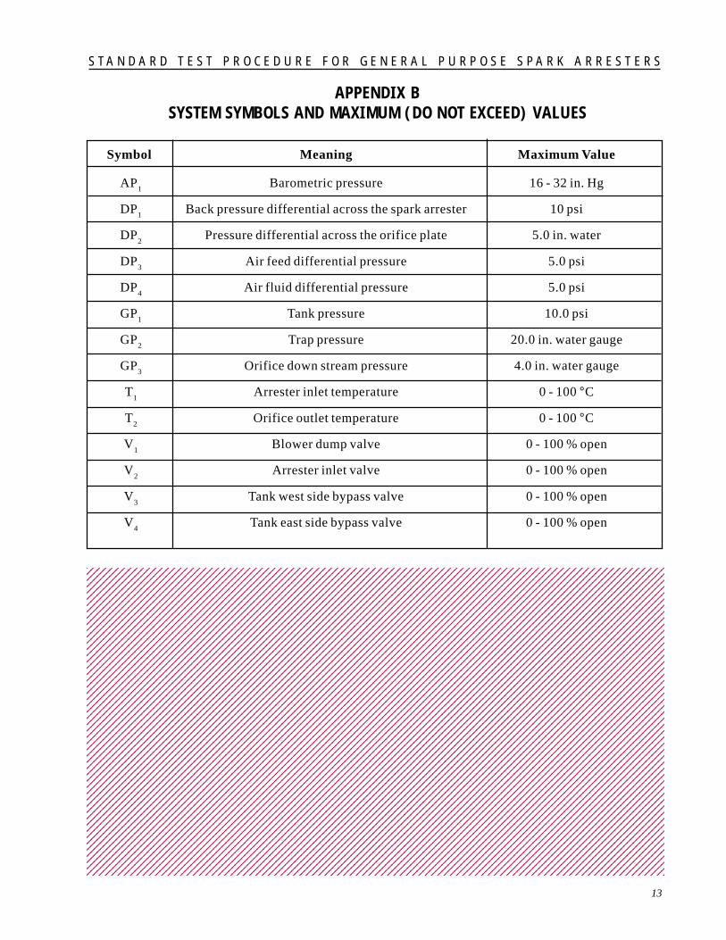
APPENDIX BSYSTEM SYMBOLS AND MAXIMUM (DO NOT EXCEED) VALUES
Symbol Meaning Maximum Value
AP1
Barometric pressure 16 - 32 in. Hg
DP1
Back pressure differential across the spark arrester 10 psi
DP2
Pressure differential across the orifice plate 5.0 in. water
DP3
Air feed differential pressure 5.0 psi
DP4
Air fluid differential pressure 5.0 psi
GP1
Tank pressure 10.0 psi
GP2
Trap pressure 20.0 in. water gauge
GP3
Orifice down stream pressure 4.0 in. water gauge
T1
Arrester inlet temperature 0 - 100 °C
T2
Orifice outlet temperature 0 - 100 °C
V1
Blower dump valve 0 - 100 % open
V2
Arrester inlet valve 0 - 100 % open
V3
Tank west side bypass valve 0 - 100 % open
V4
Tank east side bypass valve 0 - 100 % open
123456789012345678901234567890121234567890123456789012345678901212345678901234567890123456789123456789012345678901234567890121234567890123456789012345678901212345678901234567890123456789123456789012345678901234567890121234567890123456789012345678901212345678901234567890123456789123456789012345678901234567890121234567890123456789012345678901212345678901234567890123456789123456789012345678901234567890121234567890123456789012345678901212345678901234567890123456789123456789012345678901234567890121234567890123456789012345678901212345678901234567890123456789123456789012345678901234567890121234567890123456789012345678901212345678901234567890123456789123456789012345678901234567890121234567890123456789012345678901212345678901234567890123456789123456789012345678901234567890121234567890123456789012345678901212345678901234567890123456789123456789012345678901234567890121234567890123456789012345678901212345678901234567890123456789123456789012345678901234567890121234567890123456789012345678901212345678901234567890123456789123456789012345678901234567890121234567890123456789012345678901212345678901234567890123456789123456789012345678901234567890121234567890123456789012345678901212345678901234567890123456789123456789012345678901234567890121234567890123456789012345678901212345678901234567890123456789123456789012345678901234567890121234567890123456789012345678901212345678901234567890123456789123456789012345678901234567890121234567890123456789012345678901212345678901234567890123456789123456789012345678901234567890121234567890123456789012345678901212345678901234567890123456789123456789012345678901234567890121234567890123456789012345678901212345678901234567890123456789123456789012345678901234567890121234567890123456789012345678901212345678901234567890123456789123456789012345678901234567890121234567890123456789012345678901212345678901234567890123456789123456789012345678901234567890121234567890123456789012345678901212345678901234567890123456789123456789012345678901234567890121234567890123456789012345678901212345678901234567890123456789123456789012345678901234567890121234567890123456789012345678901212345678901234567890123456789123456789012345678901234567890121234567890123456789012345678901212345678901234567890123456789123456789012345678901234567890121234567890123456789012345678901212345678901234567890123456789123456789012345678901234567890121234567890123456789012345678901212345678901234567890123456789123456789012345678901234567890121234567890123456789012345678901212345678901234567890123456789123456789012345678901234567890121234567890123456789012345678901212345678901234567890123456789123456789012345678901234567890121234567890123456789012345678901212345678901234567890123456789123456789012345678901234567890121234567890123456789012345678901212345678901234567890123456789123456789012345678901234567890121234567890123456789012345678901212345678901234567890123456789123456789012345678901234567890121234567890123456789012345678901212345678901234567890123456789123456789012345678901234567890121234567890123456789012345678901212345678901234567890123456789123456789012345678901234567890121234567890123456789012345678901212345678901234567890123456789123456789012345678901234567890121234567890123456789012345678901212345678901234567890123456789123456789012345678901234567890121234567890123456789012345678901212345678901234567890123456789123456789012345678901234567890121234567890123456789012345678901212345678901234567890123456789123456789012345678901234567890121234567890123456789012345678901212345678901234567890123456789123456789012345678901234567890121234567890123456789012345678901212345678901234567890123456789123456789012345678901234567890121234567890123456789012345678901212345678901234567890123456789123456789012345678901234567890121234567890123456789012345678901212345678901234567890123456789123456789012345678901234567890121234567890123456789012345678901212345678901234567890123456789123456789012345678901234567890121234567890123456789012345678901212345678901234567890123456789123456789012345678901234567890121234567890123456789012345678901212345678901234567890123456789123456789012345678901234567890121234567890123456789012345678901212345678901234567890123456789123456789012345678901234567890121234567890123456789012345678901212345678901234567890123456789123456789012345678901234567890121234567890123456789012345678901212345678901234567890123456789123456789012345678901234567890121234567890123456789012345678901212345678901234567890123456789123456789012345678901234567890121234567890123456789012345678901212345678901234567890123456789123456789012345678901234567890121234567890123456789012345678901212345678901234567890123456789
S T A N D A R D T E S T P R O C E D U R E F O R G E N E R A L P U R P O S E S P A R K A R R E S T E R S
15
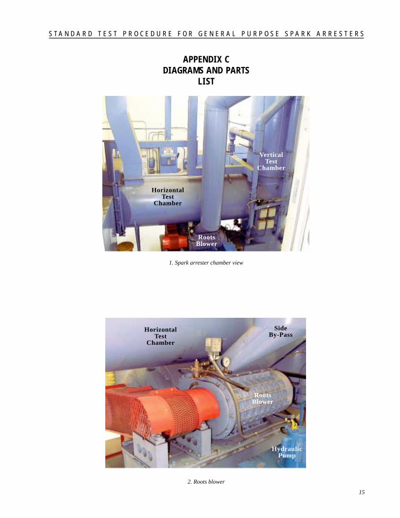
APPENDIX CDIAGRAMS AND PARTS
LIST
1. Spark arrester chamber view
2. Roots blower
HorizontalTest
Chamber
VerticalTest
Chamber
RootsBlower
HorizontalTest
Chamber
RootsBlower
SideBy-Pass
HydraulicPump

S T A N D A R D T E S T P R O C E D U R E F O R G E N E R A L P U R P O S E S P A R K A R R E S T E R S
16
3. 150 horsepower (112 kW) electricmotor
4. Manual by-pass valve
150 HPElectricMotor
Roots Blower
ManualBy-Pass
Valve
LinearActuatedBy-Pass

S T A N D A R D T E S T P R O C E D U R E F O R G E N E R A L P U R P O S E S P A R K A R R E S T E R S
17
HorizontalInletTube
5. Carbon feed tube
6. Carbon feed cylinder
StackCarbon
Feed
Tube
BackPressure
Probe
ElectricMotor
VolumeAdjustment
CarbonFeed
Cylinder

S T A N D A R D T E S T P R O C E D U R E F O R G E N E R A L P U R P O S E S P A R K A R R E S T E R S
18
7. Vertical inlet mounting tube with stack
8. Orifice meter and flow discharge fixture
Stack
BackPressure
Probe
VerticalInlet
Mounting
SmallOrificeMeter
DischargeFixture
OrificePlate
LargeOrificeMeter

S T A N D A R D T E S T P R O C E D U R E F O R G E N E R A L P U R P O S E S P A R K A R R E S T E R S
19
9. Orifice plates
10. Transducer bench(normally under cover)
OrificePlates

S T A N D A R D T E S T P R O C E D U R E F O R G E N E R A L P U R P O S E S P A R K A R R E S T E R S
21
APPENDIX DPREPARING TEST CARBON
1. All test carbon used for qualification purposes must be preparedaccording to SAE Standard J997.
2. Carbon is supplied in two rough screened size ranges. Commercialdesignation C-66-141-B 8/14X is coarse carbon, and commercialdesignation C-66-141-A 12/28X is fine carbon. The only differenceis the size range. This is done for convenience in final screening ofcoarse and fine test carbon.
3. Using a series of US sieves, start with either coarse or fine carbonand combine with carbon retained on the sieves as labeled below andin the proportions indicated:
Figure D1. Arrangement of sieves for screening carbon.
4. In addition to sieving the carbon, all test carbon used for qualificationmust be baked at no less than 160 °F (71 °C) for at least 6 hoursimmediately before use.
Air Flow
Arrester
CarbonFeed
Fitting
Back Pressure Probe Fitting
CORRECT
CORRECT
INCORRECT

S T A N D A R D T E S T P R O C E D U R E F O R G E N E R A L P U R P O S E S P A R K A R R E S T E R S
23
APPENDIX EORIFICE FACTORS
Orifice DiameterInches (mm)
C
1.37 (34.93) 6.381
2.25 (57.15) 16.93
3.50 (88.90) 41.2
4.63 (117.60) 72.1
6.25 (158.75) 133.9
10.75 (273.05) 449
12345678901234567890123456789012123456789011234567890123456789012345678901212345678901123456789012345678901234567890121234567890112345678901234567890123456789012123456789011234567890123456789012345678901212345678901123456789012345678901234567890121234567890112345678901234567890123456789012123456789011234567890123456789012345678901212345678901123456789012345678901234567890121234567890112345678901234567890123456789012123456789011234567890123456789012345678901212345678901123456789012345678901234567890121234567890112345678901234567890123456789012123456789011234567890123456789012345678901212345678901123456789012345678901234567890121234567890112345678901234567890123456789012123456789011234567890123456789012345678901212345678901123456789012345678901234567890121234567890112345678901234567890123456789012123456789011234567890123456789012345678901212345678901123456789012345678901234567890121234567890112345678901234567890123456789012123456789011234567890123456789012345678901212345678901123456789012345678901234567890121234567890112345678901234567890123456789012123456789011234567890123456789012345678901212345678901123456789012345678901234567890121234567890112345678901234567890123456789012123456789011234567890123456789012345678901212345678901123456789012345678901234567890121234567890112345678901234567890123456789012123456789011234567890123456789012345678901212345678901123456789012345678901234567890121234567890112345678901234567890123456789012123456789011234567890123456789012345678901212345678901123456789012345678901234567890121234567890112345678901234567890123456789012123456789011234567890123456789012345678901212345678901123456789012345678901234567890121234567890112345678901234567890123456789012123456789011234567890123456789012345678901212345678901123456789012345678901234567890121234567890112345678901234567890123456789012123456789011234567890123456789012345678901212345678901123456789012345678901234567890121234567890112345678901234567890123456789012123456789011234567890123456789012345678901212345678901123456789012345678901234567890121234567890112345678901234567890123456789012123456789011234567890123456789012345678901212345678901123456789012345678901234567890121234567890112345678901234567890123456789012123456789011234567890123456789012345678901212345678901123456789012345678901234567890121234567890112345678901234567890123456789012123456789011234567890123456789012345678901212345678901123456789012345678901234567890121234567890112345678901234567890123456789012123456789011234567890123456789012345678901212345678901123456789012345678901234567890121234567890112345678901234567890123456789012123456789011234567890123456789012345678901212345678901123456789012345678901234567890121234567890112345678901234567890123456789012123456789011234567890123456789012345678901212345678901123456789012345678901234567890121234567890112345678901234567890123456789012123456789011234567890123456789012345678901212345678901123456789012345678901234567890121234567890112345678901234567890123456789012123456789011234567890123456789012345678901212345678901123456789012345678901234567890121234567890112345678901234567890123456789012123456789011234567890123456789012345678901212345678901123456789012345678901234567890121234567890112345678901234567890123456789012123456789011234567890123456789012345678901212345678901

S T A N D A R D T E S T P R O C E D U R E F O R G E N E R A L P U R P O S E S P A R K A R R E S T E R S
25
APPENDIX FFACILITY CERTIFICATION
1. General(a) Familiarize yourself with the instructionmanual for the Yokogawa Digital Manometer.This manometer is the standard for the laboratoryand requires recertification at an outside metrologylaboratory a minimum of once a year (moreoften if it is found to be necessary). Duringthis review of the manual, make a special noteof the maximum allowable pressures given inTable F1. Over pressure of the instrumentcould cause damage to it.
(b) The facility blower must be off duringinstrument calibration.
(c) The primary guideline for instrument full-scale readings is the system schematic. Acopy is posted near the transducer stand inRoom 16 and on the wall across from thecontrol console in Room 16A. Refer to theschematic for all system problems and duringcalibration/certification.
(d) Attach the umbilical tube with air pumpattached to the fitting on the front of thedigital manometer. Make sure all the fittingson the umbilical tube are secure and free ofleaks. Secure the tube tightly to the fitting onthe manometer.
(e) For the initial calibration check, doublecheck the tube fittings on the transducers andassociated quick disconnects and valves toassure they are tight and leak free. Thisshould also be done this prior to system start-up also.
(f) Place the manometer on the equipmentcart; this will facilitate use and movement ofthe instrument around the transducer standduring calibration. The manometer does notneed to be plugged in to an AC outlet duringthe calibration operation unless it is discoveredthat the battery is low.
2. Preparation(a) Remove the cover on the transducer stand.
(b) Note the labeling on each transducer.
(c) Check the tube fittings as mentioned earlier.
(d) Use the system schematic for referenceduring calibration.
(e) Attach the umbilical appropriate quickdisconnect to each transducer during calibrationas required.
(f) During the calibration it is required thatthe readout on the manometer and the controlconsole are in the same engineering units. Besure to double check the units setting on themanometer prior to each transducer calibration.
3. Barometric Pressure AP1(a) Make sure the valve on the umbilical tube isoff.
(b) Attach the umbilical to the disconnect onthe AP
1 unit. Make sure the proper units have
been selected on the manometer.
(c) The reading on the manometer should agreewith the reading in the test control room forbarometric pressure.
(d) If the readings do not match notify theSpark Arrester Project Leader. There are noadjustments available on the signal conditionerfor barometric pressure.
(e) Open valve on transducer input after calibrationis completed.
4. Spark Arrester Back Pressure DP1(a) Make sure the valve on the umbilical is off.
(b) Attach the umbilical to the line which isbetween DP
1 and DP
3 (Do not connect to line
between GP2 and DP
1. If this error occurs a
negative reading will result on the control roomreadout and possible damage to the transducermay occur). Disconnect the line between GP
2and DP
1.
(c) Again, Make sure the corresponding readoutfor DP
1 in the Control Room has been checked
for zero.
S T A N D A R D T E S T P R O C E D U R E F O R G E N E R A L P U R P O S E S P A R K A R R E S T E R S
26
(d) Select the proper units on the manometer(PSID = PSI). Use the pump on the umbilical toraise the reading on the manometer to 8 psi (55kPa) (i.e. = absolute pressure of the 0-readingof about 14.2 (97.9 kPa) to 14.7 psi (101.4 kPa)+ 8 psi (55 kPa) or about 22 psi (151.7 kPa).Need to add 8 psi (55 kPa) to manometer 0reading!).
(e) Reading on the control panel should equalthe manometer reading less the initial manometerreading of 14.2 to 14.7 psi (97.9 to 101.4 kPa)air pressure or about 8 psi (55 kPa). If notadjust the gain on the transducer signal conditioneruntil they agree and repeat calibration check.
(f) Open valve on transducer input after calibrationis completed.
5. Orifice Differential Pressure, DP2(a) Attach umbilical to line between GP
3 and
DP2.
(b) Set manometer to inches of water scale.
(c) Manometer reading prior to calibration shouldbe about 390 to 393 inches of water (97 - 97.8kPa). This value plus 4 inches of water (995kPa) yields the proper value for calibration.
(d) Pump up manometer to proper reading.Check readout on control console panel andadjust, as before, accordingly.
(e) Open valve on transducer input after calibrationis completed.
6. Air Feed Delta Pressure, DP3(a) Attach umbilical to center (end) input of thetransducer.
(b) Repeat appropriate steps from the preciouscalibration for DP
1 and DP
2.
(c) Add manometer reading in PSI (prior to cal)to 4 psi (27.6 kPa) to obtain the desired readingvalue for calibration.
(d) Pump to desired value and adjust reading oncontrol console as before.
(e) Open valve on transducer input after calibrationis completed.
7. Air Fluidization Delta Pressure, DP4(a) Attach umbilical to center (end) input oftransducer.
(b) Repeat the appropriate steps from the previousDP calibrations.
(c) Check manometer scale; be sure it is set atPSI.
(d) Repeat steps given for DP3.
(e) Open valve on transducer input after calibrationis completed.
8. Tank Pressure, GP1(a) Attach umbilical to transducer input tube.
(b) Check manometer scale; be sure it is set atPSI.
(c) As before, add manometer reading to 8 psi(55 kPa) to obtain value for calibration.
(d) Calibrate as before.
(e) Open valve on transducer input after calibrationis completed.
9. Trap Pressure GP2(a) Close valve on transducer input line.
(b) Attach umbilical to GP2 side of tube between
DP1 and GP
2.
(c) Set manometer scale to inches of water.Note reading as before and add 16 inches ofwater (3.9 kPa) to value to obtain the calibrationsetting.
(d) Perform calibration as before.
(e) Open valve on transducer input after calibrationis completed.
10. Orifice Downstream Pressure, GP3(a) Close valve on transducer input line.
(b) Attach umbilical to GP3 side of tube between
GP3 and DP
2.
(c) Set manometer scale to inches of water.Note initial reading and add 4 inches of water

S T A N D A R D T E S T P R O C E D U R E F O R G E N E R A L P U R P O S E S P A R K A R R E S T E R S
27
(995 kPa) to it to obtain the calibration setting.
(d) Perform calibration as before.
(e) Open valve on transducer input after calibrationis completed.
This completes the initial system calibration. Thisprocess should be repeated at the beginning andend of each certification series of test runs (highand low flow tests) to validate the stability of thetransducers and readout equipment. Once thesystem has been determined to be stable, thisprocess should be repeated at least twice a year(more if necessary, the frequency will be determinedafter experience has been gained using the equipment).123456789012345678901234567890121234567890123123456789012345678901234567890121234567890123123456789012345678901234567890121234567890123123456789012345678901234567890121234567890123123456789012345678901234567890121234567890123123456789012345678901234567890121234567890123123456789012345678901234567890121234567890123123456789012345678901234567890121234567890123123456789012345678901234567890121234567890123123456789012345678901234567890121234567890123123456789012345678901234567890121234567890123123456789012345678901234567890121234567890123123456789012345678901234567890121234567890123123456789012345678901234567890121234567890123123456789012345678901234567890121234567890123123456789012345678901234567890121234567890123123456789012345678901234567890121234567890123123456789012345678901234567890121234567890123123456789012345678901234567890121234567890123123456789012345678901234567890121234567890123123456789012345678901234567890121234567890123123456789012345678901234567890121234567890123123456789012345678901234567890121234567890123123456789012345678901234567890121234567890123123456789012345678901234567890121234567890123123456789012345678901234567890121234567890123123456789012345678901234567890121234567890123123456789012345678901234567890121234567890123123456789012345678901234567890121234567890123123456789012345678901234567890121234567890123123456789012345678901234567890121234567890123123456789012345678901234567890121234567890123123456789012345678901234567890121234567890123123456789012345678901234567890121234567890123123456789012345678901234567890121234567890123123456789012345678901234567890121234567890123123456789012345678901234567890121234567890123123456789012345678901234567890121234567890123123456789012345678901234567890121234567890123123456789012345678901234567890121234567890123123456789012345678901234567890121234567890123123456789012345678901234567890121234567890123123456789012345678901234567890121234567890123123456789012345678901234567890121234567890123123456789012345678901234567890121234567890123123456789012345678901234567890121234567890123123456789012345678901234567890121234567890123123456789012345678901234567890121234567890123123456789012345678901234567890121234567890123123456789012345678901234567890121234567890123123456789012345678901234567890121234567890123123456789012345678901234567890121234567890123123456789012345678901234567890121234567890123123456789012345678901234567890121234567890123123456789012345678901234567890121234567890123123456789012345678901234567890121234567890123123456789012345678901234567890121234567890123123456789012345678901234567890121234567890123123456789012345678901234567890121234567890123123456789012345678901234567890121234567890123123456789012345678901234567890121234567890123123456789012345678901234567890121234567890123123456789012345678901234567890121234567890123123456789012345678901234567890121234567890123123456789012345678901234567890121234567890123123456789012345678901234567890121234567890123123456789012345678901234567890121234567890123123456789012345678901234567890121234567890123123456789012345678901234567890121234567890123123456789012345678901234567890121234567890123123456789012345678901234567890121234567890123123456789012345678901234567890121234567890123123456789012345678901234567890121234567890123123456789012345678901234567890121234567890123123456789012345678901234567890121234567890123123456789012345678901234567890121234567890123123456789012345678901234567890121234567890123123456789012345678901234567890121234567890123123456789012345678901234567890121234567890123123456789012345678901234567890121234567890123123456789012345678901234567890121234567890123123456789012345678901234567890121234567890123123456789012345678901234567890121234567890123123456789012345678901234567890121234567890123

S T A N D A R D T E S T P R O C E D U R E F O R G E N E R A L P U R P O S E S P A R K A R R E S T E R S
28
Table F1. Spark Arrester Lab Calibration Data Sheet
SPARK ARRESTER LAB CALIBRATION DATA SHEET
Transducer Applied Pressure Indicated Pressure Adjusted Reading Constant
DP1 (psi) 0.50
1.00
1.50
2.00
4.00
3.00
DP2 ( in H
2O) 1.00
2.00
3.00
4.00
2.00
1.00
DP3 (psi) 0.00
1.00
2.00
3.00
4.00
2.00
1.00
DP4 (psi) 0.00
1.00
2.00
3.00
4.00
GP1 (psi) 2.00
4.00
6.00
8.00
S T A N D A R D T E S T P R O C E D U R E F O R G E N E R A L P U R P O S E S P A R K A R R E S T E R S
29
Transducer Applied Pressure Indicated Pressure Adjusted Reading Constant
GP2 (in H
2O) 0.00
4.00
8.00
12.00
16.00
4.00
2.00
4.00
GP3 (in H
2O) 0.00
1.00
2.00
3.00
4.00
2.00
1.00
2.00
3.00
4.00
AP1 (in Hg) 28.786
123456789012345678901234567890121234567890123456789012345678901212345678901234567890123456789123456789012345678901234567890121234567890123456789012345678901212345678901234567890123456789123456789012345678901234567890121234567890123456789012345678901212345678901234567890123456789123456789012345678901234567890121234567890123456789012345678901212345678901234567890123456789123456789012345678901234567890121234567890123456789012345678901212345678901234567890123456789123456789012345678901234567890121234567890123456789012345678901212345678901234567890123456789123456789012345678901234567890121234567890123456789012345678901212345678901234567890123456789123456789012345678901234567890121234567890123456789012345678901212345678901234567890123456789123456789012345678901234567890121234567890123456789012345678901212345678901234567890123456789123456789012345678901234567890121234567890123456789012345678901212345678901234567890123456789123456789012345678901234567890121234567890123456789012345678901212345678901234567890123456789123456789012345678901234567890121234567890123456789012345678901212345678901234567890123456789123456789012345678901234567890121234567890123456789012345678901212345678901234567890123456789123456789012345678901234567890121234567890123456789012345678901212345678901234567890123456789123456789012345678901234567890121234567890123456789012345678901212345678901234567890123456789123456789012345678901234567890121234567890123456789012345678901212345678901234567890123456789123456789012345678901234567890121234567890123456789012345678901212345678901234567890123456789123456789012345678901234567890121234567890123456789012345678901212345678901234567890123456789123456789012345678901234567890121234567890123456789012345678901212345678901234567890123456789123456789012345678901234567890121234567890123456789012345678901212345678901234567890123456789123456789012345678901234567890121234567890123456789012345678901212345678901234567890123456789123456789012345678901234567890121234567890123456789012345678901212345678901234567890123456789123456789012345678901234567890121234567890123456789012345678901212345678901234567890123456789123456789012345678901234567890121234567890123456789012345678901212345678901234567890123456789123456789012345678901234567890121234567890123456789012345678901212345678901234567890123456789123456789012345678901234567890121234567890123456789012345678901212345678901234567890123456789123456789012345678901234567890121234567890123456789012345678901212345678901234567890123456789123456789012345678901234567890121234567890123456789012345678901212345678901234567890123456789123456789012345678901234567890121234567890123456789012345678901212345678901234567890123456789123456789012345678901234567890121234567890123456789012345678901212345678901234567890123456789

ST
AN
DA
RD
TE
ST
PR
OC
ED
UR
E F
OR
GE
NE
RA
L P
UR
PO
SE
SP
AR
K A
RR
ES
TE
RS31
APPENDIX G - CONSOLE CALIBRATION CHECK
Tested by Tested by Tested by Tested by Tested by Tested by Tested byTransducer Constant
Date Date Date Date Date Date Date
DP1 8.09
DP2 4.05
DP3 4.02
DP4 4.02
T1 Agree
GP1 8.00
GP2 15.89
GP3 3.93
AP1 1.59
T2 Agree
V1 6.67
V2 6.36
V3 5.27
V4 6.15
ALARM