universal 3 serieswilliamscarver.com/wp-content/uploads/2018/05/waukesha... · 2018-05-07 · gear...
TRANSCRIPT
INSTRUCTION MANUAL
Universal 3 SeriesROTARY POSITIVE DISPLACEMENT PUMP
FORM NO.: 95-03103 REVISION: 12/2017
READ AND UNDERSTAND THIS MANUAL PRIOR TO OPERATING OR SERVICING THIS PRODUCT.

ADDING A POWERFUL NEW TOOL TO YOUR MAINTENANCE PROGRAM
SPX FLOW has recently launched its SPX Connect App allowing users the ability to access
product support information 24/7 using a smart device with internet access.
A quick scan of the product’s QR code will provide you with immediate access to:
• Product Descriptions and General Operating Specifi cations
• Maintenance Manuals and Documentation
• Maintenance Videos and Product Animations
• Distributor Look Up Feature
• Submit Quote Requests
SPX FLOW is committed to providing you with innovative products and technologies to help keep your
process fl owing. Plan your next scan and download the Free SPX Connect App today.
To learn more about SPX Connect, contact SPX FLOW at 800.252.5200 or wcb@spxfl ow.com.

Information contained in this manual is subject to change without notice and does not represent a commitment on the part of SPX FLOW, Inc.. No part of this manual may be reproduced or transmitted in any form or by any means, electronic or mechanical, including photocopying and recording, for any purpose, without the express written per-mission of SPX FLOW, Inc..
Copyright © 2017 SPX Corporation. All Rights Reserved.
Gore-Tex is a registered trademark of W.L. Gore & Associates, Inc. Kalrez is a registered trademark of DuPont Dow Elastomers.
Chemraz is a registered trademark of Greene, Tweed & Co
Revision Date: 12/2017
Publication: 95-03103
SPX FLOW, Inc.611 Sugar Creek Road
Delavan, WI 53115 USA
Tel: (800) 252-5200 or (262) 728-1900Fax: (800) 252-5012 or (262) 728-4904
E-mail: [email protected] site: www.spxflow.com

Table of Contents Waukesha Cherry-Burrell Brand Universal 3 Pump
Warranty ..................................................................................................................................6Shipping Damage or Loss ...........................................................................................6Warranty Claim ...........................................................................................................6
Safety ......................................................................................................................................7Warnings .....................................................................................................................8
Care of Component Materials ...............................................................................................9Stainless Steel Corrosion ............................................................................................9Alloy 88 .......................................................................................................................9Elastomer Seal Replacement Following Passivation ..................................................9
Replacement Labels ............................................................................................................10Introduction ..........................................................................................................................11
Pump Receiving ........................................................................................................11Intended Use .............................................................................................................11Equipment Serial Number .........................................................................................11Pump Shaft Location .................................................................................................11Operating Parameters ...............................................................................................12Certifications .............................................................................................................13Pumps For Life program ...........................................................................................13Qualification Guidelines for Operating Staff ..............................................................13
Installation ............................................................................................................................15Important Safety Information .....................................................................................15Lifting .........................................................................................................................15Install Pump and Drive Unit .......................................................................................16Install Connections and Piping ..................................................................................17Install Check Valves ..................................................................................................18Install Isolation Valves ...............................................................................................18Install Pressure Gauges ............................................................................................18Install Relief Valves ...................................................................................................19Inlet Side Strainers and Traps ...................................................................................20CIP (Clean-In-Place) Design .....................................................................................20Seal Flush Connections ............................................................................................21Check Coupling Alignment ........................................................................................22Check Angular Alignment ..........................................................................................22Check Parallel Alignment ..........................................................................................22Check Belt and Chain Drive Alignment .....................................................................23Check Pump Rotation ...............................................................................................23
Operation ..............................................................................................................................24Important Safety Information .....................................................................................24Pre-Startup Checklist ................................................................................................24Starting the Pump .....................................................................................................25Stopping the Pump ....................................................................................................25
Maintenance .........................................................................................................................26Important Safety Information .....................................................................................26Lubrication .................................................................................................................27Maintenance Inspections ..........................................................................................28Annual Maintenance .................................................................................................29Maintenance Inspection Chart ..................................................................................30Cleaning ....................................................................................................................31Fluid Head Disassembly - Cover and Rotors ............................................................32
Remove Cover .............................................................................................32Remove Rotor Nuts ......................................................................................33Remove Rotors ............................................................................................33
Single and Double Mechanical Seal .........................................................................34Remove Product-Side Rotary and Stationary Seal ......................................34Remove Pump Body ....................................................................................35
Single Mechanical Seal .............................................................................................36Remove Seal Components ..........................................................................36130-U3 and smaller pumps: Install Seal Components (single mechanical seal) 38
Page 4 95-03103 12/2017

Waukesha Cherry-Burrell Brand Universal 3 Pump Table of Contents
180-U3 and larger pumps: Install Seal Components (single mechanical seal) 41Double Mechanical Seal ........................................................................................... 43
Remove Flush-Side Seal Components ........................................................ 43130-U3 and smaller pumps: Install Seal Components (double mechanical seal) 47180-U3 and larger pumps: Install Seal Components (double mechanical seal) 55
Single and Double Mechanical Seal ......................................................................... 61Install Pump Body ........................................................................................ 61Install Product-Side Rotary and Stationary Seal .......................................... 62
O-ring Seal ............................................................................................................... 65Remove Product-Side Seal Components .................................................... 65Remove Pump Body .................................................................................... 66Remove Flush-Side Seal Components ........................................................ 67Install Body Seal Components ..................................................................... 68Install O-ring Seal ........................................................................................ 70Install Pump Body ........................................................................................ 71Install Seal O-ring ........................................................................................ 72Install Rotary Seal Components .................................................................. 72
Fluid Head Assembly - Rotors and Cover ................................................................ 74Install Rotor Nuts ......................................................................................... 75Install Cover ................................................................................................. 77
Gear Case ................................................................................................................ 80Remove Gear Case Cover .......................................................................... 80Remove Shaft .............................................................................................. 80Front Bearing Assembly .............................................................................. 82Rear Bearing Assembly ............................................................................... 84Shimming ..................................................................................................... 85Install Shaft .................................................................................................. 86Install Rear Seal Assembly .......................................................................... 87Install Timing Gears ..................................................................................... 87Checking for Proper Clearance ................................................................... 88Install Gear Case Cover .............................................................................. 90
Reference Tables ..................................................................................................... 91Troubleshooting .................................................................................................................. 92Pump Dimensions ............................................................................................................... 96
Universal 3 PD Pump Dimensions ............................................................................ 96Tru-Fit ™ Universal 3 PD Pump Dimensions ........................................................... 98Pump Shaft Guards .................................................................................................. 99
Parts List ............................................................................................................................ 100006, 015, 018-U3 Parts .......................................................................................... 100030, 040-U3 Parts .................................................................................................. 104045, 060, 130-U3 Parts .......................................................................................... 108180, 220-U3 Parts .................................................................................................. 112210, 320-U3 Parts .................................................................................................. 116Universal 3 Standard Seals .................................................................................... 120Universal 3 Specialty Seals .................................................................................... 122U3 Shaft and Bearing Assemblies .......................................................................... 124Tru-Fit™ Universal 3 PD Pump Parts ..................................................................... 125Special Tools for U3 Pumps ................................................................................... 126
Long Term Storage ............................................................................................................ 127Universal 3 Maintenance Summary Reference Sheet .................................................... 128Universal 3 Maintenance Summary Reference Sheet -
Copy for optional removal ................................................................................... 129
12/2017 95-03103 Page 5

Warranty Waukesha Cherry-Burrell Brand Universal 3 Pump
Page 6 95-03103 12/2017
Warranty
LIMITED WARRANTY: Unless otherwise negotiated at the time of sale, SPX FLOW US, LLC (SPX FLOW) goods, auxiliaries and parts thereof are warranted to the original purchaser against defective workmanship and material for a period of twelve (12) months from date of installation or eighteen (18) months from date of shipment from factory, whichever expires first. If the goods or services do not conform to the warranty stated above, then as Buyer's sole remedy, SPX FLOW shall, at SPX FLOW's option, either repair or replace the defective goods or re-perform defective services. Third party goods furnished by SPX FLOW will be repaired or replaced as Buyer's sole remedy, but only to the extent provided in and honored by the original manufacturer's warranty. Unless otherwise agreed to in writing, SPX FLOW shall not be liable for breach of warranty or otherwise in any manner whatsoever for: (i) normal wear and tear; (ii) corrosion, abrasion or erosion; (iii) any good or services which, following delivery or performance by SPX FLOW, has been subjected to accident, abuse, misapplication, improper repair, alteration, improper installation or maintenance, neglect, or excessive operating con-ditions; (iv) defects resulting from Buyer's specifications or designs or those of Buyer's contractors or subcontractors other than SPX FLOW; or (v) defects resulting from the manufacture, distribution, promotion or sale of Buyer's products.
THE WARRANTIES CONTAINED HEREIN ARE THE SOLE AND EXCLUSIVE WARRANTIES AVAILABLE TO BUYER AND SPX FLOW HEREBY DISCLAIMS ANY OTHER WARRANTIES, EXPRESS OR IMPLIED, INCLUDING WITHOUT LIMITATION THE IMPLIED WARRANTIES OF MERCHANTABILITY AND FITNESS FOR A PARTICULAR PURPOSE. THE FOREGOING REPAIR, REPLACEMENT AND RE-PERFORMANCE OBLIGA-TIONS STATE SPX FLOW'S ENTIRE AND EXCLUSIVE LIABIL-ITY AND BUYER'S EXCLUSIVE REMEDY FOR ANY CLAIM IN CONNECTION WITH THE SALE AND FURNISHING OF SER-VICES, GOODS OR PARTS, THEIR DESIGN, SUITABILITY FOR USE, INSTALLATION OR OPERATIONS.
Shipping Damage or Loss If equipment is damaged or lost in transit, file a claim at once with the delivering carrier. The carrier has a signed Bill of Lading acknowledging that the shipment has been received from SPX FLOW in good condition. SPX FLOW is not responsible for the collection of claims or replacement of materials due to transit shortage or damages.
Warranty Claim Warranty claims must have a Returned Material Authorization (RMA) from the Seller or returns will not be accepted. Contact 800-252-5200 or 262-728-1900.
Claims for shortages or other errors must be made in writing to Seller within ten (10) days after delivery. This does not include transit shortage or damages. Failure to give such notice shall constitute acceptance and waiver of all such claims by Buyer.

Waukesha Cherry-Burrell Brand Universal 3 Pump Safety
SafetyREAD AND UNDERSTAND THIS MANUAL PRIOR TO INSTALLING, OPERATING, OR SERVICING THIS EQUIPMENT
SPX FLOW recommends users of our equipment and designs follow the latest Industrial Safety Standards. At a minimum, these should include the industrial safety requirements established by:
1. Occupational Safety and Health Administration (OSHA)
2. National Fire Protection Association (NFPA)
3. National Electrical Code (NEC)
4. American National Standards Institute (ANSI)
WARNINGSevere injury or death can result from electrical shock, burn, or unintended actuation of equipment. Recommended practice is to disconnect and lockout industrial equipment from power sources, and release stored energy, if present. Refer to the National Fire Protection Association Standard No. NFPA70E, Part II and (as applicable) OSHA rules for Control of Hazardous Energy Sources (Lockout-Tagout) and OSHA Electrical Safety Related Work Practices, including procedural requirements for:
• Lockout-tagout
• Personnel qualifications and training requirements
• When it is not feasible to de-energize and lockout-tagout electrical circuits and equipment before working on or near exposed circuit parts
Before putting SPX FLOW equipment into operation, the operator shall analyze the application for all foresee-able risks, their likelihood to occur and the potential consequences of the identified risks as per ISO 31000 and ISO/IEC 31010 in their actual current version.
Locking and Interlocking Devices: These devices should be checked for proper working condition and capa-bility of performing their intended functions. Make replacements only with the original equipment manufac-turer’s OEM renewal parts or kits. Adjust or repair in accordance with the manufacturer’s instructions.
Periodic Inspection: Equipment should be inspected periodically. Inspection intervals should be based on environmental and operating conditions and adjusted as indicated by experience. At a minimum, an initial inspection within 3 to 4 months after installation is recommended. Inspection of the electrical control systems should meet the recommendations as specified in the National Electrical Manufacturers Association (NEMA) Standard No. ICS 1.3, Preventative Maintenance of Industrial Control and Systems Equipment, for the general guidelines for setting-up a periodic maintenance program.
Replacement Equipment: Use only replacement parts and devices recommended by the manufacturer to maintain the integrity of the equipment. Make sure the parts are properly matched to the equipment series, model, serial number, and revision level of the equipment.
Warnings and cautions are provided in this manual to help avoid serious injury and/or possible damage to equipment:
DANGERImmediate hazards which WILL result in severe personal injury or death.
WARNINGHazards or unsafe practices which COULD result in severe personal injury or death.
CAUTIONHazards or unsafe practices which COULD result in minor personal injury or product or property damage.
12/2017 95-03103 Page 7

Safety Waukesha Cherry-Burrell Brand Universal 3 Pump
Warnings
1. Read the instructions before installing the pump and starting it up. Always follow the guidelines for assem-bly in order to achieve optimum operational reliability.
2. Always check that the specifications of the motor and the motor control unit are correct, particularly in oper-ating environments where there may be a risk of explosion.
3. Pumps should only be installed, disassembled, repaired and assembled by personnel trained in servicing pumps.
4. Always ensure that all electrical installation is carried out by qualified staff.
5. Never hose down or clean the electric motor directly with water or cleaning fluid. If the motor will be used in a washdown environment a washdown designed motor must be used.
6. Never dismantle the pump before the motor has been disconnected from the power supply. Remove the fuses and disconnect the cable from the motor terminal box.
7. Never dismantle the pump until the isolating valves on the suction and discharge side have been closed and the immediate pipe system has been drained. If the pump is used for hot and/or hazardous fluids, spe-cial precautions must be taken. In such cases follow the local regulations for personal safety when working with these products.
8. Always ensure that all pipe connections have been fitted and tightened properly before the pump is started. If the pump is used for hot and/or hazardous liquids, take special care: follow the local regulations for personal safety when working with these products.
9. Always wear personal protective equipment according to the requirements established by OSHA, NFPA, NEC (See page 7).
10. Always remove all assembly and auxiliary tools from the pump before starting it up.
11. Make sure product lines and power cables are laid in suitable guides/trays.
12. Always ensure that no debris of any kind is present in the pump.
13. Always ensure that the pump and the motor shafts are properly aligned.
14. Always ensure that the suction and discharge valves isolating the pump are fully open before starting the pump.
15. Never close or obstruct the outlet of the pump as the pressure in the system will increase above the speci-fied maximum pressure of the pump and cause damage to the pump.
16. There are rotating parts in the pump. Never put hands or fingers into a pump while it is in operation.
17. The pump components and piping may contain sharp edges. Handle the rotors carefully because edges may be sharp. Wear gloves while installing and servicing the pump to help avoid injuries from these haz-ards.
18. Never touch the gear case during operation. The surface temperature may exceed 110°F (43°C). The pump cover and body may be cold or hot depending on the product (CIP at 190°F (88°C) or 300°F (149°C) product, for example).
19. Never touch the motor or motor shroud (if supplied) during operation, as it can become very hot.
20. When moving the pump, use appropriate lifting devices. Attach lifting devices to the eye bolts on the gear case; the gear case has holes for attaching lifting eye bolts. Always use securely fitted lifting straps when lifting with a crane or similar lifting gear. See "Lifting" on page 15.
21. Never drop parts on the floor.
22. Never exceed the maximum temperature or operating pressure specified under “Operating Parameters” on page 12.
23. Guards should be used when applicable. See page 16, page 24, and page 99.
24. Make sure to keep the work area clear of machine parts, tools, product lines, foreign materials, and power cables to avoid potential hazards.
Page 8 95-03103 12/2017

Waukesha Cherry-Burrell Brand Universal 3 Pump Care of Component Materials
12/2017 95-03103 Page 9
Care of Component Materials
NOTE: SPX FLOW recommends the use of an FDA-approved anti-seize compound on all threaded connections.
WARNINGFailure to comply with the Care of Component Materials could lead to bodily injury.
Stainless Steel Corrosion
Corrosion resistance is greatest when a layer of oxide film is formed on the surface of stainless steel. If film is disturbed or destroyed, stainless steel becomes much less resistant to corrosion and may rust, pit or crack.
Corrosion pitting, rusting and stress cracks may occur due to chemical attack. Use only cleaning chemicals specified by a reputable chemical manufacturer for use with 300 series stainless steel. Do not use excessive concentrations, temperatures or exposure times. Avoid contact with highly corrosive acids such as hydroflu-oric, hydrochloric or sulfuric. Also avoid prolonged contact with chloride-containing chemicals, especially in presence of acid. If chlorine-based sanitizers are used, such as sodium hypochlorite (bleach), do not exceed concentrations of 150 ppm available chlorine, do not exceed contact time of 20 minutes, and do not exceed temperatures of 104°F (40°C).
Corrosion discoloration, deposits or pitting may occur under product deposits or under gaskets. Keep surfaces clean, including those under gaskets or in grooves or tight corners. Clean immediately after use. Do not allow equipment to set idle, exposed to air with accumulated foreign material on the surface. Corrosion pitting may occur when stray electrical currents come in contact with moist stainless steel. Ensure all electrical devices connected to the equipment are correctly grounded.
Alloy 88
Waukesha Alloy 88 is the standard rotor material for Universal 1, Universal 2, Universal 3, Universal TS, Uni-versal Lobe, Universal 420/520, and 5000 Series Rotary PD pumps. This alloy was developed specifically for corrosion resistance and close operating clearance requirements of high performance rotary positive displace-ment pumps. Alloy 88 is a nickel based, corrosion-resistant, non-galling or seizing material. The ASTM desig-nation is A494 Grade CY5SnBiM (UNS N26055), and the material is listed in the 3-A Sanitary Standards as acceptable for product contact surfaces.
The corrosion resistance of Alloy 88 is approximately equal to AISI 300 Series Stainless Steel. However, Alloy 88 has limited resistance to certain aggressive chemicals that may be commonly used in contact with AISI 300 Series Stainless Steel.
Do not use Alloy 88 in contact with nitric acid. Nitric acid is commonly used to passivate new installations of stainless steel equipment. Do not allow nitric acid based passivation chemicals to contact Alloy 88 rotors. Remove the rotors during passivation and use a separate pump to circulate the passivation chemicals. Also, if nitric acid-based CIP cleaning chemicals are used, remove the rotors prior to CIP cleaning and clean them separately by hand in a mild detergent. If you have questions regarding other aggressive chemicals, please contact SPX FLOW Application Engineering for assistance.
Elastomer Seal Replacement Following Passivation
Passivation chemicals can damage product contact areas of this equipment. Elastomers (rubber components) are most likely to be affected. Always inspect all elastomer seals after passivation is completed. Replace any seals showing signs of chemical attack. Indications may include swelling, cracks, loss of elasticity or any other noticeable changes when compared with new components.

Replacement Labels Waukesha Cherry-Burrell Brand Universal 3 Pump
Page 10 95-03103 12/2017
Replacement Labels
WARNINGThe following labels are installed on your equipment. If these labels are removed or become unreadable, contact SPX FLOW customer service at 1-800-252-5200 or 262-728-1900, and refer to the part numbers below for replacement labels. See also items 65 and 66 in the parts list section starting on page 100.
Application InstructionsApply to a clean, dry surface. Remove the backing from the label, place it in proper position, protect it with a cover sheet and burnish it. (A soft rubber roller also may be used to press the label into place.) Apply all labels to be readable from the front of the pump. The labels below are affixed to the pumps as shown.
KEEP FINGERSWARNING
OUT OF PORTS
KEEP
FIN
GERS
WAR
NING
OUT
OF P
ORTS
KEEP FINGERSW
ARNING
OUT OF PORTS
label locations-UIII
Part no.: 33-63 (130-U3 and smaller pumps) 33-60 (180-U3 and larger pumps)
Part no.: 121694+
Part no: 33-95This label is supplied on base packages, on the side of the gear case.
Part no: 112446+This label is supplied with pumps with double mechanical seals and single mechanical flush. It is attached to the eye bolt.

Waukesha Cherry-Burrell Brand Universal 3 Pump Introduction
Introduction
Pump Receiving
DANGERThe pump contains internal moving parts. DO NOT put hands or fingers into the pump body ports or drive area at any time during operation. To avoid serious injury, DO NOT install, clean, service, or repair the pump unless all power is off and locked out.
All ports are covered at the factory to keep out foreign objects during transit. If covers are missing or damaged, remove the pump cover (if damaged) and thoroughly inspect the fluid head. Be sure that the pumping head is clean and free of foreign mate-rial before rotating the shaft.
Each standard Waukesha Cherry-Burrell brand pump is shipped completely assembled and lubricated. Review “Operation” on page 24 before operating the pump.
Intended Use The Universal 3 Series Rotary Positive Displacement Pump is exclusively intended for pumping liquids, especially in food and beverage installations.
Refrain from using the pump in a manner which exceeds the scope and specifications stated in this manual.
Any use exceeding the margins and specifications set forth is considered to be not intended.
SPX FLOW is not liable for any damage resulting from such activities. The user bears the full risk.
WARNINGImproper use of the pump leads to: - damage - leakage - destruction - potential failures in the production process
Equipment Serial Number All Waukesha Cherry-Burrell brand pumps are identified by a serial number on the gear case nameplate, which is stamped on the pump body and cover.
CAUTIONThe gear case, body, and cover must be kept together as a unit due to backface, rotor, and cover clearances. Failure to do so will damage the pump.
Pump Shaft Location There are two pump drive shaft locations:
Figure 1 - Upper and Lower Shaft Mount Figure 2 - Sidemount Left Hand and Right Hand (as viewed from pump cover)
12/2017 95-03103 Page 11

Introduction Waukesha Cherry-Burrell Brand Universal 3 Pump
Operating Parameters
LV = Low Viscosity Rotors; Std = Standard Clearance Rotors
Other inlet/outlet sizes are available. Contact SPX FLOW Application Engineering.
* Contact SPX FLOW Application Engineering for higher pressures or higher temperature applications. Pump max temperature is 300°F (149°C).
DANGEROperating the pump outside the stated operating parameters may result in severe personal injury or death.
"Low Viscosity" rotors may be used with liquid temperatures up to 180°F (82°C). However, between 160° (71°C) and 200°F (93°C), consider other application factors such as; speed of operation, differential pressure, lubricating properties of liquid being pumped, and product viscosity. If these factors trend toward a difficult application (high speed, high pressure, non-lubricating) then "Standard" clearance rotors are recommended.
"Standard" clearance rotors are recommended for use with liquid temperatures between -40°F (-40°C) and 300°F (149°C). They provide additional clearance in the front face area plus rotor to body areas. Because of this additional clearance there is more slip (inefficiency) with low viscosity liquids, which the pump must overcome with higher operating speed (rpm.) VHP (viscous horsepower) is slightly lower when using standard clearance rotors. Standard clearance rotors are also used when the product viscosity is above 200 CPS.
"316SS" clearance rotors are made from 316 stainless steel material (in place of standard non-galling alloy 88) and recommended for use at temperatures up to 200°F (93°C). These rotors provide additional clearance all around (more than Standard clearance alloy 88 rotors) to ensure no running contact between the 316 SS rotors and other 316 SS pump components. Because of this additional clearance, there is more slip (inefficiency) with low viscosity liquids, which the pump must overcome with higher operating speed (rpm). VHP (viscous horsepower) is slightly lower when using "316SS" clearance rotors.
NOTE: Consult SPX FLOW Technical Services for applications near 300°F (149°C) or above 200°F (93°C) with 316SS rotors. For clearance data, see Table 18, “Rotor Clearances,” on page 89.
U3 Model
NominalDisplacement per revolution
MaximumNominalCapacity
Inlet/Outlet
OptionalInlet/Outlet
MaximumPressure
Range
Max.RPM
TempRange*
006 .0082 gal (.031 liter) 8 gpm (1.8 m3/hr.) 1" 1-1/2" 300 psi (20.7 bar) 1000
LV: -40°F (-40°C) to 180°F (82°C);
Std:-40°F (-40°C) to 300°F (149°C)
015 .0142 gal (.054 liter) 11 gpm (2.5 m3/hr.) 1-1/2" - 250 psi (17.2 bar) 800
018 .029 gal (.110 liter) 20 gpm (4.5 m3/hr.) 1-1/2" 2" 200 psi (13.8 bar) 700
030 .060 gal (.227 liter) 36 gpm (8.2 m3/hr.) 1-1/2" 2" 250 psi (17.2 bar) 600
040 .076 gal (.288 liter) 46 gpm (1.4 m3/hr.) 2" - 150 psi (10.3 bar) 600
045 .098 gal (.371 liter) 58 gpm (13.2 m3/hr.) 2" - 450 psi (31.0 bar) 600
060 .153 gal (.579 liter) 90 gpm (2.4 m3/hr.) 2-1/2" 3" 300 psi (20.7 bar) 600
130 .253 gal (.958 liter) 150 gpm (34.1 m3/hr.) 3" - 200 psi (13.8 bar) 600
180 .380 gal (1.438 liter) 230 gpm (52.2 m3/hr.) 3" - 450 psi (31.0 bar) 600
210 .502 gal (1.900 liter) 300 gpm (68.1 m3/hr.) 4" - 500 psi (34.5bar) 600
220 .521 gal (1.972 liter) 310 gpm (7.4 m3/hr.) 4" - 300 psi (20.7 bar) 600
320 .752 gal (2.847 liter) 450 gpm (102 m3/hr.) 6" - 300 psi (20.7 bar) 600
Page 12 95-03103 12/2017

Waukesha Cherry-Burrell Brand Universal 3 Pump Introduction
Certifications EHEDG
Only pumps containing the elastomers and seals listed on the EHEDG certificate are EHEDG-certified.
3-A
See the 3-A website for current certificates: www.3-a.org/3-A-Symbol/Search-Database-of-Current-Certificates.
Certificate Number 29 covers all SPX FLOW Centrifugal and Rotary Pumps. You can search using: Certificate Number 29, Company Name "SPX Flow US, LLC," or Standard Number 02-__. The 3-A Standard for fittings is 63-__. ("__" indicates the current revision.)
Only designs meeting 3-A Standards are 3-A certified.
Pumps For Life program Waukesha Cherry-Burrell brand Universal 3 pumps are not designed to be factory remanufactured. In place of a remanufac-ture program, customers may participate in a pump exchange program. The Universal 3 pump exchange program offers a brand new pump at the traditional remanufactured pump discount as long as the end user has maintained the pump with SPX FLOW genuine parts for all wear parts (seals, shafts, etc.) and returns the original pump to SPX FLOW for inspection and recy-cling.
Contact your SPX FLOW Customer Service Representative at 1-800-252-5200 or 262-728-1900 and provide the three serial num-bers (serial tag, pump body, and cover) of any pump being con-sidered for the pump exchange program.
Qualification Guidelines for Operating Staff
DefinitionsOperator
A person who is capable of handling the installation, interior, operation, warnings, cleaning, repair or transportation of the machine.
Trained person
A person who is instructed in the tasks given and the possible dangerous situation that may occur. The person is also aware of the protection installations and measures.
Skilled worker
A person who based upon his or her background and due to his or her knowledge, is able to perform the tasks, and has an appro-priate knowledge of the provisions given.
See Table 1, “Qualification Guidelines for Operating Staff,” on page 14.
12/2017 95-03103 Page 13
Introduction Waukesha Cherry-Burrell Brand Universal 3 Pump
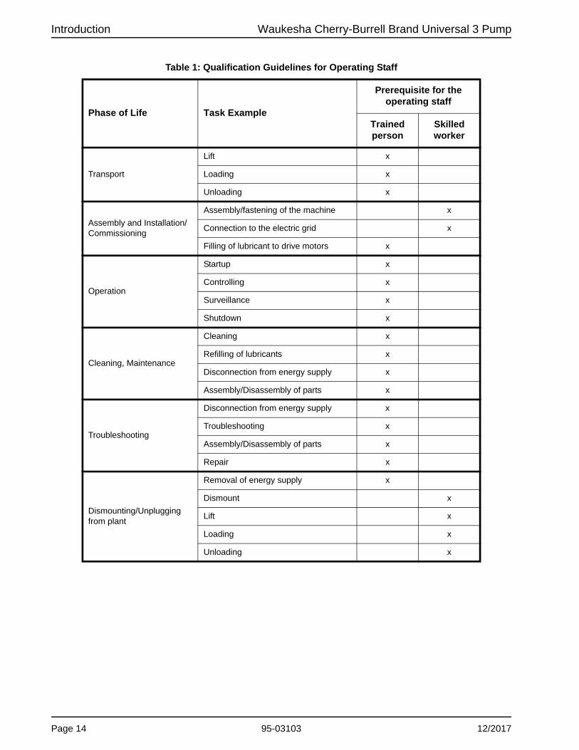
Table 1: Qualification Guidelines for Operating Staff
Phase of Life Task Example
Prerequisite for the operating staff
Trainedperson
Skilledworker
Transport
Lift x
Loading x
Unloading x
Assembly and Installation/Commissioning
Assembly/fastening of the machine x
Connection to the electric grid x
Filling of lubricant to drive motors x
Operation
Startup x
Controlling x
Surveillance x
Shutdown x
Cleaning, Maintenance
Cleaning x
Refilling of lubricants x
Disconnection from energy supply x
Assembly/Disassembly of parts x
Troubleshooting
Disconnection from energy supply x
Troubleshooting x
Assembly/Disassembly of parts x
Repair x
Dismounting/Unplugging from plant
Removal of energy supply x
Dismount x
Lift x
Loading x
Unloading x
Page 14 95-03103 12/2017

Waukesha Cherry-Burrell Brand Universal 3 Pump Installation
Installation
Important Safety Information
DANGERThe pump contains internal moving parts. DO NOT put hands or fingers into the pump body ports or drive area at any time during operation. To avoid serious injury, DO NOT install, clean, service, or repair the pump unless all power is off and locked out and the pump is de-pressurized.
WARNINGThe pump components and piping may contain sharp edges. Handle the rotors carefully because edges may be sharp. Wear gloves while installing and servicing the pump to help avoid injuries from these hazards.
CAUTIONMaintenance should be performed only by trained personnel. See “Qualification Guidelines for Operating Staff” on page 13.
Lifting CAUTIONWhen moving the pump, use appropriate lifting devices. Always use securely fitted lifting straps/chains when lifting with a crane or similar lifting gear.
DANGERDo not stand underneath the pump while it is being lifted.
As shown in Figure 3, attach lifting straps/chains to the two eye bolts on the top of the gear case.
CAUTIONTo lift the cover on a 210 or 320-U3, attach an eye bolt to the threaded hole in the cover and attach lifting straps or chains to the eye bolt. To lift the body of a 130, 180, 210, 220, or 320-U3, use a lifting strap threaded through the ports on either side of the body. To lift the gear case assembly on pumps larger than 018-U3, attach lifting straps/chains to the two eye bolts on the top of the gear case.
For Unit orders (a pump and motor mounted on a common baseplate (not pictured)), use straps to lift the unit by the baseframe at either end. Do not lift by the eye bolts on the pump or motor. Due to the wide range of pump sizes and motors, SPX FLOW cannot give lifting instructions here for all configurations. Contact SPX FLOW or an authorized lifting expert if questions arise.
Figure 3 - Lifting location
Table 2: Pump Weights (less motor or base)
U3 Model Weight, lb (kg) U3 Model Weight, lb (kg)
006 60 (27) 060 290 (132)
015 62 (28) 130 310 (141)
018 65 (29) 180 498 (226)
030 114 (52) 210 510 (231)
040 117 (53) 220 748 (339)
045 284 (129) 320 817 (371)
12/2017 95-03103 Page 15

Installation Waukesha Cherry-Burrell Brand Universal 3 Pump
Install Pump and Drive UnitCAUTION
Install the pump and piping system in accordance with local codes and restrictions. Practices described in this manual are recommended for optimum performance.
CAUTIONThe motor must be installed by qualified personnel, e.g., a licensed electrician.
All system equipment, such as motors, sheaves, drive couplings, speed reducers, etc., must be properly sized to ensure satisfac-tory operation of your Waukesha Cherry-Burrell brand pump within its limits. Customer-supplied motors should have a basic level of safety to prevent electrical hazards, and should be dealt with in accordance with the manufacturer's instructions.
In a typical installation configuration, the pump and drive unit are mounted on a common base plate. The unit can be installed in any of the arrangements shown in Figure 4 through Figure 7.
NOTE: The gap between the pump body and gearcase is required for 3-A sanitary standards.
NOTE: When installing a unit as shown in Figure 7, level the unit before installing the bolts.
The shaded area in Figure 4 through Figure 7 indicates the guard location.
See “Pump Shaft Guards” on page 99.
WARNINGFull guards must be installed to isolate operators and maintenance personnel from rotating components.
Guards are provided as part of a complete pump and drive package and are selected by SPX FLOW Engineering for the pump, base, and motor ordered. Do not modify the guard provided by SPX FLOW. If the guard provided by SPX FLOW is lost, contact SPX FLOW Customer Service and provide your order number or PO number of the pump to order a correctly- sized replacement guard.
If the pump was not purchased as a unit, it is the responsibility of the customer to ensure proper guarding. Refer to your local regulations for guidance.
Figure 4 - Portable Base
Figure 5 - Adjustable Leg Base
Figure 6 - Leveling and/or Vibration Isolation Pads
Figure 7 - Permanent Installation on Foundation
Page 16 95-03103 12/2017
Waukesha Cherry-Burrell Brand Universal 3 Pump Installation
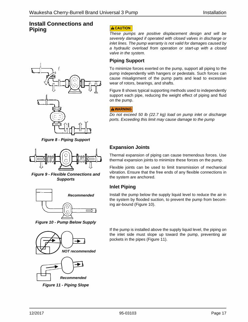
Install Connections and Piping CAUTION
These pumps are positive displacement design and will be severely damaged if operated with closed valves in discharge or inlet lines. The pump warranty is not valid for damages caused by a hydraulic overload from operation or start-up with a closed valve in the system.
Piping Support
To minimize forces exerted on the pump, support all piping to the pump independently with hangers or pedestals. Such forces can cause misalignment of the pump parts and lead to excessive wear of rotors, bearings, and shafts.
Figure 8 shows typical supporting methods used to independently support each pipe, reducing the weight effect of piping and fluid on the pump.
WARNINGDo not exceed 50 lb (22.7 kg) load on pump inlet or discharge ports. Exceeding this limit may cause damage to the pump
Expansion Joints
Thermal expansion of piping can cause tremendous forces. Use thermal expansion joints to minimize these forces on the pump.
Flexible joints can be used to limit transmission of mechanical vibration. Ensure that the free ends of any flexible connections in the system are anchored.
Inlet Piping
Install the pump below the supply liquid level to reduce the air in the system by flooded suction, to prevent the pump from becom-ing air-bound (Figure 10).
If the pump is installed above the supply liquid level, the piping on the inlet side must slope up toward the pump, preventing air pockets in the pipes (Figure 11).
Figure 8 - Piping Support
Figure 9 - Flexible Connections and Supports
Figure 10 - Pump Below Supply
Recommended
Figure 11 - Piping Slope
NOT recommended
Recommended
12/2017 95-03103 Page 17

Installation Waukesha Cherry-Burrell Brand Universal 3 Pump
Install Check Valves Inlet Side on Lift Applications
Use check valves to keep the inlet line full, particularly with low-viscosity fluids (Figure 12).
Discharge Side
For systems with liquid under a vacuum, install a check valve onthe discharge side of the pump. The check valve prevents back-flow (air or fluid) to aid in the initial start-up by minimizing the required differential pressure supplied by the pump to start the flow (Figure 13).
Install Isolation ValvesIsolation valves permit pump maintenance and safe pump removal without draining the system (Figure 14, item A).
NOTE: Make sure the inlet flow is not restricted. Don’t start the pump deadheaded, e.g., operated with no flow through it.
Install Pressure GaugesPressure and vacuum gauges provide valuable information about pump operation (Figure 15). Wherever possible, install the gauges to help provide information on the following:
• Normal or abnormal pressures
• Indication of flow
• Changes in pump condition
• Changes in system conditions
• Changes in fluid viscosity
Figure 12 - Inlet Check Valve
A. Inlet Check ValveB. Foot Check Valve
A. Closed Tank - produces vacuum on liquid (Low Absolute Pressure)
B. Check Valve (outlet)
Figure 13 - Discharge Check Valve
Figure 14 - Isolation Valves
Figure 15 - Pressure and Vacuum Gauges
Page 18 95-03103 12/2017
Waukesha Cherry-Burrell Brand Universal 3 Pump Installation
12/2017 95-03103 Page 19
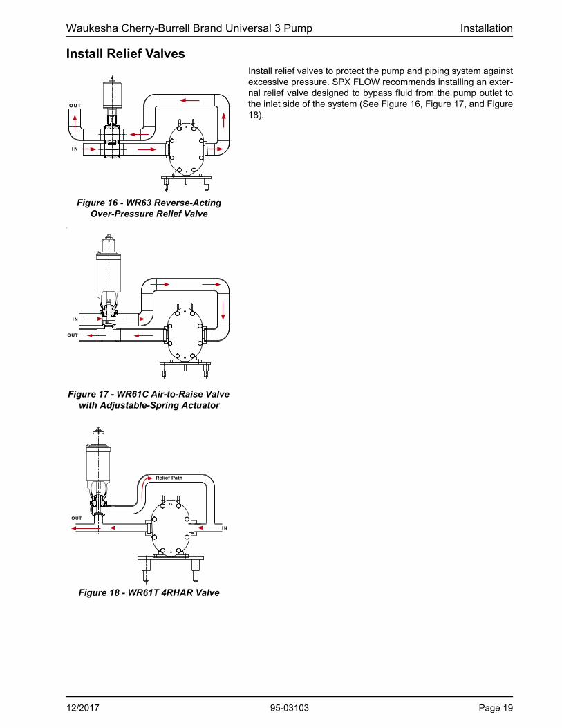
Install Relief ValvesInstall relief valves to protect the pump and piping system against excessive pressure. SPX FLOW recommends installing an exter-nal relief valve designed to bypass fluid from the pump outlet to the inlet side of the system (See Figure 16, Figure 17, and Figure 18).
I
Figure 16 - WR63 Reverse-Acting Over-Pressure Relief Valve
I N
OUT
Figure 17 - WR61C Air-to-Raise Valve with Adjustable-Spring Actuator
I N
OUT
I N
Figure 18 - WR61T 4RHAR Valve
Relief Path
I N
OUT

Installation Waukesha Cherry-Burrell Brand Universal 3 Pump
Inlet Side Strainers and Traps
Inlet side strainers and traps (Figure 19, items A and B, respec-tively) can be used to prevent foreign matter from damaging the pump.
Select carefully to prevent cavitation caused by the restriction of the inlet. If inlet strainers are used, they must be serviced regu-larly to prevent clogging and flow stoppage.
CIP (Clean-In-Place) Design
The design of the Universal 3 provides complete access of the CIP solution to all product contact surfaces:
• The flat body profile (minimum requirement for standard CIP installations) allows complete draining of the side-mounted pump, and provides the CIP solution access to the entire profiled cover gasket groove.
• Flats on the rotor hubs provide solution access to the cover hub/shaft seal areas for difficult cleaning applications.
Guidelines
Use the following guidelines when designing and installing the CIP system to ensure successful cleaning:
• Ensure that the velocity rate of CIP solutions is adequate to clean the entire circuit. For most applications, a velocity of 5 ft/sec is sufficient. For the CIP solution to achieve the proper velocity, the pump drive must have enough speed range and horsepower. The required inlet pressure also must be satisfied. If the pump does not supply enough CIP solution velocity, a separate CIP supply pump with an installed bypass may be used. To determine the appropriate bypass arrangement, contact SPX FLOW Application Engineering.
• Make sure that a differential pressure is created across the pump. Differential pressure will push CIP solutions through close-clearance areas of the pump, resulting in better cleaning action. The high pressure side may be either the inlet or outlet side. 30 psi (2 bar) is the minimum required differential pressure for most applications. For difficult cleaning applications, higher pressure or longer cleaning cycles may be required.
• The pump must be operated during CIP to increase turbulence and cleaning action within the pump.
• If complete draining is required, the pump must be in the side mount position.
Make sure to jog the rotors during draining to ensure that all fluid drains from the seal area.
A. Strainer B. Magnetic Trap
Figure 19 - Inline Strainers and Traps
CAUTIONIn order to avoid temperature shock after the introduction of hot CIP fluid, stop the pump before filling the pumphead with hot CIP fluid. Once the hot CIP fluid has filled the pumphead, allow up to 15 min-utes for the pump fluid components to thermally expand, then re-start the pump.
Page 20 95-03103 12/2017

Waukesha Cherry-Burrell Brand Universal 3 Pump Installation
Seal Flush Connections Pumps with double seals require flushing.
The flush media (water or lubricating fluid compatible with the product) must be connected and flowing whenever the pump is operated.
Two 1/8-inch female pipe thread (NPT) flush connections are located in the seal housing pieces.
1. Connect the flush inlet to the lower connection, and the outlet to the upper connection, to flood the flush area completely. Alternately, connect the flush inlet to the upper connection, and the outlet to the lower connection. See “Flush option” in Figure 20.
2. Connect the flush outlet for unrestricted flow to the drain.
NOTE: If steam is used as a flush media, connect the inlet at the upper connection, and the outlet at the lower connection to ensure condensation removal. If steam condensate is used as a flush media, connect the inlet at the lower connection, and the outlet at the upper connection.
3. Use cool, filtered flush media to obtain maximum service life of the seal components. If the pumped product is sticky or solidifies at room temperature, use warm or hot flush media.
4. Install a pressure reducing valve and flow control valve (nee-dle valve) on the flush supply line. Set the supply pressure at a maximum of 220 psi (15 bar). The required flow rate is 0.5-0.8 gpm (1.9-3.0 l/m).
NOTE: The difference between the product-side pressure and the flushing pressure must not exceed 102 psi (7 bar).
5. Also install a solenoid valve in the flush supply and wire it in series with the motor starter to provide an automatic start/stop of the flush media flow before the motor turns on and after the motor turns off.
High Pressure Flush Low Pressure Flush
Figure 20 - Flush Piping Setup
Flush In
Flush Out
Flush option
Flush Out
Flush In
IN
OUT
Restrictor Valve Pressure
Gauge
SolenoidValve
IN
OUT
Restrictor Valve
WARNINGOperating the pump without flush will damage the seal and pump parts due to excess heat from dry running.
CAUTIONCheck for buildup or restrictions (kinking) in the flush lines or fittings at regular intervals. SPX FLOW recommends using clear (transparent) flush lines for easier observation.
12/2017 95-03103 Page 21

Installation Waukesha Cherry-Burrell Brand Universal 3 Pump
Check Coupling Alignment Pumps and drives ordered from the factory and mounted on a common base plate are aligned before shipment. Alignment must be re-checked after the complete unit has been installed and piping completed. Periodic re-checking is advisable during the pump service life.
• SPX FLOW recommends using a flexible coupling to connect the drive to the pump. Several different types are available, including couplings with slip or overload provisions. SPX FLOW provides Lovejoy (Figure 21) or T.B. Woods® (Figure 22) couplings unless otherwise specified when ordering. Flexible couplings can be used to compensate for end play and small differences in alignment.
• Align the pump and drive shaft as closely as possible:
• Pump and Drive are factory aligned.
• Re-check alignment after installation and before start-up.
• Re-check alignment periodically, to maximize service life.
Check Angular Alignment1. Using feeler gauges or taper gauges (Figure 23, items A and
B), check the alignment at four points every 90 degrees around the coupling; adjust to equal dimension at all points.
2. Set the space between the coupling halves to the manufac-turer’s recommended distance.
3. Install shims to bring the system into alignment.
Check Parallel Alignment1. Check both the horizontal and vertical alignment of the pump
and drive using a straight edge.
2. Using a feeler gauge at location “A” in Figure 24, determine the direction and amount of movement needed (Figure 24, item B).
3. If necessary, shim at location “C” and/or move drive as needed.
Figure 21 - Lovejoy Coupling
Figure 22 - T.B. Woods® Coupling
Figure 23 - Check Angular Alignment
Figure 24 - Check Parallel Alignment
Page 22 95-03103 12/2017
Waukesha Cherry-Burrell Brand Universal 3 Pump Installation
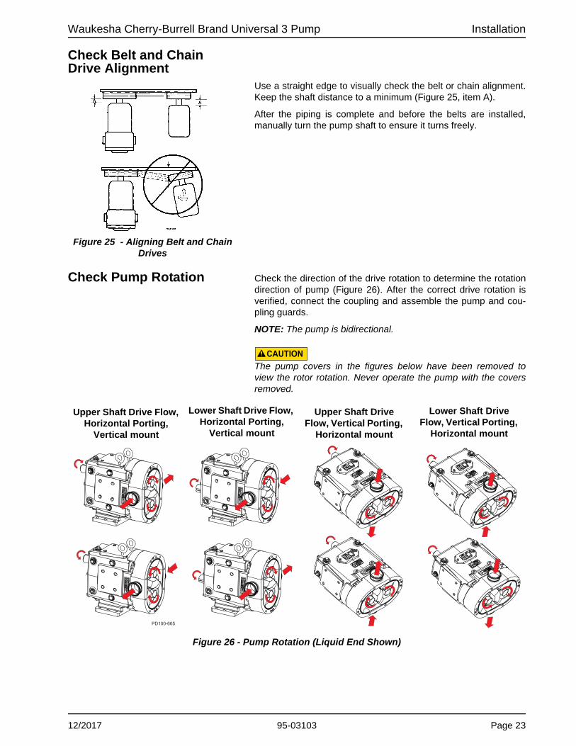
Check Belt and Chain Drive Alignment
Use a straight edge to visually check the belt or chain alignment. Keep the shaft distance to a minimum (Figure 25, item A).
After the piping is complete and before the belts are installed, manually turn the pump shaft to ensure it turns freely.
Check Pump Rotation Check the direction of the drive rotation to determine the rotation direction of pump (Figure 26). After the correct drive rotation is verified, connect the coupling and assemble the pump and cou-pling guards.
NOTE: The pump is bidirectional.
CAUTIONThe pump covers in the figures below have been removed to view the rotor rotation. Never operate the pump with the covers removed.
Figure 25 - Aligning Belt and Chain Drives
Figure 26 - Pump Rotation (Liquid End Shown)
PD100-665
Upper Shaft Drive Flow, Horizontal Porting,
Vertical mount
Lower Shaft Drive Flow, Horizontal Porting,
Vertical mount
Upper Shaft Drive Flow, Vertical Porting,
Horizontal mount
Lower Shaft Drive Flow, Vertical Porting,
Horizontal mount
12/2017 95-03103 Page 23

Operation Waukesha Cherry-Burrell Brand Universal 3 Pump
Operation
Important Safety Information
DANGERThe pump contains internal moving parts. DO NOT put hands or fingers into the pump body ports or drive area at any time during operation. To avoid serious injury, DO NOT install, clean, service, or repair the pump unless all power is off and locked out and the pump is de-pressurized.
WARNINGHandle the pump components carefully because edges may be sharp. Wear gloves while installing and servicing the pump to help avoid injuries from these hazards.
CAUTIONMaintenance should be performed only by trained personnel. See “Qualification Guidelines for Operating Staff” on page 13.
CAUTIONThese pumps are positive displacement, low slip design and will be severely damaged if operated with closed valves in the discharge or inlet lines. The pump warranty is not valid for damages caused by a hydraulic overload from operation or start-up with a closed valve in the system.
Pre-Startup Checklist
1. Ensure that the pump is correctly installed as described in “Installation” on page 15. Review “Install Relief Valves” on page 19 and install relief valves as needed.
2. Check the coupling alignment. See “Check Coupling Align-ment” on page 22.
3. Ensure that the pump and piping are clean and free of foreign material such as welding slag, gaskets, etc.
4. Ensure that all piping connections are tight and leak-free. Where possible, check the system with non-hazardous fluid.
5. Ensure that the pump and drive are lubricated. See “Lubrica-tion” on page 27.
6. Ensure that all valves are open on the discharge side and a free flow path is open to the destination.
7. Ensure that all guards are in place and secure.
CAUTIONFull guards must be installed to isolate the operators and maintenance personnel from the rotating components. Guards are provided as part of a complete pump and drive package. See page 16 and page 99.
8. Double mechanical seals require adequate supply and flow of clean flushing fluids.
9. Ensure that all valves are open on the inlet side and fluid can fill the pump. A flooded suction installation is recommended.
CAUTIONThe motor must be installed by qualified personnel, e.g., a licensed electrician.
CAUTIONConsult the motor or VFD manufac-turer's manual for setup, operation, dis-assembly, and troubleshooting of the motor or VFD, or contact the manufac-turer.
CAUTIONDo not use this pump to flush a newly-installed system. Severe damage may occur to the pump and system if the pump is used to flush the system. Remove the rotors during system flushing, to prevent debris from being trapped between the rotors and the pump body. This debris may damage the pump upon startup.
WARNINGDo not start a pump with seal flush unless the seal flush is installed and turned on.
Page 24 95-03103 12/2017

Waukesha Cherry-Burrell Brand Universal 3 Pump Operation
10. Check the direction of pump and drive rotation to ensure that the pump will rotate in the proper direction. See “Check Pump Rotation” on page 23.
Starting the PumpWARNING
Keep a safe distance (1.6 ft/.5 m) away from the pump during startup.
CAUTIONThe motor must be installed by qualified personnel, e.g., a licensed electrician.
WARNINGIn order to avoid temperature shock after the introduction of hot or cold product, stop the pump before filling the pumphead with product. Once the product has filled the pumphead, allow up to 15 minutes for the pump’s fluid components to thermally adjust, then re-start the pump.
1. Start the pump drive. Where possible, start at a slow speed or jog.
2. For sanitary applications, sanitize the pump per customer requirements before putting the pump into service.
3. Check to make sure that the liquid is reaching the pump. If pumping does not begin and stabilize, check “Troubleshoot-ing” on page 92.
Stopping the PumpWARNING
Keep a safe distance (1.6 ft/.5 m) away from the pump during shutdown.
CAUTIONThe motor must be installed by qualified personnel, e.g., a licensed electrician.
1. Shut off the power to the pump drive.
2. Shut off the supply and discharge lines.
12/2017 95-03103 Page 25

Maintenance Waukesha Cherry-Burrell Brand Universal 3 Pump
Maintenance
Important Safety Information
DANGERThe pump contains internal moving parts. DO NOT put hands or fingers into the pump body ports or drive area at any time during operation. To avoid serious injury, DO NOT install, clean, service, or repair the pump unless all power is off and locked out and the pump is de-pressurized. Shut off and drain product from the pump prior to disconnecting the piping.
WARNINGThe pump components and piping may contain sharp edges. Handle the rotors carefully because edges may be sharp. Wear gloves while installing and servicing the pump to help avoid injuries from these hazards.
WARNINGNever touch the gear case during operation. The surface temperature may exceed 110°F (43°C). The pump cover and body may be cold or hot depending on the product (CIP at 190°F (88°C) or 300°F (149°C) product, for example).
CAUTIONMaintenance should be performed only by trained personnel. See “Qualification Guidelines for Operating Staff” on page 13.
CAUTIONMake sure the pump is securely bolted or clamped down prior to performing any maintenance work. The pump center of gravity changes as parts are added or removed, and could result in tipping of an unsecured pump.
CAUTIONMake sure to keep the work area clear of machine parts, tools, product lines, foreign materials, and power cables to avoid potential hazards.
CAUTIONMake sure appropriate lighting is available: at least 1000 lux, independent of daylight and weather conditions.
CAUTIONBefore carrying out any maintenance and repair work on cold components, ensure that the machine parts in question are sufficiently heated. The contact temperature of accessible machine parts must not be lower than those in the EN ISO 13732-1.
CAUTIONTo lift the cover on a 210 or 320-U3, attach an eye bolt to the threaded hole in the cover and attach lifting straps or chains to the eye bolt. To lift the body of a 130, 180, 210, 220, or 320-U3, use a lifting strap threaded through the ports on either side of the body. To lift the gear case assembly on pumps larger than 018-U3, attach lifting straps/chains to the two eye bolts on the top of the gear case.
Page 26 95-03103 12/2017

Waukesha Cherry-Burrell Brand Universal 3 Pump Maintenance
Before detaching port connections to the pump:
• Close the suction and discharge valves.
• Drain the pump and clean or rinse, if necessary.
• Disconnect or shut off the electrical supply and lock out all power.
Lubrication Drive Lubrication
Refer to the manufacturer’s manual shipped with the drive for proper drive lubrication and frequency.
Gears
Gears are factory-lubricated with gear oil at the quantity shown in Table 3 on page 27. Change the oil every 750 hours. Aggres-sive washdown or extreme running conditions may require more frequent lubrication intervals.
When the pump is not running, the gear oil level is correct when the oil level is visible in the sight glass. Check the oil level regu-larly.
When the pump is running, the oil level may be difficult to see and may appear cloudy.
Universal 3 pumps are shipped with the oil level at or slightly above the sight glass.
Bearings
Bearings are factory-lubricated with grease. Re-lubricate them at the quantity shown in Table 3 on page 27. Grease the bearings every 750 hours. Aggressive washdown or extreme running con-ditions may require more frequent lubrication intervals.
Excess grease will accumulate in the gear case and must be removed through the cleanout hole covered with a plastic plug (Figure 27, item 48). Check the cleanout plugs for any collection of gear oil.
Best practice is to clean out this area every time you grease the pump. Water can accumulate in the gearcase from condensation or from aggressive washdown. If water is found in the gearcase, clean out this area more frequently.
Figure 27 - Lubrication Points
A. Upper Shaft Drive Pump (Standard)B. Lower Shaft Drive Pump (Optional)24D. Oil Drain Plug24F. Oil Fill Plug24L. Oil Level Check Plug, Sight glass48. Grease Clean-out Plug67. Grease Fittings
Gear Oil SpecificationStandard: ISO Grade 320, SAE 140 or AGMA Number 6EP, part no.118402+. Food-grade: part no. 000140003+.
Bearing Lubricant GreaseStandard: NLGI Grade No. 2, EP, Lith-ium-based lubricant, part no. 118401+. Food-grade: part no. 000140002+.
Table 3: Lubrication Quantities
Universal 3 ModelOil Capacity (Gears) Grease Quantity (per Bearing)
Top or Bottom Side Mount Front Rear
006, 015, 018 1.3 oz (40 ml) 3.3 oz (100 ml) .37 oz (11 ml) .13 oz (4 ml)
030, 040 2.0 oz (60 ml) 4 oz (120 ml) .60 oz (18 ml) .21 oz (6 ml)
045, 060, 130 6.0 oz (170 ml) 9.5 oz (280 ml) .84 oz (25 ml) .76 oz (22 ml)
180, 220 11 oz (320 ml) 20 oz (600 ml) 1.33 oz (39 ml) 1.03 oz (30 ml)
210, 320 17 oz (500 ml) 44 oz (1300 ml) 1.96 oz (58 ml) 1.16 oz (34 ml)
12/2017 95-03103 Page 27

Maintenance Waukesha Cherry-Burrell Brand Universal 3 Pump
Maintenance InspectionsDANGER
The pump contains internal moving parts. DO NOT put hands or fingers into the pump body ports or drive area at any time during operation. To avoid serious injury, DO NOT install, clean, service, or repair the pump unless all power is off and locked out and the pump is de-pressurized. Shut off and drain product from the pump prior to disconnecting the piping.
Detecting wear in the early stages can reduce repair costs and down time. A simple “look-feel” inspection of the pump during breakdown cleaning is recommended to detect signs of trouble at an early stage.
A detailed maintenance inspection should be scheduled annually. See “Annual Maintenance” on page 29.
Refer to the “Maintenance Inspection Chart” on page 30 for pos-sible causes and solutions to common issues discovered during inspection.
Inspection of Rotor Tips
Remove the cover (see “Remove Cover” on page 32) and check for metal-to-metal contact between the rotor wings. When contact is detected, repair or replace the pump.
Visually inspect the rotors for rotor tip to rotor tip contact and rotor tip to rotor hub contact. Manually rotate the pump drive shaft and ensure that the rotor tip clearance is equal on both sides as indi-cated in Figure 28.
Inspection of Shaft and Shaft Shoulder
Visually inspect the shaft for twists or bends; replace it as neces-sary. Visually inspect the shaft shoulder (Figure 29, item C) for excessive wear; replace it as necessary. If the shaft shoulder has a sharp edge, remove the edge with a file to prevent cutting the shaft O-ring on installation.
Inspection of Rotor
Visually inspect the rotors for worn splines (Figure 29, item A) and hub wear at the rotor stress points (see arrows in Figure 33 on page 29). Each time the rotors are removed, replace the prod-uct side seal O-rings.
NOTE: Rotor hub and shaft shoulder wear are caused by operating with a loose rotor nut(s) for extended periods.
Figure 28 - Rotor to Rotor Tip Clearance
Figure 29 - Shaft and Rotor Inspection
A
C
Page 28 95-03103 12/2017
Waukesha Cherry-Burrell Brand Universal 3 Pump Maintenance
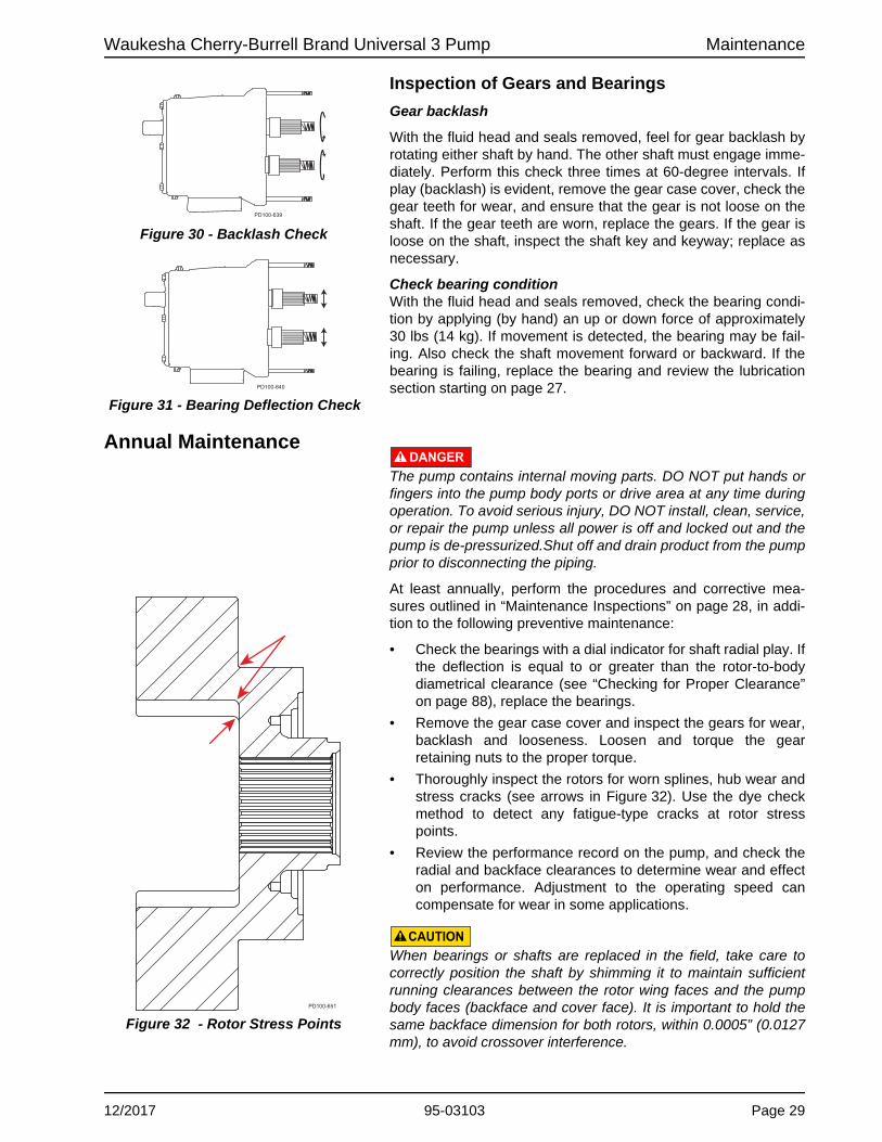
Inspection of Gears and Bearings
Gear backlash
With the fluid head and seals removed, feel for gear backlash by rotating either shaft by hand. The other shaft must engage imme-diately. Perform this check three times at 60-degree intervals. If play (backlash) is evident, remove the gear case cover, check the gear teeth for wear, and ensure that the gear is not loose on the shaft. If the gear teeth are worn, replace the gears. If the gear is loose on the shaft, inspect the shaft key and keyway; replace as necessary.
Check bearing conditionWith the fluid head and seals removed, check the bearing condi-tion by applying (by hand) an up or down force of approximately 30 lbs (14 kg). If movement is detected, the bearing may be fail-ing. Also check the shaft movement forward or backward. If the bearing is failing, replace the bearing and review the lubrication section starting on page 27.
Annual MaintenanceDANGER
The pump contains internal moving parts. DO NOT put hands or fingers into the pump body ports or drive area at any time during operation. To avoid serious injury, DO NOT install, clean, service, or repair the pump unless all power is off and locked out and the pump is de-pressurized.Shut off and drain product from the pump prior to disconnecting the piping.
At least annually, perform the procedures and corrective mea-sures outlined in “Maintenance Inspections” on page 28, in addi-tion to the following preventive maintenance:
• Check the bearings with a dial indicator for shaft radial play. If the deflection is equal to or greater than the rotor-to-body diametrical clearance (see “Checking for Proper Clearance” on page 88), replace the bearings.
• Remove the gear case cover and inspect the gears for wear, backlash and looseness. Loosen and torque the gear retaining nuts to the proper torque.
• Thoroughly inspect the rotors for worn splines, hub wear and stress cracks (see arrows in Figure 32). Use the dye check method to detect any fatigue-type cracks at rotor stress points.
• Review the performance record on the pump, and check the radial and backface clearances to determine wear and effect on performance. Adjustment to the operating speed can compensate for wear in some applications.
CAUTIONWhen bearings or shafts are replaced in the field, take care to correctly position the shaft by shimming it to maintain sufficient running clearances between the rotor wing faces and the pump body faces (backface and cover face). It is important to hold the same backface dimension for both rotors, within 0.0005” (0.0127 mm), to avoid crossover interference.
Figure 30 - Backlash Check
Figure 31 - Bearing Deflection Check
PD100-639
PD100-640
Figure 32 - Rotor Stress Points
PD100-651
12/2017 95-03103 Page 29
Maintenance Waukesha Cherry-Burrell Brand Universal 3 Pump
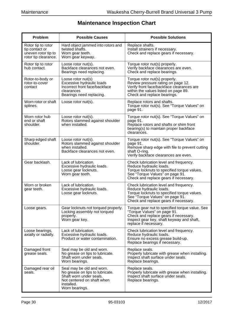
Maintenance Inspection Chart
.
Problem Possible Causes Possible Solutions
Rotor tip to rotor tip contact or uneven rotor tip to rotor tip clearance.
Hard object jammed into rotors and twisted shafts. Worn gear teeth. Worn gear keyway.
Replace shafts. Install strainers if necessary. Check and replace gears if necessary.
Rotor tip to rotor hub contact.
Loose rotor nut(s). Backface clearances not even. Bearings need replacing.
Torque rotor nut(s) properly. Verify backface clearances are even. Check and replace bearings.
Rotor-to-body or rotor-to-cover contact
Loose rotor nut(s) Excessive hydraulic loads Incorrect front face/backface clearances Bearings need replacing.
Torque rotor nut(s) properly. Review pressure rating on page 12. Verify front face/backface clearances are within the values listed on page 89. Check and replace bearings.
Worn rotor or shaft splines.
Loose rotor nut(s). Replace rotors and shafts. Torque rotor nut(s). See “Torque Values” on page 91.
Worn rotor hub end or shaft shoulder.
Loose rotor nut(s). Rotors slammed against shoulder when installed.
Torque rotor nut(s). See “Torque Values” on page 91. Replace rotors and shafts or shim front bearing(s) to maintain proper backface clearances.
Sharp edged shaft shoulder.
Loose rotor nut(s). Rotors slammed against shoulder when installed. Backface clearances not even.
Torque rotor nut(s). See “Torque Values” on page 91. Remove sharp edge with file to prevent cutting shaft O-ring. Verify backface clearances are even.
Gear backlash. Lack of lubrication. Excessive hydraulic loads. Loose gear locknuts. Worn gear teeth.
Check lubrication level and frequency. Reduce hydraulic loads. Torque locknuts to specified torque values. See “Torque Values” on page 91. Check and replace gears if necessary.
Worn or broken gear teeth.
Lack of lubrication. Excessive hydraulic loads. Loose gear locknuts.
Check lubrication level and frequency. Reduce hydraulic loads. Torque locknuts to specified torque values. See “Torque Values” on page 91. Check and replace gears if necessary.
Loose gears. Gear locknuts not torqued properly. Locking assembly not torqued properly. Worn gear key.
Torque gear nut to specified torque value. See “Torque Values” on page 91. Check and replace gears if necessary. Inspect gear key, shaft keyway and shaft, replace if necessary.
Loose bearings, axially or radially.
Lack of lubrication. Excessive hydraulic loads. Product or water contamination.
Check lubrication level and frequency. Reduce hydraulic loads. Ensure no excess grease build-up. Replace bearings if necessary.
Damaged front grease seals.
Seal may be old and worn. No grease on lips to lubricate. Shaft worn under seals. Worn bearings.
Replace seals. Properly lubricate with grease when installing. Inspect shaft surface under seals. Replace bearings.
Damaged rear oil seals.
Seal may be old and worn. No grease on lips to lubricate. Shaft worn under seals. Not centered on shaft when installed. Worn bearings.
Replace seals. Properly lubricate with grease when installing. Inspect shaft surface under seals. Replace bearings.
Page 30 95-03103 12/2017

Waukesha Cherry-Burrell Brand Universal 3 Pump Maintenance
Cleaning Determine the pump cleaning schedule on-site for materials being processed and plant maintenance schedule.
To disassemble the fluid head, see “Fluid Head Disassembly - Cover and Rotors” on page 32. Remove and clean the cover O-ring, pump seals, and the rotor nut assembly. Inspect and replace them as necessary.
NOTE: Always replace the rotor nut O-rings and product-side seal O-rings when reassembling the pump. If the area behind these seals becomes soiled, contact SPX FLOW Application Engineering for a specific cleaning and sanitizing procedure validated to remove bacteria. If a chlorine solution (200 ppm available chlorine) is used, it should leave no residual deposits which would remain in the pump.
CAUTIONAcid cleaners have a much higher metal corrosion rate and pump parts should remain in acid cleaning solutions no longer than necessary. Any strong inorganic mineral-based acids that are harmful to your hands would be harmful to pump parts. See “Stainless Steel Corrosion” on page 9.
In applications where material can harden in the pump during shutdown, a CIP cleaning, flush, or disassembly of the fluid head and manual cleaning is strongly recommended. See “CIP (Clean-In-Place) Design” on page 20.
12/2017 95-03103 Page 31

Maintenance Waukesha Cherry-Burrell Brand Universal 3 Pump
Fluid Head Disassembly - Cover and Rotors
NOTE: SPX FLOW recommends replacing elastomers every time the pump is serviced. WARNING
The pump components and piping may contain sharp edges. Handle the rotors carefully because edges may be sharp. Wear gloves while installing and servicing the pump to help avoid injuries from these hazards.
CAUTIONMake sure the pump is securely bolted or clamped down prior to performing any maintenance work. The pump center of gravity changes as parts are added or removed, and could result in tipping of an unsecured pump.
Remove Cover
1. Remove the cover nuts from the cover. Using a soft hammer, tap the cover off the body studs and dowel pins.
2. Place the cover on a protected surface with the finished surfaces facing up.
CAUTIONTo lift the cover on a 210 or 320-U3, attach an eye bolt to the threaded hole in the cover and attach lifting straps or chains to the eye bolt.
3. Remove and inspect the cover gasket.
DANGERThe pump contains internal moving parts. DO NOT put hands or fingers into the pump body ports or drive area at any time during operation. To avoid serious injury, DO NOT install, clean, service, or repair the pump unless all power is off and locked out and the pump is de-pressurized. Shut off and drain product from the pump prior to disconnecting the piping.
Table 4: Cover Nuts Wrench Size
Model U3 Wrench Size
006, 015, 018, 030, 040
5/8"
045, 060, 130, 180, 220
7/8"
210, 320 1"
Figure 33 - Remove cover
Figure 34 - Remove cover gasket
Page 32 95-03103 12/2017

Waukesha Cherry-Burrell Brand Universal 3 Pump Maintenance
Remove Rotor Nuts
1. Use the rotor blocking tool (part number 139794+) to keep the rotors from turning when removing the rotor nuts.
NOTE: When working on a rotor, always block the rotor against the body, not against the other rotor. See Figure 35.
NOTE: SPX FLOW recommends using the Non-Marring Socket Tool for Rotor Nuts to protect the rotor nut. See Table 5 and page 126.
2. Remove the rotor nuts.
3. Remove the rotor nut O-rings from each rotor nut.
NOTE: Discard the O-rings from the rotor nut; these are intended for one-time use only.
Remove Rotors
WARNINGThe pump components and piping may contain sharp edges. Handle the rotors carefully because edges may be sharp. Wear gloves while installing and servicing the pump to help avoid injuries from these hazards.
Remove the rotors by hand. Place the rotors on a protected sur-face to prevent damage to close-tolerance parts.
NOTE: Mechanical seal is shown in Figure 37.
For mechanical seals, continue.
Figure 35 - Remove Rotor Nut
Table 5: Rotor Nut Wrench Size and Socket Tool
U3 ModelWrench
SizeSocket
Tool
006, 015, 018 15/16" 126533+
030, 040 1-1/4" 139795+
045, 060, 130 1-5/8" 139796+
180, 220 2-1/4" 139797+
210, 320 2-3/8" 126536+
Figure 36 - Remove O-ring
Figure 37 - Remove rotor
For O-ring seals, skip to page 65.
12/2017 95-03103 Page 33

Maintenance Waukesha Cherry-Burrell Brand Universal 3 Pump
Single and Double Mechanical Seal
Remove Product-Side Rotary and Stationary Seal
1. Remove the rotary seal from the rotor.
2. Remove the rotary seal O-ring from the rotor.
3. Remove the stationary seal from the pump body.
Figure 38 - Remove rotary seal
Figure 39 - Remove seal O-ring
Figure 40 - Remove stationary seal
Page 34 95-03103 12/2017

Waukesha Cherry-Burrell Brand Universal 3 Pump Maintenance
4. Remove the stationary seal O-ring from the stationary seal.
NOTE: The O-ring usually comes off with the seal in step 3.
Remove Pump Body
1. Remove the two body retaining cap screws.
2. Remove the body from the gear case. If needed, use a plastic mallet to tap the body away from the gear case, until the dowel pins are dislodged from the bushings.
3. Slide the body straight off the body studs to prevent damaging the mechanical seal parts.
CAUTIONTo lift the body of a 130, 180, 210, 220, or 320-U3, use a lifting strap threaded through the ports on either side of the body.
4. Place the body on a protected surface with the seals facing up to protect the seals.
NOTE: For single mechanical seal, continue. For double mechanical seal, see page 43.
Figure 41 - Stationary Seal O-ring
The product-side seals and O-rings in a U3 mechanical seal can be replaced without removing the pump body. To replace or service these components only, skip to “Install Product-Side Rotary and Stationary Seal” on page 62.
Figure 42 - Remove body retaining screws
Table 6: Body Retaining Screws Wrench Size
Model Wrench Size
006, 015, 018, 030, 040 3/16"
045, 060, 130 1/4"
180, 220, 210, 320 5/16"
Figure 43 - Remove pump body
12/2017 95-03103 Page 35

Maintenance Waukesha Cherry-Burrell Brand Universal 3 Pump
Single Mechanical Seal Remove Seal Components
NOTE: For double mechanical seal, see page 43.
1. Remove the seal housing bolts.
2. Remove the seal housing. Figure 45 shows the design for 130-U3 and smaller sizes. See Figure 46 for 180-U3 and larger sizes.
3. Figure 46 shows the design for 180-U3 and larger sizes. See Figure 45 for 130-U3 and smaller sizes.
Figure 44 - Remove seal housing bolts
Figure 45 - Remove seal housing
Figure 46 - Remove seal housing
Page 36 95-03103 12/2017

Waukesha Cherry-Burrell Brand Universal 3 Pump Maintenance
4. Remove the wave spring (040-U3 pictured).
5. Remove the drive ring (040-U3 pictured).
6. 130-U3 and smaller pumps only: Remove the shaft ring. (180-U3 and larger sizes do not have a shaft ring.)
NOTE: To assemble a single mechanical seal for 130-U3 and smaller pumps, continue. For 180-U3 and larger pumps, see page 41.
Figure 47 - Remove wave spring
Figure 48 - Remove drive ring
Figure 49 - Remove shaft ring
12/2017 95-03103 Page 37
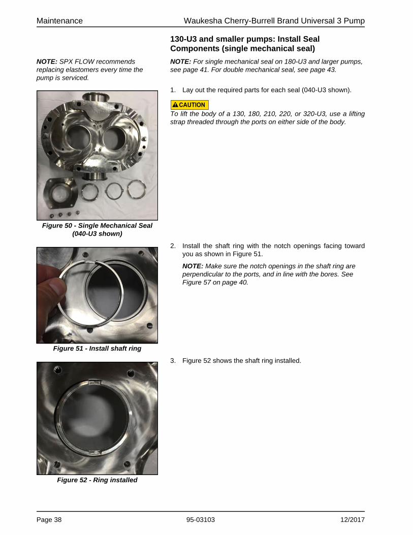
Maintenance Waukesha Cherry-Burrell Brand Universal 3 Pump
130-U3 and smaller pumps: Install Seal Components (single mechanical seal)
NOTE: SPX FLOW recommends replacing elastomers every time the pump is serviced.
NOTE: For single mechanical seal on 180-U3 and larger pumps, see page 41. For double mechanical seal, see page 43.
1. Lay out the required parts for each seal (040-U3 shown).
CAUTIONTo lift the body of a 130, 180, 210, 220, or 320-U3, use a lifting strap threaded through the ports on either side of the body.
2. Install the shaft ring with the notch openings facing toward you as shown in Figure 51.
NOTE: Make sure the notch openings in the shaft ring are perpendicular to the ports, and in line with the bores. See Figure 57 on page 40.
3. Figure 52 shows the shaft ring installed.
Figure 50 - Single Mechanical Seal (040-U3 shown)
Figure 51 - Install shaft ring
Figure 52 - Ring installed
Page 38 95-03103 12/2017

Waukesha Cherry-Burrell Brand Universal 3 Pump Maintenance
4. Install the drive ring with the tab protrusions facing the pump body.
NOTE: The side of the drive ring tab that protrudes, faces the body; the flat side of the tab faces up. (The flat side of the tab is facing the camera in Figure 53 and Figure 54.)
5. Figure 54 shows the drive ring installed.
6. Install the wave spring, centering it on the drive ring.
7. Figure 56 shows the wave spring installed.
Figure 53 - Install drive ring
Figure 54 - drive ring installed (130-U3 and smaller
Figure 55 - Install wave spring
Figure 56 - Wave spring installed
12/2017 95-03103 Page 39

Maintenance Waukesha Cherry-Burrell Brand Universal 3 Pump
8. Install the seal housing. as shown in Figure 57.
NOTE: Note the alignment of the drive ring tabs and shaft ring.
9. Lubricate the threads of the seal housing bolts with food grade anti-seize. Push down on the seal housing to compress the seal spring, and install the 4 seal housing bolts.
10. Torque the bolts to the specified torque value:
11. Figure 59 shows the seal housing installed.
12. Repeat these steps for the second seal.
Figure 57 - Install seal housing
Figure 58 - Install seal housing bolts
Table 7: Seal Housing Bolt Torque
U3 Model Seal Housing Bolt Torque
006, 015, 018 7.4 ft-lb / 10 N·m
030, 040, 045, 060, 130, 180, 220, 210, 320
14.8 ft-lb / 20 N·m
Figure 59 - Seal housing installed
Skip to “Install Pump Body” on page 61.
Page 40 95-03103 12/2017

Waukesha Cherry-Burrell Brand Universal 3 Pump Maintenance
180-U3 and larger pumps: Install Seal Components (single mechanical seal)
NOTE: SPX FLOW recommends replacing elastomers every time the pump is serviced.
NOTE: For single mechanical seal on 130-U3 and smaller pumps, see page 38. For double mechanical seal, see page 55.
1. Lay out the required parts for each seal.
CAUTIONTo lift the body of a 130, 180, 210, 220, or 320-U3, use a lifting strap threaded through the ports on either side of the body.
2. Install the drive ring as shown in Figure 60. The side of the drive ring tab that protrudes, faces the body; the flat side of the tab faces up. (The flat side of the tab is facing the camera in Figure 60 and Figure 61.)
NOTE: See also the exploded-view drawing of the seals on page 120
3. Figure 61 shows the drive ring installed.
4. Install the wave spring, centering it on the drive ring. Figure 62 shows the wave spring installed.
Figure 60 - Install drive ring
Figure 61 - Drive ring installed
Figure 62 - Wave spring installed
12/2017 95-03103 Page 41
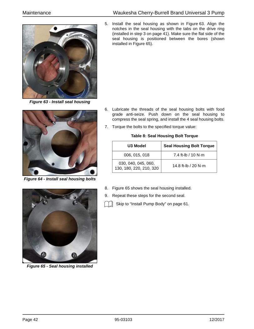
Maintenance Waukesha Cherry-Burrell Brand Universal 3 Pump
5. Install the seal housing as shown in Figure 63. Align the notches in the seal housing with the tabs on the drive ring (installed in step 3 on page 41). Make sure the flat side of the seal housing is positioned between the bores (shown installed in Figure 65).
6. Lubricate the threads of the seal housing bolts with food grade anti-seize. Push down on the seal housing to compress the seal spring, and install the 4 seal housing bolts.
7. Torque the bolts to the specified torque value:
8. Figure 65 shows the seal housing installed.
9. Repeat these steps for the second seal.
Figure 63 - Install seal housing
Figure 64 - Install seal housing bolts
Table 8: Seal Housing Bolt Torque
U3 Model Seal Housing Bolt Torque
006, 015, 018 7.4 ft-lb / 10 N·m
030, 040, 045, 060, 130, 180, 220, 210, 320
14.8 ft-lb / 20 N·m
Figure 65 - Seal housing installed
Skip to “Install Pump Body” on page 61.
Page 42 95-03103 12/2017

Waukesha Cherry-Burrell Brand Universal 3 Pump Maintenance
Double Mechanical Seal Remove Flush-Side Seal Components
NOTE: For single mechanical seal, see page 36. For O-ring seals, see page 67.
1. Remove the flush-side rotary seal from each shaft. Use caution not to damage the seals during removal.
2. Remove the flush-side rotary seal O-ring from each shaft.
3. Remove the adjusting ring from each pump shaft.
Figure 66 - Remove flush-side rotary seal
Figure 67 - Remove O-ring
Figure 68 - Remove adjusting ring
12/2017 95-03103 Page 43

Maintenance Waukesha Cherry-Burrell Brand Universal 3 Pump
4. Remove the adjusting ring O-ring from the shaft groove on each shaft.
NOTE: Before installing the new O-rings, inspect the shaft O-ring groove(s) for damage, and repair or replace the shafts if required.
NOTE: Inspect the flats on the shaft shoulder and repair or replace the shafts if required.
5. Remove the 3 stationary seal retaining bolts from each seal housing (040-U3 pictured).
NOTE: The seal may be removed by loosening 2 screws and removing the 3rd screw.
6. Remove the flush-side stationary seal (040-U3 pictured).
7. Inspect the seal housing pins for damage, and repair or replace them as necessary. If the pins are loose, replace them with new ones.
8. Remove the wave spring (040-U3 pictured).
Figure 69 - Adjusting ring O-ring
Figure 70 - Remove seal retaining bolts
Figure 71 - Remove stationary seal
Figure 72 - Remove wave spring
Page 44 95-03103 12/2017

Waukesha Cherry-Burrell Brand Universal 3 Pump Maintenance
9. Remove the stationary seal O-ring (040-U3 pictured).
10. Remove the 4 seal housing bolts (040-U3 pictured).
11. Remove the seal housing (040-U3 pictured). The arrow in Figure 75 shows the seal housing O-ring location on 130-U3 pumps and smaller.
12. (130-U3 pumps and smaller) Remove the seal housing O-ring from around the shaft ring. See Figure 75 for the seal housing O-ring location.
Figure 73 - Seal O-ring location
Figure 74 - Seal housing bolts
Figure 75 - Remove seal housing
Figure 76 - Remove seal housing O-ring
12/2017 95-03103 Page 45

Maintenance Waukesha Cherry-Burrell Brand Universal 3 Pump
13. (180-U3 pumps and larger) Remove the seal housing O-ring from the seal housing.
NOTE: On the 180-U3 pumps and larger, the seal housing O-ring is installed on the seal housing.
14. Remove the drive ring. (040-U3 pictured.)
Remove the shaft ring. (Applies to 130-U3 pumps and smaller only. 180-U3 pumps and larger do not have a shaft ring.)
1. Repeat for the second seal.
NOTE: To assemble a double mechanical seal for 130-U3 pumps and smaller, continue. For 180-U3 pumps and larger, see page 55.
Figure 77 - Remove seal housing O-ring
Figure 78 - Remove drive ring
Figure 79 - Remove shaft ring
Page 46 95-03103 12/2017

Waukesha Cherry-Burrell Brand Universal 3 Pump Maintenance
130-U3 and smaller pumps: Install Seal Components (double mechanical seal)
NOTE: For double mechanical seal on 180-U3 and larger pumps, see page 55. For single mechanical seal, see page 38.
1. Lay out the required parts for each seal (Figure 80 shows parts for one seal, on a 040-U3 size pump).
CAUTIONTo lift the body of a 130, 180, 210, 220, or 320-U3, use a lifting strap threaded through the ports on either side of the body.
2. Install the shaft ring with the notch openings facing toward you as shown in Figure 81.
NOTE: Make sure the notch openings in the shaft ring are perpendicular to the ports, and in line with the bores. See Figure 87 on page 49.
3. Figure 82 shows the shaft ring installed.
Figure 80 - Double Mechanical Seal (040-U3 shown)
Figure 81 - Install shaft ring
Figure 82 - Shaft ring installed
12/2017 95-03103 Page 47

Maintenance Waukesha Cherry-Burrell Brand Universal 3 Pump
4. Install the drive ring as shown in Figure 83. The side of the drive ring tab that protrudes, faces the body; the flat side of the tab faces up. (The flat side of the tab is facing the camera in Figure 83 and Figure 84.)
5. Note the orientation of the tabs; for pumps 130-U3 and smaller, the tabs of the drive ring are perpendicular to the side ports of the body. See Figure 87 on page 49 for the orientation as installed.
6. Figure 84 shows the drive ring installed.
7. Install the seal housing O-ring. The O-ring fits in the body, around the shaft ring. See Figure 86.
8. Figure 86 shows the seal housing O-ring installed.
Figure 83 - Install drive ring
Figure 84 - Drive ring installed
Figure 85 - Install seal housing O-ring
Figure 86 - Seal housing O-ring installed
Page 48 95-03103 12/2017
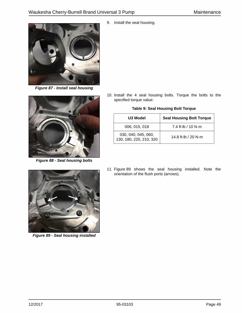
Waukesha Cherry-Burrell Brand Universal 3 Pump Maintenance
9. Install the seal housing.
10. Install the 4 seal housing bolts. Torque the bolts to the specified torque value:
11. Figure 89 shows the seal housing installed. Note the orientation of the flush ports (arrows).
Figure 87 - Install seal housing
Figure 88 - Seal housing bolts
Table 9: Seal Housing Bolt Torque
U3 Model Seal Housing Bolt Torque
006, 015, 018 7.4 ft-lb / 10 N·m
030, 040, 045, 060, 130, 180, 220, 210, 320
14.8 ft-lb / 20 N·m
Figure 89 - Seal housing installed
12/2017 95-03103 Page 49

Maintenance Waukesha Cherry-Burrell Brand Universal 3 Pump
12. Install the lubricated stationary seal O-ring as shown in Figure 90.
13. The stationary seal O-ring is located between the seal housing and the drive ring.
14. Install the wave spring.
15. Figure 93 shows the wave spring installed.
Figure 90 - Install seal O-ring
Figure 91 - Seal O-ring location
Figure 92 - Install wave spring
Figure 93 - Wave spring installed
Page 50 95-03103 12/2017

Waukesha Cherry-Burrell Brand Universal 3 Pump Maintenance
16. Install the flush-side stationary seal, making sure to line up the notches on the seal to the seal housing pins.
17. Figure 95 shows the flush-side stationary seal installed. Note the notches (white arrow) lined up with the seal housing pins (black arrow).
18. Install the 3 seal retaining bolts. Hand-tighten the bolts until snug.
19. Repeat these steps to install the second seal.
Figure 94 - Install flush-side stationary seal
Figure 95 - Flush-side stationary seal installed
Figure 96 - Install seal retaining bolts
12/2017 95-03103 Page 51

Maintenance Waukesha Cherry-Burrell Brand Universal 3 Pump
20. Figure 97 shows both seals installed.
21. Confirm that each seal moves easily in and out by applying finger pressure to the seal. If the seal does not move, reassemble the seal and re-confirm.
22. Install the lubricated adjusting ring O-ring onto the shaft groove.
Figure 97 - Seals installed
Figure 98 - Apply finger pressure
Figure 99 - Install O-ring
Page 52 95-03103 12/2017

Waukesha Cherry-Burrell Brand Universal 3 Pump Maintenance
23. Figure 100 shows the O-ring installed in the shaft groove.
24. Install the adjusting ring onto each pump shaft. Make sure to align the flats on the adjusting ring to the flats on the drive shafts.
25. Figure 102 shows the adjusting ring installed.
26. Install the rotary seal O-ring on each shaft.
Figure 100 - O-ring installed
Figure 101 - Install adjusting ring
Figure 102 - Adjusting ring installed
Figure 103 - Install O-ring
12/2017 95-03103 Page 53

Maintenance Waukesha Cherry-Burrell Brand Universal 3 Pump
27. Figure 104 shows the rotary seal O-ring installed on the shaft.
28. Install the flush-side rotary seal onto the shaft, aligning the tab with the notch on the seal.
29. Figure 106 shows the seal installed.
Figure 104 - O-ring installed
Figure 105 - Install flush-side rotary seal
Figure 106 - Rotary seal installed
Skip to “Install Pump Body” on page 61.
Page 54 95-03103 12/2017
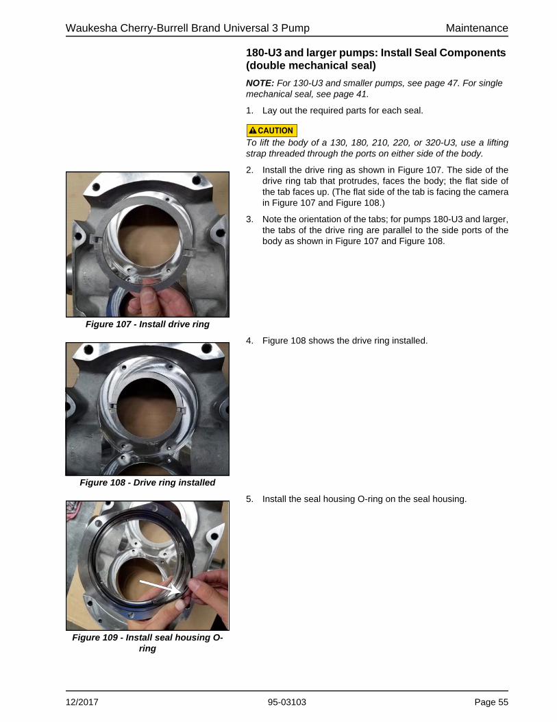
Waukesha Cherry-Burrell Brand Universal 3 Pump Maintenance
180-U3 and larger pumps: Install Seal Components (double mechanical seal)
NOTE: For 130-U3 and smaller pumps, see page 47. For single mechanical seal, see page 41.
1. Lay out the required parts for each seal.
CAUTIONTo lift the body of a 130, 180, 210, 220, or 320-U3, use a lifting strap threaded through the ports on either side of the body.
2. Install the drive ring as shown in Figure 107. The side of the drive ring tab that protrudes, faces the body; the flat side of the tab faces up. (The flat side of the tab is facing the camera in Figure 107 and Figure 108.)
3. Note the orientation of the tabs; for pumps 180-U3 and larger, the tabs of the drive ring are parallel to the side ports of the body as shown in Figure 107 and Figure 108.
4. Figure 108 shows the drive ring installed.
5. Install the seal housing O-ring on the seal housing.
Figure 107 - Install drive ring
Figure 108 - Drive ring installed
Figure 109 - Install seal housing O-ring
12/2017 95-03103 Page 55

Maintenance Waukesha Cherry-Burrell Brand Universal 3 Pump
6. Install the seal housing. Align the drive ring tabs with the notches in the seal housing.
7. Figure 111 shows the 180-U3 seal housing in place. Note the orientation of the flat (arrow), facing the center of the pump body.
8. Install the 4 seal housing bolts. Torque the bolts to the specified torque value:
Figure 110 - Seal housing O-ring installed
Figure 111 - Seal housing in place
Figure 112 - Seal housing bolts
Table 10: Seal Housing Bolt Torque
U3 Model Seal Housing Bolt Torque
006, 015, 018 7.4 ft-lb / 10 N·m
030, 040, 045, 060, 130, 180, 220, 210, 320
14.8 ft-lb / 20 N·m
Page 56 95-03103 12/2017

Waukesha Cherry-Burrell Brand Universal 3 Pump Maintenance
9. Install the lubricated stationary seal O-ring as shown in Figure 113.
10. The stationary seal O-ring is located between the seal housing and the drive ring.
11. Install the wave spring.
Figure 113 - Install seal O-ring
Figure 114 - Seal O-ring location
Figure 115 - Wave spring installed
12/2017 95-03103 Page 57

Maintenance Waukesha Cherry-Burrell Brand Universal 3 Pump
12. Install the flush-side stationary seal, making sure to line up the notches on the seal (white arrow) to the seal housing pins (black arrow).
13. Install the 3 seal retaining bolts. Hand-tighten the bolts until snug.
14. Confirm that the seal moves easily in and out by applying finger pressure to the seal. If the seal does not move, reassemble the seal and re-confirm.
15. Repeat these steps to install the second seal.
Figure 116 - Install flush-side stationary seal
Figure 117 - Install seal retaining bolts
Figure 118 - Apply finger pressure
Page 58 95-03103 12/2017

Waukesha Cherry-Burrell Brand Universal 3 Pump Maintenance
16. Install the lubricated adjusting ring O-ring onto the shaft groove.
17. Figure 120 shows the O-ring installed in the shaft groove.
18. Install the adjusting ring onto each pump shaft. Make sure to align the flats on the adjusting ring to the flats on the drive shafts.
19. Figure 122 shows the adjusting ring installed.
Figure 119 - Install O-ring
Figure 120 - O-ring installed
Figure 121 - Install adjusting ring
Figure 122 - Adjusting ring installed
12/2017 95-03103 Page 59

Maintenance Waukesha Cherry-Burrell Brand Universal 3 Pump
20. Install the rotary seal O-ring on each shaft.
21. Figure 124 shows the rotary seal O-ring installed on the shaft.
22. Install the flush-side rotary seal onto the shaft, aligning the tab with the notch on the seal.
23. Figure 126 shows the seal installed.
Figure 123 - Install O-ring
Figure 124 - O-ring installed
Figure 125 - Install flush-side rotary seal
Figure 126 - Rotary seal installed
Page 60 95-03103 12/2017

Waukesha Cherry-Burrell Brand Universal 3 Pump Maintenance
Single and Double Mechanical Seal
Install Pump Body
1. Install the pump body onto the gear case. Confirm that the pump body dowel pins align with the correct size bushing on the gear case.
NOTE: Double mechanical seal shown.
2. Figure 128 shows the pump body installed on the gear case.
3. Install the body retaining screws. Lubricate the thread with food-grade anti-seize. Lightly hand-tighten the screws, so the pump body is securely seated against the gear case.
Figure 127 - Install pump body
CAUTIONMake sure the pump is securely bolted or clamped down prior to performing any maintenance work. The pump center of gravity changes as parts are added or removed, and could result in tipping of an unsecured pump.
CAUTIONTo lift the body of a 130, 180, 210, 220, 220, or 320-U3, use a lifting strap threaded through the ports on either side of the body.
Figure 128 - Pump body installed
Figure 129 - Install body retaining screws
12/2017 95-03103 Page 61

Maintenance Waukesha Cherry-Burrell Brand Universal 3 Pump
Install Product-Side Rotary and Stationary Seal
NOTE: Applies to both single and double mechanical seal.
1. Install the lubricated stationary seal O-ring onto the stationary seal.
2. Figure 131 shows the O-ring installed on the stationary seal.
3. Install the stationary seal into the pump body. Align the notches in the seal with the tabs on the drive ring (see arrow in Figure 132). Push the seal into the pump so that the O-ring can seat in the bore and hold the seal in place.
4. After installing the stationary seal, push on it and it should spring back freely. If it does not spring back, check the seal installation.
Figure 130 - Install seal O-ring
Figure 131 - Seal O-ring installed
Figure 132 - Install stationary seal
Figure 133 - Push on stationary seal
Page 62 95-03103 12/2017

Waukesha Cherry-Burrell Brand Universal 3 Pump Maintenance
5. Figure 134 shows the stationary seal installed.
6. Install the lubricated rotary seal O-ring into the rotor.
7. Figure 136 shows the O-ring installed.
Figure 134 - Stationary seal installed
Figure 135 - Install seal O-ring
Figure 136 - Seal O-ring installed
12/2017 95-03103 Page 63

Maintenance Waukesha Cherry-Burrell Brand Universal 3 Pump
8. Install the rotary seal into the rotor. Align the notches in the seal to the drive pins on the rotor.
9. After installing the rotary seal, it should fit solidly in the rotor as shown in Figure 138.
10. Make sure the seal O-ring is not pinched.
11. If the O-ring is pinched as shown in Figure 139, push in the O-ring with the O-ring removal tool while inserting the seal. (For part number, see “O-ring Removal Tools” on page 126.)
Figure 137 - Install rotary seal
Figure 138 - Rotary seal installed
Figure 139 - Seal O-ring pinched
Figure 140 - Push in O-ring
Skip to “Install Rotors” on page 74.
Page 64 95-03103 12/2017

Waukesha Cherry-Burrell Brand Universal 3 Pump Maintenance
O-ring Seal Remove Product-Side Seal Components
NOTE: Removing the rotor normally does not remove the sleeve; the sleeve must be removed separately. Figure 141 shows the sleeve remaining after the rotor has been removed.
1. Grasp the sleeve with your fingers and pull it out of the seal housing.
2. Remove the sleeve front O-ring (indicated by the arrow in Figure 142) from the sleeve and discard it.
Removing a single O-ring or the front O-ring of a double O-ring seal
1. Remove the front O-ring using either the Standard O-ring removal tool (part no. AD0096001, shown) or U3 Double O-Ring Seal Removal Tool (part no. 140062+, pictured in Figure 144).
2. Discard the used O-ring.
Removing the back O-ring of a double O-ring seal
1. Use the U3 Double O-Ring Seal Removal Tool, part no. 140062+.
Figure 141 - Sleeve remaining after rotor removal
Figure 142 - Remove sleeve, O-ring
Figure 143 - Remove O-ring
Figure 144 - Remove O-ring
12/2017 95-03103 Page 65

Maintenance Waukesha Cherry-Burrell Brand Universal 3 Pump
2. The O-ring fits into a groove on the seal housing. With the hook on the tool facing down (facing the groove), slide the tool between the O-ring and the groove to dislodge the O-ring.
3. Then twist the tool so the hook faces the opposite direction (toward the shaft), and pull the O-ring out of the seal housing.
4. Discard the used O-ring.
Remove Pump Body
1. Remove the two body retaining cap screws.
2. Remove the body from the gear case. If needed, use a plastic mallet to tap the body away from the gear case, until the dowel pins are dislodged from the bushings.
3. Slide the body straight off the body studs to prevent damaging the mechanical seal parts.
CAUTIONTo lift the body of a 130, 180, 210, 220, or 320-U3, use a lifting strap threaded through the ports on either side of the body.
4. Place the body on a protected surface with the seals facing up to protect the seals.
Figure 145 - Remove O-ring
Figure 146 - Remove O-ring
The seal sleeve and O-rings in a U3 O-ring seal can be replaced without removing the pump body. To replace or service these components only, skip to “Install Seal O-ring” on page 72.
Figure 147 - Remove body retaining screws
Table 11: Body Retaining Screws Wrench Size
Model Wrench Size
006, 015, 018, 030, 040 3/16"
045, 060, 130 1/4"
180, 220, 210, 320 5/16"
Figure 148 - Remove pump body
Page 66 95-03103 12/2017
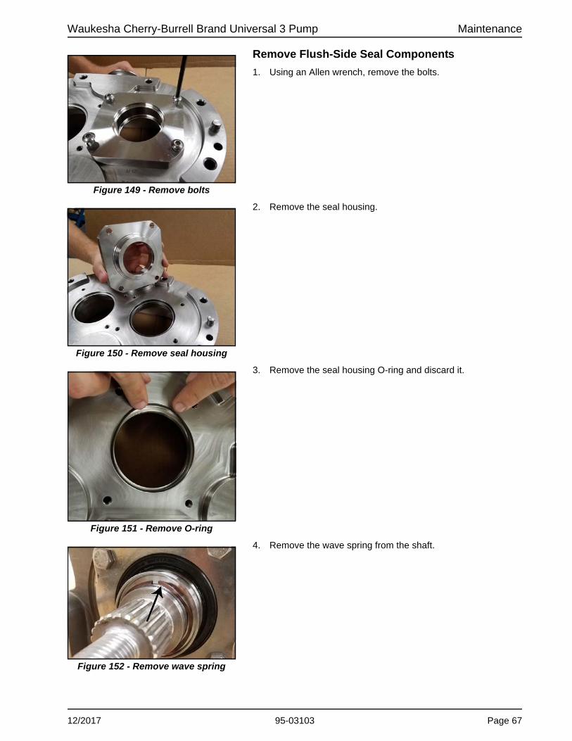
Waukesha Cherry-Burrell Brand Universal 3 Pump Maintenance
Remove Flush-Side Seal Components
1. Using an Allen wrench, remove the bolts.
2. Remove the seal housing.
3. Remove the seal housing O-ring and discard it.
4. Remove the wave spring from the shaft.
Figure 149 - Remove bolts
Figure 150 - Remove seal housing
Figure 151 - Remove O-ring
Figure 152 - Remove wave spring
12/2017 95-03103 Page 67

Maintenance Waukesha Cherry-Burrell Brand Universal 3 Pump
5. Remove the seal seat from the shaft.
6. Remove the sleeve back O-ring from the groove on the shaft and discard it.
Install Body Seal Components
1. Place the body on a protected surface. Lubricate and install the seal housing O-ring. Figure 155 shows the seal housing O-ring installed.
Figure 153 - Remove seal seat
Figure 154 - Remove O-ring
Figure 155 - Seal housing O-ring installed
Page 68 95-03103 12/2017

Waukesha Cherry-Burrell Brand Universal 3 Pump Maintenance
2. Line up the bolt holes of the O-ring seal housing with the holes on the body.
3. For a double O-ring seal, position the housing so that the flush holes are located toward the outer edge of the body, not toward the middle.
4. Lubricate the threads of the seal housing bolts with food grade anti-seize. Using an Allen wrench, install the 4 seal housing bolts.
5. Torque the bolts to the specified torque value:
6. Repeat for the second seal housing. Figure 159 shows the seal housings installed.
Figure 156 - Line up bolt holes
Figure 157 - Flush hole location
Figure 158 - Install bolts
Table 12: Seal Housing Bolt Torque
U3 Model Seal Housing Bolt Torque
006, 015, 018 7.4 ft-lb / 10 N·m
030, 040, 045, 060, 130, 180, 220, 210, 320
14.8 ft-lb / 20 N·m
Figure 159 - Seal housings installed
12/2017 95-03103 Page 69
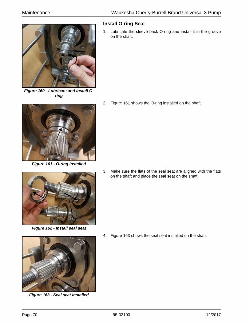
Maintenance Waukesha Cherry-Burrell Brand Universal 3 Pump
Install O-ring Seal
1. Lubricate the sleeve back O-ring and install it in the groove on the shaft.
2. Figure 161 shows the O-ring installed on the shaft.
3. Make sure the flats of the seal seat are aligned with the flats on the shaft and place the seal seat on the shaft.
4. Figure 163 shows the seal seat installed on the shaft.
Figure 160 - Lubricate and install O-ring
Figure 161 - O-ring installed
Figure 162 - Install seal seat
Figure 163 - Seal seat installed
Page 70 95-03103 12/2017

Waukesha Cherry-Burrell Brand Universal 3 Pump Maintenance
5. Install the wave spring on the shaft.
Install Pump Body
1. Install the pump body onto the gear case. Confirm that the pump body dowel pins align with the correct size bushing on the gear case.
NOTE: Double mechanical seal shown.
2. Figure 166 shows the pump body installed on the gear case.
Figure 164 - Install wave spring
Figure 165 - Install pump body
CAUTIONMake sure the pump is securely bolted or clamped down prior to performing any maintenance work. The pump center of gravity changes as parts are added or removed, and could result in tipping of an unsecured pump.
CAUTIONTo lift the body of a 130, 180, 210, 220, 220, or 320-U3, use a lifting strap threaded through the ports on either side of the body.
Figure 166 - Pump body installed
12/2017 95-03103 Page 71

Maintenance Waukesha Cherry-Burrell Brand Universal 3 Pump
3. Install the body retaining screws. Lubricate the thread with food-grade anti-seize. Lightly hand-tighten the screws, so the pump body is securely seated against the gear case.
Install Seal O-ring
NOTE: Do not lubricate the seal O-ring.
1. For a single O-ring seal, install the seal O-ring in the front groove in the seal housing.
2. For a double O-ring seal, install the back O-ring first, then install the front O-ring. The O-rings fit into the grooves in the seal housing.
Install Rotary Seal Components
1. Lubricate and install the sleeve front O-ring on the rotor.
Figure 167 - Install body retaining screws
Figure 168 - Install seal O-ring
Figure 169 - Install sleeve front O-ring
Page 72 95-03103 12/2017
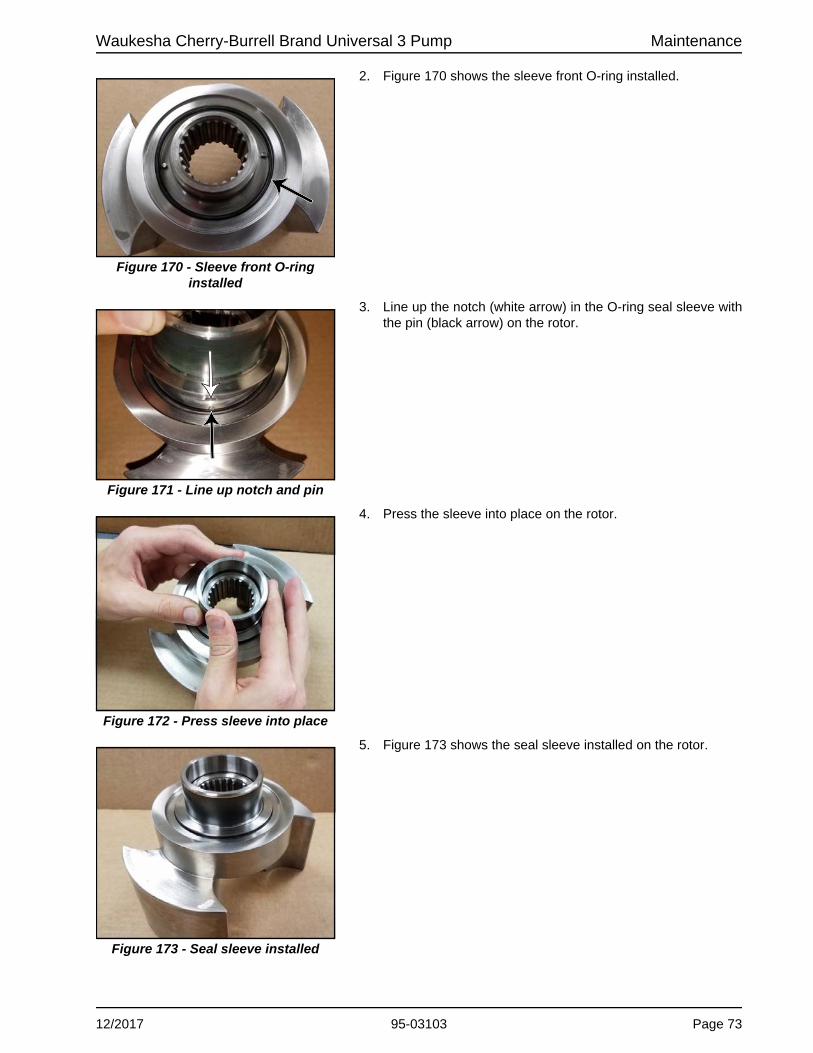
Waukesha Cherry-Burrell Brand Universal 3 Pump Maintenance
2. Figure 170 shows the sleeve front O-ring installed.
3. Line up the notch (white arrow) in the O-ring seal sleeve with the pin (black arrow) on the rotor.
4. Press the sleeve into place on the rotor.
5. Figure 173 shows the seal sleeve installed on the rotor.
Figure 170 - Sleeve front O-ring installed
Figure 171 - Line up notch and pin
Figure 172 - Press sleeve into place
Figure 173 - Seal sleeve installed
12/2017 95-03103 Page 73

Maintenance Waukesha Cherry-Burrell Brand Universal 3 Pump
6. Lubricate the outer surface of the seal sleeve.
7. Continue to install the rotors.
NOTE: Mechanical seals are shown in the “Install Rotors” section, but the instructions apply to the O-ring seal as well.
Fluid Head Assembly - Rotors and Cover
Install Rotors
NOTE: Mechanical seals are shown in this section, but the instructions apply to the O-ring seal as well.
1. Align the timing spline of the rotor and the pump shaft.
NOTE: Mechanical seal shown.
2. Figure 176 shows the timing spline of the shaft.
NOTE: Mechanical seal shown.
Figure 174 - Lubricate seal sleeve
Figure 175 - Timing spline of rotor
Figure 176 - Timing spline of shaft
Page 74 95-03103 12/2017

Waukesha Cherry-Burrell Brand Universal 3 Pump Maintenance
3. Push the rotor onto the shaft.
NOTE: When you push on the rotor, you should feel pressure from the seal spring. (With the O-ring seal, you should feel a little pressure from the spring, but not as much as from the mechanical seal.)
NOTE: Mechanical seal shown.
4. Figure 178 shows the rotor installed. Repeat these steps to install the second rotor.
Install Rotor Nuts
1. Install the lubricated rotor nut O-ring onto the rotor nut.
Figure 177 - Push rotor on shaft
Figure 178 - Rotor installed
Figure 179 - Install O-ring
12/2017 95-03103 Page 75

Maintenance Waukesha Cherry-Burrell Brand Universal 3 Pump
2. Figure 180 shows the rotor nut O-ring installed.
3. Apply a small amount of anti-seize to the shaft threads, then install the rotor nut.
4. Repeat these steps for the second rotor.
5. Insert the rotor blocking tool (part number 139794+) to keep the rotors from turning when installing the rotor nuts.
NOTE: When working on a rotor, always block the rotor against the body, not against the other rotor. See Figure 182.
NOTE: SPX FLOW recommends using the Non-Marring Socket Tool for Rotor Nuts (see below) to protect the rotor nut when torquing.
Figure 180 - O-ring installed
Figure 181 - Install rotor nut
Figure 182 - Torque rotor nut
Table 13: Rotor Nut Wrench Size and Socket Tool
U3 Model Wrench Size Socket Tool
006, 015, 018 15/16" 126533+
030, 040 1-1/4" 139795+
045, 060, 130 1-5/8" 139796+
180, 220 2-1/4" 139797+
210, 320 2-3/8" 126536+
Page 76 95-03103 12/2017

Waukesha Cherry-Burrell Brand Universal 3 Pump Maintenance
6. Torque the rotor nuts to the specified torque (see Table 14). Remove the rotor blocking tool after torquing.
CAUTIONUse a torque wrench to tighten the rotor nuts to the proper torque. Failure to tighten the nuts properly could result in the nuts loosening during operation, causing damage to the pump.
7. Figure 184 shows the rotors installed.
8. Double Mechanical Seal only: Turn on the flush and make sure there are no leaks. If there are leaks, check for pinched O-rings or cracked seals.
Install Cover
1. Install the cover gasket into the groove on the pump body.
Table 14: Rotor Nut Torque
U3 Model Rotor Nut Torque
006, 015, 018 50 ft-lb (68 N·m)
030, 040 120 ft-lb (163 N·m)
045, 060, 130 250 ft-lb (339 N·m)
180, 220 325 ft-lb (441 N·m)
210, 320 375 ft-lb (508 N·m)
Figure 183 - Rotors installed
Figure 184 - Install cover gasket
12/2017 95-03103 Page 77

Maintenance Waukesha Cherry-Burrell Brand Universal 3 Pump
2. Figure 185 shows the cover gasket installed. Apply an anti-seize compound compatible with the product to the threads of the body studs.
3. Align the pump body studs with the cover holes and install the cover on the pump body.
CAUTIONTo lift the cover on a 210 or 320-U3, attach an eye bolt to the threaded hole in the cover and attach lifting straps or chains to the eye bolt.
4. Install the cover nuts by hand, then torque the cover nuts to the correct torque.
CAUTIONFailure to tighten the cover nuts to the proper torque could cause the body studs to fail prematurely under high pressure.
Figure 185 - Cover gasket installed
Figure 186 - Install cover
Figure 187 - Install cover nuts
Table 15: Cover Nut Torque
U3 Model Cover Nut Torque
006, 015, 018 7 ft-lb / 10 N·m
030, 040 11 ft-lb / 15 N·m
045, 060 56 ft-lb / 76 N·m
130 25 ft-lb / 34 N·m
180, 220 110 ft-lb / 149 N·m
210, 320 158 ft-lb / 214 N·m
Page 78 95-03103 12/2017

Waukesha Cherry-Burrell Brand Universal 3 Pump Maintenance
5. Figure 188 shows the cover installed.
CAUTIONIf a double seal arrangement is used, the seals must be provided with a clean, compatible barrier fluid. Make certain that the flush ports in the pump body are clean and clear.
WARNINGDo not start a pump with seal flush unless the seal flush is installed and turned on.
Figure 188 - Cover installed
12/2017 95-03103 Page 79
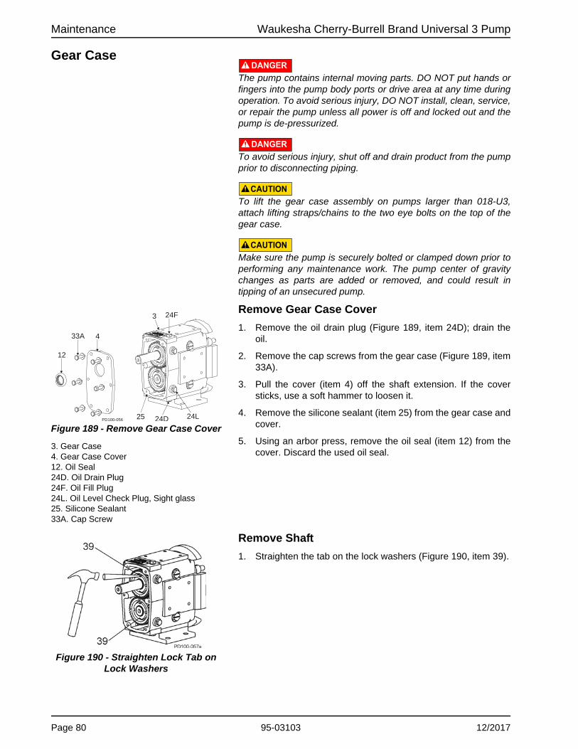
Maintenance Waukesha Cherry-Burrell Brand Universal 3 Pump
Gear CaseDANGER
The pump contains internal moving parts. DO NOT put hands or fingers into the pump body ports or drive area at any time during operation. To avoid serious injury, DO NOT install, clean, service, or repair the pump unless all power is off and locked out and the pump is de-pressurized.
DANGERTo avoid serious injury, shut off and drain product from the pump prior to disconnecting piping.
CAUTIONTo lift the gear case assembly on pumps larger than 018-U3, attach lifting straps/chains to the two eye bolts on the top of the gear case.
CAUTIONMake sure the pump is securely bolted or clamped down prior to performing any maintenance work. The pump center of gravity changes as parts are added or removed, and could result in tipping of an unsecured pump.
Remove Gear Case Cover
1. Remove the oil drain plug (Figure 189, item 24D); drain the oil.
2. Remove the cap screws from the gear case (Figure 189, item33A).
3. Pull the cover (item 4) off the shaft extension. If the cover sticks, use a soft hammer to loosen it.
4. Remove the silicone sealant (item 25) from the gear case and cover.
5. Using an arbor press, remove the oil seal (item 12) from the cover. Discard the used oil seal.
Remove Shaft
1. Straighten the tab on the lock washers (Figure 190, item 39).
Figure 189 - Remove Gear Case Cover
3. Gear Case4. Gear Case Cover12. Oil Seal24D. Oil Drain Plug24F. Oil Fill Plug24L. Oil Level Check Plug, Sight glass25. Silicone Sealant33A. Cap Screw
PD100-056
12
33A 4
3
24D
24F
24L25
Figure 190 - Straighten Lock Tab on Lock Washers
Page 80 95-03103 12/2017

Waukesha Cherry-Burrell Brand Universal 3 Pump Maintenance
2. Prevent the shafts from turning by placing a wedge or soft dowel between the gears (Figure 191, item A). Use a gear nut driver tool (see below) to remove the gear locknut. The gears will be removed later.
3. Remove the front bearing retainer screws (Figure 192, item33B) and pull off the bearing retainers (item 32). (If a retainer is stuck, leave it in place; it will press out when the shaft is removed.)
4. Remove the silicone sealant (Figure 193, item A) from the bearing retainer and gear case.
NOTE: Protect the liquid end of the shafts by wrapping them with tape.
Figure 191 - Block Shaft Rotation
Table 16: Gear Nut Driver Tool
Model U3 Pumps Part Number
006, 015, 018 109281+
030, 040 109282+
045, 060,130 109283+
180, 220 110304+
210, 320 114702+
Figure 192 - Remove Bearing Retainers
32
33B
33B
Figure 193 - Remove Sealant from Retainer
PD100-662A
12/2017 95-03103 Page 81
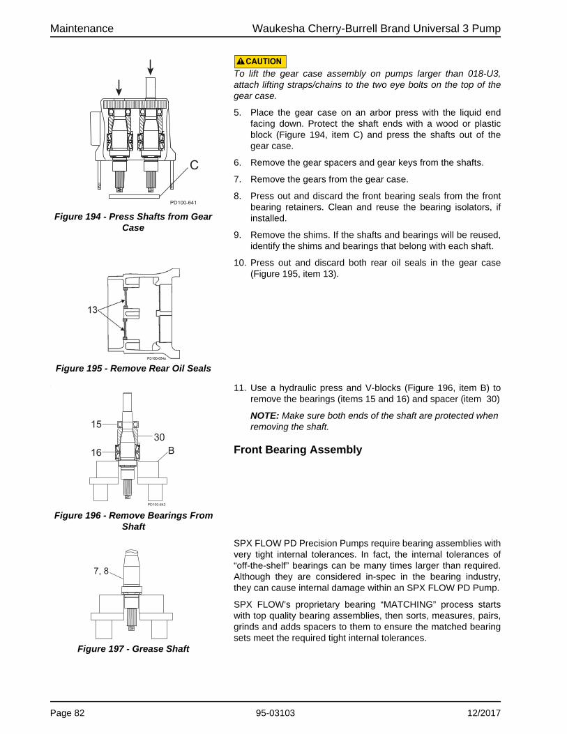
Maintenance Waukesha Cherry-Burrell Brand Universal 3 Pump
CAUTIONTo lift the gear case assembly on pumps larger than 018-U3, attach lifting straps/chains to the two eye bolts on the top of the gear case.
5. Place the gear case on an arbor press with the liquid end facing down. Protect the shaft ends with a wood or plastic block (Figure 194, item C) and press the shafts out of the gear case.
6. Remove the gear spacers and gear keys from the shafts.
7. Remove the gears from the gear case.
8. Press out and discard the front bearing seals from the front bearing retainers. Clean and reuse the bearing isolators, if installed.
9. Remove the shims. If the shafts and bearings will be reused, identify the shims and bearings that belong with each shaft.
10. Press out and discard both rear oil seals in the gear case (Figure 195, item 13).
. 11. Use a hydraulic press and V-blocks (Figure 196, item B) to remove the bearings (items 15 and 16) and spacer (item 30)
NOTE: Make sure both ends of the shaft are protected when removing the shaft.
Front Bearing Assembly
SPX FLOW PD Precision Pumps require bearing assemblies with very tight internal tolerances. In fact, the internal tolerances of “off-the-shelf” bearings can be many times larger than required. Although they are considered in-spec in the bearing industry, they can cause internal damage within an SPX FLOW PD Pump.
SPX FLOW’s proprietary bearing “MATCHING” process starts with top quality bearing assemblies, then sorts, measures, pairs, grinds and adds spacers to them to ensure the matched bearing sets meet the required tight internal tolerances.
Figure 194 - Press Shafts from Gear Case
C
PD100-641
Figure 195 - Remove Rear Oil Seals
Figure 196 - Remove Bearings From Shaft
1530
PD100-642
B16
Figure 197 - Grease Shaft
7, 8
Page 82 95-03103 12/2017

Waukesha Cherry-Burrell Brand Universal 3 Pump Maintenance
SPX FLOW bearings can be cross-referenced and appear to be the same, but competitive bearings are omitting the Matching process, which is imperative to achieve the required internal toler-ances. Once a bearing set is matched, it must remain together as a set for the life of the pump, in order to maintain the tight internal tolerances.
NOTE: The following instructions cover the assembly of a six-piece front bearing assembly. For a four-piece assembly, only one spacer and cup is used.
1. Lubricate the front bearing area of the shaft (Figure 197, item 7, 8) with anti-seize. Place it upright in a hydraulic press with the liquid end down.
2. Unwrap the front bearing assembly.
NOTE: DO NOT interchange the parts of one bearing assembly with another. The parts are precisely matched during manufacturing and must be installed as a matched assembly. See Figure 198.
3. Lift the lower cone and roller assembly (Figure 199, item A) out of the bearing stack and place it on the shaft with the radius facing down. Press it onto the shaft until it is seated against the shaft shoulder. Press only on the inner cone.
4. Place the inner spacer (Figure 200, item B) over the shaft onto the lower cone and roller assembly.
5. Place the lower cup (item C) over the lower cone and roller assembly, keeping the cup opening toward the assembly.
6. Place the outer spacer (item D) over the shaft and onto the lower cup.
7. Place the upper cup (Figure 201, item E) on top of the outer spacer.
8. Lubricate the front bearing area of the shaft with anti-seize, and slip the bearing over the shaft with the roller radius facing up (Figure 201, item F). Press it onto the shaft and into the upper cup (Figure 201, item E).
NOTE: Make sure all components are aligned before pressing. Press only on the inner cone.
Figure 198 - Bearing assembly
A. Lower Cone / Roller AssemblyB. Inner SpacerC. Lower CupD. Outer SpacerE. Upper CupF. Upper Cone / Roller Assembly
Figure 199 - Press Lower Cone onto Shaft
PD100-645
A
Figure 200 - Install Inner & Outer Spacer and Lower Cup
PD100-646
C
BD
Figure 201 - Install Upper Cup & Upper Cone
PD100-647
E
F
12/2017 95-03103 Page 83

Maintenance Waukesha Cherry-Burrell Brand Universal 3 Pump
9. Install the bearing spacer (Figure 202, item 30).
Rear Bearing Assembly
Models 006, 015, 018, 030, and 040 use a single ball bearing assembly for the rear bearing. All other models use a tapered roller bearing assembly similar to the front bearings.
1. Unwrap the rear bearing assembly.
NOTE: DO NOT interchange the parts of one bearing assembly with another. These parts are precisely matched during manufacturing and must be installed as a matched assembly.
• For models with ball bearing assemblies: Lubricate the shaft bearing area with anti-seize, then press the bearing into place. The shielded side of the bearing fits against the bearing spacer. Press only on the inner race.
• For models with tapered roller bearing assemblies: Lubricate the shaft bearing area with anti-seize. Follow the “Front Bearing Assembly” procedures starting on page 82.
NOTE: Heating the bearings is NOT recommended. If bearings are heated, do not exceed 300°F (149°C).
DANGERThe pump contains internal moving parts. DO NOT put hands or fingers into the pump body ports or drive area at any time during operation. To avoid serious injury, DO NOT install, clean, service, or repair the pump unless all power is off and locked out and the pump is de-pressurized. Shut off and drain product from the pump prior to disconnecting the piping.
Figure 202 - Install Bearing Spacer
30
PD100-648
Figure 203 - Rear Tapered Roller Bearing Assembly
PD100-644
Page 84 95-03103 12/2017

Waukesha Cherry-Burrell Brand Universal 3 Pump Maintenance
Shimming
1. When installing the shafts in the gear case, shim behind the front bearing to achieve the proper backface clearance between the back of the rotors and the body. (See Figure 204.) The backface clearance must be equal for both rotors to prevent the rotors from hitting each other during operation.
NOTE: Do not install bearing retainer sealant, gears, or gear locknuts until the correct shimming has been verified.
2. If the shafts and/or bearings do not need to be replaced and the shims are marked indicating the shaft and bearing they are matched with, a shim adjustment probably will not be necessary. Reuse the existing tagged shims, shafts and bearings in the same gear case bores.
3. If existing shims are lost and/or a standard shaft is used, determine the required shims from the chart.
4. If it is necessary to calculate the required shims for replacement shafts, bearings or both, refer to Figure 204and Figure 205; carry measurements and calculations to three decimal places (e.g. 0.059).
5. Determine the shim thickness required for the front bearing:
• Measure “B” in the gear case and “C” on the shaft (Figure 204).
NOTE: Arrange with thicker shims on outside of the shim pack.
• Measure “D” and “E” on the body (Figure 205).
• Determine the proper backface clearance. Refer to Table 18, “Rotor Clearances,” on page 89.
• Required Shims = Backface clearance - C + B + D - E.
6. Place the shims in the gear case, resting against the shoulder in the front bearing bore. (See Figure 204.)
Figure 204 - Measure B & C
Figure 205 - Measure D & E
B. Front face of gear case to back of bearing bore
C. Shaft shoulder to back of bearing raceD. Body thicknessE. Depth of rotor cavity
B
C
PD100-655
Gear case front face
Shim location
DE
Body
CAUTIONMake sure the pump is securely bolted or clamped down prior to performing any maintenance work. The pump center of gravity changes as parts are added or removed, and could result in tipping of an unsecured pump.
Suggested Shims
U3 Model Standard Shaft Replacement Shaft Shim kit
006, 015, 018 .113 in (2.87 mm) .110 in (2.79 mm) 117889+
030, 040 .105 in (2.27 mm) .102 in (2.59 mm) 117890+
045, 060, 130 .093 in (2.36 mm) .088 in (2.24 mm) 117891+
180, 220 .115 in (2.92 mm) .110 in (2.79 mm) 117892+
210, 320 .125 in (3.18 mm) .120 in (3.05 mm) 117893+
12/2017 95-03103 Page 85

Maintenance Waukesha Cherry-Burrell Brand Universal 3 Pump
Install Shaft
1. With the shims in place, install the shaft assembly in the front bearing bore with the fluid end facing up. Ensure that the shaft is installed in its original location.
NOTE: The shafts may need to be removed for a final shim adjustment.
2. Lubricate the outside diameter of the bearing.
3. Press the shaft into place until it is seated against the shim pack. Press only against the outer race of the bearing.
NOTE: A tube of the same diameter as the outer race of the bearing also can be used to press the shaft into place.
4. Temporarily secure the shaft/bearing in place with bearing retainers to aid in checking the clearances. DO NOT install silicone sealant at this time.
5. The bearing retainer must rest firmly against the bearing. Leave a 0.010 to 0.050 in (0.25 to 1.25 mm) clearance between the back of the bearing retainer and the front of the gear case (Figure 206). If this clearance is not met, place shims between the bearing and retainer.
6. Temporarily mount the body on the gear case.
7. Secure the body to the gear case using the body retaining screws.
8. Install the rotors and rotor nuts. Rotor nut O-rings and retainer O-rings are not required at this time.
9. Measure the rotor backface clearance (Figure 207, item A) through the port or from the front. The backface clearance for both rotors must be the same to prevent rotor crossover contact and must be ±0.0005" of the value found in Table 18, “Rotor Clearances,” on page 89.
10. Check the rotor front face clearance (Figure 207, item C).
11. Check the rotor to body clearance (Figure 207 and Figure 208, item B).
12. Check the clearances against Table 18, “Rotor Clearances,” on page 89. For other non-standard rotors, check with customer service.
NOTE: If the process uses special clearance rotors, contact customer service with the serial number of the pump for clearance tolerance values.
NOTE: “B” dimension is below the face of the casing.
13. If the backface clearance is not met, disassemble the pump and adjust the shimming to achieve the correct backface clearance.
14. If the rotor to body clearance is not met or is uneven, contact SPX FLOW Application Engineering for proper adjustment procedures.
15. After obtaining proper clearance, remove the rotor nuts, rotors, body, and bearing retainers.
Figure 206 - Bearing Retainer Clearance
Figure 207 - Measure Clearance
A C
B
Figure 208 - Measure Clearance
B
B
Page 86 95-03103 12/2017

Waukesha Cherry-Burrell Brand Universal 3 Pump Maintenance
16. Grease the front and rear bearing through the grease fittings until grease is visible around the bearing assemblies. The amount of grease required is listed in “Grease Quantity (per Bearing)” on page 27. Rotate the shafts while greasing to disperse the grease.
17. Lubricate the seal lips and install the grease seals in the bearing retainers (compression spring on inside).
18. Coat the retainer flanges with silicone sealant (Figure 209,
item A). (Gore-Tex® sealing tape can be used on silicone free models.) The grease seal (item 14) will be flush with the front of the bearing retainer. On 030 models, the grease seal will be against the step on the inside diameter of the retainer.
19. Install the bearing retainers (Figure 209, item 32).
Install Rear Seal Assembly
NOTE: Place tape or other material over the shaft end to prevent cutting the seal during installation.
1. Install the gear spacers (Figure 210, item 29).
2. Lubricate the inside and outside diameters of the oil seals with oil or grease.
3. Install the oil seals with the spring facing out (Figure 210, item 13).
Install Timing Gears
1. Place the gear keys into the shaft key slots. Angle the keys out for easier installation of the gears.
NOTE: To aid in timing setup, rotate the rotors until they are at right angles to each other before installing the gears.
2. Slide the spur drive gear onto the drive shaft. The spur drive gear has one punch mark on the gear.
3. Slide the short shaft gear onto the short shaft. The short shaft gear has two punch marks on the gear. Straddle the single punch mark of the spur drive gear with the two punch marks on the short shaft gear (Figure 211).
4. Use a wood or nylon block (Figure 212, item A) to keep the shafts from turning. If a block is not available, use rags to block the gears, or with one rotor on the shaft, block the rotor with a nylon dowel.
5. Slide the lock washers onto the shaft. Lubricate the threaded area on the shafts and face of the locknuts with oil or grease.
Figure 209 - Install Bearing Retainer
Gear case
Figure 210 - Install Rear Seal
Figure 211 - Timing Gear Marks
Figure 212 - Block Shaft Rotation
12/2017 95-03103 Page 87

Maintenance Waukesha Cherry-Burrell Brand Universal 3 Pump
6. Tighten the gear locknuts to the specified torque, using a gear nut driver tool.
7. Bend the locking tab on the lock washers into the locking nut slots, securing the gear locknut into place (Figure 214).
Checking for Proper Clearance
Waukesha Cherry-Burrell brand pumps are designed with close running clearances. Backface clearances are set with shims dur-ing assembly.
Shafts are positioned with shims behind the front bearing and locked into gear case with the bearing retainers. Rotors lock against the shaft shoulder. Clearance between the body backface and the back of the rotor wing is called backface clearance.
1. To check backface clearance, first mount the body (less seals) onto the housing. Assemble the rotors and secure them with rotor jam nuts.
2. With feeler gauges, measure the rotor backface clearance (Figure 215, item A), through the port or from the front.
3. Measure the rotor front face clearance (Figure 215, item C).
4. Measure the rotor to body clearance (Figure 215, item B).
5. Check the measured clearances against Table 18, “Rotor Clearances,” on page 89.
6. Make corrections as required and follow examples in Table 19, “Backface Clearance Corrections,” on page 89, to determine the exact adjustment to make and to avoid unnecessary assembly/disassembly.
7. To make shim adjustments, first remove the rotors, body and shafts. Make the required shim adjustment and reassemble. (Figure 215, item D is the front bearing rear shim.)
8. Re-check the backface clearances. Be sure both rotors have the same clearance to avoid crossover interference with the adjacent rotor hub.
Figure 213 - Install Gear Locknuts
Table 17: Torque Values and Gear Nut Driver Tool
Model U3 Pumps Gear Nut Torque Tool Part Number
006, 015, 018120 ft-lb(163 N·m)
109281+
030, 040 109282+
045, 060,130 140 ft-lb (190 N·m) 109283+
180, 220 230 ft-lb (312 N·m) 110304+
210, 320 320 ft-lb (434 N·m) 114702+
Figure 214 - Bend Locking Tab
NOTE: It is generally best to keep backface clearance to a minimum.
CAUTIONBackface clearance for both rotors must be equal to avoid crossover interference with the adjacent rotor hub.
Figure 215 - Clearance Measurements
A C
B
D
PD100-650
Page 88 95-03103 12/2017

Waukesha Cherry-Burrell Brand Universal 3 Pump Maintenance
Low Viscosity Rotors: -40°F (-40°C) to 180°F (82°C); Standard Clearance Rotors: -40°F (-40°C) to 300°F (149°C). Contact SPX FLOW Application Engineering if alternate rotors are needed.NOTE: The assembly clearances stated in Table 18 are for reference only. Actual pump clearances may vary based on pump performance testing.
.
NOTE: If the clearance corrections in Table 19 have been performed and desired performance is not achieved, contact SPX FLOW technical services for guidance.
Table 18: Rotor Clearances
Universal 3 Model
A - Back Facein (mm)
B - Rotor to Bodyin (mm)
C - Front Facein (mm)
Rotor Type Low Viscosity Standard Low Viscosity Standard Low Viscosity Standard
0060.0025 - 0.004 0.0035 - 0.005 0.001 - 0.004 0.0025 - 0.0055 0.004 - 0.005 0.0045 - 0.0055
(0.06 - 0.10) (0.09 - 0.13) (0.03 - 0.10) (0.06 - 0.14) (0.10 - 0.13) (0.11 - 0.14)
015, 0180.0025 - 0.0045 0.003 - 0.005 0.001 - 0.004 0.0025 - 0.0055 0.004 - 0.005 0.0055 - 0.0065
(0.06 - 0.11) (0.08 - 0.013) (0.03 - 0.10) (0.06 - 0.14) (0.10 - 0.13) (0.14 - 0.17)
030, 0400.002 - 0.004 0.0035 - 0.0055 0.001 - 0.005 0.0025 - 0.006 0.0045 - 0.0055 0.006 - 0.007
(0.05 - 0.10) (0.09 - 0.14) (0.03 - 0.13) (0.06 - 0.15) (0.11 - 0.14) (0.15 - 0.18)
045, 0600.003 - 0.007 0.004 - 0.008 0.003 - 0.0075 0.005 - 0.010 0.0055 - 0.0075 0.0085 - 0.0105
(0.08 - 0.18) (0.10 - 0.20) (0.08 - 0.19) (0.13 - 0.25) (0.14 - 0.19) (0.22 - 0.27)
1300.003 - 0.007 0.004 - 0.008 0.0035 - 0.0075 0.0055 - 0.0095 0.006 - 0.007 0.009 - 0.0115
(0.08 - 0.18) (0.10 - 0.20) (0.09 - 0.19) (0.14 - 0.24) (0.15 - 0.18) (0.23 - 0.29)
180, 2200.004 - 0.008 0.005 - 0.009 0.0055 - 0.0095 0.009 - 0.013 0.006 - 0.008 0.010 - 0.012
(0.10 - 0.20) (0.13 - 0.23) (0.14 - 0.24) (0.23 - 0.33) (0.15 - 0.20) (0.25 - 0.30)
210, 3200.005 - 0.009 0.007 - 0.011 0.008 - 0.012 0.010 - 0.014 0.008 - 0.010 0.012 - 0.014
(0.13 - 0.23) (0.18 - 0.28) (0.20 - 0.30) (0.25 - 0.36) (0.20 - 0.25) (0.30 - 0.36)
Table 19: Backface Clearance Corrections
Problem Condition Correction
Too Much Backface Clearance (A)
Dimension A is greater than the value in Table 18.
A (measured) minus Column A (Table 18) = shims to remove from the rear outer race of the front bearing
Rotor wing face projects past the body front face
C (measured with depth micrometer) plus C (Table 18) = shims to remove from the rear of the front bearing
Not Enough Backface Clearance (A)
Dimension A is less than the value in Table 18.
Column A (Table 18) minus A (measured) = shims to add to the rear outer race of the front bearing
12/2017 95-03103 Page 89

Maintenance Waukesha Cherry-Burrell Brand Universal 3 Pump
Install Gear Case Cover
1. Lubricate the inside diameter of a new oil seal.
2. Press the new oil seal (Figure 216, item 12) into the gear case cover (item 4) flush with the outside face, with the spring facing in.
3. Apply silicone sealant to the back of the gear case. (Gore-Tex® sealing tape can be used on silicone-free models.) Place tape on the inside of the screw holes. (Figure 217, item A).
4. Tape the shaft end to prevent cutting the seal on the keyway. Mount the cover assembly on the gear case. Secure it with cap screws and washers.
5. Remove the tape from the shaft end.
NOTE: Make sure that the shaft is centered in the lip seal before securing the cap screws.
6. Install the oil drain plug.
7. Fill gear case with gear oil to proper level. Refer to “Lubrication” on page 27.
Figure 216 - Orientation of Oil Seal
Figure 217 Sealant Placement
Table 20: Standard O-Ring Selections, Descriptions and Color Codes for U3 Pumps
Ethylene Propylene Diene Rubber (EPDM)Compound Color: Black or PurpleColor Code: GreenFDA Compliant to 21CFR177.2600
Perfluoroelastomer (FFKM)Compound Color: BlackColor Code: NoneIndividually packaged with size and material noted.
Fluorocarbon Rubber (FKM)Compound Color: Rust, Brown or BlackColor Code: WhiteFDA Compliant to 21CFR177.26003A Sanitary
Page 90 95-03103 12/2017

Waukesha Cherry-Burrell Brand Universal 3 Pump Maintenance
Reference Tables
Table 21: Universal 3 Wrench SizeGear Nut Driver
ToolModel Rotor NutBody Retaining
Cap ScrewCover Nut
006, 015, 018 15/16"3/16" 5/8"
109281+
030, 040 1-1/4" 109282+
045, 060, 130 1-5/8" 1/4"7/8"
109283+
180, 220 2-1/4"5/16"
110304+
210, 320 2-3/8" 1" 114702+
Table 22: Torque Values
Model Gear Nut Rotor Nut Cover NutSeal Housing
Bolt
006, 015, 018120 ft-lb163 N·m
50 ft-lb68 N·m
7 ft-lb10 N·m
7.4 ft-lb10 N·m
030, 040120 ft-lb163 N·m
11 ft-lb 15 N·m
14.8 ft-lb 20 N·m
045, 060140 ft-lb 190 N·m
250 ft-lb339 N·m
56 ft-lb 76 N·m
13025 ft-lb 34 N·m
180, 220230 ft-lb312 N·m
325 ft-lb441 N·m
110 ft-lb149 N·m
210, 320320 ft-lb 434 N·m
375 ft-lb 508 N·m
158 ft-lb 214 N·m
Table 23: Arbor or Hydraulic Press Tonnage (Approximate)
ModelShaft Front Bearing Rear Bearing
IN OUT ON OFF ON OFF
006, 015, 018 .25 .50 .50 1.00 .50 1.00
030, 040 .25 1.00 .50 1.00 .50 1.00
045, 060, 130 .50 1.00 2.00 5.00 3.00 5.00
180, 220 .50 1.00 5.00 15.00 5.00 15.00
210, 320 .50 1.00 5.00 2.00 5.00 2.00
12/2017 95-03103 Page 91

Troubleshooting Waukesha Cherry-Burrell Brand Universal 3 Pump
Troubleshooting
PROBLEM POSSIBLE CAUSE SUGGESTED ACTION
No flow, pump rotors are not turning
Drive motor not running. Check resets, fuses, circuit breakers.
Keys sheared or missing. Replace.
Drive belts, power transmission components slipping or broken.
Replace or adjust.
Pump shaft or gears sheared. Inspect: and replace parts as necessary.
No flow, pump rotors are turning
Rotors turn in the wrong direction.
Check motor hookup to reverse motor rotation.
Relief valve not properly adjusted, or held open by foreign material.
Adjust or clear valve.
Suction port is blocked, not allowing flow to the pump.
Check all inlet valves, strainers, tank outlet ports.
No flow, pump not priming Valve closed in inlet line. Open valve.
Inlet line clogged or restricted. Clear line, clean filters, etc.
Air leaks due to bad gaskets or pipe connections.
Replace gaskets; check lines for leakage (can be done by air pressure or by filling with liquid and pressurizing with air).
Pump speed too slow. Increase pump speed.
Pump speed too fast for high-viscosity liquid.
Decrease pump speed.
Liquid drains or siphons from system during off periods.
Use foot valve or check valves.Filling inlet lines with material before startup may solve startup priming problems due to no material in system.
"Air" lock caused by fluids which "gas off", or vaporize, or allow gas to come out of solution during off periods.
Install and use a manual or automatic air bleed from pump or lines near pump.
Extra clearance on rotors, worn pump.
Increase pump speed, use foot valve to improve priming.Replace worn rotors.
Net inlet pressure available too low.
Check Net Inlet Pressure Available & Net Inlet Pressure Required. Change inlet system as needed.
On "Vacuum'' inlet system: On initial start-up, atmospheric "blow back'' prevents pump from developing enough differential pressure to start flow.
Install check valve in discharge line.
Page 92 95-03103 12/2017

Waukesha Cherry-Burrell Brand Universal 3 Pump Troubleshooting
Insufficient flow Speed too low or too high to obtain desired flow.
Check flow-speed curve (available from SPX FLOW website) and adjust as necessary.
Air leak due to bad seals, pipe connections, or other equipment.
Replace seals, check inlet fittings.
Insufficient flow—flow being bypassed somewhere
Flow diverted in branch line, open valve, etc.
Check system and controls
Relief valve not adjusted or jammed.
Clear or adjust valve.
Insufficient flow—high slip Standard clearance rotors on "cold" fluid and/or low viscosity fluid.
Replace with low viscosity rotors.
Worn pump. Increase pump speed (within limits). Replace rotors
High pressure. Reduce pressure by adjusting system settings or hardware.
Fluid vaporization (“starved'' pump inlet)
Strainers, foot valves, inlet fittings or lines clogged.
Clear lines. If problem continues, inlet system may require changing.
Inlet line size too small, inlet line too long. Too many fittings or valves. Foot valve, strainers too small.
Increase inlet line size. Reduce length, minimize direction and size changes, reduce number of fittings.
NIPA - Net Inlet Pressure Available at Pump is too low.
Raise liquid level in source tank to increase Net Inlet Pressure (NIPA).
Increase Net Inlet Pressure Available at Pump by raising or pressurizing source tank.
Select larger pump size with lower Net Inlet Pressure Required.
Fluid viscosity greater than expected.
Reduce pump speed and accept lower flow, or change system to reduce line losses.
Change temperature of product to reduce viscosity.
Fluid temperature higher than expected (vapor pressure higher).
Reduce temperature, reduce speed and accept lower flow or change system to increase Net Inlet Pressure Available.
PROBLEM POSSIBLE CAUSE SUGGESTED ACTION
12/2017 95-03103 Page 93

Troubleshooting Waukesha Cherry-Burrell Brand Universal 3 Pump
Noisy operation Cavitation
High fluid viscosity. High vapor pressure fluid. High temperature.
Slow down pump, reduce temperature, change system setup.
Net Inlet Pressure Available less than Net Inlet Pressure Required.
Increase NIPA - Net Inlet Pressure Available or reduce NIPR - Net Inlet Pressure Required. Contact SPX FLOW if necessary.
Air or gas in fluid
Leaks in the pump or piping.
Correct leaks.
Dissolved gas or naturally aerated products.
Minimize discharge pressure (also see "Cavitation," above).
Noisy operation caused by mechanical problems
Rotor to body contact
Improper assembly of pump. Check clearances and adjust shimming.
Distortion of pump due to improper piping installation.
Change piping installation to eliminate piping stress and distortion on body.
Pressures required higher than the pump is rated for.
Reduce discharge pressure required.
Worn bearings. Rebuild with new bearings and lubricate regularly.
Rotor to Rotor Contact
Loose or incorrectly-timed gears.
This has caused severe damage to components - rebuild with new parts.
Worn gear splines. This has caused severe damage to components - rebuild with new parts.
Drive noise caused by gear trains, chains, couplings, bearings.
Repair or replace drive parts. Check bearings for damage and replace as necessary.
Pump requires excessive power (overheats, stalls, high current draw, breakers trip)
Higher than expected viscosity losses.
If within pump rating, increase drive size.
Higher than expected pressures. Reduce pump speed. Increase line sizes.
Fluid is colder with a higher viscosity than expected.
Heat fluid, insulate lines or heat trace lines.
Increase line sizes.
PROBLEM POSSIBLE CAUSE SUGGESTED ACTION
Page 94 95-03103 12/2017
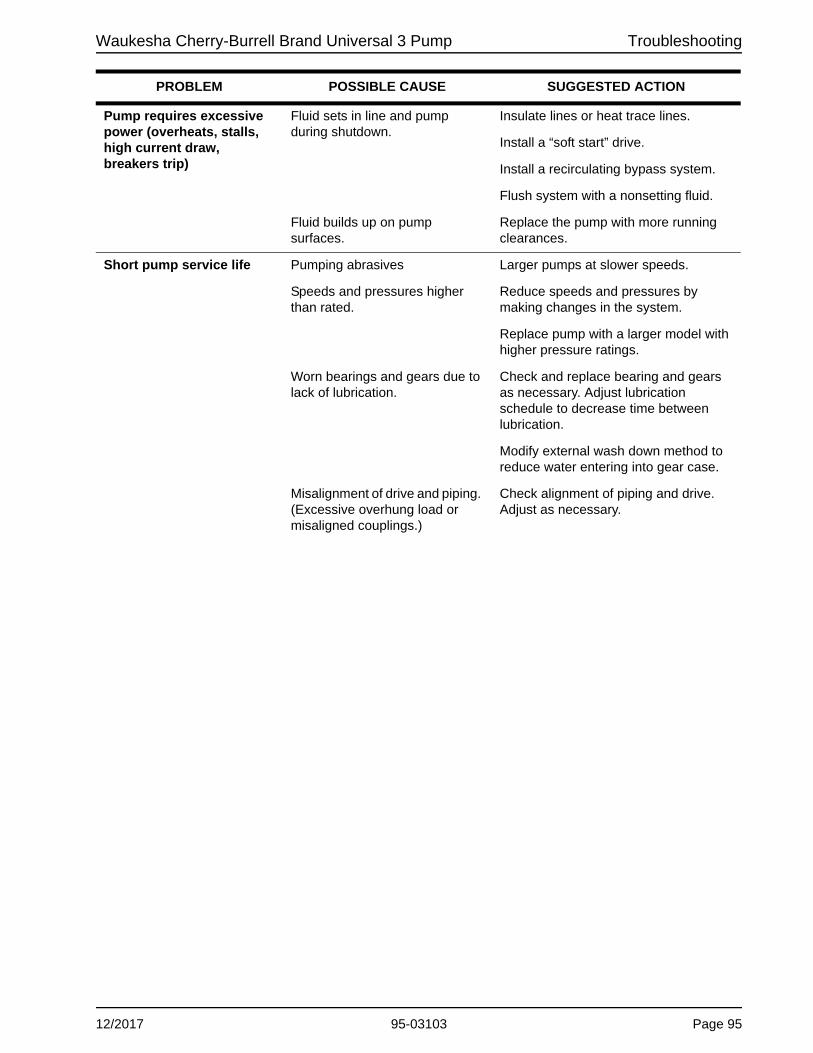
Waukesha Cherry-Burrell Brand Universal 3 Pump Troubleshooting
Pump requires excessive power (overheats, stalls, high current draw, breakers trip)
Fluid sets in line and pump during shutdown.
Insulate lines or heat trace lines.
Install a “soft start” drive.
Install a recirculating bypass system.
Flush system with a nonsetting fluid.
Fluid builds up on pump surfaces.
Replace the pump with more running clearances.
Short pump service life Pumping abrasives Larger pumps at slower speeds.
Speeds and pressures higher than rated.
Reduce speeds and pressures by making changes in the system.
Replace pump with a larger model with higher pressure ratings.
Worn bearings and gears due to lack of lubrication.
Check and replace bearing and gears as necessary. Adjust lubrication schedule to decrease time between lubrication.
Modify external wash down method to reduce water entering into gear case.
Misalignment of drive and piping. (Excessive overhung load or misaligned couplings.)
Check alignment of piping and drive. Adjust as necessary.
PROBLEM POSSIBLE CAUSE SUGGESTED ACTION
12/2017 95-03103 Page 95

Pump Dimensions Waukesha Cherry-Burrell Brand Universal 3 Pump
Pump Dimensions
Universal 3 PD Pump Dimensions
U3 Model A AA AO B CP D E F G G1 H H1
006inch 4.71 2.41 8.3 3.66 12.42 5.50 1.97 2.31 0.50 5/16-18x.62 2.50 2.50
mm 120 61 211 93 315 140 50 59 13 -- 64 64
015inch 4.71 2.41 8.3 3.66 12.69 5.50 1.97 2.31 0.50 5/16-18x.62 2.50 2.50
mm 120 61 211 93 322 140 50 59 13 -- 64 64
018inch 4.71 2.65 8.3 3.66 13.35 5.50 1.97 2.31 0.50 5/16-18x.62 2.50 2.50
mm 120 67 211 93 339 140 50 59 13 -- 64 64
030inch 6.19 3.22 10.29 4.15 15.16 6.86 2.42 2.56 .41, slot 3/8-16x.62 1.81 2.75
mm 157 82 261 105 385 174 61 65 10, slot -- 46 70
040inch 6.19 3.39 10.29 4.15 15.54 6.86 2.42 2.56 .41, slot 3/8-16x.62 1.81 2.75
mm 157 86 261 105 395 174 61 65 10, slot -- 46 70
045inch 8.25 3.85 15.31 5.88 19.11 9.56 3.5 4.12 0.53 1/2-13x.88 3.00 4.13
mm 210 98 389 149 485 243 89 105 13 -- 76 105
060inch 8.25 4.13 15.31 5.88 19.66 9.56 3.5 4.12 0.53 1/2-13x.88 3.00 4.13
mm 210 105 389 149 499 243 89 105 13 -- 76 105
130inch 8.25 4.77 15.31 5.88 20.68 9.56 3.5 4.12 0.53 1/2-13x.88 3.00 4.13
mm 210 121 389 149 525 243 89 105 13 -- 76 105
180inch 8.5 3.46 19.13 9.00 23.48 12.38 3.75 7.25 .53, slot 1/2-13x.88 5.38 5.38
mm 216 88 486 229 596 314 95 184 13, slot -- 137 137
210inch 12 4.14 23.84 11.63 27.07 13.87 5.25 8.00 .66, slot 1/2-13x.88 5.38 5.38
mm 305 105 606 295 688 352 133 203 17, slot -- 137 137
220inch 8.5 3.70 19.13 9.00 24.22 12.38 3.75 7.25 .53, slot 1/2-13x.88 5.38 5.38
mm 216 94 486 229 615 314 95 184 13, slot -- 137 137
270inch 8.5 4.33 19.13 9.00 24.85 12.38 3.75 7.25 .53, slot 1/2-13x.88 5.38 5.38
mm 216 110 486 229 631 314 95 184 13, slot -- 137 137
320inch 12 4.52 23.84 11.63 27.66 13.87 5.25 8.00 .66, slot 1/2-13x.88 5.38 5.38
mm 305 115 606 295 703 352 133 203 17, slot -- 137 137
CP STANDARD COVER
G112 PLACES
H1T1
SS1
S1
PO
RT
C L
VIEW A-A OF TOP & BOTTOMPUMP MOUNTING PADS
J
M
OPTIONAL MOUNTINGPAD LOCATION
TYPS
A
AAFRB
I
U
J
N
M
D
K-KEY
OPTIONAL UPPER SHAFTAA
T HL
BOLTS,EYE
E GE
O
PORT
AO
X
2X
SIDE MOUNTMOUNTINGPADM
J
PD100-535b
Page 96 95-03103 12/2017

Waukesha Cherry-Burrell Brand Universal 3 Pump Pump Dimensions
Universal 3 PD Pump Dimensions
Note: Dimensions "X" and "2X" apply for bevel seat, "S" Clamp, "Q" Clamp, 15I, and 14I fittings (except 320-U3).
U3 Model I J K L M N O Port Size R S S1 SS1 T T1 U X 2X
0067.61 2.93 0.19 10.04 2.43 1.92 4.21 1" 3.23 1.00 1.00 1.00 2.95 2.95 0.88 3.49 6.97
193 74 5 255 62 49 107 -- 82 25 25 25 75 75 22 89 177
0157.61 2.93 0.19 10.04 2.43 1.92 4.21 1-1/2" 3.23 1.00 1.00 1.00 2.95 2.95 0.88 3.49 6.97
193 74 5 255 62 49 107 -- 82 25 25 25 75 75 22 89 177
0187.61 2.93 0.19 10.28 2.43 1.92 4.21 1/1/2" 3.47 1.00 1.00 1.00 3.18 3.18 0.88 3.55 7.09
193 74 5 261 62 49 107 -- 88 25 25 25 81 81 22 90 180
0308.80 3.56 0.25 12.05 2.62 2.26 5.21 1-1/2" 4.26 1.12 1.12 1.12 4.42 4.01 1.25 4.25 8.50
224 90 6 306 67 57 132 -- 108 28 28 28 112 102 32 108 216
0408.80 3.56 0.25 12.21 2.62 2.26 5.21 2" 4.43 1.12 1.12 1.12 4.59 4.18 1.25 4.32 8.64
224 90 6 310 67 57 132 -- 113 28 28 28 117 106 32 110 219
04511.00 5.06 0.38 14.84 3.50 2.18 7.31 2" 4.72 1.75 2.00 1.75 5.32 4.72 1.63 5.38 10.75
279 129 10 377 89 55 186 -- 120 44 51 44 135 120 41 137 273
06011.00 5.06 0.38 15.13 3.50 2.18 7.31 2-1/2" 5.01 1.75 2.00 1.75 5.61 5.01 1.63 5.38 10.75
279 129 10 384 89 55 186 -- 127 44 51 44 142 127 41 137 273
13011.00 5.06 0.38 15.76 3.50 2.18 7.31 3" 5.64 1.75 2.00 1.75 6.24 5.64 4.63 5.38 10.75
279 129 10 400 89 55 186 -- 143 44 51 44 158 143 118 137 273
18014.80 6.38 0.50 19.03 4.50 2.67 9.38 3" 4.21 2.69 2.69 2.69 5.77 5.77 2.00 6.53 13.06
376 162 13 483 114 68 238 -- 107 68 68 68 147 147 51 166 332
21017.72 6.87 0.63 21.85 5.06 4.02 10.38 4" 5.64 2.69 2.69 2.69 8.39 8.39 2.38 7.37 14.73
450 174 16 555 129 102 264 -- 143 68 68 68 213 213 60 187 374
22014.80 6.38 0.50 18.49 4.50 2.67 9.38 4" 4.45 2.69 2.69 2.69 6.01 6.01 2.00 6.63 13.25
376 162 13 470 114 68 238 -- 113 68 68 68 153 153 51 168 337
27014.80 6.38 0.50 19.13 4.50 2.67 9.38 4" 5.08 2.69 2.69 2.69 6.65 6.65 2.00 6.63 13.25
376 162 13 486 114 68 238 -- 129 68 68 68 169 169 51 168 337
32017.72 6.87 0.63 22.34 5.06 4.02 10.38 6" 150# FLG 6.02 2.69 2.69 2.69 8.77 8.77 2.38 8.00 16.00
450 174 16 567 129 102 264 153 68 68 68 223 223 60 203 406
12/2017 95-03103 Page 97

Pump Dimensions Waukesha Cherry-Burrell Brand Universal 3 Pump
Tru-Fit ™ Universal 3 PD Pump Dimensions
Table of Dimensions
1 Dimensions affected by motor frame size2 Dimensions affected by connection type
U3Model
A B C D2 E F G H J K L M1 N1 P1 S T T1Port Size
U V
006inch 12.00 10.00 9.15 6.97 7.87 13.25 2.45 18.00 1.89 10.52 12.90 28.02 15.56 10.92 5.44 2.12 2.95 1" 5/16-16 x 62 2.00mm 305 254 232 177 200 337 62 457 48 267 328 712 395 227 138 54 75 -- -- 51
015inch 12.00 10.00 9.15 6.97 7.87 13.25 2.45 18.00 1.90 10.52 13.17 28.29 15.56 10.92 5.44 2.12 2.95 1-1/2" 5/16-16 x.62 2.00mm 304 254 232 177 200 337 62 457 48 267 335 719 395 227 138 54 75 -- -- 51
018inch 12.00 10.00 9.15 7.10 7.87 13.25 2.72 18.00 1.95 10.78 13.83 28.29 15.56 10.92 5.44 2.12 2.98 1/1/2" 5/16-16 x.62 2.00mm 304 254 232 180 200 337 69 457 50 274 351 719 395 227 138 54 76 -- -- 51
030inch 14.00 12.00 10.00 8.51 8.37 15.11 3.01 20.00 1.99 12.89 16.01 34.24 18.65 13.74 5.81 2.62 4.01 1-1/2" 3/8-16 x .62 2.25mm 356 304 255 216 213 384 76.454 508 51 327 407 870 474 349 148 67 102 -- -- 57
040inch 14.00 12.00 10.00 8.62 8.37 15.11 3.18 20.00 2.20 13.05 16.38 34.61 18.65 13.74 5.81 2.62 4.18 2" 3/8-16 x .62 2.25mm 356 305 255 219 213 384 80.772 508 56 331 416 879 474 349 148 67 106 -- -- 57
045inch 18.00 16.00 12.00 10.74 9.75 20.00 2.71 28.00 3.27 17.09 21.63 44.24 22.02 17.16 8.13 3.50 4.99 2" 1/2-13 x .88 3.50mm 457 406 305 273 248 508 69 711 83 434 549 1124 559 436 207 89 127 -- -- 89
060inch 18.00 16.00 12.00 10.74 9.75 20.00 3.00 28.00 2.91 17.38 21.91 44.52 22.02 17.16 8.13 3.50 5.00 2-1/2" 1/2-13 x .88 3.50mm 457 406 305 273 248 508 76 711 74 441 557 1131 559 436 208 89 127 -- -- 89
130inch 18.00 16.00 12.00 10.74 9.75 20.00 3.63 28.00 3.29 18.01 22.93 45.54 22.02 17.16 8.13 3.50 5.65 3" 1/2-13 x .88 3.50mm 457 406 305 273 218 508 92 711 84 457 582 1157 559 436 207 89 144 -- -- 89
180inch 20.00 18.00 14.50 13.06 11.50 23.25 3.28 36.00 4.16 19.53 24.73 50.24 25.91 18.82 10.00 4.50 6.01 3" 1/2-13 x 1.0 5.38mm 508 457 368 332 292 591 83.312 914 106 496 628 1276 658 478 254 114 153 -- -- 137
220inch 20.00 18.00 14.50 13.25 11.50 23.25 3.52 36.00 4.10 19.77 25.47 50.98 25.91 18.82 10.00 4.50 6.01 4" 1/2-13 x 1.0 5.38mm 508 457 368 337 292 591 89.408 914 104 502 647 1295 658 478 254 114 153 -- -- 137
L P
M
H
E
G
J
F
K
B/2
B
A
C
D
T1 S
T
U (3) TAPPEDHOLES
V
V/2
NPort Size
PD100-658
Page 98 95-03103 12/2017
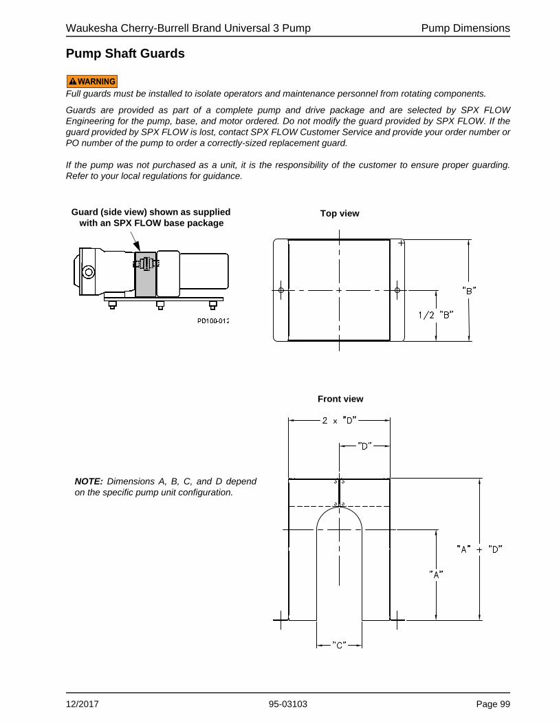
Waukesha Cherry-Burrell Brand Universal 3 Pump Pump Dimensions
Pump Shaft Guards
WARNINGFull guards must be installed to isolate operators and maintenance personnel from rotating components.
Guards are provided as part of a complete pump and drive package and are selected by SPX FLOW Engineering for the pump, base, and motor ordered. Do not modify the guard provided by SPX FLOW. If the guard provided by SPX FLOW is lost, contact SPX FLOW Customer Service and provide your order number or PO number of the pump to order a correctly-sized replacement guard.
If the pump was not purchased as a unit, it is the responsibility of the customer to ensure proper guarding. Refer to your local regulations for guidance.
Guard (side view) shown as supplied with an SPX FLOW base package
Top view
Front view
NOTE: Dimensions A, B, C, and D depend on the specific pump unit configuration.
12/2017 95-03103 Page 99

Parts List Waukesha Cherry-Burrell Brand Universal 3 Pump
Parts List
006, 015, 018-U3 Parts
��
�
��
��
����
��
��
��
���
��
���
��
����
�
����
����
��
�
��
��
��
��
�
��
�
���� ����
�
��
����
���
��
���
��
��
����
Page 100 95-03103 12/2017

Waukesha Cherry-Burrell Brand Universal 3 Pump Parts List
006, 015, 018-U3 Parts
Notes:
* Recommended spare parts1. Contact customer service with Serial Number of pump for Part Number.2. Standard clearances and finishes for rotor part numbers shown. Contact customer service for optional clearances and
finishes. All rotors include rotor drive pins installed. For replacement pin, see item 9A (not shown).4. The oil plug requires O-ring N70114.43. Tru-Fit drive shaft is longer than the standard drive shaft listed here. See page 125. For seals, see page 120 and 122.
ITEM NO. DESCRIPTIONQTY.PER
PUMPPART NO. NOTES
1 Pump Body 1 See Note 1 1006-U3 Pump Cover 1 138283+015-U3 Pump Cover 1 138242+018-U3 Pump Cover 1 138284+
3 Gear Case, SS, Model 006, 015, 018 1 138116+4 Gear Case Cover, SS 1 102280+5 Gear, Drive Shaft, Spur 1 107997+6 Gear, Short Shaft, Spur 1 107997+7 006-015-018-U3 Drive Shaft 1 138240+ 438 006-015-018-U3 Short Shaft 1 138239+ 43
006-U3 Rotor, Twin Wing, Alloy 88 2 138253+ 2006-U3 Rotor, Twin Wing, 316SS 2 138257+ 2015-U3 Rotor, Twin Wing, Alloy 88 2 138263+ 2015-U3 Rotor, Twin Wing, 316SS 2 138267+ 2018-U3 Rotor, Twin Wing, Alloy 88 2 138273+ 2018-U3 Rotor, Twin Wing, 316SS 2 138277+ 2
9A Rotor drive pin (not shown) 2 138646+ 2006-U3 Stud 8 138290+015-U3 Stud 8 138291+018-U3 Stud 8 138292+
11 Hex Nut 8 108369+12 Oil Seal, Gear Case Cover 1 000030016+13 Oil Seal, Gear Case Rear 2 000030017+14 Grease Seal, Bearing Retainer 2 121679+15 Bearing, Rear 2 015035000+16 Bearing, Front 2 101714+17 Key, Gear 2 015037000+20 Dowel Pin, Upper Cover Side 1 137001+21 Dowel Pin, Upper Gear Case Side 1 124581+22 Dowel Pin, Lower Cover Side 1 137002+23 Dowel Pin, Lower Gear Case Side 1 124582+
Oil Plug, M20 x 1.5" 5 137169+* O-Ring, Buna (for oil plug) 5 N70114
Oil Level Indicator, M20 x 1.5" 1 137435+25 Silicone Sealant 1 000142301+26 Nut, Rotor 2 138243+
O-Ring, Rotor Nut, EPDM 2 E70121* O-Ring, Rotor Nut, FKM 2 V70121
O-Ring, Rotor Nut, FFKM 2 K70121PL5060-CH152
424
26A
2
9
10
12/2017 95-03103 Page 101
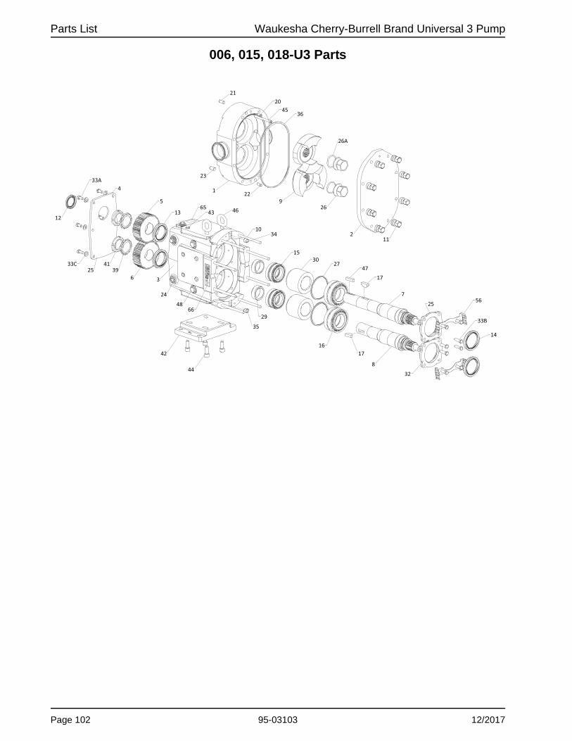
Parts List Waukesha Cherry-Burrell Brand Universal 3 Pump
006, 015, 018-U3 Parts
��
�
��
��
����
��
��
��
���
��
���
��
����
�
����
����
��
�
��
��
��
��
�
��
�
���� ����
�
��
����
���
��
���
��
��
����
Page 102 95-03103 12/2017

Waukesha Cherry-Burrell Brand Universal 3 Pump Parts List
006, 015, 018-U3 Parts
Notes:
* Recommended spare partsFor seals, see page 120 and 122. 3. See “Replacement Labels” on page 10 for detail.
ITEM NO. DESCRIPTIONQTY.PER
PUMPPART NO. NOTES
27 Shim Kit 2 117889+29 Spacer, Gear to Rear Bearing 2 015055000+30 Bearing Spacer 2 101814+32 Bearing Retainer, Front 2 120332+
33A, 33B 1/4-20 x 3/4" HHCS, SS 8 30-5833C 1/4" Flat Washer 8 43-2734 Dowel Bushing, Upper 1 AD011600035 Dowel Bushing, Lower 1 AD0116100
006-015-018-U3 Cover Gasket, FKM 1 137422+* 006-015-018-U3 Cover Gasket, FFKM 1 137423+
006-015-018-U3 Cover Gasket, EPDM 1 137424+39 Lockwasher, Gear 2 STD13600541 Locknut, Gear 2 STD23600542 Mounting Foot 006-015-018-U3 SS 1 102284+43 Plastic Cap Plug 6 000121003+44 5/16-18 x 1" SHCS, SS 4 30-525
006-U3 Body Retaining Screw 2 30-211015-U3 Body Retaining Screw 2 30-543018-U3 Body Retaining Screw 2 30-613
46 Eye Bolt, 5/16-18 x 1/2" SS 2 30-719Key, Coupling - 3/16 x 3/16 x 1-1/8" 1 000037001+Key, Coupling - Tru-Fit 1 119714+
48 Cleanout Plug, SS 2 102298+56 006-015-018-U3 Seal Guard 2 138896+61 Name Plate, Sanitary 1 135623+62 #2 x .187" RHDS 4 30-35565 Caution Plate 2 121694+66 Warning Label 2 33-6367 Grease Fitting, 1/8" 4 LL11840468 Plastic Cap, Grease Fitting 4 BD0093000
PL5060-CH153
36
45
47
12/2017 95-03103 Page 103

Parts List Waukesha Cherry-Burrell Brand Universal 3 Pump
030, 040-U3 Parts
��
�
��
��
����
��
��
��
���
��
���
��
����
�
����
����
��
�
��
��
��
��
�
��
�
���� ����
�
��
����
���
��
���
��
��
����
Page 104 95-03103 12/2017

Waukesha Cherry-Burrell Brand Universal 3 Pump Parts List
030, 040-U3 Parts
Notes:
* Recommended spare parts1. Contact customer service with Serial Number of pump for Part Number.2. Standard clearances and finishes for rotor part numbers shown. Contact customer service for optional clearances and
finishes. All rotors include rotor drive pins installed. For replacement pin, see item 9A (not shown).4. The oil plug requires O-ring N70114.43. Tru-Fit drive shaft is longer than the standard drive shaft listed here. See page 125. For seals, see page 120 and 122.
ITEM NO. DESCRIPTIONQTY.PER
PUMPPART NO. NOTES
1 Pump Body 1 See Note 1 1030-U3 Pump Cover 1 133424+040-U3 Pump Cover 1 137948+
3 Gear Case, SS, Model 030, 040 1 138122+4 Gear Case Cover, SS 1 102281+5 Gear, Drive Shaft, Spur 1 107999+6 Gear, Short Shaft, Spur 1 107999+7 030-040-U3 Drive Shaft 1 133419+ 438 030-040-U3 Short Shaft 1 133420+ 43
030-U3 Rotor, Twin Wing, Alloy 88 2 133421+ 2030-U3 Rotor, Twin Wing, 316SS 2 137963+ 2040-U3 Rotor, Twin Wing, Alloy 88 2 137966+ 2040-U3 Rotor, Twin Wing, 316SS 2 137972+ 2
9A Rotor drive pin (not shown) 2 137985+ 2030-U3 Stud 8 109865+040-U3 Stud 8 138604+
11 Hex Nut 8 108370+12 Oil Seal, Gear Case Cover 1 000030013+13 Oil Seal, Gear Case Rear 2 000030014+14 Grease Seal, Bearing Retainer 2 121680+15 Bearing, Rear 2 030035000+16 Bearing, Front 2 101715+17 Key, Gear 2 BD003700020 Dowel Pin, Upper Cover Side 1 137001+21 Dowel Pin, Upper Gear Case Side 1 124582+22 Dowel Pin, Lower Cover Side 1 137002+23 Dowel Pin, Lower Gear Case Side 1 124583+
Oil Plug, M20 x 1.5" 5 137169+* O-Ring, Buna (for oil plug) 5 N70114
Oil Level Indicator, M20 x 1.5" 1 137435+25 Silicone Sealant 1 000142301+26 Nut, Rotor 2 137947+
O-Ring, Rotor Nut, EPDM 2 E70126* O-Ring, Rotor Nut, FKM 2 V70126
O-Ring, Rotor Nut, FFKM 2 K70126PL5060-CH154
26A
4
2
9
10
24
12/2017 95-03103 Page 105
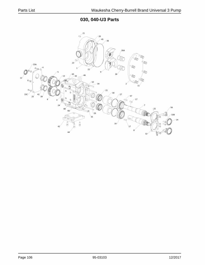
Parts List Waukesha Cherry-Burrell Brand Universal 3 Pump
030, 040-U3 Parts
��
�
��
��
����
��
��
��
���
��
���
��
����
�
����
����
��
�
��
��
��
��
�
��
�
���� ����
�
��
����
���
��
���
��
��
����
Page 106 95-03103 12/2017

Waukesha Cherry-Burrell Brand Universal 3 Pump Parts List
030, 040-U3 Parts
Notes:
* Recommended spare partsFor seals, see page 120 and 122. 3. See “Replacement Labels” on page 10 for detail.
ITEM NO. DESCRIPTIONQTY.PER
PUMPPART NO. NOTES
27 Shim Kit 2 117890+29 Spacer, Gear to Rear Bearing 2 030055000+30 Bearing Spacer 2 101815+32 Bearing Retainer, Front 2 120333+
33A 5/16-18 X 3/4" HHCS, SS 8 30-62333B 5/16-18 X 3/4" SHCS, SS 8 30-29633C 5/16" Flat Washer 8 43-24634 Dowel Bushing, Upper 1 BD011600035 Dowel Bushing, Lower 1 BD0116100
030-040-U3 Cover Gasket, FKM 1 130296+* 030-040-U3 Cover Gasket, FFKM 1 137240+
030-040-U3 Cover Gasket, EPDM 1 137245+39 Lockwasher, Gear 2 CD0036W0041 Locknut, Gear 2 CD0036N0042 Mounting Foot 030-040-U3 SS 1 102285+43 Plastic Cap Plug 6 000121002+44 3/8-16 x 1" SHCS 4 30-189
030-U3 Body Retaining Screw 2 30-613040-U3 Body Retaining Screw 2 30-740
46 Eye Bolt, 3/8-16 x 9/16" SS 2 30-720Key, Coupling - 1/4 x 1/4 x 1-3/4" 1 000037002+Key, Coupling - Tru-Fit 1 119715+
48 Cleanout Plug, SS 2 102297+56 030-040-U3 Seal Guard 2 138897+61 Name Plate, Sanitary 1 135624+62 #2 x .187" RHDS 4 30-35565 Caution Plate 2 121694+66 Warning Label 2 33-6367 Grease Fitting, 1/8" 4 LL11840468 Plastic Cap, Grease Fitting 4 BD0093000
PL5060-CH155
47
36
45
12/2017 95-03103 Page 107

Parts List Waukesha Cherry-Burrell Brand Universal 3 Pump
045, 060, 130-U3 Parts
��
�
��
��
����
��
��
��
���
��
���
��
����
�
����
����
��
�
��
��
��
��
�
��
�
���� ����
�
��
����
���
��
���
��
��
����
��
Page 108 95-03103 12/2017
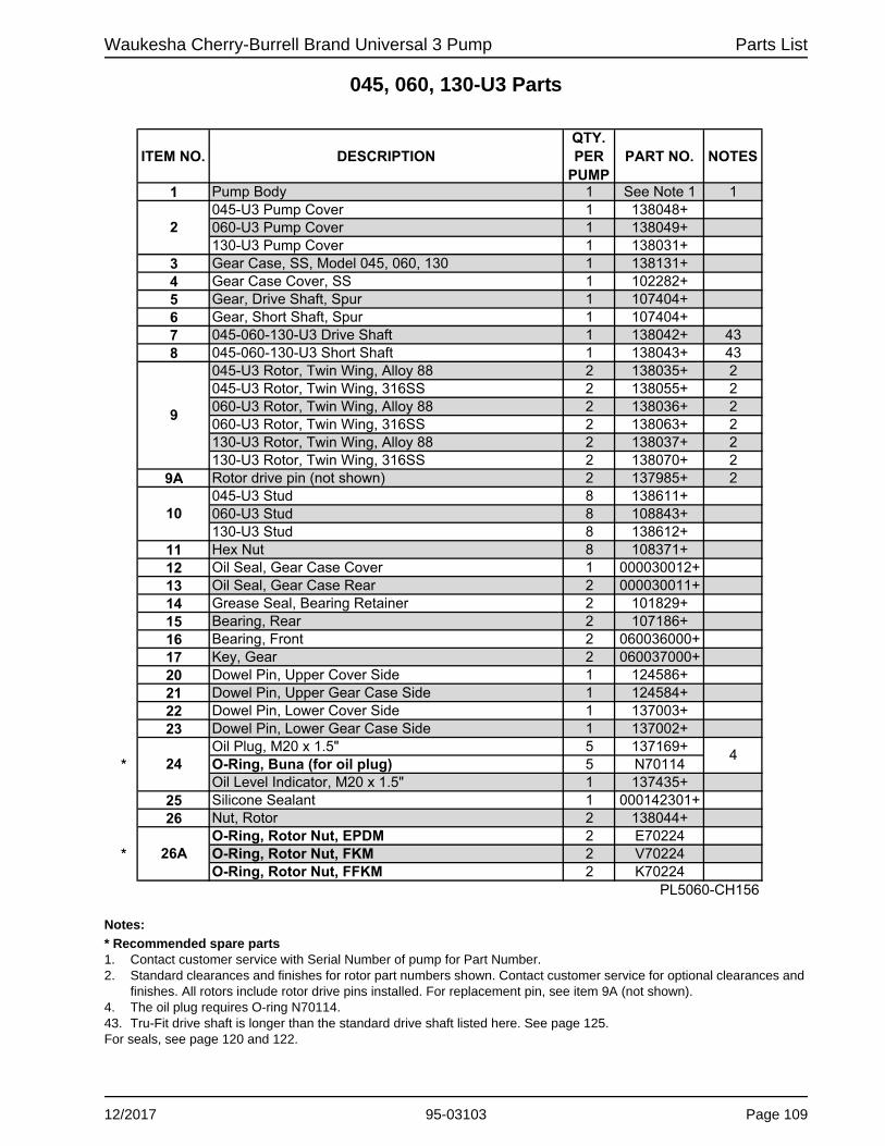
Waukesha Cherry-Burrell Brand Universal 3 Pump Parts List
045, 060, 130-U3 Parts
Notes:
* Recommended spare parts1. Contact customer service with Serial Number of pump for Part Number.2. Standard clearances and finishes for rotor part numbers shown. Contact customer service for optional clearances and
finishes. All rotors include rotor drive pins installed. For replacement pin, see item 9A (not shown).4. The oil plug requires O-ring N70114.43. Tru-Fit drive shaft is longer than the standard drive shaft listed here. See page 125. For seals, see page 120 and 122.
ITEM NO. DESCRIPTIONQTY.PER
PUMPPART NO. NOTES
1 Pump Body 1 See Note 1 1045-U3 Pump Cover 1 138048+060-U3 Pump Cover 1 138049+130-U3 Pump Cover 1 138031+
3 Gear Case, SS, Model 045, 060, 130 1 138131+4 Gear Case Cover, SS 1 102282+5 Gear, Drive Shaft, Spur 1 107404+6 Gear, Short Shaft, Spur 1 107404+7 045-060-130-U3 Drive Shaft 1 138042+ 438 045-060-130-U3 Short Shaft 1 138043+ 43
045-U3 Rotor, Twin Wing, Alloy 88 2 138035+ 2045-U3 Rotor, Twin Wing, 316SS 2 138055+ 2060-U3 Rotor, Twin Wing, Alloy 88 2 138036+ 2060-U3 Rotor, Twin Wing, 316SS 2 138063+ 2130-U3 Rotor, Twin Wing, Alloy 88 2 138037+ 2130-U3 Rotor, Twin Wing, 316SS 2 138070+ 2
9A Rotor drive pin (not shown) 2 137985+ 2045-U3 Stud 8 138611+060-U3 Stud 8 108843+130-U3 Stud 8 138612+
11 Hex Nut 8 108371+12 Oil Seal, Gear Case Cover 1 000030012+13 Oil Seal, Gear Case Rear 2 000030011+14 Grease Seal, Bearing Retainer 2 101829+15 Bearing, Rear 2 107186+16 Bearing, Front 2 060036000+17 Key, Gear 2 060037000+20 Dowel Pin, Upper Cover Side 1 124586+21 Dowel Pin, Upper Gear Case Side 1 124584+22 Dowel Pin, Lower Cover Side 1 137003+23 Dowel Pin, Lower Gear Case Side 1 137002+
Oil Plug, M20 x 1.5" 5 137169+* O-Ring, Buna (for oil plug) 5 N70114
Oil Level Indicator, M20 x 1.5" 1 137435+25 Silicone Sealant 1 000142301+26 Nut, Rotor 2 138044+
O-Ring, Rotor Nut, EPDM 2 E70224* O-Ring, Rotor Nut, FKM 2 V70224
O-Ring, Rotor Nut, FFKM 2 K70224PL5060-CH156
424
26A
2
9
10
12/2017 95-03103 Page 109

Parts List Waukesha Cherry-Burrell Brand Universal 3 Pump
045, 060, 130-U3 Parts
��
�
��
��
����
��
��
��
���
��
���
��
����
�
����
����
��
�
��
��
��
��
�
��
�
���� ����
�
��
����
���
��
���
��
��
����
��
Page 110 95-03103 12/2017
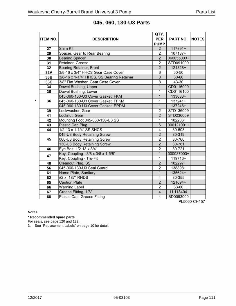
Waukesha Cherry-Burrell Brand Universal 3 Pump Parts List
045, 060, 130-U3 Parts
Notes:
* Recommended spare partsFor seals, see page 120 and 122. 3. See “Replacement Labels” on page 10 for detail.
ITEM NO. DESCRIPTIONQTY.PER
PUMPPART NO. NOTES
27 Shim Kit 2 117891+29 Spacer, Gear to Rear Bearing 2 107187+30 Bearing Spacer 2 060055003+31 Retainer, Grease 2 STD09100032 Bearing Retainer, Front 2 121828+
33A 3/8-16 x 3/4" HHCS Gear Case Cover 8 30-5033B 3/8-16 x 1-1/4" HHCS, SS Bearing Retainer 8 30-6033C 3/8" Flat Washer, Gear Case Cover 8 43-3034 Dowel Bushing, Upper 1 CD011600035 Dowel Bushing, Lower 1 CD0116100
045-060-130-U3 Cover Gasket, FKM 1 133633+* 045-060-130-U3 Cover Gasket, FFKM 1 137241+
045-060-130-U3 Cover Gasket, EPDM 1 137246+39 Lockwasher, Gear 2 STD13600941 Locknut, Gear 2 STD23600942 Mounting Foot 045-060-130-U3 SS 1 102286+43 Plastic Cap Plug 6 000121001+44 1/2-13 x 1-1/4" SS SHCS 4 30-503
045-U3 Body Retaining Screw 2 30-319060-U3 Body Retaining Screw 2 30-760130-U3 Body Retaining Screw 2 30-761
46 Eye Bolt, 1/2-13 x 3/4" 2 30-721Key, Coupling - 3/8 x 3/8 x 1-5/8" 1 000037003+Key, Coupling - Tru-Fit 1 119716+
48 Cleanout Plug, SS 2 102297+56 045-060-130-U3 Seal Guard 2 138898+61 Name Plate, Sanitary 1 135624+62 #2 x .187" RHDS 4 30-35565 Caution Plate 2 121694+66 Warning Label 2 33-6067 Grease Fitting, 1/8" 4 LL11840468 Plastic Cap, Grease Fitting 4 BD0093000
PL5060-CH157
47
36
45
12/2017 95-03103 Page 111

Parts List Waukesha Cherry-Burrell Brand Universal 3 Pump
180, 220-U3 Parts
��
�
��
��
����
��
��
��
���
��
���
��
����
�
����
����
��
�
��
��
��
��
�
��
�
���� ����
�
��
����
���
��
���
��
��
����
Page 112 95-03103 12/2017

Waukesha Cherry-Burrell Brand Universal 3 Pump Parts List
180, 220-U3 Parts
Notes:
* Recommended spare parts1. Contact customer service with Serial Number of pump for Part Number.2. Standard clearances and finishes for rotor part numbers shown. Contact customer service for optional clearances and
finishes. All rotors include rotor drive pins installed. For replacement pin, see item 9A (not shown).4. The oil plug requires O-ring N70114.43. Tru-Fit drive shaft is longer than the standard drive shaft listed here. See page 125. For seals, see page 120 and 122.
ITEM NO. DESCRIPTIONQTY.PER
PUMPPART NO. NOTES
1 Pump Body 1 See Note 1 1180-U3 Pump Cover 1 138189+220-U3 Pump Cover 1 138190+
3 Gear Case, SS, Model 180, 220 1 138143+4 Gear Case Cover, SS 1 102283+5 Gear, Drive Shaft, Spur 1 110932+6 Gear, Short Shaft, Spur 1 110932+7 180-220U3 Drive Shaft 1 138107+ 438 180-220U3 Short Shaft 1 138108+ 43
180-U3 Rotor, Twin Wing, Alloy 88 2 138159+ 2180-U3 Rotor, Twin Wing, 316SS 2 138163+ 2220-U3 Rotor, Twin Wing, Alloy 88 2 138170+ 2220-U3 Rotor, Twin Wing, 316SS 2 138174+ 2
9A Rotor drive pin (not shown) 2 M525S1670X 2180-U3 Stud 8 138340+220-U3 Stud 8 138626+
11 Hex Nut 8 108372+12 Oil Seal, Gear Case Cover 1 STD03000613 Oil Seal, Gear Case Rear 2 STD11900214 Grease Seal, Bearing Retainer 2 121681+15 Bearing, Rear 2 300035000+16 Bearing, Front 2 200036000+17 Key, Gear 2 200037000+20 Dowel Pin, Upper Cover Side 1 124586+21 Dowel Pin, Upper Gear Case Side 1 124584+22 Dowel Pin, Lower Cover Side 1 137005+23 Dowel Pin, Lower Gear Case Side 1 137004+
Oil Plug, M20 x 1.5" 5 137169+* O-Ring, Buna (for oil plug) 5 N70114
Oil Level Indicator, M20 x 1.5" 1 137435+25 Silicone Sealant 1 000142301+26 Nut, Rotor 2 138112+
O-Ring, Rotor Nut, EPDM 2 E70228* O-Ring, Rotor Nut, FKM 2 V70228
O-Ring, Rotor Nut, FFKM 2 K70228PL5060-CH158
26A
4
2
9
10
24
12/2017 95-03103 Page 113

Parts List Waukesha Cherry-Burrell Brand Universal 3 Pump
180, 220-U3 Parts
��
�
��
��
����
��
��
��
���
��
���
��
����
�
����
����
��
�
��
��
��
��
�
��
�
���� ����
�
��
����
���
��
���
��
��
����
Page 114 95-03103 12/2017

Waukesha Cherry-Burrell Brand Universal 3 Pump Parts List
180, 220-U3 Parts
Notes:
* Recommended spare partsFor seals, see page 120 and 122. 3. See “Replacement Labels” on page 10 for detail.
ITEM NO. DESCRIPTIONQTY.PER
PUMPPART NO. NOTES
27 Shim Kit 2 117892+29 Spacer, Gear to Rear Bearing 2 40878+30 Bearing Spacer 2 40752+32 Bearing Retainer, Front 2 121829+
33A 3/8-16 x 3/4" HHCS, SS Gear Case Cover 8 30-5033B 3/8-16 x 1-1/4" HHCS, SS Bearing Retainer 8 30-6033C 3/8" Flat Washer, Gear Case Cover 8 43-3034 Dowel Bushing, Upper 1 CD011600035 Dowel Bushing, Lower 1 CD0116100
180-220-U3 Cover Gasket, FKM 1 137431+* 180-220-U3 Cover Gasket, FFKM 1 137432+
180-220-U3 Cover Gasket, EPDM 1 137433+39 Lockwasher, Gear 2 STD13601141 Locknut, Gear 2 STD23601142 Mounting Foot 180-220-U3 SS 1 102287+43 Plastic Cap Plug 6 000121001+44 1/2-13 x 1-1/4" SS SHCS 4 30-503
180-U3 Body Retaining Screw 2 30-766220-U3 Body Retaining Screw 2 30-717
46 Eye Bolt, 1/2-13 x 3/4" 2 30-721Key, Coupling - 1/2 x 1/2 x 1-7/8" 1 000037004+Key, Coupling - Tru-Fit 1 119717+
48 Cleanout Plug, SS 2 102297+56 180-220-U3 Seal Guard 2 138899+61 Name Plate, Sanitary 1 135624+62 #2 x .187" RHDS 4 30-35565 Caution Plate 2 121694+66 Warning Label 2 33-6067 Grease Fitting, 1/8" 4 LL11840468 Plastic Cap, Grease Fitting 4 BD0093000
PL5060-CH159
47
36
45
12/2017 95-03103 Page 115
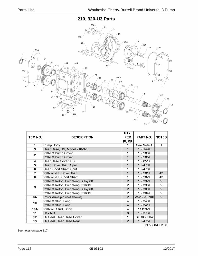
Parts List Waukesha Cherry-Burrell Brand Universal 3 Pump
210, 320-U3 Parts
See notes on page 117.
�����
� ��
�
��
� �
�� � ��
�� ��
��
��
��
��
��
�� ����
�
���� ��
��
��
�� ����
� ��
���
��
��
�
�
��
� ���
��
��
���� ��
�
��
�
��
ITEM NO. DESCRIPTIONQTY.PER
PUMPPART NO. NOTES
1 Pump Body 1 See Note 1 13 Gear Case, SS, Model 210-320 1 138149+
210-U3 Pump Cover 1 138286+320-U3 Pump Cover 1 138285+
4 Gear Case Cover, SS 1 135851+5 Gear, Drive Shaft, Spur 1 102470+6 Gear, Short Shaft, Sput 1 102470+7 210-320-U3 Drive Shaft 1 138281+ 438 210-320-U3 Short Shaft 1 138282+ 43
210-U3 Rotor, Twin Wing, Alloy 88 2 138332+ 2210-U3 Rotor, Twin Wing, 316SS 2 138336+ 2320-U3 Rotor, Twin Wing, Alloy 88 2 138300+ 2320-U3 Rotor, Twin Wing, 316SS 2 138304+ 2
9A Rotor drive pin (not shown) 2 M525S1670X 2210-U3 Stud, Long 4 138340+320-U3 Stud, Long 4 138341+
10A 210-320 Stud, Short 4 111292+11 Hex Nut 8 108373+12 Oil Seal, Gear Case Cover 1 STD03000413 Oil Seal, Gear Case Rear 2 102475+
PL5060-CH160
9
2
10
Page 116 95-03103 12/2017

Waukesha Cherry-Burrell Brand Universal 3 Pump Parts List
210, 320-U3 Parts
Notes:
* Recommended spare parts1. Contact customer service with Serial Number of pump for Part Number.2. Standard clearances and finishes for rotor part numbers shown. Contact customer service for optional clearances and
finishes. All rotors include rotor drive pins installed. For replacement pin, see item 9A (not shown).4. The oil plug requires O-ring N70114.43. Tru-Fit drive shaft is longer than the standard drive shaft listed here. See page 125. For seals, see page 120 and 122.
ITEM NO. DESCRIPTIONQTY.PER
PUMPPART NO. NOTES
14 Grease Seal, Bearing Retainer 2 121681+15 Bearing, Rear 2 0H103600016 Bearing, Front 2 0H103600317 Key, Gear 2 0H103700020 Dowel Pins, Cover Side 2 0H104000021 Dowel Pins, Gear Case Side 2 105871+
Oil Plug, M20 x 1.5" 5 137169+* O-Ring, Buna (for oil plug) 5 N70114
Oil Level Indicator, M20 x 1.5" 1 137435+25 Silicone Sealant 1 000142301+26 Nut, Rotor 2 138288+
O-Ring, Rotor Nut, EPDM 2 E70231* O-Ring, Rotor Nut, FKM 2 V70231
O-Ring, Rotor Nut, FFKM 2 K7023127 Shim Kit 2 117893+28 Shim Plate 2 134506+
Shims, Body, .002 AR 134507+Shims, Body, .003 AR 134508+Shims, Body, .005 AR 134509+Shims, Body, .010 AR 134510+Shims, Body, .020 AR 134511+
28D 5/16-18 x 1" FHSCS 4 30-61229 Spacer, Gear to Rear Bearing 2 102474+30 Bearing Spacer 2 102472+
30A Spacer Seal 2 102473+31 Retainer, Grease 2 STD09100032 Bearing Retainer, Front 2 123533+
33A 3/8-16 x .75" HHCS 6 30-5033B 5/16-18 x 1.125" BSHCS 8 30-74233C 3/8" Flat Washer 6 43-3034 Dowel Bushings 2 0H1116000
210-U3 Cover Gasket, FKM 1 139750+210-U3 Cover Gasket, FFKM 1 139751+210-U3 Cover Gasket, EPDM 1 139752+320-U3 Cover Gasket, FKM 1 133636+320-U3 Cover Gasket, FFKM 1 137243+320-U3 Cover Gasket, EPDM 1 137248+
41 Locknut, Gear 2 105697+PL5060-CH160a
* 36
24
26A
28A
4
12/2017 95-03103 Page 117
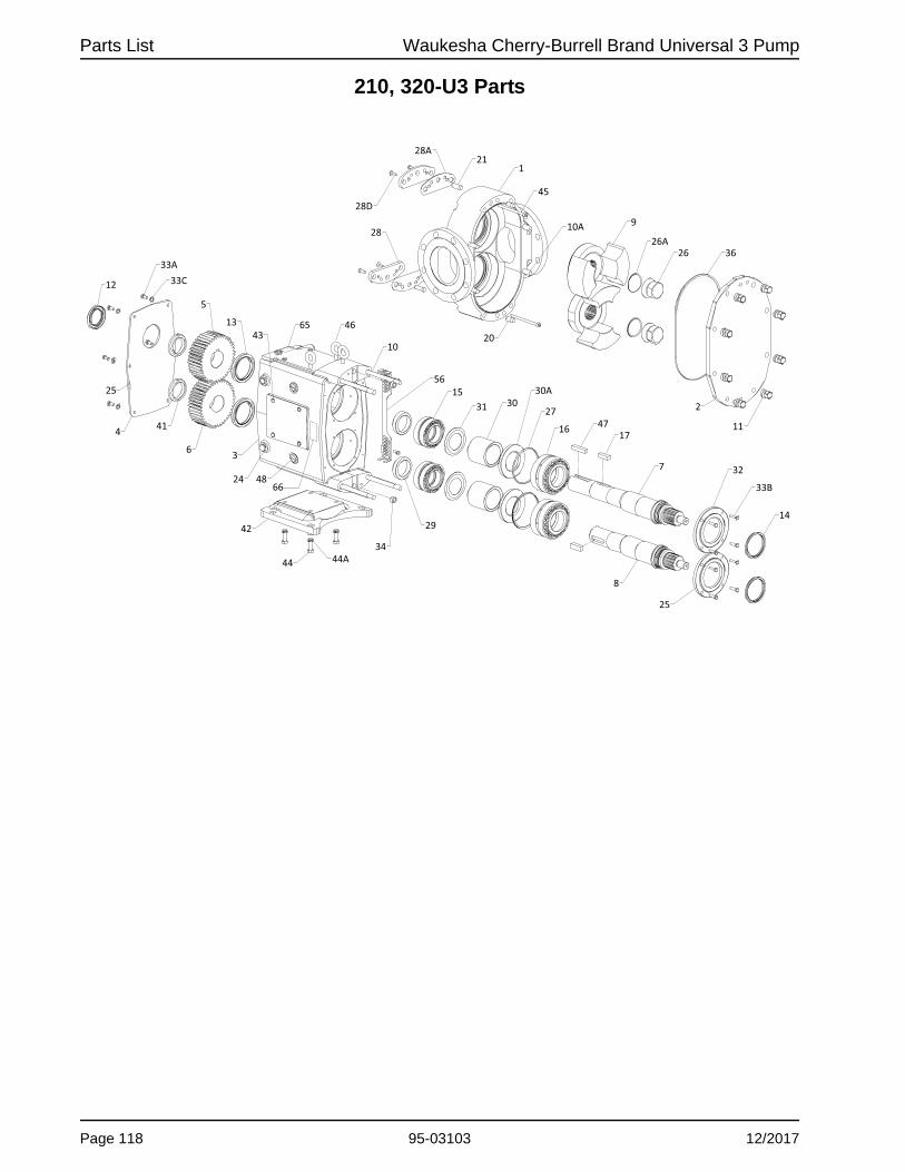
Parts List Waukesha Cherry-Burrell Brand Universal 3 Pump
210, 320-U3 Parts
�����
� ��
�
��
� �
�� � ��
�� ��
��
��
��
��
��
�� ����
�
���� ��
��
��
�� ����
� ��
���
��
��
�
�
��
� ���
��
��
���� ��
�
��
�
��
Page 118 95-03103 12/2017

Waukesha Cherry-Burrell Brand Universal 3 Pump Parts List
210, 320-U3 Parts
Notes:
* Recommended spare partsFor seals, see page 120 and 122. 3. See “Replacement Labels” on page 10 for detail.
ITEM NO. DESCRIPTIONQTY.PER
PUMPPART NO. NOTES
42 Mounting Foot 210-320-U3 SS 1 130748+43 Plastic Cap Plug 8 000121001+44 1/2-13 x 1-3/4" HHCS 4 30-127X
44A Lock Washer, 1/2" 4 43-16210-U3 Body Retaining Screws 2 30-766320-U3 Body Retaining Screws 2 30-766
46 Eye Bolt 3 30-721Key, Coupling - 5/8 x 5/8 x 2-3/4" 1 000037005+Key, Coupling - Tru-Fit 1 119718+
48 Cleanout Plug, SS 2 102297+56 210-320-U3 Seal Guard 2 113504+
56A 5/16-18 x .75" HHCS 4 30-62360A 1/8-27 Aseptic Connection Pipe Plugs 10 STD12850061 Name Plate, Sanitary 1 135624+62 #2 x .187" RHDS 4 30-35565 Caution Plate 2 121694+66 Warning Label 2 33-6067 Grease Fitting, 1/8" 4 LL11840468 Plastic Cap, Grease Fitting 4 BD0093000
PL5060-CH161
45
47
12/2017 95-03103 Page 119

Parts List Waukesha Cherry-Burrell Brand Universal 3 Pump
Universal 3 Standard Seals
^ Kit contains 1 wave spring and 1 drive ring.
Double (Top) and Single (Bottom) Mechanical Seal, U3 pumps 130-U3 and smaller
Double (Top) and Single (Bottom) Mechanical Seal, U3 pumps 180-U3 and larger
PD100-659
151152 153 154
155156
157 158A^159
160 161158B^ 162 163
164 165 166
167 168 169A^170
163 171165 166
160A
169B^
{D100-660
151152
153
154155
156157
158A^ 159 160158B^ 162
163164
165166
167168 169A^
169B^
163171 165
166
160A
Page 120 95-03103 12/2017

Waukesha Cherry-Burrell Brand Universal 3 Pump Parts List
Universal 3 Standard Seals
Notes:* Recommended spare part1. Does not apply to U3 pumps 180-U3 and larger2. Seal Service Kit (indicated with ^ on page 120) contains 1 wave spring and 1 drive ring.3. Seal Housing - DM includes stop pin installed. For a replacement pin, see item 160A.Seal Description Key:DM Double MechanicalSM Single MechanicalSC Silicon CarbideC CarbonTC Tungsten CarbideNF Narrow FaceFor specialty seals, see page 123.
006, 015, 018-U3
030, 040-U3
045, 060, 130-U3
180, 220-U3
210, 320-U3
EPDM 2 E70024FKM 2 V70024
152 Adjusting Ring 2 138246+EPDM 2 E70130FKM 2 V70130
154 Flush-Side Rotary Seal SC 2 138371+155 Seal Retaining Bolt 6 30-546156 Flush-Side Stationary Seal C 2 139787+
EPDM 2 E70134FKM 2 V70134
158A158B159 Seal Housing Bolt 8 30-765 30-725 30-742160 2 138245+ 137979+ 138074+ 138192+ 138289+ 3
160A Stop Pin, Seal 4 137124+ 3161 Shaft Ring - DM 2 LA1215200 N/A N/A 1
EPDM 2 E70036FKM 2 V70036EPDM 2 E70135FKM 2 V70135FFKM 2 K70135SC 2 138368+C 2 138385+TC 2 138400+SC NF 2 139592+TC NF 2 139593+SC 2 138362+ 138364+ 138364+TC 2 138394+ 138396+ 138396+EPDM 2 E70135 E70248 E70248FKM 2 V70135 V70248 V70248FFKM 2 K70135 K70248 K70248
167 Seal Housing Bolt 8 30-546 30-745 30-745168 Seal Housing - SM 2 138244+ 137946+ 138076+ 138195+ 138343+
169A169B170 Shaft Ring - SM 2 N/A N/A 1
SC 2 138365+ 138367+ 138367+C 2 138382+ 138384+ 138384+TC 2 138397+ 138399+ 138399+SC NF 2 139590+ N/A N/ATC NF 2 139591+ N/A N/A
PL5060-CH162
Stationary Seal
DESCRIPTION
O-Ring, Adjusting Ring
O-Ring, Flush Rotary Seal
Product-side stationary seal
Product-side rotary seal
Seal Housing - DM, includes stop pin
171
151
153
157
162
163
164
165
166
PART NO.
*
*
E70031V70031137980+E70145V70145
ITEMNO.
QTY.PER
PUMP
LA1215400
*
*
*
*
O-Ring, Flush Stationary Seal
O-Ring, Seal Housing
O-Ring, Product Stationary Seal
O-Ring, Product Rotary Seal
2 139890+
138387+138402+
30-742
138451+
139894+
E70248V70248
E70150V70150138212+E70245V70245138373+30-741
139789+30-546
E70147V70147
137985+
139788+
139892+
138393+139594+139595+
138363+138395+E70147V70147K70147
LA2363201
30-741
NOTES
L25071004L25071002
138366+138383+
138369+138386+138401+139596+139597+
E70041V70041E70147V70147K70147
138372+
2Wave Spring (sold as a kit with 158B)Drive Ring (sold as a kit with 158A)
2 139891+ 139893+ 139895+ 2Wave Spring (sold as a kit with 169B)Drive Ring (sold as a kit with 169A)
N/AN/A
E70248V70248K70248138370+
12/2017 95-03103 Page 121

Parts List Waukesha Cherry-Burrell Brand Universal 3 Pump
Universal 3 Specialty Seals
Single (Top) and Double (Bottom) O-Ring Seal
180
181182
183 184185
186187
188
180181 182
183189
185
186187
188
184 (220-320-U3)
189 (220-320-U3)
PD100-666
Page 122 95-03103 12/2017

Waukesha Cherry-Burrell Brand Universal 3 Pump Parts List
Universal 3 Specialty Seals
Notes:* Recommended spare part1. Quantity 2 for Single O-Ring Seal; Quantity 4 for Double O-Ring Seal2. Applies to Single O-Ring Seal Design only; does not apply to Double O-Ring Seal Design3. Applies to Double O-Ring Seal Design only; does not apply to Single O-Ring Seal Design
006, 015, 018-U3
030, 040-U3
045, 060, 130-U3
180, 220-U3
210, 320-U3
O-ring SealEPDM E70024FKM V70024FFKM K70024
181 2 138467+182 2 139799+
183 8 30-546
184 2 138470+ 138424+ 138425+ 139098+ 139099+ 2EPDM E70036FKM V70036FFKM K70036
O-Ring, Seal EPDM E70326O-Ring, Seal FKM V70326O-Ring, Seal FFKM K70326
187 2 138465+EPDM E70135FKM V70135FFKM K70135
189 2 138466+ 138426+ 138427+ 139095+ 139097+ 3PL5060-CH168
12/4
2
2
2 V70248
E70150V70150K70150139115+101688+
30-741
*
30-742
E70041V70041
ITEMNO.
QTY.PER
PUMP
180
185
186
188
PART NO.
E70031V70031K70031
O-Ring, Sleeve Back
O-Ring, Seal Housing
L25071004
NOTES
N/A
K70248
E70343
K70343V70343
139116+E70248
K70331
K70041
*
138428+
K70146
*
*
DESCRIPTION
L25071002
101685+
E70331V70331
E70146V70146
138442+Spring Seat, O-Ring SealWave SpringButton Socket Head Cap Screw (BSHCS)Housing, Single O-Ring Seal
Sleeve, O-Ring Seal
Housing, Double O-Ring Seal
O-Ring, Sleeve Front
12/2017 95-03103 Page 123

Parts List Waukesha Cherry-Burrell Brand Universal 3 Pump
U3 Shaft and Bearing Assemblies
Note: Assembly includes items 7 or 8 (Drive or Short Shaft), 15 (Rear Bearing), 16 (Front Bearing), 17 (gear key), and 29 (gear to rear bearing spacer). See model-specific parts list page for drawing.
DESCRIPTION QTY. PER PUMP
PARTNO.
006-015-018-U3 Drive Shaft & Bearing Assy. 1 139809+006-015-018-U3 Short Shaft & Bearing Assy. 1 139810+030-040-U3 Drive Shaft & Bearing Assy. 1 139811+030-040-U3 Short Shaft & Bearing Assy. 1 139812+045-060-130-U3 Drive Shaft & Bearing Assy. 1 139813+045-060-130-U3 Short Shaft & Bearing Assy. 1 139814+180-220-U3 Drive Shaft & Bearing Assy. 1 139815+180-220-U3 Short Shaft & Bearing Assy. 1 139816+210-320-U3 Drive Shaft & Bearing Assy. 1 139817+210-320-U3 Short Shaft & Bearing Assy. 1 139818+
PL5060-CH165
Page 124 95-03103 12/2017

Waukesha Cherry-Burrell Brand Universal 3 Pump Parts List
Tru-Fit™ Universal 3 PD Pump Parts
Note:1. Depends on the Nord motor, material, paint. Contact customer service with serial number for part number.2. Item 12, Oil seal, gear case cover, is the same seal that is used on non-Tru-Fit pumps. It is not included with item 4A.
3
7
4A
33D44A
33E
PD100-664
12
006, 015, 018 030, 040 045, 060,
130 180, 220 210, 320
3 Gear Case, SS 125414+ 121201+ 125355+ 124663+ 134290+4A Gear Case Cover, Adapter, SS 136577+ 17 Drive Shaft 139062+ 139063+ 139064+ 139065+ 139066+12 Oil Seal, Gear Case Cover 000030016+ 000030013+ 000030012+ STD030006 STD030004 2
1/4-20 x 1" HHCS 30-93 � �5/16-18 x 1-1/8" HHCS � 30-237 �3/8 - 16x1-1/2" HHCS � � �1/2-13 x 1-1/2" HHCS � � 30-1035/16" x 3/4" lg. SHSB 30-690 � �3/8" x 3/4" lg. SHSB � 30-691 �1/2" x 1" lg. SHSB � � �5/8" x 1" lg. SHSB � � 30-693Flat Washer, 5/16" 43-246 �Flat Washer, 3/8" � 43-30Flat Washer, 1/2" � �
PL5060-CH163
44A��
43-31
U3 Pump Size
Serial # Required
33D
��
30-50�
ItemNo. Description Notes
33E
��
30-692�
12/2017 95-03103 Page 125

Parts List Waukesha Cherry-Burrell Brand Universal 3 Pump
Special Tools for U3 Pumps
Non-Marring Socket Tool for Rotor Nuts
O-ring Removal Tools
Rotor Blocking Tool
Gear Nut Driver, Gear End Shaft Thread Chaser
U3 Model Part Number006, 015, 018 140074+
030, 040 139795+045, 060, 130 139796+
180, 220 139767+210, 320 126536+
PL5060-CH149
Description Part NumberStandard O-ring removal tool AD0096001U3 Double O-Ring Seal Removal Tool 140062+
PL5060-CH170
Description Part NumberRotor Blocking Tool 139794+
PL5060-CH164
Description Model U3 Pumps Part Number006, 015, 018 109281+
030, 040 109282+045, 060,130 109283+
180, 220 110304+210, 320 114702+
006, 015, 018 109287+030, 040 109288+
045, 060, 130 109289+180, 220 110305+210, 320 POA
PL5060-CH150
Gear Nut Driver
Gear End Shaft Thread Chaser
Page 126 95-03103 12/2017

Waukesha Cherry-Burrell Brand Universal 3 Pump Long Term Storage
12/2017 95-03103 Page 127
Long Term Storage Long-term storage (greater than six months) of Waukesha Cherry-Burrell brand pumps:
Before Storage 1. Lubricate all bearings and seals, including:
• Rubber o-rings and mechanical seal faces (new pump bearings installed from the factory are already lubricated).
• Motors and drives (see manufacturer's instructions)
2. Be sure the pump contains no water. Make sure to disassem-ble the wet end and wipe it dry if necessary.
3. Use rust inhibitor on any exposed metal surfaces:
• Any unpainted surfaces
• Shafts, nuts/bolts
4. Cover the inlet/outlet connections of the pumps to keep out foreign materials.
5. Put all related instruction manuals in a separate water-tight envelope or container and store them with the equipment.
6. Completely enclose the equipment to prevent contamination from moisture, dust and other possible contaminants. Certain types of plastic wrap materials, when properly used, make excellent storage enclosures.
7. Rotate the pump and drive shafts several turns every 3 months.
Storage 1. Store in a dry location. Indoor storage is preferred. If stored outdoors, the equipment must be in a weather-tight enclosure and shielded from direct sunlight.
2. Maintain even temperatures to prevent condensation.
After Storage 1. Remove the equipment from the enclosure and repair or replace any damaged items before using equipment.
NOTE: Do not start the motor if there is any indication of water contamination. Have the motor checked by a qualified electrician before starting.
2. Check the electric motor (if applicable) per the manufac-turer's instructions.
3. Pumps:
• Completely disassemble the product contact liquid end per the instruction manual.
• Clean and inspect all parts, including seals and o-rings.
• Replace rubber parts with any sign of age or damage, such as cracks, taking a set, or loss of elasticity.
4. Lubricate the seal and o-rings and reassemble the liquid end per the instruction manual.
5. Lubricate the motor/drive (if applicable) per the manufac-turer's instructions.
6. If the pump has been in storage longer than 1 year, change the oil in the pump and drive.

Maintenance Summary Waukesha Cherry-Burrell Brand Universal 3 Pump
Page 128 95-03103 12/2017
Universal 3 Maintenance Summary Reference Sheet
Low Viscosity Rotors: -40°F (-40°C) to 180°F (82°C); Standard Clearance Rotors: -40°F (-40°C) to 300°F (149°C). Contact SPX FLOW Application Engineering if alternate rotors are needed.NOTE: The assembly clearances stated above are for reference only. Actual pump clearances may vary based on pump performance testing.
Universal 3 Model
Change oil every 750 hours*ISO Grade 320, SAE 140 or AGMA Number 6EP
Grease bearings every 750 hours*NLGI Grade No. 2, EP, Lithium-based grease.
* Aggressive washdown or extreme running conditions may require more frequent lubrication intervals.
Oil Capacity (Gears) Grease Quantity (per Bearing)
Top or Bottom Side Mount Front Rear
006, 015, 018 1.3 oz (40 ml) 3.3 oz (100 ml) .37 oz (11 ml) .13 oz (4 ml)
030, 040 2.0 oz (60 ml) 4 oz (120 ml) .60 oz (18 ml) .21 oz (6 ml)
045, 060, 130 6.0 oz (170 ml) 9.5 oz (280 ml) .84 oz (25 ml) .76 oz (22 ml)
180, 220 11 oz (320 ml) 20 oz (600 ml) 1.33 oz (39 ml) 1.03 oz (30 ml)
210, 320 17 oz (500 ml) 44 oz (1300 ml) 1.96 oz (58 ml) 1.16 oz (34 ml)
Universal 3 Model
Torque Values - Locknuts Universal 3 Wrench Size
Rotor CoverRotor Nut
Body Retaining Cap Screw
Cover Nut
006, 015, 018 50 ft-lb (68 N·m) 7 ft-lb (10 N·m) 15/16"3/16" 5/8"
030, 040 120 ft-lb (163 N·m) 11 ft-lb (15 N·m) 1-1/4"
045, 060250 ft-lb (339 N·m)
56 ft-lb (76 N·m)1-5/8" 1/4"
7/8”130 25 ft-lb (34 N·m)
180, 220 325 ft-lb (441 N·m) 110 ft-lb (149 N·m) 2-1/4"5/16"
210, 320 375 ft-lb (508 N·m) 158 ft-lb (214 N·m) 2-3/8" 1"
Universal 3 Model
A - Back Facein (mm)
B - Rotor to Bodyin (mm)
C - Front Facein (mm)
Rotor Type Low Viscosity Standard Low Viscosity Standard Low Viscosity Standard
0060.0025 - 0.004 0.0035 - 0.005 0.001 - 0.004 0.0025 - 0.0055 0.004 - 0.005 0.0045 - 0.0055
(0.06 - 0.10) (0.09 - 0.13) (0.03 - 0.10) (0.06 - 0.14) (0.10 - 0.13) (0.11 - 0.14)
015, 0180.0025 - 0.0045 0.003 - 0.005 0.001 - 0.004 0.0025 - 0.0055 0.004 - 0.005 0.0055 - 0.0065
(0.06 - 0.11) (0.08 - 0.013) (0.03 - 0.10) (0.06 - 0.14) (0.10 - 0.13) (0.14 - 0.17)
030, 0400.002 - 0.004 0.0035 - 0.0055 0.001 - 0.005 0.0025 - 0.006 0.0045 - 0.0055 0.006 - 0.007
(0.05 - 0.10) (0.09 - 0.14) (0.03 - 0.13) (0.06 - 0.15) (0.11 - 0.14) (0.15 - 0.18)
045, 0600.003 - 0.007 0.004 - 0.008 0.003 - 0.0075 0.005 - 0.010 0.0055 - 0.0075 0.0085 - 0.0105
(0.08 - 0.18) (0.10 - 0.20) (0.08 - 0.19) (0.13 - 0.25) (0.14 - 0.19) (0.22 - 0.27)
1300.003 - 0.007 0.004 - 0.008 0.0035 - 0.0075 0.0055 - 0.0095 0.006 - 0.007 0.009 - 0.0115
(0.08 - 0.18) (0.10 - 0.20) (0.09 - 0.19) (0.14 - 0.24) (0.15 - 0.18) (0.23 - 0.29)
180, 2200.004 - 0.008 0.005 - 0.009 0.0055 - 0.0095 0.009 - 0.013 0.006 - 0.008 0.010 - 0.012
(0.10 - 0.20) (0.13 - 0.23) (0.14 - 0.24) (0.23 - 0.33) (0.15 - 0.20) (0.25 - 0.30)
210, 3200.005 - 0.009 0.007 - 0.011 0.008 - 0.012 0.010 - 0.014 0.008 - 0.010 0.012 - 0.014
(0.13 - 0.23) (0.18 - 0.28) (0.20 - 0.30) (0.25 - 0.36) (0.20 - 0.25) (0.30 - 0.36)
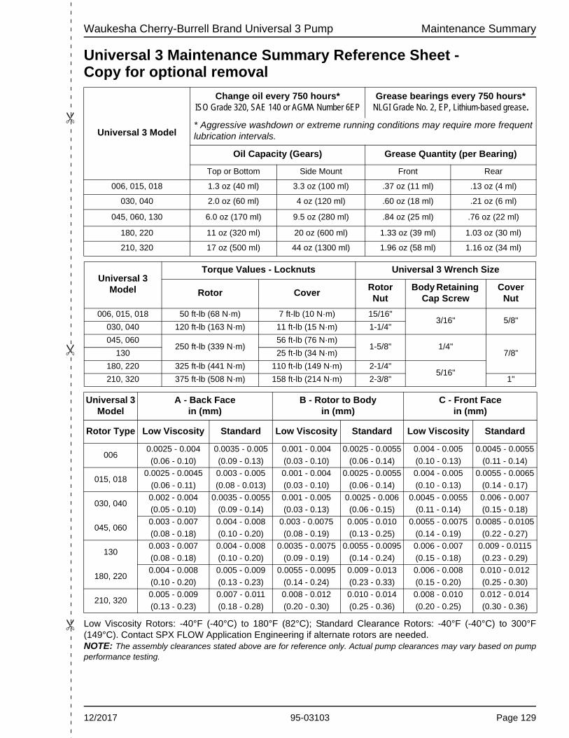
Waukesha Cherry-Burrell Brand Universal 3 Pump Maintenance Summary
��
�
Universal 3 Maintenance Summary Reference Sheet - Copy for optional removalLow Viscosity Rotors: -40°F (-40°C) to 180°F (82°C); Standard Clearance Rotors: -40°F (-40°C) to 300°F (149°C). Contact SPX FLOW Application Engineering if alternate rotors are needed.NOTE: The assembly clearances stated above are for reference only. Actual pump clearances may vary based on pump performance testing.
Universal 3 Model
Change oil every 750 hours*ISO Grade 320, SAE 140 or AGMA Number 6EP
Grease bearings every 750 hours*NLGI Grade No. 2, EP, Lithium-based grease.
* Aggressive washdown or extreme running conditions may require more frequent lubrication intervals.
Oil Capacity (Gears) Grease Quantity (per Bearing)
Top or Bottom Side Mount Front Rear
006, 015, 018 1.3 oz (40 ml) 3.3 oz (100 ml) .37 oz (11 ml) .13 oz (4 ml)
030, 040 2.0 oz (60 ml) 4 oz (120 ml) .60 oz (18 ml) .21 oz (6 ml)
045, 060, 130 6.0 oz (170 ml) 9.5 oz (280 ml) .84 oz (25 ml) .76 oz (22 ml)
180, 220 11 oz (320 ml) 20 oz (600 ml) 1.33 oz (39 ml) 1.03 oz (30 ml)
210, 320 17 oz (500 ml) 44 oz (1300 ml) 1.96 oz (58 ml) 1.16 oz (34 ml)
Universal 3 Model
Torque Values - Locknuts Universal 3 Wrench Size
Rotor CoverRotor Nut
Body Retaining Cap Screw
Cover Nut
006, 015, 018 50 ft-lb (68 N·m) 7 ft-lb (10 N·m) 15/16"3/16" 5/8"
030, 040 120 ft-lb (163 N·m) 11 ft-lb (15 N·m) 1-1/4"
045, 060250 ft-lb (339 N·m)
56 ft-lb (76 N·m)1-5/8" 1/4"
7/8”130 25 ft-lb (34 N·m)
180, 220 325 ft-lb (441 N·m) 110 ft-lb (149 N·m) 2-1/4"5/16"
210, 320 375 ft-lb (508 N·m) 158 ft-lb (214 N·m) 2-3/8" 1"
Universal 3 Model
A - Back Facein (mm)
B - Rotor to Bodyin (mm)
C - Front Facein (mm)
Rotor Type Low Viscosity Standard Low Viscosity Standard Low Viscosity Standard
0060.0025 - 0.004 0.0035 - 0.005 0.001 - 0.004 0.0025 - 0.0055 0.004 - 0.005 0.0045 - 0.0055
(0.06 - 0.10) (0.09 - 0.13) (0.03 - 0.10) (0.06 - 0.14) (0.10 - 0.13) (0.11 - 0.14)
015, 0180.0025 - 0.0045 0.003 - 0.005 0.001 - 0.004 0.0025 - 0.0055 0.004 - 0.005 0.0055 - 0.0065
(0.06 - 0.11) (0.08 - 0.013) (0.03 - 0.10) (0.06 - 0.14) (0.10 - 0.13) (0.14 - 0.17)
030, 0400.002 - 0.004 0.0035 - 0.0055 0.001 - 0.005 0.0025 - 0.006 0.0045 - 0.0055 0.006 - 0.007
(0.05 - 0.10) (0.09 - 0.14) (0.03 - 0.13) (0.06 - 0.15) (0.11 - 0.14) (0.15 - 0.18)
045, 0600.003 - 0.007 0.004 - 0.008 0.003 - 0.0075 0.005 - 0.010 0.0055 - 0.0075 0.0085 - 0.0105
(0.08 - 0.18) (0.10 - 0.20) (0.08 - 0.19) (0.13 - 0.25) (0.14 - 0.19) (0.22 - 0.27)
1300.003 - 0.007 0.004 - 0.008 0.0035 - 0.0075 0.0055 - 0.0095 0.006 - 0.007 0.009 - 0.0115
(0.08 - 0.18) (0.10 - 0.20) (0.09 - 0.19) (0.14 - 0.24) (0.15 - 0.18) (0.23 - 0.29)
180, 2200.004 - 0.008 0.005 - 0.009 0.0055 - 0.0095 0.009 - 0.013 0.006 - 0.008 0.010 - 0.012
(0.10 - 0.20) (0.13 - 0.23) (0.14 - 0.24) (0.23 - 0.33) (0.15 - 0.20) (0.25 - 0.30)
210, 3200.005 - 0.009 0.007 - 0.011 0.008 - 0.012 0.010 - 0.014 0.008 - 0.010 0.012 - 0.014
(0.13 - 0.23) (0.18 - 0.28) (0.20 - 0.30) (0.25 - 0.36) (0.20 - 0.25) (0.30 - 0.36)
12/2017 95-03103 Page 129

Maintenance Summary Waukesha Cherry-Burrell Brand Universal 3 Pump
��
�
Notes
Page 130 95-03103 12/2017


Universal 3 SeriesROTARY POSITIVE DISPLACEMENT PUMP
SPX FLOW, Inc.
611 Sugar Creek Road
Delavan, WI 53115
P: (262) 728-1900 or (800) 252-5200
F: (262) 728-4904 or (800) 252-5012
SPX FLOW, Inc. reserves the right to incorporate our latest design and material
changes without notice or obligation.
Design features, materials of construction and dimensional data, as described in
this bulletin, are provided for your information only and should not be relied upon
unless confirmed in writing.
Please contact your local sales representative for product availability in your
region. For more information visit www.spxflow.com.
The green “>” is a trademark of SPX FLOW, Inc.
ISSUED: 12/2017 - Original Manual
COPYRIGHT © 2017 SPX FLOW, Inc.