universal protocol converter user manual · should be selected for programming is at91sam7s64-ek....
TRANSCRIPT

UNIVERSAL PROTOCOL CONVERTER USER MANUAL
INTELLIGENCE IN VALIDATION
UNIVERSAL PROCOL CONVERTER 1
UPC1
1 INTRODUCTION
This manual describes the operation of the UPC Validator Interfacing System, programmed with firmware via the Atmel SAM-BA programming software or via USB. This document is intended for those who will:
• Program the UPC • Implement the UPC into machines
We recommend that you study this manual as there are many new features permitting new uses and more secure applications. If you do not understand any part of this manual please refer to www.gaming-upc.com. 2 KIT COMPONENTS
The UPC Kit comprises of the following: • UPC Device • UPC to Validator cable
3 POWER REQUIREMENTS
When programming the UPC using the SAM-BA software, it is necessary to provide power from an external source.
UNIVERSAL PROTOCOL CONVERTOR 2
UPC1
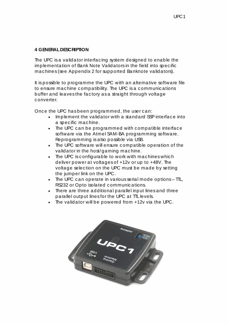
4 GENERAL DESCRIPTION
The UPC is a validator interfacing system designed to enable the implementation of Bank Note Validators in the field into specific machines (see Appendix 2 for supported Banknote validators). It is possible to programme the UPC with an alternative software file to ensure machine compatibility. The UPC is a communications buffer and leaves the factory as a straight through voltage converter. Once the UPC has been programmed, the user can:
• Implement the validator with a standard SSP interface into a specific machine.
• The UPC can be programmed with compatible interface software via the Atmel SAM-BA programming software. Reprogramming is also possible via USB.
• The UPC software will ensure compatible operation of the validator in the host/gaming machine.
• The UPC is configurable to work with machines which deliver power at voltages of +12v or up to +48V. The voltage selection on the UPC must be made by setting the jumper link on the UPC.
• The UPC can operate in various serial mode options – TTL, RS232 or Opto isolated communications.
• There are three additional parallel input lines and three parallel output lines for the UPC at TTL levels.
• The validator will be powered from +12v via the UPC.
UNIVERSAL PROTOCOL CONVERTOR 3

UPC1
5 SOFTWARE INSTALLATION – ALSO REFER TO SECTION 7 PROGRAMMING
NOTE: - Install the SAM-BA software on to your PC. The software is available for download using the following web site link http://www.atmel.com/dyn/resources/prod_documents/Install AT91-ISP v1.12.exe It is necessary to ensure that the COM port selected on your PC to allow programming of the UPC must be within the following range: COM1 to COM10 It is necessary to use serial communication via debug serial interface, TXD on pa10 (pin 29), and RXD on pa9 (pin 30) Pins 29 & 30 of the microcontroller are only used as spare comm inputs on the UPC so we can use them for downloading firmware
UNIVERSAL PROTOCOL CONVERTOR 4

UPC1
UNIVERSAL PROTOCOL CONVERTOR 5

UPC1
UNIVERSAL PROTOCOL CONVERTOR 6

UPC1
UNIVERSAL PROTOCOL CONVERTOR 7

UPC1
6 CONNECTING THE UPC TO A PC
The UPC is connected to a PC for programming purposes via a DA2 kit. The power for the UPC is then supplied via the DA2 kit. When programming using SAMBA (or JTAG) binary interface files should be used. The programming cable connects to pins 11 & 15 of the UPC on the validator connector (CON2). The firmware is downloaded to the UPC via a DA2 kit. The programming cable is configured specifically for the UPC. It is necessary to ensure that the following pins have been crossed on the programming cable: Pins 11 & 12 and 15 & 16 must be crossed over. See APPENDIX B for a drawing of the cable.
UNIVERSAL PROTOCOL CONVERTOR 8
UPC1
7 PROGRAMMING THE UPC
The UPC supports the following interfaces. Please contact [email protected] for full details of compatible interfaces.
• PR01 • PR02 • PR03 • PR04 • PR05 • PR00 - UPC used only as power supply (+48v to +12v) and i/o
voltage levels converter Compatible Protocols still to be implemented on UPC
• PR06 • PR07
Please refer to www.gaming-upc.com for further information.
UNIVERSAL PROTOCOL CONVERTOR 9

UPC1
SAMBA or JTAG programming is necessary if firmware becomes corrupted (this could happen during programming). DO NOT DISCONNECT the UPC while the firmware upgrade is taking place. Doing so could permanently damage the UPC. It is necessary to insert a short circuit in place of R48 (see location highlighted on the picture below) for more than 10 seconds, but less than 15 seconds, to allow a new file to be programmed into the UPC. The UPC can be programmed via a DA2 kit with the Sam-Ba software from Atmel as described in this manual. The device that should be selected for programming is AT91SAM7S64-EK.
1) Install Atmel ISP Programmer (you can download it from here)
2) Connect UPC CON2 to DA2 via special programming cable
3) Short R48 (‘donotfit’ resistor next to LEDs) on UPC for more than 10 seconds but less than 15 seconds
4) Unplug UPC and plug back again
UNIVERSAL PROTOCOL CONVERTOR 10

UPC1
5) Start Atmel SAM-BA 6) Select correct DA2 COM port (must be within COM1 and
COM10) 7) Select board AT91SAM7S64-EK 8) Click on ‘connect’ 9) Click on the open icon next to ‘Send file’ button and
select firmware file 10) Click on the ‘Send file’ button 11) Confirm unlocking and locking programmed sectors 12) Click on Link, Disconnect. Unplug the UPC
7.1 PROGRAMMING VIA USB - RECOMMENDED Install the UPC Utilities software UPCUtilities_1_0_3.msi available to download from www.gaming-upc.com within Download Centre / Firmware
UNIVERSAL PROTOCOL CONVERTOR 11

UPC1
The UPC Utilities will now install
UNIVERSAL PROTOCOL CONVERTOR 12

UPC1
Connect the UPC to a pc via a USB cable. Found new hardware message will appear.
Select No, not this time to Windows Update.
UNIVERSAL PROTOCOL CONVERTOR 13

UPC1
Select Install From A List Or Specific Location (Advanced)
Ensure the location is C\:Program Files\UPCUtilities
UNIVERSAL PROTOCOL CONVERTOR 14

UPC1
Click Continue Anyway to install
UNIVERSAL PROTOCOL CONVERTOR 15

UPC1
Click Finish – The UPC software is now installed
To open the UPC Utilities Program select: Start – All Programs – UPC Utilities – Universal Protocol Converter Utilities.
Using the Utilities Menu tab you can access Set UPC Options Monitor Set PR01 Configuration Update UPC OS Connect the UPC to your PC via a USB cable for programming. Set UPC Options Provides information on the currently installed UPC interface and firmware version. Host Drive TTL RS232 or Host Drive Opto Isolated options.
UNIVERSAL PROTOCOL CONVERTOR 16

UPC1
Monitor Select RUN to monitor all traffic: Target Traffic indicates communication between UPC and validator Host Traffic indicates communication between UPC and host machine Log file locations – allows traffic communication to be saved to a file on your PC
UNIVERSAL PROTOCOL CONVERTOR 17

UPC1
Set UPC PR01 Configuration Data Get UPC Data – allow manual changes Set Data to UPC – to set changes to UPC Auto Detect Cfg – attach to existing validator and host machine for current interface information. Abort Auto Cfg Exit
UNIVERSAL PROTOCOL CONVERTOR 18

UPC1
Update UPC OS Use Open UPC Files to alter interfaces. If the update files do not appear automatically select C: Program Files/UPC Utilities/Update Files Select the required interface. Use dpc. files when programming via USB. Click Run Update.
Please note this update will take approximately 2-3 minutes DO NOT DISCONNECT.
The flashing red LED on the UPC indicates it is updating. DO NOT DISCONNECT the USB or UPC during update.
UNIVERSAL PROTOCOL CONVERTOR 19

UPC1
8. USING THE UPC
8.1 CONNECTING A VALIDATOR TO THE UPC Connect the UPC to the banknote validator via the supplied cable (CN382)
UNIVERSAL PROTOCOL CONVERTOR 20

UPC1
8.2 CONNECTING THE UPC TO THE HOST MACHINE The connections to the UPC are dependant on which interface is to be used. The cable must be wired as required. The connections are shown in the table below
Pin Number Function 1 +V 2 0V 3 RS232 TxD 4 RS232 RxD 5 TxD Opto Emitter 6 RxD Opto Anode 7 TxD Opto Collector 8 RxD Opto Cathode 9 Parallel In 2 10 Parallel In 3 11 TTL RxD 12 Parallel In 1 13 Parallel Out 2 14 Parallel Out 3 15 TTL TxD 16 Parallel Out 1
The pictures below show an example cable of an RS232 connection
UNIVERSAL PROTOCOL CONVERTOR 21

UPC1
APPENDIX A – COMMS INDICATOR
Led colour Indication Red Valid data from the Host
machine Green Valid data from the validator
UNIVERSAL PROTOCOL CONVERTOR 22

UNIVERSAL PROTOCOL CONVERTER USER MANUAL
UPC 23
APPENDIX B – SAMBA PROGRAMMING CABLE
UNIVERSAL PROTOCOL CONVERTER USER MANUAL
UPC 24
APPENDIX C – SUPPORTED BANK NOTE VALIDATORS
The UPC has been tested with the following bill acceptors
- NV9 - NV10 - BV20 - BV50 - BV100 - NV200