universal serial bus type-c (usb type-c) type c functional test... · universal serial bus type-c...
TRANSCRIPT

Universal Serial Bus Type-C (USB Type-C) Functional Test Specification
Chapters 4 and 5
Date: July 12, 2019
Revision: 0.83

Compliance Rev 0.83
2
Copyright © 2016-2019, USB Implementers Forum, Inc.
All rights reserved.
A LICENSE IS HEREBY GRANTED TO REPRODUCE THIS SPECIFICATION FOR INTERNAL USE
ONLY. NO OTHER LICENSE, EXPRESS OR IMPLIED, BY ESTOPPEL OR OTHERWISE, IS GRANTED OR
INTENDED HEREBY.
USB-IF AND THE AUTHORS OF THIS SPECIFICATION EXPRESSLY DISCLAIM ALL LIABILITY FOR
INFRINGEMENT OF INTELLECTUAL PROPERTY RIGHTS, RELATING TO IMPLEMENTATION OF
INFORMATION IN THIS SPECIFICATION. USB-IF AND THE AUTHORS OF THIS SPECIFICATION ALSO
DO NOT WARRANT OR REPRESENT THAT SUCH IMPLEMENTATION(S) WILL NOT INFRINGE THE
INTELLECTUAL PROPERTY RIGHTS OF OTHERS.
THIS SPECIFICATION IS PROVIDED "AS IS" AND WITH NO WARRANTIES, EXPRESS OR IMPLIED,
STATUTORY OR OTHERWISE. ALL WARRANTIES ARE EXPRESSLY DISCLAIMED. NO WARRANTY
OF MERCHANTABILITY, NO WARRANTY OF NON-INFRINGEMENT, NO WARRANTY OF FITNESS FOR
ANY PARTICULAR PURPOSE, AND NO WARRANTY ARISING OUT OF ANY PROPOSAL,
SPECIFICATION, OR SAMPLE.
IN NO EVENT WILL USB-IF OR USB-IF MEMBERS BE LIABLE TO ANOTHER FOR THE COST OF
PROCURING SUBSTITUTE GOODS OR SERVICES, LOST PROFITS, LOSS OF USE, LOSS OF DATA OR
ANY INCIDENTAL, CONSEQUENTIAL, INDIRECT, OR SPECIAL DAMAGES, WHETHER UNDER
CONTRACT, TORT, WARRANTY, OR OTHERWISE, ARISING IN ANY WAY OUT OF THE USE OF THIS
SPECIFICATION, WHETHER OR NOT SUCH PARTY HAD ADVANCE NOTICE OF THE POSSIBILITY OF
SUCH DAMAGES.

7/12/2019
3
Revision History
Revision Issue Date Comments
0.5 2/10/15 Initial revision for internal review only.
0.6 2/23/15 First revision for external review
0.6 3/8/15 Updated to reflect USB Type-C Specification Revision 1.1,
mostly affecting Connection State Machines. More spec
revisions in progress.
0.61 4/10/15 Updated to reflect finalized version of USB Type-C
Specification Revision 1.1
0.63 5/13/15 Tests updated to reflect that Vconn can only be checked on
PUT_Rs.
Test implementation is underway
0.63 5/27/15 CVS block diagram added. Debug Accessory checks added.
0.64 6/17/15 Connection State tests implemented
0.65 7/22/15 Disconnect times are immediate, Vconn is optional
0.66 8/31/15 TDs are headings, TDs are revised per several ECRs
0.67 9/14/15 Update to reflect USB type-C Specification Revision 1.1
changes missed
0.68 10/8/15 Detach timer updates, TD 4.18, 4.31 updates
0.68.1 11/28/15 Requirement update (Product Section), addition to Source-
Capable Tests and Sink-Capable Tests sections describing
test initialization for PD DRPs with Source/Sink default.
0.7 1/6/16 Update TD Numbering to allow for changes ahead, Try.SNK
and Try.SRC connection test placeholders added, various
other edits
0.7 1/15/16 Fixed a couple TD Numbering errors
0.71 3/3/16 Updated to tPDDebounce checks out of AttachWait.SNK,
tAMETimeout update, various other edits
0.73 6/17/16 Updated test applicability for each TD and included VIF
field explanation in testing
0.75 10/18/16 Added Try.SNK and Try.SRC tests (18 new tests) and some
updates to DRP tests accordingly
0.76 12/4/16 Misc. timings and inconsistent steps updates
0.77 1/3/18 Vconn 70mW, Attach and Detach timings, Safe state, clarify
PD messaging, BC 1.2 current, Audio Accessory checks,
Applicability Sections update, attach Ra for applicable tests,
DRP attach states
0.78 3/21/18 TD 4.2.1 – Editorial change
TD 4.7.3 – Update timers
TD 4.8.3 – Updated to include Try.SNK
TDs 4.10.1, 4.10.2 – SNK power sub-states update with USB
Self and Bus-powered descriptor info
VIF field update Type_C_Battery_Powered to
Port_Battery_Powered.
TD 4.11.2 – Updated to clarify PUT cannot source Rp
TD 4.12.2 – Editorial change
0.79 5/28/18 TD 4.2.1, 4.5.1 – Terms present by 1s
TD 4.2.4, 4.6.3 – Update timers
TD 4.2.8, 4.11.1 – Applicability updated
TD 4.5.4, 4.6.3 – Updated to Attached.SRC Exit ECN
TD 4.7.5 – CVS acts as Active Cable 5A capability
TD 4.9.4 – Refers to ACCEPT not PS_RDY

Compliance Rev 0.83
4
TD 4.10.1, 4.10.2, 4.10.3 – Power check updates
TD 4.11.2 – Dead battery clarification
0.81 3/28/2019 TD 4.1.1 – Captive Cable hot plug incorporated
TD 4.1.2 – Unpowered CC Voltage test incorporated
TD 4.1.1, 4.11.1 –USB 2.0 and USB 3.2 terms are not
present checks
TD 4.2.1, 4.5.1, 4.6.5, 4.7.5 – Emulate PD 3.0 and PD 2.0
Active Cable
TD 4.2.1, 4.4.8, 4.5.1, 4.6.5, 4.7.5 – Vconn checks and SS
terms timer
Various TDs – Timers clarified, current measure timing
clarified
TD 4.3.4 – Try.SNK tCCTryDebounce
TD 4.3.5, 4.10.6 – Alt Mode Exit Mode tested
TD 4.4.8 – Unsupported.Accessory user notification check
TD 4.5.4, 4.6.3, 4.7.2 – Vbus disconnect check
TD 4.9.5 –Alt Mode Controller and no host support check
TD 4.10.1 – USB Default Current depends on current data
rate clarification
TD 4.10.3 – Suspend power clarification
TD 4.12.2 – Fix numUFP
0.82 7/8/2019 TD 4.1.2 – Add Port_Battery_Powered is NO to 3rd
applicability item, rework of procedure steps
TD 4.2.1, 4.5.1, 4.6.4, 4.7.4 – Add LFPS timing check
Source-Capable Tests – add Vconn_Swap for ports that need
PR_Swap as part of test setup
TD 4.10.1 – Specify enumeration does not configure device
TD 4.11.2 – Add prompt for tester to visually check PUT for
batteries, update applicability
TD 4.3.1, 4.10.6 – Allow device enumeration to wait for PD
contract
TD 4.10.2 – Add tSinkAdj timing to step 15.j
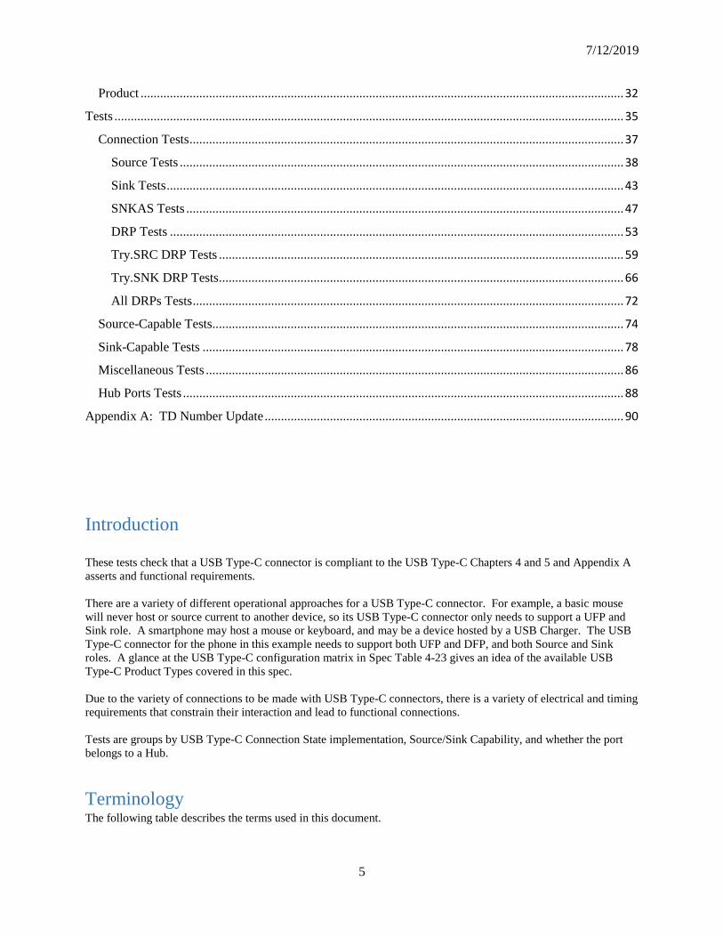
Contents Introduction ................................................................................................................................................... 5
Terminology .................................................................................................................................................. 5
Assertions ...................................................................................................................................................... 6
Test Requirements ...................................................................................................................................... 30
Hardware ................................................................................................................................................. 30
Electrical ................................................................................................................................................. 31
Timing ..................................................................................................................................................... 31
Significant Contributors:
Amanda Hosler Specwerkz LLC
Abel Astley Ellisys Corporation
Mario Pasquali Ellisys Corporation
Tyler Joe Teledyne LeCroy Corporation
Mike Micheletti Teledyne LeCroy Corporation
7/12/2019
5
Product .................................................................................................................................................... 32
Tests ............................................................................................................................................................ 35
Connection Tests ..................................................................................................................................... 37
Source Tests ........................................................................................................................................ 38
Sink Tests ............................................................................................................................................ 43
SNKAS Tests ...................................................................................................................................... 47
DRP Tests ........................................................................................................................................... 53
Try.SRC DRP Tests ............................................................................................................................ 59
Try.SNK DRP Tests ............................................................................................................................ 66
All DRPs Tests .................................................................................................................................... 72
Source-Capable Tests .............................................................................................................................. 74
Sink-Capable Tests ................................................................................................................................. 78
Miscellaneous Tests ................................................................................................................................ 86
Hub Ports Tests ....................................................................................................................................... 88
Appendix A: TD Number Update .............................................................................................................. 90
Introduction These tests check that a USB Type-C connector is compliant to the USB Type-C Chapters 4 and 5 and Appendix A
asserts and functional requirements.
There are a variety of different operational approaches for a USB Type-C connector. For example, a basic mouse
will never host or source current to another device, so its USB Type-C connector only needs to support a UFP and
Sink role. A smartphone may host a mouse or keyboard, and may be a device hosted by a USB Charger. The USB
Type-C connector for the phone in this example needs to support both UFP and DFP, and both Source and Sink
roles. A glance at the USB Type-C configuration matrix in Spec Table 4-23 gives an idea of the available USB
Type-C Product Types covered in this spec.
Due to the variety of connections to be made with USB Type-C connectors, there is a variety of electrical and timing
requirements that constrain their interaction and lead to functional connections.
Tests are groups by USB Type-C Connection State implementation, Source/Sink Capability, and whether the port
belongs to a Hub.
Terminology The following table describes the terms used in this document.

Compliance Rev 0.83
6
BC Background Check – Used in the assertions table to indicate an assertion is implicitly verified
as a function of running a Type-C Functional Test.
CabCon USB Type-C Cable Assembly and Connector Tests – Used in the assertions table to indicate an
assertion is verified by the USB Type-C Cable Assembly and Connector Test Suite.
CVS USB Type-C Connection Verification System. Test equipment capable of performing the USB
Type-C Functional tests defined in this document
DFP Downstream Facing Port – a USB Type-C port that supports the USB 3.1 Link State Machine
or USB 2.0 data as a downstream facing port.
DRP Dual Role Port – A USB Type-C port that supports the USB Type-C Connection State
Machines as a DRP. This port is capable of acting as a Source and a Sink.
DUT Device Under Test – the USB-C product which incorporates the PUT referred to in each Test
Definition.
IOP Interoperability – Used in the assertions table to indicate an assertion is verified by the USB 3.1
Interoperability and Backwards Compatibility Test Suite
NT Not tested – Used in the assertions table to indicate an assertion is not tested
PD USB Power Delivery Tests – Used in the assertion table to indicate an assertion is verified by
the USB Power Delivery Test Suite.
PUT Port Under Test – The USB Type-C Connector port that is tested by the tests defined in this
document.
PUT_C PUT that is bound to a USB Type-C captive cable or direct attach plug
PUT_R PUT that is bound to a USB Type-C receptacle.
PUT_V PUT that is required to or capable of sourcing Vconn.
Sink USB Type-C port that supports the USB Type-C Connection State Machines as a Sink
SNKAS Sink with Accessory Support – A USB Type-C port that supports the USB Type-C Connection
State Machine as a Sink with Accessory Support.
Source USB Type-C port that supports the USB Type-C Connection State Machines as a Source
Operator Person operating the test.
UFP Upstream Facing Port – A USB Type-C port that supports the USB 3.1 Link State Machine or
USB 2.0 data as an upstream facing port.
VIF Vendor Info File – A USB-IF product certification tool that logs info about the PUT for
tracking purposes and so a test vendor knows what tests are applicable.
Assertions Compliance criteria are provided as a list of assertions that describe specific characteristics or behaviors that must be
met. Each assertion provides a reference to the USB 3.1 specification or other documents from which the assertion
was derived. In addition, each assertion provides a reference to the specific test description(s) where the assertion is
tested.
Each test assertion is formatted as follows:
Assertion # Test # Assertion Description
Assertion#: Unique identifier for each spec requirement. The identifier is in the form
USB31_SPEC_SECTION_NUMBER#X, where X is a unique integer for a requirement in that section.
Assertion Description: Specific requirement from the specification
Test #: A label for a specific test description in this specification that tests this requirement. Test # can have one of
the following values:
7/12/2019
7
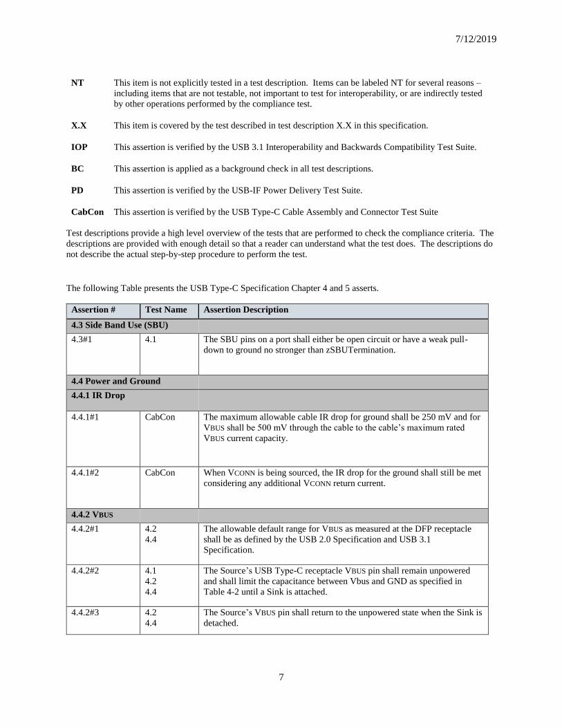
NT This item is not explicitly tested in a test description. Items can be labeled NT for several reasons –
including items that are not testable, not important to test for interoperability, or are indirectly tested
by other operations performed by the compliance test.
X.X This item is covered by the test described in test description X.X in this specification.
IOP This assertion is verified by the USB 3.1 Interoperability and Backwards Compatibility Test Suite.
BC This assertion is applied as a background check in all test descriptions.
PD This assertion is verified by the USB-IF Power Delivery Test Suite.
CabCon This assertion is verified by the USB Type-C Cable Assembly and Connector Test Suite
Test descriptions provide a high level overview of the tests that are performed to check the compliance criteria. The
descriptions are provided with enough detail so that a reader can understand what the test does. The descriptions do
not describe the actual step-by-step procedure to perform the test.
The following Table presents the USB Type-C Specification Chapter 4 and 5 asserts.
Assertion # Test Name Assertion Description
4.3 Side Band Use (SBU)
4.3#1 4.1 The SBU pins on a port shall either be open circuit or have a weak pull-
down to ground no stronger than zSBUTermination.
4.4 Power and Ground
4.4.1 IR Drop
4.4.1#1 CabCon The maximum allowable cable IR drop for ground shall be 250 mV and for
VBUS shall be 500 mV through the cable to the cable’s maximum rated
VBUS current capacity.
4.4.1#2 CabCon When VCONN is being sourced, the IR drop for the ground shall still be met
considering any additional VCONN return current.
4.4.2 VBUS
4.4.2#1 4.2
4.4
The allowable default range for VBUS as measured at the DFP receptacle
shall be as defined by the USB 2.0 Specification and USB 3.1
Specification.
4.4.2#2 4.1
4.2
4.4
The Source’s USB Type-C receptacle VBUS pin shall remain unpowered
and shall limit the capacitance between Vbus and GND as specified in
Table 4-2 until a Sink is attached.
4.4.2#3 4.2
4.4
The Source’s VBUS pin shall return to the unpowered state when the Sink is
detached.

Compliance Rev 0.83
8
Assertion # Test Name Assertion Description
4.4.2#4 4.2 A DRP or DFP or UFP with Accessory Support implementing an Rp pull-
up as its method of connection detection shall provide an impedance
between VBUS and GND on its receptacle pins as specified in Table 4-2
when not sourcing power on VBUS (i.e., when in states Unattached.SRC or
Unattached.Accessory)
4.4.3 VCONN
4.4.3#1 BC Initially, VCONN shall be sourced by all USB Type-C receptacles that
source Vbus and utilize the SSTX and SSRX pins during specific
connection states as described in Section 4.5.2.2.
4.4.3#2 BC Table 4-4 provides the voltage and power requirements that shall be met for
VCONN.
4.4.3#3 BC The VCONN source shall disconnect the bulk capacitance from the
receptacle when VCONN is powered off.
4.4.3#4 CabCon Table 4-5 provides the requirements that shall be met for cables that
consume VCONN power.
4.4.3#5 CabCon A cable shall not present more than the equivalent inrush capacitance
(10uF) to the VCONN source.
4.4.3#6 CabCon tVCONNDischarge is the time from the point that the cable is detached until
vVCONNDischarge shall be met.
4.5 Configuration Channel (CC)
4.5.1 Architectural Overview
4.5.1.1 USB Data Bus Interface and USB Type-C Plug Flip-ability
4.5.1.2 Connecting DFPs and UFPs
4.5.1.2#1 4.1 In the cases where no function results, neither port shall be harmed by this
connection.
4.5.1.2#2 4.1 VBUS and VCONN shall not be applied by a Source (host) in a host-host
connection.
4.5.1.3.2 UFP Configuration Channel Functional Model
4.5.1.3.2#1 BC The Sink shall manage its load to stay within the detected Source current
limit.
4.5.2 CC functional and Behavioral Requirements
4.5.2#1 BC The plug on a direct connect device or a device with a captive cable shall
behave as a plug on a cable that is attached at its other end in normal
orientation to a receptacle. 4.5.2#2
BC Devices with a plug on a direct connection or a captive cable shall apply
and sense CC voltage levels on pin A5 only and pin B5 shall have an
impedance above zOPEN, unless it is a Powered Accessory, in which case
B5 shall have an impedance Ra.
4.5.2.2 Connection State Machine Requirements
4.5.2.2#1
Not Tested Entry into any unattached state "when directed from any state" shall not be
used to override tDRP toggle.
7/12/2019
9
Assertion # Test Name Assertion Description
4.5.2.2.1 Disabled State
4.5.2.2.1#1 4.1 If the Disabled state is not supported, the port shall be directed to either the
Unattached.SNK or Unattached.SRC states after power-on.
4.5.2.2.1.1 Disabled State Requirements
4.5.2.2.1.1#1 4.1 The port shall not drive VBUS or VCONN, and shall present a high-
impedance to ground (above zOPEN) on its CC pins.
4.5.2.2.1.2 Exiting From Disabled State
4.5.2.2.1.2#1 Not Tested A Sink shall transition to Unattached.SNK when directed.
4.5.2.2.1.2#2 Not Tested A Source shall transition to Unattached.SRC when directed.
4.5.2.2.1.2#2 Not Tested A DRP shall transition to either Unattached.SNK or Unattached.SRC when
directed.
4.5.2.2.2 ErrorRecovery State
4.5.2.2.2#1 Not Tested If the ErrorRecovery state is not supported, the port shall be directed to the
Disabled state if supported. IF the Disabled state is not supported, the port
shall be directed to either the Unattached.SNK or Unattached.SRC states.
4.5.2.2.2.1 ErrorRecovery State Requirements
4.5.2.2.2.1#1 Not Tested The port shall not drive VBUS or VCONN, and shall present a high-
impedance to ground (above zOPEN) on its CC pins.
4.5.2.2.2.2 Exiting from ErrorRecovery State
4.5.2.2.2.2#1 Not Tested A Sink shall transition to Unattached.SNK after tErrorRecovery
4.5.2.2.2.2#2 Not Tested A Source shall transition to Unattached.SRC after tErrorRecovery
4.5.2.2.2.2#2 Not Tested A DRP shall transition to Unattached.SNK or Unattached.SRC after
tErrorRecovery
4.5.2.2.3 Unattached.SNK State
4.5.2.2.3#1 4.37 A port with a dead battery shall enter this state while unpowered.
4.5.2.2.3.1 Unattached.SNK State Requirements
4.5.2.2.3.1#1 4.8
4.9
The port shall not drive VBUS or VCONN
4.5.2.2.3.1#2 4.8
4.9
Both CC pins shall be independently terminated to ground through Rd.
4.5.2.2.3.2 Exiting from Unattached.SNK State
4.5.2.2.3.2#1 4.8
4.9
4.17
If the port supports USB PD or accessories, the port shall transition to
AttachWait.SNK when a Source connection is detected, as indicated by the
SNK.Rp state on one of its CC pins
Compliance Rev 0.83
10
Assertion # Test Name Assertion Description
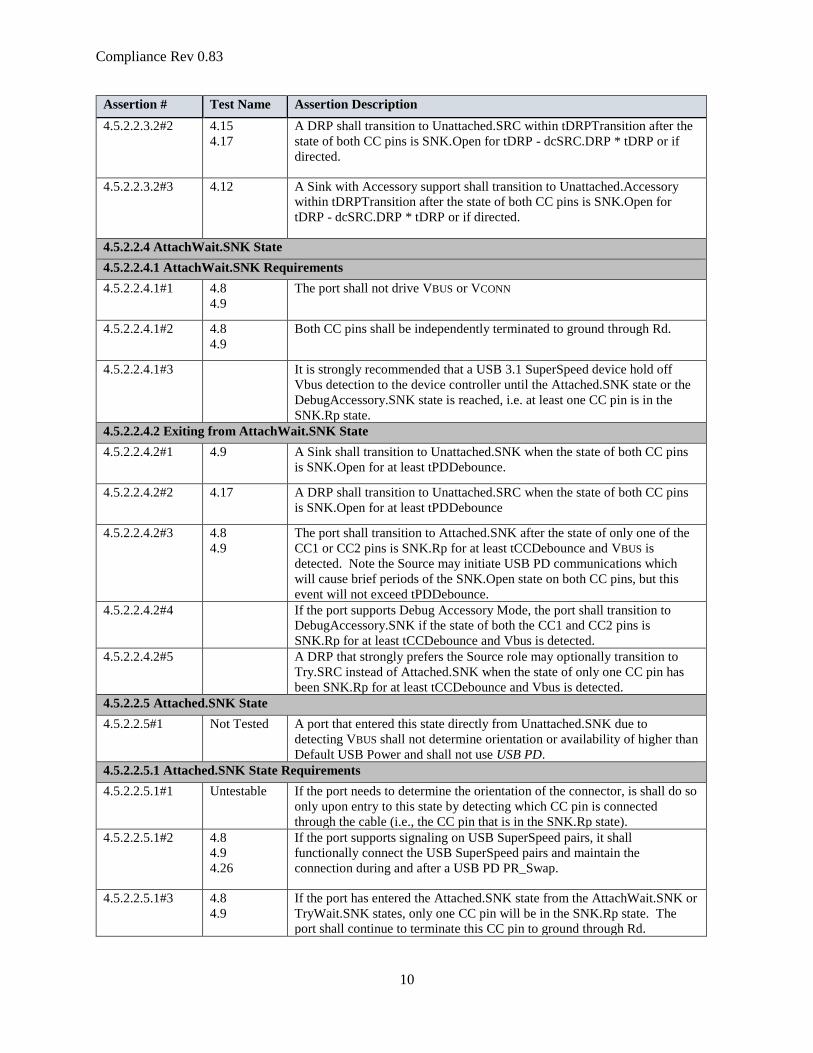
4.5.2.2.3.2#2 4.15
4.17
A DRP shall transition to Unattached.SRC within tDRPTransition after the
state of both CC pins is SNK.Open for tDRP - dcSRC.DRP * tDRP or if
directed.
4.5.2.2.3.2#3 4.12 A Sink with Accessory support shall transition to Unattached.Accessory
within tDRPTransition after the state of both CC pins is SNK.Open for
tDRP - dcSRC.DRP * tDRP or if directed.
4.5.2.2.4 AttachWait.SNK State
4.5.2.2.4.1 AttachWait.SNK Requirements
4.5.2.2.4.1#1 4.8
4.9
The port shall not drive VBUS or VCONN
4.5.2.2.4.1#2 4.8
4.9
Both CC pins shall be independently terminated to ground through Rd.
4.5.2.2.4.1#3
It is strongly recommended that a USB 3.1 SuperSpeed device hold off
Vbus detection to the device controller until the Attached.SNK state or the
DebugAccessory.SNK state is reached, i.e. at least one CC pin is in the
SNK.Rp state.
4.5.2.2.4.2 Exiting from AttachWait.SNK State
4.5.2.2.4.2#1 4.9 A Sink shall transition to Unattached.SNK when the state of both CC pins
is SNK.Open for at least tPDDebounce.
4.5.2.2.4.2#2 4.17 A DRP shall transition to Unattached.SRC when the state of both CC pins
is SNK.Open for at least tPDDebounce
4.5.2.2.4.2#3 4.8
4.9
The port shall transition to Attached.SNK after the state of only one of the
CC1 or CC2 pins is SNK.Rp for at least tCCDebounce and VBUS is
detected. Note the Source may initiate USB PD communications which
will cause brief periods of the SNK.Open state on both CC pins, but this
event will not exceed tPDDebounce.
4.5.2.2.4.2#4 If the port supports Debug Accessory Mode, the port shall transition to
DebugAccessory.SNK if the state of both the CC1 and CC2 pins is
SNK.Rp for at least tCCDebounce and Vbus is detected.
4.5.2.2.4.2#5 A DRP that strongly prefers the Source role may optionally transition to
Try.SRC instead of Attached.SNK when the state of only one CC pin has
been SNK.Rp for at least tCCDebounce and Vbus is detected.
4.5.2.2.5 Attached.SNK State
4.5.2.2.5#1 Not Tested A port that entered this state directly from Unattached.SNK due to
detecting VBUS shall not determine orientation or availability of higher than
Default USB Power and shall not use USB PD.
4.5.2.2.5.1 Attached.SNK State Requirements
4.5.2.2.5.1#1 Untestable If the port needs to determine the orientation of the connector, is shall do so
only upon entry to this state by detecting which CC pin is connected
through the cable (i.e., the CC pin that is in the SNK.Rp state).
4.5.2.2.5.1#2 4.8
4.9
4.26
If the port supports signaling on USB SuperSpeed pairs, it shall
functionally connect the USB SuperSpeed pairs and maintain the
connection during and after a USB PD PR_Swap.
4.5.2.2.5.1#3 4.8
4.9
If the port has entered the Attached.SNK state from the AttachWait.SNK or
TryWait.SNK states, only one CC pin will be in the SNK.Rp state. The
port shall continue to terminate this CC pin to ground through Rd.

7/12/2019
11
Assertion # Test Name Assertion Description
4.5.2.2.5.1#4 4.34 If the port has entered the Attached.SNK state from the Attached.SRC state
following a USB PD PR_Swap, the port shall terminate the connected CC
pin to ground through Rd.
4.5.2.2.5.1#5 4.8
4.9
The port shall meet the UFP Power Sub-State requirements specified in
Section 4.5.2.3.
4.5.2.2.5.1#6 4.8
4.9
By default, upon entry from AttachWait.SNK or Unattached.SNK, VCONN
shall not be supplied in the Attached.SNK state.
4.5.2.2.5.1#7 4.26
4.34
If Attached.SNK is entered from Attached.SRC as a result of a USB PD
PR_Swap, it shall maintain VCONN supply state, whether on or off, and its
data role and connections.
4.5.2.2.5.1#8 4.35 When the port successfully executes USB PD VCONN_Swap operation and
was not sourcing VCONN, it shall start sourcing VCONN within tVCONNON
4.5.2.2.5.1#9 4.35 The port shall execute the VCONN_Swap in a make-before-break sequence
in order to keep active USB Type-C to USB Type-C cables powered.
4.5.2.2.5.1#10 4.35 When the port successfully executes USB PD VCONN_Swap and was
sourcing VCONN, it shall stop sourcing VCONN within tVCONNOFF.
4.5.2.2.5.2 Exiting from Attached.SNK State
4.5.2.2.5.2#1 4.8
4.9
A port that is not in the process of a USB PD PR_Swap or a USB PD Hard
Reset shall transition to Unattached.SNK when VBUS falls below 3.67 V.
Note that if Vbus has been adjusted by USB PD to operate above 5V, then
the port shall transition to Unattached.SNK when Vbus falls below 80% of
the negotiated value.
4.5.2.2.5.2#2 4.34 A port transitioning to Unattached.SNK, If supplying VCONN, shall cease to
supply it within tVCONNOFF of exiting Attached.SNK.
4.5.2.2.5.2#3 4.34 After receiving a USB PD PS_RDY from the original Source during a USB
PD PR_Swap the port shall transition directly to the Attached.SRC state
(i.e. remove Rd from CC, assert Rp on CC and supply VBUS) but shall
maintain its VCONN supply state, whether off or on, and its data
role/connections.
4.5.2.2.6 Unattached.SRC State
4.5.2.2.6.1 Unattached.SRC Requirements
4.5.2.2.6.1#1 4.2
4.4
The port shall not drive VBUS or VCONN
4.5.2.2.6.1#2 4.2
4.4
The port shall source current on both CC pins independently.
4.5.2.2.6.1#3 4.2
4.4
The port shall provide a separate Rp termination on the CC1 and CC2 pins
as specified in Table 4-15
4.5.2.2.6.2 Exiting from Unattached.SRC State
4.5.2.2.6.2#1 4.2
4.4
The port shall transition to AttachWait.SRC when Vbus is vSafe0V and the
SRC.Rd state is detected on at least one CC pin
4.5.2.2.6.2#2 4.19 The port shall transition to AttachWait.SRC when Vbus is vSafe0V and the
SRC.Ra state is detected on both CC pins.
4.5.2.2.6.2#3 4.1 When a port detects SRC.Ra on one CC pin and SRC.Open on the other,
the port shall not transition to AttachWait.SRC.

Compliance Rev 0.83
12
Assertion # Test Name Assertion Description
4.5.2.2.6.2#4 4.15
4.17
A DRP shall transition to Unattached.SNK within tDRPTransition after
dcSRC.DRP * tDRP
4.5.2.2.6.2#5 4.15
4.17
A DRP shall transition to Unattached.SNK if directed.
4.5.2.2.7 AttachWait.SRC State
4.5.2.2.7.1 AttachWait.SRC Requirements
4.5.2.2.7.1#1 4.2
4.4
4.15
The port shall not drive VBUS or VCONN
4.5.2.2.7.1#2 4.2
4.4
4.15
The port shall source current on both CC pins independently.
4.5.2.2.7.1#3 4.2
4.4
4.15
The port shall provide a separate Rp termination on the CC1 and CC2 pins
as specified in Table 4-15
4.5.2.2.7.2 Exiting from AttachWait.SRC State
4.5.2.2.7.2#1 4.2
4.4
4.15
The port shall transition to Attached.SRC when Vbus is in vSafe0V and the
SRC.Rd state is detected on exactly one of the CC pins for at least
tCCDebounce.
4.5.2.2.7.2#2 4.5 If the port supports Audio Adapter Accessory Mode, it shall transition to
AudioAccessory when the SRC.Ra state is detected on both CC pins for at
least tCCDebounce.
4.5.2.2.7.2#3 Not Tested If the port supports Debug Accessory Mode, it shall transition to
UnorientedDebugAccessory.SRC when the SRC.Rd state is detected on
both CC pins for at least tCCDebounce
4.5.2.2.7.2#4 4.3 A Source shall transition to Unattached.SRC and a DRP to
Unattached.SNK when the SRC.Open state is detected on both CC pins.
4.5.2.2.7.2#5 4.2
4.15
A Source shall transition to Unattached.SRC and a DRP to
Unattached.SNK when the SRC.Open state is detected on one CC pin and
the SRC.Ra state is detected on the other CC pin.
4.5.2.2.7.2#6
A DRP that strongly prefers the Sink role may optionally transition to
Try.SNK instead of Attached.SRC when Vbus is at vSafe0V and the
SRC.Rd state is detected on exactly one of the CC1 or CC2 pins for at least
tCCDebounce.
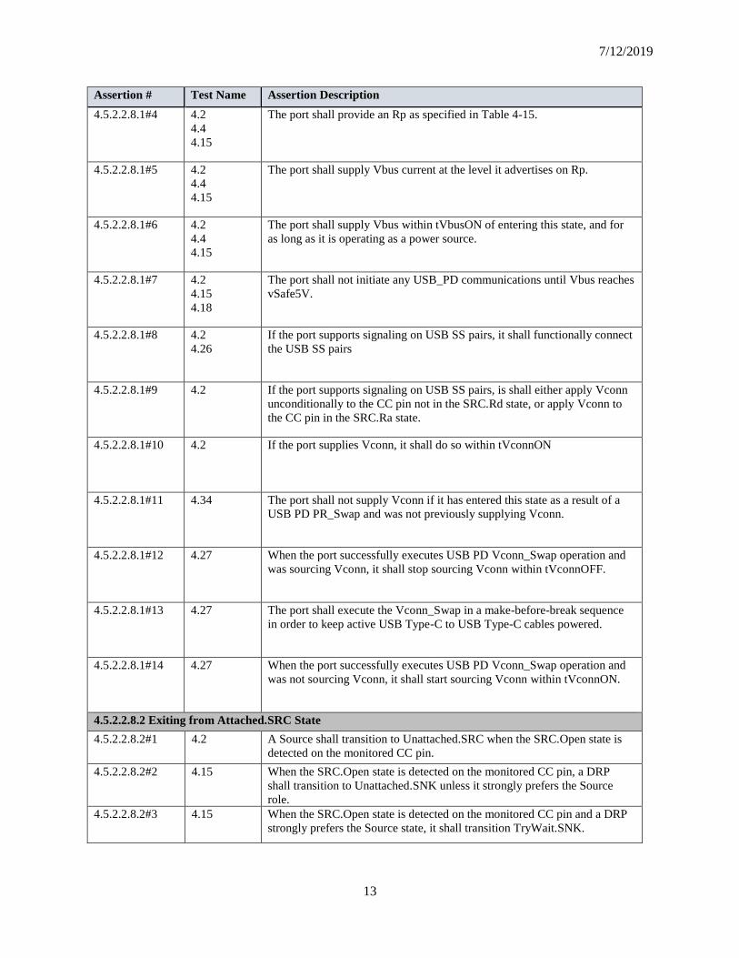
4.5.2.2.8 Attached.SRC State
4.5.2.2.8.1 Attached.SRC Requirements
4.5.2.2.8.1#1 Untestable If the port needs to determine the orientation of the connector, it shall do so
only upon entry to the Attached.SRC state by detecting which pin is in the
SRC.Rd state
4.5.2.2.8.1#2 4.2
4.4
4.15
If the port has entered this state from the AttachWait.SRC state or the
Try.SRC state, the SRC.Rd state will be on only one CC pin. The port shall
source current on this CC pin and monitor its state.
4.5.2.2.8.1#3 4.34 If the port has entered this state from the Attached.SNK state as the result
of a USB PD PR_Swap, the port shall source current on the connected CC
pin and monitor its state.
7/12/2019
13
Assertion # Test Name Assertion Description
4.5.2.2.8.1#4 4.2
4.4
4.15
The port shall provide an Rp as specified in Table 4-15.
4.5.2.2.8.1#5 4.2
4.4
4.15
The port shall supply Vbus current at the level it advertises on Rp.
4.5.2.2.8.1#6 4.2
4.4
4.15
The port shall supply Vbus within tVbusON of entering this state, and for
as long as it is operating as a power source.
4.5.2.2.8.1#7 4.2
4.15
4.18
The port shall not initiate any USB_PD communications until Vbus reaches
vSafe5V.
4.5.2.2.8.1#8 4.2
4.26
If the port supports signaling on USB SS pairs, it shall functionally connect
the USB SS pairs
4.5.2.2.8.1#9 4.2 If the port supports signaling on USB SS pairs, is shall either apply Vconn
unconditionally to the CC pin not in the SRC.Rd state, or apply Vconn to
the CC pin in the SRC.Ra state.
4.5.2.2.8.1#10 4.2 If the port supplies Vconn, it shall do so within tVconnON
4.5.2.2.8.1#11 4.34 The port shall not supply Vconn if it has entered this state as a result of a
USB PD PR_Swap and was not previously supplying Vconn.
4.5.2.2.8.1#12 4.27 When the port successfully executes USB PD Vconn_Swap operation and
was sourcing Vconn, it shall stop sourcing Vconn within tVconnOFF.
4.5.2.2.8.1#13 4.27 The port shall execute the Vconn_Swap in a make-before-break sequence
in order to keep active USB Type-C to USB Type-C cables powered.
4.5.2.2.8.1#14 4.27 When the port successfully executes USB PD Vconn_Swap operation and
was not sourcing Vconn, it shall start sourcing Vconn within tVconnON.
4.5.2.2.8.2 Exiting from Attached.SRC State
4.5.2.2.8.2#1 4.2 A Source shall transition to Unattached.SRC when the SRC.Open state is
detected on the monitored CC pin.
4.5.2.2.8.2#2 4.15 When the SRC.Open state is detected on the monitored CC pin, a DRP
shall transition to Unattached.SNK unless it strongly prefers the Source
role.
4.5.2.2.8.2#3 4.15 When the SRC.Open state is detected on the monitored CC pin and a DRP
strongly prefers the Source state, it shall transition TryWait.SNK.

Compliance Rev 0.83
14
Assertion # Test Name Assertion Description
4.5.2.2.8.2#4 4.15 A DRP that would enter Try.SRC from AttachWait.SNK shall enter
TryWait.SNK for a Sink detach from Attached.SRC.
4.5.2.2.8.2#5 4.2
4.15
A port shall cease to supply VBUS within tVBUSOFF of exiting
Attached.SRC
4.5.2.2.8.2#6 4.2
4.7
4.35
A port that is supplying VCONN shall cease to supply it within tVCONNOFF
of exiting Attached.SRC, unless it is exiting as a result of a USB PD
PR_Swap.
4.5.2.2.8.2#7 4.26 After a USB PD PR_Swap is accepted (Accept message is received or
acknowledged), a DRP shall transition directly to the Attached.SNK state
(remove Rp from CC, assert Rd on CC and stop supplying VBUS)
4.5.2.2.8.2#8 4.26 After a USB PD PR_Swap is accepted (Accept message is received or
acknowledged), a DRP shall maintain its current data role, connection and
VCONN supply state.
4.5.2.2.9 Try.SRC State
4.5.2.2.9#1
Note: If both Try.SRC and Try.SNK mechanisms are implemented, only
one shall be enabled by the port at a given time.
4.5.2.2.9.1 Try.SRC Requirements
4.5.2.2.9.1#1 4.17
4.18
The port shall not drive VBUS or VCONN.
4.5.2.2.9.1#2 4.17
4.18
The port shall source current on both CC pins independently.
4.5.2.2.9.1#3 4.17
4.18
The port shall provide an Rp as specified in Table 4-15
4.5.2.2.9.2 Exiting from Try.SRC State
4.5.2.2.9.2#1 4.18 The port shall transition to Attached.SRC when the SRC.Rd state is
detected on exactly one of the CC pins for at least tPDDebounce.
4.5.2.2.9.2#2 4.17 The port shall transition to TryWait.SNK after tDRPTry and the SRC.Rd
state has not been detected.
4.5.2.2.10 TryWait.SNK State
4.5.2.2.10.1 TryWait.SNK Requirements
4.5.2.2.10.1#1 4.17 The port shall not drive VBUS or VCONN.
4.5.2.2.10.1#2 4.17 Both CC pins shall be independently terminated to ground through Rd.
4.5.2.2.10.2 Exiting from TryWait.SNK State
4.5.2.2.10.2#1 4.17 The port shall transition to Attached.SNK after tCCDebounce if or when
VBUS is detected.
4.5.2.2.10.2#2 4.17 The port shall transition to Unattached.SNK when the state of both CC pins
is SNK.Open for at least tPDDebounce
4.5.2.2.11 Try.SNK State
4.5.2.2.11#1
Note: If both Try.SRC and Try.SNK mechanisms are implemented, only
one shall be enabled by the port at a given time.
4.5.2.2.11.1 Try.SNK Requirements
4.5.2.2.11.1#1
The port shall not drive Vbus or Vconn
4.5.2.2.11.1#2
Both the CC1 and CC2 pins shall be independently terminated to ground
through Rd.

7/12/2019
15
Assertion # Test Name Assertion Description
4.5.2.2.11.2 Exiting from Try.SNK State
4.5.2.2.11.2#1
The port shall wait for tDRPTry and only then begin monitoring the CC1
and CC2 pins for the SNK.Rp state.
4.5.2.2.11.2#2
The port shall transition to Attached.SNK when the SNK.Rp state is
detected on exactly one of the CC1 or CC2 pins for at least tPDDebounce
and Vbus is detected.
4.5.2.2.11.2#3
The port shall transition to TryWait.SRC if SNK.Rp state is not detected
for tPDDebounce.
4.5.2.2.11.2#4
A Sink with Accessory Support shall transition to Unsupported.Accessory
if SNK.Rp state is not detected for tDRPTryWait.
4.5.2.2.12 TryWait.SRC State
4.5.2.2.12.1 TryWait.SRC Requirements
4.5.2.2.12.1#1
The port shall not drive Vbus or Vconn
4.5.2.2.12.1#2
The port shall source current on both CC pins.
4.5.2.2.12.1#3
The port shall provide a separate Rp termination on the CC1 and CC2 pins
as specified in Table 4-15.
4.5.2.2.12.2 Exiting from TryWait.SRC State
4.5.2.2.12.2#1
The port shall transition to Attached.SRC when Vbus is at vSafe0V and the
SRC.Rd state is detected on exactly one of the CC pins for at least
tCCDebounce.
4.5.2.2.12.2#2
The port shall transition to Unattached.SNK after tDRPTry if neither of the
CC1 or CC2 pins are in the SRC.Rd state.
4.5.2.2.13 Unattached.Accessory State
4.5.2.2.13.1 Unattached.Accessory Requirements
4.5.2.2.13.1#1 4.1
4.12
4.14
The port shall not drive VBUS or VCONN.
4.5.2.2.13.1#2 4.12
4.14
The port shall source current on both CC pins independently.
4.5.2.2.13.1#3 4.12
4.14
The port shall provide an Rp as specified in Table 4-15.
4.5.2.2.13.2 Exiting from Unattached.Accessory State
4.5.2.2.13.2#1 4.12 The port shall transition to AttachWait.Accessory when the state of both
pins is SRC.Ra or SRC.Rd
4.5.2.2.13.2#2 4.14 A port that supports Vconn-Powered accessories also shall transition to
AttachWait.Accessory when the state of one CC pin is SRC.Ra and the
other is SRC.Rd

Compliance Rev 0.83
16
Assertion # Test Name Assertion Description
4.5.2.2.13.2#3 4.11 If at least one CC is in SRC.Open, or if SRC.Ra is on one CC pin and
SRC.Rd is on the other and the port does not support Vconn-powered
accessories, then the port shall transition to Unattached.SNK within
tDRPTransition after dcSRC.DRP * tDRP, or if directed.
4.5.2.2.14 AttachWait.Accessory State
4.5.2.2.14.1 AttachWait.Accessory Requirements
4.5.2.2.14.1#1 4.12
4.14
4.19
The port shall not drive VBUS or VCONN.
4.5.2.2.14.1#2 4.12
4.14
4.19
The port shall source current on both CC pins independently.
4.5.2.2.14.1#3 4.12
4.14
4.19
The port shall provide an Rp as specified in Table 4-15.
4.5.2.2.14.2 Exiting from AttachWait.Accessory State
4.5.2.2.14.2#1 4.12
4.19
If the port supports Audio Adapter Accessory Mode, it shall transition to
AudioAccessory when the state of both CC pins is SRC.Ra for at least
tCCDebounce
4.5.2.2.14.2#2 Not Teseted If the port supports Debug Accessory Mode, it shall transition to
DebugAccessory when the state of both CC pins is SRC.Rd for at least
tCCDebounce.
4.5.2.2.14.2#3 4.14 The port shall transition to Unattached.SNK when the state of either CC pin
is SRC.Open for at least tCCDebounce
4.5.2.2.14.2#4 4.14 If the port supports VCONN-powered accessories, it shall transition to
PoweredAccessory state if the state of one to its CC pins is SRC.Rd and
the state of the other CC pin is SRC.Ra concurrently for at least
tCCDebounce
4.5.2.2.15 AudioAccessory State
4.5.2.2.15.1 AudioAccessory Requirements
4.5.2.2.15.1#1 4.5
4.12
4.19
The port shall reconfigure its pins as detailed in Appendix A.
4.5.2.2.15.1#2 4.5
4.12
4.19
The port shall not drive VBUS or VCONN.
4.5.2.2.15.1#3 4.12
4.19
A port that sinks current from the audio accessory over VBUS shall not
draw more than 500 mA.
4.5.2.2.15.1#4 4.5
4.12
4.19
The port shall provide an Rp as specified in Table 4-15.
4.5.2.2.15.1#5 4.5
4.19
The port shall source current on at least one of the CC pins and monitor to
detect when the CC pin state is no longer SRC.Ra.
4.5.2.2.15.1#6
If the port sources and monitors only one CC pin, then it shall ensure that
the termination on the unmonitored CC pin does not affect the monitored
signal when the port is connected to an Audio Accessory that may short
both CC pins together.
4.5.2.2.15.2 Exiting from AudioAccessory State
7/12/2019
17
Assertion # Test Name Assertion Description
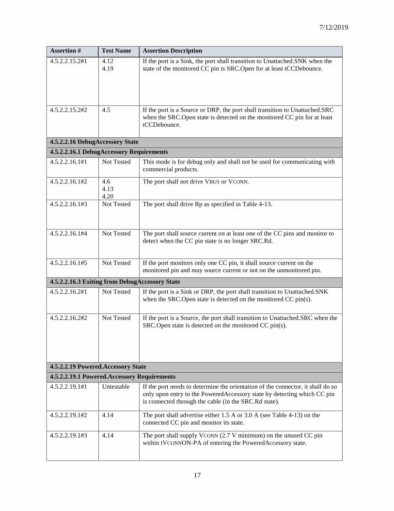
4.5.2.2.15.2#1 4.12
4.19
If the port is a Sink, the port shall transition to Unattached.SNK when the
state of the monitored CC pin is SRC.Open for at least tCCDebounce.
4.5.2.2.15.2#2 4.5 If the port is a Source or DRP, the port shall transition to Unattached.SRC
when the SRC.Open state is detected on the monitored CC pin for at least
tCCDebounce.
4.5.2.2.16 DebugAccessory State
4.5.2.2.16.1 DebugAccessory Requirements
4.5.2.2.16.1#1 Not Tested This mode is for debug only and shall not be used for communicating with
commercial products.
4.5.2.2.16.1#2 4.6
4.13
4.20
The port shall not drive VBUS or VCONN.
4.5.2.2.16.1#3 Not Tested The port shall drive Rp as specified in Table 4-13.
4.5.2.2.16.1#4 Not Tested The port shall source current on at least one of the CC pins and monitor to
detect when the CC pin state is no longer SRC.Rd.
4.5.2.2.16.1#5 Not Tested If the port monitors only one CC pin, it shall source current on the
monitored pin and may source current or not on the unmonitored pin.
4.5.2.2.16.3 Exiting from DebugAccessory State
4.5.2.2.16.2#1 Not Tested If the port is a Sink or DRP, the port shall transition to Unattached.SNK
when the SRC.Open state is detected on the monitored CC pin(s).
4.5.2.2.16.2#2 Not Tested If the port is a Source, the port shall transition to Unattached.SRC when the
SRC.Open state is detected on the monitored CC pin(s).
4.5.2.2.19 Powered.Accessory State
4.5.2.2.19.1 Powered.Accessory Requirements
4.5.2.2.19.1#1 Untestable If the port needs to determine the orientation of the connector, it shall do so
only upon entry to the PoweredAccessory state by detecting which CC pin
is connected through the cable (in the SRC.Rd state).
4.5.2.2.19.1#2 4.14 The port shall advertise either 1.5 A or 3.0 A (see Table 4-13) on the
connected CC pin and monitor its state.
4.5.2.2.19.1#3 4.14 The port shall supply VCONN (2.7 V minimum) on the unused CC pin
within tVCONNON-PA of entering the PoweredAccessory state.

Compliance Rev 0.83
18
Assertion # Test Name Assertion Description
4.5.2.2.19.1#4 4.14 The port shall not drive VBUS.
4.5.2.2.19.1#5 4.14 When the port initially enters the PoweredAccessory state it shall operate as
a DFP.
4.5.2.2.19.1#6 4.14 The port shall use USB Power Delivery Structured Vendor Defined
Messages (Structured VDMs) to identify this accessory and enter an
Alternate Mode.
4.5.2.2.19.2 Exiting from PoweredAccessory State
4.5.2.2.19.2#1 4.14 The port shall transition to Unattached.SNK when the SRC.Open state is
detected on the monitored CC pin.
4.5.2.2.19.2#2 4.14 The port shall transition to Unattached.SNK if the attached device is not a
VCONN-Powered Accessory.
4.5.2.2.19.2#3 4.14 The port shall transition to Unsupported.Accessory if it does not
successfully enter an Alternate Mode within tAMETimeout (see Section
5.1).
4.5.2.2.19.2#4 4.14 The port shall cease to supply VCONN within tVCONNOFF of exiting the
PoweredAccessory state.
4.5.2.2.20 Unsupported.Accessory State
4.5.2.2.20.1 Unsupported.Accessory Requirements
4.5.2.2.20.1#1 4.14 Only one CC pin shall be in the SRC.Rd state.
4.5.2.2.20.1#2 4.14 The port shall advertise Default USB Power (see Table 4-13) on the
connected CC pin and monitor its voltage.
4.5.2.2.20.1#3 4.14 The port shall not drive VBUS or VCONN.
4.5.2.2.20.1#4 4.14 A Sink with Accessory Support shall provide user notification that it does
not recognize or support the attached accessory.
4.5.2.2.20.2 Exiting from Unsupported.Accessory
4.5.2.2.20.2#1 4.14 The port shall transition to Unattached.SNK when the SRC.Open state is
detected on the monitored CC pin.
4.5.2.3 UFP Power Sub-State Requirements
4.5.2.3#1 4.31 When in the Attached.SNK state and the Source is supplying default VBUS,
the port shall operate in one of the sub-states shown in Figure 4-17.
4.5.2.3#2 4.31 The port in Attached.SNK shall remain within the Sink Power Sub-States
until either VBUS is removed or a USB PD contract is established with the
Source.
4.5.2.3.1 PowerDefault.UFP Sub-State
4.5.2.3.1.1 PowerDefault.UFP Requirements
4.5.2.3.1.1#1 4.31 The port shall draw no more than the default USB power from VBUS.
4.5.2.3.1.1#2 4.31 If the port wants to consume more than the default USB power, it shall
monitor vRd to determine if more current is available from the Source.

7/12/2019
19
Assertion # Test Name Assertion Description
4.5.2.3.1.2 Exiting from PowerDefault.UFP
4.5.2.3.1.2#1 4.31 For any change on CC indicating a change in allowable power, the port
shall not transition until the new vRd on CC has been stable for
tPDDebounce.
4.5.2.3.1.2#2 4.31 For a vRd in the vRd-1.5 range, the port shall transition to the
Power1.5.SNK Sub-State.
4.5.2.3.1.2#3 4.31 For a vRd in the vRd-3.0 range, the port shall transition to the
Power3.0.SNK Sub-State.
4.5.2.3.2 Power 1.5.UFP Sub-State
4.5.2.3.2.1 Power 1.5.UFP Sub-State Requirements
4.5.2.3.2.1#1 4.31 The port shall draw no more than the 1.5 A from VBUS.
4.5.2.3.2.1#2 4.31 The port shall monitor vRd while it is in this sub-state.
4.5.2.3.2.2 Exiting from Power 1.5.UFP Sub-State
4.5.2.3.2.2#1 4.31 For any change on CC indicating a change in allowable power, the port
shall not transition until the new vRd on CC has been stable for
tPDDebounce.
4.5.2.3.2.2#2 4.31 For a vRd in the vRd-USB range, the port shall transition to the
PowerDefault.SNK Sub-State and reduce its power consumption to the new
range within tSinkAdj.
4.5.2.3.2.2#3 4.31 For a vRd in the vRd-3.0 range, the port shall transition to the
Power3.0.SNK Sub-State.
4.5.2.3.3 Power3.0.UFP Sub-State
4.5.2.3.3.1 Power3.0.UFP Requirements
4.5.2.3.3.1#1 4.31 The port shall draw no more than the 3.0 A from VBUS.
4.5.2.3.3.1#2 4.31 The port shall monitor vRd while it is in this sub-state.
4.5.2.3.3.1 Power3.0.UFP Requirements
4.5.2.3.3.2#1 4.31 For any change on CC indicating a change in allowable power, the port
shall not transition until the new vRd on CC has been stable for
tPDDebounce.
4.5.2.3.3.2#2 4.31 For a vRd in the vRd-USB range, the port shall transition to the
PowerDefault.SNK Sub-State and reduce its power consumption to the new
range within tSinkAdj.
4.5.2.3.3.2#3 4.31 For a vRd in the vRd-1.5 range, the port shall transition to the
Power1.5.SNK Sub-State and reduce its power consumption to the new
range within tSinkAdj.
4.5.3.2.2 Legacy Host Port to UFP Behavior
4.5.3.2.2#1 4.29 The value of Rp shall indicate an advertisement of Default USB Power
(See Table 4-10), even though the cable itself can carry 3 A.
4.5.3.2.4 Legacy Host Port to DRP Behavior

Compliance Rev 0.83
20
Assertion # Test Name Assertion Description
4.5.3.2.4#1 4.29 The value of Rp shall indicate an advertisement of Default USB Power
(See Table 4-10), even though the cable itself can carry 3 A.
4.6 Power
4.6#1 4.25
4.31
All USB Type-C-based devices shall support USB Type-C Current and
may support other USB-defined methods for power.
4.6#2 4.32 The following order of precedence of power negotiation shall be followed:
USB BC 1.2 supersedes the USB 2.0 and USB 3.1 specifications, USB
Type-C Current at 1.5 A and 3.0 A supersedes USB BC 1.2, and USB
Power Delivery supersedes USB Type-C Current.
4.6#3 4.32 Once the PD mode (e.g. a power contract has been negotiated) has been
entered, the device shall abide by that power contract ignoring any other
previously made or offered by the USB Type-C Current, USB BC 1.2 or
USB 2.0 and USB 3.1 specifications.
4.6#4 4.32 When the PD mode is exited, the device shall fallback in order to the USB
Type-C Current, USB BC 1.2 or USB 2.0 and USB 3.1 specification power
levels.
4.6#5 4.1 All USB Type-C ports shall tolerate being connected to USB power source
supplying default USB power, e.g. a host being connected to a legacy USB
charger that always supplies VBUS.
4.6.1 Power Requirements during USB Suspend
4.6.1.1 VBUS Requirements during USB Suspend
4.6.1.1#1 4.33 USB suspend power rules shall apply when the USB Type-C Current is at
the Default USB Power level or when USB PD is being used and the
Suspend bit is set appropriately.
4.6.1.2 VCONN Requirements during USB Suspend
4.6.1.2#1 4.24 If the DFP supplies VBUS power during USB suspend, it shall also supply
at least 70 mW to VCONN.
4.6.1.2#2 CabCon Electronically marked cables shall draw no more than 70 mW from VCONN
during USB suspend.
4.6.2 VBUS Power Provided Over a USB Type-C Cable
4.6.2#1 CabCon
PD
USB Power Delivery is an optional capability that is intended to work over
un-modified USB Type-C to USB Type-C cables, therefore any USB Type-
C cable assembly that incorporates electronics that gets it power from VBUS
shall be tolerant up to 20 V.
4.6.2.1 USB Type-C Current

7/12/2019
21
Assertion # Test Name Assertion Description
4.6.2.1#1 4.31 A UFP that takes advantage of the additional current offered (e.g., 1.5 A or
3.0 A) shall monitor the CC pins and shall adjust its current consumption
within tSinkAdj to remain within the value advertised by the DFP.
4.6.2.1#2 4.32 While a USB PD contract is in place, a UFP is not required to monitor USB
Type-C Current advertisements and shall not respond to USB Type-C
Current advertisements.
4.6.2.1#3 4.2 The DFP shall source VBUS to the UFP within tVBUSON.
4.6.2.1#4 4.25 VBUS shall be in the specified voltage range at the advertised current.
4.6.2.1#5 Not Tested A port sourcing VBUS shall protect itself from a sink that draws current in
excess of the port’s USB Type-C Current advertisement.
4.6.2.1#6 4.31 If the UFP wants to consume more than the default USB current, it shall
track vRd to determine the maximum current it may draw.
4.6.2.2 USB Battery Charging
4.6.2.2#1 4.25 USB Type-C-based BC 1.2 chargers that are capable of supplying at least
1.5 A shall advertise USB Type-C Current at the 1.5 A level, otherwise the
charger shall advertise USB Type-C Current at the Default USB Power
level.
4.6.2.3 Proprietary Power Source
4.6.2.3#1 4.25 A proprietary power source (i.e., battery charger) with a USB Type-C-
captive cable or a USB Type-C receptacle that is capable of supplying at
least 1.5 A and less than 3.0 A shall advertise USB Type-C Current at least
at the 1.5 A level.
4.6.2.3#2 4.25 A proprietary power source with a USB Type-C-captive cable or a USB
Type-C receptacle that is capable of supplying at least 3.0 A shall advertise
USB Type-C Current at least at the 3.0 A level.
4.6.2.4 USB Power Delivery
4.6.2.4#1 4.2 When USB PD is implemented, USB PD Bi-phase Mark Coded (BMC)
carried on the CC wire shall be used for USB PD communications between
USB Type-C ports.
4.6.2.4#2 4.2 At attach, VBUS shall be operationally stable prior to initiating USB PD
communications.

Compliance Rev 0.83
22
Assertion # Test Name Assertion Description
4.6.2.4#3 4.25 While a USB PD contract is in place, the provider shall advertise a USB
Type-C Current of either 1.5 A or 3.0 A.
4.6.3 Supporting USB PD BFSK in Addition to USB PD BMC
4.6.3#1 Not Tested USB Type-C-based products that support USB PD BFSK and request a
voltage greater than 5V shall supply protect the CC inputs from termination
voltages higher than 5V as some adapters may present an Rp pulled up to
VBUS that may be as high as 20V.
4.6.3#2 Not Tested USB PD BFSK shall only be used if USB PD BMC fails to establish PD
communication, i.e. fails to receive a USB PD GoodCRC message in
response to a USB PD Capabilities message following two hard resets.
4.6.3#3 Not Tested USB Type-C-based UFPs that support USB PD BFSK and want to request
more than 1.5 A shall supply VCONN and confirm that the cable is
electronically marked and capable of the desired current level (see Section
5.2.2).
4.7 USB Hubs
4.7#1 4.39 USB hubs implemented with one or more USB Type-C connectors shall
comply with the USB 3.1 Specification.
4.7#2 4.40 USB hubs shall have one UFP that may be a Charging UFP (See Section
4.8.3).
4.7#3 IOP The hub shall clearly identify to the user its UFP.
4.7#4 4.40 USB hub’s DFPs shall not have DRP capability.
4.7#5 4.40 CC pins are used for port-to-port connections and shall be supported on all
USB Type-C connections on the hub.
4.7#6 4.40 USB hub ports shall not implement or pass-through Alternate or Accessory
Modes.
4.7#7 4.40 SBU pins shall not be connected (zSBUTermination) on any USB hub port.
4.7#8 4.25 The USB hub’s DFPs shall support power source requirements for a DFP.
4.8 Chargers
4.8.1 DFP as a Power Source
4.8.1#1 4.25 When a charger with a USB Type-C receptacle or a USB Type-C captive
cable, it shall follow all the applicable requirements.
4.8.1#2 4.25 A DFP shall expose its power capabilities using the USB Type-C Current
method and it may additionally support other USB-standard methods (USB
BC 1.2 or USB-PD).

7/12/2019
23
Assertion # Test Name Assertion Description
4.8.1#3 4.25 A USB Type-C power provider advertising its current capability using USB
BC 1.2 shall meet the requirements in Section 4.6.2.2 regarding USB Type-
C Current advertisement.
4.8.1#4 4.25 A USB Type-C power provider that has negotiated a USB-PD contract
shall meet the requirements in Section 4.6.2.4 regarding USB Type-C
Current advertisement.
4.8.1#5 Untestable If a USB Type-C power provider is capable of supplying a voltage greater
than default VBUS, it shall fully conform to the USB-PD specification, and
shall negotiate its power contracts using only USB-PD.
4.8.1#6 TD 4.15
TD 4.26
TD 4.34
If a USB Type-C power provider is capable of reversing source and sink
power roles, it shall fully conform to the USB-PD specification, and shall
negotiate its power contracts using only USB-PD.
4.8.1#7 Not Tested
Untestable?
If a USB Type-C power provider is capable of supplying a current greater
than 3.0 A, it shall use the USB-PD Discovery Identity to determine the
current carrying capacity of the cable.
4.8.1.1 Chargers with USB Type-C Receptacles
4.8.1.1#2 4.1 A charger with a USB Type-C receptacle (DFP) shall only apply power to
VBUS when it detects a UFP is attached and shall remove power from VBUS
when it detects the UFP is detached (vOPEN).
4.8.1.1#3 4.25 A charger with a USB Type-C receptacle shall not advertise current
exceeding 3.0 A except when it uses the USB-PD Discover Identity
mechanism to determine the cable’s actual current carrying capability and
then it shall limit the advertised current accordingly.
4.8.1.2 Chargers with USB Type-C Captive Cables
4.8.1.2#1 4.1 A charger with a USB Type-C captive cable that supports USB PD shall
only apply power to VBUS when it detects a UFP is attached and shall
remove power from VBUS when it detects the UFP is detached (vOPEN).
4.8.1.2#2 PD/CabCon/
IOP
A charger with a USB Type-C captive cable shall limit its current
advertisement so as not to exceed the current capability of the cable (up to
5 A).
4.8.2 Non-USB Charging Methods

Compliance Rev 0.83
24
Assertion # Test Name Assertion Description
4.8.2#1 4.25 When implemented, a proprietary charging method shall only be used to
establish identify and/or direct a current level at default VBUS voltage in a
manner not defined by the USB methods.
4.8.2#2 Untestable When implemented, a proprietary charging method shall only define the
current level and shall not change the voltage delivered on VBUS.
4.8.2#3 Untestable When implemented, a proprietary charging method shall not alter the DFP's
role to source VBUS or the UFP's role to sink VBUS.
4.8.2#4 Untestable A product with a USB Type-C connector that sinks power may support
proprietary charging methods, these products shall not support methods that
redefine VBUS voltage beyond what is defined by the USB 2.0 and USB 3.1
specifications.
4.8.3 Sinking UFP
4.8.3#1 4.15
4.17
4.18
The Sinking DFP shall follow the rules for a DRP (See Section 4.5.1.4 and
Figure 4-15).
4.8.3#2 4.15
4.17
4.18
The sinking DFP shall support USB PD and shall support the DR_Swap
command.
4.8.4 Charging UFP
4.8.4#1 4.15
4.17
4.18
The Charging UFP shall follow the rules for a DRP (See Section 4.5.1.4
and Figure 4-15).
4.8.4#2 4.25 The Charging UFP shall also follow the requirements for the DFP as Power
Source (See Section 4.8.1).
4.8.4#3 4.22 The Charging UFP shall support USB PD and shall support the DR_Swap
command.
4.8.5 Charging a System with a Dead Battery
4.8.5#1 4.37 A system that supports being charged by USB whose battery is dead shall
apply Rd to both CC1 and CC2 and follow all UFP rules.
4.9 Electronically Marked Cables
4.9#1 PD All USB Full-Featured Type-C cables shall be electronically marked.
4.9#2 PD Electronically marked cables shall support USB Power Delivery Structured
VDM Discover Identity command directed to SOP’.
4.9#3 PD After an explicit USB PD contract has been negotiated, only the DFP shall
communicate with SOP’.

7/12/2019
25
Assertion # Test Name Assertion Description
4.9#4 PD Electronically marked cables that do not incorporate data bus signal
conditioning circuits shall consume no more than 70 mW from VCONN.
4.9#5 PD During USB suspend, electronically marked cables shall not draw more
than 7.5 mA from VCONN, see Section 4.6.1.2.
4.9#6 PD The isolation elements (Iso) shall prevent VCONN from traversing end-to-
end through the cable.
4.9#7 PD Active cables shall not draw more than 1 W from VCONN, see Section
4.4.3.
4.9#8 PD When VCONN is not present, a powered cable shall not interfere with
normal CC operation including UFP detection, current advertisement and
USB PD operation.
4.10 VCONN-Powered Accessories
4.10#1 4.23 When operating in the UFP role and when VBUS is not present, VCONN-
powered accessories shall treat the application of VCONN as an attach
signal, and shall respond to USB Power Delivery messages.
4.10#2 4.23 When powered by only VCONN, a VCONN-powered accessory shall
negotiate an Alternate Mode.
4.10#3 4.23 VCONN-powered accessories shall be able to operate over a range of 2.7 V
to 5.5 V on VCONN.
4.10#4 4.23 The removal of VCONN when VBUS is not present shall be treated as a
detach event.
4.11 Parameter Values
4.11.1 Termination Parameters
4.11.1#1 BC Table 4-13 provides the values that shall be used for the DFP’s Rp or
current source.
4.11.1#2 BC Other pull-up voltages shall be allowed if they remain less than 5.5 V and
fall within the correct voltage ranges on the UFP side – see Table 4-21,
Table 4-22 and Table 4-23
4.11.1#3 CabCon For Rp when implemented in the USB Type-C plug on a USB Type-C to
USB 3.1 Standard-A Cable Assembly, a USB Type-C to USB 2.0
Standard-A Cable Assembly, a USB Type-C to USB 2.0 Micro-B
Receptacle Adapter Assembly or a USB Type-C captive cable connected to
a USB host, a value of 56 kOhms +- 5% shall be used, in order to provide
tolerance to IR drop on VBUS and GND in the cable assembly.
4.11.1#4 BC Transitions between Rd implementations that do not exceed tCCDebounce
shall not be interpreted as exceeding the wider Rd range.
Compliance Rev 0.83
26
Assertion # Test Name Assertion Description
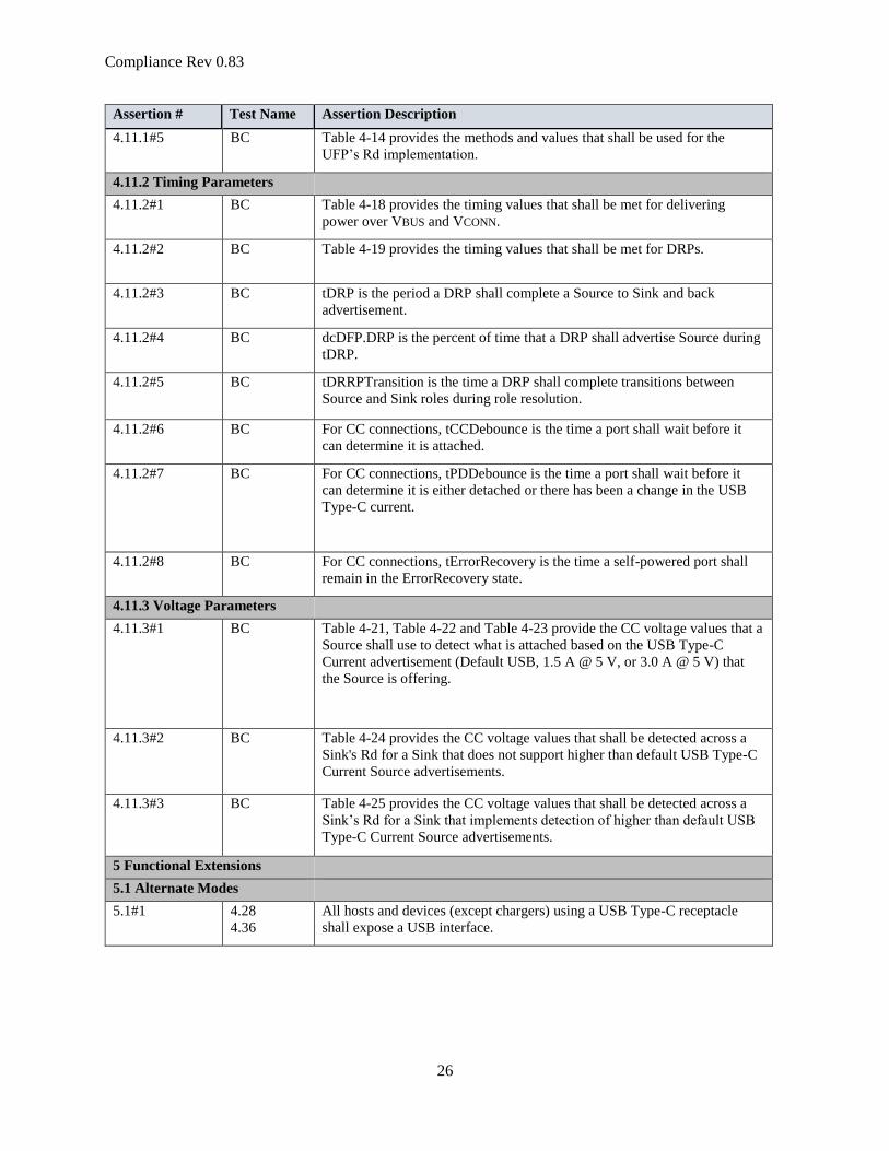
4.11.1#5 BC Table 4-14 provides the methods and values that shall be used for the
UFP’s Rd implementation.
4.11.2 Timing Parameters
4.11.2#1 BC Table 4-18 provides the timing values that shall be met for delivering
power over VBUS and VCONN.
4.11.2#2 BC Table 4-19 provides the timing values that shall be met for DRPs.
4.11.2#3 BC tDRP is the period a DRP shall complete a Source to Sink and back
advertisement.
4.11.2#4 BC dcDFP.DRP is the percent of time that a DRP shall advertise Source during
tDRP.
4.11.2#5 BC tDRRPTransition is the time a DRP shall complete transitions between
Source and Sink roles during role resolution.
4.11.2#6 BC For CC connections, tCCDebounce is the time a port shall wait before it
can determine it is attached.
4.11.2#7 BC For CC connections, tPDDebounce is the time a port shall wait before it
can determine it is either detached or there has been a change in the USB
Type-C current.
4.11.2#8 BC For CC connections, tErrorRecovery is the time a self-powered port shall
remain in the ErrorRecovery state.
4.11.3 Voltage Parameters
4.11.3#1 BC Table 4-21, Table 4-22 and Table 4-23 provide the CC voltage values that a
Source shall use to detect what is attached based on the USB Type-C
Current advertisement (Default USB, 1.5 A @ 5 V, or 3.0 A @ 5 V) that
the Source is offering.
4.11.3#2 BC Table 4-24 provides the CC voltage values that shall be detected across a
Sink's Rd for a Sink that does not support higher than default USB Type-C
Current Source advertisements.
4.11.3#3 BC Table 4-25 provides the CC voltage values that shall be detected across a
Sink’s Rd for a Sink that implements detection of higher than default USB
Type-C Current Source advertisements.
5 Functional Extensions
5.1 Alternate Modes
5.1#1 4.28
4.36
All hosts and devices (except chargers) using a USB Type-C receptacle
shall expose a USB interface.

7/12/2019
27
Assertion # Test Name Assertion Description
5.1#2 4.28
4.36
When a host or device supports Alternate Modes, the host and device shall
use USB Power Delivery Structured Vendor Defined Messages (Structured
VDMs) to discover, configure and enter/exit modes to enable Alternate
Modes
5.1#3 4.28
4.36
When a host or device supports Alternate Modes, where no equivalent USB
functionality is implemented, the device shall provide a USB interface
exposing a USB Billboard Device Class used to provide information
needed to identify the device
5.1#4 4.40 As Alternate Modes do not traverse the USB hub topology, they shall only
be used between a directly connected host and device.
5.1.1 Alternate Mode Architecture
5.1.1#1 Untestable Only Structured VDMs shall be used to alter the USB functionality or
reconfigure the pins the USB Type-C Connector exposes.
5.1.2 Alternate Mode Requirements
5.1.2#1 4.28
4.36
The host and device shall negotiate a USB PD Explicit Contract before
Structured VDMs may be used to discover or enter an Alternate Mode.
5.1.2#2 4.36 The ACK shall be sent after switching to the Alternate Mode has been
completed by the UFP for Enter Mode and Exit Mode requests.
5.1.2#3 4.36 If a device fails to successfully enter an Alternate Mode within
tAMETimeout then the device shall minimally expose a USB 2.0 interface
(USB Billboard Device Class) that is powered by VBUS.
5.1.2#4 4.36 If the device enters the mode after a host sends Enter Mode, it shall respond
with an ACK and discontinue exposing the USB Billboard Device Class
interface.
5.1.2#5 PD The current supplied over VCONN may be redefined by a specific Alternate
Mode but the power shall not exceed the current rating of the pin (See
Section 3.7.7.4).
5.1.2.1 Alternate Mode Pin Reassignment
5.1.2.1#1 4.28
4.36
Figure 5-1 illustrates the only pins that shall be available for functional
reconfiguration in a full-featured cable.
5.1.2.1#2 4.28
4.36
The pins highlighted in yellow (Fig 5-1) are the only pins that shall be
reconfigured.
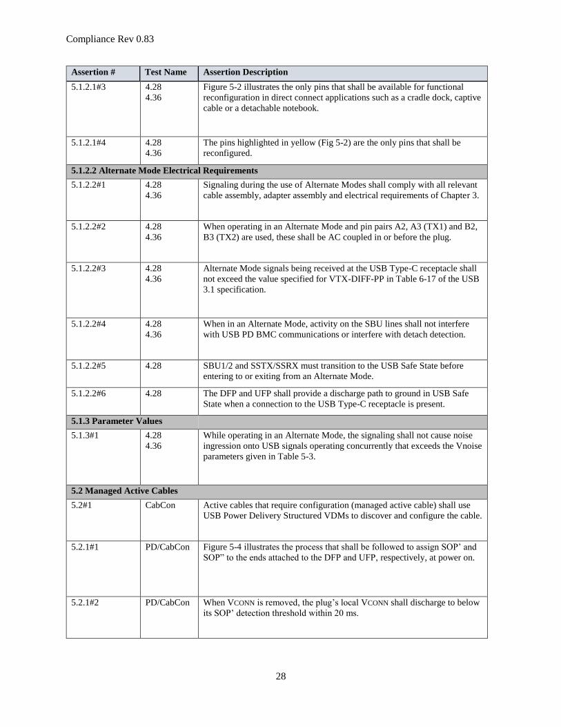
Compliance Rev 0.83
28
Assertion # Test Name Assertion Description
5.1.2.1#3 4.28
4.36
Figure 5-2 illustrates the only pins that shall be available for functional
reconfiguration in direct connect applications such as a cradle dock, captive
cable or a detachable notebook.
5.1.2.1#4 4.28
4.36
The pins highlighted in yellow (Fig 5-2) are the only pins that shall be
reconfigured.
5.1.2.2 Alternate Mode Electrical Requirements
5.1.2.2#1 4.28
4.36
Signaling during the use of Alternate Modes shall comply with all relevant
cable assembly, adapter assembly and electrical requirements of Chapter 3.
5.1.2.2#2 4.28
4.36
When operating in an Alternate Mode and pin pairs A2, A3 (TX1) and B2,
B3 (TX2) are used, these shall be AC coupled in or before the plug.
5.1.2.2#3 4.28
4.36
Alternate Mode signals being received at the USB Type-C receptacle shall
not exceed the value specified for VTX-DIFF-PP in Table 6-17 of the USB
3.1 specification.
5.1.2.2#4 4.28
4.36
When in an Alternate Mode, activity on the SBU lines shall not interfere
with USB PD BMC communications or interfere with detach detection.
5.1.2.2#5 4.28 SBU1/2 and SSTX/SSRX must transition to the USB Safe State before
entering to or exiting from an Alternate Mode.
5.1.2.2#6 4.28 The DFP and UFP shall provide a discharge path to ground in USB Safe
State when a connection to the USB Type-C receptacle is present.
5.1.3 Parameter Values
5.1.3#1 4.28
4.36
While operating in an Alternate Mode, the signaling shall not cause noise
ingression onto USB signals operating concurrently that exceeds the Vnoise
parameters given in Table 5-3.
5.2 Managed Active Cables
5.2#1 CabCon Active cables that require configuration (managed active cable) shall use
USB Power Delivery Structured VDMs to discover and configure the cable.
5.2.1#1 PD/CabCon Figure 5-4 illustrates the process that shall be followed to assign SOP’ and
SOP” to the ends attached to the DFP and UFP, respectively, at power on.
5.2.1#2 PD/CabCon When VCONN is removed, the plug’s local VCONN shall discharge to below
its SOP’ detection threshold within 20 ms.

7/12/2019
29
Assertion # Test Name Assertion Description
5.2.1#3 PD/CabCon A managed active cable shall assure that the two USB PD controllers are
uniquely assigned via the mechanism described here, one as SOP’ and the
other as SOP”.
5.2.1#4 IOP Managed active USB Type-C to USB Type-C cables shall by default
support USB operation.
5.2.1#5 IOP Multi-modal cables (e.g., an active cable that supports an Alternate Mode
in addition to USB SuperSpeed) that use the TX/RX signal pairs shall
minimally support USB 3.1 Gen 1 operation.
5.2.1#6 CabCon On a managed active cable the isolation elements (Iso) shall prevent
VCONN from traversing end-to-end through the cable.
5.2.1.1 Parameter Values
5.2.1.1#1 PD/CabCon tVCONNStable is the time between the application of VCONN until SOP’
and SOP” shall be ready for communication.
5.2.2 Cable Message Structure
5.2.2#1 PD/CabCon USB PD Structured VDMs shall be used to identify and manage active
cables.
5.2.2#2 PD/CabCon In all cases, Structured VDMs shall only use SOP’ and SOP’’
5.2.2#3 PD/CabCon Structured VDMs shall not use SOP.
5.2.2#4 PD/CabCon Only the DFP shall be allowed to communicate with SOP’ and SOP” after
an explicit USB PD contract has been entered, except when a UFP has
confirmed that it is communicating with a USB PD BFSK-based source and
needs to communicate with SOP’ to identify if the cable is capable of
greater than 1.5 A.
5.2.2#5 PD/CabCon For active cables that support both SOP’ and SOP”, after attach or a USB
PD Cable Reset, the plug directly connected to the DFP shall only respond
to SOP’ and the plug directly connected to the UFP shall only respond to
SOP”.
5.2.2#6 PD/CabCon The Discover Identity message shall start with SOP’.
5.2.3 Modal Cable Management
5.2.3#1 PD/CabCon In addition to supporting the Discover Identity message, managed active
cables shall support the following USB Power Delivery Structured VDMs.
5.2.3#2 PD/CabCon These following VDMs shall start with SOP’: Discover SVIDs, Discover
Modes, Enter Mode, Exit Mode

Compliance Rev 0.83
30
Assertion # Test Name Assertion Description
5.2.3.1 Discover SVIDs
5.2.3.1#1 PD/CabCon The managed active cable shall return a list of SVIDs that it supports.
5.2.3.2 Discover Modes
5.2.3.2#1 PD/CabCon The managed active cable shall return a list of Alternate Modes it supports
for each SVID.
5.2.3.3 Enter Mode
5.2.3.3#1 PD/CabCon The managed active cable shall use the Enter Mode command to enter an
Alternate Mode.
5.2.3.4 Exit Mode
5.2.3.4#1 PD/CabCon The managed active cable shall use the Exit Mode command to exit an
alternate mode previously entered.
5.2.3.4#2 PD/CabCon Exit Mode shall return the cable to its default USB operation.
Test Requirements
Hardware
The USB Type-C Connector Verification System (CVS) is a hardware solution capable of testing the verifications
defined by this document. The CVS implements the following block diagram:

7/12/2019
31
Figure 1: CVS Block Diagram
For a PUT bound to a USB Type-C receptacle, the CVS is required to emulate the USB Type-C Connector State
Machines from the perspective of the PUT receptacle. So it must appear as the Source / Sink / SNKAS / DRP AND
as the cable (Ra) at the same time. To accomplish this the CVS uses a special cable so that CVS hardware has
access to both CC pins on a PUT receptacle. If the PUT is bound to a captive cable, then the test hardware emulates
the USB Type-C Connector State Machines from the perspective of the captive cable connector, and does not
emulate a cable at the same time.
Additionally, the CVS must be able to measure voltages and currents as defined in the Electrical Requirements
section.
Electrical
The CVS determines PUT state by confirming that state’s electrical requirements are detected. CC terminations Rp,
Rd, and Ra and currents and voltages are defined in USB Type-C Spec Section 4.11.1 Termination Parameters and
4.11.3 Voltage Parameters. VBUS values are defined by the USB Type-C spec as well all the USB 2.0 and USB 3.1
specifications, USB BC 1.2, and USB Power Delivery specification depending on the context. VBUS current is
defined by USB Type-C Specification. VCONN is defined by the USB Type-C spec and USB PD specification. The
CVS verifications check against these defined values to confirm PUT state.
Timing
Transitions between states and other timers are defined in USB Type-C Spec Section 4.11.2 Timing Parameters.
The CVS verifications check against these defined values to confirm PUT transitions.
In addition to those parameters defined in the table, there are some clarifying points and additional timers defined
below:

Compliance Rev 0.83
32
1) DRP PUT transition to Attached state
The time from CVS transition to Unattached state to when CVS can verify one of:
1) PUT transitions to Attached.SNK
2) PUT transitions to Attached.SRC
is:
tDRP.DRPAttach = 5 x tDRP
2) PUT transition out of Attached.SRC
The PUT transition from Attached.SRC or PoweredAccessory to Unattached.SNK or Unattached.SRC is immediate
as defined in the USB Type-C Specification. But the PUT has tVbusOFF or tVconnOFF to stop sourcing Vbus and
Vconn (USB Type-C Spec Section 4.11.2). So for those transitions, the PUT may be sourcing Vbus or Vconn while
in the Unattached.SNK or Unattached.SRC state. This is the only scenario where a PUT would be sourcing those
voltages while in Unattached.SNK or Unattached.SRC, and the reader may note this is an exception to the spec
requirement that those voltages are not sourced while in those states (USB Type-C Spec Sections 4.5.2.2.3.1
Unattached.SNK Requirements & 4.5.2.2.6.1 Unattached.SRC Requirements).
Although the spec defines the transition out of Attached.SRC or PoweredAccessory to be immediate when Rd is no
longer detected, due to low clock speed on the CC pins and power saving implementations the PUT may not detect
Rd has been removed for more than 2 ms. If USB PD is implemented on the product, it may be retrying a message
and postponing far-end detection for more than 12ms.
For the purposes of Compliance testing we have given the PUT a timer of tDetach to make the transition.
tDetach = max tPDDebounce = 20ms
3) PUT transition out of Attached.SNK
When a PUT transitions from Attached.SNK to Unattached.SNK or Unattached.SRC, it must make the transition
immediately upon detecting removal of Vbus. This can be immediate and may take up to tVbusOFF.
Product
There are a few testing requirements based on the USB-C Product implementation.
The Vendor Info File (VIF) is used in conjunction with test software to indicate PUT product implementation. This
file can be generated by the following tool:
http://www.usb.org/developers/tools/#PDFile
Note: The VIF may be generated by test equipment vendors as well.
This sections lists VIF fields that are used or implicated in the USB Type-C Functional Test descriptions and gives a
brief summary of how they are used.

7/12/2019
33
Type_C_State_Machine Type_C_Implements_Try_SRC Type_C_Implements_Try_SNK Type_C_Supports_Audio_Accessory Type_C_Supports_VCONN_Powered_Accessory Type_C_Is_Vconn_Powered_Accessory Type_C_Is_Debug_Target_SNK Type_C_Is_Debug_Target_SRC
These fields’ values are used in Connection Tests to determine applicability. Source Connection tests are only
applicable when Type_C_State_Machine = 0 (SRC). Type_C_State_Machine is used in several Source-Capable or
Sink-Capable Tests to constrain applicability as well.
Type_C_Can_Act_As_Host
Type_C_Can_Act_As_Device
Type_C_Host_Speed
Type_C_Device_Speed
These fields’ values are used in various tests to determine whether the PUT supports USB 3.1 or USB 2.0 and at
what speed. With this information, the CVS will know which data conditions from the test description are
applicable for the test run. A test step might refer to a PUT that supports USB 3.1 as a host. This is equivalent to
Type_C_Can_Act_As_Host = YES and Type_C_Host_Speed = 1.
UUT_Device_Type
This field is used to ascertain whether the PUT supports PD. If the value is set to 6 (Type_C_Only) then the PUT is
not PD capable. The PUT is PD capable with any other value. If UUT_Device_Type is not set to 6 (Type_C_Only)
and Type_C_Can_Act_As_Host = YES then the Data_Capable_as_USB_Host_SOP field must also be set to YES in
the VIF. Similarly, if Type_C_Can_Act_As_Device = YES then the Data_Capable_As_USB_Device_SOP field
must be YES.
UUT_Device_Type is also used to determine whether Source-Capable or Sink-Capable Tests are applicable. If the
value is in the set {0: Consumer Only, 1: Consumer/Provider, 2: Provider/Consumer, 4: DRP}, then the Sink-
Capable Tests are required. If the value is set to one of {1: Consumer/Provider, 2: Provider/Consumer, 3: Provider
Only, 4: DRP}, then the Source-Capable Tests are required.
For USB-IF Certification, a Provider/Consumer or Consumer/Provider with Type_C_State_Machine set to SRC or
SNK are discouraged. These product schemes will limit a product’s ability to connect with its link partner and
creates a silent failure. The failure scenarios include the connection between a SNK which supports PR_Swap and a
dead battery device.
Captive_Cable
The VIF field Captive_Cable set to NO indicates the PUT is a PUT_R, and the value YES indicates PUT is a
PUT_C. More information about PUT_R and PUT_C is in the Tests section.
Rp_Value
If the VIF field Type_C_State_Machine is set to 0 (SRC) or 2 (DRP) then the PUT has an Rp pull up resistor on its
CC pins. The value of this resistor indicates the Type-C Current level that the PUT can source. The value here
indicates the PUT Rp resistor value on Attach.
Port_Battery_Powered

Compliance Rev 0.83
34
This field is used in TD 4.11.2 Sink Dead Battery Test, checking that a DUT with a Dead Battery implements a USB
Type-C Sink State Machine.
If the DUT uses a Battery then it must run the Type-C Functional Tests once with a charged battery and again with a
Dead Battery.
Type_C_Port_On_Hub
This field is used in TD Section 4.12 Hub tests.
Type_C_Power_Source
If the DUT is capable of being a UFP-powered device or an Externally-powered device (including charge-through),
then the DUT must run Type-C Functional Tests with both connection scenarios. As a UFP-powered device, the
DUT must implement a USB Type-C Sink Connection state machine.
Type_C_BC_1_2_Support
This field is used to determine if the PUT supports BC 1.2 and whether it is supported as a Source, as a Sink, or
both. If the DUT is capable of sinking via USB BC 1.2 protocol, then its usage will be exercised during TD 4.10.2
Sink Power Precedence Test.
Type_C_ Sources_Vconn
This field is used to determine if the PUT is a PUT_V and will be tested again Vconn requirements. Some PUTs are
required to source Vconn as described in the PUT_V definition in the Tests section of this document. When a PUT
is not required to source Vconn, it still may support doing so and in that case is still held to the Vconn requirements
in the spec.
DR_Swap_To_DFP_Supported
DR_Swap_To_UFP_Supported
These fields are used in TD 4.11.1 DR_Swap Test to ascertain which directions to test. Usage described in the test
steps.
If the VIF fields indicate either of the following:
• UUT_Device_Type != 6 (Type_C_Only) and Type_C_State_Machine is DRP
• Type_C_Can_Act_As_Host is YES and Type_C_Can_Act_As_Devce is YES
Then at least one of the fields DR_Swap_To_DFP_Supported or DR_Swap_To_UFP_Supported must be YES.
VCONN_Swap_To_On_Supported
VCONN_Swap_To_Off_Supported
These fields are used in TD 4.9.4 Source Vconn_Swap Test and TD 4.10.5 Sink Vconn_Swap Test to ascertain
which directions to test. Usage described in the test steps.
Modal_Operation_Supported_SOP
Attempts_Discov_SOP
These fields are used in TD 4.9.5 Source Alternate Modes Test and TD 4.10.6 Sink Alternate Mode Test to ascertain
which directions to test. Usage described in the test steps.

7/12/2019
35
Accepts_PR_Swap_As_Src
Accepts_PR_Swap_As_Snk
These fields are used in TD 4.9.3 Source PR_Swap Test and TD 4.10.4 Sink PR_Swap Test to ascertain which
directions to test. Usage described in the test steps.
Tests
Many test steps require the CVS to emulate states defined in the USB Type-C Connection State machines. In the
attached state this includes appropriate responses to capabilities messages and cable discovery as needed. During
steps that require messaging, the CVS default behavior is to reject unexpected swap messages.

Compliance Rev 0.83
36
State emulation is accomplished slightly differently when the CVS is testing a PUT bound to a USB Type-C
receptacle (PUT_R) vs. a PUT bound to a USB Type-C captive cable or a direct attach (PUT_C).
For a PUT_R, the CVS will apply the CC values indicated by a Type-C Connection State on only one CC pin. Note:
for a test run, the one CC pin stays the same throughout the test. The other pin, unless otherwise indicated, remains
in an Open state. The test steps will indicate if the other CC pin will be terminated with Ra.
For a PUT_C, the CVS will apply the CC values indicated by a Type-C Connection State on both CCs and monitors
the CCs to ascertain to which CC the PUT is connected.
For instance, when a test step indicates that the CVS transitions to Unattached.SRC:
• For a PUT_R, the CVS will apply Rp on one CC and unless otherwise indicated, the other CC pin will
remain in an Open state. The test step will indicate if the other CC pin will be terminated with Ra.
• For a PUT_C, the CVS will apply Rp on both CCs.
When a test step indicates that the CVS apply Rp, unless otherwise indicated, the Rp advertises the USB default
current.
For tests that verify load on Vbus, the CVS will give a 5 ms delay starting at Vbus ON for inrush allowance before
measuring current.
When a test step indicates it is verifying data communications:
• For USB 3.1 data communications, the tester verifies U0 is reached between CVS and PUT
• For USB 2.0 data communications, the tester verifies packets received from PUT
The following paragraphs describe the assumed initial testing state for a PUT_R and PUT_C.
For a PUT_R, every test is initialized with the following assumptions:
1. CVS starts in Disabled
2. PUT and CVS are physically connected through a cable.
3. The cable connecting the CVS and PUT has a through connection on both CC pins so the CVS can emulate
a cable. This is so the CVS can generate and monitor VCONN sourcing and sinking
For a PUT_C, every test is initialized with the following assumptions:
1. CVS starts in Disabled
2. PUT and CVS are physically connected through the PUT captive cable.
The PUT will always be either a PUT_R or a PUT_C. In addition to that, the PUT will also be categorized as a
PUT_V if it supports sourcing Vconn in the Attached.SRC state. A test step will indicate when a verification is only
checked for a PUT_V.
If the PUT is a PUT_R and indicates point 1 and either 2 or 3 below:
1. VIF field Type_C_State_Machine is set to SRC or DRP or UUT_Device_Type is Consumer/Provider
2. VIF field Type_C_Host_Speed is USB 3.1 or Type_C_Device_Speed is USB 3.1 indicating PUT supports
USB 3.1 signaling on its SS RX and SS TX pairs
3. VIF indicates any Source PDO with Max Current greater than 3A
Then the PUT is required to be capable of sourcing Vconn and shall also be referred to as a PUT_V in this
document.
If the PUT has VIF field Type_C_Port_On_Hub set to YES and Type_C_Can_Act_As_Host set to YES, then CVS
prompts the user to verify the UFP of the hub under test is plugged into a host.
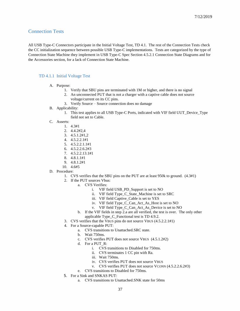
7/12/2019
37
Connection Tests
All USB Type-C Connectors participate in the Initial Voltage Test, TD 4.1. The rest of the Connection Tests check
the CC initialization sequence between possible USB Type-C implementations. Tests are categorized by the type of
Connection State Machine they implement in USB Type-C Spec Section 4.5.2.1 Connection State Diagrams and for
the Accessories section, for a lack of Connection State Machine.
TD 4.1.1 Initial Voltage Test
A. Purpose:
1. Verify that SBU pins are terminated with 1M or higher, and there is no signal
2. An unconnected PUT that is not a charger with a captive cable does not source
voltage/current on its CC pins.
3. Verify Source – Source connection does no damage
B. Applicability:
1. This test applies to all USB Type-C Ports, indicated with VIF field UUT_Device_Type
field not set to Cable.
C. Asserts:
1. 4.3#1
2. 4.4.2#2,4
3. 4.5.1.2#1,2
4. 4.5.2.2.1#1
5. 4.5.2.2.1.1#1
6. 4.5.2.2.6.2#3
7. 4.5.2.2.13.1#1
8. 4.8.1.1#1
9. 4.8.1.2#1
10. 4.6#5
D. Procedure:
1. CVS verifies that the SBU pins on the PUT are at least 950k to ground. (4.3#1)
2. If the PUT sources Vbus:
a. CVS Verifies:
i. VIF field USB_PD_Support is set to NO
ii. VIF field Type_C_State_Machine is set to SRC
iii. VIF field Captive_Cable is set to YES
iv. VIF field Type_C_Can_Act_As_Host is set to NO
v. VIF field Type_C_Can_Act_As_Device is set to NO
b. If the VIF fields in step 2.a are all verified, the test is over. The only other
applicable Type_C_Functional test is TD 4.9.2.
3. CVS verifies that the VBUS pins do not source VBUS (4.5.2.2.1#1)
4. For a Source-capable PUT:
a. CVS transitions to Unattached.SRC state.
b. Wait 750ms.
c. CVS verifies PUT does not source VBUS (4.5.1.2#2)
d. For a PUT_R:
i. CVS transitions to Disabled for 750ms.
ii. CVS terminates 1 CC pin with Ra.
iii. Wait 750ms.
iv. CVS verifies PUT does not source VBUS
v. CVS verifies PUT does not source VCONN (4.5.2.2.6.2#3)
e. CVS transitions to Disabled for 750ms.
5. For a Sink and SNKAS PUT: a. CVS transitions to Unattached.SNK state for 50ms

Compliance Rev 0.83
38
b. CVS transitions to Unattached.Accessory state for 50ms
c. CVS transitions to Unattached.SNK state for 50ms
d. CVS transitions to Disabled for 750ms.
6. For a Sink-capable PUT:
a. CVS applies USB 3.1/2.0 DFP terms
b. Wait 2s
c. CVS verifies PUT did not apply D+ pull-up or SS terms
7. CVS applies 53.2k resistance from Vbus to CC pin.
8. CVS verifies PUT does not source Vbus after tCCDebounce.
9. CVS removes 53.2k resistance from Vbus to CC pin.
10. CVS presents VBUS for 1s.
11. This test must be performed before the DUT is tested at the USB-IF Interoperability Test
Suites.
TD 4.1.2 Unpowered CC Voltage Test
A. Purpose:
1. Verify that a product which is powered off does not present Rd
B. Applicability:
1. This test applies when VIF field Type_C_State_Machine is SRC
2. This test applies when VIF field Type_C_State_Machine is DRP and
Port_Battery_Powered is NO.
3. This test applies when VIF field Type_C_State_Machine is SNK and
Type_C_Power_Source is 0 (“Externally Powered”) and Port_Battery_Powered is NO.
C. Asserts:
1. TBD
D. Procedure:
1. If Type_C_State_Machine is DRP, CVS verifies that Type_C_Power_Source is not set to
1 (UFP-Powered)
2. CVS prompts the user to unplug external power to the product so that the PUT is
unpowered
3. CVS applies Rp in the USB Default Current range
4. If Type_C_State_Machine is DRP and Type_C_Power_Source is 2 (Both), CVS verifies
that PUT applies Rd and does not toggle.
5. Else, CVS verifies that CC voltage is in vOPEN range
6. CVS transitions to Disabled for 500ms
7. CVS applies Rp in the USB Type-C Current 1.5 A range
8. If Type_C_State_Machine is DRP and Type_C_Power_Source is 2 (Both), CVS verifies
that PUT applies Rd and does not toggle.
9. Else, CVS verifies that CC voltage is in vOPEN range
10. CVS transitions to Disabled for 500ms
11. CVS applies Rp in the USB Type-C Current 3.0 A range
12. If Type_C_State_Machine is DRP and Type_C_Power_Source is 2 (Both), CVS verifies
that PUT applies Rd and does not toggle.
13. Else, CVS verifies that CC voltage is in vOPEN range
14. CVS prompts the test operator to replug external power to the product so that the PUT is
powered
Source Tests

7/12/2019
39
These tests are for USB Type-C connectors that implement the Source connection state machine in USB Type-C
Specification Figure 4-12.
TD 4.2.1 Source Connect Sink Test
A. Purpose:
1. Verify a Source transitions to Attached.SRC according to spec
2. Verify a Source transitions to Unattached.SRC when Sink removed
B. Applicability:
1. This test applies when VIF field Type_C_State_Machine is SRC
C. Asserts:
1. 4.4.2#1-3
2. 4.5.2.2.6.1#1-3
3. 4.5.2.2.6.2#1
4. 4.5.2.2.7.1#1-3
5. 4.5.2.2.7.2#1,5
6. 4.5.2.2.8.1#2,4-10
7. 4.5.2.2.8.2#1
8. 4.6.2.1#3
9. 4.6.2.4#1,2
D. Conditions:
1. CVS emulates USB PD 2.0 5A Active Cable
2. CVS emulates USB PD 3.0 5A Active Cable
E. Procedure:
1. CVS verifies PUT does not apply Rd for the remainder of the test (Note: This is to check
for toggling between Rd/Rp for connect)
2. If VIF field Type_C_Sources_Vconn is NO, CVS verifies PUT does not source Vconn
for the remainder of this test.
3. CVS transitions to Unattached.SNK.
4. For a PUT_R:
a. CVS terminates one CC pin with Ra for the duration of the test.
b. CVS emulates an Active Emarked cable with the first Condition from section D
above
c. CVS verifies PUT has transitioned to Unattached.SRC
i. PUT applies Rp simultaneously on both CC pins
d. CVS waits 80ms
e. CVS transitions to Disabled except for one CC maintaining Ra
f. CVS verifies PUT transitions to Unattached.SRC
g. Wait 750ms.
h. CVS transitions to Unattached.SNK
5. CVS verifies that:
a. CVS detects SNK.Rp on its Rd terminated CC pin
b. PUT transitions to Attached.SRC by sourcing VBUS after tCCDebounce and
before tCCDebounce + tVBUSON expires after CVS detects SNK.Rp
6. Vconn_tested = false
7. If PUT supports USB PD:
a. CVS verifies that:
i. PUT stabilizes VBUS before initiating USB PD communications
ii. CVS and PUT negotiate a contract.
b. If PUT source capabilities include a Max Current > 3 A:
i. CVS verifies that for a PUT_R, it supplied Vconn within tVconnON
ii. Vconn_tested = true
8. If PUT supports USB 3.1 DFP:
a. CVS verifies that:

Compliance Rev 0.83
40
i. PUT attaches eSS terms within 80ms of Vbus on
ii. For a PUT_R and not Vconn_tested:
01 It supplied VCONN within tVCONNON
02 Vconn_tested = true
iii. PUT transmits LFPS within 121ms of attaching eSS terms
b. CVS loads 1W on Vconn
c. Wait 1s
9. If the PUT is a PUT_V and not Vconn_tested:
a. CVS verifies that for a PUT_R, it supplied Vconn within tVconnON
10. CVS transitions to Disabled
11. CVS verifies that PUT transitions to Unattached.SRC within tDetach
a. PUT removes Vbus within tVbusOFF
b. For a PUT that supports USB 3.1 DFP, Vconn was sourced until after step 10
c. All signaling has stopped
12. CVS waits 1 second, checking that PUT does not toggle
13. The CVS continues the test with step 2, using the next Condition from section D above
TD 4.2.2 Source Connect SNKAS Test
A. Purpose:
1. Verify a Source transitions to Attached.SRC according to spec when link partner is Sink
with Accessory Support (SNKAS).
B. Applicability:
1. This test applies when VIF field Type_C_State_Machine is SRC
C. Asserts:
1. See TD 4.2 Asserts.
2. 4.5.2.2.7.2#4
D. Procedure:
1. CVS transitions to Unattached.SNK for 5ms.
2. CVS transitions to Unattached.Accessory for max dcSRC.DRP x max tDRP.
3. CVS verifies Source is in Unattached.SRC:
a. For a PUT_R, both CCs advertise Rp
b. For a PUT_C, the CC connected to Rd advertises Rp
4. CVS transitions to Unattached.SNK
5. CVS verifies that the PUT:
a. Advertises VBUS capabilities with Rp throughout the test
b. Sources VBUS after tCCDebounce deadline and before tCCDebounce +
VBUSON expires.
TD 4.2.3 Source Connect DRP
A. Purpose:
1. Verify a Source transitions to Attached.SRC according to spec
B. Applicability:
1. This test applies when VIF field Type_C_State_Machine is SRC
C. Asserts:
1. 4.4.2#1-3
2. 4.5.2.2.6.1#1-3
3. 4.5.2.2.6.2#1
4. 4.5.2.2.7.1#1-3
5. 4.5.2.2.7.2#1
6. 4.5.2.2.8.1#2,4-6
D. Procedure:
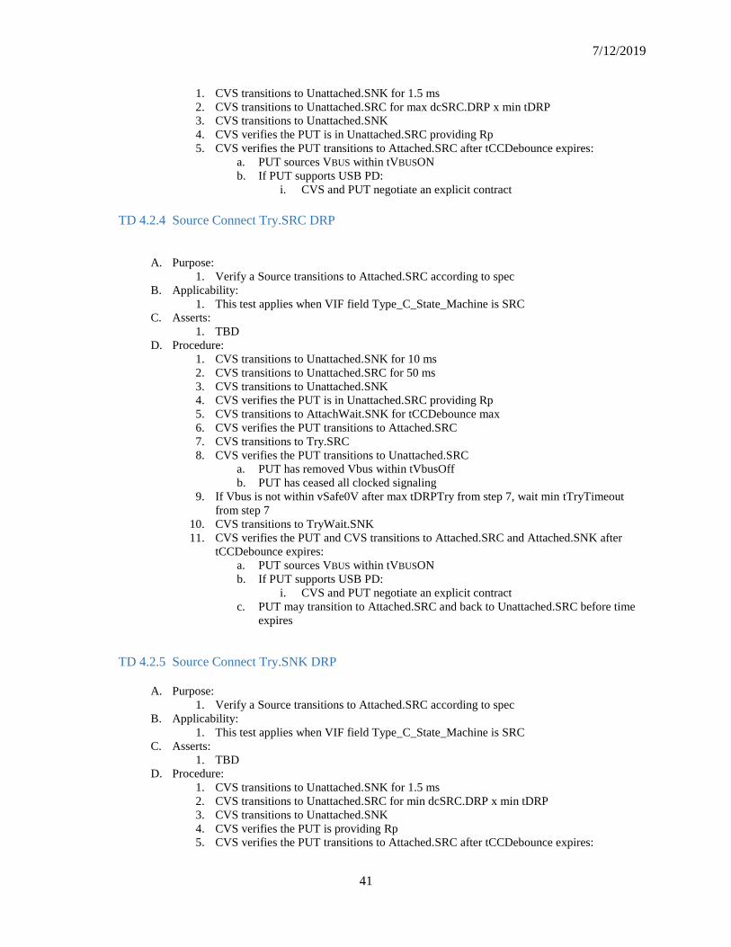
7/12/2019
41
1. CVS transitions to Unattached.SNK for 1.5 ms
2. CVS transitions to Unattached.SRC for max dcSRC.DRP x min tDRP
3. CVS transitions to Unattached.SNK
4. CVS verifies the PUT is in Unattached.SRC providing Rp
5. CVS verifies the PUT transitions to Attached.SRC after tCCDebounce expires:
a. PUT sources VBUS within tVBUSON
b. If PUT supports USB PD:
i. CVS and PUT negotiate an explicit contract
TD 4.2.4 Source Connect Try.SRC DRP
A. Purpose:
1. Verify a Source transitions to Attached.SRC according to spec
B. Applicability:
1. This test applies when VIF field Type_C_State_Machine is SRC
C. Asserts:
1. TBD
D. Procedure:
1. CVS transitions to Unattached.SNK for 10 ms
2. CVS transitions to Unattached.SRC for 50 ms
3. CVS transitions to Unattached.SNK
4. CVS verifies the PUT is in Unattached.SRC providing Rp
5. CVS transitions to AttachWait.SNK for tCCDebounce max
6. CVS verifies the PUT transitions to Attached.SRC
7. CVS transitions to Try.SRC
8. CVS verifies the PUT transitions to Unattached.SRC
a. PUT has removed Vbus within tVbusOff
b. PUT has ceased all clocked signaling
9. If Vbus is not within vSafe0V after max tDRPTry from step 7, wait min tTryTimeout
from step 7
10. CVS transitions to TryWait.SNK
11. CVS verifies the PUT and CVS transitions to Attached.SRC and Attached.SNK after
tCCDebounce expires:
a. PUT sources VBUS within tVBUSON
b. If PUT supports USB PD:
i. CVS and PUT negotiate an explicit contract
c. PUT may transition to Attached.SRC and back to Unattached.SRC before time
expires
TD 4.2.5 Source Connect Try.SNK DRP
A. Purpose:
1. Verify a Source transitions to Attached.SRC according to spec
B. Applicability:
1. This test applies when VIF field Type_C_State_Machine is SRC
C. Asserts:
1. TBD
D. Procedure:
1. CVS transitions to Unattached.SNK for 1.5 ms
2. CVS transitions to Unattached.SRC for min dcSRC.DRP x min tDRP
3. CVS transitions to Unattached.SNK
4. CVS verifies the PUT is providing Rp
5. CVS verifies the PUT transitions to Attached.SRC after tCCDebounce expires:

Compliance Rev 0.83
42
a. PUT sources VBUS within tVBUSON
b. If PUT supports USB PD:
i. CVS and PUT negotiate an explicit contract
TD 4.2.6 Source Connect Audio Accessory
A. Purpose:
1. Verify a Source that supports Audio Accessories connects according to spec requirements
B. Applicability:
1. This test applies for a PUT_R when VIF field Type_C_State_Machine is SRC and
Captive_Cable is NO
C. Asserts:
1. 4.5.2.2.7.2#2
2. 4.5.2.2.15.1#1,2,4,5
3. 4.5.2.2.15.2#2
D. Procedure:
1. CVS presents Audio Accessory CC terms with Ra
2. CVS verifies PUT provides Rp on both CCs (PUT in Unattached.SRC)
3. If VIF field Type_C_Supports_Audio_Accessory is YES:
a. CVS verifies PUT transitions to AudioAccessory after tCCDebounce:
i. The PUT reconfigures its pins as defined in Appendix A
ii. The PUT does not drive VBUS or VCONN
iii. If the PUT sinks current over VBUS, it shall not be more than 500mA
iv. The PUT applies Rp on at least one CC
4. If VIF field Type_C_Supports_Audio_Accesory is NO:
a. CVS verifies PUT does not transition to Attached.SRC or supply Vbus
5. CVS transitions to Disabled
6. If VIF field Type_C_Supports_Audio_Accessory is YES:
a. CVS verifies PUT transitions to Unattached.SRC after tCCDebounce
TD 4.2.7 Source Connect Debug Accessory
A. Purpose:
1. Verify a Source that supports Debug Accessories does source Vbus
B. Applicability:
1. This test applies for a PUT_R when VIF field Type_C_State_Machine is SRC and
Captive_Cable is NO
C. Asserts
1. 4.5.2.2.16.1#2
D. Procedure:
1. CVS presents DTS (Debug and Test System) Sink with Rds on both CCs
2. CVS verifies PUT provides Rp on both CCs (PUT in Unattached.SRC)
3. If VIF field Type_C_Is_Debug_Target_SRC is YES: a. CVS verifies PUT sources Vbus after tCCDebounce and within tVbusON.
4. Else If VIF field Type_C_Is_Debug_Target_SRC is NO or not defined: a. CVS verifies PUT does not source Vbus after tCCDebounce expires
TD 4.2.8 Source Connect VCONN Accessory
A. Purpose:
1. Verify the Source connects with an Accessory that uses VCONN.
B. Applicability:

7/12/2019
43
1. This test is applicable for a PUT_R with VIF field Type_C_State_Machine set to SRC
and Captive_Cable is NO and Type_C_Sources_Vconn is YES
C. Asserts:
1. 4.5.2.2.8.1#10
2. 4.5.2.2.8.2#6
3. 4.5.2.2.19.1#5
D. Procedure:
1. CVS presents a Vconn-powered Accessory by terminating one CC with Rd and one CC
with Ra.
2. CVS verifies that:
a. PUT transitions to Attached.SRC by sourcing VBUS after tCCDebounce and
before tCCDebounce + tVBUSON expires
b. PUT advertises VBUS capability over Rp
c. PUT_V sources VCONN within tVCONNON
d. For a PUT with PD (VIF field UUT_Device_Type is not set to Type_C_Only):
i. PUT initiates a PD Explicit Contract
ii. For a PUT with VIF field Attempts_Discov_SOP set to YES:
1 PUT initiates Alternate Mode discovery with Structured
VDMs
3. CVS transitions to Disabled
4. CVS verifies:
a. PUT stops sourcing VCONN within tVCONNOFF
b. PUT stops sourcing VBUS within tVBUSOFF
Sink Tests
These tests are for USB Type-C connectors that implement the USB Type-C Sink Connection State Diagram in
Figure 4-14.
TD 4.3.1 Sink Connect Source Test
A. Purpose:
1. Verify a Sink transitions to Attached.SNK according to spec
2. Verify that removing VBUS transitions the PUT to Unattached.SNK
B. Applicability:
1. This test applies when VIF field Type_C_State_Machine is SNK and
Type_C_Supports_Audio_Accessory is NO and Type_C_Supports_VCONN_Accessory
is NO.
C. Asserts:
1. 4.5.2.2.3.1#1-2
2. 4.5.2.2.3.2#1
3. 4.5.2.2.4.1#1-2
4. 4.5.2.2.4.2#3
5. 4.5.2.2.5.1#2-3,5-6
6. 4.5.2.2.5.2#1
D. Procedure:
1. CVS verifies the PUT does not apply Rp for the remainder of the test.
2. CVS transitions to Unattached.SRC
3. For a PUT_R, CVS terminates one CC pin with Ra in any state other than Disabled for
the remainder of the test.
4. CVS verifies PUT presents Rd for tCCDebounce
5. CVS transitions to Attached.SRC when it detects connection from PUT:
a. PUT must start USB communications on its SS or D+/D- pairs within 1 second

Compliance Rev 0.83
44
b. PUT may wait for PD contract before connecting on SS or D+/D- pairs
6. CVS verifies that PUT transitions to Attached.SNK:
a. If PUT data connection before PD contract, verify PUT sinks current according
to CVS advertisement.
b. If PUT supports PD:
i. PUT and CVS negotiate an explicit contract.
c. If VIF field PUT supports USB 3.1:
i. PUT starts data communications on its SuperSpeed pairs.
d. Else if PUT supports USB 2.0:
i. PUT starts data communications on its D+/D- pair.
e. For a PUT_R, VCONN is not supplied
7. CVS transmits Discover ID PD messaging for 200ms.
8. CVS verifies that PUT:
a. If UUT_Device_Type is not 6:
i. Responds with valid GoodCRC messages.
ii. If Responds_To_Discov_SOP is YES:
01 Transmits valid Responder ACK messages.
b. Remains in Attached.SNK during and for 500ms after step 6.
9. CVS transitions to Disabled
10. CVS verifies that PUT transitions to Unattached.SNK before tVBUSOFF expires:
a. PUT data communication has ceased.
11. CVS waits 1 second
TD 4.3.2 Sink Connect DRP Test
A. Purpose
1. Verify a Sink transitions to Attached.SNK according to spec
B. Applicability:
1. This test applies when VIF field Type_C_State_Machine is SNK and
Type_C_Supports_Audio_Accessory is NO and Type_C_Supports_VCONN_Accessory
is NO.
C. Asserts:
1. 4.5.2.2.3.1#1-2
2. 4.5.2.2.3.2#1
3. 4.5.2.2.4.1#1-2
4. 4.5.2.2.4.2#1,3
5. 4.5.2.2.5.1#2-3,5-6
6. 4.5.2.2.5.2#1
D. Procedure:
1. CVS transitions to Unattached.SRC for 5ms
2. CVS transitions to Unattached.SNK for 30ms
3. CVS transitions to Unattached.SRC
4. CVS verifies PUT continued to provide Rd on the CC pin for the duration of steps 1-3
and for tCCDebounce after
a. For a PUT_R, verify this for both CC pins
5. CVS transitions to Attached.SRC
6. CVS verifies that PUT transitions to Attached.SNK:
a. PUT sinks current according to CVS advertisement
b. If PUT supports USB 3.1:
i. PUT starts data communications on its SuperSpeed pairs.
c. Else if PUT supports USB 2.0:
i. PUT starts data communications on its D+/D- pair
d. For a PUT_R, VCONN is not applied
7. CVS transitions to Disabled

7/12/2019
45
8. CVS verifies that PUT transitions to Unattached.SNK before tVBUSOFF expires
a. PUT data communication has ceased
b. PUT is not sourcing Vbus (Vbus is at vSafe0V)
c. PUT is not sourcing Vconn
TD 4.3.3 Sink Connect Try.SRC DRP Test
A. Purpose
1. Verify a Sink transitions to Attached.SNK according to spec
B. Applicability:
1. This test applies when VIF field Type_C_State_Machine is SNK and
Type_C_Supports_Audio_Accessory is NO and Type_C_Supports_VCONN_Accessory
is NO.
C. Asserts:
1. TBD
D. Procedure:
1. CVS transitions to Unattached.SRC for 5ms
2. CVS transitions to Unattached.SNK for 30ms
3. CVS transitions to Unattached.SRC
4. CVS verifies PUT continued to provide Rd on the CC pin for the duration of steps 1-3
and for tCCDebounce after
a. For a PUT_R, verify this for both CC pins
5. CVS transitions to Attached.SRC
6. CVS verifies that PUT transitions to Attached.SNK:
a. PUT sinks current according to CVS advertisement
b. If PUT supports USB 3.1:
i. PUT starts data communications on its SuperSpeed pairs.
c. Else if PUT supports USB 2.0:
i. PUT starts data communications on its D+/D- pair
d. For a PUT_R, VCONN is not applied
7. CVS transitions to Disabled
8. CVS verifies that PUT transitions to Unattached.SNK before tVBUSOFF expires
a. PUT data communication has ceased
b. PUT is not sourcing Vbus (Vbus is at vSafe0V)
c. PUT is not sourcing Vconn
TD 4.3.4 Sink Connect Try.SNK DRP Test
A. Purpose
1. Verify a Sink transitions to Attached.SNK according to spec
B. Applicability:
1. This test applies when VIF field Type_C_State_Machine is SNK and
Type_C_Supports_Audio_Accessory is NO and Type_C_Supports_VCONN_Accessory
is NO.
C. Asserts:
1. TBD
D. Procedure:
1. CVS transitions to Unattached.SRC for 5ms

Compliance Rev 0.83
46
2. CVS transitions to Unattached.SNK for 30ms
3. CVS transitions to Unattached.SRC
4. CVS verifies PUT continues to provide Rd on the CC pin for the duration of this test
a. For a PUT_R, verify Rd is provided on both CC pins until Attached, and then on
at least one CC for the duration of this test.
5. CVS transitions to AttachWait.SRC for max tCCDebounce
6. CVS transitions to Try.SNK for max tDRPTry + max tCCTryDebounce
7. CVS transitions to TryWait.SRC for max tCCTryDebounce
8. CVS transitions to Attached.SRC
9. CVS verifies that PUT transitions to Attached.SNK:
a. PUT sinks current according to CVS advertisement
b. If PUT supports USB 3.1:
i. PUT starts data communications on its SuperSpeed pairs.
c. Else if PUT supports USB 2.0:
i. PUT starts data communications on its D+/D- pair
d. For a PUT_R, VCONN is not applied
10. CVS transitions to Disabled
11. CVS verifies that PUT transitions to Unattached.SNK before tVBUSOFF expires
a. PUT data communication has ceased
b. PUT is not sourcing Vbus (Vbus is at vSafe0V)
c. PUT is not sourcing Vconn
TD 4.3.5 Sink Connect SNKAS Test
A. Purpose:
1. Verify a Sink VCONN Powered Accessory configures an Alternate Mode when VCONN is
present
B. Applicability:
1. This test is required when VIF field Type_C_State_Machine is SNK and
Type_C_Is_VCONN_Powered_Accessory is set to YES.
C. Asserts:
1. 4.10#1-4
D. Procedure:
1. CVS does not present Vbus for the duration of this test.
2. CVS presents VCONN to the PUT CC pin terminated with Ra
3. CVS and PUT negotiate a PD Explicit Contract
4. CVS initiates negotiations for an Alternate Mode (Discover ID, SVIDs and Modes)
5. CVS verifies PUT supports an Alternate Mode
6. CVS initiates an Enter Mode command with a PUT supported Mode
7. CVS verifies:
a. PUT follows all electrical constraints for SBU and any reconfigured pins (i.e.
USB Safe States).
b. PUT sends ACK for Enter Mode
8. CVS initiates an Exit Mode command for the active mode
9. CVS verifies:
a. PUT follows all electrical constraints for SBU and any reconfigured pins (i.e.
USB Safe States).
b. PUT sends ACK for Exit Mode after successfully exiting the mode.
10. CVS removes VCONN
11. CVS verifies PUT transitions to Unattached.SNK within tVCONNOFF
a. All clocked signaling ceases
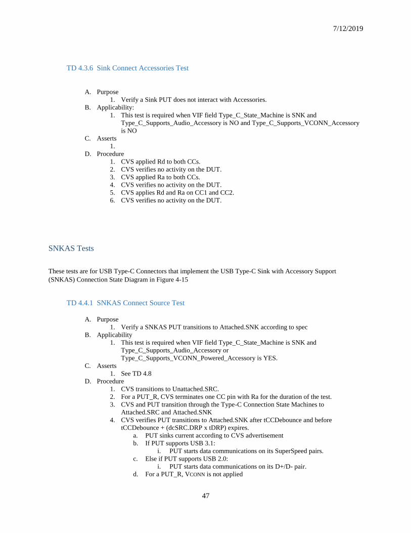
7/12/2019
47
TD 4.3.6 Sink Connect Accessories Test
A. Purpose
1. Verify a Sink PUT does not interact with Accessories.
B. Applicability:
1. This test is required when VIF field Type_C_State_Machine is SNK and
Type_C_Supports_Audio_Accessory is NO and Type_C_Supports_VCONN_Accessory
is NO
C. Asserts
1.
D. Procedure
1. CVS applied Rd to both CCs.
2. CVS verifies no activity on the DUT.
3. CVS applied Ra to both CCs.
4. CVS verifies no activity on the DUT.
5. CVS applies Rd and Ra on CC1 and CC2.
6. CVS verifies no activity on the DUT.
SNKAS Tests
These tests are for USB Type-C Connectors that implement the USB Type-C Sink with Accessory Support
(SNKAS) Connection State Diagram in Figure 4-15
TD 4.4.1 SNKAS Connect Source Test
A. Purpose
1. Verify a SNKAS PUT transitions to Attached.SNK according to spec
B. Applicability
1. This test is required when VIF field Type_C_State_Machine is SNK and
Type_C_Supports_Audio_Accessory or
Type_C_Supports_VCONN_Powered_Accessory is YES.
C. Asserts
1. See TD 4.8
D. Procedure
1. CVS transitions to Unattached.SRC.
2. For a PUT_R, CVS terminates one CC pin with Ra for the duration of the test.
3. CVS and PUT transition through the Type-C Connection State Machines to
Attached.SRC and Attached.SNK
4. CVS verifies PUT transitions to Attached.SNK after tCCDebounce and before
tCCDebounce + (dcSRC.DRP x tDRP) expires.
a. PUT sinks current according to CVS advertisement
b. If PUT supports USB 3.1:
i. PUT starts data communications on its SuperSpeed pairs.
c. Else if PUT supports USB 2.0:
i. PUT starts data communications on its D+/D- pair.
d. For a PUT_R, VCONN is not applied
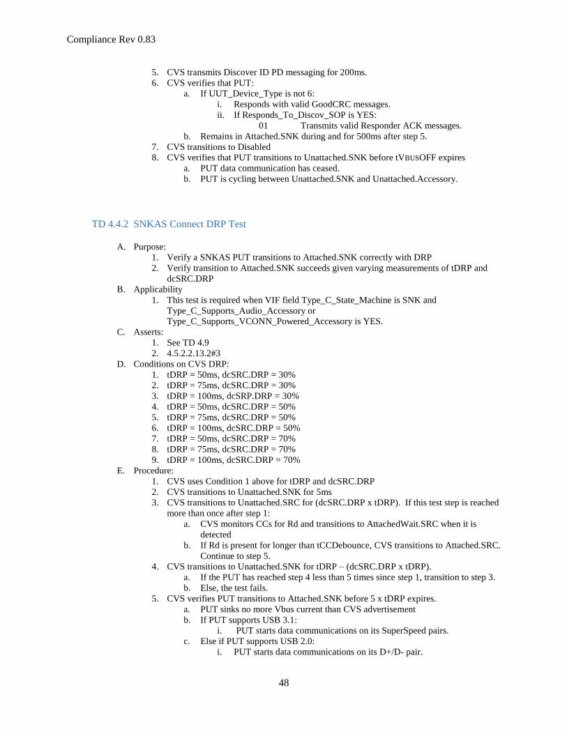
Compliance Rev 0.83
48
5. CVS transmits Discover ID PD messaging for 200ms.
6. CVS verifies that PUT:
a. If UUT_Device_Type is not 6:
i. Responds with valid GoodCRC messages.
ii. If Responds_To_Discov_SOP is YES:
01 Transmits valid Responder ACK messages.
b. Remains in Attached.SNK during and for 500ms after step 5.
7. CVS transitions to Disabled
8. CVS verifies that PUT transitions to Unattached.SNK before tVBUSOFF expires
a. PUT data communication has ceased.
b. PUT is cycling between Unattached.SNK and Unattached.Accessory.
TD 4.4.2 SNKAS Connect DRP Test
A. Purpose:
1. Verify a SNKAS PUT transitions to Attached.SNK correctly with DRP
2. Verify transition to Attached.SNK succeeds given varying measurements of tDRP and
dcSRC.DRP
B. Applicability
1. This test is required when VIF field Type_C_State_Machine is SNK and
Type_C_Supports_Audio_Accessory or
Type_C_Supports_VCONN_Powered_Accessory is YES.
C. Asserts:
1. See TD 4.9
2. 4.5.2.2.13.2#3
D. Conditions on CVS DRP:
1. tDRP = 50ms, dcSRC.DRP = 30%
2. tDRP = 75ms, dcSRC.DRP = 30%
3. tDRP = 100ms, dcSRP.DRP = 30%
4. tDRP = 50ms, dcSRC.DRP = 50%
5. tDRP = 75ms, dcSRC.DRP = 50%
6. tDRP = 100ms, dcSRC.DRP = 50%
7. tDRP = 50ms, dcSRC.DRP = 70%
8. tDRP = 75ms, dcSRC.DRP = 70%
9. tDRP = 100ms, dcSRC.DRP = 70%
E. Procedure:
1. CVS uses Condition 1 above for tDRP and dcSRC.DRP
2. CVS transitions to Unattached.SNK for 5ms
3. CVS transitions to Unattached.SRC for (dcSRC.DRP x tDRP). If this test step is reached
more than once after step 1:
a. CVS monitors CCs for Rd and transitions to AttachedWait.SRC when it is
detected
b. If Rd is present for longer than tCCDebounce, CVS transitions to Attached.SRC.
Continue to step 5.
4. CVS transitions to Unattached.SNK for tDRP – (dcSRC.DRP x tDRP).
a. If the PUT has reached step 4 less than 5 times since step 1, transition to step 3.
b. Else, the test fails.
5. CVS verifies PUT transitions to Attached.SNK before 5 x tDRP expires.
a. PUT sinks no more Vbus current than CVS advertisement
b. If PUT supports USB 3.1:
i. PUT starts data communications on its SuperSpeed pairs.
c. Else if PUT supports USB 2.0:
i. PUT starts data communications on its D+/D- pair.

7/12/2019
49
d. For a PUT_R, VCONN is not applied
6. CVS transitions to Disabled
7. CVS verifies that PUT transitions to Unattached.SNK before tVBUSOFF expires
a. PUT data communication has ceased
b. PUT is cycling between Unattached.SNK and Unattached.Accessory.
8. Continue at Step 1 with the next Condition
TD 4.4.3 SNKAS Connect Try.SRC DRP Test
A. Purpose:
1. Verify a SNKAS PUT transitions to Attached.SNK correctly with DRP
2. Verify transition to Attached.SNK succeeds when its port partner uses Try.SRC
B. Applicability
1. This test is required when VIF field Type_C_State_Machine is SNK and
Type_C_Supports_Audio_Accessory or
Type_C_Supports_VCONN_Powered_Accessory is YES.
C. Asserts:
1. See TD 4.9
2. 4.5.2.2.13.2#3
D. Procedure:
1. CVS attaches Ra on one of its CCs for the duration of the test
2. CVS transitions to Unattached.SRC for 5ms
3. CVS transitions to Unattached.SNK and starts timer max dcSRC.DRP x max tDRP
(70ms).
4. CVS monitors CCs for Rp and verifies that Rp is connected before the timer expires.
5. CVS transitions to AttachWait.SNK for max tCCDebounce.
6. CVS verifies that Vbus is not detected after tCCDebounce.
7. CVS remains in AttachWait.SNK and starts tAMETimeout
8. CVS verifies that PUT attaches Rds (transitions to Try.SNK) before tAMETimeout
expires
9. CVS transitions through Unattached.SRC to AttachWait.SRC after min tPDDebounce.
10. CVS transitions to Attached.SRC after max tCCDebounce
11. CVS verifies that PUT transitions to Attached.SNK:
a. If PUT supports USB PD:
i. PUT and CVS establish an explicit contract
b. If PUT supports USB data:
i. PUT starts USB communication on its SS or D+/D- pairs.
TD 4.4.4 SNKAS Connect Try.SNK DRP Test
A. Purpose:
1. Verify a SNKAS PUT transitions to Attached.SNK correctly with DRP
2. Verify transition to Attached.SNK succeeds when its port partner uses Try.SNK
B. Applicability
1. This test is required when VIF field Type_C_State_Machine is SNK and
Type_C_Supports_Audio_Accessory or
Type_C_Supports_VCONN_Powered_Accessory is YES.
C. Asserts:
Compliance Rev 0.83
50
1. See TD 4.9
2. 4.5.2.2.13.2#3
D. Procedure:
1. CVS applies Ra to one CC for the duration of the test
2. CVS transitions to Unattached.SNK for 5ms
3. CVS transitions to Unattached.SRC and starts timer max dcSRC.DRP x max tDRP
(70ms).
4. CVS monitors CCs for Rd and verifies that Rd is connected before the timer expires.
5. CVS transitions to AttachWait.SRC for tCCDebounce.
6. CVS transitions to Try.SNK and starts tDRPTry
7. CVS verifies that PUT transitions to attaching Rp (Unattached.Accessory) after
tPDDebounce and then before max dcSRC.DRP x max tDRP (70ms).
8. If PUT attaches Rp before tDRPTry + tPDDebounce expires:
a. CVS remains in Try.SNK
b. CVS verifies PUT attaches Rd (transitions to Try.SNK) after tCCDebounce and
then within tAMETimeout.
c. When PUT attaches Rd, CVS transitions to TryWait.SRC after tPDDebounce.
d. Skip to step 10.
9. CVS transitions to TryWait.SRC after max tDRPTry + max tPDDebounce expires.
10. CVS verifies PUT transitions to Unattached.SNK after tPDDebounce
11. CVS transitions to Attached.SRC after max tCCDebounce.
12. CVS verifies that PUT transitions to Attached.SNK:
a. If PUT supports USB PD:
i. PUT and CVS establish an explicit contract
b. If PUT supports USB data:
i. PUT starts USB communication on its SS or D+/D- pairs.
TD 4.4.5 SNKAS Connect SNKAS Test
A. Purpose:
1. Verify a SNKAS PUT interacts correctly with SNKAS
B. Applicability
1. This test is required when VIF field Type_C_State_Machine is SNK and
Type_C_Supports_Audio_Accessory or
Type_C_Supports_VCONN_Powered_Accessory is YES.
C. Asserts:
1. See TD 4.9
2. 4.5.2.2.13.2#3
D. Procedure:
1. CVS toggles between Unattached.SNK (and AttachWait.SNK) and
Unattached.Accessory while performing steps 2 and 3.
2. CVS waits 500ms.
3. CVS verifies that PUT also toggles between Unattached.SNK (and AttachWait.SNK) and
Unattached.Accessory.
4. If PUT is not a PUT_R, the test is over.
5. CVS applies Ra on one CC for the remainder of the test.
6. If Type_C_Supports_Vconn_Powered_Accessory is NO:
a. CVS verifies that PUT continues to toggle between Unattached.SNK (and
AttachWait.SNK) and Unattached.Accessory.
b. The test is over.
7. CVS transitions to Unattached.Accessory and starts timer max dcSRC.DRP x max tDRP
(70ms).
7/12/2019
51
8. CVS monitors CCs for Rd and verifies that Rd is connected before the timer expires.
9. CVS transitions to AttachWait.Accessory for tCCDebounce.
10. CVS transitions to PoweredAccessory and sources Vconn
11. If PUT VIF field Type_C_Is_Vconn_Powered_Accessory is YES
a. CVS verifies that PD signaling has commenced
b. The test is over.
12. CVS transitions to Try.SNK.
13. CVS verifies that:
a. PUT transitions to attaching Rp (Unattached.Accessory) after tPDDebounce and
then before dcSRC.DRP x tDRP max (70ms).
b. PUT attaches Rd (transitions to Try.SNK) after tCCDebounce and then within
tAMETimeout.
14. When PUT attaches Rd, CVS waits tDRPTryWait min and then transitions to
Unsupported.Accessory.
15. CVS verifies that CVS and PUT remain in Unsupported.Accessory and Try.SNK for
tAMETimeout * 2.
TD 4.4.6 SNKAS Connect Audio Accessory
A. Purpose:
1. Verify a SNKAS PUT transitions to AudioAccessory Mode correctly with Audio
Accessory
B. Applicability
1. This test is required when VIF field Type_C_State_Machine is SNK and
Type_C_Supports_Audio_Accessory or
Type_C_Supports_VCONN_Powered_Accessory is YES.
C. Asserts
1. 4.5.2.2.3.2#3
2. 4.5.2.2.13.1#1-3
3. 4.5.2.2.13.2#1
4. 4.5.2.2.14.1#1-3
5. 4.5.2.2.14.2#1
6. 4.5.2.2.15.1#1-4
7. 4.5.2.2.15.2#1
D. Procedure:
1. CVS presents an Audio Accessory (Both CC pins terminated with Ra).
2. CVS verifies PUT transitions to Unattached.Accessory within dcSRC.DRP x tDRP
3. If the VIF field Type_C_Supports_Audio_Accessory is YES:
a. CVS verifies PUT transition to AudioAccessory after tCCDebounce
i. The PUT shall reconfigure its pins as defined in Appendix A
ii. The PUT does not drive VBUS or VCONN
iii. If the PUT sinks current over VBUS, it shall not be more than 500mA
iv. The PUT applies Rp on at least one CC
4. If the VIF field Type_C_Supports_Audio_Accessory is NO:
a. Wait tAMETimeout.
b. CVS verifies no Attached state is reached.
5. CVS transitions to Disabled
6. CVS verifies PUT transitions to Unattached.SNK within tCCDebouce.
a. The PUT terminates its CC(s) with Rd
Compliance Rev 0.83
52
TD 4.4.7 SNKAS Connect Debug Accessory
A. Purpose:
1. Verify a SNKAS PUT transitions to DebugAccessory Mode and does not source Vbus
B. Applicability
1. This test is required when VIF field Type_C_State_Machine is SNK and
Type_C_Supports_Audio_Accessory or
Type_C_Supports_VCONN_Powered_Accessory is YES.
C. Asserts
1. 4.5.2.2.14.1#2
D. Procedure:
1. CVS present a DTS (Debug and Test System) SNK by terminating CC pins with Rd
2. CVS verifies PUT transitions to Unattached.Accessory within dcSRC.DRP x tDRP
3. CVS verifies PUT does not source Vbus after tCCDebounce.
TD 4.4.8 SNKAS Connect Powered.Accessory
A. Purpose:
1. Verify a SNKAS PUT transitions to Powered.Accessory Mode correctly with a VCONN
powered Accessory
B. Applicability
1. This test is required when VIF field Type_C_State_Machine is SNK and
Type_C_Supports_VCONN_Powered_Accessory is YES.
C. Asserts
1. 4.5.2.2.13.1#1-3
2. 4.5.2.2.13.2#2
3. 4.5.2.2.14.1#1-3
4. 4.5.2.2.14.2#3-4
5. 4.5.2.2.19.1#2-6
6. 4.5.2.2.19.2#1-4
7. 4.5.2.2.20.1#1-3
8. 4.5.2.2.20.2#1
D. Procedure:
1. CVS presents a VCONN powered Accessory (one CC pin terminated with Ra and one with
Rd, D+/D- and SS terms present)
2. CVS verifies the PUT transitions to Unattached.Accessory within dcSRC.DRP x tDRP
3. Wait 10ms.
4. CVS removes the Rd termination.
5. CVS verifies the PUT transitions to Unattached.SNK within tDetach.
a. PUT ceases to supply Vconn within tVconnOFF
b. PUT presents Rd terminations
6. CVS presents 1 CC pin in the vRa range and one in Rd like a VCONN powered
Accessory.
7. CVS verifies the PUT transitions to Unattached.Accessory within dcSRC.DRP x tDRP
8. CVS verifies the PUT transitions to PoweredAccessory after tCCDebounce
a. PUT provides VCONN within tVCONNON-PA
b. PUT advertises vRd-1.5 or vRd-3.0 on Rp
c. PUT does not drive VBUS
d. PUT does not drive USB Host 3.1 or 2.0 traffic.
9. CVS verifies PUT transitions to Unattached.SNK within tAMETimeout
a. PUT ceases to supply Vconn within tVconnOFF
b. PUT presents Rd terminations

7/12/2019
53
10. CVS verifies PUT transitions through Unattached.Accessory to PoweredAccessory
within 200ms (tDRP + tCCDebounce).
11. CVS transitions to Disabled.
12. CVS verifies the PUT transitions to Unattached.SNK within tDetach
a. PUT ceases to source Vconn within tVconnOFF
b. PUT presents Rd on its CCs
13. CVS presents a Vconn powered Accessory.
14. CVS verifies the PUT transitions to PoweredAccessory after tCCDebounce and within
tCCDebounce + dcSRC.DRP x tDRP:
a. PUT provides Vconn within tVconnON-PA
b. PUT initiates a PD Explicit Contract
c. PUT initiates Alternate Mode discovery with Structured VDMs
15. CVS loads 1W on Vconn
16. CVS responds to Discover SVIDs with 1 bogus SVID
17. CVS waits max tAMETimeout (1.5s).
18. CVS verifies the PUT transitions to Unsupported.Accessory.
a. The PUT ceases to supply Vconn within tVconnOFF
b. The PUT does not drive VBUS
c. The PUT applies Rp on one CC pin, advertising default USB current
19. CVS prompts the test operator whether a user notification has been provided by the
product.
20. CVS verifies the test operator responded YES to the prompt.
21. CVS transitions to Disabled.
22. CVS verifies the PUT transitions to Unattached.SNK within tDetach.
DRP Tests
These tests are for USB Type-C Connectors that implement the USB Type-C DRP Connection State Diagram in
Figure 4-16. These tests are not applicable to DRPs that implement a Try.SNK State.
TD 4.5.1 DRP Connect Sink Test
A. Purpose:
1. Verify a DRP transitions through Unattached states to Attached.SRC
2. Verify a DRP transitions to Unattached.SNK when the link partner is removed
B. Applicability:
1. This test is applicable when Type_C_State_Machine is DRP and
Type_C_Implements_Try_SNK is NO and Type_C_Implements_Try_SRC is NO
C. Asserts:
1. 4.5.2.2.3.2#2
2. 4.5.2.2.6.2#4
3. 4.5.2.2.7.1#1-3
4. 4.5.2.2.7.2#1,5
5. 4.5.2.2.8.1#2,3-7
6. 4.5.2.2.8.2#2-5
7. 4.5.2.2.10.2#2
8. 4.8.3#1
9. 4.8.4#1
D. Conditions:
1. CVS emulates USB PD 2.0 5A Active Cable
2. CVS emulates USB PD 3.0 5A Active Cable
E. Procedure:

Compliance Rev 0.83
54
1. If VIF field Type_C_Sources_Vconn is NO, CVS verifies that the PUT does not source
Vconn for the remainder of the test.
2. CVS transitions to Unattached.SNK
3. CVS waits 5ms
4. For a PUT_R:
a. CVS terminates one CC pin with Ra for the duration of the test.
b. CVS emulates an Active Emarked cable with the first Condition from section D
above
c. CVS verifies PUT has transitioned to Unattached.SRC
i. PUT applies Rp simultaneously on both CC pins
d. CVS waits 80ms
e. CVS verifies PUT has applied Rp since step 2.b
f. CVS transitions to Disabled except for one CC maintaining Ra
g. CVS verifies PUT transitions to Unattached.SNK h. Wait 750ms.
i. CVS transitions to Unattached.SNK
5. CVS verifies:
a. PUT attaches Rp within max dcSRC.DRP x max tDRP
b. After tCCDebounce, PUT supplies VBUS within tVBUSON
c. PUT sources current at the level it advertises with Type-C Current
6. Vconn_tested = false
7. If PUT supports USB PD:
a. CVS verifies that:
i. PUT stabilizes VBUS before initiating USB PD communications
ii. CVS and PUT negotiate a contract.
b. If PUT source capabilities include a Max Current > 3 A:
i. CVS verifies that for a PUT_R, it supplies Vconn within tVconnON
ii. Vconn_tested = true
8. If PUT supports USB 3.1 DFP:
a. CVS verifies that:
i. PUT attaches eSS terms within 80ms of Vbus on
ii. For a PUT_R and not Vconn_tested:
01 It supplies VCONN within tVCONNON
02 Vconn_tested = true
iii. PUT transmits LFPS within 121ms of attaching eSS terms
b. CVS load 1W on Vconn
c. CVS waits 1s
9. If the PUT is a PUT_V and not Vconn_tested:
a. CVS verifies that for a PUT_R, it supplies Vconn within tVconnON
10. CVS transitions to Disabled
11. CVS verifies that PUT transitions to Unattached.SNK within tDetach.
a. If PUT supports USB 3.1 DFP, Vconn remained on until after step 10
b. PUT_V removes Vconn within tVconnOFF.
c. PUT removes VBUS within tVBUSOFF
d. PUT presents Rd terminations on its through CC pin
i. For a PUT_R, verify both CC pins terminated to Rd
12. The CVS continues the test with step 2, using the next Condition from section D above
TD 4.5.2 DRP Connect SNKAS Test
A. Purpose:
1. Verify a DRP transitions to Attached.SRC when connected to a SNKAS
B. Applicability:
7/12/2019
55
1. This test is required for VIF field Type_C_State_Machine set to DRP and
Type_C_Implments_Try_SNK is NO and Type_C_Implements_Try_SRC is NO.
C. Asserts
1. See TD 4.14
D. Procedure:
1. CVS transitions to Unattached.Accessory
2. CVS waits 5ms
3. CVS verifies that PUT attaches Rd within max dcSRC.DRP x max tDRP
4. If PUT is a PUT_C and Ra is attached to its Vconn pin:
a. Complete steps 13 – 16.
b. Skip to step 7
5. CVS transitions to Unattached.SNK after min dcSRC.DRP x min tDRP.
6. CVS verifies that PUT attaches Rp within max dcSRC.DRP x max tDRP
7. CVS verifies that PUT transitions to Attached.SRC after tCCDebounce:
a. PUT supplies VBUS within tVBUSON
b. If PUT supports USB PD:
i. VBUS reaches vSafe5V before initiating USB PD communications
8. CVS transitions to Disabled
9. CVS verifies that PUT transitions to Unattached.SNK within tDetach.
a. PUT removes VBUS within tVBUSOFF
b. PUT presents Rd terminations on its through CC pin
i. For a PUT_R, verify both CC pins terminated to Rd
10. For a PUT_C the test is over.
11. CVS terminates one CC pin with Ra to look like an Emarked cable for the duration of the
test.
12. Repeat steps 1 –3.
13. CVS transitions to PoweredAccessory after max tCCDebounce
14. If PUT has VIF field Type_C_Is_Vconn_Powered_Accessory set to YES then the test is
over.
15. CVS transitions to Try.SNK and starts tDRPTry
16. CVS verifies PUT attaches Rp within tPDDebounce min and tPDDebounce max +
tDRPTransition
17. Repeat steps 7-9.
TD 4.5.3 DRP Connect Source Test
A. Purpose:
1. Verify a DRP transitions through Unattached states to Attached.SNK
B. Applicability
1. This test is required when VIF field Type_C_State_Machine is DRP and and
Type_C_Implements_Try_SRC is NO and Type_C_Implements_Try_SNK is NO.
C. Asserts:
1. 4.5.2.2.3.2#1-2
2. 4.5.2.2.4.2#2
3. 4.5.2.2.6.2#4
4. 4.5.2.2.9.1#1-3
5. 4.5.2.2.9.2#1-2
6. 4.5.2.2.10.1#1-2
7. 4.5.2.2.10.2#2
8. 4.8.3#1
9. 4.8.4#1
D. Procedure:
1. CVS transitions to Unattached.SRC

Compliance Rev 0.83
56
2. CVS waits 5ms
3. For a PUT_R, CVS terminates one CC pin with Ra for the duration of the test, except
when CVS is in Disabled.
4. CVS verifies:
a. PUT attaches Rd within max dcSRC.DRP x max tDRP
i. For a PUT_R, both CCs are terminated with Rd.
5. CVS waits max tDRP
6. CVS verifies PUT has applied Rd continuously since step 4
7. CVS transitions to Disabled for 100ms
8. CVS verifies PUT transitioned to Unattached.SRC within step 7
9. Wait 750ms.
10. CVS transitions to Unattached.SRC
11. Wait 5ms
12. CVS verifies:
a. PUT attaches Rd within max dcSRC.DRP x max tDRP
i. For a PUT_R, both CCs are terminated with Rd.
13. CVS transitions to Attached.SRC after max tCCDebounce.
14. CVS verifies PUT transitions to Attached.SNK:
a. PUT sinks current according to CVS advertisement
b. If PUT supports USB 3.1:
i. PUT starts data communications on its SuperSpeed pairs.
c. Else if PUT supports USB 2.0:
i. PUT starts data communications on its D+/D- pair.
d. For a PUT_R, VCONN is not supplied
15. CVS transitions to Disabled
16. CVS verifies that PUT transitions to Unattached.SNK before tVBUSOFF expires
a. PUT ceases data communication
b. PUT stops sinking current over Vbus
TD 4.5.4 DRP Connect DRP Test
A. Purpose:
1. Verify a DRP transitions to an attached state
2. Verify a DRP can support varying times of tDRP and dcSRC.DRP
B. Applicability
1. This test is required when VIF field Type_C_State_Machine is DRP and
Type_C_Implements_Try_SRC is NO and Type_C_Implements_Try_SNK is NO.
C. Asserts
1. 4.5.2.2.7.2#1
2. 4.5.2.2.8.1#7
3. 4.5.2.2.9.1#1-3
4. 4.5.2.2.9.2#2
5. 4.5.2.2.10.1#1-2
6. 4.5.2.2.10.2#1
7. 4.8.3#1
D. Timing Conditions:
1. tDRP = 50ms, dcSRC.DRP = 30%
2. tDRP = 75ms, dcSRC.DRP = 30%
3. tDRP = 100ms, dcSRP.DRP = 30%
4. tDRP = 50ms, dcSRC.DRP = 50%
5. tDRP = 75ms, dcSRC.DRP = 50%
6. tDRP = 100ms, dcSRC.DRP = 50%
7. tDRP = 50ms, dcSRC.DRP = 70%
8. tDRP = 75ms, dcSRC.DRP = 70%
7/12/2019
57
9. tDRP = 100ms, dcSRC.DRP = 70%
E. Procedure:
1. CVS uses Condition 1 above for tDRP and dcSRC.DRP
2. CVS transitions to Unattached.SRC for (dcSRC.DRP x tDRP).
a. CVS monitors CCs for Rd and transitions to AttachedWait.SRC if it is detected
b. If Rd is present for tCCDebounce:
i. CVS transitions to Attached.SRC.
ii. Skip to step 9.
3. CVS transitions to Unattached.SNK for tDRP – (dcSRC.DRP x tDRP).
a. CVS monitors CCs for Rp and transitions to AttachedWait.SNK if it is detected.
b. If Rp is present for tCCDebounce continue to step 4.
c. If the PUT has reached this step less than 5 times since step 1, transition to step
2.
4. CVS verifies PUT transitions to Attached.SRC:
a. PUT advertises VBUS capability over Rp
b. PUT sources VBUS within tCCDebounce + tVBUSOn
c. If PUT supports USB PD:
i. PUT stabilizes VBUS before initiating USB PD communications
ii. PUT waits for tDRPHold before initiating USB PD Swap
communications
5. CVS transitions to Disabled
6. CVS verifies that PUT transitions to Unattached.SNK within tDetach.
a. Vbus reaches vSave0V before tVBUSOFF expires
b. PUT ceases PD communications
c. PUT terminates CC with Rd
i. If PUT is a PUT_R, it terminates both CCs with Rd
7. CVS transitions to Unattached.SRC
a. For a PUT_R, one CC is terminated with Ra
8. CVS transitions to Attached.SRC
9. CVS verifies PUT transitions to Attached.SNK:
a. PUT sinks current according to CVS advertisement
b. If PUT supports PD, CVS and PUT establish a PD contract.
c. If PUT supports USB 3.1:
i. PUT starts data communications on its SuperSpeed pairs.
d. Else if PUT supports USB 2.0:
i. PUT starts data communications on its D+/D- pair.
e. For a PUT_R, VCONN is not supplied
10. CVS transmits Discover ID PD messaging for 200ms
11. CVS verifies PUT:
a. a. If UUT_Device_Type is not 6:
i. Responds with valid GoodCRC messages.
ii. If Responds_To_Discov_SOP is YES:
01 Transmits valid Responder ACK messages.
12. CVS programs Vbus source to meet 3.7V at the PUT connector.
13. CVS verifies PUT remains in Attached.SNK.
a. PUT maintains Rd on its CC
b. For a PUT that supports USB 3.2 or USB 2.0 signaling, the data signaling is
maintained.
14. CVS removes Rps. CVS USB 2.0 and USB 3.1 signaling behaves as though it is in
Attached.SRC as long as PUT is in Attached.SNK.
15. CVS decreases Vbus voltage by 0.1V.
a. Wait 100ms
b. If PUT removes Rd or Vbus source voltage is below 800mV, continue to step 16
c. CVS verifies PUT maintained Attached.SNK
i. PUT maintains Rd on its CC

Compliance Rev 0.83
58
ii. For a PUT that supports USB 3.2 or USB 2.0 signaling, the data
signaling is maintained
iii. PUT does not source Vbus
d. Continue to step 15
16. CVS applies Rd
17. CVS verifies PUT transitions to AttachWait.SRC within max tDRP:
a. PUT applies and maintains Rp on its CC
i. For a PUT_R, Rp is applied on both CCs
b. PUT does not source Vbus
c. All data signaling ceases
18. If Vbus is below 800 mV, continue to step 20
19. CVS verifies PUT remains in AttachWait.SRC for 500ms
20. CVS removes Vbus source
21. CVS verifies that PUT sources Vbus after Vbus is in vSafe0V, and before tVbusON
expires.
22. CVS transitions to Disabled
23. CVS continues to Step 1 with the next Condition listed above.
TD 4.5.5 DRP Connect Try.SRC DRP Test
A. Purpose:
1. Verify a DRP transitions to Attached.SNK according to spec
B. Applicability:
1. This test applies when VIF field Type_C_State_Machine is DRP and
Type_C_Implements_Try_SRC is NO and Type_C_Implements_Try_SNK is NO
C. Asserts:
1. 4.5.2.2.3.2#2
2. 4.5.2.2.5.1#2-3,5
3. 4.5.2.2.5.2#1
4. 4.5.2.2.6.1#1-3
5. 4.5.2.2.6.2#1
6. 4.5.2.2.7.1#1-3
7. 4.5.2.2.7.2#6
8. 4.5.2.2.11.1#1-2
9. 4.5.2.2.11.2#2
D. Procedure:
1. CVS transitions to Unattached.SNK
2. CVS waits 5ms
3. CVS verifies:
a. PUT presents Rp within tDRP – dcSRC.DRP x tDRP
b. PUT transitions from Rd to Rp within tDRPTransition
c. PUT transitions to Attached.SRC after tCCDebounce:
i. PUT sources Vbus within tVbusON.
4. CVS transitions to Try.SRC.
5. CVS verifies that PUT transitions to Unattached.SNK within tDetach.
6. CVS transitions to Attached.SRC after min tPDDebounce.
7. CVS verifies that PUT transitions to Attached.SNK:
a. PUT sinks current according to CVS advertisement.
b. If PUT supports PD:
i. PUT and CVS negotiate an explicit contract.
c. If VIF field PUT supports USB 3.1:
i. PUT starts data communications on its SuperSpeed pairs.
d. Else if PUT supports USB 2.0:
i. PUT starts data communications on its D+/D- pair.

7/12/2019
59
8. CVS transitions to Disabled
9. CVS verifies that PUT transitions to Unattached.SNK before tVBUSOFF expires:
a. PUT data communication has ceased.
TD 4.5.6 DRP Connect Try.SNK DRP Test
A. Purpose:
1. Verify a DRP transitions to Attached.SRC according to spec
B. Applicability:
1. This test applies when VIF field Type_C_State_Machine is DRP and
Type_C_Implements_Try_SRC is NO and Type_C_Implements_Try_SNK is NO
C. Asserts:
1. TBD
D. Procedure:
1. CVS transitions to Unattached.SRC
2. CVS waits 5ms
3. CVS verifies PUT:
a. Presents Rd within max dcSRC.DRP x max tDRP
b. Transitions from Rp to Rd within tDRPTransition
c. Applies Rd for tCCDebounce
4. CVS transitions to Try.SNK.
5. CVS verifies PUT attaches Rp within tPDDebounce min and tPDDebounce max +
tDRPTransition
6. CVS verifies that PUT transitions to Attached.SRC after tCCDebounce:
a. PUT source Vbus with tVbusON.
b. If PUT supports PD:
i. PUT and CVS negotiate an explicit contract.
c. If PUT supports USB 3.1:
i. PUT starts data communications on its SuperSpeed pairs.
d. Else if PUT supports USB 2.0:
i. PUT starts data communications on its D+/D- pair.
7. CVS transitions to Disabled
8. CVS verifies that PUT transitions to Unattached.SNK within tDetach:
a. PUT stops sourcing Vbus within tVbusOFF
b. PUT data communication has ceased.
Try.SRC DRP Tests
TD 4.6.1 Try.SRC DRP Connect Source Test
A. Purpose:
1. Verify a Try.SNK DRP transitions to Attached.SNK according to spec
2. Verify that removing VBUS transitions the PUT to Unattached.SNK
B. Applicability:
Compliance Rev 0.83
60
1. This test applies when VIF field Type_C_State_Machine is DRP and
Type_C_Implements_Try_SRC is YES
C. Asserts:
1. TBD
D. Procedure:
1. CVS transitions to Unattached.SRC
2. CVS waits 5ms
3. For a PUT_R, CVS terminates one CC pin with Ra in any state other than Disabled for
the remainder of the test.
4. CVS verifies PUT presents Rd within max dcSRC.DRP x max tDRP
5. CVS transitions to Attached.SRC after tCCDebounce:
6. CVS verifies that PUT transitions to Try.SRC after Vbus is present.
a. PUT removes Rd and applies Rp.
7. CVS transitions to Unattached.SRC at tDetach – 1ms, but Vbus does not reach vSafe0V
until the max tVbusOFF
8. CVS verifies that PUT transitions to TryWait.SNK after tTryTimeout.
a. PUT removes Rp and applies Rd.
9. CVS transitions to Attached.SRC after max tCCDebounce.
10. CVS verifies that PUT transitions to Attached.SNK when Vbus reaches vSafe5V:
a. PUT sinks current according to CVS advertisement.
b. If PUT supports PD:
i. PUT and CVS negotiate an explicit contract.
c. If VIF field PUT supports USB 3.1:
i. PUT starts data communications on its SuperSpeed pairs.
d. Else if PUT supports USB 2.0:
i. PUT starts data communications on its D+/D- pair.
e. For a PUT_R, VCONN is not supplied
11. CVS transmits Discover ID PD messaging for 200ms.
12. CVS verifies that PUT:
a. If UUT_Device_Type is not 6:
i. Responds with valid GoodCRC messages.
ii. If Responds_To_Discov_SOP is YES:
01 Transmits valid Responder ACK messages.
b. Remains in Attached.SNK during and for 500ms after step 6.
13. CVS transitions to Disabled
14. CVS verifies that PUT transitions to Unattached.SNK before tVBUSOFF expires:
a. PUT data communication has ceased.
TD 4.6.2 Try.SRC DRP Connect DRP Test
A. Purpose:
1. Verify a DRP that transitions to Try.SRC transitions through to an Attached state
2. Verify a DRP can support varying times of tDRP and dcSRC.DRP
B. Applicability
1. This test is required when VIF field Type_C_State_Machine is DRP and
Type_C_Implements_Try_SRC is YES.
C. Asserts
1. 4.5.2.2.3.1#1-2
2. 4.5.2.2.3.2#1
3. 4.5.2.2.4.1#1-2
4. 4.5.2.2.4.2#3

7/12/2019
61
5. 4.5.2.2.5.1#2-3,5-6
6. 4.5.2.2.5.2#1
7. 4.5.2.2.6.1#1-3
8. 4.5.2.2.6.2#1
9. 4.5.2.2.7.1#1-3
10. 4.5.2.2.7.2#6
11. 4.5.2.2.11.1#1-2
12. 4.5.2.2.11.2#2
13. TBD
D. Timing Conditions:
1. tDRP = 50ms, dcSRC.DRP = 30%
2. tDRP = 75ms, dcSRC.DRP = 30%
3. tDRP = 100ms, dcSRP.DRP = 30%
4. tDRP = 50ms, dcSRC.DRP = 50%
5. tDRP = 75ms, dcSRC.DRP = 50%
6. tDRP = 100ms, dcSRC.DRP = 50%
7. tDRP = 50ms, dcSRC.DRP = 70%
8. tDRP = 75ms, dcSRC.DRP = 70%
9. tDRP = 100ms, dcSRC.DRP = 70%
E. Procedure:
1. CVS uses Condition 1 above for tDRP and dcSRC.DRP
2. For a PUT_R, one CC is terminated with Ra for the test.
3. CVS transitions to Unattached.SRC for (dcSRC.DRP x tDRP).
a. CVS monitors for the presence of Rd and transitions to AttachedWait.SRC if it
is detected.
b. If Rd is present for min tCCDebounce:
i. CVS keeps tCCDebounce timer running
ii. CVS transitions to Attached.SRC
iii. If vSafe5V is present before tCCDebounce max expires, CVS verifies
that PUT attaches Rps within tDetach of tCCDebounce expiration.
iv. Else, CVS verifies PUT attaches Rps within tDetach of vSafe5V
detection.
v. CVS transitions through Unattached.SNK to AttachWait.SNK for max
tCCDebounce
vi. Skip to step 5
4. CVS transitions to Unattached.SNK for tDRP – (dcSRC.DRP x tDRP).
a. CVS monitors for the presence of Rp and transitions to AttachedWait.SNK if it
is detected.
b. If Rp is present for tCCDebounce:
i. CVS transitions to Attached.SNK.
ii. Continue to step 5.
c. If the PUT has reached this step less than 5 times since step 1, transition to step
3.
5. CVS verifies PUT transitions to Attached.SRC:
a. PUT sources Vbus within tVbusON.
b. If PUT supports USB PD:
i. PUT stabilizes VBUS before initiating USB PD communications
ii. PUT waits for tDRPHold before initiating USB PD Swap
communications
c. If PUT supports USB 3.1:
i. PUT starts data communications on its SuperSpeed pairs.
d. Else if PUT supports USB 2.0:
i. PUT starts data communications on its D+/D- pair.
e. For a PUT_V, VCONN is supplied
6. CVS transitions to Disabled
7. CVS verifies that PUT transitions to TryWait.SNK before tVBUSOFF expires:

Compliance Rev 0.83
62
a. PUT ceases all data communications
8. CVS verifies that PUT transitions to Unattached.SRC after tPDDebounce and then within
max dcSRC.DRP x max tDRP.
9. Wait 750ms.
10. CVS continues to Step 1 with the next Condition listed above.
TD 4.6.3 Try.SRC DRP Connect Try.SRC DRP Test
A. Purpose:
1. Verify a Try.SRC DRP transitions to an Attached state according to spec
2. Verify that a Try.SRC DRP will connect with another Try.SRC DRP
B. Applicability:
1. This test applies when VIF field Type_C_State_Machine is DRP and
Type_C_Implements_Try_SRC is YES
C. Asserts:
1. TBD
D. Procedure:
1. CVS transitions to Unattached.SNK
2. CVS waits 5ms
3. CVS verifies:
a. PUT presents Rp within max dcSRC.DRP x max tDRP
b. PUT transitions from Rd to Rp within tDRPTransition
4. CVS transitions to AttachWait.SNK
5. CVS verifies PUT transitions to Attached.SRC after tCCDebounce:
a. PUT sources Vbus within tVbusON
6. CVS transitions to Try.SRC.
7. CVS verifies PUT transitions to TryWait.SNK within 50 ms after CVS removes Rd.
8. CVS transitions to Attached.SRC after max tCCTryDebounce.
9. CVS verifies PUT transition to Attached.SNK:
a. If PUT supports PD:
i. PUT and CVS negotiate an explicit contract.
b. If PUT supports USB 3.1:
i. PUT starts data communications on its SuperSpeed pairs.
c. Else if PUT supports USB 2.0:
i. PUT starts data communications on its D+/D- pair.
10. CVS programs Vbus source to meet 3.7V at the PUT connector.
11. CVS verifies PUT remains in Attached.SNK.
a. PUT maintains Rd on its CC
b. For a PUT that supports USB 3.2 or USB 2.0 signaling, the data signaling is
maintained.
12. CVS removes Rps. CVS USB 2.0 and USB 3.1 signaling behaves as though it is in
Attached.SRC as long as PUT is in Attached.SNK.
13. CVS decreases Vbus voltage by 0.1V.
a. Wait 100ms
b. If PUT removes Rd or Vbus source voltage is below 800mV, continue to step 14
c. CVS verifies PUT maintained Attached.SNK
i. PUT maintains Rd on its CC
ii. For a PUT that supports USB 3.2 or USB 2.0 signaling, the data
signaling is maintained
iii. PUT does not source Vbus
d. Continue to step 13
14. CVS applies Rd
15. CVS verifies PUT transitions to AttachWait.SRC within tDRP:

7/12/2019
63
a. PUT applies and maintains Rp on its CC
i. For a PUT_R, Rp is applied on both CCs
b. PUT does not source Vbus
c. All data signaling ceases
16. If Vbus is below 800 mV, continue to step 18
17. CVS verifies PUT stays in AttachWait.SRC for 500ms
18. CVS removes Vbus source
19. CVS verifies that PUT sources Vbus after Vbus is in vSafe0V, and before tVbusON
expires.
20. CVS transitions to Disabled
TD 4.6.4 Try.SRC DRP Connect Try.SNK DRP Test
E. Purpose:
1. Verify a Try.SRC DRP transitions to Attached.SRC according to spec
F. Applicability:
1. This test applies when VIF field Type_C_State_Machine is DRP and
Type_C_Implements_Try_SRC is YES
G. Asserts:
1. TBD
H. Procedure:
1. CVS transitions to Unattached.SRC
2. CVS waits 5ms
3. CVS verifies PUT:
a. Presents Rd within max dcSRC.DRP x max tDRP
b. Transitions from Rp to Rd within tDRPTransition
4. CVS transitions to AttachWait.SRC
5. CVS verifies PUT keeps Rd attached since step 3 for tCCDebounce
6. CVS transitions to Try.SNK
7. CVS verifies PUT attaches Rp after tPDDebounce
8. CVS waits max tDRPTry.
9. CVS verifies that PUT and CVS attach with PUT in Attached.SRC:
a. PUT source Vbus with tVbusON.
b. If PUT supports PD:
i. PUT and CVS negotiate an explicit contract.
c. If PUT supports USB 3.1:
i. PUT starts data communications on its SuperSpeed pairs.
d. Else if PUT supports USB 2.0:
i. PUT starts data communications on its D+/D- pair.
10. CVS transitions to Disabled
11. CVS verifies that PUT transitions to Unattached.SNK within tDetach:
a. PUT stops sourcing Vbus within tVbusOFF
b. PUT data communication has ceased.
TD 4.6.5 Try.SRC DRP Connect Sink Test
A. Purpose:
1. Verify a Try.SRC DRP transitions to Attached.SRC according to spec
2. Verify a PUT transitions to Unattached.SNK when Sink removed
B. Applicability:

Compliance Rev 0.83
64
1. This test applies when VIF field Type_C_State_Machine is DRP and
Type_C_Implements_Try_SRC is YES
C. Asserts:
1. 4.4.2#1-3
2. 4.5.2.2.6.1#1-3
3. 4.5.2.2.6.2#1
4. 4.5.2.2.7.1#1-3
5. 4.5.2.2.7.2#1,5
6. 4.5.2.2.8.1#2,4-10
7. 4.5.2.2.8.2#1
8. 4.6.2.1#3
9. 4.6.2.4#1,2
D. Conditions:
1. CVS emulates USB PD 2.0 5A Active Cable
2. CVS emulates USB PD 3.0 5A Active Cable
E. Procedure:
1. If VIF field Type_C_Sources_Vconn is NO, CVS verifies the PUT does not source
Vconn for the remainder of the test
2. CVS transitions to Unattached.SNK.
3. CVS waits 5ms
4. For a PUT_R:
a. CVS terminates one CC pin with Ra for the duration of the test.
b. CVS emulates an Active Emarked cable with the first Condition from section D
above
c. CVS verifies PUT transitions to Unattached.SRC within tDRP
i. PUT applies Rp simultaneously on both CC pins
d. CVS waits 80ms
e. CVS transitions to Disabled except for one CC maintaining Ra
f. CVS verifies PUT transitions to Unattached.SNK
g. Wait 750ms.
h. CVS transitions to Unattached.SNK
i. Wait 5ms
5. CVS verifies that:
a. CVS detects SNK.Rp on its Rd terminated CC pin within tDRP
b. PUT transitions to Attached.SRC by sourcing VBUS after tCCDebounce and
before tCCDebounce + tVBUSON expires after CVS detects SNK.Rp
c. PUT sources current at the level advertised with Type-C Current.
6. Vconn_tested = false
7. If PUT supports USB PD:
a. CVS verifies that:
i. PUT stabilizes VBUS before initiating USB PD communications
ii. CVS and PUT negotiate a contract.
b. If PUT source capabilities include a Max Current > 3 A:
i. CVS verifies that for a PUT_R, it supplies Vconn within tVconnON
ii. Vconn_tested = true
8. If PUT supports USB 3.1 DFP:
a. CVS verifies that:
i. PUT attaches eSS terms within 80ms of Vbus on
ii. For a PUT_R and not Vconn_tested:
01 It supplies VCONN within tVCONNON
02 Vconn_tested = true
iii. PUT transmits LFPS within 121ms of attaching eSS terms
b. CVS load 1W on Vconn
c. CVS waits 1s
9. If the PUT is a PUT_V and not Vconn_tested:
a. CVS verifies that for a PUT_R, it supplies Vconn within tVconnON

7/12/2019
65
10. CVS transitions to Disabled
11. CVS verifies that PUT transitions to TryWait.SNK within tDetach:
a. PUT removes Vbus within tVbusOFF
b. If PUT supports USB 3.1 DFP, it keeps sourcing Vconn until after step 10
c. All clocked signaling has stopped
d. PUT attaches Rd on its CC
i. For a PUT_R, it attaches Rd on both CCs
12. The CVS continues the test with step 2, using the next Condition from section D above
TD 4.6.6 Try.SRC DRP Connect SNKAS Test
A. Purpose:
1. Verify a Try.SNK PUT transitions to Attached.SRC correctly with SNKAS
B. Applicability
1. This test is required when VIF field Type_C_State_Machine is DRP and
Type_C_Implements_Try_SRC is YES
C. Asserts:
1. TBD
D. Procedure:
1. CVS transitions to Unattached.Accessory
2. CVS Wait 5ms
3. CVS monitors CCs for Rd and verifies that Rd is connected within max dcSRC.DRP x
max tDRP.
4. If PUT is a PUT_C with an Ra on its plug’s Vconn pin:
a. Complete steps 14 – 16.
b. Skip to step 7.
5. CVS transitions to Unattached.SNK after max dcSRC.DRP x max tDRP
6. CVS verifies PUT applies Rp after tPDDebounce.
7. CVS verifies PUT and CVS transition to Attached.SRC and Attached.SNK after
tCCDebounce
a. PUT sources Vbus within tVbusOn
b. If PUT supports PD messaging:
i. PUT and CVS negotiate an explicit contract
c. If PUT supports USB 3.1
i. PUT starts USB communications on its SS pairs
d. If PUT supports USB 2.0
i. PUT starts USB communications on its D+/D- pair
8. CVS transitions to Disabled for 750ms
9. CVS verifies PUT transitions to TryWait.SNK before tVBUSOFF expires:
a. PUT data communication has ceased
10. If the PUT is not a PUT_R the test is over.
11. CVS waits min tPDDebounce
12. CVS attaches Ra to one CC to appear as an Emarked Cabled for the remainder of the test
13. Repeat steps 1-3.
14. CVS transitions to PoweredAccessory after max tCCDebounce
15. If PUT has VIF field Type_C_Is_Vconn_Powered_Accessory set to YES:
a. CVS verifies PUT responds with PD signaling.
b. CVS transitions to Disabled for 750ms.
c. CVS transitions to Unattached.SNK
16. Else Type_C_Is_Vconn_Powered_Accessory is NO:
a. CVS transitions to Try.SNK after 1 second and starts tDRPTry
b. CVS verifies PUT transitions to Unattached.SRC after tPDDebounce

Compliance Rev 0.83
66
17. Repeat steps 7-9.
Try.SNK DRP Tests
TD 4.7.1 Try.SNK DRP Connect Source Test
A. Purpose:
1. Verify a Try.SNK DRP transitions to Attached.SNK according to spec
2. Verify that removing VBUS transitions the PUT to Unattached.SRC
B. Applicability:
1. This test applies when VIF field Type_C_State_Machine is DRP and
Type_C_Implements_Try_SNK is YES
C. Asserts:
1. 4.5.2.2.3.2#1
2. 4.5.2.2.4.1#1-2
3. 4.5.2.2.4.2#3
4. 4.5.2.2.5.1#2-3,5-6
5. 4.5.2.2.5.2#1
6. 4.5.2.2.6.2#4
D. Procedure:
1. CVS transitions to Unattached.SRC
2. CVS waits 5ms
3. For a PUT_R, CVS terminates one CC pin with Ra in any state other than Disabled for
the remainder of the test.
4. CVS verifies:
a. PUT presents Rd within max dcSRC.DRP x max tDRP
b. PUT transitions from Rp to Rd within tDRPTransition
c. PUT applies Rd for tCCDebounce
5. CVS transitions to Attached.SRC
6. CVS verifies that PUT transitions to Attached.SNK:
a. PUT sinks current according to CVS advertisement.
b. If PUT supports PD:
i. PUT and CVS negotiate an explicit contract.
c. If VIF field PUT supports USB 3.1:
i. PUT starts data communications on its SuperSpeed pairs.
d. Else if PUT supports USB 2.0:
i. PUT starts data communications on its D+/D- pair.
e. For a PUT_R, VCONN is not supplied
7. CVS transmits Discover ID PD messaging for 200ms.
8. CVS verifies that PUT:
a. If UUT_Device_Type is not 6:
i. Responds with valid GoodCRC messages.
ii. If Responds_To_Discov_SOP is YES:
01 Transmits valid Responder ACK messages.
b. Remains in Attached.SNK during and for 500ms after step 6.
9. CVS transitions to Disabled
10. CVS verifies that PUT transitions to Unattached.SNK before tVBUSOFF expires:
a. PUT data communication has ceased.
7/12/2019
67
TD 4.7.2 Try. SNK DRP Connect DRP Test
A. Purpose:
1. Verify a DRP that transitions to Try.SNK transitions through to an Attached state
2. Verify a DRP can support varying times of tDRP and dcSRC.DRP
B. Applicability
1. This test is required when VIF field Type_C_State_Machine is DRP and
Type_C_Implements_Try_SNK is YES.
C. Asserts
1. 4.5.2.2.3.1#1-2
2. 4.5.2.2.3.2#1
3. 4.5.2.2.4.1#1-2
4. 4.5.2.2.4.2#3
5. 4.5.2.2.5.1#2-3,5-6
6. 4.5.2.2.5.2#1
7. 4.5.2.2.6.1#1-3
8. 4.5.2.2.6.2#1
9. 4.5.2.2.7.1#1-3
10. 4.5.2.2.7.2#6
11. 4.5.2.2.11.1#1-2
12. 4.5.2.2.11.2#2
D. Timing Conditions:
1. tDRP = 50ms, dcSRC.DRP = 30%
2. tDRP = 75ms, dcSRC.DRP = 30%
3. tDRP = 100ms, dcSRP.DRP = 30%
4. tDRP = 50ms, dcSRC.DRP = 50%
5. tDRP = 75ms, dcSRC.DRP = 50%
6. tDRP = 100ms, dcSRC.DRP = 50%
7. tDRP = 50ms, dcSRC.DRP = 70%
8. tDRP = 75ms, dcSRC.DRP = 70%
9. tDRP = 100ms, dcSRC.DRP = 70%
E. Procedure:
1. CVS uses Condition 1 above for tDRP and dcSRC.DRP
2. For a PUT_R, one CC is terminated with Ra for the test.
3. CVS transitions to Unattached.SNK for tDRP – (dcSRC.DRP x tDRP).
a. CVS monitors CCs for Rp and transitions to AttachedWait.SNK if it is detected
b. If Rp is present for tDRP:
i. CVS verifies that PUT attaches Rds after tCCDebounce.
ii. CVS transitions through Unattached.SRC and AttachWait.SRC to
Attached.SRC
iii. Skip to step 5
4. CVS transitions to Unattached.SRC for (dcSRC.DRP x tDRP).
a. CVS monitors CCs for Rd and transitions to AttachedWait.SRC if it is detected.
b. If Rd is present for longer than tCCDebounce, CVS transitions to Attached.SRC.
Continue to step 5.
c. If the PUT has reached this step less than 5 times since step 1, transition to step
3.
5. CVS verifies PUT transitions to Attached.SNK:
a. If PUT supports USB PD:
i. PUT stabilizes VBUS before initiating USB PD communications
ii. PUT waits for tDRPHold before initiating USB PD Swap
communications
b. PUT sinks current according to CVS advertisement
c. If PUT supports USB 3.1:
i. PUT starts data communications on its SuperSpeed pairs.

Compliance Rev 0.83
68
d. Else if PUT supports USB 2.0:
i. PUT starts data communications on its D+/D- pair.
e. For a PUT_R, VCONN is not supplied
6. CVS transmits Discover ID PD messaging for 200ms
7. CVS verifies PUT:
a. a. If UUT_Device_Type is not 6:
i. Responds with valid GoodCRC messages.
ii. If Responds_To_Discov_SOP is YES:
01 Transmits valid Responder ACK messages.
b. Remains in Attached.SNK during and for 500ms after step 6.
8. CVS programs Vbus source to meet 3.7V at the PUT connector.
9. CVS verifies PUT remains in Attached.SNK.
a. PUT maintains Rd on its CC
b. For a PUT that supports USB 3.2 or USB 2.0 signaling, the data signaling is
maintained.
10. CVS removes Rps. CVS USB 2.0 and USB 3.1 signaling behaves as though it is in
Attached.SRC as long as PUT is in Attached.SNK.
11. CVS decreases Vbus voltage by 0.1V.
a. Wait 100ms
b. If PUT removes Rd or Vbus source voltage is below 800mV, continue to step 12
c. CVS verifies PUT maintained Attached.SNK
i. PUT maintains Rd on its CC
ii. For a PUT that supports USB 3.2 or USB 2.0 signaling, the data
signaling is maintained
iii. PUT does not source Vbus
d. Continue to step 11
12. CVS applies Rd
13. CVS verifies PUT transitions to AttachWait.SRC within tDRP:
a. PUT applies and maintains Rp on its CC
i. For a PUT_R, Rp is applied on both CCs
b. PUT does not source Vbus
c. All data signaling ceases
14. If Vbus is below 800 mV, continue to step 16
15. CVS verifies PUT remains in AttachWait.SRC for 500ms
16. CVS removes Vbus source
17. CVS verifies that PUT transitions to Try.SNK:
a. PUT applies Rd
18. CVS transitions to Disabled
19. CVS continues to Step 1 with the next Condition listed above.
TD 4.7.3 Try. SNK DRP Connect Try.SRC DRP Test
E. Purpose:
1. Verify a Try.SNK DRP transitions to Attached.SNK according to spec
F. Applicability:
1. This test applies when VIF field Type_C_State_Machine is DRP and
Type_C_Implements_Try_SNK is YES
G. Asserts:
1. 4.5.2.2.3.2#2
2. 4.5.2.2.5.1#2-3,5
3. 4.5.2.2.5.2#1
4. 4.5.2.2.6.1#1-3

7/12/2019
69
5. 4.5.2.2.6.2#1
6. 4.5.2.2.7.1#1-3
7. 4.5.2.2.7.2#6
8. 4.5.2.2.11.1#1-2
9. 4.5.2.2.11.2#2
H. Procedure:
1. CVS transitions to Unattached.SNK
2. CVS waits 5ms
3. CVS verifies:
a. PUT presents Rp within tDRP – dcSRC.DRP x tDRP
b. PUT transitions from Rd to Rp within tDRPTransition
4. CVS transitions to AttachWait.SNK
5. CVS verifies PUT keeps Rp attached since step 3 for tCCDebounce
6. CVS verifies PUT transitions to Try.SNK within tCCDebounce max + tDRPTransition
since step 2:
a. PUT presents Rd
7. CVS transitions to Unattached.SRC after tPDDebounce, and on to AttachWait.SRC for
tCCDebounce
8. CVS transitions to Attached.SRC:
9. CVS verifies that PUT transitions to Attached.SNK:
a. PUT sinks current according to CVS advertisement.
b. If PUT supports PD:
i. PUT and CVS negotiate an explicit contract.
c. If VIF field PUT supports USB 3.1:
i. PUT starts data communications on its SuperSpeed pairs.
d. Else if PUT supports USB 2.0:
i. PUT starts data communications on its D+/D- pair.
10. CVS transitions to Disabled
11. CVS verifies that PUT transitions to Unattached.SNK before tVBUSOFF expires:
a. PUT data communication has ceased.
TD 4.7.4 Try. SNK DRP Connect Try.SNK DRP Test
A. Purpose:
1. Verify a Try.SNK DRP transitions to an Attached state according to spec
2. Verify that a Try.SNK DRP will connect with another Try.SNK DRP
B. Applicability:
1. This test applies when VIF field Type_C_State_Machine is DRP and
Type_C_Implements_Try_SNK is YES
C. Asserts:
1. TBD
D. Procedure:
1. CVS transitions to Unattached.SNK
2. CVS waits 5ms
3. CVS verifies PUT presents Rp within max dcSRC.DRP x maxtDRP
4. CVS transitions to AttachWait.SNK
5. CVS verifies:
a. PUT keeps Rp attached since step 3 for tCCDebounce
b. PUT removes Rp and presents Rd
6. CVS transitions to Unattached.SRC after min tPDDebounce, and on to AttachWait.SRC
for max tCCDebounce
7. CVS transitions to Try.SNK for tDRPTry

Compliance Rev 0.83
70
8. CVS verifies PUT presents Rp after tPDDebounce
9. CVS verifies PUT and CVS transition to Attached.SRC and Attached.SNK:
a. PUT sources Vbus within tVbusON
b. If PUT supports PD:
i. PUT and CVS negotiate an explicit contract.
c. If PUT supports USB 3.1:
i. PUT starts data communications on its SuperSpeed pairs.
d. Else if PUT supports USB 2.0:
i. PUT starts data communications on its D+/D- pair.
10. CVS transitions to Disabled
11. CVS verifies that PUT transitions to Unattached.SNK before tVBUSOFF expires:
a. PUT data communication has ceased.
TD 4.7.5 Try. SNK DRP Connect Sink Test
A. Purpose:
1. Verify a Try.SNK DRP transitions to Attached.SRC state with SNK
B. Applicability:
1. This test applies when VIF field Type_C_State_Machine is DRP and
Type_C_Implements_Try_SNK is YES
C. Asserts:
1. TBD
D. Conditions:
1. CVS emulates USB PD 2.0 5A Active Cable
2. CVS emulates USB PD 3.0 5A Active Cable
E. Procedure:
1. If VIF field Type_C_Vconn_Source is NO, CVS verifies the PUT does not source Vconn
for the remainder of the test.
2. CVS transitions to Unattached.SNK with Ra on one CC.
3. CVS waits 5ms
4. CVS emulates an Active Emarked cable with the first Condition from section D above
5. CVS verifies PUT presents Rp within max dcSRC.DRP x maxtDRP
6. CVS transitions to AttachWait.SNK
7. CVS verifies:
a. PUT keeps Rp attached since step 5 for tCCDebounce
b. PUT removes Rp and presents Rd for tDRPTry + tPDDebounce
c. PUT removes Rd and presents Rp for tPDDebounce
8. CVS verifies PUT and CVS transition to Attached.SRC and Attached.SNK:
a. PUT sources Vbus within tVbusON
b. PUT sources current at the level it advertises with Type-C Current.
c. Vconn_tested = false
d. If PUT supports USB PD:
i. CVS verifies that:
01 PUT stabilizes VBUS before initiating USB PD
communications
02 CVS and PUT negotiate a contract.
ii. If PUT source capabilities include a Max Current > 3 A:
01 CVS verifies that for a PUT_R, it supplies Vconn within
tVconnON
02 Vconn_tested = true
e. If PUT supports USB 3.1 DFP:
i. CVS verifies that:
7/12/2019
71
01 PUT attaches eSS terms within 80ms of Vbus on
02 For a PUT_R and not Vconn_tested:
1. It supplies VCONN within tVCONNON
2. Vconn_tested = true
03 PUT transmits LFPS within 121ms of attaching eSS terms
ii. CVS loads 1W on Vconn
iii. CVS waits 1s
f. Else if PUT supports USB 2.0:
i. PUT starts data communications on its D+/D- pair.
g. If the PUT is a PUT_V and not Vconn_tested:
i. CVS verifies that for a PUT_R, it supplies Vconn within tVconnON
9. CVS transitions to Disabled
10. CVS verifies that PUT transitions to Unattached.SNK before tVBUSOFF expires:
a. If PUT supports USB 3.1 DFP, it sourced Vconn up until after step 8
b. PUT data communication has ceased.
c. PUT attaches Rd on its CC pins.
11. The CVS continues the test with step 2, using the next Condition from section D above
TD 4.7.6 Try.SNK DRP Connect SNKAS Test
E. Purpose:
1. Verify a Try.SNK PUT transitions to Attached.SRC correctly with SNKAS
F. Applicability
1. This test is required when VIF field Type_C_State_Machine is DRP and
Type_C_Implements_Try_SNK is YES
G. Asserts:
1. TBD
H. Procedure:
1. CVS transitions to Unattached.SNK
2. CVS waits 5ms
3. CVS monitors CCs for Rp and verifies that Rp is connected within max dcSRC.DRP x
max tDRP.
4. CVS transitions to AttachWait.SNK
5. CVS verifies that PUT removes Rp and attaches Rd after tCCDebounce (transitions to
Try.SNK)
6. CVS transitions to Unattached.SNK after max tPDDebounce, then Unattached.Accessory
after min tDRP x min dcSRC.DRP
7. If PUT is a PUT_C with Ra on its plug’s Vconn pin:
a. Complete steps 16 – 18.
b. Skip to step 10.
8. CVS toggles between Unattached.SNK and Unattached.Accessory for tDRPTry
9. CVS verifies PUT attaches Rp after CVS transitions to Unattached.SNK for
tPDDebounce
10. CVS verifies PUT and CVS transition to Attached.SRC and Attached.SNK after
tPDDebounce:
a. PUT sources Vbus within tVbusOn
b. If PUT supports PD messaging:
i. PUT and CVS negotiate an explicit contract
c. If PUT supports USB 3.1
i. PUT starts USB communications on its SS pairs
d. If PUT supports USB 2.0
i. PUT starts USB communications on its D+/D- pair

Compliance Rev 0.83
72
11. CVS transitions to Disabled for 750ms
12. CVS verifies PUT transitions to Unattached.SNK before tVBUSOFF expires:
a. PUT data communication has ceased
13. If the PUT is not a PUT_R the test is over.
14. CVS attaches Ra to one CC to appear as an Emarked Cabled for the remainder of the test
15. Repeat steps 1-6.
16. CVS transitions to PoweredAccessory after max tCCDebounce
17. If PUT has VIF field Type_C_Is_Vconn_Powered_Accessory set to YES:
a. CVS verifies that PUT responds to PD signaling
b. CVS transitions to Disabled for 750ms
c. CVS transitions to Unattached.SNK
18. Else Type_C_Is_Vconn_Powered_Accessory set to NO:
a. CVS transitions to Try.SNK and starts tDRPTry
b. CVS verifies PUT transitions to TryWait.SRC after tPDDebounce
19. Repeat steps 10-12.
All DRPs Tests
These tests are for USB Type-C Connectors that implement the USB Type-C DRP Connection State Diagram in
Figure 4-16 and variations shown in Figure 4-17. USB Type-C Chargers and DFPs that Sink are required to pass
these tests.
TD 4.8.1 DRP Connect Audio Accessory Test
A. Purpose:
1. This test verifies that a DRP can connect with an Audio Accessory according to the USB
Type-C spec requirements.
B. Applicability:
1. This test is required for a PUT_R with VIF field Type_C_State_Machine is DRP and
Captive_Cable is NO
C. Asserts
1. 4.5.2.2.6.2#2
2. 4.5.2.2.14.1#1-3
3. 4.5.2.2.14.2#1
4. 4.5.2.2.15.1#1-5
5. 4.5.2.2.15.2#1
D. Procedure:
1. CVS present an Audio Accessory by terminating CC pins with Ra
2. CVS verifies PUT transitions to Unattached.SRC within tDRP – (dcSRC.DRP x tDRP)
3. If VIF field Type_C_Supports_Audio_Accessory is YES:
a. CVS verifies PUT transition to AudioAccessory within tCCDebounce
i. The PUT reconfigures its pins as defined in Appendix A
ii. The PUT does not drive VBUS or VCONN
iii. If the PUT sinks current over VBUS, it shall not be more than 500mA
iv. The PUT applies Rp on at least one CC
4. If VIF field Type_C_Supports_Audio_Accessory is NO:
a. Wait tAMETimeout
b. CVS verifies that no Attached state is reached.
5. CVS transitions to Disabled
6. If VIF field Type_C_Supports_Audio_Accessory is YES:
a. CVS verifies PUT transitions to Unattached.SRC or Disabled within
tCCDebounce.

7/12/2019
73
i. PUT CCs are terminated with Rp or not terminated
TD 4.8.2 DRP Connect Debug Accessory Test
A. Purpose:
1. This test verifies that a DRP can connect to a Debug Accessory as appropriate.
B. Applicability:
1. This test is applicable when VIF field Type_C_State_Machine set to DRP and
Captive_Cable is NO
C. Asserts
1. 4.5.2.2.16.1#1-3
2. 4.5.3.3.16.2#2
3. 4.5.2.2.19.1#2
D. Procedure:
1. CVS present a DTS (Debug and Test Accessory) Sink by terminating CC pins with Rd
2. CVS verifies PUT transitions to Unattached.SRC within tDRP – (dcSRC.DRP x tDRP)
3. If VIF field Type_C_Is_Debug_Target_SRC is YES:
a. CVS verifies PUT sources Vbus after tCCDebounce and within tVbusON.
4. Else if VIF field Type_C_Is_Debug_Target_SRC is NO or not defined:
a. CVS verifies PUT does not source Vbus after tCCDebounce expires.
TD 4.8.3 DRP Connect Vconn Accessory Test
A. Purpose:
1. Verify DRP that supports Alternate Modes attaches to a VCONN powered Accessory as
described in the spec
B. Applicability:
1. This test is applicable when VIF field Type_C_State_Machine set to DRP and
Captive_Cable is NO
C. Asserts
1. See TD 4.4.8
D. Procedure:
1. CVS presents 1 CC pin in the vRa range and one in rRd like a VCONN powered
Accessory.
2. CVS verifies the PUT transitions to Unattached.SRC within tDRP – (dcSRC.DRP x
tDRP).
3. If VIF field Type_C_Implements_Try_SNK is YES:
a. CVS verifies:
i. PUT transitions to Try.SNK within tCCDebounce
ii. PUT transitions to TryWait.SRC within tTryCCDebounce + tDRPTry
after entering Try.SNK
4. CVS verifies that PUT transitions to Attached.SRC:
a. If VIF field Type_C_Implements_Try_SNK is YES:
i. PUT sources Vbus after tTryCCDebounce and before tTryCCDebounce
+ tVbusON expires
b. If VIF field Type_C_Implements_Try_SNK is NO:
i. PUT sources VBUS after tCCDebounce and before tCCDebounce +
tVBUSON expires
c. PUT advertises VBUS capability over Rp
d. If the PUT supports PD:
i. PUT and CVS negotiate an explicit contract
e. If the PUT is a PUT_V:
i. PUT sources Vconn within tVconnON

Compliance Rev 0.83
74
ii. If PUT has VIF field Attempts_Discov_SOP set to YES:
01 PUT initiates Alternate Mode discovery with Structured
VDMs
5. CVS transitions to Disabled
6. CVS verifies the PUT transitions to Unattached.SNK within tDetach.
a. PUT stops sourcing VCONN within tVCONNOFF
b. PUT stops sourcing Vbus within tVbusOFF
c. PUT attaches Rd on its CCs
Source-Capable Tests
These tests are for any USB Type-C connector that is capable of operating as a Source. Some tests are for
connectors that support specific uses like USB PD or legacy connections. Read each test purpose and applicability
carefully to determine if the test applies.
If the DUT VIF field Type_C_State_Machine is SNK and either PD_Port_Type is 1 (Consumer/Provider) or
Accepts_PR_Swap_As_Src is YES or Accept_PR_Swap_As_Snk is YES, the following Source-Capable Tests are
applicable:
TD 4.9.1 Source Suspend Test TD 4.9.3 Source PR_Swap Test TD 4.9.4 Source VCONN Swap Test TD 4.9.5 Source Alternate Modes Test
The CVS and PUT swap initial roles in each test to connect up to Attached.SRC and Attached.SNK. Then
the CVS initiates PR_Swap to transition the PUT into Attached.SRC. For PUT_V, the CVS will perform a
PD Vconn_Swap request if necessary so that PUT is sourcing Vconn. The CVS follows the test steps in
each test from the point that the PUT enters Attached.SRC. Note that this type of product scheme is
discouraged since it will defy user-expectation that the product will charge a dead battery.
TD 4.9.1 Source Suspend Test
A. Purpose:
1. Verify a Source that continues sourcing VBUS during suspend also continues sourcing
VCONN.
B. Applicability:
1. This test is applicable when VIF field Type_C_Can_Act_as_Host is YES and
Host_Suspend_Supported = YES and the PUT is a PUT_V
C. Asserts:
1. 4.6.1.2#1
D. Procedure:
1. CVS transitions to Unattached.SNK
2. CVS presents Ra on one CC for the duration of the test and simulates an Emarked Active
Cable connected on the CC.
3. CVS and PUT transition through Type-C Connection States to Attached.SNK and
Attached.SRC
4. CVS verifies that the PUT sources Vconn within tVconnON

7/12/2019
75
5. CVS sinks 100 mW over VCONN
6. If PUT is USB 3.1 capable:
a. CVS and PUT link to U0.
b. The Operator suspends the link using whatever method is available. If the PUT
is attached to a PC, the Operator clicks a USB31CV prompt
c. CVS verifies that if the PUT still provides VBUS, it must also continue to source
VCONN
d. The Operator resumes the link using whatever method is available.
7. If PUT is USB 2.0 capable:
a. CVS and PUT enter HS/FS/LS Default state.
b. The Operator suspends the link using whatever method is available. If the PUT
is attached to a PC, the Operator clicks a USB31CV prompt
c. CVS verifies that if the PUT still provides VBUS, it must also continue to source
VCONN
d. The Operator resumes the link using whatever method is available.
TD 4.9.2 USB Type-C Current Advertisement Test
A. Purpose:
1. Verify a USB Type-C PUT advertises an Rp value in the legal range
2. Verify a USB Type-C and PD PUT advertises an Rp of at least 1.5 A while a contract
exists.
B. Applicability:
1. This test is applicable when VIF field Type_C_State_Machine is DRP or SRC
C. Assert:
1. 4.6#1
2. 4.6.2.1#4
3. 4.6.2.2#1
4. 4.6.2.3#1,2
5. 4.6.2.4#3
6. 4.7#8
7. 4.8.1#1-4
8. 4.8.1.1#2
9. 4.8.2#1
10. 4.8.4#2
D. Procedure:
1. CVS transitions to Unattached.SNK
2. CVS verifies that PUT applies Rp at a voltage range within vRd-USB or vRd-1.5 or vRd-
3.0 range.
3. CVS and PUT transition into Attached.SNK and Attached.SRC
4. Wait tVbusON
5. If the PUT supports USB BC 1.2:
a. If the BC 1.2 PUT is capable of providing 1.5 A, CVS verifies Rp is in the vRd-
1.5 or vRd-3.0 range.
6. If the PUT supports USB PD:
a. CVS adds one CC terminating Ra
b. CVS disables any USB PD transmission.
c. CVS reads PUT Source Capabilities.
i. For a PUT_R:
01 CVS verifies no Source PDOs advertise more than 3
A current.
ii. If the PUT 5V PDO reports a max current of 3 A or higher:

Compliance Rev 0.83
76
01 CVS checks Rp is in the vRd-3.0 range
iii. ELSE If the PUT 5V PDO reports a max current of 1.5 A or higher:
01 CVS checks Rp is in the vRd-1.5 range
iv. ELSE If the PUT 5V PDO reports a max current of default or higher:
01 CVS checks Rp is in the vRd-USB range.
d. CVS transitions to Disabled
e. Wait 750ms.
f. CVS transitions to Unattached.SNK and applies Ra on one CC.
g. CVS and PUT transition to Attached.SNK and Attached.SRC.
h. CVS enables USB PD SOP and SOP’ transmission.
i. For a PUT_R:
i. CVS responds to PUT Discover Identity as a cable with a max current
of 3 A.
ii. CVS verifies that PUT advertises Source Capabilities with a max
current of 3 A or less.
j. CVS verifies:
i. CVS and PUT successfully negotiate an Explicit Contract (5V at max
current advertised).
ii. PUT advertises Rp in the 1.5 A or 3.0 A range.
TD 4.9.3 Source PR_Swap Test
A. Purpose:
1. Verify a PUT with PD PR_Swap support follows specification requirements
B. Applicability:
1. This test is applicable if VIF field Accepts_PR_Swap_As_Src is set to YES
C. Asserts:
1. 4.5.2.2.5.1#2,4,7
2. 4.5.2.2.8.2#7,8
D. VIF Fields Used:
1. Accepts_PR_Swap_As_Src
2. Accepts_PR_Swap_As_Snk
E. Data Conditions:
1. PUT supports USB 3.1 as DFP
2. PUT supports USB 2.0 as DFP
F. Procedure:
1. CVS transitions to Unattached.SNK
2. For a PUT_R, CVS terminates one CC pin with Ra for the duration of the test. CVS
emulates an Emarker Active Cable on the CC terminated with Ra.
3. CVS verifies PUT transitions to Attached.SRC
4. CVS transitions to Attached.SNK.
5. CVS and PUT initiate the next PUT supported Data Condition above if applicable.
6. CVS initiates and together with PUT completes PD PR_Swap request
7. CVS verifies:
a. PUT terminates the CC to ground through Rd
b. PUT maintains data role
c. PUT stops supplying VBUS
d. PUT_V maintains VCONN supply
8. CVS transitions to Disabled
9. CVS verifies PUT transitions to Unattached before tVBUSOFF
a. If Type_C_State_Machine is SRC, CVS verifies PUT applies Rp
b. If Type_C_State_Machine is DRP or SNK, CVS verifies PUT applied Rd
7/12/2019
77
10. CVS continues to Step 1 until all PUT supported Data Conditions are exhausted
TD 4.9.4 Source VCONN Swap Test
A. Purpose:
1. Verifies a PUT that supports PD implements a VCONN swap according to requirements
B. Applicability:
1. This test is applicable to a PUT_V when VIF field VCONN_Swap_To_Off_Supported is
YES
C. Asserts:
1. 4.5.2.2.8.1#12
2. 4.5.2.2.8.1#13
3. 4.5.2.2.8.1#14
D. Procedure:
1. CVS transitions to Unattached.SNK
2. For a PUT_R, CVS terminates one CC pin with Ra for the duration of the test. CVS
emulates an Emarked Active Cable on the port.
3. CVS verifies:
a. PUT transitions to Attached.SRC
b. PUT sources Vconn within tVconnON
4. CVS transitions to Attached.SNK
5. CVS and PUT complete the PD VCONN_Swap request
6. If the PUT was sourcing VCONN when CVS initiated the swap request, CVS verifies the
PUT stops sourcing VCONN within tVCONNOFF after the CVS transmits PS_RDY
7. If VIF field VCONN_Swap_To_On_Supported is YES:
a. CVS and PUT complete the PD VCONN_Swap request
b. CVS verifies the PUT starts sourcing VCONN before sending PS_RDY
TD 4.9.5 Source Alternate Modes Test
A. Purpose:
1. Verifies a Source supports Alternate Modes according to requirements
B. Applicability:
1. Test only applies to PUTs that support PD and Alternate Modes as indicated by VIF
fields Type_C_Is_Alt_Mode_Controller set to YES
C. Asserts:
1. 5.1#1-3
2. 5.1.2#1
3. 5.1.2.1#1-4
4. 5.1.2.2#1-4,6
5. 5.1.2.2#5
6. 5.1.3#1
D. CVS Supported Alternate Modes:
1. DisplayPort
E. Data Conditions:
1. PUT supports USB 3.1
2. PUT supports USB 2.0
3. PUT does not support USB data as host
F. Procedure:
1. CVS verifies VIF field Type_C_Can_Act_As_Host is YES (NOTE: Data Condition 3 is
required so that products who set this field incorrectly will run the test and fail this step)
2. CVS transitions to Unattached.SNK
3. CVS attaches Ra to one CC for the duration of the test

Compliance Rev 0.83
78
4. CVS verifies:
a. PUT transitions to Unattached.SRC for tCCDebounce
b. PUT transitions to Attached.SRC
5. CVS transitions to Attached.SNK
6. CVS exposes a USB data interface using the next relevant Data Condition from above.
Note: Once the CVS and PUT have established USB Data communications, the Operator
maintains packet traffic between CVS and PUT via GetDescriptor() every 50ms through
USB3CV.
7. CVS and PUT complete PD Explicit Power Contract.
8. CVS verifies PUT does not send any Structured VDMs used for Alternate Modes
discovery during PD Explicit Power Contract negotiation.
9. CVS responds to all standard VDM requests with CVS Supported Alternate Mode 1 info
10. If PUT sends Enter Mode:
a. CVS transitions to Alternate Mode 1 and ACKs the host.
b. CVS verifies:
i. PUT follows all electrical constraints for SBU and any reconfigured
pins (i.e. USB Safe States).
ii. For a PUT_R, it follows all electrical constraints for VCONN
c. CVS transitions to Disabled.
d. CVS verifies PUT transition to Unattached within tDetach:
i. If Type_C_State_Machine is DRP, CVS verifies PUT applies Rd
ii. If Type_C_State_Machine is SRC, CVS verifies PUT applies Rp
iii. PUT stops sourcing VBUS within tVBUSOFF
iv. For a PUT_R, it stops sourcing VCONN within tVCONNOFF
11. Continue to step 1 with next CVS Supported Alternate Mode.
12. Continue to step 1 with next Data Condition.
Sink-Capable Tests
These tests are for a USB Type-C connector that is capable of operating as a Sink. Some tests are for connectors
that support specific uses like USB PD, Alternate Modes, legacy connections or that use batteries. Read each test
purpose carefully to determine if the test applies.
If the DUT VIF field Type_C_State_Machine is SRC and either PD_Port_Type is 2 (Provider/Consumer) or
Accepts_PR_Swap_As_Src is YES or Accepts_PR_Swap_As_Snk is YES, the following Sink-Capable Tests are
applicable:
TD 4.10.3 Sink Suspend Test TD 4.10.4 Sink PR_Swap Test TD 4.10.5 Sink VCONN_Swap Test TD 4.10.6 Sink Alternate Mode Test
The CVS and PUT swap roles in each test to connect up to Attached.SNK and Attached.SRC. Then the CVS
initiates PR_Swap to transition the PUT into Attached.SNK. For PUT_V, the CVS will perform a PD
Vconn_Swap request if necessary so that CVS is sourcing Vconn. The CVS follows the test steps in each test
from the point that the PUT enters Attached.SNK. For TD 4.10.3 Sink Suspend Test the
CVS follows the test steps starting at step C.14.
TD 4.10.1 Sink Power Sub-States Test
A. Purpose:

7/12/2019
79
1. Verify a Sink uses USB Type-C Current for initial power handshake
B. Applicability:
1. Test is applicable when VIF field Type_C_State_Machine is DRP or SNK
C. Asserts:
1. 4.5.2.3#1,2
2. 4.5.2.3.1.1#1,2
3. 4.5.2.3.1.2#1-3
4. 4.5.2.3.2.1#1,2
5. 4.5.2.3.2.2#1-3
6. 4.5.2.3.3.1#1,2
7. 4.5.2.3.3.2#1-3
8. 4.6#1
9. 4.6.2.1#1,6
D. Procedure:
1. CVS presents SS terms and D+/D-
2. CVS transitions to Unattached.SRC state with vRd in vRd-USB range.
3. The CVS and PUT link to Attached.SRC and Attached.SNK. NOTE: CVS waits
sufficiently after Attached.SNK detected to assure a Try.SRC PUT is securely in
Attached.SNK.
4. If Type_C_Power_Source = 1 (UFP-powered) or 2 (Both), CVS saves default USB
power according to PUT type:
a. If Type_C_Can_Act_As_Device is YES and Type_C_Device_Speed is HS,
default USB power is 100 mA.
b. If Type_C_Can_Act_As_Device is YES and Type_C_Device_Speed is SS or
above, default USB power is 150 mA
c. If Type_C_Can_Act_As_Device is NO, default USB power is 500 mA
5. If Type_C_Power_Source = 0 (Externally-powered), CVS verifies PUT draws < 1 mA
for the duration of the test.
6. CVS verifies the PUT draws no more than default USB power since step 3.
7. CVS transitions vRd to vRd-1.5 range
8. CVS verifies:
a. The PUT draws no more than default USB power before min tPDDebounce.
b. The PUT draws no more than 1.5 amps after max tPDDebounce.
9. CVS transitions vRd to vRd-USB range
10. CVS verifies:
a. The PUT draws no more than default USB power after max tSinkAdj.
11. CVS transitions vRd to vRd-3.0 range
12. CVS verifies:
a. The PUT draws no more than default USB power before min tPDDebounce.
b. The PUT draws no more than 3.0 amps after max tPDDebounce.
13. CVS transitions vRd to vRd-1.5 range
14. CVS verifies:
a. The PUT draws no more than 1.5 amps after max tSinkAdj.
15. CVS transitions vRd to vRd-3.0 range
16. CVS verifies:
a. The PUT draws no more than 1.5 amps before min tPDDebounce
b. The PUT draws no more than 3.0 amps after max tPDDebounce
17. CVS transitions vRd to vRd-USB range
18. CVS verifies:
a. The PUT draws no more than default USB power after max tSinkAdj.
19. CVS transitions to Disabled for 200ms.
20. CVS presents SS terms and D+/D-
21. CVS transitions to Unattached.SRC with vRd in the vRd-1.5 range.
22. The CVS and PUT link to Attached.SRC and Attached.SNK. NOTE: CVS waits
sufficiently after Attached.SNK detected to assure a Try.SRC PUT is securely in
Attached.SNK.

Compliance Rev 0.83
80
23. CVS verifies:
a. The PUT does not draw more than default USB power for min tPDDebounce.
b. The PUT draws no more than 1.5 amps after max tPDDebounce.
24. If PUT supports USB 3.1 as a device:
a. CVS enumerates the PUT device at USB 3.1 Gen 1 speed stopping short of
setting a configuration
b. For each configuration discovered during enumeration, if the configuration
bMaxPower field is greater than 0, CVS verifies that the PUT draws no more
than 150 mA.
c. CVS removes ss terms.
25. If PUT supports USB 2.0 as a device:
a. CVS enumerates the PUT device at USB 2.0 stopping short of setting a
configuration
b. For each configuration discovered during enumeration, if the configuration
bMaxPower field is greater than 0, CVS verifies that the PUT draws no more
than 100 mA. 26. CVS transitions to Disabled for 200ms.
27. CVS presents SS terms and D+/D-
28. CVS transitions to Unattached.SRC with vRd in the vRd-3.0 range
29. CVS and PUT link to Attached.SRC and Attached.SNK
30. CVS verifies:
a. The PUT draws no more than default USB power before min tPDDebounce.
b. The PUT draws no more than 3.0 amps after max tPDDebounce.
31. If PUT supports USB 3.1 as a device:
a. CVS enumerates the PUT device at USB 3.1 Gen 1 speed stopping short of
setting a configuration
b. For each configuration discovered during enumeration, if the configuration
bMaxPower field is greater than 0, CVS verifies that the PUT draws no more
than 150 mA.
c. CVS removes ss terms.
32. If PUT supports USB 2.0 as a device:
a. CVS enumerates the PUT device at USB 2.0 stopping short of setting a
configuration
b. For each configuration discovered during enumeration, if the configuration
bMaxPower field is greater than 0, CVS verifies that the PUT draws no more
than 100 mA.
TD 4.10.2 Sink Power Precedence Test
A. Purpose:
1. Verify a port receiving power negotiations from multiple avenues uses the correct
precedence requirements
B. Applicability:
1. This test is applicable when VIF field Type_C_State_Machine is DRP or SNK
C. Asserts
1. 4.6#2-4
2. 4.6.2.1#2
D. Procedure:
1. CVS transitions to Unattached.SRC advertising USB Default Current with Rp.
2. CVS and PUT transition to Attached.SRC and Attached.SNK
3. For a PUT_R, CVS emulates an Emarker cable capable of supporting 5A.
4. If the PUT Supports USB 2.0 as a device:
a. CVS enumerates the PUT device at HS
b. For the first configuration discovered during enumeration, CVS sends
SetConfiguration(iConfiguration)

7/12/2019
81
c. If Type_C_Power_Source = 0 (Externally-powered), CVS verifies:
i. The PUT draws < 1 mA over Vbus
ii. USB configuration bmAttributes bit D6 is set to 1
iii. USB configuration field bMaxPower is set to 0
d. If Type_C_Power_Source = 1 (UFP-powered), CVS Verifies:
i. The PUT draws no more than the maximum power consumption
indicated in the bMaxPower field.
ii. USB configuration bmAttributes bit D6 is set to 0
iii. USB configuration field bMaxPower is greater than 0
e. If Type_C_Power_Source = 2 (Both), CVS verifies:
i. If USB configuration field bMaxPower is set to 0, the PUT draws < 1
mA over Vbus.
ii. If USB configuration field bMaxPower is set greater than 0, the PUT
draws no more than the maximum power consumption indicated in the
bMaxPowerField.
f. Continue to step 4.b and use the next configuration. After the last configuration,
continue to the next step.
5. If VIF field BC_1_2_Supports is 1 (“Portable Device”) or 3 (“Both”):
a. CVS verifies it detects VDP_SRC on D+ within 1s
b. CVS provides VDM_SRC on D- while VDP_SRC is present
c. CVS verifies Sink draws current within BC 1.2 power requirements.
6. CVS advertises vRd-3.0 on its Rp.
7. CVS verifies the Sink draws up to 3 A
8. CVS transitions to Disabled for 200ms.
9. CVS transitions to Unattached.SRC with Rp in the vRd-USB range
10. CVS and PUT transition to Attached.SRC and Attached.SNK
11. If the PUT supports USB 3.1 as a device:
a. CVS enumerates the PUT device at USB 3.1 Gen 1 speed.
b. For the first configuration discovered during enumeration, CVS sends
SetConfiguration(iConfiguration)
c. If Type_C_Power_Source = 0 (Externally-powered), CVS verifies:
i. The PUT draws < 1 mA over Vbus
ii. USB configuration bmAttributes bit D6 is set to 1
iii. USB configuration field bMaxPower is set to 0
d. If Type_C_Power_Source = 1 (UFP-powered), CVS Verifies:
i. The PUT draws no more than the maximum power consumption
indicated in the bMaxPower field.
ii. USB configuration bmAttributes bit D6 is set to 0
iii. USB configuration field bMaxPower is greater than 0
e. If Type_C_Power_Source = 2 (Both), CVS verifies:
i. If USB configuration field bMaxPower is set to 0, the PUT draws < 1
mA over Vbus.
ii. If USB configuration field bMaxPower is set greater than 0, the PUT
draws no more than the maximum power consumption indicated in the
bMaxPowerField.
f. Continue to step 4.b and use the next configuration. After the last configuration,
continue to the next step.
12. If the PUT supports BC 1.2:
a. CVS verifies it detects VDP_SRC on D+ within 1s
b. CVS provides VDM_SRC on D- while VDP_SRC is present
c. CVS verifies Sink draws current within BC 1.2 power requirements.
13. CVS advertises vRd-3.0 on its Rp.
14. CVS verifies the Sink draws up to 3 A
15. If the PUT supports USB PD:
a. CVS advertises vRd-1.5 on its Rp and a Source Capabilities PDO with 5V 1.5A
b. CVS verifies:

Compliance Rev 0.83
82
i. PUT and CVS establish a contract
ii. After tSinkAdj expires the PUT draws no more than 1.5A
c. If PUT supports USB 3.1 as a device:
i. CVS sends Warm Reset and enumerates the PUT device
ii. For each configuration discovered during enumeration, CVS verifies:
01 The configuration bmAttributes bit D6 is set to 1
02 The configuration bMaxPower field is set to 0
iii. CVS removes ss terms.
d. If PUT supports USB 2.0 as a device:
i. CVS resets and enumerates the PUT device at USB 2.0.
ii. For each configuration discovered during enumeration, CVS verifies:
01 The configuration bmAttributes bit D6 is set to 1
02 The configuration bMaxpower field is set to 0
e. CVS advertises vRd-3.0 on its Rp
f. CVS verifies the Sink does not draw more than 1.5A current after tSinkAdj +
500ms expires.
g. CVS transmits a PD Hard Reset.
h. CVS advertises vRd-USB on its Rp
i. CVS does not communicate via PD messaging after Hard Reset and D+/D-
terms are present.
j. CVS verifies:
i. If Type_C_Can_Act_As_Device is YES and Type_C_Device_Speed is
HS, CVS verifies that PUT sinks no more than 100 mA after tSinkAdj.
ii. If Type_C_Can_Act_As_Device is YES and Type_C_Device_Speed is
SS or above, CVS verifies that PUT sinks no more than 150 mA after
tSinkAdj.
iii. If Type_C_Can_Act_As_Device is NO, CVS verifies that PUT sinks
no more than 500 mA after tSinkAdj.
TD 4.10.3 Sink Suspend Test
A. Purpose:
1. Verify a PUT correctly draws power during suspend state
B. Applicability:
1. This test is applicable when both of the following are true:
a. VIF field Type_C_State_Machine is DRP or SNK, or UUT_Device_Type is 2
(Provider/Consumer).
b. VIF field Type_C_Can_Act_As_Device is YES
C. Asserts:
1. 4.6.1.1#1
D. Procedure:
1. CVS transitions to Unattached.SRC
2. CVS and PUT transition to Attached.SRC and Attached.SNK
3. If the PUT is USB 3.1 Capable:
a. CVS presents ssrx, sstx terms
b. CVS brings PUT through the Link-Up Initialization Sequence (LIS) as defined
in the USB 3.1 Link Test Specification to U0.
c. CVS suspends the PUT to U3 with SetPortFeature(PLS=U3)
d. Wait 1 second
e. If the PUT implements BC 1.2 as a sink, CVS verifies the PUT draws suspend
current up to 100mA.
f. Else, CVS verifies the PUT draws suspend current as defined in the USB 3.1
and 2.0 specs.
g. CVS removes ssrx, sstx.

7/12/2019
83
4. If the PUT is USB 2.0 Capable:
a. CVS brings PUT to the HS/FS/LS Default state.
b. CVS suspends PUT.
c. Wait 1 second.
d. If the PUT implements BC 1.2 as a sink, CVS verifies the PUT draws suspend
current up to 100mA.
e. Else, CVS verifies the PUT draws suspend current as defined in the USB 2.0
Spec.
5. CVS transitions to Disabled
6. CVS transitions to Unattached.SRC advertising vRd-1.5 with Rp
7. If the PUT is USB 3.1 Capable:
a. CVS presents ssrx, sstx terms and brings a 3.1 PUT through the LIS to U0.
b. CVS suspends the PUT to U3 with SetPortFeature(PLS=U3)
c. Wait 1 second
d. CVS verifies the PUT draws suspend current up to 1.5 amps.
e. CVS removes ssrx, sstx terms.
8. If the PUT is USB 2.0 Capable:
a. CVS brings PUT to the HS/FS/LS Default state.
b. CVS suspends PUT.
c. Wait 1 second
d. CVS verifies the PUT draws suspend current up to 1.5 amps.
9. CVS transitions to Disabled
10. CVS transitions to Unattached.SRC advertising vRd-3.0 with Rp
11. If the PUT is USB 3.1 Capable:
a. CVS present ssrx, sstx terms and brings a 3.1 PUT through the LIS to U0.
b. CVS suspends the PUT to U3 with SetPortFeature(PLS=U3)
c. Wait 1 second
d. CVS verifies the PUT draws suspend current up to 3 amps.
e. CVS removes ssrx, sstx terms
12. If the PUT is USB 2.0 Capable:
a. CVS brings PUT to the HS/FS/LS Default state.
b. CVS transitions PUT to SUSPEND.
c. Wait 1 second
d. CVS verifies the PUT draws suspend current up to 3 amps.
13. CVS transitions to Disabled
14. If the PUT is PD Capable:
a. If VIF field Type_C_Port_On_Hub is YES, CVS prompts the test operator to
enter the number of DFP ports on the hub, and CVS notes the number as
nHubDFP. CVS then saves pSuspend = 25 + (25 * min(4, nHubDFP)) mW.
b. Else CVS saves pSuspend = 25 mW.
c. CVS transitions to Unattached.SRC advertising vRd-3.0 with Rp
d. CVS negotiates largest current draw contract available from Sink PUT with PD.
CVS indicates in its Source Capabilities that it supports USB Suspend.
Note: If the PUT is USB 3.1 capable, run step 14.b concurrently to 14.c.i, or the
PUT may drop to eSS.Disabled since it does not see a link partner.
e. If the PUT is USB 3.1 capable:
i. CVS presents ss terms and brings a 3.1 PUT through the LIS to U0.
ii. CVS suspends PUT to U3 with SetPortFeature(PLS=U3)
iii. CVS verifies PUT draws power <= pSuspend
f. If the PUT is USB 2.0 capable:
i. CVS brings PUT to the HS/FS/LS Default state.
ii. CVS transitions PUT to SUSPEND
iii. Wait 1 second
iv. CVS verifies PUT draws power <= pSuspend

Compliance Rev 0.83
84
TD 4.10.4 Sink PR_Swap Test
A. Purpose:
1. Verify that a Sink and Source Capable PUT transitions between Sink and Source
correctly according to USB Type-C Connection State Machine
B. Applicability:
1. This test is applicable when VIF field Accepts_PR_Swap_As_Snk is YES
C. Asserts:
1. 4.5.2.2.5.1#4,7
2. 4.5.2.2.5.2#2-3
3. 4.5.2.2.8.1#3,11
D. Data Conditions:
1. PUT supports USB 3.1
2. PUT supports USB 2.0
E. Procedure:
1. CVS transitions to Unattached.SRC
2. For a PUT_R, CVS terminates one CC pin with Ra for the duration of the test.
3. CVS verifies PUT transitions to Unattached.SNK for tCCDebounce
4. CVS transitions to Attached.SRC
5. CVS verifies PUT transitions to Attached.SNK.
6. CVS and PUT initiate the next PUT supported Data Condition above if applicable.
7. CVS initiates and together with PUT completes PD PR_Swap. Note: Please retry if PUT
responds with Wait message for up to 10 seconds
8. CVS verifies:
a. PUT sources current and asserts Rp on the CC pin connected to the cable
b. For a PUT_R it does not source VCONN.
c. PUT maintains its data role
9. CVS transitions to Disabled
10. CVS verifies PUT transitions to Unattached within tDetach.
a. If Type_C_State_Machine is SRC, CVS verifies that Rp is applied
b. If Type_C_State_Machine is DRP or SNK, CVS verifies that Rd is applied
c. PUT stops sourcing VBUS within tVBUSOFF (Vbus reaches vSafe0V)
11. Continue to step one until all supported Data Conditions are exhausted.
TD 4.10.5 Sink VCONN_Swap Test
A. Purpose:
1. Verify a port sourcing VCONN removes it according to spec requirements.
B. Applicability:
1. This test is applicable when VIF field VCONN_Swap_To_On_Supported is YES
C. Assert:
1. 4.5.2.2.5.1#8
2. 4.5.2.2.5.1#9
3. 4.5.2.2.5.1#10
D. Procedure:
1. CVS transitions to Unattached.SRC
2. CVS terminates one CC pin with Ra for the duration of the test.
3. CVS verifies PUT transitions to Unattached.SNK for tCCDebounce
4. CVS transitions to Attached.SRC
5. CVS verifies PUT transitions to Attached.SNK
6. CVS initiates and together with PUT advances through a PD VCONN_Swap transaction
7. CVS verifies PUT sources VCONN before it sends a PS_RDY to the CVS as the final
message in the VCONN_Swap transaction.
8. If VIF field VCONN_Swap_To_Off_Supported is YES:

7/12/2019
85
a. CVS initiates and together with PUT completes a PD VCONN_Swap transaction.
b. CVS verifies the PUT stops sourcing VCONN within tVCONNOFF after the CVS
sends the PS_RDY to the CVS as the final message in the VCONN_Swap
transaction.
TD 4.10.6 Sink Alternate Mode Test
A. Purpose:
1. Verify a PUT that supports Alternate Mode follows spec requirements
B. Applicability:
1. This test is applicable when Type_C_Is_Alt_Mode_Device is YES.
C. Asserts:
1. 5.1#1-3
2. 5.1.2#1-4
3. 5.1.2.1#1-4
4. 5.1.2.2#1-4,6
5. 5.1.2.2#5
6. 5.1.3#1
D. Data Conditions:
1. PUT supports USB 3.1 and Type_C_Port_On_Hub is NO
2. PUT supports USB 2.0
E. Procedure:
1. CVS verifies that VIF field Type_C_Can_Act_As_Device is YES
2. CVS transitions to Unattached.SRC
3. CVS verifies PUT transitions to Unattached.SNK for tCCDebounce
4. CVS presents D+/D- and SS terms as applicable to next relevant Data Condition from
above
5. CVS transitions to Attached.SRC
6. CVS verifies PUT transitions to Attached.SNK.
7. CVS starts tAMETimeout timer.
8. CVS initiates and together with PUT completes PD Explicit Power Contract.
9. CVS verifies that PUT starts USB communications within 1 second of CVS presenting
terms. Note that this state may be entered before or after the PD contract. If PUT goes to
SS.Disabled or Compliance mode, LVS will issue Warm Reset to recover device.
10. CVS maintains packet traffic with PUT via GetDescriptor() every 50ms.
11. CVS verifies PUT exposes USB Billboard Device Class Interface in Descriptor after
tAMETimeout and then within 500ms. Note: If VIF field Type_C_Port_On_Hub is
YES, CVS looks for the exposed USB Billboard Device Class Interface in the descriptors
of a downstream non-removable port. In this case, tAMETimeout starts from the first
status change indicators from the downstream port.
12. CVS sends Discover ID, SVID, and Modes to get the Alternate Modes that PUT
supports.
13. CVS sends Enter Mode for a PUT supported Alternate Mode.
14. CVS verifies:
a. The PUT successfully enters the Alternate Mode with PD messaging before
ACKing
b. PUT follows all electrical constraints for SBU and any reconfigured pins (i.e.
USB Safe States).
c. For a PUT_R, it follows all electrical constraints for VCONN
15. CVS waits 1s
16. CVS sends Exit Mode for the Alternate Mode
17. CVS verifies:
a. The PUT successfully exits the Alternate Mode before sending the PD
messaging response

Compliance Rev 0.83
86
b. PUT follows all electrical constraints for SBU and any reconfigured pins (i.e.
USB Safe States).
18. CVS transitions to Disabled.
19. CVS verifies PUT transition to Unattached within tVBUSOFF
a. If Type_C_State_Machine is DRP or SRC, CVS verifies PUT applies Rp
b. If Type_C_State_Machine is SNK, CVS verifies PUT applies Rd
20. Continue to step 2 with next Data Condition above until supported Data Conditions are
exhausted
Miscellaneous Tests
These tests don’t belong in the other categories. The DR_Swap test is required for DRPs and DRDs. The Dead
Battery Test is required for all battery-powered products.
TD 4.11.1 DR_Swap Test
Test is required for DRDs that do not implement Type-C DRPs and Type-C DRPs that implement USB
communications as a Host or Device. Steps 1-9 are applicable for a Type-C Source as defined in Figure 4-12.
Steps 10-15 are applicable for a Type-C Sink as defined in Figure 4-13. All steps are applicable to any port
that supports both DR_Swaps as indicated in its VIF.
A. Purpose:
1. Verify a DRP supports DR_Swap
2. Verify a Sinking DFP and Charging UFP support DR_Swap
3. Verify a DRD supports DR_Swap
B. Applicability:
1. When VIF field Type_C_State_Machine is SNK or DRP and
DR_Swap_To_DFP_Supported is YES, then test steps 1-10 are required.
2. When VIF field field Type_C_State_Machine is SRC or DRP and
DR_Swap_To_UFP_Supported is YES, then test steps 1, 11-17 are required.
3. When VIF field Type_C_Can_Act_As_Host is YES and Type_C_Can_Act_As_Device is
YES then:
a. When VIF field Type_C_State_Machine is SRC then test steps 1, 11-17 are
required.
b. When VIF field Type_C_State_Machine is SNK then test steps 1-10 are
required.
4. When VIF field Type_C_State_Machine is DRP then:
a. When VIF field Type_C_Can_Act_As_Host is YES and
Type_C_Can_Act_As_Device is NO then steps 1-10 are required.
b. When VIF field Type_C_Can_Act_As_Host is NO and
Type_C_Can_Act_As_Device is YES then steps 1, 11-17 are required.
C. Asserts:
1. 4.8.3#2
2. 4.8.4#3
D. Procedure:
Swap to Host:

7/12/2019
87
1. CVS monitors for D+/D- and SS terms throughout the test
a. If VIF field Type_C_Can_Act_As_Host is YES and
Type_C_Can_Act_As_Device is YES:
i. CVS verifies D+/D- pull-ups (device terminations) are present only
when Vbus is present and DUT is in a UFP role
ii. CVS issues a Warning if SS terms are present before Vbus is present
b. If VIF field Type_C_Can_Act_As_Host is YES and
Type_C_Can_Act_As_Device is NO:
i. CVS verifies that D+/D- pull-ups (device terminations) are not present
for the duration of the test.
ii. CVS issues a Warning if SS terms are present before Vbus is present
iii. CVS issues a Warning if SS terms are present when DUT is in a UFP
role
c. If VIF field Type_C_Can_Act_As_Host is NO and
Type_C_Can_Act_As_Device is YES, CVS verifies D+/D- pull-ups (device
terminations) and SS terminations are present only when Vbus is present and
DUT is in a UFP role
d. If VIF field Type_C_Can_Act_As_Host is NO and
Type_C_Can_Act_As_Device is NO, CVS verifies D+/D- pull-ups (device
terminations) and SS terminations are not present for the duration of the test.
2. CVS transitions to Unattached.SRC
3. For a PUT_R, CVS terminates one CC pin with Ra for the duration of the test. CVS
emulates an Emarker Active Cable on the pin.
4. CVS verifies PUT transitions to Unattached.SNK for at least tCCDebounce
5. CVS transitions to Attached.SRC
6. CVS verifies that PUT transitions to Attached.SNK by tDRPTry + tCCDebounce
7. CVS initiates and together with PUT completes a PD DR_Swap
8. CVS verifies that:
a. The PUT does not source VBUS
b. For a PUT_R, it does not source VCONN
c. The PUT maintains its CC termination
d. If VIF field Type_C_Can_Act_As_Host is YES:
i. The PUT USB 3.1 or 2.0 link starts Host communication
e. ELSE
i. The PUT USB 3.1 or 2.0 link has ceased signaling
9. If VIF field DR_Swap_To_UFP_Supported is YES:
a. CVS verifies that Type_C_Port_On_Hub is NO
b. CVS initiates and together with PUT completes a PD DR_Swap
c. CVS verifies that:
i. The PUT maintains its CC termination state
ii. If VIF field Type_C_Can_Act_As_Device is YES:
01 The PUT USB 3.1 or 2.0 link starts Device communication
iii. ELSE
01 The PUT USB 3.1 or 2.0 link has ceased signaling
10. CVS transitions to Disabled for 200ms
Swap to Device:
11. CVS transitions to Unattached.SNK
12. For a PUT_R, CVS terminates one CC pin with Ra for the duration of the test. CVS
emulates an Emarker Active Cable on the pin.
13. CVS verifies that PUT transitions to Attach.SRC within tDRP.DRPAttach
14. CVS transitions to Attached.SNK
15. CVS initiates and together with PUT completes PD DR_Swap
16. CVS verifies that:
a. The PUT continues to source VBUS

Compliance Rev 0.83
88
b. For a PUT_V it continues to source VCONN
c. The PUT maintains its CC termination
d. If VIF field Type_C_Can_Act_As_Device is YES:
i. The PUT USB 3.1 or 2.0 link starts Device communication
e. ELSE
i. The PUT USB 3.1 or 2.0 link has ceased signaling
17. If VIF field DR_Swap_To_DFP_supported is YES:
a. CVS verities that Type_C_Port_On_Hub is NO
b. CVS initiates and together with PUT completes PD DR_Swap
c. CVS verifies that:
i. The PUT maintains its CC termination
ii. If VIF field Type_C_Can_Act_As_Host is YES:
01 The PUT USB 3.1 or 2.0 link starts Host communication
iii. ELSE
01 The PUT USB 3.1 or 2.0 link has ceased signaling
TD 4.11.2 Sink Dead Battery Test
A. Purpose:
1. Verify a PUT with a dead battery enters Unattached.SNK
B. Applicability:
1. This test is applicable to every USB Type-C Port
C. Asserts:
1. 4.5.2.2.3#1
2. 4.8.5#1
D. Procedure:
1. CVS prompts the test operator to visually identify whether a battery is connected to the
PUT
a. If operator answers YES, CVS verifies that VIF field Port_Battery_Powered is
set to YES
b. If operator answers NO, CVS verifies that VIF field Port_Battery_Powered is
set to NO. The test is over.
2. CVS prompts the test operator to verify a dead battery is connected to the PUT.
Note: For most cases (i.e. laptop, phone, flashlight, power bank) when the battery is
“dead” it is not able to power the product’s function and needs to be recharged.
3. CVS verifies that Rp is never applied on the PUT for the duration of the test
4. CVS transitions to the Unattached.SRC state with Rp in vRd-USB.
5. Wait for max tDRP timeout
6. CVS verifies that the PUT presents Rd termination on through CC pin.
a. For a PUT_R, check both CC pins for Rd
7. CVS presents VBUS
8. CVS waits 1 seconds
9. CVS verifies that the PUT current draw has not exceeded 500mA.
10. CVS transitions to Disabled.
11. CVS prompts the test operator to disconnect the dead battery and connect a charged
battery if they wish to continue testing.
Hub Ports Tests

7/12/2019
89
TD 4.12.1 Hub Port 3.1 Test
This test has been removed.
TD 4.12.2 Hub Port Types Test
A. Purpose:
1. Verify a hub has only one UFP connector
B. Applicability:
1. This test is applicable for a PUT that is part of a hub, as indicated with VIF field
Type_C_Port_On_Hub set to YES.
2. For this test, the test operator cycles through each exposed USB Type-C port on the hub
under test
3. This test is only required to be run once per hub or compound device.
C. Asserts
1. 4.7#2,4-7
2. 5.1#4
D. Procedure:
1. Unplug all hub ports
2. Set numUFPs = 0
3. For each Hub port in succession:
a. Set bUFP = false
b. Plug in the port.
c. If PUT transitions to Unattached.SRC:
i. CVS transitions to presenting both CC pins in vRa range
ii. Wait longer than max tAccDetect
iii. Verify PUT pin states remain unchanged.
iv. CVS transitions to presenting both CC pins in vRd range
v. Wait longer than max tAccDetect
vi. Verify PUT pin states remain unchanged.
vii. CVS transitions to presenting one CC pin in vRa range and one CC pin
in vRd range
viii. Verify PUT transitions to Attached.SRC
ix. If PUT supports USB PD:
01 CVS and PUT negotiate Explicit Power contract.
02 Wait 3 * tAMETimeout
03 CVS verifies PUT does not initiate Discover SVIDs,
Discover Modes or Enter Mode requests.
04 If PUT requests DR_Swap then numUFPs++ and
bUFP = true
d. CVS transitions to Disabled for 200ms.
e. CVS transitions to Unattached.SRC
f. If PUT transitions to Unattached.SNK:
i. Wait tDRP
ii. Verify PUT did not transition to Unattached.Accessory
iii. Verify PUT did not transition to Unattached.SRC
iv. CVS transitions to Attached.SRC
v. Verify PUT presents zSBUTermination on SBU pins (open)
vi. If PUT does not support USB PD and bUFP = false, then numUFPs++
vii. If PUT supports USB PD:
01 CVS and PUT negotiate an Explicit Power contract

Compliance Rev 0.83
90
02 Wait 3 * tAMETimeout
03 If PUT does not request DR_Swap and bUFP = false,
then numUFPs++
04 Else if PUT does request DR_Swap:
1. CVS completes DR_Swap with PUT.
2. Wait 3 * tAMETimeout
3. CVS verifies PUT does not initiate Discover SVIDs,
Discover Modes or Enter Mode requests.
g. Unplug Port
h. Skip to step 1 next port until all ports are exhausted
4. If numUFPs == 1
a. CVS prompts the test operator to verify there are no USB Type-B or Micro-B
ports on the product.
5. Else If numUFPs == 0:
a. CVS prompts the test operator to verify that either the hub is embedded or there
is exactly 1 USB Type-B or Micro-B port on the product.
6. Else if numUFP > 1, the test fails.
Appendix A: TD Number Update
The Test Specification has been revised to include more connection tests as defined in the USB Type-C
Spec 1.2. Effort has been made to maintain a test category taxonomy that is ontologically sound. As a
result the Test Definitions have changed number indicator. The table below lists the previous tests and
maps them to the current test numbers.
Test Name Old TD Number New TD Number
Initial Voltage Test 4.1 4.1.1
Source Connect Sink Test 4.2 4.2.1
Source Connect SNKAS Test 4.3 4.2.2
Source Connect DRP 4.4 4.2.3
Source Connect Audio Acc. 4.5 4.2.6
Source Connect Debug Acc. 4.6 4.2.7
Source Connect Vconn Acc. 4.7 4.2.8
Sink Connect Source Test 4.8 4.3.1
Sink Connect DRP Test 4.9 4.3.2
SNKAS Connect Source Test 4.10 4.4.1
SNKAS Connect DRP Test 4.11 4.4.2
SNKAS Connect Audio Acc. 4.12 4.4.6
SNKAS Connect Debug Acc. 4.13 4.4.7
SNKAS Connect PoweredAcc. 4.14 4.4.8
DRP Connect Sink Test 4.15 4.5.1
DRP Connect SNKAS Test 4.16 4.5.2
DRP Connect Source Test 4.17 4.5.3
DRP Connect DRP Test 4.18 4.5.4
DRP Connect Audio Acc. Test 4.19 4.8.1
DRP Connect Debug Acc. Test 4.20 4.8.2
DRP Connect Alternate Mode 4.21 4.8.3
DR_Swap Test 4.22 4.11.1
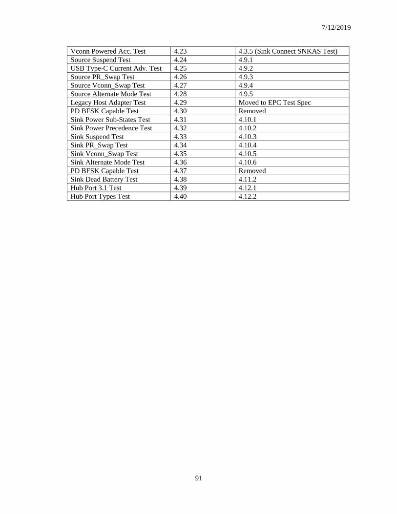
7/12/2019
91
Vconn Powered Acc. Test 4.23 4.3.5 (Sink Connect SNKAS Test)
Source Suspend Test 4.24 4.9.1
USB Type-C Current Adv. Test 4.25 4.9.2
Source PR_Swap Test 4.26 4.9.3
Source Vconn_Swap Test 4.27 4.9.4
Source Alternate Mode Test 4.28 4.9.5
Legacy Host Adapter Test 4.29 Moved to EPC Test Spec
PD BFSK Capable Test 4.30 Removed
Sink Power Sub-States Test 4.31 4.10.1
Sink Power Precedence Test 4.32 4.10.2
Sink Suspend Test 4.33 4.10.3
Sink PR_Swap Test 4.34 4.10.4
Sink Vconn_Swap Test 4.35 4.10.5
Sink Alternate Mode Test 4.36 4.10.6
PD BFSK Capable Test 4.37 Removed
Sink Dead Battery Test 4.38 4.11.2
Hub Port 3.1 Test 4.39 4.12.1
Hub Port Types Test 4.40 4.12.2