universal top-of-pole mount 4 modules (utpm4) … instructions step-by-step assembly and...
TRANSCRIPT

Assembly InstructIons
step-by-step assembly and installation
Assembly InstructIons
step-by-step assembly and installation
Version 1, Rev BSP3330-3 PCN 120516-1
Universal Top-of-Pole Mount 4 Modules (UTPM4)
Module Type G

Assembly Instructions, UTPM4 Type G (Version 2, Rev A) 1
About the product
The UTPM4 for module Type G is designed for a wide range of Module sizes, from 37-42” in width to 61-67” in length. The Universal Top-of-Pole support structure mounts on 4 inch SCH40/80 galvanized steel pipe (installer sup-plied).
Pipe size and foundation requirements are based on several factors including the array surface area, maximum design wind speed, exposure category, soil type, steepest expect-ed tilt angle, and above-ground clearance.
For foundation and pipe size recommenda-tions on a specific installation, please:Visit www.preformed.com and select the TPM online configurator.Contact us by Phone: 800-260-3792Send an Email request: [email protected]
About these instructions:
• These instructions are intended to be used by individuals with sufficient technical skills for the task. Knowledge and use of hand tools, measuring devices and torque values is also required.
• These instructions include various pre-cautions in the forms of Notes, Cautions, and Warnings. These are to assist in the assembly process and/or to draw atten-tion to the fact that certain assembly steps may be dangerous and could cause se-rious personal injury and/or damage to components. Following the step-by-step procedures and these precautions should minimize the risk of any personal injury or damage to components while making the installation not only safe but an efficient process.
Universal Top-of-Pole Mount For 4 Modules (UTPM4) For Module Type G
WARNINGFollow the pro-cedures and precautions in these instructions carefully.
Periodic InspectionPeriodic re-inspection is a recommended system maintenance procedure to check for any loose components and any corrosion. If any loose com-ponents and any corrosion is found, the affected components are required to be replaced immedi-ately, with the original mounting system manufac-turer’s component parts.
Required Tools
o7/16 inch wrench or socket for 1/4 inch module hardware
o9/16 inch wrench or socket for 3/8 inch hardware
o3/4 inch wrench or socket for 1/2 inch hardware
o1-1/8 inch wrench or socket for 3/4 inch Pivot Bolt hardware
oTorque wrench
oRatchet wrench
oRatchet extension bar
o3 to 6 foot level
oTape Measure
oSquare

2 Assembly Instructions, UTPM4 Type G (Version 2, Rev A)
UTPM4 Type G Main Components
There are seven main components and attaching hardware.
Module Rails
Strongback
Cross-Bars
Support Bar
Mounting Sleeve
Single HoleSlide Clamp
Double HoleSlide Clamp
Single HoleSlide Clamp
Double Hole Slide Clamp(secures two adjacent Modules)
There are two types of Module Slide Clamps

Assembly Instructions, UTPM4 Type G (Version 2, Rev A) 3
Universally adjustable to accommodate a range of PV Module sizes
E-W adjustability of Module Rails along the Cross-Bars.
N-S adjustability of Single & Double Hole Slide Clamps along the Module Rails.

4 Assembly Instructions, UTPM4 Type G (Version 2, Rev A)
UTPM4 Type G Parts Identification
Item
Des
crip
tion
Qty
1M
odul
e R
ail
42
3/8”
x 2
” x 2
5/8
” U-B
olt,
lock
& fl
at w
ashe
rs, h
ex n
ut8
sets
3D
oubl
e H
ole
Slid
e P
late
, 3/8
” x 7
/8” H
ex B
olt,
lock
&
flat w
ashe
r, he
x nu
t4
sets
4S
ingl
e H
ole
Slid
e P
late
, 3/8
” x 7
/8” H
ex B
olt,
lock
&
flat w
ashe
r, he
x nu
t8
sets
51/
4” x
3/4
” Bol
t, lo
ck &
flat
was
hers
(2 fl
at w
ashe
rs),
secu
res
PV
Mod
ule
16 s
ets
6C
ross
-Bar
27
Stro
ngba
ck1
8S
uppo
rt B
ar1
93/
8” x
1-3
/4” B
olt,
lock
& fl
at w
ashe
rs (2
flat
was
hers
)2
sets
10M
ount
ing
Sle
eve
1
113/
4” x
5-1
/2” P
ivot
Bol
t, lo
ck &
flat
was
hers
(2 fl
at
was
hers
)1
set
123/
8” x
3 1
/4” B
olt,
lock
& fl
at w
ashe
rs (2
flat
was
hers
)4
sets
133/
8” S
quar
e w
ashe
r4

Assembly Instructions, UTPM4 Type G (Version 2, Rev A) 5
1
2
Calculate Site Specific Dimensions
Calculate and Mark the Rail Positions on Cross-Bars
The dimensions must be taken from the site-specific Modules. The dimensions will be used to calculate the Module Rail positions.
Use the worksheet on the next page to calculate Rail positions on the Cross-Bars. Enter the two dimensions from above and complete the calculations. The resulting dimensions set the Inboard (“I”) and Outboard (“O”) Rail positions which will be measured and marked on the Cross-Bars.
NOTEWhen selecting mounting holes, make certain that the hole diameters accept 1/4” hard-ware as it will be used to secure the PV Modules to the system.

6 Assembly Instructions, UTPM4 Type G (Version 2, Rev A)
2 Calculate and Mark the Rail Positions on Cross-Bars (continued)

Assembly Instructions, UTPM4 Type G (Version 2, Rev A) 7
NOTEUse precision when measuring and marking the Rail positions on the Cross-Bars.
3 Mark the Cross-Bars
Measure and mark the center of the Cross-Bars, then use the calculated dimensions I and O from the previous page to mark off their respective Rail positions. The image below shows these marks and their relationship to the Cross-Bars and Rails after assembly.

8 Assembly Instructions, UTPM4 Type G (Version 2, Rev A)
NOTEUse precision when measuring and marking the Double Hole Slide Plate positions on the Module Rails.
4 Mark the Double Hole Slide Plate Positions on the Rails
Locate the center of the Rails and mark as shown above. These marks are for the four (one-per Rail) Double Hole Slide Plates only. The additional Slide Plates do not require marks as they will be aligned to the Module mounting holes as the Modules are installed.
5 Pre-assemble the Slide Plates
Pre-assemble each of the Slide Plates using a 3/8” x 7/8” Hex Bolt, Flat Washer, Lock Washer, and Hex Nut. Leave the hardware loose for the next step.

Assembly Instructions, UTPM4 Type G (Version 2, Rev A) 9
6 Attach Double Hole Slide Plates to Rails
On each of the four Rails, install the Double Hole Slide Plates to be centered over the previously made mark on the Rails. Insert the head of the Hex Bolt into the Rail Channel as shown and align their centers over the marks. Tighten these four securely and torque at 32-34 ft.-lbs.
7 Attach Single Hole Slide Plates to Rails
Install the two Single Hole Slide Plates in a similar manner, loosely positioning them as shown above. These do not align to any marks or measurements. They will be moved into alignment with the Module mounting holes as the Modules are installed. Hand tighten for now.

10 Assembly Instructions, UTPM4 Type G (Version 2, Rev A)
9 Install the Strongback
Secure Strongback to Mounting Sleeve with Pivot Bolt, two Flat Washers, Lock Washer and Nut. Secure Support Bar to Mounting Sleeve with 3/8” x 1-3/4” Bolt, two Flat Washers, Lock Washer and Nut.
Although this system offers variable elevation set points, for ease of assembly set the angle to 15°. Optimum tilt setting of the rack will take place later in these instructions.
Torque Support Bar hardware to 32-34 ft.-lbs.
8 Install the Mounting Sleeve on Vertical Pipe
N
Slip the Mounting Sleeve on top of the Mounting Pole allowing it to slide down and bottom out on the Pole. Rotate the Mounting Sleeve so that the Support Bar
Pivot Tab is pointing north and the Strongback Vertical Towers are leaning south. Tighten Set Bolts and torque to 32-34 ft-lbs.
CAUTION
CAUTION
This is a two person activity. The Strongback must be held in place by one person while the second person aligns it and secures it to the Mounting Sleeve using the Pivot Bolt and the 1/2” hardware. Failure to do so could lead to serious personal injury.
The Pivot Bolt cannot be left loose - the Mount-ing Sleeve Vertical Towers must be firmly clamped to the sides of the Strongback eliminating any gaps between the Vertical Towers and the Strongback. See the illustration on following page.

Assembly Instructions, UTPM4 Type G (Version 2, Rev A) 11
CAUTIONThis is a two person activity. Cross-Bars are long and unstable before they are fully secured to the Strongback. Cross-Bars must be held in place by one person while the second person aligns and se-cures them to the Strongback. Failure to do so could lead to serious personal injury.
10 Install the Cross-Bars
Tighten the Pivot Bolt closing any visible gaps between the Strongback and the Mounting Sleeve Towers. Torque to 125-150 ft.-lbs.
9 Install the Strongback (continued)
Install the two Cross-Bars with a 3/8” x 3-1/4” Hex Bolt, Square Washer, Flat Washers, Lock Washer and Hex Nut. Tighten and torque to 30-32 ft-lbs.
12 Assembly Instructions, UTPM4 Type G (Version 2, Rev A)
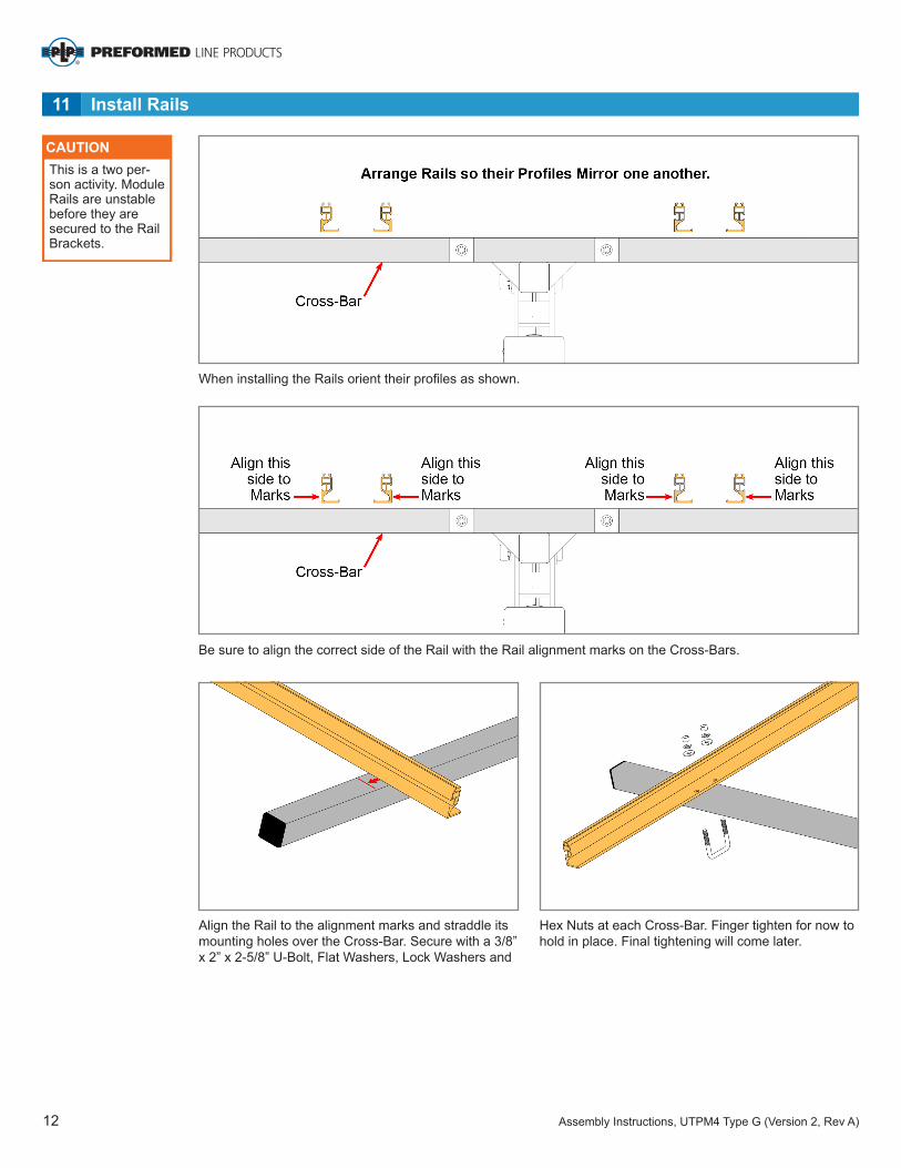
11 Install Rails
CAUTION
When installing the Rails orient their profiles as shown.
Be sure to align the correct side of the Rail with the Rail alignment marks on the Cross-Bars.
Align the Rail to the alignment marks and straddle its mounting holes over the Cross-Bar. Secure with a 3/8” x 2” x 2-5/8” U-Bolt, Flat Washers, Lock Washers and
Hex Nuts at each Cross-Bar. Finger tighten for now to hold in place. Final tightening will come later.
This is a two per-son activity. Module Rails are unstable before they are secured to the Rail Brackets.

Assembly Instructions, UTPM4 Type G (Version 2, Rev A) 13
12 Install Modules
CAUTION
CAUTION
Align Module Mounting Holes with the installed Double Hole Slide Plates and secure Module with 1/4” x 3/4” Hex Bolt, Flat Washers, Lock Washer and Hex Nut. Finger tighten for now. Repeat on opposite Rail.
Loosen Single Hole Slide Plates and align with Module Mounting Hole. Secure Module with 1/4” x 3/4” Hex Bolt, Flat Washers, Lock Washer and Hex Nut. Finger tighten for now. Repeat on opposite Rail. Continue in this manner and install the remaining Modules.
Using a square and visual references, ensure that the array is aligned to the mounting structure. Confirm that the PV Modules are square and have consistent even spaces all around. Adjust if necessary.
Tighten Mounting HardwareA. Return and tighten each set of the 3/8” U-bolts, se-
curing the Module Rails to the Cross-Bars. Torque all to 32-34 ft.-lbs.
B. Return and tighten each of the 3/8” hardware se-curing all of the Slide Clamps (Single and Double Hole) to the Module Rails. Torque all to 32-34 ft.-lbs.
C. Return and tighten each set of 1/4” mounting hardware, securing the PV Modules to the Slide Clamps. Torque all to 6-8 ft.-lbs.
This is a two person activity. Modules are heavy and unstable before they are fully secured to the Module Rails. PV Modules must be held in place by one person while the second person aligns and secures them to the Module Rails. Failure to do so could lead to serious personal injury and damaged components.
Be certain to re-tighten all Module Rail and PV Module mounting hardware and torque to the specified values. Failure to do so could lead to structural failure, damaged components and/or serious personal injury.
13 Square and Align the Array. Return and Tighten Mounting Hardware

14 Assembly Instructions, UTPM4 Type G (Version 2, Rev A)
B. Tilt the rack to the desired elevation angle (15°, 25°, 35°, 45°, 55° or 65°) and reinstall the 3/8” hardware securing the Support Bar to the Strong-
C. Re-tighten the Pivot Bolt. The Pivot Bolt cannot be left loose - the Mounting Sleeve Vertical Towers must be firmly clamped to the sides of the Strong-back eliminating any gaps between the Vertical
A. While one person holds the south edge of rack, the other loosens the Pivot Bolt and the hardware se-curing the lower end of the Support Arm Hardware.
WARNINGDo not attempt to remove the Pivot Bolt during tilt adjustments! Removal could lead to serious personal injury or death. Adjustments are made with the Pivot Bolt hardware loosened but in place.
14 Adjust the Array Tilt Angle
CAUTIONThis is a two person activity. As the hardware is loosened, the rack is heavy and unsta-ble. The rack must be held in place by one person while the second person loosens the hardware and then re-installs and tightens the hardware back in place. Failure to do so could lead to serious personal in-jury and damaged components. back. Tighten hardware (at both ends of Support
Bar) and Torque to 32-34 ft.-lbs.
Now remove the upper 3/8” hardware attaching the Support Bar to the Strongback.
Towers and the Strongback. Torque to 125-150 ft.-lbs.

Corporate Headquarters660 Beta DriveMayfield Village, OH 44143
Albuquerque Office1700 Louisiana Blvd., Suite 130Albuquerque, NM 87110
Telephone: 800.260.3792Fax: 505.889.3548www.preformed.comE-mail: [email protected]
© 2017 Preformed Line ProductsPCN 120516-1 Version 1, Rev BSP3330-3