universitÀ degli studi di padova -...
TRANSCRIPT
UNIVERSITÀ DEGLI STUDI DI PADOVA
DIPARTIMENTO DI TECNICA E GESTIONE DEI SISTEMIINDUSTRIALI
CORSO DI LAUREA MAGISTRALE IN INGEGNERIAMECCATRONICA
TESI DI LAUREA MAGISTRALE
Software in C++ for communicationbetween CAN bus and ROS in a robot
vehicle
Relatore: Monica Reggiani
Correlatore: Sami Terho, Aalto University - Finland
Laureando: Alex Battiston1034764-IMC
ANNO ACCADEMICO: 2014-15
S U M M A RY
The project has the aim to develop a C++ software for a robot vehicle in areal time system for management the communication between the CAN busand ROS. During development test measure the efficacy, in terms of time andmessages exchanged, several versions of software to test the communicationvia CAN bus the libraries provided by the PC manufacturer. In addition, it hasalso been tested software solutions that use, with different combinations, mu-tex and condition variables during the phases of sending and receiving. Fromthe analysis of the experiments it has been found that, for this architecture, themost efficiently communication via CAN bus has been obtained using mutexand condition variables during the sending of the CAN message.
.
W O R D S O F T H A N K S
Dedicated to my mom.

C O N T E N T S
1 introduction 5
2 autonomous vehicles 7
2.1 Introduction . . . . . . . . . . . . . . . . . . . . . . . . . . . . . . . 7
2.2 Levels . . . . . . . . . . . . . . . . . . . . . . . . . . . . . . . . . . . 7
2.3 History . . . . . . . . . . . . . . . . . . . . . . . . . . . . . . . . . . 8
2.4 Research . . . . . . . . . . . . . . . . . . . . . . . . . . . . . . . . . 10
2.5 Benefits . . . . . . . . . . . . . . . . . . . . . . . . . . . . . . . . . . 10
2.6 Technology . . . . . . . . . . . . . . . . . . . . . . . . . . . . . . . . 11
2.7 Estimated cost . . . . . . . . . . . . . . . . . . . . . . . . . . . . . . 14
2.8 Transform car in autonomous vehicle . . . . . . . . . . . . . . . . 14
2.9 ATV . . . . . . . . . . . . . . . . . . . . . . . . . . . . . . . . . . . . 14
3 can bus and j1939 17
3.1 Controller area network (CAN) . . . . . . . . . . . . . . . . . . . . 17
3.2 Features of CAN . . . . . . . . . . . . . . . . . . . . . . . . . . . . 17
3.3 ISO layers . . . . . . . . . . . . . . . . . . . . . . . . . . . . . . . . 19
3.3.1 Physical layer . . . . . . . . . . . . . . . . . . . . . . . . . . 19
3.3.2 Data-link layer . . . . . . . . . . . . . . . . . . . . . . . . . 20
3.4 Technology . . . . . . . . . . . . . . . . . . . . . . . . . . . . . . . . 21
3.4.1 Types of Frames . . . . . . . . . . . . . . . . . . . . . . . . . 22
3.5 J1939 . . . . . . . . . . . . . . . . . . . . . . . . . . . . . . . . . . . 23
3.5.1 ID . . . . . . . . . . . . . . . . . . . . . . . . . . . . . . . . . 23
3.5.2 Group Number . . . . . . . . . . . . . . . . . . . . . . . . . 26
3.6 ATV’s CAN architecture . . . . . . . . . . . . . . . . . . . . . . . . 27
4 hardware 29
4.1 Vehicle . . . . . . . . . . . . . . . . . . . . . . . . . . . . . . . . . . 29
4.2 Sensor . . . . . . . . . . . . . . . . . . . . . . . . . . . . . . . . . . 29
4.2.1 Angle of steering . . . . . . . . . . . . . . . . . . . . . . . . 29
4.2.2 Speed . . . . . . . . . . . . . . . . . . . . . . . . . . . . . . . 29
4.3 Control Unit . . . . . . . . . . . . . . . . . . . . . . . . . . . . . . . 30
4.4 Embedded system . . . . . . . . . . . . . . . . . . . . . . . . . . . . 30
4.5 LiDAR . . . . . . . . . . . . . . . . . . . . . . . . . . . . . . . . . . 31
4.6 Bumblebees XB3 . . . . . . . . . . . . . . . . . . . . . . . . . . . . . 31
4.7 Kvaser Leaf Light HS . . . . . . . . . . . . . . . . . . . . . . . . . . 33
4.8 Network architecture . . . . . . . . . . . . . . . . . . . . . . . . . . 33
5 communication 35
5.1 ROS . . . . . . . . . . . . . . . . . . . . . . . . . . . . . . . . . . . . 35
5.1.1 Topic . . . . . . . . . . . . . . . . . . . . . . . . . . . . . . . 35
5.2 Service . . . . . . . . . . . . . . . . . . . . . . . . . . . . . . . . . . 37
5.3 CAN library . . . . . . . . . . . . . . . . . . . . . . . . . . . . . . . 37
5.3.1 CAN message format . . . . . . . . . . . . . . . . . . . . . 37
5.3.2 sendCanMessage . . . . . . . . . . . . . . . . . . . . . . . . 38
5.3.3 getCanMessage . . . . . . . . . . . . . . . . . . . . . . . . . 38
3
5.4 Ackermann . . . . . . . . . . . . . . . . . . . . . . . . . . . . . . . . 38
5.4.1 Ackermann geometry . . . . . . . . . . . . . . . . . . . . . 38
5.4.2 AckermannDrive Message . . . . . . . . . . . . . . . . . . . 39
6 implementation 41
6.1 Introduction . . . . . . . . . . . . . . . . . . . . . . . . . . . . . . . 41
6.2 startCommunication . . . . . . . . . . . . . . . . . . . . . . . . . . 41
6.3 communication . . . . . . . . . . . . . . . . . . . . . . . . . . . . . 41
6.4 CAN.cpp . . . . . . . . . . . . . . . . . . . . . . . . . . . . . . . . . 42
6.5 CAN.h . . . . . . . . . . . . . . . . . . . . . . . . . . . . . . . . . . 42
6.6 parameterCar.h . . . . . . . . . . . . . . . . . . . . . . . . . . . . . 42
6.7 CANsimulator.exe . . . . . . . . . . . . . . . . . . . . . . . . . . . 42
7 experiments and results 45
7.1 Experiments . . . . . . . . . . . . . . . . . . . . . . . . . . . . . . . 45
7.2 Groups . . . . . . . . . . . . . . . . . . . . . . . . . . . . . . . . . . 45
7.3 Codes and versions . . . . . . . . . . . . . . . . . . . . . . . . . . . 46
7.4 Results . . . . . . . . . . . . . . . . . . . . . . . . . . . . . . . . . . 49
8 conclusion 53
Appendix a communication 55
a.1 CAN library . . . . . . . . . . . . . . . . . . . . . . . . . . . . . . . 55
a.2 AckermannDrive Message . . . . . . . . . . . . . . . . . . . . . . . 56
Appendix b ros 57
b.1 Topic . . . . . . . . . . . . . . . . . . . . . . . . . . . . . . . . . . . 57
b.2 Service . . . . . . . . . . . . . . . . . . . . . . . . . . . . . . . . . . 59
Appendix c codes and versions 63
Appendix d implementation 67
d.1 startCommunication.cpp . . . . . . . . . . . . . . . . . . . . . . . . 67
d.2 communication . . . . . . . . . . . . . . . . . . . . . . . . . . . . . 69
d.3 ./CAN.cpp . . . . . . . . . . . . . . . . . . . . . . . . . . . . . . . . 69
d.4 ./CAN.h . . . . . . . . . . . . . . . . . . . . . . . . . . . . . . . . . 75
d.5 ./parameterCar.h . . . . . . . . . . . . . . . . . . . . . . . . . . . . 77
Appendix e user guide 79
4
L I S T O F F I G U R E S
Figure 1 First test model of an autonomous car in the 1960s . . . . 8
Figure 2 Google’s driverless car, a modified Toyota Prius . . . . . 9
Figure 3 Shows self-driving applications plotted along two di-mensions: the degree of autonomy and the degree ofcooperation . . . . . . . . . . . . . . . . . . . . . . . . . . 12
Figure 4 Placement of Hardware . . . . . . . . . . . . . . . . . . . . 12
Figure 5 ISO OSI model . . . . . . . . . . . . . . . . . . . . . . . . . 19
Figure 6 CAN bus: 9-Pin D, CAN Bus Pin Out . . . . . . . . . . . 20
Figure 7 The layered ISO 11898:1993 standard Architecture . . . . 21
Figure 8 Scheme of levels of communication . . . . . . . . . . . . . 23
Figure 9 Detailed structure of Frame format . . . . . . . . . . . . 24
Figure 10 A complete structure of the frame format, ID and PNG . 26
Figure 11 PDU Format and PDU Specific . . . . . . . . . . . . . . . 27
Figure 12 ATV’s CAN network topology . . . . . . . . . . . . . . . 27
Figure 13 Polaris Ranger EV . . . . . . . . . . . . . . . . . . . . . . . 29
Figure 14 Encoder RM9000 . . . . . . . . . . . . . . . . . . . . . . . 30
Figure 15 EPEC 5050 . . . . . . . . . . . . . . . . . . . . . . . . . . . 30
Figure 16 Acrosser AIV-HM76V0FL . . . . . . . . . . . . . . . . . . 31
Figure 17 Lidar . . . . . . . . . . . . . . . . . . . . . . . . . . . . . . 32
Figure 18 View from Lidar’s scan . . . . . . . . . . . . . . . . . . . . 32
Figure 19 Bumblebee XB3 . . . . . . . . . . . . . . . . . . . . . . . . 33
Figure 20 Kvaser Leaf Light HS . . . . . . . . . . . . . . . . . . . . . 33
Figure 21 ATV’s network architecture . . . . . . . . . . . . . . . . . 34
Figure 22 ROS’s level . . . . . . . . . . . . . . . . . . . . . . . . . . . 36
Figure 23 Ackermann geometry . . . . . . . . . . . . . . . . . . . . . 39
Figure 24 Window of the program CANsimulator.exe . . . . . . . . 43
L I S T O F TA B L E S
Table 1 Bus length and signaling rate . . . . . . . . . . . . . . . . 20
Table 2 Frame format of J1939 . . . . . . . . . . . . . . . . . . . . 24
Table 3 Frame format of J1939 . . . . . . . . . . . . . . . . . . . . 25
Table 4 Abbreviation of typology of code . . . . . . . . . . . . . . 46
Table 5 1REC_S-2SEND_CMy_W . . . . . . . . . . . . . . . . . . . 46
Table 6 1REC_W-2SEND_CMy_S . . . . . . . . . . . . . . . . . . . 47
Table 7 1REC_WS-2SEND_CMy_WS . . . . . . . . . . . . . . . . 47
Table 8 1REC_S-2SEND_CMn_W . . . . . . . . . . . . . . . . . . 47
Table 9 1REC_W-2SEND_CMn_S . . . . . . . . . . . . . . . . . . . 47
5

Table 10 1REC_WS-2SEND_CMn_WS . . . . . . . . . . . . . . . . 48
Table 11 1REC_-2SEND . . . . . . . . . . . . . . . . . . . . . . . . . 48
Table 12 1REC_-1SEND . . . . . . . . . . . . . . . . . . . . . . . . . 48
Table 13 1REC_S-1SEND_W . . . . . . . . . . . . . . . . . . . . . . 48
Table 14 1REC_W-1SEND_S . . . . . . . . . . . . . . . . . . . . . . 49
Table 15 1REC_WS-1SEND_WS . . . . . . . . . . . . . . . . . . . . 49
Table 16 Results of the experiment . . . . . . . . . . . . . . . . . . 51
Table 17 RMS values of the experiments . . . . . . . . . . . . . . . 52
6

1I N T R O D U C T I O N
Autonomous vehicle is capable of sensing its environment and navigatingwithout human input and the ATV (all terrain vehicle) project has transformedan electronic four-wheel vehicle in a robot which, autonomously, is able to fol-low a person who walks in front of it and drive by itself without the humancontrol [1][2]. The motivation behind this idea is to help a person to carry peo-ple or carriage transportation, may it be luggage, boxes, groceries, etc. Thisidea also proves to be very useful for handicap/disabled applications, or alsofor driving the vehicle with a remote control like smartphone. This work isa part of the ATV project to equip with sensors and actuators which enablethe higher level system to control ATV’s motions and therefore enable twoautonomous main actions: follow a user and avoid obstacles in real time inoutdoor environment. In order for the autonomous vehicle to achieve thesefeatures, the system is implemented with a combination of computer vision,distance sensors and controls software algorithm.The aim of this thesis is to develop the C++ code written for the robot car withthe purpose of interfacing the communication between the CAN bus withodometry-based motion measurement and localisation, and the software forplanning trajectory via ROS.Data detected from car’s sensor are sent through the interface of this softwareto planning controller trajectory layer which generates a path and sends theinformation of angle of steering and speed to the vehicle.The overview of autonomous vehicles has been done in the first chapter whereit is defined the robot car, its history of the past, present and the future of them,the technology and benefits. The chapter number two introduce and describein detail the CAN bus and the protocol J1939, both adopted for this project.Entering into the project, the hardware chapter describes the components ofthe vehicle that allow the car to be autonomous. The fourth chapter focus onthe software used, it explains the communication with ROS framework and an-alyzes and exposes the libraries used for developing the communication withthe CAN bus and the tools used in the ROS frameworks, in addition in thischapter is discussed the geometry of the car involves the use of the geometryof Ackerman. The developed software is described in the fifth chapter. Theexperiments and the results obtained for developing the software are exposedin the 6th chapter and different versions of the software have been tested fordiscover which version allows the best management of communication. Theexperiments investigates whether the presence of condition variables producepositive or negative effects. The conclusion of the experiments are in the sev-enth and last chapter and concludes that the presence of variable conditions,for this system, allow a good performance of exchanging messages in the pres-ence of them only in the functions of sending message with the CAN bus.
7


2A U T O N O M O U S V E H I C L E S
2.1 introduction
An autonomous vehicle is defined as a passenger vehicle that drives by it-self. An autonomous vehicle is an unmanned vehicle with some level of au-tonomy build in front teleoperations to fully intelligent systems. Unmannedaerial vehicles (UAVs), unmanned surface vehicles (USVs), unmanned under-sea vehicles (UUVs) and unmanned ground vehicles (UGVs) have some levelof autonomy build in and it is common to call them with the acronym "AV"to refer to all such autonomous vehicles. A autonomous vehicles (also calleddriverless, driver-free, self-driving, autopiloted or robot) is a self-piloted vehi-cle that does not require an operator to navigate and accomplish its tasks. Afully autonomous car can be defined as a car which is able to perceive its en-vironment, decide what route to take to its destination and drive it. With therecent develop of technology and robotics allow significant changes to travelin ground, air and submarine without the need for human supervision or op-eration, everyone in the car could be a passenger, or it could even drive withno occupants at all [3].
2.2 levels
National Highway Traffic Safety Administration (NHTSA), in 2013, released afive-tiered system for automated vehicle classification [4]:
• No automation (Level 0) - The driver is in complete and sole control ofthe primary vehicle controls over steering, braking and throttle, althoughvehicle may provide warnings, at all times.
• Function-specific Automation (Level 1): Automation at this level involvesone or more specific control functions. For example of specific controlfunctions, such as cruise control, lane guidance, electronic stability con-trol, automated parallel parking or pre-charged brakes, where the vehicleautomatically assists with braking to enable the driver to regain controlof the vehicle or stop faster than possible by acting alone. Drivers arefully engaged and responsible for overall vehicle control (hands on thesteering wheel and foot on the pedal at all times).
• Combined Function Automation (Level 2): Automation of multiple andintegrated control functions, such as adaptive cruise control with lanecentering and traffic jam assistance. Drivers are responsible for moni-toring the roadway and are expected to be available for control at alltimes, but under certain conditions can disengaged from vehicle opera-tion (hands off the steering wheel and foot off pedal simultaneously).
9

• Limited Self-Driving Automation (Level 3): Vehicles, at this level of au-tomation, enable the driver to cede full control of all safety-critical func-tions under certain traffic or environmental conditions and in those con-ditions to rely heavily on the vehicle to monitor for changes in thoseconditions requiring transition back to driver control. Drivers are not ex-pected to constantly monitor the roadway, but with sufficiently comfort-able transition time. The Google car is an example of limited self-drivingautomation.
• Full Self-Driving Automation (Level 4): Vehicles can perform all drivingfunctions and monitor roadway conditions for an entire trip. Driver willprovide destination or navigation input, but is not expected to be avail-able for control at any time during the trip, so the vehicle can operatewith occupants who cannot drive and without human occupants.
2.3 history
For 125 years the automotive industry has been a force for innovation andeconomic growth. Now, in the early decades of the 21 st century, the new tech-nologies and the innovation is speeding up the entry of self-driving vehiclesin the daily life.Autonomous vehicles have existed as prototypes and demonstration vehiclessince the 1960s.In 1962 Robert Fenton, Pioneer of autonomous vehicle, with his team at theOhio State University built the first automated vehicle (Figure 1), which is alsobelieved to be the first land vehicle to have a computer [5]. Fenton had his self-driving cars stay on course by following a current-carrying wire laid downin the center of the roadway. A large protuberance packed with electronics tosense the current stuck out from the bumper of his early models.
Figure 1: First test model of an autonomous car in the 1960sImage from http://theinstitute.ieee.org/people/achievements/the-drivers-
behind-autonomous-vehicles
10

In 1977 Tsukuba Mechanical engineering lab built the first self-driving vehi-cle. The car achieved the speeds of up to 30 km per hour by tracking whitestreet markers for up to 50 meters.In 2004 DARPA’s Grand Challenge was launched with the goal of demonstrat-ing AV technical feasibility by navigating a 150-mile route. While the best teamcompleted just over seven miles, one year later five driverless cars successfullynavigated the route. In 2007, six teams finished the new Urban Challenge,with AVs required to obey traffic rules, deal with blocked routes, and maneu-ver around fixed and moving obstacles, together providing realistic every-day-driving scenarios.
Nowdays, the recent high profile demonstrations by automobile manufac-turers and university research groups, and by Google, have intensified interestin the technology. A fully autonomous vehicle capable of completing an entirejourney on public roads without any human interaction has already been re-alised (Figure 2). In 2012 in California and Nevada, Google’s engineers havealready tested self-driving cars on more than 300.000 kilometers in public high-ways and roads. Google’s cars not only record images of the road, but theircomputerized maps view road signs, find alternative routes and see trafficlights before they’re even visible to a person.
Figure 2: Google’s driverless car, a modified Toyota PriusImage from en.wikipedia.org/wiki/Google_driverless_car
Auto manufacturers are running to keep up. Semi autonomous features arenow commercially available, including adaptive cruise control (ACC), lane de-parture warnings, collision avoidance, parking assist systems and on-boardnavigation.
Companies as KPMG, CAR, Google, Nissan, Volvo, General Motors, Ford,Volkswagen/Audi, Nissan, Toyota, BMW, Volvo, Cadillac, and Mercedes-Benz(which, like car2go, is a subsidiary of Daimler) have all begun testing these sys-
11

tem driveerless and AVs probably will be driving on our streets and highwayswithin the next decade.
2.4 research
Other important research gaps have been identified, with broad topic areasoutlined at the 2013 Road Vehicle Automation Workshop, [6] as follows:
• Automated commercial vehicle operations
• Cyber security and resiliency
• Data ownership, access, protection, and discovery
• Energy and environment
• Human factors and human-machine interaction
• Infrastructure and operations
• Liability, risk, and insurance
• Shared mobility and transit
• Testing, certification, and licensing
• V2X communication and architecture
2.5 benefits
Technology in AVs will brings advantages for the daily life and many advan-tages for the security during in according with [7] and [8].
The new technologies could provide solutions to safe drive and to some ofour most unmanageable social problems like the high cost of traffic crashesand transportation infrastructure, the large amount of hours wasted in trafficjams and the wasted urban space given over to parking lots.
• Crash elimination: Autonomous vehicles technology have the potentialto dramatically reduce crashes. System failure may remain a possibility,but convergence also implies a multitude of redundant systems that cansubstitute for one another and yield safe operation even when failuresoccur.
• Travel Time Dependability: Anticipated travel time is the most useful in-formation to support trip decisions and assess the operational status ofa transportation network, and convergence provides the opportunity toeliminate, or at least substantially reduce, uncertainty in travel times.Non recurrent congestion can account for as much as 30 percent of thedelay faced by drivers.In addition, with unpredictable traffic patterns, traffic congestion can oc-cur at any time of day.
12
With the surface transportation network composed of self- driving vehi-cles linked electronically and via communications, the intelligent trans-portation system of the future will be able to provide each vehicle witha reliable and predictable path from origin to destination.
• Improved Energy Efficiency: In an autonomous vehicle transportationsystem, vehicles will navigate far more efficiently than current humanoperators do.The inefficiency of human-driven vehicles leads to considerable conges-tion at high traffic volumes and frequent traffic jams.Moreover historically vehicle safety driver and passenger safety espe-cially has focused on crash worthiness. This shift means that at somepoint, self-driving vehicles will no longer require significant amounts ofstructural steel, roll cages, or air bags, among other safety features andwith the result of having vehicles significantly lighter and more energywith the result of increase fuel efficiency and reduce pollution emissions.
• Driver comfort: Let and trust in a autonomous vehicle reduce the stressof driving and allow motorists to rest or work while travelling.
• Cost: Increased safety, may reduce many common accident risks andtherefore crash costs and insurance premiums.Increased road capacity, reduced costs.May allow platooning (vehicle groups travelling close together) , nar-rower lanes, and reduced intersection stops, reducing congestion androadway costs. Also more efficient parking, reduced costs.
• Society: May provide independent mobility for those too young to drive,the elderly, the disabled and non drivers.
2.6 technology
A significant portion of robotics research involves developing autonomous car-like robots. This research is often at the forefront of innovation and technologyin many areas.
Today’s researchers are using sensors and advanced software together withother custom-made hardware in order to assemble autonomous cars.
Although the prototypes seem to be very successful, a fully autonomouscar that is reliable enough to be on the streets has not been constructed yet.While better hardware is being developed there are important limitations onthe artificial intelligence side of the research. It would be fair to say that thefuture of the autonomous cars mostly depends on the development of betterartificial intelligence software.
There are at least four important technology trends shaping the next gener-ation of vehicles [9]:
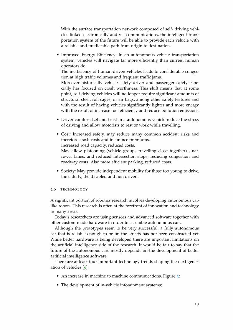
• An increase in machine to machine communications, Figure 3;
• The development of in-vehicle infotainment systems;
13
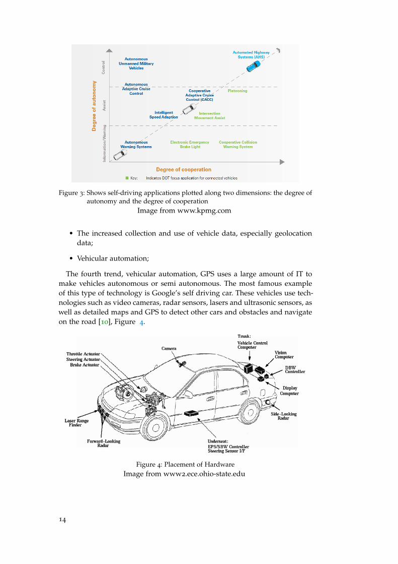
Figure 3: Shows self-driving applications plotted along two dimensions: the degree ofautonomy and the degree of cooperation
Image from www.kpmg.com
• The increased collection and use of vehicle data, especially geolocationdata;
• Vehicular automation;
The fourth trend, vehicular automation, GPS uses a large amount of IT tomake vehicles autonomous or semi autonomous. The most famous exampleof this type of technology is Google’s self driving car. These vehicles use tech-nologies such as video cameras, radar sensors, lasers and ultrasonic sensors, aswell as detailed maps and GPS to detect other cars and obstacles and navigateon the road [10], Figure 4.
Figure 4: Placement of HardwareImage from www2.ece.ohio-state.edu
14

Autonomous cars need to do basically two things: find their way and drive.For achieves these two targets driverless vehicles require equipment and services[12]:
• Automatic transmissions.
• Diverse and redundant sensors (optical, infrared, radar, ultrasonic, lidarand laser) capable of operating in diverse conditions (rain, snow, un-paved roads, tunnels, etc.) for obtain the complete map of its surround-ing area including the objects and the travel path defined in that area:
– Radar sensors: Radar sensors are mainly used to detect various ob-stacles.
– Cameras: Currently used for distinguishing the lanes and backupassistance, but as the image processing software gets more devel-oped, the importance of cameras on board will increase.
– Image-processing software currently can detect traffic signs andlights, lane stripes, and other objects.
– Ultrasound Sensor: Currently ultrasound sensors are mainly usedfor detecting obstacles in front and back of the car while manuallyor automatically parking the car.
– Laser range Finder (Lidar): Lasers that spin in order to constantlytake horizontal distance measurements.
• Wireless networks. Short range systems for vehicle to vehicle communi-cations, and long range systems to access to maps, software upgrades,road condition reports and emergency messages.
• Navigation including GPS systems and special maps.
– GPS Units: Global Positioning System is used for determining acar’s location by getting input from satellites.
• Accelerometer: Helps with navigation of the car when the signal receivedfrom GPS devices are poor.
• Wheel Sensor: Also used in Stability and Anti Lock braking systems,another use of the wheel sensors is to keep track of vehicle’s locationwhen the GPS systems are temporarily unavailable due to poor signals.
• Automated controls (steering, braking, signals, etc.).
• Servers, software and power supplies with high reliability standards.
• Additional testing, maintenance and repair costs for critical components,such as automated testing and cleaning of sensors.
2.7 estimated cost
One barrier to large-scale market adoption is the cost of AV platforms. Google’srobotic cars have about $150,000 in equipment including a $70,000 LiDaR
15

(Light Detection and Ranging) system [11]. The costs of autonomous vehi-cle will take into account the require of a variety special equipment, includ-ing sensors, communication, computers, controls technology and software foreach car, which, for avoiding the system failures could be fatal to both vehicleoccupants and other road users, all these critical components will need highmanufacturing, installation, repair, testing and maintenance standards, similarto aircraft components and so will probably be relatively expensive. Currentlyall the equipment cost tens of thousands of euro, but, as with electric vehicles,they will become cheaper with mass production.
2.8 transform car in autonomous vehicle
Most autonomous vehicle projects made use of stock cars and modified themadding hardware to create a robot cars. Transform a normal car in a au-tonomous car is possible buying a conversion kit, for example from compa-nies like Kairos Autonomi, Torc Robotics, Gnius, Ruag Defence’s Vero, IsraelAerospace Industrie, Asi Robots etc., that can transform any steered vehicleinto an autonomous unmanned ground vehicle. The kits include all comput-ing modules, localisation module, and relevant software in charge of process-ing sensor data and autonomous decision making that make autonomous op-erations possible. Kairos Autonomi developed its kit to provide by-wire capa-bilities to manned vehicles. The core of the system is made of an electronicunit, a steering ring, and actuators for brake, throttle and transmission. Nu-merous other utility modules are available such as video server, power overEthernet, analog and digital input/output, while the roof mount can includeGPS, camera, inertial unit, Ethernet radio, etc. Sahar, projected from IsraelAerospace Industrie’s Lahat Division, is a system that transforms remote de-vices into autonomous combat engineering systems to reduce unexploded ord-nance disposal and mine-clearance personnel exposure. The high level of ac-curacy required, and the heavy data and information flow exchanged withthe operator slow down the use of remotely controlled robots. Able to per-form autonomous driving and autonomous manipulator operations, the Saharcan handle the whole route clearance process including environmental terrainmapping, surveillance, road blocks removal and bomb disposal. The accuracyof manipulator operations are based on real-time sensors and mapping, thatprovide superior performances compared to operations based on camera pic-tures.
2.9 atv
Many companies and organizations are spending a lot of time and moneydeveloping autonomous vehicles for numerous applications. ATV (All TerrainVehicle) project has the purpose to built a low cost autonomous vehicle controlsystem with the task to automatize an all terrain vehicle to follow a person whowalks in front itself, avoid obstacles interpreting the environment by gatheringinformations from its sensors and keep the correct distance. ATV has been
16
equipped with sensors and actuators that enable higher level system to con-trol ATV’s motions and therefore enable autonomous actions. These shouldinclude steering and speed control, odometry-based motion measurement andlocalisation.
17


3C A N B U S A N D J 1 9 3 9
3.1 controller area network (can)
CAN bus communication for in-vehicle networks is very widespread becauseit is simple, efficient and robust. CAN, which stands for Controller Area Net-work, is a low-level serial data communication protocol for embedded real-time applications internationally standardized by International Standardiza-tion Organization (ISO). The Controller Area Network was developed in themid 1980s by Bosch GmbH, to provide a cost-effective communications busfor automotive applications, but is used also in factory and plant controls, inrobotics, medical devices and also in some avionics systems. The communica-tion between controllers, sensors and actuators uses CAN bus that allows alldevices to be connected with any other device on a common serial bus.CAN is a fine solution for embedded control systems because of its simple im-plementation, light protocol management, wide data consistency, the possibil-ity of assigning priority to messages and guaranteed maximum latency times.Also, there are built-in features for error detection (CRC, parity and framingerror checks), signalling with automatic retransmission of corrupted messages,detection a possible permanent failures of nodes and automatic switching offthe defective nodes. Another main advantages of using CAN technology asa field-bus is reduced wiring (CAN requires only two wires between nodes)and it allows to reduce production cost. The standard of CAN has been devel-oped with the objective to have an asynchronous multi-master serial data busthat uses Carrier Sense Multiple Access / Collision Resolution (CSMA/CR) todetermine access to the bus with bit-oriented synchronization.
3.2 features of can
The CAN protocol has the following features.
3.2.0.1 Multimaster
When the bus is free, all of the units connected to it can start sending a mes-sage (multimasters). The unit that first started sending a message to the busis granted the right to send (CSMA/CR method *1 ). If multiple units startsending a message at the same time, the unit that is sending a message whoseID has the highest priority is granted the right to send.
3.2.0.2 Message transmission
In CAN protocol all messages are transmitted in predetermined format. Whenthe bus is unoccupied, all units connected to the bus can start sending a new
19
message. If two or more units start sending a message at the same time, theirpriority is resolved by an identifier (hereafter the ID). The ID does not indicatethe destination to which a message is sent, but rather indicates the priorityof messages in which order the bus is accessed. If two or more units start amessage at the same time, contention for the bus is arbitrated according tothe ID of each message by comparing the IDs bitwise. The unit that won thearbitration (i.e., the one that has the highest priority) can continue to send,while the units that lost in arbitration immediately stop sending and go to areceive operation.
3.2.0.3 System flexibility
The units connected to the bus have no identifying information like an ad-dress. Therefore, when a unit is added to or removed from the bus, there is noneed to change the software, hardware, or application layer of any other unitconnected to the bus.
3.2.0.4 Communication speed
Any communication speed can be set that suits the size of a network. Withinone network, all units must have the same communication speed. If any unitwith a different communication speed is connected to the network, it will gen-erate an error, hindering communication in the network. This does not applyto units in other networks, however.
3.2.0.5 Remote data request
Data transmission from other units can be requested by sending a "remoteframe" to those units.
3.2.0.6 Error detection, error notification, and error recovery functions
All units can detect an error (error detection function). The unit that has de-tected an error immediately notifies all other units of the error simultaneously(error notification function). If a unit detects an error while sending a message,it forcibly terminates message transmission and notifies all other units of theerror. It then repeats retransmission until the message is transmitted normally(error recovery function).
3.2.0.7 Error confinement
There are two types of errors occurring in the CAN: a temporary error wheredata on the bus temporarily becomes erratic due to noise from outside or forother reasons, and a continual error where data on the bus becomes contin-ually erratic due to a unit’s internal failure, driver failure, or disconnections.The CAN has a function to discriminate between these types of errors. Thisfunction helps to lower the communication priority of an error-prone unit inorder to prevent it from hindering communication of other normal units, and
20

if a continual data error on the bus is occurring, separate the unit that is thecause of the error from the bus.
3.2.0.8 Connections
The CAN bus permits multiple units to be connected at the same time. Thereare no logical limits to the number of connectable units. However, the numberof units that can actually be connected to a bus is limited by the delay timeand electrical load in the bus. A greater number of units can be connected byreducing the communication speed. Conversely, if the communication speedis increased, the number of connectable units decreases.
3.3 iso layers
As described in the official Bosch specification document [13], the main proto-col features covers only the Physical and Data link layers. The CAN protocolhas been standardized by ISO, so that there are several ISO standards for CANsuch as ISO11898 and ISO11519-2. ISO11898 is a standard for high-speed CANcommunication and ISO11519, instead, is a standard for low-speed CAN com-munication with maximum speed 125 kbps.
Image fromen.wikipedia.org/wiki/OSI_model
Figure 5: ISO OSI model
Later, ISO provided its own specification of the CAN protocol, with addi-tional details on the implementation of the physical layer, it defines how bitsare encoded into (electrical or electromagnetic) signals with defined physicalcharacteristics, to be transmitted over wired or wireless links from one nodeto another.
3.3.1 Physical layer
The Physical Layer is the basic hardware required for a CAN network, i.e. theISO-11898-2 electrical specifications. It converts 1 and 0 into electrical pulses
21
leaving a node, then back again for a CAN message entering a node. The pro-tocol defines for this layer the manner also the bit timing, bit encoding, andsynchronization procedures. Although the other layers may be implementedin software or in hardware as a chip function, the Physical Layer is alwaysimplemented in hardware [14]. ISO-11898-2 specifies a line topology, with in-dividual nodes connected using short stubs, Table 1.
Bus Length (m) Signaling Rate (Mbps)
40 1
100 0.5
200 0.25
500 0.10
100 0.05
Table 1: Bus length and signaling rate
However, at lower data rates, potentially much longer lines are possible. Inaddition, are specified also termination, isolation and stress protection of thecable.
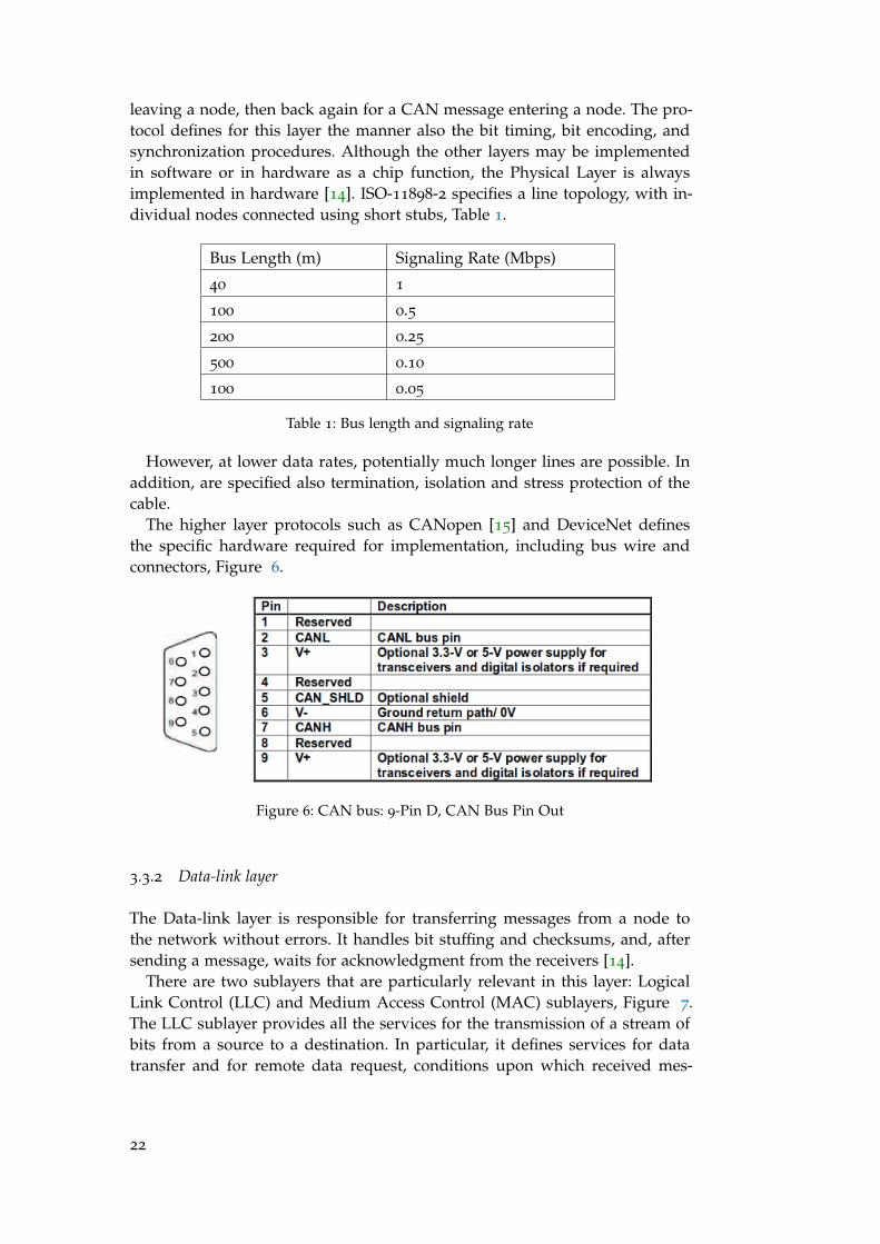
The higher layer protocols such as CANopen [15] and DeviceNet definesthe specific hardware required for implementation, including bus wire andconnectors, Figure 6.
Figure 6: CAN bus: 9-Pin D, CAN Bus Pin Out
3.3.2 Data-link layer
The Data-link layer is responsible for transferring messages from a node tothe network without errors. It handles bit stuffing and checksums, and, aftersending a message, waits for acknowledgment from the receivers [14].
There are two sublayers that are particularly relevant in this layer: LogicalLink Control (LLC) and Medium Access Control (MAC) sublayers, Figure 7.The LLC sublayer provides all the services for the transmission of a stream ofbits from a source to a destination. In particular, it defines services for datatransfer and for remote data request, conditions upon which received mes-
22
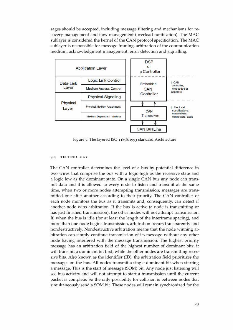
sages should be accepted, including message filtering and mechanisms for re-covery management and flow management (overload notification). The MACsublayer is considered the kernel of the CAN protocol specification. The MACsublayer is responsible for message framing, arbitration of the communicationmedium, acknowledgment management, error detection and signalling.
Figure 7: The layered ISO 11898:1993 standard Architecture
3.4 technology
The CAN controller determines the level of a bus by potential difference intwo wires that comprise the bus with a logic high as the recessive state anda logic low as the dominant state. On a single CAN bus any node can trans-mit data and it is allowed to every node to listen and transmit at the sametime, when two or more nodes attempting transmission, messages are trans-mitted one after another according to their priority. The CAN controller ofeach node monitors the bus as it transmits and, consequently, can detect ifanother node wins arbitration. If the bus is active (a node is transmitting orhas just finished transmission), the other nodes will not attempt transmission.If, when the bus is idle (for at least the length of the interframe spacing), andmore than one node begins transmission, arbitration occurs transparently andnondestructively. Nondestructive arbitration means that the node winning ar-bitration can simply continue transmission of its message without any othernode having interfered with the message transmission. The highest prioritymessage has an arbitration field of the highest number of dominant bits: itwill transmit a dominant bit first, while the other nodes are transmitting reces-sive bits. Also known as the identifier (ID), the arbitration field prioritizes themessages on the bus. All nodes transmit a single dominant bit when startinga message. This is the start of message (SOM) bit. Any node just listening willsee bus activity and will not attempt to start a transmission until the currentpacket is complete. So the only possibility for collision is between nodes thatsimultaneously send a SOM bit. These nodes will remain synchronized for the
23

duration of the packet or until one of them backs off. After the SOM bit, thearbitration field is transmitted. If multiple nodes start transmitting at the sametime, then the node with the message with the higher numeric CAN Identifierwill win arbitration and continue to send its message. The other nodes willcease transmitting and must wait until the bus becomes idle again before at-tempting to re-transmit their messages after the current message is completed.In this second attempt, the next highest value arbitration field will take controlof the bus. All nodes transmit a single dominant bit when starting a message.The highest priority message always gets through, but at the expense of thelower-priority messages. Thus, CAN’s real-time properties are analogous tothe properties of a preemptive real-time kernel on a single processor. In bothcases, the goal is to ensure that the highest-priority work gets completed assoon as possible. The CAN standard does not indicate the meaning of thosebits, but the many higher-level protocols that sit on top of CAN do definethem. For example, the J1939 standard allows one portion of the bits to be adestination address, since the CAN protocol itself specifies a source addressfor all packets, but doesn’t mandate a destination address. This is quite rea-sonable since much of the traffic on an automotive bus consists of broadcastsof measured information, which is not destined for one specific node.
3.4.1 Types of Frames
The data and the remote frames come in two frame formats: standard andextended. The standard format has a 11-bit ID (CAN 1.0, 2.0A (standard CAN))and the extended format has a 29-bit ID (2.0B (extended CAN)).
Frame types, roles and user settings of each frame are in these list.
• Data frame: the frame is used by the transmit unit to send a message tothe receive unit. User setting necessary.
• Remote frame: the frame is used by the receive unit to request trans-mission of a message that has the same ID from the transmit unit. Usersetting necessary
• Error frame: when an error is detected, this frame is used to notify otherunits of the detected error. User setting unnecessary.
• Overload frame: it is used by the receive unit to notify that it has notbeen prepared to receive frames yet. User setting unnecessary.
• Interframe space: used to separate a data or remote frame from a preced-ing frame. User setting unnecessary.
3.4.1.1 Data Frame
CAN bus protocol uses asynchronous data transmission design. The transmit-ted data is sent in a data frame, which is controlled by start and stop bits atthe beginning and end of each transmission.
24

3.4.1.2 Remote Frame
This frame is used by the receive unit to request transmission of a messagefrom the transmit unit. The remote frame consists of six fields. The remoteframe is the same as a data frame except that it does not have a data field.The differences between a Data Frame and a Remote Frame is that the RTR bitis transmitted as a dominant bit in the Data Frame and recessive in RemoteFrame and Remote Frame there is not Data Field.
3.5 j1939
The J1939 protocol is an application layer built on top of the CAN standarddeveloped by the Truck & Bus Control and Communications Network Sub-committee of the Society of Automotive Engineers (SAE). J1939 is one of threemajor CAN high level protocols, with the other two being ISO 15765 andCANopen.The J1939 standard is used in many applications, including automotive, agri-cultural and construction equipment. Planned for use in light, medium andheavy-duty trucks, it is also now being used in conventional passenger vehi-cles.SAE J1939 defines five layers of the seven-layer OSI network model and in-cludes the Controller Area Network (CAN) 2.0b specification (using only the29-bit / extended identifier) for the physical and data-link layers (the sessionand presentation layers are not part of the specification).
Figure 8: Scheme of levels of communication
J1939 is a high level messaging protocol that defines how communication be-tween different ECUs (Electronic Control Units) occurs on a vehicle’s physicalCAN bus. In J1939 each CAN node is referred to as an Electronic Control Unit(ECU). Every ECU has at least one node address. In certain applications ECUshave multiple node addresses in the same electronic assembly.
Extended frame format, with 29 identifier (ID) bits, is shown in Table 2.In Figure 9 and in Table 3, the detailed structure of Frame format.
3.5.1 ID
The SAE J1939 ID field consist of 3-bit Priority Field (Priority), reserved (R),data page (DP), PDU Format, PDU Specific and Source Address.
25

Field name Length (bits) Purpose
SOF, Start Of Frame 1 Denotes the start of frametransmission
ID, Identifier 29 Identifier for the data whichalso represents the messagepriority
RTR, Remote Transmis-sion Request
1 Select the type of frame.(0) Data Frame, (1) RemoteFrame
Control field 6 Specifies the number of bytesof data to follow (0-8)
Data Field 0...8 bytes Data to send
CRC Field 16 Error-detecting code
ACK 2 Acknowledgement
EOF, End Of Frame 7 Must be recessive (1)
Table 2: Frame format of J1939
Figure 9: Detailed structure of Frame format
• Priority: First three bits represent priority during arbitration process andaids to ensure the messages with higher importance to be sent/receivedbefore lower priority messages. Provides eight priority levels:
– A value of 0 (000) = highest priority;
– A value of 8 (111) = lowest priority;
• PDU Format: If the message contains the destination address of a spe-cific device (PDU1), then PDU Format has a number between 0 and 238.Instead, if PDU Format is intended to all devices, broadcast message(PDU2), the assigned number is in the ranges of 240-254. For destinationspecific, only 239 can be used for manufacturer-specific assignments. Forbroadcast, 255 is available for manufacturer-specific assignments.
• PDU Specific: The definition of this field is based on value of the PDUFormat field. If PDU Format is intended for a specific device (less than239), PDU Specific is interpreted as the address of that specific device. Inthis case, the PDU Specific field is referred to as the Destination Address
26

FIELD NAME MAIN FIELDNAME
LENGTH(bits)
PURPOSE
SOF, Start of frame SOF 1 Denotes the start of frametransmission
Priority ID 3 Sets the message’s priorityon the network
R, Reserved ID 1 Reserved for future use. Thisfield should be set to zero
DP, Data page ID 1 Used to expand the max-imum number of possiblemessages 10
PDU Format, ProtocolData Unit Format
ID 8 Used to determine if the mes-sage is intended for a specificdevice on the network or ifthe message is intended forthe entire network.
PDU Specific, ProtocolData Unit Specific
ID 8 The definition of this field isbased on value of the PDUFormat field.
Source Address ID 8 Address of the device placingthe message on the bus.
RTR, Remote transmis-sion request
RTR 1 Select the type of frame.(0) Data Frame, (1) RemoteFrame
IDE, Identifier exten-sion bit
Control Field 1 Declaring if 11 bit messageID or 29 bit message ID isused. Dominant (0) indicate11 bit message ID while Re-cessive (1) indicate 29 bit mes-sage
CR Control field 1 Reserved bit (it must be set todominant (0), but accepted aseither dominant or recessive)
DLC, Data length code Control field 4 Number of bytes of data (0-8bytes)
Data field Data field 0-64
(0-8bytes)
Data to be transmitted(length in bytes dictated byDLC field)
CRC CRC field 15 Cyclic redundancy check
CRC delimiter CRC field 1 Must be recessive (1)
AS, ACK slot ACK field 1 Transmitter sends recessive(1) and any receiver can as-sert a dominant (0)
AD, ACK delimiter ACK field 1 Must be recessive
EOF, End Of Frame EOF 7 Must be recessive (1)
Table 3: Frame format of J1939
27
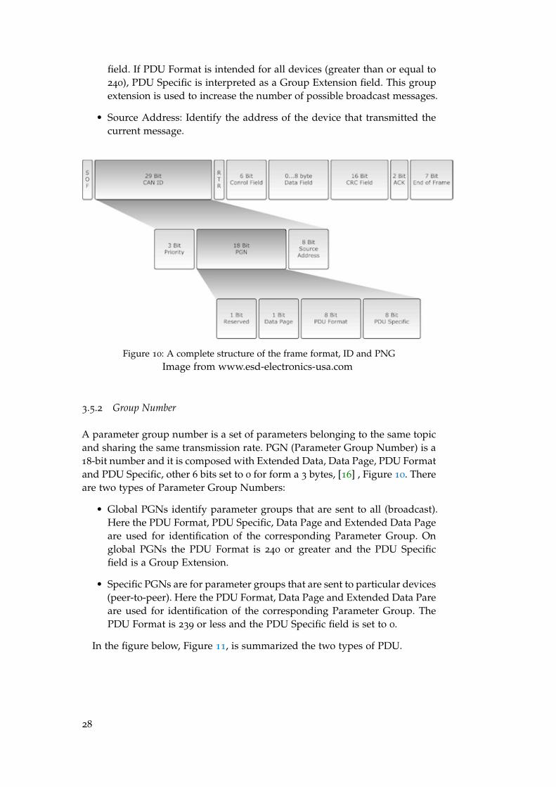
field. If PDU Format is intended for all devices (greater than or equal to240), PDU Specific is interpreted as a Group Extension field. This groupextension is used to increase the number of possible broadcast messages.
• Source Address: Identify the address of the device that transmitted thecurrent message.
Figure 10: A complete structure of the frame format, ID and PNGImage from www.esd-electronics-usa.com
3.5.2 Group Number
A parameter group number is a set of parameters belonging to the same topicand sharing the same transmission rate. PGN (Parameter Group Number) is a18-bit number and it is composed with Extended Data, Data Page, PDU Formatand PDU Specific, other 6 bits set to 0 for form a 3 bytes, [16] , Figure 10. Thereare two types of Parameter Group Numbers:
• Global PGNs identify parameter groups that are sent to all (broadcast).Here the PDU Format, PDU Specific, Data Page and Extended Data Pageare used for identification of the corresponding Parameter Group. Onglobal PGNs the PDU Format is 240 or greater and the PDU Specificfield is a Group Extension.
• Specific PGNs are for parameter groups that are sent to particular devices(peer-to-peer). Here the PDU Format, Data Page and Extended Data Pareare used for identification of the corresponding Parameter Group. ThePDU Format is 239 or less and the PDU Specific field is set to 0.
In the figure below, Figure 11, is summarized the two types of PDU.
28
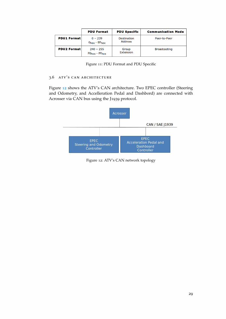
Figure 11: PDU Format and PDU Specific
3.6 atv’s can architecture
Figure 12 shows the ATV’s CAN architecture. Two EPEC controller (Steeringand Odometry, and Accelleration Pedal and Dashbord) are connected withAcrosser via CAN bus using the J1939 protocol.
Figure 12: ATV’s CAN network topology
29

4H A R D WA R E
4.1 vehicle
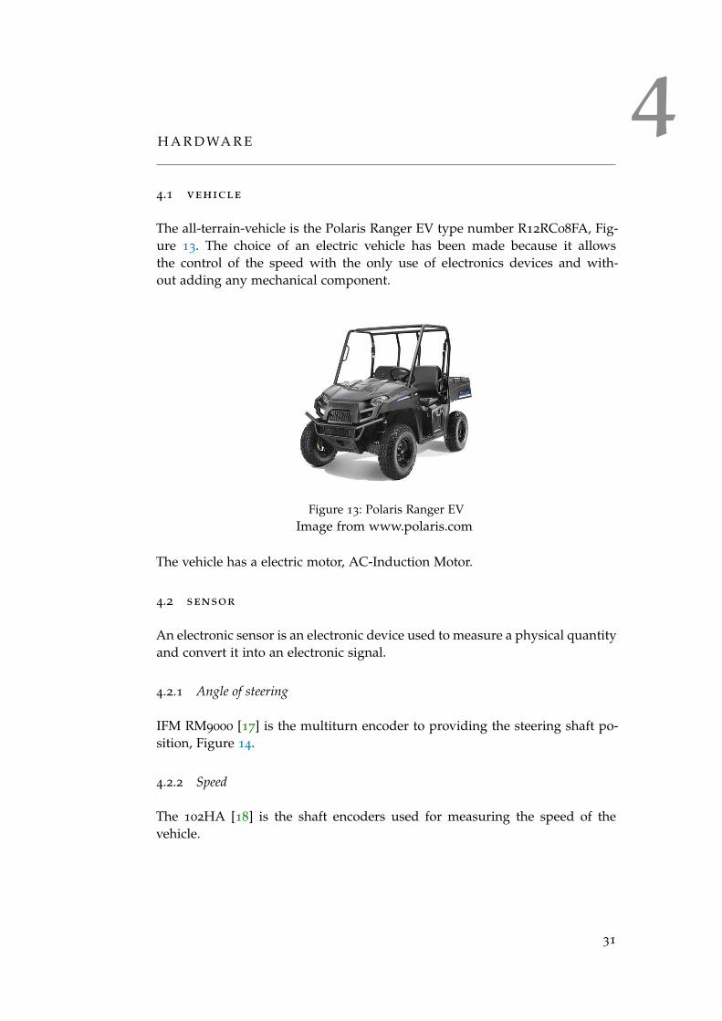
The all-terrain-vehicle is the Polaris Ranger EV type number R12RC08FA, Fig-ure 13. The choice of an electric vehicle has been made because it allowsthe control of the speed with the only use of electronics devices and with-out adding any mechanical component.
Figure 13: Polaris Ranger EVImage from www.polaris.com
The vehicle has a electric motor, AC-Induction Motor.
4.2 sensor
An electronic sensor is an electronic device used to measure a physical quantityand convert it into an electronic signal.
4.2.1 Angle of steering
IFM RM9000 [17] is the multiturn encoder to providing the steering shaft po-sition, Figure 14.
4.2.2 Speed
The 102HA [18] is the shaft encoders used for measuring the speed of thevehicle.
31

Figure 14: Encoder RM9000
Image from www.ifm.com
4.3 control unit
Epec 5050,Figure 15, is the control unit designed for machine control applica-tions and uses a 32-bit microcontroller running at 128 MHz clock frequency[19]. Four CAN interfaces have been used for the communication between allthe I/O devices.
Figure 15: EPEC 5050
Image from www.epec.fi
4.4 embedded system
An embedded system is a computer system with a dedicated function withina larger mechanical or electrical system with real-time computing constraints.The embedded system used in this project is the Acrosser model AIV-HM76V0FL[20], Figure 16. This system has a Intel i7 eight core processor and uses CANBus to allow the communication with the control unit.
32
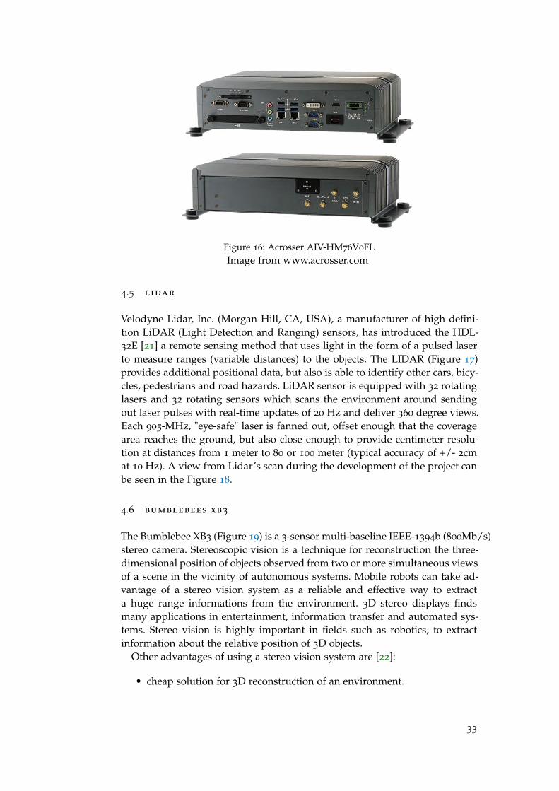
Figure 16: Acrosser AIV-HM76V0FLImage from www.acrosser.com
4.5 lidar
Velodyne Lidar, Inc. (Morgan Hill, CA, USA), a manufacturer of high defini-tion LiDAR (Light Detection and Ranging) sensors, has introduced the HDL-32E [21] a remote sensing method that uses light in the form of a pulsed laserto measure ranges (variable distances) to the objects. The LIDAR (Figure 17)provides additional positional data, but also is able to identify other cars, bicy-cles, pedestrians and road hazards. LiDAR sensor is equipped with 32 rotatinglasers and 32 rotating sensors which scans the environment around sendingout laser pulses with real-time updates of 20 Hz and deliver 360 degree views.Each 905-MHz, "eye-safe" laser is fanned out, offset enough that the coveragearea reaches the ground, but also close enough to provide centimeter resolu-tion at distances from 1 meter to 80 or 100 meter (typical accuracy of +/- 2cmat 10 Hz). A view from Lidar’s scan during the development of the project canbe seen in the Figure 18.
4.6 bumblebees xb3
The Bumblebee XB3 (Figure 19) is a 3-sensor multi-baseline IEEE-1394b (800Mb/s)stereo camera. Stereoscopic vision is a technique for reconstruction the three-dimensional position of objects observed from two or more simultaneous viewsof a scene in the vicinity of autonomous systems. Mobile robots can take ad-vantage of a stereo vision system as a reliable and effective way to extracta huge range informations from the environment. 3D stereo displays findsmany applications in entertainment, information transfer and automated sys-tems. Stereo vision is highly important in fields such as robotics, to extractinformation about the relative position of 3D objects.
Other advantages of using a stereo vision system are [22]:
• cheap solution for 3D reconstruction of an environment.
33

Figure 17: LidarImage from www.velodyne.com
Figure 18: View from Lidar’s scanImage from ATV project
• passive sensor and thus it does not introduce interferences with othersensor devices (when multiple sensors are present in the environment.
• easily integration with other vision routines, such as object recognitionand tracking.
34

Figure 19: Bumblebee XB3
Image from ww2.ptgrey.com
4.7 kvaser leaf light hs
The Kvaser Leaf Light [23] supports full speed USB interface for CAN withhigh performance. Kvaser Leaf Light is a reliable low cost product. Loss freetransmission and reception of standard and extended CAN messages on theCAN bus is transmitted with a time stamp precision of 100 microseconds.
Figure 20: Kvaser Leaf Light HSImage from www.kvaser.com
4.8 network architecture
The network architecture is showed in Figure 21. In the lower level the twoEPAC controller communicate each other and with Acrosser through CAN /SAE J1939. The upper level the communication has done by Ethernet/ROSconnecting Acrosser with laptop for high level control, sensor pc and WLANaccess point.
35

Figure 21: ATV’s network architecture
36
5C O M M U N I C AT I O N
5.1 ros
ROS (Robot Operating System) is a open source operating system for con-trolling robotic components. With a large a set of libraries, ROS is used forcreating programs that communicate efficiently, and with a flexible and sim-ply data structures. ROS provides standard operating system services such ashardware abstraction, low-level device control, implementation of commonlyused functionality, message-passing between processes and package manage-ment. In Figure 22 has shown the level of ROS is in the same level of theapplication and it is the interface between hardware and IPC (Inter-ProcessCommunication).
The fundamental concepts of the ROS implementation are nodes, messages,topics and services [24].
• Nodes: A node is an instance of an executable and can be a sensor, actu-ator, processing or monitoring algorithm.
• Messages: A message is a typed data structure made up with primitivetypes like (integer, floating point, boolean, etc.), arrays of primitives andconstants. Nodes communicate with each other by passing messages.
• Topic: A topic is a asynchronous data transport system based on a sub-scribe/publish system and is identified by a name. One or more nodesare able to publish data (messages) to a topic and one or more nodes canread data on that topic. Data is exchanged asynchronously by means ofa topic and via a service.
• Services: A services allows to communicate nodes each other with a syn-chronously communication. With service nodes are able to send a requestand receive a response.
ROS starts with the ROS master. Master allows to all other ROS instances(nodes) to find and talk each other, a node which wants to send a messageto another node needs simply asking to master to send the message withoutspecifying any address.
Examples of Topic and Services are in Appendix B.
5.1.1 Topic
A node sends a message publishing it to a given topic. A node that is inter-ested in a certain kind of data will subscribe to the appropriate topic. Theremay be multiple concurrent publishers and subscribers for a single topic and a
37

Figure 22: ROS’s level
single node may publish and/or subscribe to multiple topics. In general, pub-lishers and subscribers are not aware of each others existence. The messagespublished in a topic are called msg. Msg are simple text file which describethe fields of a ROS message with a field type and field name per line, and theyare stored in the ’msg’ directory of a package. The field types available are:
• int8, int16, int32, int64 (plus uint*)
• float32, float64
• string
• time, duration
• other msg files
• variable-length array[] and fixed-length array[]
5.1.1.1 Publisher node
In Appendix B Listing 7 a publisher, called "talker", sends a message.
5.1.1.2 Subscriber node
In this example in Listing 8 a subscriber receipts messages over the ROS sys-tem.
38

5.2 service
Service is used for synchronous transactions and it is defined by a string namethat identifies the name of the service. In the service there is the subscriberwhich sends the request and the client which returns an answer. A srv file,stored in the ’srv’ directory of a package, describes the service. Srv files arejust like msg files, except they contain two parts: a request and a response. Thetwo parts are separated by a ’- - -’ line. Listing 9 is an example of a srv filecalled AddTwoInts.
In Listing 10 and Listing 11 there are two examples of service subscriber nodeand service writing node.
5.3 can library
Sending and receiving messages via CAN bus has been done using the C++library of HM76V0FL ARV6005Lib.h, provided from Acrosser, for using theCAN bus port which allows to interface with CAN bus subsystem.
The functions of the library permit:
• Send the CAN packages over the CAN bus.
• Receive the CAN packages via the CAN bus hardware interface.
• Set and get the BAUD rate.
• Set and get the CAN package filter to selectively receive CAN packageswith specific ID.
• Set and get the mask bits to selectively make some filter bits take effect.
• Get the version information of the CAN Bus firmware.
5.3.1 CAN message format
The CAN packet will be sent or receive in the CAN bus from the software isa variable of type CanMsg with the fields id, id_type, length and data. In Ap-pendix A Listing 1 the structure of CAN messages used during the exchangeof information between the Acrosser and CAN bus.
id:
This field holds the ID information of the CAN packet. In a ’Standard DataFrame’ CAN packet, the ID field consists of 11 bits of binary digitals.In an ’Extended Data Frame’ CAN packet, the ID field consists of 29 bits ofbinary digitals. CAN packet can be a ’Standard Data Frame’ packet or an ’Ex-tended Data Frame’ packet is determined by the ’id_type’ field in the CanMsgvariable.
39
id_type:
This field identifies if CAN packet is a ’Standard Data Frame’ CAN packet,Listing 2, or a ’Extended Data Frame’ CAN packet, Listing 3.
data[8]:
’data’ field is an 8-byte long array, the range of this field ’length’ is 0 - 8 and itis filled with effective data.
length:
This field identifies the number of data bytes in the field ’data[8]’.
5.3.2 sendCanMessage
The prototype of the function sendCanMessage receive as parameter the ad-dress of the variable of type CanMsg. The function returns the result of theoperation, zero if the operation has not completed with successful otherwisea number different from zero. In Listing 4 the definition of the function send-CanMessage.
5.3.3 getCanMessage
The prototype of the function getCanMessage receives as parameter the ad-dress of the variable of type CanMsg and a integer number that representsthe amount of CAN messages that the function will get from the CAN bus.The function returns the result of the operation, zero if the operation hasn’tcompleted with successful otherwise a number different from zero. In Listing4 the definition of the function getCanMessage.
5.4 ackermann
5.4.1 Ackermann geometry
The vehicle is supported on four wheels on two axles, the robot keeps the rearwheels straight and turns the front. As can be seen in Figure 23, the angle theyhave to forward such wheel is not the same, so has been used the geometry ofAckermann.
The linear velocity of the robot, v, is corresponding to point center of the rearaxle and the angle of steering associated to the center of the front axle is calledθ. The coordinate zero is the middle of rear shaft. From these two data and thegeometry are enough to calculate the forward speeds and angles of the twowheels. For the front wheels used triangles rectangles formed by the center ofthe wheel, the center of the rear wheel same side and the center of rotation CR.The lengths of both legs are known, one being a wheelbase S and the other is
40
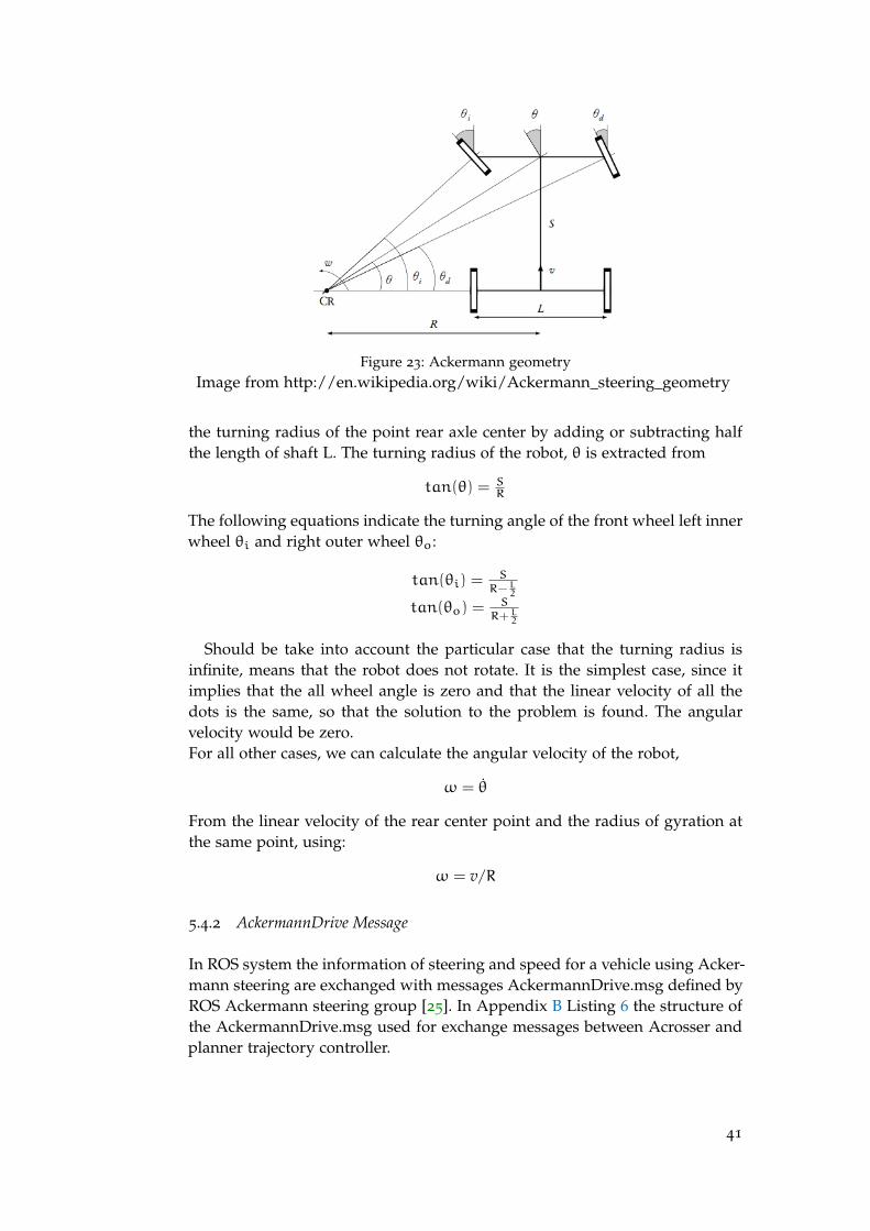
Figure 23: Ackermann geometryImage from http://en.wikipedia.org/wiki/Ackermann_steering_geometry
the turning radius of the point rear axle center by adding or subtracting halfthe length of shaft L. The turning radius of the robot, θ is extracted from
tan(θ) = SR
The following equations indicate the turning angle of the front wheel left innerwheel θi and right outer wheel θo:
tan(θi) =S
R−L2
tan(θo) =S
R+L2
Should be take into account the particular case that the turning radius isinfinite, means that the robot does not rotate. It is the simplest case, since itimplies that the all wheel angle is zero and that the linear velocity of all thedots is the same, so that the solution to the problem is found. The angularvelocity would be zero.For all other cases, we can calculate the angular velocity of the robot,
ω = θ̇
From the linear velocity of the rear center point and the radius of gyration atthe same point, using:
ω = v/R
5.4.2 AckermannDrive Message
In ROS system the information of steering and speed for a vehicle using Acker-mann steering are exchanged with messages AckermannDrive.msg defined byROS Ackermann steering group [25]. In Appendix B Listing 6 the structure ofthe AckermannDrive.msg used for exchange messages between Acrosser andplanner trajectory controller.
41


6I M P L E M E N TAT I O N
6.1 introduction
The main program, called communication, allows the communication betweenCAN bus and ROS. For this project has been realized the C++ class, called Can-Bus, which allows to manage the information from and to the CAN bus. com-munication uses ROS framework and the library ARV6005Lib.h which grantsthe communication with CAN bus. The other application developed is start-Communication and it has two purposes, the first one is to launch communi-cation and the second one is synchronize the restart of communication whenCAN bus is blocked. Before the test and the integration of the software withthe vehicle, has been developed a software that emulates the CAN commu-nication. This program, called testCanCommunication.exe allows to exchangeCAN messages, has been developed in C# and uses the library of Kvaser LeafLight HS.
6.2 startcommunication
startCommunication launchs communication when it starts and also when it re-ceives the signal via ROS service from communication that the process willterminate, so another communication process will be launched. It is necessaryuses two different threads because the process communication and the processstartCommunication must work in parallel. With this solution ROS service ad-vertiseService in startCommunication is able to catch the signal from the ROSservice serviceClient in communication which sends the notice that itself will beterminated. Without the use of the thread for opening new terminal, there isthe freezing of the calling process which restarts after the closing of the createdwindow, with this wrong configuration the signal from ServiceClient can notbe caught and handled because ServiceServer is frozen and the mechanismof synchronism does not work. The eventual use of Publisher and Subscriberinvolve the loose of the notice, especially the first communication, at the ex-pense of reliability and velocity. From this consideration it is necessary the useof the Service instead of the Publisher and Subscriber, because it is required asynchronization between the two processes.The source of startCommunication is in Appendix C Listing 26.
6.3 communication
The main software must exchange the arriving messages via vehicle’s CANbus, send them to the platform ROS and vice versa. There are two threaddedicated each one for reading and sending the message from and to CAN
43

bus. The manage of the messages in writing or in reading must be done inparallel because the communication with ROS can be a variable time.The source of startCommunication is in Appendix C in Listing 27.
6.4 can.cpp
In CAN.cpp file there are the function used for the communication with theCAN bus and ROS. The function readDataFromCan reads data from CANbus and with the received values sets parameters of angle of steering andspeed of the variable ackermannMsg, a second function readCANmessageTh-read aims to send cyclically the variable ackermannMsg to ROS with a topic.The function readDataFromRos reads data from ROS and sends the parame-ters of speed and angle of steering via CAN bus. restartCommunication is thefunction that synchronizes the restart of the application when CAN bus is notable to work anymore.The source of startCommunication is in Appendix C Listing 28.
6.5 can.h
The header file defines the class CanBus used in communication and the defini-tion of the enum EnumTypeMsg used during the reading of the CAN message.The source of startCommunication is in Appendix C Listing 29.
6.6 parametercar .h
In the header file there are the constant variables used inside the programslike CAN communication parameters, vehicle’s proprieties, ROS frequenciesand maximum waiting time for a CAN communication. The source of parame-terCar.h is in Appendix Listing 30.
6.7 cansimulator .exe
CANsimulator.exe has been developed on Windows platform because the Kvaser’slibraries for using the device Kvaser Leaf Light HS are available for Windows.The program opens and closes the connection with CAN bus and allows tosend and receive one or multiple CAN messages showed in the console of theC# .NET Framework.In Figure 24 the screenshot of the CANsimulator.exe.
44

Figure 24: Window of the program CANsimulator.exe
45


7E X P E R I M E N T S A N D R E S U LT S
7.1 experiments
The experiments test multiple version of software. In each one of them havebeen analyzed the performance, in terms of time and amount of messages ex-changed, using one or two function for send the message of steer and speedthrough the CAN bus . The experiment in the laboratory uses a program whichsends 10000 Ackermann messages from ROS to CAN bus through the soft-ware in testing and measure the efficiently of software comparing the RMS,minimum and maximum time of receiving and sending (speed and angle ofsteering) messages through the CAN bus and counts the number of missedmessages. The code C++ uses two thread that read and write from the CANbus with the function getCanMessage() and sendCanMessage() from the li-brary ARV6005Lib.h provides from Acrosser company. The documentationabout these two functions do not explain how they works when the CANbus is busy. The results obtained are in Table 16 and are synthesized using aroot mean square in Table 17.
7.2 groups
The different versions of software are divided in four groups. The first, thesecond and the third groups use two sendCanMessage() functions for send-ing the command of velocity and angle of steering, the fourth group, instead,use just once the sendCanMessage() functions for sending both messages. Infirst group the mutex and the condition variable are shared between the twosendCanMessage() functions for sending the messages to CAN bus, the sec-ond group do not share the mutex for sending functions and then there aretwo variable conditions and two whiles, third one do not use any mutex andthe last one use just one mutex and one condition variable for the only send-CanMessage() function. In each group there are experiments with the use ofmutex for sendCanMessage() and readCanMessage(), mutex only for sendCan-Message(), mutex only for readCanMessage() and without mutex.The abbreviations in Table 4 allow to identify the typology experiment. 1
In the following tables are summarized the different combinations of soft-ware used.
1 In the Table 5, 1REC_S-2SEND_CMy_W, using the the abbreviations it’s possible to identify thatthe receiving function (REC) uses one single function for receive CAN message (1), getCanMes-sage , and sets the condition variable true or false if the CAN bus is busy or not (S). The sendingfunction (SEND) uses two (2) functions sendCanMessage() for sending two CAN messages anda share condition variable is used (CMy) for wait for the while (W) until the CAN bus get free.
47

Table 4: Abbreviation of typology of code
Abbreviations Meaning
REC Receive function
SEND Send function
# Number of call function for receive or send CAN messages
S Set variable condition
W Wait variable condition
CMy Variable condition is present and it’s associate to one while,CommonMutexYes
CMn Variable condition is present and it’s associate to twowhiles, CommonMutexNo
Table 5: 1REC_S-2SEND_CMy_W
RECEIVE SEND
Function Can Steer Speed
Number getCanMessage() 1 /
Number sendCanMessage() / 1 1
Common mutex (CM) / yes
Wait condition (W) no yes
Set condition (S) yes no
Group 1: two sendCanMessage() functions are in the same mutex, Table 5,Table 6 and Table 7. The codes associated to the respective tables are in Ap-pendix C Listing 13 and 16, Listing 14 and 17, Listing 15 and 18.
Group 2: two sendCanMessage() functions are in separated mutex, Table 8,Table 9 and Table 10. The codes associated to the respective tables are in Ap-pendix C Listing 13 and 19, Listing 14 and 20, Listing 15 and 21.
Group 3: two sendCanMessage() functions and mutex are not used, Table 11
and Table 12. The codes associated to the respective tables are in Appendix CListing 13 and 22, Listing 13 and 23.
Group 4: the software use once the function sendCanMessage() for sendingboth steer and speed commands, Table 13, Table 14 and Table 15. The codes as-sociated to the respective tables are in Appendix C Listing 13 and 24, Listing 14
and 23, Listing 15 and 25.
7.3 codes and versions
The codes in Appendix C are the relevant parts of the various versions of thecode. In Listing 12 there are the variables that belong to class CanBus used
48

Table 6: 1REC_W-2SEND_CMy_S
RECEIVE SEND
Function Can Steer Speed
Number getCanMessage() 1 /
Number sendCanMessage() / 1 1
Common mutex (CM) / yes
Wait condition (W) yes no
Set condition (S) no yes
Table 7: 1REC_WS-2SEND_CMy_WS
RECEIVE SEND
Function Can Steer Speed
Number getCanMessage() 1 /
Number sendCanMessage() / 1 1
Common mutex (CM) / yes
Wait condition (W) yes yes
Set condition (S) yes yes
Table 8: 1REC_S-2SEND_CMn_W
RECEIVE SEND
Function Can Steer Speed
Number getCanMessage() 1 /
Number sendCanMessage() / 1 1
Common mutex (CM) / no
Wait condition (W) no yes yes
Set condition (S) yes no no
Table 9: 1REC_W-2SEND_CMn_S
RECEIVE SEND
Function Can Steer Speed
Number getCanMessage() 1 /
Number sendCanMessage() / 1 1
Common mutex (CM) / no
Wait condition (W) yes no no
Set condition (S) no yes yes
49
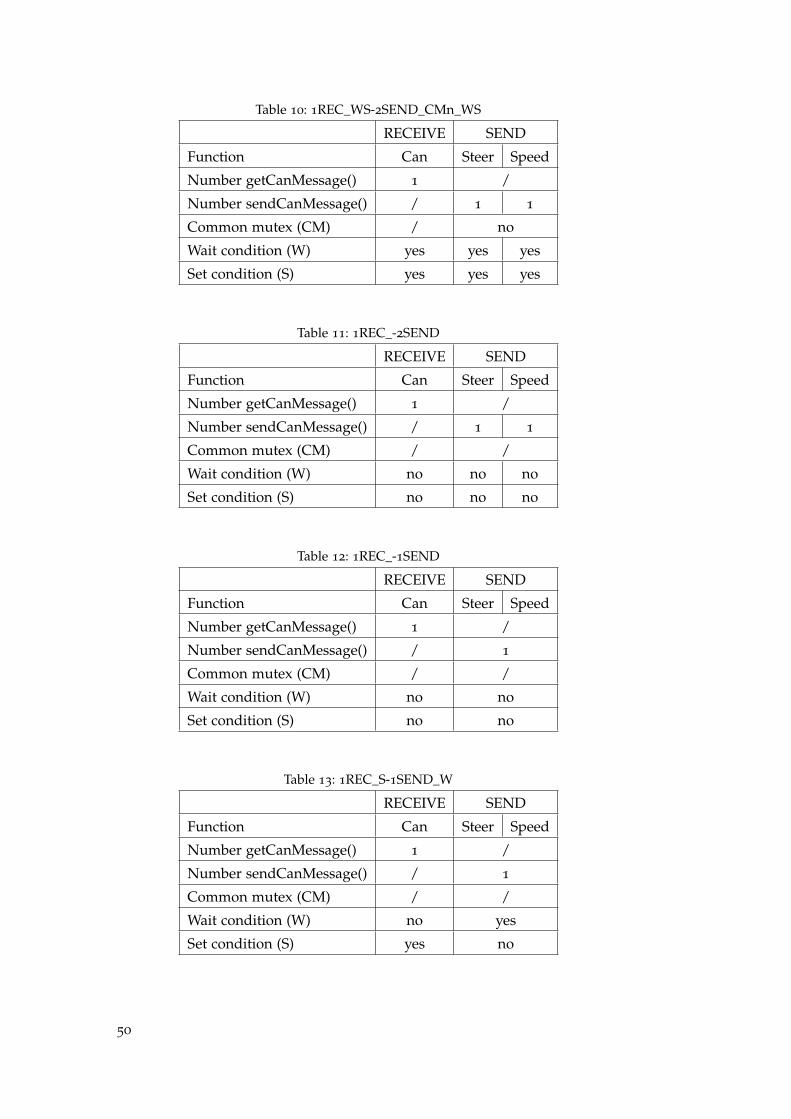
Table 10: 1REC_WS-2SEND_CMn_WS
RECEIVE SEND
Function Can Steer Speed
Number getCanMessage() 1 /
Number sendCanMessage() / 1 1
Common mutex (CM) / no
Wait condition (W) yes yes yes
Set condition (S) yes yes yes
Table 11: 1REC_-2SEND
RECEIVE SEND
Function Can Steer Speed
Number getCanMessage() 1 /
Number sendCanMessage() / 1 1
Common mutex (CM) / /
Wait condition (W) no no no
Set condition (S) no no no
Table 12: 1REC_-1SEND
RECEIVE SEND
Function Can Steer Speed
Number getCanMessage() 1 /
Number sendCanMessage() / 1
Common mutex (CM) / /
Wait condition (W) no no
Set condition (S) no no
Table 13: 1REC_S-1SEND_W
RECEIVE SEND
Function Can Steer Speed
Number getCanMessage() 1 /
Number sendCanMessage() / 1
Common mutex (CM) / /
Wait condition (W) no yes
Set condition (S) yes no
50
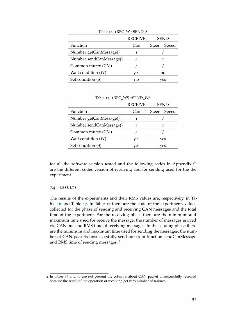
Table 14: 1REC_W-1SEND_S
RECEIVE SEND
Function Can Steer Speed
Number getCanMessage() 1 /
Number sendCanMessage() / 1
Common mutex (CM) / /
Wait condition (W) yes no
Set condition (S) no yes
Table 15: 1REC_WS-1SEND_WS
RECEIVE SEND
Function Can Steer Speed
Number getCanMessage() 1 /
Number sendCanMessage() / 1
Common mutex (CM) / /
Wait condition (W) yes yes
Set condition (S) yes yes
for all the software version tested and the following codes in Appendix Care the different codes version of receiving and for sending used for the theexperiment.
7.4 results
The results of the experiments and their RMS values are, respectively, in Ta-ble 16 and Table 17. In Table 17 there are the code of the experiment, valuescollected for the phase of sending and receiving CAN messages and the totaltime of the experiment. For the receiving phase there are the minimum andmaximum time used for receive the message, the number of messages arrivedvia CAN bus and RMS time of receiving messages. In the sending phase thereare the minimum and maximum time used for sending the messages, the num-ber of CAN packets unsuccessfully send out from function sendCanMessageand RMS time of sending messages. 2
2 In tables 16 and 17 are not present the columns about CAN packet unsuccessfully receivedbecause the result of the operation of receiving get zero number of failures.
51
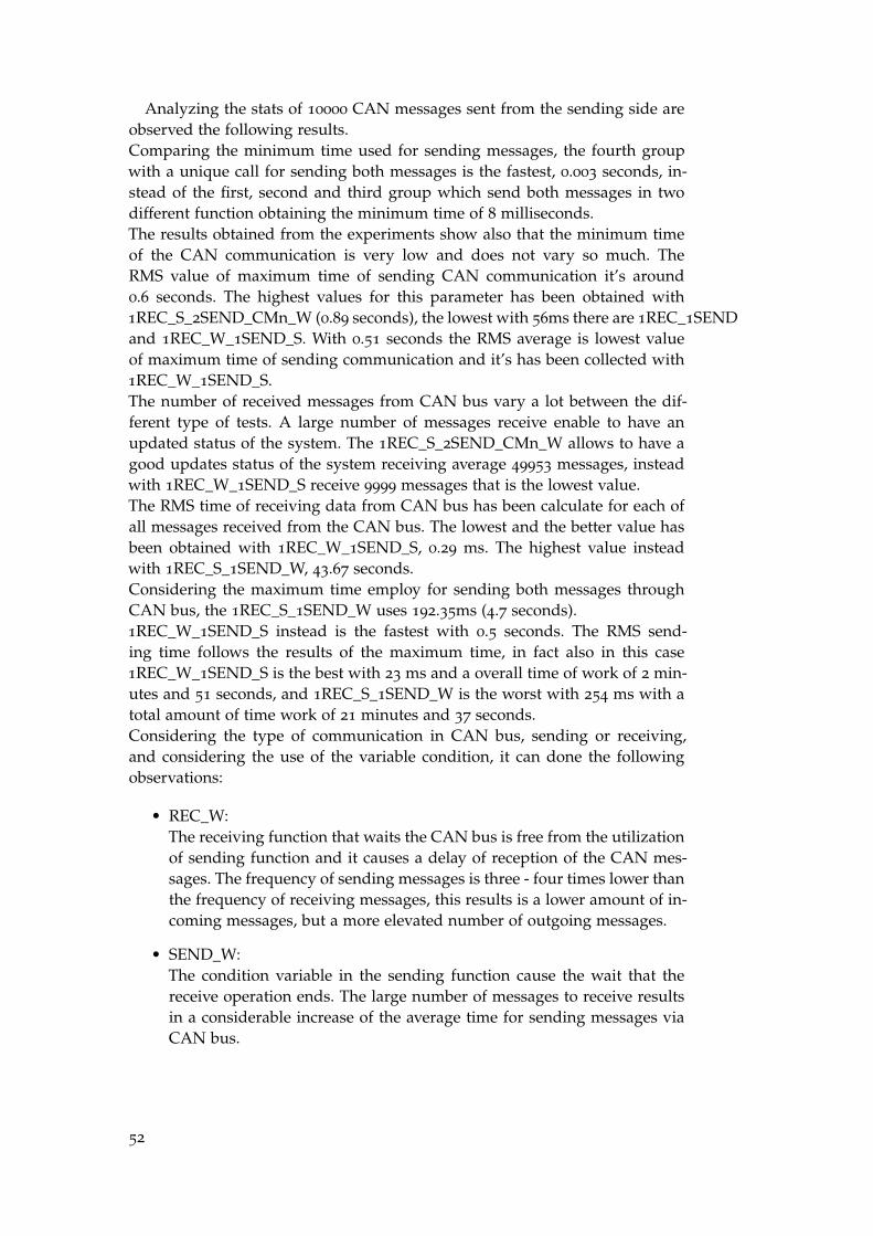
Analyzing the stats of 10000 CAN messages sent from the sending side areobserved the following results.Comparing the minimum time used for sending messages, the fourth groupwith a unique call for sending both messages is the fastest, 0.003 seconds, in-stead of the first, second and third group which send both messages in twodifferent function obtaining the minimum time of 8 milliseconds.The results obtained from the experiments show also that the minimum timeof the CAN communication is very low and does not vary so much. TheRMS value of maximum time of sending CAN communication it’s around0.6 seconds. The highest values for this parameter has been obtained with1REC_S_2SEND_CMn_W (0.89 seconds), the lowest with 56ms there are 1REC_1SENDand 1REC_W_1SEND_S. With 0.51 seconds the RMS average is lowest valueof maximum time of sending communication and it’s has been collected with1REC_W_1SEND_S.The number of received messages from CAN bus vary a lot between the dif-ferent type of tests. A large number of messages receive enable to have anupdated status of the system. The 1REC_S_2SEND_CMn_W allows to have agood updates status of the system receiving average 49953 messages, insteadwith 1REC_W_1SEND_S receive 9999 messages that is the lowest value.The RMS time of receiving data from CAN bus has been calculate for each ofall messages received from the CAN bus. The lowest and the better value hasbeen obtained with 1REC_W_1SEND_S, 0.29 ms. The highest value insteadwith 1REC_S_1SEND_W, 43.67 seconds.Considering the maximum time employ for sending both messages throughCAN bus, the 1REC_S_1SEND_W uses 192.35ms (4.7 seconds).1REC_W_1SEND_S instead is the fastest with 0.5 seconds. The RMS send-ing time follows the results of the maximum time, in fact also in this case1REC_W_1SEND_S is the best with 23 ms and a overall time of work of 2 min-utes and 51 seconds, and 1REC_S_1SEND_W is the worst with 254 ms with atotal amount of time work of 21 minutes and 37 seconds.Considering the type of communication in CAN bus, sending or receiving,and considering the use of the variable condition, it can done the followingobservations:
• REC_W:The receiving function that waits the CAN bus is free from the utilizationof sending function and it causes a delay of reception of the CAN mes-sages. The frequency of sending messages is three - four times lower thanthe frequency of receiving messages, this results is a lower amount of in-coming messages, but a more elevated number of outgoing messages.
• SEND_W:The condition variable in the sending function cause the wait that thereceive operation ends. The large number of messages to receive resultsin a considerable increase of the average time for sending messages viaCAN bus.
52

Table 16: Results of the experiment
RECEIVE SEND
CodeMin
ms
Max
ms
Number
Msg
RMS
ms
Min
ms
Max
msErr
RMS
ms
Time
min:sec
1REC_S_2SEND_CMy_W 4 509 29554 31 8 509 2 58 5:29
1REC_S_2SEND_CMy_W 1 319 30149 32 8 403 0 61 6:49
1REC_S_2SEND_CMy_W 1 1104 30032 35 8 692 8 64 6:44
1REC_W_2SEND_CMy_S 3 609 29905 34 8 692 3 63 6:40
1REC_W_2SEND_CMy_S 1 607 30222 33 8 592 3 62 6:51
1REC_W_2SEND_CMy_S 1 805 30008 34 8 806 7 64 6:44
1REC_WS_2SEND_CMy_WS 1 610 50417 41 8 2190 7 196 17:10
1REC_WS_2SEND_CMy_WS 1 601 49050 40 8 1723 10 191 16:30
1REC_WS_2SEND_CMy_WS 1 605 49990 40 8 1855 9 190 18:42
1REC_S_2SEND_CMn_W 1 889 50338 40 8 1758 8 191 17:11
1REC_S_2SEND_CMn_W 1 907 50762 41 8 2840 9 198 17:26
1REC_S_2SEND_CMn_W 1 903 48738 41 8 1989 2 187 16:18
1REC_W_2SEND_CMn_S 8 604 30478 34 8 677 7 64 6:58
1REC_W_21SEND_CMn_S 5 605 30091 34 8 646 6 65 6:49
1REC_W_2SEND_CMn_S 8 607 30585 35 8 686 9 66 6:02
1REC_WS_2SEND_CMn_WS 9 628 44653 40 8 3216 5 179 18:35
1REC_WS_2SEND_CMn_WS 1 610 47174 40 8 2675 7 180 15:24
1REC_WS_2SEND_CMn_WS 2 600 46723 40 8 4190 7 190 15:13
1REC__2SEND 1 595 30984 33 8 686 3 67 6:20
1REC__2SEND 1 604 31424 34 8 652 1 68 7:32
1REC__2SEND 4 605 31121 33 8 702 6 66 6:21
1REC_1SEND 4 603 20410 38 3 685 4 56 6:52
1REC_1SEND 4 596 20297 38 3 650 3 56 6:52
1REC_1SEND 2 603 20259 38 3 686 6 57 6:55
1REC_S_1SEND_W 4 601 46553 44 3 3244 5 230 21:37
1REC_S_1SEND_W 1 583 50255 45 3 3599 9 261 23:46
1REC_S_1SEND_W 1 603 49698 44 3 6682 5 270 22:27
1REC_W_1SEND_S 4 603 20410 38 3 685 4 56 2:28
1REC_W_1SEND_S 4 596 20297 38 3 650 3 56 3:00
1REC_W_1SEND_S 2 603 20259 38 3 686 6 57 2:59
1REC_WS_1SEND_WS 4 505 48795 44 3 1800 4 227 22:55
1REC_WS_1SEND_WS 1 590 43183 44 3 2189 7 194 19:45
1REC_WS_1SEND_WS 1 570 38480 43 3 1400 4 171 16:07
53
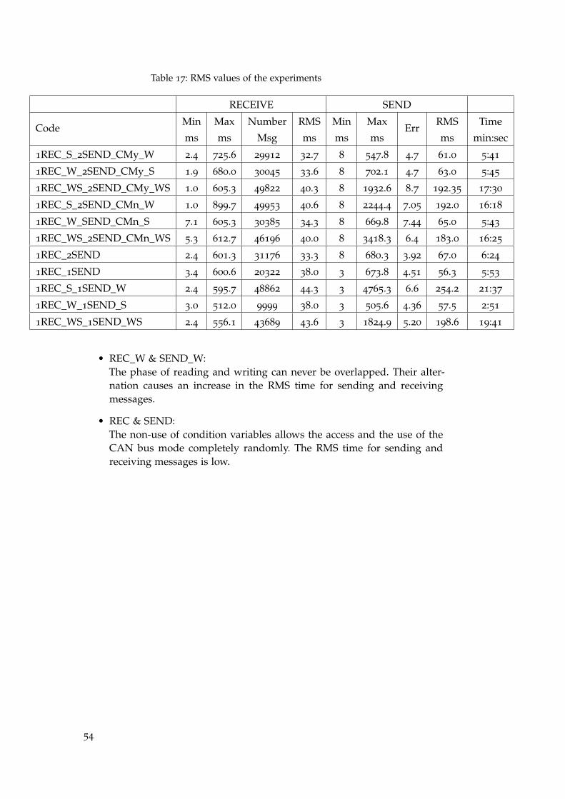
Table 17: RMS values of the experiments
RECEIVE SEND
CodeMin
ms
Max
ms
Number
Msg
RMS
ms
Min
ms
Max
msErr
RMS
ms
Time
min:sec
1REC_S_2SEND_CMy_W 2.4 725.6 29912 32.7 8 547.8 4.7 61.0 5:41
1REC_W_2SEND_CMy_S 1.9 680.0 30045 33.6 8 702.1 4.7 63.0 5:45
1REC_WS_2SEND_CMy_WS 1.0 605.3 49822 40.3 8 1932.6 8.7 192.35 17:30
1REC_S_2SEND_CMn_W 1.0 899.7 49953 40.6 8 2244.4 7.05 192.0 16:18
1REC_W_SEND_CMn_S 7.1 605.3 30385 34.3 8 669.8 7.44 65.0 5:43
1REC_WS_2SEND_CMn_WS 5.3 612.7 46196 40.0 8 3418.3 6.4 183.0 16:25
1REC_2SEND 2.4 601.3 31176 33.3 8 680.3 3.92 67.0 6:24
1REC_1SEND 3.4 600.6 20322 38.0 3 673.8 4.51 56.3 5:53
1REC_S_1SEND_W 2.4 595.7 48862 44.3 3 4765.3 6.6 254.2 21:37
1REC_W_1SEND_S 3.0 512.0 9999 38.0 3 505.6 4.36 57.5 2:51
1REC_WS_1SEND_WS 2.4 556.1 43689 43.6 3 1824.9 5.20 198.6 19:41
• REC_W & SEND_W:The phase of reading and writing can never be overlapped. Their alter-nation causes an increase in the RMS time for sending and receivingmessages.
• REC & SEND:The non-use of condition variables allows the access and the use of theCAN bus mode completely randomly. The RMS time for sending andreceiving messages is low.
54
8C O N C L U S I O N
The software developed for communication between the CAN bus and ROSenables the exchange of information between the two interfaces and allows torestart the program if the functions for communication with the CAN bus stopworking. To understand and improve the functions from libraries for commu-nication with the CAN bus, it has been made some experiments using differentversion of software with condition variables. Analyzing data from the exper-iments, it results the use of the variable condition for sending a message viaCAN bus causes its waiting if the phase of reading is running, but being thereceiving messages three or four time more frequently than sending message,this induce the decreasing of the RMS time of the sending messages. Consider-ing informations coming from the vehicle same importance as those directedtoward the vehicle and considering the frequency of read messages from theCAN bus much higher than the frequency of the messages sent to the CANbus, from the experimental data and assessments done, it has been decidedto use the version of code 1REC_W_1SEND_S ( Table 14, Listing 14 and List-ing 23) that uses a condition variable in the receiving function which waitsthat the CAN bus is free from the utilization of sending function.
The software, using a communication ROS, is able to receive the commandsto drive the vehicle (angle of steering and speed) from any node that belongsto the network ROS. In this project, the vehicle is driven by the planner con-troller (Lidar, stereo camera and the algorithm in a dedicated pc). One of futureprojects is to develop an algorithm for controlling the vehicle through a smart-phone which, connected to the wireless network of the vehicle, allows to drivethe car.
55


AC O M M U N I C AT I O N
a.1 can library
Definition of the structure of CanMsg message used from the functions de-clared ARV6005Lib.h for the communication via CAN bus.
Listing 1: CAN message format
1 // TYPE DEFINITIONtypedef unsigned char u8;typedef unsigned long u32;
struct CanMsg {6 u32 id;
u8 id\_type;u8 length;u8 data[8];
}
Declaration of variable canMsg of type CanMsg and parameter setting theparameter id_type in ’Standard Data Frame’.
Listing 2: CAN message type standard data frame
struct CanMsg canMsg;canMsg.id_type = STD_ID; // A ’Standard Data Frame’ packet
Declaration of variable canMsg of type CanMsg and parameter setting theparameter id_type in ’Extended Data Frame’.
Listing 3: CAN message type extended data frame
struct CanMsg canMsg;canMsg.id_type = EXT_ID; // A ’Extended Data Frame’ packet
Definition of the function sendCanMessage.
Listing 4: prototype of function sendCanMessage
i32 sendCanMessage(struct CanMsg *msg);
Definition of the function getCanMessage.
Listing 5: prototype of function getCanMessage
i32 getCanMessage(struct CanMsg *buf, int size);
57

a.2 ackermanndrive message
Structure of AckermannDrive.msg.
Listing 6: AckermannDrive.msg
float32 steering_angle # desired steering angle (radians)float32 steering_angle_velocity # desired rate of change (radians/s)float32 speed # desired forward speed (m/s)
4 float32 acceleration # desired acceleration (m/s^2)float32 jerk # desired jerk (m/s^3)
58

BR O S
b.1 topic
ROS programs to publish messages.
Listing 7: ROS: publisher
//includes all the headers necessary to use the most common public pieces// of the ROS system.#include "ros/ros.h"
5
//includes the std_msgs/String message.#include "std_msgs/String.h"
int main(int argc, char **argv)10 {
/*** The ros::init() function needs to see argc and argv so that it can perform* any ROS arguments and name remapping that were provided at the* command line.
15 * The third argument to init() is the name of the node.** You must call one of the versions of ros::init() before using any other* part of the ROS system.*/
20 ros::init(argc, argv, "talker");
/*** NodeHandle is the main access point to communications with the ROS* system.
25 * The first NodeHandle constructed will fully initialize this node, and the last* NodeHandle destructed will close down the node.*/
ros::NodeHandle n;
30 /*** The advertise() function is how you tell ROS that you want to* publish on a given topic name. This invokes a call to the ROS* master node, which keeps a registry of who is publishing and who* is subscribing. After this advertise() call is made, the master
35 * node will notify anyone who is trying to subscribe to this topic name,* and they will in turn negotiate a peer−to−peer connection with this* node. advertise() returns a Publisher object which allows you to* publish messages on that topic through a call to publish(). Once* all copies of the returned Publisher object are destroyed, the topic
40 * will be automatically unadvertised.
59

** The second parameter to advertise() is the size of the message queue* used for publishing messages. If messages are published more quickly* than we can send them, the number here specifies how many messages to
45 * buffer up before throwing some away.*/
ros::Publisher chatter_pub = n.advertise<std_msgs::String>("chatter", 1);
/**50 * This is a message object. You stuff it with data, and then publish it.
*/std_msgs::String msg;
msg.data = "Text to send";55
/*** The publish() function is how you send messages. The parameter* is the message object. The type of this object must agree with the type* given as a template parameter to the advertise<>() call, as was done
60 * in the constructor above.*/
chatter_pub.publish(msg);
return 0;65 }
The subscriber example show how to receive messages on a given topic.
Listing 8: ROS: subscriber
#include "ros/ros.h"#include "std_msgs/String.h"
/*4 * This is the callback function that will get called when a new
* message has arrived on the chatter topic*/
void chatterCallback(const std_msgs::String::ConstPtr& msg)9 {
ROS_INFO("I read: [%s]", msg−>data.c_str());}
int main(int argc, char **argv)14 {
/*** The ros::init() function needs to see argc and argv so that it can perform* any ROS arguments and name remapping that were provided at the* command line. For programmatic remappings you can use a different
19 * version of init() which takes remappings directly, but for most* command−line programs, passing argc and argv is the easiest* way to do it. The third argument to init() is the name of the node.** You must call one of the versions of ros::init() before using any other
24 * part of the ROS system.
60

*/ros::init(argc, argv, "listener");
/**29 * NodeHandle is the main access point to communications with the ROS
* system.* The first NodeHandle constructed will fully initialize this node, and the last* NodeHandle destructed will close down the node.*/
34 ros::NodeHandle n;
/*** The subscribe() call is how you tell ROS that you want to receive messages* on a given topic. This invokes a call to the ROS
39 * master node, which keeps a registry of who is publishing and who* is subscribing. Messages are passed to a callback function, here* called chatterCallback. subscribe() returns a Subscriber object that you* must hold on to until you want to unsubscribe. When all copies of the* Subscriber object go out of scope, this callback will automatically
44 * be unsubscribed from this topic.** The second parameter to the subscribe() function is the size of the message* queue. If messages are arriving faster than they are being processed, this* is the number of messages that will be buffered up before beginning to
49 * throw away the oldest ones.*/
ros::Subscriber sub = n.subscribe("chatter", 1000, chatterCallback);
/**54 * ros::spin() will enter a loop, pumping callbacks. With this version, all
* callbacks will be called from within this thread (the main one). ros::spin()* will exit when Ctrl−C is pressed, or the node is shutdown by the master.*/
ros::spin();59
return 0;}
b.2 service
.srv file defines the request and response data structures for services in ROS.In Listing 9 an example of service structure.
Listing 9: ROS: AddTwoInts.srv
int64 Aint64 B−−−
4 int64 Sum
In Listing 10 the subscribers of the service.
61
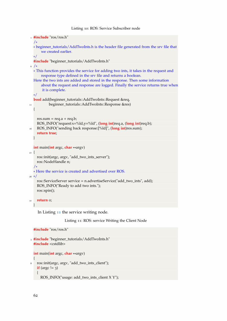
Listing 10: ROS: Service Subscriber node
1 #include "ros/ros.h"/** beginner_tutorials/AddTwoInts.h is the header file generated from the srv file that
we created earlier.*/#include "beginner_tutorials/AddTwoInts.h"
6 /** This function provides the service for adding two ints, it takes in the request and
response type defined in the srv file and returns a boolean.Here the two ints are added and stored in the response. Then some information
about the request and response are logged. Finally the service returns true whenit is complete.
*/bool add(beginner_tutorials::AddTwoInts::Request &req,
11 beginner_tutorials::AddTwoInts::Response &res){
res.sum = req.a + req.b;ROS_INFO("request:x=%ld,y=%ld", (long int)req.a, (long int)req.b);
16 ROS_INFO("sending back response:[%ld]", (long int)res.sum);return true;
}
int main(int argc, char **argv)21 {
ros::init(argc, argv, "add_two_ints_server");ros::NodeHandle n;
/** Here the service is created and advertised over ROS.
26 */ros::ServiceServer service = n.advertiseService("add_two_ints", add);ROS_INFO("Ready to add two ints.");ros::spin();
31 return 0;}
In Listing 11 the service writing node.
Listing 11: ROS: service Writing the Client Node
#include "ros/ros.h"
3 #include "beginner_tutorials/AddTwoInts.h"#include <cstdlib>
int main(int argc, char **argv){
8 ros::init(argc, argv, "add_two_ints_client");if (argc != 3){
ROS_INFO("usage: add_two_ints_client X Y");
62
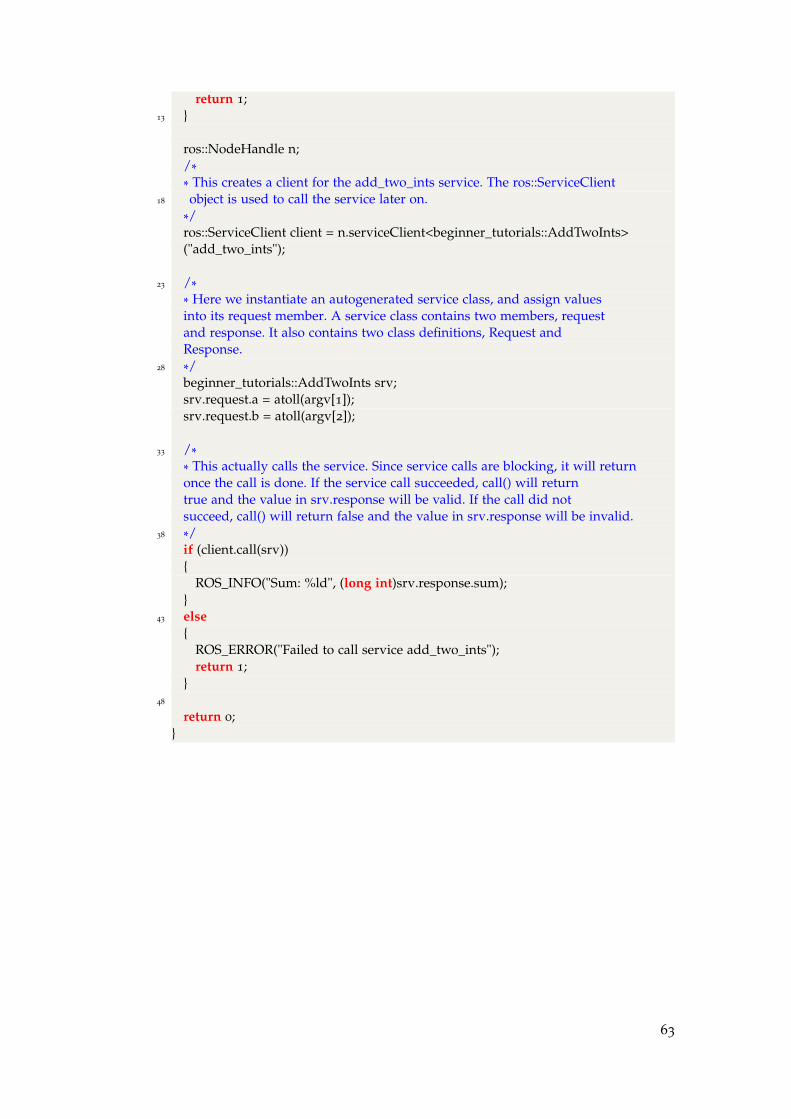
return 1;13 }
ros::NodeHandle n;/** This creates a client for the add_two_ints service. The ros::ServiceClient
18 object is used to call the service later on.*/ros::ServiceClient client = n.serviceClient<beginner_tutorials::AddTwoInts>("add_two_ints");
23 /** Here we instantiate an autogenerated service class, and assign valuesinto its request member. A service class contains two members, requestand response. It also contains two class definitions, Request andResponse.
28 */beginner_tutorials::AddTwoInts srv;srv.request.a = atoll(argv[1]);srv.request.b = atoll(argv[2]);
33 /** This actually calls the service. Since service calls are blocking, it will returnonce the call is done. If the service call succeeded, call() will returntrue and the value in srv.response will be valid. If the call did notsucceed, call() will return false and the value in srv.response will be invalid.
38 */if (client.call(srv)){
ROS_INFO("Sum: %ld", (long int)srv.response.sum);}
43 else{
ROS_ERROR("Failed to call service add_two_ints");return 1;
}48
return 0;}
63


CC O D E S A N D V E R S I O N S
Common variable inside the class CanBus used in the object variable canBus-Communication.
Listing 12: Variables
boost::mutex mtxCANbusBusy;boost::condition_variable condCANbusBusy;bool CANbusBusy = false;
Codes with the different version of receiving function:
Listing 13: 1REC_S, one function for receiving the CAN message and a set of thevariable condition CANbusBusy
canBusCommunication.CANbusBusy = true;2 result = getCanMessage(&canPkgReceive, 1);
canBusCommunication.CANbusBusy = false;canBusCommunication.condCANbusBusy.notify_one();
Listing 14: 1REC_W, one function for receiving the CAN message and a while whichchecks the variable condition CANbusBusy
1 while(canBusCommunication.CANbusBusy == true)canBusCommunication.condCANbusBusy.wait(lock);
result = getCanMessage(&canPkgReceive, 1);
Listing 15: 1REC_WS, one function for receiving the CAN message, a while whichchecks the variable condition CANbusBusy and a set of the variable condi-tion CANbusBusy
while(canBusCommunication.CANbusBusy == true)2 canBusCommunication.condCANbusBusy.wait(lock);
canBusCommunication.CANbusBusy = true;result = getCanMessage(&canPkgReceive, 1);canBusCommunication.CANbusBusy = false;canBusCommunication.condCANbusBusy.notify_one();
Codes with different version of sending function:
Listing 16: 2SEND_CMy_W, two function for sending the CAN messages and aunique while which checks the variable condition CANbusBusy
while(canBusCommunication.CANbusBusy == true)canBusCommunication.condCANbusBusy.wait(lock);
3 result = sendCanMessage(&canBusCommunication.msg2send[STEER]);...result = sendCanMessage(&canBusCommunication.msg2send[SPEED]);...
65
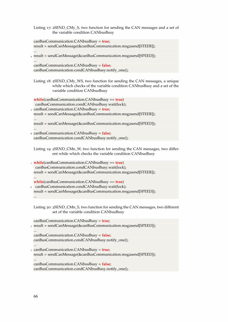
Listing 17: 2SEND_CMy_S, two function for sending the CAN messages and a set ofthe variable condition CANbusBusy
canBusCommunication.CANbusBusy = true;result = sendCanMessage(&canBusCommunication.msg2send[STEER]);...
4 result = sendCanMessage(&canBusCommunication.msg2send[SPEED]);...canBusCommunication.CANbusBusy = false;canBusCommunication.condCANbusBusy.notify_one();
Listing 18: 2SEND_CMy_WS, two function for sending the CAN messages, a uniquewhile which checks of the variable condition CANbusBusy and a set of thevariable condition CANbusBusy
while(canBusCommunication.CANbusBusy == true)canBusCommunication.condCANbusBusy.wait(lock);
3 canBusCommunication.CANbusBusy = true;result = sendCanMessage(&canBusCommunication.msg2send[STEER]);...result = sendCanMessage(&canBusCommunication.msg2send[SPEED]);...
8 canBusCommunication.CANbusBusy = false;canBusCommunication.condCANbusBusy.notify_one();
Listing 19: 2SEND_CMn_W, two function for sending the CAN messages, two differ-ent while which checks the variable condition CANbusBusy
1 while(canBusCommunication.CANbusBusy == true)canBusCommunication.condCANbusBusy.wait(lock);
result = sendCanMessage(&canBusCommunication.msg2send[STEER]);...while(canBusCommunication.CANbusBusy == true)
6 canBusCommunication.condCANbusBusy.wait(lock);result = sendCanMessage(&canBusCommunication.msg2send[SPEED]);...
Listing 20: 2SEND_CMn_S, two function for sending the CAN messages, two differentset of the variable condition CANbusBusy
canBusCommunication.CANbusBusy = true;2 result = sendCanMessage(&canBusCommunication.msg2send[SPEED]);
...canBusCommunication.CANbusBusy = false;canBusCommunication.condCANbusBusy.notify_one();...
7 canBusCommunication.CANbusBusy = true;result = sendCanMessage(&canBusCommunication.msg2send[SPEED]);...canBusCommunication.CANbusBusy = false;canBusCommunication.condCANbusBusy.notify_one();
66

Listing 21: 2SEND_CMn_WS, two function for sending the CAN messages, two dif-ferent while which check the variable condition CANbusBusy and twodifferent set of the variable condition CANbusBusy
while(canBusCommunication.CANbusBusy == true)canBusCommunication.condCANbusBusy.wait(lock);
canBusCommunication.CANbusBusy = true;4 ...
result = sendCanMessage(&canBusCommunication.msg2send[STEER]);...canBusCommunication.CANbusBusy = false;canBusCommunication.condCANbusBusy.notify_one();
9 while(canBusCommunication.CANbusBusy == true)canBusCommunication.condCANbusBusy.wait(lock);
canBusCommunication.CANbusBusy = true;...result = sendCanMessage(&canBusCommunication.msg2send[SPEED]);
14 ...canBusCommunication.CANbusBusy = false;canBusCommunication.condCANbusBusy.notify_one();
Listing 22: 2SEND, two function for sending the CAN message
result = sendCanMessage(&canBusCommunication.msg2send[STEER]);...result = sendCanMessage(&canBusCommunication.msg2send[SPEED]);
4 ...
Listing 23: 1SEND, one function for sending the CAN message
1 result = sendCanMessage(canBusCommunication.msg2send,2);
Listing 24: 1SEND_W, one function for sending the CAN messages and a while whichchecks the variable condition CANbusBusy
while(canBusCommunication.CANbusBusy == true)canBusCommunication.condCANbusBusy.wait(lock);
result = sendCanMessage(canBusCommunication.msg2send,2);
Listing 25: 1SEND_WS, one function for sending the CAN messages, a while whichchecks the variable condition CANbusBusy and a set of the variable condi-tion CANbusBusy
while(canBusCommunication.CANbusBusy == true)2 canBusCommunication.condCANbusBusy.wait(lock);
canBusCommunication.CANbusBusy = true;result = sendCanMessage(canBusCommunication.msg2send,2);canBusCommunication.CANbusBusy = false;canBusCommunication.condCANbusBusy.notify_one();
67


DI M P L E M E N TAT I O N
d.1 startcommunication.cpp
The program startCommunication allows to launch and restarts the file commu-nication.
Listing 26: startCommunication.cpp
#include "ros/ros.h"#include <atv_acrosser/killApp.h>#include <boost/thread/thread.hpp>
4
void openNewTerminal();bool notificationKilledProcess(atv_acrosser::killApp::Request &req,atv_acrosser::killApp::Response &res);
void receiveKillCommunication(int argc, char **argv);9
boost::mutex mtxTerminal;boost::mutex::scoped_lock lock (mtxTerminal);boost::condition_variable condTerminal;
14
/* It proves the presence of terminal window that execute the processcommunication */bool existTerminal = false;
19
/******************************************************************* @function: openNewTerminal* Thread opens a new terminal and executes the communication* program. It also remains waiting status on the condition variable
24 * to launch again the process communication.*******************************************************************/void openNewTerminal(){
int statusSystem = 0;29
/*Open the first terminal with communication program*/existTerminal = true;statusSystem = system("gnome−terminal −x ./communication");printf("\nTERMINAL OPENED STATUS: %d", statusSystem);
34
/* Infinite while, there will be always a condition variablewhich wait a signal from a killed process.When the the condition variable will be awake from a killed process,it will open a new terminal and execute the communication
39 program and wait again another signal from a killed process */
69

while(1){
/*Condition variable, wait to be awake after the killed process */while(existTerminal == true)condTerminal.wait(lock);
44
/*Open a new terminal and execute the communication process */statusSystem = system("gnome−terminal −x ./communication");printf("\nTERMINAL OPENED STATUS: %d", statusSystem);if(statusSystem < 0)
49 printf("\n PROBLEM TO OPEN THE NEW WINDOW DURING THERESTARTING OF THE SOFTWARE communication");
}}
54 /******************************************************************* @function: receiveKillCommunication* Thread waits the communication with communication process via* ROS service in case the process communication needs to* terminate. When receive the notice from the service the
59 * function notificationKilledProcess is called.*******************************************************************/void receiveKillCommunication(int argc, char **argv){
ros::init(argc, argv, "");64 ros::NodeHandle n;
//Here the service called "restartCommunication" is created and//advertised over ROS.ros::ServiceServer service = n.advertiseService("restartCommunication", notificationKilledProcess);
69 ros::spin();}
/******************************************************************* @function: notificationKilledProcess
74 * This function has called each time that ROS service answers from* the communication creating * a syncronization with it.* The function will change in false the value of the variable* existTerminal and wake up the * condition variable condTerminal* with the scope of open a new terminal and execute the process
79 * communication.********************************************************************/bool notificationKilledProcess(atv_acrosser::killApp::Request &req,atv_acrosser::killApp::Response &res)
{84 ROS_INFO("PID KILLED %ld", (long int)req.pid2Kill);
/* set to false the variable existTerminal, it means there aren’topen terminal with running communication */
existTerminal = false;/* wake up the condition variable condTerminal */
89 condTerminal.notify_one();return true;
}
70

94 int main(int argc, char **argv){boost::thread openNewTerminal_Thread(&openNewTerminal);boost::thread receiveKillCommunication_Thread(&receiveKillCommunication, argc, argv);
99
openNewTerminal_Thread.join();receiveKillCommunication_Thread.join();
return 0;104 }
d.2 communication
The program communication is the principle file and calls the thread read-CANmessageThread and sendCANmessageThread for the interaction with theCAN bus and ROS.
Listing 27: communication.cpp
1 #include "atvAcrosser/CAN.h"
int main(int argc, char **argv){
6 /*************************** THREAD *************************/CanBus canBusCommunication;//from CAN 2 ROSboost::thread tReadCANmessageThread(&CanBus::readCANmessageThread,&canBusCommunication, argc, argv, boost::ref(canBusCommunication));
11
//from ROS 2 CANboost::thread tSendCANmessageThread(&CanBus::sendCANmessageThread,&canBusCommunication, argc, argv, boost::ref(canBusCommunication));
16 tReadCANmessageThread.join(); //from CAN 2 ROStSendCANmessageThread.join(); //from ROS 2 CANreturn 0;
}
d.3 ./can.cpp
Can.cpp defines the function of the CanBus. These function allows the com-munication with CAN and ROS.
Listing 28: CAN.cpp
#include "../include/atvAcrosser/CAN.h"
71
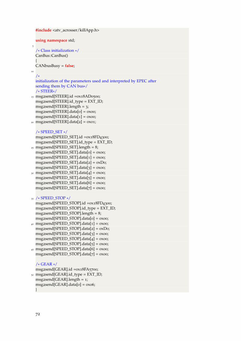
#include <atv_acrosser/killApp.h>
using namespace std;5
/* Class initialization */CanBus::CanBus(){CANbusBusy = false;
10
/*initialization of the parameters used and interpreted by EPEC aftersending them by CAN bus*//* STEER*/
15 msg2send[STEER].id =0x18AD0500;msg2send[STEER].id_type = EXT_ID;msg2send[STEER].length = 3;msg2send[STEER].data[0] = 0x00;msg2send[STEER].data[1] = 0x00;
20 msg2send[STEER].data[2] = 0x01;
/* SPEED_SET */msg2send[SPEED_SET].id =0x18FD4300;msg2send[SPEED_SET].id_type = EXT_ID;
25 msg2send[SPEED_SET].length = 8;msg2send[SPEED_SET].data[0] = 0x00;msg2send[SPEED_SET].data[1] = 0x00;msg2send[SPEED_SET].data[2] = 0xD0;msg2send[SPEED_SET].data[3] = 0x00;
30 msg2send[SPEED_SET].data[4] = 0x00;msg2send[SPEED_SET].data[5] = 0x00;msg2send[SPEED_SET].data[6] = 0x00;msg2send[SPEED_SET].data[7] = 0x00;
35 /* SPEED_STOP */msg2send[SPEED_STOP].id =0x18FD4300;msg2send[SPEED_STOP].id_type = EXT_ID;msg2send[SPEED_STOP].length = 8;msg2send[SPEED_STOP].data[0] = 0x00;
40 msg2send[SPEED_STOP].data[1] = 0x00;msg2send[SPEED_STOP].data[2] = 0xD0;msg2send[SPEED_STOP].data[3] = 0x00;msg2send[SPEED_STOP].data[4] = 0x00;msg2send[SPEED_STOP].data[5] = 0x00;
45 msg2send[SPEED_STOP].data[6] = 0x00;msg2send[SPEED_STOP].data[7] = 0x00;
/* GEAR */msg2send[GEAR].id =0x18FA5700;
50 msg2send[GEAR].id_type = EXT_ID;msg2send[GEAR].length = 1;msg2send[GEAR].data[0] = 0x06;}
72
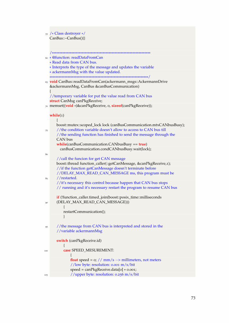
55 /* Class destroyer */CanBus::~CanBus(){}
/******************************************************************60 * @function: readDataFromCan
* Read data from CAN bus.* Interprets the type of the message and updates the variable* ackermannMsg with the value updated.******************************************************************/
65 void CanBus::readDataFromCan(ackermann_msgs::AckermannDrive&ackermannMsg, CanBus &canBusCommunication){//temporary variable for put the value read from CAN busstruct CanMsg canPkgReceive;
70 memset((void *)&canPkgReceive, 0, sizeof(canPkgReceive));
while(1){boost::mutex::scoped_lock lock (canBusCommunication.mtxCANbusBusy);
75 //the condition variable doesn’t allow to access to CAN bus till//the sending function has finished to send the message through theCAN buswhile(canBusCommunication.CANbusBusy == true)
canBusCommunication.condCANbusBusy.wait(lock);80
//call the funcion for get CAN messageboost::thread function_caller(::getCanMessage, &canPkgReceive,1);//if the function getCanMessage doesn’t terminate before//DELAY_MAX_READ_CAN_MESSAGE ms, this program must be
85 //restarted.//it’s necessary this control because happen that CAN bus stops// running and it’s necessary restart the program to resume CAN bus
if (!function_caller.timed_join(boost::posix_time::milliseconds90 (DELAY_MAX_READ_CAN_MESSAGE)))
{restartCommunication();}
95 //the message from CAN bus is interpreted and stored in the//variable ackermannMsg
switch (canPkgReceive.id){
100 case SPEED_MESUREMENT:{float speed = 0; // mm/s −> millimeters, not meters//low byte: resolution: 0.001 m/s/bitspeed = canPkgReceive.data[0] * 0.001;
105 //upper byte: resolution: 0.256 m/s/bit
73

speed += canPkgReceive.data[1] * 0.256;if(canPkgReceive.data[7] == 0x40)speed *= −1;ackermannMsg.speed = speed;break;
110 }
case STEERING_POSITION:{int position;
115 position = canPkgReceive.data[0];position += canPkgReceive.data[1] * 256;//radackermannMsg.steering_angle = atan(LENGHT_VEHICLE*(position− STEERING_DEFAULT_POSITION) /
120 (RESOLUTION_CURVATURE_CONVERSION ) );break;}
}
125 }//while(1)}
/******************************************************************130 * @function: readCANmessageThread
* Thread − send to ROS topic the ackermannMsg readed* Periodically the function readDataFromCan is called to update* the values of ackermannMsg from * CAN bus and published them* via ROS.
135 *******************************************************************/void CanBus::readCANmessageThread(int argc, char **argv, CanBus&canBusCommunication){//show the firmware version, it’s also used for checking if the CAN
140 //bus workscanShowFwVersion();
//ros initializationros::init(argc, argv, "");
145 ros::NodeHandle nodePlannerController;//create a ros::Publisher which is used to publish on a topic called "fromCan2Ros"ros::Publisher msgPublic = nodePlannerController.advertise<ackermann_msgs::AckermannDrive>("fromCan2Ros", 1);
ros::Rate loop_rate(ROS_SEND_MESSAGE_FREQUENCE_HZ); //Hz150
//call the thread readDataFromCanboost::thread threadReadDataFromCan(&CanBus::readDataFromCan,boost::ref(ackermannMsg),
boost::ref(canBusCommunication));155
while (ros::ok()){
74
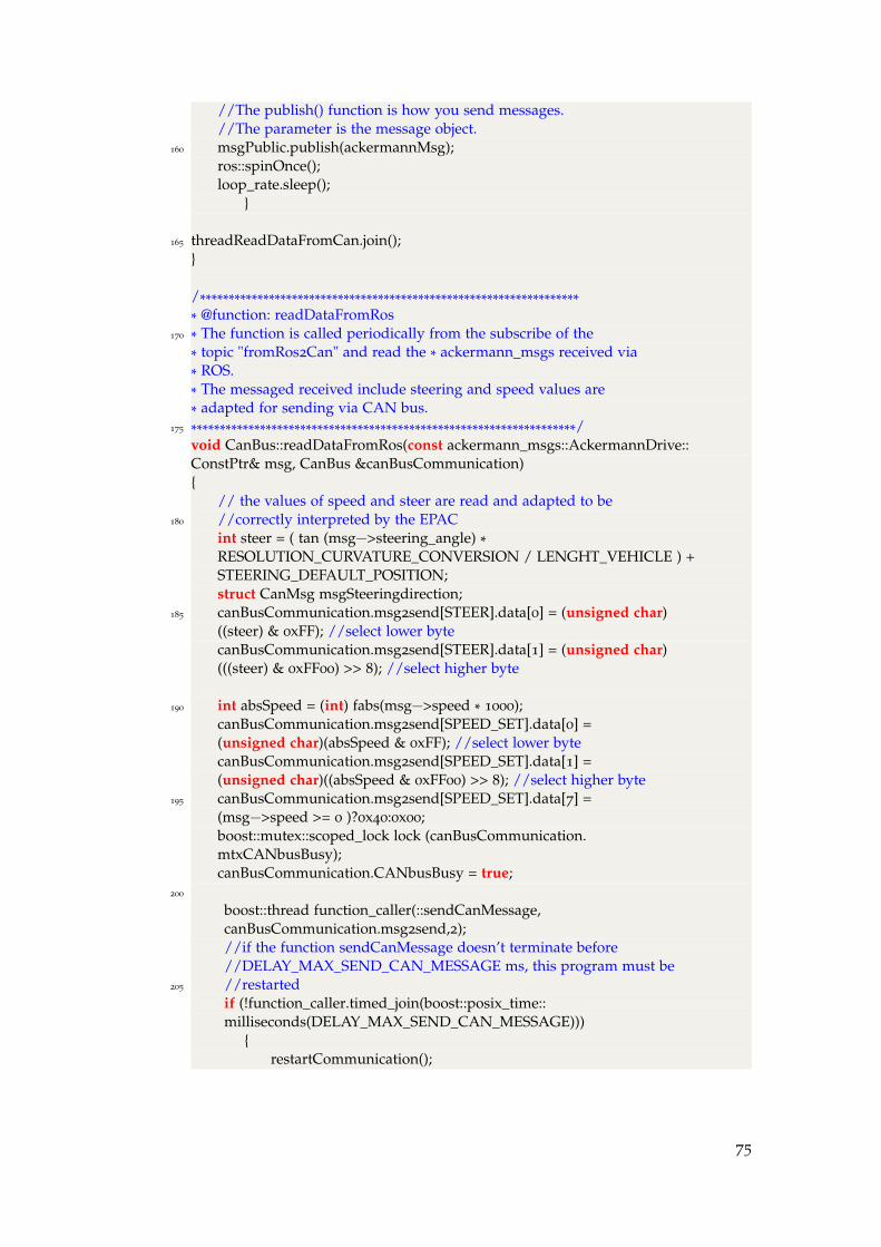
//The publish() function is how you send messages.//The parameter is the message object.
160 msgPublic.publish(ackermannMsg);ros::spinOnce();loop_rate.sleep();
}
165 threadReadDataFromCan.join();}
/******************************************************************* @function: readDataFromRos
170 * The function is called periodically from the subscribe of the* topic "fromRos2Can" and read the * ackermann_msgs received via* ROS.* The messaged received include steering and speed values are* adapted for sending via CAN bus.
175 *******************************************************************/void CanBus::readDataFromRos(const ackermann_msgs::AckermannDrive::ConstPtr& msg, CanBus &canBusCommunication){
// the values of speed and steer are read and adapted to be180 //correctly interpreted by the EPAC
int steer = ( tan (msg−>steering_angle) *RESOLUTION_CURVATURE_CONVERSION / LENGHT_VEHICLE ) +STEERING_DEFAULT_POSITION;struct CanMsg msgSteeringdirection;
185 canBusCommunication.msg2send[STEER].data[0] = (unsigned char)((steer) & 0xFF); //select lower bytecanBusCommunication.msg2send[STEER].data[1] = (unsigned char)(((steer) & 0xFF00) >> 8); //select higher byte
190 int absSpeed = (int) fabs(msg−>speed * 1000);canBusCommunication.msg2send[SPEED_SET].data[0] =(unsigned char)(absSpeed & 0xFF); //select lower bytecanBusCommunication.msg2send[SPEED_SET].data[1] =(unsigned char)((absSpeed & 0xFF00) >> 8); //select higher byte
195 canBusCommunication.msg2send[SPEED_SET].data[7] =(msg−>speed >= 0 )?0x40:0x00;boost::mutex::scoped_lock lock (canBusCommunication.mtxCANbusBusy);canBusCommunication.CANbusBusy = true;
200
boost::thread function_caller(::sendCanMessage,canBusCommunication.msg2send,2);//if the function sendCanMessage doesn’t terminate before//DELAY_MAX_SEND_CAN_MESSAGE ms, this program must be
205 //restartedif (!function_caller.timed_join(boost::posix_time::milliseconds(DELAY_MAX_SEND_CAN_MESSAGE)))
{restartCommunication();
75
210 }//set to false the boolean variable that rappresent the status//of the CAN bus and alert the condition variable that//the CAN bus is available for a possible read
canBusCommunication.CANbusBusy = false;215 canBusCommunication.condCANbusBusy.notify_one();
}
/******************************************************************220 * @function: sendCANmessageThread
* Thread − read from ROS topic "fromRos2Can"* Periodically the function readDataFromRos is called read data* from ROS and send them to CAN.*******************************************************************/
225 void CanBus::sendCANmessageThread(int argc, char **argv, CanBus&canBusCommunication){//ros initializationros::init(argc, argv, "sendCANmessageThread");
230 ros::NodeHandle n;ros::Rate loop_rate(ROS_READ_MESSAGE_FREQUENCE_HZ); //Hz//The subscribe() call the ROS master node for communicate that//the function wants to receive ROS messages from the topic//"fromRos2Can"
235 ros::Subscriber sub = n.subscribe<ackermann_msgs::AckermannDrive>("fromRos2Can", 1, boost::bind(readDataFromRos, _1,boost::ref(canBusCommunication)));while (ros::ok())
{240 ros::spinOnce();
loop_rate.sleep();}
exit(1);245 }
/******************************************************************* @function: restartCommunication
250 * Kill the program* There is a syncronous communication with the program* startCommunication via ROS with a service.* ./restartCommunication signal to startCommunication that the* process must die, when get the feedback from
255 * ./restartCommunication it proceed to kill itself.******************************************************************/void CanBus::restartCommunication(){
260 int argc = 0;char** argv;
76

//ros initializationros::init(argc, argv, "talker");ros::NodeHandle n;
265
//creates a client for the killApp serviceros::ServiceClient client = n.serviceClient<atv_acrosser::killApp>("killCAN");atv_acrosser::killApp srv;
270 //get the name of the pidsrv.request.pid2Kill = getpid();if (client.call(srv)){
//when receive the feedback from the275 ROS_INFO("Sum: %ld", (long int)srv.response.pidKilled);
exit(0);}else
ROS_ERROR("Failed to call service killCAN");280 }
/******************************************************************* @function: canShowFwVersion* Show the version of the firmware version
285 * If there are some problem for getting the firmware version* there are some problems in * the CAN communication and then* then communication must be restarte calling the function* restartCommunication().******************************************************************/
290 void CanBus::canShowFwVersion(){
PicInfo picInfo = {0};
int result = getCanFwVer(&picInfo);295
if(!result) {cout << picInfo.info;
} else {restartCommunication();
300 }
return;}
d.4 ./can.h
The header include the definition of the class CanBus.
Listing 29: CAN.h
//=================================2 // include guard
#ifndef __CAN_H_INCLUDED__
77
#define __CAN_H_INCLUDED__
//=================================7 // define
enum EnumTypeMsg { STEER, SPEED_SET, SPEED_STOP, GEAR };//=================================// included dependencies#include "../include/atvAcrosser/parameterCar.h"
12 #include "ackermann_msgs/AckermannDrive.h"#include <boost/thread/thread.hpp>#include "ros/ros.h"#include <stdio.h>#include "ARV6005Lib.h"
17
//=================================// classclass CanBus{
22 private:boost::mutex mtxCANbusBusy;boost::condition_variable condCANbusBusy;bool CANbusBusy;
27 CanMsg msg2send[2];
ackermann_msgs::AckermannDrive ackermannMsg;
static void restartCommunication();32 static void canShowFwVersion();
static void readDataFromCan(ackermann_msgs::AckermannDrive &ackermannMsg,CanBus &canBusCommunication);
37 static void readDataFromRos(const ackermann_msgs::AckermannDrive::ConstPtr& msg,CanBus &canBusCommunication);
//this function is used when I send just one message in42 //the CAN bus
//static void readDataFromRos(//const ackermann_msgs::AckermannDrive::ConstPtr& msg);
public:47 CanBus();
~CanBus();void readCANmessageThread(int argc, char **argv,CanBus &canBusCommunication);
void sendCANmessageThread(int argc, char **argv,52 CanBus &canBusCommunication);
//};
78

#endif // __CAN_H_INCLUDED__
d.5 ./parametercar .h
Definition of the constants parameters .
Listing 30: parameterCar.h
//=================================// include guard#ifndef __PARAMETERCARH_INCLUDED__
4 #define __PARAMETERCARH_INCLUDED__
//CAN communication parameters#define AUTOMATION_STATUS 0x18FF2004ULL#define SPEED_MESUREMENT 0xCF02205ULL
9 #define STEERING_POSITION 0xCAC0005ULL
//VEHICLE communication steering parameter#define STEERING_DEFAULT_POSITION 32128
#define STEERING_MAX_RANGE 4000 //bits14 #define STEERING_MAX_GRADE 70 //grads
//VEHICLE parameters#define LENGHT_VEHICLE 1.85 //m//resolution curvature: 0.25km^−1/bit
19 #define RESOLUTION_CURVATURE 4
#define CONVERSION_m2Km 1000
#define RESOLUTION_CURVATURE_CONVERSIONRESOLUTION_CURVATURE*CONVERSION_m2Km
24
//ROS frequencies parameters#define ROS_SEND_MESSAGE_FREQUENCE_HZ 100 //Hz#define ROS_READ_MESSAGE_FREQUENCE_HZ 100 //Hz
29 //maximum waiting time for a CAN communication#define DELAY_MAX_SEND_CAN_MESSAGE 5000 //ms#define DELAY_MAX_READ_CAN_MESSAGE 5000 //ms
#endif // __PARAMETERCARH_INCLUDED__
79


EU S E R G U I D E
• Start ROS Master from console editing roscore.
• startCommunication:
– Open a new console.
– cd catkin_ws/devel/lib/atv_acrosser
– sudo su
– ./startCommunication
81

B I B L I O G R A P H Y
[1] ATV Project, http://youtu.be/sPQ9SbqnfzA.
[2] ATV Project, on board camera, http://youtu.be/3RA6j4X4qKY.
[3] Self-driving cars: the next revolution, KPMG, CAR,www.kpmg.com/US/en/IssuesAndInsights/ArticlesPublications/Documents/self-driving-cars-next-revolution.pdf.
[4] National Highway Traffic Safety Administration,http://www.nhtsa.gov/staticfiles/rulemaking/pdf/Automated_Vehicles_Policy.pdf .
[5] The Drivers Behind Autonomous Vehicles, KATHY PRETZ, 2014
http://theinstitute.ieee.org/people/achievements/the-drivers-behind-autonomous-vehicles.
[6] Self-Driving Cars: The Next Revolution. Ann Arbor, MI., Richard Wallaceand Gary Silberg, KPMG and CAR (2012).
[7] Preparing a Nation for Autonomous Vehicles, Daniel J. Fagnant, 2012
Fellow, Eno Center for Transportation,https://www.enotrans.org/wp-content/uploads/wpsc/downloadables/AV-paper.pdf.
[8] Self-driving cars: The next revolution, KPMG, 2012,http://www.kpmg.com/US/en/IssuesAndInsights/ArticlesPublications/Documents/self-driving-cars-next-revolution.pdf.
[9] The Road Ahead: The Emerging Policy Debates for IT in Vehicles, ITIF ,2013, http://www2.itif.org/2013-road-ahead.pdf.
[10] The Revolutionary Development of Self-Driving Vehicles andImplications for the Transportation Engineering Profession JM Lutin, ALKornhauser, E Lerner-Lam - ITE Journal, 2013 -digitaleditions.sheridan.com
[11] An autonomous driverless car: an idea to overcome the urban roadchallenges SD Rathod - Journal of Information Engineering andApplications, 2013 - iiste.org
[12] Autonomous Vehicle Implementation Predictions, Todd Litman, VictoriaTransport Policy Institute, http://www.vtpi.org/avip.pdf.
[13] BOSCH - CAN Specification 1991, Robert Bosch GmbH,http://esd.cs.ucr.edu/webres/can20.pdf.
[14] Texas Instruments Controller Area Network Physical Layer Requirements,www.ti.com/lit/an/slla270/slla270.pdf.
83
[15] CAN in Automation(CiA) - Can Open CAN physical layer,www.can-cia.org.
[16] Vector - Introduction to J1939,www.vector.com/portal/medien/cmc/application_ notes/AN-ION-1-3100_Introduction_ to_ J1939.pdf.
[17] RM9000 - Device manual, IFM electronics,https://www.ifm.com/mounting/704820UK.pdf.
[18] 102HA - Device manual, Industrial Encoders Direct Ltd,http://www.industrialencodersdirect.co.uk/pdf/102HS.pdf.
[19] Epec 5050 Control Unit, EPEC, http://www.epec.fi.
[20] HM76V0FL - Device manual, Acrosser,www.acrosser.com/upload/AIV-HM76V0FL.pdf.
[21] LiDAR - Device manual, Velodyne,http://velodynelidar.com/lidar/hdlproducts/97-0038d.
[22] People and Robot Localization and Trackingthrough a Fixed StereoVision System, Shahram Bahadori, Luca Iocchi, Luigi Scozzafava,http://www.academia.edu/2715907/Multi-scale_Meshing_in_Real-time.
[23] Kvaser Leaf Light HS - Device manual, Kvaser,http://www.kvaser.com/products/kvaser-leaf-light-hs.
[24] ROS, http://www.ros.org.
[25] Ackermann Group, http://wiki.ros.org/Ackermann%20Group.
84