universiti teknologi malaysia - faculty of …€¦ · · 2017-08-09universiti teknologi malaysia...
TRANSCRIPT
NOTES : * If the thesis is CONFIDENTAL or RESTRICTED, please attach with the letter from the organization with period and reasons for confidentiality or restriction.
DECLARATION OF THESIS / UNDERGRADUATE PROJECT PAPER AND COPYRIGHT
Author’s full name : MOHD ARIF BIN MAT LAZI
Date of birth : 16 JULY 1985
Title : MECHANICAL PROPERTIES OF HYBRID GLASS FIBRE
RECYCLATE/KENAF FIBRE
Academic Session : 2014/2015
I declare that this thesis is classified as:
I acknowledged that Universiti Teknologi Malaysia reserves the right as follows:
1. The thesis is the property of Universiti Teknologi Malaysia. 2. The Library of Universiti Teknologi Malaysia has the right to make copies for the
purpose of research only. 3. The Library has the right to make copies of the thesis for academic exchange.
Certified by:
SIGNATURE
SIGNATURE SIGNATURE OF SUPERVISOR
850716145223 DR. SHUKUR BIN ABU HASAN (NEW IC NO. /PASSPORT NO.) NAME OF SUPERVISOR
Date : 18 DECEMBER 2014 Date : 18 DECEMBER 2014
CONFIDENTIAL (Contains confidential information under the Official Secret Act 1972)*
RESTRICTED (Contains restricted information as specified by the organization where research was done)*
OPEN ACCESS I agree that my thesis to be published as online open access
(full text)
UNIVERSITI TEKNOLOGI MALAYSIA
PSZ 19:16 (Pind. 1/07)
UTM(FKM)-1/02
Faculty of Mechanical Engineering
Universiti Teknologi Malaysia
VALIDATION OF E-THESIS PREPARATION
Title of the thesis: MECHANICAL PROPERTIES OF HYBRID GLASS FIBRE RECYCLATE/KENAF FIBRE
Degree: BACHELOR DEGREE OF MECHANICAL ENGINEERING Faculty: MECHANICAL ENGINEERING (FKM) Year: 2014
I, MOHD ARIF BIN MAT LAZI
(CAPITAL LETTER)
declare and verify that the copy of e-thesis submitted is in accordance to the Electronic
Thesis and Dissertation’s Manual, Faculty of Mechanical Engineering, UTM
_____________________
(Signature of the student)
______________________
(Signature of supervisor as a witness)
Permanent address:
NO. 37, Lorong Dato’ Mufti 9,
Kg. Dato’ Mufti Suib,
68000 Ampang,
Selangor.
Name of Supervisor: Dr. Shukur bin Abu Hasan
Faculty: Mechanical Engineering
Date: 18 DECEMBER 2014

“I hereby declare that I have read this thesis and in
my opinion this thesis is sufficient in terms of scope and
quality for the award of the degree of Bachelor of Mechanical Engineering”
Signature : _________________________
Name of Supervisor : DR. SHUKUR BIN ABU HASAN
Date : _______________

ii
MECHANICAL PROPERTIES OF HYBRID GLASS FIBRE RECYCLATE/KENAF
FIBRE
MOHD ARIF BIN MAT LAZI
A thesis submitted in partial fulfillment of the requirements for the
award of the degree of Bachelor of Mechanical Engineering
Faculty of Mechanical Engineering
Universiti Teknologi Malaysia
DECEMBER, 2014

iii
I declare that this thesis entitled “Mechanical Properties Of Hybrid Glass Fibre
Recyclate/Kenaf Fibre” is the result of my own study except as cited in the references.
The thesis has not been accepted for any degree and is not concurrently submitted in
candidature of any other degree.
Signature : ___________________________
Name : MOHD ARIF BIN MAT LAZI
Date : 18 DECEMBER 2014

iv
Specially dedicated to my beloved wife, parents, brother, sister and friends for their
understanding, caring and inspired me throughout my journey of education.
God bless all of you.

v
ACKNOWLEDGEMENT
I would like to take this opportunity to express my appreciation to all
individuals whose inspiration and constructive ideas have contributes towards the
success of this prefect. First of all, I would like to give my gratitude to our beloved
god for His blessing and giving me the strength along the challenging journey to
accomplish my project successfully.
I also want to express my sincere appreciation to my supervisor, Dr. Shukur
bin Abu Hasan for his support, guidance, instruction, critic and advice throughout my
graduate career. I am deeply impressed by his enthusiasm and helpfulness toward the
accomplishment of this project. Other than that, I’m very grateful with my family
who gave me fully moral support and encouragement throughout my studies here.
Special thanks to all the technicians from Faculty of Mechanical Engineering for
their patience and guidance during preparation of samples and conducting
experiment.
Last but not least, for those who have contributed directly or indirectly in
producing this project, your help are very much acknowledge. Thank you.

vi
ABSTRACT
The main purpose of this project is to study the mechanical properties (tensile
and bending) properties of rGFRP/KENAF composites using vacuum assisted resin
transfer moulding (VARTM) technique. Each composites formulation will be subject
to tensile loading. Specimens will prepare according to ASTM D3039. The test was
run using Universal Testing Machine, Instron 5982. Three specimens will prepare for
this test. The test will conduct with the crosshead speed of 2mm/min. The specimens
will subject to loading until failure. Three points bending test was conducted to the
specimen in order to determine the bending strength and modulus. In addition,
certain aspects such as the relationship between stress-strain can be known.
Experiment standards used in this test is based on the CRAG Test Method. The test
was run using Universal Testing Machine, Instron 5982. This machine is used in
conjunction with 'Roller Centre' to support the specimen. Test was conducted at
room temperature 28 oC and 50% humidity. The speed selected is 2 mm / min
towards the constant load throughout the experiments. Thus failed specimen was
observed and studies the fractured microstructure of the composite.

vii
ABSTRAK
Tujuan utama projek ini adalah untuk mengkaji sifat-sifat mekanik (tegangan
dan lenturan) sifat-sifat komposit rGFRP/KENAF menggunakan teknik vakum
dibantu acuan pemindahan resin (VARTM). Setiap penggubalan komposit akan
tertakluk kepada bebanan tegangan. Spesimen akan disediakan mengikut ASTM
D3039. Ujian ini telah dijalankan dengan menggunakan Mesin Universal, Instron
5982. Tiga spesimen akan disediakan untuk ujian ini. Ujian ini akan dijalankan
dengan kelajuan 2mm/min. Spesimen akan tertakluk kepada bebanan sehingga
gagal. Tiga mata ujian lenturan dijalankan bagi menentukan kekuatan lenturan dan
modulus. Di samping itu, aspek-aspek tertentu seperti hubungan antara tegasan-
terikan boleh diketahui. Piawaian eksperimen yang digunakan dalam ujian ini adalah
berdasarkan Ujian Kaedah Crag. Ujian ini telah dijalankan dengan menggunakan
Mesin Universal, Instron 5982. Mesin ini digunakan bersama dengan 'Pusat Roller'
untuk menyokong spesimen. Ujian telah dijalankan pada suhu bilik 28 oC dan 50%
kelembapan. Kelajuan dipilih adalah 2 mm/min ke arah beban yang tetap di
sepanjang eksperimen. Oleh itu spesimen yang gagal akan diperhati dan dianalisis
menggunakan mikroskop.

viii
TABLES OF CONTENTS
CHAPTER TITLE PAGE
TITLE ii
DECLARATION iii
DEDICATION iv
ACKNOWLEGEMENT v
ABSTRACT vi
ABSTRAK vii
TABLE OF CONTENTS viii
LIST OF TABLES xi
LIST OF FIGURES xii
LIST OF ABBREVIATIONS xv
LIST OF APPENDICES
xvi
1 INTRODUCTION
1.1 Background Study 1
1.2 Problem Statement 9
1.3 Project Objectives 9
1.4 Scope of studies 9
1.5 The Significance of studies 10
1.6 Thesis Outline 10
2 LITERATURE REVIEW
2.1 Introduction 11
2.2 Waste Management 13
2.3 The Waste Hierarchy 13
2.4 End Products from Recyclate 19

ix
2.5 Life Cycle Assessment and Eco Design 24
2.6 Composite 24
2.7 Matrices in Composite Material 29
2.8 Classification of Natural Fibres 34
2.9 Kenaf Plants and its Fibre 46
3 METHODOLOGY
3.1 Introduction 55
3.2 Survey of FRP Waste Management in Malaysia 55
3.3 Material Preparation 56
3.4 Composite Formulation 60
3.5 Composite Fabrication use Vacuum Assisted Resin
Transfer Moulding (VARTM)
60
3.6 Sample Testing 64
3.7 Schedule of Research 70
4 RESULT AND DISCUSSION
4.1 Introduction 71
4.2 Tensile Test 72
4.2.1 rGFRP Tensile Test 72
4.2.2 rGFRP/Kenaf Core Tensile Test 73
4.3 Bending Test 74
4.3.1 rGFRP Bending Test 74
4.3.2 rGFRP/Kenaf Core Bending Test 75
4.4 Microstructure Analysis 76
4.5 Tensile Test Comparison 78
4.6 Bending Test Comparison 79

x
5 CONCLUSION AND RECOMMENDATION
5.1 Conclusion 80
5.2 Recommendation 81
REFERENCES 82
Appendices 85
xi
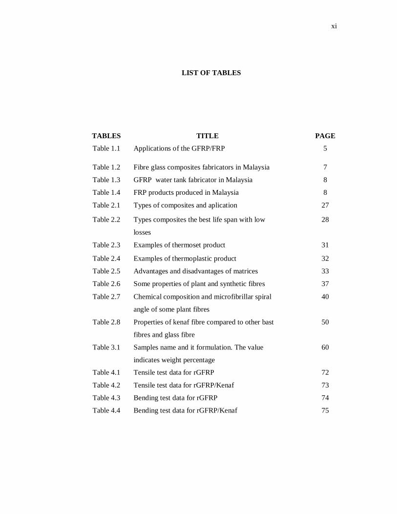
LIST OF TABLES
TABLES TITLE PAGE
Table 1.1 Applications of the GFRP/FRP 5
Table 1.2 Fibre glass composites fabricators in Malaysia 7
Table 1.3 GFRP water tank fabricator in Malaysia 8
Table 1.4 FRP products produced in Malaysia 8
Table 2.1 Types of composites and aplication 27
Table 2.2 Types composites the best life span with low
losses
28
Table 2.3 Examples of thermoset product 31
Table 2.4 Examples of thermoplastic product 32
Table 2.5 Advantages and disadvantages of matrices 33
Table 2.6 Some properties of plant and synthetic fibres 37
Table 2.7 Chemical composition and microfibrillar spiral
angle of some plant fibres
40
Table 2.8 Properties of kenaf fibre compared to other bast
fibres and glass fibre
50
Table 3.1 Samples name and it formulation. The value
indicates weight percentage
60
Table 4.1 Tensile test data for rGFRP 72
Table 4.2 Tensile test data for rGFRP/Kenaf 73
Table 4.3 Bending test data for rGFRP 74
Table 4.4 Bending test data for rGFRP/Kenaf 75
xii
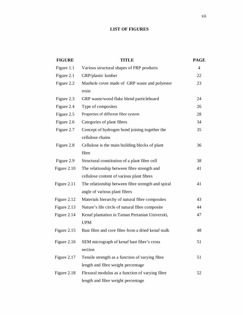
LIST OF FIGURES
FIGURE TITLE PAGE
Figure 1.1 Various structural shapes of FRP products 4
Figure 2.1 GRP/plastic lumber 22
Figure 2.2 Manhole cover made of GRP waste and polyester
resin
23
Figure 2.3 GRP waste/wood flake blend particleboard 24
Figure 2.4 Type of composites 26
Figure 2.5 Properties of different fibre system 28
Figure 2.6 Categories of plant fibres 34
Figure 2.7 Concept of hydrogen bond joining together the
cellulose chains
35
Figure 2.8 Cellulose is the main building blocks of plant
fibre
36
Figure 2.9 Structural constitution of a plant fibre cell 38
Figure 2.10 The relationship between fibre strength and
cellulose content of various plant fibres
41
Figure 2.11 The relationship between fibre strength and spiral
angle of various plant fibres
41
Figure 2.12 Materials hierarchy of natural fibre composites 43
Figure 2.13 Nature’s life circle of natural fibre composite 44
Figure 2.14 Kenaf plantation in Taman Pertanian Universiti,
UPM
47
Figure 2.15 Bast fibre and core fibre from a dried kenaf stalk 48
Figure 2.16 SEM micrograph of kenaf bast fibre’s cross
section
51
Figure 2.17 Tensile strength as a function of varying fibre
length and fibre weight percentage
51
Figure 2.18 Flexural modulus as a function of varying fibre
length and fibre weight percentage
52
xiii
Figure 2.19 Effect of different type of fibre on the tensile
strength of kenaf composite and hybrid composite
53
Figure 2.20 Tensile strength of kenaf bast and core fibre
reinforced unsaturated polyester composites
54
Figure 2.21 Flexural strength of kenaf bast and core fibre
reinforced UP composites
54
Figure 3.1 GFRP waste 56
Figure 3.2 Process flow of mechanical shredding of GFRP
waste
57
Figure 3.3 GFRP waste after shredded by crusher machine 57
Figure 3.4 Sieve shaker machine 58
Figure 3.5 GFRP recyclates size of 1 mm to 2.36 mm (fine) 58
Figure 3.6 Polyester resin and hardener (MEKP) 59
Figure 3.7 VARTM injection of test panel mould 61
Figure 3.8 Laying material 61
Figure 3.9 Resin via the peripheral runner channel 62
Figure 3.10 The resin balance 62
Figure 3.11 Sample for tensile test 63
Figure 3.12 Sample for bending test 63
Figure 3.13 Specimen failed due to tensile loading 64
Figure 3.14 Show the dimensions and position of the
specimen for bending test
66
Figure 3.15 Specimen failure due to bending loading 66
Figure 3.16 Shows graph from the 3 point bending test of
material composite
68
Figure 3.17 Flow chart of the research activities 70
Figure 4.1 Tensile test data graph for rGFRP 72
Figure 4.2 Tensile test data graph for rGFRP/Kenaf 73
Figure 4.3 Bending test graph for rGFRP 74
Figure 4.4 Bending test graph for rGFRP/Kenaf 75
Figure 4.5 SEM observations for rGFRP after tensile test 76
Figure 4.6 SEM observations for rGFRP/Kenaf after tensile
test
76

xiv
Figure 4.7 SEM observations for rGFRP after bending test 77
Figure 4.8 SEM observations for rGFRP/Kenaf after bending
test
77
Figure 4.9 Maximum loads for tensile test 78
Figure 4.10 Tensile stresses at maximum load for tensile test 78
Figure 4.11 Maximum loads for bending test 79
Figure 4.12 Bending stresses at maximum load for bending
test
79

xv
LIST OF ABBREVIATIONS
FRP Fibre Reinforce Polymer
rGFRP recyclate Glass Fibre Reinforce Polymer
GFRP Glass Fibre Reinforced Polymer
% Percentage
min minute
Spec Specification
Kg Kilogram
RM Ringgit Malaysia
USD US Dollar
N Newton
Cm Centimeter
Sec Second
mm Millimeter
Pa.s Pascal second
°C Degree Celcius
MPa Mega Pascal
g Gram

xvi
LIST OF APPENDICES
APPENDICES TITLE PAGE
A Questionnaire 85

1
CHAPTER 1
INTRODUCTION
1.1 Background Study
Strength and durability are the main criteria that need to be considered in the
design and selection of materials to ensure the structure will last for its intended design
life. Nowadays, many structures throughout the world are suffering from corrosion
problem. Many reports have highlighted the seriousness of the problem of deteriorated
infrastructure all over the world such as in Canada, the USA and Europe. The cost to
rehabilitate and retrofit existing deteriorated infrastructure worldwide reached billion of
dollars. Thus, for many years, civil engineers and researchers have been putting effort
searching for alternatives material to steel to cater the high cost of repair and maintenance
of structural damaged by corrosion and heavy use.
The search for the new durable material finally materialized when the advanced
composites material which also known as Fibre Reinforced Polymer (FRP) was found to
be applicable in some areas of civil engineering. The FRP, which is made of a
combination of continuous fibre embedded in resin matrix, is likely to be a good
alternative to the conventional materials in some applications..

2
The FRP is not only possesses high tensile strength but also highly durable and
corrosion resistance. In addition, other features of FRP are ease of installation, versatility,
anti-seismic behaviour, electromagnetic neutrality, and excellent fatigue behavior. Carbon,
aramid and glass fibre are the three type of fibre commonly used in the manufacturing of
FRP products. In the early days, the FRP is being developed and studied for aerospace
application. However, due to the advantages associated with the FRP, it has been used and
looked into in many different areas including agriculture, appliances and business
equipments, building and construction, civil engineering, transportation and many others.
The FRP products can be manufactured in various structural shapes and forms
depending on the type of applications. In civil engineering applications the FRP products
can be manufactured in the form of rebars, plates, and structural sections. It can be used as
concrete reinforcement to replace steel, strengthen the existing structure, and as structural
member. Generally, the FRP products made of glass fibre is the most widely used in the
construction industry because the cost is the cheapest among the three types of fibre
available in the market. The possible applications of the Glass Fibre Reinforced Polymer
(GFRP) products are among others as cable tray, ladder, handrail, door frame, gratings,
secondary structures, and water storage tanks. Many studies have been conducted not only
in Malaysia but also throughout the world as to the see the possible application of FRP in
the construction industry.
Given the scarcity of petroleum potential of the future and pressure to reduce
dependence on petroleum products, there is an increasing interest in maximizing the use of
materials that are renewable. Recent interest in reducing the environmental impact of the
materials led to the development of new materials or composites that can reduce pressure
on the environment. Natural fibre-reinforced unsaturated polyester has generated much
interest in recent years as a potential option is environmentally friendly and cost effective
way to make materials of low cost engineering. Environmental regulations have forced the
industry new to find new materials that can replace materials to replace non-renewable
materials are friendly. Therefore environmentally friendly natural fiber combined with
polyester resin widely introduced to the industry because of the advantages.
One of the constituents celebrated the natural fibre reinforced plastic composites in
Malaysia is kenaf fibre. Researches in plastic composite kenaf are growing along with the
demand for the plastic industry to produce petroleum-based materials. Kenaf fibre plastic

3
composite length can be used for a variety of applications where the properties of the
composite synthesis compare favourably with existing ones. Since kenaf always be in the
form of long fibre, the mechanical properties that are used in many industrial applications
such as insulation seals. In addition, kenaf fibre offers the advantage of being
biodegradable, low density, non-abrasive an environmentally friendly processing time.
Interesting features of kenaf fibre are low cost, lightweight, reform, biodegradability and
certain properties of high mechanical.
1.1.1 Types and Applications of FRP Products
The application of FRP in civil engineering can be classified into three areas
namely, applications for new construction, repair and rehabilitation applications, and
architectural applications. FRPs have been used in the new construction such as footbridge
and demonstrated exceptional durability and effective resistance to effects of
environmental exposure. In the area of repair and strengthening, worked have been carried
out on wrapping the damaged bridge piers to prevent collapse, and wrapping reinforced
concrete columns to improve the structural integrity.
This type of application is particularly beneficial foe earthquake prone area. In the
architectural area, FRP can be used in many applications such as cladding, roofing,
flooring, and partitions. The type of FRP products produced will be determined by the
manufacturing methods or process. Several methods are available in producing the FRP
products such as the hands layup, filament winding, pultrusion process and vacuum
assisted raisin transfer moulding (VARTM).
Many local manufacturers have been using the hands lay-up technique in
producing the FRP products due to cheaper production cost. However, the quality of the
product should be of the main concern by the manufacturers. The filament winding
method requires a special filament winding machine and generally used to manufacture
tubular structures. Not many local manufacturers have the filament winding machine
because it is relatively very expensive. Other than the hands lay-up and filament winding
methods, the pultrusion method is generally used to produce continuous prismatic shapes
such as I-beams, angles, channels, rods, plates and tubes.

4
These types of structural shapes are generally suitable to be used in civil
engineering application as structural member. A number of local manufacturers have used
the pultrusion method to produce various structural profiles. VARTM technique will
discuss in chapter 3. Figure 1.1 shows some of the GFRP sections that can be used in the
construction industries.
Figure 1.1 Various structural shapes of FRP products (Mohd Sam et al., 2006)
Since corrosion is one of the main problems faced by the construction industries,
the use of durable and lightweight GFRP products will be very beneficial. Due to exposure
to saltwater components for offshore structures such as oil platform, handrails, and ladder
are very likely to experience corrosion problem. Thus, the GFRP products as shown in
Figure 1.1 are the right choices for offshore application. Not only the corrosion problem
can be overcome or minimized but also the long-term maintenance cost of the structures
will be reduced substantially.
Data gathered from the study shows that the use of FRP products in Malaysia can
be divided into two groups, i.e. structural and non-structural applications. Most of the
applications fall into the category of non-structural application.
From the visit to the manufacturers in various states, it was found that, for smaller
companies, most of the GFRP products were manufactured using hands lay-up technique.

5
On the other hand, some of the larger companies have the facilities of either using
pultrusion, compression moulding or filament winding techniques. Table 1.1 shows
possible areas of applications for the GFRP/FRP products.
Table 1.1 Applications of the GFRP/FRP products (Mohd Sam et al., 2006)
Based on the current trend and feedback from the manufacturers it is believed that
the use of GFRP products in the construction industry will increase in the future due to
their advantages that can be exploited to solve some of the problems faced by the
construction industries. It was also reported that the consumption of FRP increases by
about 5 to 7 percent from the year 1996 to 1998. Many applications of GFRP can be seen
at present time. As an example, the GFRP gratings are being used as manhole cover to
solve problem of missing steel manhole cover. Since GFRP is not recyclable (for
profitable purpose), at present, then the problem of missing steel grating can be solved and
this will ensure the safety of the public. The GFRP plate can be used as signage and can
solve the problem of missing signage.

6
1.1.2 FRP Fabricator in Malaysia
Most of the findings from the study indicated that the use of the GFRP products in
Malaysia was mainly in the area of non-structural applications. Quite a number of local
manufacturers are actively involved with the manufacturing of the GFRP products.
According to the local manufacturers, from discussion during the visit, most of the raw
materials including the fibre and resin are imported from overseas such as China, Japan,
Europe and the USA. Thus, the cost of the current GFRP products may be slightly higher
when compared with the other conventional materials.
However, in the coming years when the demand for the GFRP products increase,
the price will obviously start to decrease. In general, most of the local manufacturers are
using glass fiber to manufacture their products. Table 1.2 shows the number of fiberglass
manufacturers or fabricators in Malaysia collected to date from the study. A wide range of
GFRP products were recorded including water tank, pultruded sections, plates, domes,
gratings, partitions, ceiling, door, signboard, pipes, and many others. The result of the
study shows that most of the GFRP fabricators are found in the states where the industrial
areas are located such as in the state of Johor, Selangor, and Kuala Lumpur.
7
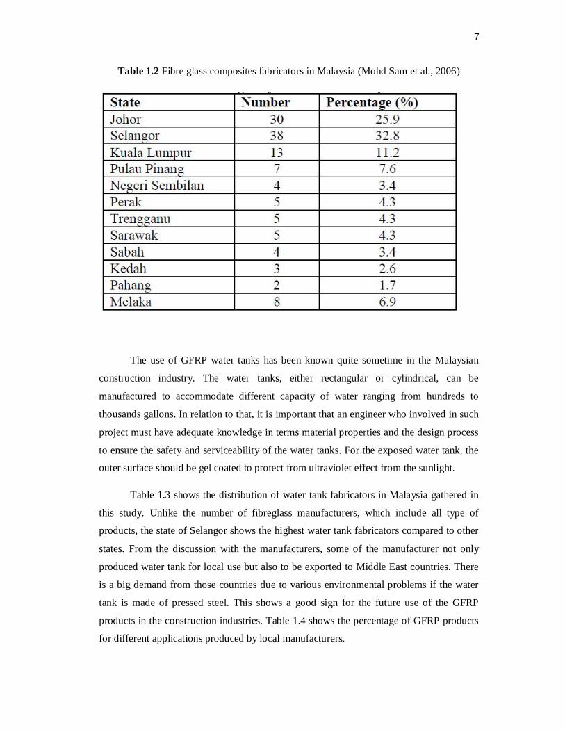
Table 1.2 Fibre glass composites fabricators in Malaysia (Mohd Sam et al., 2006)
The use of GFRP water tanks has been known quite sometime in the Malaysian
construction industry. The water tanks, either rectangular or cylindrical, can be
manufactured to accommodate different capacity of water ranging from hundreds to
thousands gallons. In relation to that, it is important that an engineer who involved in such
project must have adequate knowledge in terms material properties and the design process
to ensure the safety and serviceability of the water tanks. For the exposed water tank, the
outer surface should be gel coated to protect from ultraviolet effect from the sunlight.
Table 1.3 shows the distribution of water tank fabricators in Malaysia gathered in
this study. Unlike the number of fibreglass manufacturers, which include all type of
products, the state of Selangor shows the highest water tank fabricators compared to other
states. From the discussion with the manufacturers, some of the manufacturer not only
produced water tank for local use but also to be exported to Middle East countries. There
is a big demand from those countries due to various environmental problems if the water
tank is made of pressed steel. This shows a good sign for the future use of the GFRP
products in the construction industries. Table 1.4 shows the percentage of GFRP products
for different applications produced by local manufacturers.

8
Table 1.3 GFRP water tank fabricator in Malaysia (Mohd Sam et al., 2006)
Table 1.4 FRP products produced in Malaysia for year 2006 (Mohd Sam et al., 2006)

9
In the earthquake prone countries the use of FRP products can also play an
important role in minimizing the total damage. As an example, currently the use of glass
as partitions, widows or walls for high-rise buildings will pose a great danger once the
glass breaks due to earthquake. Thus, the use of GFRP panel will generally be able to
reduce the risk of injuries to public during the event of earthquake. The visit to one
company that produced artistic GFRP panel, which is difficult to break as compared to
glass, revealed that the use of such panel in Malaysia is still very limited. Most of the
products manufactured by the company were exported to different countries such as the
United States of America. According to the manufacturer, this may be due to lack of
information and promotion to the players in the construction industries.
1.2 Problem Statement
Even though there have been some study on recycling composite material, not
enough study have been done on the mechanical properties of hybrid glass fibre recyclate
with kenaf fibre.
1.3 Project Objective
There are two main objectives of this study, and they are as follows:
1. To study mechanical properties (tensile and bending) properties of
RGFRP/KENAF composites produced by using vacuum assisted resin transfer
moulding (VARTM) technique.
2. To analyse the microstructure of the rGFRP/kenaf composite.
1.4 Scope of Study
Shredder machine used to wreck GFRP waste and filtered by sieve shaker machine
to get the stander size of rGFRP. Specimen prepared by using vacuum assisted resin
transfer moulding (VARTM) technique. Two types of composites prepared to compare
their mechanical properties. The composite are as follows:

10
1. Recyclate Glass Fibre Reinforce Polyester (RGFRP)
2. Recyclate Glass Fibre Reinforce Polyester (RGFRP) + Kenaf Core Fibre
The tensile and bending test performed to compare between two types of
composite as mentioned above. At the end, the fracture microstructure studied on
Scanning Emission Microscope (SEM).
1.5 The Significant of the Study
To find if rGFRP/kenaf can get high stress in terms of bending and tensile thus this
composite can be produce as a product for commercial. From this study, the result that
obtain was as our expectation which is low mechanical properties compare to virgin
material.
1.6 Thesis Outline
The outline of this thesis was divided into five chapters. The first chapter discussed
about the flow of the research which consists of background of research, problem
statement, objective of research, scope of research and significant of research.
This study was focused on RGFRP and Kenaf. The methodology of this research
briefly described in chapter three. The material selection and the instrumentation been
used in this research were mentioned in this chapter. Besides that, the manufacturing
process of kenaf/polyester composite using vacuum assisted resin transfer moulding
(VARTM) technique which starts from preparation until cutting process also been
described in this chapter.
Chapter four discussed about the result and discussion. This result divide by two
which is tensile for RGFRP and RGFRP/Kenaf and bending for RGFRP and
RGFRP/Kenaf. Last chapter referred to the conclusion of this research. In this chapter
discussed of the overall result and analysis.

11
CHAPTER 2
LITERATURE REVIEW
2.1 Introduction
This chapter elaborates more on previous study on rGFRP and kenaf fibre. This
chapter also discussed about previous method to prepare sample for composite which is
vacuum assisted resin transfer moulding.
Composites can manufacture in different technique such as hands lay-up and
vacuum assisted resin transfer moulding techniques. The strength and stiffness properties
of new composite material tested. Composites are very nature mixtures of different
materials polymer, fibrous reinforcement (glass or carbon fiber) and in many cases fillers
(these may be cheap mineral powders to extend the resin or have some other function,
such as fire retardants). There are several potential recycling and end-of-life methods for
polymeric composites including pyrolysis, hydrolysis, chemical recycling, regrinding.

12
For pyrolysis reaction 1 kg composites needs 2.8 MJ energy but can provide useful
energies in the different forms of liquefied natural gas (LPG), fuel oil and composite
fillers. Consequently, the energy recovery of composite structures ideally obtainable
through the pyrolysis method is 19 MJ/kg. The more complex and contaminated the waste,
the more difficult it is to recycle it mechanically. Mechanical recycling techniques have
been investigated for both glass fiber and carbon fiber reinforced composites, but the most
extensive research has been done on glass fiber recovery.
The technique usually used is to initially reduce size of the scrap composite
components in some primary crushing process. The theoretical studies on milling by the
collision method, which were conducted at Tallinn University of Technology (TUT), were
followed by the development of the appropriate devices, called disintegrators, and the
different types of disintegrator milling, the DS-series systems. In the mechanical recycling
process, all of the constituents of the original composite are reduced in size 50 mm – 100
mm pieces. The main size reduction stage would then be in a hammer mill or other high
speed mill where the material is ground into a finer product ranging from typically 10 mm
in size down to particles less than 50 µm in size.
Typically the finer graded fractions are powders and contain a higher proportion of
filler and polymer that the original composite. The coarser fractions tend to be of a fibrous
nature where the particles have a high aspect ratio and have higher fiber content. Among
the other mechanical direct contact milling methods (ball-milling, attritor milling, hammer
milling, etc.) the plastics and composite plastics can be reprocessed by the collision
method.
The theoretical studies on milling by the collision method, which were conducted
at TUT Disintegrator Laboratory, were followed by the development of the disintegrator
mills and centrifugal air separation systems. Fillers are widely used in thermosets,
thermoplastics and elastomers.
However, in recent years it has become more widely recognized that fillers can
enhance the manufacturing and mechanical properties of compounds. Current estimates
put the global market for fillers at between 12 and 18 million tonnes annually. For ideal
filler, the characteristics should include a low cost, the availability, a good wetting and
bonding surface good chemical resistance characteristics. Originally, their main function
13
was seen as reducing the cost of the compound, by filling the thermoplastic or
thermosetting resin matrix.
One of the targets for particulate fillers is also to decrease the weight of the
manufactured composite part. The problem considered consists of three objectives: the
tensile strength and elongation at break subjected to maximization and the cost of the
materials subjected to minimization. The main goal of the current study is to develop new
composite material with optimal physical and mechanical properties.
2.2 Waste Management
Fibre reinforced polymers (FRPs) are increasingly being used in construction due
to their light weight, ease of installation, low maintenance, tailor made properties, and
corrosion resistance. The UK FRP industry produces 240,000 tonnes of products a year
with 11% of this being for the construction industry. Current and impending waste
management legislation will put more pressure on the industry to address the options
available for dealing with FRP waste. Such waste legislation focuses on dealing with
waste through the waste hierarchy and will therefore, put more pressure on solving FRP
waste management through recycling and reuse.
At present the most common disposal method for UKFRP waste is landfill. To
assist in the transition from disposal in landfill to recycling, the FRP industry needs to
consider designing materials and components for easier deconstruction, reuse and
recycling at the end of the product life. Refer appendix for waste management survey in
Malaysia industry and we will found most of FRP industry in Malaysia disposes their FRP
waste.
2.3 The Waste Hierarchy
According to the waste hierarchy, the options for FRP waste management in order
of preference are waste minimization, reuse, recycling, incineration with energy
recovery/composting, and lastly incineration without energy recovery/landfill.
14
2.3.1 Waste Minimization
The most cost effective and environmentally beneficial option of waste
management is not to produce the waste in the first place. By reviewing the manufacturing
process it may be possible to identify a method which results in less production waste.
Waste minimization does not assist in complying with the ELV directive, but may be
useful to consider in the face of increasing landfill charges and the development of
corporate environmental policies.
It could also identify where practicable cost savings can be made. The Building
Research Establishment (BRE) carried out an extensive survey of FRP manufacturing
techniques in the UK. Waste takes a variety of forms such as off-cuts, over spray
trimmings, trimming dust, trimming from vacuum infusion, defective items and trials runs,
plus obsolete moulds. Most automated processes are very efficient and there is little scope
for improvement in terms of reducing generated waste, although waste may be generated
at the beginning and end of production runs, or if components fail to meet accepted
standards, e.g. through a faulty set up.
Most of the waste produced is disposed of in landfill. Some manufacturers bear the
cost of sending bulky waste via skip container to landfill using a contractor, and there is
considerable scope for reducing this burden. Contamination of FRP waste which could be
recycled with other waste such as resin containers, release agent, rainwater, cleaning rags
etc is an important issue.
2.3.2 Reuse
Reuse is high in the hierarchy, but it is debatable how practical this might be. A
FRP component is composed of at least two constituents working together to produce
material properties that are different from the properties of these elements on their own.
The way in which FRPs are used, their applications and how they are secured to existing
structures must be considered with a view to deconstruction and reuse at the end of that
application’s life.

15
The manufacturing process must be examined to identify any possible
modifications to improve design for future reuse or recycling. Avoiding embedded metal
fixings which are difficult to separate prior to grinding is one example. Many FRP items
are bespoke in nature, being especially designed for a particular application or building
(e.g. mouldings and facade panels), meaning that it is very unlikely such products will to
be able to be reused for another, different application. Items such as FRP swimming pools,
cess pits and pipes are designed with very long service lives and are not installed with
recovery or reuse in mind.
One possible option is a downgrading of product use, e.g. tanks and silos for use in
agriculture. However, there is potential to reuse FRP features such as domes, clock towers
and chimneys. Indeed, reuse of items like cabins and gatehouses already takes place.
Structural items such as sections or I beams may be difficult to reuse since it is difficult to
re-calculate their load carrying properties as recovered items, or reliably assess any
degradation or creep effect. This is quite different from the situations for recovered steel
girders, large section timbers, and old bricks, for example, all of which are reclaimed and
have a market value today.
Without reference to the original manufacturer it will be difficult to derive the
strength characteristics such as shear and bending of a FRP section with unknown
matrix/fiber combination and makeup. FRP sections also tend to be produced to meet a
particular set of circumstances and conditions so will often not be transferable to a
different use. The designer of a building or structure will have a duty of care to make sure
it is sound and a material cannot be reused if its strength properties are unknown or in
doubt.
This also applies to any fixings, bolt holes etc for FRP claddings and mouldings.
Similarly, care must be taken with reuse of cladding or roofing to ensure its fire resisting
properties are known. Development of modular and prefabricated systems should allow
reuse if this aspect is considered at the design stage, especially in respect of the type of site
applied sealing and gluing of joints. Although FRP manufacturers have largely solved
issues relating to UV stability and colour fading of their products, many fascia panels and
mouldings may be surface degraded. This will affect the ability to reuse such components.
FRP claddings and mouldings can be refurbished, by painting for example. FRP

16
components are economical to produce, and this counts against reuse of existing items if
they require labour intensive inspection, cleaning, decontamination or repair.
2.3.3 Recycling
2.3.3.1 Production Waste
FRP production waste is generally disposed of since the raw materials used in FRP
manufacture are relatively inexpensive (with the exception of aramid and carbon fibers).
Quantities of waste produced are usually low in comparison to product volume. If the
waste is to be recycled, it may need further treatment such as heat curing before grinding.
2.3.3.2 Building Site Waste
Little or no FRP off-cut waste is generated on new-build construction sites. FRP
components are designed for a particular use, being pre-moulded and made to measure.
This is quite different from the situation with many traditional building components like
timber joists, for example, need to be cut down on site from standard sizes.
2.3.3.3 Deconstruction Waste
Current volumes of FRP deconstruction waste are minimal compared to other
forms of waste and are presently sent to landfill. However, as the quantities of FRP used in
a wider variety of applications increases over the next decade or so, the eventual volumes
of post application FRP will increase. Landfill taxes are predicted to increase sufficiently
to discourage disposal and promote reuse or recycling in the future. The FRP industry has
to address the situation and identify possible solutions in order to maintain the viability of
its products in the construction sector. There are two main types of resin used for FRPs
thermoplastics and thermosets. Thermoplastic FRPs can be recycled by re melting and re
moulding. However, this is not the case for thermoset FRPs which dominate the
construction FRP market.
17
2.3.3.4 Certification of Recycled FRP Products
Schemes are being developed to make it easier to approve construction products on
performance rather than materials specification. However, current procedures do limit the
incorporation of recycled products in many instances. Oxford Brookes University
supported by AEA Technology, Mouchel Consulting and Tony Gee & Partners are
addressing the development of a performance-based classification scheme to enable
engineering designers to select materials systems on the basis of performance
requirements.
Procedures are being developed for the assessment of materials systems on site,
involving the development of manufacturing techniques for on-site fabrication of reliable
and consistent test pieces. This activity is linked with development of in-service health
monitoring techniques that employ both destructive and non-destructive testing. Generic
design guidance is being compiled that utilises the performance classification scheme and
is informed by experience. Case histories are being used to further reinforce the guidance.
The major outputs from this project include the performance classification scheme, test
protocols, design guidance and practical application guidance.
2.3.4 Incineration with Energy Recovery and Composting
FRPs have a high calorific value therefore incineration with energy recovery is a
viable option for FRP waste. Incinerator operators actually charge more for accepting FRP
waste because the high calorific content together with toxic emissions tends to overload
the system, meaning they cannot process as much domestic refuse. It must be borne in
mind that the production of electricity from energy recovery is a secondary concern and
that the prime business of the incinerator is to dispose of domestic refuse. By burning
relatively small quantities of FRP waste, large volumes of domestic waste (of which there
is an unlimited supply) must be sent to landfill.
The use of eco composites is a growing alternative to FRPs. They use plant fibers
as an environmentally friendly and low-cost alternative to glass fibers. Natural fiber FRPs
are from renewable resources and can be composted or incinerated at the end of their life.
The European automotive industry is investigating the possibility of using natural fiber

18
reinforced thermoplastics to benefit the environment whilst saving weight (natural fibers
are 50% lighter than glass fibre) and cost at the same time. Wood floor is also being
investigated as an alternative to mineral fillers. These technologies can be used for both
thermosets and thermoplastics. Natural fibres can easily compete with glass fibres in terms
of stiffness, but their tensile, compressive and impact strength are relatively low compared
to glass fibers. By modifying the resin systems, eco composites can be designed to be
either stable or biodegradable.
As mentioned above, mechanical recycling is preferred over incineration and
landfill. However, mechanical recycling of natural fiber composites could prove
problematic as they tend to degrade near the processing temperature of most
thermoplastics. Composting is unlikely to be practicable for combinations of natural fiber
and resins such as polyester resin. Plenty of clean plant matter from municipal collection
of garden waste, together with agricultural waste such as chicken litter is available for the
compost industry to use and building components with difficult to separate organic matter
will not be considered.
2.3.5 Incineration without Energy Recovery and Landfill
Incineration without energy recovery and land filling of composites waste are the
least preferred options because they result in a loss of the energy content which could be
harvested by incineration with energy recovery. Land filling of composite waste appears to
be the most common disposal option at present in the UK because, although on the
increase, the cost of disposal of waste is still relatively low. The fate of surplus new or
used FRP components depends on the cost effectiveness of the options available. Thus,
until landfill taxes increase to a value where recycling or incineration become viable
alternatives, or legislation changes, most of the FRP waste produced will end up disposed
of in the ground.
19
2.4 End Products from Recyclate
Several potential uses for ground FRP recyclate have been investigated. Artificial
woods have been experimentally manufactured using powder from pulverized waste FRP
products. The waste trimmings from bathtubs were pulverized to make the FRP powder.
The artificial woods were autoclaved from cementitious compositions with various other
contents including carbon fiber. The material can be nailed and sawn like natural wood.
The effect of adding ground recycled fiberglass composite in combination with wood flour
to high density polyethylene (HDPE) plastic lumber has been investigated. The glass
fibers were recovered from Glass Reinforced Polyester (GRP) by granulation. The
addition of ground glass fibers to the plastic lumber significantly increased tensile and
flexural modulus, while decreasing impact strength. The ground glass fibers had a greater
stiffening effect than wood flour, but wood flour had no significant effect on impact
strength.
The use of recycled glass fiber and wood flour together provides better
performance than either alone. Data suggests that recycled glass fibers may be economical
reinforcing filler for use in HDPE plastic lumber. Other research has investigated the use
of scrap graphite/epoxy prepreg waste as high performance reinforcement for recycled
HDPE plastic obtained from the municipal solid waste stream. Flexural properties
increased dramatically with increasing prepreg content and creep resistance was enhanced.
It is thought the product may find a niche in the plastic lumber market due to the improved
modulus, strength and creep resistance measured compared to current commercial
recycled plastic lumber.
The UK highway engineering industry shows a willingness to adopt alternative
sources of material for use in road construction and thereby promote sustainable
development. As road construction consumes vast quantities of natural materials, it has the
potential to provide a suitable end-use for waste materials such as FRP. A joint RMCEF
project is aiming to improve the recyclability of composite building products by
incorporating GRP waste composites into highway materials and conducting tests to
ascertain whether they have a detrimental effect on the material performance.
Preliminary findings have shown that the addition of shredded GRP off-cuts at 1%
has had minimal effect on the performance properties of 20 mm dense bitumen macadam.

20
The research is continuing using higher proportions of shredded composite material. Glass
fibers recovered after incineration or thermal decomposition of FRP waste are sometimes
coated in char when the resin has not been completely decomposed. For the glass fibers to
be recycled as reinforcement, the char must first be cleaned off. If the fibers are to be used
as insulation material, the char does not need to be removed, however the fiber can only be
used as low grade insulation. The insulation performance of glass fiber partly mixed with
calcium carbonate (a filler often used) is not known. The end use of FRP recyclate should
be based on the properties given by the recyclate, particularly where these give added
value, such as:
Chemical and physical properties (e.g. phenolic composites for greater fire
resistance) where recyclate can give special surface effects and designs.
For noise absorption (wall panels or in roads).
Use of fluffy material for high thermal insulation or for nonwoven materials.
For viscosity modification of polymer mixes.
Use of coarse grade material as a permeable flow layer in reinforcement for
vacuum injection.
Low cost core material (in boats or in wood substitute products).
As reinforcement.
Milled fibers.
Asphalt reinforcement.
For concrete repair (concrete is prone to cracking in the first 2 days of drying, use
of glass avoids crack formation, there is a few thousand tonne market in Europe
for this application).
In white lines for road markings (abrasive resistance) the development of new,
high grade markets is a high priority for the development of composites recycling.
There are certain criteria which must be met in order for utilization of waste FRP
in a product to be economically and technically viable. In this instance ground FRP
waste is considered.
The use of ground FRP should be beneficial to the product i.e. the FRP should
have either a structural/reinforcing role or weight saving role, not just act as an
inert filler.
The mix of materials should be synergistic.

21
The product should not have to be reinforced with other material or made thicker
to compensate for some deficiency caused by inclusion of ground FRP.
It should not be merely a novel disposal method such as some component of a
geotechnical fill.
The reuse method should be realistic in respect of the likely volumes of recyclate
available.
The reuse of FRP should not make the ultimate recycling of the product difficult
(current types of ‘plastic wood’ made from post consumer HDPE and wood fiber
can be easily recycled or burned without pollution).
The product should not pose environmental problems or health and safety
problems in use, e.g. abrasion, wear related loss of glass fibers, or during cutting
and drilling.
The product should not be a substitute for something which is actually made from
a more sustainable material in the first instance, such as plantation timber.
The combination of ground FRP with some other waste material should not divert
this waste from an existing higher end reuse chain.
The product should have a suitably long service life.
The product should be cost effective.
2.4.1 Examples of Products Made from Ground GRP
Building Research Establishment UK has carried out development and evaluation
trials for three products incorporating ground GRP. The applications chosen are high-
value end-products where relatively large volumes of ground GRP could be incorporated
economically.
2.4.1.1 GRP/Plastic Lumber
This application offers an alternative to tropical hardwoods or treated softwood for
some types of lightly loaded marine piles such as groynes, fender boards, light bridge
foundations, jetties, boardwalk posts and similar applications. The material can be sawn,
drilled and notched like natural timber.

22
Figure 2.1 GRP/plastic lumber (Conroy et al., 2006)
The GRP/plastic lumber has similar properties to some other wood plastic
composite materials in density, modulus of elasticity and modulus of rupture Figure 2.1. It
is more durable in a marine environment than natural timber. A design load of 50 kN
would be applicable for the product as a 150 mm square section pile.
2.4.1.2 GRP/Polyester Composite
This product is formed from a dough moulding compound. The product offers
good durability with light weight, and has been designed for use in a petrol station
forecourt. A range of similar non-spark, chemical resistant products where weight is not
critical is also envisaged.
Figure 2.2 Manhole cover made of GRP waste and polyester resin (Conroy et al., 2006)
23
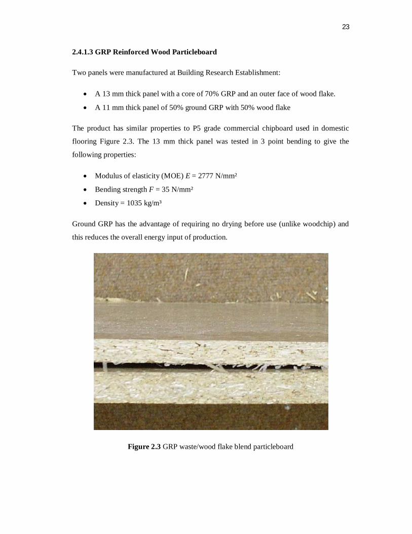
2.4.1.3 GRP Reinforced Wood Particleboard
Two panels were manufactured at Building Research Establishment:
A 13 mm thick panel with a core of 70% GRP and an outer face of wood flake.
A 11 mm thick panel of 50% ground GRP with 50% wood flake
The product has similar properties to P5 grade commercial chipboard used in domestic
flooring Figure 2.3. The 13 mm thick panel was tested in 3 point bending to give the
following properties:
Modulus of elasticity (MOE) E = 2777 N/mm²
Bending strength F = 35 N/mm²
Density = 1035 kg/m³
Ground GRP has the advantage of requiring no drying before use (unlike woodchip) and
this reduces the overall energy input of production.
Figure 2.3 GRP waste/wood flake blend particleboard

24
2.5 Life Cycle Assessment and Eco Design
The use of Life Cycle Assessment (LCA) and Ecodesign can aid the construction
industry in its search for ecologically friendly products. LCA is a quantitative method to
assess the environmental impacts occurring through the product life cycle, covering
materials extraction and processing, manufacture, use, disposal and recycling, and has
already been applied to the construction industry in the form of BRE Environmental
Profiles. Ecodesign takes into consideration the life cycle of the materials used and the
methods of interactions they have with the environment.
It looks at reducing the environmental impact of a product over its life cycle
without impacting on quality. Ecodesign concentrates on ensuring that products are easier
to disassemble and use mainly components that are more easily reused or recycled. Using
these principles in the design process can increase profitability by eliminating waste at the
beginning of the product’s life cycle rather than at the end. LCA and Ecodesign can thus
feed into any part of the waste hierarchy and are in effect an application of the Best
Practicable Environmental Option (BPEO). However, Ecodesign currently lacks the range
and detail of information to make an informed decision for all materials and components.
Environmental Profiles and LCA data already exist for many recycling and disposal
processes, and provide a mechanism to assess new and experimental technique, due to
constraints of time however, these were not explored in this project.
2.6 Composite
A composite is commonly defined as a combination of two or more distinct
materials, each of which retains its own distinctive properties, to create a new material
with properties that cannot be achieved by any of the components acting alone. Using this
definition, it can be determined that a wide range of engineering materials fall into this
category. For example, concrete is a composite because it is a mixture of Portland cement
and aggregate. Fiber glass sheet is a composite since it is made of glass fibers imbedded in
a polymer.
Composite materials are said to have two phases. The reinforcing phase is the
fibre, sheets, or particles that are embedded in the matric phase. The reinforcing material

25
and the matrices material can be metal, ceramic, or polymer. Typically, reinforcing
materials are strong with low densities while the matrices are usually a ductile, or tough
material.
Composite material is a combination of ingredients from a macro to a composite
material can be defined as a material system composed of a mixture or combination of two
or more of the elements that are different in the macro or the shape and material
composition basically inseparable. Composite formed from two different compilers
components namely amplifier (reinforcement) that have formed confidential nature but
more rigid and stronger and generally malleable matric but has the strength and stiffness
of the lower.
Fibre acts as a buffer strength of the composite structure, the load initially received
and then forwarded to the fibre matrices because of the fiber should have a tensile strength
and elasticity which is higher than the matrices. The fiber that is reinforcement in
composite structures must meet the requirements high modulus of elasticity, high fracture
strength, a uniform strength of fiber, stable for handling the production process and fiber
diameter uniform.
If the composite is designed and fabricated correctly, it combines the strength of
the reinforcement with the toughness of the matric to achieve a combination of desirable
properties not available in any single conventional material. Some composites also offer
the advantage of being tailorable so that properties, such as strength and stiffness, can
easily be changed by changing amount or orientation of the reinforcement material. The
downside is that such composites are often more expensive than conventional materials.
2.6.1 Types of composite
According to Figure 2.4, the types of composites can also be classified based on
the geometry as particle reinforced, fiber reinforced, and sandwich or laminated. The very
first known application of fiber composites was in construction .Types of composites and
its application was explained in Table 2.1. Nowadays, the construction is the field of
greatest application of fiber composites. The property of composites of being strong and
resistant to environmental impacts makes them good building material. Composite usage
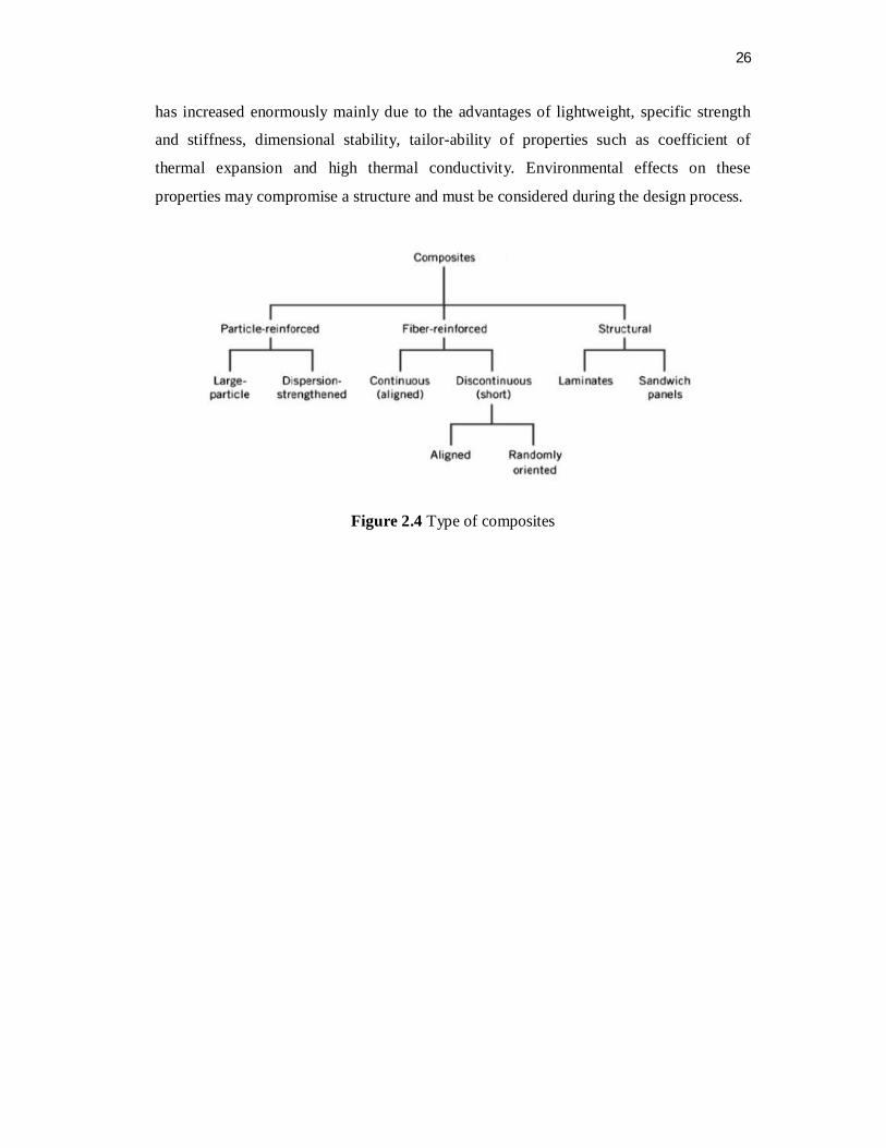
26
has increased enormously mainly due to the advantages of lightweight, specific strength
and stiffness, dimensional stability, tailor-ability of properties such as coefficient of
thermal expansion and high thermal conductivity. Environmental effects on these
properties may compromise a structure and must be considered during the design process.
Figure 2.4 Type of composites
27
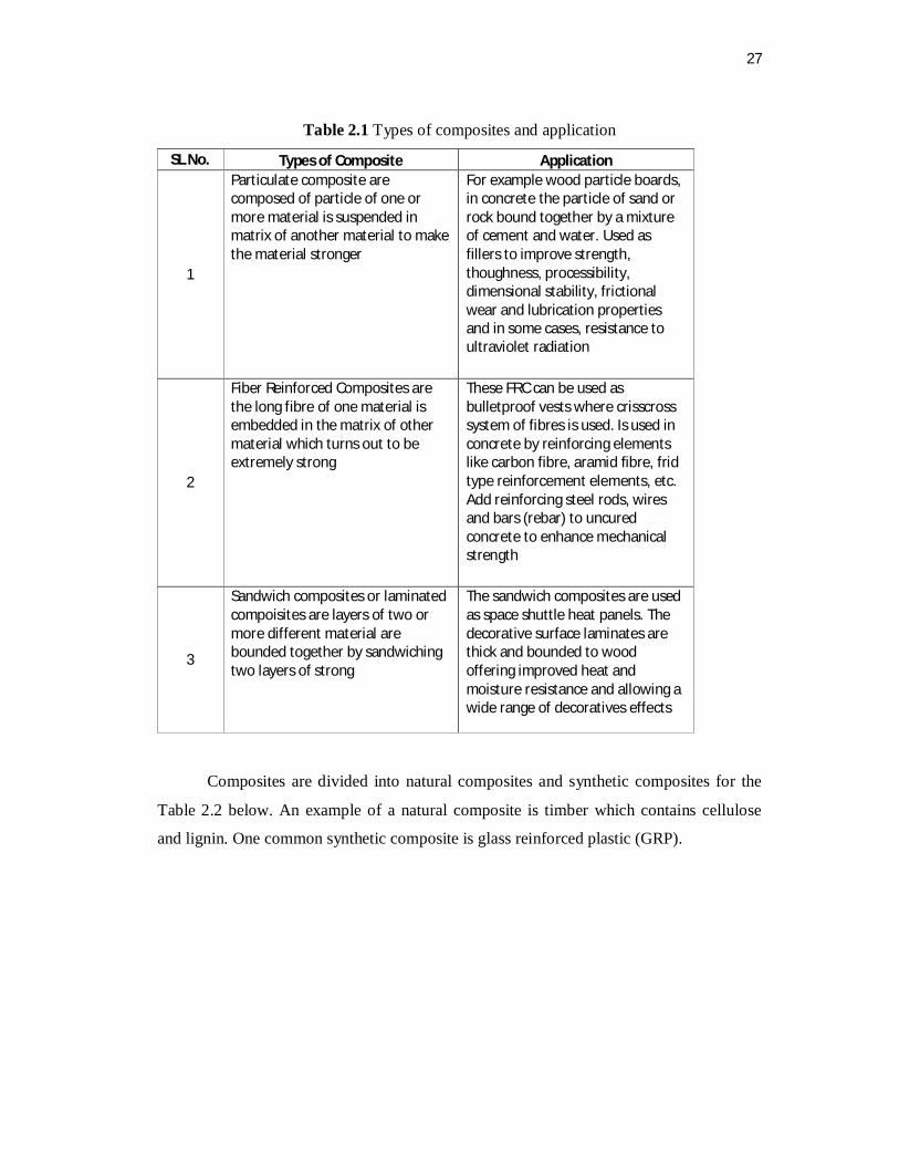
Table 2.1 Types of composites and application
SL No. Types of Composite Application
1
Particulate composite are composed of particle of one or more material is suspended in matrix of another material to make the material stronger
For example wood particle boards, in concrete the particle of sand or rock bound together by a mixture of cement and water. Used as fillers to improve strength, thoughness, processibility, dimensional stability, frictional wear and lubrication properties and in some cases, resistance to ultraviolet radiation
2
Fiber Reinforced Composites are the long fibre of one material is embedded in the matrix of other material which turns out to be extremely strong
These FRC can be used as bulletproof vests where crisscross system of fibres is used. Is used in concrete by reinforcing elements like carbon fibre, aramid fibre, frid type reinforcement elements, etc. Add reinforcing steel rods, wires and bars (rebar) to uncured concrete to enhance mechanical strength
3
Sandwich composites or laminated compoisites are layers of two or more different material are bounded together by sandwiching two layers of strong
The sandwich composites are used as space shuttle heat panels. The decorative surface laminates are thick and bounded to wood offering improved heat and moisture resistance and allowing a wide range of decoratives effects
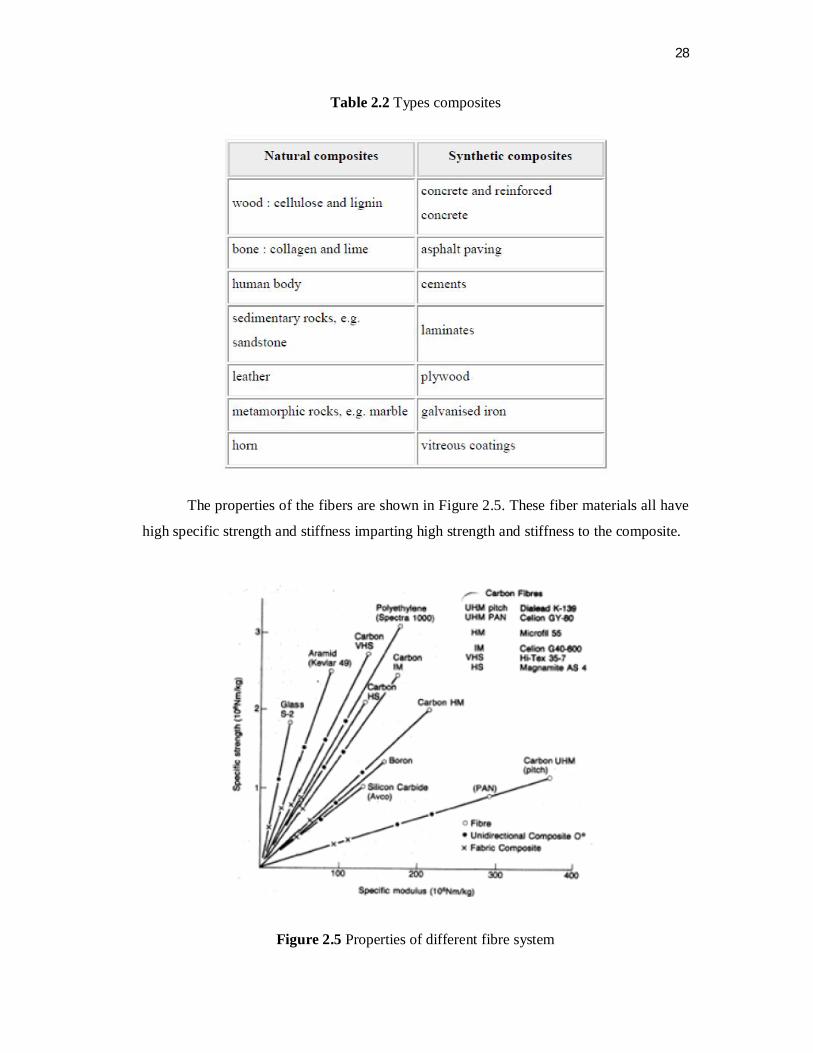
Composites are divided into natural composites and synthetic composites for the
Table 2.2 below. An example of a natural composite is timber which contains cellulose
and lignin. One common synthetic composite is glass reinforced plastic (GRP).
28
Table 2.2 Types composites
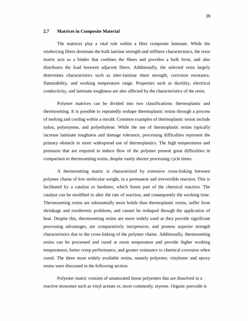
The properties of the fibers are shown in Figure 2.5. These fiber materials all have
high specific strength and stiffness imparting high strength and stiffness to the composite.
Figure 2.5 Properties of different fibre system
29
2.7 Matrices in Composite Material
The matrices play a vital role within a fiber composite laminate. While the
reinforcing fibers dominate the bulk laminar strength and stiffness characteristics, the resin
matric acts as a binder that confines the fibers and provides a bulk form, and also
distributes the load between adjacent fibers. Additionally, the selected resin largely
determines characteristics such as inter-laminar shear strength, corrosion resistance,
flammability, and working temperature range. Properties such as ductility, electrical
conductivity, and laminate toughness are also affected by the characteristics of the resin.
Polymer matrices can be divided into two classifications: thermoplastic and
thermosetting. It is possible to repeatedly reshape thermoplastic resins through a process
of melting and cooling within a mould. Common examples of thermoplastic resins include
nylon, polystyrene, and polyethylene. While the use of thermoplastic resins typically
increase laminate toughness and damage tolerance, processing difficulties represent the
primary obstacle to more widespread use of thermoplastics. The high temperatures and
pressures that are required to induce flow of the polymer present great difficulties in
comparison to thermosetting resins, despite vastly shorter processing cycle times.
A thermosetting matric is characterized by extensive cross-linking between
polymer chains of low molecular weight, in a permanent and irreversible reaction. This is
facilitated by a catalyst or hardener, which forms part of the chemical reaction. The
catalyst can be modified to alter the rate of reaction, and consequently the working time.
Thermosetting resins are substantially more brittle than thermoplastic resins, suffer from
shrinkage and exothermic problems, and cannot be reshaped through the application of
heat. Despite this, thermosetting resins are more widely used as they provide significant
processing advantages, are comparatively inexpensive, and possess superior strength
characteristics due to the cross-linking of the polymer chains. Additionally, thermosetting
resins can be processed and cured at room temperature and provide higher working
temperatures, better creep performance, and greater resistance to chemical corrosion when
cured. The three most widely available resins, namely polyester, vinylester and epoxy
resins were discussed in the following section.
Polyester matric consists of unsaturated linear polyesters that are dissolved in a
reactive monomer such as vinyl acetate or, more commonly, styrene. Organic peroxide is
30
typically used to initiate the reaction, which takes place between the unsaturated polymer
and unsaturated monomer to form a three-dimensional cross-linked network. Polyester
resins are comprised of two main categories – Orthophthalic and Isophthalic. Generally,
polyesters possess adequate mechanical properties for a large range of applications, and
are the least expensive of all thermosetting resins. Consequently they are the most widely
used matric, particularly in marine applications. Polyesters can be formulated to resist
ultra violet attack and exposure to the elements for extended periods of time. It is also
possible to formulate polyesters that are inherently fire retardant or resistant to chemical
erosion.
Vinylester resins are often included as a subset of the polyester resin family due to
the similarities in basic structure. Both consist of unsaturated polymer backbones
dissolved in styrene, and are cured by similar catalyst systems. However vinylester resins
possess a number of chemical characteristics, particularly in the backbone structure, which
set them apart from polyesters in general. Essentially, vinylesters are comprised of epoxy
resins that are cured like polyesters through reaction with acrylic or methylacrylic acids.
The primary distinction between vinylesters and polyesters therefore, is that the epoxy
molecule does not possess the weak chemical link which makes polyesters potentially
vulnerable to chemical corrosion. However, as with polyester resins, some shrinkage does
occur which is dependent on the particular formulation. Generally, shrinkage in vinylesters
is greater than epoxies, but less than polyesters. The epoxy component of a vinylester
matric allows for a wide range of modifications to be made to the resin, which affects the
matric performance.
Epoxies possess mechanical properties that are superior to both polyesters and
vinylesters. High corrosion resistance, low shrinkage, and good electrical insulation
properties are also inherent in epoxy matrices, and they are generally less susceptible to
moisture and heat. Variations in formulation are also numerous for epoxy systems. As well
as the use of common additives such as tougheners, epoxy resins can be modified for use
as a casting resin, or applied to resin transfer moulding. It is also possible to utilize epoxy
resin systems in a number of alternative ways. These include prepreg (reinforcement pre-
impregnated with resin) and adhesive films, which use modified epoxies to extend cure
times. While epoxy resins are clearly superior to other resin types in regard to mechanical
properties and versatility, extensive use by all industries is prevented due to cost. Epoxy

31
resins are significantly more expensive than both polyesters and vinylesters, and
consequently have been adopted primarily for high performance applications such as
aerospace and motor racing components, as well as racing yachts. Tables 2.3 and 2.4 have
shown different properties and therefore the type of composite used depends on the use
and product.
Table 2.3 Examples of thermoset product

32
Table 2.4 Examples of thermoplastic product

33
2.7.1 Polyester Resin
Polyesters is a just as epoxy are a family of thermosetting resins with some basic
similarities. Polyesters are also a family of thermosetting resins with characteristics unique
to themselves. The differences in characteristics between polyesters and epoxies arise
from many features of the polymers, but the root of the differences is the presence of one
or more epoxy chemical groups (also called oxirane groups) in epoxy resin molecules and,
in polyesters, the presence of the polyester and carbon-carbon double bonds.The
polyesters, vinylesters and epoxies discussed here probably account for some 90% of all
thermosetting resin systems used in structural composites. In summary the main
advantages and disadvantages of each of these types are tabulated in Table 2.5.
Table 2.5 Advantages and disadvantages of matrices
Types of Matrics Advantages Disadvantages
Polyesters *Easy to use *Lowest cost of resins available
*Only moderate mechanical properties *High styrene emissions in open moulds *High cure shrinkage *Limited range of working time
Vinylesters *Very high chemical/environmental resistance *Higher mechanical properties than polyesters
*Postcure generally required for high properties *High styrene content *Higher cost than polyesters *High cure shrinkage
Epoxies *High mechanical and thermal properties *High water resistance *Long working times available *Temperature resistance can be up to 140°C wet / 220°C dry *Low cure shrinkage
*More expensive than vinylesters *Critical mixing *Corrosive handling

34
2.8 Classification of Natural Fibres
Natural fibres are subdivided based on their origins, whether they are derived from
plants, animals, or minerals. Among the natural fibres, the main resources come from the
category of plant fibres. In this study, the word “natural fibre” refers to plant fibre or
vegetable fibre. Plant fibres are classified according to what part of the plant they come
from as shown in Figure 2.6.
Figure 2.6 Categories of plant fibres

35
2.8.1 Properties of Plant Fibres
Plant fibres or lignocellulosic fibres are made up with the basic components of
cellulose and lignin. The cellulose existence in plants was first discovered by Anselm
Payen in 1838. Cellulose is a natural polymer with the repeating formula of (C6H10O5)n. It
consists of a linear chain of several hundred to over ten thousands repeating units (n) or
degree of polymerization. Three hydroxyl groups contained in the repeating units have the
ability to make a hydrogen bond. The hydrogen bond plays a major role in directing the
high-ordered packing and also governs the physical properties of cellulose. Solid cellulose
forms a microcrystalline structure with regions of high order, called crystalline regions and
regions of low order, named amorphous regions. The high crystallinity of cellulose makes
it highly resistant to strong alkali and oxidising agents. Nevertheless, cellulose is easily
hydrolyzed by acid to water-soluble sugars. The reinforcing efficiency of plant fibre in
composite is related to its crystallinity and the configuration of the cellulose chain.
Celluloses are built through the effect of hydrogen bonds (H-bond). Cellulose
molecules or chains interact to each other by H-bonding and formed microfibril. While at
the same time, the arrangement of microfibrils creates a single plant fibre. Cellulose fibres
usually contain over 500,000 cellulose molecules and developed 2.5 billion H-bonds. Even
if an H-bond is about 1/10 the strength of a covalent bond, the cumulative bonding energy
provides the high tensile strength of cellulose. Figure 2.7 shows H-bond holding together
thousands of cellulose chain to form a single microfibril.
Figure 2.7 Concept of hydrogen bond joining together the cellulose chains

36
The word fibre refers to a bundle of individual cells with adequate strength, length,
and fineness. Each individual cell or elementary fibre, normally has a length from 1 to 50
mm and a diameter of around 10-50 µm. Within the elementary fibre there are microfibrils
which have a diameter of around 10-30 nm and made up from a collection of 30-100
cellulose chain molecules. Figure 2.8 shows an example of flax bast fibre anatomy
dissected into the smallest unit, the cellulose chain.
Figure 2.8 Cellulose is the main building blocks of plant fibre
Natural fibre can be assumed as homogeneous for the purpose of analysis. From
the microstructure point of view, natural fibre seems to be inhomogeneous due to the size
and arrangement of cells. However, the gross structure of natural fibre may be treated
mathematically as homogeneous at the macroscopic level. Every type of plant fibres are
structurally multicellular in nature, consisting of a number of continuous cells with mostly
are cylindrical honeycombs which have different sizes, shapes, and arrangements for
different types of fibres. Thus, this different structure provides different properties of
different types of fibres as shown in Table 2.6.

37
Table 2.6 Some properties of plant and synthetic fibres
Fibre Density g/cm3
Diameter (µm)
Tensile Strength
(MPa)
Young’s Modulus
(GPa)
Elongation at Break
(%) Flax 1.5 40-600 345-1500 27.6 2.7-3.2
Hemp 1.47 25-500 690 70 1.6 Jute 1.3-1.49 25-200 393-800 13-26.5 1.16-1.5
Kenaf - - 930 53 1.6
Ramie 1.55 - 400-938 61.4-128 1.2-3.8
Nettle - - 650 38 1.7 Sisal 1.45 50-200 468-700 9.4-22 3-7
Henequen - - - - -
PALF - 20-80 413-1627 34.5-82.5 1.6 Abaca - - 430-760 - -
Oil palm EFB 0.7-1.55 150-500 248 3.2 25
Oil palm mesacorp
- - 80 0.5 17
Cotton 1.5-1.6 12-38 287-800 5.5-12.6 7-8
Coir 1.15-1.46 100-460 131-220 4-6 15-40 E-glass 2.55 <17 3400 73 2.5
Kevlar 1.44 - 3000 60 2.5-3.7
Carbon 1.78 5-7 3400a-4800b 240a-425b 1.4-1.8 a Ultra high modulus carbon fibres b Ultra high tenacity carbon fibres
The physical structure of plant fibres are bundles of elongated thick walled dead
plant cells. Each and every single plant fibres are a single cell with a length from 1-50 mm
and a diameter of around 10-50 µm. The centre of the surrounding cell walls there is a
lumen which makes plant fibres are like microscopic tubes. The lumen functions as a
medium for water uptake through the plant fibres.
The structure of cell wall in a fibre is not a homogeneous membrane but comprises
of different hierarchical microstructures and layers. The primary cell wall is the outermost
layer and deposited first during cell growth. The primary cell wall consists of pectin
harden due to dehydration caused by the addition of lignin. It then becomes part of the
matrix or adhesive system which holds the cells intact to each other.

38
Figure 2.9 Structural constitution of a plant fibre cell
The structural constitution of the plant fibre cell is shown in Figure 2.9 Underneath
the primary layer is the secondary layer which consists of three sub layers, namely S1, S2,
and S3. In this layer, the molecular chain of cellulose are synthesised by enzymes, each
chain containing about 40 molecules. These cellulose chains are grouped together to form
microfibrils and surrounding the microfibrils are hemicelluloses. These hemicelluloses
function as a connection between the microfibrils, as a basis of its structural network.
This model of plant fibre cell represents the hierarchy of the microstructures and
the spiral angle of the cellulose microfibrils. The diagram also shows the layers of the
primary and secondary cell wall of plant fibre cell. As shown in figure 2.9, the secondary
cell wall makes the most of the total thickness of the plant fibre cell. The primary wall
makes up only a small portion of the total thickness of the plant cell, while the secondary
wall (S) makes up 80% of the thickness, hence the secondary wall (S) acts as the main
load bearing component. The secondary wall S2 has the dominant depth among the three
layers of secondary wall.
39
The long microfibrils lies on the surface of the cell wall and orientated at a certain
angle and spaced roughly 30 nm apart creates a helical winding formation that provides
the cell wall its support system. The cellulose microfibrils orientation or spiral angle with
respect to the fibre axis determines the stiffness of the fibres. Fibres are inflexible, rigid,
and have a high tensile strength if the microfibrils are oriented parallel to the fibre axis. On
the other hand, plant fibres are more ductile if the microfibrils have a wider spiral angle
with respect to the fibre axis.
One of the major aspects to be study in plant fibres is the understanding of the
chemical composition. The reason is that the performance of composites using natural
fibres hugely depends on the chemical composition of the natural fibre. Plant fibre also
referred to as lignocellulosics, consist mainly of cellulose, hemicelluloses, lignin and also
small amounts of free sugars, starch, proteins and other organic compounds, which can be
extracted using organic solvents but also inorganic mineral salt. There are three main
constituents of any plant fibres which are cellulose, hemicellulose, and lignin and the
different proportion of these components in a fibre depends on the age, source of the fibre
and the extraction conditions used to obtain the fibres.
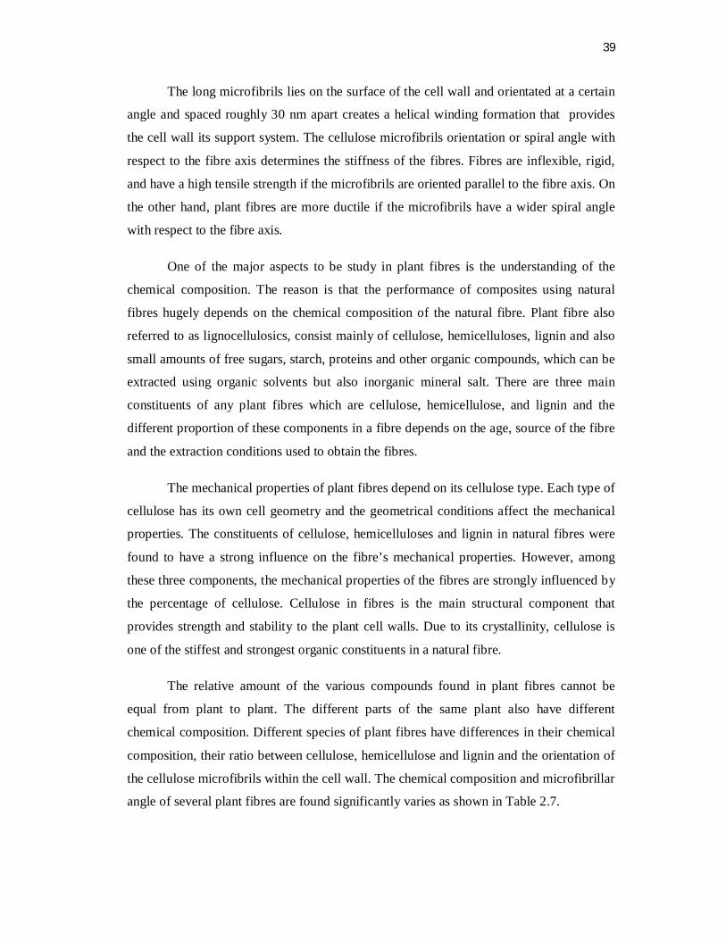
The mechanical properties of plant fibres depend on its cellulose type. Each type of
cellulose has its own cell geometry and the geometrical conditions affect the mechanical
properties. The constituents of cellulose, hemicelluloses and lignin in natural fibres were
found to have a strong influence on the fibre’s mechanical properties. However, among
these three components, the mechanical properties of the fibres are strongly influenced by
the percentage of cellulose. Cellulose in fibres is the main structural component that
provides strength and stability to the plant cell walls. Due to its crystallinity, cellulose is
one of the stiffest and strongest organic constituents in a natural fibre.
The relative amount of the various compounds found in plant fibres cannot be
equal from plant to plant. The different parts of the same plant also have different
chemical composition. Different species of plant fibres have differences in their chemical
composition, their ratio between cellulose, hemicellulose and lignin and the orientation of
the cellulose microfibrils within the cell wall. The chemical composition and microfibrillar
angle of several plant fibres are found significantly varies as shown in Table 2.7.

40
Table 2.7 Chemical composition and microfibrillar spiral angle of some plant fibres
Fibre Latin name Cellulose (wt. %)
Hemi cellulose (wt. %)
Lignin (wt. %)
Pectin (wt. %)
Micro-fibrillar angle(°)
Kenaf (Bast)
Hibiscus cannabinus 56.4 26.2 14.7 -
Kenaf (Core)
Hibiscus cannabinus 46.1 29.7 22.1 -
Ramie Boehmeria nivea 68.6-76 13.1-15.0 0.6-1 1.9-2
Hemp Cannabis sativa L. 70-78 17.9-22 3.7-5 0.9 2-6.2
Flax Linum usitatissimum 60-81 14-18.6 2-3 1.8-2.3 5-10
Jute
Corchorus capsularis, Corchorus olitorius
51-72 12-20.4 5-13 0.2 8
Cotton Gossypium hirsutum 82.7-92 2-5.7 0.5-1 5.7
Banana Musa acuminata L. 60-65 6-19 5-10 3-5
Coir Cocos nucifera L. 43 0.3 45 4.0
Henequen Agava fourcroydes Lemaire
60-78 4-28 8-13 3-4
Bagasse Sacchararum officinarum L.
40 30 20 10
Pineapple Leaf
Acanas comosus 80-81 16-19 12 2-2.5 14
Abaca Musa textilis 60.8-64 21 12 0.8
Sisal Agave sisalana Perrine
43-88 10-13 4-12 0.8-2 10-22
Wood - 45-50 23 27 -
Mechanical properties of plant fibres are largely determined by the percentage of
cellulose content, the cellulose degree of polymerization and the microfibrillar angle. A
high cellulose content and low microfibril angle are desirable properties of a fibre to be
used as reinforcement in polymer composites. Figure 2.10 and Figure 2.11 indicates the
increase of fibre strength is related to the high percentage of cellulose and narrower spiral
angle of microfibril.
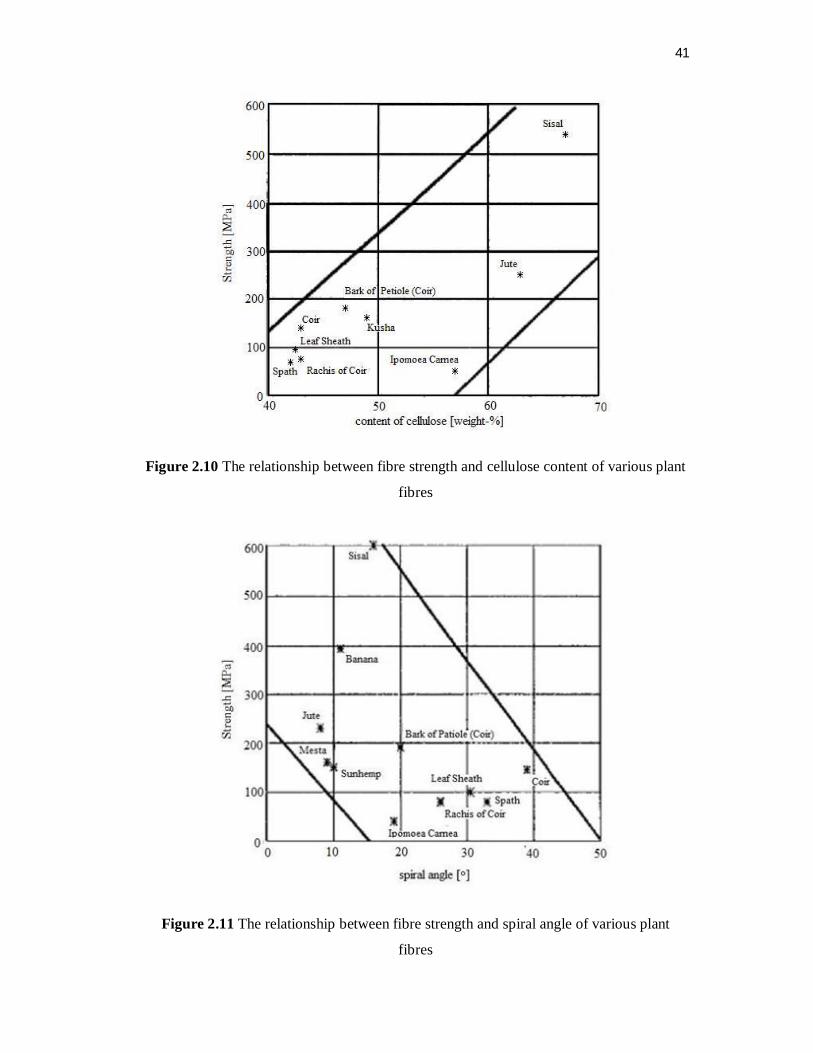
41
Figure 2.10 The relationship between fibre strength and cellulose content of various plant
fibres
Figure 2.11 The relationship between fibre strength and spiral angle of various plant
fibres
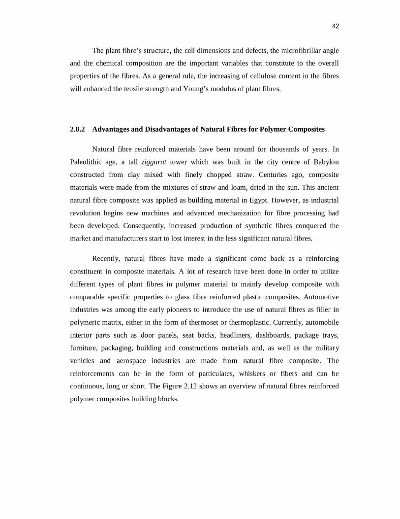
42
The plant fibre’s structure, the cell dimensions and defects, the microfibrillar angle
and the chemical composition are the important variables that constitute to the overall
properties of the fibres. As a general rule, the increasing of cellulose content in the fibres
will enhanced the tensile strength and Young’s modulus of plant fibres.
2.8.2 Advantages and Disadvantages of Natural Fibres for Polymer Composites
Natural fibre reinforced materials have been around for thousands of years. In
Paleolithic age, a tall ziggurat tower which was built in the city centre of Babylon
constructed from clay mixed with finely chopped straw. Centuries ago, composite
materials were made from the mixtures of straw and loam, dried in the sun. This ancient
natural fibre composite was applied as building material in Egypt. However, as industrial
revolution begins new machines and advanced mechanization for fibre processing had
been developed. Consequently, increased production of synthetic fibres conquered the
market and manufacturers start to lost interest in the less significant natural fibres.
Recently, natural fibres have made a significant come back as a reinforcing
constituent in composite materials. A lot of research have been done in order to utilize
different types of plant fibres in polymer material to mainly develop composite with
comparable specific properties to glass fibre reinforced plastic composites. Automotive
industries was among the early pioneers to introduce the use of natural fibres as filler in
polymeric matrix, either in the form of thermoset or thermoplastic. Currently, automobile
interior parts such as door panels, seat backs, headliners, dashboards, package trays,
furniture, packaging, building and constructions materials and, as well as the military
vehicles and aerospace industries are made from natural fibre composite. The
reinforcements can be in the form of particulates, whiskers or fibers and can be
continuous, long or short. The Figure 2.12 shows an overview of natural fibres reinforced
polymer composites building blocks.

43
Figure 2.12 Materials hierarchy of natural fibre composites
Natural fibre reinforced composites were accepted as the most appropriate and cost
effective alternative to conventional materials such as metal, plastic and wood for various
applications such as roofing, wall panels, food grain silos and low cost housing units,
structural and building applications. Many scientists and researchers concluded that
natural fibres have numerous advantages compared to glass fibres even though they cannot
equally match the same strength offered by glass fibre composites. Typically, natural
fibres may not be as strong as synthetic fibres; however the main advantages are as a
source of low cost materials and eco-friendly due to its biodegrability.
Natural lignocellulosic fibres have potential for use in moulded articles that not
requires high strength for acceptable performance which can be utilized for housing
equipments, roofing for low cost housing, and in large diameter piping. One study
suggests that natural fibres can be categorized into eight potential different applications:
non-structural composites, structural composites, sorbents, filters, geotextiles, moulded
products, packaging and combinations with other materials.

44
Utilizing natural fibre provides low cost of material and production of composites.
Natural fibres have lower durability and strength compared to glass fibre. However, its
low specific gravity produced a higher specific strength and stiffness compared to glass
fibre. As a result, natural fibres are beneficial in designing parts or products that demands
high degree of stiffness. Other than that, natural fibre reinforced composite have some
advantages which is high strength, low density and designable anisotropic properties.
Natural fibres can be processed in different ways to yield reinforcing elements having
different mechanical properties
The most significant factors on implementing plant fibres in polymeric composites
are their positive environmental impact due to its biodegradability and sustainability. Plant
fibres are renewable and sustainable resource and in the same time require little energy
consumption to produce. They are carbon dioxide neutral, which means they do not return
excess carbon dioxide into the atmosphere when they are composted or combusted.
illustration nature’s life cycle of natural fibre composite as shown in Figure 2.13.
Figure 2.13 Nature’s life circle of natural fibre composite

45
One of the main purposes of introducing natural fibre is to develop a new type of
composite that can potentially replace the use of glass fibre in composite materials. When
using natural fibres in composites production, the processing atmosphere becomes healthy
with better working conditions and therefore there will be reduced dermal and respiratory
irritation compared to glass fibres. Unlike glass fibres, plant fibres are nonabrasive to
mixing and moulding equipment, which can contribute to significant equipment
maintenance cost reductions. Plant fibres are preferable compared to glass fibre due to its
safer handling and working conditions compared to synthetic reinforcements such as glass
fibres. The automotive interior components that utilized natural fibres as reinforcement are
safer than glass fibre parts; since natural fibres have no sharp edges fracture pop out the
composite surfaces in case of vehicle crash happens.
The hollow structure of the plant cells provides excellent insulation against heat
and noise which is good for acoustic insulating properties. Natural fibres offer good
thermal and acoustic insulation properties along with ease in processing technique without
wearing out tool. Lastly, the worldwide availability of agro-based fibres and policy in
preventing deforestation are additional advantages of natural fibres composites.
Even though huge number of research effort have been done to fully harness the
use natural fibre composites, still there are some challenges of using natural fibres as
reinforcement in composites. The major drawback of plant fibres is the poor interfacial
adhesion due to hydrophilic character of cellulose. The fibre tends to attract higher
moisture uptake and resulted to dimensional instability. In any wet or humid condition,
moisture may easily penetrate into the interfacial bond between fibre and matrix which
affect swelling and deformation of the adhesive matrix, including breakage of chemical
bonds and hence deteriorating of the polymer backbone.
The non-cellulose components in some natural fibres cause problems in many
industrial processes, such as low absorbency and low reactivity with dyes as used in the
textile industry. Generally, plant fibres are rich in cellulose and therefore contains large
amount of hydroxyl group which makes it a polar and hydrophilic in nature while most of
the plastics has a hydrophobic. Introducing hydrophilic plant fibres into hydrophobic
material such as thermoplastics will cause non-uniform fibre dispersion in the matrix and
inferior fibre matrix bonding which consequently result in poor mechanical properties of
the polymeric composite. The polar nature of hydroxyl group in cellulose also results in

46
high moisture absorption in plant fibre based composite which eventually lead to fibre
swelling and voids in fibre matrix interphase. If the moisture if not eliminated from the
fibres prior to compounding by drying process it would create porosity in the composite
product.
2.9 Kenaf Plants and its Fibre
Kenaf or its scientific name Hibiscus Cannabinus is a plant species originated from
the African continent. This plant shares the same family with cotton which is in the
Mallow family. Kenaf is a warm-season annual fibre crop related to cotton, okra, and
hibiscus and can reach heights of 8 to 20 feet. As a plant that can only be cultivated in
tropical and subtropical climate, kenaf has been known for about 4000 years ago, but was
introduced in Europe about two centuries ago. It came into the United States on a
commercial scale during the early stage of World War II. This crop was introduced into
southern Asia around 1900, where the leaves are consumed in human and animal diets, the
bast fibre used for cordage, and the woody core of the stalks burned as firewood. Kenaf
plants are mainly harvested for fibres extracted from their stalks.
The major countries that produced kenaf are India, Pakistan, Thailand, Brazil,
Cuba, Taiwan, Myanmar and Japan. In the international trade, kenaf fibres are known as
mesta. While in India, these fibres are known as Bombay hemp, Ambaa hemp and Bimli
jute. Principal production areas are China, India, and the Tashkent. Statistics for 2008
conducted by Food and Agriculture Organization (FAO) of the United Nations shows the
top kenaf producers in the world are China (86.92%), Thailand (35.66%), Vietnam
(14.20%), Brazil (12.65%), Cuba (10.00%) and Indonesia (7.00%).
The plantations of kenaf in Malaysia were initiated by its government as potential
resources for pulp and paper, foods for livestock, natural fibre plastic composites and
chemical absorbent. Under the 9th Malaysian Plan, the government had allocated the
budget of RM 12 million and has formed National Kenaf Research and Development
Program to cater for development of kenaf. The change of Lembaga Tembakau Negara
(LTN) to Lembaga Kenaf dan Tembakau Negara (LKTN) has proven that Malaysia is very
serious in developing natural fibre composite industry.

47
A technical committee namely Majlis Tindakan Ekonomi Negara (MTEN) joined
by 25 researchers from various institutional including Malaysian Nuclear Agency (MNA),
Universiti Putra Malaysia (UPM), Forest Research Institute Malaysia (FRIM) and other
institutes are led by Malaysian Agricultural Research and Development Institute (MARDI)
to seek and explore the potential use of kenaf. Other than that, Ministry of Plantation
Industries and Commodities Malaysia has provided RM 5 million each to MARDI and
UPM for research in kenaf. Figure 2.14 shows a kenaf mini plantation in UPM for
research purposes.
Figure 2.14 Kenaf plantation in Taman Pertanian Universiti, UPM
More and more farmers are starting to show interest in this potential commercial
fibre crop. Given that the entire top part of kenaf is harvested, it returns little crop residue
back to the earth. Furthermore, kenaf grows quickly as little as 4 to 5 months and reaching
heights of 3.7 to 4.3 meter. During maturity, the flowering can last 3 to 4 weeks for each
and every plant, while each individual flower blooms for only one day. The kenaf stalk
contains two distinct fibres: (1) the long, jute-like bast fibres in its outer layer and (2) the
balsawood-like core fibres.
The bast fibre comprises approximately 40% of the stalk in dry condition. The
refined bast fibre measures 2.6 mm and are similar to the finest softwood fibres used for
papermaking. The whiter, inner part of the stalk known as the core fibre comprises 60% of
the dry stalk. These refined fibres measure 0.6 mm and are comparable to hardwood tree

48
fibers, which are used in a widening range of paper products. In general, these two types
of fibre have separate applications. Upon harvest, the whole kenaf stalk is processed in a
decorticator which functions as a mechanical fibre separator, similar to a cotton gin. The
separation of the bast and core fibres allows for independent processing and provides raw
materials for numerous types of products including pulp and paper, animal bedding,
particle board and bioremediation aids. Traditionally, this alternative annual crop has been
used essentially for industrial textile applications such as cordage, rope, twines and burlap
cloth. Figure 2.15 shows a harvested kenaf stalk with the bast fibre partially separated
from the core.
Figure 2.15 Bast fibre and core fibre from a dried kenaf stalk
Kenaf is an annual plant which attracts many farmers due to its rapid growth,
inexpensive and a renewable source. The harvesting of kenaf requires around 120 days
and can be cultivated up to three times a year. One study shows that kenaf plantation
produces high output which can be harvested up to 5-10 tons of dry fibre per acre. It also
reported that kenaf harvesting on average produces 20-40 ton/hectare/year. On the other
hand, the quickest production of the wood plant is only 8-12 ton/hectare/year. Moreover,
the forest trees need at least 10 to 14 years from plantation to harvest. Kenaf plant has a
growing cycle of 150–180 days with average yield of 1700 kg/hectare.

49
Kenaf plants are well known for its potential in replacing wood as a source of
paper due to its exceptional papermaking characteristic. The papermaking process requires
less chemicals, heat and time to pulp kenaf fibres because they are not as tough as wood
pulp due to the low lignin content. Toxic chemicals such as chlorine are predominantly
used in the delignification process (removal of lignin) and bleaching of wood pulp. As a
comparison, kenaf plant contains only 9% lignin, while southern pine contains 29% lignin.
Therefore, kenaf papermaking process can be quickly and easily pulped and bleached with
harmless chemicals, such as hydrogen peroxide. Moreover, pulping of kenaf uses less
chemical inputs and its operation consumes less energy than most virgin wood pulping
processes and is thus less environmental damage.
Kenaf has also been found to be important source of fibre for composites and other
industrial application due to its sustainability and environmental friendly features. Kenaf
have excellent properties for reinforcing thermoplastic composites as it has low densities,
no abrasion during processing, high filling levels, high specific mechanical properties and
biodegradability. Kenaf, as compared to other non-wood fibre, is found to be
comparatively higher in tensile strength, cheaper, sustainable as well as environmentally
friendly. Therefore, kenaf bast fibres are reliable source as reinforcement in composites.
Table 2.8 shows the comparison between kenaf fibre with other type of bast fibres in term
of density, tensile strength, Young’s modulus, elongation at failure and moisture
absorption.
The strength of kenaf fibre and other bast fibres are much lower compared to glass
fibre, still, the strength of these natural fibres is still acceptable for non-load bearing
application. Despite the low strength of these bast fibres, the low density that it has can be
a plus factor to develop lightweight applications.

50
Table 2.8 Properties of kenaf fibre compared to other bast fibres and glass fibre
Properties Fibres
Kenaf Flax Hemp Jute Nettle
E-
Glass
Density kg/m3 (ρ) 1193 1530 1520 1520 - 2550
E-modulus (GPa) 14-38 58 ± 15 70 60 87 ± 28 71
Tensile strength
(MPa)
240-
600
1339 ±
486 920 860
1594 ±
640 3400
Specific modulus
(E/1000ρ) 12-32 38 46 39 - 28
Elongation at failure
(%) -
3.27 ±
0.4 1.7 2
2.11 ±
0.81 3.4
Moisture absorption
(%) - 7 8 12 - -
Recently, a great number of studies related to kenaf fibres in polymeric composites
had been conducted. Previous research shows that the increased volume of kenaf fibre in
unidirectional kenaf/epoxy composites will increased its tensile properties. Other than that,
kenaf bast fibre also had been developed with thermoplastic elastomer for automotive
components. Optimum fibre loading for tensile strength of kenaf reinforced phenol
formaldehyde composites was 43% by weight. Kenaf fibre can also be used as a total
biodegradable composite such as research had been done by Ochi (2008) were the kenaf
fibres were embedded in a poly lactic acid (PLA) resin. Figure 2.16 shows fibre breakage
at the fractured surface of kenaf – PLA composite.

51
Figure 2.16 SEM micrograph of kenaf bast fibre’s cross section
Hybridization of kenaf fibre with other natural fibres such as pineapple leaf is
recently gaining interest among researcher as it provide different characteristics to the
composite which cannot be achieved by a using a single type of fibre. In this study, the
addition of 10 % fibre loading cause the material to loss 26% of tensile strength compared
to pure HDPE and tensile strength continues to fall as increase of fibre loading to 2 0%
and 30%. However, reinforcing effect starts to take place at 40 % - 60 % fibre loading and
improves the tensile strength of the composites. Figure 2.17 and 2.18 shows that using
fibre at 0.25 mm long and 60 % fibre loading provides the best tensile and flexural
properties for kenaf/HDPE composites.
Figure 2.17 Tensile strength as a function of varying fibre length and fibre weight
percentage

52
Figure 2.18 Flexural modulus as a function of varying fibre length and fibre weight
percentage
Referring to Figure 2.17 and 2.18, for fibre size of 0.25mm, the composite’s tensile
strength and flexural strength start to decline at 70% fibre loading. This research also had
concluded that fibre size of 0.25mm is the best in avoiding fibre agglomeration during
mixing of composites in internal mixer.
Achieving decent compatibility of kenaf fibres with polymers is one of the
challenges in composites processing. Researchers have invented ways such as adding
coupling agent and fibre modification to enhance the interfacial strength between fibres
and matrix. Chemical treatment such as silane and isocyanates were used to bridge
together the hydrophilic kenaf fibre with the hydrophobic polymer and consequently
improve the mechanical properties. Alkali treatment such as sodium hydroxide (NaOH)
has been used to make rougher surface on kenaf fibre to enhance mechanical interlocking
between the fibre and matrix.
The tensile strength of all composites considered in the present study increased
with the influence CSM and woven fibreglass respectively. It can also be observed that the
tensile strength of the long kenaf/woven glass hybrid composite is the highest. Whilst the
kenaf powder composite has the lowest tensile strength. The tensile strength of the kenaf
composite has been improved by the addition of the fibreglass. This due to the orientation
of continues of long kenaf fibre in the matrix composite. The alignment of long kenaf fiber

53
provide the resistance that transfer tensile strength forced as compared to other fiber
orientation. Figure 2.19 show the tensile strength of kenaf fibreglass hybrid composite.
Figure 2.19 Effect of different type of fibre on the tensile strength of kenaf composite and
hybrid composite
2.9.1 Mechanical properties of kenaf bast and core fibre reinforced unsaturated
polyester composites
The experimental results of tensile strength is shown in Figure 2.20. The general
conclusion can be said that the fibre loading significantly affects the mechanical properties
of the composites. It means that the fibre has proven its function by increasing the tensile
strength of the both composites compared to neat UP. It also can be observed that the
composite of 20 % fiber content showed the highest tensile strength for both kenaf bast
and core fibre composites which represents as optimal fibre content.
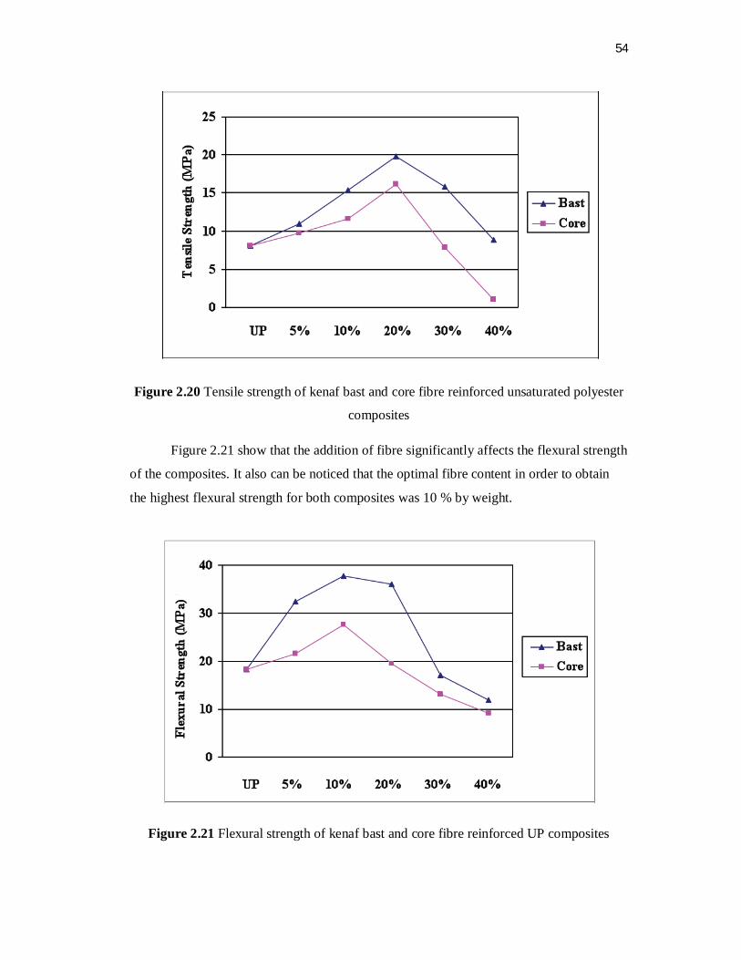
54
Figure 2.20 Tensile strength of kenaf bast and core fibre reinforced unsaturated polyester
composites
Figure 2.21 show that the addition of fibre significantly affects the flexural strength
of the composites. It also can be noticed that the optimal fibre content in order to obtain
the highest flexural strength for both composites was 10 % by weight.
Figure 2.21 Flexural strength of kenaf bast and core fibre reinforced UP composites
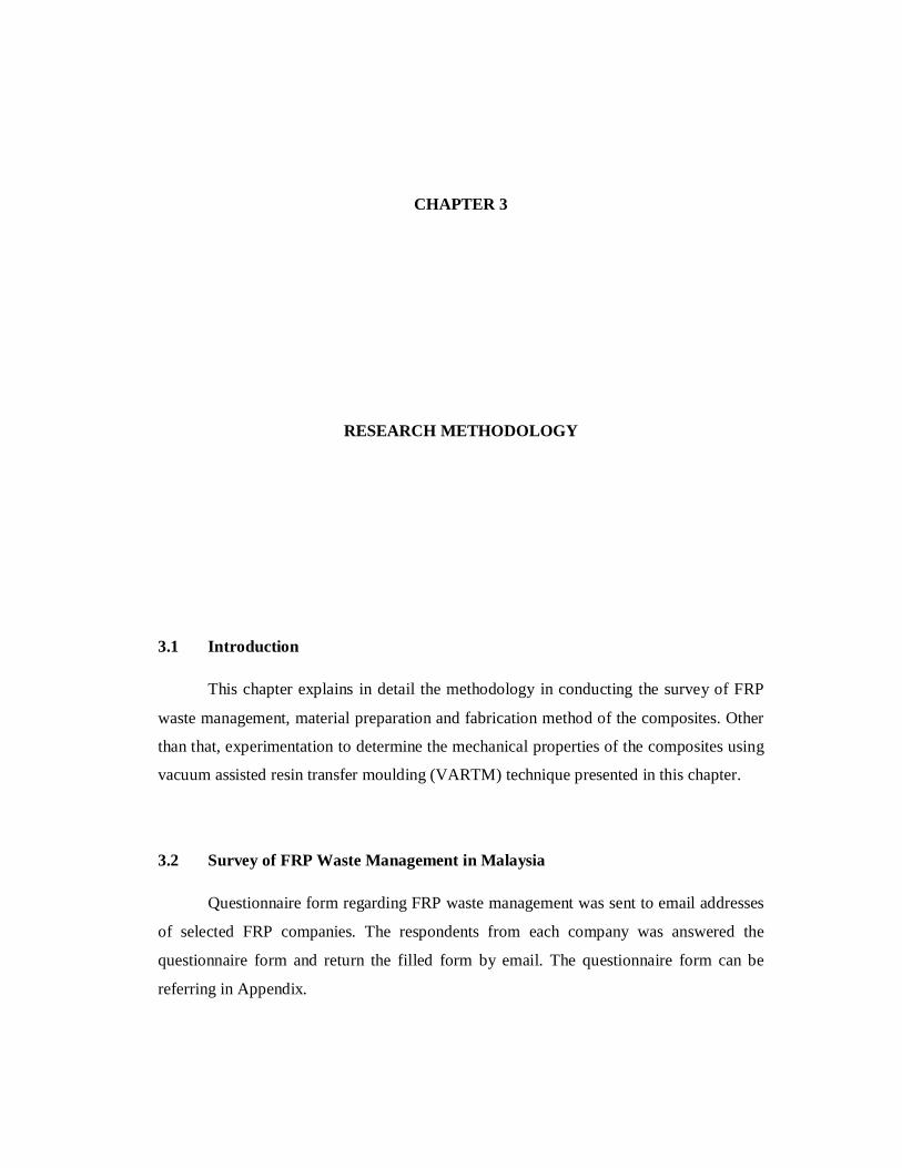
55
CHAPTER 3
RESEARCH METHODOLOGY
3.1 Introduction
This chapter explains in detail the methodology in conducting the survey of FRP
waste management, material preparation and fabrication method of the composites. Other
than that, experimentation to determine the mechanical properties of the composites using
vacuum assisted resin transfer moulding (VARTM) technique presented in this chapter.
3.2 Survey of FRP Waste Management in Malaysia
Questionnaire form regarding FRP waste management was sent to email addresses
of selected FRP companies. The respondents from each company was answered the
questionnaire form and return the filled form by email. The questionnaire form can be
referring in Appendix.
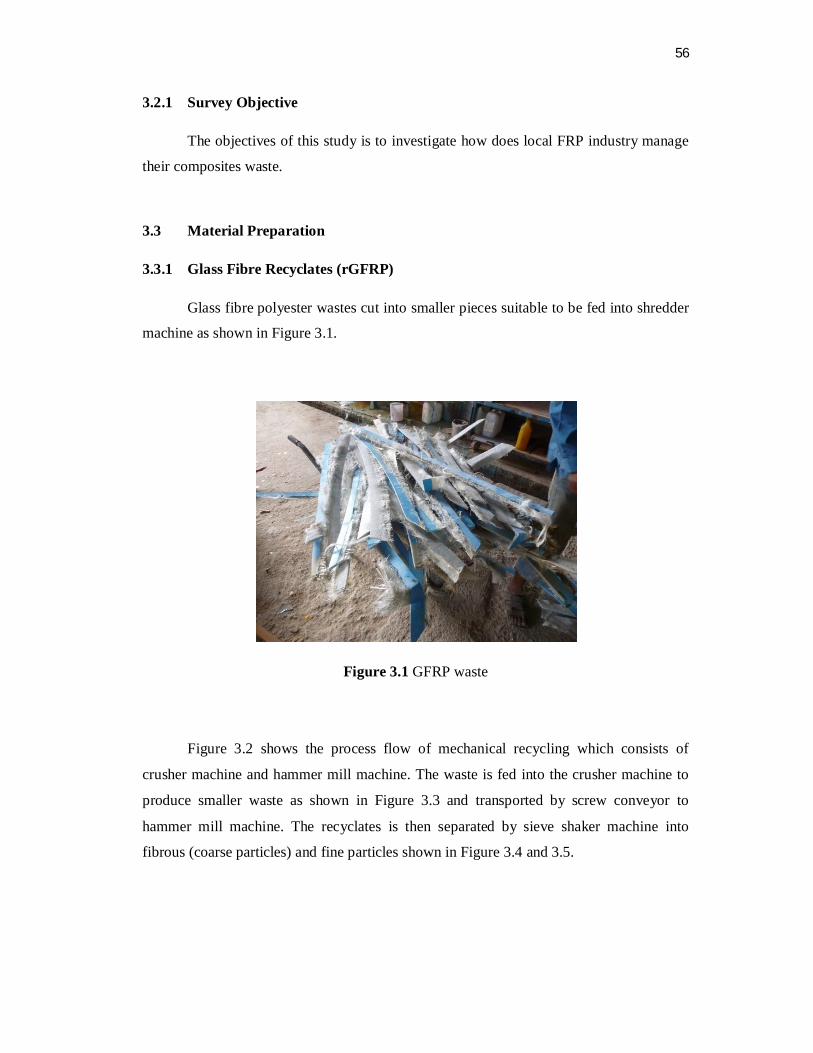
56
3.2.1 Survey Objective
The objectives of this study is to investigate how does local FRP industry manage
their composites waste.
3.3 Material Preparation
3.3.1 Glass Fibre Recyclates (rGFRP)
Glass fibre polyester wastes cut into smaller pieces suitable to be fed into shredder
machine as shown in Figure 3.1.
Figure 3.1 GFRP waste
Figure 3.2 shows the process flow of mechanical recycling which consists of
crusher machine and hammer mill machine. The waste is fed into the crusher machine to
produce smaller waste as shown in Figure 3.3 and transported by screw conveyor to
hammer mill machine. The recyclates is then separated by sieve shaker machine into
fibrous (coarse particles) and fine particles shown in Figure 3.4 and 3.5.

57
Figure 3.2 Process flow of mechanical shredding of GFRP waste
Figure 3.3 GFRP waste after shredded by crusher machine
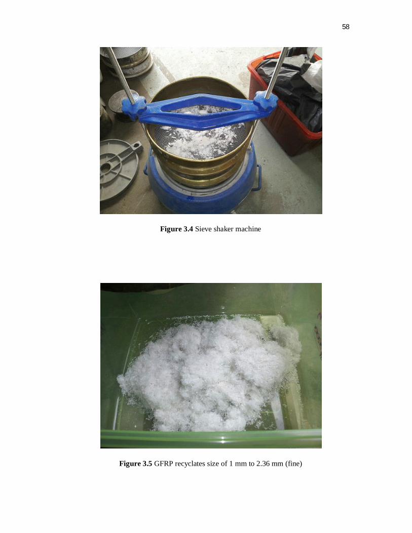
58
Figure 3.4 Sieve shaker machine
Figure 3.5 GFRP recyclates size of 1 mm to 2.36 mm (fine)

59
3.3.2 Matrices
Thermoplastic matrix which is polyester resin was used in this research as a
polymer matrix of rGF/kenaf/polyester composite. Polyester resins as a Figure 3.6 mostly
used in mass production, and for large structures due to low cost and low viscosity.
Thermoplastic matrix typically increases laminate toughness and damage tolerance, in
which the processing difficulties represent the primary obstacle to more widespread use of
thermoplastics.
Figure 3.6 Polyester resin and hardener (MEKP)

60
3.4 Composite Formulation
Table 3.1 shows the formulation of each composites developed in this study. Fine
rGFRP was obtained by sieving the whole rGFRP using a sieve shaker.
Table 3.1 Samples name and it formulation. The value indicates weight percentage
Sample Name % Weight Size rGFRP mm (fine) UP % rGFRP % Kenaf %
rGFRP 75 25 0 1 - 2.36 rGFRP + Kenaf 75 17.85 7.15 1 - 2.36
Based on the mechanical properties of each formulation, a composite formulation
will be fabricated using the optimum fiber fraction of each components and the composite
will be tested for its mechanical properties and microstructure.
3.5 Composite Fabrication use Vacuum Assisted Resin Transfer Moulding
(VARTM)
Vacuum assisted raisin transfer moulding (VARTM) is likely the most common
acronym of all us in the discussion of low pressure closed mould reinforced composite
moulding. The often use VARTM acronym is most accurately applied to the process of
vacuum infusion, that is where the composite is moulded using a rigid mould to provide
part geometry and a thin flexible membrane over the fibre, with outer atmospheric
pressure compressing the fibre tight against the rigid mould surface. It should be noted
however that VARTM simply means to add vacuum at the exit vent of the moulding tool,
thus any form of resin transfer moulding in which vacuum is applied to the vent would
qualify for the VARTM technique. Often, the aerospace industry will have very high fiber
volume composites moulded within a rigid matched mould set in which the fixed cavity
mould is clamped closed using a press and the resin injection pressures typically range less
than 100 psi. Figure 3.7 to 3.12 show the technique of the VARTM.

61
Figure 3.7 VARTM injection of test panel mould
Figure 3.8 Laying material
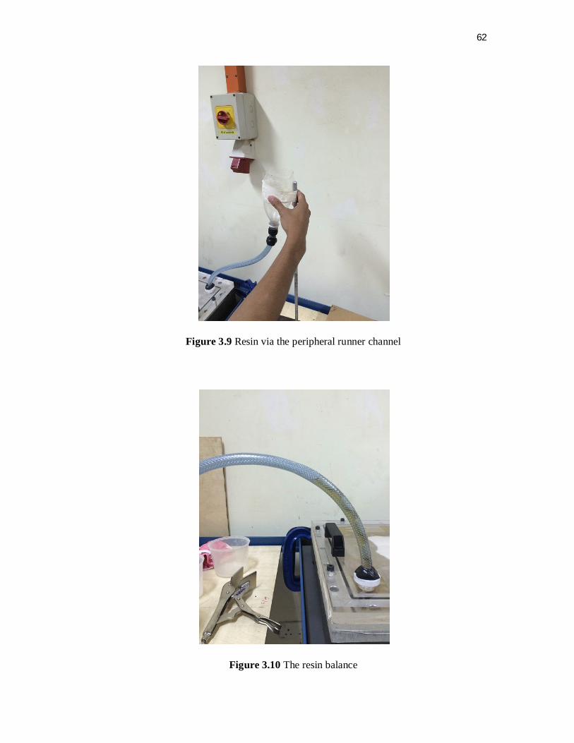
62
Figure 3.9 Resin via the peripheral runner channel
Figure 3.10 The resin balance
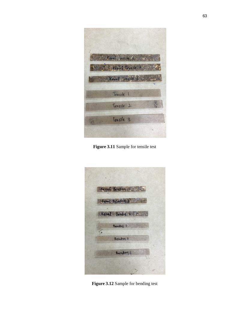
63
Figure 3.11 Sample for tensile test
Figure 3.12 Sample for bending test
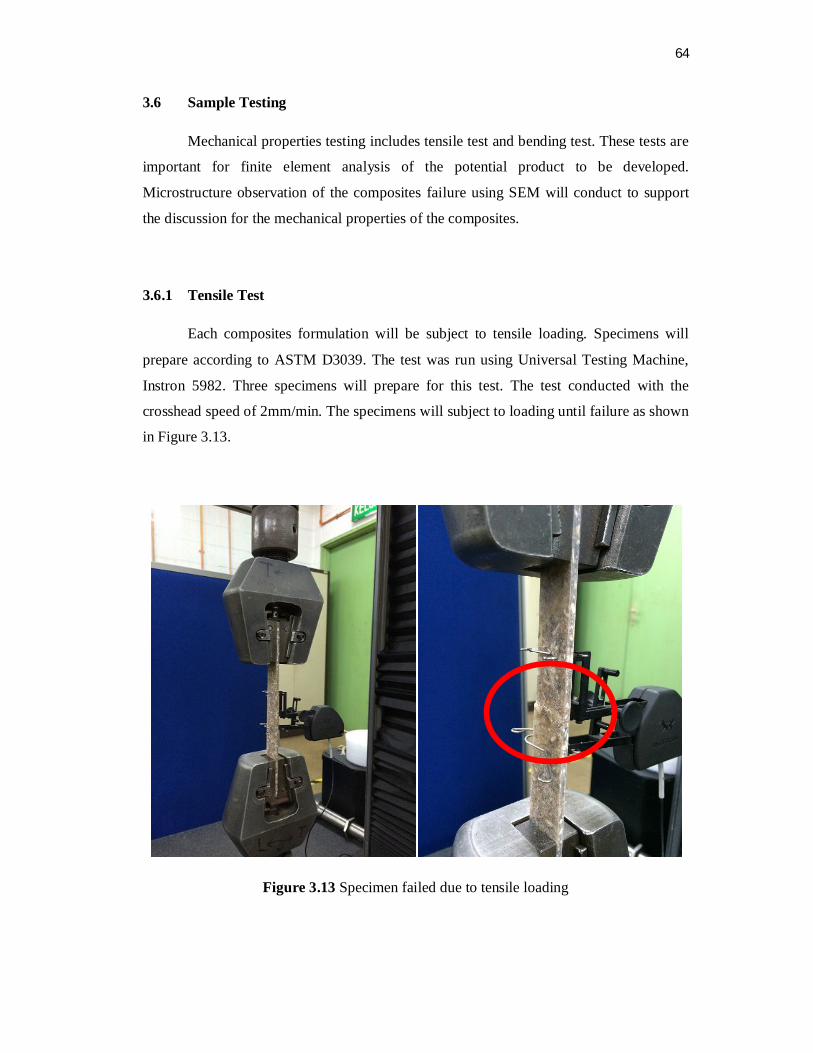
64
3.6 Sample Testing
Mechanical properties testing includes tensile test and bending test. These tests are
important for finite element analysis of the potential product to be developed.
Microstructure observation of the composites failure using SEM will conduct to support
the discussion for the mechanical properties of the composites.
3.6.1 Tensile Test
Each composites formulation will be subject to tensile loading. Specimens will
prepare according to ASTM D3039. The test was run using Universal Testing Machine,
Instron 5982. Three specimens will prepare for this test. The test conducted with the
crosshead speed of 2mm/min. The specimens will subject to loading until failure as shown
in Figure 3.13.
Figure 3.13 Specimen failed due to tensile loading

65
The determination of tensile strength and tensile modulus were calculated by using
Equations (3.1) and (3.2):
σt = F/A (3.1)
E = / (3.2)
σt = tensile strength of test specimen (MPa)
F = tensile load (kN)
A = cross section area (mm2)
E = tensile modulus (MPa)
= tensile stress (MPa)
= strain (mm/mm)
The data to be obtained in tensile test is as follows:
Tensile strength (MPa)
Tensile strain (mm/mm)
Maximum load (N)
Extension at maximum load (mm)
Elastic modulus (GPa)
Stress-strain graph

66
3.6.2 Bending Test
Three points bending test was conducted to the specimen in order to determine the
bending strength and modulus. In addition, certain aspects such as the relationship
between stress-strain can be known. Experiment standards used in this test is based on the
ASTM D 790 Flexural Properties of Unreinforced and Reinforced Plastics and Electrical
Insulating Materials Method. The test was run using Universal Testing Machine, Instron
5982. This machine is used in conjunction with 'Roller Centre' to support the specimen.
Figure 3.14 shows the dimensions and position of the specimens for bending test. Test was
conducted at room temperature 28 oC and 50% humidity. The speed selected is 2 mm /
min towards the constant load throughout the experiments.
Figure 3.14 Show the dimensions and position of the specimen for bending test
Figure 3.15 Specimen failure due to bending loading
Rod load
67
Where:
Span distance, S : 60 mm
Specimen thickness, t : 4 mm + 0.25 mm
Specimen width, W : 13 mm + 0.25 mm
Specimen length, L : 130 mm
Supporting rod diameter, d : 10 mm
Rod load diameter, D : 25 mm
Span distance, S plays a crucial role in determining the Bending Modulus
produced, in addition to other informations obtained from the experiments. For example,
suppose the thickness of the specimen is 2 mm, so the span required distance is 40 mm.
However, the length of the specimen that have to be produced must exceed the span
distance so that the specimen is well supported by the supporting rod and prevent it from
slipping during the experiments. The minimum distance of the load with the specimen is 5
mm. The load was increased constantly over the specimen until the failures occur. Some
of the specimens did not exhibit the failure modes that can be perceived with naked eyes
during the experiment, therefore, an alternative way to identify the failure is by observing
the value of the load on the Instron machine control box. When the value of the load has
dropped, the tested specimens is facing failures even though the strain in the specimen is
still valid.
The determination of bending strength and bending modulus were calculated by
using Equations (3.3) and (3.4):
2
5.1Wt
PSf (3.3)
3
3
4WtmSE f (3.4)
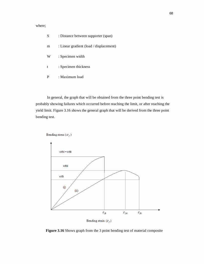
68
where;
S : Distance between supporter (span)
m : Linear gradient (load / displacement)
W : Specimen width
t : Specimen thickness
P : Maximum load
In general, the graph that will be obtained from the three point bending test is
probably showing failures which occurred before reaching the limit, or after reaching the
yield limit. Figure 3.16 shows the general graph that will be derived from the three point
bending test.
Figure 3.16 Shows graph from the 3 point bending test of material composite

69
Where:
σfM : Maximum bending stress
σfB : Bending stress yield
fM : Maximum bending tsrain
fB : Bending strain yield
Line (i) : Specimen broke before reaching the yield limit.
Line (ii) : Specimen broke after reaching maximum bending stress limit.
3.6.3 Microstructure Analysis
Scanning Electron Microscope (SEM) will use to observe the microstructure of
fractured area of composites. The data to be observed in this test is as follow:
Fibre distribution
Fibre-matric debonding
Fibre fracture
Fibre pull-out
Bubble
Matric cracking
Recyclate resin

70
3.7 Schedule of Research
Figure 3.17 Flow chart of the research activities
Start
Project discussion with supervisor
Research and discuss methodology pro and contra
Find and research on literature review
Project survey on waste management
Conclusion Find other method
End
Sample preparation
Sample testing and SEM
Result discussion

71
CHAPTER 4
RESULT AND DISCUSSION
4.1 Introduction
This chapter will present the results and the discussion from the experiment of
samples that have been tested from tensile and bending testing. There are several
parameters to be considered in this discussion such as load, stress, strain and displacement.
All obtained results will be interpreted in general understanding. Based on the results, we
will discuss the comparison between rGFRP and rGFRP/kenaf mechanical properties.
Thus microstructure of fractured area of composites will be observe using Scanning
Electron Microscope (SEM).
Therefore, each data and result being collected during the whole experimental test
will be described and display in this chapter and the further discussion on each data and
result will be discussed.

72
4.2 Tensile Test
4.2.1 rGFRP Tensile Test
The experimental results of tensile strength for rGFRP are shown in Table 4.1. The
general conclusion can be said that the rGFRP tensile strength at maximum load was
decrease from virgin GFRP but it achieves our target to check whether rGFRP can develop
new product that no need high tensile strength.
Table 4.1 Tensile test data for rGFRP
Figure 4.1 Tensile test data graph for rGFRP
No Spacimen Lable
Thickness (mm)
Width (mm)
Maximun Load (N)
Extension at
Maximun Load (mm)
Tensile Strain at
Maximum Load
(mm/mm)
Tensile Stress at
Max Load
(Mpa)
Modulus (Gpa)
1 rGFRP-1 4.1 25.48 2,001.87 1.37 0.00523 19.16249 4.00381 2 rGFRP-2 4.16 25.4 2,268.53 1.43 0.00573 21.46927 4.15007 3 rGFRP-3 4.2 25.44 2,356.47 1.71 0.00649 22.05445 3.82152
Mean 4.15 25.44 2,208.96 1.50 0.006 20.90 3.99

73
4.2.2 rGFRP/Kenaf Core Tensile Test
The test results of tensile strength for rGFRP/kenaf were shown in Table 4.2. The
general conclusion can be said that the rGFRP/kenaf tensile strength at maximum load was
decrease from virgin GFRP. This test compared, with addition rGFRP into kenaf core can
increase the mechanical properties of kenaf core itself. However the tensile strength for
this rGFRP/kenaf was same as tensile strength of kenaf core itself at 5% distribution.
Table 4.2 Tensile test data for rGFRP/Kenaf
No Spacimen Lable
Thickness (mm)
Width (mm)
Maximun Load (N)
Extension at
Maximun Load (mm)
Tensile Strain at
Maximum Load
(mm/mm)
Tensile Stress at
Max Load
(Mpa)
Modulus (Gpa)
1 Kenaf + rGFRP-1 4.14 25.18 930.40 0.74661 0.00359 8.92508 2.70279
2 Kenaf + rGFRP-2 4.24 25.1 959.40 0.82689 0.0044 9.01487 2.27819
3 Kenaf + rGFRP-3 4.12 25.4 960.98 0.74019 0.0034 9.18298 2.96906
Mean 4.15 25.23 950.26 0.77 0.0038 9.04 2.65
Figure 4.2 Tensile test data graph for rGFRP/Kenaf

74
4.3 Bending Test
4.3.1 rGFRP Bending Test
The test results of bending strength for rGFRP were shown in Table 4.3. The
general conclusion can be said that the rGFRP bending strength at maximum load was
decrease from virgin GFRP but it achieves our target to check whether rGFRP can develop
new product that no need high bending strength.
Table 4.3 Bending test data for rGFRP
No Spacimen Lable
Thickness (mm)
Width (mm)
Maximun Load (N)
Flexure Extension
at Maximun
Load (mm)
Flexure Stress at
Maximum Load
(Mpa) 1 rGFRP-1 4.1 13.4 136.76 2.68028 54.64108 2 rGFRP-2 4.22 13.24 120.64 2.24665 46.04993 3 rGFRP-3 4.22 13.24 157.76 2.87334 60.21863
Mean 4.18 13.29 138.39 2.60 53.64
Figure 4.3 Bending test graph for rGFRP

75
4.3.2 rGFRP/Kenaf Core Bending Test
The experimental results of bending strength for rGFRP/kenaf are shown in Table
4.4. The general conclusion can be said that the rGFRP/kenaf bending strength at
maximum load was decrease from virgin GFRP. In other hand this test compare whether
with addition rGFRP into kenaf core will increase the mechanical properties of kenaf core
itself. Bending test data shows that bending strength of rGFRP/kenaf core increase
compare to previous research on bending test kenaf core.
Table 4.4 Bending test data for rGFRP/Kenaf
No Spacimen Lable Thickness (mm)
Width (mm)
Maximun Load (N)
Flexure Extension
at Maximun
Load (mm)
Flexure Stress at
Maximum Load
(Mpa) 1 Kenaf + rGFRP-1 4.12 13.1 71.77 1.75999 29.04693 2 Kenaf + rGFRP-2 4 13.2 82.08 2.29365 34.9777 3 Kenaf + rGFRP-3 4.22 13.1 80.34 1.79344 30.99281
Mean 4.11 13.13 78.06 1.95 31.67
Figure 4.4 Bending test graph for rGFRP/Kenaf
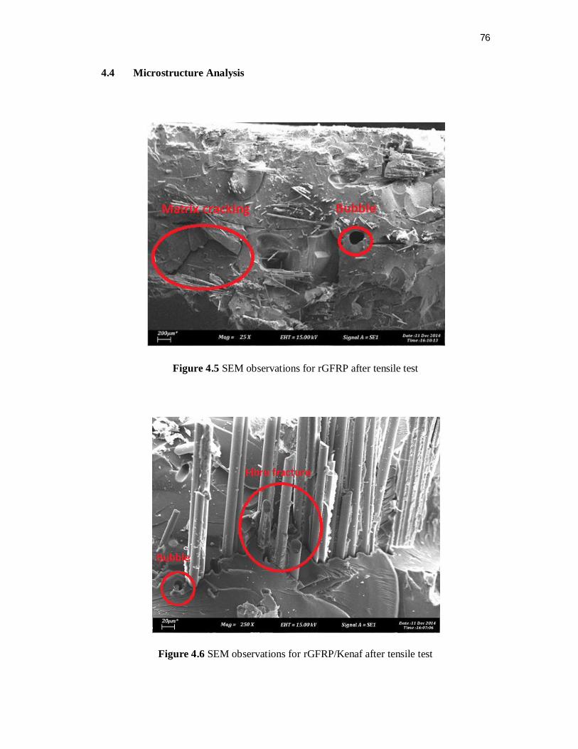
76
4.4 Microstructure Analysis
Figure 4.5 SEM observations for rGFRP after tensile test
Figure 4.6 SEM observations for rGFRP/Kenaf after tensile test
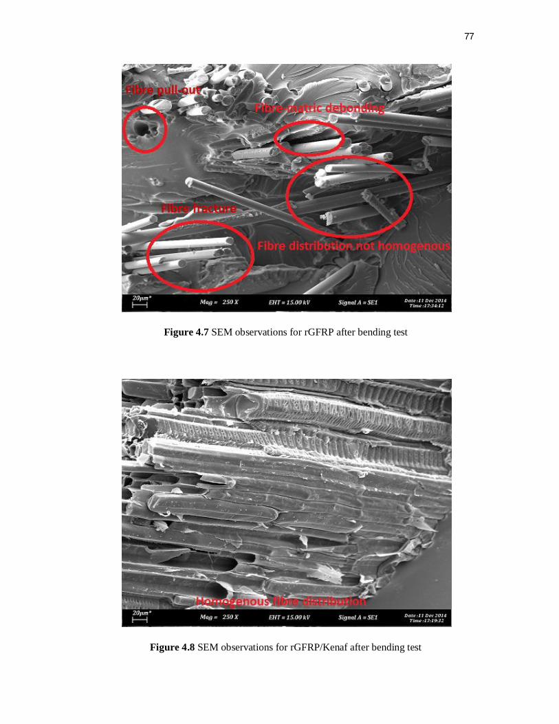
77
Figure 4.7 SEM observations for rGFRP after bending test
Figure 4.8 SEM observations for rGFRP/Kenaf after bending test

78
4.5 Tensile Test Comparison
As discussed in 4.2, tensile strength for rGFRP was higher than rGFRP/kenaf due
to some factor such as ratio of kenaf core, moisture of natural fibre, material debonding
and material composition. However sample for rGFRP/kenaf core does not effect of
tensile strength of kenaf itself. Figure 4.9 and 4.10 shows comparison of tensile strength
for both sampling.
Figure 4.9 Maximum loads for tensile test
Figure 4.10 Tensile stresses at maximum load for tensile test
0
500
1000
1500
2000
2500
Max
imum
Load
(N)
Specimen for Tensile Test
Maximum Load (N)
Kenaf + rGFRP-1
rGFRP-1
Kenaf + rGFRP-2
rGFRP-2
Kenaf + rGFRP-3
rGFRP-3
0
5
10
15
20
25
Tens
ile S
tres
s at M
ax L
oad
(Mpa
)
Specimen for Tensile Test
Tensile stress atMaximum Load
[MPa]
Kenaf + rGFRP-1
rGFRP-1
Kenaf + rGFRP-2
rGFRP-2
Kenaf + rGFRP-3
rGFRP-3

79
4.6 Bending Test Comparison
As discussed in 4.3, bending strength for rGFRP was higher than rGFRP/kenaf due
to some factor such as moisture of natural fibre, material debonding and material
composition. However sample for rGFRP/kenaf show improvement of bending strength of
kenaf core itself. Figure 4.11 and 4.12 shows comparison of tensile strength for both
sampling.
Figure 4.11 Maximum loads for bending test
Figure 4.12 Bending stresses at maximum load for bending test
0
20
40
60
80
100
120
140
160
Max
imum
Load
(N)
Specimen for Bending Test
Maximum Load (N)
Kenaf + rGFRP-1
rGFRP-1
Kenaf + rGFRP-2
rGFRP-2
Kenaf + rGFRP-3
rGFRP-3
0
10
20
30
40
50
60
70
Bend
ing
Stre
ss a
t Max
imum
Load
(M
Pa)
Specimen for Bending Test
Bending Stress at Maximum Load (MPa)
Kenaf + rGFRP-1
rGFRP-1
Kenaf + rGFRP-2
rGFRP-2
Kenaf + rGFRP-3
rGFRP-3

80
CHAPTER 5
CONCLUSION AND RECOMMENDATION
5.1 Conclusion
In Malaysia too many waste of fiber need to scrap as per my research and also as
my waste management survey in industry that using fiber as their product or material. This
research also observed that recyclate glass fiber will never get the initial strength but can
recyclate as new product that no need high capabilities in terms of strength and costing.
This research study and compare mechanical properties 2 type of composites recyclate
glass fiber which is rGFRP and rGFRP/Kenaf.
From this research, rGFRP shows the better result than rGFRP/Kenaf both in terms
of tensile and bending loadings respectively. Fiber distribution based on SEM observation
also inconsistent fibre distribution and this will affect the result. SEM also shows air
bubble obviously on resin. In other hand, moisture factor on natural fiber can be affect
bonding between rGFRP, kenaf and resin. For time being this research recommended to
use only rGFRP to develop new product for low capabilities in terms of strength.

81
5.2 Recommendation
Several things have been identified in order to improve the future research. Three
recommendations are made and to enhance the efficiency and consistency of the outcomes
results:
1. To study on rGFRP/long kenaf bast in the future
2. To study moisture on natural fiber especially on kenaf
82
REFERENCES
Amanda Conroy, Sue Halliwell, Tim Reynolds BRE, Watford, Herts, UK Received 27
April 2005; accepted 13 May 2005
Hurley J, McGrath C, Bowes H. Deconstruction and reuse of construction materials.
London: CRC; 2001.
Garoushi, S. K., Lassila, L. V. J., Vallittu, P. K., (2006), Short Fiber Reinforced
Composite: The Effect of Fiber Length and Volume Fraction, The Journal of
Contemporary Dental Practice.
CompClass—Materials classification system classification and qualification of composite
materials systems for use in the civil infrastructure, http://www.compclass.org/.
Ray, D., and Rout (2005), J., Thermoset Biocomposites, Natural Fibres, Biopolymers, and
Biocomposites, United States of America, CRC Press, page 291.
Demura K, Ohama Y and Satoh T. ‘Properties of artificial woodsusing FRP powder’,
Disposal and recycling of organic and polymeric construction materials, Proceedings of
the International Rilem Workshop, Tokyo, 26–28 March 1995.
Blizard K and Portway J. ‘A wholly recycled structural plastic lumber incorporating scrap
prepreg waste’ Plastics in building construction, 1998, vol. 22(5), p. 8–12.
Reynolds T N, Halliwell S, Conroy A, (2004) “Markets for FRP Recyclate” Institute of
Wastes Management, Scientific and Technical Review vol. 5(2) p. 29–34.
Cranfield University and WE & E Consulting. A brief guide to ecodesign.
RECOMP Project, development of a novel recycling process for the recovery of plastic
composite materials, bpf seminar on waste management for the composites industry,
London, 15 November 2001.
Broekel, J., Scharr, G. The Specialities of Fibre-reinforced Plastics in Terms of Product
Life-cycle Management. Journal of Materials Processing Technology 162 – 163 2005: pp.
725 – 729.

83
Scheirs, J. Polymer Recycling. Science Technology andApplication. John Wiley&Sons
Inc.; London, 1998.
Al-Salem, S. M., Lettieri, P., Baeyens, J. Recycling and Recovery Routes of Plastic Solid
Waste (PSW): A Review Waste Management 29 2009: pp. 2625 – 2643.
Kers, J., Majak, J., Goljandin, D., Gregor, A., Malmstein, M., Vilsaar, K. Extremes of
Apparent and Tap Densities of Recovered GFRP Filler Materials Composite Structures 92
(9) 2010: pp. 2097 – 2101.
Tamm, B., Tümanok, A. Impact Grinding and Disintegrators Proceedings of the Estonian
Academy of Sciences 2 1996: pp. 209 – 223.

84
APPENDICES

85
APPENDICES A: QUESTIONNAIRE

86

87

88

89

90