university missouri-rolla rolla, missouri · epoxy (t300/5208) composite adherends bonded with a...
TRANSCRIPT

NASA Contractor Report 178112
(NASA-CE-178112) CRITERICN FCfi A I X E D E40DE ERAC'IUBE I N CCIIPOZZ'IE ECNDED J C I N T S Report [nissouri U n i v . )
F i n a l 27 p EC A03/HP 801
N86-263 80
CSCL 11D Unclas G3/24 43587
CRITERION FOR MIXED MODE FRACTURE I N COMPOSITE BONDED JOINTS
S, Mal l and N , K, Kochhar
UNIVERSITY OF MISSOURI-ROLLA ROLLA, M I S S O U R I
GRANT NAG1-425 May 1986
National Aeronautics and Space Ad ministration
Langley Research Center Hampton, Virginia 23665
https://ntrs.nasa.gov/search.jsp?R=19860016908 2018-05-31T05:30:53+00:00Z

ABSTRACT
A study was undertaken t o character ize the debond growth mechanism
o f adhesively bonded composite j o i n t s under mode I , mixed mode 1-11,
and mode I1 s t a t i c loadings.
epoxy (T300/5208) composite adherends bonded w i t h a toughened epoxy
(EC 3445) adhesive. The mode I, mode I1 and mixed-mode 1-11 f r a c t u r e
energies o f the tes ted adhesive were found t o be equal t o each other.
Furthermore, the c r i t e r i o n f o r mixed mode f r a c t u r e i n composite bonded
j o i n t s was found t o be:
The bonded system consisted o f graphi te /
(GI/GIC) + (GII/GIIc) = 1.
1

INTRODUCTION
The adhesive bonding of laminated composite materials does n o t
require tha t structural members being jointed be perforated t o
f ac i l i t a t e bo1 ts. Without the bo1 t holes and s t ress concentrations
associated w i t h them, substantial weight savings can be realized
w h i c h i s a major reason for selecting composite materials f o r
structural components.
crack growth and t h u s an appropriate fa i lure criterion must be
based upon the in i t ia t ion and propagation of f l a w inherent i n the
Adhesive jo in ts usually fa i 1 by progressive
jo in t . Consequently, the fracture mechanics approach can be used
to characterize their fa i lure . Such an approach has been used t o
predict the f a i lu re of adhesively bonded jo in t s (1-2).
The majority of this work has been concerned w i t h the opening
or cleavage mode fa i lure (mode ?) . A crack i n an isotropic medium
will propagate i n Mode I fracture regardless of the orientation of
the i n i t i a l flaw w i t h respect t o the applied stress. However, this
i s not necessarily the case i n j o i n t fracture since crack propaga-
tion i s constrained to the adhesive layer regardless of the orien-
tation o f the adhesive layer, except, of course, when the substrate
has a lower toughness than the adhesive.
purposes, attention must be given t o j o i n t fracture under additional
loading modes.
the applicabili ty of the fracture mechanics approach for mode I I
(shear loading only) and mixed mode 1-11 (combination of tens i le and
T h u s , fo r structural design
Several studies were, therefore, undertaken t o extend

shear loading) fractures (1-2).
a l l the above mentioned studies were concerned w i t h adhesive bonds
between metal adherends.
invo lv ing the fracture behavior o f a composite-adhesive-composite
system under mode I condition only (3) .
As f a r as the au thors are aware,
Recently, a study has been reported
The objective o f the present study was, therefore, t o characterize
the debond growth mechanism o f adhesively bonded composite jo in ts
under mode I , mixed mode 1-11, and mode I1 s t a t i c loading.
purpose, graphi te/epoxy double-canti lever beam (DCB) specimens,
For this
c;acked-lap-shear (CLSj specimens acd end-notch flexur e (ENF
were tested u s i n g EC 3445 adhesive. * T h i s study focussed on the
measuring o f the c r i t i ca l strain-energy-release rates G J C 9
and Gl ic t o determine the fracture mode dependence o f debond failure.
sixcjme,is
G(I - i j I C
TEST MATERIAL AND SPECIMEN CONFIGURATION -
The debond system consisted of g raph i te/epoxy (T300/5208)
i-.:'herenc's bondcd w i t h EC 3445 :dhesivc. Thc 3f45 adhxive i s 2.
thermosetting paste w i t h a cure temperature o f 121°C, Specimens
were fabricated by the conventional secondary bonding procedure.
The bonding process followed the manufacturer's recommended proce-
dure. The nominal adhesive thickness was 0.10 mm.
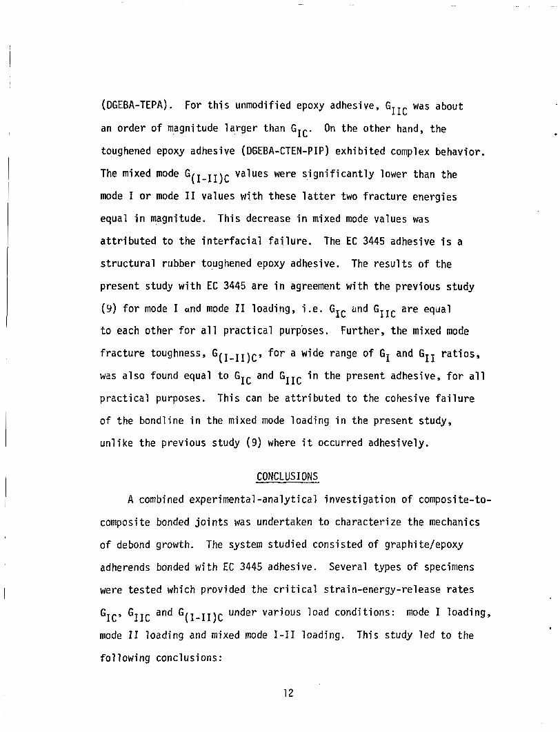
Three specimen types were fabricated: DCB, CLS and ENF specimens,
as shown i n Figures 1, 2 and 3. The DCB specimens were used t o
characterize debond growth under opening mode 1 l oad ing ( F i g 1.)
and also under mixed-mode loading ( F i g 4) . The CLS and ENF specimens
were employed to study debond fa i lure under mixed-mode 1-11 and sl iding
mode I1 loading, respectively.

The DCB specimen ( F i g 1) consisted of two bonded adherends, each
hav ing 14 unidirectional plies with an i n i t i a l debond length of 38 mm.
T h i s debond was introduced by a Teflon film of thickness equal t o the
adhesive bondline. Two aluminum end t abs were bonded t o the DCB
specimen t o apply the load. The adherends of CLS specimens (Fig 2)
consisted of quasi-isotropic lay-ups, [O/45/-45/90Js and [0/45/-45/90]2s.
Two configurations o f CLS specimens were tested:
t o 16-ply l a p and 16-ply strap bonded t o 8-ply lap.
did n o t have an i n i t i a l debond l ike the DCB specimen.
8-ply strap bonded
The CLS specimen
The ENF specimens were ubtained by bonding LWO cJmpos'lte adherends w i t h an
i n i t i a l debond introduced by a Teflon film. These adherends were
15-ply unidirectional laminates.
TESTING PROCEDURE
The objective of the t e s t program was to measure the c r i t i ca l
strain-energy-release rates , GIG, GIIc and G(I-II)c for opening,
:hear and mixec'-mode lozdinas, resFecti*?ely
separately in the following.
Mode I t e s t
These are described
All s t a t i c t e s t s of DCB specimens were performed in a displacement
controlled t e s t machine.
fatigued t o create a debond o f a t least 6 mm beyond the end of the
Teflon film.
a t a s low crosshead speed (5.0 mm/min).
Prior t o testing, these specimens were
The t e s t involved the application of displacement
When the load reached the
c r i t i ca l value, the debond grew in a stable manner. The onset of
I
growth resulted i n a deviation from linearity i n the load versus
4

crosshead displacement record.
decreased until a zero load reading was observed. After each
s t a t i c t e s t , the specimen was fatigued until the debond grew a t
The applitd displacement was then
least 6 mm further, thus forming a sharp crack for the next s t a t i c
tes t . A series of s t a t i c t e s t s was performed on each specimen,
which provided compliance and c r i t i ca l load measurements for
several debond lengths. These measurements provided the c r i t i ca l
strain-energy-release rate as explained i n the section ent i t led
I ANALYSIS . Mode I1 t e s t --
Prior t o testing, the ENF specimen was fatigued t o create a
debond of a t least 6 mm beyond the end of Teflon film. T h i s specimen
was, then, loaded i n three-point bending in a displacement controlled
mode.
were recorded.
from l inear i ty i n the load versus displacement record.
G,*o;lth was stab:e in a l l t cs t s . A ~ l i p - j a ~ e iiedr t h z crack ?ant
was also used t o measure accurately the c r i t i ca l load corresponding
t o the onset of debond growth.
growth occurred a t the mcment when there was a deviation from
l inear i ty in the load versus displacement ( a t the center) record.
Two or more s t a t i c t e s t s were performed on each specimen. After each
s t a t i c t e s t , the specimen was fatigued until the debond grew a t
least 6 mm further, thus forming a sharp crack for the next s t a t i c
tes t .
The center point displacement and the corresponding load
The onset of debond growth resulted i n a deviation
The debond
This confirmed further t h a t debond
5

Mixed-mode t e s t
The mixed-mode fracture tests were conducted with DCB and CLS
specimens. T h i s was accomplished w i t h the DCB specimen by restraining
the vertical motion of the uncracked end while loading only one end
of the cracked end, a s shown i n F ig 4.
t o measure interlaminar toughness by Jordon and Bradley (4 ) .
this purpose, a f ix ture was devised fo r the Instron testing machine.
The test involved the application of displacement a t a slow crosshead
speed (5 mm/min) .
T h i s procedure has been used
For
The debond grew i n a stable manner and a corre-
near s ronding c r i t i c a l load WPS recorded accuwately w i t h a clip-gage
the, crack front.
Fracture t e s t s w i t h CLS specimens were conducted i n a d i s p
Prior t o s t a t i c tes t ing, this specimen was f a controlled mode.
acemen t - igued ,
and thus i t had an i n i t i a l sharp debond. During the t e s t , the axial
ioad and displacement were recorded. The displacement was measured
w i t h two displacement transducers attached on the opposite sides of
the specimen.
propagated.
was measured and verified by the deviation from l inear i ty i n the
recorded load-displacement curve.
The applied load was increased slowly u n t i l the deboiid
The c r i t i c a l load corresponding to unstable debond growth
ANALYSIS
The measured data from the above mentioned four t e s t s were
analyzed different ly t o compute the c r i t i ca l strain-energy-release
ra tes i n each case. These are described separately i n the following.

Mode I
a
.
The measured data provided the c r i t i c a l load, P , and the cr
compliance, C , f o r each debonded length, a , which were used t o
compute the fracture toughness. The de ta i l s of this procedure
are given i n Reference 5. A compliance relationship o f
3 C = Ala
was f i t ted through the experimental data points by the method of
l eas t squares.
f i t t e d very well w i t h the experimental dcta. The constant Al i n
Eq 1, from l inear beam theory, i s 2/3EI where E i s the extensional
s t i f fness and I i s the second moment of area of each side of the
DCB specimen. The experimental value of A1 was i n agreement w i t h
i t s counterpart obtained from the l inear beam theory. Further, a
f i n i t e elecient analysis of the CCB specimen was carried out (5).
Th2 FEM resul ts were also i n agreement w i t h the measured compliance,
as expressed by Eq 1, t h u s verifying the linear beam theory repre-
sents the appropriate behavior of the current DCB specimen. Based
on the l inear beam theory, a relationship of the form
T h i s relationship, based on l inear beam theory,
was f i t t e d t o the experimental data by the method
Then, the averaged value of G I c f o r each specimen
the re1 ationshi p
,2 - r cr - 3A1A;/(2w) GIC - 2w aa -
o f l ea s t squares.
was computed from
where w i s the specimen w i d t h .
7

Mode I1
The end-notched flexure test.s have been developed t o measure
the interlaminar shear fracture toughness, GIIc, of composite
laminates (6) . A closed-form equation t o compute GII was derived
for t h i s t e s t us ing the l inear beam theory. This analysis yielded
the following expression of compliance, C and strain-energy-release
rate G I I ,
2~~ t 3a3 C = 8E b h3
where P i s the applied load, E is modulus, and a , b and h are as
shown i n Fig 2.
was analyzed w i t h a two-dimensional f i n i t e element program called
GAMNAS ( 7 ) t o evaluate i t s performance.
However, i n the present study, th i s t e s t specimen
A f i n i t e clement model, shown i n F i g 5, cunsisted o f 1000
isoparametric four-node elements and had about 2400 degrees of
freedom.
with the debond front a t the middle of the adhesive layer.
element size in the vicinity of the crack f r o n t was 0.02 x 0.02 mm
The adhesive was modeled with four layers o f elements
The
in order t o evaluate accurately the strain-energy-release rate GII.
This size was selected by previous experience (5) as well as by
conducting a convergence t e s t on the GII calculation w i t h mesh
refinement. The error in GII obtained i n the present study i s
8

estimated to be less than 22 percent.
ra te , GII, i n the analysis was computed us ing a virtual crack
closure technique (7 ) .
the f i n i t e element analysis.
The s t ra in energy release
The plane s t ra in condition was assumed i n
The analysis indicated t h a t mode I1 deformation i s achieved
a t the crack t i p and tha t the accompanying mode I deformation causes
closure and overlapping of the opposite faces o f the crack. T h i s
i s not possible physically.
faces, the nodal coupling technique, available w i t h the GAMNAS
program (7), war ured.
was applied a t corresponding nodes to have the same displacements
normal to the crack faces.
condition, i .e . GI = 0.
To prevent the overlapping of crack
For this purpose, the m u l t i p o i n t conztraint
This resulted i n the pure mode 11
Figure 6 shows the comparison of the measured compliance w i t h
FEM and t h e theoretical compliance (Eq 5). T h i s c lear ly shows that
the FEM resu l t s are i n good agreement w i t h the experimental values.
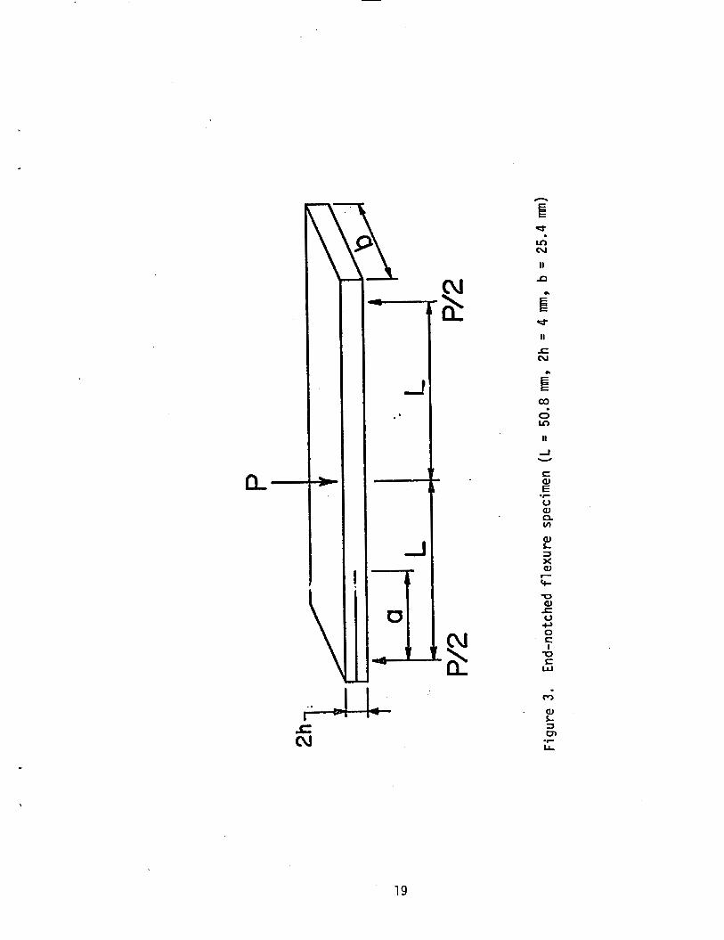
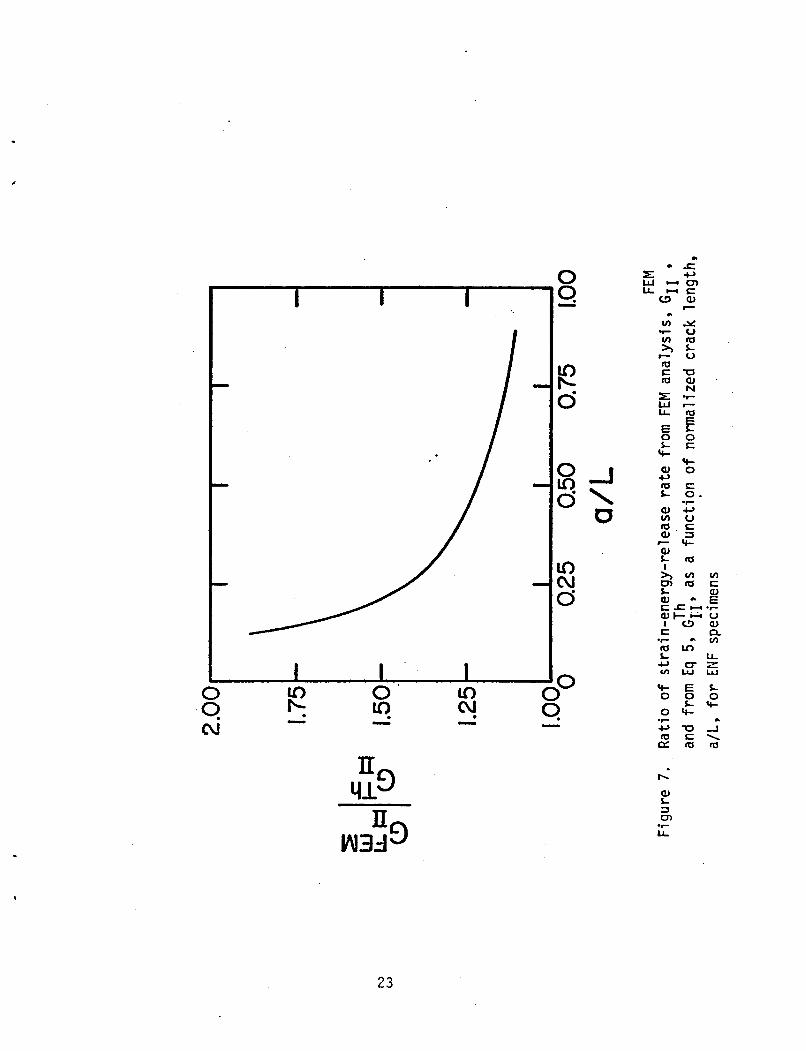
figure 7 shows the comparison of GII obtained from FEM analqsis
and from a linear beam theory, i.e. Eq 5.
GIIc was computed from the FEM analysis, since the theoretical
expressions (Eqs 4 & 5) were n o t developed for the bonded ENF specimen.
Mixed mode 1-11
In the present study,
The tested CLS specimens were analyzed with the f i n i t e element
program GAMNAS ( 7 ) t o compute GI and GII for a given geometry, debond
length and applied load. This two-dimensional analysis accounted
for the geometric nonlinearity associated w i t h large rotation i n
these sp:?cimens.
been reported i n
The de ta i l s of the FEM analsis o f CLS specimens have
Reference 8.
9.-

Jordon and Bradley (4) have developed the following relationships
based on the l inear beam theory t o compute GI and GII associated with
interlaminar crack growth of composite laminate from an asymietrically
loaded DCB specimen as shown in Fig 4.
- P2,* -4wEI
2 2
16wE I - 3P a
GII - - (7)
1.1 the present study, gecmetrically non1;near FFM analysis o f this
specimen was, however, conducted t o evaluate i t s performance fo r
bonded systems, and t o account for i t s nonlinear behavior due t o
large deflections.
DEBOND MECHANISM
In a17 the fracture t e s t s , the debond growth occurred i n a
This growth cohesive manner, i .e . i t grew within the adhesive.
remained i n the bondline d u r i n g the mode I and mode I1 t e s t s w i t h
DCB and ENF specimens, respectively. However, dur ing the mixed mode
test with b o t h DCB and CLS, the debond propagated into the composite
adherend a f t e r i t s cohesive ini t ia t ion in the adhesive.
RESULTS AND DISCUSSIONS
The cr i t ica l strain-energy-release rates, GIG, GIIc, G(I-II)c and GI/GII obtained from a l l thespecimenstested are summarized i n
Tables 1-4. The observed variation in GIG, G I I c and G(I-II)c i s
- 10

reasonable as compared t o other mechanical properties of adhesives
as well as with previous studies (1-2):
The difference i n G I I c obtained from FEM analysis and Eq 5 ,
as given i n Table 2, shows t h a t the closed-form expression derived
for delamination studies (6) does: not' represent the appropr ia te
behavior of the bonded system. The same observation should also be
noted f o r G(I-II)c obtained from the DCB as given i n Table 4.
values of GIIC and G(I-lI)c from FEM analysis i n Tables 2 and 4 will
be, therefore, considered i n the following.
The
To show the interaction between fmcture modes J and TI,
experimental da t a from a l l the speci'mens are plotted in Fig 8. The
I 1 da ta i n F i g 13 define the functiotwl veaat7finship I E ~ . \ J C ~ I - I 6 i~ntl C; j
fo r the debond growth i n the presence of tensile and in-pSi.tie shear
stresses. T h i s mixed-mode interaction is usually expressed i n the
fracture nechanics l i t e ra ture as
Therefore, the present da t a have h e n replot t ' - ,d j1-1 Fig 9 tls*irig
the average values o f G I C and GIIc.
relationship f o r mixed mode debond growth i n EC 3445 adhesive.
These show the following l-inear
GII - 1 + - - GI GIc %IC - (91
A previous study [ 9) has shwn t h ? t fracttirc energy -i Ijcrea:,eti 1y
introducing a mode I1 component i n the unmodified epoxy adhesive
11
(DGEBA-TEPA).
an order of magnitude l a r g e r than GIG. toughened epoxy adhesive (DGEBA-CTEN-PIP) exh ib i ted complex behavior.
The mixed mode G~I-II)C values were s i g n i f i c a n t l y lower than the
mode I o r mode I1 values wi.th these l a t t e r two f rac tu re energies
equal i n magnitude.
a t t r i b u t e d t o the i n t e r f a c i a l f a i l u r e .
For t h i s unmodified epoxy adhesive, GIIC was about
On the other hand, the
Th is decrease i n mixed mode values was
The EC 3445 adhesive i s a
s t r u c t u r a l rubber toughened epoxy adhesive. The r e s u l t s o f the
present study w i t h EC 3445 are i n agreement w i t h the previous study
(9) f o r mode I and mode I1 loading, i . e . GI, icnd GIJc are equal
to each o ther f o r a l l p r a c t i c a l purposes.
f r a c t u r e toughness, G(I-II)cy f o r a wide range o f GI and GII r a t i o s ,
was a lso found equal t o GIc and GIIC i n the present adhesive, f o r a l l
p r a c t i c a l purposes.
o f the bondl ine i n the mixed mode loading i n the present study,
u n l i k e the previous study (9 ) where i t occurred adhesively.
Further, the mixed mode
Th is can be a t t r i b u t e d t o the cohesive f a i l u r e
CONCLUSIONS
A combined exper imenta l -analy t ica l i nves t i ga t i on o f composite-to-
composite bonded j o i n t s was undertaken t o character ize the mechanics
o f debond growth. The system studied consisted o f graphite/epoxy
adherends bonded w i t h EC 3445 adhesive. Several types o f specimens
were tes ted which provided the c r i t i c a l strain-energy-release ra tes
under var ious load condi t ions: mode I loading, GIc’ GIIc and G(I-II)C mode I1 loading and mixed mode 1-11 loading. This study l e d t o the
f o l l o w i n g conclusions:
12

.
(a) The mode I , mode I1 and mixed mode 1-11 fracture energies o f
the toughened epoxy adhesive are equal t o each other.
(b) The fracture cri terion f0.r the mixed mode fracture of the ' toughened epoxy adhesive can be expressed as:
GI ' .GII - 1 %it=- ACKNOWLEDGEMENT
The work reported here was supported by NASA Langley Research
Center, Hampton, VA. The authclrs wish td ackr,ow?edge the subpor t
and encouragement of Dr. W. S. Johnson, NASA Langley Research Center
during the course o f t h i s i n v e s t i g a t i o n .
13

- -
REFERENCES
1.
2.
3.
4.
5 .
6.
7.
8.
9.
Kinloch, A.J. mechanics and mechanisms of failure. Journal o f Material Science , 1982 , - 17, 617-651.
Review-the science of adhesion--part 2,
Shaw, S.J. Adhesion 7, Applied Science Publishers, 1982, 173-1 96.
Ripling, E.J., Satner, J.C., and Crosley, P.B. Fracture o f composite-adhesive-composite systems. Adhesive Joints: Their Formation, Characteristics, and Testing, Plenum Press, 1984.
Jordon, W.M. and Bradley, W.L. toughened graphi te-epoxy 1 ami nates. Toughened Composi tes , ASTM STP 937, American Society for Testing and Materials, 1987 ( i n press).
Mall, S. and Johnson, W.S. mixed-mode failure o f adhesive bonds between composite adherends. NASA Technical Memorandum 86355 , 1985.
Micromechanics of fracture in
Characterization o f mode I and
Russell, A.J. and Street, K.N. laminar fracture energy of graphite/epoxy laminates. Progress in Science and Engineering o f Composites, Proc. ICCM-IV, Japan Society for Composite Materials , 1982.
Dattaguru, B. , Everett, R.A. , Jr., Whitcomb, J.D. , and Johnson, W.S.
Factors affecting the inter-
Geometrically-Nonlinear analysis of adhesively bonded joints: Journal of Engineering Materials and Tec$nology, ASME, - 106, 59-65.
Mall, S., Johnson, W.S., and Everett, R . A . , Jr. of adhesively bonded composites. Adhesive Joints: Their Forma- tion, Characteristics, and Testing, Plenum Press, 1984.
Cyclic debonding
Bascom, W.D. and Oroshnik, J. Effect of bond angle on mixed-mode adhesive fracture. Journal of Material Science, 1978, - 13, 1411-1418.
14

Table 1. G I c from DCB specimens
5 6 Avg .
3 3 3
920 1 952 1 888 1
0.5 0.625 0.75
Avg .
.Table 2. GIIc from ENF specimens
92 9 945 908 952 858 844
1022 900 824
7 07 803 742 722 730 6 90 778 767 673
909 734
15

Specimen
/)I 0.31 0.31 0.31
4 5 6
910 870 7 95
Table 3- G(I-II)C from CLS specimens
0.25 0.25 0.25
Strap P l i e s Lap P l i e s
840 7 90 8d5
1618 1618 1618
Specimen
8/ 16 8/16 8/16
Eqs 6 81 7
0.813 0.925 0.925
858
1.24 963 1053 1.24 998 1165 1.24 93 6 1032
838
I G(I-II)cs J/mL
Avg. I 965 I 1083

E E 0 (\I
b
t
\
ILJ >
E E 0 II) N
v a P v)
5 aJ n L aJ > a
17

n z LL) CT W I n a
I
E 00 ci m
I
i-
n z W
7 E a L
CT a I- -
U
v, W I
- >
2 4
c aJ E V aJ .c
n ln L Iu al c v) I
tu a - I U aJ Y u a L u
cu al ' L 3 0
L L .I-
18
a-
I
1
II
c N
.)
E 03 0 Ln
II
-I U
v aJ P VI
0 c, 0 E I
-0 t W
c3
aJ L J cn L L -I-
19

20

11.-
I
%-
I d
I
21

8 - I a \ U
Lo N ci
0' u? - p -
aJ c, tu L
I \
aJ UJ u to ~
aJ L I x
c
23

I 1 I - 1
e e e 4 0
I I rl I I I 0 0
0 N
0 0 0 (D Y!-
0 0 0 0 0
00 0
0 N - -
24
3 3 N
3 3 3
-
-
0 0 CD
0 0 d- 0 0 N
0 )

I I I
/
Lz) k 0
0 0
U
P
C tn c 0
*I- H 0
25

~ Standard Bibliographic Page
- May 1986 6. Performing Organization Code
[ 1. Report No. 12. Government Accession No. 13. Recipient's Catalog No.
BONDED JOINTS 7. Author(s)
NASA CR- 178112 4. Title and Subtitle 15. Report Date
- -
N
8. Performing Organization Report No.
I
S . Mal l and N. K. Kochhar
Un ive rs i t y o f Missour i -Rol la 9. Performing Organization Name and Address
Department o f Engineering Mechanics pl\ 5qve 1 1 2 1 \. Rolla, MO 05401
. 12. Sponsoring Agency Name and Address
I CRITERION FOR MIXED MODE FRACTURE IN COMPOSITE
10. Work Unit No.
11. Contract or Grant No.
NAG 1-425 13. Type of Report and Period Covered
Contractor ReDort
19. Security Classif.(of this report) 20. Security Classif.(of this page] 21. No. of Pages
Uncl ass i f i e d 26 Unc 1 ass i f i ed 22. Price
A0 3
National Aeronautics and Space Admini s t r a t i on Washington, DC 20546 14. Sponsoring Agency Code
534-06- 23-03 , 15. Supplementary Notes
Langley Technical Monitor: F ina l Report
D r . W. S. Johnson
16. Abstract
A study was undertaken t o character ize the debond growth mechanism o f adhesively bonded composite j o i n t s under mode I, mixed mode 1-11, and mode I 1 s t a t i c load- ings. The bonded system consisted o f graphi te/epoxy (T300/5208) composite adherends bonded w i t h a toughened epoxy (EC 3445) adhesive. The mode I , mode I 1 and mixed-mode 1-11 f r a c t u r e energies o f t he tested.adhesive were found t o be equal t o each other. -Furthermere, t he c r i t e r i o n f o r mixed mode f r a c t u r e i n com- pos i te bonded j o i n t s was found.to be: (GI/GIc) + ( G I I / G I I C ) = 1.
17. Key Words (Suggested by Authors(s)) Debond growth mechanism Adhesively bonded composite j o i n t s Graphi te/epoxy Mixed mode f r a c t u r e Composite bonded j o i n t s
~
18. Distribution Statement
Unclassi f ied-Unl imited
Subject Category 24
I For sale by the National Technical Information Service, Springfield, Virginia 22161 NASA Langley Form 63 (June 1985)