university of birmingham a new process chain for producing
TRANSCRIPT

University of Birmingham
A new process chain for producing bulk metallicglass replication masters with micro- and nano-scale featuresDimov, Stefan; Vella , Pierre ; Brousseau, Emmanuel ; Whiteside, Ben
DOI:10.1007/s00170-014-6148-1
License:Other (please specify with Rights Statement)
Document VersionPeer reviewed version
Citation for published version (Harvard):Dimov, S, Vella , P, Brousseau, E & Whiteside, B 2015, 'A new process chain for producing bulk metallic glassreplication masters with micro- and nano-scale features', The International Journal of Advanced ManufacturingTechnology, vol. 76, no. 1-4, pp. 523-543. https://doi.org/10.1007/s00170-014-6148-1
Link to publication on Research at Birmingham portal
Publisher Rights Statement:The final publication is available at Springer via: http://dx.doi.org/10.1007/s00170-014-6148-1
Eligibility for repository checked May 2015
General rightsUnless a licence is specified above, all rights (including copyright and moral rights) in this document are retained by the authors and/or thecopyright holders. The express permission of the copyright holder must be obtained for any use of this material other than for purposespermitted by law.
•Users may freely distribute the URL that is used to identify this publication.•Users may download and/or print one copy of the publication from the University of Birmingham research portal for the purpose of privatestudy or non-commercial research.•User may use extracts from the document in line with the concept of ‘fair dealing’ under the Copyright, Designs and Patents Act 1988 (?)•Users may not further distribute the material nor use it for the purposes of commercial gain.
Where a licence is displayed above, please note the terms and conditions of the licence govern your use of this document.
When citing, please reference the published version.
Take down policyWhile the University of Birmingham exercises care and attention in making items available there are rare occasions when an item has beenuploaded in error or has been deemed to be commercially or otherwise sensitive.
If you believe that this is the case for this document, please contact [email protected] providing details and we will remove access tothe work immediately and investigate.
Download date: 13. Dec. 2021

1 | P a g e
A new process chain for producing bulk metallic gla ss replication masters with micro and nano scale features
Pierre C. Vellaa, c, Stefan S. Dimova, Emmanuel Brousseaub,, Ben R. Whitesided
a School of Mechanical Engineering, University of Birmingham, Edgbaston, Birmingham, B15 2TT, UK b Cardiff School of Engineering, Cardiff University,Cardiff CF24 3AA, UK
c Department of Industrial and Manufacturing Engineering, University of Malta, Msida MSD2080, Malta d The Centre for Polymer Micro and Nano Technology, University of Bradford, Bradford, West Yorkshire, BD7
1DP, UK
Abstract
A novel process chain for serial production of polymer based devices incorporating both micro and
nano scale features is proposed. The process chain is enabled by the use of Zr-based bulk metallic
glasses (BMG) and thus to achieve the necessary level of compatibility and complementarity between
its component technologies. It integrates two different technologies, namely laser ablation and
focused ion beam (FIB) milling for micro structuring and sub-micron patterning, respectively, and thus
to fabricate inserts incorporating different length scale functional features. Two alternative laser
sources, namely Nanosecond (NS) and Picosecond (PS) lasers, were considered as potential
candidates for the first step in this master making process chain. The capabilities of the component
technologies together with some issues associated with their integration were studied. To validate the
replication performance of the produced masters, a Zr-based BMG insert was used to produce a
small batch of micro fluidic devices by micro-injection moulding. Furthermore, an experimental study
was also carried out to determine whether it would be possible by NS laser ablation to structure the
Zr-based BMG workpieces with a high surface integrity while retaining the BMG’ s non-crystalline
morphology. Collectively, it was demonstrated that the proposed process chain could be a viable
fabrication route for mass production of polymer devices incorporating different length scale features.
Keywords: Laser Ablation, Focused Ion Beam Milling, Bulk Metallic Glasses, Process Chains,
Function and Length Scale Integration, Micro-injection Moulding

2 | P a g e
1. Introduction
The global market for miniaturised products has been increasing continuously in the last decade .
(HLG, 2011). This trend is a direct consequence of the growing needs and demands across a range
of industry sectors (e.g. biotechnology, energy, medical, optoelectronics, micro-optics, printed
electronics and ultra-precision engineering) to integrate multiple functionality in the smallest possible
enclosures/packages by combining the latest advances in functional materials and high throughput
micro and nano manufacturing technologies. In addition, the development of such multifunctional
miniaturised products offers other important advantages, in particular significant cost, size, material
usage and power consumption reductions.
Thus, it is not surprising that this trend for function integration in current and new emerging products
has motivated researchers to look for new ways to “harness” the latest advances in functional
materials and micro and nano manufacturing technologies and thus to create manufacturing
capabilities for function and length scale integration (FLSI) at part and product levels (Bigot, Minev,
Dimov, & Dobrev, 2011). These capabilities underpin the development of new miniaturised devices
that depends on the manufacture of components incorporating functional features covering the whole
range of sizes from few 100 µm to sub-100 nm. In addition, to achieve FLSI in a single part it is very
important to explore the opportunities that new specially developed materials can offer and thus to
benefit from their “optimised” properties for micro and nano scale processing (Dimov, Brousseau,
Minev, & Bigot, 2012) .
Micro and nano manufacturing technologies that underpin the development of multifunctional
miniaturised products are limited in their capabilities for producing structures with different length
scale features cost effectively, from a few millimetres down to nanometres, in different materials
(Dimov et al., 2012). Therefore, the capabilities of complementary and at the same time compatible
manufacturing technologies are usually combined in process chains to produce miniaturised devices
incorporating different length scale features. Such process chains can provide the necessary
manufacturing solutions for achieving both high throughput and cost effective production of micro and
nano structured parts and devices. So, the efforts of research groups and companies are focused on
designing, validating and implementing processes and process chains that satisfy the specific

3 | P a g e
functional and technical requirements of new emerging multifunctional miniaturised products and thus
to create the necessary pre-requisites for their scale up manufacture (Lalev et al., 2009; S. G. Scholz
et al., 2011; Tosello, Bissacco, Tang, Hansen, & Nielsen, 2008; Velkova et al., 2011).
The integration of complementary and compatible technologies into process chains has been
attempted before in developing promising micro manufacturing platforms (Dimov et al., 2012).
However, there are many important factors and processing constraints that need to be considered
when combining and integrating micro and nano fabrication technologies. Therefore, it is really a
challenging task to design and implement successfully process chains aiming at FLSI in innovative
miniaturised products. In particular, it is necessary for the interfaces between component
manufacturing technologies in the process chains to be analysed systematically in terms of their
Capabilities, Complementarities and Compatibilities (C3), and this represents an important pre-
requisite for their successful design and implementation.
A systematic study of technological interfaces between micro and nano fabrication technologies
conducted by the authors revealed that the material of the workpiece plays a very important role in
their successful integration and also in achieving FLSI in parts or replication masters (Minev, Vella,
Brousseau, Dimov, Minev, et al., 2010; Minev, Vella, Brousseau, Dimov, Scholz, et al., 2010; Vella,
Brousseau, Minev, & Dimov, 2010). Hence, when designing such chains it is necessary to utilise
materials that facilitate the integration of the considered component manufacturing technologies, and
at the same time satisfy the functional and technical requirements of the final product or master. For
instance, to combine successfully the capabilities of two micro and nano structuring technologies, e.g.
focused ion beam (FIB) machining and laser ablation, it is necessary to select a workpiece material
with a favourable processing response to both technologies and also to take into account their
respective constraints in producing different length scale features with the required surface integrity
(Li, Minev, Dimov, & Lalev, 2007; Quintana, Dobrev, Aranzabe, Lalev, & Dimov, 2009; Vella et al.,
2010).
The paper presents an experimental investigation of a process chain that is enabled by the use of
a bulk metallic glass (BMG) as a workpiece material that combines the capabilities of the laser
ablation and FIB machining technologies in producing replication masters incorporating micro and
nano scale structures. To demonstrate its viability a mould insert was fabricated and then used to

4 | P a g e
produce a batch of polymer parts by micro-injection moulding. Such a process chain can be used for
mass production of polymer parts incorporating different length scale features.
The paper is organized as follows. Section 2 discusses generic process and material related
issues that have to be considered in achieving length scale integration in master-making process
chains. It also provides an overview of the component technologies investigated this research. Then,
Section 3 describes the experimental set-up employed to validate the capabilities of the proposed
process chain. Finally, the obtained results are presented and discussed, and conclusions are made.
2. Process Chain Design
When designing process chains it is necessary to take into account the technical requirements of
the product or replication master together with the processing constraints of their component micro
and nano manufacturing technologies. Also, as it was already stated, the selection of a suitable
workpiece material to facilitate the integration of these technologies into a process chain is an
important factor in producing parts or replication masters with different length scale functional
features. Specifically, the microstructure and properties of a workpiece material need to be
considered as one more “variable” in optimising the process chains, and thus to achieve a suitable
level of C3 between the component fabrication technologies. The selected material should have a
microstructure that is optimised for performing processing both at meso/macro and micro/nano
scales. In particular, the micro or nano structuring response is favourable if, such a material is
homogeneous and inclusion free at the considered processing scales. Thus, the material
microstructure and properties of the workpiece are a critical factor affecting the machining results and
their consistency in micro and nano manufacturing. Therefore, it is even more important when
designing process chains aiming at FLSI in replication masters to identify suitable combinations of
complementary structuring technologies and a workpiece material with a favourable machining
response to them.

5 | P a g e
2.1 Process and Material Issues
Major advances in material processing technologies and especially in the development of
amorphous coatings and alloys have attracted a considerable interest in recent years. This is due to
the fact that the high hardness, fracture toughness and fatigue strength of such materials represent
important value-added properties in a number of engineering applications (Inoue, 2000; Zhang, Liu, &
Zhang, 2006). For example, amorphous coatings are advantageous for manufacturing micro-electro-
mechanical systems (MEMS) and micro-sensor systems (Wang et al., 2007). Additionally, due to
absence of any long range atomic order, lattice defects and grain boundaries (Kawasegi et al.,
2006), amorphous metallic alloys are considered promising materials for micro and nano- structuring
of replication masters (Minev, Ilieva, Kettle, Lalev, Dimov, et al., 2010; Quintana et al., 2009). The
absence of grain boundaries in BMG makes them mechanically and chemically homogeneous for
processing at all length scales down to a few nanometres. As a result, they are one of the preferred
materials for micro- and nano structuring (Loffler, Kundig, & Dalla Torre, 2007). However, to benefit
from their outstanding properties and employ them successfully in different application areas, it is of
prime importance to maintain their non-crystalline morphology during machining, especially when
producing parts incorporating micro- and nano-scale features (Quintana et al., 2009). In a recently
conducted feasibility study, it was shown that the processing of an amorphous Nickel-based alloy
workpiece with both nano-second (NS) and pico-second (PS) pulsed laser ablation did not trigger
phase transitions in the material (Quintana et al., 2009). In particular, the reported research revealed
that machining with both laser ablation regimes did not lead to any crystallisation and long-range
atomic ordering of Ni-based metallic glasses. Additionally, there were no signs of crack formation,
which indicates a preserved surface integrity after laser machining with short- and ultra-short pulses.
Another study reported the effective machining of Mg-based BMG using a 355nm pulsed NS laser. In
this study it was demonstrated that by an appropriate adjustment of the laser parameters the non-
crystalline morphology of the Mg-based BMG was preserved (Lin, Lee, Hu, Li, & Huang, 2012).
Hence, both PS and NS laser machining regimes should be considered as very promising methods
for the cost effective micro structuring of metallic glasses.
Another study which compared the machining response of an amorphous and polycrystalline Ni
alloys when subjected to FIB milling, showed that a higher surface integrity could be achieved when

6 | P a g e
processing the amorphous Ni-based BMG under identical conditions to those used for the
polycrystalline Ni alloy (Li et al., 2007).
Thus, laser ablation in NS and PS regimes and FIB milling satisfy the C3 prerequisite for their
integration in process chains and are promising combinations of complementary technologies for
structuring BMGs at micro and sub-micron length scales respectively without introducing any changes
in their non-crystalline morphology. In particular, the potential integration of PS laser ablation and FIB
machining in a process chain reported in a feasibility study (S. Scholz et al., 2009) suggested that PS
laser ablation can be used for cost effective micro structuring of large areas on replication masters
while FIB milling can be utilised to machine on a pre-existing topography very complex micro and sub-
micron 2.5D and 3D structures. The same rationale also applies to the combination of NS laser
ablation and FIB milling in a process chain. Thus, the component processes in such process chains
can be utilised in their cost effective processing windows and complement each other in achieving
FLSI in replication masters.
In the proposed master making process chains that are enabled by the use of a BMG as a workpiece
material, first laser ablation is employed to structure relatively big surface areas with meso and micro
scale resolution and acceptable surface integrity, and subsequently FIB milling is applied to achieve
high resolution sub-micrometre and nano patterning within a relatively small field. In this manner, by
combining the capabilities of these two complementary technologies it is possible to achieve cost
effective FLSI in replication masters and benefit from the BMG’ s superior mechanical properties for
micro injection moulding (µIM) of thermoplastic polymers. A more detailed description of the
capabilities of these component technologies in the proposed master making process chains is
provided in the following sub-sections.
2.2 Laser machining
Laser micromilling as a technology for manufacturing replication masters has attracted research
(Dobrev, Dimov, & Thomas, 2006; Petkov, Dimov, Minev, & Pham, 2008; S. G. Scholz et al., 2011)
and industrial interest (M. Knowles, Kearsley, & Karnakis, 2007). Laser milling can be used to
structure parts in a wide range of materials directly from CAD data via a layer by-layer machining

7 | P a g e
strategy (Pham, Dimov, Ji, Petkov, & Dobrev, 2004). Material removal occurs as a result of laser
irradiation and depending on the laser source and the workpiece, the ablation can take place through
melting and ejection or sublimation (Petkov, Dimov, et al., 2008). The process allows parts with
complex shapes to be produced without the need for expensive tooling. Laser milling is mostly used
for machining parts from one side only. However, complete laser milling of parts is also possible, but it
is necessary to address the accuracy issues associated with the re-positioning of the workpiece,
which are common process design concerns when more than one machining setup is necessary
(Pham et al., 2004).
To set up the laser milling process and achieve the required surface integrity it is usually necessary to
take into account a range of factors that can influence the machining outcomes (Pham, Dimov, &
Petkov, 2007). These include laser processing parameters and applied machining
strategies(Fleischer & Kotschenreuther, 2007; Lalev et al., 2009; Petkov, Dimov, et al., 2008; Uriarte
et al., 2006; B. Wu & Ozel, 2011). Thus, their interdependencies and effects on different output
characteristics such as the achievable surface integrity or the material removal rate have to be
studied systematically in order to identify optimum processing windows. Short, NS, and ultra-short
laser sources, femtosecond (FS) and PS, have many applications in micro-machining of metals,
semiconductors, and dielectrics for the fabrication of electronic, medical, optical and other devices(B.
Wu & Ozel, 2011). The ultra-short lasers have the advantage of extremely high radiation intensities
and thus can ablate almost any material with minimal and sometimes even negligible heat affected
zone and therefore they are used for precise material removal (Brousseau, Dimov, & Pham, 2010; B.
Wu & Ozel, 2011).
NS laser technology is mature and is widely adopted in industry for micro machining (M. R. H.
Knowles, Rutterford, Karnakis, & Ferguson, 2007). This is largely due to their cost-effectiveness and
reliability and therefore NS lasers are used in many industrial applications. A major advantage of NS
laser ablation is their achievable higher removal rates when compared to lasers with shorter pulses
(Quintana et al., 2009).

8 | P a g e
However, micro machining can be a challenging application for NS lasers. Good quality sidewalls can
generally be obtained, but it is usually very difficult to achieve the necessary surface integrity for some
applications, e.g. replication masters (M. Knowles et al., 2007). The ultra-short lasers, FS and PS,
have a number of advantages in micro machining. The very high repetition rate of the latest
generation of FS and PS laser sources together with the advances in the scanning heads’ technology
allow the resulting surface integrity to be improved substantially while maintaining a higher processing
speed (Fleischer & Kotschenreuther, 2007; Petkov, Dimov, et al., 2008). However, it is worth noting
that such improvements are at the expense of the removal rates when NS and PS laser machining
results are compared.
Apart from micro machining, lasers are also used for surface texturing (Bonse, Kruger, Hohm, &
Rosenfeld, 2012; Etsion, 2005). Especially, they are applied for functionalising surfaces, e.g. to
regulate cell-implant interaction for biomedical engineering applications (Vehse, Lobler, Schmitz, &
Seitz, 2012), to reduce the surface friction in mechanical devices (Chen et al., 2012), to modify the
wetting properties of the surfaces (Fadeeva et al., 2011; P. H. Wu, Cheng, Chang, Wu, & Wang,
2011) , or to reduce the surface reflectance (Nayak & Gupta, 2010). Such applications are also very
interesting for master making as laser surface texturing rates are still low for cost effective direct
structuring of parts with relatively large surface areas.
In this research, the choice of the laser source requires careful consideration in order to avoid any
detrimental effects on the non-crystalline morphology of the BMG workpiece. Such effects are of a
particular importance for the proposed process chain as any phase transformations or crack
generation will not only change the material properties of the replication master but can also affect
any subsequent sub-micron structuring by FIB milling. Therefore, two alternative laser sources were
considered as potential candidates for the first step in this master making process chain. The primary
focus of the research is on investigating the feasibility of utilising PS laser machining in the proposed
master-making process chain due to its capabilities for machining accurately micro features whilst
preserving the mechanical properties and surface integrity of the workpiece material. However, it is
also possible to optimise the NS laser ablation process and achieve a relatively good surface integrity
while benefiting both from the higher material removal rates and the superior mechanical properties of

9 | P a g e
BMGs as they can also be preserved during the processing with short pulse lasers. Therefore, it was
also considered important to investigate the NS laser ablation of BMGs as an alternative component
technology in the process chain, in particular what level of surface finish can be achieved without
triggering any crystallisation.
2.3 FIB milling
The second stage in the process chain is FIB machining of sub-micron and nano-features over the
pre-existing topography generated by laser ablation. The FIB milling process offers many advantages,
such as flexibility, high resolution and high surface quality that are extremely important for master
making (S. Scholz et al., 2009; Youn, Takahashi, Goto, & Maeda, 2006).
The input data for FIB milling can be in a bitmap format when it is necessary to produce simple
features like 2.5D channels. In this case, the data can be uploaded into most FIB systems directly.
Then, the built-in pattern generator of such systems is used to create directly the 2.5D features. A
more sophisticated approach to 2.5D feature generation requires the use of a lithography software
and hardware like Elphy Quantum (Raith GmbH) or Nanomaker where various 3D shapes can be
designed, duplicated, and if necessary the respective exposure doses specified. However, the
generation of complex 3D shapes like diffractive optical elements, necessitates a different data
preparation procedure. Such 3D structures can be designed by employing any 3D CAD package and
then, by following a sequence of data translation operations, the 3D geometry is converted into a
stack of layers ordered along the vertical axis of the 3D model (Lalev, Dimov, Kettle, Van Delft, &
Minev, 2008). After such a ‘slicing’ step, the model is exported into a GDSII stream file format and
each GDSII layer represents a set of exposure pixels defining a slice of the model at a given point
along its vertical axis.
The main FIB parameters that should be considered when optimising the process are: ion beam
current, ion beam fluence, and exposure time (Lalev et al., 2008; Li et al., 2007; Minev, Ilieva, Kettle,
Lalev, Dimov, et al., 2010; Velkova et al., 2010). An ion beam sputtering simulation software can also
be employed to predict and thus reduce some negative effects such as re-deposition of sputtered
material and over-etching (Svintsov et al., 2009). Its use as a data pre-processing step before FIB

10 | P a g e
milling makes it possible to optimise the process parameters and even to modify the model in order to
counteract material re-deposition effects (Velkova et al., 2010) .
Another important issue when structuring processes are integrated in process chains is the alignment
of new features to any pre-existing features/topography on the workpiece. In the proposed chain, this
alignment could be realised either by manually positioning the sample stage while inspecting the
specimen in SEM or FIB imaging modes, or automatically, by using the ‘‘feature recognition” option
available in some FIB systems to find alignment marks machined in the preceding processing steps.
As stated previously, the main disadvantage of the FIB milling technology is its relatively low removal
rates. Consequently, to address this issue and thus to be able to nano structure larger areas, a multi-
ion beam concept was proposed that combines the high resolution capabilities of the FIB technology
with the high throughput that parallel lithography systems can offer. In particular, to satisfy the
requirements for high productivity, a projection maskless nano-patterning (PMLP) system has been
developed (Platzgummer, Loeschner, & Gross, 2008). A prototype, which incorporated 48,000 beams
working in parallel, demonstrated a significant increase of the removal rates and improved resolution
compared to conventional single FIB systems.
2.4 Micro Injection Moulding
The proposed master-making process chain can be used to produce masters for scale-up micro
replication including µIM and hot embossing (HE) (Heckele & Schomburg, 2004). In particular, µIM
and HE can process any thermoplastic polymer and are considered important technologies for the
cost effective serial fabrication of micro-parts (Giboz, Copponnex, & Mele, 2007). HE is widely used
for replicating structures with dimensions in the sub-micron range and with high aspect ratios. The
process is very effective for producing such functional features and can minimise the stress induced
birefringence due to the very low flow rates of the material in the imprinting plates. However, HE cycle
times, which are usually in the range from 5 to 10 minutes, are relatively long and therefore this

11 | P a g e
technology is more suitable for small to medium series production and prototyping (Giboz et al.,
2007; Heckele & Schomburg, 2004) . Conversely, the shorter µIM cycle times, which are in the order
of seconds makes it effective for high volume production with low production costs per part once the
process has been properly configured. Given that the development of new micro devices is highly
dependent on manufacturing systems that can reliably and economically produce micro parts in large
quantities, it is clear that µIM provides a more attractive option. Therefore, in this study, the structured
BMG inserts was used as a master for µIM in order to validate the proposed process chain.
When replicating micro and nano-structures employing µIM, the accuracy of the mould masters is an
important prerequisite. Nonetheless, the complex flow and cooling behaviour of the thermoplastic
materials can also have a significant influence on achievable product quality. It is therefore usually
necessary to optimise the µIM process using design of experiments (DOE) approaches. There are
numerous parameters which can influence the process but the most statistically significant factors
(Attia, Marson, & Alcock, 2009; Giboz et al., 2007; Griffiths, Dimov, Brousseau, & Hoyle, 2007; Sha,
Dimov, Griffiths, & Packianather, 2006) include: melt temperature; mould temperature; injection
speed; holding pressure and duration; mould surface roughness; runner and gate design and venting/
vacuum systems.
Micro-moulding geometries typically have a very high surface to volume ratio when compared with
macro scale injection moulded products, which means that polymer solidification can be very rapid,
with cooling rates in a fraction of a second in many cases. Such conditions require short filling times
to ensure the temperature of the material does not fall below the no-flow temperature before the
mould is completely filled. The heat flow during solidification can also have a significant influence on
the internal morphology of the part and also on a range of properties affecting its mechanical
behaviour. Therefore, the thermal behaviour of the polymer-mould system can have a high impact on
the final product’s properties and therefore a very accurate control of the melt and mould
temperatures is required to achieve a stable process. As a consequence the µIM process windows for
quality components tend to be much smaller than those in conventional injection moulding. In
particular, any small changes in the parameter settings can shift the process outside these small
windows with detrimental effects on part quality. It is therefore very important to optimise the µIM
process for the particular polymer in use and thus to ensure a stable and reliable micro replication
process.

12 | P a g e
3. Experimental Setup
3.1 Insert Material
The BMG used in this study was a Zr-based BMG, namely Vitreloy 1b (Vit1b). The mechanical
properties of this alloy are particularly attractive for the fabrication of high wear resistant mould inserts
for µIM, especially its high tensile yield strength, 1.9 GPa, and high hardness, 540 Hv. Furthermore, it
is expected that micro and nano-structures machined in this material will have a high level of surface
integrity due to the fact that crystalline defects, such as dislocation pile-ups, point defect
agglomerates and grain boundaries, are not present in the material. Using wire electro discharge
machining, the Zr-based BMG sample was cut to produce a circular workpiece with a thickness of 3
mm and a diameter of 10 mm.
3.2. Test Structure Design
The 2D design of a Quick Response (QR) code is used as a test structure.
Fig. 1 Bitmap images of the QR code
The QR code is a specific matrix barcode that consists of square fields in black colour on a white
background. The information encoded by such patterns can represent text or other data. The specific
QR code used is shown in Fig. 1 and it consists of 29 x 29 black or white squares. This pattern was
machined at two different length scales on the BMG workpiece. First, a micro scale pattern of the QR

13 | P a g e
code was produced using laser ablation. At this scale, each square has a width of 75 µm and the
white squares correspond to pockets with a depth of 10 µm. Next, a nano-scale version of the code
was machined on top of a micro-scale black square, as shown in Fig. 1, using FIB machining. In this
scale, each square has a width of 2.59 µm and the white squares correspond to pockets with a depth
of 900 nm. This test structure was selected to demonstrate the feasibility of incorporating different
length scale features, micro and sub-micron, cost effectively into replication masters for anti-
counterfeiting purposes. In particular, such QR codes could be replicated on the surfaces of macro
and meso scale polymer parts.
3.3 Laser Ablation
As it was stated in Section 2.2, PS and NS laser ablation can be used for micro machining of BMGs
without triggering any crystallisation. Therefore, in this research two different laser systems were
utilised to investigate laser-BMG interactions in these two ablation regimes.
The PS laser ablation is used for machining the features of the micro-scale QR code on the BMG
workpiece. To perform laser structuring, first the bitmap file of the QR code was converted into a .dxf
(Drawing Interchange Format) format, and then the model was scaled to ensure that the square fields
are machined to the specified sizes of 75 µm x 75 µm. Next, this data file was used to generate the
laser machining path. A layer-based machining strategy was selected for this study. In particular, the
strategy included random “hatching” with a step over of four micrometres between the parallel passes
of the laser beam and this was then followed by a border cut for each layer (Petkov, Scholz, &
Dimov, 2008). The PS laser ablation system used to perform this laser structuring operation
incorporates a mode-locked Nd:YVO4 green (532 nm) laser source. The process settings used to
carry out the PS laser machining are provided in Table 1. The process settings were selected in such
a way so that in parallel to the machining of the QR code, the machined fields were also textured with
self-organised structures and thus to investigate the µIM capabilities when replicating surfaces with a
wide range of micro and sub-micron features/structures.

14 | P a g e
Table 1: PS laser parameters
Pulse duration 8 ps
Repetition rate/ Pulse frequency 50 kHz
Laser beam scanning speed 10 mm/s
Power 25 mW
Fluence 0.28J/cm2
Pulse energy 0.5 µJ
Hatch distance 4 µm
Beam quality M²<1.3
In addition, an experimental study was carried out to determine whether it would be possible by NS
laser ablation to structure Zr-based BMG workpieces with a high surface integrity without triggering
any crystallisation. A system that integrates a NS near infrared fibre laser was used to machine fields
with depth of approximately 20 µm. Some initial trials were conducted with different processing
conditions, in particular by varying scanning speed, pulse duration, repetition rate and fluence, to
identify combinations of processing parameters for achieving a high surface integrity with a minimal
thermal load. Based on these trials the process settings in Table 2 were selected as promising for
achieving high surface integrity with minimal thermal damage. Using these settings 10x10 mm fields
were laser machined on three Vit 1B samples for a X-ray diffraction (XRD) analysis. After completing
the NS laser machining, the three samples were ultrasonically cleaned with a light degreaser to
remove any debris without affecting the resulting surface roughness. It should be stressed that this
was just a feasibility study to determine whether it will be possible by NS laser ablation to achieve a
high surface integrity while retaining the BMG non-crystalline morphology.

15 | P a g e
Table 2. NS-Laser Parameters
Sample
Pulse Frequency
[kHz]
Average Power [W], (measured)
Pulse energy
[µJ]
Fluence [J/cm 2] @ 35 micron
spot
Pulse duration
, [ns]
Scanning speed V [mm/s]
Track distance,
[µm]
Layer thickness
[µm] Hatch
direction
1 40 0.72 18 1.87 220 600 15 1 cross,
90°
2 250 1.45 5.8 0.60 25 1000 6 0.15 random
3 40 0.72 18 1.87 220 200 5 0.3 random
3.4 FIB Processing
The next process in the proposed chain was FIB milling of the features with nanometre depth over the
micro-topography produced by laser milling. The nano-scale QR code was machined on the BMG
workpiece using a Carl Zeiss XB 1540 FIB/SEM system that combines a gallium ion beam with an
electron beam column. As it was mentioned earlier, the FIB milling process can be controlled by
utilising a built-in software or an external nanolithography system (Lalev et al., 2008). Given that the
QR code represents a 2D image composed of black and white fields/pixels, the bitmap file of this
pattern was processed directly by the built-in software of the FIB system to control the milling
operation. The depth and accuracy of the structures fabricated by FIB milling are determined by the
processing parameters used. In this study, the process was set up and optimised by conducting trials
to find a suitable processing window and thus to achieve the best trade-offs between machining time
and feature quality. Especially, in identifying the process parameters it was taken into account that
FIB milling with low current results in a better pattern resolution but at the expense of longer milling
times. It should also be noted that by increasing the processing time the possibility for quality
deterioration and pattern drift also increases. The FIB milling parameters used in this study are
provided in Table 3. The alignment of the nano-scale QR pattern over the micro-scale code was
performed by a manual stage control with the help of the FIB imaging mode of the system.

16 | P a g e
Table 3: FIB parameters
Probe current 200 pA
Accelerating voltage 30kV
Exposure time duration 3 hours
Probe size 40 nm
3.5 Micro Injection Moulding
The machine used to perform the µIM trials was a Battenfeld Microsystem 50 with a 5 mm diameter
injection plunger. The BMG insert was integrated into a larger circular cavity mould and installed into
a modular tool assembly based on a Hasco 95mm x 95mm standard. The cavity form is a disc with a
17 mm diameter and 0.5 mm depth. The tool is thermoelectrically heated using a cartridge heater
array and temperature control was performed using the integrated control system in the machine.
Images in Figure 2 depict the assembled mould and one of the replicas.
(a) Mould assembly (a) µIM part
Fig. 2 Images depicting the assembled mould and one of the replicas.
A material commonly used in injection moulding for optical devices, namely Cyclic Olefin Copolymer
(COC) with a trade name Topas 5013S was selected to conduct the replication trials.

17 | P a g e
Before the experiments, the polymers were placed in industrial desiccant dryers for four hours at the
manufacturers recommended drying temperatures to remove any moisture.
To fill completely a mould cavity that incorporates micro and sub-micron features it is very important to
select the right processing window. Taking into account the results of other experimental studies
(Huang, 2007; Monkkonen et al., 2002; Sha et al., 2006; Tosello, Gava, Hansen, & Lucchetta, 2010),
some preliminary trials were conducted to identify an appropriate combination of parameter settings
and thus to produce replicas of required quality.
The trials showed that the mould temperature had the highest influence on the replication quality.
Therefore, a set of experiments were subsequently performed with the mould temperature settings in
Table 4 in order to investigate the influence of mould temperature on the replication fidelity in terms of
feature width, depth and shape. These settings were selected based on the material manufacturer’s
data sheets, experimental investigations reported in literature, and the performed trials.
To obtain representative results, the µIM process was first allowed to stabilise for each set of process
parameter settings by producing at least 40 components and then a small batch of parts was
produced for quality assessments.
Table 4: Process Settings for Micro-Injection Moulding Trials
Trial No
Parameters 1 2 3 4 5
Melt temp -- T b [oC] 290 290 290 290 290
Mould Temp -- T m [oC] 80 110 115 130 140
Holding Pressure -- P h [Bar] 1300 1300 1300 1300 1300
Injection Speed -- V i [mm/s] 200 200 200 200 200
3.6. Inspection
The surface integrity and dimensional compliance to technical requirements of the tool and
subsequently the replicas have to be assessed. Thus, a detailed dimensional analysis was carried out
based on five key representative dimensions of both the laser and FIB machined QR codes on the

18 | P a g e
BMG insert and their corresponding polymer replicas. In particular, the widths and the heights/depths
of the smallest features and the overall size of the codes were measured. The equipment and the
respective inspection procedures employed in this research are described below.
3.6.1 Scanning Electron Microscope
SEM images of the QR codes were taken at each stage of the process chain in order to assess lateral
(XY) and vertical (Z) dimensions of the produced parts. One BMG master was used for the detailed
dimensional analysis. Ten “pixels” located in the corners and the centre of both the “large” and “small”
QR codes were measured in X and Y respectively to obtain the width values of the smallest features.
Whilst to obtain the values of the overall QR codes’ dimensions, five measurements were conducted
along the X and Y axes. All X and Y measurements were carried out using the SEM. For the
height/depth measurements of the smallest features, 10 “pixels” of the “large” QR code were
measured. These Z measurements were carried out at an angle of 54o between the electron beam
and the sample holder. The tilt compensation option of the SmartSEM software was used to calculate
the actual values of the vertical dimensions. For the polymer parts’ analysis, five replicated Topas
samples were selected and each part was measured in the same way as the BMG insert.
3.6.2 Atomic Force Microscope
A representative area of the FIB milled and replicated small scale QR code was inspected with an
atomic force microscope (AFM), Asylum Research MFP 3D, to judge about the FIB structuring and
the µIM replication quality. The measurement was carried out when the instrument was in its tapping
mode configuration. The probe used was parabolic in shape, with an apical tip radius of 15nm and a
half cone angle (a) of 30°, from the vertical plane. The profiles of the features were obtained at the
same place on the FIB milled insert and all µIM parts. For the mouldings, three samples were
randomly selected from each batch of Topas 5013X parts. The dimensions of the scanned area were
50 x 50 µm. After the measurement, the data sets were processed using IGOR Pro 6 software in
order to generate the average line profiles of the features and carry out on them depth and width

19 | P a g e
measurements. Finally, the average profiles for each batch produced were compared to decide which
combination of process parameters gave the best replication results.
3.6.3 Confocal microscopy
The laser and FIB patterns on both the insert and mouldings were inspected using an Olympus LEXT
4000 laser scanning confocal microscope. Two modes of operation were used, in particular a 20×
objective with a 25 image stitched dataset (5 horizontal, 5 vertical) for the large-scale QR code
pattern and a single 100× image for the FIB structures.. The resolution of each image was 1024 x
1024 pixels and the overlap area for the stitching was 20%.
The surface roughness of the textured surfaces of the large scale QR-code on both the insert and the
replicas together with the pixel step height measurements of the insert’s “small” QR code were carried
out using this confocal microscope. In particular, in order to determine the step heights, the integrated
Olympus software was employed to obtain histograms of the height distributions. .Average step
heights of the scan areas were determined by computing the difference between the individual mean
heights of the histograms’ two peaks as shown in Fig 3. For the polymer parts’ dimensional analysis,
five Topas replicas were measured in the same way as the BMG insert.

20 | P a g e
Fig 3 . Step Height Measurement Using Olympus Software
This method for evaluating average step heights was validated using a Veeco SHV2119 step height
calibration artefact where 5 measurements were performed at various locations on the sample using
the magnification parameters adopted for each scan. The results fell within the ranges defined by the
calibration certificate so it was accepted as a valid technique.
For assessing the replication quality of the FIB structures on the BMG insert and five Topas replicas
from each mould temperature setting, three methods were used:
i) Volume ratio. The volume of the features and cavities was determined using the LEXT software
by considering the volume enclosed by the measured surface and a plane coincident with the
original (pre-machined) surface. A ratio of the volume of the moulded feature relative to the
original cavity volume was used as a measure of the replication quality.
ii) Sa ratio. The Sa parameter is the arithmetic mean of the absolute value of the height within the
sampling area. The Sa parameter of both the features and cavities was determined using the
LEXT software. The ratio between Sa of the moulded feature relative to the original cavity Sa
was used as a measure of replication quality.
iii) Average step height ratio. As described earlier, the average step height was determined for the
insert and each of the moulded specimens by using histogram information as shown in Fig 3.
The ratio between the average step height of the moulded feature relative to the original cavity
step height was used as a measure of replication quality.
3.6.4 XRD
The focus of the NS laser machining trials was to achieve as high as possible surface integrity without
triggering any crystallisation and thus to preserve the attractive mechanical properties of Zr-based
BMGs. Therefore, a XRD analysis of Vit 1B samples before and after laser machining to form 10x10
mm fields, was carried out using a Bruker D8 Advance’ X-Ray Diffractometer with Ni filtered CuKa
radiation to verify the amorphicity or otherwise of the four samples.

21 | P a g e
3.6.5 Talysurf 120L
The roughness measurements for the three NS laser machined samples were taken using a Talysurf
120 L surface texture measurement instrument. The sizes of the sampling/evaluation lengths were
chosen according to ISO 4288:1997 (ISO4288, 1997). The parameter used to evaluate the surface
roughness was the arithmetic mean roughness (Ra) because relative heights in microtopographies
are more important, especially when measuring flat surfaces.
3.6.6 Dimensional and Surface Roughness Measurements Uncertainty
The average values of dimensional measurements were calculated and where deemed applicable
were also provided with their associated expanded uncertainty, U, (at 95% confidence level) which
was determined, following an established procedure (Joint Committee for Guides in Metrology
(JCGM), 2008; Kirkup & Frenkel, 2006; United Kingdom Accreditation Service (UKAS), 2007).
The error sources for the SEM and confocal microscope were identified by adapting the
recommendations given in literature for SEM and other non-contact measuring systems (Tosello &
Chiffre, 2004; Tosello, Hansen, & Gasparin, 2009; Tosello, Marinello, & Hansen, 2012; Tosello, 2008;
Velkova, 2011). In the case of the SEM, to account for the worst-case scenario the measurement
uncertainty u(P) of the SEM measurements was calculated as 3% of the measurand’s average value
(Velkova, 2011). The reported average surface roughness measurements are also provided with their
associated expanded uncertainty, U, (at 95% confidence level) which was determined by following an
established procedure (Leach, 2001) and by adapting recommendations given for surface roughness
measurements in a separate study (Tosello et al., 2012).
4. Results and Discussion
This section discusses the results obtained after each process step and includes the detailed
dimensional analysis of the QR codes’ micro and sub-micron structures.

22 | P a g e
4.1 Laser Milling
4.1.1 PS Laser Milling
Fig. 4 shows the micro-scale QR code generated by PS laser ablation. As the PS laser machined
features had tapered side walls, the measurements of their widths were taken at the bottom of the
protrusions representing the black squares/pixels in the QR code.
The average depths and widths of one pixel in the bitmap image of the “large” QR code are provided
in Table 5. The table also includes the mean of the overall size of the QR code.
Table 5: “Large” QR Code Dimensions
Pixel Width (X)
(µm)
Pixel Width (Y) ( µm) Protrusions’
Height ( µm)
Overall QR Code
Width (X) ( µm)
Overall QR Code
Width (Y) ( µm)
Bottom Bottom
98.62 ± 6.12 98.83 ± 6.06 13.92 ± 1.06 2769.65 ± 167.26 2771.83 ± 166.78
It can be seen in Fig. 4 that the QR pattern was milled according to the scaled bitmap image and each
pixel was textured with self-organised patterns. The average height of the PS laser milled fields, the
white pixels of the QR-code, was estimated to be 13.92 µm (see Table 5) which differs from the
targeted value of 10 µm, and also there was a draft angle on their walls. The functionality of the
structured pattern, the QR code, can be affected by the dimensional accuracy of the milled square
pockets but not by the depth variations and the surface texturing effects. However, the surface
texturing might adversely affect the µIM process, in particular the part demoulding, if the textured
fields represent a substantial part of the part surface area but this is not the case in the anti-
counterfeiting applications.

23 | P a g e
The average widths at the top and the bottom of the measured QR pixels were 83.07 and 98.62 µm in
the X direction and 83.04 and 98.83 µm in the Y direction, respectively (Table 5). The average pixel
widths both at the top and bottom are considerably larger than the targeted values of 75 µm. Also, the
overall average dimensions of the “large” QR code are bigger, 2.770 and 2.772 mm in X and Y
directions respectively as stated in Table 5. These discrepancies are mostly due to not introducing a
compensation of the beam diameter, 15 µm, in the laser milling strategies and also to some extent
could be attributed to measurement errors as the edges of the QR code pixels are not well defined. It
can also be seen in Fig 4 that some of the ablated material was re-deposited on the edges of the
pockets/ pixels of the QR code that can lead to a further increase of the measurement uncertainty.
Overall, these results are encouraging but they also show that further work is required to optimise the
laser milling process and thus to improve the quality of the machined structures.
Finally in Fig 4b it can be observed that the pockets/pixels of the QR code were successfully textured
with self-organised structures consisting of an array of relatively high aspect ratio micro holes with
approximately 4.89 µm diameter. In addition, surface roughness measurements of the bottom / floor
of the machined pockets were carried out using the Confocal Microscope and the Ra roughness value
is 1.462 ± 0.06 µm.
a) Overall view of micro-scale QR code b) A magnified image of the micro-scale QR Code
Fig. 4 Micro-scale QR code generated by PS laser ablation

24 | P a g e
4.1.2 NS Laser Milling
Table 6 reports the results of the surface roughness measurements after the NS laser machining of
the 10x10 mm fields on samples 1, 2 and 3 that were measured using a sampling length of 0.8 mm
and an evaluation length of 4 mm respectively in accordance with ISO 4288:1997 (ISO4288, 1997).
Measurements were carried out diagonally across the machined fields to give the most accurate
roughness measurement. The obtained average roughness values and the corresponding SEM
images of the laser machined fields on samples 1, 2 and 3 are provided in Table 6.
Table 6 Average Surface Roughness Measurements of NS Laser Machined Fields.
Sample Ra (µm) Image of Machined Surface
1 0.22 ± 0.03
2 0.16 ± 0.01
3 0.26 ± 0.03

25 | P a g e
A comparison of the results in Table 6 shows that the best surface roughness, Ra value of 0.16 µm, is
achieved on Sample 2. However, the surface roughness of all samples is comparable to that
achievable after micro milling and thus can be considered acceptable for producing µIM tooling
inserts. Thus, it is necessary to analyse the XRD results to determine whether NS laser ablation can
be used as an alternative component technology to the PS laser ablation in the proposed process
chain. Fig 5 shows the X-ray diffraction results of the as-received Vit 1b sample workpiece, sample 4,
and after the NS laser machining of samples 1, 2 and 3. The typical broad diffraction maxima in the
XRD pattern can be observed in Fig 5a that depicts the fully amorphous characteristics of the as-
received Vit 1b sample. This is as expected and the XRD results are identical to those reported by
other investigations of amorphous Zr-Ti-Ni-Cu-Be alloys (Waniuk, Schroers, & Johnson, 2003).
a) As-received workpiece b) sample 1
c) sample 2 d) sample 3
Fig 5 XRD Results for the As-received and Laser Machined Samples
In Figs 5b and 5c it can be observed that there are a few weak but sharp crystalline peaks
superposing on the broad humps meaning that they are still predominantly amorphous. Whereas for

26 | P a g e
the sample 3 in Fig 5d there is a substantial increase in sharp crystalline peaks that indicates a
substantial increase of the crystalline phase in the Vit 1b material. These results concur with those
reported in another investigation where it was demonstrated that the non-crystalline morphology of a
Mg-based BMG could be retained after optimising the NS laser ablation process (Lin et al., 2012).
Thus, taking into account the surface roughness and XRD results obtained on the Vit 1b samples it
can considered that after some further optimisation of the NS laser ablation process it will be possible
to achieve the necessary micro machining response to potentially replace PS laser ablation in the
proposed master making process chain.
4.2 FIB Milling
a) Overall view of Nano-scale QR code
b) A magnified image of the nano-scale QR code
Fig 6 Nano-scale QR code generated by FIB milling
Fig. 6 shows the nano-scale QR code structure fabricated by FIB milling. It can be judged from this
figure that the structure was milled satisfactorily on the BMG workpiece. Similarly to the results
reported in the previous section, Table 7 presents the average values for the measured heights and
widths of the smallest features. Also, Table 7 includes the average values of the QR code overall size.
From these measurement results it can also be seen that the average widths in the X and Y directions
at the bottom of protrusions are larger than the nominal value of 2.59 µm. Again, this difference could
be due to both not introducing a compensation for the beam diameter, 40nm during the FIB machining

27 | P a g e
and also due to measurement errors as the pixels’ edges are rounded and difficult to locate precisely.
Besides these two factors, the discrepancies could also be the result of calibration and set-up issues
associated with the FIB system used. The table also includes the overall average width of the nano-
scale QR code, 76.63 and 78.11 µm in X and Y directions, respectively. Taking into consideration
these values and also that each side includes 29 pixels, it can be calculated that the average widths
of the pixels in X and Y directions are 2.64 and 2.69 µm, respectively. These two values are very
close to the nominal pixel size of 2.59 µm. Again, as it was the case with the bigger QR code, through
some process optimisation, the FIB machining accuracy can be improved but nevertheless as it is, the
nano-scale QR code has the required resolution to fulfil its functional requirements.
Table 7: “Small” QR Code Dimensions
Pixel Protrusion Width (X) ( µm))
Pixel Protrusion Width (Y) ( µm)
Protrusion Height (nm)
Overall QR Code Width
(X) (µm)
Overall QR Code Width (Y) ( µm)
Bottom Bottom
2.98 ± 0.21 3.09 ± 0.20 530.0 ± 71.1 76.63 ± 4.60 78.11 ± 4.69
The height measurements of the BMG insert are given in Table 7. It can be observed in Fig. 6b and
Table 7, that the average height of the structures was estimated to be 530 nm while the specified
target value was 900nm. Again, this result could be explained both with not calibrating the sputtering
process, in particular the sputtering rate for the selected FIB milling parameters in Table 2, and also
with the measurement errors associated with the quality of the “pixel” edges. An investigation of
different factors that affect the accuracy of the FIB milling process was carried out in another research
(Velkova, 2011). The findings of this study showed that the deviations in sizes of complex 3D
structures could be kept within 2 to 5 % of their nominal dimensions by employing a specially
developed methodology for optimising the layer-based FIB milling process. As this paper reports a
feasibility study, the process settings were not optimised using this methodology. Thus, through such
optimisation it will be possible to improve substantially the accuracy of the FIB milling process.
Finally, Fig. 6b shows that there is a draft angle on the vertical walls of the milled pockets. This
phenomenon is due to the positional drift of the pattern during the FIB milling process that is caused
28 | P a g e
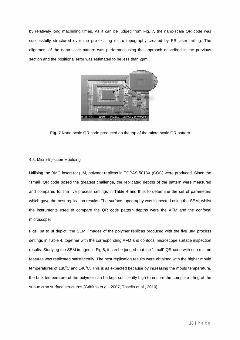
by relatively long machining times. As it can be judged from Fig. 7, the nano-scale QR code was
successfully structured over the pre-existing micro topography created by PS laser milling. The
alignment of the nano-scale pattern was performed using the approach described in the previous
section and the positional error was estimated to be less than 2µm.
Fig. 7 Nano-scale QR code produced on the top of the micro-scale QR pattern
4.3. Micro-Injection Moulding
Utilising the BMG insert for µIM, polymer replicas in TOPAS 5013X (COC) were produced. Since the
“small” QR code posed the greatest challenge, the replicated depths of the pattern were measured
and compared for the five process settings in Table 4 and thus to determine the set of parameters
which gave the best replication results. The surface topography was inspected using the SEM, whilst
the instruments used to compare the QR code pattern depths were the AFM and the confocal
microscope.
Figs 8a to 8f depict the SEM images of the polymer replicas produced with the five µIM process
settings in Table 4, together with the corresponding AFM and confocal microscope surface inspection
results. Studying the SEM images in Fig 8, it can be judged that the “small” QR code with sub-micron
features was replicated satisfactorily. The best replication results were obtained with the higher mould
temperatures of 130oC and 140oC. This is as expected because by increasing the mould temperature,
the bulk temperature of the polymer can be kept sufficiently high to ensure the complete filling of the
sub-micron surface structures (Griffiths et al., 2007; Tosello et al., 2010).

29 | P a g e
Material and Temperature
SEM AFM Confocal
a) T
opas
80o C
b) T
opas
110
o C
c) T
opas
115
o C
d) T
opas
130
o C
e) T
opas
140
o C
Fig 8 SEM images of µIM parts together with the AFM and Confocal Microscope surface inspection results

30 | P a g e
A histo-distribution generated from the AFM measurements of the inspected samples is presented in
Fig 9 and concurs with the SEM surface analysis results. As can be observed in the figure the pattern
height is much lower at the mould temperature of 80oC. This is because the bulk temperature of the
polymer cannot be kept sufficiently high and so the viscosity of the Topas 5013 melt remains relatively
high, too. Consequently, the complete filling of the “small” QR code pattern cannot be achieved and
thus resulting in premature solidification and incomplete filling of the small QR code features. From
Fig. 9, it can also be observed that as the mould temperature increases progressively the polymer
viscosity gets sufficiently low to fill the sub-micro features, and thus the cavities are filled much better.
The best height replication results were obtained for the 130oC and 140oC mould temperature
settings.
Fig 9 AFM Histo-distribution for the analysed polymer samples

31 | P a g e
a) AFM Profiles of the top left feature
b) AFM Probe and Generated Profile
Fig. 10 Profiles of the top left feature of the “small” QR code
Based on the AFM scan data, a profile of the top left feature of the “small” QR code was generated.
The profile is presented in Fig 10 and shows that the 130o and 140o C samples have sharper “pixel”
edges then those at 110oC. In addition, it can be observed that the feature depth is approximately 500
nm and this is in agreement with the confocal microscope results, below. The wall side angles of the
QR grid are 37.2°, 37.2° and 16.6° for the samples produced at 140oC, 130oC and 110oC,
respectively. Figure 10b depicts the geometry of the AFM probe in relation to the line section of the
QR grids for the 140oC, 130oC and 110oC trials, respectively. As the angles are less than 60° the
probe geometry did not affect the results. This shows again that the samples made at 130 and 140oC
are of better quality than those produced at 110oC. Whilst the profiles of the 130oC and 140oC
samples are virtually identical and steeper than the 110oC sample, they still cannot be considered as
edge-like. This is most likely due to the draft angle on the vertical walls of the FIB milled fields on the
BMG insert and also possibly due to some trapped air in the mould. As suggested in literature the

32 | P a g e
latter problem could be potentially eliminated by air evacuation from the mould just before injection
(Attia et al., 2009; Giboz et al., 2007).
An additional analysis to one of selected line sections of the insert and the polymer replicas for each
of the 140oC, 130oC 115 oC, 110oC and 80oC μIM trials was carried out by using the confocal
microscope data sets. In particular, the replication quality of the FIB structures on the replicas at these
temperature settings was assessed by applying the methods for the Volume, Sa and Average Step
height ratios as detailed in Section 3.6.3. The results are shown in Table 8.
Table 8: Results of Volume , Sa and Average Step Ratios for µIM Trials.
Volume
ratio Sa ratio Step ratio
Insert 1.000 1.000 1.000
Mould
Temp
(°C)
80 0.165 0.271 0.160
110 0.821 0.921 0.928
115 0.806 0.941 0.934
130 0.913 0.956 0.945
140 0.970 0.956 0.947
The best average step height ratios are 0.945 and 0.947 respectively, and they indicate that the
140oC mouldings are marginally better than the ones produced at the mould temperature of 130oC.
Collectively, the best replication accuracy was obtained for the 130o C and 140oC mould temperature
settings and this is in agreement with the results from the AFM inspection. It can also be observed in
Table 8 that the Sa Ratio for both the 130o C and 140oC mould temperature trials is the same. Whilst,
the volume ratios are 0.913 and 0.970 for the the130o C and 140oC mould temperature trials,
respectively. The latter Volume Ratio indicates that a slightly better fill has been achieved for the
140oC mould temperature setting than that obtained for the 130oC trials. This analysis has showed
clearly that the surface quality and the profiles of the replicated “small” QR codes were satisfactory for

33 | P a g e
the considered application. Therefore, given that the replication quality for 140oC mould temperature
setting are slightly better than that obtained at 130oC, only the parts from the 140o C trials were used
to investigate further the replication fidelity for both the “large” and “small” QR codes.
4.3.1. “Large” QR Code
The “large” QR code produced by PS laser milling on the BMG insert was replicated well as far as it
can be judged by comparing the image of the replica in Fig. 11 with the insert in Fig. 4.
(a) (b)
Fig 11 : Replicated “large” QR Code (a) overall view (b) top left features of the code
The PS laser texturing of the “large” QR code white pixels was replicated successfully on the polymer
parts as can be seen clearly in Fig 12 and “nub” structures with relatively high aspect ratio and an
average diameter of 4.09 µm were created. This average value was calculated based on the confocal
microscope inspections of three Topas parts. In addition, the average Ra surface roughness of the
parts’ textured surfaces is 1.843 ± 0.41 µm. Comparing the diameters of the micro-holes and Ra
values of the PS laser textured surfaces on the BMG insert with the diameters and Ra values of the
replicated “nub” structures on the Topas parts, it can be judged that the texturing was replicated with
relatively good fidelity. The use of BMG inserts for replicating such texturing effects on surfaces is

34 | P a g e
very important due to their very high wear resistance and thus being capable of retaining the surface
functionality for more µIM cycles.
Fig 12 Surface texturing of the “large” QR Code replica
The results from the inspection of the smallest micro scale features of the “large” QR code replicas
together with the average overall size of the code are provided in Table 9. If the dimensions of the
pixels on the COC replicas and the BMG insert are compared in Tables 6 and 9 the deviation of the
height is 3.52 % while for the width is 1.58% and 1.22% in the X and Y directions, respectively. These
deviations are higher than the expected typical shrinkage values of 0.4 to 0.7% for this material but
they could be explained both with some measurement errors and also the used injection moulding
parameters which were not fully optimised.
The average width dimensions of the 29 “large” QR pattern’s pixels can also be calculated based on
the overall size of the code in Tables 5 and 9. As stated before, these dimensions are likely to be
more accurate estimates of the pixel sizes because the measurement error is “shared” between the
pixels constituting the QR code. Thus, the average widths can be estimated to be 95.51 and 91.73 µm
in the X direction and 95.58 and 91.64 µm in the Y direction for the BMG insert and the COC replicas,
respectively. For the COC replicas, there is an average 5.7 µm difference with the as-measured pixel
cavity values reported in Table 9 in particular 97.06 µm and 97.62 µm. This again can be explained
with the measurement errors incurred whilst inspecting the individual pixels. Similarly, for the BMG
insert, the average error between the estimated and the actual pixel sizes reported in Table 5 is
approximately 3.18 µm. This means that the estimated average errors incurred when measuring the

35 | P a g e
overall size of the “large” QR code on the BMG insert and COC replicas are 3.18 µm and 5.7 µm
respectively. If these two error values are taken into account in the shrinkage calculation, the average
percentage difference between the overall side lengths of the replicated large QR code and the laser
milled BMG QR code is approximately 4.13%. From a statistical point of view, using the paired-
sample t test, it can be stated with 99% confidence that the difference between the means of the BMG
insert and COC parts is significant and they can be predominantly attributed to shrinkage. In this
case, the actual shrinkage is higher than the expected typical shrinkage values reported for this
material. However, it should be noted that by subjecting the COC material to a high holding pressure
should help minimise material shrinkage. In particular, one of the techniques that have been
suggested to decrease the effect of shrinkage is to increase the holding pressure however this
increases also the stresses inside the mouldings (Giboz et al., 2007).Thus, the results were not
expected taking into account that a high holding pressure was used, 1300 bar, that is much higher
than the recommended packing pressure for COC of 600 bar.
Overall, considering that this is only a feasibility study, and none of the component processes in the
proposed chain have been fully optimised it can be stated that the “large” QR code was replicated
with a relatively good fidelity. Also, it is clear that in order to produce a product with higher accuracy
the laser machining and the micro-injection moulding stages in the process chain have to be
optimised further and thus to improve the quality of replicated micro features. The analysis of the
replication stage shows that the results can be affected significantly by the outcome of the preceding
stages in the process chain, in particular the laser milling. Also, this feasibility study reveals some of
the challenges in performing an effective dimensional quality control and reliable manufacturing when
precise micro structures have to be produced.
Table 9: Replicated “large” QR code dimensions
Width (X) [ µm] Width (Y) [µm]
Height [ µm] Overall Width (X) [µm]
Overall Width (Y) [µm]
Top Top
97.06 ± 6.09 97.62 ± 5.94 13.43 ± 0.93 2660.03 ± 16 7.46 2657.65 ± 161.95

36 | P a g e
4.3.2. “Small” QR Code
Fig. 13 shows that the “small” QR code was replicated successfully on the COC parts. The average
heights and widths of the smallest features together with the average overall size of the “small” QR
code are provided in Table 10. If the dimensions of the smallest features on the COC replicas and the
BMG insert are compared in Tables 7 and 10 the deviation of the height is 6.72 % while for the width
is 3.36% and 6.15% in X and Y directions, respectively. Again, this is higher than the expected typical
shrinkage values of 0.4 – 0.7% for this material. The average dimensions of the 29 “small” pixels was
also calculated based on the overall size of the QR code in Tables 7 and 10, in particular the average
widths were approximately 2.64 µm in the X direction and 2.69 µm in the Y directions for both the
BMG insert and the COC replicas. Thus, the average errors incurred when measuring the overall size
of the “small” QR code on the BMG insert and COC replicas is 0.37 µm and 0.225 µm respectively
and it is mostly due to the edge definition as it is shown in Fig 14. If these two error values are taken
into account in the shrinkage calculation, the measurement errors are much smaller, and the average
percentage difference between the overall side lengths of the replicated “small” QR code and the FIB
milled QR code on the BMG insert is approximately 0.05%.
Fig 13 Replicated Small Scale QR Code.

37 | P a g e
From a statistical point of view, using the paired-sample t test, it can be judged with 80% confidence
that there is a significant difference between the means of the small QR code overall side length of
the BMG insert and the COC replicas. Therefore, it is not possible to state unequivocally if the
observed difference is significant or whether it may be attributed to stochastic factors. This is
reinforced even further when the magnitude of the measurement uncertainty is also taken into
consideration with respect to the estimated percentage difference and the number of samples
available.
Fig 14 Feature edge quality of the replicated “small” QR code.
As stated above, in Tables 7 and 10, there is also a 6.72 % difference between the average height of
the insert and the replicas that again could be attributed to the measurement errors, material
shrinkage and not fully optimised replication process. Also, the research had revealed potential
challenges in performing an effective dimensional quality control and reliable manufacturing at sub-
micron scale.

38 | P a g e
Table 10 Replicated “small” QR code dimensions
Width (X)
(µm)
Width (Y)
(µm)
Height (nm) Overall Width
(X) (µm)
Overall Width (Y)
(µm)
Top Top
2.88 ± 0.18 2.90 ± 0.18 494.4 ± 71.1 76.53 ± 4.60 78.00 ± 4.69
4.4. Future Research
The feasibility study highlighted that further research is necessary to address specific shortcomings in
the proposed master making process chain. As it was already noted all component technologies in
the proposed master-making process chain have to undergo further optimisation. Such process
optimisation can be achieved either by employing specially developed methodologies such as that
reported earlier for optimising the layer-based FIB milling process or through the use of DOE
methodology. The DOE approach can be applied by conducting first screening experiments in order to
identify critical control/input factors and also how their magnitude and direction affects the response
variable(s); and’ subsequently by employing response surface methodology to optimise the
operation conditions (Clark, Horrell, Rogelstad, & Spagon, 1995; Montgomery, 2009).
The quality of the laser machined surfaces influences significantly the replication capabilities of the
tools (Dobrev, Pham, & Dimov, 2005) and this was clearly seen in this research, too. After the µIM
trials the BMG insert had traces of polymer adhering to the textured pixels as it is shown in Fig 15. .
Thus, any laser texturing of inserts can lead to problems with the parts’ demoulding if the surface area
is relatively big and also to tool contamination as any polymer adhered to the mould will affect the
replicas’ quality. Thus, there is a need to optimise the laser machining process in order to ensure that
any surface texturing or roughness does not cause problems during the replication stage. The NS
laser machining results are very promising and demonstrate that the required surface quality for
successful replication can be achieved. Taking into account the ablation mechanism when laser
processing with ultra-short pulses is performed, it can be expected that an even better surface
integrity than that reported for the NS laser ablation could be obtained after PS laser machining in

39 | P a g e
terms of surface roughness without changes in the non-crystalline morphology of the BMG workpiece.
At the same time, it should be noted that the optimisation of the laser processing parameters will not
be enough to produce sufficiently smooth surfaces for follow up FIB sub-micron and nano structuring.
This implies that additional surface conditioning and smoothening after the laser processing will be
required. Recent results reported in the literature have shown that micro and nano scale features
imprinted on Pt based BMGs may be erased by subsequent annealing in the BMG supercooled liquid
region (Kumar & Schroers, 2008; Packard, Schroers, & Schuh, 2009) and thus to smooth the
surface.
However, to make use of this process it is necessary to optimise it so that optimum annealing
conditions for surface smoothening of Zr-based BMG masters are identified.
Fig. 15 Traces of polymer adherence on the BMG insert after µIM trials.
Finally, the replication results indicate that the Vit1B BMG is a promising candidate material for µIM
master making. However, its durability and long term performance still need to be investigated before
it can be considered as better alternative to the tooling grade steels used in both conventional and
micro injection moulding. In particular, there is a need to assess the wear and fatigue performance of
the Vit 1B BMG material when used in production runs.

40 | P a g e
5. Conclusions
A cost effective process chain for achieving FLSI in mass produced miniaturised devices was
investigated in this feasibility study. It integrates compatible and complementary structuring and
replication technologies by utilising a Zr-based BMG with very attractive mechanical properties. The
capabilities of laser machining as a micro structuring technology were combined with those of the FIB
milling to fabricate replication inserts incorporating micro and sub-micron structures. Then, to
demonstrate the viability of the proposed master making process chain, the Zr-based BMG insert was
integrated into a tool to produce a batch of thermoplastic parts by µIM.
The following conclusions about the proposed master making process chain and its component
technologies could be drawn from this research.
• The NS laser machining showed that it is possible by proper selection of the processing settings
to machine successfully Zr-based BMG workpieces with an acceptable surface integrity for µIM
without triggering significant changes in the BMG short range atom arrangements. The results
demonstrated that the required surface quality for successful replication can be achieved.
• With the selected PS laser processing parameters, it was possible to satisfactorily texture the
BMG insert surface with high aspect ratio self-organised structures. Despite the fact that the
selected PS laser machining parameters showed limitations with respect to the resulting
structuring quality, it can be concluded that the PS laser process is a promising component
technology for master making and also for achieving FLSI in replication tools.
• The viability of using Zr-based BMG masters to enable integration of compatible and
complementary micro and sub-micron structuring and replication technologies for serial
fabrication of FLSI thermoplastics components was demonstrated.
• The experimental investigation identified the factors affecting the performance of the proposed
PS-FIB-µIM process chain. In particular, the following factors are considered to have the highest
impact: the used process settings for its different component technologies, the Zr-based response
to structuring technologies, e.g. PS Laser and FIB milling, with different specific processing

41 | P a g e
energies and the metrology issue in inspecting multi-scale structures. However, it was difficult to
quantify their effects on the overall performance of the proposed process chain.
Collectively, the results demonstrate that there is good process compatibility and complementarity
between the component technologies in the proposed process chain, especially for the length scale
ranges aimed at this research. Such a process combination can therefore be used for the mass
production of polymer parts incorporating different length scale features in one step. However, it is
important to note that this is a feasibility study and thus it is necessary to investigate the proposed
process chain further, in particular the PS laser and FIB milling processes, as master making
technologies for producing replication inserts incorporating different length scale features. This
includes further research into the specific process-material interactions of the considered component
technologies and thus to identify their optimum processing windows in regards to the surface integrity
and accuracy of the machined features/structures. Also, further NS laser process optimisation is
required in order to achieve even better surface quality, whilst simultaneously preserving fully the non-
crystalline morphology of the Zr-based BMG after the laser irradiation. Finally, further work is also
required to optimise the µIM process in conjunction with the master making process chain and thus to
improve further the quality of the replicated multi-scale structures, which was not the objective of this
research.
ACKNOWLEDGMENTS
The research reported in this paper was funded by the FP7 programmes “Converging technologies for
micro systems manufacturing” (COTECH)”, ‘‘Integrating European research infrastructures for the
micro-nano fabrication of functional structures and devices out of a knowledge-based multimaterials’
repertoire” (EUMINAfab) and "High throughput integrated technologies for multimaterial functional
micro components" (HINMICO), the UK Engineering and Physical Sciences Research Council
(EP/F056745/1) and the Interreg IVB NWE project “ECO-efficient LASER technology for FACTories of
the future” (ECO-LASEFACT).

42 | P a g e
The technical assistance of the authors’ colleagues, particularly Dr. Ekaterin Minev, Dr. Petko Petkov,
Dr. Samuel Bigot, Dr. Cristina L. Tuinea-Bobe and Dr. Colin Grant at Cardiff University and Bradford
University, respectively, is also gratefully acknowledged.
References
(HLG), H. L. E. G. (2011). Key Enabling Technologies -- Final report. European Commission. Retrieved from <http://ec.europa.eu/enterprise/sectors/ict/files/kets/hlg_report_final_en.pdf>
Attia, U. M., Marson, S., & Alcock, J. R. (2009). Micro-injection moulding of polymer microfluidic devices. Microfluidics and Nanofluidics, 7(1), 1–28. doi:10.1007/s10404-009-0421-x
Bigot, S., Minev, R., Dimov, S. S., & Dobrev, T. (2011). Function and length scale integration in innovative products - technical solutions and new organisational models. International Journal of Manufacturing Technology and Management, 23(3/4), 157–178.
Bonse, J., Kruger, J., Hohm, S., & Rosenfeld, A. (2012). Femtosecond laser-induced periodic surface structures. Journal of Laser Applications, 24, 4207–42006.
Brousseau, E. B., Dimov, S. S., & Pham, D. T. (2010). Some Recent Advances in Multi-Material Micro- and Nano-manufacturing. International Journal of Advanced Manufacturing Technology, 47(1-4), 161–180.
Chen, C.-Y., Chung, C.-J., Wu, B.-H., Li, W.-L., Chien, C.-W., Wu, P.-H., & Cheng, C.-W. (2012). Microstructure and lubricating property of ultra-fast laser pulse textured silicon carbide seals. Applied Physics A, 107(2), 345–350. doi:10.1007/s00339-012-6822-9
Clark, W., Horrell, K., Rogelstad, T., & Spagon, P. (1995). SEMATECH Qualification Plan Guidelines for Engineering. SEMATECH Inc.
Dimov, S. S., Brousseau, E. B., Minev, R., & Bigot, S. (2012). Micro- and nano-manufacturing: Challenges and opportunities. Proc. Inst. Mechanical Engineers Part C: Journal of Mechanical Engineering Science, 226(3), 3–15.
Dobrev, T., Dimov, S. S., & Thomas, A. J. (2006). Laser milling: Modelling crater and surface formation. Proceedings of the Institution of Mechanical Engineers, Part C: Journal of Mechanical Engineering Science, 220(11), 1685–1696. doi:10.1243/09544062jmes221
Dobrev, T., Pham, D. T., & Dimov, S. S. (2005). A simulation model for crater formation in laser milling. In W. Menz & S. S. Dimov (Eds.), 4M 2005 First International Conference on Multi-Material Manufacture Proceedings (pp. 155–159). Karlsruhe: Elsevier.
Etsion, I. (2005). State of the Art in Laser Surface Texturing. Transactions of ASME, Journal of Tribology, 127(1), 248–253.
Fadeeva, E., Truong, V. K., Stiesch, M., Chichkov, B. N., Crawford, R. J., Wang, J., & Ivanova, E. P. (2011). Bacterial Retention on Superhydrophobic Titanium Surfaces Fabricated by Femtosecond Laser Ablation. Langmuir, 27(6), 3012–3019. doi:10.1021/la104607g

43 | P a g e
Fleischer, J., & Kotschenreuther, J. (2007). The manufacturing of micro molds by conventional and energy-assisted processes. The International Journal of Advanced Manufacturing Technology, 33(1-2), 75–85. doi:10.1007/s00170-006-0596-1
Giboz, J., Copponnex, T., & Mele, P. (2007). Microinjection Moulding of Thermoplastic Polymers - A review. Journal of Micromechanics and Microengineering, 17(6), R96 – R109.
Griffiths, C. A., Dimov, S. S., Brousseau, E. B., & Hoyle, R. T. (2007). The effects of tool surface quality in micro-injection moulding. Journal of Materials Processing Technology, 189(1-3), 418–427.
Heckele, M., & Schomburg, W. K. (2004). Review on micro molding of thermoplastic polymers. Journal of Micromechanics and Microengineering, 14(3), R1–R14. doi:10.1088/0960-1317/14/3/R01
Huang, C. K. (2007). Polymeric nanofeatures of 100 nm using injection moulding for replication. Journal of Micromechanics and Microengineering, 17(8), 1518–1526.
Inoue, A. (2000). Stabilization of Metallic Supercooled Liquid and Bulk Amorphous Alloys. Acta Materialia, 48, 278–306.
ISO4288. (1997). Geometrical Product Specifications (GPS) -- Surface texture: Profile method -- Rules and procedures for the assessment of surface texture.
Joint Committee for Guides in Metrology (JCGM). (2008). Evaluation of measurement data — Guide to the expression of uncertainty in measurement (GUM) (p. 121).
Kawasegi, N., Morita, N., Yamada, S., Takano, N., Oyama, T., Ashida, K., … Ofune, H. (2006). Rapid Nanopatterning of a Zr-based Metallic Glass Surface Utilizing Focused Ion Beam Induced Selective Etching. Applied Physics Letters, 89(14), 143115–1431153.
Kirkup, L., & Frenkel, B. (2006). An Introduction to Uncertainty in Measurement (First.). Cambridge University Press.
Knowles, M., Kearsley, A., & Karnakis, D. (2007). INDUSTRIAL LASERS: Laser micromachining expands as technology develops. Laser Focus World. PennWell Corporation/Technology Group. Retrieved from http://www.laserfocusworld.com/articles/print/volume-43/issue-6/features/industrial-lasers-laser-micromachining-expands-as-technology-develops.html
Knowles, M. R. H., Rutterford, G., Karnakis, D., & Ferguson, A. (2007). Micro-machining of metals, ceramics and polymers using nanosecond lasers. The International Journal of Advanced Manufacturing Technology, 33(1-2), 95–102. doi:10.1007/s00170-007-0967-2
Kumar, G., & Schroers, J. (2008). Write and erase mechanisms for bulk metallic glass. Applied Physics Letters, 92(3), 31901–31903. doi:10.1063/1.2834712
Lalev, G., Dimov, S. S., Kettle, J., Van Delft, F., & Minev, R. (2008). Data Preparation for FIB machining of Complex 3D Structures. Proc Instn Mech Engrs Part B: J Engineering Manufacture, 222(1), 67–76.
Lalev, G., Petkov, P., Sykes, N., Hirshy, H., Velkova, V., Dimov, S., & Barrow, D. (2009). Fabrication and validation of fused silica NIL templates incorporating different length scale features. Microelectronic Engineering, 86(4-6), 705–708. doi:10.1016/j.mee.2009.01.074
Leach, R. K. (2001). Measurement Good Practice Guide No. 37 -- The Measurement of Surface Texture using Stylus Instruments. (N. P. Laboratory, Ed.).

44 | P a g e
Li, W., Minev, R., Dimov, S. S., & Lalev, G. (2007). Patterning of Amorphous and Polycrystalline Ni78B14Si8 with a Focused Ion Beam. Applied Surface Science, 253(12), 5404–5410.
Lin, H.-K., Lee, C.-J., Hu, T.-T., Li, C.-H., & Huang, J. C. (2012). Pulsed laser micromachining of Mg-Cu-Gd bulk metallic glass. Optics and Lasers in Engineering, 50(6), 883–886. doi:http://dx.doi.org/10.1016/j.optlaseng.2012.01.003
Loffler, J. F., Kundig, A. A., & Dalla Torre, F. H. (2007). Rapid Solification and Bulk Metallic Glasses --- Processing and Properties. In J. R. Groza, J. F. Shackelford, E. J. Lavernia, & M. T. Powers (Eds.), Materials Processing Handbook (pp. 17–44). CRC Press.
Minev, R., Ilieva, M., Kettle, J., Lalev, G., Dimov, S. S., Tzaneva, D., … Shishkov, R. (2010). Deposition and FIB Milling of Anticorrosive CrC Coatings on Tool Steel Substrates. International Journal of Advanced Manufacturing Technology, 47(1-4), 29–35. Retrieved from http://dx.doi.org/10.1007/s00170-009-2078-8, 2008
Minev, R., Vella, P. C., Brousseau, E. B., Dimov, S. S., Minev, E., & Matthews, C. W. (2010). Methodology for Capability Maturity Assessment of MNT Chains. In B. Fillon, C. Khan-Malek, & S. S. Dimov (Eds.), 7th International Conference on Multi-Material Micro Manufacture (pp. 249–252). Bourg en Bresse and Onayonnax, France: Research Publishing.
Minev, R., Vella, P. C., Brousseau, E. B., Dimov, S. S., Scholz, S., & Matthews, C. W. (2010). Capability Maturity Study of the Horizontal and Vertical Integration of Structuring, Patterning and Characterization of MNTs. In B. Fillon, C. Khan-Malek, & S. S. Dimov (Eds.), 7th International Conference on Multi-Material Micro Manufacture (pp. 253–256). Bourg en Bresse and Oyonnax, France: Research Publishing.
Monkkonen, K., Hietala, J., Paakkonen, P., Paakkonen, E. J., Kaikuranta, T., Pakkanen, T. T., & Jaaskelainen, T. (2002). Replication of Sub-Micron Features Using Amorphous Thermoplastics. Polymer Engineering and Science, 42(7), 1600–1608.
Montgomery, D. C. (2009). Design and Analysis of Experiments (7th Editio., p. 656). John Wiley & Sons Inc.
Nayak, B. K., & Gupta, M. C. (2010). Self-organized micro/nano structures in metal surfaces by ultrafast laser irradiation. Optics and Lasers in Engineering, 48(10), 940–949. doi:http://dx.doi.org/10.1016/j.optlaseng.2010.04.010
Packard, C. E., Schroers, J., & Schuh, C. A. (2009). In situ measurements of surface tension-driven shape recovery in a metallic glass. Scripta Materialia, 60(12), 1145–1148. doi:http://dx.doi.org/10.1016/j.scriptamat.2009.02.056
Petkov, P. V, Dimov, S. S., Minev, R. M., & Pham, D. T. (2008). Laser milling: Pulse duration effects on surface integrity. Proceedings of the Institution of Mechanical Engineers, Part B: Journal of Engineering Manufacture, 222(1), 35–45. doi:10.1243/09544054jem840
Petkov, P. V, Scholz, S., & Dimov, S. S. (2008). Strategies for material removal in laser milling. In S. S. Dimov & W. Menz (Eds.), 4M 2008 - Fourth International Conference on Multi-Material Micro Manufacture Proceedings (pp. 249–252). Cardiff, Wales, UK: Whittles Publishing.
Pham, D. T., Dimov, S. S., Ji, C., Petkov, P. V, & Dobrev, T. (2004). Laser milling as a `rapid micromanufacturing process . Proc. Instn Mech. Engrs Part B: J. Engineering Manufacture , 218, 1–7.
Pham, D. T., Dimov, S. S., & Petkov, P. V. (2007). Laser Milling of Ceramic Components. International Journal of Machine Tools & Manufacture 47 (2007) 618–626, (47), 618–626.

45 | P a g e
Platzgummer, E., Loeschner, H., & Gross, G. (2008). Projection Maskless Patterning for Nanotechnology Applications. In 52nd International Conference on Electron, Ion and Photon Beam Technology and Nanofabrication (pp. 2059–2063). AVS.
Quintana, I., Dobrev, T., Aranzabe, A., Lalev, G., & Dimov, S. S. (2009). Investigation of Amorphous and Crystalline Ni Alloys Response to Machining with Micro-second and Pico-second Lasers. Applied Surface Science, 255(13-14), 6641–6646.
Scholz, S. G., Griffiths, C. a., Dimov, S. S., Brousseau, E. B., Lalev, G., & Petkov, P. (2011). Manufacturing routes for replicating micro and nano surface structures with bio-mimetic applications. CIRP Journal of Manufacturing Science and Technology, 4(4), 347–356. doi:10.1016/j.cirpj.2011.05.004
Scholz, S., Griffiths, C. A., Dimov, S. S., Brousseau, E. B., Lalev, G., & Petkov, P. V. (2009). New Process Chains for Replicating Micro and Nano Structured Surfaces with Bio-mimetic Applications. In ANTEC 2009 - Proceedings of the 67th Annual Technical Conference & Exhibition (pp. 3021–3027). Chicago.
Sha, B., Dimov, S., Griffiths, C., & Packianather, M. S. (2006). Micro-injection moulding: Factors affecting the achievable aspect ratios. The International Journal of Advanced Manufacturing Technology, 33(1-2), 147–156. doi:10.1007/s00170-006-0579-2
Svintsov, A., Zaitsev, S., Lalev, G., Dimov, S. S., Velkova, V., & Hirshy, H. (2009). FIB sputtering optimization using Ion Reverse Software. Microelectronic Engineering, 86(4-6), 544–547. doi:http://dx.doi.org/10.1016/j.mee.2009.01.073
Tosello, G. (2008). Precision Moulding of Polymer Micro Components - Optimistation, Simulation , Tooling, Quality Control and Multi-material Application. DTU.
Tosello, G., Bissacco, G., Tang, P. T., Hansen, H. N., & Nielsen, P. C. (2008). High Aspect Ratio Micro Tool Manufacturing for Polymer Replication using µEDM of Silicon, Selective Etching and Electroforming . Micosyetem Technologies, 14(9-11), 1757–1764.
Tosello, G., & Chiffre, L. De. (2004). Standard Traceability and Measurement Uncertainty (p. 116).
Tosello, G., Gava, A., Hansen, H. N., & Lucchetta, G. (2010). Study of process parameters effect on the filling phase of micro-injection moulding using weld lines as flow markers. International Journal of Advanced Manufacturing Technology, 47, 81–97.
Tosello, G., Hansen, H. N., & Gasparin, S. (2009). Applications of dimensional micro metrology to the product and process quality control in manufacturing of precision polymer micro components. CIRP Annals - Manufacturing Technology, 58(1), 467–472. doi:10.1016/j.cirp.2009.03.027
Tosello, G., Marinello, F., & Hansen, H. N. (2012). Characterisation and analysis of microchannels and submicrometre surface roughness of injection moulded microfluidic systems using optical metrology. Plastics, Rubber and Composites, 41(1), 29–39. doi:10.1179/0743289811Y.0000000017
United Kingdom Accreditation Service (UKAS). (2007). The Expression of Uncertainty and Confidence in Measurement (Vol. 44, pp. 1 – 82).
Uriarte, L., Herrero, a, Ivanov, a, Oosterling, H., Staemmler, L., Tang, P. T., & Allen, D. (2006). Comparison between microfabrication technologies for metal tooling. Proceedings of the Institution of Mechanical Engineers, Part C: Journal of Mechanical Engineering Science, 220(11), 1665–1676. doi:10.1243/09544062JMES220

46 | P a g e
Vehse, M., Lobler, M., Schmitz, K. P., & Seitz, H. (2012). Laser induced surface structure on stainless steel influences cell viability. Biomed Tech, 57(Suppl. 1), 419–421.
Velkova, V. (2011). Focused Ion Beam Technology: Implementation in Manufacturing Platforms and Process Optimisation. Manufacturing Engineering Centre, School of Engineering,. Cardiff University, Cardiff.
Velkova, V., Lalev, G., Hirshy, H., Omar, F., Scholz, S., Minev, E., & Dimov, S. (2011). Process chain for serial manufacture of 3D micro- and nano-scale structures. CIRP Journal of Manufacturing Science and Technology, 4(4), 340–346. doi:10.1016/j.cirpj.2011.03.005
Velkova, V., Lalev, G., Hirshy, H., Scholz, S., Hiitola-Keinänen, J., Gold, H., … Dimov, S. (2010). Design and validation of a novel master-making process chain for organic and large area electronics on flexible substrates. Microelectronic Engineering, 87(11), 2139–2145. doi:10.1016/j.mee.2010.01.015
Vella, P. C., Brousseau, E. B., Minev, R., & Dimov, S. S. (2010). A Methodology for Technology Maturity Assessment of Micro and Nano Manufacturing Processes and Process Chains. In F. E. Pfefferkorn (Ed.), The 5th International Conference on MicroManufacturing (ICOMM/4M 2010) (pp. 327–334). Madison, Wisconsin, USA.
Wang, X., Lu, P., Dai, N., Li, Y., Liao, C., Zheng, Q., & Liu, L. (2007). Noncrystalline Micromachining of Amorphous Alloys Using Femtosecond Laser Pulses. Materials Letters, 61(21), 4290–4293.
Waniuk, T., Schroers, J., & Johnson, W. L. (2003). Timescales of crystallization and viscous flow of the bulk glass-forming Zr-Ti-Ni-Cu-Be alloys. Physical Review B, 67(18), 184203–184209. Retrieved from http://link.aps.org/doi/10.1103/PhysRevB.67.184203
Wu, B., & Ozel, T. (2011). Micro-Laser Processing. In M. Koc & T. Ozel (Eds.), Micro-Manufacturing -- Design and Manufacturing of Micro-Products (First., pp. 159–195). Wiley.
Wu, P. H., Cheng, C. W., Chang, C. P., Wu, T. M., & Wang, J. K. (2011). Fabrication of large-area hydrophobic surfaces with femtosecond-laser-structured molds. Journal of Micromechanics and Microengineering, 21(11), 115032.
Youn, S. W., Takahashi, M., Goto, H., & Maeda, R. (2006). Microstructuring of glassy carbon mold for glass embossing -- Comparison of focused ion beam, nano/femtosecond-pulsed laser and mechanical machining. Microelectronic Engineering, 83(11- 12), 2482–2492. doi:http://dx.doi.org/10.1016/j.mee.2006.05.007
Zhang, G., Liu, Y., & Zhang, B. (2006). Effect of Annealing Close to Tg on Notch Fracture Toughness of Pd-based Thin-film Metallic Glass for MEMS Applications. Scripta Materialia, 54(5), 897–901.