university of birmingham evaluation of the creep behaviour
TRANSCRIPT

University of Birmingham
Evaluation of the creep behaviour of the carbonfibre in an unidirectional pultruded reinforcedcomposite using nano-indentation techniqueZhang, Zhenxue; Corujeira Gallo, Santiago; Li, Xiaoying; Dong, Hanshan; Dragatogiannis,Dimitrios; Charitidis, Costas A.DOI:10.1016/j.polymertesting.2019.106091
License:Creative Commons: Attribution-NonCommercial-NoDerivs (CC BY-NC-ND)
Document VersionPeer reviewed version
Citation for published version (Harvard):Zhang, Z, Corujeira Gallo, S, Li, X, Dong, H, Dragatogiannis, D & Charitidis, CA 2019, 'Evaluation of the creepbehaviour of the carbon fibre in an unidirectional pultruded reinforced composite using nano-indentationtechnique', Polymer Testing, vol. 80, 106091. https://doi.org/10.1016/j.polymertesting.2019.106091
Link to publication on Research at Birmingham portal
Publisher Rights Statement:Checked for eligibility: 05/09/2019
General rightsUnless a licence is specified above, all rights (including copyright and moral rights) in this document are retained by the authors and/or thecopyright holders. The express permission of the copyright holder must be obtained for any use of this material other than for purposespermitted by law.
•Users may freely distribute the URL that is used to identify this publication.•Users may download and/or print one copy of the publication from the University of Birmingham research portal for the purpose of privatestudy or non-commercial research.•User may use extracts from the document in line with the concept of ‘fair dealing’ under the Copyright, Designs and Patents Act 1988 (?)•Users may not further distribute the material nor use it for the purposes of commercial gain.
Where a licence is displayed above, please note the terms and conditions of the licence govern your use of this document.
When citing, please reference the published version.
Take down policyWhile the University of Birmingham exercises care and attention in making items available there are rare occasions when an item has beenuploaded in error or has been deemed to be commercially or otherwise sensitive.
If you believe that this is the case for this document, please contact [email protected] providing details and we will remove access tothe work immediately and investigate.
Download date: 05. Apr. 2022

Evaluation of the creep behaviour of the carbon fibre in
an unidirectional pultruded reinforced composite using
nano-indentation technique
Zhenxue Zhang1, Santiago Corujeira Gallo1, Xiaoying Li1, Hanshan Dong1,
Dimitrios Dragatogiannis2, Costas A. Charitidis2
1The School of Metallurgy and Materials, University of Birmingham, Birmingham UK
2Research Unit of Advanced, Composite, Nano Materials & Nanotechnology,
School of Chemical Engineering, National Technical University of Athens, Greece
Abstract
The interfacial strength (IFS) between carbon fibres and polymeric matrices has important
implications for the mechanical properties of composite materials, which can be evaluated by
a push-out method using an instrumented nano-indentation machine to assess the fibre’s
movement under increasing load and constant load (creep). In this paper, the nano-creep
behaviour and time-dependent properties of carbon fibres in a reinforced composite were
investigated in the first time. The indentation displacement and indentation creep rate of the
fibre in the composite were measured at different testing conditions in terms of loading rate,
peak load, holding time, elevated temperature (room temperature, 50 and 100°C). Berkovich
and cone-shaped diamond indenters were used in the creep tests. The cone-shaped indenter
had some advantages over the Berkovich indenter in terms of an extended range of
displacement before interfering with the surrounding resin. A single fibre in a thin slice
required a critical vertical load to be pushed out under the continuous loading mode, which was
strongly linked to the thickness of the composites sample, the location of the fibre in the resin
and other environmental factors such as temperature. Both the displacement and creep rate
reduced with the increase of temperature due to the resistance caused by the expansion of the
fibre and the resin. The nanoindentation creep test results were analysed by an instrumental
logarithmic software, and it was found that the creep strain rate sensitivity parameter increased
with the load and the holding time but decreased with the increment of the test temperature.
Key words: Creep; elevated temperature, unidirectional composite; carbon fibre; nano-
indentation

2
1. Introduction
The properties of interface between fibre and resin often influence significantly the composite
performance in all types of composites, such as failure mode and the fracture toughness of
composites. Interfacial debonding is an important mechanism of energy absorption during the
failure of a composite. Intensive work has been done to understand the influence of the interface
on the mechanical behaviour of fibre reinforced composites [1]. Nanoindentation enables local
probing of spatial variations in mechanical properties, time-dependent behaviour and strain rate
dependence, and information on interfacial fracture tendency and mechanisms may be obtained
depending on the location of which the nanoindentation tests were made [2]. Multicycle grid
nanoindentation tests can be applied to study the induced damage mechanisms by analysing
the elastic deformation as indentation energy absorbing mechanism right after pop-in [3].
Similar strategy has been used to investigate the viscoelastic behaviour of different area of flax
fibres [4] and load and displacement of the PEEK and CFs reinforced PEEK [5]. Recently, a
push-out method has been developed by the authors based on nanoindentation to assess the
debonding mechanism of carbon fibres in an epoxy matrix and investigate the viscoelastic
response of carbon fibre [6]. Generally, the tests are carried out by continuously increasing
load until debonding or failure is detected, however, the creep behaviour of the fibre under a
load lower than the critical load is also very important to evaluate the mechanical strength
between the fibre and the resin. The dwell time of loading (and also unloading) is usually not
considered in the evaluation of elastic properties. However, time-dependent material properties
can influence the loading diagram from which elastic properties are extracted [7]. Chudoba and
Richter reported that the creep effect sometimes led to a net increase in indenter depth with
decreasing load during the early stages of unloading [8]. Lu et al. [9] validated the techniques
of measuring linear creep compliance in the glassy state using nanoindentation with the
Berkovich and spherical indenter tips and proposed methods to measure the local surface creep
compliance of time-dependent materials. Yang and Zhang [10] suggested a simple Kelvin
model to describe the indentation elastic-viscoelastic-viscous behaviour of polymers by using
a flat-ended punch indenter and Berkovich tips. Wang found that the adhesive polymers
showed higher reduced elastic modulus (Er) and hardness (H) at elevated temperatures as
compared to room temperature [11]. Coronado et.al found that interlaminar crack initiation and
propagation under mode-I with static and fatigue loading of a carbon-fibre epoxy composite
had the highest stiffness values at 9 °C, and less fracture energy was required to initiate the
delamination when the temperature decreases[12]. The viscoelastic behaviour of the

3
T700GC/M21 composite material depended on the temperature and strain rate, and the shear
modulus increased with the decrease of the temperature [13].
The creep behaviour of the bulk composites materials at different temperatures, orientations of
carbon fibre and humidity have been reported by different groups [14], [15], [16], [17], and
there is a lot of reports on the interfacial strength between the carbon fibre and resin like pull-
out [18], push-in/push-out [19], microbond etc.[20]. However, there is no report on the creep
behaviour of individual fibre in a composite at a micro-level. In this research, a methodology
based on using the instrumented nano-indentation machine to investigate the creep behaviour
and time-dependent properties of the individual carbon fibre in a carbon fibre reinforced
composite has been set up. A loading-dwell-unloading protocol was designed to evaluate the
creep behaviour. Different shaped-diamond indenters were used in the creep test and the effect
of different testing conditions in terms of loading rate, peak load, holding time on the creep
behaviour of the fibres at room and elevated temperature were studied.
The logarithmic method and the Boltzmann integral method were used by Chen to analyse and
fit the creep data collected by NanoTest platform to study the time-dependent behaviour of a
PP at different temperatures[21]. The Boltzmann integral method required more variables,
more time and a careful selection of the initial value which could degrade the accuracy of the
solution[22]. With the logarithmic method, although only measures of extent and rate were
used to describe the visco-deformation behaviour, in practice the creep curves normally showed
a quasi-logarithmic form, therefore it could predict the creep response over a relatively long
time, thus producing an excellent fit to the raw data. In the past, this method has been used for
a range of polymer systems to identify changes in creep behaviour in our group, therefore it is
used in the current research to analyse the creep data.
2. Material and Methods
2.1 Material and sample preparation
A commercial carbon fibres reinforced unidirectional composite rod (Toray Rebar S12)
containing T700s fibres of approximately 7 μm in diameter. It has an elastic modulus between
140-150 GPa, and the onset glass transition temperature (Tg) is 84.03 °C and the midpoint is
104.1°C as tested earlier [6]. The thin disc piece (<1 mm) was cut and attached to an aluminium
stud and ground/polished on both sides progressively to 28-46 µm thick. The piece was then
stuck to a home-made holder (Figure 1a/b) with grooves etched by Electrical discharge
machining (EDM) with a width <100 µm and depth ~3µm (Figure 1c) and narrower grooves

4
etched by a Lasea L5 laser micromachining centre using nanosecond/ femtosecond lasers
(Figure 1 d/e). The designed grooves had a width of 25 μm and a depth up to 12 μm (Figure
1e). Three samples with thickness of 28-30, 32-34, 42-46µm were used in the test.
2.2. Nano-indentation creep test
Creep refers to the time-dependent deformation of material at a constant stress level lower than
the yield stress [23]. In an indentation creep test, a constant load is applied to the indenter and
the change in indentation depth (displacement) is monitored as a function of time. Indentation
creep rate is determined according to Equation 1 which is a ratio as follows [24]:
𝑐𝑟𝑒𝑒𝑝 𝑟𝑎𝑡𝑒 =𝑑1−𝑑0
𝑑0 (1)
Where d0 is the indentation depth (in nm) at time of reaching the peak load (which is kept
constant) and d1 is the indentation depth (in nm) at the end of dwell time of holding the constant
test, and the creep displacement is the difference of displacement (d1 -d0).
A Micro Materials NanoTest system was used for the nanoindentation creep testing, and two
diamond indenters were used: a Berkovich diamond indenter and a specially made cone-shaped
indenter. Firstly, a suitable area (i.e. between the two solid lines in Figure 1c&d) was identified
under optical microscopy, followed by an individual fibre selected for the specified test.
Indentations on selected individual fibre were load-controlled to different peak loads (10-50
mN) at various loading rates (1 and 5 mN/S) for different durations (5s, 60s, 120s and 300s) to
investigate the creep and time-dependent properties. All the tests were loaded from an initial
load of 10 μN to a peak load at a specified loading rate and recorded at an interval of 0.05
second. The test was normally carried out at least three times under same conditions at room
temperature, 50°C and 100 °C, and an average creep displacement was used in the statistics.
The effect of the thickness of the disc (28 µm to 46 µm) was also investigated. The parameters
involved and the denotation of the code sequence in the experiments are listed in Table 1. For
example, sample C100D35-1-60-1 is the first creep test carried out using a cone indenter (C)
at a temperature of 100 °C (100D) under a load of 35 mN with a loading rate of 1 mN/s and
hold for 60 seconds (35-1-60). Sample code like B30-1-60_2 without specified temperature is
a default room temperature test.
The fibres in the composite after creep tests were observed via the onsite microscopy or by a
JEOL 7000 SEM after unloaded from the holder.

5
Figure 1. The composite discs and the holder (a) sketch of the surface of the holder, (b)the disc on the holder (c) disc on the EDM machined groove, (d)disc on the laser machined groove after creep
test and (e) the geometry of the laser machined grooves.
Table 1. Parameters and denotation of the sample code for the creep experiments.
Creep Experiment Indenter
Indenter B for a Berkovich indenter and C for a cone indenter
Temperature RT (default):23°C, 50D: 50°C and 100D:100°C
Load (mN) 10, 15, 20, 25, 30, 40, 45, 50.
Loading rate (mN/s) 1 and 5
Holding time (Second) 5, 60, 120, 300
3. Experimental results
3.1 Typical load-displacement curve of the push-out test
In the push-out test, the load was applied on a single fibre using the diamond indenter and a
counter plate was used to support the thin disc sample. The shape of the force-displacement
(a) (b) (c)
12 µm
240 µm 25 µm
(d) (e)
EDM machined grooves
Laser machined grooves
6
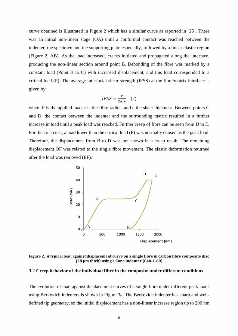
curve obtained is illustrated in Figure 2 which has a similar curve as reported in [25]. There
was an initial non-linear stage (OA) until a conformal contact was reached between the
indenter, the specimen and the supporting plate especially, followed by a linear elastic region
(Figure 2, AB). As the load increased, cracks initiated and propagated along the interface,
producing the non-linear section around point B. Debonding of the fibre was marked by a
constant load (Point B to C) with increased displacement, and this load corresponded to a
critical load (P). The average interfacial shear strength (IFSS) at the fibre/matrix interface is
given by:
𝐼𝐹𝑆𝑆 =𝑃
2𝜋𝑟𝑒 (2)
where P is the applied load, r is the fibre radius, and e the sheet thickness. Between points C
and D, the contact between the indenter and the surrounding matrix resulted in a further
increase in load until a peak load was reached. Further creep of fibre can be seen from D to E.
For the creep test, a load lower than the critical load (P) was normally chosen as the peak load.
Therefore, the displacement from B to D was not shown in a creep result. The remaining
displacement OF was related to the single fibre movement. The elastic deformation returned
after the load was removed (EF).
Figure 2. A typical load against displacement curve on a single fibre in carbon fibre composite disc (28 µm thick) using a Cone indenter (C40-1-60)
3.2 Creep behavior of the individual fibre in the composite under different conditions
The evolution of load against displacement curves of a single fibre under different peak loads
using Berkovich indenters is shown in Figure 3a. The Berkovich indenter has sharp and well-
defined tip geometry, so the initial displacement has a non-linear increase region up to 200 nm
0
10
20
30
40
50
0 500 1000 1500 2000
Load
(m
N)
Displacement (nm)
A
CB
D
F
E
O
7
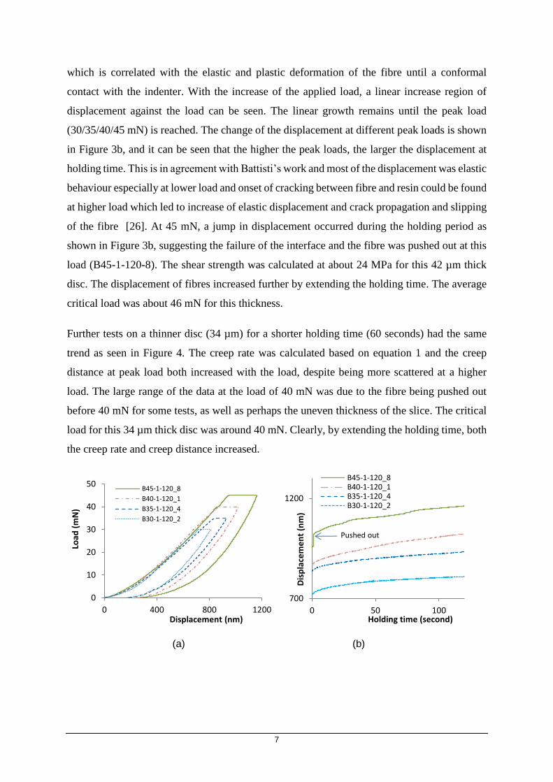
which is correlated with the elastic and plastic deformation of the fibre until a conformal
contact with the indenter. With the increase of the applied load, a linear increase region of
displacement against the load can be seen. The linear growth remains until the peak load
(30/35/40/45 mN) is reached. The change of the displacement at different peak loads is shown
in Figure 3b, and it can be seen that the higher the peak loads, the larger the displacement at
holding time. This is in agreement with Battisti’s work and most of the displacement was elastic
behaviour especially at lower load and onset of cracking between fibre and resin could be found
at higher load which led to increase of elastic displacement and crack propagation and slipping
of the fibre [26]. At 45 mN, a jump in displacement occurred during the holding period as
shown in Figure 3b, suggesting the failure of the interface and the fibre was pushed out at this
load (B45-1-120-8). The shear strength was calculated at about 24 MPa for this 42 µm thick
disc. The displacement of fibres increased further by extending the holding time. The average
critical load was about 46 mN for this thickness.
Further tests on a thinner disc (34 µm) for a shorter holding time (60 seconds) had the same
trend as seen in Figure 4. The creep rate was calculated based on equation 1 and the creep
distance at peak load both increased with the load, despite being more scattered at a higher
load. The large range of the data at the load of 40 mN was due to the fibre being pushed out
before 40 mN for some tests, as well as perhaps the uneven thickness of the slice. The critical
load for this 34 µm thick disc was around 40 mN. Clearly, by extending the holding time, both
the creep rate and creep distance increased.
(a) (b)
0
10
20
30
40
50
0 400 800 1200
Load
(m
N)
Displacement (nm)
B45-1-120_8
B40-1-120_1
B35-1-120_4
B30-1-120_2
700
1200
0 50 100
Dis
pla
cem
en
t (n
m)
Holding time (second)
B45-1-120_8B40-1-120_1B35-1-120_4B30-1-120_2
Pushed out

8
Figure 3. (a) Typical load against displacement curve of a single fibre in a 42 µm thick disc with different peak loads in a loading rate of 1 mN/s and hold for 120 seconds at peak load, (b) the
displacement of the indenter at peak load against the increment of time at dwelling period.
Figure 4. Displacements (left) and creep rate (right) of the single fibre in a 34 µm thick disc applied different peak loads in a loading rate of 1 mN/s for 60 s using a Berkvoic indenter.
As displayed in Figure 5a, when a cone-shaped indenter was used, the non-linear increase
region was reduced significantly to under 20 nm, which indicated a rapid conformal contact
with the fibre. With the increase of the applied load, a linear increase region can be seen until
the peak load reached. Once the peak load was reached and kept, a plateau of displacement was
produced. As seen in Figure 5a&b, the higher the peak loads, the further the displacement. At
the load of 40 mN, a jump in displacement occurred during the dwelling period as shown in
Figure 5b, suggesting that the fibre was pushed out at the holding time (C40-1-60-2). The
critical load using a cone-shaped indenter was just above 40 mN for a 32 µm thick disc.
(a) (b)
0
0.2
0.4
0.6
0.8
1
1.2
0
200
400
600
800
1000
20 25 30 35 40
Cre
ep
rat
e
Dis
pla
cem
en
t (n
m)
Load (mN)
Creep displacementCreep rate
0
10
20
30
40
50
0 500 1000 1500
Load
(m
N)
Displacement (nm)
C40-1-60_2
C35-1-60_1
C30-1-60_3
C25-1-60_3
400
600
800
1000
1200
1400
0 20 40 60
Dis
pla
cem
en
t (n
m)
Holding time (second)
C40-1-60_2
C35-1-60_1
C30-1-60_3
C25-1-60_3
Pushed out

9
Figure 5. (a) Typical load against displacement curve of a single fibre in a 32 µm thick disc with different peak loads in a loading rate of 1 mN/s and hold for 60 seconds at peak load, (b) the displacement of the indenter at peak load against the increment of time at dwelling period.
The creep rate was calculated based on equation 1, and the initial displacement at the beginning
of peak load was recorded and compared in Figure 6 for two different indenters. The creep tests
were carried out on single fibres in a 32 µm thick disc with a loading rate of 1 mN/s and hold
for 60 seconds at peak load of 30 mN. It was found that the creep rate was generally higher and
the initial displacement (D(0)) at peak load was lower when using a cone indenter, while the
creep rate was generally lower and the initial displacement was higher when using a Berkovich
indenter as shown in Figure 6.
Figure 6. The creep rate and initial displacement of a single fibre in a 32 µm thick disc with a loading rate of 1 mN/s and hold for 60 seconds at peak load of 30 mN for two different indenters
Two loading rates of 1 and 5 mN/s were used to compare their creep rate at two different peak
loads of 30 and 35 mN with a holding time of 120 seconds as shown in Figure 7. The impact
of the loading rate was limited, and the creep rate increased slightly at lower load (30 mN), but
it didn’t change much at 35 mN. Unsurprisingly, a fibre in a thin composite disc (34µm) had
a higher displacement, and therefore a higher creep rate than that of a thick disc (46 µm) in the
same loading conditions as seen in Figure 8.
0.00
0.05
0.10
0.15
0.20
0.25
0
200
400
600
800
1000
1200
C30-1-60_1 C30-1-60_2 C30-1-60_3 B30-1-60_1 B30-1-60_2 B30-1-60_3
Cre
ep
rat
e
D(0
) (n
m)
D(0) Creep rate

10
Figure 7. Creep rate of the single fibre in a 34 µm thick disc at different peak loads (30/35 mN) in different loading rate (1/5 mN/s) with a holding time of 120 seconds.
The effect of temperature on the creep behaviour was investigated with a peak load of 35
mN and holding for 60 seconds by the cone-shaped indenter. The thin slice was about 32 µm
thick and the loading rate was 1 mN/s. It was found that with the increment of temperature,
the initial displacement was higher, but both the displacement at peak load and creep rate of
the fibre was reduced (Figure 9a&b). At 100°C, the load-displacement curve became less
smooth. This might be due to the expansion of the fibre and resin at the elevated temperature,
which increased the friction and resistance between the fibre and resin during the test.
Figure 8. Displacements of the single fibre in a disc with different thickness applied different peak loads in a loading rate of 1 mN/s for 120 second using a Berkovic indenter.
0
0.02
0.04
0.06
0.08
0.1
0.12
0 2 4 6
Cre
ep
rat
e
Loading rate (mN/S)
30 mN35 mN
0
50
100
150
200
250
300
350
0 10 20 30 40
Cre
ep
dis
tan
ce (
nm
)
Load (mN)
1 mN/s (34 um)1 mN/S (46 um)

11
(a) (b)
Figure 9. (a) load against displacement curves and (b) Displacements and creep rate with a peak load of 35 mN using a cone-shaped indenter at elevated temperatures (loading rate: 1mN/s and dwell time: 60 seconds, 32-35µm thick disc)
4. Discussion
Interface is a key area which determine the properties of a heterogeneous system like carbon
fibre reinforced composite. At micro-level, load transfer through interface has been
characterised by: bond strength, interfacial shear stress, critical energy release rate etc.[1],
however, creep is still a relative untouched area. In this investigation, the displacement (creep),
the creep rate, the initial indentation depth at the time of reaching the peak load have been
studied with two different shaped diamond indenters at different loading conditions i.e. peak
load, holding time, loading rate and elevated temperatures. A cylindrical flat-end punch is
favourable for such a push-out test [27], but a smaller diameter <6 µm required to perform the
experiment makes the punch very fragile and difficult to machine. Therefore, in this
experiment, the Berkovich diamond indenter and a specially made cone-shaped diamond
indenter were used to investigate the creep behaviour of the single fibre in the composite thin
disc.
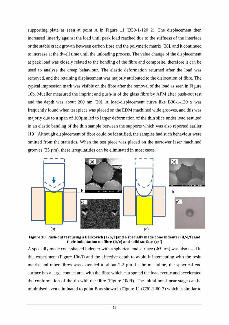
The Berkovich indenter has a well-defined three-sided pyramid tip (Figure 10a/c), with a total
included angle of 142.3 degrees and a half angle of 65.27 degrees, measured from the axis to
one of the pyramid flats. The diameter of the fibres in the Toray Rebar S12 is about 7 µm, to
avoid a Berkovich indenter intercepting with the resin matrix or adjacent fibres, the effective
penetration depth is about 1.2 µm (Figure 10a&b), therefore a value over this is invalidated.
During the loading process, the sharp tip first contacted and penetrated into the fibre and it
gradually pressed the fibre with the increasing contact area, and there was an initial non-linear
stage until a conformal contact was reached between the indenter, the specimen and the
0
5
10
15
20
25
30
35
40
0 200 400 600 800 1000
Load
(m
N)
Displacement (nm)
C100D-35-1-60-1C50D-35-1-60-2C35-1-60_1
0
0.2
0.4
0.6
0.8
1
0
200
400
600
800
0 50 100
cre
ep
rat
e
Dis
pla
cem
en
t at
pe
ak lo
ad (
nm
)
Temperature (Degree C)
Displacement
Creep rate
12
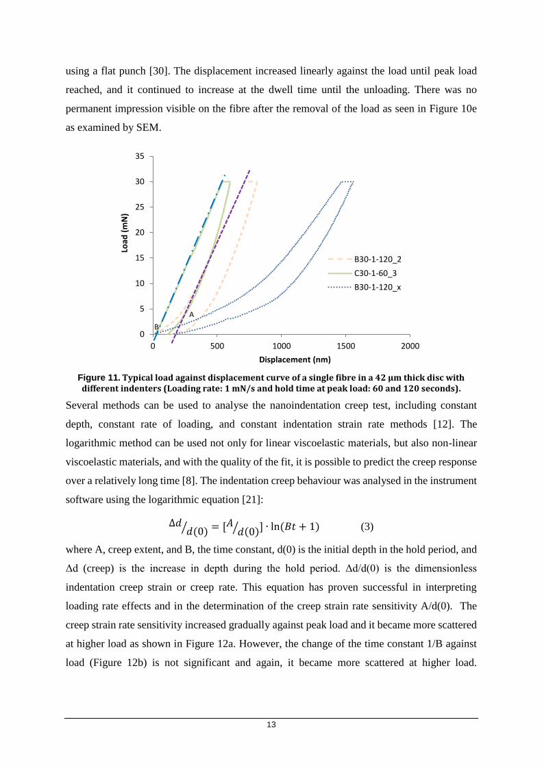
supporting plate as seen at point A in Figure 11 (B30-1-120_2). The displacement then
increased linearly against the load until peak load reached due to the stiffness of the interface
or the stable crack growth between carbon fibre and the polymeric matrix [28], and it continued
to increase at the dwell time until the unloading process. The value change of the displacement
at peak load was closely related to the bonding of the fibre and composite, therefore it can be
used to analyse the creep behaviour. The elastic deformation returned after the load was
removed, and the retaining displacement was majorly attributed to the dislocation of fibre. The
typical impression mark was visible on the fibre after the removal of the load as seen in Figure
10b. Mueller measured the imprint and push-in of the glass fibre by AFM after push-out test
and the depth was about 200 nm [29]. A load-displacement curve like B30-1-120_x was
frequently found when test piece was placed on the EDM machined wide grooves, and this was
majorly due to a span of 100µm led to larger deformation of the thin slice under load resulted
in an elastic bending of the thin sample between the supports which was also reported earlier
[19]. Although displacement of fibre could be identified, the samples had such behaviour were
omitted from the statistics. When the test piece was placed on the narrower laser machined
grooves (25 µm), these irregularities can be eliminated in most cases.
Figure 10. Push-out test using a Berkovich (a/b/c)and a specially made cone indenter (d/e/f) and their indentation on fibre (b/e) and solid surface (c/f)
A specially made cone-shaped indenter with a spherical end surface (Φ5 µm) was also used in
this experiment (Figure 10d/f) and the effective depth to avoid it intercepting with the resin
matrix and other fibres was extended to about 2.2 µm. In the meantime, the spherical end
surface has a large contact area with the fibre which can spread the load evenly and accelerated
the conformation of the tip with the fibre (Figure 10d/f). The initial non-linear stage can be
minimised even eliminated to point B as shown in Figure 11 (C30-1-60-3) which is similar to
h h
(a)
(c) (f)
(d)
(e) (b)
13
using a flat punch [30]. The displacement increased linearly against the load until peak load
reached, and it continued to increase at the dwell time until the unloading. There was no
permanent impression visible on the fibre after the removal of the load as seen in Figure 10e
as examined by SEM.
Figure 11. Typical load against displacement curve of a single fibre in a 42 µm thick disc with different indenters (Loading rate: 1 mN/s and hold time at peak load: 60 and 120 seconds).
Several methods can be used to analyse the nanoindentation creep test, including constant
depth, constant rate of loading, and constant indentation strain rate methods [12]. The
logarithmic method can be used not only for linear viscoelastic materials, but also non-linear
viscoelastic materials, and with the quality of the fit, it is possible to predict the creep response
over a relatively long time [8]. The indentation creep behaviour was analysed in the instrument
software using the logarithmic equation [21]:
∆𝑑𝑑(0)⁄ = [𝐴
𝑑(0)⁄ ] ∙ ln (𝐵𝑡 + 1) (3)
where A, creep extent, and B, the time constant, d(0) is the initial depth in the hold period, and
Δd (creep) is the increase in depth during the hold period. Δd/d(0) is the dimensionless
indentation creep strain or creep rate. This equation has proven successful in interpreting
loading rate effects and in the determination of the creep strain rate sensitivity A/d(0). The
creep strain rate sensitivity increased gradually against peak load and it became more scattered
at higher load as shown in Figure 12a. However, the change of the time constant 1/B against
load (Figure 12b) is not significant and again, it became more scattered at higher load.
0
5
10
15
20
25
30
35
0 500 1000 1500 2000
Load
(m
N)
Displacement (nm)
B30-1-120_2
C30-1-60_3
B30-1-120_x
A
B

14
Extending the holding time, the strain rate sensitivity increased (Figure 12c); this had a similar
trend to displacement at peak load.
(a) (b)
(c)
Figure 12. (a) Strain rate sensitivity and (b) time constant against different peak loads using a Berkovich indenter at room temperature (loading rate: 1mN/s and dwell time: 120 seconds, 34-38µm thick disc) (c) Strain rate sensitivity changes against holding time at 30 mN on a 38µm thick disc
As the onset temperature for the glass transition is about 84°C and the midpoint is 104.1 °, the
creep tests were carried out at 50°C and 100°C under a peak load of 25/35 mN using a cone-
shaped indenter (loading rate: 1mN/s and dwell time: 60 seconds). The strain rate sensitivity
decreased with the elevated temperature at both loads of 25 and 35 mN as shown in Figure 13.
In the meantime, as seen from the load-displacement curve (Figure 9), the initial displacement
was higher at a higher temperature, however, the creep rate and the strain rate sensitivity
reduced slightly. This may have been due to the expansion of the fibre and the resin at an
elevated temperature or the removal of the moisture in the composite [11]. Tehrani suggested
0
0.02
0.04
0.06
0.08
0.1
0.12
10 20 30 40
A/D
(0)
Load (mN)
0
10
20
30
40
10 20 30 40
1/B
load (mN)
0
0.02
0.04
0.06
0 50 100 150
A/D
(0)
Holding time (second)
B30-1-5/60/120

15
material inhomogeneity and the ongoing curing of sample while being tested at elevated
temperatures may also contribute to the decrease of strain rate sensitivity [31].
Figure 13. Strain rate sensitivity using a cone-shaped indenter at elevated temperatures (peak load of 35/40 mN, loading rate: 1mN/s and dwell time: 60 seconds, 34 µm thick disc)
By adopting the methodology developed in this work, the mechanical properties of the fibre
and polymer matrix in the varied surface modified carbon fibre reinforced composite can be
assessed under increasing or constant load at different temperatures and humidity. By
investigating the deviation in the load-displacement curve, the associated debonding and the
interfacial shear strength (IFSS) and stiffness can be calculated at different loading conditions,
and therefore propose the new strategies of strengthening the composite materials.
5. Conclusions
A method to evaluate the interfacial creep of carbon fibre in a polymeric matrix by a push-out
method under constant load via an instrumented nanoindentation is set up in this work. It has
been used to determine the creep of the unidirectional T700 carbon fibres in a commercial
carbon fibres reinforced composite (Toray Rebar S12) at different testing conditions. Initial
displacement at peak load, creep (displacement at peak load), creep rate and strain rate
sensitivity have been used to evaluate the creep behaviour of the fibre in the composite and the
following conclusions can be drawn:
A thin composite disc piece (<50 µm thick) should be carefully prepared and stuck
closely to a holder with grooves. The width of the grooves should be larger than the
diameter of the fiber (>7 µm) and accommodate a few fibers (<30 µm for best result)
with a depth >3µm to allow the movement of the fiber. Nanoindentation instrument
0
0.2
0.4
0.6
0.8
1
0 20 40 60 80 100
A/D
(0)
Temperature (°C)
35/40-1-60
35
40

16
needs an accurate location control to identify the individual fibre before and after creep
test.
Both the Berkovich and Cone indenter were used for the creep test and the latter had
some advantage due to its extended range of displacement to 2.2 µm from 1.2 µm before
interfering with the surrounding polymer matrix.
Critical load/stress, when a single fibre was pushed out under a continuous increasing
load mode, was used to calculate the interfacial strength between the fiber and the resin.
Creep of the fibre at a stress/load lower than the critical load during the dwell time of
the push-out test and the displacement/creep rate were closely relating to the loading
conditions. Generally, the displacement distance increased with the increment of the
peak load and the holding time at the peak load. Fibre in a thin composite disc had a
large displacement under the same load conditions.
The fibre became difficult to creep at elevated temperature and the displacement and
creep rate were both reduced with the increment of the temperature (50 and 100°C) due
to the resistance caused by the expansion of the fibre and polymer matrix under a cone
indenter.
The nanoindentation creep test results were analysed by an instrumental logarithmic
software, and it was found that the creep strain rate sensitivity parameter increased with
the load and the holding time, but decreased with the increment of the test temperature.
Acknowledgement
This work has received funding from the European Commission projects of MODCOMP under
Grant Agreement No. 685844 and SMARTFAN under Grant Agreement No. 760779.
References
[1] S. Zhandarov, E. Mäder, Characterization of fiber/matrix interface strength: Applicability of different
tests, approaches and parameters, Composites Science and Technology 65(1) (2005) 149-160.
[2] A. Ureña, J. Rams, M.D. Escalera, M. Sánchez, Characterization of interfacial mechanical properties
in carbon fiber/aluminium matrix composites by the nanoindentation technique, Composites Science
and Technology 65(13) (2005) 2025-2038.
[3] P. Kavouras, D.A. Dragatogiannis, D.I. Batsouli, C.A. Charitidis, Effect of local microstructure on the
indentation induced damage of a fiber reinforced composite, Polymer Testing 61 (2017) 197-204.
[4] V. Keryvin, M. Lan, A. Bourmaud, T. Parenteau, L. Charleux, C. Baley, Analysis of flax fibres
viscoelastic behaviour at micro and nano scales, Composites Part A: Applied Science and
Manufacturing 68 (2015) 219-225.

17
[5] S. Ji, C. Sun, J. Zhao, F. Liang, Comparison and Analysis on Mechanical Property and Machinability
about Polyetheretherketone and Carbon-Fibers Reinforced Polyetheretherketone, Materials (Basel,
Switzerland) 8(7) (2015) 4118-4130.
[6] S. Corujeira Gallo, X. Li, Z. Zhang, C. Charitidis, H. Dong, Viscoelastic response of carbon fibre
reinforced polymer during push-out tests, Composites Part A: Applied Science and Manufacturing 112
(2018) 178-185.
[7] J. Němeček, Nanoindentation applied to materials with an inner structure, Key Engineering
Materials, 586 (2014) 55-58.
[8] T. Chudoba, F. Richter, Investigation of creep behaviour under load during indentation experiments
and its influence on hardness and modulus results, Surface and Coatings Technology 148(2–3) (2001)
191-198.
[9] H. Lu, B. Wang, J. Ma, G. Huang, H. Viswanathan, Measurement of Creep Compliance of Solid
Polymers by Nanoindentation, Mechanics of Time-Dependent Materials 7(3) (2003) 189-207.
[10] S. Yang, Y.-W. Zhang, Analysis of nanoindentation creep for polymeric materials, Journal of
Applied Physics 95(7) (2004) 10.1063/1.1651341.
[11] X. Wang, Y. Li, S. Wang, Y. Deng, D. Xing, S. He, Investigating the nanomechanical behavior of
thermosetting polymers using high-temperature nanoindentation, European Polymer Journal 70 (2015)
360-370.
[12] P. Coronado, A. Argüelles, J. Viña, V. Mollón, I. Viña, Influence of temperature on a carbon–fibre
epoxy composite subjected to static and fatigue loading under mode-I delamination, International
Journal of Solids and Structures 49(21) (2012) 2934-2940.
[13] J. Berthe, M. Brieu, E. Deletombe, G. Portemont, Temperature effects on the time dependent
viscoelastic behaviour of carbon/epoxy composite materials: Application to T700GC/M21, Materials &
Design (1980-2015) 62(Supplement C) (2014) 241-246.
[14] Y.L. Li, W.J. Chen, M.Y. Shen, C.L. Chiang, M.C. Yip, Study on the Mechanical Properties and
Creep Behaviour of Carbon Fiber Nano-Composites, Advanced Materials Research 284-286 (2011)
557-564.
[15] W.K. Goertzen, M.R. Kessler, Creep behavior of carbon fiber/epoxy matrix composites, Materials
Science and Engineering: A 421(1) (2006) 217-225.
[16] N.P. Lorandi, M.O.H. Cioffi, C. Shigue, H.L. Ornaghi Jr., On the creep behavior of carbon/epoxy
non-crimp fabric composites, Materials Research 21(3) (2018).
[17] A. Chafidz, F.H. Latief, U.A. Samad, A. Ajbar, W. Al-Masry, Nanoindentation Creep, Nano-Impact,
and Thermal Properties of Multiwall Carbon Nanotubes–Polypropylene Nanocomposites Prepared via
Melt Blending, Polymer-Plastics Technology and Engineering 55(13) (2016) 1373-1385.
[18] J. Zhou, Y. Li, N. Li, X. Hao, C. Liu, Interfacial shear strength of microwave processed carbon
fiber/epoxy composites characterized by an improved fiber-bundle pull-out test, Composites Science
and Technology 133 (2016) 173-183.
[19] M.C. Medina, J.M. Molina-Aldareguı´a, C. Gonza´lez, M.F. Melendrez, P. Flores, J. LLorca,
Comparison of push-in and push-out tests for measuring interfacial shear strength in nano-reinforced
composite materials, Journal of Composite Materials 50 (12) (2016) 1651-1659.
18
[20] W. Tan, F. Naya, L. Yang, T. Chang, B.G. Falzon, L. Zhan, J.M. Molina-Aldareguía, C. González,
J. Llorca, The role of interfacial properties on the intralaminar and interlaminar damage behaviour of
unidirectional composite laminates: Experimental characterization and multiscale modelling,
Composites Part B: Engineering 138 (2018) 206-221.
[21] J. Chen, G.A. Bell, H. Dong, J.F. Smith, B.D. Beake, A study of low temperature mechanical
properties and creep behaviour of polypropylene using a new sub-ambient temperature
nanoindentation test platform, Journal of Physics D: Applied Physics 43(42) (2010) 9.
[22] M.L. Oyen, Sensitivity of polymer nanoindentation creep measurements to experimental variables,
Acta Materialia 55 (2007) 3633-3639.
[23] E.P. Koumoulos, P. Jagdale, I.A. Kartsonakis, M. Giorcelli, A. Tagliaferro, C.A. Charitidis, Carbon
nanotube/polymer nanocomposites: A study on mechanical integrity through nanoindentation, Polymer
Composites 36(8) (2014) 1432-1446.
[24] S. Mani, C. Palanisamy, M. Murugesan, R. Balasubramanian, Estimation of distinctive mechanical
properties of spark plasma sintered titanium–titanium boride composites through nano-indentation
technique, International Journal of Materials Research 106(11) (2015) 1182-1188.
[25] G. Lin, P.H. Geubelle, N.R. Sottos, Simulation of fiber debonding with friction in a model composite
pushout test, International Journal of Solids and Structures 38(46-47) (2001) 8547-8562.
[26] A. Battisti, D. Esqué-de los Ojos, R. Ghisleni, A.J. Brunner, Single fiber push-out characterization
of interfacial properties of hierarchical CNT-carbon fiber composites prepared by electrophoretic
deposition, Composites Science and Technology 95 (2014) 121-127.
[27] W. Mueller, J. Moosburger-Will, M. Sause, S. Horn, Microscopic analysis of single-fiber push-out
tests on ceramic matrix composites performed with Berkovich and flat-end indenter and evaluation of
interfacial fracture toughness, Journal of the European Ceramic Society 33 (2013) 441-451.
[28] J.J. Sha, J.X. Dai, J. Li, Z.Q. Wei, J.M. Hausherr, W. Krenkel, Measurement and analysis of fiber-
matrix interface strength of carbon fiber-reinforced phenolic resin matrix composites, Journal of
Composite Materials 48(11) (2014) 1303-1311.
[29] W.M. Mueller, J. Moosburger-Will, M.G.R. Sause, M. Greisel, S. Horn, Quantification of crack area
in ceramic matrix composites at single-fiber push-out testing and influence of pyrocarbon fiber coating
thickness on interfacial fracture toughness, Journal of the European Ceramic Society 35(11) (2015)
2981-2989.
[30] J. Tezcan, S. Ozcan, B. Gurung, P. Filip, Measurement and Analytical Validation of Interfacial Bond
Strength of PAN-Fiber-Reinforced Carbon Matrix Composites, Journal of Materials Science 43(5)
(2008) 1612-1618.
[31] M. Tehrani, M. Safdari, M.S. Al-Haik, Nanocharacterization of creep behavior of multiwall carbon
nanotubes/epoxy nanocomposite, International Journal of Plasticity 27(6) (2011) 887-901.