university of denver stem green denver, colorado...
TRANSCRIPT

EES Entitlement and Engineering Solutions, Inc
EES, Inc Phone: 303-572-7997 518 17th Street, Suite 1575 Denver, CO 80202
UNIVERSITY OF DENVER STEM GREEN DENVER, COLORADO 100% CONSTRUCTION DOCUMENT PROJECT MANUAL VOLUME 1 OF 1 NOVEMBER 23, 2015 Civil Engineer’s Project No.: DU-002.01

EES Entitlement and Engineering Solutions, Inc
EES, Inc Phone: 303-572-7997 518 17th Street, Suite 1575 Denver, CO 80202
TABLE OF CONTENTS
UNIVERSITY OF DENVER
STEM GREEN
DIVISION 00 00 01 02 PROJECT INFORMATION 00 21 13 INSTRUCTIONS TO BIDDERS BID FORMS 00 31 32 GEOTECHNICAL DATA 00 50 00 CONTRACTING FORMS AND SUPPLEMENTS 00 52 00 AGREEMENT FORM 00 72 00 GENERAL CONDITIONS 00 73 00 SUPPLEMENTARY CONDITIONS DIVISION 01 01 10 00 SUMMARY 01 22 00 UNIT PRICES 01 23 00 ALTERNATES 01 25 00 SUBSTITUTION PROCEDURES 01 25 00.01 SUBSTITUTION REQUEST PRE-BID 01 26 00 CONTRACT MODIFICATION PROCEDURES 01 29 00 PAYMENT PROCEDURES 01 31 00 PROJECT MANAGEMENT AND COORDINATION 01 32 00 CONSTRUCTION PROGRESS DOCUMENTATION 01 33 00 SUBMITTAL PROCEDURES 01 33 00.01 FILE TRANSFER AGREEMENT 01 40 00 QUALITY REQUIREMENTS 01 42 00 REFERENCES 01 50 00 TEMPORARY FACILITIES AND CONTROLS 01 60 00 PRODUCT REQUIREMENTS 01 73 00 EXECUTION 01 74 19 CONSTRUCTION WASTE MANAGEMENT AND DISPOSAL 01 77 00 CLOSEOUT PROCEDURES 01 78 23 OPERATION AND MAINTENANCE DATA

EES Entitlement and Engineering Solutions, Inc
EES, Inc Phone: 303-572-7997 518 17th Street, Suite 1575 Denver, CO 80202
01 78 39 PROJECT RECORD DOCUMENTS 01 79 00 DEMONSTRATION AND TRAINING DIVISION 02 02 30 00 SUBSURFACE INVESTIGATION 02 41 00 DEMOLITION DIVISION 03 03 30 01 CAST-IN-PLACE CONCRETE FOR LANDSCAPE 03 30 13 SIDEWALKS AND BIKEWAYS DIVISION 04 04 43 00 STONE MASONRY 04 43 13.14 ANCHORED STONE MASONRY VENEER FOR LANDSCAPE DIVISION 12 12 93 00 SITE FURNISHINGS DIVISION 31 31 00 00 EARTHWORK 31 23 26 EXCAVATION AND BACKFILL FOR STRUCTURES 31 23 33 UTILITY TRENCHING AND BACKFILLING 31 25 00 EROSION AND SEDIMENTATION CONTROLS DIVISION 32 32 01 90 TREE AND PLANT PROTECTION 32 12 43 POROUS FLEXIBLE PAVING 31 13 13 CONCRETE PAVING 32 14 00 UNIT PAVING 32 15 40 STABILIZED CRUSHED AGGREGATE PAVING 32 16 13 CONCRETE CURBS AND GUTTERS 32 91 13 LANDSCAPE SYSTEMS 32 91 19 LANDSCAPE GRADING 32 92 00 TURF 32 93 00 TREES, PLANTS AND GROUNDCOVER

EES Entitlement and Engineering Solutions, Inc
EES, Inc Phone: 303-572-7997 518 17th Street, Suite 1575 Denver, CO 80202
DIVISION 33 33 00 00 UTILITIES 33 05 25 SUPPORT AND PROTECTION OF UTILITIES 33 40 00 STORM DRAINAGE SYSTEM APPENDIX A ATTACHMENT A – SUPPLEMENTARY CONDITIONS FOR CONSTRUCTION PROJECTS APPENDIX B CONSTRUCTION SERVICES AGREEMENT APPENDIX C GEOTECHNICAL INVESTIGATION, DATED JUNE 21.2013

EES 00 01 02 - 1 STEM GREEN PROJECT INFORMATION
DOCUMENT 00 01 02
PROJECT INFORMATION
PART 1 - GENERAL
1.1 PROJECT IDENTIFICATION
Project Name: University of Denver, STEM Green 2150 East Iliff Ave. Denver, CO 80208.
Project Number: DU-002.01
The Owner, hereinafter referred to as Owner: Colorado Seminary, which owns and operates the University of Denver.
Address: 2199 South University Boulevard City, State, Zip: Denver, Colorado 80208
Owner's Project Manager: Linda Lautenbach, P.E..
Department: Facilities Management. Address: 2240 East Wesley Avenue City, State, Zip: Denver, Colorado 80208. Phone: 303-871-4808. E-mail: [email protected].
1.2 NOTICE TO PROSPECTIVE BIDDERS
These documents constitute an Invitation to Bid to General Contractors for the construction of the project described below.
1.3 PROJECT DESCRIPTION
The project consists of a two-pond system connected by a water channel. There will be multiple pathways and a bridge over the channel along with bench seating and green space.
Contract Scope: New Construction. The work shall be done in a single phase.
Contract Terms: Lump sum (fixed price, stipulated sum).
1.4 PRE-QUALIFIED BIDDERS
Those already qualified to submit bids are:
1. General Contractor: American Civil Constructors – ACC Mountain West Address: 4901 South Windermere St. Littleton, CO 80120 Phone: 303.795.2582

EES 00 01 02 - 2 STEM GREEN PROJECT INFORMATION
2. General Contractor: GH Phipps Construction Company Address: 5995 Greenwood Plaza Boulevard, Suite 100
Greenwood Village, CO 80111 Phone: 303.571.5377
3. General Contractor: Weitz Address: 4725 South Monaco St. Suite 100 Denver, CO 80237 Phone: 303.860.6600
4. General Contractor: ValleyCrest Address: 8888 N. Motsenbocker Rd. Suite A Parker, CO 80134 Phone: 303.8419.8400
1.5 PRE-APPROVED SUBCONTRACTORS
Pre-Approved Sub-Contractors for specific trades are listed below.
Spec Division 04 - Stone Veneer Masonry
Firm Name
1 AP Eberlein Company
2 Berich Masonry, Inc.
3 Gallegos Masonry
4 Glover Masonry
5 Soderberg Masonry
Spec Division 04 - Exterior Stone Cladding/Anchored Stone Masonry Veneer Suppliers
Firm Name
1 B.G. Hoadley Quarries (Anchored Stone Masonry Veneer only)
2 Indiana Limestone Fabricators
3 Architectural Stone Sales
4 Bybee Stone Co
5 3-D Stone Inc.
6 Texacon Cut
Spec Division 32 - Exterior Improvements Trees & Plant Protection/Site Furnishings/Landscape Systems/Landscape Grading/Lawn Sodding/Trees Plants and Groundcover
Firm Name
1 Land Tech 2 American Civil Constructors
3 Custom Landscapes of Colorado
4 CO Cal
5 All Phase Landscape

EES 00 01 02 - 3 STEM GREEN PROJECT INFORMATION
6 LMI Landscapes
7 Environmental Landworks
8 Schultz Industries Inc
9 Designs by Sundown
Spec Division 32 - Brick Unit Paving
Firm Name
1 Cogan
2 Colorado Hardscapes
3 Continental Hardscape Systems
4 Creative Hardscape Company
5 Land Tech
PART 2 - PRODUCTS (NOT USED)
PART 3 - EXECUTION (NOT USED)
END OF DOCUMENT

EES 00 01 02 - 4 STEM GREEN PROJECT INFORMATION
THIS PAGE LEFT INTENTIONALLY BLANK
EES 00 21 13 - 1 STEM GREEN INSTRUCTIONS TO BIDDERS
DOCUMENT 00 21 13
INSTRUCTIONS TO BIDDERS
PART 1 - SUMMARY
1.1 DOCUMENT INCLUDES
A. Invitation
1. Bid Submission 2. Intent 3. Work Identified in the Contract Documents 4. Contract Time
B. Bid Documents and Contract Documents
1. Inquiries/Addenda 2. Product/Assembly/System Substitutions
C. Site Assessment
1. Prebid Conference
D. Qualifications
1. Qualifications 2. Prequalification 3. Subcontractors/Suppliers/Others
E. Bid Submission
1. Bid Depository 2. Submission Procedure 3. Bid Ineligibility
F. Bid Enclosures/Requirements
1. Security Deposit 2. Consent of Surety 3. Payment and Performance Bonds 4. Insurance 5. Bid Form Requirements 6. Bid Form Signature 7. Selection and Award of Alternatives
G. Offer Acceptance/Rejection
1. Duration of Offer 2. Acceptance of Offer

EES 00 21 13 - 2 STEM GREEN INSTRUCTIONS TO BIDDERS
PART 2 - INVITATION
2.1 BID SUBMISSION
A. Bid Form, Pages 1-2 shall be signed and under seal, executed, and dated with Base Bid Schedule of Values and Exclusions, and will be received at the office of the Owner at 2400 South Race Street, Denver, Colorado before 2:00 PM local standard time on the 17th day of December, 2015. Attention: Linda Lautenbach.
B. Bid Form, Page 1 shall be signed and under seal, executed, and dated with Alternates and will be received at the office of the Owner at 2400 South Race Street, Denver, Colorado before 4:00 PM local standard time on the 18th day of December, 2015. Attention Linda Lautenbach.
C. Bid Form, Page 3 shall be signed and under seal, executed, and dated with Project Manager and Superintendent resumes, List of Subcontractors and Unit Prices and will be received at the office of the Owner at 2400 South Race Street, Denver, Colorado before 2:00 PM local standard time on the 18th day of December, 2017. Attention Linda Lautenbach.
D. Offers submitted after the above time may be returned to the bidder unopened.
E. Offers will be opened privately immediately after the time for receipt of bids.
F. Final Bid Forms, if different from those published herewith, will be issued with the final addendum prior to the bid date.
G. The Owner reserves the right to change the schedule or terminate the entire procurement process at any time.
2.2 INTENT
A. The intent of this Bid request is to obtain an offer to perform work to complete construction of STEM Green, located at 2150 East Iliff Ave., Denver, Colorado 80208 for a Stipulated Sum contract, in accordance with the Contract Documents.
2.3 WORK IDENTIFIED IN THE CONTRACT DOCUMENTS
A. Work of this proposed Contract comprises site development, including general construction, structural, landscaping, irrigation and grading.
2.4 CONTRACT TIME
A. The Owner will require Substantial Completion by the 15th day of August, 2016 and Final Completion by the 31st day of August, 2016. Start of Construction will be on or about the 4th day of April, 2016, depending on the issuance of the Building Permit.

EES 00 21 13 - 3 STEM GREEN INSTRUCTIONS TO BIDDERS
PART 3 - BID DOCUMENTS AND CONTRACT DOCUMENTS
3.1 INQUIRIES/ADDENDA
A. Addenda shall be issued during the bidding period, as indicated below. All Addenda become part of the Contract Documents. Include resultant costs in the Bid Amount.
B. Verbal answers are not binding on any party.
C. If discrepancies exist between contract documents, the Contractor shall notify the Engineer and Owner via a clarification request.
D. Clarifications requested by bidders must be via email to the Engineer with a copy to the Owner's Project Manager (Linda Lautenbach), received by the dates indicated below. The reply will be in the form of an Addendum, a copy of which will be forwarded to known recipients. Clarification requests submitted after this time may not be addressed in addenda prior to the bid date.
3.2 PRODUCT/ASSEMBLY/SYSTEM SUBSTITUTIONS
A. Where the Bid Documents stipulate a particular product, substitutions will be considered up to 5:00 p.m. on the 9th day of December, 2015. Requests received after this time will not be considered. Contractors are encouraged to make their requests before this date. Should too many requests be made on the last day, some requests may not be reviewed by the Engineer.
B. The submission shall provide sufficient information to determine acceptability of such products. Bidders must use and fill out completely the enclosed Substitution Request Form 01 25 00.01 (CSI Form 1.5C). Incomplete forms will be rejected by the Engineer.
C. Provide complete information on required revisions to other work to accommodate each proposed substitution.
D. Provide products as specified unless substitutions are submitted in this manner and accepted.
E. When a request to substitute a Product is made, the Engineer may approve the substitution and will issue in Addendum 01 or Addendum 02, to Pre-Qualified General Contractors indicating approval. If product is not acceptable or if information submitted is inadequate, no action will be taken.
F. See Section 01 60 00 - Product Requirements for additional requirements.
PART 4 - SITE ASSESSMENT
4.1 PREBID CONFERENCE
A. A bidders conference has been scheduled for 2:00-4:00 PM on the 30th day of November, 2015 at the location of the University of Denver, Wesley Hall Conference Room.
B. All general contract bidders are required to attend, and suppliers are invited to attend.
C. Representatives of the University and the Engineer will be in attendance.

EES 00 21 13 - 4 STEM GREEN INSTRUCTIONS TO BIDDERS
D. Summarized minutes of this meeting will be circulated to attendees. These minutes will not form part of the Contract Documents.
PART 5 - QUALIFICATIONS
5.1 PREQUALIFICATION
A. Refer to Document 00 01 02 Project Information for list of Pre-Qualified Bidders.
5.2 SUBCONTRACTORS/SUPPLIERS/OTHERS
A. Refer to Document 00 01 02 Project Information for list of Pre-Approved Subcontractors.
B. No substitutions or additions to the Pre-Approved Subcontractors list will be permitted for work in the Divisions/Sections listed. For all other work, Bidder may select subcontractors who comply with requirements of Division 01 and individual sections of the Project Manual.
C. Owner reserves the right to reject a proposed subcontractor for reasonable cause.
D. Successful bidder shall comply with all requirements of 7.02, Payment and Performance Bonds.
PART 6 - BID SUBMISSION
6.1 SUBMISSION PROCEDURE
A. Bidders shall be solely responsible for the delivery of their bids in the manner and time prescribed. Bidders will not be allowed within the Facilities Management building during the bid period other than to deliver the bid. Facilities Management staff may not be disturbed and equipment (i.e. copiers, phones, fax machines, etc.) will not be available for the bidder's use at any time. Bidder's staff are not welcome to occupy and use any University facilities, including parking facilities, during the bid period.
B. The Bidder must deliver all Alternates shown Bid Form page 1, and Unit Prices shown on Bid Form page 3, by the times and dates indicated in 2.01 Bid Submission. Failure to comply may be cause for rejection.
C. The Owner has paid $3,789.00 plan review fee. The Bidder must include in their bids all remaining required permit fees.
D. Bids shall be made on the unaltered Bid Forms as bound in the Project Manual unless reissued by Addendum. Do not remove forms from the Project Manual. Bid Forms may be photo copied from the Project Manual. Fill in all blank spaces and submit one copy. Bids shall be signed with name typed below signature.
E. Where bidder is a corporation, bids must be signed with the legal name of the corporation followed by the name of the State of incorporation and the legal signature of an officer authorized to bind the corporation to a contract.

EES 00 21 13 - 5 STEM GREEN INSTRUCTIONS TO BIDDERS
F. Submit one copy of the executed offer on the Bid Forms provided, signed and sealed with the required security in a closed opaque envelope, clearly identified with bidder's name, project name and Owner's name (Attention: Linda Lautenbach) on the outside.
G. Enclose Bid Security with base bid proposal.
H. Enclose resumè of proposed Project Manager, resumè of proposed Project Superintendent, with Base Bid Schedule of Values and Base Bid Exclusions by the times and dates indicated in 2.01 Bid Submission. Failure to comply may be cause for rejection.
I. Enclose complete Subcontractor List by the times and dates indicated in 2.01 Bid Submission.
6.2 BID INELIGIBILITY
A. Bids are by invitation, only from selected bidders. Bids from unsolicited bidders will be returned.
B. Bids may be disqualified before or after opening upon evidence of collusion with intent to defraud or other illegal practices on the part of the bidder.
PART 7 - BID ENCLOSURES/REQUIREMENTS
7.1 SECURITY DEPOSIT
A. Bids shall be accompanied by a security deposit as follows:
1. Bid Bond of a sum no less than 5 percent of the Bid Amount on AIA A310 Bid Bond Form.
B. Security shall be issued by a surety licensed to conduct business in the State of Colorado. All bonds shall list the Owner as "Colorado Seminary, a Colorado non-profit organization, which owns and operates the University of Denver".
C. The successful bidder's security will be retained until he has signed the Contract and furnished the required payment and performance bonds. The Owner reserves the right to retain the security of the next two lowest bidders until the low bidder enters into a Contract, or until sixty (60) calendar days after bid opening, whichever is the shorter. All other bid security will be returned as soon as possible.
D. Include the cost of bid security in the Bid Amount.
E. If no contract is awarded, all security deposits will be returned.
F. If any bidder refuses to enter into a Contract, the Owner will retain his bid security as liquidated damages, but not as a penalty.
7.2 PAYMENT AND PERFORMANCE BONDS
A. Not applicable.

EES 00 21 13 - 6 STEM GREEN INSTRUCTIONS TO BIDDERS
7.3 INSURANCE
A. Provide an executed "Undertaking of Insurance" on a standard form provided by the insurance company stating their intention to provide insurance to the bidder in accordance with the insurance requirements of the Contract Documents. All bonds and insurance documents shall list the owner as "Colorado Seminary, a Colorado non-profit organization, who owns and operates the University of Denver".
7.4 SELECTION AND AWARD OF ALTERNATIVES
A. Bids will be initially evaluated on the base bid price. Determination of the successful bidder may be made on the basis of the lowest Bid combining the Base Bid and those Alternates accepted by the Owner.
B. The Owner reserves the right to accept or reject any or all Bids as it may be deemed to be in his best interest. The Owner reserves the right to waive any informalities or irregularities in the bidding.
PART 8 - OFFER ACCEPTANCE/REJECTION
8.1 DURATION OF OFFER
A. Bids shall remain open to acceptance and shall be irrevocable for a period of sixty (60) calendar days after the bid closing date. Alternates shall remain open to acceptance and shall be irrevocable for a period of (90) calendar days after bid closing date, unless noted otherwise in Specification Section 01 23 00 Alternates.
8.2 ACCEPTANCE OF OFFER
A. Owner reserves the right to accept or reject any or all offers.
B. Upon notice of acceptance of Bid (within (60) calendar days of bid opening), the successful bidder agrees to execute a Contract for the work and compensation in the Bid on the American Institute of Architects Standard Form of Agreement A101 as modified and of which an example is bound herein.
END OF INSTRUCTIONS TO BIDDERS
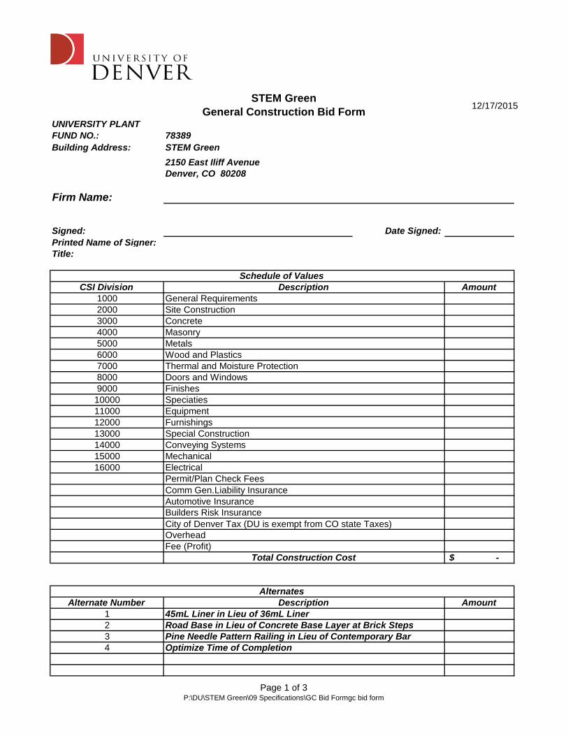
STEM GreenGeneral Construction Bid Form
12/17/2015
Page 1 of 3P:\DU\STEM Green\09 Specifications\GC Bid Formgc bid form
UNIVERSITY PLANT FUND NO.: 78389Building Address:
Firm Name:
Signed: Date Signed:Printed Name of Signer:Title:
CSI Division Amount100020003000400050006000700080009000
10000110001200013000140001500016000
-$
Alternate Number Amount1234
STEM Green2150 East Iliff AvenueDenver, CO 80208
Pine Needle Pattern Railing in Lieu of Contemporary Bar
Schedule of Values
Description
Permit/Plan Check Fees
Optimize Time of Completion
45mL Liner in Lieu of 36mL LinerRoad Base in Lieu of Concrete Base Layer at Brick Steps
DescriptionGeneral Requirements
MetalsWood and Plastics
EquipmentFurnishings
Site ConstructionConcreteMasonry
Doors and WindowsThermal and Moisture Protection
Electrical
Finishes
Alternates
OverheadFee (Profit)
Total Construction Cost
Automotive Insurance
Speciaties
Comm Gen.Liability Insurance
Builders Risk InsuranceCity of Denver Tax (DU is exempt from CO state Taxes)
Special ConstructionConveying SystemsMechanical

STEM GreenGeneral Construction Bid Form
12/17/2015
Page 2 of 3P:\DU\STEM Green\09 Specifications\GC Bid Formgc bid form
UNIVERSITY PLANT FUND NO.: 78389Firm Name:Project Manager:Superintendent:
Proposed Construction Start Date:Proposed Construction End Date:
Bid Exclusions

STEM GreenGeneral Construction Bid Form
12/17/2015
Page 3 of 3P:\DU\STEM Green\09 Specifications\GC Bid Formgc bid form


EES 00 31 32 - 1 STEM GREEN GEOTECHNICAL DATA
DOCUMENT 00 31 32
GEOTECHNICAL DATA
1.1 GEOTECHNICAL DATA
A. This Document with its referenced attachments is part of the Procurement and Contracting Requirements for Project. They provide Owner's information for Bidders' convenience and are intended to supplement rather than serve in lieu of Bidders' own investigations. They are made available for Bidders' convenience and information, but are not a warranty of existing conditions. This Document and its attachments are not part of the Contract Documents.
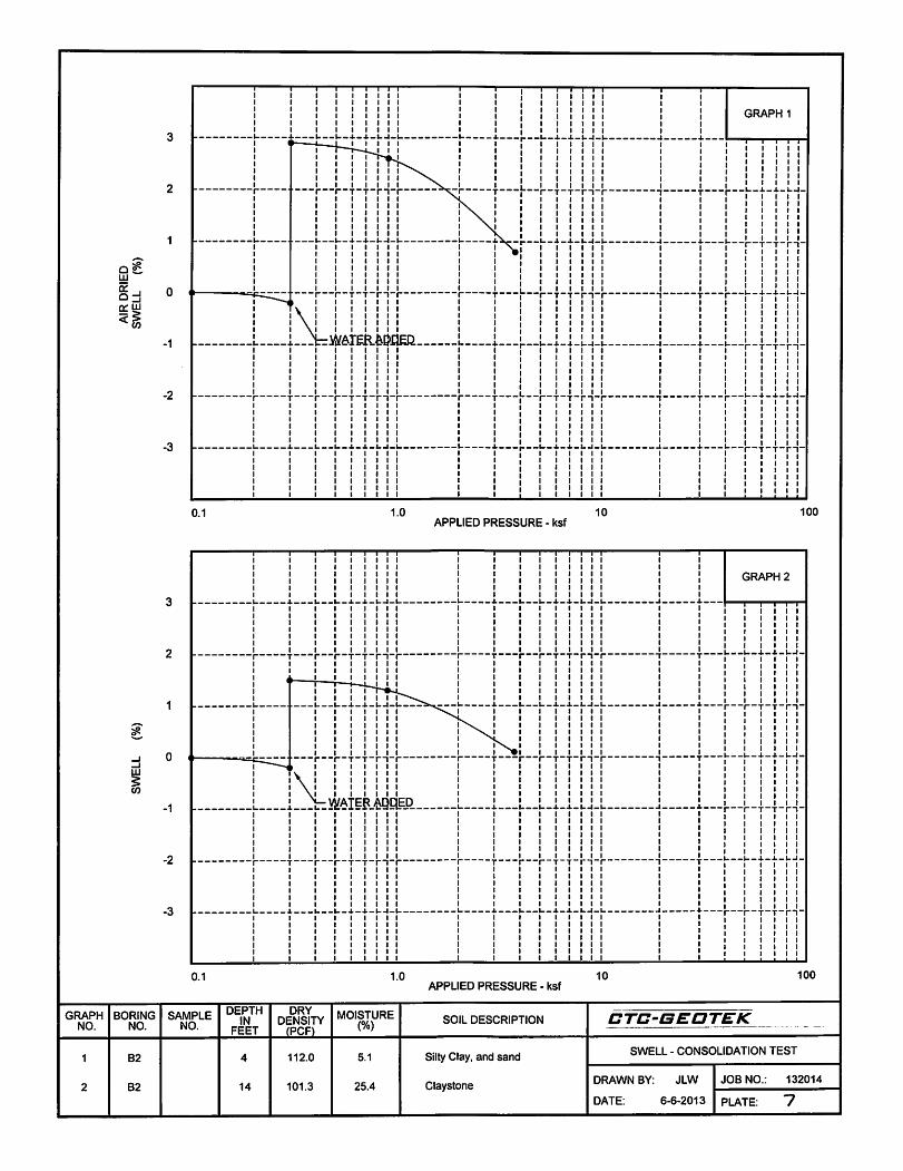
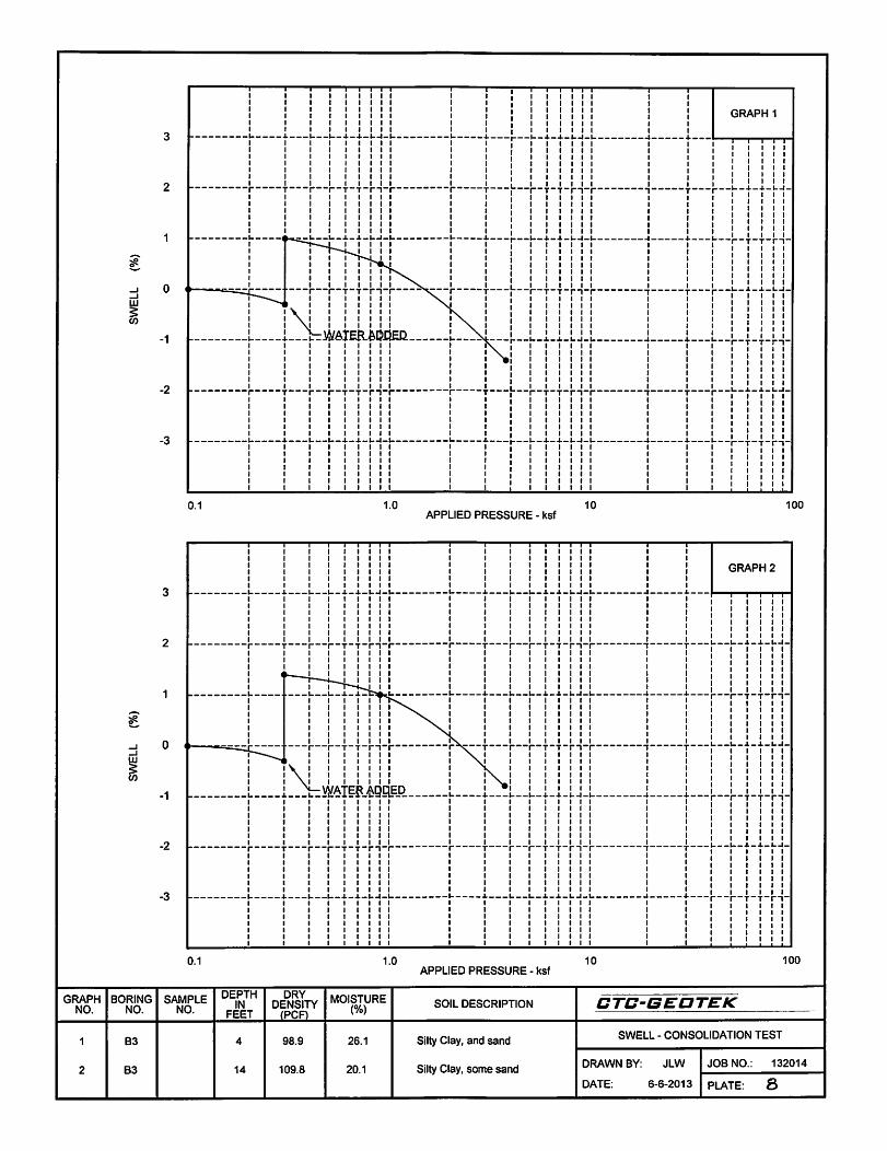
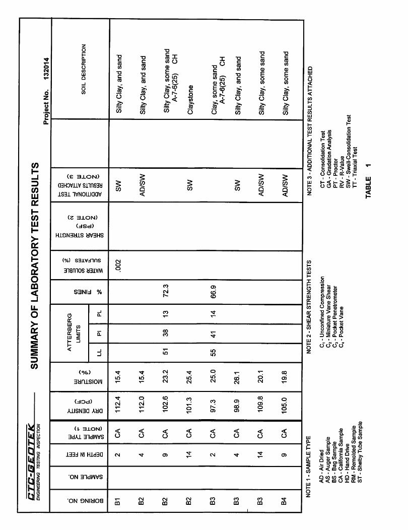
B. A geotechnical investigation report for Project, prepared by CTC-Geotek, Inc., dated June 21, 2013, and review letter dated June 27, 2013, are available for viewing as appended to this Document in Appendix C.
END OF DOCUMENT

EES 00 31 32 - 2 STEM GREEN GEOTECHNICAL DATA
THIS PAGE LEFT INTENTIONALLY BLANK

EES 00 50 00 - 1 STEM GREEN
CONTRACTING FORMS AND SUPPLEMENTS
DOCUMENT 00 50 00
CONTRACTING FORMS AND SUPPLEMENTS
PART 1 - GENERAL
1.1 CONTRACTOR IS RESPONSIBLE FOR OBTAINING A VALID LICENSE TO USE ALL COPYRIGHTED DOCUMENTS SPECIFIED BUT NOT INCLUDED IN THE PROJECT MANUAL.
1.2 AGREEMENT AND CONDITIONS OF THE CONTRACT
A. See Document 00 52 00 for the Agreement form to be executed.
B. See Document 00 72 00 for the General Conditions.
C. See Document 00 73 00 for the Supplementary Conditions in Appendix A.
D. DU standard Construction Services Agreement in Appendix B.
1.3 FORMS
A. Use the following forms for the specified purposes unless otherwise indicated elsewhere in the Contract Documents.
B. Bond Forms:
1. Bid Bond Form: AIA A310 2. Performance and Payment Bond Form: AIA A312. 3. List of Subcontractors: G705
C. Post-Award Certificates and Other Forms:
1. License Waiver, Release and Indemnity Agreement: See Section 01 30 00.01 2. Substitution Request Form: See Section 01 25 00.01 3. Application for Payment Form: AIA G702 and G703. 4. Consent of Surety to Reduction of Retainage Form: G707A. 5. Architect’s Field Report: G711 6. Instruction Sheet and Attachment for ACORD Certificate of Insurance: G715 7. Shop Drawing and Sample Record: G712
D. Clarification and Modification Forms:
1. Request for Information Form: G716. 2. Construction Change Directive Form: AIA G714. 3. Request for Proposal Form: G709. 4. Change Order Form: AIA G701.

EES 00 50 00 - 2 STEM GREEN
CONTRACTING FORMS AND SUPPLEMENTS
E. Closeout Forms:
1. Certificate of Substantial Completion Form: AIA G704. 2. Affidavit of Payment of Debts and Claims Form: G706. 3. Affidavit of Release of Liens Form: G706A. 4. Consent of Surety to Final Payment Form: G707.
1.4 REFERENCE STANDARDS
A. AIA A310 - Bid Bond Form; 1970
B. AIA A312 - Performance Bond and Payment Bond ; 1984.
C. AIA G701 - Change Order ; 2001.
D. AIA G702 - Application and Certificate for Payment ; 1992.
E. AIA G703 - Continuation Sheet ; 1992.
F. AIA G704 - Certificate of Substantial Completion ; 2000.
G. AIA G706 - Contractor's Affidavit of Payment of Debts and Claims; 1994
H. AIA G706A - Contractor's Affidavit of Release of Liens; 1994
I. AIA G707 - Consent of Surety to Final Payment: 1994
J. AIA G707A - Consent of Surety to Reduction in or Partial Release of Payment; 1994
K. AIA G709 - Work Changes Proposal Request; 2001
L. AIA G711 - Architect's Field Report; 1972
M. AIA G712 - Shop Drawing and Sample Record; 1972
N. AIA G714 - Construction Change Directive; 2007.
O. AIA G715 - Instruction Sheet and Attachment for ACORD Certificate of Insurance
P. AIA G716 - Request for Information; 2004
Q. AIA G805 - List of Subcontractors; 2001
PART 2 - PRODUCTS - NOT USED
PART 3 - EXECUTION - NOT USED
END OF DOCUMENT

EES 00 52 00 - 1 STEM GREEN AGREEMENT FORM
DOCUMENT 00 52 00
AGREEMENT FORM
PART 1 - GENERAL
1.1 FORM OF AGREEMENT
1.2 THE AGREEMENT TO BE EXECUTED IS PROVIDED IN APPENDIX B.
PART 2 - PRODUCTS (NOT USED)
PART 3 - EXECUTION (NOT USED)
END OF AGREEMENT

EES 00 52 00 - 2 STEM GREEN AGREEMENT FORM
THIS PAGE LEFT INTENTIONALLY BLANK

EES 00 72 00 - 1 STEM GREEN GENERAL CONDITIONS
DOCUMENT 00 72 00
GENERAL CONDITIONS
PART 1 - GENERAL
1.1 SUPPLEMENTARY CONDITIONS
A. Refer to document 00 73 00 for amendments to these general conditions.
PART 2 - PRODUCTS - NOT USED
PART 3 - EXECUTION - NOT USED
END OF DOCUMENT

EES 00 72 00 - 2 STEM GREEN GENERAL CONDITIONS
THIS PAGE LEFT INTENTIONALLY BLANK
EES 00 73 00 - 1 STEM GREEN SUPPLEMENTARY CONDITIONS
DOCUMENT 00 73 00
SUPPLEMENTARY CONDITIONS
PART 1 - GENERAL
1.1 SUMMARY
A. Supplementary Conditions of the Agreement, which follow this page on the Owner's standard form, will be a Part of the Owner-Contractor Agreement in Appendix A.
B. The terms used in these Supplementary Conditions that are defined in the General Conditions have the meanings assigned to them in the General Conditions.
PART 2 - PRODUCTS - NOT USED
PART 3 - EXECUTION - NOT USED
END OF DOCUMENT

EES 00 73 00 - 2 STEM GREEN SUPPLEMENTARY CONDITIONS
THIS PAGE LEFT INTENTIONALLY BLANK

EES 01 10 00 - 1 STEM GREEN SUMMARY
SECTION 01 10 00
SUMMARY
PART 1 - GENERAL
1.1 RELATED DOCUMENTS
A. Drawings and general provisions of the Contract, including General and Supplementary Conditions and other Division 01 Specification Sections, apply to this Section.
1.2 SUMMARY
A. Section Includes:
1. Project information. 2. Work covered by Contract Documents. 3. Work by Owner. 4. Future work. 5. Owner-furnished products. 6. Contractor-furnished, Owner-installed products. 7. Access to site. 8. Coordination with occupants. 9. Work restrictions. 10. Specification and drawing conventions. 11. Miscellaneous provisions.
B. Related Requirements:
1. Section 01 50 00 "Temporary Facilities and Controls" for limitations and procedures governing temporary use of Owner's facilities.
1.3 DEFINITIONS
A. Public Spaces: Areas accessible to the public such as lobbies, corridors, toilet rooms, and other areas not specifically dedicated to the function of the facility.
B. Program Spaces: Areas used by building occupants that are dedicated to the function of the facility.
C. Service Spaces: Areas used by building occupants and maintenance personnel such as mechanical and electrical rooms, custodial closets, and other areas dedicated to the operation of the facility.
1.4 PROJECT INFORMATION
A. Project Identification: STEM Green.
EES 01 10 00 - 2 STEM GREEN SUMMARY
1. Project Location: University of Denver 2150 East Iliff Avenue Denver, CO 80208
2. Owner: University of Denver
3. Owner's Representative: Linda Lautenbach, P.E. Facilities Management 2240 East Wesley Avenue Denver, CO 80208 303-871-4808
B. Engineer: Entitlement & Engineering Solutions, Inc. 518 17th Street, Suite 1575
Denver, CO 80202 303-572-7997
C. Engineer's Consultants: The Engineer has retained the following design professionals who have prepared designated portions of the Contract Documents:
1. Landscape Architect: Didier Design Studio 342 West Douglas Road Fort Collins, CO 80524 970-416-1018
2. Lighting Engineer: Kazin & Associates 9364 Teddy Lane, Suite 101 Lone Tree, CO 80124 720-489-1609
3. Structural Engineer: San Engineering 801 W. Mineral Avenue, Suite 200 Littleton, CO 80120 303-953-9014
4. Irrigation and Water Systems: HydroSystems-KDI 860 Tabor Street, Suite 200 Lakewood, CO 80401 303-980-5327
5. Pond Designer: Aqua-Sierra Inc. 9094 US Highway 285 Morrison, CO 80465 303-697-5486
D. Contractor will be used for purposes of managing communication and documents during the construction stage.
1. See Section 01 31 00 "Project Management and Coordination." for requirements for establishing administering and using the Project Web site.
EES 01 10 00 - 3 STEM GREEN SUMMARY
1.5 WORK COVERED BY CONTRACT DOCUMENTS
A. Briefly, and without force and effect on the Contract Documents, the Work consists of the following:
1. The project consists of a two-pond system connected by a water channel. There will be multiple pathways and a bridge over the channel along with bench seating and green space.
2. Utility Work. 3. Grading and Drainage. 4. Paving and Surfacing. 5. Landscaping and Irrigation. 6. Structural Concrete.
B. Type of Contract:
1. Project will be constructed under a single prime contract.
1.6 WORK BY OWNER
A. General: Cooperate fully with Owner so work may be carried out smoothly, without interfering with or delaying work under this Contract or work by Owner. Coordinate the Work of this Contract with work performed by Owner.
B. Preceding Work: Owner will perform the following construction operations at Project site. Those operations are scheduled to be substantially complete before work under this Contract begins. 1. Demolition of E-3 Building.
1.7 FUTURE WORK
A. The Contract Documents include requirements that will allow Owner to carry out future work following completion of this Project; provide for the following future work:
1.8 OWNER-FURNISHED PRODUCTS
A. Owner Furnished, Contractor Installed Products (OFCI): Owner will furnish products indicated. The Work includes receiving, unloading, handling, storing, protecting, and installing Owner-furnished products and making building services connections.
1. Owner-Furnished, Contractor Installed Products: a. Exterior Trash Receptacles. Refer to Section 32 39 00 "Site Furnishings." b. Exterior Tables and Chairs. Refer to Section 32 39 00 "Site Furnishings." c. Exterior Benches. Refer to Section 32 39 00 "Site Furnishings."
B. Owner Furnished, Owner Installed Products (OFOI): Owner will furnish and install products indicated.
a. Water Plants. b. Flame of Hope Sculpture

EES 01 10 00 - 4 STEM GREEN SUMMARY
1.9 ACCESS TO SITE
A. General: Contractor shall have full use of Project site for construction operations during construction period. Contractor's use of Project site is limited only by Owner's right to perform work or to retain other contractors on portions of Project.
B. Use of Site: Limit use of Project site to work in areas indicated. Do not disturb portions of Project site beyond areas in which the Work is indicated.
1. Limits: Limit site disturbance, including earthwork and clearing of vegetation, 10 feet beyond surface walkways, surface parking, and utilities less than 12 inches in diameter; 15 feet beyond primary roadway curbs and main utility branch trenches; and 25 feet beyond constructed areas with permeable surfaces (such as pervious paving areas, stormwater detention facilities, and playing fields) that require additional staging areas in order to limit compaction in the constructed area.
2. Driveways, Walkways and Entrances: Keep driveways loading areas, and entrances serving premises clear and available to Owner, Owner's employees, and emergency vehicles at all times. Do not use these areas for parking or storage of materials.
a. Schedule deliveries to minimize use of driveways and entrances by construction operations.
b. Schedule deliveries to minimize space and time requirements for storage of materials and equipment on-site.
1.10 COORDINATION WITH OCCUPANTS
A. Owner Limited Occupancy of Completed Areas of Construction: Owner reserves the right to occupy and to place and install equipment in completed portions of the Work, prior to Substantial Completion of the Work, provided such occupancy does not interfere with completion of the Work. Such placement of equipment and limited occupancy shall not constitute acceptance of the total Work.
1. Engineer of record will prepare a Certificate of Substantial Completion for each specific portion of the Work to be occupied prior to Owner acceptance of the completed Work.
2. Obtain a Certificate of Occupancy from authorities having jurisdiction before limited Owner occupancy.
3. Before limited Owner occupancy, mechanical and electrical systems shall be fully operational, and required tests and inspections shall be successfully completed. On occupancy, Owner will operate and maintain mechanical and electrical systems serving occupied portions of Work.
4. On occupancy, Owner will assume responsibility for maintenance and custodial service for occupied portions of Work.
B. Cooperate with Owner to minimize conflict and to facilitate Owner's operations.
C. Schedule the Work to accommodate Owner occupancy.
1.11 WORK RESTRICTIONS
A. Work Restrictions, General: Comply with restrictions on construction operations.
1. Comply with limitations on use of public streets and with other requirements of authorities having jurisdiction.
EES 01 10 00 - 5 STEM GREEN SUMMARY
B. On-Site Work Hours: Limit work in the existing building to normal business working hours of 7:00a.m. to 6:00p.m., Monday through Saturday, unless otherwise indicated.
1. Work may not be performed on University Graduation Days without prior arrangement. 2. Hours for Utility Shutdowns: Coordinate with Owner. 3. Hours for Core Drilling: Coordinate with Owner.
C. Parking: The Contractor may buy parking passes for employees through DU Parking Services.
D. Contractor will submit a copy of their safety and hot work programs to the University's Environmental Health and Safety Manager.
E. Existing Utility Interruptions: Do not interrupt utilities serving facilities occupied by Owner or others unless permitted under the following conditions and then only after providing temporary utility services according to requirements indicated:
1. Notify Owner not less than two days in advance of proposed utility interruptions. 2. Obtain Owner's written permission before proceeding with utility interruptions.
F. Noise, Vibration, and Odors: Coordinate operations that may result in high levels of noise and vibration, odors, or other disruption to Owner occupancy with Owner.
1. Notify Owner not less than two days in advance of proposed disruptive operations. 2. Obtain Owner's written permission before proceeding with disruptive operations.
G. Controlled Substances: Use of tobacco products and other controlled substances on Project site is not permitted. Contractor will provide a smoking area within the bounds of their construction project fencing that is screened from view from outside the construction fence. All workers are required to smoke within this smoking enclosure. Smoking is not permitted on the University Campus.
1.12 SPECIFICATION AND DRAWING CONVENTIONS
A. The Contract Documents are complementary, and what is called for by any one document shall be as binding as if called for by all. The intention of the documents is to include all labor, materials, equipment and transportation necessary for the proper execution of the Work. Words describing materials or work which have a well-known technical or trade meaning shall be held to refer to such recognized standards.
1. Should apparent contradictions occur between the various Contract documents, submit a Request for Interpretation in accordance with the requirements of Section 01 31 00 "Project Management and Coordination" for clarification.
B. Specification Content: The Specifications use certain conventions for the style of language and the intended meaning of certain terms, words, and phrases when used in particular situations. These conventions are as follows:
1. Imperative mood and streamlined language are generally used in the Specifications. The words "shall," "shall be," or "shall comply with," depending on the context, are implied where a colon (:) is used within a sentence or phrase.
2. Specification requirements are to be performed by Contractor unless specifically stated otherwise.

EES 01 10 00 - 6 STEM GREEN SUMMARY
C. Division 01 General Requirements: Requirements of Sections in Division 01 apply to the Work of all Sections in the Specifications.
D. Drawing Coordination: Requirements for materials and products identified on Drawings are described in detail in the Specifications. One or more of the following are used on Drawings to identify materials and products:
1. Terminology: Materials and products are identified by the typical generic terms used in the individual Specifications Sections.
2. Abbreviations: Materials and products are identified by abbreviations scheduled on Drawings.
1.13 MISCELLANEOUS PROVISIONS
A. All requests for information shall include a reasonable cost estimate for all potential changes to the work involved.
B. Record Keeping and Audits (To be used for Change Orders only)
1. For any work performed by Contractor on a cost reimbursement basis, Owner shall have the right to audit, inspect and copy all of Contractor's books and records. Contractor will make available to owner on five (5) business days notice, either on site or at Contractor's local office, full and detailed records, accounts and books including but not limited to: accounting methods, work papers, computer files, supplier invoices, supplier rebates or refunds, purchase orders, subcontractor billings, sub contracts, consultant billings, payroll records, timekeeping records, travel vouchers, cost estimates, correspondence, inter-office correspondence, internal memos, conversation memorandums; policies and procedures; subcontract files; change order files; back charge logs and supporting documentation; scheduling files, sources of cost estimate data and other records that relate costs estimated or incurred or charged directly or indirectly to the Project. All financial information shall be maintained in accordance with generally accepted accounting principals.
2. It is the intent of the Owner to audit wages, salaries, associated employee benefits, equipment rates, reimbursable expenses for both general conditions cost and self performed Work, including all components of both indirect and direct costs.
3. Contractor will retain all records listed above for five (5) years after the date of final payment for this Project, and will make such records available to Owner during such period.
4. Contractor will include in his sub-contracts the necessary clauses to establish the right of Contractor and Owner to audit subcontractor's records pertaining to the Project and the responsibility of the subcontractor to retain all such records for five (5) years after the date of final payment to the subcontractor and make such records available to Owner during such period.
5. Any cost billed to Owner by Contractor which are not allowed by the Contract Documents as determined by audit by Owner, will be deducted from payments due Contractor.
6. The initial costs of the audit will be paid for by the Owner. If extensive additional audit review is necessary, the entire cost of the audit shall be borne by Contractor

EES 01 10 00 - 7 STEM GREEN SUMMARY
PART 2 - PRODUCTS (Not Used)
PART 3 - EXECUTION (Not Used)
END OF SECTION

EES 01 10 00 - 8 STEM GREEN SUMMARY
THIS PAGE LEFT INTENTIONALLY BLANK

EES 01 22 00 - 1 STEM GREEN UNIT PRICES
SECTION 01 22 00
UNIT PRICES PART 1 - GENERAL
1.1 RELATED DOCUMENTS
A. Drawings and general provisions of the Contract, including General and Supplementary
Conditions and other Division 01 Specification Sections, apply to this Section.
1.2 SUMMARY
A. Section includes administrative and procedural requirements for unit prices.
B. Related Requirements:
1. Section 01 26 00 "Contract Modification Procedures" for procedures for submitting and handling Change Orders.
2. Section 01 40 00 "Quality Requirements" for general testing and inspecting requirements.
1.3 DEFINITIONS
A. Unit price is an amount incorporated in the Agreement, applicable during the duration of the Work as a price per unit of measurement for materials, equipment, or services, or a portion of the Work, added to or deducted from the Contract Sum by appropriate modification, if the scope of Work or estimated quantities of Work required by the Contract Documents are increased or decreased.
1.4 PROCEDURES
A. Unit prices include all necessary material, plus cost for delivery, installation, insurance,
applicable taxes, overhead, and profit.
B. Measurement and Payment: See individual Specification Sections for work that requires establishment of unit prices. Methods of measurement and payment for unit prices are specified in those Sections.
C. Owner reserves the right to reject Contractor's measurement of work-in-place that involves use of established unit prices and to have this work measured, at Owner's expense, by an independent surveyor acceptable to Contractor.
D. List of Unit Prices: A schedule of unit prices is included in Part 3. Specification Sections referenced in the schedule contain requirements for materials described under each unit price.
PART 2 - PRODUCTS (Not Used) PART 3 - EXECUTION
3.1 SCHEDULE OF UNIT PRICES
A. Unit Price No. 1: Fine Grading.
EES 01 22 00 - 2 STEM GREEN UNIT PRICES
1. Description: Fine grading, soil removal, till, compact and fine grade approved topsoil material according to Section 32 91 19 – “Landscape Grading."
2. Unit of Measurement: Cubic Yard (CY), based on survey of placed volume.
B. Unit Price No. 2: Sprinkler Pipe and Heads.
1. Description: Installation and material for sprinkler pipe and heads per Drawings. 2. Unit of Measurement: Installed unit price.
C. Unit Price No. 3: Brick Paving.
1. Description: Excavation, compaction, base material as required, according to
Section 312000 "Earth Moving." Include cost for filter fabric, aggregate base, sand setting bed, brick and “Pave Stop” according to Section 32 14 16 "Brick Unit Paving.”
a. Excavation, compaction, base material as required, according to Section 312000 "Earth Moving." Include cost for, aggregate base, sand setting bed, concrete and brick according to Section 32 14 16 "Brick Unit Paving.”
2. Paving.Unit of Measurement: Square Feet (SF).
D. Unit Price No. 4: Subsurface Electrical Conduit.
1. Description: Excavation, installation and material for the electrical conduit as required to match Drawings.
2. Unit of Measurement: Linear Feet (LF) as measured along centerline.
E. Unit Price No. 5: Site Light Fixture
1. Description: Excavation, materials and installation of the light fixtures with pre-cast concrete base to match Drawings.
2. Unit of Measurement: Per unit installed.
F. Unit Price No. 4: Stone Wall A.
1. Description: Excavation, backfill, and compaction, according to Section 31 20 00 – “Earth Moving” as required for preparation, placement of cast in place concrete and steel reinforcing according to Section 03 30 00 – “Cast-In-Place Concrete.” Include cost of limestone veneer and coping according to Section 04 43 13 – “Anchored Stone Masonry Veneer.”
2. Unit of Measurement: Linear Feet (LF) as measured along centerline.
G. Unit Price No. 5: Wall B.
1. Description: Excavation, backfill, and compaction, according to Section 31 20 00 – “Earth Moving” as required for subbase preparation, placement of cast in place concrete and steel reinforcing according to Section 03 30 00 – “Cast-In-Place Concrete.” Include cost of limestone veneer and coping according to Section 04 43 13 – “Anchored Stone Masonry Veneer.”
2. Unit of Measurement: Linear Feet (LF) as measured along centerline.
H. Unit Price No. 6: Mechanical Vault.
1. Description: Excavation, backfill, and compaction, according to Section 31 20 00 – “Earth Moving” as required for subbase preparation, placement of cast in place concrete and steel reinforcing according to Section 03 30 00 – “Cast-In-Place Concrete.”– Include all related materials and installation associated with vault.
2. Unit of Measurement: Cubic Yard (CY) based on survey of placed volume.

EES 01 22 00 - 3 STEM GREEN UNIT PRICES
I. Unit Price No. 14: Black Granite Boulders.
1. Description: Excavation, backfill, and compaction, according to Section 31 20 00 –
“Earth Moving” as required for subbase preparation, placement of black granite boulders.
2. Unit of Measurement: Linear Feet (LF) as measured along centerline.
J. Unit Price No. 15: Deciduous Shade Tree.
1. Description: Include all costs associated with digging, installing, planting soil, mulch, staking and guy wire of deciduous shade trees per planting schedule/plan
2. Unit of Measurement: Each (EA).
K. Unit Price No. 15a: Evergreen Shade Tree.
1. Description: Include all costs associated with digging, installing, planting soil, mulch, staking and guy wire of evergreen shade trees per planting schedule/plan
2. Unit of Measurement: Each (EA).
L. Unit Price No. 16: Deciduous - Specimen Tree.
1. Description: Include all costs associated with digging, installing, planting soil, mulch, staking and guy wire of deciduous specimen trees per planting schedule.
2. Unit of Measurement: Each (EA).
M. Unit Price No. 16a: Evergreen - Specimen Tree.
1. Description: Include all costs associated with digging, installing, planting soil, mulch, staking and guy wire of Evergreen specimen trees per planting schedule.
2. Unit of Measurement: Each (EA).
N. Unit Price No. 17: Deciduous Shrub (#5.).
1. Description: Include all costs associated with digging, installing, planting soil, and mulch, for #5 container deciduous shrubs.
2. Unit of Measurement: Each (EA).
O. Unit Price No. 18: Evergreen Shrub (#5)
1. Description: Include all costs associated with digging, installing, planting soil, and mulch, for #5 container evergreen shrubs.
2. Unit of Measurement: Each (EA).
P. Unit Price No. 19: Ornamental Grass (#1).
1. Description: Include all costs associated with digging, installing, planting soil, and mulch, for #1 container ornamental grass.
2. Unit of Measurement: Each (EA).
Q. Unit Price No. 20: Turf. 1. Description: Include all costs associated with fine grading, installing, laying, rolling of
sodded turf according to Section 32 92 00 - Turf. 2. Unit of Measurement: Square Feet (SF).

EES 01 22 00 - 4 STEM GREEN UNIT PRICES
END OF SECTION
EES 01 23 00 - 1 STEM GREEN ALTERNATES
SECTION 01 23 00
ALTERNATES
PART 1 - GENERAL
1.1 RELATED DOCUMENTS
A. Drawings and general provisions of the Contract, including General and Supplementary Conditions and other Division 01 Specification Sections, apply to this Section.
1.2 SUMMARY
A. Section includes administrative and procedural requirements for alternates.
1.3 PROCEDURES
A. Coordination: Revise or adjust affected adjacent work as necessary to completely integrate work of the alternate into Project.
1. Include as part of each alternate, miscellaneous devices, accessory objects, and similar items incidental to or required for a complete installation whether or not indicated as part of alternate.
B. Execute accepted alternates under the same conditions as other work of the Contract.
PART 2 - PRODUCTS (Not Used)
PART 3 - EXECUTION
3.1 SCHEDULE OF ALTERNATES
A. Alternate No. 01: 45mL Liner in Lieu of 36mL Liner
1. Base Bid: 36mL RPE pond liner 2. Alternates: 45mL RPE pond liner
B. Alternate No. 02: Concrete Base Layer in lieu of Road Base at Brick Steps.
1. Base Bid: Provide compacted gravel with a 12”x24” concrete support at the step in the bricks.
2. Alternate: Provide a continuous concrete slab/step 6” thick over compacted gravel below the brick step with 1” washed premix sand between the concrete and brick.
C. Alternate No. 03: Pine Needle Patterned Railing in lieu of Contemporary Bar Patterned Railing
1. Base Bid: Provide contemporary bar patterned railing per details on sheets L3-01

EES 01 23 00 - 2 STEM GREEN ALTERNATES
and L3-02. 2. Alternate: Provide pine needle patterned railing per details 2 and 3 on sheet L3-12.
D. Alternate No. 04: Optimize Time of Completion.
3. Base Bid: The bidder agrees to achieve substantial completion of the entire project
within the number of calendar days identified in the documents provided in Division 00 “Procurement and Contracting Requirements.”
4. Alternate: Provide the cost savings for changing the number of calendar days to the time of completion that would result in the lowest Project Cost. Indicate the number of calendar days which the bidder considers to be optimal.
END OF SECTION

EES 01 25 00 - 1 STEM GREEN SUBSTITUTION PROCEDURES
SECTION 01 25 00
SUBSTITUTION PROCEDURES
PART 1 - GENERAL
1.1 RELATED DOCUMENTS
A. Drawings and general provisions of the Contract, including General and Supplementary Conditions and other Division 01 Specification Sections, apply to this Section.
1.2 SUMMARY
A. Section includes administrative and procedural requirements for substitutions.
B. Related Requirements:
1. Section 01 23 00 "Alternates" for products selected under an alternate. 2. Section 01 60 00 "Product Requirements" for requirements for submitting comparable
product submittals for products by listed manufacturers.
1.3 DEFINITIONS
A. Substitutions: Changes in products, materials, equipment, and methods of construction from those required by the Contract Documents and proposed by Contractor.
1. Substitutions for Cause: Changes proposed by Contractor that are required due to changed Project conditions, such as unavailability of product, regulatory changes, or unavailability of required warranty terms.
2. Substitutions for Convenience: Changes proposed by Contractor or Owner that are not required in order to meet other Project requirements but may offer advantage to Contractor or Owner.
1.4 ACTION SUBMITTALS
A. Substitution Requests: Submit one electronic copy of each request for consideration. Identify product or fabrication or installation method to be replaced. Include Specification Section number and title and Drawing numbers and titles.
1. Substitution Request Form: Use CSI Form 1.5C. 2. Documentation: Show compliance with requirements for substitutions and the following,
as applicable:
a. Coordination information, including a list of changes or revisions needed to other parts of the Work and to construction performed by Owner and separate contractors, that will be necessary to accommodate proposed substitution.

EES 01 25 00 - 2 STEM GREEN SUBSTITUTION PROCEDURES
b. Detailed comparison of significant qualities of proposed substitution with those of the Work specified. Include annotated copy of applicable Specification Section. Significant qualities may include attributes such as performance, weight, size, durability, visual effect, sustainable design characteristics, warranties, and specific features and requirements indicated. Indicate deviations, if any, from the Work specified.
c. Product Data, including drawings and descriptions of products and fabrication and installation procedures.
d. Samples, where applicable or requested. e. Certificates and qualification data, where applicable or requested. f. List of similar installations for completed projects with project names and
addresses and names and addresses of architects and owners. g. Material test reports from a qualified testing agency indicating and interpreting test
results for compliance with requirements indicated. h. Research reports evidencing compliance with building code in effect for Project,
from ICC-ES . i. Contractor's certification that proposed substitution complies with requirements in
the Contract Documents except as indicated in substitution request, is compatible with related materials, and is appropriate for applications indicated.
3. Engineer’s Action: If necessary, Engineer will request additional information or documentation for evaluation. Additional requested information must be received by Engineer no later than two days prior to the date of Addendum, as indicated in Document 00 21 13, Instruction to Bidders.
a. Forms of Acceptance: Addendum to Bidding Documents. b. Use product specified if Architect does not issue a decision on use of a proposed
substitution within time allocated.
1.5 QUALITY ASSURANCE
A. Compatibility of Substitutions: Investigate and document compatibility of proposed substitution with related products and materials. Engage a qualified testing agency to perform compatibility tests recommended by manufacturers.
1.6 PROCEDURES
A. Coordination: Revise or adjust affected work as necessary to integrate work of the approved substitutions.
PART 2 - PRODUCTS
2.1 SUBSTITUTIONS
A. Substitutions for Cause: Submit requests for substitution immediately on discovery of need for change, but not later than 15 days prior to time required for preparation and review of related submittals.
1. Conditions: Engineer will consider Contractor's request for substitution when the

EES 01 25 00 - 3 STEM GREEN SUBSTITUTION PROCEDURES
following conditions are satisfied. If the following conditions are not satisfied, Engineer will return requests without action, except to record noncompliance with these requirements:
a. Changes proposed by Contractor are required due to changed Project conditions, such as unavailability of specified product, regulatory changes, or unavailability of required warranty terms.
b. Requested substitution is consistent with the Contract Documents and will produce indicated results.
c. Substitution request is fully documented and properly submitted. d. Requested substitution will not adversely affect Contractor's construction schedule. e. Requested substitution has received necessary approvals of authorities having
jurisdiction. f. Requested substitution is compatible with other portions of the Work. g. Requested substitution has been coordinated with other portions of the Work. h. Requested substitution provides specified warranty. i. If requested substitution involves more than one contractor, requested substitution
has been coordinated with other portions of the Work, is uniform and consistent, is compatible with other products, and is acceptable to all contractors involved.
B. Substitutions for Convenience: Engineer will consider requests for substitution if received within the Bid Period, as indicated in Document 00 21 13 Instructions to Bidders. Substitutions for Convenience received after that time will not be considered.
1. Conditions: Engineer will consider Contractor's request for substitution when the following conditions are satisfied. If the following conditions are not satisfied, Engineer will return requests without action, except to record noncompliance with these requirements:
a. Requested substitution offers Owner a substantial advantage in cost, time, energy conservation, or other considerations, after deducting additional responsibilities Owner must assume. Owner's additional responsibilities may include compensation to Engineer for redesign and evaluation services, increased cost of other construction by Owner, and similar considerations.
b. Requested substitution does not require extensive revisions to the Contract Documents.
c. Requested substitution is consistent with the Contract Documents and will produce indicated results.
d. Substitution request is fully documented and properly submitted. e. Requested substitution will not adversely affect Contractor's construction schedule. f. Requested substitution has received necessary approvals of authorities having
jurisdiction. g. Requested substitution is compatible with other portions of the Work. h. Requested substitution has been coordinated with other portions of the Work. i. Requested substitution provides specified warranty. j. If requested substitution involves more than one contractor, requested substitution
has been coordinated with other portions of the Work, is uniform and consistent, is compatible with other products, and is acceptable to all contractors involved.
PART 3 - EXECUTION (Not Used)
END OF SECTION

EES 01 25 00 - 4 STEM GREEN SUBSTITUTION PROCEDURES
THIS PAGE LEFT INTENTIONALLY BLANK

SUBSTITUTION REQUEST PRE-BID 01 25 00.01 - 1

SUBSTITUTION REQUEST PRE-BID 01 25 00.01 - 2

EES 01 26 00 - 1 STEM GREEN
CONTRACT MODIFICATION PROCEDURES
SECTION 01 26 00
CONTRACT MODIFICATION PROCEDURES
PART 1 - GENERAL
1.1 RELATED DOCUMENTS
A. Drawings and general provisions of the Contract, including General and Supplementary Conditions and other Division 01 Specification Sections, apply to this Section.
1.2 SUMMARY
A. Section includes administrative and procedural requirements for handling and processing Contract modifications.
B. Related Requirements:
1. Section 01 25 00 "Substitution Procedures" for administrative procedures for handling requests for substitutions made after the Contract award.
1.3 MINOR CHANGES IN THE WORK
A. Engineer will issue supplemental instructions authorizing minor changes in the Work, not involving adjustment to the Contract Sum or the Contract Time, on AIA Document G710, "Engineer's Supplemental Instructions."
1.4 PROPOSAL REQUESTS
A. Owner-Initiated Proposal Requests: Engineer will issue a detailed description of proposed changes in the Work that may require adjustment to the Contract Sum or the Contract Time. If necessary, the description will include supplemental or revised Drawings and Specifications.
1. Work Change Proposal Requests issued by Engineer are not instructions either to stop work in progress or to execute the proposed change.
2. Within 10 days after receipt of Proposal Request, submit a quotation estimating cost adjustments to the Contract Sum and the Contract Time necessary to execute the change.
a. Include a list of quantities of products required or eliminated and unit costs, with total amount of purchases and credits to be made. If requested, furnish survey data to substantiate quantities.
b. Indicate applicable taxes, delivery charges, equipment rental, and amounts of trade discounts.
c. Include costs of labor and supervision directly attributable to the change. d. Include an updated Contractor's construction schedule that indicates the effect of
the change, including, but not limited to, changes in activity duration, start and finish times, and activity relationship. Use available total float before requesting an extension of the Contract Time.

EES 01 26 00 - 2 STEM GREEN
CONTRACT MODIFICATION PROCEDURES
B. Contractor-Initiated Proposals: If latent or changed conditions require modifications to the Contract, Contractor may initiate a claim by submitting a request for a change to Engineer.
1. Include a statement outlining reasons for the change and the effect of the change on the Work. Provide a complete description of the proposed change. Indicate the effect of the proposed change on the Contract Sum and the Contract Time.
2. Include a list of quantities of products required or eliminated and unit costs, with total amount of purchases and credits to be made. If requested, furnish survey data to substantiate quantities.
3. Indicate applicable taxes, delivery charges, equipment rental, and amounts of trade discounts.
4. Include costs of labor and supervision directly attributable to the change. 5. Include an updated Contractor's construction schedule that indicates the effect of the
change, including, but not limited to, changes in activity duration, start and finish times, and activity relationship. Use available total float before requesting an extension of the Contract Time.
6. Comply with requirements in Section 01 25 00 "Substitution Procedures" if the proposed change requires substitution of one product or system for product or system specified.
1.5 ADMINISTRATIVE CHANGE ORDERS
A. Allowance Adjustment: See Section 01 21 00 "Allowances" for administrative procedures for preparation of Change Order Proposal for adjusting the Contract Sum to reflect actual costs of allowances.
B. Unit-Price Adjustment: See Section 01 22 00 "Unit Prices" for administrative procedures for preparation of Change Order Proposal for adjusting the Contract Sum to reflect measured scope of unit-price work.
1.6 CHANGE ORDER PROCEDURES
A. On Owner's approval of a Work Changes Proposal Request, Engineer will issue a Change Order for signatures of Owner and Contractor on AIA Document G701.
1.7 CONSTRUCTION CHANGE DIRECTIVE
A. Construction Change Directive: Engineer may issue a Construction Change Directive on AIA Document G714. Construction Change Directive instructs Contractor to proceed with a change in the Work, for subsequent inclusion in a Change Order.
1. Construction Change Directive contains a complete description of change in the Work. It also designates method to be followed to determine change in the Contract Sum or the Contract Time.
B. Documentation: Maintain detailed records on a time and material basis of work required by the Construction Change Directive.
1. After completion of change, submit an itemized account and supporting data necessary to substantiate cost and time adjustments to the Contract.

EES 01 26 00 - 3 STEM GREEN
CONTRACT MODIFICATION PROCEDURES
1.8 CHANGES TO CONTRACT AMOUNT
A. Computation of Change in Contract Amount: As specified in the Agreement and Conditions of the Contract.
1. For change requested by Engineer for work falling under a fixed price contract, the amount will be based on Contractor's price quotation.
2. For change requested by Contractor, the amount will be based on the Contractor's request for a Change Order as approved by Engineer.
3. For pre-determined unit prices and quantities, the amount will based on the fixed unit prices.
4. For change ordered by Engineer without a quotation from Contractor, the amount will be determined by Engineer based on the Contractor's substantiation of costs as specified for Time and Material work.
B. Substantiation of Costs: Provide full information required for evaluation.
1. provide following data:
a. Quantities of products, labor, and equipment. b. Taxes, insurance, and bonds. c. Overhead and profit. d. Justification for any change in Contract Time. e. Credit for deletions from Contract, similarly documented.
2. Support each claim for additional costs with additional information:
a. Origin and date of claim. b. Dates and times work was performed, and by whom. c. Time records and wage rates paid. d. Invoices and receipts for products, equipment, and subcontracts, similarly
documented.
3. For Time and Material work, submit itemized account and supporting data after completion of change, within time limits indicated in the Conditions of the Contract.
C. Contractor shall maintain the DU Change Order Log as directed by the Owner, in addition to the Contractor’s standard Change Order Log. The DU change order log will be kept on an Internet accessible collaboration site. Owner and Engineer will have full access to modify or edit the log.
PART 2 - PRODUCTS (Not Used)
PART 3 - EXECUTION (Not Used)
END OF SECTION

EES 01 26 00 - 4 STEM GREEN
CONTRACT MODIFICATION PROCEDURES
THIS PAGE LEFT INTENTIONALLY BLANK

EES 01 29 00 - 1 STEM GREEN PAYMENT PROCEDURES
SECTION 01 29 00
PAYMENT PROCEDURES
PART 1 - GENERAL
1.1 RELATED DOCUMENTS
A. Drawings and general provisions of the Contract, including General and Supplementary Conditions and other Division 01 Specification Sections, apply to this Section.
1.2 SUMMARY
A. Section includes administrative and procedural requirements necessary to prepare and process Applications for Payment.
B. Related Requirements:
1. Section 01 22 00 "Unit Prices" for administrative requirements governing the use of unit prices.
2. Section 01 26 00 "Contract Modification Procedures" for administrative procedures for handling changes to the Contract.
3. Section 01 32 00 "Construction Progress Documentation" for administrative requirements governing the preparation and submittal of the Contractor's construction schedule.
1.3 DEFINITIONS
A. Schedule of Values: A statement furnished by Contractor allocating portions of the Contract Sum to various portions of the Work and used as the basis for reviewing Contractor's Applications for Payment.
1.4 SCHEDULE OF VALUES
A. Coordination: Coordinate preparation of the schedule of values with preparation of Contractor's construction schedule. Cost-loaded Critical Path Method Schedule may serve to satisfy requirements for the schedule of values.
1. Coordinate line items in the schedule of values with other required administrative forms and schedules, including the following:
a. Application for Payment forms with continuation sheets. b. Submittal schedule. c. Items required to be indicated as separate activities in Contractor's construction
schedule.
2. Submit the Schedule of Values in duplicate within 15 days after date established in Notice to Proceed.
a. If revisions are required by the Owner or Engineer, resubmit corrected Schedule of
EES 01 29 00 - 2 STEM GREEN PAYMENT PROCEDURES
Values within 5 days of receipt of revisions
B. Format and Content: Use Project Manual table of contents as a guide to establish line items for the schedule of values. Provide at least one line item for each Specification Section.
1. Identification: Include the following Project identification on the schedule of values:
a. Project name and location. b. Name of Engineer. c. Engineer's project number. d. Contractor's name and address. e. Date of submittal.
2. Arrange schedule of values consistent with format of AIA Document G703. 3. Electronic media printout including equivalent information will be considered in lieu of
standard form specified; submit sample to Engineer for approval. 4. Forms filled out by hand will not be accepted. 5. Arrange the schedule of values in tabular form with separate columns to indicate the
following for each item listed:
a. Related Specification Section or Division. b. Description of the Work. c. Name of subcontractor. d. Name of manufacturer or fabricator. e. Name of supplier. f. Change Orders (numbers) that affect value. g. Dollar value of the following, as a percentage of the Contract Sum to nearest
one-hundredth percent, adjusted to total 100 percent.
1) Labor. 2) Materials. 3) Equipment.
6. Provide a breakdown of the Contract Sum in enough detail to facilitate continued evaluation of Applications for Payment and progress reports. Coordinate with Project Manual table of contents. Provide multiple line items for principal subcontract amounts in excess of five percent of the Contract Sum.
a. Include separate line items under Contractor and principal subcontracts for LEED documentation and other Project closeout requirements in an amount totaling five percent of the Contract Sum and subcontract amount.
7. Round amounts to nearest whole dollar; total shall equal the Contract Sum. 8. Provide a separate line item in the schedule of values for each part of the Work where
Applications for Payment may include materials or equipment purchased or fabricated and stored, but not yet installed.
a. Differentiate between items stored on-site and items stored off-site. If required, include evidence of insurance.
9. Provide separate line items in the schedule of values for initial cost of materials, for each subsequent stage of completion, and for total installed value of that part of the Work.
10. Each item in the schedule of values and Applications for Payment shall be complete. Include total cost and proportionate share of general overhead and profit for each item.

EES 01 29 00 - 3 STEM GREEN PAYMENT PROCEDURES
a. Temporary facilities and other major cost items that are not direct cost of actual work-in-place may be shown either as separate line items in the schedule of values or distributed as general overhead expense, at Contractor's option.
11. Schedule Updating: Update and resubmit the schedule of values before the next Applications for Payment when Change Orders or Construction Change Directives result in a change in the Contract Sum.
1.5 APPLICATIONS FOR PAYMENT
A. Each Application for Payment following the initial Application for Payment shall be consistent with previous applications and payments as certified by Engineer and paid for by Owner.
1. Initial Application for Payment, Application for Payment at time of Substantial Completion, and final Application for Payment involve additional requirements.
B. Payment Application Times: Submit Application for Payment to Engineer by the last day of the month. The period covered by each Application for Payment is one month, ending on the last day of the month.
C. Application for Payment Forms: Use AIA Document G702 and AIA Document G703 as form for Applications for Payment.
1. Electronic media printout including equivalent information will be considered in lieu of standard form specified; submit sample to Engineer for approval.
2. Forms filled out by hand will not be accepted. 3. Execute certification by signature of authorized officer.
D. Application Preparation: Complete every entry on form. Notarize and execute by a person authorized to sign legal documents on behalf of Contractor. Engineer will return incomplete applications without action.
1. Entries shall match data on the schedule of values and Contractor's construction schedule. Use updated schedules if revisions were made.
2. Include amounts for work completed following previous Application for Payment, whether or not payment has been received. Include only amounts for work completed at time of Application for Payment.
3. Include amounts of Change Orders and Construction Change Directives issued before last day of construction period covered by application.
4. Indicate separate amounts for work being carried out under Owner-requested project acceleration.
E. Stored Materials: Include in Application for Payment amounts applied for materials or equipment purchased or fabricated and stored, but not yet installed. Differentiate between items stored on-site and items stored off-site.
1. Provide certificate of insurance, evidence of transfer of title to Owner, and consent of surety to payment, for stored materials.
2. Provide supporting documentation that verifies amount requested, such as paid invoices. Match amount requested with amounts indicated on documentation; do not include overhead and profit on stored materials.
3. Provide summary documentation for stored materials indicating the following:
a. Value of materials previously stored and remaining stored as of date of previous

EES 01 29 00 - 4 STEM GREEN PAYMENT PROCEDURES
Applications for Payment. b. Value of previously stored materials put in place after date of previous Application
for Payment and on or before date of current Application for Payment. c. Value of materials stored since date of previous Application for Payment and
remaining stored as of date of current Application for Payment.
F. Transmittal: Submit three signed and notarized original copies of each Application for Payment to Engineer by a method ensuring receipt within 24 hours. One copy shall include waivers of lien and similar attachments if required.
1. Transmit each copy with a transmittal form listing attachments and recording appropriate information about application.
G. Waivers of Mechanic's Lien: With each Application for Payment, submit waivers of mechanic's liens from subcontractors, sub-subcontractors, and suppliers for construction period covered by the previous application.
1. Submit partial waivers on each item for amount requested in previous application, after deduction for retainage, on each item.
2. When an application shows completion of an item, submit conditional final or full waivers. 3. Owner reserves the right to designate which entities involved in the Work must submit
waivers. 4. Submit final Application for Payment with or preceded by conditional final waivers from
every entity involved with performance of the Work covered by the application who is lawfully entitled to a lien.
5. Waiver Forms: Submit executed waivers of lien on forms, acceptable to Owner.
H. Initial Application for Payment: Administrative actions and submittals that must precede or coincide with submittal of first Application for Payment include the following:
1. List of subcontractors. 2. Schedule of values. 3. Contractor's construction schedule (preliminary if not final). 4. Products list (preliminary if not final). 5. Schedule of unit prices. 6. Submittal schedule (preliminary if not final). 7. List of Contractor's staff assignments. 8. List of Contractor's principal consultants. 9. Copies of building permits. 10. Copies of authorizations and licenses from authorities having jurisdiction for performance
of the Work. 11. Initial progress report. 12. Report of preconstruction conference. 13. Certificates of insurance and insurance policies. 14. Performance and payment bonds. 15. Data needed to acquire Owner's insurance.
I. Application for Payment at Substantial Completion: After Engineer issues the Certificate of Substantial Completion, submit an Application for Payment showing 100 percent completion for portion of the Work claimed as substantially complete.
1. Include documentation supporting claim that the Work is substantially complete and a statement showing an accounting of changes to the Contract Sum.
2. This application shall reflect Certificate(s) of Substantial Completion issued previously for Owner occupancy of designated portions of the Work.
EES 01 29 00 - 5 STEM GREEN PAYMENT PROCEDURES
J. Final Payment Application: After completing Project closeout requirements, submit final Application for Payment with releases and supporting documentation not previously submitted and accepted, including, but not limited, to the following:
1. Evidence of completion of Project closeout requirements. 2. Insurance certificates for products and completed operations where required and proof
that taxes, fees, and similar obligations were paid. 3. Updated final statement, accounting for final changes to the Contract Sum. 4. AIA Document G706, "Contractor's Affidavit of Payment of Debts and Claims." 5. AIA Document G706A, "Contractor's Affidavit of Release of Liens." 6. AIA Document G707, "Consent of Surety to Final Payment." 7. Evidence that claims have been settled. 8. Final meter readings for utilities, a measured record of stored fuel, and similar data as of
date of Substantial Completion or when Owner took possession of and assumed responsibility for corresponding elements of the Work.
9. Final liquidated damages settlement statement.
PART 2 - PRODUCTS (Not Used)
PART 3 - EXECUTION (Not Used)
END OF SECTION

EES 01 29 00 - 6 STEM GREEN PAYMENT PROCEDURES
THIS PAGE LEFT INTENTIONALLY BLANK

EES 01 31 00 - 1 STEM GREEN PROJECT MANAGEMENT AND COORDINATION
SECTION 01 31 00
PROJECT MANAGEMENT AND COORDINATION
PART 1 - GENERAL
1.1 RELATED DOCUMENTS
A. Drawings and general provisions of the Contract, including General and Supplementary Conditions and other Division 01 Specification Sections, apply to this Section.
1.2 SUMMARY
A. Section includes administrative provisions for coordinating construction operations on Project including, but not limited to, the following:
1. General coordination procedures. 2. Coordination drawings. 3. Requests for Information (RFIs). 4. Project Web site. 5. Project meetings.
B. Related Requirements:
1. Section 01 32 00 "Construction Progress Documentation" for preparing and submitting Contractor's construction schedule.
2. Section 01 73 00 "Execution" for procedures for coordinating general installation and field-engineering services, including establishment of benchmarks and control points.
3. Section 01 77 00 "Closeout Procedures" for coordinating closeout of the Contract.
1.3 DEFINITIONS
A. RFI: Request from Owner, or Contractor seeking information required by or clarifications of the Contract Documents.
1.4 INFORMATIONAL SUBMITTALS
A. Subcontract List: Prepare a written summary identifying individuals or firms proposed for each portion of the Work, including those who are to furnish products or equipment fabricated to a special design. Use CSI Form 1.5A. Include the following information in tabular form:
1. Name, address, and telephone number of entity performing subcontract or supplying products.
2. Number and title of related Specification Section(s) covered by subcontract. 3. Drawing number and detail references, as appropriate, covered by subcontract.
B. Key Personnel Names: Within 15 days of starting construction operations, submit a list of key personnel assignments, including superintendent and other personnel in attendance at Project site. Identify individuals and their duties and responsibilities; list addresses and telephone

EES 01 31 00 - 2 STEM GREEN PROJECT MANAGEMENT AND COORDINATION
numbers, including home, office, and cellular telephone numbers and e-mail addresses. Provide names, addresses, and telephone numbers of individuals assigned as alternates in the absence of individuals assigned to Project.
1. Post copies of list in project meeting room, in temporary field office, on Project Web site, and by each temporary telephone. Keep list current at all times.
1.5 GENERAL COORDINATION PROCEDURES
A. Coordination: Coordinate construction operations included in different Sections of the Specifications to ensure efficient and orderly installation of each part of the Work. Coordinate construction operations, included in different Sections, that depend on each other for proper installation, connection, and operation.
1. Schedule construction operations in sequence required to obtain the best results where installation of one part of the Work depends on installation of other components, before or after its own installation.
2. Coordinate installation of different components to ensure maximum performance and accessibility for required maintenance, service, and repair.
3. Make adequate provisions to accommodate items scheduled for later installation.
B. Prepare memoranda for distribution to each party involved, outlining special procedures required for coordination. Include such items as required notices, reports, and list of attendees at meetings.
1. Prepare similar memoranda for Owner and separate contractors if coordination of their Work is required.
C. Administrative Procedures: Coordinate scheduling and timing of required administrative procedures with other construction activities to avoid conflicts and to ensure orderly progress of the Work. Such administrative activities include, but are not limited to, the following:
1. Preparation of Contractor's construction schedule. 2. Preparation of Submittals Schedule.
D. Preparation of the Schedule of Values.
1. Installation and removal of temporary facilities and controls. 2. Delivery and processing of submittals. 3. Progress meetings. 4. Preinstallation conferences. 5. Project closeout activities. 6. Startup and adjustment of systems.
1.6 COORDINATION DRAWINGS
A. Coordination Drawings, General: Prepare coordination drawings according to requirements in individual Sections, and additionally where installation is not completely shown on Shop Drawings, where limited space availability necessitates coordination, or if coordination is required to facilitate integration of products and materials fabricated or installed by more than one entity.
1. Content: Project-specific information, drawn accurately to a scale large enough to

EES 01 31 00 - 3 STEM GREEN PROJECT MANAGEMENT AND COORDINATION
indicate and resolve conflicts. Do not base coordination drawings on standard printed data. Include the following information, as applicable:
a. Use applicable Drawings as a basis for preparation of coordination drawings. Prepare sections, elevations, and details as needed to describe relationship of various systems and components.
b. Indicate functional and spatial relationships of components of architectural, structural, civil, and electrical systems.
c. Indicate space requirements for routine maintenance and for anticipated replacement of components during the life of the installation.
d. Show location and size of access doors required for access to concealed dampers, valves, and other controls.
e. Indicate required installation sequences. f. Indicate dimensions shown on the Drawings. Specifically note dimensions that
appear to be in conflict with submitted equipment and minimum clearance requirements. Provide alternate sketches to Engineer indicating proposed resolution of such conflicts. Minor dimension changes and difficult installations will not be considered changes to the Contract.
B. Modification of Architectural features is not permitted without obtaining prior approval from the Engineer.
1.7 KEY PERSONNEL
A. Key Personnel Names: Within 15 days of starting construction operations, submit a list of key personnel assignments, including superintendent and other personnel in attendance at Project site. Identify individuals and their duties and responsibilities; list addresses and telephone numbers, including home, office, and cellular telephone numbers and email addresses. Provide names, addresses, and telephone numbers of individuals assigned as standbys in the absence of individuals assigned to Project.
B. Post copies of list in project meeting room, in temporary field office, on Project Web site, and by each temporary telephone. Keep list current at all times.
1.8 REQUESTS FOR INFORMATION (RFIs)
A. General: Immediately on discovery of the need for additional information or interpretation of the Contract Documents, Contractor shall prepare and submit an RFI in the form specified.
1. Engineer will return RFIs submitted to Engineer by other entities controlled by Contractor with no response.
2. Coordinate and submit RFIs in a prompt manner so as to avoid delays in Contractor's work or work of subcontractors.
B. Content of the RFI: Include a detailed, legible description of item needing information or interpretation and the following:
1. Project name. 2. Project number. 3. Date. 4. Name of Contractor. 5. Name of Engineer. 6. RFI number, numbered sequentially.

EES 01 31 00 - 4 STEM GREEN PROJECT MANAGEMENT AND COORDINATION
7. RFI subject. 8. Specification Section number and title and related paragraphs, as appropriate. 9. Field dimensions and conditions, as appropriate. 10. Contractor's suggested resolution. If Contractor's suggested resolution impacts the
Contract Time or the Contract Sum, Contractor shall state impact in the RFI. 11. Contractor's signature. 12. Attachments: Include sketches, descriptions, measurements, photos, Product Data,
Shop Drawings, coordination drawings, and other information necessary to fully describe items needing interpretation.
a. Include dimensions, thicknesses, structural grid references, and details of affected materials, assemblies, and attachments on attached sketches.
C. RFI Forms: AIA Document G716 Software-generated form with substantially the same content as indicated above, acceptable to Engineer.
1. Attachments shall be electronic files in Adobe Acrobat or Bluebeam PDF format.
D. Engineer's Action: Engineer will review each RFI, determine action required, and respond. Allow 14 days for Engineer's response for each RFI. RFIs received by Engineer after 1:00 p.m. will be considered as received the following day.
1. The following Contractor-generated RFIs will be returned without action:
a. Requests for approval of submittals. b. Requests for approval of substitutions. c. Requests for approval of Contractor's means and methods. d. Requests for coordination information already indicated in the Contract Documents. e. Requests for adjustments in the Contract Time or the Contract Sum. f. Requests for interpretation of Engineer's actions on submittals. g. Incomplete RFIs or inaccurately prepared RFIs.
2. Engineer's action may include a request for additional information, in which case Engineer's time for response will date from time of receipt of additional information.
3. Engineer's action on RFIs that may result in a change to the Contract Time or the Contract Sum may be eligible for Contractor to submit Change Proposal according to Section 01 26 00 "Contract Modification Procedures."
a. If Contractor believes the RFI response warrants change in the Contract Time or the Contract Sum, notify Engineer in writing within 4 days of receipt of the RFI response.
E. RFI Log: Prepare, maintain, and submit a tabular log of RFIs organized by the RFI number. Submit log weekly. Use software log that is part of Project Web site.
1. Project name. 2. Name and address of Contractor. 3. Name and address of Engineer. 4. RFI number including RFIs that were returned without action or withdrawn. 5. RFI description. 6. Date the RFI was submitted. 7. Date Engineer's response was received.

EES 01 31 00 - 5 STEM GREEN PROJECT MANAGEMENT AND COORDINATION
F. On receipt of Engineer's action, update the RFI log and immediately distribute the RFI response to affected parties. Review response and notify Engineer within seven days if Contractor disagrees with response.
1. Identification of related Minor Change in the Work, Construction Change Directive, and Proposal Request, as appropriate.
2. Identification of related Field Order, Work Change Directive, and Proposal Request, as appropriate.
1.9 CONSTRUCTION DEFICIENCY LOG
A. Construction Deficiency Log: Maintain a log of construction deficiencies and other non-conforming work noted by the Owner, Engineer, Engineer's Consultants, Contractor or Independent Testing Agency.
1. Reference each deficiency by an item number. Include the following:
a. Description of deficiency. b. Date deficiency was noted. c. Description of corrective action taken. d. Date corrective action was taken. e. Date Non-Compliance Report is approved by Engineer.
2. Non-Compliance Report:
a. Issue a Non-Compliance Report containing items a through d above for each line-item on Construction Deficiency Log.
1) Include "Approved" and "Dis-Approved" check-boxes. 2) Provide space for Engineer's comments. 3) Provide space for Engineer's signature.
b. Re-issue Non-Compliance Report until approved by Engineer.
3. Do not use RFI process for documenting construction deficiencies.
1.10 PROJECT WEB SITE
A. Provide, administer, and use Project Web site for purposes of hosting and managing project communication and documentation until Final Completion. Project Web site shall include the following functions:
1. Project directory. 2. Project correspondence. 3. Meeting minutes. 4. Contract modifications forms and logs. 5. RFI forms and logs. 6. Task and issue management. 7. Photo documentation. 8. Schedule and calendar management. 9. Submittals forms and logs. 10. Payment application forms. 11. Drawing and specification document hosting, viewing, and updating.
EES 01 31 00 - 6 STEM GREEN PROJECT MANAGEMENT AND COORDINATION
12. Online document collaboration. 13. Reminder and tracking functions. 14. Archiving functions. 15. DU Change Order Log.
B. Provide up to seven Project Web site user licenses for use of the Owner, Owner's Commissioning Authority, Engineer, and Engineer's consultants. Provide eight hours of software training at Engineer's office for Project Web site users.
C. On completion of Project, provide one complete archive copy(ies) of Project Web site files to Owner and to Engineer in a digital storage format acceptable to Engineer.
D. Provide one of the following Project Web site software packages under their current published licensing agreements:
1. Autodesk, Buzzsaw. 2. Autodesk, Constructware. 3. Meridian Systems, Prolog.
E. Contractor, subcontractors, and other parties granted access by Contractor to Project Web site shall execute a data licensing agreement in the form of .
1.11 PROJECT MEETINGS
A. General: Schedule and conduct meetings and conferences at Project site unless otherwise indicated.
1. Attendees: Inform participants and others involved, and individuals whose presence is required, of date and time of each meeting. Notify Owner and Engineer of scheduled meeting dates and times.
2. Agenda: Prepare the meeting agenda. Distribute the agenda to all invited attendees. 3. Minutes: Entity responsible for conducting meeting will record significant discussions and
agreements achieved. Distribute the meeting minutes to everyone concerned, including Owner and Engineer, within 2 days of the meeting.
B. Preconstruction Conference: Schedule and conduct a preconstruction conference before starting construction, at a time convenient to Owner and Engineer, but no later than 15 days after execution of the Agreement.
1. Conduct the conference to review responsibilities and personnel assignments. 2. Attendees: Authorized representatives of Owner Engineer, and their consultants;
Contractor and its superintendent; major subcontractors; suppliers; and other concerned parties shall attend the conference. Participants at the conference shall be familiar with Project and authorized to conclude matters relating to the Work.
3. Agenda: Discuss items of significance that could affect progress, including the following:
a. Tentative construction schedule. b. Phasing. c. Critical work sequencing and long-lead items. d. Designation of key personnel and their duties. e. Lines of communications. f. Procedures for processing field decisions and Change Orders. g. Procedures for testing and inspecting. h. Procedures for processing Applications for Payment.

EES 01 31 00 - 7 STEM GREEN PROJECT MANAGEMENT AND COORDINATION
i. Distribution of the Contract Documents. j. Submittal procedures. k. Preparation of record documents. l. Use of the premises. m. Work restrictions. n. Working hours. o. Owner's occupancy requirements. p. Responsibility for temporary facilities and controls. q. Procedures for moisture and mold control. r. Procedures for disruptions and shutdowns. s. Construction waste management and recycling. t. Parking availability. u. Office, work, and storage areas. v. Equipment deliveries and priorities. w. First aid. x. Security. y. Progress cleaning.
4. Minutes: Entity responsible for conducting meeting will record and distribute meeting minutes.
C. Preinstallation Conferences: Conduct a preinstallation conference at Project site before each construction activity that requires coordination with other construction.
1. Attendees: Installer and representatives of manufacturers and fabricators involved in or affected by the installation and its coordination or integration with other materials and installations that have preceded or will follow, shall attend the meeting. Advise Engineer, and Owner's Commissioning Authority of scheduled meeting dates.
2. Agenda: Review progress of other construction activities and preparations for the particular activity under consideration, including requirements for the following:
a. Contract Documents. b. Options. c. Related RFIs. d. Related Change Orders. e. Purchases. f. Deliveries. g. Submittals. h. Review of mockups. i. Possible conflicts. j. Compatibility requirements. k. Time schedules. l. Weather limitations. m. Manufacturer's written instructions. n. Warranty requirements. o. Compatibility of materials. p. Acceptability of substrates. q. Temporary facilities and controls. r. Space and access limitations. s. Regulations of authorities having jurisdiction. t. Testing and inspecting requirements. u. Installation procedures. v. Coordination with other work. w. Required performance results. x. Protection of adjacent work. y. Protection of construction and personnel.

EES 01 31 00 - 8 STEM GREEN PROJECT MANAGEMENT AND COORDINATION
3. Record significant conference discussions, agreements, and disagreements, including required corrective measures and actions.
4. Reporting: Distribute minutes of the meeting to each party present and to other parties requiring information.
5. Do not proceed with installation if the conference cannot be successfully concluded. Initiate whatever actions are necessary to resolve impediments to performance of the Work and reconvene the conference at earliest feasible date.
D. Project Closeout Conference: Schedule and conduct a project closeout conference, at a time convenient to Owner and Engineer, but no later than 90 days prior to the scheduled date of Substantial Completion.
1. Conduct the conference to review requirements and responsibilities related to Project closeout.
2. Attendees: Authorized representatives of Owner, Owner's Commissioning Authority, Engineer, and their consultants; Contractor and its superintendent; major subcontractors; suppliers; and other concerned parties shall attend the meeting. Participants at the meeting shall be familiar with Project and authorized to conclude matters relating to the Work.
3. Agenda: Discuss items of significance that could affect or delay Project closeout, including the following:
a. Preparation of record documents. b. Procedures required prior to inspection for Substantial Completion and for final
inspection for acceptance. c. Submittal of written warranties. d. Requirements for preparing operations and maintenance data. e. Requirements for delivery of material samples, attic stock, and spare parts. f. Requirements for demonstration and training. g. Preparation of Contractor's punch list. h. Procedures for processing Applications for Payment at Substantial Completion and
for final payment. i. Submittal procedures. j. Coordination of separate contracts. k. Owner's partial occupancy requirements. l. Installation of Owner's furniture, fixtures, and equipment. m. Responsibility for removing temporary facilities and controls.
4. Minutes: Entity conducting meeting will record and distribute meeting minutes.
E. Progress Meetings: Conduct progress meetings at weekly intervals.
1. Coordinate dates of meetings with preparation of payment requests. 2. Attendees: In addition to representatives of Owner and Engineer, each contractor,
subcontractor, supplier, and other entity concerned with current progress or involved in planning, coordination, or performance of future activities shall be represented at these meetings. All participants at the meeting shall be familiar with Project and authorized to conclude matters relating to the Work.
3. Agenda: Review and correct or approve minutes of previous progress meeting. Review other items of significance that could affect progress. Include topics for discussion as appropriate to status of Project.
a. Contractor's Construction Schedule: Review progress since the last meeting. Determine whether each activity is on time, ahead of schedule, or behind schedule, in relation to Contractor's construction schedule. Determine how construction behind schedule will be expedited; secure commitments from parties involved to do

EES 01 31 00 - 9 STEM GREEN PROJECT MANAGEMENT AND COORDINATION
so. Discuss whether schedule revisions are required to ensure that current and subsequent activities will be completed within the Contract Time.
1) Review schedule for next period.
b. Review present and future needs of each entity present, including the following:
1) Interface requirements. 2) Sequence of operations. 3) Status of submittals. 4) Deliveries. 5) Off-site fabrication. 6) Access. 7) Site utilization. 8) Temporary facilities and controls. 9) Progress cleaning. 10) Quality and work standards. 11) Status of correction of deficient items. 12) Field observations. 13) Status of RFIs. 14) Status of proposal requests. 15) Pending changes. 16) Status of Change Orders. 17) Pending claims and disputes. 18) Documentation of information for payment requests.
4. Minutes: Entity responsible for conducting the meeting will record and distribute the meeting minutes to each party present and to parties requiring information.
a. Schedule Updating: Revise Contractor's construction schedule after each progress meeting where revisions to the schedule have been made or recognized. Issue revised schedule concurrently with the report of each meeting.
F. Coordination Meetings: Conduct Project coordination meetings at weekly intervals. Project coordination meetings are in addition to specific meetings held for other purposes, such as progress meetings and preinstallation conferences.
1. Attendees: In addition to representatives of Owner, Owner's Commissioning Authorityand Engineer, each contractor, subcontractor, supplier, and other entity concerned with current progress or involved in planning, coordination, or performance of future activities shall be represented at these meetings. All participants at the meetings shall be familiar with Project and authorized to conclude matters relating to the Work.
2. Agenda: Review and correct or approve minutes of the previous coordination meeting. Review other items of significance that could affect progress. Include topics for discussion as appropriate to status of Project.
a. Combined Contractor's Construction Schedule: Review progress since the last coordination meeting. Determine whether each contract is on time, ahead of schedule, or behind schedule, in relation to combined Contractor's construction schedule. Determine how construction behind schedule will be expedited; secure commitments from parties involved to do so. Discuss whether schedule revisions are required to ensure that current and subsequent activities will be completed within the Contract Time.
b. Schedule Updating: Revise combined Contractor's construction schedule after each coordination meeting where revisions to the schedule have been made or recognized. Issue revised schedule concurrently with report of each meeting.

EES 01 31 00 - 10 STEM GREEN PROJECT MANAGEMENT AND COORDINATION
c. Review present and future needs of each contractor present, including the following:
1) Interface requirements. 2) Sequence of operations. 3) Status of submittals. 4) Deliveries. 5) Off-site fabrication. 6) Access. 7) Site utilization. 8) Temporary facilities and controls. 9) Work hours. 10) Hazards and risks. 11) Progress cleaning. 12) Quality and work standards. 13) Change Orders.
3. Reporting: Record meeting results and distribute copies to everyone in attendance and to others affected by decisions or actions resulting from each meeting.
PART 2 - PRODUCTS (Not Used)
PART 3 - EXECUTION (Not Used)
END OF SECTION

EES 01 32 00 - 1 STEM GREEN CONSTRUCTION PROGRESS DOCUMENTATION
SECTION 01 32 00
CONSTRUCTION PROGRESS DOCUMENTATION
PART 1 - GENERAL
1.1 RELATED DOCUMENTS
A. Drawings and general provisions of the Contract, including General and Supplementary Conditions and other Division 01 Specification Sections, apply to this Section.
1.2 SUMMARY
A. Section includes administrative and procedural requirements for documenting the progress of construction during performance of the Work, including the following:
1. Startup construction schedule. 2. Contractor's construction schedule. 3. Construction schedule updating reports. 4. Daily construction reports. 5. Material location reports. 6. Site condition reports. 7. Special reports.
B. Related Requirements:
1. Section 01 33 00 "Submittal Procedures" for submitting schedules and reports. 2. Section 01 40 00 "Quality Requirements" for submitting a schedule of tests and
inspections.
1.3 DEFINITIONS
A. Activity: A discrete part of a project that can be identified for planning, scheduling, monitoring, and controlling the construction project. Activities included in a construction schedule consume time and resources.
1. Critical Activity: An activity on the critical path that must start and finish on the planned early start and finish times.
2. Predecessor Activity: An activity that precedes another activity in the network. 3. Successor Activity: An activity that follows another activity in the network.
B. Cost Loading: The allocation of the schedule of values for the completion of an activity as scheduled. The sum of costs for all activities must equal the total Contract Sum unless otherwise approved by Engineer.
C. CPM: Critical path method, which is a method of planning and scheduling a construction project where activities are arranged based on activity relationships. Network calculations determine when activities can be performed and the critical path of Project.
EES 01 32 00 - 2 STEM GREEN CONSTRUCTION PROGRESS DOCUMENTATION
D. Critical Path: The longest connected chain of interdependent activities through the network schedule that establishes the minimum overall Project duration and contains no float.
E. Event: The starting or ending point of an activity.
F. Float: The measure of leeway in starting and completing an activity.
1. Float time is not for the exclusive use or benefit of either Owner or Contractor, but is a jointly owned, expiring Project resource available to both parties as needed to meet schedule milestones and Contract completion date.
2. Free float is the amount of time an activity can be delayed without adversely affecting the early start of the successor activity.
3. Total float is the measure of leeway in starting or completing an activity without adversely affecting the planned Project completion date.
G. Resource Loading: The allocation of manpower and equipment necessary for the completion of an activity as scheduled.
1.4 INFORMATIONAL SUBMITTALS
A. Format for Submittals: Submit required submittals in the following format:
1. Working electronic copy of schedule file, where indicated. 2. PDF electronic file. 3. Two paper copies.
B. Startup construction schedule.
1. Approval of cost-loaded, startup construction schedule will not constitute approval of schedule of values for cost-loaded activities.
C. Startup Network Diagram: Of size required to display entire network for entire construction period. Show logic ties for activities.
D. Contractor's Construction Schedule: Initial schedule, of size required to display entire schedule for entire construction period.
1. Submit a working electronic copy of schedule, using software indicated, and labeled to comply with requirements for submittals. Include type of schedule (initial or updated) and date on label.
E. CPM Reports: Concurrent with CPM schedule, submit each of the following reports. Format for each activity in reports shall contain activity number, activity description, cost and resource loading, original duration, remaining duration, early start date, early finish date, late start date, late finish date, and total float in calendar days.
1. Activity Report: List of all activities sorted by activity number and then early start date, or actual start date if known.
2. Logic Report: List of preceding and succeeding activities for all activities, sorted in ascending order by activity number and then early start date, or actual start date if known.
3. Total Float Report: List of all activities sorted in ascending order of total float. 4. Earnings Report: Compilation of Contractor's total earnings from the Notice to Proceed
until most recent Application for Payment.

EES 01 32 00 - 3 STEM GREEN CONSTRUCTION PROGRESS DOCUMENTATION
F. Construction Schedule Updating Reports: Submit with Applications for Payment.
G. Qualification Data: For scheduling consultant.
1.5 QUALITY ASSURANCE
A. Prescheduling Conference: Conduct conference at Project site to comply with requirements in Section 01 31 00 "Project Management and Coordination." Review methods and procedures related to the preliminary construction schedule and Contractor's construction schedule, including, but not limited to, the following:
1. Review software limitations and content and format for reports. 2. Verify availability of qualified personnel needed to develop and update schedule. 3. Discuss constraints, including phasing work stages area separations interim milestones
and partial Owner occupancy. 4. Review delivery dates for Owner-furnished products. 5. Review schedule for work of Owner's separate contracts. 6. Review submittal requirements and procedures. 7. Review time required for review of submittals and resubmittals. 8. Review requirements for tests and inspections by independent testing and inspecting
agencies. 9. Review time required for Project closeout and Owner startup procedures, including
commissioning activities. 10. Review and finalize list of construction activities to be included in schedule. 11. Review procedures for updating schedule.
1.6 COORDINATION
A. Coordinate Contractor's construction schedule with the schedule of values, list of subcontracts, submittal schedule, progress reports, payment requests, and other required schedules and reports.
1. Secure time commitments for performing critical elements of the Work from entities involved.
2. Coordinate each construction activity in the network with other activities and schedule them in proper sequence.
PART 2 - PRODUCTS
2.1 CONTRACTOR'S CONSTRUCTION SCHEDULE, GENERAL
A. Time Frame: Extend schedule from date established for the Notice to Proceed to date of Substantial Completion.
1. Contract completion date shall not be changed by submission of a schedule that shows an early completion date, unless specifically authorized by Change Order.
B. Activities: Treat each story or separate area as a separate numbered activity for each main element of the Work. Comply with the following:
1. Activity Duration: Define activities so no activity is longer than 20 days, unless
EES 01 32 00 - 4 STEM GREEN CONSTRUCTION PROGRESS DOCUMENTATION
specifically allowed by Engineer. 2. Procurement Activities: Include procurement process activities for the following long
lead items and major items, requiring a cycle of more than 60 days, as separate activities in schedule. Procurement cycle activities include, but are not limited to, submittals, approvals, purchasing, fabrication, and delivery.
3. Submittal Review Time: Include review and resubmittal times indicated in Section 01 33 00 "Submittal Procedures" in schedule. Coordinate submittal review times in Contractor's construction schedule with submittal schedule.
4. Startup and Testing Time: Include no fewer than 15 days for startup and testing. 5. Substantial Completion: Indicate completion in advance of date established for
Substantial Completion, and allow time for Engineer's administrative procedures necessary for certification of Substantial Completion.
6. Punch List and Final Completion: Include not more than 30 days for completion of punch list items and final completion.
C. Constraints: Include constraints and work restrictions indicated in the Contract Documents and as follows in schedule, and show how the sequence of the Work is affected.
1. Phasing: Arrange list of activities on schedule by phase. 2. Work under More Than One Contract: Include a separate activity for each contract. 3. Work by Owner: Include a separate activity for each portion of the Work performed by
Owner. 4. Products Ordered in Advance: Include a separate activity for each product. Include
delivery date indicated in Section 01 10 00 "Summary." Delivery dates indicated stipulate the earliest possible delivery date.
5. Owner-Furnished Products: Include a separate activity for each product. Include delivery date indicated in Section 01 10 00 "Summary." Delivery dates indicated stipulate the earliest possible delivery date.
6. Work Restrictions: Show the effect of the following items on the schedule:
a. Coordination with existing construction. b. Limitations of continued occupancies. c. Uninterruptible services. d. Partial occupancy before Substantial Completion. e. Use of premises restrictions. f. Provisions for future construction. g. Seasonal variations. h. Environmental control.
7. Work Stages: Indicate important stages of construction for each major portion of the Work, including, but not limited to, the following:
a. Subcontract awards. b. Submittals. c. Purchases. d. Mockups. e. Fabrication. f. Sample testing. g. Deliveries. h. Installation. i. Tests and inspections. j. Adjusting. k. Curing. l. Building flush-out. m. Startup and placement into final use and operation.

EES 01 32 00 - 5 STEM GREEN CONSTRUCTION PROGRESS DOCUMENTATION
8. Construction Areas: Identify each major area of construction for each major portion of the Work. Indicate where each construction activity within a major area must be sequenced or integrated with other construction activities to provide for the following:
a. Structural completion. b. Temporary enclosure and space conditioning. c. Permanent space enclosure. d. Completion of mechanical installation. e. Completion of electrical installation. f. Substantial Completion.
D. Milestones: Include milestones indicated in the Contract Documents in schedule, including, but not limited to, the Notice to Proceed, Substantial Completion, and final completion.
E. Cost Correlation: Superimpose a cost correlation timeline, indicating planned and actual costs. On the line, show planned and actual dollar volume of the Work performed as of planned and actual dates used for preparation of payment requests.
1. See Section 01 29 00 "Payment Procedures" for cost reporting and payment procedures.
F. Upcoming Work Summary: Prepare summary report indicating activities scheduled to occur or commence prior to submittal of next schedule update. Summarize the following issues:
1. Unresolved issues. 2. Unanswered Requests for Information. 3. Rejected or unreturned submittals. 4. Notations on returned submittals. 5. Pending modifications affecting the Work and Contract Time.
G. Recovery Schedule: When periodic update indicates the Work is 14 or more calendar days behind the current approved schedule, submit a separate recovery schedule indicating means by which Contractor intends to regain compliance with the schedule. Indicate changes to working hours, working days, crew sizes, and equipment required to achieve compliance, and date by which recovery will be accomplished.
H. Computer Scheduling Software: Prepare schedules using current version of a program that has been developed specifically to manage construction schedules.
1. Use Microsoft Project, Primavera, Meridian Prolog, Scheduling component of Project Web site software specified in Section 01 31 00 "Project Management and Coordination," for current Windowsoperating system.
2.2 CONTRACTOR'S CONSTRUCTION SCHEDULE (CPM SCHEDULE)
A. General: Prepare network diagrams using AON (activity-on-node) format.
B. Startup Network Diagram: Submit diagram within 10 days of the date of the Agreement. Outline significant construction activities for the first 60 days of construction. Include skeleton diagram for the remainder of the Work and a cash requirement prediction based on indicated activities.
1. If Startup Network Diagram requires revision after review, submit revised diagram within 10 days.
EES 01 32 00 - 6 STEM GREEN CONSTRUCTION PROGRESS DOCUMENTATION
C. CPM Schedule: Prepare Contractor's construction schedule using a cost- and resource-loaded, time-scaled CPM network analysis diagram for the Work.
1. Within 20 days after review of Startup Network Diagram, submit draft of CPM schedule.
a. Include written certification that major Subcontractors have reviewed and accepted proposed schedule.
b. Within 10 days after joint review, submit complete schedule.
2. Conduct educational workshops to train and inform key Project personnel, including subcontractors' personnel, in proper methods of providing data and using CPM schedule information.
3. Establish procedures for monitoring and updating CPM schedule and for reporting progress. Coordinate procedures with progress meeting and payment request dates.
4. Use "one workday" as the unit of time for individual activities. Indicate nonworking days and holidays incorporated into the schedule in order to coordinate with the Contract Time.
D. CPM Schedule Preparation: Prepare a list of all activities required to complete the Work. Using the startup network diagram, prepare a skeleton network to identify probable critical paths.
1. Activities: Indicate the estimated time duration, sequence requirements, and relationship of each activity in relation to other activities. Include estimated time frames for the following activities:
a. Preparation and processing of submittals. b. Mobilization and demobilization. c. Purchase of materials. d. Delivery. e. Fabrication. f. Utility interruptions. g. Installation. h. Work by Owner that may affect or be affected by Contractor's activities. i. Testing and commissioning. j. Punch list and final completion. k. Activities occurring following final completion.
2. Critical Path Activities: Identify critical path activities, including those for interim completion dates. Scheduled start and completion dates shall be consistent with Contract milestone dates.
3. Processing: Process data to produce output data on a computer-drawn, time-scaled network. Revise data, reorganize activity sequences, and reproduce as often as necessary to produce the CPM schedule within the limitations of the Contract Time.
4. Format: Mark the critical path. Locate the critical path near center of network; locate paths with most float near the edges.
a. Subnetworks on separate sheets are permissible for activities clearly off the critical path.
5. Cost- and Resource-Loading of CPM Schedule: Assign cost to construction activities on the CPM schedule. Do not assign costs to submittal activities. Obtain Engineer's approval prior to assigning costs to fabrication and delivery activities. Assign costs under main subcontracts for testing and commissioning activities, operation and maintenance manuals, punch list activities, Project record documents, and demonstration and training (if applicable), in the amount of 5 percent of the Contract Sum.

EES 01 32 00 - 7 STEM GREEN CONSTRUCTION PROGRESS DOCUMENTATION
a. Each activity cost shall reflect an appropriate value subject to approval by Engineer.
b. Total cost assigned to activities shall equal the total Contract Sum.
E. Contract Modifications: For each proposed contract modification and concurrent with its submission, prepare a time-impact analysis using a network fragment to demonstrate the effect of the proposed change on the overall project schedule.
F. Initial Issue of Schedule: Prepare initial network diagram from a sorted activity list indicating straight "early start-total float." Identify critical activities. Prepare tabulated reports showing the following:
1. Contractor or subcontractor and the Work or activity. 2. Description of activity. 3. Main events of activity. 4. Immediate preceding and succeeding activities. 5. Early and late start dates. 6. Early and late finish dates. 7. Activity duration in workdays. 8. Total float or slack time. 9. Average size of workforce. 10. Dollar value of activity (coordinated with the schedule of values).
G. Schedule Updating: Concurrent with making revisions to schedule, prepare tabulated reports showing the following:
1. Identification of activities that have changed. 2. Changes in early and late start dates. 3. Changes in early and late finish dates. 4. Changes in activity durations in workdays. 5. Changes in the critical path. 6. Changes in total float or slack time. 7. Changes in the Contract Time.
H. Value Summaries: Prepare two cumulative value lists, sorted by finish dates.
1. In first list, tabulate activity number, early finish date, dollar value, and cumulative dollar value.
2. In second list, tabulate activity number, late finish date, dollar value, and cumulative dollar value.
3. In subsequent issues of both lists, substitute actual finish dates for activities completed as of list date.
4. Prepare list for ease of comparison with payment requests; coordinate timing with progress meetings.
a. In both value summary lists, tabulate "actual percent complete" and "cumulative value completed" with total at bottom.
b. Submit value summary printouts with each Application for Payment.
2.3 REPORTS
A. Daily Construction Reports: Prepare a daily construction report recording the following information concerning events at Project site:

EES 01 32 00 - 8 STEM GREEN CONSTRUCTION PROGRESS DOCUMENTATION
1. List of subcontractors at Project site. 2. List of separate contractors at Project site. 3. Approximate count of personnel at Project site. 4. Equipment at Project site. 5. Material deliveries. 6. High and low temperatures and general weather conditions, including presence of rain or
snow. 7. Accidents. 8. Meetings and significant decisions. 9. Unusual events (see special reports). 10. Stoppages, delays, shortages, and losses. 11. Meter readings and similar recordings. 12. Emergency procedures. 13. Orders and requests of authorities having jurisdiction. 14. Change Orders received and implemented. 15. Construction Change Directives received and implemented. 16. Services connected and disconnected. 17. Equipment or system tests and startups. 18. Partial completions and occupancies. 19. Substantial Completions authorized.
B. Material Location Reports: At monthly intervals, prepare and submit a comprehensive list of materials delivered to and stored at Project site. List shall be cumulative, showing materials previously reported plus items recently delivered. Include with list a statement of progress on and delivery dates for materials or items of equipment fabricated or stored away from Project site. Indicate the following categories for stored materials:
1. Material stored prior to previous report and remaining in storage. 2. Material stored prior to previous report and since removed from storage and installed. 3. Material stored following previous report and remaining in storage.
C. Site Condition Reports: Immediately on discovery of a difference between site conditions and the Contract Documents, prepare and submit a detailed report. Submit with a Request for Information. Include a detailed description of the differing conditions, together with recommendations for changing the Contract Documents.
2.4 SPECIAL REPORTS
A. General: Submit special reports directly to Owner within 3 day(s) of an occurrence. Distribute copies of report to parties affected by the occurrence.
B. Reporting Unusual Events: When an event of an unusual and significant nature occurs at Project site, whether or not related directly to the Work, prepare and submit a special report. List chain of events, persons participating, response by Contractor's personnel, evaluation of results or effects, and similar pertinent information. Advise Owner in advance when these events are known or predictable.

EES 01 32 00 - 9 STEM GREEN CONSTRUCTION PROGRESS DOCUMENTATION
PART 3 - EXECUTION
3.1 CONTRACTOR'S CONSTRUCTION SCHEDULE
A. Contractor's Construction Schedule Updating: At monthly intervals, update schedule to reflect actual construction progress and activities. Issue schedule one week before submitting monthly Application for Payment.
1. Revise schedule immediately after each meeting or other activity where revisions have been recognized or made. Issue updated schedule concurrently with the report of each such meeting.
2. Include a report with updated schedule that indicates every change, including, but not limited to, changes in logic, durations, actual starts and finishes, and activity durations.
3. As the Work progresses, indicate final completion percentage for each activity.
B. Distribution: Distribute copies of approved schedule to Architect Owner, separate contractors, testing and inspecting agencies, and other parties identified by Contractor with a need-to-know schedule responsibility.
1. Post copies in Project meeting rooms and temporary field offices. 2. When revisions are made, distribute updated schedules to the same parties and post in
the same locations. Delete parties from distribution when they have completed their assigned portion of the Work and are no longer involved in performance of construction activities.
END OF SECTION

EES 01 32 00 - 10 STEM GREEN CONSTRUCTION PROGRESS DOCUMENTATION
THIS PAGE LEFT INTENTIONALLY BLANK

EES 01 33 00 - 1 STEM GREEN SUBMITTAL PROCEDURES
SECTION 01 33 00
SUBMITTAL PROCEDURES
PART 1 - GENERAL
1.1 RELATED DOCUMENTS
A. Drawings and general provisions of the Contract, including General and Supplementary Conditions and other Division 01 Specification Sections, apply to this Section.
1.2 SUMMARY
A. Section includes requirements for the submittal schedule and administrative and procedural requirements for submitting Shop Drawings, Product Data, Samples, and other submittals.
B. Related Requirements:
1. Section 01 29 00 "Payment Procedures" for submitting Applications for Payment and the schedule of values.
2. Section 01 32 00 "Construction Progress Documentation" for submitting schedules and reports, including Contractor's construction schedule.
3. Section 01 78 23 "Operation and Maintenance Data" for submitting operation and maintenance manuals.
4. Section 01 78 39 "Project Record Documents" for submitting record Drawings, record Specifications, and record Product Data.
5. Section 01 79 00 "Demonstration and Training" for submitting video recordings of demonstration of equipment and training of Owner's personnel.
1.3 DEFINITIONS
A. Action Submittals: Written and graphic information and physical samples that require Engineer's responsive action. Action submittals are those submittals indicated in individual Specification Sections as "action submittals."
B. Informational Submittals: Written and graphic information and physical samples that do not require Engineer's responsive action. Submittals may be rejected for not complying with requirements. Informational submittals are those submittals indicated in individual Specification Sections as "informational submittals."
C. File Transfer Protocol (FTP): Communications protocol that enables transfer of files to and from another computer over a network and that serves as the basis for standard Internet protocols. An FTP site is a portion of a network located outside of network firewalls within which internal and external users are able to access files.
D. Portable Document Format (PDF): An open standard file format licensed by Adobe Systems used for representing documents in a device-independent and display resolution-independent fixed-layout document format.
EES 01 33 00 - 2 STEM GREEN SUBMITTAL PROCEDURES
1.4 ACTION SUBMITTALS
A. Submittal Schedule: Submit a schedule of submittals, arranged in chronological order by dates required by construction schedule. Include time required for review, ordering, manufacturing, fabrication, and delivery when establishing dates. Include additional time required for making corrections or revisions to submittals noted by Engineer and additional time for handling and reviewing submittals required by those corrections.
1. Coordinate submittal schedule with list of subcontracts, the schedule of values, and Contractor's construction schedule.
2. Initial Submittal: Submit concurrently with startup construction schedule. Include submittals required during the first 60 days of construction. List those submittals required to maintain orderly progress of the Work and those required early because of long lead time for manufacture or fabrication.
3. Submittals received prior to receipt of the initial Submittals Schedule will be rejected. 4. Submittals received prior to the time they are indicated on the Submittal Schedule to be
submitted will be rejected. 5. Final Submittal: Submit concurrently with the first complete submittal of Contractor's
construction schedule.
a. Submit revised submittal schedule to reflect changes in current status and timing for submittals.
6. Format: Arrange the following information in a tabular format:
a. Scheduled date for first submittal. b. Specification Section number and title. c. Submittal category: Action; informational. d. Name of subcontractor. e. Description of the Work covered. f. Scheduled date for Engineer's final release or approval. g. Scheduled date of fabrication. h. Scheduled dates for purchasing. i. Scheduled dates for installation. j. Activity or event number.
1.5 SUBMITTAL ADMINISTRATIVE REQUIREMENTS
A. Engineer's Digital Data Files: Electronic digital data files of the Contract Drawings will be provided by Engineer for Contractor's use in preparing submittals.
1. Engineer will furnish Contractor one set of digital data drawing files of the Contract Drawings for use in preparing Shop Drawings and Project record drawings. a. Engineer makes no representations as to the accuracy or completeness of digital
data drawing files as they relate to the Contract Drawings. b. Digital Drawing Software Program: The Contract Drawings are available in
AutoCAD 2011. c. Contractor shall execute a data licensing agreement in the form of Engineer's File
Transfer Agreement provided at the end of Section.
B. Coordination: Coordinate preparation and processing of submittals with performance of construction activities.
1. Coordinate each submittal with fabrication, purchasing, testing, delivery, other submittals,

EES 01 33 00 - 3 STEM GREEN SUBMITTAL PROCEDURES
and related activities that require sequential activity. 2. Submit all submittal items required for each Specification Section concurrently unless
partial submittals for portions of the Work are indicated on approved submittal schedule. 3. Do not submit product data for items being obtained from individual vendors when
products from several vendors are required to perform the work of the Section. 4. Submit action submittals and informational submittals required by the same Specification
Section as separate packages under separate transmittals. 5. Coordinate transmittal of different types of submittals for related parts of the Work so
processing will not be delayed because of need to review submittals concurrently for coordination.
a. Engineer reserves the right to withhold action on a submittal requiring coordination with other submittals until related submittals are received.
C. Processing Time: Allow time for submittal review, including time for resubmittals, as follows. Time for review shall commence on Engineer's receipt of submittal. No extension of the Contract Time will be authorized because of failure to transmit submittals enough in advance of the Work to permit processing, including resubmittals.
1. Initial Review: Allow 21 days for initial review of each submittal. Allow additional time if coordination with subsequent submittals is required. Engineer will advise Contractor when a submittal being processed must be delayed for coordination.
2. Intermediate Review: If intermediate submittal is necessary, process it in same manner as initial submittal.
3. Resubmittal Review: Allow 21 days for review of each resubmittal. 4. Sequential Review: Where sequential review of submittals by Engineer's consultants,
Owner, or other parties is indicated, allow 21 days for initial review of each submittal. 5. Concurrent Consultant Review: Where the Contract Documents indicate that submittals
may be transmitted simultaneously to Engineer and to Engineer's consultants, allow 21 days for review of each submittal. Submittal will be returned to Engineer before being returned to Contractor.
D. Electronic Submittals: Identify and incorporate information in each electronic submittal file as follows:
1. Assemble complete submittal package into a single indexed file incorporating submittal requirements of a single Specification Section and transmittal form with links enabling navigation to each item.
2. Name file with submittal number or other unique identifier, including revision identifier.
a. File name shall use project identifier and Specification Section number followed by a decimal point and then a sequential number (e.g., LNHS-061000.01). Resubmittals shall include an alphabetic suffix after another decimal point (e.g., LNHS-061000.01.A).
3. Provide means for insertion to permanently record Contractor's review and approval markings and action taken by Engineer.
4. Transmittal Form for Electronic Submittals: Use software-generated form from electronic project management software electronic form acceptable to Owner, containing the following information:
a. Project name. b. Date. c. Name and address of Engineer. d. Name of Construction Manager. e. Name of Contractor.

EES 01 33 00 - 4 STEM GREEN SUBMITTAL PROCEDURES
f. Name of firm or entity that prepared submittal. g. Names of subcontractor, manufacturer, and supplier. h. Category and type of submittal. i. Submittal purpose and description. j. Specification Section number and title. k. Specification paragraph number or drawing designation and generic name for each
of multiple items. l. Drawing number and detail references, as appropriate. m. Location(s) where product is to be installed, as appropriate. n. Related physical samples submitted directly. o. Indication of full or partial submittal. p. Transmittal number, numbered consecutively. q. Submittal and transmittal distribution record. r. Other necessary identification. s. Remarks.
5. Metadata: Include the following information as keywords in the electronic submittal file metadata:
a. Project name. b. Number and title of appropriate Specification Section. c. Manufacturer name. d. Product name.
E. Options: Identify options requiring selection by Engineer.
F. Deviations and Additional Information: On an attached separate sheet, prepared on Contractor's letterhead, record relevant information, requests for data, revisions other than those requested by Engineer on previous submittals, and deviations from requirements in the Contract Documents, including minor variations and limitations. Include same identification information as related submittal.
G. Resubmittals: Make resubmittals in same form and number of copies as initial submittal.
1. Note date and content of previous submittal. 2. Note date and content of revision in label or title block and clearly indicate extent of
revision with clouding. 3. Resubmit submittals until they are marked "REVIEWED (No Exceptions Taken)." Or
"REVIEWED WITH COMMENTS (Make Corrections Noted, re-submittal not required)."
H. Distribution: Furnish copies of final submittals to manufacturers, subcontractors, suppliers, fabricators, installers, authorities having jurisdiction, and others as necessary for performance of construction activities. Show distribution on transmittal forms.
I. Use for Construction: Retain complete copies of submittals on Project site. Use only final action submittals that are marked with approval notation from Engineer's action stamp.
EES 01 33 00 - 5 STEM GREEN SUBMITTAL PROCEDURES
PART 2 - PRODUCTS
2.1 SUBMITTAL PROCEDURES
A. General Submittal Procedure Requirements: Prepare and submit submittals required by individual Specification Sections. Types of submittals are indicated in individual Specification Sections.
1. Post electronic submittals as PDF electronic files directly to Engineer's FTP site specifically established for Project.
a. Engineer will return annotated file. Annotate and retain one copy of file as an electronic Project record document file.
2. Submit electronic submittals via email as PDF electronic files.
a. Engineer will return annotated file. Annotate and retain one copy of file as an electronic Project record document file.
3. Action Submittals: Submit three paper copies of each submittal unless otherwise indicated. Engineer will return two copies.
4. Informational Submittals: Submit two paper copies of each submittal unless otherwise indicated. Engineer will not return copies.
5. Certificates and Certifications Submittals: Provide a statement that includes signature of entity responsible for preparing certification. Certificates and certifications shall be signed by an officer or other individual authorized to sign documents on behalf of that entity.
a. Provide a digital signature with digital certificate on electronically submitted certificates and certifications where indicated.
b. Provide a notarized statement on original paper copy certificates and certifications where indicated.
B. Product Data: Collect information into a single submittal for each element of construction and type of product or equipment.
1. If information must be specially prepared for submittal because standard published data are not suitable for use, submit as Shop Drawings, not as Product Data.
2. Mark each copy of each submittal to show which products and options are applicable. 3. Include the following information, as applicable:
a. Manufacturer's catalog cuts. b. Manufacturer's product specifications. c. Standard color charts. d. Statement of compliance with specified referenced standards. e. Testing by recognized testing agency. f. Application of testing agency labels and seals. g. Notation of coordination requirements. h. Availability and delivery time information.
4. For equipment, include the following in addition to the above, as applicable:
a. Wiring diagrams showing factory-installed wiring. b. Printed performance curves.
EES 01 33 00 - 6 STEM GREEN SUBMITTAL PROCEDURES
c. Operational range diagrams. d. Clearances required to other construction, if not indicated on accompanying Shop
Drawings.
5. Submit Product Data before or concurrent with Samples. 6. Submit Product Data in the following format:
a. PDF electronic file.
C. Shop Drawings: Prepare Project-specific information, drawn accurately to scale. Do not base Shop Drawings on reproductions of the Contract Documents or standard printed data.
1. Preparation: Fully illustrate requirements in the Contract Documents. Include the following information, as applicable:
a. Identification of products. b. Schedules. c. Compliance with specified standards. d. Notation of coordination requirements. e. Notation of dimensions established by field measurement. f. Relationship and attachment to adjoining construction clearly indicated. g. Seal and signature of professional engineer if specified.
2. Sheet Size: Except for templates, patterns, and similar full-size drawings, submit Shop Drawings on sheets at least 8-1/2 by 11 inches, but no larger than 30 by 42 inches.
3. Submit Shop Drawings in the following format:
a. PDF electronic file.
D. Samples: Submit Samples for review of kind, color, pattern, and texture for a check of these characteristics with other elements and for a comparison of these characteristics between submittal and actual component as delivered and installed.
1. Transmit Samples that contain multiple, related components such as accessories together in one submittal package.
2. Identification: Attach label on unexposed side of Samples that includes the following:
a. Generic description of Sample. b. Product name and name of manufacturer. c. Sample source. d. Number and title of applicable Specification Section. e. Specification paragraph number and generic name of each item.
3. For projects where electronic submittals are required, provide corresponding electronic submittal of Sample transmittal, digital image file illustrating Sample characteristics, and identification information for record.
4. Disposition: Maintain sets of approved Samples at Project site, available for quality-control comparisons throughout the course of construction activity. Sample sets may be used to determine final acceptance of construction associated with each set.
a. Samples that may be incorporated into the Work are indicated in individual Specification Sections. Such Samples must be in an undamaged condition at time of use.
b. Samples not incorporated into the Work, or otherwise designated as Owner's property, are the property of Contractor.

EES 01 33 00 - 7 STEM GREEN SUBMITTAL PROCEDURES
5. Samples: Submit full-size units or Samples of size indicated, prepared from same material to be used for the Work, cured and finished in manner specified, and physically identical with material or product proposed for use, and that show full range of color and texture variations expected. Samples include, but are not limited to, the following: partial sections of manufactured or fabricated components; small cuts or containers of materials; complete units of repetitively used materials; swatches showing color, texture, and pattern; color range sets; and components used for independent testing and inspection.
a. Number of Samples: Submit three sets of Samples. Engineer will retain two Sample sets; remainder will be returned.
1) Submit a single Sample where assembly details, workmanship, fabrication techniques, connections, operation, and other similar characteristics are to be demonstrated.
2) If variation in color, pattern, texture, or other characteristic is inherent in material or product represented by a Sample, submit at least threesets of paired units that show approximate limits of variations.
E. Product Schedule: As required in individual Specification Sections, prepare a written summary indicating types of products required for the Work and their intended location. Include the following information in tabular form:
1. Type of product. Include unique identifier for each product indicated in the Contract Documents or assigned by Contractor if none is indicated.
2. Manufacturer and product name, and model number if applicable. 3. Number and name of room or space. 4. Location within room or space. 5. Submit product schedule in the following format:
a. PDF electronic file.
F. Coordination Drawing Submittals: Comply with requirements specified in Section 01 31 00 "Project Management and Coordination."
G. Contractor's Construction Schedule: Comply with requirements specified in Section 01 32 00 "Construction Progress Documentation."
H. Application for Payment and Schedule of Values: Comply with requirements specified in Section 01 29 00 "Payment Procedures."
I. Test and Inspection Reports and Schedule of Tests and Inspections Submittals: Comply with requirements specified in Section 01 40 00 "Quality Requirements."
J. Closeout Submittals and Maintenance Material Submittals: Comply with requirements specified in Section 01 77 00 "Closeout Procedures."
K. Maintenance Data: Comply with requirements specified in Section 01 78 23 "Operation and Maintenance Data."
L. Qualification Data: Prepare written information that demonstrates capabilities and experience of firm or person. Include lists of completed projects with project names and addresses, contact information of Engineers and owners, and other information specified.

EES 01 33 00 - 8 STEM GREEN SUBMITTAL PROCEDURES
M. Welding Certificates: Prepare written certification that welding procedures and personnel comply with requirements in the Contract Documents. Submit record of Welding Procedure Specification and Procedure Qualification Record on AWS forms. Include names of firms and personnel certified.
N. Installer Certificates: Submit written statements on manufacturer's letterhead certifying that Installer complies with requirements in the Contract Documents and, where required, is authorized by manufacturer for this specific Project.
O. Manufacturer Certificates: Submit written statements on manufacturer's letterhead certifying that manufacturer complies with requirements in the Contract Documents. Include evidence of manufacturing experience where required.
P. Product Certificates: Submit written statements on manufacturer's letterhead certifying that product complies with requirements in the Contract Documents.
Q. Material Certificates: Submit written statements on manufacturer's letterhead certifying that material complies with requirements in the Contract Documents.
R. Material Test Reports: Submit reports written by a qualified testing agency, on testing agency's standard form, indicating and interpreting test results of material for compliance with requirements in the Contract Documents.
S. Product Test Reports: Submit written reports indicating that current product produced by manufacturer complies with requirements in the Contract Documents. Base reports on evaluation of tests performed by manufacturer and witnessed by a qualified testing agency, or on comprehensive tests performed by a qualified testing agency.
T. Research Reports: Submit written evidence, from a model code organization acceptable to authorities having jurisdiction, that product complies with building code in effect for Project. Include the following information:
1. Name of evaluation organization. 2. Date of evaluation. 3. Time period when report is in effect. 4. Product and manufacturers' names. 5. Description of product. 6. Test procedures and results. 7. Limitations of use.
U. Preconstruction Test Reports: Submit reports written by a qualified testing agency, on testing agency's standard form, indicating and interpreting results of tests performed before installation of product, for compliance with performance requirements in the Contract Documents.
V. Compatibility Test Reports: Submit reports written by a qualified testing agency, on testing agency's standard form, indicating and interpreting results of compatibility tests performed before installation of product. Include written recommendations for primers and substrate preparation needed for adhesion.
W. Field Test Reports: Submit written reports indicating and interpreting results of field tests performed either during installation of product or after product is installed in its final location, for compliance with requirements in the Contract Documents.
X. Design Data: Prepare and submit written and graphic information, including, but not limited to, performance and design criteria, list of applicable codes and regulations, and calculations.
EES 01 33 00 - 9 STEM GREEN SUBMITTAL PROCEDURES
Include list of assumptions and other performance and design criteria and a summary of loads. Include load diagrams if applicable. Provide name and version of software, if any, used for calculations. Include page numbers.
PART 3 - EXECUTION
3.1 CONTRACTOR'S REVIEW
A. Action and Informational Submittals: Review each submittal and check for coordination with other Work of the Contract and for compliance with the Contract Documents. Note corrections and field dimensions. Mark with approval stamp before submitting to Engineer.
B. Project Closeout and Maintenance Material Submittals: See requirements in Section 01 77 00 "Closeout Procedures."
C. Approval Stamp: Stamp each submittal with a uniform, approval stamp. Include Project name and location, submittal number, Specification Section title and number, name of reviewer, date of Contractor's approval, and statement certifying that submittal has been reviewed, checked, and approved for compliance with the Contract Documents.
3.2 ENGINEER'S ACTION
A. Action Submittals: Engineer will review each submittal, make marks to indicate corrections or revisions required, and return it. Engineer’s review of submittals is for the limited purpose of checking for conformance with the information given and the design concept expressed in the Construction Documents. Review of submittals is not conducted for the purpose of determining accuracy and completeness of other details such as dimensions and quantities, or for substantiating instructions for installation or performance of equipment or systems. Engineer’s review does not constitute approval of safety precautions or construction means, methods, techniques, sequences or procedures. Approval of a specific item does not indicate approval of an assembly of which the item is a component. Engineer will stamp each submittal with an action stamp and will mark stamp appropriately to indicate action, as follows:
1. APPROVED. No corrections noted. 2. APPROVED AS NOTED Make corrections noted. Re-Submittal not required. 3. REVISE AND RESUBMIT Revise as noted and re-submit for review. 4. REJECTED Reasons noted. New submittal or other action required.
B. The E/LA Review Stamp phrase shall read as follows:
1. Submittal was reviewed for design conformity and general conformance to contract documents only. The contractor is responsible for confirming and correlating dimensions at jobsite for tolerance, clearance, quantities, fabrication processes and techniques of construction. Coordination of his work with other trades and full compliance with contract documents.
2. By: 3. Date:
C. Informational Submittals: Engineer will review each submittal and will not return it, or will return it if it does not comply with requirements. Engineer will forward each submittal to appropriate party.

EES 01 33 00 - 10 STEM GREEN SUBMITTAL PROCEDURES
D. Partial submittals prepared for a portion of the Work will be reviewed when use of partial submittals has received prior approval from Engineer.
E. Incomplete submittals are unacceptable, will be considered nonresponsive, and will be returned for resubmittal without review.
F. Submittals not required by the Contract Documents may be returned by the Engineer without action.
END OF SECTION

EES 01 33 00.1 - 1 STEM GREEN ELECTRONIC FILES TRANSFER AGREEMENT
ELECTRONIC FILES TRANSFER AGREEMENT This Agreement is made and entered into by and between Entitlement and Engineering Solutions, Inc. and its consultants (hereinafter referred to as "EES"), with reference to its Agreement with University of Denver. RECITALS WHEREAS, EES has prepared electronic files which contain machine-readable information of certain information for the project referenced below (hereinafter referred to as “Project Files”), and; WHEREAS, EES Project Files include 2-dimensional information (hereinafter referred to as “Drawing Files”) and text-based information (hereinafter referred to as “Specification Files”), and; WHEREAS, EES has prepared Project Files to produce specific hard copy contract drawings and specifications and not for the purposes of construction or coordination of aspects of construction, and; WHEREAS, the Contractor has requested EES’s Project Files to facilitate the Contractor’s understanding of the subject project, but not to be used in lieu of contract documents or for the purposes of determining Contractor’s means and methods of construction, and; WHEREAS, EES and Contractor recognize that the Project Files are subject to alteration, either intentionally or unintentionally, due to, among other causes, transmission, conversion, media degradation, software error, or human alteration, and; WHEREAS, the Contractor and the Owner understand that the transfer of Project Files from the system and format used by EES to an alternate system or format cannot be accomplished without the introduction of anomalies and/or errors, and; WHEREAS, EES and Contractor acknowledge that Project Files are not the contract documents, and; WHEREAS, EES will supply its Project Files to Contractor but only based upon the express terms and conditions set forth herein.

EES 01 33 00.1 - 2 STEM GREEN ELECTRONIC FILES TRANSFER AGREEMENT
AGREEMENT In consideration of EES supplying its Project Files to Contractor, and the covenants and conditions agreed to by Contractor as set forth herein, all of which shall be deemed to be sufficient consideration to support this Agreement, EES and Contractor agree as follows:
A. This Agreement between EES and Contractor applies to the transfer from EES to Contractor of the following electronic information:
PROJECT: STEM Green.
Drawing Files: Plans With regard to the transfer of any Project Files, the Parties agree as follows:
1. EES reserves the right to retain hardcopy originals of the Project Files delivered to Contractor and all such originals shall be controlling in the event of any inconsistency between the hardcopies and the files.
2. EES will transfer to Contractor its Project Files as of the date of this Agreement, for the exclusive use of the Contractor.
3. The Project Files and documents are not contract documents as defined in the construction agreement entered into by the Contractor, and Contractor expressly agrees that it is not relieved from any of its duties or obligations under the contract. The files are provided for information purposes only and are not intended as an end product. The Project Files may be a work in process and EES is under no obligation to provide Contractor with any updated versions of the Project Files.
4. Contractor acknowledges and understands that the Project Files may not reflect all data contained in the contract documents, addenda, or other pertinent contract related documents. Contractor acknowledges and understands that the Project Files may contain data which is not included in the Contract Documents.
5. Contractor expressly agrees that the Project Files are not being furnished for purposes of determining the Contractor’s means and methods of construction which remains the sole prerogative of the Contractor or for Contractor’s coordination of building systems required in the Contractor’s agreement with the Owner.
6. Contractor hereby waives any and all claims, known or unknown, now or in the future, against EES, including its employees and representatives, and the Owner which in any way relate to Contractor’s use of EES’s Project Files. Contractor further agrees that the Project Files shall not be used by Contractor in any manner to support a change order request, nor shall they be used as evidence in support of any such request or in support of any alleged error or omission on the part of EES or the Owner. The Owner is hereby deemed to be an intended beneficiary of this provision.
7. In the event Contractor breaches any provision contained herein, then EES, at its sole discretion, in addition to all remedies provided at law, shall be entitled to the return of all EES Project Files. The Contractor shall promptly comply with any request by EES for the return of EES’s Project Files. This provision shall be specifically enforceable in the District Courts of Colorado.
B. Contractor shall indemnify and hold harmless EES and its employees, agents, and representatives from any and all claims, including any such claim which may be filed by the Owner, which in any way relates, whether in whole or in part, to the Contractor’s use of or utilization of EES’s Project Files.
C. All claims, disputes, or other matters in question between EES and Contractor arising out of, or relating to this Agreement, may at EES’s sole option, and only upon the exercise of that sole option by EES, be decided by binding arbitration in accordance with the Construction Industry Arbitration Rules of the American Arbitration Association. In the event EES prevails at all in

EES 01 33 00.1 - 3 STEM GREEN ELECTRONIC FILES TRANSFER AGREEMENT
such action, it shall recover all of its reasonable costs, expert witness fees, and attorneys fees.
D. The transfer of the Project Files shall not be deemed a sale. To the extent this transfer is construed otherwise, then ALL WARRANTIES, INCLUDING ANY EXPRESS WARRANTY OR IMPLIED WARRANTY OF MERCHANTABILITY OR FITNESS FOR A PARTICULAR PURPOSE ARE HEREBY DISCLAIMED.
In witness whereof, the parties hereto have executed this Agreement as of the dates set forth below. Entitlement and Engineering Solutions, Inc.
By: _________________________ Title
Date of Execution: _____________
Contractor
By: _________________________ Title
Date of Execution: _____________

EES 01 33 00.1 - 4 STEM GREEN ELECTRONIC FILES TRANSFER AGREEMENT
THIS PAGE INTENTIONALLY LEFT BLANK
EES 01 40 00 - 1 STEM GREEN QUALITY REQUIREMENTS
SECTION 01 40 00
QUALITY REQUIREMENTS
PART 1 - GENERAL
1.1 RELATED DOCUMENTS
A. Drawings and general provisions of the Contract, including General and Supplementary Conditions and other Division 01 Specification Sections, apply to this Section.
1.2 SUMMARY
A. Section includes administrative and procedural requirements for quality assurance and quality control.
B. Testing and inspecting services are required to verify compliance with requirements specified or indicated. These services do not relieve Contractor of responsibility for compliance with the Contract Document requirements.
1. Specific quality-assurance and -control requirements for individual construction activities are specified in the Sections that specify those activities. Requirements in those Sections may also cover production of standard products.
2. Specified tests, inspections, and related actions do not limit Contractor's other quality-assurance and -control procedures that facilitate compliance with the Contract Document requirements.
3. Requirements for Contractor to provide quality-assurance and -control services required by Engineer, Owner, or authorities having jurisdiction are not limited by provisions of this Section.
4. Specific test and inspection requirements are not specified in this Section.
1.3 DEFINITIONS
A. Quality-Assurance Services: Activities, actions, and procedures performed before and during execution of the Work to guard against defects and deficiencies and substantiate that proposed construction will comply with requirements.
B. Quality-Control Services: Tests, inspections, procedures, and related actions during and after execution of the Work to evaluate that actual products incorporated into the Work and completed construction comply with requirements. Services do not include contract enforcement activities performed by Engineer.
C. Preconstruction Testing: Tests and inspections performed specifically for Project before products and materials are incorporated into the Work, to verify performance or compliance with specified criteria.
D. Source Quality-Control Testing: Tests and inspections that are performed at the source, e.g., plant, mill, factory, or shop.
EES 01 40 00 - 2 STEM GREEN QUALITY REQUIREMENTS
E. Field Quality-Control Testing: Tests and inspections that are performed on-site for installation of the Work and for completed Work.
F. Testing Agency: An entity engaged to perform specific tests, inspections, or both. Testing laboratory shall mean the same as testing agency.
G. Installer/Applicator/Erector: Contractor or another entity engaged by Contractor as an employee, Subcontractor, or Sub-subcontractor, to perform a particular construction operation, including installation, erection, application, and similar operations.
1. Use of trade-specific terminology in referring to a trade or entity does not require that certain construction activities be performed by accredited or unionized individuals, or that requirements specified apply exclusively to specific trade(s).
H. Experienced: When used with an entity or individual, "experienced" means having successfully completed a minimum of five previous projects similar in nature, size, and extent to this Project; being familiar with special requirements indicated; and having complied with requirements of authorities having jurisdiction.
1.4 CONFLICTING REQUIREMENTS
A. Referenced Standards: If compliance with two or more standards is specified and the standards establish different or conflicting requirements for minimum quantities or quality levels, comply with the most stringent requirement. Refer conflicting requirements that are different, but apparently equal, to Engineer for a decision before proceeding.
B. Minimum Quantity or Quality Levels: The quantity or quality level shown or specified shall be the minimum provided or performed. The actual installation may comply exactly with the minimum quantity or quality specified, or it may exceed the minimum within reasonable limits. To comply with these requirements, indicated numeric values are minimum or maximum, as appropriate, for the context of requirements. Refer uncertainties to Engineer for a decision before proceeding.
C. Drawings and Specifications are complimentary, and any portion of the work described in one shall be provided as if described in both. Refer uncertainties to Engineer for a decision before proceeding.
1.5 ACTION SUBMITTALS
A. Shop Drawings: For integrated exterior mockups, provide plans, sections, and elevations, indicating materials and size of mockup construction.
1. Indicate manufacturer and model number of individual components. 2. Provide axonometric drawings for conditions difficult to illustrate in two dimensions.
1.6 INFORMATIONAL SUBMITTALS
A. Contractor's Quality-Control Plan: For quality-assurance and quality-control activities and responsibilities.
B. Qualification Data : For Contractor's quality-control personnel.
EES 01 40 00 - 3 STEM GREEN QUALITY REQUIREMENTS
C. Contractor's Statement of Responsibility: When required by authorities having jurisdiction, submit copy of written statement of responsibility sent to authorities having jurisdiction before starting work on the following systems:
1. Seismic-force-resisting system, designated seismic system, or component listed in the designated seismic system quality-assurance plan prepared by Engineer.
2. Main wind-force-resisting system or a wind-resisting component listed in the wind-force-resisting system quality-assurance plan prepared by Engineer.
D. Testing Agency Qualifications: For testing agencies specified in "Quality Assurance" Article to demonstrate their capabilities and experience. Include proof of qualifications in the form of a recent report on the inspection of the testing agency by a recognized authority.
E. Schedule of Tests and Inspections: Prepare in tabular form and include the following:
1. Specification Section number and title. 2. Entity responsible for performing tests and inspections. 3. Description of test and inspection. 4. Identification of applicable standards. 5. Identification of test and inspection methods. 6. Number of tests and inspections required. 7. Time schedule or time span for tests and inspections. 8. Requirements for obtaining samples. 9. Unique characteristics of each quality-control service.
1.7 CONTRACTOR'S QUALITY-CONTROL PLAN
A. Quality-Control Plan, General: Submit quality-control plan within 10 days of Notice to Proceed, and not less than five days prior to preconstruction conference. Submit in format acceptable to Engineer. Identify personnel, procedures, controls, instructions, tests, records, and forms to be used to carry out Contractor's quality-assurance and quality-control responsibilities. Coordinate with Contractor's construction schedule.
B. Quality-Control Personnel Qualifications: Engage qualified full-time personnel trained and experienced in managing and executing quality-assurance and quality-control procedures similar in nature and extent to those required for Project.
1. Project quality-control manager may also serve as Project superintendent.
C. Submittal Procedure: Describe procedures for ensuring compliance with requirements through review and management of submittal process. Indicate qualifications of personnel responsible for submittal review.
D. Testing and Inspection: In quality-control plan, include a comprehensive schedule of Work requiring testing or inspection, including the following:
1. Contractor-performed tests and inspections including subcontractor-performed tests and inspections. Include required tests and inspections and Contractor-elected tests and inspections.
2. Special inspections required by authorities having jurisdiction and indicated on the "Statement of Special Inspections."
3. Owner-performed tests and inspections indicated in the Contract Documents.

EES 01 40 00 - 4 STEM GREEN QUALITY REQUIREMENTS
E. Continuous Inspection of Workmanship: Describe process for continuous inspection during construction to identify and correct deficiencies in workmanship in addition to testing and inspection specified. Indicate types of corrective actions to be required to bring work into compliance with standards of workmanship established by Contract requirements and approved mockups.
F. Monitoring and Documentation: Maintain testing and inspection reports including log of approved and rejected results. Include work Engineer has indicated as nonconforming or defective. Indicate corrective actions taken to bring nonconforming work into compliance with requirements. Comply with requirements of authorities having jurisdiction.
1.8 REPORTS AND DOCUMENTS
A. Test and Inspection Reports: Prepare and submit certified written reports specified in other Sections. Include the following:
1. Date of issue. 2. Project title and number. 3. Name, address, and telephone number of testing agency. 4. Dates and locations of samples and tests or inspections. 5. Names of individuals making tests and inspections. 6. Description of the Work and test and inspection method. 7. Identification of product and Specification Section. 8. Complete test or inspection data. 9. Test and inspection results and an interpretation of test results. 10. Record of temperature and weather conditions at time of sample taking and testing and
inspecting. 11. Comments or professional opinion on whether tested or inspected Work complies with
the Contract Document requirements. 12. Name and signature of laboratory inspector. 13. Recommendations on retesting and reinspecting.
B. Manufacturer's Technical Representative's Field Reports: Prepare written information documenting manufacturer's technical representative's tests and inspections specified in other Sections. Include the following:
1. Name, address, and telephone number of technical representative making report. 2. Statement on condition of substrates and their acceptability for installation of product. 3. Statement that products at Project site comply with requirements. 4. Summary of installation procedures being followed, whether they comply with
requirements and, if not, what corrective action was taken. 5. Results of operational and other tests and a statement of whether observed performance
complies with requirements. 6. Statement whether conditions, products, and installation will affect warranty. 7. Other required items indicated in individual Specification Sections.
C. Factory-Authorized Service Representative's Reports: Prepare written information documenting manufacturer's factory-authorized service representative's tests and inspections specified in other Sections. Include the following:
1. Name, address, and telephone number of factory-authorized service representative making report.
2. Statement that equipment complies with requirements.

EES 01 40 00 - 5 STEM GREEN QUALITY REQUIREMENTS
3. Results of operational and other tests and a statement of whether observed performance complies with requirements.
4. Statement whether conditions, products, and installation will affect warranty. 5. Other required items indicated in individual Specification Sections.
D. Permits, Licenses, and Certificates: For Owner's records, submit copies of permits, licenses, certifications, inspection reports, releases, jurisdictional settlements, notices, receipts for fee payments, judgments, correspondence, records, and similar documents, established for compliance with standards and regulations bearing on performance of the Work.
1.9 QUALITY ASSURANCE
A. General: Qualifications paragraphs in this article establish the minimum qualification levels required; individual Specification Sections specify additional requirements.
B. Manufacturer Qualifications: A firm experienced in manufacturing products or systems similar to those indicated for this Project and with a record of successful in-service performance, as well as sufficient production capacity to produce required units.
C. Fabricator Qualifications: A firm experienced in producing products similar to those indicated for this Project and with a record of successful in-service performance, as well as sufficient production capacity to produce required units.
D. Installer Qualifications: A firm or individual experienced in installing, erecting, or assembling work similar in material, design, and extent to that indicated for this Project, whose work has resulted in construction with a record of successful in-service performance.
E. Professional Engineer Qualifications: A professional engineer who is legally qualified to practice in jurisdiction where Project is located and who is experienced in providing engineering services of the kind indicated. Engineering services are defined as those performed for installations of the system, assembly, or product that are similar in material, design, and extent to those indicated for this Project.
F. Specialists: Certain Specification Sections require that specific construction activities shall be performed by entities who are recognized experts in those operations. Specialists shall satisfy qualification requirements indicated and shall be engaged for the activities indicated.
1. Requirements of authorities having jurisdiction shall supersede requirements for specialists.
G. Manufacturer's Technical Representative Qualifications: An authorized representative of manufacturer who is trained and approved by manufacturer to observe and inspect installation of manufacturer's products that are similar in material, design, and extent to those indicated for this Project.
H. Factory-Authorized Service Representative Qualifications: An authorized representative of manufacturer who is trained and approved by manufacturer to inspect installation of manufacturer's products that are similar in material, design, and extent to those indicated for this Project.
I. Preconstruction Testing: Where testing agency is indicated to perform preconstruction testing for compliance with specified requirements for performance and test methods, comply with the following:

EES 01 40 00 - 6 STEM GREEN QUALITY REQUIREMENTS
1. Contractor responsibilities include the following:
a. Provide test specimens representative of proposed products and construction. b. Submit specimens in a timely manner with sufficient time for testing and analyzing
results to prevent delaying the Work. c. Provide sizes and configurations of test assemblies, mockups, and laboratory
mockups to adequately demonstrate capability of products to comply with performance requirements.
d. Build site-assembled test assemblies and mockups using installers who will perform same tasks for Project.
e. Build laboratory mockups at testing facility using personnel, products, and methods of construction indicated for the completed Work.
f. When testing is complete, remove test specimens, assemblies, and mockups; do not reuse products on Project.
2. Testing Agency Responsibilities: Submit a certified written report of each test, inspection, and similar quality-assurance service to Engineer with copy to Contractor. Interpret tests and inspections and state in each report whether tested and inspected work complies with or deviates from the Contract Documents.
1.10 QUALITY CONTROL
A. Owner Responsibilities: Where quality-control services are indicated as Owner's responsibility, Owner will engage a qualified testing agency to perform these services.
1. Owner will furnish Contractor with names, addresses, and telephone numbers of testing agencies engaged and a description of types of testing and inspecting they are engaged to perform.
2. Payment for these services will be made from testing and inspecting allowances, as authorized by Change Orders.
3. Costs for retesting and reinspecting construction that replaces or is necessitated by work that failed to comply with the Contract Documents will be charged to Contractor, and the Contract Sum will be adjusted by Change Order.
B. Manufacturer's Field Services: Where indicated, engage a factory-authorized service representative to inspect field-assembled components and equipment installation, including service connections. Report results in writing as specified in Section 01 33 00 "Submittal Procedures."
C. Manufacturer's Technical Services: Where indicated, engage a manufacturer's technical representative to observe and inspect the Work. Manufacturer's technical representative's services include participation in preinstallation conferences, examination of substrates and conditions, verification of materials, observation of Installer activities, inspection of completed portions of the Work, and submittal of written reports.
D. Retesting/Reinspecting: Regardless of whether original tests or inspections were Contractor's responsibility, provide quality-control services, including retesting and reinspecting, for construction that replaced Work that failed to comply with the Contract Documents.
E. Associated Services: Cooperate with agencies performing required tests, inspections, and similar quality-control services, and provide reasonable auxiliary services as requested. Notify agency sufficiently in advance of operations to permit assignment of personnel. Provide the following:

EES 01 40 00 - 7 STEM GREEN QUALITY REQUIREMENTS
1. Access to the Work. 2. Incidental labor and facilities necessary to facilitate tests and inspections. 3. Adequate quantities of representative samples of materials that require testing and
inspecting. Assist agency in obtaining samples. 4. Facilities for storage and field curing of test samples. 5. Delivery of samples to testing agencies. 6. Preliminary design mix proposed for use for material mixes that require control by testing
agency. 7. Security and protection for samples and for testing and inspecting equipment at Project
site.
F. Coordination: Coordinate sequence of activities to accommodate required quality-assurance and -control services with a minimum of delay and to avoid necessity of removing and replacing construction to accommodate testing and inspecting.
1. Schedule times for tests, inspections, obtaining samples, and similar activities.
G. Schedule of Tests and Inspections: Prepare a schedule of tests, inspections, and similar quality-control services required by the Contract Documents as a component of Contractor's quality-control plan. Coordinate and submit concurrently with Contractor's construction schedule. Update as the Work progresses.
1. Distribution: Distribute schedule to Owner, Engineer, testing agencies, and each party involved in performance of portions of the Work where tests and inspections are required.
1.11 SPECIAL TESTS AND INSPECTIONS
A. The City of Denver will require a pre-construction and a post-construction video of sanitary sewer line located in alley.
B. Special Tests and Inspections: Conducted by a qualified testing agency as required by authorities having jurisdiction, as indicated in individual Specification Sections and in Statement of Special Inspections attached to this Section, and as follows:
1. Verifying that manufacturer maintains detailed fabrication and quality-control procedures and reviews the completeness and adequacy of those procedures to perform the Work.
2. Notifying Engineer and Contractor promptly of irregularities and deficiencies observed in the Work during performance of its services.
3. Submitting a certified written report of each test, inspection, and similar quality-control service to Engineer with copy to Contractor and to authorities having jurisdiction.
4. Submitting a final report of special tests and inspections at Substantial Completion, which includes a list of unresolved deficiencies.
5. Interpreting tests and inspections and stating in each report whether tested and inspected work complies with or deviates from the Contract Documents.
6. Retesting and reinspecting corrected work.
EES 01 40 00 - 8 STEM GREEN QUALITY REQUIREMENTS
PART 2 - PRODUCTS (Not Used)
PART 3 - EXECUTION
3.1 TEST AND INSPECTION LOG
A. Test and Inspection Log: Prepare a record of tests and inspections. Include the following:
1. Date test or inspection was conducted. 2. Description of the Work tested or inspected. 3. Date test or inspection results were transmitted to Engineer. 4. Identification of testing agency or special inspector conducting test or inspection.
B. Maintain log at Project site. Post changes and revisions as they occur. Provide access to test and inspection log for Engineer's reference during normal working hours.
3.2 REPAIR AND PROTECTION
A. General: On completion of testing, inspecting, sample taking, and similar services, repair damaged construction and restore substrates and finishes.
1. Provide materials and comply with installation requirements specified in other Specification Sections or matching existing substrates and finishes. Restore patched areas and extend restoration into adjoining areas with durable seams that are as invisible as possible. Comply with the Contract Document requirements for cutting and patching in Section 01 73 00 "Execution."
B. Protect construction exposed by or for quality-control service activities.
C. Repair and protection are Contractor's responsibility, regardless of the assignment of responsibility for quality-control services.
END OF SECTION

EES 01 42 00 - 1 STEM GREEN REFERENCES
SECTION 01 42 00
REFERENCES
PART 1 - GENERAL
1.1 RELATED DOCUMENTS
A. Drawings and general provisions of the Contract, including General and Supplementary Conditions and other Division 01 Specification Sections, apply to this Section.
1.2 DEFINITIONS
A. General: Basic Contract definitions are included in the Conditions of the Contract.
B. "Approved": When used to convey Architect's action on Contractor's submittals, applications, and requests, "approved" is limited to Architect's duties and responsibilities as stated in the Conditions of the Contract.
C. "Directed": A command or instruction by Architect. Other terms including "requested," "authorized," "selected," "required," and "permitted" have the same meaning as "directed."
D. "Indicated": Requirements expressed by graphic representations or in written form on Drawings, in Specifications, and in other Contract Documents. Other terms including "shown," "noted," "scheduled," and "specified" have the same meaning as "indicated."
E. "Regulations": Laws, ordinances, statutes, and lawful orders issued by authorities having jurisdiction, and rules, conventions, and agreements within the construction industry that control performance of the Work.
F. "Furnish": Supply and deliver to Project site, ready for unloading, unpacking, assembly, installation, and similar operations.
G. "Install": Unload, temporarily store, unpack, assemble, erect, place, anchor, apply, work to dimension, finish, cure, protect, clean, and similar operations at Project site.
H. "Provide": Furnish and install, complete and ready for the intended use.
I. "Project Site": Space available for performing construction activities. The extent of Project site is shown on Drawings and may or may not be identical with the description of the land on which Project is to be built.
1.3 INDUSTRY STANDARDS
A. Applicability of Standards: Unless the Contract Documents include more stringent requirements, applicable construction industry standards have the same force and effect as if bound or copied directly into the Contract Documents to the extent referenced. Such standards are made a part of the Contract Documents by reference.
B. Publication Dates: Comply with standards in effect as of date of the Contract Documents

EES 01 42 00 - 2 STEM GREEN REFERENCES
unless otherwise indicated.
1.4 ABBREVIATIONS AND ACRONYMS
A. Industry Organizations: Where abbreviations and acronyms are used in Specifications or other Contract Documents, they shall mean the recognized name of the entities in the following list. This information is subject to change and is believed to be accurate as of the date of the Contract Documents.
1. ACI - American Concrete Institute; (Formerly: ACI International); www.concrete.org.
2. ACPA - American Concrete Pipe Association; www.concrete-pipe.org.
3. AEIC - Association of Edison Illuminating Companies, Inc. (The); www.aeic.org.
4. AF&PA - American Forest & Paper Association; www.afandpa.org.
5. AI - Asphalt Institute; www.asphaltinstitute.org.
6. AIA - American Institute of Architects (The); www.aia.org.
7. AISC - American Institute of Steel Construction; www.aisc.org.
8. AISI - American Iron and Steel Institute; www.steel.org.
9. ANSI - American National Standards Institute; www.ansi.org.
10. AOSA - Association of Official Seed Analysts, Inc.; www.aosaseed.com.
11. APA - Architectural Precast Association; www.archprecast.org.
12. ASCE - American Society of Civil Engineers; www.asce.org.
13. ASCE/SEI - American Society of Civil Engineers/Structural Engineering Institute; (See ASCE).
14. ASME - ASME International; (American Society of Mechanical Engineers); www.asme.org.
15. ASSE - American Society of Safety Engineers (The); www.asse.org.
16. ASSE - American Society of Sanitary Engineering; www.asse-plumbing.org.
17. ASTM - ASTM International; (American Society for Testing and Materials International); www.astm.org.
18. AWPA - American Wood Protection Association; (Formerly: American Wood-Preservers' Association); www.awpa.com.
19. AWS - American Welding Society; www.aws.org.
20. AWWA - American Water Works Association; www.awwa.org.
21. BOCA - BOCA; (Building Officials and Code Administrators International Inc.); (See ICC).

EES 01 42 00 - 3 STEM GREEN REFERENCES
22. CEA - Consumer Electronics Association; www.ce.org.
23. CSI - Construction Specifications Institute (The); www.csinet.org.
24. FM Approvals - FM Approvals LLC; www.fmglobal.com.
25. ICBO - International Conference of Building Officials; (See ICC).
26. ICC - International Code Council; www.iccsafe.org.
27. ICEA - Insulated Cable Engineers Association, Inc.; www.icea.net.
28. ICPA - International Cast Polymer Alliance; www.icpa-hq.org.
29. ICRI - International Concrete Repair Institute, Inc.; www.icri.org.
30. IEEE - Institute of Electrical and Electronics Engineers, Inc. (The); www.ieee.org.
31. IES - Illuminating Engineering Society; (Formerly: Illuminating Engineering Society of North America); www.ies.org.
32. IESNA - Illuminating Engineering Society of North America; (See IES).
33. IEST - Institute of Environmental Sciences and Technology; www.iest.org.
34. MHIA - Material Handling Industry of America; www.mhia.org.
35. NCAA - National Collegiate Athletic Association (The); www.ncaa.org.
36. NCMA - National Concrete Masonry Association; www.ncma.org.
37. NEBB - National Environmental Balancing Bureau; www.nebb.org.
38. NECA - National Electrical Contractors Association; www.necanet.org.
39. NEMA - National Electrical Manufacturers Association; www.nema.org.
40. NETA - InterNational Electrical Testing Association; www.netaworld.org.
41. NFHS - National Federation of State High School Associations; www.nfhs.org.
42. NFPA - NFPA; (National Fire Protection Association); www.nfpa.org.
43. NFPA - NFPA International; (See NFPA).
44. NRMCA - National Ready Mixed Concrete Association; www.nrmca.org.
45. NSF - NSF International; (National Sanitation Foundation International); www.nsf.org.
46. NSPE - National Society of Professional Engineers; www.nspe.org.
47. TPI - Turfgrass Producers International; www.turfgrasssod.org.
48. UBC - Uniform Building Code; (See ICC).
EES 01 42 00 - 4 STEM GREEN REFERENCES
49. UL - Underwriters Laboratories Inc.; www.ul.com.
50. USGBC - U.S. Green Building Council; www.usgbc.org.
B. Code Agencies: Where abbreviations and acronyms are used in Specifications or other Contract Documents, they shall mean the recognized name of the entities in the following list. This information is believed to be accurate as of the date of the Contract Documents.
1. DIN - Deutsches Institut fur Normung e.V.; www.din.de.
2. IAPMO - International Association of Plumbing and Mechanical Officials; www.iapmo.org.
3. ICC - International Code Council; www.iccsafe.org.
4. ICC-ES - ICC Evaluation Service, LLC; www.icc-es.org.
C. Federal Government Agencies: Where abbreviations and acronyms are used in Specifications or other Contract Documents, they shall mean the recognized name of the entities in the following list. Information is subject to change and is up-to-date as of the date of the Contract Documents.
1. COE - Army Corps of Engineers; www.usace.army.mil.
2. CPSC - Consumer Product Safety Commission; www.cpsc.gov.
3. DOC - Department of Commerce; National Institute of Standards and Technology; www.nist.gov.
4. DOD - Department of Defense; http://dodssp.daps.dla.mil.
5. DOE - Department of Energy; www.energy.gov.
6. EPA - Environmental Protection Agency; www.epa.gov.
7. FAA - Federal Aviation Administration; www.faa.gov.
8. FG - Federal Government Publications; www.gpo.gov.
9. GSA - General Services Administration; www.gsa.gov.
10. HUD - Department of Housing and Urban Development; www.hud.gov.
11. LBL - Lawrence Berkeley National Laboratory; Environmental Energy Technologies Division; http://eetd.lbl.gov.
12. OSHA - Occupational Safety & Health Administration; www.osha.gov.
13. SD - Department of State; www.state.gov.
14. TRB - Transportation Research Board; National Cooperative Highway Research Program; www.trb.org.
15. USDA - Department of Agriculture; Agriculture Research Service; U.S. Salinity

EES 01 42 00 - 5 STEM GREEN REFERENCES
Laboratory; www.ars.usda.gov.
16. USDA - Department of Agriculture; Rural Utilities Service; www.usda.gov.
17. USDJ - Department of Justice; Office of Justice Programs; National Institute of Justice; www.ojp.usdoj.gov.
18. USP - U.S. Pharmacopeia; www.usp.org.
19. USPS - United States Postal Service; www.usps.com.
D. Standards and Regulations: Where abbreviations and acronyms are used in Specifications or other Contract Documents, they shall mean the recognized name of the standards and regulations in the following list. This information is subject to change and is believed to be accurate as of the date of the Contract Documents.
1. CFR - Code of Federal Regulations; Available from Government Printing Office; www.gpo.gov/fdsys.
2. DOD - Department of Defense; Military Specifications and Standards; Available from Department of Defense Single Stock Point; http://dodssp.daps.dla.mil.
3. DSCC - Defense Supply Center Columbus; (See FS).
4. FED-STD - Federal Standard; (See FS).
5. FS - Federal Specification; Available from Department of Defense Single Stock Point; http://dodssp.daps.dla.mil.
a. Available from Defense Standardization Program; www.dsp.dla.mil.
b. Available from General Services Administration; www.gsa.gov.
c. Available from National Institute of Building Sciences/Whole Building Design Guide; www.wbdg.org/ccb.
6. MILSPEC - Military Specification and Standards; (See DOD).
7. USAB - United States Access Board; www.access-board.gov.
8. USATBCB - U.S. Architectural & Transportation Barriers Compliance Board; (See USAB).
PART 2 - PRODUCTS (Not Used)
PART 3 - EXECUTION (Not Used)
END OF SECTION

EES 01 42 00 - 6 STEM GREEN REFERENCES
THIS PAGE LEFT INTENTIONALLY BLANK

EES 01 50 00 - 1 STEM GREEN TEMPORARY FACILITIES AND CONTROLS
SECTION 01 50 00
TEMPORARY FACILITIES AND CONTROLS
PART 1 - GENERAL
1.1 RELATED DOCUMENTS
A. Drawings and general provisions of the Contract, including General and Supplementary Conditions and other Division 01 Specification Sections, apply to this Section.
1.2 SUMMARY
A. Section includes requirements for temporary utilities, support facilities, and security and protection facilities.
B. Related Requirements:
1. Section 01 10 00 "Summary" for work restrictions and limitations on utility interruptions. 2. Division 32 for Paving construction and maintenance.
1.3 USE CHARGES
A. General: Installation and removal of and use charges for temporary facilities shall be included in the Contract Sum unless otherwise indicated. Allow other entities to use temporary services and facilities without cost, including, but not limited to, Owner's construction forces, Architect, occupants of Project, testing agencies, and authorities having jurisdiction.
B. Sewer Service: Pay sewer-service use charges for sewer usage by all entities for construction operations.
1. The City of Denver will require a pre-construction and a post-construction video of sanitary sewer. Damage to the sewer shall be repaired, or sewer line replaced, at Contractor's expense. Refer to Section 01 40 00 Quality Requirements for Special Testing.
C. Water Service: Pay water-service use charges for water used by all entities for construction operations.
D. Electric Power Service: Pay electric-power-service use charges for electricity used by all entities for construction operations.
1.4 INFORMATIONAL SUBMITTALS
A. Site Plan: Show temporary facilities, utility hookups, staging areas, and parking areas for construction personnel.
B. Erosion- and Sedimentation-Control Plan: Show compliance with requirements of EPA Construction General Permit or authorities having jurisdiction, whichever is more stringent.
EES 01 50 00 - 2 STEM GREEN TEMPORARY FACILITIES AND CONTROLS
C. Fire-Safety Program: Show compliance with requirements of NFPA 241 and authorities having jurisdiction. Indicate Contractor personnel responsible for management of fire-prevention program.
D. Moisture-Protection Plan: Describe procedures and controls for protecting materials and construction from water absorption and damage.
1. Describe delivery, handling, and storage provisions for materials subject to water absorption or water damage.
2. Indicate procedures for discarding water-damaged materials, protocols for mitigating water intrusion into completed Work, and replacing water-damaged Work.
3. Indicate sequencing of work that requires water, such as sprayed fire-resistive materials, plastering, and terrazzo grinding, and describe plans for dealing with water from these operations. Show procedures for verifying that wet construction has dried sufficiently to permit installation of finish materials.
1.5 QUALITY ASSURANCE
A. Electric Service: Comply with NECA, NEMA, and UL standards and regulations for temporary electric service. Install service to comply with NFPA 70.
B. Tests and Inspections: Arrange for authorities having jurisdiction to test and inspect each temporary utility before use. Obtain required certifications and permits.
C. Accessible Temporary Egress: Comply with applicable provisions in the U.S. Architectural & Transportation Barriers Compliance Board's ADA-ABA Accessibility Guidelines andICC/ANSI A117.1.
1.6 PROJECT CONDITIONS
A. Temporary Use of Permanent Facilities: Engage Installer of each permanent service to assume responsibility for operation, maintenance, and protection of each permanent service during its use as a construction facility before Owner's acceptance, regardless of previously assigned responsibilities.
PART 2 - PRODUCTS
2.1 MATERIALS
A. Chain-Link Fencing: Minimum 2-inch, 0.148-inch- thick, galvanized-steel, chain-link fabric fencing; minimum 6 feet high with galvanized-steel pipe posts; minimum 2-3/8-inch- OD line posts and 2-7/8-inch- OD corner and pull posts, with 1-5/8-inch- OD top rails.
B. Polyethylene Sheet: Reinforced, fire-resistive sheet, 10-mil minimum thickness, with flame-spread rating of 15 or less per ASTM E 84 and passing NFPA 701 Test Method 2.
C. Lumber and Plywood: Comply with requirements in Section 06 10 00 Rough Carpentry.
EES 01 50 00 - 3 STEM GREEN TEMPORARY FACILITIES AND CONTROLS
2.2 TEMPORARY FACILITIES
A. Field Offices, General: Prefabricated or mobile units with serviceable finishes, temperature controls, and foundations adequate for normal loading.
B. Common-Use Field Office: Of sufficient size to accommodate needs of Owner, Architect, and construction personnel office activities and to accommodate Project meetings specified in other Division 01 Sections. Keep office clean and orderly. Furnish and equip offices as follows:
1. Furniture required for Project-site documents including file cabinets, plan tables, plan racks, and bookcases.
2. Drinking water and private toilet. 3. Heating and cooling equipment necessary to maintain a uniform indoor temperature of 68
to 72 deg F. 4. Lighting fixtures capable of maintaining average illumination of 20 fc at desk height.
C. Storage and Fabrication Sheds: Provide sheds sized, furnished, and equipped to accommodate materials and equipment for construction operations.
1. Store combustible materials apart from building.
2.3 EQUIPMENT
A. Fire Extinguishers: Portable, UL rated; with class and extinguishing agent as required by locations and classes of fire exposures.
PART 3 - EXECUTION
3.1 INSTALLATION, GENERAL
A. Locate facilities where they will serve Project adequately and result in minimum interference with performance of the Work. Relocate and modify facilities as required by progress of the Work.
1. Locate facilities to limit site disturbance as specified in Section 01 10 00 "Summary."
B. Provide each facility ready for use when needed to avoid delay. Do not remove until facilities are no longer needed or are replaced by authorized use of completed permanent facilities.
3.2 TEMPORARY UTILITY INSTALLATION
A. General: Install temporary service or connect to existing service.
1. Arrange with utility company, Owner, and existing users for time when service can be interrupted, if necessary, to make connections for temporary services.
B. Sanitary Facilities: Provide temporary toilets, wash facilities, and drinking water for use of construction personnel. Comply with requirements of authorities having jurisdiction for type, number, location, operation, and maintenance of fixtures and facilities.
C. Electric Power Service: Provide electric power service and distribution system of sufficient

EES 01 50 00 - 4 STEM GREEN TEMPORARY FACILITIES AND CONTROLS
size, capacity, and power characteristics required for construction operations.
1. Install electric power service overhead unless otherwise indicated.
D. Lighting: Provide temporary lighting with local switching that provides adequate illumination for construction operations, observations, inspections, and traffic conditions.
1. Install and operate temporary lighting that fulfills security and protection requirements without operating entire system.
2. Install lighting for Project identification sign.
E. Electronic Communication Service: Provide a desktop computer in the primary field office adequate for use by Engineer and Owner to access Project electronic documents and maintain electronic communications. Equip computer with not less than the following:
1. Processor: Intel Pentium D or Intel CoreDuo, 3.0 GHz processing speed. 2. Memory: 4 gigabyte. 3. Disk Storage: 300 gigabyte hard-disk drive and combination DVD-RW/CD-RW drive. 4. Display: 22-inch LCD monitor with 256-Mb dedicated video RAM. 5. Full-size keyboard and mouse. 6. Network Connectivity: 10/100BaseT Ethernet. 7. Operating System: Microsoft Windows XP Professional or Microsoft Windows Vista
Business. 8. Productivity Software:
a. Microsoft Office Professional, XP or higher, including Word, Excel, and Outlook. b. Adobe Reader 7.0 or higher. c. WinZip 7.0 or higher.
9. Printer: "All-in-one" unit equipped with printer server, combining color printing, photocopying, scanning, and faxing, or separate units for each of these three functions.
10. Internet Service: Broadband modem, router and ISP, equipped with hardware firewall, providing minimum 384 Kbps upload and 1 Mbps download speeds at each computer.
11. Internet Security: Integrated software, providing software firewall, virus, spyware, phishing, and spam protection in a combined application.
12. Backup: External hard drive, minimum 40 gigabyte, with automated backup software providing daily backups.
3.3 SUPPORT FACILITIES INSTALLATION
A. General: Comply with the following:
1. Provide construction for temporary offices, shops, and sheds located within construction area or within 30 feet of building lines that is noncombustible according to ASTM E 136. Comply with NFPA 241.
2. Maintain support facilities until Engineer schedules Substantial Completion inspection. Remove before Substantial Completion. Personnel remaining after Substantial Completion will be permitted to use permanent facilities, under conditions acceptable to Owner.
B. Temporary Roads and Paved Areas: Construct and maintain temporary roads and paved areas adequate for construction operations. Locate temporary roads and paved areas as indicated on Drawings.

EES 01 50 00 - 5 STEM GREEN TEMPORARY FACILITIES AND CONTROLS
1. Provide dust-control treatment that is nonpolluting and nontracking. Reapply treatment as required to minimize dust.
C. Temporary Use of Permanent Roads and Paved Areas: Locate temporary roads and paved areas in same location as permanent roads and paved areas. Construct and maintain temporary roads and paved areas adequate for construction operations. Extend temporary roads and paved areas, within construction limits indicated, as necessary for construction operations.
1. Coordinate elevations of temporary roads and paved areas with permanent roads and paved areas.
2. Prepare subgrade and install subbase and base for temporary roads and paved areas according to Division 31.
3. Delay installation of final course of permanent hot-mix asphalt pavement until immediately before Substantial Completion. Repair hot-mix asphalt base-course pavement before installation of final course according to Division 32 Exterior Improvements.
D. Traffic Controls: Comply with requirements of authorities having jurisdiction.
1. Protect existing site improvements to remain including curbs, pavement, and utilities. 2. Maintain access for fire-fighting equipment and access to fire hydrants.
E. Parking: Provide temporary parking areas for construction personnel.
1. Control construction-related parking to preclude interference with public traffic and parking, access by emergency vehicles, Owner's operations, and construction operations.
a. Monitor parking areas for construction personnel's private vehicles to preclude them from becoming a public nuisance or endangering public safety.
F. Dust Control: Use one of the following, or both, methods.
1. Water Method:
a. Apply water by means of pipelines and sprinklers, or by mobile units with a minimum tank capacity of 1000 gallons.
1) If mobile units are utilized, they shall be present at site at all times and tanks shall be kept full, except when in use.
b. Apply water for compacting embankment material, fill materials, sub-base, base, and surfacing material, and for controlling dust by means of pressure type distribution or pipelines with a spray system, or hoses with nozzles that will ensure a uniform application of water.
G. Dewatering Facilities and Drains: Comply with requirements of authorities having jurisdiction. Maintain Project site, excavations, and construction free of water.
1. Dispose of rainwater in a lawful manner that will not result in flooding Project or adjoining properties or endanger permanent Work or temporary facilities.
2. Remove snow and ice as required to minimize accumulations.
H. Project Signs: Provide Project signs as indicated. Unauthorized signs are not permitted.
EES 01 50 00 - 6 STEM GREEN TEMPORARY FACILITIES AND CONTROLS
1. Identification Signs: Provide Project identification signs as indicated on Drawings. 2. Temporary Signs: Provide other signs as indicated and as required to inform public and
individuals seeking entrance to Project.
a. Provide temporary, directional signs for construction personnel and visitors.
3. Maintain and touchup signs so they are legible at all times.
I. Waste Disposal Facilities: Comply with requirements specified in Section 01 74 19 "Construction Waste Management and Disposal."
J. Lifts and Hoists: Provide facilities necessary for hoisting materials and personnel.
1. Truck cranes and similar devices used for hoisting materials are considered "tools and equipment" and not temporary facilities.
K. Temporary Use of Permanent Stairs: Use of new stairs for construction traffic will be permitted, provided stairs are protected and finishes restored to new condition at time of Substantial Completion.
3.4 SECURITY AND PROTECTION FACILITIES INSTALLATION
A. Protection of Existing Facilities: Protect existing vegetation, equipment, structures, utilities, and other improvements at Project site and on adjacent properties, except those indicated to be removed or altered. Repair damage to existing facilities.
B. Environmental Protection: Provide protection, operate temporary facilities, and conduct construction as required to comply with environmental regulations and that minimize possible air, waterway, and subsoil contamination or pollution or other undesirable effects.
1. Comply with work restrictions specified in Section 01 10 00 "Summary."
C. Temporary Erosion and Sedimentation Control: Comply with requirements of 2003 EPA Construction General Permit or authorities having jurisdiction, whichever is more stringent and requirements specified in Section 31 10 00 "Site Clearing."
D. Temporary Erosion and Sedimentation Control: Provide measures to prevent soil erosion and discharge of soil-bearing water runoff and airborne dust to undisturbed areas and to adjacent properties and walkways, according to requirements of 2003 EPA Construction General Permit or authorities having jurisdiction, whichever is more stringent.
1. Verify that flows of water redirected from construction areas or generated by construction activity do not enter or cross tree- or plant- protection zones.
2. Inspect, repair, and maintain erosion- and sedimentation-control measures during construction until permanent vegetation has been established.
3. Clean, repair, and restore adjoining properties and roads affected by erosion and sedimentation from Project site during the course of Project.
4. Remove erosion and sedimentation controls and restore and stabilize areas disturbed during removal.
E. Stormwater Control: Comply with requirements of authorities having jurisdiction. Provide barriers in and around excavations and subgrade construction to prevent flooding by runoff of stormwater from heavy rains.
EES 01 50 00 - 7 STEM GREEN TEMPORARY FACILITIES AND CONTROLS
F. Tree and Plant Protection: Comply with requirements specified in Section 01 56 39 "Temporary Tree and Plant Protection."
G. Tree and Plant Protection: Install temporary fencing located as indicated or outside the drip line of trees to protect vegetation from damage from construction operations. Protect tree root systems from damage, flooding, and erosion.
H. Pest Control: Engage pest-control service to recommend practices to minimize attraction and harboring of rodents, roaches, and other pests and to perform extermination and control procedures at regular intervals so Project will be free of pests and their residues at Substantial Completion. Perform control operations lawfully, using environmentally safe materials.
I. Site Enclosure Fence: Before construction operations begin, furnish and install site enclosure fence in a manner that will prevent people and animals from easily entering site except by entrance gates.
1. Extent of Fence: As required to enclose entire Project site or portion determined sufficient to accommodate construction operations.
2. Maintain security by limiting number of keys and restricting distribution to authorized personnel. Furnish one set of keys to Owner.
J. Security Enclosure and Lockup: Install temporary enclosure around partially completed areas of construction. Provide lockable entrances to prevent unauthorized entrance, vandalism, theft, and similar violations of security. Lock entrances at end of each work day.
K. Barricades, Warning Signs, and Lights: Comply with requirements of authorities having jurisdiction for erecting structurally adequate barricades, including warning signs and lighting.
L. Temporary Egress: Maintain temporary egress from existing occupied facilities as indicated and as required by authorities having jurisdiction.
a.
3.5 OPERATION, TERMINATION, AND REMOVAL
A. Supervision: Enforce strict discipline in use of temporary facilities. To minimize waste and abuse, limit availability of temporary facilities to essential and intended uses.
B. Maintenance: Maintain facilities in good operating condition until removal.
1. Maintain operation of temporary enclosures, heating, cooling, humidity control, ventilation, and similar facilities on a 24-hour basis where required to achieve indicated results and to avoid possibility of damage.
C. Operate Project-identification-sign lighting daily from dusk until 12:00 midnight.
D. Temporary Facility Changeover: Do not change over from using temporary security and protection facilities to permanent facilities until Substantial Completion.
E. Termination and Removal: Remove each temporary facility when need for its service has ended, when it has been replaced by authorized use of a permanent facility, or no later than Substantial Completion. Complete or, if necessary, restore permanent construction that may have been delayed because of interference with temporary facility. Repair damaged Work, clean exposed surfaces, and replace construction that cannot be satisfactorily repaired.

EES 01 50 00 - 8 STEM GREEN TEMPORARY FACILITIES AND CONTROLS
1. Materials and facilities that constitute temporary facilities are property of Contractor. Owner reserves right to take possession of Project identification signs.
2. Remove temporary roads and paved areas not intended for or acceptable for integration into permanent construction. Where area is intended for landscape development, remove soil and aggregate fill that do not comply with requirements for fill or subsoil. Remove materials contaminated with road oil, asphalt and other petrochemical compounds, and other substances that might impair growth of plant materials or lawns. Repair or replace street paving, curbs, and sidewalks at temporary entrances, as required by authorities having jurisdiction.
3. At Substantial Completion, repair, renovate, and clean permanent facilities used during construction period. Comply with final cleaning requirements specified in Section 01 77 00 "Closeout Procedures."
END OF SECTION

EES 01 60 00 - 1 STEM GREEN PRODUCT REQUIREMENTS
SECTION 01 60 00
PRODUCT REQUIREMENTS
PART 1 - GENERAL
1.1 RELATED DOCUMENTS
A. Drawings and general provisions of the Contract, including General and Supplementary Conditions and other Division 01 Specification Sections, apply to this Section.
1.2 SUMMARY
A. Section includes administrative and procedural requirements for selection of products for use in Project; product delivery, storage, and handling; manufacturers' standard warranties on products; special warranties; and comparable products.
B. Related Requirements:
1. Section 01 21 00 "Allowances" for products selected under an allowance. 2. Section 01 23 00 "Alternates" for products selected under an alternate. 3. Section 01 25 00 "Substitution Procedures" for requests for substitutions. 4. Section 01 42 00 "References" for applicable industry standards for products specified.
1.3 DEFINITIONS
A. Products: Items obtained for incorporating into the Work, whether purchased for Project or taken from previously purchased stock. The term "product" includes the terms "material," "equipment," "system," and terms of similar intent.
1. Named Products: Items identified by manufacturer's product name, including make or model number or other designation shown or listed in manufacturer's published product literature, that is current as of date of the Contract Documents.
2. New Products: Items that have not previously been incorporated into another project or facility. Products salvaged or recycled from other projects are not considered new products.
3. Comparable Product: Product that is demonstrated and approved through submittal process to have the indicated qualities related to type, function, dimension, in-service performance, physical properties, appearance, and other characteristics that equal or exceed those of specified product.
B. Basis-of-Design Product Specification: A specification in which a specific manufacturer's product is named and accompanied by the words "basis-of-design product," including make or model number or other designation, to establish the significant qualities related to type, function, dimension, in-service performance, physical properties, appearance, and other characteristics for purposes of evaluating comparable products of additional manufacturers named in the specification.

EES 01 60 00 - 2 STEM GREEN PRODUCT REQUIREMENTS
1.4 ACTION SUBMITTALS
A. Comparable Product Requests: Submit request for consideration of each comparable product. Identify product or fabrication or installation method to be replaced. Include Specification Section number and title and Drawing numbers and titles.
1. Include data to indicate compliance with the requirements specified in "Comparable Products" Article.
2. Architect's Action: If necessary, Architect will request additional information or documentation for evaluation within one week of receipt of a comparable product request. Architect will notify Contractor of approval or rejection of proposed comparable product request within 15 days of receipt of request, or seven days of receipt of additional information or documentation, whichever is later.
a. Form of Approval: As specified in Section 01 33 00 "Submittal Procedures." b. Use product specified if Architect does not issue a decision on use of a comparable
product request within time allocated.
B. Basis-of-Design Product Specification Submittal: Comply with requirements in Section 01 33 00 "Submittal Procedures." Show compliance with requirements.
1.5 QUALITY ASSURANCE
A. Compatibility of Options: If Contractor is given option of selecting between two or more products for use on Project, select product compatible with products previously selected, even if previously selected products were also options.
1.6 PRODUCT DELIVERY, STORAGE, AND HANDLING
A. Deliver, store, and handle products using means and methods that will prevent damage, deterioration, and loss, including theft and vandalism. Comply with manufacturer's written instructions.
B. Delivery and Handling:
1. Schedule delivery to minimize long-term storage at Project site and to prevent overcrowding of construction spaces.
2. Coordinate delivery with installation time to ensure minimum holding time for items that are flammable, hazardous, easily damaged, or sensitive to deterioration, theft, and other losses.
3. Deliver products to Project site in an undamaged condition in manufacturer's original sealed container or other packaging system, complete with labels and instructions for handling, storing, unpacking, protecting, and installing.
4. Inspect products on delivery to determine compliance with the Contract Documents and to determine that products are undamaged and properly protected.
C. Storage:
1. Store products to allow for inspection and measurement of quantity or counting of units. 2. Store materials in a manner that will not endanger Project structure. 3. Store products that are subject to damage by the elements, under cover in a weathertight
enclosure above ground, with ventilation adequate to prevent condensation.

EES 01 60 00 - 3 STEM GREEN PRODUCT REQUIREMENTS
4. Protect foam plastic from exposure to sunlight, except to extent necessary for period of installation and concealment.
5. Comply with product manufacturer's written instructions for temperature, humidity, ventilation, and weather-protection requirements for storage.
6. Protect stored products from damage and liquids from freezing. 7. Provide a secure location and enclosure at Project site for storage of materials and
equipment by Owner's construction forces. Coordinate location with Owner.
1.7 PRODUCT WARRANTIES
A. Warranties specified in other Sections shall be in addition to, and run concurrent with, other warranties required by the Contract Documents. Manufacturer's disclaimers and limitations on product warranties do not relieve Contractor of obligations under requirements of the Contract Documents.
1. Manufacturer's Warranty: Written warranty furnished by individual manufacturer for a particular product and specifically endorsed by manufacturer to Owner.
2. Special Warranty: Written warranty required by the Contract Documents to provide specific rights for Owner.
B. Special Warranties: Prepare a written document that contains appropriate terms and identification, ready for execution.
1. Manufacturer's Standard Form: Modified to include Project-specific information and properly executed.
2. Specified Form: When specified forms are included with the Specifications, prepare a written document using indicated form properly executed.
3. See other Sections for specific content requirements and particular requirements for submitting special warranties.
C. Submittal Time: Comply with requirements in Section 01 77 00 "Closeout Procedures."
PART 2 - PRODUCTS
2.1 PRODUCT SELECTION PROCEDURES
A. General Product Requirements: Provide products that comply with the Contract Documents, are free of hazardous materials in any form that can cause death, serious injury, disease, and other long-lasting health effects, are undamaged and, unless otherwise indicated, are new at time of installation.
1. Provide products complete with accessories, trim, finish, fasteners, and other items needed for a complete installation and indicated use and effect.
2. Standard Products: If available, and unless custom products or nonstandard options are specified, provide standard products of types that have been produced and used successfully in similar situations on other projects.
3. Owner reserves the right to limit selection to products with warranties not in conflict with requirements of the Contract Documents.
4. Where products are accompanied by the term "as selected," Architect will make selection.
5. Descriptive, performance, and reference standard requirements in the Specifications establish salient characteristics of products.

EES 01 60 00 - 4 STEM GREEN PRODUCT REQUIREMENTS
6. Or Equal: For products specified by name and accompanied by the term "or equal," or "or approved equal," or "or approved," comply with requirements in "Comparable Products" Article to obtain approval for use of an unnamed product.
B. Nameplates:
1. Except for required labels and operating data, do not attach or imprint manufacturer's or producer's nameplates or trademarks on exposed surfaces of products which will be exposed to view in occupied spaces or on the exterior.
2. Labels: Locate required product labels and stamps on a concealed surface or, where required for observation after installation, on an accessible surface that is not conspicuous.
3. Equipment Nameplates: Provide a permanent nameplate on each item of service connected or power operated equipment. Locate on an easily accessible surface which is inconspicuous in occupied spaces. Provide the following information and other essential operating data:
a. Name of product and manufacturer. b. Model and serial number. c. Capacity. d. Speed. e. Ratings. f. Power characteristics (where applicable). g. UL Label or compliance (where applicable).
C. Product Selection Procedures:
1. Product: Where Specifications name a single manufacturer and product, provide the named product that complies with requirements. Comparable products or substitutions for Contractor's convenience will not be considered.
2. Manufacturer/Source: Where Specifications name a single manufacturer or source, provide a product by the named manufacturer or source that complies with requirements. Comparable products or substitutions for Contractor's convenience will not be considered.
3. Products:
a. Restricted List: Where Specifications include a list of names of both manufacturers and products, provide one of the products listed that complies with requirements. Comparable products or substitutions for Contractor's convenience will not be considered unless otherwise indicated.
4. Manufacturers:
a. Restricted List: Where Specifications include a list of manufacturers' names, provide a product by one of the manufacturers listed that complies with requirements. Comparable products or substitutions for Contractor's convenience will not be considered unless otherwise indicated.
5. Basis-of-Design Product: Where Specifications name Basis-of-Design product(s), the design is based on the product(s) named. Subject to compliance with requirements, provide either the named product or a comparable product. The characteristics of the Basis-of-Design Product establish the significant qualities related to type, function, dimension, in-service performance, physical properties, appearance, and other characteristics for purposes of evaluating comparable products. Other products may be acceptable, provided their details and characteristics comply with size and profile
EES 01 60 00 - 5 STEM GREEN PRODUCT REQUIREMENTS
requirements, and material and performance standards.
a. Restricted List: Where Basis-of-Design specifications include a list of comparable manufacturers and products, provide either product indicated or a comparable product from one of the manufacturers listed, subject to compliance with specification requirements. Other comparable products or substitutions for Contractor's convenience will not be considered unless otherwise indicated.
b. Comparable Products:
1) Where indicated, Architect will consider alternative products that in Architect’s judgment are comparable to the Basis-of-Design product(s).
a) Submit proposed comparable products for evaluation by the Architect at least two weeks prior to awarding contract to the manufacturer of a comparable product.
b) Obtain samples of Basis-of-Design product(s). c) Select comparable products that comply with the characteristics
specified.
6. Submit samples of comparable products displayed side-by-side with samples of Basis-if-Design product(s).
D. Visual Matching Specification: Where Specifications require "match Architect's sample", provide a product that complies with requirements and matches Architect's sample. Architect's decision will be final on whether a proposed product matches.
1. If no product available within specified category matches and complies with other specified requirements, comply with requirements in Section 01 25 00 "Substitution Procedures" for proposal of product.
E. Visual Selection Specification: Where Specifications include the phrase "as selected by Architect from manufacturer's full range" or similar phrase, select a product that complies with requirements. Architect will select color, gloss, pattern, density, or texture from manufacturer's product line that includes both standard and premium items.
2.2 COMPARABLE PRODUCTS
A. Conditions for Consideration: Where Specifications indicate that a comparable product acceptable to Architect may be used, Architect will consider Contractor's request for comparable product when the following conditions are satisfied. If the following conditions are not satisfied, Architect may return requests without action, except to record noncompliance with these requirements:
1. Evidence that the proposed product does not require revisions to the Contract Documents, that it is consistent with the Contract Documents and will produce the indicated results, and that it is compatible with other portions of the Work.
2. Detailed comparison of significant qualities of proposed product with those named in the Specifications. Significant qualities include attributes such as performance, weight, size, durability, visual effect, and specific features and requirements indicated.
3. Evidence that proposed product provides specified warranty. 4. List of similar installations for completed projects with project names and addresses and
names and addresses of architects and owners, if requested. 5. Samples, if requested.

EES 01 60 00 - 6 STEM GREEN PRODUCT REQUIREMENTS
PART 3 - EXECUTION (Not Used)
END OF SECTION

EES 01 73 00 - 1 STEM GREEN EXECUTION
SECTION 01 73 00
EXECUTION
PART 1 - GENERAL
1.1 RELATED DOCUMENTS
A. Drawings and general provisions of the Contract, including General and Supplementary Conditions and other Division 01 Specification Sections, apply to this Section.
1.2 SUMMARY
A. Section includes general administrative and procedural requirements governing execution of the Work including, but not limited to, the following:
1. Construction layout. 2. Field engineering and surveying. 3. Installation of the Work. 4. Cutting and patching. 5. Coordination of Owner-installed products. 6. Progress cleaning. 7. Starting and adjusting. 8. Protection of installed construction.
B. Related Requirements:
1. Section 01 10 00 "Summary" for limits on use of Project site. 2. Section 01 33 00 "Submittal Procedures" for submitting surveys. 3. Section 01 77 00 "Closeout Procedures" for submitting final property survey with Project
Record Documents, recording of Owner-accepted deviations from indicated lines and levels, and final cleaning.
4. Section 02 41 19 "Selective Demolition" for demolition and removal of selected portions of the building.
1.3 DEFINITIONS
A. Cutting: Removal of in-place construction necessary to permit installation or performance of other work.
B. Patching: Fitting and repair work required to restore construction to original conditions after installation of other work.
1.4 INFORMATIONAL SUBMITTALS
A. Qualification Data: For land surveyor professional engineer.

EES 01 73 00 - 2 STEM GREEN EXECUTION
B. Certificates: Submit certificate signed by land surveyor pr professional engineer certifying that location and elevation of improvements comply with requirements.
C. Cutting and Patching Plan: Submit plan describing procedures at least 10 days prior to the time cutting and patching will be performed. Include the following information:
1. Extent: Describe reason for and extent of each occurrence of cutting and patching. 2. Changes to In-Place Construction: Describe anticipated results. Include changes to
structural elements and operating components as well as changes in building appearance and other significant visual elements.
3. Products: List products to be used for patching and firms or entities that will perform patching work.
4. Dates: Indicate when cutting and patching will be performed. 5. Utilities and Mechanical and Electrical Systems: List services and systems that cutting
and patching procedures will disturb or affect. List services and systems that will be relocated and those that will be temporarily out of service. Indicate length of time permanent services and systems will be disrupted.
a. Include description of provisions for temporary services and systems during interruption of permanent services and systems.
D. Landfill Receipts: Submit copy of receipts issued by a landfill facility, licensed to accept hazardous materials, for hazardous waste disposal.
E. Certified Surveys: Submit two copies signed by land surveyorprofessional engineer.
F. Final Property Survey: Submit 10 copies showing the Work performed and record survey data.
1.5 QUALITY ASSURANCE
A. Land Surveyor Qualifications: A professional land surveyor who is legally qualified to practice in jurisdiction where Project is located and who is experienced in providing land-surveying services of the kind indicated.
B. Cutting and Patching: Comply with requirements for and limitations on cutting and patching of construction elements.
1. Structural Elements: When cutting and patching structural elements, notify Engineer of locations and details of cutting and await directions from Engineer before proceeding. Shore, brace, and support structural elements during cutting and patching. Do not cut and patch structural elements in a manner that could change their load-carrying capacity or increase deflection
2. Operational Elements: Do not cut and patch operating elements and related components in a manner that results in reducing their capacity to perform as intended or that results in increased maintenance or decreased operational life or safety. Operational elements include the following:
a. Primary operational systems and equipment. b. Operating systems of special construction.
3. Other Construction Elements: Do not cut and patch other construction elements or components in a manner that could change their load-carrying capacity, that results in reducing their capacity to perform as intended, or that results in increased maintenance or decreased operational life or safety. Other construction elements include but are not

EES 01 73 00 - 3 STEM GREEN EXECUTION
limited to the following:
a. Water, moisture, or vapor barriers. b. Membranes and flashings. c. Equipment supports. d. Piping, ductwork, vessels, and equipment.
4. Visual Elements: Do not cut and patch construction in a manner that results in visual evidence of cutting and patching. Do not cut and patch exposed construction in a manner that would, in Engineer's opinion, reduce the building's aesthetic qualities. Remove and replace construction that has been cut and patched in a visually unsatisfactory manner.
C. Cutting and Patching Conference: Before proceeding, meet at Project site with parties involved in cutting and patching, including mechanical and electrical trades. Review areas of potential interference and conflict. Coordinate procedures and resolve potential conflicts before proceeding.
D. Manufacturer's Installation Instructions: Obtain and maintain on-site manufacturer's written recommendations and instructions for installation of products and equipment.
PART 2 - PRODUCTS
2.1 MATERIALS
A. General: Comply with requirements specified in other Sections.
B. In-Place Materials: Use materials for patching identical to in-place materials. For exposed surfaces, use materials that visually match in-place adjacent surfaces to the fullest extent possible.
1. If identical materials are unavailable or cannot be used, use materials that, when installed, will provide a match acceptable to Engineer for the visual and functional performance of in-place materials.
PART 3 - EXECUTION
3.1 EXAMINATION
A. Existing Conditions: The existence and location of underground and other utilities and construction indicated as existing are not guaranteed. Before beginning sitework, investigate and verify the existence and location of underground utilities, mechanical and electrical systems, and other construction affecting the Work.
1. Before construction, verify the location and invert elevation at points of connection of sanitary sewer, storm sewer, and water-service piping; underground electrical services, and other utilities.
2. Furnish location data for work related to Project that must be performed by public utilities serving Project site.
B. Examination and Acceptance of Conditions: Before proceeding with each component of the

EES 01 73 00 - 4 STEM GREEN EXECUTION
Work, examine substrates, areas, and conditions, with Installer or Applicator present where indicated, for compliance with requirements for installation tolerances and other conditions affecting performance. Record observations.
1. Examine roughing-in for mechanical and electrical systems to verify actual locations of connections before equipment and fixture installation.
2. Examine walls, floors, and roofs for suitable conditions where products and systems are to be installed.
3. Verify compatibility with and suitability of substrates, including compatibility with existing finishes or primers.
C. Written Report: Where a written report listing conditions detrimental to performance of the Work is required by other Sections, include the following:
1. Description of the Work. 2. List of detrimental conditions, including substrates. 3. List of unacceptable installation tolerances. 4. Recommended corrections.
D. Proceed with installation only after unsatisfactory conditions have been corrected. Proceeding with the Work indicates acceptance of surfaces and conditions.
3.2 PREPARATION
A. Existing Utility Information: Furnish information to local utility and Owner that is necessary to adjust, move, or relocate existing utility structures, utility poles, lines, services, or other utility appurtenances located in or affected by construction. Coordinate with authorities having jurisdiction.
B. Field Measurements: Take field measurements as required to fit the Work properly. Recheck measurements before installing each product. Where portions of the Work are indicated to fit to other construction, verify dimensions of other construction by field measurements before fabrication. Coordinate fabrication schedule with construction progress to avoid delaying the Work.
C. Space Requirements: Verify space requirements and dimensions of items shown diagrammatically on Drawings.
D. Review of Contract Documents and Field Conditions: Immediately on discovery of the need for clarification of the Contract Documents caused by differing field conditions outside the control of Contractor, submit a request for information to Engineer according to requirements in Section 01 31 00 "Project Management and Coordination."
3.3 CONSTRUCTION LAYOUT
A. Verification: Before proceeding to lay out the Work, verify layout information shown on Drawings, in relation to the property survey and existing benchmarks. If discrepancies are discovered, notify Engineer promptly.
B. General: Engage a land surveyor professional engineer to lay out the Work using accepted surveying practices.
1. Establish benchmarks and control points to set lines and levels at each story of

EES 01 73 00 - 5 STEM GREEN EXECUTION
construction and elsewhere as needed to locate each element of Project. 2. Establish limits on use of Project site. 3. Establish dimensions within tolerances indicated. Do not scale Drawings to obtain
required dimensions. 4. Inform installers of lines and levels to which they must comply. 5. Check the location, level and plumb, of every major element as the Work progresses. 6. Notify Engineer when deviations from required lines and levels exceed allowable
tolerances. 7. Close site surveys with an error of closure equal to or less than the standard established
by authorities having jurisdiction.
C. Site Improvements: Locate and lay out site improvements, including pavements, grading, fill and topsoil placement, utility slopes, and rim and invert elevations.
D. Record Log: Maintain a log of layout control work. Record deviations from required lines and levels. Include beginning and ending dates and times of surveys, weather conditions, name and duty of each survey party member, and types of instruments and tapes used. Make the log available for reference by Engineer.
3.4 FIELD ENGINEERING
A. Reference Points: Locate existing permanent benchmarks, control points, and similar reference points before beginning the Work. Preserve and protect permanent benchmarks and control points during construction operations.
1. Do not change or relocate existing benchmarks or control points without prior written approval of Engineer. Report lost or destroyed permanent benchmarks or control points promptly. Report the need to relocate permanent benchmarks or control points to Engineer before proceeding.
2. Replace lost or destroyed permanent benchmarks and control points promptly. Base replacements on the original survey control points.
B. Benchmarks: Establish and maintain a minimum of two permanent benchmarks on Project site, referenced to data established by survey control points. Comply with authorities having jurisdiction for type and size of benchmark.
1. Record benchmark locations, with horizontal and vertical data, on Project Record Documents.
2. Where the actual location or elevation of layout points cannot be marked, provide temporary reference points sufficient to locate the Work.
3. Remove temporary reference points when no longer needed. Restore marked construction to its original condition.
C. Certified Survey: On completion of foundation walls, major site improvements, and other work requiring field-engineering services, prepare a certified survey showing dimensions, locations, angles, and elevations of construction and sitework.
D. Final Property Survey: Engage a land surveyor or professional engineer to prepare a final property survey showing significant features (real property) for Project. Include on the survey a certification, signed by land surveyor or professional engineer, that principal metes, bounds, lines, and levels of Project are accurately positioned as shown on the survey.
1. Show boundary lines, monuments, streets, site improvements and utilities, existing improvements and significant vegetation, adjoining properties, acreage, grade contours,

EES 01 73 00 - 6 STEM GREEN EXECUTION
and the distance and bearing from a site corner to a legal point. 2. Recording: At Substantial Completion, have the final property survey recorded by or
with authorities having jurisdiction as the official "property survey."
3.5 INSTALLATION
A. General: Locate the Work and components of the Work accurately, in correct alignment and elevation, as indicated.
1. Make vertical work plumb and make horizontal work level. 2. Where space is limited, install components to maximize space available for maintenance
and ease of removal for replacement.
B. Comply with manufacturer's written instructions and recommendations for installing products in applications indicated.
C. Install products at the time and under conditions that will ensure the best possible results. Maintain conditions required for product performance until Substantial Completion.
D. Conduct construction operations so no part of the Work is subjected to damaging operations or loading in excess of that expected during normal conditions of occupancy.
E. Sequence the Work and allow adequate clearances to accommodate movement of construction items on site and placement in permanent locations.
F. Tools and Equipment: Do not use tools or equipment that produce harmful noise levels.
G. Templates: Obtain and distribute to the parties involved templates for work specified to be factory prepared and field installed. Check Shop Drawings of other work to confirm that adequate provisions are made for locating and installing products to comply with indicated requirements.
H. Attachment: Provide blocking and attachment plates and anchors and fasteners of adequate size and number to securely anchor each component in place, accurately located and aligned with other portions of the Work. Where size and type of attachments are not indicated, verify size and type required for load conditions.
1. Mounting Heights: Where mounting heights are not indicated, mount components at heights directed by Engineer.
2. Allow for building movement, including thermal expansion and contraction. 3. Coordinate installation of anchorages. Furnish setting drawings, templates, and
directions for installing anchorages, including sleeves, concrete inserts, anchor bolts, and items with integral anchors, that are to be embedded in concrete or masonry. Deliver such items to Project site in time for installation.
I. Joints: Make joints of uniform width. Where joint locations in exposed work are not indicated, arrange joints for the best visual effect. Fit exposed connections together to form hairline joints.
J. Hazardous Materials: Use products, cleaners, and installation materials that are not considered hazardous.

EES 01 73 00 - 7 STEM GREEN EXECUTION
3.6 CUTTING AND PATCHING
A. Cutting and Patching, General: Employ skilled workers to perform cutting and patching. Proceed with cutting and patching at the earliest feasible time, and complete without delay.
1. Cut in-place construction to provide for installation of other components or performance of other construction, and subsequently patch as required to restore surfaces to their original condition.
B. Existing Warranties: Remove, replace, patch, and repair materials and surfaces cut or damaged during installation or cutting and patching operations, by methods and with materials so as not to void existing warranties.
C. Temporary Support: Provide temporary support of work to be cut.
D. Protection: Protect in-place construction during cutting and patching to prevent damage. Provide protection from adverse weather conditions for portions of Project that might be exposed during cutting and patching operations.
E. Adjacent Occupied Areas: Where interference with use of adjoining areas or interruption of free passage to adjoining areas is unavoidable, coordinate cutting and patching according to requirements in Section 01 10 00 "Summary."
F. Existing Utility Services and Mechanical/Electrical Systems: Where existing services/systems are required to be removed, relocated, or abandoned, bypass such services/systems before cutting to minimize interruption to occupied areas.
G. Cutting: Cut in-place construction by sawing, drilling, breaking, chipping, grinding, and similar operations, including excavation, using methods least likely to damage elements retained or adjoining construction. If possible, review proposed procedures with original Installer; comply with original Installer's written recommendations.
1. In general, use hand or small power tools designed for sawing and grinding, not hammering and chopping. Cut holes and slots neatly to minimum size required, and with minimum disturbance of adjacent surfaces. Temporarily cover openings when not in use.
2. Finished Surfaces: Cut or drill from the exposed or finished side into concealed surfaces.
3. Concrete and Masonry: Cut using a cutting machine, such as an abrasive saw or a diamond-core drill.
4. Excavating and Backfilling: Comply with requirements in applicable Sections where required by cutting and patching operations.
5. Mechanical and Electrical Services: Cut off pipe or conduit in walls or partitions to be removed. Cap, valve, or plug and seal remaining portion of pipe or conduit to prevent entrance of moisture or other foreign matter after cutting.
6. Proceed with patching after construction operations requiring cutting are complete.
H. Patching: Patch construction by filling, repairing, refinishing, closing up, and similar operations following performance of other work. Patch with durable seams that are as invisible as practicable. Provide materials and comply with installation requirements specified in other Sections, where applicable.
1. Inspection: Where feasible, test and inspect patched areas after completion to demonstrate physical integrity of installation.
EES 01 73 00 - 8 STEM GREEN EXECUTION
2. Exposed Finishes: Restore exposed finishes of patched areas and extend finish restoration into retained adjoining construction in a manner that will minimize evidence of patching and refinishing.
a. Clean piping, conduit, and similar features before applying paint or other finishing materials.
b. Restore damaged pipe covering to its original condition.
I. Cleaning: Clean areas and spaces where cutting and patching are performed. Remove paint, mortar, oils, putty, and similar materials from adjacent finished surfaces.
3.7 OWNER-INSTALLED PRODUCTS
A. Site Access: Provide access to Project site for Owner's construction personnel.
B. Coordination: Coordinate construction and operations of the Work with work performed by Owner's construction personnel.
1. Construction Schedule: Inform Owner of Contractor's preferred construction schedule for Owner's portion of the Work. Adjust construction schedule based on a mutually agreeable timetable. Notify Owner if changes to schedule are required due to differences in actual construction progress.
2. Preinstallation Conferences: Include Owner's construction personnel at preinstallation conferences covering portions of the Work that are to receive Owner's work. Attend preinstallation conferences conducted by Owner's construction personnel if portions of the Work depend on Owner's construction.
3.8 PROGRESS CLEANING
A. General: Clean Project site and work areas daily, including common areas. Enforce requirements strictly. Dispose of materials lawfully.
1. Comply with requirements in NFPA 241 for removal of combustible waste materials and debris.
2. Do not hold waste materials more than seven days during normal weather or three days if the temperature is expected to rise above 80 deg F.
3. Containerize hazardous and unsanitary waste materials separately from other waste. Mark containers appropriately and dispose of legally, according to regulations.
a. Use containers intended for holding waste materials of type to be stored.
B. Site: Maintain Project site free of waste materials and debris.
C. Work Areas: Clean areas where work is in progress to the level of cleanliness necessary for proper execution of the Work.
1. Remove liquid spills promptly. 2. Where dust would impair proper execution of the Work, broom-clean or vacuum the
entire work area, as appropriate.
D. Installed Work: Keep installed work clean. Clean installed surfaces according to written instructions of manufacturer or fabricator of product installed, using only cleaning materials specifically recommended. If specific cleaning materials are not recommended, use cleaning

EES 01 73 00 - 9 STEM GREEN EXECUTION
materials that are not hazardous to health or property and that will not damage exposed surfaces.
E. Exposed Surfaces in Finished Areas: Clean exposed surfaces and protect as necessary to ensure freedom from damage and deterioration at time of Substantial Completion.
F. Waste Disposal: Do not bury or burn waste materials on-site. Do not wash waste materials down sewers or into waterways. Comply with waste disposal requirements in Section 01 74 19 "Construction Waste Management and Disposal."
G. During handling and installation, clean and protect construction in progress and adjoining materials already in place. Apply protective covering where required to ensure protection from damage or deterioration at Substantial Completion.
H. Clean and provide maintenance on completed construction as frequently as necessary through the remainder of the construction period. Adjust and lubricate operable components to ensure operability without damaging effects.
I. Limiting Exposures: Supervise construction operations to assure that no part of the construction, completed or in progress, is subject to harmful, dangerous, damaging, or otherwise deleterious exposure during the construction period.
3.9 STARTING AND ADJUSTING
A. Coordinate startup and adjusting of equipment and operating components with requirements in Section 01 91 13 "General Commissioning Requirements."
B. Start equipment and operating components to confirm proper operation. Remove malfunctioning units, replace with new units, and retest.
C. Adjust equipment for proper operation. Adjust operating components for proper operation without binding.
D. Test each piece of equipment to verify proper operation. Test and adjust controls and safeties. Replace damaged and malfunctioning controls and equipment.
E. Manufacturer's Field Service: Comply with qualification requirements in Section 01 40 00 "Quality Requirements."
3.10 PROTECTION OF INSTALLED CONSTRUCTION
A. Provide final protection and maintain conditions that ensure installed Work is without damage or deterioration at time of Substantial Completion.
B. Comply with manufacturer's written instructions for temperature and relative humidity.
C. Do not cause deterioration or damage to other adjacent property or utilities, public or private, directly or indirectly.
D. Notify Engineer and Owner immediately when any construction, new or existing, building or grounds elements, are damaged through fire, water, wind, or construction activities.
1. Construction not specifically required to be modified or removed shall remain undisturbed

EES 01 73 00 - 10 STEM GREEN EXECUTION
throughout the execution of the work.
a. Provide appropriate means of protection necessary to accomplish this objective. b. Provide protection from natural elements.
E. Provide, install, and maintain shoring, bracing and other temporary construction necessary for the protection of existing construction to remain, and as required for the safety of personnel and public.
F. Protect existing sod, trees, plants, bushes, ground cover, and landscaping not scheduled for removal.
1. Restore or replace damaged landscape materials and elements upon completion of construction operations.
a. Restore damaged lawn areas, whether damaged by construction activities or lack of water, by proper soil preparation and treatment, grading, filling, and laying new sod.
G. Repair damage to irrigation systems in the vicinity of construction unless documented as pre-existing.
1. Inspect and test the existing system in the presence of the Owner to establish performance criteria of the re-established system following construction.
a. Notify Owner prior to dismantling portions of existing irrigation systems.
H. Take precautions to protect existing concrete and asphalt pavement from damage due to vehicle loads, parking, and storage.
1. Schedule loading to minimize pavement materials consolidation during hot weather. Distribute wheel loads to the greatest extent possible.
2. Restore or replace damaged pavement upon completion of construction operations.
3.11 CORRECTION OF THE WORK
A. Repair or remove and replace defective construction. Restore damaged substrates and finishes.
1. Repairing includes replacing defective parts, refinishing damaged surfaces, touching up with matching materials, and properly adjusting operating equipment.
B. Restore permanent facilities used during construction to their specified condition.
C. Remove and replace damaged surfaces that are exposed to view if surfaces cannot be repaired without visible evidence of repair.
D. Repair components that do not operate properly. Remove and replace operating components that cannot be repaired.
E. Remove and replace chipped, scratched, and broken glass or reflective surfaces.
END OF SECTION

EES 01 74 19 - 1 STEM GREEN
CONSTRUCTION WASTE MANAGEMENT AND DISPOSAL
SECTION 01 74 19
CONSTRUCTION WASTE MANAGEMENT AND DISPOSAL
PART 1 - GENERAL
1.1 RELATED DOCUMENTS
A. Drawings and general provisions of the Contract, including General and Supplementary Conditions and other Division 01 Specification Sections, apply to this Section.
1.2 SUMMARY
A. Section includes administrative and procedural requirements for the following:
1. Recycling nonhazardous construction waste. 2. Disposing of nonhazardous construction waste.
B. Related Requirements:
1. Section 02 41 19 "Selective Demolition" for disposition of waste resulting from partial demolition of buildings, structures, and site improvements, and for disposition of hazardous waste.
1.3 DEFINITIONS
A. Construction Waste: Building and site improvement materials and other solid waste resulting from construction, remodeling, renovation, or repair operations. Construction waste includes packaging.
B. Demolition Waste: Building and site improvement materials resulting from demolition or selective demolition operations.
C. Disposal: Removal off-site of demolition and construction waste and subsequent sale, recycling, reuse, or deposit in landfill or incinerator acceptable to authorities having jurisdiction.
D. Recycle: Recovery of demolition or construction waste for subsequent processing in preparation for reuse.
E. Salvage: Recovery of demolition or construction waste and subsequent sale or reuse in another facility.
F. Salvage and Reuse: Recovery of demolition or construction waste and subsequent incorporation into the Work.
1.4 PERFORMANCE REQUIREMENTS
A. General: Achieve end-of-Project rates for salvage/recycling of 75 percent by weight of total

EES 01 74 19 - 2 STEM GREEN
CONSTRUCTION WASTE MANAGEMENT AND DISPOSAL
non-hazardous solid waste generated by the Work. Practice efficient waste management in the use of materials in the course of the Work. Use all reasonable means to divert construction and demolition waste from landfills and incinerators. Facilitate recycling and salvage of materials, including the following:
1. Construction Waste:
a. Masonry and CMU. b. Lumber. c. Piping. d. Electrical conduit. e. Packaging: Regardless of salvage/recycle goal indicated in "General" Paragraph
above, salvage or recycle 100 percent of the following uncontaminated packaging materials:
1) Paper. 2) Cardboard. 3) Boxes. 4) Plastic sheet and film. 5) Polystyrene packaging. 6) Wood crates. 7) Plastic pails.
1.5 ACTION SUBMITTALS
A. Waste Management Plan: Submit plan within 30 days of date established for the Notice to Proceed.
1.6 INFORMATIONAL SUBMITTALS
A. Records of Sales: Indicate receipt and acceptance of salvageable waste sold to individuals and organizations. Indicate whether organization is tax exempt.
B. Recycling and Processing Facility Records: Indicate receipt and acceptance of recyclable waste by recycling and processing facilities licensed to accept them. Include manifests, weight tickets, receipts, and invoices.
C. Landfill and Incinerator Disposal Records: Indicate receipt and acceptance of waste by landfills and incinerator facilities licensed to accept them. Include manifests, weight tickets, receipts, and invoices.
D. Qualification Data: For waste management coordinator and refrigerant recovery technician.
E. Statement of Refrigerant Recovery: Signed by refrigerant recovery technician responsible for recovering refrigerant, stating that all refrigerant that was present was recovered and that recovery was performed according to EPA regulations. Include name and address of technician and date refrigerant was recovered.
1.7 QUALITY ASSURANCE
A. Waste Management Coordinator Qualifications: Experienced firm, with a record of successful

EES 01 74 19 - 3 STEM GREEN
CONSTRUCTION WASTE MANAGEMENT AND DISPOSAL
waste management coordination of projects with similar requirements, that employs a LEED-Accredited Professional, certified by the USGBC, as waste management coordinator. Waste management coordinator may also serve as LEED coordinator.
B. Regulatory Requirements: Comply with hauling and disposal regulations of authorities having jurisdiction.
C. Waste Management Conference: Conduct conference at Project site to comply with requirements in Section 01 31 00 "Project Management and Coordination." Review methods and procedures related to waste management including, but not limited to, the following:
1. Review and discuss waste management plan including responsibilities of waste management coordinator.
2. Review requirements for documenting quantities of each type of waste and its disposition.
3. Review and finalize procedures for materials separation and verify availability of containers and bins needed to avoid delays.
4. Review procedures for periodic waste collection and transportation to recycling and disposal facilities.
5. Review waste management requirements for each trade.
PART 2 - PRODUCTS (Not Used)
PART 3 - EXECUTION
3.1 PLAN IMPLEMENTATION
A. Ensure minimum interference with roads, streets, walks, walkways, and other adjacent occupied and used facilities.
1. Designate and label specific areas on Project site necessary for separating materials that are to be salvaged, recycled, reused, donated, and sold.
2. Comply with Section 01 50 00 "Temporary Facilities and Controls" for controlling dust and dirt, environmental protection, and noise control.
3.2 RECYCLING CONSTRUCTION WASTE, GENERAL
A. General: Recycle paper and beverage containers used by on-site workers.
B. Recycling Incentives: Revenues, savings, rebates, tax credits, and other incentives received for recycling waste materials shall accrue to Contractor.
C. Preparation of Waste: Prepare and maintain recyclable waste materials according to recycling or reuse facility requirements. Maintain materials free of dirt, adhesives, solvents, petroleum contamination, and other substances deleterious to the recycling process.
D. Procedures: Separate recyclable waste from other waste materials, trash, and debris. Separate recyclable waste by type at Project site to the maximum extent practical according to approved construction waste management plan.

EES 01 74 19 - 4 STEM GREEN
CONSTRUCTION WASTE MANAGEMENT AND DISPOSAL
1. Provide appropriately marked containers or bins for controlling recyclable waste until removed from Project site. Include list of acceptable and unacceptable materials at each container and bin.
a. Inspect containers and bins for contamination and remove contaminated materials if found.
2. Stockpile processed materials on-site without intermixing with other materials. Place, grade, and shape stockpiles to drain surface water. Cover to prevent windblown dust.
3. Stockpile materials away from construction area. Do not store within drip line of remaining trees.
4. Store components off the ground and protect from the weather. 5. Remove recyclable waste from Owner's property and transport to recycling receiver or
processor.
3.3 RECYCLING CONSTRUCTION WASTE
A. Packaging:
1. Cardboard and Boxes: Break down packaging into flat sheets. Bundle and store in a dry location.
2. Polystyrene Packaging: Separate and bag materials. 3. Pallets: As much as possible, require deliveries using pallets to remove pallets from
Project site. For pallets that remain on-site, break down pallets into component wood pieces and comply with requirements for recycling wood.
4. Crates: Break down crates into component wood pieces and comply with requirements for recycling wood.
B. Wood Materials:
1. Clean Cut-Offs of Lumber: Grind or chip into small pieces. 2. Clean Sawdust: Bag sawdust that does not contain painted or treated wood.
a. Comply with requirements in Section 32 93 00 "Plants" for use of clean sawdust as organic mulch.
3.4 DISPOSAL OF WASTE
A. General: Except for items or materials to be salvaged, recycled, or otherwise reused, remove waste materials from Project site and legally dispose of them in a landfill or incinerator acceptable to authorities having jurisdiction.
1. Except as otherwise specified, do not allow waste materials that are to be disposed of accumulate on-site.
2. Remove and transport debris in a manner that will prevent spillage on adjacent surfaces and areas.
B. Burning: Do not burn waste materials.
C. Disposal: Remove waste materials from Owner's property and legally dispose of them.

EES 01 74 19 - 5 STEM GREEN
CONSTRUCTION WASTE MANAGEMENT AND DISPOSAL
END OF SECTION

EES 01 74 19 - 6 STEM GREEN
CONSTRUCTION WASTE MANAGEMENT AND DISPOSAL
THE PAGE LEFT INTENTIONALLY BLANK

EES 01 77 00 - 1 STEM GREEN CLOSEOUT PROCEDURES
SECTION 01 77 00
CLOSEOUT PROCEDURES
PART 1 - GENERAL
1.1 RELATED DOCUMENTS
A. Drawings and general provisions of the Contract, including General and Supplementary Conditions and other Division 01 Specification Sections, apply to this Section.
1.2 SUMMARY
A. Section includes administrative and procedural requirements for contract closeout, including, but not limited to, the following:
1. Substantial Completion procedures. 2. Final completion procedures. 3. Warranties. 4. Final cleaning. 5. Repair of the Work.
B. Related Requirements:
1. Section 01 32 33 "Photographic Documentation" for submitting final completion construction photographic documentation.
2. Section 01 73 00 "Execution" for progress cleaning of Project site. 3. Section 01 78 23 "Operation and Maintenance Data" for operation and maintenance
manual requirements. 4. Section 01 78 39 "Project Record Documents" for submitting record Drawings, record
Specifications, and record Product Data. 5. Section 01 79 00 "Demonstration and Training" for requirements for instructing Owner's
personnel.
1.3 ACTION SUBMITTALS
A. Product Data: For cleaning agents.
B. Contractor's List of Incomplete Items: Initial submittal at Substantial Completion.
C. Certified List of Incomplete Items: Final submittal at Final Completion.
1.4 CLOSEOUT SUBMITTALS
A. Certificates of Release: From authorities having jurisdiction.
B. Certificate of Insurance: For continuing coverage.
C. Field Report: For pest control inspection.

EES 01 77 00 - 2 STEM GREEN CLOSEOUT PROCEDURES
1.5 MAINTENANCE MATERIAL SUBMITTALS
A. Schedule of Maintenance Material Items: For maintenance material submittal items specified in other Sections.
1.6 SUBSTANTIAL COMPLETION PROCEDURES
A. Contractor's List of Incomplete Items: Prepare and submit a list of items to be completed and corrected (Contractor's punch list), indicating the value of each item on the list and reasons why the Work is incomplete.
B. Submittals Prior to Substantial Completion: Complete the following a minimum of 10 days prior to requesting inspection for determining date of Substantial Completion. List items below that are incomplete at time of request.
1. Provide submittals and documents according to "Close Out Document Specification Requirements" attached to the end of this section, and as indicated below.
2. Certificates of Release: Obtain and submit releases from authorities having jurisdiction permitting Owner unrestricted use of the Work and access to services and utilities. Include occupancy permits, operating certificates, and similar releases.
3. Submit closeout submittals specified in other Division 01 Sections, including project record documents, operation and maintenance manuals, final completion construction photographic documentation, damage or settlement surveys, property surveys, and similar final record information.
4. Submit closeout submittals specified in individual Sections, including specific warranties, workmanship bonds, maintenance service agreements, final certifications, and similar documents.
5. Submit maintenance material submittals specified in individual Sections, including tools, spare parts, extra materials, and similar items, and deliver to location designated by Architect. Label with manufacturer's name and model number where applicable.
a. Schedule of Maintenance Material Items: Prepare and submit schedule of maintenance material submittal items, including name and quantity of each item and name and number of related Specification Section. Obtain Architect's signature for receipt of submittals.
6. Submit test/adjust/balance records. 7. Submit changeover information related to Owner's occupancy, use, operation, and
maintenance.
C. Procedures Prior to Substantial Completion: Complete the following a minimum of 10 days prior to requesting inspection for determining date of Substantial Completion. List items below that are incomplete at time of request.
1. Advise Owner of pending insurance changeover requirements. 2. Make final changeover of permanent locks and deliver keys to Owner. Advise Owner's
personnel of changeover in security provisions. 3. Complete startup and testing of systems and equipment. 4. Perform preventive maintenance on equipment used prior to Substantial Completion. 5. Instruct Owner's personnel in operation, adjustment, and maintenance of products,
equipment, and systems. Submit demonstration and training video recordings specified in Section 01 79 00 "Demonstration and Training."
6. Advise Owner of changeover in heat and other utilities.

EES 01 77 00 - 3 STEM GREEN CLOSEOUT PROCEDURES
7. Participate with Owner in conducting inspection and walkthrough with local emergency responders.
8. Terminate and remove temporary facilities from Project site, along with mockups, construction tools, and similar elements.
9. Complete final cleaning requirements, including touchup painting. 10. Touch up and otherwise repair and restore marred exposed finishes to eliminate visual
defects.
D. The contractor cannot request Substantial Completion until all Owner Training as required in specification Division 11 "Equipment," Division 22 "Plumbing,” Division 26 "Electrical," and Division 28 "Electronic Security and Safety" are complete.
E. Inspection: Submit a written request for inspection to determine Substantial Completion a minimum of 10 days prior to date the work will be completed and ready for final inspection and tests. On receipt of request, Architect will either proceed with inspection or notify Contractor of unfulfilled requirements. Architect will prepare the Certificate of Substantial Completion after inspection or will notify Contractor of items, either on Contractor's list or additional items identified by Architect, that must be completed or corrected before certificate will be issued.
1. Reinspection: Request reinspection when the Work identified in previous inspections as incomplete is completed or corrected.
2. Results of completed inspection will form the basis of requirements for final completion.
1.7 FINAL COMPLETION PROCEDURES
A. Submittals Prior to Final Completion: Before requesting final inspection for determining final completion, complete the following:
1. Submit a final Application for Payment according to Section 01 29 00 "Payment Procedures."
2. Certified List of Incomplete Items: Submit certified copy of Architect's Substantial Completion inspection list of items to be completed or corrected (punch list), endorsed and dated by Architect. Certified copy of the list shall state that each item has been completed or otherwise resolved for acceptance.
3. Certificate of Insurance: Submit evidence of final, continuing insurance coverage complying with insurance requirements.
4. Submit pest-control final inspection report.
B. Inspection: Submit a written request for final inspection to determine acceptance a minimum of 10 days prior to date the work will be completed and ready for final inspection and tests. On receipt of request, Architect will either proceed with inspection or notify Contractor of unfulfilled requirements. Architect will prepare a final Certificate for Payment after inspection or will notify Contractor of construction that must be completed or corrected before certificate will be issued.
1. Reinspection: Request reinspection when the Work identified in previous inspections as incomplete is completed or corrected.
1.8 LIST OF INCOMPLETE ITEMS (PUNCH LIST)
A. Organization of List: Include name and identification of each space and area affected by construction operations for incomplete items and items needing correction including, if necessary, areas disturbed by Contractor that are outside the limits of construction. Use CSI Form 14.1A.

EES 01 77 00 - 4 STEM GREEN CLOSEOUT PROCEDURES
1. Organize list of spaces in sequential order, starting with exterior areas first andproceeding from lowest floor to highest floor.
2. Organize items applying to each space by major element, including categories for ceiling, individual walls, floors, equipment, and building systems.
3. Include the following information at the top of each page:
a. Project name. b. Date. c. Name of Architect. d. Name of Contractor. e. Page number.
4. Submit list of incomplete items in the following format:
a. MS Excel electronic file. Architect will return annotated file. b. PDF electronic file. Architect will return annotated file. c. Three paper copies. Architect will return two copies.
1.9 SUBMITTAL OF PROJECT WARRANTIES
A. Time of Submittal: Submit written warranties on request of Architect for designated portions of the Work where commencement of warranties other than date of Substantial Completion is indicated, or when delay in submittal of warranties might limit Owner's rights under warranty.
B. Partial Occupancy: Submit properly executed warranties within 15 days of completion of designated portions of the Work that are completed and occupied or used by Owner during construction period by separate agreement with Contractor.
C. Organize warranty documents into an orderly sequence based on the table of contents of Project Manual.
1. Provide submittals and documents according to "Close Out Document Specification Requirements" attached to the end of this section, and as indicated below.
2. Bind warranties and bonds in heavy-duty, three-ring, vinyl-covered, loose-leaf binders, thickness as necessary to accommodate contents, and sized to receive 8-1/2-by-11-inch paper.
3. Provide heavy paper dividers with plastic-covered tabs for each separate warranty. Mark tab to identify the product or installation. Provide a typed description of the product or installation, including the name of the product and the name, address, and telephone number of Installer.
4. Identify each binder on the front and spine with the typed or printed title "WARRANTIES," Project name, and name of Contractor.
5. Warranty Electronic File: Scan warranties and bonds and assemble complete warranty and bond submittal package into a single indexed electronic PDF file with links enabling navigation to each item. Provide bookmarked table of contents at beginning of document.
D. Provide additional copies of each warranty to include in operation and maintenance manuals.
EES 01 77 00 - 5 STEM GREEN CLOSEOUT PROCEDURES
PART 2 - PRODUCTS
2.1 MATERIALS
A. Cleaning Agents: Use cleaning materials and agents recommended by manufacturer or fabricator of the surface to be cleaned. Do not use cleaning agents that are potentially hazardous to health or property or that might damage finished surfaces.
PART 3 - EXECUTION
3.1 FINAL CLEANING
A. General: Perform final cleaning. Conduct cleaning and waste-removal operations to comply with local laws and ordinances and Federal and local environmental and antipollution regulations.
B. Cleaning: Employ experienced workers or professional cleaners for final cleaning. Clean each surface or unit to condition expected in an average commercial building cleaning and maintenance program. Comply with manufacturer's written instructions.
1. Complete the following cleaning operations before requesting inspection for certification of Substantial Completion for entire Project or for a designated portion of Project:
a. Clean Project site, yard, and grounds, in areas disturbed by construction activities, including landscape development areas, of rubbish, waste material, litter, and other foreign substances.
b. Sweep paved areas broom clean. Remove petrochemical spills, stains, and other foreign deposits.
c. Rake grounds that are neither planted nor paved to a smooth, even-textured surface.
d. Remove tools, construction equipment, machinery, and surplus material from Project site.
e. Remove snow and ice to provide safe access to building. f. Remove debris and surface dust from limited access spaces, including roofs,
plenums, shafts, trenches, equipment vaults, manholes, attics, and similar spaces. g. Sweep concrete floors broom clean in unoccupied spaces. h. Remove labels that are not permanent. i. Wipe surfaces of mechanical and electrical equipment, elevator equipment, and
similar equipment. Remove excess lubrication, paint and mortar droppings, and other foreign substances.
j. Clean light fixtures, lamps, globes, and reflectors to function with full efficiency. k. Leave Project clean and ready for occupancy.
C. Pest Control: Comply with pest control requirements in Section 01 50 00 "Temporary Facilities and Controls." Prepare written report.
D. Construction Waste Disposal: Comply with waste disposal requirements in Section 01 74 19 "Construction Waste Management and Disposal."

EES 01 77 00 - 6 STEM GREEN CLOSEOUT PROCEDURES
3.2 REPAIR OF THE WORK
A. Complete repair and restoration operations before requesting inspection for determination of Substantial Completion.
B. Repair or remove and replace defective construction. Repairing includes replacing defective parts, refinishing damaged surfaces, touching up with matching materials, and properly adjusting operating equipment. Where damaged or worn items cannot be repaired or restored, provide replacements. Remove and replace operating components that cannot be repaired. Restore damaged construction and permanent facilities used during construction to specified condition.
1. Remove and replace chipped, scratched, and broken glass, reflective surfaces, and other damaged transparent materials.
2. Touch up and otherwise repair and restore marred or exposed finishes and surfaces. Replace finishes and surfaces that that already show evidence of repair or restoration.
a. Do not paint over "UL" and other required labels and identification, including mechanical and electrical nameplates. Remove paint applied to required labels and identification.
3. Replace parts subject to operating conditions during construction that may impede operation or reduce longevity.
4. Replace burned-out bulbs, bulbs noticeably dimmed by hours of use, and defective and noisy starters in fluorescent and mercury vapor fixtures to comply with requirements for new fixtures.
END OF SECTION
EES 01 78 23 - 1 STEM GREEN OPERATION AND MAINTENANCE DATA
SECTION 01 78 23
OPERATION AND MAINTENANCE DATA
PART 1 - GENERAL
1.1 RELATED DOCUMENTS
A. Drawings and general provisions of the Contract, including General and Supplementary Conditions and other Division 01 Specification Sections, apply to this Section.
1.2 SUMMARY
A. Section includes administrative and procedural requirements for preparing operation and maintenance manuals, including the following:
1. Operation and maintenance documentation directory. 2. Emergency manuals. 3. Operation manuals for systems, subsystems, and equipment. 4. Product maintenance manuals. 5. Systems and equipment maintenance manuals.
B. Related Requirements:
1. Section 01 33 00 "Submittal Procedures" for submitting copies of submittals for operation and maintenance manuals.
1.3 DEFINITIONS
A. System: An organized collection of parts, equipment, or subsystems united by regular interaction.
B. Subsystem: A portion of a system with characteristics similar to a system.
1.4 CLOSEOUT SUBMITTALS
A. Manual Content: Operations and maintenance manual content is specified in individual Specification Sections to be reviewed at the time of Section submittals. Submit reviewed manual content formatted and organized as required by this Section.
1. Engineer will comment on whether content of operations and maintenance submittals are acceptable.
2. Where applicable, clarify and update reviewed manual content to correspond to revisions and field conditions.
B. Format: Submit operations and maintenance manuals in the following format:
1. PDF electronic file. Assemble each manual into a composite electronically indexed file. Submit on digital media acceptable to Engineer.

EES 01 78 23 - 2 STEM GREEN OPERATION AND MAINTENANCE DATA
a. Name each indexed document file in composite electronic index with applicable item name. Include a complete electronically linked operation and maintenance directory.
b. Enable inserted reviewer comments on draft submittals.
2. Three paper copies. Include a complete operation and maintenance directory. Enclose title pages and directories in clear plastic sleeves. Engineer will return two copies.
C. Initial Manual Submittal: Submit draft copy of each manual at least 30 days before commencing demonstration and training. Engineer will comment on whether general scope and content of manual are acceptable.
D. Final Manual Submittal: Submit each manual in final form prior to requesting inspection for Substantial Completion and at least 15 days before commencing demonstration and training. Engineer will return copy with comments.
1. Correct or revise each manual to comply with Engineer's and comments. Submit copies of each corrected manual within 15 days of receipt of Engineer's comments and prior to commencing demonstration and training.
2. Provide O&M manual submittals and documents according to "Close Out Document Specification Requirements" attached to the end of Section 01 77 00 "Closeout Procedures."
PART 2 - PRODUCTS
2.1 OPERATION AND MAINTENANCE DOCUMENTATION DIRECTORY
A. Directory: Prepare a single, comprehensive directory of emergency, operation, and maintenance data and materials, listing items and their location to facilitate ready access to desired information. Include a section in the directory for each of the following:
1. List of documents. 2. List of systems. 3. List of equipment. 4. Table of contents.
B. List of Systems and Subsystems: List systems alphabetically. Include references to operation and maintenance manuals that contain information about each system.
C. List of Equipment: List equipment for each system, organized alphabetically by system. For pieces of equipment not part of system, list alphabetically in separate list.
D. Tables of Contents: Include a table of contents for each emergency, operation, and maintenance manual.
E. Identification: In the documentation directory and in each operation and maintenance manual, identify each system, subsystem, and piece of equipment with same designation used in the Contract Documents. If no designation exists, assign a designation according to ASHRAE Guideline 4, "Preparation of Operating and Maintenance Documentation for Building Systems."
EES 01 78 23 - 3 STEM GREEN OPERATION AND MAINTENANCE DATA
2.2 REQUIREMENTS FOR EMERGENCY, OPERATION, AND MAINTENANCE MANUALS
A. Organization: Unless otherwise indicated, organize each manual into a separate section for each system and subsystem, and a separate section for each piece of equipment not part of a system. Each manual shall contain the following materials, in the order listed:
1. Title page, including General Contractor's warranty contact information and warranty perior start and end dates.
2. Second Page to include a complete Sub-contractor Contact List. 3. Table of contents. 4. Manual contents.
B. Title Page: Include the following information:
1. Subject matter included in manual. 2. Name and address of Project. 3. Name and address of Owner. 4. Date of submittal. 5. Name and contact information for Contractor warranty, and warranty period start and end
dates. 6. Name and contact information for Engineer. 7. Names and contact information for major consultants to the Engineer that designed the
systems contained in the manuals. 8. Cross-reference to related systems in other operation and maintenance manuals.
C. Sub-Contractor Contact List: Name and contact information for all sub-contractors.
D. Table of Contents: List each product included in manual, identified by product name, indexed to the content of the volume, and cross-referenced to Specification Section number in Project Manual.
1. If operation or maintenance documentation requires more than one volume to accommodate data, include comprehensive table of contents for all volumes in each volume of the set.
E. Manual Contents: Organize into sets of manageable size. Arrange contents alphabetically by system, subsystem, and equipment. If possible, assemble instructions for subsystems, equipment, and components of one system into a single binder.
1. First Section of the Manual shall contain a copy of all warranties for all equipment and materials.
F. Manuals, Electronic Files: Submit manuals in the form of a multiple file composite electronic PDF file for each manual type required.
1. Electronic Files: Use electronic files prepared by manufacturer where available. Where scanning of paper documents is required, configure scanned file for minimum readable file size.
2. File Names and Bookmarks: Enable bookmarking of individual documents based on file names. Name document files to correspond to system, subsystem, and equipment names used in manual directory and table of contents. Group documents for each system and subsystem into individual composite bookmarked files, then create composite manual, so that resulting bookmarks reflect the system, subsystem, and equipment names in a readily navigated file tree. Configure electronic manual to display bookmark panel on opening file.

EES 01 78 23 - 4 STEM GREEN OPERATION AND MAINTENANCE DATA
G. Manuals, Paper Copy: Submit manuals in the form of hard copy, bound and labeled volumes.
1. Binders: Heavy-duty, three-ring, vinyl-covered, loose-leaf binders, in thickness necessary to accommodate contents, sized to hold 8-1/2-by-11-inch paper; with clear plastic sleeve on spine to hold label describing contents and with pockets inside covers to hold folded oversize sheets.
a. If two or more binders are necessary to accommodate data of a system, organize data in each binder into groupings by subsystem and related components. Cross-reference other binders if necessary to provide essential information for proper operation or maintenance of equipment or system.
b. Identify each binder on front and spine, with printed title "OPERATION AND MAINTENANCE MANUAL," Project title or name, and subject matter of contents, and indicate Specification Section number on bottom of spine. Indicate volume number for multiple-volume sets.
2. Dividers: Heavy-paper dividers with plastic-covered tabs for each section of the manual. Mark each tab to indicate contents. Include typed list of products and major components of equipment included in the section on each divider, cross-referenced to Specification Section number and title of Project Manual.
3. Protective Plastic Sleeves: Transparent plastic sleeves designed to enclose diagnostic software storage media for computerized electronic equipment.
4. Supplementary Text: Prepared on 8-1/2-by-11-inch white bond paper. 5. Drawings: Attach reinforced, punched binder tabs on drawings and bind with text.
a. If oversize drawings are necessary, fold drawings to same size as text pages and use as foldouts.
b. If drawings are too large to be used as foldouts, fold and place drawings in labeled envelopes and bind envelopes in rear of manual. At appropriate locations in manual, insert typewritten pages indicating drawing titles, descriptions of contents, and drawing locations.
2.3 EMERGENCY MANUALS
A. Content: Organize manual into a separate section for each of the following:
1. Type of emergency. 2. Emergency instructions. 3. Emergency procedures.
B. Type of Emergency: Where applicable for each type of emergency indicated below, include instructions and procedures for each system, subsystem, piece of equipment, and component:
1. Fire. 2. Flood. 3. Gas leak. 4. Water leak. 5. Power failure. 6. Water outage. 7. System, subsystem, or equipment failure. 8. Chemical release or spill.
EES 01 78 23 - 5 STEM GREEN OPERATION AND MAINTENANCE DATA
C. Emergency Instructions: Describe and explain warnings, trouble indications, error messages, and similar codes and signals. Include responsibilities of Owner's operating personnel for notification of Installer, supplier, and manufacturer to maintain warranties.
D. Emergency Procedures: Include the following, as applicable:
1. Instructions on stopping. 2. Shutdown instructions for each type of emergency. 3. Operating instructions for conditions outside normal operating limits. 4. Required sequences for electric or electronic systems. 5. Special operating instructions and procedures.
2.4 OPERATION MANUALS
A. Content: In addition to requirements in this Section, include operation data required in individual Specification Sections and the following information:
1. System, subsystem, and equipment descriptions. Use designations for systems and equipment indicated on Contract Documents.
2. Performance and design criteria if Contractor has delegated design responsibility. 3. Operating standards. 4. Operating procedures. 5. Operating logs. 6. Wiring diagrams. 7. Control diagrams. 8. Piped system diagrams. 9. Precautions against improper use. 10. License requirements including inspection and renewal dates.
B. Descriptions: Include the following:
1. Product name and model number. Use designations for products indicated on Contract Documents.
2. Manufacturer's name. 3. Equipment identification with serial number of each component. 4. Equipment function. 5. Operating characteristics. 6. Limiting conditions. 7. Performance curves. 8. Engineering data and tests. 9. Complete nomenclature and number of replacement parts.
C. Operating Procedures: Include the following, as applicable:
1. Startup procedures. 2. Equipment or system break-in procedures. 3. Routine and normal operating instructions. 4. Regulation and control procedures. 5. Instructions on stopping. 6. Normal shutdown instructions. 7. Seasonal and weekend operating instructions. 8. Required sequences for electric or electronic systems. 9. Special operating instructions and procedures.

EES 01 78 23 - 6 STEM GREEN OPERATION AND MAINTENANCE DATA
D. Systems and Equipment Controls: Describe the sequence of operation, and diagram controls as installed.
E. Piped Systems: Diagram piping as installed, and identify color-coding where required for identification.
2.5 PRODUCT MAINTENANCE MANUALS
A. Content: Organize manual into a separate section for each product, material, and finish. Include source information, product information, maintenance procedures, repair materials and sources, and warranties and bonds, as described below.
B. Source Information: List each product included in manual, identified by product name and arranged to match manual's table of contents. For each product, list name, address, and telephone number of Installer or supplier and maintenance service agent, and cross-reference Specification Section number and title in Project Manual and drawing or schedule designation or identifier where applicable.
C. Product Information: Include the following, as applicable:
1. Product name and model number. 2. Manufacturer's name. 3. Color, pattern, and texture. 4. Material and chemical composition. 5. Reordering information for specially manufactured products.
D. Maintenance Procedures: Include manufacturer's written recommendations and the following:
1. Inspection procedures. 2. Types of cleaning agents to be used and methods of cleaning. 3. List of cleaning agents and methods of cleaning detrimental to product. 4. Schedule for routine cleaning and maintenance. 5. Repair instructions.
E. Repair Materials and Sources: Include lists of materials and local sources of materials and related services.
F. Warranties and Bonds: Include copies of warranties and bonds in first section of Manual, and lists of circumstances and conditions that would affect validity of warranties or bonds.
1. Include procedures to follow and required notifications for warranty claims.
2.6 SYSTEMS AND EQUIPMENT MAINTENANCE MANUALS
A. Content: For each system, subsystem, and piece of equipment not part of a system, include source information, manufacturers' maintenance documentation, maintenance procedures, maintenance and service schedules, spare parts list and source information, maintenance service contracts, and warranty and bond information, as described below.
B. Source Information: List each system, subsystem, and piece of equipment included in manual, identified by product name and arranged to match manual's table of contents. For each product, list name, address, and telephone number of Installer or supplier and maintenance

EES 01 78 23 - 7 STEM GREEN OPERATION AND MAINTENANCE DATA
service agent, and cross-reference Specification Section number and title in Project Manual and drawing or schedule designation or identifier where applicable.
C. Manufacturers' Maintenance Documentation: Manufacturers' maintenance documentation including the following information for each component part or piece of equipment:
1. Standard maintenance instructions and bulletins. 2. Drawings, diagrams, and instructions required for maintenance, including disassembly
and component removal, replacement, and assembly. 3. Identification and nomenclature of parts and components. 4. List of items recommended to be stocked as spare parts.
D. Maintenance Procedures: Include the following information and items that detail essential maintenance procedures:
1. Test and inspection instructions. 2. Troubleshooting guide. 3. Precautions against improper maintenance. 4. Disassembly; component removal, repair, and replacement; and reassembly instructions. 5. Aligning, adjusting, and checking instructions. 6. Demonstration and training video recording, if available.
E. Maintenance and Service Schedules: Include service and lubrication requirements, list of required lubricants for equipment, and separate schedules for preventive and routine maintenance and service with standard time allotment.
1. Scheduled Maintenance and Service: Tabulate actions for daily, weekly, monthly, quarterly, semiannual, and annual frequencies.
2. Maintenance and Service Record: Include manufacturers' forms for recording maintenance.
F. Spare Parts List and Source Information: Include lists of replacement and repair parts, with parts identified and cross-referenced to manufacturers' maintenance documentation and local sources of maintenance materials and related services.
G. Maintenance Service Contracts: Include copies of maintenance agreements with name and telephone number of service agent.
H. Warranties and Bonds: Include copies of warranties and bonds and lists of circumstances and conditions that would affect validity of warranties or bonds.
1. Include procedures to follow and required notifications for warranty claims.
PART 3 - EXECUTION
3.1 MANUAL PREPARATION
A. Operation and Maintenance Documentation Directory: Prepare a separate manual that provides an organized reference to emergency, operation, and maintenance manuals.
B. Emergency Manual: Assemble a complete set of emergency information indicating procedures for use by emergency personnel and by Owner's operating personnel for types of emergencies indicated.

EES 01 78 23 - 8 STEM GREEN OPERATION AND MAINTENANCE DATA
C. Product Maintenance Manual: Assemble a complete set of maintenance data indicating care and maintenance of each product, material, and finish incorporated into the Work.
D. Operation and Maintenance Manuals: Assemble a complete set of operation and maintenance data indicating operation and maintenance of each system, subsystem, and piece of equipment not part of a system.
1. Engage a factory-authorized service representative to assemble and prepare information for each system, subsystem, and piece of equipment not part of a system.
2. Prepare a separate manual for each system and subsystem, in the form of an instructional manual for use by Owner's operating personnel.
E. Manufacturers' Data: Where manuals contain manufacturers' standard printed data, include only sheets pertinent to product or component installed. Mark each sheet to identify each product or component incorporated into the Work. If data include more than one item in a tabular format, identify each item using appropriate references from the Contract Documents. Identify data applicable to the Work and delete references to information not applicable.
1. Prepare supplementary text if manufacturers' standard printed data are not available and where the information is necessary for proper operation and maintenance of equipment or systems.
F. Drawings: Prepare drawings supplementing manufacturers' printed data to illustrate the relationship of component parts of equipment and systems and to illustrate control sequence and flow diagrams. Coordinate these drawings with information contained in record Drawings to ensure correct illustration of completed installation.
1. Do not use original project record documents as part of operation and maintenance manuals.
2. Comply with requirements of newly prepared record Drawings in Section 01 78 39 "Project Record Documents."
G. Comply with Section 01 77 00 "Closeout Procedures" for schedule for submitting operation and maintenance documentation.
END OF SECTION
EES 01 78 39 - 1 STEM GREEN PROJECT RECORD DOCUMENTS
SECTION 01 78 39
PROJECT RECORD DOCUMENTS
PART 1 - GENERAL
1.1 RELATED DOCUMENTS
A. Drawings and general provisions of the Contract, including General and Supplementary Conditions and other Division 01 Specification Sections, apply to this Section.
1.2 SUMMARY
A. Section includes administrative and procedural requirements for project record documents, including the following:
1. Record Drawings. 2. Record Specifications. 3. Record Product Data. 4. Miscellaneous record submittals.
B. Related Requirements:
1. Section 01 73 00 "Execution" for final property survey. 2. Section 01 77 00 "Closeout Procedures" for general closeout procedures. 3. Section 01 78 23 "Operation and Maintenance Data" for operation and maintenance
manual requirements.
1.3 CLOSEOUT SUBMITTALS
A. Record Drawings: Comply with the following:
1. Number of Copies: Submit one set(s) of marked-up record prints. 2. Number of Copies: Submit copies of record Drawings as follows:
a. Initial Submittal:
1) Submit one paper-copy set(s) of marked-up record prints. 2) Engineer will indicate whether general scope of changes, additional
information recorded, and quality of drafting are acceptable.
b. Final Submittal:
1) Submit record digital data files and one mylar set(s) of record digital data file plots.
2) Plot each drawing file, whether or not changes and additional information were recorded.
B. Record Specifications: Submit annotated PDF and word electronic files of Project's Specifications, including addenda and contract modifications.

EES 01 78 39 - 2 STEM GREEN PROJECT RECORD DOCUMENTS
C. Record Product Data: Submit annotated PDF electronic files and directories of each submittal.
1. Where record Product Data are required as part of operation and maintenance manuals, submit duplicate marked-up Product Data as a component of manual.
D. Miscellaneous Record Submittals: See other Specification Sections for miscellaneous record-keeping requirements and submittals in connection with various construction activities. Submit annotated PDF electronic files and directories of each submittal.
E. Reports: Submit written report weekly indicating items incorporated into project record documents concurrent with progress of the Work, including revisions, concealed conditions, field changes, product selections, and other notations incorporated.
PART 2 - PRODUCTS
2.1 RECORD DRAWINGS
A. Record Prints: Maintain one set of marked-up paper copies of the Contract Drawings and Shop Drawings, incorporating new and revised drawings as modifications are issued.
1. Preparation: Mark record prints to show the actual installation where installation varies from that shown originally. Require individual or entity who obtained record data, whether individual or entity is Installer, subcontractor, or similar entity, to provide information for preparation of corresponding marked-up record prints.
a. Give particular attention to information on concealed elements that would be difficult to identify or measure and record later.
b. Accurately record information in an acceptable drawing technique. c. Record data as soon as possible after obtaining it. d. Record and check the markup before enclosing concealed installations. e. Cross-reference record prints to corresponding archive photographic
documentation.
2. Content: Types of items requiring marking include, but are not limited to, the following:
a. Dimensional changes to Drawings. b. Revisions to details shown on Drawings. c. Depths of foundations below first floor. d. Locations and depths of underground utilities. e. Revisions to routing of piping and conduits. f. Revisions to electrical circuitry. g. Actual equipment locations. h. Locations of concealed internal utilities. i. Changes made by Change Order or Construction Change Directive. j. Changes made following Engineer's written orders. k. Details not on the original Contract Drawings. l. Field records for variable and concealed conditions. m. Record information on the Work that is shown only schematically.
3. Mark the Contract Drawings and Shop Drawings completely and accurately. Use personnel proficient at recording graphic information in production of marked-up record prints.

EES 01 78 39 - 3 STEM GREEN PROJECT RECORD DOCUMENTS
4. Mark record sets with erasable, red-colored pencil. Use other colors to distinguish between changes for different categories of the Work at same location.
5. Mark important additional information that was either shown schematically or omitted from original Drawings.
6. Note Construction Change Directive numbers, alternate numbers, Change Order numbers, and similar identification, where applicable.
B. Record Digital Data Files: Immediately before inspection for Certificate of Substantial Completion, review marked-up record prints with Engineer. When authorized, prepare a full set of corrected digital data files of the Contract Drawings, as follows:
1. Format: DWG, Version AutoCAD 2012, Microsoft Windows operating system. 2. Incorporate changes and additional information previously marked on record prints.
Delete, redraw, and add details and notations where applicable. 3. Refer instances of uncertainty to Engineer for resolution. 4. Engineer will furnish Contractor one set of digital data files of the Contract Drawings for
use in recording information.
a. Engineer makes no representations as to the accuracy or completeness of digital data files as they relate to Drawings.
b. See Section 01 33 00 "Submittal Procedures" for requirements related to use of Engineer's digital data files.
c. Engineer will provide data file layer information. Record markups in separate layers.
C. Format: Identify and date each record Drawing; include the designation "PROJECT RECORD DRAWING" in a prominent location.
1. Record Prints: Organize record prints and newly prepared record Drawings into manageable set on mylar paper. Include identification on cover sheet.
2. Record Digital Data Files: Organize digital data information into separate electronic files that correspond to each sheet of the Contract Drawings. Name each file with the sheet identification. Include identification in each digital data file.
3. Identification: As follows:
a. Project name. b. Date. c. Designation "PROJECT RECORD DRAWINGS." d. Name of Engineer. e. Name of Contractor.
2.2 RECORD SPECIFICATIONS
A. Preparation: Mark Specifications to indicate the actual product installation where installation varies from that indicated in Specifications, addenda, and contract modifications.
1. Give particular attention to information on concealed products and installations that cannot be readily identified and recorded later.
2. Mark copy with the proprietary name and model number of products, materials, and equipment furnished, including substitutions and product options selected.
3. Record the name of manufacturer, supplier, Installer, and other information necessary to provide a record of selections made.

EES 01 78 39 - 4 STEM GREEN PROJECT RECORD DOCUMENTS
4. For each principal product, indicate whether record Product Data has been submitted in operation and maintenance manuals instead of submitted as record Product Data.
5. Note related Change Orders, record Product Data, and record Drawings where applicable.
B. Format: Submit record Specifications as paper copy.
2.3 RECORD PRODUCT DATA
A. Preparation: Mark Product Data to indicate the actual product installation where installation varies substantially from that indicated in Product Data submittal.
1. Give particular attention to information on concealed products and installations that cannot be readily identified and recorded later.
2. Include significant changes in the product delivered to Project site and changes in manufacturer's written instructions for installation.
3. Note related Change Orders, record Specifications, and record Drawings where applicable.
B. Format: Submit record Product Data as annotated PDF electronic file.
1. Include record Product Data directory organized by Specification Section number and title, electronically linked to each item of record Product Data.
2.4 MISCELLANEOUS RECORD SUBMITTALS
A. Assemble miscellaneous records required by other Specification Sections for miscellaneous record keeping and submittal in connection with actual performance of the Work. Bind or file miscellaneous records and identify each, ready for continued use and reference.
B. Format: Submit miscellaneous record submittals as PDF electronic file.
1. Include miscellaneous record submittals directory organized by Specification Section number and title, electronically linked to each item of miscellaneous record submittals.
PART 3 - EXECUTION
3.1 RECORDING AND MAINTENANCE
A. Recording: Maintain one copy of each submittal during the construction period for project record document purposes. Post changes and revisions to project record documents as they occur; do not wait until end of Project.
B. Maintenance of Record Documents and Samples: Store record documents and Samples in the field office apart from the Contract Documents used for construction. Do not use project record documents for construction purposes. Maintain record documents in good order and in a clean, dry, legible condition, protected from deterioration and loss. Provide access to project record documents for Engineer's reference during normal working hours.
END OF SECTION

EES 01 79 00 - 1 STEM GREEN DEMONSTRATION AND TRAINING
SECTION 01 79 00
DEMONSTRATION AND TRAINING
PART 1 - GENERAL
1.1 RELATED DOCUMENTS
A. Drawings and general provisions of the Contract, including General and Supplementary Conditions and other Division 01 Specification Sections, apply to this Section.
1.2 SUMMARY
A. Section includes administrative and procedural requirements for instructing Owner's personnel, including the following:
1. Demonstration of operation of systems, subsystems, and equipment. 2. Training in operation and maintenance of systems, subsystems, and equipment.
1.3 INFORMATIONAL SUBMITTALS
A. Instruction Program: Submit outline of instructional program for demonstration and training, including a list of training modules and a schedule of proposed dates, times, length of instruction time, and instructors' names for each training module. Include learning objective and outline for each training module.
1. Indicate proposed training modules using manufacturer-produced demonstration and training video recordings for systems, equipment, and products in lieu of video recording of live instructional module.
B. Qualification Data: For instructor.
C. Attendance Record: For each training module, submit list of participants and length of instruction time.
1.4 QUALITY ASSURANCE
A. Instructor Qualifications: A factory-authorized service representative, complying with requirements in Section 01 40 00 "Quality Requirements," experienced in operation and maintenance procedures and training.
B. Preinstruction Conference: Conduct conference at Project site to comply with requirements in Section 01 31 00 "Project Management and Coordination." Review methods and procedures related to demonstration and training including, but not limited to, the following:
1. Inspect and discuss locations and other facilities required for instruction. 2. Review and finalize instruction schedule and verify availability of educational materials,
instructors' personnel, audiovisual equipment, and facilities needed to avoid delays. 3. Review required content of instruction.

EES 01 79 00 - 2 STEM GREEN DEMONSTRATION AND TRAINING
4. For instruction that must occur outside, review weather and forecasted weather conditions and procedures to follow if conditions are unfavorable.
1.5 COORDINATION
A. Coordinate instruction schedule with Owner's operations. Adjust schedule as required to minimize disrupting Owner's operations and to ensure availability of Owner's personnel.
B. Coordinate instructors, including providing notification of dates, times, length of instruction time, and course content.
C. Coordinate content of training modules with content of approved emergency, operation, and maintenance manuals. Do not submit instruction program until operation and maintenance data has been reviewed and approved by Engineer.
PART 2 - PRODUCTS
2.1 INSTRUCTION PROGRAM
A. Program Structure: Develop an instruction program that includes individual training modules for each system and for equipment not part of a system, as required by individual Specification Sections.
B. Training Modules: Develop a learning objective and teaching outline for each module. Include a description of specific skills and knowledge that participant is expected to master. For each module, include instruction for the following as applicable to the system, equipment, or component:
1. Basis of System Design, Operational Requirements, and Criteria: Include the following:
a. System, subsystem, and equipment descriptions. b. Performance and design criteria if Contractor is delegated design responsibility. c. Operating standards. d. Regulatory requirements. e. Equipment function. f. Operating characteristics. g. Limiting conditions. h. Performance curves.
2. Documentation: Review the following items in detail:
a. Emergency manuals. b. Operations manuals. c. Maintenance manuals. d. Project record documents. e. Identification systems. f. Warranties and bonds. g. Maintenance service agreements and similar continuing commitments.
3. Emergencies: Include the following, as applicable:
a. Instructions on meaning of warnings, trouble indications, and error messages. b. Instructions on stopping.

EES 01 79 00 - 3 STEM GREEN DEMONSTRATION AND TRAINING
c. Shutdown instructions for each type of emergency. d. Operating instructions for conditions outside of normal operating limits. e. Sequences for electric or electronic systems. f. Special operating instructions and procedures.
4. Operations: Include the following, as applicable:
a. Startup procedures. b. Equipment or system break-in procedures. c. Routine and normal operating instructions. d. Regulation and control procedures. e. Control sequences. f. Safety procedures. g. Instructions on stopping. h. Normal shutdown instructions. i. Operating procedures for emergencies. j. Operating procedures for system, subsystem, or equipment failure. k. Seasonal and weekend operating instructions. l. Required sequences for electric or electronic systems. m. Special operating instructions and procedures.
5. Adjustments: Include the following:
a. Alignments. b. Checking adjustments. c. Noise and vibration adjustments. d. Economy and efficiency adjustments.
6. Troubleshooting: Include the following:
a. Diagnostic instructions. b. Test and inspection procedures.
7. Maintenance: Include the following:
a. Inspection procedures. b. Types of cleaning agents to be used and methods of cleaning. c. List of cleaning agents and methods of cleaning detrimental to product. d. Procedures for routine cleaning e. Procedures for preventive maintenance. f. Procedures for routine maintenance. g. Instruction on use of special tools.
8. Repairs: Include the following:
a. Diagnosis instructions. b. Repair instructions. c. Disassembly; component removal, repair, and replacement; and reassembly
instructions. d. Instructions for identifying parts and components. e. Review of spare parts needed for operation and maintenance.
EES 01 79 00 - 4 STEM GREEN DEMONSTRATION AND TRAINING
PART 3 - EXECUTION
3.1 PREPARATION
A. Assemble educational materials necessary for instruction, including documentation and training module. Assemble training modules into a training manual organized in coordination with requirements in Section 01 78 23 "Operation and Maintenance Data."
B. Set up instructional equipment at instruction location.
3.2 INSTRUCTION
A. Engage qualified instructors to instruct Owner's personnel to adjust, operate, and maintain systems, subsystems, and equipment not part of a system.
1. Engineer will furnish an instructor to describe basis of system design, operational requirements, criteria, and regulatory requirements.
2. Owner will furnish an instructor to describe Owner's operational philosophy. 3. Owner will furnish Contractor with names and positions of participants.
B. Scheduling: Provide instruction at mutually agreed on times. For equipment that requires seasonal operation, provide similar instruction at start of each season.
1. Schedule training with Owner with at least seven days' advance notice.
C. Training Location and Reference Material: Conduct training on-site in the completed and fully operational facility using the actual equipment in-place. Conduct training using final operation and maintenance data submittals.
D. Cleanup: Collect used and leftover educational materials and remove from Project site. Remove instructional equipment. Restore systems and equipment to condition existing before initial training use.
END OF SECTION

EES 02 30 00 - 1 STEM GREEN SUBSURFACE INVESTIGATION
SECTION 02 30 00
SUBSURFACE INVESTIGATION
PART 1 - GENERAL
1.1 RELATED DOCUMENTS
A. Drawings and general provisions of the Contract, including General and Supplementary Conditions and Division 01 Specification Sections, apply to this Section.
1.2 SUMMARY
A. Section includes site preparation which includes subsurface investigations for geological conditions and existing utilities.
1.3 RELATED SECTIONS
A. SECTION 30 00 00 – UTILITIES
B. SECTION 33 05 25 – SUPPORT AND PROTECTION OF UTILITIES PART 2 - PRODUCT NOT USED PART 3 - EXECUTION 3.1 GENERAL
A. GEOLOGICAL CONDITIONS: Contractor shall be responsible for all assumptions, deductions and conclusions that may be made as to the nature of the materials to be excavated, the difficulties of making and maintaining the required excavation and of doing such other work affected by the geology and physical conditions encountered, including the presence of groundwater, tailings, rock, and contaminated materials, at the site of the Work.
1. Various geological reports, studies, or information is available and should be utilized as needed.
B. EXISTING UTILITIES: Contact the Utility Notification Center of Colorado (phone number: 8-1-1) in
accordance with state statutes and laws for information regarding existing utilities, both above ground and below ground, prior to excavation and if it is felt that it is necessary for bidding. Review the site conditions, utility locates, and plans and determine if potholing is required to perform the work in a safe manner
C. WORK PERFORMED AND NOTIFICATIONS:
1. In performing the work under the Contract, take the necessary action, including making arrangements with the Owner or Operators of existing power, telephone lines, gas, water, sewer and other utilities or installations that may be encountered, whether privately or publicly

EES 02 30 00 - 2 STEM GREEN SUBSURFACE INVESTIGATION
owned, to prevent interference with the conditions, operations and maintenance, all in a manner satisfactory to the Designer, as well as to Operators of the respective utilities. Relocation or repair of utilities encountered, even though not shown on the plans, shall be the responsibility of the Contractor.
2. The Contractor and its subcontractors shall contact the Utility Notification Center of Colorado three business days in advance of commencing excavation, grading, or digging.
END OF SECTION

EES 02 41 00 - 1 STEM GREEN DEMOLITION
SECTION 02 41 00
DEMOLITION PART 1 - GENERAL
1.1 RELATED DOCUMENTS
A. Drawings and general provisions of the Contract, including General and Supplementary Conditions and Division 01 Specification Sections, apply to this Section.
1.2 SUMMARY
A. Section includes demolition work, including but not limited to, the existing facilities identified for
removal or abandonment on the Contract Drawings and as specified herein. The Work includes complete removal and disposal of existing facilities from the top of the structure to the bottom of its foundations unless otherwise indicated. It shall also include plugging and/or filling and abandoning of sewer pipes and appurtenant structures.
1.3 RELATED SECTIONS
A. SECTION 31 00 00 – EARTHWORK.
B. SECTION 31 25 00 – EROSION AND SEDIMENTATION CONTROLS. 1.4 SUBMITTALS
A. The following shall be submitted before any demolition is performed:
1. A copy of the request to utility companies that own or to the agency that controls services and appurtenances affected by demolition work for discontinuance of services along with certificates of severance.
2. Demolition Permits from any utility agency as appropriate.
3. Traffic Permits from the jurisdictional agency for transportation of debris.
4. Demolition procedures and operating sequence.
5. Temporary power and lighting plan for sites to remain in operation during construction.
6. Temporary support and protection of existing utilities remaining in service during construction. 1.5 JOB CONDITIONS
A. The University of Denver assumes no responsibility for the condition of existing structures to be demolished. Original construction plans are not available for structures to be demolished under this Contract.
B. Unknown Conditions:
1. The Contract Drawings and related documents may not represent all surface conditions at the site and adjoining areas. The known surface conditions are as indicated and shall be compared with actual conditions before commencement of work.

EES 02 41 00 - 2 STEM GREEN DEMOLITION
2. Existing utilities and drainage systems below grade are located from existing documents and from surface facilities such as manholes, valve boxes, area drains, and other such surface fixtures.
3. If existing active services encountered are not indicated or otherwise made known to the Contractor and interfere with the permanent facilities under construction, notify the Designer in writing, requesting instructions on their disposition. Take immediate steps to ensure that the service provided is not interrupted, and do not proceed with the work until written instructions are received from the Engineer.
C. Utilities:
1. Make arrangements with the appropriate utility owner for the rerouting, removal, disposal, storage, salvage, abandonment and/or capping of utilities. All work performed on any utility shall be in compliance with that utility’s regulations.
D. Protection and Restoration:
1. Prevent damage to pipes, conduits, wires, cables, duct banks, vaults, manholes and structures above and below ground that are not designated for removal. Damaged items shall be repaired or replaced.
2. Existing survey monuments shall be protected. Any monument disturbed, damaged or destroyed by the work shall be repaired or restored by or under the direction of a Professional Land Surveyor registered in the State of Colorado.
3. Do not use explosives of any kind in the demolition of structures.
4. Provide safe passage for other users of the site around the demolition area, and operations shall be conducted to prevent damage to adjacent track, structures, other facilities, and people.
5. Where special procedures are required such as barriers, flag persons, safety devices for work around the railroad tracks, temporary or permanent disconnection of utility services, or detouring or restricting vehicular traffic, perform the work in accordance with applicable agency and contract requirements.
E. Protection of Property:
1. Protect all public and private property, insofar as it may be endangered by operations, and take every reasonable precaution to avoid damage to such property.
2. Restore and bear the cost of all public and private improvement facilities, structures or land, and landscaping within the right-of-way or easement that is damaged or injured, directly or indirectly, by or on account or an act, omission, or neglect in the execution of the work. Restore to a condition substantially equivalent to that existing before such damage or injuries occurred by repairing, rebuilding, or otherwise affecting restoration thereof or, if this is not feasible, make a suitable settlement with the owner of the damaged property.
3. Protect all designated trees, lawns, planted areas and irrigation within the right-of-way or easements. Erosion control shall be in accordance with SECTION 31 25 00 - EROSION AND SEDIMENTATION CONTROLS.
F. Storage or sale of removed items or materials on-site will not be permitted.
G. Immediately notify the Designer if chemicals, gases, explosives, acids, flammable or other
dangerous materials are encountered before proceeding with demolition operations. 1.6 QUALITY ASSURANCE

EES 02 41 00 - 3 STEM GREEN DEMOLITION
A. Demolition Firm Qualifications: Engage an experienced firm that has successfully completed demolition work similar to that indicated for this Contract.
B. Comply with hauling and disposal regulations of authorities having jurisdiction.
PART 2 - PRODUCTS 2.1 MATERIALS
A. Materials used in backfill shall conform to the requirements of SECTION 31 00 00 - EARTHWORK.
B. Flow-fill may be used when approved by the Designer. See SECTION 31 00 00 - EARTHWORK for mix design.
PART 3 - EXECUTION 3.1 GENERAL
A. Where an abutting structure or a part of a structure is to be left in place, clean, smooth vertical cuts shall be made with a saw or other approved cutting device to lines established on the Contract Drawings.
B. Materials from demolition may be used in temporary facilities. Reused or recycled materials shall
not be used in the work unless approved in writing by the Designer for each specific case. C. Coordinate the termination and removal of utility services from all structures designated to be
demolished.
D. All holes and below-grade areas resulting from removals and demolitions shall be backfilled with suitable materials and in accordance with the requirements shown on the plans.
3.2 PREPARATION
A. All required protection measures, protective and regulatory devices, and personnel shall be in place before demolition commences.
B. Ingress and egress requirements shall be maintained. The work shall be performed in a manner that causes as little inconvenience to the public as possible.
C. Perform surveys as the work progresses to detect any hazards resulting from demolition activities. 3.3 REMOVAL OF UTILITIES
A. Remove all conduits, wiring, light poles, fixtures, hand-holes, pull boxes, and all other items associated with electrical and lighting demolition. All circuits, including, but not limited to, conduits and wires, shall be removed back to the source.
3.4 REMOVAL OF PAVING
A. Pavement, curb and gutter, sidewalks and driveways shall be removed to the limits of new construction or demolition as shown on the Contract Drawings. Materials removed by the Contractor beyond the indicated limits of new construction or demolition shall be replaced.

EES 02 41 00 - 4 STEM GREEN DEMOLITION
3.5 MISCELLANEOUS REMOVALS
A. Removal of signs and/or posts shall include the complete removal of foundations and/or sleeves below existing grade.
B. Remove existing pavement markings that are in conflict with the proposed striping plans. Remove
pavement markings by sandblasting, grinding or chemical methods providing that the pavement surface is not materially damaged. Remove markings to the extent that they will not be visible under day or night conditions.
3.6 DISPOSAL
A. Materials shall be disposed of in accordance with local regulations, codes, and ordinances.
B. Pavements, sidewalks and curbs that are designated for removal shall be disposed of in accordance with the Rules and Regulations Governing Street Cuts and Roadway Excavations, City and County of Denver.
C. Promptly dispose of demolished materials. Do not allow demolished materials to accumulate on-
site.
D. Do not burn demolished materials. 3.7 EXISTING FACILITIES
A. Take care not to disturb or damage all existing facilities and/or appurtenances that are to remain in service upon completion of the Contract. The Contractor shall clean up, restore, and/or replace portions thereof that are disturbed or damaged by construction operations.
3.8 MATERIALS
A. Unless otherwise stipulated, all materials resulting from demolition and the removal of obstructions shall become the property of the Contractor at the place of origin and shall be disposed of by the Contractor in conformance with all laws, regulations, and rules legally imposed on such activities.
B. Materials shall not be disposed of on publicly-owned or publicly-controlled lands except by written
permission of the Designer, and, if so permitted, the materials shall be placed at such locations and in such manner as the Designer may direct.
3.9 RESETTING
A. Install items identified for resetting in the Contract Drawings in accordance with pertinent standards and manufacturer recommendations. Provide additional materials to complete the installation as needed.
B. Repair, or replace with new material, material identified for resetting that is damaged or destroyed
due to Contractor’s negligence, as determined by the Designer.
END OF SECTION

EES 03 30 01 - 1 STEM GREEN CAST-IN-PLACE CONCRETE FOR LANDSCAPE
SECTION 03 30 01
CAST-IN-PLACE CONCRETE FOR LANDSCAPE PART 1 - GENERAL
1.1 RELATED DOCUMENTS
A. Drawings and general provisions of the Contract, including General and Supplementary
Conditions and Division 01 Specification Sections, apply to this Section.
1.2 SUMMARY
A. Section includes cast-in-place concrete, including formwork, reinforcement, concrete materials, mixture design, placement procedures, and finishes, for the following:
1. Footings 2. Foundation walls 3. Bridge spanning slab and curb
B. Related Sections:
1. Section 31 20 00 "Earth Moving" for drainage fill under slabs-on-grade.
1.3 DEFINITIONS
A. Cementitious Materials: Portland cement alone or in combination with one or more of the
following: blended hydraulic cement, fly ash and other pozzolans, ground granulated blast-furnace slag, and silica fume; subject to compliance with requirements.
1.4 ACTION SUBMITTALS
A. Product Data: For each type of product indicated.
B. Design Mixtures: For each concrete mixture. Submit alternate design mixtures when
characteristics of materials, Project conditions, weather, test results, or other circumstances warrant adjustments.
1. Indicate amounts of mixing water to be withheld for later addition at Project site.
C. Steel Reinforcement Shop Drawings: Placing drawings that detail fabrication, bending, and
placement. Include bar sizes, lengths, material, grade, bar schedules, stirrup spacing, bent bar diagrams, bar arrangement, splices and laps, mechanical connections, tie spacing, hoop spacing, and supports for concrete reinforcement.
1.5 INFORMATIONAL SUBMITTALS
A. Qualification Data: For Installer, and testing agency. B. Material Certificates: For each of the following, signed by manufacturers:
1. Cementitious materials. 2. Admixtures. 3. Form materials and form-release agents. 4. Steel reinforcement and accessories.

EES 03 30 01 - 2 STEM GREEN CAST-IN-PLACE CONCRETE FOR LANDSCAPE
5. Bonding agents. 6. Adhesives. 7. Repair materials.
C. Material Test Reports: For the following, from a qualified testing agency, indicating
compliance with requirements:
1. Aggregates. Include service record data indicating absence of deleterious expansion of concrete due to alkali aggregate reactivity.
D. Field quality-control reports.
1.6 QUALITY ASSURANCE
A. Installer Qualifications: A qualified installer who employs personnel qualified as ACI-certified
Flatwork Technician and Finisher and a supervisor who is an ACI-certified Concrete Flatwork Technician.
B. Manufacturer Qualifications: A firm experienced in manufacturing ready-mixed concrete
products and that complies with ASTM C 94/C 94M requirements for production facilities and equipment.
1. Manufacturer certified according to NRMCA's "Certification of Ready Mixed Concrete
Production Facilities."
C. Testing Agency Qualifications: An independent agency, acceptable to authorities having jurisdiction, qualified according to ASTM C 1077 and ASTM E 329 for testing indicated.
D. Source Limitations: Obtain each type or class of cementitious material of the same brand
from the same manufacturer's plant, obtain aggregate from single source, and obtain admixtures from single source from single manufacturer.
E. ACI Publications: Comply with the following unless modified by requirements in the Contract
Documents:
1. ACI 301, "Specifications for Structural Concrete," Sections 1 through 5. 2. ACI 117, "Specifications for Tolerances for Concrete Construction and Materials."
F. Concrete Testing Service: Engage a qualified independent testing agency to perform material evaluation tests and to design concrete mixtures.
G. Mockups: Before casting architectural concrete, build mockups to verify selections made under Sample submittals and to demonstrate typical joints, surface finish, texture, tolerances, and standard of workmanship. Build mockups to comply with the following requirements, using materials indicated for the completed Work.
PART 2 - PRODUCTS
2.1 FORM-FACING MATERIALS
A. Rough-Formed Finished Concrete: Plywood, lumber, metal, or another approved material.
Provide lumber dressed on at least two edges and one side for tight fit.
1. Provide fiberglass, laminate, or other ultra-smooth materials for locations the following locations and others indicated to be “Very Smooth”:
a. Concrete curb
EES 03 30 01 - 3 STEM GREEN CAST-IN-PLACE CONCRETE FOR LANDSCAPE
b. Bridge spanning slab
B. Form-Release Agent: Commercially formulated form-release agent that will not bond with, stain, or adversely affect concrete surfaces and will not impair subsequent treatments of concrete surfaces.
1. Formulate form-release agent with rust inhibitor for steel form-facing materials.
C. Form Ties: Factory-fabricated, removable or snap-off metal or glass-fiber-reinforced plastic
form ties designed to resist lateral pressure of fresh concrete on forms and to prevent spalling of concrete on removal. 1. No ties shall be used for the formwork on the bridge face.
2.2 STEEL REINFORCEMENT
A. Reinforcing Bars: ASTM A 615/A 615M, Grade 60, deformed.
2.3 REINFORCEMENT ACCESSORIES
A. Joint Dowel Bars: ASTM A 615/A 615M, Grade 60, plain-steel bars, cut true to length with
ends square and free of burrs. B. Bar Supports: Bolsters, chairs, spacers, and other devices for spacing, supporting, and
fastening reinforcing bars and welded wire reinforcement in place. Manufacture bar supports from steel wire, plastic, or precast concrete according to CRSI's "Manual of Standard Practice," of greater compressive strength than concrete.
2.4 CONCRETE MATERIALS
A. Cementitious Material: Use the following cementitious materials, of the same type, brand,
and source, throughout Project:
1. Portland Cement: ASTM C 150, Type I Type II Type I/II Type V, gray. Supplement with the following:
a. Fly Ash: ASTM C 618, Class F.
B. Normal-Weight Aggregates: ASTM C 33, Class 3S coarse aggregate or better, graded.
Provide aggregates from a single source.
1. Maximum Coarse-Aggregate Size: 1 inch nominal. 2. Fine Aggregate: Free of materials with deleterious reactivity to alkali in cement.
C. Water: ASTM C 94/C 94M and potable.
2.5 ADMIXTURES
A. Air-Entraining Admixture: ASTM C 260.
2.6 CURING MATERIALS
A. Moisture-Retaining Cover: ASTM C 171, polyethylene film or white burlap-polyethylene
sheet. B. Water: Potable.

EES 03 30 01 - 4 STEM GREEN CAST-IN-PLACE CONCRETE FOR LANDSCAPE
2.7 RELATED MATERIALS
A. Expansion- and Isolation-Joint-Filler Strips: ASTM D 1751, asphalt-saturated cellulosic fiber or ASTM D 1752, cork or self-expanding cork.
B. Bonding Agent: ASTM C 1059/C 1059M, Type II, non-redispersible, acrylic emulsion or
styrene butadiene. C. Epoxy Bonding Adhesive: ASTM C 881, two-component epoxy resin, capable of humid
curing and bonding to damp surfaces, of class suitable for application temperature and of grade to suit requirements, and as follows:
1. Types I and II, non-load bearing, for bonding hardened or freshly mixed concrete to
hardened concrete.
2.8 REPAIR MATERIALS
A. Repair Underlayment: Cement-based, polymer-modified, self-leveling product that can be applied in thicknesses from 1/8 inch and that can be feathered at edges to match adjacent floor elevations.
1. Cement Binder: ASTM C 150, portland cement or hydraulic or blended hydraulic
cement as defined in ASTM C 219. 2. Primer: Product of underlayment manufacturer recommended for substrate, conditions,
and application. 3. Aggregate: Well-graded, washed gravel, 1/8 to 1/4 inch or coarse sand as
recommended by underlayment manufacturer. 4. Compressive Strength: Not less than 4000 psi at 28 days when tested according to
ASTM C 109/C 109M.
2.9 CONCRETE MIXTURES, GENERAL
A. Prepare design mixtures for each type and strength of concrete, proportioned on the basis of laboratory trial mixture or field test data, or both, according to ACI 301.
1. Use a qualified independent testing agency for preparing and reporting proposed
mixture designs based on laboratory trial mixtures.
B. Cementitious Materials: Use fly ash, pozzolan, ground granulated blast-furnace slag, and silica fume as needed to reduce the total amount of portland cement, which would otherwise be used, by not less than 40 percent. Limit percentage, by weight, of cementitious materials other than portland cement in concrete as follows:
1. Fly Ash: 25 percent. 2. Combined Fly Ash and Pozzolan: 25 percent. 3. Combined Fly Ash or Pozzolan and Ground Granulated Blast-Furnace Slag: 50
percent portland cement minimum, with fly ash or pozzolan not exceeding 25 percent.
C. Limit water-soluble, chloride-ion content in hardened concrete to 0.15 percent by weight of cement.
D. Admixtures: Use admixtures according to manufacturer's written instructions.
1. Use water-reducing admixture in concrete, as required, for placement and workability. 2. Use water-reducing and retarding admixture when required by high temperatures, low
humidity, or other adverse placement conditions.

EES 03 30 01 - 5 STEM GREEN CAST-IN-PLACE CONCRETE FOR LANDSCAPE
3. Use water-reducing admixture in pumped concrete, concrete for heavy-use industrial slabs and parking structure slabs, concrete required to be watertight, and concrete with a water-cementitious materials ratio below 0.50.
2.10 CONCRETE MIXTURES FOR BUILDING ELEMENTS
A. Footings: Proportion normal-weight concrete mixture as follows:
1. Minimum Compressive Strength: 4000 psi at 28 days. 2. Maximum Water-Cementitious Materials Ratio: 0.50. 3. Slump Limit: 4 inches, plus or minus 1 inch . 4. Air Content: 5.5 percent, plus or minus 1.5 percent at point of delivery for 1-1/2-inch
nominal maximum aggregate size. 5. Air Content: 6 percent, plus or minus 1.5 percent at point of delivery for 1-inch nominal
maximum aggregate size.
B. Foundation Walls: Proportion normal-weight concrete mixture as follows:
1. Minimum Compressive Strength: 4000 psi at 28 days. 2. Maximum Water-Cementitious Materials Ratio: 0.50. 3. Slump Limit: 4 inches, plus or minus 1 inch . 4. Air Content: 5.5 percent, plus or minus 1.5 percent at point of delivery for 1-1/2-inch
nominal maximum aggregate size. 5. Air Content: 6 percent, plus or minus 1.5 percent at point of delivery for 1-inch nominal
maximum aggregate size.
2.11 FABRICATING REINFORCEMENT
A. Fabricate steel reinforcement according to CRSI's "Manual of Standard Practice."
2.12 CONCRETE MIXING
A. Ready-Mixed Concrete: Measure, batch, mix, and deliver concrete according to ASTM C 94/C 94M, and furnish batch ticket information.
1. When air temperature is between 85 and 90 deg F , reduce mixing and delivery time
from 1-1/2 hours to 75 minutes; when air temperature is above 90 deg F , reduce mixing and delivery time to 60 minutes.
PART 3 - EXECUTION
3.1 FORMWORK
A. Design, erect, shore, brace, and maintain formwork, according to ACI 301, to support vertical, lateral, static, and dynamic loads, and construction loads that might be applied, until structure can support such loads.
B. Construct formwork so concrete members and structures are of size, shape, alignment,
elevation, and position indicated, within tolerance limits of ACI 117.
C. In addition to ACI 303.1 limits on form-facing panel deflection, limit cast-in-place architectural concrete surface irregularities, designated by ACI 347 as abrupt or gradual, as follows:
1. Class A, 1/8 inch for smooth-formed finished surfaces. 2. Class B, 1/4 inch for rough-formed finished surfaces.

EES 03 30 01 - 6 STEM GREEN CAST-IN-PLACE CONCRETE FOR LANDSCAPE
D. Construct forms tight enough to prevent loss of concrete mortar. E. Fabricate forms for easy removal without hammering or prying against concrete surfaces.
Provide crush or wrecking plates where stripping may damage cast concrete surfaces. Provide top forms for inclined surfaces steeper than 1.5 horizontal to 1 vertical. 1. Install keyways, reglets, recesses, and the like, for easy removal. 2. Do not use rust-stained steel form-facing material.
F. Set edge forms, bulkheads, and intermediate screed strips for slabs to achieve required
elevations and slopes in finished concrete surfaces. Provide and secure units to support screed strips; use strike-off templates or compacting-type screeds.
G. Provide temporary openings for cleanouts and inspection ports where interior area of
formwork is inaccessible. Close openings with panels tightly fitted to forms and securely braced to prevent loss of concrete mortar. Locate temporary openings in forms at inconspicuous locations.
H. Do not chamfer exterior corners and edges of permanently exposed concrete. I. Form openings, chases, offsets, sinkages, keyways, reglets, blocking, screeds, and
bulkheads required in the Work. Determine sizes and locations from trades providing such items.
J. Clean forms and adjacent surfaces to receive concrete. Remove chips, wood, sawdust, dirt,
and other debris just before placing concrete. K. Retighten forms and bracing before placing concrete, as required, to prevent mortar leaks
and maintain proper alignment. L. Coat contact surfaces of forms with form-release agent, according to manufacturer's written
instructions, before placing reinforcement.
3.2 EMBEDDED ITEMS
A. Place and secure anchorage devices and other embedded items required for adjoining work that is attached to or supported by cast-in-place concrete. Use setting drawings, templates, diagrams, instructions, and directions furnished with items to be embedded.
3.3 REMOVING AND REUSING FORMS
A. General: Formwork for sides of beams, walls, columns, and similar parts of the Work that
does not support weight of concrete may be removed after cumulatively curing at not less than 50 deg F for 24 hours after placing concrete. Concrete has to be hard enough to not be damaged by form-removal operations and curing and protection operations need to be maintained.
1. Leave formwork for beam soffits, joists, slabs, and other structural elements that
supports weight of concrete in place until concrete has achieved at least 70 percent of its 28-day design compressive strength.
2. Remove forms only if shores have been arranged to permit removal of forms without loosening or disturbing shores.

EES 03 30 01 - 7 STEM GREEN CAST-IN-PLACE CONCRETE FOR LANDSCAPE
B. Clean and repair surfaces of forms to be reused in the Work. Split, frayed, delaminated, or otherwise damaged form-facing material will not be acceptable for exposed surfaces. Apply new form-release agent.
C. When forms are reused, clean surfaces, remove fins and laitance, and tighten to close joints.
Align and secure joints to avoid offsets. Do not use patched forms for exposed concrete surfaces unless approved by Engineer.
D. Comply with ACI 318 and ACI 301 for design, installation, and removal of shoring and
reshoring.
1. Do not remove shoring or reshoring until measurement of slab tolerances is complete.
E. Plan sequence of removal of shores and reshore to avoid damage to concrete. Locate and provide adequate reshoring to support construction without excessive stress or deflection.
3.4 STEEL REINFORCEMENT
A. General: Comply with CRSI's "Manual of Standard Practice" for placing reinforcement. B. Clean reinforcement of loose rust and mill scale, earth, ice, and other foreign materials that
would reduce bond to concrete. C. Accurately position, support, and secure reinforcement against displacement. Locate and
support reinforcement with bar supports to maintain minimum concrete cover. Do not tack weld crossing reinforcing bars.
D. Set wire ties with ends directed into concrete, not toward exposed concrete surfaces.
3.5 JOINTS
A. General: Construct joints true to line with faces perpendicular to surface plane of concrete. B. Construction Joints: Install so strength and appearance of concrete are not impaired, at
locations indicated or as approved by Landscape Architect.
1. Place joints perpendicular to main reinforcement. Continue reinforcement across construction joints unless otherwise indicated. Do not continue reinforcement through sides of strip placements of floors and slabs.
2. Form keyed joints as indicated. Embed keys at least 1-1/2 inches into concrete. 3. Locate joints for beams, slabs, joists, and girders in the middle third of spans. Offset
joints in girders a minimum distance of twice the beam width from a beam-girder intersection.
4. Locate horizontal joints in walls and columns at underside of floors, slabs, beams, and girders and at the top of footings or floor slabs.
5. Use a bonding agent at locations where fresh concrete is placed against hardened or partially hardened concrete surfaces.
6. Use epoxy-bonding adhesive at locations where fresh concrete is placed against hardened or partially hardened concrete or other masonry surfaces.
C. Doweled Joints: Install dowel bars and support assemblies at joints where indicated.
Lubricate or asphalt coat one-half of dowel length to prevent concrete bonding to one side of joint.
EES 03 30 01 - 8 STEM GREEN CAST-IN-PLACE CONCRETE FOR LANDSCAPE
3.6 CONCRETE PLACEMENT
A. Before placing concrete, verify that installation of formwork, reinforcement, and embedded items is complete and that required inspections have been performed. 1. Landscape Architect to review Class A Concrete formwork prior to concrete installation.
B. Do not add water to concrete during delivery, at Project site, or during placement unless
approved by Engineer.. C. Before test sampling and placing concrete, water may be added at Project site, subject to
limitations of ACI 301.
1. Do not add water to concrete after adding high-range water-reducing admixtures to mixture.
D. Deposit concrete continuously in one layer or in horizontal layers of such thickness that no
new concrete will be placed on concrete that has hardened enough to cause seams or planes of weakness. If a section cannot be placed continuously, provide construction joints as indicated. Deposit concrete to avoid segregation.
1. Deposit concrete in horizontal layers of depth to not exceed formwork design pressures
and in a manner to avoid inclined construction joints. 2. Consolidate placed concrete with mechanical vibrating equipment according to
ACI 301. 3. Do not use vibrators to transport concrete inside forms. Insert and withdraw vibrators
vertically at uniformly spaced locations to rapidly penetrate placed layer and at least 6 inches into preceding layer. Do not insert vibrators into lower layers of concrete that have begun to lose plasticity. At each insertion, limit duration of vibration to time necessary to consolidate concrete and complete embedment of reinforcement and other embedded items without causing mixture constituents to segregate.
E. Deposit and consolidate concrete in a continuous operation, within limits of construction
joints, until placement of a panel or section is complete.
1. Consolidate concrete during placement operations so concrete is thoroughly worked around reinforcement and other embedded items and into corners.
2. Maintain reinforcement in position on chairs during concrete placement. 3. Screed slab surfaces with a straightedge and strike off to correct elevations. 4. Slope surfaces uniformly to drains where required. 5. Begin initial floating using bull floats or darbies to form a uniform and open-textured
surface plane, before excess bleedwater appears on the surface. Do not further disturb slab surfaces before starting finishing operations.
F. Cold-Weather Placement: Comply with ACI 306.1 and as follows. Protect concrete work from physical damage or reduced strength that could be caused by frost, freezing actions, or low temperatures.
1. When average high and low temperature is expected to fall below 40 deg F for three
successive days, maintain delivered concrete mixture temperature within the temperature range required by ACI 301.
2. Do not use frozen materials or materials containing ice or snow. Do not place concrete on frozen subgrade or on subgrade containing frozen materials.
3. Do not use calcium chloride, salt, or other materials containing antifreeze agents or chemical accelerators unless otherwise specified and approved in mixture designs.
EES 03 30 01 - 9 STEM GREEN CAST-IN-PLACE CONCRETE FOR LANDSCAPE
G. Hot-Weather Placement: Comply with ACI 301 and as follows:
1. Maintain concrete temperature below 90 deg F at time of placement. Chilled mixing water or chopped ice may be used to control temperature, provided water equivalent of ice is calculated to total amount of mixing water. Using liquid nitrogen to cool concrete is Contractor's option.
2. Fog-spray forms, steel reinforcement, and subgrade just before placing concrete. Keep subgrade uniformly moist without standing water, soft spots, or dry areas.
3.7 FINISHING FORMED SURFACES
A. Rough-Formed Finish: As-cast concrete texture imparted by form-facing material with tie
holes and defects repaired and patched. Remove fins and other projections that exceed specified limits on formed-surface irregularities.
1. Apply to concrete surfaces not exposed to public view.
B. Related Unformed Surfaces: At tops of walls, horizontal offsets, and similar unformed
surfaces adjacent to formed surfaces, strike off smooth and finish with a texture matching adjacent formed surfaces. Continue final surface treatment of formed surfaces uniformly across adjacent unformed surfaces unless otherwise indicated.
1. Top of bridge curb to match face of bridge; ground as smooth as possible; Landscape Architect to approve finish.
3.8 MISCELLANEOUS CONCRETE ITEMS
A. Filling In: Fill in holes and openings left in concrete structures after work of other trades is in
place unless otherwise indicated. Mix, place, and cure concrete, as specified, to blend with in-place construction. Provide other miscellaneous concrete filling indicated or required to complete the Work.
B. Equipment Bases and Foundations: Provide machine and equipment bases and foundations
as shown on Drawings. Set anchor bolts for machines and equipment at correct elevations, complying with diagrams or templates from manufacturer furnishing machines and equipment.
3.9 CONCRETE PROTECTING AND CURING
A. General: Protect freshly placed concrete from premature drying and excessive cold or hot
temperatures. Comply with ACI 306.1 for cold-weather protection and ACI 301 for hot-weather protection during curing.
B. Formed Surfaces: Cure formed concrete surfaces, including underside of beams, supported
slabs, and other similar surfaces. If forms remain during curing period, moist cure after loosening forms. If removing forms before end of curing period, continue curing for the remainder of the curing period.
C. Cure concrete according to ACI 308.1, by one or a combination of the following methods:
1. Moisture-Retaining-Cover Curing: Cover concrete surfaces with moisture-retaining
cover for curing concrete, placed in widest practicable width, with sides and ends lapped at least 12 inches, and sealed by waterproof tape or adhesive. Cure for not less than seven days. Immediately repair any holes or tears during curing period using cover material and waterproof tape.

EES 03 30 01 - 10 STEM GREEN CAST-IN-PLACE CONCRETE FOR LANDSCAPE
3.10 CONCRETE SURFACE REPAIRS
A. Defective Concrete: Repair and patch defective areas when approved by Landscape Architect. Remove and replace concrete that cannot be repaired and patched to Landscape Architect's approval.
B. Patching Mortar: Mix dry-pack patching mortar, consisting of one part portland cement to two
and one-half parts fine aggregate passing a No. 16 sieve, using only enough water for handling and placing.
C. Repairing Formed Surfaces: Surface defects include color and texture irregularities, cracks,
spalls, air bubbles, honeycombs, rock pockets, fins and other projections on the surface.
1. Immediately after form removal, cut out honeycombs, rock pockets, and voids more than 1/2 inch in any dimension to solid concrete. Limit cut depth to 3/4 inch. Make edges of cuts perpendicular to concrete surface. Clean, dampen with water, and brush-coat holes and voids with bonding agent. Fill and compact with patching mortar before bonding agent has dried. Fill form-tie voids with patching mortar or cone plugs secured in place with bonding agent.
2. Repair defects on concealed formed surfaces that affect concrete's durability and structural performance as determined by Landscape Architect.
3. Repair random cracks and single holes 1 inch or less in diameter with patching mortar. Groove top of cracks and cut out holes to sound concrete and clean off dust, dirt, and loose particles. Dampen cleaned concrete surfaces and apply bonding agent. Place patching mortar before bonding agent has dried. Compact patching mortar and finish to match adjacent concrete. Keep patched area continuously moist for at least 72 hours.
D. Perform structural repairs of concrete, subject to Landscape Architect's approval, using epoxy
adhesive and patching mortar. E. Repair materials and installation not specified above may be used, subject to Landscape
Architect's approval.
3.11 FIELD QUALITY CONTROL
A. Testing and Inspecting: Engage a qualified testing and inspecting agency to perform tests and inspections and to submit reports.
B. Inspections:
1. Steel reinforcement placement. 2. Verification of use of required design mixture. 3. Concrete placement, including conveying and depositing. 4. Curing procedures and maintenance of curing temperature. 5. Verification of concrete strength before removal of shores and forms from beams and
slabs.
C. Concrete Tests: Testing of composite samples of fresh concrete obtained according to ASTM C 172 shall be performed according to the following requirements:
1. Testing Frequency: Obtain one composite sample for each day's pour of each
concrete mixture exceeding 5 cu. yd. , but less than 25 cu. yd., plus one set for each additional 50 cu. yd. or fraction thereof.

EES 03 30 01 - 11 STEM GREEN CAST-IN-PLACE CONCRETE FOR LANDSCAPE
2. Slump: ASTM C 143/C 143M; one test at point of placement for each composite sample, but not less than one test for each day's pour of each concrete mixture. Perform additional tests when concrete consistency appears to change.
3. Air Content: ASTM C 231, pressure method, for normal-weight concrete; one test for each composite sample, but not less than one test for each day's pour of each concrete mixture.
4. Concrete Temperature: ASTM C 1064/C 1064M; one test hourly when air temperature is 40 deg F and below and when 80 deg F and above, and one test for each composite sample.
5. Compression Test Specimens: ASTM C 31/C 31M.
a. Cast and laboratory cure two sets of two standard cylinder specimens for each composite sample.
6. Compressive-Strength Tests: ASTM C 39/C 39M; test one set of two laboratory-cured
specimens at 7 days and one set of two specimens at 28 days.
a. A compressive-strength test shall be the average compressive strength from a set of two specimens obtained from same composite sample and tested at age indicated.
7. Strength of each concrete mixture will be satisfactory if every average of any three
consecutive compressive-strength tests equals or exceeds specified compressive strength and no compressive-strength test value falls below specified compressive strength by more than 500 psi .
8. Test results shall be reported in writing to Engineer, concrete manufacturer, and Contractor within 48 hours of testing. Reports of compressive-strength tests shall contain Project identification name and number, date of concrete placement, name of concrete testing and inspecting agency, location of concrete batch in Work, design compressive strength at 28 days, concrete mixture proportions and materials, compressive breaking strength, and type of break for both 7- and 28-day tests.
9. Nondestructive Testing: Impact hammer, sonoscope, or other nondestructive device may be permitted by Engineer but will not be used as sole basis for approval or rejection of concrete.
10. Additional Tests: Testing and inspecting agency shall make additional tests of concrete when test results indicate that slump, air entrainment, compressive strengths, or other requirements have not been met, as directed by Engineer. Testing and inspecting agency may conduct tests to determine adequacy of concrete by cored cylinders complying with ASTM C 42/C 42M or by other methods as directed by Engineer.
11. Additional testing and inspecting, at Contractor's expense, will be performed to determine compliance of replaced or additional work with specified requirements.
12. Correct deficiencies in the Work that test reports and inspections indicate do not comply with the Contract Documents.
END OF SECTION

EES 03 30 01 - 12 STEM GREEN CAST-IN-PLACE CONCRETE FOR LANDSCAPE
THIS PAGE LEFT INTENTIONALLY BLANK

EES 03 30 13 - 1 STEM GREEN SIDEWALKS AND BIKEWAYS
SECTION 03 30 13
SIDEWALKS AND BIKEWAYS PART 1 - GENERAL
1.1 RELATED DOCUMENTS
A. Drawings and general provisions of the Contract, including General and Supplementary Conditions and Division 01 Specification Sections, apply to this Section.
1.2 SUMMARY
A. Refer to City and County of Denver – Rules and Regulations Governing the Right of Way 1.3 RELATED SECTIONS
A. SECTION 32 13 13 – CONCRETE PAVING 1.4 REFERENCE STANDARDS
A. Pertinent provisions of the following listed documents shall apply to this Work, except as they may be modified herein, and are hereby made a part of this Specification to the extent required.
1. City and County of Denver – Transportation Standards and Details for the Engineering Division, 2015 Edition.
2. City and County of Denver – Public Works Rules and Regulations for the Construction of Curbs, Gutters, Sidewalks, Driveways, Street Paving, and Other Public Right-Of-Way Improvements, Latest Edition.
3. City and County of Denver – Wastewater Detail and Technical Specifications, Latest Edition.
4. City and County of Denver – Rules and Regulations for Sidewalk and Curb Ramp Construction, Latest Edition.
PART 2 - PRODUCTS 2.1 MATERIALS
A. In accordance with the City and County of Denver Standards and Specifications. PART 3 - EXECUTION 3.1 FIELD CONSTRUCTION REQUIREMENTS
A. In accordance with the City and County of Denver Standards and Specifications.
END OF SECTION

EES 03 30 13 - 2 STEM GREEN SIDEWALKS AND BIKEWAYS
THIS PAGE LEFT INTENTIONALLY BLANK

EES 04 43 00 - 1 STEM GREEN STONE MASONRY
SECTION 04 43 00
STONE MASONRY
PART 1. GENERAL 1.01 RELATED DOCUMENTS
A. Drawings and general provisions of the Contract, including General and Supplementary
Conditions and Division 01 Specification Sections, apply to this Section.
1.02 GENERAL REQUIREMENTS
A. Examine all other Sections of the Specifications for requirements which affect work of this Section whether or not such work is specifically mentioned in this Section.
B. Coordinate work with that of all other trades affecting, or affected by work of this Section.
Cooperate with such trades to assure the steady progress of all work under the Contract. 1.03 WORK INCLUDED
A. Perform all work required to complete the work of the Section, as indicated. Such work includes, but is not limited to, the following:
1. Dry-Laid Boulder Wall (stone spine) 2. Landscape Boulders, loosely laid 3. Integrated boulders at pond edge 4. Riprap
B. Related Requirements
1. Section 31 20 00 “Earth Moving” 2. Section 04 43 13.14 “Anchored Stone Masonry Veneer for Landscape” for stone
walls adhered to concrete with capstones.
1.04 REFERENCES
A. Comply with applicable requirements of the following standards. Where these standards conflict with other specified requirements, the most restrictive requirement shall govern.
1. American Society for Testing and Materials (ASTM):
a. C 144 Aggregate for Masonry Mortar b. C 150 Portland Cement
1.05 PREINSTALLATION MEETINGS
A. Preinstallation Conference: Conduct conference at Project site, to discuss requirements for
shop Drawings and submittals as they pertain to the scope of the this Section
1.06 SAMPLE WALLS
A. Construct sample boulder wall section before start of any wall work. Sample panels shall exhibit proposed backup construction, texture, fastening, jointing, and workmanship of the wall. Size of sample wall shall be a minimum length of 8 ft.
B. Sample boulder wall sections shall be inspected by the Landscape Architect. If the wall

EES 04 43 00 - 2 STEM GREEN STONE MASONRY
section is not acceptable, construct additional wall sections at no cost to the Owner until an acceptable sample is constructed. Accepted sample shall become the standard for the entire job, and shall remain undisturbed until completion of all work.
1.07 TESTING AND INSPECTION
A. The Owner reserves the right to have tests made of materials, at his option, as the job progresses.
B. Tests will be performed by a recognized Testing Laboratory, selected by the Landscape
Architect, with all costs paid by the Owner.
C. The Contractor shall agree to abide by the results of the tests; he shall make all adjustments and changes to materials to meet the specification requirements at no additional cost to the Owner.
1.08 DELIVERY, STORAGE, AND HANDLING
A. Deliver manufactured products in manufacturer's original, unopened, and undamaged containers with labels intact and legible.
B. Store and handle manufactured products to prevent damage and deterioration.
1.09 ACTION SUBMITTALS
A. Product Data: For each variety of stone, stone accessory, and manufactured product.
B. Shop Drawings: Supply shop drawings at an approved scale for location, installation and erection of all parts of the work under this section.
C. Stone Samples: Supply sample for approval of each stone type color and finish. D. Sealant Samples: For each type and color of joint sealant required.
1.10 INFORMATIONAL SUBMITTALS
A. Qualification Data: For Installer, fabricator, and testing agency. B. Material Test Reports:
1. Sealant Compatibility and Adhesion Test Report: From sealant manufacturer
complying with requirements in Section 07 92 00 "Joint Sealants" and indicating that sealants will not stain or damage stone. Include interpretation of test results and recommendations for primers and substrate preparation needed for adhesion.
C. Preconstruction test reports. D. Source quality-control reports.
1.11 QUALITY ASSURANCE
A. Installer Qualifications: A firm or individual experienced in installing dry-laid stone assemblies
similar in material, design, and extent to that indicated for this Project, whose work has a record of successful in-service performance.
EES 04 43 00 - 3 STEM GREEN STONE MASONRY
B. Mockups: Build mockups to demonstrate aesthetic effects and to set quality standards for materials and execution.
1. Build mockup of typical wall area as shown on Drawings. 2. Build mockups for stone spine, size as requested. 3. Protect accepted mockups from the elements with weather-resistant membrane. 4. Approval of mockups does not constitute approval of deviations from the Contract
Documents contained in mockups unless Landscape Architect specifically approves such deviations in writing.
5. Maintain mockups of walls in place and in good condition during period of construction and until completion of all stone work as a point of reference for quality control purposes.
6. Subject to compliance with requirements, approved mockups may become part of the completed Work if undisturbed at time of Substantial Completion.
1.12 DELIVERY, STORAGE AND HANDLING
A. Store and handle stone and related materials to prevent deterioration or damage due to moisture, temperature changes, contaminants, corrosion, breaking, chipping, and other causes.
1. Lift stone with wide-belt slings; do not use wire rope or ropes that might cause staining.
Move stone, if required, using dollies with cushioned wood supports. 2. Store stone on wood skids or pallets with nonstaining, waterproof covers. Arrange to
distribute weight evenly and to prevent damage to stone. Ventilate under covers to prevent condensation.
3. Protect stone from discoloration, damage due to moisture, temperature changes, contaminants, corrosion, breaking, chipping, and other causes.
B. Mark stone units, on surface that will be concealed after installation, with designations used
on Shop Drawings to identify individual stone units. Orient markings on vertical panels so that they are right side up when units are installed.
C. Time delivery and installation of dimension stone cladding to avoid extended on-site storage
and to coordinate with work adjacent to stonework. D. Store aggregates in locations where grading and other required characteristics can be
maintained and where contamination can be avoided.
1.13 FIELD CONDITIONS
A. Protect dimension stone cladding during erection by doing the following:
1. Cover tops of dimension stone cladding installation with nonstaining, waterproof sheeting at end of each day's work. Cover partially completed structures when work is not in progress. Extend cover a minimum of 24 inches down both sides and hold securely in place.
2. Prevent staining of stone from mortar, grout, sealants, and other sources. Immediately remove such materials without damaging stone.
3. Protect base of walls from rain-splashed mud and mortar splatter by coverings spread on ground and over wall surface.
4. Protect sills, ledges, and projections from mortar and sealant droppings.

EES 04 43 00 - 4 STEM GREEN STONE MASONRY
B. Stone used as primary building structure shall be protected by covering all exposed surfaces with 1/2 inch plywood securely around stone. Do not penetrate stone with Fasteners. It is the Contractor's responsibility to protect stone from damage and staining.
C. Turn scaffold boards near the wall on edge at end of each day to prevent rain from splashing mortar and dirt on completed stone assemblies.
1.14 COORDINATION
A. Time delivery and installation of stonework to avoid extended on-site storage and to coordinate with work adjacent to stonework.
PART 2. PRODUCTS 2.01 BOULDER SELECTION GENERAL
B. Landscape Landscape Architect shall select all boulders at the quarry. Each boulder shall be marked with a letter/number code. Each coded boulder will be referenced on the plans on Drawings after the selection of the boulders at the quarry.
C. Landscape Landscape Architect shall verify proper selection of stones to be used for the two sections of “boulder spine”. These consist of dry stack series of boulders and stones to create two large “geological uplifts” as shown in the set of drawings.
2.02 PERFORMANCE REQUIREMENTS
A. Safety Factors for Stone: Design stonework assembly to withstand loads indicated without exceeding stone's allowable working stress determined by dividing stone's average ultimate strength, as established by testing, a safety of 3.
B. Corrosion and Staining Control: Prevent galvanic and other forms of corrosion as well as
staining by isolating metals and other materials from direct contact with incompatible materials. Materials shall not stain exposed surfaces of stone and joint materials.
2.03 GRANITE
A. Material Standard: Comply with ASTM C 615.
B. Description: Granite
C. Varieties and Sources:
1. Finish exposed stone faces and edges to comply with requirements indicated and to
match approved samples and mockups:
a. Wall stones: Finish as indicated. b. Sizes: Varies, refer to Drawings.
D. Match Landscape Architect's samples for color, finish, and other stone characteristics relating
to aesthetic effects.
E. Quarry Source: Albert Frei and Sons, or approved equal.
F. Riprap VL grade, 6” average.
EES 04 43 00 - 5 STEM GREEN STONE MASONRY
PART 3. EXECUTION 3.01 INSTALLTION AND PLACEMENT GENERAL
A. Contractor should ensure delivery on site of additional 20 percent of required stone. This does not include the selected boulders at the quarry. Additional quantity of stone is to guarantee choice availability during construction.
B. Contractor to prepare site and area of installation of boulders, including of the sub-base at proper elevation to match the desired final elevation of boulders, and as per the drawings.
C. Contractor shall have all materials including equipment and personal available for prompt adjustments to the subgrades elevation during the installation of the boulders.
D. Landscape Architects map shall be followed and considered as part of the Contract Documents.
a. Mock up: Construct Wall B north of East face as mockup.
E. Contact Landscape Architect two weeks prior to the installation to coordinate, Landscape Architect shall be present on site during installation. Landscape Architect shall provide guidance on stone placement for aesthetic purposes only.
F. Contractor shall anticipate adjustments may be requested to achieve the desired effect and design as conveyed on the landscape plans during the installation.
G. Client/Owner, Landscape Architect shall review boulder placement at 50 percent completion of installation. Adjustments shall be made according to the direction of the Client/Owner.
3.02 STONE SPINE INSTALLATION
A. Install stone spine on compacted 6 inch aggregate base as per the drawings. Wall to be set level per the elevations indicated on the drawings.
B. For grading around stones, refer to drawings.
C. Refer to Drawings for maximum slope for stones’ sizing and geometry. 3.03 LANDSCAPE BOULDER INSTALLATION
A. Install boulders per the drawings.
3.04 ADJUSTING AND CLEANING
A. Remove and replace broken, chipped, stained, or otherwise damaged stone, defective joints,
and stonework that does not match approved samples and mockups. Damaged stone may be repaired if Landscape Architect approves methods and results.
B. Replace damaged or defective work in a manner that results in stonework matching approved
samples and mockups, complying with other requirements, and showing no evidence of replacement.
C. In-Progress Cleaning: Clean stonework as work progresses. Remove excess sealant and
smears as sealant is installed.

EES 04 43 00 - 6 STEM GREEN STONE MASONRY
D. Final Cleaning: Clean stonework no fewer than six days after completion of sealing, using
clean water and stiff-bristle fiber brushes. Do not use wire brushes, acid-type cleaning agents, cleaning agents containing caustic compounds or abrasives, or other materials or methods that could damage stone.
END OF SECTION

EES 04 43 13.14 - 1 STEM GREEN STONE MASONRY VENEER FOR LANDSCAPE
SECTION 04 43 13.14
STONE MASONRY VENEER FOR LANDSCAPE PART 1 - GENERAL
1.1 RELATED DOCUMENTS
A. Drawings and general provisions of the Contract, including General and Supplementary
Conditions and Division 01 Specification Sections, apply to this Section.
1.2 SUMMARY
A. Section Includes:
1. Anchored stone masonry to concrete backup 2. Adhered stone masonry to concrete backup 3. Capstone
B. Related Requirements:
1. Section 03 30 01 "Cast-in-Place Concrete for Landscape" for installing dovetail slots in
concrete for anchoring stone. 2. Section 04 43 00 “Stone Masonry” for stone walls adhered to concrete with capstones
1.3 DEFINITIONS
A. Back: The surface of a block of stone which faces the backup surface or the wall cavity. B. Bed: A surface of a block of stone which is horizontal, and is not exposed to view. C. Edge: A surface of a block of stone which is vertical, and is not exposed to view. D. Face: A surface of a block of stone which is exposed to view. E. Fleuri Cut: A block of sedimentary stone whose face is cut parallel to the bedding or layering
of the stone. F. Vein Cut/Cross Cut: A block of sedimentary stone whose face is cut perpendicular to the
bedding or layering of the stone.
1.4 PERFORMANCE REQUIREMENTS
A. Engineer, fabricate, and install stonework to withstand loads from wind, gravity, movement of building structure, and thermally induced movement as well as to resist deterioration under conditions of normal use, including exposure to weather, without failure.
B. Provide hand-set (field-installed) anchoring system, including connections to building
structure, that is designed for forces generated by gravity loads, wind loads, and stresses induced by thermal movement, acting separately or in combination, within the following parameters. Anchors and their attachments shall conform to the International Building Code, Chapter 14:
1. For stone: Without exceeding allowable working stresses of stone, determine the
capacity of stone to sustain anchor loads by dividing the stone's average ultimate

EES 04 43 13.14 - 2 STEM GREEN STONE MASONRY VENEER FOR LANDSCAPE
strength, as established by test, by stone's safety factor for anchor loads. Minimum factory of safety shall be 8.
2. For metal components: Without exceeding allowable stresses established by the following: Stainless steel anchors in tension, shear, and compression: 54 percent of yield stress.
C. Design stone anchors and backup structure to withstand loads indicated without exceeding
allowable working stresses established by the following:
1. For Structural Steel: American Institute of Steel Construction (AISC) S335, "Specification for Structural Steel Buildings Allowable Stress Design and Plastic Design with Commentary."
2. For Cold-Formed Steel: American Iron and Steel Institute (AISI) SG-973, Part V, "Specification for the Design of Cold-Formed Steel Structural Members."
D. Allow for thermal movement resulting from the following maximum change (range) in ambient
temperature in the engineering, fabricating, and installing of stone veneer to prevent displacement opening up of joints, and overstressing of components; failure of joint sealants and connections; and other detrimental effects. Base engineering calculation on actual surface temperatures of materials due to both solar heat gain and nighttime sky heat loss.
1. Temperature Change (Range): 120 degrees F, ambient; 180 degrees F, material
surfaces.
E. Engineer, detail, and fabricate connections of stone veneer to the building's structural frame so that allowance is made for not only fabrication and erection tolerances but also structural deflections from loads and other causes. Engineer to "wet-stamp" engineering submittals.
F. Prevent galvanic and other forms of corrosion as well as staining by insulating metals and
other materials from direct contact with incompatible materials. Use materials that are non-staining to exposed surfaces of stone and joint materials.
1.5 PREINSTALLATION MEETINGS
A. Preinstallation Conference: Conduct conference at Project site.
1.6 ACTION SUBMITTALS
A. Product Data: For each variety of stone, stone accessory, and manufactured product. B. Shop Drawings: Indicate requirements for stone attachment devices, joint patterns, and other
relevant information. Certify stone attachment complies with ASTM International (ASTM) C 1242 "Standard Guide for Selection, Design, and Installation of Dimension Stone Anchoring Systems." Submit engineering calculations demonstrating compliance with criteria herein, including connection calculations.
C. Calculations: Signed and sealed by an Engineer licensed in the State of Colorado. D. Samples for Verification:
1. For each stone type indicated submit as required in Section 01 33 00 "Submittal
Procedures", assuring that samples in each set show the full range of color and other visual characteristics in completed Work.
1.7 INFORMATIONAL SUBMITTALS

EES 04 43 13.14 - 3 STEM GREEN STONE MASONRY VENEER FOR LANDSCAPE
A. Material Test Reports:
1. Stone Test Reports: For each stone variety proposed for use on Project, by a qualified testing agency, indicating compliance with required physical properties, other than abrasion resistance, according to referenced ASTM standards. Base reports on testing done within previous three years.
2. Sealant Compatibility and Adhesion Test Report: From sealant manufacturer indicating that sealants will not stain or damage stone. Include interpretation of test results and recommendations for primers and substrate preparation needed for adhesion.
1.8 QUALITY ASSURANCE
A. Perform limestone work in accordance with ILI Indiana Limestone Handbook. B. Installer Qualifications: A qualified installer who employs experienced stonemasons and
stone fitters.
1. Installer's responsibilities include engineering, fabricating, and installing dimension stone cladding system.
2. Engineering Responsibility: Preparation of Shop Drawings and comprehensive engi-neering analysis by a qualified professional engineer.
C. Professional Engineer Qualifications: A professional engineer who is legally qualified to
practice in the State of Colorado and who is experienced in providing engineering services of the kind indicated. Engineering services are defined as those performed for installations of limestone that are similar to those indicated for this Project in material, design, and extent.
D. Testing Agency Qualifications: An independent testing agency, acceptable to authorities
having jurisdiction, qualified according to ASTM E 329 "Standard Specification for Agencies Engaged in Construction Inspection and/or Testing" to conduct the testing indicated.
1. Owner's testing agency will inspect stone anchors under provisions of Division 01
Section "Quality Requirements."
E. Mockups: Build mockups to demonstrate aesthetic effects and to set quality standards for materials and execution.
1. Build mockup at wall B North East face. 2. Build mockups for each type of exterior wall in sizes approximately 72 inches long by
48 inches high by full thickness for veneer walls; and 48 inches long by 30 inches high by full thickness for limestone veneer walls, including face and backup wythes and accessories.
a. Include stone capstone at top of mockup. 3. Protect accepted mockups from the elements with weather-resistant membrane. 4. Approval of mockups does not constitute approval of deviations from the Contract
Documents contained in mockups unless Landscape Architect specifically approves such deviations in writing.
5. Maintain mockups of walls in place and in good condition during period of construction and until completion of all stone work as a point of reference for quality control purposes.
6. Subject to compliance with requirements, approved mockups may become part of the completed Work if undisturbed at time of Substantial Completion.
1.9 PRECONSTRUCTION TESTING
EES 04 43 13.14 - 4 STEM GREEN STONE MASONRY VENEER FOR LANDSCAPE
A. Preconstruction Sealant Compatibility and Adhesion Testing: Submit to joint-sealant manufacturers, for compatibility and adhesion testing according to sealant manufacturer's standard testing methods and Section 07 92 00 "Joint Sealants," Samples of materials that will contact or affect joint sealants.
1.10 DELIVERY, STORAGE, AND HANDLING
A. Store cementitious materials on elevated platforms, under cover, and in a dry location. Do
not use cementitious materials that have become damp. B. Store aggregates where grading and other required characteristics can be maintained and
contamination avoided. C. Deliver pre-blended, dry mortar mix in moisture-resistant containers designed for use with
dispensing silos. Store pre-blended, dry mortar mix in delivery containers on elevated platforms, under cover, in a dry location, or in covered weatherproof dispensing silos.
D. Store masonry accessories, including metal items, to prevent corrosion and accumulation of
dirt and oil.
1.11 FIELD CONDITIONS
A. Protection of Stone Masonry: During construction, cover tops of walls, projections, and sills with waterproof sheeting at end of each day's work. Cover partially completed stone masonry when construction is not in progress.
1. Extend cover a minimum of 24 inches down both sides and hold cover securely in
place.
B. Stain Prevention: Immediately remove mortar and soil to prevent them from staining stone masonry face.
1. Protect base of walls from rain-splashed mud and mortar splatter using coverings
spread on the ground and over the wall surface. 2. Protect sills, ledges, and projections from mortar droppings. 3. Protect surfaces of window and door frames, as well as similar products with painted
and integral finishes, from mortar droppings. 4. Turn scaffold boards near the wall on edge at end of each day to prevent rain from
splashing mortar and dirt on completed stone masonry.
C. Cold-Weather Requirements: Do not use frozen materials or materials mixed or coated with ice or frost. Do not build on frozen substrates. Remove and replace stone masonry damaged by frost or freezing conditions. Comply with cold-weather construction requirements contained in ACI 530.1/ASCE 6/TMS 602.
1. Cold-Weather Cleaning: Use liquid cleaning methods only when air temperature is 40
deg F and above and will remain so until masonry has dried, but not less than seven days after completing cleaning.
D. Hot-Weather Requirements: Comply with hot-weather construction requirements contained
in ACI 530.1/ASCE 6/TMS 602.
1.12 COORDINATION
A. Advise installers of other work about specific requirements for placement of reinforcement, veneer anchors, flashing, and similar items to be built into stone masonry.

EES 04 43 13.14 - 5 STEM GREEN STONE MASONRY VENEER FOR LANDSCAPE
PART 2 - PRODUCTS
2.1 MANUFACTURERS
A. Source Limitations for Stone: Obtain each variety of stone, regardless of finish, from single quarry with resources to provide materials of consistent quality in appearance and physical properties.
B. Source Limitations for Mortar Materials: Obtain mortar ingredients of uniform quality for each
cementitious component from single manufacturer and each aggregate from single source or producer.
2.2 LIMESTONE
A. Material Standard: Comply with ASTM C 568.
1. Classification: II Medium Density.
B. Description: Oolitic limestone. C. Varieties and Sources: Indiana limestone quarried in Lawrence, Monroe, or Owen Counties,
Indiana.
1. Indiana Limestone Grade and Color: “Select Buff” for sign panel, “Variegated” for wall veneer and coping, according to grade and color classification established by ILI.
2. Finish exposed stone faces and edges to comply with requirements indicated and to match approved samples and mockups:
a. Veneer: “Split Face” on all visible, exposed surfaces. b. Capstones: Refer to Drawings for surface finishes. Joints to be saw cut.
D. Match Landscape Architect's samples for color, finish, and other stone characteristics
relating to aesthetic effects.
2.3 MORTAR MATERIALS
A. Mortar Cement: ASTM C 1329.
1. Products: Subject to compliance with requirements, provide one of the following:
a. Lafarge North America Inc.; Lafarge Mortar Cement or Magnolia Superbond Mortar Cement.
B. Aggregate: ASTM C 144 and as follows: C. Water: Potable.
D. Cementitious damproofing. Cementitious formulation recommended by ILI and nonstaining
stone compatible with joint sealants and noncorrosive to anchors and attachments
2.4 VENEER ANCHORS
A. Materials:
EES 04 43 13.14 - 6 STEM GREEN STONE MASONRY VENEER FOR LANDSCAPE
1. Stainless-Steel Wire: ASTM A 580/A 580M "Specification for Stainless Steel Wire," Type 316.
B. Size: Sufficient to extend at least halfway, but not less than 1-1/2 inches, through stone ma-
sonry and with at least a 5/8-inch cover on exterior face.
C. Wire Veneer Anchors: Wire ties formed from W1.7 or 0.148-inch- diameter, stainless-steel wire.
1. Ties are bent in the form of loops with legs not less than 15 inches in length and with
last 2 inches bent at 90 degrees. 2. Ties are bent in the form of rectangular loops with ends bent downward for inserting in-
to eyes projecting from masonry joint reinforcement specified in Section 04 20 00 "Unit Masonry."
3. Ties are bent in the form of triangular loops designed to be attached to masonry joint reinforcement specified in Section 04 20 00 "Unit Masonry" with vertical wires passing through ties and through eyes projecting from masonry joint reinforcement.
2.5 MISCELLANEOUS MASONRY ACCESSORIES
A. Weep/Vent Products: Use the following unless otherwise indicated:
1. Rectangular Plastic Tubing: Clear butyrate, 3/8 by 1-1/2 inches by thickness of stone masonry.
2.6 FABRICATION
A. General: Fabricate stone units in sizes and shapes required to comply with requirements
indicated.
1. For limestone, comply with recommendations in ILI's "Indiana Limestone Handbook."
B. Cut stone to produce pieces of thickness, size, and shape indicated, including details on Drawings.
C. Dress joints (bed and vertical) straight and at right angle to face unless otherwise indicated.
Shape beds to fit supports. D. Carefully inspect stone at quarry or fabrication plant for compliance with requirements for
appearance, material, and fabrication. Replace defective units before shipment.
1. Clean sawed backs of stone to remove rust stains and iron particles.
E. Thickness of Stone: Provide thickness indicated within the following ranges:
1. Limestone thickness: varies by wall; see drawings.
F. Shape stone for type of masonry (pattern) as follows:
1. Limestone: sawed-bed with uniform course heights and random lengths as indicated on Drawings.
2. Stone: sawed-bed, range ashlar with varied course heights and random lengths as indicated on Drawings.

EES 04 43 13.14 - 7 STEM GREEN STONE MASONRY VENEER FOR LANDSCAPE
2.7 MORTAR MIXES
A. General: Do not use admixtures, including pigments, air-entraining agents, accelerators,
retarders, water-repellent agents, antifreeze compounds, or other admixtures, unless otherwise indicated.
1. Do not use calcium chloride.
B. Mortar for Stone Masonry: Comply with ASTM C 270, Proportion Specification.
1. Mortar for Setting Stone: Type N mortar composed of one part Portland cement, one
part mason’s lime, and six parts sand mixed with potable water. 2. Mortar for Pointing Stone: Pointing mortar shall be composed of one part white
Portland cement, one part hydrated lime, and six parts white sand passing a #16 sieve mixed with potable water.
PART 3 - EXECUTION
3.1 EXAMINATION
A. Examine surfaces indicated to receive stone masonry, with Installer present, for compliance with requirements for installation tolerances and other conditions affecting performance of stone masonry.
B. Examine substrate to verify that dovetail slots, inserts, reinforcement, veneer anchors,
flashing, and other items installed in substrates and required for or extending into stone masonry are correctly installed.
C. Proceed with installation only after unsatisfactory conditions have been corrected.
3.2 PREPARATION
A. Clean dirty or stained stone surfaces by removing soil, stains, and foreign materials before setting. Clean stone by thoroughly scrubbing with fiber brushes and then drenching with clear water. Use only mild cleaning compounds that contain no caustic or harsh materials or abrasives.
3.3 SETTING OF STONE MASONRY, GENERAL
A. Perform necessary field cutting and trimming as stone is set.
1. Use power saws to cut stone that is fabricated with saw-cut surfaces. Cut lines straight
and true, with edges eased slightly to prevent snipping. 2. Use hammer and chisel to split stone that is fabricated with split surfaces. Make edges
straight and true, matching similar surfaces that were shop or quarry fabricated.
B. Arrange stones in range running bond pattern. See drawings for specific arrangement patterns, and match mock up.
1. Limestone: Use consistent course heights as indicated on details.
C. Maintain uniform joint widths except for variations due to different stone sizes and where
minor variations are required to maintain bond alignment if any. Lay walls with joints not less than 1/4 inch at narrowest points or more than 3/8 inch at widest points.

EES 04 43 13.14 - 8 STEM GREEN STONE MASONRY VENEER FOR LANDSCAPE
1. For mortared stone veneer, recess mortar joints for dry-laid look. Provide a minimum
of 3 inches of mortar bed contact with bedding plane.
D. Capstones to be set level and true, with hand-tight joints. Top surfaces shall be flush to all adjacent capstones.
E. Provide sealant joints of widths and at locations indicated.
1. Keep sealant joints free of mortar and other rigid materials. 2. Sealing joints is specified in Section 079200 "Joint Sealants."
F. Coat limestone with cementitious dampproofing as follows:
1. Stone at Grade: Beds, joints, and back surfaces to at least 12 inches above finish-
grade elevations. 2. Stone Extending below Grade: Beds, joints, back surfaces, and face surfaces below
grade. 3. Allow cementitious dampproofing formulations to cure before setting dampproofed
stone. Do not damage or remove dampproofing in the course of handling and setting stone.
3.4 CONSTRUCTION TOLERANCES
A. Variation from Plumb:
1. Provide wall batter for stone walls ‘A’ and ‘B’ as per detail drawings. 2. For all other walls, unless otherwise indicated, vertical lines and surfaces shall not
exceed 1/4 inch in 10 feet 3/8 inch in 20 feet, or 1/2 inch in 40 feet or more. For external corners, expansion joints, control joints, and other conspicuous lines, do not exceed 1/4 inch in 20 feet or 1/2 inch in 40 feet or more.
B. Variation from Level: For bed joints and lines of exposed horizontal grooves, and other
conspicuous lines, do not exceed 1/4 inch in 20 feet or 1/2 inch in 40 feet or more. C. Variation of Linear Building Line: For position shown in plan, do not exceed 1/2 inch in 20
feet or 3/4 inch in 40 feet or more. D. Measure variation from level, plumb, and position shown in plan as a variation of the average
plane of each stone face from level, plumb, or dimensioned plane. E. Variation in Mortar-Joint Thickness: Do not vary from joint size range indicated. F. Variation in Plane between Adjacent Stones: Do not exceed one-half of tolerance specified
for thickness of stone. 3.5 INSTALLATION OF ADHERED STONE MASONRY
A. Coat backs of stone units and face of with cement-paste bond coat, then butter both surfaces with setting mortar. Use sufficient setting mortar so a slight excess will be forced out the edges of stone units as they are set. Tap units into place, completely filling space between units.

EES 04 43 13.14 - 9 STEM GREEN STONE MASONRY VENEER FOR LANDSCAPE
3.6 INSTALLATION OF ANCHORED STONE MASONRY
A. Anchor stone masonry to concrete as indicated on Drawings. Secure anchors by inserting
dovetailed ends into dovetail slots in concrete. B. Embed veneer anchors in mortar joints of stone masonry at least halfway, but not less than 1-
1/2 inches, through stone masonry and with at least a 5/8-inch cover on exterior face. C. Space anchors not more than 18 inches o.c. vertically and 32 inches o.c. horizontally, with
not less than one anchor per 2.67 sq. ft. of wall area. Install additional anchors within 12 inches of openings, sealant joints, and perimeter at intervals not exceeding 12 inches.
D. Set stone in full bed of mortar with full head joints unless otherwise indicated. Build anchors
into mortar joints as stone is set. E. Provide 1-inch cavity between stone masonry and backup construction where indicated.
Keep cavity free of mortar droppings and debris.
1. Slope beds toward cavity to minimize mortar protrusions into cavity. 2. Do not attempt to trowel or remove mortar fins protruding into cavity. 3. At each outside corner condition, close cavities off vertically with a strip of compressible
filler bonded to outer wythe of veneer.
F. Rake out joints for pointing with mortar to depth of not less than 1/2 inch before setting mortar has hardened. Rake joints to uniform depths with square bottoms and clean sides.
3.7 ADJUSTING AND CLEANING
A. Remove and replace stone masonry of the following description:
1. Broken, chipped, stained, or otherwise damaged stone. Stone may be repaired if
methods and results are approved by Landscape Architect. 2. Defective joints. 3. Stone masonry not matching approved samples and mockups. 4. Stone masonry not complying with other requirements indicated.
B. Replace in a manner that results in stone masonry matching approved samples and
mockups, complying with other requirements, and showing no evidence of replacement. C. In-Progress Cleaning: Clean stone masonry as work progresses. Remove mortar fins and
smears before tooling joints. D. Final Cleaning: After mortar is thoroughly set and cured, clean stone masonry as follows:
1. Remove large mortar particles by hand with wooden paddles and nonmetallic scrape
hoes or chisels. 2. Test cleaning methods on mockup; leave one-half of panel uncleaned for comparison
purposes. Obtain Landscape Architect's approval of sample cleaning before cleaning stone masonry.
3. Protect adjacent stone and nonmasonry surfaces from contact with cleaner by covering them with liquid strippable masking agent, polyethylene film, or waterproof masking tape.
4. Clean limestone masonry to comply with recommendations in ILI's "Indiana Limestone Handbook."
5. Clean stone masonry to satisfaction of Landscape Architect and/or Owner.

EES 04 43 13.14 - 10 STEM GREEN STONE MASONRY VENEER FOR LANDSCAPE
3.8 EXCESS MATERIALS AND WASTE
A. Excess Stone: Stack excess stone where directed by Owner for Owner's use. B. Disposal as Fill Material: Dispose of clean masonry waste, including mortar and excess or
soil-contaminated sand, by crushing and mixing with fill material as fill is placed.
1. Crush masonry waste to less than 4 inches in greatest dimension. 2. Mix masonry waste with at least 2 parts of specified fill material for each part of
masonry waste. Fill material is specified in Section 312000 "Earth Moving." 3. Do not dispose of masonry waste as fill within 18 inches of finished grade.
C. Excess Masonry Waste: Remove excess clean masonry waste that cannot be used as fill, as
described above, and other waste, and legally dispose of off Owner's property.
END OF SECTION

EES 12 93 00 - 1 STEM GREEN SITE FURNISHINGS
SECTION 12 93 00
SITE FURNISHINGS PART 1 - GENERAL 1.01 GENERAL REQUIREMENTS
A. Include GENERAL CONDITIONS and SUPPLEMENTARY CONDITIONS as part of this Section.
B. Examine all other Sections of the Specifications for requirements which affect work of this Section whether or not such work is specifically mentioned in this Section.
C. Coordinate work with trades affecting, or affected by, work of this Section. Cooperate with such trades to assure the steady progress of all work under the Contract.
1.02 WORK INCLUDED
A. Perform all work required to complete the work of the Section, as indicated. Site furnishings work includes, but is not limited to, the following:
1. Trash Receptacle 2. Bicycle Rack 3. Benches 4. Light Post 5. Building and Wayfinding Signage
1.03 RELATED WORK UNDER OTHER SECTIONS
A. Earthwork
B. Bituminous Concrete Paving
C. Portland Cement Concrete Paving 1.04 REFERENCES
A. ASTM - American Society for Testing and Materials:
B. Massachusetts Highway Department Standard Specifications for Highways and Bridges (MHD Specifications).
1.05 QUALITY ASSURANCE
A. Source: For each type of product required for the work of this Section, provide products of one manufacturer and source for consistency.
B. Codes and Standards: Perform site furnishings work in compliance with applicable requirements of governing authorities having jurisdiction. Workmanship and finish shall be equal to the best practice of modern shops for each item of work.
C. Qualifications of Workers: Use adequate numbers of skilled workers who are trained in the necessary crafts and who are completely familiar with the specified requirements and methods needed for proper performance of the work of this Section.
EES 12 93 00 - 2 STEM GREEN SITE FURNISHINGS
D. The work of this Section shall be completely coordinated with the work of other Sections. Verify dimensions and work of other trades which adjoin materials of this Section before installing items specified.
E. Protect site furnishings from paint spatter, splashed concrete, and other construction damage by wrapping and taping in place plastic sheeting or heavy kraft paper until adjacent work is completed. Repair any damage to finish in a manner consistent with manufacturer's recommendations.
1.06 SUBMITTALS
A. Shop Drawings: Supply shop drawings at an approved scale for location, installation and erection of each site furnishing item under this Section.
B. Product Data: Provide manufacturer's product data showing installation and limitations in use of each site furnishing item. Supply Certificates of Compliance for all materials required for fabrication and installation.
C. Material Selection and Samples: Submit samples showing the complete range of colors, textures and finishes available for all components required for construction. Work includes but is not limited to the following:
1. Provide one sample, 6 in. x 6 in., of shop-applied finish for each site furnishings item.
PART 2 - PRODUCTS 2.01 TRASH AND RECYCLING RECEPTACLES
A. Trash and recycling receptacles shall be LandscapeForms “Presidio” Side Opening Litter Receptacle. Trash and recycling receptacles are to be provided by University of Denver and installed by contractor. See product specification sheet for installation details.
B. Appropriate recycling information signage to be affixed to all sides of recycling receptacles as per University standards.
2.02 BICYCLE RACK
A. Bicycle racks shall be “Expo ‘W’ Series” Bike Rack, manufactured by Cora Bike Rack. Bicycle racks are to be provided by University of Denver and installed by contractor. See product specification sheet for installation details.
2.03 BENCH
A. Benches shall be LandscapeForms “Hyde Park” Bench. Benches are to be provided by University of Denver and installed by contractor. See product specification sheet for installation details.
2.04 LIGHT POST
A. Light posts shall be AAL “Promenade Fixture” (PRMS-V3-70HPS-PND) on 4 inch fluted extruded aluminum shaft, attached to Beacon Products #P2524-12 Cast aluminum base. Light posts is to be provided by University of Denver and installed by contractor. See product specification sheet for installation details. a. Finish/Color: #RAL 3004 Tiger drylac powdercoat.

EES 12 93 00 - 3 STEM GREEN SITE FURNISHINGS
2.05 BUILDING AND WAYFINDING SIGNAGE
A. Building and wayfinding signage shall be Boyd Sign Systems “Type A Building Identity Sign” aluminum post-mounted signage. See product specification sheet for installation details.
PART 3 - EXECUTION 3.01 GENERAL
A. Site furnishings shall be erected as indicated on the Drawings, plumb, level, snug, and free from rocking. Make necessary shimming and final adjustments. Shims shall be stainless steel sized so that they do not protrude beyond the base of the item so as to be visible in completed installation.
3.02 TRASH RECEPTACLE
A. Trash receptacles shall be located as indicated on the Drawings. Each receptacle shall be surface mounted as per the details and product specification sheet. Locations to be approved by Landscape Architect prior to final installation.
B. Receptacles shall be positioned in the required location and firmly secured to the base. 3.03 BICYCLE RACK
A. Bicycle racks shall be located as indicated on the Drawings. Locations to be approved by Landscape Architect prior to final installation.
B. Racks shall be firmly secured to pavement in accordance with manufacturer's recommendations.
3.04 BENCHES
A. Benches shall be located as indicated on the Drawings. Locations to be approved by Landscape Landscape Architect prior to final installation.
B. Benches shall be firmly secured to pavement in accordance with manufacturer's recommendations.
3.05 LIGHT POST
B. Light posts shall be located as indicated on the Drawings. Locations to be approved by Landscape Architect prior to final installation.
C. Light Posts shall be anchored in concrete base, University standard by Copeland Corporation, See product specification sheet for installation details.
3.06 BUILDING AND WAYFINDING SIGNAGE
A. Building and wayfinding signs shall be located as indicated on the Drawings. Locations to be approved by Landscape Architect prior to final installation.
B. Building and wayfinding signage shall be welded to aluminum mounting plates and firmly secured to 12 inch diameter by 36 inch deep concrete footings with L-bolts in accordance with manufacturer's recommendations.

EES 12 93 00 - 4 STEM GREEN SITE FURNISHINGS
C. Bottom edge of aluminum mounting plates shall be set at 4 inches below finished grade.
END OF SECTION
EES 31 00 00 - 1 STEM GREEN EARTHWORK
SECTION 31 00 00
EARTHWORK PART 1 – GENERAL
1.1 RELATED DOCUMENTS
A. Drawings and general provisions of the Contract, including General and Supplementary Conditions and Division 01 Specification Sections, apply to this Section.
1.2 SUMMARY A. Section includes the construction of all embankments and excavation areas, and revising
existing ground elevations to bring identified areas to proposed elevations.
1. Staking and grades. 2. Existing utilities. 3. Earthwork general requirements. 4. Subsurface extraction. 5. Rough grading and filling. 6. Excavation. 7. Embankment Construction. 8. Foundation Preparation. 9. Subgrade Filling/Raising Grade. 10. Compaction. 11. Backfilling. 12. Finish Grading. 13. Field Quality Control.
1.3 RELATED SECTIONS
A. SECTION 02 41 00 - DEMOLITION.
B. SECTION 31 23 19 - RECONDITIONING.
C. SECTION 31 25 00 – EROSION AND SEDIMENTATION CONTROLS.
1.4 REFERENCES
A. Pertinent provisions of the following listed documents shall apply to this Work, except as they may be modified herein and are hereby made a part of this Specification to the extent required. 1. City and County of Denver – Transportation Standards and Details for the Engineering
Division, 2015 Edition.
2. City and County of Denver – Public Works Rules and Regulations for the Construction of Curbs, Gutters, Sidewalks, Driveways, Street Paving, and Other Public Right-Of-Way Improvements, Latest Edition.
3. City and County of Denver – Wastewater Detail and Technical Specifications, Latest Edition.
4. Subsections for “Method of Measurement” and “Basis of Payment” are hereby deleted.
B. American Association of State Highway and Transportation Officials (AASHTO).
1. AASHTO T 89 - Standard Method of Test for Determining the Liquid Limit of Soils.

EES 31 00 00 - 2 STEM GREEN EARTHWORK
2. AASHTO T 90 - Determining the Plastic Limit and Plasticity Index of Soils.
3. AASHTO T 99 - Standard Specification for Moisture-Density Relations of Soils Using a 5.5-lb. Rammer and a 12-inch Drop.
4. AASHTO T 180 - Standard Specification for Moisture-Density Relations of Soils Using a 10.0-lb. Rammer and an 18-inch Drop.
C. ASTM International (formerly known as American Society for Testing and Materials) (ASTM): 1. ASTM C39/C39M-10 - Standard Test Method for Compressive Strength of Cylindrical
Concrete Specimens.
2. ASTM D698-07e1 - Standard Test Methods for Laboratory Compaction Characteristics of Soil Using Standard Effort (12 400 ft-lbf/ft3 (600 kN-m/m3)).
3. ASTM D1556-07 - Standard Test Method for Density and Unit Weight of Soil in Place by the Sand-Cone Method.
4. ASTM D1557-09 - Standard Test Methods for Laboratory Compaction Characteristics of Soil Using Modified Effort (56,000 ft-lbf/ft3(2,700 kN-m/m3)).
5. ASTM D2167-08 - Standard Test Method for Density and Unit Weight of Soil in Place by the Rubber Balloon Method.
6. ASTM D2487-10 - Standard Practice for Classification of Soils for Engineering Purposes (Unified Soil Classification System).
7. ASTM D2937-10 - Standard Test Method for Density of Soil in Place by the Drive-Cylinder Method.
8. ASTM D4832-10 - Standard Test Method for Preparation and Testing of Controlled Low Strength Material (CLSM) Test Cylinders
9. ASTM D5971-07 - Standard Practice for Sampling Freshly Mixed Controlled Low-Strength Material.
10. ASTM D6023-07 - Standard Test Method for Unit Weight, Yield, Cement Content, and Air Content (Gravimetric) of Controlled Low Strength Material (CLSM).
11. ASTM D6938-10 - Standard Test Methods for In-Place Density and Water Content of Soil and Soil-Aggregate by Nuclear Methods (Shallow Depth).
D. CDOT- Colorado Procedures Laboratory CPL 3102 Determination of Resistance Value at Equilibrium.
E. Occupational Safety and Health Administration (OSHA). 1. Title 29 Code of Federal Regulations, Parts 1910 and 1926 (29 CFR 1910 and 1926).
1.5 DEFINITIONS
A. Excavation: Removal of material encountered above subgrade elevations to the lines and dimensions indicated on the Contract Documents.
B. Authorized Additional Excavation/Subexcavation: Excavation below subgrade elevations or
beyond indicated lines and dimensions indicated on the Contract Documents, as directed by the Designer.
C. Unclassified Excavation: Excavation of all materials of whatever character required for the
work, obtained within the right of way, including surface boulders and excavation for ditches and channels that are not removed under some other item.
D. Unauthorized Excavation: Excavation below subgrade elevations or beyond indicated lines
and dimensions without direction by the Designer.
E. Borrow Soil: Satisfactory soil imported from off-site for use as fill or backfill.

EES 31 00 00 - 3 STEM GREEN EARTHWORK
F. Backfill: Soil material or controlled low-strength material used to fill an excavation.
G. Fill: Soil materials used to raise existing grades.
H. Bedding Course: Course placed over the excavated subgrade.
I. Stockpile: Pile or storage location for bulk materials to be used for the Project.
J. Rock Excavation: Rock excavation consists of igneous, metamorphic, and sedimentary rock
which cannot be excavated without blasting or the use of rippers or hydraulic breakers, including all boulders or other detached stones having a volume of 1/2 cubic yard or more, as determined by physical or visual measurement.
K. Structures: Buildings, bridges, footings, foundations, retaining walls, slabs, tanks, curbs,
mechanical and electrical appurtenances, or other man-made stationary features constructed above or below the ground surface.
L. Subgrade: Surface or elevation remaining after completing excavation, or top surface of a fill
or backfill immediately below foundation, roadway or guideway subbase, drainage fill, or topsoil materials.
M. Subexcavation Backfill: Moisture-conditioned and recompacted project-derived or imported
materials placed in excavations below wall foundations or guideway. Low Permeability Suitable Fill, Alternative Low Permeability Suitable fill, or Chemically Treated Low Permeability Soils, as defined in Part 2 of this Specification, shall be used as subexcavation backfill.
N. Unsuitable Material: Material which does not meet specified requirements for use for fill or
backfill and is prohibited for use in the Work. Unsuitable material includes but is not limited to existing old artificial fill containing trash, debris, garbage, organics, wet, yielding materials, previously placed uncontrolled fill, or other deleterious substances.
O. Structure Backfill (Class 1): Material used in the backfill around structures.
P. Chemically Treated Low Permeability Soil: Project-derived soil amended with lime or other
additives approved by the Engineer. Chemical treatment is required for project-derived expansive soils not meeting the requirements of Low Permeability Suitable Fill or Alternative Low Permeability Suitable Fill, as defined in Part 2 of this Specification.
Q. Surplus Excavated Material: Excavated material which is not used in embankments or as fill
within the Project Limits.
R. Potholing: Exposing and verifying the location of existing utilities by a method that shall not damage the utility.
1.6 SUBMITTALS
A. Submit the following information:
1. Qualifications of Independent Testing Laboratory for soils testing.
2. Material Test Reports: At least fourteen calendar days in advance of desired date of approval; submit test results of material proposed for fill, backfill, controlled low strength material (flowable fill) certifying that the material complies with the Specifications. Tests shall be performed by an independent testing laboratory approved by the Geotechnical Engineer and complying with project specifications.
EES 31 00 00 - 4 STEM GREEN EARTHWORK
a. Classification according to ASTM D2487-10 - Standard Practice for Classification of Soils for Engineering Purposes (Unified Soil Classification System) of each site-derived and borrow soil material proposed for fill and backfill. Site-derived soil shall be tested at a frequency of at least 1 test per source area of material placed, or when the source or visual classification changes.
b. Laboratory compaction curve according to ASTM D698-07e1 - Standard Test
Methods for Laboratory Compaction Characteristics of Soil Using Standard Effort (12 400 ft-lbf/ft3 (600 kN-m/m3)), ASTM D1557-09 - Standard Test Methods for Laboratory Compaction Characteristics of Soil Using Modified Effort (56,000 ft-lbf/ft3(2,700 kN-m/m3)) for each on-site and borrow soil material proposed for fill and backfill. Site-derived soil shall be tested at a frequency of at least 1 test per per source area of material placed, or when the source or visual classification changes.
3. Documentation of permits for off-site disposal of excavated material.
4. Submit written releases from each property owner of land on which any excavated material will be deposited, absolving Contractor from responsibility in connection with such disposal. Submit releases at least fourteen calendar days prior to disposal of material. Releases shall be signed by owners of property on which material will be deposited.
1.7 REGULATORY REQUIREMENTS
A. Perform excavation work in accordance with OSHA Safety and Health Standards and Colorado Trench Excavation Safety Laws. 1. Prior to any excavation, contact Utility Notification Center of Colorado (8-1-1) to request
identification and location of any buried utilities in the planned excavation limits.
1.8 SITE CONDITIONS
A. Unfavorable Weather Conditions: 1. Excavating, filling, backfilling, and grading work shall not be performed during weather
conditions which might damage or be detrimental to the condition of existing ground, in-progress work, or completed work. When the work is interrupted by rain, excavating, filling, backfilling, and grading work shall not resume until the site and soil condition (moisture content) are suitable for compaction.
2. Subgrade shall be free from mud, snow, ice, and deleterious material when work is resumed.
3. Soil material that is too wet for compaction shall be left to drain, to be aerated and dried by disking and harrowing or other approved methods until the moisture content of the area is uniform and within the specified limits.
B. Prevention of Erosion: Comply with requirements specified in SECTION 31 25 00 - EROSION AND SEDIMENTATION CONTROLS, and the following: 1. Prevent erosion of stockpiles, ditches, embankments, filled, backfilled, and graded areas
until such time as drainage and erosion control measures have been installed.
2. Perform "protective grading" to provide positive drainage and to minimize ponding of surface water.
C. Toxic, Hazardous, and Combustible Substances: 1. Excavation in areas where contaminated materials may exist based on the Phase II
Environmental Site Assessment data, the Environmental Contractor of Contractor’s choice will provide environmental oversight, including monitoring site conditions.
2. Take action to safeguard persons and property in accordance with rules and regulations of jurisdictional agencies and utility owners.
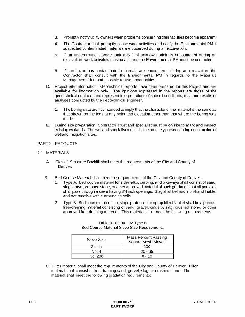
EES 31 00 00 - 5 STEM GREEN EARTHWORK
3. Promptly notify utility owners when problems concerning their facilities become apparent.
4. The Contractor shall promptly cease work activities and notify the Environmental PM if suspected contaminated materials are observed during an excavation.
5. If an underground storage tank (UST) of unknown origin is encountered during an excavation, work activities must cease and the Environmental PM must be contacted.
6. If non-hazardous contaminated materials are encountered during an excavation, the
Contractor shall consult with the Environmental PM in regards to the Materials Management Plan and possible re-use opportunities.
D. Project-Site Information: Geotechnical reports have been prepared for this Project and are available for information only. The opinions expressed in the reports are those of the geotechnical engineer and represent interpretations of subsoil conditions, test, and results of analyses conducted by the geotechnical engineer.
1. The boring data are not intended to imply that the character of the material is the same as
that shown on the logs at any point and elevation other than that where the boring was made.
E. During site preparation, Contractor’s wetland specialist must be on site to mark and inspect existing wetlands. The wetland specialist must also be routinely present during construction of wetland mitigation sites.
PART 2 - PRODUCTS
2.1 MATERIALS
A. Class 1 Structure Backfill shall meet the requirements of the City and County of Denver.
B. Bed Course Material shall meet the requirements of the City and County of Denver. 1. Type A: Bed course material for sidewalks, curbing, and bikeways shall consist of sand,
slag, gravel, crushed stone, or other approved material of such gradation that all particles shall pass through a sieve having 3/4 inch openings. Slag shall be hard, non-hand friable, and not reactive with surrounding soils.
2. Type B: Bed course material for slope protection or riprap filter blanket shall be a porous, free-draining material consisting of sand, gravel, cinders, slag, crushed stone, or other approved free draining material. This material shall meet the following requirements:
Table 31 00 00 - 02 Type B
Bed Course Material Sieve Size Requirements
Sieve Size Mass Percent Passing Square Mesh Sieves
3 inch 100 No. 4 20 - 65
No. 200 0 - 10
C. Filter Material shall meet the requirements of the City and County of Denver. Filter material shall consist of free-draining sand, gravel, slag, or crushed stone. The material shall meet the following gradation requirements:

EES 31 00 00 - 6 STEM GREEN EARTHWORK
Table 31 00 00 - 03 Gradation Requirements for Filter Material
Sieve Size Mass Percent Passing Square Mesh Sieves
Class A Class B Class C 3" 100
1 1/2" 100 3/4" 20 - 90 100
No. 4 0 - 20 20 - 60 60 - 100 No. 16 10 - 30 No. 50 0 - 10 10 - 30 No. 100 0 - 10 No. 200 0 - 3 0 - 3 0 - 3
PART 3 - EXECUTION 3.1 STAKING AND GRADES
A. Lay out the work, establish all necessary markers, bench marks, grading stakes, and other stakes as required, in accordance with the requirements specified.
3.2 EXISTING UTILITIES
A. Verify locations of underground facilities and structures. Locations shown for utility facilities and structures are taken from the various utility records and are approximate. 1. Any excavation planned within five feet of an active utility line shall be potholed to identify
the exact location and extents of the line prior to the start of work, and excavation around the utility shall be performed by hand.
B. Contact utility-locator service for area where Project is located before excavating. 1. Contact Utility Notification Center of Colorado at 8-1-1.
C. Active utility lines encountered that are not indicated in the Contract Documents shall be reported immediately to the Designer and utility owners involved. The Designer and utility owners shall be permitted free access to determine the measures deemed necessary to repair, relocate, or remove the utility.
D. Notify Designer no less than two days in advance of proposed utility interruptions. 1. Do not proceed with utility interruptions without the Designer's written permission.
E. Abandoned sewers, piping, and other utilities encountered in progress of the excavating shall either be removed and the ends of the remaining sections plugged or filled with CLSM, as approved by the engineer.
3.3 EARTHWORK GENERAL REQUIREMENTS
A. Erosion Protection: Prevent erosion of the site at all times. Construct temporary berms and dikes and cut temporary swales to promote natural drainage of site. Refer to SECTION 31 25 00 - EROSION AND SEDIMENTATION CONTROLS, for additional requirements.
B. Preparation of subgrade for earthwork operations including removal of vegetation, topsoil, debris, obstructions, and deleterious materials from ground surface as specified herein.
C. On-site Excavation or Borrow Pits: Do not excavate or remove any material from the project site or right-of-way which is not within the designated excavation, as indicated by the slope and grade lines, without written authorization from the Designer.
D. Protect structures, utilities, sidewalks, pavements and other facilities from damage caused by settlement, lateral movement, undermining, washout, and other hazards created by earthwork operations.
EES 31 00 00 - 7 STEM GREEN EARTHWORK
E. Provide protective insulating materials to protect subgrades and foundation soils against freezing temperatures or frost.
F. Explosives: Do not use explosives. G. Ramps:
1. Construct temporary ramps as necessary to provide access to work area.
2. Locate such access ramps in Contractor's storage, operations, and access areas or within excavation for structure and maintain traffic in accordance with the requirements of the governing local agency.
3. When ramps are in use, station properly equipped flaggers at ramp entrances to keep unauthorized vehicles and persons from entering work area.
4. When work necessitating entrance or exit of vehicles via ramps is not being performed, protect entrances and exits of ramps by warning signs and barricades in accordance with the requirements of the governing local agency.
H. Excavation Near Surface and Underground Structures: Control excavation in areas near all structures including buildings, underground and overhead utilities, bridges, and pavement to maintain stability and function of structures.
I. Stockpiling of Fill and Backfill Material: 1. Excavate and separately stockpile suitable fill and backfill material, as indicated, during
the progress of the excavation work. Save sufficient suitable excavated material, if available, for later filling, backfilling, and embankment construction.
2. Store materials from required excavations that are suitable for fill, backfill, and bottom of stockpiles may become contaminated and shall not be used as backfill materials unless approved by Geotechnical Engineer.
3. Establish excavated material stockpiles on site only in locations where they will not interfere with the progress of the work. The Contractor shall not store or deposit surplus excavation or any other material in any area designated as a Flood Plain or along natural drainage ways. Materials so deposited shall be removed and the area restored to its natural condition. Off-site stockpiling, if necessary, shall be the responsibility of the Contractor.
J. Salvaging Topsoil: 1. Salvage topsoil, including wetland topsoil, from areas to be stripped and excavated as
shown on Contract Documents or as otherwise indicated. Stockpile on the site at appropriate locations. Stockpile wetland topsoil separately from other topsoil and label with source and date of harvesting. Prevent topsoil from contamination by other materials, and provide adequate drainage and erosion protection.
2. Place stockpiled topsoil in areas to be landscaped as indicated on the Contract Documents.
K. Excess Material: Suitable surplus excavated material shall be used in the construction of embankment. At the completion of the project, all remaining excess material shall be removed from the site. 1. Remove excess and waste material, including unsatisfactory soil, trash, and debris, and
legally dispose of it off the project property.
L. Maintenance of Excavations, Slopes, and Embankments: 1. Maintain barricades and other protective devices around perimeter of excavations.
2. Excavate and remove material outside the limits of the excavation which is unstable and constitutes potential slides, and material which comes into excavations for any reason including from the driving of piles.
3. Maintain slopes and embankments until substantial completion and acceptance of the work. Promptly repair slides, slipouts, washouts, settlements, and subsidences that occur for any reason, and refinish the slope or embankment to the indicated lines and grades.
EES 31 00 00 - 8 STEM GREEN EARTHWORK
4. Water shall not be allowed to collect in excavation areas supporting structures or proposed structures.
5. Temporary Cut and Fill slopes shall be constructed in accordance with OSHA Safety and Health Standards and Colorado Trench Excavation Safety Laws.
3.4 SUBSURFACE EXTRACTION
A. Remove subsurface facilities and obstructions to the extent indicated.
B. When subsurface facilities are encountered during excavation which interferes with new construction, and such facilities are not indicated, notify the Designer promptly for corrective determination.
C. Relic underground utilities shall be abandoned in accordance with applicable regulations,
removed as necessary, and properly capped.
D. Where new roadways or structures will be constructed within the limits of the demolition of existing structures, all foundation elements and associated structures shall be entirely removed and a controlled, compacted fill placed in uniform thickness and compacted in accordance with the project specifications beneath the proposed structures.
3.5 ROUGH GRADING
A. Prior to commencement of earthwork, perform such soil and rock removal and filling as may be required to facilitate the progress of the work and bring all elevations to the rough grading lines indicated on the Contract Documents.
B. Fill or backfill test pits or holes which will not be completely removed by excavation with CLSM,
pervious backfill, or clean structural fill, and compact as herein specified in layers not exceeding eight inches in uncompacted thickness.
C. Fill or backfill holes, swales, and low points that will not otherwise be removed in the course of
the work to the indicated grades. 3.6 EXCAVATION
A. General Excavation Requirements: 1. Perform excavating as indicated and required for trackway and roadway beds, for
concrete footings, foundations, retaining walls, exterior paving, floor slabs, concrete walks, and for site levels and grading, and provide shoring, bracing, underpinning, ribbing, pumping, and planking as required.
2. Perform excavation work in accordance with OSHA Safety and Health Standards and Colorado Trench Excavation Safety Laws.
3. The bottoms of excavations shall be level, firm, undisturbed earth, clean and free from organics, loose material, debris, and foreign matter.
4. Excavate to the lines and grades indicated on the Contract Documents. Thoroughly scarify the top eight (8) or more inches of the bottom of the excavation and embankments, and compact the scarified layer with moisture and density control to the relative compaction specified.
5. Excavations shall be supported and maintained by providing structural support of earth walls so that sides are stable and will not move. Excavations may be maintained by sloping cut faces where space permits. If calculations are required for any structural support of earth, they shall be sealed and signed by a Civil or Structural Engineer

EES 31 00 00 - 9 STEM GREEN EARTHWORK
currently registered in the State of Colorado, showing that the excavation method is safe. Calculations shall consider all existing conditions, including adjacent traffic, construction loading, and other local effects.
6. Limits of excavations shall allow for adequate working space for installing forms, wall waterproofing, and as required for safety of personnel. Cut excavations in solid rock accurately to the lines indicated on the Contract Documents, or to the width of the ductbank or concrete encasement.
7. Place excavated material at a sufficient distance from edge of excavation so as not to cause cave-ins or bank slides, but in no case closer than five (5) feet from the edge of excavations or a distance equal to the depth of the excavation, whichever is greater.
8. Remove unsuitable subgrade materials. If the Contract Documents identify subexcavation or if the Geotechnical Engineer determines that unsuitable, wet, soft, yielding, uncontrolled fill and/or expansive subgrade conditions are present, continue excavation to achieve complete removal and replace with properly compacted and moisture conditioned materials approved by the Geotechnical Engineer.
9. If the proof roll indicates unstable subgrade conditions, stabilize with aggregate materials measuring less than 6 inches in diameter, approved geogrid or geotextile, recycled concrete, or excavate unsuitable material and replace with Structure Backfill as directed by the Geotechnical Engineer.
10. Except as otherwise indicated, preserve the material below and beyond the lines of excavations. Where an excavation is carried below the indicated grade, backfill to the indicated grade as here-in specified.
11. Excavations for convenience of the Contractor shall be approved by the Designer and/or Geotechnical Engineer.
12. Unauthorized overexcavations of footings and foundations shall be filled with CLSM as specified in Article 2.1 of this Section.
13. Excavated earth material that is suitable for fill, backfill, or embankment shall be conditioned for re-use and properly stockpiled for later filling and backfilling operations as herein specified. Test, screen, and mix as necessary to meet specified requirements.
B. Excavations for Retaining Walls: 1. Where unsuitable material is encountered at the bottom of retaining walls, the unsuitable
material shall be removed down to natural stable soils. The removal zone shall include areas below wall foundations, areas below the active wedges, areas below leveling pads for MSE walls, below reinforced areas for MSE walls, below retained earth areas for MSE walls, and below areas supporting the track guideway or station platforms behind retaining walls unless otherwise approved by the Designer and Geotechnical Engineer.
2. Pile Foundations: Stop excavations six to twelve inches above bottom of pile cap before piles are placed. After piles have been driven, remove loose and displaced material. Excavate to final grade, leaving solid base to receive concrete pile caps.
C. Excavation for Underground Tanks, Basins, and Mechanical or Electrical Utility Structures: Excavate to elevations and dimensions indicated within a tolerance of plus or minus one inch. Do not disturb bottom of excavations intended as bearing surfaces.
D. Rock Excavation: 1. Perform rock excavation to neat lines shown and so as to produce surfaces free of loose
rock.
2. Remove loose, semi-detached, and unsound fragments from rock surfaces. Remove standing water, debris, oil, and other objectionable coatings from surfaces of rock upon or against which concrete and porous fill material is to be placed.

EES 31 00 00 - 10 STEM GREEN EARTHWORK
3. Repair shattered and loosened rock surfaces outside neat lines shown, which, in the opinion of the Engineer, would be detrimental to substructures or would adversely affect drainage system.
4. Remove excavated rock to approved fill or disposal locations.
5. Fill unauthorized and excess excavation with concrete or other approved material.
3.7 EMBANKMENT CONSTRUCTION
A. Site grading should be performed as early as possible in the construction sequence to allow settlement of fills and surcharged ground to be realized to the extent practical prior to subsequent construction.
B. Thoroughly scarify the soil upon which embankments are to be constructed to a depth of eight
(8) or more inches, then compact the scarified layer with moisture and density control to the relative compaction specified.
C. If excavation surfaces intended to receive fill, expose loose, wet, soft or otherwise deleterious
material, additional material shall be excavated, or other measures shall be taken to establish a firm platform for filling. The surfaces to receive fill must be stable prior to placement of fill and approved by Geotechnical Engineer.
D. Construct soil embankments with moisture and density control. Construct embankments to
lines, grades, and contours indicated, in layers as nearly uniform and horizontal as is consistent with the indicated finished contour and profile. Maximum thickness of each layer shall be eight (8) inches before compaction.
E. Compact each layer to specified density for entire width of the embankment. Achieve required
compaction by rolling with compaction equipment suitable for type and condition of the particular material. Roll in a longitudinal direction parallel to longest dimension, starting at outer edges and progressing toward the center.
F. Moisture-condition embankment fill material as required in Section 3.10 to achieve its
compaction to the specified density, within the tolerances specified herein.
G. Do not compact material that contains excessive moisture. In such cases, scarify to the full depth of the layer having excessive moisture content and dry by reworking, mixing with dry materials, or other approved methods.
H. Remove material that cannot be compacted to required density within specified tolerances, and
replace with suitable material.
I. Where pipes, culverts, or structures extend into embankments, construct embankment to at least two (2) feet over and ten (10) feet on each side of the pipe, culvert, or structure location prior to excavation.
J. Where fill is to be placed against hillsides or slopes steeper than four (4) to one (1) (horizontal
to vertical), the existing slope shall be benched at least eight (8) feet horizontally into the hillside as the new embankment is placed in horizontal lifts.
K. Do not commence final shaping until above specified requirements have been completed.
Shape entire surface of the slopes of cuts and embankments to true grade, alignment, and cross-section indicated. Leave cut slopes in rock with uniform surface, and remove all loose overhanging rock.

EES 31 00 00 - 11 STEM GREEN EARTHWORK
3.8 SUBGRADE FILLING / RAISING GRADE
A. Compacted fill for raising of subgrade to indicated elevation shall be constructed in accordance with this Section. Fill material shall be spread in uniform lifts not exceeding eight (8) inches in uncompacted thickness. Fill material that does not contain sufficient moisture to compact properly shall be moisture conditioned. If it contains excess moisture, it shall be aerated or permitted to dry to the appropriate moisture content. Each layer of spread fill material shall be compacted to the specified density.
B. Control of fill shall consist of field inspection and testing to determine that each layer has been
compacted to the required density and to ensure that specified moisture contents have been attained. Any layer or portion of a layer that does not attain the required compaction at the specified moisture content shall be scarified, moisture conditioned and re-compacted until the required compaction and moisture conditions are attained.
3.9 COMPACTION
A. Fills shall be properly placed and moisture conditioned to meet the recommendation of the Geotechnical Engineers as presented in the Geotechnical Report. 1. Density testing shall adhere to the following proctor tests: Standard-ASTM
D698/AASHTO T 99 : Standard Proctor Density.
2. Backfill materials at stations shall be placed in accordance with City and County of Denver standards.
3.10 PROOF ROLLING
A. Proof rolling of the subgrade shall be required for fill, embankments, walls, slabs, backfill, pavements, and the fixed guideway portions of the Project. Proof rolling shall be done after the specified compaction has been obtained for the final lift. Proof rolling shall be conducted in accordance with the requirements of the City and County of Denver. The Geotechnical Engineer may direct the use of other equipment where access to proof rolling trucks is not practical.
B. Upon approval of the proof rolling, sub base, base course, or initial pavement course shall be
placed within 48 hours. If Contractor fails to place the sub base, base course, or initial pavement course within 48 hours or the condition of the subgrade changes due to weather or other conditions, proof rolling and correction shall be performed until area meets requirements.
3.11 FINISH GRADING
A. Finish grade landscape areas as follows: 1. Plant areas: Seven to eight inches below the grades and elevations indicated.
2. Lawn areas: Three inches below established finished grade.
B. On completion of work, clean ditches and channels.
C. Slope and shape borrow areas to provide positive drainage.
D. Place and spread stockpiled topsoil to a uniform specified thickness in areas to receive topsoil and landscape planting. Place and spread to a uniform thickness approximately one inch below finished grades indicated.
E. Leave site in neat, presentable condition. 3.12 FIELD QUALITY CONTROL

EES 31 00 00 - 12 STEM GREEN EARTHWORK
A. Testing Agency: The Contractor shall engage a qualified independent geotechnical
engineering testing agency to perform field quality control testing.
B. Allow testing agency to inspect and test subgrades and each fill or backfill layer. Proceed with subsequent earthwork only after test results for previously completed work comply with requirements. Test results shall be provided in writing as final documentation.
C. Testing agency, at their sole option, shall test compaction of soils in place according to ASTM
D1556-07 - Standard Test Method for Density and Unit Weight of Soil in Place by the Sand-Cone Method, or ASTM D2167-08 - Standard Test Method for Density and Unit Weight of Soil in Place by the Rubber Balloon Method, or ASTM D2937-10 - Standard Test Method for Density of Soil in Place by the Drive-Cylinder Method, or ASTM D6938-10 - Standard Test Methods for In-Place Density and Water Content of Soil and Soil-Aggregate by Nuclear Methods (Shallow Depth). Reference densities shall be determined using AASHTO T 180 - Standard Specification for Moisture-Density Relations of Soils Using a 10.0-lb. Rammer and an 18-inch Drop, or AASHTO T 99 - Standard Specification for Moisture-Density Relations of Soils Using a 5.5-lb. Rammer and a 12-inch Drop, as applicable.
Test shall be performed in accordance with the City and County of Denver specifications for structure backfill and at frequencies of at least those presented in the Wastewater Detail and Technical Specifications).
D. When testing agency reports that subgrades, fills, or backfills have not achieved degree of
compaction specified, scarify and moisture condition, or remove and replace soil to depth required; re-compact and retest until specified compaction is obtained.
F. Allowable Finish Grade Tolerances:
1. Bituminous or concrete surfacing areas: Variation from the subgrade plan elevations specified shall not be more than 0.04 foot.
2. All other areas: 0.08 foot plus or minus the elevation shown.
END OF SECTION

EES 31 23 26 - 1 STEM GREEN EXCAVATION AND BACKFILL FOR STRUCTURES
SECTION 31 23 26
EXCAVATION AND BACKFILL FOR STRUCTURES PART 1 - GENERAL
1.1 RELATED DOCUMENTS
A. Drawings and general provisions of the Contract, including General and Supplementary Conditions and Division 01 Specification Sections, apply to this Section.
1.2 SUMMARY
A. Refer to City and County of Denver Standards
1.3 RELATED SECTIONS
A. SECTION 02 30 00 – SUBSURFACE INVESTIGATION.
B. SECTION 02 41 00 - DEMOLITION.
C. SECTION 31 23 19 - DEWATERING.
D. SECTION 31 23 33 – UTILITY TRENCHING AND BACKFILING.
E. SECTION 31 25 00 – EROSION AND SEDIMENTATION CONTROLS.
F. SECTION 33 05 25 – SUPPORT AND PROTECTION AND UTILITIES.
G. SECTION 33 46 16 - SUBDRAINAGE SYSTEMS. 1.4 REFERENCE STANDARDS
A. Pertinent provisions of the following listed documents shall apply to this work, except as they may be modified herein, and are hereby made a part of this Specification to the extent required.
B. City and County of Denver – Transportation Standards and Details for the Engineering Division, 2015 Edition.
C. City and County of Denver – Wastewater Detail and Technical Specifications, Latest Edition.
D. The documents listed above are appended to these specifications in their entirety and made a part hereof.
PART 2 - PRODUCTS 2.1 MATERIALS
A. In accordance with the City and County of Denver Standards and Specifications. PART 3 - EXECUTION 3.1 FIELD CONSTRUCTION REQUIREMENTS

EES 31 23 26 - 2 STEM GREEN EXCAVATION AND BACKFILL FOR STRUCTURES
A. In accordance with the City and County of Denver Standards and Specifications.
END OF SECTION
EES 31 23 33 - 1 STEM GREEN UTILITY TRENCHING AND BACKFILLING
SECTION 31 23 33
UTILITY TRENCHING AND BACKFILLING PART 1 - GENERAL
1.1 RELATED DOCUMENTS A. Drawings and general provisions of the Contract, including General and Supplementary
Conditions and Division 01 Specification Sections, apply to this Section. 1.2 SUMMARY
A. Section includes provisions for the following: 1. Pavement and Concrete Cutting and Removal. 2. Trench Grade. 3. Trench Widths. 4. Fine Grading and Pipe Support. 5. Overexcavation. 6. Excavation for Manholes, Inlets, Catch Basins, and Other Accessories. 7. Shoring and Sheeting. 8. Open Trench. 9. Trench Bedding. 10. Backfill. 11. Utility Marking Identification and Tracer Wire. 12. Compaction. 13. Grading and Stockpiling. 14. Pavement Replacement and Surface Restoration. 15. Protection. 16. Field Quality Control.
B. The specifications and standards of jurisdictional agencies shall be used for utilities within jurisdictional boundaries.
1.3 RELATED SECTIONS
A. SECTION 31 00 00 - EARTHWORK. B. SECTION 31 23 19 - DEWATERING. C. SECTION 32 12 16 - ASPHALT PAVING. D. SECTION 32 13 13 - CONCRETE PAVING. E. SECTION 32 16 13 - CONCRETE CURBS AND GUTTERS. F. SECTION 33 05 25 – SUPPORT AND PROTECTION OF UTILITIES
1.4 REFERENCES
A. Pertinent provisions of the following listed documents shall apply to this work, except as they may be modified herein, and are hereby made a part of this Specification to the extent required.
B. City and County of Denver – Wastewater Detail and Technical Specifications, Latest Edition.
C. American Association of State Highway and Transportation Officials (AASHTO). 1. AASHTO T 89 - Standard Method of Test for Determining the Liquid Limit of Soils. 2. AASHTO T 90 - Determining the Plastic Limit and Plasticity Index of Soils. 3. AASHTO T 99 - Standard Specification for Moisture-Density Relations of Soils Using a 5.5-
lb. Rammer and a 12-inch Drop. 4. AASHTO T 191 - Density of Soil In-Place by the Sand-Cone Method.
D. ASTM International (formerly known as American Society for Testing and Materials) (ASTM): 1. ASTM C33/C33M-11 – Standard Specification for Concrete Aggregates.
EES 31 23 33 - 2 STEM GREEN UTILITY TRENCHING AND BACKFILLING
2. ASTM D6938-10 - Standard Test Methods for In-Place Density and Water Content of Soil and Soil-Aggregate by Nuclear Methods (Shallow Depth).
E. Occupational Safety and Health Administration (OSHA).
1. Title 29 Code of Federal Regulations, Parts 1910 and 1926 (29 CFR 1910 and 1926). 1.5 UTILITY REFERENCE STANDARDS
A. City and County of Denver – Wastewater Detail and Technical Specifications, Latest Edition. 1.6 DEFINITIONS
A. Utility Agency: The owner of the utility, which may be a governmental agency, department or division, a quasi-municipal district, or a private company.
B. Bedding: Select fill placed under, beside and directly over pipe, prior to subsequent backfill operations.
C. Backfill: Fill placed above the pipe bedding to the finished surface grade or subgrade. 1.7 DESCRIPTION
A. Section includes specifications for excavating, trenching, and backfilling for utilities and related structures, as indicated, including underground piping for water supply, sanitary and storm sewerage piping; trackway and roadway site subsurface and drainage piping; underground electrical conduits and ductbanks; and utility boxes, catch basins, manholes, inlets, pull boxes, and vaults. 1. Trenching and backfilling for utilities includes restoration of existing pavements, where
applicable, to the conditions existing before excavation. Conform to applicable requirements of SECTION 32 16 13 - CONCRETE CURBS AND GUTTERS.
B. Stockpile and handle material so as to not cause undue segregation of particles sizes either in the stockpile or while loading, hauling, and handling.
1.8 REGULATORY REQUIREMENTS
A. Design and perform trench excavation and support of excavation work in accordance with OSHA Safety and Health Standards and Colorado Trench Excavation Safety Laws. 1. Prior to any excavation, contact Utility Notification Center of Colorado at 8-1-1 or 1-800-
922-1987 to request identification and location of all buried utilities in the planned excavation limits, within proper time frame to have locates provided prior to excavation schedule.
B. The requirements for the governing agency that owns the utilities or the governing agency that owns the right-of-way, whichever is more stringent, shall be followed.
1.9 SITE CONDITIONS
A. Location of Underground Facilities and Structures: 1. Contractor shall verify locations of underground facilities and structures. 2. Active utility lines encountered that are not indicated in the Contract Documents shall be
reported immediately to the Designer and utility owners involved. The Designer and utility owners shall be permitted free access to determine the measures deemed necessary to repair, relocate, or remove the utility.
3. Notify Utility Agency no less than three days in advance of proposed utility interruptions. 4. Abandoned sewers, piping, and other utilities encountered in progress of the excavating
shall be removed and the ends plugged in accordance with the governing agencies’ criteria.
B. Unfavorable Weather Conditions:

EES 31 23 33 - 3 STEM GREEN UTILITY TRENCHING AND BACKFILLING
1. Excavating, filling, backfilling, and grading work shall not be performed during weather conditions which might damage or be detrimental to the condition of existing ground, in-progress work, or completed work. When the work is interrupted by unfavorable weather conditions, excavating, filling, backfilling, and grading work shall not resume until the site and soil condition (moisture content) are suitable for compaction.
2. Subgrade shall be free from mud, snow, ice, and deleterious material. 3. Soil material that is too wet for compaction shall be left to drain, aerated and dried by
disking and harrowing or other approved methods until the moisture content of the area is uniform and within the specified limits.
C. Dewatering: Prevent surface water and ground water from entering excavations. 1. Reroute surface water runoff away from excavated areas. Do not allow water to
accumulate in excavations. Do not use excavated trenches as temporary drainage ditches.
D. Toxic, Hazardous, and Combustible Substances: During excavation, provide equipment and carry out such tests as necessary to detect
presence of toxic, hazardous, and combustible substances. Take action to safeguard persons and property in accordance with rules and regulations of
jurisdictional agencies and utility owners. Promptly notify utility owners when problems concerning their facilities become apparent.
1.10 SUBMITTALS
A. Product Data
1. Permanent pipe supports.
2. Warning Identification Tape.
3. Tracer wire.
4. Permanent Marking Posts. B. Trench Safety Plan: Submit drawings and supporting calculations for trench excavations and
support systems of twenty (20) feet or more in depth. All such submittals shall be prepared, sealed, and signed by a Professional Civil or Structural Engineer currently registered in the State of Colorado. Submit Shop Drawings and specifications for excavation support systems. Include the following:
1. The size and grade of all structural materials. 2. Design notes, including design assumptions, and construction details. 3. Where applicable, restrictions on heavy equipment placement at specific locations
adjacent to the shoring. 4. Areas determined by the Designer where de-watering of the shored excavation will be
required, and a description of the requirements (i.e., head added by the pump, flow rate, minimum pump size, etc.) and methods to be used for de-watering.
5. Other information determined by the Contractor’s Engineer to be pertinent to the design and successful construction of the shoring.
C. Test Results:
1. Granular Material.
2. Dry Density Testing.
PART 2 - PRODUCTS 2.1 BEDDING AND BACKFILLING MATERIALS
A. Bedding: Bedding material shall comply with the requirements of the jurisdictional agency. If no specification and standard exists, the bedding material shall conform to the requirements of City

EES 31 23 33 - 4 STEM GREEN UTILITY TRENCHING AND BACKFILLING
and County of Denver Standards, unless otherwise shown on the plans. Class I structure backfill shall meet the following gradation requirements:
Table 31 23 33 - 01 Class I Structure Backfill Gradation Requirements
Sieve Size Mass Percent Passing Square Mesh Sieves
2 inch 100 No. 4 30 - 100
No. 50 10 - 60 No. 200 5 - 20
1. Class 1 Structure Backfill shall have a liquid limit of 35 or less and a plasticity index of 6 or
less when determined in conformity with AASHTO T89 - Standard Method of Test for Determining the Liquid Limit of Soils and T 90 - Determining the Plastic Limit and Plasticity Index of Soils, respectively.
B. Backfill Material: Backfill for excavations and trenches under structures and paving shall be Structural Fill as indicated. Refer to SECTION 31 00 00 - EARTHWORK, Article 2.1 for requirements. Common Fill will be permitted only for backfilling of excavations and trenches in open areas and landscaped areas.
C. Flow-Fill: Flow-Fill shall consist of a fluid, workable mixture of Portland cement, clean and graded aggregate, and water. Refer to SECTION 31 00 00 - EARTHWORK, Article 2.1 for requirements.
2.2 MARKING AND IDENTIFICATION
A. Warning Identification Tape: Provide tape continuously inscribed with a description of the utility buried below and color coded as follows: 1. Provide acid and alkali resistant polyethylene film warning type manufactured for marking
and identifying underground utilities. 2. Size: Minimum three inches wide by four mils thick. 3. Warning nomenclature: Provide tape continuously inscribed with a description of the utility
buried below and color coded as follows:
a. Red: Electric.
b. Yellow: Gas, oil, steam, and other dangerous materials.
c. Orange: Telephone and other communications.
d. Blue: Water Systems.
e. Green: Sewer Systems and Irrigation Ditch Water Systems.
f. Purple: Reclaimed, Re-used and Non-Potable water systems.
B. Tracer Wire: Direct burial rated insulated AWS #12 copper conductor.
C. Permanent Marker Posts: Provide permanent marker posts meeting the following requirements: 1. Manufactured of fiber reinforced composite material capable of withstanding a minimum of
ten vehicle impacts at 55 mile per hour with a car bumper. 2. Opaque UV Block Coating: Post must have UV-protective coating. 3. Temperature Stable: Post shall remain flexible from -40 deg F to +140 deg F. 4. Dimensions: Four inches wide x 66 inches long. 5. Color: Color to match the same coding as indicated above for buried piping warning
identification tape. 6. Warning Nomenclature: High visibility UV-resistant decal labels for the posts. Standard
manufacturer legend decals per appropriate utility type. 7. Product and Manufacturer: Provide one of the following:

EES 31 23 33 - 5 STEM GREEN UTILITY TRENCHING AND BACKFILLING
a. Rhino 3-Rail™ as manufactured by Rhino, Bloomington, MN. Phone - 952-703-7020.
b. Or equal.
PART 3 - EXECUTION 3.1 PAVEMENT AND CONCRETE CUTTING AND REMOVAL
A. In paved areas, cut pavement on the neat lines at the width indicated for the trench. Pavement shall be saw cut. 1. Concrete: Clean cut to full depth. All damaged or cut concrete pavement or other
concrete sections shall be restored with full panels only. 2. Asphalt: Clean-cut to full depth. 3. Do not rip or root outside limits of cuts.
4. After compacting the backfill, restore pavement to a condition equivalent to that existing at the start of construction. Restore pavement damaged outside the neat lines. Sawcut and remove damaged areas prior to repaving.
3.2 TRENCH GRADE
A. Furnish alignment and elevation stakes at set intervals.
B. Utilizing furnished alignment and elevation stakes, the Contractor shall provide additional grading or staking necessary to complete the work.
C. Conduit or structure foundation. 1. Accurately finish the material upon which conduit or structures are to be placed to the
grade or dimensions shown on the Contract Documents or as directed by the Designer. 2. Bring the bottom of the trench to grade so that the conduit or structure is continuously in
contact with the material on which it is being placed. 3. If rocky or unsuitable soil is encountered, conform to the requirements of Article 3.5.
3.3 TRENCH WIDTHS
A. For other than cast-in-place or pre-fabricated concrete pipe, construct trenches conforming to the dimensions in Table 31 23 33 - 02 below unless otherwise specified in the Special Provisions, Standards for the Utility Agency, Contract Documents, or approved by the Designer. 1. Do not excavate trench widths greater than the maximum specified in Table 31 23 33 - 02
at or below the level of the top of the pipe. 2. If the maximum trench width as specified in Table 31 23 33 - 02 is exceeded at the top of
the pipe, provide the necessary additional load bearing capacity by means of bedding having a higher bedding factor than that specified; higher strength pipe; a concrete cradle, cap, or encasement; or by other means approved by the Designer.
Table 31 23 33 - 02 Trench Widths
Size of Pipe (inside Diameter)
Maximum Width at Top of Pipe Greater Than Outside
Diameter of Barrel
Minimum Width at Springline Each Side of
Pipe Less than 18 inches 16 inches 6 inches
18 to 24 inches inclusive 19 inches 7-1/2 inches 27 to 39 inches inclusive 22 inches 9 inches 42 to 60 inches inclusive 1/2 O.D. 12 inches
Over 60 inches 36 inches 12 inches

EES 31 23 33 - 6 STEM GREEN UTILITY TRENCHING AND BACKFILLING
B. Make the width of trench above the top of the pipe as wide as necessary for shoring, sheeting, or other wall support measures necessary for a safe and proper installation. 1. Sloping the trench walls in lieu of shoring, sheeting, or other wall support measures is
acceptable where space permits. 2. All problems encountered as the result of increasing trench width are the responsibility of
the Contractor. 3.4 FINE GRADING AND PIPE SUPPORT
A. Unless otherwise specified in the Contract Documents and/or Special Provisions, accurately grade the bottom of the trench to provide uniform bearing and support for each section of pipe or raceway at every point along its entire length, except for portions of the pipe or raceway where it is necessary to excavate for bells and for proper sealing of joints.
B. Dig bell or coupling holes after the trench bottom has been graded. 1. Construct such holes with sufficient width to provide ample room for jointing, caulking,
banding, or bolting. 2. Excavate holes only as necessary to permit accurate work in making joints and to ensure
that the pipe or raceway will rest upon the prepared bottom of the trench and not be supported by any portion of the joint.
C. Construct depressions for joints, other than bell and spigot, in accordance with the recommendations of the joint manufacturer of the particular joint used.
D. Erect permanent pipe or raceway supports at locations shown on the Contract Documents and/or at any other locations as necessary, or as determined by the Designer.
3.5 OVER-EXCAVATION
A. Except at locations where excavation of rock from the bottom of the trench is required and Article 3.5E of this specification applies, do not excavate below the depth indicated.
B. Any overexcavation beyond the authorized neat lines established by the Designer and any excavation made solely for the convenience of the Contractor shall be considered incidental to the work required for the construction of that item.
C. Existing piping overexcavated or undermined by construction shall be backfilled to the springline with Class 1 Structure Backfill to insure proper support during backfill and subsequent operation of the system.
D. Refill all unauthorized excavation below the specified grade line with Class 1 Structure Backfill compacted to a uniform density of not less than 95 percent of the maximum density as determined by AASHTO T 99 - Standard Specification for Moisture-Density Relations of Soils Using a 5.5-lb. Rammer and a 12-inch Drop and AASHTO T 191- Density of Soil In-Place by the Sand-Cone Method or ASTM D6938-10 - Standard Test Methods for In-Place Density and Water Content of Soil and Soil-Aggregate by Nuclear Methods (Shallow Depth) may be authorized in writing at the discretion of the Designer.
E. Whenever rock is encountered in the trench bottom, over-excavate it to a minimum depth of six inches below the outside diameter of the pipe or pipe bell. 1. Fill this over-excavation with Class 1 Structure Backfill or other approved material.
F. Whenever unsuitable soil not capable of supporting the pipe is encountered, notify the Designer.
3.6 EXCAVATION FOR MANHOLES, INLETS, CATCH BASINS, AND OTHER ACCESSORIES
A. When placing concrete for a cast-in-place structure, concrete may be placed directly against the excavated surface provided that the faces of the excavation are firm and unyielding and are at all points outside the structure lines shown on the Contract Documents. Over-poured concrete

EES 31 23 33 - 7 STEM GREEN UTILITY TRENCHING AND BACKFILLING
shall be limited to no more than six inches outside of the limits of the structure with prior approval of the Designer.
B. If the native material will not stand without sloughing or if precast structures are used, over-excavate or use shoring to place the structure.
C. When the structure is within the open pipe trench limit, backfill the structure in accordance with the requirements specified for the adjoining pipe.
D. If the item is being constructed outside of the open pipe trench limits, backfill the over-excavation with aggregate base course compacted to 100 percent of the maximum density as determined by AASHTO T 99 - Standard Specification for Moisture-Density Relations of Soils Using a 5.5-lb. Rammer and a 12-inch Drop and AASHTO T 191- Density of Soil In-Place by the Sand-Cone Method or ASTM D6938-10 - Standard Test Methods for In-Place Density and Water Content of Soil and Soil-Aggregate by Nuclear Methods (Shallow Depth).
E. Fill any excavation below the elevation indicated for the foundation of any structure with Class 1 Structure Backfill or other approved material and compact it to at least 95 percent of the maximum density as determined by AASHTO T 99 - Standard Specification for Moisture-Density Relations of Soils Using a 5.5-lb. Rammer and a 12-inch Drop and AASHTO T 191- Density of Soil In-Place by the Sand-Cone Method or ASTM D6938-10 - Standard Test Methods for In-Place Density and Water Content of Soil and Soil-Aggregate by Nuclear Methods (Shallow Depth).
3.7 SHORING AND SHEETING
A. Brace, sheath, or shore trenches as necessary to perform and protect the excavation for safety and to conform to governing laws including, but not limited to, the provisions of the OSHA regulations.
B. Excavations shall be supported and maintained by providing structural support of earth walls so that sides are stable and will not move. Excavations may be maintained by sloping cut faces where space permits.
1. The Contractor shall locate, size, design, and construct excavation support systems which provides all necessary rigidity, and supports the loads imposed to facilitate construction as shown on the Contract Documents.
2. If calculations are required for any structural support of earth, they shall be sealed and signed by a Civil or Structural Engineer currently registered in the State of Colorado, showing that the excavation method is safe. Calculations shall consider all existing conditions, including adjacent traffic, construction loading, and other local effects.
3. The excavation support system shall be constructed in conformity with the Shop Drawings provided to the Designer. Prior to placing construction or traffic loads on the supported earth, the Contractor’s Engineer shall certify in writing that excavation support system materials and construction have been inspected and that all support, materials and construction are in conformity with the Shop Drawings. A copy of this certification shall be submitted in an appropriate form for the Designer’s records.
4. If the embankment, construction, traffic, or any other surcharge is in excess of what the original support system was designed for and is to be placed adjacent to any shoring, the Contractor shall provide a signed letter from the Designer prior to the load placement stating that the excavation support system shall support the additional load.
3.8 OPEN TRENCH
A. Except where otherwise noted in the Special Provisions or approved by the Designer, the maximum length of open trench where the construction is in any stage of completion must not exceed 660 feet in aggregate at any one location.

EES 31 23 33 - 8 STEM GREEN UTILITY TRENCHING AND BACKFILLING
1. Any excavated area is considered open trench until all aggregate base course for pavement replacement, where required, has been placed and compacted.
2. Pipe laying may be carried on at more than one separate location, with the restrictions on open trenches applying to each location.
B. Completely backfill trenches across streets as soon as possible after laying pipe.
C. Use steel plates of sufficient thickness to withstand HS-20 traffic loading with adequate trench bracing to bridge across trenches at street crossings where trench backfill and temporary patches have not been completed during regular working hours. The thickness of the plates and bracing, if determined to be necessary, shall be established in an analysis completed by an Engineer currently licensed in the State of Colorado.
3.9 TRENCH BEDDING
A. Bedding is the material placed in the area from the bottom of the trench to one foot above the top of the pipe or conduit and to the spring line for RCP pipe for storm sewers, unless otherwise shown on the Contract Documents.
B. Bedding material shall comply with the requirements of the jurisdictional agency.
C. If no specification or standard exists, provide Select Material Structural Fill Class 1 per CDOT 703.08 - Structure Backfill Material. 1. Do not use open graded rock without written approval of the Designer.
D. For all pipe eight inches or greater in diameter, excavate for and provide an initial granular bedding at least six inches thick or 1/2 the outside diameter of the pipe, whichever is greater. 1. Place this bedding material at a uniform density with minimum compaction of 95% of
maximum dry density and fine graded as specified in Article 3.4.
E. Provide mechanical compaction of the bedding material. Provide bedding material with a moisture content within the range of plus two percent to minus four percent of its optimum moisture content prior to placing the material into the trench. 1. Provide the first lift eight inches deep or 2/3 of the distance to the springline, whichever is
greater. 2. Walk-behind compaction equipment shall be used to compact backfill up to and including
12 inches above top of buried pipe or conduit. 3. Do not exceed one foot of loose, un-compacted material in succeeding lifts. 4. Take extreme care to prevent damage to or movement of the pipe/conduit caused by the
compaction equipment. 5. Mechanical compaction is required for wet utilities.
F. Provide foundation and bedding for electronic, cable, telephonic, electric, oil, and gas lines consisting of native material or sand conforming to the grading requirement of ASTM C33/C33M-11 – Standard Specification for Concrete Aggregates for fine aggregate. 1. When backfill material consists of aggregate base course, crushed stone, or other material
containing stones, only use sand for the foundation and bedding. 2. Provide a foundation depth of six inches. 3. Provide a bedding depth of one foot above the top of the facility. 4. Compact the material in accordance with Article 3.12.
3.10 BACKFILL
A. Backfill trenches in the public right of way in accordance with the requirements of the jurisdictional agency. Compacted soil, aggregate or flowfill (CLSM) may be required.
B. Backfill trenches outside the public right-of-way in accordance with the following requirements: 1. Backfill for excavations and trenches under structures and paving shall be Structural Fill as
indicated. Refer to SECTION 31 00 00 - EARTHWORK, for requirements. 2. Backfill for excavations located in open areas and landscaped areas may consist of
Common Fill.
EES 31 23 33 - 9 STEM GREEN UTILITY TRENCHING AND BACKFILLING
a. Do not use organic matter, debris, cinders, frozen material, or other deleterious material.
C. Provide backfill material with moisture content in the range of plus three percent to minus two percent of the optimum prior to placing the material in the trench. 1. Provide uniform moisture content throughout the backfill material. 2. Remove material not meeting these requirements from the trench, and remove or add
moisture to replacement material to correct deficiencies prior to placing it in the trench. 3. Blend excavated material, removing or adding moisture as may be necessary to meet the
requirements of the specifications.
D. Excavated material must meet the specified requirements to be used as backfill.
E. Place backfill around utilities exposed during trench excavation in accordance with the bedding methods provided in Article 3.9.
3.11 UTILITY MARKING IDENTIFICATION AND TRACER WIRE
A. Underground warning utility identification marking tape shall be installed over all utility lines. 1. Tape shall be buried approximately six to twelve inches below the subgrade directly over
the utility. 2. Utility should be properly identified on the tape in accordance with Article 2.3A of this
section.
B. Tracer Wire: 1. Buried non-metallic utilities (electrical, mechanical, and civil) shall receive a tracer wire.
a. The tracer wire shall be positively attached to the non-metallic buried utilities by tape or plastic wire ties of similar type of attachment every six feet for straight run of utility and at all changes of direction. Tape shall be Polyken “930-35,” Protecto-Wrap “310”, or equal.
b. Contractor is responsible for testing continuity of wire from structure to structure.
c. A minimum length of six feet of wire shall be left accessible at clean-outs and other structures.
3.12 COMPACTION
A. Compaction Densities: Unless otherwise provided in the Contract Documents and/or Special Provisions, thoroughly compact trench backfill to not less than the densities listed in Table 31 23 33 - 03 when tested and determined by AASHTO T 99 - Standard Specification for Moisture-Density Relations of Soils Using a 5.5-lb. Rammer and a 12-inch Drop and AASHTO T 191- Density of Soil In-Place by the Sand-Cone Method or ASTM D6938-10 - Standard Test Methods for In-Place Density and Water Content of Soil and Soil-Aggregate by Nuclear Methods (Shallow Depth). 1. Compaction tests shall be taken at the frequency and at the locations required by the local
authority having jurisdiction. 2. Required compaction density depends on the type of compaction shown on the Contract
Documents and/or called for in the Special Provisions. 3. In determining backfill Types, also consider trench widths as shown in the Contract
Documents.
a. If trench widths are increased beyond those widths referred to in Trench Widths and fall within the two-foot limit of paved surfaces and other improvements indicated in Table 31 23 33 - 03 due to construction necessity, the backfill designation for that portion within the two-foot limit of such improvements is Type I even though Type II may be shown on the Contract Documents.

EES 31 23 33 - 10 STEM GREEN UTILITY TRENCHING AND BACKFILLING
Table 31 23 33 - 03 Minimum Compaction Density Required
Compaction Type Location
From Surface To 2 Feet
Below Surface
From 2 Feet Below Surface
To 1 Foot Above Top of
Pipe
From 1 Foot Above Top
of Pipe to
Bottom of Trench
I
Under any existing or proposed track right-of-way, pavement, curb, gutter, sidewalk, or similar paved area, or if any part of trench is within 2 feet of the above.
100 percent for granular, 95 percent for non-granular (note 2).
95 percent 95 percent
II On any utility easement, street, road, or alley right-of-way outside limits of Type I.
90 percent 90 percent 90 percent
III Around any structure or exposed utilities.
95 percent in all cases
Note 1: The Type of compaction required will be shown on the Contract Documents; for work within the ROW of local jurisdictions, follow the compaction requirement of the jurisdiction; if no type is shown on the Contract Documents determine the type from Section 31 00 00, Article 3.10 Compaction.
Note 2: Where full-depth asphalt is placed on native material, compact the pavement subgrade to 100 percent.
B. Compaction shall be accomplished using mechanical compaction equipment. Place and compact backfill in maximum eight-inch loose layers. Take care not to damage or misalign pipe. Compact to the density and moisture requirements specified above.
3.13 GRADING AND STOCKPILING
A. Control all grading in the vicinity of trench excavation to prevent surface water from flowing into the trenches. 1. Remove any water accumulated in trenches, whether surface or ground, by pumping or
other approved methods.
B. During excavation, pile material suitable for backfilling in an orderly manner and sufficiently away from the edges of trenches to avoid overloading and to prevent slides or cave-ins. 1. Haul excess material from the job site and legally dispose of it. 2. Surplus spoils shall be removed from the construction area. Only material required for the
construction will be stored on the construction project site.
C. Excavated material not meeting moisture content requirements and is unsuitable for proper compaction shall be handled as follows: 1. Remove or add moisture to the excavated material to bring it to within a range of plus three
percent to minus two percent of the optimum moisture content in order that proper compaction per Table 31 23 33 - 03 can be obtained.
2. In lieu of drying or adding moisture to the excavated material, haul off and dispose of excessively wet or dry material and replace it with material conforming to the backfill specifications.
3. In either event, obtain the proper compaction and stability.
D. Where Contract Documents and/or Special Provisions provide for segregation of topsoil from underlying material for purposes of backfill, do not mix the material.

EES 31 23 33 - 11 STEM GREEN UTILITY TRENCHING AND BACKFILLING
E. Grading: Grade the area adjacent to backfilled trenches and structures necessary to leave the area in a neat and satisfactory condition approved by the Designer.
3.14 PAVEMENT REPLACEMENT AND SURFACE RESTORATION
A. Restoring Surface: Resurface in kind or as specified all streets, alleys, driveways, sidewalks, curbs, or other surfaces having surfaces broken or damaged by the installation of the new work to the satisfaction of the Engineer in accordance with the jurisdictional agency.
B. Clean-up: Leave the job site in a neat and acceptable condition and remove excess soil, concrete, and similar materials from the premises.
3.15 PROTECTION
A. Protection of existing utilities: 1. Adequately support sanitary sewer, water, storm drain, and irrigation pipe including but not
limited to vitrified clay pipe (VCP), ductile iron pipe (DIP), poly-vinyl chloride pipe (PVC), Polyethylene pipe (PE), reinforced concrete pipe (RCP), non-reinforced concrete pipe, cast-in-place pipe, etc. Temporary pipe support for lines above 12 inches in diameter shall be provided. Shop drawings for pipe supports shall be designed by a Professional Engineer registered in the State of Colorado and shall be submitted for approval by the Designer.
2. Vitrified clay pipe, ductile iron, poly-vinyl chloride pipe, polyethylene pipe, reinforced concrete pipe, and other materials undermined during construction shall be backfilled to the springline with Controlled Low Strength Material to insure proper support during backfill and subsequent operation of the system.
3. Adequately support underground electronic, cable, telegraphic, electrical, oil, and gas lines.
a. Support plastic pipes and raceways continuously along the bottom of the pipe or raceway.
b. Support metal pipe or electrical conduit continuously or use nylon webbing for suspension at no greater than ten-foot intervals.
c. Avoid damaging plastic pipe, pipeways, and conduits during trench backfilling and during foundation and bedding placement.
B. Protection of existing buildings, foundations, and structures: 1. Where trenches are located next to buildings, foundations, bridges, or other structures,
take all necessary precaution against damage to them. 2. The Contractor is liable for any damage to such structures caused by the construction. 3. Water settling of backfill material in trenches adjacent to structures is prohibited.
3.16 FIELD QUALITY CONTROL
A. Trench Backfill Compaction Test Frequency: 1. 1 test at above ground appurtenance (i.e. valve box, manhole, hydrant, etc.) 2. 1 test for every 1 foot of backfill for every 250 LF of mainline trench. 3. At intervals set in the City and County of Denver Standards.
END OF SECTION

EES 31 23 33 - 12 STEM GREEN UTILITY TRENCHING AND BACKFILLING
THIS PAGE LEFT INTENTIONALLY BLANK

EES 31 23 33 - 1 STEM GREEN EROSION AND SEDIMENTATION CONTROLS
SECTION 31 25 00
EROSION AND SEDIMENTATION CONTROLS
PART 1 - GENERAL
1.1 RELATED DOCUMENTS
A. Drawings and general provisions of the Contract, including General and Supplementary Conditions and Division 01 Specification Sections, apply to this Section.
1.2 SUMMARY
A. Refer to City and County of Denver Details and Standards.
1.3 REFERENCE STANDARDS
A. Pertinent provisions of the following listed documents shall apply to this Work, except as they may
be modified herein, and are hereby made a part of this Specification to the extent required.
B. City and County of Denver Construction Activities Stormwater Manual, latest edition.
E. City and County of Denver – Storm Drainage Design and Technical Criteria Manual, Amended on 11/2013.
PART 2 - PRODUCTS
2.1 MATERIALS
A. In accordance with the City and County of Denver Stormwater Manual.
PART 3 - EXECUTION
3.1 FIELD CONSTRUCTION REQUIREMENTS
A. In accordance with the City and County of Denver Stormwater Manual.
END OF SECTION

EES 31 23 33 - 2 STEM GREEN EROSION AND SEDIMENTATION CONTROLS
THIS PAGE LEFT INTENTIONALLY BLANK

EES 32 01 90 - 1 STEM GREEN TREE AND PLANT PROTECTION
SECTION 32 01 90
TREE AND PLANT PROTECTION PART 1 – GENERAL 1.1 SUMMARY
A. This section includes:
1. Installation of Fencing. 2. Siltation Control. 3. Transplanting. 4. Tree Removals. 5. Protection of Trees to Remain
1.2 REFERENCES
A. ANSI Z133.1 Safety Requirements for Pruning, Trimming, Repairing, Maintaining and
Removing Trees, and for Cutting Brush. B. International Society of Arboriculture (ISA): Guide for Establishing Values of Trees and Other
Plants. C. International Society of Arboriculture (ISA): Tree and Shrub Transplanting Manual. D. National Arborist Association (NAA) Book of Standards, most recent edition.
1.3 DEFINITIONS
A. Tree Protection Fencing: Temporary fencing installed prior to site preparation and demolition
which protects a group of trees or shrubs. B. Boxing: Temporary wood box form installed prior to site preparation and demolition which
protects individual trees and shrubs. C. Root Pruning: Physical cutting of plant roots to minimize root damage and promote healing. D. Construction Branch Pruning: Physical cutting of any branch which interferes with
construction.
1.4 SUBMITTALS
A. Comply with Section 01 30 00. All submittals shall be accepted by the Landscape Architect in writing before Work commences.
B. Schedule: Submit construction schedule which includes time frame for work near existing
plant material. Provide transplanting and tree removal schedule including tree transplants and locations. Obtain approval by Landscape Architect prior to beginning of transplanting work and construction near plant protection areas.
C. Work Methods: Submit proposed methods and schedule for effecting tree and plant
protection for approval, including proposed methods, materials, and schedule for root pruning, construction pruning, aeration and subsequent tree fertilization. Mark plan location of root pruning and siltation fencing in field with paint for approval by Landscape Architect. Any root pruning which is required due to construction work adjacent to existing trees and shrubs designated to remain shall occur any time ground can be worked except when tree or shrubs

EES 32 01 90 - 2 STEM GREEN TREE AND PLANT PROTECTION
are in leaf. Root pruning when tree or shrubs are in leaf may occur only with approval by Landscape Architect.
D. Sample: Submit material sample and description of aeration filler for approval by Landscape
Architect. E. Maintenance Manual: Prepare within 10 days of the initial acceptance or inspection, a
maintenance manual for use by the Owner after the maintenance period expires.
1.5 QUALITY ASSURANCE
A. Comply with Division One. B. Qualifications
1. Arborist: Company having adequate capacity and facilities to meet the specified
requirements. All tree pruning and cleaning shall be performed by a licensed arborist with a minimum 5 years documented experience. Evidence to this effect shall be provided by the supplier if required by the Landscape Architect.
C. Regulatory Requirements: City permits are necessary for pruning or removal of all trees in
the right-of-way. D. Pre-Installation Conference
1. Conduct on site pre-installation conference prior to construction. 2. Attendance required by: Owner, Landscape Architect, Contractor(s),
Manufacturer(s)/Supplier(s), other parties who are involved.
1.6 PROJECT/SITE CONDITIONS
A. All plant materials to remain or be moved as part of this project will be tagged by the Landscape Architect to assist the Contractor in identifying the trees. Provide ten working day notice prior to tree removal.
B. Maintain all plant materials within tree protection areas. Designated tree protection areas of
trees, shrubs, and grasses are to remain untouched and unharmed. C. Construction activities in tree protection areas are prohibited.
1.7 PREFERRED SEQUENCING AND SCHEDULING A. Submit schedule for the following items commensurate with overall construction schedule:
1. Canopy And Construction Pruning: Six months prior to construction. 2. Fertilization: March thru May or as approved by the Landscape Architect. 3. Root Pruning: Per paragraph above.
1.8 MAINTENANCE
A. Maintenance Services: Performed by installing licensed arborist for the first year after final completion of all site construction.
B. Maintenance Period: Begin maintenance immediately upon start of construction. Continue
maintenance until one year after final completion of all site construction.
C. Maintenance To Include:

EES 32 01 90 - 3 STEM GREEN TREE AND PLANT PROTECTION
1. Monthly review and monitoring of tree conditions. 2. Maintaining guying and lightening protection. Repair or replace when required. 3. Apply pesticides only as needed. 4. Water at a sufficient frequency to saturate root system and keep soil moist. 5. Pruning, including removal of dead or broken branches, and treatment of pruned areas
or other wounds. 6. Disease Control.
D. Protection: In accordance with paragraph below. E. Root Zone Fertilization: Root zone fertilize all trees affected by construction. The first root
zone fertilization shall occur within 6 months after completion of site construction and the second within 12 months. Use a liquid application with an 18 inch soil probe. Fertilization mix shall be submitted to the Landscape Architect for acceptance prior to application.
F. Pesticides: Apply pesticides in accordance with manufactures instructions. Remedy damage
resulting from improper use of pesticides. G. Maintenance Reports: Provide maintenance report including date and detailed summary of
work completed on site, to the Landscape Architect after each maintenance visit.
PART 2 - PRODUCTS 2.1 TREE PROTECTION FENCING
A. Fencing: Galvanized chain link fencing, 6 ft. high.
1. Tree protection fencing is the property of the Contractor. 2. Gates at tree protection areas shall be 6'-0" width min. for maintenance vehicles and be
6'-0" ht. galvanized chain link fence.
B. Metal Fence Posts: 9 ft. galvanized steel posts, driven a minimum of 3 ft. into the ground. Space 10 ft. o.c. maximum.
C. Gates: Provide gates as indicated on the Drawings.
2.2 SILTATION CONTROL FENCING
A. Fencing: Siltation fencing complying to local codes. B. Posts: Attach to tree protection fencing.
2.3 SIGNAGE
A. Material: Durable, weather-proof. B. Size: 11" x 17" C. Color: Sign color - other than white, to be easily seen. Letter color - black. D. Message: Sign shall read "TREE PRESERVATION AREA". Lettering shall be block letters
minimum 2.5" height.

EES 32 01 90 - 4 STEM GREEN TREE AND PLANT PROTECTION
2.4 SOIL AMENDMENTS/MULCH
A. Humus Wood Chips: Nitrified aspen humus suitable for use as a soil amendment. Comply with Section 02950. Submit sample for Landscape Architect's approval.
B. Wood Mulch: Shredded western red cedar bark mulch.
PART 3 - EXECUTION
A. Curb cuts should not be closer than the dripline of the tree without permission from the Landscape Architect, except in urban situations where trees exist in tree grates or vaults.
B. New sidewalks, paving or asphalt must allow breathing space for tree roots. The following
should be used as a guideline: For trees up to 4 inches in trunk caliper, 25 square feet of porous area is needed. For each additional 2 inches of tree caliper, 10 more square feet are needed.
C. Where grade change is required, the same area must be provided either by construction of a
drywell where the level is to be raised or by building a retaining wall where the level is to be lowered. Engineer approval is required.
D. Avoid cutting surface roots wherever possible. Sidewalks and paving levels would be
contoured sufficiently to avoid such cutting. 3.1 EXAMINATION
A. Verification of Conditions: Examine areas and conditions under which the Work of this
Section will be performed. Report unsatisfactory or questionable conditions to the Landscape Architect. Do not proceed with the Work until unsatisfactory conditions have been corrected. Commencement of work implies acceptance of all areas and conditions.
B. Verify all utility locations in the field prior to digging.
3.2 PREPARATION
A. Protection: Protect areas in accordance requirements. B. Marking Of Construction/Demolition/Tree Preservation Limits
1. Clearly mark the tree protection fence locations as indicated on the Drawings, boxing
and all construction/demolition limits in the field. 2. Mark individual tree root pruning areas and location of siltation fencing with paint. 3. Verify all trees to be removed, transplanted, or protected with Landscape Architect. Tag
all plant material with appropriate tags noting action to be taken with each plant. 4. Contact and accompany Landscape Architect on a joint review of
construction/demolition limits, tagging and painting prior to the installation of the tree protection fencing and start of work.
5. Limit of construction is generally defined as the limit of demolition. Contractor to immediately notify Landscape Architect if work will occur outside the construction/demolition limits.
3.3 INSTALLATION OF FENCING
A. Fencing: Install tree protection fencing prior to start of demolition work and clearing and
grubbing operations in accordance with the following:

EES 32 01 90 - 5 STEM GREEN TREE AND PLANT PROTECTION
1. Following approval of staking by the Landscape Architect, install fencing at the tree protection areas.
2. Install fencing as approved. 3. Install posts 10'-0" o.c. maximum. 4. Install gates as needed.
B. Signs: Affix 'TREE PRESERVATION AREA' signs to the protective fencing. Signs shall be
clearly visible from all angles on the construction site. Post a minimum of two (2) signs for each Tree Preservation Area.
3.4 SILTATION CONTROL
A. Fencing: Provide silt control at Tree Protection Areas by attaching silt fence to the uphill side
of the protective fencing. Place lower 6" of silt fence in trench below grade. Backfill trench. B. Drainage: Maintain positive drainage from Tree Protection Areas. Divert runoff from site
around Tree Protection Areas. 3.5 TRANSPLANTING
A. Schedule: Obtain approval of schedule prior to starting transplanting work. B. Notification: Trees to be transplanted according to the Tree Protection Plans shall be tagged
by the Contractor and approved by the Landscape Architect prior to transplanting. Trees to be transplanted shall be transplanted to locations directed by the Landscape Architect. Notify Landscape Architect at least 72 hours in advance of transplanting any trees so new locations for the trees can be staked and so transplanting operation can be observed.
C. Marking Orientation: Prior to digging, mark the north side of each tree with a flag so that the
tree can be planted with the same orientation to prevent sun scald on the bark. D. Equipment: Transplant trees using a 90" tree spade with sharp blades which cuts roots
cleanly. A 60" spade may be used for trees less than 4" in caliper. Moving trees with a backhoe, end loader, or other similar equipment is not allowed. If any circumstances are encountered that preclude the use of a 90" or a 60" tree spade, recommend alternative method of transplant for Landscape Architect's approval.
E. Execution of Transplanting
1. Center tree in the tree spade. 2. Scarify sides of the tree pit prior to placement of tree. 3. Plant vertically in the new location. 4. Stake and guy with (3) 24" long steel "T" stakes @ 120 degrees, and 16 gauge wire
with fabric tree straps specifically designed for guying. 5. After the tree has been guyed, fill hole with good, viable topsoil. The loose topsoil shall
be worked down into the hole with a hand spade while being watered to assure that all air pockets are eliminated and filled with muddy soil.
6. Build soil berm around the newly transplanted trees approximately 6" high and 6'-0" in diameter. Fill area with 4" depth of wood mulch - see planting detail.
F. Maintenance: The 90 day maintenance and watering requirements of the Standard
Landscape Specifications apply, except that watering quantities shall be increased by 10 gallons per tree for each caliper inch greater that 1". Contractor will not be required to replace trees which, in the opinion of the Owner, have died at the end of the 90 day period, however, the Contractor will be required to remove any trees that have died and regrade and reseed the disturbed areas. Contractor responsible to repair any damage to public or private property during the transplant process at no extra cost to the contract or Owner.

EES 32 01 90 - 6 STEM GREEN TREE AND PLANT PROTECTION
G. Protection: Contractor responsible for protection of all trees designated to remain or be transplanted during transplanting procedures.
3.6 TREE REMOVALS
A. Schedule: Obtain approval of schedule prior to starting work. B. Notification: Trees to be removed according to the Tree Protection Plans shall be tagged by
the Contractor and approved by the Landscape Architect prior to removal. C. Stump Removal: Remove approved tree stumps by an Landscape Architect to a depth of 12"
below the proposed finished grade surface in lawn areas and 36" below finish grade in paved areas as determined by the Engineer. Remove wood chips from site. Fill stump removal areas with existing soil. Chemicals which will harm future landscape above stumps may not be applied to aid in stump removal.
D. Disposal: Dispose of all removals from the site at an approved disposal or recycling facility.
Contractor may grind tree removals to be used for mulching purposes if mulch is approved by the Landscape Architect. Removals or mulch become the property of the Contractor.
E. Protection: Contractor responsible for protection of all trees designated to remain or
transplanted during removal procedures.
3.7 ROOT PRUNING AND PROTECTION
A. Root Pruning
1. Prune roots where construction will sever roots. 2. Only clean cutting methods are acceptable. Root pruning is the physical cutting of tree
roots to minimize root damage and promote healing. Unsuitable means for root pruning include trenching, vibrating plow, stump grinder. Any method which tears roots or disturbs the soil beyond the grading limit is unacceptable.
3. Hand trim roots and trench walls. Make clean cuts through roots. 4. Prune tree roots to a depth no greater than required by construction excavation, by
approved means only. All roots shall be pruned by an approved method.
B. Backfill: Close trenches within 24 hours. Backfill root pruning trench with existing soil. Tamp lightly to set soil. 1. When trench closing is not possible within 24 hours, protect trench side in accordance
with this Section.
C. Mulching: Apply wood mulch to a depth of 4 in. to 5 in. at minimum 10 ft. to 15 ft. radius around tree to reduce compaction and increase moisture retention. Soil shall be kept moist in root pruning areas.
D. Root Protection: If tree roots larger than two (2) inches in diameter are encountered with
digging or trenching, tunnel under for any improvements if possible. Dig trench by hand only.
1. Notify Landscape Architect to allow physical inspection of excavation around root zones to determine damage and health of tree. Do not tear the roots out. Removal of two (2) inches or larger diameter roots encountered during construction is not allowed without permission of Landscape Architect.
2. Upon approval by Landscape Architect, wrap cut roots two (2) inches or larger with burlap to prevent scarring or excessive drying.
EES 32 01 90 - 7 STEM GREEN TREE AND PLANT PROTECTION
3.8 CONSTRUCTION BRANCH PRUNING
A. Prune any branches of trees to be preserved which interfere with construction only at the direction of the Landscape Architect. Approval of all proposed pruning is required prior to start of work. Pruning is an item associated with the transplanting of existing trees, the planting of new trees, and the care of existing trees to remain.
B. Remove any branches which are weak or dead. C. Any pruning included as part of the project shall be done by a licensed tree company and in
accordance with good pruning practices as approved by the Landscape Architect. Pruning shall maintain balance, form and function of tree.
3.9 TEMPORARY TREE GUYING
A. Upon review of on-site root pruning and construction grading limits, the Landscape Architect shall determine whether the existing trees designated to remain should be temporarily guyed.
B. Complete tree guying using materials and techniques designated by the Landscape Architect
in accordance with Section 329300 and complete in a timely manner. 3.10 AERATION
A. If areas inside the restricted area become compacted as determined by the Landscape Architect, aerate to a 20 inch depth using an aeration "grow gun," avoiding damage to surface absorbing feeder roots.
B. Inject filler material to hold aeration fractures open.
3.11 WATERING
A. Apply supplemental watering to a depth of 10-12" (18" max) with a deep root feeder if loss of grasses or heating of the roots occurs during construction or as directed by Landscape Architect. Approximately 100 gallons per tree shall be applied.
B. Contractor to water existing trees as determined by Landscape Architect to promote healthy,
thriving plant material. C. Contractor and Landscape Architect to determine appropriate water pressure.
3.12 EXCAVATION INSULATION
A. Provide mitigation from moisture and temperature fluctuations by pinning 3 layers of burlap
onto the entire face of excavations exposed for more than 24 hours. B. Wet burlap insulation immediately following installation. C. Keep moist for the entire period the excavation remains open. D. Remove insulation prior to backfilling.
3.13 CHEMICALS, FERTILIZATION AND INSECT SPRAYING
A. No chemicals shall be applied or used around or near existing trees. B. No fertilizers, insect sprays or other chemicals shall be applied before or during root or branch
pruning process.
EES 32 01 90 - 8 STEM GREEN TREE AND PLANT PROTECTION
3.14 CONCRETE WASHOUT
A. Provide concrete washout in areas which drain away from the Tree Protection Areas as indicated on the Drawings. The Landscape Architect shall approve concrete washout area prior to the start of any site work.
3.15 GRADING AT TREE PROTECTION AREAS
A. All grading within protected areas shall proceed only after review and approval by the
Landscape Architect. B. No more than 3" of fill earth shall be allowed without approval by the Landscape Architect.
Tamping of fill earth shall be allowed; compaction of fill earth shall not be allowed. No "cutting" of grades in root area shall be allowed.
3.16 FIELD QUALITY CONTROL/DAMAGE PENALTIES
A. Trees labeled as requiring "General Protection" or "Special Protection" adjacent to
construction areas and in other key locations are identified on the Drawings. Loss of any of these trees due to Contractor neglect or improper construction activities will result in liquidated damages for the assessed value of the tree as determined by a licensed arborist. Damage to a portion of these trees will be assessed by the arborist and a portion of the liquidated damages will be assessed to the Contractor. A list of tree values for the project will be on file in the Landscape Architect's office. Any damaged tree not on this list shall be evaluated by the Landscape Architect as necessary to comply with this penalty.
B. A fine of $1,000 will be levied against the Contractor for each incident of construction
(including construction traffic) inside tree protection areas. C. Trees or roots visibly damaged will cause the Owner to withhold from the Contractor an
assessed amount conforming to the requirements stipulated above, for a period of two years. After that period the impact of the damage to any tree will be assessed by the Landscape Architect.
D. If any trees or shrubs designated to be saved are damaged and replacement is required, a
number and diameter of trees or shrubs of the same species and variety, as specified by the Landscape Architect, shall be furnished and planted by the Contractor. The total inch diameter of the replacement trees or shrubs shall equal the diameter of the tree or shrub to be replaced as measured by The Guide For Establishing Value of Trees and Other Plants, published by the International Society of Arboriculture. The Contractor shall not be liable for any loss or damage which occurs while the Contractor is complying with instructions given by the Landscape Architect working on the Project.
3.17 ADJUSTING
A. Tree Protection Area Access: When construction traffic is unavoidable as concurred by the Contractor and Landscape Architect the following procedure shall be followed:
1. Obtain approval from the Landscape Architect for Tree Protection Area access. 2. Install protective fencing by hand to delineate the construction corridor. Fencing
location must be approved on site by the Landscape Architect. 3. Install a 12" layer of wood chips overlaid with continuous 3/4" plywood sheets on the
existing grade for the entire area of the traffic route to allay rutting and reduce soil compaction.
4. Remove all materials and return area to preconstruction condition within one week of the work.
EES 32 01 90 - 9 STEM GREEN TREE AND PLANT PROTECTION
3.18 CLEANING
A. Removal Of Protection: Except as otherwise indicated or requested by Engineer, temporary protection devices and facilities installed during course of the work shall be removed only after all work which may injure or damage trees and plants is completed.
B. Removal: Remove all excess material during construction period and haul off-site. C. Repair: Repair surface damage caused by fence posts. Restore to match surrounding
conditions.
3.19 PROTECTION
A. Protect planting areas and plants at all times against damage of any kind for the duration of the maintenance. If any plants become damaged of injured, they shall be treated at replace as directed by the Landscape Architect at no additional cost to the Owner. The contractor shall not be responsible for acts of vandalism or acts of God during the maintenance period.
B. Protect tree roots in accordance with paragraph 3.8 this Section. C. Branch Protection: Contact Landscape Architect if it appears that construction will damage to
the branches of any tree. The Landscape Architect will determine action to be taken. If pruning is required, perform in accordance with paragraph 3.9 this Section.
END OF SECTION

EES 32 01 90 - 10 STEM GREEN TREE AND PLANT PROTECTION
THIS PAGE LEFT INTENTIONALLY BLANK

EES 32 12 43 - 1 STEM GREEN POROUS FLEXIBLE PAVING
SECTION 32 12 43 POROUS FLEXIBLE PAVING PART 1 – GENERAL 1.1 SECTION INCLUDES
A. Porous pavement system. 1.2 RELATED SECTIONS
A. Section 31 00 00 – Earthwork.
B. Section 32 92 00 – Turf. C. Section 32 93 00 – Trees, Plants and Groundcovers
1.3 REFERENCES
A. ASTM F 1951-08 Standard Specification for Determination of Accessibility of Surface Systems Under and Around Playground Equipment.
B. ASTM D 638-10 Standard Test Method for Tensile Properties of Plastics C. ASTM C 33 Standard Specification for Concrete Aggregates D. AASHTO M6 Standard Specification for Fine Aggregate for Hydraulic Cement Concrete
1.4 SYSTEM DESCRIPTION
A. The Grasspave2 porous pavement system provides vehicular and pedestrian load support for
grass areas, while protecting grass roots from harmful effects of traffic. B. Major Components of the Complete System
1. Grasspave2 units, assembled in rolls. 2. Engineered sand and gravel base course. 3. Hydrogrow soil amendment and fertilizer, supplied with Grasspave2. 4. Sand fill or USGA greens mix. 5. Selected grass from seed, hydroseeding/hydro-mulching, or sod. 6. Selected topsoil (only for seeded installation). 7. Mulch (needed only for seeded or hydroseeded installations).
C. The Grasspave2 grass paving units, sand, and base course work together to support
imposed loading.
D. The Grasspave2 grass paving units, Hydrogrow, and sand fill contribute to vegetation support.
1.5 SUBMITTALS
A. Submit under provisions of Section 01 30 00.

EES 32 12 43 - 2 STEM GREEN POROUS FLEXIBLE PAVING
B. Shop Drawings: Submit design detail showing proper cross-section. C. Samples: Submit manufacturer's sample of Grasspave2 10” x 10” section of Grasspave2
material. D. Installation Instructions: Manufacturer’s printed installation instructions. Include methods for
maintaining installed products. E. Certificates:
1. Manufacturer signed certificate stating the product is made in the USA. 2. Submit Material Certificates for base course and sand (or USGA mix) fill materials 3. Product certificates signed by the manufacturer certifying material compliance of
polyethylene used to make Grasspave2 units. 4. ISO Certificate certifying manufacturer’s quality management system is currently
registered to ISO 9001:2008 quality standards.
F. Substitutions: No material will be considered as an equivalent to the Grasspave2 unit specified herein unless it meets all areas of this specification without exception. Manufacturers seeking to supply what they represent as equivalent material must submit records, data, independent test results, samples, certifications, and documentation deemed necessary by the Specifier to prove equivalency.
G. Manufacturer’s Material Certification: Product manufacturers shall provide certification of
compliance with all applicable testing procedures and related specifications upon written request. Request for certification shall be submitted by the purchasing agency no later than the date of order placement.
H. Product manufacturers shall also have a minimum of 30 years’ experience producing
products for porous pavement systems. I. Manufacturer Quality Certification: ISO Certification certifying manufacturer’s quality
management system for its Grasspave2 system is currently registered to ISO 9001:2008 quality standards. Any alternate materials submitted shall provide a certification that their porous pavement system manufacturing process is part of an ISO program and a certification will be required specifically stating that their testing facility is certified and in accordance with ISO.
1.6 DELIVERY, STORAGE, AND HANDLING
A. Store products in manufacturer’s unopened packaging until ready for installation. B. Protect Grasspave2 units/rolls from damage during delivery and store rolls upright, under
tarp, to protect from sunlight, when time for delivery to installation exceeds one week. C. Store Hydrogrow in a dark and dry location D. Handling: Protect materials during handling and installation to prevent damage.
1.7 MAINTENANCE SERVICE
A. Installer responsible for maintenance of grass plants – water/irrigation, fertilizing, mowing –
for one growing season. DO NOT AERATE. See Grasspave2 Maintenance Guide from Invisible Structures

EES 32 12 43 - 3 STEM GREEN POROUS FLEXIBLE PAVING
B. System to be maintained by University of Denver, after one growing season.
1.8 PROJECT CONDITIONS
A. Maintain environmental conditions within limits recommended by manufacturer for optimum
results. Do not install products under environmental conditions outside manufacturer's absolute limits.
B. Do not begin installation of porous pavements until all hard surface paving adjacent to porous
pavement areas, including concrete walks and asphalt paving, is completed. C. Install turf when ambient air temperatures are at least 55 degrees F (13 degrees C). D. In cold weather, do not use frozen materials or materials mixed or coated with ice or frost,
and do not build on frozen base or wet, saturated or muddy subgrade. E. Protect partially completed paving against damage from other construction traffic when work
is in progress. F. Adequately water sod or grass seed to assure germination of seed and growth of root
system. G. Grass coverage on the sand-filled Grasspave2 rings must be completed within one week. H. DO NOT DRIVE, PARK ON, or use Grasspave2 system for two or three mowing cycles until
grass root system has matured (about 3 to 4 weeks for sod and 6 to 8 weeks for seeded areas). Any barricades constructed must still be accessible by emergency and fire equipment during and after installation.
1.9 LIMITED WARRANTY
A. Invisible Structures, Inc. (ISI) warrants to its purchasers that all products furnished by ISI will
be free from defects in material and/or workmanship. B. This warranty shall be extended for a period of five (5) years following the date of shipment
by ISI.
C. Providing a written claim is presented to ISI within the warranty period and after inspection by ISI showing the materials have failed under this warranty, all defective materials shall be refurnished under this warranty, at no charge, excluding re-installation costs. This in lieu of all other warranties expressed or implied and is the sole warranty extended by ISI.
D. Our liability under this warranty is limited to the refurnishing of materials and does not include
any responsibility for incidental, consequential, or other damages of any nature. PART 2 – PRODUCTS 2.1 MANUFACTURERS
A. Acceptable Manufacturer: Invisible Structures, Inc., which is located at: 1600 Jackson St. Suite 310 ; Golden, CO 80401; Toll Free Tel: 800-233-1510; Tel: 303-233-8383; Email: request info ([email protected]); Web: www.invisiblestructures.com.

EES 32 12 43 - 4 STEM GREEN POROUS FLEXIBLE PAVING
B. Substitutions: Not permitted.
2.2 GRASSPAVE2
A. Composition:
1. Manufactured in the USA. 2. High density polyethylene (HDPE): 100 percent recycled materials. 3. Color: black 4. Color Uniformity: Uniform color throughout all units rolls. 5. Carbon Black for ultraviolet light stabilization. 6. Hydrogrow soil amendment and fertilizer, provided by manufacturer with Grasspave2.
B. Performance Properties:
1. Maximum Loading Capability: 5721 psi (39,273 kPA) when filled with sand. 2. Wheelchair Access testing for ADA Compliance: Passing ASTM F 1951-08. 3. Wheelchair Access testing for ADA Compliance: Passing Rotational Penetrometer
testing. 4. Tensile strength, pull-apart testing: 458 lbf/in from ASTM D638 Modified. 5. System Permeability (Grasspave2, sand, base course): 2.63 to 38.55 inches of water
per hour. 6. Effective Imperviousness (E.I.): 10%.
C. Dimensions (individual units are assembled and distributed into rolls):
1. Roll area: From 108 sq ft (10 sq m) to 538 sq ft (50 sq m), in 108 sq ft (10 sq m)
increments 2. Roll Widths: From 3.3 ft (1 m) to 8.2 ft (2.5 m), in 1.6 ft (0.5 m) increments. 3. Roll Lengths: From 32.8 ft (10m) to 65.6 ft (20 m), in 3.3 ft (1 m) increments. 4. Roll Weights: From 41 lbs (19kg) to 205 lbs (93kg), in 41 lbs (19 kg) increments. 5. Unit Nominal Width by Length: 20 inches by 20 inches (0.5 m by 0.5 m). 6. Nominal Depth: 1 inch (2.5 cm) – for rolls and individual units. 7. Unit Weight: 18 oz (510 g) or 5 lbs. (2.27 kg). 8. Volume Solid: 8 percent.
2.3 SYSTEM MATERIALS
A. Base Course: Sandy gravel material from local sources commonly used for road base construction (recycled materials such as crushed concrete or crushed asphalt are NOT acceptable).
1. Conforming to the following sieve analysis and requirements:
a. 100 percent passing sieve size 1 inch (25 mm). b. 90-100 percent passing sieve size 3/4 inch (19 mm). c. 70-80 percent passing sieve size 3/8 inch (9 mm). d. 55-70 percent passing sieve size #4. e. 45-55 percent passing sieve size #10. f. 25-35 percent passing sieve size #40. g. 3-8 percent passing sieve size #200.
2. Provide a base course material nearly neutral in pH (range from 6.5 to 7.2) to provide
adequate root zone development for turf. 3. Material may be either "pit run" or "crusher run." Avoid using clay based crusher run/pit
run. Crusher run material will generally require coarse, well-draining sand conforming

EES 32 12 43 - 5 STEM GREEN POROUS FLEXIBLE PAVING
to AASHTO M6 or ASTM C 33 to be added to mixture (20 to 30 percent by volume) to ensure long-term porosity.
4. Alternative materials such as crushed shell, limerock, or crushed lava may be used for base course use, provided they are mixed with sharp sand (20 to 30 percent) to ensure long-term porosity, and are brought to proper compaction. Without added sand, crushed shell and limerock set up like concrete and become impervious.
5. Alternative size and/or composition of base course materials should be submitted to Invisible Structures, Inc. (Manufacturer) for approval.
6. For installations within fire lane, Fire Department inspectors are to be scheduled to inspect installation of Grasspave2 during preparation of the subbase, installation of the base course, and installation of Grasspave2 units. Contractor to verify with Fire Department whether certificates of inspection are required.
B. Sand Fill for Rings and Spaces Between Rings: Clean sharp sand (washed concrete sand).
Choose one of the following:
1. Coarse, well-draining sand, such as washed concrete sand conforming to AASHTO M6 or ASTM C-33.
2. United States Golf Association (USGA) greens, section - sand mix “The Root Zone Mixture.”
C. Turf Conditioner:
1. Hydrogrow, a proprietary soil amendment manufactured by Invisible Structures, Inc.
and provided with Grasspave2. 2. NO SUBSTITUTIONS.
D. Grass:
1. Sod: Species mix as per Section 32 92 00 - Turf. Use 13 mm (0.5") thick (soil thickness)
rolled sod from a reputable local grower. Species should be wear resistant, free from disease, and in excellent condition. Sod shall be grown in sand or sandy loam soils only. Sod grown in soils of clay, silt, or high organic materials such as peat, will not be accepted.
PART 3 – EXECUTION 3.1 INSPECTION
A. Examine subgrade and base course installed conditions. Do not start porous paving
installation until unsatisfactory conditions are corrected. Check for improperly compacted trenches, debris, and improper gradients.
B. For fire lane installations: prior to installing base course for turf paving, obtain approval of
local fire authorities of sub-base. C. Start of installation constitutes acceptance of existing conditions and responsibility for
satisfactory performance. If existing conditions are found unsatisfactory, contact Landscape Architect for resolution.
3.2 PREPARATION
A. Subgrade Preparation:
1. Prepare subgrade as specified in Section 32 10 00. Verify subgrade in accordance

EES 32 12 43 - 6 STEM GREEN POROUS FLEXIBLE PAVING
with porous paving system manufacturer's instructions. 2. Proper subgrade preparation will enable the Grasspave2 rolls/units to connect properly
and remain level and stationary after installation. 3. Excavate area allowing for unit thickness, the engineered base depth (where required),
and 0.5 inch (1.25 cm) for depth of sod root zone or topsoil germination area (when applicable).
4. Provide adequate drainage from excavated area if area has potential to collect water, when working with in-place soils that have poor permeability.
5. Ensure in-place soil is relatively dry and free from standing water. 6. Uniformly grade base. 7. Level and clear base of large objects, such as rocks and pieces of wood.
B. Base Preparation:
1. Install Base as specified in Section 32 10 00. Verify engineered base (if required) is
installed in accordance with porous paving system manufacturer’s instructions. 2. Coordinate base installation and preparation with subdrains specified in Section 33 46
00. 3. If required, place a geotextile separation layer between the natural ground and the
‘engineered base’. 4. If required, install the specified sub-drain and outlet according to construction drawings. 5. Coordinate base installation and preparation with irrigation and drip irrigation lines
specified in Section 32 80 00 and 32 84 13, respectively. 6. Place engineered base in lifts not to exceed 6 inches (150 mm), compacting each lift
separately to 95 percent Modified Proctor. 7. Leave 1 inch (2.5 cm) of depth below final grade for porous paver unit and sand fill and
0.5 inch (1.25 cm) for depth of sod root zone or topsoil germination area (when applicable).
3.4 HYDROGROW INSTALLATION
A. Spread all Hydrogrow mix provided (spreader rate = 4.53 kg per 100 m2 (10 lbs per 1076 ft2)
evenly over the surface of the base course with a hand-held, or wheeled, rotary spreader. B. The Hydrogrow mix should be placed immediately before installing the Grasspave2.
3.5 GRASSPAVE2 INSTALLATION
A. Install the Grasspave2 units by placing units with rings facing up, and using snap-fit
connectors, pegs and holes, provided to maintain proper spacing and interlock the units. Units can be easily shaped with pruning shears or knife. Units placed on curves, slopes, and high traffic areas shall be anchored to the base course, using 40d common nails with fender washer, as required to secure units in place. Tops of rings shall be between 1" to 1.25" below the surface of adjacent hard-surface pavements.
B. Install sand in rings as they are laid in sections by "back-dumping" directly from a dump truck,
or from buckets mounted on tractors, which then exit the site by driving over rings already filled with sand. The sand is then spread laterally from the pile using flat bottomed shovels and/or wide "asphalt rakes" to fill the rings. A stiff bristled broom should be used for final "finishing" of the sand. The sand must be "compacted" by using water from hose, irrigation heads, or rainfall, with the finish grade no less than the top of rings and no more than 6 mm (0.25") above top of rings.
C. Provide 0.75” of topsoil over rings and sand. Prepare topsoil for sod planting according to
Section 32 92 00 – Turf.

EES 32 12 43 - 7 STEM GREEN POROUS FLEXIBLE PAVING
3.6 INSTALLATION OF GRASS
A. Grass coverage on the sand-filled rings must be completed within one week. Sand must be
re-installed and leveled and Grasspave2 checked for integrity if rings become exposed due to wind, rain, traffic, or other factors. (Choose one paragraph below to meet grass installation method desired.)
1. Install thin sod directly over sand filled rings, filled no higher than the top of the rings.
Sod strips should be placed with very tight joints. Sodded areas must be fertilized and kept moist during root establishment (minimum of 3 weeks). DO NOT DRIVE ON SYSTEM: Sodded areas must be protected from any traffic, other than emergency vehicles, for a period of 3 to 4 weeks, or until the root system has penetrated and established well below the Grasspave2 units.
B. Adequately water sod or grass seed to assure germination of seed and growth of root
system.
3.7 PROTECTION
A. Sodded areas must be protected from any traffic, other than emergency vehicles, for a period of 3 to 4 weeks, or until the root system has penetrated below the Grasspave2 units.
3.8 FIELD QUALITY CONTROL
A. Remove and replace segments of Grasspave2 units where three or more adjacent rings are
broken or damaged, reinstalling as specified, so no evidence of replacement is apparent. B. Perform cleaning during the installation of work and upon completion of the work. Remove all
excess materials, debris, and equipment from site. Repair any damage to adjacent materials and surfaces resulting from installation of this work.
3.9 MAINTENANCE
A. Maintain grass in accordance with manufacturer’s instructions and as specified in Section 32
92 00 Manufacturers of Turfs and Grasses. B. Lawn Care: Normal turf care procedures should be followed, including de-thatching. C. DO NOT AERATE. Aerator will damage the Grasspave2 units. Aeration in not necessary in a
sand root zone. D. When snow removal is required, keep a metal edged plow blade a minimum of ¾ inch (17
mm) above the surface during plowing operations to avoid causing damage to the Grasspave2 units, or:
1. Use a plow blade with a flexible rubber edge, or 2. Use a plow blade with skids on the lower outside corners set so the plow blade does
not come in contact with the units. END OF SECTION

EES 32 12 43 - 8 STEM GREEN POROUS FLEXIBLE PAVING
THIS PAGE LEFT INTENTIONALLY BLANK

EES 32 13 13 - 1 STEM GREEN CONCRETE PAVING
SECTION 32 13 13
CONCRETE PAVING PART 1 - GENERAL 1.1 RELATED DOCUMENTS
A. Drawings and general provisions of the Contract, including General and Supplementary Conditions and Division 01 Specification Sections, apply to this Section.
1.2 DESCRIPTION
A. Refer to the City and County of Denver Details and Standards.
1.3 REFERENCE STANDARDS
A. Pertinent provisions of the following listed documents shall apply to this work, except as they may be
modified herein, and are hereby made a part of this Specification to the extent required.
1. City and County of Denver – Wastewater Detail and Technical Specifications, Latest Edition.
2. City and County of Denver – Transportation Standards and Details for the Engineering
Division, 2015 Edition. 3. City and County of Denver – Public Works Rules and Regulations for the Construction of
Curbs, Gutters, Sidewalks, Driveways, Street Paving, and Other Public Right-Of-Way Improvements, Latest Edition.
4. City and County of Denver – Rules and Regulations for Sidewalk and Curb Ramp
Construction, Latest Edition. PART 2 - PRODUCTS 2.1 MATERIALS
A. In accordance with local agency requirements within the jurisdiction that the work is being
performed. PART 3 - EXECUTION 3.1 FIELD CONSTRUCTION REQUIREMENTS
A. In accordance with local agency requirements within the jurisdiction that the work is being
performed.
END OF SECTION

EES 32 13 13 - 2 STEM GREEN CONCRETE PAVING
THIS PAGE LEFT INTENTIONALLY BLANK
EES 32 14 00 - 1 STEM GREEN UNIT PAVERS
SECTION 32 14 00
UNIT PAVERS PART 1 - GENERAL
1.01 RELATED DOCUMENTS
A. Drawings and general provisions of the Contract, including General and Supplementary Conditions and Division 01 Specification Sections, apply to this Section.
1.02 SUMMARY
A. Section Includes:
1. Brick unit pavers set in aggregate setting beds. 2. Limestone pavers set in aggregate setting bed. 3. Plastic edge restraints.
B. Related Requirements:
1. Section 32 12 43 "Porous Flexible Paving" for unit paving using grid pavers or pavers with openings between them.
1.03 PREINSTALLATION MEETINGS
A. Preinstallation Conference: Conduct conference at Project site.
1.04 ACTION SUBMITTALS
A. Product Data: For materials other than water and aggregates.
B. Product Data: For the following:
1. Pavers. 2. Edge restraints.
C. Sieve Analyses: For aggregate setting-bed materials, according to ASTM C 136.
D. Samples for Initial Selection: For each type of unit paver indicated.
E. Samples for Verification
1. Unit Pavers: Submit at least four full size sample sets to the Landscape Architect. Each sample shall include minimum 4 unit pavers. Samples to show the texture, finish and anticipated range of color. Show extreme ranges of color, texture, finish and quality in each set. a. One set of samples approved by the Landscape Architect shall be
retained by the Landscape Architect, the other being returned to the Contractor for his guidance.
2. Submit samples of base course, concrete sand, and Limestone crusher fines for swept joints.

EES 32 14 00 - 2 STEM GREEN UNIT PAVERS
1.05 INFORMATIONAL SUBMITTALS
A. Adhesion and Compatibility Test Reports: From latex-additive manufacturer for mortar and grout containing latex additives.
B. Material Certificates: For unit pavers. Include statements of material properties indicating compliance with requirements, including compliance with standards. Provide for each type and size of unit.
C. Product Test Reports: Based on evaluation of comprehensive tests performed by a qualified testing agency, for unit pavers, indicating compliance with requirements.
1. For solid interlocking paving units, include test data for freezing and thawing according to ASTM C 67.
1.06 QUALITY ASSURANCE
A. Mockups: Build mockups to verify selections made under Sample submittals, to demonstrate aesthetic effects, and to set quality standards for materials and execution.
1. Subject to compliance with requirements, approved mockups may become part of the completed Work if undisturbed at time of Substantial Completion.
1.07 PRECONSTRUCTION TESTING
A. Preconstruction Adhesion and Compatibility Testing: Submit to latex-additive manufacturer, for testing as indicated below, Samples of flooring materials that will contact or affect mortar and grout that contain latex additives.
1. Use manufacturer's standard test methods to determine whether mortar and grout materials will obtain optimal adhesion with, and will be nonstaining to, installed brick and other materials constituting brick flooring installation.
1.08 DELIVERY, STORAGE, AND HANDLING
A. Store pavers on elevated platforms in a dry location. If units are not stored in an enclosed location, cover tops and sides of stacks with waterproof sheeting, securely tied.
B. Store cementitious materials on elevated platforms, under cover, and in a dry location. Do not use cementitious materials that have become damp.
C. Store aggregates where grading and other required characteristics can be maintained and contamination avoided.
D. Store liquids in tightly closed containers protected from freezing.
E. Store asphalt cement and other bituminous materials in tightly closed containers.
1.09 FIELD CONDITIONS
A. Cold-Weather Protection: Do not use frozen materials or materials mixed or coated with ice or frost. Do not build on frozen subgrade or setting beds. Remove and replace unit paver work damaged by frost or freezing.

EES 32 14 00 - 3 STEM GREEN UNIT PAVERS
B. Weather Limitations for Bituminous Setting Bed:
1. Install bituminous setting bed only when ambient temperature is above 40 deg F and when base is dry.
2. Apply asphalt adhesive only when ambient temperature is above 50 deg F and when temperature has not been below 35 deg F for 12 hours immediately before application. Do not apply when setting bed is wet or contains excess moisture.
C. Weather Limitations for Mortar and Grout:
1. Cold-Weather Requirements: Comply with cold-weather construction requirements contained in TMS 602/ACI 530.1/ASCE 6.
2. Hot-Weather Requirements: Comply with hot-weather construction requirements contained in TMS 602/ACI 530.1/ASCE 6. Provide artificial shade and windbreaks and use cooled materials as required. Do not apply mortar to substrates with temperatures of 100 deg F and higher. a. When ambient temperature exceeds 100 deg F , or when wind velocity
exceeds 8 mph and ambient temperature exceeds 90 deg F , set pavers within 1 minute of spreading setting-bed mortar.
PART 2 - PRODUCTS 2.01 BRICK PAVERS
A. Source Limitations: Obtain each type of unit paver, joint material, and setting material from single source with resources to provide materials and products of consistent quality in appearance and physical properties.
B. Paving Brick: ASTM C 902, Grade SX, Type I. Provide brick without frogs or cores in surfaces exposed to view in the completed Work. Match standard Owner colors and manufacturers per the options listed below.
1. Manufacturers: Subject to compliance with requirements, provide products by the following: a. Basalite Concrete Products b. ACME Brick c. Pine Hall Brick
2. Thickness: 2-1/4 inches. 3. Face Size: 4 by 8 inches “True Pavers.” 4. Color: Interstate Mountain Red.
C. Alternate Paving Brick: ASTM C 1272 Type F. Provide brick without frogs or cores in surfaces exposed to view in the completed Work.
1. Manufacturers: Subject to compliance with requirements, provide products by the following: a. Basalite Concrete Products b. ACME Brick c. Pine Hall Brick
2. Thickness: 2-1/4 inches. 3. Face Size: 4 by 8 inches “True Pavers.”
EES 32 14 00 - 4 STEM GREEN UNIT PAVERS
4. Color: Interstate Mountain Red.
D. Efflorescence: Brick shall be rated "not effloresced" when tested according to ASTM C 67.
E. Temporary Protective Coating: Precoat exposed surfaces of brick pavers with a continuous film of a temporary protective coating that is compatible with brick, mortar, and grout products and can be removed without damaging grout or brick. Do not coat unexposed brick surfaces; handle brick to prevent coated surfaces from contacting backs or edges of other units. If, despite these precautions, coating does contact bonding surfaces of brick, remove coating from bonding surfaces before setting brick.
2.02 STONE PAVERS
A. Limestone Pavers: Rectangular paving slabs made from Limestone complying with ASTM C 568.
1. Finish: “Natural Cleft” finish on all top faces. All joints / edges are to be saw cut. 2. Thickness: 2 inches unless otherwise indicated. 3. Face size: Varying sizes as indicated on the detail drawings, ranging from 12
inches to 36 inches in length and 4 inches to 18 inches in width. 4. Match wall Limestone, Refer to Division 04 Section “Anchored Veneer for
Landscape”
2.03 CURBS AND EDGE RESTRAINTS
A. Plastic Edge Restraints: Manufacturer's standard triangular PVC extrusions designed to serve as edge restraints for unit pavers; rigid type for straight edges and flexible type for curved edges; with pipe connectors and 3/8-inch diameter steel spikes.
1. Manufacturers: Pave Tech Inc. 2. Spike length per manufacturer’s specifications. 3. Use spike in every available hole in pave edge in every walk. 4. Do not use edger intended for curves on any straight edges or any edges over
12’ radius without Landscape Architect’s approval.
2.04 ACCESSORIES
A. Cork Joint Filler: Preformed strips complying with ASTM D 1752, Type II.
B. Compressible Foam Filler: Preformed strips complying with ASTM D 1056, Grade 2A1.
2.05 AGGREGATE SETTING-BED MATERIALS
A. Graded Aggregate for Subbase: Sound, crushed stone or gravel complying with ASTM D 2940 / D 2940M, subbase material.
B. Graded Aggregate for Base: Sound, crushed stone or gravel complying with ASTM D 2940 / D 2940M, base material.
C. Sand for Leveling Course: Sound, sharp, washed, natural sand or crushed stone complying with gradation requirements in ASTM C 33/C 33M for fine aggregate; depth as per detail drawings.

EES 32 14 00 - 5 STEM GREEN UNIT PAVERS
D. Stone Screenings for Leveling Course: Sound stone screenings complying with ASTM D 448 for Size No. 10.
E. Sand for Joints: Fine, sharp, washed, natural sand or crushed stone with 100 percent passing No. 16 (1.18-mm) sieve and no more than 10 percent passing No. 200 (0.075-mm) sieve.
1. Provide sand of color needed to produce required joint color.
F. Separation Geotextile: Woven geotextile fabric, manufactured for separation applications; made from polyolefins or polyesters, with elongation less than 50 percent; complying with AASHTO M 288 and the following, measured per test methods referenced:
1. Survivability: Class 2, AASHTO M 288. 2. Apparent Opening Size: No. 60 sieve, maximum; ASTM D 4751. 3. Permittivity: 0.02 per second, minimum; ASTM D 4491. 4. UV Stability: 50 percent after 500 hours' exposure, ASTM D 4355.
G. Drainage Geotextile: Nonwoven needle-punched geotextile fabric, manufactured for subsurface drainage applications, made from polyolefins or polyesters; with elongation greater than 50 percent; complying with AASHTO M 288 and the following, measured per test methods referenced:
1. Survivability: Class 2, AASHTO M 288. 2. Apparent Opening Size: No. 40 sieve, maximum; ASTM D 4751. 3. Permittivity: 0.5 per second, minimum; ASTM D 4491. 4. UV Stability: 50 percent after 500 hours' exposure, ASTM D 4355.
H. Herbicide: Commercial chemical for weed control, registered with the EPA. Provide in granular, liquid, or wettable powder form.
I. Water: Potable.
2.06 FABRICATION TOLERANCES
A. Brick and Stone Unit Pavers
1. Length and Width Dimension: + 1/16". 2. Thickness Dimension: + 1/8".
PART 3 - EXECUTION
3.01 EXAMINATION
A. Examine surfaces indicated to receive unit paving, with Installer present, for compliance with requirements for installation tolerances and other conditions affecting performance.
B. Where unit paving is to be installed over waterproofing, examine waterproofing installation, with waterproofing Installer present, for protection from paving operations, including areas where waterproofing system is turned up or flashed against vertical surfaces.
C. Proceed with installation only after unsatisfactory conditions have been corrected and waterproofing protection is in place.

EES 32 14 00 - 6 STEM GREEN UNIT PAVERS
3.02 PREPARATION
A. Remove substances from concrete substrates that could impair mortar bond, including curing and sealing compounds, form oil, and laitance.
B. Sweep concrete substrates to remove dirt, dust, debris, and loose particles.
C. Proof-roll prepared subgrade according to requirements in Section 31 20 00 "Earth Moving" to identify soft pockets and areas of excess yielding. Proceed with unit paver installation only after deficient subgrades have been corrected and are ready to receive base course for unit pavers.
3.03 INSTALLATION, GENERAL
A. Do not use unit pavers with chips, cracks, voids, discolorations, or other defects that might be visible or cause staining in finished work.
B. Mix pavers from several pallets or cubes, as they are placed, to produce uniform blend of colors and textures.
C. Cut unit pavers with motor-driven masonry saw equipment to provide clean, sharp, unchipped edges. Cut units to provide pattern indicated and to fit adjoining work neatly. Use full units without cutting where possible. Hammer cutting is not acceptable.
1. For concrete pavers, a block splitter may be used.
D. Handle protective-coated brick pavers to prevent coated surfaces from contacting backs or edges of other units. If, despite these precautions, coating does contact bonding surfaces of brick, remove coating from bonding surfaces before setting brick.
E. Joint Patterns:
1. Brick Pavers: herringbone with sailor course edging or as indicated on drawings. 2. Limestone Pavers: parallel courses of varying stone widths as indicated on
drawings.
F. Pavers over Waterproofing: Exercise care in placing pavers and setting materials over waterproofing so protection materials are not displaced and waterproofing is not punctured or otherwise damaged. Carefully replace protection materials that become displaced and arrange for repair of damaged waterproofing before covering with paving.
1. Provide joint filler at waterproofing that is turned up on vertical surfaces unless otherwise indicated; where unfilled joints are indicated, provide temporary filler or protection until paver installation is complete.
G. Tolerances: Do not exceed 1/32-inch unit-to-unit offset from flush (lippage) nor 1/8 inch in 10 feet from level, or indicated slope, for finished surface of paving to comply with ADA guidelines for accessibility.
H. Expansion and Control Joints: Provide for sealant-filled joints at locations and of widths indicated. Provide compressible foam filler as backing for sealant-filled joints unless otherwise indicated; where unfilled joints are indicated, provide temporary filler until paver installation is complete. Install joint filler before setting pavers. Sealant materials and

EES 32 14 00 - 7 STEM GREEN UNIT PAVERS
installation are specified in Section 07 92 00 "Joint Sealants."
I. Expansion and Control Joints: Provide cork joint filler at locations and of widths indicated. Install joint filler before setting pavers. Make top of joint filler flush with top of pavers.
J. Provide edge restraints as indicated. Install edge restraints before placing unit pavers.
1. Install edge restraints to comply with manufacturer's written instructions. Install stakes at intervals required to hold edge restraints in place during and after unit paver installation.
2. For metal edge restraints with top edge exposed, drive stakes at least 1 inch below top edge.
3. Install job-built concrete edge restraints to comply with requirements in Section 03 30 00 "Cast-in-Place Concrete."
4. Where pavers embedded in concrete are indicated as edge restraints for pavers set in aggregate setting bed, install pavers embedded in concrete and allow concrete to cure before placing aggregate setting bed and remainder of pavers. Hold top of concrete below aggregate setting bed.
K. Provide steps made of pavers as indicated. Install paver steps before installing adjacent pavers.
1. Where pavers set in mortar bed are indicated for steps constructed adjacent to pavers set in aggregate setting bed, install steps and allow mortar to cure before placing aggregate setting bed and remainder of pavers. Cut off mortar bed at a steep angle so it will not interfere with aggregate setting bed.
3.04 AGGREGATE SETTING-BED APPLICATIONS
A. Compact soil subgrade uniformly to at least 95 percent of ASTM D 698 or ASTM D 1557 laboratory density, as applicable.
B. Proof-roll prepared subgrade to identify soft pockets and areas of excess yielding. Excavate soft spots, unsatisfactory soils, and areas of excessive pumping or rutting, as determined by Landscape Architect, and replace with compacted backfill or fill as directed.
C. Place separation geotextile over prepared subgrade, overlapping ends and edges at least 12 inches.
D. Place aggregate base, compact by tamping with plate vibrator, and screed to depth indicated.
E. Place aggregate base, compact to 100 percent of ASTM D 1557 maximum laboratory density, and screed to depth indicated.
F. Place drainage geotextile over compacted base course, overlapping ends and edges at least 12 inches.
G. Place leveling course and screed to thicknesses indicated below, taking care that moisture content remains constant and density is loose and uniform until pavers are set and compacted.
1. Brick Pavers: sand setting bed 1 to 1-1/2 inches thick.

EES 32 14 00 - 8 STEM GREEN UNIT PAVERS
2. Limestone Pavers: sand setting bed 6” thick
H. Treat leveling course with herbicide to inhibit growth of grass and weeds.
I. Set pavers with a minimum joint width of 1/16 inch and a maximum of 1/8 inch, being careful not to disturb leveling base. If pavers have spacer bars, place pavers hand tight against spacer bars. Use string lines to keep straight lines. Fill gaps between units that exceed 3/8 inch with pieces cut to fit from full-size unit pavers.
1. When installation is performed with mechanical equipment, use only unit pavers with spacer bars on sides of each unit.
J. Vibrate pavers into leveling course with a low-amplitude plate vibrator capable of a 3500- to 5000-lbf compaction force at 80 to 90 Hz. Use vibrator with neoprene mat on face of plate or other means as needed to prevent cracking and chipping of pavers. Perform at least three passes across paving with vibrator.
1. Compact pavers when there is sufficient surface to accommodate operation of vibrator, leaving at least 36 inches of uncompacted pavers adjacent to temporary edges.
2. Before ending each day's work, compact installed concrete pavers except for 36-inch width of uncompacted pavers adjacent to temporary edges (laying faces).
3. As work progresses to perimeter of installation, compact installed pavers that are adjacent to permanent edges unless they are within 36 inches of laying face.
4. Before ending each day's work and when rain interrupts work, cover pavers that have not been compacted and cover leveling course on which pavers have not been placed with nonstaining plastic sheets to protect them from rain.
K. Spread dry sand and fill joints immediately after vibrating pavers into leveling course. Vibrate pavers and add sand until joints are completely filled, then remove excess sand. Leave a slight surplus of sand on the surface for joint filling.
L. Do not allow traffic on installed pavers until sand has been vibrated into joints.
M. Repeat joint-filling process 30 days later.
3.05 REPAIRING, POINTING, AND CLEANING
A. Remove and replace unit pavers that are loose, chipped, broken, stained, or otherwise damaged or that do not match adjoining units. Provide new units to match adjoining units and install in same manner as original units, with same joint treatment and with no evidence of replacement.
B. Pointing: During tooling of joints, enlarge voids or holes and completely fill with grout. Point joints at sealant joints to provide a neat, uniform appearance, properly prepared for sealant application.
C. Cleaning: Remove excess grout from exposed paver surfaces; wash and scrub clean.
1. Remove temporary protective coating as recommended by coating manufacturer and as acceptable to paver and grout manufacturers.
2. Do not allow protective coating to enter floor drains. Trap, collect, and remove coating material.
END OF SECTION
EES 32 15 40 - 1 STEM GREEN STABILIZED CRUSHED AGGREGATE
SECTION 32 15 40
STABILIZED CRUSHED AGGREGATE PAVING PART 1 - GENERAL
1.1 SUMMARY
A. This Section includes material and labor requirements for construction with 1/4" minus
crushed granite gravel aggregate paving with stabilizer binder additive for the following items:
1. Stabilized Crushed Aggregate (“Crusher Fines”) Pathways
B. Related Sections:
1. Section 31 00 00 – Earthwork
1.2 PERFORMANCE REQUIREMENTS
A. Perform gradation of 1/4" minus crushed granite gravel aggregate in accordance with ASTM C 136 – Method for Sieve Analysis for Fine and Course.
1.3 SUBMITTALS
A. Products Data: For each product specified. Submit a 5 lb. sample and sieve analysis for
grading of 1/4" minus crushed granite gravel aggregate to be sent to Stabilizer Solutions, Inc. prior to any construction – (allow 2 week turn around). Must be approved by Landscape Landscape Architect and owner.
B. Shop Drawings: Show details of installation, including plans and sections.
1.4 PROJECT/SITE CONDITIONS
A. Field Measurements: Each bidder is required to visit the site of the Work to verify the existing conditions. No adjustments will be made to the Contract Sum for variations in the existing conditions.
1. Where surfacing is indicated to fit with other construction, verify dimensions of other
construction by field measurements before proceeding with the work.
B. Environmental Limitations: Do not install 1/4" minus crushed granite gravel aggregate paving during rainy conditions or below 40 degrees Fahrenheit and falling.
1.5 QUALITY ASSURANCE
A. Installer Qualifications: Installer to provide evidence to indicate successful experience in
providing 1/4" minus crushed granite gravel aggregate paving containing stabilizer binder additive
B. Mock-ups: Install 4 ft. wide x 10 ft. long mock-up of 1/4“ minus crushed granite gravel aggregate paving with stabilizer additive at location as directed by owner’s representative.
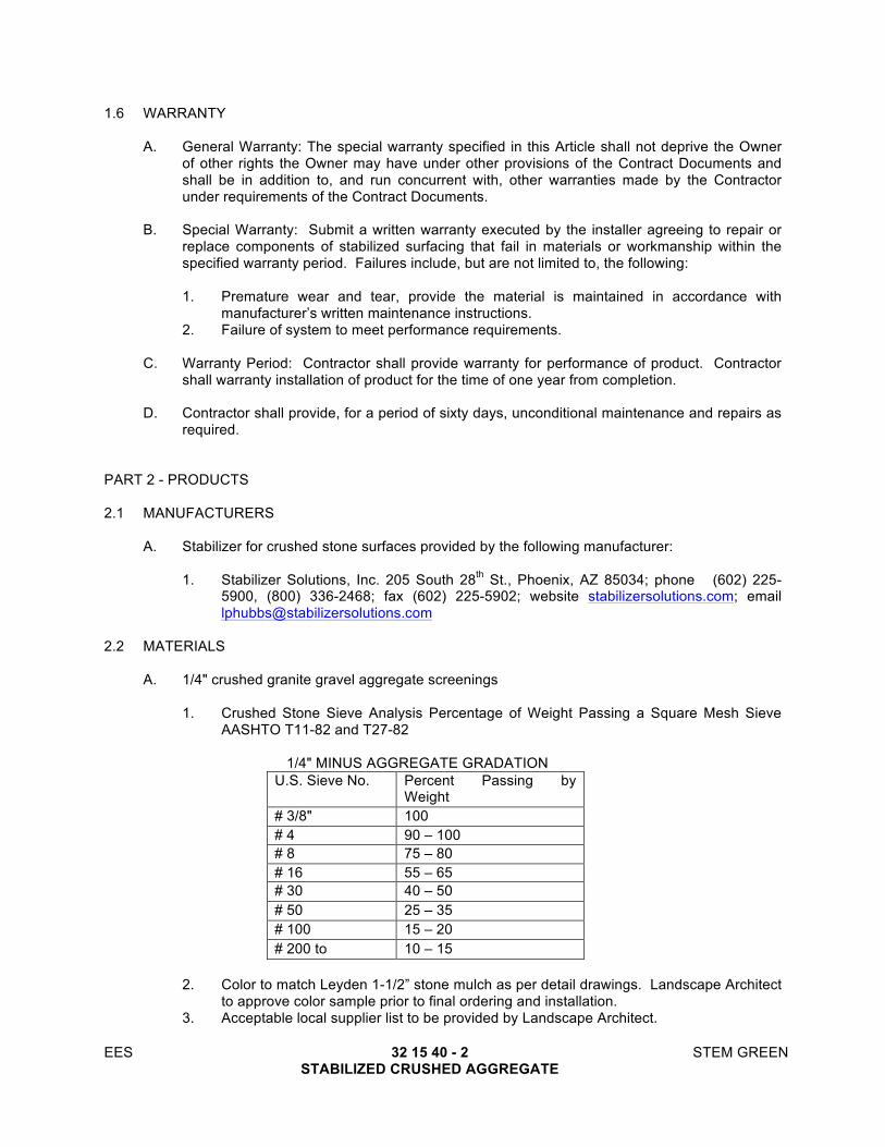
EES 32 15 40 - 2 STEM GREEN STABILIZED CRUSHED AGGREGATE
1.6 WARRANTY
A. General Warranty: The special warranty specified in this Article shall not deprive the Owner of other rights the Owner may have under other provisions of the Contract Documents and shall be in addition to, and run concurrent with, other warranties made by the Contractor under requirements of the Contract Documents.
B. Special Warranty: Submit a written warranty executed by the installer agreeing to repair or replace components of stabilized surfacing that fail in materials or workmanship within the specified warranty period. Failures include, but are not limited to, the following:
1. Premature wear and tear, provide the material is maintained in accordance with
manufacturer’s written maintenance instructions. 2. Failure of system to meet performance requirements.
C. Warranty Period: Contractor shall provide warranty for performance of product. Contractor shall warranty installation of product for the time of one year from completion.
D. Contractor shall provide, for a period of sixty days, unconditional maintenance and repairs as required.
PART 2 - PRODUCTS
2.1 MANUFACTURERS
A. Stabilizer for crushed stone surfaces provided by the following manufacturer:
1. Stabilizer Solutions, Inc. 205 South 28th St., Phoenix, AZ 85034; phone (602) 225-5900, (800) 336-2468; fax (602) 225-5902; website stabilizersolutions.com; email [email protected]
2.2 MATERIALS
A. 1/4" crushed granite gravel aggregate screenings
1. Crushed Stone Sieve Analysis Percentage of Weight Passing a Square Mesh Sieve
AASHTO T11-82 and T27-82
1/4" MINUS AGGREGATE GRADATION U.S. Sieve No. Percent Passing by
Weight # 3/8" 100 # 4 90 – 100 # 8 75 – 80 # 16 55 – 65 # 30 40 – 50 # 50 25 – 35 # 100 15 – 20 # 200 to 10 – 15
2. Color to match Leyden 1-1/2” stone mulch as per detail drawings. Landscape Architect
to approve color sample prior to final ordering and installation. 3. Acceptable local supplier list to be provided by Landscape Architect.

EES 32 15 40 - 3 STEM GREEN STABILIZED CRUSHED AGGREGATE
B. Stabilized Binder
1. Patented, non-toxic, organic binder that is a colorless and odorless concentrated powder that binds 1/4" minus crushed granite gravel aggregate
2.3 EXCESS MATERIALS
A. Provide owner’s authorized rep. With the following excess materials for use in future 1/4"
minus crushed granite gravel aggregate paving repair: 40 to 50 lb. Bags of the aggregate paving blended with proper amount of stabilizer.
PART 3 - EXECUTION
3.1 BLENDING STABILIZER
A. Blend 12 to 16 lbs (call manufacturer for exact blend) of stabilizer per 1-ton of 1/4” minus crushed granite gravel aggregate screenings. It is critical that stabilizer be thoroughly and uniformly mixed throughout 1/4” minus crushed granite gravel aggregate screenings. Bucket blending is not acceptable. Blending with a rake and or shovel is not acceptable.
3.2 PLACEMENT
A. After pre-blending, place the stabilized 1/4" minus crushed granite gravel aggregate
screenings on prepared sub-grade. Level to desired grade and cross section.
B. Depth of pathways – 5” compacted depth for heavy foot traffic and light vehicles.
3.3 WATERING
A. Water heavily to achieve full depth moisture penetration of the stabilized pathway Profile. Water activates stabilizer. To achieve saturation of stabilized pathway Profile, 25 to 45 gallons of water per 1-ton must be applied. During water application randomly test for depth using a probing device to the final depth.
3.4 COMPACTION
A. Upon thorough moisture penetration, compact aggregate screenings to 85% relative
compaction by compaction equipment such as; a 2 to 4-ton double drum roller or a 1,000 lb. Single drum roller with vibratory plate tamp. Do not begin compaction for six hours after placement and up to 48 hours.
B. Take care in compacting 1/4" minus crushed granite gravel aggregate screenings when adjacent to planting and irrigation systems. Hand tamping with 8” or 10” hand tamp recommended
3.5 INSPECTION
A. Finished surface of pathway shall be smooth, uniform and solid. There shall be no evidence
of chipping or cracking. Cured and compacted pathway shall be firm throughout profile with no spongy areas. Loose material shall not be present on the surface. Any significant irregularities in path surface shall be repaired to the uniformity of entire installation.

EES 32 15 40 - 4 STEM GREEN STABILIZED CRUSHED AGGREGATE
3.6 MAINTENANCE
A. Remove debris, such as paper, grass clippings, leaves or other organic material by
mechanically blowing or hand raking the surface as needed. Any plowing program required during winter months shall involve the use of a rubber baffle on the plow blade or wheels on the plow that lifts the blade 1/4" off the paving surface.
B. During the first year, a minor amount of loose aggregate will appear on the paving surface (1/16” to 1/4"). If this material exceeds 1/4", redistribute the material over the entire surface. Water thoroughly to the depth of 1”. Compact with power roller of no less than 1000 lbs. This process should be repeated as needed.
C. If cracking occurs, simply sweep fines into the cracks, water thoroughly and hand tamp with an 8” – 10” hand tamp plate.
3.7 REPAIRS
A. Excavate damaged area to the depth of the stabilized aggregate and square off sidewalls.
B. If area is dry, moisten damaged portion lightly.
C. Pre-blend the dry required amount of stabilizer powder with the proper amount of aggregate
in a concrete mixer.
D. Add water to the pre-blended aggregate and stabilizer. Thoroughly moisten mix with 25 to 45 gallons per 1-ton of pre-blended material or to approximately 10% moisture content.
E. Apply moistened pre-blended aggregate to excavated area to finish grade.
F. Compact with an 8” to 10” hand tamp or 250 to 300 pound roller. Keep traffic off areas for 12 to 48 hours after repair has been completed.
END OF SECTION

EES 32 16 13 - 1 STEM GREEN CONCRETE CURBS AND GUTTERS
SECTION 32 16 13
CONCRETE CURBS AND GUTTERS PART 1 - GENERAL 1.1 RELATED DOCUMEMENTS
A. Drawings and general provisions of the Contract, including General and Supplementary Conditions and Division 01 Specification Sections, apply to this Section.
1.2 SUMMARY
A. Refer to Section 609.01 – Curb and Gutter of Colorado Department of Transportation (CDOT)
Standard Specifications for Road and Bridge Construction, 2011 Edition. 1.3 REFERENCE STANDARDS
A. Pertinent provisions of the following listed documents shall apply to this work, except as they
may be modified herein, and are hereby made a part of this Specification to the extent required.
1. CDOT Standard Specifications for Road and Bridge Construction, 2011 Edition.
a. CDOT Section 609-Curb and Gutter and all references included therein.
b. Subsections 609.06 and 609.07 are hereby deleted.
2. City and County of Denver – Transportation Standards and Details for the Engineering Division, 2015 Edition.
3. City and County of Denver – Public Works Rules and Regulations for the Construction of Curbs, Gutters, Sidewalks, Driveways, Street Paving, and Other Public Right-Of-Way Improvements, Latest Edition.
PART 2 - PRODUCTS 2.1 MATERIAL
A. CDOT Class B Concrete.
PART 3 - EXECUTION 3.1 FIELD CONSTRUCTION REQUIREMENTS
A. In conformance with CDOT Standard Specifications for Road and Bridge Construction, 2011 Edition, Sections 609.03 and local agency requirements within the jurisdiction that the work is being performed.
END OF SECTION

EES 32 16 13 - 2 STEM GREEN CONCRETE CURBS AND GUTTERS
THIS PAGE LEFT INTENTIONALLY BLANK

EES 32 91 13 - 1 STEM GREEN LANDSCAPE SYSTEMS
SECTION 32 91 13
LANDSCAPE SYSTEMS PART 1 - GENERAL 1.1 SUMMARY
A. This Section includes the following:
1. Mulch 2. Steel Edging 3. Clean Up 4. Protection 5. Maintenance
1.2 REFERENCES
A. ASTM D1557 - Test Method for Moisture-Density Relations of Soils and Soil-Aggregate Mixtures Using 10-lb Rammer and 18-inch Drop.
1.3 DEFINITIONS
A. Weeds: Includes Goatheads, Bindweed, Twitch, Dandelion, Jimsonweed, Quackgrass,
Horsetail, Morning Glory, Rush Grass, Mustard, Lambsquarter, Chickweed, Cress, Crabgrass, Canadian Thistle, Nutgrass, Poison Oak, Blackberry, Tansy Ragwort, Bermuda Grass, Johnson Grass, Poison Ivy, Nut Sedge, Nimble Weed, Bindweed, Bent Grass, Wild Garlic, Perennial Sorrel, and Broom Grass.
1.4 SUBMITTALS
A. Comply with Section 01 33 00. All submittals shall be accepted by the Landscape Architect
in writing before planting commences. B. Descriptive Product Data: Submit catalog cuts, brochures, and analyses of all manufactured
items. C. Certificates
1. Submit certificates of inspection as required by governmental authorities. 2. Submit manufacturer's certified analysis packaged with standard products.
D. Analysis and Standards: Wherever applicable, for non packaged materials, provide analysis
by recognized laboratory made in accordance with methods established by the Association of Official Agriculture Chemists.
E. Mulch Submittal: Submit 1 quart sample of each wood and stone mulch type to be installed,
full color range. Obtain Landscape Architect's approval prior to bulk delivery to site.
1.5 QUALITY ASSURANCE
A. Comply with Section 01 40 00. B. Regulatory Requirements: Comply with regulatory agencies concerning classification,
transportation, handling and storage of landscape materials.

EES 32 91 13 - 2 STEM GREEN LANDSCAPE SYSTEMS
1.6 DELIVERY, STORAGE AND HANDLING
A. Comply with Section 01 40 00. B. Packaged Materials: Deliver packaged materials in containers showing weight, analysis and
name of manufacturer. Protect materials from deterioration during delivery, and while stored at site.
C. Mulch: Exercise care in the storage of mulches on site to avoid mixing soil with mulch. D. Weed Barrier Fabric: Exercise care in the storage of fabric on site to prevent damage to
fabric prior to and during installation. E. Rejection of Material
1. Evidence of inadequate protection or improper handling or storage, shall be cause for rejection.
2. Any product or material exhibiting signs of damage due to nonconformity to specifications or due to delivery, storage or handling shall be rejected by the Landscape Architect. Contractor shall be responsible for hauling off-site and disposing of according to general conditions and codes of the governing jurisdiction.
1.7 PROJECT/SITE CONDITIONS
A. Environmental Requirements: Work shall occur only when weather and soil conditions permit
in accordance with locally accepted practice. B. Existing Conditions
1. Existing Plants: Do not damage any existing plantings indicated to remain in accordance with Section 32 0190: Tree and Plant Protection.
2. Utilities: Determine location of underground utilities. Perform work in a manner to avoid possible damage. Hand excavate, as required.
3. Excavation: Maintain grade stakes set by others until removal is mutually agreed upon by parties concerned.
1.8 SEQUENCING AND SCHEDULING
A. Work Scheduling: Proceed with and complete landscape work as rapidly as portions of the site become available, working within the specified planting season and approved schedule.
1.9 WARRANTY AND REPLACEMENT
A. Provide one year warranty and replacement on landscape systems 1.10 MAINTENANCE
A. General: Maintain Work in accordance with standard industry practice or as directed by the Landscape Architect.
B. Maintain areas until the end of the Warranty period; comply with Section 01 7700. If sodding
occurs in autumn and maintenance has not been performed, or if work was not yet acceptable at the end of the autumn growing season (October 1), continue maintenance the following spring beginning March 15 (or sooner, weather permitting) and continue to the end of the warranty period.

EES 32 91 13 - 3 STEM GREEN LANDSCAPE SYSTEMS
PART 2 - PRODUCTS 2.1 WATER
A. Clean, potable and free of substances or matter which could inhibit vigorous growth of plant material.
B. Available on-site at no expense to Contractor. Landscape Contractor is responsible for
coordination of water needs for watering and irrigation water with the General Contractor.
2.2 MULCH
A. Wood Mulch: Shredded western red cedar bark mulch or Landscape Architect-approved substitute, free from deleterious materials and suitable for top dressing of trees, shrubs and ground covers. Mulch shall be of a long fibrous nature capable of matting together and interlocking when moistened and settled.
B. Stone Mulch: Per plan several areas call for stone mulches of varying stone sizes and
colors. Carefully review layout and materials plan for appropriate mulch per planting area. Ground cover, annual and perennial beds to receive mulch per details.
C. Submit samples of wood and stone mulches prior to delivery to the site in accordance with
paragraph 1.4.E of this Section. D. Substitutions: Do not make substitutions: If specified wood or stone mulch is not obtainable,
submit proof of non-availability to Landscape Architect together with proposal for use of equivalent material for review and acceptance by Landscape Architect.
2.3 METAL EDGING
A. Edging: 1/4 inch thick x 5 inches deep steel edging with stakes placed 30 inches on center and meeting the following requirements: 1. Hot Rolled low carbon steel ASTM-A-36, ASTM-A-283, ASTM-A-569 2. ASTM A366 carbon content: 0.10 maximum 3. Material hardness Rockwell: 57 minimum 4. Tensile strength ksi: 58 minimum 5. Yield strength ksi: 36 minimum 6. Finish: powder coated. Color: Black.
B. Manufacturer: Col-Met Edging, ITEM #1025-5, ph: (703)739-6909, or approved equal. C. Provide steel edging in all locations shown on the drawings. D. Substitutions: Do not make substitutions: If specified metal edging is not obtainable, submit
proof of non-availability to Landscape Architect together with proposal for use of equivalent material for review and acceptance by Landscape Architect.
2.4 WEED BARRIER FABRIC
A. Fabric: Nonwoven porous fabric, Dupont 'Typar', for use as indicated in details.
B. MANUFACTURER: Dupont, Reemay, P.O. Box 511, Old Hickory, TN, 37138, (800)321-6271 or approved equal.

EES 32 91 13 - 4 STEM GREEN LANDSCAPE SYSTEMS
PART 3 - EXECUTION 3.1 EXAMINATION
A. Verification Of Conditions: Examine areas and conditions under which the Work of this
Section will be performed. Report unsatisfactory or questionable conditions to the Landscape Architect. Do not proceed with the Work until unsatisfactory conditions have been corrected. Commencement of work implies acceptance of all areas and conditions.
1. Verify that during grading, topsoil spreading and landscape grading operations, the
ground surface was cleaned of materials which might hinder final operations. 3.2 PREPARATION
A. Protection: Protect areas in accordance with paragraph 3.7 this Section. B. All areas within the limits of planting shall be seeded, sodded, planted with trees, shrubs,
groundcovers, perennials or mulched as indicated on the Drawings and Specifications. C. Layout: Stake outline location of shrub bed edge in accordance with Drawings. Obtain
Landscape Architect's approval prior to starting Work. 3.3 MULCH
A. Shrub Beds: Mulch areas between shrubs where noted on drawings. Place 3 inches thick. Cover entire area of planting bed.
B. Groundcover Beds: Mulch areas between ground cover plants where noted in drawings.
Place mulch per details. Cover entire area of planting bed. C. Individual Plants: Mulch planted areas around individual trees and shrubs as shown on
detail. Provide minimum 3 inches of mulch. Finish level with adjacent finish grades. 3.4 STEEL EDGING
A. General: Install steel edging at locations indicated in the Drawings. Where required, cut edging square and accurately to required length.
B. Installation
1. Securely stake edging in required position. Stakes shall be driven every 30-inches o.c.
along length of edging. 2. Butt adjacent ends and lock together with a splicing stake. 3. Set edging plumb and vertical at required line and grade. Straight sections shall not be
wavy; curved sections shall be smooth and shall have no kinks or sharp bends. 4. Bend angles using a jig. 5. Weld together cut pieces if unable to lock together with stakes. 6. Segments shall be no less than four feet in length.
3.5 FIELD QUALITY CONTROL
A. Tests: Costs of tests and material analyses made by the testing agency will be borne by the Owner when tests indicate compliance and by the Contractor when test indicated non-compliance.
B. Reviews

EES 32 91 13 - 5 STEM GREEN LANDSCAPE SYSTEMS
1. Pre-Planting Review
a. All mulches and edging shall be inspected and accepted at the site by the Landscape Architect before they are used in planting operations.
2. Substantial Completion
a. At the time of this walk-through, the Contractor shall have :
i. Installed all items in accordance with this Section. ii. Cleaned all walkways and curbs of debris and litter and shall have cleaned
areas of soil and debris left from planting operations.
3.6 CLEANUP
A. During Landscape Installation: All areas shall be reasonably clean at the end of each work day. Sidewalks and other paved areas shall be swept or washed down as needed. Keep pavements clean and work area in an orderly condition.
B. Project Completion: All debris, soil, trash, and excavated and/or stripped material resulting
from landscape operations and unsuitable for or in excess of requirements for completing work of this Section shall be disposed of off-site. All paved areas shall be washed down.
3.7 PROTECTION
A. Protect landscape work and materials from damage due to landscape operations, operations by other contractors and trades and trespassers.
B. Maintain protection during installation and maintenance periods. Treat, repair or replace
damaged landscape work as directed. C. Perform Work near and in Tree Protection Areas in accordance with Section 32 0190.33 -
Tree and Plant Protection.
END OF SECTION

EES 32 91 13 - 6 STEM GREEN LANDSCAPE SYSTEMS
THIS PAGE INTENTIONALLY LEFT BLANK

EES 32 91 19 - 1 STEM GREEN LANDSCAPE GRADING
SECTION 32 91 19
LANDSCAPE GRADING
PART 1 - GENERAL 1.1 SUMMARY
A. This Section includes the following:
1. Subsoil Preparation. 2. Placing Imported Fill. 3. Placing Topsoil. 4. Soil Tests. 5. Coordination of Soil Amendments. 6. Fine Grading. 7. Adjusting. 8. Protection.
1.2 REFERENCES
A. Colorado Division of Labor Rules and Regulations: Excavation. B. ANSI/ASTM D 698 - Test Methods for Moisture-Density Relations of Soils and Soil-Aggregate
Mixtures, Using 5.5 lb (2.49 Kg) Rammer and 12 inch (304.8 mm) Drop. C. ANSI/ASTM D 1556 - Test Method for Density of Soil in Place by the Sand-Cone Method. D. Association of Official Agricultural Chemists: Topsoil Analysis.
1.3 DEFINITIONS
A. Weeds: Includes Goatheads, Bindweed, Twitch, Dandelion, Jimsonweed, Quackgrass, Horsetail, Morning Glory, Rush Grass, Mustard, Lambsquarter, Chickweed, Cress, Crabgrass, Canadian Thistle, Nutgrass, Poison Oak, Blackberry, Tansy Ragwort, Bermuda Grass, Johnson Grass, Poison Ivy, Nut Sedge, Nimble Weed, Bindweed, Bent Grass, Wild Garlic, Perennial Sorrel, and Broom Grass.
1.4 SUBMITTALS
A. Comply with Section 01 30 00. All submittals shall be accepted by the Landscape Architect in writing before planting commences.
B. Topsoil Testing:
1. After topsoil spreading, submit, for Landscape Architect's approval, topsoil samples
and test results from
a. Three locations as designated by the Landscape Architect on the Drawings. b. Each off-site topsoil source.
2. Each location submission shall include:
a. 1 qt. representative sample in air tight container. b. Agricultural analysis by recognized laboratory made in accordance with methods
established by the Association of Official Agricultural Chemists. Test shall include available nutrients, soil pH, soil texture, salt, and percentage organic

EES 32 91 19 - 2 STEM GREEN LANDSCAPE GRADING
matter, and recommended fertilization and amendment rates for plant material types specified.
c. Location of borrow site, if applicable.
3. Deliver copies of all test reports and samples to landscape contractor and Landscape Architect.
C. Certificates: Submit certificates of inspection as required by governmental authorities.
1.5 QUALITY ASSURANCE
A. Comply with Section 01 40 00. B. Qualifications
1. Installer: Company with minimum five (5) years successful experience in the placing
on topsoil similar in scope and size to this project. 2. Testing Agency: Certified soils laboratory with capability to analyze materials for
conformance to specification requirements (where applicable).
1.6 DELIVERY, STORAGE AND HANDLING
A. Topsoil: Protect materials from erosion, wind, rodents, deterioration and contamination during delivery, installation and site storage.
1.7 PROJECT / SITE CONDITIONS
A. Environmental Requirements
1. Comply with requirements of referenced standards for environmental conditions before, during, and after installation. Maintain environmental conditions and protect work during and after installation to comply with referenced standards.
2. Moisture Content: Topsoil and other materials shall not be placed, backfilled, or spread while in a wet or saturated condition. Moisture content shall not be so great that excessive compaction will occur, nor so low that dust will form in the air or that clods will not break readily. Apply water if necessary to bring soil to optimum moisture content for tilling.
3. Do not work soil when muddy or frozen.
B. Existing Conditions
1. Plants: Protect existing plant material in accordance with Section 32 01 90. Do not damage any plantings indicated to remain.
2. Utilities: Determine location of underground utilities including irrigation system. Perform work in a manner to avoid possible damage. Hand excavate, as required.
3. Excavation: Maintain grade stakes set by others until removal is mutually agreed upon by parties concerned. When conditions detrimental to Work are encountered, such as rubble fill, adverse drainage conditions, noxious materials or obstructions, notify Landscape Architect before proceeding.
1.8 SEQUENCING AND SCHEDULING
A. Coordination
1. Coordinate with sod installation and landscape Contractor(s) approved schedule. Do
not place topsoil more than 3 days prior to commencement of landscaping in the area without Landscape Architects approval. Limit fine grading to areas which can be planted within 24 hours after fine grading.
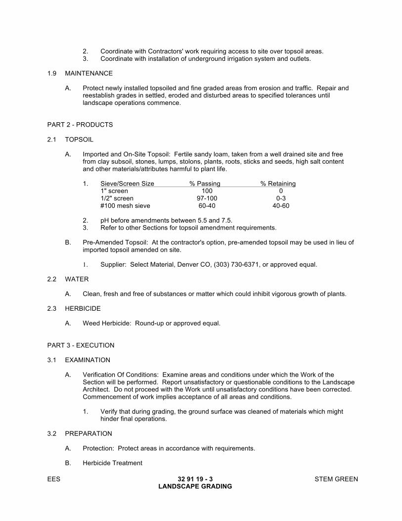
EES 32 91 19 - 3 STEM GREEN LANDSCAPE GRADING
2. Coordinate with Contractors' work requiring access to site over topsoil areas. 3. Coordinate with installation of underground irrigation system and outlets.
1.9 MAINTENANCE
A. Protect newly installed topsoiled and fine graded areas from erosion and traffic. Repair and reestablish grades in settled, eroded and disturbed areas to specified tolerances until landscape operations commence.
PART 2 - PRODUCTS 2.1 TOPSOIL
A. Imported and On-Site Topsoil: Fertile sandy loam, taken from a well drained site and free from clay subsoil, stones, lumps, stolons, plants, roots, sticks and seeds, high salt content and other materials/attributes harmful to plant life.
1. Sieve/Screen Size % Passing % Retaining 1" screen 100 0 1/2" screen 97-100 0-3 #100 mesh sieve 60-40 40-60 2. pH before amendments between 5.5 and 7.5. 3. Refer to other Sections for topsoil amendment requirements.
B. Pre-Amended Topsoil: At the contractor's option, pre-amended topsoil may be used in lieu of
imported topsoil amended on site.
1. Supplier: Select Material, Denver CO, (303) 730-6371, or approved equal. 2.2 WATER
A. Clean, fresh and free of substances or matter which could inhibit vigorous growth of plants. 2.3 HERBICIDE
A. Weed Herbicide: Round-up or approved equal. PART 3 - EXECUTION 3.1 EXAMINATION
A. Verification Of Conditions: Examine areas and conditions under which the Work of the Section will be performed. Report unsatisfactory or questionable conditions to the Landscape Architect. Do not proceed with the Work until unsatisfactory conditions have been corrected. Commencement of work implies acceptance of all areas and conditions.
1. Verify that during grading, the ground surface was cleaned of materials which might
hinder final operations. 3.2 PREPARATION
A. Protection: Protect areas in accordance with requirements.
B. Herbicide Treatment

EES 32 91 19 - 4 STEM GREEN LANDSCAPE GRADING
1. Confirm Landscape Architects requirement to proceed with herbicide treatment of on-site subsoil. Herbicide treatment must be completed during the growing season.
2. If plant growth is evident, treat site with Roundup herbicide in accordance with manufacturers recommendations.
3. Water subsoil 1/2" per week if natural precipitation does not supply this amount. 4. Ten (10) days after Roundup application, review subsoil surface for evidence of plant
growth. 5. Repeat steps 2, 3 and 4, up to three (3) applications, until there is no evidence of plant
growth after ten (10) day period. 6. Obtain Landscape Architects approval of subsoil fourteen (14) days after last herbicide
application. 7. Remove plant debris from treated area.
3.3 SUBSOIL PREPARATION
A. Verify subsoil base has been contoured and compacted and is free of contaminated material. B. Prepare subsoil to eliminate uneven areas and low spots. Maintain lines, levels, profiles, and
contours. Make changes in grade gradual. Blend slopes into level areas. C. Remove foreign materials, stones exceeding 2 inches, weeds and undesirable plants and
their roots. D. Scarify subsoil to a depth of 6 inches where topsoil is to be placed. Repeat cultivation in
areas where equipment, used for hauling and spreading topsoil, has compacted subsoil. E. Remove foreign materials, including, but not limited to stones exceeding two (2) inches
diameter weeds and undesirable plants and their roots which came to the surface during subsoil scarification.
3.4 PLACING TOPSOIL
A. Place topsoil where seeding, sodding and planting are scheduled and in accordance with paragraph above.
B. Place topsoil during dry weather and on dry, unfrozen subsoil. C. Remove vegetative matter and foreign, non-organic material and debris larger than 1.5
inches in diameter at the time of placement. D. Place topsoil to the following depths:
1. Sod Areas: 6” 2. Shrub Beds: 12" 3. Flower Beds: 12"
E. Place topsoil eliminating rough or low areas to ensure positive drainage. Maintain profiles
and contour of subgrade. F. Manually place topsoil close to existing trees, shrubs, plants, curbs, new construction, stone
flat work and buildings to prevent damage.
3.5 SOIL TESTS
A. Perform soil testing and submission in accordance with paragraph 1.06 this Section.
EES 32 91 19 - 5 STEM GREEN LANDSCAPE GRADING
3.6 COORDINATION OF SOIL AMENDMENTS
A. Coordinate soil amendments with landscape contractor in accordance with Sections 01 31 00, 32 01 90 and 32 91 13.
3.7 FINE GRADING
A. Fine grade topsoil to finished elevations with smooth, even surface with loose, uniformly fine texture.
B. Remove foreign materials, including but not limited to: stones exceeding 1.5 inches in
diameter, weeds and undesirable plants and their roots which came to the surface during soil amending.
C. Roll, rake and drag lawn areas, remove ridges and fill depressions, as required to meet finish
grades. Limit fine grading to areas which can be planted immediately after grading. Compact seeded areas to 90%, as indicated.
D. Remove surplus subsoil and topsoil from site. E. Leave stockpile area and site clean and raked, ready to receive landscaping.
3.8 TOLERANCES
A. Topsoil: Topsoil elevations shall be within the following tolerances from elevations indicated
on the drawings: 1. Landscape Areas: ± 0.04' (1/2”). 2. Adjacent to Paving and Curbs: ± 0.04' (1/2").
3.9 FIELD QUALITY CONTROL
A. Reviews: Comply with Section 01 40 00 – Quality Requirements. 3.10 ADJUSTING
A. Reconditioning Compacted Areas: When completed topsoil areas are disturbed by subsequent construction operations or adverse weather, scarify surface, reshape, and compact to required density prior to further construction.
3.11 CLEANUP
A. During Landscape Installation
1. All areas shall be reasonably clean at the end of each work day. Sidewalks and other paved areas shall be swept or washed down as needed. Keep pavements clean and work area in an orderly condition.
2. Contractor shall make a reasonable effort to clean up the project on a daily basis to maintain a neat and orderly site.
B. Project Completion
1. All debris, soil and trash resulting from landscape operations shall be removed from the
site. Burning of waste material is prohibited. All paved areas shall be washed down. 2. Restore all areas outside the Contract limits which have been disturbed to their original
condition at no cost to the Owner including but not limited to landscaping and irrigation arterials and systems. Contractor shall become familiar with the site and necessary

EES 32 91 19 - 6 STEM GREEN LANDSCAPE GRADING
repairs prior to bid. All needed repairs are part of base bid and no additional cost to owner.
3.12 PROTECTION
A. Protect landscape work and materials from damage due to landscape operations, operations
by other contractors and trades and trespassers. B. Maintain protection during installation and maintenance periods. Treat, repair or replace
damaged landscape work as directed. C. Perform Work near and in Tree Protection Areas in accordance with Section 32 01 90 – Tree
Protection.
END OF SECTION

TURF 32 92 00 - 1 STEM GREEN TURF
SECTION 32 92 00
TURF PART 1 - GENERAL
1.1 SUMMARY
A. Section Includes:
1. Sodding. 2. Turf renovation.
B. Related Requirements:
1. Section 32 01 90 - Tree and Plant Protection 2. Section 32 91 13 - Landscape Systems for metal edging 3. Section 32 91 19 - Landscape Grading for soil amendments, topsoil, and topsoil testing
1.2 DEFINITIONS
A. Finish Grade: Elevation of finished surface of planting soil. B. Pesticide: A substance or mixture intended for preventing, destroying, repelling, or mitigating
a pest. Pesticides include insecticides, miticides, herbicides, fungicides, rodenticides, and molluscicides, including substances or mixtures intended for use as a plant regulator, defoliant, or desiccant.
C. Pests: Living organisms that occur where they are not desired or that cause damage to
plants, animals, or people. Pests include insects, mites, grubs, mollusks (snails and slugs), rodents (gophers, moles, and mice), unwanted plants (weeds), fungi, bacteria, and viruses.
D. Planting Soil: Existing, on-site soil; imported soil; or manufactured soil that has been
modified with soil amendments and perhaps fertilizers to produce a soil mixture best for plant growth. Section 32 9119 - Landscape Grading and drawing designations for planting soils.
E. Subgrade: The surface or elevation of subsoil remaining after excavation is complete, or the
top surface of a fill or backfill before planting soil is placed.
1.3 INFORMATIONAL SUBMITTALS
A. Qualification Data: For landscape Installer. B. Certification of Grass Seed: From seed vendor for each grass-seed monostand or mixture,
stating the botanical and common name, percentage by weight of each species and variety, and percentage of purity, germination, and weed seed. Include the year of production and date of packaging.
1. Certification of each seed mixture for turfgrass sod. Include identification of source and
name and telephone number of supplier.
C. Product Certificates: For fertilizers, from manufacturer. D. Pesticides and Herbicides: Product label and manufacturer's application instructions specific
to Project.
TURF 32 92 00 - 2 STEM GREEN TURF
1.4 CLOSEOUT SUBMITTALS
A. Maintenance Data: Recommended procedures to be established by Owner for maintenance
of turf during a calendar year. Submit before expiration of required maintenance periods.
1.5 QUALITY ASSURANCE
A. Installer Qualifications: A qualified landscape installer whose work has resulted in successful turf establishment.
1. Professional Membership: Installer shall be a member in good standing of either the
Professional Landcare Network or the American Nursery and Landscape Association. 2. Experience: Five years of experience in turf installation in addition to requirements in
Section 01 40 00 "Quality Requirements." 3. Installer's Field Supervision: Require Installer to maintain an experienced full-time
supervisor on Project site when work is in progress. 4. Personnel Certifications: Installer's field supervisor shall have certification in one of the
following categories from the Professional Landcare Network:
a. Landscape Industry Certified Technician - Exterior. b. Landscape Industry Certified Lawncare Manager. c. Landscape Industry Certified Lawncare Technician.
5. Pesticide Applicator: State licensed, commercial.
1.6 DELIVERY, STORAGE, AND HANDLING
A. Packaged Materials: Deliver packaged materials in original, unopened containers showing
weight, certified analysis, name and address of manufacturer, and indication of compliance with state and Federal laws, as applicable.
B. Sod: Harvest, deliver, store, and handle sod according to requirements in "Specifications for
Turfgrass Sod Materials" and "Specifications for Turfgrass Sod Transplanting and Installation" sections in TPI's "Guideline Specifications to Turfgrass Sodding." Deliver sod within 24 hours of harvesting and in time for planting promptly. Protect sod from breakage and drying.
C. Bulk Materials:
1. Do not dump or store bulk materials near structures, utilities, walkways and pavements,
or on existing turf areas or plants. 2. Provide erosion-control measures to prevent erosion or displacement of bulk materials;
discharge of soil-bearing water runoff; and airborne dust reaching adjacent properties, water conveyance systems, or walkways.
3. Accompany each delivery of bulk materials with appropriate certificates.
1.7 FIELD CONDITIONS
A. Planting Restrictions: Plant during period below. Coordinate planting periods with initial maintenance periods to provide required maintenance from date of Substantial Completion.
1. Fall Planting: September 1 – October 5.
B. Weather Limitations: Proceed with planting only when existing and forecasted weather
conditions permit planting to be performed when beneficial and optimum results may be

TURF 32 92 00 - 3 STEM GREEN TURF
obtained. Apply products during favorable weather conditions according to manufacturer's written instructions.
PART 2 - PRODUCTS
2.1 TURFGRASS SOD
A. Turfgrass Sod: Certified, Number 1 Quality/Premium, including limitations on thatch, weeds,
diseases, nematodes, and insects, complying with "Specifications for Turfgrass Sod Materials" in TPI's "Guideline Specifications to Turfgrass Sodding." Furnish viable sod of uniform density, color, and texture that is strongly rooted and capable of vigorous growth and development when planted.
B. Turfgrass Species: “Sun and Shade Sod” by ScienTurfic Sod, with not less than 85 percent
germination, not less than 95 percent pure seed, and not more than 0.5 percent weed seed.
2.2 FERTILIZERS
A. Commercial Fertilizer: Commercial-grade complete fertilizer of neutral character, consisting of fast- and slow-release nitrogen, 50 percent derived from natural organic sources of urea formaldehyde, phosphorous, and potassium in the following composition:
1. Composition: Nitrogen, phosphorous, and potassium in amounts recommended in soil
reports from a qualified soil-testing laboratory.
2.3 PESTICIDES
A. General: Pesticide, registered and approved by the EPA, acceptable to authorities having jurisdiction, and of type recommended by manufacturer for each specific problem and as required for Project conditions and application. Do not use restricted pesticides unless authorized in writing by authorities having jurisdiction.
B. Post-Emergent Herbicide (Selective and Nonselective): Effective for controlling weed growth
that has already germinated. PART 3 - EXECUTION
3.1 EXAMINATION
A. Examine areas to be planted for compliance with requirements and other conditions affecting
installation and performance of the Work.
1. Verify that no foreign or deleterious material or liquid such as paint, paint washout, concrete slurry, concrete layers or chunks, cement, plaster, oils, gasoline, diesel fuel, paint thinner, turpentine, tar, roofing compound, or acid has been deposited in soil within a planting area.
2. Suspend planting operations during periods of excessive soil moisture until the moisture content reaches acceptable levels to attain the required results.
3. Uniformly moisten excessively dry soil that is not workable or which is dusty.
B. Proceed with installation only after unsatisfactory conditions have been corrected.
TURF 32 92 00 - 4 STEM GREEN TURF
C. If contamination by foreign or deleterious material or liquid is present in soil within a planting area, remove the soil and contamination as directed by Landscape Architect and replace with new planting soil.
3.2 PREPARATION
A. Protect structures; utilities; sidewalks; pavements; and other facilities, trees, shrubs, and
plantings from damage caused by planting operations.
1. Protect grade stakes set by others until directed to remove them.
B. Install erosion-control measures to prevent erosion or displacement of soils and discharge of soil-bearing water runoff or airborne dust to adjacent properties and walkways.
C. Prior to the installation of sod, Contractor to verify that the irrigation is in good working condition and operational.
3.3 TURF AREA PREPARATION
A. General: Prepare planting area for soil placement and mix planting soil according to Section
32 91 19 - Landscape Grading
1. Reduce elevation of planting soil to allow for soil thickness of sod.
B. Moisten prepared area before planting if soil is dry. Water thoroughly and allow surface to dry before planting. Do not create muddy soil.
C. Before planting, obtain Landscape Architect's acceptance of finish grading; restore planting
areas if eroded or otherwise disturbed after finish grading.
3.4 SODDING
A. Lay sod within 24 hours of harvesting. Do not lay sod if dormant or if ground is frozen or muddy.
B. Lay sod to form a solid mass with tightly fitted joints. Butt ends and sides of sod; do not
stretch or overlap. Stagger sod strips or pads to offset joints in adjacent courses. Avoid damage to soil or sod during installation. Tamp and roll lightly to ensure contact with soil, eliminate air pockets, and form a smooth surface. Work sifted soil or fine sand into minor cracks between pieces of sod; remove excess to avoid smothering sod and adjacent grass.
1. Lay sod across slopes exceeding 1:3. 2. Anchor sod on slopes exceeding 1:6 with wood pegs [or steel staples] spaced as
recommended by sod manufacturer but not less than two anchors per sod strip to prevent slippage.
C. Saturate sod with fine water spray within two hours of planting. During first week after
planting, water daily or more frequently as necessary to maintain moist soil to a minimum depth of 1-1/2 inches below sod.
3.5 TURF RENOVATION
A. Renovate turf damaged by Contractor's operations, such as storage of materials or
equipment and movement of vehicles.

TURF 32 92 00 - 5 STEM GREEN TURF
1. Reestablish turf where settlement or washouts occur or where minor regrading is required.
2. Install new planting soil as required.
B. Remove sod and vegetation from diseased or unsatisfactory turf areas; do not bury in soil. C. Remove topsoil containing foreign materials, such as oil drippings, fuel spills, stones, gravel,
and other construction materials resulting from Contractor's operations, and replace with new planting soil.
D. Mow, dethatch, core aerate, and rake existing turf. E. Remove weeds before seeding. Where weeds are extensive, apply selective herbicides as
required. Do not use pre-emergence herbicides. F. Remove waste and foreign materials, including weeds, soil cores, grass, vegetation, and turf,
and legally dispose of them off Owner's property. G. Till stripped, bare, and compacted areas thoroughly to a soil depth of 6 inches . H. Apply soil amendments and initial fertilizer required for establishing new turf and mix
thoroughly into top 4 inches of existing soil. Install new planting soil to fill low spots and meet finish grades.
1. Soil Amendment(s): Amend according to requirements of Section 32 91 19 -
Landscape Grading apply soil amendment at the rate specified by an agricultural soils test.
2. Initial Fertilizer: Commercial fertilizer applied according to manufacturer's recommendations.
I. Apply sod as required for new turf. J. Water newly planted areas and keep moist until new turf is established.
3.6 TURF MAINTENANCE
A. General: Maintain and establish turf by watering, fertilizing, weeding, mowing, trimming,
replanting, and performing other operations as required to establish healthy, viable turf. Roll, regrade, and replant bare or eroded areas and remulch to produce a uniformly smooth turf. Provide materials and installation the same as those used in the original installation.
1. Fill in as necessary soil subsidence that may occur because of settling or other
processes. Replace materials and turf damaged or lost in areas of subsidence. 2. Apply treatments as required to keep turf and soil free of pests and pathogens or
disease. Use integrated pest management practices whenever possible to minimize the use of pesticides and reduce hazards.
B. Watering: Install and maintain temporary piping, hoses, and turf-watering equipment to
convey water from sources and to keep turf uniformly moist to a depth of four (4) inches .
1. Schedule watering to prevent wilting, puddling, erosion, and displacement of seed or mulch. Lay out temporary watering system to avoid walking over muddy or newly planted areas.
2. Water turf with fine spray at a minimum rate of 1 inch per week unless rainfall precipitation is adequate.
TURF 32 92 00 - 6 STEM GREEN TURF
C. Mow turf as soon as top growth is tall enough to cut. Repeat mowing to maintain specified height without cutting more than one-third of grass height. Remove no more than one-third of grass-leaf growth in initial or subsequent mowings. Do not delay mowing until grass blades bend over and become matted. Do not mow when grass is wet. Schedule initial and subsequent mowings to maintain the following grass height:
1. Mow Kentucky bluegrass to a height of 1-1/2 to 2 inches .
D. Turf Post Fertilization: Apply commercial fertilizer after initial mowing and when grass is dry.
1. Use fertilizer that provides actual nitrogen of at least 1 lb/1000 sq. ft. to turf area.
3.7 SATISFACTORY TURF
A. Turf installations shall meet the following criteria as determined by Landscape Architect:
1. Satisfactory Sodded Turf: At end of maintenance period, a healthy, well-rooted, even-
colored, viable turf has been established, free of weeds, open joints, bare areas, and surface irregularities.
B. Use specified materials to reestablish turf that does not comply with requirements, and
continue maintenance until turf is satisfactory.
3.8 PESTICIDE APPLICATION
A. Apply pesticides and other chemical products and biological control agents according to requirements of authorities having jurisdiction and manufacturer's written recommendations. Coordinate applications with Owner's operations and others in proximity to the Work. Notify Owner before each application is performed.
B. Post-Emergent Herbicides (Selective and Nonselective): Apply only as necessary to treat
already-germinated weeds and according to manufacturer's written recommendations.
3.9 CLEANUP AND PROTECTION
A. Promptly remove soil and debris created by turf work from paved areas. Clean wheels of vehicles before leaving site to avoid tracking soil onto roads, walks, or other paved areas.
B. Remove surplus soil and waste material, including excess subsoil, unsuitable soil, trash, and
debris, and legally dispose of them off Owner's property. C. Erect temporary fencing or barricades and warning signs as required to protect newly planted
areas from traffic. Maintain fencing and barricades throughout initial maintenance period and remove after plantings are established.
D. Remove nondegradable erosion-control measures after grass establishment period.
3.10 MAINTENANCE SERVICE
A. Turf Maintenance Service: Provide full maintenance by skilled employees of landscape
Installer. Maintain as required in "Turf Maintenance" Article. Begin maintenance immediately after each area is planted and continue until acceptable turf is established, but for not less than the following periods:
1. Sodded Turf: 30 days from date of Substantial Completion.
END OF SECTION

EES 32 93 00 - 1 STEM GREEN TREES, PLANTS AND GROUNDCOVER
PSECTION 32 93 00
TREES, PLANTS AND GROUNDCOVER PART 1 - GENERAL 1.1 SUMMARY
A. This Section includes the following:
1. General Planting Requirements. 2. Trees and Shrubs Planted in Individual Plant Pits or Trenches. 3. Shrubs, Perennials and Groundcovers Planted in Prepared Planting Beds. 4. Clean Up. 5. Protection. 6. Maintenance.
1.2 REFERENCE
A. American Standards for Nursery Stock (ANSI Z60.1 - most recent edition), American Association of Nurserymen, Washington D.C.
B. Hortus III, L.H. Bailey Hortorium and Staff, MacMillan Co., New York, 1976. C. Manual of Woody Landscape Plants, M.A. Dirr, Stipes Publishing Co., Champaign, Illinois,
1990. D. A New Tree Biology, Alex L. Shigo, Shigo and Trees Associates, Durham, New Hampshire,
1986. E. A New Tree Biology Dictionary, Alex L. Shigo, Shigo and Trees Associates, Durham, New
Hampshire, 1986. 1.3 DEFINITIONS
A. Weeds: Includes Goatheads, Bindweed, Twitch, Dandelion, Jimsonweed, Quackgrass, Horsetail, Morning Glory, Rush Grass, Mustard, Lambsquarter, Chickweed, Cress, Crabgrass, Canadian Thistle, Nutgrass, Poison Oak, Blackberry, Tansy Ragwort, Bermuda Grass, Johnson Grass, Poison Ivy, Nut Sedge, Nimble Weed, Bindweed, Bent Grass, Wild Garlic, Perennial Sorrel, Pigweed, Kosher, and Broom Grass.
B. Plants: Trees, shrubs, groundcovers, annuals, perennials, and bulbs specified in the plant
list. 1.4 SUBMITTALS
A. Comply with Section 01 30 00. All submittals and plant materials shall be accepted by the
Landscape Architect in writing before planting commences. B. Topsoil Testing
1. Submit per Section 32 91 19 - Landscape Grading
C. Certificates
1. Submit certificates of inspection as required by governmental authorities.

EES 32 93 00 - 2 STEM GREEN TREES, PLANTS AND GROUNDCOVER
2. Submit manufacturer's certified analysis packaged with standard products.
D. Analysis and Standards: Wherever applicable, for non packaged materials, provide analysis by recognized laboratory made in accordance with methods established by the Association of Official Agriculture Chemists.
E. Planting Schedule: Submit planting schedule. F. Plant Photographs: Submit one color photograph or 35 mm color transparency of all trees
over 1 inch caliper or 5 foot height for any plant materials which are located outside of 30 mile radius of Denver for approval by Landscape Architect prior to shipment to the site or the contractor' holding yard.
G. Tree Planting Material Submittal: Submit 1 tree collar and 1 sample of tree wrap. H. Samples: Submit 1 quart sample of wood mulch for acceptance by Landscape Architect. I. Contractor Qualifications: Submit nursery and installation company qualifications in
accordance with paragraph below for acceptance by Landscape Architect J. Submit product data sheets for each of the following items:
1. Ryerson Steel Landscape Edger 3/16”x4”, or approved equal with stakes placed 3 feet on center.
2. Wooden Posts for tree stakes: 6’ tall 3. Tree Wrap 4. Weed Barrier Fabric: Nonwoven porous fabric, Dupont ‘Typar’ 5. Fertilizer: Organic commercial Fertilizer (Grow Power Plus 5-3-1) 6. Compost
1.5 QUALITY ASSURANCE
A. Qualifications
1. Nursery: Company specializing in growing and cultivating the plants with minimum five (5) years experience, and certified by the State of Colorado Department of Agriculture.
2. Installer: Company with minimum five (5) years successful experience in the installation of landscape areas similar in size and complexity to this project. Company shall be a member in good standing of one of the following organizations:
a. Associated Landscape Contractors of America. b. American Association of Nurserymen. c. A member of the Nurserymen's Association of the state in which the work is
being performed.
B. Regulatory Requirements
1. Comply with regulatory agencies concerning classification, transportation, handling and storage of plants, fertilizer, herbicide and pesticide materials.
2. Comply with regulatory agencies for fertilizer, herbicide and pesticide composition and application.
C. Rejection of Materials
1. Evidence of inadequate or inappropriate protection after digging, transportation, or
improper handling or storage, shall be cause for rejection. 2. Landscape Architect will inspect plants for proper shipping procedures upon arrival at
the temporary storage location or the site. The Landscape Architect will reject injured
EES 32 93 00 - 3 STEM GREEN TREES, PLANTS AND GROUNDCOVER
plants including those with dried out roots, broken large branches, broken, or loosened balls or earth, split trunks or torn areas of bark.
3. The Contractor shall immediately remove and replace rejected plants.
D. Plant List:
1. Plant quantities are provided for the Contractor's convenience only. The Contractor shall provide all plants in quantities as shown on Drawings despite any discrepancies which may exist with quantities called for on the plant list. Notify Landscape Architect during bid if take off varies from plant list, at Contractor’s expense.
2. Substitution of plant material will not be accepted. Contractor must document all attempts to acquire plant material in a timely manner. If plant material is unavailable, Contractor must submit a letter, including date and signature, from a minimum of three (3) nurseries where the material is grown, therein stating unavailability and reason to Landscape Architect.
1.7 DELIVERY, STORAGE AND HANDLING
A. Packaged Materials: Deliver packaged materials in containers showing weight, analysis and
name of manufacturer. Protect materials from deterioration during delivery, and while stored at site.
B. Shipping of Plants
1. Plant Names and Labeling: Botanic and common names given in the plant list are in
conformance with standard horticultural practice in the area. Deliver all plants to the site with tags bearing the botanical name and size as indicated in the plant list.
2. Nursery Harvesting: Provide freshly dug trees and shrubs. Do not prune prior to delivery unless otherwise approved by Landscape Architect. Plants shall be dug and prepared for shipment in a manner that will not cause damage to branches, shape and future development after planting. Trunks shall be wrapped for added protection. All balled and burlapped trees are to be dug during the appropriate time of year for the species listed, but in no case after buds have opened or prior to fall leaf drop. Do not bend or bind-tie trees or shrubs in such manner as to damage bark, break branches or destroy natural shape. Wounds, scars or damage shall be grounds for rejection. Do not drop balled and burlapped stock during delivery.
a. If necessary obtain Landscape Architect's approval to dig plants in full leaf. Spray
foliage with antidessicant such as Wilt-proof or approved equal.
3. Transportation
a. Open vehicles used to transport plants to the project shall be covered with tarpaulins or other suitable covers securely fastened to the vehicle to prevent damage to the plants. Closed vehicles shall be adequately ventilated to prevent overheating of the plants. Do not remove plants from refrigerated trucks into hot weather without allowing time for plants to adjust to heat.
b. Ship landscape materials with certificates of inspection required by governing authorities. Comply with regulations applicable to landscape materials.
c. Keep plants moist fresh and protected at all times.
4. Contractor shall exercise care in the handling of plant materials to avoid damage or stress.

EES 32 93 00 - 4 STEM GREEN TREES, PLANTS AND GROUNDCOVER
C. Acceptance Of Plants At Site: Unless otherwise authorized by the Landscape Architect, the Contractor shall notify the Landscape Architect at least two working days in advance of the anticipated delivery date of any plant material. A legible copy of the bill of lading, showing the quantities, kinds, and sizes of materials included for each shipment shall be furnished to the Landscape Architect.
D. Storage And Protection Of Plants
1. Keep plants moist fresh and protected at all times, including entire period of transit,
handling, and temporary storage. 2. Deliver trees and shrubs after preparations for planting have been completed and plant
immediately. If planting is delayed more than 6 hours after delivery, set trees and shrubs in shade, protect from weather and mechanical damage, and keep roots moist by covering with mulch, burlap or other acceptable means of retaining moisture. Duration and method of storage are subject to Landscape Architect's approval. Plants shall not remain on the site more than 24 hours prior to planting unless specific authorization is obtained by the Landscape Architect.
1.8 PROJECT/SITE CONDITIONS
A. Environmental Requirements
1. Planting Season: Planting shall occur only after April 15 and before October 1 or as
specified on the Drawings without written approval from Landscape Architect. 2. Planting shall occur only when weather and soil conditions permit in accordance with
locally accepted practice. Do not plant during periods of prolonged cold or heat, or during excessively wet or dry periods.
B. Existing Conditions
1. Existing Plants: Do not damage any existing plantings indicated to remain in
accordance with Section 31 01 90: Tree and Plant Protection. Plant areas after final grades are established in accordance with Section 32 91 13, unless otherwise directed by the Landscape Architect.
2. Utilities: Determine location of underground utilities. Perform work in a manner to avoid possible damage. Hand excavate, as required.
3. Excavation: Maintain grade stakes set by others until removal is mutually agreed upon by parties concerned. When conditions detrimental to plant growth are encountered, such as rubble fill, adverse drainage conditions, noxious materials or obstructions, notify Landscape Architect before planting.
1.9 SEQUENCING AND SCHEDULING
A. Work Scheduling: Proceed with and complete landscape work as rapidly as portions of the site become available, working within the specified planting season and approved schedule.
B. Coordination
1. Coordinate with Contractor's work requiring access to site through planting areas. 2. Coordinate with installation of underground irrigation system and outlets. 3. Coordinate Planting with Seeded and Sodded Areas: Plant trees and shrubs after final
grades are established and prior to seeding and sodding, unless otherwise acceptable to Landscape Architect. If planting occurs after sodding, protect areas and promptly repair damage resulting from planting operations.
4. Coordinate planting to provide maintenance up to date of Substantial Completion in accordance with this Section.
5. Contractor to stake tree locations in advance of delivery for Landscape Architect’s approval.
EES 32 93 00 - 5 STEM GREEN TREES, PLANTS AND GROUNDCOVER
1.10 WARRANTY AND REPLACEMENT
A. Plant Warranty Conditions: Warranty all plants against defects due to any cause except vandalism and acts of God. The following warranty conditions apply:
1. Replant when plants are no longer in a satisfactory growing condition as determined by
the Landscape Architect for the entire warranty period. 2. If plants fail after having been replaced previously, plant shall be replaced until it is
approved. The warranty period begins anew and extends each time an area requires replanting. Replacement plants shall be of the same kind, condition and quality as original plants and subject to all requirements in this specification.
3. Plants shall be healthy, and in flourishing condition at the end of the warranty period. Plants shall be free of dying branches and branch tips, and shall bear foliage of normal density, size and color.
4. All expenses incurred in the replacements shall be borne by the Contractor. 5. Make replacements within seven days of notification by Landscape Architect.
C. Post Construction Inspection (Review For Final Warranty Compliance): a six (6) month and
eleven (11) month post construction punch list will be conducted for warranty compliance. 1.11 MAINTENANCE
A. General: Maintain plants by watering, fertilizing, pruning, restoring planting saucers, tightening and repairing stake supports, resetting trees and shrubs to proper grades or vertical position as required, spraying as required to keep trees and shrubs free of insects and disease, cultivating and weeding as required for healthy growth or as directed by the Landscape Architect.
1. Monitor watering of plants and lawns to verify overwatering is not causing stress to
trees. 2. Tree Wrap
a. Apply a coating of insecticide and fungicide to the tree trunk area to be wrapped. b. Apply wrap to overlap 1 1/2" from ground line up to the lowest branch. Wrap
trunks in late fall (approximately November 15). c. Tie securely in at least five places with jute twine, placed at least 12" apt. d. Remove tree wrap the beginning of the growing season (approximately April 15).
B. Maintenance Period: Begin maintenance immediately after planting. Maintain plants until
Final Acceptance.
PART 2 - PRODUCTS 2.1 SOIL AMENDMENTS
A. Organic Material:
1. Organic material shall be well composted, as available from A-1 Organics, 16350 County Road 76, Eaton, CO 80615, ph. (970) 454-3492, or other approved supplier, meeting the following criteria:
a. pH Range 5.0–7.0 preferred, up to 8.0 acceptable b. Carbon:Nitrogen ratio 15:1 to 30:1 c. Salts Less than 6.0 mmhos/cm d. Organic matter % Over 30% if C:N ratio is acceptable

EES 32 93 00 - 6 STEM GREEN TREES, PLANTS AND GROUNDCOVER
2. Mountain peat or sand is unacceptable. Gypsum is unacceptable unless specified by the soil test.
2.2 COMMERCIAL FERTILIZER
A. Organic Fertilizer: Provide fertilizer of neutral character, with some elements derived from
organic sources and containing the percentages of available plant nutrients given below. Deliver fertilizers to the site fully labeled according to applicable state fertilizer laws and bearing the name, tradename, trademark and warranty of the supplier. Fertilizers which are mixed into soil shall be:
1. Gro-Power Plus: Granular fertilizer meeting Gro-Power Plus analysis
(5-3-1); with 50% humus, 15% humic acids, 1.25% soil penetrant, and bacterial culture included, containing no animal, human, or poultry waste. Submit manufacturer's guaranteed analysis. Guaranteed analysis shall conform to amendment requirements as given in Part 3 of this Section.
a. Manufacturer: So. California Organic Fertilizer Co., P.O. Box 769, Glendale, CA.
91029, 213-245-6849; 714-750-3830; and as distributed by Direct Landscape Supply, 1501 West Campus Drive, Unit D, Littleton, CO, 80120, 303-797-7733, or approved equal.
2. Bone Meal: Commercial, raw, finely ground ; 4% nitrogen and 20% phosphoric acid. 3. Mountain peat in any form or sand is not acceptable.
2.3 WATER
A. Clean, potable and free of substances or matter which could inhibit vigorous growth of plants. B. Available on-site at no expense to Contractor. Landscape Contractor is responsible for
coordination of water needs for watering and irrigation water with the General Contractor. 2.4 GENERAL PLANT REQUIREMENTS
A. No Substitutions permitted
B. Health: Plant materials provided shall:
1. Be healthy and vigorous. 2. Be free from disease, injury, insects and their eggs, larvae. 3. Have a well developed fibrous root system. 4. Be free of physical damage such as scrapes, broken or split branches, scars, bark
abrasions, sun scalds, fresh limb cuts, disfiguring knots, or other defects. 5. Be free of weed roots.
C. Size And Form: Plant materials provided shall:
1. Meet the sizes indicated on the Plant List. Where a size or caliper range is stated, at
least 50% of the plants shall be closer in size to the top of the stated range. Plants larger or smaller than specified may be used only if accepted by the Landscape Architect.
2. Meet the requirements of the reference standards for size, branching, condition, ball size, number of canes and all other conditions particular to each species.
3. Be well branched and proportioned with respect to height and width relationships, and characteristic of the exact type called for in the plant list.
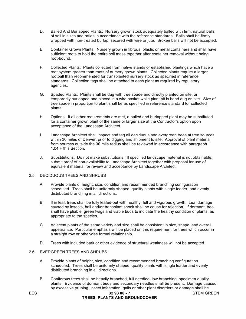
EES 32 93 00 - 7 STEM GREEN TREES, PLANTS AND GROUNDCOVER
D. Balled And Burlapped Plants: Nursery grown stock adequately balled with firm, natural balls of soil in sizes and ratios in accordance with the reference standards. Balls shall be firmly wrapped with non-treated burlap, secured with wire or jute. Broken balls will not be accepted.
E. Container Grown Plants: Nursery grown in fibrous, plastic or metal containers and shall have
sufficient roots to hold the entire soil mass together after container removal without being root-bound.
F. Collected Plants: Plants collected from native stands or established plantings which have a
root system greater than roots of nursery grown plants. Collected plants require a larger rootball than recommended for transplanted nursery stock as specified in reference standards. Collection tags shall be attached to each plant as required by regulatory agencies.
G. Spaded Plants: Plants shall be dug with tree spade and directly planted on site, or
temporarily burlapped and placed in a wire basket while plant pit is hand dug on site. Size of tree spade in proportion to plant shall be as specified in reference standard for collected plants.
H. Options: If all other requirements are met, a balled and burlapped plant may be substituted
for a container grown plant of the same or larger size at the Contractor's option upon acceptance of the Landscape Architect.
I. Landscape Architect shall inspect and tag all deciduous and evergreen trees at tree sources,
within 30 miles of Denver, prior to digging and shipment to site. Approval of plant material from sources outside the 30 mile radius shall be reviewed in accordance with paragraph 1.04.F this Section.
J. Substitutions: Do not make substitutions: If specified landscape material is not obtainable,
submit proof of non-availability to Landscape Architect together with proposal for use of equivalent material for review and acceptance by Landscape Architect.
2.5 DECIDUOUS TREES AND SHRUBS
A. Provide plants of height, size, condition and recommended branching configuration scheduled. Trees shall be uniformly shaped, quality plants with single leader, and evenly distributed branching in all directions.
B. If in leaf, trees shall be fully leafed-out with healthy, full and vigorous growth. Leaf damage
caused by insects, hail and/or transplant shock shall be cause for rejection. If dormant, tree shall have pliable, green twigs and viable buds to indicate the healthy condition of plants, as appropriate to the species.
C. Adjacent plants of the same variety and size shall be consistent in size, shape, and overall
appearance. Particular emphasis will be placed on this requirement for trees which occur in a straight row or otherwise formal relationship.
D. Trees with included bark or other evidence of structural weakness will not be accepted.
2.6 EVERGREEN TREES AND SHRUBS
A. Provide plants of height, size, condition and recommended branching configuration scheduled. Trees shall be uniformly shaped, quality plants with single leader and evenly distributed branching in all directions.
B. Coniferous trees shall be heavily branched, full needled, low branching, specimen quality
plants. Evidence of dormant buds and secondary needles shall be present. Damage caused by excessive pruning, insect infestation, galls or other plant disorders or damage shall be

EES 32 93 00 - 8 STEM GREEN TREES, PLANTS AND GROUNDCOVER
cause for rejection. Container grown evergreens will be acceptable subject to paragraph 2.04.D this Section.
C. Adjacent plants of the same variety and size shall be consistent in size, shape, and overall
appearance. Particular emphasis will be placed on this requirement for trees which occur in a straight row or otherwise formal relationship.
2.7 GROUND COVERS, VINES AND PERENNIALS
A. Provide plants established and well-rooted in removable containers or integral peat pots with not less than minimum number and length of canes, runners or blades as required by the reference standard.
2.8 ACCESSORIES
A. Tree Stakes: Two-inch diameter lodgepole stake, straight and true, treated for resistance to rot, 8 foot length.
B. Staking Wire: Annealed, galvanized steel, 12 gauge wire. C. Tree Collar: Non-stretch fabric with grommets, 1.5 inch wide by 12 inches length.
1. Supplier: Central Bag and Burlap Co., 2715 Blake Street, Denver, CO 80205, (303)
297-9955, or approved equal.
D. Wrapping Material: First quality 4 inch wide, bituminous impregnated tape, corrugated or crepe paper, specifically manufactured for tree wrapping and having qualities to resist insect infestation.
E. PVC: 3/4" diameter PVC pipe.
PART 3 - EXECUTION 3.1 EXAMINATION
A. Verification Of Conditions: Examine areas and conditions under which the Work of this Section will be performed. Report unsatisfactory or questionable conditions to the Landscape Architect. Do not proceed with the Work until unsatisfactory conditions have been corrected. Commencement of Work implies acceptance of all areas and conditions.
1. Verify that during grading, topsoil spreading and landscape grading operations, the
ground surface was cleaned of materials which might hinder final operations. 3.2 PREPARATION
A. Herbicide Treatment
1. Confirm Landscape Architects requirement to proceed with herbicide treatment of on site topsoil in accordance with Section 32 92 00. Herbicide treatment must be completed during the growing season.
2. Obtain Landscape Architects approval of topsoil ten (10) days after last herbicide application prior to planting in accordance with Section 32 91 13.
B. Protection: Protect areas in accordance with requirements. C. Layout: Stake locations of individual plants and outline areas for multiple plantings. Secure
Landscape Architect's approval prior to starting Work.

EES 32 93 00 - 9 STEM GREEN TREES, PLANTS AND GROUNDCOVER
3.3 GENERAL PLANTING REQUIREMENTS
A. Planting Season: Plant in accordance with paragraph above this Section. 3.4 TREES AND SHRUBS PLANTED IN INDIVIDUAL PLANT PITS OR TRENCHES
A. Excavation For Trees And Shrubs In Individual Plant Pits Or Trenches
1. Excavate pits, beds and trenches with sides shaped and sized as detailed. Scarify subsoil on bottom and sides of excavation.
2. Fill each pit with water to test drainage. Pits shall drain within 24 hours.
a. In the event non-draining soil is encountered, recommend to the Landscape Architect method to achieve subsurface drainage from details on the Drawings.
b. Drainage system shall be approved by Landscape Architect prior to installation. c. Payment for subsurface drainage not included in the original Drawings shall be in
accordance with the unit price submitted during base bid.
3. For balled and burlapped and container grown stock, excavate as shown on the Drawings. Adjust excavation to size of container width and depth, shaping excavation as indicated.
4. Preserve soil removed from tree and shrub planting excavations for reuse as tree and shrub planting soil.
B. Soil Preparation For Trees And Shrubs In Individual Plant Pits
1. Clean soil on plant pits of roots, plants, sods, stones over 1.5 inches, clay lumps,
asphaltic materials, concrete, metal and wire fragments and other extraneous materials harmful or toxic to plant growth. Remove contaminated subsoil.
2. Mix soil amendments with soil from pit at rates specified below:
70% soil from pit by volume 15% wood chips by volume 15% compost by volume
3. Uniformly mix planting soil mix, turning several times to achieve a uniform, evenly
blended consistency, free of all pockets of unblended materials and any clods or stones greater than 1.5 inches in their greatest dimension.
C. Planting Trees and Shrubs In Individual Plant Pits
1. Plant container grown and balled and burlapped (B&B) material in same manner except
where noted. 2. Place planting soil mix in pit and compact to depth which will place top of rootball at
specified height above surrounding grade. Set plants slightly high, as detailed and accepted by the Landscape Architect.
3. Set plant on layer of compacted planting soil mix, plumb and in center of pit or trench with top of ball at required elevation.
4. Place plant for best appearance for review and final orientation by the Landscape Architect.
5. Remove non-biodegradable root containers.
a. Wire Baskets: Cut and remove a minimum of the top 2/3 of wire baskets. b. Containers: Cut container cans on 2 sides with an approved can cutter; remove
container so as not to damage root balls; A spade shall not be used.

EES 32 93 00 - 10 STEM GREEN TREES, PLANTS AND GROUNDCOVER
6. Space fertilizer tablets evenly around root ball no higher than 1/3 of the way up the root ball. Place approximately 2 inches away from root tips for container stock, and adjacent to ball for B&B stock. Use at rates specified by manufacturer.
7. When set, place additional backfill around base and sides of root ball, and work each layer to settle backfill and eliminate voids and air pockets. When excavation is approximately 2/3 full, water thoroughly. Repeat watering until no more is absorbed.
8. Place remaining planting soil mix and tamp firmly. Water again after placing final layer of planting soil mix.
9. Dish top of backfill to allow for mulching as indicated. 10. Unless otherwise directed by Landscape Architect, do not cut tree leaders and remove
only injured or dead branches from trees and shrubs, if any. Make flush cuts perpendicular to the secondary branches being removed in accordance with the References.
11. Remove and replace excessively pruned or stock. 12. Stake trees immediately after planting, as detailed using stakes or guying as noted on
planting plan. Set trees plumb. Wrap only trees noted on plant list. 3.5 TREES, SHRUBS, PERENNIALS AND GROUNDCOVERS PLANTED IN PREPARED PLANTING
BEDS
A. Soil Preparation for Shrubs, Perennials And Groundcovers Planted In Prepared Planting Beds And Planters
1. Prior to placing topsoil, disc or scarify existing subsoil in planting beds and planters to a
minimum depth of 6 inches or to a depth as indicated in drawings using a cultimulcher or similar equipment. Remove roots, plants, sods, stones over 1.5 inches, clay lumps, asphaltic materials, concrete, metal and wire fragments and other extraneous materials harmful or toxic to plant growth. Remove contaminated subsoil.
2. Soil Preparation for Planting Beds
a. Soil Amendment Rates for Planting Beds
i. Organics: Apply 5 cubic yards per 1,000 square feet of 40% wood chips by volume and 60% organic material by volume.
ii. Fertilizer: Apply 150 pounds of Gro-Power Plus per 1,000 square feet. Verify application rate after reviewing soils analysis.
iii. Substantiate quantities with delivery tickets and empty manufacturer's bags on a daily basis to Landscape Architect.
b. Incorporate 50% of the required soil amendments and fertilizer. Thoroughly
rototill into existing subsoil to a depth of 5 inches to achieve a uniform, evenly blended consistency free of all pockets of unblended materials and any clods or stones greater than 1.5 inches.
c. Spread stockpiled topsoil in accordance with Section 32 9119 - Landscape Grading, over amended subsoil in all planting bed areas. Remove roots, plants, sods, stones over 1.5 inches, clay lumps, asphaltic materials, concrete, metal and wire fragments and other extraneous materials harmful or toxic to plant growth.
d. Incorporate remaining 50% of the required soil amendments and fertilizer with topsoil and existing soil. Rototill to a depth of 7 inches. Apply and rototill in fertilizer no more than 48 hours before planting.
e. Fill prepared planting bed with water and allow to percolate out before planting. If water does not drain out in 24 hours, notify Landscape Architect.
i. In the event non-draining soil is encountered, recommend to the
Landscape Architect method to achieve subsurface drainage. ii. Drainage system shall be approved by Landscape Architect prior to
installation.
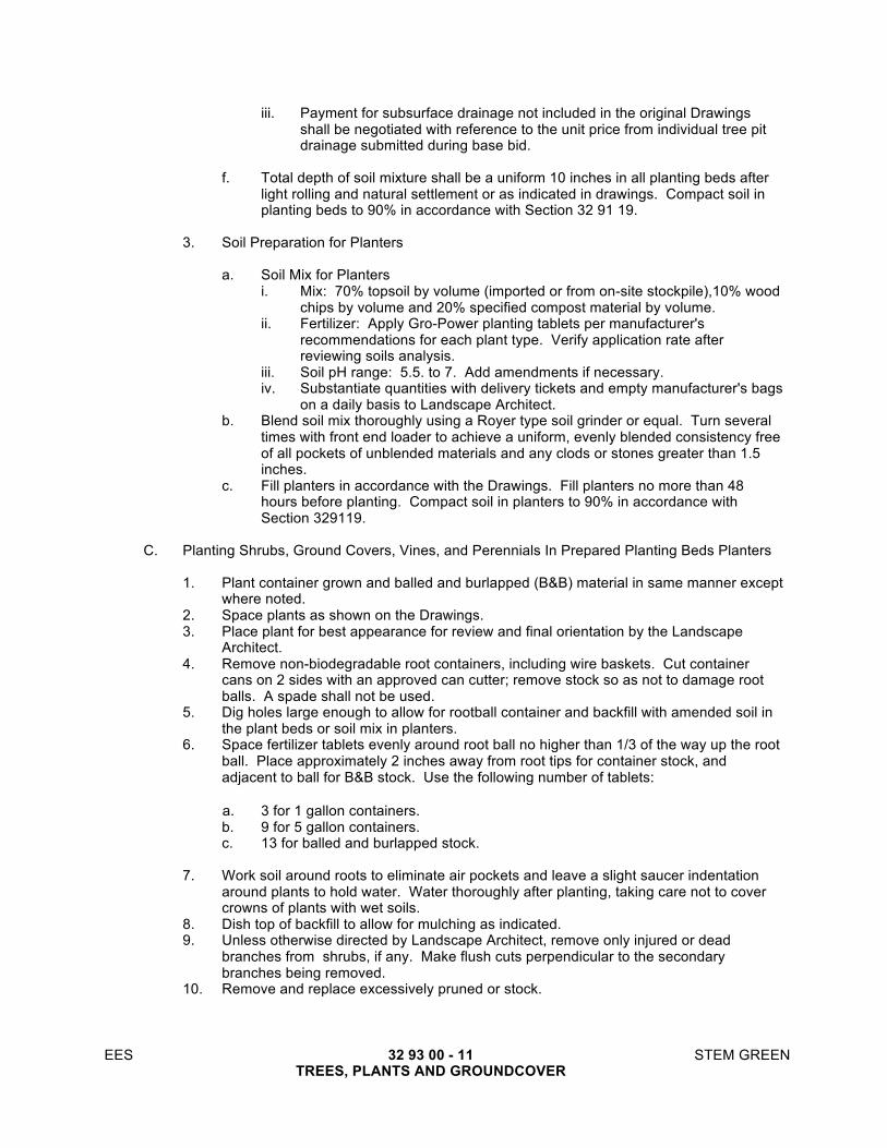
EES 32 93 00 - 11 STEM GREEN TREES, PLANTS AND GROUNDCOVER
iii. Payment for subsurface drainage not included in the original Drawings shall be negotiated with reference to the unit price from individual tree pit drainage submitted during base bid.
f. Total depth of soil mixture shall be a uniform 10 inches in all planting beds after
light rolling and natural settlement or as indicated in drawings. Compact soil in planting beds to 90% in accordance with Section 32 91 19.
3. Soil Preparation for Planters
a. Soil Mix for Planters
i. Mix: 70% topsoil by volume (imported or from on-site stockpile),10% wood chips by volume and 20% specified compost material by volume.
ii. Fertilizer: Apply Gro-Power planting tablets per manufacturer's recommendations for each plant type. Verify application rate after reviewing soils analysis.
iii. Soil pH range: 5.5. to 7. Add amendments if necessary. iv. Substantiate quantities with delivery tickets and empty manufacturer's bags
on a daily basis to Landscape Architect. b. Blend soil mix thoroughly using a Royer type soil grinder or equal. Turn several
times with front end loader to achieve a uniform, evenly blended consistency free of all pockets of unblended materials and any clods or stones greater than 1.5 inches.
c. Fill planters in accordance with the Drawings. Fill planters no more than 48 hours before planting. Compact soil in planters to 90% in accordance with Section 329119.
C. Planting Shrubs, Ground Covers, Vines, and Perennials In Prepared Planting Beds Planters
1. Plant container grown and balled and burlapped (B&B) material in same manner except
where noted. 2. Space plants as shown on the Drawings. 3. Place plant for best appearance for review and final orientation by the Landscape
Architect. 4. Remove non-biodegradable root containers, including wire baskets. Cut container
cans on 2 sides with an approved can cutter; remove stock so as not to damage root balls. A spade shall not be used.
5. Dig holes large enough to allow for rootball container and backfill with amended soil in the plant beds or soil mix in planters.
6. Space fertilizer tablets evenly around root ball no higher than 1/3 of the way up the root ball. Place approximately 2 inches away from root tips for container stock, and adjacent to ball for B&B stock. Use the following number of tablets:
a. 3 for 1 gallon containers. b. 9 for 5 gallon containers. c. 13 for balled and burlapped stock.
7. Work soil around roots to eliminate air pockets and leave a slight saucer indentation
around plants to hold water. Water thoroughly after planting, taking care not to cover crowns of plants with wet soils.
8. Dish top of backfill to allow for mulching as indicated. 9. Unless otherwise directed by Landscape Architect, remove only injured or dead
branches from shrubs, if any. Make flush cuts perpendicular to the secondary branches being removed.
10. Remove and replace excessively pruned or stock.

EES 32 93 00 - 12 STEM GREEN TREES, PLANTS AND GROUNDCOVER
3.6 FIELD QUALITY CONTROL
A. Tests: Costs of tests and material analyses made by the testing agency will be borne by the Owner when tests indicate compliance and by the Contractor when test indicated non-compliance.
B. Reviews
1. Pre-Planting Review
a. Plant Procurement Inspection
i. Contractor shall notify Landscape Architect upon selection of all trees and shall designate source and location for inspection. Proposed materials shall be flagged by the Contractor to facilitate inspection.
ii. Landscape Architect may choose to attach his seal to each tree or to representative samples. Inspection and/or sealing of plants by the Landscape Architect at the source does not preclude his rejection of trees for improper handling, transportation, storage, damage, insects or disease or otherwise not meeting this specification at the site of planting.
iii. Do not ship trees to site without the Landscape Architect's approval.
b. Plant Inspection i. All plant materials must be inspected by the Landscape Architect at
supplier's or contractor's nursery and at the site before planting commences. Tag acceptable plant material with Contractor's numbered tag and verify upon arrival at the project site. Notify Landscape Architect 48 hours in advance to request inspection of plant material. Any materials planted prior to acceptance are subject to rejection. Inspection of plant materials may be sequenced by major planting areas to accommodate efficient planting operations. All rejected materials must be removed from the site, replaced and reinspected before any additional inspections are made.
ii. The Landscape Architect may elect to inspect trees and shrubs at place of growth before planting, for compliance with requirements for genus, species, variety, size and quality. Landscape Architect retains the right to further inspect trees and shrubs for size and conditions of balls and root systems, insects, injuries and latent defects, and to reject unsatisfactory or defective material at any time during progress of work.
iii. If, in the opinion of the Landscape Architect, there is probable cause to suspect root damage, root binding, or disease conditions in the container stock plants, the Contractor will remove the container for the Landscape Architect's inspection before planting.
c. Grading: All finish grading shall be inspected by Landscape Architect prior to planting commencing. Correct any discrepancies prior to planting.
d. Staking: Stake all tree and shrub locations with flags. Landscape Architect shall inspect the staked locations before digging shall occur. The Contractor shall give the Landscape Architect 48 hours notice to request inspection of staked locations.
2. Substantial Completion
a. At the time of this walk-through, the Contractor shall have
i. Established all planted areas free of weeds, and neatly cultivated. All plant basins shall be in good repair. Pruning shall be completed.
ii. Verified installed irrigation system is fully operational with heads properly adjusted.

EES 32 93 00 - 13 STEM GREEN TREES, PLANTS AND GROUNDCOVER
iii. Cleaned all walkways and curbs of debris and litter and shall have cleaned areas of soil and debris left from planting operations.
3.7 CLEANUP
A. During Landscape Installation - All areas shall be reasonably clean at the end of each work day. Sidewalks and other paved areas shall be swept or washed down as needed. Keep pavements clean and work area in an orderly condition.
B. Project Completion: All debris, soil and trash resulting from landscape operations shall be
removed from the site. All paved areas shall be washed down. All tags shall be removed from plant material.
3.8 PROTECTION
A. Protect landscape work and materials from damage due to landscape operations, operations by other contractors and trades and trespassers.
B. Maintain protection during installation and maintenance periods. Treat, repair or replace
damaged landscape work as directed. C. Perform Work near and in Tree Protection Areas in accordance with Section 02111: Tree
and Plant Protection.
END OF SECTION

EES 32 93 00 - 14 STEM GREEN TREES, PLANTS AND GROUNDCOVER
THIS PAGE LEFT INTENTIONALLY BLANK

EES 33 00 00 - 1 STEM GREEN UTILITIES
SECTION 33 00 00
UTILITIES PART 1 - GENERAL 1.1 RELATED DOCUMENTS
A. Drawings and general provisions of the Contract, including General and Supplementary Conditions and Division 01 Specification Sections, apply to this Section.
1.2 SUMMARY
A. All work associated with water and sanitary sewer utilities shall follow the standards of the agency that owns the utility as well as conform to the requirements of other agencies having jurisdiction, such as the right of way property owner. The agency that owns the utility is listed on the Contract Documents. If there is no agency listed, the Contractor is responsible for determining the ownership of the utility. The utility specifications for construction within the utilities’ jurisdictions shall be followed.
B. Section includes the names of the water and sanitary sewer utility agencies and contact
information that have been provided are shown below:
Owner/Contact Name/Address Phone E-mail Address
City and County of Denver Brenda Boeck 201 W. Colfax, Dept. 203 Denver, CO 80202
720-865-3060 720-865-3048d [email protected]
Denver Water 1600 W. 12th Ave. Denver, CO 80204 303-628-6100
1.3 RELATED SECTIONS
A. SECTION 31 23 33 – UTILITY TRENCHING AND BACKFILL
B. SECTION 33 05 25 – SUPPORT AND PROTECTION OF UTILITIES
1.4 REFERENCES
A. The specifications and standards of jurisdictional agencies shall be used for utilities within
jurisdictional boundaries. PART 2 - PRODUCTS Not Applicable

EES 33 00 00 - 2 STEM GREEN UTILITIES
PART 3 - EXECUTION Not Applicable
END OF SECTION

EES 33 05 25 - 1 STEM GREEN SUPPORT AND PROTECTION OF UTILITIES
SECTION 33 05 25
SUPPORT AND PROTECTION OF UTILITIES PART 1 - GENERAL 1.1 RELATED DOCUMENTS
A. Drawings and general provisions of the Contract, including General and Supplementary Conditions and Division 01 Specification Sections, apply to this Section.
1.2 SUMMARY
A. Section includes specifications for maintenance, support, and protection of existing underground utilities.
1. Utilities, underground and above-ground, shall include but not be limited to: gas, telephone,
electric, steam, water, sanitary and storm sewers, irrigation lines, cable tv, conduits, fiber optics (including empty ducts), all abandoned utilities, etc., and their accessories, appurtenances and service connections. The type, size, location, and number of all known above-ground and underground utilities have been shown on the Contract Documents based on information obtained from the respective Utility Agencies; however, no guarantee is made as to the true, size, location or number of such utilities. It shall be the responsibility of the Contractor to verify the existence and location (vertically and horizontally) of all underground utilities along the route of the work, to ensure construction as shown in the Contract Documents. The omission from or the inclusion of existing or abandoned utility locations on the Contract Documents is not to be considered as the nonexistence of, or a definite location of, said utilities.
2. The Contractor shall at all times take extreme and proper precautions for the protection of utility
lines, the presence of which are known or can be determined by the examination of appropriate utility maps, exploratory excavations, etc. The Contractor shall be responsible for the repair of any damaged service or utility lines, and any utility line damaged by construction operations shall be repaired. The Contractor shall notify the appropriate sanitary, water, electric, gas, telephone, cable and fiber optic companies, as well as all other interested parties, prior to commencement of work in order to insure that there shall not be interruptions of these services during construction. Existing utility lines and utility poles, trees, shrubbery, fences, water mains, gas mains, sewers, cables, conduits, curb, gutter, walks, and other structures in the vicinity of the work not authorized to be removed, shall be supported and protected from damage by the Contractor until all construction and related work is complete. The Contractor shall be liable for all damages to existing facilities, structures, and property.
1.3 RELATED SECTIONS
A. SECTION 31 23 26 – EXCAVATION AND BACKFILL FOR STRUCTURES.
B. SECTION 31 23 33 – UTILITY TRENCHING AND BACKFILLING.
C. SECTION 33 00 00 – UTILITIES. 1.4 REQUIREMENTS
A. Maintain existing utilities and protect from damage as necessary to satisfy the requirements of jurisdictional Utility Agencies and related codes and regulations.

EES 33 05 25 - 2 STEM GREEN SUPPORT AND PROTECTION OF UTILITIES
B. Do not disconnect or shut down any part of the existing utilities and services, except by permission of authorities having jurisdiction.
C. Utilities to be removed shall not be removed until the shut-down and outage time can be kept to a
minimum. Do not remove an existing utility line or service from service until the replacement line, crossover, or capping is ready to be performed.
D. Provide shoring, underpinning, and structural support for existing utility lines and structures that
become suspended or otherwise unsupported because of adjacent excavation operations. 1.5 REQUIRED NOTIFICATIONS
A. The Contractor shall call the Utility Notification Center of Colorado at 811 or 1-800-922-1987 for utility locations at least three working days, not including day of notice, prior to any digging. The Contractor shall notify the Designer and utility owners before performing any such excavation work. Contact utility owners not covered by the Utility Notification Center of Colorado, such as Ditch Companies, owners of non-pressurized sewer lines and CDOT, by calling the affected utility owners directly.
B. Protect active underground utilities from damage. If underground utilities are damaged in any way,
notify the Designer and affected facility owner immediately for corrective action. The names of the Utility Agencies in the area and their respective addresses and telephone numbers are specified in Section 33 00 00 – UTILITIES.
PART 2 - PRODUCTS 2.1. NOT USED PART 3 - EXECUTION 3.1 RELOCATION AND ADJUSTMENT OF EXISTING UTILITIES
A. It is anticipated that certain utilities will be relocated by the affected utility companies prior to start of construction; this shall be confirmed with Utility Agencies prior to the start of construction. The names and contact information of such Utility Agencies are specified in Section 33 00 00 – UTILITIES.
B. If it is determined prior to, or during construction that any underground or aboveground utilities are
required to be relocated or adjusted, the Contractor shall notify the affected utility owner and Designer well in advance of the need to work in the affected area to schedule arrangements with the owner or owners of the affected utility to ensure the relocation is completed without delaying construction. It is the Contractor’s responsibility to coordinate all utility relocations and adjustments required to complete the scope of work designated within the construction plans and documents. All utilities requiring relocation and/or adjustment shall be constructed in accordance with each specific owner’s requirements and specifications.
1. Water Services – The type, size and location of water services are shown on the construction
plans based on the best available information, and it shall be the Contractor’s responsibility to identify and locate the services affected during construction. The Contractor is required to maintain service and adjust all water service taps and/or connections encountered during construction. Service adjustments and reconnections for homeowners, businesses, and facilities with special circumstances will be completed during a time frame to be determined by mutual agreement between the Contractor, Water Agency and customer. The Contractor is required to coordinate all service relocations with the affected parties well in advance of
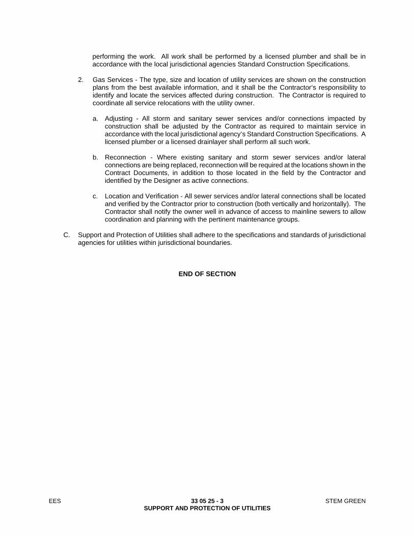
EES 33 05 25 - 3 STEM GREEN SUPPORT AND PROTECTION OF UTILITIES
performing the work. All work shall be performed by a licensed plumber and shall be in accordance with the local jurisdictional agencies Standard Construction Specifications.
2. Gas Services - The type, size and location of utility services are shown on the construction
plans from the best available information, and it shall be the Contractor’s responsibility to identify and locate the services affected during construction. The Contractor is required to coordinate all service relocations with the utility owner.
a. Adjusting - All storm and sanitary sewer services and/or connections impacted by
construction shall be adjusted by the Contractor as required to maintain service in accordance with the local jurisdictional agency’s Standard Construction Specifications. A licensed plumber or a licensed drainlayer shall perform all such work.
b. Reconnection - Where existing sanitary and storm sewer services and/or lateral
connections are being replaced, reconnection will be required at the locations shown in the Contract Documents, in addition to those located in the field by the Contractor and identified by the Designer as active connections.
c. Location and Verification - All sewer services and/or lateral connections shall be located
and verified by the Contractor prior to construction (both vertically and horizontally). The Contractor shall notify the owner well in advance of access to mainline sewers to allow coordination and planning with the pertinent maintenance groups.
C. Support and Protection of Utilities shall adhere to the specifications and standards of jurisdictional
agencies for utilities within jurisdictional boundaries.
END OF SECTION

EES 33 05 25 - 4 STEM GREEN SUPPORT AND PROTECTION OF UTILITIES
THIS PAGE LEFT INTENTIONALLY BLANK
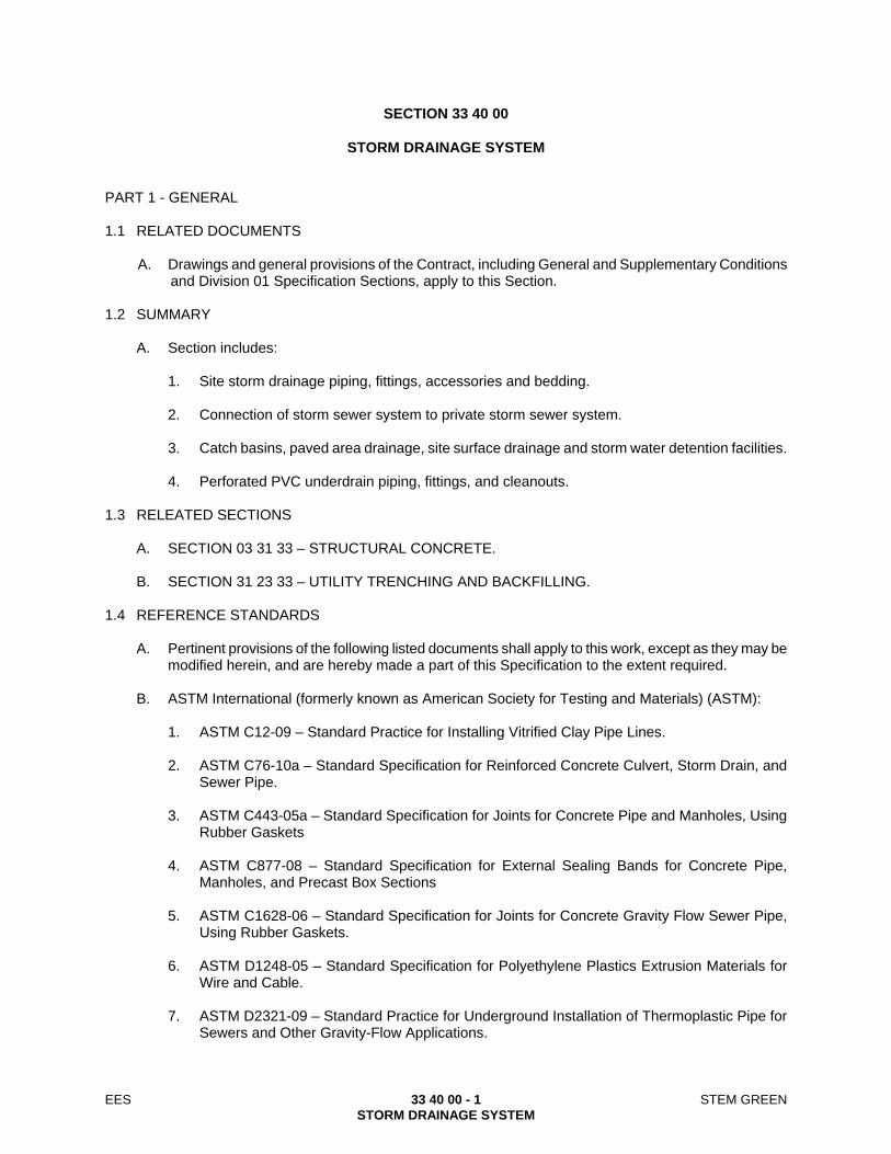
EES 33 40 00 - 1 STEM GREEN STORM DRAINAGE SYSTEM
SECTION 33 40 00
STORM DRAINAGE SYSTEM PART 1 - GENERAL 1.1 RELATED DOCUMENTS
A. Drawings and general provisions of the Contract, including General and Supplementary Conditions and Division 01 Specification Sections, apply to this Section.
1.2 SUMMARY
A. Section includes:
1. Site storm drainage piping, fittings, accessories and bedding.
2. Connection of storm sewer system to private storm sewer system.
3. Catch basins, paved area drainage, site surface drainage and storm water detention facilities.
4. Perforated PVC underdrain piping, fittings, and cleanouts. 1.3 RELEATED SECTIONS
A. SECTION 03 31 33 – STRUCTURAL CONCRETE.
B. SECTION 31 23 33 – UTILITY TRENCHING AND BACKFILLING. 1.4 REFERENCE STANDARDS
A. Pertinent provisions of the following listed documents shall apply to this work, except as they may be modified herein, and are hereby made a part of this Specification to the extent required.
B. ASTM International (formerly known as American Society for Testing and Materials) (ASTM):
1. ASTM C12-09 – Standard Practice for Installing Vitrified Clay Pipe Lines.
2. ASTM C76-10a – Standard Specification for Reinforced Concrete Culvert, Storm Drain, and
Sewer Pipe.
3. ASTM C443-05a – Standard Specification for Joints for Concrete Pipe and Manholes, Using Rubber Gaskets
4. ASTM C877-08 – Standard Specification for External Sealing Bands for Concrete Pipe,
Manholes, and Precast Box Sections
5. ASTM C1628-06 – Standard Specification for Joints for Concrete Gravity Flow Sewer Pipe, Using Rubber Gaskets.
6. ASTM D1248-05 – Standard Specification for Polyethylene Plastics Extrusion Materials for
Wire and Cable.
7. ASTM D2321-09 – Standard Practice for Underground Installation of Thermoplastic Pipe for Sewers and Other Gravity-Flow Applications.
EES 33 40 00 - 2 STEM GREEN STORM DRAINAGE SYSTEM
8. ASTM D3034-08 – Standard Specification for Type PSM Poly (Vinyl Chloride) (PVC) Sewer
Pipe and Fittings.
9. ASTM D3350-10a – Standard Specification for Polyethylene Plastics Pipe and Fittings Materials.
10. ASTM F405-05 – Standard Specification for Corrugated Polyethylene (PE) Pipe and Fittings.
11. ASTM C877-08 – Standard Specification for External Sealing Bands for Concrete Pipe,
Manholes, and Precast Box Sections.
12. ASTM C1433-10 – Standard Specification for Precast Reinforced Concrete Monolithic Box Sections for Culverts, Storm Drains, and Sewers.
13. ASTM C14-07 – Standard Specification for Nonreinforced Concrete Sewer, Storm Drain and
Culvert Pipe. 14. ASTM C990-09 – Standard Specification for Joints for Concrete Pipe, Manholes, and Precast
Box Sections Using Preformed Flexible Joint Sealants.
C. Storm Drainage Systems within the following jurisdictional boundaries follow the local agency requirements within the jurisdiction that the work is being performed:
1. City and County of Denver Storm Drainage Design and Technical Criteria Manual, Latest
Edition.
D. American Water Works Association (AWWA):
1. AWWA C905-10 – Polyvinyl Chloride (PVC) Water Transmission Pipe, Nominal Diameters 14 In. Through 48 In. (350 mm Through 1,200 mm).
E. American Association of Highway and Transportation Officials (AASHTO):
1. AASHTO M252-09 – Standard Specification for Corrugated Polyethylene Drainage Pipe.
2. AASHTO M199 – Standard Specification for Precast Reinforced Concrete Manhole Sections.
1.5 DEFINITIONS
A. Bedding: Fill placed under, beside and directly over pipe, prior to subsequent backfill operations.
B. Diameter of Pipe: Diameter stated in the Contract Documents refers to inside diameter of the pipe. 1.6 SUBMITTALS
A. Procedures for submittals:
1. Product Data: Data for each type of pipe, pipe accessories, and fittings.
2. Assurance/Control Submittals:
a. Certificates: Manufacturer’s certificate certifying that products meet or exceed specified ASTM requirements.

EES 33 40 00 - 3 STEM GREEN STORM DRAINAGE SYSTEM
1.7 QUALITY ASSURANCE
A. Regulatory Requirements: Perform work in accordance with applicable local authority having jurisdiction requirements for materials and installation of the work of this Section.
PART 2 - PRODUCTS 2.1 MATERIALS
A. NOT USED 2.2 PIPE MATERIALS
A. Polyvinyl Chloride (PVC) Pipe:
1. AWWA C905-10 – Polyvinyl Chloride (PVC) Water Transmission Pipe, Nominal Diameters 14 In. through 48 In. (350 mm through 1,200 mm), DR-18: Continuously mark pipe with manufacturer’s name, pipe size, cell classification, DR rating, and AWWA classification.
2. Joints: Integrally molded bell ends and factory supplied elastomeric gaskets and lubricants.
3. Underdrains: The pipe material for underdrains shall conform to the specifications for
Subdrainage Systems, except all solid pipe shall be ASTM 3034-08 – Standard Specification for Type PSM Poly(Vinyl Chloride) (PVC) Sewer Pipe and Fittings, SDR-35 Gravity Sewer PVC Pipe.
2.3 INLETS, CATCH BASINS AND JUNCTION BOXES
A. Lid and Frame: Cast iron as indicated on the Contract Documents.
B. Structure: As indicated on the Contract Documents.
C. Concrete: As specified in Section 2.1.
D. Precast Concrete: Precast Concrete inlet structures are not allowed without prior approval from the Town of Parker.
PART 3 - EXECUTION 3.1 PREPARATION
A. Hand trim excavations to required elevations. Correct over-excavation with fine aggregate.
B. Remove large stones or other hard matter which could damage the pipe or impede consistent backfilling operations.
3.2 BEDDING
A. Excavate pipe trench to 6 inches below the bottom of the outside of the pipe and place 6 inches of
bedding material. Hand work bedding to allow for accurate placement of pipe to elevations indicated on Contract Documents. Provide trench wall shoring as required.
B. Upon completion of pipe placement, continue with placement of pipe bedding material up to
springline of the pipe, working bedding material into the haunches of the pipe to gain adequate pipe support.

EES 33 40 00 - 4 STEM GREEN STORM DRAINAGE SYSTEM
C. Maintain optimum moisture content of bedding material to attain required compaction density.
Remove excess excavated material
D. The trench width shall be outside diameter plus 36 inches for all RCP storm sewer pipe. This width matches the local jurisdiction’s trench width parameters for RCP pipe.
3.3 INSTALLATION – PIPE
A. Install pipe, fittings and accessories in accordance with ASTM C12-09 – Standard Practice for Installing Vitrified Clay Pipe Lines, ASTM D2321-09 – Standard Practice for Underground Installation of Thermoplastic Pipe for Sewers and Other Gravity-Flow Applications, ASTM C443-05a – Standard Specification for Joints for Concrete Pipe and Manholes, Using Rubber Gaskets or ASTM C1628-06 – Standard Specification for Joints for Concrete Gravity Flow Sewer Pipe, Using Rubber Gaskets, and ASTM C877-08 – Standard Specification for External Sealing Bands for Concrete Pipe, Manholes, and Precast Box Sections or manufacturer’s published instructions, and state and local requirements.
B. Install pipe on minimum six inches of bedding as specified in Division 33 Sections. C. Lay pipe to slope gradients indicated on the Contract Documents, beginning at the downstream end. D. Install aggregate at sides and over top of pipe. Provide top cover to minimum compacted thickness
equal to paving subgrade indicated on the Contract Documents. E. Refer to Division 33 – Utilities for trenching requirements. Do not displace or damage pipe when
compacting. F. Connect to private storm sewer system, manholes, and inlets as indicated on the Contract
Documents.
3.4 INSTALLATION – CATCH BASINS, INLETS, AND JUNCTION BOXES
A. Form bottom of excavation clean and smooth to elevation indicated on Contract Documents.
B. Form and place cast-in-place concrete walls, sleeved at required elevation, to receive storm sewer pipe as indicated on the Contract Documents.
C. Precast inlets and catch basins may be used upon receiving an approved submittal meeting
standard specification requirements. 3.5 CONSTRUCTION
A. Interface with Other work: Coordinate the work with termination of storm sewer connection at existing inlet structure.
3.6 FIELD QUALITY CONTROL
A. Site Tests:
1. Perform inspections prior to and immediately after placing bedding.
2. Compaction:
a. If tests indicate that work does not meet specified requirements, remove work, replace and retest.

EES 33 40 00 - 5 STEM GREEN STORM DRAINAGE SYSTEM
b. Frequency of Tests: One test for each 250 lineal feet of trench or at a frequency that
meets local jurisdictional specifications; whichever is more stringent. .
END OF SECTION

EES 33 40 00 - 6 STEM GREEN STORM DRAINAGE SYSTEM
THIS PAGE LEFT INTENTIONALLY BLANK
Supplementary Conditions Last Approved 3-11-2011
APPENDIX A
SUPPLEMENTARY CONDITIONS FOR CONSTRUCTION PROJECTS

Supplementary Conditions Last Approved 3-11-2011
ATTACHMENT A SUPPLEMENTARY CONDITIONS FOR CONSTRUCTION PROJECTS
1. If discrepancies exist between Contract Documents, Contractor shall notify the
Architect and Owner immediately. The highest quality and/or greater quantity should be assumed by Contractor until the discrepancy can be clarified by the Architect and Owner. In terms of detail, the largest scale drawing or the drawing with the most detail should be assumed correct by Contractor until the discrepancy can be clarified by the Architect and Owner.
2. Record Keeping and Audits
a. For any work performed by Contractor on a cost reimbursement basis, Owner shall have the right to audit, inspect and copy all of Contractor’s books and records as it relates to the Project. Contractor will make available to Owner on 48 hours notice, either on site or at Contractor's local office, full and detailed records, accounts and books including but not limited to: accounting methods, work papers, computer files, supplier invoices, supplier rebates or refunds, purchase orders, subcontractor billings, sub contracts, consultant billings, payroll records, timekeeping records, travel vouchers, cost estimates, correspondence, inter-office correspondence, internal memos, conversation memorandums, policies and procedures, subcontract files, change order files, backcharge logs and supporting documentation, scheduling files, sources of cost estimate data and other records that relate to costs estimated or incurred or charged directly or indirectly to the Project. All financial information shall be maintained in accordance with generally accepted accounting principles.
b. It is the intent of Owner to audit wages, salaries, associated employee
benefits, equipment rates, and reimbursable expenses for both general condition costs and self-performed work, including all components of both direct and indirect costs.
c. Contractor will retain all records listed above for five (5) years after the date
of final payment for this Project and will make such records available to Owner during such period.
d. Contractor will include in his subcontracts the necessary clauses to establish
the right of Contractor and Owner to audit Subcontractors' records who perform work on a time and material or cost plus a fee basis, pertaining to the Project and the responsibility of the Subcontractor to retain all such records for five (5) years after the date of final payment to the Subcontractor and make such records available to Owner during such period.
e. Any cost billed to Owner by Contractor which is not allowed by the Contract
Documents will be deducted from payments due Contractor.

Supplementary Conditions Last Approved 3-11-2011
f. The initial cost of the audit will be paid for by the Owner. If extensive
additional audit review is reasonably necessary due to irregularities discovered, the entire cost of the audit shall be borne by the Contractor.
3. The following items and behaviors are strictly forbidden (there will be no
exceptions):
a. Alcohol and illegal drugs. All school/campus worksites are to be alcohol and drug free areas.
b. Fighting
c. Firearms or weapons
d. Loud or obnoxious noises (swearing, yelling, whistling, etc.) or behavior that
appears harassing or obscene (staring, gesturing, etc.). Everyone will behave in a professional manner on campus.
e. Pets
f. Audio equipment (radios, TV's, CD's, walkman, etc.) not including walky-
talky type radios used for field communication.
g. Offensive clothing. Clothing must not display obscene pictures, graphics, massages, or double meaning statements.
h. Talking to University of Denver students, staff, faculty or guests (even if
initiated by them).
i. Use of school facilities (i.e. bathrooms, concessions, tables, chairs, telephones, etc.). Use your own or company-provided equipment, facilities, port-o-lets, etc.
j. Parking in areas other that Contractor's designated parking areas (areas are
subject to change). Off limit parking areas include neighborhood streets within an eight-block radius of the campus, university visitor and non-gated lots. Be advised that vehicles improperly parked will be subject to towing at the Owner's expense.
k. Truck haul routes are restricted to those as identified.
l. Taking breaks of any duration outside the confines of the construction site.
m. The Project Superintendent(s), Contractor's Project Manager(s) and the
University of Denver's Project Manager will strictly enforce these rules of

Supplementary Conditions Last Approved 3-11-2011
conduct. Infractions will result in permanent expulsion from the site and Project.
n. The Contractor will obtain written confirmation from all Subcontractors,
suppliers and vendors that they will adhere to the above behavioral standards and that any infraction will result in permanent expulsion from the site and Project.
o. The Contractor's Superintendent(s), Project Manager(s) and the University of
Denver's Project Manager will strictly enforce these rules of conduct and can expel any person from the site for any infraction of the above behavioral standards.
4. A job sign will be allowed on the Project site and on the Contractor's trailers. 5. Safety and Security signs will be required on perimeter fences, including
emergency contact information. Security lights are required on all job trailers.
6. Contractor's safety program shall be available to the University upon request. Contractor is solely responsible for responding to all safety inspections related to the work, including but not limited to OSHA, CDPHE, and the University with or without advance notice. Contractor shall keep on site all Material Safety Data Sheets (MSDS) for all materials that they anticipate will be used on site as well as other pertinent information relating to employee protection. Contractor MSDS shall be available to University upon request.
7. Any proposals by the Contractor for changes to the Work or the method to be used in completing the Work shall include a reasonable cost estimate associated with the change
8. One or more of the original contract documents executed by the parties may
contain stricken language or other typed changes to standard form documents. Each such change may not be initialed by the parties. In the event of any dispute about what document reflects the agreement of the parties, the original signed contract documents in the possession of Owner shall govern.
END OF SUPLEMENTARY CONDITIONS

APPENDIX B
CONSTRUCTION SERVICES AGREEMENT

2
CONSTRUCTION SERVICES AGREEMENT This Agreement ("Agreement") is made and entered into as of ____________ and is by and between Colorado Seminary, a Colorado not for Profit Corporation which owns and operates the University of Denver ("University") and _________________________ ("Contractor"). University and Contractor hereby agree as follows: 1. Scope of Work.
a. The Scope of the Work ("Work"), and the time for performance thereof, is as set forth in Exhibit A attached hereto and made a part hereof for all purposes.
b. Upon execution of this Agreement, all services previously performed by Contractor on
behalf of University and included in the Scope of Work, shall become a part of the Work and shall be subject to the terms and conditions hereof.
c. Contractor shall obtain and make payment for any and all approvals and permits that are
necessary for the performance of the Work.
d. If the Work includes providing any designs, drawings, specifications or information of any kind ("Work Product") for the use of others in the construction, manufacture, fabrication, installation, or purchase of any items described by the Work Product, then Contractor and University shall mutually agree on a cost for such items ("Budget") prior to the commencement of the Work if such items are not included in the Contract Sum (as defined in Section 5 herein). The performance of the Work by Contractor shall be responsive to and in conformance with the Budget. If the costs, as bid or negotiated, exceed the Budget, University shall have the option to
(1) Authorize an increase in the Budget; (2) Authorize rebidding or negotiation; (3) Authorize revisions to the Work Product at no additional cost to University.
If option (3) is chosen, Contractor will, without additional compensation and in a prompt and timely manner, revise its Work Product to achieve a cost that is within the Budget. The foregoing shall be in addition to, and not in lieu of, any remedies that University may have at law or in equity.
e. University shall provide Contractor with a program of its requirements for the Work or for
work by others which utilize Contractor's Work Product ("Program"). The Program may be a series of documents or other communications. Contractor shall, at all times, conform its Work to the requirements of the Program and to the requirements of University.
2. The Project.
The Work as described in Exhibit A shall be:
3. Time for Commencement and Completion.
3
It is understood that time is of the essence of this Agreement and that Contractor shall complete all authorized Work in accordance with the time for performance described for the Work, and in a minimum of time consistent with the highest customs, standards, and practices of Contractor's business or profession. Work is to commence on ___________ with an estimated time of completion on or at ______________.
4. Contractor's Duties and Representations.
a. Notwithstanding anything to the contrary contained in this Agreement, University and Contractor agree and acknowledge that University is entering into this Agreement in reliance on Contractor's special and unique abilities with respect to performing the Work. The Contractor accepts the relationship of trust and confidence established between it and the University by this Agreement. Contractor covenants with University to use its best efforts, skill, judgment, and abilities to perform the Work and to further the interests of University in accordance with University’s requirements and procedures, in accordance with the highest standards of Contractor’s profession or business and in compliance with all applicable national, federal, state, municipal, laws, regulations, codes, ordinances, orders and with those of any other body having jurisdiction and the University’s Construction Rules of Conduct attached hereto as Exhibit B. All of Contractor’s employees, agents, partners or subcontractors who perform services for University shall sign Exhibit B prior to the commencement of the Work. Contractor warrants, represents, covenants, and agrees that there are no obligations, commitments, or impediments of any kind that will limit or prevent performance of the Work.
b. The Contractor warrants, represents, covenants, and agrees that all of the Work to be
performed by the Contractor under or pursuant to this Agreement shall be of the standard and quality which prevail among similar businesses and organizations of superior knowledge and skill engaged in providing similar services in major United States urban areas under the same or similar circumstances and involving a project such as the Project.
c. Contractor warrants, represents, covenants, and agrees that the Work will be accurate and
free from any material errors. The Contractor's duties as set forth herein shall at no time be in any way diminished by reason of any approval by the University nor shall the Contractor be released from any liability by reason of such approval by the University, it being understood that the University at all times is ultimately relying upon the Contractor's skill and knowledge in performing the Work.
d. The Contractor warrants, represents, covenants, and agrees that all persons connected with
the Contractor directly in charge of the Work are duly registered and/or licensed under the laws, rules and regulations of any authority having jurisdiction, if so required by such laws, rules and regulations.
e. The Contractor warrants, represents, covenants, and agrees to call to University's attention
anything of any nature in any drawings, specifications, plans, sketches, instructions, information, requirements, procedures, and other data supplied to the Contractor (by the University or any other party) which it regards in its opinion as unsuitable, improper, or inaccurate in connection with the purposes for which such document or data is furnished. Nothing shall excuse or detract from the Contractor's responsibilities or obligations hereunder in a case where such document or data is furnished unless the Contractor advises University in writing that in its opinion such document or data and any requests made

4
therein for action are unsuitable, improper, or inaccurate and University confirms in writing that it wishes the Contractor to proceed in accordance with the data as originally given.
f. The Contractor warrants, represents, covenants, and agrees to furnish efficient business
administration and superintendence and perform the Work in the best way and in the most expeditious and economical manner consistent with the interests of University.
g. The Contractor warrants, represents, covenants, and agrees that it shall, at its own cost, make
good any defects in the Work as soon as the Contractor becomes aware of such defects or is notified of such defects. Subject to the further provisions, including time limitations, of Section 8 of this Agreement, should the Contractor refuse or neglect to make good such defects within a reasonable time after receiving notice requesting such remedial work, then the University shall be entitled to make good such defective Work at the expense of the Contractor. This commitment by Contractor is in addition to, and not in substitution for, any other remedy for defective Work which the University may have at law or in equity.
h. Contractor warrants, represents, and agrees that if (i) it is a corporation or limited liability
company, then it is a corporation duly organized, validly existing and in good standing under the laws of the State of Colorado, or a foreign corporation or limited liability company duly authorized and in good standing to conduct business in the State of Colorado, that it has all necessary corporate power and has received all necessary corporate approvals to execute and deliver the Agreement, and the individual executing the Agreement on behalf of Contractor has been duly authorized to act for and bind Contractor; or (ii) if it is a partnership, limited partnership, or limited liability partnership, then it has all necessary partnership power and has secured all necessary approvals to execute and deliver this Agreement and perform all its obligations hereunder; and the individual executing this Agreement on behalf of Contractor has been duly authorized to act for and bind Contractor.
i. Contractor warrants, represents, and agrees that neither the execution and delivery of this
Agreement by Contractor nor the performance of its obligation hereunder will result in the violation of any provision, if a corporation, of its articles of incorporation or by-laws, if a limited liability company, of its articles of organization or regulations, or if a partnership, by any partnership agreement by which Contractor is bound, or any agreement by which Contractor is bound or to the best of the Contractor's knowledge and belief, will conflict with any order or decree of any court or governmental instrumentality relating to Contractor.
j. Contractor agrees as a part of this Agreement that it will comply with all applicable state and
federal laws, rules, regulations and executive orders governing discrimination on the basis of race, creed, color, sex, or handicap as amended or as may be further amended hereafter.
k. Contractor shall not knowingly employ or contract with an illegal alien to perform work
under this Agreement or enter into a contract with a subcontractor that fails to certify to Contractor that the subcontractor shall not knowingly employ or contract with an illegal alien to perform work under this Agreement. Contractor represents, warrants, and agrees that it has verified that it does not employ any illegal aliens. Failure to comply with any requirement of this provision shall be cause for termination for breach and Contractor shall be liable for actual and consequential damages.
l. Except for the obligation of University to pay Contractor certain fees and expenses pursuant
to the terms of this Agreement, University shall have no liability to Contractor or to anyone claiming through or under Contractor by reason of the execution or performance of this

5
Agreement. Notwithstanding any obligation or liability of University to Contractor, no present or future partner or affiliate of University or any agent, officer, director, employee, or trustee of the University, or departments or divisions comprising the University, or anyone claiming under University has or shall have any personal liability to Contractor or to anyone claiming through or under Contractor by reason of the execution or performance of this Agreement.
5. The Contract Sum.
a. The University shall pay Contractor in current funds for the performance of the Work, subject to adjustments, additions or deletions, if any, the contract sum of ____________________($_________). (All references to dollars shall mean U.S. currency in this Agreement).
b. The Contract Sum includes any applicable Federal, State or Local Sales or use tax payable
on this transaction. 6. Payment Terms.
a. Provided that an application for payment is received by University not later than the thirtieth (30th) day of a calendar month, University shall make payment to Contractor no later than the fifteenth (15th) day of the following month. If an application is received by the University after the date fixed above, payment shall be made by the University not later than thirty (30) days after the University receives the application for payment. Contractor shall submit to the University an application for payment covering the services performed to date which application shall be accompanied by waivers of mechanic’s and materialmen’s liens for all work performed and materials delivered prior to the last date covered by the application for payment and other forms, statements, invoices, and payroll reports that University may reasonably require to support the amount requested and to be submitted. The University will approve or disapprove the amount reflected in such application and if University approves such amount or any portion of such amount, it shall pay to Contractor the amount so approved, provided Contractor is not in breach of or in default under this Agreement. If University disapproves any amount requested by Contractor, University shall give Contractor specific reasons for its disapproval in writing.
b. The cumulative amounts of monthly progress payments as set forth in this Article ("Progress
Payment") shall not exceed the Contract Sum.
c. Thirty (30) days after final completion of the Work and acceptance thereof by University or as soon thereafter as possible, Contractor shall submit a final request ("Final Request") which shall set forth all amounts due and remaining unpaid to Contractor and upon approval thereof by University, University shall pay to Contractor the amount due ("Final Payment") under such Final Request.
d. Any provision hereof to the contrary notwithstanding, University shall not be obligated to
make any payment (whether a Progress Payment or Final Payment) to Contractor hereunder if any one or more of the following conditions precedent exist:
(1) Contractor is in breach or default under this Agreement;

6
(2) Any part of such payment is attributable to Work which is not performed in accordance with this Agreement; provided, however, such payment shall be made as to the part thereof attributable to Work which is performed in accordance with this Agreement;
(3) Contractor has failed to make payments promptly to its contractors or
subcontractors or other third parties used in connection with the Work for which University has made payment to Contractor; or
(4) If University, in its good faith judgment, determines that the portion of the
compensation then remaining unpaid will not be sufficient to complete the Work in accordance with this Agreement, no additional payments will be due Contractor hereunder unless and until Contractor, at its sole cost, performs a sufficient portion of the Work so that such portion of the compensation then remaining unpaid is determined by University to be sufficient to so complete the Work.
e. No partial payment made hereunder shall be or construed to be final acceptance or approval
of that part of the Work to which such partial payment relates or relieve Contractor of any of its obligations hereunder with respect thereto.
f. Contractor shall promptly pay all bills for labor and material performed and furnished by
others in connection with the performance of the Work.
g. The acceptance of Final Payment shall constitute a waiver of all claims by the Contractor except those previously made in writing and identified by the Contractor as unsettled at the time of the Final Request for payment. Contractor warrants that title to all Work covered by this Agreement will pass to University upon acceptance of Final Payment and will be free and clear of liens, claims, security interest or other encumbrances.
h. University shall have the right to verify the details set forth in Contractor's billings,
certificates, and statements, either before or after payment therefore, by (1) inspecting the books and records of Contractor at mutually convenient times; (2) examining any reports with respect to this Project; (3) interviewing Contractor's business employees; (4) visiting any place where performance of all or a portion of the Project occurs; and (5) other reasonable action.
i. Contractor shall not suffer or permit any mechanics' or materialmen's liens to be filed against
the Project for services performed, or materials, machinery and equipment for which payment has been made by University or for which an application for payment has not been properly submitted to University. Final payment for the Work shall not be due until Contractor has delivered to University a complete release of all liens and claims including releases of liens and claims from all subcontractors arising out of this Agreement.
j. If any lien shall be filed against the Project relating to the Work performed or to be performed under this Agreement in violation of the terms of this Agreement, including any lien filed by any subcontractor and University has paid for such work, Contractor, at its sole expense, shall, within ten (10) days following the filing of the lien, cause the release and discharge of such lien, whether by payment or bonding over. Additionally, Contractor shall be liable to University for all damages incurred by University in any way relating to the filing of any lien in violation of the terms of this Agreement, including any attorneys’ fees

7
and costs incurred by University. Contractor shall promptly notify University of the filing of any such lien or statement of intent to file a lien against the Project or any part thereof.
7. Ownership and Use of Documents.
a. All drawings, specifications, computations, sketches, data, photographs, tapes, renderings, models, publications, and other materials particular to the Work prepared by Contractor or Contractor's contractors and subcontractors ("Work Material"), are the property of the University and for its exclusive use and reuse at any time without further compensation and without any restrictions.
b. Except for such Work Material which is intended to be made public as part of the Project,
Contractor shall treat all such Work Material as confidential, and Contractor shall neither use any such Work Material or copies thereof on other work nor disclose such material or information to any other party without University's prior written approval.
8. Default and Termination.
a. In the event of substantial failure by a party hereunder to perform in accordance with the terms hereof, the other party may terminate this Agreement upon seven (7) days’ written notice of termination setting forth the nature of the failure (the termination shall not be effective if the failure is fully cured prior to the end of the seven-day period), provided that said failure is through no fault of the terminating party.
b. University may terminate this Agreement, without any right to cure on the part of the
Contractor upon giving seven (7) days' advance notice and take possession of the site and of all materials, equipment, tools and construction equipment and machinery thereon owned by the Contractor and may finish the Work by whatever reasonable method the University may deem expedient, if the Contractor:
(1) Persistently or repeatedly refuses or fails to supply enough properly skilled workers
or proper materials;
(2) Fails to make payment to subcontractors for material or labor
(3) Persistently disregards laws, ordinance or rules, regulation or orders of a public authority having jurisdiction; or
(4) Otherwise is guilty of a material breach of this Agreement.
Upon termination pursuant to this paragraph, the Contractor shall be entitled to payment of such amount as shall compensate Contractor for the services satisfactorily performed from the time of the last payment date to the termination date in accordance with this Agreement; provided the Contractor shall have delivered to University such statements, accounts, reports and other materials as required by clause (d) below, and provided that Contractor shall have delivered to University all reports, documents and other materials prepared by Contractor prior to termination. University shall not be required to reimburse Contractor for any services performed or expenses incurred after the date of the termination notice.
c. A termination under sections a and b above shall not relieve the Contractor or any of its employees of liability for violations of this Agreement or any other act or omission of the

8
Contractor and the provisions of Paragraphs 6.h., 9, 12.f., and 12.i. shall survive the termination of this Agreement. In the event of a termination under Sections 8 a or b above, Contractor hereby consents to employment by University of a substitute Contractor to complete the Work under this Agreement, with the substitute Contractor having all rights and privileges of the original Contractor of the Project. If Contractor is terminated pursuant to Section a or b above, and the cost to complete the Work exceeds the remaining balance of the Contract Sum, then Contractor shall be liable to University and shall reimburse University on demand for the amount of such excess.
d. As of the date of termination of this Agreement, Contractor shall furnish to University all
statements, accounts, reports, and other materials as are required hereunder or as have been prepared by Contractor in connection with its responsibilities hereunder. University shall have the right to use the ideas and designs therein contained for the completion of the work hereunder or otherwise. In the event of termination of this Agreement or upon completion of the Work hereunder, the University may, at all times, retain the originals of all such lists, publications, data, drawings, originals of renderings, special art work, or models. All such lists, publications, data, drawings, plans, specifications, renderings and models, etc. are the property of the University as described in Section 12.f hereof. They are not to be used by any person other than the University on other projects unless expressly authorized by the University.
e. If Contractor fails to cure any default hereunder for which cure is permitted within seven (7)
days after receiving written notice of such default, University shall be entitled (but shall not be obligated) to cure any such default and shall have the right to offset against all amounts due to Contractor hereunder, any and all reasonable expenses incurred in connection with such curative actions.
9. Indemnification.
a. TO THE FULLEST EXTENT PERMITTED BY APPLICABLE LAW, THE CONTRACTOR AND ITS AGENTS, PARTNERS, EMPLOYEES, AND SUBCCONTRACTORS (COLLECTIVELY "INDEMNITORS") SHALL AND DO AGREE TO INDEMNIFY, PROTECT, DEFEND WITH COUNSEL APPROVED BY UNIVERSITY, AND HOLD HARMLESS THE UNIVERSITY, ITS OFFICERS, DIRECTORS, TRUSTEES, EMPLOYEES AND AGENTS (COLLECTIVELY "INDEMNITEES") FROM AND AGAINST ALL CLAIMS, DAMAGES, LOSSES, LIENS, CAUSES OF ACTION, SUITS, JUDGMENTS AND EXPENSES, INCLUDING ATTORNEY FEES, OF ANY NATURE, KIND, OR DESCRIPTION (COLLECTIVELY "LIABILITIES") OF ANY PERSON OR ENTITY WHOMSOEVER ARISING OUT OF, CAUSED BY, OR RESULTING FROM THE PERFORMANCE OF THE WORK OR ANY PART THEREOF WHICH ARE CAUSED IN WHOLE OR IN PART BY ANY NEGLIGENT ACT OR OMISSION OF THE CONTRACTOR, ANYONE DIRECTLY OR INDIRECTLY EMPLOYED BY IT OR ANYONE FOR WHOSE ACTS IT MAY BE LIABLE EVEN IF IT IS CAUSED IN PART BY THE NEGLIGENCE OR OMISSION OF ANY INDEMNITEE, SO LONG AS IT IS NOT CAUSED BY THE SOLE NEGLIGENCE OR WILLFUL MISCONDUCT OF ANY INDEMNITEE. IN THE EVENT MORE THAN ONE OF THE INDEMNITORS ARE CONNECTED WITH AN ACCIDENT OR OCCURRENCE COVERED BY THIS INDEMNIFICATION, THEN EACH OF SUCH INDEMNITORS SHALL BE JOINTLY AND SEVERALLY RESPONSIBLE TO THE INDEMNITEES FOR INDEMNIFICATION AND THE ULTIMATE RESPONSIBILITY AMONG SUCH INDEMNITORS FOR THE LOSS

9
AND EXPENSE OF ANY SUCH INDEMNIFICATION SHALL BE SETTLED BY SEPARATE PROCEEDINGS AMONG THEM AND WITHOUT JEOPARDY TO ANY INDEMNITEE. THE PROVISIONS OF THIS ARTICLE SHALL NOT BE CONSTRUED TO ELIMINATE OR REDUCE ANY OTHER INDEMNIFICATION OR RIGHT WHICH UNIVERSITY OR ANY OF THE INDEMNITEES HAS BY LAW.
b. CONTRACTOR SHALL PROTECT AND INDEMNIFY THE UNIVERSITY FROM
AND AGAINST ALL CLAIMS, DAMAGES, JUDGMENTS AND LOSS ARISING FROM INFRINGEMENT OR ALLEGED INFRINGEMENT OF ANY UNITED STATES PATENT, OR COPYRIGHT, ARISING BY OR OUT OF ANY OF THE WORK PERFORMED HEREUNDER OR THE USE BY CONTRACTOR, OR BY UNIVERSITY AT THE DIRECTION OF CONTRACTOR, OF ANY ARTICLE OR MATERIAL, PROVIDED THAT UPON BECOMING AWARE OF A SUIT OR THREAT OF SUIT FOR PATENT OR COPYRIGHT INFRINGEMENT, UNIVERSITY SHALL PROMPTLY NOTIFY CONTRACTOR AND CONTRACTOR SHALL BE GIVEN FULL OPPORTUNITY TO NEGOTIATE A SETTLEMENT. ANY SETTLEMENT SHALL BE SUBJECT TO THE PRIOR APPROVAL BY THE UNIVERSITY IF SUCH SETTLEMENT IMPOSES ANY OBLIGATIONS ON THE UNIVERSITY. CONTRACTOR DOES NOT WARRANT AGAINST INFRINGEMENT BY REASON OF UNIVERSITY'S DESIGN OF ARTICLES OR THE USE THEREOF IN COMBINATION WITH OTHER MATERIALS OR IN THE OPERATION OF ANY PROCESS. IN THE EVENT OF LITIGATION, UNIVERSITY AGREES TO COOPERATE REASONABLY WITH CONTRACTOR AND PARTIES SHALL BE ENTITLED, IN CONNECTION WITH ANY SUCH LITIGATION, TO BE REPRESENTED BY COUNSEL AT THEIR OWN EXPENSE.
c. The indemnities contained herein shall survive the termination of this Agreement for any
reason whatsoever. 10. Independent Contractor; Subcontractors.
a. Contractor recognizes that it is engaged as an independent contractor and acknowledges that University will have no responsibility to provide transportation, insurance or other fringe benefits normally associated with employee status. Contractor, in accordance with its status as an independent contractor, covenants and agrees that it shall conduct itself consistent with such status, that it will neither hold itself out as nor claim to be an officer, partner, employee or agent of University by reason hereof, and that it will not by reason hereof make any claim, demand or application to or for any right or privilege applicable to an officer, partner, employee or agent of University, including, but not limited to, unemployment insurance benefits, social security coverage or retirement benefits. Contractor hereby agrees to make its own arrangements for any of such benefits as it may desire and agrees that it is responsible for all income taxes required by applicable law.
b. Those portions of the Work that Contractor does not customarily perform with its own
personnel shall be performed under subcontracts. Contractor shall have full authority over the execution of all subcontracts, as the Contractor is responsible for the general management of construction operations of the Work. Contractor shall be responsible for all subcontractors complying with the terms of this Agreement and related documents with respect to subcontractors’ portion of the Work. Any breach of any of the terms of this Agreement by a subcontractor shall be a breach by Contractor.

10
11. Insurance. a. Contractor, consistent with its status as an independent contractor, shall carry at least the following
insurance in such form, in such companies and in such amounts (unless otherwise specified) as University may require:
(1) Worker's Compensation and Employer’s Liability insurance, including All States
Endorsement, to the extent required by federal law and complying with the laws of the State of Colorado, and to the extent necessary to protect University against workers' compensation claims;
(2) Commercial General Liability insurance, including Personal Injury, Completed
Operations/Products Liability, for at least One Million Dollars ($1,000,000) per occurrence and Two Million Dollars ($2,000,000) aggregate and Fire Damage Liability of a minimum of $250,000;
(3) Comprehensive Automobile Liability insurance covering all owned, non-owned or
hired automobiles to be used by Contractor, with coverage for at least One Million Dollars ($1,000,000) Combined Single Limit Bodily Injury and Property Damage;
b. Contractor shall deliver to University:
(1) Certificates evidencing the existence of all such insurance promptly after the
execution and delivery hereof and prior to the continued or additional performance of any services to be performed by Contractor hereunder from or after the date of this Agreement; and
(2) Replacement certificates within ten (10) days after the expiration of any such insurance. If, however, Contractor fails to pay any of the renewal premiums for the expiring policies, University shall have the right to make such payments and set off the amount thereof against the next payment coming due to Contractor under this Agreement; and
(3) Such Certificates shall name University as an Additional Insured, with the exception
of Workers' Compensation and Employer's Liability, and shall provide that the policies will not be canceled until after thirty (30) days' unconditional written notice to University, giving the University the right to pay the Premium to maintain coverage, in which event Paragraph 11.b.(2) shall apply.
c. The insurance policies required in this Agreement shall be kept in force for the periods
specified below:
(1) Commercial General Liability Insurance shall be kept in force until receipt of final payment by the Contractor;
(2) Workers' Compensation Insurance shall be kept in force until the Contractor's
Services have been fully performed and accepted by University in writing. 12. Miscellaneous.

11
a. Assignment. This Agreement is a personal service contract for the services of Contractor, and Contractor's interest in this Agreement, duties hereunder and/or fees due hereunder may not be assigned or delegated to a third party. The benefits and burdens of this Agreement are, however, assignable by University.
b. Entire Agreement; Modifications. This Agreement supersedes all prior agreements, written
or oral, between Contractor and University and shall constitute the entire Agreement and understanding between the parties with respect to the subject matter hereof. This Agreement and each of its provisions shall be binding upon the parties and may not be waived, modified, amended or altered except by a writing signed by University and Contractor.
c. Captions. The captions of paragraphs in this Agreement are for convenience only and shall
not be considered or referred to in resolving questions of interpretation or construction.
d. Governing Law. This Agreement and all of the rights and obligations of the parties hereto and all of the terms and conditions hereof shall be construed, interpreted and applied in accordance with and governed by and enforced under the laws of the State of Colorado.
e. Waivers. No delay or omission by either of the parties hereto in exercising any right or
power accruing upon the non compliances or failure of performance by the other party hereto of any of the provisions of this Agreement shall impair any such right or power or be construed to be a waiver thereof. A waiver by either of the parties hereto of any of the covenants, conditions or agreements hereof to be performed by the other party hereto shall not be construed to be a waiver of any subsequent breach thereof or of any other covenant, condition or agreement herein contained.
f. Proprietary Interests. Contractor agrees that all reports, studies, plans, models, drawings,
specifications, and any other information or data of any type relating to its activities hereunder, whether or not any of the same is accepted or rejected by University, shall remain the property of University and shall not be used or published by Contractor or any other party without the express prior consent of University. In implementation of the foregoing, Contractor hereby grants and assigns to University all rights and claims of whatever nature and whether now or hereafter arising in and to any and all of such reports, studies, plans, models, drawings, specifications, and other information or data and shall cooperate fully with University in any steps University may take to obtain copyrights, trademark or like protections with respect thereto. All information owned, possessed or used by University which is communicated to, learned, developed or otherwise acquired by Contractor in the performance of consulting services for University, which is not generally known to the public, shall be confidential and Contractor shall not, beginning on the date of first association or communication between University and Contractor and continuing through the term of this Agreement and any time thereafter, disclose, communicate or divulge, or permit disclosure, communication or divulgence, to another or use for Contractor's own benefit or the benefit of another, any such confidential information, unless required by law. Except when defined as part of the Work, Contractor shall not make any press releases, public statements, or advertisement referring to the Project or the engagement of Contractor as an independent contractor of University in connection with the Project, or release any information relative to the Project for publications, advertisement or any other purpose without the prior written approval of University. Contractor shall obtain assurances similar to those contained in this Subparagraph from persons, contractors, and subcontractors retained by Contractor. Contractor acknowledges and agrees that a breach by Contractor of the provisions hereof will cause University irreparable injury and damage. Notwithstanding

12
anything to the contrary herein, Contractor, therefore, expressly agrees that University shall be entitled to injunctive and/or other equitable relief in any court of competent jurisdiction to prevent or otherwise restrain a breach of this Agreement.
g. Binding Effect. This Agreement shall be binding upon and inure to the benefit of the parties
hereto and their respective permitted assigns and successors.
h. Appointment. University hereby expressly reserves the right from time to time to designate by notice to Contractor a representative to act partially or wholly for University in connection with the performance of University's obligations hereunder. Contractor shall act only upon instructions from such representative unless otherwise specifically notified to the contrary.
i. Records. Records of Contractor's costs, reimbursable expenses pertaining to the Project and
payments shall be available to University or its authorized representative during business hours and shall be retained for three years after final Payment or abandonment of the Project, unless University otherwise instructs Contractor in writing.
j. Notices. All notices, consents, approvals, demands, requests or other communications
provided for or permitted to be given under any of the provisions of this Agreement shall be in writing and shall be deemed to have been duly given or served when delivered by hand delivery or when deposited in the U.S. mail by registered or certified mail, return receipt requested, postage prepaid, and addressed as follows:
(1) If to University: University of Denver (Colorado Seminary)
Department of Facilities Management 2400 South Race Street Denver, CO 80208
With respect to legal matters: University of Denver (Colorado Seminary) University Counsel 2199 S. University Blvd.
Denver, CO 80208 Phone: 303.871.4646 Fax: 303.871.2811
If to Contractor:
(2) or to such other person or address as may be given in writing by either party to the
other in accordance with the aforesaid.
k. Severability. If any provision of this Agreement is held to be unenforceable or invalid by a court of competent jurisdiction, such provision shall be reformed to the minimum extent necessary to cause such provision to be valid, enforceable and legal while preserving the intent of the parties as expressed in, and the benefits to the parties provided by, this Agreement. In the event that any provision cannot be so reformed, such provision shall be severed from this Agreement and an equitable adjustment shall be made to this Agreement (including, without limitation, addition of necessary further provisions to this Agreement) so as to give effect to the intent so expressed and the benefits so provided

13
l. Enforcement. It is acknowledged and agreed that Contractor's services to University are unique, which gives Contractor a peculiar value to University and for the loss of which University cannot be reasonably or adequately compensated in damages; accordingly, Contractor acknowledges and agrees that a breach by Contractor of the provisions hereof will cause University irreparable injury and damage. Notwithstanding anything to the contrary herein, Contractor, therefore, expressly agrees that University shall be entitled to injunctive and/or other equitable relief in any court of competent jurisdiction to prevent or otherwise restrain a breach of this Agreement, but only if University is not in breach of this Agreement.
m. Dispute Resolution.
(1) The parties shall attempt in good faith to resolve any dispute arising out of or
relating to this Agreement promptly by negotiation between executives who have authority to settle the controversy and who are at a higher level of management than the persons with direct responsibility for administration of this Agreement. Any party may give the other party written notice of any dispute not resolved in the normal course of business. Within ten (10) days after delivery of this notice, the receiving party shall include: (a) a statement of the receiving party's position and a summary of arguments supporting that position; and (b) the name and title of the executive who will represent that party and of any other person who will accompany the executive. Within ten (10) days after delivery of the disputing party's notice, the executives of both parties shall meet at a mutually acceptable time and place, and thereafter as often as they reasonably deem necessary, to attempt to resolve the dispute. All reasonable requests for information made by one party to the other party will be honored. If the matter has not been resolved within thirty (30) days after the disputing party's notice, or if the parties fail to meet within thirty (30) days, either party may initiate arbitration proceedings in accordance with the Construction Industry Arbitration Rules of the American Arbitration Association currently in effect. All negotiations pursuant to this clause are confidential and shall be treated as compromise and settlement negotiations for purposes of the Federal Rules of Evidence and State Rules of Evidence.
(2) Disputes not resolved by negotiation shall be decided by arbitration. A demand for
arbitration shall be filed in writing with the other party to this Agreement and with the American Arbitration Association and the arbitration shall be held in Denver, CO before and according to the rules and practices of the American Arbitration Association from time to time in force, except that if such rules and practices related to discovery shall conflict with Rules 26 through 36 of the Colorado Rules of Civil Procedure or other provisions of Colorado law governing discovery then in force, such Colorado rules and provisions shall govern. The intent hereof is that the parties shall have the right and obligation to prepare and receive disclosures, submit interrogatories and requests for production of documents, take depositions and submit requests for admission in accordance with the Colorado Rules of Civil Procedure. The arbitrator shall apply and be governed by the substantive law of Colorado in reaching his or her decision and shall prepare a reasoned decision on each issue submitted to arbitration pursuant hereto. This agreement of the parties to submit disputes to binding arbitration shall be specifically enforceable. Without limiting the generality of the foregoing, the following shall be considered disputes for purposes of this paragraph: (a) all questions relating to the breach of any obligation or condition hereunder, or relating to the termination of this Agreement;

14
(b) all questions relating to the representations, negotiations and other proceedings leading to the execution hereof; and (c) all questions as to whether the right to arbitrate any question exists. The award rendered by the arbitrator or arbitrators shall be final, and judgment may be entered upon it in accordance with applicable law in any court having jurisdiction thereof. Except by written consent of the person or entity sought to be joined, no arbitration arising out of or relating to this Agreement under which such arbitration arises shall enjoin a person not a party to this Agreement, unless it is shown at the time the demand for arbitration is filed that (1) such person or entity is substantially involved in common question of fact or law; (2) the presence of such person or entity is required if complete relief is to be accorded in the arbitration; and (3) the interest or responsibility of such person or entity in the matter is not insubstantial.
IN WITNESS WHEREOF, University and Contractor have executed and delivered this Agreement as a sealed instrument as of the date first above written. COLORADO SEMINARY which owns and operates the University of Denver By: ________________________________ Name: Title: Date: ______________________________
CONTRACTOR: By: Name: Title: Date:_____________________________

EXHIBIT A SCOPE OF WORK SEE ATTACHED: SCHEDULE:

2
EXHIBIT B
UNIVERSITY OF DENVER
CONSTRUCTION RULES OF CONDUCT
[Document Follows]

3
UNIVERSITY OF DENVER CONSTRUCTION RULES OF CONDUCT
THIS NOTICE APPLIES TO ALL CONSTRUCTION WORKERS
SUPPLIERS AND VENDORS
THE FOLLOWING ITEMS AND BEHAVIORS ARE STRICTLY FORBIDDEN; THERE ARE NO EXCEPTIONS!!!
1. Alcohol and illegal drugs. All school/campus worksites are to be alcohol and drug free areas.
2. FIGHTING
3. FIREARMS or weapons.
4. Loud or obnoxious noises (swearing, yelling, whistling, etc.) or behavior that appears harassing or
obscene (staring, gesturing, etc.). All of Contractor’s employees, agents, partners or subcontractors who perform services for University shall behave in a professional manner while on the University’s campus.
5. Pets
6. Audio equipment (radios, TV’s CD’s, walkman, etc.)
7. Offensive clothing. Clothing must not display obscene pictures, graphics, messages, or double
meaning statements.
8. Use of school facilities (i.e. bathrooms, concessions, tables, chairs, telephones, etc.). Contractor’s employees, agents, partners or subcontractors shall use only their own or Contractor-provided equipment, facilities, port-o-lets, etc.
9. Parking in areas other than Contractor’s designated parking areas (areas are subject to change). Off
limit parking areas include neighborhood streets within an eight-block radius of the campus, University visitor and non-gated lots. Be advised that vehicles improperly parked will be subject to towing at the owner’s expense.
10. Taking breaks of any duration outside the confines of the construction site.
The Contractor’s superintendent(s), project manager(s) and the University of Denver will strictly enforce these rules of conduct. Infractions will result in permanent expulsion from the site and project. I have read, understand and will comply with the above rules of conduct: Date _____________________________ Company _____________________________________ Print Name ________________________ Signature _____________________________________

APPENDIX C
GEOTECHNICAL INVESTIGATION