university of engineering & … in-charge hod, ece dept. ... orbital mechanics, geostationary...
TRANSCRIPT

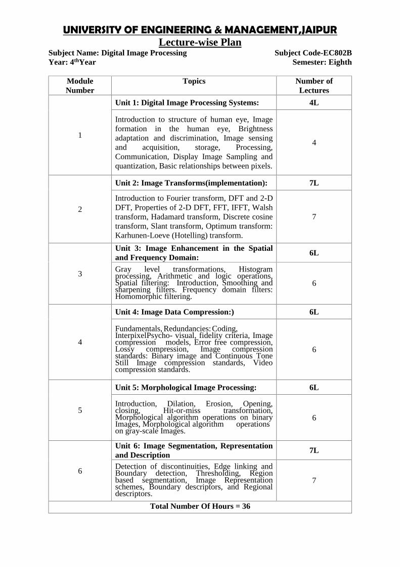
UNIVERSITY OF ENGINEERING & MANAGEMENT,JAIPURLecture-wise Plan
Subject Name: Organizational Behavior Subject Code-HU801Year: 4th Year Semester: EighthModu
leNumber
Topics Number ofLectu
res
1
Introduction:
Organization:Mission,Goals,Characteristics,Types,Structure&Design–Elements,DesignsbyFunction,Product,Location,Matrix;VirtualOrganisation,LearningOrganisation,Mechanistic andOrganicModels; DeterminantsofanOrganizationStructure–Strategy,Size,Technology&Environment
6
ManagerialPerspectivesonOrganizationalBehaviour:ManagementFunctions,ManagerialRoles,Skills, ChallengesandEffectiveness
4
OrganizationalCulture: CultureanditsCharacteristics,TypesofCultures,WesternandOrientalOrganizationCultures,IndianOrganizationCulture,CultureChange
4
GroupBehaviour:CharacteristicsofGroup,TypesofGroups,StagesofDevelopment,GroupDecision-making,OrganizationalPolitics,CasesonGroupDecision-making
4
2
CommunicationinOrganization :Purpose,Process,ChannelsandNetworks,Barriers,MakingCommunicationEffective,TransactionalAnalysis(TA),CasesonCommunication
3
LeadershipStyles:LeadershipTheories,LeadershipStyles,SkillsandInfluenceProcesses,LeadershipandPower,ExamplesofEffectiveOrganizationalLeadershipinIndia,CasesonLeadership
4
ConflictinOrganization:SourcesofConflict,TypesofConflict,ConflictProcess,JohariWindow,ConflictResolution,Caseson ConflictResolution.
4
OrganizationalChangeandDevelopment: Meaning,Process,ResistancetoChange, OD-Meaning,Process,Interventions:SensitivityTraining,SurveyFeedback,ProcessConsultation,TeamBuilding,Inter-group Development
4
Total Number of Hours 33


UNIVERSITY OF ENGINEERING & MANAGEMENT,JAIPURLecture-wise Plan
Faculty In-Charge HOD, Humanities Dept.
UNIVERSITY OF ENGINEERING & MANAGEMENT,JAIPURLecture-wise Plan
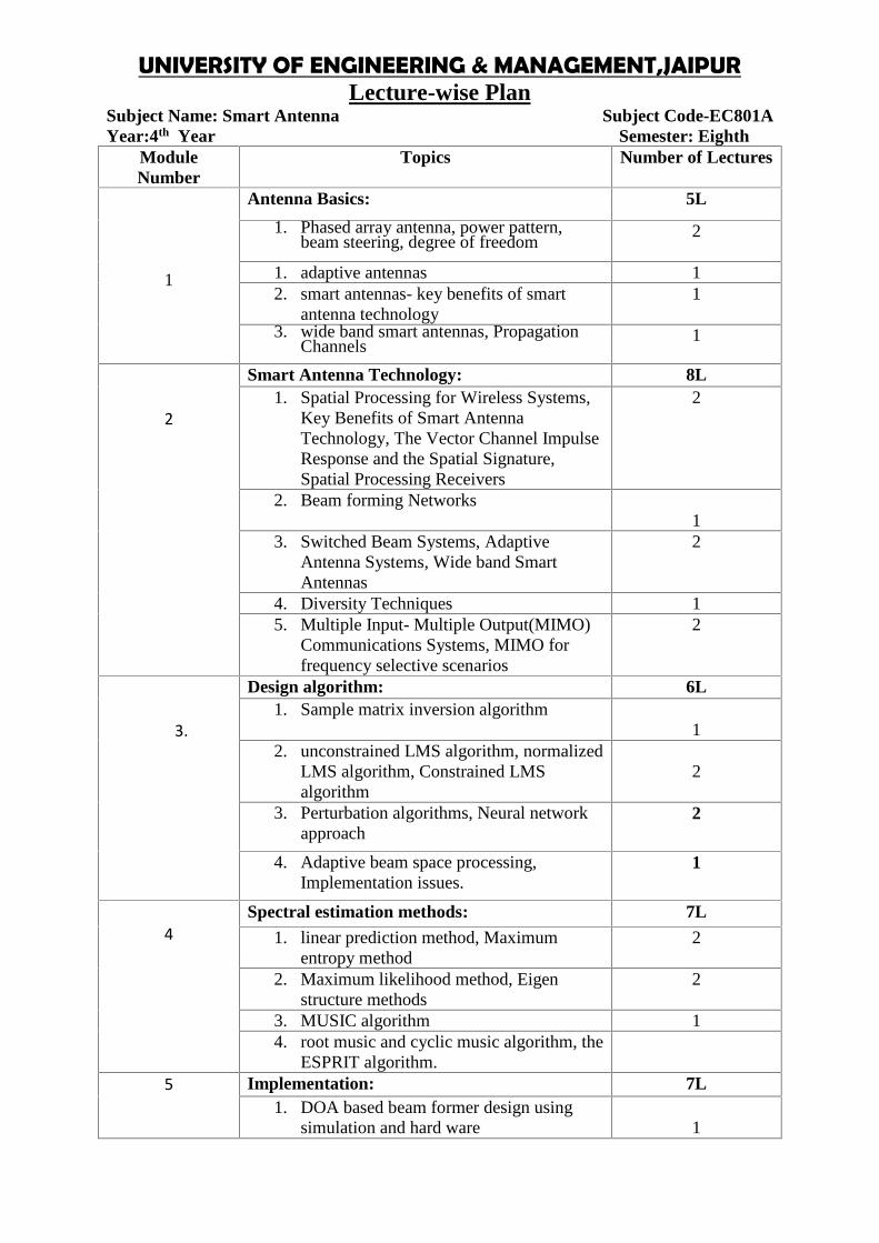
Subject Name: Smart Antenna Subject Code-EC801AYear:4th Year Semester: Eighth
ModuleNumber
Topics Number of Lectures
1
Antenna Basics: 5L
1. Phased array antenna, power pattern,beam steering, degree of freedom
2
1. adaptive antennas 12. smart antennas- key benefits of smart
antenna technology1
3. wide band smart antennas, PropagationChannels
1
2
Smart Antenna Technology: 8L1. Spatial Processing for Wireless Systems,
Key Benefits of Smart AntennaTechnology, The Vector Channel ImpulseResponse and the Spatial Signature,Spatial Processing Receivers
2
2. Beam forming Networks1
3. Switched Beam Systems, AdaptiveAntenna Systems, Wide band SmartAntennas
2
4. Diversity Techniques 15. Multiple Input- Multiple Output(MIMO)
Communications Systems, MIMO forfrequency selective scenarios
2
3.
Design algorithm: 6L1. Sample matrix inversion algorithm
12. unconstrained LMS algorithm, normalized
LMS algorithm, Constrained LMSalgorithm
2
3. Perturbation algorithms, Neural networkapproach
2
4. Adaptive beam space processing,Implementation issues.
1
4Spectral estimation methods: 7L
1. linear prediction method, Maximumentropy method
2
2. Maximum likelihood method, Eigenstructure methods
2
3. MUSIC algorithm 14. root music and cyclic music algorithm, the
ESPRIT algorithm.5 Implementation: 7L
1. DOA based beam former design usingsimulation and hard ware 1

2. Adaptive beam forming implementationusing Altera Stratix® Series FPGA
2
3. QRDRLS Algorithm2
4. CORDIC algorithm 2
Total Number Of Hours = 33
Faculty In-Charge HOD, CSE Dept.
Assignment:Module-1(Antenna Basics):
1. Discuss the radiation from slot antenna?2. Determine the power radiated from the open-end of a coaxial line ?3. What are the types of lens antenna? Give the equation of the shape of the lens4. Explain how E-plan type metal plate lens antennas are developed and derive the
expression for spacing between the plates and equation of ellipse.5. For an array N element feed with signal of equivalent amplitude and phase,
determine the maxima and minima directions. Draw the radiation pattern
Module-2 (Smart Antenna Technology):1. Define dipole antenna. Derive the radiation field and radiation resistance from a
half wave dipole.2. Derive the expression for radiation field and radiation resistance.3. For an array N element feed with signal of equivalent amplitude and phase,
determine the maxima and minima directions. Draw the radiation pattern4. Obtain the expression for the field and the radiation pattern produced by a 2
element array of infinitesimal dipole with distance of separation λ/2 & currentsof equal magnitude and phase shift 180°.
5. Obtain the expression for the field and the radiation pattern produced by a 2element array of infinitesimal dipole with distance of separation λ/2 and currentsof equal magnitude and same phase.
Module-3(Design algorithm):1. What is meant by Travelling wave antenna?2. What do you mean by driven elements?3. What do you mean by parasitic elements?4. What is rhombic antenna and give its applications?5. What is LPDA?6. What are the applications of log periodic and Yagi Uda antenna?7. Explain the construction of Yagi antenna. Discuss the design aspects.8. Specify the design consideration for a rhombic antenna.9. Explain the geometry of a log periodic antenna. How wideband operation is
possible with this antenna.
Module-3(Spectral estimation methods):

UNIVERSITY OF ENGINEERING & MANAGEMENT,JAIPURLecture-wise Plan
1. What are the major problems with the nonparametric power spectrumestimation methods that are overcome by using the parameter power spectrumestimation methods?
2. What is the basic limitation of the nonparametric methods and what is thereason for this limitation ?
3. What is the basic difference between the parametric and nonparametric powerspectrum estimation methods ?
4. For what types of signals would the parametric spectrum estimation methods bemuch better to use instead of the nonparametric methods, and why?
5. We all know that for a linear system if the input is a sinusoid then the resultantoutput will also be a sinusoid. Can we say the same thing about stationaryrandom process input? Explain

UNIVERSITY OF ENGINEERING & MANAGEMENT,JAIPURLecture-wise Plan
Subject Name:Material Science & Engineering Subject Code-EC801BYear: 4th Year Semester: Eight
ModuleNumber
Topics Number ofLectures
1
Unit 1: Structure of Solids 5L
Atoms and their binding, Bonds, CrystalSystems, Bravais Lattice Miller Indices,Crystalline, Polycrystalline and AmorphousMaterials; Metals, Semiconductors andInsulators, Lattice defects- Qualitative ideas ofpoint, line, surface and volume defects.
5
2
Unit 2: Dielectric Properties 4L
Dielectric Polarization and Mechanism-Internalor local field, Dielectric Loss, Temperature andFrequency dependence of dielectric constant,Elementary ideas of Piezoelectric, Ferroelectricsand Pyroelectric Materials and its Applications.
4
3
Unit 3: Magnetic Properties 2L
Elementary ideas of classification of magneticmaterials– Diamagnetism, Para magnetism,Ferromagnetism, Ferrimagnetism, MagneticDomains.
2
4
Unit 4: Superconductors 3L
Basic concepts of super conductivity, Transitiontemperature, Meissner effect High-Tsuperconductors, Hard and Soft Materials,SQUID
3
5
Unit 5: Optical properties 3L
Absorption, Emission, Luminescence, Electro-optic and Acousto-optic effects, Photorefractiveeffects.
3
6Unit 6: Materials for Optical Communication 3L
LED and Laser Materials, Optical Fiber. 3
7
Unit 7: Materials for Data Storage 5L
Magnetic Cores, Tapes, Disks, Hard disk,Floppy disk, Magneto-optic devices, Bubblememories, Magneto electronic Materials, CD,DVD, CCD.
5
8Unit 8: Materials for Display Devices 3L
CRT, LED, LCD, TFT, Plasma Display. 3
9Unit 9: Advanced Materials 2L
Metallic Glasses, Nanomaterials, etc. 2Total Number Of Hours = 30
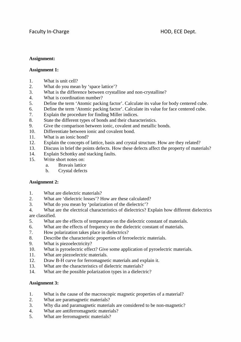
Faculty In-Charge HOD, ECE Dept.
Assignment:
Assignment 1:
1. What is unit cell?2. What do you mean by ‘space lattice’?3. What is the difference between crystalline and non-crystalline?4. What is coordination number?5. Define the term ‘Atomic packing factor’. Calculate its value for body centered cube.6. Define the term ‘Atomic packing factor’. Calculate its value for face centered cube.7. Explain the procedure for finding Miller indices.8. State the different types of bonds and their characteristics.9. Give the comparison between ionic, covalent and metallic bonds.10. Differentiate between ionic and covalent bond.11. What is an ionic bond?12. Explain the concepts of lattice, basis and crystal structure. How are they related?13. Discuss in brief the points defects. How these defects affect the property of materials?14. Explain Schottky and stacking faults.15. Write short notes on:
a. Bravais latticeb. Crystal defects
Assignment 2:
1. What are dielectric materials?2. What are ‘dielectric losses’? How are these calculated?3. What do you mean by ‘polarization of the dielectric’?4. What are the electrical characteristics of dielectrics? Explain how different dielectricsare classified.5. What are the effects of temperature on the dielectric constant of materials.6. What are the effects of frequency on the dielectric constant of materials.7. How polarization takes place in dielectrics?8. Describe the characteristic properties of ferroelectric materials.9. What is piezoelectricity?10. What is pyroelectric effect? Give some application of pyroelectric materials.11. What are piezoelectric materials.12. Draw B-H curve for ferromagnetic materials and explain it.13. What are the characteristics of dielectric materials?14. What are the possible polarization types in a dielectric?
Assignment 3:
1. What is the cause of the macroscopic magnetic properties of a material?2. What are paramagnetic materials?3. Why dia and paramagnetic materials are considered to be non-magnetic?4. What are antiferromagnetic materials?5. What are ferromagnetic materials?
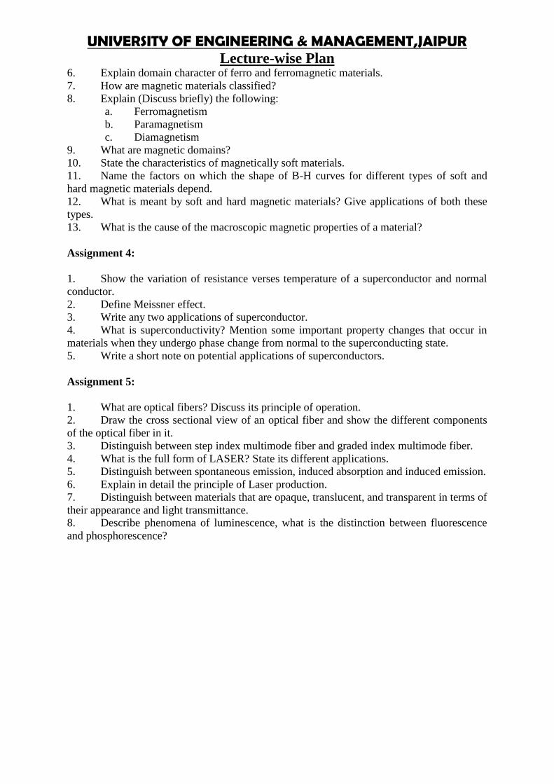
UNIVERSITY OF ENGINEERING & MANAGEMENT,JAIPURLecture-wise Plan
6. Explain domain character of ferro and ferromagnetic materials.7. How are magnetic materials classified?8. Explain (Discuss briefly) the following:
a. Ferromagnetismb. Paramagnetismc. Diamagnetism
9. What are magnetic domains?10. State the characteristics of magnetically soft materials.11. Name the factors on which the shape of B-H curves for different types of soft andhard magnetic materials depend.12. What is meant by soft and hard magnetic materials? Give applications of both thesetypes.13. What is the cause of the macroscopic magnetic properties of a material?
Assignment 4:
1. Show the variation of resistance verses temperature of a superconductor and normalconductor.2. Define Meissner effect.3. Write any two applications of superconductor.4. What is superconductivity? Mention some important property changes that occur inmaterials when they undergo phase change from normal to the superconducting state.5. Write a short note on potential applications of superconductors.
Assignment 5:
1. What are optical fibers? Discuss its principle of operation.2. Draw the cross sectional view of an optical fiber and show the different componentsof the optical fiber in it.3. Distinguish between step index multimode fiber and graded index multimode fiber.4. What is the full form of LASER? State its different applications.5. Distinguish between spontaneous emission, induced absorption and induced emission.6. Explain in detail the principle of Laser production.7. Distinguish between materials that are opaque, translucent, and transparent in terms oftheir appearance and light transmittance.8. Describe phenomena of luminescence, what is the distinction between fluorescenceand phosphorescence?

UNIVERSITY OF ENGINEERING & MANAGEMENT,JAIPURLecture-wise Plan
Subject Name: Satellite Communication & Remote Sensing Subject Code-EC801CYear: 4thYear Semester: Eighth
ModuleNumber Topics
Number ofLectures
1
Unit 1: Historical background, Basicconcepts
2L
Frequency allocation for satellite services,orbital & spacecraft problems, Comparison ofnetworks and services, modulation techniquesused for satellite communication.
2
2
Unit 2: Orbits 2L
Two body problem, orbital mechanics,geostationary orbit, change in longitude, orbitalmanoeuvres, orbital transfer, orbitalperturbations.
2
3
Unit 3: Launch Vehicles 1L
principles of Rocket propulsion, powered flight,Launch vehicles for communication satellite 1
4
Unit 4: RF link 5L
noise, the basic RF link, satellite links (up anddown), optimization RF link, inter satellite link,noise temperature, Antenna temperature, overallsystem temperature, propagation factors, rainattenuation model. Tropospheric andIonospheric EFFECT
5
5
Unit 5: Multiple access 5L
FDMA, TDMA, CDMA techniques, comparisonof multiple access techniques, error connectingcodes
5
6
Unit 6: Satellite subsystems and satellite linkdesign 6L
AOCS, TT&C, power system, spacecraftantenna, transponder, Friis transmissionequation, G/T ratio of earth station
6
7
Unit 7: Basic of remote sensing 3L
Electromagnetic Radiation principles,Atmospheric window, Indian satellite sensingsatellite system, Active, Passive, ground basedand space based remote sensing
3
8Unit 8 9LSpatial, spectral, Radiometric and temporalresolution, satellite sensors, detectors and 9
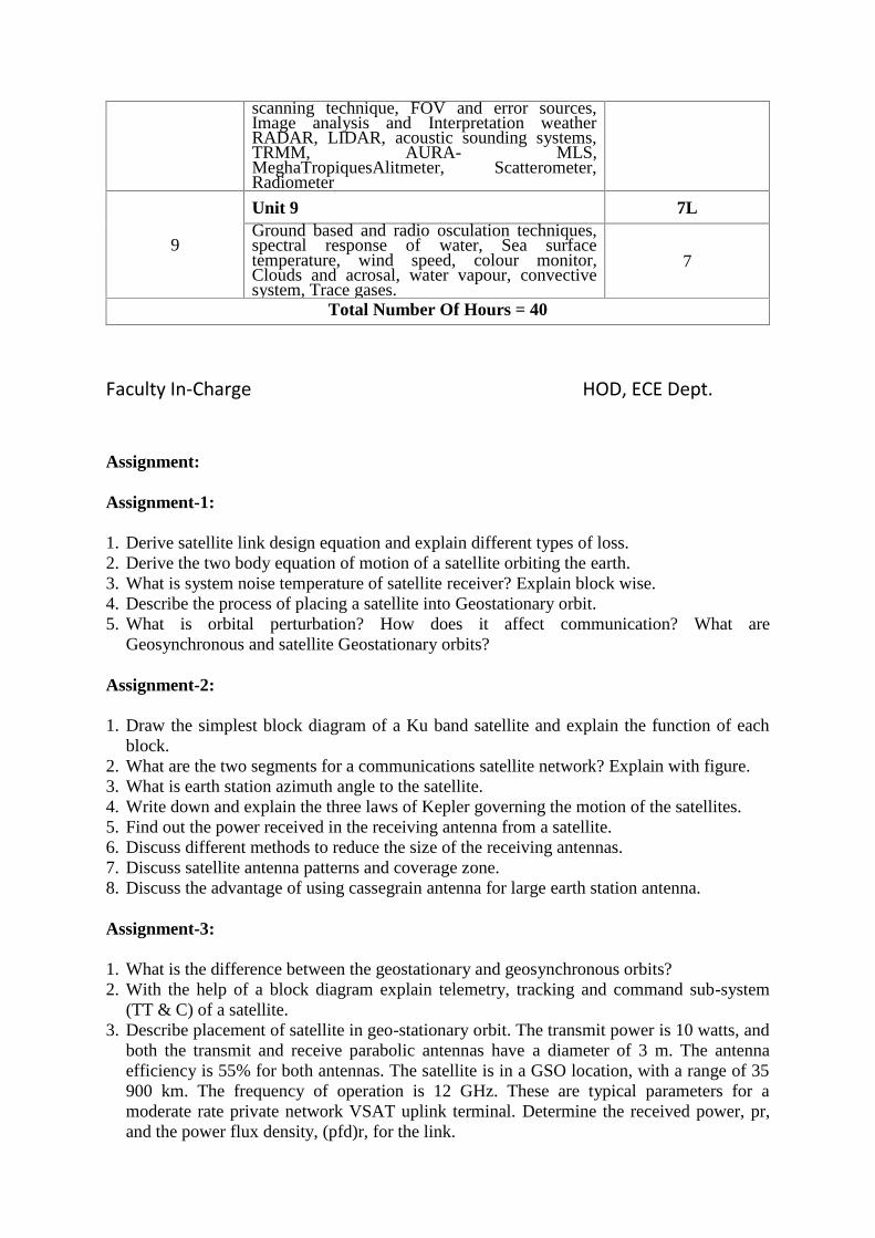
scanning technique, FOV and error sources,Image analysis and Interpretation weatherRADAR, LIDAR, acoustic sounding systems,TRMM, AURA- MLS,MeghaTropiquesAlitmeter, Scatterometer,Radiometer
9
Unit 9 7LGround based and radio osculation techniques,spectral response of water, Sea surfacetemperature, wind speed, colour monitor,Clouds and acrosal, water vapour, convectivesystem, Trace gases.
7
Total Number Of Hours = 40
Faculty In-Charge HOD, ECE Dept.
Assignment:
Assignment-1:
1. Derive satellite link design equation and explain different types of loss.2. Derive the two body equation of motion of a satellite orbiting the earth.3. What is system noise temperature of satellite receiver? Explain block wise.4. Describe the process of placing a satellite into Geostationary orbit.5. What is orbital perturbation? How does it affect communication? What are
Geosynchronous and satellite Geostationary orbits?
Assignment-2:
1. Draw the simplest block diagram of a Ku band satellite and explain the function of eachblock.
2. What are the two segments for a communications satellite network? Explain with figure.3. What is earth station azimuth angle to the satellite.4. Write down and explain the three laws of Kepler governing the motion of the satellites.5. Find out the power received in the receiving antenna from a satellite.6. Discuss different methods to reduce the size of the receiving antennas.7. Discuss satellite antenna patterns and coverage zone.8. Discuss the advantage of using cassegrain antenna for large earth station antenna.
Assignment-3:
1. What is the difference between the geostationary and geosynchronous orbits?2. With the help of a block diagram explain telemetry, tracking and command sub-system
(TT & C) of a satellite.3. Describe placement of satellite in geo-stationary orbit. The transmit power is 10 watts, and
both the transmit and receive parabolic antennas have a diameter of 3 m. The antennaefficiency is 55% for both antennas. The satellite is in a GSO location, with a range of 35900 km. The frequency of operation is 12 GHz. These are typical parameters for amoderate rate private network VSAT uplink terminal. Determine the received power, pr,and the power flux density, (pfd)r, for the link.

UNIVERSITY OF ENGINEERING & MANAGEMENT,JAIPURLecture-wise Plan
Subject Name: Neural Networks & Application Subject Code: EC802Year: 4th Year Semester: Eighth
ModuleNumber
Topics Number of Lectures
1
Introduction to artificial neural networks : 5L
1. Biological neural networks, Pattern analysistasks: Classification, Regression, Clustering.
2
2. Computational models of neurons. 13. Structures of neural networks 14. Learning principles 1
2
Linear models for regression andclassification:
8L
1. Polynomial curve fitting, Bayesian curvefitting.
2
2. Linear basis function models, Bias-variance decomposition.
2
3. Bayesian linear regression, Least squaresfor classification.
2
4. Logistic regression for classification,Bayesian logistic regression forclassification.
2
3.
Feed forward neural networks : 8L1. Pattern classification using perceptron,
Multilayer feed forward neural networks(MLFFNNs).
2
2. Pattern classification and regression usingMLFFNNs.
2
3. Error back propagation learning. 1
4. Fast learning methods: Conjugate gradientmethod, Auto associative neural networks.
2
5. Bayesian neural networks. 1
4Radial basis function networks : 5L
1. Regularization theory. 22. RBF networks for function
approximation.2
3. RBF networks for pattern classification. 1
5Self-organizing maps : 4L
1. Pattern clustering, Topological mapping 2
2. Kohonen’s self-organizing map. 2
6Feedback neural networks : 5L
1. Pattern storage and retrieval, Hopfieldmodel 2

2. Boltzmann machine 1
3. Recurrent neural networks. 2
7
Kernel methods for pattern analysis : 8L1. Statistical learning theory 2
2. Support vector machines for patternclassification
2
3. Support vector regression for functionapproximation
2
4. Relevance vector machines forclassification and regression
2
Total Number Of Hours = 43
Faculty In-Charge HOD, CSE Dept.
Assignment:
Module-1(Introduction):1. Write Down short Notes: Classification & Regrassion.2. Draw the structure of Neural networks & describe it.
Module-2(Linear models for regression and classification):1. Notes: Bayesian linear regression & Bias-variance decomposition.2. Prove that: MSE = Bias^2 + Var.
Module-3(Feed forward neural networks):1. Short Notes: Bayesian neural networks.2. Describe the Error back propagation learning.3. Write algorithm of back-propagation rule
Module-4(Radial basis function networks):1. Write down short notes: RBF networks.
Module-5(Self-organizing maps):1. Consider a Kohonen net with two cluster (outputs) units & five input units. The weightvectors for the output units are W1=[1,0.8,0.6,0.4,0.2] and W2=[1,0.5,1,0.5,1]. Use thesquare of the Euclidean distance to find the winning neuron for the input patternX=[0.5,1,0.5,0,0.5]. Find the new weights for the winning unit. Assume learning rate as 0.2.
Module-6(Feedback neural networks):1. Short Notes: Boltzmann machine & Recurrent neural networks.
Module-7(Kernel methods for pattern analysis):1. Write down short note for SVM.2. How its works in classification & regression?
UNIVERSITY OF ENGINEERING & MANAGEMENT,JAIPURLecture-wise Plan
Subject Name: Digital Image Processing Subject Code-EC802BYear: 4thYear Semester: Eighth
ModuleNumber
Topics Number ofLectures
1
Unit 1: Digital Image Processing Systems: 4L
Introduction to structure of human eye, Imageformation in the human eye, Brightnessadaptation and discrimination, Image sensingand acquisition, storage, Processing,Communication, Display Image Sampling andquantization, Basic relationships between pixels.
4
2
Unit 2: Image Transforms(implementation): 7L
Introduction to Fourier transform, DFT and 2-DDFT, Properties of 2-D DFT, FFT, IFFT, Walshtransform, Hadamard transform, Discrete cosinetransform, Slant transform, Optimum transform:Karhunen-Loeve (Hotelling) transform.
7
3
Unit 3: Image Enhancement in the Spatialand Frequency Domain: 6L
Gray level transformations, Histogramprocessing, Arithmetic and logic operations,Spatial filtering: Introduction, Smoothing andsharpening filters. Frequency domain filters:Homomorphic filtering.
6
4
Unit 4: Image Data Compression:) 6L
Fundamentals, Redundancies:Coding,InterpixelPsycho- visual, fidelity criteria, Imagecompression models, Error free compression,Lossy compression, Image compressionstandards: Binary image and Continuous ToneStill Image compression standards, Videocompression standards.
6
5
Unit 5: Morphological Image Processing: 6L
Introduction, Dilation, Erosion, Opening,closing, Hit-or-miss transformation,Morphological algorithm operations on binaryImages, Morphological algorithm operationson gray-scale Images.
6
6
Unit 6: Image Segmentation, Representationand Description
7L
Detection of discontinuities, Edge linking andBoundary detection, Thresholding, Regionbased segmentation, Image Representationschemes, Boundary descriptors, and Regionaldescriptors.
7
Total Number Of Hours = 36

Faculty In-Charge HOD, ECE Dept.
Assignment:
Assignment-1:
1. Obtain the images “lena.bin” and “peppers.bin” from the web. Each imagehas 256 × 256 pixels and each pixel has 8 bits.(a) Read and display the images.(b) Define a new 256 × 256 image J as follows: the left half of J, e.g., the first 128columns, should be equal to the left half of the Lena image. The right half of J,e.g., the 129th column through the 256th column, should be equal to the righthalf of the Peppers image.(c) Define a new 256 × 256 image K by swapping the left and right halves of J.(d) Be sure to turn in: A listing of your code and printouts of the original images,image J, and image K.
Assignment-2:
1. Obtain the images Suzi1.bin and ctscan.bin from the web. Each image has 256 ×256 pixels and each pixel has 8 bits.In this assignment you will perform object extraction(target extraction) by using simple thresholding, followed by connected componentslabelling (blob colouring) with minor region removal. This is a specialcase of two classicalimage processing problems known as image segmentation and classification. Throughoutthe assignment, including the printing of your results, use a value of 255 (Hex 0xFF) forLOGIC ONEand a value of zero (Hex 0x00) for LOGIC ZERO.Objectives:1. Suzi1: the first objective is to produce a binary image J that is LOGIC ONE at pixelscontained in the“girl” object of the original image and that is LOGIC ZERO at pixelscontained in the background ofthe original image. The second objective is to produce agrayscale image K of the segmented “girl”object. At pixels where J is LOGIC ONE, Kshould be equal to the original Suzi1 image. At pixelswhere J is LOGIC ZERO, K shouldbe 255.2. ct scan: the first objective is to produce a binary image J that is LOGIC ONE at pixelscontainedin the “torso section” object of the original image and that is LOGIC ZERO atpixels contained inthe background of the original image. The second objective is toproduce a grayscale image K ofthe segmented “torso section” object. This should be doneexactly the same way it was for the Suzi1image.For each image, use the following procedure:A) Study the image and select an appropriate threshold that will discriminate between thedesired objectand the background.B) Form a binary image J by applying the threshold so that pixels likely to be part of thedesired objectare assigned the value LOGIC ONE, while those likely to be part of thebackground are assigned thevalue LOGIC ZERO.Hint: for the Suzi1 image, this means that J(i, j) should be LOGIC ONE if thecorresponding inputpixel is below threshold. For the ct scan image the opposite is true: you should set J(i, j)=LOGIC ONE if the corresponding input pixel is above threshold.

UNIVERSITY OF ENGINEERING & MANAGEMENT,JAIPURLecture-wise Plan
C) Apply connected components labeling with minor region removal to refine thesegmentation in J.D) Construct the segmented object grayscale image K.
Assignment-3:
1. Obtain the image “Mammogram.bin” from the course web site. This image has 256× 256pixels. Each pixel has 8 bits. Note: the server is Unix; the filename is casesensitive. Do notmake the mistake of getting the incorrect 512 × 512 file “mammogram.bin.”(a) There are two main regions in the input image: the imaged tissue and thedarkbackground region on the left side of the image. Write a program to convert thisgrayscale image into a binary image by simple thresholding. In the binary image,use a value of255 = 0xff for logical one and a value of 0 = 0x00 for logical zero.Select the threshold sothat the binary image is equal to logical zero over thebackground region and logical oneover the tissue.(b) Write a program to implement the Approximate Contour Image Generationalgorithmgiven on page 2.104 of the notes. Your program should input the binaryimageand output a binary contour image. Run your program to generate anappoximate contourimage from the binary image you obtained by thresholdingMammogram.bin.(c) Could a chain code be used to represent the main contour in your contour image?Whyor why not?
2. Obtain the image “lady.256” from the course web site. This is a 256 × 256 grayscaleimage with 8-bit pixels. Plot a histogram for the image. Write a program to performafull-scale contrast stretch on the image and plot a histogram for the result.
3. Obtain the image “actontBin.bin” from the course web site. This image has 256 ×256pixels with 8 bits each. It is a true binary image; the pixel value 255 representslogicalone and the pixel value 0 represents logical zero.Write a program to find instances of the letter “T” in the image using the BinaryTemplateMatching algorithm given on pages 2.92 - 2.97 of the notes. You will haveto design thetemplate yourself based on an analysis of the image. Apply the matchmeasure M2 at everypixel in the input image where a sufficiently large neighbourhood exists. Construct anoutput image J1 where each pixel is equal to the match measureM2 (set J1 equal to zero atpixels where a sufficiently large neighbourhood does notexist in the inputimage).Threshold the image J1 to obtain a binary image J2 that should be equal to logicaloneat pixels where there is a high probability that the letter “T” is present in theinputimage.
4. Obtain the image “johnny.bin” from the course web site. This image has 256 × 256pixels.Each pixel has 8 bits. Plot the histogram of the original image. Write a programto performhistogram equalization on this image. Show the equalized image and plot its histogram.

UNIVERSITY OF ENGINEERING & MANAGEMENT,JAIPURLecture-wise Plan
Subject Name: Renewable Energy Subject Code: EC802CYear: 4th Year Semester: EighthModuleNumber
Topics Numberof
Lectures
1
Chapter 1: Introduction to Energy sources: 2L1. Renewable and non-renewable energy sources, energy consumption as ameasure of Nation’s development; strategy for meeting the future energyrequirements.
1
2. Global and National scenarios, Prospects of renewable energy sources.Impact of renewable energy generation on environment, Kyoto Protocol.
1
Chapter 2: Solar Energy: 5L1. Solar radiation -beam and diffuse radiation, solar constant, earth sunangles, attenuation and measurement of solar radiation, local solar time,derived solar angles, sunrise, sunset and day length.
1
2. Flat plate collectors, concentrating collectors, Solar air heaters types,solar driers, storage of solar energy-thermal storage, solar pond, solar waterheaters of PV Cells, Mono-poly Crystalline and amorphous Silicon solarcells. solardistillation,solarstill,solarcooker,solarheating&coolingofbuildings,photovoltaics-solarcells, differenttypes
2
3. Design of PV array. Efficiency and cost of PV systems & its applications.PV hybrid systems.
2
Chapter 3: Wind Energy: 6L1. Principle of wind energy conversion; Basic components of wind energyconversion systems;
1
2. Wind mill components, various types and their constructional features 23. Design considerations of horizontal and vertical axis wind machines:analysis of aerodynamic or cesacting on wind mill blades and estimation ofpower output; wind data and site selection considerations
3
2.
Chapter 4: Energy from Biomass: 4L
1. Biomass conversion technologies, Biogas generation plants,classification, advantages and disadvantages,
1
2. Constructional details, site selection, digester design consideration, fillinga digester for starting, maintaining biogas production
2
3. Fuel properties of bio gas, utilization of biogas 1Chapter 5: Geothermal Energy: 4L1. Introduction, Basic definitions. 12. Estimation and nature of geothermal energy, geothermal sources andresources like hydrothermal, geo-pressured hot dry rock , magma.
2
3. Advantages, disadvantages and application of geothermal energy,prospects of geothermal energy in India.
1
Chapter 6: Energy from Ocean: 6L
1. Ocean Thermal Electric Conversion (OTEC) systems like open cycle,closed cycle, Hybrid cycle, prospects of OTEC in India.
2
2. Energy from tides, basic principle of tidal power, single basin and doublebasin tidal power plants, advantages, limitation and scope of tidal energy
2

3. Wave energy and power from wave, wave energy conversion devices,advantages and disadvantages of wave energy.
2
3.
Chapter 7: Magneto Hydrodynamic power generation: 3L1. Principle of MHD power generation, MHD system, Design problems anddevelopments
2
2. Gas conductivity, materials for MHD generators and future prospects. 1
4.
Chapter 8: Hydrogen Energy: 3L
1. Introduction, Hydrogen Production methods, Hydrogen storage,hydrogen transportation
2
2. Utilization of hydrogen gas, hydrogen as alternative fuel for vehicles. 1Chapter 9: Fuel cell: 3L
1. Introduction, Design principle and operation of fuel cell, Types of fuelcells 22. conversion efficiency of fuel cell, application of fuel cells 1
Total Number Of Hours = 36L
Shubhajit Pal Prof. Aniruddh MukherjeeFaculty In-Charge HOD, EE Dept.
Assignment:Module-11. Mention the different forms of energy.2. What is Kyoto protocol and what are its implications for developed and developing countries.3. Explain the different characteristics of PV system.4. With a neat diagram, explain how wind energy can be converted into electrical energy.
Module-21. What is the prospect of geothermal energy?2. What principles guide in the location of a geothermal power station?3. Write a short note on Biodiesel
Module-3:1. Write short notes on:(a) Magneto hydrodynamic energy (b) Wave energy2. Discuss the advantages and limitations of tidal energy.
Module-4:1. What is fuel cell? Discuss different types of fuel cell. What are the advantages of fuel cell energy?Discuss on alkaline fuel cell and hydrogen fuel cell.2. Discuss the various methods of hydrogen production.

UNIVERSITY OF ENGINEERING & MANAGEMENT,JAIPURLab Manual
Title of Course: Digital Image ProcessingCourse Code: EC892BL-T-P scheme: 0-0-3 Course Credit: 2
Objectives:
Introduces practice of digital image processing. Topics presented include, two-dimensional signalprocessing theory, image acquisition, representation, elementary operations, enhancement, filtering,coding, compressing, restoration, and analysis, as well as image processing hardware.The students will learn about state-of-the-art techniques in the lecture, and experiment with selectedmethods during the lab sessions. The computer lab session is an essential part of this course as it issupposed to lower the barrier and the reservations that some students might have towards usingcomputer-based biomedical imaging technology for their own work.
Learning Outcomes:
Students who complete this course will be able to:1. Describe different modalities and current techniques in image acquisition2. Describe how digital images are represented and stored efficiently depending on the desired
quality, color depth, dynamics (time-varying data)3. Use the mathematical principles of digital image enhancement (contrast, gradients, noise)4. Describe and apply the concepts of feature detection and contour finding algorithms.5. Analyze the constraints in image processing when dealing with larger data sets (efficient storage
and compression schemes)6. Apply the knowledge primarily obtained by studying examples and cases in the field of
biomedical imaging to other engineering disciplines
Course Contents:Exercises that must be done in this course are listed below:
Exercise No.1: Histogram display and histogram equalizationExercise No.2: Kernel processing on images leading to image enhancementExercise No.3: Display of 2D filters frequency responses and processing the images using theseExercise No.4: Implementation of Arithmetic Coding for imagesExercise No.5: Basic JPEG algorithm implementationExercise No.6: DPCM encoding and decoding of imagesExercise No.7: Simple image watermarking algorithms using LSB substitutionExercise No.8: Simple content based image retrieval using various distance metricsExercise No.9: Image segmentation algorithms using SnakesExercise No.10:Color images manipulations, reading and writing of color images
Text Book:1. R.C Gonzalezand R. Woods:-Digital Image Processing, (Indian reprint: Pearsonpublication)2. AnilK.Jain:-DigitalImageProcessing (Prentice-Hall,India)
Recommended Systems/Software Requirements:1. Intel based desktop PC with at least 2GB RAM and 15 GB free disk space.2. Matlab/Scilab in Windows XP or Linux Operating System.
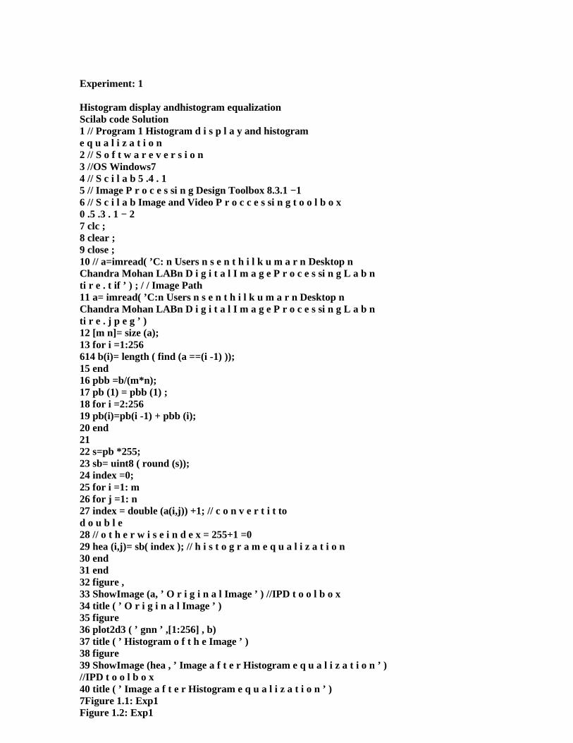
Experiment: 1
Histogram display andhistogram equalizationScilab code Solution1 // Program 1 Histogram d i s p l a y and histograme q u a l i z a t i o n2 // S o f t w a r e v e r s i o n3 //OS Windows74 // S c i l a b 5 .4 . 15 // Image P r o c e s si n g Design Toolbox 8.3.1 −16 // S c i l a b Image and Video P r o c c e s si n g t o o l b o x0 .5 .3 . 1 − 27 clc ;8 clear ;9 close ;10 // a=imread( ’C: n Users n s e n t h i l k u m a r n Desktop nChandra Mohan LABn D i g i t a l I m a g e P r o c e s si n g L a b nti r e . t if ’ ) ; / / Image Path11 a= imread( ’C:n Users n s e n t h i l k u m a r n Desktop nChandra Mohan LABn D i g i t a l I m a g e P r o c e s si n g L a b nti r e . j p e g ’ )12 [m n]= size (a);13 for i =1:256614 b(i)= length ( find (a ==(i -1) ));15 end16 pbb =b/(m*n);17 pb (1) = pbb (1) ;18 for i =2:25619 pb(i)=pb(i -1) + pbb (i);20 end2122 s=pb *255;23 sb= uint8 ( round (s));24 index =0;25 for i =1: m26 for j =1: n27 index = double (a(i,j)) +1; // c o n v e r t i t tod o u b l e28 // o t h e r w i s e i n d e x = 255+1 =029 hea (i,j)= sb( index ); // h i s t o g r a m e q u a l i z a t i o n30 end31 end32 figure ,33 ShowImage (a, ’ O r i g i n a l Image ’ ) //IPD t o o l b o x34 title ( ’ O r i g i n a l Image ’ )35 figure36 plot2d3 ( ’ gnn ’ ,[1:256] , b)37 title ( ’ Histogram o f t h e Image ’ )38 figure39 ShowImage (hea , ’ Image a f t e r Histogram e q u a l i z a t i o n ’ )//IPD t o o l b o x40 title ( ’ Image a f t e r Histogram e q u a l i z a t i o n ’ )7Figure 1.1: Exp1Figure 1.2: Exp1
UNIVERSITY OF ENGINEERING & MANAGEMENT,JAIPURLab Manual
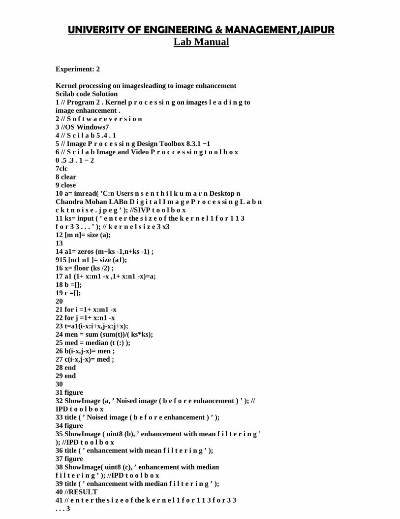
Experiment: 2
Kernel processing on imagesleading to image enhancementScilab code Solution1 // Program 2 . Kernel p r o c e s si n g on images l e a d i n g toimage enhancement .2 // S o f t w a r e v e r s i o n3 //OS Windows74 // S c i l a b 5 .4 . 15 // Image P r o c e s si n g Design Toolbox 8.3.1 −16 // S c i l a b Image and Video P r o c c e s si n g t o o l b o x0 .5 .3 . 1 − 27clc8 clear9 close10 a= imread( ’C:n Users n s e n t h i l k u m a r n Desktop nChandra Mohan LABn D i g i t a l I m a g e P r o c e s si n g L a b nc k t n o i s e . j p e g ’ ); //SIVP t o o l b o x11 ks= input ( ’ e n t e r the s i z e o f the k e r n e l 1 f o r 1 1 3f o r 3 3 . . . ’ ); // k e r n e l s i z e 3 x312 [m n]= size (a);1314 a1= zeros (m+ks -1,n+ks -1) ;915 [m1 n1 ]= size (a1);16 x= floor (ks /2) ;17 a1 (1+ x:m1 -x ,1+ x:n1 -x)=a;18 b =[];19 c =[];2021 for i =1+ x:m1 -x22 for j =1+ x:n1 -x23 t=a1(i-x:i+x,j-x:j+x);24 men = sum (sum(t))/( ks*ks);25 med = median (t (:) );26 b(i-x,j-x)= men ;27 c(i-x,j-x)= med ;28 end29 end3031 figure32 ShowImage (a, ’ Noised image ( b e f o r e enhancement ) ’ ); //IPD t o o l b o x33 title ( ’ Noised image ( b e f o r e enhancement ) ’ );34 figure35 ShowImage ( uint8 (b), ’ enhancement with mean f i l t e r i n g ’); //IPD t o o l b o x36 title ( ’ enhancement with mean f i l t e r i n g ’ );37 figure38 ShowImage( uint8 (c), ’ enhancement with medianf i l t e r i n g ’ ); //IPD t o o l b o x39 title ( ’ enhancement with median f i l t e r i n g ’ );40 //RESULT41 // e n t e r the s i z e o f the k e r n e l 1 f o r 1 1 3 f o r 3 3. . . 3

Experiment: 3
Display of 2D filters frequencyresponses and processing theimages using these
Scilab code Solution1 // Program 3 : D i s p l a y o f 2D f i l t e r s f r e q u e n c yr e s p o n s e s and p r o c e s si n g t h e i m a g e s u s i n g t h e s efi l t e r s2 // R e f e r e n c e : " D i g i t a l Image P r o c e s si n g " , Dr . S .Jayaraman , S . E s a k ki r a j a n , T . Veerakumar ,TMH, 2 0 1 13 // Note : The in−b u i l t s c i l a b f u n c t i o n s f f t 2 d andi f f t 2 d a r e n o t w o r k i n g p r o p e r l y4 // I t g i v e wrong r e s u l t s .5 // Use My f u n c t i o n s f o r 2D−FFT and 2D−IFFT .6 // S o f t w a r e v e r s i o n127 //OS Windows78 // S c i l a b 5 .4 . 19 // Image P r o c e s si n g Design Toolbox 8.3.1 −110 // S c i l a b Image and Video P r o c c e s si n g t o o l b o x0 .5 .3 . 1 − 211 clc ;12 close ;13 clear ;14 exec ( ’C:n U s e r s n s e n t h i l k u m a r n Desktop nChandra Mohan LABn D i g i t a l I m a g e P r o c e s si n g L a b nff t 2 d . s c e ’ )15 exec ( ’C:n U s e r s n s e n t h i l k u m a r n Desktop nChandra Mohan LABn D i g i t a l I m a g e P r o c e s si n g L a b ni f f t 2 d . s c e ’ )16 im1 = imread( ’C:n U s e r s n s e n t h i l k u m a r n Desktop nChandra Mohan LABn D i g i t a l I m a g e P r o c e s si n g L a b nb a l l o o n s n o i s y . png ’ ); // c o l o u r n o i s e image17 im = rgb2gray ( im1 ); // gray n o i s e image18 fc = 100; // c u t o f ff r e q u e n c y −more f e a t u r e s c h o o s ehi g h c u t o f ff r e q u e n c y19 n = 1; // f i l t e r o r d e r =120 [co ,ro ]= size (im);21 cx = round (co /2) ; // c e n t r e o f t h e image22 cy = round (ro /2) ;23 IM = fft2d ( double (im));24 imf = fftshift (IM);25 H = zeros (co ,ro);26 for i = 1: co27 for j = 1: ro28 d = (i-cx) .^2+(j-cy) .^2;29 H(i,j) = 1/(1+(( d/fc/fc) .^(2* n))); //LowPass B u t t e r wo r t h F i r s t Order f i l t e r30 end31 end32 out_im = imf .*H;33 out = abs ( ifft2d ( out_im ));34 out = uint8 ( out );35 figure13Figure 3.1: Exp336 ShowColorImage (im1 , ’ Colour Noisy Image ’ )37 figure38 ShowImage (im , ’ Gray Noise Image ’ )39 figure
UNIVERSITY OF ENGINEERING & MANAGEMENT,JAIPURLab Manual
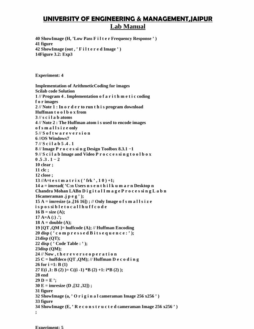
40 ShowImage (H, ’Low Pass F i l t e r Frequency Response ’ )41 figure42 ShowImage (out , ’ F i l t e r e d Image ’ )14Figure 3.2: Exp3
Experiment: 4
Implementation of ArithmeticCoding for imagesScilab code Solution1 // Program 4 . Implementation o f a r i t h m e t i c codingf o r images2 // Note 1 : In o r d e r to run t h i s program downloadHuffman t o o l b o x from3 // s c i l a b atoms4 // Note 2 : The Huffman atom i s used to encode imageso f s m a l l s i z e only5 // S o f t w a r e v e r s i o n6 //OS Windows77 // S c i l a b 5 .4 . 18 // Image P r o c e s si n g Design Toolbox 8.3.1 −19 // S c i l a b Image and Video P r o c c e s si n g t o o l b o x0 .5 .3 . 1 − 210 clear ;11 clc ;12 close ;13 //A=t e s t m a t r i x ( ’ frk ’ , 1 0 ) +1;14 a = imread( ’C:n Users n s e n t h i l k u m a r n Desktop nChandra Mohan LABn D i g i t a l I m a g e P r o c e s si n g L a b n16cameraman .j p e g ’ );15 A = imresize (a ,[16 16]) ; // Only Image o f s m a l l s i z ei s p o s si b l e t o c a l l h u f f c o d e16 B = size (A);17 A=A (:) .’;18 A = double (A);19 [QT ,QM ]= huffcode (A); // Huffman Encoding20 disp ( ’ c o m p r e s s e d B i t s e q u e n c e : ’ );21disp (QT);22 disp ( ’ Code Table : ’ );23disp (QM);24 // Now , t h e r e v e r s e o p e r a t i o n25 C = huffdeco (QT ,QM); // Huffman D e c o d i n g26 for i =1: B (1)27 E(i ,1: B (2) )= C((i -1) *B (2) +1: i*B (2) );28 end29 D = E ’;30 E = imresize (D ,[32 ,32]) ;31 figure32 ShowImage (a, ’ O r i g i n a l cameraman Image 256 x256 ’ )33 figure34 ShowImage (E, ’ R e c o n s t r u c t e d cameraman Image 256 x256 ’ );
Experiment: 5Basic JPEG algorithmimplementation
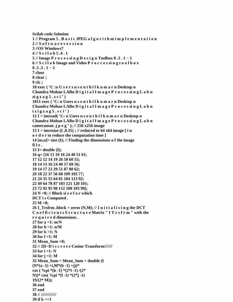
Scilab code Solution1 // Program 5 . B a s i c JPEG a l g o r i t h m i m p l e m e n t a t i o n2 // S o f t w a r e v e r s i o n3 //OS Windows74 // S c i l a b 5 .4 . 15 // Image P r o c e s si n g D e s i g n Toolbox 8 .3 . 1 − 16 // S c i l a b Image and Video P r o c c e s si n g t o o l b o x0 .5 .3 . 1 − 27 close8 clear ;9 clc ;10 exec ( ’C :n U s e r s n s e n t h i l k u m a r n Desktop nChandra Mohan LABn D i g i t a l I m a g e P r o c e s si n g L a b nzi g z a g 5 . s c i ’ )1811 exec ( ’C: n Users n s e n t h i l k u m a r n Desktop nChandra Mohan LABn D i g i t a l I m a g e P r o c e s si n g L a b ni z i g z a g 5 . s c i ’ )12 I = imread( ’C: n Users n s e n t h i l k u m a r n Desktop nChandra Mohan LABn D i g i t a l I m a g e P r o c e s si n g L a b ncameraman .j p e g ’ ); // 256 x256 image13 I = imresize (I ,0.25) ; // reduced to 64 x64 image [ i no r d e r to reduce the computation time ]14 [m,n]= size (I); // Finding the dimensions o f the imagefi l e .15 I= double (I);16 q= [16 11 10 16 24 40 51 61;17 12 12 14 19 26 58 60 55;18 14 13 16 24 40 57 69 56;19 14 17 22 29 51 87 80 62;20 18 22 37 56 68 109 103 77;21 24 35 55 64 81 104 113 92;22 49 64 78 87 103 121 120 101;23 72 92 95 98 112 100 103 99];24 N =8; // Block si z e f o r whichDCT i s Computed .25 M =8;26 I_Trsfrm .block = zeros (N,M); // I n i t i a l i s i n g the DCTC o e f fi c i e n t s S t r u c t u r e Matrix " I T r s f r m " with ther e q u i r e d dimensions .27 for a =1: m/N28 for b =1: n/M29 for k =1: N30 for l =1: M31 Mean_Sum =0;32 // 2D−D i s c r e t e Cosine Transform///////33 for i =1: N34 for j =1: M35 Mean_Sum = Mean_Sum + double (I(N*(a -1) +i,M*(b -1) +j))*cos ( %pi *(k -1) *(2*i -1) /(2*N))* cos( %pi *(l -1) *(2*j -1)19/(2* M));36 end37 end38 // /////////////39 if k ==140 Mean_Sum = Mean_Sum * sqrt (1/ N);41 else

UNIVERSITY OF ENGINEERING & MANAGEMENT,JAIPURLab Manual
42 Mean_Sum = Mean_Sum * sqrt (2/ N);43 end44 if l ==145 Mean_Sum = Mean_Sum * sqrt (1/ M);46 else47 Mean_Sum = Mean_Sum * sqrt (2/ M);48 end49 I_Trsfrm (a,b). block (k,l)= Mean_Sum ;50 end51 end52 // N o r m a l i z i n g t h e DCT Matrix and Q u a n t i z i n gt h e r e s u l t i n g v a l u e s .53 I_Trsfrm (a,b). block = round ( I_Trsfrm (a,b).block ./q);54 end55 end56 I_zigzag .block = zeros (N,M);57 for a= 1:m/N58 for b = 1:n/M59 I_zigzag (a,b). block = zigzag_5 ( I_Trsfrm (a,b). block );60 end61 end62 I_rec_Trnsfm .block = zeros (N,M);63 for a= 1:m/N64 for b = 1:n/M65 I_rec_Trnsfm (a,b). block = izigzag_5 ( I_zigzag(a,b). block );66 end67 end68 // D e n o r m a l i z i n g t h e R e c o n s t r u c t e d Tranform matrix20u s i n g the same69 // N o r m a l i z a t i o n matrix .70 for a =1: m/N71 for b =1: n/M72 I_rec_Trnsfm (a,b). block =( I_rec_Trnsfm (a,b).block ).*q;73 end74 end75 // I n v e r s e 2D−DCT76 for a =1: m/N77 for b =1: n/M78 for i =1: N79 for j =1: M80 Mean_Sum =0;81 for k =1: N82 for l =1: M83 if k ==184 temp = double ( sqrt (1/2) *I_rec_Trnsfm (a,b).block (k,l))* cos( %pi *(k-1) *(2*i -1) /(2* N))* cos( %pi *(l -1) *(2*j -1) /(2*M));85 else86 temp = double (I_rec_Trnsfm (a,b).
block (k,l))* cos( %pi *(k -1) *(2*i -1) /(2* N))*cos ( %pi *(l -1) *(2*j -1)/(2* M));87 end88 if l ==189 temp = temp * sqrt (1/2) ;90 end91 Mean_Sum = Mean_Sum + temp ;92 end93 end94 Mean_Sum = Mean_Sum *(2/ sqrt (M*N));2195 I_rec ((a -1) *N+i ,(b -1) *M+j)= Mean_Sum;96 end97 end98 end99 end100 // D i s p l a y i n g t h e R e c o n s t r u c t e d Image .101 diff_image = im2double (I)*255 - I_rec ;102 diff_image = diff_image / max (max(diff_image ));103 diff_image = im2uint8 ( diff_image );104 I_rec = I_rec /max( max ( I_rec ));105 I_rec = im2uint8 ( I_rec );106 figure107 ShowImage (I_rec , ’ Recovered Image ’ );108 figure109 ShowImage ( diff_image , ’ D i f f e r e n c e Image ’ )110 figure111 imhist( I_rec );112 figure113 imhist( diff );
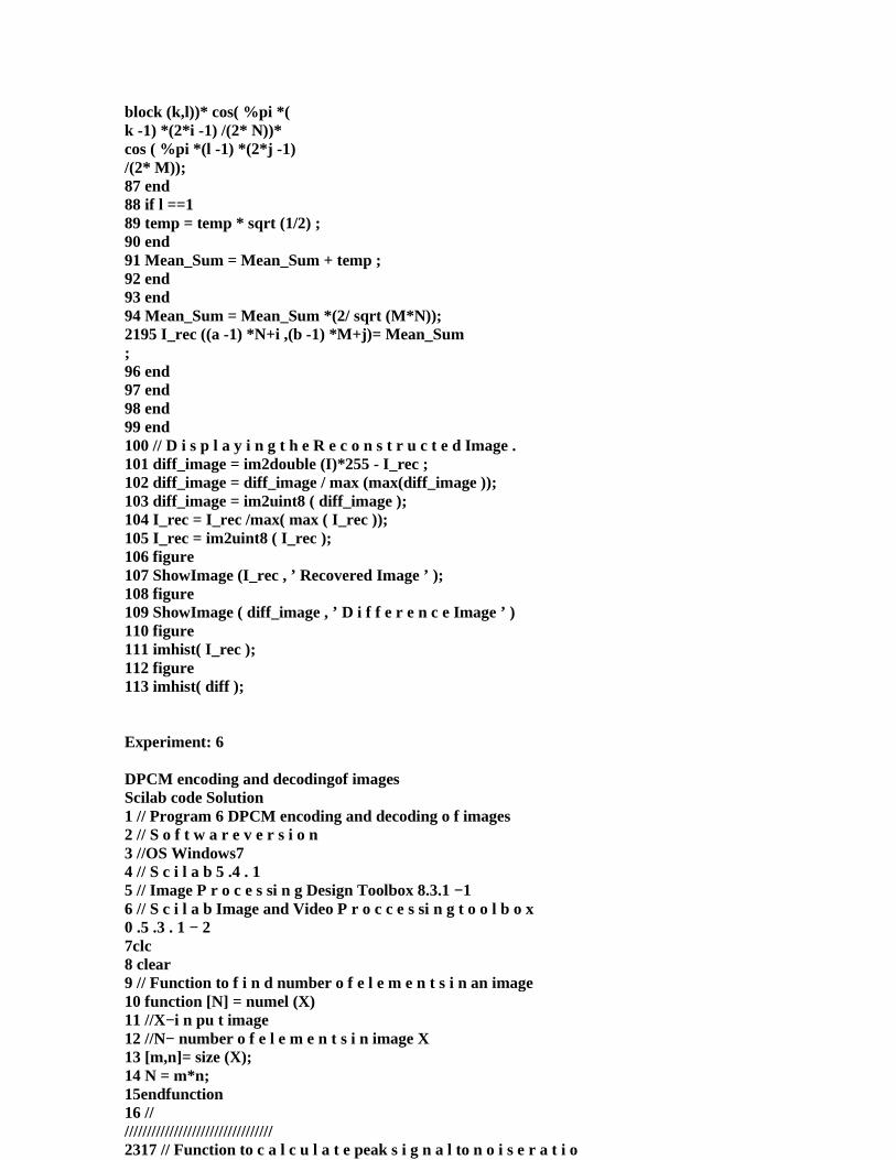
Experiment: 6
DPCM encoding and decodingof imagesScilab code Solution1 // Program 6 DPCM encoding and decoding o f images2 // S o f t w a r e v e r s i o n3 //OS Windows74 // S c i l a b 5 .4 . 15 // Image P r o c e s si n g Design Toolbox 8.3.1 −16 // S c i l a b Image and Video P r o c c e s si n g t o o l b o x0 .5 .3 . 1 − 27clc8 clear9 // Function to f i n d number o f e l e m e n t s i n an image10 function [N] = numel (X)11 //X−i n pu t image12 //N− number o f e l e m e n t s i n image X13 [m,n]= size (X);14 N = m*n;15endfunction16 ///////////////////////////////////2317 // Function to c a l c u l a t e peak s i g n a l to n o i s e r a t i o18 function [psnr ,mse , maxerr ] = psnr_mse_maxerr (X, Xapp )19 //PSNR MSE MAXERR Peak s i g n a l to n o i s e r a t i o
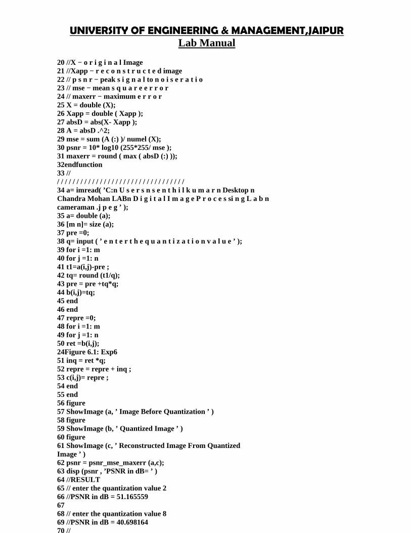
UNIVERSITY OF ENGINEERING & MANAGEMENT,JAIPURLab Manual
20 //X − o r i g i n a l Image21 //Xapp − r e c o n s t r u c t e d image22 // p s n r − peak s i g n a l to n o i s e r a t i o23 // mse − mean s q u a r e e r r o r24 // maxerr − maximum e r r o r25 X = double (X);26 Xapp = double ( Xapp );27 absD = abs(X- Xapp );28 A = absD .^2;29 mse = sum (A (:) )/ numel (X);30 psnr = 10* log10 (255*255/ mse );31 maxerr = round ( max ( absD (:) ));32endfunction33 /// / / / / / / / / / / / / / / / / / / / / / / / / / / / / / / / /34 a= imread( ’C:n U s e r s n s e n t h i l k u m a r n Desktop nChandra Mohan LABn D i g i t a l I m a g e P r o c e s si n g L a b ncameraman .j p e g ’ );35 a= double (a);36 [m n]= size (a);37 pre =0;38 q= input ( ’ e n t e r t h e q u a n t i z a t i o n v a l u e ’ );39 for i =1: m40 for j =1: n41 t1=a(i,j)-pre ;42 tq= round (t1/q);43 pre = pre +tq*q;44 b(i,j)=tq;45 end46 end47 repre =0;48 for i =1: m49 for j =1: n50 ret =b(i,j);24Figure 6.1: Exp651 inq = ret *q;52 repre = repre + inq ;53 c(i,j)= repre ;54 end55 end56 figure57 ShowImage (a, ’ Image Before Quantization ’ )58 figure59 ShowImage (b, ’ Quantized Image ’ )60 figure61 ShowImage (c, ’ Reconstructed Image From QuantizedImage ’ )62 psnr = psnr_mse_maxerr (a,c);63 disp (psnr , ’PSNR in dB= ’ )64 //RESULT65 // enter the quantization value 266 //PSNR in dB = 51.1655596768 // enter the quantization value 869 //PSNR in dB = 40.69816470 //

Experiment: 7
Simple image watermarkingalgorithms using LSBsubstitutionScilab code Solution1 // Program 7 . Simple image watermarking a l g o r i t h m su s i n g LSB s u b s t i t u t i o n2 // Note 1 : The imread f u n c t i o n i n SIVP t o o l b o x readthe b i n a r y image as gray3 // s c a l e image . During b i t s e t i t w i l l c r e a t e problems.4 //The g r a y s c a l e image can be c o n v e r t e d i n t o b i n a r yimage u s i n g the f u n c t i o n5 // g r a y 2 b i n ( )6 // Note 2 : The f u n c t i o n s b i t s e t and b i t g e t a r ew r i t t e n i n o r d e r to save the7 // s c i l a b workspace memory during e x e c u t i o n8 // S o f t w a r e v e r s i o n9 //OS Windows710 // S c i l a b 5 .4 . 111 // Image P r o c e s si n g Design Toolbox 8.3.1 −112 // S c i l a b Image and Video P r o c c e s si n g t o o l b o x270 .5 .3 . 1 − 213clc14 clear15 close16 // Function to f i n d number o f e l e m e n t s i n an image17 function [N] = numel (X)18 //X−i n p u t image19 //N− number o f e l e m e n t s i n image X20 [m,n]= size (X);21 N = m*n;22endfunction23 // Function to c a l c u l a t e peak s i g n a l to n o i s e r a t i o24 function [psnr ,mse , maxerr ] = psnr_mse_maxerr (X, Xapp )25 //PSNR MSE MAXERR Peak s i g n a l to n o i s e r a t i o26 //X − o r i g i n a l Image27 //Xapp − r e c o n s t r u c t e d image28 // p s n r − peak s i g n a l to n o i s e r a t i o29 // mse − mean s q u a r e e r r o r30 // maxerr − maximum e r r o r31 X = double (X);32 Xapp = double ( Xapp );33 absD = abs(X- Xapp );34 A = absD .^2;35 mse = sum (A (:) )/ numel (X);36 psnr = 10* log10 (255*255/ mse );37 maxerr = round ( max ( absD (:) ));38endfunction39 /// / / / / / / / / / / / / / / / / / / / / / / / / / / / / / / / /40 function [A]= gray2bin (B)41 [m,n] = size (B)42 for i = 1:m43 for j = 1:n44 if(B(i,j) >200)45 A(i,j)= 1;46 else47 A(i,j) =0;

UNIVERSITY OF ENGINEERING & MANAGEMENT,JAIPURLab Manual
2848 end4950 end5152 end53endfunction54 /// / / / / / / / / / / / / / / / / / / / / / / / / / / / / / / / /55 function [c]=bit_set (c,b)56 [m,n] = size (c);57 for i =1: m58 for j =1: n59 c(i,j)= bitset (c(i,j) ,1,b(i,j));60 end61 end62endfunction63 /// / / / / / / / / / / / / / / / / / / / / / / / / / / / / / / / /64 function [d] = bit_get (c)65 [m,n] = size (c);66 for i =1: m67 for j =1: n68 d(i,j)= bitget (c(i,j) ,1);69 end70 end71endfunction72 /// / / / / / / / / / / / / / / / / / / / / / / / / / / / / / / / /73 a = imread( ’C: n U s e r s n s e n t h i l k u m a r n Desktop nChandra Mohan LABn D i g i t a l I m a g e P r o c e s si n g L a b ncameraman .j p e g ’ ); // o r i g i n a l image74 b = imread( ’C: n U s e r s n s e n t h i l k u m a r n Desktop nChandra Mohan LABn D i g i t a l I m a g e P r o c e s si n g L a b n wat. j p g ’ ); // watermark image75 b = gray2bin (b);29Figure 7.1: Exp776 [m n] = size (a);77 a = double (a);78 c = a;79 c = bit_set (c,b);80 d = bit_get (c);8182 figure83 ShowImage (a, ’ O r i g i n a l image ’ );84 title ( ’ O r i g i n a l image ’ );85 figure86 ShowImage (b, ’ watermark image ’ );87 title ( ’ watermark image ’ );88 figure89 ShowImage ( uint8 (c), ’ watermarked image ’ );90 title ( ’ watermarked image ’ );91 figure92 ShowImage (d, ’ extracted watermark ’ );93 title ( ’ extracted watermark ’ );94 psnr = psnr_mse_maxerr (a,c);95 correlation = corr2 (b,d);96 disp( correlation , ’ c o r r e l a t i o n between watermark

image and extracted watermark=’ )Experiment: 8
Simple content based imageretrieval using various distancemetricsScilab code Solution1 // Program 8 : Simple c o n t e n t based image r e t r i e v a lu s i n g v a r i o u s d i s t a n c e m e t r i c s .2 // Based on S i m i l a r i t y matrix3 // Using Colormaps o f d i f f e r e n t images4 // Note 1 : Other methods l i k e w a v e l e t basedd e c o m p o s i t i o n a lo n g with E u c l i d e a n d i s t a n c e5 // comparison o f sub images can be used f o r imager e t r i e v a l6 // Note 2 : P r i n c i p a l Component A n a l y s i s (PCA) i n b u i l tf u n c t i o n i s a v a i l a b l e to7 // g e t e i g e n v e c t o r s and e i g e n v a l u e s f o r imager e t r i e v a l8 // S o f t w a r e v e r s i o n9 //OS Windows710 // S c i l a b 5 .4 . 111 // Image P r o c e s si n g Design Toolbox 8.3.1 −112 // S c i l a b Image and Video P r o c c e s si n g t o o l b o x320 .5 .3 . 1 − 213 clear ;14 clc ;15 close ;16 I1 = imread( ’C:n U s e r s n s e n t h i l k u m a r n Desktop nChandra Mohan LABn D i g i t a l I m a g e P r o c e s si n g L a b nP i c t u r e 1 .png ’ ); // 257 x257x3 .17 I1 = imresize (I1 ,0.5) ;18 [ IndexedImage_I1 , ColorMap ] = RGB2Ind (I1); //IPDt o o l b o x19 I = ColorMap ; // 66049 x320 J1 = imread( ’C:n U s e r s n s e n t h i l k u m a r n Desktop nChandra Mohan LABn D i g i t a l I m a g e P r o c e s si n g L a b nP i c t u r e 2 .png ’ ); // 257 x257x3 .21 J1 = imresize (J1 ,0.5) ;22 [ IndexedImage_J1 , ColorMap ] = RGB2Ind (J1); //IPDt o o l b o x23 J = ColorMap ; // 66049 x324 // S i m i l a r i t y Matrix Method25 [r,c]= size (I);26 A = [];27 I = double (I);28 J = double (J);29 for i = 1:r30 for j = 1:c31 M1(i,j) = (I(i ,2) * sin (I(i ,1) )-J(j ,2) * sin (J(j,1) )) ^2;32 M2(i,j) = (I(i ,2) * cos (I(i ,1) )-J(j ,2) * cos (J(j,1) )) ^2;33 M3(i,j) = (I(i ,3) -J(i ,3) ) ^2;34 M(i,j)= sqrt (M1(i,j)+M2(i,j)+M3(i,j));35 A(i,j) = 1-M(i,j)/ sqrt (5) ;36 end37 end38 I1_rec = Ind2RGB ( IndexedImage_I1 ,A)39 I1_rec = imresize( I1_rec ,2) ;40 J1_rec = Ind2RGB ( IndexedImage_J1 ,A)
UNIVERSITY OF ENGINEERING & MANAGEMENT,JAIPURLab Manual
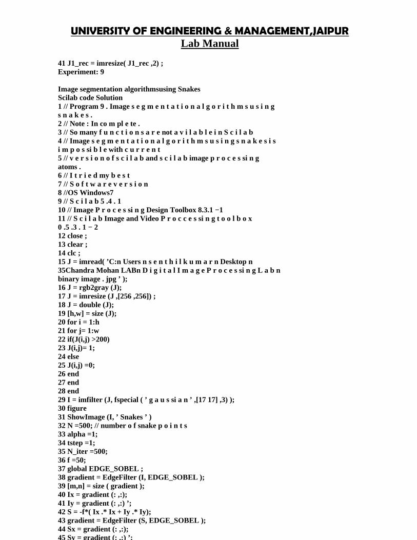
41 J1_rec = imresize( J1_rec ,2) ;Experiment: 9
Image segmentation algorithmsusing SnakesScilab code Solution1 // Program 9 . Image s e g m e n t a t i o n a l g o r i t h m s u s i n gs n a k e s .2 // Note : In co m pl e te .3 // So many f u n c t i o n s a r e not a v i l a b l e i n S c i l a b4 // Image s e g m e n t a t i o n a l g o r i t h m s u s i n g s n a k e s i si m p o s si b l e with c u r r e n t5 // v e r s i o n o f s c i l a b and s c i l a b image p r o c e s si n gatoms .6 // I t r i e d my b e s t7 // S o f t w a r e v e r s i o n8 //OS Windows79 // S c i l a b 5 .4 . 110 // Image P r o c e s si n g Design Toolbox 8.3.1 −111 // S c i l a b Image and Video P r o c c e s si n g t o o l b o x0 .5 .3 . 1 − 212 close ;13 clear ;14 clc ;15 J = imread( ’C:n Users n s e n t h i l k u m a r n Desktop n35Chandra Mohan LABn D i g i t a l I m a g e P r o c e s si n g L a b nbinary image . jpg ’ );16 J = rgb2gray (J);17 J = imresize (J ,[256 ,256]) ;18 J = double (J);19 [h,w] = size (J);20 for i = 1:h21 for j= 1:w22 if(J(i,j) >200)23 J(i,j)= 1;24 else25 J(i,j) =0;26 end27 end28 end29 I = imfilter (J, fspecial ( ’ g a u s si a n ’ ,[17 17] ,3) );30 figure31 ShowImage (I, ’ Snakes ’ )32 N =500; // number o f snake p o i n t s33 alpha =1;34 tstep =1;35 N_iter =500;36 f =50;37 global EDGE_SOBEL ;38 gradient = EdgeFilter (I, EDGE_SOBEL );39 [m,n] = size ( gradient );40 Ix = gradient (: ,:);41 Iy = gradient (: ,:) ’;42 S = -f*( Ix .* Ix + Iy .* Iy);43 gradient = EdgeFilter (S, EDGE_SOBEL );44 Sx = gradient (: ,:);45 Sy = gradient (: ,:) ’;46 eps = 2.2204e -016;
47 Smag = sqrt (Sx .^2 + Sy .^2) + eps ;48 Sx (:) = Sx ./Smag ;49 Sy (:) = Sy ./Smag ;50 D=[- tstep * alpha * ones (N ,1) (1+2* tstep * alpha )* ones (N,1) -tstep * alpha * ones (N ,1) ];3651 D(2 ,3)=D(2 ,3) -tstep * alpha ;52 D($ -1 ,1)=D($ -1 ,1) -tstep * alpha ;53 theta = linspace (0 ,2* %pi ,N);54 theta = theta (:) ;55 x = w/2 + 10 + (h /3) * cos( theta );56 y = h/2 - 10 + (h /4) * sin( theta );57 plot (x,y, ’ r ’ );
Experiment: 10
Color images manipulations,reading and writing of colorimagesScilab code Solution1 // Program 1 0 . Color images manipulations , r e a d i n g andw r i t i n g o f c o l o r images2 // S o f t w a r e v e r s i o n3 //OS Windows74 // S c i l a b 5 .4 . 15 // Image P r o c e s si n g Design Toolbox 8.3.1 −16 // S c i l a b Image and Video P r o c c e s si n g t o o l b o x0 .5 .3 . 1 − 27clc8 clear9 close10 // Showing RGB components o f a c o l o r RGB image .11 // S p l i t ti n g the c o l o r image (RGB Image )i n t o t h r e ep l a n e s12 a= imread( ’C:n Users n s e n t h i l k u m a r n Desktop nChandra Mohan LABn DIP Scilab Programs n peppers .png ’ ); // t h i s image i s 348 x512x3 s i z e3813 figure14 ar=a(: ,: ,1);15 ShowImage (ar , ’RED Matrix ’ )16 figure17 ag=a(: ,: ,2);18 ShowImage (ag , ’GREEN Matrix ’ )19 figure20 ab=a(: ,: ,3);21 ShowImage (ab , ’BLUE Matrix ’ )22 // R e c o n s t r u c t i o n o f o r i g i n a l c o l o r image from t h r e eRGB p l a n e s2324 RGB = imread( ’C: n Users n s e n t h i l k u m a r n Desktop nChandra Mohan LABn DIP Scilab Programs n peppers .png ’ ); //SIVP t o o l b o x25 RGB_128 = RGB /2;26 RGB_128 = round ( RGB_128 )27 [X, map ] = RGB2Ind ( RGB_128 );28 figure29 ShowImage (X, ’ Indexed Image ’ ,map )30 // L i m i t i n g no o f c o l o u r s to 8 without d i t h e r i n g31 figure32 RGB_8 = RGB /7;33 RGB_8 = round ( RGB_8 )

UNIVERSITY OF ENGINEERING & MANAGEMENT,JAIPURLab Manual
34 [X1 , map1 ]= RGB2Ind ( RGB );35 ShowImage (X1 , ’ Without Dither ’ ,map1 )3637 figure38 ShowColorImage (RGB , ’RGB Color Image ’ )39 YIQ = rgb2ntsc ( RGB );40 figure41 ShowColorImage (YIQ , ’NTSC image YIQ ’ )42 RGB = ntsc2rgb ( YIQ );43 YCC = rgb2ycbcr ( RGB );44 figure45 ShowColorImage (YCC , ’ e q u i v a l e n t HSV image YCbCr ’ )46 RGB = ycbcr2rgb ( YCC );47 HSV = rgb2hsv ( RGB );3948 figure49 ShowColorImage (HSV , ’ e q u i v a l e n t HSV image ’ )50 RGB = hsv2rgb ( HSV )

UNIVERSITY OF ENGINEERING & MANAGEMENT, JAIPURCourse Description
Title of Course: Grand VivaCourse Code: EC881L-T –P Scheme: 0P Course Credits: 4
Aims and Objectives
1. To compare the traditional viva examination (TVE) with OSVE (Objective Structured VivaExamination).
2. To obtain the students’ opinion regarding OSVE as an assessment tool.
3. A suggestion to include OSVE as a part of university examination.
Materials and Methods
The study was carried out in November 2012, at K.J. Somaiya Medical College, in thedepartment of Anatomy. 50 students were exposed to different stations of viva as well as OSVE.A comparison was made of the student’s performance and a feedback was taken from thestudents regarding the same.
As the OSVE was being conducted for the first time, the students were notified in advanceregarding the plan for conducting the part ending practical assessment – by both the TVE andOSVE. The OSVE was planned for 20 marks, viva voce of 20 marks.
Purpose and Format of the Viva Voce Examination
Literally, "viva voce" means by or with the living voice - i.e., by word of mouth as opposed to
writing. So the viva examination is where you will give a verbal defence of your thesis.
Put simply, you should think of it as a verbal counterpart to your written thesis. Your thesis
demonstrates your skill at presenting your research in writing. In the viva examination, you will
demonstrate your ability to participate in academic discussion with research colleagues.
Purpose of the Exam
The purpose of the viva examination is to:
demonstrate that the thesis is your own work
confirm that you understand what you have written and can defend it verbally
investigate your awareness of where your original work sits in relation to the wider research field
UNIVERSITY OF ENGINEERING & MANAGEMENT, JAIPURCourse Description
establish whether the thesis is of sufficiently high standard to merit the award of the degree for
which it is submitted
allow you to clarify and develop the written thesis in response to the examiners' questions
The Examiners and Exam Chair
You will normally have two examiners:
an internal examiner who will be a member of academic staff of the University, usually from
your School/Department but not one of your supervisors
an external examiner who will normally be a member of academic staff of another institution or
occasionally a professional in another field with expertise in your area of research (candidates
who are also members of University staff will normally have two external examiners in place of
an internal and an external examiner)
Your supervisor should let you know who your examiners will be as it is important that you
ensure you are familiar with their work and any particular approach that they may take when
examining your thesis.
In some cases there may also be a Chair person for the examination. A Chair is appointed if the
Graduate Dean or either of the examiners feels this is appropriate, for example where the
examining team has relatively little experience of examining UK research degrees. The Chair is
there to ensure the examination is conducted in line with University regulations and is not there
to examine your thesis. If there is a Chair person, it will usually be a senior member of the
academic staff of your School/Department.
Normally no one else is present in the exam.
Exam Venue and Arrangements
Your internal examiner is responsible for arranging your viva exam and they will contact you
with the relevant details - date, time, venue, etc.
Usually the viva exam will take place in your School/Department, though occasionally another
University location may be used. If you are unsure where you need to go, make sure you check
this before the day of your exam.

UNIVERSITY OF ENGINEERING & MANAGEMENT, JAIPURCourse Description
If you returned your Notice of Intention to Submit Your Thesis three months before your
submission date, your viva exam should normally take place quite soon after submission. Almost
all viva exams take place within three months of thesis submission and in many cases it is within
one month.
Format of the Exam
All viva examinations are different, so it is not possible to describe exactly what will happen -
but there are general points which can be made which may be helpful, and you should have the
opportunity before your examination to discuss what will happen with your supervisor or to
attend the University's pre-viva examination workshop.
The purpose of the viva is to establish that your work is of a sufficiently high standard to merit
the award of the degree for which it is submitted. In order to be awarded a research degree, the
thesis should demonstrate an original contribution to knowledge and contain work which is
deemed worthy of publication.
In order to do this, examiners may:
ask you to justify your arguments
ask you to justify not only things which you have included in your thesis but also things which
you may have left out
ask you questions about the wider research context in which the work has been undertaken
argue certain points with you
expect you to discuss any developments which may flow from your work in the future
Inevitably, your thesis will have strengths and weaknesses and the examiners will want to
discuss these. It is considered a positive thing, indeed an essential thing, that you can discuss
both the strengths and the weaknesses. You can think of the weaknesses as an opportunity to
demonstrate your skill at critical appraisal.
Remember that examiners seek to find and discuss weaknesses in all theses - you should not
interpret criticism as an indication that the examination will not end successfully.

UNIVERSITY OF ENGINEERING & MANAGEMENT, JAIPURCourse Description
Title of Course: Project Part-IICourse Code: EC882L-T –P Scheme: 12P Course Credits: 12
Project: an activity where the participants have some degree of choice in the outcome. The resultis complete and functional, that is, it has a beginning, middle and end. Usually, it spans multiplelab periods and requires work outside scheduled lab periods. Since there are choices inimplementation, design is inherently a component of a project. A project is inherently differentfrom an analysis or exercise, in which the solution has a predictable form. Projects span a widevariety of possibilities: design and build, identify a system, do a forensic analysis, evaluate aproduct or assess some environmental situation.
Program Objective 1Graduates shall make their way to the society with proper scientific and technical knowledge inmechanical engineering.
Program Objective 2Graduates shall work in design and analysis of mechanical systems with strong fundamentals andmethods of synthesis.
Program Objective 3Graduates shall adapt to the rapidly changing environment in the areas of mechanicalengineering and scale new heights in their profession through lifelong learning.
Program Objective 4Graduates shall excel in career by their ability to work and communicate effectively as a teammember and/or leader to complete the task with minimal resources, meeting deadlines.
Program Outcomes:
1. Ability to apply knowledge of mathematics, science and mechanical engineeringfundamentals for solving problems.
2. Ability to Identify, formulate and analyze mechanical engineering problems arriving atmeaningful conclusions involving mathematical inferences.
3. Ability to design and develop mechanical components and processes to meet desiredneeds considering public health, safety, cultural, social, and environmental aspects.
4. Ability to understand and investigate complex mechanical engineering problemsexperimentally.
5. Ability to apply modern engineering tools, techniques and resources to solve complexmechanical engineering activities with an understanding of the limitations.
6. Ability to understand the effect of mechanical engineering solutions on legal, cultural,social, public health and safety aspects./li>

UNIVERSITY OF ENGINEERING & MANAGEMENT, JAIPURCourse Description
7. Ability to develop sustainable solutions and understand their impact on society andenvironment.
8. Ability to apply ethical principles to engineering practices and professionalresponsibilities.
9. Ability to function effectively as an individual and as a member or leader in diverseteams and in multidisciplinary settings.
10. Ability to comprehend, design documentation, write effective reports, make effectivepresentations to the engineering community and society at large.
11. Ability to apply knowledge of engineering and management principles to lead teams andmanage projects in multidisciplinary environments.
12. Ability to engage in independent and life-long learning in the broad context oftechnological changes and advancements.