university of hong kong librariesebook.lib.hku.hk/hkg/b35842167.pdf · guidance notes on...
TRANSCRIPT

UNIVERSITY OF HONG KONG
LIBRARIES
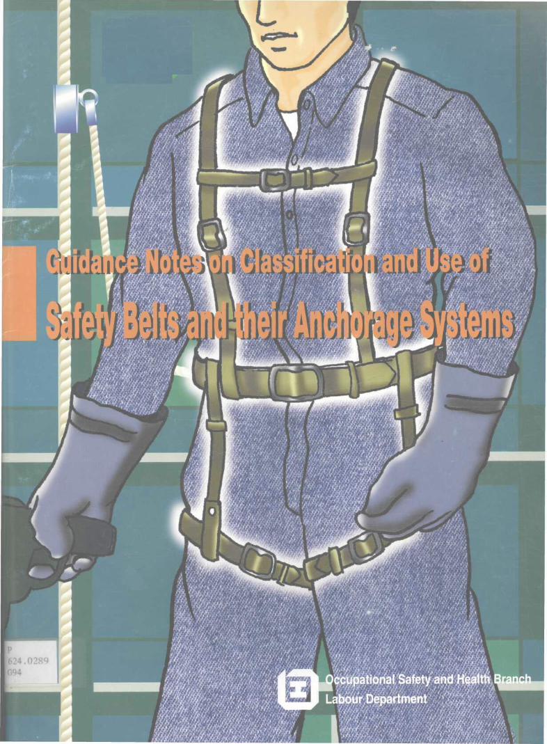
Guidance Notes onClassification and Use ofSafety Belts and theirAnchorage Systems

This guidance notes is prepared by theOccupational Safety and Health BranchLabour Department
First edition November 1998
This guidance notes is issued free of charge andcan be obtained from offices of the OccupationalSafety and Health Branch. Addresses and telephonenumbers of the offices can be found in the bookletuThe Labour Department Offers You its Services" orby telephone 2559 2297.

Contents
Page
I. Introduction 1
II. Selection of Industrial Safety Belts and 4
their Anchorage Systems
(1) Consideration to use Safety Net 4
(2) Planning 4
(3) Selection 5
III. Use of Equipment 8
(1) Manufacturer's Instructions 8
(2) Training 8
(3) Inspection, Examination and Supervision 9
(4) Safety Notes 11
IV. Classification of Safety Belts 14
(1) Safety Harness or Full Body Harness 15
(2) Semi-Harness or Chest Harness 16
(3) General Purpose Safety Belt or Body 18
Belt
(4) Work Positioning Belt, Pole or Linesman 20
Safety Belt
(5) Safety Rescue Harness 20
V. Anchorage of Safety Belt 22
(1) Fixed Anchorage 23
(2) Vertical Independent Lifeline 27
(3) Horizontal Lifeline (Guide rope) 28
(4) Fall Arrester 29
(a) Retractable Fall Arrester 30
(b) Guided Type Fall Arrester on a 32
Rigid Anchorage Line
(c) Guided Type Fall Arrester on a 33
Flexible Anchorage Line
VI. Practical Examples of using Safety Belts 35
and their Anchorage
(1) Example of using Fixed Anchorage 35
(2) Vertical Independent Lifeline 36
(3) Guide Rope 38
(4) Retractable Fall Arrester 39

(5) Guided Type Fall Arrester on a Rigid 40
Anchorage Line
Appendix 1 41
(a) Full Body Harness under BSEN 361:1992 41
(b) Safety Harness under AS/NZS 1891.1:1995 42
(c) Safety Harness under ANSI AID.14-1991 43
(d) Safety Harness under GB 720-65 45
(e) Harness Safety Belts from Japan 47
.Appendix 2 48
(a) Chest Harness from Japan 48
(b) Chest Harness under ANSI A10.14-1991 49
(c) Scaffolding Safety Belt under GB 721-65 50
Appendix 3 51
(a) Body Belt under ANSI A10.14-1991 51
(b) Industrial Safety Belt under JIS M7624 51
Appendix 4 54
(a) Work Positioning Belt under 54
BSEN 358:1993

(b) Pole Safety Belt under 55
AS/NZS 1891.1:1995
(c) Linemen's Safety Belt under 55
JIS T8165-1987
(d) Linemen's Safety Belt under GB 723-65 56
List of Reference 58
Useful Information 61

I. Introduction
Fall from height is a. primitive hazard when a worker worksat height. The provision of a suitable working platform,safe access and egress and proper fencing to a dangerousplace are the primary safety measures that the local safetyregulations have asked for. The use of safety nets andsafety belts are only the last resort when it isimpracticable to provide such platforms, access and egressand safe place of work.
Statutory provisions on the use of safety belts are setout in :
(i) the use of Boatswain's Chair underregulation 381 of the Construction Sites(Safety) Regulations (CSSR);
(ii) a circumstance when it is impracticable toprovide a suitable working platform , safeaccess and egress or safe place of workunder regulation 38Q of CSSR;
(iii) the use of suspended working platformsunder regulation 15 of the Factories andIndustrial Undertakings (SuspendedWorking Platforms) Regulation; and
(iv) the use of a receptacle of less than 900 mmdeep for carrying persons by a liftingappliance under regulation 18B(1) of theFactories and Industrial Undertakings(Lifting Appliances and Lifting Gear)Regulations.
Other examples that require the use of safety belts butare not explicitly stated in the law are :-
(i) working on container tops during cargo orcontainer handling under regulation 10B of
- 1 -
the Factories and Industrial Undertakings(Cargo & Container Handling) Regulations;
(ii) working in a confined space underregulation 6 (c) of the Factories andIndustrial Undertakings (Confined Spaces)Regulations;
(iii) working at a dangerous place which requiresalternative protection under regulation24 (a) of the Factories and IndustrialUndertakings Regulations.
^Safety belt' referred in this guidance notes is acollective name for the following types of harnesses andbelts :-
(i) safety harness or fully body harness;
(ii) semi-harness or chest harness;
(iii) rescue harness;
(iv) work positioning belt, pole safety belt orlineman safety belt; and
(v) general purpose safety belt.
It includes a lanyard. When a safety belt works with anappropriate anchorage system, they form a personal fallarresting system.
vCompetei2t person7 mentioned in this guidance notes shouldbe a person who has the knowledge and experience toclassify and use safety belt, competent in identificationand selection of. various types of anchorage systems forthe use of the safety belt, and capable to check theapparent defect of the belt and its anchorage system.
^Professional Engineer' mentioned in this guidance notesshould be an engineer who is a member of the Hong Kong
-2-

Institution of Engineers within a discipline or theequivalent.
This guidance notes provides information on someconfigurations of anchorage systems, the types, uses andspecifications of safety belts under several nationalsafety standards. As safety belts are imported fromvarious countries, suitable safety belts or safety beltsrequired under the law are those safety belts which meetthe specifications of national safety standards, such asBritish Standard (BS or BSEN) , American National Standard(ANSI), Japanese Industrial Standard (JIS) or Safety BeltStandard of Japan's Ministry of Labour, the People'sRepublic of China National Standard (GB) or equivalence.Although BS is quoted in this guidance notes, equivalentnational or international standards can also be used.
-3-

II. Selection of Industrial Safety Beltsand their Anchorage Systems
(1) Consideration to use safety net
When it is impracticable to provide suitable workingplatform, safe access and egress, safe place of work andfencing of dangerous place where a worker is required towork at height, consideration of erecting safety net isalways the secondary option to protect the worker frominjury due to falling hazard. It is recommended that BS3913:1982-Specification for Industrial Safety Nets becomplied with. In addition, the users should seek theopinions of the safety net manufacturers, so that the bestnet which suits the type of work to be conducted under theprevailing conditions can be found. For the siting ofsafety net (outrigged) , BS 8093: 1991 should be compliedwith. Although BS is quoted in this guidance notes,equivalent national or international standards can alsobe used.
(2) Planning
During the planning process, primary consideration shouldbe given to methods of avoiding the use of the safety beltand tackling the possibility of provision of safe placeof work or adopting of a proper safety net as a secondaryoption.
The use of safety belt and its anchorage system is onlythe last resort of fall protection if it is impracticableto erect any safety net. In this case, careful planningfor the selection of safety belt and choice of anchoragesystem should be first drawn up before they are put intouse by workers.
Prior to the selection of safety belt and its anchoragesystem, the contractor or proprietor should develop a planwhich identifies the following ingredients.:.-
-4-

(i) the activity to be performed by workers;
(ii) the mobility required;
(iii) the workplace conditions;
(iv) availability of anchorage points for theanchorage system;
(v) the environmental factors; and
(vi) the hazards which may be encountered duringthe activity and the proposed precautionarymeasures to be taken.
Such plan should be the basis for selecting rigging, usingand unrigging of the personal fall arresting system as wellas identifying the training needs for users . The planshould be expanded to address how the work activity is tobe carried out by the users.
(3) Selection
Prior to selecting the safety belt and its anchorage, thecontractor or proprietor should conduct an assessment ofthe workplace conditions where the equipment is required.Such assessment should, at least, identify thefollowing :-
(i) presence of hot objects and heat-producingoperations;
(ii) chemicals and electrical hazards;
(iii) sharp object, abrasive surfaces, movingequipment, unguarded opening, etc.;
(iv) the paths of intended user movement and allfall hazards along such paths, and;
(v) the type of anchorage best fitted the
-5-

workplace and the work activity, and thecontinuous protection offered by theanchorage system.
During the selection of the anchorage system, particularattention should be drawn to the choice and limitation ofconnectors, fittings, the self locking devices, shockabsorbers, lifelines and supports of the anchorage to beused. The weight of the user including his working toolsand equipment, and his mobility during his work will needto be determined before selecting the type of appropriateanchorage system. It is important to note that no matterwhich type of anchorage or fall-arrest ing system isselected, such system must be able to offer continuousprotection throughout the period when the user is exposedto the risk of fall.
In the case where an eye bolt is chosen as fixed anchorage,or an anchorage line for the guided type fall arrester isselected, the design and construction, the strength andstability of the eye bolt and the anchorage line, theirfittings and embedded material, should be designed andchecked by a Professional Engineer of the structuraldiscipline. The user shall check the markings and theinstructions for use of various components of theanchorage system before he uses them.
It is important that full investigation should beconducted before purchase of safety belts in order toidentify the aspects of use and to determine the type ofbelt likely to suit the type of work and the environmentalconditions. In the selection of a safety belt for anyparticular task, care should be taken to ensure that theequipment gives the user, as far as it is practicable inrespect to safety and the maximum degree of comfort,freedom of movement and, in the event of falling, thegreatest possible security against injury either-
(i) from impact with the ground or with thesurrounding structures; or
-6--

(ii) from the belt or harnesses as a result ofa suddenly arrested fall.
It is strongly recommended that, when a choice of safetybelt is possible/ a safety harness incorporating buttockstraps, as distinct from a general purpose safety belt,should be used*
-7-

III. Use of Equipment
(1) Manufacturer's Instructions
Manufacturer7 s instructions are supplied with each deviceindicating the method of fitting, adjustment and use.These instructions should be brought to the attention ofuser who, before using the equipment, should be made awareof the possible adverse effects of an arrested free fallexceeding their specifications. Moreover, specialattention shall be addressed to the guidelines in theinspection before use, maintenance procedures, properstorage techniques in accordance with the manufacturer'srecommendations and instructions.
(2) Training
Training shall be provided, even with an experiencedworkforce. The Training should include:-
(i) how to use the equipment;
(ii) how to estimate and limit the maximumarresting force to an acceptable limit forthe system;
(iii) proper methods of wearing, adjusting, andinterconnecting of the equipment;
(iv) proper attachment locations on theequipment;
(v) intended function and performancecharacteristic in respect of each item ofequipment;
(vi) proper attachment methods includingcompatibility of the sizes of snap hooks,D-rings, and other connections to reducethe probability of accidental

disengagement;
(vii) what to do after a fall to protect the userfrom injury;
(viii) emergency rescue planning and execution toinclude:-
• methods of rescue,
• rescue personnel availability,
® type of equipment available forrescue and effective means tosummons rescue personnel;
• drilling of rescue personnel inrescue and evacuation procedures.
A record of training should be kept to register the coursecontent, the name of the user, the type of equipment, thetime and duration of the course. A refresher course shouldbe arranged if the user has been absent for a.period oftime in using a particular system.
(3) Inspection, Examination and Supervision
In order to ensure that the system is functioning properly,the system should be inspected and examined for detectingand controlling against the use of defective, damaged,improperly maintained equipment and misuse of components.The examination should also focus on the construction ofthe anchorage and the fitness of safety belts so selected.In addition, the inspection should cover for the absenceor illegibility of markings, absence of any element, fitor function, and evidence for defects in or damage tohardware.
The user should make a visual inspection prior to usingthe equipment to ensure that the equipment is in aserviceable condition. The inspection requirements
,9-

should follow those set forth in the manufacturer'sinstructions. They should include the following:
(i) absence or illegibility of markings;
(ii) absence of any elements affecting theequipment form, fit or function;
(iii) evidence of defects in or damage tohardware elements; and
(iv) evidence of defects in or damage tostraps or ropes;
When an inspection reveals defects in, damage to orinadequate maintenance of equipment, the equipment shouldbe permanently removed from service or undergo adequatecorrective maintenance before return to service.
To provide the maximum degree of safety to users, allsafety belts should be thoroughly examined by a competentperson periodically, e.g. at periods not exceeding 12months and in accordance with the manufacturer'sinstructions. When the safety belts are not in regular useduring any 6-month period, they should be examined beforeuse.
The inspection and examination should also focus on theconstruction of the anchorage and its connectors. Evidenceof alteration, absence of parts, or defect in, damage toor improper function of mechanical devices and connectorsshould be looked for to ensure that the anchorage is fittedfor providing support in case of a fall should occur.
Supervision on the wearing of safety belts, properattachment of lanyard to connectors, and correct positionof snaphooks etc. should also be conducted by a competentperson. If abnormal situation and/or mal-practice areobserved by the competent person, measures should be takento stop the using of the fall arresting system, and toprovide additional training or retraining to .the. user.
-10-

(4) Safety Notes
When using a safety belt and an anchorage, the followingpoints should be noted:
Anchorage
* Selection and inspection of suitable anchorage pointsshould be the subject of particular care. A suitableanchorage point must be strong enough. Reinforcedconcrete beam or column, or structural steel beam shouldbe used for anchoring lifelines preferably after theirstrength have been checked by a Professional Engineerof the structural discipline.
* The anchorage point should be as nearly vertical aspossible directly above the place of work to reduce theliability to swing. Where the possibility of swing inthe event of a fall is unavoidable, the user should usea second line to limit the swing.
* It is undesirable to use a structural member with sharpedges as an anchorage for a rope lifeline. If it isunavoidable, then the lifeline must be protected bysuitable packing.
* Each lifeline should be used by one person only at anyparticular time.
Before use
* Check that each safety belt should be accompanied withclear instructions for fitting, adjustment for use,markings of the national standard, name of manufacturer,serial number, year and month of manufacture in theproduct packing. Do not use the safety belt from unknownsource and unknown standard.
* Only safety belt which is free from defects should beused. Faulty equipment must be marked 'defective' and
-11-

handed over to a competent person for replacement.
* Users should check for correct assembly and functionof the safety belt before trusting weight to the
equipment.
During use
* All safety belts should be fitted and used in accordancewith the manufacturer's instructions.
* Attach the snaphook at higher level than user's waist.
* Fasten the belt firmly around the user's waist.
* Protect the lanyard and the belt from coming intocontact with acids and alkalis.
* Keep the lanyard and the belt away from spark, heat orheated structure.
* Never hooking two lanyards together.
* Do not wrap a lanyard around any sharp edge. Forcesexerted during a fall could cut the lanyard.
* Do not trail the lanyard. It may result in improperfunction of the safety catch and abrasion of thelanyard.
* Detach the lanyard from the anchorage point only whilethe user reaches a safe place.
*. If the equipment has been used to arrest a free fall,the equipment should be withdrawn from service andreferred for inspection by a competent person.
After use • ' • • . ' • ' • • . ' ' . •: /•. ' • • - • . •
* Safety equipment should always be carefully handled toensure parts are not damaged. Metal items such as snap
-12-

hook latches are particularly vulnerable.
* After use, the equipment is to be stored away from directsunlight in a cool, dry place.
* Keep the safety belt on the wall in the shade where itis exposed to the fresh air.
* Ensure that the safety belt will not be deformed ordamaged under piled goods.
* Mop up the sweat, dust and oil on the belt or lifelinewith a dry cloth.
* Mop up the sand, dust and water on the metal parts, suchas buckle and snap hook, and lubricate the movable part.
-13 -

IV. Classification of Safety Belts
Safety belts can be classified under various nationalstandards as :-
(i) safety harness or full body harness;
(ii) semi-harness or chest harness;
(iii) general purpose safety belt;
(iv) work positioning belt , pole safety belt,or linesman safety belt; and
(v) rescue harness.
These safety belts work with lanyards, fixed anchorages,independent lifelines, or fall arresters. It isimportant that full investigations be conducted beforepurchase of safety belts and selection of anchorage systemto determine the correct type of appliances that most suitthe class of work and the environmental conditions.
'-'14-

(1) Safety Harness or Full Body Harness
Full BodyHarness
Lifeline
Figure 1 Full Body Harness attached to
independent lifeline
General safety harnesses are harnesses incorporatingthigh straps and shoulder straps used in conjunction withsafety lanyards, for attachment to anchorage points. Allstraps and any waist belt shall be capable of adjustmentto fit the user and mean of adjustment shall be provided.The harness may be incorporated within a garment. Theharness should provide support for the body around thelower chest, over the shoulders and around the thighs. TheD-ring or other equivalent facility provided for theattachment of the lanyard is located in the upper part ofthe harness so that angle formed between the spine of asuspended user and the safety lanyard does not exceed acertain angle specified by the national standards. Atypical full body harness was shown in. Figure 1.
-15-

The specifications of full body harnesses can be found inBritish Standard (BSEN 361:1992), American NationalStandard (ANSI A10.14-1991) , Australian Standard (AS/NZS1891.1:1995), the People's Republic of China NationalStandard (GB 720-65) , and Safety Belt Standard of Japan's
Ministry of Labour.
Please see Appendix 1 for the description of this type ofharness under various standards.
(2) Semi-Harness or Chest Harness
Chest safety harnesses are used in connection with safetylanyards for attachment to anchorage points. Itincorporates a chest belt with shoulder straps, linkedtogether by a strong fabric, either at the front or at therear, capable of providing support for the body of the user.A XD' ring or rings is provided on the harness be capableof accepting two safety lanyards.
D-ring
Shoulderstrap
Figure 2 Semi-Harness or Chest Harness
They are intended to limit the drop to a specif ied distanceby the combined effects of the position of the anchorage,the length of the lanyard, the attachment point on theharness and the length of any extensible webbing.
-16-

Chest harness was defined in BS1397:1979 which waswithdrawn in 1993. At present, specifications on chestharnesses can only be found in American National Standard.
Chest harness is known as semi-harness safety belt in Japan.It meets the test requirement of the Safety Belt Standardof Japan's Ministry of Labour. A typical chest harness issketched at Figure 2.
Please refer to Appendix 2 for the description of this typeof harness under various standards.
-17-

(3) General Purpose Safety Belt
General purpose safety belts are belts used in conjunctionwith safety lanyards incorporating attachment devices,for attachment to anchorage points. It consists of a bodybelt provided with one or more D-rings for attachment to
a safety line or anchorage.
GeneralPurposeSafetyBelt Lanyard
Lifeline
Figure 3 General Purpose Safety Belt
Depending on the specifications of various nationalstandards; the length of lanyard varies from 1.5 m to 3.0 m.
-18-

Before 1992, general purpose safety belts were defined inBritish Standard BS 1397 :1979 . However, the standard waswithdrawn in 1993 when another British Standard, BSEN onthe same subject, was prepared under the direction of theEuropean Committee for Standardization (CEN). Generalpurpose safety belt was no longer covered by the BSEN.
General purpose safety belt was also withdrawn from theAS/NZS 1892 .1 :1995 which says that there is ample evidenceto show that even for relatively short unrestrained falls,the wearing of a belt only can lead to injuries such asbroken ribs, or damage to the kidneys, spleen, or lung.
The technical specifications of the general purpose safetybelts are contained in either the ANSI, JIS or the SafetyBelt Standard of Japan's Ministry of Labour. It is worthto note that after December 31, 1997, body belts was onlyacceptable by the Occupational Safety and HealthAdministration of United States of America as part ofpositioning devices. Figure 3 shows the general shape ofsuch a belt.
Please refer to Appendix 3 for the description of this typeof belt under various standards.
-19-

(4) Work Positioning Belt, Pole or Linesman Safety Belt
IFigure 4 Work Positioning
Belt
It consists of a waist strap,a back support, a buckle, twoXD' rings for attachment of alanyard. Some belts can beequipped with adjustableshoulder and sitting straps.The lanyard accompanies witha rope adjuster to keep itslength to a specifieddimension.
It is designed for use oflinesmen and other requiredto work on poles or similarstructures in conditionswhere the belts arecontinuously loaded. Figure4 shows a general shape ofsuch a belt.
Pole safety belt has different configurations and namesunder different national standards. The famous ones arethose under BSEN 358:1993, AS/NZS 1891,1:1995, JIST8165-1987, and GB 723-65.
Please refer to Appendix 4 for the description of this typeof belt under various standards.
(5) Safety Rescue Harness
Safety rescue harnesses are worn by persons working inconfined spaces where there is a risk of being overcomeby noxious gases or fume, such as oil tanks, sewage manholeand the like, where there is the danger of suffocating byimmersion in the material on which they are standing.Rescue harnesses, although primarily intended forwithdrawal in the event of an accident, are intended alsofor a drop or for use with a rescue line where there isno risk of free fall.
-20-'

It is similar in design to a safety harness and has theD-ring mounted so that the user will remain in an uprightposition while being lifted with rescue line.
In order to provide easy exit from an opening of less thannormal shoulder width, a wrist strap is provided. Thisprovides for one of the user's hands to be automaticallyraised above his head during rescue.
Safety rescue harnesses were specified in BS 1397:1979which was withdrawn in 1992. The construction of theharness can be found in AS/NZS 1891.1:1995 whichemphasizes the followings :-
(i) the harness shall comply with therequirements of the fall-arrest harness;
(ii) the wrist straps shall enable the user'sarms to be raised above the head tofacilitate rescue and which shall bereadily detachable from the wrist;
(iii) lifting attachment points fitted to theharness in a manner that will retain theuser in a head-up position when being lifted;and
(iv) where practicable, the design of theharness should be such that all adjustmentscan be made with the hand.
-21-

V* Anchorage of Safety Belt
The requirement of an anchorage is clearly stated invarious statutory provisions when a safety belt isrequired.
Under regulation 15(1) of the Factories and IndustrialUndertakings (Suspended Working Platforms) Regulation,the owner of a suspended working platform used for carryingpersons shall provide each person using it with a safetybelt and an independent lifeline or an anchorage withfittings.
Under regulation 38Q (3) of the Construction Sites (Safety)Regulations, where a safety belt is provided, thecontractor shall provide a suitable and sufficientanchorage and suitable fitting therefor.
Under regulation 18B(1) of the Factories and IndustrialUndertakings (Lifting Appliances and Lifting Gear)Regulations, where a person is carried in a boatswain'schair or other similar plant or equipment less than 900mm deep, a suitable safety belt attached to an independentlifeline is securely suspended.
Under regulation 381(1) of the Construction Sites (Safety)Regulations, safety belts attached to independentlifelines are provided to occupants of a boatswain7 s chairand each lifeline is securely suspended.
Safety belts are used with their lanyards attached orconnected to anchorages to either limit or arrest the fallor restraint the user at work level. Anchorages can be ofa fixed anchor, or an independent lifeline, or a fallarresting system.
The selection of the type of anchorages will depend on thenature and location of. the task and the type ofconstruction of the building or supporting structure/Prior to selecting • an anchorage, an assessment of the
-22-

workplace conditions should be made by a competent person.The equipment and anchorage point must match the worksituation and workplace environmental factors. Referenceshould be made to BSEN 795:1997 for requirements andtesting of the anchorage point.
(1) Fixed Anchorage
Fixed anchorage is used for direct attachment of thelanyard of the safety belt to prevent fall from height.Fixed anchorage can be a built-in eye bolt, a rigid beamor a strong column of a building. When a fixture is chosenas a fixed anchorage for safety belt, its strength andstability should be assessed by a Professional Engineerof the structural discipline. It is not recommended toanchor the lanyard of a safety belt to railings or anymember of a temporary scaffolding, bamboo scaffolding, orin any section of water, gas and drainage pipes as thesestructures are not designed to withstand sudden shock loador impact force.
If eye bolts are embedded into concrete or masonry to serveas fixed anchorages, their strength and stability shouldbe designed and checked by a Professional Engineer of thestructural discipline. Reference should be made to BS7883:1997 for requirements and testing of the fixedanchorage.
Fixed anchorages should be selected and located so that
(i) the lanyard can be attached before the usermoves into a position where he would be atrisk from a fall;
(ii) the anchorage is of a material strong enoughto take the shock load of the arrest of afalling person; due regard should be paidto possible deterioration of anchorages,e.g. that caused by atmospheric conditions;
(iii) the length of fall is restricted so that a
-23-

person wearing a safety belt will not fallthrough heights specified by thespecifications of the belt;
(iv) unless they are specially designed or arein steelworks, anchorages should not beplaced so as to allow a pull on them in anaxial direction;
(v) where anchorages are to be installed in anexisting building, the types of wall shouldbe checked to ascertain the nature andthickness of the structural materials, andappropriate anchorages should be selected.The installer should follow themanufacturer's fixing instruction;
(vi) fixed anchorage in a wall of building shouldbe tested after it has been constructedunder the supervision of a ProfessionalEngineer of the structural discipline.The tested anchorage should be identifiedand marked to enable the user to locate anduse it afterwards; and
(vii) all anchorages should be designed towithstand a minimum pull-out force of 5 KN.
Examples of fixed anchorages are illustrated in the Figure5-7.
-24-
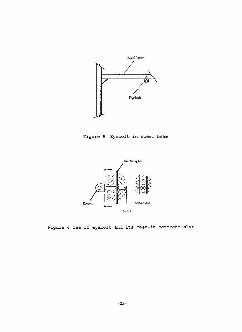
Steel beam
A
Eyebolt
Figure 5 Eyebolt in steel beam
Reinforing bar
Eyebolt
( ). v.»• .« ..
,* °." •
•>>
*.'.•Q\
Ic.«••
«t •
>>•'•. * * . " '- ,9' .'^ o]. ' • . ' • i** b • • "tt
j
R. *.*.'9 ':c
Sec
• ^ •
- »>l!̂ )̂:N-XT• 9 • y
tion A-
t .
Socket
Figure 6 Use of eyebolt and its cast-in concrete slab
•-25-

Eyebolt Steel structure
\
Figure 7 Eyebolt in steel structures
-26-

(2) Vertical Independent Lifeline
The use of independent lifeline is a very common safetyprecaution to prevent a person wearing safety belt fromfalling from height. Independent lifeline works with alanyard and a positioning devices such as a rope chuck,rope grab or rope adjuster, the upper end of which issecurely attached to a structural anchorage point „ Figure8 shows the use of a vertical independent lifeline.
Re-inforcedconcrete column
Protection
Lifeline
The lifeline can be offibre rope or metalcables. The minimumdiameter of a fibre ropelife line is 15.9 mmunder ANSI. Metalcables used for lifelineshall have a minimumdiameter of 8 mm and aminimum static breakingstrength of 25 KM whentested in accordancewith BS 302; Part 1.
Fibre rope and metalcable lifeline shall befitted with an end stop.On fibre ropes, afigure-of-8 knot wouldbe acceptable. Wirerope shall not be used
where electrical hazards are present. Lifeline shall beof a single continuous line. It shall suspend freely fromits anchorage point without contact with structure alongits length or other objects which would adversely affectits function in conjunction with other components of thesafety belt.
It shall be extended to or below the lowest level to whichthe user is expected to travel. Each worker shall beprovided with a separate lifeline and only one person is
Figure 8
Figure-of-8knot
Vertical IndependentLifeline
-27-

allowed to anchor his safety belt to one lifeline. Whena lifeline works with a fall arresting device, correctfitting and adjustment shall be carried out as recommendedby manufacturer.
The anchorage point for the lifeline shall be structuralsafe. Reinforced concrete beam or column, structuralsteel member are suitable anchorage points for securingthe lifeline preferably after their strength have beenchecked by Professional Engineer of the structuraldiscipline.
It is not recommended to fix the upper end of a lifelineto any temporary work such as scaffolding member/ windowframe, roof pipes etc. Protection against sharp edge ofsteel beam and wall shall be considered where the lifelinepasses over such edges during its fixing to the structure.
(3) Horizontal Lifeline (Guide rope)
To enable a workman to walk along beams, steel girders orother similar dangerous structure at height inconstruction sites, shipyards, mines etc., horizontallifeline with a rope stretcher and a safety belt formanother fall protection system. The lifeline is mountedbetween two supports to waist level. According toAmerican National Standard ANSI Z359.1:1992, it is tightenup to a tensile force of 0.75 - 1.0 KN for the anchorageof a lanyard and is capable of supporting a static loadof at least 2280 kg per employee using the lifeline,applied anywhere along the lifeline.
Anchorage for horizontal lifeline shall be of reinforcedconcrete columns or structural steel member, and shall beof a strength capable of sustaining the above loads. Theangle of sag, and pre-tensioning of the lifeline shall beconsidered when installing the anchorages and thehorizontal lifeline system. The installation should beerected in accordance with the manufacturer'sspecifications and monitored and checked under thesupervision of a competent person.
-28-

It is important to note that horizontal lifeline shouldbe used by one person at one time between supports. Figure9 shows a horizontal lifeline.
Structural member
Tension adjuster
Guide rope
Figure 9 Horizontal Lifeline
(4) Fall Arrester
Mechanical devices have been developed for use with safetybelts that will extend the working distance of the usersfrom structural anchorage points to work level. Fallarresters become the major components of a fall arrestingsystem. They work with lifelines, guide rails or energyabsorbers to protect the user from body injury during afall.
Under ANSI, AS/NZS and BSEN, fall arresters arerecommended to be used in connection with safety harnesses,but not for general purpose safety belts.
-29-

Two types of fall arresters are commonly used : retractabletype fall arrester, guided type fall arresters either ona rigid anchorage line or on a flexible anchorage line.
A fall arrester and its accessories shall only be used ifthe system complies with the requirements of a nationalstandard and the specifications issued by manufacturer.The selection of the type of fall arrester will depend onthe nature and location of the task and the structuralenvironment. The erection must be conducted under thesupervision of a competent person who should inspect thesystem before each use.
The user of a fall arresting system should follow allmanufacturer's instructions regarding the inspection,maintenance and storage of the equipment. Suitabletraining should be provided to each user before he isallowed to use the system.
(a) Retractable Fall Arrester
, RetractableStructural' { )*~~—" fall arrestersteel beam
Retractablelanyard
Figure 10 Retractable Fall Arrester
- 3 0 - - '

The retractable fall arrester system consists of ananchorage point, a retractable type fall arrester with aretractable lanyard such as an inertia reel, and a safetybelt which is a safety harness required under BSEN or ANSI.The arrester has a self-locking function and an automatictensioning and return facility for the lanyard. It maycomprise of a drum around which the retractable lanyardreels or unreels, or a return pulley with counter weights.
Because a retractable type fall arrester is designed andtested so as to be a complete connecting system for fallarresting purposes, an energy absorber shall not beattached to the connector of the retractable lanyard.
The system requires a reliable anchorage point and anecessary minimum clearance below the user which can beestimated from the arrest distance. The anchorage pointshould be either a trolley on a steel I-beam, or hookedto a shackle which is secured to a reinforced concrete beamor column by means of wire rope after the strength of thesupporting structures has been checked by ProfessionalEngineer of the structural discipline. Railings oftemporary scaffoldings, water or gas pipes on the roof ofa building, window frames, or any drainage system shouldnot be used for anchoring the arrester.
The performance and test requirements, and lockingcondition are defined in either BSEN 360:1993 or ANSIZ359.1-1992. A sketch of the system is at Figure 10.
-31-

(b) Guided type fall arrester on a rigid anchorage line
Arrester
Figure 11 Guided Type Fall Arrester
It is an arrester with a self-locking function and a guidefacility. The arrester works on a rigid anchorage lineand a lanyard. An energy dissipating element may beincorporated in the guided type fall arrester.
It travels along an anchorage line, accompanies the userwithout requiring manual adjustment during upward ordownward changes of position and locks automatically onthe anchorage line when a fall occurs.
The anchorage line may be a rail or a wire rope and issecured to a structure in such way that lateral movementsof the line are limited.
-32-

The arrester shall meet the performance, dynamic andstatic test requirements under BSEN 351-1:1992 or ANSIZ359-1992, both of which recommend to work with full bodyharness. In Japan, the arrester works with a generalpurpose safety belt. Figure 11 shows the system.
(c) Guided type fall arrester on a flexible anchorage line
Packing I-beam
Flexibleanchoragelife (lifeline)
End stop andattachment weight
Fall arrester
Energy dissipatingdevice
Figure 12 Flexible anchorage line
This system consists of a flexible anchorage line, aself-locking guided type fall arrester which is attachedto the flexible anchorage line and a lanyard. The arrestertravels along the anchorage line, accompanies the userwithout requiring manual adjustment during upward ordownward changes of position and locks automatically onthe anchorage line when a fall occurs. The anchorage linemay be a synthetic fibre rope or a wire rope and is securedto an upper anchorage point. An energy dissipating
- 33 -

element may be incorporated in the guided type fallarrester, in the lanyard or in the anchorage line. Figure12 shows the system.
In BSEN, AS/NZS and ANSI standard, this system works withfull body harness only. However, a general purpose safetybelt may connect to this arrangement if recommended byJapanese manufacturers who sell fall arresting device. Inview of the possibility of injuries to the users, the useof general purpose safety belt with the fall arrester isnot recommended.
Flexible anchorage line shall be secured to an upperanchorage point and shall be either fitted with an end stopto prevent the arrester from running off the anchorage line.If a guided type fall arrester has a manual locking feature,the lower end of the flexible anchorage line shall besecured, e.g. by an attached lower termination or anattachment weight. Flexible anchorage wire ropes shallhave an attached lower termination or an attachment weightin every case.
The requirements, performance and test procedure areoutlined in either BSEN 352.2 : 1992 or ANSI 2359.1:1992.
-34-

VI. Practical Examples of using SafetyBelts and their Anchorage
(1 ) Example of using Fixed Anchorage
Photo 1 - windows cleaning
work using full-
body harness and
fixed anchorage
Photo 2 - an eye-bolt
as the fixed
anchorage
- 3 5 -

( 2 ) Vertical Independent Lifeline
Photo 3 - external window panel
installation work using
rope chuck and vertical
independent lifeline
-36-

Photo 4 - b a m b o o
s c a f f o l d i n g
e r e c t i o n /
dismantl ing
u s i n g rope
c h u c k a n d
v e r t i c a l
independent
lifeline
Photo 5 - bamboo scaffolding erection/dismantling using
rope chuck and vertical independent lifeline
-37-

( 3 ) Guide Rope
•BBBB
Photo 7
Photo 6 - e l e c t r i c a l
t o w e r
ass e m b l i n g
work u s i n g
guide rope,
rope grab and
rope adjuster
the rope tension adjuster used in
tensioning the guide rope
-38-

(4) Retractable Fall Arrester
Photo 8 - inertia reel ( re t rac table f a l l
arrester) used in container handling
work
-39-
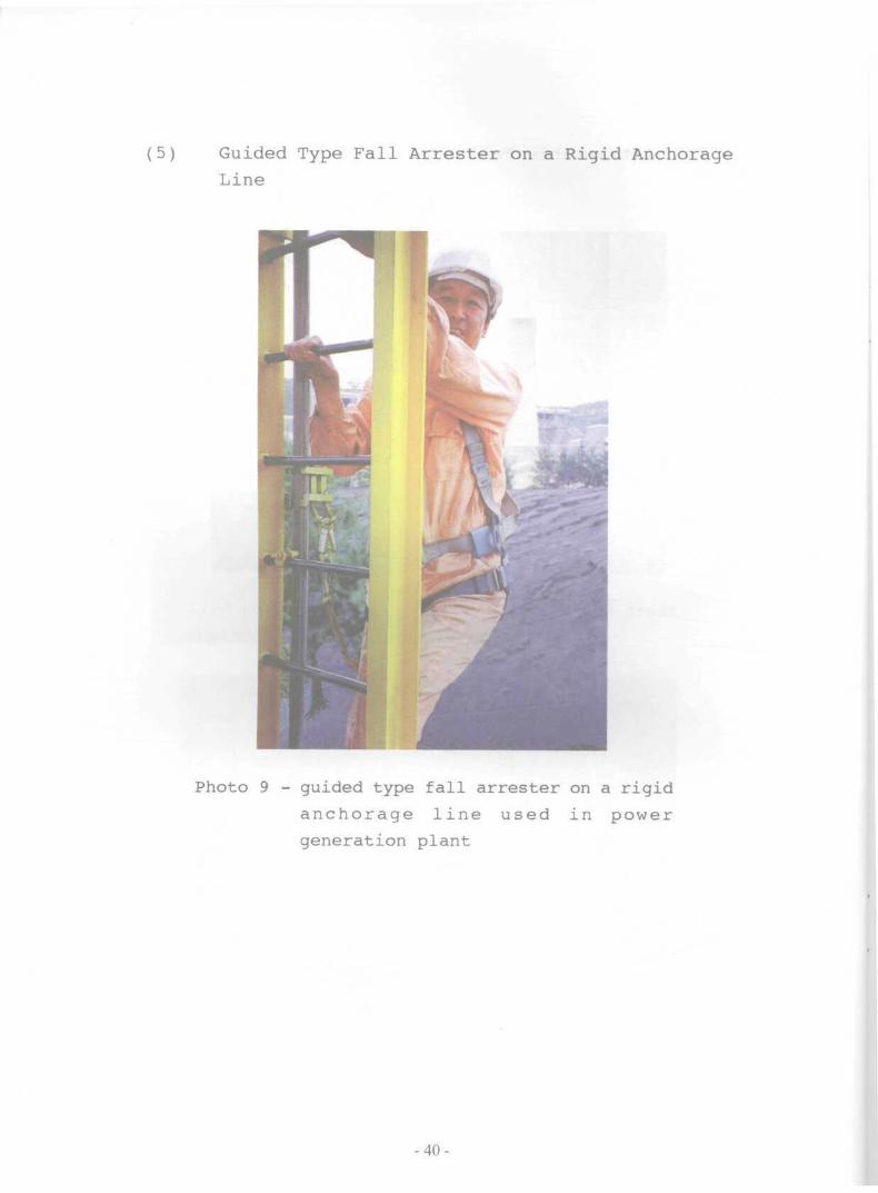
( 5 ) Guided Type Fall Arrester on a Rigid AnchorageLine
Photo 9 - guided type fall arrester on a rigid
a n c h o r a g e l ine used in power
generation plant
-40 -

Appendix 1
Safety Harness or Full
(a) Full Body Harness under 361s1992
Under the British Standard, BSEN 361:1992, it is a bodysupport for fall arrest purpose, i.e. a component of a fallarrest system which is to support the whole body of a personand to restrain the user during a fall and after the arrestof a fall. It consists of shoulder strap, sit strap, thighstrap and back support for work positioning. The widthof sit strap and shoulder strip shall be at least 40 mm.Straps shall not migrate from position and shall not loosenby themselves. The fall arrest attachment element suchas D-ring, may be placed so as to lie, during the use ofthe full body harness, in front of the chest, at the centerof gravity, at both shoulders, and/or at the back of theuser. Figure 13 shows a full body harness under thisstandard.
Shoulder strap
Sit strap
Thigh strap
D-ring
Figure 13 A Full Body Harness (BSEN)
-41-

In the standard, it specifies that during the drop test,the torso dummy shall be arrested in a head-up positionand the angle between the longitudinal axis of the dorsalplane of the torso dummy and the vertical shall be a maximumof 50 degree.
When it works with a lanyard, the length of lanyard,including energy absorber, if applicable, and te:nnination,e.g. connectors or eyes, shall not exceed 2 metres.
(b) Safety Harness under AS/NZS 1891.Is 1995
Under Australian/New Zealand Standard, AS/NZS1891.1:1995, safety harness under this standard is knownas fall-arrest harness which comprises of a singleassembly of interconnected shoulder and leg straps. Theharness may incorporate a body belt or other horizontalstraps designed to provide a bearing area on the body toprevent the user falling out of the harness during a fall.The shoulder straps is positioned so that, when the personis suspended, they shall not transmit undue pressure tothe area of the body under the armpits.
Shoulderstrap
Leg strap
Jf
\1
s
IV?1ft
\h
u
^
r\^
Figure 14 Full Body Harness without horizontal straps
(AS/NZS)
-42-

The harness incorporates attachment hardware forattachment to the lanyard assembly. The hardware locatesin such a position that the user, whether conscious orunconscious, is retained in the head-up position in theevent of fall. A typical fall-arrest harness isillustrated in Figure 14 and Figure 15.
Horizontalstrap orbody belt
Figure 15 Full Body Harness with horizontal strap(AS/NZS)
(c) Safety Harness under ANSI A10.14-1991
Under the American National Standard, ANSIA10.14-1991, it is called body harness . It consistsof straps that are secured about a user in a mannerthat distributes the arresting forces over at leastthe thighs, shoulders and pelvis, with provisionsfor attaching a lanyard, lifeline or decelerationdevice.
The waist strap shall be a minimum.of 44 mm nominalwidth and strap ends shall be finished so as toprevent fraying/Figure 16 shows a harness underthis standard.
-43-

Figure 16 Full Body Harness (ANSI)
The body harness is used for restraint and/or fall arrestand where vertical free fall hazards exist, to reduce theprobability of falls or known as Type I equipment. Duringa performance test, the angle at rest measured between thetorso vertical center line and the vertical shall notexceed 30 degrees after the test torso comes to rest.
When more than one attachment element exists on a harness,such as D-rings, the purpose and limitations of eachelement shall be designated by the manufacturer.
The harness shall carry the following information, eitherindelibly print or stamp, onto the device or a tag securelyattached on the harness :-
(i) Manufacturer'Name or Trade mark
(ii) Model Number
(iii) Date of Manufacture
- 44 -

(d) Safety Harness under GB 720-65
Under the People's Republic of China National Standard,GB 720-65, there are two types of safety harnesses : TypeI and Type II. They have same shape of waist straps andthigh straps but different forms of lanyards and shoulderstraps. The width of the waist strap and the shoulderstrap shall not be less than 40 mm while the width of otherstraps shall not be less than 30 mm. The length of thelanyard of the Type I harness is 2 .41 m long and the harnessis attached to the D-ring of the shoulder strap. On theother hand, the lanyard of the Type II harness is eye-spliced to the shoulder strap and measured 3.0m long.
The shape of Type I and Type II safety harnesses are shownin Figure 17 and Figure 18.
The best performance, packing details and instructions foruse are specified in the standard.
Shoulder strap
Body belt
Leg strap
Lanyard
Figure 17 Type I Full Body Harness (GB)
-45-

Lanyard
Shoulder strap
Leg strap Body belt
Figure 18 Type II Full Body Harness (GB)
-46-

(e) Harness Safety Belts from Japan
Lifeline
Figure 19 Full Body Harness (Japan)
In Japan, safety harness is called harness safetybelt. Its design and mechanical strength have toconform to the test requirements of the Safety BeltStandard of Japan's Ministry of Labour. The harnessis designed to protect worker working at heightagainst free fall. The drop impact, should a falloccur, is minimised by distributing the force overthe shoulder, chest, back, waist, thighs andbuttocks of the body. The typical width of nylonbelt is 50 mm, with a lanyard which is 14 mm indiameter and 2.0 m long. The lanyard can beconnected to the D-ring on the back or the waist.Figure 19 shows a typical harness from Japan.
-47-

Appendix 2
Semi-Harness or Chest Harness
(a) Chest Harness from Japan
Lifeline^
Lanyard
Figure 20 Semi-Harness Figure 21 Chest Harness
In Japan, the chest harness is called semi-harness safetybelt. There are two types of semi-harness safety belts :semi-harness safety belt with thigh straps and semi-harness safety belt with shoulder strap. Its mechanicalproperty conforms to the test requirements of the SafetyBelt Standard of Japan's Ministry of Labour.
Semi-harness safety belt with thigh straps is suitable touse at construction sites, tanks and manholes. Figure 20shows a harness with thigh strap.
-48-

The body is supported mainly by the thighs which permitsworking at ease. The shock or impact of a fall, shouldit occur, can be distributed over the waist, thighs andbuttock to minimize the effects against this limited areaof the body. The waist strap is 50 mm wide, with a lanyardwhich is 2.0 m long.
Semi-harness safety belt with shoulder strap is for usein work at construction sites, shipyards, mines and steelconstruction work. The load is distributed to the upperhalf of the worker' s body such as shoulder, back and waist,so the user can work at ease. The waist strap is also 50mm wide with a 2.0 m lanyard. Figure 21 shows the shapeof such a harness.
(b) Chest Harness under ANSI A10.14-1991
Under the American National Standard, chest harness is anequipment which is used for restraint but is not for usewhere any vertical free fall hazard exists or known as TypeII equipment. It consists of straps secured only aroundthe chest with shoulder straps to assure proper chest strappositioning. The waist strap should be at least 44 mmwidth. When it works with a lanyard and an anchor, it isto keep the user at the work level or limit any free fallto a maximum of 0.6m from the work level. The harness shallbe marked "Type II', either indelibly printed or stampedonto the device or a securely attached tag.
-49-

(c) Scaffolding Safety Belt under GB 721-65
Shoulder strap
Body belt
Figure 22 Scaffolding Safety Belt (GB)
This belt is designed and manufactured in China under thePeople7 s Republic of China National Standard GB 721-65 forscaffolders in construction industry. It consists of awaist strap of 40 mm wide, a shoulder strap of 30 mm wide,and a lanyard of 2.12m long, but without any D-rings. Thebelt is stitched with a label which carries the trade markof the manufacturer and a certificate. Its serial number,month and year of manufacture, test strop weigh 120 kg,test drop distance 2.8m, name of the product examiner andperiod of warranty can be found in the said certificate,too. The shape of the belt is shown in Figure 22.
-50-

Appendix 3
General Purpose Safety Belt
(a) *Body Belt/ under ANSI A10.14-1991
The general purpose safety belt is called "Body Belt" inthe American National Standard for construction anddemolition. It composes of a 44 mm strap that both securesaround the waist and attaches to a lanyard, lifeline ordeceleration device.
"Body Belt7 is used for restraint and/or fall arrest wherevertical free fall hazards exists, and reduce theprobability of falls. When it works with a lanyard, itshall limit the fall to 1.5 m or less.
It is worthy to note that after December 31, 1997, "BodyBelts7 is acceptable by the OSHA as part of positioningdevices as studies have proven that ̂ Body Belts7 can causeback injury, internal injuries and create the possibilityof the user falling out of the belt.
(b) Industrial Safety Belt under JIS M7624
Under the Japanese Industrial Standard (JIS) , the .safetybelts for miners are safety belts of body-bind type usedto prevent a worker from a free fall while he is performingworks on a height or sharp slope such as mining, quarryingor civil engineering works. It consists of a body-bindbelt of not less than 50 mm in width, a buckle withanti-corrosion treatment, a lanyard of less than 1.5 mexcluding the hook, one or two D-rings, a hook, a carbinesor a grip. The belt can carry an auxiliary belt which ismore than 75 mm in width for reinforcing twisted or chinkedportions of the body-bind belt coupled with it.
The belt can be fitted with a longer lanyard. Even whenit is necessary to use a longer lanyard due to the nature
-51-

of work, the length shall be limited to 2.5m. Under thisstandard, the belt without auxiliary belt is classifiedas Class 1A, and the belt fitted with an auxiliary beltis called Class 2A. Both safety belts also meet therequirements of the Safety Belt Standard of Japan'sMinistry of Labour and are commonly used in theconstruction industry in Hong Kong. Figure 23 and Figure24 shows the configurations of Class 1A & 2A belts.
-52-

Lanyard Hook
*04
Buckle D-ring Body belt
Figure 23 Class 1A General Purpose Safety Belt (JIS)
Auxiliary belt Body Belt
Figure 24 Class 2A General Purpose Safety Belt (JIS)
-53-

Appendix 4
Work Positioning Belt, Pole or Linesman
Safety Belt
(a) Work Positioning Belt under BSEN 358:1993
Back support
Lengthadjuster
Waist strap
Lanyard
Figure 25 Work Positioning Belt (BSEN)
The design, construction, static and dynamic strength andtest of a work positioning belt are defined in this BritishStandard, i.e. BSEN 358:1993. The waist strap shall benot less than 43 ram wide and the back support not less than100 mm. It can be equipped with adjustable shoulder andsitting straps. The lanyard shall be equipped with alength adjuster and shall have a maximum length of 2m underall normal circumstances. "When purchase, clearinstructions for fitting, adjustment and use are suppliedwith each belt. Markings with the number of standards,name of manufacturer, serial number, year and month ofmanufacture are available in the product packing. Figure25 is a work positioning belt under this standard.
..-54-'

(b) Pole Safety Belt under AS/NZS 1891.1:1995
Under this Australian/New Zealand Standard, workpositioning belt is replaced by work positioningharness. The work positioning harness is used inconjunction with a restraint line or pole strap onlyin situations where there is not a risk of free fall .Where there is a risk of a fall, the harness is usedin such a way that under working conditions the polestrap or restraint line is always in tension. Theworking positioning harness comprises an assemblyof an adjustable waist strap or body belt connectedto a pair of leg loops by means of front straps,and other straps such as a sitting strap which passesunder the pelvis so as to support the lower partof the body in a sitting position, e.g. a "sit7
harness. The harness may include back support orshoulder strap, which may be incorporated withina garment. The harness may be used with a shortlanyard in such a way that a free fall of greaterthan 600mm is not possible.
(c) Linemen's Safety Belt under JIS T8165-1987
The design, construction and configuration of alinemen's safety belt are described under SafetyBelt Standard by Japan's Ministry of Labour andJapanese Industrial Standard (JIS). There are twotypes of linemen's safety belts, i.e. single-linesuspension and U-shaped suspension. Single-linesuspension allows the snaphook to anchor onto thelanyard while U-shaped suspension requires thesnaphook to clamp onto the D-ring of the belt. Thelength of lanyard varies from 2.0 m to 3.5 m. Thewaist strap is 40 - 50 mm wide and the back supportshall not be less than 75 mm in width. The thicknessof the strap is not less than 2 mm. Each safety beltis required to be marked on its conspicuous portionthe manufacturer's name, the year and month ofmanufacture. Figure 26 illustrated the two typesof belts.
-55-

Figure 26 Linemen's Safety Belt (JIS)
(d) Linemen's Safety belt under GB 723-65
Under the People's Republic of China National Standard GB723-65, there are two types of linemen's safety belts,electrician safety belt and signalman safety belt. Inaddition to a lanyard, a pole strap is also equipped tobe fitted to the D-rings of waist strap of the electriciansafety belt. The configurations of these safety belts areshown in Figure 27 and Figure 28.
The electrician safety belt works either with a pole strapof 2.3 m or a lanyard of 2.4 m. The pole strap wraps arounda pole to support the weight of an electrician. The lanyardcan be used to anchor the safety belt at height during thework.
The signalman safety belt is equipped with a pole strapwhich looks like a lanyard. The pole strap is made up ofa rope protected by a sleeve. Care must be exercised notto convert the usage of the pole strap to achieve thefunction of a lanyard although the tensile strengths ofa lanyard and a pole strap are set to withstand a forceof 1200 kg. Technical specification of these two safetybelts are listed out in the GB 723-65 standard.
-56-

Shoulder strap
D-ring
Back supportWaist strap
o o!iii
Lanyard
Figure 27 Electrician Safety Belt (GB)
Back support
Lanyard
Waist strap
Figure 28 Signalman Safety Belt (GB)
-57-

List of Reference
1. British Standard, BS EM 353-1 and BS EN 353-2: 1993Personal protective equipment against falls from aheight : guided type fall arresters.
® Part 1. Specification for guided type fallarresters on a rigid anchorage line.
• Part 2. Specification for guided type fallarresters on a flexible anchorage line.
2. British Standard, BS EN 360 : 1993Personal protective equipment against falls from aheight - retractable type fall arresters.
3. British Standard, BS EN 361:1993Personal protective equipment against falls from aheight - full body harnesses.
4. British Standard, BS EN 795 : 1997Protection against falls from a height - Anchor devices- Requirements and testing
5. British Standard, BS 1397 : 1979Specification for industrial safety belts, harnessesand safety lanyards.(Note: this standard was superceded by BSEN 354, 355,358, 359, 361, 362, 363, 364, 365 : 1993)
6. British Standard, BS 5845 : 1991Permanent anchors for industrial safety belts andharnesses(Note: this standard was superceded by BSEN 795 : 1997)
7. British Standard, BS 6858 : 1987Manually operated positioning devices and associatedanchorage lines for use with industrial safety beltsand harnesses.
-58-

8. British Standard, BS 7883 : 1997Code of practice for Application and use of anchordevices conforming to BS EN 795
9. American National Standard, ANSI Z359.1 : 1992Safety requirements for personal fall arrest systems,subsystems and components.
10. American National Standard, ANSI A10.14 : 1991Construction and demolition operations ---Requirements for safety belts, harnesses, lanyards andlifelines for construction and demolition use
11. Japanese Industrial Standard, JIS M7624 : 1974Safety belts for miners
12. Japanese Industrial Standard, JIS T8165 : 1987Safety belts for line-men
13 . Ministry of Labour Notification No. 67,Safety Belt Standard of Japan's Ministry of Labour,September 1975.
14 . Australian Standard, AS2626 : 1983Industrial safety belts and harnesses --- selection,use and maintenance.
15. Australian/New Zealand Standard, AS/NZS1891.1 : 1995Industrial fall arrest system and device.Part I : Safety belt and harness
16. German Standard, DIN 7470Protective equipment against fall --- safety belts,safety requirements, testing.
17 . S U H * » GB720-65
18 . S P I H ' GB721-65
-59-

19. ' GB722-65
~ri -
GB723-65
-60-

Useful Information
If you wish to enquire about this guidance notes or require
advice on occupational safety and health, you can contact
the Occupational Safety and Health Branch through :
Telephone : 2559 2297 (auto-recording after office hours)
Fax : 2915 1410
E-mail : [email protected]
Information on the services offered by the Labour
Department and on major labour legislation can also be
found by visiting our Home Page on the Internet. Address
of our Home Page is http://www.info.gov.hk/labour .
<••", #'
-61-

XllEllSSO
P 624.0239 G94Guidance notes onclassification and use ofsafety belts and theiranchorage systems
Date Due