university of huddersfield repositoryeprints.hud.ac.uk/15019/1/thesis_hao_zhang.pdf · a thesis...
TRANSCRIPT
University of Huddersfield Repository
Zhang, Hao
Model Development and Stability Analysis for a Turbocharger Rotor System under MultiField Coupled Forces
Original Citation
Zhang, Hao (2012) Model Development and Stability Analysis for a Turbocharger Rotor System under MultiField Coupled Forces. Doctoral thesis, University of Huddersfield.
This version is available at http://eprints.hud.ac.uk/id/eprint/15019/
The University Repository is a digital collection of the research output of theUniversity, available on Open Access. Copyright and Moral Rights for the itemson this site are retained by the individual author and/or other copyright owners.Users may access full items free of charge; copies of full text items generallycan be reproduced, displayed or performed and given to third parties in anyformat or medium for personal research or study, educational or notforprofitpurposes without prior permission or charge, provided:
• The authors, title and full bibliographic details is credited in any copy;• A hyperlink and/or URL is included for the original metadata page; and• The content is not changed in any way.
For more information, including our policy and submission procedure, pleasecontact the Repository Team at: [email protected].
http://eprints.hud.ac.uk/
Model Development and Stability Analysis for a Turbocharger Rotor System under Multi-Field
Coupled Forces
Hao Zhang
A thesis submitted to the University of Huddersfield
in partial fulfilment of the requirements for
the degree of Doctor of Philosophy
April 2012

Model Development and Stability Analysis for a Turbocharger Rotor System under Multi-Field Coupled Forces
DEGREE OF DOCTOR OF PHILOSOPHY (PHD) PAGE 2 OF 237
List of Contents
List of Contents.......................................................................................................................2
List of Tables...........................................................................................................................8
List of Figures.........................................................................................................................9
Abstract.................................................................................................................................16
Declaration............................................................................................................................18
Copyright Statement .............................................................................................................19
Acknowledgement ................................................................................................................20
Publications...........................................................................................................................21
CHAPTER ONE INTRODUCTION.................................................................................23
1.1 Introduction to the Rotating Machinery...................................................................24
1.2 Introduction to the Turbocharger .............................................................................26
1.3 Background..............................................................................................................27
1.3.1 Development of the research of the fluid lubrication ....................................27
1.3.2 Development of the research of the rotordynamics .......................................29
1.3.3 Research areas of the rotordynamics .............................................................31
1.3.3.1 The critical speeds calculation of the rotor bearing system.................31
1.3.3.2 Calculation of the steady state response under the rotor imbalance ....31
1.3.3.3 Balancing of the flexible rotor system.................................................32
1.3.3.4 The stability analysis of the rotor bearing system ...............................33
Model Development and Stability Analysis for a Turbocharger Rotor System under Multi-Field Coupled Forces
DEGREE OF DOCTOR OF PHILOSOPHY (PHD) PAGE 3 OF 237
1.4 Motivation................................................................................................................34
1.5 Research Objectives.................................................................................................35
1.6 The Structure of the Thesis ......................................................................................36
CHAPTER TWO LITERATURE REVIEW .....................................................................38
2.1 Review of the Research of the Fluid Lubrication ....................................................41
2.1.1 The linear models of hydrodynamic forces ...................................................41
2.1.1.1 The linear expression of the hydrodynamic force increment...............41
2.1.1.2 The undetermined function matrix.......................................................42
2.1.1.3 Conventional expressions of the hydrodynamic force.........................42
2.1.1.4 Database approach ...............................................................................42
2.1.2 The limitation of the linear hydrodynamic force model ................................43
2.1.3 The nonlinear analytical model of the hydrodynamic force ..........................44
2.1.4 The list of classical nonlinear models of the hydrodynamic force ................45
2.1.4.1 The infinitely short bearing model.......................................................45
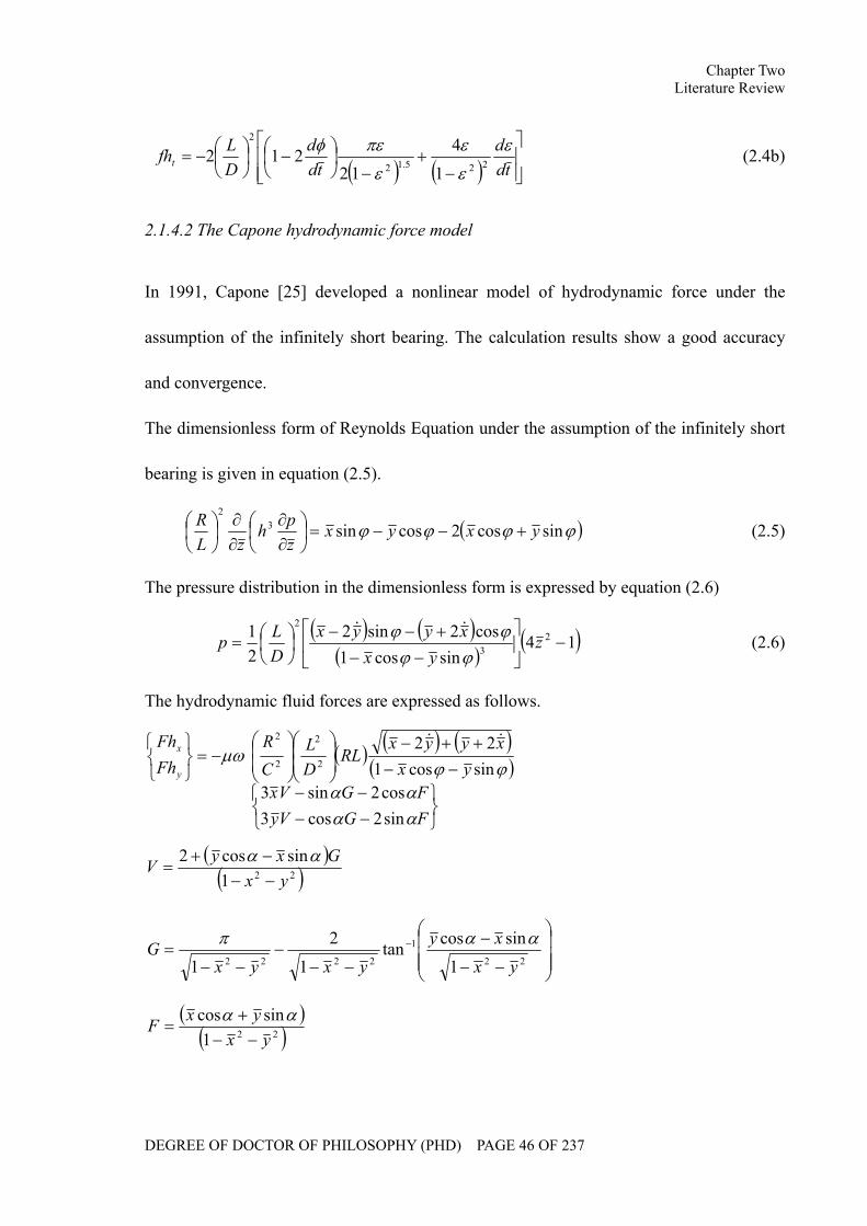
2.1.4.2 The Capone hydrodynamic force model..............................................46
2.1.4.3 Zhang hydrodynamic force model .......................................................47
2.1.4.4 The comparison of the classical models ..............................................48
2.2 Review of the Research on the Dynamic Characteristics of the Rotor Bearing
System............................................................................................................................49
2.2.1 Critical speed calculations .............................................................................49
2.2.2 Forced response estimation............................................................................52
2.2.3 The stability analysis......................................................................................54
Model Development and Stability Analysis for a Turbocharger Rotor System under Multi-Field Coupled Forces
DEGREE OF DOCTOR OF PHILOSOPHY (PHD) PAGE 4 OF 237
2.2.4 Approaches to the analysis of the dynamic performance and stability of the
rotor bearing system................................................................................................56
2.3 Review of the Research on Turbocharger Rotordynamics ......................................57
2.4 Review of the Research of the Nonlinearity of the Vibration System.....................59
2.5 Review of the Research of the Modal Synthesis Method........................................61
2.6 Review of the Numerical Integration Approaches...................................................63
2.7 Summary..................................................................................................................64
CHAPTER THREE ANALYTICAL INVESTIGATION OF THE LUBRCIATION OF
FLOATING RING BEARINGS ...........................................................................................65
3.1 Introduction to the Lubrication of Floating Ring Bearings .....................................66
3.2 Theoretical modeling for the lubrication of a floating ring bearing ........................69
3.3 Simulation results and analysis................................................................................73
3.3.1 The equilibrium position................................................................................74
3.3.2 Oil film continuity .........................................................................................76
3.3.3 Inner oil film lubrication................................................................................79
3.3.4 Effects of external load on the oil flow rate into the inner oil film ...............83
3.3.5 Effects of inlet pressure on the oil flow rate into the inner oil film...............86
3.4 Summary..................................................................................................................89
CHAPTER FOUR THEORETICAL MODELLING FOR A TURBOCHARGER ROTOR
SYSTEM...............................................................................................................................90
4.1 Finite Element Analysis of the Rotor System..........................................................96
4.1.1 Finite element method ...................................................................................96
Model Development and Stability Analysis for a Turbocharger Rotor System under Multi-Field Coupled Forces
DEGREE OF DOCTOR OF PHILOSOPHY (PHD) PAGE 5 OF 237
4.1.2 Motion equations of the unit ..........................................................................96
4.2 Modeling of a Turbocharger in Rotordynamics.....................................................100
4.3 Hydrodynamic Fluid Forces in the Model.............................................................104
4.3.1 Linear force model.......................................................................................104
4.3.2 Nonlinear force model .................................................................................107
4.4 Rub-impact Force ..................................................................................................111
4.5 Summary................................................................................................................112
CHAPTER FIVE CALCULATION OF CRITICAL SPEEDS AND MODE SHAPES OF
A TURBOCHARGER ROTOR SYSTEM.........................................................................113
5.1 Modal Analysis for a Free Rotor............................................................................114
5.2 Modal Analysis for a Turbocharger Rotor System ................................................116
5.3 Simulation and Analysis ........................................................................................120
5.4 Summary................................................................................................................137
CHAPTER SIX STABILITY ANALYSIS OF A TURBOCHARGER ROTOR SYSTEM
UNDER MULTI-FIELD COUPLED FORCES .................................................................138
6.1 Introduction to the motion of the Turbocharger Rotor System..............................139
6.2 Stability Analysis of a Turbocharger Rotor System...............................................139
6.2.1 Stability characteristics of the floating ring bearing....................................139
6.2.2 Influences of the rotor imbalance ................................................................140
6.2.3 Influences of the lubricant viscosity ............................................................149
6.2.4 Influences of bearing clearances..................................................................155
6.2.5 Influences of the lubricant feed pressure .....................................................164
Model Development and Stability Analysis for a Turbocharger Rotor System under Multi-Field Coupled Forces
DEGREE OF DOCTOR OF PHILOSOPHY (PHD) PAGE 6 OF 237
6.3 Summary................................................................................................................170
CHAPTER SEVEN TURBOCHARGER TEST RIG DEVELOPMENT.......................172
7.1 Introduction to the Turbocharger Test Rig.............................................................173
7.2 The Turbocharger...................................................................................................174
7.3 Air Resource System..............................................................................................175
7.4 Lubrication System................................................................................................176
7.5 Pipeline System......................................................................................................178
7.6 Sensors and Installation .........................................................................................180
7.7 Signal Acquisition System.....................................................................................187
7.8 The Entire Test Rig ................................................................................................188
CHATPER EIGHT EXPERIMENTAL RESULTS AND ANALYSIS............................190
8.1 Introduction to the Experiment Procedure.............................................................191
8.2 Experimental Results and Analysis........................................................................192
8.3 Summary................................................................................................................205
CHAPTER NINE CONCLUSIONS AND FUTURE WORK.........................................206
9.1 Review of Research Objectives and Achievements...............................................207
9.2 Conclusions............................................................................................................209
9.3 Contribution to Knowledge ...................................................................................213
9.4 Future Work ...........................................................................................................215
Appendices..........................................................................................................................218
Appendix A ..................................................................................................................218
Appendix B ..................................................................................................................220
Model Development and Stability Analysis for a Turbocharger Rotor System under Multi-Field Coupled Forces
DEGREE OF DOCTOR OF PHILOSOPHY (PHD) PAGE 7 OF 237
Appendix C ..................................................................................................................222
Reference ............................................................................................................................223
Model Development and Stability Analysis for a Turbocharger Rotor System under Multi-Field Coupled Forces
DEGREE OF DOCTOR OF PHILOSOPHY (PHD) PAGE 8 OF 237
List of Tables
Table 3. 1. Simulation Parameters................................................................................73
Table 5. 1. Parameters of a turbocharger rotor system for modal analysis ................121
Table 5. 2. Natural frequencies of a free rotor ...........................................................122
Table 5. 3. First ten orders of natural frequencies of a turbocharger rotor system.....124
Table 6. 1. Simulation parameters in the rotor imbalance analysis............................141
Table 6. 2. Simulation parameters in the lubricant viscosity analysis........................149
Table 6. 3. Simulation parameters in the bearing clearances analysis .......................155
Table 6. 4. Simulation parameters in the lubricant feed pressure analysis.................165
Table 7. 1. The typical specification of a KD2306 1U1 eddy current displacement
transducer............................................................................................................182
Table 7. 2. Typical specification of the BR100_DDT_P photoelectric sensor...........185
Model Development and Stability Analysis for a Turbocharger Rotor System under Multi-Field Coupled Forces
DEGREE OF DOCTOR OF PHILOSOPHY (PHD) PAGE 9 OF 237
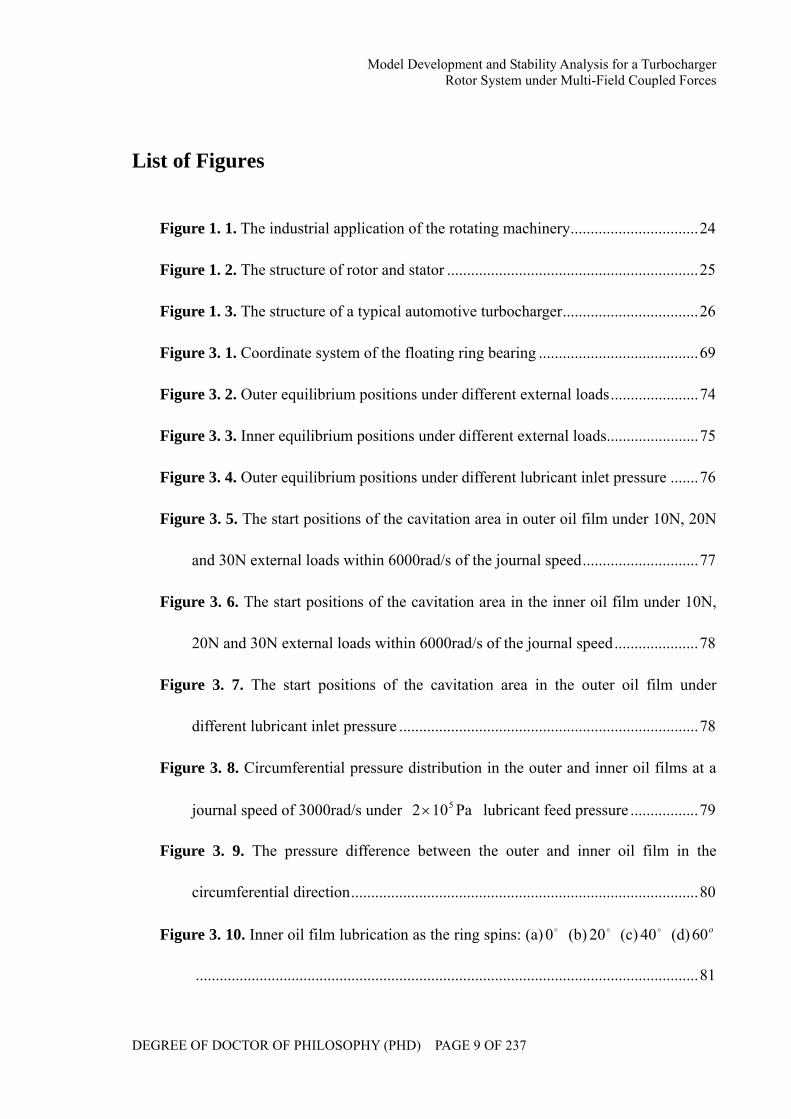
List of Figures
Figure 1. 1. The industrial application of the rotating machinery................................24
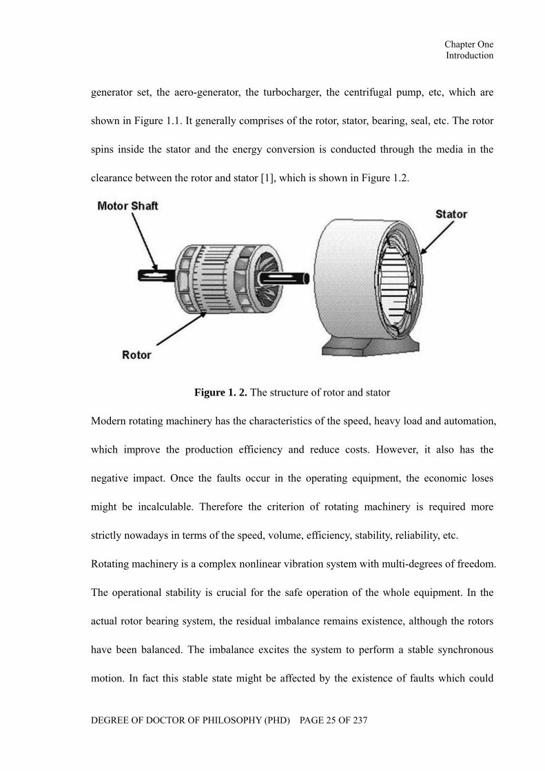
Figure 1. 2. The structure of rotor and stator ...............................................................25
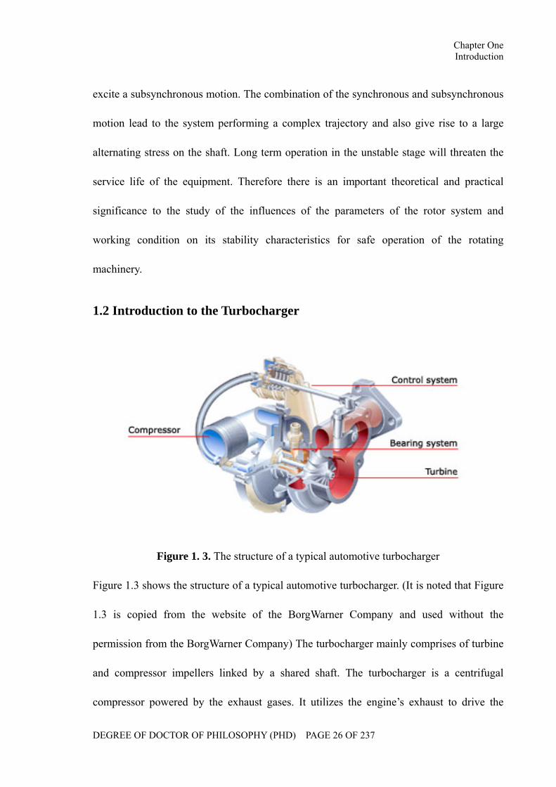
Figure 1. 3. The structure of a typical automotive turbocharger..................................26
Figure 3. 1. Coordinate system of the floating ring bearing ........................................69
Figure 3. 2. Outer equilibrium positions under different external loads......................74
Figure 3. 3. Inner equilibrium positions under different external loads.......................75
Figure 3. 4. Outer equilibrium positions under different lubricant inlet pressure .......76
Figure 3. 5. The start positions of the cavitation area in outer oil film under 10N, 20N
and 30N external loads within 6000rad/s of the journal speed.............................77
Figure 3. 6. The start positions of the cavitation area in the inner oil film under 10N,
20N and 30N external loads within 6000rad/s of the journal speed.....................78
Figure 3. 7. The start positions of the cavitation area in the outer oil film under
different lubricant inlet pressure ...........................................................................78
Figure 3. 8. Circumferential pressure distribution in the outer and inner oil films at a
journal speed of 3000rad/s under Pa102 5× lubricant feed pressure .................79
Figure 3. 9. The pressure difference between the outer and inner oil film in the
circumferential direction.......................................................................................80
Figure 3. 10. Inner oil film lubrication as the ring spins: (a) o0 (b) o20 (c) o40 (d) o60
..............................................................................................................................81
Model Development and Stability Analysis for a Turbocharger Rotor System under Multi-Field Coupled Forces
DEGREE OF DOCTOR OF PHILOSOPHY (PHD) PAGE 10 OF 237
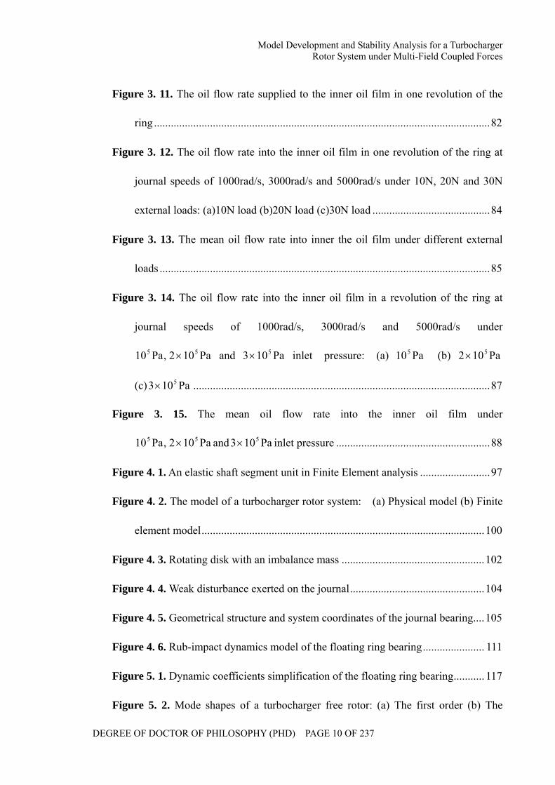
Figure 3. 11. The oil flow rate supplied to the inner oil film in one revolution of the
ring ........................................................................................................................82
Figure 3. 12. The oil flow rate into the inner oil film in one revolution of the ring at
journal speeds of 1000rad/s, 3000rad/s and 5000rad/s under 10N, 20N and 30N
external loads: (a)10N load (b)20N load (c)30N load ..........................................84
Figure 3. 13. The mean oil flow rate into inner the oil film under different external
loads ......................................................................................................................85
Figure 3. 14. The oil flow rate into the inner oil film in a revolution of the ring at
journal speeds of 1000rad/s, 3000rad/s and 5000rad/s under
Pa102,Pa10 55 × and Pa103 5× inlet pressure: (a) Pa105 (b) Pa102 5×
(c) Pa103 5× ..........................................................................................................87
Figure 3. 15. The mean oil flow rate into the inner oil film under
Pa102,Pa10 55 × and Pa103 5× inlet pressure .......................................................88
Figure 4. 1. An elastic shaft segment unit in Finite Element analysis .........................97
Figure 4. 2. The model of a turbocharger rotor system: (a) Physical model (b) Finite
element model.....................................................................................................100
Figure 4. 3. Rotating disk with an imbalance mass ...................................................102
Figure 4. 4. Weak disturbance exerted on the journal................................................104
Figure 4. 5. Geometrical structure and system coordinates of the journal bearing....105
Figure 4. 6. Rub-impact dynamics model of the floating ring bearing...................... 111
Figure 5. 1. Dynamic coefficients simplification of the floating ring bearing........... 117
Figure 5. 2. Mode shapes of a turbocharger free rotor: (a) The first order (b) The
Model Development and Stability Analysis for a Turbocharger Rotor System under Multi-Field Coupled Forces
DEGREE OF DOCTOR OF PHILOSOPHY (PHD) PAGE 11 OF 237
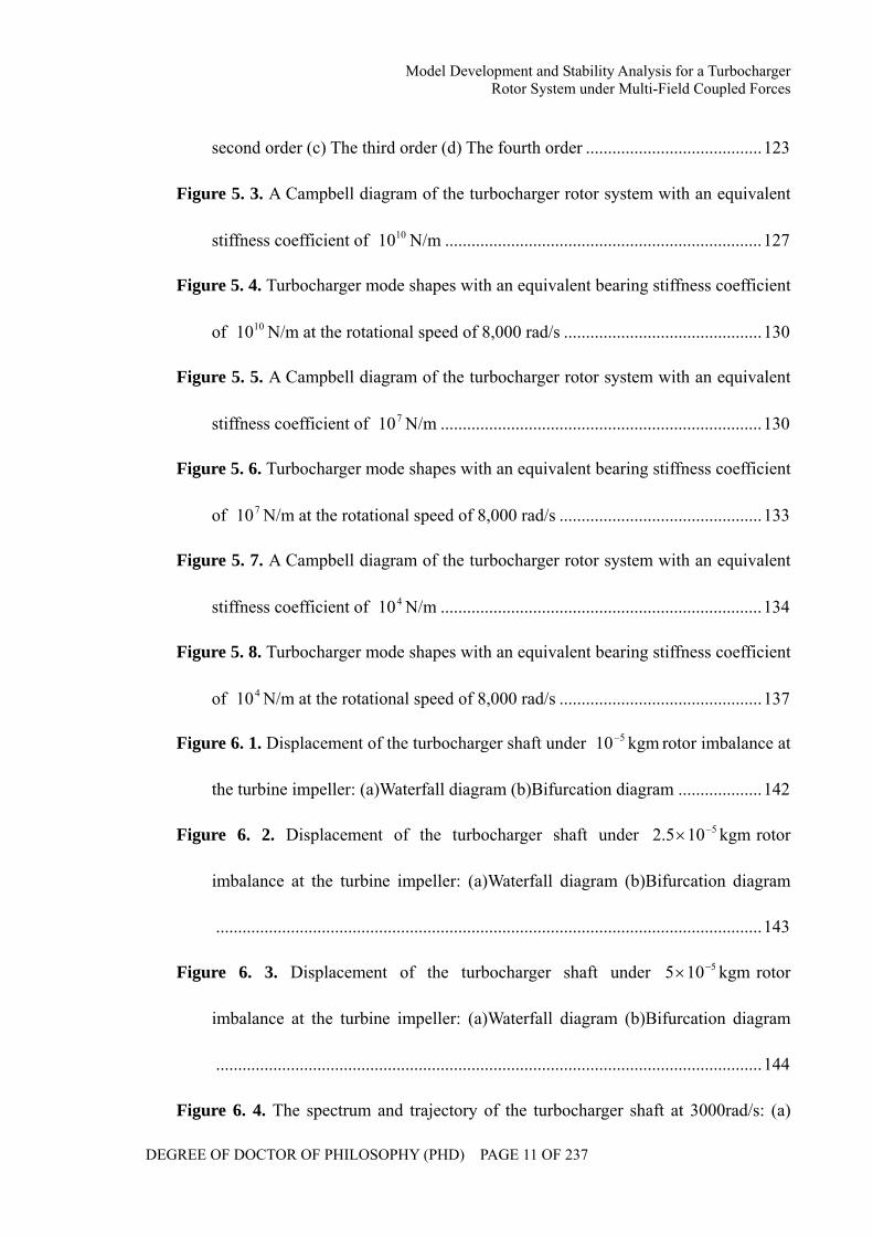
second order (c) The third order (d) The fourth order ........................................123
Figure 5. 3. A Campbell diagram of the turbocharger rotor system with an equivalent
stiffness coefficient of 1010 N/m ........................................................................127
Figure 5. 4. Turbocharger mode shapes with an equivalent bearing stiffness coefficient
of 1010 N/m at the rotational speed of 8,000 rad/s .............................................130
Figure 5. 5. A Campbell diagram of the turbocharger rotor system with an equivalent
stiffness coefficient of 710 N/m .........................................................................130
Figure 5. 6. Turbocharger mode shapes with an equivalent bearing stiffness coefficient
of 710 N/m at the rotational speed of 8,000 rad/s ..............................................133
Figure 5. 7. A Campbell diagram of the turbocharger rotor system with an equivalent
stiffness coefficient of 410 N/m .........................................................................134
Figure 5. 8. Turbocharger mode shapes with an equivalent bearing stiffness coefficient
of 410 N/m at the rotational speed of 8,000 rad/s ..............................................137
Figure 6. 1. Displacement of the turbocharger shaft under kgm10 5− rotor imbalance at
the turbine impeller: (a)Waterfall diagram (b)Bifurcation diagram ...................142
Figure 6. 2. Displacement of the turbocharger shaft under kgm105.2 5−× rotor
imbalance at the turbine impeller: (a)Waterfall diagram (b)Bifurcation diagram
............................................................................................................................143
Figure 6. 3. Displacement of the turbocharger shaft under kgm105 5−× rotor
imbalance at the turbine impeller: (a)Waterfall diagram (b)Bifurcation diagram
............................................................................................................................144
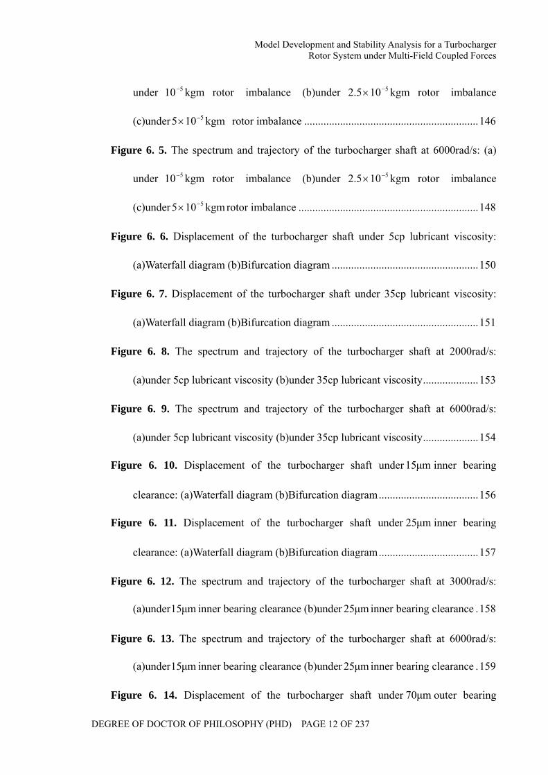
Figure 6. 4. The spectrum and trajectory of the turbocharger shaft at 3000rad/s: (a)
Model Development and Stability Analysis for a Turbocharger Rotor System under Multi-Field Coupled Forces
DEGREE OF DOCTOR OF PHILOSOPHY (PHD) PAGE 12 OF 237
under kgm10 5− rotor imbalance (b)under kgm105.2 5−× rotor imbalance
(c)under kgm105 5−× rotor imbalance ...............................................................146
Figure 6. 5. The spectrum and trajectory of the turbocharger shaft at 6000rad/s: (a)
under kgm10 5− rotor imbalance (b)under kgm105.2 5−× rotor imbalance
(c)under kgm105 5−× rotor imbalance .................................................................148
Figure 6. 6. Displacement of the turbocharger shaft under 5cp lubricant viscosity:
(a)Waterfall diagram (b)Bifurcation diagram .....................................................150
Figure 6. 7. Displacement of the turbocharger shaft under 35cp lubricant viscosity:
(a)Waterfall diagram (b)Bifurcation diagram .....................................................151
Figure 6. 8. The spectrum and trajectory of the turbocharger shaft at 2000rad/s:
(a)under 5cp lubricant viscosity (b)under 35cp lubricant viscosity....................153
Figure 6. 9. The spectrum and trajectory of the turbocharger shaft at 6000rad/s:
(a)under 5cp lubricant viscosity (b)under 35cp lubricant viscosity....................154
Figure 6. 10. Displacement of the turbocharger shaft under µm15 inner bearing
clearance: (a)Waterfall diagram (b)Bifurcation diagram....................................156
Figure 6. 11. Displacement of the turbocharger shaft under µm25 inner bearing
clearance: (a)Waterfall diagram (b)Bifurcation diagram....................................157
Figure 6. 12. The spectrum and trajectory of the turbocharger shaft at 3000rad/s:
(a)under µm15 inner bearing clearance (b)under µm25 inner bearing clearance .158
Figure 6. 13. The spectrum and trajectory of the turbocharger shaft at 6000rad/s:
(a)under µm15 inner bearing clearance (b)under µm25 inner bearing clearance .159
Figure 6. 14. Displacement of the turbocharger shaft under µm70 outer bearing
Model Development and Stability Analysis for a Turbocharger Rotor System under Multi-Field Coupled Forces
DEGREE OF DOCTOR OF PHILOSOPHY (PHD) PAGE 13 OF 237
clearance: (a)Waterfall diagram (b)Bifurcation diagram....................................160
Figure 6. 15. Displacement of the turbocharger shaft under µm90 inner bearing
clearance: (a)Waterfall diagram (b)Bifurcation diagram....................................161
Figure 6. 16. The spectrum and trajectory of the turbocharger shaft at 3000rad/s:
(a)under µm70 outer bearing clearance (b)under µm90 outer bearing clearance.163
Figure 6. 17. The spectrum and trajectory of the turbocharger shaft at 6000rad/s:
(a)under µm70 outer bearing clearance (b)under µm90 outer bearing clearance.164
Figure 6. 18. Displacement of the turbocharger shaft under 2N static load on the ring:
(a)Waterfall diagram (b)Bifurcation diagram .....................................................166
Figure 6. 19. Displacement of the turbocharger shaft under 5N static load on the ring:
(a)Waterfall diagram (b)Bifurcation diagram .....................................................167
Figure 6. 20. The spectrum and trajectory of the turbocharger shaft at 3000rad/s:
(a)under 2N static load (b)under 5N static load..................................................168
Figure 6. 21. The spectrum and trajectory of the turbocharger shaft at 6000rad/s:
(a)under 2N static load (b)under 5N static load..................................................169
Figure 7. 1. The block diagram of the turbocharger test rig ......................................174
Figure 7. 2. The GJ90C turbocharger.........................................................................175
Figure 7. 3. The block diagram of the lubrication system .........................................177
Figure 7. 4. CB-B gear lubrication pump...................................................................178
Figure 7. 5. Tescom 44-52-12243V Hydraulic control valve ....................................178
Figure 7. 6. A photograph of the assembly flanges between the lubricant pipe and the
turbocharger ........................................................................................................180
Model Development and Stability Analysis for a Turbocharger Rotor System under Multi-Field Coupled Forces
DEGREE OF DOCTOR OF PHILOSOPHY (PHD) PAGE 14 OF 237
Figure 7. 7. KAMAN KD2306 1U1 eddy current displacement transducer..............182
Figure 7. 8. A photograph of the eddy current displacement transducers installed on
the turbocharger ..................................................................................................184
Figure 7. 9. A BR100_DDT_P cylindrical photoelectric sensor................................184
Figure 7. 10. The speed nut for the light sensitive belt placement ............................186
Figure 7. 11. The rotational speed sensor fixed on a universal bracket .....................186
Figure 7. 12. USB-6251 BNC signal collection card.................................................187
Figure 7. 13. A photograph of the turbocharger test rig .............................................188
Figure 8. 1. The turbocharger shaft end motion at the compressor impeller side at
1,000r/min rotational speed: (a)X displacement (b)Spectrum of X displacement
(c)Y displacement (d)Spectrum of Y displacement (e)Trajectory ......................194
Figure 8. 2. The turbocharger shaft end motion at the compressor impeller side at
5,000r/min rotational speed: (a)X displacement (b)Spectrum of X displacement
(c)Y displacement (d)Spectrum of Y displacement (e)Trajectory ......................196
Figure 8. 3. The turbocharger shaft end motion at the compressor impeller side at
11,000r/min rotational speed: (a)X displacement (b)Spectrum of X displacement
(c)Y displacement (d)Spectrum of Y displacement (e)Trajectory ......................198
Figure 8. 4. The turbocharger shaft end motion at the compressor impeller side at
15,000r/min rotational speed: (a)X displacement (b)Spectrum of X displacement
(c)Y displacement (d)Spectrum of Y displacement (e)Trajectory ......................200
Figure 8. 5. Waterfall diagrams of the turbocharger shaft end motion at the compressor
side: (a)X displacement (b)Y displacement .....................................................202
Model Development and Stability Analysis for a Turbocharger Rotor System under Multi-Field Coupled Forces
DEGREE OF DOCTOR OF PHILOSOPHY (PHD) PAGE 15 OF 237
Figure 8. 6. Bifurcation diagrams of the turbocharger shaft end motion at the
compressor side: (a)X displacement (b)Y displacement ....................................203
Model Development and Stability Analysis for a Turbocharger Rotor System under Multi-Field Coupled Forces
DEGREE OF DOCTOR OF PHILOSOPHY (PHD) PAGE 16 OF 237
Abstract
Automotive turbochargers have been widely applied in vehicles in order to increase the power output of internal combustion engines by increasing the air to fuel ratio entering the piston cylinders. Turbochargers use the exhaust flow to spin a turbine at speeds of up to 140,000 r/min. Under such extreme working conditions, even a weak vibration can lead to the bearing failure and the whole turbocharger destroyed. In order to guarantee a safe operation, it is necessary to carry out a theoretical research on the dynamics performance of turbochargers. Therefore, the primary objective of this research is to develop a dynamics model for the turbocharger rotor system under multi-field coupled forces and then to study the dynamic characteristics and the stability of its rotor system according to the simulation and experimental results. A turbocharger is a special kind of rotating machinery because of the following aspects: Firstly, the turbocharger rotor system is supported by floating ring bearings. The impact of nonlinear multi-field coupled forces must be considered. Secondly, the turbocharger rotor system is a multi-span rotor bearing system that makes the modeling and simulation more complicated. Thirdly, the working speed range of the turbocharger covers multiple orders of critical speeds. This flexible rotor system cannot be studied using the conventional theory of rigid rotors. In this thesis, the lubrication system of a turbocharger is initially investigated. The analytical expressions of the hydrodynamic pressure distribution in the floating ring bearing are derived using the infinitely long bearing theory, taking into account the oil inlet pressure and the cavitation area. The influences of external loads and oil inlet pressure on the oil flow rate into the inner clearance are analytically investigated, while considering the effect of the rotation of the ring. A finite element model is then developed for the turbocharger rotor system. In this model, the excitation forces considered include rotor imbalance, hydrodynamic forces, lubricant feed pressure and the dead weight. The dimensionless form of Capone hydrodynamic force model is extended into the floating ring bearing. Following model development, modal analysis is carried out on both a free rotor system and a turbocharger rotor system. The effects of the structural parameters and working conditions, such as the rotor imbalance, lubricant viscosity, bearing clearances and lubricant feed pressure, on the stability of the turbocharger rotor system are studied. A turbocharger test rig is then designed and developed to monitor the turbocharger shaft motion. The experimental data agree well with the simulation results from the theoretical model. The primary contribution of the current research can be categorized into the following aspects: Firstly, the analytical expressions of the hydrodynamic pressure distribution have been solved. The equilibrium positions of the journal and ring have been deduced under
Model Development and Stability Analysis for a Turbocharger Rotor System under Multi-Field Coupled Forces
DEGREE OF DOCTOR OF PHILOSOPHY (PHD) PAGE 17 OF 237
different external loads and lubricant feed pressure. The relationship between the oil flow rate and the rotational velocity of the shaft has been obtained. Secondly, Capone hydrodynamic force model is introduced and extended to simulate the dynamic performance of the floating ring bearing. The analytical expression of the hydrodynamic forces of double oil films have been derived based on the dimensionless form of the Reynolds Equations. Thirdly, the motion of the turbocharger shaft is simulated within a speed range of 0 to 8,000 rad/s. The influences of structural parameters and working conditions on the stability of the turbocharger rotor system are clearly understood. It should be noted that the developed model still needs to be validated when turbocharger is operated at a relatively high speed, although it agrees well with experimental results within the speed range of 0 to 2,000 rad/s.
Model Development and Stability Analysis for a Turbocharger Rotor System under Multi-Field Coupled Forces
DEGREE OF DOCTOR OF PHILOSOPHY (PHD) PAGE 18 OF 237
Declaration
No portion of the work referred to in this thesis has been submitted in support of an
application for another degree or qualification of the University of Huddersfield or any
other university or other institute of learning.
Model Development and Stability Analysis for a Turbocharger Rotor System under Multi-Field Coupled Forces
DEGREE OF DOCTOR OF PHILOSOPHY (PHD) PAGE 19 OF 237
Copyright Statement
1. The author of this thesis (including any appendices and/or schedules to this thesis)
owns any copyright in it (the “Copyright”) and he has given The University of
Huddersfield the right to use such Copyright for any administrative, promotional,
educational and/or teaching purposes.
2. Copies of this thesis, either in full or in extracts, may be made only in accordance with
the regulations of the University Library. Details of these regulations may be obtained
from the Librarian. This page must form part of any such copies made.
3. The ownership of any patents, designs, trade marks and any and all other intellectual
property rights except for the Copyright (the “Intellectual Property Rights”) and any
reproductions of copyright works, for example graphs and tables (“Reproductions”),
which may be described in this thesis, may not be owned by the author and may be
owned by third parties. Such Intellectual Property Rights and Reproductions cannot
and must not be made available for use without the prior written permission of the
owner(s) of the relevant Intellectual Property Rights and/or Reproductions.
Model Development and Stability Analysis for a Turbocharger Rotor System under Multi-Field Coupled Forces
DEGREE OF DOCTOR OF PHILOSOPHY (PHD) PAGE 20 OF 237
Acknowledgement
I would like to express my deep and sincere gratitude to my main supervisor, Professor
Andrew Ball. His wide knowledge and his logical way of thinking have been of great value
for me. His understanding, encouragement and personal guidance have provided a good
basis for the present thesis.
I am deeply grateful to my former supervisor, Dr. Zhanqun Shi for his important support
throughout this work.
I wish to express my warm and sincere thanks to Dr. Fengshou Gu for his help during this
experiment.
I would like to thank my parents for their encouragement and support during my study.
The financial support of the University of Huddersfield is gratefully acknowledged.
Model Development and Stability Analysis for a Turbocharger Rotor System under Multi-Field Coupled Forces
DEGREE OF DOCTOR OF PHILOSOPHY (PHD) PAGE 21 OF 237
Publications
1. Zhang H, Shi ZQ, Song YM, Gu FS and Ball AD. (2012) Analytical investigation on
the lubrication of floating ring bearing under the influences of external load and oil
inlet pressure. Proceedings of the Institution of Mechanical Engineers, Part J: Journal
of Engineering Tribology. (Under Review)
2. Zhang H, Shi ZQ, Gu FS and Ball AD. (2012) Stability analysis against turbocharger
rotor system supported on floating ring bearings. The 25th International Congress on
Condition Monitoring and Diagnostic Engineering Management, University of
Huddersfield, United Kingdom, June 2012. (Under Review)
3. Zhang H, Shi ZQ, Gu FS and Ball AD. (2011) Stability analysis against turbocharger
rotor system under coupling of multi-field nonlinear forces. Scientific Research and
Essays. (Under Review)
4. Zhang H, Shi ZQ, Gu FS and Ball AD. (2011) Modelling of outer and inner film oil
pressure for floating ring bearing clearance in turbochargers. The 9th International
Conference on Damage Assessment of Structures, St. Anne’s College, Oxford, United
Kingdom, July 2011.
5. Zhang H, Shi ZQ, Gu FS and Ball AD. (2010) Bending vibration of an automotive
turbocharger under the influence of rotor imbalance. CM 2010 and MFPT 2010 The 7th
International Conference on Condition Monitoring and Machinery Failure Prevention
Technologies, Ettington Chase, Stratford-upon-Avon, United Kingdom, June 2010.
Model Development and Stability Analysis for a Turbocharger Rotor System under Multi-Field Coupled Forces
DEGREE OF DOCTOR OF PHILOSOPHY (PHD) PAGE 22 OF 237
6. Zhang H, Shi ZQ, Gu FS, Mishra R and Ball AD. (2009) Model-based fault detection
for a turbocharger. Proceedings of COMADEM 2009 : Condition Monitoring and
Diagnostic Engineering Management (COMADEM). ISBN 9788493206468.
7. Zhang H and Shi ZQ. (2009) Modelling for a turbocharger in rotordynamics.
Proceedings of Computing and Engineering Annual Researchers’ Conference 2009:
CEARC’09. University of Huddersfield, United Kingdom, 2009. ISBN
9781862180857.
Chapter One Introduction
DEGREE OF DOCTOR OF PHILOSOPHY (PHD) PAGE 23 OF 237
CHAPTER ONE
INTRODUCTION
This chapter provides an introduction to why this investigation is conducted. The
application and development of the rotating machinery are firstly introduced. The structure
and working principle of an automotive turbocharger is then described. After that, the
research background related to the fluid lubrication and the rotordynamics are given in
order to provide a foundation for this research. The motivation to study the dynamic
characteristics of the turbocharger rotor system is stated. Finally, the project objectives
and structure of the thesis are presented.
Chapter One Introduction
DEGREE OF DOCTOR OF PHILOSOPHY (PHD) PAGE 24 OF 237
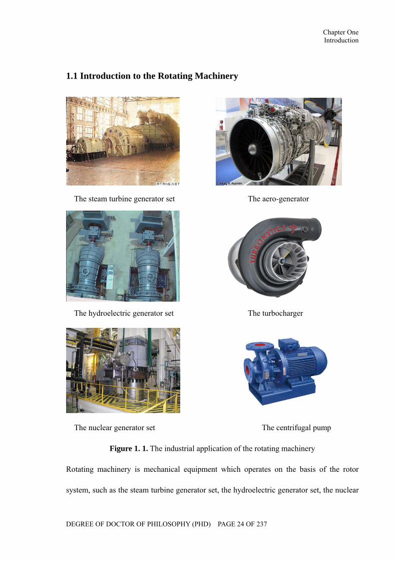
1.1 Introduction to the Rotating Machinery
The steam turbine generator set The aero-generator
The hydroelectric generator set The turbocharger
The nuclear generator set The centrifugal pump
Figure 1. 1. The industrial application of the rotating machinery
Rotating machinery is mechanical equipment which operates on the basis of the rotor
system, such as the steam turbine generator set, the hydroelectric generator set, the nuclear
Chapter One Introduction
DEGREE OF DOCTOR OF PHILOSOPHY (PHD) PAGE 25 OF 237
generator set, the aero-generator, the turbocharger, the centrifugal pump, etc, which are
shown in Figure 1.1. It generally comprises of the rotor, stator, bearing, seal, etc. The rotor
spins inside the stator and the energy conversion is conducted through the media in the
clearance between the rotor and stator [1], which is shown in Figure 1.2.
Figure 1. 2. The structure of rotor and stator
Modern rotating machinery has the characteristics of the speed, heavy load and automation,
which improve the production efficiency and reduce costs. However, it also has the
negative impact. Once the faults occur in the operating equipment, the economic loses
might be incalculable. Therefore the criterion of rotating machinery is required more
strictly nowadays in terms of the speed, volume, efficiency, stability, reliability, etc.
Rotating machinery is a complex nonlinear vibration system with multi-degrees of freedom.
The operational stability is crucial for the safe operation of the whole equipment. In the
actual rotor bearing system, the residual imbalance remains existence, although the rotors
have been balanced. The imbalance excites the system to perform a stable synchronous
motion. In fact this stable state might be affected by the existence of faults which could
Chapter One Introduction
DEGREE OF DOCTOR OF PHILOSOPHY (PHD) PAGE 26 OF 237
excite a subsynchronous motion. The combination of the synchronous and subsynchronous
motion lead to the system performing a complex trajectory and also give rise to a large
alternating stress on the shaft. Long term operation in the unstable stage will threaten the
service life of the equipment. Therefore there is an important theoretical and practical
significance to the study of the influences of the parameters of the rotor system and
working condition on its stability characteristics for safe operation of the rotating
machinery.
1.2 Introduction to the Turbocharger
Figure 1. 3. The structure of a typical automotive turbocharger
Figure 1.3 shows the structure of a typical automotive turbocharger. (It is noted that Figure
1.3 is copied from the website of the BorgWarner Company and used without the
permission from the BorgWarner Company) The turbocharger mainly comprises of turbine
and compressor impellers linked by a shared shaft. The turbocharger is a centrifugal
compressor powered by the exhaust gases. It utilizes the engine’s exhaust to drive the
Chapter One Introduction
DEGREE OF DOCTOR OF PHILOSOPHY (PHD) PAGE 27 OF 237
turbine wheel. Through the rotation of the coaxial compressor wheel, the ambient air is
compressed and then delivered to engine cylinders. Therefore, the engine burns more air
and fuel so that more mechanical power is created. In addition, the application of
turbochargers reduces the exhaust gases emission and improves the efficiency of the
engine [2]. The major advantage of the turbocharger is that the output power and torque of
the engine can be significantly improved without increasing the displacement. Generally
speaking, the output power and torque of a turbocharged engine could be improved 20% -
30% compared to a normal engine [2].
Turbochargers, as the best way to improve the performance of the engine, can be viewed as
a milestone in the history of the engine’s development [3]. In 1905, the first turbocharger
was designed by Buchi, a Swiss engineer. At that period, turbochargers were applied in the
aero-engines in order to improve the performance of the engine in a high altitude. In 1950s,
racers tried to install the turbochargers in the automotive engines and the first turbocharged
automotive engine was produced in 1960s. In recent years, with the requirement of the
energy saving and environmental protection, turbochargers have been widely applied in
automobiles.
1.3 Background
1.3.1 Development of the research of the fluid lubrication
From 1883 to 1885, B. Tower [4] conducted the first investigation on the fluid lubrication
of the radial journal bearings on the railway. During the experiment, he noticed the
existence of the hydrodynamic pressure in the oil holes. The experimental results about oil
Chapter One Introduction
DEGREE OF DOCTOR OF PHILOSOPHY (PHD) PAGE 28 OF 237
film pressure distribution attracted the interests of the researchers. In 1886, according to
the published experimental results, O. Reynolds [5] conducted an analytical research on the
mechanism of the pressure distribution and derived the well-known Reynolds Equation for
the oil film pressure that provided the theoretical foundation for a further research of the
fluid lubrication. From the mathematical point of view, the core issue of the fluid
lubrication is the solution of Reynolds Equation to reveal the oil film pressure distribution.
Unfortunately, the attempt to derive the analytical solution is unsuccessful so far except for
rare cases, the numerical calculation is still the most common approach [6, 7].
With the development of mathematical algorithms and the application of the fast
computers, a considerable progress has been made on the research of the fluid lubrication
and bearing techniques. The research field covers both static and dynamic characteristics of
the bearing, both in the steady state and non-steady state. In 1931, Kingsbury [8] used the
electrolyzer simulation method to calculate the oil film pressure distribution. In 1942,
Christopherson [9] initially introduced the finite difference method to solve Reynolds
Equation. In 1969, Reddi [10] adopted the finite element method to derive the oil film
pressure distribution in the journal bearing.
From 1980s, researchers paid more attention to the stability analysis of the nonlinear rotor
bearing system that becomes increasingly important for the high speed rotor systems. As
far as the nonlinear analysis is concerned, the key issue is to derive a satisfied functional
expression to reflect the dynamic characteristics of the nonlinear hydrodynamic force,
which determines the accuracy of nonlinear dynamics design of the rotating machinery. To
date, the general approach to solve the Reynolds Equation is to simplify the non-steady
Chapter One Introduction
DEGREE OF DOCTOR OF PHILOSOPHY (PHD) PAGE 29 OF 237
state boundary of the oil film to the steady state boundary, such as Sommerfeld boundary
condition, mbeluG && boundary condition, Reynolds boundary condition, etc, which ignores
the impact of the journal perturbation velocity on the oil film boundary [11]. As a result,
the derived expression of the nonlinear hydrodynamic force is insufficient to meet the
reality. It is necessary to develop a more reasonable theory of the fluid lubrication to meet
the demand of the modern industry.
1.3.2 Development of the research of the rotordynamics
The development of rotordynamics is closely related to industrial development. In 1869,
the first rotordynamic investigation was published by Rankine [12], who studied the
equilibrium condition of an undamped homogeneous shaft under perturbation at its initial
position. Without consideration of the influences of Coriolis Forces, he concluded that the
shaft performs a stable motion below the first order critical speed, an unstable motion over
the first order critical speed and an uncertain motion around the first order critical speed.
In 1919, H. Jeffcott [13] was invited to conduct the research of the rotordynamics. The
model he studied was an elastic shaft without mass, both sides of which were rigidly
hinged. A rigid disk with mass, imbalance and damping, was fixed in the middle of the
shaft. This simplified model of the flexible rotor system is called ‘Jeffcott rotor’. From this
research, he drew the following conclusion:
In a dynamic coordinate system rotating at the same velocity of the shaft, the position of
the centroid of the disk will be changed rather than fixed. If the shaft speed is much lower
than the critical speed, the centroid will be located outside the deflection; if the shaft speed
Chapter One Introduction
DEGREE OF DOCTOR OF PHILOSOPHY (PHD) PAGE 30 OF 237
is much higher than the critical speed, the centroid will be located inside the deflection; if
the shaft speed equals the critical speed, the eccentricity and deflection will place in a
perpendicular position. Therefore, it is possible for a rotor system to keep stable even the
shaft rotating in a supercritical state. In addition, the load of the bearing is even declined as
increasing the shaft speed.
Based on this theory, in 1920s, numerous rotor systems were designed and produced,
which operating speeds are far higher than the first order critical speeds. Unfortunately, the
serious vibration always occurred in some of the equipment. In order to clarify the reasons
of the accidents, experts conducted a series of experimental investigation. The results
indicate that when the rotor system working over the first order critical speed, a dramatic
motion will occur until the shaft reaches a certain speed. The angular frequency of the
motion approximately equals the first order critical speed. The speed when the dramatic
motion occurs can be viewed as the threshold speed of the instability of the rotor bearing
system. In addition, the amplitude of the motion will become larger as increasing further
the operating speed. This conclusion provides a foundation for the stability analysis of the
rotor system [1].
Since the 1950s, the rapid development of the aviation industry, electric industry,
shipbuilding industry, petroleum and chemical industry, etc, promoted the development of
rotordynamics. More and more rotor systems were running in the flexible state, even
working over the third and fourth order critical speeds. Therefore, more stable and reliable
rotors are required to be designed and the theory of the rotordynamics needs to be further
investigated.
Chapter One Introduction
DEGREE OF DOCTOR OF PHILOSOPHY (PHD) PAGE 31 OF 237
1.3.3 Research areas of the rotordynamics
1.3.3.1 The critical speeds calculation of the rotor bearing system
In order to avoid the occurrence of the resonance for a rotor system, it is required to
estimate its critical speed as accurately as possible. To date, the most popular approaches
of the critical speed calculation are the transfer matrix method and the finite element
method. The transfer matrix method has the advantage of simple solution, easy
programming and being able to calculate the higher orders critical speeds. However, the
accuracy of this approach is not satisfied, especially in the calculation of dynamic
performance of the large-scale rotor system working at high speed. Also, numerical
instability would be occurred. Compared to the transfer matrix method, the finite element
method is a more accurate approach that also can avoid the numerical instability, which is
usually occurred in the transfer matrix method. On the other hand, the disadvantage of the
finite element method is that more computer resources will be occupied, and also difficult
to program.
1.3.3.2 Calculation of the steady state response under the rotor imbalance
It is crucial for the design of a rotor bearing system to accurately estimate the deflection of
the rotor, support and the load of the bearing under a given rotor imbalance. The classical
approaches of calculation of the rotor imbalance response primarily include the transfer
matrix method and the modal synthesis method. However, neither two approaches are
accurate enough for the industrial calculation as a result of the difficulty of the estimation
of the structural damping. In addition, the modal synthesis method is only suitable for
Chapter One Introduction
DEGREE OF DOCTOR OF PHILOSOPHY (PHD) PAGE 32 OF 237
linear systems, which can not be used in the rotor bearing systems with nonlinear factors.
In recent years, the finite element method gradually becomes popular in the forced
response of the rotor system with the development of the computer and mathematical
software.
1.3.3.3 Balancing of the flexible rotor system
Most of modern rotor systems work in the supercritical state so that the flexible deflection
can not be ignored. It is, therefore, necessary to study the balancing techniques for the
flexible rotor systems. The primary approaches include the mode decomposition method
and the influence coefficient method.
In the mode decomposition method, the rotor is driven to spin at the 1st, 2nd, … , n order
critical speeds respectively and then a group of appropriate mass is used to achieve
balancing. This method has an advantage of high sensitivity. However, it is difficult to
obtain an accurate result. In addition, this method is unsuitable for the systems with
significant damping. In the influence coefficient method, the dynamic flexibility matrices
are required to be obtained under each balancing velocity to calculate the eccentricity and
altitude degree of the unknown disks. This method will consume a long calculation time.
The academic research of balancing techniques for flexible rotor systems concentrates on
two fields: firstly, the relationship of the rotor imbalance and the flexible deflection,
supporting forces, vibration; secondly, the compensation method, the balancing criterion
and their relationship.

Chapter One Introduction
DEGREE OF DOCTOR OF PHILOSOPHY (PHD) PAGE 33 OF 237
1.3.3.4 The stability analysis of the rotor bearing system
The self-excited vibration of the rotor system can lead to a dramatic alternating stress on
the shaft that may cause a failure of the equipment. The higher the rotor velocity, the more
possible the vibration occurs, because most of the self-excited vibration occur in the
supercritical state of the rotor.
To date, most of the stability analysis is conducted based on the Jeffcott model. The
primary approaches for the stability analysis are listed as follows:
(I) Eigenvalue approach
In this approach, eigenvalues should be solved by the derived characteristic equation of the
rotor system. When the real part of the eigenvalue is zero, the corresponding velocity can
be viewed as the threshold velocity of the self-excited vibration and then the stability
boundary of the system can be obtained. However, due to the difficulty to solve a higher
order polynomial, it is not a good approach in terms of the numerical integration.
(II) Routh-Hurwitz criterion
In this approach, the roots of the characteristic equation are not required to solve. However,
this approach is not suitable for a higher order characteristic equation, thus it can only be
applied in a qualitative research on the stability of the simplified rotor bearing system.
(III) Numerical integration approach
In this approach, the motion of the rotor system is solved numerically and then the system
stability can be determined by the system response. This approach is not only suitable for
stability analysis, steady state forced response and critical speeds calculation, but also fit
for the study of the transient system response. Also, it can be used for both linear and
Chapter One Introduction
DEGREE OF DOCTOR OF PHILOSOPHY (PHD) PAGE 34 OF 237
nonlinear systems.
The disadvantage of the numerical integration approach is that a long calculation time will
be consumed. In addition, the time step has to be short enough to ensure the calculation
accuracy and stability, and also the integration period must be long enough to eliminate the
impacts of the initial perturbation.
1.4 Motivation
A turbocharger is a rotating machine of the high speed and light load categroy. The
rotational speed can reach 140,000r/min and over. At such a high speed, even a weak
vibration can lead to the failure of its rotor system. In order to ensure the turbocharger
operating safely under the extreme working conditions, it is therefore, crucial to conduct
the research on the rotordynamics of the turbocharger rotor system.
The research of the vibration characteristics and the stability of the turbocharger rotor
system mainly concentrate on two fields: Firstly, floating ring bearings. The extreme
working condition of the turbocharger could not be withstood by the general journal
bearings and ball bearings. As a result, most automotive turbochargers use floating ring
bearings to support their rotor systems. When the shaft spins, double oil films connected by
the supply holes on the ring are formed inside the bearing clearance. The pressure
distribution and the stability of two oil films simultaneously affect the turbocharger rotor
system that makes the vibration characteristics and stability more complex to analyze.
Secondly, modeling of a multi-span rotor system. Compared to the Jeffcott rotor model, the
turbocharger rotor system is a multi-span rotor bearing system which performs a complex
Chapter One Introduction
DEGREE OF DOCTOR OF PHILOSOPHY (PHD) PAGE 35 OF 237
nonlinear behavior. In addition, the existence of double oil films increases the number of
the degree of freedom of the rotor system. In this thesis, research will be conducted on the
above two fields.
1.5 Research Objectives
The primary objective of this research is to study the dynamic performance of the
turbocharger rotor system under nonlinear forces in order to provide a theoretical
foundation for the design and application of the automotive turbocharger and to ensure that
the turbochargers operate safely under extreme working conditions. On the other hand,
work also involves investigation of the lubrication of floating ring bearings in order to
study the influences of double oil films on the dynamic performance of the rotor system
and derive the analytical expression of the nonlinear hydrodynamic fluid forces of two oil
films.
In particular, the objectives can be categorized into several parts, as listed as follows:
Objective 1. To conduct a full literature review of current research in the areas of fluid
lubrication, rotordynamics and turbocharger rotordynamics.
Objective 2. To investigate the fluid lubrication of floating ring bearings.
Objective 3. To develop a theoretical dynamics model for the turbocharger rotor system..
Objective 4. To analyze the dynamic performance of the turbocharger rotor system and to
calculate the critical speeds and mode shapes.
Objective 5. To study the effects of working conditions on the dynamic performance and
stability of the turbocharger rotor system.
Chapter One Introduction
DEGREE OF DOCTOR OF PHILOSOPHY (PHD) PAGE 36 OF 237
Objective 6. To construct a turbocharger test rig to validate and verify the theoretical
model.
1.6 The Structure of the Thesis
In the first chapter, the development of the rotating machinery and turbochargers are
introduced. The research background of the rotordynamics is given. The motivation of the
research on the turbocharger rotor system and the stability is briefly discussed. The
research objectives and the structure of the thesis are listed.
In the second chapter, the literatures regarding fluid lubrication, rotordynamics and
turbocharger rotordynamics are reviewed. The approaches of the research on the
nonlinearity of the vibration system, the modal synthesis method and the numerical
integration method are introduced.
In the third chapter, the lubrication system of a turbocharger is analytically studied. The
effects of external loads and oil inlet pressure on the oil film pressure distribution and oil
flow rate are investigated.
In the fourth chapter, a dynamics model is developed for the turbocharger rotor system
using the finite element method. Linear and nonlinear hydrodynamic fluid forces are
studied respectively. Rub-impact forces are considered in modeling.
Chapter One Introduction
DEGREE OF DOCTOR OF PHILOSOPHY (PHD) PAGE 37 OF 237
In the fifth chapter, the modal analysis is conducted to the turbocharger rotor system.
Critical speeds and mode shapes of the turbocharger rotor system are calculated and
analyzed based on the linear dynamics model.
In the sixth chapter, motions of the turbocharger rotor system are simulated. The stability
disciplines are analyzed under the influences of the rotor imbalance, the lubricant viscosity,
bearing clearances and the lubricant feed pressure.
In the seventh chapter, a turbocharger test rig is developed to validate the theoretical model
and investigate the motion discipline of turbocharger rotor system.
In the eighth chapter, the experimental data of the turbocharger shaft end motion at the
compressor impeller side as well as the rotational speed of the shaft are monitored. The
instability discipline of the turbocharger rotor system is studied according to the
experimental and simulation results.
In the ninth chapter, the current research is concluded and makes suggestions for future
work.
Chapter Two Literature Review
DEGREE OF DOCTOR OF PHILOSOPHY (PHD) PAGE 38 OF 237
CHAPTER TWO
LITERATURE REVIEW
In this chapter, literature regarding the research of fluid lubrication and dynamic
characteristics of the rotor bearing system has been reviewed. Literature regarding the
turbocharger rotordynamics, which is a special nonlinear rotor bearing system supported
by floating ring bearings, is studied. The key backgrounds of the theory involved in this
research have been introduced, such as the nonlinear theory of the vibration system, the
modal synthesis method and the numerical integration approach.
Chapter Two Literature Review
DEGREE OF DOCTOR OF PHILOSOPHY (PHD) PAGE 39 OF 237
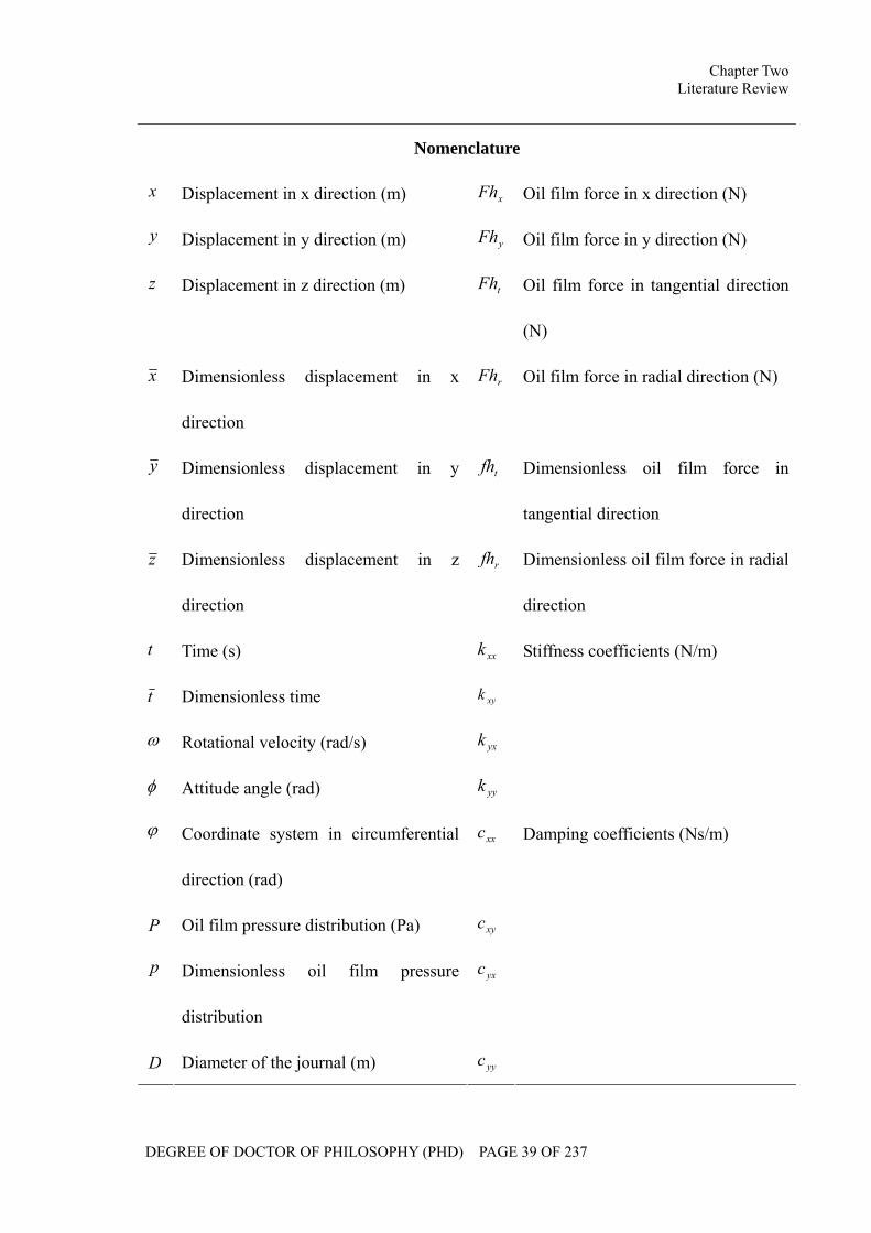
Nomenclature
x Displacement in x direction (m) xFh Oil film force in x direction (N)
y Displacement in y direction (m) yFh Oil film force in y direction (N)
z Displacement in z direction (m) tFh Oil film force in tangential direction
(N)
x Dimensionless displacement in x
direction
rFh Oil film force in radial direction (N)
y Dimensionless displacement in y
direction
tfh Dimensionless oil film force in
tangential direction
z Dimensionless displacement in z
direction
rfh Dimensionless oil film force in radial
direction
t Time (s) xxk
t Dimensionless time xyk
ω Rotational velocity (rad/s) yxk
φ Attitude angle (rad) yyk
Stiffness coefficients (N/m)
ϕ Coordinate system in circumferential
direction (rad)
xxc
P Oil film pressure distribution (Pa) xyc
p Dimensionless oil film pressure
distribution
yxc
D Diameter of the journal (m) yyc
Damping coefficients (Ns/m)
Chapter Two Literature Review
DEGREE OF DOCTOR OF PHILOSOPHY (PHD) PAGE 40 OF 237
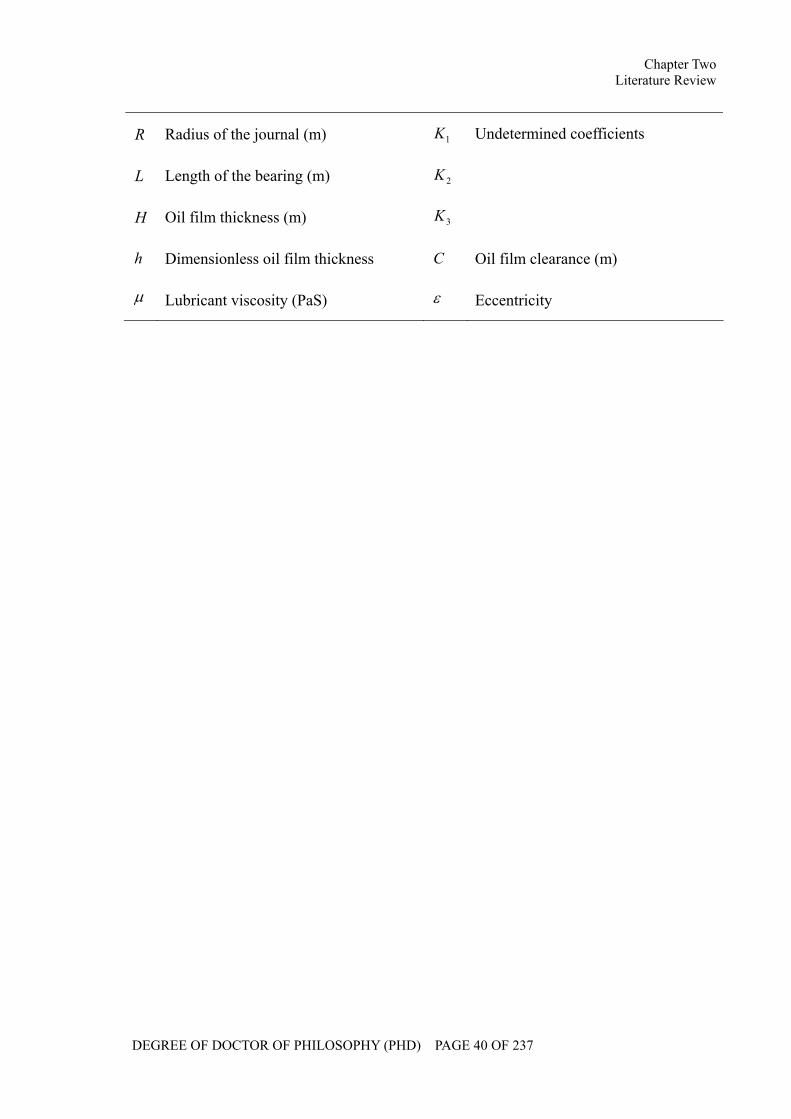
R Radius of the journal (m) 1K
L Length of the bearing (m) 2K
H Oil film thickness (m) 3K
Undetermined coefficients
h Dimensionless oil film thickness C Oil film clearance (m)
µ Lubricant viscosity (PaS) ε Eccentricity
Chapter Two Literature Review
DEGREE OF DOCTOR OF PHILOSOPHY (PHD) PAGE 41 OF 237
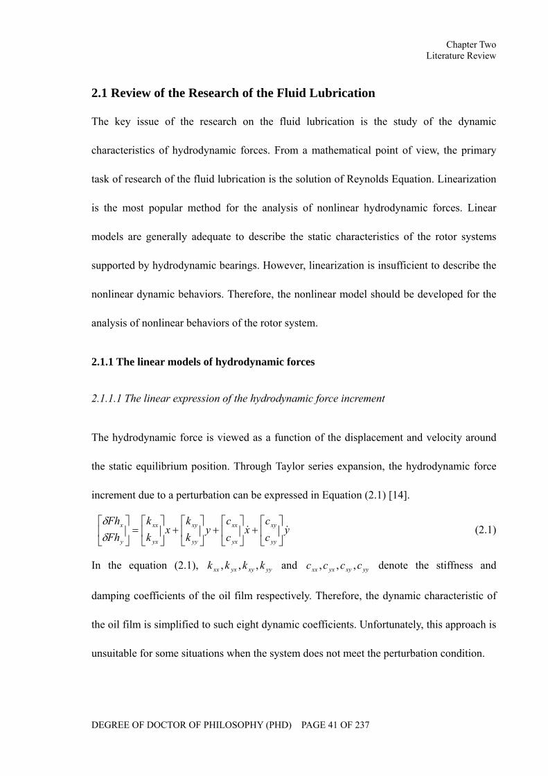
2.1 Review of the Research of the Fluid Lubrication
The key issue of the research on the fluid lubrication is the study of the dynamic
characteristics of hydrodynamic forces. From a mathematical point of view, the primary
task of research of the fluid lubrication is the solution of Reynolds Equation. Linearization
is the most popular method for the analysis of nonlinear hydrodynamic forces. Linear
models are generally adequate to describe the static characteristics of the rotor systems
supported by hydrodynamic bearings. However, linearization is insufficient to describe the
nonlinear dynamic behaviors. Therefore, the nonlinear model should be developed for the
analysis of nonlinear behaviors of the rotor system.
2.1.1 The linear models of hydrodynamic forces
2.1.1.1 The linear expression of the hydrodynamic force increment
The hydrodynamic force is viewed as a function of the displacement and velocity around
the static equilibrium position. Through Taylor series expansion, the hydrodynamic force
increment due to a perturbation can be expressed in Equation (2.1) [14].
ycc
xcc
ykk
xkk
FhFh
yy
xy
yx
xx
yy
xy
yx
xx
y
x && ⎥⎦
⎤⎢⎣
⎡+⎥
⎦
⎤⎢⎣
⎡+⎥
⎦
⎤⎢⎣
⎡+⎥
⎦
⎤⎢⎣
⎡=⎥
⎦
⎤⎢⎣
⎡δδ
(2.1)
In the equation (2.1), yyxyyxxx kkkk ,,, and yyxyyxxx cccc ,,, denote the stiffness and
damping coefficients of the oil film respectively. Therefore, the dynamic characteristic of
the oil film is simplified to such eight dynamic coefficients. Unfortunately, this approach is
unsuitable for some situations when the system does not meet the perturbation condition.
Chapter Two Literature Review
DEGREE OF DOCTOR OF PHILOSOPHY (PHD) PAGE 42 OF 237
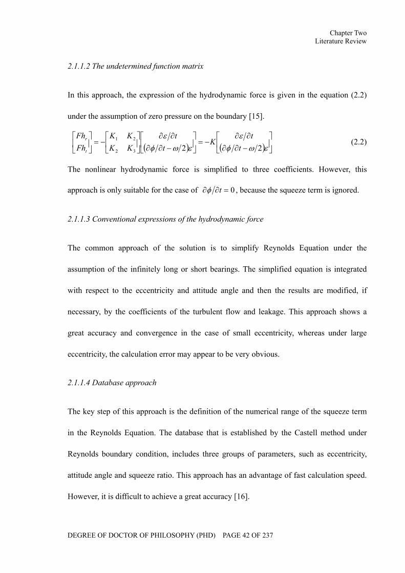
2.1.1.2 The undetermined function matrix
In this approach, the expression of the hydrodynamic force is given in the equation (2.2)
under the assumption of zero pressure on the boundary [15].
( ) ( ) ⎥⎦
⎤⎢⎣
⎡−∂∂∂∂
−=⎥⎦
⎤⎢⎣
⎡−∂∂∂∂
⎥⎦
⎤⎢⎣
⎡−=⎥
⎦
⎤⎢⎣
⎡εωφ
εεωφ
ε2232
21
tt
Kt
tKKKK
FhFh
t
r (2.2)
The nonlinear hydrodynamic force is simplified to three coefficients. However, this
approach is only suitable for the case of 0=∂∂ tφ , because the squeeze term is ignored.
2.1.1.3 Conventional expressions of the hydrodynamic force
The common approach of the solution is to simplify Reynolds Equation under the
assumption of the infinitely long or short bearings. The simplified equation is integrated
with respect to the eccentricity and attitude angle and then the results are modified, if
necessary, by the coefficients of the turbulent flow and leakage. This approach shows a
great accuracy and convergence in the case of small eccentricity, whereas under large
eccentricity, the calculation error may appear to be very obvious.
2.1.1.4 Database approach
The key step of this approach is the definition of the numerical range of the squeeze term
in the Reynolds Equation. The database that is established by the Castell method under
Reynolds boundary condition, includes three groups of parameters, such as eccentricity,
attitude angle and squeeze ratio. This approach has an advantage of fast calculation speed.
However, it is difficult to achieve a great accuracy [16].
Chapter Two Literature Review
DEGREE OF DOCTOR OF PHILOSOPHY (PHD) PAGE 43 OF 237
2.1.2 The limitation of the linear hydrodynamic force model
It has been demonstrated by numerous accidents of the rotating machinery caused by
instability that the analytical results derived from the linear hydrodynamic force model are
insufficient to predict dynamic performance of nonlinear rotor bearing systems in practice.
In the linear model, the hydrodynamic force is expressed by the stiffness and damping
coefficients. Although this model has been widely applied in rotating machinery under
small perturbation, the actual rotor bearing system might not satisfy the condition of the
small perturbation. As a result, the predicted result based on the linear model can not
comprehensively reflect the mechanism of the oil film. In addition, the linear model lacks a
clear link among such dynamic coefficients. It is, therefore, necessary to derive a more
logical and accurate expression for the nonlinear hydrodynamic force to provide a
theoretical support for the comprehensive dynamic analysis of rotating machinery.
To date, although a considerable achievement has been made in the research of rotor
bearing system based on the linear model, it is still insufficient to analyze the mechanism
of the oil film instability. Here take the plain journal bearing as an example to illustrate the
oil film instability. The oil film instability, such as oil whirl and whip, is an unstable free
vibration of the journal bearing. Under an insufficient unit loading, the shaft centerline
dynamic motion is usually circular in the direction of rotation. Oil whirl occurs at the oil
flow velocity within the bearing, usually 40% to 49% of the shaft speed. Oil whip occurs
when the whirl frequency coincide with a shaft resonant frequency. It is the nonlinear
hydrodynamic force that leads to the subsynchronous motion of the rotor system. The
Chapter Two Literature Review
DEGREE OF DOCTOR OF PHILOSOPHY (PHD) PAGE 44 OF 237
analytical expression of the hydrodynamic force can not be derived from the linear
Reynolds Equation. In order to study the mechanism of oil film instability and reveal the
intrinsic link between oil film instability and the stability of rotor system, a reasonable
expression of the nonlinear hydrodynamic force is required to be derived.
2.1.3 The nonlinear analytical model of the hydrodynamic force
The nonlinear analytical models of hydrodynamic forces can be categorized into the
infinitely long/short bearing model and the finite length bearing model. To date, most of
the research regarding oil film nonlinear behaviors is based on the simplified infinitely
long/short model. Gardner [17] used the method of multiple scales to study the weakly
nonlinear motion of the rotor system under the assumption of the infinite long/short
bearing theory. The subcritical and supercritical bifurcations at the equilibrium position
were studied. Russo [18] investigated the impacts of the turbulent flow on the stability of
synchronous motion. Adams and Abu-Mahfouz [19] used numerical investigation method
to study the nonlinear dynamic behaviors of the rotors supported by the cylindrical bearing
and tilting pad bearing. With the aid of the spectrum, the trajectory and Poincare map, the
way into chaos was analyzed. Based on the shooting method and Floquet theory, Yuan and
Zhu [20] discussed the influences of the rotor imbalance on the instability of the rotor
supported on cylindrical bearings. It was found that the unbalance of rotors has an
important effect on the stability, and the larger the unbalance magnitude is, the more
serious the effect is. Under the assumption of infinite short bearing theory, Chen [21]
adopted the center manifold theorem to study the subsynchronous motion of the shaft
Chapter Two Literature Review
DEGREE OF DOCTOR OF PHILOSOPHY (PHD) PAGE 45 OF 237
around the critical equilibrium position. Furthermore, the bifurcation set was obtained by
Floquet theory. According to the research of the rotor supported by the oil film damper,
Zhao et al [22, 23] illustrated the nonlinear dynamic behaviors, e.g. synchronous motion,
quasi-periodic motion, sub-harmonic motion and chaos, and the bifurcation behaviors, e.g.
limit point bifurcation, quasi-periodic bifurcation, double periodic bifurcation and
sub-harmonic bifurcation.
2.1.4 The list of classical nonlinear models of the hydrodynamic force
In the following section, three classical nonlinear models of the hydrodynamic force are
listed, which have been widely used in the nonlinear behaviors analysis of journal
bearings.
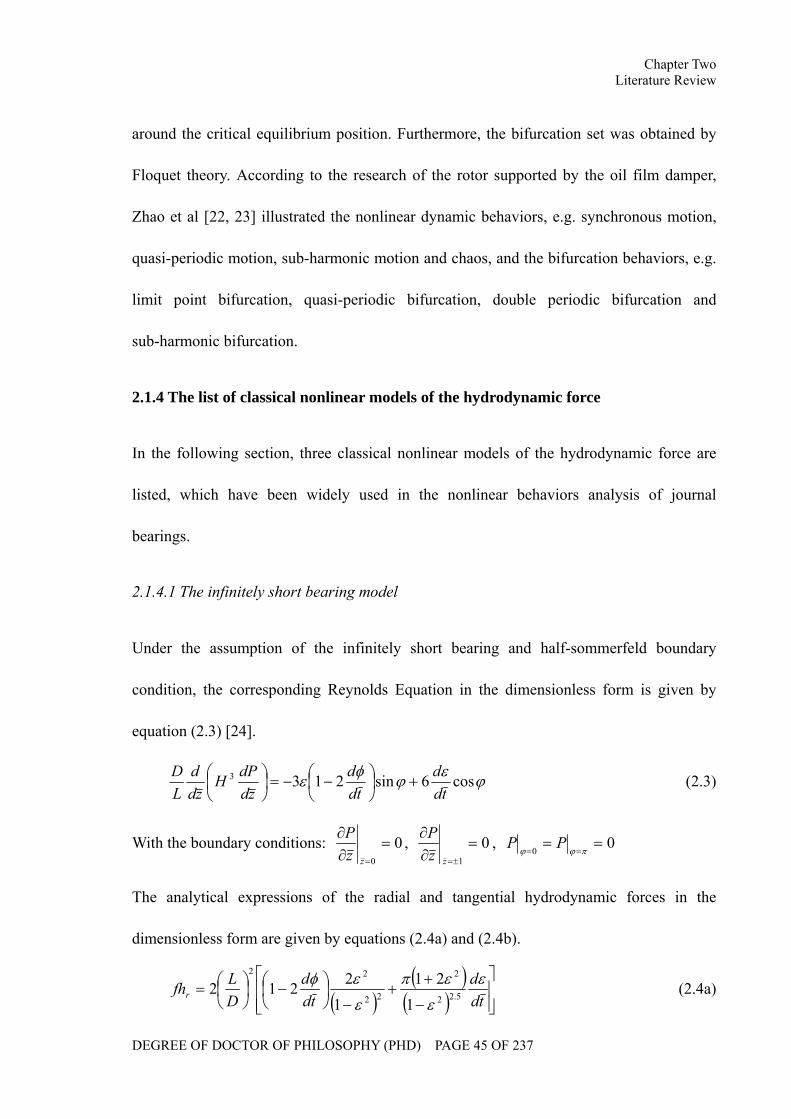
2.1.4.1 The infinitely short bearing model
Under the assumption of the infinitely short bearing and half-sommerfeld boundary
condition, the corresponding Reynolds Equation in the dimensionless form is given by
equation (2.3) [24].
ϕεϕφε cos6sin2133
tdd
tdd
zddPH
zdd
LD
+⎟⎠⎞
⎜⎝⎛ −−=⎟
⎠⎞
⎜⎝⎛ (2.3)
With the boundary conditions: 00
=∂∂
=zzP , 0
1
=∂∂
±=zzP , 0
0==
== πϕϕPP
The analytical expressions of the radial and tangential hydrodynamic forces in the
dimensionless form are given by equations (2.4a) and (2.4b).
( )( )( ) ⎥
⎥⎦
⎤
⎢⎢⎣
⎡
−
++
−⎟⎠⎞
⎜⎝⎛ −⎟
⎠⎞
⎜⎝⎛=
tdd
tdd
DLfhr
ε
ε
επ
ε
εφ5.22
2
22
22
121
12212 (2.4a)
Chapter Two Literature Review
DEGREE OF DOCTOR OF PHILOSOPHY (PHD) PAGE 46 OF 237
( ) ( ) ⎥⎥⎦
⎤
⎢⎢⎣
⎡
−+
−⎟⎠⎞
⎜⎝⎛ −⎟
⎠⎞
⎜⎝⎛−=
tdd
tdd
DLfht
ε
ε
ε
ε
πεφ225.12
2
14
12212 (2.4b)
2.1.4.2 The Capone hydrodynamic force model
In 1991, Capone [25] developed a nonlinear model of hydrodynamic force under the
assumption of the infinitely short bearing. The calculation results show a good accuracy
and convergence.
The dimensionless form of Reynolds Equation under the assumption of the infinitely short
bearing is given in equation (2.5).
( )ϕϕϕϕ sincos2cossin32
yxyxzph
zLR
+−−=⎟⎠⎞
⎜⎝⎛
∂∂
∂∂
⎟⎠⎞
⎜⎝⎛ (2.5)
The pressure distribution in the dimensionless form is expressed by equation (2.6)
( ) ( )( )
( )14sincos1
cos2sin221 2
3
2
−⎥⎦
⎤⎢⎣
⎡
−−+−−
⎟⎠⎞
⎜⎝⎛= z
yxxyyx
DLp
ϕϕϕϕ &&
(2.6)
The hydrodynamic fluid forces are expressed as follows.
( ) ( ) ( )( )
⎭⎬⎫
⎩⎨⎧
−−−−
−−++−
⎟⎟⎠
⎞⎜⎜⎝
⎛⎟⎟⎠
⎞⎜⎜⎝
⎛−=
⎭⎬⎫
⎩⎨⎧
FGVyFGVx
yxxyyx
RLDL
CR
FhFh
y
x
αααα
ϕϕµω
sin2cos3cos2sin3
sincos122
2
2
2
2 &&
( )( )221
sincos2yx
GxyV−−−+
=αα
⎟⎟⎟
⎠
⎞
⎜⎜⎜
⎝
⎛
−−
−
−−−
−−= −
22
1
2222 1sincostan
12
1 yxxy
yxyxG ααπ
( )( )221
sincosyx
yxF−−
+=
αα
Chapter Two Literature Review
DEGREE OF DOCTOR OF PHILOSOPHY (PHD) PAGE 47 OF 237
( )xysignyxxysign
yxxy &
&
&
&
&2
22
22tan 1 +−⎟⎟
⎠
⎞⎜⎜⎝
⎛−+
−⎟⎟⎠
⎞⎜⎜⎝
⎛−+
= − ππα (2.7)
2.1.4.3 Zhang hydrodynamic force model
In this model, the adopted form of Reynolds Equation is given in equation (2.8) [26, 27].
ϕεϕεωφµϕϕµ
cossin21212
12
233
2 dtd
dtd
zphph
R+⎟
⎠⎞
⎜⎝⎛ −=
∂∂
−⎟⎟⎠
⎞⎜⎜⎝
⎛∂∂
∂∂
− (2.8)
With the boundary condition: 0=∂s
P , where s∂ denotes the boundary of the oil film.
The analytical expressions of hydrodynamic forces in radial and tangential directions are
given in (2.9).
⎥⎥⎥⎥
⎦
⎤
⎢⎢⎢⎢
⎣
⎡
⎟⎠⎞
⎜⎝⎛ −−
⎥⎦
⎤⎢⎣
⎡=⎥
⎦
⎤⎢⎣
⎡
εφ
ε
tdd
tdd
CCCC
ff
t
r
2121
2221
1211 (2.9)
( )
( ) ( )⎥⎥⎥⎥⎥⎥
⎦
⎤
⎢⎢⎢⎢⎢⎢
⎣
⎡
∆−
++
⎥⎥⎦
⎤
⎢⎢⎣
⎡⎟⎠⎞
⎜⎝⎛ −−−
⎥⎥⎦
⎤
⎢⎢⎣
⎡⎟⎠⎞
⎜⎝⎛ −−+
= 5.22
2
2
42
222
22
22
211
1221
21411
2152413
4ε
ε
εφε
εφεεε
λ
tddA
tddAA
tdd
C
( )
( ) ( )⎥⎥⎥⎥⎥⎥
⎦
⎤
⎢⎢⎢⎢⎢⎢
⎣
⎡
∆−
+
⎥⎥⎦
⎤
⎢⎢⎣
⎡⎟⎠⎞
⎜⎝⎛ −−−
⎥⎥⎦
⎤
⎢⎢⎣
⎡⎟⎠⎞
⎜⎝⎛ −−+
= 5.122
42
222
22
22
222
121
21411
21241
4ε
εφε
εφεεε
λ
tddA
tddAA
tdd
C
2
42
2
43
2
2112
2141
21
⎥⎥⎦
⎤
⎢⎢⎣
⎡⎟⎠⎞
⎜⎝⎛ −−
⎟⎠⎞
⎜⎝⎛ −
−==
εφ
εφλ
tddA
tddA
CC
RL
DL
2==λ
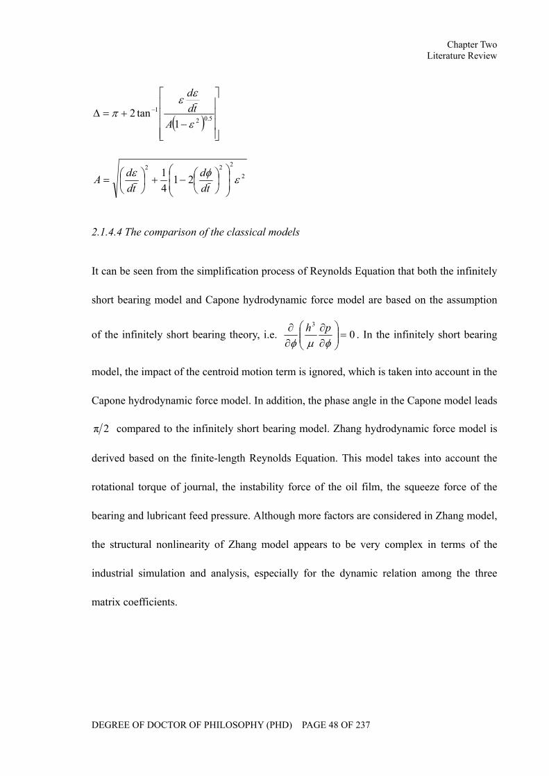
Chapter Two Literature Review
DEGREE OF DOCTOR OF PHILOSOPHY (PHD) PAGE 48 OF 237
( )⎥⎥⎥⎥
⎦
⎤
⎢⎢⎢⎢
⎣
⎡
−+=∆ −
5.02
1
1tan2
ε
εεπ
Atd
d
2
222
2141 εφε
⎟⎟⎠
⎞⎜⎜⎝
⎛⎟⎠⎞
⎜⎝⎛−+⎟
⎠⎞
⎜⎝⎛=
tdd
tddA
2.1.4.4 The comparison of the classical models
It can be seen from the simplification process of Reynolds Equation that both the infinitely
short bearing model and Capone hydrodynamic force model are based on the assumption
of the infinitely short bearing theory, i.e. 03
=⎟⎟⎠
⎞⎜⎜⎝
⎛∂∂
∂∂
φµφph . In the infinitely short bearing
model, the impact of the centroid motion term is ignored, which is taken into account in the
Capone hydrodynamic force model. In addition, the phase angle in the Capone model leads
2π compared to the infinitely short bearing model. Zhang hydrodynamic force model is
derived based on the finite-length Reynolds Equation. This model takes into account the
rotational torque of journal, the instability force of the oil film, the squeeze force of the
bearing and lubricant feed pressure. Although more factors are considered in Zhang model,
the structural nonlinearity of Zhang model appears to be very complex in terms of the
industrial simulation and analysis, especially for the dynamic relation among the three
matrix coefficients.
Chapter Two Literature Review
DEGREE OF DOCTOR OF PHILOSOPHY (PHD) PAGE 49 OF 237
2.2 Review of the Research on the Dynamic Characteristics of the Rotor
Bearing System
Rotordynamics is a specialized branch of applied mechanics concerned with the behavior
of rotating structures. Rotordynamics include factors such as dynamic response, vibration,
strength, fatigue, stability, reliability, status monitoring, fault detection and control, etc
[28~33]. The primary research objective of rotordynamics is to provide a theoretical
foundation and a technical support pertaining to the design optimization, efficiency
improvement, security guarantee and fault detection for rotors. Most of the academic
papers regarding the research of rotordynamics concentrate on three fields, such as critical
speed calculations, forced response estimation and stability analysis.
2.2.1 Critical speed calculations
The critical speed calculation of the rotor bearing system is an important issue in the
research of rotordynamics. The rule of rotating machinery design requires a separation
margin between the service speed and critical speed of the rotor. For example, in petroleum,
chemical industry and natural gas industries, the rotor bearing system design of the
centrifugal compressors and expanders adopt the standard 617 of the American Petroleum
Institute (API617) [34], which is an uncontroversial technical standard for the specification
for the axial and centrifugal compressors and expander compressors, and the rotor bearing
system design of steam turbines adopt the standard 612 of the American Petroleum
Institute (API612) [35], which is an uncontroversial technical standard for the specification
for the special purposes steam turbines. The reason for creating separation margins is not
Chapter Two Literature Review
DEGREE OF DOCTOR OF PHILOSOPHY (PHD) PAGE 50 OF 237
only to guarantee the stable operation of rotors under the fluctuation of the rotational speed,
but also to tolerate a deviation between the predicted and the actual critical speed.
Consequently the separation margin of critical speed should be corrected after the design of
the rotor bearing system. If the separation margin does not meet the requirement, it will be
necessary to optimize the structure of the system until it satisfies the standard.
Calculation of the critical speeds of the rotor bearing system uses both the transfer matrix
method and the finite element method.
(I) Transfer matrix method
N.O.Myklestad and M.A.Prohl developed the initial parameter method for multi-disc
torsional vibration into the shaft bending vibration, this extension is called the Prohl
method [36]. In this method, the state vectors of cross sections of the rotor system, e.g.
deflection, slope, bending moment and shear force, are transferred among the discreticized
nodes of the rotor system. The advantage of the Prohl method is that the matrix order does
not increase as the system degree of freedom is increased, thus it fits for a chained system
such as a rotor system.
However, the Prohl method is limited to rotors which are supported on isotropic bearings.
In 1974, J. W. Lund [37] applied complex vectors in transfer matrices, with the
consideration of system damping effects. The transfer matrix method could therefore be
applied to an anisotropic rotor bearing system by solving complex characteristic values.
In 1978, G. C. Honer [38] developed the Riccati transfer matrix method. This approach
transforms the two point boundary condition of the differential equation to a single point
boundary condition in order to improve the numerical stability of the transfer matrix
Chapter Two Literature Review
DEGREE OF DOCTOR OF PHILOSOPHY (PHD) PAGE 51 OF 237
method. In 1990, D. Kim and J. W. David [39, 40] improved the transfer matrix method
and did not substitute values in the matrix multiplication. In the calculation, the matrix
multiplication was transformed to the sum of several matrices and then the QR method,
which is an approach to calculate the eigenvalues and eigenvectors of a matrix by a QR
decomposition, writing the matrix as a product of an orthogonal matrix and an upper
triangular matrix, multiply the factors in the other, and iterate, was utilized to solve the
characteristic polynomial. This approach enables the whole eigenvalues to be calculated,
and also prevents the problem of roots leakage.
(II) Finite element method
In 1970, the finite element method was initially introduced into rotordynamics. It is a direct
variation approximation method based on the Rayleigh law [41, 42]. In the finite element
method, a rotor bearing system is discreticized into units such as the disk, the shaft
segment and bearing, etc, which are linked at nodes. Through unit analysis, the relationship
between the nodal force and the nodal displacement can be established. The motion
equation of the rotor system is formed by the combination of all units. As a result, a
continuous rotor system could be turned into a discreticized system with finite degrees of
freedom, and critical speeds could then be solved by a group of linearized algebraic
equations.
Initially, the finite element method was only able to calculate the moment of inertia of the
rotors. With the development of the numerical calculation method, the finite element model
for the rotor system has been gradually improved. So far, the model has been extended,
which include effects such as moment of inertia, gyroscopic moment, axial load, damping,
Chapter Two Literature Review
DEGREE OF DOCTOR OF PHILOSOPHY (PHD) PAGE 52 OF 237
and shear deformation, etc.
2.2.2 Forced response estimation
According to the theory of rotordynamics, at a rotational speed of 3,000 r/min, the
centrifugal force caused by 0.1 mm eccentricity is similar to the dead weight of the rotor
[43] and can cause the undesirable vibration in rotating machinery.
Forced vibration caused by an external exciting force or torque is called force response and
is a common fault of rotating machinery. In order to eliminate the effects on the rotor
system, researchers have carried out an extensive research on the performance of forced
response to the rotor bearing system.
Shiraki [44] utilized the approach of the modal response circular to draw a vector diagram
of the vibration response in polar coordinates using the rotational speed as the reference
variable. In 1988, J.Verhoeven [45] obtained the rotor imbalance response at a given speed
and then applied Gaussian elimination to acquire the transformation matrix, from the
imbalance response matrix to the imbalance mass matrix, to estimate the position of the
imbalance on the rotor. In 1999, H.Irretier [46] introduced an imbalance factor to estimate
the residual imbalance distribution on the rotor system. The imbalance factor includes the
amplitude and the phase of imbalance. He also established a transformation matrix from
the centrifugal force to an imbalance factor. Lyn M.Greenhill [47] noted that the rotor
imbalance would have excited the reverse precession mode of a rotor supported on the
bearings with an asymmetric main stiffness. After analyzing the effects of the principal
stiffness, the cross stiffness and the damping of the Jeffcott rotor on such resonance
Chapter Two Literature Review
DEGREE OF DOCTOR OF PHILOSOPHY (PHD) PAGE 53 OF 237
phenomena, he concluded that the more asymmetrical the principal stiffness is, the easier
the resonance could be excited and that large damping could obviously inhibit the
resonance. S.W.Hong [48] applied the matrix concentration method to reduce the
dimension of the system matrix to obtain an imbalance response for the whole rotor system.
This method greatly improves calculation speed especially for the rotor system motion
equation with gyroscopic torque. Jun and Kim [49] made a precise study of the free
bending vibration of a multi-step rotor using a Timoshenko beam model. The differential
equation of motion for a continuous system was used and obtained solutions by applying
boundary conditions. The shear force and bending moment distributions were obtained. A.
C. Chasalevris and C. A. Papadopoulos [50] investigated the cross-coupled bending
vibrations of a rotating shaft, with a breathing crack, mounted in resilient bearings. They
found that the coupling could affect the forced response in both time and frequency
domains and amplifies the higher harmonics in the vibration. In addition, the coupling due
to a crack is negligible in respect to the coupling that the bearings introduce. Ehrich [51]
investigated bifurcations in a high-speed rotor-bearing system and found that the rotor
response was characterized by a sub-harmonic vibration phenomenon. Parkinson [52]
provided an observation that the amplitude and phase of vibration response are severely
affected by the location of mass unbalance, thus demanding a complex balancing scheme.
Lin et al [53] have investigated the optimal weight design of rotor bearing systems. A
Timoshenko rotor model with oil-lubricated support bearings was developed and it was
found that the rotor weight can be significantly reduced with constraint conditions being
satisfied. Aleyaasin et al [54] have used the dynamic stiffness matrix method to perform
Chapter Two Literature Review
DEGREE OF DOCTOR OF PHILOSOPHY (PHD) PAGE 54 OF 237
the lateral vibration analysis of the rotor-bearing system. It was concluded that for the
computation of the eigenvalues and mode shapes of the rotor-bearing system, the transfer
matrix method should be chosen and for the frequency response computation, the dynamic
stiffness matrix method will give results with great accuracy. Firoozian and Zhu [55] have
used the transfer matrix method to study the lateral vibration of the rotor-bearing system.
In their research, the transfer matrix method was modified by a combination of the transfer
matrix method and the finite element method.
2.2.3 The stability analysis
Since the 1960s, it has been found that the conventional theory of the fluid lubrication has
been insufficient to predict some faults in high speed rotating machines. In these instances,
the shaft shows a great flexibility and the whirling motion becomes obvious. The relative
eccentricity of the journal centerline might exceed 0.7~0.9, which is caused by the
nonlinear oil film instabilities of the rotor bearing system. Numerous academic papers have
been published in the research of the stability analysis of journal bearings.
A.C.Hagg [56], B.Sternlicht [57], J.W.Lund [58, 59] and J.Glieniake [60] proposed a
theory to describe dynamic characteristics of the journal bearing by using linearized
coefficients such as stiffness and damping coefficients. In this theory, the hydrodynamic
force is expressed by a function of the displacement and velocity around the equilibrium
position. Reynolds Equation is solved to obtain the oil film pressure, which is then used to
calculate the hydrodynamic fluid force. However, the condition of the weak perturbation is
sometimes not satisfied, thus the linearized results might be insufficient to describe the oil
Chapter Two Literature Review
DEGREE OF DOCTOR OF PHILOSOPHY (PHD) PAGE 55 OF 237
film motion. In order to reveal the mechanism of oil film instability, researchers have
studied in depth the principle of the journal motion based on the research of the nonlinear
rotor system differential motion equation [61~65]. The following three models are popular
in nonlinear rotor bearing system research.
(I) A Jeffcott rotor supported on the rigid journal bearings
A Jeffcott rotor supported on rigid journal bearing is the most popular model in nonlinear
rotor bearing system analysis because of its simplicity, although there is an obvious
deviation in practical system analysis [66~68].
(II) A Jeffcott rotor supported on the elastic journal bearings
A Jeffcott rotor supported on elastic journal bearing is a multi-field coupling model in
nonlinear rotor system dynamics analysis in which fluid and solid fields are involved [69,
70]. Goldman and Muszynska [71] studied the chaotic behavior of rotor/stator systems
with rub-impacts. The analytical and numerical simulations show that the regular periodic
vibration of the order of the synchronous, the subsynchronous and the chaos vibration are
all accompanied by higher harmonics. Chu and Zhang [72] investigated the nonlinear
vibration characteristics of a rub-impact Jeffcott rotor. They found that when the rotating
speed is increased, the grazing bifurcation, the quasi-periodic motion and chaotic motion
occur after the rub-impact. Chang-Jian and Chen [73~76] presented a series of papers on
the nonlinear dynamics of rotor-bearing systems under nonlinear suspension and combined
these with rub-impact effect, turbulent effect and micropolar lubricant. They found that
many non-periodic responses occurred in the rotor-bearing systems. Fu et al [77]
investigated the chaotic motions of a rotor system with a transverse crack by theoretical
Chapter Two Literature Review
DEGREE OF DOCTOR OF PHILOSOPHY (PHD) PAGE 56 OF 237
and numerical approaches.
(III) A multi-span rotor supported on the elastic journal bearings
The coupling effects in this model between the rotor and the bearing are very complicated
[78, 79], it is therefore difficult to analyse, especially for the coupling of the bending and
torsional vibration as well as the coupling of the dynamic and static load distribution.
Research on the elastic journal bearing still has a long way to go because the conventional
dynamic theory is insufficient to depict the dynamic performance of a multi-dimensional
nonlinear rotor bearing system.
2.2.4 Approaches to the analysis of the dynamic performance and stability of the rotor
bearing system
Due to complex working conditions such as constraint, disturbance and load in the
nonlinear rotor bearing system, there is, as yet, no unified approach. Different analysis
methods are suitable for different conditions of the constraint and excitation. The common
approaches are:
Research on a weak nonlinear dynamic system, for example: the perturbation method,
the Krylov-Bogoliubov method, the Krylov-Bogoliubov-Mitropolskii method, the
multiple scale method, etc.
Research on the asymptotic solution of single degree of freedom nonlinear dynamics
system, for example: the generalized average method, the area average method, the
Jacobi elliptic function method, the time transformation method, the parameter
expansion method, the stroboscopic method, the incremental harmonic balance method,
Chapter Two Literature Review
DEGREE OF DOCTOR OF PHILOSOPHY (PHD) PAGE 57 OF 237
etc.
Research on the system with multi-degrees of freedom, for example: the improved
average method, the multiple frequency perturbation approach, etc.
Research on the response, bifurcation and chaos of nonlinear dynamic systems, for
example: the average method, the multiple scale method, the generalized harmonic
balance method, the least squares method, the singularity theory, the center manifold
theory, the power series method, the Poincaré map, etc.
2.3 Review of the Research on Turbocharger Rotordynamics
The turbocharger rotor system is a special kind of rotor bearing system because of the
following aspects. Firstly, the working speed range of an automotive turbocharger covers
multiple orders of critical speeds. Therefore, rigid rotors are unsuitable for analyzing
turbocharger rotor systems. Secondly, a turbocharger rotor is supported on the floating ring
bearings which comprise of two fluid films in series. The inner and outer films affect each
other which make the stability characteristics more complicated to study compared to a
rotor supported on journal bearings with a single fluid film. Thirdly, turbocharger
rotordynamics is a multi-field coupling topic which involves thermodynamics, fluid
mechanics, rotordynamics, etc. For example, the stability of a rotor system might be
affected by the high temperature from the exhaust gas and local temperature increases due
to the mechanical power dissipated in the bearing. In addition, the exhaust pulse might also
affect the bending and torsional vibration of the rotor system. To date, a significant amount
of research on turbocharger rotor systems has been carried out.
Chapter Two Literature Review
DEGREE OF DOCTOR OF PHILOSOPHY (PHD) PAGE 58 OF 237
Tatara [80] stated that as soon as whirl appears in the inner film, the ring begins to spin and
the bearing could stabilize the rotor system. Tanaka and Hori [81] developed a dynamics
model for a flexible rotor supported on floating ring bearings based on the infinitely short
bearing theory. They then estimated the stable speed under different bearing parameters.
By comparison of predicted and experimental results acquired by Hill [82], Dworski [83]
and Tondl [84], it was demonstrated that the frequency of the oil film whirl was
approximately one half of the sum of the shaft speed and the ring speed under medium
pressure. Rohde and Ezzat [85] reported that floating ring bearings have the potential to
reduce power loss of the automotive engine. Tatara [80] and Tanaka [87] carried out linear
stability analysis of the floating ring rotor bearing system. It was found that unstable speed
shows sensitivity to the outer bearing clearance and the thinner of the outer bearings
clearance is, the wider speed range covered. Trippett and Dennis [86] concluded that oil
film whirl and whip is caused by shear effects between the inner and outer fluid films and
will eventually reach a stable limit cycle. Howard [88, 89] discussed the possibility of
replacing oil film bearings with air bearings in a diesel truck turbocharger. Walton et al [90]
developed a miniature test rig of a rotor system to simulate a turbocharger rotor system in
the aero-engine which is supported on air bearings. The predicted results show good
agreement with the experimental results in natural frequency, rotor displacement and the
load capability of the trust bearing. Aretakis et al [91] discussed the possibility of detecting
the instabilities in the turbocharger rotor system by vibration and noise signals of the
compressor impeller. By signal features extraction, a bi-parametric criterion was
established for determination of whether the compressor of the turbocharger operates in the
Chapter Two Literature Review
DEGREE OF DOCTOR OF PHILOSOPHY (PHD) PAGE 59 OF 237
stable stage. Chen et al [92] developed a model for a turbocharger turbine under pulsating
inlet conditions. The one-dimensional unsteady flow method was applied to study the
behavior of the turbine under the steady and the unsteady flow conditions. This model
showed an improved prediction at off-design condition. Kreuz-Ihli et al [93] utilized a
commercial Navier-stokes solver to study the vibration of radial inflow turbines under the
unsteady flow and then validated the model by experimental data collected from a
Laser-Doppler velocimeter. Peat et al [94] presented a model for the passive acoustic
behavior of a turbine impeller of an automotive turbocharger. Based on the knowledge of
the rotor vibration, the effects of the primary noises, such as the gas pulsation and the
exhaust tailpipe orifice, on the behavior of the turbine was studied. Payri [95, 96]
published a series of papers focusing on the investigation of the transient performance of
turbocharged diesel engines and developed an action model for calculating the transient
operation.
2.4 Review of the Research of the Nonlinearity of the Vibration System
The objective of the research on the nonlinearity of the vibration system is to reveal the
discipline of the system motion under various parameters and initial conditions based on
the mathematical model of the nonlinear vibration system. The stability and bifurcation
analysis play key roles in the theoretical research of the system nonlinearity.
The stability analysis addresses the stability of trajectories of dynamical systems under
small perturbations of initial conditions [97]. It studies the relationship among the
topological properties of the trajectories of a cluster of similar systems. The bifurcation
Chapter Two Literature Review
DEGREE OF DOCTOR OF PHILOSOPHY (PHD) PAGE 60 OF 237
analysis reveals the interrelation and transformation of the system states. The system
parameters in the mathematical models of practical systems, such as differential equations,
difference equations, integral equations and etc, might be affected by the working
conditions. It is required to understand the impacts of the change of system parameters on
the system performance. Bifurcation analysis has a greatly theoretical significance and
practical value in the research of the nonlinear vibration system.
The approaches of the bifurcation analysis include the theoretical approach and numerical
approach. Due to the limitation of the theoretical approach, the most popular way to study
the bifurcation and stability of the nonlinear vibration system is the numerical approach. C.
Padmanabhan and R. Singh [98] utilized the algorithm of the parameter extension to
investigate the dynamic characteristics of a nonlinear, non-autonomous system. They found
the subsynchronous motion, chaotic motion and the parameter range of the jumping
phenomenon occurred. For the bifurcation analysis of a non-conservative, nonlinear system
with large degrees of freedom, P. Sundamrarajan and S. T. Noah [99] adopted the modal
synthesis method to separate the linear and nonlinear vectors. The shooting method was
used to solve the system periodic solution and then the system stability and bifurcation is
justified by the Floquet theory. L. Cherfils [100] developed an efficient algorithm of
parameter extension for a large-scale nonlinear system, in which an adapted meshing
approach and parallel calculation were introduced to improve the calculation efficiency.
Blair et al [101] stated a novel algorithm combining the harmonic balance method and the
continuation method, by which a series of periodic solution of the modified
Holmes-Duffing Equation was derived. This approach can also be introduced into the
Chapter Two Literature Review
DEGREE OF DOCTOR OF PHILOSOPHY (PHD) PAGE 61 OF 237
solution of strongly nonlinear systems. The key step of this approach is the
Newton-Raphson iteration that requires the derivation of the Jacobi matrix. Hu [102]
presented a curve fitting method to simulate the system periodic motion by the transient
response without the calculation of the Jacobi matrix. Chen and Zheng [103, 104] defined
the stability of the periodic solution of a nonlinear, non-autonomous system and then
developed a numerical calculation approach to the stability of the periodic solution of the
transient response. Lust, Roose et al [105] developed the Newton-Picard algorithm, in
which the feature space of the single valued matrix of the periodic motion is separated into
a stable subspace and an unstable subspace. In the stable subspace, Picard iteration is
carried out and in the unstable subspace, Newton iteration is conducted. Obviously this
algorithm is more efficient compared to the Newton-Raphson algorithm and the
continuation-shooting algorithm. Van Noorden et al [106] introduced the Newton-Picard
algorithm in the calculation of the cyclic chemical reaction. The high efficiency of this
algorithm was demonstrated by the comparison with the directly numerical integration
method, the Newton-Raphson algorithm and the Broyden quasi-Newtion algorithm.
Tiesinga et al [107] investigated the bifurcation of the incompressible fluid from the stable
state to the quasi-periodic state within the range of the Reynolds number between 7500 and
10000. The influences of the Reynolds number of the fluid on the Hopf bifurcation were
concluded.
2.5 Review of the Research of the Modal Synthesis Method
With the research of the stability in depth, the system with less degree of freedom is
Chapter Two Literature Review
DEGREE OF DOCTOR OF PHILOSOPHY (PHD) PAGE 62 OF 237
insufficient to model the practical system. It is, therefore, necessary to carry out the
research on the high dimensional system. As far as a high dimensional system is concerned,
it is generally required to conduct the dimensionality reduction. The modal synthesis
method is an efficient approach that has been widely applied in the study of the high
dimensional system.
In 1960, Hurty [108] initially presented the fixed-interface modal synthesis method and in
1964, Gladwell [109] clearly clarified the idea of decomposition for a system. Since then, a
variety of modal synthesis methods have been developed, most of which are based on the
orthogonal modes of the subsystems. According to the boundary conditions of the
subsystems, the modal synthesis method can be classified into the fixed-interface modal
synthesis method, the free-interface modal synthesis method, the mixed-interface synthesis
method and the loaded-interface modal synthesis method.
Tran [110, 111], Meirovitch [112], Craig [113~115] et al carried out respectively the review
of study on the modal synthesis method. Kuhar and Stahle [116] stated that the free and
fixed interface modal synthesis methods are equivalent to the dynamic coordinate
transformation method with stiffness and inertial connection respectively. Kubomura
[117-119] derived the formula of the free and fixed interface modal synthesis methods
using the data of the 1st and 2nd order modes. Curnier [120] obtained the formula of the free,
the fixed and the loaded interface modal synthesis methods and proved the accuracy under
no modal truncation. Eagels [121] developed an approach to improve the precision of the
modal vectors in the presence of the attachment modes of the subsystem. By the eigen
analysis of heterogeneous and homogeneous finite element models of a high speed civil
Chapter Two Literature Review
DEGREE OF DOCTOR OF PHILOSOPHY (PHD) PAGE 63 OF 237
transport, Farhatt and Geradin [122] proved that the fixed-interface modal synthesis
method can be derived by the impedance equation. Thonon et al [123] utilized the modal
expansion to establish the admittance equation of the free-interface modal synthesis
method. Ohayon et al [124] extended the free and the fixed interface modal synthesis
methods into the damping system and then developed an approach of the subsystems
coupling by the singular value decomposition of the constraint matrix.
In the modal synthesis methods, subsystems are generally coupled by displacements of the
points in the interface. In order to reduce the interface coordinates and the dimension of the
coupled system, Bourquin [125, 126] developed the Poincaré-Steklov approach that is
suitable for the fixed-interface modal synthesis method. Other common approaches include
the GUYAN method, the SEREP method, the IRS method, etc [127].
2.6 Review of the Numerical Integration Approaches
The numerical calculation approach has developed rapidly since the 1950s. With the
popularization of computers, many direct numerical integration methods have been
developed, such as the Euler method, the Runge-Kutta method, the Adams linear multistep
method, etc [128, 129]. With the aid of computers and related mathematical software,
numerical approaches have been used to solve many ordinary differential equations of
initial value cases in research and in practical applications.
Problems associated with the dynamics of mechanical systems can be expressed as the
second order ordinary differential equations. The primary approaches for the solution of
differential equations include direct numerical integration methods and the state space
Chapter Two Literature Review
DEGREE OF DOCTOR OF PHILOSOPHY (PHD) PAGE 64 OF 237
method [130]. Direct integration methods include: the central difference method, the
Houbolt method, the Wilson method, the Newmark method, etc. The state space method
transforms the original equations into a group of the first order differential equations and
then the reduced differential equations can be solved by the Taylor expansion method, the
Runge-kutta method, the Adams multistep method or the shooting method [131, 132].
2.7 Summary
In this chapter, a comprehensive literature review with regard to the current research is
carried out. Publications associated with the research on the fluid lubrication are initially
reviewed. Both linear and nonlinear hydrodynamic force models are compared and studied,
which provide a foundation of the investigation of the lubrication of the floating ring
bearing. Literature associated with the research of rotordynamics and turbocharger
rotordynamics are reviewed. The nonlinearity of the vibration system is introduced because
the nonlinear behaviors of the rotor system are involved in the research. Modal synthesis
method and numerical integration approach, as the popular methods in the analysis of rotor
system behaviors, are also introduced.
Chapter Three Analytical Investigation of the Lubrication
of Floating Ring Bearings
DEGREE OF DOCTOR OF PHILOSOPHY (PHD) PAGE 65 OF 237
CHAPTER THREE
ANALYTICAL INVESTIGATION OF THE
LUBRCIATION OF FLOATING RING BEARINGS
A turbocharger adopts floating ring bearings to support its rotor system. Floating ring
bearings significantly affect the dynamic performance of turbochargers. In this chapter, the
lubrication of floating ring bearings has been investigated analytically. Based on the
simulation results, the influences of working conditions on the oil film pressure and the oil
flow rate have been studied.
Chapter Three Analytical Investigation of the Lubrication
of Floating Ring Bearings
DEGREE OF DOCTOR OF PHILOSOPHY (PHD) PAGE 66 OF 237
3.1 Introduction to the Lubrication of Floating Ring Bearings
Compared to a conventional journal bearing with single film, the lubrication procedure for
a floating ring bearing is more complex. Lubricant is fed into the outer oil film from a
fixed supply hole on the bearing shell, while the inner clearance is lubricated through a
number of holes evenly distributed on the ring. Lubrication can be affected by working
circumstances, such as the oil inlet pressure, external loads, the service speed, etc. An
unreasonable design or operation can cause serious faults in the bearing or even the whole
system. It is, therefore, worthwhile to investigate the floating ring bearing lubrication and
to understand the effects of such working conditions on the lubrication procedure.
In this chapter, the infinitely long bearing theory is adopted to solve the steady state
Reynolds Equation. Both oil inlet pressure and the starting and ending positions of the
cavitation area are considered as the boundary conditions in order to obtain the analytical
expressions of the pressure distribution of the outer and inner oil films in the floating ring
bearing. The inner oil film lubrication model is developed according to the relationship
between the oil flow rate and the pressure difference of a tube. Following model
development, the effects of external loads and inlet pressure on the equilibrium positions of
the journal and ring have been studied based on simulation results. The disciplines of inner
oil film lubrication have been analyzed and the impacts of external loads and inlet pressure
on the oil flow rate into the inner oil film have also been investigated.
Chapter Three Analytical Investigation of the Lubrication
of Floating Ring Bearings
DEGREE OF DOCTOR OF PHILOSOPHY (PHD) PAGE 67 OF 237
Nomenclature
oP Pressure distribution in outer film
(Pa)
iP Pressure distribution in inner film
(Pa)
oθ Circumferential coordinate
starting from the line across the
centers of the ring and bearing
shell (Degree)
JΩ Rotational speed of the journal
(rad/s)
RΩ Rotational speed of the ring
(rad/s)
η Lubricant viscosity (Pa s)
iθ Circumferential coordinate
starting from the line across the
centers of the journal and ring
(Degree)
JR Radius of the journal (m)
RoR Outer radius of the ring (m)
ostart _θ Starting position of outer film
(Degree)
RiR Inner radius of the ring (m)
oC Outer clearance (m)
istart _θ Starting position of inner oil
film (Degree)
iC Inner clearance (m)
oh Outer oil film thickness (m)
oend _θ End position of outer oil film
(Degree)
ih Inner oil film thickness (m)
oε Outer eccentricity ratio
iend _θ End position of inner oil film
(Degree)
iε Inner eccentricity ratio
L Length of the bearing (m)
Ψ Coordinate starting from Y axis
(Degree)
Chapter Three Analytical Investigation of the Lubrication
of Floating Ring Bearings
DEGREE OF DOCTOR OF PHILOSOPHY (PHD) PAGE 68 OF 237
oXF _ Outer fluid force in X direction
(N)
of _ε Radial component of outer
fluid force (N)
iXF _ Inner fluid force in X direction
(N)
if _ε Radial component of inner
fluid force (N)
oYF _ Outer fluid force in Y direction
(N)
of _φ Tangential component of outer
fluid force (N)
iYF _ Inner fluid force in Y direction
(N)
if _φ Tangential component of inner
fluid force (N)
ρ Density ( 3kg/m ) diffP _ Pressure difference (Pa)
S Friction coefficient g Gravitation constant ( 2m/s )
T Length of the tube (m) Rm Mass of the ring (kg)
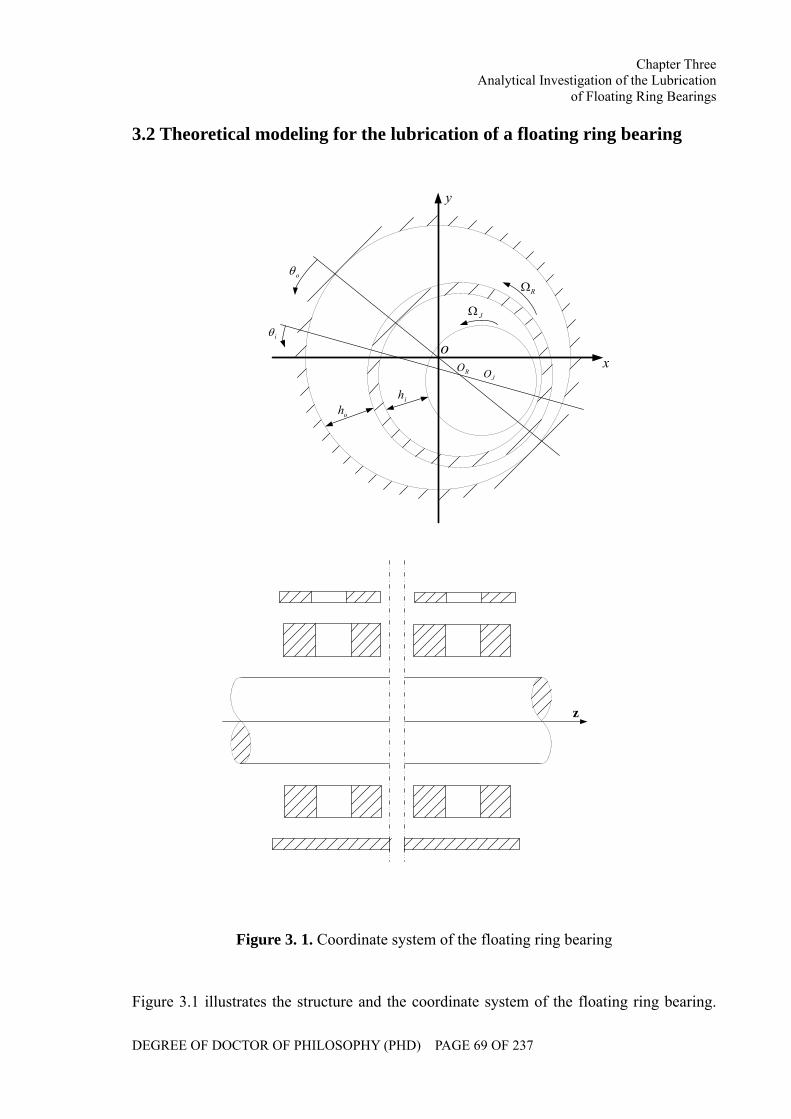
Chapter Three Analytical Investigation of the Lubrication
of Floating Ring Bearings
DEGREE OF DOCTOR OF PHILOSOPHY (PHD) PAGE 69 OF 237
3.2 Theoretical modeling for the lubrication of a floating ring bearing
ihoh
ox
y
RΩ
JΩ
oθ
iθ
JORO
z
Figure 3. 1. Coordinate system of the floating ring bearing
Figure 3.1 illustrates the structure and the coordinate system of the floating ring bearing.
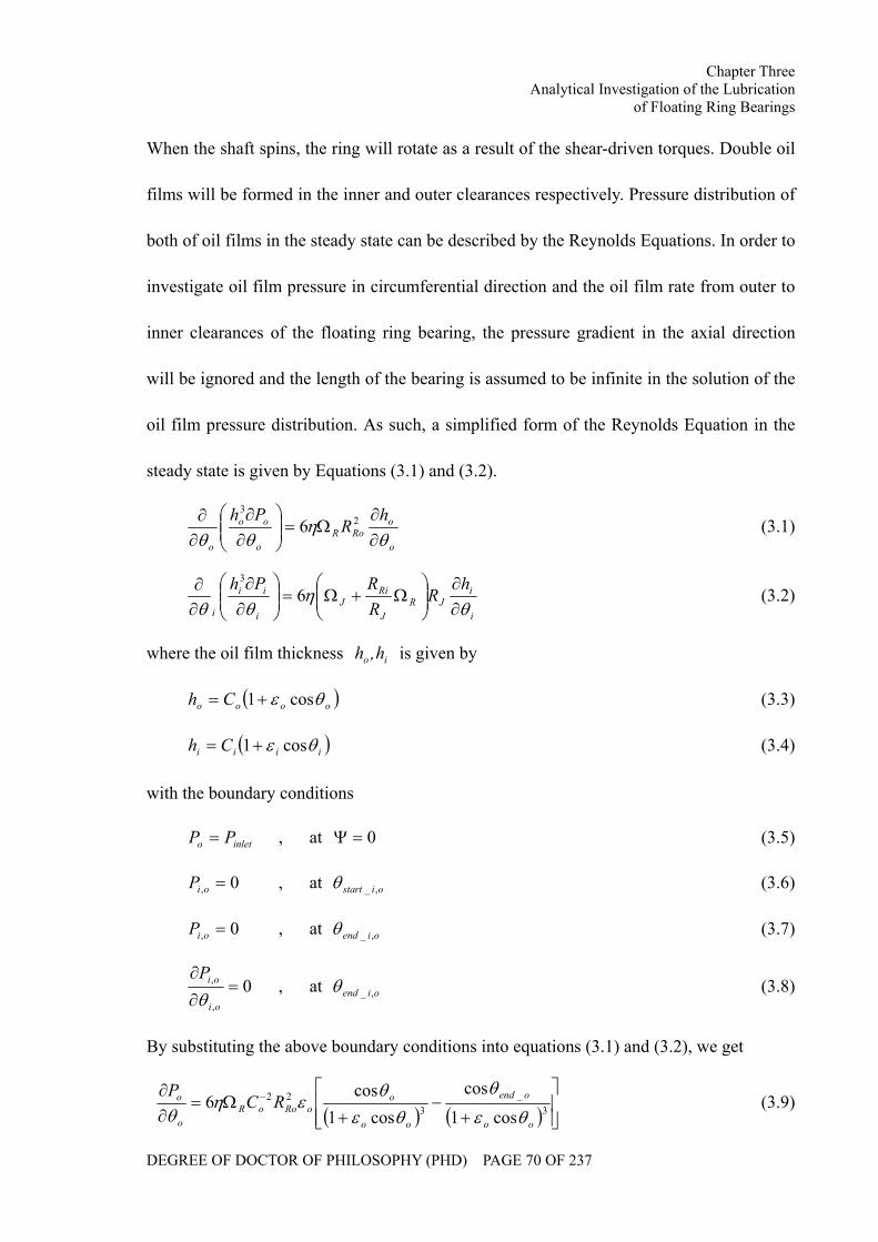
Chapter Three Analytical Investigation of the Lubrication
of Floating Ring Bearings
DEGREE OF DOCTOR OF PHILOSOPHY (PHD) PAGE 70 OF 237
When the shaft spins, the ring will rotate as a result of the shear-driven torques. Double oil
films will be formed in the inner and outer clearances respectively. Pressure distribution of
both of oil films in the steady state can be described by the Reynolds Equations. In order to
investigate oil film pressure in circumferential direction and the oil film rate from outer to
inner clearances of the floating ring bearing, the pressure gradient in the axial direction
will be ignored and the length of the bearing is assumed to be infinite in the solution of the
oil film pressure distribution. As such, a simplified form of the Reynolds Equation in the
steady state is given by Equations (3.1) and (3.2).
o
oRoR
o
oo
o
hR
Phθ
ηθθ ∂
∂Ω=⎟⎟
⎠
⎞⎜⎜⎝
⎛∂∂
∂∂ 2
3
6 (3.1)
i
iJR
J
RiJ
i
ii
i
hR
RRPh
θη
θθ ∂∂
⎟⎟⎠
⎞⎜⎜⎝
⎛Ω+Ω=⎟⎟
⎠
⎞⎜⎜⎝
⎛∂∂
∂∂ 6
3
(3.2)
where the oil film thickness io h,h is given by
( )oooo Ch θε cos1+= (3.3)
( )iiii Ch θε cos1+= (3.4)
with the boundary conditions
inleto PP = , at 0=Ψ (3.5)
0, =oiP , at oistart ,_θ (3.6)
0, =oiP , at oiend ,_θ (3.7)
0,
, =∂
∂
oi
oiPθ
, at oiend ,_θ (3.8)
By substituting the above boundary conditions into equations (3.1) and (3.2), we get
( ) ( ) ⎥⎥⎦
⎤
⎢⎢⎣
⎡
+−
+Ω=
∂∂ −
3_
322
cos1
cos
cos1cos
6oo
oend
oo
ooRooR
o
o RCP
θε
θ
θεθ
εηθ
(3.9)
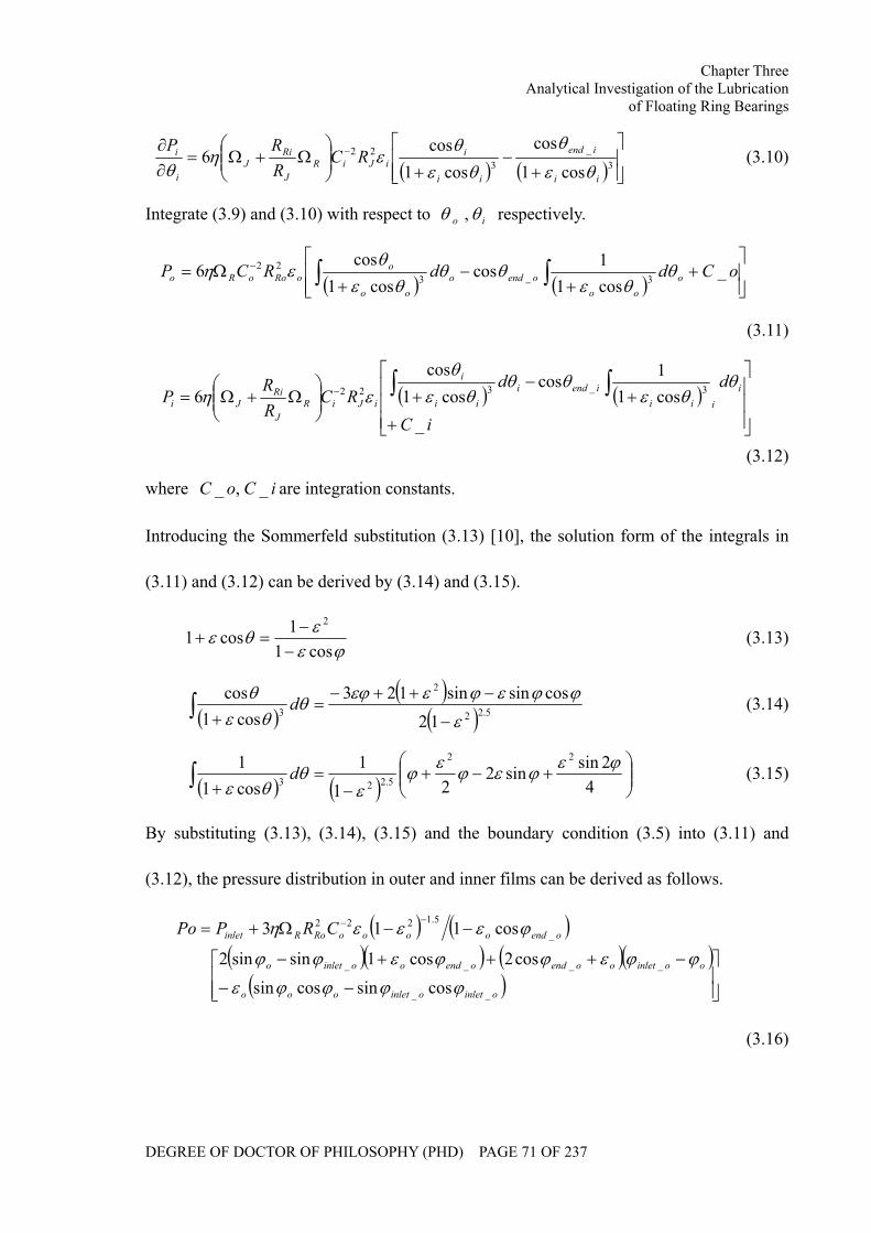
Chapter Three Analytical Investigation of the Lubrication
of Floating Ring Bearings
DEGREE OF DOCTOR OF PHILOSOPHY (PHD) PAGE 71 OF 237
( ) ( ) ⎥⎥⎦
⎤
⎢⎢⎣
⎡
+−
+⎟⎟⎠
⎞⎜⎜⎝
⎛Ω+Ω=
∂∂ −
3_
322
cos1
cos
cos1cos
6ii
iend
ii
iiJiR
J
RiJ
i
i RCRRP
θε
θ
θεθ
εηθ
(3.10)
Integrate (3.9) and (3.10) with respect to io θθ , respectively.
( ) ( ) ⎥⎥⎦
⎤
⎢⎢⎣
⎡+
+−
+Ω= ∫ ∫− oCddRCP o
oooendo
oo
ooRooRo _
cos11cos
cos1cos
6 3_322 θ
θεθθ
θεθ
εη
(3.11)
( ) ( )⎥⎥⎥
⎦
⎤
⎢⎢⎢
⎣
⎡
+
+−
+⎟⎟⎠
⎞⎜⎜⎝
⎛Ω+Ω= ∫ ∫−
iC
ddRC
RR
P iiii
iendiii
i
iJiRJ
RiJi
_cos11cos
cos1cos
6 3_322θ
θεθθ
θεθ
εη
(3.12)
where iCoC _,_ are integration constants.
Introducing the Sommerfeld substitution (3.13) [10], the solution form of the integrals in
(3.11) and (3.12) can be derived by (3.14) and (3.15).
ϕεεθεcos1
1cos12
−−
=+ (3.13)
( )( )
( )∫−
−++−=
+ 5.22
2
3 12cossinsin123
cos1cos
ε
ϕϕεϕεεϕθθε
θ d (3.14)
( ) ( )∫ ⎟⎟⎠
⎞⎜⎜⎝
⎛+−+
−=
+ 42sinsin2
211
cos11 22
5.223
ϕεϕεϕεϕε
θθε
d (3.15)
By substituting (3.13), (3.14), (3.15) and the boundary condition (3.5) into (3.11) and
(3.12), the pressure distribution in outer and inner films can be derived as follows.
( ) ( )( )( ) ( )( )
( ) ⎥⎥⎦
⎤
⎢⎢⎣
⎡
−−
−+++−
−−Ω+=−−
oinletoinletooo
ooinletooendoendooinleto
oendooooRoRinlet CRPPo
__
____
_5.1222
cossincossincos2cos1sinsin2
cos113
ϕϕϕϕε
ϕϕεϕϕεϕϕ
ϕεεεη
(3.16)
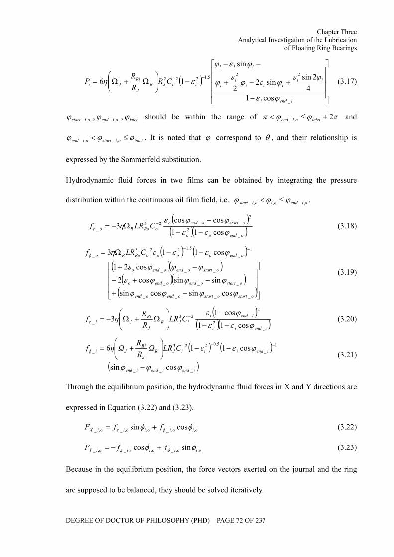
Chapter Three Analytical Investigation of the Lubrication
of Floating Ring Bearings
DEGREE OF DOCTOR OF PHILOSOPHY (PHD) PAGE 72 OF 237
( )⎥⎥⎥⎥
⎦
⎤
⎢⎢⎢⎢
⎣
⎡
−
+−+
−−
−⎟⎟⎠
⎞⎜⎜⎝
⎛Ω+Ω=
−−
iendi
iiiii
ii
iii
iiJRJ
RiJi CR
RR
P
_
225.1222
cos14
2sinsin2
2
sin
16
ϕε
ϕεϕεϕ
εϕ
ϕεϕ
εη (3.17)
inletoiendoistart ϕϕϕ ,, ,_,_ should be within the range of πϕϕπ 2,_ +≤< inletoiend and
inletoistartoiend ϕϕϕ ≤< ,_,_ . It is noted that ϕ correspond to θ , and their relationship is
expressed by the Sommerfeld substitution.
Hydrodynamic fluid forces in two films can be obtained by integrating the pressure
distribution within the continuous oil film field, i.e. oiendoioistart ,_,,_ ϕϕϕ ≤< .
( )( )( )oendoo
ostartoendooRoRo CLRf
_2
2__23
_ cos11coscos
3ϕεεϕϕε
ηε −−
−Ω−= − (3.18)
( ) ( )( )( )
( )( )( )⎥
⎥⎥
⎦
⎤
⎢⎢⎢
⎣
⎡
−+
−+−
−+
−−Ω= −−−
ostartostartoendoend
ostartoendoendo
ostartoendoendo
oendooooRoRo CLRf
____
___
___
1_
5.1223_
cossincossin
sinsincos2
cos21
cos113
ϕϕϕϕ
ϕϕϕε
ϕϕϕε
ϕεεεηφ
(3.19)
( )( )( )iendii
iendiiJR
J
RiJi CLR
RR
f_
2
2_23
_ cos11cos1
3ϕεε
ϕεηε −−
−⎟⎟⎠
⎞⎜⎜⎝
⎛Ω+Ω−= − (3.20)
( ) ( )( )iendiendiend
iendiiiJRJ
RiJi εCLRΩ
RR
Ωηf
___
1_
5.0223_
cossin
cos116
ϕϕϕ
ϕεφ
−
−−⎟⎟⎠
⎞⎜⎜⎝
⎛+= −−−
(3.21)
Through the equilibrium position, the hydrodynamic fluid forces in X and Y directions are
expressed in Equation (3.22) and (3.23).
oioioioioiX ffF ,,_,,_,_ cossin φφ φε += (3.22)
oioioioioiY ffF ,,_,,_,_ sincos φφ φε +−= (3.23)
Because in the equilibrium position, the force vectors exerted on the journal and the ring
are supposed to be balanced, they should be solved iteratively.
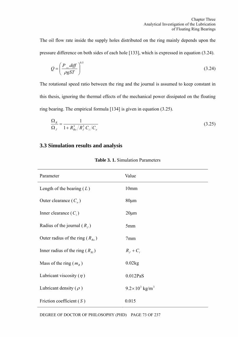
Chapter Three Analytical Investigation of the Lubrication
of Floating Ring Bearings
DEGREE OF DOCTOR OF PHILOSOPHY (PHD) PAGE 73 OF 237
The oil flow rate inside the supply holes distributed on the ring mainly depends upon the
pressure difference on both sides of each hole [133], which is expressed in equation (3.24).
5.0_
⎟⎟⎠
⎞⎜⎜⎝
⎛=
gSTdiffPQ
ρ (3.24)
The rotational speed ratio between the ring and the journal is assumed to keep constant in
this thesis, ignoring the thermal effects of the mechanical power dissipated on the floating
ring bearing. The empirical formula [134] is given in equation (3.25).
oiJRoJ
R
CCRR 3311
+=
ΩΩ (3.25)
3.3 Simulation results and analysis
Table 3. 1. Simulation Parameters
Parameter Value
Length of the bearing ( L ) mm10
Outer clearance ( oC ) µm80
Inner clearance ( iC ) µm20
Radius of the journal ( JR ) mm5
Outer radius of the ring ( RoR ) mm7
Inner radius of the ring ( RiR ) iJ CR +
Mass of the ring ( Rm ) kg02.0
Lubricant viscosity (η ) PaS012.0
Lubricant density ( ρ ) 3102.9 × 3kg/m
Friction coefficient ( S ) 0.015
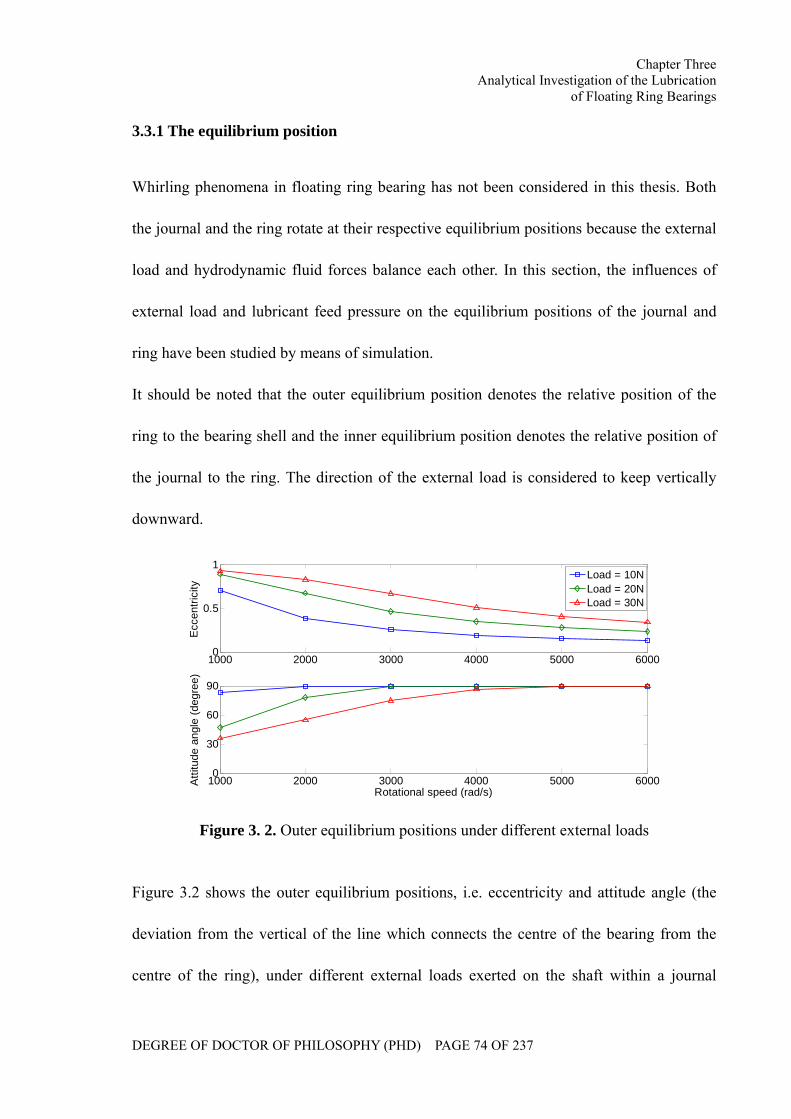
Chapter Three Analytical Investigation of the Lubrication
of Floating Ring Bearings
DEGREE OF DOCTOR OF PHILOSOPHY (PHD) PAGE 74 OF 237
3.3.1 The equilibrium position
Whirling phenomena in floating ring bearing has not been considered in this thesis. Both
the journal and the ring rotate at their respective equilibrium positions because the external
load and hydrodynamic fluid forces balance each other. In this section, the influences of
external load and lubricant feed pressure on the equilibrium positions of the journal and
ring have been studied by means of simulation.
It should be noted that the outer equilibrium position denotes the relative position of the
ring to the bearing shell and the inner equilibrium position denotes the relative position of
the journal to the ring. The direction of the external load is considered to keep vertically
downward.
1000 2000 3000 4000 5000 60000
0.5
1
Ecc
entri
city
1000 2000 3000 4000 5000 60000
30
60
90
Rotational speed (rad/s)
Atti
tude
ang
le (d
egre
e)
Load = 10NLoad = 20NLoad = 30N
Figure 3. 2. Outer equilibrium positions under different external loads
Figure 3.2 shows the outer equilibrium positions, i.e. eccentricity and attitude angle (the
deviation from the vertical of the line which connects the centre of the bearing from the
centre of the ring), under different external loads exerted on the shaft within a journal
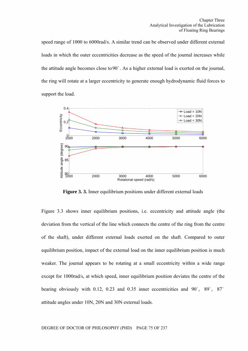
Chapter Three Analytical Investigation of the Lubrication
of Floating Ring Bearings
DEGREE OF DOCTOR OF PHILOSOPHY (PHD) PAGE 75 OF 237
speed range of 1000 to 6000rad/s. A similar trend can be observed under different external
loads in which the outer eccentricities decrease as the speed of the journal increases while
the attitude angle becomes close to o90 . As a higher external load is exerted on the journal,
the ring will rotate at a larger eccentricity to generate enough hydrodynamic fluid forces to
support the load.
1000 2000 3000 4000 5000 60000
0.2
0.4
Ecc
entri
city
1000 2000 3000 4000 5000 600080
85
90
Rotational speed (rad/s)
Atti
tude
ang
le (d
egre
e)
Load = 10NLoad = 20NLoad = 30N
Figure 3. 3. Inner equilibrium positions under different external loads
Figure 3.3 shows inner equilibrium positions, i.e. eccentricity and attitude angle (the
deviation from the vertical of the line which connects the centre of the ring from the centre
of the shaft), under different external loads exerted on the shaft. Compared to outer
equilibrium position, impact of the external load on the inner equilibrium position is much
weaker. The journal appears to be rotating at a small eccentricity within a wide range
except for 1000rad/s, at which speed, inner equilibrium position deviates the centre of the
bearing obviously with 0.12, 0.23 and 0.35 inner eccentricities and ooo 87,89,90
attitude angles under 10N, 20N and 30N external loads.
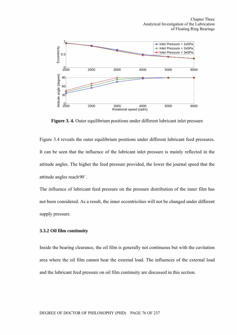
Chapter Three Analytical Investigation of the Lubrication
of Floating Ring Bearings
DEGREE OF DOCTOR OF PHILOSOPHY (PHD) PAGE 76 OF 237
1000 2000 3000 4000 5000 60000
0.5
1
Ecc
entri
city
1000 2000 3000 4000 5000 60000
30
60
90
Rotational speed (rad/s)
Atti
tude
ang
le (d
egre
e)
Inlet Pressure = 1e5PaInlet Pressure = 2e5PaInlet Pressure = 3e5Pa
Figure 3. 4. Outer equilibrium positions under different lubricant inlet pressure
Figure 3.4 reveals the outer equilibrium positions under different lubricant feed pressures.
It can be seen that the influence of the lubricant inlet pressure is mainly reflected in the
attitude angles. The higher the feed pressure provided, the lower the journal speed that the
attitude angles reach o90 .
The influence of lubricant feed pressure on the pressure distribution of the inner film has
not been considered. As a result, the inner eccentricities will not be changed under different
supply pressure.
3.3.2 Oil film continuity
Inside the bearing clearance, the oil film is generally not continuous but with the cavitation
area where the oil film cannot bear the external load. The influences of the external load
and the lubricant feed pressure on oil film continuity are discussed in this section.
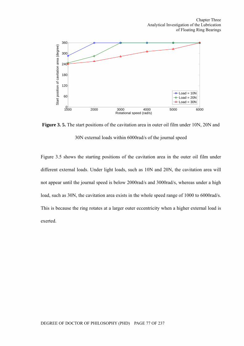
Chapter Three Analytical Investigation of the Lubrication
of Floating Ring Bearings
DEGREE OF DOCTOR OF PHILOSOPHY (PHD) PAGE 77 OF 237
1000 2000 3000 4000 5000 60000
60
120
180
240
300
360
Rotational speed (rad/s)
Sta
rt po
sitio
n of
cav
itatio
n ar
ea (d
egre
e)
Load = 10NLoad = 20NLoad = 30N
Figure 3. 5. The start positions of the cavitation area in outer oil film under 10N, 20N and
30N external loads within 6000rad/s of the journal speed
Figure 3.5 shows the starting positions of the cavitation area in the outer oil film under
different external loads. Under light loads, such as 10N and 20N, the cavitation area will
not appear until the journal speed is below 2000rad/s and 3000rad/s, whereas under a high
load, such as 30N, the cavitation area exists in the whole speed range of 1000 to 6000rad/s.
This is because the ring rotates at a larger outer eccentricity when a higher external load is
exerted.
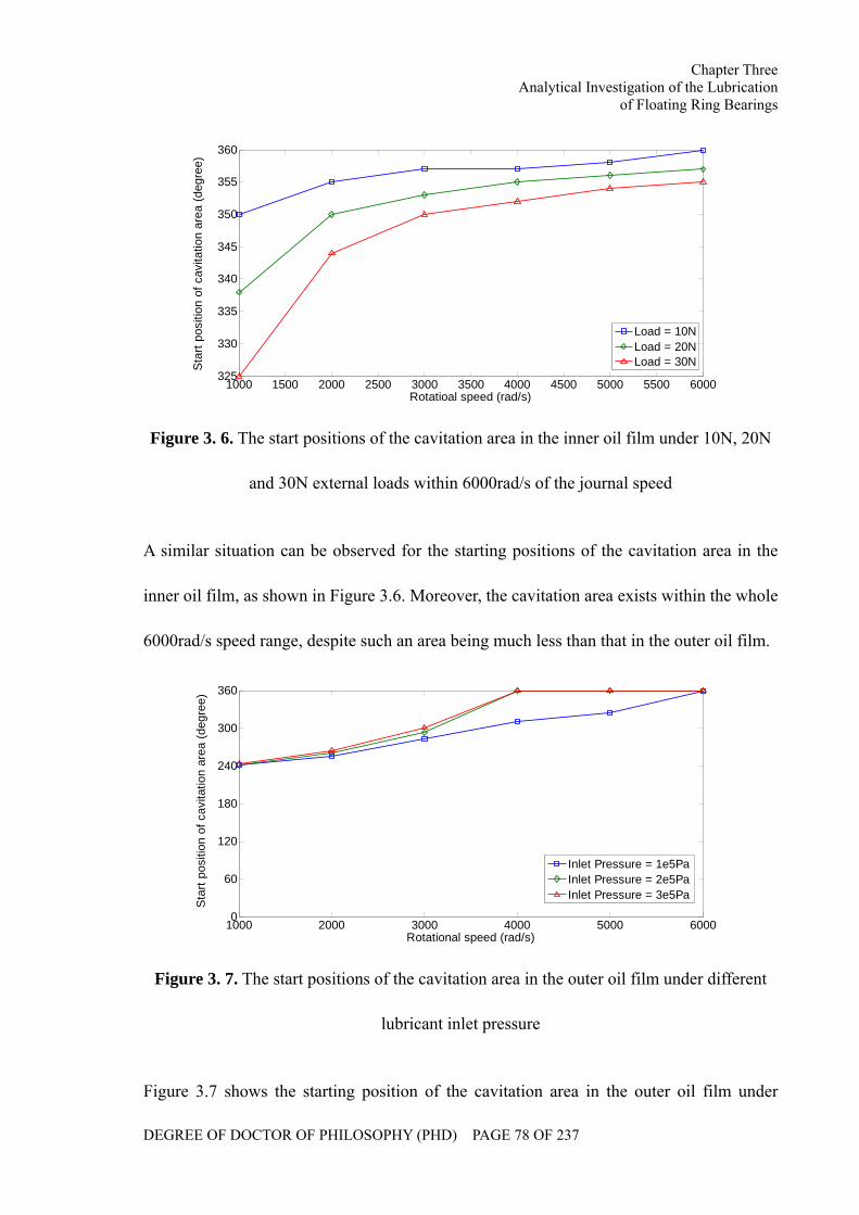
Chapter Three Analytical Investigation of the Lubrication
of Floating Ring Bearings
DEGREE OF DOCTOR OF PHILOSOPHY (PHD) PAGE 78 OF 237
1000 1500 2000 2500 3000 3500 4000 4500 5000 5500 6000325
330
335
340
345
350
355
360
Rotatioal speed (rad/s)
Sta
rt po
sitio
n of
cav
itatio
n ar
ea (d
egre
e)
Load = 10NLoad = 20NLoad = 30N
Figure 3. 6. The start positions of the cavitation area in the inner oil film under 10N, 20N
and 30N external loads within 6000rad/s of the journal speed
A similar situation can be observed for the starting positions of the cavitation area in the
inner oil film, as shown in Figure 3.6. Moreover, the cavitation area exists within the whole
6000rad/s speed range, despite such an area being much less than that in the outer oil film.
1000 2000 3000 4000 5000 60000
60
120
180
240
300
360
Rotational speed (rad/s)
Sta
rt po
sitio
n of
cav
itatio
n ar
ea (d
egre
e)
Inlet Pressure = 1e5PaInlet Pressure = 2e5PaInlet Pressure = 3e5Pa
Figure 3. 7. The start positions of the cavitation area in the outer oil film under different
lubricant inlet pressure
Figure 3.7 shows the starting position of the cavitation area in the outer oil film under
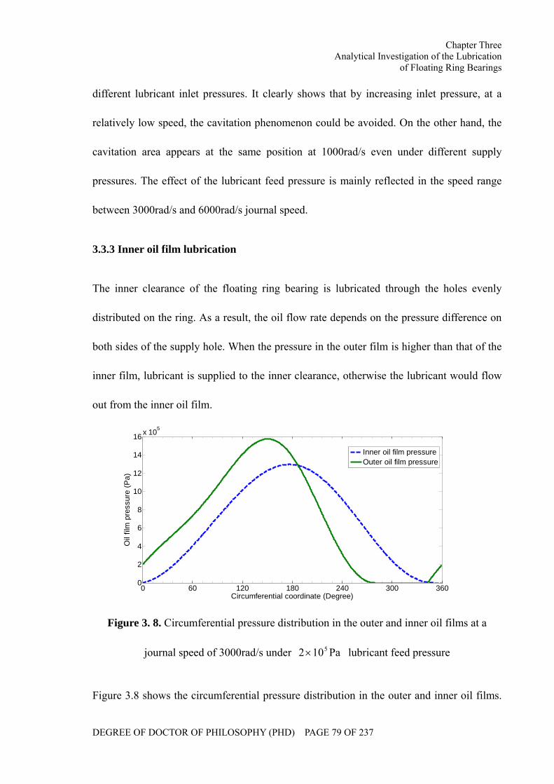
Chapter Three Analytical Investigation of the Lubrication
of Floating Ring Bearings
DEGREE OF DOCTOR OF PHILOSOPHY (PHD) PAGE 79 OF 237
different lubricant inlet pressures. It clearly shows that by increasing inlet pressure, at a
relatively low speed, the cavitation phenomenon could be avoided. On the other hand, the
cavitation area appears at the same position at 1000rad/s even under different supply
pressures. The effect of the lubricant feed pressure is mainly reflected in the speed range
between 3000rad/s and 6000rad/s journal speed.
3.3.3 Inner oil film lubrication
The inner clearance of the floating ring bearing is lubricated through the holes evenly
distributed on the ring. As a result, the oil flow rate depends on the pressure difference on
both sides of the supply hole. When the pressure in the outer film is higher than that of the
inner film, lubricant is supplied to the inner clearance, otherwise the lubricant would flow
out from the inner oil film.
0 60 120 180 240 300 3600
2
4
6
8
10
12
14
16 x 105
Circumferential coordinate (Degree)
Oil
film
pre
ssur
e (P
a)
Inner oil film pressureOuter oil film pressure
Figure 3. 8. Circumferential pressure distribution in the outer and inner oil films at a
journal speed of 3000rad/s under Pa102 5× lubricant feed pressure
Figure 3.8 shows the circumferential pressure distribution in the outer and inner oil films.
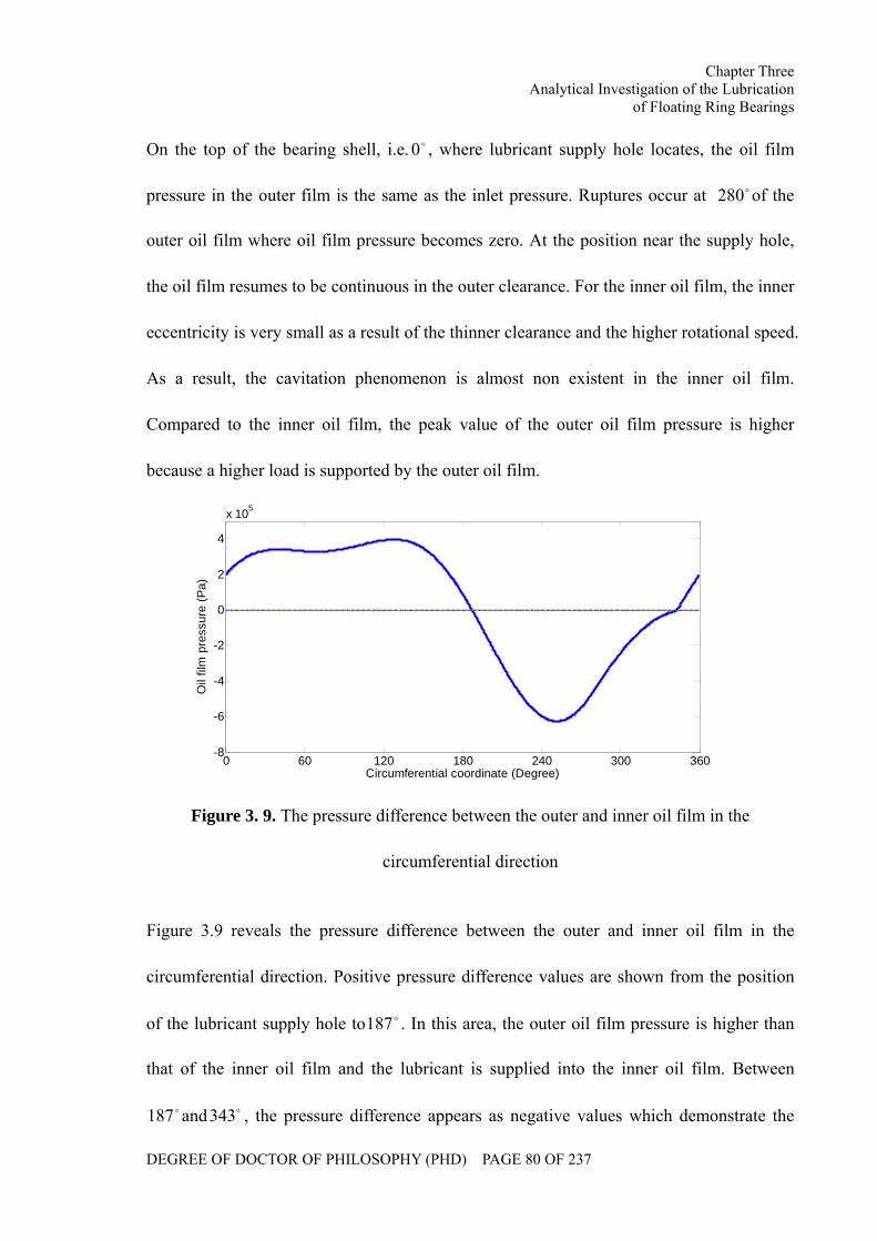
Chapter Three Analytical Investigation of the Lubrication
of Floating Ring Bearings
DEGREE OF DOCTOR OF PHILOSOPHY (PHD) PAGE 80 OF 237
On the top of the bearing shell, i.e. o0 , where lubricant supply hole locates, the oil film
pressure in the outer film is the same as the inlet pressure. Ruptures occur at o280 of the
outer oil film where oil film pressure becomes zero. At the position near the supply hole,
the oil film resumes to be continuous in the outer clearance. For the inner oil film, the inner
eccentricity is very small as a result of the thinner clearance and the higher rotational speed.
As a result, the cavitation phenomenon is almost non existent in the inner oil film.
Compared to the inner oil film, the peak value of the outer oil film pressure is higher
because a higher load is supported by the outer oil film.
0 60 120 180 240 300 360-8
-6
-4
-2
0
2
4
x 105
Circumferential coordinate (Degree)
Oil
film
pre
ssur
e (P
a)
Figure 3. 9. The pressure difference between the outer and inner oil film in the
circumferential direction
Figure 3.9 reveals the pressure difference between the outer and inner oil film in the
circumferential direction. Positive pressure difference values are shown from the position
of the lubricant supply hole to o187 . In this area, the outer oil film pressure is higher than
that of the inner oil film and the lubricant is supplied into the inner oil film. Between
o187 and o343 , the pressure difference appears as negative values which demonstrate the
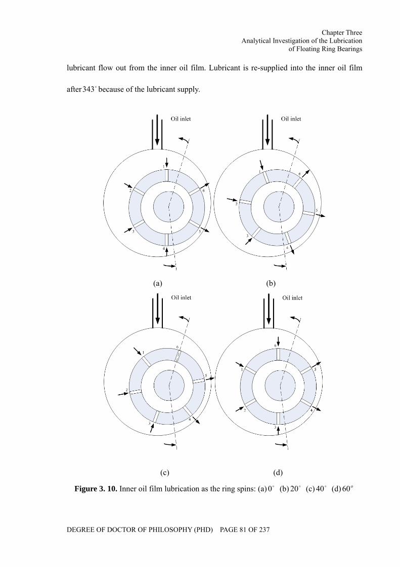
Chapter Three Analytical Investigation of the Lubrication
of Floating Ring Bearings
DEGREE OF DOCTOR OF PHILOSOPHY (PHD) PAGE 81 OF 237
lubricant flow out from the inner oil film. Lubricant is re-supplied into the inner oil film
after o343 because of the lubricant supply.
(a) (b)
(c) (d)
Figure 3. 10. Inner oil film lubrication as the ring spins: (a) o0 (b) o20 (c) o40 (d) o60
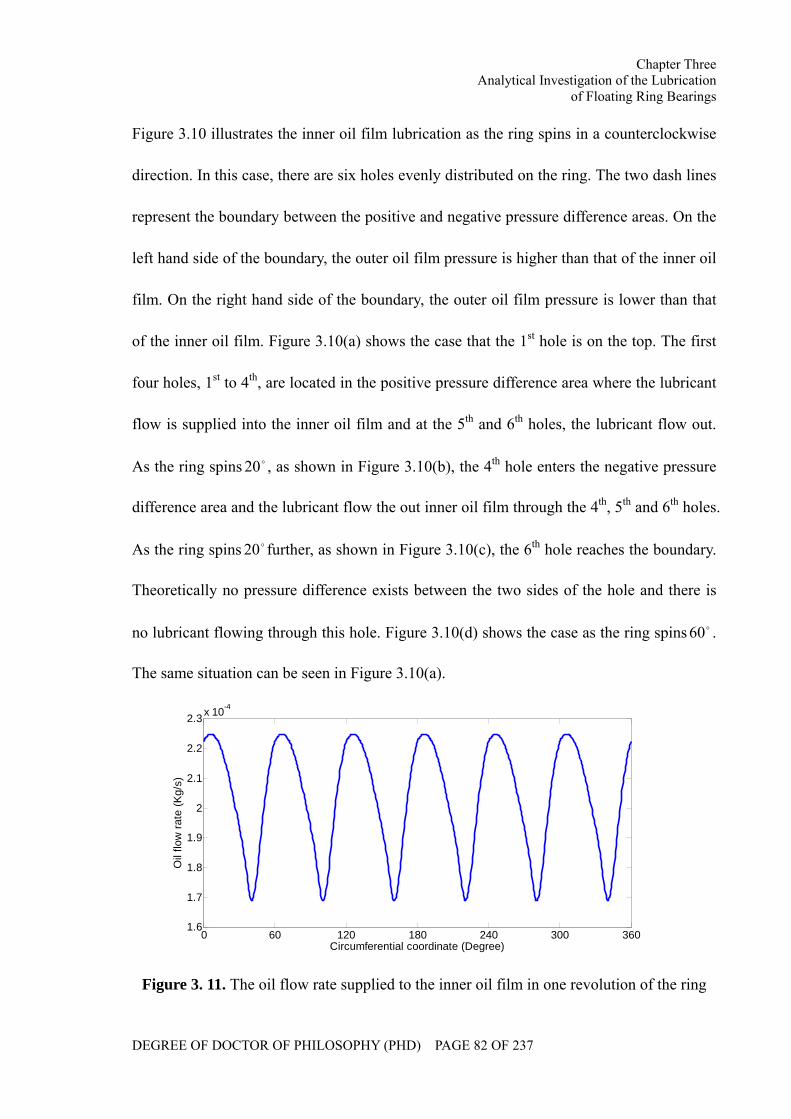
Chapter Three Analytical Investigation of the Lubrication
of Floating Ring Bearings
DEGREE OF DOCTOR OF PHILOSOPHY (PHD) PAGE 82 OF 237
Figure 3.10 illustrates the inner oil film lubrication as the ring spins in a counterclockwise
direction. In this case, there are six holes evenly distributed on the ring. The two dash lines
represent the boundary between the positive and negative pressure difference areas. On the
left hand side of the boundary, the outer oil film pressure is higher than that of the inner oil
film. On the right hand side of the boundary, the outer oil film pressure is lower than that
of the inner oil film. Figure 3.10(a) shows the case that the 1st hole is on the top. The first
four holes, 1st to 4th, are located in the positive pressure difference area where the lubricant
flow is supplied into the inner oil film and at the 5th and 6th holes, the lubricant flow out.
As the ring spins o20 , as shown in Figure 3.10(b), the 4th hole enters the negative pressure
difference area and the lubricant flow the out inner oil film through the 4th, 5th and 6th holes.
As the ring spins o20 further, as shown in Figure 3.10(c), the 6th hole reaches the boundary.
Theoretically no pressure difference exists between the two sides of the hole and there is
no lubricant flowing through this hole. Figure 3.10(d) shows the case as the ring spins o60 .
The same situation can be seen in Figure 3.10(a).
0 60 120 180 240 300 3601.6
1.7
1.8
1.9
2
2.1
2.2
2.3 x 10⁻⁴
Circumferential coordinate (Degree)
Oil
flow
rate
(Kg/
s)
Figure 3. 11. The oil flow rate supplied to the inner oil film in one revolution of the ring
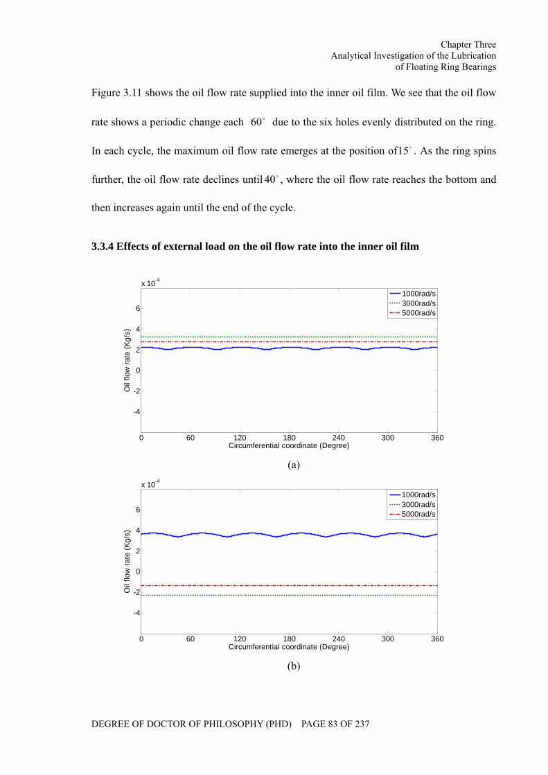
Chapter Three Analytical Investigation of the Lubrication
of Floating Ring Bearings
DEGREE OF DOCTOR OF PHILOSOPHY (PHD) PAGE 83 OF 237
Figure 3.11 shows the oil flow rate supplied into the inner oil film. We see that the oil flow
rate shows a periodic change each o60 due to the six holes evenly distributed on the ring.
In each cycle, the maximum oil flow rate emerges at the position of o15 . As the ring spins
further, the oil flow rate declines until o40 , where the oil flow rate reaches the bottom and
then increases again until the end of the cycle.
3.3.4 Effects of external load on the oil flow rate into the inner oil film
0 60 120 180 240 300 360
-4
-2
0
2
4
6
x 10-4
Circumferential coordinate (Degree)
Oil
flow
rate
(Kg/
s)
1000rad/s3000rad/s5000rad/s
(a)
0 60 120 180 240 300 360
-4
-2
0
2
4
6
x 10-4
Circumferential coordinate (Degree)
Oil
flow
rate
(Kg/
s)
1000rad/s3000rad/s5000rad/s
(b)
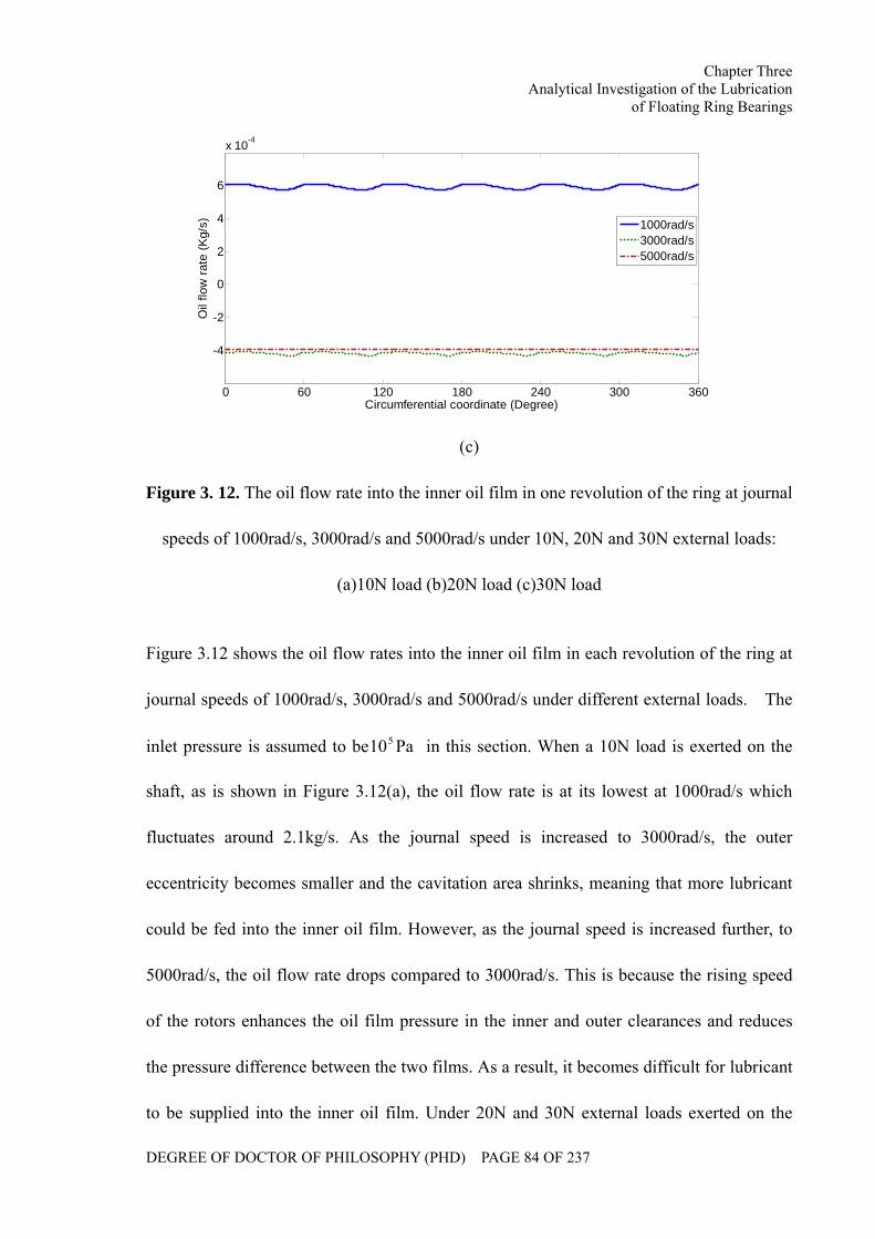
Chapter Three Analytical Investigation of the Lubrication
of Floating Ring Bearings
DEGREE OF DOCTOR OF PHILOSOPHY (PHD) PAGE 84 OF 237
0 60 120 180 240 300 360
-4
-2
0
2
4
6
x 10-4
Circumferential coordinate (Degree)
Oil
flow
rate
(Kg/
s)
1000rad/s3000rad/s5000rad/s
(c)
Figure 3. 12. The oil flow rate into the inner oil film in one revolution of the ring at journal
speeds of 1000rad/s, 3000rad/s and 5000rad/s under 10N, 20N and 30N external loads:
(a)10N load (b)20N load (c)30N load
Figure 3.12 shows the oil flow rates into the inner oil film in each revolution of the ring at
journal speeds of 1000rad/s, 3000rad/s and 5000rad/s under different external loads. The
inlet pressure is assumed to be Pa105 in this section. When a 10N load is exerted on the
shaft, as is shown in Figure 3.12(a), the oil flow rate is at its lowest at 1000rad/s which
fluctuates around 2.1kg/s. As the journal speed is increased to 3000rad/s, the outer
eccentricity becomes smaller and the cavitation area shrinks, meaning that more lubricant
could be fed into the inner oil film. However, as the journal speed is increased further, to
5000rad/s, the oil flow rate drops compared to 3000rad/s. This is because the rising speed
of the rotors enhances the oil film pressure in the inner and outer clearances and reduces
the pressure difference between the two films. As a result, it becomes difficult for lubricant
to be supplied into the inner oil film. Under 20N and 30N external loads exerted on the
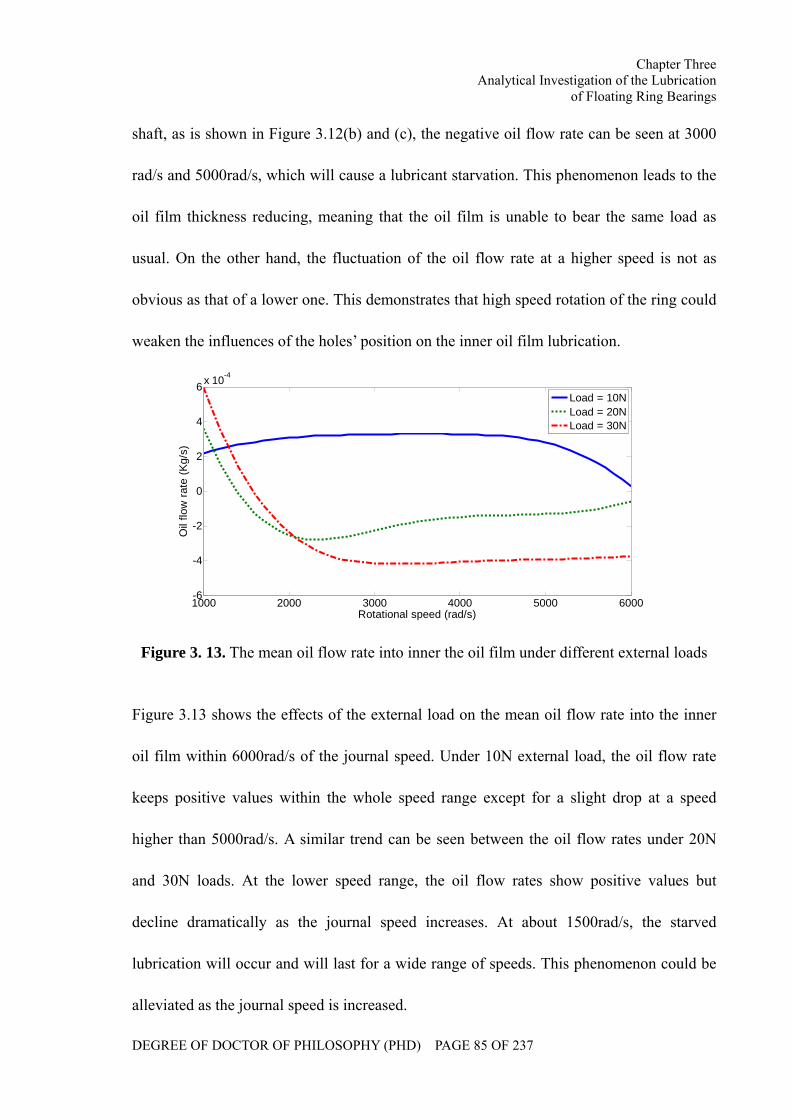
Chapter Three Analytical Investigation of the Lubrication
of Floating Ring Bearings
DEGREE OF DOCTOR OF PHILOSOPHY (PHD) PAGE 85 OF 237
shaft, as is shown in Figure 3.12(b) and (c), the negative oil flow rate can be seen at 3000
rad/s and 5000rad/s, which will cause a lubricant starvation. This phenomenon leads to the
oil film thickness reducing, meaning that the oil film is unable to bear the same load as
usual. On the other hand, the fluctuation of the oil flow rate at a higher speed is not as
obvious as that of a lower one. This demonstrates that high speed rotation of the ring could
weaken the influences of the holes’ position on the inner oil film lubrication.
1000 2000 3000 4000 5000 6000-6
-4
-2
0
2
4
6 x 10⁻⁴
Rotational speed (rad/s)
Oil
flow
rate
(Kg/
s)
Load = 10NLoad = 20NLoad = 30N
Figure 3. 13. The mean oil flow rate into inner the oil film under different external loads
Figure 3.13 shows the effects of the external load on the mean oil flow rate into the inner
oil film within 6000rad/s of the journal speed. Under 10N external load, the oil flow rate
keeps positive values within the whole speed range except for a slight drop at a speed
higher than 5000rad/s. A similar trend can be seen between the oil flow rates under 20N
and 30N loads. At the lower speed range, the oil flow rates show positive values but
decline dramatically as the journal speed increases. At about 1500rad/s, the starved
lubrication will occur and will last for a wide range of speeds. This phenomenon could be
alleviated as the journal speed is increased.
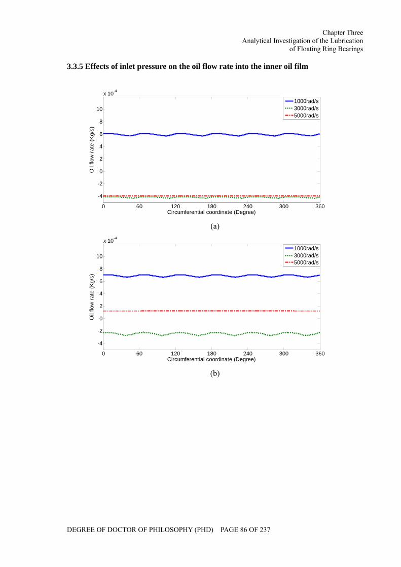
Chapter Three Analytical Investigation of the Lubrication
of Floating Ring Bearings
DEGREE OF DOCTOR OF PHILOSOPHY (PHD) PAGE 86 OF 237
3.3.5 Effects of inlet pressure on the oil flow rate into the inner oil film
0 60 120 180 240 300 360
-4
-2
0
2
4
6
8
10
x 10-4
Circumferential coordinate (Degree)
Oil
flow
rate
(Kg/
s)
1000rad/s3000rad/s5000rad/s
(a)
0 60 120 180 240 300 360
-4
-2
0
2
4
6
8
10
x 10-4
Circumferential coordinate (Degree)
Oil
flow
rate
(Kg/
s)
1000rad/s3000rad/s5000rad/s
(b)
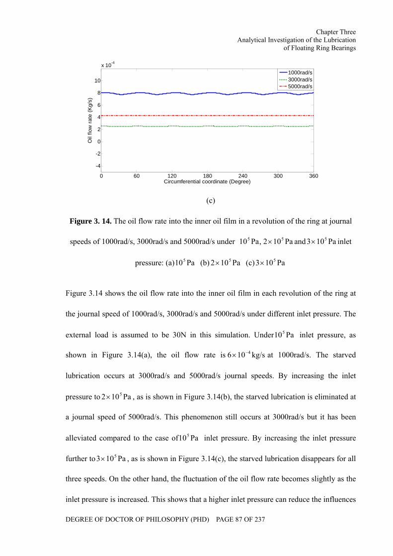
Chapter Three Analytical Investigation of the Lubrication
of Floating Ring Bearings
DEGREE OF DOCTOR OF PHILOSOPHY (PHD) PAGE 87 OF 237
0 60 120 180 240 300 360
-4
-2
0
2
4
6
8
10
x 10-4
Circumferential coordinate (Degree)
Oil
flow
rate
(Kg/
s)
1000rad/s3000rad/s5000rad/s
(c)
Figure 3. 14. The oil flow rate into the inner oil film in a revolution of the ring at journal
speeds of 1000rad/s, 3000rad/s and 5000rad/s under Pa102,Pa10 55 × and Pa103 5× inlet
pressure: (a) Pa105 (b) Pa102 5× (c) Pa103 5×
Figure 3.14 shows the oil flow rate into the inner oil film in each revolution of the ring at
the journal speed of 1000rad/s, 3000rad/s and 5000rad/s under different inlet pressure. The
external load is assumed to be 30N in this simulation. Under Pa105 inlet pressure, as
shown in Figure 3.14(a), the oil flow rate is kg/s106 4−× at 1000rad/s. The starved
lubrication occurs at 3000rad/s and 5000rad/s journal speeds. By increasing the inlet
pressure to Pa102 5× , as is shown in Figure 3.14(b), the starved lubrication is eliminated at
a journal speed of 5000rad/s. This phenomenon still occurs at 3000rad/s but it has been
alleviated compared to the case of Pa105 inlet pressure. By increasing the inlet pressure
further to Pa103 5× , as is shown in Figure 3.14(c), the starved lubrication disappears for all
three speeds. On the other hand, the fluctuation of the oil flow rate becomes slightly as the
inlet pressure is increased. This shows that a higher inlet pressure can reduce the influences
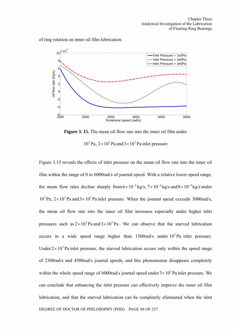
Chapter Three Analytical Investigation of the Lubrication
of Floating Ring Bearings
DEGREE OF DOCTOR OF PHILOSOPHY (PHD) PAGE 88 OF 237
of ring rotation on inner oil film lubrication.
1000 2000 3000 4000 5000 6000-6
-4
-2
0
2
4
6
8
10 x 10-4
Rotational speed (rad/s)
Oil
flow
rate
(Kg/
s)
Inlet Pressure = 1e5PaInlet Pressure = 2e5PaInlet Pressure = 3e5Pa
Figure 3. 15. The mean oil flow rate into the inner oil film under
Pa102,Pa10 55 × and Pa103 5× inlet pressure
Figure 3.15 reveals the effects of inlet pressure on the mean oil flow rate into the inner oil
film within the range of 0 to 6000rad/s of journal speed. With a relative lower speed range,
the mean flow rates decline sharply from kg/s107,kg/s106 44 −− ×× and kg/s108 4−× under
Pa102,Pa10 55 × and Pa103 5× inlet pressure. When the journal speed exceeds 3000rad/s,
the mean oil flow rate into the inner oil film increases especially under higher inlet
pressures such as Pa102 5× and Pa103 5× . We can observe that the starved lubrication
occurs in a wide speed range higher than 1500rad/s under Pa105 inlet pressure.
Under Pa102 5× inlet pressure, the starved lubrication occurs only within the speed range
of 2300rad/s and 4500rad/s journal speeds, and this phenomenon disappears completely
within the whole speed range of 6000rad/s journal speed under Pa103 5× inlet pressure. We
can conclude that enhancing the inlet pressure can effectively improve the inner oil film
lubrication, and that the starved lubrication can be completely eliminated when the inlet
Chapter Three Analytical Investigation of the Lubrication
of Floating Ring Bearings
DEGREE OF DOCTOR OF PHILOSOPHY (PHD) PAGE 89 OF 237
pressure is high enough.
3.4 Summary
In this chapter, the steady state Reynolds Equations regarding two oil films of the floating
ring bearing have been derived based on the infinitely long bearing theory. Analytical
expressions of oil film pressure distribution have been obtained in which oil inlet pressure
and cavitation situation have been taken into account.
Under different external loads and oil inlet pressure, the equilibrium positions of journal
and ring along with the cavitation areas of two oil films have been simulated. It is found
that heavy external loads could result in large outer eccentricity but the influence to inner
eccentricity is not obvious which is reflected only within the lower speed range. Oil inlet
pressure mainly affects the outer attitude range. On the other hand, external load could
extend cavitation areas in both outer and inner oil films, which could be shrinking at high
speed while increasing oil inlet pressure.
Inner oil film lubrication procedure has been studied and the effects of external loads and
oil inlet pressure on oil flow rate into the inner oil film have been investigated. It is found
that heavier external load could reduce oil flow rate into the inner oil film within a wide
speed range even might lead to inner film oil starvation, although the flow rate is initially
larger at low speed. On the other hand, increasing oil inlet pressure could improve
effectively the inner oil film lubrication.
Chapter Four Theoretical Modeling for a Turbocharger
Rotor System
DEGREE OF DOCTOR OF PHILOSOPHY (PHD) PAGE 90 OF 237
CHAPTER FOUR
THEORETICAL MODELLING FOR A
TURBOCHARGER ROTOR SYSTEM
The rotor system plays a key role in a turbocharger which determines whether the
turbocharger will work normally or not. In addition, the dynamic characteristics of the
bearing can also affect the rotor motion to a large degree. Most of the faults associated
with turbochargers are related to their rotor bearing systems. In this chapter, a theoretical
model has been developed for the turbocharger rotor bearing system using the Finite
Element method in order to investigate the dynamic performance of the turbocharger rotor
system.
Chapter Four Theoretical Modeling for a Turbocharger
Rotor System
DEGREE OF DOCTOR OF PHILOSOPHY (PHD) PAGE 91 OF 237
Nomenclature of Section 4.1
dm Mass of the disk (kg) yBθ Rotation angle of B end of shaft
segment in y direction (rad) dJ Diameter moment of inertia of the
disk ( 2kgm ) s Coordinate in shaft segment (m)
sl Length of shaft segment (m) pJ Polar moment of inertia of the disk
( 2kgm ) sr Radius of shaft segment (m)
sµ Mass of the unit length (kg/m) dx Displacement of the disk in x
direction (m) dsj Diameter moment of inertial of the
unit length ( /mkgm2 ) dy Displacement of the disk in y
direction (m) psj Polar moment of inertial of the unit
length ( /mkgm2 ) xθ Rotation angle in x direction (rad)
sT Kinetic energy of shaft segment (J)
sV Potential energy of shaft segment (J) yθ Rotation angle in y direction (rad)
EI Flexural rigidity ( 2N/m )
dT Kinetic energy (J) xxc
xyc Ax Displacement of A end of shaft
segment in x direction (m) yxc
yyc
Damping coefficients (Ns/m)
Ay Displacement of A end of shaft
segment in y direction (m) xxk
xyk Bx Displacement of B end of shaft
segment in x direction (m) yxk
Stiffness coefficients (N/m)
Chapter Four Theoretical Modeling for a Turbocharger
Rotor System
DEGREE OF DOCTOR OF PHILOSOPHY (PHD) PAGE 92 OF 237
yyk By Displacement of B end of shaft
segment in y direction (m) sjx Displacement of the journal in x
direction (m) xAθ Rotation angle of A end of shaft
segment in x direction (rad) sjy Displacement of the journal in y
direction (m) yAθ Rotation angle of A end of shaft
segment in y direction (rad)
xBθ Rotation angle of B end of shaft
segment in x direction (rad)
Nomenclature of Section 4.2
6...1m Mass of the nodes (kg) [ ]M System mass matrix
5...1k Stiffness coefficients of shaft
segments (N/m)
[ ]RM Mass matrix of the ring
5...1c Damping coefficients of shaft
segments (Ns/m)
[ ]K System stiffness matrix
6...1x Displacement of the nodes in x
direction (m)
[ ]C System damping matrix
6..1y Displacement of the nodes in y
direction (m)
U System displacement vector
Ω Rotational speed (rad/s) RU Displacement vector of the ring
ξe Eccentricities in the rotating W System dead weight
Chapter Four Theoretical Modeling for a Turbocharger
Rotor System
DEGREE OF DOCTOR OF PHILOSOPHY (PHD) PAGE 93 OF 237
ηe coordinate system RW Dead weight of the ring
imbm Imbalance mass (kg) uF Imbalance centrifugal force
imbxF _ Imbalance centrifugal force in x
direction (N)
P Lubricant feed pressure
imbyF _ Imbalance centrifugal force in y
direction (N)
innerFh Inner oil film force
outerFh Outer oil film force
Nomenclature of Section 4.3
xFh Oil film force in x direction (N) oR Outer radius of the ring (m)
yFh Oil film force in y direction (N) iR Inner radius of the ring (m)
xoFh Original oil film force in x direction
(N)
JR Radius of the journal (m)
yoFh Original oil film force in y direction
(N)
oC Outer bearing clearance (m)
x∆ Micro displacement in x direction
(m)
iC Inner bearing clearance (m)
y∆ Micro displacement in y direction
(m)
L Bearing length (m)
x&∆ Micro velocity in x direction (m/s) RΩ Rotational speed of the ring (rad/s)
y&∆ Micro velocity in y direction (m/s) ix Dimensionless displacement of the
Chapter Four Theoretical Modeling for a Turbocharger
Rotor System
DEGREE OF DOCTOR OF PHILOSOPHY (PHD) PAGE 94 OF 237
journal in x direction
φ Attitude angle (degree) iy Dimensionless displacement of the
journal in y direction
θ Circumferential coordinate (degree) Rx Dimensionless displacement of the
ring in x direction
µ Lubricant viscosity (PaS) Ry Dimensionless displacement of the
ring in y direction
oP Pressure distribution of outer oil film
(Pa)
oh Dimensionless thickness of outer oil
film
iP Pressure distribution of inner oil film
(Pa)
ih Dimensionless thickness of inner oil
film
X Journal displacement in x direction
(m)
oτ
Y Journal displacement in y direction
(m)
iτ
Dimensionless time
RX Ring displacement in x direction (m) op Dimensionless outer oil film pressure
RY Ring displacement in y direction (m) ip Dimensionless inner oil film pressure
Z Axial coordinate system (m)
Chapter Four Theoretical Modeling for a Turbocharger
Rotor System
DEGREE OF DOCTOR OF PHILOSOPHY (PHD) PAGE 95 OF 237
Nomenclature of Section 4.4
impF Impact force (N) ζ Displacement of the rotor (m)
rubF Rub force (N)
kr Radial stiffness (N/m)
f Friction coefficient
Chapter Four Theoretical Modeling for a Turbocharger
Rotor System
DEGREE OF DOCTOR OF PHILOSOPHY (PHD) PAGE 96 OF 237
A turbocharger is a rotating machine of high speed and light load. The rotational speed can
easily reach 140,000r/min or higher. Whether the turbocharger is able to work safely at
such high speeds largely depends upon its dynamic performance. In this chapter, a dynamic
model has been developed for the turbocharger rotor system using the theory of finite
element method to provide a foundation for modal analysis, critical speeds calculation,
bending vibration and stability analysis.
4.1 Finite Element Analysis of the Rotor System
4.1.1 Finite element method
As the rotor system is usually comprised of impellers, shaft segments with distributed mass
and elasticity, bearings, etc, it can be discreticized into a number of units, such as the disk,
the shaft segment and the bearing along the axial direction. Through the unit analysis, the
relationship between the nodal force and nodal displacement can be established. The rotor
system motion equation is formed by combing all units. As a consequence, it is possible to
transfer a continuous rotor system into a system with multiple degrees of freedom. The
critical speeds and force response of the system can then be obtained by solving a group of
linear equations.
4.1.2 Motion equations of the unit
(I) Rigid disk unit
Assuming the mass, diameter moment of inertia and polar moment of inertia of a rigid disk
unit to be pd JJm ,, respectively, the unit displacement vector is expressed by:
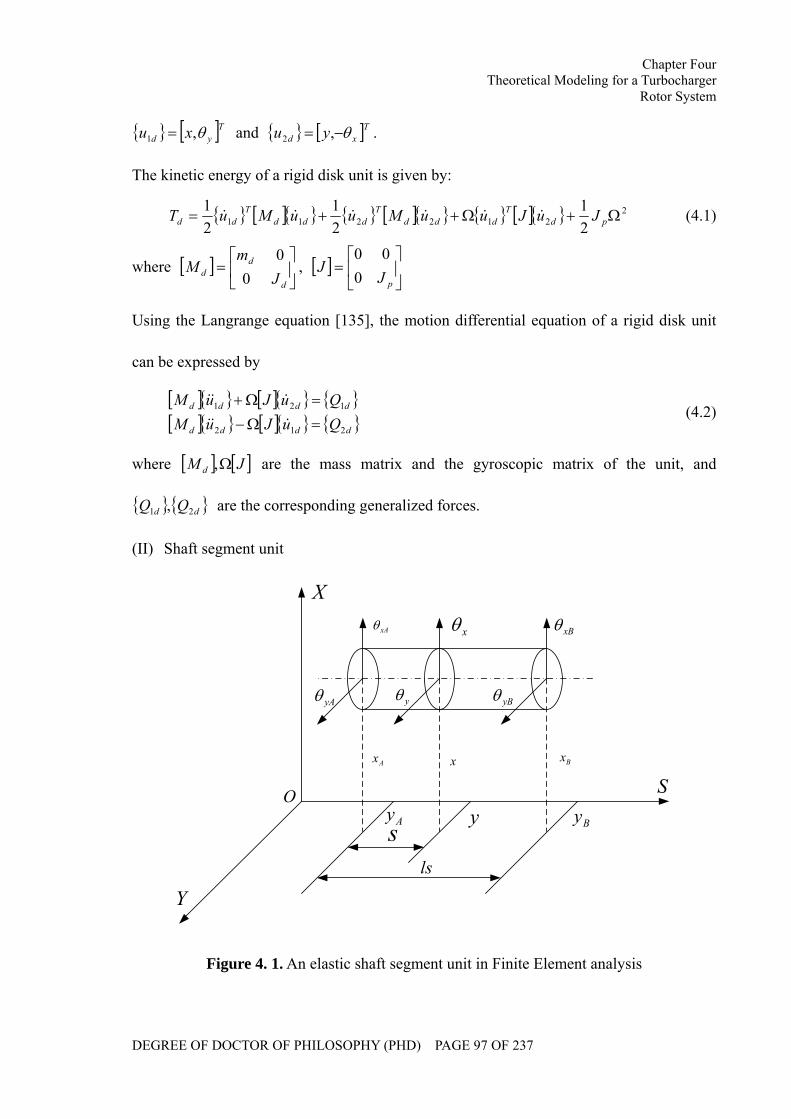
Chapter Four Theoretical Modeling for a Turbocharger
Rotor System
DEGREE OF DOCTOR OF PHILOSOPHY (PHD) PAGE 97 OF 237
[ ]Tyd xu θ,1 = and [ ]Txd yu θ−= ,2 .
The kinetic energy of a rigid disk unit is given by:
[ ] [ ] [ ] 2212211 2
121
21
Ω+Ω++= pdT
dddT
dddT
dd JuJuuMuuMuT &&&&&& (4.1)
where [ ] ⎥⎦
⎤⎢⎣
⎡=
d
dd J
mM
00
, [ ] ⎥⎦
⎤⎢⎣
⎡=
pJJ
000
Using the Langrange equation [135], the motion differential equation of a rigid disk unit
can be expressed by
[ ] [ ] [ ] [ ] dddd
dddd
QuJuMQuJuM
212
121
=Ω−=Ω+
&&&
&&& (4.2)
where [ ] [ ]JM d Ω, are the mass matrix and the gyroscopic matrix of the unit, and
dd QQ 21 , are the corresponding generalized forces.
(II) Shaft segment unit
Ax Bxx
Ay Byy
xAθ
yAθ
xBθ
yBθ
xθ
yθ
sls
S
X
Y
O
Figure 4. 1. An elastic shaft segment unit in Finite Element analysis
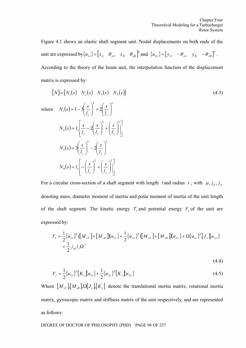
Chapter Four Theoretical Modeling for a Turbocharger
Rotor System
DEGREE OF DOCTOR OF PHILOSOPHY (PHD) PAGE 98 OF 237
Figure 4.1 shows an elastic shaft segment unit. Nodal displacements on both ends of the
unit are expressed by [ ]TyBByAAs xxu θθ=1 and [ ]TxBBxAAs yyu θθ −−=2 .
According to the theory of the beam unit, the interpolation function of the displacement
matrix is expressed by:
[ ] ( ) ( ) ( ) ( )[ ]sNsNsNsNN 4321= (4.3)
where ( )32
1 231 ⎟⎟⎠
⎞⎜⎜⎝
⎛+⎟⎟
⎠
⎞⎜⎜⎝
⎛−=
ss ls
lssN
( )⎥⎥⎦
⎤
⎢⎢⎣
⎡⎟⎟⎠
⎞⎜⎜⎝
⎛+⎟⎟
⎠
⎞⎜⎜⎝
⎛−=
32
2 2sss
s ls
ls
lslsN
( )32
3 23 ⎟⎟⎠
⎞⎜⎜⎝
⎛−⎟⎟
⎠
⎞⎜⎜⎝
⎛=
ss ls
lssN
( )⎥⎥⎦
⎤
⎢⎢⎣
⎡⎟⎟⎠
⎞⎜⎜⎝
⎛+⎟⎟
⎠
⎞⎜⎜⎝
⎛−=
32
4ss
s ls
lslsN
For a circular cross-section of a shaft segment with length l and radius r , with pd jj ,,µ
denoting mass, diameter moment of inertia and polar moment of inertia of the unit length
of the shaft segment. The kinetic energy sT and potential energy sV of the unit are
expressed by:
[ ] [ ]( ) [ ] [ ]( ) [ ] 2
212211
21
21
21
Ω+
Ω++++=
sps
ssT
sssRsTT
sssRsTT
ss
lj
uJuuMMuuMMuT &&&&&
(4.4)
[ ] [ ] ssT
sssT
ss uKuuKuV 2211 21
21
+= (4.5)
Where [ ] [ ] [ ] [ ]sssRsT KJMM ,,, Ω denote the translational inertia matrix, rotational inertia
matrix, gyroscopic matrix and stiffness matrix of the unit respectively, and are represented
as follows:
Chapter Four Theoretical Modeling for a Turbocharger
Rotor System
DEGREE OF DOCTOR OF PHILOSOPHY (PHD) PAGE 99 OF 237
[ ] [ ] [ ]⎥⎥⎥⎥
⎦
⎤
⎢⎢⎢⎢
⎣
⎡
−−−−−−
== ∫22
22
0
422313221561354313422135422156
420
ssss
ss
ssss
ss
sl
TsT
llllll
llllll
ldsNNM
s µµ (4.6)
[ ] [ ] [ ]⎥⎥⎥⎥
⎦
⎤
⎢⎢⎢⎢
⎣
⎡
−−−−−−−
−
=′′= ∫22
222
0
433336336
343336336
120
ssss
ss
ssss
ss
s
sl
TdssR
llllll
llllll
lr
dsNNjMs µ
(4.7)
[ ] [ ] [ ]⎥⎥⎥⎥
⎦
⎤
⎢⎢⎢⎢
⎣
⎡
−−−−−−−
−
=′′= ∫22
222
0
433336336
343336336
60
ssss
ss
ssss
ss
s
sl
Tpss
llllll
llllll
lr
dsNNjJs µ
(4.8)
[ ] [ ] [ ]⎥⎥⎥⎥
⎦
⎤
⎢⎢⎢⎢
⎣
⎡
−−−−
−−
=′′′′= ∫22
22
30
4626612612
2646612612
ssss
ss
ssss
ss
s
lT
s
llllll
llllll
lEIdsNNEIK
s
(4.9)
Using the Lagrange equation, the motion differential equation of the shaft segment unit is
expressed by
[ ] [ ] [ ] [ ] [ ] [ ] sssssss
sssssss
QuKuJuMQuKuJuM
2212
1121
=+Ω−=+Ω+
&&&
&&& (4.10)
where the mass matrix [ ] [ ] [ ]sRsTs MMM += and ss QQ 21 , are generalized force
vectors.
(III) The bearing unit
Ignoring the influence of the bearing bases, the effects of the bearing on the rotor system
are determined only by the hydrodynamic forces. If the hydrodynamic fluid force is
linearized, it can be expressed by a polynomial of stiffness and damping coefficients, given
by:
⎭⎬⎫
⎩⎨⎧⎥⎦
⎤⎢⎣
⎡−
⎭⎬⎫
⎩⎨⎧⎥⎦
⎤⎢⎣
⎡−=
⎭⎬⎫
⎩⎨⎧
sj
sj
yyyx
xyxx
sj
sj
yyyx
xyxx
d
d
yx
kkkk
yx
cccc
&
&
2
1 (4.11)
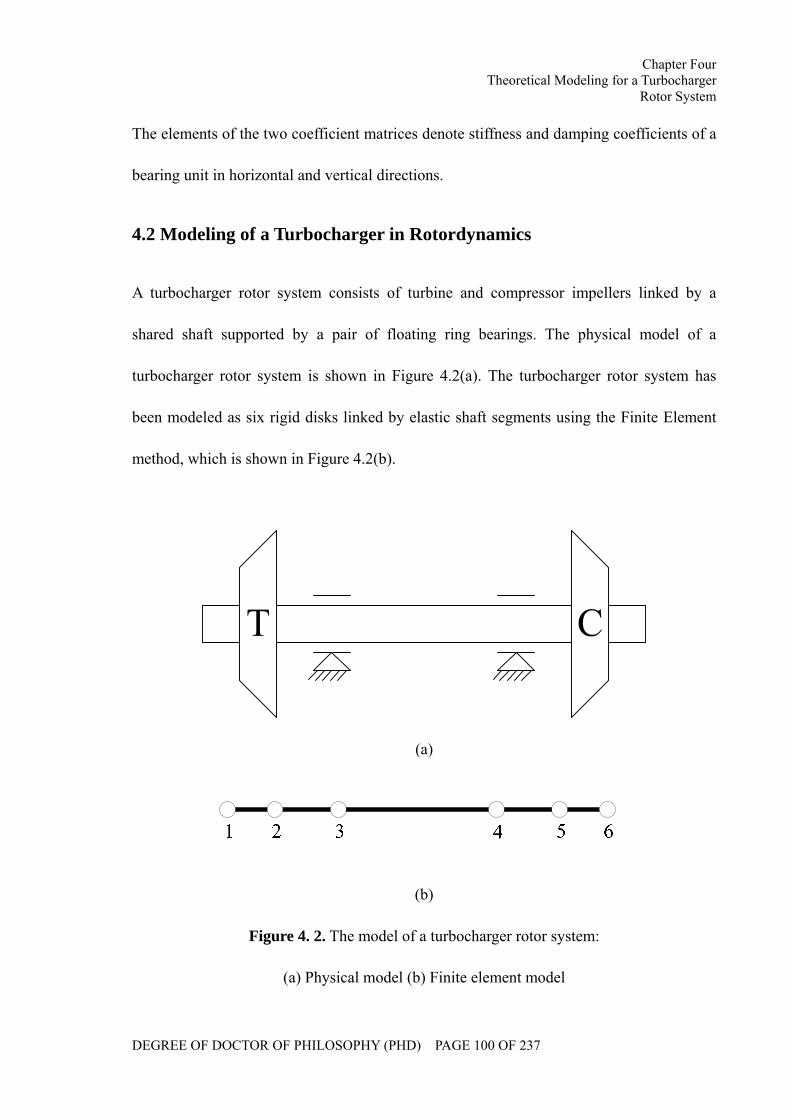
Chapter Four Theoretical Modeling for a Turbocharger
Rotor System
DEGREE OF DOCTOR OF PHILOSOPHY (PHD) PAGE 100 OF 237
The elements of the two coefficient matrices denote stiffness and damping coefficients of a
bearing unit in horizontal and vertical directions.
4.2 Modeling of a Turbocharger in Rotordynamics
A turbocharger rotor system consists of turbine and compressor impellers linked by a
shared shaft supported by a pair of floating ring bearings. The physical model of a
turbocharger rotor system is shown in Figure 4.2(a). The turbocharger rotor system has
been modeled as six rigid disks linked by elastic shaft segments using the Finite Element
method, which is shown in Figure 4.2(b).
(a)
(b)
Figure 4. 2. The model of a turbocharger rotor system:
(a) Physical model (b) Finite element model
Chapter Four Theoretical Modeling for a Turbocharger
Rotor System
DEGREE OF DOCTOR OF PHILOSOPHY (PHD) PAGE 101 OF 237
The system mass, stiffness and damping matrices are formed as follows:
It is assumed that the system mass is distributed on the mass nodes, thus the system mass
matrix becomes diagonalised.
[ ]
⎥⎥⎥⎥⎥⎥⎥⎥
⎦
⎤
⎢⎢⎢⎢⎢⎢⎢⎢
⎣
⎡
=
6
5
4
3
2
1
mm
mm
mm
M (4.12)
where 61......mm denote the mass of the discreticized mass nodes.
Assuming the materials of the turbocharger shaft to be uniformed, the stiffness and
damping matrices can be expressed by.
[ ]
⎥⎥⎥⎥⎥⎥⎥⎥
⎦
⎤
⎢⎢⎢⎢⎢⎢⎢⎢
⎣
⎡
−−+−
−+−−+−
−+−−
=
55
5544
4433
3322
2211
11
kkkkkk
kkkkkkkk
kkkkkk
K (4.13)
[ ]
⎥⎥⎥⎥⎥⎥⎥⎥
⎦
⎤
⎢⎢⎢⎢⎢⎢⎢⎢
⎣
⎡
−−+−
−+−−+−
−+−−
=
55
5544
4433
3322
2211
11
cccccc
cccccccc
cccccc
C (4.14)
where 51......kk , 51......cc denote the stiffness and damping coefficients of the shaft
segments respectively.
As far as the turbocharger rotor system is concerned, the primary exciting forces for the
system bending vibration include the static and dynamic loads. Static loads denote the
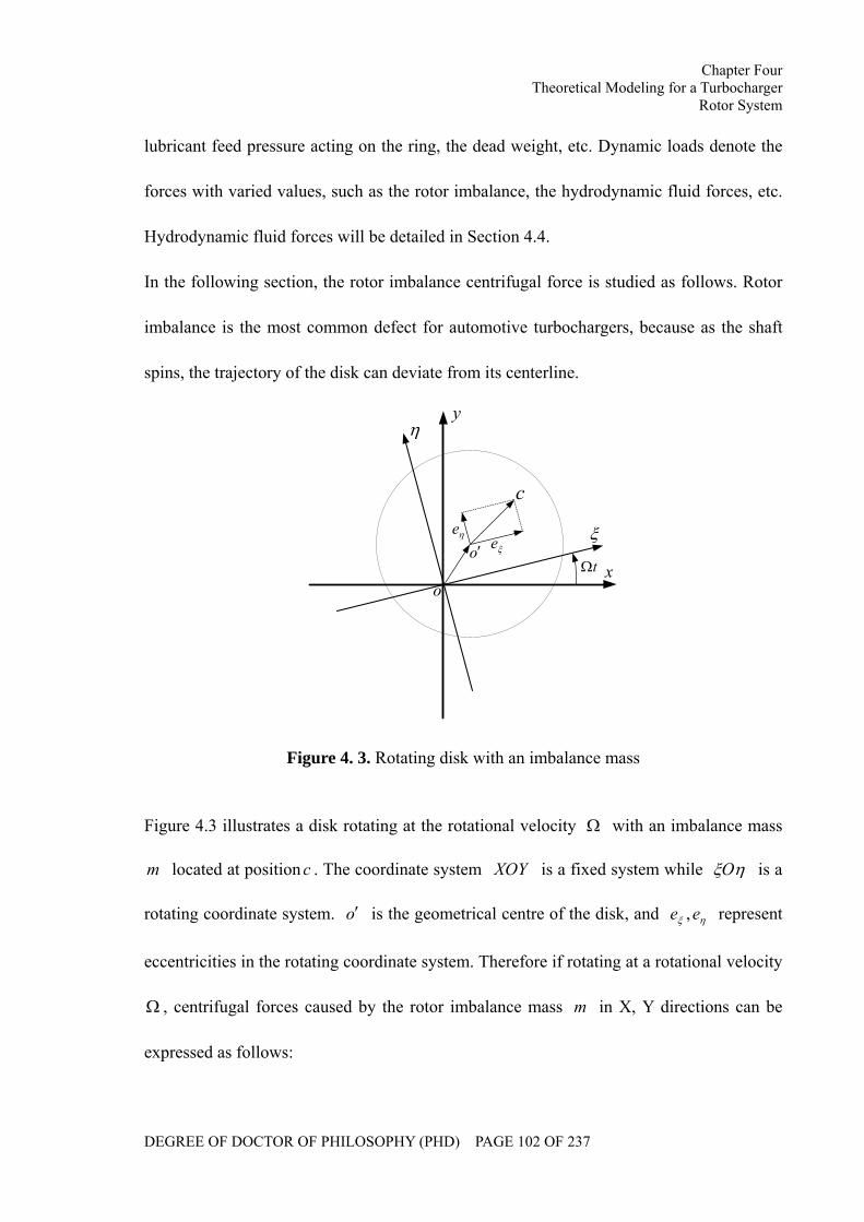
Chapter Four Theoretical Modeling for a Turbocharger
Rotor System
DEGREE OF DOCTOR OF PHILOSOPHY (PHD) PAGE 102 OF 237
lubricant feed pressure acting on the ring, the dead weight, etc. Dynamic loads denote the
forces with varied values, such as the rotor imbalance, the hydrodynamic fluid forces, etc.
Hydrodynamic fluid forces will be detailed in Section 4.4.
In the following section, the rotor imbalance centrifugal force is studied as follows. Rotor
imbalance is the most common defect for automotive turbochargers, because as the shaft
spins, the trajectory of the disk can deviate from its centerline.
o
o′
c
ξ
η
x
y
tΩξeηe
Figure 4. 3. Rotating disk with an imbalance mass
Figure 4.3 illustrates a disk rotating at the rotational velocity Ω with an imbalance mass
m located at position c . The coordinate system XOY is a fixed system while ηξO is a
rotating coordinate system. o′ is the geometrical centre of the disk, and ηξ ee , represent
eccentricities in the rotating coordinate system. Therefore if rotating at a rotational velocity
Ω , centrifugal forces caused by the rotor imbalance mass m in X, Y directions can be
expressed as follows:
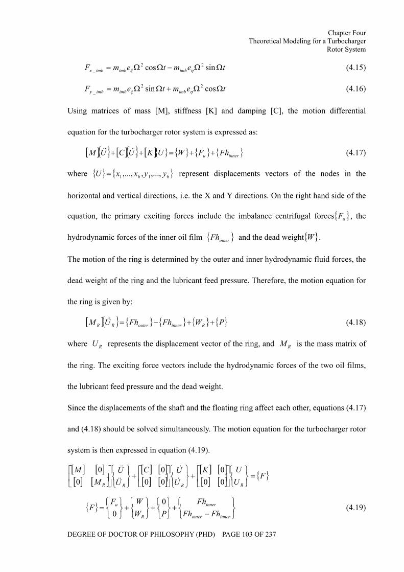
Chapter Four Theoretical Modeling for a Turbocharger
Rotor System
DEGREE OF DOCTOR OF PHILOSOPHY (PHD) PAGE 103 OF 237
temtemF imbimbimbx ΩΩ−ΩΩ= sincos 22_ ηξ (4.15)
temtemF imbimbimby ΩΩ+ΩΩ= cossin 22_ ηξ (4.16)
Using matrices of mass [M], stiffness [K] and damping [C], the motion differential
equation for the turbocharger rotor system is expressed as:
[ ] [ ] [ ] inneru FhFWUKUCUM ++=++ &&& (4.17)
where 6161 ,...,,,..., yyxxU = represent displacements vectors of the nodes in the
horizontal and vertical directions, i.e. the X and Y directions. On the right hand side of the
equation, the primary exciting forces include the imbalance centrifugal forces uF , the
hydrodynamic forces of the inner oil film innerFh and the dead weight W .
The motion of the ring is determined by the outer and inner hydrodynamic fluid forces, the
dead weight of the ring and the lubricant feed pressure. Therefore, the motion equation for
the ring is given by:
[ ] PWFhFhUM RinnerouterRR ++−=&& (4.18)
where RU represents the displacement vector of the ring, and RM is the mass matrix of
the ring. The exciting force vectors include the hydrodynamic forces of the two oil films,
the lubricant feed pressure and the dead weight.
Since the displacements of the shaft and the floating ring affect each other, equations (4.17)
and (4.18) should be solved simultaneously. The motion equation for the turbocharger rotor
system is then expressed in equation (4.19).
[ ] [ ][ ] [ ]
[ ] [ ][ ] [ ]
[ ] [ ][ ] [ ] F
UUK
UUC
UU
MM
RRRR
=⎭⎬⎫
⎩⎨⎧⎥⎦
⎤⎢⎣
⎡+
⎭⎬⎫
⎩⎨⎧⎥⎦
⎤⎢⎣
⎡+
⎭⎬⎫
⎩⎨⎧⎥⎦
⎤⎢⎣
⎡000
000
00
&
&
&&
&&
⎭⎬⎫
⎩⎨⎧
−+
⎭⎬⎫
⎩⎨⎧
+⎭⎬⎫
⎩⎨⎧
+⎭⎬⎫
⎩⎨⎧
=innerouter
inner
R
u
FhFhFh
PWWF
F0
0 (4.19)
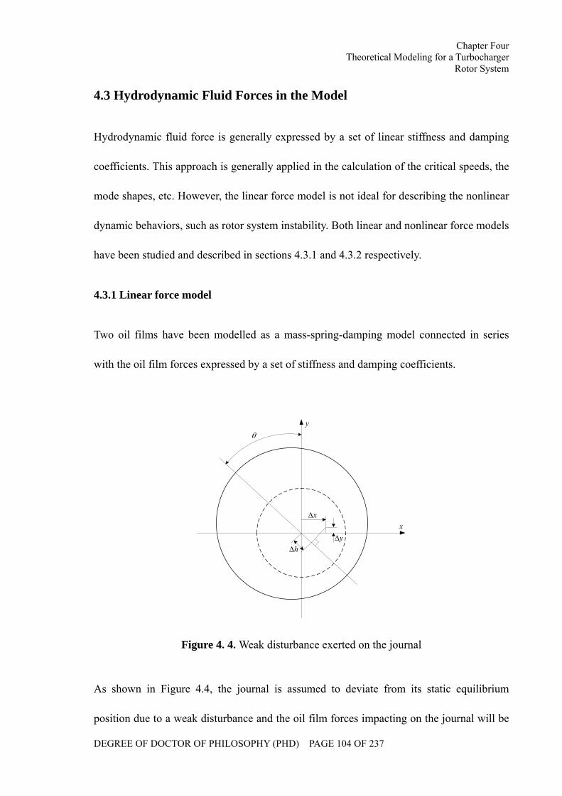
Chapter Four Theoretical Modeling for a Turbocharger
Rotor System
DEGREE OF DOCTOR OF PHILOSOPHY (PHD) PAGE 104 OF 237
4.3 Hydrodynamic Fluid Forces in the Model
Hydrodynamic fluid force is generally expressed by a set of linear stiffness and damping
coefficients. This approach is generally applied in the calculation of the critical speeds, the
mode shapes, etc. However, the linear force model is not ideal for describing the nonlinear
dynamic behaviors, such as rotor system instability. Both linear and nonlinear force models
have been studied and described in sections 4.3.1 and 4.3.2 respectively.
4.3.1 Linear force model
Two oil films have been modelled as a mass-spring-damping model connected in series
with the oil film forces expressed by a set of stiffness and damping coefficients.
θ
h∆
x∆
y∆x
y
Figure 4. 4. Weak disturbance exerted on the journal
As shown in Figure 4.4, the journal is assumed to deviate from its static equilibrium
position due to a weak disturbance and the oil film forces impacting on the journal will be
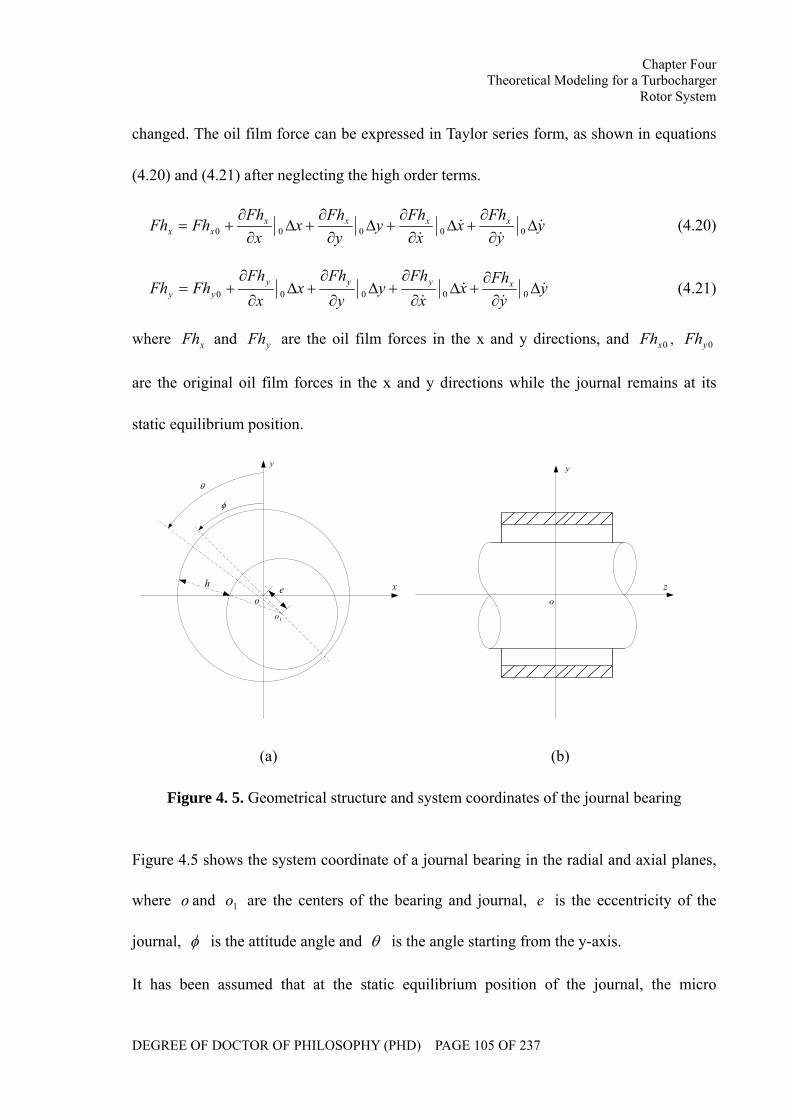
Chapter Four Theoretical Modeling for a Turbocharger
Rotor System
DEGREE OF DOCTOR OF PHILOSOPHY (PHD) PAGE 105 OF 237
changed. The oil film force can be expressed in Taylor series form, as shown in equations
(4.20) and (4.21) after neglecting the high order terms.
yy
Fhx
xFh
yy
Fhx
xFh
FhFh xxxxxx &
&&
&∆
∂∂
+∆∂∂
+∆∂∂
+∆∂∂
+= 00000 (4.20)
yy
Fhx
xFh
yy
Fhx
xFh
FhFh xyyyyy &
&&
&∆
∂∂
+∆∂
∂+∆
∂
∂+∆
∂
∂+= 00000 (4.21)
where xFh and yFh are the oil film forces in the x and y directions, and 0xFh , 0yFh
are the original oil film forces in the x and y directions while the journal remains at its
static equilibrium position.
θ
φ
x
y
o
1o
eh
o
y
z
(a) (b)
Figure 4. 5. Geometrical structure and system coordinates of the journal bearing
Figure 4.5 shows the system coordinate of a journal bearing in the radial and axial planes,
where o and 1o are the centers of the bearing and journal, e is the eccentricity of the
journal, φ is the attitude angle and θ is the angle starting from the y-axis.
It has been assumed that at the static equilibrium position of the journal, the micro
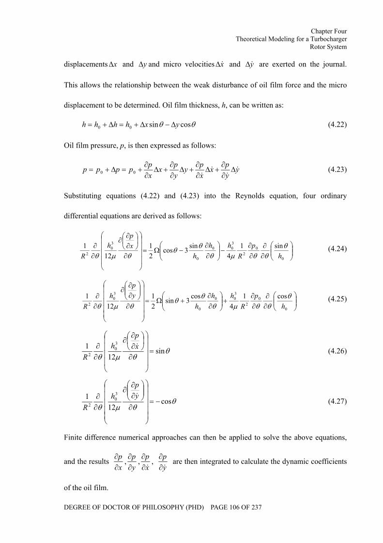
Chapter Four Theoretical Modeling for a Turbocharger
Rotor System
DEGREE OF DOCTOR OF PHILOSOPHY (PHD) PAGE 106 OF 237
displacements x∆ and y∆ and micro velocities x&∆ and y&∆ are exerted on the journal.
This allows the relationship between the weak disturbance of oil film force and the micro
displacement to be determined. Oil film thickness, h, can be written as:
θθ cossin00 yxhhhh ∆−∆+=∆+= (4.22)
Oil film pressure, p, is then expressed as follows:
yypx
xpy
ypx
xppppp &
&&
&∆
∂∂
+∆∂∂
+∆∂∂
+∆∂∂
+=∆+= 00 (4.23)
Substituting equations (4.22) and (4.23) into the Reynolds equation, four ordinary
differential equations are derived as follows:
⎟⎟⎠
⎞⎜⎜⎝
⎛∂∂
∂∂
−⎟⎟⎠
⎞⎜⎜⎝
⎛∂∂
−Ω=⎟⎟⎟⎟
⎠
⎞
⎜⎜⎜⎜
⎝
⎛
∂
⎟⎠⎞
⎜⎝⎛∂∂
∂
∂∂
0
02
300
0
30
2
sin14
sin3cos21
121
hp
Rhh
hxp
hR
θθθµθ
θθθµθ
(4.24)
⎟⎟⎠
⎞⎜⎜⎝
⎛∂∂
∂∂
+⎟⎟⎠
⎞⎜⎜⎝
⎛∂∂
+Ω=
⎟⎟⎟⎟⎟
⎠
⎞
⎜⎜⎜⎜⎜
⎝
⎛
∂
⎟⎟⎠
⎞⎜⎜⎝
⎛∂∂
∂
∂∂
0
02
300
0
30
2
cos14
cos3sin21
121
hp
Rhh
hyp
hR
θθθµθ
θθθµθ
(4.25)
θθµθ
sin12
1 30
2 =⎟⎟⎟⎟
⎠
⎞
⎜⎜⎜⎜
⎝
⎛
∂
⎟⎠⎞
⎜⎝⎛∂∂
∂
∂∂ x
ph
R& (4.26)
θθµθ
cos12
1 30
2 −=
⎟⎟⎟⎟⎟
⎠
⎞
⎜⎜⎜⎜⎜
⎝
⎛
∂
⎟⎟⎠
⎞⎜⎜⎝
⎛∂∂
∂
∂∂ y
ph
R&
(4.27)
Finite difference numerical approaches can then be applied to solve the above equations,
and the results xp∂∂ ,
yp∂∂ ,
xp&∂
∂ , yp&∂
∂ are then integrated to calculate the dynamic coefficients
of the oil film.
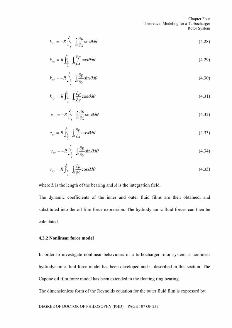
Chapter Four Theoretical Modeling for a Turbocharger
Rotor System
DEGREE OF DOCTOR OF PHILOSOPHY (PHD) PAGE 107 OF 237
θθ∫∫ ∂∂
−=− A
L
Lxx dxpRk sin2
2
(4.28)
θθ∫∫ ∂∂
=− A
L
Lyx dxpRk cos2
2
(4.29)
θθ∫∫ ∂∂
−=− A
L
Lxy dypRk sin2
2
(4.30)
θθ∫∫ ∂∂
=− A
L
Lyy dypRk cos2
2
(4.31)
∫∫ ∂∂
−=− A
L
Lxx dxpRc θθsin2
2 & (4.32)
∫∫ ∂∂
=− A
L
Lyx dxpRc θθcos2
2 & (4.33)
∫∫ ∂∂
−=− A
L
Lxy dypRc θθsin2
2 & (4.34)
∫∫ ∂∂
=− A
L
Lyy dypRc θθcos2
2 & (4.35)
where L is the length of the bearing and A is the integration field.
The dynamic coefficients of the inner and outer fluid films are then obtained, and
substituted into the oil film force expression. The hydrodynamic fluid forces can then be
calculated.
4.3.2 Nonlinear force model
In order to investigate nonlinear behaviours of a turbocharger rotor system, a nonlinear
hydrodynamic fluid force model has been developed and is described in this section. The
Capone oil film force model has been extended to the floating ring bearing.
The dimensionless form of the Reynolds equation for the outer fluid film is expressed by:
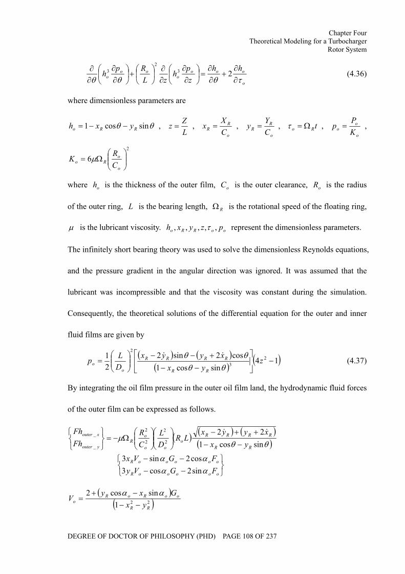
Chapter Four Theoretical Modeling for a Turbocharger
Rotor System
DEGREE OF DOCTOR OF PHILOSOPHY (PHD) PAGE 108 OF 237
o
oooo
ooo
hhz
ph
zLRp
hτθθθ ∂∂
+∂∂
=⎟⎠⎞
⎜⎝⎛
∂∂
∂∂
⎟⎠⎞
⎜⎝⎛+⎟
⎠⎞
⎜⎝⎛
∂∂
∂∂ 23
23 (4.36)
where dimensionless parameters are
θθ sincos1 RRo yxh −−= , LZz = ,
o
RR C
Xx = ,
o
RR C
Yy = , tRo Ω=τ ,
o
oo K
Pp = ,
2
6 ⎟⎟⎠
⎞⎜⎜⎝
⎛Ω=
o
oRo C
RK µ
where oh is the thickness of the outer film, oC is the outer clearance, oR is the radius
of the outer ring, L is the bearing length, RΩ is the rotational speed of the floating ring,
µ is the lubricant viscosity. ooRRo pzyxh ,,,,, τ represent the dimensionless parameters.
The infinitely short bearing theory was used to solve the dimensionless Reynolds equations,
and the pressure gradient in the angular direction was ignored. It was assumed that the
lubricant was incompressible and that the viscosity was constant during the simulation.
Consequently, the theoretical solutions of the differential equation for the outer and inner
fluid films are given by
( ) ( )( )
( )14sincos1
cos2sin221 2
3
2
−⎥⎦
⎤⎢⎣
⎡
−−+−−
⎟⎟⎠
⎞⎜⎜⎝
⎛= z
yxxyyx
DLp
RR
RRRR
oo θθ
θθ && (4.37)
By integrating the oil film pressure in the outer oil film land, the hydrodynamic fluid forces
of the outer film can be expressed as follows.
( ) ( ) ( )( )
⎭⎬⎫
⎩⎨⎧
−−−−
−−++−
⎟⎟⎠
⎞⎜⎜⎝
⎛⎟⎟⎠
⎞⎜⎜⎝
⎛Ω−=
⎭⎬⎫
⎩⎨⎧
oooooR
oooooR
RR
RRRRo
oo
oR
youter
xouter
FGVyFGVx
yxxyyx
LRDL
CR
FhFh
αααα
θθµ
sin2cos3cos2sin3
sincos122
2
2
2
2
_
_ &&
( )( )221
sincos2
RR
ooRoRo yx
GxyV
−−−+
=αα
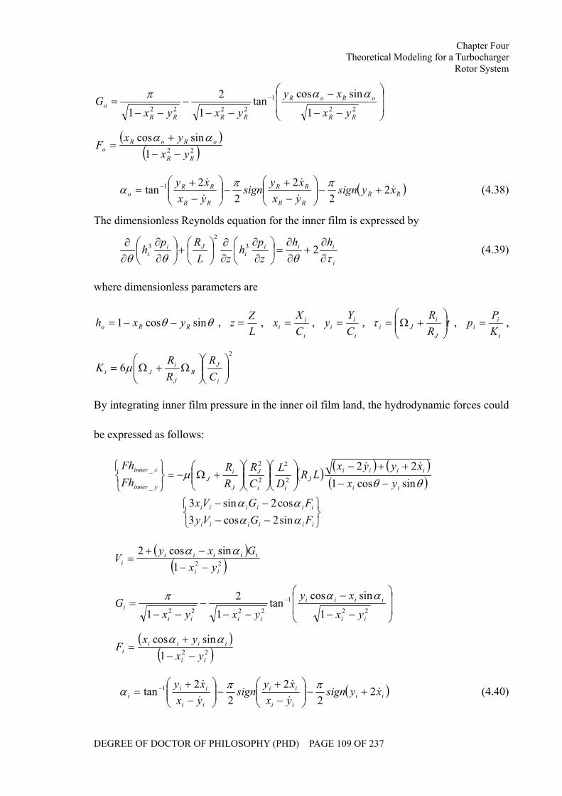
Chapter Four Theoretical Modeling for a Turbocharger
Rotor System
DEGREE OF DOCTOR OF PHILOSOPHY (PHD) PAGE 109 OF 237
⎟⎟
⎠
⎞
⎜⎜
⎝
⎛
−−
−
−−−
−−= −
22
1
2222 1
sincostan
12
1 RR
oRoR
RRRR
oyx
xy
yxyxG
ααπ
( )( )221
sincos
RR
oRoRo yx
yxF
−−+
=αα
( )RRRR
RR
RR
RRo xysign
yxxy
signyxxy
&&
&
&
&2
22
22
tan 1 +−⎟⎟⎠
⎞⎜⎜⎝
⎛−+
−⎟⎟⎠
⎞⎜⎜⎝
⎛−+
= − ππα (4.38)
The dimensionless Reynolds equation for the inner film is expressed by
i
iiii
Jii
hhzp
hzL
Rph
τθθθ ∂∂
+∂∂
=⎟⎠⎞
⎜⎝⎛
∂∂
∂∂
⎟⎠⎞
⎜⎝⎛+⎟
⎠⎞
⎜⎝⎛
∂∂
∂∂ 23
23 (4.39)
where dimensionless parameters are
θθ sincos1 RRo yxh −−= , LZz = ,
i
ii C
Xx = ,
i
ii C
Yy = , t
RR
J
iJi ⎟⎟
⎠
⎞⎜⎜⎝
⎛+Ω=τ ,
i
ii K
Pp = ,
2
6 ⎟⎟⎠
⎞⎜⎜⎝
⎛⎟⎟⎠
⎞⎜⎜⎝
⎛Ω+Ω=
i
JR
J
iJi C
RRR
K µ
By integrating inner film pressure in the inner oil film land, the hydrodynamic forces could
be expressed as follows:
( ) ( ) ( )( )
⎭⎬⎫
⎩⎨⎧
−−−−
−−++−
⎟⎟⎠
⎞⎜⎜⎝
⎛⎟⎟⎠
⎞⎜⎜⎝
⎛⎟⎟⎠
⎞⎜⎜⎝
⎛+Ω−=
⎭⎬⎫
⎩⎨⎧
iiiiii
iiiiii
ii
iiiiJ
ii
J
J
iJ
yinner
xinner
FGVyFGVx
yxxyyx
LRDL
CR
RR
FhFh
αααα
θθµ
sin2cos3cos2sin3
sincos122
2
2
2
2
_
_ &&
( )
( )221sincos2
ii
iiiiii yx
GxyV
−−−+
=αα
⎟⎟
⎠
⎞
⎜⎜
⎝
⎛
−−
−
−−−
−−= −
22
1
2222 1
sincostan
12
1 ii
iiii
iiii
iyx
xy
yxyxG
ααπ
( )( )221
sincos
ii
iiiii yx
yxF
−−+
=αα
( )iiii
ii
ii
iii xysign
yxxy
signyxxy
&&
&
&
&2
22
22
tan 1 +−⎟⎟⎠
⎞⎜⎜⎝
⎛−+
−⎟⎟⎠
⎞⎜⎜⎝
⎛−+
= − ππα (4.40)
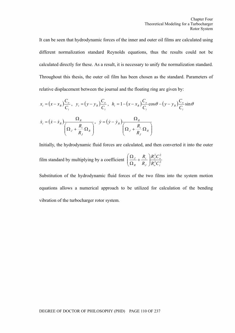
Chapter Four Theoretical Modeling for a Turbocharger
Rotor System
DEGREE OF DOCTOR OF PHILOSOPHY (PHD) PAGE 110 OF 237
It can be seen that hydrodynamic forces of the inner and outer oil films are calculated using
different normalization standard Reynolds equations, thus the results could not be
calculated directly for these. As a result, it is necessary to unify the normalization standard.
Throughout this thesis, the outer oil film has been chosen as the standard. Parameters of
relative displacement between the journal and the floating ring are given by:
( )i
oRi C
Cxxx −= , ( )
i
oRi C
Cyyy −= , ( ) ( ) θθ sincos1
i
oR
i
oRi C
Cyy
CC
xxh −−−−=
( )⎟⎟⎠
⎞⎜⎜⎝
⎛Ω+Ω
Ω−=
RJ
iJ
RRi
RR
xxx &&& , ( )⎟⎟⎠
⎞⎜⎜⎝
⎛Ω+Ω
Ω−=
RJ
iJ
RR
RR
yyy &&&
Initially, the hydrodynamic fluid forces are calculated, and then converted it into the outer
film standard by multiplying by a coefficient 22
22
io
oJ
J
i
R
J
CRCR
RR
⎟⎟⎠
⎞⎜⎜⎝
⎛+
ΩΩ
Substitution of the hydrodynamic fluid forces of the two films into the system motion
equations allows a numerical approach to be utilized for calculation of the bending
vibration of the turbocharger rotor system.
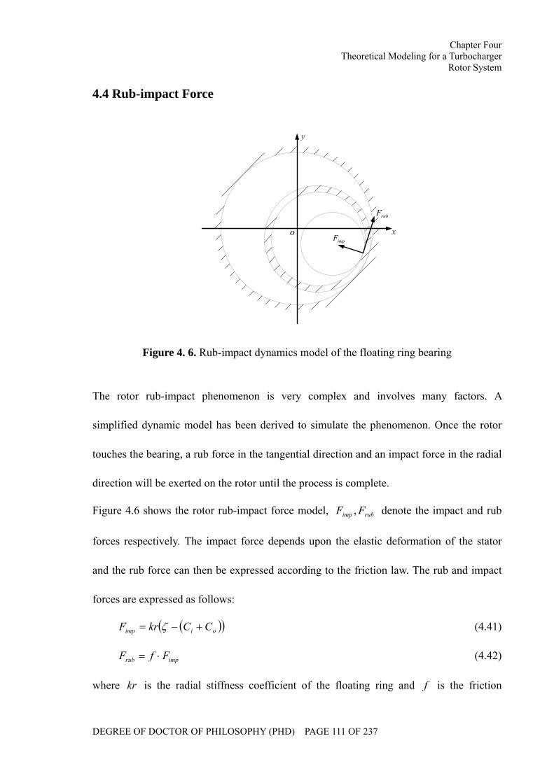
Chapter Four Theoretical Modeling for a Turbocharger
Rotor System
DEGREE OF DOCTOR OF PHILOSOPHY (PHD) PAGE 111 OF 237
4.4 Rub-impact Force
o x
y
impF
rubF
Figure 4. 6. Rub-impact dynamics model of the floating ring bearing
The rotor rub-impact phenomenon is very complex and involves many factors. A
simplified dynamic model has been derived to simulate the phenomenon. Once the rotor
touches the bearing, a rub force in the tangential direction and an impact force in the radial
direction will be exerted on the rotor until the process is complete.
Figure 4.6 shows the rotor rub-impact force model, rubimp FF , denote the impact and rub
forces respectively. The impact force depends upon the elastic deformation of the stator
and the rub force can then be expressed according to the friction law. The rub and impact
forces are expressed as follows:
( )( )oiimp CCkrF +−= ζ (4.41)
imprub FfF ⋅= (4.42)
where kr is the radial stiffness coefficient of the floating ring and f is the friction
Chapter Four Theoretical Modeling for a Turbocharger
Rotor System
DEGREE OF DOCTOR OF PHILOSOPHY (PHD) PAGE 112 OF 237
coefficient between the journal and the ring.
4.5 Summary
In this chapter, a theoretical model is developed for the turbocharger rotor system to
simulate its bending vibration according to the finite element theory. The exciting forces
which are taken into account include rotor imbalance, lubricant feed pressure,
hydrodynamic forces of the floating ring bearing and the dead weight of the rotor.
Furthermore, both linear and nonlinear hydrodynamic force models are studied for the
modal analysis and stability analysis respectively. The rub-impact phenomenon is also
investigated.
Chapter Five Calculation of Critical Speeds and Mode Shapes of
a Turbocharger Rotor System
DEGREE OF DOCTOR OF PHILOSOPHY (PHD) PAGE 113 OF 237
CHAPTER FIVE
CALCULATION OF CRITICAL SPEEDS AND MODE
SHAPES OF A TURBOCHARGER ROTOR SYSTEM
As far as a rotor system is concerned, the critical speed is one of the most important
parameters. Once critical speeds are reached, the resonance occurs which may damage the
entire rotor system. Preventing the working speed from reaching critical speed and
guaranteeing safe operation is crucial for a turbocharger rotor system whose service speed
covers a quite wide speed range. In this chapter, the critical speeds and mode shapes of the
turbocharger rotor system have been calculated and analyzed based on the mathematical
model.
Chapter Five Calculation of Critical Speeds and Mode Shapes of
a Turbocharger Rotor System
DEGREE OF DOCTOR OF PHILOSOPHY (PHD) PAGE 114 OF 237
The motion of a turbocharger rotor system is generally dominated by the forced vibration
caused by the rotor imbalance and the self-excited vibration, which is caused by
hydrodynamic fluid forces. Once the rotational velocity approaches the natural frequency,
the rotor begins to resonate, dramatically increasing the system vibration. This speed is
known as the critical speed. For a rotor system with a series of natural frequencies, there
are a series of corresponding rotational speeds.
In order to guarantee safe operation and to prevent working speeds from approaching
critical speeds, modal analysis has been carried out in this chapter for a turbocharger rotor
system based on the mathematical model. Firstly, a free rotor system has been analyzed,
ignoring the effects of the bearing and gyroscopic effects; Critical speeds and mode shapes
of a turbocharger rotor system were then studied, taking into account the influences of
floating ring bearings and gyroscopic effects.
5.1 Modal Analysis for a Free Rotor
By ignoring the influences of the bearings and the gyroscopic effects, the frequency
characteristic equation of a free rotor is expressed by:
[ ] [ ] 0=+ UKUM && (5.1)
The mass matrix [M] and stiffness matrix [K] are formed using the finite element method.
[ ] [ ][ ]⎥⎦
⎤⎢⎣
⎡=
1
1
00
MM
M (5.2)

Chapter Five Calculation of Critical Speeds and Mode Shapes of
a Turbocharger Rotor System
DEGREE OF DOCTOR OF PHILOSOPHY (PHD) PAGE 115 OF 237
[ ]
⎥⎥⎥⎥⎥⎥⎥⎥⎥⎥⎥⎥⎥⎥⎥⎥⎥
⎦
⎤
⎢⎢⎢⎢⎢⎢⎢⎢⎢⎢⎢⎢⎢⎢⎢⎢⎢
⎣
⎡
=
6
6
5
5
4
4
3
3
2
2
1
1
1
Jdm
Jdm
Jdm
Jdm
Jdm
Jdm
M
[ ] [ ][ ]⎥⎦
⎤⎢⎣
⎡=
1
1
00
KK
K (5.3)
[ ]
⎥⎥⎥⎥⎥⎥⎥⎥
⎦
⎤
⎢⎢⎢⎢⎢⎢⎢⎢
⎣
⎡
++
++
=
22_521_5
12_511_522_421_4
12_411_422_321_3
12_311_322_221_2
12_211_222_121_1
12_111_1
1
kkkkkk
kkkkkkkk
kkkkkk
K
[ ]⎥⎥⎥⎥
⎦
⎤
⎢⎢⎢⎢
⎣
⎡
=
i
i
i
i
i
i
i
i
i
lEI
lEI
lEI
lEI
k 46
612
2
23
11_ [ ]⎥⎥⎥⎥
⎦
⎤
⎢⎢⎢⎢
⎣
⎡
−
−=
i
i
i
i
i
i
i
i
i
lEI
lEI
lEI
lEI
k 26
612
2
23
12_
[ ]⎥⎥⎥⎥
⎦
⎤
⎢⎢⎢⎢
⎣
⎡ −−=
i
i
i
i
i
i
i
i
i
lEI
lEI
lEI
lEI
k 26
612
2
23
21_ [ ]⎥⎥⎥⎥
⎦
⎤
⎢⎢⎢⎢
⎣
⎡
−
−=
i
i
i
i
i
i
i
i
i
lEI
lEI
lEI
lEI
k 46
612
2
23
22_
[ ]TUUU 21= (5.4)
[ ]6655443322111 yyyyyy xxxxxxU θθθθθθ=
[ ]6655443322112 xxxxxx yyyyyyU θθθθθθ −−−−−−=
The solution form of the frequency characteristic equation is assumed as:
tjwo
neUU = (5.5)
Chapter Five Calculation of Critical Speeds and Mode Shapes of
a Turbocharger Rotor System
DEGREE OF DOCTOR OF PHILOSOPHY (PHD) PAGE 116 OF 237
Substitute equation (5.5) into equation (5.1)
( ) 02 =+− on UKMω (5.6)
The natural frequencies and mode shapes of the free rotor can be obtained by solving the
eigenvalues of the characteristic equation (5.6). The results can be found in Section 5.3.
5.2 Modal Analysis for a Turbocharger Rotor System
In this section, the critical speeds and mode shapes of the turbocharger rotor system are
studied and both the influences of floating ring bearings and the gyroscopic effects are
taken into account. The two oil films of the floating ring bearing can be simplified as a
mass-spring-damping model. In the critical speed calculation, it is reasonable to ignore the
damping effects and consider the support as isotropic when the stiffness and equivalent
mass of the support are approximately similar in all directions [136]. Figure 5.1(a) shows
the support model on one plane, where 1k and 2k denote the equivalent stiffness
coefficients of the inner and outer oil films, Rm denotes the equivalent mass of the ring.
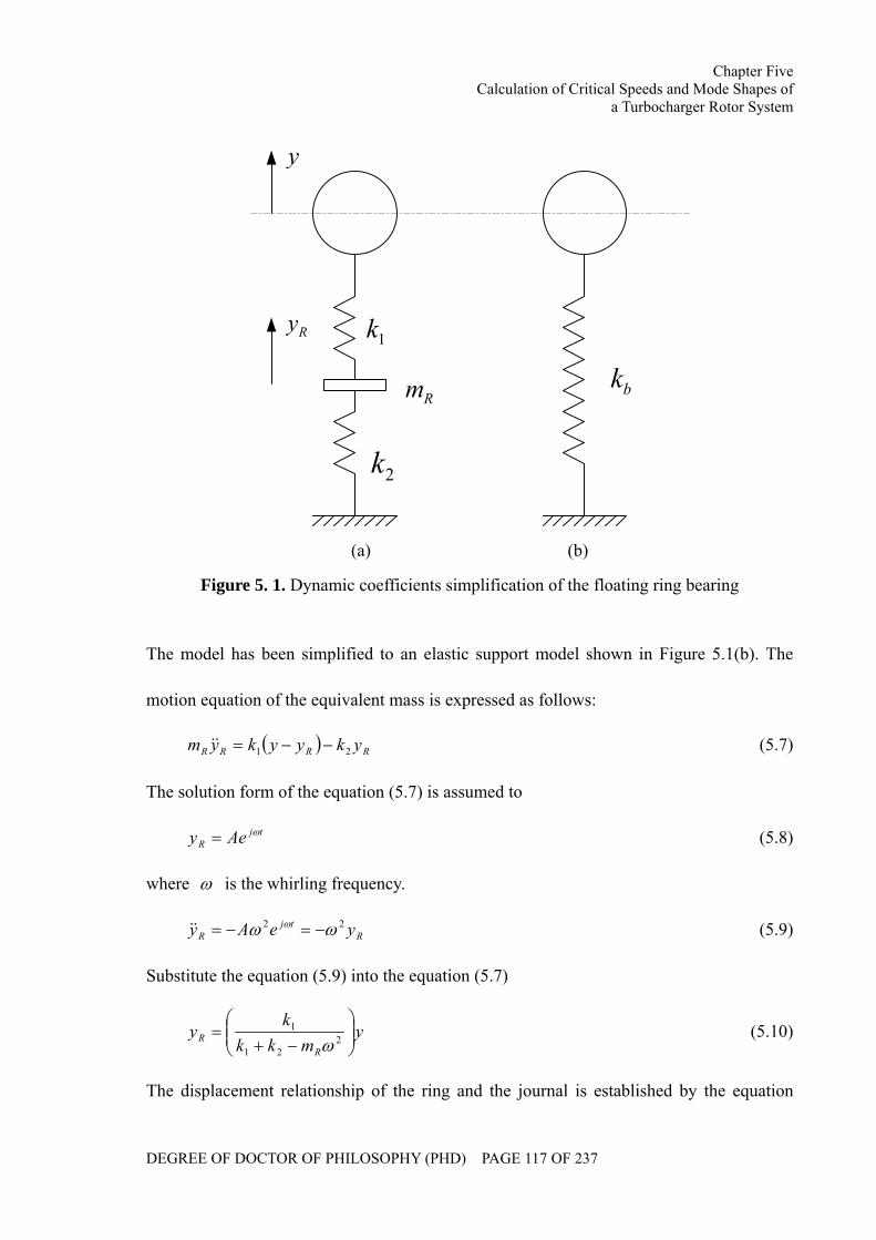
Chapter Five Calculation of Critical Speeds and Mode Shapes of
a Turbocharger Rotor System
DEGREE OF DOCTOR OF PHILOSOPHY (PHD) PAGE 117 OF 237
1k
2k
Rm bk
y
Ry
(a) (b)
Figure 5. 1. Dynamic coefficients simplification of the floating ring bearing
The model has been simplified to an elastic support model shown in Figure 5.1(b). The
motion equation of the equivalent mass is expressed as follows:
( ) RRRR ykyykym 21 −−=&& (5.7)
The solution form of the equation (5.7) is assumed to
tjR Aey ω= (5.8)
where ω is the whirling frequency.
Rtj
R yeAy 22 ωω ω −=−=&& (5.9)
Substitute the equation (5.9) into the equation (5.7)
ymkk
ky
RR ⎟⎟
⎠
⎞⎜⎜⎝
⎛−+
= 221
1
ω (5.10)
The displacement relationship of the ring and the journal is established by the equation
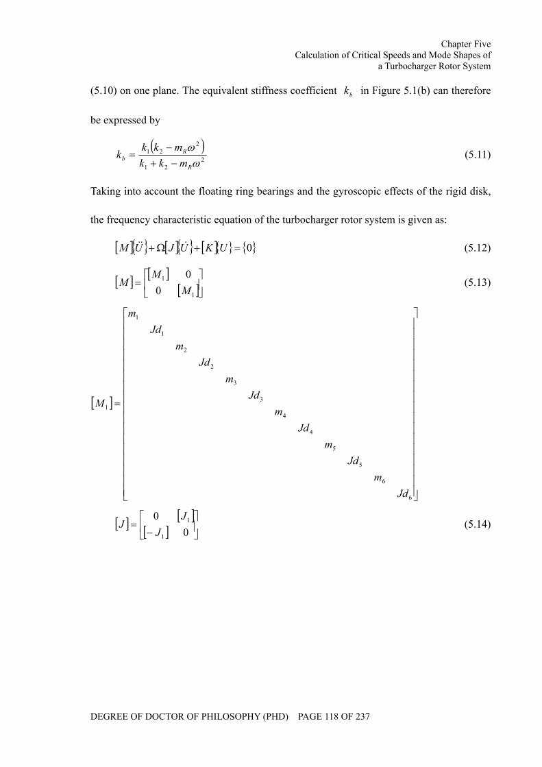
Chapter Five Calculation of Critical Speeds and Mode Shapes of
a Turbocharger Rotor System
DEGREE OF DOCTOR OF PHILOSOPHY (PHD) PAGE 118 OF 237
(5.10) on one plane. The equivalent stiffness coefficient bk in Figure 5.1(b) can therefore
be expressed by
( )2
21
221
ωω
R
Rb mkk
mkkk−+−
= (5.11)
Taking into account the floating ring bearings and the gyroscopic effects of the rigid disk,
the frequency characteristic equation of the turbocharger rotor system is given as:
[ ] [ ] [ ] 0=+Ω+ UKUJUM &&& (5.12)
[ ] [ ][ ]⎥⎦
⎤⎢⎣
⎡=
1
1
00
MM
M (5.13)
[ ]
⎥⎥⎥⎥⎥⎥⎥⎥⎥⎥⎥⎥⎥⎥⎥⎥⎥
⎦
⎤
⎢⎢⎢⎢⎢⎢⎢⎢⎢⎢⎢⎢⎢⎢⎢⎢⎢
⎣
⎡
=
6
6
5
5
4
4
3
3
2
2
1
1
1
Jdm
Jdm
Jdm
Jdm
Jdm
Jdm
M
[ ] [ ][ ] ⎥
⎦
⎤⎢⎣
⎡−
=0
0
1
1
JJ
J (5.14)
Chapter Five Calculation of Critical Speeds and Mode Shapes of
a Turbocharger Rotor System
DEGREE OF DOCTOR OF PHILOSOPHY (PHD) PAGE 119 OF 237
[ ]
⎥⎥⎥⎥⎥⎥⎥⎥⎥⎥⎥⎥⎥⎥⎥⎥⎥
⎦
⎤
⎢⎢⎢⎢⎢⎢⎢⎢⎢⎢⎢⎢⎢⎢⎢⎢⎢
⎣
⎡
=
6
5
4
3
2
1
1
0
0
0
0
0
0
p
p
p
p
p
p
J
J
J
J
J
J
J
[ ] [ ][ ]⎥⎦
⎤⎢⎣
⎡=
1
1
00
KK
K (5.15)
[ ]
⎥⎥⎥⎥⎥⎥⎥⎥
⎦
⎤
⎢⎢⎢⎢⎢⎢⎢⎢
⎣
⎡
+++
+++
=
22_521_5
12_511_522_421_4
12_411_422_321_3
12_311_322_221_2
12_211_222_121_1
12_111_1
1
kkkkkk
kkkkkkkkkk
kkkkkk
Kb
b
[ ]⎥⎥⎥⎥
⎦
⎤
⎢⎢⎢⎢
⎣
⎡
=
i
i
i
i
i
i
i
i
i
lEI
lEI
lEI
lEI
k 46
612
2
23
11_ [ ]⎥⎥⎥⎥
⎦
⎤
⎢⎢⎢⎢
⎣
⎡
−
−=
i
i
i
i
i
i
i
i
i
lEI
lEI
lEI
lEI
k 26
612
2
23
12_
[ ]⎥⎥⎥⎥
⎦
⎤
⎢⎢⎢⎢
⎣
⎡ −−=
i
i
i
i
i
i
i
i
i
lEI
lEI
lEI
lEI
k 26
612
2
23
21_ [ ]⎥⎥⎥⎥
⎦
⎤
⎢⎢⎢⎢
⎣
⎡
−
−=
i
i
i
i
i
i
i
i
i
lEI
lEI
lEI
lEI
k 46
612
2
23
22_
[ ]TUUU 21= (5.16)
[ ]6655443322111 yyyyyy xxxxxxU θθθθθθ=
[ ]6655443322112 xxxxxx yyyyyyU θθθθθθ −−−−−−=
The solution form of the equation (5.12) is assumed to
to eUU λ= (5.17)
Chapter Five Calculation of Critical Speeds and Mode Shapes of
a Turbocharger Rotor System
DEGREE OF DOCTOR OF PHILOSOPHY (PHD) PAGE 120 OF 237
Equation (5.17) is then substituted into equation (5.12)
[ ] [ ] [ ]( ) 02 =+Ω+ oUKJM λλ (5.18)
The eigenvalue of the equation (5.18) should be purely imaginary, njωλ = . 0>nω
corresponds to the natural frequency of the synchronous forward precession and 0<nω
corresponds to the natural frequency of synchronous backward precession. Where the
gyroscopic effect is concerned, the natural frequency nω will be determined not only by
system parameters, but also by the rotational speed, Ω .
5.3 Simulation and Analysis
Table 5.1 lists the simulation parameters of the turbocharger rotor system for modal
analysis, which is estimated according to the parameters of the GJ90C turbocharger. Based
on the given parameters, the natural frequencies and mode shapes of a free rotor have been
calculated. A finite element model with six mass nodes can theoretically provide twelve
natural frequencies and twelve vibration modes. In this section, the first four orders natural
frequencies and the corresponding mode shapes are listed.
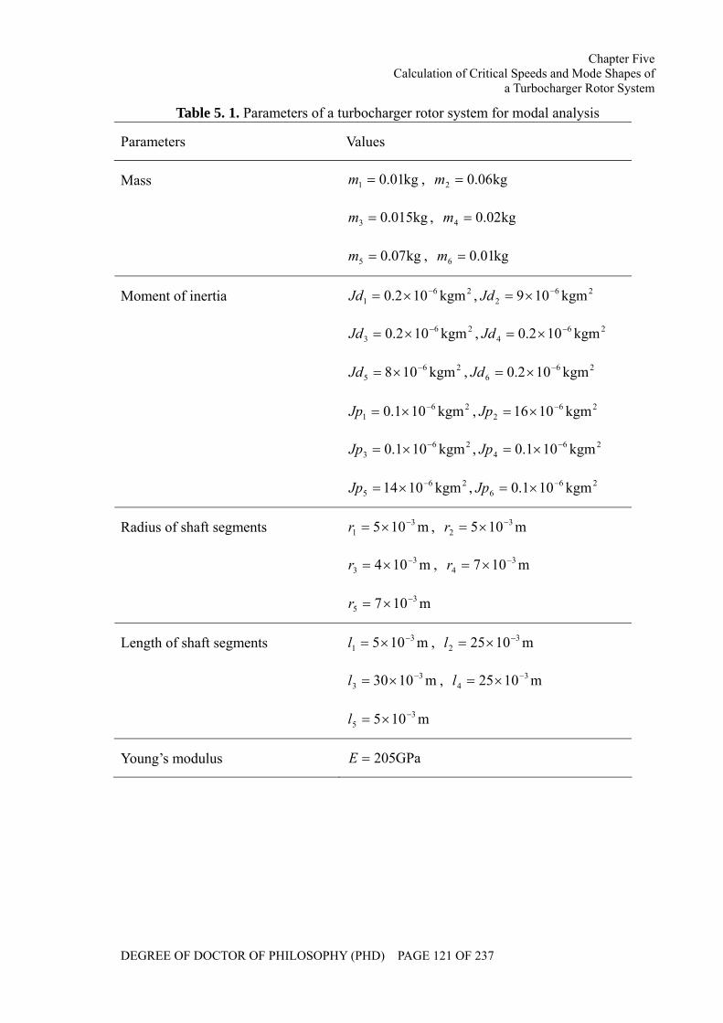
Chapter Five Calculation of Critical Speeds and Mode Shapes of
a Turbocharger Rotor System
DEGREE OF DOCTOR OF PHILOSOPHY (PHD) PAGE 121 OF 237
Table 5. 1. Parameters of a turbocharger rotor system for modal analysis
Parameters Values
kg01.01 =m , kg06.02 =m
kg015.03 =m , kg02.04 =m
Mass
kg07.05 =m , kg01.06 =m
261 kgm102.0 −×=Jd , 26
2 kgm109 −×=Jd
263 kgm102.0 −×=Jd , 26
4 kgm102.0 −×=Jd
265 kgm108 −×=Jd , 26
6 kgm102.0 −×=Jd
261 kgm101.0 −×=Jp , 26
2 kgm1016 −×=Jp
263 kgm101.0 −×=Jp , 26
4 kgm101.0 −×=Jp
Moment of inertia
265 kgm1014 −×=Jp , 26
6 kgm101.0 −×=Jp
m105 31
−×=r , m105 32
−×=r
m104 33
−×=r , m107 34
−×=r
Radius of shaft segments
m107 35
−×=r
m105 31
−×=l , m1025 32
−×=l
m1030 33
−×=l , m1025 34
−×=l
Length of shaft segments
m105 35
−×=l
Young’s modulus GPa205=E
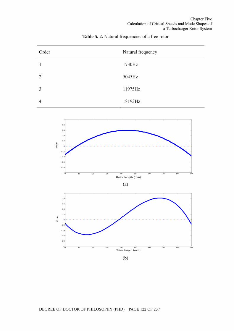
Chapter Five Calculation of Critical Speeds and Mode Shapes of
a Turbocharger Rotor System
DEGREE OF DOCTOR OF PHILOSOPHY (PHD) PAGE 122 OF 237
Table 5. 2. Natural frequencies of a free rotor
Order Natural frequency
1 1730Hz
2 5045Hz
3 11975Hz
4 18193Hz
0 10 20 30 40 50 60 70 80 90-1
-0.8
-0.6
-0.4
-0.2
0
0.2
0.4
0.6
0.8
1
Rotor length (mm)
Mod
e
(a)
0 10 20 30 40 50 60 70 80 90-1
-0.8
-0.6
-0.4
-0.2
0
0.2
0.4
0.6
0.8
1
Rotor length (mm)
Mod
e
(b)
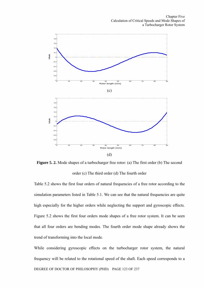
Chapter Five Calculation of Critical Speeds and Mode Shapes of
a Turbocharger Rotor System
DEGREE OF DOCTOR OF PHILOSOPHY (PHD) PAGE 123 OF 237
0 10 20 30 40 50 60 70 80 90-1
-0.8
-0.6
-0.4
-0.2
0
0.2
0.4
0.6
0.8
1
Rotor length (mm)
Mod
e
(c)
0 10 20 30 40 50 60 70 80 90-1
-0.8
-0.6
-0.4
-0.2
0
0.2
0.4
0.6
0.8
1
Rotor length (mm)
Mod
e
(d)
Figure 5. 2. Mode shapes of a turbocharger free rotor: (a) The first order (b) The second
order (c) The third order (d) The fourth order
Table 5.2 shows the first four orders of natural frequencies of a free rotor according to the
simulation parameters listed in Table 5.1. We can see that the natural frequencies are quite
high especially for the higher orders while neglecting the support and gyroscopic effects.
Figure 5.2 shows the first four orders mode shapes of a free rotor system. It can be seen
that all four orders are bending modes. The fourth order mode shape already shows the
trend of transforming into the local mode.
While considering gyroscopic effects on the turbocharger rotor system, the natural
frequency will be related to the rotational speed of the shaft. Each speed corresponds to a
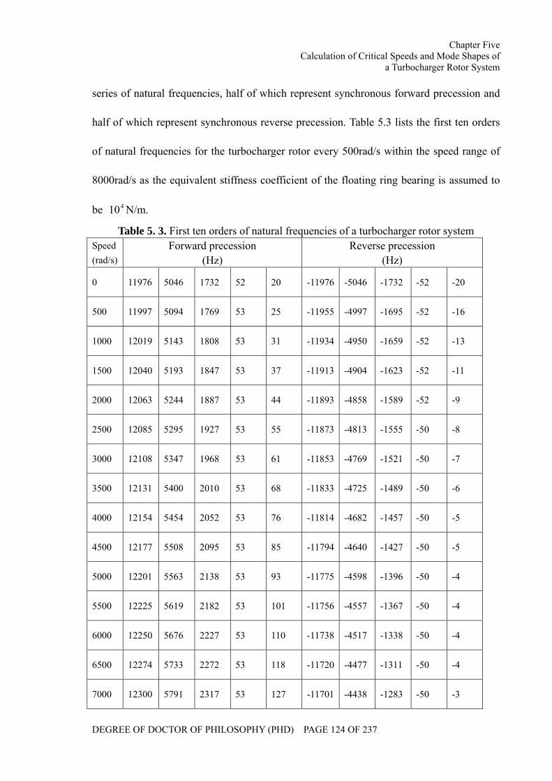
Chapter Five Calculation of Critical Speeds and Mode Shapes of
a Turbocharger Rotor System
DEGREE OF DOCTOR OF PHILOSOPHY (PHD) PAGE 124 OF 237
series of natural frequencies, half of which represent synchronous forward precession and
half of which represent synchronous reverse precession. Table 5.3 lists the first ten orders
of natural frequencies for the turbocharger rotor every 500rad/s within the speed range of
8000rad/s as the equivalent stiffness coefficient of the floating ring bearing is assumed to
be 410 N/m.
Table 5. 3. First ten orders of natural frequencies of a turbocharger rotor system Speed (rad/s)
Forward precession (Hz)
Reverse precession (Hz)
0 11976 5046 1732 52 20 -11976 -5046 -1732 -52 -20
500 11997 5094 1769 53 25 -11955 -4997 -1695 -52 -16
1000 12019 5143 1808 53 31 -11934 -4950 -1659 -52 -13
1500 12040 5193 1847 53 37 -11913 -4904 -1623 -52 -11
2000 12063 5244 1887 53 44 -11893 -4858 -1589 -52 -9
2500 12085 5295 1927 53 55 -11873 -4813 -1555 -50 -8
3000 12108 5347 1968 53 61 -11853 -4769 -1521 -50 -7
3500 12131 5400 2010 53 68 -11833 -4725 -1489 -50 -6
4000 12154 5454 2052 53 76 -11814 -4682 -1457 -50 -5
4500 12177 5508 2095 53 85 -11794 -4640 -1427 -50 -5
5000 12201 5563 2138 53 93 -11775 -4598 -1396 -50 -4
5500 12225 5619 2182 53 101 -11756 -4557 -1367 -50 -4
6000 12250 5676 2227 53 110 -11738 -4517 -1338 -50 -4
6500 12274 5733 2272 53 118 -11720 -4477 -1311 -50 -4
7000 12300 5791 2317 53 127 -11701 -4438 -1283 -50 -3
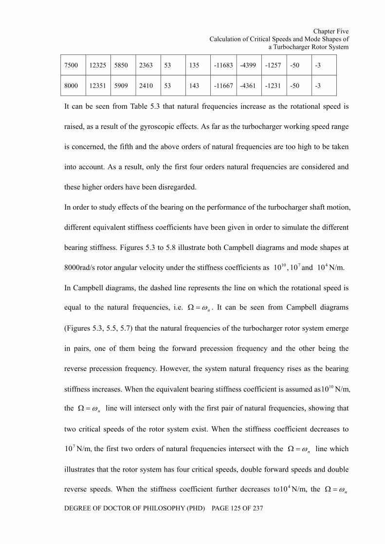
Chapter Five Calculation of Critical Speeds and Mode Shapes of
a Turbocharger Rotor System
DEGREE OF DOCTOR OF PHILOSOPHY (PHD) PAGE 125 OF 237
7500 12325 5850 2363 53 135 -11683 -4399 -1257 -50 -3
8000 12351 5909 2410 53 143 -11667 -4361 -1231 -50 -3
It can be seen from Table 5.3 that natural frequencies increase as the rotational speed is
raised, as a result of the gyroscopic effects. As far as the turbocharger working speed range
is concerned, the fifth and the above orders of natural frequencies are too high to be taken
into account. As a result, only the first four orders natural frequencies are considered and
these higher orders have been disregarded.
In order to study effects of the bearing on the performance of the turbocharger shaft motion,
different equivalent stiffness coefficients have been given in order to simulate the different
bearing stiffness. Figures 5.3 to 5.8 illustrate both Campbell diagrams and mode shapes at
8000rad/s rotor angular velocity under the stiffness coefficients as 710 10,10 and 410 N/m.
In Campbell diagrams, the dashed line represents the line on which the rotational speed is
equal to the natural frequencies, i.e. nω=Ω . It can be seen from Campbell diagrams
(Figures 5.3, 5.5, 5.7) that the natural frequencies of the turbocharger rotor system emerge
in pairs, one of them being the forward precession frequency and the other being the
reverse precession frequency. However, the system natural frequency rises as the bearing
stiffness increases. When the equivalent bearing stiffness coefficient is assumed as 1010 N/m,
the nω=Ω line will intersect only with the first pair of natural frequencies, showing that
two critical speeds of the rotor system exist. When the stiffness coefficient decreases to
710 N/m, the first two orders of natural frequencies intersect with the nω=Ω line which
illustrates that the rotor system has four critical speeds, double forward speeds and double
reverse speeds. When the stiffness coefficient further decreases to 410 N/m, the nω=Ω
Chapter Five Calculation of Critical Speeds and Mode Shapes of
a Turbocharger Rotor System
DEGREE OF DOCTOR OF PHILOSOPHY (PHD) PAGE 126 OF 237
line will also intersect with the third reverse frequency line, a line which demonstrates the
existence of the third reverse critical speed besides the above four speeds.
From Figure 5.4, it can be seen that the first forward and the reverse modes are bending
modes while the others are elastic gyroscopic modes when the bearing stiffness is assumed
to be relatively high, i.e. 1010 N/m. As is shown in Figure 5.6, as the bearing stiffness
decreases to 710 N/m, rigid body conical modes emerge, which is shown in both the first
forward and reverse modes. The second forward and reverse modes, however, are
approximately translational modes and the others are bending and gyroscopic modes
respectively. The same trends can be observed as the bearing stiffness further decreases to
410 N/m as is shown in Figure 5.7. Both mode shapes are rigid shapes (conical modes and
translational modes respectively). The third forward and reverse modes are bending modes
and the fourth are gyroscopic modes.
Chapter Five Calculation of Critical Speeds and Mode Shapes of
a Turbocharger Rotor System
DEGREE OF DOCTOR OF PHILOSOPHY (PHD) PAGE 127 OF 237
0 1000 2000 3000 4000 5000 6000 7000 80000
5000
10000
15000
Rotational speed (rad/s)
Nat
ural
freq
uenc
y (H
z)
Figure 5. 3. A Campbell diagram of the turbocharger rotor system with an equivalent
stiffness coefficient of 1010 N/m
0 10 20 30 40 50 60 70 80 90-0.005
0
0.005
0.01
0.015
0.02
0.025
0.03
Rotor length (mm)
Mod
e
(a) The first forward mode
Chapter Five Calculation of Critical Speeds and Mode Shapes of
a Turbocharger Rotor System
DEGREE OF DOCTOR OF PHILOSOPHY (PHD) PAGE 128 OF 237
0 10 20 30 40 50 60 70 80 90-0.03
-0.025
-0.02
-0.015
-0.01
-0.005
0
0.005
Rotor length (mm)
Mod
e
(b) The first reverse mode
0 10 20 30 40 50 60 70 80 90-0.02
-0.015
-0.01
-0.005
0
0.005
0.01
0.015
0.02
0.025
0.03
Rotor length (mm)
Mod
e
(c) The second forward mode
0 10 20 30 40 50 60 70 80 90-0.03
-0.025
-0.02
-0.015
-0.01
-0.005
0
0.005
0.01
0.015
0.02
Rotor length (mm)
Mod
e
(d) The second reverse mode
Chapter Five Calculation of Critical Speeds and Mode Shapes of
a Turbocharger Rotor System
DEGREE OF DOCTOR OF PHILOSOPHY (PHD) PAGE 129 OF 237
0 10 20 30 40 50 60 70 80 90-2.5
-2
-1.5
-1
-0.5
0
0.5
1 x 10⁻³
Rotor length (mm)
Mod
e
(e) The third forward mode
0 10 20 30 40 50 60 70 80 90-1
0
1
2
3
4
5
6
7 x 10⁻³
Rotor length (mm)
Mod
e
(f) The third reverse mode
0 10 20 30 40 50 60 70 80 90-1
-0.5
0
0.5
1
1.5
2 x 10⁻³
Rotor length (mm)
Mod
e
(g) The fourth forward mode
Chapter Five Calculation of Critical Speeds and Mode Shapes of
a Turbocharger Rotor System
DEGREE OF DOCTOR OF PHILOSOPHY (PHD) PAGE 130 OF 237
0 10 20 30 40 50 60 70 80 90-3
-2.5
-2
-1.5
-1
-0.5
0
0.5
1 x 10⁻³
Rotor length (mm)
Mod
e
(h)
Figure 5. 4. Turbocharger mode shapes with an equivalent bearing stiffness coefficient of
1010 N/m at the rotational speed of 8,000 rad/s
0 1000 2000 3000 4000 5000 6000 7000 80000
1000
2000
3000
4000
5000
6000
7000
Rotational speed (rad/s)
Nat
ural
freq
uenc
y (H
z)
Figure 5. 5. A Campbell diagram of the turbocharger rotor system with an equivalent
stiffness coefficient of 710 N/m
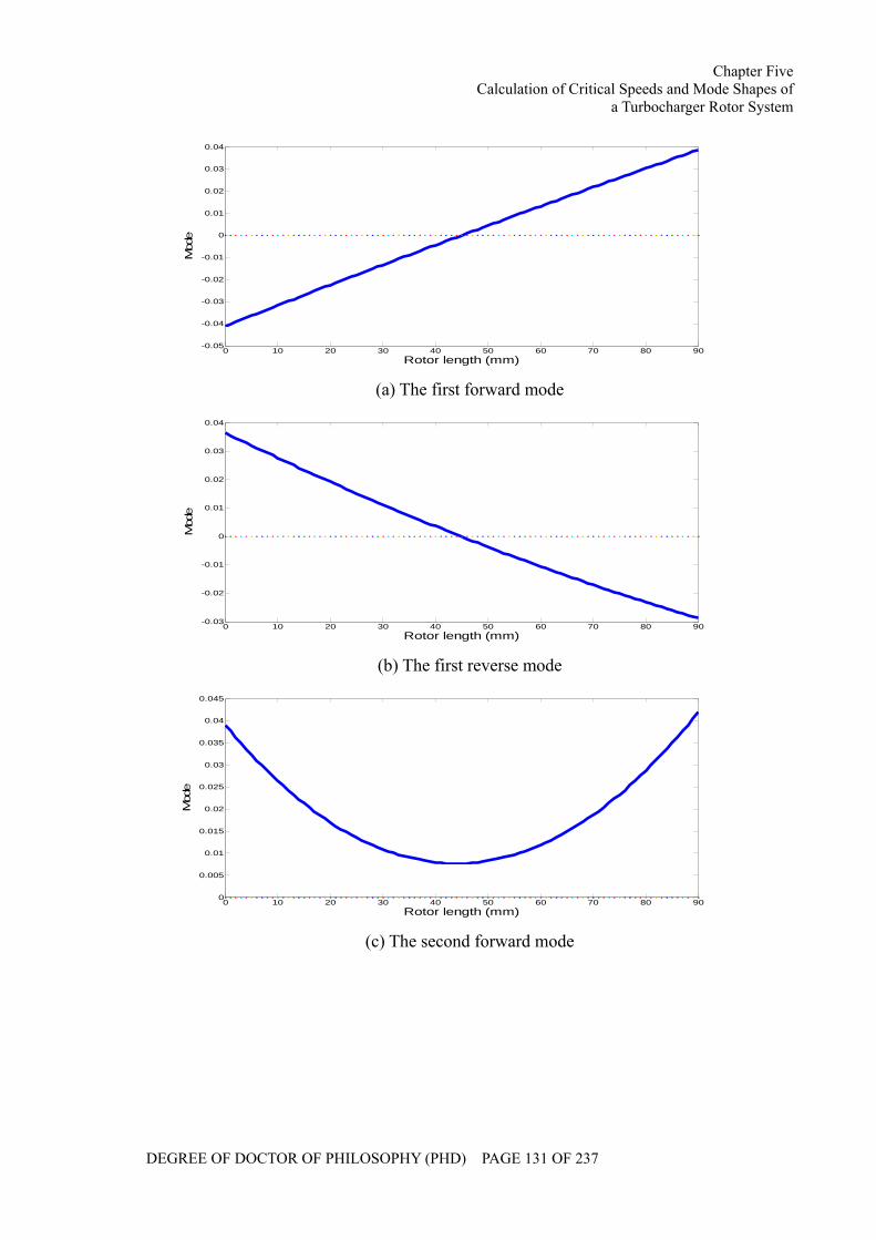
Chapter Five Calculation of Critical Speeds and Mode Shapes of
a Turbocharger Rotor System
DEGREE OF DOCTOR OF PHILOSOPHY (PHD) PAGE 131 OF 237
0 10 20 30 40 50 60 70 80 90-0.05
-0.04
-0.03
-0.02
-0.01
0
0.01
0.02
0.03
0.04
Rotor length (mm)
Mod
e
(a) The first forward mode
0 10 20 30 40 50 60 70 80 90-0.03
-0.02
-0.01
0
0.01
0.02
0.03
0.04
Rotor length (mm)
Mod
e
(b) The first reverse mode
0 10 20 30 40 50 60 70 80 900
0.005
0.01
0.015
0.02
0.025
0.03
0.035
0.04
0.045
Rotor length (mm)
Mod
e
(c) The second forward mode
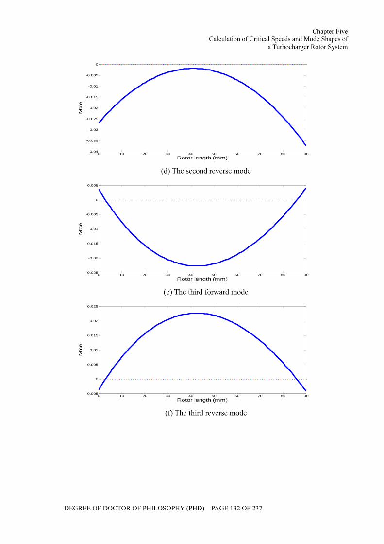
Chapter Five Calculation of Critical Speeds and Mode Shapes of
a Turbocharger Rotor System
DEGREE OF DOCTOR OF PHILOSOPHY (PHD) PAGE 132 OF 237
0 10 20 30 40 50 60 70 80 90-0.04
-0.035
-0.03
-0.025
-0.02
-0.015
-0.01
-0.005
0
Rotor length (mm)
Mod
e
(d) The second reverse mode
0 10 20 30 40 50 60 70 80 90-0.025
-0.02
-0.015
-0.01
-0.005
0
0.005
Rotor length (mm)
Mod
e
(e) The third forward mode
0 10 20 30 40 50 60 70 80 90-0.005
0
0.005
0.01
0.015
0.02
0.025
Rotor length (mm)
Mod
e
(f) The third reverse mode
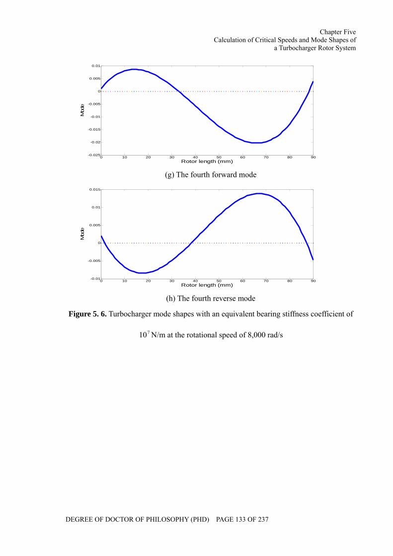
Chapter Five Calculation of Critical Speeds and Mode Shapes of
a Turbocharger Rotor System
DEGREE OF DOCTOR OF PHILOSOPHY (PHD) PAGE 133 OF 237
0 10 20 30 40 50 60 70 80 90-0.025
-0.02
-0.015
-0.01
-0.005
0
0.005
0.01
Rotor length (mm)
Mod
e
(g) The fourth forward mode
0 10 20 30 40 50 60 70 80 90-0.01
-0.005
0
0.005
0.01
0.015
Rotor length (mm)
Mod
e
(h) The fourth reverse mode
Figure 5. 6. Turbocharger mode shapes with an equivalent bearing stiffness coefficient of
710 N/m at the rotational speed of 8,000 rad/s
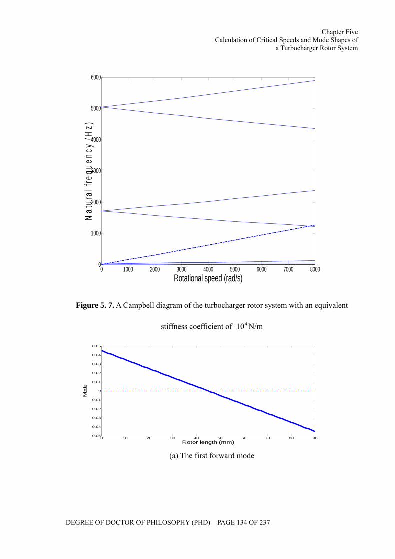
Chapter Five Calculation of Critical Speeds and Mode Shapes of
a Turbocharger Rotor System
DEGREE OF DOCTOR OF PHILOSOPHY (PHD) PAGE 134 OF 237
0 1000 2000 3000 4000 5000 6000 7000 80000
1000
2000
3000
4000
5000
6000
Rotational speed (rad/s)
Nat
ural
freq
uenc
y (H
z)
Figure 5. 7. A Campbell diagram of the turbocharger rotor system with an equivalent
stiffness coefficient of 410 N/m
0 10 20 30 40 50 60 70 80 90-0.05
-0.04
-0.03
-0.02
-0.01
0
0.01
0.02
0.03
0.04
0.05
Rotor length (mm)
Mod
e
(a) The first forward mode
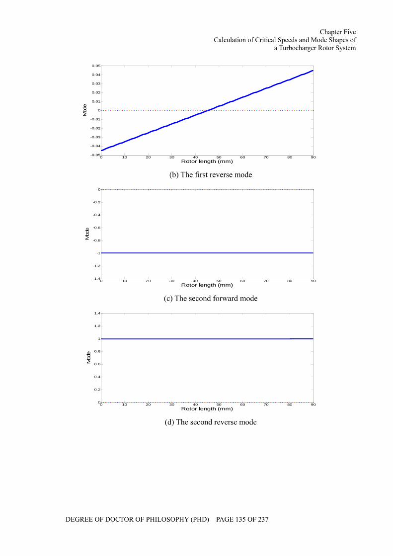
Chapter Five Calculation of Critical Speeds and Mode Shapes of
a Turbocharger Rotor System
DEGREE OF DOCTOR OF PHILOSOPHY (PHD) PAGE 135 OF 237
0 10 20 30 40 50 60 70 80 90-0.05
-0.04
-0.03
-0.02
-0.01
0
0.01
0.02
0.03
0.04
0.05
Rotor length (mm)
Mod
e
(b) The first reverse mode
0 10 20 30 40 50 60 70 80 90-1.4
-1.2
-1
-0.8
-0.6
-0.4
-0.2
0
Rotor length (mm)
Mod
e
(c) The second forward mode
0 10 20 30 40 50 60 70 80 900
0.2
0.4
0.6
0.8
1
1.2
1.4
Rotor length (mm)
Mod
e
(d) The second reverse mode
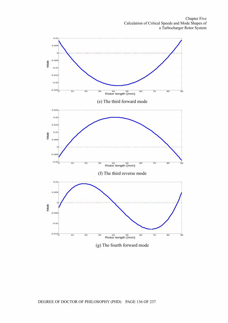
Chapter Five Calculation of Critical Speeds and Mode Shapes of
a Turbocharger Rotor System
DEGREE OF DOCTOR OF PHILOSOPHY (PHD) PAGE 136 OF 237
0 10 20 30 40 50 60 70 80 90-0.025
-0.02
-0.015
-0.01
-0.005
0
0.005
0.01
Rotor length (mm)
Mod
e
(e) The third forward mode
0 10 20 30 40 50 60 70 80 90-0.01
-0.005
0
0.005
0.01
0.015
0.02
0.025
Rotor length (mm)
Mod
e
(f) The third reverse mode
0 10 20 30 40 50 60 70 80 90-0.015
-0.01
-0.005
0
0.005
0.01
Rotor length (mm)
Mod
e
(g) The fourth forward mode
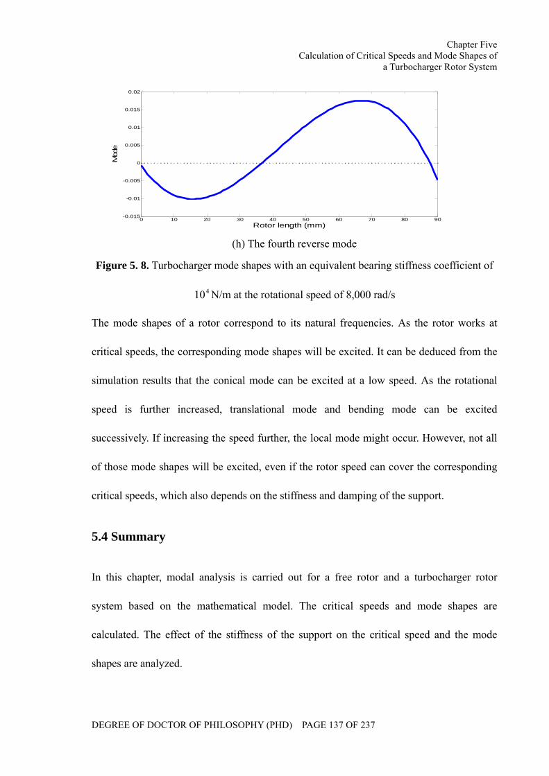
Chapter Five Calculation of Critical Speeds and Mode Shapes of
a Turbocharger Rotor System
DEGREE OF DOCTOR OF PHILOSOPHY (PHD) PAGE 137 OF 237
0 10 20 30 40 50 60 70 80 90-0.015
-0.01
-0.005
0
0.005
0.01
0.015
0.02
Rotor length (mm)
Mod
e
(h) The fourth reverse mode
Figure 5. 8. Turbocharger mode shapes with an equivalent bearing stiffness coefficient of
410 N/m at the rotational speed of 8,000 rad/s
The mode shapes of a rotor correspond to its natural frequencies. As the rotor works at
critical speeds, the corresponding mode shapes will be excited. It can be deduced from the
simulation results that the conical mode can be excited at a low speed. As the rotational
speed is further increased, translational mode and bending mode can be excited
successively. If increasing the speed further, the local mode might occur. However, not all
of those mode shapes will be excited, even if the rotor speed can cover the corresponding
critical speeds, which also depends on the stiffness and damping of the support.
5.4 Summary
In this chapter, modal analysis is carried out for a free rotor and a turbocharger rotor
system based on the mathematical model. The critical speeds and mode shapes are
calculated. The effect of the stiffness of the support on the critical speed and the mode
shapes are analyzed.
Chapter Six Stability Analysis of a Turbocharger Rotor System
Under Multi-field Coupled Forces
DEGREE OF DOCTOR OF PHILOSOPHY (PHD) PAGE 138 OF 237
CHAPTER SIX
STABILITY ANALYSIS OF A TURBOCHARGER
ROTOR SYSTEM UNDER MULTI-FIELD COUPLED
FORCES
The system vibration and the stability are the key issues for a rotor bearing system. In
addition, instability is one of the most common faults that might threaten the system
security. In this chapter, the stability characteristics of a turbocharger rotor system have
been investigated based on the simulation results. The effects of the rotor imbalance,
lubricant viscosity, bearing clearances and lubricant feed pressure on the stability of the
turbocharger rotor system have been studied.
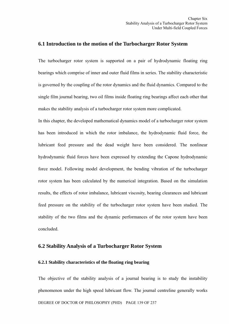
Chapter Six Stability Analysis of a Turbocharger Rotor System
Under Multi-field Coupled Forces
DEGREE OF DOCTOR OF PHILOSOPHY (PHD) PAGE 139 OF 237
6.1 Introduction to the motion of the Turbocharger Rotor System
The turbocharger rotor system is supported on a pair of hydrodynamic floating ring
bearings which comprise of inner and outer fluid films in series. The stability characteristic
is governed by the coupling of the rotor dynamics and the fluid dynamics. Compared to the
single film journal bearing, two oil films inside floating ring bearings affect each other that
makes the stability analysis of a turbocharger rotor system more complicated.
In this chapter, the developed mathematical dynamics model of a turbocharger rotor system
has been introduced in which the rotor imbalance, the hydrodynamic fluid force, the
lubricant feed pressure and the dead weight have been considered. The nonlinear
hydrodynamic fluid forces have been expressed by extending the Capone hydrodynamic
force model. Following model development, the bending vibration of the turbocharger
rotor system has been calculated by the numerical integration. Based on the simulation
results, the effects of rotor imbalance, lubricant viscosity, bearing clearances and lubricant
feed pressure on the stability of the turbocharger rotor system have been studied. The
stability of the two films and the dynamic performances of the rotor system have been
concluded.
6.2 Stability Analysis of a Turbocharger Rotor System
6.2.1 Stability characteristics of the floating ring bearing
The objective of the stability analysis of a journal bearing is to study the instability
phenomenon under the high speed lubricant flow. The journal centreline generally works
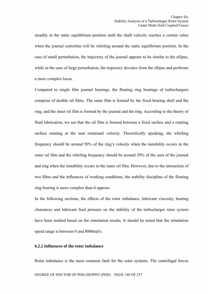
Chapter Six Stability Analysis of a Turbocharger Rotor System
Under Multi-field Coupled Forces
DEGREE OF DOCTOR OF PHILOSOPHY (PHD) PAGE 140 OF 237
steadily at the static equilibrium position until the shaft velocity reaches a certain value
when the journal centreline will be whirling around the static equilibrium position. In the
case of small perturbation, the trajectory of the journal appears to be similar to the ellipse,
while in the case of large perturbation, the trajectory deviates from the ellipse and performs
a more complex locus.
Compared to single film journal bearings, the floating ring bearings of turbochargers
comprise of double oil films. The outer film is formed by the fixed bearing shell and the
ring, and the inner oil film is formed by the journal and the ring. According to the theory of
fluid lubrication, we see that the oil film is formed between a fixed surface and a rotating
surface running at the sum rotational velocity. Theoretically speaking, the whirling
frequency should be around 50% of the ring’s velocity when the instability occurs in the
outer oil film and the whirling frequency should be around 50% of the sum of the journal
and ring when the instability occurs in the inner oil film. However, due to the interaction of
two films and the influences of working conditions, the stability discipline of the floating
ring bearing is more complex than it appears.
In the following sections, the effects of the rotor imbalance, lubricant viscosity, bearing
clearances and lubricant feed pressure on the stability of the turbocharger rotor system
have been studied based on the simulation results. It should be noted that the simulation
speed range is between 0 and 8000rad/s.
6.2.2 Influences of the rotor imbalance
Rotor imbalance is the most common fault for the rotor systems. The centrifugal forces
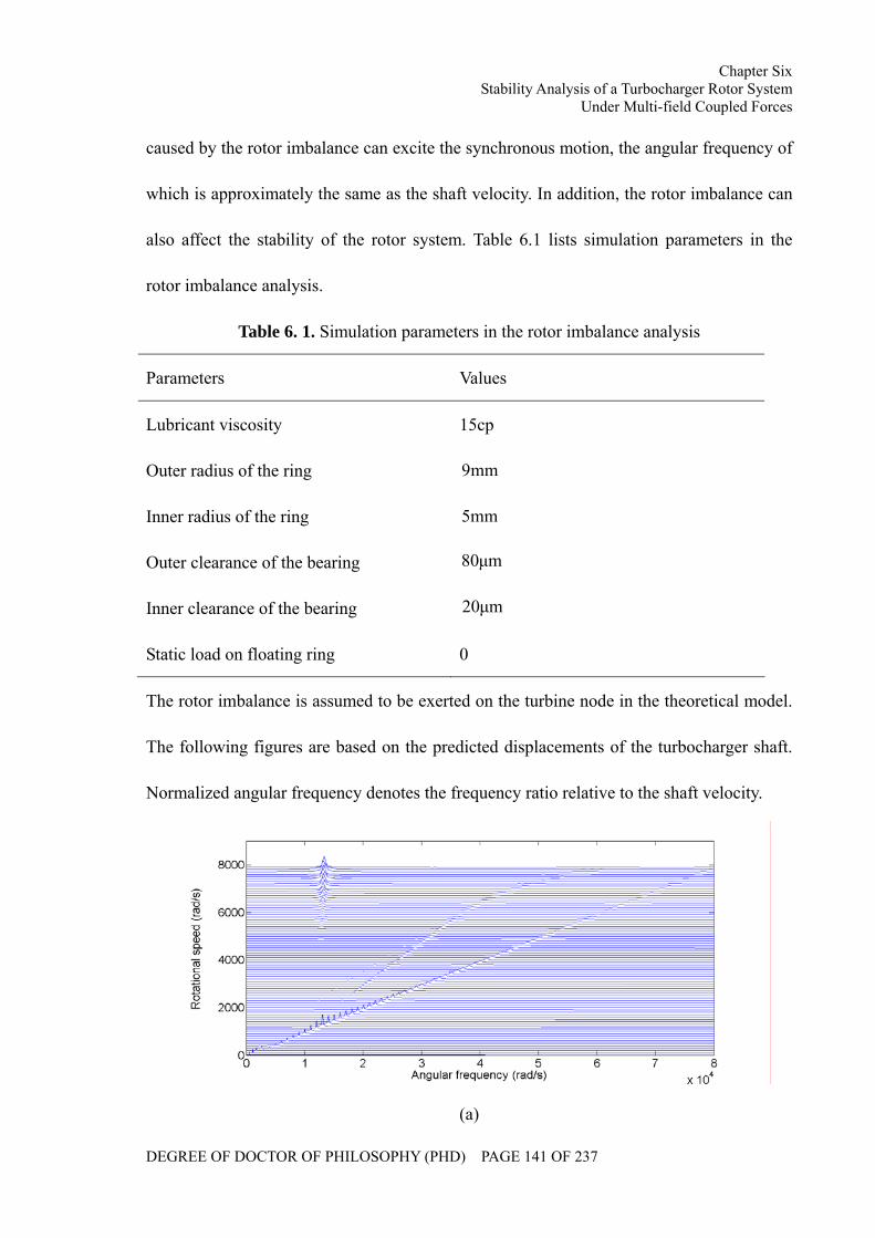
Chapter Six Stability Analysis of a Turbocharger Rotor System
Under Multi-field Coupled Forces
DEGREE OF DOCTOR OF PHILOSOPHY (PHD) PAGE 141 OF 237
caused by the rotor imbalance can excite the synchronous motion, the angular frequency of
which is approximately the same as the shaft velocity. In addition, the rotor imbalance can
also affect the stability of the rotor system. Table 6.1 lists simulation parameters in the
rotor imbalance analysis.
Table 6. 1. Simulation parameters in the rotor imbalance analysis
Parameters Values
Lubricant viscosity 15cp
Outer radius of the ring mm9
Inner radius of the ring mm5
Outer clearance of the bearing µm80
Inner clearance of the bearing µm20
Static load on floating ring 0
The rotor imbalance is assumed to be exerted on the turbine node in the theoretical model.
The following figures are based on the predicted displacements of the turbocharger shaft.
Normalized angular frequency denotes the frequency ratio relative to the shaft velocity.
(a)
Chapter Six Stability Analysis of a Turbocharger Rotor System
Under Multi-field Coupled Forces
DEGREE OF DOCTOR OF PHILOSOPHY (PHD) PAGE 142 OF 237
(b)
Figure 6. 1. Displacement of the turbocharger shaft under kgm10 5− rotor imbalance at the
turbine impeller: (a)Waterfall diagram (b)Bifurcation diagram
(a)
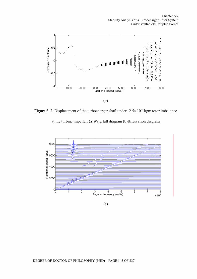
Chapter Six Stability Analysis of a Turbocharger Rotor System
Under Multi-field Coupled Forces
DEGREE OF DOCTOR OF PHILOSOPHY (PHD) PAGE 143 OF 237
(b)
Figure 6. 2. Displacement of the turbocharger shaft under kgm105.2 5−× rotor imbalance
at the turbine impeller: (a)Waterfall diagram (b)Bifurcation diagram
(a)
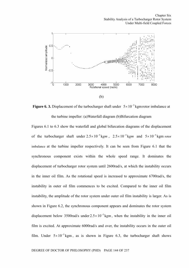
Chapter Six Stability Analysis of a Turbocharger Rotor System
Under Multi-field Coupled Forces
DEGREE OF DOCTOR OF PHILOSOPHY (PHD) PAGE 144 OF 237
(b)
Figure 6. 3. Displacement of the turbocharger shaft under kgm105 5−× rotor imbalance at
the turbine impeller: (a)Waterfall diagram (b)Bifurcation diagram
Figures 6.1 to 6.3 show the waterfall and global bifurcation diagrams of the displacement
of the turbocharger shaft under gmk105.2 5−× , gmk105.2 5−× and kgm105 5−× rotor
imbalance at the turbine impeller respectively. It can be seen from Figure 6.1 that the
synchronous component exists within the whole speed range. It dominates the
displacement of turbocharger rotor system until 2600rad/s, at which the instability occurs
in the inner oil film. As the rotational speed is increased to approximate 6700rad/s, the
instability in outer oil film commences to be excited. Compared to the inner oil film
instability, the amplitude of the rotor system under outer oil film instability is larger. As is
shown in Figure 6.2, the synchronous component appears and dominates the rotor system
displacement below 3500rad/s under gmk105.2 5−× , when the instability in the inner oil
film is excited. At approximate 6000rad/s and over, the instability occurs in the outer oil
film. Under kgm105 5−× , as is shown in Figure 6.3, the turbocharger shaft shows
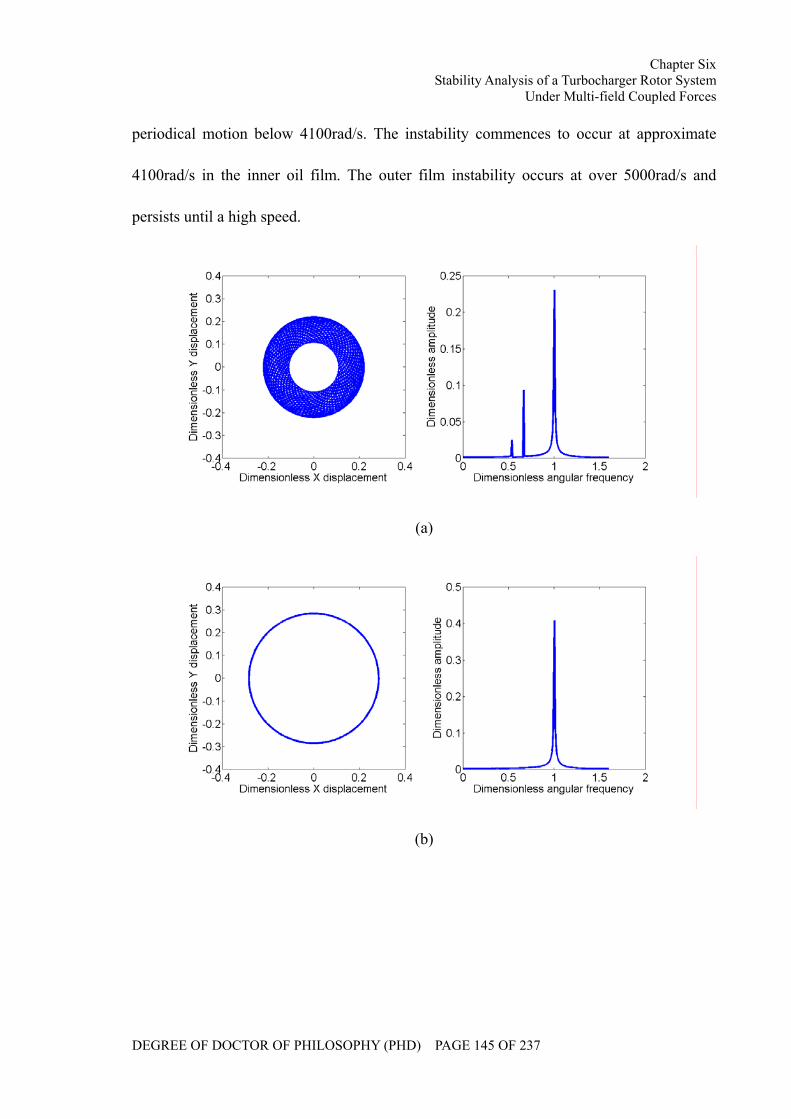
Chapter Six Stability Analysis of a Turbocharger Rotor System
Under Multi-field Coupled Forces
DEGREE OF DOCTOR OF PHILOSOPHY (PHD) PAGE 145 OF 237
periodical motion below 4100rad/s. The instability commences to occur at approximate
4100rad/s in the inner oil film. The outer film instability occurs at over 5000rad/s and
persists until a high speed.
(a)
(b)
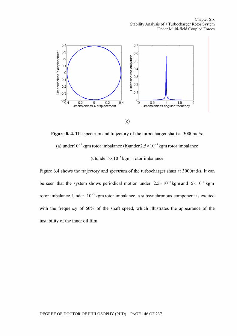
Chapter Six Stability Analysis of a Turbocharger Rotor System
Under Multi-field Coupled Forces
DEGREE OF DOCTOR OF PHILOSOPHY (PHD) PAGE 146 OF 237
(c)
Figure 6. 4. The spectrum and trajectory of the turbocharger shaft at 3000rad/s:
(a) under kgm10 5− rotor imbalance (b)under kgm105.2 5−× rotor imbalance
(c)under kgm105 5−× rotor imbalance
Figure 6.4 shows the trajectory and spectrum of the turbocharger shaft at 3000rad/s. It can
be seen that the system shows periodical motion under kgm105.2 5−× and kgm105 5−×
rotor imbalance. Under kgm10 5− rotor imbalance, a subsynchronous component is excited
with the frequency of 60% of the shaft speed, which illustrates the appearance of the
instability of the inner oil film.
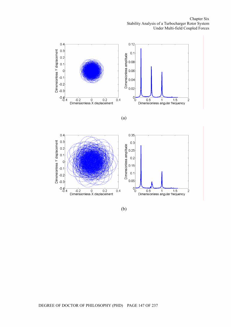
Chapter Six Stability Analysis of a Turbocharger Rotor System
Under Multi-field Coupled Forces
DEGREE OF DOCTOR OF PHILOSOPHY (PHD) PAGE 147 OF 237
(a)
(b)
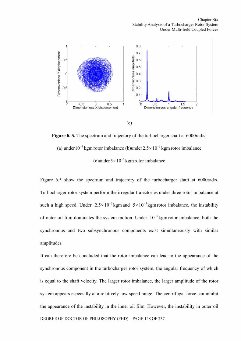
Chapter Six Stability Analysis of a Turbocharger Rotor System
Under Multi-field Coupled Forces
DEGREE OF DOCTOR OF PHILOSOPHY (PHD) PAGE 148 OF 237
(c)
Figure 6. 5. The spectrum and trajectory of the turbocharger shaft at 6000rad/s:
(a) under kgm10 5− rotor imbalance (b)under kgm105.2 5−× rotor imbalance
(c)under kgm105 5−× rotor imbalance
Figure 6.5 show the spectrum and trajectory of the turbocharger shaft at 6000rad/s.
Turbocharger rotor system perform the irregular trajectories under three rotor imbalance at
such a high speed. Under kgm105.2 5−× and kgm105 5−× rotor imbalance, the instability
of outer oil film dominates the system motion. Under kgm10 5− rotor imbalance, both the
synchronous and two subsynchronous components exist simultaneously with similar
amplitudes
It can therefore be concluded that the rotor imbalance can lead to the appearance of the
synchronous component in the turbocharger rotor system, the angular frequency of which
is equal to the shaft velocity. The larger rotor imbalance, the larger amplitude of the rotor
system appears especially at a relatively low speed range. The centrifugal force can inhibit
the appearance of the instability in the inner oil film. However, the instability in outer oil
Chapter Six Stability Analysis of a Turbocharger Rotor System
Under Multi-field Coupled Forces
DEGREE OF DOCTOR OF PHILOSOPHY (PHD) PAGE 149 OF 237
film can be excited at a lower speed, when the amplitude of the rotor system becomes
larger.
6.2.3 Influences of the lubricant viscosity
The lubricant viscosity affects the characteristics of the lubricant flow in the bearing
clearances which might influence the oil film pressure distribution and the hydrodynamic
fluid forces around the shaft and the ring. Therefore, the stability of the turbocharger rotor
system will be affected. Table 6.2 lists the simulation parameters in the lubricant viscosity
analysis.
Table 6. 2. Simulation parameters in the lubricant viscosity analysis
Parameters Values
Outer radius of the ring mm9
Inner radius of the ring mm5
Outer clearance of the bearing µm80
Inner clearance of the bearing µm20
Imbalance on turbine node kgm105.2 5−×
Static load on floating ring 0
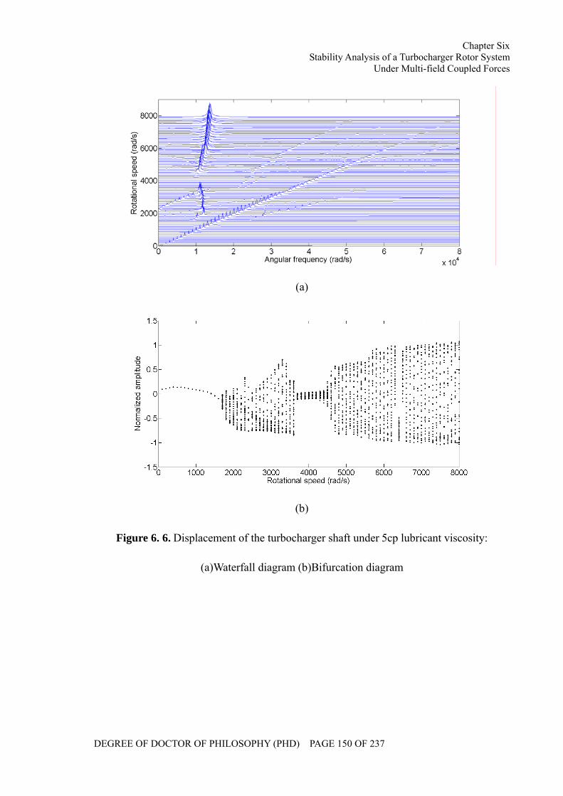
Chapter Six Stability Analysis of a Turbocharger Rotor System
Under Multi-field Coupled Forces
DEGREE OF DOCTOR OF PHILOSOPHY (PHD) PAGE 150 OF 237
(a)
(b)
Figure 6. 6. Displacement of the turbocharger shaft under 5cp lubricant viscosity:
(a)Waterfall diagram (b)Bifurcation diagram
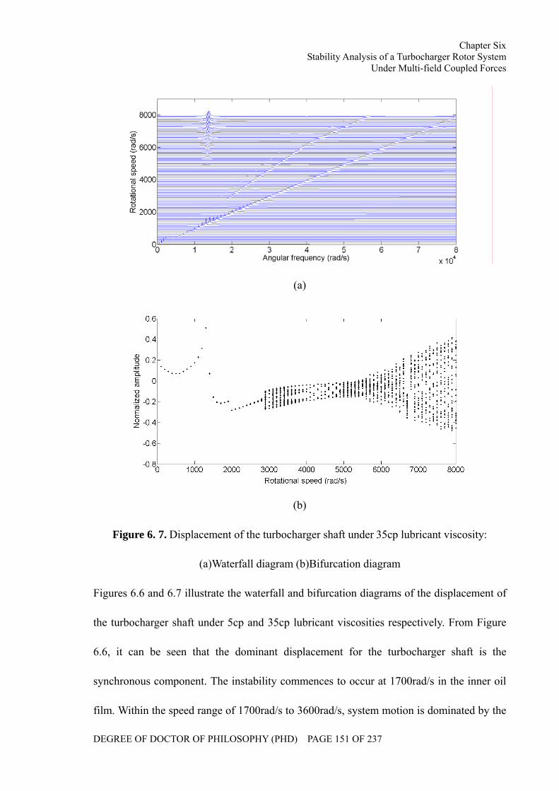
Chapter Six Stability Analysis of a Turbocharger Rotor System
Under Multi-field Coupled Forces
DEGREE OF DOCTOR OF PHILOSOPHY (PHD) PAGE 151 OF 237
(a)
(b)
Figure 6. 7. Displacement of the turbocharger shaft under 35cp lubricant viscosity:
(a)Waterfall diagram (b)Bifurcation diagram
Figures 6.6 and 6.7 illustrate the waterfall and bifurcation diagrams of the displacement of
the turbocharger shaft under 5cp and 35cp lubricant viscosities respectively. From Figure
6.6, it can be seen that the dominant displacement for the turbocharger shaft is the
synchronous component. The instability commences to occur at 1700rad/s in the inner oil
film. Within the speed range of 1700rad/s to 3600rad/s, system motion is dominated by the
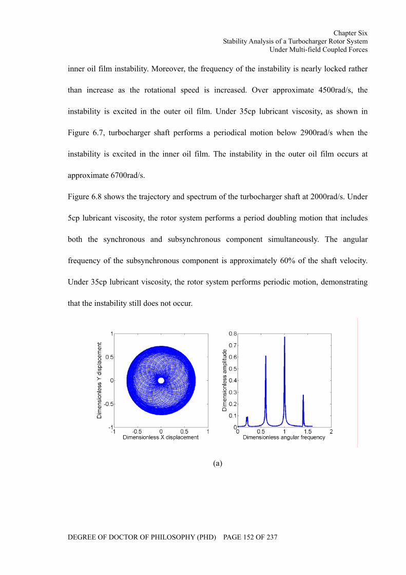
Chapter Six Stability Analysis of a Turbocharger Rotor System
Under Multi-field Coupled Forces
DEGREE OF DOCTOR OF PHILOSOPHY (PHD) PAGE 152 OF 237
inner oil film instability. Moreover, the frequency of the instability is nearly locked rather
than increase as the rotational speed is increased. Over approximate 4500rad/s, the
instability is excited in the outer oil film. Under 35cp lubricant viscosity, as shown in
Figure 6.7, turbocharger shaft performs a periodical motion below 2900rad/s when the
instability is excited in the inner oil film. The instability in the outer oil film occurs at
approximate 6700rad/s.
Figure 6.8 shows the trajectory and spectrum of the turbocharger shaft at 2000rad/s. Under
5cp lubricant viscosity, the rotor system performs a period doubling motion that includes
both the synchronous and subsynchronous component simultaneously. The angular
frequency of the subsynchronous component is approximately 60% of the shaft velocity.
Under 35cp lubricant viscosity, the rotor system performs periodic motion, demonstrating
that the instability still does not occur.
(a)
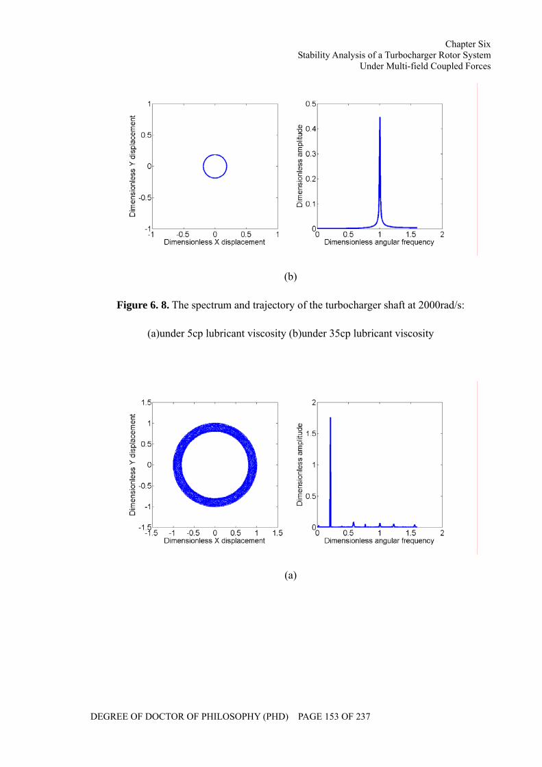
Chapter Six Stability Analysis of a Turbocharger Rotor System
Under Multi-field Coupled Forces
DEGREE OF DOCTOR OF PHILOSOPHY (PHD) PAGE 153 OF 237
(b)
Figure 6. 8. The spectrum and trajectory of the turbocharger shaft at 2000rad/s:
(a)under 5cp lubricant viscosity (b)under 35cp lubricant viscosity
(a)
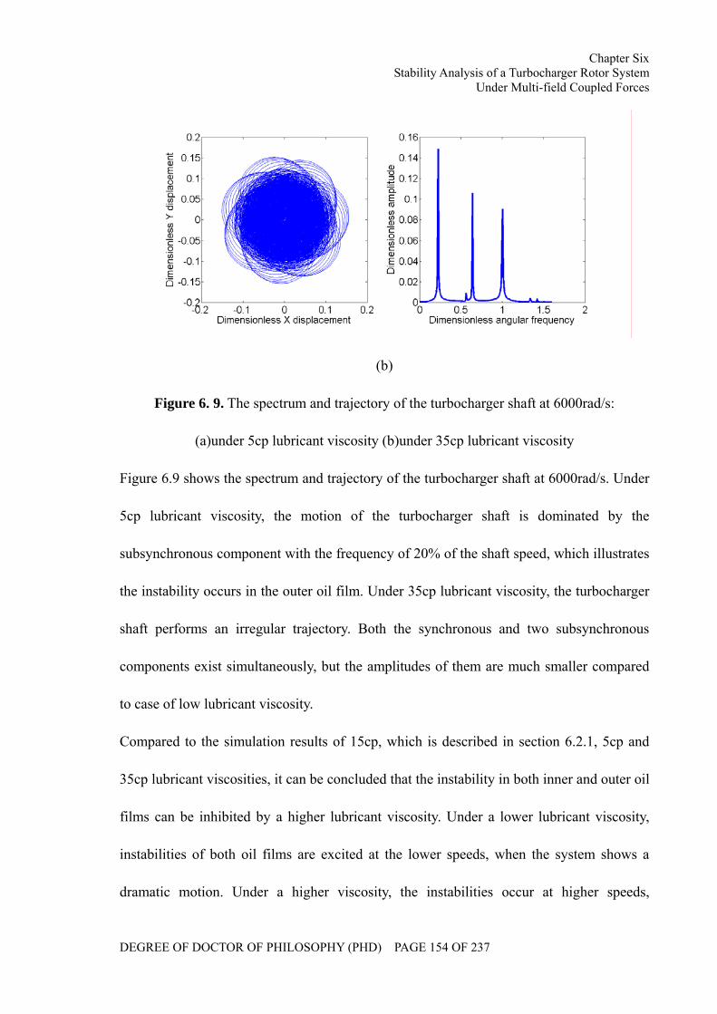
Chapter Six Stability Analysis of a Turbocharger Rotor System
Under Multi-field Coupled Forces
DEGREE OF DOCTOR OF PHILOSOPHY (PHD) PAGE 154 OF 237
(b)
Figure 6. 9. The spectrum and trajectory of the turbocharger shaft at 6000rad/s:
(a)under 5cp lubricant viscosity (b)under 35cp lubricant viscosity
Figure 6.9 shows the spectrum and trajectory of the turbocharger shaft at 6000rad/s. Under
5cp lubricant viscosity, the motion of the turbocharger shaft is dominated by the
subsynchronous component with the frequency of 20% of the shaft speed, which illustrates
the instability occurs in the outer oil film. Under 35cp lubricant viscosity, the turbocharger
shaft performs an irregular trajectory. Both the synchronous and two subsynchronous
components exist simultaneously, but the amplitudes of them are much smaller compared
to case of low lubricant viscosity.
Compared to the simulation results of 15cp, which is described in section 6.2.1, 5cp and
35cp lubricant viscosities, it can be concluded that the instability in both inner and outer oil
films can be inhibited by a higher lubricant viscosity. Under a lower lubricant viscosity,
instabilities of both oil films are excited at the lower speeds, when the system shows a
dramatic motion. Under a higher viscosity, the instabilities occur at higher speeds,
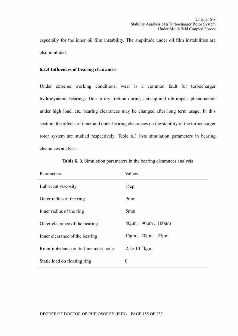
Chapter Six Stability Analysis of a Turbocharger Rotor System
Under Multi-field Coupled Forces
DEGREE OF DOCTOR OF PHILOSOPHY (PHD) PAGE 155 OF 237
especially for the inner oil film instability. The amplitude under oil film instabilities are
also inhibited.
6.2.4 Influences of bearing clearances
Under extreme working conditions, wear is a common fault for turbocharger
hydrodynamic bearings. Due to dry friction during start-up and rub-impact phenomenon
under high load, etc, bearing clearances may be changed after long term usage. In this
section, the affects of inner and outer bearing clearances on the stability of the turbocharger
rotor system are studied respectively. Table 6.3 lists simulation parameters in bearing
clearances analysis.
Table 6. 3. Simulation parameters in the bearing clearances analysis
Parameters Values
Lubricant viscosity 15cp
Outer radius of the ring mm9
Inner radius of the ring mm5
Outer clearance of the bearing µm80 ; µm90 ; µm100
Inner clearance of the bearing µm15 ; µm20 ; µm25
Rotor imbalance on turbine mass node kgm105.2 5−×
Static load on floating ring 0
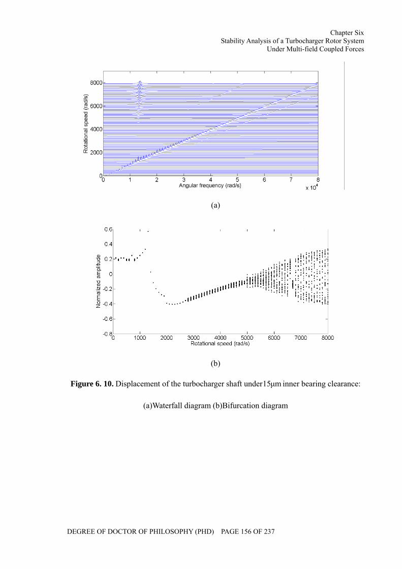
Chapter Six Stability Analysis of a Turbocharger Rotor System
Under Multi-field Coupled Forces
DEGREE OF DOCTOR OF PHILOSOPHY (PHD) PAGE 156 OF 237
(a)
(b)
Figure 6. 10. Displacement of the turbocharger shaft under µm15 inner bearing clearance:
(a)Waterfall diagram (b)Bifurcation diagram
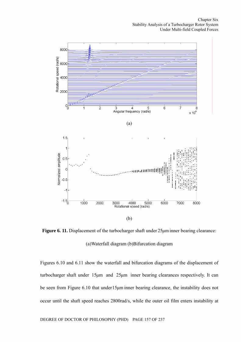
Chapter Six Stability Analysis of a Turbocharger Rotor System
Under Multi-field Coupled Forces
DEGREE OF DOCTOR OF PHILOSOPHY (PHD) PAGE 157 OF 237
(a)
(b)
Figure 6. 11. Displacement of the turbocharger shaft under µm25 inner bearing clearance:
(a)Waterfall diagram (b)Bifurcation diagram
Figures 6.10 and 6.11 show the waterfall and bifurcation diagrams of the displacement of
turbocharger shaft under µm15 and µm25 inner bearing clearances respectively. It can
be seen from Figure 6.10 that under µm15 inner bearing clearance, the instability does not
occur until the shaft speed reaches 2800rad/s, while the outer oil film enters instability at
Chapter Six Stability Analysis of a Turbocharger Rotor System
Under Multi-field Coupled Forces
DEGREE OF DOCTOR OF PHILOSOPHY (PHD) PAGE 158 OF 237
5000rad/s.
(a)
(b)
Figure 6. 12. The spectrum and trajectory of the turbocharger shaft at 3000rad/s:
(a)under µm15 inner bearing clearance (b)under µm25 inner bearing clearance
Under µm25 inner bearing clearance, as shown in Figure 6.11, the rotational speed, at
which the inner oil film instability occurs, is increased to 4000rad/s. The speed of outer oil
film instability is also increased to 5900rad/s. On the other hand, under µm25 inner bearing
clearance, the amplitude of the shaft motion during outer oil film instability is much larger
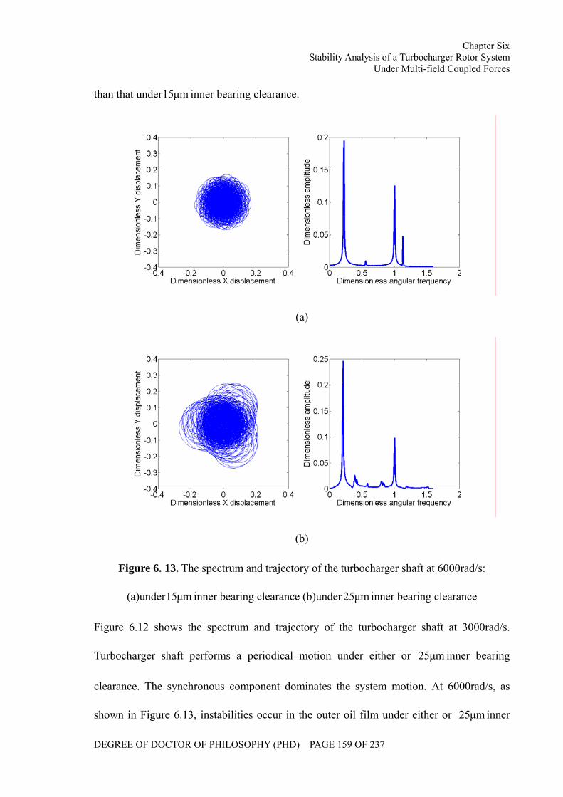
Chapter Six Stability Analysis of a Turbocharger Rotor System
Under Multi-field Coupled Forces
DEGREE OF DOCTOR OF PHILOSOPHY (PHD) PAGE 159 OF 237
than that under µm15 inner bearing clearance.
(a)
(b)
Figure 6. 13. The spectrum and trajectory of the turbocharger shaft at 6000rad/s:
(a)under µm15 inner bearing clearance (b)under µm25 inner bearing clearance
Figure 6.12 shows the spectrum and trajectory of the turbocharger shaft at 3000rad/s.
Turbocharger shaft performs a periodical motion under either or µm25 inner bearing
clearance. The synchronous component dominates the system motion. At 6000rad/s, as
shown in Figure 6.13, instabilities occur in the outer oil film under either or µm25 inner
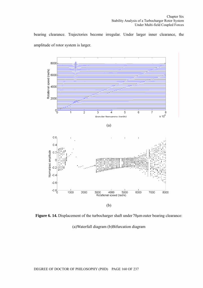
Chapter Six Stability Analysis of a Turbocharger Rotor System
Under Multi-field Coupled Forces
DEGREE OF DOCTOR OF PHILOSOPHY (PHD) PAGE 160 OF 237
bearing clearance. Trajectories become irregular. Under larger inner clearance, the
amplitude of rotor system is larger.
(a)
(b)
Figure 6. 14. Displacement of the turbocharger shaft under µm70 outer bearing clearance:
(a)Waterfall diagram (b)Bifurcation diagram
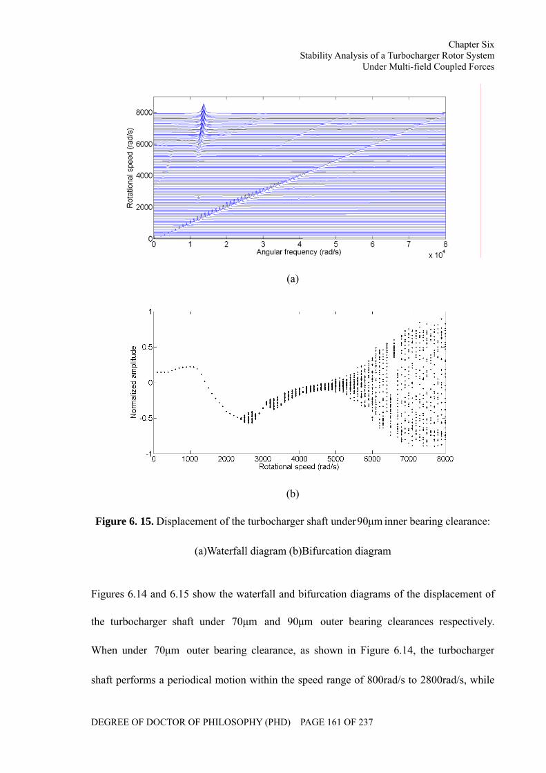
Chapter Six Stability Analysis of a Turbocharger Rotor System
Under Multi-field Coupled Forces
DEGREE OF DOCTOR OF PHILOSOPHY (PHD) PAGE 161 OF 237
(a)
(b)
Figure 6. 15. Displacement of the turbocharger shaft under µm90 inner bearing clearance:
(a)Waterfall diagram (b)Bifurcation diagram
Figures 6.14 and 6.15 show the waterfall and bifurcation diagrams of the displacement of
the turbocharger shaft under µm70 and µm90 outer bearing clearances respectively.
When under µm70 outer bearing clearance, as shown in Figure 6.14, the turbocharger
shaft performs a periodical motion within the speed range of 800rad/s to 2800rad/s, while
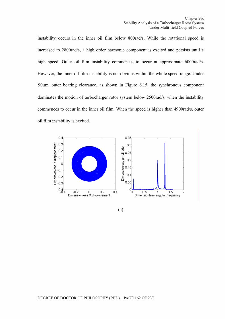
Chapter Six Stability Analysis of a Turbocharger Rotor System
Under Multi-field Coupled Forces
DEGREE OF DOCTOR OF PHILOSOPHY (PHD) PAGE 162 OF 237
instability occurs in the inner oil film below 800rad/s. While the rotational speed is
increased to 2800rad/s, a high order harmonic component is excited and persists until a
high speed. Outer oil film instability commences to occur at approximate 6000rad/s.
However, the inner oil film instability is not obvious within the whole speed range. Under
µm90 outer bearing clearance, as shown in Figure 6.15, the synchronous component
dominates the motion of turbocharger rotor system below 2500rad/s, when the instability
commences to occur in the inner oil film. When the speed is higher than 4900rad/s, outer
oil film instability is excited.
(a)
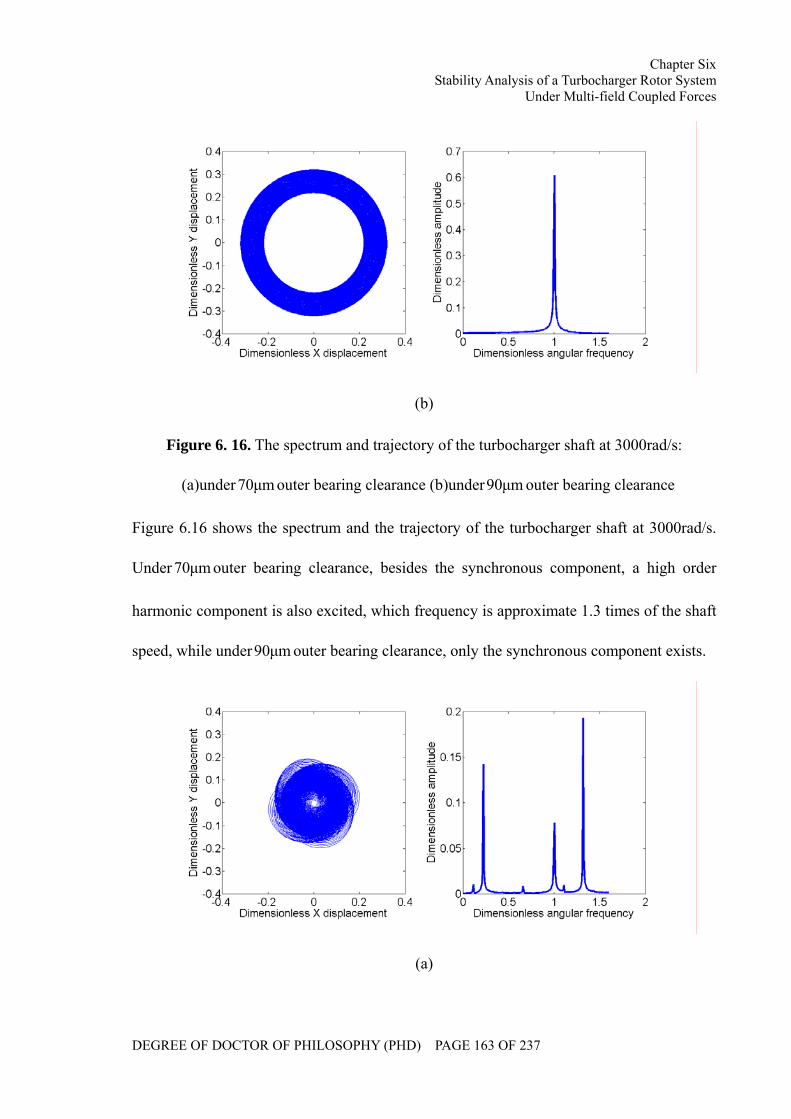
Chapter Six Stability Analysis of a Turbocharger Rotor System
Under Multi-field Coupled Forces
DEGREE OF DOCTOR OF PHILOSOPHY (PHD) PAGE 163 OF 237
(b)
Figure 6. 16. The spectrum and trajectory of the turbocharger shaft at 3000rad/s:
(a)under µm70 outer bearing clearance (b)under µm90 outer bearing clearance
Figure 6.16 shows the spectrum and the trajectory of the turbocharger shaft at 3000rad/s.
Under µm70 outer bearing clearance, besides the synchronous component, a high order
harmonic component is also excited, which frequency is approximate 1.3 times of the shaft
speed, while under µm90 outer bearing clearance, only the synchronous component exists.
(a)
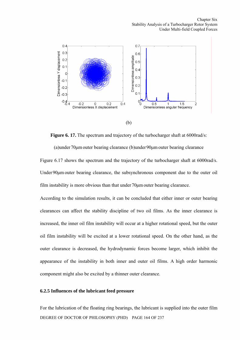
Chapter Six Stability Analysis of a Turbocharger Rotor System
Under Multi-field Coupled Forces
DEGREE OF DOCTOR OF PHILOSOPHY (PHD) PAGE 164 OF 237
(b)
Figure 6. 17. The spectrum and trajectory of the turbocharger shaft at 6000rad/s:
(a)under µm70 outer bearing clearance (b)under µm90 outer bearing clearance
Figure 6.17 shows the spectrum and the trajectory of the turbocharger shaft at 6000rad/s.
Under µm90 outer bearing clearance, the subsynchronous component due to the outer oil
film instability is more obvious than that under µm70 outer bearing clearance.
According to the simulation results, it can be concluded that either inner or outer bearing
clearances can affect the stability discipline of two oil films. As the inner clearance is
increased, the inner oil film instability will occur at a higher rotational speed, but the outer
oil film instability will be excited at a lower rotational speed. On the other hand, as the
outer clearance is decreased, the hydrodynamic forces become larger, which inhibit the
appearance of the instability in both inner and outer oil films. A high order harmonic
component might also be excited by a thinner outer clearance.
6.2.5 Influences of the lubricant feed pressure
For the lubrication of the floating ring bearings, the lubricant is supplied into the outer film
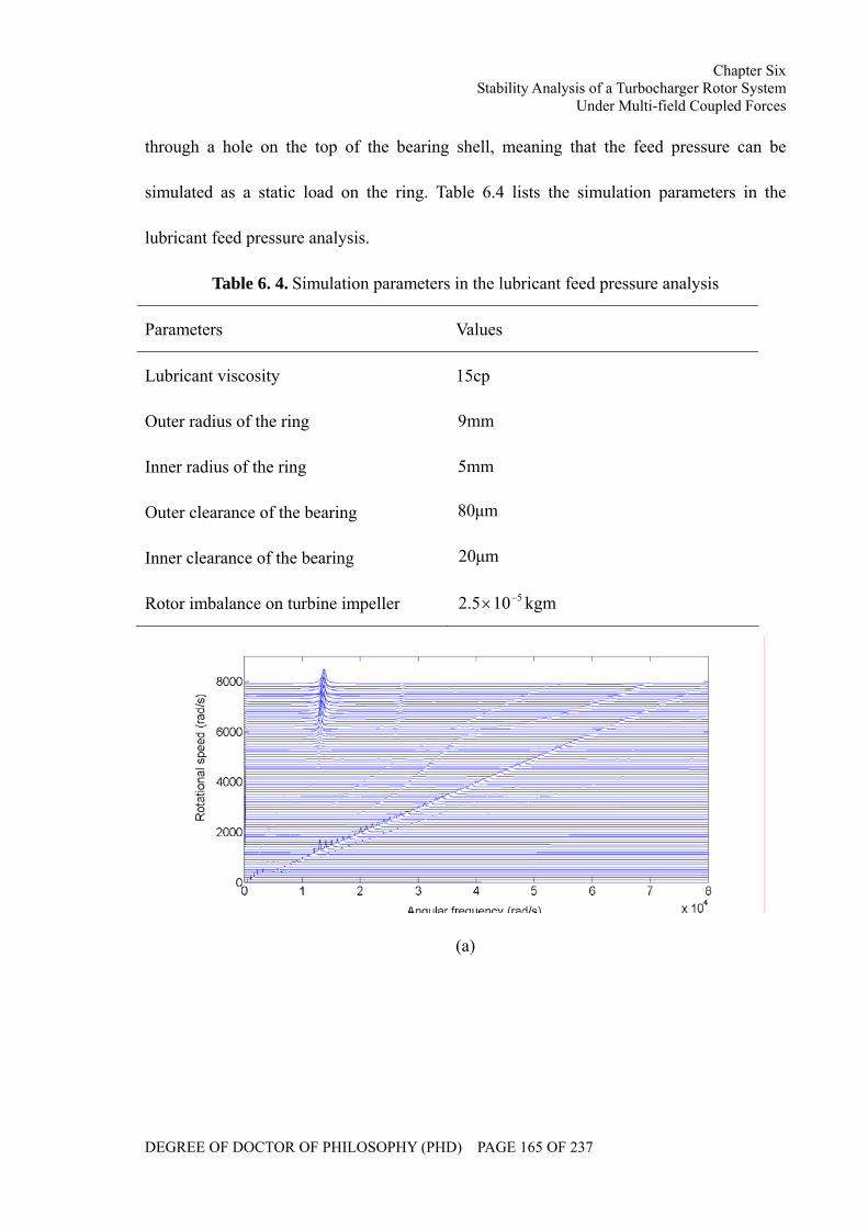
Chapter Six Stability Analysis of a Turbocharger Rotor System
Under Multi-field Coupled Forces
DEGREE OF DOCTOR OF PHILOSOPHY (PHD) PAGE 165 OF 237
through a hole on the top of the bearing shell, meaning that the feed pressure can be
simulated as a static load on the ring. Table 6.4 lists the simulation parameters in the
lubricant feed pressure analysis.
Table 6. 4. Simulation parameters in the lubricant feed pressure analysis
Parameters Values
Lubricant viscosity 15cp
Outer radius of the ring mm9
Inner radius of the ring mm5
Outer clearance of the bearing µm80
Inner clearance of the bearing µm20
Rotor imbalance on turbine impeller kgm105.2 5−×
(a)
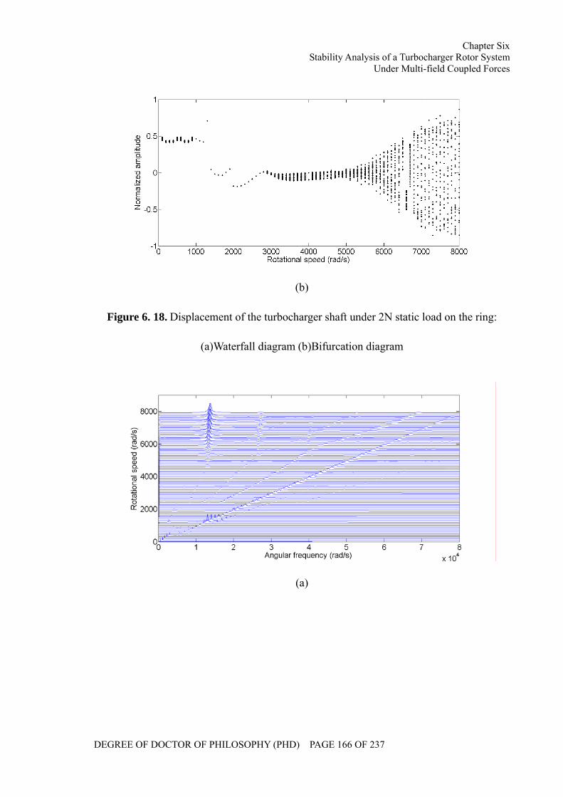
Chapter Six Stability Analysis of a Turbocharger Rotor System
Under Multi-field Coupled Forces
DEGREE OF DOCTOR OF PHILOSOPHY (PHD) PAGE 166 OF 237
(b)
Figure 6. 18. Displacement of the turbocharger shaft under 2N static load on the ring:
(a)Waterfall diagram (b)Bifurcation diagram
(a)
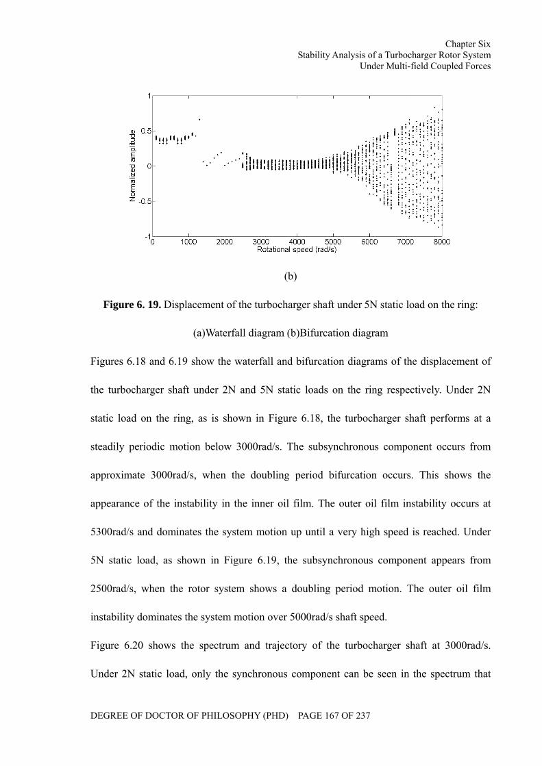
Chapter Six Stability Analysis of a Turbocharger Rotor System
Under Multi-field Coupled Forces
DEGREE OF DOCTOR OF PHILOSOPHY (PHD) PAGE 167 OF 237
(b)
Figure 6. 19. Displacement of the turbocharger shaft under 5N static load on the ring:
(a)Waterfall diagram (b)Bifurcation diagram
Figures 6.18 and 6.19 show the waterfall and bifurcation diagrams of the displacement of
the turbocharger shaft under 2N and 5N static loads on the ring respectively. Under 2N
static load on the ring, as is shown in Figure 6.18, the turbocharger shaft performs at a
steadily periodic motion below 3000rad/s. The subsynchronous component occurs from
approximate 3000rad/s, when the doubling period bifurcation occurs. This shows the
appearance of the instability in the inner oil film. The outer oil film instability occurs at
5300rad/s and dominates the system motion up until a very high speed is reached. Under
5N static load, as shown in Figure 6.19, the subsynchronous component appears from
2500rad/s, when the rotor system shows a doubling period motion. The outer oil film
instability dominates the system motion over 5000rad/s shaft speed.
Figure 6.20 shows the spectrum and trajectory of the turbocharger shaft at 3000rad/s.
Under 2N static load, only the synchronous component can be seen in the spectrum that
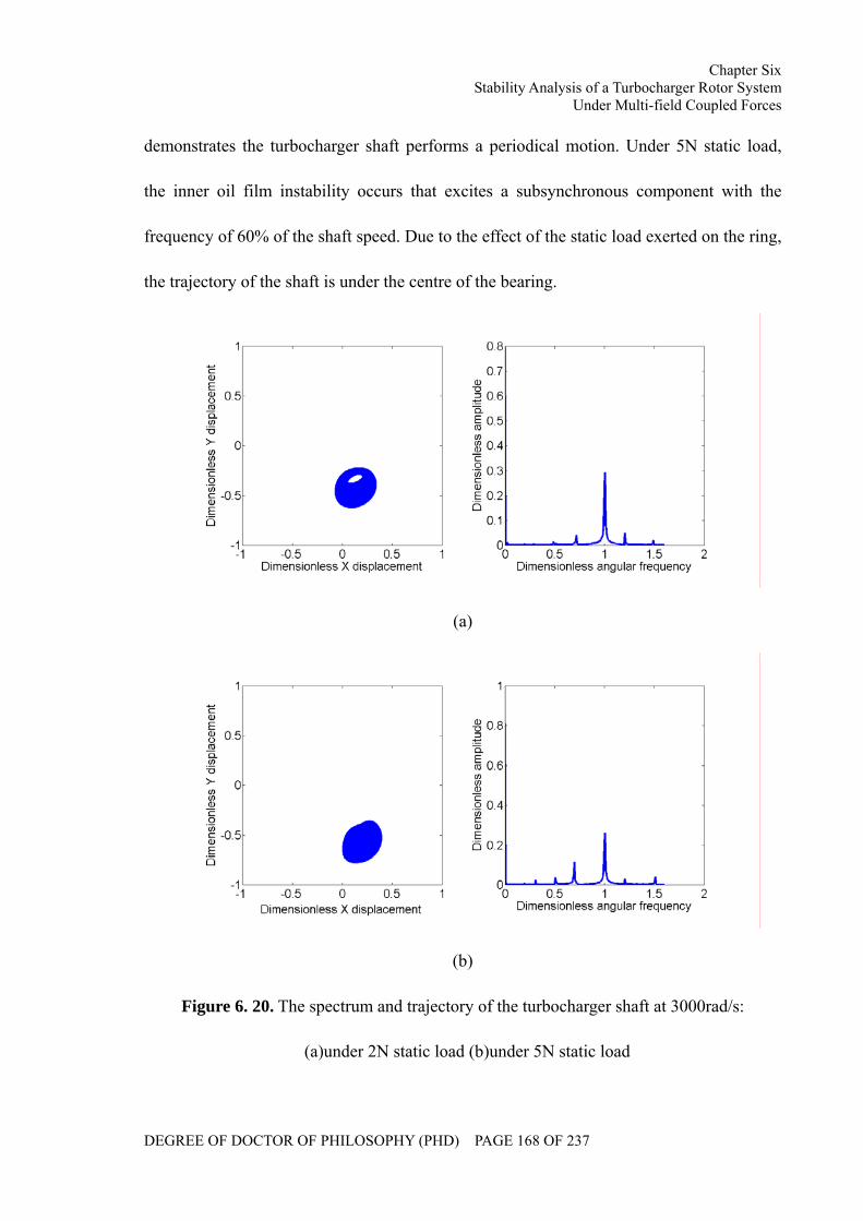
Chapter Six Stability Analysis of a Turbocharger Rotor System
Under Multi-field Coupled Forces
DEGREE OF DOCTOR OF PHILOSOPHY (PHD) PAGE 168 OF 237
demonstrates the turbocharger shaft performs a periodical motion. Under 5N static load,
the inner oil film instability occurs that excites a subsynchronous component with the
frequency of 60% of the shaft speed. Due to the effect of the static load exerted on the ring,
the trajectory of the shaft is under the centre of the bearing.
(a)
(b)
Figure 6. 20. The spectrum and trajectory of the turbocharger shaft at 3000rad/s:
(a)under 2N static load (b)under 5N static load
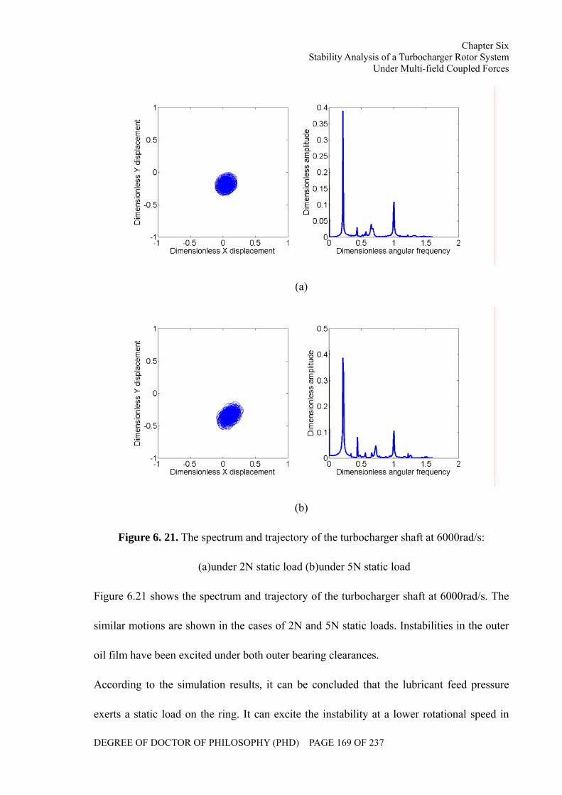
Chapter Six Stability Analysis of a Turbocharger Rotor System
Under Multi-field Coupled Forces
DEGREE OF DOCTOR OF PHILOSOPHY (PHD) PAGE 169 OF 237
(a)
(b)
Figure 6. 21. The spectrum and trajectory of the turbocharger shaft at 6000rad/s:
(a)under 2N static load (b)under 5N static load
Figure 6.21 shows the spectrum and trajectory of the turbocharger shaft at 6000rad/s. The
similar motions are shown in the cases of 2N and 5N static loads. Instabilities in the outer
oil film have been excited under both outer bearing clearances.
According to the simulation results, it can be concluded that the lubricant feed pressure
exerts a static load on the ring. It can excite the instability at a lower rotational speed in
Chapter Six Stability Analysis of a Turbocharger Rotor System
Under Multi-field Coupled Forces
DEGREE OF DOCTOR OF PHILOSOPHY (PHD) PAGE 170 OF 237
both inner and outer bearing clearances.
6.3 Summary
In this chapter, the stability characteristic of the floating ring bearing is introduced.
According to the simulation results, the effects of the rotor imbalance, lubricant feed
pressure, bearing clearances and lubricant feed pressure on the stability of the turbocharger
rotor system are analysed.
The rotor imbalance can lead to the appearance of the synchronous component in the
turbocharger rotor system, the angular frequency of which is equal to the shaft velocity.
The larger rotor imbalance, the larger amplitude of the rotor system appears especially at a
relatively low speed range. The centrifugal force can inhibit the appearance of the
instability in the inner oil film. However, the instability in outer oil film can be excited at a
lower speed, when the amplitude of the rotor system becomes larger.
The lubricant viscosity can inhibit the instability in both inner and outer oil films. Under a
lower lubricant viscosity, instabilities of both oil films are excited at the lower speeds,
when the system shows a dramatic motion. Under a higher viscosity, the instabilities occur
at higher speeds, especially for the inner oil film instability. The amplitude under oil film
instabilities is also inhibited.
Either inner or outer bearing clearance can affect the stability discipline of two oil films.
As the inner clearance is increased, the inner oil film instability will occur at a higher
rotational speed, but the outer oil film instability will be excited at a lower rotational speed.
On the other hand, as the outer clearance is decreased, the hydrodynamic forces become
Chapter Six Stability Analysis of a Turbocharger Rotor System
Under Multi-field Coupled Forces
DEGREE OF DOCTOR OF PHILOSOPHY (PHD) PAGE 171 OF 237
larger, which inhibit the appearance of the instability in both inner and outer oil films. A
high order harmonic component might also be excited by a thinner outer clearance.
The lubricant feed pressure exerts a static load on the ring. It can excite the instability at a
lower rotational speed in both inner and outer bearing clearances.
Chapter Seven Turbocharger Test Rig Development
DEGREE OF DOCTOR OF PHILOSOPHY (PHD) PAGE 172 OF 237
CHAPTER SEVEN
TURBOCHARGER TEST RIG DEVELOPMENT
In order to validate the developed theoretical model, the related experimental data are
required. In this chapter, a turbocharger test rig has been developed. The motion of a
turbocharger rotor system can be monitored under different working conditions.
Chapter Seven Turbocharger Test Rig Development
DEGREE OF DOCTOR OF PHILOSOPHY (PHD) PAGE 173 OF 237
7.1 Introduction to the Turbocharger Test Rig
A turbocharger test rig has been designed and developed to monitor the shaft motion and
validate the developed dynamics model of the turbocharger. A turbocharger test rig can
generally be categorized into ‘hot air driven’ and ‘cold air driven’ in terms of the driven
style. In the hot air driven style, the compressed air is heated in a combustion chamber and
then delivered into the turbocharger. A close loop system is generally also used in this style
in which the compressed air is recycled and delivered to the combustion chamber. In the
cold air driven style, the driving force is directly provided by an air compressor or a fan.
An open loop system is generally applied in this driven style. The air from the compressor
of the turbocharger is directly discharged into the atmosphere.
As the thermal effects of exhaust gases on the performances of the turbocharger shaft
motion have not been involved and the cost of the test rig establishment of a hot air driven
is very high, a cold air driven style is adopted in this test rig.
The test rig comprises of the turbocharger, the air resource system, the lubrication system,
the pipeline system, the sensors and the signal acquisition system. The block diagram of
the turbocharger test rig is shown in Figure 7.1.
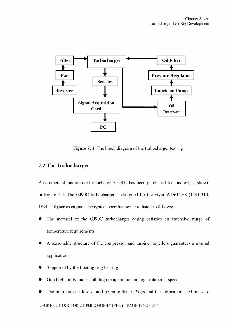
Chapter Seven Turbocharger Test Rig Development
DEGREE OF DOCTOR OF PHILOSOPHY (PHD) PAGE 174 OF 237
Figure 7. 1. The block diagram of the turbocharger test rig
7.2 The Turbocharger
A commercial automotive turbocharger GJ90C has been purchased for this test, as shown
in Figure 7.2. The GJ90C turbocharger is designed for the Styer WD615.68 (1491-310,
1891-310) series engine. The typical specifications are listed as follows:
The material of the GJ90C turbocharger casing satisfies an extensive range of
temperature requirements.
A reasonable structure of the compressor and turbine impellers guarantees a normal
application.
Supported by the floating ring bearing.
Good reliability under both high temperature and high rotational speed.
The minimum airflow should be more than 0.2kg/s and the lubrication feed pressure
Fan
Inverter
Filter Turbocharger
Sensors
Signal Acquisition Card
PC
Oil Filter
Pressure Regulator
Lubricant Pump
Oil Reservoir
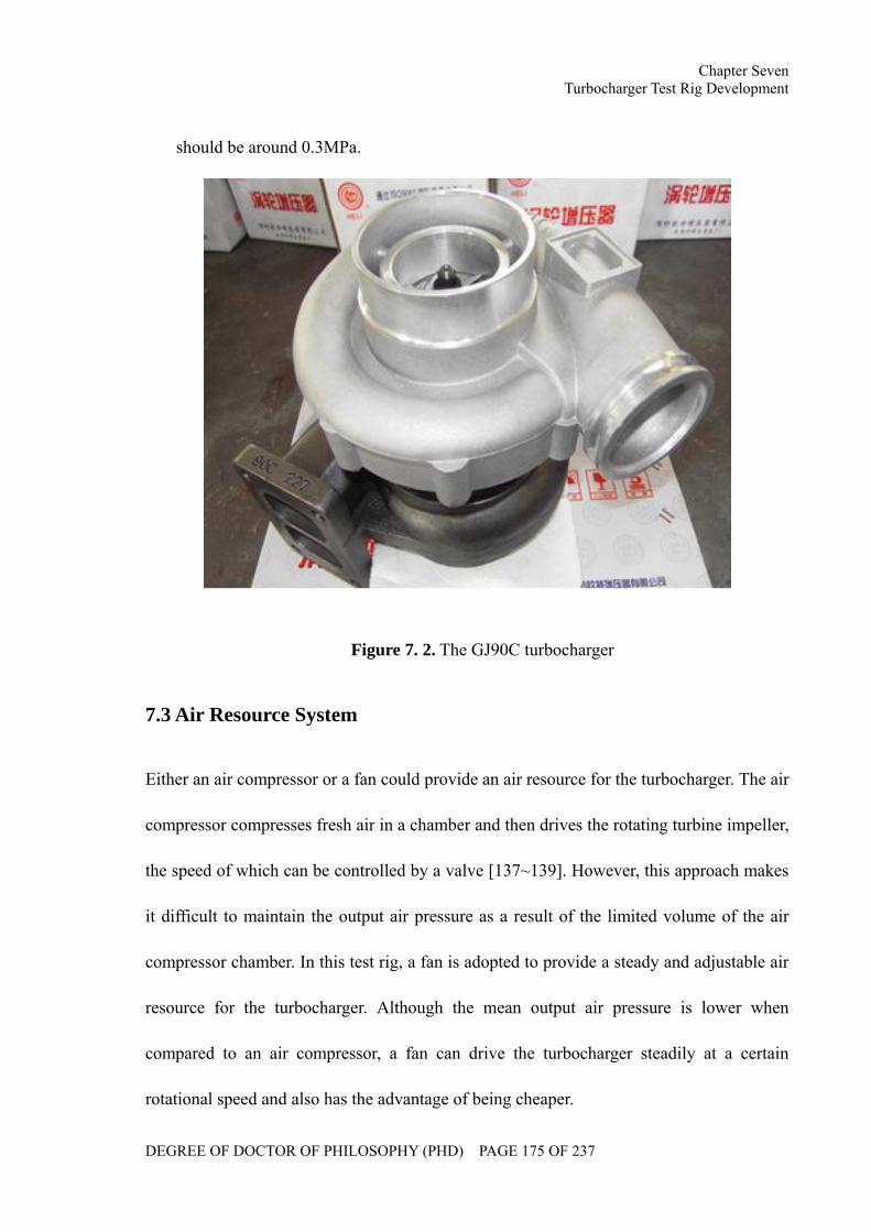
Chapter Seven Turbocharger Test Rig Development
DEGREE OF DOCTOR OF PHILOSOPHY (PHD) PAGE 175 OF 237
should be around 0.3MPa.
Figure 7. 2. The GJ90C turbocharger
7.3 Air Resource System
Either an air compressor or a fan could provide an air resource for the turbocharger. The air
compressor compresses fresh air in a chamber and then drives the rotating turbine impeller,
the speed of which can be controlled by a valve [137~139]. However, this approach makes
it difficult to maintain the output air pressure as a result of the limited volume of the air
compressor chamber. In this test rig, a fan is adopted to provide a steady and adjustable air
resource for the turbocharger. Although the mean output air pressure is lower when
compared to an air compressor, a fan can drive the turbocharger steadily at a certain
rotational speed and also has the advantage of being cheaper.
Chapter Seven Turbocharger Test Rig Development
DEGREE OF DOCTOR OF PHILOSOPHY (PHD) PAGE 176 OF 237
The flow rate of the fan is mainly determined by the diameter of the impeller, the rotational
speed and the blade shape, while the output pressure depends upon the diameter of impeller,
the rotational speed, the density and the blade shape. The empirical formulas [140] are
given as follows:
2224vDQQ π
= (7.1)
22
22000334.0 vDHH = (7.2)
where HQ, denote the output flow rate ( /sm3 ) and pressure (Pa), 22 ,vD denote the
diameter (m) and the rotational speed of the impeller (rad/s) respectively, HQ , are the
coefficients of the flow rate and the pressure.
According to the specification of the GJ90C turbocharger, a 5.5kw fan has been utilized
with a maximum air flow and output pressure of 1500 /hm3 and 5kPa respectively.
An inverter has also been installed to control the motor speed of the fan. In addition, the
inverter can also protect the whole device in case of the current, voltage or load exceeding
their secure thresholds. A DZB200 general inverter has been purchased from Fuling
Inverter Company China, which can output a maximum of 80Hz for the motor and drive
with the fan rotating at a maximum speed of 4400r/min. According to the output flow rate
and pressure, it can be estimated that the turbocharger working speed can therefore
theoretically reach 30000r/min. The real maximal speed, however, will also depend upon
numerous factors including the turbocharger, hose, etc.
7.4 Lubrication System
A turbocharger is lubricated by the engine lubrication system in vehicles. In this test rig, an
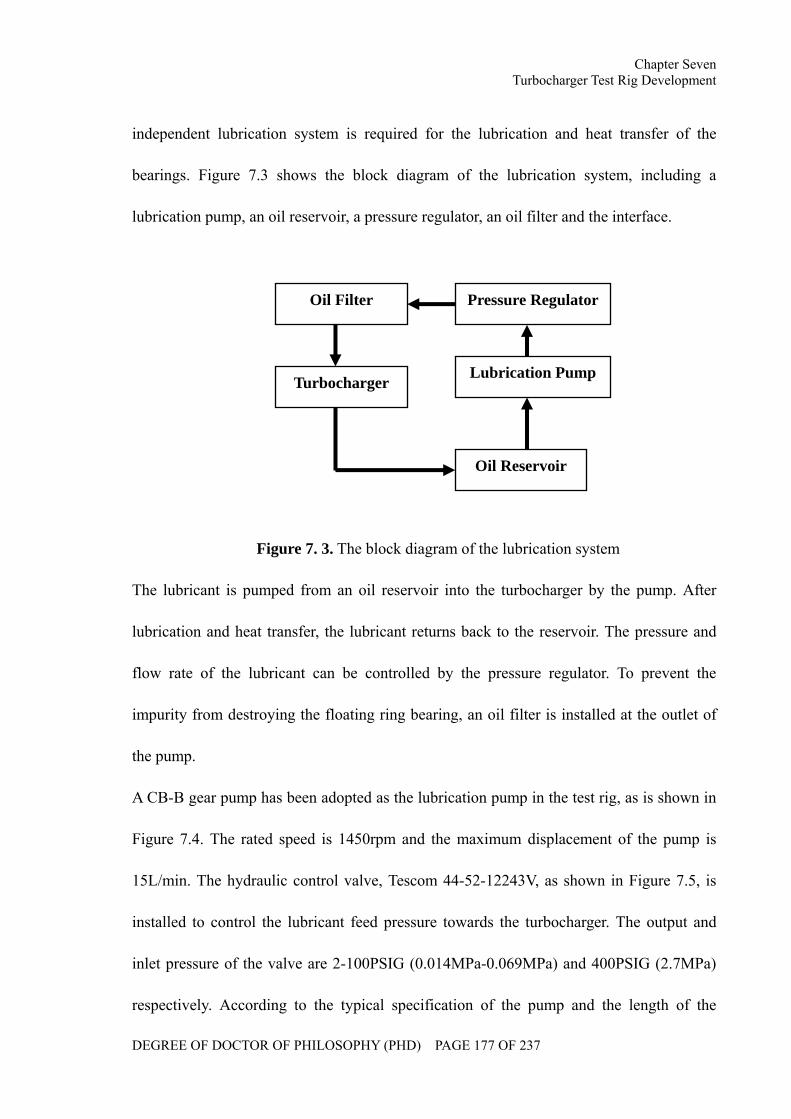
Chapter Seven Turbocharger Test Rig Development
DEGREE OF DOCTOR OF PHILOSOPHY (PHD) PAGE 177 OF 237
independent lubrication system is required for the lubrication and heat transfer of the
bearings. Figure 7.3 shows the block diagram of the lubrication system, including a
lubrication pump, an oil reservoir, a pressure regulator, an oil filter and the interface.
Figure 7. 3. The block diagram of the lubrication system
The lubricant is pumped from an oil reservoir into the turbocharger by the pump. After
lubrication and heat transfer, the lubricant returns back to the reservoir. The pressure and
flow rate of the lubricant can be controlled by the pressure regulator. To prevent the
impurity from destroying the floating ring bearing, an oil filter is installed at the outlet of
the pump.
A CB-B gear pump has been adopted as the lubrication pump in the test rig, as is shown in
Figure 7.4. The rated speed is 1450rpm and the maximum displacement of the pump is
15L/min. The hydraulic control valve, Tescom 44-52-12243V, as shown in Figure 7.5, is
installed to control the lubricant feed pressure towards the turbocharger. The output and
inlet pressure of the valve are 2-100PSIG (0.014MPa-0.069MPa) and 400PSIG (2.7MPa)
respectively. According to the typical specification of the pump and the length of the
Oil Filter
Turbocharger
Pressure Regulator
Lubrication Pump
Oil Reservoir
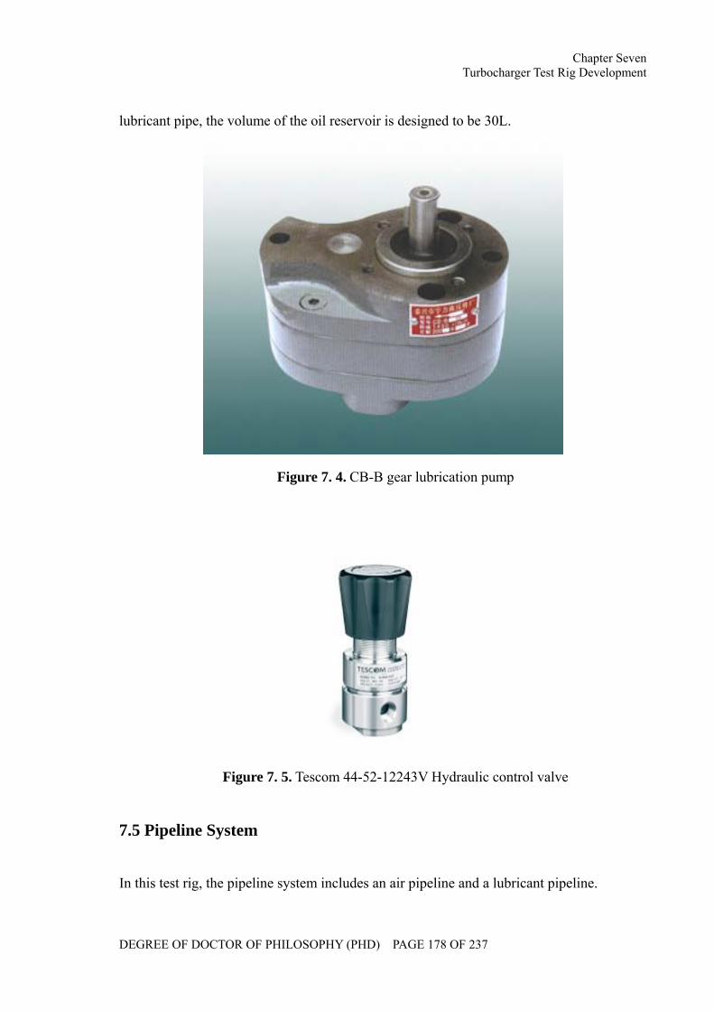
Chapter Seven Turbocharger Test Rig Development
DEGREE OF DOCTOR OF PHILOSOPHY (PHD) PAGE 178 OF 237
lubricant pipe, the volume of the oil reservoir is designed to be 30L.
Figure 7. 4. CB-B gear lubrication pump
Figure 7. 5. Tescom 44-52-12243V Hydraulic control valve
7.5 Pipeline System
In this test rig, the pipeline system includes an air pipeline and a lubricant pipeline.
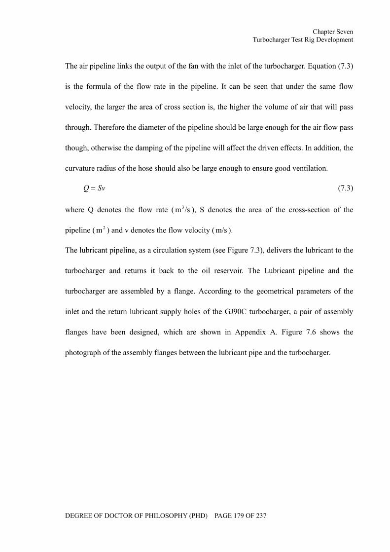
Chapter Seven Turbocharger Test Rig Development
DEGREE OF DOCTOR OF PHILOSOPHY (PHD) PAGE 179 OF 237
The air pipeline links the output of the fan with the inlet of the turbocharger. Equation (7.3)
is the formula of the flow rate in the pipeline. It can be seen that under the same flow
velocity, the larger the area of cross section is, the higher the volume of air that will pass
through. Therefore the diameter of the pipeline should be large enough for the air flow pass
though, otherwise the damping of the pipeline will affect the driven effects. In addition, the
curvature radius of the hose should also be large enough to ensure good ventilation.
SvQ = (7.3)
where Q denotes the flow rate ( /sm3 ), S denotes the area of the cross-section of the
pipeline ( 2m ) and v denotes the flow velocity ( m/s ).
The lubricant pipeline, as a circulation system (see Figure 7.3), delivers the lubricant to the
turbocharger and returns it back to the oil reservoir. The Lubricant pipeline and the
turbocharger are assembled by a flange. According to the geometrical parameters of the
inlet and the return lubricant supply holes of the GJ90C turbocharger, a pair of assembly
flanges have been designed, which are shown in Appendix A. Figure 7.6 shows the
photograph of the assembly flanges between the lubricant pipe and the turbocharger.
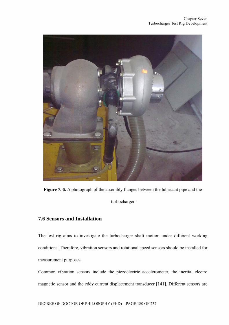
Chapter Seven Turbocharger Test Rig Development
DEGREE OF DOCTOR OF PHILOSOPHY (PHD) PAGE 180 OF 237
Figure 7. 6. A photograph of the assembly flanges between the lubricant pipe and the
turbocharger
7.6 Sensors and Installation
The test rig aims to investigate the turbocharger shaft motion under different working
conditions. Therefore, vibration sensors and rotational speed sensors should be installed for
measurement purposes.
Common vibration sensors include the piezoelectric accelerometer, the inertial electro
magnetic sensor and the eddy current displacement transducer [141]. Different sensors are
Chapter Seven Turbocharger Test Rig Development
DEGREE OF DOCTOR OF PHILOSOPHY (PHD) PAGE 181 OF 237
fitted for different measurement conditions. In the case of analyzing damage or fault
caused by inertia forces, acceleration should be selected as the primary measurement
parameter; in the case of investigating the vibration intensity and condition, velocity
should be selected as the primary measurement parameter; in the case of the measurement
of the object position, displacement should be selected as the primary measurement
parameter.
As far as the bending vibration of the turbocharger rotor system is concerned, a
non-contact type sensor should be chosen due to the high speed rotation. In addition, the
material of the GJ90C turbocharger shaft, 41NiCrMo22, is not a magnetizer but an
electrical conductor on the surface of which the eddy current can be formed. Therefore, the
eddy current displacement transducer is used to measure the bending vibration of the
turbocharger rotor system.
The turbocharger shaft motion shows characteristics such as low amplitude and high
frequency. Therefore, the frequency response is a critical criterion in the selection of
vibration sensors, because even the fundamental frequency of the turbocharger shaft is
approximately 2-3KHz. KAMAN KD2306 1U1, a kind of high precision eddy current
displacement transducer is adopted in the test rig, shown in Figure 7.7. KAMAN precision
products’ model KD2306 is a non-contact, linear, analog displacement measuring system.
The system operates on a traditional inductive bridge circuit, which can be used for a
precisively static and dynamic measurement of conductive targets. Table 7.1 lists its typical
specification.
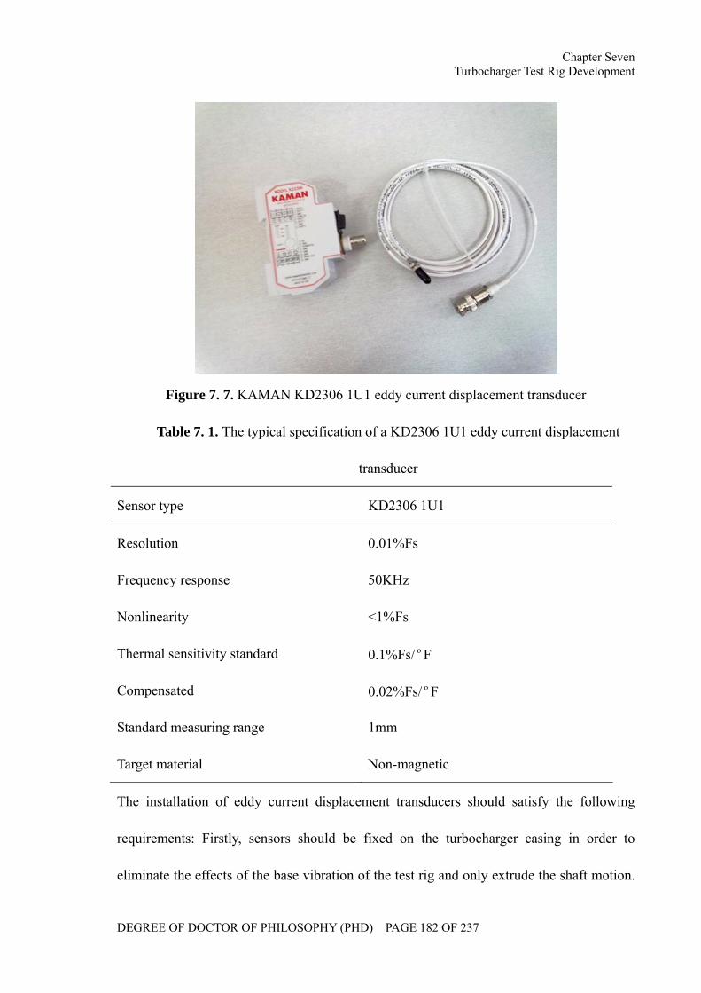
Chapter Seven Turbocharger Test Rig Development
DEGREE OF DOCTOR OF PHILOSOPHY (PHD) PAGE 182 OF 237
Figure 7. 7. KAMAN KD2306 1U1 eddy current displacement transducer
Table 7. 1. The typical specification of a KD2306 1U1 eddy current displacement
transducer
Sensor type KD2306 1U1
Resolution 0.01%Fs
Frequency response 50KHz
Nonlinearity <1%Fs
Thermal sensitivity standard 0.1%Fs/ Fo
Compensated 0.02%Fs/ Fo
Standard measuring range 1mm
Target material Non-magnetic
The installation of eddy current displacement transducers should satisfy the following
requirements: Firstly, sensors should be fixed on the turbocharger casing in order to
eliminate the effects of the base vibration of the test rig and only extrude the shaft motion.
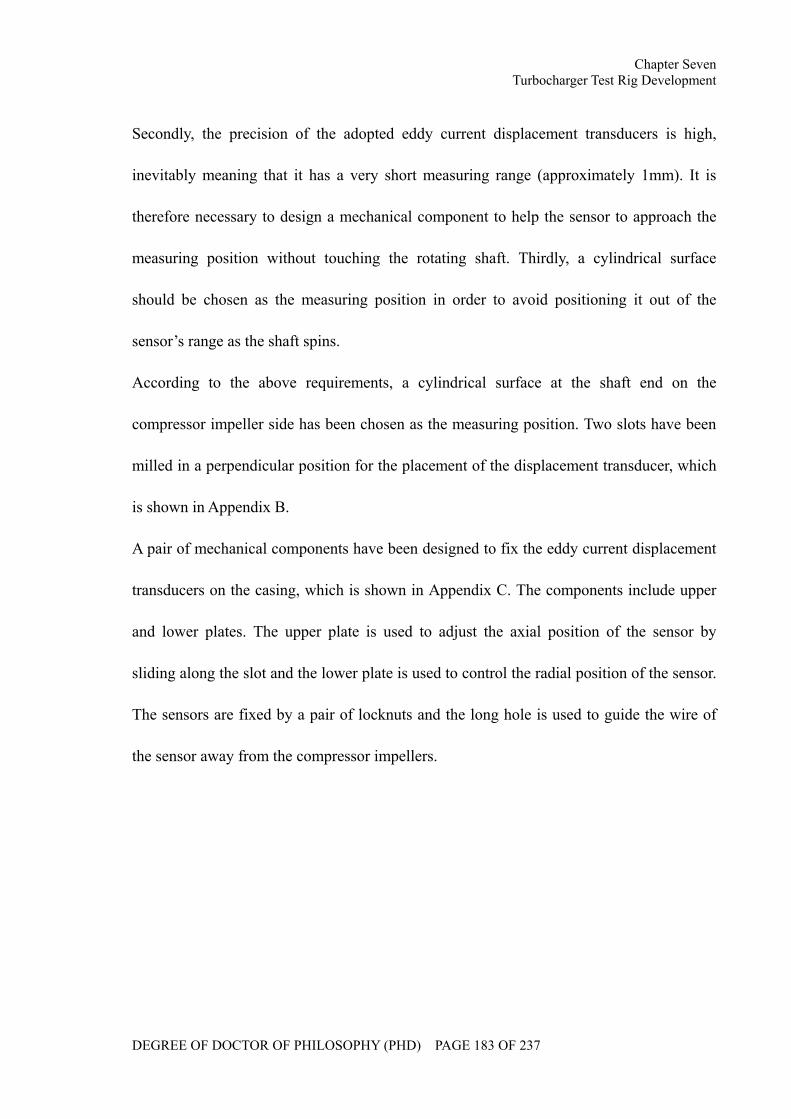
Chapter Seven Turbocharger Test Rig Development
DEGREE OF DOCTOR OF PHILOSOPHY (PHD) PAGE 183 OF 237
Secondly, the precision of the adopted eddy current displacement transducers is high,
inevitably meaning that it has a very short measuring range (approximately 1mm). It is
therefore necessary to design a mechanical component to help the sensor to approach the
measuring position without touching the rotating shaft. Thirdly, a cylindrical surface
should be chosen as the measuring position in order to avoid positioning it out of the
sensor’s range as the shaft spins.
According to the above requirements, a cylindrical surface at the shaft end on the
compressor impeller side has been chosen as the measuring position. Two slots have been
milled in a perpendicular position for the placement of the displacement transducer, which
is shown in Appendix B.
A pair of mechanical components have been designed to fix the eddy current displacement
transducers on the casing, which is shown in Appendix C. The components include upper
and lower plates. The upper plate is used to adjust the axial position of the sensor by
sliding along the slot and the lower plate is used to control the radial position of the sensor.
The sensors are fixed by a pair of locknuts and the long hole is used to guide the wire of
the sensor away from the compressor impellers.
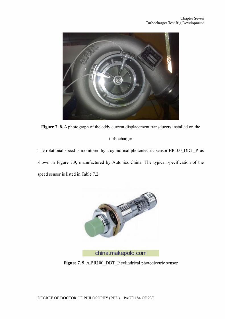
Chapter Seven Turbocharger Test Rig Development
DEGREE OF DOCTOR OF PHILOSOPHY (PHD) PAGE 184 OF 237
Figure 7. 8. A photograph of the eddy current displacement transducers installed on the
turbocharger
The rotational speed is monitored by a cylindrical photoelectric sensor BR100_DDT_P, as
shown in Figure 7.9, manufactured by Autonics China. The typical specification of the
speed sensor is listed in Table 7.2.
Figure 7. 9. A BR100_DDT_P cylindrical photoelectric sensor
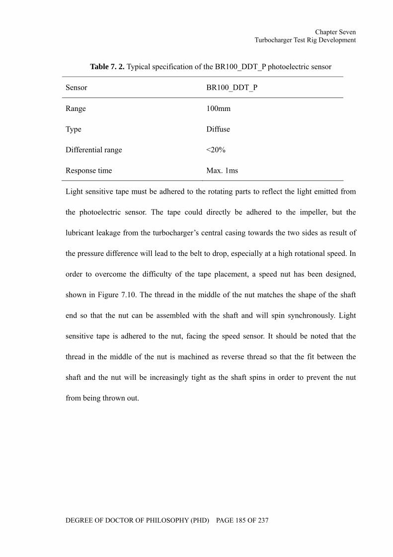
Chapter Seven Turbocharger Test Rig Development
DEGREE OF DOCTOR OF PHILOSOPHY (PHD) PAGE 185 OF 237
Table 7. 2. Typical specification of the BR100_DDT_P photoelectric sensor
Sensor BR100_DDT_P
Range 100mm
Type Diffuse
Differential range <20%
Response time Max. 1ms
Light sensitive tape must be adhered to the rotating parts to reflect the light emitted from
the photoelectric sensor. The tape could directly be adhered to the impeller, but the
lubricant leakage from the turbocharger’s central casing towards the two sides as result of
the pressure difference will lead to the belt to drop, especially at a high rotational speed. In
order to overcome the difficulty of the tape placement, a speed nut has been designed,
shown in Figure 7.10. The thread in the middle of the nut matches the shape of the shaft
end so that the nut can be assembled with the shaft and will spin synchronously. Light
sensitive tape is adhered to the nut, facing the speed sensor. It should be noted that the
thread in the middle of the nut is machined as reverse thread so that the fit between the
shaft and the nut will be increasingly tight as the shaft spins in order to prevent the nut
from being thrown out.
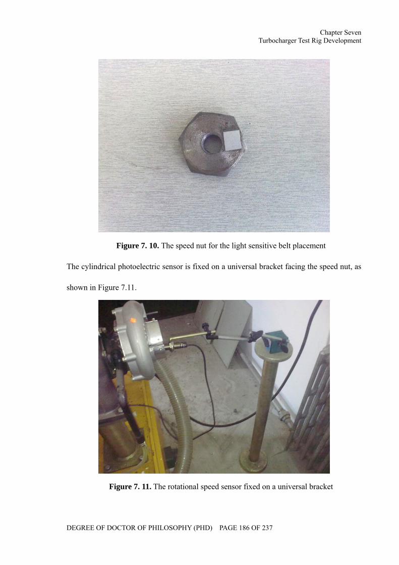
Chapter Seven Turbocharger Test Rig Development
DEGREE OF DOCTOR OF PHILOSOPHY (PHD) PAGE 186 OF 237
Figure 7. 10. The speed nut for the light sensitive belt placement
The cylindrical photoelectric sensor is fixed on a universal bracket facing the speed nut, as
shown in Figure 7.11.
Figure 7. 11. The rotational speed sensor fixed on a universal bracket
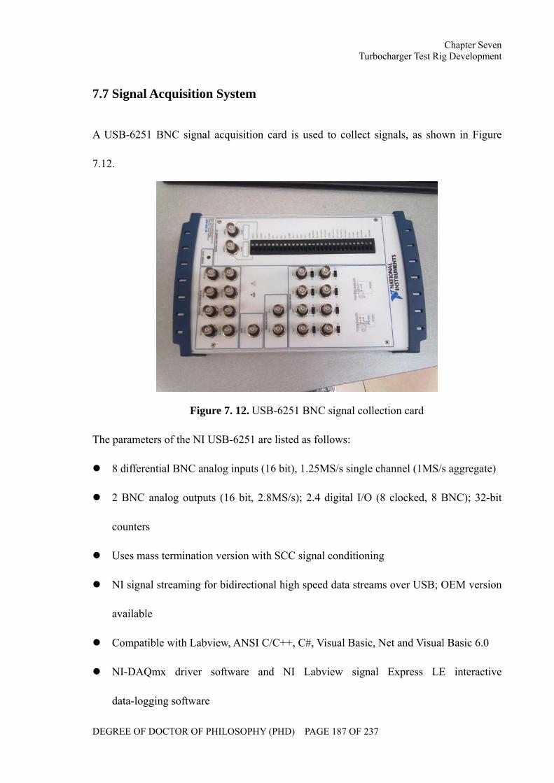
Chapter Seven Turbocharger Test Rig Development
DEGREE OF DOCTOR OF PHILOSOPHY (PHD) PAGE 187 OF 237
7.7 Signal Acquisition System
A USB-6251 BNC signal acquisition card is used to collect signals, as shown in Figure
7.12.
Figure 7. 12. USB-6251 BNC signal collection card
The parameters of the NI USB-6251 are listed as follows:
8 differential BNC analog inputs (16 bit), 1.25MS/s single channel (1MS/s aggregate)
2 BNC analog outputs (16 bit, 2.8MS/s); 2.4 digital I/O (8 clocked, 8 BNC); 32-bit
counters
Uses mass termination version with SCC signal conditioning
NI signal streaming for bidirectional high speed data streams over USB; OEM version
available
Compatible with Labview, ANSI C/C++, C#, Visual Basic, Net and Visual Basic 6.0
NI-DAQmx driver software and NI Labview signal Express LE interactive
data-logging software
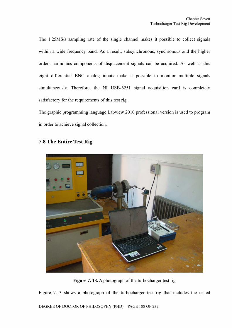
Chapter Seven Turbocharger Test Rig Development
DEGREE OF DOCTOR OF PHILOSOPHY (PHD) PAGE 188 OF 237
The 1.25MS/s sampling rate of the single channel makes it possible to collect signals
within a wide frequency band. As a result, subsynchronous, synchronous and the higher
orders harmonics components of displacement signals can be acquired. As well as this
eight differential BNC analog inputs make it possible to monitor multiple signals
simultaneously. Therefore, the NI USB-6251 signal acquisition card is completely
satisfactory for the requirements of this test rig.
The graphic programming language Labview 2010 professional version is used to program
in order to achieve signal collection.
7.8 The Entire Test Rig
Figure 7. 13. A photograph of the turbocharger test rig
Figure 7.13 shows a photograph of the turbocharger test rig that includes the tested
Chapter Seven Turbocharger Test Rig Development
DEGREE OF DOCTOR OF PHILOSOPHY (PHD) PAGE 189 OF 237
turbocharger, the lubrication system, the pipeline system, the sensors and the signal
acquisition system. This test rig is designed for the monitor of turbocharger rotor system
motion. Through a pair of eddy current displacement transducers installed in a
perpendicular direction, both the rotor system motion in two directions and the shaft
trajectory can be collected simultaneously. In addition, the rotational speed of the tested
turbocharger can be controlled by adjusting the output frequency of the inverter. Therefore,
the rotor system motion in the steady-state at different rotational speeds and in the process
of the acceleration and deceleration can be obtained by adjusting the shaft speed,
monitored by the cylindrical photoelectric sensor. The lubricant feed pressure can be
manually controlled by a pressure regulator. As well as this, by port expansion, this test rig
can also be used for the investigation of the performance of the turbocharger in other areas,
such as the air fluid, thermal effects, materials, etc.
Chapter Eight Experimental Results and Analysis
DEGREE OF DOCTOR OF PHILOSOPHY (PHD) PAGE 190 OF 237
CHATPER EIGHT
EXPERIMENTAL RESULTS AND ANALYSIS
Following the turbocharger test rig development, the motion of the turbocharger rotor
system has been monitored under various working conditions. The dynamic performances
and stability of the turbocharger rotor system have been investigated according to the
experimental data and simulation results.
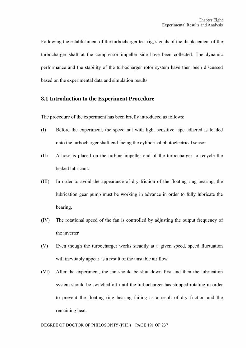
Chapter Eight Experimental Results and Analysis
DEGREE OF DOCTOR OF PHILOSOPHY (PHD) PAGE 191 OF 237
Following the establishment of the turbocharger test rig, signals of the displacement of the
turbocharger shaft at the compressor impeller side have been collected. The dynamic
performance and the stability of the turbocharger rotor system have then been discussed
based on the experimental data and simulation results.
8.1 Introduction to the Experiment Procedure
The procedure of the experiment has been briefly introduced as follows:
(I) Before the experiment, the speed nut with light sensitive tape adhered is loaded
onto the turbocharger shaft end facing the cylindrical photoelectrical sensor.
(II) A hose is placed on the turbine impeller end of the turbocharger to recycle the
leaked lubricant.
(III) In order to avoid the appearance of dry friction of the floating ring bearing, the
lubrication gear pump must be working in advance in order to fully lubricate the
bearing.
(IV) The rotational speed of the fan is controlled by adjusting the output frequency of
the inverter.
(V) Even though the turbocharger works steadily at a given speed, speed fluctuation
will inevitably appear as a result of the unstable air flow.
(VI) After the experiment, the fan should be shut down first and then the lubrication
system should be switched off until the turbocharger has stopped rotating in order
to prevent the floating ring bearing failing as a result of dry friction and the
remaining heat.
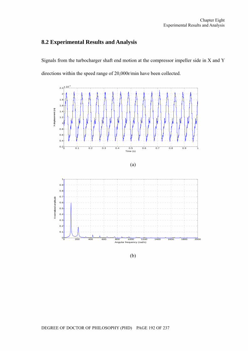
Chapter Eight Experimental Results and Analysis
DEGREE OF DOCTOR OF PHILOSOPHY (PHD) PAGE 192 OF 237
8.2 Experimental Results and Analysis
Signals from the turbocharger shaft end motion at the compressor impeller side in X and Y
directions within the speed range of 20,000r/min have been collected.
0 0.1 0.2 0.3 0.4 0.5 0.6 0.7 0.8 0.9 10.2
0.4
0.6
0.8
1
1.2
1.4
1.6
1.8
2
2.2 x 10⁻⁴
Time (s)
X d
ispl
acem
ent (
m)
(a)
0 200 400 600 800 1000 1200 1400 1600 1800 20000
0.1
0.2
0.3
0.4
0.5
0.6
0.7
0.8
0.9
1
Angular frequency (rad/s)
X n
orm
aliz
ed a
mpl
itude
(b)
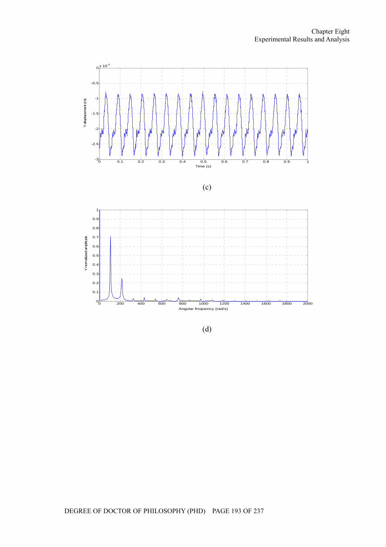
Chapter Eight Experimental Results and Analysis
DEGREE OF DOCTOR OF PHILOSOPHY (PHD) PAGE 193 OF 237
0 0.1 0.2 0.3 0.4 0.5 0.6 0.7 0.8 0.9 1-3
-2.5
-2
-1.5
-1
-0.5
0 x 10-4
Time (s)
Y d
ispl
acem
ent (
m)
(c)
0 200 400 600 800 1000 1200 1400 1600 1800 20000
0.1
0.2
0.3
0.4
0.5
0.6
0.7
0.8
0.9
1
Angular frequency (rad/s)
Y n
orm
aliz
ed a
mpl
itude
(d)
Chapter Eight Experimental Results and Analysis
DEGREE OF DOCTOR OF PHILOSOPHY (PHD) PAGE 194 OF 237
0.2 0.4 0.6 0.8 1 1.2 1.4 1.6 1.8 2 2.2x 10⁻⁴
-3
-2.5
-2
-1.5
-1
-0.5
0 x 10-4
X displacement (m)
Y d
ispl
acem
ent (
m)
(e)
Figure 8. 1. The turbocharger shaft end motion at the compressor impeller side at
1,000r/min rotational speed: (a)X displacement (b)Spectrum of X displacement (c)Y
displacement (d)Spectrum of Y displacement (e)Trajectory
Figure 8.1 shows the turbocharger shaft end motion at the compressor impeller end within
one second at 1,000r/min (≈100rad/s) rotational speed. The turbocharger shaft can be seen
to perform the periodic motion in X and Y directions. The displacement signals obtained
are not smooth but with glitches at some places, and the irregular shaft trajectory
demonstrates the existence of these glitches. The spectrum diagrams illustrate that shaft
motion comprises of the synchronous component, the second order harmonic component
and a series of slightly higher orders components. The subsynchronous component does
not emerge at this speed. Due to the lubricant feed pressure, however, the shaft is whirling
below the central position of the bearing.
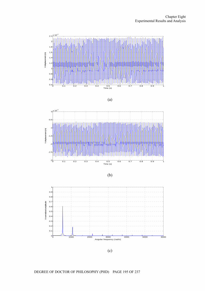
Chapter Eight Experimental Results and Analysis
DEGREE OF DOCTOR OF PHILOSOPHY (PHD) PAGE 195 OF 237
0 0.1 0.2 0.3 0.4 0.5 0.6 0.7 0.8 0.9 10.4
0.6
0.8
1
1.2
1.4
1.6
1.8
2
2.2 x 10⁻⁴
Time (s)
X d
ispl
acem
ent (
m)
(a)
0 0.1 0.2 0.3 0.4 0.5 0.6 0.7 0.8 0.9 1-3
-2.5
-2
-1.5
-1
-0.5
0 x 10-4
Time (s)
Y d
ispl
acem
ent (
m)
(b)
0 1000 2000 3000 4000 5000 60000
0.1
0.2
0.3
0.4
0.5
0.6
0.7
0.8
0.9
1
Angular frequency (rad/s)
X n
orm
aliz
ed a
mpl
itude
(c)
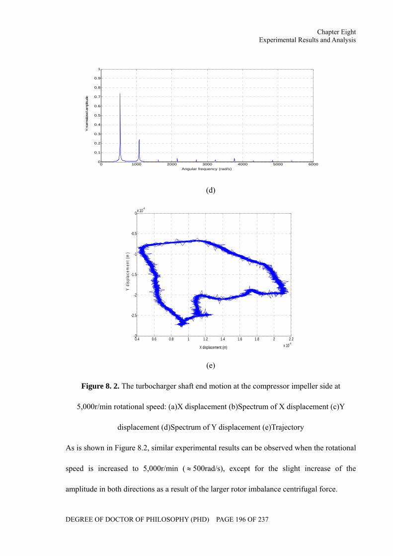
Chapter Eight Experimental Results and Analysis
DEGREE OF DOCTOR OF PHILOSOPHY (PHD) PAGE 196 OF 237
0 1000 2000 3000 4000 5000 60000
0.1
0.2
0.3
0.4
0.5
0.6
0.7
0.8
0.9
1
Angular frequency (rad/s)
Y n
orm
aliz
ed a
mpl
itude
(d)
0.4 0.6 0.8 1 1.2 1.4 1.6 1.8 2 2.2x 10⁻⁴
-3
-2.5
-2
-1.5
-1
-0.5
0 x 10-4
X displacement (m)
Y d
ispl
acem
ent (
m)
(e)
Figure 8. 2. The turbocharger shaft end motion at the compressor impeller side at
5,000r/min rotational speed: (a)X displacement (b)Spectrum of X displacement (c)Y
displacement (d)Spectrum of Y displacement (e)Trajectory
As is shown in Figure 8.2, similar experimental results can be observed when the rotational
speed is increased to 5,000r/min ( ≈ 500rad/s), except for the slight increase of the
amplitude in both directions as a result of the larger rotor imbalance centrifugal force.
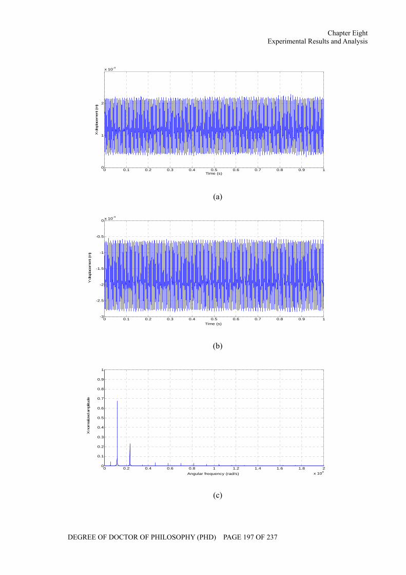
Chapter Eight Experimental Results and Analysis
DEGREE OF DOCTOR OF PHILOSOPHY (PHD) PAGE 197 OF 237
0 0.1 0.2 0.3 0.4 0.5 0.6 0.7 0.8 0.9 10
1
2
x 10-4
Time (s)
X d
ispl
acem
ent (
m)
(a)
0 0.1 0.2 0.3 0.4 0.5 0.6 0.7 0.8 0.9 1-3
-2.5
-2
-1.5
-1
-0.5
0 x 10-4
Time (s)
Y d
ispl
acem
ent (
m)
(b)
0 0.2 0.4 0.6 0.8 1 1.2 1.4 1.6 1.8 2x 10⁴
0
0.1
0.2
0.3
0.4
0.5
0.6
0.7
0.8
0.9
1
Angular frequency (rad/s)
X n
orm
aliz
ed a
mpl
itude
(c)
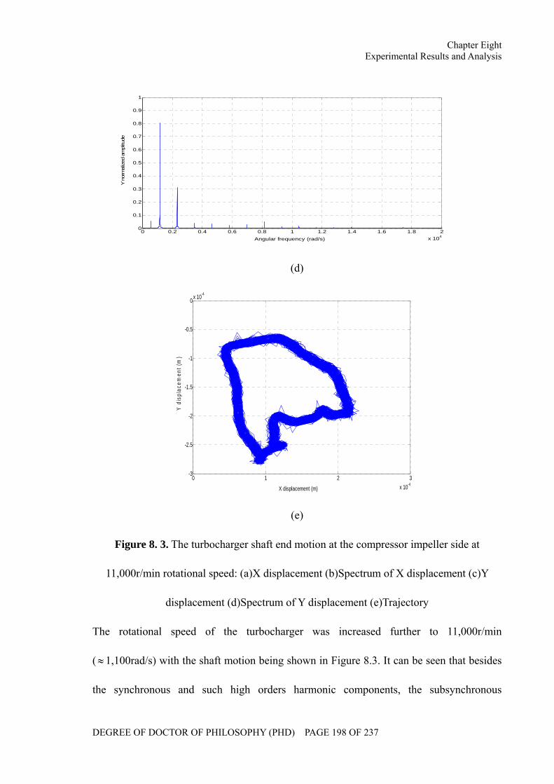
Chapter Eight Experimental Results and Analysis
DEGREE OF DOCTOR OF PHILOSOPHY (PHD) PAGE 198 OF 237
0 0.2 0.4 0.6 0.8 1 1.2 1.4 1.6 1.8 2x 10⁴
0
0.1
0.2
0.3
0.4
0.5
0.6
0.7
0.8
0.9
1
Angular frequency (rad/s)
Y n
orm
aliz
ed a
mpl
itude
(d)
0 1 2 3x 10⁻⁴
-3
-2.5
-2
-1.5
-1
-0.5
0 x 10-4
X displacement (m)
Y d
ispl
acem
ent (
m)
(e)
Figure 8. 3. The turbocharger shaft end motion at the compressor impeller side at
11,000r/min rotational speed: (a)X displacement (b)Spectrum of X displacement (c)Y
displacement (d)Spectrum of Y displacement (e)Trajectory
The rotational speed of the turbocharger was increased further to 11,000r/min
(≈1,100rad/s) with the shaft motion being shown in Figure 8.3. It can be seen that besides
the synchronous and such high orders harmonic components, the subsynchronous
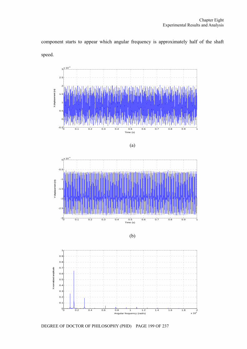
Chapter Eight Experimental Results and Analysis
DEGREE OF DOCTOR OF PHILOSOPHY (PHD) PAGE 199 OF 237
component starts to appear which angular frequency is approximately half of the shaft
speed.
0 0.1 0.2 0.3 0.4 0.5 0.6 0.7 0.8 0.9 1-0.5
0
0.5
1
1.5
2
2.5
3 x 10⁻⁴
Time (s)
X d
ispl
acem
ent (
m)
(a)
0 0.1 0.2 0.3 0.4 0.5 0.6 0.7 0.8 0.9 1-3
-2.5
-2
-1.5
-1
-0.5
0 x 10-4
Time (s)
Y d
ispl
acem
ent (
m)
(b)
0 0.2 0.4 0.6 0.8 1 1.2 1.4 1.6 1.8 2x 10⁴
0
0.1
0.2
0.3
0.4
0.5
0.6
0.7
0.8
0.9
1
Angular frequency (rad/s)
X n
orm
aliz
ed a
mpl
itude
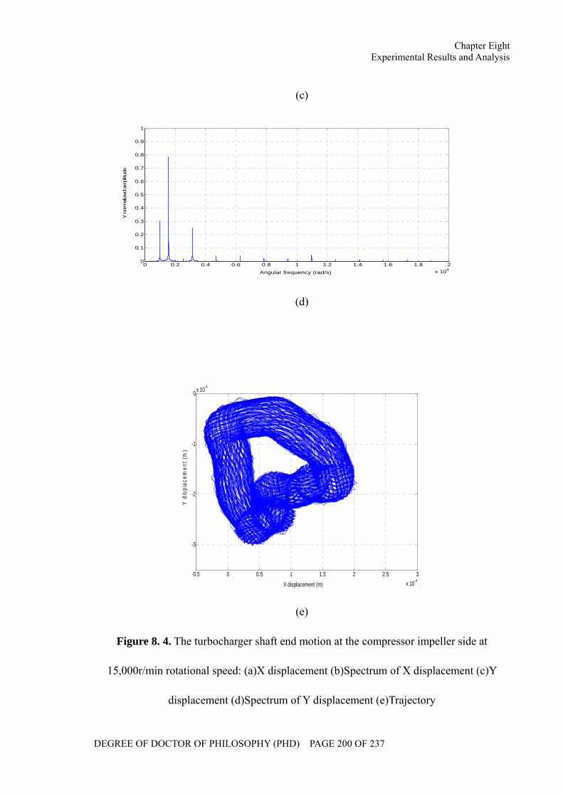
Chapter Eight Experimental Results and Analysis
DEGREE OF DOCTOR OF PHILOSOPHY (PHD) PAGE 200 OF 237
(c)
0 0.2 0.4 0.6 0.8 1 1.2 1.4 1.6 1.8 2x 10⁴
0
0.1
0.2
0.3
0.4
0.5
0.6
0.7
0.8
0.9
1
Angular frequency (rad/s)
Y n
orm
aliz
ed a
mpl
itude
(d)
-0.5 0 0.5 1 1.5 2 2.5 3x 10⁻⁴
-3
-2
-1
0 x 10-4
X displacement (m)
Y d
ispl
acem
ent (
m)
(e)
Figure 8. 4. The turbocharger shaft end motion at the compressor impeller side at
15,000r/min rotational speed: (a)X displacement (b)Spectrum of X displacement (c)Y
displacement (d)Spectrum of Y displacement (e)Trajectory
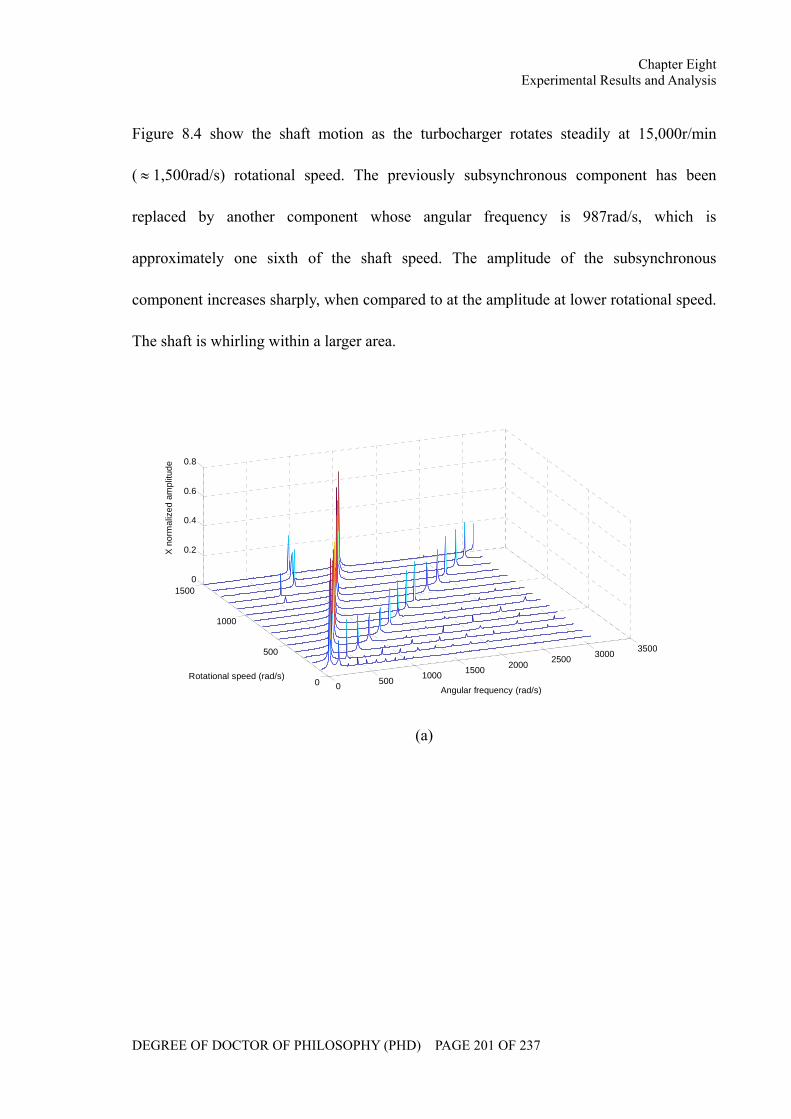
Chapter Eight Experimental Results and Analysis
DEGREE OF DOCTOR OF PHILOSOPHY (PHD) PAGE 201 OF 237
Figure 8.4 show the shaft motion as the turbocharger rotates steadily at 15,000r/min
( ≈ 1,500rad/s) rotational speed. The previously subsynchronous component has been
replaced by another component whose angular frequency is 987rad/s, which is
approximately one sixth of the shaft speed. The amplitude of the subsynchronous
component increases sharply, when compared to at the amplitude at lower rotational speed.
The shaft is whirling within a larger area.
0 500 1000 1500 2000 2500 3000 3500
0
500
1000
15000
0.2
0.4
0.6
0.8
Angular frequency (rad/s)Rotational speed (rad/s)
X n
orm
aliz
ed a
mpl
itude
(a)
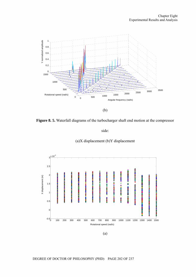
Chapter Eight Experimental Results and Analysis
DEGREE OF DOCTOR OF PHILOSOPHY (PHD) PAGE 202 OF 237
0 500 1000 1500 2000 2500 3000 3500
0
500
1000
15000
0.2
0.4
0.6
0.8
1
Angular frequency (rad/s)
Rotational speed (rad/s)
Y n
orm
aliz
ed a
mpl
itude
(b)
Figure 8. 5. Waterfall diagrams of the turbocharger shaft end motion at the compressor
side:
(a)X displacement (b)Y displacement
0 100 200 300 400 500 600 700 800 900 1000 1100 1200 1300 1400 1500-0.5
0
0.5
1
1.5
2
2.5
3 x 10⁻⁴
Rotational speed (rad/s)
X d
ispl
acem
ent (
m)
(a)
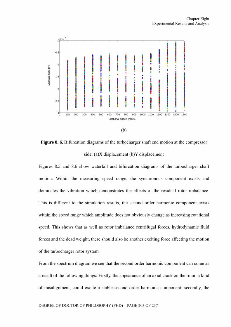
Chapter Eight Experimental Results and Analysis
DEGREE OF DOCTOR OF PHILOSOPHY (PHD) PAGE 203 OF 237
0 100 200 300 400 500 600 700 800 900 1000 1100 1200 1300 1400 1500-3
-2.5
-2
-1.5
-1
-0.5
0 x 10-4
Rotational speed (rad/s)
Dis
plac
emen
t (m
)
(b)
Figure 8. 6. Bifurcation diagrams of the turbocharger shaft end motion at the compressor
side: (a)X displacement (b)Y displacement
Figures 8.5 and 8.6 show waterfall and bifurcation diagrams of the turbocharger shaft
motion. Within the measuring speed range, the synchronous component exists and
dominates the vibration which demonstrates the effects of the residual rotor imbalance.
This is different to the simulation results, the second order harmonic component exists
within the speed range which amplitude does not obviously change as increasing rotational
speed. This shows that as well as rotor imbalance centrifugal forces, hydrodynamic fluid
forces and the dead weight, there should also be another exciting force affecting the motion
of the turbocharger rotor system.
From the spectrum diagram we see that the second order harmonic component can come as
a result of the following things: Firstly, the appearance of an axial crack on the rotor, a kind
of misalignment, could excite a stable second order harmonic component; secondly, the
Chapter Eight Experimental Results and Analysis
DEGREE OF DOCTOR OF PHILOSOPHY (PHD) PAGE 204 OF 237
bolts may have loosened or a crack may have occurred on the base; thirdly, the rub-impact
phenomenon - once the rotors touch the stators, a series of harmonic vibration components
can be caused; fourthly, concentricity deviation between the disks may lead to the
appearance of the second harmonic component.
Within the speed range of the measurement, the appearance of the subsynchronous
components at which the angular frequencies are approximately 1/2 and 1/6 of the shaft
speed shows the oil whirling phenomenon occurring in the fluid films inside the floating
ring bearing; this also supports the simulation results at the relatively low speed range.
According to the simulation and experimental results, we can see that the rotational speed
at which subsynchronous components occur as well as the sequence in which the
instability of the two oil films emerge, depends upon parameters such as the rotor system
eccentricity, the phase difference between the rotor imbalance, the bearing clearances, the
lubricant viscosity and the feed pressure.
Rotor system instability can be illustrated using a typical procedure as an example: At low
speed range, the inner oil film is crucial to the rotor system motion. When the rotational
speed reaches a critical value, the damping of the outer film cannot inhibit the excitation
from the inner oil film. At that time, oil whirl and whip phenomenon will then occur in the
inner oil film. The whirling frequency is generally approximately one third of the shaft
speed and will slightly increase as the rotational speed rises. In addition, the amplitude of
the subsynchronous component will be larger than that of the synchronous component. If
the rotational speed is increased yet further, the outer oil film will gradually replace the
inner oil film to dominate the rotor system motion. Once a critical value is reached, the
Chapter Eight Experimental Results and Analysis
DEGREE OF DOCTOR OF PHILOSOPHY (PHD) PAGE 205 OF 237
outer oil film can no longer inhibit the inner film. The second bifurcation occurs and the
rotor system becomes unstable once again. As mentioned above, the instability procedure
is determined by the parameters of the rotor system which can affect not only the angular
velocity at which subsynchronous components occur, but also the sequence in which oil
film instabilities emerge.
8.3 Summary
In this chapter, the procedure of the experiment is briefly introduced. Then, the
experimental data regarding bending vibration of the turbocharger rotor system are
collected within the speed range of 1000 to 20000 r/min. The stability characteristics of
turbocharger rotor system are analyzed through the experimental and simulation results.
Chapter Nine Conclusions and Future Work
DEGREE OF DOCTOR OF PHILOSOPHY (PHD) PAGE 206 OF 237
CHAPTER NINE
CONCLUSIONS AND FUTURE WORK
In this chapter, the achievements of this research project are summarized. The findings and
conclusions are presented. The contributions to knowledge have been summarized
separately and proposals for future research to develop this area of work are discussed.
Chapter Nine Conclusions and Future Work
DEGREE OF DOCTOR OF PHILOSOPHY (PHD) PAGE 207 OF 237
9.1 Review of Research Objectives and Achievements
The objectives of this research project and key achievements are described below:
Objective 1: To conduct a full literature review of current research in the areas of fluid
lubrication, rotordynamics and turbocharger rotordynamics.
Achievement 1: Publications associated with research on fluid lubrication were reviewed
and linear and nonlinear models of the hydrodynamic forces were summarized and
compared. The classical models of nonlinear hydrodynamic forces are listed in Section 2.1.
The theory and background of three areas of rotordynamics were introduced, namely:
critical speeds, forced response and stability analysis. General approaches to the research
of rotordynamics are given in Section 2.2.
Literature associated with rotordynamics research of the turbocharger, which is a flexible
rotor system supported by floating ring bearings, were reviewed and are presented in
Section 2.3. Background theory related to the research of the turbocharger rotordynamics
were introduced, including: the nonlinear theory of the vibration system, the modal
synthesis method and the numerical calculation approach; and are presented in Sections 2.4,
2.5 and 2.6 respectively.
Objective 2: To investigate the fluid lubrication of the floating ring bearing system.
Achievement 2: The analytical expressions of the oil film pressure distribution in the
floating ring bearing were derived using the infinitely long bearing theory, taking into
account the oil inlet pressure and cavitation area – see Section 3.2.
Chapter Nine Conclusions and Future Work
DEGREE OF DOCTOR OF PHILOSOPHY (PHD) PAGE 208 OF 237
The equilibrium positions of the journal and ring, in terms of the eccentricity and attitude
angle, were simulated. The influences of external loads and oil inlet pressure on the oil
flow rate into the inner clearance were investigated analytically based on the simulation
results shown in Section 3.3.
Objective 3: To develop a theoretical dynamics model for the turbocharger rotor system.
Achievement 3: Using the finite element method, a finite element model was developed for
the turbocharger rotor system. The shaft was modeled as a series of beam elements and the
turbine and compressor wheels were modeled as rigid disks. The dimensionless form of the
Capone hydrodynamic force model was extended into the floating ring bearing with double
oil films. The adaptive time step Runge-kutta approach was introduced to numerically
integrate the second order system motion equation as shown in Section 4.2.
Objective 4: To analyze the dynamic performance of the turbocharger rotor system and to
calculate the critical speeds and mode shapes.
Achievement 4: Modal analysis was carried out on both a free rotor system as in Section
5.2 and a turbocharger rotor system as in Section 5.3. Influences of the support and
gyroscopic effects were ignored in the free rotor system analysis, whilst the turbocharger
rotor system analysis took into account the support of the floating ring bearings and
gyroscopic effects. The studies of the critical speeds and mode shapes were based on the
simulation results shown in Section 5.4.
Chapter Nine Conclusions and Future Work
DEGREE OF DOCTOR OF PHILOSOPHY (PHD) PAGE 209 OF 237
Objective 5: To study the effects of working conditions on the dynamic performance and
stability of the turbocharger rotor system.
Achievement 5: Dynamic performance and stability of the turbocharger rotor system was
simulated under various parameters. Parameters investigated included: the trajectory, the
spectrum, the waterfall and bifurcation diagrams, effects of the rotor imbalance, lubricant
viscosity and feed pressure and bearing clearances (results provided in Section 6.2).
Objective 6: To construct a turbocharger test rig to validate and verify the theoretical
model.
Achievement 6: A cold air driven turbocharger test rig was designed and assembled, as
described in Chapter 7. Following test rig development, the experimental data associated
with the bending vibration of the turbocharger shaft was acquired, as given in Section 8.2.
The experimental and simulation results were then used to determine the stability of the
turbocharger rotor system in Section 8.3.
9.2 Conclusions
Conclusion 1: Based on the infinitely long bearing form of the steady-state Reynolds
Equation, the analytical expressions of the oil film pressure distribution in two clearances
of the floating ring bearing have been derived. These expressions take into account the
influences of the oil inlet pressure and cavitation area and the lubrication model has been
described.
Chapter Nine Conclusions and Future Work
DEGREE OF DOCTOR OF PHILOSOPHY (PHD) PAGE 210 OF 237
Conclusion 2: The equilibrium positions of the journal and ring in terms of the eccentricity
and attitude angle have been simulated under different external loads and oil inlet pressures.
It was found that heavy external loads could result in larger outer eccentricities but the
effect on inner eccentricity was inconclusive and was only observed in the lower speed
range. The oil inlet pressure primarily affected the outer range of the attitude angle, but the
external load could extend the cavitation areas in both the outer and inner oil film causing
shrinkage of the cavitation area at high speeds when the oil inlet pressure is increased.
Conclusion 3: The lubrication of the inner oil film of the floating ring bearing was studied.
The effects of external loads and oil inlet pressures on the oil flow rate into the inner
bearing clearance were investigated. It was found that a heavier external load could reduce
the oil flow rate into the inner oil film across a wide speed range. These conditions could
lead to inner film oil starvation even if the initial flow rate was higher at lower speed.
However, increasing oil inlet pressure effectively improved the inner oil film lubrication.
Conclusion 4: Modal analysis was carried out on a free rotor system ignoring the influence
of support and gyroscopic effects. Calculation results showed that all four orders of mode
shapes were bending modes in which the fourth order already showed the trend of
transforming into the local mode.
Conclusion 5: Modal analysis was carried out on the turbocharger rotor system, taking into
account the effects of the floating ring bearing and gyroscopic effects. The characteristic
Chapter Nine Conclusions and Future Work
DEGREE OF DOCTOR OF PHILOSOPHY (PHD) PAGE 211 OF 237
equation of the turbocharger rotor system was derived and critical speeds and mode shapes
of the turbocharger rotor system were calculated. The results showed that the critical speed
increased as the shaft speed is increased due to gyroscopic effects. It was then
demonstrated, through the Campbell diagram that the critical speeds of the turbocharger
rotor system would increase as the stiffness coefficient of the bearing increased. This
condition could also affect the mode shapes of the rotor system.
Conclusion 6: Studies of the influence of the rotor imbalance on the stability of the
turbocharger shaft motion concluded that the rotor imbalance could lead to the appearance
of the synchronous component for the turbocharger rotor system, the angular frequency of
which was equal to the shaft velocity. The centrifugal force can inhibit the appearance of
the instability in the inner oil film. However, the instability in outer oil film can be excited
at a lower speed, when the amplitude of the rotor system becomes larger.
Conclusion 7: Studies of the influence of the lubricant viscosity on the stability of the
turbocharger shaft motion concluded that the lubricant viscosity can inhibit the instability
in both inner and outer oil films. Under a lower lubricant viscosity, instabilities of both oil
films are excited at the lower speeds, when the system shows a dramatic motion. Under a
higher viscosity, the instabilities occur at higher speeds, especially for the inner oil film
instability. The amplitude under oil film instabilities is also inhibited.
Conclusion 8: An investigation of the influence of the bearing clearances on the stability of
Chapter Nine Conclusions and Future Work
DEGREE OF DOCTOR OF PHILOSOPHY (PHD) PAGE 212 OF 237
the turbocharger shaft motion concluded that either inner or outer bearing clearance can
affect the stability discipline of two oil films. As the inner clearance is increased, the inner
oil film instability will occur at a higher rotational speed, but the outer oil film instability
will be excited at a lower rotational speed. On the other hand, as the outer clearance is
decreased, the hydrodynamic forces become larger, which inhibit the appearance of the
instability in both inner and outer oil films. A high order harmonic component might also
be excited by a thinner outer clearance.
Conclusion 9: The lubricant feed pressure exerts a static load on the ring. It can excite the
instability at a lower rotational speed in both inner and outer bearing clearances.
Conclusion 10: The displacement signals of the turbocharger shaft end at the compressor
side were collected within the speed range 0~15,000r/min. The experimental data showed
that the synchronous component and second order harmonic component existed within the
entire measuring speed range. Apart from glitches in the data observed at the measuring
position, it is concluded that the synchronous component is caused by the residual rotor
imbalance. A number of reasons have been identified which could excite the second order
harmonic component of the turbocharger rotor system. Both simulation and experimental
data were used to study the stability characteristics of the turbocharger rotor system
supported by the floating ring bearing.
Chapter Nine Conclusions and Future Work
DEGREE OF DOCTOR OF PHILOSOPHY (PHD) PAGE 213 OF 237
9.3 Contribution to Knowledge
Contribution 1: Static performance of the fluid lubrication of the turbocharger floating ring
bearings.
Most commercial turbochargers use the floating ring bearings to support the rotor system.
The application of floating ring bearings not only decreases the relative speed between the
journal and the bearing shell, but also inhibits self-excited vibration. It is difficult to study
the static performance of the fluid lubrication of floating ring bearings, due to the
interaction of the inner and outer oil films.
In this thesis, the Reynolds Equation has been extended to study both the inner and outer
oil films of the floating ring bearing. The analytical expressions for the oil film pressure
distribution have been obtained by taking into account the oil inlet pressure, and the
Reynolds boundary condition, when numerically solving the Reynolds Equations. Based
on the results obtained, the rotational velocity of the shaft and the equilibrium positions for
the journal and ring have been deduced under different external loads and lubricant feed
pressures. Furthermore, during this work the conditions at which a rupture could occur
between the divergent wedge of the oil films, was determined.
Contribution 2: Effects of ring rotation on the fluid lubrication of the inner oil film of the
floating ring bearings.
The outer clearance of the floating ring bearing was lubricated through the supply hole
located on top of the bearing shell, whilst lubrication of the inner clearance was determined
Chapter Nine Conclusions and Future Work
DEGREE OF DOCTOR OF PHILOSOPHY (PHD) PAGE 214 OF 237
by the pressure difference between the two oil films. Rotation of the ring also significantly
affected the lubrication of the inner oil film.
In this thesis, a lubrication model for the floating ring bearing was developed and used to
study the effects of the rotation of the ring rotation on the oil flow rate into the inner
bearing clearance. The relationship of the oil flow rate and the rotational velocity of the
journal were obtained under different external loads and lubricant feed pressures.
Furthermore, trigger conditions and solution approaches for oil starvation have been
simulated and mean oil flow rates into the inner bearing clearance, have been determined.
Contribution 3: Nonlinear hydrodynamic forces.
The primary exciting forces of the turbocharger rotor system bending vibration include
rotor imbalance and hydrodynamic forces, the latter of which demonstrate highly nonlinear
characteristics. The standard method used to resolve this, is linearization using the
perturbation method. Although this method is suitable for the calculation of critical speeds
and mode shapes of the rotor system, it is inadequate for describing the bending vibration
and nonlinear behaviors.
In this thesis, the Capone hydrodynamic force model has been extended to simulate the
dynamic performance of the floating ring bearing. The analytical expression for the
hydrodynamic forces of the two oil films have been derived based on the dimensionless
form of the Reynolds Equations. The calculations have been normalized by using a
multiplication coefficient for the two oil films.
Chapter Nine Conclusions and Future Work
DEGREE OF DOCTOR OF PHILOSOPHY (PHD) PAGE 215 OF 237
Contribution 4: Stability analysis of the turbocharger rotor system.
A turbocharger rotor system can be viewed as a rotor bearing system with double disks
supported by a pair of floating ring bearings. The dynamic performance and stability of the
system depends on the working conditions, but studies are complicated by the interaction
and nonlinear behavior of the inner and outer oil films.
In this thesis, the motion of the turbocharger shaft was simulated within a shaft speed range
of 0 to 8000rad/s under different rotor imbalance, lubricant viscosity, bearing clearance and
lubricant feed pressure conditions - numerical integration approaches were used. The
influences of the structural parameters and working conditions on the stability of the
turbocharger rotor system were obtained from the spectra, trajectory, bifurcation and
waterfall diagrams.
9.4 Future Work
Future work 1: In this research, the lubricant flow in the floating ring bearing was
simplified as a laminar flow. However, turbulent flow sometimes occurred in the bearing
clearance when the Reynolds number exceeded 4000 and conventional fluid lubrication
theory based on laminar flow could not be applied.
To date, the standard approach for studying turbulent flow lubrication is to introduce a
modified form of the Reynolds Equation using an empirical coefficient. This approach is
clearly inappropriate for describing such a complex phenomenon. Therefore, it is
recommended that turbulent flow lubrication theory and its impact on displacement of the
rotor system should be investigated in more depth.
Chapter Nine Conclusions and Future Work
DEGREE OF DOCTOR OF PHILOSOPHY (PHD) PAGE 216 OF 237
Future work 2: In the dynamics model which has been developed, the exciting forces for
the vibration of the turbocharger rotor system included the rotor imbalance, hydrodynamic
forces, lubricant feed pressure and the dead weight. However, potential faults, such as the
crack, loosening of the base, fatigue fracture, etc, have not been considered. These faults
could occur individually or simultaneously as coupled faults.
To date, the majority of rotor fault research has been based on the Jeffcott rotor model. It is,
therefore, necessary to carry out an in depth analysis of the stability for a multi-span rotor
bearing system with coupled faults.
Future work 3: Stability analysis of a rotor bearing system is an important industrial
application. It is therefore insufficient to observe only the trend of the stability
characteristics of the system. In order to understand the capability of the rotor system to
withstand actual working conditions, it is also necessary to quantify the degree of stability
of the system and this should form part of a future research study.
Future work 4: Throughout this research, the influence of rotational velocity fluctuation
has been ignored in both theoretical modeling and experimental study. But in practice, a
turbocharger is driven by the exhaust discharged from the engine cylinders. The
intermittent nature of the engine exhaust results in the driven force being a series of gas
pulses rather than a steady flow and this will inevitably lead to a bending-torsional coupled
vibration of the rotor system. This effect on the stability of the rotor bearing system
Chapter Nine Conclusions and Future Work
DEGREE OF DOCTOR OF PHILOSOPHY (PHD) PAGE 217 OF 237
requires deeper investigation.
Future work 5: In the dynamics model of the turbocharger rotor system developed in this
research, the turbine impeller and the compressor impeller were modeled as rigid disks.
Modeling ignored the elasticity of the disk, as well as the effect which the geometrical
shape of the impellers had on the dynamic performance of the turbocharger rotor system.
Although simplification of the model made the study more convenient, the accuracy of the
model was inevitably affected. Therefore, it is recommended that a more comprehensive
model is developed in the future.
Future work 6: Due to reasons of security and high cost, this turbocharger test rig was a
cold air driven system. The air supply was provided by a fan, making it difficult for the
turbocharger to be driven at higher rotational velocities. For future work, it is
recommended that a combustion chamber is installed in the test rig and high temperature
and high pressure air supplies are used to extend the speed range of the turbocharger.
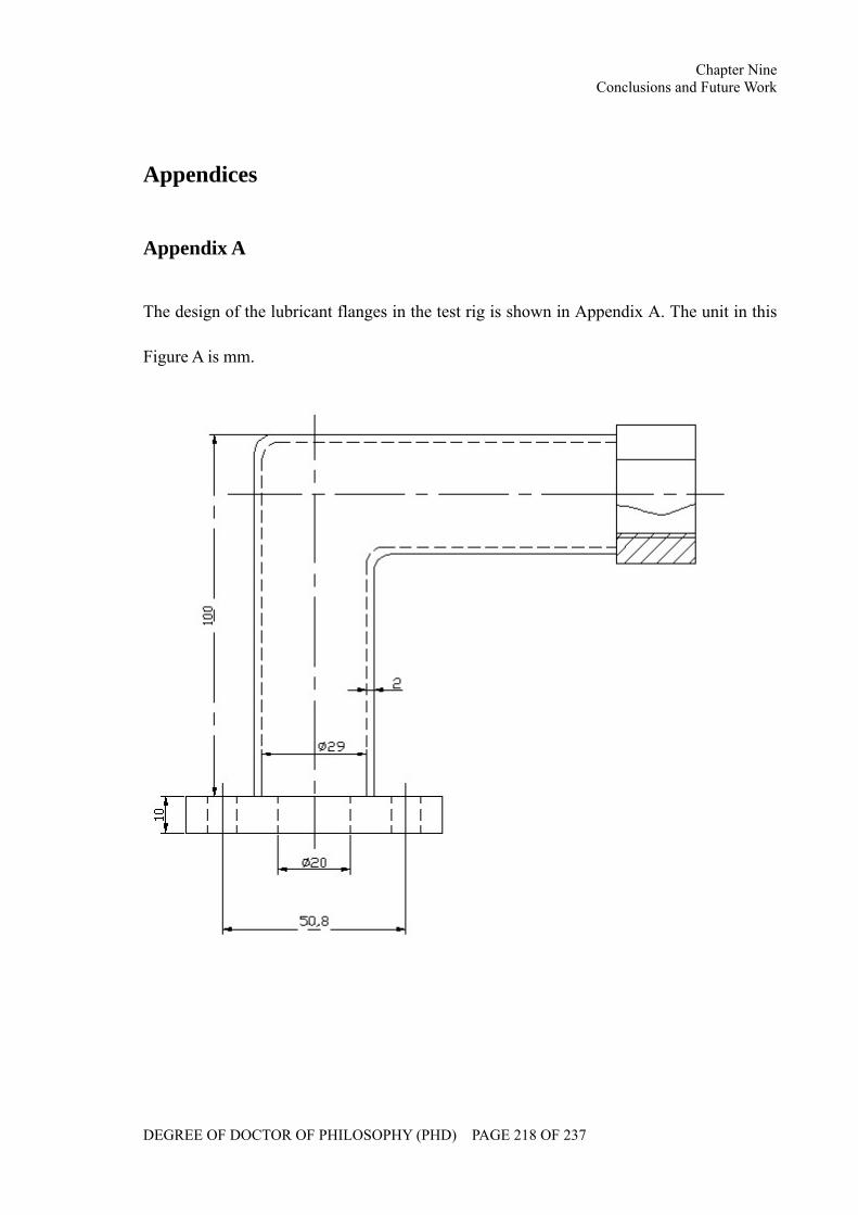
Chapter Nine Conclusions and Future Work
DEGREE OF DOCTOR OF PHILOSOPHY (PHD) PAGE 218 OF 237
Appendices
Appendix A
The design of the lubricant flanges in the test rig is shown in Appendix A. The unit in this
Figure A is mm.
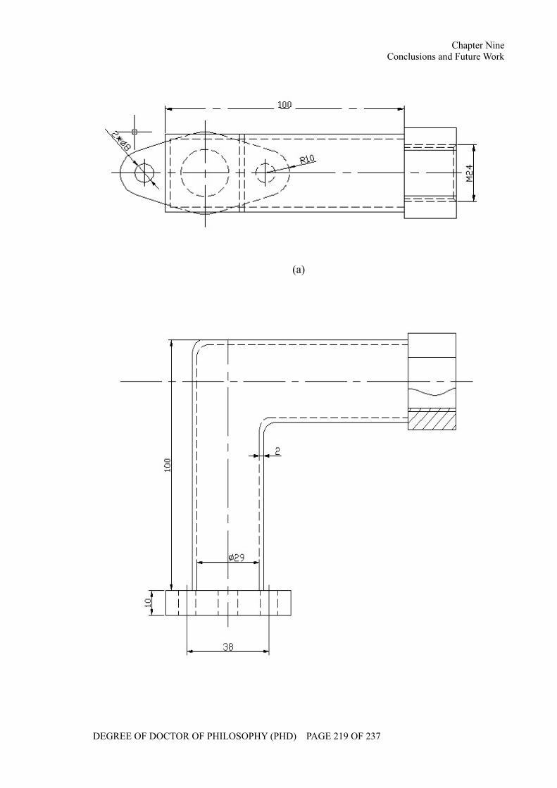
Chapter Nine Conclusions and Future Work
DEGREE OF DOCTOR OF PHILOSOPHY (PHD) PAGE 219 OF 237
(a)
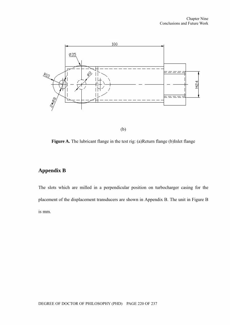
Chapter Nine Conclusions and Future Work
DEGREE OF DOCTOR OF PHILOSOPHY (PHD) PAGE 220 OF 237
(b)
Figure A. The lubricant flange in the test rig: (a)Return flange (b)Inlet flange
Appendix B
The slots which are milled in a perpendicular position on turbocharger casing for the
placement of the displacement transducers are shown in Appendix B. The unit in Figure B
is mm.
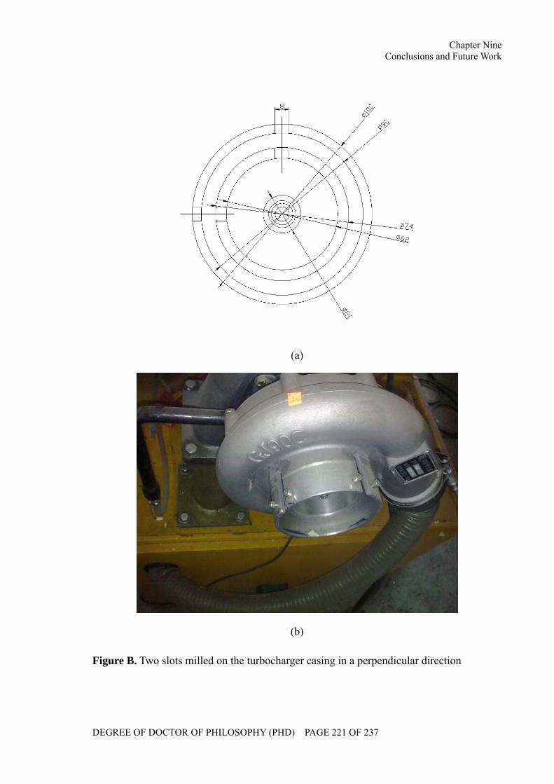
Chapter Nine Conclusions and Future Work
DEGREE OF DOCTOR OF PHILOSOPHY (PHD) PAGE 221 OF 237
(a)
(b)
Figure B. Two slots milled on the turbocharger casing in a perpendicular direction
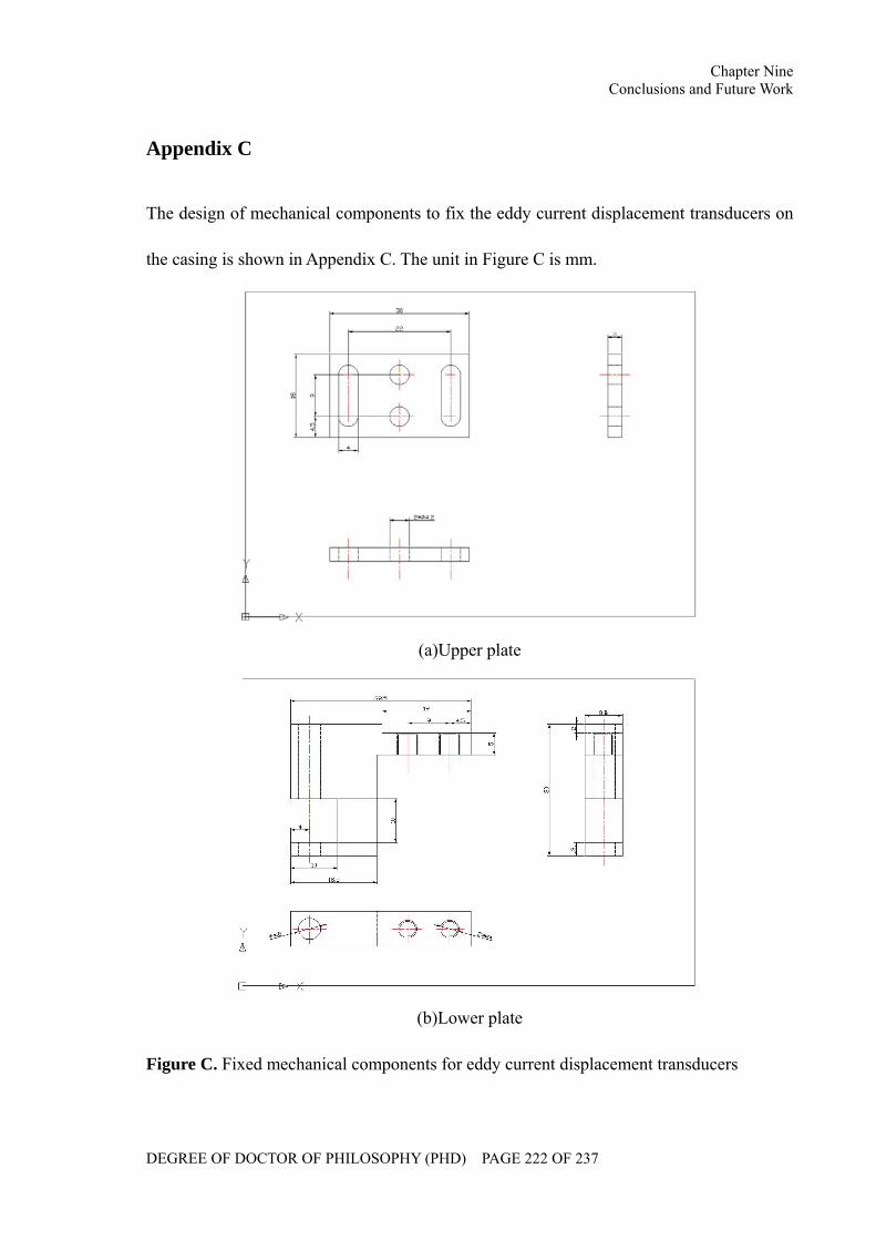
Chapter Nine Conclusions and Future Work
DEGREE OF DOCTOR OF PHILOSOPHY (PHD) PAGE 222 OF 237
Appendix C
The design of mechanical components to fix the eddy current displacement transducers on
the casing is shown in Appendix C. The unit in Figure C is mm.
(a)Upper plate
(b)Lower plate
Figure C. Fixed mechanical components for eddy current displacement transducers
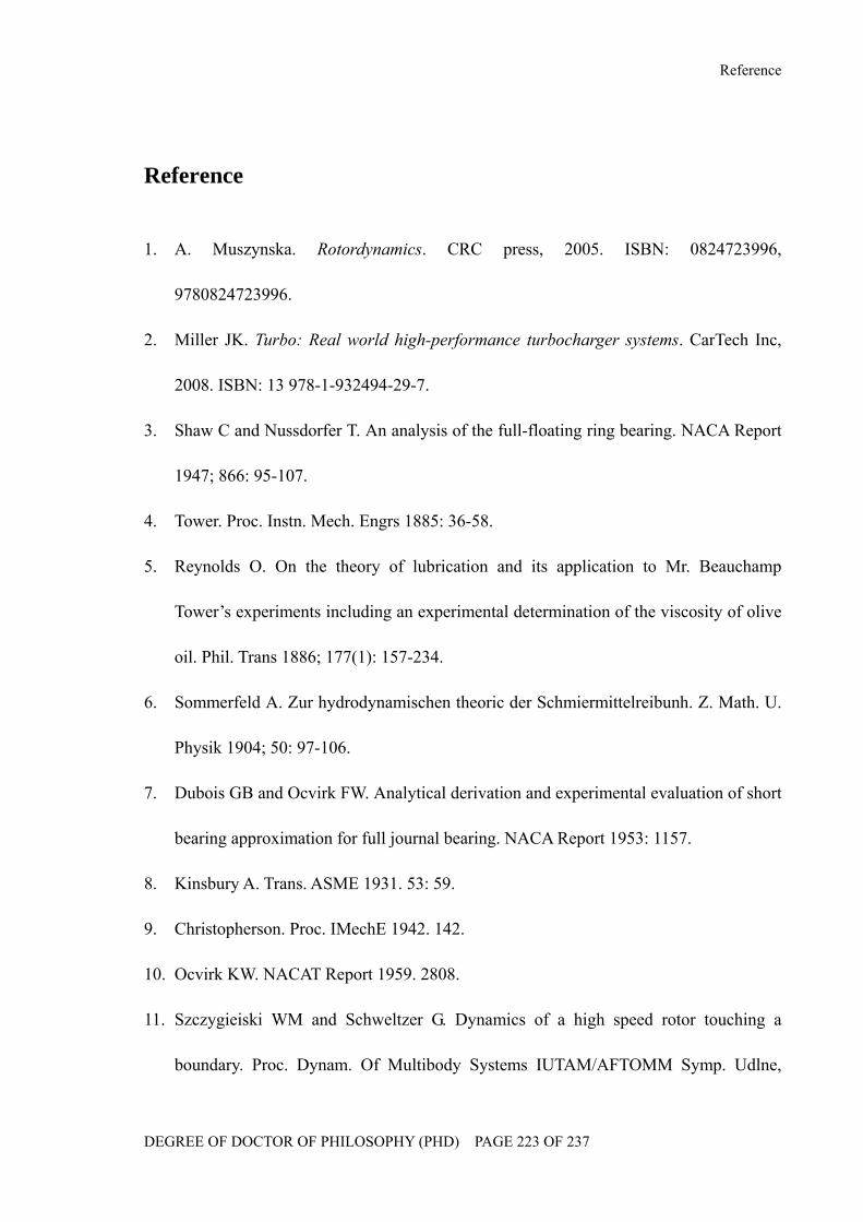
Reference
DEGREE OF DOCTOR OF PHILOSOPHY (PHD) PAGE 223 OF 237
Reference
1. A. Muszynska. Rotordynamics. CRC press, 2005. ISBN: 0824723996,
9780824723996.
2. Miller JK. Turbo: Real world high-performance turbocharger systems. CarTech Inc,
2008. ISBN: 13 978-1-932494-29-7.
3. Shaw C and Nussdorfer T. An analysis of the full-floating ring bearing. NACA Report
1947; 866: 95-107.
4. Tower. Proc. Instn. Mech. Engrs 1885: 36-58.
5. Reynolds O. On the theory of lubrication and its application to Mr. Beauchamp
Tower’s experiments including an experimental determination of the viscosity of olive
oil. Phil. Trans 1886; 177(1): 157-234.
6. Sommerfeld A. Zur hydrodynamischen theoric der Schmiermittelreibunh. Z. Math. U.
Physik 1904; 50: 97-106.
7. Dubois GB and Ocvirk FW. Analytical derivation and experimental evaluation of short
bearing approximation for full journal bearing. NACA Report 1953: 1157.
8. Kinsbury A. Trans. ASME 1931. 53: 59.
9. Christopherson. Proc. IMechE 1942. 142.
10. Ocvirk KW. NACAT Report 1959. 2808.
11. Szczygieiski WM and Schweltzer G. Dynamics of a high speed rotor touching a
boundary. Proc. Dynam. Of Multibody Systems IUTAM/AFTOMM Symp. Udlne,
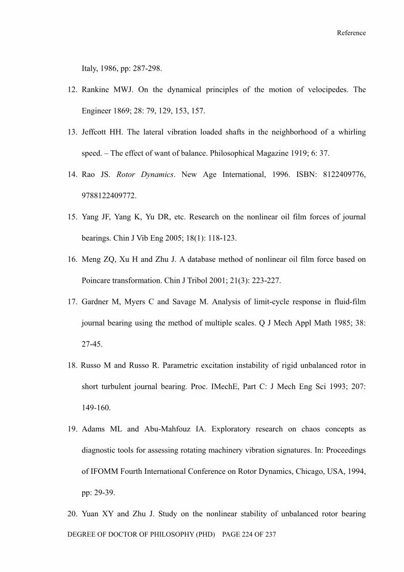
Reference
DEGREE OF DOCTOR OF PHILOSOPHY (PHD) PAGE 224 OF 237
Italy, 1986, pp: 287-298.
12. Rankine MWJ. On the dynamical principles of the motion of velocipedes. The
Engineer 1869; 28: 79, 129, 153, 157.
13. Jeffcott HH. The lateral vibration loaded shafts in the neighborhood of a whirling
speed. – The effect of want of balance. Philosophical Magazine 1919; 6: 37.
14. Rao JS. Rotor Dynamics. New Age International, 1996. ISBN: 8122409776,
9788122409772.
15. Yang JF, Yang K, Yu DR, etc. Research on the nonlinear oil film forces of journal
bearings. Chin J Vib Eng 2005; 18(1): 118-123.
16. Meng ZQ, Xu H and Zhu J. A database method of nonlinear oil film force based on
Poincare transformation. Chin J Tribol 2001; 21(3): 223-227.
17. Gardner M, Myers C and Savage M. Analysis of limit-cycle response in fluid-film
journal bearing using the method of multiple scales. Q J Mech Appl Math 1985; 38:
27-45.
18. Russo M and Russo R. Parametric excitation instability of rigid unbalanced rotor in
short turbulent journal bearing. Proc. IMechE, Part C: J Mech Eng Sci 1993; 207:
149-160.
19. Adams ML and Abu-Mahfouz IA. Exploratory research on chaos concepts as
diagnostic tools for assessing rotating machinery vibration signatures. In: Proceedings
of IFOMM Fourth International Conference on Rotor Dynamics, Chicago, USA, 1994,
pp: 29-39.
20. Yuan XY and Zhu J. Study on the nonlinear stability of unbalanced rotor bearing
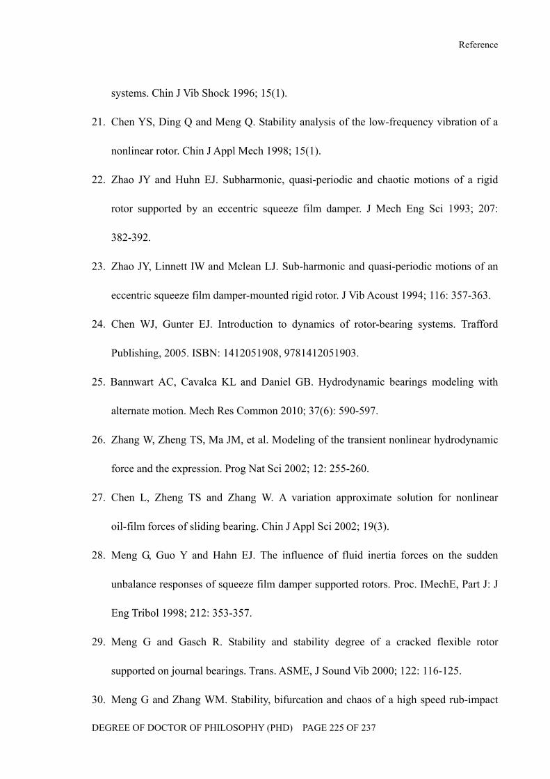
Reference
DEGREE OF DOCTOR OF PHILOSOPHY (PHD) PAGE 225 OF 237
systems. Chin J Vib Shock 1996; 15(1).
21. Chen YS, Ding Q and Meng Q. Stability analysis of the low-frequency vibration of a
nonlinear rotor. Chin J Appl Mech 1998; 15(1).
22. Zhao JY and Huhn EJ. Subharmonic, quasi-periodic and chaotic motions of a rigid
rotor supported by an eccentric squeeze film damper. J Mech Eng Sci 1993; 207:
382-392.
23. Zhao JY, Linnett IW and Mclean LJ. Sub-harmonic and quasi-periodic motions of an
eccentric squeeze film damper-mounted rigid rotor. J Vib Acoust 1994; 116: 357-363.
24. Chen WJ, Gunter EJ. Introduction to dynamics of rotor-bearing systems. Trafford
Publishing, 2005. ISBN: 1412051908, 9781412051903.
25. Bannwart AC, Cavalca KL and Daniel GB. Hydrodynamic bearings modeling with
alternate motion. Mech Res Common 2010; 37(6): 590-597.
26. Zhang W, Zheng TS, Ma JM, et al. Modeling of the transient nonlinear hydrodynamic
force and the expression. Prog Nat Sci 2002; 12: 255-260.
27. Chen L, Zheng TS and Zhang W. A variation approximate solution for nonlinear
oil-film forces of sliding bearing. Chin J Appl Sci 2002; 19(3).
28. Meng G, Guo Y and Hahn EJ. The influence of fluid inertia forces on the sudden
unbalance responses of squeeze film damper supported rotors. Proc. IMechE, Part J: J
Eng Tribol 1998; 212: 353-357.
29. Meng G and Gasch R. Stability and stability degree of a cracked flexible rotor
supported on journal bearings. Trans. ASME, J Sound Vib 2000; 122: 116-125.
30. Meng G and Zhang WM. Stability, bifurcation and chaos of a high speed rub-impact
Reference
DEGREE OF DOCTOR OF PHILOSOPHY (PHD) PAGE 226 OF 237
rotor system in MEMS. Sens Actuators A 2006; 127: 163-178.
31. Leng XL, Meng G, Zhang T, et al. Bifurcation and chaos response of a cracked rotor
with random disturbance. J Sound Vib 2007; 299: 621-632.
32. Wang JX and Meng G. Study of the vibration control of a rotor system using a
magnetorheological fluid damper. J Vib Control 2005; 11: 263-276.
33. Cheng M, Meng G and Jing JP. Numerical and experimental study of a
rotor-bearing-seal system. Mech Mach Theory 2007; 42: 1043-1057.
34. American Petroleum Institute. API Standard 617. 7th ed. 2002, 6.
35. American Petroleum Institute. API Standard 612. 4th ed. 1995, 6.
36. Prohl MA. A general method for calculating critical speed of flexible rotors. Trans.
ASME, J Appl Mech 1945; 12: 142-148.
37. Lund JW. Stability and damped critical speed of a flexible rotor in fluid-film
bearings. Trans. ASME, J End Ing 1974; 96: 509-517.
38. Horner GC and Pilkey WD. The Riccati transfer matrix method. Trans. ASME, J
Mech Des 1978; 100: 297-302.
39. Kim D and David JW. An improved method for stability and damped critical speeds of
rotor-bearing systems. Trans. ASME, J Vib Acoust 1990; 102: 112-119.
40. Guo L and Sheng XM. An improved method for critical speed of rotor bearing system.
Lubr Eng 1998; 3: 33-36.
41. Ozguven HN and Ozkan ZL. Whirl speeds and unbalance response of multibearing
rotors using finite element. Trans. ASME, J Vib Acoust Stress Reliab Des 1984; 106:
72-79.
Reference
DEGREE OF DOCTOR OF PHILOSOPHY (PHD) PAGE 227 OF 237
42. Childs DW and Graviss K. A note on critical-speed solutions for finite element based
rotor models. Trans. ASME, J Mech Des 1982; 104: 412-416.
43. Jia XM. The calculation and analysis of unbalance vibration of 200MW steam turbine
rotor system. Turbine Tech 2000; 42.
44. Shiraki K, Ingaki T and Kanki H. Transverse vibration of a general cracked rotor
bearing system. Trans. ASME, J Mech Des 1982; 104: 343.
45. Verhoeven J. Excitation force identification of rotating machines using operational
rotor/stator amplitude data and analytical synthesized transfer functions. J Vib Acoust
1988; 110(3): 307-314.
46. Irretier H. Mathematical foundations of experimental modal analysis in rotor dyanmics.
Mech Syst Sig Process 1999; 13: 183-191.
47. Greenhill LynM and Cornejo GA. Critical speeds resulting from unbalance excitation
of backward whirl modes. In: Proceedings of ASME of Design Engineering Technical
Conference. Boston, USA, 1995, Vol. 3. pp: 991-1000.
48. Hong SW and Park JH. An efficient method for the unbalance response analysis of
rotor bearing systems. J Sound Vib 1997; 200: 491-504.
49. Jun OS and Kim JO. Free bending vibration of a multi-step rotor. J Sound Vib 1999;
224: 625-642.
50. Chasalevris AC and Papadopoulos CA. A continuous model approach for
cross-coupled bending vibrations of a rotor-bearing system with a transverse breathing
crack. Mech Mach Theory 2009; 44: 1176-1191.
51. Ehrich FF. Some observations of chaotic vibration phenomena in high-speed
Reference
DEGREE OF DOCTOR OF PHILOSOPHY (PHD) PAGE 228 OF 237
rotordynamics. Trans. ASME. J Vib Acoust 1991; 113: 50-57.
52. Parkinson AG. Second order vibration of flexible shafts. Proceedings Royal Society of
London 1965; 259: 1-31.
53. Lin YH and Lin SC. Optimal weight design of rotor systems with oil film bearings
subjected to frequency constraints. Finite Elem Anal Des 2001; 37: 777-798.
54. Aleyaasin M, Ebrahimi M and Whalley R. Vibration analysis of distributed-lumped
rotor systems. Comput Meth Appl Mech Eng 2000; 189: 545-558.
55. Firoozian R and Zhu H. A hybrid method for the vibration analysis of rotor-bearing
system. Proc. IMechE, Part C: J Mech Eng Sci 1991; 205: 131-137.
56. Hagg AC. Some dynamic properties of oil film journal bearings. Trans. ASME, J Eng
1956; 3: 302-306.
57. Sternlicht B. Elastic and damping properties of cylindrical journal bearings. Trans.
ASME, J Basic Eng 1959; 81: 101-108.
58. Lund JW. Spring and damping coefficients for the tilting pad journal bearing. Trans.
ASME, J Tribol 1964; 7: 342-352.
59. Lund JW. Calculation of stiffness and damping properties of gas bearing. Trans.
ASME, J Lubr Tech 1968; 90: 793-803.
60. Glienicke J. Experimental investigation of the stiffness and damping coefficients of
turbine bearings and their application to instability prediction. In: Journal Bearings for
Reciprocating and Turbomachinery, IME Symposium in Nottingham, pp: 122-135,
1966.
61. Yang JF, Yang K and Yu DR. Nonlinear dynamic oil film pressure distribution of
Reference
DEGREE OF DOCTOR OF PHILOSOPHY (PHD) PAGE 229 OF 237
sliding bearings. Chi J Power Eng 2005; 25: 4.
62. Yang JF, Yang K and Yu DR. Characteristics of nonlinear dynamic oil film forces and
the decomposition of π oil film forces. Chi J Power Eng 2005; 25: 6.
63. Yang JF, Liu ZS and Yu DR. Research on nonlinear oil film force and its stability of
journal bearing. Power Eng 2004; 24.
64. Yang JF, Yang K and Yu DR. Nonlinear film-force of journal bearing. Journal of Harbin
Institute of Technology 2003; 35.
65. Yang JF and Liu ZS. Research on nonlinear oil film force and its stability of journal
bearing. Vib Eng 2004; 24.
66. Zhang YM, Wen BC and Liu QL. Sensitivity of rotor-stator systems with rubbing.
Mech Struct Mach 2002; 30: 203-211.
67. Zhang YM, Wen BC and Leung Andrew YT. Reliability analysis for rotor rubbing.
Trans. ASME, J Vib Acoust 2002; 124: 58-62.
68. Zhang YM, Wen BC and Liu QL. Reliability sensitivity for rotor-stator systems with
rubbing. J Sound Vib 2003; 259: 1059-1107.
69. Tang BX, Zhu EH and Wen BC. High-speed balancing. J Mech Strength 1992; 1.
70. Ting Q and Chen YS. Non-stationary motion and instability of a shaft/casing system
with rubs. J Vib Control 2001; 7: 327-338.
71. Goldman P and Muszynska A. Chaotic behavior of rotor/stator systems with rubs.
Trans. ASME, J Eng Gas Turbines Power 1994; 116: 692-701.
72. Chu F and Zhang Z. Bifurcation and chaos in rub-impact jeffcott rotor system. J Sound
Vib 1998; 210: 1-18.
Reference
DEGREE OF DOCTOR OF PHILOSOPHY (PHD) PAGE 230 OF 237
73. Chang-Jian CW and Chen CK. Chaos and bifurcation of a flexible rub-impact rotor
supported by oil film bearings with non-linear suspension. Mech Mach Theory 2007;
42: 312-333.
74. Chang-Jian CW and Chen CK. Bifurcation and chaos of a flexible rotor supported by
turbulent journal bearings with non-linear suspension. Trans. ImechE, Part J: J Eng
Tribol 2006; 220: 549-561.
75. Chang-Jian CW and Chen CK. Nonlinear dynamic analysis of a flexible rotor
supported by micropolar fluid film journal bearings. Int J Eng Sci 2006; 44:
1050-1070.
76. Chang-Jian CW and Chen CK. Bifurcation and chaos analysis of a flexible rotor
supported by turbulent long journal bearings. Chaos Solitons Fractals 2007; 34:
1160-1179.
77. Fu YM, Zheng YF and Zhu SJ. Analysis of the chaotic motion for a rotor system with
a transverse crack. Acta Mech Solida Sin 2003; 16: 74-80.
78. Gadangi RK, Palazzolo AB and Kim J. Transient analysis of plain and tilt pad journal
bearings including fluid film temperature effects. Trans. ASME, J Tribol 1996; 118:
423-430.
79. Chen YS. Nonlinear bifurcation of rotor-bearing system. J Vib Eng 1996; 9: 266-275.
80. Tatara A. An experimental study on the stability effect of floating bush journal bearings.
JSME Bulletin 1970; 13: 859-863.
81. Tanaka M and Hori Y. Stability characteristics of floating bush bearings. Trans. ASME,
J Lubr Tech 1972; 94: 248-259.
Reference
DEGREE OF DOCTOR OF PHILOSOPHY (PHD) PAGE 231 OF 237
82. Hill HC. Sliper bearings and vibration control in small gas turbine. Trans. ASME, Soc
Mech Engrs 1950; 80: 1756-1764.
83. Dworski J. High-speed rotor suspension formed by full floating hydrodynamic radial
and thrust bearings. Trans. ASME, J Eng Power 1964; 86: 149-160.
84. Tondl A. Some problems of rotordynamics. Chapman and Hall, London, 1965, pp:
155-160, 200-201.
85. Rohde SM and Ezzat HA. Analysis of dynamically loaded floating ring bearings for
automotive applications. Trans. ASME, J Lubr Tech 1980; 102: 271-277.
86. Trippett R and Dennis FC. High-speed floating-ring bearing test and analysis. Trans.
ASLE 1983; 27: 73-81.
87. Tanaka M. A theoretical analysis of stability characteristics of high speed floating bush
bearings. In: Proceedings of the 6th International Conference on Vibration in Rotating
Machinery, ImechE Conference Transaction, Oxford, Uk, Sept. 1996, Paper
C500/087/96: 133-142.
88. Howard SA. Rotordynamic design analysis of an oil-free turbocharger. NASA
Conference Publication, n 10193/2, Applied Life Models, Design, Vibration Control,
Mechanical Components, Tribology, 1997, pp: 36.
89. Howard SA. Rotordynamics and design methods of an oil-free turbocharger. Trans.
Tribol 1999; 42: 174-179.
90. Walton JF, Heshmat H and Tomaszewski MJ. Testing of a small turbocharger/turbojet
sized simulator rotor supported on foil bearings. In: Proceedings of ASME Turbo Expo,
Vienna, Austria, 2004, v6: Microturbines and Small Turbomachinery; Structures and
Reference
DEGREE OF DOCTOR OF PHILOSOPHY (PHD) PAGE 232 OF 237
Dynamics; General; Structural Mechanics and Vibration; Unsteady Aerodynamics;
Rotordynamics: 67-73.
91. Aretakis N, Mathioudakis K, Kefalakis M, et al. Turbocharger unstable operation
diagnosis using vibroacoustics measurements. Trans. ASME, J Eng Gas Turbine Power
2004; 126: 840-847.
92. Chen H, Hakeem I and Martinez-Botas RF. Modelling of a turbocharger turbine under
pulsating inlet conditions. Proc. IMechE, Part A: J Power Eng 1996; 210: 397-408.
93. Kreuz-Ihli T, Filsinger D, Shulz A, et al. Numerical and experimental study of unsteady
flow field and vibration in radial inflow turbines. J Turbomach 2000; 122: 247-254.
94. Peat KS, Torregrosa AJ, Broatch A, et al. An investigation into the passive acoustic
effect of the turbine in an automotive turbocharger. J Sound Vib 2006; 295: 60-75.
95. Payri F, Benajes J and Reyes M. Modelling of a supercharger turbines in
internal-combustion diesel engines. Int J Mech Sci 1995; 38: 853-869.
96. Payri F, Desantes JM and Broatch A. Modified impulse method for the measurement of
the frequency response of acoustic filters to weakly nonlinear transient excitations. J
Acoust Soc Am 2000; 107: 731-738.
97. W Thomson. Theory of vibration with applications. Taylor & Francis, 2004. ISBN:
0748743804, 9780748743803
98. Padmanabhan C and Singh R. Analysis of periodically excited non-linear systems by a
parametric continuation technique. J Sound Vib 1995; 184(1): 35-38.
99. Sundararajan P and Noah ST. An algorithm for response and stability of large order
non-linear systems-applications to rotor systems. J Sound and Vib 1998; 214(4):
Reference
DEGREE OF DOCTOR OF PHILOSOPHY (PHD) PAGE 233 OF 237
695-723.
100. Cherfils L. A parallel and adaptive continuation method for semilinear bifurcation
problems. Comput Meth Appl Mech Eng 1998; 163: 247-259.
101. Blair KB, Krousgrill CM and Farris TN. Harmonic balance and continuation
techniques in the dynamic analysis of Duffing’s equation. J Sound Vib 1997; 202(5):
717-731.
102. Hu HY. Numerical scheme of locating the periodic response of non-smooth
non-autonomous systems of high dimension. Comput Meth Appl Mech Eng 1995;
123(1): 53-62.
103. Zheng HP and Chen YS. A method evaluating stability degree of periodic solution
based on perturbing response data in a non-autonomous system. Chin J Appl Sci 2002;
19(2): 75-77.
104. Zheng HP and Chen YS. A numerical method on estimation of stable regions of rotor
systems supported on lubricated bearings. Appl Math Mech 2002; 23(10): 991-996.
105. Roose D, Lust K, Champneys A, et al. A Newton-Picard shooting method for
computing periodic solution of large-scale dynamical system. Chaos Solitons Fractals
1995; 5(10): 1913-1925.
106. Van Noorden TL, Verduyn Lunel SM and Bliek A. Acceleration of the determination
of periodic states of cyclically operated reactors and separators. Chem Eng Sci 2002;
57: 1041-1055.
107. Tiesinga G, Wubs FW and Veldman AEP. Bifurcation analysis of incompressible flow
in a driven cavity by the Newton-Picard method. J Comput Appl Math 2002; 140:
Reference
DEGREE OF DOCTOR OF PHILOSOPHY (PHD) PAGE 234 OF 237
751-772.
108. Hurty WC. Vibrations of structural systems by component mode synthesis. J Eng
Mech Div 1960; 86: 51-69.
109. Gladwell GML. Branch mode analysis of vibrating system. J Sound Vib 1964; 1:
41-59.
110. Tran DM. Component mode synthesis methods using interface modes: Application to
structures with cyclic symmetry. Comput Struct 2001; 79: 209-222.
111. Tran DM. A comparison of component mode synthesis methods for cyclic structures.
ASME, Dyn Syst Contr Div 2000; 68: 23-30.
112. Meirovitch L. Computational methods in structural dynamics. Springer, 1980.
113. Craig RR and Chang CJ. Free-interface methods of substructure coupling for dynamic
analysis. AIAA J 1976; 14: 1633-1635.
114. Craig RR. Substructure coupling for dynamic analysis. Washington: National
Aeronautics and Space Administration, 1977.
115. Craig RR. Review of time-domain and frequency-domain component mode synthesis
method. J Modal Anal 1985; 2(2): 59-72.
116. Kuhar EJ and Stahle CV. Dynamic transformation method for modal synthesis. AIAA
J 1974; 12: 672-678.
117. Kubomura K. Theory of substructure modal synthesis. Trans. ASME, J Appl Mech
1982; 49: 903-909.
118. Kubomura K. A collection of technical papers: AIAA/ASME/ASCE/AHS 26th
Structures, Structural Dynamics & Materials Conference, Orlando, April 15-17, 1985.
Reference
DEGREE OF DOCTOR OF PHILOSOPHY (PHD) PAGE 235 OF 237
119. Kubomura K. Component mode synthesis for damped structures. AIAA J 1987; 25:
740-745.
120. Curnier A. On three modal synthesis variants. J Sound Vib 1983; 90: 527-540.
121. Engels RC. Convergence improvement for component mode synthesis. AIAA J 1922;
30: 490-495.
122. Farhatt C and Geradin M. On a component mode synthesis method and its application
to incompatible substructures. Comput Struct 1994; 51: 459-473.
123. Thonon C, Geradin M, Cardonna A, et al. Unification of the impedence and
component mode formulations in the assembling of flexible structures. Application to
linear systems. Report VA-144. LTAS, University de Liege, 1995.
124. Ohayon R, Sampaio R and Soize C. Dynamic substructuring of damped structures
using singular value decomposition. Trans. ASME, J Appl Mech 1997; 64: 292-298.
125. Bourquin F and Hennezel F. Intrinsic component mode synthesis and plate vibrations.
Comput Struct 1992; 44: 315-324.
126. Bourquin F. Component mode synthesis and eigenvalues of second-order operators:
discretization and algorithm. Math Model Number Annual 1992; 26: 385-423.
127. Minnicino II MA and Hopkins DA. Overview of reduction methods and their
implementation into finite-element local-to-global techniques. ARL-TR-3340. Army
Research Laboratory. Aberdeen Proving Ground, MD 21005-5069, 2004.
128. Bathe KJ and Wilson EL. Numerical methods in finite element analysis. New Jersey,
Prentice-hall, Inc. Englewood Cliffs, 1976.
129. Press WH, Teukolsky SA, Vetterling WT, et al. Numerical recipes in C. Press of
Reference
DEGREE OF DOCTOR OF PHILOSOPHY (PHD) PAGE 236 OF 237
Cambridige University, 1992.
130. Palm WJ. Mechanical vibration. John Wiley, USA, 2007.
131. Griffiths DV and Smith IM. Numerical methods for engineers. Chapman & Hall/CRC,
2006. ISBN: 1584884010, 9781584884019.
132. Dahlquist G and Bjorck A. Numerical methods in scientific computing. SIAM, 2008.
ISBN: 0898716446, 9780898716443.
133. Song Y, Li XS and Gu CW. CFD analysis of the load capacity and oil feeding
characteristics of floating bush bearings with bush rotation being considered. J Eng
Thermophys 2010; 31: 951-954.
134. Andres LS and Kerth J. Thermal effects on the performance of floating ring bearings
for turbochargers. J Eng Tribol 2004; 218: 437-450.
135. Forsyth AR. Calculus of variations. New York: Dover, 1960, pp: 17-20 and 26.
136. Lund JW. Sensitivity of the critical speeds of a rotor to changes in the design. Trans.
ASME, J Mech Des 1980; 102: 115-121.
137. Zima S. Development of turbocharger test rig. MTZ 1993; 54: 218-222.
138. Zhong HG, Liu K and Wen GZ. Test rig and test technology of turbocharger for
vehicles. Gas Turbine Experiment and Research 2003; 16: 37-44.
139. Holt C, Andres LS, Sahay S, et al. Test response and nonlinear analysis of a
turbocharger supported on floating ring bearings. J Vib Acoust 2005; 127: 107-115.
140. Warsi ZUA. Fluid dynamics: theoretical and computational approaches. Taylor &
Francis, 2006. ISBN: 0849333970, 9780849333972.
141. Fraden J. Handbook of modern sensors: Physics, Designs, and Application. Springer,
Reference
DEGREE OF DOCTOR OF PHILOSOPHY (PHD) PAGE 237 OF 237
2010. ISBN: 1441964657, 9781441964656.