university of kentucky good samaritan hospital generator
TRANSCRIPT

l
2429 Members Way | Lexington, KY 40504 | 859.253.0892 | cmta.com
MEP Engineering | Performance Contracting | Zero Energy Engineering | Technology | Commissioning
University of Kentucky – Good Samaritan Hospital
Generator Configuration Study
12/19/2019
EXISTING EMERGENCY POWER PLANT
Good Samaritan Hospital presently utilizes two 750KW diesel generators. These are connected so that
each generator supplies approximately one half of the facility load, but each may supply the entire load
in the event of a failure. This is done by automatic switching; the generators do not operate in parallel.
In order to maintain redundancy in the generation the total load of the facility must be kept below 900
Amps. This limit will allow operation at 80% of the nameplate capacity and maintain some reserve for
varying loads and inrush from randomly starting equipment.
The hospital performs monthly test of their generators. These occur between 3:00 AM and 5:00 AM.
Data from these tests indicate that the peak measured load between July 2017 and June 2019 was 647
Amps. Typical loads from these tests are around 600 Amps. Since this data is taken during the early
morning, it does not capture the true peak power demand. Areas such as operating rooms and imaging
are not in use during these tests.
Projects are underway to reconfigure an emergency feeder from an underutilized Xray machine to a new
unit, and to repurpose an unused emergency CT feeder to a new IR suite. Miscellaneous renovation
projects are expanding the availability of emergency receptacles to conform to present standards.
These loads are not reflected in the monthly test data. We anticipate that there is between 100 Amps
and 200 Amps of potential emergency power demand with this change. The hospital is also in the
process of installing a new 1.5T MRI unit which will be connected to the generator. The connected load
of this equipment is 220 Amps. These known changes will take all remaining generator capacity and will
likely require some of the reserve.
The hospital would like to provide emergency operation for a new 3T MRI. Connected load for the MRI
is approximately 250 Amps. Another priority is to provide limited space cooling to patient care areas.
Additional cooling loads will be up to 500 Amps as discussed below.
With the current construction at Good Samaritan Hospital, the emergency power plant is at capacity. In
order to accommodate growth and modernization efforts the generator facility needs to be expanded.
After reviewing the existing installation and exploring several options we recommend reconfiguring the
existing generators and supplementing them with a third unit. These should be paralleled to make the
best use of capacity and provide for redundancy. In order to electrically connect the new and old units,
the alternator pitch of all units must be identical. The existing Good Samaritan generators are
“optimum pitch” wound. Because of this winding the new generator must be a custom-wound machine.
The design engineer must specify this requirement in the construction documents. The design team will
have to consider Architectural and Structural modifications as outlined below.
Rev 12/23/19

l
2429 Members Way | Lexington, KY 40504 | 859.253.0892 | cmta.com
MEP Engineering | Performance Contracting | Zero Energy Engineering | Technology | Commissioning
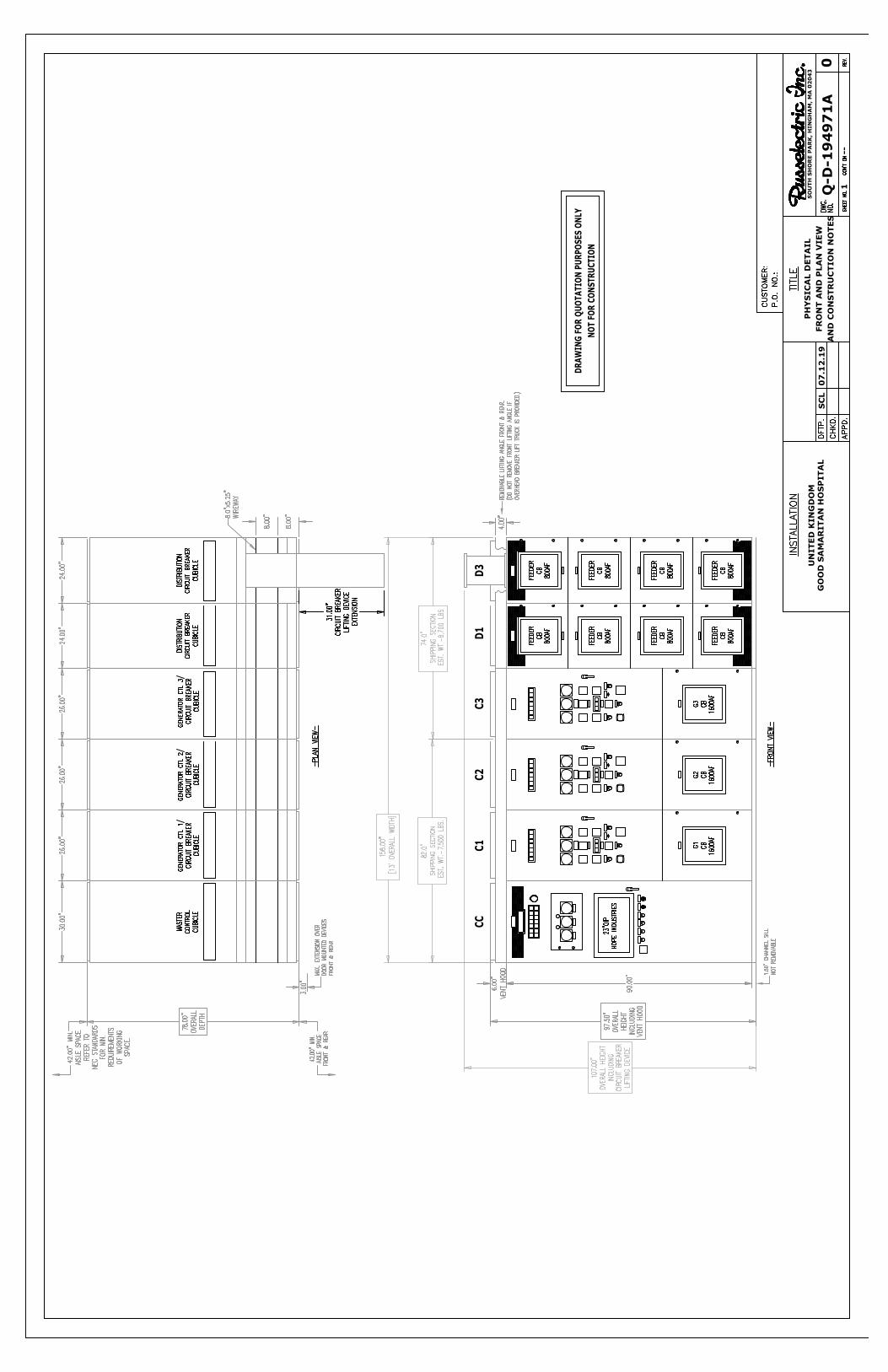
PREFERRED GENERATOR ADDITION
Add a new interior 750KVA generator and connect in parallel with the existing two. In this
configuration, two generators will support the facility. The third generator will be redundant and allow
for routine maintenance without compromising the emergency operation of the hospital. Design
capacity will be 1800A at 480V. This additional generator may be placed in the existing paint shop and
two adjacent storage areas. Refer to the attached preliminary layout. The following items discuss the
major points for this approach.
1. Cooling and combustion airflow need to be added. This will require approximately 9’ x 9’ intake
and exhaust penetrations in the building. Options for this are:
a. Discharge through end wall - This is the preferred solution and is the best fit within the
space. The adjacent wooden storage building will have to be removed or relocated.
b. Intake on roof - This will require a 2hr rated shaft and ducting through the 2nd floor
storage area.
c. Discharge through back wall - This direction is directly adjacent to the dorm and
presents a noise concern. It also takes more room for ducting unless a remote radiator
is used.
d. Discharge through roof - This will require a 2hr shaft and ducting up through the 2nd
floor storage space. The discharge must be remote from the intake which will require
additional space.
e. Remote radiator on roof - Increased noise. More difficult maintenance. Weight and
access concerns for the roof.
2. This configuration will need to create an opening in the building to install generator and gear.
The location depends on the louver discussed above.
3. The interior walls of the paint shop and storage will need to be reconfigured. Equipment access
and Code required egress must be provided. The room must be 2 hour fire resistive rated. The
existing column will have to be accounted for in the equipment layout.
4. The proposed area does not extend over the basement so structural concerns are minimal.
5. Additional fuel capacity will be required to meet on-site storage requirements. The existing 2000
gallon above-ground tank will only supply two generators at full load for 16 hours.
6. Provide a new paralleling switchboard with new control and output breakers.
a. Remove ATS1 and ATS2. Refeed E/SWBD1 and E/SWBD2 from the new paralleling gear.
b. Provide new 800A ATS in chiller plant.
c. Provide new load bank connection.
d. Drawout style breakers with spare breakers and cubicles for future expansion,
maintenance and failure recovery.
e. Tridium BMS interface for generator monitoring.
7. The existing transfer switches are not monitored by the BMS. To expedite troubleshooting
these should report status and control faults back to the medical campus Tridium system.

l
2429 Members Way | Lexington, KY 40504 | 859.253.0892 | cmta.com
MEP Engineering | Performance Contracting | Zero Energy Engineering | Technology | Commissioning
8. Anticipated construction cost: (Costs do not include construction contingency, design fees,
administrative or other project costs.)
a. Generator and Switchgear Equipment $695,000
b. Generator and Switchgear Installation $335,000
c. Building modifications $155,000
ALTERNATE GENERATOR ADDITION
Another possible solution is to add new exterior 750KVA generator and connect in parallel with the
existing two. In this configuration, two generators will support the facility. The third generator will be
redundant and allow for routine maintenance without compromising the emergency operation of the
hospital. Design capacity will be 1800A at 480V.
1. Install the generator with a walk-in sound attenuating enclosure on east side of Chiller Building.
This will take several parking spaces. Approximate size is 10’ x 25’.
2. Paralleling gear will fit within the paint shop, leaving the end storage room available for other
use. The former Paint Shop must be 2 hour fire resistive rated (NFPA 99). The existing column
will have to be accounted for in the equipment layout.
3. The new generator can be supplied with a sub-base fuel tank, but additional capacity is still
needed in main tank since two generators will potentially draw from it.
4. Provide a new paralleling switchboard with new control and output breakers.
a. Remove ATS1 and ATS2. Refeed E/SWBD1 and E/SWBD2 from the new paralleling gear.
b. Provide new 800A ATS in chiller plant.
c. Provide new load bank connection.
d. Drawout style breakers with spare breakers and cubicles for future expansion,
maintenance and failure recovery.
e. Tridium BMS interface for generator monitoring.
5. The existing transfer switches are not monitored by the BMS. To expedite troubleshooting
these should report status and control faults back to the medical campus Tridium system.
6. Anticipated construction cost: (Costs do not include construction contingency, design fees,
administrative or other project costs.)
a. Generator and Switchgear Equipment $695,000
b. Generator and Switchgear Installation $195,000
c. Building modifications $25,000
PROPOSED COOLING MODIFICATIONS
The University would like to provide limited cooling during power outages. This will be focused on AHUs
supplying the Operating Rooms, Radiology and Emergency. Most patient rooms are equipped with
individual fan coil units, making these spaces costly to connect to emergency power. The North Wing
addition was constructed with emergency power to the fan coils and will remain as such. To provide
some measure of temperature and humidity control in these rooms we recommend moving the outside
air unit to generator power.

l
2429 Members Way | Lexington, KY 40504 | 859.253.0892 | cmta.com
MEP Engineering | Performance Contracting | Zero Energy Engineering | Technology | Commissioning
1. Good Samaritan utilizes three chillers for cooling. Two 500 ton and one 345 ton. 500 tons of
capacity will be reconnected to the expanded generator plant.
2. A new 800A automatic transfer switch will be provided to pick up selected chiller plant
equipment. The switch will be located in the utility plant.
3. Due to maintenance concerns, both 500 ton chillers will be connected to emergency power,
however only one will be allowed to operate at a time. The primary and condensate pumps
associated with both large chillers will be similarly connected. This selection will be managed
through the BAS system.
4. One cooling tower fan will be connected to the new emergency distribution.
5. Affected BAS system panels will be connected to the new emergency distribution to ensure
operation during a utility outage. Panels not equipped with a UPS will be provided with one.
6. Secondary chilled water pumping is located in the main hospital. Based on initial research and
conversations the following pumps will be connected to the existing main building emergency
distribution.
a. PU-13 serving the 5th floor operating rooms.
b. PU-19 serving patient room outside air.
c. PU- 21 serving radiology and operating rooms.
7. Anticipated construction cost: (Costs do not include construction contingency, design fees,
administrative or other project costs.)
a. Cooling emergency power $245,000
PROPOSED MRI MODIFICATIONS
The University has also requested that the upcoming 3.0T MRI be added to emergency power. It will
initially be connected to utility power only, but provisions were made to convert it to generator power
when the capacity is available.
1. This change will require adding cable to a spare conduit and revising the MRI power conditioner
connection.
2. Anticipated construction cost: (Costs do not include construction contingency, design fees,
administrative or other project costs.)
a. MRI emergency power $25,000
COST SUMMARY FOR PREFERRED OPTION
Anticipated construction cost: (Costs do not include construction contingency, design fees,
administrative or other project costs.)
a. Generator and Switchgear Equipment $695,000
b. Generator and Switchgear Installation $335,000
c. Building modifications $155,000
d. Cooling emergency power $245,000
e. MRI emergency power $25,000
Construction Total - $1,455,000


Standard Features
Standby60 Hz ekW (kVA)
Prime60 Hz ekW (kVA)
Standby60 Hz ekW (kVA)
Prime60 Hz ekW (kVA) Emissions Performance
750 (937) 680 (850) 800 (1000) 725 (906) U.S. EPA Emergency Stationary Use Only (Tier 2)
Bore – mm (in) 137.2 (5.4)
Stroke – mm (in) 152.4 (6.0)
Displacement – L (in3) 27.03 (1649.47)
Compression Ratio 16.5:1
Aspiration TA
Fuel System MEUI
Governor Type ADEM™ A4
Cat® Diesel Engine• Meets U.S. EPA Emergency Stationary Use
Only (Tier 2) emission standards• Reliable performance proven in thousands of
applications worldwide
Generator Set Package• Accepts 100% block load in one step and meets
NFPA 110 loading requirements• Conforms to ISO 8528-5 G3 load acceptance
requirements• Reliability verified through torsional vibration,
fuel consumption, oil consumption, transientperformance, and endurance testing
Alternators• Superior motor starting capability minimizes
need for oversizing generator• Designed to match performance and output
characteristics of Cat diesel engines
Cooling System • Cooling systems available to operate in ambient
temperatures up to 50°C (122°F)• Tested to ensure proper generator set cooling
EMCP 4 Control Panels• User-friendly interface and navigation• Scalable system to meet a wide range of
installation requirements• Expansion modules and site specific
programming for specific customer requirements
Warranty• 24 months/1000-hour warranty for standby and
mission critical ratings• 12 months/unlimited hour warranty for prime
and continuous ratings• Extended service protection is available to
provide extended coverage options
Worldwide Product Support• Cat dealers have over 1,800 dealer branch
stores operating in 200 countries• Your local Cat dealer provides extensive
post-sale support, including maintenance andrepair agreements
Financing• Caterpillar offers an array of financial products
to help you succeed through financial serviceexcellence
• Options include loans, finance lease,operating lease, working capital, and revolvingline of credit
• Contact your local Cat dealer for availability inyour region
Cat® C27Diesel Generator Sets
LEHE1213-04 Page 1 of 4
Image shown may not refl ect actual confi guration
Custom Wound Optimum Pitch

C27 Diesel Generator SetsElectric Power
LEHE1213-04 Page 3 of 4
Package PerformancePerformance Standby Prime Standby Prime
Frequency 60 Hz 60 Hz 60 Hz 60 Hz
Gen set power rating with fan 750 ekW 680 ekW 800 ekW 725 ekW
Gen set power rating with fan @ 0.8 power factor 937 kVA 850 kVA 1000 kVA 906 kVA
Emissions EPA ESE (Tier 2) EPA ESE (Tier 2) EPA ESE (Tier 2) EPA ESE (Tier 2)
Performance number DM9071-03 DM9073-02 DM7696-02 DM9069-02
Fuel Consumption100% load with fan – L/hr (gal/hr) 202.9 (53.6) 187.4 (49.5) 216.9 (57.3) 199.6 (52.7)
75% load with fan – L/hr (gal/hr) 162.4 (42.9) 149.6 (39.5) 171.7 (45.4) 157.8 (41.7)
50% load with fan – L/hr (gal/hr) 116.2 (30.7) 107.0 (28.3) 122.3 (32.3) 112.5 (29.7)
25% load with fan – L/hr (gal/hr) 70.6 (18.7) 66.0 (17.4) 73.9 (19.5) 69.0 (18.2)
Cooling SystemRadiator air flow restriction (system) – kPa (in. water) 0.12 (0.48) 0.12 (0.48) 0.12 (0.48) 0.12 (0.48)
Radiator air flow – m3/min (cfm) 1200 (42377) 1200 (42377) 1200 (42377) 1200 (42377)
Engine coolant capacity – L (gal) 55.0 (14.5) 55.0 (14.5) 55.0 (14.5) 55.0 (14.5)
Radiator coolant capacity – L (gal) 41.0 (10.0) 41.0 (10.0) 41.0 (10.0) 41.0 (10.0)
Total coolant capacity – L (gal) 96.0 (24.5) 96.0 (24.5) 96.0 (24.5) 96.0 (24.5)
Inlet AirCombustion air inlet flow rate – m3/min (cfm) 58.7 (2073.6) 56.0 (1977.7) 62.8 (2216.4) 60.3 (2129.4)
Exhaust SystemExhaust stack gas temperature – °C (°F) 509.3 (948.7) 502.5 (936.5) 511.4 (952.5) 500.6 (933.0)
Exhaust gas flow rate – m3/min (cfm) 158.9 (5610.2) 149.7 (5285.5) 170.3 (6011.7) 160.7 (5674.4)Exhaust system backpressure (maximum allowable) – kPa (in. water) 6.7 (27.0) 6.7 (27.0) 6.7 (27.0) 6.7 (27.0)
Heat RejectionHeat rejection to jacket water – kW (Btu/min) 324 (18441) 307 (17433) 330 (18785) 320 (18191)
Heat rejection to exhaust (total) – kW (Btu/min) 738 (41994) 693 (39387) 796 (45257) 741 (42135)
Heat rejection to aftercooler – kW (Btu/min) 139 (7898) 123 (6970) 162 (9235) 146 (8320)Heat rejection to atmosphere from engine –kW (Btu/min) 110 (6249) 92 (5238) 110 (6240) 89 (5074)
Heat rejection from alternator – kW (Btu/min) 53 (3014) 47 (2644) 40 (2292) 37 (2081)
Emissions* (Nominal)NOx mg/Nm3 (g/hp-h) 2637.1 (5.25) 2330.9 (4.68) 2580.0 (5.18) 2283.7 (4.61)
CO mg/Nm3 (g/hp-h) 123.9 (0.25) 147.4 (0.29) 115.1 (0.23) 135.6 (0.27)
HC mg/Nm3 (g/hp-h) 11.2 (0.03) 10.9 (0.02) 12.5 (0.03) 12.2 (0.03)
PM mg/Nm3 (g/hp-h) 8.8 (0.02) 8.8 (0.02) 9.7 (0.02) 9.0 (0.02)
*mg/Nm3 levels are corrected to 5% O2. Contact your local Cat dealer for further information.

C27 Diesel Generator SetsElectric Power
Ratings Defi nitionsStandbyOutput available with varying load for the duration of the interruption of the normal source power. Average power output is 70% of the standby power rating. Typical operation is 200 hours per year, with maximum expected usage of 500 hours per year.
PrimeOutput available with varying load for an unlimited time. Average power output is 70% of the prime power rating. Typical peak demand is 100% of prime rated ekW with 10% overload capability for emergency use for a maximum of 1 hour in 12. Overload operation cannot exceed 25 hours per year.
C27 PGBG LEHE1213-04 (10/19)
Weights and Dimensions
Dim “A”mm (in)
Dim “B”mm (in)
Dim “C”mm (in)
Dry Weightkg (lb)
4674 (184.0) 1723 (67.8) 2162 (85.1) 6622 (14,600)
Note: For reference only. Do not use for installation design. Contact your local Cat dealer for precise weights and dimensions.
A B
C
www.cat.com/electricpower ©2019 Caterpillar
All rights reserved.Materials and specifications are subject to change without notice. The International System of Units (SI) is used in this publication.
CAT, CATERPILLAR, LET'S DO THE WORK, their respective logos, “Caterpillar Yellow”, the “Power Edge” and Cat “Modern Hex” trade dress as well as corporate and product
identity used herein, are trademarks of Caterpillar and may not be used without permission.
Applicable Codes and StandardsAS 1359, CSA C22.2 No. 100-04, UL 142, UL 489, UL 869, UL 2200, NFPA 37, NFPA 70, NFPA 99, NFPA 110, IBC, IEC 60034-1, ISO 3046, ISO 8528, NEMA MG1-22, NEMA MG1-33, 2014/35/EU, 2006/42/EC, 2014/30/EU.
Note: Codes may not be available in all model configurations. Please consult your local Cat dealer for availability.
Data Center Applications• ISO 8528-1 Data Center Power (DCP)
compliant per DCP application of Cat dieselgenerator set prime power rating.
• All ratings Tier III/Tier IV compliant per UptimeInstitute requirements.
• All ratings ANSI/TIA-942 compliant for Rated-1through Rated-4 data centers.
Fuel Rates Fuel rates are based on fuel oil of 35º API [16°C (60ºF)] gravity having an LHV of 42,780 kJ/kg (18,390 Btu/lb) when used at 29ºC (85ºF) and weighing 838.9 g/liter (7.001 lbs/U.S. gal.)
CC
D3
C1
C2
DR
AW
IN
G FO
R Q
UO
TA
TIO
N P
UR
PO
SES
O
NLY
NO
T FO
R C
ON
STR
UC
TIO
N
D1
C3
SO
UTH
S
HO
RE P
AR
K, H
IN
GH
AM
, M
A 0
20
43
UN
ITED
K
IN
GD
OM
GO
OD
S
AM
AR
ITA
N H
OS
PITA
L
SC
L0
7.1
2.1
9
PH
YS
IC
AL D
ETA
IL
FR
ON
T A
ND
P
LA
N V
IEW
AN
D C
ON
STR
UC
TIO
N N
OTES
Q-D
-1
94
97
1A
0
1--