university of toronto - canada lynx 1.0 - intelligent ground vehicle
TRANSCRIPT

UTRA.ca/IGVC
THE AUTONOMOUS ROBOTIC SYSTEMS TEAM INTELLIGENT GROUND VEHICLE COMPETITION
Detailed Design Document
Last Modified 7 May 2011 Draft - Rev Final - Rev. 1.0
Author(s)
Rohaan Ahmed Hasnain Arshad Matthew Cott Osman Saleem
Faculty Advisors
Dr. Phil Anderson Dr. Lacra Pavel
This document and the information contained within it is the intellectual property of its author(s).

ARS IGVC Detailed Design Document Final Rev. 1.0 Date: 7 May. 2011 Page 2 of 2

ARS IGVC Detailed Design Document Final Rev. 1.0 Date: 7 May. 2011 Page 3 of 3
Table of Contents Section Page List of Figures ........................................................................................................................................... 5
List of Tables ............................................................................................................................................. 5
Acknowledgements ................................................................................................................................. 6
1. Engineering Overview ..................................................................................................................... 7
1.1 The Engineering Team ............................................................................................................ 7
1.2 The Design Ideology – Evolution, not Revolution ........................................................... 8
1.3 The Design Process ................................................................................................................ 8
2. System Level Design ....................................................................................................................... 9
2.1 System Level Diagram ............................................................................................................ 9
2.2 Vehicle Overview .................................................................................................................... 10
2.3 Cost Breakdown ..................................................................................................................... 11
2.4 System Level Design Description ...................................................................................... 12
4.1.1 Sensors & Hardware...................................................................................................... 12
4.1.2 Guidance, Navigation and Control - System Level Overview ........................... 13
4.1.3 Player Interface ............................................................................................................... 14
4.1.4 Microcontroller................................................................................................................ 15
4.1.5 Electrical ........................................................................................................................... 15
3. Guidance, Navigation & Control – Detailed Design .............................................................. 16
3.1 Collision and Lane Avoidance System (CLAS) .............................................................. 16
5.1.1. The Computer Vision Module ..................................................................................... 16
5.1.2. The Obstacle Detection Module ................................................................................. 19
3.2 Simultaneous Localization and Mapping (SLAM) ......................................................... 19
6.2.1. The Localization Module .............................................................................................. 19
3.3 Navigation and Control System ......................................................................................... 19
3.3.1 Navigation Module ......................................................................................................... 19

ARS IGVC Detailed Design Document Final Rev. 1.0 Date: 7 May. 2011 Page 4 of 4
3.3.2 Control Module ............................................................................................................... 21

List of Figures Figure Page Figure 1 Team Structural Breakdown Diagram ‐‐‐‐‐‐‐‐‐‐‐‐‐‐‐‐‐‐‐‐‐‐‐‐‐‐‐‐‐‐‐‐‐‐‐‐‐‐‐‐‐‐‐‐‐‐‐‐‐‐‐‐‐‐‐‐‐‐‐‐‐‐‐‐‐‐‐‐‐‐‐‐‐‐‐‐‐‐‐ 7 Figure 2 System Level Diagram of Canada Lynx 1.0 ‐‐‐‐‐‐‐‐‐‐‐‐‐‐‐‐‐‐‐‐‐‐‐‐‐‐‐‐‐‐‐‐‐‐‐‐‐‐‐‐‐‐‐‐‐‐‐‐‐‐‐‐‐‐‐‐‐‐‐‐‐‐‐‐‐‐‐‐‐‐‐ 9 Figure 3 Left: CAD model of the robot, Right: Actual robotic vehicle (under construction) ‐‐‐‐‐‐‐‐‐‐‐‐10 Figure 4 The use of Player within the design project ‐‐‐‐‐‐‐‐‐‐‐‐‐‐‐‐‐‐‐‐‐‐‐‐‐‐‐‐‐‐‐‐‐‐‐‐‐‐‐‐‐‐‐‐‐‐‐‐‐‐‐‐‐‐‐‐‐‐‐‐‐‐‐‐‐‐‐‐‐14 Figure 5 Left: Hough Transform image, Center: Intermediate image, Right: Final image ‐‐‐‐‐‐‐‐‐‐‐‐‐‐‐‐17 Figure 6 Left: Original image, Center: Final lane detection, Right: Final ramp detection ‐‐‐‐‐‐‐‐‐‐‐‐‐‐‐‐17 Figure 7 Left: Original image with simulated flags, Right: Final image ‐‐‐‐‐‐‐‐‐‐‐‐‐‐‐‐‐‐‐‐‐‐‐‐‐‐‐‐‐‐‐‐‐‐‐‐‐‐‐‐‐‐17 Figure 8 Control Flow Diagram for the Computer Vision module ‐‐‐‐‐‐‐‐‐‐‐‐‐‐‐‐‐‐‐‐‐‐‐‐‐‐‐‐‐‐‐‐‐‐‐‐‐‐‐‐‐‐‐‐‐‐‐‐‐‐‐18 Figure 9 Control Flow Diagram for the Autonomous Challenge Navigation module ‐‐‐‐‐‐‐‐‐‐‐‐‐‐‐‐‐‐‐‐‐‐‐20 Figure 10 Actual Laser Rangefinder input captured via the PlayerV plugin ‐‐‐‐‐‐‐‐‐‐‐‐‐‐‐‐‐‐‐‐‐‐‐‐‐‐‐‐‐‐‐‐‐‐‐21 Figure 11 An example configuration of obstacles ‐‐‐‐‐‐‐‐‐‐‐‐‐‐‐‐‐‐‐‐‐‐‐‐‐‐‐‐‐‐‐‐‐‐‐‐‐‐‐‐‐‐‐‐‐‐‐‐‐‐‐‐‐‐‐‐‐‐‐‐‐‐‐‐‐‐‐‐‐‐‐‐‐21 Figure 12 The Vector Field Histogram for Figure 10 ‐‐‐‐‐‐‐‐‐‐‐‐‐‐‐‐‐‐‐‐‐‐‐‐‐‐‐‐‐‐‐‐‐‐‐‐‐‐‐‐‐‐‐‐‐‐‐‐‐‐‐‐‐‐‐‐‐‐‐‐‐‐‐‐‐‐‐‐‐‐21 Figure 13 Control Flow Diagram for the Control module ‐‐‐‐‐‐‐‐‐‐‐‐‐‐‐‐‐‐‐‐‐‐‐‐‐‐‐‐‐‐‐‐‐‐‐‐‐‐‐‐‐‐‐‐‐‐‐‐‐‐‐‐‐‐‐‐‐‐‐‐‐‐‐22
List of Tables Table Page Table 1 List of team-members and their roles within the team ............................................................... 8 Table 2 Physical specifications of the robotic vehicle ............................................................................ 10 Table 3 Cost breakdown of the robotic vehicle ........................................................................................ 11

ARS IGVC Detailed Design Document Final Rev. 1.0 Date: 7 May. 2011 Page 6 of 6
Acknowledgements
The design team would like to extend our sincerest gratitude to the following individuals and organizations for their assistance, advice, foresight and understanding throughout the design process. Dr. Larca Pavel, Team Supervisor and Advisor Dr. Phil Anderson, Team Administrator and Advisor Ms. Lynne Vanin, Public Affairs Manager at MDA Ms. Jeannie Tomlinson, Human Resources Manager at MDA Rosanna Reid, Business Services Coordinator, ECE Department The University of Toronto Robotics Association The Ontario Center for Excellence MDA Space Systems NovaTel Microstrain High Strength Plates & Profiles Dutchman Industries BioInsight Inc. Orbis Software Edward S. Rogers Department of Electrical and Computer Engineering The Electrical and Computer Engineering Design Center Organizers of the Intelligent Ground Vehicle Competition

ARS IGVC Detailed Design Document Final Rev. 1.0 Date: 7 May. 2011 Page 7 of 7
1. Engineering Overview
1.1 The Engineering Team The University of Toronto’s Autonomous Robotic Systems team consists of undergraduate engineering students from the departments of Electrical & Computer Engineering and Mechanical Engineering, working under the supervision of faculty advisors and the executive body of the University of Toronto Robotics Association. In order to solve the multi-disciplinary problems posed by the IGVC, the team was been subdivided into specific areas of expertise, each lead by a student. Figure 1 provides an overview of the team’s structural breakdown.
Figure 1 Team Structural Breakdown Diagram
Table 1 provides a list of all the members involved in the project, and their respective roles within the design team. The amount of time spent on the project by each student ranges between 200-300 hours Member Responsibilities Rohaan Ahmed Software Engineering, Project Management, System Integration Matthew Cott Software Engineering Hasnain Arshad Software Engineering Osman Saleem Software Integration Paul Giampuzzi Electrical and Power Systems Rehman Merali Advisor - Mechanical Systems Soren Massoumi Advisor - Finance Jose Chen Project Management Murtasim Syed Mechanical Systems
ARS IGVC Detailed Design Document Final Rev. 1.0 Date: 7 May. 2011 Page 8 of 8
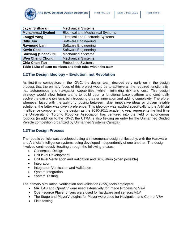
Jayan Sritharan Mechanical Systems Muhammad Syahmi Electrical and Mechanical Systems Zongyi Yang Electrical and Electronic Systems Billy Jun Software Engineering Raymond Lam Software Engineering Kevin Choi Software Engineering Shixiang (Shane) Gu Mechanical Systems Wen Cheng Chong Mechanical Systems Chia Chen Tan Embedded Systems Table 1 List of team-members and their roles within the team
1.2 The Design Ideology – Evolution, not Revolution As first-time competitors in the IGVC, the design team decided very early on in the design process that the primary focus of this project would be to achieve all the required functionality, i.e., autonomous and navigation capabilities, while minimizing risk and cost. This design strategy would allow future teams to build upon a functional base platform and continually evolve the existing systems by introducing greater innovation and adding complexity. Therefore, whenever faced with the task of choosing between riskier innovative ideas or proven reliable solutions, the latter was given preference. This ideology was applied specifically to the Artificial Intelligence component of the design as the 2010-2011 academic year represents the first time the University of Toronto Robotics Association has ventured into the field of autonomous robotics (in addition to the IGVC, the UTRA is also fielding an entry for the Unmanned Guided Vehicle competition organized by Unmanned Systems Canada). 1.3 The Design Process The robotic vehicle was developed using an incremental design philosophy, with the Hardware and Artificial Intelligence systems being developed independently of one another. The design involved continuously iterating through the following phases:
• Conceptual Design • Unit level Development • Unit level Verification and Validation and Simulation (when possible) • Integration • Integration Verification and Validation • System Integration • System Testing
The primary simulation, verification and validation (V&V) tools employed:
• MATLAB and OpenCV were used extensively for Image Processing V&V • Open-source Player drivers were used for hardware and sensors V&V • The Stage and PlayerV plugins for Player were used for Navigation and Control V&V • Field testing

ARS IGVC Detailed Design Document Final Rev. 1.0 Date: 7 May. 2011 Page 9 of 9
2. System Level Design
2.1 System Level Diagram The figure below, Figure 2, provides a system level illustration of the final robot design. Various sections within the figure will be discussed in the following sections.
Figure 2 System Level Diagram of Canada Lynx 1.0

ARS IGVC Detailed Design Document Final Rev. 1.0 Date: 7 May. 2011 Page 10 of 10
2.2 Vehicle Overview The Canada Lynx 1.0 is based on a electric wheelchair chassis with a custom built frame to support the hardware and sensor package. The chassis is driven using two Victor HV motor controllers rated at 36V and 120A, controlling two drive motors acquired as part of the wheelchair chassis. Four smaller dragger wheels provide forward and rearward stability. The drive motors are powered using two 12VDC lead-acid batteries, whereas the on-board computer, electronics and sensor packages are powered from a custom-built 32V battery pack. The Artificial Intelligence system, designated Guidance, Navigation & Control, is run on a quad-core computer, and is responsible for making all the robotic vehicle’s decisions in real-time based on inputs from the sensor suite. Figure 3 provides an illustration of the robotic vehicle.
Figure 3 Left: CAD model of the robot, Right: Actual robotic vehicle (under construction)
Top Speed Limited to 10mph Total On-board Power Capacity 56V DC Ramp Climbing 15+ degrees (up to standard wheelchair incline requirement) Battery Life 1 hour (computer), 2 hours (motors) Dimensions 90cm X 70xm X 180cm Table 2 Physical specifications of the robotic vehicle

ARS IGVC Detailed Design Document Final Rev. 1.0 Date: 7 May. 2011 Page 11 of 11
2.3 Cost Breakdown Table 1 provides a breakdown of the cost of the robotic vehicle. Component Team Cost Retail
Cost Comments
Fire‐I Digital CMOS Camera $220 $220 NovAtel ProPak V3 Differential GPS
$2,300 $5,000 Sponsored by: NovAtel
Microstrain 3DM‐GX1 Inertial Measurement Unit
$1,000 $2,000 Sponsored by: MicroStrain Hoskin
Hokuyo URG‐04 Laser Rangefinder $0 $2,000 Already in UTRA Inventory Mini ITX Quad‐core Computer $400 $400 Wheelchair Chassis Motors 2x 12VDC Batteries
$500 $500
32VDC Battery Pack $350 $350 E‐Stop and Wireless Relay $50 $50 2x Motor Controllers $200 $200 Frame/Body $0 $200 Donated by:
Dutchman Industries High Strength Plates & Profiles
Miscellaneous $500 $500 TOTAL $5,522 $13,420
Table 3 Cost breakdown of the robotic vehicle

ARS IGVC Detailed Design Document Final Rev. 1.0 Date: 7 May. 2011 Page 12 of 12
2.4 System Level Design Description 4.1.1 Sensors & Hardware This section is a classification of the sensor-systems on-board the designed vehicle. Proximity Sensor: The Hokuyo URG-04LX is the proximity sensor on-board the vehicle and provides directional and distance information about any objects within four meters of the sensor. The Hokuyo was selected over other LRF systems because it was already available in the UTRA inventory and, thus, resulted in a savings of over $2,000. Despite its limited range (under 4m), the Hokuyo meets all other design requirements and, therefore, offers a reasonable compromise between functionality and financial constraints.
Fire-I Digital Board CMOS Camera Hokuyo URG-04LX
Vision Sensor: The Fire-I Digital Board CMOS Camera is the on-board visual sensor and provides information regarding the visual obstacles and/or markings around the robotic vehicle. The Fire-I’s CMOS technology results in images that are much sharper than standard video cameras within its price range. The greater sharpness allows the camera to capture edges and lines much more clearly than regular cameras, thus making it well suited to its role as the primary lane and secondary obstacle detection sensor. Directional Sensor: The Microstrain 3DM-GX1 Inertial Measurement Unit is on-board as the primary directional sensor in order to provide information regarding the pitch, roll and yaw of the robot about its starting position. The 3DM-GX1 combines three angular rate gyros with three orthogonal DC accelerometers, three orthogonal magnetometers, a multiplexer, a 16 bit A2D converter, and an embedded microcontroller to output its orientation in both dynamic and static environments.
NovaTel ProPak V3 Microstrain 3DM-GX1
Differential GPS Unit: The NovaTel ProPak V3 is the primary localization device on-board the vehicle. It is a GPS unit that relies on military-standard differential error correction technology to give measurements that are measurably far more accurate than regular GPS units. The ProPak

ARS IGVC Detailed Design Document Final Rev. 1.0 Date: 7 May. 2011 Page 13 of 13
V3 was chosen over its competitors because the accuracy offered by this system was significantly greater with a worst-case margin of error of less then 25cm. On-board Computer: Due to the high computation requirements placed on the robot’s computer system, the team chose an NCIX HTPC quad-core ITX PC with 4GB DDR3 RAM on a Mini-ITX Motherboard as the on-board computer for the robotic vehicle. The computer runs using a 24VDC power supply rather than an AC supply, enabling it to run using the available on-board 24VDC batteries. Furthermore, this Mini-ITX computer bundle is approximately the size of a human hand and offers tremendous weight and size reductions over conventional computers, while offering greater computing power and resources than standard laptops for a much lower price.
NCIX HTPC quad-core Mini-ITX PC
4.1.2 Guidance, Navigation and Control - System Level Overview 4.1.2.1 Collision and Lane Avoidance System This sub-system contains modules that acquire raw input data regarding the vehicle’s surroundings from the Proximity and Vision Sensors, manipulate that information to perform the necessary computation, and provide this information to the Simultaneous Localization and Mapping sub-system. Computer Vision: This module acquires raw input data from the vision sensor, performs image manipulation and transformations in order to extract important information from it, and computes the distances and directions of all lane-markings and visible obstacles on the ground. This module outputs obstacle information to the Obstacle Detection module. Obstacle Detection: This module acquires raw input data from the proximity sensor, computes the distances and directions to all objects with respect to the robot, and fuses this data with Computer Vision information. This module outputs of obstacle information to the Navigation and Control sub-system. 4.1.2.2 Simultaneous Localization and Mapping This sub-system contains modules that acquire processed data from the Collision and Lane Avoidance System as well as raw data from the Directional, Differential Speed and Differential GPS Sensors. The sub-system determines and provides, as an output, the current position, speed and direction of the robotic vehicle. Localization: This module acquires raw input information from the Differential GPS Unit, the and the Directional Sensor(s). It then determines the true position, speed and direction of the robotic vehicle and outputs this information to the Navigation and Control sub-system.

ARS IGVC Detailed Design Document Final Rev. 1.0 Date: 7 May. 2011 Page 14 of 14
4.1.2.3 Navigation and Control System This sub-system contains modules that acquire information regarding the position, speed, direction and obstacle data from the Simultaneous Localization and Mapping and Collision and Lane Avoidance System sub-systems. It forms the lowest layer of the Guidance, Navigation and Control system and interacts directly with the propulsion system via the Player interface. As its output, this sub-system provides control commands to be sent to a motor-controlling Microcontroller. Navigation: This module acquires processed information about the true position, speed and direction of the robotic vehicle from the Localization module and combines it with the obstacle data from the Obstacle Detection and Computer Vision modules. It then determines the robotic vehicle’s desired direction of travel in order to avoid any and all obstacles while taking the optimal path towards the next waypoint. The output of this module is the desired direction of travel of the robot. Control: This module acquires the desired direction from the Navigation module and converts it into differential speed commands that are understandable by the motor-controlling microcontroller’s firmware. It accomplishes this via the open-source Player library for communicating with robotic vehicles. The Control module is the lowest level module in the Guidance, Navigation and Control system and interfaces directly with the motor-controlling microcontroller. 4.1.3 Player Interface In this project, the open-source Player Project is used as the primary interfacing layer between all external hardware and the software. All sensors and controllers, with the exception of the camera and the IMU, are linked to the code via the Player interface using USB, RS232 and FireWire ports, utilizing given interfacing functionality. By doing so, the design team was able to take advantage of the vast collection of drivers and interface functionality pre-built into Player, rather than developing everything from scratch. Figure 4 shows how the Player has been used as the interface between the robot’s environment and its artificial intelligence system.
Developed by the design
team
Provided by Player
Figure 4 The use of Player within the design project

ARS IGVC Detailed Design Document Final Rev. 1.0 Date: 7 May. 2011 Page 15 of 15
4.1.4 Microcontroller An Atmel Mega8 microcontroller with external 16 MHz clock is used to interface between the Guidance, Navigation & Control system and the Victor HV motor controllers. The embedded firmware, which is developed entirely in C via AVR Studio, receives signals from the high-level software via a UART interface. The microcontroller’s internal 16-bit timer with PWM Frequency 1000Hz is used to configure the motor speed controllers. The communication protocol between the high-level software and the embedded system composes of a string of 8 characters formatted as XSDX, where X is the status of the message transmission, S is the indexed speed of 1 digit for the left motor and D is the indexed speed of 1 digit for the right motor. 4.1.5 Electrical The following list comprises the main electrical components of the vehicle:
1. 12Vswitching regulator PCB 2. 5V switching regulator PCB 3. Microcontroller PCB 4. Wireless Emergency Stop (Purchased) 5. Push-button Emergency Stop 6. Motor Controllers (Purchased)
Multiple Printed Circuit Boards (PCBs) are used, as opposed to central circuit boards, in order to reduce the risk of failure propagation and ease of maintainability. All circuit boards are designed using the EagleCAD software, and printed in-house. In order to reduce the noise within the power system, separate batteries are used to power the drive motors and all other electrical components. All circuits are fused to protect the electronics so that no instantaneous change in voltage or current will have significant negative effects on the robot. The competition rules require the implementation of a push-button and wireless Emergency Stop (or E-Stop). In order to make the e-stop hardware-governed, as per the safety requirements of the IGVC, the E-stop is placed within the power-supply to the motors and motor controllers. When the E-stop is activated, the power to the motors is cut and the vehicle comes to a stop.

ARS IGVC Detailed Design Document Final Rev. 1.0 Date: 7 May. 2011 Page 16 of 16
3. Guidance, Navigation & Control – Detailed Design
3.1 Collision and Lane Avoidance System (CLAS) The Collision and Lane Avoidance System (CLAS) consists of two modules, labelled Computer Vision and Obstacle Detection. 5.1.1. The Computer Vision Module The Canada Lynx makes use of the OpenCV libraries for its image processing, relying on a variety of detection techniques to produce the resulting image which contains any element that the vehicle must avoid. Making use of the knowledge of the environment and the elements contained within, various thresholds are applied at multiple stages in order to isolate every unique element. All programming is done in the C++ programming language. Rather than deal with the standard computer imaging format of Red (R), Green (G), Blue (B), the primary thresholding takes place in the Hue (H), Saturation (S), Value (V) colour plane. By dividing the colour information and lighting information apart, it is easier to identify colours and elements we desire when compared to RGB-based processing. Once all the necessary elements are identified, a custom algorithm calculates the real-distance to each object identified and converts it into Laser Rangefinder data. This data is then passed into the Object Detection module. Figure 8 displays the control flow diagram of the Computer Vision module. Lane and Object Detection The original RGB image is first passed into the HSV plane for manipulation. Thresholds are applied to the various layers to first remove grass and any other terrain types that we wish to ignore. The end result leaves only elements of unique interest in the image, namely lanes, objects, and ramps. A clean-up algorithm is then employed which checks for connected components as well as their size, and discards anything that is too small and disconnected, assuming it to be excessive noise that the initial thresholds could not completely eliminate. Once completed, the image is reverted back to the RGB colour plane, where the ramps and lanes/objects each share a unique colouring. One final threshold is applied to pull the ramps out of the image, leaving only lanes and objects. In order to account for the presence of dashed lanes, appropriate edge detectors are then applied, and the Hough Transform is then employed and cleaned in order to overlay straight lines onto the image. Figure 5 provides an example of the ramp detection algorithm. Ramp Detection Similar to lane detection system, the HSV colour plane is employed for ramp detection. Thresholds are again applied, but their parameters are configured differently in order to better emphasize ramps in the image. Once the ramps have been identified, they can easily be separated from lanes and objects in the image through simple extraction. Figure 6 provides an example of the ramp detection algorithm. Flag Detection Due to the nature of the flags and the special conditions they entail, a separate system was created to identify the flags and their individual colouring. First, the image is converted to the

ARS IGVC Detailed Design Document Final Rev. 1.0 Date: 7 May. 2011 Page 17 of 17
HSV plane, in order to make the transforms easier to apply. After identifying the red and green Hue regions in the image, a mask of these regions is applied to the Value plane. Thresholds are then applied on this mask in order to remove any non-red and non-green element from the image in the RGB plane. Once complete, a custom triangle-detection algorithm is swept along the image, retaining only triangular shapes and nothing else. With the red and green flags isolated, they are split into their respective Red and Green planes. A clean-up algorithm is again applied, but this time it retains the coordinates of the “center of mass” of each significant element. Using these coordinates, a “wall” is drawn on each image from the left/right (depending on colour) to the center of mass, giving the appearance that everything to the right/left is simply a large object or lane that will be avoided. Figure 7 provides an example of the ramp detection algorithm.
Figure 5 Left: Hough Transform image, Center: Intermediate image, Right: Final image
Figure 6 Left: Original image, Center: Final lane detection, Right: Final ramp detection
Figure 7 Left: Original image with simulated flags, Right: Final image

ARS IGVC Detailed Design Document Final Rev. 1.0 Date: 7 May. 2011 Page 18 of 18
Figure 8 Control Flow Diagram for the Computer Vision

ARS IGVC Detailed Design Document Final Rev. 1.0 Date: 7 May. 2011 Page 19 of 19
5.1.2. The Obstacle Detection Module The objects en-route the robotic vehicle’s paths are detected, primarily, using the proximity sensors and transmitted to the C++ based Obstacle Detection module via a USB port using the Player interface tool. The Obstacle Detection module fuses the Laser Rangefinder and Computer Vision distance and direction data to all obstacles, lanes, flags etc., to be used in the Control module. 3.2 Simultaneous Localization and Mapping (SLAM) The SLAM consists of only one module, namely the Localization module. 6.2.1. The Localization Module In order to navigate the given route, it is important for the robot to keep track of its position at all times, which is provided by the Localization module. This C++ based module communicates with the Differential GPS unit, which provides geographical coordinates corresponding to the robotic vehicle’s absolute position, and the Inertial Measurement Unit, which provides its direction relative to its starting orientation, and combines this information to provide the robotic vehicle’s true position and orientation. The communication is accomplished using the Player interfacing tool via two separate USB ports. This information is then forwarded to the Navigation and Control modules. 3.3 Navigation and Control System This system consists of two modules, namely Navigation and Control, that will determine and execute the desired direction of travel of the robotic vehicle. 3.3.1 Navigation Module This module take inputs from the SLAM module in the form of speed, direction and position data and makes determines the desired direction of travel. The Navigation module first determines the waypoint traversal order and calculates the distance to the next waypoint using the Haversine formula. Once this has been completed, the vehicle’s current direction of travel is compared to the vehicle’s desired direction of travel, and a desired rotation is calculated. This rotation is then fed as input to the Control module. Once a waypoint is traversed, the module automatically selects the next waypoint and continues operation until the starting position is reached, at which point it terminates. Autonomous Challenge Navigation The Autonomous Challenge requires that the vehicle visit a minimum of five out of eight waypoints in no particular order. This can be easily achieved in most cases using a simple Greedy Algorithm which selects the closest waypoint from the current position as the next waypoint to traverse. Figure 9 illustrates the control flow diagram for the Autonomous Challenge Navigation module. Navigation Challenge Navigation

ARS IGVC Detailed Design Document Final Rev. 1.0 Date: 7 May. 2011 Page 20 of 20
The Navigation Challenge requires the selection of waypoints such that the time of travel between them is minimized. Dijkstra’s Algorithm is used to calculate the waypoint traversal order which results in the lowest distance path.
Figure 9 Control Flow Diagram for the Autonomous Challenge Navigation module

ARS IGVC Detailed Design Document Final Rev. 1.0 Date: 7 May. 2011 Page 21 of 21
3.3.2 Control Module The Control module acts as the communication link between the Guidance, Navigation and Control system and the embedded motor-controllers. It receives information regarding the desired direction of travel from the Navigation module as well as the combined obstacle data as input. It then calculates the differential motor speed based on the Vector Field Histogram probabilistic algorithm to find the optimal path to circumvent the obstacles, while maintaining the desired direction of travel. The Control module communicates with the motor-controlling embedded system via a USB port using the Player interfacing tool. Figure 13 illustrates the control flow diagram for the Control module. The Vector Field Histogram The VFH algorithm is a two-dimensional software abstraction of the robotic vehicle’s “field of view”. It takes as input the combined visual and obstacle data and generates an obstacle density vs. direction probabilistic histogram. The direction of travel is then calculated using a threshold value of maximum density and the direction to the next waypoint. Figure 11 displays an example configuration of objects and the corresponding Vector Field Histogram diagram is illustrated in Figure 12.
Obstacle Density
Desired Direction of
Travel
Threshold
Desired Direction of
Travel
Angle
Figure 12 The Vector Field Histogram for Figure 10
Figure 11 An example configuration of obstacles
Figure 10 Actual Laser Rangefinder input captured via the PlayerV plugin

ARS IGVC Detailed Design Document Final Rev. 1.0 Date: 7 May. 2011 Page 22 of 22
Figure 13 Control Flow Diagram for the Control module