university of york department of computer science
TRANSCRIPT

A formal semantics of State�ow charts
Alvaro Miyazawa
Ana Cavalcanti
University of York
Department of Computer Science
January 13, 2011


Abstract
Simulink diagrams are widely used in industry for specifying control sys-tems and a particular type of block used in them is a State�ow chart.Often, the systems speci�ed are safety-critical ones. Therefore, the issueof correctness of implementations of these systems is relevant. We areinterested in the veri�cation of implementations of Simulink diagramsthat include State�ow charts. For that, we need to formalise the seman-tics of the charts (as well as that of the programs). An extensive subsetof Simulink has been formalised in a notation for re�nement (namelyCircus), but State�ow charts were not covered. In this report, we discussthe literature on formalisation of the State�ow and other statechart no-tations, and present an operational model of State�ow charts. We alsodiscuss how we intend to continue our work, particularly the validationof the model and de�nition of a re�nement strategy in order to prove thecorrectness of implementations using re�nement.
3


Contents
1 Introduction 9
1.1 Motivation . . . . . . . . . . . . . . . . . . . . . . . . . . . . . . . . . . . . . 9
1.2 Objectives . . . . . . . . . . . . . . . . . . . . . . . . . . . . . . . . . . . . . 10
1.3 Report Structure . . . . . . . . . . . . . . . . . . . . . . . . . . . . . . . . . 11
2 Formal Models of State�ow Charts 13
2.1 Simulink State�ow . . . . . . . . . . . . . . . . . . . . . . . . . . . . . . . . 13
2.1.1 Elements of the notations . . . . . . . . . . . . . . . . . . . . . . . . 14
2.1.2 Informal Semantics of State�ow charts . . . . . . . . . . . . . . . . . 16
2.2 Formal models . . . . . . . . . . . . . . . . . . . . . . . . . . . . . . . . . . 18
2.2.1 Veri�cation approaches . . . . . . . . . . . . . . . . . . . . . . . . . . 18
2.2.2 Code generation approaches . . . . . . . . . . . . . . . . . . . . . . . 21
2.2.3 Final considerations . . . . . . . . . . . . . . . . . . . . . . . . . . . 21
2.3 Speci�cation languages . . . . . . . . . . . . . . . . . . . . . . . . . . . . . . 22
2.4 Circus . . . . . . . . . . . . . . . . . . . . . . . . . . . . . . . . . . . . . . . 23
3 Formal Model 25
3.1 Overview . . . . . . . . . . . . . . . . . . . . . . . . . . . . . . . . . . . . . 25
3.2 Structure . . . . . . . . . . . . . . . . . . . . . . . . . . . . . . . . . . . . . 29
3.2.1 Diagram structures . . . . . . . . . . . . . . . . . . . . . . . . . . . . 29
3.2.2 Process derived from the chart . . . . . . . . . . . . . . . . . . . . . 33
3.3 Simulator . . . . . . . . . . . . . . . . . . . . . . . . . . . . . . . . . . . . . 41
3.3.1 Executing a sequence of transitions . . . . . . . . . . . . . . . . . . . 41
3.3.2 Entering a state . . . . . . . . . . . . . . . . . . . . . . . . . . . . . . 44
3.3.3 Executing a state . . . . . . . . . . . . . . . . . . . . . . . . . . . . . 48
3.3.4 Exiting a state . . . . . . . . . . . . . . . . . . . . . . . . . . . . . . 48
3.3.5 Executing a chart . . . . . . . . . . . . . . . . . . . . . . . . . . . . . 49
3.4 Final Considerations . . . . . . . . . . . . . . . . . . . . . . . . . . . . . . . 51
4 Translation strategy 53
4.1 Syntax of State�ow charts . . . . . . . . . . . . . . . . . . . . . . . . . . . . 53
4.1.1 Names and Identi�ers . . . . . . . . . . . . . . . . . . . . . . . . . . 53
4.1.2 Expressions and Actions . . . . . . . . . . . . . . . . . . . . . . . . . 54
4.1.3 State�ow objects . . . . . . . . . . . . . . . . . . . . . . . . . . . . . 55
4.2 Well-formedness conditions . . . . . . . . . . . . . . . . . . . . . . . . . . . 58
4.3 Translation strategy in Z . . . . . . . . . . . . . . . . . . . . . . . . . . . . . 59
4.3.1 Renaming functions . . . . . . . . . . . . . . . . . . . . . . . . . . . 60
4.3.2 Expression and Action functions . . . . . . . . . . . . . . . . . . . . 61
4.3.3 Identi�er and binding declaration functions . . . . . . . . . . . . . . 63
5

CONTENTS
4.3.4 Action, condition and process declaration functions . . . . . . . . . . 644.4 Final considerations . . . . . . . . . . . . . . . . . . . . . . . . . . . . . . . 67
5 s2c: from State�ow to Circus 69
5.1 Design . . . . . . . . . . . . . . . . . . . . . . . . . . . . . . . . . . . . . . . 695.1.1 Architecture . . . . . . . . . . . . . . . . . . . . . . . . . . . . . . . . 705.1.2 Implementation of translation rules . . . . . . . . . . . . . . . . . . . 75
5.2 Evaluation . . . . . . . . . . . . . . . . . . . . . . . . . . . . . . . . . . . . . 795.3 Conclusion . . . . . . . . . . . . . . . . . . . . . . . . . . . . . . . . . . . . . 80
6 Conclusion 83
6.1 Contributions so far . . . . . . . . . . . . . . . . . . . . . . . . . . . . . . . 836.2 Future work . . . . . . . . . . . . . . . . . . . . . . . . . . . . . . . . . . . . 84
A Complete speci�cation of the shift logic example 85
B Z Syntax 107
C Circus Syntax 111
D Formal Syntax of State�ow Diagrams 115
E Well-formedness Conditions 119
F Formal Translation Rules 125
G State�ow Toolkit 149
H Usage of s2c 159
H.1 Text interface . . . . . . . . . . . . . . . . . . . . . . . . . . . . . . . . . . . 159H.2 Graphical interface . . . . . . . . . . . . . . . . . . . . . . . . . . . . . . . . 159
6

List of Figures
2.1 Executing a Set of Transitions . . . . . . . . . . . . . . . . . . . . . . . . . . 162.2 Entering a State . . . . . . . . . . . . . . . . . . . . . . . . . . . . . . . . . 172.3 Executing a State . . . . . . . . . . . . . . . . . . . . . . . . . . . . . . . . . 172.4 Exiting a State . . . . . . . . . . . . . . . . . . . . . . . . . . . . . . . . . . 18
3.1 Overview of the model . . . . . . . . . . . . . . . . . . . . . . . . . . . . . . 263.2 Example of a State�ow Chart describing a car's shift logic. . . . . . . . . . . 28
5.1 Architecture of s2c: main packages. . . . . . . . . . . . . . . . . . . . . . . . 705.2 Architecture of the package Parser. . . . . . . . . . . . . . . . . . . . . . . 705.3 Structure of a .mdl �le. . . . . . . . . . . . . . . . . . . . . . . . . . . . . . 715.4 Excerpt from a .mdl �le. . . . . . . . . . . . . . . . . . . . . . . . . . . . . . 715.5 Architecture of the package MDL Parser. . . . . . . . . . . . . . . . . . . . . 725.6 State label . . . . . . . . . . . . . . . . . . . . . . . . . . . . . . . . . . . . . 725.7 Implementation . . . . . . . . . . . . . . . . . . . . . . . . . . . . . . . . . . 725.8 Architecture of the package Label Parser. . . . . . . . . . . . . . . . . . . 735.9 Syntax of State�ow diagrams: main packages. . . . . . . . . . . . . . . . . . 735.10 Syntax of State�ow diagrams: Objects. . . . . . . . . . . . . . . . . . . . . . 745.11 Syntax of State�ow diagrams: Actions. . . . . . . . . . . . . . . . . . . . . . 745.12 Syntax of State�ow diagrams: Expressions. . . . . . . . . . . . . . . . . . . 755.13 Syntax of Circus. . . . . . . . . . . . . . . . . . . . . . . . . . . . . . . . . . 755.14 Architecture of s2c: the Translator package. . . . . . . . . . . . . . . . . . . 765.15 Implementations of the translation rule for variable expressions. . . . . . . . 775.16 Implementations of the translation rule for the declaration of data. . . . . . 785.17 Implementation of simulation instance rule . . . . . . . . . . . . . . . . . . . 78
H.1 Graphical interface of s2c. . . . . . . . . . . . . . . . . . . . . . . . . . . . . 160H.2 Adding a library to the graphical interface of s2c. . . . . . . . . . . . . . . . 160
7


Chapter 1
Introduction
This report presents an improved and extended version of the Circus models of State�owcharts �rst described in [Miyazawa and Cavalcanti, 2010], a formalisation of the translationrules that support the derivation of such models, and the s2c tool that implements thetranslation process. The material in Chapters 1 and 2 are mostly the same as in [Miyazawaand Cavalcanti, 2010], and Chapter 3 was modi�ed to re�ect the changes to the models ofState�ow charts. The contents of Chapters 4 and 5 are entirely new.
1.1 Motivation
State�ow is part of the Matlab Simulink tool [The MathWorks,Inc., a] and consists of astatechart notation used to de�ne charts used as blocks in control law diagrams. Controllaw diagrams are a popular notation for specifying control systems, and they are widelyused in the avionics and automotive industries.
While control law diagrams tackle the aspects of a system that are usually speci�edby di�erential equations relating inputs and outputs graphically, State�ow charts are usedto describe aspects of the system that are better modelled by �nite state machines, e.g.change in modes of operation due to certain events and conditions. For example, in asystem with redundant subsystems, a State�ow chart can be used to interchange betweenthem according to their statuses.
There are several approaches to the formal analysis of state diagram notations, State-�ow being one of them. However, most of these approaches focus on veri�cation of prop-erties, not on veri�cation of implementations; the veri�cation of implementations withrespect to a speci�cation can be seen as a particular type of property veri�cation in whichthe property in question is that the implementation is a re�nement of the speci�cation.By restricting ourselves to the veri�cation of implementations we can take advantage ofspeci�c techniques (such as the re�nement calculus) that are more adequate for this task.[Arthan et al., 2000] and [Adams and Clayton, 2005] describe ClawZ, a tool for trans-lating Simulink diagrams into Z [Woodcock and Davies, 1996] in order to formally verifyimplementations in Ada. This approach does not cover the State�ow notation and canonly deal with sequential implementations; to overcome the latter limitation, concurrentaspects were speci�ed in CSP [Roscoe, 1998] and analysed through the model checker FDR[Formal Systems (Europe) Ltd.].
Circus is a speci�cation language that combines Z and CSP and provides a re�nementcalculus. [Cavalcanti and Woodcock, 2005] de�ne the semantics of control law diagrams inCircus reusing ClawZ and the CSP approach to concurrency, also extending them to covera larger subset of the notation, but still not covering the State�ow notation. Therefore, a
9

1.2. OBJECTIVES
Circus model of State�ow charts is a natural extension of previous work, allowing for theveri�cation of a broader variety of control law diagrams.
Some of the systems speci�ed and designed using Simulink diagrams and State�owcharts are safety critical systems. [BS EN 61508-3:2002, 2002] recommends, for SIL (Safetyintegrity level) 2 and 3 (and highly recommends for SIL 4), the use of formal methods for thespeci�cation of safety requirements and for the design and development (architecture anddetailed design) of software; it also recommends the use of formal proof for the veri�cationof software. [DO-178b, 1992] does not mandate the use of formal methods, but considersit as an alternative method. This suggests that formal techniques that can deal with thesenotations are useful, if not necessary.
One of the main approaches used for the veri�cation of implementations consists of ver-ifying an automatic code generator. This approach makes the implementation immutablebecause only generated code is correct by construction; however, in many cases, code tai-lored to speci�c situations is necessary, which makes such an approach not applicable. Theveri�cation of implementations, instead of the code generator, can overcome this problem,but can potentially increase the complexity of its use.
1.2 Objectives
We are concerned with the veri�cation of implementations of State�ow charts, i.e., we wantto verify whether a program correctly implements a State�ow chart or not. We focus thiswork in the Simulink State�ow variety of state diagrams because it is part of the widelyused Matlab Simulink tool; an advantage of working with Simulink State�ow charts isthat we can take advantage of previous work on the formalisation of Simulink diagrams,of which State�ow charts are part.
In order to achieve the objective of verifying implementations of State�ow charts, weneed, �rst, a formal semantics of these charts and, second, techniques suitable for theveri�cation of implementations with respect to the proposed semantics.
The formal semantics of State�ow charts needs to be suitable for formal reasoning aboutthe correctness of implementations; it must be written in a way that facilitates validationand be subject to integration to models of Simulink diagrams. This last requirement isdue to the fact that State�ow charts appear in the context of Simulink diagrams, and inorder to verify a system, we must be able to cover both notations.
The veri�cation techniques must allow us to verify code and must also be consistentwith the techniques used for Simulink diagrams, so that Simulink and State�ow blockswithin the same diagram can be veri�ed in a uniform manner.
By using Circus as a speci�cation language, we are able to tackle these desired prop-erties: ability to formally reason about the model, to verify code and to integrate themodel with the existing models of Simulink diagrams. Since Circus is a formal speci�ca-tion language, we can de�ne properties of models and mathematically prove whether theyhold or not, the veri�cation of code is carried out by proving that the code is (or is not)a re�nement of a speci�cation, and the integration with existing models of Simulink dia-grams is possible because these models were previously speci�ed in Circus[Cavalcanti andWoodcock, 2005].
Due to the informal nature of State�ow semantics, we need to de�ne a formal modelbased on the informal description contained in the State�ow User's Guide [The Math-Works,Inc., b]. Since there is no formal semantics to which we can compare this model,we must validate it through alternative approaches.
10
CHAPTER 1. INTRODUCTION
We distinguish two main possibilities: one is based on testing and is achieved by com-paring a particular chart and its model with respect to the simulation, and the other isbased on inspection of the informal description. The �rst form of validation can be achievedby simulation of the model and comparison of the traces to the results of the simulationof charts; we can improve this validation by using techniques for the selection of test casesof charts that yield better coverage.
In order to allow for the second form of validation, the model presented in Chapter3 was de�ned in a way that facilitates the comparison to the informal description, whichis given is steps in the State�ow User's Guide (pp. A-2 to A-5) for each of the mainsemantic rules that describe the behaviour of states and transitions. The comparison iseased by establishing a correspondence between the steps and elements of the speci�cation.Moreover, the veri�cation of implementations itself can be seen as a validation of theproposed model.
In summary, for each of the steps of the informal description of the simulator, we de�neelements of the speci�cation that are gathered according to their function. In this way, weallow for two di�erent approaches for the validation of the model.
1.3 Report Structure
This report is structured in the following fashion. Chapter 2 reviews some of the variants ofstate diagram notations, speci�cation languages that can be used to formalise statecharts,and existing approaches for modelling and analysis of statecharts. Chapter 3 presents anoperational model of State�ow charts, Chapter 4 discusses the formalisation of the transla-tion rules necessary to support the derivation of State�ow models, and Chapter 5 presentsthe s2c tool that implements the translation rules and allows the automatic generation ofCircusmodels of State�ow charts.Chapter 6 concludes with a discussion of the contributionsand limitations of the current work, and future lines of research.
11


Chapter 2
Formal Models of State�ow Charts
Our objective is to formally verify implementations of State�ow charts. State�ow chartsare a variant of Harel's statecharts [Harel, 1987], which are an extension of state diagrams.
State diagrams are basically directed graphs, where nodes represent states and edgesrepresent transitions [Hopcroft et al., 2006]; the latter can be guarded by conditions andconnect states. We identify three main variants of the state diagram notations that are ob-tained by adding new features, changing existing ones or modifying the semantics: Harel'sstatecharts, UML State Diagrams and Simulink State�ow charts.
Statecharts [Harel, 1987] extend state diagrams to improve the speci�cation capabilitiesof the basic notation, allowing for the speci�cation of complex reactive systems, concur-rent systems, communication protocols, etc. This extension is achieved by introducingconcepts such as hierarchy of states (states within states), concurrency (parallel states)and communication (local events).
According to [Latella et al., 1999], UML State Diagrams are an object-oriented versionof statecharts. They mainly di�er from Harel's statecharts with respect to the semantics,but also present syntactical di�erences, such as entry and exit actions in states [von derBeeck, 2002].
Simulink State�ow charts [The MathWorks,Inc., b] extend statecharts by adding, amongother features, �ow charts, temporal logic triggers and di�erent types of actions (duringactions, on event actions, transition actions).
According to [Crane and Dingel, 2007], even among close variants of statecharts, suchas UML statecharts, Classical statecharts and Rhapsody statecharts, there are severalsyntactic and semantic di�erences. Moreover, [Fecher et al., 2005] identify 29 problems inthe de�nition of the semantics of UML statecharts [OMG, 2005] such as inconsistenciesand omitted restrictions. For those reasons, formal models of one variant cannot be easilyreused for other variants.
Section 2.1 brie�y describes the State�ow notations. Section 2.2 reviews approachesfor modelling and analysis of state diagram notations. In Section 2.3, we introduce someof the speci�cation languages that could be used to model State�ow charts, and Section2.4 introduces Circus, the language we used to model the diagrams.
2.1 Simulink State�ow
In this section, we give an brief overview of Simulink State�ow charts based on the User'sGuide [The MathWorks,Inc., b].
Simulink State�ow de�nes a new type of Simulink block, namely a State�ow chart, thatis used in a Simulink diagram. A Simulink diagram consists of blocks and wires connecting
13

2.1. SIMULINK STATEFLOW
the inputs and outputs of the blocks. The execution of a Simulink diagram is done in steps,in which each of its blocks is executed in a particular order determined by the wiring.
The chart is the root for the execution of the State�ow model; whenever an event isdirected at a chart, the chart is either entered or executed, depending on whether it waspreviously active or not. A chart comprises mainly objects of the following types: events,data, actions, states, junctions, transitions and function blocks, of which events and datacan be used to communicate with other blocks of the Simulink diagram.
Section 2.1.1 describes the main elements of the notation and Section 2.1.2 describesthe informal semantics of State�ow charts.
2.1.1 Elements of the notations
Events Events are objects that trigger the execution of a Simulink block, e.g. a chart.They can be distinguished according to trigger type and scope. With respect to the triggertype, an event can be edge-triggered or function-call; the scope characterises an event asinput, output, local, exported or imported.
The basic di�erence between edge-triggered and function-call events is the time stepin which outputs of the triggered block are available. If a block is triggered by an edge-triggered event, it is executed in the same time step of the Simulink diagram, but its outputsare only available in the next time step of the State�ow chart. If a block is triggered bya function-call event, it is executed in the same time step of the State�ow chart, and itsoutputs are available in that same time step, that is, a function-call triggered block isexecuted in interleave with the block that produced the function-call event.
An input event is one generated in a di�erent block in the Simulink diagram andprocessed by the chart; an output event is generated by the chart and processed by someblock in the Simulink diagram; a local event is generated inside the chart and processed bythe same chart. An exported event is generated by the chart and processed by a moduleexternal to the chart and Simulink diagram; an imported event is generated by an externalmodule and processed by the chart.
Data Another type of object is called data; it consists of variables that record valuesused by the chart. It can be used to record internal information or to communicate withthe Simulink diagram.
As events, data can be distinguished according to scope. Local data are de�ned in aparticular state (or chart) and are available for their parent and children; input data areprovided to the chart by the Simulink model through input ports; output data are providedby the chart to the Simulink model through output ports; data store memory are globalvariables of the Simulink model available to all blocks; exported data are made availableto external modules and imported data are made available from external modules.
Actions Actions are objects that allow one to specify how to modify a particular variable,when to broadcast an event, etc. For example, an action can require that when certainconditions are met, local variable a is incremented and output event B is broadcasted.Actions are always sequentially executed.
There are a series of actions that depend on the type of object that contains them andthe scenario that triggers their execution. State actions are de�ned in the label of statesand can be of type: entry , exit , during , on and bind .
The entry actions are executed when a state is entered; the exit actions are executedwhen a state is exited; the during actions are executed when an active state is executed
14

CHAPTER 2. FORMAL MODELS OF STATEFLOW CHARTS
and is not left through a transition; on actions are executed in the same situation as duringactions with the additional restriction that the state is processing a speci�c event; bindactions make an event or data bound to a state, so that only the state and its children canbroadcast the event or modify the data. The on actions can also be used with temporaloperator that specify scenarios such as "after an event occurs n times".
Transitions can have two types of actions: condition and transition actions. A conditionaction is executed when a transition is deemed valid (refer to the description of transitions)and a transition action is executed when a transition path is successful (refer to the de-scription of transitions).
States A state can be active or inactive, and this status can be changed by entering andexiting it; it can also have sub-states. This creates a hierarchy of states inside a chart andbecause of this hierarchy, every state has a parent, including the top level states whoseparent is the chart itself.
A state has a property called decomposition, which determines which sub-states (if any)can be active at any given time. The two types of decomposition are exclusive (CLUSTER)and parallel (SET ). A state can also have associated actions as described previously.
States with exclusive decomposition can only have sub-states of type exclusive (OR)and there always must be at most one active sub-state; states with parallel decompositioncan only have sub-states of type parallel (AND) and either all the sub-states are inactiveor all of them are active at the same time.
Junctions Junctions are connective nodes used to de�ne decision points in a chart; theycan be used, for example, to de�ne if-then-else and for statements. Another type ofjunction is called history junction; it records information about the most recent activesub-state of a state that contains the history junction. A history junction can stand byitself inside a state with exclusive decomposition, or it can be reached by a transition.
Transitions A transition is usually a connection between two nodes, these nodes can beeither states or junctions; a transition starts in a source node and ends in a destinationnode. A transition that starts or ends in a junction is called a transition segment, and asequence of transition segments that starts and ends in states is called a transition path. Atransition can connect nodes on di�erent levels of the hierarchy; such a transition is calledan inter-level transition.
A transition can have a trigger that consists of a set of events (possibly empty), acondition and two types of actions: condition and transition actions (refer to the descriptionof actions). A transition is considered a valid transitions if the event being processed bythe chart triggers it and its condition evaluates to true.
There are three types of transitions. Default transitions (or transition paths) deter-mine which sub-state must be entered when entering a state; they have no source node.Outer transitions (or transition paths) connect a state to an external state. Finally, innertransitions (or transition paths) connect a state to one of its sub-states.
Function blocks A function block is an object that allow for the de�nition of functionsthat take input values and return output values. There are two types of function blocksthat can be embedded in a State�ow chart: graphical functions are de�ned using State�owobjects and the action language, and Simulink functions are de�ned by a Simulink diagram.
15

2.1. SIMULINK STATEFLOW
2.1.2 Informal Semantics of State�ow charts
The semantics of State�ow is given primarily by simulation. However, it is also describedin the User's Guide, scattered across object's descriptions and examples, and in a morecoherent way, in Chapter 3 "State�ow Chart Semantics". In this section, we will focus onhow to execute a transition, and how to enter, execute and exit a state.
The description presented in Chapter 3 of the User's Guide contains some inconsisten-cies that were partially addressed in a on-line document called Semantic Rules Summary.Although this document �xes some of the problems found in the User's Guide, some ex-isting problems are not reviewed and new one are introduced.
In this section, we present modi�ed versions of the semantic rules that determine howstates and transitions are to be interpreted.
Figure 2.1 presents the steps for the execution of a set of transitions; these stepsspecify that if a transition is invalid, the next one must be executed, otherwise it de�nesthe execution of the transition according to the destination node. If the destination is astate, the necessary states are exited, the transition path is executed and the destinationstate is entered. If the destination is a junction, the behaviour depends on the outgoingtransitions of the junctions. If there are no outgoing transitions, the execution of thetransitions stops, otherwise the outgoing transitions of the junction are executed.
1. Ordering of a set of transition segments occurs.
2. While there are remaining segments to test, testing a segment for validityoccurs. If the segment is invalid, testing of the next segment occurs. If thesegment is valid, execution depends on the destination:
States
(a) Testing of transition segments stops and a transition path formsby backing up and including the transition segment from each pre-ceding junction until the respective starting transition.
(b) The states that are the immediate children of the parent of thetransition path exit (see Exiting an Active State).
(c) The transition action from the �nal transition segment executes.
(d) The destination state becomes active (see Entering a State).
Junctions with no outgoing transition segments
Testing stops without any state exits or entries.
Junctions with outgoing transition segments
Step 1 is repeated with the set of outgoing segments from the junction.
3. After testing all outgoing transition segments at a junction, backtrack theincoming transition segment that brought you to the junction and continueat step 2, starting with the next transition segment after the backtrack seg-ment. The set of �ow graphs �nishes execution when testing of all startingtransitions is complete.
Figure 2.1: Executing a Set of Transitions
Figure 2.2 shows the steps for entering a state; before a state is entered, some conditionsmust hold: the parent of the state and the left sibling of the state (if the state is parallel)
16

CHAPTER 2. FORMAL MODELS OF STATEFLOW CHARTS
must be active. Once this conditions are established, the entry action is executed and thechildren (if any) are entered. After a state is entered, if it is parallel, its right sibling mustbe entered; this must hold for all states entered.
1. If the parent of the state is not active, perform steps 1-4 for the parent.
2. If this is a parallel state, check that all siblings with a higher (i.e., earlier)entry order are active. If not, perform all entry steps for these states �rst.
3. Mark the state active.
4. Perform any entry actions.
5. Enter children, if needed:
(a) If the state contains a history junction and there was an active childof this state at some point after the most recent chart initialisation,perform entry steps 1-5 for that child. Otherwise, execute the default�ow paths for the state.
(b) If this state has parallel decomposition, i.e., has children that are paral-lel states, perform entry steps 1-5 for each state according to its entryorder.
6. If this is a parallel state, perform all entry steps for the sibling state next inentry order if one exists.
7. If the transition path parent is not the same as the parent of the currentstate, perform entry steps 6 and 7 for the immediate parent of this state.
Figure 2.2: Entering a State
The steps for executing a state are described in Figure 2.3; this steps specify that theouter transitions of the state must be executed �rst. If the state is not exited, the duringaction is executed, followed by the inner transitions. If the inner transitions do not leadto a state transition, the active children are executed.
1. The set of outer �ow graphs execute (see Executing a Set of Flow Graphs).If this action causes a state transition, execution stops. (Note that this stepnever occurs for parallel states.)
2. During actions and valid on-event actions are performed.
3. The set of inner �ow graphs execute. If this action does not cause a statetransition, the active children execute, starting at step 1. Parallel statesexecute in the same order that they become active.
Figure 2.3: Executing a State
Figure 2.4 de�nes the steps for exiting a state; before a state is exited, its active rightsiblings (if the state is parallel) and active children must be exited. Finally, the exit actionsof the state are executed.
These are the semantic rules for executing transitions, entering, executing and exiting astate. These are corrected versions of the rules found in User's Guide [The MathWorks,Inc.,
17

2.2. FORMAL MODELS
1. If this is a parallel state, make sure that all sibling states that became activeafter this state have already become inactive. Otherwise, perform all exitingsteps on those sibling states.
2. If there are any active children, perform the exit steps on these states in thereverse order that they became active.
3. Perform any exit actions.
4. Mark the state as inactive.
Figure 2.4: Exiting a State
b], which contained a series of inconsistencies regarding, particularly, the di�erence betweensteps and actions. In the User's guide, the term "entry action" is used ambiguously todenote the steps of entering a state and the action that must be executed when a state isentered, for example.
2.2 Formal models of state diagram notations
Our objective is to verify implementations of Simulink State�ow charts. In order to achievethese objective, we need some formal account of the notation. In the literature on veri�ca-tion and analysis of state diagrams, we can �nd di�erent approaches that can be dividedinto two types according to how the formalisation is carried out: formal semantics andtranslation strategies to a formal notation. Another distinction can be made with respectto the objectives of this formalisation: veri�cation (of properties and implementations)and automatic code generation.
Works that establish the formal semantics of a notation allow for the analysis andveri�cation of diagrams and can be used to de�ne simulation and compilation procedures.Those that de�ne a translation strategy can achieve the same results, but are able to re-useexisting technologies for the formal notation to which the state diagrams are translated.
In what follows, we discuss some of the formal approaches to state diagram notations.We divide them in two groups according to the objectives: veri�cation and automatic codegeneration. Within these groups, we will �nd works that can be classi�ed according tothe formalisation techniques. Section 2.2.1 discusses works that focus on veri�cation ofproperties, and Section 2.2.2 describes the approaches for code generation.
2.2.1 Veri�cation approaches
The semantics of statecharts was �rst introduced in [Harel et al., 1987]; however, this workdid not give a complete formal semantics, only discussing how such a semantics could bede�ned. After that, various di�erent semantics were de�ned that did not agree with eachother on some aspects, e.g. if changes made in one step should be noticeable in the samestep or the next one.
[Pnueli and Shalev, 1991] de�ne the execution step of statecharts. In [Harel and Naa-mad, 1996], the semantics implemented in the STATEMATE system [Harel and Politi,1998] is presented, but again in an informal fashion. [Mikk et al., 1997] give a formal ac-count of the simulation of the semantics implemented in STATEMATE; this semantics wasde�ned in the Z notation. Given the syntactic and semantic di�erences of STATEMATEstatecharts and State�ow charts, it is not possible to apply this semantics, and although Z
18

CHAPTER 2. FORMAL MODELS OF STATEFLOW CHARTS
has a re�nement calculus, it is not clear from the text how this could be used to verify par-allel implementations of charts. One possibility would be to specify the reactive behaviourof the chart in Z as described in [Evans, 1997].
The semantics of State�ow charts is given in two forms: an informal description con-tained in the User's Guide [The MathWorks,Inc., b] and a simulation semantics imple-mented in the State�ow simulator. In [Hamon and Rushby, 2004], an operational semanticsfor State�ow charts is proposed; however, it does not cover some features of the notation,e.g. history junctions, and also imposes restrictions on the use of local events and transi-tions. Moreover, this operational semantics, while suited for interpretation, is not adequatefor compilation, for example.
[Hamon, 2005] proposes a denotational semantics that overcomes some of the limitationsof [Hamon and Rushby, 2004]; it claims to cover most of the notation. It is not clear,however, how to use this semantics in the context of program veri�cation, and how tointegrate this semantics with a semantics of Simulink diagrams. [Hamon and Rushby,2004] and [Hamon, 2005] can be used to verify properties, implementations and automaticcode generations; however, because of the formalism in which the semantics is given, newtheories and tools would need to be developed in order to support such goals.
[Sekerinski and Zurob, 2002] translate statecharts to the B notation, but impose somelimitations on the structure of valid diagrams. The translation strategy is implemented inthe iState tool that can also generate code in other languages; the choice of the B notationas a target languages is due to its support of non-determinism and suitability for safetyanalysis. Although the B notation supports veri�cation of implementations, this aspectis not mentioned in this work; moreover, using this approach as a basis to ours wouldbe rather di�cult, given the syntactic and semantic di�erences between statecharts andState�ow charts.
[Latella et al., 1999] proposes an operational semantics of extended hierarchical au-tomata and a translation strategy from UML state machines to this formalism. However,the subset of the language that is formalised is small. [Lilius et al., 1999] translates UMLstate machines to PROMELA [Holtzmann, 1991] and use the model checker SPIN [Holtz-mann, 1997] to analyse the diagrams. None of these works contemplate the veri�cation ofimplementations.
[Ng and Butler, 2003] de�ne a translation from UML state machines to CSP speci�ca-tions by translating UML states to CSP processes and UML events to CSP events. Thiswork presents a very simple model of UML state machines; however, it does not mentionaspects of statecharts that make the semantics of State�ow charts challenging, e.g. inter-level transitions. CSP is used primarily for its tool support for the veri�cation of propertiesand re�nement of UML state machines.
The approach presented in [Ramos et al., 2005] extends that of [Ng and Butler, 2003]by translating UML statecharts to Circus speci�cations, covering more aspects of the nota-tion. A state is translated into a CSP action, and as in the previous work, a UML event ismapped to a Circus event. None of this works formalise aspects that render the semanticsof State�ow charts challenging, e.g. local event broadcast, connective and history junc-tions, etc. Therefore, formalisations of UML statecharts do not shed much light into theformalisation of State�ow charts.
[Banphawatthanarak and Krogh, 2000] propose a translation from State�ow charts tothe input notation of the SMV symbolic model checker, thus allowing for the veri�cationof properties of the charts [Banphawatthanarak et al., 1999]; they impose restrictionson the types of input signals, number of transitions reaching a junctions, output signalsand transition actions. [Tiwari, 2002] translates State�ow charts to a formalism called
19

2.2. FORMAL MODELS
communicating push-down automata and uses the Symbolic Analysis Laboratory (SAL)framework to analyse the models; this work contemplates the main aspects of the State�ownotation (parallel and exclusive states, connective and history junctions, transitions, etc),but it is not clear what elements are not treated.
[Scaife et al., 2004] translate State�ow models to the synchronous language Lustre [Halb-wachs et al., 1991], allowing for the model checking of the models; the subset treated im-poses some limitations on features such as inter-level transitions. This work extends previ-ous work that de�nes a translation strategy from discrete-time Simulink to Lustre [Caspiet al., 2003a]. [Banphawatthanarak et al., 1999], [Tiwari, 2002] and [Scaife et al., 2004]focus on properties veri�cation, and the last could be used for automatic code generation;the veri�cation of implementations of State�ow charts is not supported by these works orby the notations used to formalise State�ow charts.
In [Toyn and Galloway, 2005], State�ow charts are formalised in the ISO StandardZ [ISO, 2002]; assumptions that record the requirements on the states of the chart are thencombined with the chart using the Practical Formal Speci�cation method [McDermid et al.,1998] producing a set of healthiness conditions that are veri�ed by the Simulink/State�owAnalyser [Toyn, 2005] in order to validate the State�ow model. While we are interestedin verifying that a program correctly implements a State�ow chart, [Toyn and Galloway,2005] are interested on whether the chart is the intended model of the system. Moreover,the Simulink/State�ow Analyser does not support features of the State�ow notation, suchas parallel states and junctions.
[Cavalcanti and Woodcock, 2005] present the most similar work with respect to our ob-jectives; it describes an approach for translating Simulink diagrams to Circus speci�cations.It uses extended versions of the tools ClawZ [Arthan et al., 2000] and ClaSP developedby QinetiQ to translate control law diagrams to Z and CSP, respectively, and generate aCircus speci�cation that allows the veri�cation of functional and concurrent aspects in anintegrated manner, as well as the veri�cation of implementations of control law diagrams.
ClawZ comprises a library of block de�nitions and a translation strategy that mapsa diagram into a schema that declares all the input and output signals, and constants;the predicate of the schema establishes the relationship between inputs and outputs. Thetranslation strategy also includes in the speci�cation the schemas corresponding to theblocks used in the diagram.
ClaSP, in fact, does not produce a CSP speci�cations of the control law diagrams, butgenerates a set of pairs that relate inputs and outputs; for each block A in the diagram,the pair (x , y), where x is the set of inputs of block A, and y is the sequence of outputs ofblock A, is in this set.
ClawZ and ClaSP are extended to produce more information about the diagrams, sothat it is possible to merge both speci�cations (from ClawZ and ClaSP) into one Circus spec-i�cation. For that purpose, ClawZ is extended to include action and enabled subsystems,and merge blocks (i.e, block that output the last input received), and ClaSP is modi�edso that it includes, for a particular diagram, its name, inputs, outputs and blocks; theblocks are characterised by its sequence of inputs, its sequence of outputs and its �ows ofexecution.
A translation strategy is de�ned to merge this extended speci�cations; it de�nes thesignals as channels and de�nes a channel called end cycle. It includes the ClawZ libraryand translates the diagram into a Circus process called clasp.spec that consists of theparallel execution of all its blocks. The parallel execution of two blocks synchronises overthe intersection of their alphabets, i.e. the set that contains a block's input and outputchannels, determining the order of execution of the blocks. The blocks also synchronise over
20

CHAPTER 2. FORMAL MODELS OF STATEFLOW CHARTS
the channel end cycle, determining the end of the execution of each block and markingthe end of the execution of a cycle of the diagram.
2.2.2 Code generation approaches
[Caspi et al., 2003b] propose a code generation approach for obtaining embedded softwareimplemented in a distributed computer architecture called TTA [TTA-Group, 2007]. Thisapproach consists of using Simulink for designing control systems, SCADE/Lustre [Es-terel Technologies, Inc.] for designing software and TTA as the distributed platform forthe generated code. The three tools chosen are widely used in avionics and automotivedomains.
The decision to use SCADE/Lustre as an intermediate level between Simulink andTTA is due to a series of features of SCADE/Lustre. It has a DO178B-level-A quali�edautomatic code generator suitable for the development of high criticality applications; ithas analysis tools (model checkers and test generators) and presents some features thatdistinguish it as a programming language, rather then a simulation tool such as Simulink.
The approach consists �rst of translating a Simulink diagram to SCADE/Lustre [EsterelTechnologies, Inc.], and then producing an implementation with the aid of the certi�edautomatic code generator. This work extends [Caspi et al., 2003a] focusing on automaticcode generation, but it does not cover the State�ow notation. However, the fact that [Caspiet al., 2003a] was extended to contemplate the State�ow notation [Scaife et al., 2004]suggests that this approach can also be extended.
[Toom et al., 2008] and [Elena Rugina et al., 2008] report on work done in the contextof the Gene-Auto ITEA European project. The goal of this project is to develop a codegenerator for Simulink/State�ow and Scicos and qualify the code generator through for-mal approaches. [Izerrouken et al., 2008] accounts for the validation and veri�cation of thecode generator. Since this work is based on automatic code generation, the only imple-mentations that can be deemed correct are those generated by the tool. For this reason,the implementations cannot be modi�ed. With an approach of veri�cation of implementa-tions, modi�ed implementations can be individually assessed; thus allowing, for example,for code optimisation.
2.2.3 Final considerations
None of the works mentioned in this section cover all desired features we discussed inSection 1.2. The work in [Scaife et al., 2004] deals in an integrated way with models ofState�ow charts and Simulink diagrams [Caspi et al., 2003a], but does not cover veri�cationof implementations because the code generated is supposedly correct by construction.
Most of the works on translation of State�ow charts to formal notations focus onveri�cation of properties, except perhaps [Ng and Butler, 2003] and [Ramos et al., 2005],which translate UML state machines into CSP and Circus, languages that provide meansfor the veri�cation of implementations; however, these works are concerned with UMLstate machines, which do not present the same complexities as State�ow charts. Also,these works deal only with a well-behaved subset of UML state machines. For that reason,they do not give much insight into the formal treatment of more complicated aspects ofstatechart-like notations.
One approach that can be used in order to formalise State�ow charts is the extension ofthe work presented in [Cavalcanti and Woodcock, 2005]. This is specially suitable because,in order to model Simulink function, we need a model of Simulink diagrams, and State�owcharts are always inserted in a Simulink diagram.
21

2.3. SPECIFICATION LANGUAGES
2.3 Speci�cation languages for formalising statechart seman-
tics
In order to verify implementations of State�ow charts, we need to formalise them in anotation that allows for this kind of veri�cation. In this section, we survey speci�cationlanguages that could be used for this formalisation.
Two aspects that can be used to distinguish speci�cation languages are the capabilityof representing state and communication. State based notations, such as Z [Woodcockand Davies, 1996], VDM [Jones, 1986] and B [Abrial, 1996], are used mainly to specifysequential systems with complex data structures. Process algebras, such as CCS [Milner,1982], CSP [Roscoe, 1998, Schneider, 1999, Hoare, 1985], ACP [Bergstra and Klop, 1985]and LOTOS [Eijk and Diaz, 1989], can specify reactive and concurrent systems.
[Arthan et al., 2000] and [Adams and Clayton, 2005] use Z to verify implementations ofSimulink diagrams; however, Z is not enough to describe all the aspects of such diagramsand programs. For that reason, CSP is used to describe the concurrent aspects. Giventhat State�ow charts can have complex data types, for example arrays and matrices [TheMathWorks,Inc., b], and complex reactive behaviour, it is convenient to use a speci�cationlanguage that can tackle both aspects: complex data structures and reactive behaviour.
[Fischer, 1997] and [Smith, 1997] provide integrations of CSP and Object-Z [Smith,2000], an object-oriented extension of the Z notations, by de�ning a failures-divergencesemantics for Object-Z classes. [Mahony and Dong, 1998] and [Hoenicke and Olderog,2002] also integrate CSP and Object-Z, but add a temporal aspect; [Mahony and Dong,1998] use Timed-CSP [Schneider and Davies, 1995] for that, and [Hoenicke and Olderog,2002] use the duration calculus [Zhou et al., 1991].
[Butler and Leuschel, 2005] and [Treharne and Schneider, 1999] use CSP and the B no-tation to provide an integrated notation. [Butler and Leuschel, 2005] identify B operationsand CSP channels. [Treharne and Schneider, 1999] de�ne a compatibility criteria betweena B machine and a CSP speci�cation that allows for the CSP speci�cation to direct the Bmachine execution.
[Taguchi and Araki, 1997] integrate Z and CCS [Milner, 1982] by providing a state-based semantics of CCS, and then composing it with the semantics of Z in terms of labelledtransition systems. It also introduces a logic for the speci�cation of properties of systemsdescribed in this formalism.
[Woodcock and Cavalcanti, 2002] de�ne Circus as a combination of Z, CSP, the re-�nement calculus and Dijkstra's language of guarded commands. The semantics of Cir-
cus [Woodcock and Cavalcanti, 2002] is de�ned using the UTP [Hoare and Jifeng, 1998],and its main advantage is the existence of a re�nement calculus [Oliveira et al., 2005] thatallows us to verify implementations of Circus speci�cations.
Although most of the combinations mentioned in this section present the features nec-essary to formalise State�ow charts, since we are interested in the veri�cation of implemen-tations of such charts, we also need a notation that has a theory that allows us to verifyimplementations, for instance a re�nement theory. The work of [Smith and Derrick, 2001]discusses the re�nement of speci�cations written in the combination proposed in [Smith,1997], and [Oliveira et al., 2005] proposes a re�nement calculus for Circus. Both combina-tions have re�nement theories, but Circus is the only one known to support the veri�cationof executable code [Cavalcanti and Clayton, 2006].
In the next section, we present a brief description of Circus. We chose Circus as thebasis for our formalisation of State�ow charts because of the existing work on formalisationof Simulink diagrams and on veri�cation of implementations of such diagrams. Moreover,
22

CHAPTER 2. FORMAL MODELS OF STATEFLOW CHARTS
Circus allows us to specify both the static and dynamic behaviour and provides a re�nementcalculus that allows us to verify implementations of speci�cations. It also provides toolsupport for the re�nement calculus [Oliveira et al., 2008].
2.4 Circus
In this section, we provide a brief description of the main elements of the Circus notation.We present a simple example of a Circus process in order to explain some of the featuresof the language.
Circus allows for the speci�cation of state-rich concurrent systems; a Circus speci�cationconsists of a sequence of paragraphs that can be the Z paragraphs (axiomatic de�nition,schemas, etc), channel and channel set declarations and process de�nitions. We use theexample shown in [Cavalcanti and Woodcock, 2003] to explain the notation; the exampleconsists of a bounded, reactive bu�er that stores natural numbers.
Z paragraphs can be used outside and inside a process de�nition. An axiomatic de�ni-tion is used to de�ne the maximum size of the bu�er as a constant.
maxbu� : N1
A channel declaration contains a channels name and the types of the values that canbe communicated through the channel. A channel with no type does not communicate anyvalue, being used for synchronisation purposes only. The Bu�er process uses two channelsto read its input and write its output; the type of these channels is N.
channel input , output : N
A basic process de�nition consists of a process name, a state de�nition and a mainaction; the state is de�ned by a schema expression. We de�ne the process Bu�er whosestate is de�ned by the schema State that contains a sequence of the elements stored in thebu�er and the size of that sequence. The state invariant establishes the relation betweenthe components; it also establishes the relation of the state components and the constantmaxbu� .
processBu�er =̂ begin
Statebu� : seqNsize : 0..maxbu�
size = # bu�size ≤ maxbu�
stateBu�erState == State
Processes can also be de�ned through process operator, for example we can de�ne anew process by composing two other processes in parallel (JcsK), where cs is the set of
23

2.4. CIRCUS
synchronisation channels; other process operators are interleave (9), internal choice (u),external choice (@) and sequential composition (; ). Processes can be parametrised, haveits components renamed, have its channels hidden, etc.
The main action of the process can be de�ned in terms of other actions de�ned withinthe process. A Circus action can be a schema expression, a CSP action, a command or thecomposition of Circus actions; commands can be assignments, if expressions, local variabledeclarations, etc. The bu�er must be initialised before it is used; for that, we specify aninitialisation action as an operation schema that relates the state of the process before andafter the operation. Bu�erInit establishes that after the operation, the component bu� isthe empty sequence and the value of the component size is 0.
Bu�erInitBu�erState ′
bu� ′ = 〈〉size ′ = 0
In order to store a value in the bu�er, there must be space available; in this case, thevalue is appended to the end of the sequence; this is achieved through the concatenationoperator (a). This operation is speci�ed in the schema operation InputCmd .
InputCmd∆Bu�erStatex? : N
size < maxbu�
bu� ′ = bu� a 〈x?〉size ′ = size + 1
The action that speci�es the behaviour of reading an input and storing it is de�nedas the action Input that is guarded by the pre-condition of the schema InputCmd . If thecondition de�ned by the guard does not hold, the action deadlocks.
Input =̂ (size < maxbu� ) N input?x −→ (InputCmd)
The output operation and action are de�ned in a similar fashion. Finally, the mainaction of the process is de�ned as the initialisation of the state followed by a recursion thatcontinuously o�ers the input and output actions. The o�er of input and output actions isspeci�ed by the external choice operator (@) that o�ers the environment a choice of whichaction to execute.
• (Bu�erInit) ; (µX • (Input @ Output) ; X )
end
The same operators used to de�ne new processes can be used to de�ne new actions. Asshown in [Cavalcanti and Woodcock, 2003], this example can be re�ned into a distributeddesign.
24

Chapter 3
An operational model of State�ow
Charts
In this chapter, we introduce an operational model of the implementations of State�owcharts described in Circus as a basis for future work on veri�cation of State�ow charts.Since these charts lack a formal semantics, it is not possible to prove that one particularmodel is correct; however, one can develop a model close enough to the informal descriptionof the behaviour of such charts, so that its validity can be argued with some degree ofcon�dence.
The model consists of three processes which are described in the sections that follow.In Section 3.1, we provide an overview of the model, its main components and how theyinteract. Section 3.2 explains the component that must be generated from each chartthrough an example adapted from a State�ow demo model called "Modelling an AutomaticTransmission Controller". Section 3.3 presents the formal speci�cation of the simulatorbased on the informal description shown in Section 2.1.2.
3.1 Overview of the model
The model presented in this chapter consists of three Circus processes. The �rst is a processthat represents a State�ow Chart and must be generated from one particular instance ofthese charts. When referring to the class of processes that represent charts, we will call theprocess Chart process. When particular instances of Chart processes are de�nes, they arenamed after the particular charts they represent. The second process called the Simulatorprocess represents the simulator and is generic and independent from a particular chart.The third process is the parallel composition of the Simulator process and a Chart process;it captures the execution of the chart.
The way the Chart process is obtained and how it interacts with the Simulator processand the environment is shown in Figure 3.1. From the concrete representation of thechart as adopted in Simulink (that is, an .mdl �le), we can obtain, by a simple parsing, arepresentation of its structure and its components similar to that described in [Cavalcanti,2009]. The speci�cation of some elements of this representation are part of the de�nitionof a schema called State�owDiagram. The full speci�cation of the process that representsa particular chart uses these general de�nitions to model the complete structure of thechart.
The Chart process and the Simulator process interact through a set of channels. Next,we will describe these channels, what data they can carry, and for what they are used.
25
3.1. OVERVIEW
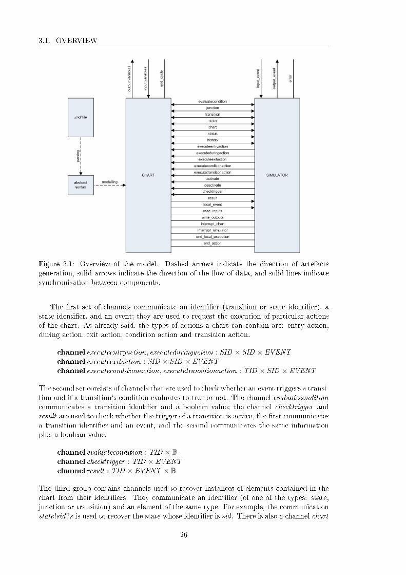
Figure 3.1: Overview of the model. Dashed arrows indicate the direction of artefactsgeneration, solid arrows indicate the direction of the �ow of data, and solid lines indicatesynchronisation between components.
The �rst set of channels communicate an identi�er (transition or state identi�er), astate identi�er, and an event; they are used to request the execution of particular actionsof the chart. As already said, the types of actions a chart can contain are: entry action,during action, exit action, condition action and transition action.
channel executeentryaction, executeduringaction : SID × SID × EVENTchannel executeexitaction : SID × SID × EVENTchannel executeconditionaction, executetransitionaction : TID × SID × EVENT
The second set consists of channels that are used to check whether an event triggers a transi-tion and if a transition's condition evaluates to true or not. The channel evaluateconditioncommunicates a transition identi�er and a boolean value; the channel checktrigger andresult are used to check whether the trigger of a transition is active, the �rst communicatesa transition identi�er and an event, and the second communicates the same informationplus a boolean value.
channel evaluatecondition : TID × Bchannel checktrigger : TID × EVENTchannel result : TID × EVENT × B
The third group contains channels used to recover instances of elements contained in thechart from their identi�ers. They communicate an identi�er (of one of the types: state,junction or transition) and an element of the same type. For example, the communicationstate!sid?s is used to recover the state whose identi�er is sid . There is also a channel chart
26

CHAPTER 3. FORMAL MODEL
that communicates the chart, that is, the top state; it does not use an identi�er becausewithin a State�ow Chart the chart is unique.
channel junction : JID × Junctionchannel transition : TID × Transitionchannel state : SID × Statechannel chart : State
The channels in the fourth set are used to request information about the status and his-tory of particular states and to request activation and deactivation of states. They allcommunicate a state identi�er. The status channel communicates also a boolean valuethat represents whether the state is active or not, and the history channel communicatesthe state identi�er of the last activated substate.
channel status : SID × Bchannel history : SID × SIDchannel activate, deactivate : SID
The last set comprises channels used to communicate data and events; some of theminteract with the environment. The channels input event and output event communicateevents, and the channel local event communicates an event and a state; the �rst is used toreceive an input event from a Simulink model, the second is used to send an output eventto a Simulink model, and the third communicates an event and a destination state (of theevent) to the Simulator process.
The channels read inputs and write outputs are used by the Simulator process to re-quest the chart process to, respectively, read the inputs and write the outputs. The channelinterrupt simulator is used to halt the execution of a step of the simulator, interrupt charthalts the execution of a step of the chart, end cycle is used to indicate the end of a cycle ofexecution of the chart, and error is used to signal errors of simulation created by problemsin the diagram, e.g. a missing default transition that leads to a state inconsistency. Thechannel end local execution signals that the recursive execution of the simulation step ini-tiated by a local event broadcast has ended, and end action indicates that a chart actionhas terminated.
channel input event , output event : EVENTchannel local event : EVENT × Statechannel read inputs,write outputschannel interrupt simulator , interrupt chart , end cyclechannel error , end local execution, end action
We identify below the set of channels that are used exclusively between the processes chartand simulator, and should be hidden from the environment; we call this set interface.
channelset interface == {| executeentryaction, executeduringaction, executeexitaction,executeconditionaction, executetransitionaction, evaluatecondition, checktrigger ,result , junction, transition, state, chart , status, history , activate, deactivate,local event , interrupt simulator , interrupt chart , read inputs,write outputs,end local execution, end action |}
Figure 3.2 shows a State�ow chart adapted from an example found in the Simulink/S-tate�ow tool that models a component of a automatic transmission controller. This chart
27

3.1. OVERVIEW
Figure 3.2: Example of a State�ow Chart describing a car's shift logic.
contains two parallel states gear state and selection state; each of them has a set of ex-clusive substates. The state gear state comprises exclusive states �rst , second , third andfourth; the transitions between these states are controlled by local events UP and DOWNthat are broadcasted by the state selection state; the choice of which event to broadcast,if any at all, is made according to the relation between the input variable speed and thelocal variables up th and down th. These local variables are updated by the Simulinkfunction calc th that takes variables gear and speed as parameters every time the stateselection state is executed. We are not modelling the Simulink function calc th, but leav-ing it under-speci�ed. We can use the translation strategy of [Arthan et al., 2000] to obtainoperation schemas that represent these function.
In our description of the models of State�ow charts, we use the chart in Figure 3.2 asan example. In the next section, we present the Chart process using as an example a chartcalled ShiftLogic adapted from a State�ow demo model that specify the gear system of acar.
The process that models the execution of this chart is called Shift logic and is de�nedas follows.
processShift logic =̂ (P shift logic J interface ∪ {| end cycle |} K Simulator) \ interface
Shift logic consists of the parallel composition of the processes P shift logic and Simulatorcommunicating over the channel set interface extended with the channel end cycle (whichis not hidden). The channels in interface are local to the model, and are, therefore, hidden.The process P shift logic is the Chart process for the example in Figure 3.2; its statemodels the structure of that chart, and its actions model the state and transition actions,and the triggers and conditions of the chart. The Circus action of the process P shift logic
28

CHAPTER 3. FORMAL MODEL
also allow the recovery of elements of the chart from identi�ers. The process Simulator isindependent from any particular chart; its de�nition is discussed in Section 3.3.
3.2 Structure of a State�ow Chart
A particular instance of a State�ow Chart is structured as a Circus process whose statecharacterises information about the chart, such as its states, junctions, transitions andvariables, as well as the states' status and history. The actions, conditions, and triggers ofthe chart are encoded as Circus actions because there is a direct correspondence betweenState�ow actions and Circus actions.
As brie�y discussed, the process that represents the chart in Figure 3.2 depends upon aset of de�nitions that are independent of the chart; these de�nitions characterise elementssuch as states, junctions, transitions etc. There is also a group of Circus actions that arethe same for all Chart processes.
The model of the chart in Figure 3.2 is structured in the following way.
de�nitions of constantsde�nitions of channelsprocessP shift logic =̂ begin
axiomatic de�nition that exposes the structure of the chartschemas that characterise the state of the processstate initialisation operationentry, during, exit, condition and transition actionscondition evaluation and transition trigger checking actionsactions that provide elements given their identi�ersactions that provide information about status and historyactions that activate and deactivate statesactions that read input variables and write output variablesmain action that recursively o�er the actions previously de�ned
end
In Section 3.2.1, we introduce the de�nitions that are the same for all Chart processes andlie outside the process de�nition. In Section 3.2.2, we present by means of our example themain elements that must be de�ned for each particular chart to build the Chart process,and some of the actions that are used in all Chart processes.
3.2.1 Diagram structures
The main elements of State�ow Charts are states, junctions and transitions; each instanceof these elements is uniquely identi�ed. To represent these, we declare the given sets ofstate identi�ers, transition identi�ers, and junction identi�ers. Another important classof objects of State�ow Charts is that of events, and since these are atomic elements, werepresent them also as elements of a given set.
[SID , TID , JID , EVENT ]
A state must be of type AND or OR, and have decomposition of type SET or CLUSTER.
TYPE ::= AND | OR | CHARTDECOMPOSITION ::= SET | CLUSTER
29

3.2. STRUCTURE
A state has an identi�er, three possibly empty sequences of transitions (default, inner andouter transitions), the identi�ers of the parent, an of the left and right siblings, a possiblyempty sequence of substates, a decomposition, a type and a component identifying whetherthe state has a history junction or not.
In order to capture the structure of the chart as it is used in the informal description ofthe simulator, we explicitly encode information that could otherwise be calculated from amore concise speci�cation. For example, the simulation description relies on notions suchas left and right siblings of a state, and although this information can be derived fromthe sequence of substates of the parent state, we explicitly record them in the state of theCircus process in order to make the description of the simulation process simpler.
Instead of representing sequences of transitions explicitly, we represent them as linkedlists of transitions, i.e, each transition points to the next in sequence and is terminated bythe null transition nulltransition. This facilitates our handling of sequences of transitionsand is closer to the representation the simulation description uses.
Stateidenti�er : SIDdefault , inner , outer : TIDparent , left , right : SIDsubstates : seqSIDdecomposition : DECOMPOSITIONtype : TYPEhistory : B
Although notions such as parent, left and right siblings, etc. seem to be properties of thestate itself, they cannot be described for a state in isolation, i.e. they are properties ofthe whole chart described later. A chart has properties such as decomposition, substatesand default transitions that render them a state aspect. The state aspect of a chartcomprises those elements that are common to states, and it is necessary in order to keepthe speci�cation of the simulator simpler.
One of the steps of executing a transition consists of acting on the parent of a transitionspath; this parent can be the chart, and if we did not have a state representation of thechart, we would need to treat a chart and a state as separate cases in every place wherethe parent of a state or transition path is manipulated. Other parts of the simulator thatexplore the state aspect of a chart are points where the chart's default transitions areexecuted, and where its substates are entered.
A chart contains also information that is not relevant to a state, such as the relationbetween state identi�ers and state de�nitions. Because of this duality of charts, we providetwo descriptions of it, one is the state aspect (its substates, default transitions, decompo-sition, etc.) speci�ed by the schema Chart and the other is the global aspect (states, tran-sitions and junctions contained in the whole chart) de�ned in the schema State�owChart .To avoid confusion between a regular state and the state aspect of a chart, we add a newtype called CHART . The state aspect of a chart is represented in the schema below; theonly extra restriction is that it has type CHART .
Chart == [State | type = CHART ]
A state has also three actions, namely entry, during and exit actions, which are not speci�edin the schema above. This is so because, as stated before, there is a direct correspondencebetween State�ow actions and Circus actions; therefore, they are speci�ed in the processitself.
30

CHAPTER 3. FORMAL MODEL
A junction is a simpler version of a state; it contains an identi�er, a sequence oftransitions and a reference to the junction's parent. It can be a connective junction ora history junction, in which case the component history has value True. Notice thatunlike states, it's not possible to recover information about the parent of a junction fromthe hierarchy because a state does not keep information about its junctions.
Junctionidenti�er : JIDtransition : TIDparent : SIDhistory : B
A transition has an identi�er. It also has a source, possibly null in the case of default tran-sitions, and a destination, necessarily not null. The source and destination of a transitioncan be states or junctions. For that reason, we de�ne a new type NID of node identi�ersas follows.
NID ::= snode〈〈SID〉〉 | jnode〈〈JID〉〉
This de�nition yields two injective function snode and jnode that take, respectively, a stateidenti�er and a junction identi�er, and produce a node identi�er. Given a node identi�er,to �nd out whether the node is a state or a junction, it su�ces to check if it belongs tothe range of snode or jnode. To recover the state identi�er of a node identi�er that is ofa state, we apply the inverse snode ∼ of the function snode; the same holds for junctionidenti�ers.
As usual, we keep data about the parent of the transition, i.e., the nearest state thatcontains both ends of the transition. In the case of a default transition, the parent isnecessarily the state that contains the default transition; this holds because it is a syntacticrestriction that a default transition path must be contained within that state. Since werepresent sequences of transitions as linked list, we need a component in a transition thatpoints to the next one in the sequence; this component is called next .
Transitionidenti�er : TIDsource, destination : NIDnext : TIDparent : SID
In what follows, we de�ne the null state, the null transition and the null junction; theseare used to indicate that no such element exists where one is required. For example, forthe last transition in a sequence, the component next 's value is the identi�er of the nulltransition. Also, a chart has no parent; to specify that, the component parent has theidenti�er of the null state as value. The speci�cation does not de�ne the identi�ers of thenull state, null transition, and null junction, but requires that this elements are not in theset of states, transitions and junctions of a chart, making them unique.
nullstate : Statenulljunction : Junctionnulltransition : Transition
As mentioned before, we distinguish a global aspect of a Chart from its state aspect.The �rst is represented by the schema State�owChart , and the second is represented by
31

3.2. STRUCTURE
the schema Chart . The State�owChart schema is described below; it contains globalinformation about the chart.
State�owChartidenti�er : SIDstates : SID 7→ Statetransitions : TID 7→ Transitionjunctions : JID 7→ Junction
nullstate 6∈ ran statesnulltransition 6∈ ran transitionsnulljunction 6∈ ran junctions#{s : ran states | s.type = CHART} = 1(states(identi�er)).type = CHART∀n : SID | n ∈ dom states • (states(n)).identi�er = n∀n : JID | n ∈ dom junctions • (junctions(n)).identi�er = n∀n : TID | n ∈ dom transitions • (transitions(n)).identi�er = n
The schema State�owChart contains an identi�er, a partial function from state identi�ersto states, a partial function from transition identi�ers to transitions, and a partial functionfrom junction identi�ers to junctions. The predicate of the schema establishes that the nullstate, the null transition, and the null junction must not be in the range of these functions,and that there must exist exactly one element in the range of the partial function states,such that it is of type Chart and has the same identi�er as the State�owChart . It alsorequires that these functions take an identi�er to an element whose identi�er is the same;we keep information about the identi�er in the element to avoid the repeated use of theinverse of these functions in the simulator process.
There are other restriction on the structure of a State�ow chart. For example, whenstates are put in the context of a hierarchy, some restrictions must be met. First, therelation between type and decomposition of states must respect the following restrictions.
• If a state has decomposition SET , then all of its substates must have type AND ;
• If a state has decomposition CLUSTER, then all of its substates must have type OR.
This restriction, among others, concerns the actual chart, while the invariant of theschema State�owChart captures restrictions upon our model. The former type of restric-tion are enforced by the Simulink/State�ow tool, and some of them are captured in ourformalisation of the syntax (see Section 4.1).
One piece of information we frequently need is the least ancestor of two states in thehierarchy of states, i.e., the most immediate ancestor of both states. To de�ne that, we�rst de�ne the relation parent , and then the relation ancestors.
parent : State↔ State
∀ s1, s2 : State • parent(s1) = s2 ⇔ s1.parent = s2.identi�er
The ancestors of a state are all states who are either parent of the state or ancestor of itsparent. This is calculated by the transitive closure of the relation parent .
ancestors : State↔ PState
∀ s : State • ancestors(s) = {x : State | (parent +)(s) = x}
32

CHAPTER 3. FORMAL MODEL
Finally, the function la (least ancestor) is de�ned as the ancestor a of both states suchthat for all other ancestors b of both states, b equals a or is itself an ancestor of a.
la : (State × State)↔ State
∀ s1, s2 : State • la(s1, s2) = µ x : (ancestors(s1) ∩ ancestors(s2)) |(∀ y : (ancestors(s1) ∩ ancestors(s2)) • x = y ∨ y ∈ ancestors(x )) • x
In the next section, we de�ne the process c shift logic using the de�nitions of this section.
3.2.2 Process derived from the chart
As previously mentioned the structure of the chart dependent part of the model consists ofa series of de�nitions that culminate in the de�nition of a Circus process that encapsulatesthe chart.
In order to de�ne the process, we need to declare the elements that will form thechart, that is, its events, data, states, transitions, etc. Events are declared by axiomaticde�nitions. The example uses two local events e UP and e DOWN , which are de�ned inthe following axiomatic de�nition.
e UP , e DOWN : EVENT
The data declared in the chart are represented in the state of the process, but the inputand output data need to be accessible outside the process. Input data are read throughchannels of the appropriate type whose names are pre�xed by the letter i ; output data arewritten through channels whose name is pre�xed by the letter o. Our example, containstwo input data (speed and throttle) and one output data (gear). The channels associatedwith these data are declared below.
channel o gear , i speed , i throttle : R
In order to describe the state of a chart, we need de�nitions for each state, junction andtransition of the chart. Since this chart has no junctions, we only need to declare the statesand transitions. Here, we will show the de�nition of one state and one transition. Thede�nitions of all states and transitions can be found in Appendix A.
For each state in the diagram, we de�ne a constant of type State and a constant oftype SID ; the name of the �rst is the name of the state pre�xed by a capital S , and thename of the second is created in the same fashion, but pre�xed by a lower case s. For stategear state, the constant S gear state has type State and the value of its components arede�ned by the following binding. This state's identi�er is s gear state. It has a defaulttransition whose identi�er is default �rst . It has no inner or outer transitions, no leftsibling, but has a right sibling that has identi�er s selection state. It has a sequence ofsubstates and exclusive decomposition (CLUSTER). It is a parallel (AND) state and hasno history junction.
S gear state : State
S gear state = 〈|identi�er == s gear state, default == default �rst ,inner == nulltransition.identi�er , outer == nulltransition.identi�er ,parent == s shift logic, left == nullstate.identi�er ,right == s selection state, substates == 〈s �rst , s second , s third , s fourth〉,decomposition == CLUSTER, type == AND , history == False|〉
33
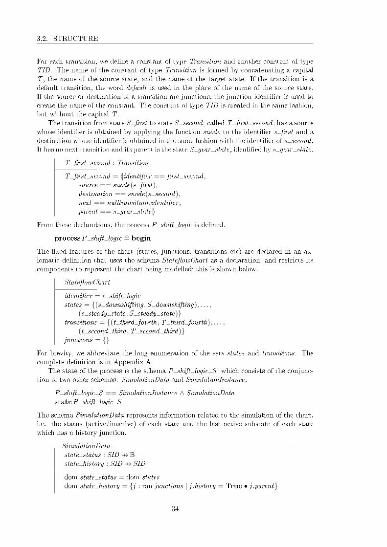
3.2. STRUCTURE
For each transition, we de�ne a constant of type Transition and another constant of typeTID . The name of the constant of type Transition is formed by concatenating a capitalT , the name of the source state, and the name of the target state. If the transition is adefault transition, the word default is used in the place of the name of the source state.If the source or destination of a transition are junctions, the junction identi�er is used tocreate the name of the constant. The constant of type TID is created in the same fashion,but without the capital T .
The transition from state S �rst to state S second , called T �rst second , has a sourcewhose identi�er is obtained by applying the function snode to the identi�er s �rst and adestination whose identi�er is obtained in the same fashion with the identi�er of s second .It has no next transition and its parent is the state S gear state, identi�ed by s gear state.
T �rst second : Transition
T �rst second = 〈|identi�er == �rst second ,source == snode(s �rst),destination == snode(s second),next == nulltransition.identi�er ,parent == s gear state|〉
From these declarations, the process P shift logic is de�ned.
processP shift logic =̂ begin
The �xed features of the chart (states, junctions, transitions etc) are declared in an ax-iomatic de�nition that uses the schema State�owChart as a declaration, and restricts itscomponents to represent the chart being modelled; this is shown below.
State�owChart
identi�er = c shift logicstates = {(s downshifting ,S downshifting), . . . ,
(s steady state,S steady state)}transitions = {(t third fourth,T third fourth), . . . ,
(t second third ,T second third)}junctions = {}
For brevity, we abbreviate the long enumeration of the sets states and transitions. Thecomplete de�nition is in Appendix A.
The state of the process is the schema P shift logic S , which consists of the conjunc-tion of two other schemas: SimulationData and SimulationInstance.
P shift logic S == SimulationInstance ∧ SimulationDatastateP shift logic S
The schema SimulationData represents information related to the simulation of the chart,i.e. the status (active/inactive) of each state and the last active substate of each statewhich has a history junction.
SimulationDatastate status : SID 7→ Bstate history : SID 7→ SID
dom state status = dom statesdom state history = {j : ran junctions | j .history = True • j .parent}
34

CHAPTER 3. FORMAL MODEL
The status of the states is recorded by a partial function state status that takes a stateidenti�er as parameter and returns a boolean value that encodes the status of the state.This function is de�ned for all states in the chart; this invariant is recorded by the predicatedom state status = dom states that requires the domain of the function state status to bethe same as the domain of the function states that maps state identi�ers to state bindings.The history information of state is recorded in a similar fashion by the partial functionstate history from state identi�ers to state identi�ers; this function returns the identi�erof the last active state (or nullstate.identi�er) of a state. This function is de�ned only forthe states that contain a history junction; this is also encoded in the predicate part of theschema.
We de�ne an initialisation operation InitSimulationData for the schema SimulationData;it initialises the functions state status and state history .
InitSimulationDataSimulationData ′
state status ′ = {n : dom states • n 7→ False}state history ′ = {n : dom states | states(n).history = True •
n 7→ nullstate.identi�er}
Since initially no state is active, all elements of the domain of state status are set to False,and no information is stored in the history junctions, that is, all the elements of the domainof state history point to the identi�er of the null state.
The schema SimulationInstance, on the other hand, records information that can bechanged by the execution of the chart, but are part of the chart. Unlike the componentsof SimulationData, which are not part of the chart, but part of its execution.
SimulationInstancev gear , v TWAIT , v speed : Rv throttle, v up th, v down th : R
This schema declares variables for each of the data declared in the chart.We de�ne an operation InitSimulationInstance that initialises the schema
SimulationInstance; it is responsible for de�ning the initial values of the variables, anddepends on a particular chart; for our example, it is as follows.
InitSimulationInstanceSimulationInstance ′
v gear ′ = 0v TWAIT ′ = 0v speed ′ = 0v throttle ′ = 0v up th ′ = 0v down th ′ = 0
This initialisation is necessary because the initial values of variables can be modi�ed.The operations InitSimulationData and InitSimulationInstance are then composed in
a conjunction to for the initialisation operation of the state of the chart.
InitState == InitSimulationData ∧ InitSimulationInstance
35

3.2. STRUCTURE
Once the state and initialisation operation have been de�ned, we need to declare theCircus actions that correspond to the chart's actions. Again, we will only show some ofthese actions, for a complete speci�cation refer to Appendix A.
The entry action of the state S �rst assigns the value 1 to the variable v gear . This isspeci�ed as a Circus action that waits for a communication of the identi�er s �rst throughthe channel executeentryaction and then assigns the value to the variable. This action isnamed after the state by pre�xing its name with the word entryaction.
entryaction �rst =̂ executeentryaction.s �rst?o?ce −→ v gear := 1
The channel executeentryaction also communicates two extra values, o identi�es the originstate of the action being executed, and ce identi�es the current event. These values aresent from the simulator process to the chart process, and are necessary to executed onactions and evaluate early return logic conditions.
We gather all the entry actions in one Circus action called entryactions de�ned by anexternal choice as illustrated below.
entryactions =̂ (entryaction �rst @ . . . @ entryaction fourth)
The same procedure is followed for the other kinds of actions. The Circus actions thatmodel these actions of the chart are: duringactions, exitactions, conditionactions andtransitionactions, and the name of individual actions is created by pre�xing the state ortransition name with the type of action. One important aspect of actions is the broadcast-ing of event, in particular the broadcasting of local events. Next, we present a conditionaction that broadcasts a local event; this is done by synchronising on the channel interruptin order to interrupt the execution of the simulator and communicating the event overchannel local event , thus starting a new step of the simulator.
conditionaction upshifting steady state26 =̂executeconditionaction.(t upshifting steady state26)?o?ce−→broadcast(e UP , s upshifting , s gear state)
This action waits for the communication of the identi�er t upshifting steady state26 on thechannel executeconditionaction, and broadcasts the event e UP to the state s gear state.The broadcasting is done through the action broadcast that takes an event, and the originand destination states of the broadcast as parameters.
The broadcasting of a local event triggers the reexecution of the chart, and this canlead to an inconsistent state where, for instance, the state that issued the broadcasting isno longer active. If this situation is reached, the execution that led to the broadcasting ofthe event is halted (after the end of the recursive execution), and a new step of executionis initiated; this is called early return logic. The action broadcast de�ned below executesthe broadcasting and checks if early return logic should take place.
broadcast =̂ e : EVENT ; origin, dest : SID • local event !(e, states(dest))−→ µX •
AllActions ; X@end local execution −→ Skip
;
if state status(origin) = True−→ Skip
8state status(origin) = False−→ interrupt simulator −→ Skip
�
The check necessary to decide if early return logic should take place is done on the originstate, which for state actions is the state that contains the actions for condition actions
36

CHAPTER 3. FORMAL MODEL
it is the source of the transition path, and for transition actions the origin state is theparent of the transition path. The condition for early return logic for transition actions isdi�erent, earluy return logic takes place, if the parent of the transition path is no longeractive, or if one of its children is active. This is speci�ed by the action broadcast tactionshown below.
broadcast taction =̂ e : EVENT ; tpp, dest : SID • broadcast(e, tpp, dest);if(state status, states(tpp)) ∈ has active substate−→
interrupt simulator −→ Skip
8(state status, states(tpp)) 6∈ has active substate −→ Skip
�
This action �rst attempts the standard check for early return logic, using the parent of thetransition path (tpp) as the origin; if it holds, the action executeChart of the simulationstep is interrupted, and this triggers the interruption of the current step of the processc shift logic. In this case, the second part of the action is not executed. However, ifthe �rst part (call to broadcast) does not lead to interruption, broadcast taction checksthe additional condition; it uses the set called has active substate that contains all thestate identi�ers of states that have at least one active substate. The de�nition of the sethas active substate is omitted and can be found in appendix A.
The conditions are speci�ed for each transition; transitions that have no conditionare treated by a default Circus action that always communicates value True in channelresult . For example, the transition from S steady state to S downshifting has conditionv speed < v down th; it is translated into the following action that evaluates the conditionand communicate the appropriate value in the channel evaluatecondition if the transitionidenti�er communicated in the same channel is s steady state downshifting .
condition steady state downshifting =̂if((v speed<Av down th) 6= 0)−→
evaluatecondition.(t steady state downshifting)!(True)−→ Skip
8(¬ ((v speed<Av down th) 6= 0))−→evaluatecondition.(t steady state downshifting)!(False)−→ Skip
�
The action that models the conditions of all transitions is then de�ned as the one thatmodels entry actions, for instance.
conditions =̂
condition steady state downshifting@. . .@condition steady state upshifting
The veri�cation of whether an event triggers a transition is de�ned by the an action whosename is pre�xed by trigger ; it �rst communicates on the channel checktrigger the tran-sition identi�er and the event, and then waits for the answer in the channel result . Forexample, the transition from S �rst to S second is triggered by event UP ; this action iscalled trigger �rst second and is de�ned as follows.
trigger �rst second =̂ checktrigger .(t �rst second)?e−→ if e = e UP −→ result .(t �rst second).(e)!(True)−→ Skip
8(¬ e = e UP)−→ result .(t �rst second).(e)!(False)−→ Skip
�
37
3.2. STRUCTURE
The transitions with no trigger, the trigger action always returns true. For example, thetrigger of the transition from S steady state to S upshifting is de�ned below.
trigger steady state upshifting =̂ checktrigger .(t steady state upshifting)?e−→result .(t steady state upshifting).(e)!(True)−→ Skip
The same approach is used to specify the Circus actions that check the condition of atransition that does not have a condition; it always returns true. The action that groupsthe triggers in the chart is de�ned as usual.
triggers =̂(trigger �rst second @ . . . @ trigger second third
)The next actions allow the communication of an element given its identi�er. We de�nethem for states, junctions, and transitions. Since there is only one chart, the action thatreturns the chart does not expect any identi�er. Below, we show the action for states; itwaits for a communication on the channel state of an identi�er that is in the domain offunction states and outputs the result of applying states, to the identi�er.
getstate =̂ state?n : (n ∈ dom states)!(states n)−→ Skip
This action getstate, as well as the actions getjunction, gettransition and getchart , for thejunctions, the transitions, and the chart are independent of the chart.
We must de�ne actions that provide information about the status of states and thehistory of states that have a history junction. They use channels status and history forthat.
status =̂ status?n : (n ∈ dom state status)!(state status n)−→ Skip
history =̂ history?n : (n ∈ dom state history)!(state history n)−→ Skip
The activation and deactivation of a state is de�ned by schema operations; the reason forthis is that they alter the function state status. In order to activate a state, it must beinactive; to deactivate a state it must be active. The activation of a state is more com-plicated because we need to account for the possibility of a history junction being presentin the parent. If there is no history junction, it su�ces to update function state status tore�ect that the state is now active using the override operator (⊕).
ActivateNoHistory∆SimulationDatan? : SID
(parent (states n?)).history = False
state status n? = False
state history ′ = state historystate status ′ = state status ⊕ {n? 7→True}
If there is a history junction, one needs also to update the function state history with themapping from the parent of the state to it, i.e. the application of state history to theparent of the state being activated must yield the state.
38

CHAPTER 3. FORMAL MODEL
ActivateWithHistory∆SimulationDatan? : SID
(parent (states n?)).history = True
state status n? = False
state history ′ = state history ⊕ {((states n?).parent) 7→ n?}state status ′ = state status ⊕ {n? 7→True}
The di�erence between the two operations is their pre-conditions, the �rst requires thatthe parent of the state has no history junction; the second requires the opposite. In casethe state is already active, we do nothing; this is speci�ed by operation ActivateFail .
ActivateFailΞSimulationDatan? : SID
state status n? = True
The operation Activate is then de�ned by the disjunction of the three partial operationsde�ned above, conjoined to the schema ΞSimulationInstance. It is independent of theparticular diagram under consideration.
Activate ==((ActivateWithHistory ∨ ActivateNoHistory) ∨ ActivateFail)∧ΞSimulationInstance
The conjunction is necessary for this operation to be de�ned over the state of the process.The de�nition of the deactivation operation is similar; for details refer to Appendix G.
The actions that o�er activation and deactivation of a state wait for a communicationon the channels activate and deactivate of a state identi�er and execute the appropriateoperation.
activation =̂ activate?n −→ (Activate)deactivation =̂ deactivate?n −→ (Deactivate)
We group the actions that specify the entry, during, exit, condition and transition actionsin an action called ChartActions by composing them with the external choice operator.
ChartActions =̂
entryactions@duringactions@exitactions@conditionactions@transitionactions
; end action −→ Skip
All chart actions must indicate its completion through the channel end action; this isachieved by synchronising on that channel after the external choice is resolved and thechosen action terminates.
39
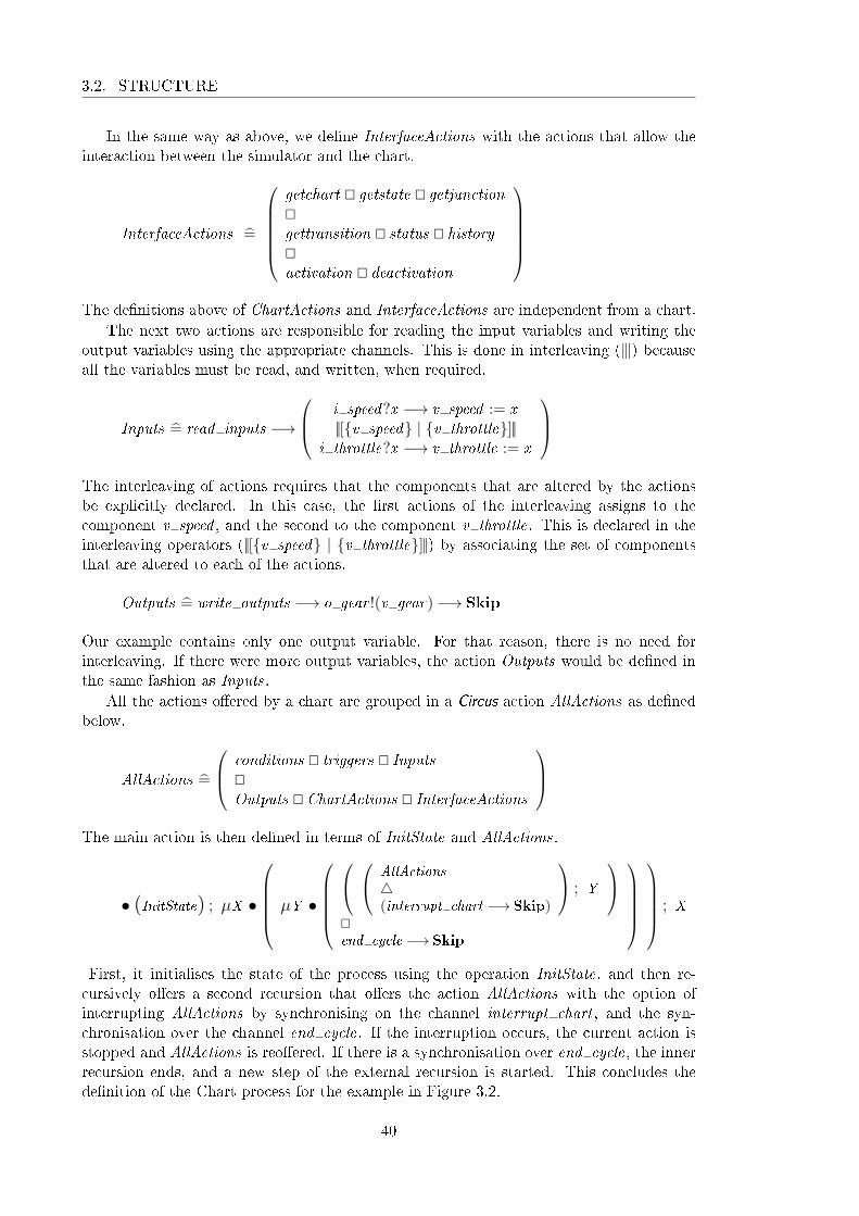
3.2. STRUCTURE
In the same way as above, we de�ne InterfaceActions with the actions that allow theinteraction between the simulator and the chart.
InterfaceActions =̂
getchart @ getstate @ getjunction@gettransition @ status @ history@activation @ deactivation
The de�nitions above of ChartActions and InterfaceActions are independent from a chart.
The next two actions are responsible for reading the input variables and writing theoutput variables using the appropriate channels. This is done in interleaving (9) becauseall the variables must be read, and written, when required.
Inputs =̂ read inputs −→
i speed?x −→ v speed := x||[{v speed} | {v throttle}]||
i throttle?x −→ v throttle := x
The interleaving of actions requires that the components that are altered by the actionsbe explicitly declared. In this case, the �rst actions of the interleaving assigns to thecomponent v speed , and the second to the component v throttle. This is declared in theinterleaving operators (||[{v speed} | {v throttle}]||) by associating the set of componentsthat are altered to each of the actions.
Outputs =̂ write outputs −→ o gear !(v gear)−→ Skip
Our example contains only one output variable. For that reason, there is no need forinterleaving. If there were more output variables, the action Outputs would be de�ned inthe same fashion as Inputs.
All the actions o�ered by a chart are grouped in a Circus action AllActions as de�nedbelow.
AllActions =̂
conditions @ triggers @ Inputs@Outputs @ ChartActions @ InterfaceActions
The main action is then de�ned in terms of InitState and AllActions.
• (InitState) ; µX •
µY •
AllActions
4(interrupt chart −→ Skip)
; Y
@end cycle −→ Skip
; X
First, it initialises the state of the process using the operation InitState, and then re-cursively o�ers a second recursion that o�ers the action AllActions with the option ofinterrupting AllActions by synchronising on the channel interrupt chart , and the syn-chronisation over the channel end cycle. If the interruption occurs, the current action isstopped and AllActions is reo�ered. If there is a synchronisation over end cycle, the innerrecursion ends, and a new step of the external recursion is started. This concludes thede�nition of the Chart process for the example in Figure 3.2.
40

CHAPTER 3. FORMAL MODEL
3.3 Speci�cation of the State�ow Simulator
The State�ow Simulator is speci�ed as another Circus process that communicates with thechart through the channels in the channel set interface. It uses internally four channelsto control the �ow of execution. These channels control whether or not a transition pathreached a state.
channel stsuccess, stfail
Since these channels are always used in a pair, we de�ne a channel set to abbreviate them.
channelset statetransition == {| stsuccess, stfail |}
The channels stsuccess and stfail are used to control the �ow of an action. We run twoactions in parallel synchronising on the channels stsuccess and stfail ; one executes andaccording to internal conditions synchronises on one of these channels; the other waits forsynchronisation on the channels and executes some action according to the outcome of the�rst action. They are used to decide what to do in case a transition path is successful ornot.
The process Simulator has no state, as all the information is recorded in the chartprocess and communicated through channels.
processSimulator =̂ begin
It has �ve sets of actions that deal with execution of transitions, entering states, executingstates, exiting states and executing charts. We de�ne these actions in that order andbreak them into sub-actions (when necessary) to agree with the speci�cation steps used todescribe the simulation in the User's Guide. All the actions that de�ne the step of executionof the simulator process have a common input varaible (current event : EVENT ) that isused to keep a record of the current event being executed.
3.3.1 Executing a sequence of transitions
We start by de�ning the execution of a transition, which is actually the execution of asequence of transitions, as de�ned in the steps shown in Figure 2.1. Once one transitionpath is completely successful (reaches a state or a junction that has no transition) theexecution of the sequence stops. This action takes as parameters a transition identi�erthat represents the transition being executed, a sequence of transitions that represent thecurrent transition path being followed, and the state from which the path originates. Thetransition path keeps a record of the transitions already executed and is used to backtrackwhen the path fails and to execute the transition actions when the path succeeds. Thesource state is necessary so that we know which state to exit once a path succeeds.
If the transition being executed is the null transition, it means that we reached the endof the sequence of transitions we were trying to execute. If the path is empty, it means thatthis sequence of transitions originated from a state and the execution of the transitionsfrom that state fails. If it is not empty, then we recover the last transition executed, take ito� of the path, and execute the next one in the sequence. If the transition being executedis not the null transition, we check its validity and proceed adequately by executing the
41

3.3. SIMULATOR
action CheckValidity .
ExecuteTransition =̂ tid : TID ; path : seqTID ; source : State; current event : EVENT •
if tid = nulltransition.identi�er−→if path = ∅−→ stfail −→ Skip
8path 6= ∅−→(transition!(last path)?lt−→ExecuteTransition(lt .next , (front path), source, current event)
)�
8tid 6= nulltransition.identi�er−→CheckValidity(tid , path, source, current event)�
The action that checks the validity of a transition simply communicates with the chartasking for the evaluation of the events and the condition. If both are true, then it requeststhe execution of the condition action, treats any possible local event broadcast, adds thecurrent transition to the path and proceeds by calling the action Proceed . Otherwise, itexecutes the next transition in the sequence.
CheckValidity =̂ tid : TID ; path : seqTID ; source : State; current event : EVENT •checktrigger !tid !current event−→
result !tid !current event?e −→ evaluatecondition!tid?c−→
if e = True ∧ c = True−→(executeconditionaction!tid !(source.identi�er)!current event−→LocalEvent ; Proceed(tid , path a 〈tid〉, source, current event)
)8¬ (e = True ∧ c = True)−→ transition!tid?t−→ExecuteTransition(t .next , path, source, current event)�
Whenever the simulator requests the execution of a chart action (entry, during, exit, con-dition and transition actions), there is a possibility that a local event will be broadcasted.We account for this possibility by executing the action LocalEvent after the request as canbe seen in the action CheckValidity . The action LocalEvent recursively o�ers two choices:treat a local event that has been broadcasted (local event?e?s) or terminates the action(end action). The termination is signalled by the action ChartActions of the chart processby synchronising on the channel end action.
LocalEvent =̂ µX •
(local event?e?s −→ TreatLocalEvent(e, s) ; X )@end action −→ Skip
The treatment of the local event consists of starting a local execution with the new evente, waiting for it to �nish, and synchronising on the channel end local execution, indicatingthat the local execution under the new event has �nished. The local execution consists ofeither executing the chart if it is a unrestricted broadcast, or executing the appropriatestate if it is a directed broadcast. Finally, the original execution continues.
TreatLocalEvent =̂ e : EVENT ; s : State • if s.type = CHART −→ ExecuteChart(e)8s.type 6= CHART −→ ExecuteState(s, e)�
;
end local execution −→ Skip
42

CHAPTER 3. FORMAL MODEL
Once the transition is deemed valid, we need to proceed. Here, we have two possibilities,proceed to a state or to a junction. This decision is taken based on the type of thedestination of the transition. If the destination is a state, we recover the identi�er of thestate by applying the inverse of the injective function that de�nes the type NID ; from thisidenti�er, we obtain the actual state and execute the action proceedToState on the sourceand destination of the transition path and the path itself. If the destination is a junction,we execute the action proceedToJunction on the transition identi�er, the transition pathand its source state.
Proceed =̂ tid : TID ; path : seqTID ; source : State; current event : EVENT •transition!tid?t−→
if t .destination ∈ ran snode−→(state!((snode ∼) t .destination)?dest−→proceedToState(source, dest , path, current event)
)8t .destination ∈ ran jnode−→
proceedToJunction(tid , path, source, current event)�
The action proceedToState simply exits the substates of the least ancestor of the source anddestination of the transition path, executes the transition path, enters the least ancestorof the source and destination of the transition path and, �nally, synchronises on channelstsuccess indicating the the path succeed in entering a state.
proceedToState =̂ src, dest : State; path : seqTID ; current event : EVENT • ExitStates((la(src, dest)).substates, current event);executePath(path, src, dest , current event);EnterState(dest , la(src, dest), current event) ; stsuccess −→ Skip
The execution of the path consists of executing all the transition actions in the path.
executePath =̂ path : seqTID ; src, dest : State; current event : EVENT •if # path = 0−→ Skip
8 # path > 0−→(executetransitionaction!(head path)!((la(src, dest)).identi�er)!current event−→LocalEvent ; executePath(tail path, src, dest , current event)
)�
If the destination of the transition is a junction, we must �rst check whether this junctionis a history junction or not. If it is not a history junction, we execute it, otherwise, we tryto recover the state recorded in the history. If none exists, we follow the default transitionof the parent of the history junction. If there is some state recorded in the history, we
43

3.3. SIMULATOR
proceed as if the destination were the state.
proceedToJunction =̂ tid : TID ; path : seqTID ; source : State; current event : EVENT •
transition!tid?t −→ junction!((jnode ∼) t .destination)?dj−→
if dj .history = False−→ executeJunction(dj , path, source, current event)8dj .history = True−→ history !(dj .parent)?lsid−→
if lsid = nullstate.identi�er−→(state!(dj .parent)?s−→ExecuteDefaultTransition(s, s, current event)
)8lsid 6= nullstate.identi�er−→(
state!lsid?ls−→proceedToState(source, ls, path, current event)
)�
�
When executing a junction, if the junction has no outgoing transitions, we communicatethe failure of the transition path in reaching a state and do nothing. Otherwise, we executethe outgoing transitions.
executeJunction =̂ j : Junction; path : seqTID ; source : State; current event : EVENT •if j .transition = nulltransition.identi�er−→
stfail −→ Skip
8j .transition 6= nulltransition.identi�er−→ExecuteTransition(j .transition, path, source, current event)
�
The execution of default transitions is a little di�erent from regular transitions becausewe need to account for the possibility of implicit default transitions. For example, a statemight have only one substate, in this case the default transition is redundant and State�owallows its omission. If there is more than one substate, an error should be issued.
ExecuteDefaultTransition =̂ s, tpp : State; current event : EVENT •
if s.default 6= nulltransition.identi�er−→ExecuteTransition(s.default , 〈〉, s, current event)
8s.default = nulltransition.identi�er−→if # s.substates = 1−→
(state!(head s.substates)?saux−→EnterState(saux , tpp, current event)
)8 # s.substates > 1−→ error −→ Skip
8 # s.substates = 0−→ Skip
�
�
In summary, the main actions used for executing transitions are ExecuteTransition andExecuteDefaultTransition.
3.3.2 Entering a state
The second group of actions comprises the actions responsible for entering a state. Theseactions take as parameters the state to be entered and the parent of the transition paththat led to the state being entered. The main action of this group is decomposed in manyactions enumerated to reference the steps shown in Figure 2.2. For example, EnterState1
44

CHAPTER 3. FORMAL MODEL
refers to the step 1 and EnterState14 refers to steps from 1 to 4. These steps are sequentiallycomposed to describe the full action of entering a state.
The action that models the step 1 is de�ned as follows. It checks if the parent of thestate being entered is active or not. If it is, we do nothing, otherwise we execute steps1 through 4. If the state is a chart, it has no parent and, therefore, nothing should bedone. We only execute steps 1 to 4 because steps beyond those are mainly responsible forentering the substates, and since we are starting from a substate there is no need to runthe other steps.
EnterState1 =̂ s, tpp : State; current event : EVENT • status!(s.parent)?active−→if s.type 6= CHART ∧ active = False−→(
state!(s.parent)?p−→EnterState14(p, tpp, current event)
)8s.type = CHART ∨ active = True−→ Skip
�
The second step checks if the state is of type AND , and if it has an inactive left sibling.It enters that state, otherwise nothing is done.
EnterState2 =̂ s, tpp : State; current event : EVENT •
if s.type = AND−→
if s.left 6= nullstate.identi�er−→status!(s.left)?False−→(
state!(s.left)?ls−→EnterState(ls, tpp, current event)
)@status!(s.left)?True−→ Skip
8s.left = nullstate.identi�er −→ Skip
�
8s.type 6= AND −→ Skip
�
Step 3 activates the state by communicating with the chart.
EnterState3 =̂ s, tpp : State; current event : EVENT •activate!(s.identi�er)−→ Skip
Step 4 executes the entry action by communicating with the chart as well.
EnterState4 =̂ s, tpp : State; current event : EVENT •executeentryaction!(s.identi�er)!(s.identi�er)!current event −→ LocalEvent
Since we frequently use the sequence of steps from 1 to 4, it is useful to de�ne an actionfor that.
EnterState14 =̂ s, tpp : State; current event : EVENT •(EnterState1(s, tpp, current event) ; EnterState2(s, tpp, current event);EnterState3(s, tpp, current event) ; EnterState4(s, tpp, current event)
)In Step 5, we execute the step 5a, and then the step 5b. The step 5a deals with stateswith sequential decomposition and the step 5b is concerned with states with a paralleldecomposition.
EnterState5 =̂ s, tpp : State; current event : EVENT •EnterState5a(s, tpp, current event) ; EnterState5b(s, tpp, current event)
45

3.3. SIMULATOR
Step 5a checks if the state has a parallel decomposition (s.decomposition 6= CLUSTER),in which case the action terminates, or if it has a sequential decomposition. In this case, itchecks if the state has a history junction or not. If it does and there is a state recorded inthe history, steps 1 through 5 are executed for that state. If no state is recorded or thereis no history junction, the default transitions of the state being entered are executed.
EnterState5a =̂ s, tpp : State; current event : EVENT •
if s.decomposition 6= CLUSTER −→ Skip
8s.decomposition = CLUSTER−→
if s.history = True−→ history !(s.identi�er)?lsid −→ state!lsid?ls−→ if ls 6= nullstate −→ EnterState15(ls, tpp, current event)8ls = nullstate −→ ExecuteDefaultTransition(s, tpp, current event)�
8s.history = False−→ ExecuteDefaultTransition(s, tpp, current event)�
�
The step 5b is modelled by the action EnterState5b; if the chart has parallel (SET ) de-composition, steps 1 to 5 are executed on the substates in that order. Otherwise, nothingis done.
EnterState5b =̂ s, tpp : State; current event : EVENT • if s.decomposition = SET −→ EnterStates15(s.substates, tpp, current event)8s.decomposition 6= SET −→ Skip
�
Actions that enter a sequence of states do so by entering the �rst state of the sequence ifthis is inactive, and recursively entering the rest of the sequence. One example of such anaction is the one described below, which applies steps 1 to 5 to a sequence of states.
EnterStates15 =̂ ss : seqSID ; tpp : State; current event : EVENT •
if # ss = 0−→ Skip
8 # ss > 0−→ status!(head ss)?active−→ if active = False−→ state!(head ss)?�rst −→ EnterState15(�rst , tpp, current event)8active = True−→ Skip
�
;
EnterStates15(tail ss, tpp, current event)�
The sequence of steps from 1 to 5 is also de�ned as a separated action, as well as thesequence of steps 6 and 7.
EnterState15 =̂ s, tpp : State; current event : EVENT •EnterState14(s, tpp, current event) ; EnterState5(s, tpp, current event)
The steps 6 and 7 are grouped by sequential composition in the de�nition of the actionEnterState67.
EnterState67 =̂ s, tpp : State; current event : EVENT •EnterState6(s, tpp, current event) ; EnterState7(s, tpp, current event)
46

CHAPTER 3. FORMAL MODEL
Step 6 enters the right sibling of the state being entered, if this state has type AND anda right sibling, and such sibling is inactive. Otherwise, nothing is done.
EnterState6 =̂ s, tpp : State; current event : EVENT •
if s.type = AND−→
if s.right 6= nullstate.identi�er−→status!(s.right)?False−→
(state!(s.right)?rs−→EnterState(rs, tpp, current event)
)@status!(s.right)?False−→ Skip
8s.right = nullstate.identi�er −→ Skip
�
8s.type 6= AND −→ Skip
�
In step 7, if the state being entered is a chart or its parent is the parent of the transitionpath, nothing is done, otherwise steps 6 and 7 are executed for its parent.
EnterState7 =̂ s, tpp : State; current event : EVENT •
if s.type 6= CHART −→ state!(s.parent)?p−→ if tpp 6= p −→ EnterState67(p, tpp, current event)8tpp = p −→ Skip
�
8s.type = CHART −→ Skip
�
Finally, to apply all the steps to a state we de�ne the EnterState action.
EnterState =̂ s, tpp : State; current event : EVENT • EnterState14(s, tpp, current event);EnterState5(s, tpp, current event);EnterState67(s, tpp, current event)
To enter a sequence of states we de�ne the following action, in the same fashion as explainedbefore for executing steps 1 to 5 on a sequence of states.
EnterStates =̂ ss : seqSID ; tpp : State; current event : EVENT •
if # ss = 0−→ Skip
8 # ss > 0−→ status!(head ss)?active−→if active = False−→
state!(head ss)?�rst −→ EnterState(�rst , tpp, current event)8active = True−→ Skip
�
;
EnterStates(tail ss, tpp, current event)�
The main actions for entering a state are EnterState and EnterStates; the second is usedin order to enter a sequence of states.
47
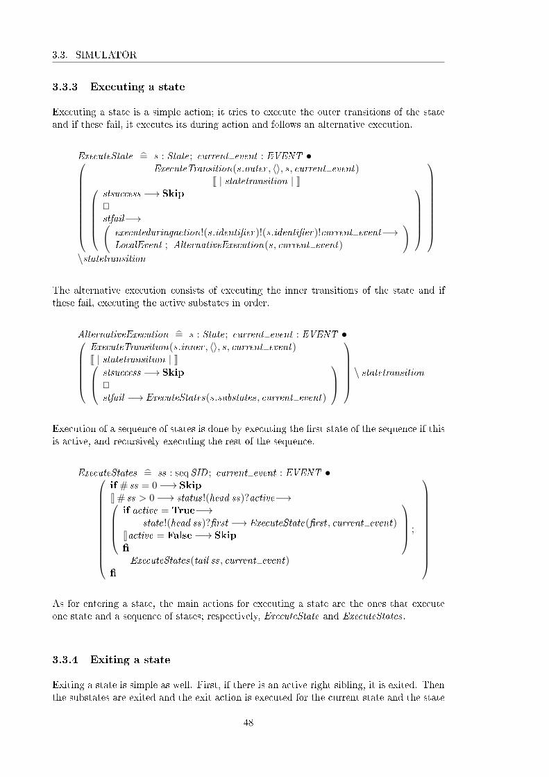
3.3. SIMULATOR
3.3.3 Executing a state
Executing a state is a simple action; it tries to execute the outer transitions of the stateand if these fail, it executes its during action and follows an alternative execution.
ExecuteState =̂ s : State; current event : EVENT •
ExecuteTransition(s.outer , 〈〉, s, current event)J | statetransition | K
stsuccess −→ Skip
@stfail−→(
executeduringaction!(s.identi�er)!(s.identi�er)!current event−→LocalEvent ; AlternativeExecution(s, current event)
)
\statetransition
The alternative execution consists of executing the inner transitions of the state and ifthese fail, executing the active substates in order.
AlternativeExecution =̂ s : State; current event : EVENT •ExecuteTransition(s.inner , 〈〉, s, current event)J | statetransition | K stsuccess −→ Skip
@stfail −→ ExecuteStates(s.substates, current event)
\ statetransition
Execution of a sequence of states is done by executing the �rst state of the sequence if thisis active, and recursively executing the rest of the sequence.
ExecuteStates =̂ ss : seqSID ; current event : EVENT •
if # ss = 0−→ Skip
8 # ss > 0−→ status!(head ss)?active−→if active = True−→
state!(head ss)?�rst −→ ExecuteState(�rst , current event)8active = False−→ Skip
�
;
ExecuteStates(tail ss, current event)�
As for entering a state, the main actions for executing a state are the ones that executeone state and a sequence of states; respectively, ExecuteState and ExecuteStates.
3.3.4 Exiting a state
Exiting a state is simple as well. First, if there is an active right sibling, it is exited. Thenthe substates are exited and the exit action is executed for the current state and the state
48

CHAPTER 3. FORMAL MODEL
is deactivated. The last two actions are achieved by communicating with the chart.
ExitState =̂ s : State; current event : EVENT •
if s.right 6= nullstate.identi�er−→status!(s.right)?True−→ state!(s.right)?rs−→
ExitState(rs, current event)@status!(s.right)?False−→ Skip
8s.right = nullstate.identi�er −→ Skip
�
;
ExitStates(s.substates, current event);executeexitaction!(s.identi�er)!(s.identi�er)!current event −→ LocalEvent ;deactivate!(s.identi�er)−→ Skip
To exit a sequence of states, we start by exiting the last state, if it is active, and thenrecursively exit the rest of the sequence. We observe that we proceed from the last stateto the �rst (opposite entering and executing a sequence of states).
ExitStates =̂ ss : seqSID ; current event : EVENT •
if # ss = 0−→ Skip
8 # ss > 0−→ status!(last ss)?active−→ if active = True−→ state!(last ss)?l −→ ExitState(l , current event)8active = False−→ Skip
�
;
ExitStates(front ss, current event)�
In order to exit a state, we use action ExitState, and to exit a sequence of states, we useExitStates.
3.3.5 Executing a chart
The last group of actions are responsible for executing a chart, which can be active orinactive.
ExecuteChart =̂ current event : EVENT •chart?c −→ status!(c.identi�er)?active−→ if active = True−→ ExecuteActiveChart(c, current event)
8active = False−→ ExecuteInactiveChart(c, current event)�
If the chart is inactive, it is activated, and its default transitions are executed. If they failand the chart has a parallel (SET ) decomposition, the substates are entered in sequence.If the chart has exclusive (CLUSTER) decomposition, an error is issued. If the default
49

3.3. SIMULATOR
transitions are successful, nothing is done.
ExecuteInactiveChart =̂ c : State; current event : EVENT • activate!(c.identi�er)−→
ExecuteDefaultTransition(c, c, current event)J | statetransition | K
stsuccess −→ Skip
@
stfail −→
if c.decomposition = SET−→
EnterStates(c.substates, c, current event)8c.decomposition 6= SET−→
error −→ Skip
�
\statetransition
If the chart is active and has no substates, it is executed as if it were inactive. If it is activeand has substates, they are executed (only the active substated are executed).
ExecuteActiveChart =̂ c : State; current event : EVENT • if c.substates = ∅−→ ExecuteInactiveChart(c, current event)8c.substates 6= ∅−→ ExecuteStates(c.substates, current event)�
A step of execution of a chart (with single rate and edge trigger events only) consistsof reading an input event and assigning it to current event , reading the input variables,executing the chart, writing the outputs and ending the cycle.
Step =̂input event?ie −→ var ce : EVENT • ce := ie ; read inputs−→
(ExecuteChart(ce)4 (interrupt simulator −→ interrupt chart −→ Skip));write outputs −→ end cycle −→ Skip
The execution of the chart modelled by ExecuteChart can be interrupted at any time if thechart process synchronises on the channel interrupt simulator ; in this case, the interruptingaction immediately interrupts the chart by synchronising on the channel interrupt chart ,and terminates. If the execution is interrupted, the outputs are written, the cycle is endedand the step is re-started.
The main action of the process consists of recursively running the step of execution.However, if an action of the chart broadcasts a local event, the action must �rst interruptthe step of execution of the chart and then communicate the event. For that reason, weneed to allow for the interruption of the step of execution; this is done through channelinterrupt .
• µX • Step ; Xend
This concludes the speci�cation of the Simulator process. We de�ne the execution step ofthe chart; this step must no be confused with the step of execution of a Simulink diagram.In one step of the Simulink diagram, many steps of the State�ow chart can occur.
50

CHAPTER 3. FORMAL MODEL
3.4 Final Considerations
To summarise, we translate a State�ow chart into a Chart process, compose it in parallelwith the Simulator process that speci�es the simulator, obtaining a process that representsthe simulation of the given chart. The main action of the Chart process o�ers actions ofthe chart, and the main action of the Simulator process waits for an event and executes asteps of the simulation.
This model corrects and extends the model presented in Miyazawa and Cavalcanti[2010]. In particular, it provides a more complete account for the possibility of earlyreturn logic in local event broadcasts. This model covers aspect that were left untreatedon other works, such as history junctions, local events and inter-level transitions. Otheraspects, in particular the interaction with Simulink blocks, are not yet formalised.
51


Chapter 4
Translation strategy: from State�ow
charts to Circus
The model discussed in Chapter 3 consists of two Circus processes in parallel, one is a modelof the simulator, while the other is a model of a chart. In this way, we achieve a degreeof separation between simulation and chart structure that allows us to generate only partof the model, i.e., the part that represents the information that is speci�c to a particularchart. In this chapter, we explain and formalise the algebraic strategy devised in order totranslate a State�ow chart into a Circus model as presented in the previous chapter. Thisstrategy is implemented in a tool called s2c which is described in Chapter 5.
Section 4.1 introduces the formal syntax of State�ow charts that is used as a basis forthe formalisation of the translation rules, and Section 4.3 presents the translation strategyused to produce the Circus models of charts. Section 5.3 concludes by evaluating the resultsobtained and discussing the main limitations.
4.1 Syntax of State�ow charts
In this section, we explain the formalisation of the syntax of State�ow charts that is usedas a basis for the de�nition of the translation rules and implementation of the translationtool. The syntax is formalised in Z, and basic knowledge of the Z notation is assumed.
The syntax of State�ow charts is captured by seven main groups of objects: charts,states, junctions, transitions, functions, events and data. Supporting the de�nition of someof these objects are identi�ers, names, expressions and actions. Section 4.1.1 discussesnames and identi�ers, Section 4.1.2 presents the syntax of expressions and actions, andSection 4.1.3 describes the syntax of the main objects previously mentioned.
4.1.1 Names and Identi�ers
Every State�ow object contains an identi�er that makes it unique among all objects de�nedin a .mdl �le. Moreover, some objects contain names that are used as references in actionsand expressions. The objects that are named are charts, states, functions, events and data.
We de�ne the set NAME of names (as a given set) and subsets that correspond to eachgroup of objects that have associated names. The set of names of charts, states, functions,events and data are disjoint sets of names.
CNAME ,SNAME ,FNAME ,ENAME ,DNAME : PNAME
disjoint〈CNAME ,SNAME ,FNAME ,ENAME ,DNAME 〉
53

4.1. SYNTAX OF STATEFLOW CHARTS
We de�ne the sets of identi�ers of each of the groups of objects in the same way we de�nedthe sets of names. We must also include sets of identi�ers of junctions and transitions,which have no name.
CID ,SID , JID ,TID ,EID ,DID ,FID : PN
disjoint〈CID ,SID , JID ,TID ,EID ,DID ,FID〉
Names and identi�ers play an important role in allowing references to be made both in theencoding in the .mdl �le and in the expression and actions used within certain objects.For example, in a .mdl �le, the chart associated to a state is refered by its identi�er, whilea piece of data is refered by its name in an action or expression.
4.1.2 Expressions and Actions
One of the most basic elements of the State�ow notation are expressions. Expressions areelements of the notation that have an associated value, for example, the number 1 hasvalue 1, the expression 1 + 1 has value 2, etc.
An expression can be a variable name, a value, a function application, an operatorapplied to one or more expressions, or a temporal expression.
The set EXPR of expressions is de�ned as a free type, a Z construct that allows usto de�ne a set by specifying its elements in terms of constants and constructor functions.Free types and schemas are the constructs of Z commonly used to model syntax. The freetype de�nition of the set EXPR is partially shown below. The constructors not , and , andor are used to build logical expressions from other expressions or pairs of expressions.
EXPR ::= . . .
not〈〈EXPR〉〉 |and〈〈EXPR × EXPR〉〉 |or〈〈EXPR × EXPR〉〉 |. . .
It is worth noticing that expressions which refer to State�ow objecs always do so by name,not by identi�er. For example, the constructor in builds an expression from a state namewhich returns 1 if the state refered by the expression is active, and 0 otherwise.
in〈〈SNAME 〉〉
There is a special set of expressions called temporal expressions; they are built by thefollowing constructors:
after〈〈EXPR × ENAME 〉〉 | before〈〈EXPR × ENAME 〉〉 |at〈〈EXPR × ENAME 〉〉 | every〈〈EXPR × ENAME 〉〉 |tempCount〈〈ENAME 〉〉 |
The set of temporal expressions is the range of the constructors of those expressions.
TEXPR == ran after ∪ ran before ∪ ran at ∪ ran every ∪ ran tempCount
The complete de�nition of the set EXPR can be found in Appendix D.
54

CHAPTER 4. TRANSLATION STRATEGY
Actions, in general, alter the state of the system and do not have an associated value.Actions can be the broadcasting of an event, the execution of an expression, the assignmentof an expression to a variable, and the sequential composition of two actions.
ACTION ::= bcast〈〈ENAME 〉〉 |expr〈〈EXPR〉〉 |assign〈〈DNAME × seqEXPR × EXPR〉〉 |massign〈〈seqDNAME × EXPR〉〉
Multiple assignment actions, represented above using the constructor massign, only occurwhen assigning the return value of a function with multiple output data.
In general, an expression being used as an action can be ignored, since it does nota�ect the state of the chart. However, the evaluation of certain expressions can triggerchanges to the chart; in particular, a function can be de�ned to alter the value of datain the chart that contains the function. In this case, we cannot ignore the evaluation ofthe expression, as this could change the behaviour of the chart. Our current treatmentof functions does not cover the modelling of functions which change data values becausethey are speci�ed externally to the chart process, and therefore do not have access to itsvariables. In Chapter 6, we discuss how this limitation can be overcome.
A derived type of action is an on action, which associates an action to an event name.
ONACTION == ENAME × seqACTION
As already mentioned, expressions and actions are used in the de�nition of the main objectsof State�ow, which are discussed next.
4.1.3 State�ow objects
In this section, we specify the main objects of the language of State�ow diagrams; they arestates, junctions, transitions, events, data, functions and charts. These are the objects usedto build diagrams; the expressions and actions previously de�ned are used to complementthe behaviour of some of these objects (states, transitions and functions).
State
A state contains an identi�er, a name, a reference to its parent, information about its typeand decomposition, entry, during and exit actions, and a list of bound variables and events.While the decomposition of a state refers to the organisation of its sub-states, the type ofa state refers to the way it is organised with respect to its siblings. The terms used torepresent type are the same as for decomposition, but their meanings are di�erent.
DECOMP ::= SEQ | PARSTYPE == DECOMP
The parent of a state can be either a state or a chart, so the set of possible identi�ers of aparent is CID ∪SID . Some of the information contained in a state are optional, e.g., entryand exit actions. Unlike entry and exit action, a during action can be either a regularaction or an on action. We de�ne the type of during actions as follows.
DACTION ::= action〈〈seqACTION 〉〉 | on〈〈ONACTION 〉〉
55

4.1. SYNTAX OF STATEFLOW CHARTS
The type State is de�ned as a Z schema that includes all the components needed to char-acterise a state as described above.
Stateidenti�er : SID ; name : SNAMEparent : CID ∪ SIDdecomp : DECOMP ; type : STYPEentry , exit : seqACTION ; during : seqDACTIONbinding : seq(ENAME ∪DNAME )history : Bdefault , inner , outer : optTIDleft , right : optSID ; substates : seqSID
The components entry and exit of the schema State are sequences of actions, and thecomponent during is a sequence of during actions. Notice that some of the componentshave an opt type; components of this type are optional components, that is, they can havea value (of the appropriate set) associated to it or not. The opt type is de�ned as the setof all sequences of size one plus the empty sequence.
Junction
A junction has an identi�er, a reference to its parent and the �rst outgoing transition, andinformation about whether or not it is a history junction.
Junctionidenti�er : JIDparent : CID ∪ SIDtransition : optTIDhistory : B
The schema Junction represents two types of junctions: connective junctions and historyjunctions; this di�erence is established by the component history . If the parent of ajunctions is the chart or a state with parallel decomposition, then it should not be ahistory junction. Well-formedness conditions like this are formalised in Appendix E anddiscussed in Section 4.2.
Transition
A transition has a sequence of triggers, a condition, a condition action and a transitionactions. A trigger is either an event or a temporal expression.
TRIGGER ::= e〈〈ENAME 〉〉 | t〈〈TEXPR〉〉
The event should be an input or a local event of the chart.
Transitionidenti�er : TID ; parent : CID ∪ SIDsource : opt (SID ∪ JID); destination : SID ∪ JIDtrigger : seqTRIGGER; condition : optEXPRcondact , transact : seqACTIONnext : optTID
56

CHAPTER 4. TRANSLATION STRATEGY
Event
An event has a trigger type and scope; the trigger type can be rising edge, falling edge,either edge or function call, and the event scope can be local, input or output.
EVENTTRIGGER ::= RISINGEDGE | FALLINGEDGE |EITHEREDGE | FUNCTIONCALL
EVENTSCOPE ::= LOCALEVENT | INPUTEVENT |OUTPUTEVENT
The representation of an event consists of an identi�er and a name, a reference to itsparent, and information about its scope and trigger type.
Eventidenti�er : EID ; name : ENAMEparent : CID ∪ SIDscope : EVENTSCOPE ; trigger : EVENTTRIGGER
Data
Data has a larger choice of scopes; it can be local, input, output, constant, parameter, ordata store memory. The type of the data is restricted to scalar types and multi-dimentionalvectors of scalar types.
DATASCOPE ::= LOCALDATA | INPUTDATA | OUTPUTDATA |CONSTANTDATA | PARAMETERDATA |DATASTOREMEMORYDATA
SCALAR ::= BOOLEAN | DOUBLE | SINGLE |INT32 | INT16 | INT8 |UINT32 | UINT16 | UINT8
DATATYPE ::= scalar〈〈SCALAR〉〉 | vector〈〈SCALAR × seqN〉〉
A piece of data consists of an identi�er and a name, a reference to its parent, and infor-mation about its scope and type.
Dataidenti�er : DID ; name : DNAMEparent : CID ∪ SIDscope : DATASCOPE ; type : DATATYPE
Functions
A Simulink function consists an identi�er and a name, a sequence of names of input vari-ables, a sequence of names of output variables, a reference to its parent, and the name ofthe Simulink block that de�nes the function.
SimulinkFunctionidenti�er : FID ; name : FNAMEinputs, outputs : seqDNAMEparent : CID ∪ SIDblock : NAME
57

4.2. WELL-FORMEDNESS CONDITIONS
A graphical function is similar to a Simulink function, but instead of a block name, itincludes an identi�er of a chart as a component; the chart to which the function refers isobtained from the �owchart that de�nes the function. The schema GraphicalFunction canbe found in Appendix D
Chart
The top object of a State�ow model is a chart; it contains an identi�er, a name, a sequenceof state identi�ers, its decomposition, and partial functions from identi�er to the objectscontained in the chart.
Chartidenti�er : CID ; name : CNAMEdefault : optTIDsubstates : seqSIDdecomp : DECOMPstates : SID 7→ Statejunctions : JID 7→ Junction; transitions : TID 7→ Transitionevents : EID 7→ Eventdata : DID 7→Datasfunctions : FID 7→ SimulinkFunction; gfunctions : FID 7→GraphicalFunction
The default component is a reference to the �rst default transition of the chart; its type isoptTID since this reference is optional because a chart with an unambiguous start pointcan prescind from it.
There are two levels of representation in a chart: the chart as a container, and a chartas an object in itself. The latter aspect is associated with the �rst �ve component, whereasthe former is associated with the remaining components.
4.2 Well-formedness conditions
In this section, we discuss the well-formedness conditions for the syntax of the State�ownotation. These conditions are characterised by the de�nition of set of well formed ex-pressions and objects, culminating in the de�nition of the set of well-formed charts. Thefunctions snames, dnames, enames, sfnames and gfnames are used to extract informationabout names of states, data, events, Simulink functions and graphical functions from achart. They are de�ned in the Appendix E.
We further de�ne three sets, unary , binary and tempbinary , of expressions that repre-sent, respectively, unary expression, binary expressions, and temporal binary expressions.The well-formedness conditions over expressions are de�ned in terms of these sets in orderto simplify the speci�cation.
Well-formedness of expressions is characterised inductively over the the constructorsof expressions. A name expression is well-formed with respect to a chart if, and only if,its name component corresponds to a piece of data in the chart, and the expressions inthe index sequence are well-formed with respect to the chart. A well-formedness conditionalways depends on a chart.
A value expression is always well-formed; since we do not model a particular repre-sentation of data types, we are not concerned with value well-formedness. A functionapplication expression is well-formed if, and only if, the name corresponds to a function
58

CHAPTER 4. TRANSLATION STRATEGY
de�nition and the sequence of expressions that de�nes the parameters consists of well-formed expressions. The application of a unary operator to an expression is well-formedif, and only if, the expression is well-formed; the application of a binary operator to twoexpressions is well-formed if, and only if, both expressions are well-formed. The applicationof a binary temporal operator to an expression and an event name is well-formed if, andonly if, the expression is well-formed and the name corresponds to an event. A tempCountexpression is well formed if the name that forms that expression corresponds to an event.
WF EXPR : Chart ↔ EXPR
∀ c : Chart ; n : DNAME ; s : seqEXPR • (c, variable(n, s)) ∈WF EXPR ⇔n ∈ dnames(c) ∧ (∀ e : ran s • (c, e) ∈WF EXPR)
∀ c : Chart ; a : A • (c, value(a)) ∈WF EXPR ⇔ true∀ c : Chart ; e : EXPR; op : unary • (c, op(e)) ∈WF EXPR ⇔
(c, e) ∈WF EXPR∀ c : Chart ; e1, e2 : EXPR; op : binary • (c, op(e1, e2)) ∈WF EXPR ⇔
((c, e1) ∈WF EXPR ∧ (c, e2) ∈WF EXPR)∀ c : Chart ; s : SNAME • (c, in(s)) ∈WF EXPR ⇔ s ∈ snames(c)∀ c : Chart ; e : EXPR; n : ENAME ; op : tempbinary •
((c, op(e,n)) ∈WF EXPR ⇔ ((c, e) ∈WF EXPR ∧ n ∈ enames(c))∀ c : Chart ; n : ENAME • (c, tempCount(n)) ∈WF EXPR ⇔ n ∈ enames(c)
Like in the case of expressions, we de�ne the well-formedness of actions inductively. Abroadcast action is well-formed if, and only if, the name corresponds to an event. Anaction formed by an expression is well-formed if, and only if, the expression is well-formed.An assignment is well-formed if, and only if, the assigned name corresponds to a piece ofdata, the expressions that form the sequence of indexes are well-formed, and the expressionbeing assigned is well-formed. The sequential composition of two action is well-formed if,and only if, both actions are well-formed.
WF ACTION : Chart ↔ ACTION
∀ c : Chart ; n : ENAME • (c, bcast(n)) ∈WF ACTION ⇔ n ∈ enames(c)∀ c : Chart ; e : EXPR • (c, expr(e)) ∈WF ACTION ⇔ (c, e) ∈WF EXPR∀ c : Chart ; n : DNAME ; s : seqEXPR; e : EXPR •
(c, assign(n, s, e)) ∈WF ACTION ⇔(n ∈ dnames(c) ∧ (∀ e : ran s • (c, e) ∈WF EXPR) ∧ (c, e) ∈WF EXPR)
Well-formedness conditions for the other syntactic categories are also formalised in Ap-pendix E. Like for expressions and actions, the de�nitions are not surprising.
A chart is well formed if, and only if, each of its states, junctions, transitions, data,events, graphical functions and Simulink functions is well-formed.
4.3 Translation strategy in Z
The translation strategy devised for obtaining Circus models of State�ow charts is de�nedin a top-down fashion; it is formalised as a set of translation rules. The translation processstarts by the application of one translation rule which uses other translation rules to treatspeci�c features, and these rules potentially rely on other translation rules, and so on. Inthe sequel, we present and exemplify the main groups of translation rules; the completeformalisation can be found in Appendix F.
59

4.3. TRANSLATION STRATEGY IN Z
In order to support the formalisation of the translation rules, we formalised the syntax ofCircus and Z in a similar fashion as for the syntax of State�ow diagrams. The formalisationyields a set of constructs which are used to build elements of the Circus notations, suchas actions and processes, as well as elements of the Z notations, such as free types andschemas. Because the rules are fully formalised, we are able to parser and type check them,and this allows us to conclude that the use of Circus and Z constructors in the translationrules is correct.
A translation rule is an equation that contributes to the de�nition of a function mappinga construct of a State�ow diagram, that is, an element of one of the sets de�ned in theprevious section, to a Circus construct. We can divide the translation rules in four groups:renaming functions, expression and action functions, identi�er and binding declarationfunctions, and action and process declaration functions. These groups are explained in thefollowing sections.
4.3.1 Renaming functions
These functions are responsible for eliminating ambiguity in the names of State�ow objects;for example, two states can have the same name as long as they are not siblings, but in theCircus model this creates complications. How the ambiguity is eliminated is not speci�ed,but the implementation uses pre�xes to eliminate ambiguity; type pre�xes are attached tothe names. For example, the pre�x S is attached to the name of a state, and, in the caseof two states with the same name, the name of the parent state is pre�xed to each oneof them. There are also renaming function for identi�ers, which behave like the renamingfunctions for names, but attach a lower case letter pre�x to the name, for example, theidenti�ers of states have the pre�x s instead of S .
There are twenty such renaming functions; they take a well-formed object (state, tran-sition, junction, and so on) and return a name. For example, Rule 4.1 below declares thefunction used to rename states.
Rule 4.1. Renaming function for states.
statename : WF STATE � NAME
As already said, we do not specify how unique names are to be constructed. The functionschartname, statename, junctionname and transitionname give names for the respectiveobjects, whereas their identi�er counterparts, chartid , stateid , junctionid and transitionidprovide unique identi�ers for these objects. The functions dataname and eventname donot have an identi�er counterpart, because data and events are not represented as bindingsof some schema; they are given names, that are determined by these functions. There isan additional renaming function for data, datachannelname, which gives the name of thechannel used to communicate the values of the variables to the environment.
The functions processname and processstatename de�ne, respectively, the name of theprocess that models the chart, and the name of the schema that represents that chartand is part of the process' state. The functions entryactionname, duringactionname,exitactionname, conditionactionname, transitionactionname, conditionname and triggernamename the Circus actions that specify the corresponding elements. The range of all the re-naming functions is speci�ed to be disjoint. The same holds for the functions that provideidenti�ers.
60

CHAPTER 4. TRANSLATION STRATEGY
4.3.2 Expression and Action functions
These functions translate expressions, actions, on actions, during actions, predicates, trig-gers, and sequences of these objects. They are translateExpr , translateExprs , translateAct ,translateActs , translateONAct , translateDAct , translateDActs , translatePred , translateTrigger andtranslateTriggers . The complete de�nition of these functions can be found in Appendix F;below, we discuss the rules that we consider more interesting.
Variable expression The translation of this type of expression is separated in twocases: simple variable and vector position. A simple variable is translated by obtaining thecorresponding data and calculating the appropriate name through the renaming functiondataname. A vector position requires us to �rst translate the expressions that are used asindexes, calculate the appropriate name of the variable (as in the case of simple variables)and apply this name to the translated expressions. Rule 4.2 presents the formal translationrule for variable expressions.
As already mentioned, the domain of translateExpr is the set of well-formed expressions.We apply the function to a well-formed variable expression characterised by a well-formedchart c, and a variable formed by a name n and a sequence of vector indexes es. If thesequence es is empty (# es = 0), then we recover the data to which the name refers,calculate its name with function dataname, and build a reference from this name usingthe Z constructors reference and ref . If the sequence es is not empty, we build a functionapplication from the name of the data (obtained as in the previous case) and the sequenceof translated expressions from es.
Rule 4.2 (F). Formal translation rule for variable expressions.
translateExpr : WF EXPR→ Expression
∀n : DNAME ; es : seqEXPR; c : WF CHART |(c,name(n, es)) ∈WF EXPR • translateExpr (c,name(n, es)) =if # es = 0then reference(ref (dataname(c, getdatabyname(c,n))))else functionapplication(
app(dataname(c, getdatabyname(c,n)),translateExprs(c, es)))
The formal translation rule can be hard to read because of the amount of constructorapplications used to build the expressions; this is necessary to keep the syntactical andtype information correct. Rule 4.2 shows the same translation rule as Rule 4.2, but in asemi-formal fashion; instead of building the expression from the language constructors, weshow how the expression would be rendered in Circus.
Rule 4.2. Semi-formal translation rule for variable expressions.
translateExpr (name) = dataname(c, getdatabyname(c,name))
translateExpr (name[e1] . . . [en ]) =
dataname(c, getdatabyname(c,name))(translateExpr (e1), . . . , translateExpr (en))
All the translation rules take a well-formed parameter, and all well-formed parameterscontain an instance of a chart. In the semi-formal translation rules, we leave the chartparameter c implicit, except where it is the only parameter. Rule 4.2 shows the twopossible cases of variable expressions: simple variable and vector position. In the case
61

4.3. TRANSLATION STRATEGY IN Z
of a simple variable, the translation returns the name of the data processed according toSection 4.3.1, otherwise a function application is build by applying the name of the data (asbefore) to the translated indexes. In the sequel, we only present the semi-formal versions ofthe rules. The complete formalisation of the translation rules can be found in Appendix F.
Assignment action The translation of assignment is also separated in the two caseswhere the variable being assigned is either a simple variable or a vector position. The simplevariable case is trivial, and consists of renaming the variable (as previously discussed),and building the Circus assignment expression. The vector position case n[e1] . . . [em ] ismore interesting; because multi-dimensional vectors are speci�ed as �nite functions, theassignment of a value to one position needs to alter the function only in that position.This is achieved by overriding (⊕) the function with the mapping (indexes) 7→ value andassigning the result to the function variable. Rule 4.3 formalises this translation rule.
Rule 4.3. Semi-formal translation rule for assignment actions.
translateAct(name = e) =
dataname(getdatabyname(name)) := translateExpr(e)
translateAct(name[e1] . . . [en ] = e) =
dataname(getdatabyname(name)) :=
dataname(getdatabyname(name))⊕{(translateExpr (e1), . . . , translateExpr (en)) 7→ translateExpr (e)}
The translation rule is de�ned for the two cases previously mentioned. If the variable beingassigned is simple (name = e), we recover the data to which name refers, calculate its namewith function dataname, and use this name together with the translation of the expressione to build an assignment. If the variable being assigned is a vector position, we obtain thename of the data in the same way as in the previous case, and build an assignment fromthat and from an expression built by applying the override operator to the name of thevariable and a mapping that speci�es the change to the vector position; this mapping iscomposed by the translated indexes of the vector position and the translated expressionthat is being assigned.
On action These actions are translated to a conditional action that executes the associ-
62

CHAPTER 4. TRANSLATION STRATEGY
ated action if the current event is the one speci�ed by the on action, otherwise it executesthe Skip action, as shown in Rule 4.4.
Rule 4.4. Semi-formal translation rule for on action.
translateONAct(onn : a1, . . . an) =if ce = eventname(geteventbyname(n))−→
translateActs(〈a1, . . . , an〉)8ce 6= eventname(geteventbyname(n))−→
Skip
�
Trigger There are two cases to be treated when translating triggers. If the trigger is thename of an event, a predicate is generated that compares the current event to the nameof the trigger event. If the event is a temporal expression, a predicate that compares theboolean value of the expression to 0 is generated. This function can take either an eventname or a temporal expression, and is formalised by Rule 4.5.
Rule 4.5. Semi-formal translation rule for a trigger.
translateTrigger (n) = (e = eventname(geteventbyname(n)))
translateTrigger (texp) = translatePred (texp)
The variable E is an event variable that is put in scope by a trigger declaration. Triggerdeclarations are discussed in Section 4.3.4.
4.3.3 Identi�er and binding declaration functions
Every chart, state, junction and transition in a model has a unique identi�er; we de-�ne these identi�ers through axiomatic de�nitions and the identi�er renaming functions.Rule 4.6 shows the translation function that produces the declaration of all state identi�ersbelonging to a well-formed chart.
Rule 4.6. Semi-formal translation rule for the declaration of state identi�ers.
StateIdenti�erDeclaration(c) =
stateid(c.states(1)), . . . , stateid(c.states(# c.states)), chartid(c) : STATEID
This rule takes a well-formed chart, calculates the sequence of processed identi�ers (asdiscussed in Section 4.3.1) of the states in the chart using the function stateid , creates asequence containing the processed identi�er of the chart obtained by applying the functionchartid , and returns an axiomatic description that declares these names as belonging tothe set SID . The rules for declaring junction and transition identi�ers are similar and canbe found in Appendix F.
Once the identi�ers of the charts, states, junctions and transitions are declared, we needto declare the bindings (of the appropriate type) that represent them in the Circus model.Rule 4.7 presents the rule that declares a junction; it takes a well-formed junction j andreturns an axiomatic description that declares a variable of type JUNCTION and equatesit to the appropriate binding.
63
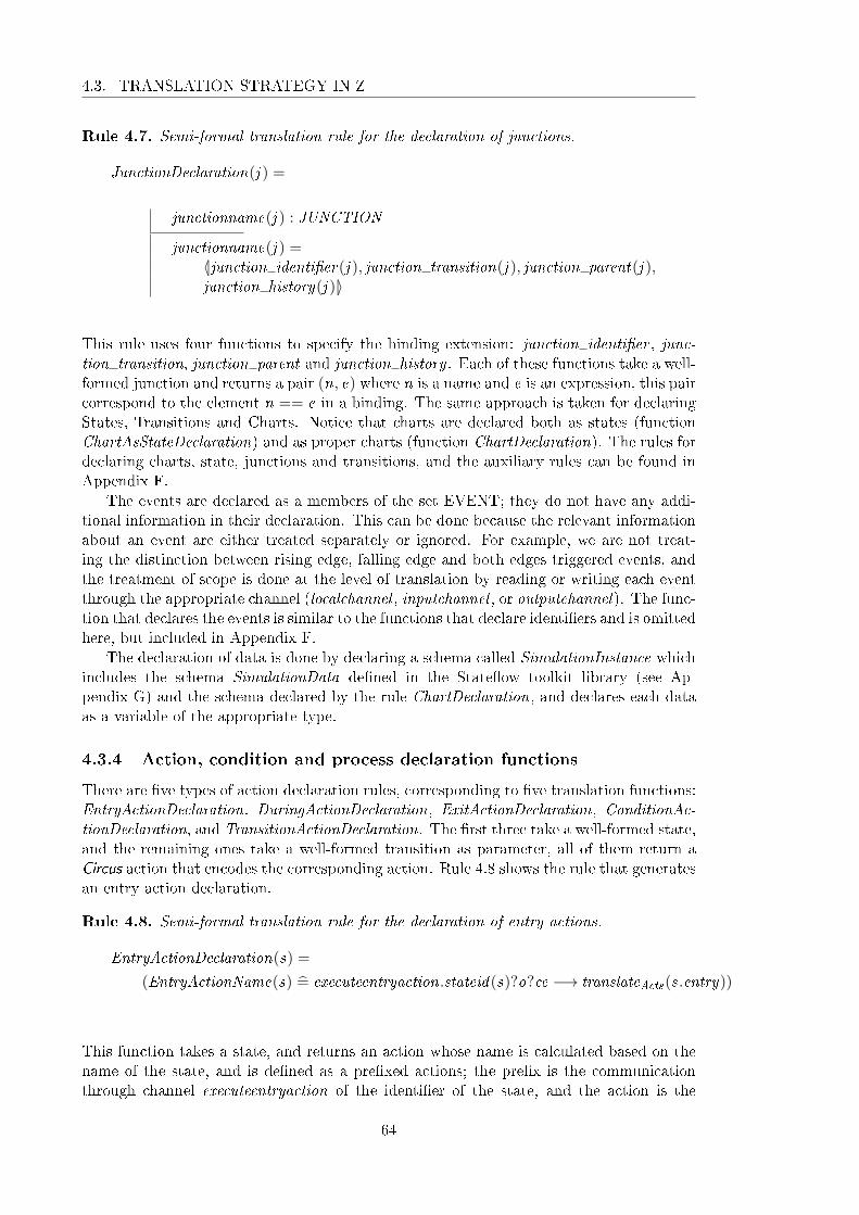
4.3. TRANSLATION STRATEGY IN Z
Rule 4.7. Semi-formal translation rule for the declaration of junctions.
JunctionDeclaration(j ) =
junctionname(j ) : JUNCTION
junctionname(j ) =〈|junction identi�er(j ), junction transition(j ), junction parent(j ),junction history(j )|〉
This rule uses four functions to specify the binding extension: junction identi�er , junc-tion transition, junction parent and junction history . Each of these functions take a well-formed junction and returns a pair (n, e) where n is a name and e is an expression, this paircorrespond to the element n == e in a binding. The same approach is taken for declaringStates, Transitions and Charts. Notice that charts are declared both as states (functionChartAsStateDeclaration) and as proper charts (function ChartDeclaration). The rules fordeclaring charts, state, junctions and transitions, and the auxiliary rules can be found inAppendix F.
The events are declared as a members of the set EVENT; they do not have any addi-tional information in their declaration. This can be done because the relevant informationabout an event are either treated separately or ignored. For example, we are not treat-ing the distinction between rising edge, falling edge and both edges triggered events, andthe treatment of scope is done at the level of translation by reading or writing each eventthrough the appropriate channel (localchannel , inputchannel , or outputchannel). The func-tion that declares the events is similar to the functions that declare identi�ers and is omittedhere, but included in Appendix F.
The declaration of data is done by declaring a schema called SimulationInstance whichincludes the schema SimulationData de�ned in the State�ow toolkit library (see Ap-pendix G) and the schema declared by the rule ChartDeclaration, and declares each dataas a variable of the appropriate type.
4.3.4 Action, condition and process declaration functions
There are �ve types of action declaration rules, corresponding to �ve translation functions:EntryActionDeclaration, DuringActionDeclaration, ExitActionDeclaration, ConditionAc-tionDeclaration, and TransitionActionDeclaration. The �rst three take a well-formed state,and the remaining ones take a well-formed transition as parameter, all of them return aCircus action that encodes the corresponding action. Rule 4.8 shows the rule that generatesan entry action declaration.
Rule 4.8. Semi-formal translation rule for the declaration of entry actions.
EntryActionDeclaration(s) =
(EntryActionName(s) =̂ executeentryaction.stateid(s)?o?ce −→ translateActs(s.entry))
This function takes a state, and returns an action whose name is calculated based on thename of the state, and is de�ned as a pre�xed actions; the pre�x is the communicationthrough channel executeentryaction of the identi�er of the state, and the action is the
64
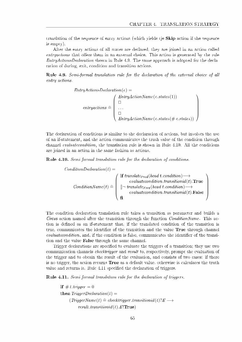
CHAPTER 4. TRANSLATION STRATEGY
translation of the sequence of entry actions (which yields tje Skip action if the sequenceis empty).
After the entry actions of all states are declared, they are joined in an action calledentryactions that o�ers them in an external choice. This action is generated by the ruleEntryActionsDeclaration shown in Rule 4.9. The same approach is adopted for the decla-ration of during, exit, condition and transition actions.
Rule 4.9. Semi-formal translation rule for the declaration of the external choice of allentry actions.
EntryActionsDeclaration(c) =
entryactions =̂
EntryActionName(c.states(1))@. . .@EntryActionName(c.states(# c.states))
The declaration of conditions is similar to the declaration of actions, but involves the useof an if-statement, and the action communicates the truth value of the condition throughchannel evaluatecondition, the translation rule is shown in Rule 4.10. All the conditionsare joined in an action in the same fashion as actions.
Rule 4.10. Semi-formal translation rule for the declaration of conditions.
ConditionDeclaration(t) =
ConditionName(t) =̂
if translatePred (head t .condition)−→
evaluatecondition.transitionid(t).True8¬ translatePred (head t .condition)−→
evaluatecondition.transitionid(t).False�
The condition declaration translation rule takes a transition as parameter and builds aCircus action named after the transition through the function ConditionName. This ac-tion is de�ned as an if-statement that, if the translated condition of the transition istrue, communicates the identi�er of the transition and the value True through channelevaluatecondition, and, if the condition is false, communicates the identi�er of the transi-tion and the value False through the same channel.
Trigger declarations are speci�ed to evaluate the triggers of a transition; they use twocommunication channels checktrigger and result to, respectively, prompt the evaluation ofthe trigger and to obtain the result of the evaluation, and consists of two cases: if thereis no trigger, the action returns True as a default value, otherwise it calculates the truthvalue and returns it. Rule 4.11 speci�ed the declaration of triggers.
Rule 4.11. Semi-formal translation rule for the declaration of triggers.
if # t .trigger = 0
thenTriggerDeclaration(t) =
(TriggerName(t) =̂ checktrigger .transitionid(t)?E −→result .transitionid(t).E !True)
65

4.3. TRANSLATION STRATEGY IN Z
elseTriggerDeclaration(t) =
(TriggerName(t) =̂ checktrigger .transitionid(t)?E −→ if translateTriggers(t .trigger)−→ result .transitionid(t).E !True8¬ translateTriggers(t .trigger)−→ result .transitionid(t).E !False�
)
This translation rule takes a transition as parameter and generates a Circus action whosename is the result of the function TriggerName, and whose behaviour depends on whetherthe transitions has a trigger or not. If there is no trigger, the action uses channel checktriggerto synchronise on the transition identi�er and receive the current event E , and uses channelresult to synchronise on the transition identi�er and event, and output the value True. Ifthere is a trigger, the action communicates through channel checktrigger in the same wayas before, and uses an if-statement to o�er two di�erent communications. If the translationof the trigger is true, the channel result is used to synchronise on the transition identi�erand current event, and output the value True, otherwise, instead of the value True, thevalue False is outputted through the channel result .
The process declaration rule takes a well-formed chart and produces a Circus processthat encloses the appropriate paragraphs produced by other functions, and is shown inRule 4.12. This rule is rather large, so we omit some parts.
Rule 4.12. Semi-formal translation rule for the declaration of chart processes.
ProcessDeclaration(c) =
process processname(c) =̂ begin
ChartDeclaration(c))SimulationInstanceDeclaration(c)InitSimulationInstanceDeclaration(c)SimulationDataDeclaration(c)InitSimulationDataDeclaration(c)ProcessStateDeclarationInitProcessStateDeclarationstateProcessStateEntryActionDeclaration(s1). . .EntryActionDeclaration(sn)EntryActionsDeclaration(c). . .ConditionActionsDeclaration(c). . .ConditionsDeclaration(c) . . .TriggersDeclaration(c)GetStateDeclaration. . .• MainActionDeclarationend
This rule takes a chart c and returns a Circus process whose name is the result of applyingprocessname to c. The body of the process consists of a series of schema and action decla-rations which are obtained by applying the appropriate translation functions. For instance,
66

CHAPTER 4. TRANSLATION STRATEGY
the axiomatic de�nition that represents the chart is part of the process, this is speci�ed inthe rule by the application of the translation rule ChartDeclaration. The translation ruleincludes in the body of the process the declarations of the chart, the simulation instanceand the simulation data, and the initialisation of the simulation instance and the simula-tion data, state of the process, and all the actions. It completes the process by declaringthe main action through the function MainActionDeclaration.
The root translation rule translate takes a well-formed chart and outputs a Circus spec-i�cation. This rule is structured in the same way as the process declaration rule; it declaresthe paragraphs external to the process (e.g., identi�er declarations) and the process throughpreviously de�ned translation rules.
4.4 Final considerations
In this section, we discussed the syntax of State�ow charts, the conditions that establishthe well-formedness of charts, and the translation rules that guide the translation process.The syntax, well-formedness conditions and translation rules cover an large portion of theState�ow notation, including many aspects that, as far as we know, are not covered inother approaches presented in the literature.
To the best of our knowledge, no other work has treated history junctions, unrestrictedtransitions and early return logic. Moreover, as far as we know, no one has provideda partial (or complete) treatment of functions. The main features that are usually nottreated by other approaches to veri�cation of State�ow charts are: during actions, inter-level transitions, local event broadcast, �ow-charts, and in expressions. It is worth noticing,however, that some features that are speci�ed in the syntax are not treated by the trans-lation rules. They are temporal expressions. Graphical and Simulink functions are onlypartially treated. The reason the syntax covers features not treated by the translationrules is two-fold: �rst because a parser would need to be able to deal with this features,and second because this allows us to, in the future, extend the translation rules to coverthese features.
67


Chapter 5
s2c: from State�ow to Circus
The process of manual translation is extremely error prone, and a mechanisation of suchprocess eliminates this problem. Moreover, when the translation of very simple charts (6states and 7 transitions) generates more than ten pages of speci�cation, the translation oflarger diagrams is prohibitively costly. One of our experiments on an industrial case studyyielded a 180-page speci�cation.
A mechanisation of the translation process can reduce the cost of the translation,thus increasing the viability of any task that depends on a Circus model. In addition,mechanising the translation provides extra validation of the model (and translation rules),uncovering potential errors and inconsistencies. Since the Circus models are meant tobe used in the formal veri�cation of implementations of State�ow charts, the mechanicaltranslation increases the number and size of charts that can be tackled, and minimises thepossibility that translation errors occur.
In this chapter, we describe the tool s2c which implements the translation rules dis-cussed in the previous chapter. s2c takes a .mdl �le and produces a Circus speci�cationcontaining the processes that model the charts contained in the �le.
The translation of State�ow diagrams into Circus processes is de�ned in a manner thatmakes it suitable for mechanisation: using formal, yet very concrete, translation rules.Since the implementation of s2c resembles the formal speci�cation, it can be inspectedand compared to the formalisation.
Section 5.1 discusses the architecture and implementation of s2c. Section 5.2 describesthe evaluation of the tool. Section 5.3 concludes this chapter by examining the mainbene�ts arising from the implementation of s2c and clarifying its limitations.
5.1 Design
The implementation of s2c is guided by one main principle: to keep a close relationshipbetween the implementation and the formalisation of the translation rules. The advantageof an implementation based on this principle is that it is easy to identify how components ofthe code and map to the formal rules, thus facilitating the validation of the implementationwith respect to the formalisation.
Section 5.1.1 presents the architecture of the tool, and Section 5.1.2 describes how thetranslation rules are implemented.
69

5.1. DESIGN
5.1.1 Architecture
The implementation of s2c is organised in �ve main packages: parser, stateflow abstract
syntax, Circus syntax, Z syntax and translator. Figure 5.1 shows the main packagesand their relationships. The translator package is the main one, and uses all the otherpackages to perform the translation. In the sequel, we discuss each package in more detail.
Figure 5.1: Architecture of s2c: main packages.
The parser package contains two packages: MDL parser and label parser; this isdepicted in Figure 5.2. The MDL parser takes a .mdl �le and converts it into a treestructure that facilitates the manipulation of data. The label parser provides a methodthat takes the label of a state or transition and builds a state or a transition. The Javaclass Builder uses both packages to de�ne a method to build the abstract syntax tree ofthe diagram. In the following, we give more details about these packages, and explain howthe class Builder interacts with them in order to build the abstract syntax tree.
Figure 5.2: Architecture of the package Parser.
The MDL parser package takes a .mdl �le that has a particular structure and builds adata structure that facilitates the querying and manipulation of the data contained in the�le. As depicted in Figure 5.3, a .mdl �le contains groups of attribute-value pairs and othergroups. The hierarchy established by an .mdl �le makes it simple to extract some of theinformation needed to build an abstract syntax tree, but not all. Namely, the representationof states and transitions contains a pair whose attribute is called labelString, and whosevalue encodes, for states, the name and the actions of the state, and, for transitions,the trigger, the condition, and the actions of the transition; this encoding is processedseparately by the label parser, as we explain later.
Of the top groups in a .mdl �le, that is, those without a parent group, the one that isrelevant to State�ow diagrams is called Stateflow. This group contains other groups thatdescribe charts, states, transitions, junctions, data and events. Each one of these groupshas attribute-value pairs, e.g. the pair "id 2" associates the value 2 to the attribute id,or other groups (for example, a transition group has an src group and a dst group thatrepresent, respectively, the source and the destination of the transition). Figure 5.4 showsan excerpt from a .mdl �le.
We observe that, as we mentioned before, the actions, conditions and triggers used ina diagram are encoded in the label (labelString attribute) of the appropriate object. For
70

CHAPTER 5. S2C: FROM STATEFLOW TO CIRCUS
Figure 5.3: Structure of a .mdl �le.
Stateflow {
chart {
id 2
name "Chart"
decomposition CLUSTER_CHART
...
}
state {
id 3
labelString "State1"
type OR_STATE
decomposition CLUSTER_STATE
...
}
transition {
id 9
labelString "{Data = Data+1;}"
src {
}
dst {
id 3
}
chart 2
...
}
...
}
Figure 5.4: Excerpt from a .mdl �le.
example, in Figure 5.4, in the group transition, the attribute labelString is associatedto a string that encodes the condition action of the transition.
The MDL parser processes a .mdl �le and structures it in a way that facilitates themanipulation of the groups and pairs. From this structure, a method in the class calledBuilder builds the charts, states, transitions, junctions, data and events. In order to pro-
71

5.1. DESIGN
cess the labels of states and transitions (that contain the actions, conditions and triggers),the Builder class uses the label parser. The class MDLParser extends the class Parserwhich is automatically generated by the tool jacc [Jones, 2004], and uses the class Lexer,which was automatically generated by the tool j�ex [JFlex, 2009], as shown in Figure 5.5.
Figure 5.5: Architecture of the package MDL Parser.
The label parser package contains two parsers: state parser and transition parser.These parsers are contained in the same package because, although state and transitionlabels have di�erent structures, they have common units of information, namely expressionsand actions. The syntax of expressions and actions constitutes most of the syntax of labels,therefore we reuse the syntax of expressions and actions in both parsers. Figure 5.7 showsthe structure of state and transition labels.
state nameen: actiondu: actionex: actionon event name: actionon event name: action. . .
Figure 5.6: State label
trigger[expression]action/action
Figure 5.7: Implementation
The state parser takes the value of the attribute labelString of a state group, andreturns a State object with the appropriate actions assigned to it. The rest of the in-formation that is not available from the label is �lled in by a method in the Builder
class. The same process is carried out by the transition parser, with the di�erence thatthe object returned is of type Transition. As with the MDL parser, both the state parserand the transition parser were automatically generated by the tool jacc, and the classLexer, which is common to both parsers, was generated automatically by the tool j�ex.The classes TransitionParser and StateParser respectively extend the automaticallygenerated classes TParser and SParser, as shown in Figure 5.8.
Both state and transition objects are de�ned in the state�ow abstract syntax, whichde�nes the main State�ow objects, i.e. chart, state, transition, junction, data and event,as well as the action language used in the labels. The state�ow abstract syntax is an im-plementation of the formal syntax of State�ow diagrams discussed in the previous chapter,and its implementation is discussed in the sequel.
The stateflow abstract syntax package is organised in three packages: Objects,
72

CHAPTER 5. S2C: FROM STATEFLOW TO CIRCUS
Figure 5.8: Architecture of the package Label Parser.
Actions and Expressions, as shown in Figure 5.9. The package Objects contains theclasses that represent the main objects of the language. The package Actions groups theclass model of the action language, which uses the model of expressions contained in thepackage Expressions.
Figure 5.9: Syntax of State�ow diagrams: main packages.
As it can be seen in Figure 5.10, data, event and junction are simple objects, whilestate, transition and chart concentrate most of the complexity of the diagram structure.A chart object contains sets of state, transition, junction, data and event objects. A stateobject contains two sequences of actions, entry and exit, and a sequence of during actionsduring. A transition object has two sequences of actions, condition action (condAction)and transition action (transAction), one expression condition, and one sequence of triggerstrigger.
Figure 5.11 depicts the representation of the syntax of actions. There are four subclassesrepresenting four types of actions: massign, assign, bcast and expr. Objects of the classmassign represent multiple assignments in which the left-hand side of the assignment is anarray of variables. Objects of the class assign represent simple assignments and objectsof the class bcast represent broadcasting of events. Object of the class expr representexpressions used as actions. Objects of the class ONACTION represent actions that areexecuted only if a certain trigger occurs, and objects of the class DACTION represent duringactions and can be either objects of the class ACTION or objects of the class ONACTION.
The model for the syntax of expressions is the largest, but it is fairly simple. Theonly di�erent type of expression is the variable expression, which can take a sequenceof expressions as indexes, in the case where the variable represents an array. The classdiagram is shown in Figure 5.12.
Each free type constructor de�ned in the formal de�nition of the State�ow syntax
73

5.1. DESIGN
Figure 5.10: Syntax of State�ow diagrams: Objects.
Figure 5.11: Syntax of State�ow diagrams: Actions.
presented in Section 4.1 is represented by a class. For example, for the free type ACTION,we have the constructors bcast , expr , assign, and massign, which correspond to the classesbcast, expr, assign, and massign. The type of the constructor functions determines thetype of the constructor methods of the corresponding classes. For example, the constructorbcast takes a value of type ENAME which is implemented as a String, thus the methodbcast takes a String as parameter. The type of the constructor is not represented in thediagrams, but is speci�ed in the formal syntax and implemented in the tool.
The Circus syntax package implements the Circus syntax di�erently from the way theState�ow abstract syntax is implemented. Instead of de�ning classes for each element ofthe syntax, we de�ne functions that return the Circus element encoded in some form. We
74

CHAPTER 5. S2C: FROM STATEFLOW TO CIRCUS
Figure 5.12: Syntax of State�ow diagrams: Expressions.
adopt this approach because we do not need to manipulate Circus syntax trees in the tool,and the use of functions to build Circus speci�cations makes the resulting code resemblemore the formal speci�cation. We de�ne an interface that contains the functions that canbe used to build Circus statements. We provide an implementation of this interface thatproduces LATEX code, and it is simple to implement the interface to generate speci�cationssuitable for other tools.
The Z syntax package is structured in exactly the same fashion. The Circus syntaxinterface and implementation extend, respectively, the interface and implementation of theZ syntax, as shown in Figure 5.13.
Figure 5.13: Syntax of Circus.
Finally, the Translator class contains a method translate that takes a State�ow chartrepresented in the abstract syntax and produces the Circus speci�cation of the chart. Thetranslator uses an implementation of the Circus syntax interface and a name generator toproduce the speci�cations. The name generator is responsible for taking State�ow objectsand returning their names in an appropriate format. For example, we disambiguate statenames (when needed) by pre�xing the name of the state's parent. State identi�ers areobtained by pre�xing the (disambiguated) name of the state with a lower case "s", whilestate names are obtained by pre�xing the name with a capital "S". Figure 5.14 shows thearchitecture of the translator package.
The next section describes the implementation of the translation rules.
5.1.2 Implementation of translation rules
We illustrate the strategy used for implementing the translation rules through an exam-ple. For convenience, Figure 5.1 reproduces the formal speci�cation of the translationfunction for variable expressions. This function takes a well-formed expression (the setof well-formed expressions is de�ned in the Appendix D) and produces a Z expression (Zexpressions are de�ned in the Appendix B); the resulting Z expression depends on whether
75

5.1. DESIGN
Figure 5.14: Architecture of s2c: the Translator package.
the variable expression represents a simple variable or a position in an array. If the ex-pression represents a simple variable, the function returns a reference to the appropriatedata; we observe that the name of the piece of data being treated needs to be processed inorder to avoid duplicated names and attach the variable pre�x v . This is the objective ofthe function dataname. If the variable is a position in an array, the function returns theapplication of the name of the appropriate data to the translated expressions contained inthe index sequence; multi-dimensional arrays are implemented as functions from a set ofindexes to the set U.
Rule 5.1. Formal translation rule for variable expressions.
translateExpr : WF EXPR→ Expression
∀n : DNAME ; es : seqEXPR; c : WF CHART |(c, variable(n, es)) ∈WF EXPR) •translateExpr (c, variable(n, es)) =
if # es = 0then reference(ref (dataname(c, getdatabyname(c,n))))
else functionapplication(app
(dataname(c, getdatabyname(c,n)),translateExprs(c, es))
)
Figure 5.15 shows the implementation of the rule shown in Figures 5.1. The translateExprfunction is translated into a Java method called translate expr. The local variables in-troduced by the let expression in the formal rule are translated into local variables of themethod. The function getdatabyname is mapped to a static function of the same namecontained in the class ObjectGetters, and the function dataname is mapped to a functionfrom the object n of a class that implements the interface NameGenerator. The con-structor functions are used exactly in the same way as in the formal speci�cation; each ofthem is mapped to a method of the same name contained in the object c of a class thatimplements the interface CircusSyntax. Calls to other translation functions are mappedto methods of the Translator class with equivalent names. For example, the functiontranslateExprs is mapped to the method translate exprs.
The implementation of the example shown in Figure 5.1 is straightforward once weprovide an embedding of the syntax of State�ow diagrams, of Circus, and of Z operations
76

CHAPTER 5. S2C: FROM STATEFLOW TO CIRCUS
public St r ing t rans la te_expr ( Chart c , EXPR e ) {i f ( e instanceof va r i ab l e ) {
St r ing n = ( ( va r i ab l e ) e ) . dname ;Lis t<EXPR> es = ( ( va r i a b l e ) e ) . e s ;Data d = ObjectGetters . getdatabyname ( c , n ) ;i f ( es . s i z e ( ) == 0) {
return _c . r e f e r e n c e (_c . r e f (_n. dataname ( c , d ) ) ) ;}else {
return _c . f un c t i o n app l i c a t i o n (_c . app (_n. dataname ( c , d ) ,t rans la t e_exprs ( c , e s ) ) ) ;
}}. . .
}
Figure 5.15: Implementations of the translation rule for variable expressions.
used in the formal speci�cation. The implementation of some of the translation rules,however, impose a challenge; this is due mainly to the use of sequence extensions of theform 〈a, b, c〉, and set comprehensions.
Sequence extension
Figure 5.2 shows the translation rule that takes a well-formed data and produces the dec-laration associated to that data. The constructor variable requires a sequence of declarednames (built through the application of the constructor decl to a name) and an expressionthat de�nes the type of the variables being declared. In this case, the sequence containsonly the declared name of the data being declared and the type is U.
Rule 5.2. Formal translation rule for the declaration of data.
DataDeclaration : WF DATA→Declaration
∀ c : WF CHART ; d : Data | (c, d) ∈WF DATA •datadeclaration(c, d) =
variable(〈decl(dataname(c, d))〉, reference(ref (UNIVERSE )))
In order to translate the DataDeclaration function, we de�ne a instance method calledDataDeclaration that takes a chart and a piece of data (a well-formed data is de�ned asa pair (c, d) where c is a chart and d is a data), and returns a String that contains thedeclaration. The use of a sequence extension as an argument to the constructor variableis tackled by introducing an auxiliary variable (in this case, called declarations) of typeList<String>, instantiating it, and adding the appropriate element to the list. Finally,the auxiliary variable is used in place of the sequence extension. The implementation ofthe function shown in Figures 5.2 is presented in Figure 5.16.
Although the structure of the implementation of this function is di�erent than thespeci�cation, by establishing how the translation of sequence and set constructors is done,we provide a simple way to assess its correspondence. In the next example, we examine theimplementation of functions that contain set comprehensions of the form {x : S | p(x ) •f (x )}, where x is a variable, S is a set, p is a predicate, and f is is a function.
77

5.1. DESIGN
public St r ing DataDeclarat ion ( Chart c , Data d) {Lis t<Str ing> de c l a r a t i o n s = new LinkedList<Str ing >() ;d e c l a r a t i o n s . add (_c . de c l (_n. dataname ( c , d ) ) ) ;return _c . v a r i ab l e (
d e c l a r a t i on s ,_c . r e f e r e n c e (_c . r e f (_n.UNIVERSE( ) ) ) ) ;
}
Figure 5.16: Implementations of the translation rule for the declaration of data.
Set comprehension
Figure 5.3 shows a function that declares a schema that is used as part of the state of thechart process; it takes a well-formed chart and produces a Z paragraph. Notice that thelocal variable variables is de�ned as a set through a set comprehension; more precisely, itis de�ned as a sequence. The set comprehension takes the indexes of the sequence c.dataand produces a sequence of data declarations by applying a translation function to thedata contained in c.data.
Rule 5.3. Formal translation rules for the declaration of the simulation instance.
SimulationInstanceDeclaration : WF CHART → Paragraph
∀ c : WF CHART • SimulationInstanceDeclaration(c) = let
variables == {i : dom c.data • i 7→DataDeclaration(c, c.data(i))} • letdecl == declpart(variables) •
schemade�nition(SIMULATIONINSTANCE , schematext(〈decl〉, 〈〉))
The implementation of this example follows the approach illustrated so far, exceptwhere the set comprehension is used.
public St r ing S imu la t i on Ins tanceDec l a ra t i on ( Chart c ) {Lis t<Str ing> va r i a b l e s = new LinkedList<Str ing >() ;
for ( In t eg e r i : c . data . keySet ( ) ) {v a r i a b l e s . add ( DataDeclarat ion ( c , c . data . get ( i ) ) ) ;
}S t r ing dec l = _c . d e c l p a r t_ve r t i c a l ( v a r i a b l e s ) ;return _c . s chemade f in i t i on (
_n.SIMULATIONINSTANCE( ) ,_c . schematext_vert i ca l (
new Opt<Str ing >(dec l ) ,new LinkedList<Str ing >( ) ) ) ;
}
Figure 5.17: Implementations of the translation rule for the declaration of the simulationinstance.
As shown in Figure 5.17, the set comprehension is translated into the instantiation ofa list (because the set comprehension, in this example, de�nes a list) which is assignedto the variable variables. The list is then �lled in with all the data declarations obtainedfrom the data in the list c.data. Notice that we use the class Opt which implements thetype Opt de�ned in the speci�cation to obtain, more easily, lists of size zero or one.
78

CHAPTER 5. S2C: FROM STATEFLOW TO CIRCUS
Set comprehensions could be implemented by the Java class Set, but, in most cases,the sets de�ned in the speci�cation are transformed in sequences. Since a sequence can beseen as an ordered set, we do not lose information by using sequences instead of sets.
In some of the rules, we use a function set2seq which takes a set and produces asequence with the same objects; the de�nition of this function is underspeci�ed, statingonly that the range of the sequence obtained from the application of the function to a set Smust be equal to S . Since the order of the elements in the list is clearly not important, weadd them directly to a list, instead of a set, thus rendering the use of the function set2sequnnecessary.
The implementation of s2c has approximately 5000 lines of code, and can be down-loaded from http://www-users.cs.york.ac.uk/~alvarohm/s2c/tool/. In the next sec-tion, we will discuss the usage and evaluation of s2c.
5.2 Evaluation
The tool s2c takes an .mdl �le that contains the de�nition of a number of charts, and pro-duces a Circus process for each chart; each process and associated de�nitions are enclosedin a Z section. It ignores de�nitions of Simulink and graphical functions, truth tables, aswell as Simulink blocks. The existence of functions implies that there are data de�nitionsof the input and output variables of the function; these are also ignored.
Since Simulink and graphical functions are not translated, but are widely used in chartsalong with matlab and C functions, we adopt a strategy for dealing with functions thatconsists of requiring the user to supply the formal de�nition of the functions being used inthe form of libraries. Each library is speci�ed in a separate �le within a named Z sectionwhich is inherited by the section that contains the model of the chart that uses the library.
Our evaluation strategy consists of testing the tool on three distinct sets of examples:basic charts, complete examples, and industrial case studies. The group of basic chartscontains models that exercise speci�c features of the State�ow notation, for example, foreach type of action a, we have a chart formed by a single state whose entry action isa. The group of complete examples is formed by those charts (or collection of charts)that model a simpli�ed system (usually toy-examples), but whose complexity is larger,for example, the shift logic chart of the Automatic Transmission Control found in theState�ow toolkit and used in Chapter 3. The third group contemplates models suppliedby industrial collaborators; these models usually describe the whole of a system. Forexample, one of the case studies with which we have tested s2c was supplied by Airbusand describes a generic Fuel Management Control system.
By testing basic charts, we can easily track any errors in the tool to the speci�c featurebeing tested. Moreover, since these models are very small, it is possible to check the gen-erated speci�cation and notice any potential errors. With this approach, while validatingthe tool, we also validate the translation strategy and the model presented in Chapter 3.The complete examples allow us to test the interaction between di�erent features of thenotation, and while their size makes it di�cult to manually check the generated speci�ca-tion, it is still feasible to track errors in the translation process to features of the State�owmodel. The speci�cation generated by industrial case-studies can be extremely large, and,therefore, not tractable manually, and, while it is possible to track translation errors topieces of the model, it is a demanding task. Nevertheless, testing industrial case-studiesallows us to evaluate the correctness, robustness and e�ciency of the tool.
In the sequel, we summarise the results of testing the tool with all three groups. Dueto the number of examples in the �rst group, we only give an overview of how they were
79

5.3. CONCLUSION
built, and discuss the main results.
We have tested the tool with the basic charts in di�erent stages of development, anderrors found during the development were corrected. The same was done for the otherexamples, however, less frequently. The main problems found during testing were thehandling of elements not treated by the translation strategy, and simple programmingerrors such as index out of bound errors, uninitialised variables etc. The latter errors wereeasily �xed, while the former required us either to treat the features in the translationstrategy, or �nd a way to overcome the features when they appear in a chart.
The testing of the tool pointed out to features that were not treated, one known andthe other unknown. The former is the treatment of functions, and the latter is the use ofthe time symbol t .
The treatment of functions is not a simple issue, because the functions that can be usedin charts are not restricted to the types of functions that can be de�ned within a chart,MATLAB and even C function can be used. The complete treatment of function wouldrequire us to formalise all the possible function, including the MATLAB and C ones. Ourapproach to this issue was to assume that the user of the tool has a library of de�nitionof the functions being used in the chart. It is worth mentioning that this approach islimited in the sense that it does not allow the speci�cation of graphical functions withside-e�ect, i.e., graphical functions that change the state of the chart. However, if aseparate translation strategy is de�ned for graphical functions, it can be incorporated tothe tool, thus eliminating this limitation.
The proper treatment of the time symbol t was delegated to the Simulink diagram andreferenced by a process variable which is updated through a channel time. The reason whythe treatment of t can be delegated to the Simulink diagram is that this symbol representsthe "absolute time inherited from a Simulink signal" [The MathWorks,Inc., b].
The two industrial case studies we used to test the tool were provided, respectively,by Embraer and Airbus. The example from Embraer is fairly simple and the translation,although laborious, is trivial. This examples used the abs function, which reinforced theneed to reconsider the treatment of functions, and motivated the use of libraries for spec-ifying functions. The case study from Airbus is larger, and the translation of four chartsfound in one of the �les resulted in a 180-page speci�cation; it also required the treatmentof functions and the symbol t . We observe that the charts contained in both case stud-ies extensively used functions (MATLAB functions and graphical functions), and that theapproach to the treatment of general function by use of Z libraries proved successful so far.
In its current version, the tool translates, without errors, all the tested examples, andthe speci�cations generated by the tool are all correctly parsed and type checked by theCircus CZT toolkit [Malik and Utting, 2005].
5.3 Conclusion
In this chapter, we discussed the structure of the tool s2c, the principles that oriented itsdesign, and the approach applied to implement the translation rules. The implementationwas developed with the validation of the tool in mind; this led to the development ofguidelines for the implementations of rules (see Section 5.1.2) which can be easily appliedto the implementation of new rules (for features like Simulink and graphical functions,temporal expressions, and change detection operators, which are not covered).
The architecture of the tool and these guidelines make the extension of s2c a simpleprocess. This has been observed during the development of the tool when minor errors werecorrected and new features introduced to produce a working version of the tool. Another
80

CHAPTER 5. S2C: FROM STATEFLOW TO CIRCUS
noticeable feature of the implementation is the fact that, except for minor errors (e.g.,missing semicolons, misspelled identi�er, etc.), the tool was executable from a early stageof development. Moreover, once the coverage of the State�ow language was enough totest our examples, and implementation errors were corrected, the resulting speci�cationswere correctly parser and type checked without the need of further changes to the tool orspeci�cations.
It is worth mentioning that the use of the model generated by the tool for the veri�cationof implementations will further evaluate and validate both the tool and the translation rulesimplemented in it.
81

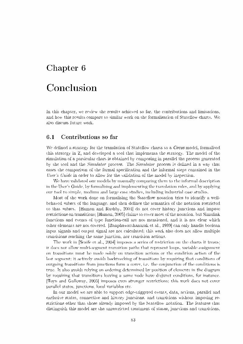
Chapter 6
Conclusion
In this chapter, we review the results achieved so far, the contributions and limitations,and how this results compare to similar work on the formalisation of State�ow charts. Wealso discuss future work.
6.1 Contributions so far
We de�ned a strategy for the translation of State�ow charts to a Circus model, formalisedthis strategy in Z, and developed a tool that implements the strategy. The model of thesimulation of a particular chart is obtained by composing in parallel the process generatedby the tool and the Simulator process. The Simulator process is de�ned in a way thateases the comparison of the formal speci�cation and the informal steps contained in theUser's Guide in order to allow for the validation of the model by inspection.
We have validated our models by manually comparing them to the informal descriptionin the User's Guide, by formalising and implementing the translation rules, and by applyingour tool to simple, medium and large case studies, including industrial case studies.
Most of the work done on formalising the State�ow notation tries to identify a well-behaved subset of the language, and then de�nes the semantics of the notation restrictedto that subset. [Hamon and Rushby, 2004] do not cover history junctions and imposerestrictions on transitions; [Hamon, 2005] claims to cover most of the notation, but Simulinkfunctions and events of type function-call are not mentioned, and it is not clear whichother elements are not covered. [Banphawatthanarak et al., 1999] can only handle booleaninput signals and output signal are not calculated; this work also does not allow multipletransitions reaching the same junction, nor transition actions.
The work in [Scaife et al., 2004] imposes a series of restriction on the charts it treats;it does not allow multi-segment transition paths that represent loops, variable assignmenton transitions must be made solely on transition actions or the condition action of thelast segment; it actively avoids backtracking of transitions by requiring that conditions ofoutgoing transitions from junctions form a cover, i.e. the conjunction of the conditions istrue. It also avoids relying on ordering determined by position of elements in the diagramby requiring that transitions leaving a same node have disjunct conditions, for instance.[Toyn and Galloway, 2005] imposes even stronger restrictions; this work does not coverparallel states, junctions, local variables etc.
In our model we are able to support edge-triggered events, data, actions, parallel andexclusive states, connective and history junctions, and transitions without imposing re-strictions other that those already imposed by the State�ow notation. The features thatdistinguish this model are the unrestricted treatment of states, junctions and transitions,
83

6.2. FUTURE WORK
the partial support for Simulink and graphical functions, and the possibility of verifyingimplementations of State�ow charts in the context of Simulink diagrams.
We do not treat function-call events; this type of event can be supported in the currentmodel by re�ning the de�nition of events to account for type, modifying the procedure forreading input variables and writing output variables, and modifying the model of Simulinkdiagrams in order to execute the function-call block and the chart in interleaving. Temporalexpression are not treated; they can be supported by re�ning the de�nition of events inorder to record information about the number of times an event has been broadcasted.Elements such as sub-charts and super-transitions are also not covered by our approach;we believe that the treatment of these elements will be simple because they are basicallythe encapsulation of already supported elements. As far as we know, none of the worksdiscussed above cover any of these features. Functions are partially treated by relying onan external library of function de�nitions.
We have evaluated the coverage of this model by applying it to the industrial casestudies. The introduction of new features to the subset of the State�ow notation that weformalised should not require global modi�cations to the translation strategy because thebehaviour of most of the elements is independent of other elements; the exceptions to thisare some of the main elements of the language such as transitions that behave di�erentlyaccording to the type of its nodes. For example, the introduction of new data types andoperations will only a�ect the chart process, and consequently the translation process;nevertheless, the modi�cations to the translation process will be local to the new elementand should not a�ect the existing translation rules.
6.2 Future work
The next step in our work is the veri�cation of implementations of State�ow charts withrespect to the model generated by our tool using the re�nement calculus. From the appli-cation of the re�nement calculus to our case studies, we will devise a strategy that supportsthe veri�cation of implementations and explores the structure of the models as well as thestructure of implementations.
The model of the Simulink diagram is a parallel composition of blocks, and the re-�nement strategy presented in [Cavalcanti and Clayton, 2006] consists of four steps thatsystematically collapse the massive parallelism of the speci�cation in order to match theprocesses of the implementation, prove that each of the procedures in the implementationre�ne the action that speci�es it in the corresponding process, and �nally, prove that themain programs re�ne the process that speci�es the system. The main actions of compo-nent processes are always put in a normal form where they are de�ned as the iterativeexecution of a step. The steps consists of reading the inputs in interleaving, calculatingthe outputs and updating the state, writing the outputs in interleaving, and synchronisingon the channel end state.
The step of execution of the Simulator process is speci�ed in a similar fashion, but ithas an extra initial step of waiting for an event; moreover, the step can be interruptedby the chart. We need to de�ne a strategy in order to collapse the parallelism betweenthe Chart process and the Simulator process, and put the main action of this new processin the normal form. It is possible that the requirements of the re�nement strategy ofthe implementation of a State�ow chart are di�erent from those of a Simulink diagram;this needs to be assessed and a re�nement strategy must be catered for this particularscenario. The strategy will then be applied to the case studies possibly with the aid of theProofPower theorem prover [Zeyda and Cavalcanti, 2009].
84

Appendix A
Complete speci�cation of the shift
logic example
section sf simple car shift logic parents state�ow toolkit , functions
s downshifting , s gear state, s fourth, s second , s third , s �rst ,s selection state, s upshifting , s steady state, c shift logic : SID
t third fourth, t second third , t �rst second , t fourth third , t default �rst ,t second �rst , t third second , t steady state upshifting ,t default steady state, t upshifting steady state23,t steady state downshifting , t downshifting steady state25,t downshifting steady state24, t upshifting steady state26 : TID
S downshifting : State
S downshifting =
〈|identi�er == s downshifting ,default == nulltransition.identi�er ,inner == nulltransition.identi�er ,outer == t downshifting steady state24,parent == s selection state,left == nullstate.identi�er ,right == nullstate.identi�er ,substates == 〈〉,decomposition == CLUSTER,type == OR,history == False|〉
85

S gear state : State
S gear state =
〈|identi�er == s gear state,default == t default �rst ,inner == nulltransition.identi�er ,outer == nulltransition.identi�er ,parent == c shift logic,left == nullstate.identi�er ,right == s selection state,substates == 〈s �rst , s fourth, s second , s third〉,decomposition == CLUSTER,type == AND ,history == False|〉
S fourth : State
S fourth =
〈|identi�er == s fourth,default == nulltransition.identi�er ,inner == nulltransition.identi�er ,outer == t fourth third ,parent == s gear state,left == nullstate.identi�er ,right == nullstate.identi�er ,substates == 〈〉,decomposition == CLUSTER,type == OR,history == False|〉
S second : State
S second =
〈|identi�er == s second ,default == nulltransition.identi�er ,inner == nulltransition.identi�er ,outer == t second third ,parent == s gear state,left == nullstate.identi�er ,right == nullstate.identi�er ,substates == 〈〉,decomposition == CLUSTER,type == OR,history == False|〉
86

APPENDIX A. COMPLETE SPECIFICATION OF THE SHIFT LOGIC EXAMPLE
S third : State
S third =
〈|identi�er == s third ,default == nulltransition.identi�er ,inner == nulltransition.identi�er ,outer == t third fourth,parent == s gear state,left == nullstate.identi�er ,right == nullstate.identi�er ,substates == 〈〉,decomposition == CLUSTER,type == OR,history == False|〉
S �rst : State
S �rst =
〈|identi�er == s �rst ,default == nulltransition.identi�er ,inner == nulltransition.identi�er ,outer == t �rst second ,parent == s gear state,left == nullstate.identi�er ,right == nullstate.identi�er ,substates == 〈〉,decomposition == CLUSTER,type == OR,history == False|〉
S selection state : State
S selection state =
〈|identi�er == s selection state,default == t default steady state,inner == nulltransition.identi�er ,outer == nulltransition.identi�er ,parent == c shift logic,left == s gear state,right == nullstate.identi�er ,substates == 〈s upshifting , s steady state, s downshifting〉,decomposition == CLUSTER,type == AND ,history == False|〉
87

S upshifting : State
S upshifting =
〈|identi�er == s upshifting ,default == nulltransition.identi�er ,inner == nulltransition.identi�er ,outer == t upshifting steady state26,parent == s selection state,left == nullstate.identi�er ,right == nullstate.identi�er ,substates == 〈〉,decomposition == CLUSTER,type == OR,history == False|〉
S steady state : State
S steady state =
〈|identi�er == s steady state,default == nulltransition.identi�er ,inner == nulltransition.identi�er ,outer == t steady state upshifting ,parent == s selection state,left == nullstate.identi�er ,right == nullstate.identi�er ,substates == 〈〉,decomposition == CLUSTER,type == OR,history == False|〉
T third fourth : Transition
T third fourth =
〈|identi�er == t third fourth,source == snode(s third),destination == snode(s fourth),next == t third second ,parent == s gear state|〉
T second third : Transition
T second third =
〈|identi�er == t second third ,source == snode(s second),destination == snode(s third),next == t second �rst ,parent == s gear state|〉
T �rst second : Transition
T �rst second =
〈|identi�er == t �rst second ,source == snode(s �rst),destination == snode(s second),next == nulltransition.identi�er ,parent == s gear state|〉
88

APPENDIX A. COMPLETE SPECIFICATION OF THE SHIFT LOGIC EXAMPLE
T fourth third : Transition
T fourth third =
〈|identi�er == t fourth third ,source == snode(s fourth),destination == snode(s third),next == nulltransition.identi�er ,parent == s gear state|〉
T default �rst : Transition
T default �rst =
〈|identi�er == t default �rst ,source == snode(nullstate.identi�er),destination == snode(s �rst),next == nulltransition.identi�er ,parent == s gear state|〉
T second �rst : Transition
T second �rst =
〈|identi�er == t second �rst ,source == snode(s second),destination == snode(s �rst),next == nulltransition.identi�er ,parent == s gear state|〉
T third second : Transition
T third second =
〈|identi�er == t third second ,source == snode(s third),destination == snode(s second),next == nulltransition.identi�er ,parent == s gear state|〉
T steady state upshifting : Transition
T steady state upshifting =
〈|identi�er == t steady state upshifting ,source == snode(s steady state),destination == snode(s upshifting),next == t steady state downshifting ,parent == s selection state|〉
T default steady state : Transition
T default steady state =
〈|identi�er == t default steady state,source == snode(nullstate.identi�er),destination == snode(s steady state),next == nulltransition.identi�er ,parent == s selection state|〉
89

T upshifting steady state23 : Transition
T upshifting steady state23 =
〈|identi�er == t upshifting steady state23,source == snode(s upshifting),destination == snode(s steady state),next == nulltransition.identi�er ,parent == s selection state|〉
T steady state downshifting : Transition
T steady state downshifting =
〈|identi�er == t steady state downshifting ,source == snode(s steady state),destination == snode(s downshifting),next == nulltransition.identi�er ,parent == s selection state|〉
T downshifting steady state25 : Transition
T downshifting steady state25 =
〈|identi�er == t downshifting steady state25,source == snode(s downshifting),destination == snode(s steady state),next == nulltransition.identi�er ,parent == s selection state|〉
T downshifting steady state24 : Transition
T downshifting steady state24 =
〈|identi�er == t downshifting steady state24,source == snode(s downshifting),destination == snode(s steady state),next == t downshifting steady state25,parent == s selection state|〉
T upshifting steady state26 : Transition
T upshifting steady state26 =
〈|identi�er == t upshifting steady state26,source == snode(s upshifting),destination == snode(s steady state),next == t upshifting steady state23,parent == s selection state|〉
e DOWN , e UP : EVENT
channel o gear , i speed , i throttle : R
90

APPENDIX A. COMPLETE SPECIFICATION OF THE SHIFT LOGIC EXAMPLE
processP shift logic =̂ begin
State�owChart
identi�er = c shift logicstates = {(s downshifting ,S downshifting), (s gear state,S gear state),(s fourth,S fourth), (s second ,S second), (s third ,S third), (s �rst ,S �rst),(s selection state,S selection state), (s upshifting ,S upshifting),(s steady state,S steady state)}transitions = {(t third fourth,T third fourth),(t second third ,T second third),(t �rst second ,T �rst second), (t fourth third ,T fourth third),(t default �rst ,T default �rst), (t second �rst ,T second �rst),(t third second ,T third second),(t steady state upshifting ,T steady state upshifting),(t default steady state,T default steady state),(t upshifting steady state23,T upshifting steady state23),(t steady state downshifting ,T steady state downshifting),(t downshifting steady state25,T downshifting steady state25),(t downshifting steady state24,T downshifting steady state24),(t upshifting steady state26,T upshifting steady state26)}junctions = {}
SimulationInstancev gear : Rv TWAIT : Rv speed : Rv throttle : Rv up th : Rv down th : R
InitSimulationInstanceSimulationInstance ′
v gear ′ = 0v TWAIT ′ = 0v speed ′ = 0v throttle ′ = 0v up th ′ = 0v down th ′ = 0
91

SimulationDatastate status : SID 7→ Bstate history : SID 7→ SID
dom state status = dom states∀ p : ran states | p.decomposition = SET ∧ state status(p.identi�er) = True •
(∃1 s : {x : ran states | x .parent = p.identi�er} •state status(s.identi�er) = True)
dom state history = {j : ran junctions | j .history = True • j .parent}
InitSimulationDataSimulationData ′
state status ′ = {n : dom states • n 7→ False}state history ′ = {n : dom state history ′ • n 7→ nullstate.identi�er}
ActivateNoHistory∆SimulationDatax? : SID
(parent (states x?)).history = False
state status x? = False
state history ′ = state historystate status ′ = state status ⊕ {x? 7→True}
ActivateWithHistory∆SimulationDatax? : SID
(parent (states x?)).history = True
state status x? = False
state history ′ = state history ⊕ {((states x?).parent) 7→ x?}state status ′ = state status ⊕ {x? 7→True}
ActivateFailΞSimulationDatax? : SID
state status x? = True
92

APPENDIX A. COMPLETE SPECIFICATION OF THE SHIFT LOGIC EXAMPLE
DeactivateSuccess∆SimulationDatax? : SID
state status x? = True
state history ′ = state historystate status ′ = state status ⊕ {x? 7→ False}
DeactivateFailΞSimulationDatax? : SID
state status x? = False
P shift logic S == SimulationInstance ∧ SimulationData
stateP shift logic S
Activate == ((ActivateWithHistory ∨ ActivateNoHistory) ∨ ActivateFail) ∧ΞInitSimulationInstance
Deactivate == (DeactivateSuccess ∨ DeactivateFail) ∧ΞInitSimulationInstance
InitState == (InitSimulationInstance) ∧ (InitSimulationData)
entryaction downshifting =̂ (executeentryaction.(s downshifting)?o?ce −→ Skip)
entryaction gear state =̂ (executeentryaction.(s gear state)?o?ce −→ Skip)
entryaction fourth =̂ (executeentryaction.(s fourth)?o?ce −→ v gear := 4)
entryaction second =̂ (executeentryaction.(s second)?o?ce −→ v gear := 2)
93

entryaction third =̂ (executeentryaction.(s third)?o?ce −→ v gear := 3)
entryaction �rst =̂ (executeentryaction.(s �rst)?o?ce −→ v gear := 1)
entryaction selection state =̂ (executeentryaction.(s selection state)?o?ce −→ Skip)
entryaction upshifting =̂ (executeentryaction.(s upshifting)?o?ce −→ Skip)
entryaction steady state =̂ (executeentryaction.(s steady state)?o?ce −→ Skip)
entryactions =̂
entryaction downshifting@entryaction gear state@entryaction fourth@entryaction second@entryaction third@entryaction �rst@entryaction selection state@entryaction upshifting@entryaction steady state
duringaction downshifting =̂ (executeduringaction.(s downshifting)?o?ce −→ Skip)
duringaction gear state =̂ (executeduringaction.(s gear state)?o?ce −→ Skip)
duringaction fourth =̂ (executeduringaction.(s fourth)?o?ce −→ Skip)
duringaction second =̂ (executeduringaction.(s second)?o?ce −→ Skip)
94

APPENDIX A. COMPLETE SPECIFICATION OF THE SHIFT LOGIC EXAMPLE
duringaction third =̂ (executeduringaction.(s third)?o?ce −→ Skip)
duringaction �rst =̂ (executeduringaction.(s �rst)?o?ce −→ Skip)
duringaction selection state =̂ (executeduringaction.(s selection state)?o?ce−→
(var aux : R× R •
aux := calc th(v gear , v throttle);v down th := aux .1;v up th := aux .2
))
duringaction upshifting =̂ (executeduringaction.(s upshifting)?o?ce −→ Skip)
duringaction steady state =̂ (executeduringaction.(s steady state)?o?ce −→ Skip)
duringactions =̂
duringaction downshifting@duringaction gear state@duringaction fourth@duringaction second@duringaction third@duringaction �rst@duringaction selection state@duringaction upshifting@duringaction steady state
exitaction downshifting =̂ (executeexitaction.(s downshifting)?o?ce −→ Skip)
exitaction gear state =̂ (executeexitaction.(s gear state)?o?ce −→ Skip)
exitaction fourth =̂ (executeexitaction.(s fourth)?o?ce −→ Skip)
95

exitaction second =̂ (executeexitaction.(s second)?o?ce −→ Skip)
exitaction third =̂ (executeexitaction.(s third)?o?ce −→ Skip)
exitaction �rst =̂ (executeexitaction.(s �rst)?o?ce −→ Skip)
exitaction selection state =̂ (executeexitaction.(s selection state)?o?ce −→ Skip)
exitaction upshifting =̂ (executeexitaction.(s upshifting)?o?ce −→ Skip)
exitaction steady state =̂ (executeexitaction.(s steady state)?o?ce −→ Skip)
exitactions =̂
exitaction downshifting@exitaction gear state@exitaction fourth@exitaction second@exitaction third@exitaction �rst@exitaction selection state@exitaction upshifting@exitaction steady state
conditionaction third fourth =̂ (executeconditionaction.(t third fourth)?o?ce −→ Skip)
conditionaction second third =̂ (executeconditionaction.(t second third)?o?ce −→ Skip)
conditionaction �rst second =̂ (executeconditionaction.(t �rst second)?o?ce −→ Skip)
96

APPENDIX A. COMPLETE SPECIFICATION OF THE SHIFT LOGIC EXAMPLE
conditionaction fourth third =̂ (executeconditionaction.(t fourth third)?o?ce −→ Skip)
conditionaction default �rst =̂ (executeconditionaction.(t default �rst)?o?ce −→ Skip)
conditionaction second �rst =̂ (executeconditionaction.(t second �rst)?o?ce −→ Skip)
conditionaction third second =̂ (executeconditionaction.(t third second)?o?ce −→ Skip)
conditionaction steady state upshifting =̂(executeconditionaction.(t steady state upshifting)?o?ce −→ Skip)
conditionaction default steady state =̂(executeconditionaction.(t default steady state)?o?ce −→ Skip)
conditionaction upshifting steady state23 =̂(executeconditionaction.(t upshifting steady state23)?o?ce −→ Skip)
conditionaction steady state downshifting =̂(executeconditionaction.(t steady state downshifting)?o?ce −→ Skip)
conditionaction downshifting steady state25 =̂(executeconditionaction.(t downshifting steady state25)?o?ce −→ Skip)
conditionaction downshifting steady state24 =̂(executeconditionaction.(t downshifting steady state24)?o?ce −→ Skip)
conditionaction upshifting steady state26 =̂(executeconditionaction.(t upshifting steady state26)?o?ce −→ Skip)
97

conditionactions =̂
conditionaction third fourth@conditionaction second third@conditionaction �rst second@conditionaction fourth third@conditionaction default �rst@conditionaction second �rst@conditionaction third second@conditionaction steady state upshifting@conditionaction default steady state@conditionaction upshifting steady state23@conditionaction steady state downshifting@conditionaction downshifting steady state25@conditionaction downshifting steady state24@conditionaction upshifting steady state26
transitionaction third fourth =̂ (executetransitionaction.(t third fourth)?o?ce −→ Skip)
transitionaction second third =̂ (executetransitionaction.(t second third)?o?ce −→ Skip)
transitionaction �rst second =̂ (executetransitionaction.(t �rst second)?o?ce −→ Skip)
transitionaction fourth third =̂ (executetransitionaction.(t fourth third)?o?ce −→ Skip)
transitionaction default �rst =̂ (executetransitionaction.(t default �rst)?o?ce −→ Skip)
transitionaction second �rst =̂ (executetransitionaction.(t second �rst)?o?ce −→ Skip)
98

APPENDIX A. COMPLETE SPECIFICATION OF THE SHIFT LOGIC EXAMPLE
transitionaction third second =̂ (executetransitionaction.(t third second)?o?ce −→ Skip)
transitionaction steady state upshifting =̂(executetransitionaction.(t steady state upshifting)?o?ce −→ Skip)
transitionaction default steady state =̂(executetransitionaction.(t default steady state)?o?ce −→ Skip)
transitionaction upshifting steady state23 =̂(executetransitionaction.(t upshifting steady state23)?o?ce −→ Skip)
transitionaction steady state downshifting =̂(executetransitionaction.(t steady state downshifting)?o?ce −→ Skip)
transitionaction downshifting steady state25 =̂(executetransitionaction.(t downshifting steady state25)?o?ce −→ Skip)
transitionaction downshifting steady state24 =̂(executetransitionaction.(t downshifting steady state24)?o?ce −→ Skip)
transitionaction upshifting steady state26 =̂(executetransitionaction.(t upshifting steady state26)?o?ce −→ Skip)
99

transitionactions =̂
transitionaction third fourth@transitionaction second third@transitionaction �rst second@transitionaction fourth third@transitionaction default �rst@transitionaction second �rst@transitionaction third second@transitionaction steady state upshifting@transitionaction default steady state@transitionaction upshifting steady state23@transitionaction steady state downshifting@transitionaction downshifting steady state25@transitionaction downshifting steady state24@transitionaction upshifting steady state26
condition third fourth =̂ (evaluatecondition.(t third fourth)!(True)−→ Skip)
condition second third =̂ (evaluatecondition.(t second third)!(True)−→ Skip)
condition �rst second =̂ (evaluatecondition.(t �rst second)!(True)−→ Skip)
condition fourth third =̂ (evaluatecondition.(t fourth third)!(True)−→ Skip)
condition default �rst =̂ (evaluatecondition.(t default �rst)!(True)−→ Skip)
condition second �rst =̂ (evaluatecondition.(t second �rst)!(True)−→ Skip)
100

APPENDIX A. COMPLETE SPECIFICATION OF THE SHIFT LOGIC EXAMPLE
condition third second =̂ (evaluatecondition.(t third second)!(True)−→ Skip)
condition steady state upshifting =̂if((v speed>Av up th) 6= 0)−→
(evaluatecondition.(t steady state upshifting)!(True)−→ Skip)8¬ (((v speed>Av up th) 6= 0))−→
((evaluatecondition.(t steady state upshifting)!(False)−→ Skip))�
condition default steady state =̂(evaluatecondition.(t default steady state)!(True)−→ Skip)
condition upshifting steady state23 =̂if((v speed<Av up th) 6= 0)−→
(evaluatecondition.(t upshifting steady state23)!(True)−→ Skip)8¬ (((v speed<Av up th) 6= 0))−→
((evaluatecondition.(t upshifting steady state23)!(False)−→ Skip))�
condition steady state downshifting =̂if((v speed<Av down th) 6= 0)−→
(evaluatecondition.(t steady state downshifting)!(True)−→ Skip)8¬ (((v speed<Av down th) 6= 0))−→
((evaluatecondition.(t steady state downshifting)!(False)−→ Skip))�
condition downshifting steady state25 =̂if((v speed≤Av down th) 6= 0)−→
(evaluatecondition.(t downshifting steady state25)!(True)−→ Skip)8¬ (((v speed≤Av down th) 6= 0))−→
((evaluatecondition.(t downshifting steady state25)!(False)−→ Skip))�
condition downshifting steady state24 =̂if((v speed>Av down th) 6= 0)−→
(evaluatecondition.(t downshifting steady state24)!(True)−→ Skip)8¬ (((v speed>Av down th) 6= 0))−→
((evaluatecondition.(t downshifting steady state24)!(False)−→ Skip))�
101

condition upshifting steady state26 =̂if((v speed≥Av up th) 6= 0)−→
(evaluatecondition.(t upshifting steady state26)!(True)−→ Skip)8¬ (((v speed≥Av up th) 6= 0))−→
((evaluatecondition.(t upshifting steady state26)!(False)−→ Skip))�
conditions =̂
condition third fourth@condition second third@condition �rst second@condition fourth third@condition default �rst@condition second �rst@condition third second@condition steady state upshifting@condition default steady state@condition upshifting steady state23@condition steady state downshifting@condition downshifting steady state25@condition downshifting steady state24@condition upshifting steady state26
trigger third fourth =̂ (checktrigger .(t third fourth)?e−→ if e = e UP −→ (result .(t third fourth).(e)!(True)−→ Skip)8¬ (e = e UP)−→ ((result .(t third fourth).(e)!(False)−→ Skip))�
)
trigger second third =̂ (checktrigger .(t second third)?e−→ if e = e UP −→ (result .(t second third).(e)!(True)−→ Skip)8¬ (e = e UP)−→ ((result .(t second third).(e)!(False)−→ Skip))�
)
102

APPENDIX A. COMPLETE SPECIFICATION OF THE SHIFT LOGIC EXAMPLE
trigger �rst second =̂ (checktrigger .(t �rst second)?e−→ if e = e UP −→ (result .(t �rst second).(e)!(True)−→ Skip)8¬ (e = e UP)−→ ((result .(t �rst second).(e)!(False)−→ Skip))�
)
trigger fourth third =̂ (checktrigger .(t fourth third)?e−→ if e = e DOWN −→ (result .(t fourth third).(e)!(True)−→ Skip)8¬ (e = e DOWN )−→ ((result .(t fourth third).(e)!(False)−→ Skip))�
)
trigger default �rst =̂ (checktrigger .(t default �rst)?e−→(result .(t default �rst).(e)!(True)−→ Skip))
trigger second �rst =̂ (checktrigger .(t second �rst)?e−→ if e = e DOWN −→ (result .(t second �rst).(e)!(True)−→ Skip)8¬ (e = e DOWN )−→ ((result .(t second �rst).(e)!(False)−→ Skip))�
)
trigger third second =̂ (checktrigger .(t third second)?e−→ if e = e DOWN −→ (result .(t third second).(e)!(True)−→ Skip)8¬ (e = e DOWN )−→ ((result .(t third second).(e)!(False)−→ Skip))�
)
trigger steady state upshifting =̂ (checktrigger .(t steady state upshifting)?e−→(result .(t steady state upshifting).(e)!(True)−→ Skip))
trigger default steady state =̂ (checktrigger .(t default steady state)?e−→(result .(t default steady state).(e)!(True)−→ Skip))
trigger upshifting steady state23 =̂ (checktrigger .(t upshifting steady state23)?e−→(result .(t upshifting steady state23).(e)!(True)−→ Skip))
trigger steady state downshifting =̂ (checktrigger .(t steady state downshifting)?e−→(result .(t steady state downshifting).(e)!(True)−→ Skip))
trigger downshifting steady state25 =̂ (checktrigger .(t downshifting steady state25)?e−→(result .(t downshifting steady state25).(e)!(True)−→ Skip))
103

trigger downshifting steady state24 =̂ (checktrigger .(t downshifting steady state24)?e−→(result .(t downshifting steady state24).(e)!(True)−→ Skip))
trigger upshifting steady state26 =̂ (checktrigger .(t upshifting steady state26)?e−→(result .(t upshifting steady state26).(e)!(True)−→ Skip))
triggers =̂
trigger third fourth@trigger second third@trigger �rst second@trigger fourth third@trigger default �rst@trigger second �rst@trigger third second@trigger steady state upshifting@trigger default steady state@trigger upshifting steady state23@trigger steady state downshifting@trigger downshifting steady state25@trigger downshifting steady state24@trigger upshifting steady state26
getstate =̂ (state?x : (x ∈ dom(states))!(states(x ))−→ Skip)
getjunction =̂ (junction?x : (x ∈ dom(junctions))!(junctions(x ))−→ Skip)
gettransition =̂ (transition?x : (x ∈ dom(transitions))!(transitions(x ))−→ Skip)
getchart =̂ (chart !(states(identi�er))−→ Skip)
104

APPENDIX A. COMPLETE SPECIFICATION OF THE SHIFT LOGIC EXAMPLE
broadcast =̂ e : EVENT ; origin, dest : SID • ((local event !((e, states(dest)))−→ ((µx •((AllActions ; x ) @ (end local execution −→ Skip))); if state status(origin) = True−→ Skip
8state status(origin) = False−→ ((interrupt simulator −→ Skip))�
)))
broadcast taction =̂ e : EVENT ; tpp, dest : SID • broadcast(e, tpp, dest); if(state status, states(tpp)) ∈ has active substate −→ (interrupt simulator −→ Skip)8(state status, states(tpp)) 6∈ has active substate −→ Skip
�
status =̂ (status?x : (x ∈ dom(state status))!(state status(x ))−→ Skip)
history =̂ (history?x : (x ∈ dom(state history))!(state history(x ))−→ Skip)
activation =̂ (activate?x −→ (Activate))
deactivation =̂ (deactivate?x −→ (Deactivate))
ChartActions =̂ (
entryactions@duringactions@exitactions@conditionactions@transitionactions
; (end action −→ Skip))
InterfaceActions =̂
getchart@getstate@getjunction@gettransition@status@history@activation@deactivation
105
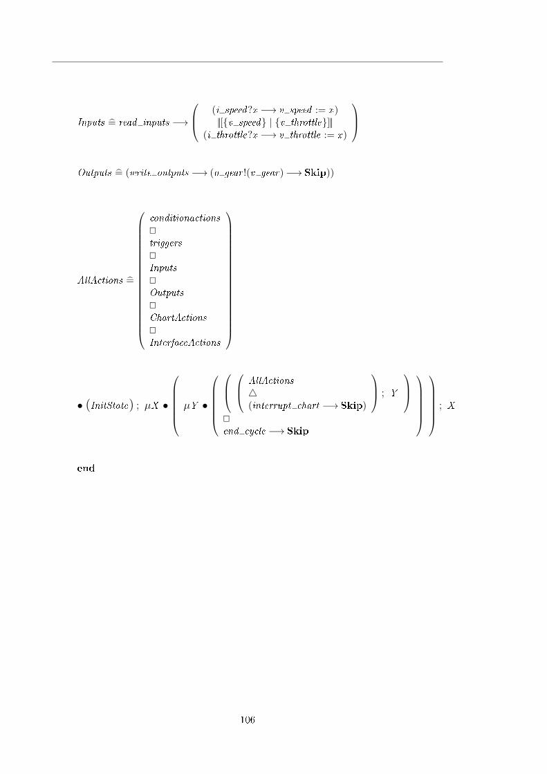
Inputs =̂ read inputs −→
(i speed?x −→ v speed := x )||[{v speed} | {v throttle}]||
(i throttle?x −→ v throttle := x )
Outputs =̂ (write outputs −→ (o gear !(v gear)−→ Skip))
AllActions =̂
conditionactions@triggers@Inputs@Outputs@ChartActions@InterfaceActions
• (InitState) ; µX •
µY •
AllActions4(interrupt chart −→ Skip)
; Y
@end cycle −→ Skip
; X
end
106

Appendix B
Z Syntax
sectionZFormalSyntax parents basic toolkit
[GenName,OperatorTemplate]
DeclName ::= decl〈〈NAME 〉〉RefName ::= ref 〈〈NAME 〉〉Formals == seq1NAME
STROKECHAR ::= primestroke | outputstroke | inputstrokeDECIMAL == 0..9STROKE ::= char〈〈STROKECHAR〉〉 | decimal〈〈DECIMAL〉〉
Declaration ::=variable〈〈seq1DeclName × Expression〉〉 |constant〈〈DeclName × Expression〉〉 |expression〈〈Expression〉〉
Predicate ::=
newline〈〈Predicate × Predicate〉〉 | semicolon〈〈Predicate × Predicate〉〉 |forall〈〈SchemaText × Predicate〉〉 | exists〈〈SchemaText × Predicate〉〉 |unique〈〈SchemaText × Predicate〉〉 |equivalence〈〈Predicate × Predicate〉〉 |implication〈〈Predicate × Predicate〉〉 |disjunction〈〈Predicate × Predicate〉〉 |conjunction〈〈Predicate × Predicate〉〉 | negation〈〈Predicate〉〉 |relationapplication〈〈Relation〉〉 | schemapredicate〈〈Expression〉〉 |TRUE | FALSE | parenthesizedpredicate〈〈Predicate〉〉
Relation ::= rel〈〈NAME × seqExpression〉〉Application ::= app〈〈NAME × seqExpression〉〉SchemaText ::= schematext〈〈 optDeclPart × optPredicate〉〉DeclPart ::= declpart〈〈seq1Declaration〉〉
107

Expression ::=
schemaforall〈〈SchemaText × Expression〉〉 |schemaexists〈〈SchemaText × Expression〉〉 |schemaunique〈〈SchemaText × Expression〉〉 |functionconstruction〈〈SchemaText × Expression〉〉 |de�nitedescription〈〈SchemaText × Expression〉〉 |substitution〈〈seq1(DeclName × Expression)× Expression〉〉 |schemaequivalence〈〈Expression × Expression〉〉 |schemaimplication〈〈Expression × Expression〉〉 |schemadisjunction〈〈Expression × Expression〉〉 |schemaconjunction〈〈Expression × Expression〉〉 |schemanegation〈〈Expression〉〉 |conditional〈〈Predicate × Expression × Expression〉〉 |composition〈〈Expression × Expression〉〉 |piping〈〈Expression × Expression〉〉 |hiding〈〈Expression × seq1DeclName〉〉 |projection〈〈Expression × Expression〉〉 |precondition〈〈Expression〉〉 |product〈〈Expression × Expression〉〉 |powerset〈〈Expression〉〉 |functionapplication〈〈Application〉〉 |application〈〈Expression × Expression〉〉 |decoration〈〈Expression × STROKE 〉〉 |schemarenaming〈〈Expression × seq1(DeclName ×DeclName)〉〉 |bindingselection〈〈Expression × RefName〉〉 |tupleselection〈〈Expression × N〉〉 |bindingconstruction〈〈Expression × seqSTROKE 〉〉 |reference〈〈RefName〉〉 |genericinstantitaion〈〈RefName × seq1 Expression〉〉 |numberliteral〈〈Z〉〉 |setextension〈〈seqExpression〉〉 |setcomprehension〈〈SchemaText × Expression〉〉 |characteristicsetcomprehension〈〈(SchemaText\{schematext(〈〉, 〈〉)})\{e : Expression; p : optPredicate •
schematext(〈declpart(〈expression(e)〉)〉, p)}〉〉 |schemaconstruction〈〈SchemaText\{e : Expression; p : optPredicate •
schematext(〈declpart(〈expression(e)〉)〉, p)}〉〉 |bindingextension〈〈seq(DeclName × Expression)〉〉 |tupleextension〈〈{s : seqExpression | # s ≥ 2}〉〉 |characteristicde�nitedescription〈〈SchemaText〉〉 |parenthesizedexpression〈〈Expression〉〉 |sequence〈〈seqExpression〉〉
Branch ::= branch〈〈DeclName × optExpression〉〉Freetype ::= freetype〈〈NAME × seqBranch〉〉
108

APPENDIX B. Z SYNTAX
Paragraph ::=
giventypes〈〈seq1NAME 〉〉 |axiomaticdescription〈〈SchemaText〉〉 |schemade�nition〈〈NAME × SchemaText〉〉 |genericaxiomaticdescription〈〈Formals × SchemaText〉〉 |genericschemade�nition〈〈NAME × Formals × SchemaText〉〉 |horizontalde�nition〈〈DeclName × Expression〉〉 |generichorizontalde�nition〈〈NAME × Formals × Expression〉〉 |genericoperatorde�nition〈〈GenName × Expression〉〉 |freetypes〈〈seq1 Freetype〉〉 |conjecture〈〈Predicate〉〉 |genericconjecture〈〈Formals × Predicate〉〉 |operatortemplate〈〈OperatorTemplate〉〉
109


Appendix C
Circus Syntax
sectionCircusFormalSyntax parentsZFormalSyntax
N == NAMEPar == Paragraph
CSExp ::=
csname〈〈N 〉〉 |cs〈〈seqN 〉〉 |csunion〈〈CSExp × CSExp〉〉 |csinter〈〈CSExp × CSExp〉〉 |csminus〈〈CSExp × CSExp〉〉
NSExp ::=
ns〈〈seqN 〉〉 |nsunion〈〈NSExp × NSExp〉〉 |nsinter〈〈NSExp × NSExp〉〉 |nsminus〈〈NSExp × NSExp〉〉
Program ::= program〈〈seqCircusPar〉〉
CircusPar ::=
zparagraphdeclaration〈〈Par〉〉 |channeldeclaration〈〈CDecl〉〉 |channelsetdeclaration〈〈N × CSExp〉〉 |processdeclaration〈〈ProcDecl〉〉
SimpleCDecl ::=simplecdecl〈〈seq1N 〉〉 |typedsimplecdecl〈〈seq1N × Expression〉〉 |genericcdecl〈〈Formals × seq1N × Expression〉〉
CDecl ::= cdecl〈〈seq1 SimpleCDecl〉〉
ProcDecl ::=simpleprocessdeclaration〈〈N × ProcDef 〉〉 |genericprocessdeclaration〈〈N × Formals × ProcDef 〉〉
111

ProcDef ::=processde�nition〈〈Proc〉〉 |parameterisedprocessde�nition〈〈DeclPart × Proc〉〉 |indexedprocessde�nition〈〈DeclPart × Proc〉〉
Proc ::=
proc〈〈seqPPar × Expression × seqPPar × Action〉〉 |processsequentialcomposition〈〈Proc × Proc〉〉 |processexternalchoice〈〈Proc × Proc〉〉 |processinternalchoice〈〈Proc × Proc〉〉 |procesparallelcomposition〈〈Proc × CSExp × Proc〉〉 |processinterleave〈〈Proc × Proc〉〉 |processhiding〈〈Proc × CSExp〉〉 |processinstantiation〈〈DeclPart × ProcDef × seq1 Expression〉〉 |processcallinstantiation〈〈N × seq1 Expression〉〉 |processcall〈〈N 〉〉 |indexedprocessinstantiation〈〈DeclPart × ProcDef × seq1 Expression〉〉 |incexedprocesscallinstantiation〈〈N × seq1 Expression〉〉 |processrenaming〈〈Proc × seq1N × seq1N 〉〉 |genericprocessinstantiation〈〈N × seq1 Expression〉〉 |iteratedprocesssequentialcomposition〈〈DeclPart × Proc〉〉 |iteratedprocessexternalchoice〈〈DeclPart × Proc〉〉 |iteratedprocessinternalchoice〈〈DeclPart × Proc〉〉 |iteratedprocessparallelcomposition〈〈CSExp ×DeclPart × Proc〉〉 |iteratedprocessinterleave〈〈DeclPart × Proc〉〉
PPar ::=zparagraph〈〈Par〉〉 |actionparagraph〈〈N × ParAction〉〉 |namesetparagraph〈〈N × NSExp〉〉
ParAction ::=paraction〈〈Action〉〉 |genericparaction〈〈DeclPart × ParAction〉〉
Action ::=
schemaaction〈〈Expression〉〉 |commandaction〈〈Command〉〉 |namedaction〈〈N 〉〉 |cspaction〈〈CSPAction〉〉 |renamingaction〈〈Action × seq1(N × Expression)〉〉
CParameter ::=
inputparameter〈〈N 〉〉 |guardedinputparameter〈〈N × Predicate〉〉 |outputparameter〈〈Expression〉〉 |simpleparameter〈〈Expression〉〉
Comm ::=communication〈〈N × seqCParameter〉〉 |genericcommunication〈〈N × seq1 Expression × seqCParameter〉〉
112

APPENDIX C. CIRCUS SYNTAX
Command ::=
assignment〈〈seq1(N × Expression)〉〉 |ifcommand〈〈GActions〉〉 |variableblock〈〈DeclPart × Action〉〉 |actionspeci�cation〈〈seq1N × Predicate × Predicate〉〉 |assumption〈〈Predicate〉〉 |coercion〈〈Predicate〉〉 |substitutionbyvalue〈〈DeclPart × Action〉〉 |substitutionbyresult〈〈DeclPart × Action〉〉 |substitutionbyvalueresult〈〈DeclPart × Action〉〉
GActions ::= gactions〈〈seq1(Predicate × Action)〉〉
CSPAction ::=
skip | stop | chaos |pre�xedaction〈〈Comm × Action〉〉 |guardedaction〈〈Predicate × Action〉〉 |actionsequentialcomposition〈〈Action × Action〉〉 |actionexternalchoice〈〈Action × Action〉〉 |actioninternalchoice〈〈Action × Action〉〉 |actionparallelcomposition〈〈Action × NSExp × CSExp×
NSExp × Action〉〉 |actioninterleave〈〈Action × NSExp × NSExp × Action〉〉 |actionhding〈〈Action × CSExp〉〉 |paractioninstantiation〈〈ParAction × seq1 Expression〉〉 |recursiveaction〈〈N × Action〉〉 |iteratedactionsequentialcomposition〈〈DeclPart × Action〉〉 |iteratedactionexternalchoice〈〈DeclPart × Action〉〉 |iteratedactioninternalchoice〈〈DeclPart × Action〉〉 |iteratedactionparallelcomposition〈〈CSExp ×DeclPart×
NSExp × Action〉〉 |iteratedactioninterleave〈〈DeclPart × NSExp × Action〉〉
113


Appendix D
Formal Syntax of State�ow Diagrams
sectionState�owAbstractSyntax parents basic toolkit
CNAME ,SNAME ,DNAME ,ENAME ,FNAME : PNAME
disjoint〈CNAME ,SNAME ,DNAME ,ENAME ,FNAME 〉
CID ,SID , JID ,TID ,EID ,DID ,FID : PN
disjoint〈CID ,SID , JID ,TID ,EID ,DID ,FID〉
EXPR ::=
name〈〈DNAME × seqEXPR〉〉 | value〈〈A〉〉 | not〈〈EXPR〉〉 |and〈〈EXPR × EXPR〉〉 | or〈〈EXPR × EXPR〉〉 | bnot〈〈EXPR〉〉 |band〈〈EXPR × EXPR〉〉 | bor〈〈EXPR × EXPR〉〉 |bxor〈〈EXPR × EXPR〉〉 | neg〈〈EXPR〉〉 | sum〈〈EXPR × EXPR〉〉 |sub〈〈EXPR × EXPR〉〉 | mult〈〈EXPR × EXPR〉〉 |division〈〈EXPR × EXPR〉〉 | modulus〈〈EXPR × EXPR〉〉 |lshift〈〈EXPR × EXPR〉〉 | rshift〈〈EXPR × EXPR〉〉 |gt〈〈EXPR × EXPR〉〉 | lt〈〈EXPR × EXPR〉〉 | geq〈〈EXPR × EXPR〉〉 |leq〈〈EXPR × EXPR〉〉 | eq〈〈EXPR × EXPR〉〉 | neq〈〈EXPR × EXPR〉〉 |in〈〈SNAME 〉〉 | after〈〈EXPR × ENAME 〉〉 |before〈〈EXPR × ENAME 〉〉 | at〈〈EXPR × ENAME 〉〉 |every〈〈EXPR × ENAME 〉〉 | tempCount〈〈ENAME 〉〉
TEXPR == ran after ∪ ran before ∪ ran at ∪ ran every ∪ ran tempCount
ACTION ::=bcast〈〈ENAME 〉〉 | expr〈〈EXPR〉〉 |assign〈〈DNAME × seqEXPR × EXPR〉〉 |massign〈〈seqDNAME × EXPR〉〉
ONACTION == ENAME × seqACTION
115

DECOMP ::= SEQ | PAR
STYPE == DECOMP
DACTION ::= action〈〈seqACTION 〉〉 | on〈〈ONACTION 〉〉
Stateidenti�er : SIDname : SNAMEparent : CID ∪ SIDdecomp : DECOMPtype : STYPEentry , exit : seqACTIONduring : seqDACTIONbinding : seq(ENAME ∪DNAME )history : Bdefault , inner , outer : optTIDleft , right : optSIDsubstates : seqSID
Junctionidenti�er : JIDparent : CID ∪ SIDtransition : optTIDhistory : B
TRIGGER ::= e〈〈ENAME 〉〉 | t〈〈TEXPR〉〉
Transitionidenti�er : TIDparent : CID ∪ SIDsource : opt (SID ∪ JID)destination : SID ∪ JIDtrigger : seqTRIGGERcondition : optEXPRcondact : seqACTIONtransact : seqACTIONnext : optTID
116

APPENDIX D. FORMAL SYNTAX OF STATEFLOW DIAGRAMS
EVENTTRIGGER ::=RISINGEDGE | FALLINGEDGE | EITHEREDGE |FUNCTIONCALL
EVENTSCOPE ::= LOCALEVENT | INPUTEVENT | OUTPUTEVENT
Eventidenti�er : EIDname : ENAMEparent : CID ∪ SIDscope : EVENTSCOPEtrigger : EVENTTRIGGER
DATASCOPE ::=LOCALDATA | INPUTDATA | OUTPUTDATA |CONSTANTDATA | PARAMETERDATA |DATASTOREMEMORYDATA
SCALAR ::=BOOLEAN | DOUBLE | SINGLE | INT32 | INT16 | INT8 |UINT32 | UINT16 | UINT8
DATATYPE ::= scalar〈〈SCALAR〉〉 | vector〈〈SCALAR × seqN〉〉
Dataidenti�er : DIDname : DNAMEparent : CID ∪ SIDscope : DATASCOPEtype : DATATYPE
SimulinkFunctionidenti�er : FIDname : FNAMEinputs, outputs : seqDNAMEparent : CID ∪ SIDblock : NAME
GraphicalFunctionidenti�er : FIDname : FNAMEinputs, outputs : seqDNAMEparent : CID ∪ SIDchart : CID
117

Chartidenti�er : CIDname : CNAMEdefault : optTIDsubstates : seqSIDdecomp : DECOMPstates : SID 7→ Statejunctions : JID 7→ Junctiontransitions : TID 7→ Transitionevents : EID 7→ Eventdata : DID 7→Datasfunctions : FID 7→ SimulinkFunctiongfunctions : FID 7→GraphicalFunction
Diagramcharts : CID 7→ Chart
118

Appendix E
Well-formedness Conditions
snames : Chart → PSNAMEdnames : Chart → PDNAMEenames : Chart → PENAMEsfnames : Chart → PFNAMEgfnames : Chart → PFNAME
∀ c : Chart • snames(c) = {s : ran c.states • s.name}∀ c : Chart • dnames(c) = {data : ran c.data • data.name}∀ c : Chart • enames(c) = {e : ran c.events • e.name}∀ c : Chart • sfnames(c) = {f : ran c.sfunctions • f .name}∀ c : Chart • gfnames(c) = {f : ran c.gfunctions • f .name}
unary : P(EXPR→ EXPR)binary : P(EXPR × EXPR→ EXPR)tempbinary : P(EXPR × ENAME → EXPR)
unary = {not , bnot ,neg}binary = {and , or , band , bor , bxor , sum, sub,mult , division,modulus, lshift , rshift ,
gt , lt , geq , leq , eq ,neq}tempbinary = {after , before, at , every}
WF EXPR : Chart ↔ EXPR
∀ c : Chart ; n : DNAME ; s : seqEXPR • (c,name(n, s)) ∈WF EXPR ⇔(n ∈ dnames(c) ∧ (∀ e : ran s • (c, e) ∈WF EXPR))
∀ c : Chart ; a : A • (c, value(a)) ∈WF EXPR ⇔ true∀ c : Chart ; e : EXPR; op : unary • (c, op(e)) ∈WF EXPR ⇔
(c, e) ∈WF EXPR∀ c : Chart ; e1, e2 : EXPR; op : binary • (c, op(e1, e2)) ∈WF EXPR ⇔
((c, e1) ∈WF EXPR ∧ (c, e2) ∈WF EXPR)∀ c : Chart ; s : SNAME • (c, in(s)) ∈WF EXPR ⇔ s ∈ snames(c)∀ c : Chart ; e : EXPR; n : ENAME ; op : tempbinary •
((c, op(e,n)) ∈WF EXPR ⇔ (c, e) ∈WF EXPR ∧ n ∈ enames(c))∀ c : Chart ; n : ENAME • (c, tempCount(n)) ∈WF EXPR ⇔ n ∈ enames(c)
119

WF ACTION : Chart ↔ ACTION
∀ c : Chart ; n : ENAME • (c, bcast(n)) ∈WF ACTION ⇔ n ∈ enames(c)∀ c : Chart ; e : EXPR • (c, expr(e)) ∈WF ACTION ⇔ (c, e) ∈WF EXPR∀ c : Chart ; n : DNAME ; s : seqEXPR; e : EXPR •
(c, assign(n, s, e)) ∈WF ACTION ⇔(n ∈ dnames(c) ∧ (∀ e : ran s • (c, e) ∈WF EXPR) ∧ (c, e) ∈WF EXPR)
WF ONACTION : Chart ↔ONACTION
∀ c : Chart ; n : ENAME ; as : seqACTION •(c, (n, as)) ∈WF ONACTION ⇔(n ∈ enames(c) ∧ (∀ a : ran as • (c, a) ∈WF ACTION ))
WF DACTION : Chart ↔DACTION
∀ c : Chart ; as : seqACTION • (c, action(as)) ∈WF DACTION ⇔∀ a : ran as • (c, a) ∈WF ACTION
∀ c : Chart ; a : ONACTION • (c, on(a)) ∈WF DACTION ⇔(c, a) ∈WF ONACTION
WF BINDING : Chart ↔ seq(ENAME ∪DNAME )
∀ c : Chart ; s : seq(ENAME ∪DNAME ) • (c, s) ∈WF BINDING ⇔foralln : ran s • n ∈ enames(c) ∪ dnames(c)
120

APPENDIX E. WELL-FORMEDNESS CONDITIONS
WF STATE : Chart ↔ State
∀ c : Chart ; s : State • (c, s) ∈WF STATE ⇔(s ∈ ran c.states ∧s.parent ∈ dom c.states ∪ {c.identi�er} ∧s.parent ∈ dom c.states ⇒
(s.type = PAR ⇔ (c.states s.parent).decomp = PAR) ∧s.parent 6∈ dom c.states ⇒ (s.type = PAR ⇔ c.decomp = PAR) ∧s.parent ∈ dom c.states ⇒
(s.type = SEQ ⇔ (c.states s.parent).decomp = SEQ) ∧s.parent 6∈ dom c.states ⇒ (s.type = SEQ ⇔ c.decomp = SEQ) ∧∀ a : ran s.entry • (c, a) ∈WF ACTION ∧∀ a : ran s.exit • (c, a) ∈WF ACTION ∧∀ a : ran s.during • (c, a) ∈WF DACTION ∧(c, s.binding) ∈WF BINDING ∧s.history = True⇒ s.decomp = SEQ ∧ran s.default ⊆ dom c.transitions ∧ran s.inner ⊆ dom c.transitions ∧ran s.outer ⊆ dom c.transitions ∧ran s.left ⊆ dom c.states ∧ran s.right ⊆ dom c.states ∧ran s.substates ⊆ dom c.states)
WF JUNCTION : Chart ↔ Junction
∀ c : Chart ; j : Junction • (c, j ) ∈WF JUNCTION ⇔j ∈ ran c.junctions ∧j .parent ∈ dom c.states ∪ {c.identi�er} ∧ran j .transition ⊆ dom c.transitions ∧j .parent = c.identi�er ⇒ j .history = False ∧j .parent ∈ dom c.states ⇒ (c.states j .parent).decomp = PAR ⇒j .history = False
WF TRIGGER : Chart ↔ TRIGGER
∀ c : Chart ; n : ENAME • (c, e(n)) ∈WF TRIGGER ⇔∃ event : ran c.events • event .name = n ∧ event .scope 6= OUTPUTEVENT
∀ c : Chart ; texp : TEXPR • (c, t(texp)) ∈WF TRIGGER ⇔(c, texp) ∈WF EXPR
121

WF TRANSITION : Chart ↔ Transition
∀ c : Chart ; t : Transition • (c, t) ∈WF TRANSITION ⇔t ∈ ran c.transitions ∧ran t .source ⊆ (dom c.states ∪ dom c.junctions) ∧t .destination ∈ (dom c.states ∪ dom c.junctions) ∧t .parent ∈ dom c.states ∪ {c.identi�er} ∧# t .condition > 0⇒ (c, t .condition 1) ∈WF EXPR ∧∀ a : ran t .condact • (c, a) ∈WF ACTION ∧∀ a : ran t .transact • (c, a) ∈WF ACTION
WF DATA : Chart ↔Data
∀ c : Chart ; data : Data • (c, data) ∈WF DATA⇔data ∈ ran c.data ∧data.parent ∈ dom c.states ∪ {c.identi�er}
WF EVENT : Chart ↔ Event
∀ c : Chart ; e : Event • (c, e) ∈WF EVENT ⇔e ∈ ran c.events ∧e.parent ∈ dom c.states ∪ {c.identi�er}
WF SFUNCTION : Chart ↔ SimulinkFunction
∀ c : Chart ; f : SimulinkFunction • (c, f ) ∈WF SFUNCTION ⇔f ∈ ran c.sfunctions ∧ran f .inputs ⊆ sfnames(c) ∧ran f .outputs ⊆ sfnames(c) ∧f .parent ∈ dom c.states ∪ {c.identi�er}
WF GFUNCTION : Chart ↔GraphicalFunction
∀ c : Chart ; f : GraphicalFunction • (c, f ) ∈WF GFUNCTION ⇔f ∈ ran c.gfunctions ∧ran f .inputs ⊆ gfnames(c) ∧ran f .outputs ⊆ gfnames(c) ∧f .parent ∈ dom c.states ∪ {c.identi�er} ∧f .chart ∈ dom c.transitions
122

APPENDIX E. WELL-FORMEDNESS CONDITIONS
WF CHART : PChart
∀ c : Chart • c ∈WF CHART ⇔ran c.substates ⊆ dom c.states ∧∀ s : ran c.states • (c, s) ∈WF STATE ∧∀ j : ran c.junctions • (c, j ) ∈WF JUNCTION ∧∀ t : ran c.transitions • (c, t) ∈WF TRANSITION ∧∀ data : ran c.data • (c, data) ∈WF DATA ∧∀ e : ran c.events • (c, e) ∈WF EVENT ∧∀ f : ran c.gfunctions • (c, f ) ∈WF GFUNCTION ∧∀ f : ran c.sfunctions • (c, f ) ∈WF SFUNCTION
123


Appendix F
Formal Translation Rules
sectionState�ow2Circus parentsState�owAbstractSyntax ,CircusFormalSyntax
chartname, chartid : WF CHART � NAMEstatename : WF STATE � NAMEstateid : WF STATE � NAMEjunctionname, junctionid : WF JUNCTION � NAMEtransitionname, transitionid : WF TRANSITION � NAMEdataname : WF DATA� NAMEeventname : WF EVENT � NAMEdatachannelname : WF DATA� NAMEprocessname, processstatename : WF CHART � NAMEDuringActionName : WF STATE � NAMEEntryActionName : WF STATE � NAMEExitActionName : WF STATE � NAMEConditionActionName : WF TRANSITION � NAMETransitionActionName : WF TRANSITION � NAMEConditionName : WF TRANSITION � NAMETriggerName : WF TRANSITION � NAMEnamesets : seq(PNAME )
namesets = 〈ran chartname, ran chartid , ran statename, ran stateid ,ran junctionname, ran junctionid , ran transitionname, ran transitionid ,ran dataname, ran eventname, ran datachannelname, ran processname,ran processstatename, ranDuringActionName, ranEntryActionName,ranExitActionName, ranConditionActionName, ranTransitionActionName,ranConditionName, ranTriggerName〉
disjointnamesets
getdatabyname : WF CHART ×DNAME 7→Datageteventbyname : WF CHART × ENAME 7→ Eventgettransitionbyid : WF CHART × TID 7→ Transitiongetstatebyid : WF CHART × SID 7→ Stategetchartbyid : WF CHART × CID 7→WF CHARTgetjunctionbyid : WF CHART × JID 7→ Junction
125

STATESTATUS : NAMEOVERRIDE : NAMEEQUAL : NAME
EXECUTEDURINGACTION ,DURINGACTIONS : NAMEEXECUTEENTRYACTION ,X ,ENTRYACTIONS : NAMEEXECUTEEXITACTION ,EXITACTIONS : NAMEEXECUTECONDITIONACTION ,CONDITIONACTIONS : NAMEEXECUTETRANSITIONACTION ,TRANSITIONACTIONS : NAMEEVALUATECONDITION ,CONDITIONSACTION : NAME
CHECKTRIGGERCHANNEL,TRIGGERSACTION : NAMERESULTCHANNEL,ENDACTION : NAME
IN ,DOM ,GETSTATE ,GETTRANSITION ,GETJUNCTION : NAMEGETCHART ,STATUSACTION ,HISTORYACTION : NAMESTATEHISTORY ,STATECHANNEL, JUNCTIONCHANNEL : NAMETRANSITIONCHANNEL,CHARTCHANNEL : NAMESTATUSCHANNEL,HISTORYCHANNEL : NAME
E ,CE ,ACTIVATIONACTION ,ACTIVATECHANNEL,ACTIVATESCHEMA : NAME
DEACTIVATIONACTION ,DEACTIVATECHANNEL,DEACTIVATESCHEMA : NAME
CHARTACTIONS , INTERFACEACTIONS , INPUTSACTION ,OUTPUTSACTION : NAME
READINPUTSCHANNEL,WRITEOUTPUTSCHANNEL,ACTIONVARIABLE : NAME
STATE ,STATEID ,TRANSITION ,TRANSITIONID : NAMEJUNCTION , JUNCTIONID : NAMEEVENT ,CHART ,SimulationData, InitSimulationData,UNIVERSE : NAMESimulationInstance, InitSimulationInstance : NAMEIDENTIFIER,DEFAULT , INNER,OUTER,PARENT ,TRANS : NAMELEFT ,RIGHT ,SUBSTATES ,DECOMPOSITION ,TYPE : NAMEHISTORY ,CLUSTER,SET ,T ,F ,AND ,OR : NAMESOURCE ,DESTINATION ,NEXT ,SNODE , JNODE : NAMENULLTRANSITIONID ,NULLSTATEID : NAME
STATES ,TRANSITIONS , JUNCTIONS ,STATEFLOWCHART : N
inputchannel , outputchannel , localchannel : NAME
126

APPENDIX F. FORMAL TRANSLATION RULES
binarysfop : P(EXPR × EXPR� EXPR)
binarysfop = {or , and , bor , band , bxor ,neq , eq , leq , geq , lt , gt , lshift , rshift , sum,sub,modulus,mult , division}
unarysfop : P(EXPR� EXPR)
unarysfop = {not , bnot ,neg}
binaryop : binarysfop 7→ (Expression × Expression→ Expression)unaryop : unarysfop 7→ (Expression→ Expression)
translateExpr : WF EXPR→ ExpressiontranslateExprs : WF CHART × seqEXPR 7→ seqExpression
∀ op : dom unaryop; e : EXPR; c : WF CHART | (c, op(e)) ∈WF EXPR •translateExpr (c, op(e)) = unaryop(op)(translateExpr (c, e))
∀ op : dom binaryop; e1, e2 : EXPR; c : WF CHART |(c, op(e1, e2)) ∈WF EXPR • translateExpr (c, op(e1, e2)) =
binaryop(op)(translateExpr (c, e1), translateExpr (c, e2))∀n : DNAME ; es : seqEXPR; c : WF CHART |
(c,name(n, es)) ∈WF EXPR • translateExpr (c,name(n, es)) =if # es = 0then reference(ref (dataname(c, getdatabyname(c,n))))
else functionapplication(app
(dataname(c, getdatabyname(c,n)),translateExprs(c, es)
))
∀ v : A; c : WF CHART | (c, value(v)) ∈WF EXPR •
translateExpr (c, value(v)) = numberliteral(v)∀n : SNAME ; s : State; c : WF CHART |
s.name = n ∧ (c, s) ∈WF STATE • translateExpr (c, in(n)) =
functionapplication(app
(STATESTATUS ,〈reference(ref (stateid(c, s)))〉
))
∀ c : WF CHART • translateExprs(c, 〈〉) = 〈〉∀ es : seqEXPR; c : WF CHART |
# es > 0 ∧ (∀ e : ran es • (c, e) ∈WF EXPR) • translateExprs(c, es) =
〈translateExpr (c, head es)〉a translateExprs(c, tail es)
127

translateAct : WF ACTION → Action
∀n : DNAME ; es : seqEXPR; e : EXPR; c : WF CHART |(c, assign(n, es, e)) ∈WF ACTION • translateAct(c, assign(n, es, e)) =
if # es = 0then commandaction(assignment(〈(dataname(c, getdatabyname(c,n)),
translateExpr (c, e))〉))
else
if # es = 1then commandaction(assignment(〈
(dataname(c, getdatabyname(c,n)),functionapplication(app(OVERRIDE , 〈
reference(ref (dataname(c, getdatabyname(c,n)))),setextension(〈
tupleextension(〈translateExpr (c, head es),translateExpr (c, e)
〉)〉)
〉)))〉))else commandaction(assignment(〈
(dataname(c, getdatabyname(c,n)),functionapplication(app(OVERRIDE , 〈
reference(ref (dataname(c, getdatabyname(c,n)))),setextension(〈
tupleextension(〈tupleextension(translateExprs(c, es)),translateExpr (c, e)
〉)〉)
〉)))〉))
∀n : ENAME ; c : WF CHART | (c, bcast(n)) ∈WF ACTION •
translateAct(c, bcast(n)) =
if (geteventbyname(c,n)).scope = OUTPUTEVENTthen cspaction(pre�xedaction(communication(
outputchannel ,〈outputparameter(reference(ref (
eventname(c, geteventbyname(c,n)))))〉),
cspaction(skip)))else cspaction(pre�xedaction(communication(
localchannel ,〈outputparameter(reference(ref (
eventname(c, geteventbyname(c,n)))))〉),
cspaction(skip)))
∀ e : EXPR; c : WF CHART | (c, expr(e)) ∈WF ACTION •
translateAct(c, expr(e)) = cspaction(skip)
128

APPENDIX F. FORMAL TRANSLATION RULES
translateActs : WF CHART × seqACTION 7→ Action
∀ as : seqACTION ; c : WF CHART | # as = 0 •translateActs(c, as) = cspaction(skip)
∀ as : seqACTION ; c : WF CHART | # as = 1 ∧(∀ a : ran as • (c, a) ∈WF ACTION ) •
translateActs(c, as) = translateAct(c, head as)∀ as : seqACTION ; c : WF CHART | # as > 1 ∧
(∀ a : ran as • (c, a) ∈WF ACTION ) • translateActs(c, as) =cspaction(actionsequentialcomposition(
translateAct(c, head as),translateActs(c, tail as)))
translateONAct : WF ONACTION → Action
∀n : ENAME ; as : seqACTION ; c : WF CHART |(c, (n, as)) ∈WF ONACTION • translateONAct(c, (n, as)) =
commandaction(ifcommand(gactions(〈(relationapplication(
rel(EQUAL, 〈reference(ref (CE )),reference(ref (eventname(c, geteventbyname(c,n))))〉)),
translateActs(c, as)),(negation(relationapplication(
rel(EQUAL, 〈reference(ref (CE )),reference(ref (eventname(c, geteventbyname(c,n))))〉))),
cspaction(skip))〉)))
translateDAct : WF DACTION → Action
∀ as : seqACTION ; c : WF CHART | ∀ a : ran as • (c, a) ∈WF ACTION •translateDAct(c, action(as)) = translateActs(c, as)
∀ a : ONACTION ; c : WF CHART | (c, a) ∈WF ONACTION •translateDAct(c, on(a)) = translateONAct(c, a)
129

translateDActs : WF CHART × seqDACTION 7→ Action
∀ as : seqDACTION ; c : WF CHART | # as = 0 •translateDActs(c, as) = cspaction(skip)
∀ as : seqDACTION ; c : WF CHART |# as = 1 ∧ (∀ a : ran as • (c, a) ∈WF DACTION ) •
translateDActs(c, as) = translateDAct(c, head as)∀ as : seqDACTION ; c : WF CHART |
# as > 1 ∧ (∀ a : ran as • (c, a) ∈WF DACTION ) •translateDActs(c, as) =
cspaction(actionsequentialcomposition(translateDAct(c, head as),translateDActs(c, tail as)))
truthvalue : Expression→ Predicate
∀ e : Expression • truthvalue(e) =negation(relationapplication(rel(EQUAL, 〈e,numberliteral(0)〉)))
translatePred : WF EXPR→ Predicate
∀ e : EXPR; c : WF CHART | (c, e) ∈WF EXPR •translatePred (c, e) = truthvalue(translateExpr (c, e))
translateTrigger : WF TRIGGER→ Predicate
∀n : ENAME ; c : WF CHART | (c, e(n)) ∈WF TRIGGER •translateTrigger (c, e(n)) = relationapplication(rel(
EQUAL,〈reference(ref (E )),reference(ref (eventname(c, geteventbyname(c,n))))〉))
∀ texp : TEXPR; c : WF CHART | (c, t(texp)) ∈WF TRIGGER •translateTrigger (c, t(texp)) = translatePred (c, texp)
translateTriggers : WF CHART × seq1TRIGGER 7→ Predicate
∀ ts : seq1TRIGGER; c : WF CHART |# ts = 1 ∧ (c, head ts) ∈WF TRIGGER •translateTriggers(c, ts) = translateTrigger (c, head ts)
∀ ts : seq1TRIGGER; c : WF CHART |# ts > 1 ∧ ∀ t : ran ts • (c, t) ∈WF TRIGGER •translateTriggers(c, ts) =
disjunction(translateTrigger (c, head ts), translateTriggers(c, tail ts))
130

APPENDIX F. FORMAL TRANSLATION RULES
[X ]set2seq : PX → seqX
∀ s : PX • ran(set2seq(s)) = s
StateIdenti�erDeclaration : WF CHART → Paragraph
∀ c : WF CHART • StateIdenti�erDeclaration(c) = let
snames == set2seq({s : ran c.states • decl(stateid(c, s))});cname == 〈decl(chartid(c))〉;type == reference(ref (STATEID)) • let
decl == declpart(〈variable(snames a cname, type)〉) •axiomaticdescription(schematext(〈decl〉, 〈〉))
state identi�er : WF STATE → (DeclName × Expression)
∀ s : State; c : WF CHART | (c, s) ∈WF STATE • state identi�er(c, s) =(decl(IDENTIFIER), reference(ref (stateid(c, s))))
state default : WF STATE → (DeclName × Expression)
∀ c : WF CHART ; s : State | (c, s) ∈WF STATE • state default(c, s) =if # s.default = 0then (decl(DEFAULT ),
reference(ref (NULLTRANSITIONID)))else (decl(DEFAULT ),
reference(ref (transitionid(c, gettransitionbyid(c, head (s.default))))))
state inner : WF STATE → (DeclName × Expression)
∀ c : WF CHART ; s : State | (c, s) ∈WF STATE • state inner(c, s) =if # s.inner = 0then (decl(INNER),
reference(ref (NULLTRANSITIONID)))else (decl(INNER),
reference(ref (transitionid(c, gettransitionbyid(c, head (s.inner))))))
state outer : WF STATE → (DeclName × Expression)
∀ c : WF CHART ; s : State | (c, s) ∈WF STATE • state outer(c, s) =if # s.outer = 0then (decl(OUTER),
reference(ref (NULLTRANSITIONID)))else (decl(OUTER),
reference(ref (transitionid(c, gettransitionbyid(c, head (s.outer))))))
131

state parent : WF STATE → (DeclName × Expression)
∀ c : WF CHART ; s : State | (c, s) ∈WF STATE • state parent(c, s) =if s.parent ∈ dom c.statesthen (decl(PARENT ),
reference(ref (stateid(c, getstatebyid(c, s.parent)))))else (decl(PARENT ),
reference(ref (chartid(c))))
state left : WF STATE → (DeclName × Expression)
∀ c : WF CHART ; s : State | (c, s) ∈WF STATE • state left(c, s) =if # s.left = 0then (decl(LEFT ), reference(ref (NULLSTATEID)))else (decl(LEFT ),
reference(ref (stateid(c, getstatebyid(c, head(s.left))))))
state right : WF STATE → (DeclName × Expression)
∀ c : WF CHART ; s : State | (c, s) ∈WF STATE • state right(c, s) =if # s.right = 0then (decl(RIGHT ), reference(ref (NULLSTATEID)))else (decl(RIGHT ),
reference(ref (stateid(c, getstatebyid(c, head(s.right))))))
state substates : WF STATE → (DeclName × Expression)
∀ c : WF CHART ; s : State | (c, s) ∈WF STATE • state substates(c, s) =(decl(SUBSTATES ),sequence({i : dom s.substates •
i 7→ reference(ref (stateid(c, getstatebyid(c, (s.substates)(i)))))}))
state decomposition : WF STATE → (DeclName × Expression)
∀ c : WF CHART ; s : State | (c, s) ∈WF STATE • state decomposition(c, s) =if s.decomp = SEQthen (decl(DECOMPOSITION ), reference(ref (CLUSTER)))else (decl(DECOMPOSITION ), reference(ref (SET )))
state type : WF STATE → (DeclName × Expression)
∀ c : WF CHART ; s : State | (c, s) ∈WF STATE • state type(c, s) =if s.type = PARthen (decl(TYPE ), reference(ref (AND)))else (decl(TYPE ), reference(ref (OR)))
132

APPENDIX F. FORMAL TRANSLATION RULES
state history : WF STATE → (DeclName × Expression)
∀ c : WF CHART ; s : State | (c, s) ∈WF STATE • state history(c, s) =if s.history = True
then (decl(HISTORY ), reference(ref (T )))else (decl(HISTORY ), reference(ref (F )))
StateDeclaration : WF STATE → Paragraph
∀ c : WF CHART ; s : State | (c, s) ∈WF STATE • StateDeclaration(c, s) =let
name == 〈decl(statename(c, s))〉;type == reference(ref (STATE ));binding == bindingextension(〈
state identi�er(c, s), state default(c, s),state inner(c, s), state outer(c, s),state parent(c, s), state left(c, s),state right(c, s), state substates(c, s),state decomposition(c, s), state type(c, s),state history(c, s)
〉) • letdecl == declpart(〈variable(name, type)〉);pred == relationapplication(rel(EQUAL,〈reference(ref (statename(c, s))),binding〉)) •axiomaticdescription(schematext(〈decl〉, 〈pred〉))
chart identi�er : WF CHART → (DeclName × Expression)
∀ c : WF CHART • chart identi�er(c) =(decl(IDENTIFIER), reference(ref (chartid(c))))
chart default : WF CHART → (DeclName × Expression)
∀ c : WF CHART • chart default(c) =if # c.default = 0then (decl(DEFAULT ),
reference(ref (NULLTRANSITIONID)))else (decl(DEFAULT ),
reference(ref (transitionid(c, gettransitionbyid(c, head (c.default))))))
chart inner : WF CHART → (DeclName × Expression)
∀ c : WF CHART • chart inner(c) =(decl(INNER),
reference(ref (NULLTRANSITIONID)))
133

chart outer : WF CHART → (DeclName × Expression)
∀ c : WF CHART • chart outer(c) =(decl(OUTER),
reference(ref (NULLTRANSITIONID)))
chart parent : WF CHART → (DeclName × Expression)
∀ c : WF CHART • chart parent(c) =(decl(PARENT ), reference(ref (NULLSTATEID)))
chart left : WF CHART → (DeclName × Expression)
∀ c : WF CHART • chart left(c) =(decl(LEFT ), reference(ref (NULLSTATEID)))
chart right : WF CHART → (DeclName × Expression)
∀ c : WF CHART • chart right(c) =(decl(RIGHT ), reference(ref (NULLSTATEID)))
chart substates : WF CHART → (DeclName × Expression)
∀ c : WF CHART • chart substates(c) =(decl(SUBSTATES ), sequence({i : dom c.substates •
i 7→ reference(ref (stateid(c, getstatebyid(c, (c.substates)(i)))))}))
chart decomposition : WF CHART → (DeclName × Expression)
∀ c : WF CHART • chart decomposition(c) =if c.decomp = SEQthen (decl(DECOMPOSITION ), reference(ref (CLUSTER)))else (decl(DECOMPOSITION ), reference(ref (SET )))
chart type : WF CHART → (DeclName × Expression)
∀ c : WF CHART • chart type(c) =(decl(TYPE ), reference(ref (CHART )))
chart history : WF CHART → (DeclName × Expression)
∀ c : WF CHART • chart history(c) =(decl(HISTORY ), reference(ref (F )))
134

APPENDIX F. FORMAL TRANSLATION RULES
ChartAsStateDeclaration : WF CHART → Paragraph
∀ c : WF CHART • ChartAsStateDeclaration(c) = let
name == 〈decl(chartname(c))〉;type == reference(ref (STATE ));binding == bindingextension(〈
chart identi�er(c), chart default(c), chart inner(c),chart outer(c), chart parent(c), chart left(c),chart right(c), chart substates(c), chart decomposition(c),chart type(c), chart history(c)
〉) • letdecl == declpart(〈variable(name, type)〉);pred == relationapplication(rel(EQUAL,〈reference(ref (chartname(c))),binding〉)) •axiomaticdescription(schematext(〈decl〉, 〈pred〉))
TransitionIdenti�erDeclaration : WF CHART → Paragraph
∀ c : WF CHART • TransitionIdenti�erDeclaration(c) = let
tnames == set2seq({t : ran c.transitions • decl(transitionid(c, t))});type == reference(ref (TRANSITIONID)) • let
decl == declpart(〈variable(tnames, type)〉) •axiomaticdescription(schematext(〈decl〉, 〈〉))
transition identi�er : WF TRANSITION → (DeclName × Expression)
∀ c : WF CHART ; t : Transition | (c, t) ∈WF TRANSITION •transition identi�er(c, t) =(decl(IDENTIFIER), (reference(ref (transitionid(c, t)))))
transition source : WF TRANSITION → (DeclName × Expression)
∀ c : WF CHART ; t : Transition | (c, t) ∈WF TRANSITION •transition source(c, t) =
if # t .source = 0then (decl(SOURCE ), (reference(ref (NULLTRANSITIONID))))
else
if head t .source ∈ dom c.statesthen (decl(SOURCE ),
application(reference(ref (SNODE )),reference(ref (stateid(c, getstatebyid(c, head t .source))))))
else (decl(SOURCE ),application(reference(ref (JNODE )),reference(ref (junctionid(c,
getjunctionbyid(c, head t .source))))))
135

transition destination : WF TRANSITION → (DeclName × Expression)
∀ c : WF CHART ; t : Transition | (c, t) ∈WF TRANSITION •transition destination(c, t) =
if t .destination ∈ dom c.statesthen (decl(DESTINATION ),
application(reference(ref (SNODE )),reference(ref (stateid(c, getstatebyid(c, t .destination))))))
else (decl(DESTINATION ),application(reference(ref (JNODE )),reference(ref (junctionid(c, getjunctionbyid(c, t .destination))))))
transition next : WF TRANSITION → (DeclName × Expression)
∀ c : WF CHART ; t : Transition | (c, t) ∈WF TRANSITION •transition next(c, t) =
if # t .next = 0then (decl(NEXT ),
reference(ref (NULLTRANSITIONID)))else (decl(NEXT ),
reference(ref (transitionid(c, gettransitionbyid(c, head t .next)))))
transition parent : WF TRANSITION → (DeclName × Expression)
∀ c : WF CHART ; t : Transition | (c, t) ∈WF TRANSITION •transition parent(c, t) = if t .parent ∈ dom c.states
then (decl(PARENT ), reference(ref (stateid(c, getstatebyid(c, t .parent)))))else (decl(PARENT ), reference(ref (chartid(c))))
TransitionDeclaration : WF TRANSITION → Paragraph
∀ c : WF CHART ; t : Transition | (c, t) ∈WF TRANSITION •TransitionDeclaration(c, t) = let
name == 〈decl(transitionname(c, t))〉;type == reference(ref (TRANSITION ));binding == bindingextension(〈
transition identi�er(c, t),transition source(c, t),transition destination(c, t),transition next(c, t),transition parent(c, t) 〉) • letdecl == declpart(〈variable(name, type)〉);pred == relationapplication(rel(EQUAL,〈reference(ref (transitionname(c, t))), binding〉)) •
axiomaticdescription(schematext(〈decl〉, 〈pred〉))
136

APPENDIX F. FORMAL TRANSLATION RULES
JunctionIdenti�erDeclaration : WF CHART → Paragraph
∀ c : WF CHART • JunctionIdenti�erDeclaration(c) = let
jnames == set2seq({j : ran c.junctions • decl(junctionid(c, j ))});type == reference(ref (JUNCTIONID)) • let
decl == declpart(〈variable(jnames, type)〉) •axiomaticdescription(schematext(〈decl〉, 〈〉))
junction identi�er : WF JUNCTION → (DeclName × Expression)
∀ c : WF CHART ; j : Junction | (c, j ) ∈WF JUNCTION •junction identi�er(c, j ) =(decl(IDENTIFIER), (reference(ref (junctionid(c, j )))))
junction transition : WF JUNCTION → (DeclName × Expression)
∀ c : WF CHART ; j : Junction | (c, j ) ∈WF JUNCTION •junction transition(c, j ) =
if # j .transition = 0then (decl(TRANS ),
reference(ref (NULLTRANSITIONID)))else (decl(TRANS ),
reference(ref (transitionid(c,gettransitionbyid(c, head j .transition)))))
junction parent : WF JUNCTION → (DeclName × Expression)
∀ c : WF CHART ; j : Junction | (c, j ) ∈WF JUNCTION •junction parent(c, j ) = if j .parent ∈ dom c.states
then (decl(PARENT ), reference(ref (stateid(c, getstatebyid(c, j .parent)))))else (decl(PARENT ), reference(ref (chartid(c))))
junction history : WF JUNCTION → (DeclName × Expression)
∀ c : WF CHART ; j : Junction | (c, j ) ∈WF JUNCTION •junction history(c, j ) = if j .history = True
then (decl(HISTORY ), reference(ref (T )))else (decl(HISTORY ), reference(ref (F )))
137

JunctionDeclaration : WF JUNCTION → Paragraph
∀ c : WF CHART ; j : Junction | (c, j ) ∈WF JUNCTION •JunctionDeclaration(c, j ) = let
name == 〈decl(junctionname(c, j ))〉;type == reference(ref (JUNCTION ));binding == bindingextension(〈
junction identi�er(c, j ),junction transition(c, j ),junction parent(c, j ),junction history(c, j ) 〉) • letdecl == declpart(〈variable(name, type)〉);pred == relationapplication(rel(EQUAL,〈reference(ref (junctionname(c, j ))), binding〉)) •
axiomaticdescription(schematext(〈decl〉, 〈pred〉))
EventDeclaration : WF CHART → Paragraph
∀ c : WF CHART • EventDeclaration(c) = let
names == set2seq({e : ran c.events • decl(eventname(c, e))});type == reference(ref (EVENT )) • let
decl == declpart(〈variable(names, type)〉) •axiomaticdescription(schematext(〈decl〉, 〈〉))
ChartDeclaration : WF CHART → Paragraph
∀ c : WF CHART • ChartDeclaration(c) = let
states == set2seq({s : ran c.states •tupleextension(〈reference(ref (stateid(c, s))),
reference(ref (statename(c, s)))〉)});transitions == set2seq({t : ran c.transitions •
tupleextension(〈reference(ref (transitionid(c, t))),reference(ref (transitionname(c, t)))〉)});
junctions == set2seq({j : ran c.junctions •tupleextension(〈reference(ref (junctionid(c, j ))),
reference(ref (junctionname(c, j )))〉)}) • letdecl == declpart(〈expression(reference(ref (STATEFLOWCHART )))〉);pred == newline(relationapplication(rel(EQUAL,〈reference(ref (IDENTIFIER)), reference(ref (chartid(c)))〉)),newline(relationapplication(rel(EQUAL,〈reference(ref (STATES )), setextension(states)〉)),newline(relationapplication(rel(EQUAL,〈reference(ref (TRANSITIONS )), setextension(transitions)〉)),relationapplication(rel(EQUAL,〈reference(ref (JUNCTIONS )), setextension(junctions)〉))))) •
axiomaticdescription(schematext(〈decl〉, 〈pred〉))
138

APPENDIX F. FORMAL TRANSLATION RULES
DataDeclaration : WF DATA→Declaration
∀ c : WF CHART ; d : Data | (c, d) ∈WF DATA • DataDeclaration(c, d) =variable(〈decl(dataname(c, d))〉, reference(ref (UNIVERSE )))
SimulationInstanceDeclaration : WF CHART → Paragraph
∀ c : WF CHART • SimulationInstanceDeclaration(c) = let
variables == {i : dom c.data • i 7→DataDeclaration(c, c.data(i))} • letdecl == declpart(variables) •
schemade�nition(SimulationInstance, schematext(〈decl〉, 〈〉))
newline conjunction : seq1 Predicate→ Predicate
∀ ps : seqPredicate | # ps = 1 • newline conjunction(ps) = ps(1)∀ ps : seqPredicate | # ps > 1 • newline conjunction(ps) =
newline(head ps,newline conjunction(tail ps))
InitSimulationInstanceDeclaration : WF CHART → Paragraph
∀ c : WF CHART • InitSimulationInstanceDeclaration(c) = let
simulationinstance == decoration(reference(ref (SimulationInstance)),char(primestroke));
initialisations == {i : dom c.data • i 7→ relationapplication(rel(EQUAL,〈reference(ref (dataname(c, c.data(i)))),numberliteral(0)〉))} • let
decl == declpart(〈simulationinstance〉);pred == newline conjunction(initialisations) •
schemade�nition(InitSimulationInstance, schematext(〈decl〉, 〈pred〉))
EntryActionDeclaration : WF STATE → PPar
∀ c : WF CHART ; s : State | (c, s) ∈WF STATE •EntryActionDeclaration(c, s) = let
name == EntryActionName(c, s);comm == communication(EXECUTEENTRYACTION ,〈simpleparameter(reference(ref (stateid(c, s)))),inputparameter(o), inputparameter(ce)〉) •
if # s.entry > 0then actionparagraph(name,
paraction(cspaction(pre�xedaction(comm,translateActs(c, s.entry)))))
else actionparagraph(name,paraction(cspaction(pre�xedaction(comm, cspaction(skip)))))
139

EntryActionsDeclaration : WF CHART → PPar
∀ c : WF CHART • EntryActionsDeclaration(c) = let
actions == {s : ran c.states • EntryActionName(c, s)} •actionparagraph(ENTRYACTIONS ,
paraction(externalchoiceextension(set2seq(actions))))
DuringActionDeclaration : WF STATE → PPar
∀ c : WF CHART ; s : State | (c, s) ∈WF STATE •DuringActionDeclaration(c, s) = let
name == DuringActionName(c, s);comm == communication(EXECUTEDURINGACTION ,〈simpleparameter(reference(ref (stateid(c, s)))),inputparameter(o), inputparameter(ce)〉) •
if # s.during > 0then actionparagraph(name,
paraction(cspaction(pre�xedaction(comm,translateDActs(c, s.during)))))
else actionparagraph(name,paraction(cspaction(pre�xedaction(comm, cspaction(skip)))))
DuringActionsDeclaration : WF CHART → PPar
∀ c : WF CHART • DuringActionsDeclaration(c) = let
actions == {s : ran c.states • DuringActionName(c, s)} •actionparagraph(DURINGACTIONS ,
paraction(externalchoiceextension(set2seq(actions))))
ExitActionDeclaration : WF STATE → PPar
∀ c : WF CHART ; s : State | (c, s) ∈WF STATE •ExitActionDeclaration(c, s) = let
name == ExitActionName(c, s);comm == communication(EXECUTEEXITACTION ,〈simpleparameter(reference(ref (stateid(c, s)))),inputparameter(o), inputparameter(ce)〉) •
if # s.exit > 0then actionparagraph(name,
paraction(cspaction(pre�xedaction(comm,translateActs(c, s.exit)))))
else actionparagraph(name,paraction(cspaction(pre�xedaction(comm, cspaction(skip)))))
ExitActionsDeclaration : WF CHART → PPar
∀ c : WF CHART • ExitActionsDeclaration(c) = let
actions == {s : ran c.states • ExitActionName(c, s)} •actionparagraph(EXITACTIONS ,
paraction(externalchoiceextension(set2seq(actions))))
140

APPENDIX F. FORMAL TRANSLATION RULES
ConditionActionDeclaration : WF TRANSITION → PPar
∀ c : WF CHART ; t : Transition | (c, t) ∈WF TRANSITION •ConditionActionDeclaration(c, t) = let
name == ConditionActionName(c, t);comm == communication(EXECUTECONDITIONACTION ,〈simpleparameter(reference(ref (transitionid(c, t)))),inputparameter(o), inputparameter(ce)〉) •
if # t .condact > 0then actionparagraph(name,
paraction(cspaction(pre�xedaction(comm,translateActs(c, t .condact)))))
else actionparagraph(name,paraction(cspaction(pre�xedaction(comm, cspaction(skip)))))
ConditionActionsDeclaration : WF CHART → PPar
∀ c : WF CHART • ConditionActionsDeclaration(c) = let
actions == {t : ran c.transitions • ConditionActionName(c, t)} •actionparagraph(CONDITIONACTIONS ,
paraction(externalchoiceextension(set2seq(actions))))
TransitionActionDeclaration : WF TRANSITION → PPar
∀ c : WF CHART ; t : Transition | (c, t) ∈WF TRANSITION •TransitionActionDeclaration(c, t) = let
name == TransitionActionName(c, t);comm == communication(EXECUTETRANSITIONACTION ,〈simpleparameter(reference(ref (transitionid(c, t)))),inputparameter(o), inputparameter(ce)〉) •
if # t .transact > 0then actionparagraph(name,
paraction(cspaction(pre�xedaction(comm,translateActs(c, t .transact)))))
else actionparagraph(name,paraction(cspaction(pre�xedaction(comm, cspaction(skip)))))
TransitionActionsDeclaration : WF CHART → PPar
∀ c : WF CHART • TransitionActionsDeclaration(c) = let
actions == {t : ran c.transitions • TransitionActionName(c, t)} •actionparagraph(TRANSITIONACTIONS ,
paraction(externalchoiceextension(set2seq(actions))))
141

ConditionDeclaration : WF TRANSITION → PPar
∀ c : WF CHART ; t : Transition | (c, t) ∈WF TRANSITION •ConditionDeclaration(c, t) = let
name == ConditionName(c, t);truecomm == communication(EVALUATECONDITION ,〈simpleparameter(reference(ref (transitionid(c, t)))),outputparameter(reference(ref (T )))〉);
falsecomm == communication(EVALUATECONDITION ,〈simpleparameter(reference(ref (transitionid(c, t)))),outputparameter(reference(ref (F )))〉) •
if # t .condition > 0then actionparagraph(name,
paraction(commandaction(ifcommand(gactions(〈(translatePred (c, head t .condition),
cspaction(pre�xedaction(truecomm, cspaction(skip)))),(negation(translatePred (c, head t .condition)),
cspaction(pre�xedaction(falsecomm, cspaction(skip))))〉)))))else actionparagraph(name,
paraction(cspaction(pre�xedaction(truecomm, cspaction(skip)))))
ConditionsDeclaration : WF CHART → PPar
∀ c : WF CHART • ConditionsDeclaration(c) = let
conditions == {t : ran c.transitions • ConditionName(c, t)} •actionparagraph(CONDITIONSACTION ,
paraction(externalchoiceextension(set2seq(conditions))))
142

APPENDIX F. FORMAL TRANSLATION RULES
TriggerDeclaration : WF TRANSITION → PPar
∀ c : WF CHART ; t : Transition | (c, t) ∈WF TRANSITION •TriggerDeclaration(c, t) = let
name == TriggerName(c, t);comm == communication(CHECKTRIGGERCHANNEL, 〈
simpleparameter(reference(ref (transitionid(c, t)))),inputparameter(E )〉);
trueguard == translateTriggers(c, t .trigger);truecomm == communication(RESULTCHANNEL, 〈
simpleparameter(reference(ref (transitionid(c, t)))),simpleparameter(reference(ref (E ))),outputparameter(reference(ref (T ))) 〉);
falsecomm == communication(RESULTCHANNEL, 〈simpleparameter(reference(ref (transitionid(c, t)))),simpleparameter(reference(ref (E ))),outputparameter(reference(ref (F )))〉) •
if # t .trigger > 0then actionparagraph(name,
paraction(cspaction(pre�xedaction(comm,commandaction(ifcommand(gactions(〈
(trueguard ,cspaction(pre�xedaction(truecomm, cspaction(skip)))),(negation(trueguard),cspaction(pre�xedaction(falsecomm, cspaction(skip))))
〉)))))))else actionparagraph(name,
paraction(cspaction(pre�xedaction(comm,cspaction(pre�xedaction(truecomm, cspaction(skip)))))))
TriggersDeclaration : WF CHART → PPar
∀ c : WF CHART • TriggersDeclaration(c) = let
triggers == {t : ran c.transitions • TriggerName(c, t)} •actionparagraph(TRIGGERSACTION ,paraction(externalchoiceextension(set2seq(triggers))))
GetStateDeclaration : PPar
GetStateDeclaration = let
comm == communication(STATECHANNEL, 〈guardedinputparameter(X , relationapplication(rel(IN , 〈
reference(ref (X )),functionapplication(app(DOM , 〈reference(ref (STATES ))〉))
〉))),outputparameter(functionapplication(app(STATES ,〈reference(ref (X ))〉)))
〉) • actionparagraph(GETSTATE ,paraction(cspaction(pre�xedaction(comm, cspaction(skip)))))
143

GetJunctionDeclaration : PPar
GetJunctionDeclaration = let
comm == communication(JUNCTIONCHANNEL, 〈guardedinputparameter(X , relationapplication(rel(IN , 〈
reference(ref (X )),functionapplication(app(DOM , 〈reference(ref (JUNCTIONS ))〉))
〉))),outputparameter(functionapplication(app(JUNCTIONS ,〈reference(ref (X ))〉)))
〉) • actionparagraph(GETJUNCTION ,paraction(cspaction(pre�xedaction(comm, cspaction(skip)))))
GetTransitionDeclaration : PPar
GetTransitionDeclaration = let
comm == communication(TRANSITIONCHANNEL, 〈guardedinputparameter(X , relationapplication(rel(IN , 〈
reference(ref (X )), functionapplication(app(DOM ,〈reference(ref (TRANSITIONS ))〉))
〉))),outputparameter(functionapplication(app(TRANSITIONS ,〈reference(ref (X ))〉)))
〉) • actionparagraph(GETTRANSITION ,paraction(cspaction(pre�xedaction(comm, cspaction(skip)))))
GetChartDeclaration : PPar
GetChartDeclaration = let
comm == communication(CHARTCHANNEL, 〈outputparameter(functionapplication(app(STATES ,〈reference(ref (IDENTIFIER))〉)))
〉) • actionparagraph(GETCHART ,paraction(cspaction(pre�xedaction(comm, cspaction(skip)))))
StatusDeclaration : PPar
StatusDeclaration = let
comm == communication(STATUSCHANNEL, 〈guardedinputparameter(X , relationapplication(rel(IN , 〈
reference(ref (X )),functionapplication(app(DOM ,〈reference(ref (STATESTATUS ))〉))
〉))),outputparameter(functionapplication(app(STATESTATUS ,〈reference(ref (X ))〉)))
〉) • actionparagraph(STATUSACTION ,paraction(cspaction(pre�xedaction(comm, cspaction(skip)))))
144

APPENDIX F. FORMAL TRANSLATION RULES
HistoryDeclaration : PPar
HistoryDeclaration = let
comm == communication(HISTORYCHANNEL, 〈guardedinputparameter(X , relationapplication(rel(IN , 〈
reference(ref (X )),functionapplication(app(DOM ,〈reference(ref (STATEHISTORY ))〉))
〉))),outputparameter(functionapplication(app(STATEHISTORY ,〈reference(ref (X ))〉)))
〉) • actionparagraph(HISTORYACTION ,paraction(cspaction(pre�xedaction(comm, cspaction(skip)))))
ActivationDeclaration : PPar
ActivationDeclaration = let
comm == communication(ACTIVATECHANNEL, 〈inputparameter(X )〉);
activate == schemaaction(reference(ref (ACTIVATESCHEMA))) •actionparagraph(ACTIVATIONACTION ,
paraction(cspaction(pre�xedaction(comm, activate))))
DeactivationDeclaration : PPar
DeactivationDeclaration = let
comm == communication(DEACTIVATECHANNEL, 〈inputparameter(X )〉);
deactivate == schemaaction(reference(ref (DEACTIVATESCHEMA))) •actionparagraph(DEACTIVATIONACTION ,
paraction(cspaction(pre�xedaction(comm, deactivate))))
ChartActionsDeclaration : PPar
ChartActionsDeclaration = let
actions == 〈ENTRYACTIONS ,DURINGACTIONS ,EXITACTIONS ,CONDITIONACTIONS ,TRANSITIONACTIONS 〉;
endaction == pre�xedaction(communication(ENDACTION ), cspaction(skip)) •actionparagraph(CHARTACTIONS ,
paraction(actionsequentialcomposition(externalchoiceextension(actions),cspaction(endaction))))
145
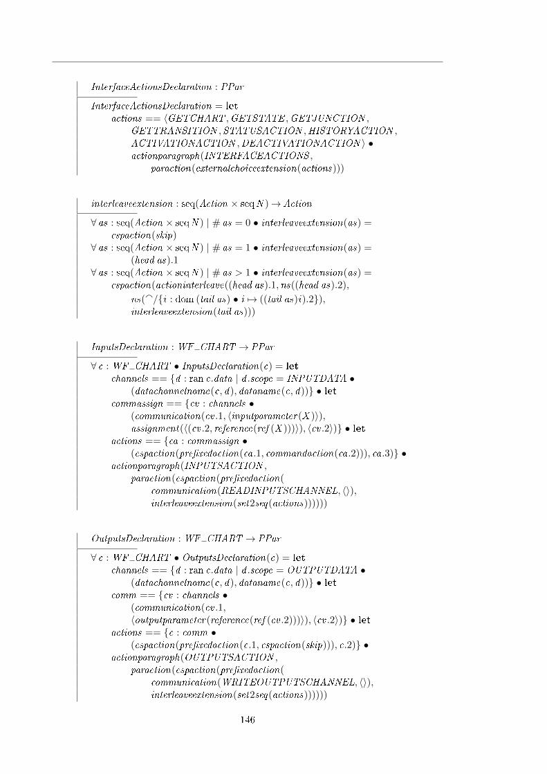
InterfaceActionsDeclaration : PPar
InterfaceActionsDeclaration = let
actions == 〈GETCHART ,GETSTATE ,GETJUNCTION ,GETTRANSITION ,STATUSACTION ,HISTORYACTION ,ACTIVATIONACTION ,DEACTIVATIONACTION 〉 •actionparagraph(INTERFACEACTIONS ,
paraction(externalchoiceextension(actions)))
interleaveextension : seq(Action × seqN )→ Action
∀ as : seq(Action × seqN ) | # as = 0 • interleaveextension(as) =cspaction(skip)
∀ as : seq(Action × seqN ) | # as = 1 • interleaveextension(as) =(head as).1
∀ as : seq(Action × seqN ) | # as > 1 • interleaveextension(as) =cspaction(actioninterleave((head as).1,ns((head as).2),
ns(a/{i : dom (tail as) • i 7→ ((tail as)i).2}),interleaveextension(tail as)))
InputsDeclaration : WF CHART → PPar
∀ c : WF CHART • InputsDeclaration(c) = let
channels == {d : ran c.data | d .scope = INPUTDATA •(datachannelname(c, d), dataname(c, d))} • let
commassign == {cv : channels •(communication(cv .1, 〈inputparameter(X )〉),assignment(〈(cv .2, reference(ref (X )))〉), 〈cv .2〉)} • let
actions == {ca : commassign •(cspaction(pre�xedaction(ca.1, commandaction(ca.2))), ca.3)} •
actionparagraph(INPUTSACTION ,paraction(cspaction(pre�xedaction(
communication(READINPUTSCHANNEL, 〈〉),interleaveextension(set2seq(actions))))))
OutputsDeclaration : WF CHART → PPar
∀ c : WF CHART • OutputsDeclaration(c) = let
channels == {d : ran c.data | d .scope = OUTPUTDATA •(datachannelname(c, d), dataname(c, d))} • let
comm == {cv : channels •(communication(cv .1,〈outputparameter(reference(ref (cv .2)))〉), 〈cv .2〉)} • let
actions == {c : comm •(cspaction(pre�xedaction(c.1, cspaction(skip))), c.2)} •
actionparagraph(OUTPUTSACTION ,paraction(cspaction(pre�xedaction(
communication(WRITEOUTPUTSCHANNEL, 〈〉),interleaveextension(set2seq(actions))))))
146

APPENDIX F. FORMAL TRANSLATION RULES
ProcessDeclaration : WF CHART → ProcDecl
∀ c : WF CHART • ProcessDeclaration(c) = let
stateparagraphs == 〈zparagraph(ChartDeclaration(c)),zparagraph(SimulationInstanceDeclaration(c)),zparagraph(InitSimulationInstanceDeclaration(c)),zparagraph(SimulationDataDeclaration),zparagraph(InitSimulationDataDeclaration),zparagraph(StateDeclaration),zparagraph(ActivateNoHistoryDeclaration),zparagraph(ActivateWithHistoryDeclaration),zparagraph(ActivateFailDeclaration),zparagraph(DeactivateSuccessDeclaration),zparagraph(DeactivateFailDeclaration)〉;
state == reference(ref (statename(c)));stateactions == 〈zparagraph(ActivateDeclaration),
zparagraph(DeactivateDeclaration),zparagraph(InitStateDeclaration)〉;
entryactions == set2seq({s : ran c.states •EntryActionDeclaration(c, s)} ∪ {EntryActionsDeclaration(c)});
duringactions == set2seq({s : ran c.states •DuringActionDeclaration(c, s)}{DuringActionsDeclaration(c)});
exitactions == set2seq({s : ran c.states •ExitActionDeclaration(c, s)}{ExitActionsDeclaration(c)});
conditionactions == set2seq({t : ran c.transitions •ConditionActionDeclaration(c, t)}∪{ConditionActionsDeclaration(c)});
transitionactions == set2seq({t : ran c.transitions •TransitionActionDeclaration(c, t)}∪{TransitionActionsDeclaration(c)});
conditions == set2seq({t : ran c.transitions •ConditionDeclaration(c, t)} ∪ {ConditionsDeclaration(c)});
triggers == set2seq({t : ran c.transitions •TriggerDeclaration(c, t)} ∪ {TriggersDeclaration(c)});
getters == 〈GetStateDeclaration,GetJunctionDeclaration,GetTransitionDeclaration,GetChartDeclaration〉;
others == 〈StatusDeclaration,HistoryDeclaration,ActivationDeclaration,DeactivationDeclaration〉;
collections == 〈ChartActionsDeclaration, InterfaceActionsDeclaration,InputsDeclaration(c),OutputsDeclaration(c)〉 • let
actions == stateactions a entryactions a duringactions a exitactionsa
conditionactions a transitionactions a conditionsa
triggers a getters a others a collections •simpleprocessdeclaration(processname(c),
processde�nition(proc(stateparagraphs, state,actions,MainActionDeclaration)))
147

ChannelsDeclaration : WF CHART → CircusPar
∀ c : WF CHART • ChannelsDeclaration(c) = let
cnames == {d : ran c.data |d .scope = INPUTDATA ∨ d .scope = OUTPUTDATA •
datachannelname(c, d)} •channeldeclaration(cdecl(〈typedsimplecdecl(set2seq(cnames),
reference(ref (UNIVERSE )))〉))
EventsDeclaration : WF CHART → Paragraph
∀ c : WF CHART • EventsDeclaration(c) = let
enames == set2seq({e : ran c.events • decl(eventname(c, e))}) •axiomaticdescription(schematext(〈declpart(〈
variable(enames, reference(ref (EVENT )))〉)〉, 〈〉))
translate : WF CHART → Program
∀ c : WF CHART • translate(c) = let
identi�ers == 〈zparagraphdeclaration(StateIdenti�erDeclaration(c)),zparagraphdeclaration(JunctionIdenti�erDeclaration(c)),zparagraphdeclaration(TransitionIdenti�erDeclaration(c))〉;
states == set2seq({s : ran c.states •zparagraphdeclaration(StateDeclaration(c, s))});
junctions == set2seq({j : ran c.junctions •zparagraphdeclaration(JunctionDeclaration(c, j ))});
transitions == set2seq({t : ran c.transitions •zparagraphdeclaration(TransitionDeclaration(c, t))});
events == 〈zparagraphdeclaration(EventsDeclaration(c))〉;channels == 〈ChannelsDeclaration(c)〉;proc == 〈processdeclaration(ProcessDeclaration(c))〉 •program(identi�ers a states a junctions a transitionsaevents a channels a proc)
148

Appendix G
State�ow Toolkit
section state�ow toolkit parents circus toolkit , basic toolkit
truthvalue : A→ B
R : PA
function 40 leftassoc ( ∧A )function 40 leftassoc ( ∨A )function(¬ A )function 40 leftassoc ( ∧B )function 40 leftassoc ( ∨B )function 40 leftassoc ( ⊕B )function(¬ B )function 40 leftassoc ( << )function 40 leftassoc ( >> )function 40 leftassoc ( <A )function 40 leftassoc ( >A )function 40 leftassoc ( ≤A )function 40 leftassoc ( ≥A )function 40 leftassoc ( =A )function 40 leftassoc ( 6=A )
149

∧A : A× A→ A∨A : A× A→ A¬ A : A→ A∧B : A× A→ A∨B : A× A→ A⊕B : A× A→ A¬ B : A→ A<< : A× A→ A>> : A× A→ A<A : A× A→ A>A : A× A→ A≤A : A× A→ A≥A : A× A→ A=A : A× A→ A6=A : A× A→ A
∀ x , y : A • x ∧A y = ¬ A(¬ Ax ∨A ¬ Ay)∀ x , y : A • x ∧B y = ¬ B(¬ Bx ∨B ¬ By)∀ x , y : A • x ⊕B y = (x ∧B ¬ By) ∨B (¬ Bx ∧B y)
DECOMPOSITION ::= SET | CLUSTERTYPE ::= AND | OR | CHARTDESTINATION ::= STATE | JUNCTION[SID ,TID , JID ,EVENT ]NID ::= snode〈〈SID〉〉 | jnode〈〈JID〉〉
Stateidenti�er : SIDdefault , inner , outer : TIDparent , left , right : SIDsubstates : seqSIDdecomposition : DECOMPOSITIONtype : TYPEhistory : B
Junctionidenti�er : JIDtransition : TIDparent : SIDhistory : B
150

APPENDIX G. STATEFLOW TOOLKIT
Transitionidenti�er : TIDsource, destination : NIDnext : TIDparent : SID
nullstate : Statenulljunction : Junctionnulltransition : Transition
State�owChartidenti�er : SIDstates : SID 7→ Statetransitions : TID 7→ Transitionjunctions : JID 7→ Junction
nullstate 6∈ ran statesnulltransition 6∈ ran transitionsnulljunction 6∈ ran junctions#{s : ran states | s.type = CHART} = 1(states(identi�er)).type = CHART∀n : SID | n ∈ dom states • (states(n)).identi�er = n∀n : JID | n ∈ dom junctions • (junctions(n)).identi�er = n∀n : TID | n ∈ dom transitions • (transitions(n)).identi�er = n
has active substate : P((SID 7→ B)× State)
∀ state status : SID 7→ B; s : State •(state status, s) ∈ has active substate ⇔
(∃ ss : ran(s.substates) • state status(ss) = True)
parent : State↔ State
∀ s1, s2 : State • parent(s1) = s2 ⇔ s1.parent = s2.identi�er
ancestors : State↔ PState
∀ s : State • ancestors(s) = {x : State | (parent +)(s) = x}
la : (State × State)↔ State
∀ s1, s2 : State • la(s1, s2) = µ x : (ancestors(s1) ∩ ancestors(s2)) |(∀ y : (ancestors(s1) ∩ ancestors(s2)) • x = y ∨ y ∈ ancestors(x )) • x
151

channel read inputs,write outputschannel executeentryaction, executeduringaction, executeexitaction : SID × SID × EVENTchannel executeconditionaction, executetransitionaction : TID × SID × EVENTchannel evaluatecondition : TID × Bchannel checktrigger : TID × EVENTchannel errorchannel junction : JID × Junctionchannel transition : TID × Transitionchannel state : SID × Statechannel chart : Statechannel status : SID × Bchannel history : SID × SIDchannel activate, deactivate : SIDchannel result : TID × EVENT × Bchannel interrupt simulator , interrupt chart , end local execution, end actionchannel local event : EVENT × Statechannel input event , output event : EVENTchannelset interface == {| executeentryaction, executeduringaction, executeexitaction,
executeconditionaction, executetransitionaction, evaluatecondition, checktrigger , result ,junction, transition, state, chart , status, history , activate, deactivate, read inputs,write outputs,end local execution, end action, local event , interrupt simulator , interrupt chart |}
channel end cycle
channel stsuccess, stfailchannelset statetransition == {| stsuccess, stfail |}
processSimulator =̂ begin
ExecuteTransition =̂ tid : TID ; path : seqTID ; source : State; current event : EVENT •
if tid = nulltransition.identi�er−→if path = ∅−→ stfail −→ Skip
8path 6= ∅−→(
transition!(last path)?lt−→ExecuteTransition(lt .next , (front path), source, current event)
)�
8tid 6= nulltransition.identi�er−→CheckValidity(tid , path, source, current event)�
152

APPENDIX G. STATEFLOW TOOLKIT
CheckValidity =̂ tid : TID ; path : seqTID ; source : State; current event : EVENT •checktrigger !tid !current event−→
result !tid !current event?e −→ evaluatecondition!tid?c−→
if e = True ∧ c = True−→(executeconditionaction!tid !(source.identi�er)!current event−→LocalEvent ; Proceed(tid , path a 〈tid〉, source, current event)
)8¬ (e = True ∧ c = True)−→ transition!tid?t−→ExecuteTransition(t .next , path, source, current event)�
Proceed =̂ tid : TID ; path : seqTID ; source : State; current event : EVENT •transition!tid?t−→
if t .destination ∈ ran snode−→(state!((snode ∼) t .destination)?dest−→proceedToState(source, dest , path, current event)
)8t .destination ∈ ran jnode−→proceedToJunction(tid , path, source, current event)�
proceedToState =̂ src, dest : State; path : seqTID ; current event : EVENT • ExitStates((la(src, dest)).substates, current event);executePath(path, src, dest , current event);EnterState(dest , la(src, dest), current event) ; stsuccess −→ Skip
executePath =̂ path : seqTID ; src, dest : State; current event : EVENT •if # path = 0−→ Skip
8 # path > 0−→(executetransitionaction!(head path)!((la(src, dest)).identi�er)!current event−→LocalEvent ; executePath(tail path, src, dest , current event)
)�
proceedToJunction =̂ tid : TID ; path : seqTID ; source : State; current event : EVENT •
transition!tid?t −→ junction!((jnode ∼) t .destination)?dj−→
if dj .history = False−→ executeJunction(dj , path, source, current event)8dj .history = True−→ history !(dj .parent)?lsid−→
if lsid = nullstate.identi�er−→(state!(dj .parent)?s−→ExecuteDefaultTransition(s, s, current event)
)8lsid 6= nullstate.identi�er−→(
state!lsid?ls−→proceedToState(source, ls, path, current event)
)�
�
153

executeJunction =̂ j : Junction; path : seqTID ; source : State; current event : EVENT •if j .transition = nulltransition.identi�er−→
stfail −→ Skip
8j .transition 6= nulltransition.identi�er−→ExecuteTransition(j .transition, path, source, current event)
�
ExecuteDefaultTransition =̂ s, tpp : State; current event : EVENT •
if s.default 6= nulltransition.identi�er−→ExecuteTransition(s.default , 〈〉, s, current event)
8s.default = nulltransition.identi�er−→if # s.substates = 1−→
(state!(head s.substates)?saux−→EnterState(saux , tpp, current event)
)8 # s.substates > 1−→ error −→ Skip
8 # s.substates = 0−→ Skip
�
�
EnterState =̂ s, tpp : State; current event : EVENT •
EnterState14(s, tpp, current event);EnterState5(s, tpp, current event);EnterState67(s, tpp, current event)
EnterState14 =̂ s, tpp : State; current event : EVENT •(EnterState1(s, tpp, current event) ; EnterState2(s, tpp, current event);EnterState3(s, tpp, current event) ; EnterState4(s, tpp, current event)
)
EnterState1 =̂ s, tpp : State; current event : EVENT • status!(s.parent)?active−→if s.type 6= CHART ∧ active = False−→
(state!(s.parent)?p−→EnterState14(p, tpp, current event)
)8s.type = CHART ∨ active = True−→ Skip
�
EnterState2 =̂ s, tpp : State; current event : EVENT •
if s.type = AND−→if s.left 6= nullstate.identi�er −→
status!(s.left)?False−→(
state!(s.left)?ls−→EnterState(ls, tpp, current event)
)@status!(s.left)?True−→ Skip
8s.left = nullstate.identi�er −→ Skip
�
8s.type 6= AND −→ Skip
�
154

APPENDIX G. STATEFLOW TOOLKIT
EnterState3 =̂ s, tpp : State; current event : EVENT • activate!(s.identi�er)−→ Skip
EnterState4 =̂ s, tpp : State; current event : EVENT •executeentryaction!(s.identi�er)!(s.identi�er)!current event −→ LocalEvent
EnterState5 =̂ s, tpp : State; current event : EVENT •EnterState5a(s, tpp, current event) ; EnterState5b(s, tpp, current event)
EnterState5a =̂ s, tpp : State; current event : EVENT •
if s.decomposition 6= CLUSTER −→ Skip
8s.decomposition = CLUSTER−→
if s.history = True−→ history !(s.identi�er)?lsid −→ state!lsid?ls−→ if ls 6= nullstate −→ EnterState15(ls, tpp, current event)8ls = nullstate −→ ExecuteDefaultTransition(s, tpp, current event)�
8s.history = False−→ ExecuteDefaultTransition(s, tpp, current event)�
�
EnterState5b =̂ s, tpp : State; current event : EVENT • if s.decomposition = SET −→ EnterStates15(s.substates, tpp, current event)8s.decomposition 6= SET −→ Skip
�
EnterStates15 =̂ ss : seqSID ; tpp : State; current event : EVENT •
if # ss = 0−→ Skip
8 # ss > 0−→ status!(head ss)?active−→if active = False−→ state!(head ss)?�rst−→
EnterState15(�rst , tpp, current event)8active = True−→ Skip
�
;
EnterStates15(tail ss, tpp, current event)�
EnterState15 =̂ s, tpp : State; current event : EVENT •EnterState14(s, tpp, current event) ; EnterState5(s, tpp, current event)
EnterState67 =̂ s, tpp : State; current event : EVENT •EnterState6(s, tpp, current event) ; EnterState7(s, tpp, current event)
155

EnterState6 =̂ s, tpp : State; current event : EVENT •
if s.type = AND−→
if s.right 6= nullstate.identi�er−→status!(s.right)?False−→
(state!(s.right)?rs−→EnterState(rs, tpp, current event)
)@status!(s.right)?False−→ Skip
8s.right = nullstate.identi�er −→ Skip
�
8s.type 6= AND −→ Skip
�
EnterState7 =̂ s, tpp : State; current event : EVENT •
if s.type 6= CHART −→ state!(s.parent)?p−→ if tpp 6= p −→ EnterState67(p, tpp, current event)8tpp = p −→ Skip
�
8s.type = CHART −→ Skip
�
EnterStates =̂ ss : seqSID ; tpp : State; current event : EVENT •
if # ss = 0−→ Skip
8 # ss > 0−→ status!(head ss)?active−→ if active = False−→ state!(head ss)?�rst −→ EnterState(�rst , tpp, current event)8active = True−→ Skip
�
;
EnterStates(tail ss, tpp, current event)�
ExecuteState =̂ s : State; current event : EVENT •
ExecuteTransition(s.outer , 〈〉, s, current event)J | statetransition | K
stsuccess −→ Skip
@
stfail −→(
executeduringaction!(s.identi�er)!(s.identi�er)!current event−→LocalEvent ; AlternativeExecution(s, current event)
)
\statetransition
AlternativeExecution =̂ s : State; current event : EVENT •ExecuteTransition(s.inner , 〈〉, s, current event)J | statetransition | K stsuccess −→ Skip
@stfail −→ ExecuteStates(s.substates, current event)
\ statetransition
156

APPENDIX G. STATEFLOW TOOLKIT
ExecuteStates =̂ ss : seqSID ; current event : EVENT •
if # ss = 0−→ Skip
8 # ss > 0−→ status!(head ss)?active−→if active = True−→ state!(head ss)?�rst−→
ExecuteState(�rst , current event)8active = False−→ Skip
�
;
ExecuteStates(tail ss, current event)�
ExitState =̂ s : State; current event : EVENT •
if s.right 6= nullstate.identi�er−→status!(s.right)?True−→ state!(s.right)?rs−→
ExitState(rs, current event)@status!(s.right)?False−→ Skip
8s.right = nullstate.identi�er −→ Skip
�
;
ExitStates(s.substates, current event);executeexitaction!(s.identi�er)!(s.identi�er)!current event −→ LocalEvent ;deactivate!(s.identi�er)−→ Skip
ExitStates =̂ ss : seqSID ; current event : EVENT •
if # ss = 0−→ Skip
8 # ss > 0−→ status!(last ss)?active−→ if active = True−→ state!(last ss)?l −→ ExitState(l , current event)8active = False−→ Skip
�
;
ExitStates(front ss, current event)�
ExecuteChart =̂ current event : EVENT •chart?c −→ status!(c.identi�er)?active−→ if active = True−→ ExecuteActiveChart(c, current event)
8active = False−→ ExecuteInactiveChart(c, current event)�
157

ExecuteInactiveChart =̂ c : State; current event : EVENT • activate!(c.identi�er)−→
ExecuteDefaultTransition(c, c, current event)J | statetransition | K
stsuccess −→ Skip
@
stfail −→
if c.decomposition = SET−→
EnterStates(c.substates, c, current event)8c.decomposition 6= SET−→
error −→ Skip
�
\statetransition
ExecuteActiveChart =̂ c : State; current event : EVENT • if c.substates = ∅−→ ExecuteInactiveChart(c, current event)8c.substates 6= ∅−→ ExecuteStates(c.substates, current event)�
LocalEvent =̂ µX •
(local event?e?s −→ TreatLocalEvent(e, s) ; X )@end action −→ Skip
The recursive execution of the the chart (or state) does not contain an interruptaction because the original interrupt action from the Step action is still active. If aninterrupt simulator event occurs the action will be interrupted (including the recursiveexecution).
TreatLocalEvent =̂ e : EVENT ; s : State • if s.type = CHART −→ ExecuteChart(e)8s.type 6= CHART −→ ExecuteState(s, e)�
;
end local execution −→ Skip
Step =̂
input event?ie −→ var ce : EVENT • ce := ie ; read inputs−→
(ExecuteChart(ce)4 (interrupt simulator −→ interrupt chart −→ Skip));write outputs −→ end cycle −→ Skip
• (µX • Step ; X )
end
158

Appendix H
Usage of s2c
There are two main forms of interacting with s2c: command line and graphical interface.Additionally, it is also possible to integrate s2c within another piece of code by invokingthe appropriate methods of the translate class.
H.1 Text interface
The core of s2c is contained in a JAR �le called s2c.jar located in the lib folder; this �lecontains all the classes used in s2c and provides the command line interface. The graphicalinterface is provided separately in S2CGUI.jar uses the �le s2c.jar as a library.
The expected format of the command line input is as follows.
s2c [input] [-o output] [-l libraries]
The parameters are explained below:
input is the path to the .mdl �le that contains the charts.
output is an optional parameter that points to the �le in which the generated speci�cationwill be written. If this parameter is not provided, s2c will derive an output �lename from the input �le name by eliminating the .mdl extension and adding a .texextension.
libraries consists of a (possibly empty) list of �les that represent the libraries being usedin the speci�cations; the function of these libraries is to allow the introduction ofaspects of the charts which are not captured by the translation. One such exampleis the use of matlab functions such as abs (absolute value); the generated model doesnot contain a de�nition of this function and expects the user to provide a librarythat contains it.
H.2 Graphical interface
The graphical interface requires the same parameters as above, but in a graphical fashion.Figure H.1 show the main window of the graphical interface; it contains two text �eldsand a list. The input and output �elds can be completed either by typing the path to theappropriate �les or by selecting the �les through the button labelled ". . . ".
The list of library �les can be manipulated by adding new �les or removing items ofthe list. The button "Add" shows a dialog box that request the name of a library as shown
159

H.2. GRAPHICAL INTERFACE
Figure H.1: Graphical interface of s2c.
Figure H.2: Adding a library to the graphical interface of s2c.
in Figure H.2. An item of the list can be removed from the list by selecting it and pressingthe button "Remove".
The translation process is started by pressing the "Translate" button. In order tofacilitate the use of s2c, after the translation process is complete, s2c does not close, thuspermitting the user to re-generate the model with di�erent parameters, or generate newmodels from di�erent input �les.
Any message that would be written to the command prompt in the text interface iswritten to a log �le whose name is formed by the name of the .mdl �le without the .mdlextension and added the .log extension. Some error messages (e.g., missing parameters)are shown in the form of a warning dialog box.
160

Bibliography
UML 2.0 Superstructure Speci�cation. Technical report, Object Management Group(OMG), August 2005.
J.-R. Abrial. The B-book: assigning programs to meanings. Cambridge University Press,New York, NY, USA, 1996. ISBN 0-521-49619-5.
M. M. Adams and Philip B. Clayton. ClawZ: Cost-E�ective Formal Veri�cation for ControlSystems. In Kung-Kiu Lau and Richard Banach, editors, ICFEM, volume 3785 of LectureNotes in Computer Science, pages 465�479. Springer, 2005. ISBN 3-540-29797-9. URLhttp://dx.doi.org/10.1007/11576280_32.
R. Arthan, P. Caseley, C. O'Halloran, and A. Smith. ClawZ: control laws in Z. In ICFEM,2000. pp. 169.
C. Banphawatthanarak and B. H. Krogh. Veri�cation of state�ow diagrams using smv:sf2smv 2.0. Technical Report CMU-ECE-2000-020, Carnegie Mellon University, 2000.
C. Banphawatthanarak, B.H. Krogh, and K. Butts. Symbolic veri�cation of executablecontrol speci�cations. In Proceedings of the 1999 IEEE International Symposium onComputer Aided Control System Design, pages 581�586, August 1999.
J A Bergstra and J W Klop. Algebra of communicating processes with abstraction. The-oretical Computer Science, 37(1):77�121, 1985.
BS EN 61508-3:2002. Functional safety of electrical/electronic/programmable electronicsafety related systems � Part 1: General requirements, 2002.
Michael Butler and Michael Leuschel. Combining CSP and B for Speci�cation and Prop-erty Veri�cation. In John Fitzgerald, Ian Hayes, and Andrzej Tarlecki, editors, For-mal Methods 2005, number LNCS 3582, pages 221�236. Springer, January 2005. URLhttp://eprints.ecs.soton.ac.uk/10388/.
P. Caspi, A. Curic, A. Maignan, C. Sofronis, and S. Tripakis. Translating discrete-timeSimulink to Lustre. In R. Alur and I. Lee, editors, EMSOFT'03 LNCS. Springer Verlag,2003a.
Paul Caspi, Adrian Curic, Aude Maignan, Christos Sofronis, Stavros Tripakis, and PeterNiebert. From simulink to SCADE/lustre to TTA: a layered approach for distributedembedded applications. ACM SIGPLAN Notices, 38(7):153�162, 2003b. ISSN 0362-1340.doi: http://doi.acm.org/10.1145/780731.780754.
A. L. C. Cavalcanti and P. Clayton. Veri�cation of Control Systems using Circus. In Pro-ceedings of the 11th IEEE International Conference on Engineering of Complex Com-puter Systems, pages 269 � 278. IEEE Computer Society, 2006.
161

BIBLIOGRAPHY
A. L. C. Cavalcanti and J. C. P. Woodcock. Predicate Transformers in the Semantics ofCircus. IEE Proceedings Software, 150(1):85 � 94, 2003.
A. L. C. Cavalcanti and J. C. P. Woodcock. Angelic Nondeterminism and Unifying Theoriesof Programming . In J. Derrick and E. Boiten, editors, REFINE 2005, volume 137 ofEletronic Notes in Theoretical Computer Science. Elsevier, 2005.
Ana Cavalcanti. State�ow diagrams in Circus. Electron. Notes Theor. Comput. Sci., 240:23�41, 2009. ISSN 1571-0661. doi: http://dx.doi.org/10.1016/j.entcs.2009.05.043.
Michelle L. Crane and Juergen Dingel. Uml vs. classical vs. rhapsody statecharts: notall models are created equal. Software and Systems Modeling, 6, 2007. doi: 10.1007/s10270-006-0042-8. URL http://dx.doi.org/10.1007/s10270-006-0042-8.
DO-178b. Software considerations in airborne systems and equipment certi�cation, 1992.
P. Van Eijk and Michel Diaz, editors. Formal Description Technique Lotos: Results of theEsprit Sedos Project. Elsevier Science Inc., New York, NY, USA, 1989. ISBN 0444872671.
Ana Elena Rugina, Dave Thomas, Xavier Olive, and Guillaume Veran. Gene-Auto: Au-tomatic software code generation for real-time embedded systems. In DASIA 2008, theInternational Space System Engineering Conference, 2008.
Esterel Technologies, Inc. Scade suiteTM. 11 December 2008http://www.esterel-technologies.com/products/scade-suite/.
Andy Evans. An improved recipe for specifying reactive systems in z. In ZUM '97: Pro-ceedings of the 10th International Conference of Z Users on The Z Formal Speci�cationNotation, pages 275�294, London, UK, 1997. Springer-Verlag. ISBN 3-540-62717-0.
Harald Fecher, Jens Schönborn, Marcel Kyas, and Willem P. de Roever. 29 new unclaritiesin the semantics of uml 2.0 state machines. In ICFEM, pages 52�65, 2005.
Clemens Fischer. CSP-OZ: a combination of Object-Z and CSP. In FMOODS '97: Proceed-ings of the IFIP TC6 WG6.1 international workshop on Formal methods for open object-based distributed systems, pages 423�438, London, UK, UK, 1997. Chapman & Hall,Ltd. ISBN 0-412-82040-4.
Formal Systems (Europe) Ltd. Failures-Divergence Re�nement. www.fsel.com.
N. Halbwachs, P. Caspi, P. Raymond, and D. Pilaud. The synchronous data-�ow program-min language LUSTRE. In Proceedings of the IEEE, volume 79, pages 1305 � 1320,1991.
Grégoire Hamon. A denotational semantics for state�ow. In Wayne Wolf, editor, EMSOFT,pages 164�172. ACM, 2005. ISBN 1-59593-091-4. URL http://doi.acm.org/10.1145/
1086228.1086260.
Grégoire Hamon and John Rushby. An operational semantics for State�ow. In M. Wer-melinger and T. Margaria-Ste�en, editors, Fundamental Approaches to Software Engi-neering:7th International Conference (FASE), volume 2984 of Lecture Notes in ComputerScience, pages 229�243, Barcelona, Spain, 2004. Springer-Verlag.
D. Harel. Statecharts: A visual formalism for complex systems. Science of ComputerProgramming, 8(3):231�274, 1987.
162

BIBLIOGRAPHY
D. Harel and A. Naamad. The STATEMATE semantics of statecharts. ACM Transactionson Software Engineering and Methodology, 5(4):293�333, October 1996. ISSN 1049-331X.
D. Harel and M. Politi. Modeling Reactive Systems with Statecharts: The Statemate Ap-proach. McGraw-Hill, Inc., New York, NY, USA, 1998. ISBN 0070262055.
D. Harel, A. Pnueli, J. P. Schmidt, and R. Sherman. On the formal semantics fo statecharts.In Proceedings of the 2nd IEEE Symposium on Logic in Computer Science, pages 54�64,New York, 1987. IEEE Press.
C. A. R. Hoare. Communicating sequential processes. Prentice-Hall, Inc., Upper SaddleRiver, NJ, USA, 1985. ISBN 0-13-153271-5.
C. A. R. Hoare and H. Jifeng. Unifying Theories of Programming. Prentice Hall, 1998.
Jochen Hoenicke and Ernst-Rüdiger Olderog. Combining speci�cation techniques for pro-cesses, data and time. In IFM '02: Proceedings of the Third International Conference onIntegrated Formal Methods, pages 245�266, London, UK, 2002. Springer-Verlag. ISBN3-540-43703-7.
G. J. Holtzmann. Design and Validation of Computer Protocols. Prentice Hall, 1991.
G. J. Holtzmann. The model checker SPIN. In IEEE Transactions on Software Engineering,volume 23, May 1997.
John E. Hopcroft, Rajeev Motwani, and Je�rey D. Ullman. Introduction to Automata The-ory, Languages, and Computation (3rd Edition). Addison-Wesley Longman PublishingCo., Inc., Boston, MA, USA, 2006. ISBN 0321455363.
ISO. Information technology � Z formal speci�cation notation � Syntax, type system andsemantics. Technical Report ISO/IEC 13568, International Organization for Standard-ization, 2002.
N. Izerrouken, X. Thirioux, M. Pantel, and M. Strecker. Certifying an Automated CodeGenerator Using Formal Tools. In ERTS'08, 4th European symposium on Real TimeSystems, 2008.
JFlex. JFlex - The Fast Scanner Generator for Java, 2009. http://jflex.de/.
C. B. Jones. Systematic Software Development Using VDM. Prentice-Hall International,1986.
Mark P. Jones. jacc: just another compiler compiler for Java, 2004. http://web.cecs.
pdx.edu/~mpj/jacc/.
Diego Latella, Istvan Majzik, and Mieke Massink. Towards a formal operational semanticsof uml statechart diagrams. In Proceedings of the IFIP TC6/WG6.1 Third InternationalConference on Formal Methods for Open Object-Based Distributed Systems (FMOODS),page 465, Deventer, The Netherlands, The Netherlands, 1999. Kluwer, B.V. ISBN 0-7923-8429-6.
Johan Lilius, Ivn Porres Paltor, Turku Centre, and Computer Science. The semantics ofuml state machines. Technical report, 1999.
163

BIBLIOGRAPHY
Brendan Mahony and Jin Song Dong. Blending object-z and timed csp: an introductionto tcoz. In ICSE '98: Proceedings of the 20th international conference on Softwareengineering, pages 95�104, Washington, DC, USA, 1998. IEEE Computer Society. ISBN0-8186-8368-6.
Petra Malik and Mark Utting. CZT: A Framework for Z Tools. In ZB. Lecture, pages65�84. Springer, 2005.
John McDermid, Andy Galloway, Simon Burton, John Clark, Ian Toyn, Nigel Tracey, andSam Valentine. Towards industrially applicable formal methods: Three small steps, andone giant leap. In Proceedings of the International Conference on Formal EngineeringMethods, pages 76�88. Press, 1998.
Erich Mikk, Yassine Lakhnech, Carsta Petersohn, and Michael Siegel. On formal semanticsof statecharts as supported by statemate. In In Second BCS-FACS Northern FormalMethods Workshop. Springer-Verlag, 1997.
R. Milner. A Calculus of Communicating Systems. Springer-Verlag New York, Inc., Se-caucus, NJ, USA, 1982. ISBN 0387102353.
Alvaro Miyazawa and Ana Cavalcanti. Towards the formal veri�cation of implementationsof State�ow Diagrams. Technical Report YCS 449, University of York, 2010.
Muan Yong Ng and Michael J. Butler. Towards formalizing UML state diagrams in CSP.In SEFM, page 138. IEEE Computer Society, 2003. ISBN 0-7695-1949-0.
M. V. M. Oliveira, A. L. C. Cavalcanti, and J. C. P. Woodcock. Formal development ofindustrial-scale systems. Innovations in Systems and Software Engineering, 1(2):125 �146, 2005.
M. V. M. Oliveira, A. C. Gurgel, and C. G. de Castro. CRe�ne: Support for the Circus
Re�nement Calculus. In Antonio Cerone and Stefan Gruner, editors, 6th IEEE Interna-tional Conferences on Software Engineering and Formal Methods, pages 281�290. IEEEComputer Society Press, 2008. ISBN 978-0-7695-3437-4. c© IEEE Computer SocietyPress.
A. Pnueli and M. Shalev. What is in a step: On the semantics of statecharts. In TheoreticalAspects of Computer Software. Springer Berlin / Heidelberg, 1991.
Rodrigo Ramos, Augusto Sampaio, and Alexandre Mota. A semantics for UML-RT activeclasses via mapping into Circus. In Martin Ste�en and Gianluigi Zavattaro, editors,FMOODS, volume 3535 of Lecture Notes in Computer Science, pages 99�114. Springer,2005. ISBN 3-540-26181-8. URL http://dx.doi.org/10.1007/11494881\_7.
A. W. Roscoe. The Theory and Practice of Concurrency. Prentice-Hall Series in ComputerScience. Prentice-Hall, New York, 1998. ISBN 0-13-674409-5. Oxford.
Norman Scaife, Christos Sofronis, Paul Caspi, Stavros Tripakis, and Florence Maraninchi.De�ning and translating a "safe" subset of simulink/state�ow into lustre. In Giorgio C.Buttazzo, editor, EMSOFT, pages 259�268. ACM, 2004. ISBN 1-58113-860-1. URLhttp://doi.acm.org/10.1145/1017753.1017795.
S. Schneider and J. Davies. A brief history of Timed CSP. Theoretical Computer Science.1995.
164

BIBLIOGRAPHY
Steve Schneider. Concurrent and Real Time Systems: The CSP Approach. John Wiley& Sons, Inc., New York, NY, USA, 1999. ISBN 0471623733.
E. Sekerinski and R. Zurob. Translating Statecharts to B. In Springer-Verlag, editor, IFM2002, volume 2335 of LNCS, pages 128�144, 2002.
G. Smith. The Object-Z Speci�cation Language. Kluwer Academic Publishers, Norwell,MA, USA, 2000. ISBN 0-7923-8684-1.
Graeme Smith. A semantic integration of object-z and csp for the speci�cation of con-current systems. In FME '97: Proceedings of the 4th International Symposium of For-mal Methods Europe on Industrial Applications and Strengthened Foundations of FormalMethods, pages 62�81, London, UK, 1997. Springer-Verlag. ISBN 3-540-63533-5.
Graeme Smith and John Derrick. Speci�cation, re�nement and veri�cation of concurrentsystems�an integration of object-z and csp. Formal Methods in System Design, 18(3):249�284, 2001. ISSN 0925-9856. doi: http://dx.doi.org/10.1023/A:1011269103179.
K. Taguchi and K. Araki. The state-based ccs semantics for concurrent z speci�cation.In ICFEM '97: Proceedings of the 1st International Conference on Formal EngineeringMethods, page 283, Washington, DC, USA, 1997. IEEE Computer Society. ISBN 0-8186-8002-4.
The MathWorks,Inc. Simulink, a. http://www.mathworks.com/products/simulink.
The MathWorks,Inc. State�ow and State�ow Coder 7 User's Guide, b. http://www.
mathworks.com/products/stateflow.
A. Tiwari. Formal semantics and analysis methods for Simulink State�ow models. Technicalreport, SRI International, 2002. http://www.csl.sri.com/∼tiwari/stateflow.html.
A. Toom, T. Naks, M. Panter, M. Grandriau, and I. Wati. Gene-Auto: an AutomaticCode Generator for a safe subset of Simulink/State�ow and Scicos. In ERTS'08, 4thEuropean symposium on Real Time Systems, 2008.
I. Toyn. Simulink/State�ow Analyser user's manual. Technical report, Department ofComputer Science, University of York, 2005.
Ian Toyn and Andy Galloway. Proving properties of State�ow models using ISO StandardZ and CADiZ. In In ZB-2005, vol. 3455 of LNCS, pages 104�123, 2005.
Helen Treharne and Steve Schneider. Using a process algebra to control B OPERATIONS.In IFM'99 1st International Conference on Integrated Formal Methods, pages 437�457,York, June 1999. Springer-Verlag. URL http://www.cs.rhbnc.ac.uk/~helent.
TTA-Group. TTA � A Dependable Real-Time Communication Platform for Safety-Relevant Applications, 2007. http://www.ttagroup.org/technology/tta.htm.
Michael von der Beeck. A structured operational semantics for UML-statecharts. Softwareand Systems Modeling, V1:130�141, 2002.
J. C. P. Woodcock and A. L. C. Cavalcanti. The Semantics of Circus. In D. Bert, J. P.Bowen, M. C. Henson, and K. Robinson, editors, ZB 2002: Formal Speci�cation andDevelopment in Z and B, volume 2272 of Lecture Notes in Computer Science, pages184�203. Springer-Verlag, 2002.
165

BIBLIOGRAPHY
JimWoodcock and Jim Davies. Using Z: speci�cation, re�nement, and proof. Prentice-Hall,Inc., Upper Saddle River, NJ, USA, 1996. ISBN 0-13-948472-8.
F. Zeyda and A. Cavalcanti. Encoding Circus Programs in ProofPowerZ. Lecture Notes inComputer Science. Springer, 2009. Awaiting publication.
C. Zhou, C. A. R. Hoare, and A. P. Ravn. A calculus of durations. In InformationProcessing Letters, volume 40, pages 269�276, 1991.
166