university on nairobi faculty of...
TRANSCRIPT
i
UNIVERSITY ON NAIROBI
FACULTY OF ENGINEERING
DEPARTMENT OF MECHANICAL AND MANUFACTURING ENGINEERING
FINAL YEAR PROJECT
PROJECT CODE: SMK 01/2014
TITLE: STATUS OF METAL FABRICATION INDUSTRIES IN NAIROBI
UNDERTAKEN BY:
NDICHU MARGARET WANGARE F18/31143/2009
CHEGE ELIZABETH NJERI F18/29361/2009
SUPERVISOR: MR SM KABUGO
Project report submitted in partial fulfillment of the requirement for the award of the degree of
Bachelor of Science in Mechanical Engineering of the University of Nairobi.
Submitted on: April 17, 2014
ii
DECLARATION AND CERTIFICATION
We declare that this our own original work and to the best of our knowledge and has never been
presented elsewhere for academic purposes.
……………………………………………….. ……………………………………………
NDICHU MARGARET WANGARE CHEGE ELIZABETH NJERI
F18/31143/2009 F18/29361/2009
This project report has been submitted for examination with my approval as university supervisor for
the award of the degree of Bachelor of Science in Mechanical Engineering.
Sign:
……………………………………………..
Date:
……………………………………………..
Supervisor:
Mr S.M Kabugo.

iii
DEDICATION
We would like to dedicate this report to our parents who brought us to this world and supported us
throughout our lives, and to all those who have been inspired by fabrication and pursue it as their
source of income and career, also to all the upcoming fabrication companies.
QUOTE
“The man who will use his skill and constructive imagination to see how much he can give for a dollar,
instead of how little he can give for a dollar, is bound to succeed.” – Henry Ford.

iv
ACKNOWLEDGEMENT
We would like to thank the almighty God for sustaining us throughout this undertaken and for giving us
everything we call our. We express our sincere appreciation to Mr. S.M Kabugo for his guidance, advice,
criticism, systematic, supervision, encouragement and insight throughout this project.
We are especially glad that our Department of Mechanical Engineering has been kind, supportive in
many ways and generous beyond measure.
This project would have not been possible without help from our friends, colleagues and family. They
have been supportive in many ways and have been patient with us all through the project.
v
TABLE OF CONTENTS DECLARATION AND CERTIFICATION……………………………………………………………………………………………………i
DEDICATION / QUOTE…………………………………………………………………………………………………………………………ii
ACKNOWLEDGEMENT ....................................................................................................................... iii
TABLE OF CONTENTS ......................................................................................................................... iv
ABSTRACT .......................................................................................................................................... 1
CHAPTER ONE .................................................................................................................................... 2
1.1 Metal fabrication…………………………………………………………………………………….......................2
1.2 Objective……………………………………………………………………………………………………………………..2
1.3 Methodology……………………………………………………………………………………………………………...2
CHAPTER TWO: TYPES OF FABRICATION PROCESSES……………………………………………………………………………4
2.1. MATERIAL SELECTION………………………………………………………………………………………………………….4
2.1.1 Plate metal…………………………………………………………………………………………………………………….4
2.1.2 Formed and expanded metal………………………………………………………………………………………….4
2.1.3 Sheet metal……………………………………………………………………………………………………………………4
2.1.4 Square stock………………………………………………………………………………………………………………….5
2.1.5 Tube stock…………………………………………………………………………………………………………………….5
2.1.6 Sectional metals (I beams, W beams, C channel….)………………………………………………………5
2.1.7 Welding wire/welding rod…………………………………………………………………………………………….5
2.1.8 Hardware………………………………………………………………………………………………………………………5
2.1.9 Fittings…………………………………………………………………………………………………………………………..6
2.2. CUTTING PROCESS ……………………………………………………………………………………………………………6
2.2.1 Sawing……………………………………………………………………………………………………………………………6
2.2.2 Shearing…………………………………………………………………………………………………………………………8
2.2.3. Drilling and reaming…………………………………………………………………………………………………….11
2.2.4 Melt cutting process……………………………………………………………………………………………………14
2.3. FORMING / SHAPING PROCESS………………………………………………………………………………………….18
vi
2.3.1 Bending process…………………………………………………………………………………………………………..18
2.3.2 Rolling process……………………………………………………………………………………………………………..23
2.3.3 Folding………………………………………………………………………………………………………………………….25
2.3.4 Drawing………………………………………………………………………………………………………………………..26
2.3.5 Die forming…………………………………………………………………………………………………………27
2.4. JOINING PROCESS……………………………………………………………………………………………………...........29
2.4.1 Welding……………………………………………………………………………………………………………..29
2.4.2 braze-welding …………………………………………………………………………………………………………….35
2.4.3 Brazing……………………………………………………………………………………………………………………….35
2.4.4 Soldering ……………………………………………………………………………………………………………………36
2.4.5 Riveting……………………………………………………………………………………………………………………….37
2.4.6 Adhesives……………………………………………………………………………………………………………………37
2.5. FINISHING PROCESS…………………………………………………………………………………………………………..37
2.5.1 Metal cleaning and treating…………………………………………………………………………………………37
2.5.2 Chemical cleaning…………………………………………………………………………………………………………39
2.5.3 Finishing……………………………………………………………………………………………………………………….40
2.6. ASSEMBLY PROCESSES………………………………………………………………………………………………………………….41
2.6.1 Temporary mechanical fasteners…………………………………………………………………………………..41
CHAPTER THREE: FABRICATION EQUIPMENT……………………………………………………………………….43
3.1. CUTTING EQUIPMENT…………………………………………………………………………………………………………………43
3.1.1 Drilling equipment………………………………………………………………………………………………………...43
3.1.2 Arc cutting equipment……………………………………………………………………………………………………46
3.1.3 Shearing equipment ……………………………………………………………………………………………………..47
3.1.4 Sawing equipment.………………………………………………………………………………………………………..48
3.2. BENDING EQUIPMENT…………………………………………………………………………………………………………………48
vii
3.2.1 Press brake …………………………………………………………………………………………………………………48
3.2.2 Rolling machines…………………………………………………………………………………………………………..51
3.2.3 Deep drawing press………………………………………………………………………………………………………54
3.2.4 Die forming machine………………………………. ………………………………………………………………….54
3.3. JOINING EQUIPMENT……………………………………………………………………………………………………………………55
3.3.1 Ultrasonic welding equipment……………………………………………………………………………………..55
3.3.2 Laser system………………………………………………………………………………………………………………..56
3.3.3 Riveting machine…………………………………………………………………………………………………………56
3.3.4 Standard spot welding machine…………………………………………………………………………………..57
3.3.5 Brazing machine……………..……………………………………………………………………………………………58
3.3.6 Soldering machine………………………………………………………………………………………………………..58
3.4 FINISHING EQUIPMENT…………………………………………………………………………………………………………………59
3.4.1 Grinding machine63……………………………………………………………………………………………………..59
3.4.2 Brushing and smoothening equipment ………………………………………………………………………..61
3.4.3. Paint application equipments………………………………………………………………………………………65
3.4.4 Enamel application………………………………………………………………………………………………………69
CHAPTER FOUR…………………………………………………………………………………………………………………………………70
4.1 DESIGN OF QUESTIONNAIRE……………………………………………………………………………………………………….70
CHAPTER FIVE……………………………………………………………………………………………………………………………………73
5.1 ANALYSIS/RESULTS…………………………………………………………………………………………………………………….73
CHAPTER SIX……………………………………………………………………………………………………………………………………..76
6.1 DISCUSSION……………………………………………………………………………………………………………………………….76
CHAPTER SEVEN………………………………………………………………………………………………………………………………..77
7.1 CONCLUSION……………………………………………………………………………………………………………………………..77
REFERENCES…..…………………………………………………………………………………………………………………………………78
viii
ABSTRACT
The objectives of the project were:
1. Study and research on the metal fabrication processes.
2. To survey the current status of the metal fabrication industry capacity in Nairobi.
Metal fabrication is the value added process that involves the construction of machines and structures
from various raw materials. It involves various processes which include; material selection, cutting,
bending and forming, joining and finally finishing.
A literature review of the processes was done highlighting the different types each of the major
processes and the different types of equipments used to perform this processes. They are discussed in
detail in the chapter two of the project report as well as the specialized equipment used in fabrication
processes which are discussed in depth in chapter three. This completed the first part of the project,
which enables us to come up with a questionnaire to start off the second part of the project which was
on survey of the metal fabrication industry.
This questionnaire was designed to survey the different companies in Nairobi that do fabrication, the
nature of their business, their product range, the size of their of workshop, layout, type of equipment
and the labor force in the company. The results obtained from the selected visits were then analyzed
and discussed as indicated in chapter five and six of the project report. Samples of the filled in
questionnaires are attached as evidence of the survey made. From these results as well as the
background knowledge on the literature review done, a conclusion was drawn highlighting the current
status of the metal fabrication industry in Nairobi.
1
CHAPTER ONE.
1.1 Metal fabrication
Metal fabrication is the process of constructing machine and structure from raw material. Metal
fabricators (companies that specialize in the process) are called fab shops. Metal fabricators are referred
to as a value added process because they add additional value at certain stage of production.
Once a contract has been given the metal fabricators begin the planning stages this involve ordering the
correct materials and having a manufacturing engineer program CNC machines for the project. Some of
the work may be sub-contracted out depending on the size and specialized needs of the project. Some
of the raw material used by metal fabricator are; plate metal, sheet metal, and expanded material,
square stock, tube stock, sectional material, welding wire, hardwire and fitting . To begin this raw
material need to be cut to the correct size. This is done with specialized tools of cutting depending on
the selected material. Metal can be formed using dies bending machines and rolling machines are also
used to bend and make round sections of metal. These parts are joined to form the required products
which are then finished by cleaning the metal, grinding it or even painting as required.
Many metal fabricators specialize in specific processes based on their clients’ needs and their own
expertise.
1.2 Objective
The objectives of the project were:
1. Study and research on the metal fabrication processes.
2. To survey the current status of the metal fabrication industry capacity in Nairobi.
1.3 Methodology
The literature review of the processes was done highlighting the different types of each of the major
processes and the different types of equipments used to perform this processes. This completed the
first part of the project, which enables us to come up with a questionnaire to start off the second part of
the project which was on survey.
This questionnaire was designed to survey the different companies in Nairobi that do fabrication, the
nature of their business, their product range, the size of their of workshop, layout, type of equipment
and the labor force in the company.
Different companies that offer metal fabrication in Nairobi region were identified. The visit to these
companies was done and the questioners filled, the data then was analyzed and discussed from which a
conclusion was made.
2
CHAPTER TWO
2. TYPES OF FABRICATION PROCESSES
There are different types of fabrication processes from the raw material until the final product, namely;
I. Material selection
II. Cutting
III. Bending /forming
IV. Joining
V. Finishing
VI. Assembly
2.1. MATERIAL SELECTION
The standard raw materials used by metal fabricators are:
2.1.1. Plate metal
It is a material profile formed with specific shape or cross section on certain standards of chemical
composition and mechanical properties. It can also be defined as a rectangular metal stock that is more
than 6mm or 0.25 inch thick.
2.1.2 Formed and expanded metal
It is a form of metal stock made by shearing a metal plate in a press, so that the metal stretches, leaving
diamond-shaped voids surrounded by interlinked bars of the metal. The most common method of
manufacture is to simultaneously slit and stretch the material with one motion. Expanded metal is also
referred to as perforated metal. It is a large part of the metal industry and plays a key role in metal
fabrication. Expanded metal is used in: grates, in outdoor furniture (e.g. benches), fencing, installation of
"heating floor" system, plastering. It is often used for guarding to prevent contact with hot surfaces or
machinery. Expanded metal is often used for architectural details and finds use in security applications
such as in the walls of a Sensitive Compartmented Information Facility because, in heavier grades, it is
difficult to breach without heavy cutting equipment or explosives
2.1.3 Sheet metal
It is a metal formed by an industrial process into thin, flat pieces of varying thicknesses. It can be cut,
rolled and bent into a variety of shapes. The thicknesses can vary significantly; extremely thin
thicknesses are considered foil or leaf and pieces thicker than 6mm are considered plate.
3
2.1.4 Square stock
It is a common form of raw purified metal used by industry to manufacture metal parts and products. It
is formed via rolling or extrusion into long continuous strips of various size and shapes. The most
common shape is a square bar which is a case of equal sides. A square stock can be of ¾ inch
2.1.5 Tube stock
A tube stock is formed in the same manner as a square stock only that they have hollow centers.
2.1.6 Sectional metals (I beams, W beams, C channel….)
An I-beam, also known as H-beam, W-beam (for "wide flange"), Universal Beam (UB), Rolled Steel
Joist (RSJ), is a beam with an I- or H-shaped cross-section. The horizontal elements of the "I" are flanges,
while the vertical element is termed the "web". I-beams are usually made of structural steel and are
used in construction and civil engineering. The web resists shear forces, while the flanges resist most of
the bending moment experienced by the beam. Beam theory shows that the I-shaped section is a very
efficient form for carrying both bending and shear loads in the plane of the web. On the other hand, the
cross-section has a reduced capacity in the transverse direction, and is also inefficient in carrying
torsion, for which hollow structural sections is often preferred. There are two standard I-beam forms:
Rolled I-beam, formed by hot rolling, cold rolling or extrusion (depending on material). Plate girder,
formed by welding (or occasionally bolting or riveting) plates. I-beams are commonly made of structural
steel but may also be formed from aluminum or other materials. A common type of I-beam is the rolled
steel joist (RSJ)—sometimes incorrectly rendered as reinforced steel joist. British and European
standards also specify Universal Beams (UBs) and Universal Columns (UCs). These sections have parallel
flanges, as opposed to the varying thickness of RSJ flanges which are seldom now rolled in the UK.
Parallel flanges are easier to connect to and do away with the need for tapering washers. UCs have
equal or near-equal width and depth and are more suited to being orientated vertically to carry axial
load such as columns in multi-storey construction, while UBs are significantly deeper than they are wide
are more suited to carrying bending load such as beam elements in floors
2.1.7 Welding wire/welding rod
Welding rod can be defined as a rod or heavy wire that melts and thus supplies metal in fusion welding.
While welding wire can be defined as a welding electrode fed into the handset from a rail.
2.1.8 Hardware
This is a group of metal hardware specifically used for protection, decoration and convenience in
buildings. Building products do not make any part of a building rather they support them and make
them work. It usually supports fixtures like windows, doors and cabinets. Common examples include
door handles, door hinges, bolts, latches, numerals, letter plates, switch plates and door knockers.
4
2.1.9 Fittings
A fitting is any machine component, piping or tubing part that can attach or connect two or more larger
parts. For example coupling, compression fits, piping, plumbing fittings and pipe fitting.
2.2. CUTTING PROCESS
Cutting is a manufacturing process where the required shape of a material e.g. metal is obtained by
removing unwanted material from a work piece. This process includes drilling, sawing, shearing, laser,
oxyfuel cutting and arc cutting.
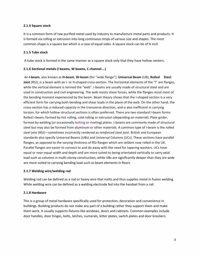
2.2.1 SAWING
It is a cutting operation where the tool is a series of small teeth on the saw. Its width of cut is narrow
and process is used on all materials that are machinable by other cutting process.
Fig 2.2.1 set pattern for sawing [. http://www.americanmachinetools.com/how_to_use_bandsaw.html]
Typical saw teeth and saw blade design are as shown above. The teeth are made so as to;-
• Prevent saw from binding or rubbing during cutting.
• They are also offset so that the width of cut is greater than the width of the blade.
During the process of sawing at least two or three teeth should be in contact with the work piece in
order to prevent shagging.
The basic saw types are namely;
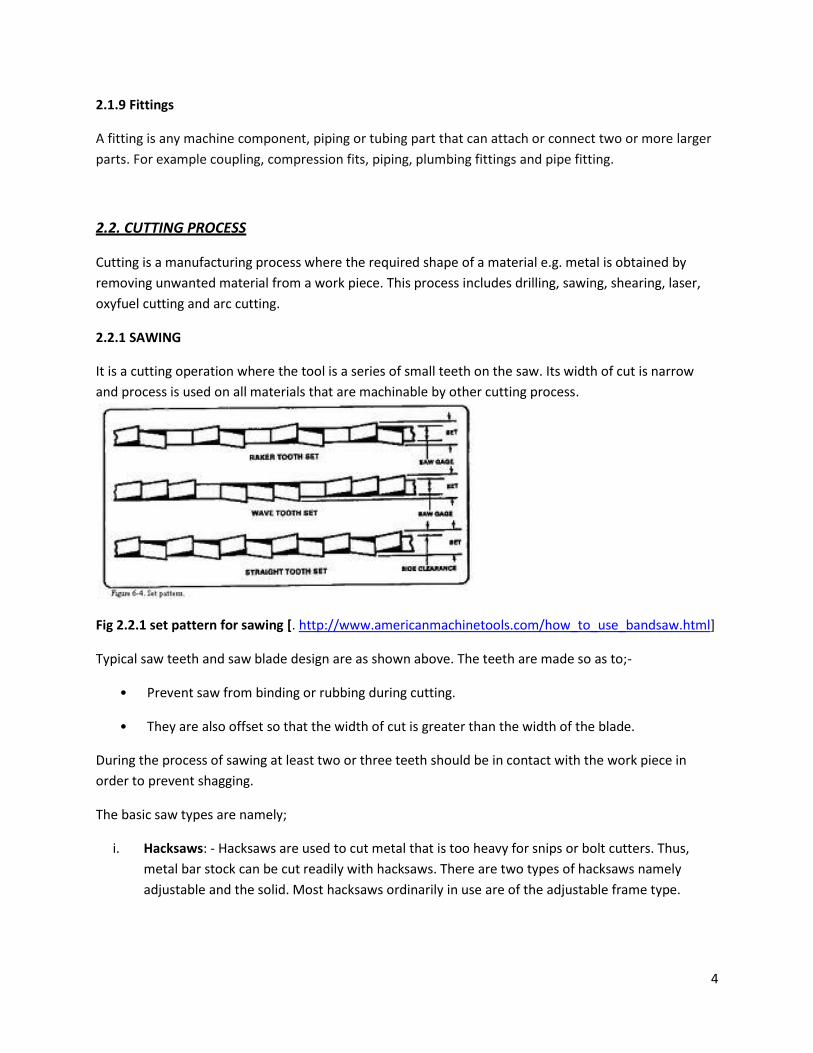
i. Hacksaws: - Hacksaws are used to cut metal that is too heavy for snips or bolt cutters. Thus,
metal bar stock can be cut readily with hacksaws. There are two types of hacksaws namely
adjustable and the solid. Most hacksaws ordinarily in use are of the adjustable frame type.
5
Fig 2.2.2: hacksaws
[http://www.listoftools.com/handtools/metal_cutting_tools/hacksaws.html]
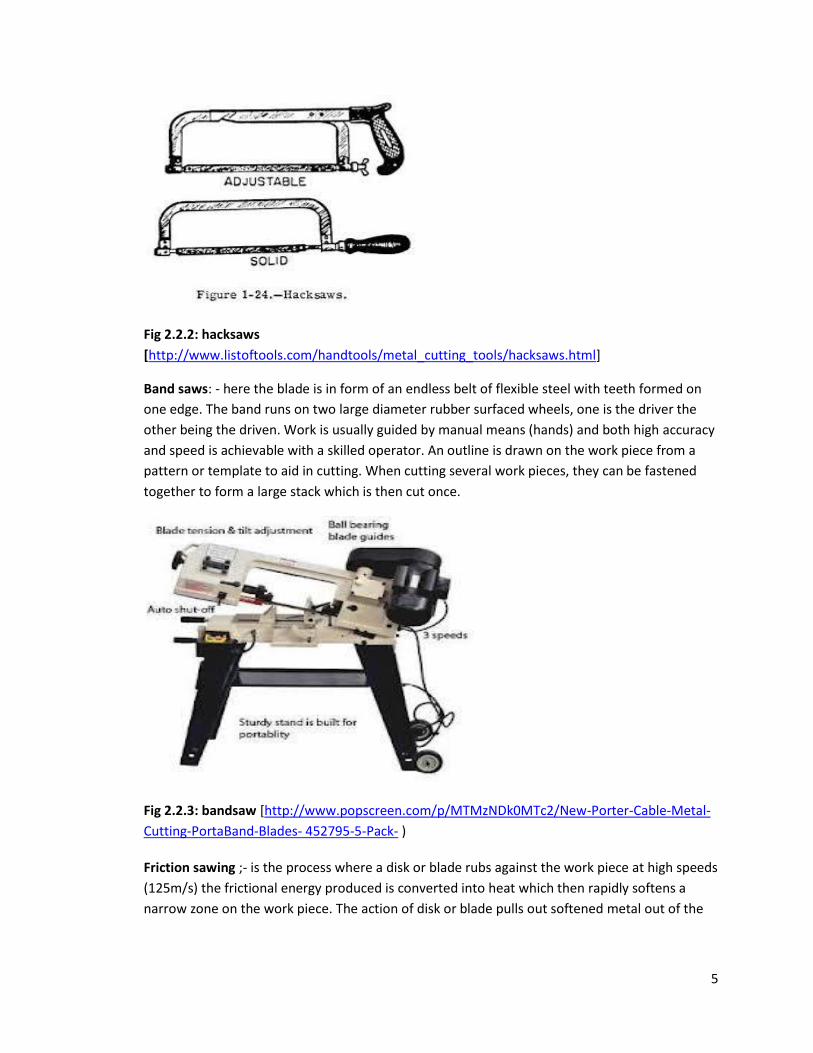
Band saws: - here the blade is in form of an endless belt of flexible steel with teeth formed on
one edge. The band runs on two large diameter rubber surfaced wheels, one is the driver the
other being the driven. Work is usually guided by manual means (hands) and both high accuracy
and speed is achievable with a skilled operator. An outline is drawn on the work piece from a
pattern or template to aid in cutting. When cutting several work pieces, they can be fastened
together to form a large stack which is then cut once.
Fig 2.2.3: bandsaw [http://www.popscreen.com/p/MTMzNDk0MTc2/New-Porter-Cable-Metal-
Cutting-PortaBand-Blades- 452795-5-Pack- )
Friction sawing ;- is the process where a disk or blade rubs against the work piece at high speeds
(125m/s) the frictional energy produced is converted into heat which then rapidly softens a
narrow zone on the work piece. The action of disk or blade pulls out softened metal out of the
6
cutting zone. This friction-sawing process is suitable for a variety of ferrous metals since non-
ferrous metals tend to adhere to the blade.
ii. Rotary files and burrs;-they are cutters in shape of cones cylinders, spheres and other shapes
with various tooth profiles. They also have similar action as to reamers except that they remove
small amounts of materials at very high speed with small diameter burrs.
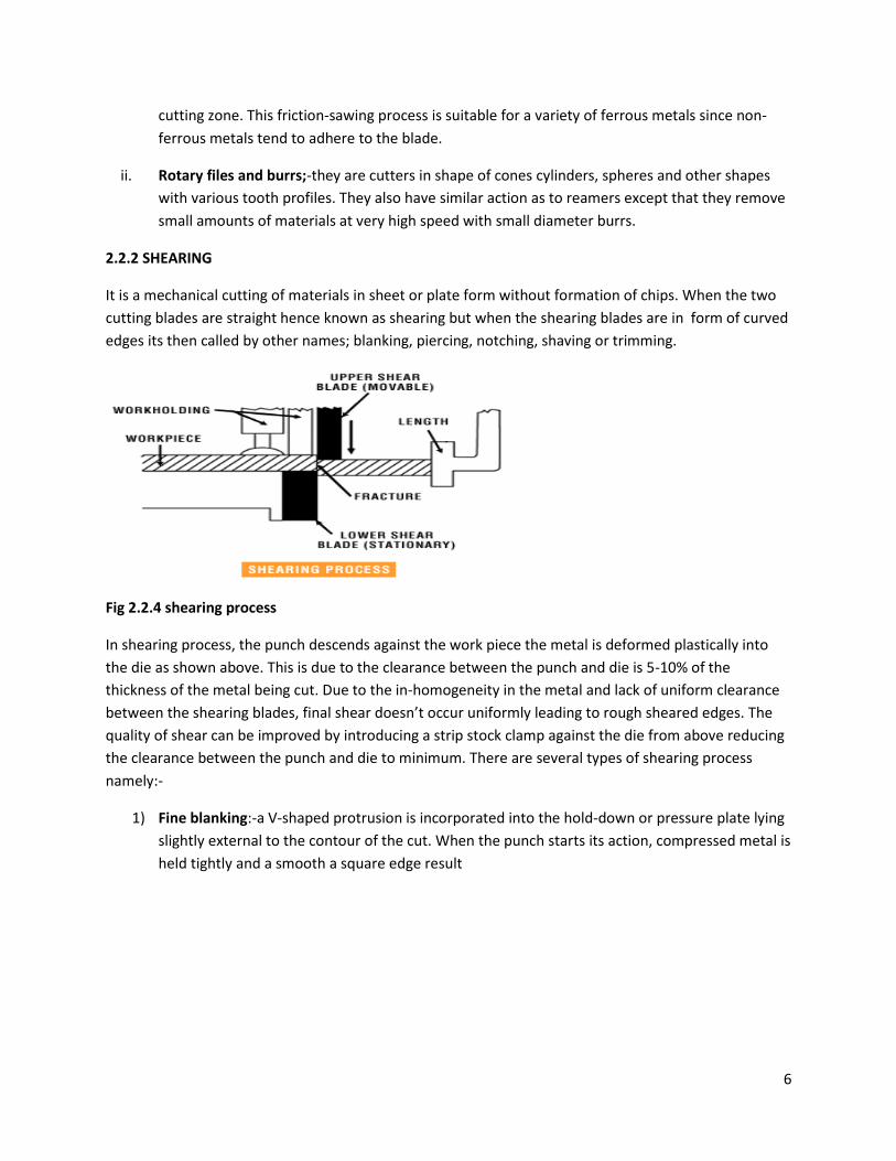
2.2.2 SHEARING
It is a mechanical cutting of materials in sheet or plate form without formation of chips. When the two
cutting blades are straight hence known as shearing but when the shearing blades are in form of curved
edges its then called by other names; blanking, piercing, notching, shaving or trimming.
Fig 2.2.4 shearing process
In shearing process, the punch descends against the work piece the metal is deformed plastically into
the die as shown above. This is due to the clearance between the punch and die is 5-10% of the
thickness of the metal being cut. Due to the in-homogeneity in the metal and lack of uniform clearance
between the shearing blades, final shear doesn’t occur uniformly leading to rough sheared edges. The
quality of shear can be improved by introducing a strip stock clamp against the die from above reducing
the clearance between the punch and die to minimum. There are several types of shearing process
namely:-
1) Fine blanking:-a V-shaped protrusion is incorporated into the hold-down or pressure plate lying
slightly external to the contour of the cut. When the punch starts its action, compressed metal is
held tightly and a smooth a square edge result
7
Fig 2.2.5: fine blanking
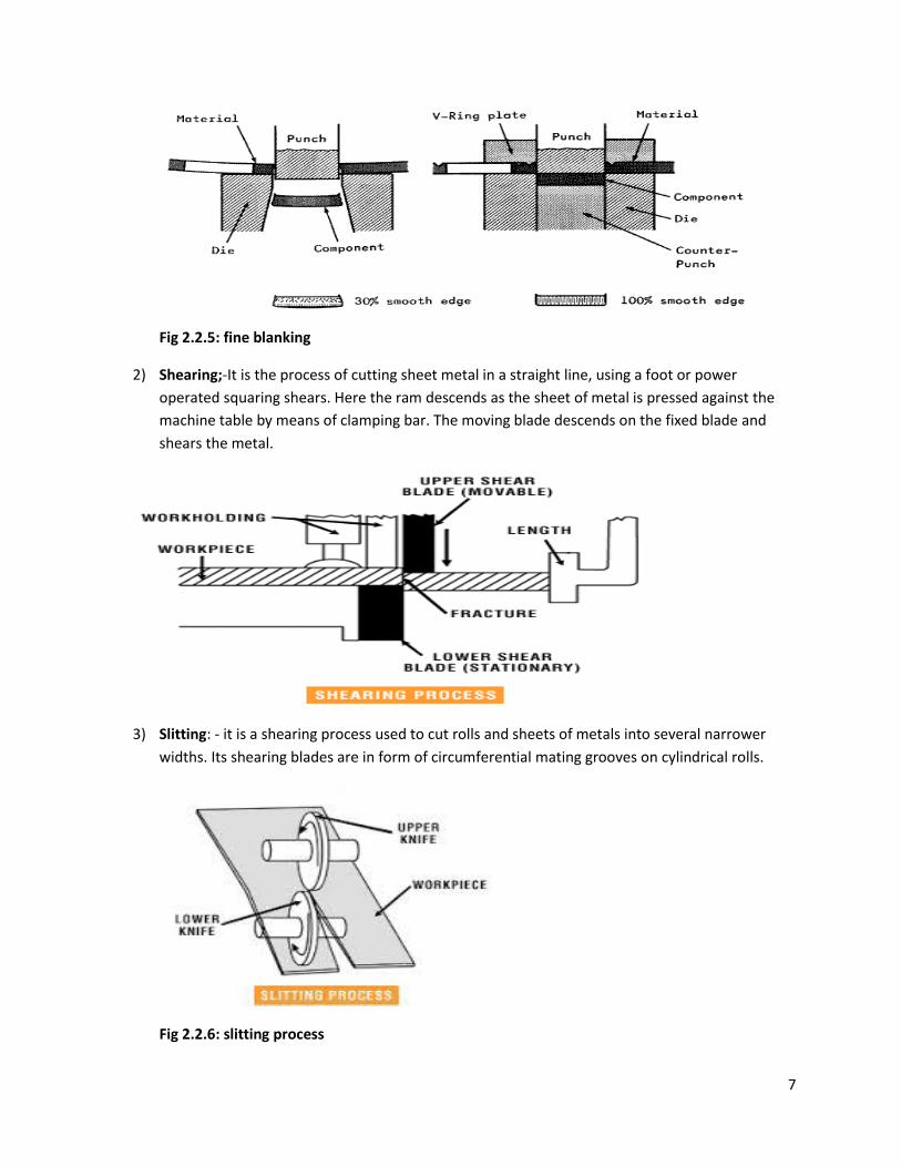
2) Shearing;-It is the process of cutting sheet metal in a straight line, using a foot or power
operated squaring shears. Here the ram descends as the sheet of metal is pressed against the
machine table by means of clamping bar. The moving blade descends on the fixed blade and
shears the metal.
3) Slitting: - it is a shearing process used to cut rolls and sheets of metals into several narrower
widths. Its shearing blades are in form of circumferential mating grooves on cylindrical rolls.
Fig 2.2.6: slitting process
8
4) Piercing and blanking:- it is a shearing operation in which the shearing blades takes the form of
closed, curved lines on edges of punch and die. In blanking, the piece punched out is the desired
work piece while in piercing the punched out piece is the scrap and reminder of the strip
becomes desired work piece. This is achievable in mechanical presses. some of the piercing and
blanking operations are;-
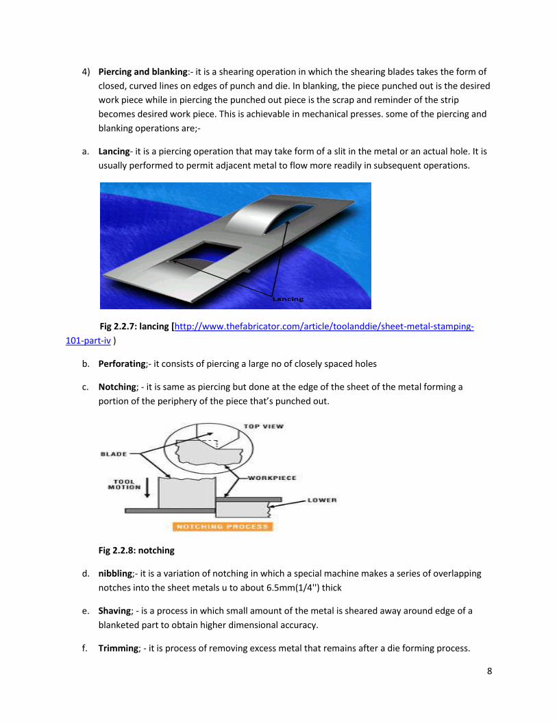
a. Lancing- it is a piercing operation that may take form of a slit in the metal or an actual hole. It is
usually performed to permit adjacent metal to flow more readily in subsequent operations.
Fig 2.2.7: lancing [http://www.thefabricator.com/article/toolanddie/sheet-metal-stamping-
101-part-iv )
b. Perforating;- it consists of piercing a large no of closely spaced holes
c. Notching; - it is same as piercing but done at the edge of the sheet of the metal forming a
portion of the periphery of the piece that’s punched out.
Fig 2.2.8: notching
d. nibbling;- it is a variation of notching in which a special machine makes a series of overlapping
notches into the sheet metals u to about 6.5mm(1/4'') thick
e. Shaving; - is a process in which small amount of the metal is sheared away around edge of a
blanketed part to obtain higher dimensional accuracy.
f. Trimming; - it is process of removing excess metal that remains after a die forming process.
9
Fig 2.2.9: Trimming [. http://hubpages.com/hub/Basic-Metal-Stamping-Die-Terminology]
g. Cut off; - it is an operation done in which stamping is removed from a strip of stock by means of
punch and die. The cutoff punch and die cut across the entire width of the strip.
2.2.3. DRILLING AND REAMING.
It is a cutting process that uses a drill bit to cut or enlarge a hole of a circular cross-section in solid
materials. The drill bit is a rotary cutting tool often multipoint and is usually pressed against the work
piece and rotated at different revolutions per minute. This forces the cutting edge against the work
piece, cutting off chips from the holes as it is drilled. There are several types of drill bits used namely:-
1) Twist drills; -they are the most common type of drill used. It entails a cutting point at tip of a
cylindrical shaft with helical flute. The helical flute acts as a lift of swarf out of the hole. They
range in diameter 0.051-89mm.
Fig 2.2.10: types of twist drills [http://www.hnsa.org/doc/tools/]
10
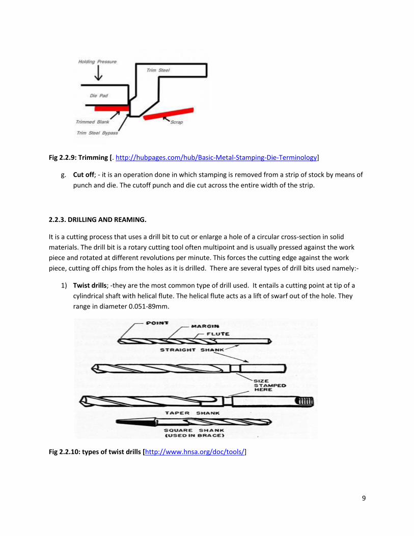
2) Step drill; - it has its tip ground down to a different dia. This transition between ground
diameter and original diameter is either straight for it to form a counter bore or angled to form
a countersink. Counter boring is the process of providing an enlarged cylindrical hole with a flat
bottom so that the bolt head will have a smooth bearing surface normal to the axis of the hole.
Countersinking in the other hand is the provision of a beveled section at the end of a drilled hole
to provide proper seat for a rivet or screw.
Fig 2.2.11 step drill
[http://www.automationdirect.com/adc/Overview/Catalog/Tools/Hole_Cutting_Tools/]
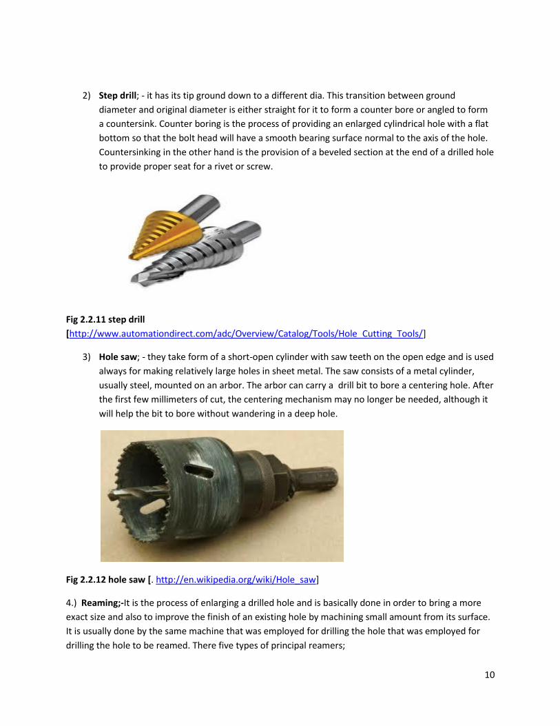
3) Hole saw; - they take form of a short-open cylinder with saw teeth on the open edge and is used
always for making relatively large holes in sheet metal. The saw consists of a metal cylinder,
usually steel, mounted on an arbor. The arbor can carry a drill bit to bore a centering hole. After
the first few millimeters of cut, the centering mechanism may no longer be needed, although it
will help the bit to bore without wandering in a deep hole.
Fig 2.2.12 hole saw [. http://en.wikipedia.org/wiki/Hole_saw]
4.) Reaming;-It is the process of enlarging a drilled hole and is basically done in order to bring a more
exact size and also to improve the finish of an existing hole by machining small amount from its surface.
It is usually done by the same machine that was employed for drilling the hole that was employed for
drilling the hole to be reamed. There five types of principal reamers;
11
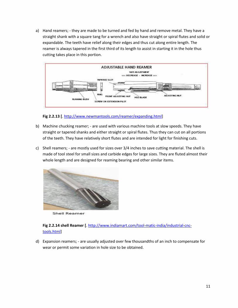
a) Hand reamers; - they are made to be turned and fed by hand and remove metal. They have a
straight shank with a square tang for a wrench and also have straight or spiral flutes and solid or
expandable. The teeth have relief along their edges and thus cut along entire length. The
reamer is always tapered in the first third of its length to assist in starting it in the hole thus
cutting takes place in this portion.
Fig 2.2.13 [. http://www.newmantools.com/reamer/expanding.html]
b) Machine chucking reamer; - are used with various machine tools at slow speeds. They have
straight or tapered shanks and either straight or spiral flutes. Thus they can cut on all portions
of the teeth. They have relatively short flutes and are intended for light for finishing cuts.
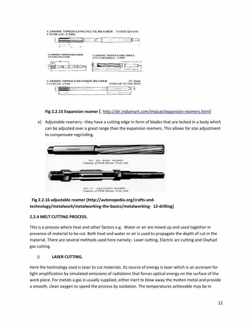
c) Shell reamers; - are mostly used for sizes over 3/4 inches to save cutting material. The shell is
made of tool steel for small sizes and carbide edges for large sizes. They are fluted almost their
whole length and are designed for reaming bearing and other similar items.
Fig 2.2.14 shell Reamer [. http://www.indiamart.com/tool-matic-india/industrial-cnc-
tools.html]
d) Expansion reamers; - are usually adjusted over few thousandths of an inch to compensate for
wear or permit some variation in hole size to be obtained.
12
Fig 2.2.15 Expansion reamer [. http://dir.indiamart.com/impcat/expansion-reamers.html]
e) Adjustable reamers;- they have a cutting edge in form of blades that are locked in a body which
can be adjusted over a great range than the expansion reamers. This allows for size adjustment
to compensate regrinding.
Fig 2.2.16 adjustable reamer [http://autonopedia.org/crafts-and-
technology/metalwork/metalworking-the-basics/metalworking- 12-drilling]
2.2.4 MELT CUTTING PROCESS.
This is a process where heat and other factors e.g. Water or air are mixed up and used together in
presence of material to be cut. Both heat and water or air is used to propagate the depth of cut in the
material. There are several methods used here namely;- Laser cutting, Electric arc cutting and Oxyfuel
gas cutting.
i) LASER CUTTING.
Here the technology used is laser to cut materials. Its source of energy is laser which is an acronym for
light amplification by simulated emissions of radiations that forces optical energy on the surface of the
work piece. For metals a gas is usually supplied, either inert to blow away the molten metal and provide
a smooth, clean oxygen to speed the process by oxidation. The temperatures achievable may be in
13
excess of 20,000*F and cutting speeds of 20” per minute is common [3]. There are several methods of
cutting lasers;-
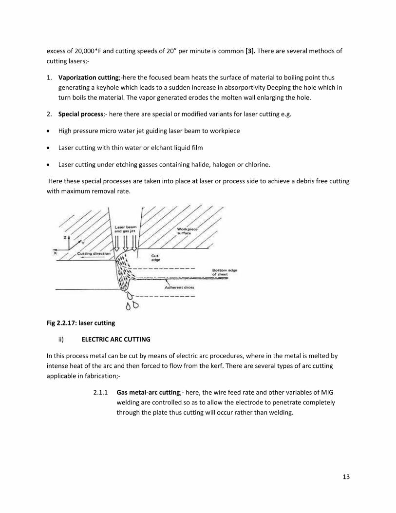
1. Vaporization cutting;-here the focused beam heats the surface of material to boiling point thus
generating a keyhole which leads to a sudden increase in absorportivity Deeping the hole which in
turn boils the material. The vapor generated erodes the molten wall enlarging the hole.
2. Special process;- here there are special or modified variants for laser cutting e.g.
High pressure micro water jet guiding laser beam to workpiece
Laser cutting with thin water or elchant liquid film
Laser cutting under etching gasses containing halide, halogen or chlorine.
Here these special processes are taken into place at laser or process side to achieve a debris free cutting
with maximum removal rate.
Fig 2.2.17: laser cutting
ii) ELECTRIC ARC CUTTING
In this process metal can be cut by means of electric arc procedures, where in the metal is melted by
intense heat of the arc and then forced to flow from the kerf. There are several types of arc cutting
applicable in fabrication;-
2.1.1 Gas metal-arc cutting;- here, the wire feed rate and other variables of MIG
welding are controlled so as to allow the electrode to penetrate completely
through the plate thus cutting will occur rather than welding.
14
Fig 2.2.18: air carbon arc cutting
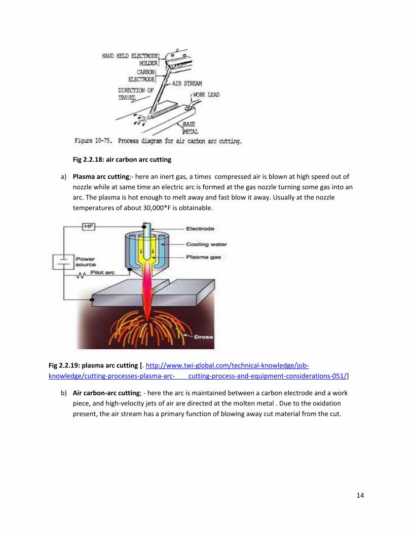
a) Plasma arc cutting;- here an inert gas, a times compressed air is blown at high speed out of
nozzle while at same time an electric arc is formed at the gas nozzle turning some gas into an
arc. The plasma is hot enough to melt away and fast blow it away. Usually at the nozzle
temperatures of about 30,000*F is obtainable.
Fig 2.2.19: plasma arc cutting [. http://www.twi-global.com/technical-knowledge/job-
knowledge/cutting-processes-plasma-arc- cutting-process-and-equipment-considerations-051/]
b) Air carbon-arc cutting; - here the arc is maintained between a carbon electrode and a work
piece, and high-velocity jets of air are directed at the molten metal . Due to the oxidation
present, the air stream has a primary function of blowing away cut material from the cut.
15
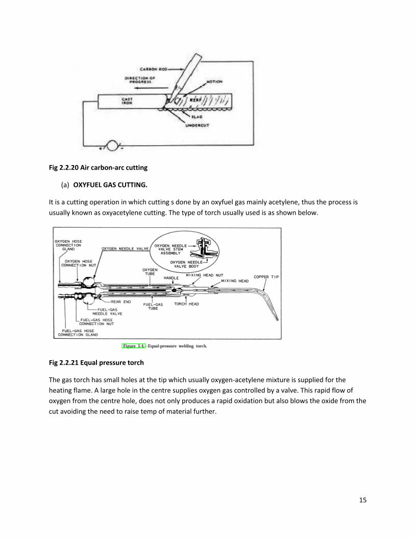
Fig 2.2.20 Air carbon-arc cutting
(a) OXYFUEL GAS CUTTING.
It is a cutting operation in which cutting s done by an oxyfuel gas mainly acetylene, thus the process is
usually known as oxyacetylene cutting. The type of torch usually used is as shown below.
Fig 2.2.21 Equal pressure torch
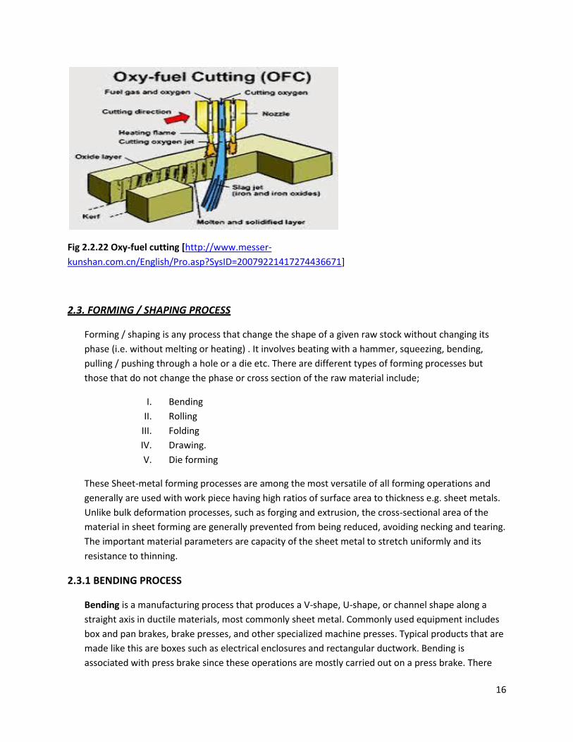
The gas torch has small holes at the tip which usually oxygen-acetylene mixture is supplied for the
heating flame. A large hole in the centre supplies oxygen gas controlled by a valve. This rapid flow of
oxygen from the centre hole, does not only produces a rapid oxidation but also blows the oxide from the
cut avoiding the need to raise temp of material further.
16
Fig 2.2.22 Oxy-fuel cutting [http://www.messer-
kunshan.com.cn/English/Pro.asp?SysID=20079221417274436671]
2.3. FORMING / SHAPING PROCESS
Forming / shaping is any process that change the shape of a given raw stock without changing its
phase (i.e. without melting or heating) . It involves beating with a hammer, squeezing, bending,
pulling / pushing through a hole or a die etc. There are different types of forming processes but
those that do not change the phase or cross section of the raw material include;
I. Bending
II. Rolling
III. Folding
IV. Drawing.
V. Die forming
These Sheet-metal forming processes are among the most versatile of all forming operations and
generally are used with work piece having high ratios of surface area to thickness e.g. sheet metals.
Unlike bulk deformation processes, such as forging and extrusion, the cross-sectional area of the
material in sheet forming are generally prevented from being reduced, avoiding necking and tearing.
The important material parameters are capacity of the sheet metal to stretch uniformly and its
resistance to thinning.
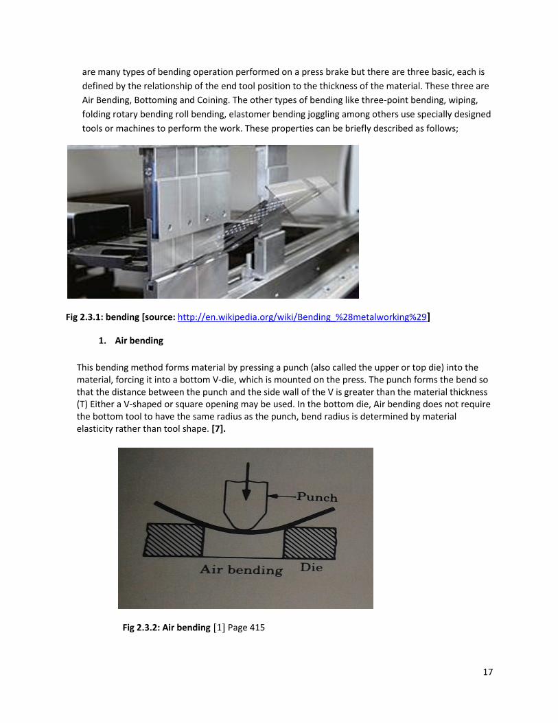
2.3.1 BENDING PROCESS
Bending is a manufacturing process that produces a V-shape, U-shape, or channel shape along a
straight axis in ductile materials, most commonly sheet metal. Commonly used equipment includes
box and pan brakes, brake presses, and other specialized machine presses. Typical products that are
made like this are boxes such as electrical enclosures and rectangular ductwork. Bending is
associated with press brake since these operations are mostly carried out on a press brake. There
17
are many types of bending operation performed on a press brake but there are three basic, each is
defined by the relationship of the end tool position to the thickness of the material. These three are
Air Bending, Bottoming and Coining. The other types of bending like three-point bending, wiping,
folding rotary bending roll bending, elastomer bending joggling among others use specially designed
tools or machines to perform the work. These properties can be briefly described as follows;
Fig 2.3.1: bending [source: http://en.wikipedia.org/wiki/Bending_%28metalworking%29]
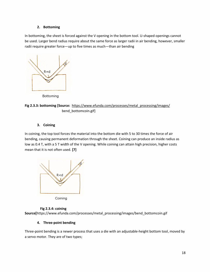
1. Air bending
This bending method forms material by pressing a punch (also called the upper or top die) into the material, forcing it into a bottom V-die, which is mounted on the press. The punch forms the bend so that the distance between the punch and the side wall of the V is greater than the material thickness (T) Either a V-shaped or square opening may be used. In the bottom die, Air bending does not require the bottom tool to have the same radius as the punch, bend radius is determined by material elasticity rather than tool shape. [7].
Fig 2.3.2: Air bending [1] Page 415
18
2. Bottoming
In bottoming, the sheet is forced against the V opening in the bottom tool. U-shaped openings cannot
be used. Larger bend radius require about the same force as larger radii in air bending, however, smaller
radii require greater force—up to five times as much—than air bending
Fig 2.3.3: bottoming [Source: https://www.efunda.com/processes/metal_processing/images/
bend_bottomcoin.gif]
3. Coining
In coining, the top tool forces the material into the bottom die with 5 to 30 times the force of air
bending, causing permanent deformation through the sheet. Coining can produce an inside radius as
low as 0.4 T, with a 5 T width of the V opening. While coining can attain high precision, higher costs
mean that it is not often used. [7]
Fig 2.3.4: coining Source[https://www.efunda.com/processes/metal_processing/images/bend_bottomcoin.gif
4. Three-point bending
Three-point bending is a newer process that uses a die with an adjustable-height bottom tool, moved by
a servo motor. They are of two types;
19
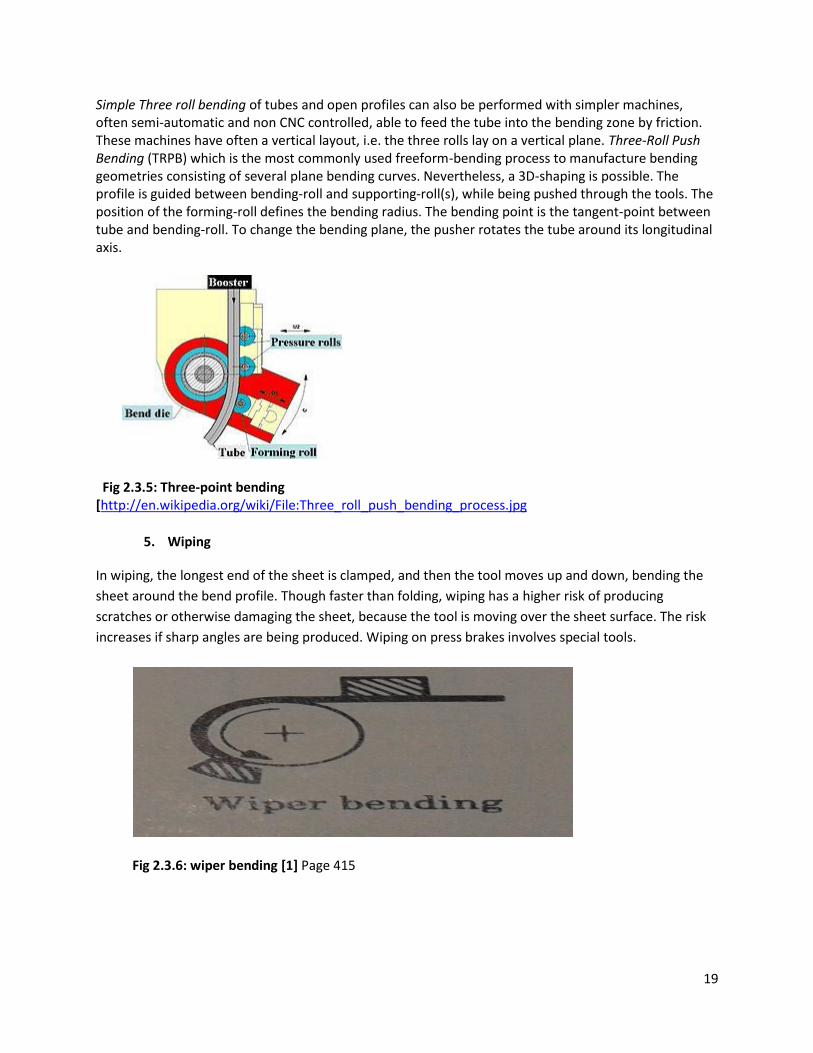
Simple Three roll bending of tubes and open profiles can also be performed with simpler machines, often semi-automatic and non CNC controlled, able to feed the tube into the bending zone by friction. These machines have often a vertical layout, i.e. the three rolls lay on a vertical plane. Three-Roll Push Bending (TRPB) which is the most commonly used freeform-bending process to manufacture bending geometries consisting of several plane bending curves. Nevertheless, a 3D-shaping is possible. The profile is guided between bending-roll and supporting-roll(s), while being pushed through the tools. The position of the forming-roll defines the bending radius. The bending point is the tangent-point between tube and bending-roll. To change the bending plane, the pusher rotates the tube around its longitudinal axis.
Fig 2.3.5: Three-point bending [http://en.wikipedia.org/wiki/File:Three_roll_push_bending_process.jpg
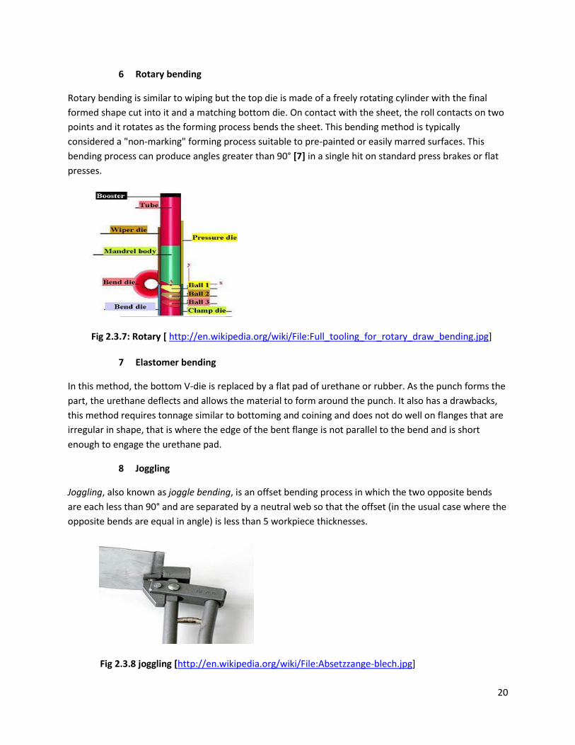
5. Wiping
In wiping, the longest end of the sheet is clamped, and then the tool moves up and down, bending the
sheet around the bend profile. Though faster than folding, wiping has a higher risk of producing
scratches or otherwise damaging the sheet, because the tool is moving over the sheet surface. The risk
increases if sharp angles are being produced. Wiping on press brakes involves special tools.
Fig 2.3.6: wiper bending [1] Page 415
20
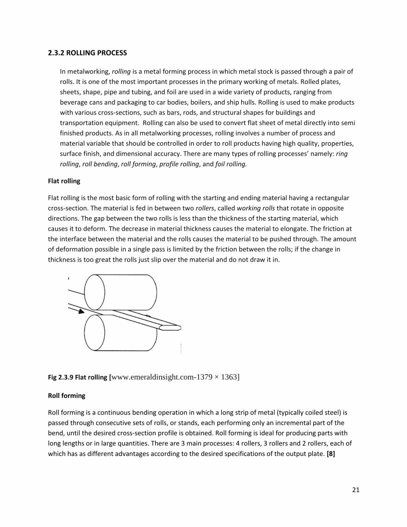
6 Rotary bending
Rotary bending is similar to wiping but the top die is made of a freely rotating cylinder with the final
formed shape cut into it and a matching bottom die. On contact with the sheet, the roll contacts on two
points and it rotates as the forming process bends the sheet. This bending method is typically
considered a "non-marking" forming process suitable to pre-painted or easily marred surfaces. This
bending process can produce angles greater than 90° [7] in a single hit on standard press brakes or flat
presses.
Fig 2.3.7: Rotary [ http://en.wikipedia.org/wiki/File:Full_tooling_for_rotary_draw_bending.jpg]
7 Elastomer bending
In this method, the bottom V-die is replaced by a flat pad of urethane or rubber. As the punch forms the
part, the urethane deflects and allows the material to form around the punch. It also has a drawbacks,
this method requires tonnage similar to bottoming and coining and does not do well on flanges that are
irregular in shape, that is where the edge of the bent flange is not parallel to the bend and is short
enough to engage the urethane pad.
8 Joggling
Joggling, also known as joggle bending, is an offset bending process in which the two opposite bends
are each less than 90° and are separated by a neutral web so that the offset (in the usual case where the
opposite bends are equal in angle) is less than 5 workpiece thicknesses.
Fig 2.3.8 joggling [http://en.wikipedia.org/wiki/File:Absetzzange-blech.jpg]
21
2.3.2 ROLLING PROCESS
In metalworking, rolling is a metal forming process in which metal stock is passed through a pair of
rolls. It is one of the most important processes in the primary working of metals. Rolled plates,
sheets, shape, pipe and tubing, and foil are used in a wide variety of products, ranging from
beverage cans and packaging to car bodies, boilers, and ship hulls. Rolling is used to make products
with various cross-sections, such as bars, rods, and structural shapes for buildings and
transportation equipment. Rolling can also be used to convert flat sheet of metal directly into semi
finished products. As in all metalworking processes, rolling involves a number of process and
material variable that should be controlled in order to roll products having high quality, properties,
surface finish, and dimensional accuracy. There are many types of rolling processes’ namely: ring
rolling, roll bending, roll forming, profile rolling, and foil rolling.
Flat rolling
Flat rolling is the most basic form of rolling with the starting and ending material having a rectangular
cross-section. The material is fed in between two rollers, called working rolls that rotate in opposite
directions. The gap between the two rolls is less than the thickness of the starting material, which
causes it to deform. The decrease in material thickness causes the material to elongate. The friction at
the interface between the material and the rolls causes the material to be pushed through. The amount
of deformation possible in a single pass is limited by the friction between the rolls; if the change in
thickness is too great the rolls just slip over the material and do not draw it in.
Fig 2.3.9 Flat rolling [www.emeraldinsight.com-1379 × 1363]
Roll forming
Roll forming is a continuous bending operation in which a long strip of metal (typically coiled steel) is
passed through consecutive sets of rolls, or stands, each performing only an incremental part of the
bend, until the desired cross-section profile is obtained. Roll forming is ideal for producing parts with
long lengths or in large quantities. There are 3 main processes: 4 rollers, 3 rollers and 2 rollers, each of
which has as different advantages according to the desired specifications of the output plate. [8]
22
Fig 2.3.10 Roll forming [: www.custompartnet.com-640 × 480]
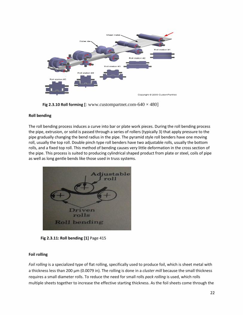
Roll bending
The roll bending process induces a curve into bar or plate work pieces. During the roll bending process the pipe, extrusion, or solid is passed through a series of rollers (typically 3) that apply pressure to the pipe gradually changing the bend radius in the pipe. The pyramid style roll benders have one moving roll, usually the top roll. Double pinch type roll benders have two adjustable rolls, usually the bottom rolls, and a fixed top roll. This method of bending causes very little deformation in the cross section of the pipe. This process is suited to producing cylindrical shaped product from plate or steel, coils of pipe as well as long gentle bends like those used in truss systems.
Fig 2.3.11: Roll bending [1] Page 415
Foil rolling
Foil rolling is a specialized type of flat rolling, specifically used to produce foil, which is sheet metal with
a thickness less than 200 µm (0.0079 in). The rolling is done in a cluster mill because the small thickness
requires a small diameter rolls. To reduce the need for small rolls pack rolling is used, which rolls
multiple sheets together to increase the effective starting thickness. As the foil sheets come through the
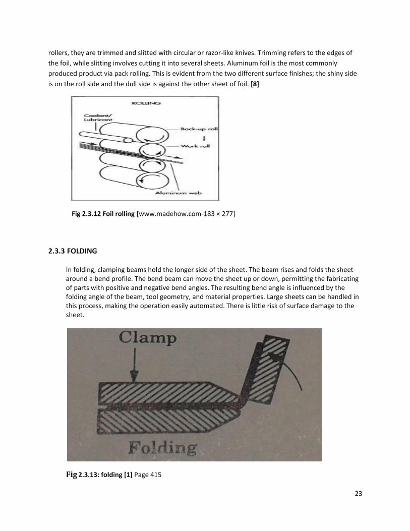
23
rollers, they are trimmed and slitted with circular or razor-like knives. Trimming refers to the edges of
the foil, while slitting involves cutting it into several sheets. Aluminum foil is the most commonly
produced product via pack rolling. This is evident from the two different surface finishes; the shiny side
is on the roll side and the dull side is against the other sheet of foil. [8]
Fig 2.3.12 Foil rolling [www.madehow.com-183 × 277]
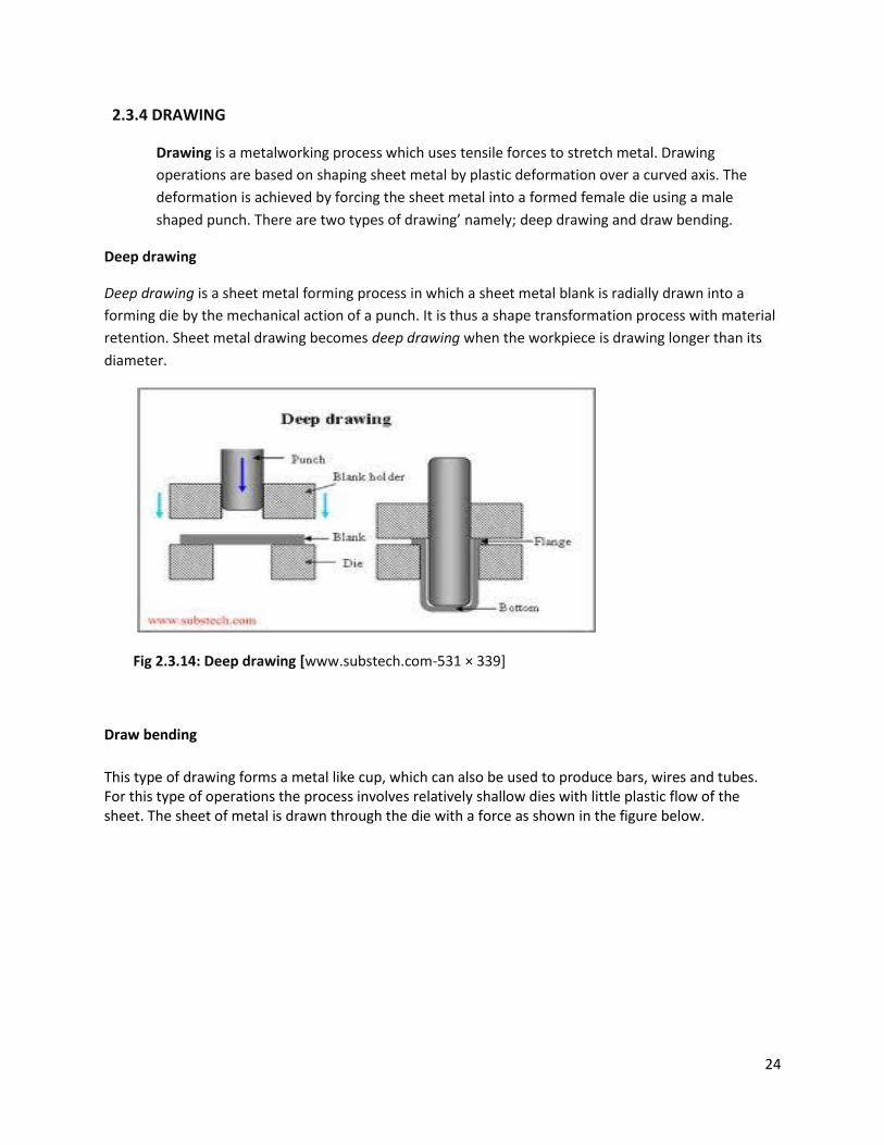
2.3.3 FOLDING
In folding, clamping beams hold the longer side of the sheet. The beam rises and folds the sheet around a bend profile. The bend beam can move the sheet up or down, permitting the fabricating of parts with positive and negative bend angles. The resulting bend angle is influenced by the folding angle of the beam, tool geometry, and material properties. Large sheets can be handled in this process, making the operation easily automated. There is little risk of surface damage to the sheet.
Fig 2.3.13: folding [1] Page 415
24
2.3.4 DRAWING
Drawing is a metalworking process which uses tensile forces to stretch metal. Drawing
operations are based on shaping sheet metal by plastic deformation over a curved axis. The
deformation is achieved by forcing the sheet metal into a formed female die using a male
shaped punch. There are two types of drawing’ namely; deep drawing and draw bending.
Deep drawing
Deep drawing is a sheet metal forming process in which a sheet metal blank is radially drawn into a
forming die by the mechanical action of a punch. It is thus a shape transformation process with material
retention. Sheet metal drawing becomes deep drawing when the workpiece is drawing longer than its
diameter.
Fig 2.3.14: Deep drawing [www.substech.com-531 × 339]
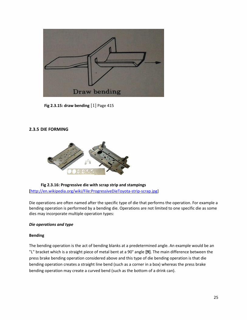
Draw bending
This type of drawing forms a metal like cup, which can also be used to produce bars, wires and tubes. For this type of operations the process involves relatively shallow dies with little plastic flow of the sheet. The sheet of metal is drawn through the die with a force as shown in the figure below.
25
Fig 2.3.15: draw bending [1] Page 415
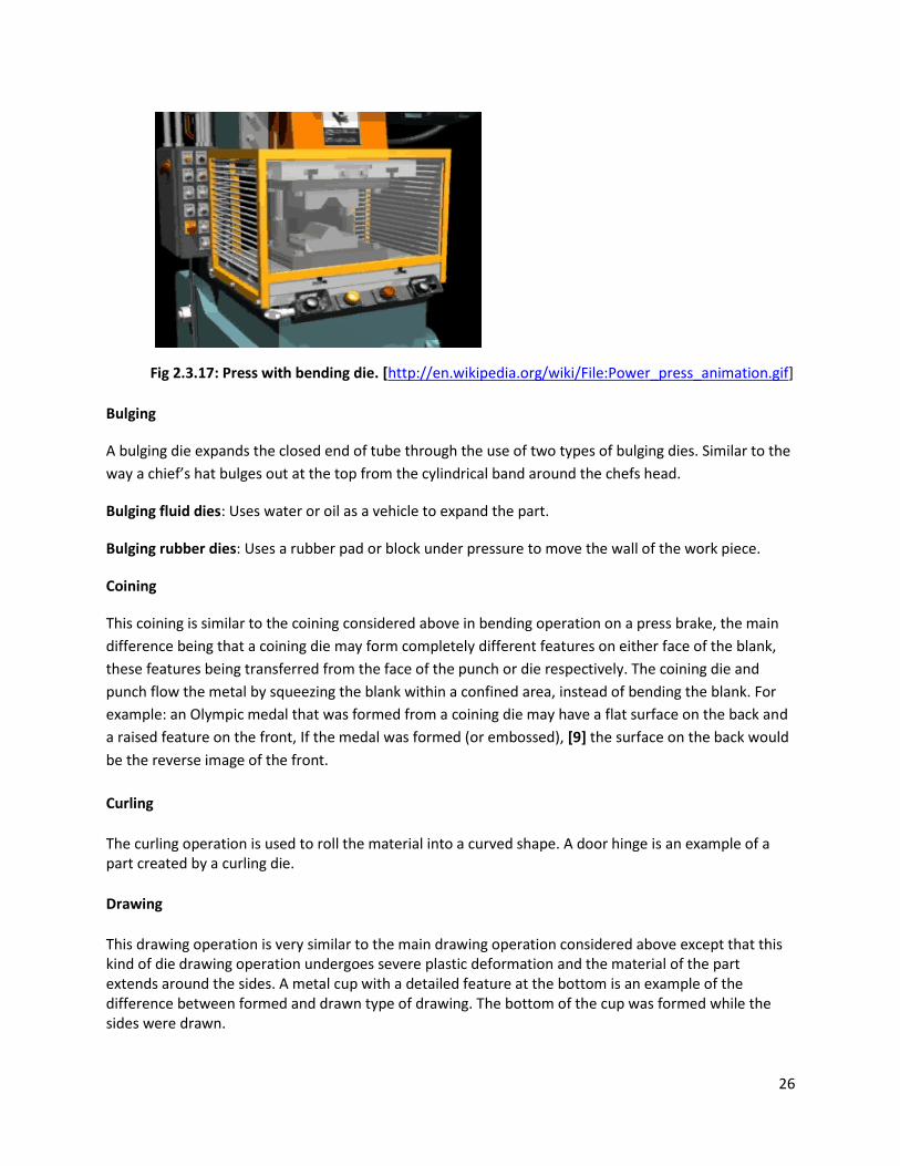
2.3.5 DIE FORMING
Fig 2.3.16: Progressive die with scrap strip and stampings
[http://en.wikipedia.org/wiki/File:ProgressiveDieToyota-strip-scrap.jpg]
Die operations are often named after the specific type of die that performs the operation. For example a bending operation is performed by a bending die. Operations are not limited to one specific die as some dies may incorporate multiple operation types: Die operations and type Bending
The bending operation is the act of bending blanks at a predetermined angle. An example would be an
"L" bracket which is a straight piece of metal bent at a 90° angle [9]. The main difference between the
press brake bending operation considered above and this type of die bending operation is that die
bending operation creates a straight line bend (such as a corner in a box) whereas the press brake
bending operation may create a curved bend (such as the bottom of a drink can).
26
Fig 2.3.17: Press with bending die. [http://en.wikipedia.org/wiki/File:Power_press_animation.gif]
Bulging
A bulging die expands the closed end of tube through the use of two types of bulging dies. Similar to the
way a chief’s hat bulges out at the top from the cylindrical band around the chefs head.
Bulging fluid dies: Uses water or oil as a vehicle to expand the part.
Bulging rubber dies: Uses a rubber pad or block under pressure to move the wall of the work piece.
Coining
This coining is similar to the coining considered above in bending operation on a press brake, the main
difference being that a coining die may form completely different features on either face of the blank,
these features being transferred from the face of the punch or die respectively. The coining die and
punch flow the metal by squeezing the blank within a confined area, instead of bending the blank. For
example: an Olympic medal that was formed from a coining die may have a flat surface on the back and
a raised feature on the front, If the medal was formed (or embossed), [9] the surface on the back would
be the reverse image of the front.
Curling
The curling operation is used to roll the material into a curved shape. A door hinge is an example of a part created by a curling die.
Drawing
This drawing operation is very similar to the main drawing operation considered above except that this kind of die drawing operation undergoes severe plastic deformation and the material of the part extends around the sides. A metal cup with a detailed feature at the bottom is an example of the difference between formed and drawn type of drawing. The bottom of the cup was formed while the sides were drawn.
27
Forming
Forming dies bend the blank along a curved surface. An example of a part that has been formed would be the positive end (+) of an AA battery.
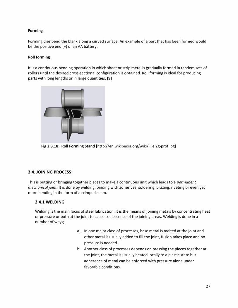
Roll forming
It is a continuous bending operation in which sheet or strip metal is gradually formed in tandem sets of rollers until the desired cross-sectional configuration is obtained. Roll forming is ideal for producing parts with long lengths or in large quantities. [9]
Fig 2.3.18: Roll Forming Stand [http://en.wikipedia.org/wiki/File:Zg-prof.jpg]
2.4. JOINING PROCESS
This is putting or bringing together pieces to make a continuous unit which leads to a permanent mechanical joint. It is done by welding, binding with adhesives, soldering, brazing, riveting or even yet more bending in the form of a crimped seam.
2.4.1 WELDING
Welding is the main focus of steel fabrication. It is the means of joining metals by concentrating heat or pressure or both at the joint to cause coalescence of the joining areas. Welding is done in a number of ways;
a. In one major class of processes, base metal is melted at the joint and
other metal is usually added to fill the joint, fusion takes place and no
pressure is needed.
b. Another class of processes depends on pressing the pieces together at
the joint, the metal is usually heated locally to a plastic state but
adherence of metal can be enforced with pressure alone under
favorable conditions.
28
Welding process has various applications; construction such as building and bridges, piping, pressure vessels, boilers and storage tanks, ship building, aircraft, aerospace, automotive and railroad.
As many as fifty different types of welding operations have been cataloged; they can be divided into two major groups: fusion welding and solid-state welding.
A. Fusion welding
A filler metal is added to the molten pool to facilitate the process and provide bulk and strength to the welded joint or we can have an autogenously weld which means no filler is added. Fusion welding includes the most widely used welding processes which can be organized into the following major groups:
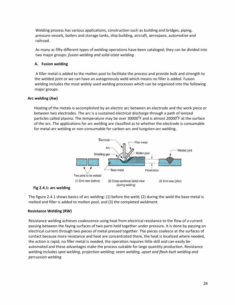
Arc welding (Aw)
Heating of the metals is accomplished by an electric arc between an electrode and the work piece or between two electrodes. The arc is a sustained electrical discharge through a path of ionized particles called plasma. The temperature may be over 300000F and is almost 200000F at the surface of the arc. The applications for arc welding are classified as to whether the electrode is consumable for metal-arc welding or non-consumable for carbon-arc and tungsten-arc welding.
Fig 2.4.1: arc welding
The figure 2.4.1 shows basics of arc welding: (1) before the weld; (2) during the weld the base metal is melted and filler is added to molten pool; and (3) the completed weldment.
Resistance Welding (RW)
Resistance welding achieves coalescence using heat from electrical resistance to the flow of a current passing between the faying surfaces of two parts held together under pressure. It is done by passing an electrical current through two pieces of metal pressed together. The pieces coalesce at the surfaces of contact because more resistance and heat are concentrated there, the heat is localized where needed, the action is rapid, no filler metal is needed, the operation requires little skill and can easily be automated and these advantages make the process suitable for large quantity production. Resistance welding includes spot welding, projection welding; seam welding, upset and flash-butt welding and percussion welding.
29
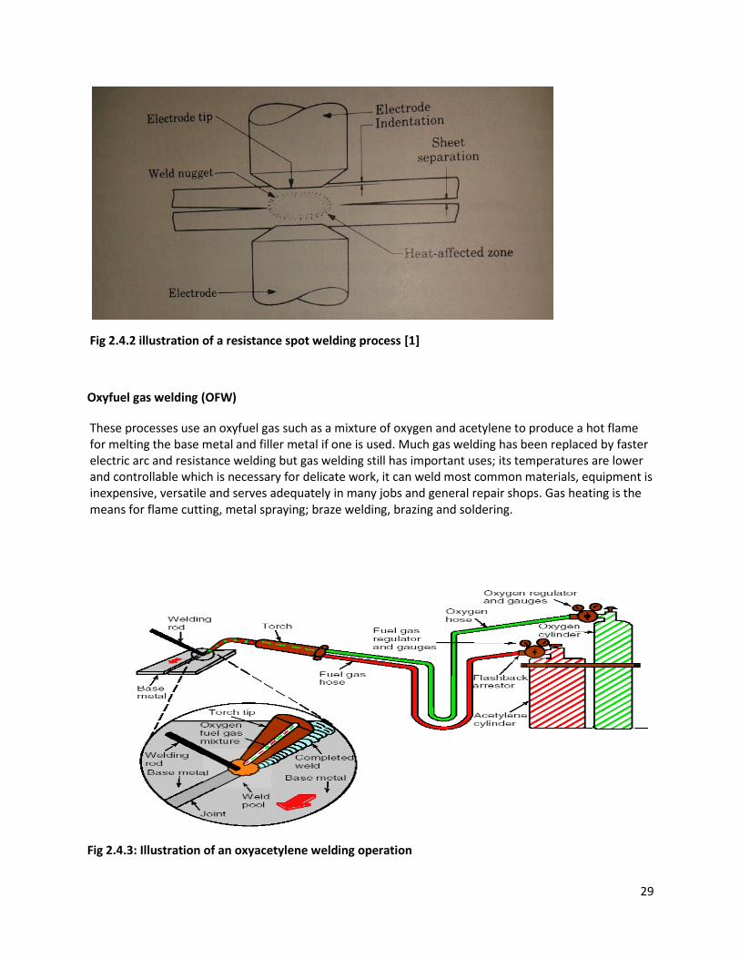
Fig 2.4.2 illustration of a resistance spot welding process [1]
Oxyfuel gas welding (OFW)
These processes use an oxyfuel gas such as a mixture of oxygen and acetylene to produce a hot flame for melting the base metal and filler metal if one is used. Much gas welding has been replaced by faster electric arc and resistance welding but gas welding still has important uses; its temperatures are lower and controllable which is necessary for delicate work, it can weld most common materials, equipment is inexpensive, versatile and serves adequately in many jobs and general repair shops. Gas heating is the means for flame cutting, metal spraying; braze welding, brazing and soldering.
Fig 2.4.3: Illustration of an oxyacetylene welding operation
30
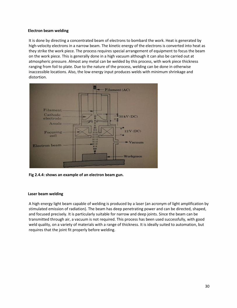
Electron beam welding
It is done by directing a concentrated beam of electrons to bombard the work. Heat is generated by high-velocity electrons in a narrow beam. The kinetic energy of the electrons is converted into heat as they strike the work piece. The process requires special arrangement of equipment to focus the beam on the work piece. This is generally done in a high vacuum although it can also be carried out at atmospheric pressure. Almost any metal can be welded by this process, with work piece thickness ranging from foil to plate. Due to the nature of the process, welding can be done in otherwise inaccessible locations. Also, the low energy input produces welds with minimum shrinkage and distortion.
Fig 2.4.4: shows an example of an electron beam gun.
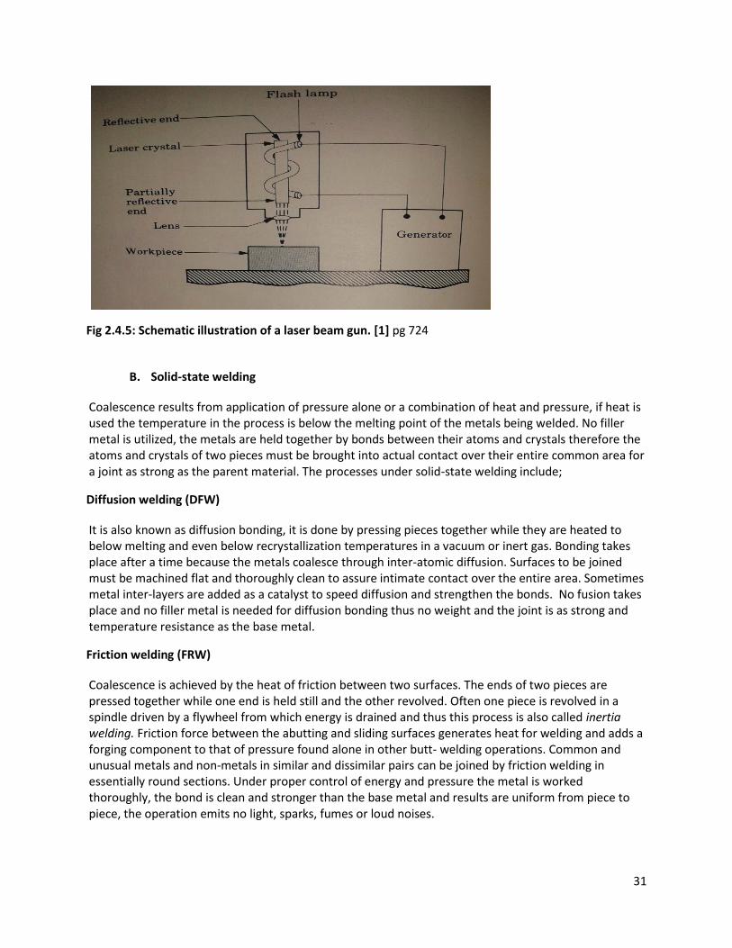
Laser beam welding
A high energy light beam capable of welding is produced by a laser (an acronym of light amplification by stimulated emission of radiation). The beam has deep penetrating power and can be directed, shaped, and focused precisely. It is particularly suitable for narrow and deep joints. Since the beam can be transmitted through air, a vacuum is not required. This process has been used successfully, with good weld quality, on a variety of materials with a range of thickness. It is ideally suited to automation, but requires that the joint fit properly before welding.
31
Fig 2.4.5: Schematic illustration of a laser beam gun. [1] pg 724
B. Solid-state welding
Coalescence results from application of pressure alone or a combination of heat and pressure, if heat is used the temperature in the process is below the melting point of the metals being welded. No filler metal is utilized, the metals are held together by bonds between their atoms and crystals therefore the atoms and crystals of two pieces must be brought into actual contact over their entire common area for a joint as strong as the parent material. The processes under solid-state welding include;
Diffusion welding (DFW)
It is also known as diffusion bonding, it is done by pressing pieces together while they are heated to below melting and even below recrystallization temperatures in a vacuum or inert gas. Bonding takes place after a time because the metals coalesce through inter-atomic diffusion. Surfaces to be joined must be machined flat and thoroughly clean to assure intimate contact over the entire area. Sometimes metal inter-layers are added as a catalyst to speed diffusion and strengthen the bonds. No fusion takes place and no filler metal is needed for diffusion bonding thus no weight and the joint is as strong and temperature resistance as the base metal.
Friction welding (FRW)
Coalescence is achieved by the heat of friction between two surfaces. The ends of two pieces are pressed together while one end is held still and the other revolved. Often one piece is revolved in a spindle driven by a flywheel from which energy is drained and thus this process is also called inertia welding. Friction force between the abutting and sliding surfaces generates heat for welding and adds a forging component to that of pressure found alone in other butt- welding operations. Common and unusual metals and non-metals in similar and dissimilar pairs can be joined by friction welding in essentially round sections. Under proper control of energy and pressure the metal is worked thoroughly, the bond is clean and stronger than the base metal and results are uniform from piece to piece, the operation emits no light, sparks, fumes or loud noises.
32
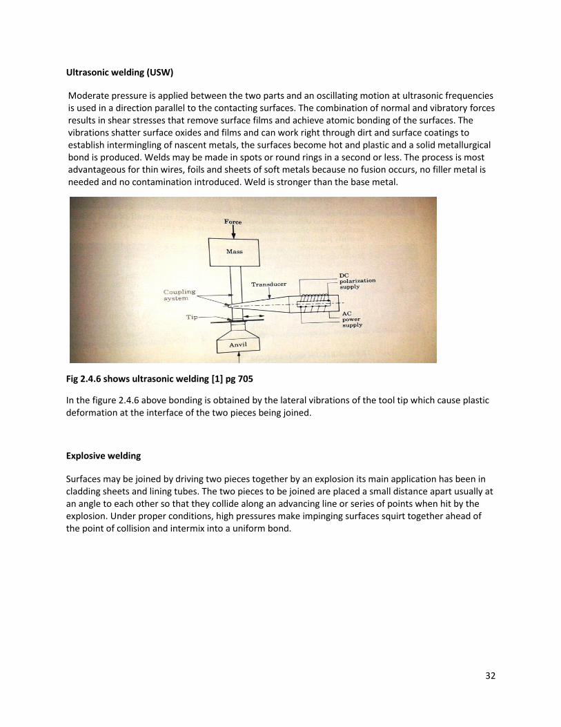
Ultrasonic welding (USW)
Moderate pressure is applied between the two parts and an oscillating motion at ultrasonic frequencies is used in a direction parallel to the contacting surfaces. The combination of normal and vibratory forces results in shear stresses that remove surface films and achieve atomic bonding of the surfaces. The vibrations shatter surface oxides and films and can work right through dirt and surface coatings to establish intermingling of nascent metals, the surfaces become hot and plastic and a solid metallurgical bond is produced. Welds may be made in spots or round rings in a second or less. The process is most advantageous for thin wires, foils and sheets of soft metals because no fusion occurs, no filler metal is needed and no contamination introduced. Weld is stronger than the base metal.
Fig 2.4.6 shows ultrasonic welding [1] pg 705
In the figure 2.4.6 above bonding is obtained by the lateral vibrations of the tool tip which cause plastic deformation at the interface of the two pieces being joined.
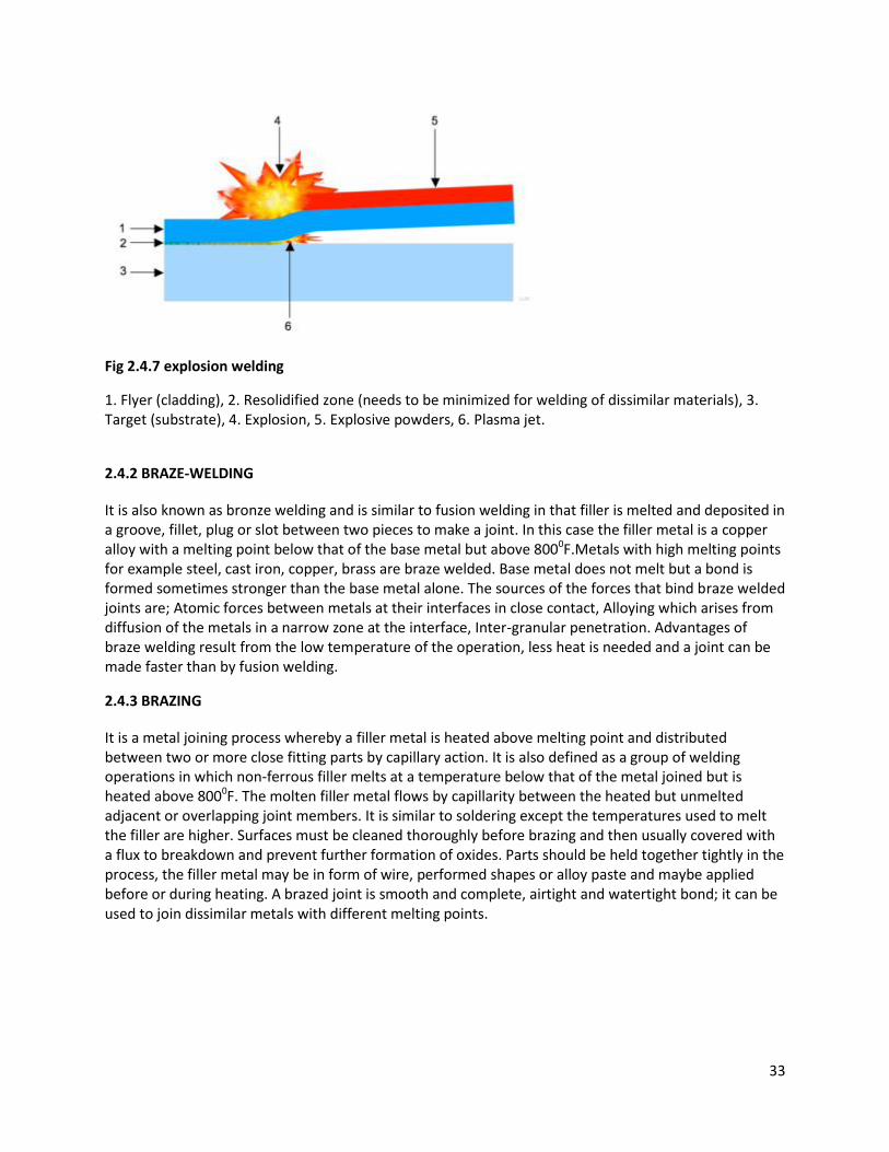
Explosive welding
Surfaces may be joined by driving two pieces together by an explosion its main application has been in cladding sheets and lining tubes. The two pieces to be joined are placed a small distance apart usually at an angle to each other so that they collide along an advancing line or series of points when hit by the explosion. Under proper conditions, high pressures make impinging surfaces squirt together ahead of the point of collision and intermix into a uniform bond.
33
Fig 2.4.7 explosion welding
1. Flyer (cladding), 2. Resolidified zone (needs to be minimized for welding of dissimilar materials), 3. Target (substrate), 4. Explosion, 5. Explosive powders, 6. Plasma jet.
2.4.2 BRAZE-WELDING
It is also known as bronze welding and is similar to fusion welding in that filler is melted and deposited in a groove, fillet, plug or slot between two pieces to make a joint. In this case the filler metal is a copper alloy with a melting point below that of the base metal but above 8000F.Metals with high melting points for example steel, cast iron, copper, brass are braze welded. Base metal does not melt but a bond is formed sometimes stronger than the base metal alone. The sources of the forces that bind braze welded joints are; Atomic forces between metals at their interfaces in close contact, Alloying which arises from diffusion of the metals in a narrow zone at the interface, Inter-granular penetration. Advantages of braze welding result from the low temperature of the operation, less heat is needed and a joint can be made faster than by fusion welding.
2.4.3 BRAZING
It is a metal joining process whereby a filler metal is heated above melting point and distributed between two or more close fitting parts by capillary action. It is also defined as a group of welding operations in which non-ferrous filler melts at a temperature below that of the metal joined but is heated above 8000F. The molten filler metal flows by capillarity between the heated but unmelted adjacent or overlapping joint members. It is similar to soldering except the temperatures used to melt the filler are higher. Surfaces must be cleaned thoroughly before brazing and then usually covered with a flux to breakdown and prevent further formation of oxides. Parts should be held together tightly in the process, the filler metal may be in form of wire, performed shapes or alloy paste and maybe applied before or during heating. A brazed joint is smooth and complete, airtight and watertight bond; it can be used to join dissimilar metals with different melting points.
34
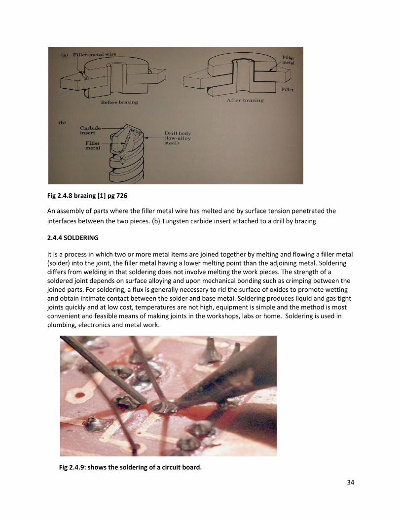
Fig 2.4.8 brazing [1] pg 726
An assembly of parts where the filler metal wire has melted and by surface tension penetrated the
interfaces between the two pieces. (b) Tungsten carbide insert attached to a drill by brazing
2.4.4 SOLDERING
It is a process in which two or more metal items are joined together by melting and flowing a filler metal (solder) into the joint, the filler metal having a lower melting point than the adjoining metal. Soldering differs from welding in that soldering does not involve melting the work pieces. The strength of a soldered joint depends on surface alloying and upon mechanical bonding such as crimping between the joined parts. For soldering, a flux is generally necessary to rid the surface of oxides to promote wetting and obtain intimate contact between the solder and base metal. Soldering produces liquid and gas tight joints quickly and at low cost, temperatures are not high, equipment is simple and the method is most convenient and feasible means of making joints in the workshops, labs or home. Soldering is used in plumbing, electronics and metal work.
Fig 2.4.9: shows the soldering of a circuit board.
35
2.4.5 RIVETING
A rivet is a permanent mechanical fastener. Before being installed a rivet consists of a smooth cylindrical shaft with a head on one end. The end opposite the head is called the buck tail. On installation the rivet is placed in a punched or drilled hole and the tail is bucked (deformed) so that it expands to about 1.5 times the original shaft diameter holding the rivet in place. To distinguish between the two ends of the rivet, the original head is called the factory head and the deformed end is called the shop head or buck tail. Since there is a head on each end of an installed rivet, it can support tension loads (loads parallel to the axis of shaft) however it is much more capable of supporting shear loads (loads perpendicular to the axis of shaft).
Rivets are of different types; solid/round head rivets, semi-tubular rivets, blind rivets, Oscar rivets, drive rivets, flush rivets, and friction-lock rivets
The stress and shear in a rivet is analyzed like a bolted joint, it is not wise to combine rivets with bolts and screws in the same joint. Rivets fill the hole where they are installed to establish a very tight fit. It is impossible to obtain such a tight fit with other fasteners. A joint with similar fasteners is the most efficient because all fasteners reach capacity simultaneously.
2.4.6 ADHESIVES
This is any substance that when applied to the surfaces of the materials, binds the surface together and resists separation. An adhesive provides a bond at the interface either for structural strength (load-bearing) or for non- structural applications with properties such as sealing, insulating, preventing electro-chemical corrosion between dissimilar metals and reducing vibration through internal damping at the joints. Adhesive bonding has the additional advantage of distributing the load at an interface (because of the inherent plasticity of the adhesive) thus eliminating localized stress that generally result from mechanical fastening or welding. Structural integrity of the sections is maintained since no holes are required and the appearance of the component is generally improved. There are three types of adhesives:
Natural products: starch, dextrin, soya flour and animal products (commonly referred to as glues).
Inorganic adhesives: sodium silicate and magnesium oxychloride.
Synthetic organic adhesives: thermoplastics or thermosetting polymers. Because of their strength, these
adhesives are the most important for manufacturing processes.
2.5. FINISHING PROCESS
2.5.1 Metal cleaning and treating
This is a post-metal treatment operation where metal surfaces are thoroughly cleaned before a finish
can be applied successfully. All foreign matter is removed prior to painting or other surface preparation
for acceptable adhesion to occur. Foreign matter include; Grease, oil, particulates, corrosion oxides,
36
scale and stencil markings. Effective surface cleaning is achieved through a combination of detergency,
chemical reaction, solvent dissolution and mechanical action. Principle methods employed in cleaning
fabricated metal parts include.
Grinding
Grinding is the process of removing metal by application of abrasives which are bonded to form a
rotating wheel. When the moving abrasive particles contact the workpiece, they act as tiny cutting tools,
each particle cutting a tiny chip from the workpiece. It is a common error to believe that grinding
abrasive wheels remove material by a rubbing action; actually the process is as much a cutting action as
drilling, milling and lathe turning.
The grinding machine supports and rotates the grinding abrasive wheel and often supports and positions
the workpiece in proper relation to the wheel. The grinding machine is used for roughening and finishing
flat, cylindrical and conical surfaces; snagging or removing rough projections from fabricated parts; and
cleaning, polishing and buffing surfaces of fabricated metals.
Wire brushing
Wire brushes are good for cleaning welds because they dislodge slag without removing the weld metal
and clean the surface for painting or another welding pass. They also work well in removing large burrs.
Each strand is like a dull tool bit in that its tip strikes the surfaces, knocks off burrs and slightly work
hardens the part. Bristles for most wire brushes are either medium carbon heat treated steel or 302
stainless. Tempered high tensile carbon steel is the best for most carbon steel parts. It lasts up to 10
times longer than non- heat treated materials. Carbon steel brushes should never be used on stainless
and non -ferrous metal parts. As the brush rubs the workpiece, small pieces of carbon steel embed on
the part surface and will rust. Instead, use stainless steel. Stainless steel brushes can also contaminate
the workpiece because they can attract carbon steel particles from the air or work benches. To prevent
this, the brushes are washed in a degreaser and wrapped in plastic. Crimped and twisted-knot styles are
two most popular wireforms. The waveform shape of crimped wires allows the strands to interact to
reduce vibration damage to themselves as they strike the workpiece. This configuration also allows
many wire tips to touch the work surface.
Buffing
This is a polishing operation in which the work piece is brought in contact with a revolving cloth buffing
wheel that has been charged with a very fine abrasive such as polishing rouge. Buffing wheels are made
of disks of linen, cotton, broad cloth or canvas that are made more or less firm by the amount of
stitching used to fasten the layers of cloth together.
Buffing wheels for very softer polishing or which can be used to polish into the interior corners may
have no stitching, the cloth layers being kept in proper position by centrifugal force resulting from the
rotation of the wheel. Various types of polishing rouges are available; most of them being primarily
37
ferric oxide in some type of binder .Buffing should be used only to remove very fine scratches, or to
remove oxide or similar coatings that may be on the work surface.
2.5.2 Chemical cleaning
At some stage in finishing of virtually all metal products, it’s necessary to employ chemical cleaning
which involves use of chemicals to remove dirt, oil, or other materials that may adhere to the surface so
that subsequent painting or plating can be done successfully. Some of the main chemical cleaning
methods include;
Alkaline cleaning
This employs such agents as sodium metasilicate or caustic soda with some type of soap to aid in
emulsification [4]. Wetting agents often assist in obtaining thorough cleaning. The cleaning action is by
emulsification of oils and greases. Thus the solution must penetrate any dirt that covers them. It is also
necessary to rinse the cleaning solution from the work surface so as not to leave any residue.
The cleaning bath must be controlled to maintain a constant and proper PH value. Too high as well as
too low PH levels may produce poor results.
Vapor degreasing
This is widely used to remove oil from ferrous parts and from such metals as aluminum and zinc alloys,
which would be attacked by alkaline cleaners. A non- flammable solvent, such as trichloroethylene, is
heated to its boiling point and the parts to be cleaned are hung in its vapors. The vapor condenses on
the work and washes off the grease and oil. Excess vapor is condensed by cooling coils in the top of the
vapor chamber. Although grease and oil from the work are washed off into the liquid solvent, causing
the bath to become dirty, because they are only slightly volatile at the boiling temperatures of the
solvent, the vapor remains relatively clean at all times and so continues to clean effectively. Vapor
degreasing is effective only if the vapor condenses on the work. Thus work must remain relatively cool.
These methods have the advantage of being rapid and of having almost no visible effect on the surface.
Pickling
Pickling involves dipping metal parts in dilute acid solutions to remove the oxides and dirt that are left
on the surface by various processing operations. The most commonly pickling solution is 10% [5] of
sulphuric acid bath at temperatures from 66 to 85. It is very important that parts be thoroughly cleaned
prior to pickling; the pickling solution will not act as a cleaner, and any dirt or oil on the surface will
result in uneven removal of oxides. Pickling inhibitors, which decrease the attack of the acid on the
metal but do not interfere with the action of the acid on the oxides, frequently are added to the pickling
bath. After parts are removed from the pickling bath, they should be rinsed thoroughly, to remove all
traces of acid and then dipped in a bath that is slightly alkaline to prevent subsequent rusting. Parts
should not be over pickled as this may result in roughening.
38
2.5.3 FINISHING
Metal finishing is used to treat the exterior of a metal product by applying a thin complementary layer
to its surface. Paints are by far the most widely used finishes on manufactured products, and a great
variety is available to meet a wide range of requirements. Some of the general advantages of metal
finishing include; Increased durability, improved decorative appeal, Enhanced electrical conductivity,
higher electrical resistance, higher chemical resistance, higher tarnish resistance and Potential for
vulcanization. Some of the principle processes of metal finishing include;
Spraying
This is probably the most widely used painting process, owing to its versatility and economy in the use of
paint. The paint is atomized by three methods; air, mechanical pressure or electro statically. Either
manual or automatic application is used. When hand spraying is used, either air or mechanical
atomization is employed, and the spray of paint is directed against the work by means of a hand
manipulated gun. The worker must be careful so as to obtain proper coverage without alloying the paint
to drape or run downward. Good results are obtained from either manual or automatic spray painting
by using the electrostatic principle. In the air process, the spray gun atomizes the paint, giving the
particles an electrostatic charge and considerable velocity. The atomized particles are attracted to, and
deposited on, the work which is grounded electrically.
Powder coating
This is a variation of electrostatic spraying. The difference is that what is sprayed is a paint powder. The
object is then baked, and the powder melts into a smooth, durable coat. Overspray can be reused, and
no other pollutants are created or released because the powder has no solvents in it. The equipment for
powder coating is expensive, so it may be economical for only larger businesses. A variation of this is
plasma powder coating. The powder is fed into an extremely hot gas stream and is then sprayed at the
object. Plasma powder coating is for large objects that can’t fit into a conventional curing oven.
Overspray cannot be reused because it hardens. Another variation is flame sprayed powder coating,
where the powder is melted with a high temperature flame. Again, it is for large objects and overspray
cannot be reused.
Enameling
This is the process of applying a thin coat of finely ground glass to a metal. When heated to a high
temperature, the glass melts and fuses to the metal. Enamel or more precisely, porcelain enamel is
essentially a vitreous compound composed of silica, borax and potash. Unusual colour effects are
obtained by adding small amounts of metal oxides to the base enamel. On industrial basis, enamel has
been used extensively for refrigerators, washing machine tubs and stoves. In recent years, porcelain has
been used for advertising signs, chemical and food tanks, and hospital furniture and meat market cases.
Electroplating
39
Electroplating is the application of a metal coating to a metallic or other conducting surface by an
electrochemical process. The article to be plated (the work) is made the cathode (negative electrode) of
an electrolysis cell through which a direct current is passed. The article is immersed in an aqueous
solution (the bath) containing the required metal in an oxidized form, either as an aquated cation or as a
complex ion. The anode is usually a bar of the metal being plated.
Galvanizing
This is the process of applying a metallic zinc coating to fabricated steel by immersing the material in a
bath consisting of molten zinc. Although galvanization can be done with electrochemical and electrode
position processes, the most common method in current use is hot-dip galvanization, in which steel
parts are submerged in a bath of molten zinc. The value of galvanizing stems from the corrosion
resistance of zinc, which under most service conditions, is considerably greater than that of iron and
steel. The zinc acts as the sacrificial anode, so that it cathodically protects exposed steel. This means
that even if the coating is scratched or abraded, the exposed steel will still be protected from corrosion
by the remaining zinc-an advantage absent from paint, enamel, powder coating and other methods.
Galvanization is also favored as a means of protective coating because of its low cost, ease of application
and comparatively long maintenance-free service life.
2.6 .ASSEMBLY PROCESSES
These processes are used to make temporary mechanical joints and they involve the use of; temporary mechanical fasteners. It therefore also said to be a semi-permanent joinery process.
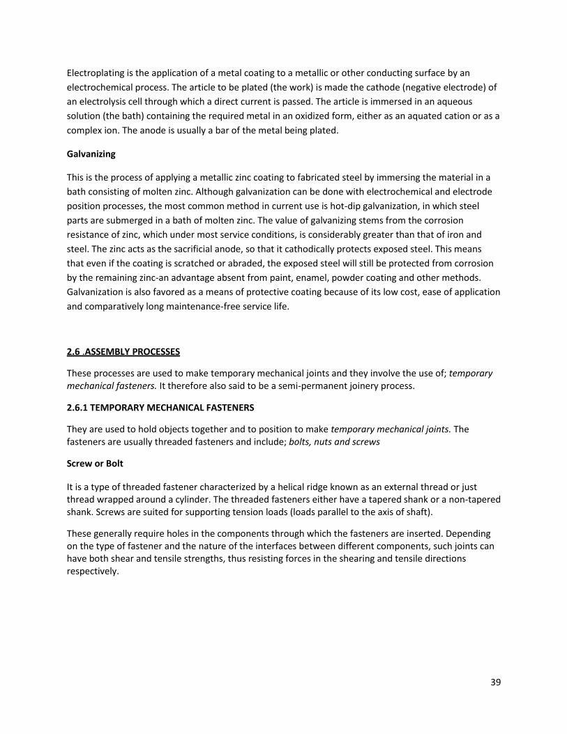
2.6.1 TEMPORARY MECHANICAL FASTENERS
They are used to hold objects together and to position to make temporary mechanical joints. The fasteners are usually threaded fasteners and include; bolts, nuts and screws
Screw or Bolt
It is a type of threaded fastener characterized by a helical ridge known as an external thread or just thread wrapped around a cylinder. The threaded fasteners either have a tapered shank or a non-tapered shank. Screws are suited for supporting tension loads (loads parallel to the axis of shaft).
These generally require holes in the components through which the fasteners are inserted. Depending on the type of fastener and the nature of the interfaces between different components, such joints can have both shear and tensile strengths, thus resisting forces in the shearing and tensile directions respectively.
40
Fig 2.6.1 shows selected examples of threaded fasteners. [1] pg 697
41
CHAPTER THREE
3.1 CUTTING EQUIPMENT
3.1.1. DRILLING EQUIPMENT.
They are of different types namely:-
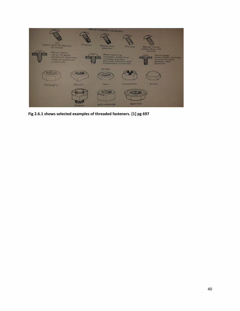
Bench
It has a spindle that rotates on ball bearings with a non-rotating quill that can be moved up and down in
a machine to provide feed to drill. Vertical motion is imparted by hand operated capstan wheel and has
a spring that raises the quill-and-spindle assembly to the highest position on releasing the hand lever.
They can drill holes up to 13mm diameter and have a worktable for clamping work.
Fig 3.1.1 bench drilling [http://www.splashmaritime.com.au/Marops/data/text/Tooltex/Powertooltex.htm]
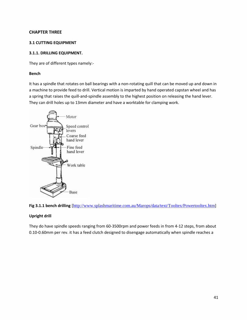
Upright drill
They do have spindle speeds ranging from 60-3500rpm and power feeds in from 4-12 steps, from about
0.10-0.60mm per rev. it has a feed clutch designed to disengage automatically when spindle reaches a
42
preset depth. It also has an upright work table containing holes and slots for use in clamping work.
Fig 3.1.2 upright drill [. http://constructionmanuals.tpub.com/14251/css/14251_316.htm]
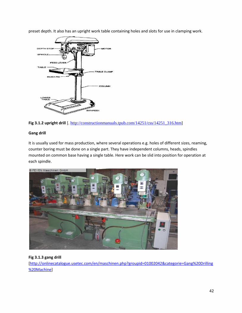
Gang drill
It is usually used for mass production, where several operations e.g. holes of different sizes, reaming,
counter boring must be done on a single part. They have independent columns, heads, spindles
mounted on common base having a single table. Here work can be slid into position for operation at
each spindle.
Fig 3.1.3 gang drill
[http://onlinecatalogue.usetec.com/en/maschinen.php?groupid=01002042&categorie=Gang%20Drilling
%20Machine]
43
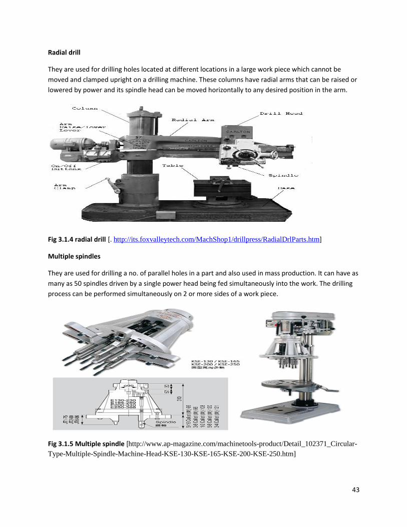
Radial drill
They are used for drilling holes located at different locations in a large work piece which cannot be
moved and clamped upright on a drilling machine. These columns have radial arms that can be raised or
lowered by power and its spindle head can be moved horizontally to any desired position in the arm.
Fig 3.1.4 radial drill [. http://its.foxvalleytech.com/MachShop1/drillpress/RadialDrlParts.htm]
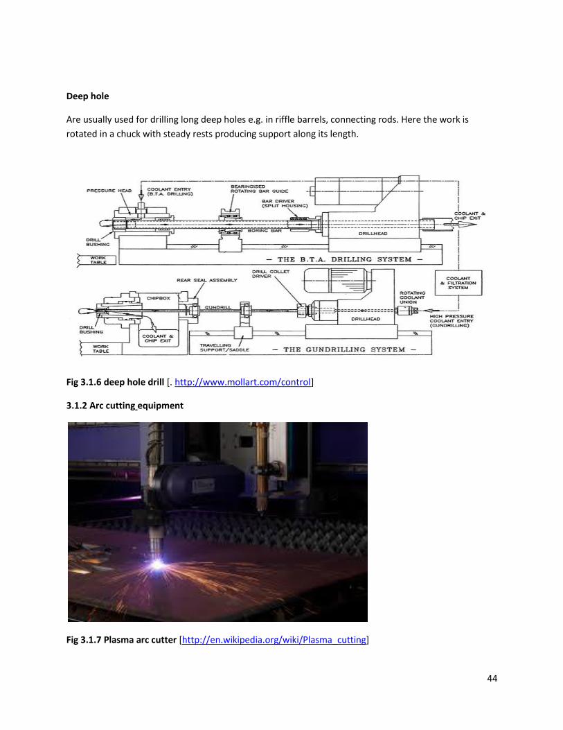
Multiple spindles
They are used for drilling a no. of parallel holes in a part and also used in mass production. It can have as
many as 50 spindles driven by a single power head being fed simultaneously into the work. The drilling
process can be performed simultaneously on 2 or more sides of a work piece.
Fig 3.1.5 Multiple spindle [http://www.ap-magazine.com/machinetools-product/Detail_102371_Circular-
Type-Multiple-Spindle-Machine-Head-KSE-130-KSE-165-KSE-200-KSE-250.htm]
44
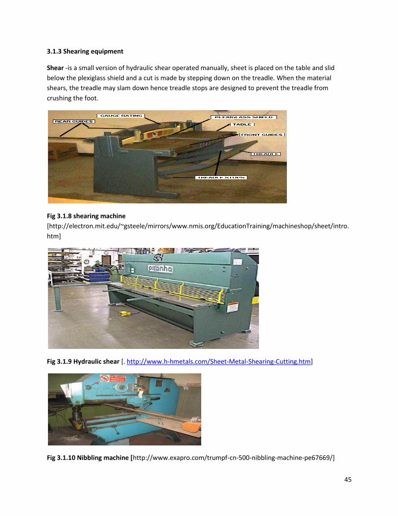
Deep hole
Are usually used for drilling long deep holes e.g. in riffle barrels, connecting rods. Here the work is
rotated in a chuck with steady rests producing support along its length.
Fig 3.1.6 deep hole drill [. http://www.mollart.com/control]
3.1.2 Arc cutting equipment
Fig 3.1.7 Plasma arc cutter [http://en.wikipedia.org/wiki/Plasma_cutting]
45
3.1.3 Shearing equipment
Shear -is a small version of hydraulic shear operated manually, sheet is placed on the table and slid
below the plexiglass shield and a cut is made by stepping down on the treadle. When the material
shears, the treadle may slam down hence treadle stops are designed to prevent the treadle from
crushing the foot.
Fig 3.1.8 shearing machine
[http://electron.mit.edu/~gsteele/mirrors/www.nmis.org/EducationTraining/machineshop/sheet/intro.
htm]
Fig 3.1.9 Hydraulic shear [. http://www.h-hmetals.com/Sheet-Metal-Shearing-Cutting.htm]
Fig 3.1.10 Nibbling machine [http://www.exapro.com/trumpf-cn-500-nibbling-machine-pe67669/]
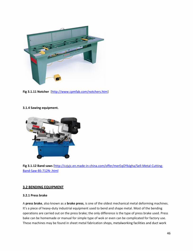
46
Fig 3.1.11 Notcher [http://www.cpmfab.com/notchers.htm]
3.1.4 Sawing equipment.
Fig 3.1.12 Band saws [http://czjyjc.en.made-in-china.com/offer/merEqOYbJgha/Sell-Metal-Cutting-
Band-Saw-BS-712N-.html
3.2 BENDING EQUIPMENT
3.2.1 Press brake
A press brake, also known as a brake press, is one of the oldest mechanical metal deforming machines.
It’s a piece of heavy-duty industrial equipment used to bend and shape metal. Most of the bending
operations are carried out on the press brake; the only difference is the type of press brake used. Press
bake can be homemade or manual for simple type of wok or even can be complicated for factory use.
These machines may be found in sheet metal fabrication shops, metalworking facilities and duct work
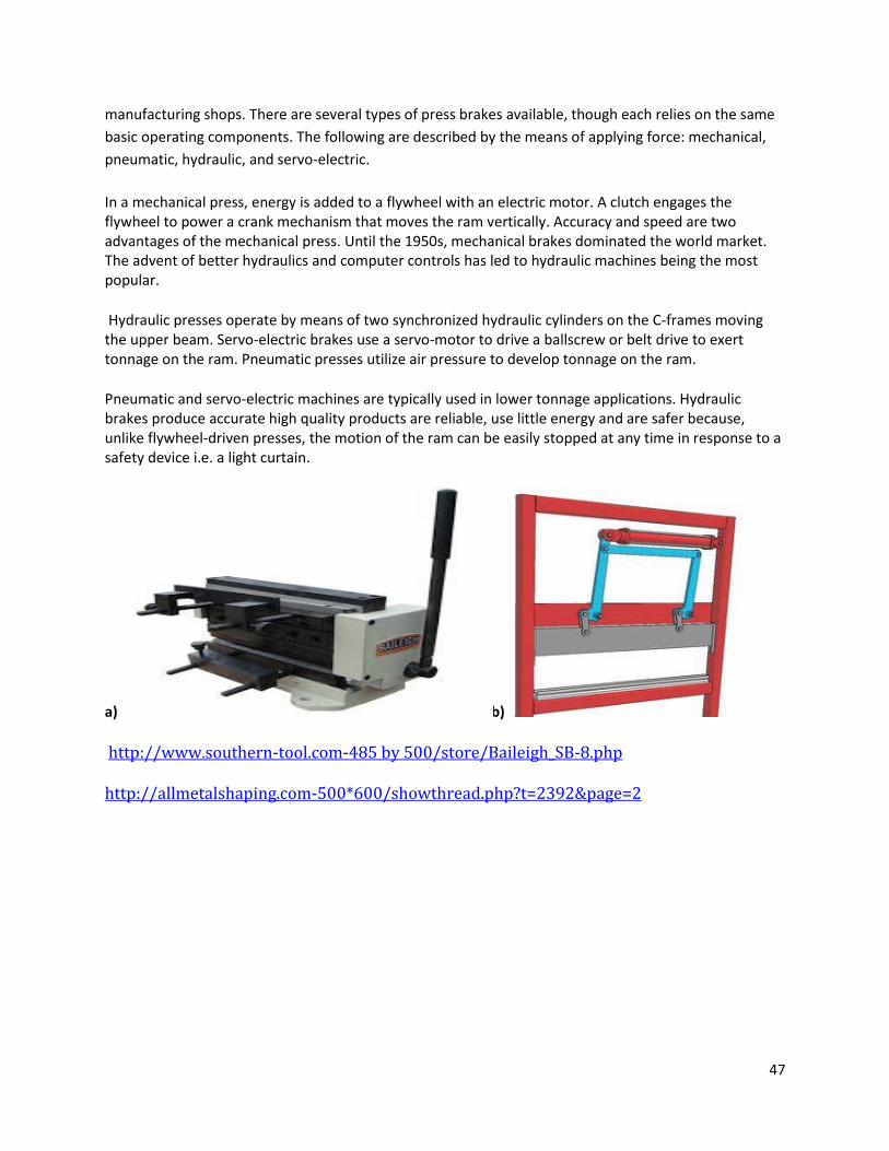
47
manufacturing shops. There are several types of press brakes available, though each relies on the same
basic operating components. The following are described by the means of applying force: mechanical,
pneumatic, hydraulic, and servo-electric.
In a mechanical press, energy is added to a flywheel with an electric motor. A clutch engages the flywheel to power a crank mechanism that moves the ram vertically. Accuracy and speed are two advantages of the mechanical press. Until the 1950s, mechanical brakes dominated the world market. The advent of better hydraulics and computer controls has led to hydraulic machines being the most popular.
Hydraulic presses operate by means of two synchronized hydraulic cylinders on the C-frames moving the upper beam. Servo-electric brakes use a servo-motor to drive a ballscrew or belt drive to exert tonnage on the ram. Pneumatic presses utilize air pressure to develop tonnage on the ram.
Pneumatic and servo-electric machines are typically used in lower tonnage applications. Hydraulic brakes produce accurate high quality products are reliable, use little energy and are safer because, unlike flywheel-driven presses, the motion of the ram can be easily stopped at any time in response to a safety device i.e. a light curtain.
a) b)
http://www.southern-tool.com-485 by 500/store/Baileigh_SB-8.php
http://allmetalshaping.com-500*600/showthread.php?t=2392&page=2
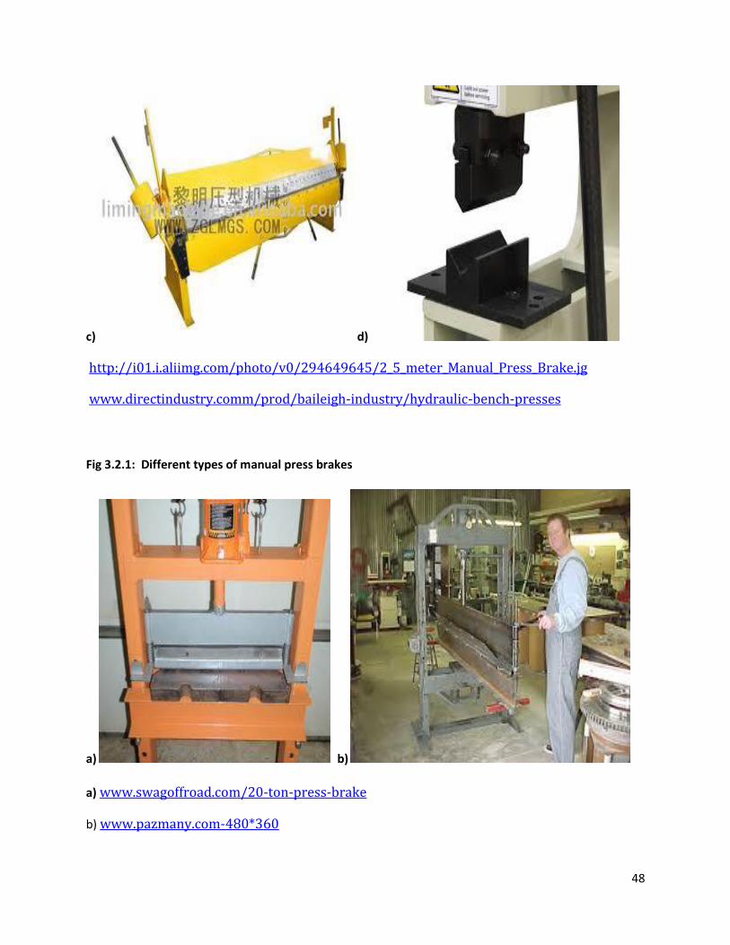
48
c) d)
http://i01.i.aliimg.com/photo/v0/294649645/2_5_meter_Manual_Press_Brake.jg
www.directindustry.comm/prod/baileigh-industry/hydraulic-bench-presses
Fig 3.2.1: Different types of manual press brakes
a) b)
a) www.swagoffroad.com/20-ton-press-brake
b) www.pazmany.com-480*360
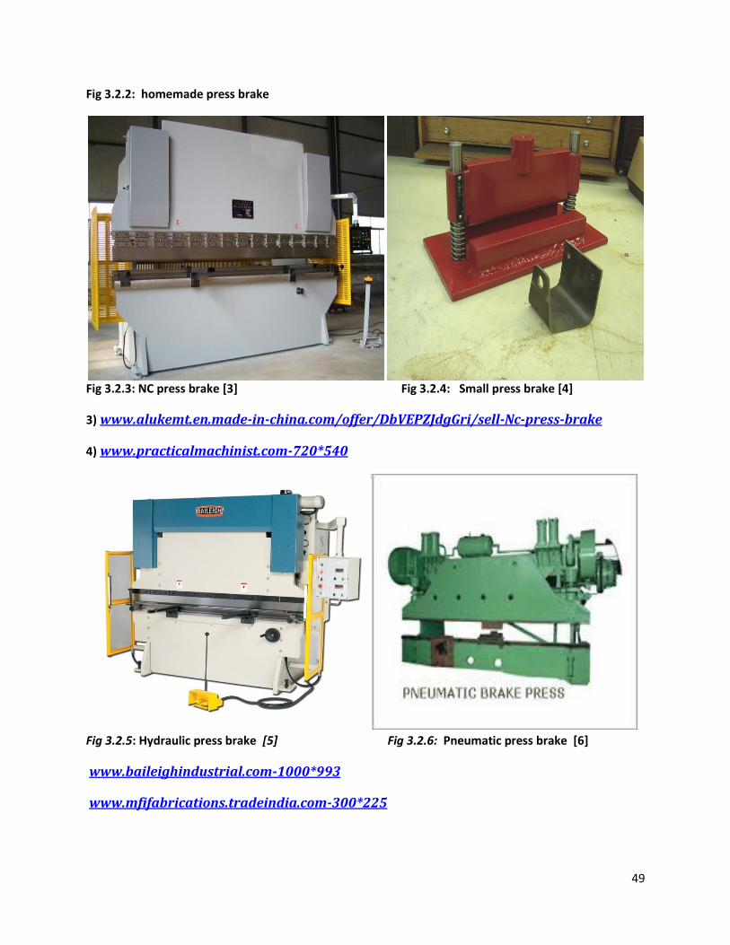
49
Fig 3.2.2: homemade press brake
Fig 3.2.3: NC press brake [3] Fig 3.2.4: Small press brake [4]
3) www.alukemt.en.made-in-china.com/offer/DbVEPZJdgGri/sell-Nc-press-brake
4) www.practicalmachinist.com-720*540
Fig 3.2.5: Hydraulic press brake [5] Fig 3.2.6: Pneumatic press brake [6]
www.baileighindustrial.com-1000*993
www.mfifabrications.tradeindia.com-300*225
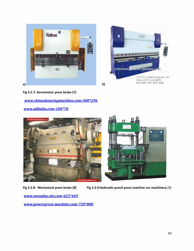
50
a) b)
Fig 3.2.7: Servomotor press brake [7]
www.chinashearingmachine.com-400*296
www.alibaba.com-100*78
Fig 3.2.8: Mechanical press brake [8] Fig 3.2.9:Hydraulic punch press machine cnc machinery.[9]
www.noonday.olx.com-625*469
www.powerpress-machine.com-720*800
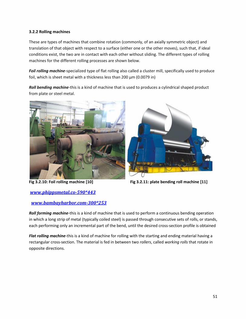
51
3.2.2 Rolling machines
These are types of machines that combine rotation (commonly, of an axially symmetric object) and
translation of that object with respect to a surface (either one or the other moves), such that, if ideal
conditions exist, the two are in contact with each other without sliding. The different types of rolling
machines for the different rolling processes are shown below.
Foil rolling machine-specialized type of flat rolling also called a cluster mill, specifically used to produce
foil, which is sheet metal with a thickness less than 200 µm (0.0079 in)
Roll bending machine-this is a kind of machine that is used to produces a cylindrical shaped product
from plate or steel metal.
Fig 3.2.10: Foil rolling machine [10] Fig 3.2.11: plate bending roll machine [11]
www.phippsmetal.co-590*443
www.bambayharbor.com-300*253
Roll forming machine-this is a kind of machine that is used to perform a continuous bending operation
in which a long strip of metal (typically coiled steel) is passed through consecutive sets of rolls, or stands,
each performing only an incremental part of the bend, until the desired cross-section profile is obtained
Flat rolling machine-this is a kind of machine for rolling with the starting and ending material having a
rectangular cross-section. The material is fed in between two rollers, called working rolls that rotate in
opposite directions.
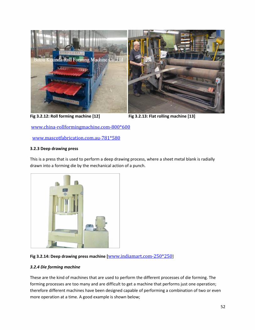
52
Fig 3.2.12: Roll forming machine [12] Fig 3.2.13: Flat rolling machine [13]
www.china-rollformingmachine.com-800*600
www.mascotfabrication.com.au-781*580
3.2.3 Deep drawing press
This is a press that is used to perform a deep drawing process, where a sheet metal blank is radially
drawn into a forming die by the mechanical action of a punch.
Fig 3.2.14: Deep drawing press machine [www.indiamart.com-250*250]
3.2.4 Die forming machine
These are the kind of machines that are used to perform the different processes of die forming. The
forming processes are too many and are difficult to get a machine that performs just one operation;
therefore different machines have been designed capable of performing a combination of two or even
more operation at a time. A good example is shown below;
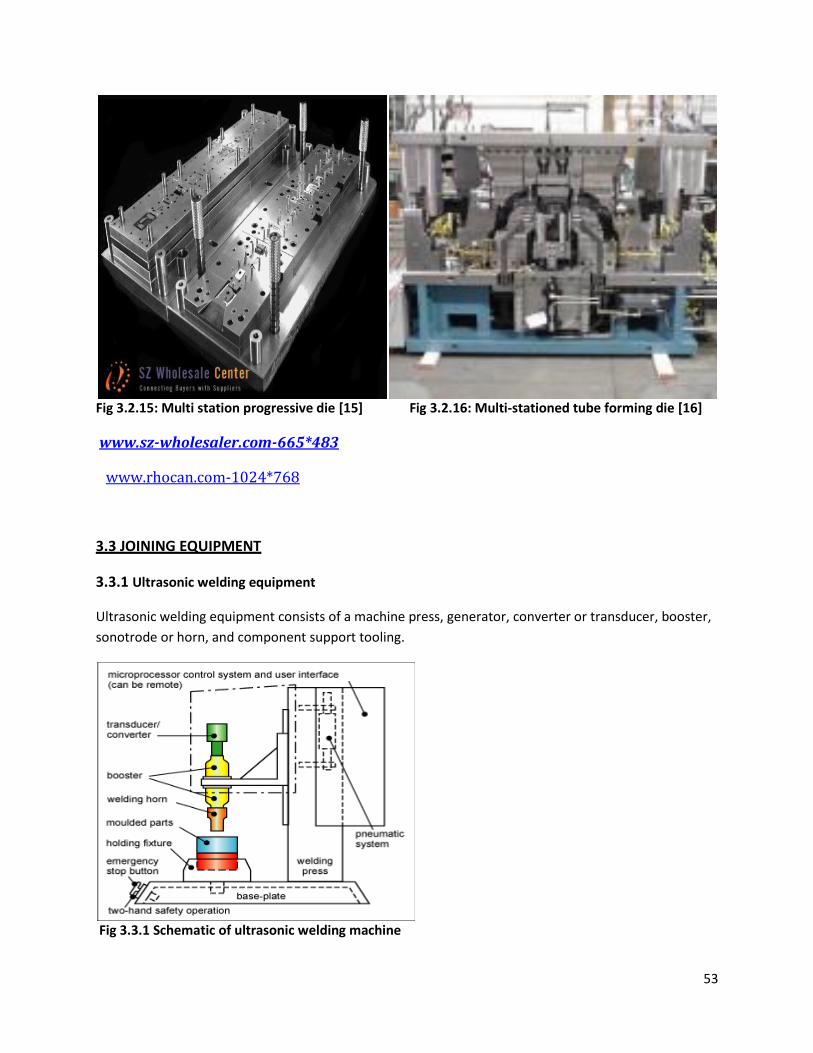
53
Fig 3.2.15: Multi station progressive die [15] Fig 3.2.16: Multi-stationed tube forming die [16]
www.sz-wholesaler.com-665*483
www.rhocan.com-1024*768
3.3 JOINING EQUIPMENT
3.3.1 Ultrasonic welding equipment
Ultrasonic welding equipment consists of a machine press, generator, converter or transducer, booster,
sonotrode or horn, and component support tooling.
Fig 3.3.1 Schematic of ultrasonic welding machine
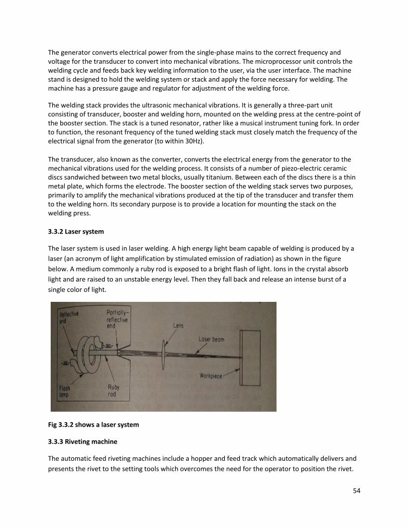
54
The generator converts electrical power from the single-phase mains to the correct frequency and voltage for the transducer to convert into mechanical vibrations. The microprocessor unit controls the welding cycle and feeds back key welding information to the user, via the user interface. The machine stand is designed to hold the welding system or stack and apply the force necessary for welding. The machine has a pressure gauge and regulator for adjustment of the welding force.
The welding stack provides the ultrasonic mechanical vibrations. It is generally a three-part unit consisting of transducer, booster and welding horn, mounted on the welding press at the centre-point of the booster section. The stack is a tuned resonator, rather like a musical instrument tuning fork. In order to function, the resonant frequency of the tuned welding stack must closely match the frequency of the electrical signal from the generator (to within 30Hz).
The transducer, also known as the converter, converts the electrical energy from the generator to the mechanical vibrations used for the welding process. It consists of a number of piezo-electric ceramic discs sandwiched between two metal blocks, usually titanium. Between each of the discs there is a thin metal plate, which forms the electrode. The booster section of the welding stack serves two purposes, primarily to amplify the mechanical vibrations produced at the tip of the transducer and transfer them to the welding horn. Its secondary purpose is to provide a location for mounting the stack on the welding press.
3.3.2 Laser system
The laser system is used in laser welding. A high energy light beam capable of welding is produced by a
laser (an acronym of light amplification by stimulated emission of radiation) as shown in the figure
below. A medium commonly a ruby rod is exposed to a bright flash of light. Ions in the crystal absorb
light and are raised to an unstable energy level. Then they fall back and release an intense burst of a
single color of light.
Fig 3.3.2 shows a laser system
3.3.3 Riveting machine
The automatic feed riveting machines include a hopper and feed track which automatically delivers and
presents the rivet to the setting tools which overcomes the need for the operator to position the rivet.
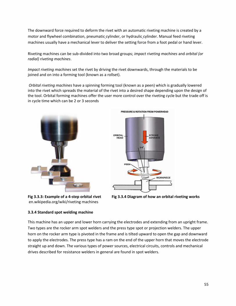
55
The downward force required to deform the rivet with an automatic riveting machine is created by a
motor and flywheel combination, pneumatic cylinder, or hydraulic cylinder. Manual feed riveting
machines usually have a mechanical lever to deliver the setting force from a foot pedal or hand lever.
Riveting machines can be sub-divided into two broad groups; impact riveting machines and orbital (or radial) riveting machines.
Impact riveting machines set the rivet by driving the rivet downwards, through the materials to be joined and on into a forming tool (known as a rollset).
Orbital riveting machines have a spinning forming tool (known as a peen) which is gradually lowered into the rivet which spreads the material of the rivet into a desired shape depending upon the design of the tool. Orbital forming machines offer the user more control over the riveting cycle but the trade off is in cycle time which can be 2 or 3 seconds
Fig 3.3.3: Example of a 4-step orbital rivet Fig 3.3.4 Diagram of how an orbital riveting works en.wikipedia.org/wiki/riveting machines 3.3.4 Standard spot welding machine
This machine has an upper and lower horn carrying the electrodes and extending from an upright frame.
Two types are the rocker arm spot welders and the press type spot or projection welders. The upper
horn on the rocker arm type is pivoted in the frame and is tilted upward to open the gap and downward
to apply the electrodes. The press type has a ram on the end of the upper horn that moves the electrode
straight up and down. The various types of power sources, electrical circuits, controls and mechanical
drives described for resistance welders in general are found in spot welders.
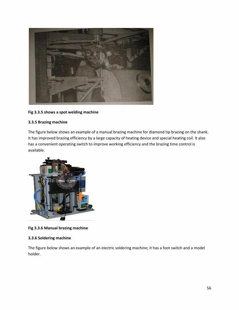
56
Fig 3.3.5 shows a spot welding machine
3.3.5 Brazing machine
The figure below shows an example of a manual brazing machine for diamond tip brazing on the shank.
It has improved brazing efficiency by a large capacity of heating device and special heating coil. It also
has a convenient operating switch to improve working efficiency and the brazing time control is
available.
Fig 3.3.6 Manual brazing machine
3.3.6 Soldering machine
The figure below shows an example of an electric soldering machine; it has a foot switch and a model
holder.
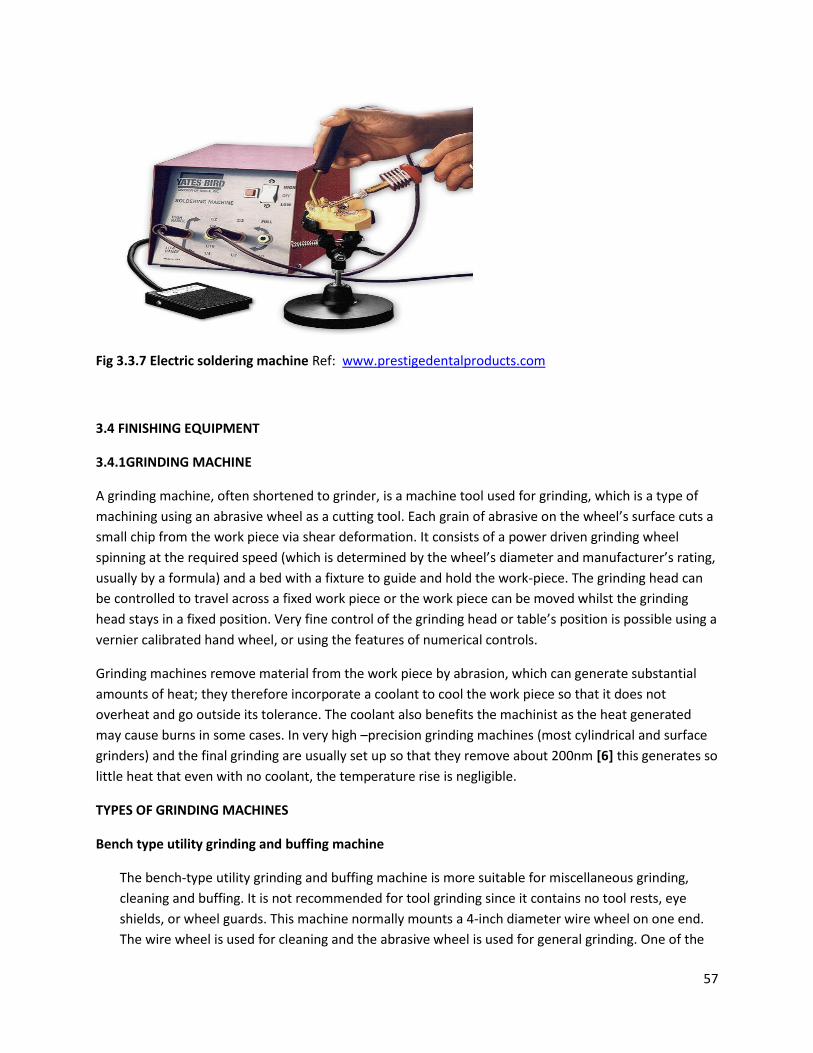
57
Fig 3.3.7 Electric soldering machine Ref: www.prestigedentalproducts.com
3.4 FINISHING EQUIPMENT
3.4.1GRINDING MACHINE
A grinding machine, often shortened to grinder, is a machine tool used for grinding, which is a type of
machining using an abrasive wheel as a cutting tool. Each grain of abrasive on the wheel’s surface cuts a
small chip from the work piece via shear deformation. It consists of a power driven grinding wheel
spinning at the required speed (which is determined by the wheel’s diameter and manufacturer’s rating,
usually by a formula) and a bed with a fixture to guide and hold the work-piece. The grinding head can
be controlled to travel across a fixed work piece or the work piece can be moved whilst the grinding
head stays in a fixed position. Very fine control of the grinding head or table’s position is possible using a
vernier calibrated hand wheel, or using the features of numerical controls.
Grinding machines remove material from the work piece by abrasion, which can generate substantial
amounts of heat; they therefore incorporate a coolant to cool the work piece so that it does not
overheat and go outside its tolerance. The coolant also benefits the machinist as the heat generated
may cause burns in some cases. In very high –precision grinding machines (most cylindrical and surface
grinders) and the final grinding are usually set up so that they remove about 200nm [6] this generates so
little heat that even with no coolant, the temperature rise is negligible.
TYPES OF GRINDING MACHINES
Bench type utility grinding and buffing machine
The bench-type utility grinding and buffing machine is more suitable for miscellaneous grinding,
cleaning and buffing. It is not recommended for tool grinding since it contains no tool rests, eye
shields, or wheel guards. This machine normally mounts a 4-inch diameter wire wheel on one end.
The wire wheel is used for cleaning and the abrasive wheel is used for general grinding. One of the
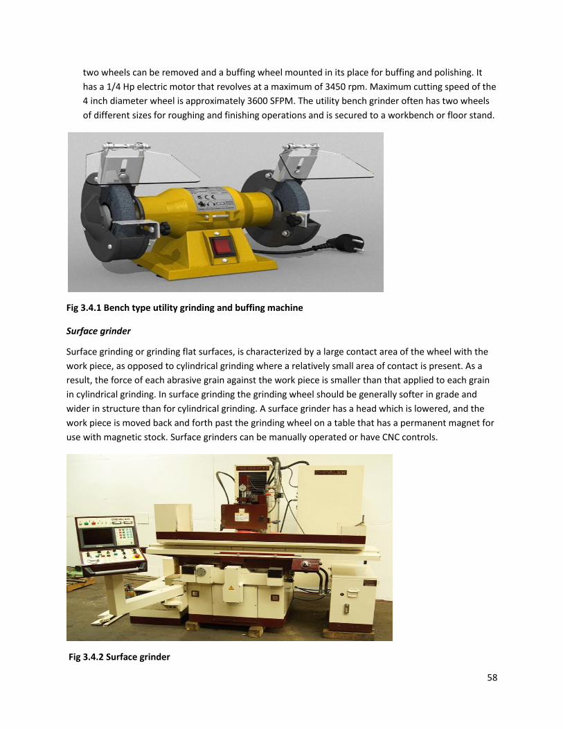
58
two wheels can be removed and a buffing wheel mounted in its place for buffing and polishing. It
has a 1/4 Hp electric motor that revolves at a maximum of 3450 rpm. Maximum cutting speed of the
4 inch diameter wheel is approximately 3600 SFPM. The utility bench grinder often has two wheels
of different sizes for roughing and finishing operations and is secured to a workbench or floor stand.
Fig 3.4.1 Bench type utility grinding and buffing machine
Surface grinder
Surface grinding or grinding flat surfaces, is characterized by a large contact area of the wheel with the
work piece, as opposed to cylindrical grinding where a relatively small area of contact is present. As a
result, the force of each abrasive grain against the work piece is smaller than that applied to each grain
in cylindrical grinding. In surface grinding the grinding wheel should be generally softer in grade and
wider in structure than for cylindrical grinding. A surface grinder has a head which is lowered, and the
work piece is moved back and forth past the grinding wheel on a table that has a permanent magnet for
use with magnetic stock. Surface grinders can be manually operated or have CNC controls.
Fig 3.4.2 Surface grinder
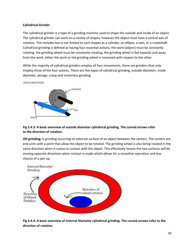
59
Cylindrical Grinder
The cylindrical grinder is a type of a grinding machine used to shape the outside and inside of an object.
The cylindrical grinder can work on a variety of shapes; however the object must have a central axis of
rotation. This includes but is not limited to such shapes as a cylinder, an ellipse, a cam, or a crankshaft.
Cylindrical grinding is defined as having four essential actions; the work (object) must be constantly
rotating, the grinding wheel must be constantly rotating, the grinding wheel is fed towards and away
from the work, either the work or the grinding wheel is traversed with respect to the other.
While the majority of cylindrical grinders employ all four movements, there are grinders that only
employ three of the four actions. There are five types of cylindrical grinding, outside diameter, inside
diameter, plunge, creep and centerless grinding.
Fig 3.4.3: A basic overview of outside diameter cylindrical grinding. The curved arrows refer
to the direction of rotation.
OD grinding; Is grinding occurring on external surface of an object between the centers. The centers are
end units with a point that allow the object to be rotated. The grinding wheel is also being rotated in the
same direction when it comes in contact with the object. This effectively means the two surfaces will be
moving opposite directions when contact is made which allows for a smoother operation and less
chance of a jam up.
Fig 3.4.4: A basic overview of Internal Diameter cylindrical grinding. The curved arrows refer to the
direction of rotation.
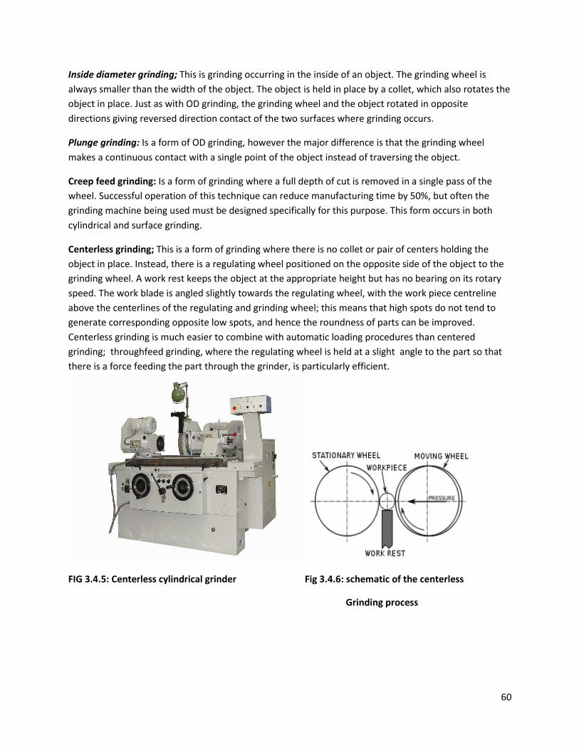
60
Inside diameter grinding; This is grinding occurring in the inside of an object. The grinding wheel is
always smaller than the width of the object. The object is held in place by a collet, which also rotates the
object in place. Just as with OD grinding, the grinding wheel and the object rotated in opposite
directions giving reversed direction contact of the two surfaces where grinding occurs.
Plunge grinding: Is a form of OD grinding, however the major difference is that the grinding wheel
makes a continuous contact with a single point of the object instead of traversing the object.
Creep feed grinding: Is a form of grinding where a full depth of cut is removed in a single pass of the
wheel. Successful operation of this technique can reduce manufacturing time by 50%, but often the
grinding machine being used must be designed specifically for this purpose. This form occurs in both
cylindrical and surface grinding.
Centerless grinding; This is a form of grinding where there is no collet or pair of centers holding the
object in place. Instead, there is a regulating wheel positioned on the opposite side of the object to the
grinding wheel. A work rest keeps the object at the appropriate height but has no bearing on its rotary
speed. The work blade is angled slightly towards the regulating wheel, with the work piece centreline
above the centerlines of the regulating and grinding wheel; this means that high spots do not tend to
generate corresponding opposite low spots, and hence the roundness of parts can be improved.
Centerless grinding is much easier to combine with automatic loading procedures than centered
grinding; throughfeed grinding, where the regulating wheel is held at a slight angle to the part so that
there is a force feeding the part through the grinder, is particularly efficient.
FIG 3.4.5: Centerless cylindrical grinder Fig 3.4.6: schematic of the centerless
Grinding process
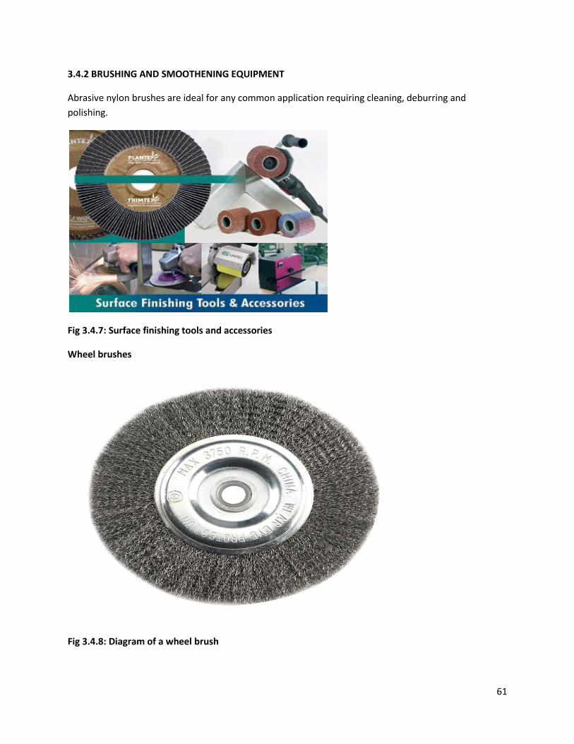
61
3.4.2 BRUSHING AND SMOOTHENING EQUIPMENT
Abrasive nylon brushes are ideal for any common application requiring cleaning, deburring and
polishing.
Fig 3.4.7: Surface finishing tools and accessories
Wheel brushes
Fig 3.4.8: Diagram of a wheel brush
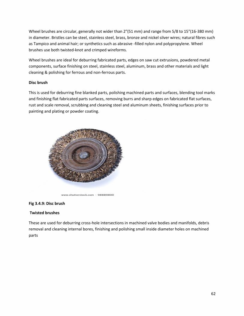
62
Wheel brushes are circular, generally not wider than 2"(51 mm) and range from 5/8 to 15"(16-380 mm)
in diameter. Bristles can be steel, stainless steel, brass, bronze and nickel silver wires; natural fibres such
as Tampico and animal hair; or synthetics such as abrasive -filled nylon and polypropylene. Wheel
brushes use both twisted-knot and crimped wireforms.
Wheel brushes are ideal for deburring fabricated parts, edges on saw cut extrusions, powdered metal
components, surface finishing on steel, stainless steel, aluminum, brass and other materials and light
cleaning & polishing for ferrous and non-ferrous parts.
Disc brush
This is used for deburring fine blanked parts, polishing machined parts and surfaces, blending tool marks
and finishing flat fabricated parts surfaces, removing burrs and sharp edges on fabricated flat surfaces,
rust and scale removal, scrubbing and cleaning steel and aluminum sheets, finishing surfaces prior to
painting and plating or powder coating.
Fig 3.4.9: Disc brush
Twisted brushes
These are used for deburring cross-hole intersections in machined valve bodies and manifolds, debris
removal and cleaning internal bores, finishing and polishing small inside diameter holes on machined
parts
63
Fig 3.4.10: Diagram of twisted-knot wheel brush
3.4.3. PAINT APPLICATION EQUIPMENTS
There are about a dozen different ways to apply paint. Each one is uniquely suited to a particular job.
Here is an overview of several types of industrial paint application methods and their strengths and
weaknesses.
Fig 3.4.11: paint kitchen
Conventional (air atomized) spraying
A conventional spray gun is a tool which utilizes compressed air to atomize (break up) paint and apply it
on a surface. Air and paint enter the gun through separate channels and are mixed using an air cap to
form a controlled pattern, known as a ‘fan’
Paint can be fed to a conventional spray gun via different methods. These vary from a cup which are
attached to the bottom of the gun which supplies the paint by suction (suction fed), or a cup on the
bottom of the gun which supplies the paint by gravity (gravity fed) to a supply hose which supplies the
paint via pressure applied to the paint. The latter can use a pressure pot, which is a vessel containing the
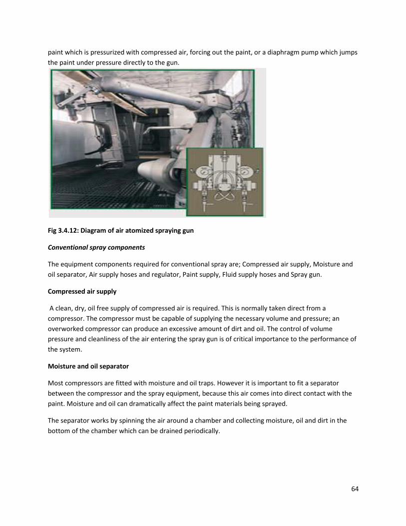
64
paint which is pressurized with compressed air, forcing out the paint, or a diaphragm pump which jumps
the paint under pressure directly to the gun.
Fig 3.4.12: Diagram of air atomized spraying gun
Conventional spray components
The equipment components required for conventional spray are; Compressed air supply, Moisture and
oil separator, Air supply hoses and regulator, Paint supply, Fluid supply hoses and Spray gun.
Compressed air supply
A clean, dry, oil free supply of compressed air is required. This is normally taken direct from a
compressor. The compressor must be capable of supplying the necessary volume and pressure; an
overworked compressor can produce an excessive amount of dirt and oil. The control of volume
pressure and cleanliness of the air entering the spray gun is of critical importance to the performance of
the system.
Moisture and oil separator
Most compressors are fitted with moisture and oil traps. However it is important to fit a separator
between the compressor and the spray equipment, because this air comes into direct contact with the
paint. Moisture and oil can dramatically affect the paint materials being sprayed.
The separator works by spinning the air around a chamber and collecting moisture, oil and dirt in the
bottom of the chamber which can be drained periodically.
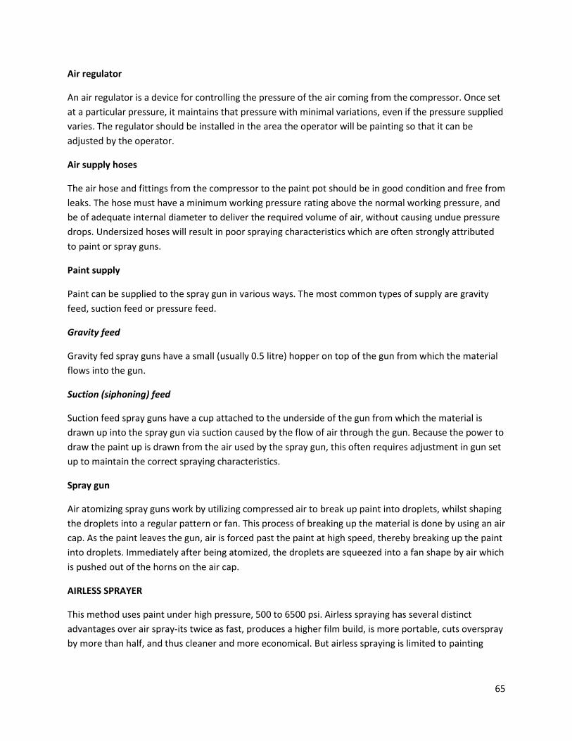
65
Air regulator
An air regulator is a device for controlling the pressure of the air coming from the compressor. Once set
at a particular pressure, it maintains that pressure with minimal variations, even if the pressure supplied
varies. The regulator should be installed in the area the operator will be painting so that it can be
adjusted by the operator.
Air supply hoses
The air hose and fittings from the compressor to the paint pot should be in good condition and free from
leaks. The hose must have a minimum working pressure rating above the normal working pressure, and
be of adequate internal diameter to deliver the required volume of air, without causing undue pressure
drops. Undersized hoses will result in poor spraying characteristics which are often strongly attributed
to paint or spray guns.
Paint supply
Paint can be supplied to the spray gun in various ways. The most common types of supply are gravity
feed, suction feed or pressure feed.
Gravity feed
Gravity fed spray guns have a small (usually 0.5 litre) hopper on top of the gun from which the material
flows into the gun.
Suction (siphoning) feed
Suction feed spray guns have a cup attached to the underside of the gun from which the material is
drawn up into the spray gun via suction caused by the flow of air through the gun. Because the power to
draw the paint up is drawn from the air used by the spray gun, this often requires adjustment in gun set
up to maintain the correct spraying characteristics.
Spray gun
Air atomizing spray guns work by utilizing compressed air to break up paint into droplets, whilst shaping
the droplets into a regular pattern or fan. This process of breaking up the material is done by using an air
cap. As the paint leaves the gun, air is forced past the paint at high speed, thereby breaking up the paint
into droplets. Immediately after being atomized, the droplets are squeezed into a fan shape by air which
is pushed out of the horns on the air cap.
AIRLESS SPRAYER
This method uses paint under high pressure, 500 to 6500 psi. Airless spraying has several distinct
advantages over air spray-its twice as fast, produces a higher film build, is more portable, cuts overspray
by more than half, and thus cleaner and more economical. But airless spraying is limited to painting
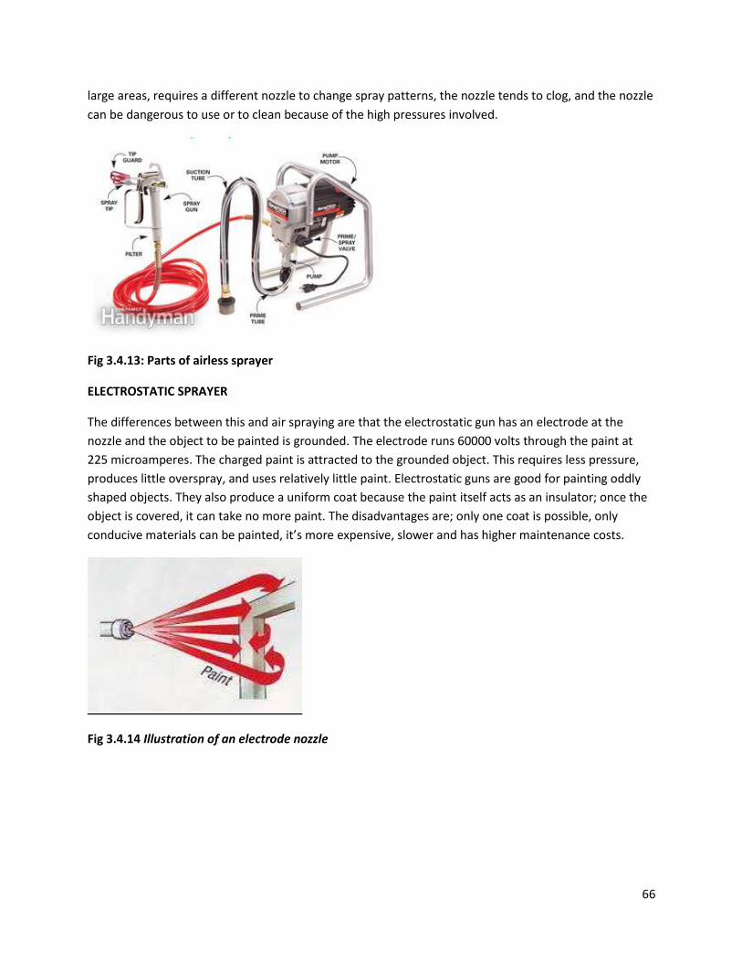
66
large areas, requires a different nozzle to change spray patterns, the nozzle tends to clog, and the nozzle
can be dangerous to use or to clean because of the high pressures involved.
Fig 3.4.13: Parts of airless sprayer
ELECTROSTATIC SPRAYER
The differences between this and air spraying are that the electrostatic gun has an electrode at the
nozzle and the object to be painted is grounded. The electrode runs 60000 volts through the paint at
225 microamperes. The charged paint is attracted to the grounded object. This requires less pressure,
produces little overspray, and uses relatively little paint. Electrostatic guns are good for painting oddly
shaped objects. They also produce a uniform coat because the paint itself acts as an insulator; once the
object is covered, it can take no more paint. The disadvantages are; only one coat is possible, only
conducive materials can be painted, it’s more expensive, slower and has higher maintenance costs.
Fig 3.4.14 Illustration of an electrode nozzle
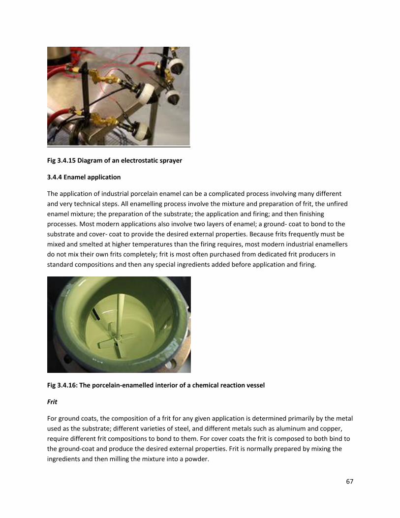
67
Fig 3.4.15 Diagram of an electrostatic sprayer
3.4.4 Enamel application
The application of industrial porcelain enamel can be a complicated process involving many different
and very technical steps. All enamelling process involve the mixture and preparation of frit, the unfired
enamel mixture; the preparation of the substrate; the application and firing; and then finishing
processes. Most modern applications also involve two layers of enamel; a ground- coat to bond to the
substrate and cover- coat to provide the desired external properties. Because frits frequently must be
mixed and smelted at higher temperatures than the firing requires, most modern industrial enamellers
do not mix their own frits completely; frit is most often purchased from dedicated frit producers in
standard compositions and then any special ingredients added before application and firing.
Fig 3.4.16: The porcelain-enamelled interior of a chemical reaction vessel
Frit
For ground coats, the composition of a frit for any given application is determined primarily by the metal
used as the substrate; different varieties of steel, and different metals such as aluminum and copper,
require different frit compositions to bond to them. For cover coats the frit is composed to both bind to
the ground-coat and produce the desired external properties. Frit is normally prepared by mixing the
ingredients and then milling the mixture into a powder.
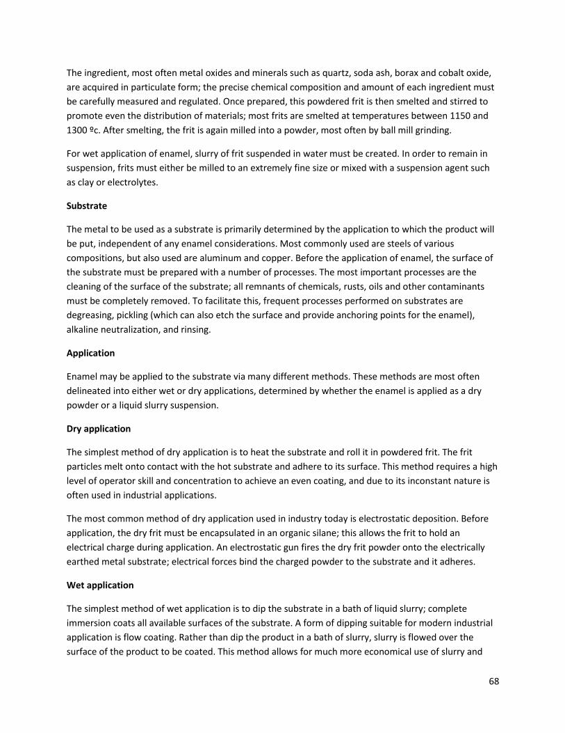
68
The ingredient, most often metal oxides and minerals such as quartz, soda ash, borax and cobalt oxide,
are acquired in particulate form; the precise chemical composition and amount of each ingredient must
be carefully measured and regulated. Once prepared, this powdered frit is then smelted and stirred to
promote even the distribution of materials; most frits are smelted at temperatures between 1150 and
1300 ºc. After smelting, the frit is again milled into a powder, most often by ball mill grinding.
For wet application of enamel, slurry of frit suspended in water must be created. In order to remain in
suspension, frits must either be milled to an extremely fine size or mixed with a suspension agent such
as clay or electrolytes.
Substrate
The metal to be used as a substrate is primarily determined by the application to which the product will
be put, independent of any enamel considerations. Most commonly used are steels of various
compositions, but also used are aluminum and copper. Before the application of enamel, the surface of
the substrate must be prepared with a number of processes. The most important processes are the
cleaning of the surface of the substrate; all remnants of chemicals, rusts, oils and other contaminants
must be completely removed. To facilitate this, frequent processes performed on substrates are
degreasing, pickling (which can also etch the surface and provide anchoring points for the enamel),
alkaline neutralization, and rinsing.
Application
Enamel may be applied to the substrate via many different methods. These methods are most often
delineated into either wet or dry applications, determined by whether the enamel is applied as a dry
powder or a liquid slurry suspension.
Dry application
The simplest method of dry application is to heat the substrate and roll it in powdered frit. The frit
particles melt onto contact with the hot substrate and adhere to its surface. This method requires a high
level of operator skill and concentration to achieve an even coating, and due to its inconstant nature is
often used in industrial applications.
The most common method of dry application used in industry today is electrostatic deposition. Before
application, the dry frit must be encapsulated in an organic silane; this allows the frit to hold an
electrical charge during application. An electrostatic gun fires the dry frit powder onto the electrically
earthed metal substrate; electrical forces bind the charged powder to the substrate and it adheres.
Wet application
The simplest method of wet application is to dip the substrate in a bath of liquid slurry; complete
immersion coats all available surfaces of the substrate. A form of dipping suitable for modern industrial
application is flow coating. Rather than dip the product in a bath of slurry, slurry is flowed over the
surface of the product to be coated. This method allows for much more economical use of slurry and

69
time; it is capable of allowing very rapid production runs. Wet enamel may also be sprayed onto the
product using specialized spray guns. Liquid slurry is fed into the nozzle of a spray gun, and compressed
air atomizes the slurry and ejects it from the nozzle of the gun in a controlled jet.
Firing
Firing, where coated substrates are passed through a furnace to experience long periods of stable high
temperatures, converts the adhering particles of frit into a continuous glass layer. The effectiveness of
the process is highly dependent on time, temperature and quality or thickness of the coating on the
substrate. Most frits for industrial applications are fired for as low as 20 minutes, but frits for very
heavy-duty industrial applications may take double this time. Porcelain enamel coatings on aluminum
substrates may be fired at temperatures as low as 530 ºC, but most steel substrates require
temperatures in excess of 800 ºC.
70
CHAPTER FOUR
4.1 DESIGN OF THE QUESTIONAIRE.
From the literature review, relevant information was gathered which enabled us to design the
questionnaire used for the survey. The first part of the questionnaire was to give the name of the
company, its physical address and its contact details. Nature of business was the second section of the
questionnaire where the company was to give us its main fabricated product. All the other different
products produced by the company and any side contracts that the company performs were listed on
the third section under the product range. The size of the workshop plays a major role in the fabrication,
it determines how much a company can produce and therefore was listed on the fourth section of the
questionnaire. Different companies use different type of layout therefore layout stands as a very
important part in determining the kind of products fabricated and the size of workshop hence being
listed as the second part in the fourth section.
The different types of machinery (equipment) used for fabrications processes were listed according to
the type, size and capacity used any support equipment used in the fabrication workshop were listed as
the fifth section. Fabrication processes require a lot of skilled work force in order to achieve or produce
the right quality and in quantity therefore the last section covered the category and number of different
personnel in the fabrication workshop.
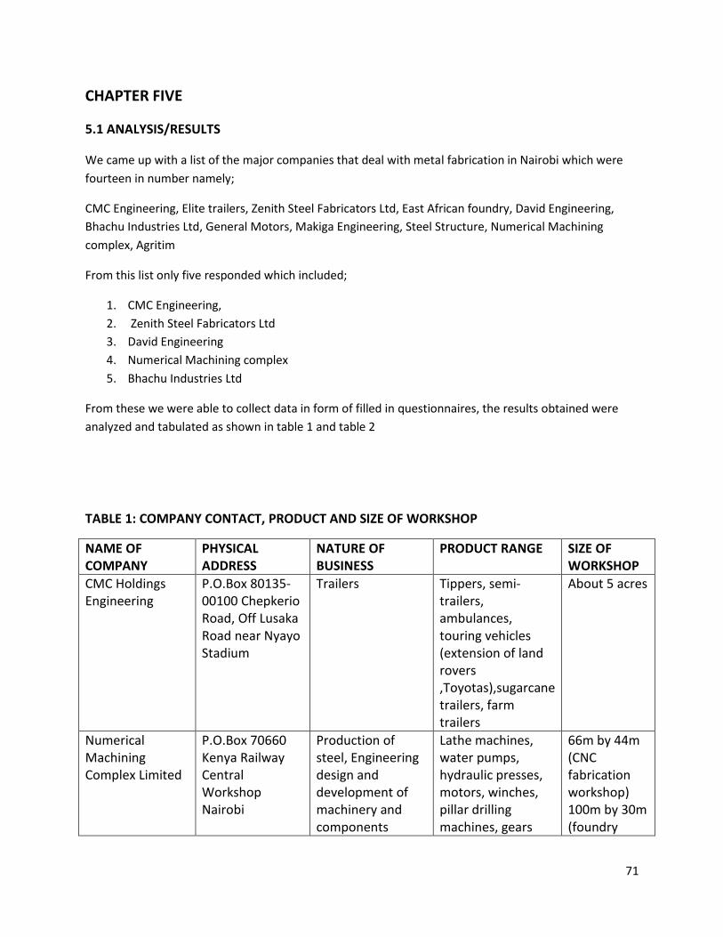
71
CHAPTER FIVE
5.1 ANALYSIS/RESULTS
We came up with a list of the major companies that deal with metal fabrication in Nairobi which were
fourteen in number namely;
CMC Engineering, Elite trailers, Zenith Steel Fabricators Ltd, East African foundry, David Engineering,
Bhachu Industries Ltd, General Motors, Makiga Engineering, Steel Structure, Numerical Machining
complex, Agritim
From this list only five responded which included;
1. CMC Engineering,
2. Zenith Steel Fabricators Ltd
3. David Engineering
4. Numerical Machining complex
5. Bhachu Industries Ltd
From these we were able to collect data in form of filled in questionnaires, the results obtained were
analyzed and tabulated as shown in table 1 and table 2
TABLE 1: COMPANY CONTACT, PRODUCT AND SIZE OF WORKSHOP
NAME OF COMPANY
PHYSICAL ADDRESS
NATURE OF BUSINESS
PRODUCT RANGE SIZE OF WORKSHOP
CMC Holdings Engineering
P.O.Box 80135-00100 Chepkerio Road, Off Lusaka Road near Nyayo Stadium
Trailers Tippers, semi-trailers, ambulances, touring vehicles (extension of land rovers ,Toyotas),sugarcane trailers, farm trailers
About 5 acres
Numerical Machining Complex Limited
P.O.Box 70660 Kenya Railway Central Workshop Nairobi
Production of steel, Engineering design and development of machinery and components
Lathe machines, water pumps, hydraulic presses, motors, winches, pillar drilling machines, gears
66m by 44m (CNC fabrication workshop) 100m by 30m (foundry
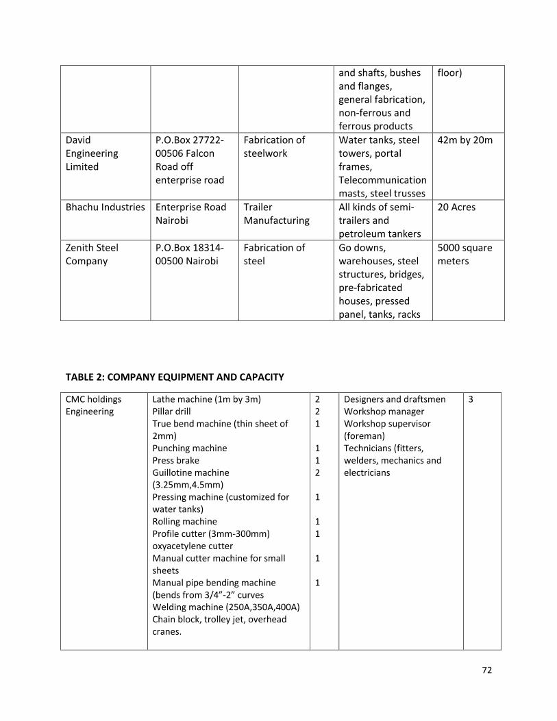
72
and shafts, bushes and flanges, general fabrication, non-ferrous and ferrous products
floor)
David Engineering Limited
P.O.Box 27722-00506 Falcon Road off enterprise road
Fabrication of steelwork
Water tanks, steel towers, portal frames, Telecommunication masts, steel trusses
42m by 20m
Bhachu Industries Enterprise Road Nairobi
Trailer Manufacturing
All kinds of semi-trailers and petroleum tankers
20 Acres
Zenith Steel Company
P.O.Box 18314-00500 Nairobi
Fabrication of steel
Go downs, warehouses, steel structures, bridges, pre-fabricated houses, pressed panel, tanks, racks
5000 square meters
TABLE 2: COMPANY EQUIPMENT AND CAPACITY
CMC holdings Engineering
Lathe machine (1m by 3m) Pillar drill True bend machine (thin sheet of 2mm) Punching machine Press brake Guillotine machine (3.25mm,4.5mm) Pressing machine (customized for water tanks) Rolling machine Profile cutter (3mm-300mm) oxyacetylene cutter Manual cutter machine for small sheets Manual pipe bending machine (bends from 3/4”-2” curves Welding machine (250A,350A,400A) Chain block, trolley jet, overhead cranes.
2 2 1 1 1 2 1 1 1 1 1
Designers and draftsmen Workshop manager Workshop supervisor (foreman) Technicians (fitters, welders, mechanics and electricians
3
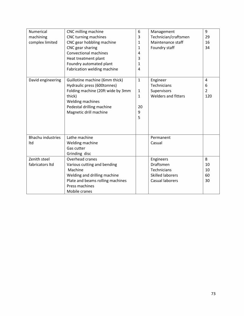
73
Numerical machining complex limited
CNC milling machine CNC turning machines CNC gear hobbling machine CNC gear sharing Convectional machines Heat treatment plant Foundry automated plant Fabrication welding machine
6 3 1 1 4 3 1 4
Management Technician/craftsmen Maintenance staff Foundry staff
9 29 16 34
David engineering Guillotine machine (6mm thick) Hydraulic press (600tonnes) Folding machine (20ft wide by 3mm thick) Welding machines Pedestal drilling machine Magnetic drill machine
1 1 1 20 9 5
Engineer Technicians Supervisors Welders and fitters
4 6 2 120
Bhachu industries ltd
Lathe machine Welding machine Gas cutter Grinding disc
Permanent Casual
Zenith steel fabricators ltd
Overhead cranes Various cutting and bending Machine Welding and drilling machine Plate and beams rolling machines Press machines Mobile cranes
Engineers Draftsmen Technicians Skilled laborers Casual laborers
8 10 10 60 30

74
CHAPTER SIX
6.1 DISCUSSION
From the knowledge of fabrication from chapter one, the different processes from the different
companies visited were compared to the ideal processes. It was noted that the nature of business varies
from company to company, while they had different product range and sometimes specific contracts
based on their clients’ needs and their own expertise. The size of the various fabrication workshops in
the various companies also varied with the nature of business. The type, size and capacity of fabrication
equipment was identified for the different processes, some of the machines were found to be common
for example; lathe machines, welding machines, drilling machines, bending machines, and some types of
cutting machines.
Different workshops had different types of layout which included; product layout, process layout, fixed
layout and combined layout. It was however noted that the most common layout most of the
workshops was the combined layout.
However the collection of data was efficient due to some challenges encountered during the field visits.
Most of the companies have restrictions when it comes to filling in of questionnaire, therefore
accessibility was difficult. Very busy schedules of some companies also played as a challenge whereby
there was hardly anyone to attend to us. Some of the companies are not well known thereby making it
difficult to locate them. In some cases we were assigned to personnel who were not well skilled which
made it difficult to collect the correct data.
75
CHAPTER SEVEN
7.1 CONCLUSION
The objectives of the project which were: to Study and research on the metal fabrication processes, and
to survey the current status of the metal fabrication industry capacity in Nairobi were achieved.
The literature review of the metal fabrication processes was broadly researched from books, internet
sources and information from the supervisor. The equipments used for this processes were described
and schematically shown also with the help of the mechanical workshop in the university. The
questionnaire was well designed with required information to be collected on the metal fabrication.
It was noted that there are a quite number companies that do metal fabrication in Nairobi, however
some were selected and visited. The visits were successful despite the few hitches. Data collected was
analyzed, discussed and it was found that the current status of metal fabrication in Nairobi is advanced
and quite diverse depending on the product range. However most of the companies were found to have
a common layout which was the combined layout, the type and sizes of equipment solely depended on
the product range of the industry as well as side contracts that a company carries out. In most of the
companies it is evident that personnel or the labor force are skilled or trained to specialize in specific
fabrication process and also operate equipment of the specific process. The sizes of the fabrication
workshops also varied for different industries whereby some have big yards or even acres which cover
their fabrication work.
76
REFERENCES
1. Kalpakjian, Serope, 1928,
Manufacturing processes for engineering materials,
Reading, Mass. : Addison-Wesley, c1984,
(OCoLC)566347510.
2. Lawrence E Doyle; Carl A Keyser; James L Leach; George F Schrader; Morse B Singer
manufacturing processes and materials for engineers ,
Englewood Cliffs, c1969,
second edition
3. Ernest Paul DeGarmo; J Temple Black; Ronald A Kohser,
Materials and processes in manufacturing,
New York [etc.]: J. Wiley & Sons, c2003.
Ninth edition
4. Tuthill, A.H. and Avery,
ASTM, standard methods for cleaning, descaling of stainless steel parts, equipment and systems,
c1993 revised edition.
5. Walter de Gruyter, Eagleson, Mary,
Concise encylopedia Chemistry
c1994, revised edition.
6. Serope Kalpakjian; Steven R Schmid,
Manufacturing engineering and technology,
Upper Saddle River, NJ: Pearson,
c2014 Seventh edition
7. http://en.wikipedia.org/wiki/Bending_%28metalworking%29 ,
viewed on 9th October 2013.
8. http://en.wikipedia.org/wiki/Rolling_%28metalworking%29,
viewed on 20th November 2013.
9. http://en.wikipedia.org/wiki/Die_%28manufacturing%29,
viewed on 4th December 2013.
77
APPENDIX A
FABRICATION QUESTIONNAIRE
1. NAME OF COMPANY
_____________________________________________________________________________________
_____________________________________________________________________________________
i. PHYSICAL ADDRESS
_____________________________________________________________________________________
_____________________________________________________________________________________
ii. TELEPHONE NUMBER
_____________________________________________________________________________________
_____________________________________________________________________________________
2. NATURE OF BUSSINESS (MAIN PRODUCT)
_____________________________________________________________________________________
_____________________________________________________________________________________
3. PRODUCT RANGE
_____________________________________________________________________________________
_____________________________________________________________________________________
_____________________________________________________________________________________
_____________________________________________________________________________________
_____________________________________________________________________________________
_____________________________________________________________________________________
_____________________________________________________________________________________
4. SIZE OF WORKSHOP
_____________________________________________________________________________________
____________________________________________________________________________________
i. LAYOUT

78
_____________________________________________________________________________________
_____________________________________________________________________________________
5. MACHINERY (EQUIPMENT)
TYPE NO.
_____________________________________________________________________________________
_____________________________________________________________________________________
_____________________________________________________________________________________
_____________________________________________________________________________________
_____________________________________________________________________________________
_____________________________________________________________________________________
_____________________________________________________________________________________
____________________________________________________________________________________
6. LABOUR FORCE (PERSONELL)
CATEGORY NO.
_____________________________________________________________________________________
_____________________________________________________________________________________
_____________________________________________________________________________________
_____________________________________________________________________________________
_____________________________________________________________________________________
_____________________________________________________________________________________
_____________________________________________________________________________________