unmanned aerial vehicles (uavs) and their application in ... · unmanned aerial vehicles (uavs) and...
TRANSCRIPT

British Society for Geomorphology Geomorphological Techniques, Chap. 2, Sec. 1.7 (2015)
Unmanned Aerial Vehicles (UAVs) and their application in geomorphic mapping
Christopher Hackney1 and Alexander I Clayton1
1 Geography and Environment, University of Southampton, UK ([email protected])
ABSTRACT: Detailed topographic surveys are a pre-requisite for many studies into Earth surface processes and dynamics. Often such surveys are required for large (>10 km2) areas and at a relatively high temporal resolution (sub-daily to daily) for use in hazard monitoring, monitoring ecological change, and detailed process studies. Techniques such as Terrestrial Laser Scanning, Total Stations and low-level aerial photography via chartered light aircraft flights may provide the spatial resolution required, but are often costly and time-intensive, making them less viable in obtaining the temporal resolution necessary. Further still, satellite imaging platforms often produce products whose image resolution is too coarse to resolve fine scale topography. Recent technological advances have seen the development of Unmanned Aerial Vehicles (UAVs) as a platform from which to acquire aerial photos over large spatial scales at high temporal resolution. These photos may then be combined as orthophotos for spectral analysis, or used to generate useful digital terrain models through Structure from Motion (SfM) photogrammetric techniques. The tandem development of low-cost, rapid deployment UAV platforms and SfM algorithms has seen the rapid growth in in the application of UAVs for generating high-resolution topographic data. Here we detail some of the considerations needed before deployment of UAV systems, before showing how UAVs may be used to collect high resolution aerial photos to enable generation of pro-glacial topography in Iceland.
KEYWORDS: UAVs; fixed-wing platform, rotor-wing platform, aerial surveys; topographic models
Introduction
The acquisition of high resolution topographic data is key to many studies in Earth science. For mapping studies requiring data at high temporal (hourly, daily), and large spatial (>5 km2), scales traditional surveying methods are often costly and time intensive. Recent advances in technology have seen the advent of digital photogrammetry as a viable means of obtaining such high resolution topographic data (Smith et al., 2009; Rosnell and Honavaara, 2012; Fonstad et al., 2013). In tandem, the development and increased affordability of Unmanned Aerial Vehicles (UAVs) as a novel platform with which to collect the low-level aerial photography needed for such photogrammetry has seen a rapid increase in their usage in geomorphological studies (Lejot et al., 2007; Hugenholtz et al., 2013).
Previously the domain of the military, UAVs have seen an increase in civilian and academic use, partly driven by the improvements in affordable miniature GPS and Inertial Measurement Units (IMUs) which enable accurate operation of UAV systems. UAVs come in a range of designs. Large fixed-wing platforms have been adapted from military-grade platforms and are typically 5 m of more in wingspan and may carry payloads greater than 200 kg. These systems may have an extended range of ~500 km but require full aviation clearance and need a large ground operations team (Anderson and Gaston, 2013). Smaller UAV systems may come as either fixed-wing or multi-rotor systems. At this scale, many off-the-shelf designs and user-built kit systems are available. Small fixed-wing UAVs may be only a couple of meters wide. Small rotor-wing platforms may have up to eight rotors and may only weight one or two kilograms. At
ISSN 2047-0371

Unmanned Aerial Vehicles (UAVs) 2
British Society for Geomorphology Geomorphological Techniques, Chap. 2, Sec. 1.7 (2015)
the even smaller scale, Micro-dones may weigh less than kilogram, however they have limited flight durations (~10 mins) and payloads (<1 kg). Of particular interest to the geomorphological community are the small, mini- and micro-UAV systems (Anderson and Gaston, 2013). The flexibility in operation and shorter response times afforded by small UAV systems means they enable rapid deployment and the collection of high spatial- and temporal-resolution datasets where traditional aerial techniques, including larger UAV systems, may not. The use of UAVs in geomorphological mapping is often facilitated by the application of photogrammetric techniques such as Structure from Motion (SfM) (e.g. Harwin and Lucieer, 2012; Westoby et al., 2012; Micheletti et al. 2015). SfM utilises overlapping imagery acquired from multiple viewpoints to reconstruct the camera position and camera geometry. From these reconstructed camera locations it is then possible to generate spatial relationships between common feature points and thereby
generate a feature’s structure (Westoby et
al., 2012; Fonstad et al. 2013; Micheletti et al. 2015). Given correct deployment and attainment of accurate ground control data, the horizontal accuracy and precision of resultant aerial imagery and Digital Elevation Models (DEMs) generated through SfM can be better than satellite imagery and aerial
LIDAR (±0.2 m; Fonstad et al., 2013;
Hugenholtz et al., 2013), whilst vertical
accuracy is typically better than ±0.1m
(Fonstad et al., 2013). After some years of development commercially available small fixed-wing and rotor-wing UAV systems now enable the low-cost acquisition of aerial photos over large areas at high temporal resolution. Coupled with the concurrent development of SfM techniques (Micheletti et al., 2015) and a greater appreciation of the potential errors introduced by these methodologies (James and Robson, 2014; Nouwakpo et al., 2014), low-cost, rapid, high resolution topographic data for use in geomorphological mapping collection is now becoming common place in the geosciences..
Applications of UAVs in geomorphology are wide ranging and include, for example, surveying fluvial bathymetry to map and monitor gravel bar location and change using a small remote controlled motorized vehicle
(Lejot et al., 2007). d’Oleire-Oltmanns et al.
(2012) deployed a small fixed-wing platform to monitor rates of soil erosion over a 6km2
area in Morocco, showing how small UAVs may be used to bridge the gap between field scale and satellite imagery. Repeat topographic surveys over a 2.5 km2 gully allowed Grellier et al. (2012) to constrain rates of gully erosion and vegetation change allowing them to elucidate subsurface processes controlling gully evolution. Niethammer et al. (2012) deployed a quad-copter, rotary-wing platform to monitor landslides in the Southern French Alps, mapping failures, source and sink zones from orthophotos and digital terrain models (DTMs) generated from the UAV imagery. UAVs have also been deployed in glacial environments, with Whitehead et al. (2013), using a fixed-wing UAV system carrying a Lumix LX3 camera to monitor glacial ablation in consecutive ablation seasons on the Fountain Glacier, Canada. Additionally, and as technology and capabilities evolve, the ability of UAVs to carry variable payloads will open up the possibility of using multispectral sensors to add value to mapping projects, for example it is already possible to detect the geomorphological controls on crop production from combined multi-spectral and traditional photogrammetric techniques using UAV systems (Dunford et al., 2009; Martinez-Casasnovas et al., 2013). More recent advances have seen the application of survey-grade Lidar equipment on small fixed-wing UAV platforms (Lin et al., 2011). This advance will allow the acquisition of topographic data beneath vegetation which current SfM algorithms do not. The rest of this article will focus specifically on the use of small UAVs (c. Anderson and Gaston, 2013) in obtaining aerial imagery for the purpose of geomorphological mapping. It will outline considerations when selecting a suitable UAV platform. It will then provide some background as to the legal framework within which such studies must be conducted in the EU. Finally, it will provide a case study

3 Christopher Hackney and Alexander Clayton
British Society for Geomorphology Geomorphological Techniques, Chap. 2, Sec. 1.7 (2015)
example of the deployment of a small fixed-wing UAV in a pro-glacial environment in Iceland, which details good practice workflows and site-specific considerations for operations in remote and topographically restrictive environments.
Considerations
Hardware
UAVs commonly used for geomorphological surveying are predominately built around two types of airframe; fixed-wing and rotor-wing. Both platforms are used in geomorphological applications working off of the same theoretical standpoint; the acquisition of overlapping, photographs which can later be used with SfM (Fonstad et al., 2013; Micheletti et al., 2015) algorithms to reconstruct topography. Recent work has shown how topographic datasets derived from UAV derived aerial photos are improved by having images captured from non-parallel viewing locations (James and Robson, 2014). That is to say, it may be beneficial to collect imagery from more unstable platforms which enable more photo acquisition form non-uniform camera locations. A summary of typical small fixed-wing and rotary-wing systems is provided in Table 1. These systems reflect those commonly used in geomorphological studies and do not represent the actual maximum values obtained by larger UAV systems (Anderson and Gaston, 2013). Note the specifications and details provided below are limited to
those which may be operated under CAA requirements (see below for more details).
Fixed-Wing Platforms
Fixed-wing platforms (Figure 1A) are perhaps the most common form of UAV. Wings and bodies are normally constructed from lightweight polystyrene with a wingspan typically <2m. The lift characteristics of a flying wing mean that, relative to rotor-wing platforms, their fuel efficiency is high. The limited number of moving parts and lightweight design also means that damage inflicted by hard landings is more limited than with rotor-wing designs (although it is less likely that hard landings will occur with rotor-wing designs). They are launched from the ground either by hand or, more commonly now, with use of a catapult. Whilst the apparatus is small, the necessity for a non-vertical climb to altitude means they require more space to take off than their rotor-wing counterparts. They are larger in size than their rotor-wing counterparts (Figure 1) and as such require more space to operate. They often also have more associated peripheries (additional laptop and launching gear, Figure 1A) required for their operation than rotor-wing UAVs. However, recent advances in fixed-wing platforms have seen an increase in their flight endurance such that they can now fly longer than rotor-wing platforms enabling greater areas to be covered with more ease. They are often controlled in-flight
Figure 1: A) A fixed-wing UAV system with associated peripheries required for its operation. B) A quad-copter rotor-wing UAV system and associated operational peripheries. The same 1.5 m2 ground control target has been used a background to provide consistent scale between both A) and B).

Unmanned Aerial Vehicles (UAVs) 4
British Society for Geomorphology Geomorphological Techniques, Chap. 2, Sec. 1.7 (2015)
Table 1: Technical specification comparison between typical small fixed-wing and multi-rotor UAV platforms which may be used in geomorphological studies. Values in italicised parentheses relate to CAA operating regulations as per CAP393 and CAP722. Values as reported in Hugenholtz et al. (2013), Mancini et al. (2013) and Anderson and Gaston (2013).
Fixed-wing UAVs Multi-rotor UAVs
Wingspan (m) 1 – 3 <1
Flight time (mins) 20 - 60 20
Max payload Weight (kg) 30 (7) 15 (7)
Max. Speed (km/h) 50 – 80 (130) 30 – 50 (130)
Operating Range (km) 1 - 5 (0.5) 1 – 2 (0.5)
Altitude Range (m) > 2000 (121) 400 (121)
by built-in autopilots, with flight plans pre-programmed before deployment. This means they require less user interaction in flight, and are more stable, than rotor-wing platforms. However, this has implications for topographic data sets derived from photos obtained from fixed-wing platforms, as the increased stability of the platform and pre-programmed, often parallel flight lines may introduce errors into the topographic dataset (James and Robson, 2014). Fixed-wing airframes inevitably require more space than rotor-wing options. Often a ~100 m strip is sensible to allow for overrun and variations in headwind strength. There is also a need for the survey area to be less constricted (e.g. from valley side walls) than is required with rotor-wing UAVs as they have a larger footprint and may be operated at a greater range from the operator. Fixed-wing UAVs may be more suited to topographic surveys over larger spatial scales due to their longevity in flight. However, their application to locations bounded by terrain, trees or other obstructions may limit their successful operation. Likewise, their relative lack of maneuverability may provide challenges in certain situations.
Rotor-wing Platforms
Rotor-wing platforms comprise a suite of designs ranging from common helicopter designs to quad-copters (with four rotary
blades, Figure 1B), hexa-copters (with six rotary blades), and octa-copters (with eight rotary blades) which are becoming the standard for heavy lift photography work. Their footprint is typically smaller than fixed-wing platforms (~0.8 m). Vertical take-off and landing means that they do not require extensive unconstrained landing sites and can be deployed from relatively inaccessible areas. This favours rapid deployment and enables access to areas previously unfeasible with traditional survey techniques and fixed-wing UAV platforms. Due to their smaller footprint, rotor-wing UAVs have limited flight endurance (typically less than 20 mins) when compared to fixed-wing platforms, requiring many battery packs and/or recharging units to accomplish the same spatial coverage as fixed-wing UAVs. This increases the likelihood of inclement weather impacting the survey. However, as rotor-wing platforms typically fly at slower speeds than fixed-wing UAVs, and often contain better gimbals, they are more stable at higher wind speeds than fixed-wing UAVs. This permits a trained pilot greater control of the UAV, and facilitates the collection of non-parallel survey lines under a wider range of wind conditions. It is therefore likely that topographic datasets derived from rotor-wing systems are likely to be of higher quality than equivalent data-sets produced from fixed-wing systems as their ability to be more flexible in their survey lines will permit the acquisition of a more non-uniform set of photos (James and Robson, 2014).

5 Christopher Hackney and Alexander Clayton
British Society for Geomorphology Geomorphological Techniques, Chap. 2, Sec. 1.7 (2015)
Additionally, unlike fixed-wing platforms, rotor-wing platforms are able to hover over objects and locations. This facilitates higher precision photogrammetry over features of interest and allows for complete 3D inspection of stationary objects, whilst also opening the possibility of at-a-point temporal sequences in measurements. Similarly, it enables users to survey the same feature at different altitudes, thereby assessing issues of pixel resolution and photo quality as a function of varying altitude.
Sensing Applications
Both fixed-wing and rotor-wing UAVs have payloads capable of carrying small to medium size digital cameras and video recorders (and are restricted to payloads of 7 kg under CAA regulations; see below for further details). These cameras can be simple RGB digital cameras suitable for the acquisition of high resolution aerial photos which can subsequently be used in the generations of georectified ortho-photos or digital elevation models (e.g. Fonstad et al., 2013; Hugenholtz et al., 2013). Alternatively, these sensing unit can be hyper-spectral cameras which can be used to enable an assessment of the local water stress (Zarco-Tejada et al., 2012) or agricultural and forestry health (e.g. Saari et al., 2011). More recently, UAVs have been deployed with small Lidar sensors (Lin et al., 2011; Wallace et al., 2012). This growing area allows for high resolution topographic surveys from UAVs to be conducted without recourse to SfM software. It should be noted however that the current suite of Lidar sensors which may be deployed on UAVs are less high powered than traditional Lidars and have a higher signal-to-noise ratio. In addition, the development of smaller Lidar sensors capable of being lifted by UAVs could possibly enable more data to be obtained than tradition photogrammetric techniques, for example Lidar intensity return data can be used to identify moisture variability and surface geology variability more easily than would be visible from RGB camera images. Furthermore, one of the current limitations with SfM is that the cameras used are passive sensors, i.e. they cannot penetrate through vegetation. Having active Lidar, and phased-based sensors onboard UAVs would
enable greater detail of the surface to be captured. Although these techniques would be less cost effective than photogrammetric techniques for obtaining topographic data, they will still require careful planning of flight lines, acquisition of a detailed ground control network and will still have to operate within the legal restrictions.
Ground Control
For the successful registration and alignment of photos collected from any UAV platform and sensor, an accurate and precisely located network of Ground Control Points (GCPs) must be acquired. To ensure that no lens warping, or ‘doming’ (c. James and Robson, 2014) is present in the final product, it is vital the GCPs are distributed throughout the study area. Of particular importance is the placement of GCPs close to the edges of the survey area, where potential doming may be exacerbated. The number of GCPs deployed depends on the overall aim of the survey. For example, for geomorphic mapping it is more important to distribute GCPs across the survey area to ensure doming and registration errors are constrained. However, if the survey is designed for obtain detailed topography, then it is important that subtle variations in topography are accurately resolved. As such a denser network of GCPs in locations of interest may be necessary to ensure such fine-scale topography is captured. It is worth noting, that it is still important to maintain a good distribution of GCPs in this case, to avoid doming of the final DEMs. GCPs normally consist of brightly coloured targets which will be visible within the aerial photographs, laid out by the operator evenly across the survey area. The GCPs should be larger than the pixel resolution of the sensor onboard the UAV such that they are clearly visible within the photographs. As pixel resolution varies in size with survey elevation, surveys conducted at higher altitudes require larger GCPs. The pixel size (PR) for a sensor with a given focal length (LF) and pixel dimension (PD), at a given altitude (A) can be calculated using the following calculation
PR = PD(A/LF) (1)
Equation 1 can therefore be used to determine the required size of GCPs for a survey of any given altitude. For example,

Unmanned Aerial Vehicles (UAVs) 6
British Society for Geomorphology Geomorphological Techniques, Chap. 2, Sec. 1.7 (2015)
Smith et al. (2009) deployed 30 GCPs across a 40 x 50 m survey area. Their GCPs consisted of 20 cm laminated sheets containing a black and white target design. Smith et al. (2009) flew their survey at 50 m altitude. For surveys flown at higher altitudes (> 50m) the size of GCPs deployed are recommended to be larger than 1 m2 to be captured in the aerial photos. Alternatively, it is possible to use unique ground features as GCPs, for example, Fonstad et al. (2013) identified features on the ground to use as GCPs which provide fixed features in the survey photos (e.g. field corners, lake edges, road junctions). Once a network of GCPs has been constructed, the position of each GCP must be obtained. This can either be a real world coordinate of the GCP obtained through the use of a differential Global Positioning System (dGPS) or a relative position to an arbitrary coordinate grid obtained through a total station or similar surveying equipment. Either technique should result in positional accuracies of approximately ± 0.05 m. The technique used depends upon the ultimate goal of the survey being conducted. If the data is to be used in conjunction with other data sets and registered within a real-world context then global coordinates will be necessary. However, if this is not the case then it is possible to use an arbitrary, relative, coordinate system.
Legal Limits
The legal requirements for UAV flight vary between countries. It is necessary to research country specific regulations before any survey work is undertaken to ensure you meet the requirements. Many legal considerations exist when planning a survey with a UAV. Within the EU flights undertaken with a UAV must adhere to central legislation (and the reader is guided towards the Civil Aviation Authority (the governing body within the UK) protocols CAP393 and CAP722 for full details of the legislation which is applicable across the entire EU). Here (for brevity) we will cover a few key points arising from this legislation which require consideration when planning geomorphological surveys. It is stressed that you check the legislation before deployment at each new site to ensure you adhere to the rules.
EU law states that UAVs operated in any EU country airspace must be kept within the visual line of sight. This equates to approximately 500 m in the horizontal and 400 feet in the vertical, although this is heavily dependent upon local weather conditions and terrain. This has practical implications for survey and flight line design, limiting the operational space achievable with each flight. As such, it is likely that multiple launches will need to be made if your area of interest covers a substantial area. Further, this increases the importance of a dense ground control network (see above) to aid stitching of photos and georectification during post-processing. Additionally, UAVs may not be flown within 50 m of a member of the public (with the exception of the operating crew), thus limiting their use within public spaces and over tourist locations. Similarly, they may not be flown over or within 150 m of any organised open-air assembly of more than 1,000 people.
Case Study
Science questions and aims
Proglacial zones are highly dynamic regions which are subject to seasonal variations in energy regime and thus geomorphological activity. These regions are often inaccessible and remote. The foreland of Skalafellsjokull, Iceland (Figure 2) includes a series of well-preserved push moraines, the spacing of which relate to local climatic conditions (Boulton, 1986; Bennett, 2001). Yet, our understanding of how these features respond to climatic variations at Skalafellsjokull is poorly understood. In order to map these features and determine accurately the inter-seasonal spacing, a high resolution DEM was required (see Chandler et al., In Prep, for details). These features are located in a topographically constrained region which does not easily facilitate high resolution mapping with terrestrial laser scanning, Lidar or satellite radar mapping. As such, the use of a UAV presented a lower cost, more time effective option than standard aerial surveys and due to the size of the site (2 km2) a terrestrial approach would not have been suitable. In addition, satellite imagery is of too coarse a resolution to resolve the spatial scales of the push moraines.

7 Christopher Hackney and Alexander Clayton
British Society for Geomorphology Geomorphological Techniques, Chap. 2, Sec. 1.7 (2015)
Figure 2: Google Earth image of Heinbergjokull and Skallafellsjokull in Icealand. The UAV flight lines are depicted in yellow and blue dots represent the GCPs used to register the aerial photos.
Methodology and Results
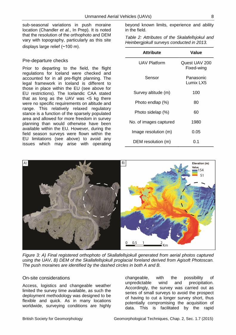
To that end, during 2013 a Quest 200 fixed-wing UAV carrying a Panasonic Lumix LX5 off-the-shelf, point-and-shoot camera (see Table 2 for details) was used to survey proglacial and ice marginal geomorphology at Skalafellsjokull and Heinbergjokull in Iceland (Figures 2 and 3). The aim of the surveys was to obtain low level aerial photography which could subsequently be processed with SfM software to produce high resolution topographic surveys of the study area (Figure 3). The UAV was used in conjunction within Leica dGPS deployed in Real-Time Kinematic (RTK) mode to limit distortion in the final photogrammetric product. RTK
corrections were accurate to ±0.01 m and
±0.05 m. in the horizontal and vertical,
respectively. Fifteen ground control point targets were created in the field from orange plastic material and measured 2 m2. Tape was used to indicate the centre of the target. The use of tape larger than the pixel resolution enabled a precise determination of target centres. The targets were deployed in a grid network spaced approximately 0.5 km apart and a
density of 1.2 points/km2; this results in ~0.03
GCPs per image (Figure 2). GCPs were deployed before the UAV was launched to ensure they would be visible in the survey. The resulting orthophoto (Figure 3A) and DEM (Figure 3B) have spatial resolutions of 0.05 and 0.1 m respectively, and are of suitable resolution to be able to determine
Unmanned Aerial Vehicles (UAVs) 8
British Society for Geomorphology Geomorphological Techniques, Chap. 2, Sec. 1.7 (2015)
sub-seasonal variations in push moraine location (Chandler et al., In Prep). It is noted that the resolution of the orthophoto and DEM vary with topography, particularly as this site
displays large relief (~100 m).
Pre-departure checks
Prior to departing to the field, the flight regulations for Iceland were checked and accounted for in all pre-flight planning. The legal framework in Iceland is different to those in place within the EU (see above for EU restrictions). The Icelandic CAA stated that as long as the UAV was <5 kg there were no specific requirements on altitude and range. This relatively relaxed regulatory stance is a function of the sparsely populated area and allowed for more freedom in survey planning than would otherwise have been available within the EU. However, during the field season surveys were flown within the EU limitations (see above) to avoid any issues which may arise with operating
beyond known limits, experience and ability in the field.
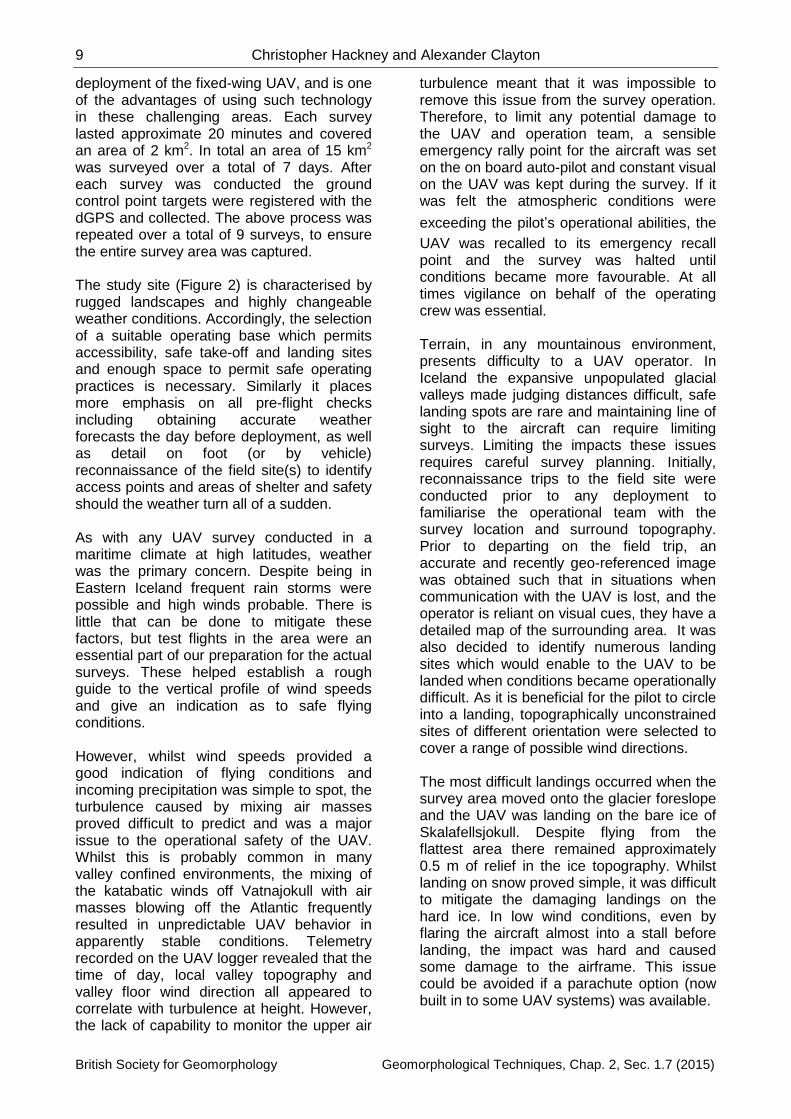
Table 2: Attributes of the Skalafellsjokul and Heinbergjokull surveys conducted in 2013.
Attribute Value
UAV Platform Quest UAV 200 Fixed-wing
Sensor Panasonic Lumix LX5
Survey altitude (m) 100
Photo endlap (%) 80
Photo sidelap (%) 60
No. of images captured 1980
Image resolution (m) 0.05
DEM resolution (m) 0.1
Figure 3: A) Final registered orthophoto of Skallafellsjokull generated from aerial photos captured using the UAV. B) DEM of the Skallafellsjokull proglacial foreland derived from Agisoft Photoscan. The push moraines are identified by the dashed circles in both A and B.
On-site considerations
Access, logistics and changeable weather limited the survey time available, as such the deployment methodology was designed to be flexible and quick. As in many locations worldwide, surveying conditions are highly
changeable, with the possibility of unpredictable wind and precipitation. Accordingly, the survey was carried out as series of small surveys to avoid the prospect of having to cut a longer survey short, thus potentially compromising the acquisition of data. This is facilitated by the rapid
9 Christopher Hackney and Alexander Clayton
British Society for Geomorphology Geomorphological Techniques, Chap. 2, Sec. 1.7 (2015)
deployment of the fixed-wing UAV, and is one of the advantages of using such technology in these challenging areas. Each survey lasted approximate 20 minutes and covered an area of 2 km2. In total an area of 15 km2
was surveyed over a total of 7 days. After each survey was conducted the ground control point targets were registered with the dGPS and collected. The above process was repeated over a total of 9 surveys, to ensure the entire survey area was captured. The study site (Figure 2) is characterised by rugged landscapes and highly changeable weather conditions. Accordingly, the selection of a suitable operating base which permits accessibility, safe take-off and landing sites and enough space to permit safe operating practices is necessary. Similarly it places more emphasis on all pre-flight checks including obtaining accurate weather forecasts the day before deployment, as well as detail on foot (or by vehicle) reconnaissance of the field site(s) to identify access points and areas of shelter and safety should the weather turn all of a sudden. As with any UAV survey conducted in a maritime climate at high latitudes, weather was the primary concern. Despite being in Eastern Iceland frequent rain storms were possible and high winds probable. There is little that can be done to mitigate these factors, but test flights in the area were an essential part of our preparation for the actual surveys. These helped establish a rough guide to the vertical profile of wind speeds and give an indication as to safe flying conditions. However, whilst wind speeds provided a good indication of flying conditions and incoming precipitation was simple to spot, the turbulence caused by mixing air masses proved difficult to predict and was a major issue to the operational safety of the UAV. Whilst this is probably common in many valley confined environments, the mixing of the katabatic winds off Vatnajokull with air masses blowing off the Atlantic frequently resulted in unpredictable UAV behavior in apparently stable conditions. Telemetry recorded on the UAV logger revealed that the time of day, local valley topography and valley floor wind direction all appeared to correlate with turbulence at height. However, the lack of capability to monitor the upper air
turbulence meant that it was impossible to remove this issue from the survey operation. Therefore, to limit any potential damage to the UAV and operation team, a sensible emergency rally point for the aircraft was set on the on board auto-pilot and constant visual on the UAV was kept during the survey. If it was felt the atmospheric conditions were
exceeding the pilot’s operational abilities, the
UAV was recalled to its emergency recall point and the survey was halted until conditions became more favourable. At all times vigilance on behalf of the operating crew was essential. Terrain, in any mountainous environment, presents difficulty to a UAV operator. In Iceland the expansive unpopulated glacial valleys made judging distances difficult, safe landing spots are rare and maintaining line of sight to the aircraft can require limiting surveys. Limiting the impacts these issues requires careful survey planning. Initially, reconnaissance trips to the field site were conducted prior to any deployment to familiarise the operational team with the survey location and surround topography. Prior to departing on the field trip, an accurate and recently geo-referenced image was obtained such that in situations when communication with the UAV is lost, and the operator is reliant on visual cues, they have a detailed map of the surrounding area. It was also decided to identify numerous landing sites which would enable to the UAV to be landed when conditions became operationally difficult. As it is beneficial for the pilot to circle into a landing, topographically unconstrained sites of different orientation were selected to cover a range of possible wind directions. The most difficult landings occurred when the survey area moved onto the glacier foreslope and the UAV was landing on the bare ice of Skalafellsjokull. Despite flying from the flattest area there remained approximately 0.5 m of relief in the ice topography. Whilst landing on snow proved simple, it was difficult to mitigate the damaging landings on the hard ice. In low wind conditions, even by flaring the aircraft almost into a stall before landing, the impact was hard and caused some damage to the airframe. This issue could be avoided if a parachute option (now built in to some UAV systems) was available.

Unmanned Aerial Vehicles (UAVs) 10
British Society for Geomorphology Geomorphological Techniques, Chap. 2, Sec. 1.7 (2015)
As well as an increased chance of inclement weather, the higher latitudes also presented issues with the quality of the photos obtained from the surveys; namely light angle and quality. However, the low angle of the sun at high latitudes resulted in a very flat lighting angle combined with high levels of shading due to the confined valley environments. Clearly this presents an issue when image quality, and specifically detail, are of paramount importance in a photogrammetric survey. The available options were limited as weather conditions were the primary restraint on surveying. To that end it is highly worth investing in a camera with good low light sensitivity for flat light situations. Ideally one should be used that has the option to programme a range of apertures, exposures and ISO settings in order to best capture the image with the minimal amount of distortion but best detail. This functionality should enable the user to optimise the camera settings for a range of lighting conditions and facilitate a much broader range of deployment conditions with the same result in image quality.
Conclusion
Unmanned aerial vehicles (UAVs) provide a low-cost, rapid deployment method of obtaining high-resolution aerial photography over areas of varying size. Whether fixed-wing or rotor-wing, UAVs provide a viable alternative to traditional surveying techniques which can deployed in a range of situations and locations. Although strict restrictions apply with regards to their use and deployment in many locations, their application in a wide range of geomorphological environments (glacial, fluvial, hillslope, coastal) means UAVs are becoming more and more popular in geomorphological research. Here, we outline some of the considerations and regulations which must be adhered to when operating UAVs in many situations. It is vital that weather conditions are researched and that the operating team have scouted the study site prior to deployment. We use the example of an aerial survey of pro-glacial push moraines in Iceland to detail a suggested best practice when operating UAVs in challenging and remote locations.
Although set in a remote, constricted location, the methodology and work-flow adopted in Iceland can be applied to the majority of geomorphological settings UAVs are likely to be deployed within.
Acknowledgements
Christopher Hackney was supported by award NE/JO21970/1 to the University of Southampton from NERC. Alexander Clayton gratefully acknowledges PhD studentship funding from NERC. We wish to extend our thanks to Tom Bishop and James O’Dwyer for their assistance in the field. The comments of two reviewers and the editor, Lucy Clarke, have greatly improved the quality of this paper.
References
Anderson K, Gaston KJ. 2013 Lightweight unmanned aerial vehicles will revolutionize spatial ecology, Frontiers in Ecology and the Environment 11: 138-146. DOI: 10.1890/120150.
Bennett MR. 2001 The morphology, structural evolution and significance of push moraines. Earth-Science Reviews 53(3-4): 197-236. DOI: 10.1016/S0012-8252(00)00039-8.
Boulton GS. 1986 Push-moraines and glacier-contact fans in marine and terrestrial environments, Sedimentology 33(5): 677-698. DOI: 10.1111/j.1365-3091.1986.tb01969.x
Chandler BMP, Ewertowski MW, Evans DJ, Roberts DH, Clayton A. (In Prep) Glacial
geomorphological mapping of “annual”
moraines on the foreland of Skalafellsjokul, S.E. Iceland, Journal of Maps.
d’Oleire-Oltmanns S, Marzolff I, Peter KD,
Ries JB. 2012. Unmanned aerial vehicles (UAVs) for monitoring soil erosion in Morocco. Remote Sensing 4: 3390-3416. DOI: 10.3390/rs4113390.
Dunford R, Michel K, Gagnage M, Piegay H, Tremelo ML. 2009. Potential and constraints of unmanned aerial vehicle technology for characterization of Mediterranean riparian forest. International Journal of Remote Sensing 30(19): 4915-4935.
Fonstad MA, Dietrich JT, Courville BC, Jensen JL, Carbonneau PE. 2013. Topographfonic structure from motion: a new

11 Christopher Hackney and Alexander Clayton
British Society for Geomorphology Geomorphological Techniques, Chap. 2, Sec. 1.7 (2015)
development in photogrammetric measurement. Earth Surface Processes and Landforms 38: 421-430. DOI: 10.1002/esp.3366
Grellier S, Kemp J, Janeau JJ, Florsch N, Ward D, Barot S, Podwojewski P, Lorentz S, Valentin C. 2012. The indirect impact of encroaching trees on gully extension: A 64 year study in a sub-humid grassland of South Africa. Catena 98: 110-119. DOI: 10.1016/j.catena.2012.07.002.
Harwin S, Lucieer A. 2012. Assessing the accuracy of georeferenced point clouds produced via multi-view stereopsis from unmanned aerial vehicle (UAV) imagery. Remote Sensing 4(6): 1573-1599. DOI: 10.3390/rs4061573.
Hugenholtz CH, Whitehead K, Brown OW, Barchyn TE, Moorman BJ, LeClair A, Riddell K, Hamilton T. 2013. Geomorphological mapping with a small unmanned aircraft system (sUAS): Feature detection and accuracy assessment of a photgrammetrically-derived digital terrain model. Geomorphology 194: 16-24. DOI: 10.1016/j.geomorph.2013.03.023.
James M, Robson S. 2014 Mitigating systematic error in topographic models derived from UAV and ground-based image networks. Earth Surface Processes and Landforms 39(10): 1413-1420.
DOI: 10.1002/esp.3609.
Lejot J, Delacourt C, Piegay H, Fourier T, Tremelo ML, Allemand P. 2007. Very high spatial resolution imagery for channel bathymetry and topography from an unmanned mapping controlled platform. Earth Surface Processes and Landforms 32: 1705-1725. DOI: 10.1002/esp.1595.
Lin Y, Hyyppa J, Jaakkola A. 2011. Mini-UAV-Borne LIDAR for fine-scale mapping. IEEE Geoscience and Remote Sensing Letters 8(3): 426-430.
Mancini F, Dubbini M, Gattelli M, Stecchi F, Fabbri S, Gabbianelli G. 2013. Using unmanned aerial vehicles (UAV) for high-resolution reconstructions of topography: the structure from motion approach on coastal environments. Remote Sensing 5(12): 6880-6898. DOI: 10.3390/rs5126880.
Martinez-Casasnovas J, Ramos M, Balasch C. 2013. Precision analysis of the effect of ephemeral gully erosion on vine vigour using NDVI images. In Stafford, J. (Eds.) Precision
Agriculture ’13. Wageningen Academic
Publishers, Wageningen, The Netherlands.
Micheletti N, Chandler JH, Lane SN, 2015. Section 2.2: Structure from Motion (SfM) Photogrammetry. In: Clarke LE, Nield JM. (Eds.) Geomorphological Techniques (Online Edition). British Society for Geomorphology; London, UK. ISSN: 2047-0371.
Niethammer U, James MR, Rothmund S, Travelletti J, Joswig M. 2012. UAV-based remote sensing of the Super-Sauze landslide: Evaluation and results. Engineering Geology 128: 2-11. DOI: 10.1016/j.enggeo.2011.03.012.
Nouwakpo SK, James M, Weltz MA, Huang C, Chagas I, Lima L. 2014 Evaluation of structure from motion for soil microtopography measurement. Photogrammetric record 147: 297-316. DOI: 10.1111/phor.12072.
Rosnell T, Honkavaara E., 2012. Point cloud generation from aerial image data acquisition by a quadcopter type micro unmanned aerial vehicle and a digital still camera. Sensors 12:
453-480. DOI: 10.3390/s120100453.
Saari H, Pellikka I, Pesonen L, Tuominen S, Heikkila J, Holmlund C, Makyen J, Ojala K, Antila T. 2011. Unmanned aerial vehicle (UAV) operated spectral camera system for forest and agriculture applications. Proceedings SPIE 8174, Remote sensing for agriculture, ecosystems and hydrology XIII. DOI: 10.1117/12.897585.
Smith M, Chandler J, Rose J. 2009. High spatial resolution data acquisition for the geosciences: kite aerial photography. Earth Surface Processes and Landforms 34: 161-255. DOI:10.1002/esp.1702.
Wallace L, Lucieer A, Watson C, Turner D. 2012. Development of a UAV-LIDAR system with application to forest inventory. Remote Sensing 4: 1519-1543.
Westoby MJ, Brasington J, Glasser NF,
Hambrey MJ, Reynolds JM. 2012. ‘Structure-
from-Motion’ photogrammetry: A low-cost,
effective tool for geoscience applications. Geomorphology 179: 300-314, DOI: 10.1016/j.geomorph.2012.08.021.
Whitehead K, Moorman BJ, Hugenholtz CH. 2013. Brief communication: Low-cost, on-demand aerial photogrammetry for

Unmanned Aerial Vehicles (UAVs) 12
British Society for Geomorphology Geomorphological Techniques, Chap. 2, Sec. 1.7 (2015)
glaciological measurement. The Cryosphere 7: 1879-1884. DOI: 10.5194/tc-7-1879-2013.
Zarco-Tejada PJ, Gonzalez-Dugo V, Berni JAJ. 2012. Flourescence, temperature and narrow-band indices acquired from a UAV platform for water stress detection using a micro-hyperspectral imager and thermal camera. Remote sensing and the Environment 117: 322-337.