unpacking, installation, and customization manual...2 netshelter sx networking enclosure —...
TRANSCRIPT
Unpacking, Installation,and Customization
Manual
NetShelter® SXNetworking Enclosure
U.S. Patent No. 7,293,666 B2Date of Patent: November 13, 2007

This manual is available in English on the enclosed CD.
Dieses Handbuch ist in Deutsch auf der beiliegenden CD-ROM verfügbar.
Este manual está disponible en español en el CD-ROM adjunto.
Ce manuel est disponible en français sur le CD-ROM ci-inclus.
Questo manuale è disponibile in italiano nel CD-ROM allegato.
本マニュアルの日本語版は同梱の CD-ROM からご覧になれます。
Instrukcja obs³ugi w jêzyku polskim jest dostêpna na CD.
O manual em Português está disponível no CD-ROM em anexo.
Данное руководство на русском языке имеется на прилагаемом компакт-диске.
Bu kullanim kilavuzunun Türkçe'sä, äläxäkte gönderälen CD äçeräsände mevcuttur.
您可以从包含的 CD 上获得本手册的中文版本。
Contents
Introduction ..................................................................... 1
Safety Warnings and Cautions ...................................... 1
Unpacking the Enclosure ............................................... 2
Component Identification............................................... 3
Removing and Reinstalling Side Panels,Roof, and Doors .............................................................. 5
Side Panels . . . . . . . . . . . . . . . . . . . . . . . . . . . . . . . . . . . . . . . . . . . . . . 5
Roof . . . . . . . . . . . . . . . . . . . . . . . . . . . . . . . . . . . . . . . . . . . . . . . . . . . . 5
Doors . . . . . . . . . . . . . . . . . . . . . . . . . . . . . . . . . . . . . . . . . . . . . . . . . . . 6
Enclosure Installation..................................................... 7Moving the Enclosure. . . . . . . . . . . . . . . . . . . . . . . . . . . . . . . . . . . . . . 7
Leveling the Enclosure. . . . . . . . . . . . . . . . . . . . . . . . . . . . . . . . . . . . . 8
Joining Enclosures . . . . . . . . . . . . . . . . . . . . . . . . . . . . . . . . . . . . . . . . 9
Reversing the Front Door. . . . . . . . . . . . . . . . . . . . . . . . . . . . . . . . . . 10
Securing the Enclosure . . . . . . . . . . . . . . . . . . . . . . . . . . . . . . . . . . . 13
Grounding the Enclosure . . . . . . . . . . . . . . . . . . . . . . . . . . . . . . . . . . 14
Equipment Installation.................................................. 15Adjusting Vertical Mounting Flanges . . . . . . . . . . . . . . . . . . . . . . . . 15
Installing Equipment. . . . . . . . . . . . . . . . . . . . . . . . . . . . . . . . . . . . . .18
NetShelter SX Networking Enclosure — Unpacking, Installation, and Customization Manual i
Airflow Management ..................................................... 20Installing Airflow Management Panels . . . . . . . . . . . . . . . . . . . . . . . 20
Airflow Management Accessories . . . . . . . . . . . . . . . . . . . . . . . . . . 21
Cable Routing and Cable Management ....................... 23Adjusting the Vertical 0 U Accessory Channels . . . . . . . . . . . . . . . 23
Removing Vertical Cable Managers . . . . . . . . . . . . . . . . . . . . . . . . . 23
Cable Management Accessories. . . . . . . . . . . . . . . . . . . . . . . . . . . . 24
Specifications ................................................................ 30
APC Limited Factory Warranty..................................... 31
NetShelter SX Networking Enclosure — Unpacking, Installation, and Customization Manualii
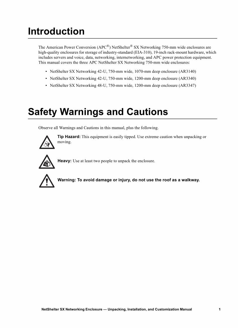
IntroductionThe American Power Conversion (APC®) NetShelter® SX Networking 750-mm wide enclosures arehigh-quality enclosures for storage of industry-standard (EIA-310), 19-inch rack-mount hardware, which includes servers and voice, data, networking, internetworking, and APC power protection equipment. This manual covers the three APC NetShelter SX Networking 750-mm wide enclosures:
• NetShelter SX Networking 42-U, 750-mm wide, 1070-mm deep enclosure (AR3140)
• NetShelter SX Networking 42-U, 750-mm wide, 1200-mm deep enclosure (AR3340)
• NetShelter SX Networking 48-U, 750-mm wide, 1200-mm deep enclosure (AR3347)
Safety Warnings and CautionsObserve all Warnings and Cautions in this manual, plus the following.
Tip Hazard: This equipment is easily tipped. Use extreme caution when unpacking or moving.
Heavy: Use at least two people to unpack the enclosure.
Warning: To avoid damage or injury, do not use the roof as a walkway.
1NetShelter SX Networking Enclosure — Unpacking, Installation, and Customization Manual
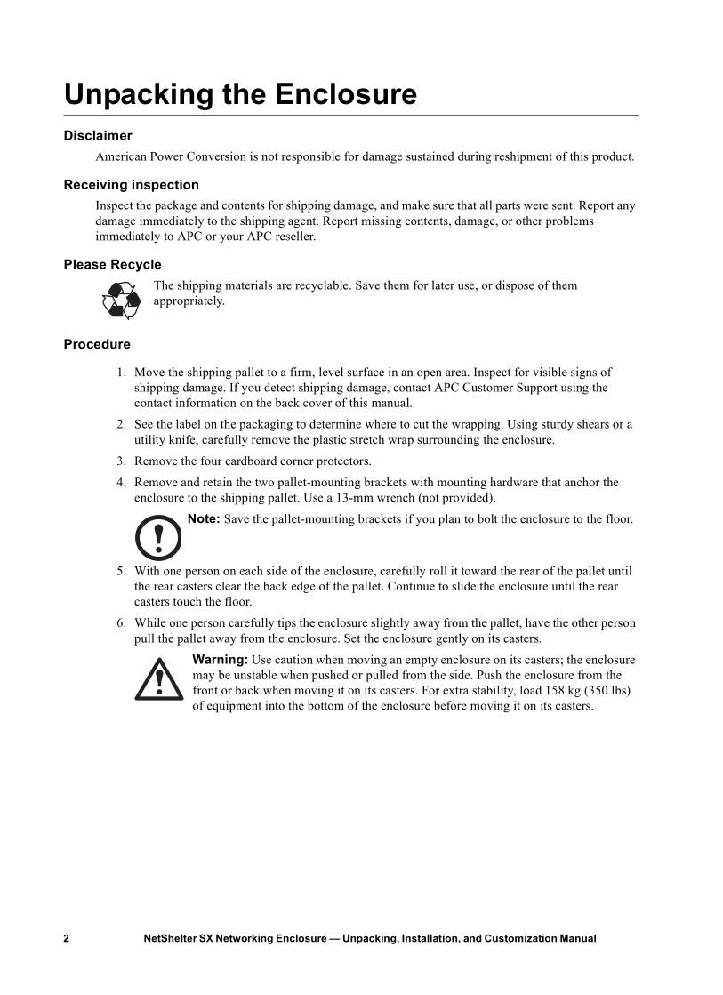
Unpacking the EnclosureDisclaimer
American Power Conversion is not responsible for damage sustained during reshipment of this product.
Receiving inspectionInspect the package and contents for shipping damage, and make sure that all parts were sent. Report any damage immediately to the shipping agent. Report missing contents, damage, or other problems immediately to APC or your APC reseller.
Please RecycleThe shipping materials are recyclable. Save them for later use, or dispose of them appropriately.
Procedure
1. Move the shipping pallet to a firm, level surface in an open area. Inspect for visible signs of shipping damage. If you detect shipping damage, contact APC Customer Support using the contact information on the back cover of this manual.
2. See the label on the packaging to determine where to cut the wrapping. Using sturdy shears or a utility knife, carefully remove the plastic stretch wrap surrounding the enclosure.
3. Remove the four cardboard corner protectors.
4. Remove and retain the two pallet-mounting brackets with mounting hardware that anchor the enclosure to the shipping pallet. Use a 13-mm wrench (not provided).
Note: Save the pallet-mounting brackets if you plan to bolt the enclosure to the floor.
5. With one person on each side of the enclosure, carefully roll it toward the rear of the pallet until the rear casters clear the back edge of the pallet. Continue to slide the enclosure until the rear casters touch the floor.
6. While one person carefully tips the enclosure slightly away from the pallet, have the other person pull the pallet away from the enclosure. Set the enclosure gently on its casters.
Warning: Use caution when moving an empty enclosure on its casters; the enclosure may be unstable when pushed or pulled from the side. Push the enclosure from the front or back when moving it on its casters. For extra stability, load 158 kg (350 lbs) of equipment into the bottom of the enclosure before moving it on its casters.
NetShelter SX Networking Enclosure — Unpacking, Installation, and Customization Manual2
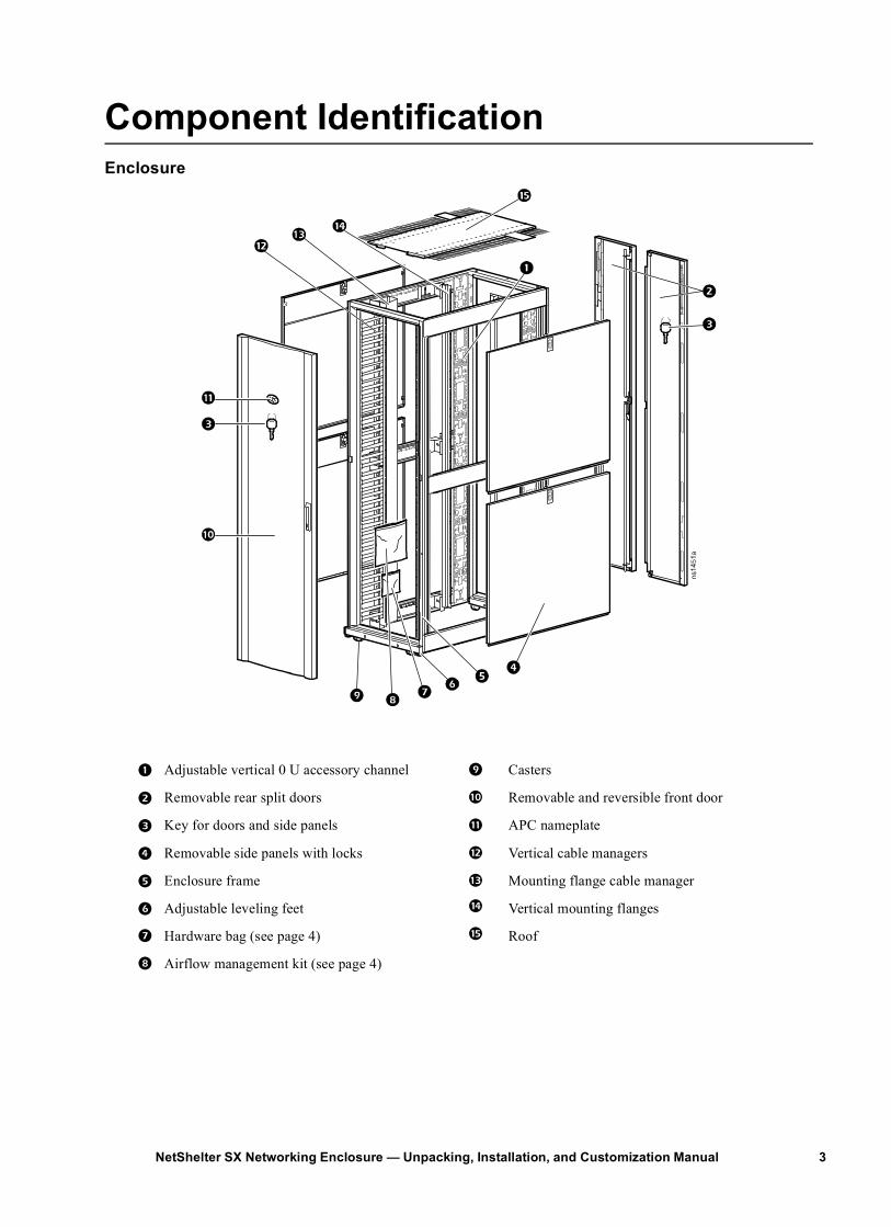
Component IdentificationEnclosure
1 Adjustable vertical 0 U accessory channel 9 Casters
2 Removable rear split doors : Removable and reversible front door
3 Key for doors and side panels ; APC nameplate
4 Removable side panels with locks < Vertical cable managers
5 Enclosure frame = Mounting flange cable manager
6 Adjustable leveling feet > Vertical mounting flanges
7 Hardware bag (see page 4) ? Roof
8 Airflow management kit (see page 4)
3NetShelter SX Networking Enclosure — Unpacking, Installation, and Customization Manual
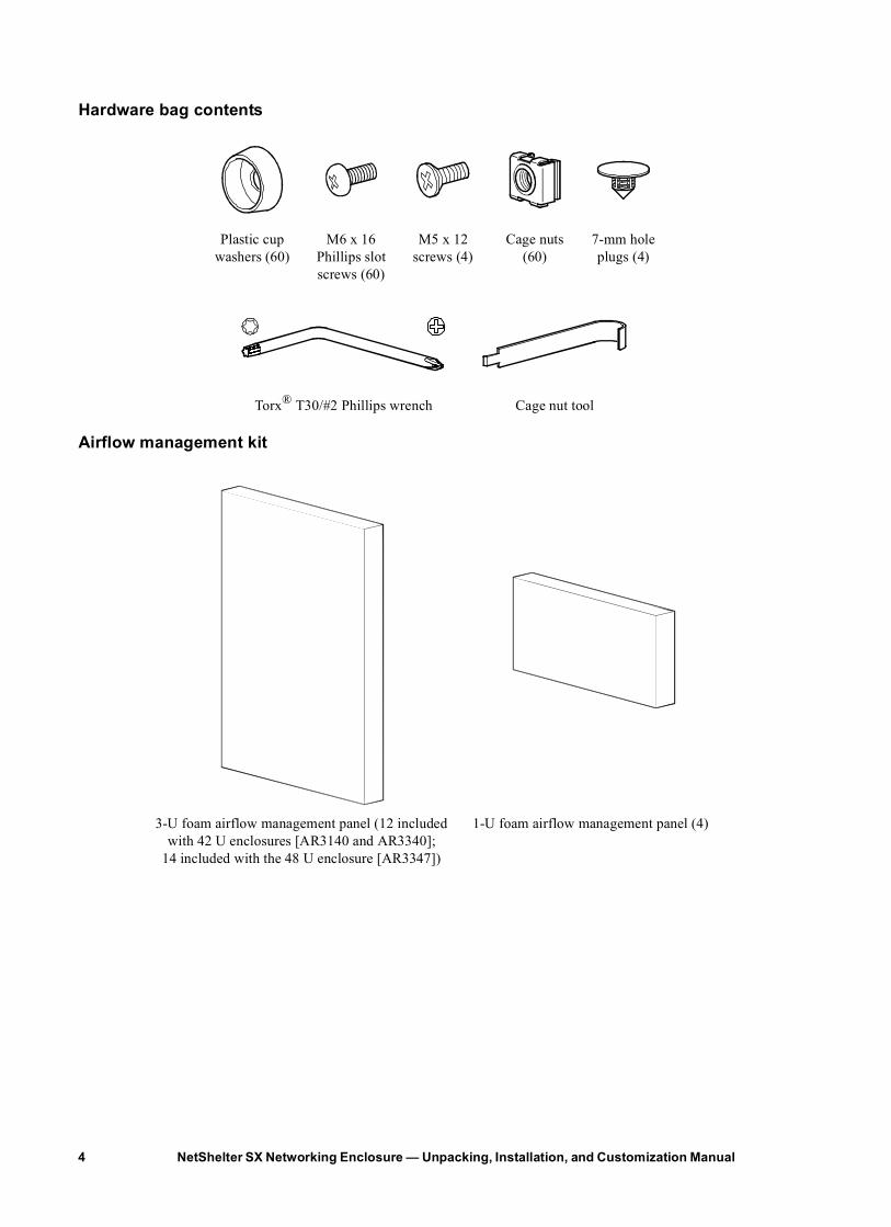
Hardware bag contents
Airflow management kit
Plastic cup washers (60)
M6 x 16 Phillips slot screws (60)
M5 x 12 screws (4)
Cage nuts (60)
7-mm hole plugs (4)
Torx® T30/#2 Phillips wrench Cage nut tool
3-U foam airflow management panel (12 included with 42 U enclosures [AR3140 and AR3340];
14 included with the 48 U enclosure [AR3347])
1-U foam airflow management panel (4)
NetShelter SX Networking Enclosure — Unpacking, Installation, and Customization Manual4
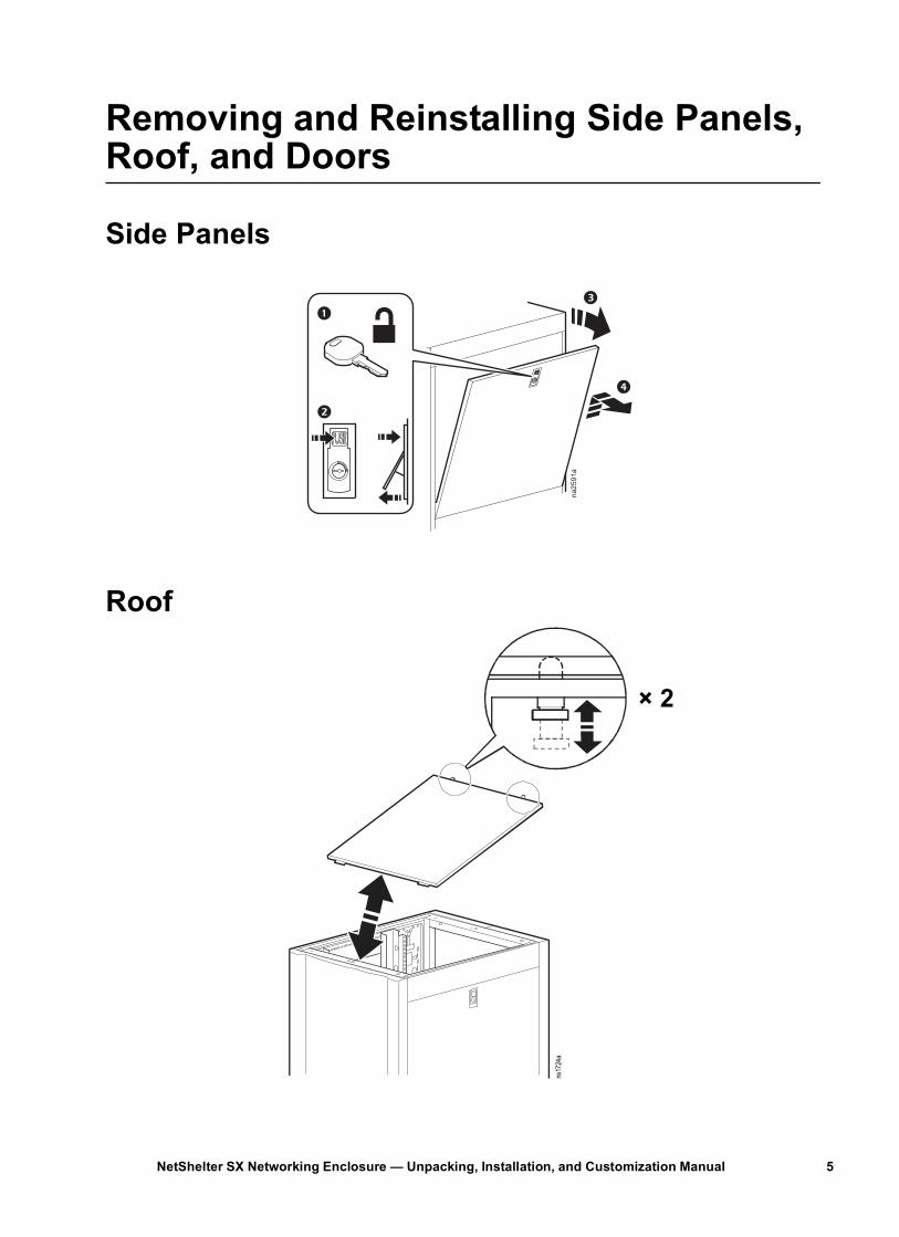
Removing and Reinstalling Side Panels, Roof, and Doors
Side Panels
Roofna2591a
× 2
ns17
24a
5NetShelter SX Networking Enclosure — Unpacking, Installation, and Customization Manual
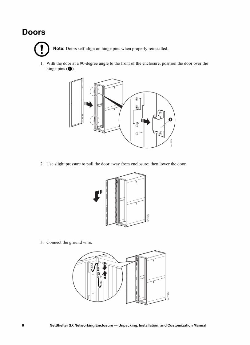
Doors
Note: Doors self-align on hinge pins when properly reinstalled.
1. With the door at a 90-degree angle to the front of the enclosure, position the door over the hinge pins (1).
2. Use slight pressure to pull the door away from enclosure; then lower the door.
3. Connect the ground wire.
ns1750b
ns1751b
ns1752b
NetShelter SX Networking Enclosure — Unpacking, Installation, and Customization Manual6
Enclosure Installation
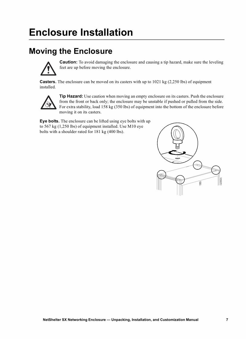
Moving the EnclosureCaution: To avoid damaging the enclosure and causing a tip hazard, make sure the leveling feet are up before moving the enclosure.
Casters. The enclosure can be moved on its casters with up to 1021 kg (2,250 lbs) of equipment installed.
Tip Hazard: Use caution when moving an empty enclosure on its casters. Push the enclosure from the front or back only; the enclosure may be unstable if pushed or pulled from the side. For extra stability, load 158 kg (350 lbs) of equipment into the bottom of the enclosure before moving it on its casters.
Eye bolts. The enclosure can be lifted using eye bolts with up to 567 kg (1,250 lbs) of equipment installed. Use M10 eye bolts with a shoulder rated for 181 kg (400 lbs).
ns08
82b
7NetShelter SX Networking Enclosure — Unpacking, Installation, and Customization Manual
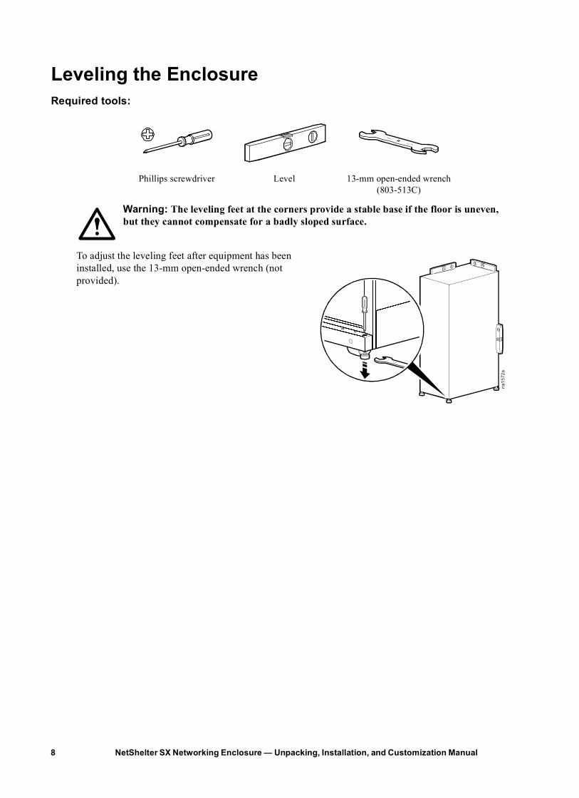
Leveling the EnclosureRequired tools:
Warning: The leveling feet at the corners provide a stable base if the floor is uneven, but they cannot compensate for a badly sloped surface.
To adjust the leveling feet after equipment has been installed, use the 13-mm open-ended wrench (not provided).
Phillips screwdriver Level 13-mm open-ended wrench (803-513C)
na15
72a
NetShelter SX Networking Enclosure — Unpacking, Installation, and Customization Manual8
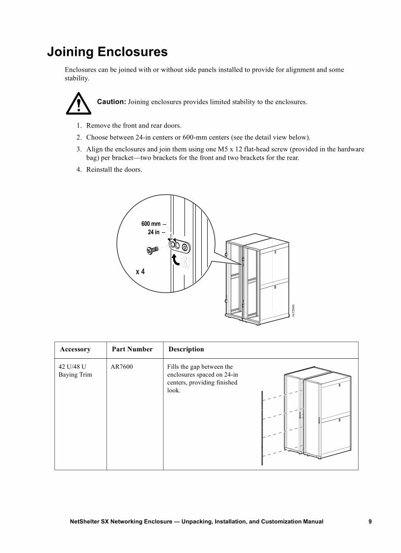
Joining EnclosuresEnclosures can be joined with or without side panels installed to provide for alignment and some stability.
Caution: Joining enclosures provides limited stability to the enclosures.
1. Remove the front and rear doors.
2. Choose between 24-in centers or 600-mm centers (see the detail view below).
3. Align the enclosures and join them using one M5 x 12 flat-head screw (provided in the hardware bag) per bracket—two brackets for the front and two brackets for the rear.
4. Reinstall the doors.
Accessory Part Number Description
42 U/48 U Baying Trim
AR7600 Fills the gap between the enclosures spaced on 24-in centers, providing finished look.
ns1594b
24 in600 mm
x 4
9NetShelter SX Networking Enclosure — Unpacking, Installation, and Customization Manual
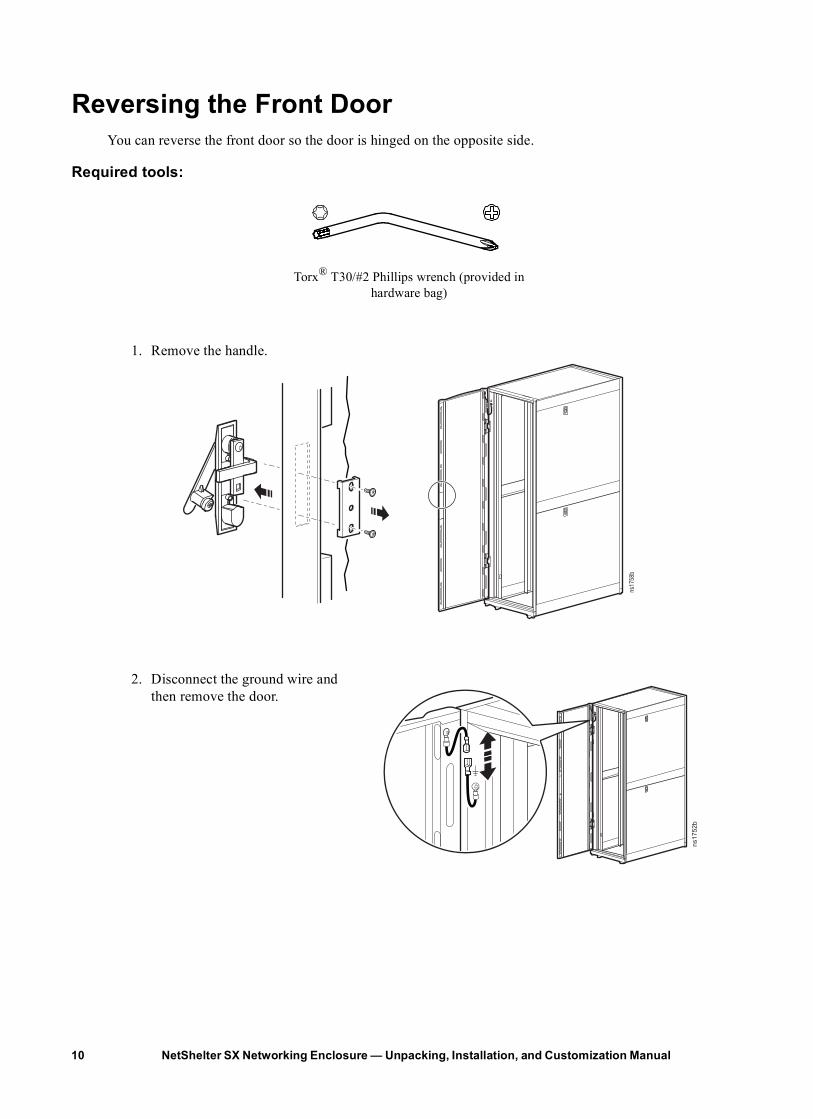
Reversing the Front DoorYou can reverse the front door so the door is hinged on the opposite side.
Required tools:
1. Remove the handle.
2. Disconnect the ground wire and then remove the door.
Torx® T30/#2 Phillips wrench (provided in hardware bag)
ns17
58b
ns1752b
NetShelter SX Networking Enclosure — Unpacking, Installation, and Customization Manual10
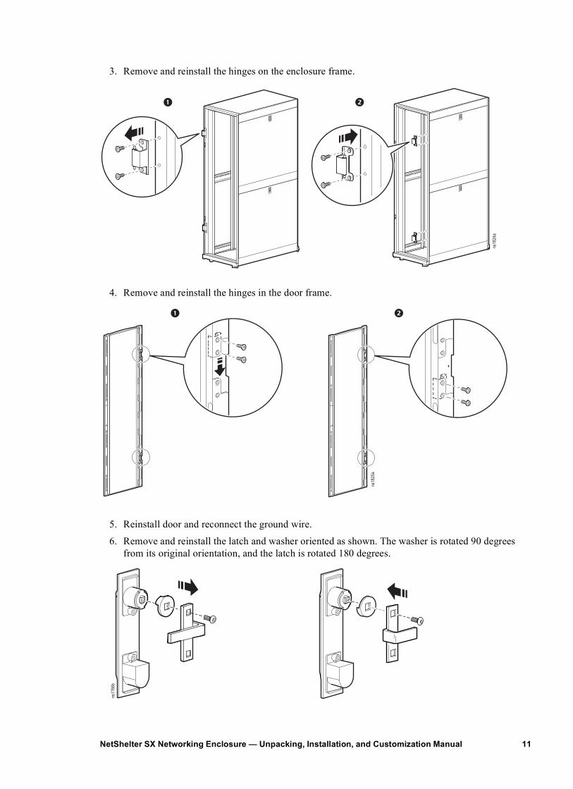
3. Remove and reinstall the hinges on the enclosure frame.
4. Remove and reinstall the hinges in the door frame.
5. Reinstall door and reconnect the ground wire.
6. Remove and reinstall the latch and washer oriented as shown. The washer is rotated 90 degrees from its original orientation, and the latch is rotated 180 degrees.
ns18
24a
ns18
25a
ns17
66b
11NetShelter SX Networking Enclosure — Unpacking, Installation, and Customization Manual
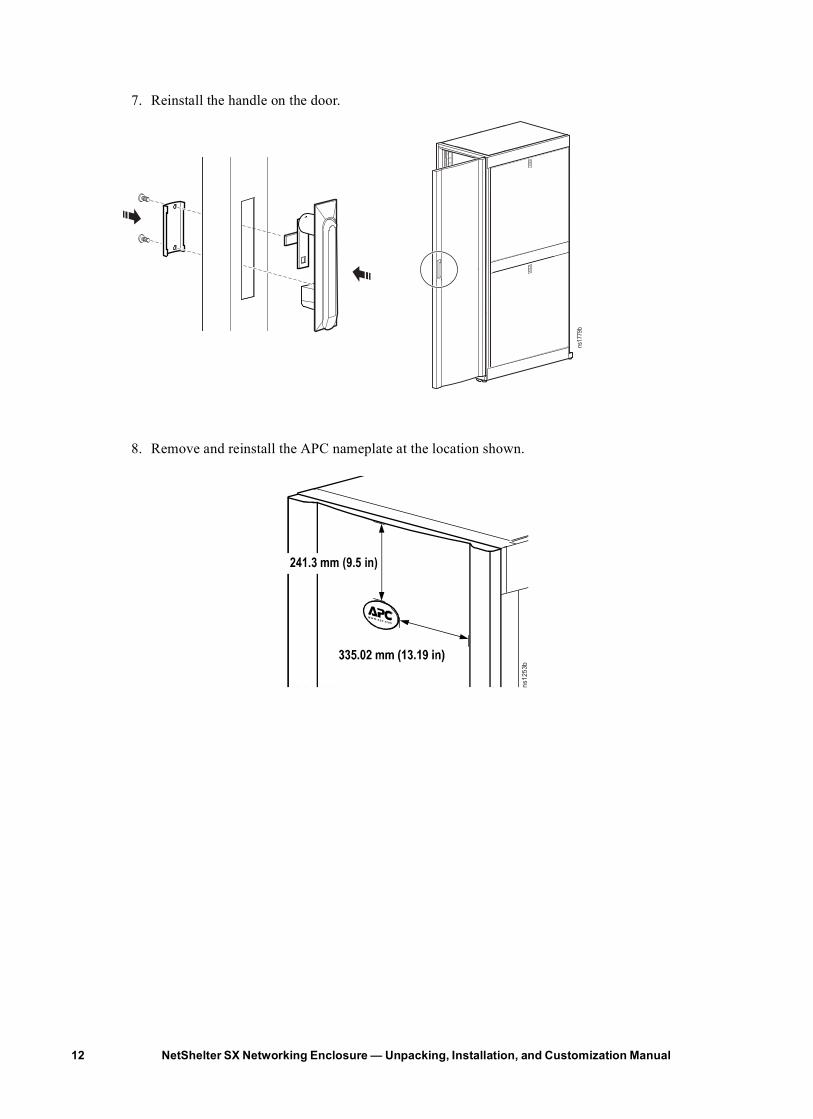
7. Reinstall the handle on the door.
8. Remove and reinstall the APC nameplate at the location shown.
ns17
79b
241.3 mm (9.5 in)
ns12
53b
NetShelter SX Networking Enclosure — Unpacking, Installation, and Customization Manual12
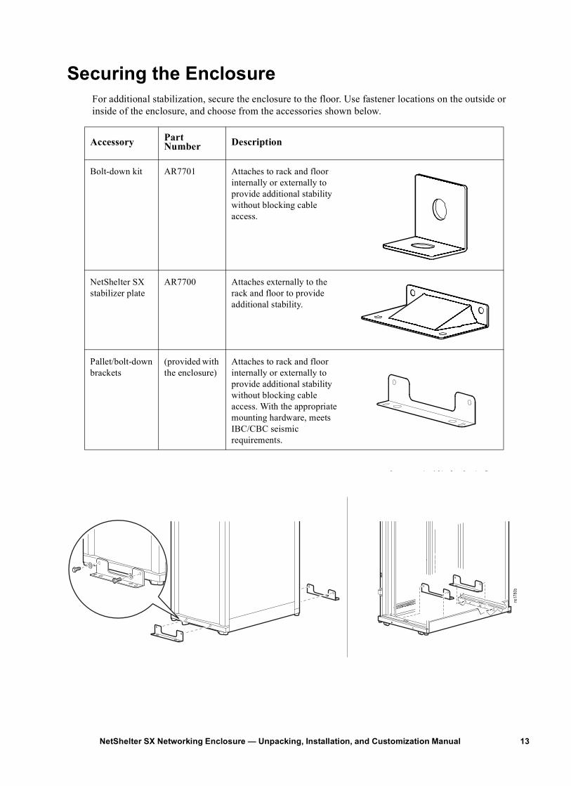
Securing the EnclosureFor additional stabilization, secure the enclosure to the floor. Use fastener locations on the outside or inside of the enclosure, and choose from the accessories shown below.
Accessory Part Number Description
Bolt-down kit AR7701 Attaches to rack and floor internally or externally to provide additional stability without blocking cable access.
NetShelter SX stabilizer plate
AR7700 Attaches externally to the rack and floor to provide additional stability.
Pallet/bolt-down brackets
(provided with the enclosure)
Attaches to rack and floor internally or externally to provide additional stability without blocking cable access. With the appropriate mounting hardware, meets IBC/CBC seismic requirements.
ns17
80b
13NetShelter SX Networking Enclosure — Unpacking, Installation, and Customization Manual
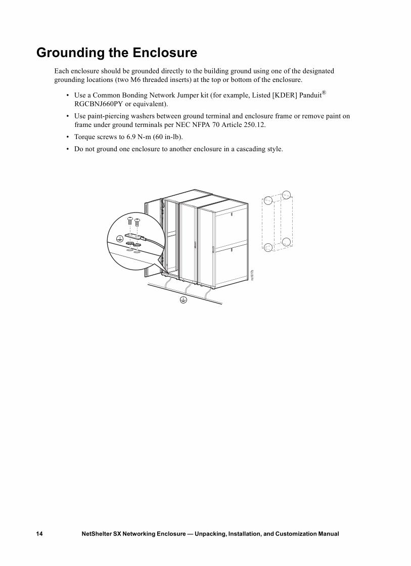
Grounding the EnclosureEach enclosure should be grounded directly to the building ground using one of the designated grounding locations (two M6 threaded inserts) at the top or bottom of the enclosure.
• Use a Common Bonding Network Jumper kit (for example, Listed [KDER] Panduit® RGCBNJ660PY or equivalent).
• Use paint-piercing washers between ground terminal and enclosure frame or remove paint on frame under ground terminals per NEC NFPA 70 Article 250.12.
• Torque screws to 6.9 N-m (60 in-lb).
• Do not ground one enclosure to another enclosure in a cascading style.
ns16
17b
NetShelter SX Networking Enclosure — Unpacking, Installation, and Customization Manual14
Equipment Installation
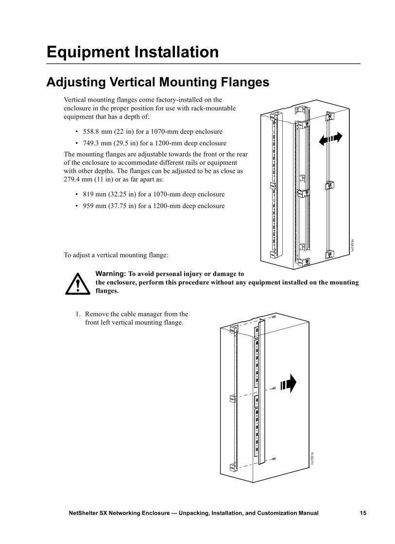
Adjusting Vertical Mounting FlangesVertical mounting flanges come factory-installed on the enclosure in the proper position for use with rack-mountable equipment that has a depth of:
• 558.8 mm (22 in) for a 1070-mm deep enclosure
• 749.3 mm (29.5 in) for a 1200-mm deep enclosureThe mounting flanges are adjustable towards the front or the rear of the enclosure to accommodate different rails or equipment with other depths. The flanges can be adjusted to be as close as 279.4 mm (11 in) or as far apart as:
• 819 mm (32.25 in) for a 1070-mm deep enclosure
• 959 mm (37.75 in) for a 1200-mm deep enclosure
To adjust a vertical mounting flange:
Warning: To avoid personal injury or damage to the enclosure, perform this procedure without any equipment installed on the mounting flanges.
1. Remove the cable manager from the front left vertical mounting flange.
ns14
53a
ns15
61a
15NetShelter SX Networking Enclosure — Unpacking, Installation, and Customization Manual
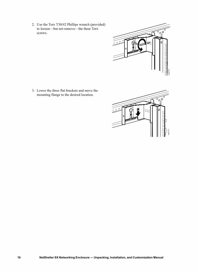
2. Use the Torx T30/#2 Phillips wrench (provided) to loosen—but not remove—the three Torx screws.
3. Lower the three flat brackets and move the mounting flange to the desired location.
ns09
77b
ns07
17c
NetShelter SX Networking Enclosure — Unpacking, Installation, and Customization Manual16
17NetShelter SX Networking Enclosure — Unpacking, Installation, and Customization Manual
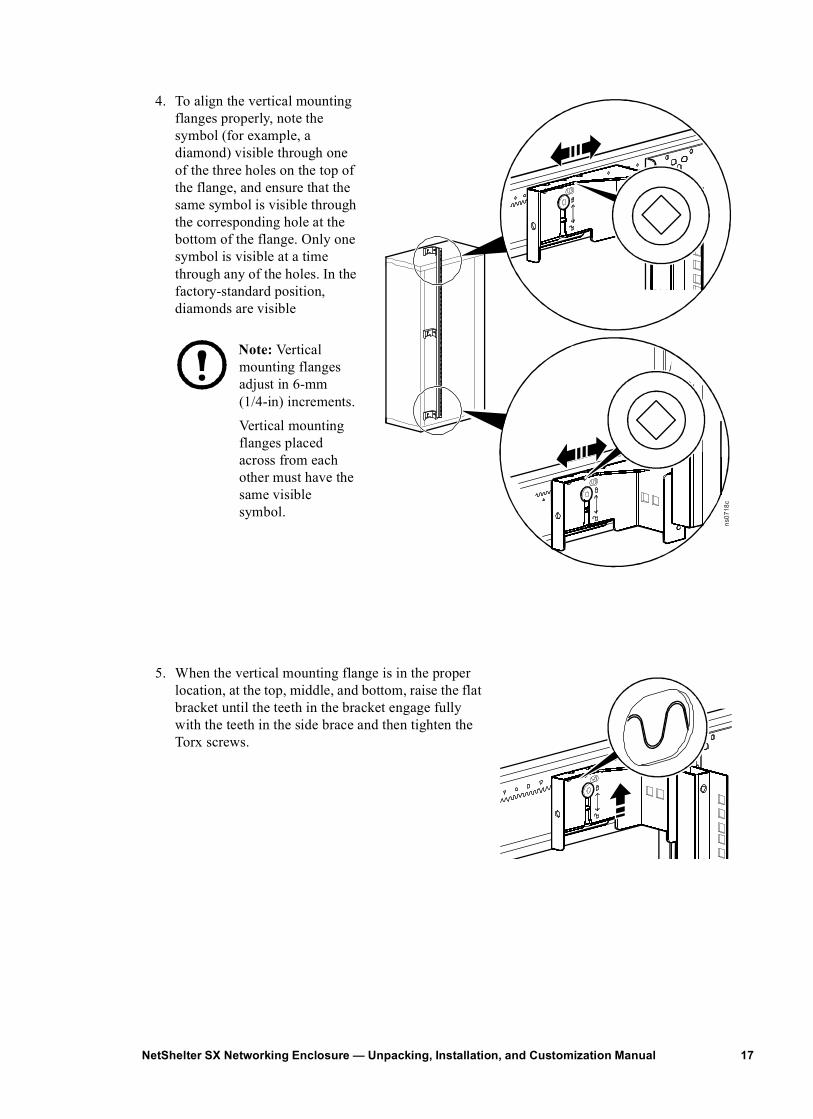
4. To align the vertical mounting flanges properly, note the symbol (for example, a diamond) visible through one of the three holes on the top of the flange, and ensure that the same symbol is visible through the corresponding hole at the bottom of the flange. Only one symbol is visible at a time through any of the holes. In the factory-standard position, diamonds are visible
Note: Vertical mounting flanges adjust in 6-mm (1/4-in) increments.
Vertical mounting flanges placed across from each other must have the same visible symbol.
5. When the vertical mounting flange is in the proper location, at the top, middle, and bottom, raise the flat bracket until the teeth in the bracket engage fully with the teeth in the side brace and then tighten the Torx screws.
ns07
18c

Installing EquipmentWarning: To prevent the enclosure from tipping over after equipment installation:
• Make sure you have secured the enclosure to the floor before installing equipment.
• Install the heaviest equipment first toward the bottom of the enclosure to prevent the enclosure from becoming top-heavy.
• Do not extend equipment on sliding rails until you have installed three or more pieces of similar-sized equipment or until you have installed the stabilizer plate or bolt-down brackets. Do not extend more than one piece of equipment on sliding rails at a time.
To install rack-mount equipment in the enclosure:
1. Review the equipment manufacturer’s installation instructions.
2. Locate the top and bottom U-space on the vertical mounting rails. Every third hole on the mounting rails is numbered to indicate the middle of a U-space.
3. Install the cage nuts on the interior of the vertical mounting rail; then install the equipment.
How to install a cage nut
Warning: To ensure equipment installs securely, install cage nuts with tabs engaging the left and right sides of the
square hole. Do NOT install cage nuts with tabs engaging the top and bottom of the square hole.
Note: To remove a cage nut, squeeze the sides to release it from the square hole.
1 U
7
6
5
ns00
14a
ns17
88a
NetShelter SX Networking Enclosure — Unpacking, Installation, and Customization Manual18
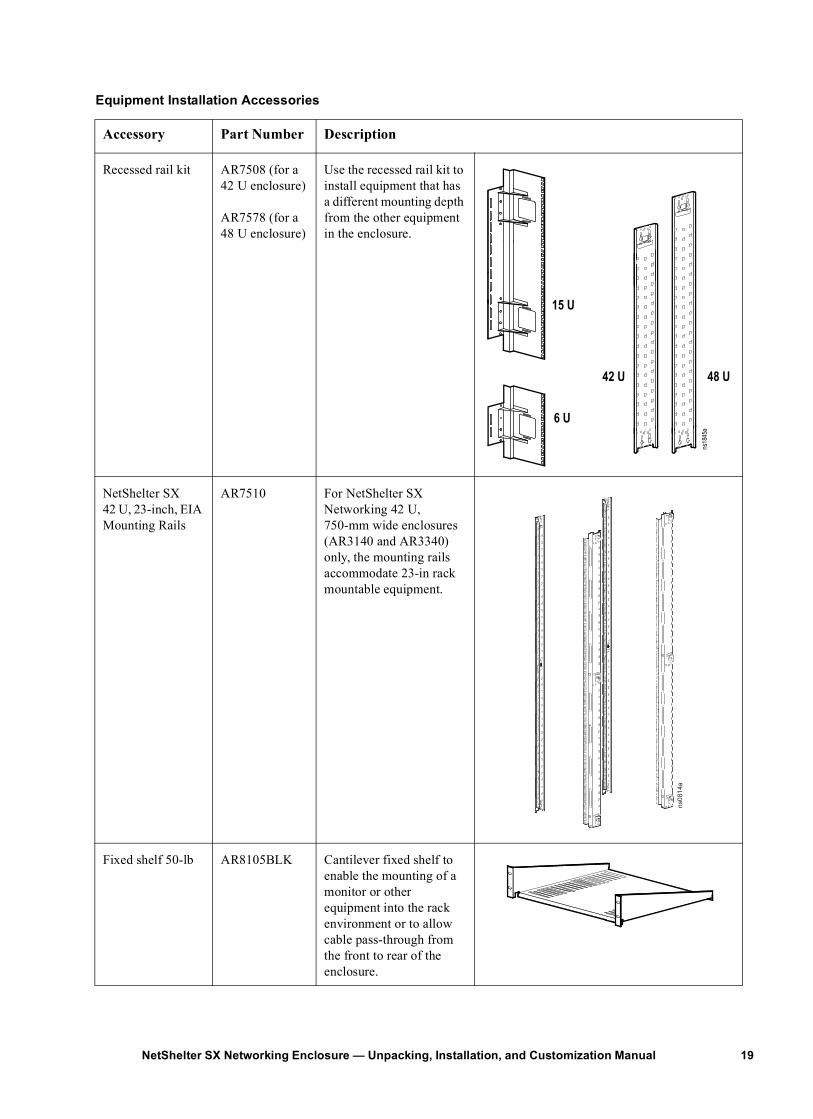
Equipment Installation Accessories
Accessory Part Number Description
Recessed rail kit AR7508 (for a42 U enclosure)
AR7578 (for a48 U enclosure)
Use the recessed rail kit to install equipment that has a different mounting depth from the other equipment in the enclosure.
NetShelter SX 42 U, 23-inch, EIA Mounting Rails
AR7510 For NetShelter SX Networking 42 U, 750-mm wide enclosures (AR3140 and AR3340) only, the mounting rails accommodate 23-in rack mountable equipment.
Fixed shelf 50-lb AR8105BLK Cantilever fixed shelf to enable the mounting of a monitor or other equipment into the rack environment or to allow cable pass-through from the front to rear of the enclosure.
42 U 48 U
6 U
15 U
ns18
45a
ns08
14a
19NetShelter SX Networking Enclosure — Unpacking, Installation, and Customization Manual
20
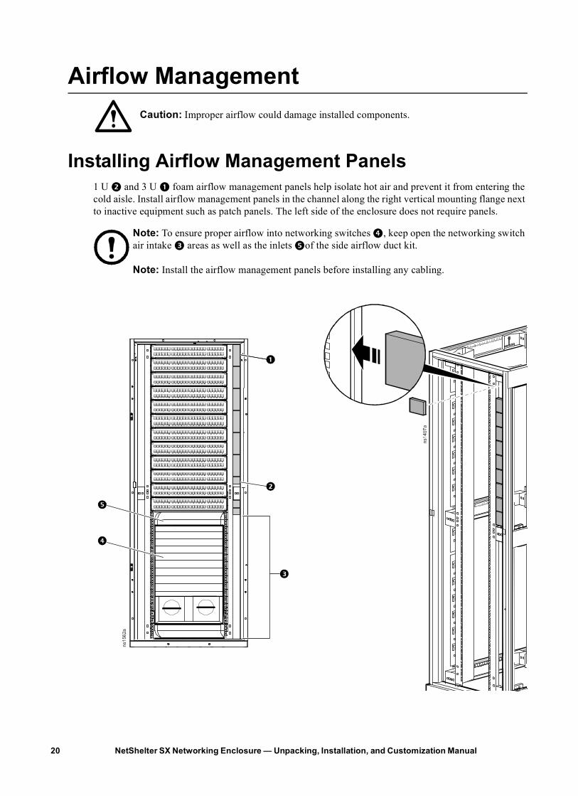
Airflow ManagementCaution: Improper airflow could damage installed components.
Installing Airflow Management Panels1 U 2 and 3 U 1 foam airflow management panels help isolate hot air and prevent it from entering the cold aisle. Install airflow management panels in the channel along the right vertical mounting flange next to inactive equipment such as patch panels. The left side of the enclosure does not require panels.
Note: To ensure proper airflow into networking switches 4, keep open the networking switch air intake 3 areas as well as the inlets 5of the side airflow duct kit.
Note: Install the airflow management panels before installing any cabling.
ns15
62a
NetShelter SX Networking Enclosure — Unpacking, Installation, and Customization Manual
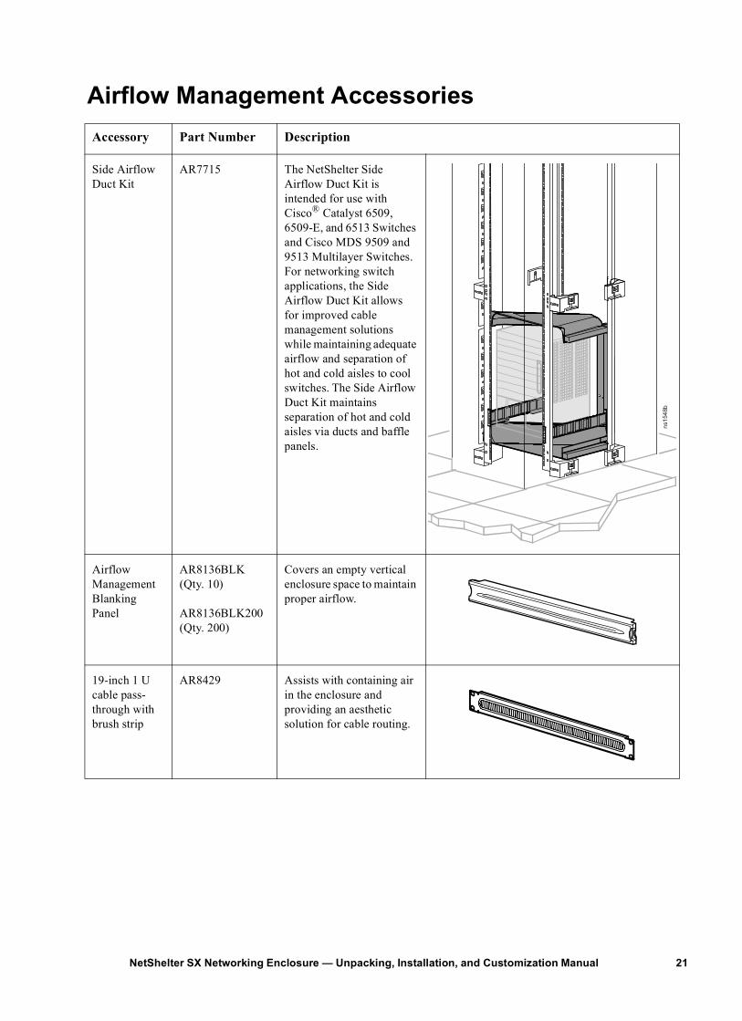
Airflow Management AccessoriesAccessory Part Number Description
Side Airflow Duct Kit
AR7715 The NetShelter Side Airflow Duct Kit is intended for use with Cisco® Catalyst 6509, 6509-E, and 6513 Switches and Cisco MDS 9509 and 9513 Multilayer Switches. For networking switch applications, the Side Airflow Duct Kit allows for improved cable management solutions while maintaining adequate airflow and separation of hot and cold aisles to cool switches. The Side Airflow Duct Kit maintains separation of hot and cold aisles via ducts and baffle panels.
Airflow Management Blanking Panel
AR8136BLK (Qty. 10)
AR8136BLK200 (Qty. 200)
Covers an empty vertical enclosure space to maintain proper airflow.
19-inch 1 U cable pass-through with brush strip
AR8429 Assists with containing air in the enclosure and providing an aesthetic solution for cable routing.
ns15
48b
21NetShelter SX Networking Enclosure — Unpacking, Installation, and Customization Manual
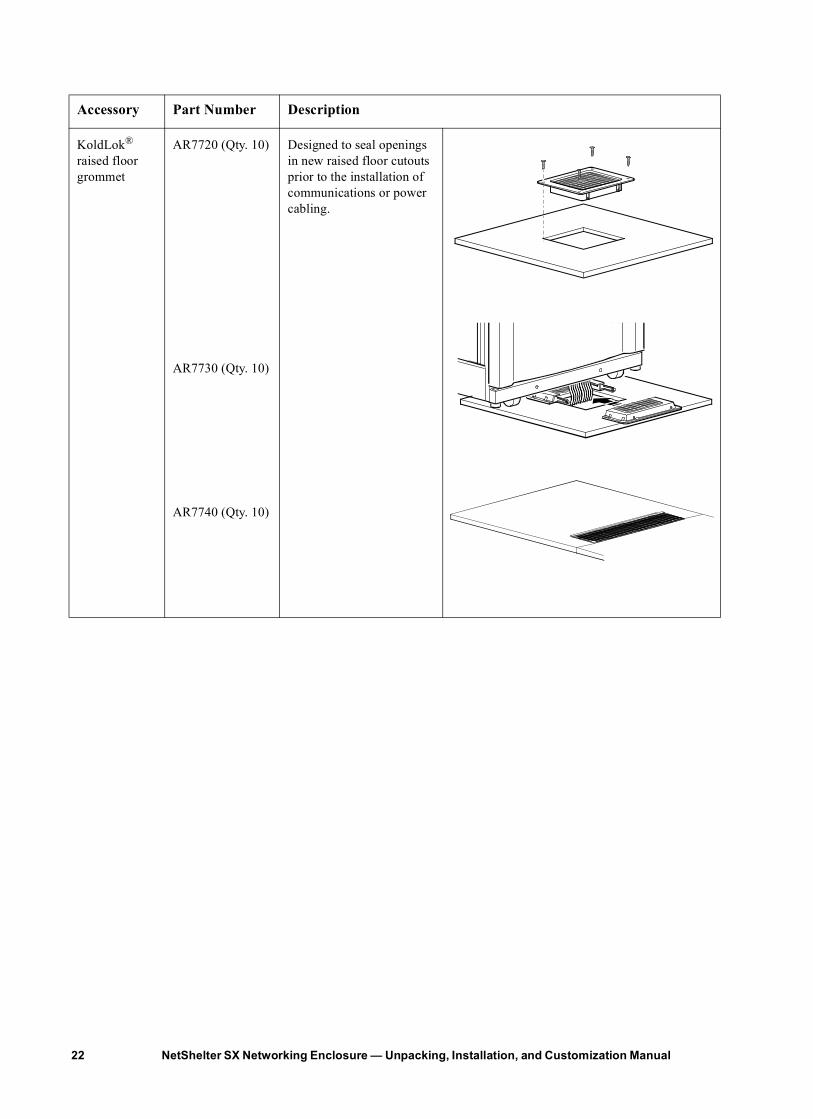
KoldLok® raised floor grommet
AR7720 (Qty. 10)
AR7730 (Qty. 10)
AR7740 (Qty. 10)
Designed to seal openings in new raised floor cutouts prior to the installation of communications or power cabling.
Accessory Part Number Description
NetShelter SX Networking Enclosure — Unpacking, Installation, and Customization Manual22
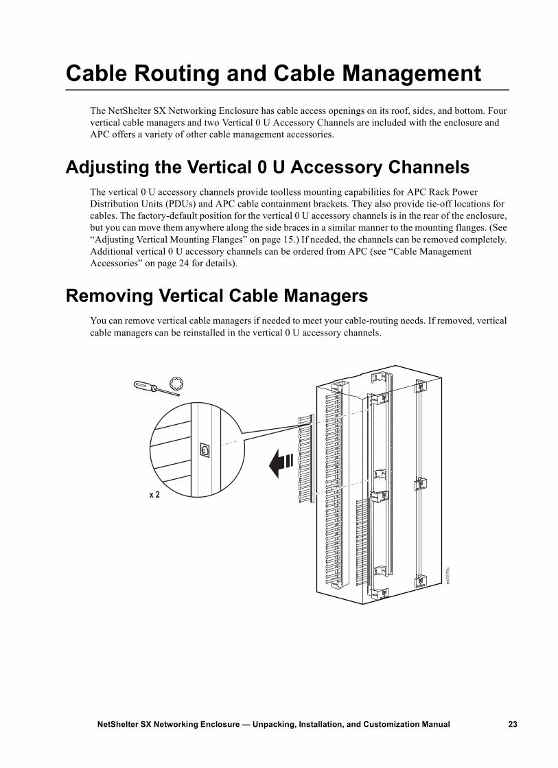
Cable Routing and Cable ManagementThe NetShelter SX Networking Enclosure has cable access openings on its roof, sides, and bottom. Four vertical cable managers and two Vertical 0 U Accessory Channels are included with the enclosure and APC offers a variety of other cable management accessories.
Adjusting the Vertical 0 U Accessory ChannelsThe vertical 0 U accessory channels provide toolless mounting capabilities for APC Rack Power Distribution Units (PDUs) and APC cable containment brackets. They also provide tie-off locations for cables. The factory-default position for the vertical 0 U accessory channels is in the rear of the enclosure, but you can move them anywhere along the side braces in a similar manner to the mounting flanges. (See “Adjusting Vertical Mounting Flanges” on page 15.) If needed, the channels can be removed completely. Additional vertical 0 U accessory channels can be ordered from APC (see “Cable Management Accessories” on page 24 for details).
Removing Vertical Cable ManagersYou can remove vertical cable managers if needed to meet your cable-routing needs. If removed, vertical cable managers can be reinstalled in the vertical 0 U accessory channels.
ns1511c
x 2
23NetShelter SX Networking Enclosure — Unpacking, Installation, and Customization Manual
NetShelter SX Networking Enclosure — Unpacking, Installation, and Customization Manual24
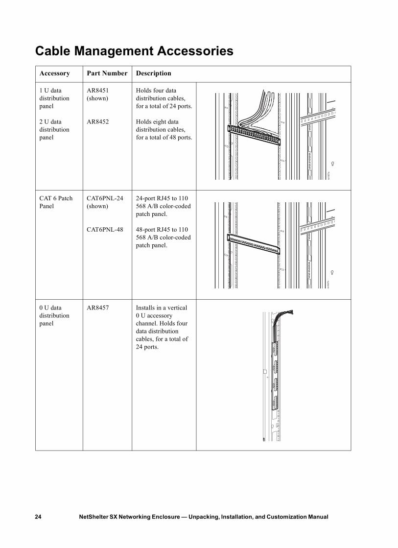
Cable Management AccessoriesAccessory Part Number Description
1 U data distribution panel
2 U data distribution panel
AR8451 (shown)
AR8452
Holds four data distribution cables, for a total of 24 ports.
Holds eight data distribution cables, for a total of 48 ports.
CAT 6 Patch Panel
CAT6PNL-24 (shown)
CAT6PNL-48
24-port RJ45 to 110 568 A/B color-coded patch panel.
48-port RJ45 to 110 568 A/B color-coded patch panel.
0 U data distribution panel
AR8457 Installs in a vertical 0 U accessory channel. Holds four data distribution cables, for a total of 24 ports.
ns1827a
12
34
5
76
89
1011
1213
1415
1617
1819
2021
2223
24
ns1827b
12
34
5
76
89
1011
1213
1415
1617
1819
2021
2223
24
21
34
56
87
910
1112
14
13
15
16
17
18
20
19
21
22
23
24
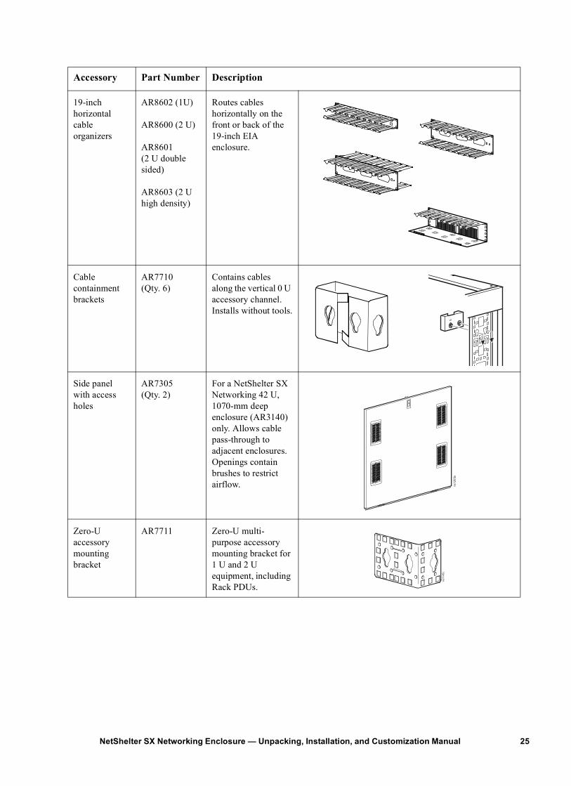
19-inch horizontal cable organizers
AR8602 (1U)
AR8600 (2 U)
AR8601 (2 U double sided)
AR8603 (2 U high density)
Routes cables horizontally on the front or back of the 19-inch EIA enclosure.
Cable containment brackets
AR7710 (Qty. 6)
Contains cables along the vertical 0 U accessory channel. Installs without tools.
Side panel with access holes
AR7305(Qty. 2)
For a NetShelter SX Networking 42 U, 1070-mm deep enclosure (AR3140) only. Allows cable pass-through to adjacent enclosures. Openings contain brushes to restrict airflow.
Zero-U accessory mounting bracket
AR7711 Zero-U multi-purpose accessory mounting bracket for 1 U and 2 U equipment, including Rack PDUs.
Accessory Part Number Description
ns12
05a
ns11
45c
25NetShelter SX Networking Enclosure — Unpacking, Installation, and Customization Manual
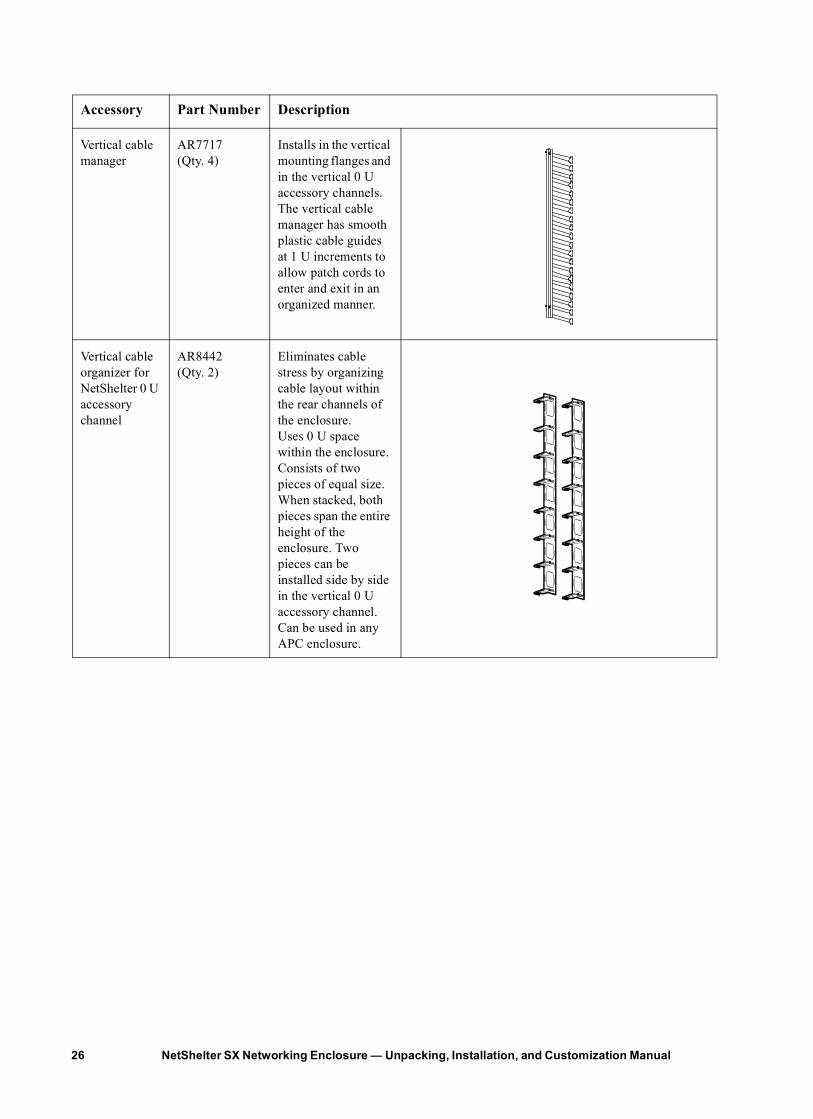
Vertical cable manager
AR7717 (Qty. 4)
Installs in the vertical mounting flanges and in the vertical 0 U accessory channels. The vertical cable manager has smooth plastic cable guides at 1 U increments to allow patch cords to enter and exit in an organized manner.
Vertical cable organizer for NetShelter 0 U accessory channel
AR8442 (Qty. 2)
Eliminates cable stress by organizing cable layout within the rear channels of the enclosure. Uses 0 U space within the enclosure. Consists of two pieces of equal size. When stacked, both pieces span the entire height of the enclosure. Two pieces can be installed side by side in the vertical 0 U accessory channel. Can be used in any APC enclosure.
Accessory Part Number Description
NetShelter SX Networking Enclosure — Unpacking, Installation, and Customization Manual26
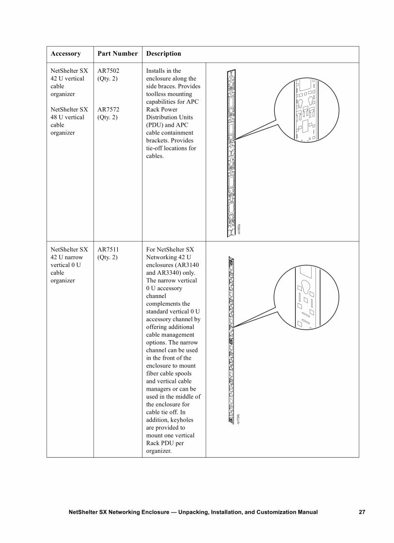
NetShelter SX 42 U vertical cable organizer
NetShelter SX 48 U vertical cable organizer
AR7502(Qty. 2)
AR7572 (Qty. 2)
Installs in the enclosure along the side braces. Provides toolless mounting capabilities for APC Rack Power Distribution Units (PDU) and APC cable containment brackets. Provides tie-off locations for cables.
NetShelter SX 42 U narrow vertical 0 U cable organizer
AR7511(Qty. 2)
For NetShelter SX Networking 42 U enclosures (AR3140 and AR3340) only. The narrow vertical0 U accessory channel complements the standard vertical 0 U accessory channel by offering additional cable management options. The narrow channel can be used in the front of the enclosure to mount fiber cable spools and vertical cable managers or can be used in the middle of the enclosure for cable tie off. In addition, keyholes are provided to mount one vertical Rack PDU per organizer.
Accessory Part Number Description
ns18
52a
ns17
54b
27NetShelter SX Networking Enclosure — Unpacking, Installation, and Customization Manual
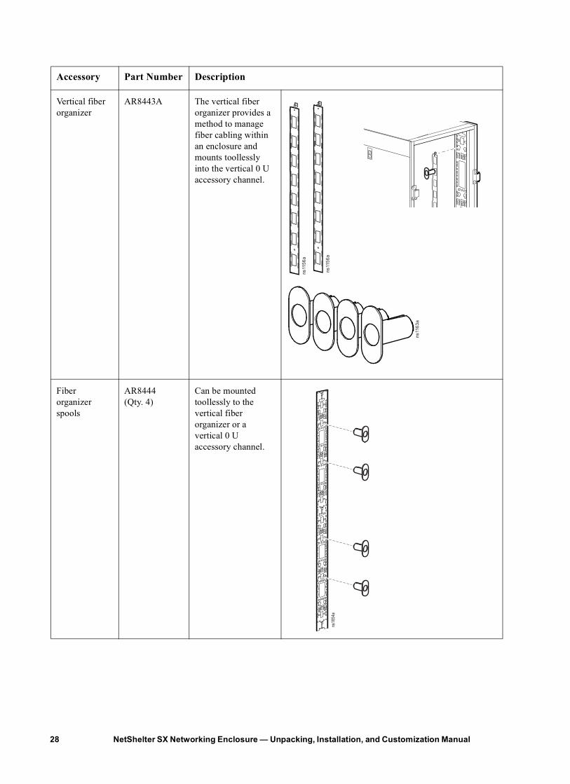
Vertical fiber organizer
AR8443A The vertical fiber organizer provides a method to manage fiber cabling within an enclosure and mounts toollessly into the vertical 0 U accessory channel.
Fiber organizer spools
AR8444(Qty. 4)
Can be mounted toollessly to the vertical fiber organizer or a vertical 0 U accessory channel.
Accessory Part Number Description
ns11
56a
ns11
56a
ns11
63a
ns18
54a
NetShelter SX Networking Enclosure — Unpacking, Installation, and Customization Manual28
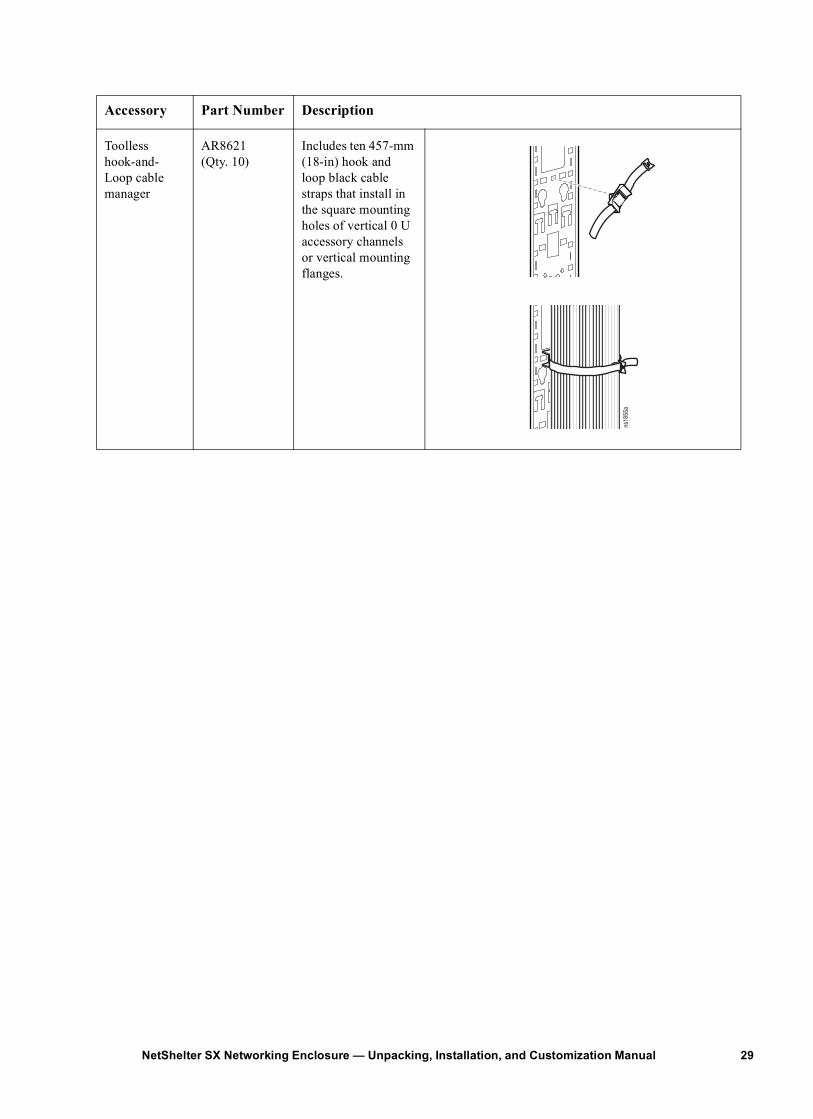
Toolless hook-and-Loop cable manager
AR8621(Qty. 10)
Includes ten 457-mm (18-in) hook and loop black cable straps that install in the square mounting holes of vertical 0 U accessory channels or vertical mounting flanges.
Accessory Part Number Description
ns18
55a
29NetShelter SX Networking Enclosure — Unpacking, Installation, and Customization Manual
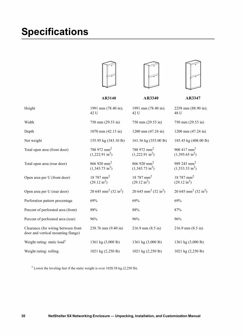
Specifications
AR3140 AR3340 AR3347
Height 1991 mm (78.40 in); 42 U
1991 mm (78.40 in); 42 U
2258 mm (88.90 in); 48 U
Width 750 mm (29.53 in) 750 mm (29.53 in) 750 mm (29.53 in)
Depth 1070 mm (42.13 in) 1200 mm (47.24 in) 1200 mm (47.24 in)
Net weight 155.95 kg (343.10 lb) 161.36 kg (355.00 lb) 185.45 kg (408.00 lb)
Total open area (front door) 788 972 mm2 (1,222.91 in2)
788 972 mm2 (1,222.91 in2)
900 417 mm2 (1,395.65 in2)
Total open area (rear door) 866 920 mm2 (1,343.73 in2)
866 920 mm2 (1,343.73 in2)
989 243 mm2 (1,533.33 in2)
Open area per U (front door) 18 787 mm2
(29.12 in2)18 787 mm2
(29.12 in2)18 787 mm2
(29.12 in2)
Open area per U (rear door) 20 645 mm2 (32 in2) 20 645 mm2 (32 in2) 20 645 mm2 (32 in2)
Perforation pattern percentage 69% 69% 69%
Percent of perforated area (front) 88% 88% 87%
Percent of perforated area (rear) 96% 96% 96%
Clearance (for wiring between front door and vertical mounting flange)
238.76 mm (9.40 in) 216.9 mm (8.5 in) 216.9 mm (8.5 in)
Weight rating: static load† 1361 kg (3,000 lb) 1361 kg (3,000 lb) 1361 kg (3,000 lb)
Weight rating: rolling 1021 kg (2,250 lb) 1021 kg (2,250 lb) 1021 kg (2,250 lb)
† Lower the leveling feet if the static weight is over 1020.58 kg (2,250 lb).
NetShelter SX Networking Enclosure — Unpacking, Installation, and Customization Manual30
APC Limited Factory WarrantyThe limited warranty provided by American Power Conversion (APC®) in this Statement of Limited Factory Warranty applies only to Products you purchase for your commercial or industrial use in the ordinary course of your business.
Terms of Warranty American Power Conversion warrants its products to be free from defects in materials and workmanship for a period of five years (two years in Japan) from the date of purchase. Its obligation under this warranty is limited to repairing or replacing, at its sole discretion, any such defective products. This warranty does not apply to equipment that has been damaged by accident, negligence, or misapplication or has been altered or modified in any way. Repair or replacement of a defective product or part thereof does not extend the original warranty period. Any parts furnished under this warranty may be new or factory- remanufactured.
Non-transferable Warranty This warranty applies only to the original purchaser who must have properly registered the product. Product may be registered at http://www.warranty.apc.com.
Exclusions APC shall not be liable under the warranty if its testing and examination disclose that the alleged defect in the product does not exist or was caused by end user’s or any third person’s misuse, negligence, improper installation or testing. Further APC shall not be liable under the warranty for unauthorized attempts to repair or modify wrong or inadequate electrical voltage or connection, inappropriate on-site operation conditions, corrosive atmosphere, repair, installation, start-up by non-APC designated personnel, a change in location or operating use, exposure to the elements, Acts of God, fire, theft, or installation contrary to APC recommendations or specifications or in any event if the APC serial number has been altered, defaced, or removed, or any other cause beyond the range of the intended use.
THERE ARE NO WARRANTIES, EXPRESS OR IMPLIED, BY OPERATION OF LAW OR OTHERWISE, OF PRODUCTS SOLD, SERVICED OR FURNISHED UNDER THIS AGREEMENT OR IN CONNECTION HEREWITH. APC DISCLAIMS ALL IMPLIED WARRANTIES OF MERCHANTABILITY, SATISFACTION AND FITNESS FOR A PARTICULAR PURPOSE. APC EXPRESS WARRANTIES WILL NOT BE ENLARGED, DIMINISHED, OR AFFECTED BY AND NO OBLIGATION OR LIABILITY WILL ARISE OUT OF, APC RENDERING OF TECHNICAL OR OTHER ADVICE OR SERVICE IN CONNECTION WITH THE PRODUCTS. THE FOREGOING WARRANTIES AND REMEDIES ARE EXCLUSIVE AND IN LIEU OF ALL OTHER WARRANTIES AND REMEDIES. THE WARRANTIES SET FORTH ABOVE CONSTITUTE APC SOLE LIABILITY AND PURCHASER’S EXCLUSIVE REMEDY FOR ANY BREACH OF SUCH WARRANTIES. APC WARRANTIES RUN ONLY TO PURCHASER AND ARE NOT EXTENDED TO ANY THIRD PARTIES.
31NetShelter SX Networking Enclosure — Unpacking, Installation, and Customization Manual

IN NO EVENT SHALL APC, ITS OFFICERS, DIRECTORS, AFFILIATES OR EMPLOYEES BE LIABLE FOR ANY FORM OF INDIRECT, SPECIAL, CONSEQUENTIAL OR PUNITIVE DAMAGES, ARISING OUT OF THE USE, SERVICE OR INSTALLATION, OF THE PRODUCTS, WHETHER SUCH DAMAGES ARISE IN CONTRACT OR TORT, IRRESPECTIVE OF FAULT, NEGLIGENCE OR STRICT LIABILITY OR WHETHER APC HAS BEEN ADVISED IN ADVANCE OF THE POSSIBLY OF SUCH DAMAGES. SPECIFICALLY, APC IS NOT LIABLE FOR ANY COSTS, SUCH AS LOST PROFITS OR REVENUE, LOSS OF EQUIPMENT, LOSS OF USE OF EQUIPMENT, LOSS OF SOFTWARE, LOSS OF DATA, COSTS OF SUBSTITUANTS, CLAIMS BY THIRD PARTIES, OR OTHERWISE.
NO SALESMAN, EMPLOYEE OR AGENT OF APC IS AUTHORIZED TO ADD TO OR VARY THE TERMS OF THIS WARRANTY. WARRANTY TERMS MAY BE MODIFIED, IF AT ALL, ONLY IN WRITING SIGNED BY AN APC OFFICER AND LEGAL DEPARTMENT.
Warranty Claims Customers with warranty claims issues may access the APC worldwide customer support network by visiting http://www.apc.com/support. Select your country from the country selection pull-down menu. Open the Support tab at the top of the web page to obtain contact information for customer support in your region.
NetShelter SX Networking Enclosure — Unpacking, Installation, and Customization Manual32


11/2010990-3548B-001
APC Worldwide Customer SupportCustomer support for this or any other APC product is available at no charge in any of the following ways:
• Visit the APC Web site to access documents in the APC Knowledge Base and to submit customer support requests.– www.apc.com (Corporate Headquarters)
Connect to localized APC Web sites for specific countries, each of which provides customer support information.
– www.apc.com/support/Global support searching APC Knowledge Base and using e-support.
• Contact the APC Customer Support Center by telephone or e-mail.– Local, country-specific centers: go to www.apc.com/support/contact for contact information.
For information on how to obtain local customer support, contact the APC representative or other distributors from whom you purchased your APC product.
© 2010 APC by Schneider Electric. APC, the APC logo, and NetShelter are owned by Schneider Electric Industries S.A.S., American Power Conversion Corporation, or their affiliated companies. All other
trademarks are property of their respective owners.