update on cdr issues; organization of technical work towards cdr
DESCRIPTION
Update on CDR issues; Organization of technical work towards CDR. CDR vs TDR CDR schedule Highest priority work: Feasibility (:=Critical) Items Organization of Technical Work Creation (2008) of CTC Working groups, examples - PowerPoint PPT PresentationTRANSCRIPT
H.Schmickler, 4th ACE meeting May 2009
Update on CDR issues; Organization of technical work towards CDR
1. CDR vs TDR2. CDR schedule3. Highest priority work: Feasibility (:=Critical) Items4. Organization of Technical Work
Creation (2008) of CTC Working groups, examples
5. Tools:- EDMS documentation, CLIC PBS- workshops/reviews- R&D summary sheets, Feasibility Benchmarks
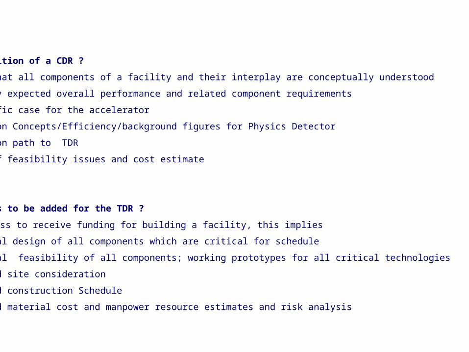
Our definition of a CDR ?
• Proof that all components of a facility and their interplay are conceptually understood
• Quantify expected overall performance and related component requirements
• Scientific case for the accelerator
• Detection Concepts/Efficiency/background figures for Physics Detector
• Evolution path to TDR
• Proof of feasibility issues and cost estimate
What needs to be added for the TDR ?
Readiness to receive funding for building a facility, this implies
• Technical design of all components which are critical for schedule
• Technical feasibility of all components; working prototypes for all critical technologies
• Detailed site consideration
• Detailed construction Schedule
• Detailed material cost and manpower resource estimates and risk analysis
H.Schmickler, 4th ACE meeting May 2009
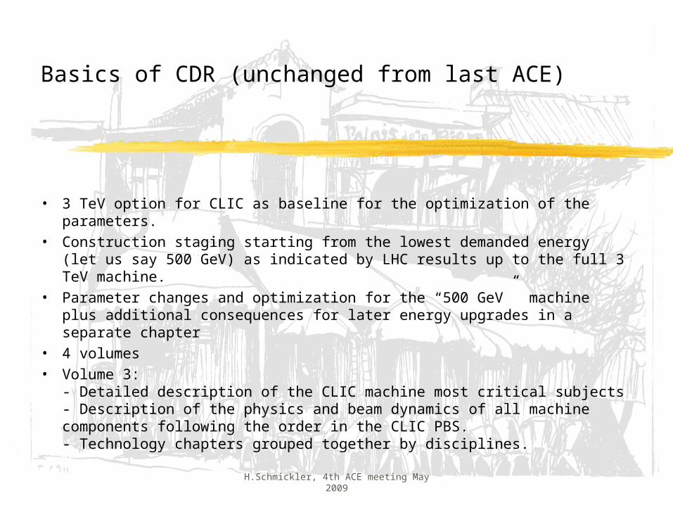
Basics of CDR (unchanged from last ACE)
• 3 TeV option for CLIC as baseline for the optimization of the parameters.
• Construction staging starting from the lowest demanded energy (let us say 500 GeV) as indicated by LHC results up to the full 3 TeV machine.
• Parameter changes and optimization for the “500 GeV” machine plus additional consequences for later energy upgrades in a separate chapter
• 4 volumes• Volume 3:
- Detailed description of the CLIC machine most critical subjects- Description of the physics and beam dynamics of all machine components following the order in the CLIC PBS.- Technology chapters grouped together by disciplines.
H.Schmickler, 4th ACE meeting May 2009
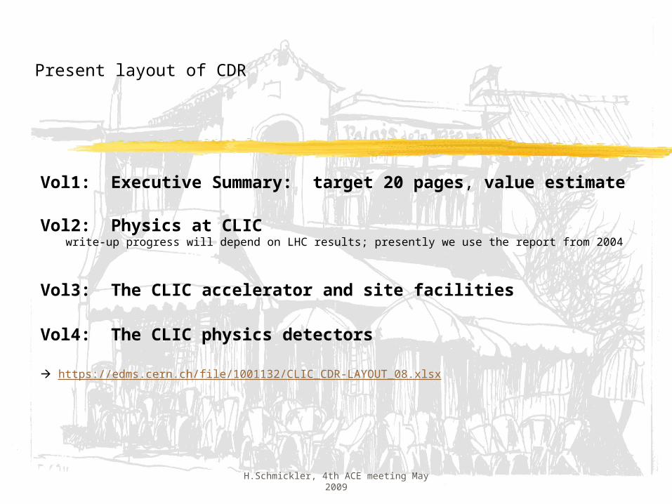
Present layout of CDR
Vol1: Executive Summary: target 20 pages, value estimate
Vol2: Physics at CLIC write-up progress will depend on LHC results; presently we use the report from 2004
Vol3: The CLIC accelerator and site facilities
Vol4: The CLIC physics detectors
https://edms.cern.ch/file/1001132/CLIC_CDR-LAYOUT_08.xlsx
H.Schmickler, 4th ACE meeting May 2009
CDR schedule
-Due to the LHC technical accident several resources, which were scheduled to start working on CLIC, are still working on the LHC.
- The original publication date of July 2010 had to be delayed and the first “90% draft for volume 3; ready in summer 2009” has been canceled.- The new target publication date is December 2010.
- The present technical work (including this meeting) consist in establishing a realistic work-plan to see what results can be obtained by end 2010.
H.Schmickler, 4th ACE meeting May 2009
List of CLIC items
- Effort started in April 2008 with an overview of CLIC subjects by D.Schulte and H.Braun
- Successive discussions in the CSC, CTC, etc produced as working document an excel spread-sheet called “List of critical items”.This file is (almost) kept up-to-date in EDMS:https://edms.cern.ch/file/918791/8/list-open-points_all_CLIC_ver20022009_V8.xlsx
This file contains a classification of the subjects by“critical = feasibility item”, “performance item”, “ cost item”.
Daniel’s talk has shown all details and has explained the selection of the:
- list of critical items (next slide), which summarizes the high priority working fields of the CLIC study.
H.Schmickler, 4th ACE meeting May 2009
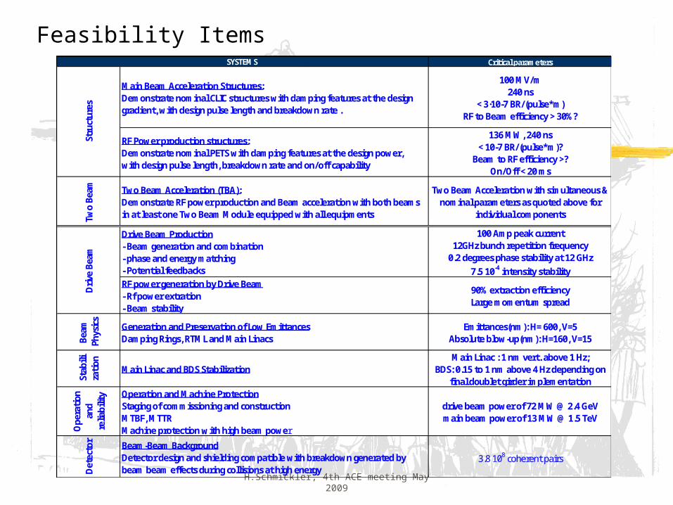
Feasibility ItemsCritical parameters
Main Beam Acceleration Structures:Demonstrate nominal CLIC structures with damping features at the design gradient, with design pulse length and breakdown rate .
100 MV/m 240 ns
< 3·10-7 BR/(pulse*m)RF to Beam efficiency > 30%?
RF Power production structures:Demonstrate nominal PETS with damping features at the design power, with design pulse length, breakdown rate and on/off capability
136 MW, 240 ns< 10-7 BR/(pulse*m)?
Beam to RF efficiency >?On/Off < 20 ms
Two
Beam Two Beam Acceleration (TBA):
Demonstrate RF power production and Beam acceleration with both beams in at least one Two Beam Module equipped with all equipments
Two Beam Acceleration with simultaneous & nominal parameters as quoted above for
individual components
Drive Beam Production- Beam generation and combination- phase and energy matching- Potential feedbacks
100 Amp peak current12GHz bunch repetition frequency
0.2 degrees phase stability at 12 GHz7.5 10-4 intensity stability
RF power generation by Drive Beam- Rf power extration- Beam stability
90% extraction efficiencyLarge momentum spread
Beam
Ph
ysic
s Generation and Preservation of Low EmittancesDamping Rings, RTML and Main Linacs
Emittances(nm): H= 600, V=5Absolute blow-up(nm): H=160, V=15
Stab
iliza
tion
Main Linac and BDS StabilizationMain Linac : 1 nm vert. above 1 Hz;
BDS: 0.15 to 1 nm above 4 Hz depending on final doublet girder implementation
Ope
ratio
n an
d re
liabi
lity Operation and Machine Protection
Staging of commissioning and constructionMTBF, MTTRMachine protection with high beam power
drive beam power of 72 MW @ 2.4 GeVmain beam power of 13 MW @ 1.5 TeV
Det
ecto
r Beam-Beam BackgroundDetector design and shielding compatible with breakdown generated by beam beam effects during collisions at high energy
3.8 108 coherent pairs
Driv
e Be
am
SYSTEMS
Stru
ctur
es
H.Schmickler, 4th ACE meeting May 2009
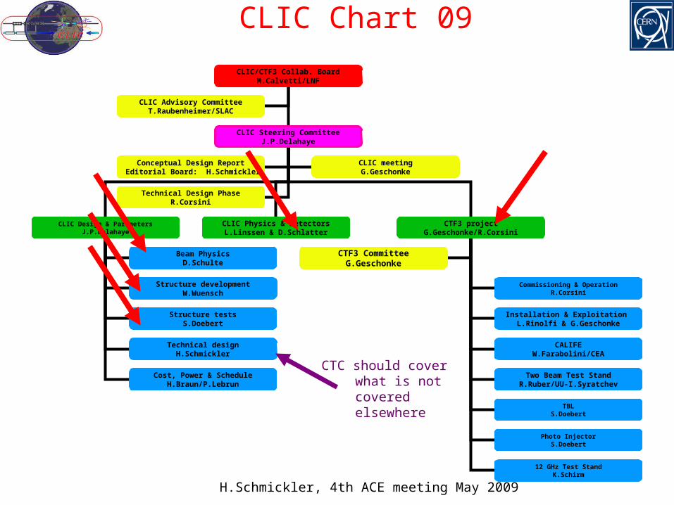
CLIC Chart 09
CLIC/CTF3 Collab. BoardM.Calvetti/LNF
CLIC Steering CommitteeJ.P.Delahaye
CLIC Advisory CommitteeT.Raubenheimer/SLAC
CLIC Design & ParametersJ.P.Delahaye
CLIC Physics & DetectorsL.Linssen & D.Schlatter
CTF3 projectG.Geschonke/R.Corsini
Beam PhysicsD.Schulte
Structure developmentW.Wuensch
Structure testsS.Doebert
Technical designH.Schmickler
Conceptual Design Report Editorial Board: H.Schmickler
Commissioning & OperationR.Corsini
Installation & Exploitation L.Rinolfi & G.Geschonke
CALIFEW.Farabolini/CEA
Two Beam Test StandR.Ruber/UU-I.Syratchev
Cost, Power & ScheduleH.Braun/P.Lebrun
TBLS.Doebert
CTF3 CommitteeG.Geschonke
Photo InjectorS.Doebert
12 GHz Test StandK.Schirm
CLIC meetingG.Geschonke
Technical Design PhaseR.Corsini
CTC should cover what is not covered elsewhere
CH-080708 CLIC Design Committee 9
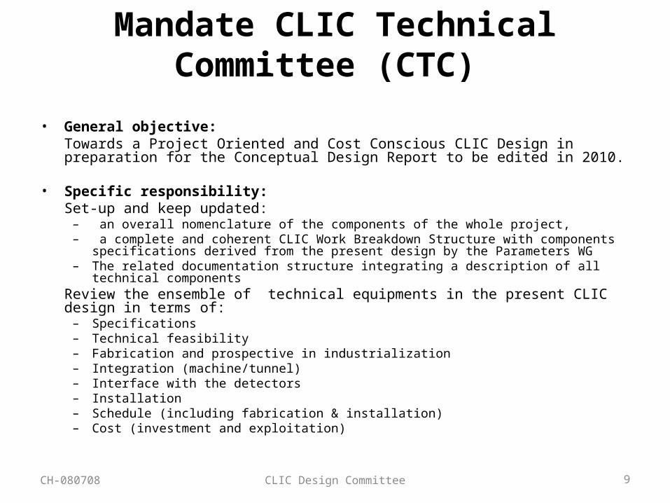
Mandate CLIC Technical Committee (CTC)
• General objective:Towards a Project Oriented and Cost Conscious CLIC Design in preparation for the Conceptual Design Report to be edited in 2010.
• Specific responsibility:Set-up and keep updated:
– an overall nomenclature of the components of the whole project,– a complete and coherent CLIC Work Breakdown Structure with components specifications derived
from the present design by the Parameters WG – The related documentation structure integrating a description of all technical components
Review the ensemble of technical equipments in the present CLIC design in terms of:– Specifications– Technical feasibility– Fabrication and prospective in industrialization – Integration (machine/tunnel)– Interface with the detectors– Installation– Schedule (including fabrication & installation)– Cost (investment and exploitation)
H.Schmickler, 4th ACE meeting May 2009
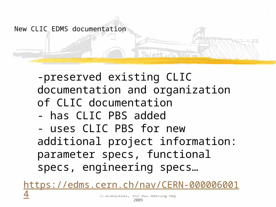
New CLIC EDMS documentation
-preserved existing CLIC documentation and organization of CLIC documentation- has CLIC PBS added- uses CLIC PBS for new additional project information:parameter specs, functional specs, engineering specs…
https://edms.cern.ch/nav/CERN-0000060014
11
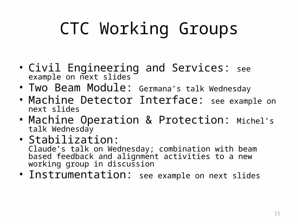
CTC Working Groups
• Civil Engineering and Services: see example on next slides• Two Beam Module: Germana’s talk Wednesday• Machine Detector Interface: see example on next slides• Machine Operation & Protection: Michel’s talk Wednesday• Stabilization:
Claude’s talk on Wednesday; combination with beam based feedback and alignment activities to a new working group in discussion
• Instrumentation: see example on next slides
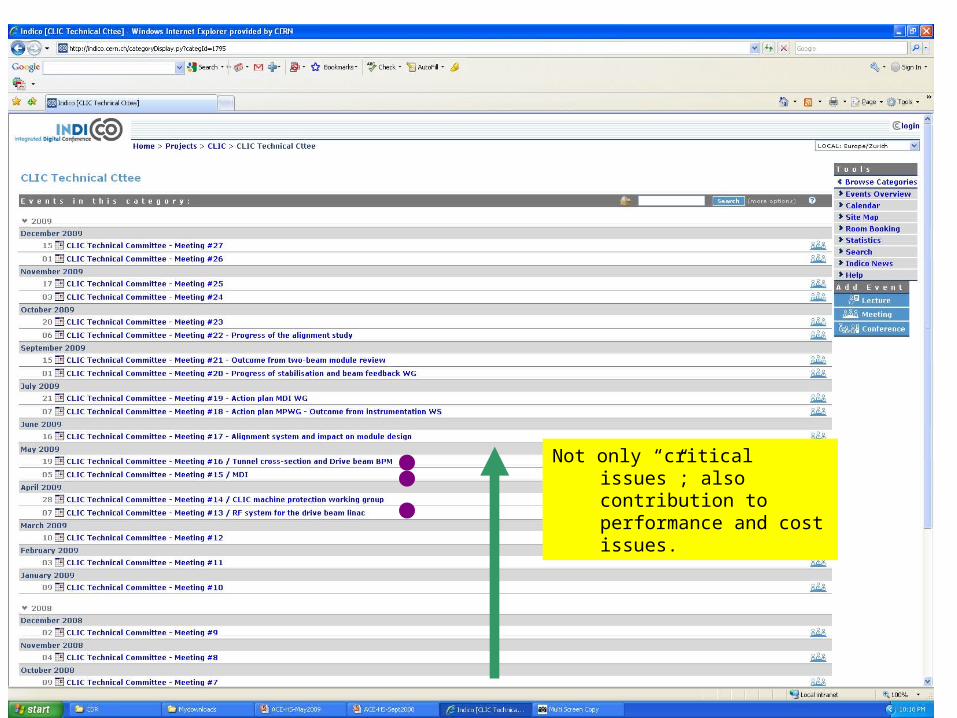
Not only “critical issues”; also contribution to performance and cost issues.
CTC#13: Erk Jensen - RF system for the Drive Beam Linac
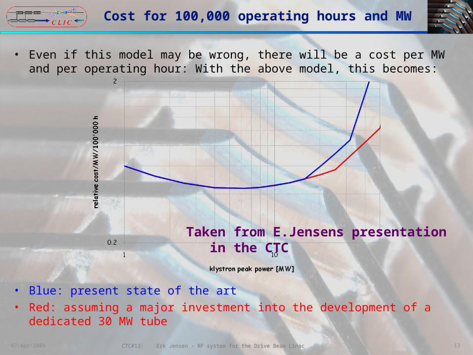
Cost for 100,000 operating hours and MW
• Even if this model may be wrong, there will be a cost per MW and per operating hour: With the above model, this becomes:
• Blue: present state of the art • Red: assuming a major investment into the development of a
dedicated 30 MW tube1307/Apr/2009 CTC#13: Erk Jensen - RF system for the Drive Beam Linac
Taken from E.Jensens presentation in the CTC
H.Schmickler, 4th ACE meeting May 2009
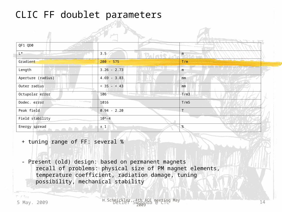
CLIC FF doublet parameters
5 May. 2009 Detlef Swoboda @ CTC 14
QF1 QD0
L* 3.5 m
Gradient 200 - 575 T/m
Length 3.26 - 2.73 m
Aperture (radius) 4.69 - 3.83 mm
Outer radius < 35 - < 43 mm
Octupolar error 106 T/m3
Dodec. error 1016 T/m5
Peak field 0.94 - 2.20 T
Field stability 10^-4
Energy spread ± 1 %
+ tuning range of FF: several %
- Present (old) design: based on permanent magnetsrecall of problems: physical size of PM magnet elements, temperature coefficient, radiation damage, tuning possibility, mechanical stability
H.Schmickler, 4th ACE meeting May 2009
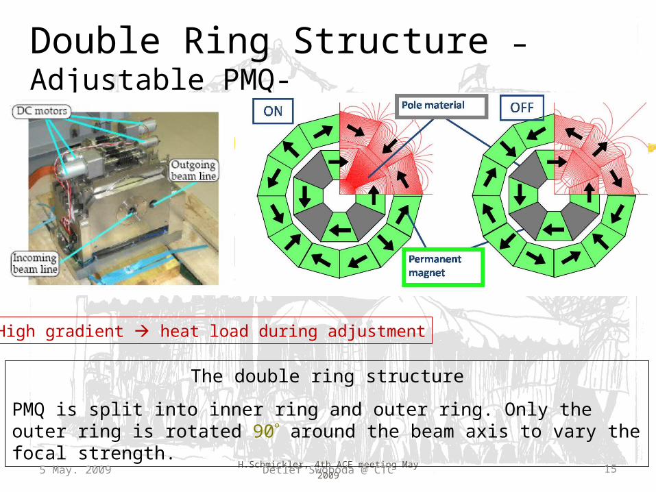
Double Ring Structure –Adjustable PMQ-
The double ring structure
PMQ is split into inner ring and outer ring. Only the outer ring is rotated 90 around the beam axis to vary the focal strength.
5 May. 2009 15Detlef Swoboda @ CTC
•High gradient heat load during adjustment
H.Schmickler, 4th ACE meeting May 2009
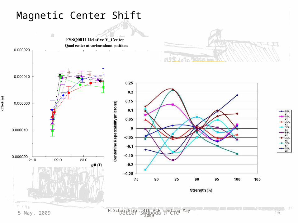
Magnetic Center Shift
5 May. 2009 Detlef Swoboda @ CTC 16
H.Schmickler, 4th ACE meeting May 2009
Present situation with FF magnet:
• Have to reconsider SC option, permanent magnet option (tuning range?), or normal conducting option or combination of these
• Needs for each option strong interaction with physics detector project
• Will have to review aperture requirements within beam dynamics WG
• Work will happen within next months in the newly formed (and reinforced) MDI working group
• MDI WG will have to produce urgently input to stabilization WG• No experimental work before CDR; studies and simulations only
John Osborne : GS-SEM Civil Engineering19 May 2009
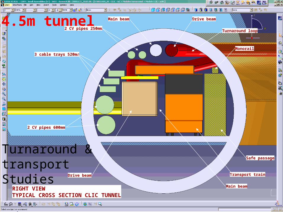
3 cable trays 520mm
2 CV pipes 600mm
2 CV pipes 250mm
Drive beam
Drive beam
Main beam
Main beam
Safe passage
Transport train
Turnaround loop
RIGHT VIEWTYPICAL CROSS SECTION CLIC TUNNEL
Monorail
Turnaround & transport Studies
4.5m tunnel
John Osborne : GS-SEM Civil Engineering19 May 2009
TREATED FRESH AIRSUPPLY
90 000 m3/harea=2,2 m2
EXTRACTEDAIR
EXTRACTEDAIR
INSTALLATIONCORRIDOR
TRANSFERTLINES
CLIC
EXTRACTION AIR SUPPLY
INSTALLATIONCORRIDOR
TRANSFERTLINES
R= 2.5
Ventilation Concepts Advantages of transversal ventilation :
•Safety (see CLIC note from F.Corsanego EDMS 827669)
•Much better control of temperature & humidity gradient along the tunnel
H.Schmickler, 4th ACE meeting May 2009
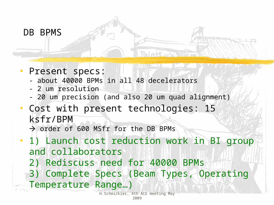
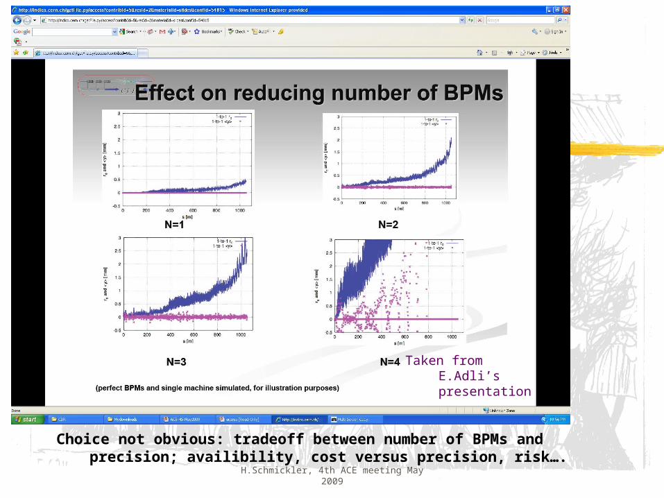
DB BPMS
• Present specs:- about 40000 BPMs in all 48 decelerators- 2 um resolution- 20 um precision (and also 20 um quad alignment)
• Cost with present technologies: 15 ksfr/BPM order of 600 MSfr for the DB BPMs
• 1) Launch cost reduction work in BI group and collaborators2) Rediscuss need for 40000 BPMs3) Complete Specs (Beam Types, Operating Temperature Range…)
H.Schmickler, 4th ACE meeting May 2009
Choice not obvious: tradeoff between number of BPMs and precision; availibility, cost versus precision, risk….
Taken from E.Adli’s presentation
H.Schmickler, 4th ACE meeting May 2009
Workshops/Reviews
• April 2009: Workshop on Wire Position Sensors for Alignment Systems; Search for Collaborators
• June 2009 (next week): Beam Instrumentation workshopPurpose: Review CLIC beam instrumentation requirements;Identify together with BI group unsolved technology problemsDefine and launch most important studies and prototyping
• September 2009: Two beam module ReviewPurpose: Present all integration issues, discuss some of the old design choices, define new baseline for the CDR
H.Schmickler, 4th ACE meeting May 2009
Charge of this ACE meeting
The CLIC project is aiming to demonstrate the feasibility of the Two Beam Accelerator concept on the 2010-timescale so that a complete evaluation of technical options for a future linear collider can be made once data from the LHC is available. To this end, the CLIC project is planning to document the status of the TBA technology and the CLIC design in a Conceptual Design Report to be written by the end of 2010.
The Committee is invited to review, assess and comment on these plans. In specific, the committee is asked to evaluate:
1. a prioritized list of the most relevant CLIC technical issues and their classification by feasibility, performance and cost impact.
2. the R&D status and plans to address the critical issues in terms of objectives and schedule
3. the R&D program and the schedule to complete a CLIC Feasibility Demonstration as well as a Conceptual Design Report by the end of 2010
4. A first proposal of technical objectives and planning for the Technical Design Phase in the years 2011 - 2015
H.Schmickler, 4th ACE meeting May 2009
Complementary information:
• List of CLIC critical items file
• List of “all” CLIC items file
• Written evaluations for R&D plans for most critical items
all copied into indico
H.Schmickler, 4th ACE meeting May 2009
Summary
• CTC was created in 2008
• CTC complements existing work in CTF3, Structures WGs, Beam dynamics WG and LCD Project
• Start of complementary QA documentation in EDMS
• Definition and follow-up of technical work• Together with CSC (and other WGs) elaboration of
R&D plans and workpackage definitions for resource holders(will eventually lead to a CLIC WBS)