update on cfetr - iaea · update on cfetr concept design ... 1250 ss 2200 m/ss ss ?? b.n. wan et...
TRANSCRIPT

S
Update on CFETR Concept Design
X. Gao for CFETR team
Institute of Plasma Physics, Chinese Academy of Sciences
Email: [email protected]
Dec. 17-20, 2013, Vienna, Austria
2nd IAEA DEMO Programme Workshop

Outline Introduction
Progress of CFETR design
Overview and machine layout
CFETR physical design
Magnet, cryostat and vacuum
system
Divertor and blanket system
Heating & current drive,
diagnostic & CODAC
Tritium technology
Remote handling
Summary

Outline Introduction
Progress of CFETR design
Overview and machine layout
CFETR physical design
Magnet, cryostat and vacuum
system
Divertor and blanket system
Heating & current drive,
diagnostic & CODAC
Tritium technology
Remote handling
Summary

X. Gao, 2nd IAEA DEMO Programme Workshop
To provide two options of concept design of CFETR
(2011- 2014 ) which should include:
• Missions, type, size, main physics basis, main techniques basis
• The concept engineering design for all sub-systems
• Budget & schedule, location, management system
To complete proposals in 2015 :
• “Key R&D Items for CFETR”
• “Construction Proposal for CFETR”
based on the concept design, and to submit them to the
government to try to get the construction permission.
China Fusion Engineering Test Reactor
Many upgrades on EAST tokamak have been
developed towards CFETR R&D items recently.
X. Gao, 2nd IAEA DEMO Programme Workshop
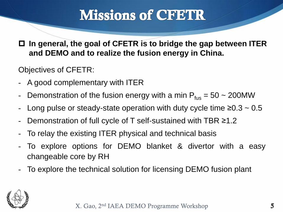
Objectives of CFETR:
- A good complementary with ITER
- Demonstration of the fusion energy with a min Pfus = 50 ~ 200MW
- Long pulse or steady-state operation with duty cycle time ≥0.3 ~ 0.5
- Demonstration of full cycle of T self-sustained with TBR ≥1.2
- To relay the existing ITER physical and technical basis
- To explore options for DEMO blanket & divertor with a easy
changeable core by RH
- To explore the technical solution for licensing DEMO fusion plant
In general, the goal of CFETR is to bridge the gap between ITER
and DEMO and to realize the fusion energy in China.

X. Gao, 2nd IAEA DEMO Programme Workshop
Phase I: 2030~2038 ITER baseline H-mode
Pfus=50~200 MW
H, D, DT-1
Tritium self-sustained and steady state
operation
Phase II: 2038~2045 AT H-mode
Upgrade of CFETR
DT-2
Q~10, Pfus~1 GW J. Li et al, ASIPP report, 2013

X. Gao, 2nd IAEA DEMO Programme Workshop
Option 2:
Water-Cooling Cu Magnets Tokamak
Option 1:
Full superconducting Tokamak

X. Gao, 2nd IAEA DEMO Programme Workshop
R(m) 5.7
a(m) 1.6
A 3.56
2.0
0.4
V(m3) 576
S(m2) 587
B0(T) 5.0
Ip(MA) 10~8
P(MW) 80
Main parameters:
Y.X. Wan et al, 34th FPA 2013

X. Gao, 2nd IAEA DEMO Programme Workshop
16 TF coils, 6 CS coils, 12 PF coils. The coil material is copper alloy conductor.
G. Zheng et al, 25th SOFE 2013

X. Gao, 2nd IAEA DEMO Programme Workshop
Option 2:
Water-Cooling Cu Magnets Tokamak
Option 1:
Full superconducting Tokamak
Option 1 will be discussed in this talk in detail.

Outline Introduction
Progress of CFETR design
Overview and machine layout
CFETR physical design
Magnet, cryostat and vacuum
system
Divertor and blanket system
Heating & current drive,
diagnostic & CODAC
Tritium technology
Remote handling
Summary

X. Gao, 2nd IAEA DEMO Programme Workshop
5. In-vessel Components & Blanket System
6. Heating & Current Drive System
7. Diagnosis & CODAC
8. Electrical Power & Control System
9. Fuel Circulation System & Waste Disposal
10.Radiation Protection & Safety
11.Remote Control and Maintenance System
12.Auxiliary Supporting System
13.Project Management
1. Layout Design and System Integration
2. Plasma Physics and Technology
3. Superconducting Magnet and Cryostat System
4. Vacuum Vessel & Vacuum System
Sub-systems for the Integration Design for CFETR

X. Gao, 2nd IAEA DEMO Programme Workshop
R(m) 5.7
a(m) 1.6
A 3.56
2.0
0.4
V(m3) 576
S(m2) 587
B0(T) 5.0
Ip(MA) 10~8
P(MW) 80
Main parameters:
Y.X. Wan et al, 34th FPA 2013

X. Gao, 2nd IAEA DEMO Programme Workshop
radial
Size at equatorial plane (mm)

Outline Introduction
Progress of CFETR design
Overview and machine layout
CFETR physical design
Magnet, cryostat and vacuum
system
Divertor and blanket system
Heating & current drive,
diagnostic & CODAC
Tritium technology
Remote handling
Summary

X. Gao, 2nd IAEA DEMO Programme Workshop
Fusion energy:
Wfus=Pfus*tb∝ (βN7B9a9/fDL
3)1/2 (ψCS – ψI)/q95(1 – fBS – fCD)
At low q95, higher Pfus,
expensive for SSO
At high q95, easier SSO, but
lower Pfus
At modest q95, possible SSO
with high Pfus (only operating
near the pressure limit)
favor high N and low density
T. C. Luce, Phys. Plasmas 18, 030501 (2011)

X. Gao, 2nd IAEA DEMO Programme Workshop
Operation mode A B C D E ITER-
SS
Upgrade
Ip(MA) 10 10 10 8 8 9 15
Paux(MW) 65 65 65 65~70 65 59 65
q95 3.9 3.9 3.9 4.9 4.9 5.2 3.9
W(MJ) 171~174 193 270~278 171 255 287 540
PFus (MW) 197~230 209 468~553 187~210 409 356 1000
Qpl 3.0~3.5 3.2 7.2~8.5 2.7~3.2 6.3 6.0 15
Ti0(keV) 17.8~18.5 29 19.8~20.8 20.6~21 21 19 25
Nel(1020/m3) 0.75 0.52 1.06 0.65 0.94 1
nGR 0.6 0.42 0.85 0.65 0.95 0.82 0.85
N 1.59~1.62 1.8 2.51~2.59 2 2.97 3.0 2.7
T(%) ~2.0 2.3 3.1~3.25 2 2.97 2.8 4.2
fbs(%) 31.7~32.3 35.8 50~51.5 50 73.9 48 47
98Y2(s) 1.82~1.74 1.55 1.57~1.47 1.37 1.29 1.94 1.88
PN/A(MW/m2) 0.35~0.41 0.37 0.98 0.33~0.37 0.73 0.5 1.38
ICD(MA) 3.0~3.1 7.0 2.45 4.0 2.76 3.0
H98 1 1.3 1.2 1.3 1.5 1.57 1.2
Tburning(S) 1250 SS 2200 M/SS SS ??
B.N. Wan et al, 25th SOFE 2013

X. Gao, 2nd IAEA DEMO Programme Workshop
Operational modes at high/low density

Outline Introduction
Progress of CFETR design
Overview and machine layout
CFETR physical design
Magnet, cryostat and vacuum
system
Divertor and blanket system
Heating & current drive,
diagnostic & CODAC
Tritium technology
Remote handling
Summary

X. Gao, 2nd IAEA DEMO Programme Workshop
Equ. Calculation (5.0T, 10 MA)
(a) ITER-Like (b) Super-X (c) snowflake
2 4 6 8 10 12
−8
−6
−4
−2
0
2
4
6
8
CS1U
CS2U
CS3U
PF1U
PF2U
PF3U
CS1L
CS2L
CS3L
PF1L
PF2L
PF3L
DC1 DC2
Ip= 10MA g121218.01100
R [m]
Z [
m]
−56
−13
13
15
−6
−14
−58
4
13
20
−1
−20
2 4 6 8 10 12
−8
−6
−4
−2
0
2
4
6
8
CS1U
CS2U
CS3U
PF1U
PF2U
PF3U
CS1L
CS2L
CS3L
PF1L
PF2L
PF3L
DC1 DC2
Ip= 10MA g121218.01110
R [m]
Z [
m]
−59
−10
13
15
−6
−13
−57
2
17
26
−14
−19
−2427
2 4 6 8 10 12
−8
−6
−4
−2
0
2
4
6
8
CS1U
CS2U
CS3U
PF1U
PF2U
PF3U
CS1L
CS2L
CS3L
PF1L
PF2L
PF3L
DC1 DC2
Ip= 10MA g121218.01120
R [m]
Z [
m]
−40
10
25
35
−20
−1
−46
47
53
−11
−17
−27
1530
coil R(m) Z(m) △R(m) △Z(m) turns
Current (kA/turn)
ITER-
like Super-X
Snowfla
ke
CS1U 1.415 0.999 0.650 1.938 374 -56 -59 -40
CS2U 1.415 2.997 0.650 1.938 374 -13 -10 10
CS3U 1.415 4.995 0.650 1.938 374 13 13 25
CS1L 1.415 -0.999 0.650 1.938 374 -56 -57 -46
CS2L 1.415 -2.997 0.650 1.938 374 4 2 47
CS3L 1.415 -4.995 0.650 1.938 374 13 17 53
PF1U 3.109 7.642 1.382 1.111 616 15 15 35
PF2U 9.400 6.698 0.909 0.909 324 -6 -6 -20
PF3U 11.554 2.742 0.909 0.909 324 -14 -13 -1
PF1L 3.109 -7.642 1.382 1.111 616 20 26 -11
D1 5.459 -7.792 0.909 0.909 324 -1 -24 15
D2 7.640 -7.448 0.909 0.909 324 -20 27 30
PF2L 9.400 -6.698 0.909 0.909 324 -56 -14 -17
PF3L 11.554 -2.742 0.909 0.909 324 -13 -19 -27
Poloidal field and equ. design:

X. Gao, 2nd IAEA DEMO Programme Workshop
parameters ITER-Like Super-X Snowflake ITER
No. of TF coils 16 16 16 18
Plasma current(MA) 10 10 10 15
Central field(T) 5.0 5.0 5.0 5.3 Max. current of TF coil
magnet 67.4 kA/turn 67.4 kA/turn 67.4kA/turn 68 kA/turn
R(m) 5.7 5.7 5.7 6.2 a(m) 1.6 1.6 1.48 2.0
Radius of Ohmic coil(m) 1.415 1.415 1.415 2.055 Max. CS flux 160 160 160 240-250
1.8/2.0 1.8/2.0 2.17/2.14 1.70/1.85 No. of PF coils 6 8 8 6
Supporting
Legs
Gravity support
5 4678910
R (m)
Z (
m)
11.42
9.787
8.156
6.525
4.8943.263
1.631
1.631
4.894
stray field from 2GS to 20GS
Z (
m)
R (m)
TF magnet optimization
flux
field
CS magnet optimization
Y. T. Song et al, ASIPP report, 2013

X. Gao, 2nd IAEA DEMO Programme Workshop
EM analysis for CS coil: C
ase 2
C
ase 1
A2(B2)
A1(B1)
Y. Ren et al, ASIPP report, 2013

X. Gao, 2nd IAEA DEMO Programme Workshop
Users of CFETR Cryostat System:
FORS
Cryopumps
FORS
Magnet
FORS
Magnet
LN2
bath
GHe CompressorStation
GN2 CompressorStation
LN2
Liquefier
LN2
Liquefier
300KGHe
80KLN2
4.5K LHe80K
QuenchTankPurifier
Storage
LHe bath
Hx
LHe bath
Hx
LHe bath
Hx
LHe bath
Hx
LHe bath
Hx
9CTBs of TF Coils
System of long cryogenic users inside the Tokamak building
6 CTBs of CS Coils11 CTBs of PF&CC
Coils
3 CVBs of magnet
Structures
14 CVBs of Cryopumpsfor Cryostat,
Torus&PIS, NB
2 CVBs of Thermal Shields
(TSCS)
CTCB
ACB-5CP
CCBACB-3
STACB-4
PF&CCACB-1
CSACB-2
TF
LN2 Plant80K GHe LoopLHe Plant
16 TF coils ;
6 CS coils ;
8 PF and 18 CC ;
Encasing and
supporting structures ;
Cryopumps for Torus,
Cryostat, NBI ;
HTS current leads ;
Thermal Shield system
of the tokamak ;
Other small users.
X. G. Liu et al, ASIPP report, 2013

X. Gao, 2nd IAEA DEMO Programme Workshop
The vacuum vessel:
4 upper ports
8 equatorial ports
8 lower ports.
These ports are used for
equipment installation,
vacuum pumping,
maintenance, etc.
ITER-like
Overall
large
window
Large
middle
window
Vacuum vessel and window configuration:
A new design of large- vertical window
scheme was selected by discussing the
advantages and disadvantages of the three
conceptual CFETR design.

Outline Introduction
Progress of CFETR design
Overview and machine layout
CFETR physical design
Magnet, cryostat and vacuum
system
Divertor and blanket system
Heating & current drive,
diagnostic & CODAC
Tritium technology
Remote handling
Summary

X. Gao, 2nd IAEA DEMO Programme Workshop
Divertor design:
ITER-like or Snowflake (Super-X configuration not available)
mono-block design of first wall
Space for shielding blanket reserved between divertor
support structure and vacuum vessel
Pumping channel between Dome and target plates
Space for diagnostic reserved between cassette and first
wall
60 modules in toroidal direction, 9.5 t weight each
length×width×height (mm): 2834×650×1713.

X. Gao, 2nd IAEA DEMO Programme Workshop
Group I: Helium cooling solid blanket 1) HC (8MPa, 300/5000C),
Li4SiO4 (Li2TiO3 ), Be , RAFM
Group II : Liquid blanket 1) SLL ( ~150 0 C ) , CLAM
2) DLL( ~700 0C), CLAM
Group III : Water cooling solid blanket 1) HC, Li4SiO4 , Be , RAFM
2) WC, Li2TiO3, Be12Ti , RAFM
Radial sizes of the CFETR (Equatorial Plane)
Blanket design:

Outline Introduction
Progress of CFETR design
Overview and machine layout
CFETR physical design
Magnet, cryostat and vacuum
system
Divertor and blanket system
Heating & current drive,
diagnostic & CODAC
Tritium technology
Remote handling
Summary

X. Gao, 2nd IAEA DEMO Programme Workshop
Heating & CD system currently planned:
NBI: 500 keV, 20 (potential upgrade to 40) MW, negative
ion source, off-axis injection
LHW: 4.6 GHz, 15 MW
ICRF: 30-50 MHz, 25 MW
ECW: 170 GHz, 20 MW

X. Gao, 2nd IAEA DEMO Programme Workshop
Phase I (H, D, DT-1)
~26 diagnostics
For machine safety and additional control in some scenarios
Phase II (DT-2)
~16 diagnostics
Only for machine protection and basic control
(Maybe an additional phase between phase I and II is needed. To test the diag.
reliability under fusion environment, to reduce the number of diagnostics.)
position Diag. Windows taken
Inner wall of VV magnetic
Outer wall of VV magnetic
Vertical window Visible/IR camera(4), Visible/UV spec., bolometer, neutron monitor, CXRS, MSE,etc… 1(4)
Mil-plane
window
Reflectometry, FIR inter./polor., neutron monitor, ECE, TS, CXRS, neutron spec., hard
X-ray spec. etc…
2~3(8)
Divertor window Visible/IR camera(4), Visible/UV spec., bolometer, neutron monitor, divertor
thermocouples, erosion& dust analysers, residual gas analysers, etc…
3~4(8)
One example of diagnostic design in CFETR phase I:
Y. Yang et al, 25th SOFE 2013

X. Gao, 2nd IAEA DEMO Programme Workshop
Safety
control
Central
safety
system
Central
interlock
system
CODAC
port
CODAC
server
CODAC
terminal
CODAC
port
switch
CODAC
server
switch
Plant
system
host
Slow
control
Fast
control
CODAC
HPC (PCS)
switch switch
(TBD)
interlock
controller Safety
controller
SDN TCN
CN
CSN

Outline Introduction
Progress of CFETR design
Overview and machine layout
CFETR physical design
Magnet, cryostat and vacuum
system
Divertor and blanket system
Heating & current drive,
diagnostic & CODAC
Tritium technology
Remote handling
Summary

X. Gao, 2nd IAEA DEMO Programme Workshop
• Concepts of the main processes (TES,
TEP, ISS, WDS, VDS and ADS) have
been finished.
Concept design of T-plant for CFETR
• Launched in 2012
• Key issues:
Start-up tritium preparation
Plant breakdown structure (PBS)
Technological principle, parameters
for each PBS
Tritium safety measures
Preliminary safety analysis
R&D scheme
Preliminary fuel recycling for CFETR

Outline Introduction
Progress of CFETR design
Overview and machine layout
CFETR physical design
Magnet, cryostat and vacuum
system
Divertor and blanket system
Heating & current drive,
diagnostic & CODAC
Tritium technology
Remote handling
Summary

X. Gao, 2nd IAEA DEMO Programme Workshop
Duty cycle: 0.3-0.5
Fusion power: 50-200
MW
High dosage of
neutron: 2-3 orders of
ITER in amplitude
To meet CFETR
design parameters
Prevention of
diffusion of
Radioactive dust
Big modules (divertor,
blanket, etc..)
High decay heat needs
to be removed
To reduce the quantity
of middle plane port
High magnetic field
intensity of CS (max:
13T)
Radiation resistance
of RH devices
High load for RH and
less maintenance time
Forced cooling
needed after SD
High utilization of port
(diagnostic integration,
reduction of
maintenance port)
New superconducting
material for magnet
High safety and
availability
requirement

X. Gao, 2nd IAEA DEMO Programme Workshop
Blanket RH
Divertor
RH
AIA RH
End
effectors Cask
system

Outline Introduction
Progress of CFETR design
Overview and machine layout
CFETR physical design
Magnet, cryostat and vacuum
system
Divertor and blanket system
Heating & current drive,
diagnostic & CODAC
Tritium technology
Remote handling
Summary

X. Gao, 2nd IAEA DEMO Programme Workshop
Concept design of CFETR which includes (1) full superconducting magnets
and (2) water cooling Cu magnets is well progressing. The engineering
parameters of the device has been determined by considering engineering
constraints. The two design options will be finished by Sept. 2014.
CFETR operation modes have been studied. SSO is proved to be possible.
More detailed 1.5D calculation needs to be done.
A new design of large vertical window scheme was selected by discussing
the advantages and disadvantages of the three conceptual CFETR design.
Vacuum vessel and window configuration by considering remote handling
technology have been decided.
ITER-like, snowflake, super-X divertor configurations have been studied.
Integration design of divertors for ITER-like and snowflake configurations has
been done. Many upgrades on EAST tokamak have been developed towards
CFETR R&D items recently.
Summary

X. Gao, 2nd IAEA DEMO Programme Workshop

X. Gao, 2nd IAEA DEMO Programme Workshop

S
Thank you for your attention !
2nd IAEA DEMO Programme Workshop

X. Gao, 2nd IAEA DEMO Programme Workshop