upgrading the ductility and seismic …... used a method for strengthening of exterior beam-column...
TRANSCRIPT

CD04-001
UPGRADING THE DUCTILITY AND SEISMIC BEHAVIOR FACTOR OF ORDINARY RC FRAMES USING FIBER
COMPOSITE SHEETS
A. Niroomandi1, A. Maheri2 1Seismic Retrofitting Center, Shiraz University, Iran
2Faculty of Engineering, University of Bristol, UK ABSTRACT The ductility and seismic behavior factor (R) are evaluated for an existing Reinforced Concrete (RC) frame that has been retrofitted with web-bonded Carbon Fiber Reinforced Polymer (CFRP) system. For this purpose, firstly using a nonlinear finite element analysis the flexural stiffness of FRP-retrofitted and original exterior and interior joints of the frame are determined. The obtained stiffness is then implemented into another software package in order to analyze the FRP-retrofitted frame using nonlinear static analyses. Then the R factor components including ductility reduction factor and over strength factors are extracted from pushover analyses. The results are compared with the results of the original RC frame and the same frame that has been retrofitted with steel bracings reported by other investigators. The results show that the ductility and the seismic behavior factor of the existing RC frame that has been retrofitted with CFRP sheets are better than the original frame, and upgrade the ductility of the ordinary RC frame to the Intermediate and even Special RC frame. Keywords: seismic behavior factor (R), nonlinear static analysis, pushover, reinforced concrete frame, web-bonded CFRP-retrofitting, steel bracings 1. INTRODUCTION Recently, FRP has been utilized for retrofitting or upgrading RC structures. Parvin & Granata [1] indicated that when joints of an RC frame were reinforced with FRP laminates, the moment capacity was increased up to 37 percent. Mahini & Ronagh [2] used a method for strengthening of exterior beam-column joints using web-bonded FRP sheets. They tested the effectiveness of web-bonded CFRP on energy absorption capacity of 2.21 scale RC joints, in order to evaluate the possibility of relocating the plastic hinge location away from the column face. Their experimental studies showed that the FRP repairing/retrofitting system can restore/upgrade the integrity of the joint, keeping/upgrading its strength, stiffness and ductility as well as shifting the plastic hinge from the column facing toward the beam in such a way that the joint remains elastic. The practicality and effectiveness of using web-bonded FRPs on plastic hinge relocation has been also reported by Smith and Shrestha [3]. In another experimental study Balsamo et al. [4] evaluated

588 / Upgrading the Ductility and Seismic Behavior…––––––––––––––––––––
the seismic behavior of a full-scale RC frame repaired using CFRP laminates. They indicated that the repaired frame had a large displacement capacity without exhibiting any loss of strength, while providing almost the same energy dissipation of the original frame. In this paper, seismic behavior factors affecting parameters for CFRP-retrofitted ordinary moment-resisting RC frame are evaluated and compared with corresponding original moment resisting and steel-braced RC frames. The R factor components including ductility reduction factor and over strength factor are extracted from nonlinear static analyses of the frames. For this purpose, an eight storey three bay existing RC moment resisting frame which was retrofitted by Maheri & Akbari [5] using steel bracing systems is retrofitted again with web-bonded CFRP method in order to compare their ductility and seismic behavior factor. 2. GEOMETRY AND MATERIAL PROPERTIES OF THE RC FRAME Figure 1 shows the selected frame of this study. The design dead and live loads are assumed to be 2750kg/m and 1750kg/m respectively. The compressive strength,
cf ' and tensile strength, tf of the concrete are taken as 27.46 MPa and 3.668 MPa, respectively. In addition, the elastic modulus of the concrete cE is taken as 24.63 GPa and the yield stress of steel reinforcement is assumed to be 412 MPa.
Figure 1. Selected moment resisting frame [5]
Design base shears were determined for a Peak Ground Acceleration (PGA) of
g3.0 . The weight of the system is taken as the dead load plus 20 percent of live load as an estimation of the equivalent earthquake load, based on the Iranian earthquake code [6]. Initial R factor was assumed to be equal to 6 for this system. The moment resisting frame was designed based on "weak beam-strong column" principle using ACI-95 Code [7] and the steel bracings system was designed using
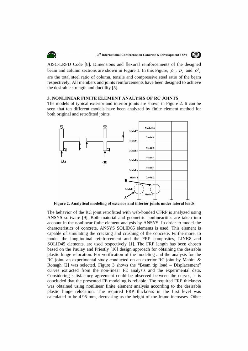
––––––––––––––––––––––– 3rd International Conference on Concrete & Development / 589 AISC-LRFD Code [8]. Dimensions and flexural reinforcements of the designed beam and column sections are shown in Figure 1. In this Figure, tρ , sρ and s'ρ are the total steel ratio of column, tensile and compressive steel ratio of the beam respectively. All members and joints reinforcements have been designed to achieve the desirable strength and ductility [5]. 3. NONLINEAR FINITE ELEMENT ANALYSIS OF RC JOINTS The models of typical exterior and interior joints are shown in Figure 2. It can be seen that ten different models have been analyzed by finite element method for both original and retrofitted joints.
Figure 2. Analytical modeling of exterior and interior joints under lateral loads
The behavior of the RC joint retrofitted with web-bonded CFRP is analyzed using ANSYS software [9]. Both material and geometric nonlinearities are taken into account in the nonlinear finite element analysis by ANSYS. In order to model the characteristics of concrete, ANSYS SOLID65 elements is used. This element is capable of simulating the cracking and crushing of the concrete. Furthermore, to model the longitudinal reinforcement and the FRP composites, LINK8 and SOLID45 elements, are used respectively [1]. The FRP length has been chosen based on the Paulay and Priestly [10] design approach for obtaining the desirable plastic hinge relocation. For verification of the modeling and the analysis for the RC joint, an experimental study conducted on an exterior RC joint by Mahini & Ronagh [2] was selected. Figure 3 shows the “Beam tip load – Displacement” curves extracted from the non-linear FE analysis and the experimental data. Considering satisfactory agreement could be observed between the curves, it is concluded that the presented FE modeling is reliable. The required FRP thickness was obtained using nonlinear finite element analysis according to the desirable plastic hinge relocation. The required FRP thickness in the first level was calculated to be 4.95 mm, decreasing as the height of the frame increases. Other

590 / Upgrading the Ductility and Seismic Behavior…––––––––––––––––––––
characteristics of CFRP laminates are given in Table 1. Note that the characteristics given in Table 1 satisfy the consistency conditions which are necessary for a non-isotropic material like ANISO in the analysis as described in reference [9] and stated by Kachlakev et al. [11]. The numerical models of retrofitted exterior and interior joints at seventh floor of the selected frame are depicted in Figure 4. Figures 5 and 6 show the failure mechanism of retrofitted exterior and interior joints (Isosurface style of concrete strain) at seventh level of the selected frame before and after retrofitting by web-bonded CFRP sheets. It can be seen that desirable plastic hinge relocation is achieved successfully thanks to CFRP sheets, as it was already obtained from an experimental study by Mahini & Ronagh [2]. Figure 7 shows the failure mechanism of an exterior RC joint tested by Mahini & Ronagh [2] before and after retrofitting by web-bonded FRP sheets.
0.0E+00
5.0E+03
1.0E+04
1.5E+04
2.0E+04
2.5E+04
0 5 10 15 20 25 30Displacement, Δ (mm)
Bea
m ti
p lo
ad, P
(N)
Experimental [2]
ANSYS (current study)
Figure 3. “Beam tip load – Displacement” curve for an exterior RC joint from
experiment [2] and calculated from FE analysis
Figure 4. Finite element models of an (a) exterior and (b) interior retrofitted joint

––––––––––––––––––––––– 3rd International Conference on Concrete & Development / 591
Table 1: Mechanical properties of CFRP sheets used for FE modeling [9] In fibers direction Ex=240000 In fibers direction σx=80
Ey=18581 σy=80
Modulus of
elasticity (MPa)
Perpendicular to fibers direction Ez=18581
Compressive strength (MPa) Perpendicular to fibers
direction σz=80
In fibers direction σ'x=3900 Gxy=12576 υxy=0.2
σ'y=53.7 Gxz=12576 υxz=0.2 Tensile strength (MPa)
Perpendicular to fibers direction σ'z=53.7
Shear modulus (MPa)
Gyz=7147
Poisson’s ratio
υyz=0.3
Figure 5. Failure mechanism of an exterior joint (a) before and (b) after retrofitting
by web-bonded CFRP sheets
Figure 6. Failure mechanism of an interior joint (a) before and (b) after retrofitting by
web-bonded CFRP sheets Figure 8 shows the "moment-rotation" curves of an exterior original and FRP-retrofitted beam-column joint at seventh level of the selected frame. In this Figure, K13 is the difference between the two curves.

592 / Upgrading the Ductility and Seismic Behavior…––––––––––––––––––––
Figure 7. Failure mechanism of an exterior joint (a) before and (b) after retrofitting
by web-bonded FRP sheets [2]
0.0E+00
5.0E+07
1.0E+08
1.5E+08
2.0E+08
2.5E+08
3.0E+08
3.5E+08
4.0E+08
4.5E+08
5.0E+08
0 0.002 0.004 0.006 0.008 0.01
Rotation, θ (rad)
Mom
ent,
M (N
.mm
)
Model 9-OriginalModel 9-FRP StrengthendK13
Figure 8. “Moment-rotation” curve of an exterior original and FRP-retrofitted joint
3. NONLINEAR STATIC ANALYSIS OF THE FRAMES • Original Frame: Nonlinear static analysis (pushover) of each system is
carried out using SAP 2000 10.1.0 program [12]. For this purpose, a constant gravity load equal to the total dead load plus 20 percent of the live load is applied to each frame, and an inverted triangular distribution over the height is used as the lateral load pattern. Δ−P effect is also considered in the analysis. Force-deformation criteria for plastic hinging is defined based on ATC-40 [13] and FEMA356 [14] patterns.
• Retrofitted Frames: The analytical models of the retrofitted frames with web-bonded CFRP system and steel bracings are shown in Figure 9. This frame has already been retrofitted using steel bracing system (Maheri & Akbari [5]). In order to model the FRP-retrofitted frame, SAP 2000 Non-Linear Link (NLLink) elements are used, which can simulate the equivalent additional stiffness to the beams provided by web-bonded CFRP sheets on the system. These elements are assumed to be located at a distance of 500 mm away from

––––––––––––––––––––––– 3rd International Conference on Concrete & Development / 593
the column face, corresponding to the FRP length. In Figure 9, Ki is the additional rotational stiffness of each retrofitted beam, which is modeled on the original frame with a NLLink element. The "moment-rotation" curve of original and FRP retrofitted joints are extracted from finite element analysis and the differences are used as the rotational stiffness of retrofitted joints.
Figure 9. Analytical modeling of the (a) web-bonded CFRP (current study) and (b)
steel-braced frame [5] The base shear versus roof displacement curves of original and retrofitted (both steel-braced and FRP-retrofitted) frames are shown in Figure 10. In this Figure, X-brace retrofitting systems examined by Maheri & Akbari [5] have been designed based on 50% and also 100% of the lateral loading on the RC frames.
0
50
100
150
200
250
0 10 20 30 40 50 60Roof Displacement, Δ (cm)
Bas
e Sh
ear,
V (t
on)
Original
X-Braced 50%
FRP-Retrofitted
X-Braced 100%
Figure 10. Base shear-roof displacement curves of all frames

594 / Upgrading the Ductility and Seismic Behavior…––––––––––––––––––––
4. SEISMIC BEHAVIOR FACTOR AFFECTING PARAMETERS In forced-based seismic design procedures, seismic behavior factor, R is a force reduction factor used to reduce the linear elastic response spectra to the inelastic response spectra. In other words, seismic behavior factor is the ratio of the strength required to maintain the structure elastic to the inelastic design strength of the structure. The seismic behavior factor, R, therefore accounts for the inherent ductility and over strength of a structure as well as the difference in the level of stresses considered in its design. Taking into account the above three components, It is generally expressed in the following, YRRR s ..μ= (1)
Where, μR is the ductility-dependent component, also known as the ductility
reduction factor, sR is the over strength factor and Y stands for the allowable stress factor. With reference to Figure 11, in which the actual "force-displacement" response curve is idealized by a bilinear "elastic-perfectly plastic" response curve, the seismic behavior factor parameters may be defined as: wssysye VVYVVRVVR === ,,μ (2) Where, eV , yV , sV and wV denote the elastic response strength of the structure, the idealized yield strength, the first significant yield strength and the allowable stress design strength, respectively. For structures designed using an ultimate strength method, the allowable stress factor, Y, becomes unity and the seismic behavior factor is therefore reduced to: ( )( ) ( )sesyyes VVVVVVRRR === ..μ (3) The structure ductility, μ , is defined in terms of the maximum structural drift (Δmax) and the displacement corresponding to the idealized yield strength ( )yΔ as:
yΔ
Δ= maxμ (4)
Many investigators have discussed the two main components of R factor presented in Eq. (3). In particular, the ductility dependent component, μR , has received
considerable attention. Ductility reduction factor μR is a function of both of the characteristics of the structure, including ductility, damping and fundamental period of vibration (T), and the characteristics of earthquake ground motion. Nassar and Krawinkler [15] presented a relation for μR in the following form:

––––––––––––––––––––––– 3rd International Conference on Concrete & Development / 595
( )[ ]11 1+−= μμ cR c (5)
Figure 11. Typical pushover response curve for evaluation of behavior factor, R [5]
Where,
( )Tb
TTTc a
a
++
=1
,α (6)
In Eq. (6), α is the post-yield stiffness given as a percentage of the initial stiffness of the system and a and b are parameters given as functions of α that can be obtained from Table 2 [16].
Table 2: a and b values regarding α [16] α (%) a b
0 1 0.42 2 1 0.37
10 0.8 0.29 5. DETERMINATION OF SEISMIC BEHAVIOR FACTOR A number of performance parameters may govern the capacity of a structure. In order to carry out a nonlinear static analysis, one or a number of these parameters should be considered for determination of the displacement limit state ( )maxΔ . For the medium-rise ductile building considered in this study, the global drift (maximum roof displacement) is commonly used as a failure criterion. In evaluation of the displacement ductility, μ , the ultimate capacity of each frame is assumed when the global drift has been reached to 1.5% of the system height. This criterion is based on the NEHRP recommendations [17] for RC moment resisting frames. The idealized "force-displacement" (obtained based on the FEMA-356 method) and the capacity curves for the FRP-retrofitted frame are shown in Figure

596 / Upgrading the Ductility and Seismic Behavior…––––––––––––––––––––
12. In this Figure, yV and yΔ , are yield strength and yield displacement,
respectively, and tΔ and tV are the target displacement and its corresponding base shear. To calculate the yield displacement, yΔ , and yield strength, yV , line segments on the "force–displacement" curve were located using an iterative procedure that approximately balanced the area above and below the curve [14]. The effective lateral stiffness, eK , shall be also taken as the secant stiffness calculated at a base shear force equal to 60% of the effective yield strength of the structure [14]. After calculation of μ , now μR can be obtained from Eq. 5, 6 and
Table 2 and sR is determined from Eq. 2. The seismic behavior factor parameters of all systems have been presented in Table 3. It can be seen that the ductility ratio of FRP-retrofitted frame is improved in comparison with the original frame, and is very similar to the one obtained for the X-Braced frames. The R factor of FRP-retrofitted frame is improved significantly in comparison with the original frame and is also better than X-Braced frames.
0
20
40
60
80
100
120
0 10 20 30 40 50 60Roof Displacement, Δ (cm)
Bas
e Sh
ear,
V (t
on)
Capacity Curve
Idealized curve
δ t
V y
Δ y
V t
0.6 V y
Figure 12. Capacity and Idealized curve of FRP retrofitted frame based on the
FEMA356
Table 3: Seismic behavior factor parameters of all systems R Rs Rμ μ Frame
4.6 1.92 2.4 2.27 Original [5] 7.9 2.97 2.66 2.7 Xbraced-50% [5] 9.5 3.33 2.86 2.84 Xbraced-100% [5]
9.63 3.193 3.016 2.83 FRP Retrofitted

––––––––––––––––––––––– 3rd International Conference on Concrete & Development / 597 6. CONCLUSIONS Conventional retrofitting systems in earthquake-resisting frames have some limitations. For example, conventional steel bracings in RC frames which were considered in this paper for verification of web-bonded CFRP retrofitting are able to dissipate considerable energy by yielding under tension, but they buckle without much energy dissipation in the compression loads [18]. In this paper, an eight-storey frame that was previously strengthened with steel bracings system is selected and retrofitted with web-bonded CFRP. In order to estimate the flexural stiffness of the FRP retrofitting system, nonlinear finite element analysis by ANSYS is employed. The additional flexural stiffness of the FRP joints is implemented into the frame using NLLink elements on the beam end of exterior and interior joints. A systematic evaluation of each system including ductility ratio and seismic behavior factor is made using nonlinear static analysis. Based on the obtained results, it is concluded that the ductility ratio and the seismic behavior factor of the FRP retrofitted RC frame are significantly improved in comparison with the original frame and increased from 4.6 (original frame) to 9.63 (FRP retrofitted frame). REFERENCES 1. Parvin, A. and Granata, P., Investigation on the Effects of Fiber Composites at
Concrete Joints, Journal of Composites part B, 2000, 31, pp 499-509. 2. Mahini, S. S., and Ronagh, H. R., A New Method for Improving Ductility in
Existing RC Ordinary Moment Resisting Frames using FRPs, Asian Journal of Civil Engineering (Building and Housing), 2007, Vol. 8, no. 6.
3. Smith, S. T., and Shrestha, R., A Review of FRP Strengthened RC Beam Column Connections, Proceeding of the Third International Conference on FRP Composites in Civil Engineering (CICE 2006), 13-15 December-Miami, Florida, USA, pp 661-664.
4. Balsamo, A., Colombo, A., Manfredi, G., Negro, P., and Prota, A., Seismic Behavior of a Full Scale RC Frame Repaired using CFRP Laminates, Engineering Structures, 2005, 27, pp 769-780.
5. Maheri, M. R., and Akbari, R., Seismic Behavior Factor, R, for Steel X-Braced and Knee-Braced RC Buildings, Engineering Structures, 2003, 25, pp 1505-1513.
6. Iranian Code of Practice for Seismic Resistance Design of Buildings, standard no.2800 2nd. Edition-1999.
7. ACI Committee 318. Building Code Requirements for Reinforced Concrete (ACI 318-95) and Commentary (ACI 318R-95). American Concrete Institute, Detroit, Michigan, 1989.
8. Manual of Steel Construction, Load and Resistance Factor Design, LRFD. 2nd ed. American Institute of Steel Construction, Chicago. III, 1994.
9. ANSYS. ANSYS Manual set., ANSYS,Inc., Canonsburg, PA 15317, USA, 2005.
10. Paulay, T., and Priestley, M.J.N., Seismic Design of Reinforced Concrete and Masonry Buildings, John Wiley & Sons, INC, 1992.

598 / Upgrading the Ductility and Seismic Behavior…––––––––––––––––––––
11. Kachlakev, D., Miller, T., Yim, S. & Chansawat, K., Finite Element Modeling of Reinforced Concrete Structures Strengthened with FRP Laminates, Final Report for Oregon Department of Transportation Research Group, Internet File, 2001.
12. SAP2000 Non-linear version 10.1.0. Analysis Reference Manual. Computers and Structures Inc., Berkeley, Calif, 2006.
13. ATC. Seismic Evaluation and Retrofit of Concrete Buildings. ATC-40, Applied Technology Council, Redwood City, 1996.
14. American Society of Civil Engineering (ASCE). Prestandard and Commentary for the Seismic Rehabilitation of Buildings., prepared for the Federal Emergency Management Agency, FEMA 356, 2000.
15. Nassar, A.A., and Krawinkler, H., Seismic Demands for SDOF and MDOF Systems, report No. 95. Stanford, California: The John A. Blume Earthquake Engineering Center, Stanford University, 1991.
16. Miranda, E., Eeri, M., and Bertero, V., Evaluation of Strength Reduction Factors for Earthquake-Resistant Design, Engineering Spectra, Vol 10, No. 2, 1994, PP. 357-379.
17. Federal Emergency Management Agency (FEMA). NEHRP Provisions for the Seismic Rehabilitation of Buildings. Rep FEMA 273 and 274, Washington DC, 1997.
18. Ravi Kumar, G., Satish Kumar, S. R., and Kalyanaraman, V., Behavior of Frames with Non-Buckling Bracings under Earthquake Loading, Journal of Constructional Steel Research, 2007, 63, pp 254-262.