upload-2903892a37eae7807e7ca642f4dcdb9e ...…5 4.7.4. star-hash (*#) network...
TRANSCRIPT


Contents
1. Introduction ..........................................................................................15
2. Configuration Commands...................................................................16
2.1. AT&V Display current configuration ............................................................... 17
2.1.1. AT&V responses ................................................................................................... 17
2.2. AT+GCAP Capabilities List ............................................................................ 19
2.3. AT+CSCS Character Set ............................................................................... 20
2.4. AT+CFGRI Indicate RI When Using URC...................................................... 21
2.5. AT&F Reset AT Command Settings to Factory Default Values ..................... 22
2.5.1. Factory Default Settings Restorable with AT&F..................................................... 22
2.6. AT&W Store AT Command Settings to User Defined Profile ......................... 25
2.7. ATQ Result Code Presentation Mode............................................................ 26
2.8. ATV Result code format mode ....................................................................... 27
2.8.1. Verbose and numeric result codes ........................................................................ 28
2.9. ATX CONNECT Result Code Format ............................................................ 29
2.10. ATZ Restore AT Command Settings from User Defined Profile..................... 30
2.11. AT+CEXTBUT Headset Button Status Reporting .......................................... 31
2.12. AT+CEXTHS External Headset Jack Control ................................................ 33
2.13. AT+CFUN Functionality Level........................................................................ 34
2.13.1. Wake up the ME from SLEEP mode.................................................................. 39
2.14. AT+CHF Configure Hands Free Operation .................................................... 40
2.15. AT+CIURC Enable Or Disable Initial URC Presentation................................ 41
2.16. AT+CLPORT Set Local Port .......................................................................... 42
2.17. AT+CMEE Error Message Format ................................................................. 43
2.17.1. CME/CMS Error Code Overview ....................................................................... 44
2.18. AT+CMTE Set Critical Temperature Operating Mode Or Query Temperature48
2.19. AT+CPOWD Power Off.................................................................................. 49
2.20. AT+CSCLK Configure Slow Clock ................................................................. 50
2.21. AT+CSDT Switch On Or Off Detecting SIM Card .......................................... 51
2.22. AT+CSMINS SIM Inserted Status Reporting ................................................. 52
2.23. AT+EXUNSOL Enable /Disable Proprietary Unsolicited Indications .............. 53
2.24. AT^SCFG Extended Configuration Settings .................................................. 55
2.25. AT^SM20 Set M20 compatibility mode .......................................................... 70
2.26. AT^SMSO Switch Off MG21 ........................................................................... 72

3
2.27. AT\Q Flow Control ......................................................................................... 73
2.28. AT&C Set Data Carrier Detect (DCD) Line Mode .......................................... 74
2.29. AT&D Set Data Terminal Ready (DTR) Line Mode........................................ 75
2.30. AT&S Set Data Set Ready (DSR) Line Mode ................................................ 76
2.31. ATE AT Command Echo................................................................................ 77
2.32. AT+CMUX Multiplex mode............................................................................. 78
2.32.1. Restrictions on Multiplex mode.......................................................................... 79
2.33. AT+ICF Set TE-TA Control Character Framing ............................................. 82
2.34. AT+IFC TE-TA local flow control.................................................................... 84
2.35. AT+ILRR Bit Rate Reporting.......................................................................... 85
2.36. AT+IPR Bit Rate............................................................................................. 87
2.36.1. Autobauding ...................................................................................................... 89
3. Status Control and Identification Commands ..................................91
3.1. AT+CMER Common Event Reporting Configuration ..................................... 92
3.2. AT+CPAS Activity Status............................................................................... 95
3.3. AT+WS46 Select wireless network ................................................................ 96
3.4. AT+CIND Indicator control ............................................................................. 97
3.5. AT^SIND Extended Indicator Control.......................................................... 101
3.6. AT+CEER Extended Error Report................................................................ 111
3.6.1. Cause Location ID for the extended error report.................................................. 113
3.6.2. Proprietary L2 cause ........................................................................................... 114
3.6.3. GSM release cause for L3 Radio Resource (RR) ................................................ 114
3.6.4. Proprietary release cause for L3 Radio Resource (RR) ....................................... 114
3.6.5. GSM release cause for Mobility Management (MM) or Session Management (SM)
115
3.6.6. Proprietary release cause for L3 Mobility Management (MM) .............................. 116
3.6.7. GSM release cause for L3 Call Control (CC) ....................................................... 116
3.6.8. Proprietary release cause for L3 Call Control (CC).............................................. 118
3.6.9. Proprietary release cause for L3 Advice of Charge (AOC)................................... 118
3.6.10. GSM Release cause for Supplementary Service Call ...................................... 118
3.6.11. Proprietary release cause for Call-related Supplementary Ser-vices (CRSS) .. 120
3.6.12. Proprietary release cause for Supplementary Services Entity.......................... 121
3.6.13. Proprietary release cause for Supplementary Services Manager..................... 121
3.6.14. Proprietary release cause for GPRS Mobility Management ............................. 122
3.6.15. Proprietary release cause for Session Management (SM) ............................... 123

4
3.6.16. GSM cause for L3 Protocol module or other local cause ................................. 123
3.6.17. Proprietary release cause for GPRS API ......................................................... 124
3.6.18. Proprietary release cause for Link Management.............................................. 124
3.6.19. Proprietary release cause for PPP/IP-Stack .................................................... 124
3.7. ATS18 Extended call release report ............................................................ 125
3.8. ATI Display product identification information .............................................. 127
3.9. AT+AUTEST Audio Channel Loopback Test ............................................... 128
3.10. AT+CDEVICE View Current Flash Device Type .......................................... 129
3.11. AT+CGMI Request manufacturer identification............................................ 130
3.12. AT+GMI Request manufacturer identification .............................................. 131
3.13. AT+CGMM Request model identification ..................................................... 132
3.14. AT+GMM Request model identification........................................................ 133
3.15. AT+CGMR Request revision identification of software status...................... 134
3.16. AT+GMR Request revision identification of software status ........................ 135
3.17. AT+CGSN Request International Mobile Equipment Identity (IMEI) ............ 136
3.18. AT+GSN Request International Mobile Equipment Identity (IMEI)............... 137
3.19. AT+GOI Request Global Object Identification.............................................. 138
3.20. AT+GSV Display Product Identification Information..................................... 139
3.21. AT+CCID Show ICCID................................................................................. 140
3.22. AT+CIMI Request International Mobile Subscriber Identity (IMSI)............... 141
3.23. AT+CLTS Get Local Timestamp .................................................................. 142
4. Call related Commands.....................................................................143
4.1. AT+CLCC List of current calls...................................................................... 144
4.2. AT^SLCC Extended list of current calls ....................................................... 147
4.3. AT^SCNI List Call Number Information....................................................... 154
4.4. AT^SLCD Display Last Call Duration........................................................... 156
4.5. AT^STCD Display Total Call Duration.......................................................... 157
4.6. ATA Connect to Incoming Call ..................................................................... 158
4.7. ATD Mobile originated call to specified number ........................................... 160
4.7.1. ATD><mem><n> Mobile originated call using specific memory and index number
163
4.7.2. ATD><n> Mobile originated call from active memory using index number........... 165
4.7.3. ATD><str> Mobile originated call from active memory using cor-responding field
166

5
4.7.4. Star-Hash (*#) Network Commands .................................................................... 168
4.7.5. Restricted access to SIM data after SIM PIN authentication................................ 170
4.7.6. Remote-SAT Command Types............................................................................ 171
4.8. ATDI Mobile originated data call to ISDN number........................................ 173
4.9. ATDL Redial last number used ................................................................... 174
4.10. ATH Disconnect existing connection............................................................ 175
4.11. AT+CHUP Hang up call ............................................................................... 176
4.12. AT^SHUP Hang up call(s) indicating a specific GSM04.08 release cause .. 177
4.13. +++ Escape from Data Mode to AT Command Mode .................................. 179
4.14. ATO Switch from command mode to data mode / PPP online mode........... 180
4.15. ATS0 Set number of rings before automatically answering a call ................. 181
4.16. ATS6 Set pause before blind dialing........................................................... 183
4.17. ATS7 Set number of seconds to wait for connection completion ................ 184
4.18. ATS8 Comma Dial Pause Time .................................................................. 185
4.19. ATS10 Set disconnect delay after indicating the absence of data carrier .... 186
4.20. AT+CCALR Call Ready Query..................................................................... 187
4.21. AT+CCPD Connected Line Identification Presentation Without Alpha String188
4.22. AT+CCWE Call Meter Maximum Event ....................................................... 189
4.23. AT+CLDTMF Local DTMF Tone Generation ............................................... 191
4.24. AT+CMOD Configure Alternating Mode Calls.............................................. 192
4.25. AT+CBST Select Bearer Service Type ........................................................ 193
4.26. AT+CRLP Configure RLP Parameters for Outgoing Non-Trans-parent Data
Calls 195
4.27. AT+CR Service reporting control ................................................................. 197
4.28. AT+CRC Incoming Call Indication Format ................................................... 199
4.29. AT+CSNS Single Numbering Scheme......................................................... 201
4.30. AT+CSTA Select Type Of Address.............................................................. 203
4.31. AT+HVOIC Disconnect Voice Call Only....................................................... 204
4.32. AT+MORING Show State of Mobile Originated Call .................................... 205
4.33. ATP Select pulse dialing .............................................................................. 206
4.34. ATT Select tone dialing................................................................................ 206
4.35. ATS2 Set escape sequence character........................................................ 207
5. Network Service Commands ............................................................208
5.1. AT+CBAND Get And Set Mobile Operation Band........................................ 209

6
5.2. AT+CDSCB Reset Cell Broadcast .............................................................. 210
5.3. AT+COPN Read operator names ................................................................ 211
5.4. AT+COPS Operator Selection ..................................................................... 212
5.5. AT+CPOL Preferred Operator List ............................................................... 215
5.6. AT+CREG Network registration ................................................................... 217
5.7. AT+CSQ Signal quality ................................................................................ 220
5.8. AT^MONI Monitor idle mode and dedicated mode....................................... 222
5.8.1. AT^MONI responses .......................................................................................... 223
5.8.2. Service states...................................................................................................... 224
5.9. AT^MONP Monitor neighbor cells ................................................................ 226
5.9.1. AT^MONP responses.......................................................................................... 227
5.10. AT^SALS Alternate Line Service.................................................................. 228
5.11. AT^SHOM Display Homezone..................................................................... 230
5.12. AT^SMONC Cell Monitoring ........................................................................ 231
5.13. AT^SMOND Cell Monitoring ........................................................................ 233
5.14. AT^SMONG Packet Data Monitor................................................................ 237
5.15. AT^SOPS Extended Operator Selection...................................................... 239
5.16. AT^SPCL Set Preferred Cell List ................................................................. 241
5.17. AT^SPLM Read the PLMN list ..................................................................... 243
5.18. AT^SPLR Read entry from the preferred operators list................................ 244
5.19. AT^SPLW Write an entry to the preferred operators list .............................. 245
5.20. AT^SRPN Replace Operator Names ........................................................... 246
5.21. AT+CACM Accumulated call meter (ACM) reset or query ........................... 248
5.22. AT^SACM Advice of charge and query of ACM and ACMmax .................... 249
5.23. AT+CAMM Accumulated call meter maximum (ACMmax) set or query....... 251
5.24. AT+CAOC Advice of Charge information..................................................... 252
5.25. AT+CCFC Call forwarding number and conditions control........................... 254
5.26. AT+CCUG Closed User Group .................................................................... 259
5.27. AT+CCWA Call Waiting ............................................................................... 261
5.28. AT+CHLD Call Hold and Multiparty.............................................................. 265
5.29. AT+CLIP Calling Line Identification Presentation ........................................ 268
5.30. AT+CLIR Calling Line Identification Restriction ........................................... 271
5.31. AT+COLP Connected Line Identification Presentation ................................ 273
5.32. AT+CPUC Price Per Unit And Currency Table ............................................ 275

7
5.33. AT+CSSN Supplementary service notifications ........................................... 276
5.34. AT+CUSD Unstructured Supplementary Service Data ................................ 278
6. Internet Service and GPRS Commands ..........................................281
6.1. AT+CDNSCFG Configure Domain Name Server......................................... 282
6.2. AT+CDNSGIP Query The IP Address Of Given Domain Name................... 283
6.3. AT+CDRIND CS Voice/Data/Fax Call Termination Indication...................... 284
6.4. AT+CIFSR Get Local IP Address................................................................. 285
6.5. AT+CIICR Bring Up Wireless Connection With GPRS Or CSD ................... 286
6.6. AT+CIPACK Query Previous Connection Data Transmitting State.............. 287
6.7. AT+CIPATS Set Auto Sending Timer ......................................................... 288
6.8. AT+CIPCCFG Configure Transparent Transfer mode ................................. 289
6.9. AT+CIPCLOSE Close TCP Or UDP Connection ......................................... 290
6.10. AT+CIPCSGP Set CSD Or GPRS For Connection Mode............................ 291
6.11. AT+CIPHEAD Add An IP Head When Receiving Data ................................ 293
6.12. AT+CIPMODE Select TCPIP Application Mode........................................... 294
6.13. AT+CIPMUX Start Up Multi-IP Connection .................................................. 295
6.14. AT+CIPQSEND Select Data Transmitting Mode ......................................... 296
6.15. AT+CIPSEND Send Data Through TCP Or UDP Connection ..................... 297
6.16. AT+CIPSERVER Configure As Server ........................................................ 300
6.17. AT+CIPSHOWTP Display transfer protocol in IP head when receiving data 301
6.18. AT+CIPSHUT Deactivate GPRS PDP Context ............................................ 302
6.19. AT+CIPSPRT Set Prompt Of ‘>’ When Sending Data ................................. 303
6.20. AT+CIPSRIP Set Whether Display IP Address And Port Of Sender When
Receive Data .................................................................................................................. 304
6.21. AT+CIPSTART Start Up TCP Or UDP Connection...................................... 305
6.22. AT+CIPSTATUS Query Current Connection Status .................................... 308
6.23. AT+CSPN Get Service Provider Name From SIM ....................................... 310
6.24. AT+CSTT START Task And Set APN, USER NAME, PASSWORD............ 311
6.25. AT^SICI Internet Connection Information.................................................... 313
6.25.1. Checking Connection Profile Status ................................................................ 314
6.26. AT^SICS Internet Connection Setup Profile................................................ 316
6.26.1. Example: Default values of a CSD connection profile ...................................... 319
6.26.2. Example: GPRS connection profile.................................................................. 320
6.27. AT^SISI Internet Service Information.......................................................... 321

8
6.28. AT^SISO Internet Service Open ................................................................. 324
6.28.1. Example: Accepting / Rejecting Socket Connection Request from Remote Client
328
6.29. AT^SISC Internet Service Close ................................................................. 330
6.30. AT^SISE Internet Service Error Report....................................................... 331
6.31. AT^SISR Internet Service Read Data ......................................................... 333
6.31.1. Example: Socket Host Reads Small Amounts of UDP Data Packets (URC Mode)
335
6.32. AT^SISS Internet Service Setup Profile ...................................................... 337
6.33. AT^SIST Enter Transparent Access Mode ................................................. 350
6.34. AT^SISW Internet Service Write Data.......................................................... 352
6.34.1. Usage of parameter <eodFlag>....................................................................... 355
6.35. ATA Manual acceptance of a network request for PDP context activation ... 356
6.36. ATH Manual rejection of a network request for PDP context acti-vation....... 357
6.37. ATS0 Automatic Response to Network Request for PDP Context Activation
358
6.38. ATD*99# Request GPRS service................................................................. 360
6.39. ATD*98# Request GPRS IP service ............................................................ 362
6.40. AT+CGACT PDP context activate or deactivate .......................................... 363
6.41. AT+CGANS Manual response to a network request for PDP context activation
365
6.42. AT+CGATT GPRS attach or detach ........................................................... 367
6.43. AT+CGAUTO Automatic response to a network request for PDP context
activation 369
6.44. AT+CGDATA Enter data state ..................................................................... 371
6.45. AT+CGDCONT Define PDP Context ........................................................... 373
6.46. AT+CGEQMIN Rel. 99 Quality of Service Profile (Minimum acceptable)..... 376
6.47. AT+CGEQREQ Rel. 99 Quality of Service Profile (Requested)................... 381
6.48. AT+CGEREP GPRS event reporting ........................................................... 386
6.49. AT+CGMSCLASS Change GPRS Multislot Class ....................................... 389
6.50. AT+CGPADDR Show PDP address ............................................................ 390
6.51. AT+CGQMIN Quality of Service Profile (Minimum acceptable) ................... 391
6.52. AT+CGQREQ Quality of Service Profile (Requested).................................. 396
6.53. AT+CGREG GPRS Network Registration Status........................................ 401

9
6.54. AT+CGSMS Select service for MO SMS messages ................................... 403
6.55. AT^SGAUTH Set type of authentication for PPP connection....................... 405
6.56. AT^SGCONF Configuration of GPRS related Parameters............................ 406
7. FAX Commands .................................................................................407
7.1. AT+FBADLIN Bad Line Threshold ............................................................... 408
7.2. AT+FBADMUL Error Threshold Multiplier .................................................... 409
7.3. AT+FBOR Query data Bit Order .................................................................. 410
7.4. AT+FCIG Query or set the Local Polling ID ................................................. 411
7.5. AT+FCLASS Fax: Select, read or test service class.................................... 412
7.6. AT+FCQ Copy Quality Checking ................................................................. 414
7.7. AT+FCR Capability to Receive .................................................................... 415
7.8. AT+FDCC Query or set capabilities............................................................. 416
7.9. AT+FDFFC Data Compression Format Conversion..................................... 417
7.10. AT+FDIS Query or set session parameters ................................................. 418
7.11. AT+FDR Begin or continue phase C Data Reception .................................. 419
7.12. AT+FDT Data Transmission ........................................................................ 420
7.13. AT+FET End a page or document ............................................................... 421
7.14. AT+FK Kill operation, orderly FAX abort ...................................................... 422
7.15. AT+FLID Query or set the Local Id setting capabilities ................................ 423
7.16. AT+FMDL Identify Product Model ................................................................ 424
7.17. AT+FMFR Request Manufacturer Identification........................................... 425
7.18. AT+FMI FAX: Report Manufactured ID........................................................ 426
7.19. AT+FMM FAX: Rreport Model ID................................................................. 427
7.20. AT+FMR FAX: Report Revision ID............................................................... 428
7.21. AT+FOPT Set bit Order independently ........................................................ 429
7.22. AT+FPHCTO DTE Phase C Response Timeout.......................................... 430
7.23. AT+FREV Identify Product Revision ............................................................ 431
7.24. AT+FRH Receive Data Using HDLC Framing ............................................. 432
7.25. AT+FRM Receive Data ................................................................................ 433
7.26. AT+FRS Receive Silence ............................................................................ 434
7.27. AT+FTH Transmit Data Using HDLC Framing............................................. 435
7.28. AT+FTM Transmit Data ............................................................................... 436
7.29. AT+FTS Stop Transmission and Wait.......................................................... 437

10
7.30. AT+FVRFC Vertical Resolution Format Conversion ................................... 438
8. SMS Commands.................................................................................439
8.1. AT+CMGC Send SMS Command................................................................ 440
8.2. AT+CMGD Delete short message................................................................ 441
8.3. AT+CMGDA Delete All SMS........................................................................ 442
8.4. AT+CMGF Select SMS message format ..................................................... 443
8.5. AT+CMGHEX Enable To Send Non-ASCII Character SMS ........................ 444
8.6. AT+CMGL List SMS messages from preferred store................................... 445
8.7. AT+CMGR Read SMS messages................................................................ 447
8.8. AT+CMGS Send SMS ................................................................................. 449
8.9. AT+CMGW Write Short Messages to Memory............................................. 451
8.10. AT+CMSS Send short messages from storage ........................................... 453
8.11. AT+CNMA New Message Acknowledgement to ME/TE.............................. 454
8.12. AT+CNMI SMS Event Reporting Configuration ........................................... 456
8.13. AT+CPMS Preferred SMS message storage............................................... 460
8.14. AT+CRES Restore SMS Settings ................................................................ 463
8.15. AT+CSAS Save SMS Settings..................................................................... 464
8.16. AT+CSCA SMS Service Center Address..................................................... 465
8.17. AT+CSCB Select Cell Broadcast Message Indication ................................. 466
8.18. AT+CSDH Show SMS text mode parameters.............................................. 468
8.19. AT+SCLASS0 Store Class 0 SMS To SIM When Received Class 0 SMS... 469
8.20. AT+CSMP Set SMS text Mode Parameters................................................. 470
8.21. AT+CSMS Select Message Service............................................................. 472
8.22. AT^SLMS List SMS Memory Storage .......................................................... 474
8.23. AT^SMGL List Short Messages from preferred store without setting status to
REC READ ..................................................................................................................... 476
8.24. AT^SMGO Set or query SMS overflow presentation mode or query SMS
overflow 477
8.25. AT^SMGR Read short message without setting status to REC READ ........ 479
8.26. AT^SSCONF SMS Command Configuration ............................................... 480
8.27. AT^SSDA Set SMS Display Availability ....................................................... 481
8.28. AT^SSMSS Set Short Message Storage Sequence .................................... 483
9. SIM related Commands .....................................................................484

11
9.1. AT+CCVM Get And Set The Voice Mail Number On The SIM..................... 485
9.2. AT+CGID Get SIM Card Group Identifier..................................................... 486
9.3. AT+CRSM Restricted SIM Access............................................................... 487
9.4. AT+CSIM Generic SIM Access.................................................................... 490
9.5. AT+CXXCID Display card ID ....................................................................... 492
9.6. AT^SCID Display SIM card identification number ....................................... 493
9.7. AT^SCKS Query SIM and Chip Card Holder Status ................................... 494
9.8. AT^SSET SIM Data Ready Indication.......................................................... 496
9.9. AT^SXSM Extended SIM Access................................................................. 498
9.10. AT^SSTA Remote-SAT Interface Activation ................................................ 501
9.11. AT^SSTGI SAT Get Information .................................................................. 503
9.11.1. AT^SSTGI SAT Get Information - Refresh (1) ................................................. 504
9.11.2. AT^SSTGI SAT Get Information - Set Up Event List (5) .................................. 506
9.11.3. AT^SSTGI SAT Get Information - Set Up Call (16)......................................... 508
9.11.4. AT^SSTGI SAT Get Information - Send SS (17)............................................. 511
9.11.5. AT^SSTGI SAT Get Information - Send USSD (18)........................................ 512
9.11.6. AT^SSTGI SAT Get Information - Send Short Message (19)........................... 514
9.11.7. AT^SSTGI SAT Get Information - Send DTMF (20)........................................ 515
9.11.8. AT^SSTGI SAT Get Information - Launch Browser (21) ................................. 516
9.11.9. AT^SSTGI SAT Get Information - Play Tone (32)........................................... 519
9.11.10. AT^SSTGI SAT Get Information - Display Text (33) ....................................... 521
9.11.11. AT^SSTGI SAT Get Information - Get Inkey (34)............................................ 523
9.11.12. AT^SSTGI SAT Get Information - Get Input (35) ............................................ 524
9.11.13. AT^SSTGI SAT Get Information - Select Item (36) ......................................... 526
9.11.14. AT^SSTGI SAT Get Information - Set up Menu (37)....................................... 529
9.11.15. AT^SSTGI SAT Get Information - Set up Idle Mode Text (40) ........................ 532
9.11.16. AT^SSTGI SAT Get Information - Language Notification (53)......................... 533
9.12. AT^SSTR SAT Response ............................................................................ 535
9.12.1. AT^SSTR SAT Response - Refresh (1).......................................................... 536
9.12.2. AT^SSTR SAT Response - Set Up Event List (5) ........................................... 537
9.12.3. AT^SSTR SAT Response - Set Up Call (16) .................................................. 538
9.12.4. AT^SSTR SAT Response - Send SS (17) ...................................................... 539
9.12.5. AT^SSTR SAT Response - Send USSD (18) ................................................. 539
9.12.6. AT^SSTR SAT Response - Send Short Message (19) ................................... 540
9.12.7. AT^SSTR SAT Response - Send DTMF (20) ................................................. 541

12
9.12.8. AT^SSTR SAT Response - Launch Browser (21)........................................... 542
9.12.9. AT^SSTR SAT Response - Play Tone (32) .................................................... 543
9.12.10. AT^SSTR SAT Response - Display Text (33)................................................. 544
9.12.11. AT^SSTR SAT Response - Get Inkey (34) ..................................................... 545
9.12.12. AT^SSTR SAT Response - Get Input (35)...................................................... 547
9.12.13. AT^SSTR SAT Response - Select Item (36)................................................... 548
9.12.14. AT^SSTR SAT Response - Setup Menu (37) ................................................. 549
9.12.15. AT^SSTR SAT Response - Set Up Idle Mode Text (40) ................................. 550
9.12.16. AT^SSTR SAT Response - Language Notification (53) .................................. 551
9.12.17. AT^SSTR SAT Event - Menu Selection (211)................................................. 552
9.12.18. AT^SSTR SAT Event - User Activity (232)...................................................... 552
9.12.19. AT^SSTR SAT Event - Idle Screen Available (233) ........................................ 553
9.12.20. AT^SSTR SAT Event - Language Selection (235) .......................................... 553
9.12.21. AT^SSTR SAT Event - Browser Termination (236)......................................... 554
9.12.22. AT^SSTR SAT Event - Terminate Command (254) ........................................ 554
9.12.23. Examples for Using Remote-SAT.................................................................... 555
10. Phonebook Commands.....................................................................560
10.1. AT+CNUM Read own numbers.................................................................... 561
10.2. AT+CPBF Find Phonebook Entries.............................................................. 562
10.3. AT+CPBR Read from Phonebook................................................................ 564
10.4. AT+CPBS Select phonebook memory storage ............................................ 567
10.5. AT+CPBW Write into Phonebook ................................................................ 570
10.6. AT^SDLD Delete the 'last number redial' memory ....................................... 574
10.7. AT^SPBC Find first matching entry in sorted phonebook ............................ 575
10.8. AT^SPBD Purge phonebook memory storage............................................. 577
10.9. AT^SPBG Display phonebook entries in alphabetical order ........................ 579
10.10. AT^SPBS Step through the selected phonebook alphabetically............... 583
11. Audio Commands ..............................................................................588
11.1. ATL Set monitor speaker loudness .............................................................. 589
11.2. ATM Set monitor speaker mode .................................................................. 590
11.3. AT+CHFA Swap The Audio Channels ......................................................... 591
11.4. AT+CLVL Loudspeaker volume level............................................................ 592
11.5. AT+CMIC Change The Microphone Gain Level........................................... 594
11.6. AT+CMUT Mute control ............................................................................... 596

13
11.7. AT+CRSL Ringer Sound Level .................................................................... 597
11.8. AT+SIDET Change The Side Tone Gain Level............................................ 598
11.9. AT+SIMTONE Generate Specifically Tone .................................................. 599
11.10. AT+VTD Tone duration ............................................................................ 600
11.11. AT+VTS DTMF and tone generation........................................................ 601
11.12. AT^SNFA Set or query of microphone attenuation................................... 603
11.13. AT^SNFD Set audio parameters to manufacturer default values ............. 605
11.14. AT^SNFG Generate Tone ........................................................................ 606
11.15. AT^SNFI Set microphone path parameters............................................. 608
11.16. AT^SNFM Set microphone audio path and power supply ........................ 610
11.17. AT^SNFO Set audio output (= loudspeaker path) parameter ................... 612
11.18. AT^SNFPT Set progress tones ................................................................ 614
11.19. AT^SNFS Select audio hardware set ....................................................... 615
11.20. AT^SNFTTY Signal TTY/CTM audio mode capability .............................. 617
11.21. AT^SNFV Set loudspeaker volume .......................................................... 619
11.22. AT^SNFW Write audio setting in non-volatile store .................................. 621
11.23. AT^SRTC Ring tone configuration............................................................ 622
12. Hardware related Commands...........................................................625
12.1. AT+CALA Alarm Configuration .................................................................... 626
12.2. AT+CBC Battery Charge............................................................................. 630
12.3. AT+CCLK Real Time Clock ......................................................................... 631
12.4. AT^SBV Battery/Supply Voltage ................................................................. 632
12.5. AT^SCTM Critical Operating Temperature Monitoring................................. 633
12.5.1. Deferred shutdown .......................................................................................... 635
12.6. AT^SRADC Configure and Read ADC Measurement.................................. 636
12.7. AT^SSPI Serial Protocol Interface .............................................................. 640
12.7.1. Transmitting Data over AT Interface ................................................................ 641
12.7.2. Structure of Messages on the I²C Bus ............................................................. 644
12.7.3. Example: Using I²C Bus................................................................................... 646
12.8. AT^SSYNC Configure SYNC Pin................................................................. 648
12.8.1. ME status indicated by status LED patterns..................................................... 649
12.9. AT^SWDAC PWM Signal Configuration for DAC......................................... 650
12.10. AT^SCPIN Pin Configuration.................................................................... 652
12.11. AT^SGIO Get IO state of a specified pin .................................................. 654

14
12.12. AT^SPIO General Purpose IO Driver Open/Close ................................... 655
12.12.1. GPIO configuration table ................................................................................. 656
12.13. AT^SSIO Set IO state of a specified pin................................................... 657
13. Security Commands ..........................................................................658
13.1. AT+CPIN PIN Authentication ....................................................................... 659
13.1.1. What to do if PIN or password authentication fails? ......................................... 661
13.2. AT+CPIN2 PIN2 Authentication ................................................................... 662
13.3. AT+SPIC Times Remain To Input SIM PIN/PUK ......................................... 665
13.4. AT^SPIC Display PIN counter....................................................................... 666
13.5. AT+CLCK Facility lock ................................................................................. 672
13.6. AT^SLCK Facility lock.................................................................................. 678
13.7. AT+CPWD Change Password ..................................................................... 679
13.8. AT^SPWD Change Password...................................................................... 684
13.9. AT+CPSPWD Change PS Super Password ................................................ 685
14. Miscellaneous Commands................................................................686
14.1. A/ Repeat Previous Command Line............................................................. 687
14.2. ATS3 Command Line Termination.............................................................. 688
14.3. ATS4 Response Formatting........................................................................ 689
14.4. ATS5 Command Line Editing...................................................................... 690
14.5. AT+CALM Alert Sound Mode....................................................................... 691

15
1. Introduction This document contain the AT command set for iRZ MG21 module. All commands are divided into relevant
sections (chapters).
They are:
Configuration Commands;
Status Control and Identification Commands;
Call related Commands;
Network Service Commands;
Internet Service and GPRS Commands;
Fax Commands;
SMS Commands;
SIM related Commands;
Phonebook Commands;
Audio Commands;
Hardware related Commands;
Security Commands;
Miscellaneous Commands.

16
2. Configuration Commands The AT Commands described in this chapter used to configure MG21, serial interface,
display current configuration and other functions.
Display Configure Configure serial interface AT&V AT&F AT\Q AT+GCAP AT&W AT&C AT+CSCS ATQ AT&D AT+CFGRI ATV AT&S ATX ATE ATZ AT+CMUX AT+CEXTBUT AT+ICF AT+CEXTHS AT+IFC AT+CFUN AT+ILRP AT+CHF AT+ILRR AT+CIURC AT+IPR AT+CLPORT AT+CMEE AT+CMTE AT+CPOWD AT+CSCLK AT+CSDT AT+CSMINS AT+EXUNSOL AT^SCFG AT^SM20 AT^SMSO

17
2.1. AT&V Display current configuration
AT&V returns the current parameter setting. The configuration varies depending on whether or not PIN
authentication has been done and whether or not Multiplex mode is enabled (see AT+CMUX).
Syntax
Exec Command
AT&V[<value>]
Response(s)
ACTIVE PROFILE: ... OK
PIN ASC0 MUX1 MUX2 MUX3 A Last - + + ± ± - -
Reference(s)
V.250
Parameter Description
<value>(num)
[0] Profile number
Notes
The parameters of AT^SMGO can only be displayed after the SMS data from the SIM have been read
successfully for the first time. Reading starts after successful SIM authentication has been performed, and
may take up to 30 seconds depending on the SIM used. While the read process is in progress, an attempt
to read the parameter will result in empty values.
The parameter of AT+CSDH will only be displayed in SMS PDU mode, see AT+CMGF.
2.1.1. AT&V responses
The following tables show four different kinds of responses depending on whether or not the PIN is entered
and whether or not the Multiplex mode is enabled (see AT+CMUX).
Table: Current configuration on ASC0 / MUX channel 1 (example)
PIN authentication done No PIN authentication ACTIVE PROFILE: E1 Q0 V1 X4 &C1 &D2 &S0 \Q0 S0:000 S3:013 S4:010 S5:008 S6:000 S7:060 S8:000 S10:002 S18:000 +CBST: 7,0,1 +CRLP: 61,61,78,6 +CR: 0
ACTIVE PROFILE: E1 Q0 V1 X4 &C1 &D2 &S0 \Q0 S0:000 S3:013 S4:010 S5:008 S6:000 S7:060 S8:000 S10:002 S18:000 +CBST: 7,0,1 +CRLP: 61,61,78,6 +CR: 0

18
+FCLASS: 0 +CRC: 0 +CMGF: 1 +CSDH: 0 +CNMI: 0,0,0,0,1 +ILRR: 0 +IPR: 57600 +CMEE: 2 ^SMGO: 0,0 +CSMS: 0,1,1,1 ^SACM: 0,"000000","000000" ^SLCC: 0 ^SCKS: 0,1 ^SSET: 0 +CREG: 0,1 +CLIP: 0,2 +CAOC: 0 +COPS: 0,0,"operator" +CGSMS: 3 OK
+FCLASS: 0 +ILRR: 0 +IPR: 57600 +CMEE: 2 ^SCKS: 0,1 ^SSET: 0 OK
Table: Current configuration on MUX channel 2 and 3 (example)
PIN authentication done No PIN authentication ACTIVE PROFILE: E1 Q0 V1 X4 &C1 &D0 &S0 \Q0 S0:000 S3:013 S4:010 S5:008 +CR: 0 +CRC: 0 +CMGF: 1 +CSDH: 0 +CNMI: 0,0,0,0,1 +ILRR: 0 +IPR: 57600 +CMEE: 2 ^SMGO: 0,0 +CSMS: 0,1,1,1 ^SACM: 0,"000000","000000" ^SLCC: 0 ^SCKS: 0,1 ^SSET: 0 +CREG: 0,1 +CLIP: 0,2 +CAOC: 0 +COPS: 0,0,"operator" +CGSMS: 3 OK
ACTIVE PROFILE: E1 Q0 V1 X4 &C1 &D0 &S0 \Q0 S0:000 S3:013 S4:010 S5:008 +CR: 0 +FCLASS: 0 +ILRR: 0 +IPR: 57600 +CMEE: 2 ^SCKS: 0,1 ^SSET: 0 OK

19
2.2. AT+GCAP Capabilities List
AT+GCAP displays a list of basic capabilities supported by the MG21. This allows the TE to determine
which groups of extended-syntax AT commands can be used with the ME.
Syntax
Test Command
AT+GCAP=?
Response(s)
OK
Exec Command
AT+GCAP
Response(s)
+GCAP: <name> OK
PIN ASC0 MUX1 MUX2 MUX3 A Last - + + + + - -
Reference(s)
V.250
Parameter Description
<name>(str)
e.g. +CGSM, +FCLASS

20
2.3. AT+CSCS Character Set
AT+CSCS write command informs the MG21 which character set is used by the TE. This enables the ME to
convert character strings correctly between TE and ME character sets.
Syntax
Test Command
AT+CSCS=?
Response(s)
+CSCS: (list of supported<chset>s) OK
Read Command
AT+CSCS?
Response(s)
+CSCS: <chset> OK
Write Command
AT+CSCS=[<chset>]
Response(s)
OK ERROR +CME ERROR: <err>
PIN ASC0 MUX1 MUX2 MUX3 A Last - + + + + - -
Reference(s)
GSM 07.07, GSM 11.11
Parameter Description
<chset>(str)
“GSM“(&F)(P) GSM default alphabet (GSM 03.38 subclause 6.2.1).
Note: This setting may cause software flow control problems since the codes used to
stop and resume data flow (XOFF = decimal 19, XON = decimal 17) are interpreted as
normal characters.
“UCS2“ 16-bit universal multiple-octet coded character set (ISO/IEC10646 [32]). UCS2
character strings are converted to hexadecimal numbers in the range 0000 to FFFF;
e.g. "004100620063" equates to three 16-bit characters with decimal values 65, 98 and
99.

21
2.4. AT+CFGRI Indicate RI When Using URC
Syntax
Read Command
AT+CFGRI?
Response(s)
+CFGRI: <status> OK
Write Command
AT+CFGRI=[<status>]
Response(s)
OK ERROR
Parameter Description
<status>(num)
0 On
1 Off

22
2.5. AT&F Reset AT Command Settings to Factory Default Values
AT&F resets AT command settings to their factory default values.
Every ongoing or incoming call will be terminated.
Syntax
Exec Command
AT&F[<value>]
Response(s)
OK
PIN ASC0 MUX1 MUX2 MUX3 A Last - + + + + - -
Reference(s)
V.250
Parameter Description
<value>(num)
[0] Reset parameters in Section “Factory Default Settings Restorable with AT&F” (see
below) to their factory default values
2.5.1. Factory Default Settings Restorable with AT&F
Table: Factory Default Settings
AT Command Factory Defaults
Configuration Commands
ATQ <n>=0
ATV <value>=1
ATX <value>=4
AT+CFUN <fun>=1
AT+CMEE <errMode>0=
AT+CSCS <chset>=”GSM”
AT^SM20 <CallMode>=1, <CmgwMode>=1
AT\Q <n>=0
AT&C <value>=1
AT&D <value>=2
AT&S <value>=0
ATE <value>=1
AT+ILRR <value>=0

23
Table: Factory Default Settings
AT Command Factory Defaults
Status Control and Identification Commands
AT+CMER <mode>=0, <keyp>=0, <disp>=0, <ind>=0, <bfr>=0
AT+CIND <mode>=1
ATS18 <n>=0
Call related Commands
ATS0 <n>=000
ATS7 <n>=060
ATS10 <n>=002
AT+CBST <speed>=7, <name>=0, <ce>=1
AT+CRLP <iws>=61, <mws>=61, <T1>=78, <N2>=6
AT^SLCC <n>=0
AT+CR <mode>=0
AT+CRC <mode>=0
Network Service Commands AT+COPS <format>=0
AT+CREG <n>=0
AT^SALS <view>=0, <line>=1
AT^SACM <n>=0
AT+CLIP <n>=0
AT+CSSN <n>=0, <m>=0
AT+CUSD <ussdMode>=0
Internet Service and GPRS Commands AT+CGAUTO <n>=3
AT+CGREG <n>=0
AT+CGSMS <service>=3
AT^SGAUTH <auth>=000
ATS0 <n>=000
Fax Commands
AT+FCLASS <n>=0
SMS Commands
AT+CMGF <mode>=0
AT+CNMI <mode>=0, <mt>=0, <bm>=0, <ds>=0, <bfr>=1
AT+CSCB <mode>=0, <mids>=” ”, <dcss>=” ”
AT+CSDH <show>=0
AT+CSMP <fo>=17, <vp>=167, <dcs>=0, <pid>=0
AT+CSMS <service>=0
AT^SMGO <n>=0
AT^SSCONF <mode>=0
AT^SSDA <da>=0
AT^SSMSS <seq>=0

24
Table: Factory Default Settings
AT Command Factory Defaults
SIM related Commands
AT^SCKS <mode>=0
AT^SSET <n>=0
Phonebook Commands
AT+CPBS <storage>=”SM”
AT^SPBS <internal-counter>=0
Audio Commands
AT+VTD <duration>=1
Hardware related Commands
AT^SCTM <Urc>=0, <tempCtrl>=0
AT^SSPI <connectionState>=0, <StopStartPeriod>=0
Miscellaneous Commands
ATS3 <n>=013
ATS4 <n>=010
ATS5 <n>=008

25
2.6. AT&W Store AT Command Settings to User Defined Profile
AT&W stores the current AT command settings to a user defined profile in non-volatile memory of MG21.
The AT command settings will automatically be restored from the user defined profile during power-up or if ATZ
is used. AT&F restores AT command factory default settings. Hence, until first use of AT&W, ATZ works as
AT&F.
Syntax
Exec Command
AT&W[<value>]
Response(s)
OK ERROR +CME ERROR: <err>
PIN ASC0 MUX1 MUX2 MUX3 A Last - + + + + - -
Reference(s)
V.250
Parameter Description
<value>(num)
[0] User Profile Number

26
2.7. ATQ Result Code Presentation Mode
ATQ controls if the MG21 transmits any result code to the TE. Other information text transmitted as
response is not affected.
Syntax
Exec Command
ATQ[<n>]
Response(s)
If <n>=0: OK If <n>=1: (none)
PIN ASC0 MUX1 MUX2 MUX3 A Last - + + + + - -
Reference(s)
V.250
Parameter Description
<n>(num)(&W)(&V)
Result Code Presentation Mode.
It is not recommended to change this value.
[0](&F) ME transmits result code.
1 Result codes are suppressed and not transmitted.

27
2.8. ATV Result code format mode
This command determines the contents of header and trailer transmitted with AT command result codes
and information responses. Possible responses are described in Section "Verbose and numeric result codes"
(see below).
Syntax
Exec Command
ATV[<value>]
Response(s)
OK ERROR
PIN ASC0 MUX1 MUX2 MUX3 A Last - + + + + - -
Reference(s)
V.250
Parameter Description
<value>(num)(&W)(&V)
[0] Information response: <text><CR><LF>
Short result code format: <numeric code><CR>
1(&F) Information response: <CR><LF><text><CR><LF>
Long result code format: <CR><LF><verbose code><CR>

28
2.8.1. Verbose and numeric result codes
Verbose format Numeric format Meaning OK 0 command executed, no errors CONNECT 1 link established RING 2 ring detected NO CARRIER 3 link not established or disconnected ERROR 4 invalid command or command line too long NO DIALTONE 6 no dial tone, dialling impossible, wrong
mode BUSY 7 remote station busy NO ANSWER 8 no answer CONNECT 2400/RLP 47 link with 2400 bps and Radio Link Protocol CONNECT 4800/RLP 48 link with 4800 bps and Radio Link Protocol CONNECT 9600/RLP 49 link with 9600 bps and Radio Link Protocol CONNECT 14400/RLP 50 link with 14400 bps and Radio Link
Protocol ALERTING alerting at called phone DIALING mobile phone is dialing

29
2.9. ATX CONNECT Result Code Format
ATX determines whether or not the MG21 transmits particular result codes to the TE. It also controls
whether or not the ME verifies the presence of a dial tone when it begins dialing, and if engaged tone (busy
signal) detection is enabled.
Syntax
Exec Command
ATX[<value>]
Response(s)
OK ERROR
PIN ASC0 MUX1 MUX2 MUX3 A Last - + + + + - -
Reference(s)
V.250
Parameter Description
<value>(num)(&W)(&V)
[0] CONNECT result code only returned. Dial tone and busy detection are disabled.
1 CONNECT <text> result code only returned. Dial tone and busy detection are both
disabled.
2 CONNECT <text> result code returned. Dial tone detection is enabled, busy detection
is disabled.
3 CONNECT <text> result code returned. Dial tone detection is disabled, busy detection
is enabled.
4(&F) CONNECT <text> result code returned. Dial tone and busy detection are both enabled.

30
2.10. ATZ Restore AT Command Settings from User Defined Profile
First ATZ resets the AT command settings to their factory default values, similar to AT&F. Afterwards the
AT command settings are restored from a user defined profile in non-volatile memory of MG21, if one was
stored with AT&W before. Any additional AT command on the same command line may be ignored. A delay of
300 ms is required before next AT command is sent.
If a connection is in progress, it will be terminated.
Syntax
Exec Command
ATZ[<value>]
Response(s)
OK
PIN ASC0 MUX1 MUX2 MUX3 A Last - + + + + - -
Reference(s)
V.250
Parameter Description
<value>(num)(&W)(&V)
[0] User Profile Number

31
2.11. AT+CEXTBUT Headset Button Status Reporting
Syntax
Test Command
AT+CEXTBUT=?
Response(s)
+CEXTBUT: (<mode>s) OK
Read Command
AT+CEXTBUT?
Response(s)
+CEXTBUT: <mode>,<headset button press> OK
Write Command
AT+CEXTBUT=<mode>
Response(s)
OK ERROR If error is related to ME functionality: +CME ERROR: <err>
Unsolicited result code
+CEXTBUT: <mode>,<headset button press>
Parameter Description
<mode>(num)
a numeric parameter which indicates whether an unsolicited event code (indicating whether the headset
button has been pressed) should be sent to the terminal.
0 not send unsolicited event code
1 send unsolicited event code

32
<headset attach>(num)
a numeric parameter which indicates whether a headset button has been pressed or not
0 not pressed
1 pressed
Note
For this command, please refer to actual model.

33
2.12. AT+CEXTHS External Headset Jack Control
Syntax
Test Command
AT+CEXTHS=?
Response(s)
+CEXTHS: (<mode>s) OK
Read Command
AT+CEXTHS?
Response(s)
+CEXTHS: <mode>,<headset attach> OK
Write Command
AT+CEXTHS=<mode>
Response(s)
OK ERROR If error is related to ME functionality: +CME ERROR: <err>
Unsolicited result code:
+CEXTHS: <mode>,<headset attach>
Parameter Description
<view>(num)
a numeric parameter which indicates whether an unsolicited event code (indicating whether the headset has
been attached/detached) should be sent to the terminal.
0 not send unsolicited event code
1 send unsolicited event code
<headset attach>(num)
a numeric parameter which indicates whether a headset has been attached or not
0 not attached
1 attached

34
Note
For this command, please refer to actual model.
2.13. AT+CFUN Functionality Level
AT+CFUN controls the MG21's functionality level. It can be used to reset the ME, to choose one of the
power save (SLEEP) modes or to return to full functionality.
Intended for power saving, SLEEP mode usage reduces the functionality of the ME to a minimum and thus
min-imizes the current consumption. Further information, particularly power supply ratings during the various
operat-ing modes and the timing of hardware signals in SLEEP mode can be found in the "Hardware Interface
Description.
Power save (SLEEP) modes fall in two categories:
- NON-CYCLIC SLEEP mode selectable with <fun>=0
- and CYCLIC SLEEP modes selectable with <fun>= 7 or 9.
NON-CYCLIC SLEEP mode permanently blocks the serial interface. The benefit of CYCLIC SLEEP mode
is that the serial interface remains accessible and that, in intermittent wake-up periods, characters can be sent
or received without terminating the selected mode. This allows the ME to wake up for the duration of an event
and, afterwards, to resume power saving. By setting/resetting the CTS signal the ME indicates to the
application whether or not the UART is active. A summary of all SLEEP modes and the different ways of
waking up the mod-ule can be found in Section “Wake up the ME from SLEEP mode” (see below).
For NON-CYCLIC and CYCLIC SLEEP mode both the ME and the application must be configured to use
hard-ware flow control. The default setting of hardware flow control is AT\Q0 which must be altered to AT\Q3.
For use after restart you are advised to add it to the user profile saved with AT&W.
AT+CFUN test command returns the values of the supported parameters.
AT+CFUN read command returns the current functionality value.
AT+CFUN write command can be used to reset the ME, to choose one of the SLEEP modes or to return to
full functionality.
Syntax
Test Command
AT+CFUN=?
Response(s)
+CFUN: (list of supported <fun>s) , (list of supported <rst>s) OK

35
Read Command
AT+CFUN?
Response(s)
+CFUN: <fun> OK
Write Command
AT+CFUN=[<fun>[, <rst>]]
Response(s)
OK ERROR +CME ERROR: <err>
PIN ASC0 MUX1 MUX2 MUX3 A Last - + ± ± ± + -
Reference(s)
GSM 07.07
Unsolicited Result Code
^SYSSTART
Indicates that the ME has been started and is ready to operate. If autobauding is active (AT+IPR=0) the
URC is not generated.

36
Parameter Description
<fun>(num)
0 NON-CYCLIC SLEEP mode:
In this mode, the AT interface is not accessible. Consequently, after setting <fun>=0,
do not send further characters. Otherwise these characters remain in the input buffer
and may delay the output of an unsolicited result code.
The first wake-up event stops power saving and takes the ME back to full func-tionality
level <fun>=1.
[1](&F)(P) Full functionality (no power saving).
If the ME is in one of the CYCLIC SLEEP modes you can issue AT+CFUN=1 to stop
power saving and return to full functionality.
Keep in mind that, unlike the reset command described below, this action does not
restart the ME but only changes the level of functionality. See parameter <rst> for
details on the reset.
7 CYCLIC SLEEP mode:
In this mode, the serial interface is shortly enabled while CTS is active. If char-acters
are recognized on the serial interface, the ME stays active for 2 seconds after the last
character was sent or received.
The ME exits SLEEP mode only, if AT+CFUN=1 is entered.
9 CYCLIC SLEEP mode:
In this mode, the serial interface is shortly enabled while CTS is active. If char-acters
are recognized on the serial interface, the ME stays active after the last character was
sent or received for at least the time, which can be configured by
AT^SCFG="PowerSaver/Mode9/Timeout",<psm9to> (temporary wakeup).
In contrast to SLEEP mode 7 assertion of RTS can also be used to temporarily wake
up the ME. In this case too, activity time is at least the time set with
AT^SCFG="PowerSaver/Mode9/Timeout",<psm9to>. RTS can be activated either from
ASC0.
The ME exits SLEEP mode only, if AT+CFUN=1 is entered.

37
<rst>(num)
The parameter can only be used if the serial interface is enabled.
Due to the command syntax, you need to enter parameter <fun>, followed by <rst>, where <fun> is only a
placeholder and has no effect. See examples below.
[0] Placeholder for <fun> as stated above.
1 ME resets and restarts to full functionality. After reset and restart, PIN1 authen-tication
is necessary (AT+CPIN).
Notes
The settings made with AT+CFUN apply to serial interface ASC0.
CYCLIC SLEEP mode cannot be activated or resumed as long as data is buffered in one of the output
buffers of the ME (ASC0). Therefore, ensure that the following requirements be met:
If hardware flow control is set in the ME (AT\Q3), the host must also use hardware flow control.
In Multiplex mode, the CFUN profile is shared by all multiplexer channels.
If the ME is in Multiplexer mode, it is not recommended to activate SLEEP mode with AT+CFUN=<fun>.
The best approach to properly control SLEEP mode in this case is to issue the PSC messages described in
Multiplexer User's Guide.
While a circuit-switched call is in progress, <fun>=7 or 9 can be activated without terminating the call. How-
ever, setting <fun>=0 during a circuit-switched call immediately disconnects this call.
Power saving works properly only when PIN authentication has been done. If you attempt to activate power
saving while the SIM card is not inserted or the PIN is not correctly entered, the selected <fun> level will be
set, though power saving does not take effect. Furthermore, in order to accept incoming calls, SMS or
network related URCs in SLEEP mode the ME must be registered when it enters the SLEEP mode.
To check whether power saving is on, you can query the status with the read command AT+CFUN? only if
the module is in full functionality mode or in CYCLIC SLEEP mode.
Recommendation: In NON-CYCLIC SLEEP mode, you can set an RTC alarm to wake up the ME and
return to full functionality. This is a useful approach because, in this mode, the AT interface is not
accessible.

38
Examples
EXAMPLE 1
To check the level of functionality use the read command:
AT+CFUN? +CFUN: 1 Default mode after ME was restarted
Remember that the AT interface is not accessible in NON-CYCLIC SLEEP mode. The read command is
only useful when the ME is set to full functionality or CYCLIC SLEEP mode.
AT+CFUN? +CFUN: 9 CYCLIC SLEEP mode
EXAMPLE 2
To set the ME to NON-CYCLIC SLEEP mode enter
AT+CFUN=0 OK
When, for example, an SMS is being received and indicated by an unsolicited result code (URC), the ME
wakes up to full operation.
+CMTI: "SM",5 Note that the URC used in this example will appear only, if AT+CNMI=1,1 was configured before.
After this, you may want to verify the operating status:
AT+CFUN? +CFUN: 1 Indicates that ME has entered full functionality mode.
EXAMPLE 3
To stop CYCLIC SLEEP mode and return to full functionality:
AT+CFUN? +CFUN: 9 OK AT+CFUN=1 OK
Remember that this approach is not applicable to the NON-CYCLIC SLEEP mode (since the serial interface
is disabled). The NON-CYCLIC SLEEP mode ends with the first wake-up event.
EXAMPLE 4
To reset and restart the ME:
AT+CFUN=1,1 or alternatively, AT+CFUN=0,1 or 7,1 or 9,1 OK ^SYSSTART The ^SYSSTART URC confirms that the ME has been rebooted. Note that
^SYSSTART appears only if AT+IPR ≠ 0. Remember to enter the SIM PIN after restart.

39
2.13.1. Wake up the ME from SLEEP mode
A wake-up event is any event that causes the ME to draw more current. Depending on the selected mode,
the wake-up event either switches the SLEEP mode off and takes the ME back to full functionality
AT+CFUN=1, or activates the ME temporarily without terminating the selected SLEEP mode.
Definitions of the state transitions described in Table “Wake-up events in NON-CYCLIC and CYCLIC SLEEP
modes”
Quit: ME exits SLEEP mode.
Temporary: ME becomes active temporarily for the duration of the event and the mode-specific follow-up
time after the last character was sent or received on the serial interface.
No effect: Event is not relevant in the selected SLEEP mode. The ME does not wake up.
Table: Wake-up events in NON-CYCLIC and CYCLIC SLEEP modes
Event Selected mode: <fun>=0
Selected mode: <fun>=7 or 9
Ignition line No effect No effect RTS0 or RTS1 activation Quit Mode 7: No effect (RTS is only used
for flow control) Mode 9: Temporary
Unsolicited Result Code (URC) Quit Temporary Incoming voice or data call Quit Temporary Any AT command (incl. outgoing SMS, voice or data call)
Not possible (UART disabled) Temporary
Incoming SMS (AT+CNMI is set to 0,0 (this is the default setting)
No effect No effect
Incoming SMS (AT+CNMI is set to 1,1) Quit Temporary GPRS data transfer Not possible (UART disabled) Temporary RTC alarm (AT+CALA) Quit Temporary AT+CFUN=1 Not possible (UART disabled) Quit

40
2.14. AT+CHF Configure Hands Free Operation
Syntax
Test Command
AT+CHF=?
Response(s)
+CHF: (0-1),(0-1) OK
Read Command
AT+CHF?
Response(s)
+CHF: <ind>,<state> OK
Write Command
AT+CHF=[<ind>[,<state>]]
Response(s)
OK ERROR If error is related to ME functionality: CME ERROR: <err>
Parameter Description
<ind>(num)
0 Unsolicited result code disabled
1 Unsolicited result code enabled
(non-volatile)
<state>(num)
0 Hands free operation disabled
1 Hands free operation enabled
(volatile)
Note
For this command, please refer to actual model.
41
2.15. AT+CIURC Enable Or Disable Initial URC Presentation
Syntax
Test Command
AT+CIURC=?
Response(s)
+CIURC: (0,1) OK
Read Command
AT+CIURC?
Response(s)
+CIURC:<mode> OK
Write Command
AT+CIURC=[<mode>]
Response(s)
OK ERROR
Parameter Description
<view>(num)
0 disable URC presentation.
1 enable URC presentation
Notes
When module power on and initialization procedure is over.
URC “Call Ready” will be presented if <mode> is 1.

42
2.16. AT+CLPORT Set Local Port
Syntax
Test Command
AT+CLPORT=?
Response(s)
+CLPORT: (list of supported <port>s) OK
Read Command
AT+CLPORT?
Response(s)
TCP: <port> UDP: <port> OK
Write Command
AT+CLPORT=<mode>,<port>
Response(s)
OK ERROR
Parameter Description
<mode>(str)
a string parameter(string should be included in quotation
marks) which indicates the connection type
“TCP” TCP local port
“UDP” UDP local port
<port>(num)
0-65535 a numeric parameter which indicates the local port
0 is default value, it can be dynamically allocated a port.
Note
This command will be effective only in single connection mode (+CIPMUX=0) and when module as a Client

43
2.17. AT+CMEE Error Message Format
AT+CMEE controls the format of error result codes that indicates errors related to MG21 functionality.
Format can be selected between plain "ERROR" output, error numbers or verbose "+CME ERROR: <err>" and
"+CMS ERROR: <err>" messages.
Possible error result codes are listed in Table “General "CME ERROR" Codes (GSM 07.07)”, Table
“General "CME ERROR" Codes (proprietary)”, Table “GPRS related "CME ERROR" Codes (GSM 07.07)” and
Table “SMS related "CMS ERROR" Codes (GSM 07.05)” (see below).
In multiplex mode (refer AT+CMUX) the setting applies only to the logical channel where selected. The
setting on the other channels may differ.
Syntax
Test Command
AT+CMEE=?
Response(s)
+CMEE: (list of supported<errMode>s) OK
Read Command
AT+CMEE?
Response(s)
+CMEE: <errMode> OK
Write Command
AT+CMEE=<errMode>
Response(s)
OK ERROR +CME ERROR: <err>
PIN ASC0 MUX1 MUX2 MUX3 A Last - + + + + - -
Reference(s)
GSM 07.07
Parameter Description
<errMode>(num)(&W)(&V)
0(&F)(D) Disable result code, i.e. only "ERROR" will be displayed.
1 Enable error result code with numeric values.
2 Enable error result code with verbose (string) values.

44
Example
To obtain enhanced error messages it is recommended to choose <errMode>=2.
AT+CMEE=2 OK
2.17.1. CME/CMS Error Code Overview
Table: General "CME ERROR" Codes (GSM 07.07)
<err> Code Text (if AT+CMEE=2) 0 phone failure 1 no connection to phone 2 phone adapter link reserved 3 operation not allowed 4 operation not supported 5 PH-SIM PIN required 6 PH-FSIM PIN required 7 PH-FSIM PUK required 10 SIM not inserted 11 SIM PIN required 12 SIM PUK required 13 SIM failure 14 SIM busy 15 SIM wrong 16 incorrect password 17 SIM PIN2 required 18 SIM PUK2 required 20 memory full 21 invalid index 22 not found 23 memory failure 24 text string too long 25 invalid characters in text string 26 dial string too long 27 invalid characters in dial string 30 no network service 31 network timeout 32 network not allowed - emergency calls only 40 network personalization PIN required 41 network personalization PUK required 42 network subset personalization PIN required 43 network subset personalization PUK required 44 service provider personalization PIN required 45 service provider personalization PUK required

45
46 corporate personalization PIN required 47 corporate personalization PUK required 48 PH-SIM PUK (master phone code) required 100 unknown 132 service option not supported 133 requested service option not subscribed 134 service option temporary out of order 256 operation temporary not allowed 257 call barred 258 phone busy 259 user abort 260 invalid dial string 261 SS not executed 262 SIM blocked 263 invalid block
Table: General "CME ERROR" Codes (proprietary)
<err> Code Text (if AT+CMEE=2) 615 network failure 616 network is down 639 service type not yet available 640 operation of service temporary not allowed 764 missing input value 765 invalid input value 767 operation failed
Table: GPRS related "CME ERROR" Codes (GSM 07.07)
<err> Code Text (if AT+CMEE=2) 103 illegal MS 106 illegal ME 107 GPRS services not allowed 111 PLMN not allowed 112 location area not allowed 113 roaming not allowed in this location area 148 unspecified GPRS error 149 PDP authentication failure 150 invalid mobile class
Table: SMS related "CMS ERROR" Codes (GSM 07.05)
<err> Code Text (if AT+CMEE=2) 1 unassigned (unallocated) number 8 operator determined barring 10 call barred 21 short message transfer rejected 27 destination out of service

46
28 unidentified subscriber 29 facility rejected 30 unknown subscriber 38 network out of order 41 temporary failure 42 congestion 47 resources unavailable, unspecified 50 requested facility not subscribed 69 requested facility not implemented 81 invalid short message transfer reference value 95 invalid message, unspecified 96 invalid mandatory information 97 message type non-existent or not implemented 98 message not compatible with short message protocol state 99 information element non-existent or not implemented 111 protocol error, unspecified 127 interworking, unspecified 128 telematic interworking not supported 129 short message type 0 not supported 130 cannot replace short message 143 unspecified TP-PID error 144 data coding scheme (alphabet) not supported 145 message class not supported 159 unspecified TP-DCS error 160 command cannot be actioned 161 command unsupported 175 unspecified TP-command error 176 TPDU not supported 192 SC busy 193 no SC subscription 194 SC system failure 195 invalid SME address 196 destination SME barred 197 SM rejected-duplicate SM 198 TP-VPF not supported 199 TP-VP not supported 208 do SIM SMS storage full 209 no SMS storage capability in SIM 210 error in MS 211 memory capacity exceeded 212 SIM application toolkit busy 213 SIM data download error 255 unspecified error cause 300 ME failure 301 SMS service of ME reserved 302 operation not allowed

47
303 operation not supported 304 invalid PDU mode parameter 305 invalid text mode parameter 310 SIM not inserted 311 SIM PIN required 312 PH-SIM PIN required 313 SIM failure 314 SIM busy 315 SIM wrong 316 SIM PUK required 317 SIM PIN2 required 318 SIM PUK2 required 320 memory failure 321 invalid memory index 322 memory full 330 SMSC address unknown 331 no network service 332 network timeout 340 no +CNMA acknowledgement expected 500 unknown error 512 user abort 513 unable to store 514 invalid status 515 invalid character in address string 516 invalid length 517 invalid character in PDU 518 invalid parameter 519 invalid length or character 520 invalid character in text 521 timer expired 522 operation temporary not allowed

48
2.18. AT+CMTE Set Critical Temperature Operating Mode Or Query Temperature
Syntax
Read Command
AT+ CMTE?
Response(s)
+CMTE: <mode><Temperature> OK
Write Command
AT+CMTE=[<mode>]
Response(s)
OK ERROR
PIN ASC0 MUX1 MUX2 MUX3 A Last + + + + + - -
Parameter Description
<mode>(num)
0 disable temperature detection
1 enable temperature detection
<Temperature>(num)
range of -40 to 90
Note
When temperature is extreme high or low, product will power off.
URCs indicating the alert level "1" or "-1" are intended to enable the user to take appropriate precautions,
such as protect the module from exposure to extreme conditions, or save or back up data etc.
Level "2" or "-2" URCs are followed by immediate shutdown.

49
2.19. AT+CPOWD Power Off
Syntax
Write Command
AT+CPOWD =<n>
Response(s)
Parameter Description
<n>(num)
0 Power off urgently ( Will not send out NORMAL POWER DOWN)
1 Normal power off (Will send out NORMAL POWER DOWN)

50
2.20. AT+CSCLK Configure Slow Clock
Syntax
Test Command
AT+CSCLK=?
Response(s)
+CSCLK: (0,1,2) OK
Read Command
AT+CSCLK?
Response(s)
+CSCLK: <n> OK
Write Command
AT+CSCLK=[<n>]
Response(s)
OK ERROR
Parameter Description
<n>(num)
Controls the presentation mode of the URC "^SALS" which indicates the line number used by an incoming
call:
0 Disable slow clock, module will not enter sleep mode.
1 Enable slow clock, it is controlled by DTR. When DTR is high, module can enter sleep
mode. When DTR changes to low level, module can quit sleep mode.
2 The module decides by itself when it enters sleep mode. When there is no data on
serial port, module can enter sleep mode. Otherwise, it will quit sleep mode.

51
2.21. AT+CSDT Switch On Or Off Detecting SIM Card
Syntax
Test Command
AT+ CSDT =?
Response(s)
+CSDT: (0-1) OK
Read Command
AT+ CSDT?
Response(s)
+CSDT: <mode> OK
Write Command
AT+CSDT=[<mode>]
Response(s)
OK ERROR
Parameter Description
<mode>(num)
0 switch off detecting SIM card (default)
1 switch on detecting SIM card
Note
It is not supported temporarily.

52
2.22. AT+CSMINS SIM Inserted Status Reporting
Syntax
Test Command
AT+CSMINS=?
Response(s)
+CSMINS: (list of supported <n>s) OK
Read Command
AT+CSMINS?
Response(s)
+CSMINS: <n>,<SIM inserted> OK
Write Command
AT+CSMINS=<n>
Response(s)
OK ERROR If error is related to ME functionality: +CME ERROR: <err>
Parameter Description
<n>(num)
a numeric parameter which indicates whether to show an unsolicited event code indicating whether the SIM
has just been inserted or removed.
0 disable
1 enable
<SIM inserted>(num)
a numeric parameter which indicates whether SIM card has been inserted.
0 not inserted
1 inserted

53
2.23. AT+EXUNSOL Enable /Disable Proprietary Unsolicited Indications
Syntax
Test Command
AT+EXUNSOL=?
Response(s)
+EXUNSOL:(list of supported < exunsol>s) OK
Write Command
AT+EXUNSOL=<exunsol> ,<mode>
Response(s)
OK ERROR
Parameter Description
<exunsol>(str)
string type(string should be included in quotation marks).
values currently reserved by the present document
“SQ” Signal Quality Report
Displays signal strength and channel bit error rate (similar To AT+CSQ) in form
+CSQN: <rssi>, <ber> when values change.
“FN” forbidden network available only
When returning to a non- registered state this indicates whether
All the available PLMNs are forbidden.
“MW” SMS Message waiting
On receiving an SMS (as indicated by the +CMTI indication) the SMS is decoded and
checked to see if it contains one or more of the message waiting indications (i.e.
voicemail, email, fax etc). If so, an unsolicited indication is shown in the form for each
message type:
+CMWT: <store>, <index>, <voice>, <fax>, <email>, <other>
Where <store> is the message store containing the SM, index is the message index
and <voice>, <email>, <fax>, <other> contain the number of waiting messages (with ‘0’
defined as clear indication, non-zero for one or more waiting messages) or blank for
not specified in this message.
“UR” Unsolicited result code
Produces an unsolicited indication following particular call state
Transitions. Multiple notifications may occur for the same transition

54
+CGURC: <event>
Where <event> describes the current call state:
<event>
0
1
2
3
4
5
6
7
8
9
10
Active call terminated, at least one held call remaining
Attempt to make an Mobile Originated call
Mobile Originated Call has failed for some reason
Mobile Originated call is ringing
Mobile Terminated call is queued (Call waiting)
Mobile Originated Call now connected
Mobile Originated or Mobile Terminated call has disconnected
Mobile Originated or Mobile Terminated call hung up
Mobile Originated call to non-emergency number in emergency mode
Mobile Originated call no answer
Mobile Originated call remote number busy
“BC” Battery Charge
Displays battery connection status and battery charge level (similar To AT+CBC) in
form +CBCN:<bcs>,<bcl> when values change.
“BM” Band mode
Displays band mode (similar to AT+CBAND) in form +CBAND:
<band> when value changes.
“SM” Additional SMS Information
Displays additional information about SMS events in the form of
Unsolicited messages of the following format
+TSMSINFO: <CMS error info>
where <CMS error info> is a standard CMS error in the format defined by the
AT+CMEE command i.e. either a number or a string.
“CC” Call information
Displays the disconnected call ID and the remain call numbers after
one of the call disconnected.
+CCINFO : <Call id Disconnected>,<Remain calls>
<mode>(num)
0 disable
1 enable

55
Note
Only “SQ” is supported currently.
2.24. AT^SCFG Extended Configuration Settings
AT^SCFG can be used to query and configure various settings of the MG21.
AT^SCFG read command returns a list of all supported parameters and their current values.
AT^SCFG write command queries a configuration parameter (if no value is entered) or sets its value(s).
Input of parameter names is always coded in GSM character set, parameter values are expected to be
given as specified via AT+CSCS.
Syntax
Test Command
AT^SCFG=?
Response(s)
^SCFG: "Audio/AMR", (list of supported <amr>s) ^SCFG: "Audio/Loop", (list of supported <al>s) ^SCFG: "Call/ECC", (list of supported <ecc>s) ^SCFG: "Call/SpeechVersion1", (list of supported <csv1>s) ^SCFG: "GPRS/ATS0/withAttach", (list of supported <gs0aa>s) ^SCFG: "GPRS/AutoAttach", (list of supported <gaa>s) ^SCFG: "GPRS/RingOnIncomingData", (list of supported <groid>s) ^SCFG: "MEopMode/CregRoam", (list of supported <mrs>s) ^SCFG: "PowerSaver/Mode9/Timeout", (list of supported <psm9to>s) ^SCFG: "Radio/Band/HandOver", (list of supported <HandOverStatus>s) ^SCFG: "Tcp/IRT", (list of supported <tcpIrt>) ^SCFG: "Tcp/MR", (list of supported <tcpMr>) ^SCFG: "Tcp/OT", (list of supported <tcpOt>) ^SCFG: "Tcp/WithURCs", (list of supported <tcpWithUrc>) ^SCFG: "URC/CallStatus/CIEV", (list of supported <succ>s) ^SCFG: "URC/CallStatus/SLCC", (list of supported <sucs>s) ^SCFG: "URC/Datamode/Ringline", (list of supported <udri>s) ^SCFG: "URC/Ringline", (list of supported <uri>s) ^SCFG: "URC/Ringline/ActiveTime", (list of supported <urat>s) OK

56
Read Command
AT^SCFG=?
Response(s)
^SCFG: "Audio/AMR", <amr>1[, <amr>2[, <amr>3...[<amr>10]]] ^SCFG: "Audio/Loop", <al> ^SCFG: "Call/ECC", <ecc> ^SCFG: "Call/SpeechVersion1", <csv1> ^SCFG: "GPRS/ATS0/withAttach", <gs0aa> ^SCFG: "GPRS/AutoAttach", <gaa> ^SCFG: "GPRS/RingOnIncomingData", <groid> ^SCFG: "MEopMode/CregRoam", <mrs> ^SCFG: "PowerSaver/Mode9/Timeout", <psm9to> ^SCFG: "Radio/Band/HandOver", <HandOverStatus> ^SCFG: "Tcp/IRT", <tcpIrt> ^SCFG: "Tcp/MR", <tcpMr> ^SCFG: "Tcp/OT", <tcpOt> ^SCFG: "Tcp/WithURCs", <tcpWithUrc> ^SCFG: "URC/CallStatus/CIEV", <succ> ^SCFG: "URC/CallStatus/SLCC", <sucs> ^SCFG: "URC/Datamode/Ringline", <udri> ^SCFG: "URC/Ringline", <uri>
Read Command
AT^SCFG?
Response(s)
^SCFG: "URC/Ringline/ActiveTime", <urat> OK
Write Command
Adaptive Multi Rate (AMR): AT^SCFG="Audio/AMR"[, <amr>]
Response(s)
^SCFG: "Audio/AMR", <amr>1[, <amr>2[, <amr>3...[<amr>10]]] OK ERROR +CME ERROR: <err>
Write Command
Configure Audio Loop: AT^SCFG="Audio/Loop"[, <al>]
Response(s)
^SCFG: "Audio/Loop", <al> OK ERROR +CME ERROR: <err>

57
Write Command
Query/Configure Emergency numbers for SIM without ECC field AT^SCFG="Call/ECC"[, <ecc>]
Response(s)
^SCFG: "Call/ECC", <ecc> OK ERROR +CME ERROR: <err>
Write Command
Call/Configure SpeechVersion1 AT^SCFG="Call/SpeechVersion1"[, <csv1>]
Response(s)
^SCFG: "Call/SpeechVersion1", <csv1> OK ERROR +CME ERROR: <err>
Write Command
GPRS ATS0 with automatic attach AT^SCFG="GPRS/ATS0/withAttach"[, <gs0aa>]
Response(s)
^SCFG: "GPRS/ATS0/withAttach", <gs0aa> OK ERROR +CME ERROR: <err>
Write Command
Automatic GPRS attach AT^SCFG="GPRS/AutoAttach"[, <gaa>]
Response(s)
^SCFG: "GPRS/AutoAttach", <gaa> OK ERROR +CME ERROR: <err>
Write Command
Ring on incoming GPRS IP data packets AT^SCFG="GPRS/RingOnIncomingData"[, <groid>]
Response(s)
^SCFG: "GPRS/RingOnIncomingData", <groid> OK ERROR +CME ERROR: <err>

58
Write Command
AT^SCFG="MEopMode/CregRoam"[, <mrs>]
Response(s)
^SCFG: "MEopMode/CregRoam", <mrs> OK ERROR +CME ERROR: <err>
Write Command
Query/Set timeout value for power saving mode 9 AT^SCFG="PowerSaver/Mode9/Timeout"[, <psm9to>]
Response(s)
^SCFG: "PowerSaver/Mode9/Timeout", <psm9to> OK ERROR +CME ERROR: <err>
Write Command
Query/Set timeout value for power saving mode 9 AT^SCFG="PowerSaver/Mode9/Timeout"[, <psm9to>]
Response(s)
^SCFG: "PowerSaver/Mode9/Timeout", <psm9to> OK ERROR +CME ERROR: <err>
Write Command
Control Special Call Handover Setting AT^SCFG="Radio/Band/HandOver"[, <HandOverStatus>]
Response(s)
^SCFG: "Radio/Band/HandOver", <HandOverStatus> OK ERROR +CME ERROR: <err>
Write Command
Automatic GPRS attach AT^SCFG="GPRS/AutoAttach"[, <gaa>]
Response(s)
^SCFG: "GPRS/AutoAttach", <gaa> OK ERROR +CME ERROR: <err>

59
Write Command
Configuration of TCP parameter 'InitialRetransmissionTimeout': AT^SCFG="Tcp/IRT"[, <tcpIrt>]
Response(s)
^SCFG: "Tcp/IRT", <tcpIrt> OK ERROR +CME ERROR: <err>
Write Command
Configuration of TCP parameter 'MaxRetransmissions': AT^SCFG="Tcp/MR"[, <tcpMr>]
Response(s)
^SCFG: "Tcp/MR", <tcpMr> OK ERROR +CME ERROR: <err>
Write Command
Configuration of TCP parameter 'OverallTimeout': AT^SCFG="Tcp/OT"[, <tcpOt>]
Response(s)
^SCFG: "Tcp/OT", <tcpOt> OK ERROR +CME ERROR: <err>
Write Command
Configuration of Internet Service URCs: AT^SCFG="Tcp/WithURCs"[, <tcpWithUrc>]
Response(s)
^SCFG: "Tcp/WithURCs", <tcpWithUrc> OK ERROR +CME ERROR: <err>
Write Command
Configuration of URC "+CIEV: call" Call Status Indication AT^SCFG="URC/CallStatus/CIEV"[, <succ>]
Response(s)
^SCFG: "URC/CallStatus/CIEV", <succ> OK ERROR +CME ERROR: <err>

60
Write Command
Configuration of URC "^SLCC" Call Status Indication AT^SCFG="URC/CallStatus/SLCC"[, <sucs>]
Response(s)
^SCFG: "URC/CallStatus/SLCC", <sucs> OK ERROR +CME ERROR: <err>
Write Command
URC indication in datamode via Ring line: AT^SCFG="URC/Datamode/Ringline"[, <udri>]
Response(s)
^SCFG: "URC/Datamode/Ringline", <udri> OK ERROR +CME ERROR: <err>
Write Command
URC indication via Ring line: AT^SCFG="URC/Ringline"[, <uri>]
Response(s)
^SCFG: "URC/Ringline", <uri> OK ERROR +CME ERROR: <err>
Write Command
Duration of active RING line for URC indications: AT^SCFG="URC/Ringline/ActiveTime"[, <urat>]
Response(s)
^SCFG: "URC/Ringline/ActiveTime", <urat> OK ERROR +CME ERROR: <err>
PIN ASC0 MUX1 MUX2 MUX3 A Last - + + + + - -
61
Parameter Description
<arm>(str)(+CSCS)
Adaptive Multi Rate
This parameter can be used to control the usage of the feature "Adaptive Multi Rate" (AMR). It is possible to
enable or disable this feature for all network operators, or to enable it for selected operators (max. 10). If the
feature is enabled for all operators, any request to enable it for a specific operator will result in a "+CME
ERROR: operation temporary not allowed".
Changes of this parameter become active with the next call.
Parameter is global for all interfaces, volatile and will not be reset by AT&F.
“enabled“(P) AMR is used for every operator.
“disabled“ AMR is not used for any operator.
00000...999999 Enable AMR for the specified operator (in BCD or IRA format; see AT+COPS).
<al>(str)
Audio Loop Setting
This parameter can be used to configure an audio loop for performing a simple verification of audio
connections. The feature is intended for testing only.
Full audio processing will be performed. Audio parameterization capabilities remain nearly unrestricted.
Microphone and loudspeaker ports can be selected with random access. Neither a SIM nor a GSM network is
necessary to turn the audio loop on.
Turning the audio loop on activates audio mode 0 which cannot be selected during normal operation of the
ME. Turning the audio loop off activates audio mode 1. The active audio mode can be verified via AT^SNFS.
Audio mode 0 contains linear filters and neither echo canceller nor noise suppression are activated. It is also
possible to select any other audio mode. These audio modes use the parameterization set as default during
normal operation of the ME.
Activation of the audio loop turns sidetone off, even if sidetone is on in the selected audio mode during
normal operation.
Audio mode can be selected via AT command AT^SNFS.
Parameter is global for all interfaces, volatile and will not be reset by AT&F.
“0“(P) No audio loop active
“1“ Audio loop active

62
<ecc>(str)(+CSCS)
Emergency call numbers on non-ECC SIM
This parameter specifies emergency call numbers on SIM without ECC field. The parameter has no influence
on the commonly used emergency numbers 112 and 911 which are always supported.
Please refer also to ATD where you can find a list of emergency call numbers supported if no SIM is inserted.
The value range of <ecc> is "0"..."255". To select or deselect an emergency number calculate the sum of the
values of all desired numbers and use the resulting value. For example, for "08" (2) and "118" (8) please
enter the value (10).
Parameter is global for the ME, non-volatile and will not be reset by AT&F.
“0“(D) No additional emergency numbers
“1“ 000
“2“ 08
“4“ 110
“8“ 118
“16“ 119
“32“ 999
“64“ Reserved
“128“ Reserved
“255“ All additional emergency call numbers are supported
<csv1>(str)(+CSCS)
Call Speech Version1
This parameter can be used to query or configure the speech version 1 indication in the bearer capabilities in
case of voice calls (see GSM 04.08).
If you try to change this parameter as long as a circuit switched call is active, the command returns the new
value and "OK", but the changes will not take effect before next call setup.
Parameter is global for the ME, volatile and will not be reset by AT&F.
“0“(P) Full rate (FR) and half rate (HR) codecs are enabled for speech calls - full rate
“1“ Full rate (FR) and half rate (HR) codecs are enabled for speech calls - half rate
(HR) codec is preferred.
“2“ Half rate (HR) codec is disabled and full rate (FR) codec is enabled for speech
calls.

63
<gs0aa>(str)(+CSCS)
GPRS ATS0 with Attach
This parameter can be used to control the behaviour of ATS0.
Parameter is global for all interfaces, volatile and will not be reset by AT&F.
“on“(P) When the ATS0=<n> (<n>>0) command is received, the MT will attempt to
perform a GPRS attach.
“off“ When the ATS0=<n> (<n>>0) command is received, the MT will not attempt to
perform a GPRS attach.
<gaa>(str)(+CSCS)
GPRS with AutoAttach
This parameter can be used to control whether the ME will perform a GPRS attach immediately after power-
up and registering to the network or not. If the setting is changed to "enabled" and the ME is not attached yet,
it will not initiate an attach immediately but after the next power-up and registration to the network. Parameter
is global for all interfaces, non-volatile and will not be reset by AT&F
“disabled“(D) GPRS auto attach is disabled.
“enabled“ GPRS auto attach is enabled.
<groid>(str)(+CSCS)
Ring on incoming GPRS IP data packets
This parameter can be used to control the behaviour of the RING line for incoming IP packets in GPRS online
mode. Parameter is local for the interface, volatile and will not be reset by AT&F.
“on“ If the ME is in power saving mode 7 or 8 or 9 (see AT+CFUN) and hardware
flow control is in use (AT\Q3) and the RTS line is inactive and there are incom-
ing IP packets for a GPRS context which is online, then the RING line will be
activated once, for a time which is configured by the parameter "URC/Ringline/
ActiveTime" (<urat>). The RING line to be used can be configured with the
parameter "URC/Ringline" (<uri>).
“off“(P) RING line is not activated for incoming IP packets.

64
<psm9to>(str)(+CSCS)
Power saving mode 9 timeout
This parameter can be used to query or configure the wake up time for power saving mode 9 (see AT+CFUN
with parameter <fun>=9).
Parameter is global for the ME, volatile and will not be reset by AT&F..
5...20(P)...36000 The granularity of the timeout value is 100ms (i.e. a value of 10 equal 1 sec-
ond). The minimum timeout value that can be applied is 5, but accuracy is only
guaranteed for timeout values greater than 20.
<HandOverStatus>(str)(+CSCS)
Call Handover Status
This parameter offers a workaround to prevent problems during call handover into the 1900 MHz band,
caused by non-conforming configurations of the 1900 MHz GSM network.
“0“(P) Disable workaround.
“1“ Enable workaround. This value should be selected when handover into a 1900
MHz GSM network fails. If required for permanent use the value needs to be set
each time the ME is restarted.
<tcpIrt>(str)(+CSCS)
Initial Retransmission Timeout (IRT)
1...3(D)...60 This parameter determines the time (in seconds) the TCP/IP stack will wait
before starting the first retransmission of packets during the initial connection
establishment phase.
The TCP protocol ensures the retransmission of packets several times at
increasing intervals until some upper limit is reached. This mechanism prevents
packet loss and serious congestion problems. In addition, the parameters
<tcpMr> and <tcpOt> can be set to further optimize this mechanism for special
conditions depending on the mobile network.
Parameter is global for the ME and non-volatile. Use of default value is
recommended. If changed the new value takes effect the next time you start an
Internet service with AT^SISO.

65
<tcpMr>(str)(+CSCS)
Maximum Number of Retransmissions (MR)
1...10(D)...30 This parameter determines the maximum number of times to retransmit TCP
packets.
The value set with <tcpMr> will be assumed as default for the <srvParmTag>
"tcpMR" when a new service profile is created with AT^SISS. In each service
profile, you can set another "tcpMR" value which has precedence over the
global value set with AT^SCFG. Existing service profiles are not affected when
you change the global value via AT^SCFG.
Parameter is global for the ME and non-volatile. Use of default value is
recommended.
<tcpWithUrc>(str)(+CSCS)
URC mode or polling mode for Internet service commands
This parameter enables or disables the presentation of the following URCs related to Internet service
commands: "^SISR" URC, "^SISW" URC and "^SIS" URC for parameter <urcCause>=0 (Internet service
events). "^SIS" URCs with <urcCause>=1 or 2 used to indicate incoming Socket connections are always
enabled.
Parameter is global for the ME and non-volatile.
“on“(D) Enable URCs related to Internet service commands.
Throughout the Chapter "Internet Service AT Commands" the mode is also
referred to as URC mode.
“off“ Disable URCs related to Internet service commands.
This requires the TE to employ polling techniques when using the Internet
service AT commands: The TE is responsible to retrieve all status information
needed to control an Internet session. The method is referred to as polling
mode.

66
<succ>(str)(+CSCS)
CIEV Call Status Indication
This parameter can be used to control the behaviour of URC "+CIEV: call". See also AT+CIND, AT+CMER.
Parameter is global for all interfaces and will not be reset by AT&F.
“restricted“(P) URC "+CIEV: call" will be issued only when a Call Status transition ends in state
"active" or "unknown" for a call in the list of active calls.
“verbose“ URC "+CIEV: call" will be issued when any state transition (including transi-tions
beginning or ending in state "unknown") occurs in the list of active calls, or when
a traffic channel is established.
<sucs>(str)(+CSCS)
SLCC Call Status Indication
This parameter can be used to control the behaviour of URC "^SLCC". See also AT^SLCC.
Parameter is global for all interfaces and will not be reset by AT&F.
“restricted“ URC "+CIEV: call" will be issued only when a Call Status transition ends in state
"active" or "unknown" for a call in the list of active calls.
“verbose“(D) URC "^SLCC" will be issued when any state transition (including transitions
beginning or ending in state "unknown") occurs in the list of active calls, or when
a traffic channel is established.
<uri>(str)(+CSCS)
URC RING line
This parameter can be used to control the behaviour of the RING line to indicate URCs (both for idle
interfaces and, if configured by the parameter "URC/Datamode/Ringline", if link is reserved) and, if
configured, the indicator for incoming IP packets (see parameter "GPRS/RingOnIncomingData" (<groid>).
Parameter is local for the interface, volatile and will not be reset by AT&F.
“off“ URC is not indicated by RING.
“local“(P) URC will be indicated by an activated RING line of the interface on which the
URC appears
“asc0“ URC is indicated by an activated RING0 line.

67
<udri>(str)(+CSCS)
URC Datamode RING line
This parameter specifies whether RING or BREAK is used for the signaling of URCs when the ME-TE link is
reserved (e.g. during circuit-switched data calls, fax connections, in GPRS data mode, in transparent TCP
access mode opened with AT^SIST or during the execution of an AT command).
Parameter is global for all interfaces, volatile and will not be reset by AT&F.
“off“(P) URC will be indicated by BREAK
“on“ URC is indicated by an active RING line for a time which is configured by the
parameter "URC/Ringline/ActiveTime" (<urat>). The RING line which will be
used, can be configured by the parameter "URC/Ringline" (<uri>).
<urat>(str)(+CSCS)
URC RING line Active Time
This parameter can be used to control how long the RING line is activated to indicate URCs (both for idle
interfaces and, if configured by the parameter "URC/Datamode/Ringline" (<udri>), if link is reserved) and, if
con-figured by the parameter "GPRS/RingOnIncomingData", to indicate incoming GPRS IP data packets
(<groid>).
Parameter is global for all interfaces, volatile and will not be reset by AT&F.
“0“ RING line will be activated for a time between 4.6 and 9.2 ms.
“1“ RING line will be activated for about 100ms.
“2“(P) RING line will be activated for about 1s.
<mrs>(str)(+CSCS)
Modified Roaming Status
This parameter enables or disables the modified roaming status displayed by AT+CREG. If it is enabled, the
registration status is "registered to home network" instead of "registered, roaming", when the registered
PLMN and the Home PLMN from SIM Elementary File EFIMSI are mapped to the same network name in the
MG21 internal operator list.
Parameter is global for all interfaces, non-volatile and will not be reset by AT&F.
“0“(D) Disable the Modified Roaming Status Display.
“1“ Enable the Modified Roaming Status Display.

68
Note
Parameters "GPRS/ATS0/withAttach" (<gs0aa>) and "GPRS/RingOnIncomingData" (<groid>) are available
only if ME supports GPRS.
Examples
EXAMPLE 1
Usage of "Audio/AMR":
AT+CSCS="UCS2" Switch to UCS2 character set. OK AT^SCFG? You receive a notification that you have an incoming call on line 2 … ^SCFG:"Audio/AMR","0065006E00610062006C00650064" … OK AT+CSCS="GSM" OK AT^SCFG? … ^SCFG:"Audio/AMR","enabled" AMR will be used for any operator. … OK AT^SCFG="Audio/AMR","disabled" ^SCFG:"Audio/AMR","disabled" AMR is disabled for any operator. OK AT^SCFG="Audio/AMR","23405" ^SCFG:"Audio/AMR","23405" AMR is disabled for any operator, but enabled for operator "23405". OK
AT^SCFG="Audio/AMR","23203" ^SCFG:"Audio/AMR","23405","23203" AMR is disabled for any operator, but enabled for operators "23405" and
"23203". Query parameter "Audio/AMR"
OK AT^SCFG="Audio/AMR" ^SCFG:"Audio/AMR","23405","23203" OK

69
EXAMPLE 2
Usage of "URC/Ringline" and "URC/Datamode/Ringline":
C Switch to GSM character set. OK AT^SCFG? Query all parameters. ... ^SCFG:"URC/Datamode/Ringline","off" While the ME-TE link is reserved URCs will be indi-cated by BREAK. ^SCFG:"URC/Ringline","local" URCs on this interface will be indicated by Ring line associated to the
interface (e.g. RING0 for ASC0). … OK AT^SCFG="URC/Datamode/Ringline","on" ^SCFG:"URC/Datamode/Ringline","on" While the ME-TE link is reserved URCs will be indi-cated by an activated
"local" Ring line.
OK AT^SCFG="URC/Ringline","asc0" ^SCFG:"URC/Ringline","asc0" URCs on this interface will be indicated by an acti-vated RING0 no matter
whether or not the ME-TE link is reserved. OK AT^SCFG="URC/Datamode/Ringline","off" ^SCFG:"URC/Datamode/Ringline","off" URCs on this interface will be indicated by an acti-vated RING0 if the ME-
TE link is not reserved and by BREAK if the ME-TE link is reserved. OK AT^SCFG="URC/Ringline" Disable any Ring line indication for URCs on this interface. ^SCFG:"URC/Ringline","off" OK

70
2.25. AT^SM20 Set M20 compatibility mode
M20 is an earlier, widely used GSM engine. The AT^SM20 command selects different modes of responses
returned upon execution of the commands ATD and sms commands like e.g. AT+CMGW. Please note that the
AT^SM20 command has no effect on any other features and is not intended to adjust other differences
between M20 and MG21.
Syntax
Test Command
AT^SM20=?
Response(s)
OK
Read Command
AT^SM20=?
Response(s)
^SM20:<CallMode>, <CmgwMode> OK
Write Command
AT^SM20=<CallMode>[, <CmgwMode>]
Response(s)
OK
PIN ASC0 MUX1 MUX2 MUX3 A Last - + + + + - -
Parameter Description
<CallMode>(num)
Call setup response mode
Applies only to voice calls.
0 Set compatibility to iRZ Wireless Modules. ME will return "OK" immediately after
attempting a call with the ATD command. In case of failure, additional call
release indications, such as "NO DIALTONE, "NO CARRIER", "BUSY" will
follow.
1(&F) Default call setup mode, compatible to M20. ME will return "OK" in case of a
successful connection, otherwise one of the call release indications "NO
DIALTONE, "NO CARRIER", "BUSY" are indi-cated.

71
<CmgwMode>(num)
Response mode for sending and writing short messages
Applies to the sms commands like e.g. AT+CMGS and AT+CMGW command.
0 Set compatibility to IRZ Wireless Modules. ME will return +CMS ERROR: <err>
when writing or sending of short mes-sages fails.
1(&F) Default mode for sending and writing short messages, compatible to M20. ME
will return "OK", no matter whether or not sms command was successfully
executed.

72
2.26. AT^SMSO Switch Off MG21
AT^SMSO initiates MG21's power-off procedure. Do not send any other AT command after this.
Low level of the ME's V180/V285 pins notifies that the procedure has completed and the ME has entered
the POWER DOWN mode. Therefore, be sure not to disconnect the operating voltage until the V180/V285 pins
are low or until the URC "^SHUTDOWN" is displayed. Otherwise, you run the risk of losing data. Particular
attention should be paid to the sections dealing with an external power indication circuit and back powering.
Syntax
Test Command
AT^SMSO=?
Response(s)
OK
Exec Command
AT^SMSO
Response(s)
^SMSO: MS OFF OK ERROR
PIN ASC0 MUX1 MUX2 MUX3 A Last - + + + + + +
Unsolicited Result Code
^SHUTDOWN
Indicates that the power-off procedure is finished and the module will be switched off in less than 1 second.
Note
If AT^SMSO is entered on one of the Multiplexer channels the ME closes the Multiplexer channels,
terminates the Multiplexer and deactivates all other functions. Then, the URC "^SHUTDOWN" will be
issued on the physical serial interface (ASC0). The URC will be transmitted at the bit rate last activated on
ASC0 for use with the Multiplex driver.

73
2.27. AT\Q Flow Control
AT\Q allows to configure flow control on the MG21's asynchronous serial interface ASC0. It is strongly
recommended to always use RTS/CTS hardware flow control.
Syntax
Exec Command
AT\Q[<value>]
Response(s)
OK If RTS/CTS flow control is not supported by interface and <n> is 2 or 3: ERROR
PIN ASC0 MUX1 MUX2 MUX3 A Last - + ± ± ± - -
Reference(s)
V.250
Parameter Description
<value>(num)(&W)(&V)
[0](&F) Disable flow control
1 XON/XOFF software flow control
2 Only CTS flow control by ME
3 RTS/CTS hardware flow control
Notes
When using XON/XOFF flow control (AT\Q1) in online mode, +++ should not be used while the data
transmission is paused with XOFF. Before entering the command mode with +++ the paused transmission
should be resumed using the XON character.
For compatibility reasons, the AT\Q command can be used in Multiplex mode, though the settings will not
take effect. However, be aware that whenever you use the AT\Q write command in Multiplex mode and
then save the current configuration to the user profile with AT&W, the changed AT\Q setting will become
active after restart.

74
2.28. AT&C Set Data Carrier Detect (DCD) Line Mode
The AT&C command controls the behavior of the ME's DCD line.
Syntax
Exec Command
AT&C[<value>]
Response(s)
OK
PIN ASC0 MUX1 MUX2 MUX3 A Last - + ± ± ± - -
Reference(s)
V.250
Parameter Description
<value>(num)(&W)(&V)
[0] DCD line shall always be on.
1(&F) DCD line shall be on only when data carrier signal is present.
2 DCD line shall be on when one or more Internet services defined on the related serial
channel are in state "Connecting" or "Up" as described below. For details on the
various service states refer to AT^SISI, parameter <srvState> or AT^SISO, parameter
<srvState>.
Transparent TCP service, SOCKET, HTTP, SMTP, POP3: DCD shall be on when
<srvState>="Connnecting" or "Up"
FTP: DCD shall be on when data channel is connected, i.e. <srvState>=”Up”

75
2.29. AT&D Set Data Terminal Ready (DTR) Line Mode
AT&D determines how the ME responds if the DTR line is changed from ON to OFF state during data
connection
(CSD or PPP or active Internet service opened with AT^SIST).
Syntax
Exec Command
AT&D[<value>]
Response(s)
OK
PIN ASC0 MUX1 MUX2 MUX3 A Last - + ± ± ± - -
Reference(s)
V.250
Parameter Description
<value>(num)(&W)(&V)
[0] ME ignores status of the DTR line.
1 ON->OFF on DTR: Change to command mode while retaining the data connection.
2(&F) ON->OFF on DTR: Disconnect the data connection (only for CSD and PPP) and
change to command mode. For internet service the behaviour is like AT&D1. During
OFF state of the DTR line auto-answer is disabled.

76
2.30. AT&S Set Data Set Ready (DSR) Line Mode
AT&S determines how the ME sets the DSR line depending on its communication state.
Syntax
Exec Command
AT&S[<value>]
Response(s)
OK
PIN ASC0 MUX1 MUX2 MUX3 A Last - + ± ± ± - -
Reference(s)
V.250
Parameter Description
<value>(num)(&W)(&V)
[0](&F) DSR line is always ON
1 ME in command mode: DSR is OFF.
ME in data mode: DSR is ON.

77
2.31. ATE AT Command Echo
ATE controls if the MG21 echoes characters received from TE during AT command state.
Syntax
Exec Command
ATE[<value>]
Response(s)
OK
PIN ASC0 MUX1 MUX2 MUX3 A Last - + + + + - -
Reference(s)
V.250
Parameter Description
<value>(num)(&W)(&V)
[0] Echo mode off
1(&F) Echo mode on

78
2.32. AT+CMUX Multiplex mode
Multiplex mode according to GSM 07.10 and 3G TS 27.010 enables the use of virtual channels set up over
one single serial interface. Every channel is used as an independent serial link. This way, up to three
simultane-ous AT command sessions can be handled at a time. For example, the first channel can be used to
send or receive data, while two channels are available to control the module with AT commands or to establish
a dedi-cated channel to receive Unsolicited Result Codes (URC), e.g. "+CIEV:" or "RING".
All information provided in this section applies only to the ASC0 interface. AT+CMUX write command is
used to enter Multiplex mode. Setup of the logical channels is initiated by the TE, i.e. the TE acts as initiator.
This means that the TE shall ensure that logical channels are established before any further actions on the
channels can be started. There is a timeout of five seconds, if the multiplexer protocol is enabled but no
multiplexer control channel is established. Afterwards MG21 returns to AT command mode. The parameter
maximum frame size (N1) according to GSM 07.10 is implemented as 98 bytes by default. All other parameters
are not available. Refer to Multiplexer User's Guide for further details regarding frame size.

79
Syntax
Test Command
AT+CMUX=?
Response(s)
+CMUX: (list of supported<mode>s) OK
Read Command
AT+CMUX?
Response(s)
+CMUX: <mode> OK ERROR +CME ERROR: <err>
Write Command
AT+CMUX=<mode>
Response(s)
OK ERROR +CME ERROR: <err>
PIN ASC0 MUX1 MUX2 MUX3 A Last - + - - - - +
Reference(s)
GSM 07.07, GSM 07.10, 3GPP TS 27.010
Parameter Description
<view>(num)
Enable Multiplex mode.
0 Basic option
2.32.1. Restrictions on Multiplex mode
In Multiplex mode, data and fax calls can only be set up on logical channel 1. Due to this restriction, AT
commands have a different behavior on channels 2+3 compared to channel 1. Several commands are not
available, others return different responses. This section summarizes the concerned commands.

80
Table: Availability of AT Commands on Virtual Channels
Command Behavior on channel 1 Behavior on channel 2+3 +++ not usable, but see note 1) not usable, but see note 1) AT+CBST as described not usable AT+CRLP as described not usable AT+CG... (GPRS commands) as described see note 2) AT+F... (Fax commands) as described not usable AT&C as described not usable AT&D as described not usable AT&S as described not usable ATA as described no Data Calls ATD as described no Data Calls ATDI as described not usable ATO as described not usable ATS10 as described not usable ATS18 as described not usable
1) The applicability of the +++ escape sequence depends on the customer's external application based on the Mulitplexer Protocol.
Recommendations for implementing an appropriate modem status command (MSC) are provided in Multiplexer User's Guide.
2) PDP contexts can be defined on any channel, but are visible and usable only on the channel on which they are defined (thus it is
not possible to define a context on channel 2 and activate it on channel 3). GPRS connections can be estab-lished on two channels at a
time.

81
Table: Summary of AT commands with Different Behavior in Multiplex mode
Command Description AT\Q It is recommended to use hardware flow control (AT\Q3). XON/XOFF flow control
(AT\Q1) is not supported in Multiplex mode. See note regarding AT\Qn settings stored with AT&W if Multiplex mode is active.
AT&V Different default configurations on channels 1, 2 and 3. AT&W Different user profiles can be stored on each channel. AT+IPR Before starting Multiplex mode, ensure that the bit rate set with AT+IPR is not lower
than 57600 bps. For using data services in Multiplex mode it is recommended to set at least 115200 bps. In Multiplex mode, the write command AT+IPR=<rate> will not change the bit rate currently used, but the new bit rate will be stored and becomes active, when the module is restarted.
AT+IPR=0 Multiplex mode cannot be activated while Autobaud mode is enabled. AT+CALA An alarm set on one of the interfaces overwrites the the alarm setting on all remain-ing
interfaces. When the alarm is timed out and executed the ME sends the URC only on the channel where the most recent alarm setting was made. The alarm time will be reset to "00/01/01,00:00:00" on all channels.
AT+CMEE Presentation mode can be separately configured for each channel. AT+CNMA If Multiplex mode is activated the +CNMI parameter will be set to zero on all chan-nels,
if one channel fails to acknowledge an incoming message within the required time. AT+CNMI Phase 2+ parameters can only be used on one channel. The parameter for <mt> and
<ds> on the other channels have to be set to zero. If either a SM or a Status Report is not acknowledged, all +CNMI parameter will be set to zero on all chan-nels.
AT+CFUN If the ME is in Multiplex mode, it is not recommended to activate SLEEP mode with AT+CFUN=<fun>. The best approach to properly control SLEEP mode in this case is to issue the PSC messages described in Multiplexer User's Guide.
AT+CPMS Parameter <mem3> will be the same on all instances, but the settings of <mem1> and <mem2> may vary on each instance.
AT^SSDA If one instance is set to <da>=1 and <mt>=1, then all other instances must be con-figured for <mt>=0.

82
2.33. AT+ICF Set TE-TA Control Character Framing
Syntax
Test Command
AT+ICF=?
Response(s)
+ICF: (list of supported <format>s), (list of supported <parity>s) OK
Read Command
AT+ICF?
Response(s)
+ICF: <format>,<parity> OK
Write Command
AT+ICF=[<format>,[<parity>]]
Response(s)
This parameter setting determines the serial interface character framing format and parity received by TA from TE. OK
Reference(s)
V.25ter
Parameter Description
<format>
1 8 data 0 parity 2 stop
2 8 data 1 parity 1 stop
3 8 data 0 parity 1 stop
4 7 data 0 parity 2 stop
5 7 data 1 parity 1 stop
6 7 data 0 parity 1 stop
<parity>
0 odd
1 even
3 space (0)

83
Notes
The Command is applied for Command state;
In <format> parameter, “0 parity” means no parity;
The <parity> field is ignored if the <format> field specifies no parity and string “+ICF: <format>,255” will be
response to AT+ICF? Command.

84
2.34. AT+IFC TE-TA local flow control
Syntax
Test Command
AT+IFC=?
Response(s)
+IFC: (list of supported <dce_by_dte>s), (list of supported <dte_by_dce>s) OK
Read Command
AT+IFC?
Response(s)
+IFC: <dce_by_dte>, <dte_by_dce> OK
Write Command
AT+IFC=[<dce_by_dte>[, <dte_by_dce>]]
Response(s)
This parameter setting determines the data flow control on the serial interface for data mode. OK
PIN ASC0 MUX1 MUX2 MUX3 A Last + + + + + - -
Reference(s)
V.25ter
Parameter Description
<dce_by_dte>(num)
specifies the method will be used by TE at receive of data from TA
0 No flow control (default)
1 Software flow control
2 Hardware flow control
<dte_by_dce>(num)
specifies the method will be used by TA at receive of data from TE
0 No flow control
1 Software flow control
2 Hardware flow control (default)

85
2.35. AT+ILRR Bit Rate Reporting
AT+ILRR controls whether or not the intermediate result code "+ILRR" is transmitted from the MG21 to the
TE when a connection is being set up. The result code indicates the current bit rate. It is issued before the final
result code of the connection, e.g. CONNECT, is transmitted to the TE.
Syntax
Test Command
AT+ILRR=?
Response(s)
+ILRR: (list of supported <value>s) OK
Read Command
AT+ILRR?
Response(s)
+ILRR: <value> OK
Write Command
AT+ILRR=<value>
Response(s)
OK ERROR +CME ERROR: <err>
PIN ASC0 MUX1 MUX2 MUX3 A Last + + + - - - -
Reference(s)
V.250
Intermediate Result Code
+ILRR: <rate>
Indicates current bit rate setting upon connection setup.
Parameter Description
<value>(num)(&W)(&V)
0(&F) Disables bit rate reporting.
1 Enables bit rate reporting.

86
<rate>(num)
Bit rate setting upon connection setup (bps)
0 Autobauding.
300
600
1200
2400
4800
9600
14400
19200
28800
38400
57600
115200
230400

87
2.36. AT+IPR Bit Rate
AT+IPR allows to query and set the bit rate of the MG21's asynchronous serial interfaces (UART). The test
command returns the values of supported automatically detectable bit rates and the values of the supported
fixed bit rates.
The read command returns the current bit rate of the interface.
The write command specifies the bit rate to be used for the interface. Delivery bit rate value (<rate>) is
Auto-baud mode enabled (AT+IPR=0) on ASC0. This setting will not be restored with AT&F.
If using a fixed bit rate, make sure that both MG21 and TE are configured to the same rate. A selected bit
rate takes effect after the write command returns OK and is stored in non-volatile memory. It is not
recommended to set bit rates lower than 9600 bps in order to avoid timing problems.
In case of Autobaud mode (AT+IPR=0) the detected TE bit rate will not be saved and, therefore, needs to
be resynchronized after any restart of the ME. If Autobaud mode is activated, the ME will automatically
recognize bit rate currently used by the TE.
In Multiplex mode the write command will not change the bit rate currently used, but the new bit rate will be
stored and becomes active, when the ME is restarted.
The current setting of AT+IPR will be preserved when you download firmware (i.e. a firmware update does
not restore the factory setting) or in the event of power failure.
Syntax
Test Command
AT+IPR=?
Response(s)
+IPR: (list of supported auto-detectable <rate>s) , (list of supported fixed-only <rate>s) OK
Read Command
AT+IPR?
Response(s)
+IPR: <rate> OK
Write Command
AT+IPR=<rate>
Response(s)
OK ERROR +CME ERROR: <err>
PIN ASC0 MUX1 MUX2 MUX3 A Last Reference(s)

88
- + ± ± + - - V.250
Parameter Description
<rate>(num)
Bit rate setting upon connection setup (bps)
0 Autobauding.
300
600
1200
2400
4800
9600
14400
19200
28800
38400
57600
115200
230400

89
Note
Generally, AT+IPR should be used as a standalone command. If nevertheless combinations with other
commands on the same command line cannot be avoided, there are several constraints to be considered:
- Avoid combinations with the AT commands listed in Section “Concatenating AT Commands”.
- Keep in mind that there shall be a minimum pause between two AT commands.
- If AT+IPR=0 is entered, Autobaud mode will be activated after the response to the last command is
received.
- If local echo is active (ATE1) and AT+IPR=x is entered with other commands you may encounter the fol-
lowing problem: If switching to the new bit rate takes effect while a response is being transmitted, the
last bytes may be sent with the new bit rate and thus, not properly transmitted. The following commands
will be correctly sent at the new bit rate.
2.36.1. Autobauding
To take advantage of Autobaud mode specific attention must be paid to the following requirements:
Synchronization between TE and ME:
Ensure that TE and ME are correctly synchronized and the bit rate used by the TE is detected by the ME.
To allow the bit rate to be synchronized simply use an "AT" or "at" string. This is necessary
- after you have activated Autobaud mode
- when you start up the ME while Autobaud mode is enabled. It is recommended to wait 3 to 5 seconds
before sending the first AT character. Otherwise undefined characters might be returned.
If you want to use Autobaud mode and auto-answer at the same time, you can easily enable the TE-ME
syn-chronization, when you activate Autobaud mode first and then configure the auto-answer mode (ATS0
≠ 0).
Restrictions on Autobaud mode operation:
- The serial interface shall be used with 8 data bits, no parity and 1 stop bit (factory setting), e.g. 2 stop
bits are not supported for Autobaud mode.
- A/ cannot be used.
- Only the strings "AT" or "at" can be detected (neither "At" nor "aT").
- URCs that may be issued before the ME detects a new bit rate (by receiving the first AT character) will
be sent at the previously detected bit rate or, after ME restart, at 57600 bps.
- It is not recommended to switch to Autobaud mode from a bit rate that cannot be detected by the
Autobaud mode mechanism (e.g. 300 bps). Responses to AT+IPR=0 and any commands on the same
line might be corrupted.
Autobaud mode and bit rate after restart:
Unless the bit rate is determined, the following constraints apply:

90
- An incoming CSD call or a network initiated GPRS request cannot be accepted. This must be taken into
account when Autobaud mode and auto-answer mode (ATS0 ≠ 0) are enabled at the same time,
escpecially if SIM PIN 1 authentication is done automatically and the setting ATS0 ≠ 0 is stored to the
user profile with AT&W.
- Until the bit rate is found, URCs generated after restart will be output at 57600 bps. This applies only to
user defined URCs, such as "+CREG", "CCWA", "^SCKS" etc. The URCs "^SYSSTART" and
"^SYSSTART ALARM MODE" will not be indicated when Autobaud mode is enabled.
Note: To avoid any problems caused by undetermined bit rates in the direction from ME to TE we strongly
recommend to configure a fixed bit rate rather than Autobaud mode.
Autobaud mode and Multiplex mode:
If Autobaud mode is active you cannot switch to Multiplex mode (see AT+CMUX).

91
3. Status Control and Identification Commands The AT Commands described in this chapter used to control status of MG21 and get
various identification information.
Status Control Identification AT+CMER ATI AT+CPAS AT+AUTEST AT+WS46 AT+CDEVICE AT+CIND AT+CGMI AT^SIND AT+GMI AT+CEER AT+CGMM ATS18 AT+GMM AT+CGMR AT+GMR AT+CGSN AT+GSN AT+GOI AT+GSV AT+CCID AT+CIMI AT+CLTS

92
3.1. AT+CMER Common Event Reporting Configuration
AT+CMER controls details of the "+CIEV" URC presentation related to AT^SIND and AT+CIND. If
registered via those commands the URCs are sent whenever a value of the related indicator changes.
In addition, AT+CMER controls "^SLCC" URCs related to AT^SLCC. For details refer to Call Status Infor-
mation, AT^SLCC and AT^SCFG, parameter <sucs>.
The read command returns the URC presentation mode <mode> and among others, the indicator event
reporting status <ind>.
The write command enables and disables the presentation of "+CIEV: <indDescr>, <indValue>1[,
<indValue>2]" URCs. <indDescr> refers to the name of a "+CIEV" indicator and <indValue> is the new value of
this indicator.
After AT+CMER has been switched on, initial URCs for all registered indicators will be issued.
AT+CNMI is a similar command to control SMS related URCs.
Syntax
Test Command
AT+CMER=?
Response(s)
+CMER: (list of supported<mode>s), (list of supported <keyp>s), (list of supported <disp>s), (list of supported <ind>s), (list of supported <bfr>s) OK
Read Command
AT+CMER?
Response(s)
+CMER: <mode>, <keyp>, <disp>, <ind>, <bfr> OK
Write Command
AT+CMER=[<mode>[, <keyp>[, <disp>[, <ind>[, <bfr>]]]]]
Response(s)
OK ERROR +CME ERROR: <err>
PIN ASC0 MUX1 MUX2 MUX3 A Last - + + + + - -
Reference(s)
GSM 07.07
Unsolicited Result Code
+CIEV: <indDescr>, <indValue>1[, <indValue>2]
A value of an indicator has changed.

93
Parameter Description
<mode>(num)
0(&F) Always discard "+CIEV" and "^SLCC" URCs.
1 "+CIEV" and "^SLCC" URCs are forwarded directly to the TE. However, if this is not
possible because ME-TE link is reserved, e.g. during a data call, these URCs are
discarded.
2 "+CIEV" and "^SLCC" URCs are forwarded directly to the TE. However, if this is not
possible because ME-TE link is reserved these URCs are buffered and flushed to the
TE afterwards.
3 "+CIEV" and "^SLCC" URCs are forwarded directly to the TE. However, if this is not
possible because ME-TE link is reserved these URCs are buffered and flushed to the
TE afterwards.
Additionally, while ME-TE link is reserved, buffered URCs are signaled to the TE via
sending a BREAK or activating the RING line, according to AT^SCFG parameters
<uri>, <udri> and <urat>.
<keyp>(num)
0(&F) Keypad event reporting is not supported by MG21.
<disp>(num)
0(&F) Display event reporting is not supported by MG21.
<ind>(num)
0(&F) Disable indicator event reporting.
2 Enable indicator event reporting.
<bfr>(num)
0(&F)(D) ME's buffer of "+CIEV" and "^SLCC" URCs is cleared when <mode> 1, 2 or 3 is
entered.
<indDescr>(str)
Name of indicator; for a list of all supported indicators please refer to AT+CIND and AT^SIND.
<indValue>(num)

94
Value of indicator; for a list of all values for the supported indicators please refer to AT+CIND and AT^SIND.
Note
If ME operates on different instances (Multiplex mode channels 1, 2, 3 or ASC0) avoid different settings for
routing and indicating SMS. For example, if messages shall be routed directly to one instance of the TE
(set with AT+CNMI, AT^SSDA), it is not possible to activate the presentation of URCs with AT+CMER or
AT+CNMI on another instance. Any attempt to activate settings that conflict with existing settings on
another interface, will result in "+CME ERROR", or accordingly "+CMS ERROR".

95
3.2. AT+CPAS Activity Status
AT+CPAS execute command queries MG21's activity status.
Syntax
Test Command
AT+CPAS=?
Response(s)
+CPAS: (list of supported<pas>s) OK
Exec Command
AT+CPAS
Response(s)
+CPAS: <pas> OK
PIN ASC0 MUX1 MUX2 MUX3 A Last - + + + + - -
Reference(s)
GSM 07.07
Parameter Description
<pas>(num)
0 Ready
3 Incoming call (ringing)
4 Call in progress or call hold

96
3.3. AT+WS46 Select wireless network
Syntax
Test Command
AT+WS46=?
Response(s)
+WS46: (list of supported<n>s) OK
Read Command
AT+WS46?
Response(s)
<n> OK
Write Command
AT+WS46=[<n>]
Response(s)
OK ERROR +CME ERROR: <err>
PIN ASC0 MUX1 MUX2 MUX3 A Last - + + + + - -
Reference(s)
GSM 07.07
Parameter Description
<n>(num)
12 GSM digital cellular

97
3.4. AT+CIND Indicator control
The AT+CIND command controls the presentation of Indicator Event Reports related to various functions
such as signal quality, service availability, sound generation, indication of unread short messages, full SMS
storage, call in progress or roaming activities.
Use of AT+CIND has become outdated. Rather we recommend the more powerful AT^SIND command
which is easier to use and provides additional indicators. All indicators provided by AT+CIND can be handled
with AT^SIND as well.
AT+CIND supports two ways to get the values related to indicators:
One approach is to query the current status of each indicator by using the read command AT+CIND?. It
returns the status no matter whether the indicator has been registered with the write command
AT+CIND=[<mode>[,<mode>[,...]]].
The other way is an event-driven notification based on the "+CIEV" URCs. In this case, the ME will
automat-ically send a message to the application, whenever the value of an indicator changes. The
application should be designed to react adequately when receiving a URC.
The presentation of these URCs depends on two settings:
- The indicators must be registered with the write command AT+CIND=[<mode>[,<mode>[,...]]]. When the
ME is switched on all of them are in registered mode. Any indicator can be excluded if deregistered with
<mode>=0. To register or deregister an indicator the AT+CIND write command requires to type the
value <mode>=1 or 0 exactly at the position where the indicator is located in the list. This is not
necessary with AT^SIND which allows to specify indicators by name. See examples below.
- The presentation of the registered indicators must be enabled with AT+CMER.
Syntax
Test Command
AT+CIND=?
Response(s)
+CIND: (<indDescr>, list of supported <indValue>s)[, (<indDescr>, list of supported <indValue>s)[, ...]] OK
Read Command
AT+CIND?
Response(s)
+CIND: <indValue>[, <indValue>[, ...]] OK ERROR +CME ERROR: <err>

98
Write Command
AT+CIND=<mode>[, <mode>[, ...]]
Response(s)
OK ERROR +CME ERROR: <err>
PIN ASC0 MUX1 MUX2 MUX3 A Last - + + + + - -
Reference(s)
GSM 07.07
Parameter Description
<indValue>(num)
Integer type value, which shall be in range of corresponding <indDescr>
<indDescr>(num)
String values and their <indValue> ranges.
More indications are available via AT^SIND. Therefore use of AT^SIND for control of all indications is
recommended.
The following indications are accessible via AT+CIND:
“battchg“ Battery charge level always equals 5, i.e. value is not relevant for MG21
“signal“ Signal quality (0..7) or (99) if not measurable
The indicated value is the bit error rate of the signal received. Bit errors are esti-mated
values. See also AT+CSQ.
“service“ Service availability (0-1)
0: Not registered to any network
1: Registered to home network or, if "roam"=1 then registered to another net-work
“sounder“ Sounder activity (0-1)
Reports every event that causes the ME to generate a tone.
Value 1 means for example:
Incoming call - ME is ringing. Note that the URC "+CIEV: sounder" will be out-put only
if ringing tones are activated with AT^SRTC.
Waiting call - ME generates waiting call tone (if call waiting is enabled).
Outgoing call - ME generates Call Progress tone.
Outgoing call - ME generates BUSY tone.
The value changes to 0 when the tone stops.

99
“message“ Unread received short message (0-1)
“call“ Call in progress (0-1). Indicator value is "1" if at least one call is in state "active" or
"held".
Depending on the parameter <succ> selected with AT^SCFG the indicator "call" will be
issued
when a state transition ends in state "active" or state "unknown", if <succ>="restricted",
when any state transition (including transitions beginning or ending in state "unknown")
occurs in the list of active calls or when a traffic channel is established, if
<succ>="verbose".
“roam“ Roaming indicator (0-1)
0: Registered to home network or not registered
1: Registered to other network
“smsfull“ A short message memory storage in the MT has become full (1) or memory locations
are available (0), i.e. range is (0-1)
“rssi“ Received signal (field) strength (0..5) or (99) if not measurable
0: signal strength ≤ -112 dBm
1-4: signal strength in 15 dB steps
5: signal strength ≥ -51 dBm
99: not known or not detectable
Received signal (field) strength can also be obtained with AT+CSQ. However, the
signal strength is scaled to value range 0..31 by this command.
<mode>(num)
0 Indicator is deregistered. The indicator will not be presented as "+CIEV" URC, but can
be queried with AT+CIND?.
[1](&F)(P) Indicator is registered, indicator event report allowed.
Notes
Due to its restrictive value range, indicator "call" does not clearly reflect specific call states (such as
alerting, active, held etc.), but rather serves to trigger the application to retrieve the new call status from the
list of cur-rent calls with the AT commands AT^SLCC, AT+CLCC or AT^SCNI.
If AT^SCFG setting <succ>="verbose", indicator "call" will be issued also when a traffic channel is estab-
lished, or when a call enters states "terminating" or "dropped" (see Call Status Information). In these cases,
the relevant information about the cause of the display is available only from AT command AT^SLCC.

100
Examples
EXAMPLE 1
^SYSSTART AT+CPIN=9999 OK
AT+CIND? +CIND: 5,99,1,0,0,0,0,0 The battery is either full or no battery is connected to the ME. The bit error
rate of the signal quality is not available (since there is no call in progress). The ME is registered to its home network.
OK AT+CMER=2,0,0,2 Now activate the Indicator Event Report with AT+CMER. OK +CIEV: battchg,5 +CIEV: signal,0 +CIEV: service,1 +CIEV: sounder,0 +CIEV: message,0 +CIEV: call,0 +CIEV: roam,0 +CIEV: smsfull,0
+CIEV: rssi,5 Full receive signal strength. ATD0123456; Make a call. OK +CIEV: sounder,1 A set of "+CIEV" URCs is received. +CIEV: call,1 +CIEV: sounder,0 +CIEV: call,0 Called party hangs up. NO CARRIER AT+CIND=,,,0,,0 Deregister the indicators "sounder" and "call". OK ATD0123456; Dial the same call. OK This time, no URCs are displayed. NO CARRIER Called party hangs up.
EXAMPLE 2
Deactivation of indicator "sounder" via AT+CIND
AT+CIND? Query the current status of indicators. +CIND: 5,99,1,0,1,0,0,0,4 OK AT+CIND=,,,0 To deactivate indicator "sounder" (= fourth item in list of indicators). OK

101
EXAMPLE 3
Deactivation of indicator "sounder" via AT^SIND
AT^SIND="sounder",0 To deactivate indicator "sounder". ^SIND: sounder,0,0 OK
3.5. AT^SIND Extended Indicator Control
Designed for extended event indicator control AT^SIND
offers greater flexibility than the standard command AT+CIND,
offers several extra indicators,
can show the current status of all indicators supported by AT+CIND and AT^SIND,
can be used to register or deregister the indicators of both commands,
displays all indicator event reports via "+CIEV" URCs.
Presentation mode of the generated URCs is controlled via AT+CMER.
AT^SIND read command provides a list of all indicators supported by AT+CIND and AT^SIND. Each
indicator is represented with its registration mode and current value.
AT^SIND write command can be used to select a single indicator in order to modify its registration and to
view the current value.
Syntax
Test Command
AT^SIND=?
Response(s)
^SIND: (<indDescr>, list of supported <indValue>s)[, (<indDescr>, list of supported <indValue>s)[, ...]], (list of supported <mode>s) OK
Read Command
AT^ SIND?
Respones(s)
^SIND: <indDescr>, <mode>[, <indValue>] [^SIND: <indDescr>, <mode>[, <indValue>]] ... In case of <indDescr>="eons" ^SIND: "eons", <mode>, <eonsOperator>, <servProvider> In case of <indDescr>="nitz" ^SIND: "nitz", <mode>, <nitzUT>, <nitzTZ>, <nitzDST> OK ERROR +CME ERROR: <err>

102
Write Command
AT^SIND=<indDescr>, <mode>
Respones(s)
^SIND: <indDescr>, <mode>[, <indValue>] In case of: <indDescr>="eons" and <mode>=2 ^SIND: "eons", <mode>, <indValue>, <eonsOperator>, <servProvider> In case of: <indDescr>="nitz" and <mode>=2 ^SIND: "nitz", <mode>, <nitzUT>, <nitzTZ>, <nitzDST> OK ERROR +CME ERROR: <err>
PIN ASC0 MUX1 MUX2 MUX3 A Last - + + + + - -
Unsolicited Result Codes
URC 1
Format of the standard indicator:
+CIEV: <indDescr>[, <indValue>]
Indicator related event has occured, e.g. value has changed.
URC 2
Format of the "simdata" indicator follows AT^SSTGI response:
+CIEV: <indDescr>, <cmdType>, <commandDetails>[, <pathLen>, <fileNum>,<fileList>]
This URC is issued if MG21 is in Remote-SAT Autoresponse mode (AT^SSTA) and the SIM sent a SAT
REFRESH command (i.e. <cmdType>=1) indicating that the content of one or more Elementary Files has been
changed.
The ME holds a limited storage available to keep numerous "simdata" events received while AT^SIND
setting was not enabled or ME-TE link was reserved, e.g. in online data mode. In case of storage overflow a
special URC "+CIEV: simdata,1,254" is issued.
URC 3
Format of the Voice Message indicator, if the number of waiting messages is delivered by the network:
+CIEV: <indDescr>, <indValue>, <vmCounter>
If the number of waiting messages is not delivered the standard indicator applies.

103
URC 4
Format of the "eons" indicator:
+CIEV: <indDescr>, <indValue>, <eonsOperator>, <servProvider>
One URC is issued for each new LAI (Location Area Information) broadcast by the network.
URC 5
Format of the "nitz" indicator:
+CIEV: <indDescr>, <nitzUT>, <nitzTZ>, <nitzDST>
Parameter Description
<indDescr>(str)
String values and their <indValue> ranges.
All indicators supported by AT+CIND are accessible with this command, too. A detailed description of these
indi-cators can be found there.
The following indicators are accessible via AT^SIND only:
“audio“ Activity of the built-in audio unit.
0 Audio unit not active.
1 Audio unit is active, for example:
MO voice call: Indicator is output with value 1 when dialing starts.
MT voice call: Indicator is output with value 1 when call is ringing.
“simdata“ SIM notifies of changed Elementary File data.
All data provided by the SIM is stored in one of many of its so-called Elemen-tary
Files. This data can be queried by the TE directly via AT+CRSM and AT+CSIM, or
implicitly via many AT commands presented by this document. For instance the
SIM's identification number (IMSI) can be queried via AT+CIMI, but actually is
stored in EFIMSI, as defined in 3GPP TS 51.011 (GSM11.11) [21]. However, be
aware that this Elementary File data can be changed at any time by the network
provider or an application running on the SIM. For details refer to SAT feature "Data
Download to SIM" in 3GPP TS 11.14 (GSM 11.14) [22]. If this happens the TE
urgently needs to refresh its internal representation (i.e. copy) of the changed data
to ensure its safe and consistent use! Therefore, a "+CIEV: "simdata"" URC is
issued if MG21 is in Remote-SAT Autoresponse mode (AT^SSTA) and the SIM
sent a SAT REFRESH command indicating that the content of one or more
Elementary Files has been changed.

104
“simtray“ Indication of SIM tray status as indicated by CCIN line. Result does not depend on
whether the tray holds a SIM or not.
Generating a URC on status change is not supported.
1 SIM tray empty
0 SIM tray plugged in
“vmwait1“ Voice Message Waiting Indication for line 1
0 The value 0 notifies that no new voice message is available, and is
provided by the service center to clear the voice message indication after
the subscriber has retrieved all voice messages.
1 The value 1 notifies the subscriber that the mailbox contains one or several
messages.
"vmwait1" and "vmwait2" indicate the receipt of a special short message with a
Voice Message Waiting Indicator. The service must be provisioned by the operator.
The numbers 1 or 2 in "vmwait1" and "vmwait2" are related to the two lines of the
Alternate Line Service (ALS), also defined in CPHS Phase 2 standard. For further
details refer to the AT^SALS command. The presentation mode of the indicator
varies with the operator: If more than one message are waiting, some operators
only indicate the first one, others deliver the indicator each time a new voice
message is put into the mailbox. After the subscriber has retrieved all voice
messages the service center automatically sends another message indication
which provides the value 0. Some operators may also send the number of waiting
voice messages along with the indication. In this case, the number will be displayed
by the MG21 as part of the URC. For example, "+CIEV: vmwait1,1,5" notifies that
five new voice messages are waiting. However, it should be noted that neither the
read command AT^SIND? nor the write command AT^SIND=<mode>,2 display the
number of waiting messages. The "vmwait" indicators do not apply if a network
provider signals new voice mail(s) via standard SMS. In this case the indicator
"message" will be displayed (see AT+CIND).
“vmwait2“ Voice Message Waiting Indication for line 2
0 See description of "vmwait1".
1 See description of "vmwait1".
“ciphcall“ Ciphering Status Change Indication
0 Current call or SMS is not ciphered.
1 Current call or SMS is ciphered.

105
As stated in GSM specifications 02.07 and 02.09 the ciphering indicator feature
allows the MG21 to detect that ciphering is not switched on and to indicate this to
the user. The ciphering indicator feature may be disabled by the home network
operator setting data in the "administrative data" field (EFAD) in the SIM, as defined
in 3GPP TS 51.011 (GSM 11.11). If this feature is not disabled by the SIM, then
whenever a connection is in place, which is, or becomes unenciphered, an
indication shall be given to the user. This enables the user's decision how to
proceed. Read command returns valid ciphering status only if a call is in progress
or active. If EFAD setting disables the ciphering indicator feature read command
always indicates a ciphered link and no URC presentaion will take place.
The following restrictions apply if the same serial channel is used for AT^SIND
"ciphcall" indication and for the action triggering this URC. In general, the
recommended solution is to use a dedicated channel for all status signalling via
URCs.
If an unciphered mobile originated SMS is performed, AT^SIND "ciphcall"
URCs on the same serial channel will be issued after the related "OK" and
indicate the ciphering state at this time. Because the SMS is already sent at this
time, two URCs will be issued on this channel, but both are indicating that
ciphering is enabled.
If an unciphered mobile originated data call is performed, AT^SIND "ciph-call"
URCs on the same serial channel will be issued after the interface is not longer
blocked by the call (call is released or temporarily stopped) and indicate the
ciphering state at this time.

106
“eons“ Enhanced Operator Name String (EONS) Indication
The Enhanced Operator Name String indicator feature allows the MG21 to output
various operator names for different PLMN identities via URC. It also allows the
output of a different operator name based on a subset of the regis-tered network by
using a range of Location Area Codes (LACs) or a single LAC. The presentation of
the "eons" indicator is determined by network activity. For example, the indicator
appears every time a location update occurs or a NITZ information is sent, no
matter whether or not the status of the EONS information has changed. This means
that the same EONS information may be reported several times.
The EONS tables are stored on the SIM and will be read at power-up.
Following are the SIM Elementary Files that are affected by the introduction of
EONS feature in the SIM:
EFSST (SIM Service Table) - describes which features are active.
EFOPL (Operator PLMN List) - contains the PLMN identification and location ID
together with the index of the corresponding PNN record
EFPNN (PLMN Network Name) - contains the full and short form version of the
network name for the registered PLMN
If the Operator Name Source is CPHS Operator Name String long and short form,
refer to <indValue>, the following two SIM Elementary Files will be used:
EFONString (Operator Name String) - contains the name of the PLMN operator who
issued the SIM.
EFOPShort (Operator Name Short form) - contains a short form of the name of the
PLMN operator who issued the SIM.
107
“steerroam“ Steering-of-roaming Indication.
The "steerroam" Indication supports so called "steering-of-roaming" ("SOR")
techniques of some providers.
If a ME roaming within a certain country tries to register to a VPLMN (visited
PLMN), the VPLMN will ask the HLR of the subscribers home operator for
authorization credentials of the subscriber. Steering-of-roaming means that instead
of sending those credentials, the HLR sends back an error message which will
make the VPLMN send back a location update reject to the ME. This location
updating procedure is described in 3GPP TS 24.008 chapter 4.4.4.9. When ME is
attempting to register into a PLMN and get updating rejected with reject cause 17
then ME stays in limited service on the configured network, ME may reattempt
network registration four times, and after that ME will inform the TE via Steering-of-
roaming Indication URC "steerroam" that the registration attempt has failed.
When the ME is in manual PLMN selection mode (see AT+COPS) the TE has to
start a new manual PLMN search to select a different network or switch to
automatic PLMN selection mode.
When ME is in automatic PLMN selection mode (see AT+COPS) ME itself attempts
a PLMN search to select a different network.
“nitz“ Network Identity and Time Zone indication
This indicator shows the time relevant information elements of an MM Informa-tion
(MMI) or GMM Information (GMMI) message received from the network (see GSM
24.008, ch. 9.2.15a and 9.4.19). The network usually sends a NITZ indicator when
the mobile attaches to the network, when it enters a location area with different time
zone or when a daylight change occurs.
A NITZ indicator may consist of the following parameters: Universal Time (UT),
local Time Zone (TZ), Daylight Saving Time (DST). All information elements of
MMI/GMMI are optional and therefore, the presentation of the parameters
<nitzUT>, <nitzTZ>, <nitzDST> varies with the network. For example, the network
may send all three parameters UT, TZ, DST, or only UT and TZ or only TZ.
UT is indicated in usual date/time format and represents the current world time
(GMT) at the moment when sent. TZ is given as a positive (east) or negative (west)
offset from UT in units of 15 minutes. DST shows the number of hours added to the
local TZ because of daylight sav-ing time (summertime) adjustment. Usually DST is
1 hour but it can be also 2 hours in certain locations.

108
Example for time and time zone with DST: +CIEV: nitz,"04/07/23,13:39:20",-28,1 In
this example TZ is -28, showing a time offset of -7 hours (west) to Universal
Time/GMT (which never changes for DST). DST is 1 which indicates that one hour
was added to TZ because of Daylight Saving Time. If a network does not send the
DST parameter the TZ value would be -32 (8 hours west) as would be done in
winter: +CIEV: nitz,"04/11/23,13:39:20",-32
Please be aware that despite the last NITZ value can be looked up again via
"AT^SIND=nitz,2" the returned values may be out of date. Especially the UT value
is obsolete because there is no internal NITZ clock and therefore no con-tinuation
of UT. NITZ values are lost when the ME detaches from network. Also when a
manual network selection fails and the ME automatically falls back to the previous
net-work the NITZ values cannot be recalled. Nevertheless an indicated time zone
is valid until a new MMI/GMMI will trigger another NITZ indication.
<indValue>(num)
Integer type value in the range stated above for the corresponding <indDescr>.
Notes specific to EONS feature:
If indicator is "eons", <indValue> is a type associated to the operator name according to GSM 22.101 [23].
This type depends on the source of the operator name. Priority of types associated to the operator names is
defined as follows (the type listed first has the highest pri-ority). If a type cannot be indicated the next one will
be used.
0 Not registered.
1 EFOPL and EFPNN (alphanumeric format, can contain up to 24 characters.)
2 Operator Name String in long and short format according to Common PCN Handset
Specification (CPHS) [24] (alphanumeric format, can contain up to 16 characters).
3 Name information received by the NITZ service long and short form (alphanu-meric
format, can contain up to 16 characters). The short form will be displayed only if
EFOPShort from CPHS is available.
4 Any operator name stored internal to the ME (alphanumeric format, can con-tain up
to 16 characters).
5 Broadcast MCC-MNC (numeric format which consists of a 3-digit country code plus
a 2- or 3-digit network code).
If the type is 2, 4 or 5, AT+COPS with the appropriate <mode> displays the same operator name.
109
<mode>(num)
0 Indicator is deregistered, i.e. no such indicator event report (URC) will be issued.
<mode>=0 is power-up and factory default of indicators defined by AT^SIND only.
1 Indicator is registered.
Indicator event reports are controlled via AT+CMER.
All indicators can be registered or deregistered via AT^SIND, but different
default settings apply: Power-up and factory default of the indicators sup-ported
by AT+CIND is <mode>=1, while, as stated above, indicators defined by
AT^SIND only are set to <mode>=0.
2 Query the registration status and the current value of a single indicator type.
<vmCounter>
If delivered by the network: Number of new voice messages sent as part of the Voice Message Waiting
Indicator. Refer to <indDescr>.
<eonsOperator>
Operator in format which depends on the type associated to the operator name. Refer to <indValue>.
<servProvider>(str)
Service Provider Name according to the status settings (SIM Service No. 17) in the SIM Service Table (SST)
of the SIM.
<nitzUT>
Universal Time delivered as part of the "nitz" Indicator. Refer to <indDescr>.
<nitzTZ>
Time Zone delivered as part of the "nitz" Indicator. Refer to <indDescr>.
<nitzDST>
Adjustment for Daylight Saving Time as part of the "nitz" Indicator. Refer to <indDescr>.

110
Example
Activation and use of indicator "audio":
AT^SIND="audio",1 ^SIND: audio,1,0 OK
You register the indicator "audio".
AT+CMER=2,,,2 You activate the Indicator Event Report with AT+CMER. OK A set of all registered URCs is presented. (Please note that the example includes
the indicators registered due to the power-up default settings of AT+CIND.) +CIEV: battchg,5 +CIEV: signal,0 +CIEV: service,1 +CIEV: sounder,0 +CIEV: message,1 +CIEV: call,0 +CIEV: roam,0 +CIEV: smsfull,0 +CIEV: rssi,4 +CIEV: audio,0
ATD030123456; You make a call OK +CIEV: audio,1 +CIEV: sounder,1 +CIEV: call,1 +CIEV: signal,0 +CIEV: sounder,0
ATH You hang up OK +CIEV: call,0 +CIEV: rssi,3 +CIEV: audio,0 +CIEV: signal,0 +CIEV: rssi,4

111
3.6. AT+CEER Extended Error Report
AT+CEER returns an extended error report regarding the reason of the last
call release
failure to set up a call (both mobile originated or terminated)
failure to modify a call by using Supplementary Services
failed attempt to activate, register, query, deactivate or deregister a Supplementary Service
unsuccessful GPRS attach or unsuccessful PDP context activation
GPRS detach or PDP context deactivation
The release cause report is presented in numeric format. Default output in case of a none-error-situation is
+CEER: 0,0,0. A description associated with each number can be found in the tables given in the following sub-
clauses and the relevant GSM specifications.
The first parameter <locationID> serves to locate the other two parameters. Depending on the failure or
release cause either <reason> or <ssRelease> are applicable, i.e. if <reason> ≠ 0, then <ssRelease> = 0. Vice
versa, if <reason> = 0, then <ssRelease> may be ≠ 0.
In addition to AT+CEER, the command ATS18 can be used to check especially the status of fax and data
calls.
When losing network coverage the MG21 will disconnect the call. In this case, no network release cause is
available, and AT+CEER returns only the default values +CEER: 0,0,0.
Syntax
Test Command
AT+CEER=?
Response(s)
OK ERROR +CME ERROR: <err>
Exec Command
AT+CEER
Response(s)
+CEER: <locationID>, <reason>, <ssRelease> OK ERROR +CME ERROR: <err>
PIN ASC0 MUX1 MUX2 MUX3 A Last + + + + + - -
Reference(s)
GSM 07.07

112
Parameter Description
<locationID>(num)
Location ID as number code. Location IDs are listed in Section “Cause Location ID for the extended error
report”. Most IDs are connected to another table that contains a list of <reason>s or <ssRelease>s.
<reason>(num)
Reason for last call release as number code. The number codes are listed in several tables, sorted by
different categories in the following subclauses. The tables can be found proceeding from the Location ID
given in Section “Cause Location ID for the extended error report”.
<ssRelease>(num)
Release cause for last Supplementary Service call or last call related use of a Supplementary Service or
release cause for supplementary services entity or manager.
Examples
EXAMPLE 1
ATD"01751223344"; A mobile originated call is rejected by the remote party. NO CARRIER Call setup is terminated with NO CARRIER. AT+CEER To check the cause, the caller enters AT+CEER. +CEER: 8,21,0 OK
The Location ID 8 in Section 3.6.1 points to Section 3.6.7, where 21 ="call rejected". 0 = "no error" refers to parameter <ssRelease> that is not applicable.
EXAMPLE 2
The user attempts to activate call barring, but uses a wrong password.
AT+clck=oi,1,"0000",3 +CME ERROR: incorrect password AT+CEER +CEER: 35,0,38 OK
The Location ID 35 in Section 3.6.1 points to Section 3.6.10, where 38 = "negative PW check" may mean that a wrong password was tried for the first time. 0 = "no error" refers to parameter <reason> that is not applicable.

113
3.6.1. Cause Location ID for the extended error report
ID Description Causes 0 no error (default) -- 1 Proprietary L2 cause Section 3.6.2 2 GSM cause for L3 radio resource sublayer (GSM 04.08 annex F) Section 3.6.3 3 Proprietary cause for L3 radio resource sublayer Section 3.6.4 4 GSM cause for L3 mobility management (GSM 04.08 annex G) Section 3.6.5 5 Proprietary cause for L3 mobility management Section 3.6.6 6 GSM cause for L3 mobility management via MMR-SAP (GSM 04.08 annex G) -- 7 Proprietary cause for L3 mobility management via MMR-SAP -- 8 GSM cause for L3 call control (GSM 04.08 10.5.4.11 and annex H) Section 3.6.7 9 Proprietary cause for L3 call control Section 3.6.8 11 Proprietary cause for L3 advice of charge entity Section 3.6.9 12 GSM cause for L3 SMS CP entity -- 13 Proprietary cause for L3 SMS CP entity -- 14 GSM cause for L3 SMS RL entity -- 15 Proprietary cause for L3 SMS RL entity -- 16 GSM cause for L3 SMS TL entity -- 17 Proprietary cause for L3 SMS TL entity -- 18 Proprietary cause for DSM entity -- 21 GSM cause for L3 call-related supplementary services Section 3.6.10 22 Proprietary cause for L3 call-related supplementary services Section 3.6.11 32 Proprietary cause for supplementary services entity Section 3.6.12 33 Proprietary cause for supplementary services manager Section 3.6.13 34 network cause for supplementary services (GSM 04.08 10.5.4.11 and annex H) -- 35 supplementary services network error (GSM 04.80 3.6.6) -- 48 GSM cause for GPRS mobility management (GSM 04.08 annex G.6) -- 49 Proprietary cause for GPRS mobility management Section 3.6.14 50 GSM cause for session management (GSM 04.08 annex I) -- 51 Proprietary cause for session management Section 3.6.15 127 GSM cause for protocol module or other local cause Section 3.6.16 128 supplementary services general problem (GSM 04.80 3.6.7) -- 129 supplementary services invoke problem (GSM 04.80 3.6.7) -- 130 supplementary services result problem (GSM 04.80 3.6.7) -- 131 supplementary services error problem (GSM 04.80 3.6.7) -- 241 Proprietary cause for GPRS API Section 3.6.17 242 Proprietary cause for link management Section 3.6.18 243 Proprietary cause for PPP/IP-stack Section 3.6.19

114
3.6.2. Proprietary L2 cause
Number Description 249 no network response received, e.g. due to low signal quality
3.6.3. GSM release cause for L3 Radio Resource (RR)
Number Description 0 normal event 1 abnormal release, unspecified 2 abnormal release, channel unacceptable 3 abnormal release, timer expired 4 abnormal release, no activity on the radio path 5 pre-emptive release 8 handover impossible, timing advance out of range 9 channel mode unacceptable 10 frequency not implemented 65 call already cleared 95 semantically incorrect message 96 invalid mandatory information 97 message type non-existent or not implemented 98 message type not compatible with protocol state 100 conditional information element error 101 no cell allocation available 111 protocol error unspecified
3.6.4. Proprietary release cause for L3 Radio Resource (RR)
Number Description 1 RACCHs not answered 2 RACCHs rejected 3 access class of the SIM is barred by the network provider 4 SABM failure 5 radio link counter expiry or perform abnormal release 6 confirm ABORT of the MM 7 respond to DEACT REQ 8 loss of coverage 9 reestablishment not possible 10 T3122 still running 11 cell selection in progress 12 responding to paging 13 location area code has changed 14 circuit switched not available

115
3.6.5. GSM release cause for Mobility Management (MM) or Session Management (SM)
Number Description causes related to MS identification 2 IMSI unknown in HLR 3 illegal MS 4 IMSI unknown in VLR 5 IMEI not accepted 6 illegal ME cause related to subscription options 11 PLMN not allowed 12 location area not allowed 13 roaming not allowed in this location area causes related to PLMN specific network failures and congestion 17 network failure 22 congestion causes related to nature of request 32 service option not supported 33 requested service option not subscribed 34 service option temporary out of order 38 call cannot be identified causes related to invalid messages 95 semantically incorrect message 96 invalid mandatory information 97 message type non-existent or not implemented 98 message not compatible with protocol state 99 information element non-existent or not implemented 100 conditional information element error 101 messages not compatible with protocol state 111 protocol error, unspecified causes related to GPRS 7 GPRS services not allowed 8 GPRS services not allowed in combination with non-GPRS services 9 MS identity cannot be identified by the network 10 implicitly detached 14 GPRS services not allowed in current PLMN 15 no suitable cells in location area 16 MSC temporary unreachable 36 regular PDP context deactivation 37 QoS not accepted 40 No PDP context activated

116
3.6.6. Proprietary release cause for L3 Mobility Management (MM)
Number Description 1 no SIM available 8 no MM connection 9 authentification failure 11 MM performs detach 17 registration failed and will be re-attempted in a short term 18 CM connection establishment failed 19 registration failed and will be re-attempted in a long term 20 RR connection is released 21 MS tries to register 22 SPLMN is not available 23 an MTC is in progress 24 a PLMN scan is in progress 25 the MM is detached, the MS is in MS class C GPRS only
3.6.7. GSM release cause for L3 Call Control (CC)
Number Description 0 no error Normal class (all other values in the range 0 to 31 shall be treated as cause 31) 1 unassigned (unallocated) number 2 service not available 3 no route to destination 6 channel unacceptable 8 operator determined barring 9 FDN mismatch 16 normal call clearing 17 user busy 18 no user responding 19 user alerting, no answer 21 call rejected 22 number changed 25 pre-emption 26 non-selected user clearing 27 destination out of order 28 invalid number format (incomplete number) 29 facility rejected 30 response to STATUS ENQUIRY 31 normal, unspecified Resource unavailable class (all other values in the range 32 to 47 shall be treated as cause 47) 34 no circuit/channel available 38 network out of order 41 temporary failure

117
42 switching equipment congestion 43 access information discarded 44 requested circuit/channel not available 47 resource unavailable, unspecified Service or option not available class (all other values in the range 48 to 63 shall be treated as cause 63) 49 quality of service unavailable 50 requested facility not subscribed 55 incoming calls barred within the CUG 57 bearer capability not authorized 58 bearer capability not presently available 63 service or option not available, unspecified Service or option not implemented (all other values in the range 64 to 79 shall be treated as cause 79) 65 bearer service not implemented 68 ACM equal or greater than ACM max 69 requested facility not implemented 70 only restricted digital information bearer capability is available 79 service or option not implemented, unspecified Invalid message (e.g. parameter out of range) class (all other values in the range 80 to 95 shall be treated as cause 95) 81 invalid transaction identifier value 87 user not member of CUG 88 incompatible destination 91 invalid transit network selection 95 semantically incorrect message Protocol error (e.g. unknown message) class (all other values in the range 96 to 111 shall be treated as cause 111) 96 invalid mandatory information 97 message type non-existant or not implemented 98 message type not comaptible with protocol state 99 information element non-existent or not implemented 100 conditional information element error 101 message not compatible with protocol 102 recovery on timer expiry 111 protocol error, unspecified Interworking class (all other values in the range 112 to 127 shall be treated as cause 127) 127 interworking, unspecified

118
3.6.8. Proprietary release cause for L3 Call Control (CC)
Number Description 1 call dropped 2 service not available 3 hold procedure not available 4 temporary no service, previous procedure not yet finished 5 no speech service available 6 call reestablishment procedure active 7 mobile received a release (complete) message during a modify procedure (modify
reject) 8 call clearing, because loss of radio connection, if no reestablishment is allowed (call
not active) 10 number not included in FDN list 11 zero length called party number 12 no more CC transactions available 13 outgoing calls barred 14 number is blacklisted in auto-call retry list 15 auto-call number is not in list and list is full 16 auto-call redial before minimum time elapsed 17 requesting entity is not in control of CC notifications 300 called party barred incoming call
3.6.9. Proprietary release cause for L3 Advice of Charge (AOC)
Number Description 1 SIM data not available 2 SIM does not support AOC 3 SIM data access error 4 ACM limit almost reached ACM range overflow 5 ACM range overflow
3.6.10. GSM Release cause for Supplementary Service Call
Number Description 0 no error (default) 1 unknown subscriber 9 illegal subscriber 10 bearer service not provisioned 11 teleservice not provisioned 12 illegal equipment

119
13 call barred 15 CUG reject 16 illegal SS operation 17 SS error status 18 SS not available 19 SS subscription violation 20 SS incompatibility 21 facility not supported 27 absent subscriber 29 short term denial 30 long term denial 34 system failure 35 data missing 36 unexpected data value 37 PW registration failure 38 negative PW check 43 number of PW attempts violation 71 unknown alphabet 72 USSD busy 126 max nums of MPTY calls exceeded 127 resources not available general problem codes 300 unrecognized component 301 mistyped component 302 badly structured component invoke problem codes 303 duplicate invoke ID 304 unrecognized operation 305 mistyped parameter 306 resource limitation 307 initiating release 308 unrecognized linked ID 309 linked response unexpected 310 unexpected linked operation return result problem codes 311 unrecognize invoke ID 312 return result unexpected 313 mistyped parameter return error problem codes 314 unrecognized invoke ID 315 return error unexpected 316 unrecognized error 317 unexpected error 318 mistyped parameter

120
3.6.11. Proprietary release cause for Call-related Supplementary Ser-vices (CRSS)
Number Description 0 ECT procedure failed (timer expired) 1 call has been cleared without receiving an answer to ECT request 2 initial conditions not fulfilled (one active, one held call) 3 received "return error" 4 call has been cleared without receiving an answer to CCBS request 5 initial conditions for CCBS not fulfilled (Idle CRSS) causes related to nature of request 25 LLC or SNDCP failure 26 insufficient resources 27 unknown or missing access point name 28 unknown PDP address or PDP type 29 user authentification failed 30 activation rejected by GGSN 31 activation rejected, unspecified 32 service option not supported 33 requested service option not subscribed 34 service option temporary out of order 35 NSAPI already used 36 regular PDP context deactivation 37 QoS not accepted 38 network failure 39 reactivation requested 40 feature not supported causes related to invalid messages 81 invalid transaction identifier value 95 semantically incorrect message 96 invalid mandatory information 97 message type non-existant or not implemented 98 message type not comaptible with protocol state 99 information element non-existent or not implemented 100 conditional information element error 101 message not compatible with protocol 111 protocol error, unspecified

121
3.6.12. Proprietary release cause for Supplementary Services Entity
Number Description 1 Normal 2 MM (Mobility Managment) error 3 MM (Mobility Managment) release 4 SIM or power off 5 ASN (Abstract Syntax Notation) error 6 Unexpected release 7 MTC (Mobile Terminated Core) collision 8 Out of memory 9 RX erraneous message 10 RX registration on activating transaction identifier
3.6.13. Proprietary release cause for Supplementary Services Manager
Number Description 0 Out of memory 1 Missing parameter 2 Unexpected parameter 3 Activate not allowed 4 Deactivate not allowed 5 Registrate not allowed 6 Erase not allowed 7 Interrogate not allowed 8 Illegal request 9 Null request 10 Busy 11 Rx unexpected facility information element 12 Rx release complete return error 13 Rx release complete return reject 14 Rx release complete without facility information element 15 Rx release complete with erroneous facility information element 16 Rx facility with erroneous information element 17 Rx return result with unexpected operator code 18 Rx return result with illegal operator code 19 Rx return result with unexpected empty result 20 Rx request barred 21 No error multiple TA (only internal) 22 Modified (used for SS AL) 23 Alphabet not IA5 compatible (the USSD string requested for transmission could not be
con-verted into the IA5 alphabet when trying to re-transmit the string according to phase 1. The transmission was not successful)
24 No fallback in application mode (the USSD string transmission according to phase 2 was rejected by the network but the MS is not allowed to re-transmit the string when using USSD application mode)

122
25 No TI available (there are no transaction identifiers left to fullfil the request) 26 No peer response
3.6.14. Proprietary release cause for GPRS Mobility Management
Number Description 0 Unknown 1 Authentication and ciphering reject 17 Internal error (not used) 19 Power off 20 SIM invalid 21 SIM out 22 GMM (GPRS Mobility Management) is in deactivation (not used) 23 Virtual detach 32 Successful update 33 Fifth attempt 34 VLR (Visitor Location Register) failure 35 Local detach 36 Attempt counter increment 48 GAPI initiated detach 49 Network initiated detach with reattach 50 Network initiated detach no reattach no cause 51 Paging with IMSI 64 MS not GPRS attached 65 RAT (Radio Access Technology) is GSM/GPRS 66 GPRS temporary not available (includes no coverage) 80 T3317 expiry 81 PS connection already released

123
3.6.15. Proprietary release cause for Session Management (SM)
Number Description 1 The MS has not got any answer to the activate (secondary) PDP context request
message sent five times to the network 2 The MS has not got any answer to the MODIFY PDP CONTEXT REQUEST message
sent five times to the network 3 A MT PDP context which is active or in the activation process is deactivated because
another MT PDP context with the same TI is requested by the network to be activated 4 A MT PDP context which is active or in the activation process is deactivated because
another MT PDP context with the same TI is requested by the network to be activated. The activation request is rejected by the SM sending the cause 'insufficient resources' to the network because the SM was not able to perform the necessary comparisons for a static PDP address collision detection.
5 A MT PDP context which is active or in the activation process is deactivated because another MT PDP context with the same TI is requested by the network to be activated. As a static PDP address collision with an MO activating PDP context has been detected by the SM the SM dis-cards the activation request
6 A MT PDP context request has been indicated but could not be processed in time. The acti-vation request is rejected by the SM sending the cause 'insufficient resources' to the network.
7 GAPI rejected a PDP context activation request or rejected of a activation request for a sec-ondary PDP context.
8 As the consequence of a handover from a release 1999 to a GPRS release 1997/98 network all PDP contexts with the same PDP address and APN are deactivated except the one with the highest QoS.
9 deactivation of a PDP context initiated by the RABM. 10 The GAPI has requested either a secondary PDP context activation or a MS initiated
PDP con-text modification in a release 1997/98 network. As these features both are not supported by in Release 1997/98, the SM rejects the request.
11 rejection of a PDP context modification request because of missing a new QoS or a new TFT.
12 The network requests to activate a PDP context with the same combination of APN and PDP address as an already activated PDP context. The MS has to deactivate the already activated PDP context and all linked PDP contexts (matching the combination of APN and PDP address) locally.
13 The network indicates that a PDP context which is regarded as not inactive by the MS is regarded as inactive by the network. The MS has to deactivate this PDP context locally.
3.6.16. GSM cause for L3 Protocol module or other local cause
Number Description 2 no detailed cause

124
3.6.17. Proprietary release cause for GPRS API
Number Description 0 regular deactivation of the call 1 action temporary not allowed 2 wrong connection type 3 specified data service profile invalid 4 PDP type or address is unknown 5 FDN check was not successful; GPRS attach and PDP context activation blocked 9 GPRS service not available 255 undefined
3.6.18. Proprietary release cause for Link Management
Number Description 1 ActionTempNotAllowed (Mobile temporary busy due to previous conflicting action) 2 Invalid bearer setting 3 Data service profile not valid or complete 4 GPRS Data service profile not valid or complete 5 CSD Data service profile not valid or complete 6 CSD Service not allowed due to MS Class setting CG 17 CSD Modem Instance in already in use (e.g. Data cable is connected when WAP CSD
connection shall be established) 18 CSD Modem is not responding 19 Modem returned ERROR 20 CSD Modem doesn't answered not within specified time 21 CSD Modem answered call request NO CARRIER (call estabishment failed) 22 CSD Modem answered call request with NO DIALTONE (no call possible at the
moment e.g. no network available) 23 CSD Modem answered call request with BUSY (called subscriber is busy) 24 CSD Modem call establishment timed out (e.g. called subscriber modem doesn't
answer) 25 CSD Modem established call lost (e.g. called subscriber hang up, network lost)
3.6.19. Proprietary release cause for PPP/IP-Stack
Number Description 0 regular call deactivation 1 LCP stopped 255 undefined

125
3.7. ATS18 Extended call release report
ATS18 controls the presentation of extended call release reports for circuit switched fax and data calls.
Extended call release reports related to voice calls are controlled via AT+CEER.
The call release report is presented in numeric format and shows as follows:
+CAUSE: <locationID>:<reason>
If enabled the message will be reported every time a fax or data call is released or fails to be established.
Syntax
Read Command
ATS18?
Response(s)
<n> OK
Write Command
ATS18=<n>
Response(s)
OK ERROR
PIN ASC0 MUX1 MUX2 MUX3 A Last - + + - - - -
Reference(s)
V.250
Parameter Description
<n>(num)(&W)(&V)
An odd number enables the presentation of the extended call release report. Any even number disables this
feature.
0(&F)…255 Number of tenths of seconds to wait before disconnecting after ME has indi-cated the
absence of received line signal
<locationID>(num)
Location ID as number code, see also <locationID> of AT+CEER.
Location IDs are listed in Section “Cause Location ID for the extended error report” (AT+CEER command
chapter). Each ID is related to another table that contains a list of <reason>s.

126
<reason>(num)
Reason for last call release as number code (see also <reason> of AT+CEER).
<reason> numbers and the associated descriptions are listed in several tables, sorted by different categories
at AT+CEER. The tables can be found proceeding from the Location IDs listed in Section “Cause Location ID
for the extended error report” (AT+CEER command chapter).

127
3.8. ATI Display product identification information
The ATI execute command delivers a product information text.
The "Revision" information consists of the following parts: Version xx and variant yyy of software release.
Syntax
Exec Command
ATI
Response(s)
iRZ MG21 REVISION xx.yyy OK
Exec Command
ATI[<value>]
Response(s)
OK
Exec Command
ATI1
Response(s)
iRZ MG21 REVISION xx.yyy A-REVISION aa.bbb.cc OK
PIN ASC0 MUX1 MUX2 MUX3 A Last - + + + + - -
Reference(s)
V.250
Parameter Description
<view>(num)
Values are not supported and only return OK.
Note
"A-REVISION aa.bbb.cc" information consists of the following parts:
Application Revision Number 'aa' as an indication of the supported application ('01' ... no dedicated applica-
tion is present, ATC is the default application).
Application Revision Version 'bbb' as an assignment to changes in customer application. 'cc' as an
additional number, e.g. defined by customer.

128
3.9. AT+AUTEST Audio Channel Loopback Test
Syntax
Test Command
AT+AUTEST=?
Response(s)
+AUTEST: (0-1), (0-1) OK
Write Command
AT+AUTEST= <state>[,<type>]
Response(s)
OK ERROR
Parameter Description
<state>(num)
0 test is off
1 test is on
<type>(num)
0 Normal audio channel
1 AUX audio channel

129
3.10. AT+CDEVICE View Current Flash Device Type
Syntax
Read Command
AT+CDEVICE?
Response(s)
Device Name: (Current flash device type) OK
Reference(s)
V.25ter

130
3.11. AT+CGMI Request manufacturer identification
AT+CGMI returns a manufacturer identification text. See also: AT+GMI.
Syntax
Test Command
AT+CGMI=?
Response(s)
OK
Exec Command
AT+CGMI
Response(s)
iRZ OK
PIN ASC0 MUX1 MUX2 MUX3 A Last - + + + + - -
Reference(s)
GSM 07.07

131
3.12. AT+GMI Request manufacturer identification
AT+GMI returns a manufacturer identification text. See also: AT+CGMI.
Syntax
Test Command
AT+GMI=?
Response(s)
OK
Exec Command
AT+GMI
Response(s)
iRZ OK
PIN ASC0 MUX1 MUX2 MUX3 A Last - + + + + - -
Reference(s)
V.250

132
3.13. AT+CGMM Request model identification
AT+CGMM returns a product model identification text. Command is identical with AT+GMM.
Syntax
Test Command
AT+CGMM=?
Response(s)
OK
Exec Command
AT+CGMM
Response(s)
MG21 OK
PIN ASC0 MUX1 MUX2 MUX3 A Last - + + + + - -
Reference(s)
GSM 07.07

133
3.14. AT+GMM Request model identification
AT+GMM returns a product model identification text. Command is identical with AT+CGMM.
Syntax
Test Command
AT+GMM=?
Response(s)
OK
Read Command
AT+GMM
Response(s)
MG21 OK
PIN ASC0 MUX1 MUX2 MUX3 A Last - + + + + - -
Reference(s)
V.250

134
3.15. AT+CGMR Request revision identification of software status
AT+CGMR delivers a product firmware version identification. Command is identical with AT+GMR.
Syntax
Test Command
AT+CGMR=?
Response(s)
OK
Exec Command
AT+CGMR
Response(s)
REVISION <number> OK
PIN ASC0 MUX1 MUX2 MUX3 A Last - + + + + - -
Reference(s)
GSM 07.07
Parameter Description
<number>(str)
Version xx and variant yyy of software release.

135
3.16. AT+GMR Request revision identification of software status
AT+GMR delivers a product firmware version identification. Command is identical with AT+CGMR.
Syntax
Test Command
AT+GMR=?
Response(s)
OK
Read Command
AT+GMR
Response(s)
REVISION <number> OK
PIN ASC0 MUX1 MUX2 MUX3 A Last - + + + + - -
Reference(s)
V.250
Parameter Description
<number>(text)
Version xx and variant yyy of software release.

136
3.17. AT+CGSN Request International Mobile Equipment Identity (IMEI)
AT+CGSN delivers the International Mobile Equipment Identity (IMEI). Command is identical with:
AT+GSN.
Syntax
Test Command
AT+CGSN=?
Response(s)
OK
Exec Command
AT+CGSN
Response(s)
<sn> OK
PIN ASC0 MUX1 MUX2 MUX3 A Last - + + + + - -
Reference(s)
GSM 07.07
Parameter Description
<sn>(str)
International Mobile Equipment Identity (IMEI) used to identify a GSM mobile equipment to the GSM network

137
3.18. AT+GSN Request International Mobile Equipment Identity (IMEI)
AT+GSN delivers the International Mobile Equipment Identity (IMEI). Command is identical with AT+CGSN
Syntax
Test Command
AT+GSN=?
Response(s)
OK
Read Command
AT+GSN
Response(s)
<sn> OK
PIN ASC0 MUX1 MUX2 MUX3 A Last - + + + + - -
Reference(s)
V.250
Parameter Description
<sn>(str)
International Mobile Equipment Identity (IMEI) used to identify a GSM mobile equipment to the GSM network.

138
3.19. AT+GOI Request Global Object Identification
Syntax
Test Command
AT+GOI=?
Response(s)
OK
Exec Command
AT+GOI
Response(s)
TA reports one or more lines of information text which permit the user to identify the device, based on the ISO system for registering unique object identifiers. <Object Id> SIM900 OK
Reference(s)
V.25ter
Parameter Description
<Object Id>
identifier of device type
see X.208, 209 for the format of <Object Id>

139
3.20. AT+GSV Display Product Identification Information
Syntax
Exec Command
AT+GSV
Response(s)
TA issues product information text Example: SIMCOM_Ltd SIMCOM_ Revision: 1137B01V01SIM900M32_ST OK

140
3.21. AT+CCID Show ICCID
Syntax
Test Command
AT+CCID =?
Response(s)
OK
Exec Command
AT+ CCID
Response(s)
Ccid data [ex. 898600810906F8048812] OK

141
3.22. AT+CIMI Request International Mobile Subscriber Identity (IMSI)
AT+CIMI delivers the International Mobile Subscriber Identity (IMSI). The IMSI permits the TE to identify the
indi-vidual SIM attached to the ME.
Syntax
Test Command
AT+CIMI=?
Response(s)
OK
Exec Command
AT+CIMI
Response(s)
<imsi> OK ERROR +CME ERROR: <err>
PIN ASC0 MUX1 MUX2 MUX3 A Last + + + + + - -
Reference(s)
GSM 07.07
Parameter Description
<imsi>(str)
International Mobile Subscriber Identity (string without quotes).

142
3.23. AT+CLTS Get Local Timestamp
Syntax
Test Command
AT+CLTS=?
Response(s)
+CLTS: the format of <timestamp> OK
Exec Command
AT+CLTS
Response(s)
+CLTS: <timestamp> OK
Parameter Description
<timestamp>(str)
a string parameter(string should be included in quotation marks) which indicates the local timestamp. The
format oftimestamp is "yy/MM/dd,hh:mm:ss+/-zz"
yy year
MM month
dd day
hh hour
mm minute
ss second
zz time zone
Note
Support for this Command will be network dependant

143
4. Call related Commands The AT Commands described in this chapter used to control or configurate Mobile
Originated (outgoing) Calls and Mobile Terminated (incoming) Calls.
Display call information Working with calls AT+CLCC ATA AT^SLCC ATD AT^SCNI ATDI AT^SLCD ATDL AT^STCD ATH AT+CHUP AT^SHUP +++ ATO ATS0 ATS6 ATS7 ATS8 ATS10 AT+CCALR AT+CCPD AT+CCWE AT+CLDTMF AT+CMOD AT+CBST AT+CRLP AT+CR AT+CRC AT+CSNS AT+CSTA AT+HVOIC AT+MORING ATP ATT ATS2

144
4.1. AT+CLCC List of current calls
The execute command lists all current calls. If the command is successful, but no calls are available, no
infor-mation response is sent to TE.
Syntax
Test Command
AT+CLCC=?
Response(s)
OK
Exec Command
AT+CLCC
Response(s)
[+CLCC: <idx>, <dir>, <stat>, <mode>, <mpty>[, <number>, <type>[, <alpha>]]] [+CLCC: <idx>, <dir>, <stat>, <mode>, <mpty>[, <number>, <type>[, <alpha>]]] [+CLCC: ...] OK ERROR +CME ERROR: <err>
PIN ASC0 MUX1 MUX2 MUX3 A Last + + + + + - -
Reference(s)
GSM 07.07
Parameter Description
<idx>(num)
Call identification number as described in GSM02.30 subclause 4.5.5.1; this number can be used in
AT+CHLD command operations
<dir>(num)
0 Mobile originated call (MOC)
1 Mobile terminated call (MTC)

145
<stat>(num)
State of the call
0 Active
1 Held
2 Dialing (MOC)
3 Alerting (MOC)
4 Incoming (MTC)
5 Waiting (MTC)
<mode>(num)
Bearer/teleservice
0 Voice
1 Data
2 Fax
3 Voice followed by data, voice mode (only in connection with single numbering scheme
AT+CSNS)
4 Alternating voice/data, voice mode (only in connection with single numbering scheme
AT+CSNS)
5 Alternating voice/fax, voice mode (only in connection with single numbering scheme
AT+CSNS)
6 Voice followed by data, data mode (only in connection with single numbering scheme
AT+CSNS)
7 Alternating voice/data, data mode (only in connection with single numbering scheme
AT+CSNS)
8 Alternating voice/fax, fax mode (only in connection with single numbering scheme
AT+CSNS)
9 Unknown
<mode>(num)
0 Call is not one of multiparty (conference) call parties
1 Call is one of multiparty (conference) call parties

146
<number>(str)
Phone number in format specified by <type>
<type>(num)
Type of address octect
145 Dialing string <number> includes international access code character '+'
128 Number is restricted
129 Otherwise
<alpha>(num)
Alphanumeric representation of <number> corresponding to the entry found in phonebook (see for example
AT+CPBW, parameter <text>).
Due to time constraints on the necessary evaluation of the phonebook, this parameter may show a default
value in early call phases (e.g. for <stat>= ''dialing'', ''incoming'' or ''alerting''), even if a phonebook entry is
present for the number concerned.
Note
Teleservices other than voice, data, fax are not fully supported by ME. They are used only in connection
with the handling for AT+CSNS, and may therefore occur in parameter <mode> for mobile terminated calls.

147
4.2. AT^SLCC Extended list of current calls
AT^SLCC covers essentially the same information as GSM 07.07 command AT+CLCC, with the following
extensions:
The execute command response contains the additional parameter <traffic channel assigned> which
indicates whether the call has been assigned a traffic channel by the network and transmission of DTMF
tones, data or inband information is possible.
The additional write command allows to activate event reporting for the list of current calls. If event
reporting is active for an interface, a call status transition (cf. Call Status Information) and (if desired) the
assignment of a traffic channel will generate an event report indication to this interface. In order to receive
this event report as an URC, the URC presentation mode for this interface has to be configured with
AT+CMER. Interface settings are saved with AT&W and can be displayed with AT&V.
The frequency of event report generation can be configured with AT command AT^SCFG. Refer to Call
Status Information for further detail on the configuration options.
The additional read command returns an indication whether event reporting is active for the current
interface. Mind that the URC will be displayed only if the URC presentation mode for the interface
concerned has been configured with AT+CMER.
The exec command returns, like AT+CLCC, a list of current calls. If the command is successful, but no calls
are available, no information response is sent to the TE.
Syntax
Test Command
AT^SLSS=?
Response(s)
^SLCC: (list of supported<n>s) OK
Read Command
AT^ SLCC?
Respones(s)
^SLCC: <n> OK
Exec Command
AT^SLCC
Respones(s)
[^SLCC:<idx>, <dir>, <stat>, <mode>, <mpty>, <traffic channel assigned>[, <number>, <type>[, <alpha>]]] [^SLCC:<idx>, <dir>, <stat>, <mode>, <mpty>, <traffic channel assigned>[, <number>, <type>[, <alpha>]]] [^SLCC:...] OK ERROR +CME ERROR: <err>

148
Write Command
AT^SLCC=[<n>]
Respones(s)
OK ERROR +CME ERROR: <err>
PIN ASC0 MUX1 MUX2 MUX3 A Last + + + + + - -
Unsolicited Result Code
Unsolicited Call Status information if the list of current calls is empty:
^SLCC:
if one or more calls are currently in the list:
^SLCC: <idx>, <dir>, <stat>, <mode>, <mpty>, <traffic channel assigned>[,<number>, <type>[, <alpha>]]
[^SLCC: <idx>, <dir>, <stat>, <mode>, <mpty>, <traffic channel assigned>[,<number>, <type>[, <alpha>]]]
[... ]
^SLCC:
URC "^SLCC" displays the list of current calls as displayed with the execute command AT^SLCC. The list is
displayed in the state it has at the time of display, not in the state it had when the signal was generated.
The URC's occurrence indicates call status changes for any of the calls in the list of current calls.
Please refer to Call Status Information and AT^SCFG for further information about the configuration of this
URC.
Event reporting can be enabled separately for each interface. Interface settings are saved with AT&W and
can be displayed with AT&V. Additionally, The URC presentation mode for the interface must be configured
with AT+CMER.
Depending on the value of AT^SCFG setting <sucs>, Indicator "^SLCC" will be issued (if configured with
write command AT^SLCC and AT+CMER)
when a state transition ends in state "active" or in state "unknown" (if AT^SCFG setting
<sucs>="restricted")
when any state transition (including transitions beginning or ending in state "unknown") occurs in the list of
active calls, or when a traffic channel is established (if AT^SCFG setting <sucs>="verbose").
If multiple displays of identical list configurations occur, this happens because of short intermediate states
of the list, that have already been overridden by new transitions and states. Thus, it is guaranteed that the
configuration displayed is always the current configuration at the time of the last display.
The list of active calls displayed with this URC will always be terminated with an empty line preceded by
prefix "^SLCC: ", in order to indicate the end of the list.

149
Parameter Description
<n>(num)(&W)(&V)
0(&F) Presentation of URC "^SLCC" disabled
1 Presentation of URC "^SLCC" enabled
<idx>(num)
Call identification number as described in GSM02.30 subclause 4.5.5.1; this number can be used in
AT+CHLD command operations.
<dir>(num)
1 Mobile originated call (MOC)
1 Mobile terminated call (MTC)
<stat>(num)
State of the call
0 Active
1 Held
2 Dialing (MOC)
3 Alerting (MOC)
4 Incoming (MTC)
5 Waiting (MTC)
6 Terminating: The call is not active anymore, but inband information is still avail-
able.
7 Dropped: The call has been suspended by the network, but may be resumed
later.

150
<mode>(num)
Bearer/teleservice
0 Voice
1 Data
2 Fax
3 Voice followed by data, voice mode (only in connection with single numbering
scheme AT+CSNS)
4 Alternating voice/data, voice mode (only in connection with single numbering
scheme AT+CSNS)
5 Alternating voice/fax, voice mode (only in connection with single numbering
scheme AT+CSNS)
6 Voice followed by data, data mode (only in connection with single numbering
scheme AT+CSNS)
7 Alternating voice/data, data mode (only in connection with single numbering
scheme AT+CSNS)
8 Alternating voice/fax, fax mode (only in connection with single numbering
scheme AT+CSNS)
9 Unknown
<mpty>(num)
0 Call is not one of multiparty (conference) call parties
1 Call is one of multiparty (conference) call parties
<traffic channel assigned>(num)
0 No traffic channel assigned. Transmission of DTMF tones not possible.
1 Traffic channel is assigned and the progress indicator IE has been received (call
setup) or a voice connection has an active state. The parameter indicates that
the audio path is activated. DTMF tones can be sent with AT+VTS.
<number>(str)
Phone number in format specified by <type>

151
<type>(num)
Type of address octect
145 Dialing string <number> includes international access code character '+'
128 Number is restricted
129 Otherwise
<alpfa>(str)(+CSCS)
Alphanumeric representation of <number> corresponding to the entry found in phonebook (see for example
AT+CPBW, parameter <text>).
Due to time constraints on the necessary evaluation of the phonebook, this parameter may show a default
value during early call phases (e.g. for <stat>= "dialing", "incoming" or "alerting"), even if a phonebook entry
is present for the number concerned.
Notes
Teleservices other than voice, data, fax are not fully supported by ME. They are used only in connection
with the handling for AT+CSNS, and may therefore occur in parameter <mode> for mobile terminated calls.
If a URC "^SLCC" in verbose mode (see AT^SCFG) has been buffered while the interface was in dedicated
mode (depending on the settings of AT+CMER parameter <bfr>), each buffered event indicator will be
output as a separate URC after the interface returns to idle mode. However, the output will deliver the list of
current calls in the "current" state (at the time when the output is generated), possibly leading to multiple
displays of identical list configurations.
Some parameters of the AT+CHLD command, as well as some situations where the call status in the
network changes very quickly (e.g. the transition between <stat>= "unknown", "dialing" and "alerting" for a
call to a reachable subscriber within the registered network) may lead to quasi-simultaneous changes to
the states of one or several calls in the list, possibly leading to multiple displays of identical list
configurations.
If multiple displays of identical list configurations occur, this happens because of intermediate states of the
list, that have already been overridden by new transitions and states. Thus, it is guaranteed that the
configuration displayed in such cases is the current configuration at the time of the last display.
It is adviseable to receive URC "^SLCC" on an interface that is not used for call initiation, if verbose output
is configured. If only voice calls are expected, a setting of AT^SM20= 0 may be used alternatively in order
to keep the call from blocking the interface.

152
Examples
EXAMPLE 1
^SYSSTART at+cpin=9999 OK +CREG: 2 +CREG: 1,"0145","0016" at^sm20=0
We are now registered. Command ATD for an outgoing voice call will termi-nate immediately with response "OK".
OK atd"1234567"; OK ^SLCC: 1,0,2,0,0,0,"1234567",129,"Called Party" ^SLCC: ^SLCC: 1,0,2,0,0,1,"1234567",129,"Called Party"
We start a voice call. "OK" response is issued immediately because of set-ting AT^SM20="0". MO voice call starts, paging B-party. End of current list Traffic channel established, network may now transmit network announcements, ME may now transmit DTMF tones.
^SLCC: ^SLCC: 1,0,3,0,0,1,"1234567",129,"Called Party"
End of current list Call is now ringing at B-Party.
^SLCC: End of current list ^SLCC: 1,0,0,0,0,1,"1234567",129,"Called Party" B-Party has accepted the call, connection estab-lished. ^SLCC: atd23456; OK
End of current list. We start a second voice call. "OK" response is issued immediately because another call is already active (cf. ATD).
^SLCC: 1,0,1,0,0,0,"1234567",129,"Called Party" ^SLCC: 2,0,2,0,0,1,"23456",129
The active call is automatically put on hold, triggering the display of the list. The second call has already started before the indi-cation for the held call could be displayed
^SLCC: ^SLCC: 1,0,1,0,0,0,"1234567",129,"Called Party" ^SLCC: 2,0,2,0,0,1,"23456",129
End of current list. The identical list is displayed again, triggered by the start of the second voice call. The status of the second list entry has already been displayed with the previous URC.
^SLCC: ^SLCC: 1,0,1,0,0,0,"1234567",129,"Called Party"
End of current list. The held call doesn't change status right now.
^SLCC: 2,0,3,0,0,1,"23456",129 The second call is now alerting the B-Party. ^SLCC: End of current list. ^SLCC: 1,0,0,0,0,1,"1234567",129,"Called Party" The held call doesn't change status right now. ^SLCC: End of current list: the B-Party of the second call has not accepted
the call in time, the second call has ended. NO CARRIER ^SLCC: NO CARRIER
The second call has ended. list is now empty: B-Party has ended the first call. The first call has ended.

153
EXAMPLE 2
^SLCC: 1,1,4,0,0,1,"1234567",129 Incoming voice call is signalled. Display is triggered by the incoming call, but the cur-rent status of the call at the time of display already comprises an active traffic channel.
^SLCC: End of current list. RING Incoming call is signalled. Incoming call is signalled. The incoming call had a traffic channel assigned from the start.
This second identical display is triggered by the traf-fic channel assignment. Since the traffic channel was already indicated in the previous URC, both instances of the URC contain identical information.
^SLCC: RING ata OK ^SLCC: 1,1,0,0,0,1,"1234567",129 ^SLCC: ath OK ^SLCC:
End of current list Incoming call is signalled. Incoming call is accepted. call is established. The call is now active. End of current list. Hang up the call. hang up complete. The list of current calls is empty again.

154
4.3. AT^SCNI List Call Number Information
Syntax
Test Command
AT^SCNI =?
Response(s)
OK
Exec Command
AT^SCNI
Response(s)
^SCNI: <id>1[,<cs>[,<number>,<type>]] ^SCNI: <id>2[,<cs>[,<number>,<type>]] [...] OK ERROR +CME ERROR: <err>
PIN ASC0 MUX1 MUX2 MUX3 A Last + + + + + - -
Command Description
TA returns a list of current calls of ME.
Parameter Description
<id>(num)
call identification number as described in GSM 02.30[19] subclause 4.5.5.1; this number can be used in
AT+CHLD command operations
1...7
<cs>(num)
Call status of respective call number (first parameter)
0 call hold
1 call in progress
2 waiting call

155
<number>(str)
string type phone number in format specified by <type>
<type>(num)
type of address octet in integer format; 145 when dialling string includes international access code character
"+", 128 when number is restricted otherwise 129
Note
See also GSM 07.07: AT+CLCC

156
4.4. AT^SLCD Display Last Call Duration
Syntax
Test Command
AT^SLCD=?
Response(s)
OK ERROR +CME ERROR: <err>
Exec Command
AT^ SLCD?
Response(s)
^SLCD: <time> OK ERROR +CME ERROR: <err>
PIN ASC0 MUX1 MUX2 MUX3 A Last + + + + + - -
Command Description
TA returns last call duration or current call duration.
Parameter Description
<time>(str)
Format is "hh:mm:ss", where characters indicate hours, minutes, seconds; E.g. 22:10:00 "22:10:00" Max
value is 9999:59:59
Note
The proper working of that command is network dependant.

157
4.5. AT^STCD Display Total Call Duration
Syntax
Test Command
AT^STCD=?
Response(s)
OK ERROR +CME ERROR: <err>
Exec Command
AT^STCD
Response(s)
^STCD: <time> OK ERROR +CME ERROR: <err>
PIN ASC0 MUX1 MUX2 MUX3 A Last + + + + + - -
Command Description
TA returns total call duration (accumulated duration of all calls).
Parameter Description
<view>(num)
Format is "hh:mm:ss", where characters indicate hours, minutes, seconds; E.g. 22:10:00 "22:10:00" Max
value is 9999:59:59
Notes
The Total Call Duration will not be reset by power off or other means.
The proper working of that command is network dependant and only for MO calls.

158
4.6. ATA Connect to Incoming Call
ATA connects the MG21 to an incoming voice or data call, which is indicated by a "RING" URC. AT+CRC
allows to customize the format of the incoming call URC.
ATA may also be used to accept a network request for a PDP context activation (see ATA).
Syntax
Test Command
ATA
Response(s)
In case of incoming data call, if successfully connected (ME switches to data mode): CONNECT <text> In case of voice call, if successfully connected: OK When ME returns to command mode after call release: OK If incoming call is not available, i.e. already disconnected or hanged up: NO CARRIER
PIN ASC0 MUX1 MUX2 MUX3 A Last + + + + + - -
Reference(s)
V.250
Parameter Description
<text>(str)
Connection speed
Presented only if ATX parameter setting is greater 0.
Possible connection speed values:
“300“
“1200“
“2400“
“4800“
“9600“
“14400“

159
Notes
Additional AT commands on the same command line are ignored.
ATA may be aborted if receiving a character during execution. It can't be aborted in some connection setup
states, such as handshaking.
If AT+FCLASS setting is 1 or 2, all incoming calls will be answered as fax calls, when ATA is issued on
multi-plexer channel 1 resp. ASC0. For calls explicitly signalled as voice or data calls, this procedure will fail
with result code "NO CARRIER", but the call in question will continue to ring.
It is possible to change the setting for AT+FCLASS to 0 while the call is ringing, and accept the call
normally afterwards with ATA.

160
4.7. ATD Mobile originated call to specified number
Syntax
Exec Command
ATD<n>[<mgsm>][;]
Response(s)
If no dialtone (parameter setting ATX2 or ATX4): NO DIALTONE If busy (parameter setting ATX3 or ATX4): BUSY If a connection cannot be set up: NO CARRIER NO DIALTONE If successfully connected and non-voice call (TA switches to online data mode): CONNECT <text> When TA returns to command mode after call release: OK If successfully connected and voice call: OK
PIN ASC0 MUX1 MUX2 MUX3 A Last ± + + ± ± - -
Reference(s)
V.250
Command Description
This command can be used to set up outgoing voice, data or fax calls. It also serves to control
Supplementary Services. The termination character ";" is mandatory to set up voice calls or to send *# codes
for Supplementary Services. It must not be used for data and fax calls.
Additional notes on the responses returned after dialing with ATD:
For voice calls, you have the choice of two different response modes that can be selected with AT^SM20:
AT^SM20=1 (factory default) causes the ME to respond once the call setup is completed either
successfully ("OK") or unsuccessfully ("NO CARRIER", "NO DIALTONE", "BUSY").
AT^SM20=0 causes the ME to return "OK" immediately after dialing was completed (i.e. before call setup
terminates successfully or unsuccessfully).
For data connections, call setup always terminates when the call has been established (indicated by the
result code "CONNECT <text>"), or when it fails (indicated by "NO CARRIER"). The settings of AT^SM20
do not apply.
Different call release indications:
Upon termination, an outgoing fax or data call may show a different result code than a voice call would
show under identical conditions. In order to track down the actual reason for call termination, AT+CEER or
ATS18 should be used for all applicable connections.
Using ATD during an active call:

161
When a user originates a second voice call while there is already an active voice call, the first call will
automatically put on hold. The second call attempt is acknowledged with "OK" immediately after dialing with
ATD has completed, without relation to a successful call setup. In case of failure, the additional result
codes "NO CARRIER", "NO DIALTONE", "BUSY" will be presented afterwards (see example below).
Parameter Description
<n>(text)
String of dialing digits and optional V.250 modifiers: 0-9, *, #, +, A, B, C, D and p
The following V.250 modifiers are ignored: ,(comma), T, !, W ,@
<mgsm>(str)
String of GSM modifiers:
l Activates CLIR (disables presentation of own phone number to called party, if no
*#31#-code is within the dial string)
i Deactivates CLIR (enables presentation of own phone number to called party, if no
*#31#-code is within the dial string)
G Activate Closed User Group explicit invocation for this call only.
g Deactivate Closed User Group explicit invocation for this call only.
Notes
The command may be aborted generally when receiving a character during execution. It cannot be aborted
in some connection setup states, such as handshaking.
<mgsm> is not supported for data calls.
<n> is default for last number that can be dialled by ATDL.
See also ATX for <text>.
If ATD is used with a USSD command (e.g. ATD*100#;) an AT+CUSD=1 is executed implicitly (see
AT+CUSD).
Parameter 'G' or 'g' will be ignored if Closed User Group was already activated, respectively deactivated
with AT+CCUG command before. Call by call invocation of CUG uses the settings provisioned by the
provider or, if available, the settings of the parameters <index> and <info> made with AT+CCUG.
The ME is equipped with a "Blacklist" function according to GSM02.07 Annex A. The handling of failed call
attempts follows the timing restrictions specified there. When the maximum number of failed call attempts is
reached the number will be blacklisted. Call attempts to blacklisted numbers will be barred by the ME and
not signalled to the network.
An attempt to start a voice call to a barred phone number is denied with a "+CME ERROR: call barred".
An attempt to start a data or fax call to a barred phone number is denied with "NO CARRIER".

162
According to GSM02.07 Annex A, the barred numbers will be removed from the blacklist after a call attempt
was successful or after module restart.
Emergency calls:
If no SIM is inserted, call numbers 000, 08, 110, 112, 118,119, 911 and 999 cause an emergency call
setup.
If a SIM with ECC file is inserted, 112 and 911 and all additional call numbers stored in the ECC file cause
an emergency call setup.
If a SIM without or empty ECC file is inserted, call numbers 112 and 911 and in addition all call numbers
spec-ified with AT^SCFG, "Call/ECC", parameter <ecc> will cause an emergency call setup.
DTMF transmission:
If a dial string contains the call modifier "p" the digits after this call modifier till the end are handled as
DTMF tones, which are transmitted at connect state for voice calls. When encountering the DTMF
separator subse-quently, the module will insert a pause.
Example
The following example shows the call setup procedure when a call is already active and a second call
attempt fails because the line of the called party is busy:
ATD03012345678; Dialing out the first party's number. OK The first call is established. ATD03022222222; The number of the second party is dialed. OK The response "OK" is issued immediately though no call is established
(same behavior as is you had chosen AT^SM20=0.) BUSY Line of the second called party is busy.

163
4.7.1. ATD><mem><n> Mobile originated call using specific memory and index number
Syntax
Exec Command
ATD><mem><n>[<mgsm>];
Response(s)
ERROR +CME ERROR: <err> If no dialtone (parameter ATX2 or ATX4): NO DIALTONE If busy (parameter setting ATX3 or ATX4): BUSY If connection cannot be set up: NO CARRIER NO DIALTONE When TA returns to command mode after call release: OK If successfully connected: OK
PIN ASC0 MUX1 MUX2 MUX3 A Last + + + ± ± - -
Reference(s)
V.250
Command Description
TA attempts to set up an outgoing call to the specified number. The termination character ";" is mandatory
since dialing from a phonebook is only supported for voice calls and for sending *# codes of Supplementary
Services or other functions.
Parameter Description
<mem>(str)
Phonebook storage:
For detailed description of storages see AT+CPBS.
“FD“ Fixed dialing phonebook
“SM“ SIM phonebook
“ON“ MSISDN list
“ME“ Mobile Equipment Phonebook
“LD“ Last number dialed phonebook
“MC“ Missed (unanswered received) calls list
164
“RC“ Received calls list
“VM“ CPHS voice mailbox phonebook
<n>(num)
Integer type memory location in the range of locations available in the selected memory, i.e. the index
number returned by AT+CPBR.
<mgsm>(str)
String of GSM modifiers:
l Activates CLIR (disables presentation of own phone number to called party, if no
*#31#-code is within the dial string)
i Deactivates CLIR (enables presentation of own phone number to called party, if no
*#31#-code is within the dial string)
Notes
This command may be aborted generally by receiving a character during execution. Abortion is not
possible during some states of connection setup such as handshaking.
There is no <mem> for emergency call ("EN").
The command is not applicable to data calls. Any attempt to dial a data call number from <mem> causes
the result code "NO CARRIER" to appear.
Parameter <mgsm> only if no *# code is within the dialing string.
See ATX for setting result code and call monitoring parameters.
Examples
EXAMPLE 1
To query the location number of the phonebook entry:
AT+CPBR=1,xx TA returns the entries available in the active phonebook.
EXAMPLE 2
To dial a number from the SIM phonebook, for example the number stored to location 15:
ATD>"SM"15; OK

165
EXAMPLE 3
To dial a phone number stored in the last dial memory on the SIM card:
ATD>"LD"9; OK
4.7.2. ATD><n> Mobile originated call from active memory using index number
Syntax
Exec Command
ATD><n>[<mgsm>];
Response(s)
ERROR +CME ERROR: <err> If no dialtone (parameter ATX2 or ATX4): NO DIALTONE If busy (parameter setting ATX3 or ATX4): BUSY If connection cannot be set up: NO CARRIER NO DIALTONE When TA returns to command mode after call release: OK If successfully connected: OK
PIN ASC0 MUX1 MUX2 MUX3 A Last + + + ± ± - -
Reference(s)
V.250
Command Description
TA attempts to set up an outgoing call to the specified number. The termination character ";" is mandatory
since dialing from a phonebook is only supported for voice calls and for sending *# codes of Supplementary
Services or other functions.
Parameter Description
<n>(num)
Integer type memory location in the range of locations available in the selected memory, i.e. the index
number returned by AT+CPBR.

166
<mgsm>(str)
String of GSM modifiers:
l Activates CLIR (disables presentation of own phone number to called party)
i Deactivates CLIR (enables presentation of own phone number to called party)
Notes
This command may be aborted generally by receiving a character during execution. Abortion is not
possible during some states of connection setup such as handshaking.
The command is not applicable to data calls. Any attempt to dial a data call number from <n> causes the
result code "NO CARRIER" to appear.
Parameter <mgsm> only if no *# code is within the dialing string.
4.7.3. ATD><str> Mobile originated call from active memory using cor-responding field
Syntax
Exec Command
ATD><str>[<mgsm>];
Response(s)
ERROR +CME ERROR: <err> If no dialtone (parameter ATX2 or ATX4): NO DIALTONE If busy (parameter setting ATX3 or ATX4): BUSY If connection cannot be set up: NO CARRIER NO DIALTONE When TA returns to command mode after call release: OK If successfully connected: OK
PIN ASC0 MUX1 MUX2 MUX3 A Last + + + ± ± - -
Reference(s)
V.250

167
Command Description
This command searches the active phonebook for a given string <str> and dials the assigned phone
number. The termination character ";" is mandatory since dialing from a phonebook is only supported for voice
calls and for sending *# codes of Supplementary Services or other functions.
Parameter Description
<str>(str)(+CSCS)
String type value ("x") that should equal an alphanumeric field in at least one phonebook entry in the
searched memories; used character set should be the one selected with AT+CSCS. <str> can contain
escape sequences.
<str> must be wrapped in quotation marks (""), if escape sequences or parameter <mgsm> are used or if the
alphanumeric strings contains a blank. If not, quotation marks are optional. If AT+CSCS is set to "UCS2",
with respect to the coding of UCS2-characters only phonebook entries that contain an alphanumeric string
with a size less than the half of the parameter <tlength> from AT+CPBW can be dialed.
<mgsm>(str)
String of GSM modifiers:
l Activates CLIR (disables presentation of own phone number to called party, if no
*#31#-code is within the dial string)
i Deactivates CLIR (enables presentation of own phone number to called party, if no
*#31#-code is within the dial string)
Notes
This command may be aborted generally by receiving a character during execution. Abortion is not
possible during some states of connection setup such as handshaking.
The command is not applicable to data calls. Any attempt to dial <str> without semicolon ";" causes the
result code "NO CARRIER" to appear.
Parameter <mgsm> only if no *# code is within the dialing string.

168
4.7.4. Star-Hash (*#) Network Commands
The following command strings can be sent to the network via ATD and have to be terminated with a
semicolon. The command strings are defined with GSM 2.30.
Table: Star-Hash (*#) Command Overview
Star-Hash Code Functionality Response Phone Security *#06# Query IMEI <IMEI> OK **04[2]*oldPin[2]*newPin[2]*newPin[2]#
Change SIM pwd +CME ERROR: <err> / OK
**05[2]*unblKey[2]*newPin[2]*newPin[2]#
Change/Unblocking SIM pwd +CME ERROR: <err> / OK
*#0003*MasterPhoneCode# Unlock ''PS'' lock with Master Phone Code
+CME ERROR: <err> / OK
*[*]03*[ZZ]*oldPw*newPw*newPw# Registration of net password +CME ERROR: <err> / OK Phone number presentation *#30# Check status of CLIP (Calling Line
Identification Presentation) +CLIP : <n>,<m> OK (see AT+CLIP)
*#31# Check status of CLIR (Calling Line Identification Restriction)
+CLIR : <n>,<m> OK (see AT+CLIR)
*31#<Phonenumber>[;] Suppress CLIR (see AT+CLIR) #31#<Phonenumber>[;] Activate CLIR (see AT+CLIR) *#76# Check status of COLP (Connected
Line Identification Presentation) +COLP : <n>,<m> OK (see: AT+COLP)
*#77# Check status of COLR (Connected Line Identification Restriction)
+COLR : 0,<m> OK (where <m> = active or not active)
Call forwarding (choice of *,#,*#,**,##)21*DN*BS# Act/deact/int/reg/eras CFU ^SCCFC : <reason>, <status>,
<class> [,...] like +CCFC *) (see: AT+CCFC)
(choice of *,#,*#,**,##)67*DN*BS# Act/deact/int/reg/eras CF busy see above (choice of *,#,*#,**,##)61*DN*BS*T# Act/deact/int/reg/eras CF no reply see above (choice of *,#,*#,**,##)62*DN*BS# Act/deact/int/reg/eras CF no reach see above (choice of *,#,*#,**,##)002*DN*BS*T# Act/deact/int/reg/eras CF all see above (choice of *,#,*#,**,##)004*DN*BS*T# Act/deact/int/reg/eras CF all cond. see above Call waiting (choice of *,#,*#)43*BS# Activation/deactivation/int WAIT +CCWA : <status>, <class> [,...]
like +CCWA *) (see: AT+CCWA)

169
Star-Hash Code Functionality Response Call barring
(choice of *,#,*#)33*Pw*BS# Act/deact/int BAOC ^SCLCK : <fac>, <status>, <class> [, ...] like +CLCK *) (Refer to AT+CLCK)
(choice of *,#,*#)331*Pw*BS# Act/deact/int BAOIC see above
(choice of *,#,*#)332*Pw*BS# Act/deact/int BAOIC exc.home see above
(choice of *,#,*#)35*Pw*BS# Act/deact/int. BAIC see above
(choice of *,#,*#)351*Pw*BS# Act/deact/int BAIC roaming see above
#330*Pw*BS# Deact. All Barring Services see above
#333*Pw*BS# Deact. All Outg.Barring Services see above
#353*Pw*BS# Deact. All Inc.Barring Services see above
Call Hold / Multiparty
C[C] in call Call hold and multiparty +CME ERROR: <err> / OK
USSD messages
[C]...[C]# Send USSD message +CME ERROR: <err> / OK
C[C] (excluded 1[C]) Send USSD message +CME ERROR: <err> / OK
*) Notes on ^SCCFC, +CCWA, ^SCLCK: The output depends on the affected basic service of the Star-Hash code. One line will be output for every tele- or bearer service coded in basic service code BS. ^SCCFC and ^SCLCK are modified by giving an additional <reason> or <fac> in front of the regular output string gener-ated by the standard commands +CCFC and +CLCK.
Table: Abbreviations of Codes and Parameters
Abbreviation Meaning Value ZZ Type of supplementary services:
Barring services All services
330 Not specified
DN Dialing number String of digits 0-9 BS Basic service equivalent to parameter class:
Voice FAX SMS SMS+FAX Data circuit asynchrony Data circuit synchron dedicated PAD access dedicated Packet access Data circuit asynchron+PAD Data circuit synchron+Packet Data circuit asynchron+synchron+Packet+PAD All Services
11 12 16 12 25 24 27 26 21 22 20 --
T Time in seconds In contrast to AT+CCFC, parameter T has no default value. If T is not specified, an operator defined default or the last known value may be used, depending on the network operator.
PW Password -- C Character of TE character set (e.g. asterisk, hash
or digit in case of USSD, or digits in case of held calls or multiparty calls)
--

170
Table: Star-Hash Command Response Parameters
Parameter Meaning <m> Mode: 0 = not active, 1 = active <n> Unsolicited result code: 0 = presentation disabled, 1 = presentation enabled <status> Status: 0 = not active, 1 = active <class> Represents BS = basic service, refer to AT+CCFC, AT+CLCK <fac> Facility lock, refer to AT+CLCK <reason> Call forwarding reason
For exact specification of format and parameters for Star-Hash commands refer to GSM 02.04 and GSM
02.30, Annex C.
Table: Star-Hash Commands for Supplementary Services
Star-Hash Code Abbreviations Functionality * act Activate (except for CLIR, see list above) ** reg Register and activate *# int Check status (interrogate) # deact Deactivate (except for CLIR, see list above) ## eras Unregister and deactivate
4.7.5. Restricted access to SIM data after SIM PIN authentication
The following commands can be used only after data from the SIM have been read successfully for the first
time. Reading starts after successful SIM authentication has been performed, and may take up to 30 seconds
depend-ing on the SIM used. While the read process is in progress, an attempt to use any of the following
commands will result in "+CME Error: 14" (SIM busy).
We recommend to take advantage of the "^SSIM READY" URC. If enabled with AT^SSET, this URC
acknowl-edges to the user that SIM data is accessible after SIM PIN authentication. It will be delivered once the
ME has completed reading data from the SIM card
ø ... AT Command not available
- ... AT command accessible immediately after PIN entry has returned OK
+ ... AT command fully accessible after SIM PIN authentication has been completed

171
AT Command Exec Test Read Write AT+CMGL + - ø + AT^SMGL + - ø + AT+CMGR ø - ø + AT^SMGR ø - ø + AT+CSCA ø - + - AT^SSTGI ø + + + AT^SSTR ø + + + AT+CPBR ø + ø + AT+CPBW ø + ø + AT+CPBS ø + + + AT^SDLD + + ø ø AT^SPBC ø + ø + AT^SPBD ø + ø + AT^SPBG ø + ø + AT^SPBS ø + ø + ATD><mem><n> + ø ø ø
4.7.6. Remote-SAT Command Types
The Command Type value (cmdType) identifies the type of command or associated response passed
between the TE and the ME.
cmdType is the parameter that comes first in AT commands, in responses to AT^SSTGI and AT^SSTR
commands, and in the "^SSTN" URC. Also, the cmdType values may be used as Next Action Indicator for the
SETUP MENU and for SELECT ITEM.
The SAT implementation supports SAT class 3 (GSM 11.14 Release 99, letter class "c").

172
Table: Command Type Table
Proactive Toolkit commands vs. Terminal Responses Proactive Toolkit command (AT^SSTR=<cmdType>)
Terminal Response in Automatic Response Mode (see AT^SSTA=0)
Terminal Response user choices in Explicit Response Mode (see AT^SSTR=<cmdType>,<status>)
Terminal Response after user timeout in Explicit Response Mode (see URC ^SSTN: <cmdTerminateValue>)
REFRESH (1) 0 0 0 SET UP EVENT LIST (5) 0 0, 32, 48, 132 132 SET UP CALL (16) 48 0, 4, 16, 20, 32, 34, 35, 48, 132 132 SEND SS (17) 48 0, 4, 20, 32, 48, 132 132 SEND USSD (18) 48 0, 4, 20, 32, 48, 132 132 SEND SHORT MESSAGE (19)
48 0, 4, 32, 48, 132 132
SEND DTMF (20) 48 0, 4, 16, 32, 48, 132 132 LAUNCH BROWSER (21) 48 0, 4, 32, 34, 38, 48, 132, 138,
238, 239 132
PLAY TONE (32) 48 0, 4, 16, 32, 48, 132 132 DISPLAY TEXT (33) 0 0, 4, 16, 17, 18, 32, 48, 132 132 GET INKEY (34) 48 0, 4, 16, 17, 18, 32, 48, 132 18 GET INPUT (35) 48 0, 4, 16, 17, 18, 32, 48, 132 18 SELECT ITEM (36) 48 0, 4, 16, 17, 18, 32, 48, 132 18 SET UP MENU (37) 0 0, 4, 32, 48, 132 132 SET UP IDLE MODE TEXT (40)
48 0, 4, 32, 48, 132 132
LANGUAGE NOTIFICATION (53)
0 0 0

173
4.8. ATDI Mobile originated data call to ISDN number
Syntax
Exec Command
ATDI<n>
Response(s)
If no dialtone (parameter ATX2 or ATX4): NO DIALTONE If busy (parameter setting ATX3 or ATX4): BUSY If connection cannot be set up: NO CARRIER NO DIALTONE All other error reasons: +CME ERROR: <err> If successfully connected : CONNECT <text> When TA returns to command mode after call release: OK
PIN ASC0 MUX1 MUX2 MUX3 A Last + + + - - - -
Reference(s)
V.250
Command Description
TA attempts to set up an outgoing data call to ISDN number.
Parameter Description
<n>(str)
ISDN number
String with maximum length of 20 characters. Allowed characters: +, 0-9, A, B, C.
Note
This command may be aborted generally by receiving a character during execution. Abortion is not
possible during some states of connection setup such as handshaking.

174
4.9. ATDL Redial last number used
Syntax
Exec Command
ATDI<n>
Response(s)
If there is no last number or number is not valid: +CME ERROR: <err> If no dialtone (parameter ATX2 or ATX4): NO DIALTONE If busy (parameter setting ATX3 or ATX4): BUSY If connection cannot be set up: NO CARRIER NO DIALTONE If successfully connected and non-voice call (TA switches to online data mode): CONNECT <text> When TA returns to command mode after call release: OK If successfully connected and voice call: OK
PIN ASC0 MUX1 MUX2 MUX3 A Last + + + ± ± - -
Reference(s)
V.250
Command Description
This command redials the last voice and data call number used in the ATD command. If terminated with
semicolon ";" ATDL dials the last voice call number stored in the "LD" phonebook. Otherwise, the last dialed
data or fax number will be used (not contained in the "LD" phonebook).
Notes
This command may be aborted generally by receiving a character during execution. Abortion is not
possible during some states of connection setup such as handshaking.
Parameter "I" and "i" only if no *#-code is within the dial string.
175
4.10. ATH Disconnect existing connection
Syntax
Exec Command
ATH[<n>]
Response(s)
OK
PIN ASC0 MUX1 MUX2 MUX3 A Last - + + + + - -
Reference(s)
V.250
Command Description
Disconnect existing call from command line by local TE and terminate call.
Parameter Description
<n>(num)
[0] disconnect from line and terminate call
Notes
OK is issued after circuit 109 (DCD) is turned off, if it was previously on.
ATH terminates every circuit switched call (voice, data or fax), even if it is issued via another interface. This
behavior is in accordance with ITU-T V.250; (07/97, "Hook control": "ATH is terminating any call in
progress.").
ATH clears any active PDP context or terminates any existing PPP connection, but only if issued on the
same interface where GPRS is used and if there is no pending network request for PDP context activation.
It does not affect PDP contexts and PPP connections on other interfaces.

176
4.11. AT+CHUP Hang up call
Syntax
Test Command
AT+CHUP=?
Response(s)
OK ERROR +CME ERROR: <err>
Exec Command
AT+CHUP
Response(s)
OK ERROR +CME ERROR: <err>
PIN ASC0 MUX1 MUX2 MUX3 A Last - + + + + - -
Reference(s)
GSM 07.07
Command Description
Cancels all active and held calls.
Note
AT+CHUP implements the same function as ATH.

177
4.12. AT^SHUP Hang up call(s) indicating a specific GSM04.08 release cause
The AT^SHUP write command terminates calls known to the ME and indicates a specific GSM04.08
release cause specified by the user. The command can be used for voice, Fax and data calls. Calls will be
terminated regardless of their current call status, which may be any of the states listed with AT+CLCC.
Syntax
Test Command
AT^SHUP=?
Response(s)
OK
Write Command
AT^SHOM
Respones(s)
OK ERROR
PIN ASC0 MUX1 MUX2 MUX3 A Last + + + + + - -
Parameter Description
<cause>(num)
Release cause
GSM04.08 release cause to be indicated to the network.
The MG21 will release the selected connection(s) with release cause indication "cause" and location "user"
(0) in the "disconnect" protocol message to the network. It depends on the network whether or not the
release cause will be forwarded to the remote party.
1 Send GSM04.08 release cause "unassigned (unallocated) number"
16 Send GSM04.08 release cause "normal call clearing"
17 Send GSM04.08 release cause "user busy"
18 Send GSM04.08 release cause "no user responding”
27 Send GSM04.08 release cause "destination out of order"
31 Send GSM04.08 release cause "normal, unspecified"

178
<cn>(num)
Internet connection profile identifier as defined by AT^SICS (<conProfileId>).
0…5
<auth>(num)
Indicates types of supported authentication.
0 none

179
4.13. +++ Escape from Data Mode to AT Command Mode
+++ escape sequence is only available during a CSD call or a GPRS connection. The +++ character
sequence causes the MG21 to pause data mode and return to AT command mode. This allows to enter AT
commands while maintaining the data connection to the remote device or, accordingly, the GPRS connection.
By the way the same task can be performed by toggling the DTR line if AT&D is set to 1. ATO is used to
resume data or PPP online mode.
To prevent the +++ character sequence from being misinterpreted as data, it must be preceded and
followed by a pause of at least 1000 ms. The +++ characters must be entered in quick succession, all within
1000 ms.
Syntax
Exec Command
+++
Response(s)
OK
PIN ASC0 MUX1 MUX2 MUX3 A Last - + - - - - -
Reference(s)
V.250
Notes
In Multiplex mode the +++ sequence does not work. Therefore, if required in Multiplex mode, the escape
sequence needs to be implemented in the Customer Application. Design solutions, for example using the
DTR signal or a modem status command (MSC), can be found in Multiplexer User's Guide. Also refer to
AT+CMUX.
When using XON/XOFF flow control (AT\Q1) in online mode, +++ should not be used while the data
transmission is paused with XOFF. Before entering the command mode with +++ the paused transmission
should be resumed using the XON character.

180
4.14. ATO Switch from command mode to data mode / PPP online mode
Syntax
Exec Command
ATO[<n>]
Response(s)
If connection is not successfully resumed: NO CARRIER or TA returns to data mode from command mode CONNECT <text> Note: <text> output only if ATX parameter setting with value > 0.
PIN ASC0 MUX1 MUX2 MUX3 A Last - + + - - - -
Reference(s)
V.250
Command Description
ATO is the corresponding command to the +++ escape sequence: When you have established a CSD call
or a GPRS connection and TA is in command mode, ATO causes the TA to resume the data or GPRS
connection and takes you back to data mode or PPP online mode.
Parameter Description
<n>(num)
[0] Switch from command mode to data mode
181
4.15. ATS0 Set number of rings before automatically answering a call
Syntax
Read Command
ATS0?
Response(s)
<n> OK ERROR
Write Command
ATS0=<n>
Response(s)
OK ERROR
PIN ASC0 MUX1 MUX2 MUX3 A Last ± + + + + - -
Reference(s)
V.250
Parameter Description
<n>(num)(&W)(&V)
000(&F) Automatic answer mode is disabled.
001-255 Enable automatic answering after specified number of rings.
Notes
This command works for MT data and fax calls.
Autoanswering of CSD data and fax calls is supported on ASC0 /Mux1 only.
A CSD call will not be automatically answered when the module is in GPRS online mode, but it is possible
in GPRS command mode. The application can detect a call by evaluating the RING line and determine
whether to change into GPRS command mode or stay in GPRS online mode until GPRS is available again.
To answer, to reject or to wait for automatically answering the incoming call the application has to switch
into GPRS command mode.
If <n> is set to higher values, the calling party may hang up before the call is automatically answered.
The correlation between ATS7 and ATS0 is important.
Example: Call setup may fail if ATS7=30 and ATS0=20.
Setting is local to the interface. It is allowed to have different settings on different interfaces. In such cases
the interface 'wins', which is idle and uses the smallest <n> value.
The ATS0 write command is PIN protected.

182
According to "3GPP TS 27.007 (GSM 07.07): AT command set for User Equipment (UE)", ATS0 is also
used as GPRS compatibility command to answer automatically to a network request for PDP context
activation (see Section 11.21). Therefore, when the ATS0 write command is issued with <n> greater than 0,
the ME will attempt to perform a GPRS attach if not yet attached and if configured to do so (due to the
setting AT^SCFG="GPRS/ATS0/withAttach","on").
If the automatic GPRS attach fails the ME keeps trying to attach for approx. 5 minutes, before ATS0 ends
up with "ERROR" or "+CME ERROR: unknown", though the new <n> value takes effect. To avoid the risk
of long response times to ATS0 in such case take care that the parameter AT^SCFG=<gs0aa> is off, if
autoanswer mode is not needed for GPRS or if the mobile works in non-GPRS networks.
The GPRS attach will not be performed on recalling a stored user profile with ATZ or on powerup, even
though a value <n> greater than 0 was stored in the user profile with AT&W.

183
4.16. ATS6 Set pause before blind dialing
ATS6 is implemented for compatibility reasons only, and has no effect.
Syntax
Read Command
ATS6?
Response(s)
<n> OK
Write Command
ATS6=<n>
Response(s)
OK ERROR
PIN ASC0 MUX1 MUX2 MUX3 A Last - + + - - - -
Reference(s)
V.250
Parameter Description
<n>(num)(&W)(&V)

184
4.17. ATS7 Set number of seconds to wait for connection completion
ATS7 specifies the number of seconds the ME will wait for the completion of the call setup when answering
or originating a data call. Also referred to as "no answer timeout". To put it plainly, this is the time to wait for the
carrier signal. If no carrier signal is received within the specified time, the ME hangs up.
Syntax
Read Command
ATS7?
Response(s)
<n> OK
Write Command
ATS7=<n>
Response(s)
OK ERROR
PIN ASC0 MUX1 MUX2 MUX3 A Last - + + - - - -
Reference(s)
V.250
Parameter Description
<n>(num)(&W)(&V)
Number of seconds to wait for connection completion
000…060(&F)
Notes Command ATS7 is only applicable to data calls.
Values greater than 60 cause no error, but <n> will be restored to the maximum value of 60.
The correlation between ATS7 and ATS0 is important. If the called party has specified a high value for
ATS0=<n> call setup may fail.
Example: Call setup may fail if ATS7=30 and ATS0=20.

185
4.18. ATS8 Comma Dial Pause Time
ATS8 is implemented for compatibility reasons only, and has no effect.
Syntax
Read Command
ATS8?
Response(s)
<n> OK
Write Command
ATS8=<n>
Response(s)
OK
PIN ASC0 MUX1 MUX2 MUX3 A Last - + + - - - -
Reference(s)
V.250
Parameter Description
<n>(num)(&W)(&V)

186
4.19. ATS10 Set disconnect delay after indicating the absence of data carrier
ATS10 determines the amount of time, that the ME remains connected in absence of a data carrier. If the
data carrier is detected before disconnect, the ME remains connected.
Syntax
Read Command
ATS10?
Response(s)
<n> OK
Write Command
ATS10=<n>
Response(s)
OK ERROR
PIN ASC0 MUX1 MUX2 MUX3 A Last - + + - - - -
Reference(s)
V.250
Parameter Description
<n>(num)(&W)(&V)
001…2(&F)…254 Number of tenths of seconds to wait before disconnecting after ME has indi-cated the
absence of received line signal

187
4.20. AT+CCALR Call Ready Query
Syntax
Test Command
AT+CCALR=?
Response(s)
+CCALR: (list of supported <mode>s) OK
Read Command
AT+CCALR=?
Response(s)
ME returns the status of result code presentation and an integer <n> which shows whether the module is currently ready for phone call. +CCALR: <n> OK
Parameter Description
<mode>(num)
a numeric parameter which indicates whether the module is ready for phone call.
0 module is not ready for phone call
1 module is ready for phone call
Note
URC “Call Ready” will be presented after power on and initialize.

188
4.21. AT+CCPD Connected Line Identification Presentation Without Alpha String
Syntax
Read Command
AT+ CCPD?
Response(s)
+CCPD: <mode> OK
Write Command
AT+CCPD=[<mode>]
Response(s)
OK ERROR
Parameter Description
<mode>(num)
0 Disable to present alpha string
1 Enable to present alpha string

189
4.22. AT+CCWE Call Meter Maximum Event
Syntax
Test Command
AT+CCWE=?
Response(s)
+CCWE: (list of supported <mode>s) OK +CME ERROR: <err>
Read Command
AT+CCWE?
Response(s)
+CCWE: <mode> OK +CME ERROR: <err>
Write Command
AT+CCWE=[<mode>]
Response(s)
OK +CME ERROR: <err>
Reference(s)
GSM 07.07
Unsolicited result codes supported
+CCWV
Shortly before the ACM (Accumulated Call Meter) maximum value is reached, an unsolicited result code
+CCWV will be
Approximately when 5 seconds call time remains. It is also issued when starting a call if less than 5 s call
time remains.
Parameter Description
<mode>(num)
0 Disable call meter warning event
1 Enable call meter warning event

190
Note
GSM 07.07 specifies 30 seconds, so SIMCOM deviates from the specification.

191
4.23. AT+CLDTMF Local DTMF Tone Generation
Syntax
Test Command
AT+CLDTMF=?
Response(s)
+CLDTMF: (0-1000),(0-9,A,B,C,D,*,#) OK
Exec Command
AT+CLDTMF
Response(s)
OK Aborts any DTMF tone currently being generated and any DTMF tone sequence.
Write Command
AT+CLDTMF=<n>[,<DTMF string>]
Response(s)
OK ERROR
Parameter Description
<n>(num)
a numeric parameter (1-1000) which indicates the duration of all DTMF tones in < DTMF -string> in 1/10 secs
<DTMF -string>(str)
a string parameter(string should be included in quotation marks) which has a max length of 20 chars of form
< DTMF >, separated by commas.
<DTMF>(str)
A single ASCII chars in the set 0-9,#,*,A-D.

192
4.24. AT+CMOD Configure Alternating Mode Calls
Syntax
Test Command
AT+CMOD =?
Response(s)
+CMOD: (0) OK
Read Command
AT+CMOD?
Response(s)
+CMOD: <mode> OK
Write Command
AT+CMOD=[<mode>]
Response(s)
OK ERROR
Parameter Description
<mode>(num)
0 Only single mode is supported

193
4.25. AT+CBST Select Bearer Service Type
AT+CBST write command selects the bearer service <name>, the data rate <speed> and the connection
element <ce> to be used when data calls are originated. The settings also apply to mobile terminated data
calls, especially when single numbering scheme calls or calls from analog devices are received (see
AT+CSNS). See GSM 02.02 for a list of allowed combinations of subparameters.
Syntax
Test Command
AT+CBST=?
Response(s)
+CBST: (list of supported<speed>s), (list of supported<name>s), (list of supported<ce>s) OK
Read Command
AT+CBST?
Response(s)
+CBST: <speed>, <name>, <ce> OK
Write Command
AT+CBST=<speed>[, <name>[, <ce>]]
Response(s)
OK ERROR
PIN ASC0 MUX1 MUX2 MUX3 A Last - + + - - - -
Reference(s)
GSM 07.07

194
Parameter Description
<speed>(num)(&W)(&V)
0 Automatic Speed Selection
4 2400 bps (V.22bis)
6 4800 bps (V.32)
[7](&F) 9600 bps (V.32)
14 14400 bps (V.34)
68 2400 bps (V.110)
70 4800 bps (V.110)
71 9600 bps (V.110)
75 14400 bps (V.110)
<name>(num)(&W)
0 Asynchronous Modem
<ce>(num)(&W)
Transparent mode is not supported
0 Non-transparent

195
4.26. AT+CRLP Configure RLP Parameters for Outgoing Non-Trans-parent Data Calls
The AT+CRLP write command sets radio link protocol (RLP) parameters used when non-transparent data
calls are originated. The read command returns the current settings for the supported RLP version 0.
Syntax
Test Command
AT+CRLP=?
Response(s)
+CRLP: (list of supported<iws>s), (list of supported<mws>s), (list of supported<T1>s), (list of supported<N2>s) OK
Read Command
AT+CRLP?
Response(s)
+CRLP: <iws>, <mws>, <T1>, <N2> OK
Write Command
AT+CRLP=[<iws>[, <mws>[, <T1>[, <N2>]]]]
Response(s)
OK ERROR +CME ERROR: <err>
PIN ASC0 MUX1 MUX2 MUX3 A Last - + + - - - -
Reference(s)
GSM 07.07
Parameter Description
<iws>(num)(&W)(&V)
Interworking window size (IWF to MS)
0...61(&F)
<mws>(num)(&W)(&V)
Mobile window size (MS to IWF)
0...61(&F)

196
<T1>(num)(&W)(&V)
Acknowledgement timer (T1 in 10 ms units)
48...[78](&F)...255
<N2>(num)(&W)(&V)
Re-transmission attempts N2
1...6(&F)...255

197
4.27. AT+CR Service reporting control
AT+CR configures the TA whether or not to transmit an intermediate result code +CR: <serv> to the TE
when a call is being set up.
Setting the value of <mode> to 1 may lead to connection failure, if the application (e.g. WinFax) waits for
default result code/URC.
Syntax
Test Command
AT+CR=?
Response(s)
+CR: (list of supported<mode>s) OK ERROR
Read Command
AT+CR?
Response(s)
+CR: <mode> OK ERROR
Write Command
AT+CR=[<mode>]
Response(s)
OK ERROR
PIN ASC0 MUX1 MUX2 MUX3 A Last + + + + + - -
Reference(s)
GSM 07.07
Intermediate Result Code
If enabled, an intermediate result code is transmitted during connect negotiation when the TA has
determined the speed and quality of service to be used, before any error control or data compression reports
are transmitted, and before any final result code (e.g. CONNECT) appears.
+CR: <serv>

198
Parameter Description
<mode>(num)(&W)(&V)
0(&F) Disable
1 Enable
<serv>(str)
“REL ASYNC“ Asynchronous non-transparent
“GPRS“ GPRS

199
4.28. AT+CRC Incoming Call Indication Format
AT+CRC controls the format of the incoming call indication.
Syntax
Test Command
AT+CRC=?
Response(s)
+CRC: (list of supported<mode>s) OK ERROR
Read Command
AT+CRC?
Response(s)
+CRC: <mode> OK ERROR
Write Command
AT+CRC=[<mode>]
Response(s)
OK ERROR
PIN ASC0 MUX1 MUX2 MUX3 A Last - + + + + - -
Reference(s)
GSM 07.07
Unsolicited Result Codes
URC 1
RING
Incoming call indication if <mode>=0.
URC 2
+CRING: <type>
Incoming call indication if <mode>=1.

200
Parameter Description
<mode>(num)(&W)(&V)
[0](&F) Disable extended format.
1 Enable extended format.
Using this mode may lead to connection failures, if the Customer Application (e.g.
running WinFax) expects default formatted URCs.
<type>(str)
“REL ASYNC“ Asynchronous non-transparent
“FAX“ Facsimile
“VOICE“ Voice
“GPRS“ <PDP_type>, <PDP_addr> [,[<L2P>][,<APN>]] GPRS network request for PDP context
activation

201
4.29. AT+CSNS Single Numbering Scheme
The AT+CSNS command enables the ME to accept incoming calls when no bearer capability information is
pro-vided with the call, e.g. single numbering scheme calls or calls originating from analog devices.
Syntax
Test Command
AT+CSNS=?
Response(s)
+CSNS: (list of supported<mode>s) OK
Read Command
AT+CSNS?
Response(s)
+CSNS: <mode> OK
Write Command
AT+CSNS=[<mode>]
Response(s)
OK ERROR +CME ERROR: <err>
PIN ASC0 MUX1 MUX2 MUX3 A Last - + + + + - -
Reference(s)
GSM 07.07
Parameter Description
<mode>(num)
[0](D) Voice: Each call received without bearer element is assumed to be speech
2 Fax: Each call received without bearer element is assumed to be an incoming fax.
4 Data: Each call received without bearer element is assumed to be a data call. Please
take into account that the bearer service parameters set with AT+CBST apply to all
data calls including those received without bearer capability.

202
Notes
The command must be set before the call comes. By default, when you do not modify the settings, all calls
received without bearer element are assumed to be voice.
The setting will be saved when you power down the ME with AT^SMSO, provided that PIN authentication
has been done. The saved value will be restored when the same SIM card is inserted and PIN
authentication done again. If no SIM card or a different SIM card is inserted the default value 0 takes effect.

203
4.30. AT+CSTA Select Type Of Address
Syntax
Test Command
AT+CSTA=?
Response(s)
+CSTA: (list of supported <type>s) OK
Read Command
AT+CSTA?
Response(s)
+CSTA: <type> OK Parameter < type > Current address type setting.
Write Command
AT+CSTA=<type>
Response(s)
OK If <type> is not in the parameter range: ERROR
Reference(s)
GSM 07.07 [13]
Parameter Description
<type>
type of address octet in integer format;
129 Unknown type(IDSN format number)
161 National number type(IDSN format)
145 International number type(ISDN format)
177 Network specific number(ISDN format)
Note
The ATD Command overrides this setting when a number is dialed.

204
4.31. AT+HVOIC Disconnect Voice Call Only
Syntax
Exec Command
AT+HVOIC
Response(s)
Disconnect existing voice call by local TE from Command line and terminate call with existing PPP or CSD connection on. OK
Reference(s)
V.25ter

205
4.32. AT+MORING Show State of Mobile Originated Call
Syntax
Test Command
AT+MORING=?
Response(s)
+MORING: (0,1) OK
Read Command
AT+MORING?
Response(s)
+MORING: <mode> OK
Write Command
AT+MORING=[<mode>]
Response(s)
OK ERROR
Parameter Description
<mode>(num)
0 not show call state of mobile originated call
1 show call state of mobile originated call. After dialing call numbers, the URC strings of
MO RING will be sent if the other call side is alerted and the URC strings of MO
CONNECTED will be sent if the call is established.

206
4.33. ATP Select pulse dialing
Syntax
Exec Command
ATP
Response(s)
OK
PIN ASC0 MUX1 MUX2 MUX3 A Last - + + - - - -
Reference(s)
V.250
Note
No effect for GSM.
4.34. ATT Select tone dialing
Syntax
Exec Command
ATT
Response(s)
OK
PIN ASC0 MUX1 MUX2 MUX3 A Last - + + - - - -
Reference(s)
V.250
Note
No effect for GSM.

207
4.35. ATS2 Set escape sequence character
The ATS2=43 is implemented for V.250ter compatibility reasons only, and has no effect.
Syntax
Read Command
ATS2?
Response(s)
<n> OK
Write Command
ATS2=<n>
Response(s)
OK ERROR
PIN ASC0 MUX1 MUX2 MUX3 A Last - + + + + - -
Reference(s)
V.250
Parameter Description
<n>(num)
43 The data value

208
5. Network Service Commands The AT Commands described in this chapter used to operate with various services in GSM
Network.
Main Supplementary AT+COPN AT+CACM AT+COPS AT^SACM AT+CPOL AT+CAMM AT+CREG AT+CAOC AT+CSQ AT+CCFC AT^MONI AT+CCUG AT^MONP AT+CCWA AT^SALS AT+CHLD AT^SHOM AT+CLIP AT^SMONC AT+CLIR AT^SMOND AT+COLP AT^SMONG AT+CPUC AT^SOPS AT+CSSN AT^SPCL AT+CUSD AT^SPLM AT^SPLR AT^SPLW AT^SRPN

209
5.1. AT+CBAND Get And Set Mobile Operation Band
Syntax
Read Command
AT+CBAND?
Response
+CBAND:<op_band>[,<ALL_BAND>] OK
Test Command
AT+CBAND=?
Response
+CBAND: (list of supported <op_band>) OK
Test Command
AT+CBAND=?
Response
+CBAND: (list of supported <op_band>) OK
Parameter Description
<op_band>
PGSM_MODE
DCS_ MODE
PCS_ MODE
EGSM_DCS_ MODE
GSM850_PCS_ MODE
ALL_BAND
A string parameter which indicate the operation band.
And the following strings should be included in quotation marks.
Note
Radio settings following updates are stored in non-volatile memory

210
5.2. AT+CDSCB Reset Cell Broadcast
Syntax
Read Command
AT+CDSCB
Response(s)
OK
Note
Please also refer to AT+CSCB.

211
5.3. AT+COPN Read operator names
The AT+COPN command returns the list of operator names from the ME. Each operator code <numericn>
that has an alphanumeric equivalent <alphan> in the ME memory is returned. See also: AT^SPLM.
Syntax
Test Command
AT+COPN=?
Response(s)
OK ERROR +CME ERROR: <err>
Exec Command
AT+COPN
Response(s)
+COPN: <numericn>, <alphan> [+COPN: ...] OK ERROR +CME ERROR: <err>
PIN ASC0 MUX1 MUX2 MUX3 A Last + + + + + - -
Reference(s)
GSM 07.07
Parameter Description
<numericn>(str)
Operator in numeric format; GSM location area identification number.
<alphan>(str)
Operator in long alphanumeric format; can contain up to 16 characters.

212
5.4. AT+COPS Operator Selection
AT+COPS queries the present status of the MG21's network registration and allows to determine whether
auto-matic or manual network selection shall be used. Additional service is available with AT^SOPS.
Three operator selection modes are available:
Automatic
MG21 searches for the home operator automatically. If successful the MG21 registers to the home net-
work. If the home network is not found, MG21 goes on searching. If a permitted operator is found, MG21
registers to this operator.
If no operator is found the MG21 remains unregistered.
Manual
Desired operator can be determined using the AT+COPS write command. If the operator is found, MG21
registers to it immediately. If the selected operator is forbidden, the MG21 remains unregistered.
Manual/automatic
The ME first tries to find the operator determined via AT+COPS write command. If the ME fails to register to
this operator, then it starts to select another (permitted) operator automatically.
The AT+COPS test command conists of several parameter sets, each representing an operator present in
the network.
Each set contains the following information:
an integer indicating the availability of the operator,
long alphanumeric format of the operator's name and
numeric format representation of the operator.
Any of the parameters may be unavailable and will then be an empty field (,,). The list of operators comes
in the following order: Home network, networks referenced in SIM and other networks.
The operator list is followed by a list of the supported <mode>s and <format>s. These lists are delimited
from the operator list by two commas.
If the test command is used during an ongoing GPRS transfer, traffic will be interrupted for up to one
minute.
The AT+COPS read command returns the current <mode> and the currently selected operator. If no
operator is selected, <format> and <opName> are omitted.
The AT+COPS write command forces an attempt to select and register to the GSM network operator (see
note below). If the selected operator is not available, no other operator will be selected (except <mode>=4).
The selected operator name <format> will apply to further read commands, too.
Command settings are effective over all serial interfaces of the MG21.

213
Syntax
Test Command
AT+COPS=?
Response(s)
+COPS: [list of present operators (<opStatus>, long alphanumeric <opName>s,,numeric <opName>s ], , (list of supported <mode>s), (list of supported <format>s) OK ERROR +CME ERROR: <err>
Read Command
AT+COPS?
Response(s)
+COPS:<mode>[, <format>[, <opName>]] OK ERROR +CME ERROR: <err>
Write Command
AT+COPS=<mode>[, <format>[, <opName>]]
Response(s)
OK ERROR +CME ERROR: <err>
PIN ASC0 MUX1 MUX2 MUX3 A Last ± + + + + - -
Reference(s)
GSM 07.07
Parameter Description
<opStatus>(num)
Operator Status
0 Unknown
1 Operator available
2 Current operator
3 Operator forbidden
<opName>(str)(&V)
Operator Name
If test command: Operator name in long alphanumeric format and numeric format.
If read command: Operator name as per <format>.
If write command: Operator name in numeric format.

214
<mode>(num)(&V)
Parameter values 0 and 1 are stored non-volatile in the MG21.
0(D) Automatic mode; <opName> field is ignored.
1 Manual operator selection
Write command requires <opName> in numeric format, i.e. <format> shall be 2.
Read command returns the current <mode> and the currently selected <opName>. If
no operator is selected, <format> and <opName> are omitted.
2 Manually deregister from network and remain unregistered until <mode>=0 or 1 or 4 is
selected.
3 Set only <format> (for AT+COPS read command).
4 Automatic / manual selection; if manual selection fails, automatic mode (<mode>=0) is
entered (<opName> field will be present).
<view>(num)
0(&F) Long alphanumeric format of <opName>. Can be up to 16 characters long.
2 Numeric format of <opName>. This is the GSM Location Area Identification (LAI)
number, which consists of the 3-digit Mobile Country Code (MCC) plus the 2- or 3-digit
Mobile Network Code (MNC).
Note
It is not recommended to use the AT+COPS command before passing the CHV (card holder verification) /
SIM PIN1 verification. This is because after PIN1 verification the ME will automatically try to register to the
network as though AT+COPS were 0, regardless of the settings done before with or without SIM, such as
AT+COPS=2 which remains unchanged. Also, the test command should only be used after PIN1
authentication.

215
5.5. AT+CPOL Preferred Operator List
AT+CPOL read command queries the list of the preferred operators.
AT+CPOL write command allows to edit the list of the preferred operators.
If <index> is given but <operator> is left out, the entry is deleted.
Syntax
Test Command
AT+CPOL=?
Response(s)
+CPOL:(list of supported <index>s), (list of supported <format>s) OK ERROR +CME ERROR: <err>
Read Command
AT+CPOL?
Response(s)
+CPOL: <index>, <format>, <operator> +CPOL: ... OK ERROR +CME ERROR: <err>
Write Command
AT+CPOL=<index>[, <format>, <operator>]
Response(s)
OK ERROR +CME ERROR: <err>
PIN ASC0 MUX1 MUX2 MUX3 A Last + + + + + - -
Reference(s)
GSM 07.07
Parameter Description
<index>(num)
The order number of the operator in the SIM preferred operator list.
<format>(num)
2 Numeric format

216
<operator>(str)
Operator in numeric format (GSM Location Area Identification number which consists of a 3-digit country
code plus a 2- or 3-digit network code).

217
5.6. AT+CREG Network registration
The AT+CREG command serves to verify the network registration status of the ME. For this purpose two
types of URCs are available.
The AT+CREG read command returns the URC presentation mode <n> and an integer <stat> that shows
the registration status of the ME. The location information elements <lac> and <ci> are returned only when
<n>=2 and ME is registered to the network.
Syntax
Test Command
AT+CR=?
Response(s)
+CR: (list of supported<mode>s) OK ERROR
Read Command
AT+CR?
Response(s)
+CR: <mode> OK ERROR
Write Command
AT+CR=[<mode>]
Response(s)
OK ERROR
PIN ASC0 MUX1 MUX2 MUX3 A Last + + + + + - -
Reference(s)
GSM 07.07
Unsolicited Result Codes
URC 1
If <n>=1 and there is a change in the ME network registration status:
+CREG: <stat>
URC 2
If <n>=2 and there is a change in the ME network registration status or a change of the network cell:
+CREG: <stat>[, <lac>, <ci>]

218
Parameter Description
<n>(num)(&W)(&V)
[0](&F) Disable +CREG URC
1 Enable URC +CREG:<stat> to report status of network registration
2 Enable URC +CREG:<stat>[,<lac>,<ci>] to report status of network regis-tration
including location information. The optional parameters <lac> and <ci> will not be
updated during calls.
<stat>(num)(&V)
0 Not registered, ME is currently not searching for new operator
There is a technical problem. User intervention is required. Yet, emergency calls can
be made if any network is available. Probable causes:
no SIM card available
no PIN entered
no valid Home PLMN entry found on the SIM
1 Registered to home network
2 Not registered, but ME is currently searching for a new operator The ME searches for
an available network. Failure to log in until after more than a minute may be due to one
of the following reasons:
No network available or insufficient Rx level.
The ME has no access rights to the networks available.
Networks from the SIM list of allowed networks are around, but login fails due to
one of the following reasons:
- #11 ... PLMN not allowed
- #12 ... Location area not allowed
- #13 ... Roaming not allowed in this location area
After this, the search will be resumed (if automatic network search is enabled).
The Home PLMN or an allowed PLMN is available, but login is rejected by the cell
(reasons: Access Class or LAC).
If at least one network is available, emergency calls can be made.
3 Registration denied
If automatic network search is enabled:
Authentication or registration fails after Location Update Reject due to one of the
following reasons:
- #2 ... IMSI unknown at HLR

219
- #3 ... Illegal MS
- #6 ... Illegal ME
Either the SIM or the MS or the ME are unable to log into any network. User
intervention is required. Emergency calls can be made, if any network is available.
Only if manual network search is enabled:
Manual registration fails after Location Update Reject due to the following reasons:
- #2 ... IMSI unknown at HLR
- #3 ... Illegal MS
- #6 ... Illegal ME
- #11 ... PLMN not allowed
- #12 ... Location area not allowed
- #13 ... Roaming not allowed in this location area
No further attempt is made to search or log into a network. Emergency calls can be
made if any network is available.
4 Unknown (not used)
5 Registered, roaming
The ME is registered at a foreign network (national or international network)
<lac>(str)
Two byte location area code in hexadecimal format (e.g. "00C3" equals 193 in decimal).
<ci>(str)
Two byte cell ID in hexadecimal format.
Example
AT+CREG=2 Activates extended URC mode. OK AT+COPS=0 Forces ME to automatically search network operator. OK +CREG: 2 URC reports that ME is currently searching. +CREG: 1,"0145","291A" URC reports that operator has been found.

220
5.7. AT+CSQ Signal quality
The AT+CSQ execute command indicates the received signal strength <rssi> and the channel bit error rate
<ber>.
Syntax
Test Command
AT+CSQ=?
Response(s)
+CSQ: (list of supported<rssi>s), (list of supported<ber>s) OK
Exec Command
AT+CSQ
Response(s)
+CSQ: <rssi>,<ber> OK
PIN ASC0 MUX1 MUX2 MUX3 A Last - + + + + - -
Reference(s)
GSM 07.07
Parameter Description
<rssi>(num)
0 -113 dBm or less
1 -111 dBm
2..30 -109... -53 dBm
31 -51 dBm or greater
99 not known or not detectable
<ber>(num)
To check the bit error rate there must be a call in progress to obtain realistic values. If no call is set up, there
is no BER to be determined. In this case the indicated value may be 0 or 99, depending on the SIM card.
0..7 as RXQUAL values in the table in GSM 05.08 section 8.2.4.
99 not known or not detectable

221
Note
After using network related commands such as AT+CCWA, AT+CCFC, AT+CLCK, users are advised to
wait 3s before entering AT+CSQ. This is recommended to be sure that any network access required for the
preceding command has finished.

222
5.8. AT^MONI Monitor idle mode and dedicated mode
The AT^MONI command supplies information of the serving/dedicated cell. There are two ways to retrieve
the information: once on request by using the execute command or automatically every <period> seconds by
using the write command. To stop the periodic presentation type "AT" or "at".
Syntax
Test Command
AT^MONI=?
Response(s) ^MONI:(list of supported <period>s) OK
Exec Command
AT+MONI=?
Response(s) OK
Write Command
AT^MONI=<period>
Response(s)
OK ERROR +CME ERROR: <err>
PIN ASC0 MUX1 MUX2 MUX3 A Last - + + + + - -
Parameter Description
<period>(num)
Display period in seconds
1…254

223
Notes
The two header lines are output after every ten data lines.
The length of following output lines exceeds 80 characters. Therefore a terminal program may draw a
carriage return on a screen. However, this is not part of the response.
The parameters LAC and cell are presented as hexadecimal digits, the remaining parameters are
composed of decimal digits.
If the radio cell changes during a connection, the parameters PWR, RXLev and C1 of the 'Serving Cell' part
cannot be updated under certain conditions.
If the BS supports frequency hopping during a connection, the dedicated channel (parameter chann) is not
stable. This mode is indicated by chann = 'h'.
To some extent, the cell monitoring command AT^SMONC covers the same parameters. The receiving
level, for example, can be queried with both commands. Yet the resulting values may be slightly different,
even though obtained over a time period of a few seconds. This is quite normal and nothing to worry about,
as the cell information is permanently updated.
For compatibility with earlier products and to support legacy applications, any input character may be used
to stop the output in certain cases (depending on the settings of AT+IPR and AT+CMUX)
5.8.1. AT^MONI responses
ME is not connected:
a) ME is camping on a cell and registered to the network:
Serving Cell I Dedicated channel shann rs dVm MCC MNC LAC cell NCC BCC PWR RXLev C1 I chann TS timAdv PWR dBm Q ChMod 1013 21 -71 001 01 1001 0103 7 7 33 -105 33 I No Connection
b) ME is camping on a cell but not registered to the network (only emergency call allowed):
Serving Cell I Dedicated channel shann rs dVm MCC MNC LAC cell NCC BCC PWR RXLev C1 I chann TS timAdv PWR dBm Q ChMod 1013 21 -71 001 01 1001 0103 7 7 33 -105 33 I Limited Service
c) ME camping on a cell, but searching for a better cell (cell reselection):
Serving Cell I Dedicated channel shann rs dVm MCC MNC LAC cell NCC BCC PWR RXLev C1 I chann TS timAdv PWR dBm Q ChMod 1013 21 -71 001 01 1001 0103 7 7 33 -105 33 I Cell Reselection
d) ME is searching and could not (yet) find a suitable cell:
Serving Cell I Dedicated channel shann rs dVm MCC MNC LAC cell NCC BCC PWR RXLev C1 I chann TS timAdv PWR dBm Q ChMod Searching

224
ME is connected (Call in progress):
Serving Cell I Dedicated channel shann rs dVm MCC MNC LAC cell NCC BCC PWR RXLev C1 I chann TS timAdv PWR dBm Q ChMod 1013 19 -76 001 01 1001 0103 7 7 33 -105 33 I 1015 1 0 5 -76 0 S-HR
Columns for Serving Cell:
Column Description
chann ARFCN (Absolute Frequency Channel Number) of the BCCH carrier
rs RSSI value 0 - 63 (RSSI = Received signal strength indication)
dBm Receiving level of the BCCH carrier in dBm
MCC Mobile Country Code (first part of the PLMN code)
MNC Mobile Network Code (second part of the PLMN code)
LAC Location area code, see note
cell Cell ID
NCC PLMN colour code
BCC Base station colour code
PWR Maximal power level used on RACH channel in dBm
RXLev Minimal receiving level (in dBm) to allow registration
C1 Coefficient for base station selection
Columns for Dedicated channel:
Column Description
chann ARFCN (Absolute Frequency Channel Number) of the TCH carrier Note: <chann> = H or H850 or H900 or H18 or H19 indicate frequency hopping.
TS Timeslot number
timAdv Timing advance in bits
PWR Current power level
dBm Receiving level of the traffic channel carrier in dBm
Q Receiving quality (0-7)
ChMod Channel mode (--: Signalling, S_HR: Half rate, S_FR: Full rate, S_EFR: Enhanced Full Rate, A_HR: AMR Half rate, A_FR: AMR Full rate)
5.8.2. Service states
Depending on the service state, an additional textual output is generated (refer also to the response
examples):
'Searching' - The MS is searching, but could not (yet) find a suitable cell. This output appears after restart
of the MS or after loss of coverage.
'No connection' - The MS is camping on a cell and registered to the network. The service state is 'idle', i.e.
there is no connection established or a dedicated channel in use.

225
'Cell Reselection' - The MS has not yet lost coverage but is searching for a better cell, since the cell
reselection criterion is fulfilled.
'Limited Service' - The MS is camping on a cell but not registered to the network. Only emergency calls are
allowed. The MS enters this state, for example, when
- no SIM card is inserted, or PIN has not been given,
- neither Home PLMN nor any other allowed PLMN are found,
- registration request was not answered or denied by the network (use command AT+CREG to query the
registration status),
- authentication failed.

226
5.9. AT^MONP Monitor neighbor cells
The AT^MONP supplies information of up to six neighbor cells. There are two ways to retrieve the
information: once on request by using the execute command or automatically every <period> seconds by using
the write command. To stop the periodic presentation type "AT" or "at".
Syntax
Test Command
AT^MONP=?
Response(s)
^MONP:(list of supported <period>s) OK
Read Command
AT^MONP
Response(s)
See: AT^MONP responses section OK
Write Command
AT^MONP=<period>
Response(s)
See: AT^MONP responses section OK ERROR +CME ERROR: <err>
PIN ASC0 MUX1 MUX2 MUX3 A Last - + + + + - -
Parameter Description
<period>(num)
Display period in seconds
1...254
Notes Due to the fact that not all necessary information of the neighbor cells can be decoded during a connection,
there are several constraints to be considered:
- Only neighbor cells that have already been visible in IDLE mode will be further updated, as long as they
are still included in the list.
- Though new neighbor cells can be added to the list (e.g. due to handover), their C1 and C2 parameters
cannot be displayed until the connection is released. In this case "-" will be presented for C1 and C2.

227
To some extent, the cell monitoring command AT^SMONC covers the same parameters. The receiving
level, for example, can be queried with both commands. Yet the resulting values may be slightly different,
even though obtained over a time period of a few seconds. This is quite normal and nothing to worry about,
as the cell information is permanently updated.
For compatibility with earlier products and to support legacy applications, any input character may be used
to stop the output in certain cases (depending on the settings of AT+IPR and AT+CMUX).
5.9.1. AT^MONP responses
Response of AT^MONP (Example): chann rs dBm MCC MNC BCC C1 C2
653 26 -84 262 07 0 22 22
660 20 -90 262 07 3 16 16
687 19 -91 262 07 1 15 15
678 14 -96 262 07 3 10 10
671 14 -96 262 07 1 10 10
643 10 -100 262 07 7 6 6
Column Description Chann ARFCN (Absolute Radio Frequency Channel Number) of the BCCH carrier rs RSSI value 0 - 63 (RSSI = Received signal strength indication) dBm Receiving level in dBm MCC Mobile Country Code (first part of the PLMN code) MNC Mobile Network Code (second part of the PLMN code) BCC Base Station colour code C1 cell selection criterion C2 cell reselection criterion

228
5.10. AT^SALS Alternate Line Service
The AT^SALS command is designed to support Alternate Line Service. This allows the subscriber to use
two voice numbers on the same SIM card (service requires a dual line SIM card).
The write command enables or disables the presentation of <view> and specifies the <line> used for
outgoing calls. The read command returns the presentation mode of <view> and the currently selected <line>.
Syntax
Test Command
AT^SALS=?
Response(s)
^SALS:(list of supported <view>s), (list of supported <line>s) OK
Read Command
AT+ SALS?
Response(s)
^SALS: <view>, <line> OK ERROR
Write Command
AT^SALS=<view>[, <line>]
Response(s)
OK ERROR
PIN ASC0 MUX1 MUX2 MUX3 A Last + + + + + - -
Unsolicited Result Code
If switched on with <view>=1:
^SALS: <line>
Indicates the line used by an incoming call.

229
Parameter Description
<view>(num)
Controls the presentation mode of the URC "^SALS" which indicates the line number used by an incoming
call:
[0](&F)(P) Disables indication of the called line
1 Enables indication of the called line
<line>(num)
Selects the line to be used for outgoing calls. Setting is global for the ME and non volatile:
[0](&F)(D) ALS Line 1
1 ALS Line 2
Note
If a non ALS SIM is inserted, the <line> will be reset to line 1.
Example
AT^SALS=1,1 Line 1 has been selected for outgoing calls. "^SALS" URC is enabled. RING You receive a notification that you have an incoming call on line 2 ^SALS:
230
5.11. AT^SHOM Display Homezone
The AT^SHOM returns the homezone state. The result is valid only, if network registration state <stat> is 1
(registered) (see AT+CREG).
The feature is available only for supported network operators (Viag, One2One, Orange and LCI) and
requires a suitable SIM card. If the homezone feature is not supported by the network operator or SIM card,
result is always 0.
Syntax
Test Command
AT^SHOM=?
Response(s)
OK
Exec Command
AT^SHOM
Response(s)
^SHOM: <homezonestate> OK ERROR +CME ERROR: <err>
PIN ASC0 MUX1 MUX2 MUX3 A Last + + + + + - -
Parameter Description
<homezonestate>(num)
0 ME is out of Homezone
1 ME is within the Homezone

231
5.12. AT^SMONC Cell Monitoring
The AT^SMONC execute command delivers cell information containing 9 values from a maximum of 7 base
stations. The first base station is the serving cell.
Syntax
Exec Command
AT^SMONC=?
Response(s)
OK ERROR +CME ERROR: <err>
Exec Command
AT^SMONC
Response(s)
^SMONC:<MCC>1, <MNC>1, <LAC>1, <cell>1, <BSIC>1, <chann>1, <RSSI>1, <C1>1, <C2>1, <MCC>2, <MNC>2, <LAC>2, <cell>2, <BSIC>2, <chann>2, <RSSI>2, <C1>2, <C2>2, ... OK ERROR +CME ERROR: <err>
PIN ASC0 MUX1 MUX2 MUX3 A Last + + + + + - -
Reference(s)
3GPP TS 05.08
Parameter Description
<MCC>(num)
Mobile country code
3 digits, e.g. 232
000 Not decoded
<MNC>(num)
Mobile network code
2 digits or 3 digits, e.g. 07 or 003
000 Not decoded
<LAC>(num)
Location area code
4 hexadecimal digits, e.g. 4EED
0000 Not decoded

232
<cell>(num)
Cell identifier
4 hexadecimal digits, e.g. 4EAF
0000 Not decoded
<BSIC>(num)
Base station identity code
2 digits, e.g. 32
00 Not decoded
<chann>(num)
ARFCN (Absolute Frequency Channel Number)
0 Not decoded. In this case, all remaining parameters related to the same channel are
neither decoded. For example, a non-existing cell appears as follows:
000,000,0000,0000,00,0,0,-,-
<RSSI>(num)
Received signal level of the BCCH carrier (0..63). The indicated value is composed of the measured value in
dBm plus an offset. This is in accordance with a formula specified in 3GPP TS 05.08
<C1>(num)
Coefficient for base station reselection, e.g. 30. In dedicated mode, under certain conditions the parameter
can-not be updated. In such cases a '-' is presented.
<C2>(num)
Coefficient for base station reselection, e.g. 30. In dedicated mode, under certain conditions the parameter
can-not be updated. In such cases a '-' is presented.
Note
To some extent, the cell monitoring commands AT^MONI, AT^MONP and AT^SMONC cover the same
parameters. The receiving level, for example, can be queried with all three commands. Yet the resulting
values may be slightly different, even though obtained over a time period of a few seconds. This is quite
normal and nothing to worry about, as the cell information is permanently updated.

233
5.13. AT^SMOND Cell Monitoring
The AT^SMOND execute command can be used to obtain status information of the service cell and up to
six neighbour cells. The advantage over other cell monitoring commands is that AT^SMOND delivers more
detailed information about the received signal strength.
Syntax
Test Command
AT^SMOND=?
Response(s)
OK ERROR +CME ERROR: <err>
Exec Command
AT^SMOND
Response(s)
^SMOND:[<sci>][, <nci>][, <TA>][, <rssiber>] OK ERROR +CME ERROR: <err>
PIN ASC0 MUX1 MUX2 MUX3 A Last + + + + + - -
Reference(s)
3GPP TS 05.08
Parameter Description
<sci>(str)
Serving cell information (comma-separated, no cr/lf included)
<MCC>,<MNC>,<LAC>,<cell>,<BSIC>,<chann>,<RxLev>,<RxLev>Full,<RxLev>Sub,<RxQual>,<RxQual
>Full,<RxQual>Sub,<Timeslot>
If no serving cell is found, unavailable values are omitted:" ,,,,,,<RxLev>,,,0,,,0"
<nci>(str)
Neighbour cell information for neighbour cell 1 through 6 (comma-separated, no cr/lf included)
<MCC>1,<MNC>1,<LAC>1,<cell>1,<BSIC>1,<chann>1,<RxLev>1, (these parameters repeated for neighbour
cells 2 through 6 with no CR/LF): ... <MCC>6, <MNC>6, <LAC>6, <cell>6, <BSIC>6, <chann>6, <RxLev>6
An unavailable cell appears as follows: " ,,,,,,0"

234
<rssiber>(str)
Values for RSSI and BER (comma-separated, no cr/lf included)
<RSSI>,<BER>
<MCC>(num)
Mobile country code
3 digits, e.g. 232
000 Not decoded
<MNC>(num)
Mobile network code
2 digits or 3 digits, e.g. 07 or 003
000 Not decoded
<LAC>(num)
Location area code
4 hexadecimal digits, e.g. 4EED
0000 Not decoded
<cell>(num)
Cell identifier
4 hexadecimal digits, e.g. 4EAF
0000 Not decoded
<BSIC>(num)
Base station identity code
2 digits, e.g. 32
00 Not decoded
<chann>(num)
ARFCN (Absolute Frequency Channel Number)

235
<RxLev>(num)
Received signal level in dBm
<RxQual>(num)
Received signal quality as defined in GSM05.08
<Timeslot>(num)
Assigned timeslot. If mobile is in idle mode, timeslot 0 (BCCH timeslot) will be indicated.
0...8 Assigned timeslot
<TA>(num)
Timing advance for the serving cell, in bits.
<RSSI>(num)
Receive Level, with value 99 indicating "not known or not detectable"
0...31 Signifies the RSSI range from -113dBm or less ("0") to -51dBm or greater ("31") in
steps of -2dBm (e.g. "1" = -111 dBm, "2" = -109 dBm ..., "30" = - 53dBm)
<BER>(num)
Bit Error rate, with value 99 indicating "not known or not detectable"
0...7 as RXQUAL values RXQUAL0 to RXQUAL7 in GSM 05.08 section 8.2.4
Notes
To some extent, the cell monitoring commands AT^SMOND, AT^MONI, AT^MONP and AT^SMONC cover
the same parameters. The receiving level, for example, can be queried with all three commands. Yet the
resulting values may be slightly different, even though obtained over a time period of a few seconds. This is
quite nor-mal and nothing to worry about, as the cell information is permanently updated.
During a connection, not all of the neighbour cell information can be decoded. The following restrictions
apply:
- Information is updated only for neighbour cells that have already been visible at connection setup, and
continue to be included in the list of cells.
- New neighbour cells added to the list, for example after handover, cannot be displayed until the
connection is released.

236
Example
at^smond Execute command ^SMOND:262,01,3008,6060,32,100,66,,,0,,,0, 262,01,3008,DDD1,35,92,80, 262,01,3008,,31,96,83, 262,01,3008,BFBE,35,27,86, 262,01,3008,,32,98,88, 262,01,3008,BB44,32,90,89, 262,01,3008,8307,31,22,93, 2,23,99
Line breaks inserted for readability in print

237
5.14. AT^SMONG Packet Data Monitor
The AT^SMONG command supplies packet data specific cell information. There are two ways to retrieve
the information: once on request by using the execute command or automatically every <period> seconds by
using the write command. To stop the periodic presentation type "AT" or "at".
Syntax
Test Command
AT^SMONG=?
Response(s)
^SMONG:(list of supported <table>s), (list of supported <period>s) OK ERROR +CME ERROR: <err>
Read Command
AT^SMONG
Response(s)
GPRS Monitor Cell Info Table OK ERROR +CME ERROR: <err>
Write Command
AT^SMONG=<table>[, <period>]
Response(s)
^SMONG: GPRS Monitor Cell Info Table OK ERROR +CME ERROR: <err>
PIN ASC0 MUX1 MUX2 MUX3 A Last + + + + + - -

238
Parameter Description
<table>(num)
1 Cell Info Table
<period>(num)
Display period in seconds
If <period> is omitted the cell data will be presented only once on a single line (as if Execute command was
issued).
If <period> is given, the cell data will be listed repeatedly on 10 data lines. Every 10th data line is followed by
the header, simply to repeat the column titles.
1…100
Note
For compatibility with earlier products and to support legacy applications, often any input character will stop
the periodic output of the write command. But since this applies only in certain cases (depending on the
settings of AT+IPR and AT+CMUX), it is recommended to always use "at" or "AT".

239
5.15. AT^SOPS Extended Operator Selection
AT^SOPS queries the present status of the MG21's network registration. Since basic operator selection
services are available with AT+COPS this command uses the methods of the Enhanced Operator Name String
(EONS) specification while handling operator name strings. Additional EONS related information is available
with AT^SIND.
AT^SOPS test command lists sets of five parameters, each representing an operator present in the
network.
A set consists of
1. an integer indicating the availability of the operator,
2. specification of the source of the operator name <eonsOperator>,
3. operator name according to EONS Table,
4. Service Provider Name from the SIM Service Table and
5. numeric format representation of the operator.
Any of the parameters may be unavailable and will then be an empty field (,,). The list of operators comes
in the following order: Home network, networks referenced in SIM and other networks.
If the test command is used during an ongoing GPRS transfer, traffic will be interrupted for up to a minute.
Syntax
Test Command
AT^SOPS=?
Response(s)
^SOPS:[list of present operator(<opStatus>, <eonsType>, <eonsOperator>, <servProvider>, <opName>)s], , (), () OK ERROR +CME ERROR: <err>
PIN ASC0 MUX1 MUX2 MUX3 A Last + + ± ± ± - -
Reference(s)
iRZ
Parameter Description
<opStatus>(num)
Status
0 unknown
1 operator available
2 current operator
3 operator forbidden

240
<eonsType>(num)
Specification of the source of the operator name <eonsOperator>. Details of EONS-supplied operator name
types are available at AT^SIND.
<eonsOperator>(+CSCS)
Operator name; format depends on the source of the operator name, specified by <eonsType>. Can be up to
24 characters long.
<servProvider>(str)(+CSCS)
Service Provider Name according to setting of Service No. 17 in the SIM Service Table (EFSST). Can be up to
16 characters long.
<opName>
Operator
Operator name in numerical presentation contains the GSM Location Area Identification (LAI) number, which
consists of the 3-digit Mobile Country Code (MCC) plus the 2- or 3-digit Mobile Network Code (MNC).
Parameter is stored non-volatile to the SIM.
Note
The AT^SOPS Test command is only accepted by the module after a valid pin has been entered.

241
5.16. AT^SPCL Set Preferred Cell List
AT^SPCL can be used to specify a list of cells the ME shall preferably register to. The list may contain up to
8 pairs of location area code and cell ID. The list is stored non-volatile.
If a preferred cell list is available the ME will try to register to one of the listed cells, regardless of signal
strength and quality. If more than one of the listed cells is visible on the air interface, the one with the best
signal strength and quality is chosen to register to. If none of the listed cells is currently visible on the air
interface, the normal cell selection mechanism applies.
Preferred cell registration works only in the home PLMN.
If the list is written with less than 8 elements then all other elements remain unchanged.
Syntax
Test Command
AT^SPCL=?
Response(s)
OK
Read Command
AT^SPCL?
Response(s)
^SPCL: <status> OK ERROR +CME ERROR: <err>
Write Command
To specify the list: AT^SPCL=[<LAC>1, <cell>1[, <LAC>2, <cell>2[, <LAC>3, <cell>3[, <LAC>4, <cell>4[, <LAC>5, <cell>5[, <LAC>6, <cell>6[, <LAC>7, <cell>7[, <LAC>8, <cell>8]]]]]]]]
Response(s)
OK ERROR +CME ERROR: <err>
Write Command
To erase the list: AT^SPCL=0
Response(s)
OK ERROR +CME ERROR: <err>

242
PIN ASC0 MUX1 MUX2 MUX3 A Last - + + + + - -
Unsolicited Result Code
The following URC is available as long as the preferred cell registration feature is enabled, i.e., as long as a
pre-ferred cell list is configured. After erasing the list with AT^SPCL=0 the URC is no longer generated.
^SPCL: <status>
The URC indicates whether the ME has registered to one of the listed cells or has lost registration to a
listed cell.
Parameter Description
<LAC>(str)
Two byte location area code in hexadecimal format (e.g. "3008" equals 12296 in decimal).
<cell>(str)
Two byte cell ID in hexadecimal format (e.g. "77D5" equals 30677 in decimal).
<status>(num)
0 Not registered to a listed preferred cell. Normal cell selection applies.
1 Registered to a listed preferred cell.
Note
URC "^SPCL: 1" is only generated as long as the ME is registered to the home network and the current
serving cell is recorded in the preferred cell list.

243
5.17. AT^SPLM Read the PLMN list
The AT^SPLM execute command returns the list of operators from the ME. Each operator code <numeric>
that has an alphanumeric equivalent <alpha> in the ME memory is returned. The list is sorted by operator
codes, but operators newly added by AT^SRPN are always listed last. See also GSM 07.07: AT+COPN,
AT+COPS
Syntax
Test Command
AT^SPLM=?
Response(s)
OK If error is related to ME functionality: ERROR +CME ERROR: <err>
Exec Command
AT^SPLM
Response(s)
^SPLM: <numeric>,<alpha> [^SPLM: ...] OK If error is related to ME functionality: ERROR +CME ERROR: <err>
PIN ASC0 MUX1 MUX2 MUX3 A Last + + + + + - -
Reference(s)
GSM 07.07
Parameter Description
<numeric>(str)
Operator in numeric form; GSM location area identification number
<alpha>(str)
Operator in long alphanumeric format; can contain up to 16 characters

244
5.18. AT^SPLR Read entry from the preferred operators list
The AT^SPLR write command returns used entries from the SIM list of preferred operators with <index>
between <index1> and <index2>. If <index2> is not given, only entry at <index1> is returned. The test
command returns the whole index range supported by the SIM. See also GSM 07.07: AT+CPOL
Syntax
Test Command
AT^SPLR=?
Response(s)
^SPLR:(list of supported <index>s) OK ERROR +CME ERROR: <err>
Exec Command
AT^SPLR=<index1>[, <index2>]
Response(s)
^SPLR: <index1>, <oper> [^SPLR: <index2>, <oper>] [^SPLR: ...] OK ERROR +CME ERROR: <err>
PIN ASC0 MUX1 MUX2 MUX3 A Last + + + + + - -
Reference(s)
iRZ
Parameter Description
<index1>(num)
Location number to start reading from
<index2>(num)
Location number where to stop reading
<index>(num)
Index range supported by the SIM card (between <index1> and <index2>)
<oper>(str)
Operator in numeric form; GSM location area identification number

245
5.19. AT^SPLW Write an entry to the preferred operators list
The AT^SPLW write command writes an entry to the SIM list of preferred operators at location number
<index>. If <index> is given but <oper> is left out, the entry is deleted. An operator can be only once in the list.
Test command returns the whole index range supported by the SIM. See also GSM 07.07: AT+CPOL
Syntax
Test Command
AT^SPLW=?
Response(s)
^SPLW:(list of supported) <index>s OK ERROR +CME ERROR: <err>
Write Command
AT^SPLW=<index>[, <oper>]
Response(s)
OK ERROR +CME ERROR: <err>
PIN ASC0 MUX1 MUX2 MUX3 A Last + + + + + - -
Parameter Description
<index>(num)
location number
<oper>(str)
Operator in numeric format (GSM Location Area Identification number which consists of a 3-digit country
code plus a 2- or 3-digit network code).

246
5.20. AT^SRPN Replace Operator Names
AT^SRPN can be used to add or modify entries of the operator list. Changes will be effective for commands
like AT^SPLM, AT+COPN, AT+COPS or AT^SIND (EONS).
The read command returns only the changed entries of the operator list. The write command allows to add
a new operator with short and long name, to set the short and long name for a given operator or to restore the
original operator names (delete the changed names). Changes are non-volatile and effective immediately.
Syntax
Test Command
AT^SRPN=?
Response(s)
^SRPN:(<maxEntries>), (<usedEntries>) OK
Read Command
AT^SRPN?
Response(s)
[^SRPN: <operator>, <origShortName>, <origLongName>, <updtShortName>, <updtLongName>] [^SRPN: ...] OK ERROR +CME ERROR: <err>
Write Command
AT^SRPN=<mode>, <operator>[, <updtShortName>, <updtLongName>]
Response(s)
OK ERROR +CME ERROR: <err>
PIN ASC0 MUX1 MUX2 MUX3 A Last - + + + + - -

247
Parameter Description
<mode>(num)
0 Restore the original short and long names of the specified operator or delete an
operator previously added with AT^SRPN.
The parameter <operator> is mandatory, parameters <updtShortName> and
<updtLongName> are ignored.
1 Set short and long operator names for the specified operator. Creates a new entry if
the specified operator was not yet listed. The parameters <operator>,
<updtShortName> and <updtLongName> are mandatory. Changes are non-volatile.
<operator>(str)
The GSM Location Area Identification (LAI) number, which consists of the 3-digit Mobile Country Code
(MCC) plus the 2- or 3-digit Mobile Network Code (MNC).
<origShortName>(str)
Original short alphanumeric operator name. Can be up to 8 characters long. If the operator is not part of the
original provider list, then <origShortName> is empty.
<origLongName>(str)
Original long alphanumeric operator name. Can be up to 16 characters long. If the operator is not part of the
original provider list, then <origLongName> is empty.
<updtShortName>(str)
Updated short alphanumeric operator name. Can be up to 8 characters long.
<updtLongName>(str)
Updated long alphanumeric operator name. Can be up to 16 characters long.
<maxEntries>(num)
50 Maximum number of operator list entries which can be added or modified.
<mode>(num)
0(D)...50 Number of currently added or modified operator list entries.

248
5.21. AT+CACM Accumulated call meter (ACM) reset or query
Syntax
Test Command
AT+CACM=?
Response(s)
OK
Read Command
AT+CACM=?
Response(s)
+CACM: <acm> OK ERROR +CME ERROR: <err>
Write Command
AT+CACM=[<passwd>]
Response(s)
OK ERROR +CME ERROR: <err>
PIN ASC0 MUX1 MUX2 MUX3 A Last + + + + + - -
Reference(s)
GSM 07.07
Command Description
The read command returns the current ACM value.
The write command resets the Advice of Charge related to the accumulated call meter (ACM) value in SIM
file EF(ACM). ACM contains the total number of home units for both the current and preceding calls.
Parameter Description
<acm>(str)
Three bytes of the current ACM value in hexadecimal format (e.g. "00001E" indicates decimal value 30)
000000 - FFFFFF.
<passwd>(str)
SIM PIN2

249
5.22. AT^SACM Advice of charge and query of ACM and ACMmax
Syntax
Test Command
AT^SACM=?
Response(s)
^ SACM:(list of supported <n>s) OK
Exec Command
AT+ SACM
Response(s)
^SACM: <n>, <acm>, <acmMax> OK ERROR +CME ERROR: <err>
Write Command
AT^SACM=<n>
Response(s)
OK ERROR +CME ERROR: <err>
PIN ASC0 MUX1 MUX2 MUX3 A Last + + + + + - -
Unsolicited Result Code
+CCCM: <ccm>
When activated, an unsolicited result code is sent when the CCM value changes, but not more often than
every 10 seconds.
Command Description
The execute command can be used to query the current mode of the Advice of Charge supplementary
service, the SIM values of the accumulated call meter (ACM) and accumulated call meter maximum (ACMmax).
The write command enables or disables the presentation of unsolicited result codes to report the call
charges.

250
Parameter Description
<n>(num)(&W)(&V)
[0](&F) Suppress unsolicited result code
1 display unsolicited result code
<acm>(str)(&V)
Three bytes of the current ACM value in hexadecimal format (e.g. "00001E" indicates decimal value 30)
000000- FFFFFF
<acmMax>(str)(&V)
Three bytes of the max. ACM value in hexadecimal format (e.g. "00001E" indicates decimal value 30)
000000 disable ACMmax feature 000001-FFFFFF
<ccm>(str)
Three bytes of the current CCM value in hexadecimal format (e.g. "00001E" indicates decimal value 30);
bytes are coded in the same way as ACMmax value in the SIM 000000-FFFFFF
Notes
When you power down or reset the ME with AT+CFUN=1,1 the URC presentation mode will be reset to its
default. To benefit from the URC it is recommended to have the setting included in the user profile saved
with AT&W, or to select <n>=1 every time you reboot the ME.
See also GSM07.07: AT+CACM, AT+CAMM, AT+CAOC.

251
5.23. AT+CAMM Accumulated call meter maximum (ACMmax) set or query
Syntax
Test Command
AT+CAMM=?
Response(s)
OK
Read Command
AT+CAMM=?
Response(s)
+CAMM: <acmmax> OK ERROR +CME ERROR: <err>
Write Command
AT+CAMM=<acmmax>[, <passwd>]
Response(s)
OK ERROR +CME ERROR: <err>
PIN ASC0 MUX1 MUX2 MUX3 A Last + + + + + - -
Reference(s)
GSM 07.07
Command Description
The read command returns the current ACMmax value.
The write command sets the Advice of Charge related to the accumulated call meter maximum value in SIM
file EF (ACMmax). ACMmax contains the maximum number of home units allowed to be consumed by the
subscriber.
Parameter Description
<acmmax>(str)
Three bytes of the max. ACM value in hexadecimal format (e.g. "00001E" indicates decimal value 30)
000000 disable ACMmax feature 000001-FFFFFF.
<passwd>(str)
SIM PIN2

252
5.24. AT+CAOC Advice of Charge information
Syntax
Test Command
AT+CAOC=?
Response(s)
+CAOC: (list of supported<mode>s) OK
Read Command
AT+CAOC=?
Response(s)
+CAOC: <mode> OK
Exec Command
AT+CAOC
Response(s)
ERROR +CME ERROR: <err> If <mode>=0, TA returns the current call meter value: +CAOC: <ccm> OK
Write Command
AT+CAOC=[<mode>]
Response(s)
ERROR +CME ERROR: <err> OK
PIN ASC0 MUX1 MUX2 MUX3 A Last + + + + + - -
Reference(s)
GSM 07.07
Command Description
Execute command returns the current call meter value. The write command sets the Advice of Charge
supplementary service function mode.
Parameter Description
<mode>(num)(&V)
0 query CCM value

253
<ccm>(str)
Three bytes of the current CCM value in hexadecimal format (e.g. "00001E" indicates decimal value 30);
bytes are similarly coded as ACMmax value in the SIM 000000-FFFFFF.

254
5.25. AT+CCFC Call forwarding number and conditions control
AT+CCFC controls the call forwarding supplementary service. Registration, erasure, activation, deactivation
and status query are supported.
Syntax
Test Command
AT+CCFC=?
Response(s)
+CCFC:(list/range of supported <reason>s) OK
Write Command
AT+CCFC=<reason>, <mode>[, <number>[, <type>[, <class>[, <time>]]]]
Response(s)
If <mode> is not equal 2 and command successful: OK If <mode>= 2, <reason> is not equal 2 and command successful: +CCFC: <status>, <class>[, <number>, <type>] OK If <mode>= 2, <reason>= 2 and command successful: +CCFC: <status>, <class>[, <number>, <type>, <time>] OK If error is related to ME functionality ERROR +CME ERROR: <err>
PIN ASC0 MUX1 MUX2 MUX3 A Last + + + + + - -
Reference(s)
GSM 07.07, GSM 02.04, GSM 02.82, GSM 03.82, GSM 04.82
Parameter Description
<reason>(num)
Reason for call forwarding
0 unconditional
1 mobile busy
2 no reply
3 not reachable
4 all call forwarding (includes reasons 0, 1, 2 and 3)
5 all conditional call forwarding (includes reasons 1, 2 and 3)

255
<mode>(num)
String type phone number of forwarding address in format specified by <type>. If you select <mode>= 3, the
phone <number> will be registered in the network. This allows you to disable / enable CF to the same
destination without the need to enter the phone number once again. Depending on the services offered by
the provider the registration may be mandatory before CF can be used. The number remains registered in
the network until you register another number or erase it using <mode> = 4.
0 disable call forwarding (disable service)
1 enable call forwarding (enable service)
2 query status of call forwarding (query service status)
3 register <number> and activate call forwarding (register service)
4 erase <number> and deactivate call forwarding (erase service)
<number>(str)
String type phone number of forwarding address in format specified by <type>. If you select <mode>= 3, the
phone <number> will be registered in the network. This allows you to disable / enable CF to the same
destination without the need to enter the phone number once again. Depending on the services offered by
the provider the registration may be mandatory before CF can be used. The number remains registered in
the network until you register another number or erase it using <mode> = 4.
<type>(num)
Type of address octect
145 dialing string <number> includes international access code character '+'
129 otherwise

256
<class>(num)
Integer or sum of integers each representing a class of information, i.e. a bearer service, telecommunication
service or bearer service group as defined in "GSM 02.04"
1 voice
2 data
<class> 2 (data) comprises all those <class> values between 16 and 128, that are
supported both by the network and the MS. This means, a setting made for <class> 2
applies to all remaining data classes (if supported). In addition, you can assign a
different setting to a specific class. For example, you can activate Call Forwarding for
all data classes, but deactivate it for a specific data class.
4 fax
8 SMS
16 data circuit sync
32 data circuit async
64 dedicated packet access
128 dedicated PAD access
1…[7]…255 combination of some of the above classes. For example, the default setting 7
represents the sum of the integers 1, 2 and 4 (CF for voice, data and fax). The value
255 covers all classes. If the <class> parameter is omitted, the default value 7 is used.
<time>(num)
5...[20]...30 Time to wait before call is forwarded, rounded to a multiple of 5 sec. (only for
<reason>=no reply)
<status>(num)
0 Call Forwarding not active
1 Call Forwarding active
Notes
You can register, disable, enable and erase <reason> 4 and 5 as described above. However, querying the
status of <reason> 4 and 5 with AT+CCFC will result in an error ("+CME ERROR: operation not
supported"). As an alternative, you may use the ATD command followed by *'# codes to check the status of

257
these two reasons. See Star-Hash (*#) Network Commands for a complete list of *# GSM codes. See also
examples below.
Most networks will not permit registration of new parameters for conditional call forwarding (reasons
1,2,3,5) while unconditional call forwarding is enabled.
The AT+CCFC command offers a broad range of call forwarding options according to the GSM
specifications. However, when you attempt to set a call forwarding option which is not provisioned or not
yet subscribed to, the setting will not take effect regardless of the response returned. The responses in
these cases vary with the network (for example "OK", "Operation not allowed", "Operation not supported"
etc.). To make sure check the call forwarding status with <mode>=2.
Some networks may choose to have certain call forwarding condtions permanently enabled (e.g.
forwarding to a mailbox if the mobile is not reachable). In this case, erasure or deactivation of call
forwarding for these conditions will not be successful, even if the CCFC request is answered with response
"OK".
The command has been implemented with the full set of <class> parameters according to GSM 07.07. For
actual applicability of SS "call forwarding" to a specific service or service group (a specific <class> value)
please consulttable A.1 of GSM 02.04.
There is currently no release of GSM standard "GSM 02.04", in which the "Call Forwarding" Supplementary
Service is defined as applicable to SMS services.
Example Please note that when you configure or query call forwarding without specifying any classes, the settings
will refer to classes 1, 2 and 4 only (=default). The handling of classes is equivalent to AT+CLCK.
- To register the destination number for unconditional call forwarding (CFU):
at+ccfc=0,3,"+493012345678",145 OK
The destination number will be registered for voice, data and fax services (default <class> 7). In most
networks, the registration will also cause call forwarding to be activated for these <class> values.
- To query the status of CFU without specifying <class>:
at+ccfc=0,2 +CCFC: 1,1,"+493012345678",145 +CCFC: 1,2,"+493012345678",145 +CCFC: 1,4,"+493012345678",145 OK
- To deactivate CFU without specifying <class>:
at+ccfc=0,0 OK

258
To check whether CFU was successfully deactivated (note that the destination number remains registered
in the network when you disable CFU):
at+ccfc=0,2 +CCFC: 0,1,"+493012345678",145 +CCFC: 0,2,"+493012345678",145 +CCFC: 0,4,"+493012345678",145 OK
- To erase the registered CFU destination number:
at+ccfc=0,4 OK
Now, when you check the status, no destination number will be indicated:
at+ccfc=0,2 +CCFC: 0,1 +CCFC: 0,2 +CCFC: 0,4 OK
- To query the status of CFU for all classes:
at+ccfc=0,2,,,255 +CCFC: 0,1 +CCFC: 0,2 +CCFC: 0,4 +CCFC: 0,8 +CCFC: 0,16 +CCFC: 0,32 +CCFC: 0,64 +CCFC: 0,128 OK
- <reason> 4 or 5 cannot be used to query the status of all call forwarding reasons (see also notes
above):
at+ccfc=4,2 +CME ERROR: operation not supported at+ccfc=5,2 +CME ERROR: operation not supported

259
5.26. AT+CCUG Closed User Group
Syntax
Test Command
AT+CCUG=?
Response(s)
list of supported <n>, range of supported <index>, range of supported <info> OK ERROR +CME ERROR: <err>
Read Command
AT+CCUG?
Response(s)
+CCUG:<n>, <index>, <info> OK ERROR +CME ERROR: <err>
Write Command
AT+CCUG=[[<n>][, <index>][, <info>]]
Response(s)
OK ERROR +CME ERROR: <err>
PIN ASC0 MUX1 MUX2 MUX3 A Last + + + + + - -
Reference(s)
GSM 07.07, GSM 02.85, GSM 03.85, GSM 04.85
Command Description
The Test command returns the supported parameters.
The Read command returns if the Explicit CUG invocation is activated (in parameter <n>), which CUG
<index> is chosen, and if Preferential Group or Outgoing Access is suppressed (in parameter <info>).
The write command serves to activate or deactivate the explicit CUG invocation, to set the desired index,
and to specify if Preferential Group or Outgoing Access shall be suppressed.

260
Parameter Description
<n>(num)
explicit CUG invocation options
0(D) Deactivate explicit CUG invocation
1 Activate explicit CUG invocation
<index>(num)
0-9 explicit selection of CUG index
10(D) No index (preferred CUG taken from subscriber data)
<info>(num)
state of the call
0(D) no information
1 suppress outgoing access
2 suppress preferential CUG
3 Suppress preferential CUG and Outgoing Access.
Notes
The active settings for omitted parameters are retained without changes.
Explicit CUG invocation means that at each call setup, CUG information is added to the called number.
Upon delivery, settings are predefined with
<n>=0,
<index>=10,
<info>=0.
These delivery defaults cannot be recalled automatically.
When starting a call with ATD, Parameter 'G' or 'g' of command ATD will have no effect if the option
selected for this single call is identical to the option already selected with AT+CCUG.
Current settings are saved in the ME automatically.
ATZ or AT&F do not influence the current settings.
some combinations of parameters may lead to rejection of CUG calls by the network. For more information,
please consult GSM 04.85

261
5.27. AT+CCWA Call Waiting
The AT+CCWA write command controls the "Call Waiting" supplementary service according to GSM 02.83.
Activation, deactivation and status query are supported. The read command returns the current value of <n>.
Syntax
Test Command
AT+CCWA=?
Response(s)
+CCWA:(list of supported <n>s) OK
Read Command
AT+CCWA?
Response(s)
+CCWA:<n> OK
Write Command
AT+CCWA=[[<n>][, <mode>][, <class>]]
Response(s)
If <mode> is not equal 2 and command successful: OK If <mode>= 2 and command successful: +CCWA: <status>, <class> [+CCWA: <status>, <class>] [+CCWA: ...] OK If error is related to ME functionality +CME ERROR: <err>
PIN ASC0 MUX1 MUX2 MUX3 A Last + + + + + - -
Reference(s)
GSM 07.07, GSM 02.04, GSM 02.83, GSM 03.83, GSM 04.83
Unsolicited Result Codes
URC 1
Indication of a call that is currently waiting and can be accepted.
+CCWA: <calling number>, <type of number>, <class>, , <CLI validity>
If <n>=1 and the call waiting supplementary service is enabled in the network, URC "+CCWA" indicates a
wait-ing call to the TE. It appears while the waiting call is still ringing.
URC 2
Indication of a call that has been waiting.
^SCWA:

262
If <n>=1 and the call waiting supplementary service is enabled in the network, this URC indicates that a
wait-ing call rang when the ME was in online mode during a CSD call, but the calling party hung up before the
ME went back to command mode.
Parameter Description
<n>(num)
Switch URCs "+CCWA" and "^SCWA" for call waiting on/off
0 Disable display of URCs "+CCWA" and "^SCWA"
1 Enable display of URCs "+CCWA" and "^SCWA"
<mode>(num)
Network operation to be performed for Supplementary service call waiting
0 Disable call waiting (disable service)
1 Enable call waiting (enable service)
2 Query status of call waiting (query service status)
<class>(num)
Integer or sum of integers each representing a class of information, i.e. a bearer service, telecommunication
ser-vice or bearer service group as defined in "GSM 02.04". In the write command, parameter <class>
specifies the class of the active call during which an incoming call of any class is to be regarded as a waiting
call.
In URC "+CCWA: <calling number>, <type of number>, <class>, , <CLI validity>", parameter <class>
specifies the class of the waiting call.
1 Voice
2 Data
<class> 2 (data) comprises all those <class> values between 16 and 128, that are
supported both by the network and the MS. This means, a setting made for <class> 2
applies to all remaining data classes (if supported). In addition, you can assign a
different setting to a specific class. For example, you can activate call waiting for all
data classes, but deactivate it for a specific data class.
4 Fax
[7] Voice, data and fax (1+2+4)
8 SMS

263
16 Data circuit sync
32 Data circuit async
64 Dedicated packet access
128 Dedicated PAD access
1…[7]…255 Combination of some of the above classes. For example, the default setting 7
represents the sum of the integers 1, 2 and 4 (CF for voice, data and fax). The value
255 covers all classes. If parameter "class"is omitted, the default value 7 is used.
<status>(num)
0 Call waiting service is not active
1 Call waiting service is active
<calling number>(str)
Phone number of waiting caller in the format specified by parameter <type of number>.
<type of number>(num)
Type of address octet in integer format (refer to GSM 04.08, subclause 10.5.4.7)
145 <calling number> includes international access code character '+'
128 number restricted
129 Otherwise
<CLI validity>(num)
0 CLI valid
1 CLI has been withheld
2 CLI is not available
Notes
If the active call is a CSD call, and a waiting call is received, then the ME produces a BREAK while still in
online mode, and displays
- the +CCWA URC (as above) when the ME goes back to command mode while the waiting call is still
active and can be accepted;
- or the ^SCWA URC (as above) when the ME goes back to command mode after the waiting call has
ended.

264
With the AT+CHLD command, it is possible to establish a multiparty call or to set the active voice call on
hold and then accept a waiting voice call (not possible with fax and data call). See also AT+CHLD
Users should be aware that if call waiting is activated (<mode>=1), the presentation of URCs needs to be
enabled, too (<n>=1).
Otherwise, on the one hand, a waiting caller would be kept waiting due to lack of BUSY signals, while, on
the other hand, the waiting call would not be indicated to the called party.
The AT+CCWA command offers a broad range of options according to the GSM specifications. However,
when you attempt to enable call waiting for a <class> for which the service is not provisioned or not sup-
ported , the setting will not take effect regardless of the response returned. The responses in these cases
vary with the network (for example "OK", "Operation not allowed", "Operation not supported" etc.). To make
sure check the current call waiting settings with <mode>=2.
The AT+CCWA command has been implemented with the full set of <class> parameters according to GSM
07.07. For actual applicability of SS call waiting to a specific service or service group (a specific <class>
value) please consult table A.1 of GSM 02.04
Despite the specifications stated in GSM 02.04 call waiting is not handled uniformly among all networks:
GSM 02.04, Annex A, provides the following specification:
"The applicability of call waiting refers to the telecommunication service of the active call and not of the
waiting call. The incoming, waiting, call may be of any kind." Nevertheless, networks do differ on the actual
imple-mentation of the service. For example, the activation of call waiting for <class> 4, "fax", causes some
net-works to send a call waiting indication if a call "of any kind" comes in during an active fax call, but
others may (with the same settings active) indicate a waiting fax call during any kind of active call. Thus,
the only reliable way to receive or prevent a call waiting indication under any circumstances and in any
network, is to activate or deactivate call waiting for all tele- and bearer services (<class> 255).

265
5.28. AT+CHLD Call Hold and Multiparty
The AT+CHLD command controls the Supplementary Services Call Hold and Multiparty. Calls can be put
on hold, recovered, released and added to a conversation.
Like for all Supplementary Services, the availability and detailed functionality of Call Hold and Multiparty
services depends on the configuration of the GSM network. The MG21 can only request the service, but the
network decides whether and how the request will be answered.
Syntax
Test Command
AT+CHLD=?
Response(s)
+CHLD: (list of supported <n>s) OK
Write Command
AT+CHLD=[<n>]
Response(s)
OK ERROR +CME ERROR: <err>
PIN ASC0 MUX1 MUX2 MUX3 A Last + + + + + - -
Reference(s)
GSM 07.07

266
Parameter Description
<n>(num)
0 Release all held calls or set User Determined User Busy (UDUB) for a waiting call:
- If a call is waiting, release the waiting call. The calling party will receive a
"BUSY" indication (Supplementary Service User Determined User Busy "UDUB")
- Otherwise, terminate all held calls (if any).
1 Terminate all active calls (if any) and accept "the other call" as the active call:
- If a call is waiting, the waiting call will be accepted.
- Otherwise, if a held call is present, the held call becomes active.
1X Terminate a specific call X. The call may be active, held or waiting. The remote party of
the terminated call will receive a "NO CARRIER" indication.
Parameter X is the call number <idx> in the list of current calls indicated by AT+CLCC.
Instead of AT+CLCC, the AT^SLCC command with parameter <idx> can be used.
2 Place all active calls on hold (if any) and accept "the other call" as the active call:
- If a call is waiting, the waiting call will be accepted.
- Otherwise, if a held call is present, the held call becomes active.
2X Place all active calls on hold except call X.
Parameter X is the call number <idx> in the list of current calls indicated by AT+CLCC.
Instead of AT+CLCC, the AT^SLCC command with parameter <idx> can be used.
3 Add a held call to the active calls in order to set up a conference (multiparty) call.
4 Connects the two calls of a multiparty call and disconnects the subscriber from both
calls (ECT).
Notes
The AT+CHLD command offers a broad range of options according to the GSM specifications. However, if
you attempt to invoke an option which is not provisioned by the network, or not subscribed to, invocation of
this option will fail. The responses in these cases may vary with the network (for example "Operation not
allowed", "Operation not supported" etc.).
The handling of the supplementary service Call hold and Multiparty varies with the types of calls. This is
because only voice calls can be put on hold, while data or fax calls cannot. The following procedures apply:
With AT+CHLD=2 the user can simultaneously place a voice call on hold and accept another waiting voice,
data or fax call. If the waiting call is a data or fax call, it is also possible to put the voice call on hold. To
switch back from the active data or fax call to the held voice call the active call must be terminated with
AT+CHLD=1. If all active and held calls are voice calls it is possible to switch back and forth with
AT+CHLD=2.

267
In conflict situations, e.g. when a waiting call comes while there are already held calls, the above
procedures apply to the waiting call only. For example, <n>=0 rejects the waiting call, but does not affect
the held calls.
See also the AT+CCWA command for details on how to display waiting calls.
Example
^SYSSTART at+cpin="9999" OK
+CREG: 2 +CREG: 1,"0145","0016" The mobile is now registered. at+ccwa=1,1,1 You activate the indication of waiting calls during voice calls. OK atd"1234567";
You make a voice call.
OK +CCWA: "+491791292364",145,32,,0 You receive a URC indicating a waiting data call. at+chld=2 You put the voice call on hold. CONNECT 9600/RLP The data connection is set up. Hello +++ With ''+++'' you go in command mode. OK at+clcc You interrogate the status of all established calls. +CLCC: 1,0,1,0,0,"03038639268",129 +CLCC: 2,1,0,1,0,"+491791292364",145 OK at+chld=1 The active data call is terminated and the held voice call becomes active. OK at+clcc +CLCC: 1,0,0,0,0,"03038639268",129 OK

268
5.29. AT+CLIP Calling Line Identification Presentation
This command refers to the GSM supplementary service CLIP (Calling Line Identification Presentation) that
enables a called subscriber to get the calling line identity (CLI) of the calling party when receiving a mobile
terminated call.
The AT+CLIP write command enables or disables the presentation of the CLI at the TE. It has no effect on
the execution of the supplementary service CLIP in the network.
The AT+CLIP read command gives the status of <n>, and also triggers an interrogation of the provision
status of the CLIP service according to GSM 02.81 (given in <m>). If no SIM card is available or the SIM-PIN is
not entered, the command response is "ERROR".
Syntax
Test Command
AT+CLIP=?
Response(s)
+CLIP: (list of supported<n>s) OK
Read Command
AT+CLIP?
Response(s)
+CLIP: <n>, <m> OK ERROR +CME ERROR: <err>
Write Command
AT+CLIP=<n>
Response(s)
OK ERROR +CME ERROR: <err>
PIN ASC0 MUX1 MUX2 MUX3 A Last ± + + + + - -
Reference(s)
GSM 07.07, GSM 02.81
Unsolicited Result Codes
URC 1
Voice call response format:
+CLIP: <number>, <type>[, , [, [<alpha>][, <CLI validity>]]]
URC 2
Data/FAX call response format:

269
+CLIP: <number>, <type>
When CLIP is enabled at the TE (and is permitted by the calling subscriber), this URC is delivered after
every "RING" or "+CRING" URC when a mobile terminated call occurs.
Parameter Description
<n>(num)(&W)(&V)
[0](&F) Suppress unsolicited result codes
1 Display unsolicited result codes
<m>(num)(&V)
0 CLIP not provisioned
1 CLIP provisioned
2 Unknown
<number>(str)
String type phone number of calling address in format specified by <type>.
<type>(num)
Type of address octet in integer format; 145 when dialing string includes international access code character
"+",128 when number is restricted otherwise 129.
<alpha>(str)
String type alphanumeric representation of <number> corresponding to the entry found in phonebook; used
character set is the one selected with AT+CSCS.
Due to time constraints on the necessary evaluation of the phonebook, this parameter may show a default
value in early call phases (e.g. for AT^SLCC parameter <stat>= "dialing", "incoming" or "alerting"), even if a
phone-book entry is present for the number concerned.
<view>(num)
0 CLI valid
1 CLI has been withheld by the originator.
2 CLI is not available due to interworking problems or limitations of originating network.
<number> shall be an empty string ("") and <type> value will not be significant.

270
When CLI is not available ( <CLI validity>=2), <number> shall be an empty string ("") and <type> value will
not be significant. Nevertheless, TA shall return the recommended value 128 for <type> (TON/NPI unknown
in accordance with GSM 04.08 subclause 10.5.4.7).
When CLI has been withheld by the originator, (<CLI validity>=1) and the CLIP is provisioned with the
"override category" option (refer GSM 02.81 and GSM 03.81), <number> and <type> is provided. Otherwise,
TA shall return the same setting for <number> and <type> as if the CLI was not available.

271
5.30. AT+CLIR Calling Line Identification Restriction
The AT+CLIR command refers to the GSM supplementary service CLIR (Calling Line Identification
Restriction).
Syntax
Test Command
AT+CLIR=?
Response(s)
+CLIR: (list of supported <n>s) OK
Read Command
AT+CLIR?
Response(s)
+CLIR<n>, <m> OK ERROR +CME ERROR: <err>
Write Command
AT+CLIR=[<n>]
Response(s)
OK ERROR +CME ERROR: <err>
PIN ASC0 MUX1 MUX2 MUX3 A Last + + + + + - -
Reference(s)
GSM 07.07
Parameter Description
<n>(num)
Parameter shows the settings for outgoing calls:
[0] Presentation indicator is used according to the subscription of the CLIR service
1 CLIR invocation
2 CLIR suppression

272
<m>(num)
Parameter shows the subscriber CLIR service status in the network:
0 CLIR not provisioned
1 CLIR provisioned in permanent mode
2 Unknown (e.g. no network, etc.)
3 CLIR temporary mode presentation restricted
4 CLIR temporary mode presentation allowed
Note
The setting of <n> is dependant of the current status at the network. In case of <n>=3 or 4 (temporary
mode) the user settings in the network will be presented.

273
5.31. AT+COLP Connected Line Identification Presentation
This command refers to the GSM supplementary service COLP (Connected Line Identification
Presentation) that enables a calling subscriber to get the connected line identity (COL) of the called party after
setting up a mobile originated call. The command enables or disables the presentation of the COL at the TE. It
has no effect on the execution of the supplementary service COLR in the network.
Syntax
Test Command
AT+COLP=?
Response(s)
+COLP:(list of supported <n>s) OK
Read Command
AT+COLP?
Response(s)
+COLP: <n>, <m> OK ERROR +CME ERROR: <err>
Write Command
AT+COLP=[<n>]
Response(s)
OK ERROR +CME ERROR: <err>
PIN ASC0 MUX1 MUX2 MUX3 A Last + + + + + - -
Reference(s)
GSM 07.07
Unsolicited Result Code
Call response format:
+COLP: <number>, <type>
Parameter Description
<n>(num)
0 Disable - suppress unsolicited result codes
1 Enable - display unsolicited result codes

274
<m>(num)
0 COLP not provisioned (no presentation)
1 COLP provisioned
2 Unknown
<number>(str)
String type phone number of connected address in format specified by <type>
<view>(num)
Type of address octet in integer format; 145 when dialling string includes international access code character
"+", otherwise 129.

275
5.32. AT+CPUC Price Per Unit And Currency Table
Syntax
Test Command
AT+CPUC=?
Response(s)
OK
Read Command
AT+CPUC?
Response(s)
+CPUC: <currency>,<ppu> OK +CME ERROR: <err>
Write Command
AT+CPUC=<currency>,<ppu>[,<passwd>]
Response(s)
OK +CME ERROR: <err>
Reference(s)
GSM 07.07
Parameter Description
<currency>(str)
string type(string should be included in quotation marks);
three-character currency code (e.g. "GBP", "DEM");
character set as specified by Command Select TE
Character Set +CSCS
<ppu>(str)
string type(string should be included in quotation marks); price per unit; dot is used as a decimal
separator(e.g. "2.66")
<passwd>(str)
string type(string should be included in quotation marks);
SIM PIN2

276
5.33. AT+CSSN Supplementary service notifications
Syntax
Test Command
AT+CSSN=?
Response(s)
+CSSN: (list of supported<n>s), (list of supported<m>s) OK
Read Command
AT+CSSN?
Response(s)
+CSSN: <n>, <m> OK
Write Command
AT+CSSN=<n>[, <m>]
Response(s)
OK ERROR +CME ERROR: <err>
PIN ASC0 MUX1 MUX2 MUX3 A Last - + + + + - -
Reference(s)
GSM 07.07
Unsolicited Result Codes
URC 1
+CSSI: <code 1>
When <n>=1 and a supplementary service notification is received after a mobile originated call setup, inter-
mediate result code "+CSSI: <code 1>" is sent to TE before any other MO call setup result codes
URC 2
+CSSU: <code 2>
When <m>=1 and a supplementary service notification is received during a mobile terminated call setup or
during a call, unsolicited result code "+CSSU: <code 2>" is sent to TE.
Command Description
The write command enables or disables the presentation of URCs for supplementary services.

277
Parameter Description
<n>(num)
0(&F)(P) Suppress "+CSSI" URCs
1 Activate "+CSSI" URCs
<m>(num)
0(&F)(P) Suppress "+CSSU" URCs
1 Activate "+CSSU" URCs
<code 1>(num)
0 unconditional call forwarding is active
1 some of the conditional call forwardings are active
2 call has been forwarded
3 Waiting call is pending
<code 2>(num)
0 The incoming call is a forwarded call.
5 Held call was terminated by other party
10 additional incoming call forwarded
Note
URCs will be displayed only if the call concerned is a voice call, but some URCs will be displayed as well
as for data calls (like "+CSSU"=0).

278
5.34. AT+CUSD Unstructured Supplementary Service Data
AT+CUSD allows to control the handling of Unstructured Supplementary Service Data (USSD) according to
GSM 02.90. Both network and mobile initiated operations are supported. The interaction of this command with
other AT commands based on other GSM supplementary services is described in the related technical
specifications.
Parameter <ussdMode> is used to control the presentation of "+CUSD" URCs to the TE, which will be
caused by a USSD response from the network or by different network or SAT initiated operations. Therefore, it
is recommended to always have "+CUSD" URCs enabled.
If parameter <ussdReq> is given, a mobile initiated USSD send request or a USSD response to a network
or SAT initiated operation is sent to the network. A possible response USSD of the network is again presented
by a subsequent "+CUSD" URC.
Syntax
Test Command
AT+CUSD=?
Response(s)
+CUSD: (list of supported<ussdMode>s) OK
Read Command
AT+CUSD?
Response(s)
+CUSD: <ussdMode> OK
Write Command
AT+CUSD=<ussdMode>[, <ussdReq>[, <ussdDCS>]]
Response(s)
OK ERROR +CME ERROR: <err>
PIN ASC0 MUX1 MUX2 MUX3 A Last + + + + + - -
Reference(s)
GSM 07.07, GSM 02.90, GSM 03.90, GSM 04.90

279
Unsolicited Result Code
+CUSD: <ussdStatus>[, <ussdRsp>[, <ussdDCS>]]
"+CUSD" URC indicates a USSD response from the network, respectively caused by a network or SAT
initiated operation.
Parameter Description
<ussdMode>(num)
0(&F) Disable "+CUSD" URC presentation.
1 Enable "+CUSD" URC presentation. If a USSD send request is sent via ATD or
handled by Remote-SAT (in ER mode) this setting is activated implicitly.
2 Cancel session (not applicable to read command response).
<ussdReq>(str)
Unstructured Supplementary Service Data (USSD) to be sent to the network.
If <ussdReq> parameter is not given, network is not interrogated. AT+CUSD write command only supports
setting <ussdDCS>=15.
<ussdRsp>(str)(+CSCS)
Unstructured Supplementary Service Data (USSD) received from the network.
If <ussdDCS> indicates GSM 03.38 default alphabet is used, the ME converts GSM alphabet into current TE
character set according to rules of GSM 07.05 Annex A. However, in case of invalid or omitted <ussdDCS>,
conversion of <ussdRsp> is not possible.
<ussdDCS>(num)
GSM 03.38 Cell Broadcast Data Coding Scheme (default 15).
In case of an incoming USSD with invalid or omitted data coding scheme information <ussdDCS> will not be
presented.

280
<ussdStatus>(num)
0 No further user action required (network initiated USSD notification, or no further
information needed after mobile initiated operation).
1 Further user action is required (network initiated USSD request, or further information
is needed after mobile initiated operation).
If <ussdStatus>=1 the URC ends with ">" to prompt the TE for the response data. The
input action is terminated with <CTRL-Z> or aborted with <ESC>.
2 USSD exchange is terminated by network.
4 Operation not supported.
5 Network operation timeout.
Note
It is recommended to finalize or escape a pending USSD user interaction before further actions are done to
prevent blocking situations.

281
6. Internet Service and GPRS Commands The AT Commands described in this chapter used to operate with various Internet Services
and control packet switched services. Access is provided to Socket Client and Server for TCP,
Client for UDP, Transparent TCP Client, HTTP Client, FTP Client, SMTP Client and POP3
Client.
Internet Services GPRS AT+CDNSCFG ATA AT+CDNSGIP ATH AT+CDRIND ATS0 AT+CIFSR ATD*99# AT+CIICR ATD*98# AT+CIPACK AT+CGACT AT+CIPATS AT+CGANS AT+CIPCCFG AT+CGATT AT+CIPCLOSE AT+CGAUTO AT+CIPCSGP AT+CGDATA AT+CIPHEAD AT+CGDCONT AT+CIPMODE AT+CGEQMIN AT+CIPMUX AT+CGEQREQ AT+CIPQSEND AT+CGEREP AT+CIPSEND AT+CGMSCLASS AT+CIPSERVER AT+CGPADDR AT+CIPSHOWTP AT+CGQMIN AT+CIPSHUT AT+CGQREQ AT+CIPSPRT AT+CGREG AT+CIPSRIP AT+CGSMS AT+CIPSTART AT^SGAUTH AT+CIPSTATUS AT^SGCONF AT+CSPN AT+CSTT AT^SICI AT^SICS AT^SISI AT^SISO AT^SISC AT^SISE AT^SISR AT^SISS AT^SIST AT^SISW

282
6.1. AT+CDNSCFG Configure Domain Name Server
Syntax
Test Command
AT+CDNSCFG=?
Response(s)
+CDNSCFG: (“Primary DNS”),(“Secondary DNS”) OK
Read Command
AT+CDNSCFG?
Response(s)
PrimaryDns: <pri_dns> SecondaryDns: <sec_dns> OK
Write Command
AT+CDNSCFG=<pri_dns>,<sec_dns>
Response(s)
OK ERROR
Parameter Description
<pri_dns>(str)
a string parameter(string should be included in quotation marks) which indicates the IP address of the
primary domain name server
<sec_dns>(str)
a string parameter(string should be included in quotation marks) which indicates the IP address of the
secondary domain name server

283
6.2. AT+CDNSGIP Query The IP Address Of Given Domain Name
Syntax
Test Command
AT+CDNSGIP=?
Response(s)
OK
Write Command
AT+CDNSGIP=<domain name>
Response(s)
OK ERROR If successful, return: +CDNSGIP: 1, <domain name>,<IP> If fail, return: +CDNSGIP:0,<dns error code>
Parameter Description
<domain name>(str)
a string parameter(string should be included in quotation marks) which indicates the domain name
<IP address>(str)
a string parameter(string should be included in quotation marks) which indicates the IP address
corresponding to the domain name
<dns error code>(num)
a numeric parameter which indicates the error code
10 DNS GENERAL ERROR
11 DNS MAX RETRIES
12 DNS NO SERVER ADDR
13 DNS NO MEMORY
14 DNS INVALID NAME
15 DNS INVALID RESP
There are some other error code as well.
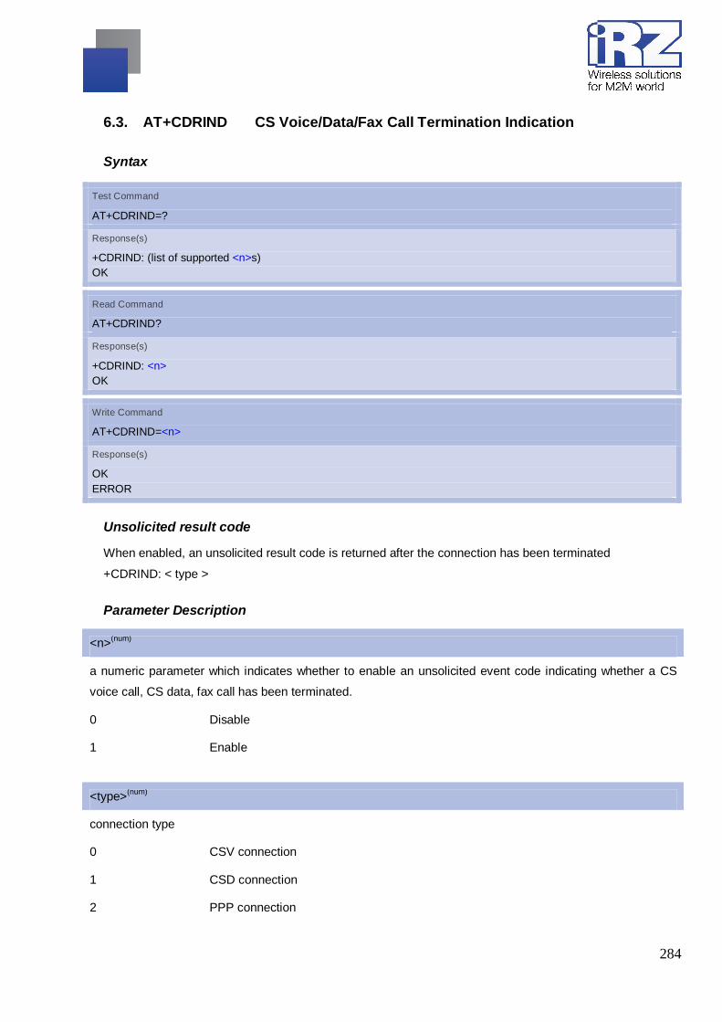
284
6.3. AT+CDRIND CS Voice/Data/Fax Call Termination Indication
Syntax
Test Command
AT+CDRIND=?
Response(s)
+CDRIND: (list of supported <n>s) OK
Read Command
AT+CDRIND?
Response(s)
+CDRIND: <n> OK
Write Command
AT+CDRIND=<n>
Response(s)
OK ERROR
Unsolicited result code
When enabled, an unsolicited result code is returned after the connection has been terminated
+CDRIND: < type >
Parameter Description
<n>(num)
a numeric parameter which indicates whether to enable an unsolicited event code indicating whether a CS
voice call, CS data, fax call has been terminated.
0 Disable
1 Enable
<type>(num)
connection type
0 CSV connection
1 CSD connection
2 PPP connection

285
6.4. AT+CIFSR Get Local IP Address
Syntax
Test Command
AT+CIFSR=?
Response(s)
OK
Exec Command
AT+CIFSR
Response(s)
<IP address> ERROR
Parameter Description
<IP address>(str)
a string parameter(string should be included in quotation marks) which indicates the IP address assigned
from GPRS or CSD
Note
Only at the status of activated the moving scene: IP GPRSACT、TCP/UDP CONNECTING、CONNECT
OK、IP CLOSE can get local IP Address by AT+CIFSR, otherwise response ERROR.

286
6.5. AT+CIICR Bring Up Wireless Connection With GPRS Or CSD
Syntax
Test Command
AT+CIICR=?
Response(s)
OK
Exec Command
AT+CIICR
Response(s)
OK ERROR
Notes
AT+CIICR only activates moving scene at the status of IP START, after operating this Command, the state
will be changed to IP CONFIG.
After module accepting the activated operation, if activate successfully, the state will be changed to IP
GPRSACT, response OK, otherwise response ERROR.

287
6.6. AT+CIPACK Query Previous Connection Data Transmitting State
Syntax
Test Command
AT+CIPACK=?
Response(s)
OK
Exec Command
If in single IP connection (+CIPMUX=0) AT+CIPACK
Response(s)
+CIPACK: <txlen>, <acklen>, <nacklen>
Write Command
If in multi IP connection (+CIPMUX=1) AT+CIPACK=<n>
Response(s)
+CIPACK: <txlen>, <acklen>, <nacklen> OK
Parameter Description
<n>
a numeric parameter which indicates the connection number
<txlen>
the data amount which has been sent
<acklen>
the data amount confirmed successful by the server
<nacklen>
the data amount without confirmed by the server

288
6.7. AT+CIPATS Set Auto Sending Timer
Syntax
Test Command
AT+CIPATS=?
Response(s)
+CIPATS: (list of supported <mode>s),(list of supported <time>) OK
Read Command
AT+CIPATS?
Response(s)
+CIPATS: <mode>,<time> OK
Write Command
AT+CIPATS=<mode>[,<time>]
Response(s)
OK ERROR
Parameter Description
<mode>(num)
a numeric parameter which indicates whether set timer
when sending data
0 not set timer when sending data
1 Set timer when sending data
<time>(num)
0..100 a numeric parameter which indicates the seconds after which the data will be sent

289
6.8. AT+CIPCCFG Configure Transparent Transfer mode
Syntax
Test Command
AT+CIPCCFG=?
Response(s)
+CIPCCFG: (NmRetry:3-8),(WaitTm:2-10),(SendSz:1-1460),(esc:0,1) OK
Read Command
AT+CIPCCFG?
Response(s)
+CIPCCFG: <NmRetry>,<WaitTm>,<SendSz>,<esc> OK
Write Command
AT+CIPCCFG=<NmRetry>,<WaitTm>,<SendSz>,<esc>
Response(s)
OK ERROR
Parameter Description
<NmRetry>(num)
number of retries to be made for an IP packet.
<WaitTm>(num)
number of 200ms intervals to wait for serial input before sending the packet.
<SendSz>(num)
size in bytes of data block to be received from serial port before sending.
<esc>
whether turn on the escape sequence, default is TRUE.
Note
This command will be effective only in single connection mode (+CIPMUX=0)

290
6.9. AT+CIPCLOSE Close TCP Or UDP Connection
Syntax
Test Command
AT+CIPCLOSE=?
Response(s)
OK
Read Command
AT+CIPCLOSE
Response(s)
If close successfully: CLOSE OK If close fail: ERROR
Write Command
1) If single IP connection (+CIPMUX=0) AT+CIPCLOSE=<id> 2) If multi IP connection (+CIPMUX=1) AT+CIPCLOSE=<n><id>
Response(s)
1) If single IP connection (+CIPMUX=0) CLOSE OK 2) If multi IP connection (+CIPMUX=1) <n>, CLOSE OK
Parameter Description
<id>(num)
0 slow close (default)
1 quick close
<n>(num)
a numeric parameter which indicates the connection number
Note
AT+CIPCLOSE only close connection at the status of TCP/UDP CONNECTING or CONNECT OK,
otherwise response ERROR, after closing the connection, the status is IP CLOSE when in single IP mode
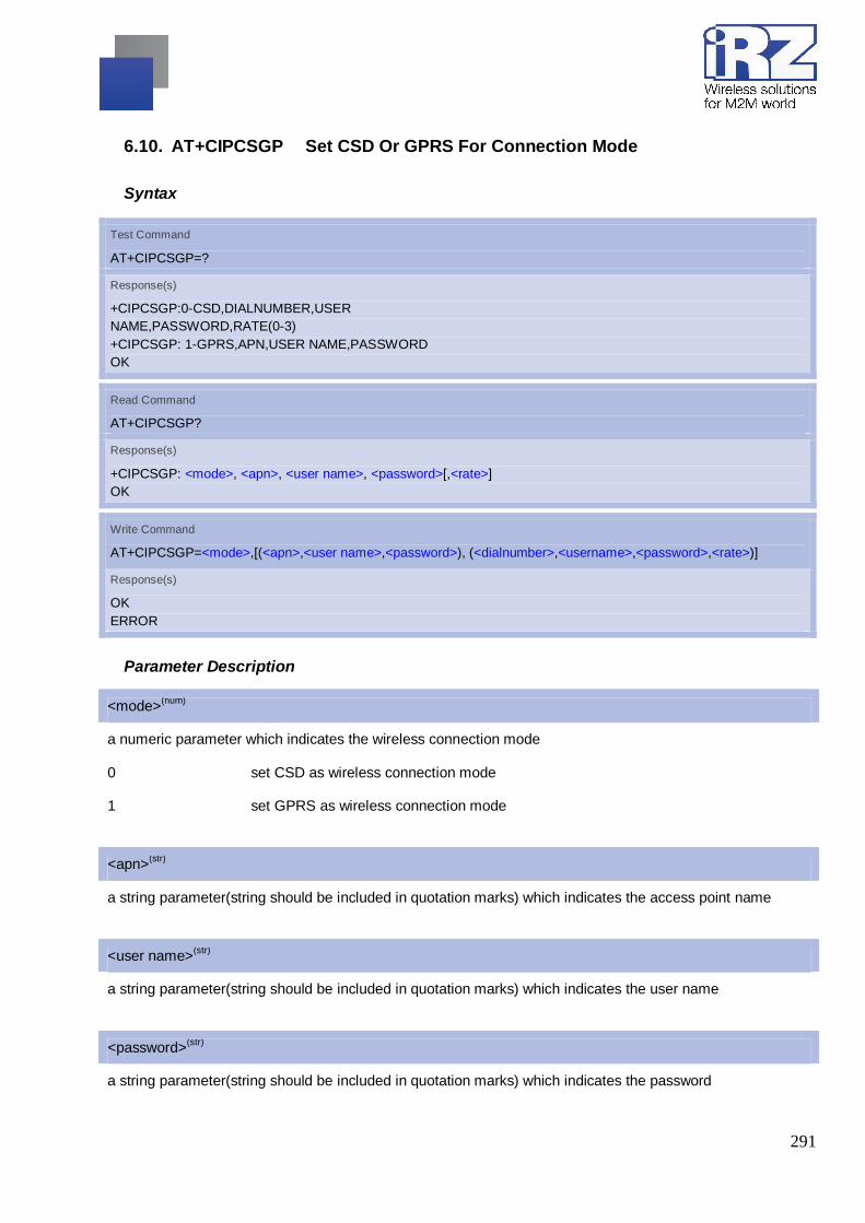
291
6.10. AT+CIPCSGP Set CSD Or GPRS For Connection Mode
Syntax
Test Command
AT+CIPCSGP=?
Response(s)
+CIPCSGP:0-CSD,DIALNUMBER,USER NAME,PASSWORD,RATE(0-3) +CIPCSGP: 1-GPRS,APN,USER NAME,PASSWORD OK
Read Command
AT+CIPCSGP?
Response(s)
+CIPCSGP: <mode>, <apn>, <user name>, <password>[,<rate>] OK
Write Command
AT+CIPCSGP=<mode>,[(<apn>,<user name>,<password>), (<dialnumber>,<username>,<password>,<rate>)]
Response(s)
OK ERROR
Parameter Description
<mode>(num)
a numeric parameter which indicates the wireless connection mode
0 set CSD as wireless connection mode
1 set GPRS as wireless connection mode
<apn>(str)
a string parameter(string should be included in quotation marks) which indicates the access point name
<user name>(str)
a string parameter(string should be included in quotation marks) which indicates the user name
<password>(str)
a string parameter(string should be included in quotation marks) which indicates the password

292
<dial number>(str)
a string parameter(string should be included in quotation marks) which indicates the CSD dial numbers
<user name>(str)
a string parameter(string should be included in quotation marks) which indicates the CSD user name
<password>(str)
a string parameter(string should be included in quotation marks) which indicates the CSD password
<rate>(num)
a numeric parameter which indicates the CSD connection rate
0 2400
1 4800
2 9600 (default)
3 14400

293
6.11. AT+CIPHEAD Add An IP Head When Receiving Data
Syntax
Test Command
AT+CIPHEAD=?
Response(s)
+CIPHEAD: (list of supported <mode>s) OK
Read Command
AT+CIPHEAD?
Response(s)
+CIPHEAD: <mode> OK
Write Command
AT+CIPHEAD=<mode>
Response(s)
OK ERROR
Parameter Description
<mode>(num)
a numeric parameter which indicates whether adding an IP header to received data or not
0 not add IP header
1 add IP header, the format is “+IPD,data length:”

294
6.12. AT+CIPMODE Select TCPIP Application Mode
Syntax
Test Command
AT+CIPMODE=?
Response(s)
+CIPMODE 0-NORMAL MODE,1-TRANSPARENT MODE) OK
Read Command
AT+CIPMODE?
Response(s)
+CIPMODE: <mode> OK
Write Command
AT+CIPMODE=<mode>
Response(s)
OK ERROR
Parameter Description
<mode>(num)
0 normal mode
1 transparent mode

295
6.13. AT+CIPMUX Start Up Multi-IP Connection
Syntax
Test Command
AT+CIPMUX=?
Response(s)
+CIPMUX: (0,1) OK
Read Command
AT+CIPMUX?
Response(s)
+CIPMUX: <n> OK
Write Command
AT+CIPMUX=<n>
Response(s)
OK
Parameter Description
<n>(num)
0 Single IP connection
1 Multi IP connection
Notes
Only in IP initial state, AT+CIPMUX=1 is effective;
Only when multi IP connection and GPRS application are both shut down, AT+CIPMUX=0 is effective

296
6.14. AT+CIPQSEND Select Data Transmitting Mode
Syntax
Test Command
AT+CIPQSEND=?
Response(s)
+CIPQSEND: (0,1) OK
Read Command
AT+CIPQSEND?
Response(s)
+CIPQSEND: <n> OK
Write Command
AT+CIPQSEND=<n>
Response(s)
OK
Parameter Description
<n>(num)
0 Normal mode – when the server receives TCP data, it will response SEND OK
1 Quick send mode – when the data is sent to module, it will response DATA ACCEPT,
while not response SEND OK

297
6.15. AT+CIPSEND Send Data Through TCP Or UDP Connection
Syntax
Test Command
AT+CIPSEND=?
Response(s)
1) If single IP connection (+CIPMUX=0) +CIPSEND: <length> OK 2) If multi IP connection (+CIPMUX=1) +CIPSEND: <0-7>,<length> OK
Read Command
AT+CIPSEND?
Response(s)
1) If single IP connection (+CIPMUX=0) +CIPSEND:<size> OK 2) If multi IP connection (+CIPMUX=1) +CIPSEND:<n><size> OK
Exec Command
AT+CIPSEND response ”> ”, then type data for send, tap CTRL+Z to send, tap ESC to cancel the operation
Response(s) This Command is used to send changeable length data. If single IP connection (+CIPMUX=0) If connection is not established or disconnection: +CME ERROR <err> If sending successfully: When +CIPQSEND=0 SEND OK When +CIPQSEND=1 DATA ACCEPT:<length> If sending fail: SEND FAIL Note This Command can only be used in single IP connection mode (+CIPMUX=0) and to send data on the TCP or UDP connection that has been established already. Ctrl-Z is used as a termination symbol. ESC is used to cancel sending data. There are at most <size> bytes that can be sent at a time.

298
Write Command
If single IP connection (+CIPMUX=0) +CIPSEND=<length> 2) If multi IP connection (+CIPMUX=1) +CIPSEND=<n>[,<length>]
Response(s)
This Command is used to send changeable length data If single IP connection (+CIPMUX=0) If connection is not established or disconnection: +CME ERROR <err> If sending successfully: When +CIPQSEND=0 SEND OK When +CIPQSEND=1 DATA ACCEPT:<length> If sending fail: SEND FAIL If multi IP connection (+CIPMUX=1) If connection is not established or disconnection: +CME ERROR <err> If sending successfully: When +CIPQSEND=0 <n>,SEND OK When +CIPQSEND=1 DATA ACCEPT:<n>,<length> If sending fail: <n>,SEND FAILParameter
Parameter Description
<n>(num)
a numeric parameter which indicates the connection number
<size>(num)
a numeric parameter which indicates the data length sent at a time
<length>(num)
a numeric parameter which indicates the length of sending data, it must less than <size>

299
Notes
The data length which can be sent depends on network status.Set the time that send data automatically
with the Command of AT+CIPATS.
Only send data at the status of established connection

300
6.16. AT+CIPSERVER Configure As Server
Syntax
Test Command
AT+CIPSERVER=?
Response(s)
+CIPSERVER: (0-CLOSE SERVER, 1-OPENSERVER),(1,65535) OK
Read Command
AT+CIPSERVER?
Response(s)
+CIPSERVER: <mode>[,<port>,<channel id>,<bearer>] OK
Write Command
AT+CIPSERVER=<mode>[,<port>]
Response(s)
OK ERROR
Parameter Description
<mode>(num)
0 close server
1 open server
<port>(num)
1..65535 Listening port
<channel id>
channel id
<bearer>
GPRS bearer

301
Note
This command is allowed to establish a TCP server only when the state is IP INITIAL or IP STATUS when
it is in single state. In multi-IP state, the state is in IP STATUS only.
6.17. AT+CIPSHOWTP Display transfer protocol in IP head when receiving data
Syntax
Test Command
AT+CIPSHOWTP=?
Response(s)
+CIPSHOWTP: (list of supported <mode>s) OK
Read Command
AT+CIPSHOWTP?
Response(s)
+CIPSHOWTP: <mode> OK
Write Command
AT+CIPSHOWTP=<mode>
Response(s)
OK ERROR
Parameter Description
<mode>(num)
a numeric parameter which indicates whether display transfer protocol in IP header to received data or not
0 does not display transfer protocol
1 display transfer protocol, the format is “+IPD, <dataSize>, <TCP/UDP>: <data>”
Note
Only when +CIPHEAD set to 1,the setting of this command would work

302
6.18. AT+CIPSHUT Deactivate GPRS PDP Context
Syntax
Test Command
AT+CIPSHUT=?
Response(s)
OK
Exec Command
AT+CIPSHUT
Response(s)
If close successfully: SHUT OK If close fail: ERROR Note Except at the status of IP INITIAL, you can close moving scene by AT+CIPSHUT. After closed, the status is IP INITIAL.
Note
If this command executed in multi-connection mode, all of the IP connection will be shut

303
6.19. AT+CIPSPRT Set Prompt Of ‘>’ When Sending Data
Syntax
Test Command
AT+CIPSPRT=?
Response(s)
+CIPSPRT: (<send prompt>s) OK
Read Command
AT+CIPSPRT?
Response(s)
+CIPSPRT: <send prompt> OK
Write Command
AT+CIPSPRT=<send prompt>
Response(s)
OK ERROR
Parameter Description
<send prompt>(num)
a numeric parameter which indicates whether echo prompt ‘>’ after issuing AT+CIPSEND Command
0 no prompt and show “send ok” when send successfully
1 echo ‘>’ prompt and show “send ok” when send successfully
2 no prompt and not show “send ok” when send successfully

304
6.20. AT+CIPSRIP Set Whether Display IP Address And Port Of Sender When Receive Data
Syntax
Test Command
AT+CIPSRIP=?
Response(s)
+CIPSRIP: (list of supported <mode>s) OK
Read Command
AT+CIPSRIP?
Response(s)
+CIPSRIP: <mode> OK
Write Command
AT+CIPSRIP=<mode>
Response(s)
OK ERROR
Parameter Description
<mode>(num)
a numeric parameter which indicates whether show the prompt of where the data received are from or not
before received data.
0 do not show the prompt
1 show the prompt, the format is as follows: RECV FROM:<IP ADDRESS>:<PORT>
Note that the default mode is not to show the prompt.

305
6.21. AT+CIPSTART Start Up TCP Or UDP Connection
Syntax
Test Command
AT+CIPSTART=?
Response(s)
1) If AT+CIPMUX=0 +CIPSTART: (list of supported <mode>),IP address range,(port range) +CIPSTART: (list of supported <mode>),(domain name),(port range) OK 2) If AT+CIPMUX=1 +CIPSTART: (list of supported <n>),(list of supported <mode>),IP address range,(port range) +CIPSTART: (list of supported <n>),(list of supported <mode>),(domain name),(port range) OK
Read Command
1)If single IP connection (+CIPMUX=0) +CIPSTART=<mode>,<IP address>,<port> Or +CIPSTART=<mode>,<domain name>,<port> 2)If multi-IP connection (+CIPMUX=1) +CIPSTART=<n>,<mode>,<address>,<port> +CIPSTART=<n>,<mode>,<domainname>,<port>
Response(s)
1) If single IP connection (+CIPMUX=0) If format is right response OK, otherwise response +CME ERROR <err> If connection exists, response ALREAY CONNECT If connected successfully response CONNECT OK Otherwise STATE: <state> CONNECT FAIL 2) If multi-IP connection (+CIPMUX=1) If format is right response OK, otherwise response +CME ERROR <err> If connection exists, response <n>,ALREAY CONNECT If connected successfully response <n>,CONNECT OK Otherwise <n>,CONNECT FAIL

306
Parameter Description
<n>(num)
0..7 a numeric parameter which indicates the connection number
<mode>(str)
a string parameter(string should be included in quotation
marks) which indicates the connection type
“TCP” Establish a TCP connection
“UDP” Establish a UDP connection
<IP address>(str)
a string parameter(string should be included in quotation marks) which indicates remote server IP address
<port>
remote server port
<domain name>(str)
a string parameter(string should be included in quotation marks) which indicates remote server domain name

307
<state>(str)
a string parameter(string should be included in quotation marks) which indicates the progress of connecting
0 IP INITIAL
1 IP START
2 IP CONFIG
3 IP GPRSACT
4 IP STATUS
5 TCP CONNECTING/UDP
CONNECTING/SERVER LISTENING
6 CONNECT OK
7 TCP CLOSING/UDP CLOSING
8 TCP CLOSED/UDP CLOSED
9 PDP DEACT
In Multi-IP state:
0 IP INITIAL
1 IP START
2 IP CONFIG
3 IP GPRSACT
4 IP STATUS
5 IP PROCESSING
9 PDP DEACT
Notes
This command is allowed to establish a TCP/UDP connection only when the state is IP INITIAL or IP
STATUS when it is in single state. In multi-IP state, the state is in IP STATUS only. So it is necessary to
process “AT+CIPSHUT” before establish a TCP/UDP connection with this command when the state is not
IP INITIAL or IP STATUS.
When in multi-IP state, before executing this command, it is necessary to process” AT+CSTT, AT+CIICR,
AT+CIFSR”

308
6.22. AT+CIPSTATUS Query Current Connection Status
Syntax
Test Command
AT+CIPSTATUS=?
Response(s)
OK
Read Command
AT+CIPSTATUS
Response(s)
1)If single connection mode (+CIPMUX=0) OK STATE: <state> 2) If multi-connection mode (+CIPMUX=1) OK STATE: <state> If the module is set as server S: 0, <bearer>, <port>, <server state> C: <n>,<bearer>, <TCP/UDP>, <IP address>, <port>, <client state>
Parameter Description
<n>(num)
0..7 a numeric parameter which indicates the connection number
<bearer>
0-1 GPRS bearer, default is 0
<server state>
OPENING
LISTENING
CLOSING

309
<client state>
INITIAL
CONNECTING
CONNECTED
CLOSING
CLOSED
<state>(str)
a string parameter(string should be included in quotation marks) which indicates the progress of connecting
0 IP INITIAL
1 IP START
2 IP CONFIG
3 IP GPRSACT
4 IP STATUS
5 TCP CONNECTING/UDP
CONNECTING/SERVER LISTENING
6 CONNECT OK
7 TCP CLOSING/UDP CLOSING
8 TCP CLOSED/UDP CLOSED
9 PDP DEACT
In Multi-IP state:
0 IP INITIAL
1 IP START
2 IP CONFIG
3 IP GPRSACT
4 IP STATUS
5 IP PROCESSING
9 PDP DEACT

310
6.23. AT+CSPN Get Service Provider Name From SIM
Syntax
Test Command
AT+CSPN?
Response(s)
+CSPN: <spn>,<display mode> OK +CME ERROR: <err>
Parameter Description
<spn>(str)
string type(string should be included in quotation
marks);
service provider name on SIM
<display mode>(num)
0 don’t display PLMN. Already registered on PLMN
1 display PLMN
Note
CME errors if SIM not inserted.

311
6.24. AT+CSTT START Task And Set APN, USER NAME, PASSWORD
Syntax
Test Command
AT+CSTT=?
Response(s)
+CSTT: "APN","USER","PWD" OK
Read Command
AT+CSTT?
Response(s)
+CSTT: <apn>,<user name>,<password> OK
Write Command
AT+CSTT=<apn>,<user name>,<password>
Response(s)
OK ERROR
Exec Command
AT+CSTT=<apn>,<user name>,<password>
Response(s)
OK ERROR
Parameter Description
<apn>(str)
a string parameter(string should be included in quotation marks) which indicates the GPRS access point
name
<user name>(str)
a string parameter(string should be included in quotation marks) which indicates the GPRS user name
<password>(str)
a string parameter(string should be included in quotation marks) which indicates the GPRS password

312
Note
The write command and execution command of this command is valid only at the state of IP INITIAL. After
operating this command, the state will be changed to IP START.

313
6.25. AT^SICI Internet Connection Information
The AT^SICI read command requests the current status of the Internet connection profiles currently defined
with AT^SICS.
The AT^SICI write command displays the status of the specified Internet connection profile. If the
connection profile is not defined yet, the command returns a "+CME ERROR" response.
Syntax
Test Command
AT^SICI=?
Response(s)
[^SICI:(list of defined <conProfileId>s)] OK
Read Command
AT^ SICI?
Respones(s)
OK ERROR
Exec Command
AT^SICI=<conProfileId>
Respones(s)
^SICI: <conProfileId>, <conState>, <numServices>, <conAddr> OK ERROR +CME ERROR: <err>
PIN ASC0 MUX1 MUX2 MUX3 A Last - + + + + - -
Parameter Description
<conProfileId>(num)
Internet connection profile identifier as defined by AT^SICS (<conProfileId>).
0…5

314
<conState>(num)
State of the Internet connection profile.
0 Down - Internet connection is defined but not connected.
1 Connecting - A service has been opened and so the Internet connection is ini-
tated.
2 Up - Internet connection is established and usable by one or more services.
3 Limited Up - Internet connection is established, but temporarily no network cov-
erage.
This state applies only to GPRS profiles (it does not occur with CSD).
4 Closing - Internet connection is terminating.
<numServices>(num)
Number of services using this Internet connection profile.
0…9
<conAddr>(str)
Local IP address of the Internet connection profile (empty if no address is associated yet).
Notes
Before opening a service profile based on a connection profile recently used, check with AT^SICI that the
previous connection was properly closed. If AT^SICI confirms that the connection profile is in <conState>0
(Down) the connection profile may be used again.
If AT^SICI is used simultaneously on different instances (e.g. Mux channels) only one request can be
handled at a time. On the other instance(s) "+CME ERROR: operation temporary not allowed" will be
displayed. If so, repeat the command on this instance.
After closing the last service which uses this connection profile, parameter value <numServices> is
decreased after the expiry of the inactivity timeout "inactTO" of AT^SICS only.
6.25.1. Checking Connection Profile Status
at^sici? Query the current status of the connection profile. ^SICI: 1,2,1,"10.10.0.161" One connection profile has been created at <conProfileId>=1, and one service is
opened using this connection profile. The Internet connection is in <conState>=2 ("Up").
Assume the network connection is temporarily not available. (If URC presentation mode of network
registration is enabled the state is shown by the URC "+CREG: 2").

315
at^sici? Query the current status of the connection profile. ^SICI: 1,2,1,"10.10.0.161" One connection profile has been created at <conProfileId>=1, and one service is
opened using this connection profile. The Internet connection is in <conState>=2 ("Up").
Assume the network connection is temporarily not available. (If URC presentation mode of network
registration is enabled the state is shown by the URC "+CREG: 2").
at^sici? Query once again the current status of the connection profile. ^SICI: 1,3,1,"10.10.0.161" Parameter <conState> has changed to state "Lim-ited up". OK
The network connection is temporarily not available but the Internet connection is still established, so the
host may decide to stop the data transfer to minimize the risk of losing data due to memory limitations.
at^sici? Query once again the current status of the connection profile. ^SICI: 1,2,1,"10.10.0.161" After re-establishing the network connection, <conState> reverts to state "Up". OK
Another service has been opened with AT^SISO:
at^sici? Query once again the current status of the connection profile. ^SICI: 1,2,2,"10.10.0.161" After opening another service, parameter <numServices> has increased. OK
After closing one service with AT^SISC:
at^sici? Query once again the current status of the connection profile. ^SICI: 1,2,1,"10.10.0.161" Parameter <numServices> has decreased. OK
After closing the last service with AT^SISC:
at^sici? Query once again the current status of the connection profile. ^SICI: 1,2,1,"10.10.0.161" The bearer is still open because of the inactivity timeout "inactTO" of AT^SICS. OK at^sici? Query again the current status. ^SICI: 1,0,0,"0.0.0.0" The inactivity timeout "inactTO" of AT^SICS has expired, therefore the bearer is
closed now. Parameter <numServices> has decreased. OK

316
6.26. AT^SICS Internet Connection Setup Profile
AT^SICS serves to create and edit Internet connection profiles. A connection profile can be assigned to one
or more service profiles defined with AT^SISS, and thus, determines which type of connection is to be
established when opening a service profile with AT^SISO.
The AT^SICS read command requests the current settings of all Internet connection profiles. One line is
issued for every possible parameter of a given <conParmTag> "conType" value.
The AT^SICS write command specifies all parameters of a connection profile identified by <conProfileId>.
At first the type of Internet connection needs to be selected via <conParmTag> value "conType". This
determines the applicability of all other <conParmTag> values related to this "conType" and automatically sets
their defaults. An exception is the <conParmValue-alphabet> which can be set before or after selecting
"conType".
To change the settings the write command needs to be executed for each single <conParmTag>. All profile
parameters set with AT^SICS are volatile.
MG21 supports the authentication methods PAP (Password Authentication Protocol), CHAP (Handshake
Authentication Protocol) or none. The method actually used for an Internet connection via CSD or GPRS is
negotiated at the LCP layer, i.e. it is negotiated with the remote peer at connection setup.
Table: Applicability of AT^SICS <conParmTag> values
<conParmTag> value CSD GPRS0
"conType" mandatory mandatory
"user" optional optional
"passwd" optional optional
"apn" ø mandatory
"inactTO" optional optional
"calledNum" mandatory ø
"dataType" mandatory ø
"dns1" optional optional
"dns2" optional optional
"alphabet" optional optional

317
Syntax
Test Command
AT^SICS=?
Response(s)
OK
Read Command
AT^ SICS?
Respones(s)
^SICS: <conProfileId>, <conParmTag>, <conParmValue> OK
Write Command
AT^SICS=<conProfileId>, <conParmTag>, <conParmValue>
Respones(s)
OK ERROR +CME ERROR: <err>
PIN ASC0 MUX1 MUX2 MUX3 A Last - + + + + - -
Parameter Description
<conProfileId>(num)
0…5 Internet connection profile identifier.
The <conProfileId> identifies all parameters of a connection profile, and, when a
service profile is created with AT^SISS the <conProfileId> needs to be set as
"conId" value of the AT^SISS parameter <srvParmTag>.
<conParmTag>(str)
Internet connection parameter
“conType“ Type of Internet connection.
For supported values of <conParmValue> refer to <conParmValue-conType>.
“alphabet“ Selects the character set for input and output of string parameters within a pro-file.
The selected value is bound to the specific profile. This means that different
profiles may use different alphabets. Unlike other parameters the alphabet can be
changed no matter whether the <conParmTag> value "conType" has been set.
For supported values of <conParmValue> refer to <conParmValue-alphabet>.
“user“ User name string: maximum 32 characters (where "" is default).

318
“passwd“ Password string: maximum 32 characters (where ***** is default).
“apn“ Access point name string value: maximum 100 characters (where "" is default).
“inactTO“ Inactivity timeout value in seconds: 0 ... 216-1, default = 20
Number of seconds the bearer remains open although the service no longer needs
the bearer connection.
Do not set the timeout value below 3 sec. This may result in problems when using
the <eodFlag> (set in the last AT^SISW command to terminate an upload data
stream).
“calledNum“ Called BCD number.
“dataType“ Data call type.
For supported values of <conParmValue> refer to <conParmValue-dataType>.
“dns1“ Primary DNS server address (IP address in dotted-four-byte format).
This value determines whether to use the DNS server addresses dynamically
assigned by the network or a specific DNS server address given by the user.
"dns1" = "0.0.0.0" (default) means that the CSD or GPRS connection profile uses
dynamic DNS assignment. Any other address means that the Primary DNS is
manually set.
The default value applies automatically if no other address is set. Note that the
AT^SICS read command only returns a manually configured IP address, while the
value "0.0.0.0" is not indicated at all, no matter whether assumed by default or
explicitly specified. See also note below.
“dns2“ Secondary DNS server address (IP address in dotted-four-byte format).
If "dns1" = "0.0.0.0" this setting will be ignored. Otherwise this value can be used to
manually configure an alternate server for the DNS1.
If "dns1" is not equal "0.0.0.0" and no "dns2" address is given, then
"dns2"="0.0.0.0" will be assumed automatically. The AT^SICS read command only
returns a manually configured IP address, while the value "0.0.0.0" is not indicated
at all, no matter whether assumed by default or explicitly specified.
<conParmValue>(str)
Parameter value; type and supported content depend on related <conParmTag>.

319
<conParmValue-conType>(str)
Supported connection type values in <conParmValue> for <conParmTag> value "conType".
“CSD“ Circuit-switched data call.
“GPRS0“ GPRS connection.
Settings of GPRS related commands are not used, e.g. AT+CGDCONT. When a
service based on a GPRS connection profile is started after entering AT^SISO
MG21 automatically tries to attach to the GPRS. Yet, the only exception is
AT+CGATT which can be used any time to detach from the GPRS and thus dis-
connect the bearer opened with AT^SISO.
“none“ Clears the connection profile.
<conParmValue-alphabet>(str)
Character set selectable with <conParmValue> for <conParmTag> value "alphabet".
[“0“] Character set determined with AT+CSCS applies.
“1“ International Reference Alphabet (IRA, seven bit ASCII) applies.
<conParmValue-dataType>(str)
Supported data call type values in <conParmValue> for <conParmTag> value "dataType".
[“0“] ISDN
“1“ Analog
Notes
Before opening a service profile based on a connection profile recently used, check with AT^SICI that the
previous connection was properly closed. If AT^SICI confirms that the connection profile is in <conState> 0
(Down) the connection profile may be used again.
If a GPRS network does not support or is not correctly configured for automatic DNS address assignment
the TCP/IP stack cannot resolve fully qualified domain names. In this case, a warning message will be
returned when trying to open an Internet service configured for automatic DNS address assignment.
6.26.1. Example: Default values of a CSD connection profile
As stated earlier, the "conType" selected with AT^SICS determines all other matching profile parameters
related to this "conType". Once "conType" is set in a new profile, the default values of all other related
parameters are assumed. To view the default settings you can use the read command AT^SICS?.

320
at^sics=1,conType,CSD Select connection type CSD, identified by <conProfileId>1 OK at^sics? Query current profiles. ^SICS: 0, "conType", "" Profile with <conProfileId> 0 is still empty. ^SICS: 1, "conType", "CSD" The new CSD profile just created is indicated with all related parameters set to
their default. ^SICS: 1, "alphabet", "0" Character set determined with AT+CSCS applies when string parameters are
input with AT^SICS. ^SICS: 1, "user", "" No user name set. ^SICS: 1, "passwd", "*****" Password masked with asteriks. ^SICS: 1, "inactTO", "20" Inactivity timeout = 20s. ^SICS: 1, "calledNum", "" No destination set. ^SICS: 1, "dataType", "1" Remote device is analog, e.g. an analog modem. ^SICS: 2, "conType", "" Profile with <conProfileId> 2 is still empty. ^SICS: 3, "conType", "" Profile with <conProfileId> 3 is still empty. ^SICS: 4, "conType", "" Profile with <conProfileId> 4 is still empty. ^SICS: 5, "conType", "" Profile with <conProfileId> 5 is still empty. OK
6.26.2. Example: GPRS connection profile
at^sics=0,conType,GPRS0 OK
Select connection type GPRS0.
AT^SICS=0,"inactTO", "20" OK
Inactivity timeout = 20s.
AT^SICS=0,dns1,"193.254.160.1" IP address of Primary DNS server. OK AT^SICS=0,passwd,t-d1 Password for GPRS services provided by the Ger-man operator T-D1. OK AT^SICS=0,apn,"internet.t-d1.de" APN to access the GPRS services provided by the German operator T-D1. OK

321
6.27. AT^SISI Internet Service Information
AT^SISI serves to monitor the status of Internet service profiles defined with AT^SISS.
The AT^SISI read command requests the current status of all defined Internet service profiles.
The AT^SISI write command requests the status of the specified Internet service profile. If the specified
service profile is not defined yet, "+CME ERROR" is returned.
Test Command
AT^SISI=?
Response(s)
[^SISI:(list of defined <srvProfileId>s)] OK
Read Command
AT^ SISI?
Respones(s)
If response is related to service profile(s) created / opened on this interface: [^SISI: <srvProfileId>, <srvState>, <rxCount>, <txCount>, <ackData>, <unackData>] [^SISI: ...] If response is related to service profile(s) created / opened on other interface(s): [^SISI: <srvProfileId>, <srvParmTag>value "srvType"] [^SISI: ...] OK ERROR
Exec Command
AT^SISI=<srvProfileId>
Respones(s)
^SISI: <srvProfileId>, <srvState>, <rxCount>, <txCount>, <ackData>, <unackData> OK ERROR +CME ERROR: <err>
PIN ASC0 MUX1 MUX2 MUX3 A Last - + + + + - -

322
Parameter Description
<srvProfileId>(num)
Internet service profile identifier as defined by AT^SISS (<srvProfileId>).
0…9
<srvState>(num)
Internet service state (for details see AT^SISO parameter <srvState>).
2 Allocated
3 Connecting
4 Up
5 Closing
6 Down
<rxCount>(num)
Number of bytes received via AT^SISR or AT^SIST since last successful AT^SISO write command. This is
the same value as displayed by the AT^SISO read command with the parameter <rxCount>.
<txCount>(num)
Number of bytes sent via AT^SISW or AT^SIST since last successful AT^SISO write command. This is the
same value as displayed by the AT^SISO read command with the parameter <txCount>.
<ackData>(num)
Number of data bytes already sent and acknowledged at TCP layer. Value 0 indicates that no sent data is
acknowledged yet.
Parameter is not applicable to HTTP, POP3, SMTP and Socket with UDP. For these services the counter is
always set to 0.
<unackData>(num)
Number of data bytes already sent but not yet acknowledged at TCP layer. A value 0 indicates that all sent
data is already acknowledged.
This is the same value as displayed in the response of the AT^SISW write command with the parameter
<unackData>.
Parameter is not applicable to HTTP, POP3, SMTP and Socket with UDP. For these services the counter is
always set to 0.

323
Note
If a service is in state "Down" the responses for <rxCount>, <txCount>, <ackData> and <unackData> are
the last known values for the service in the states "Connecting", "Up" and "Closing".

324
6.28. AT^SISO Internet Service Open
The AT^SISO write command starts the Internet session configured by the service profile. All further steps
needed to control the session depend on whether you are using URC mode or polling mode. The AT^SISO
read command returns the current status of all services.
URC mode:
If the service opens successfully, the URCs "^SISW" and "^SISR" will trigger the action to follow, either
writing data with AT^SISW or reading data with AT^SISR. To terminate an upload data stream set the
<eodFlag> within the last AT^SISW command. If the URCs notify that a data transfer has been successful
("^SISR: x, 2" or "^SISW: x, 2"), the service can be closed with AT^SISC. If a special event occurs, e.g. an error
or a warning, after opening or while using a service then the URC type "^SIS" will be delivered.
Polling mode:
After opening the service, all progress information needed to control the session shall be explicitly
requested by the host application. The particular sequence of AT commands varies depending on the service
used. The following list summarizes, by way of an example, the steps normally involved in managing an upload
or download job.
Upload (Socket, FTP, HTTP,SMTP):
- Enter the AT^SISO command, e.g. AT^SISO=9.
- Enter AT^SISW, specify <reqWriteLength>, e.g. AT^SISW=9,20. Check resulting response for
<cnfWriteLength>. Optionally, check error with AT^SISE, e.g. AT^SISE=9. If necessary, repeat the
sequence several times.
- Enter last AT^SISW command and enable <eodFlag>, e.g. AT^SISW=9,0,1.
- If Socket service: Query available data with AT^SISR, e.g. AT^SISR=9,1430.
- Check service state with AT^SISI, e.g. AT^SISI=9, if necessary several times until <srvState>=6
("Down").
- Check error with AT^SISE, e.g. AT^SISE=9.
- Close service with AT^SISC, e.g. AT^SISC=9.
Download (Socket, FTP, HTTP, POP3):
- Enter the AT^SISO command, e.g. AT^SISO=9.
- Enter AT^SISR, specify <reqReadLength>, e.g. AT^SISR=9,1000. Check resulting response for
<cnfReadLength>. If necessary, repeat the sequence several times until <cnfReadLength>= -2 (end of
data) or ERROR.
- Check error with AT^SISE, e.g. AT^SISE=9.
- Close service with AT^SISC, e.g. AT^SISC=9.

325
Socket service (upload and download possible in one session):
- Recommended: Set AT+CMEE=2 to enable extended error text.
- Enter the AT^SISO command, e.g. AT^SISO=9.
- Enter AT^SISR or AT^SISW, specifying <reqReadLength> or <reqWriteLength>, e.g. AT^SISR=9,20 or
AT^SISW=9,20. Check resulting response for <cnfReadLength> or <cnfWriteLength>. If necessary,
repeat the sequence several times.
- Check error with AT^SISE, e.g. AT^SISE=9.
- If write action: Enter last AT^SISW command and enable <eodFlag>, e.g. AT^SISW=9,0,1. 1) If Socket
service: Query available data with AT^SISR, e.g. AT^SISR=9,1430.
- Close service with AT^SISC, e.g. AT^SISC=9.
Transparent TCP service:
- Enter the AT^SISO command, e.g. AT^SISO=9.
- Enter AT^SIST to enter transparent data mode. After communication has finished return to AT
command mode via +++ escape sequence.
- Check error with AT^SISE, e.g. AT^SISE=9.
- Close service with AT^SISC, e.g. AT^SISC=9.
Syntax
Test Command
AT^SISO=?
Response(s)
OK
Read Command
AT^ SISI?
Respones(s)
^SISO: <srvProfileId>, <srvParmTag>value "srvType" [, <srvState>, <socketState>, <rxCount>, <txCount>, <locAddr>, <remAddr>] [^SISO: ...] OK
Exec Command
AT^SISI=<srvProfileId>
Respones(s)
^SISI: <srvProfileId>, <srvState>, <rxCount>, <txCount>, <ackData>, <unackData> OK ERROR +CME ERROR: <err>
PIN ASC0 MUX1 MUX2 MUX3 A Last ± + + + + - -

326
Parameter Description
<srvProfileId>(num)
<srvProfileId> 0 ... 9 specified with AT^SISS.
<srvState>(num)
Internet service state.
Please note, that the state of an Internet service may influence the state of the serial DCD line. For details
see description of value 2 for parameter <value> of command AT&C.
2 Allocated
Service profile resources are allocated, i.e. at least the service type has been set
(parameter <srvParmTag>, value "srvType" of AT^SISS). The service is not
opened, but ready for configuration.
3 Connecting
State after opening a service with AT^SISO where the connection is being
established.
If connection setup is successful the service proceeds to the state "4" (Up) and one
of the URCs "^SISW" and "^SISR" may follow. If connection setup is not successful,
the "^SIS" URC may appear and the service enters <srvState> 6 (Down).
In the case of FTP, <srvState>=3 means that the command channel is being
established.
If the service profile is configured as Socket listener, then the listener always stays
at <srvState>=3 and <socketState>=3 (LISTENER), while the <srvState> and
<socketState> of the dynamically assigned service pro-file may change.
4 Up
The service performs its purpose. The data transfer process is the major function at
this state.
FTP: Data channel is up.
SMTP: The SMTP service will not enter <srvState>=4 until the host has written the
first data packet with AT^SISW.
5 Closing
Internet Service is closing the network connection.
FTP: Command channel is released.
6 Down
This state is entered if
the service has successfully finished its session (see note on Socket),
the remote peer has reset the connection or
the IP connection has been closed because of an error (see note below on
service or network errors).

327
If a service in this state be sure to close it with AT^SISC before reopening it.
<socketState>(num)
Socket state identifier
0 Same as value "1", but applicable only if service profile is POP3.
1 Socket not assigned, i.e. no TCP/UDP connection active.
2 Socket assigned as CLIENT.
3 Socket assigned as LISTENER.
4 Socket assigned as SERVER.
<rxState>(num)
Number of bytes received via AT^SISR or AT^SIST since last successful AT^SISO write command.
<txState>(num)
Number of bytes sent via AT^SISW or AT^SIST since last successful AT^SISO write command..
<locAddr>(str)
Recently used local IP address in dotted-four-byte format and TCP port, separated by colon, e.g.
"192.60.10.10:80".
<remAddr>(str)
Remote IP address in dotted-four-byte format and TCP port, separated by colon, e.g. "192.60.10.10:80".

328
Notes
If the bearer cannot be established and AT^SISO returns an error there might be a general GSM/GPRS
problem. To identify the reason you can take advantage of the AT+CEER command. Using AT+CEER is
especially recommended when the <infoID> parameter of the AT^SISE command equals 0.
If a service or network error occurs during an IP session and the "^SIS" URC or the AT^SISE command
display an error message, the service enters <srvState>=5 and then 6, i.e. the IP connection is closed. In
this case, the service still allows reading the data stored in the buffer, but writing data is denied. After
reading, close the service and open it again.
As in polling mode no error URCs are available you are advised to integrate the commands AT^SISI and
AT^SISE into the command sequences for upload and download jobs. So, the AT^SISO command may be
followed by AT^SISI to check that the service has entered the <srvState>=4 before sending AT^SISR,
AT^SISW or AT^SIST. This helps you to detect errors even though the "^SIS" URCs are disabled. A typical
example is that the service fails to be opened because the service profile contains a wrong destination
address. In such a case, after opening with AT^SISO and OK response, the service quickly enters the
states <srvState>=2, 4 and 6, with an error being returned no earlier than after sending the first AT^SISR or
AT^SISW command. In URC mode, an error URC, such as "Host not found" would be received in this
situation, but in polling mode the only way to detect the state is using AT^SISI or, alternatively, AT^SISO.
6.28.1. Example: Accepting / Rejecting Socket Connection Request from Remote Client
Host 1 configured as Socket listener with IP address 10.10.0.187 at port 65534 is receiving a connection
request from the remote client 10.10.0.185 (at port 1024). The example assumes that connection and service
profiles have been created as stated earlier.
Start the Socket service in listener mode, then query the IP address dynamically assigned to the Socket
listener:
at^siso=4 at^siso? ^SISO: 0, " " ^SISO: 1, " " ^SISO: 2, " " ^SISO: 3, " "
Host 1 opens the Socket service. Query the current status of all services. All service profiles are unused, except for service profile 4 which is running in listener mode, where <srvState>=3 (listening) and <socketState>=3 (LISTENER). The response also indicates the IP address dynamically assigned to the listener. The listener's access data (IP address and TCP port number) shall be passed on to the client.
^SISO: 4, "Socket","3","3","0","0","10.10.0.187:65534","0.0.0.0:0" ^SISO: 6, "" ^SISO: 7, "" ^SISO: 8, "" ^SISO: 9, "" OK
Indication of incoming Socket connection request:

329
^SIS: 4, 1, 0 at^siso?
The URC indicates that the listener configured on service profile 4 is receiving a Socket connection request (<urcCause>=1) from the remote client. The last URC parameter <urcInfoId> represents the ID of the dynamically assigned service profile, here 0.
at^siso? ^SISO: 0, "Socket","2","4","0","0", "10.10.0.187:0","10.10.0.185:1024" ^SISO: 1, "" ^SISO: 2, "" ^SISO: 3, ""
Query the current status of services. Indication on host 1 that the connection request from the remote client has been dynamically assigned to service profile 0 which is set to Server mode (<socketState>=4).
^SISO: 4, "Socket","3","3","0","0", "10.10.0.187:65534","0.0.0.0:0" ^SISO: 6, "" ^SISO: 7, "" ^SISO: 8, "" ^SISO: 9, "" OK
Host 1 accepts the Socket connection request:
at^siso=0 OK ^SISW: 0, 1
Host 1 accepts the connection request, where 0 is the ID of the dynamically assigned service profile. The URC indicates that data transmission to the remote client is possible. If the remote client has already sent some data the additional URC ^SISR: 0,1 is displayed.
at^siso? ^SISO: 0, "Socket","4","4","0","0", ^SISO: 1, "" ^SISO: 2, "" ^SISO: 3, ""
Query the current status of services. The socket connection between host 1 and remote client is successfully established.
^SISO: 4, "Socket","3","3","0","0","10.10.0.187:65534","0.0.0.0:0" ^SISO: 6, "" ^SISO: 7, "" ^SISO: 8, "" ^SISO: 9, "" OK
Host 1 rejects the Socket connection request:
at^sisc=0 OK at^siso?
Host 1 rejects the connection request, where 0 is the ID of the dynamically assigned service profile. Query the current status of services
^SISO: 0, "" ^SISO: 1, "" ^SISO: 2, "" ^SISO: 3, ""
The dynamically assigned service profile is free again. The Socket listener stays at <srvState>=3 (listening) and <socketState>=3 (LISTENER).
^SISO: 4, "Socket","3","3","0","0","10.10.0.187:65534","0.0.0.0:0" ^SISO: 6, "" ^SISO: 7, "" ^SISO: 8, "" ^SISO: 9, "" OK

330
6.29. AT^SISC Internet Service Close
The AT^SISC write command closes the TCP/IP connection to the remote peer which was opened with
AT^SISO. All resources are released, all status information parameters, e.g. <srvState>, <unackData>,
<ackData>, <rxCount> and <txCount> counters, are reset. Only the initial configuration settings are preserved.
The service can be restarted any time, using the same configuration or a new one.
Syntax
Test Command
AT^ SISC?
Respones(s)
OK
Write Command
AT^SISC=<srvProfileId>
Respones(s)
OK ERROR +CME ERROR: <err>
PIN ASC0 MUX1 MUX2 MUX3 A Last ± + + + + - -
Parameter Description
<srvProfileId>(num)
0…9 <srvProfileId> specified with AT^SISS.

331
6.30. AT^SISE Internet Service Error Report
The AT^SISE write command returns the current error status of the specified Internet service profile. If the
service profile is not defined or the value is invalid "+CME ERROR" response is returned.
The error status is identical to the content of the "^SIS" URC last issued.
If a service fails the commands AT^SISR, AT^SISW or AT^SIST will return an error response. However, if
the AT^SISE command returns <infoID>=0 it is recommended to use the AT+CEER command because a
general GSM/GPRS problem might be the reason.
Syntax
Test Command
AT^ SISE?
Respones(s)
OK
Write Command
AT^SISE=<srvProfileId>
Respones(s)
^SISE: <srvProfileId>, <infoID>[, <info>] OK ERROR +CME ERROR: <err>
PIN ASC0 MUX1 MUX2 MUX3 A Last - + + + + - -
Parameter Description
<srvProfileId>(num)
Internet service profile identifier as defined by AT^SISS <srvProfileId>.
0…9
<infoID>(num)
Reason for Internet service error. This is a subset of the <urcInfoId>s. The value 0 indicates there is no
special Internet service error. In this case the application may use AT+CEER to check for general
GSM/GPRS problems.

332
<info>()
Information text related to <infoID>. This is a subset of the <urcInfoText>s.
Note
In particular cases, the AT^SISE command may deliver information and warnings. This applies the
following services:
FTP: Information 2100
POP3: Warnings
SMTP: Warnings
If an error occurs the information and warning messages are overwritten by error messages.

333
6.31. AT^SISR Internet Service Read Data
The AT^SISR command either triggers a read operation (download) or queries the number of bytes in the
internal buffer.
The AT^SISR write command may return the following errors:
"+CME ERROR: operation failed" if there is a problem on application, socket, PPP or GPRS/GSM level.
The AT^SISE command and the "^SIS" URC offer additional error information.
"+CME ERROR: operation temporary not allowed" e.g. if the service has not network resources allocated.
"+CME ERROR: operation not allowed" e.g. if the service is not configured.
Syntax
Test Command
AT^ SISR?
Respones(s)
OK
Write Command
AT^SISR=<srvProfileId>, <reqReadLength>
Respones(s)
^SISR: <srvProfileId>, <cnfReadLength>[, <remainUdpPacketLength>] Number of data bytes are sent as specified by <cnfReadLength>. If peek operator was used no data bytes are sent. OK ERROR +CME ERROR: <err>
PIN ASC0 MUX1 MUX2 MUX3 A Last ± + + + + - +
Unsolicited Result Code
^SISR: <srvProfileId>, <urcCauseId>
Data availability status of the Internet service configured with AT^SISS has changed. The URC is issued
when:
data is available after opening an Internet service or
less data was confirmed (in <cnfReadLength>) than requested (with <reqReadLength>) during the last
"Read Data" operation and new data is available.
The URC is disabled in polling mode. See AT^SCFG, parameter "Tcp/WithURCs", <tcpWithUrc>.

334
Parameter Description
<srvProfileId>(num)
<srvProfileId> 0 ... 9 specified with AT^SISS.
<reqReadLength>(num)
0 Peek Operator: Query number of received bytes within internal buffers.
The behaviour of the peek operator depends on the selected Internet service, i.e. it
may not be supported by all IP Services.
For "Socket" service configured for UDP the size of the next available UDP packet
is returned.
1…1500 Requested number of data bytes to be read via the Internet service specified in
<srvProfileId>.
<cnfReadLength>(num)
-2 Indicates end of data. Data transfer has been finished (all data have been read)
and the service can be closed with AT^SISC.
-1 Applies only to HTTP: Querying number of available bytes is not supported by the
HTTP service.
0 Indicates that no further data is available at the moment.
>0 Number of available data bytes. The range is determined by <reqReadLength>:
If <reqReadLength> was greater than 0, then <cnfReadLength> may be less or
equal to the value requested with <reqReadLength>.
If <reqReadLength> equals 0 (peek operator) the value indicated by
<cnfReadLength> may be greater than 1500.
<urcCauseId>(num)
Indicates whether or not data is available for reading with AT^SISR.
1 Data is available and can be read by sending the AT^SISR command. The URC
appears when less data was confirmed (in <cnfReadLength>) than requested (with
<reqReadLength>) during the last "Read Data" operation and new data is available.
2 End of data. Data transfer has completed (all data read). The service can be closed
with AT^SISC.

335
<remainUdpPacketLength>(num)
Optional third parameter of the AT^SISR write command response displayed only if the Socket service uses
the UDP protocol.
The reception of each datagram must be completed before the next datagram can be received. This may be
a problem if the buffer of the host application is limited and not designed to handle the maximum packet size
of 1500 bytes. To compensate this, the host is advised to request, via <reqReadLength>, an amount less or
equal its maxmimum buffer capacity and wait for the resulting AT^SISR write command response with
parameter <remainUdpPacketLength>. The benefit of this approach is that the host may properly receive all
parts of a UDP datagram, as after each received data part the number of remaining bytes is synchronized,
until reading the datagram is finished.
If the currently read datagram is smaller than the number of bytes requested by the host the
<remainUdpPacketLength> parameter is omitted.
Further write attempts with AT^SISR are denied as long as the <remainUdpPacketLength> is unequal 0 or is
not omitted. In this case the service returns "+CME ERROR: operation of service temporary not allowed".
0 Indicates that all bytes of the current UDP datagram are read.
1...(max. data size)-1 Indicates that the currently read UDP datagram is not yet complete. The dis-played
value is the remaining number of bytes.
<remainUdpPacketLength> is unequal 0 until reading all parts of the cur-rent
datagram is finished.
6.31.1. Example: Socket Host Reads Small Amounts of UDP Data Packets (URC Mode)
This section applies only to the Socket service using the UDP protocol. The example shows how to read
UDP packets if the buffer of the host application can handle only a few bytes. There are two datagrams
available for reading.
Buffer size: 6 bytes
Datagram A = 18 bytes (content "THIS_IS_DATAGRAM_A")
Datagram B = 3 bytes (content "NEW")
^SISR: 0,1 Service profile 0 is configured for Socket service and UDP. The URC notifies host that data is available for reading.
at^sisr=0,6 The host requests to read 6 bytes. ^SISR: 0,6,12 THIS_I OK
The first 6 bytes of datagram A are confirmed and transmitted. Another 12 bytes are still available.
at^sisr=0,6 The host requests to read the next part of 6 bytes. ^SISR: 0,6,6 S_DATA
The next 6 bytes of datagram A are confirmed and transmitted. Another 6 bytes are still available.
OK at^sisr=0,6 The host requests to read the next part of 6 bytes. ^SISR: 0,6,0 Last part of datagram A was received, no remainder is left.

336
GRAM_A OK at^sisr=0,6 Again, the host requests to read 6 bytes. This time, the request refers to datagram B which
has only 3 bytes. As the read datagram is smaller than the size requested by the host, the response does not include the <remainUdpPacketLength>.
^SISR: 0,3 NEW
3 bytes are confirmed and transmitted. Datagram B was properly received.
OK

337
6.32. AT^SISS Internet Service Setup Profile
AT^SISS serves to set up the necessary parameters in the Internet service profiles. Any service profile can
then be used to control a data link in conjunction with AT^SISI, AT^SISO, AT^SISC, AT^SISR, AT^SISW,
AT^SIST and AT^SISE.
The AT^SISS read command requests the current settings of all Internet service profiles. One line is issued
for every possible parameter of a given <srvParmTag> "srvType" value.
The AT^SISS write command specifies the parameters for a service profile identified by <srvProfileId>. At
first the type of Internet service needs to be selected via <srvParmTag> value "srvType". This determines the
applicability of all other <srvParmTag> values related to this "srvType" and sets their defaults. Changing the
<srvParmTag> "srvType" of an existing service profile will reset all <srvParmTag> default values to suit the
new "srvType". An exception is the <srvParmValue-alphabet> which can be set before or after selecting
"srvType" and is not reset when "srvType" changes.
To change the settings the write command needs to be executed for each single <srvParmTag>. All profile
parameters set with AT^SISS are volatile.
The list below shows which <srvParmTag> parameters apply to each Internet service and which of them
are mandatory or optional.
Table: Applicability of AT^SISS <srvParmTag> values
<srvParmTag> Mandatory or optional
Socket service "srvType" mandatory
"conId" mandatory
"alphabet" optional
"address" mandatory
"tcpMR" optional
"tcpOT" optional
Transparent service "srvType" mandatory
"conId" mandatory
"alphabet" optional
"address" mandatory
"tcpMR" optional
"tcpOT" optional
FTP service

338
"srvType" mandatory
"conId" mandatory
"alphabet" optional
"address" mandatory
"tcpMR" optional
"tcpOT" optional
HTTP service "srvType" mandatory
"conId" mandatory
"alphabet" optional
"address" mandatory
"user" optional
"password" optional
"hcContent" optional
"hcContLen" optional
"hcUserAgent" optional
"hcMethod" mandatory
"hcProp" optional
"hcRedir" optional
"hcAuth" optional
"tcpMR" optional
"tcpOT" optional
SMTP service "srvType" mandatory
"conId" mandatory
"alphabet" optional
"address" mandatory
"user" optional
"password" optional
"tcpPort" optional
"smFrom" mandatory
"smRcpt" mandatory
"smCC" optional
"smSubj" optional
"smHdr" optional
"smAuth" optional
"tcpMR" optional
"tcpOT" optional
POP3 service "srvType" mandatory
"conId" mandatory

339
"alphabet" optional
"address" mandatory
"user" mandatory
"password" mandatory
"tcpPort" optional
"pCmd" mandatory
"pNumber" optional
"pLength" optional
"pDelFlag" optional
"tcpMR" optional
"tcpOT" optional
Syntax
Test Command
AT^SISS=?
Response(s)
OK
Read Command
AT^ SISS?
Respones(s)
^SISS: <srvProfileId>, <srvParmTag>, <srvParmValue> OK ERROR +CME ERROR: <err>
Write Command
AT^SISS=<srvProfileId>, <srvParmTag>, <srvParmValue>
Respones(s)
OK ERROR +CME ERROR: <err>
PIN ASC0 MUX1 MUX2 MUX3 A Last - + + + + - -

340
Parameter Description
<srvProfileId>(num)
Internet service profile identifier.
The <srvProfileId> is used to reference all parameters related to the same service profile. Furthermore, when
using the AT commands AT^SISO, AT^SISR, AT^SISW, AT^SIST and AT^SISC the <srvProfileId> is needed
to select a specific service profile.
0...9
<srvProfileId>(num)
Internet service profile parameter.
srvType Type of Internet service to be configured with consecutive usage of AT^SISS. For
supported values of <srvParmValue> refer to <srvParmValue-srvType>.
alphabet Selects the character set for input and output of string parameters within a pro-file.
The selected value is bound to the specific profile. This means that different profiles
may use different alphabets. Unlike other parameters the alphabet can be changed
no matter whether the <srvParmTag> value "srvType" has been set. For
supported values of <srvParmValue> refer to <srvParmValue-alphabet>.
user User name string
6. Socket
Not applicable.
7. Transparent
Not applicable.
8. FTP
Not applicable; set within "address" parameter.
9. HTTP
Length: 2 ... 31
User name for the HTTP authentication mechanism.
Currently only HTTP simple authentication is supported.
10. SMTP
User name to be used for SMTP authentication (string).
Length: 4 ... 64.
If SMTP authentication is disabled, i.e. "smAuth" flag
not set, user name parameter will be ignored.
11. POP3
User name identifying a mailbox, i.e. mailbox name (string).
Length: 1 ... 64.

341
passwd Password string
1. Socket
Not applicable.
2. Transparent
Not applicable.
3. FTP
Not applicable; set within "address" parameter.
4. HTTP
Length: 2 ... 31 Password for the HTTP authentication mechanism.
Currently HTTP simple authentication is supported only.
5. SMTP
Password to be used for SMTP authentication (string).
Length: 4 ... 64.
If SMTP authentication is disabled, i.e. "smAuth" flag
not set, password parameter will be ignored.
6. POP3
Server/mailbox-specific password (string).
Length: 1 ... 64.
Used to perform authentication with a POP3 server.
conId Internet connection profile to be used, for details refer AT^SICS.
tcpPort TCP Port Number
1. Socket
Not applicable; set within "address" parameter.
2. Transparent
Not applicable; set within "address" parameter.
3. FTP
Not applicable; set within "address" parameter.
4. HTTP
Not applicable; set within "address" parameter.
If parameter is omitted the service connects to HTTP default port 80.
5. SMTP
SMTP server TCP port number (numeric)
Length: 0 ... 216-1
If this parameter is not set, SMTP default port number 25 is used.
6. POP3
POP3 server TCP port number (numeric)
Length: 0 ... 216-1
If this parameter is not set, POP3 default port number 110 is used.

342
address String value, depending on the service type either a URL in the case of Socket, FTP
and HTTP or an address in the case of SMTP and POP3:
1. Socket
- Socket type TCP client URL
"socktcp://'host':'remote tcpPort'
- Socket type TCP server URL
"socktcp://listener:'local tcpPort' "
- Socket type UDP client URL
"sockudp://'host':'remote udpPort'[;size='byte'][;port='word']"
Parameter "size" (optional):
0: PDU size is variable (default).
1 ... 1460: Fixed PDU size in bytes.
Parameter "port" (optional):
0: Port number will be assigned from service (default).
1 ... 216-1: defines the local port number for the UDP client.
2. Transparent
"'host':'remote TcpPort'[;timer=100][;etx=<etxChar>]"
Parameter "timer" (optional): 20 ... 500 milliseconds in steps of 20. Default if
parameter is not specified: 100ms. The parameter configures the Nagle
algorithm, which is used in transparent access mode.
Parameter "etx" (optional): Specifies the character used to change from
transparent access mode to AT command mode.
Range of <etxChar>: 1 ...15, 17 ... 255. 16 is not allowed because defined as
DLE (0x10).
If value is not set no escaping is configured, thus requiring either +++ or DTR
ON-OFF transition for changing to AT command mode. If value is set, the
transmitted bytes are parsed for the DLE (0x10) character followed by the
specified <etxChar> value. If both characters are found the service returns to
AT command mode without transmitting these two bytes. This behavior differs
from +++ handling, where +++ is transmitted over the air. If you wish to send
DLE characters as normal text string within your payload data the characters
shall be doubled (DLE DLE).
3. FTP
- FTP client URL (get)
ftp://'user':'password'@'host':'tcpPort'/'url-path' [;type='a|i|d']
Refer to "IETF-RFC 1738".
- FTP client URL (put)
"ftpput://'user':'password'@'host':'tcpPort'/'url-path'/'element name'
[;type='a|i'][;mode='u|a|d'] "

343
Used patameters:
"host" is mandatory, all other parameters are optional.
If "password" is set then "user" must be set as well.
If "user" is omitted the string "anonymous" is selected for "user" and "pass-
word".
If "password" is omitted the password request is served by an empty string.
If "tcpPort" is omitted the service connects to the FTP default port 21.
If "url-path" contains only the IP address a directory listing is requested.
If "url-path" contains the IP address and has a slash '/' appended a detailed
directory listing is requested.
"type": [a)scii | i)mage | d)irectory]
"mode": [u)nique | a)ppend | d)elete]
"u)nique" selects the FTP Store Unique command to create a file name unique
to the current directory. If the file name is assigned by the server then the
"^SIS" URC will appear, indicating <urcInfoId> 2100 and the file name.
"d)elete" clears given 'element name'.
If "mode" is omitted "replace mode" is default setting.
4. HTTP
HTTP client URL
Length: 6 ... 255
"http://'server'/'path':'tcpPort' "
"server": FQDN or IP-address
"path": path of file or directory
"tcpPort": If parameter is omitted the service connects to HTTP default port 80.
Refer to "IETF-RFC 2616".
5. SMTP
SMTP server address (string).
Length: 4 ... 256.
6. POP3
POP3 server address (string). Length: 4 ... 256.
hcContent Optional parameter for HTTP method "Post". Length:
0 ... 127
Can be used to transfer a small amount of data. The content of this string will only
be sent if "hcContLen" = 0. The maximum length of "hcContent" is 127 bytes.
To transmit a larger amount of data "hcContLen" must be set to a non-zero value.
In this case the "hcContent" string will be ignored, and data transmission from the
client to the server is done with AT^SISW.

344
hcContLen Mandatory parameter for HTTP method "Post".
Length: 0 ... 231-1
The content length shall be set in the header of the HTTP "Post" request before the
data part is transferred.
If "hcContLen" = 0 then the data given in the "hcContent" string will be posted. If
"hcContLen" > 0 then the AT^SISW command will be used to send data from the
client to the server. In this case, "hcContLen" specifies the total amount of data to
be sent. The data can be sent in one or several parts. For each part, the
transmission is triggered by the URC "^SISW: x, 1", then the AT^SISW write
command can be executed. After the exact number of bytes are transferred via the
serial interface, the HTTP client will go from service state "Up" to service state
"Closing" (see parameters <srvState> and <srvState> for detail). Finally, the URC
"^SISW: x, 2" indicates that all data have been transferred and the service can be
closed with AT^SISC.
hcUsrAgent The user agent string must be set by the application to identify the mobile. Usu-ally
operation system and software version info is set with this browser identifier.
Length: 0 ... 63
hcMethod HTTP method specification: 0=GET, 1=POST, 2=HEAD.
hcProp Parameter for several HTTP settings.
Length: 0 ... 127
The general format is 'key': <space> 'value'
Multiple settings can be given separated by "\0d\0a" sequences within the string, do
not put them at the end.
Possible 'key' values are defined at HTTP/1.1 Standard RFC 2616.
hcRedir This flag controls the redirection mechanism of the MG21 acting as HTTP cli-ent
(numeric).
If "hcRedir" = 0: No redirection.
If "hcRedir" = 1: The client automatically sends a new HTTP request if the server
answers with a redirect code (range 30x).
Default is 1.
hcAuth If set ("hcAuth" = 1) this flag determines that the HTTP client will automatically
answer on authentication requests from the server with the current "passwd" and
"user" parameter settings. If these parameters are not specified the MG21 will
terminate the HTTP connection and send an indication to the TA.
Default is 1.
smFrom Email sender address, i.e. "MAIL FROM" address (string).
Length: 6 ... 256
A valid address parameter consists of local part and domain name delimited by a
'@' character, e.g. "[email protected]".

345
smRcpt Recipient address of the email, i.e. "RCPT TO" address (string). Length: 6 ... 256
If multiple recipient addresses are to be supplied the comma character is used as
delimiter to separate individual address values, e.g. "john.smith@somedo-
main.de,[email protected]". Some mail servers do not accept recip-ient
addresses without brackets <>. It is recommended to use the "RCPT TO" variable
with brackets.
smCC CC recipient address of the email (string).
Length: 6 ... 256
If multiple CC recipient addresses are to be supplied the comma character is used
as delimiter to separate individual address values, e.g.
"[email protected], [email protected]".
smSubj Subject content of the email (string).
Length: 0 ... 256
If no subject is supplied the email will be sent with an empty subject.
smHdr This parameter, if set, will be appended at the end of the email header section
(string).
Length: 0... 256
Hence, it serves as a generic header field parameter which allows the user to
provide any email header field. It is the user's responsibility to provide correct
header fields!
String of max. 256 characters.
Example for multipart MIME messages:
"Content-Type: multipart/mixed".
smAuth SMTP authentication control flag (numeric).
If disabled (<srvParmValue> "0" by default), MG21 performs action without SMTP
authentication.
If enabled (<srvParmValue> "1") authentication procedure with the SMTP server
will be performed by means of supported authentication methods, using values of
"user" and "passwd" parameters. If MG21 and SMTP server are not able to
negotiate an authentication mechanism supported by both parties, the MG21
continues action without authentication.
MG21 supports SMTP authentication.
pCmd POP3 user command to be executed by the POP3 service (numeric). For
supported values of <srvParmValue> refer to <srvParmValue-pCmd>.

346
pNumber Optional message number argument used by the POP3 commands List ("2"),
Retrieve ("3") and Delete ("4"). For POP3 commands see <srvParmTag> value
"pCmd".
Length: 0 ... 231-1
If no specific value is set in the service profile, the value "0" is assumed by default,
i.e. "pNumber" is disabled.
pLength Maximum message length (string, optional)
Length: 0 ... 231-1
"pLength" can be used to specify the length of the message(s) to be retrieved from
or deleted on the POP3 server. If no specific value is set in the service profile, the
default value "0" is assumed, which means that there is no limit on the message
size.
A warning will be issued inthe following cases:
If "pNumber" > 0 and a specific message to be retrieved from / deleted on the
server is longer than "pLength".
If "pNumber" = 0 and all messages to be retrieved from / deleted on the server
are longer than "pLength".
No warning will be issued in the following cases:
If there are no messages at all on the server.
If the server has message(s) below and above the "pLength" specified. In this
case, the message(s) within the range of "pLength" can be successfully
retrieved or deleted, but the message(s) above "pLength" remain on the server
without any further notification given to the user.
Therefore, after retrieving / deleting messages, it is recommended to check the
message status on the server. This can be done by adding a further POP3
service profile using the POP3 user command List ("2").
pDelFlag Flag to be used with the POP3 user command Retrieve ("3"). Specifies whether or
not to delete retrieved emails on the server (optional). For supported values of
<srvParmValue> refer to <srvParmValue-pDelFlag>.
tcpMR Parameter can be used to overwrite the global AT^SCFG parameter "Tcp/
MaxRetransmissions" <tcpMr> for a specific Internet Service connection pro-file. If
the parameter is not specified the value specified with AT^SCFG will be used.
Supported values <srvParmValue> for this parameter are the same as described
for <tcpMr>.
Setting is not relevant for Internet Service "Socket" with type "UDP".

347
tcpOT Parameter can be used to overwrite the global AT^SCFG parameter "Tcp/Over-
allTimeout" <tcpOt> for a specific Internet Service connection profile. If the
parameter is not specified the value specified with AT^SCFG will be used.
Supported values <srvParmValue> for this parameter are the same as described
for <tcpOt>. Setting is not relevant for Internet Service "Socket" with type "UDP".
<srvParmValue>(str)
Parameter value; type and supported content depend on related <srvParmTag>.
<srvParmValue-srvType>(str)
Supported Internet service type values in <srvParmValue> for <srvParmTag> value "srvType". Before
changing the "srvType" of an existing service profile be sure that the profile is closed. To verify the con-
nection state of the service profile enter the read command AT^SISI. Only when <srvState>=2 is returned for
this specific service profile you can change its service type.
“Socket“ MG21 acting as client or server (listener) for TCP or UDP. If MG21 is TCP listener
at least two service profiles are required. The first socket profile must be configured
as listener. The second service profile will be dynamically assigned when a socket
connection request from a remote client is incoming. For this purpose, one service
profile must be left free (= not con-figured with AT^SISS). An incoming socket
connection request will be indicated by the "^SIS" URC, with the next free
<srvProfileId> shown inside the URC as parameter <urcInfoId>. The connection
request can be accepted or rejected by using the commands AT^SISO or AT^SISC
and the ID retrieved from the "^SIS".
“Transparent“ MG21 acting as Transparent TCP socket client.
“Ftp“ MG21 acting as FTP client.
“Http“ MG21 acting as HTTP client.
“Smtp“ MG21 acting as SMTP client.
“Pop3“ MG21 acting as POP3 client.
“none“ Reset Internet service profile settings. Operation is not allowed if profile is in use,
i.e. it was activated via AT^SISO.
<srvParmValue-alphabet>(str)
Supported string parameter character set selections in <srvParmValue> for <srvParmTag> value "alphabet".
[“0“] Applicable character set is determined by current setting of AT+CSCS.
“1“ International Reference Alphabet (IRA, seven bit ASCII).

348
<srvParmValue-pCmd>(num)
Supported POP3 user command values in <srvParmValue> for <srvParmTag> value "pCmd".
1 Status command.
This command retrieves the "drop listing" of a POP3 server. A "drop listing" consists
of a single line containing the number of messages in the maildrop list followed by
the total size of the maildrop list in bytes. Each drop listing will be finished by a so-
called "dotline", i.e. a new line with just a single dot.
2 List command.
If <srvParmTag> value "pNumber" is set to a non-zero value the "List" command
returns the "scan listing", consisting of a single line which contains the message
number and the message size in bytes if the specified message exists in the
maildrop list on the POP3 server. If no such message exists on the server than the
POP3 service issues an error response to the user.
If <srvParmTag> value "pNumber" is zero the "List" command returns a multi-line
"scan listing". For each message on the maildrop list of the server the POP3 service
returns a line containing the message number and its size in bytes. A final "dotline"
will be printed at the end of the "scan listing". If there are no messages on the
maildrop list of the server, the POP3 service returns a positive response, i.e. it
doesn't issue an error response, but the "scan listing" will be empty.
In either case, each scan listing will be finished by a so-called "dotline", i.e. a new
line with just a single dot.
3 Retrieve command.
If <srvParmTag> value "pNumber" is set to a non-zero value this command
retrieves the related message from the POP3 server's maildrop list. If no such
message exists on the server the POP3 service issues an error response to the
user.
It depends on the parameter "pDelFlag" if the message will be deleted from the
POP3 server upon successful retrieval.
If <srvParmTag> value "pNumber" is zero the "Retrieve" command returns all
messages pending in the POP3 server's maildrop.
If there are no messages on the maildrop list of the server the POP3 service returns
with a positive response, i.e. it doesn't issue an error response, but the returned list
will be empty.
Each email will be finished by a so-called "dotline", i.e. a new line with just a single
dot.

349
4 Delete command
If <srvParmTag> value "pNumber" is set to a non-zero value the command deletes
the related message from the POP3 server's maildrop list. In fact, the message is
marked as deleted on the server and will be deleted permanently if the POP3
service command executes successfully. In case an error has occurred, e.g.
network loss, the message will not be deleted on the server even though the POP3
service command has been finished.
If <srvParmTag> value "pNumber" is zero the "Delete" command deletes all
messages from the POP3 server's maildrop list. In fact, the messages are marked
as deleted on the server and will be deleted permanently if the POP3 service
command executes successfully. In case an error has occurred, the messages will
not be deleted on the server even though the POP3 service command has been
finished.
<srvParmValue-pDelFlag>(num)
Supported flag values in <srvParmValue> for <srvParmTag> value "pDelFlag". Only applicable if the profile
contains the POP3 user command Retrieve ("3").
[0] Messages will not be deleted on the server.
1 Delete messages on the server which have been retrieved successfully.
Notes
String parameters are truncated if greater than the maximum length specified above.
If AT^SISS is used simultaneously on different instances (e.g. Mux channels) only one request can be
handled at a time. On the other instance(s) "+CME ERROR: operation temporary not allowed" will be
displayed. If so, repeat the command on this instance.
For correct input of the @ character in address parameters.

350
6.33. AT^SIST Enter Transparent Access Mode
AT^SIST applies only to Transparent TCP service if defined with AT^SISS. It can be used after the
Transparent service has been opened with AT^SISO and is in "Up" state (<srvState>=4). If the service is not
"Up" trying to open it will be denied with "+CME ERROR: operation temporary not allowed".
There are two ways to verify that the service is "Up": Each time after opening the service with AT^SISO wait
for the "^SISW: x, 1" URC (if URC mode is enabled). In addition, or when using Polling mode, you can request
the <srvState> with AT^SISO or AT^SISI.
Then, after entering the AT^SIST command, the CONNECT response notifies that the service has entered
transparent access mode and is ready to transparently send and receive payload data over the serial interface.
In this mode, the signaling of URCs is dependent on the settings made with AT^SCFG, parameter <udri>.
There are several ways to quit the transparent access mode and revert to AT command mode:
+++ escape sequence (also transmitted over the air)
DTR ON-OFF transition (see AT&D for configuring DTR line)
"etx" parameter set within the server address for transparent access mode (see AT^SISS,
<srvParmTag>"address".
Switching back and forth between both modes does not affect the underlying socket and has no influence
on the service <srvState>.
If the Transparent service is released by the server the following applies:
If the service is in transparent access mode (CONNECT mode): ME returns to AT command mode, issues
a specific "NO CARRIER" result code and goes to <srvState> 6 ("Down"). The "NO CARRIER" result code
starts with 0x10 (DLE) and 0x04 (EOT) and ends with the command line termination character (ATS3),
followed by the response formatting character (ATS4).
If the service is in AT command mode and no data is pending: "^SIS" URCs notify the client that the server
has disconnected and the ME goes to <srvState> 6 ("Down").
If the service is in AT command mode and data is still available: "^SIS" URCs notify the client that the
server has disconnected and the service remains in <srvState> 5 ("Closing"). In this case the client shall
open the transparent access mode with AT^SIST. After the CONNECT response, all remaining data can be
transferred. After that, the ME goes to <srvState> 6 ("Down").
In all above scenarios, the Transparent TCP service shall be closed with AT^SISC. Trying to return to
transparent access mode with AT^SIST would only end up with "NO CARRIER" once again and is not
recommended.
Use AT^SISO and AT^SISI to check the <srvState>.
Please note that the "^SIS" URCs mentioned above vary with the network. There may be for example
"^SIS" URCs with <urcInfoId> 15 ("Remote host has reset the connection") and 19 ("Socket has been shut
down).

351
Syntax
Test Command
AT^ SICT=?
Respones(s)
OK
Write Command
AT^SIST=<srvProfileId>
Respones(s)
CONNECT (indicates that ME has entered transparent access mode) OK ERROR +CME ERROR: <err>
PIN ASC0 MUX1 MUX2 MUX3 A Last - + + + + - +
Parameter Description
<srvProfileId>(num)
<srvProfileId> 0 ... 9 specified with AT^SISS.

352
6.34. AT^SISW Internet Service Write Data
AT^SISW triggers a write operation (upload) and queries the amount of data already sent, but not
acknowledged at the TCP layer. The write operation may be run in binary mode, or in interactive text mode.
AT^SISW write command may return the following errors:
"+CME ERROR: operation failed" if there is a problem on application, socket, PPP or GPRS/GSM level.
The AT^SISE command and the "^SIS" URC offer additional error information.
"+CME ERROR: operation temporary not allowed" e.g. if the service has not network resources allocated.
"+CME ERROR: operation not allowed" e.g. if the service is not configured.
Syntax
Test Command
AT^SISW=?
Response(s)
OK
Write Command
AT^SISW=<srvProfileId>, <reqWriteLength>[, <eodFlag>[, <mode>]]
Respones(s)
^SISW: <srvProfileId>, <cnfWriteLength>, <unackData> Number of data bytes as specified by <cnfWriteLength>. OK ERROR +CME ERROR: <err>
PIN ASC0 MUX1 MUX2 MUX3 A Last ± + + + + - -
Unsolicited Result Code
^SISW: <srvProfileId>, <urcCauseId>
Data availability status of the Internet service configured with AT^SISS has changed. The URC is issued
when the service is ready to accept new user data. In this context the URC is also issued for Transparent TCP
service that supports data transfer via AT^SIST only.
The URC is disabled in polling mode. See AT^SCFG, parameter "Tcp/WithURCs", <tcpWithUrc>.

353
Parameter Description
<srvProfileId>(num)
<srvProfileId> 0 ... 9 specified with AT^SISS.
<reqWriteLength>(num)
0...1500
Specifies the number of bytes to be sent with AT^SISW or, if set to 0, requests the amount of data already
sent with AT^SISW but not yet acknowledged:
Parameter <reqWriteLength> may be 1...1500 bytes to specify the amount of data to be sent with
AT^SISW.
If parameter <reqWriteLength> equals 0, AT^SISW does not expect any data, but a normal query is per-
fomed. This allows the application to explictly request, in particular at the end of an upload job, the
amount of unacknowledged data at the TCP layer indicated by <unackData>.
In interactive text mode, <reqWriteLength> must be set to any value greater than 0 (but not necessarily
the precise number of bytes). If set to 0 in interactive text mode, <reqWriteLength> would be interpreted
as query for unacknowledged data and, thus, prevent data transfer.
If Socket service is selected with UDP protocol
- <reqWriteLength>=0 can be used to send an empty UDP packet;
- it is recommended that the size of each data packet be limited to 1460 bytes. Otherwise, it is possible
that the following URC occurs: "^SIS: <id>, 0, 9, The supplied buffer was too small / large".
<eodFlag>(num)
End of data indication flag.
Parameter is ignored for HTTP, POP3, FTP download.
[0] No end of data. Other data may follow to be transmitted via the Internet service.
1 End of data is signalled to the Internet Service. Further AT^SISW write commands
return an error response. However, reading data may be possible. The <eodFlag>
is effective only if the <reqWriteLength> equals <cnfWriteLength>, in particular if
the <reqWriteLength> equals 0. If <mode> equals 1 the <eodFlag> is effective only
if the write operation has been finished with CTRL-Z.
<mode>(num)
Control how the application provides the data bytes to be sent.
[0] Binary mode This mode allows sending a number of bytes defined with parameter
<reqWriteLength>.

354
1 Interactive text mode
This mode allows the user to type and send 8-bit ASCII characters while the service
is open. Ctrl-Z terminates data input and causes the data to be transferred.
Interactive text mode requires that the <reqWriteLength> is set to any value greater
than 0 (though it is not necessary to specify the precise number of bytes). In this
case the <cnfWriteLength> parameter indicates the maxi-mum length of the data
stream without control character CTRL-Z. In interactive text mode, the following
characters are predefined as control codes:
BACKSPACE ("\x08") deletes the last given character,
CTRL-Z ("\x1a") terminates the input,
ESC ("\x1b") aborts the command. An <eodFlag> is ignored in this case.
The V.25 command ATE also controls the echo mode of the interactive text mode.
If echo is enabled (ATE1) all characters are echoed until <cnfWriteLength> is
reached. Any attempt to input further data ends up with the warning message 4001
indicated after the data stream has been completed with CTRL-Z, nevertheless all
data within the range of <cnfWriteLength> will be sent. ATE0 disables the echo
mode generally.
<cnfWriteLength>(num)
0…1500 Confirmed number of data bytes which can be transmitted via the Internet service
configured in <srvProfileId>. In binary mode (see <mode>) this number may be less
or equal to the value requested with <reqWriteLength>. The application has to
deliver exactly the number of bytes indicated by <cnfWriteLength>. A 0 value
means that no data can be written at this time, i.e. it serves as a flow control
mechanism.
In interactive text mode, <cnfWriteLength> indicates the maximum number of bytes
it can process. Characters above the indicated number are ignored.
<unackData>(num)
Number of data bytes already sent but not yet acknowledged at the TCP layer.
The value is constantly changing until the entire upload job has completed. If the value equals 0 all data sent
so far is acknowledged.
In binary mode, <unackData> includes the <cnfWriteLength> value of the pending write operation. There-
fore, the very first write operation of an upload job returns identical values for <cnfWriteLength> and
<unackData>.
This mechanism allows the host application to easily verify whether or not the remote host has successfully
received the data.
Parameter is not applicable to HTTP, POP3, SMTP and Socket with UDP protocol. For these services the
counter is always set to 0.

355
<urcCauseId>(num)
1 The service is ready to accept new user data.
2 Data transfer has been finished successfully and Internet service may be closed
without loss of data.
Notes
Do not send any characters after AT^SISW command line termination (ATS3) until response "^SISW" is
received. This is necessary to avoid that any characters related to the AT command can be interpreted as
being part of the data stream to be transferred.
If the Socket service is configured for use as UDP client and fixed size and the interactive text mode is
active, the PDU length always equals the specified fixed length. If the input characters exceed the specified
fixed length, then all surplus characters will be ignored. If the input characters are less than the specified
fixed length, then the remaining range will be filled with "\0" bytes.
6.34.1. Usage of parameter <eodFlag>
Service type
Socket After the service accepts the end-of-data flag the service state changes to "Closing". No further user data is accepted. After releasing the TCP link the service remains in state "Down".
FTP Parameter only applicable for FTP upload session. After accepting the end-of-data flag the service state changes to "Closing" and starts to end the running FTP session. No further user data is accepted. After the FTP session is completed on FTP protocol level the service state switches to "Down". In case of successful completion the URC "^SISW: x,2" is generated.
SMTP SMTP service sends some "closing" commands to the SMTP server which are necessary to mark the email as successfully sent on the server. The service enters "Closing" state and remains in it until the final protocol exchange with the SMTP server has been completed. The "OK" response following AT^SISW indicates that the SMTP service has accepted the last data - IT DOES NOT indicate the successful completion of the SMTP service. Successful completion will be indicated either by the appropriate URC "^SISW:x,2" or due to the fact that the SMTP service state changes to "Down" state without any error.
HTTP / POP3 Parameter not applicable, i.e. value is ignored.

356
6.35. ATA Manual acceptance of a network request for PDP context activation
The V.250 ATA command may be used to accept a network request for a PDP context activation
announced by the unsolicited result codes "RING" or "+CRING: GPRS". MG21 responds with CONNECT,
enters V.250 online data state and follows the same procedure as it would after having received a
AT+CGANS=1 with no <L2P> or <cid> values specified.
If you try to answer a request which is no longer present or which is already answered by another instance,
NO CARRIER is returned.
Syntax
Exec Command
ATA
Response(s)
CONNECT NO CARRIER
PIN ASC0 MUX1 MUX2 MUX3 A Last + + + + + - +
Reference(s)
3GPP 27.007

357
6.36. ATH Manual rejection of a network request for PDP context acti-vation
The V.250 ATH command may be used to deactivate all PDP contexts which are active or online on the
same interface. This command should not be used to deactivate PDP contexts during the implicit PDP context
deacti-vation procedure which is started automatically after LCP termination or by dropping the DTR line (if
AT&D2 is configured). The ATH command may also be used to reject a network request for PDP context
activation announced by the unsolicited result codes "RING" or "+CRING: GPRS".
Syntax
Exec Command
ATH
Response(s)
OK
PIN ASC0 MUX1 MUX2 MUX3 A Last + + + ± ± - -
Reference(s)
3GPP 27.007
Notes
In contrast to 3GPP 27.007 it is possible to cancel a connection with ATH after a break. This is done for
com-patibility reasons due to the "dial-up network" drivers of Microsoft Windows.
ATH is used as a standard V.250 AT command, too (see ATH for details).
If ATH is used to reject a network request for PDP context activation, then other PDP contexts on the same
interface which are active or online will not be deactivated.

358
6.37. ATS0 Automatic Response to Network Request for PDP Context Activation
The V.250 ATS0=<n> (Automatic answer) command may be used to turn off (n=0) and on (n>0) the
automatic response to a network request for a PDP context activation.
When the ATS0=<n> (<n> > 0) command is received, MG21 will attempt to perform a GPRS attach if not
yet attached and if configured to do so (see AT^SCFG, parameter <gs0aa>). Subsequently, the ME will
announce a network request for PDP context activation by issuing the URCs "RING" or "+CRING: GPRS" to
the TE, followed by the intermediate result code CONNECT. The ME then enters V.250 online data state and
follows the same procedure as it would after receiving a AT+CGANS=1 command with no <L2P> or <cid>
values specified.
ATS0=0 does not perform an automatic GPRS detach.
Syntax
Read Command
ATS0?
Response(s)
<n> OK
Write Command
ATS0=<n>
Response(s)
OK
PIN ASC0 MUX1 MUX2 MUX3 A Last ± + + + + - -
Reference(s)
3GPP 27.007
Parameter Description
<n>(num)(&W)(&V)
000(&F) Disable automatic response mode.
001-255 Enable automatic response after specified number of rings.
Notes If different settings are used on each interface, and a request for PDP context activation is received, the
inter-face 'wins' which is idle and uses the smallest ATS0 value.
When a network request for PDP context activation is answered automatically and another AT command is
issued at the same time on the same interface then this AT command will not be executed. Any response
relates to the automatic context activation procedure. If the AT command which caused the collision was a

359
CS data call, the CONNECT response does not pertain to this data call but to GPRS. This can be detected
if ATX is not set to 0. The CS data call will issue CONNECT <text>, GPRS will issue CONNECT only.
A network request for PDP context activation has a maximum duration of approximately 40 seconds (for
details see GSM 04.08). A RING/CRING URC is issued every 5 seconds, so setting parameter <n> to
values greater than 7 will not allow a successful context activation and is not recommended.
Automatic GPRS attach will not be performed on recalling a stored user profile with ATZ or on power-up,
even though a value <n> greater than 0 was stored in the user profile with AT&W.
If AT^SCFG="GPRS/ATS0/withAttach","on" is selected, but the automatic GPRS attach attempt fails (e.g.
the network rejects the attach request), the ATS0 write command ends up with "ERROR" or "+CME
ERROR: unknown" after approx. 5 minutes, though the new <n> value takes effect. This is necessary
because ATS0 is used for circuit switched calls too.

360
6.38. ATD*99# Request GPRS service
This command causes the MT to perform whatever actions are necessary to establish a communication
between the TE and the external PDN.
The V.250 'D' (Dial) command causes the MT to enter the V.250 online data state and, with the TE, to start
the specified layer 2 protocol. No further commands may follow on the AT command line. GPRS attachment
and PDP context activation procedures may take place prior to or during the PDP startup if they have not
already been performed using the AT+CGATT and AT+CGACT commands. If the context to be used is already
activated, it will be deactivated first. This ensures that the right context parameters will be used (e.g. QoS
changes since the last context activation or the called address specified by ATD*99#).
To confirm acceptance of the command before entering the V.250 online data state command will respond
with CONNECT.
When the layer 2 protocol has terminated, either as a result of an orderly shut down of the PDP or an error,
the MT enters V.250 command state and returns NO CARRIER.
Syntax
Exec Command
ATD*99[* [<called_address>][* [<L2P>][* [<cid>]]]]#
Response(s)
CONNECT NO CARRIER
PIN ASC0 MUX1 MUX2 MUX3 A Last + + + + + - +
Reference(s)
GSM 07.07
Parameter Description
<called_address>(str)
IP V4 address in the form w.x.y.z, which identifies the called party; if it is provided, the MT will automatically
set up a virtual call to the specified address after the context has been activated. This parameter is currently
not used and needs not to be specified.
<L2P>(str)
Layer 2 protocol to be used between the TE and MT.
“PPP“ layer 2 protocol PPP
“1“ layer 2 protocol PPP

361
<cid>(num)
Parameter specifies a particular PDP context definition (see AT+CGDCONT command). If no context is
specified, an internal context with default properties is used (see AT+CGDCONT, AT+CGQREQ and
AT+CGQMIN).
1...2
Notes
If MG21 is in dedicated mode, command returns "+CME ERROR: phone busy".
ATD is used as a standard V.250 AT command, too.

362
6.39. ATD*98# Request GPRS IP service
This command causes the MT to perform whatever actions are necessary to establish a communication
between the TE and the external PDN.
The V.250 'D' (Dial) command causes the MT to enter the V.250 online data state and, with the TE, to start
the layer 2 protocol.
GPRS attachment and PDP context activation procedures may take place prior to or during the PDP startup
if they have not already been performed using the AT+CGATT and AT+CGACT commands. If the context to be
used is already activated, it will be deactivated first. This ensures that the right context parameters will be used
(e.g. QoS changes since the last context activation).
To confirm acceptance of the command before entering the V.250 online data state command will respond
with CONNECT.
When the layer 2 protocol has terminated, either as a result of an orderly shut down of the PDP or an error,
the MT enters V.250 command state and returns NO CARRIER.
Syntax
Exec Command
ATD*98[* <cid>]#
Response(s)
CONNECT NO CARRIER
PIN ASC0 MUX1 MUX2 MUX3 A Last + + + + + - +
Reference(s)
GSM 07.07
Parameter Description
<cid>(num)
Parameter specifies a particular PDP context definition (see AT+CGDCONT command). If no context is
specified, an internal context with default properties is used (see AT+CGDCONT, AT+CGQREQ and
AT+CGQMIN).
1...2
Notes
If MG21 is in dedicated mode, command returns "+CME ERROR: phone busy".
ATD is used as a standard V.250 AT command, too.

363
6.40. AT+CGACT PDP context activate or deactivate
Syntax
Test Command
AT+CGACT=?
Response(s)
+CGACT: (list of supported <state>s) OK
Read Command
AT+CGACT?
Response(s)
+CGACT: <cid>, <state> [+CGACT: <cid>, <state>] ... OK
Write Command
AT+CGACT=[<state>[, <cid>[, <cid>]]]
Response(s)
OK ERROR +CME ERROR: <err>
PIN ASC0 MUX1 MUX2 MUX3 A Last + + + + + - -
Reference(s)
GSM 07.07
Command Description
The test command is used for requesting information on the supported PDP context activation states.
The read command returns the current activation states for all the defined PDP contexts.
The write command is used to activate or deactivate the specified PDP context(s). After the command has
com-pleted, the MT remains in V.250 command state. If any PDP context is already in the requested state, the
state for that context remains unchanged. If the MT is not GPRS attached when the activation form of the
command is executed, the MT first performs a GPRS attach and then attempts to activate the specified
contexts. If no <cid>s are specified the activation/deactivation form of the command activates/deactivates all
defined contexts. If the MT is not able to activate a context because of a failed attach, the command returns
"ERROR" or "+CME ERROR: unknown" after 385 seconds (timer T3310 expired).
If the MT is attached but is not able to activate a context for more than 160 seconds (timer T3380 expired),
command returns "ERROR" or "+CME ERROR: unspecified GPRS error". In this case AT+CEER returns
"+CEER: 51,3,0".

364
The command should not be used to deactivate a PDP context during the implicit PDP context deactivation
pro-cedure which is started automatically after LCP termination or by dropping the DTR line (if AT&D2 is
configured).
Parameter Description
<state>(num)
Indicates the state of PDP context activation.
0 deactivated
[1] activated
<cid>(num)
PDP Context Identifier is a numeric parameter which specifies a particular PDP context definition. The
param-eter is local to the TE-MT interface and is used in other PDP context related commands.
1...2
Notes
ATH will deactivate any PDP context.
If the MT is in dedicated mode, the write command returns "+CME ERROR: operation temporary not
allowed".
A maximum of 2 contexts can be activated at the same time, no matter on which interface. Trying to
activate more than 2 contexts will cause "+CME ERROR: operation temporary not allowed". Note that,
depending on the provider, the number of activated contexts may be further restricted. In such cases
"+CME ERROR: unspecified GPRS error" will be returned and AT+CEER returns "+CEER: 50,26,0".
Remember that contexts may be activated implicitly by using the ATD*98# or ATD*99# GPRS compatibility
commands without specifying a <cid>.
If an activated context will be deactivated without using the command AT+CGACT, then the result code
"NO CARRIER" will be issued to indicate the context deactivation. This happens for example if the context
deac-tivation is forced by the network or if deactivation results from a network deregistration with
AT+COPS=2.

365
6.41. AT+CGANS Manual response to a network request for PDP context activation
Syntax
Test Command
AT+CGANS=?
Response(s)
+CGANS: (list of supported <response>s), (list of supported <L2P>s) OK
Write Command
AT+CGANS=[<response>[, <L2P>[, <cid>]]]
Response(s)
CONNECT NO CARRIER ERROR +CME ERROR: <err>
PIN ASC0 MUX1 MUX2 MUX3 A Last + + + + + - -
Reference(s)
3GPP 27.007
Command Description
The write command requests MG21 to respond to a network request for Packet Domain PDP context
activation which has been signaled to the TE by the "RING" or "+CRING: GPRS" URC. The <response>
parameter allows the TE to accept or reject the request.
Parameter Description
<response>(num)
[0] the request is rejected and MG21 returns OK to the TE
1 accept the request
<response>(num)
a string parameter which indicates the layer 2 protocol to be used (see AT+CGDATA command)
<response>(num)
a numeric parameter which specifies a particular PDP context definition (see AT+CGDCONT command).

366
Note
If <response> is 1, the following procedure is followed by MG21:
If the <L2P> parameter value is unacceptable to MG21, then it will return an "ERROR" or "+CME ERROR:
<err>" response. Otherwise, MG21 issues the intermediate result code CONNECT and enters V.250 online
data state.
A <cid> may be specified for use in the context activation request.
During the PDP startup procedure MG21 has the PDP type and the PDP address provided by the network
in the Request PDP context activation message. If this is in conflict with the information provided by a spec-
ified <cid>, the command will fail. There will be no conflict, if the PDP type matches exactly and the PDP
address given by the context definition for <cid> is empty or matches exactly with the address specified
with the network PDP context activation message.
The context will be activated using the values for PDP type and address provided by the network, together
with all other information found in the PDP context definition.
If no <cid> is given or if there is no matching context definition, MG21 will attempt to activate the context
using the values for PDP type and address provided by the network. The other parameters will be set to
their default values (see AT+CGDCONT).
If activation is successful, data transfer will proceed.
After data transfer is complete, and the layer 2 protocol termination procedure has completed successfully,
the V.250 command state is reentered and MG21 returns the final result code OK.
In the event of an erroneous termination or a failure to start up, the V.250 command state is re-entered and
MG21 returns the final result code NO CARRIER, or if enabled, "+CME ERROR: <err>". Attach, activate
and other errors may be reported. It is also an error to issue the AT+CGANS command when there is no
pend-ing network request.
The command can be used in both normal and modem compatibility modes.

367
6.42. AT+CGATT GPRS attach or detach
Syntax
Test Command
AT+CGATT=?
Response(s)
+CGATT: (list of supported <state>s) OK
Read Command
AT+CGATT?
Response(s)
+CGATT: <state> OK
Write Command
AT+CGATT=[<state>]
Response(s)
OK ERROR +CME ERROR: <err>
PIN ASC0 MUX1 MUX2 MUX3 A Last + + + + + - -
Reference(s)
GSM 07.07
Command Description
The test command is used for requesting information on the supported GPRS service states.
The read command returns the current GPRS service state.
The write command is used to attach the MT to, or detach the MT from the GPRS service. After the
command has completed, the MT remains in V.250 command state. If the MT is already in the requested state,
the command is ignored and the OK response is returned. Any active PDP contexts will be automatically
deactivated when the attachment state changes to detached.
If the MT is not able to attach for more than 5 minutes, command returns "ERROR" or "+CME ERROR:
unknown", but MT is still trying to attach.
If the MT is not able to detach for more than 80 seconds, command returns "ERROR" or "+CME ERROR:
unknown", but MT is still trying to detach. If an attach is issued during a running detach, command returns
"ERROR" or "+CME ERROR: unspecified GPRS error".

368
Parameter Description
<state>(num)
Indicates the state of GPRS attachement.
0(P) detached
[1] attached
Note
If the MT is in dedicated mode, write command returns "+CME ERROR: operation temporary not allowed".
When the module is GPRS attached and a PLMN reselection occurs to a non-GPRS network or to a
network where the SIM is not subscribed to for using GPRS, the resulting GMM (GPRS mobility
management) state according to GSM 24.008 is REGISTERED/NO CELL, meaning that the read command
will still show <state>=1.

369
6.43. AT+CGAUTO Automatic response to a network request for PDP context activation
Syntax
Test Command
AT+CGAUTO=?
Response(s)
+CGAUTO: (list of supported <n>s) OK
Read Command
AT+CGAUTO?
Response(s)
+CGAUTO: <n> OK
Write Command
AT+CGAUTO=[<n>]
Response(s)
OK ERROR +CME ERROR: <err>
PIN ASC0 MUX1 MUX2 MUX3 A Last + + + + + - -
Reference(s)
GSM 07.07
Command Description
The test command returns the values of <n> supported by the MT as a compound value.
The write command disables or enables an automatic positive response (auto-answer) to the receipt of a
Request PDP Context Activation message from the network. It also provides control over the use of the V.250
basic commands ATS0, ATA and ATH for handling network requests for PDP context activation.

370
Parameter Description
<n>(num)
0 Disable automatic response for network requests for GPRS PDP context acti-vation.
GPRS network requests are manually accepted or rejected by the AT+CGANS
command.
1 Enable automatic response for network requests for GPRS PDP context acti-vation.
GPRS requests are automatically accepted according to the description below.
3(&F)(P) Modem compatibility mode. The automatic acceptance of both GPRS and incoming
CSD calls is controlled by the ATS0 command. Manual control uses the ATA and ATH
commands, respectively, to accept or reject GPRS network requests or incoming CSD
calls.
Notes
It is allowed to have different AT+CGAUTO settings on different interfaces.
When the AT+CGAUTO=0 command is received, the MT will not perform a GPRS detach if it is attached.
Sub-sequently, when the MT announces a network request for PDP context activation by issuing the URC
RING or CRING, the TE may manually accept or reject the request by issuing the AT+CGANS command or
may sim-ply ignore the network request.
When the AT+CGAUTO=1 command is received, the MT will attempt to perform a GPRS attach if it is not
yet attached. Failure will result in ERROR or, if enabled +CME ERROR being returned to the TE.
Subsequently, the MT announces a network request for PDP context activation by issuing the URC RING
to the TE, followed by the intermediate result code CONNECT. The MT then enters V.250 online data state
and follows the same procedure as it would after having received a +CGANS=1 with no <L2P> or <cid>
values specified.
If a GPRS attach will be initiated by this command and the MT is not able to attach for more than 385
seconds (timer T3310 expired), command returns with "ERROR" or "+CME ERROR: unknown", but MT is
still trying to attach and the requested automatic mode <n> is in use.
If a network request for PDP context activation is answered automatically and if another AT command is
issued at the same time on the same interface, then this AT command is not executed. Any response
belongs to the automatic context activation procedure. If the AT command which caused the collision was a
circuit switched data call, the CONNECT response does not belong to this data call but to the GPRS. This
can be detected if ATX is not set to 0. CS data call will issue CONNECT <text>, GPRS will issue
CONNECT only.

371
6.44. AT+CGDATA Enter data state
Syntax
Test Command
AT+CGDATA=?
Response(s)
+CGDATA: (list of supported <L2P>s) OK
Write Command
AT+CGDATA=[<L2P>[, <cid>[, <cid>]]]
Response(s)
CONNECT NO CARRIER ERROR +CME ERROR: <err>
PIN ASC0 MUX1 MUX2 MUX3 A Last + + + + + - +
Reference(s)
GSM 07.07
Command Description
The test command is used for requesting information on the supported layer 2 protocols to be used
between the TE and MT.
The write command causes the MT to perform all actions which are necessary to establish communication
between the TE and the network using one or more GPRS PDP types. This may include performing a GPRS
attach and one or more PDP context activations. Commands following the AT+CGDATA command in the AT
command line will not be processed by the MT.
If no <cid> is given or if there is no matching context definition, the MT will attempt to activate the context
with PDP type IP and all other context parameters set to their default values (see AT+CGDCONT,
AT+CGQREQ, AT+CGQMIN).
If the <L2P> parameter is omitted, the layer 2 protocol is unspecified and PPP will be used. If the write
command is successful, the MT issues the intermediate result code CONNECT and enters V.250 online data
state.
After data transfer is complete, and the layer 2 protocol termination procedure has completed successfully,
the command state is reentered and the MT returns the final result code OK.
If the <L2P> parameter value is unacceptable to the MT, the MT returns ERROR or +CME ERROR.
In the event of erroneous termination or a failure to start up, the command state is reentered and the MT
returns NO CARRIER, or if enabled +CME ERROR.

372
Parameter Description
<L2P>(str)
Layer 2 protocol to be used between the TE and MT.
[“PPP“] layer 2 protocol PPP
<cid>(num)
Parameter specifies a particular PDP context definition. The parameter is local to the TE-MT interface and is
used in other PDP context-related commands.
1...2
Notes
If the MT is in dedicated mode, write command returns "+CME ERROR: operation temporary not allowed".
It is possible to leave the GPRS data mode and enter the command mode by using the V.250 command
+++. By using the command AT+CGDATA again, the data mode is reentered. Which context is used to
return to data mode, depends on the supplied parameter <cid>.
If no <cid> is specified, this is equivalent to using the V.250 command ATO, which is usable for GPRS con-
nections too. In this case the first context will be used, which is active and already in data mode since it has
been activated (the internal context used for GPRS connection without explicitly specifiying a context identi-
fier has the highest priority).
It is possible to use AT+CGDATA to enter the data mode for a context, which is not yet in data mode since
it has been activated. With ATO this is not possible.

373
6.45. AT+CGDCONT Define PDP Context
Syntax
Test Command
AT+CGDCONT=?
Response(s)
+CGDCONT: (range of supported<cid>s), <PDP_type>, , , (list of supported <d_comp>s), (list of supported <h_comp>s) OK ERROR +CME ERROR: <err>
Read Command
AT+CGDCONT?
Response(s)
[+CGDCONT: <cid>, <PDP_type>, <APN>, <PDP_addr>, <d_comp>, <h_comp>] [+CGDCONT: ...] OK ERROR +CME ERROR: <err>
Write Command
AT+CGDCONT=[<cid>[, <PDP_type>[, <APN>[, <PDP_addr>]]]]
Response(s)
OK ERROR +CME ERROR: <err>
PIN ASC0 MUX1 MUX2 MUX3 A Last + + + + + - -
Reference(s)
GSM 07.07
Command Description
The test command returns supported values as a compound value.
The read command returns the current settings for each defined PDP context.
The write command specifies the parameters for a PDP context identified by the context identifier <cid>.
The number of contexts that may be in a defined state at the same time is given by the range returned by the
test command. A special form of the write command (AT+CGDCONT=<cid>) causes the values for context
<cid> to become undefined.

374
Parameter Description
<cid>(num)
PDP Context Identifier
Parameter specifies a particular PDP context definition. The parameter is local to the TE-MT interface and is
used in other PDP context-related commands.
1...2
<PDP_type>(str)
Packet Data Protocol type
Specifies the type of the packet data protocol.
“IP“ Internet Protocol (IETF STD 5)
<APN>(str)
Access Point Name
The logical name that is used to select the GGSN or the external packet data network. If the value is null or
omitted, then the subscription value will be requested.
<PDP_addr>(str)
Packet Data Protocol address
Identifies the MT in the address space applicable to PDP (e.g. IP V4 address for PDP type IP). If the value is
null or omitted, then a value may be provided by the TE during the PDP startup procedure or, failing that, a
dynamic address will be requested. The read command will continue to return the null string even if an
address has been allocated during the PDP startup procedure. The allocated address may be read using
AT+CGPADDR.
<d_comp>(num)
Data Compression
Controls the PDP data compression (applicable for Subnetwork Dependent Convergence Protocol (SNDCP)
only) 3GPP TS 44.065
[0] off

375
<h_comp>(num)
Header Compression
Controls the PDP header compression 3GPP TS 44.065, 3GPP TS 25.323
[0] off
Notes
The MT supports PDP type IP only.
On ASC0 all context definitions will be stored non volatile. On all other instances only the settings of
context 1 are stored non volatile.

376
6.46. AT+CGEQMIN Rel. 99 Quality of Service Profile (Minimum acceptable)
Syntax
Test Command
AT+CGEQMIN=?
Response(s)
+CGEQMIN: <PDP_type>, (list of supported <Traffic class>s), (list of supported <Maximum bitrate UL>s), (list of supported <Maximum bitrate DL>s), (list of supported <Guaranteed bitrate UL>s), (list of supported <Guaranteed bitrate DL>s), (list of supported <Delivery order>s), (list of supported <Maximum SDU size>s), (list of supported <SDU error ratio>s), (list of supported <Residual bit error ratio>s), (list of supported <Delivery of erroneous SDUs>s), (list of supported <Transfer delay>s), (list of supported <Traffic handling priority>s) OK
Read Command
AT+CGEQMIN?
Response(s)
[+CGEQMIN: <cid>, <Traffic class>, <Maximum bitrate UL>, <Maximum bitrate DL>, <Guaranteed bitrate UL>, <Guaranteed bitrate DL>, <Delivery order>, <Maximum SDU size>, <SDU error ratio>, <Residual bit error ratio>, <Delivery of erroneous SDUs>, <Transfer delay>, <Traffic handling priority>] [+CGEQMIN: ...]
Write Command
AT+CGEQMIN=[<cid>[, <Traffic class>[, <Maximum bitrate UL>[, <Maximum bitrate DL>[, <Guaranteed bitrate UL>[, <Guaranteed bitrate DL>[, <Delivery order>[, <Maximum SDU size>[, <SDU error ratio>[, <Residual bit error ratio>[, <Delivery of erroneous SDUs>[, <Transfer delay>[, <Traffic handling priority>]]]]]]]]]]]]]
Response(s)
OK ERROR +CME ERROR: <err>
PIN ASC0 MUX1 MUX2 MUX3 A Last + + + + + - -
Reference(s)
3GPP TS 27.007
Command Description
The test command returns values supported as a compound value.
The read command returns the current settings for each defined context.
The write command allows the TE to specify a Quality of Service Profile for the context identified by the
(local) context identification parameter <cid> which is checked by the MT against the negotiated profile returned
in the Activate/Modify PDP Context Accept message.
A special form of the write command, AT+CGEQMIN=<cid> causes the requested profile for context
number <cid> to become undefined.
On ASC0 all QoS profiles will be stored non volatile. On all other instances only the QoS settings for
context 1 are stored non volatile.

377
Parameter Description
<cid>(num)
Parameter specifies a particular PDP context definition. The parameter is local to the TE-MT interface and is
used in other PDP context-related commands.
1...2
<Traffic class>(num)
0 conversational
1 streaming
2 interactive
3 background
[4] subscribed value
<Maximum bitrate UL>(num)
This parameter indicates the maximum number of kbits/s delivered to UMTS (up-link traffic) at a SAP. As an
example a bitrate of 32kbit/s would be specified as 32 (e.g. AT+CGEQMIN=...,32,...).
[0] subscribed value
1…63
64…658 (value needs to be divisible by 8 without remainder)
576…8640 (value needs to be divisible by 64 without remainder)
< Maximum bitrate DL >(num)
This parameter indicates the maximum number of kbits/s delivered to UMTS (down-link traffic) at a SAP. As
an example a bitrate of 32kbit/s would be specified as 32 (e.g. AT+CGEQMIN=...,32,...).
[0] subscribed value
1…63
64…658 (value needs to be divisible by 8 without remainder)
576…8640 (value needs to be divisible by 64 without remainder)

378
<Guaranteed bitrate UL>(num)
This parameter indicates the guaranteed number of kbits/s delivered to UMTS (up-link traffic) at a SAP
(provided that there is data to deliver). As an example a bitrate of 32kbit/s would be specified as 32 (e.g.
AT+CGEQ-MIN=...,32,...).
[0] subscribed value
1…63
64…658 (value needs to be divisible by 8 without remainder)
576…8640 (value needs to be divisible by 64 without remainder)
<Guaranteed bitrate DL>(num)
This parameter indicates the guaranteed number of kbits/s delivered by UMTS (down-link traffic) at a SAP
(pro-vided that there is data to deliver). As an example a bitrate of 32kbit/s would be specified as 32 (e.g.
AT+CGEQ-MIN=...,32,...).
[0] subscribed value
1…63
64…658 (value needs to be divisible by 8 without remainder)
576…8640 (value needs to be divisible by 64 without remainder)
<Delivery order>(num)
This parameter indicates whether the UMTS bearer shall provide in-sequence SDU delivery or not.
0 no
1 yes
[2] subscribed value
<Maximum SDU size>(num)
This parameter indicates the maximum allowed SDU size in octets.
[0] subscribed value
10…1520 (value needs to be divisible by 10 without remainder)
1502

379
<SDU error ratio>(str)
This parameter indicates the target value for the fraction of SDUs lost or detected as erroneous. SDU error
ratio is defined only for conforming traffic. The value is specified as "mEe". As an example a target SDU error
ratio of 5*10-3 would be specified as "5E3" (e.g. AT+CGEQMIN=...,"5E3",...).
[“0E0“] subscribed value
“1E2“
“7E3“
“1E3“
“1E4“
“1E5“
“1E6“
“1E1“
<Residual bit error ratio>(str)
This parameter indicates the target value for the undetected bit error ratio in the delivered SDUs. If no error
detection is requested, Residual bit error ratio indicates the bit error ratio in the delivered SDUs. The value is
specified as "mEe". As an example a target residual bit error ratio of 5*10-3 would be specified as "5E3" (e.g.
AT+CGEQMIN=...,"5E3",...).
[“0E0“] subscribed value
“5E2“
“1E2“
“5E3“
“4E3“
“1E3“
“1E4“
“1E5“
“1E6“
“6E8“

380
<Delivery of erroneous SDUs>(num)
This parameter indicates whether SDUs detected as erroneous shall be delivered or not.
0 no
1 yes
2 no detect
[3] subsribed value
<Transfer delay>(num)
This parameter indicates the targeted time between request to transfer an SDU at one SAP to its delivery at
the other SAP, in milliseconds.
[0] subscribed value
10…150 (value needs to be divisible by 10 without remainder)
200…950 (value needs to be divisible by 50 without remainder)
1000…4000 (value needs to be divisible by 100 without remainder)
<Traffic handling priority>(num)
This parameter specifies the relative importance for handling of all SDUs belonging to the UMTS bearer com-
pared to the SDUs of the other bearers.
[0] subscribed
1
2
3
<PDP_type>(str)
Packet Data Protocol Type
“IP“
Notes If parameters are not defined, the parameter default values depend on the HLR-stored subscribed default
values.
Definitions of parameters can be found in 3GPP TS 23.107
If QOS settings are configured with AT+CGQMIN and AT+CGEQMIN in parallel the MT will use only the
AT+CGEQMIN settings for connection setup while the AT+CGQMIN settings are ignored.

381
6.47. AT+CGEQREQ Rel. 99 Quality of Service Profile (Requested)
Syntax
Test Command
AT+CGEQREQ=?
Response(s)
+CGEQREQ: <PDP_type>, (list of supported <Traffic class>s), (list of supported <Maximum bitrate UL>s), (list of supported <Maximum bitrate DL>s), (list of supported <Guaranteed bitrate UL>s), (list of supported <Guaranteed bitrate DL>s), (list of supported <Delivery order>s), (list of supported <Maximum SDU size>s), (list of supported <SDU error ratio>s), (list of supported <Residual bit error ratio>s), (list of supported <Delivery of erroneous SDUs>s), (list of supported <Transfer delay>s), (list of supported <Traffic handling priority>s) OK
Read Command
AT+CGEQREQ?
Response(s)
[+CGEQREQ: <cid>, <Traffic class>, <Maximum bitrate UL>, <Maximum bitrate DL>, <Guaranteed bitrate UL>, <Guaranteed bitrate DL>, <Delivery order>, <Maximum SDU size>, <SDU error ratio>, <Residual bit error ratio>, <Delivery of erroneous SDUs>, <Transfer delay>, <Traffic handling priority>] [+CGEQREQ: ...]
Write Command
AT+CGEQREQ=[<cid>[, <Traffic class>[, <Maximum bitrate UL>[, <Maximum bitrate DL>[, <Guaranteed bitrate UL>[, <Guaranteed bitrate DL>[, <Delivery order>[, <Maximum SDU size>[, <SDU error ratio>[, <Residual bit error ratio>[, <Delivery of erroneous SDUs>[, <Transfer delay>[, <Traffic handling priority>]]]]]]]]]]]]]
Response(s)
OK ERROR +CME ERROR: <err>
PIN ASC0 MUX1 MUX2 MUX3 A Last + + + + + - -
Reference(s)
3GPP TS 27.007
Command Description
The test command returns values supported as a compound value.
The read command returns the current settings for each defined context.
The write command allows the TE to specify a Quality of Service Profile for the context identified by the
(local) context identification parameter <cid> which is used when the MT sends an Activate PDP Context
Request message to the network.
A special form of the write command, AT+CGEQREQ=<cid> causes the requested profile for context
number <cid> to become undefined.
On ASC0 all QoS profiles will be stored non volatile. On all other instances only the QoS settings for
context 1 are stored non volatile.

382
Parameter Description
<cid>(num)
Parameter specifies a particular PDP context definition. The parameter is local to the TE-MT interface and is
used in other PDP context-related commands.
1...2
<Traffic class>(num)
0 conversational
1 streaming
2 interactive
3 background
[4] subscribed value
<Maximum bitrate UL>(num)
This parameter indicates the maximum number of kbits/s delivered to UMTS (up-link traffic) at a SAP. As an
example a bitrate of 32kbit/s would be specified as 32 (e.g. AT+CGEQREQ=...,32,...).
[0] subscribed value
1…63
64…658 (value needs to be divisible by 8 without remainder)
576…8640 (value needs to be divisible by 64 without remainder)
< Maximum bitrate DL >(num)
This parameter indicates the maximum number of kbits/s delivered by UMTS (down-link traffic) at a SAP. As
an example a bitrate of 32kbit/s would be specified as 32 (e.g. AT+CGEQREQ=...,32,...).
[0] subscribed value
1…63
64…658 (value needs to be divisible by 8 without remainder)
576…8640 (value needs to be divisible by 64 without remainder)

383
<Guaranteed bitrate UL>(num)
This parameter indicates the guaranteed number of kbits/s delivered to UMTS (up-link traffic) at a SAP
(provided that there is data to deliver). As an example a bitrate of 32kbit/s would be specified as 32 (e.g.
AT+CGEQREQ=...,32,...).
[0] subscribed value
1…63
64…658 (value needs to be divisible by 8 without remainder)
576…8640 (value needs to be divisible by 64 without remainder)
<Guaranteed bitrate DL>(num)
This parameter indicates the guaranteed number of kbits/s delivered by UMTS (down-link traffic) at a SAP
(pro-vided that there is data to deliver). As an example a bitrate of 32kbit/s would be specified as 32 (e.g.
AT+CGEQREQ=...,32,...).
[0] subscribed value
1…63
64…658 (value needs to be divisible by 8 without remainder)
576…8640 (value needs to be divisible by 64 without remainder)
<Delivery order>(num)
This parameter indicates whether the UMTS bearer shall provide in-sequence SDU delivery or not.
0 no
1 yes
[2] subscribed value
<Maximum SDU size>(num)
This parameter indicates the maximum allowed SDU size in octets.
[0] subscribed value
10…1520 (value needs to be divisible by 10 without remainder)
1502

384
<SDU error ratio>(str)
This parameter indicates the target value for the fraction of SDUs lost or detected as erroneous. SDU error
ratio is defined only for conforming traffic. The value is specified as "mEe". As an example a target SDU error
ratio of 5*10-3 would be specified as "5E3" (e.g. AT+CGEQREQ=...,"5E3",...).
[“0E0“] subscribed value
“1E2“
“7E3“
“1E3“
“1E4“
“1E5“
“1E6“
“1E1“
<Residual bit error ratio>(str)
This parameter indicates the target value for the undetected bit error ratio in the delivered SDUs. If no error
detection is requested, Residual bit error ratio indicates the bit error ratio in the delivered SDUs. The value is
specified as "mEe". As an example a target residual bit error ratio of 5*10-3 would be specified as "5E3" (e.g.
AT+CGEQREQ=...,"5E3",...).
[“0E0“] subscribed value
“5E2“
“1E2“
“5E3“
“4E3“
“1E3“
“1E4“
“1E5“
“1E6“
“6E8“

385
<Delivery of erroneous SDUs>(num)
This parameter indicates whether SDUs detected as erroneous shall be delivered or not.
0 no
1 yes
2 no detect
[3] subsribed value
<Transfer delay>(num)
This parameter indicates the targeted time between request to transfer an SDU at one SAP to its delivery at
the other SAP, in milliseconds.
[0] subscribed value
10…150 (value needs to be divisible by 10 without remainder)
200…950 (value needs to be divisible by 50 without remainder)
1000…4000 (value needs to be divisible by 100 without remainder)
<Traffic handling priority>(num)
This parameter specifies the relative importance for handling of all SDUs belonging to the UMTS bearer com-
pared to the SDUs of the other bearers.
[0] subscribed
1
2
3
<PDP_type>(str)
Packet Data Protocol Type
“IP“
Notes If parameters are not defined, the parameter default values depend on the HLR-stored subscribed default
val-ues.
Definitions of parameters can be found in 3GPP TS 23.107
If QOS settings are configured with AT+CGQREQ and AT+CGEQREQ in parallel the MT will use only the
AT+CGEQREQ settings for connection setup while the AT+CGQREQ settings are ignored.

386
6.48. AT+CGEREP GPRS event reporting
The write command enables or disables sending of unsolicited result codes, "+CGEV" from MT to TE in the
case of certain events occurring in the GPRS MT or the network. <mode> controls the processing of unsolicited
result codes specified within this command. <bfr> controls the effect on buffered codes when <mode> 1 or 2 is
entered. If a setting is not supported by the MT, ERROR or +CME ERROR: is returned.
Read command returns the current <mode> and buffer settings.
Test command returns the modes and buffer settings supported by the MT as compound values.
Syntax
Test Command
AT+CGEREP=?
Response(s)
+CGEREP: (list of supported <mode>s), (list of supported <bfr>s) OK
Read Command
AT+CGEREP?
Response(s)
+CGEREP: <mode>, <bfr> OK
Write Command
AT+CGEREP=[<mode>[, <bfr>]]
Response(s)
OK ERROR +CME ERROR: <err>
PIN ASC0 MUX1 MUX2 MUX3 A Last + + + + + - -
Reference(s)
GSM 07.07
Unsolicited Result Codes
URC 1
+CGEV: REJECT <PDP_type>, <PDP_addr>
A network request for PDP context activation occurred when the MT was unable to report it to the TE with a
+CRING unsolicited result code and was automatically rejected.
URC 2
+CGEV: NW REACT <PDP_type>, <PDP_addr>, [<cid>]
The network has requested a context reactivation. The <cid> that was used to reactivate the context is pro-
vided if known to the MT.

387
URC 3
+CGEV: NW DEACT <PDP_type>, <PDP_addr>, [<cid>]
The network has forced a context deactivation. The <cid> that was used to activate the context is provided
if known to the MT.
URC 4
+CGEV: ME DEACT <PDP_type>, <PDP_addr>, [<cid>]
The mobile equipment has forced a context deactivation. The <cid> that was used to activate the context is
provided if known to the MT.
URC 5
+CGEV: NW DETACH
The network has forced a GPRS detach.
URC 6
+CGEV: ME DETACH
The mobile equipment has forced a GPRS detach.
URC 7
+CGEV: NW CLASS <class>
The network has forced a change of MS class. The highest available class is reported.
URC 8
+CGEV: ME CLASS <class>
The mobile equipment has forced a change of MS class. The highest available class is reported.
<mode>(num)
0(P) Buffer unsolicited result codes in the MT. Currently 3 +CGEV URCs can be buffered. If
MT result code buffer is full, the oldest ones will be discarded. No codes are forwarded
to the TE.
1 Discard unsolicited result codes when MT TE link is reserved (e.g. in on line data
mode); otherwise forward them directly to the TE.
2 Buffer unsolicited result codes in the MT when MT TE link is reserved (e.g. in on line
data mode) and flush them to the TE when MT TE link becomes avail-able; otherwise
forward them directly to the TE. Currently 3 +CGEV URCs can be buffered. If MT result
code buffer is full, the oldest URCs will be discarded.

388
<bfr>(num)
0 MT buffer of unsolicited result codes defined within this command is cleared when
<mode> 1 or 2 is entered
1 MT buffer of unsolicited result codes defined within this command is flushed to the TE
when <mode> 1 or 2 is entered (OK response will be given before flush-ing the codes).
Buffer is empty afterwards.
<class>(str)
Parameter indicates the GPRS mobile class.
“B“ class B

389
6.49. AT+CGMSCLASS Change GPRS Multislot Class
Syntax
Test Command
AT+CGMSCLASS=?
Response(s)
MULTISLOT CLASS: <4,8,9,10> OK
Read Command
AT+CGMSCLASS?
Response(s)
MULTISLOT CLASS: <class> OK
Write Command
AT+CGMSCLASS=<class>
Response(s)
OK ERROR
Parameter Description
<class>
GPRS multislot class

390
6.50. AT+CGPADDR Show PDP address
Syntax
Test Command
AT+CGPADDR=?
Response(s)
[+CGPADDR: (list of defined <cid>s)] OK
Write Command
AT+CGPADDR=[<cid>[,<cid>]]
Response(s)
[+CGPADDR: <cid>, <PDP_address>] [+CGPADDR: <cid>, <PDP_address>] OK ERROR +CME ERROR: <err>
PIN ASC0 MUX1 MUX2 MUX3 A Last + + + + + - -
Reference(s)
GSM 07.07
Command Description
The test command returns a list of defined <cid>s.
The write command returns a list of PDP addresses for the specified context identifiers. If no <cid> is
specified, the addresses for all defined contexts are returned.
Parameter Description
<cid>(num)
A numeric parameter which specifies a particular PDP context definition (see AT+CGDCONT command).
<PDP_address>(str)
A string that identifies the MT in the address space applicable to the PDP. The address may be static or
dynamic.
Note
If no <cid> is specified, the write command will return a list of all defined contexts.

391
6.51. AT+CGQMIN Quality of Service Profile (Minimum acceptable)
Syntax
Test Command
AT+CGQMIN=?
Response(s)
+CGQMIN: <PDP_type>, (list of supported <precedence>s), (list of supported <delay>s), (list of supported <reliability>s), (list of supported <peak>s), (list of supported <mean>s) OK ERROR +CME ERROR: <err>
Read Command
AT+CGQMIN?
Response(s)
[+CGQMIN: <cid>, <precedence>, <delay>, <reliability>, <peak>, <mean>] [+CGQMIN: ...] OK ERROR +CME ERROR: <err>
Write Command
AT+CGQMIN=[<cid>[, <precedence>[, <delay>[, <reliability>[, <peak>[, <mean>]]]]]]
Response(s)
OK ERROR +CME ERROR: <err>
PIN ASC0 MUX1 MUX2 MUX3 A Last + + + + + - -
Reference(s)
GSM 07.07
Command Description
The test command returns values supported as a compound value. If the MT supports several PDP types,
the parameter value ranges for each PDP type are returned on a separate line.
The read command returns the current settings for each defined context. If no minimum profile was
explicitly specified for a context, simply OK will be returned, but default values will be used for that context.
This command allows the TE to specify a minimum acceptable profile which is checked by the MT against
the negotiated profile returned in the Activate PDP Context Accept message. The set command specifies a
profile for the context identified by the (local) context identification parameter, <cid>.
A special form of the set command, AT+CGQMIN= <cid> causes the minimum acceptable profile for
context number <cid> to become undefined. In this case no check is made against the negotiated profile.
On ASC0 all QoS profiles will be stored non volatile. On all other instances only the QoS settings for
context 1 are stored non volatile.

392
Parameter Description
<cid>(num)
Parameter specifies a particular PDP context definition. The parameter is local to the TE-MT interface and is
used in other PDP context-related commands.
1...2
<precedence>(num)
Precedence class
[0] network subscribed value
1 High Priority
Service commitments shall be maintained ahead of precedence classes 2 and 3
2 Normal priority
Service commitments shall be maintained ahead of precedence class 3
3 Low priority
Service commitments shall be maintained
<precedence>(num)
Delay class
The delay parameter defines the end-to-end transfer delay incurred in the transmission of SDUs through the
GPRS network(s).
[0] network subscribed value
1..4 SDU size: 128 octets:
Delay Class Mean Transfer Delay 95 percentile 1 (Predictive) <0.5 <1.5 2 (Predictive) <5 <25 3 (Predictive) <50 <250 4 (Best Effort) Unspecified
SDU size: 1024 octets:
Delay Class Mean Transfer Delay 95 percentile 1 (Predictive) <0.5 <1.5 2 (Predictive) <5 <25 3 (Predictive) <50 <250 4 (Best Effort) Unspecified

393
<reliability>(num)
Reliability class
[0] network subscribed value
1 Non real-time traffic, error-sensitive application that cannot cope with data loss
2 Non real-time traffic, error-sensitive application that can cope with infrequent data loss
3 Non real-time traffic, error-sensitive application that can cope with data loss, GMM/SM,
and SMS
4 Real-time traffic, error-sensitive application that can cope with data loss
5 Real-time traffic, error non-sensitive application that can cope with data loss
<peak>(num)
Peak throughput class (in octets per second).
[0] network subscribed value
1 Up to 1 000 (8 kbit/s).
2 Up to 2 000 (16 kbit/s).
3 Up to 4 000 (32 kbit/s).
4 Up to 8 000 (64 kbit/s).
5 Up to 16 000 (128 kbit/s).
6 Up to 32 000 (256 kbit/s).
7 Up to 64 000 (512 kbit/s).
8 Up to 128 000 (1024 kbit/s).
9 Up to 256 000 (2048 kbit/s).

394
<mean>(num)
Mean throughput class(in octets per hour).
[0] network subscribed value
1 100 (~0.22 bit/s)
2 200 (~0.44 bit/s)
3 500 (~1.11 bit/s)
4 1 000 (~2.2 bit/s)
5 2 000 (~4.4 bit/s)
6 5 000 (~11.1 bit/s)
7 10 000 (~22 bit/s)
8 20 000 (~44 bit/s)
9 50 000 (~111 bit/s)
10 100 000 (~0.22 kbit/s)
11 200 000(~0.44 kbit/s)
12 500 000(~1.11 kbit/s)
13 1 000 000 (~2.2 kbit/s)
14 2 000 000 (~4.4 kbit/s)
15 5 000 000 (~11.1 kbit/s)
16 10 000 000 (~22 kbit/s)
17 20 000 000 (~44 kbit/s)
18 50 000 000 (~111 kbit/s)
31 best effort
<PDP_type>(str)
Packet Data Protocol Type
“IP“

395
Notes If parameters are not defined, the parameter default values depend on the HLR-stored subscribed default
values.
Definitions of parameters in GSM 02.60 and GSM 03.60 paragraph 15.2 "Quality of Service Profile".
If some of the QoS parameters are omitted, they will keep their current value (or the default value if not
specified so far).
If QOS settings are configured with AT+CGQMIN and AT+CGEQMIN in parallel the MT will use only the
AT+CGEQMIN settings for connection setup while the AT+CGQMIN settings are ignored.

396
6.52. AT+CGQREQ Quality of Service Profile (Requested)
Syntax
Test Command
AT+CGQREQ=?
Response(s)
+CGQREQ: <PDP_type>, (list of supported <precedence>s), (list of supported <delay>s), (list of supported <reliability>s), (list of supported <peak>s), (list of supported <mean>s) OK
Read Command
AT+CGQREQ?
Response(s)
[+CGQREQ: <cid>, <precedence>, <delay>, <reliability>, <peak>, <mean>] [+CGQREQ: ...]
Write Command
AT+CGQREQ=[<cid>[, <precedence>[, <delay>[, <reliability>[, <peak>[, <mean>]]]]]]
Response(s)
OK ERROR +CME ERROR: <err>
PIN ASC0 MUX1 MUX2 MUX3 A Last + + + + + - -
Reference(s)
GSM 07.07
Command Description
The test command returns values supported as a compound value. If the MT supports several PDP types,
the parameter value ranges for each PDP type are returned on a separate line.
The read command returns the current settings for each defined context. If no requested profile was
explicitly specified for a context, simply OK will be returned, but default values will be used for that context.
This command allows the TE to specify a Quality of Service Profile that is used when the MT sends an
Activate PDP Context Request message to the network. The set command specifies a profile for the context
identified by the (local) context identification parameter, <cid>.
A special form of the set command, +CGQREQ=<cid> causes the requested profile for context number
<cid> to become undefined.
On ASC0 all QoS profiles will be stored non volatile. On all other instances only the QoS settings for
context 1 are stored non volatile.

397
Parameter Description
<cid>(num)
Parameter specifies a particular PDP context definition. The parameter is local to the TE-MT interface and is
used in other PDP context-related commands.
1...2
<precedence>(num)
Precedence class
[0] network subscribed value
1 High Priority
Service commitments shall be maintained ahead of precedence classes 2 and 3
2 Normal priority
Service commitments shall be maintained ahead of precedence class 3
3 Low priority
Service commitments shall be maintained
<precedence>(num)
Delay class
The delay parameter defines the end-to-end transfer delay incurred in the transmission of SDUs through the
GPRS network(s).
[0] network subscribed value
1..4 SDU size: 128 octets:
Delay Class Mean Transfer Delay 95 percentile 1 (Predictive) <0.5 <1.5 2 (Predictive) <5 <25 3 (Predictive) <50 <250 4 (Best Effort) Unspecified
SDU size: 1024 octets:
Delay Class Mean Transfer Delay 95 percentile 1 (Predictive) <0.5 <1.5 2 (Predictive) <5 <25 3 (Predictive) <50 <250 4 (Best Effort) Unspecified

398
<reliability>(num)
Reliability class
[0] network subscribed value
1 Non real-time traffic, error-sensitive application that cannot cope with data loss
2 Non real-time traffic, error-sensitive application that can cope with infrequent data loss
3 Non real-time traffic, error-sensitive application that can cope with data loss, GMM/SM,
and SMS
4 Real-time traffic, error-sensitive application that can cope with data loss
5 Real-time traffic, error non-sensitive application that can cope with data loss
<peak>(num)
Peak throughput class (in octets per second).
[0] network subscribed value
1 Up to 1 000 (8 kbit/s).
2 Up to 2 000 (16 kbit/s).
3 Up to 4 000 (32 kbit/s).
4 Up to 8 000 (64 kbit/s).
5 Up to 16 000 (128 kbit/s).
6 Up to 32 000 (256 kbit/s).
7 Up to 64 000 (512 kbit/s).
8 Up to 128 000 (1024 kbit/s).
9 Up to 256 000 (2048 kbit/s).

399
<mean>(num)
Mean throughput class (in octets per hour).
[0] network subscribed value
1 100 (~0.22 bit/s)
2 200 (~0.44 bit/s)
3 500 (~1.11 bit/s)
4 1 000 (~2.2 bit/s)
5 2 000 (~4.4 bit/s)
6 5 000 (~11.1 bit/s)
7 10 000 (~22 bit/s)
8 20 000 (~44 bit/s)
9 50 000 (~111 bit/s)
10 100 000 (~0.22 kbit/s)
11 200 000(~0.44 kbit/s)
12 500 000(~1.11 kbit/s)
13 1 000 000 (~2.2 kbit/s)
14 2 000 000 (~4.4 kbit/s)
15 5 000 000 (~11.1 kbit/s)
16 10 000 000 (~22 kbit/s)
17 20 000 000 (~44 kbit/s)
18 50 000 000 (~111 kbit/s)
31 best effort
<PDP_type>(str)
Packet Data Protocol Type
“IP“
Notes
If parameters are not defined, the parameter default values depend on the HLR-stored subscribed default
values.

400
Definitions of parameters in GSM 02.60 and GSM 03.60 paragraph 15.2 "Quality of Service Profile".
If some of the QoS parameters are omitted, they will keep their current value (or the default value if not
specified so far).
If QOS settings are configured with AT+CGQREQ and AT+CGEQREQ in parallel the MT will use only the
AT+CGEQREQ settings for connection setup while the AT+CGQREQ settings are ignored.

401
6.53. AT+CGREG GPRS Network Registration Status
AT+CGREG write command enables presentation of URC "+CGREG: <stat>" when <n>=1 and ME's GPRS
net-work registration status changes.
AT+CGREG read command queries the current URC presentation status and <stat> which shows whether
the network has currently indicated the registration of the ME.
Syntax
Test Command
AT+CGREG=?
Response(s)
+CGREG: (list of supported <n>s) OK
Read Command
AT+CGREG?
Response(s)
+CGREG: <n>, <stat> OK
Write Command
AT+CGREG=[<n>]
Response(s)
OK ERROR +CME ERROR: <err>
PIN ASC0 MUX1 MUX2 MUX3 A Last + + + + + - -
Reference(s)
GSM 07.07
Unsolicited Result Code
+CGREG: <stat>
Indicates a change in the ME's GPRS network registration status.
Parameter Description
<n>(num)
0(&F)(P) Disable network registration unsolicited result code
1 Enable network registration URC "+CGREG: <stat>"

402
<stat>(num)
0 Not registered, ME is not currently searching an operator to register to. The ME is in
GMM state GMM-NULL or GMM-DEREGISTERED-INITIATED.
GPRS service is disabled, the ME is allowed to attach to GPRS if requested by the
user.
1 Registered, home network. The ME is in GMM state GMM-REGISTERED or GMM-
ROUTING-AREA-UPDATING-INITIATED INITIATED on the home PLMN
2 Not registered, but ME is currently trying to attach or searching an operator to register
to. The ME is in GMM state GMM-DEREGISTERED or GMM-REGISTERED-
INITIATED. The GPRS service is enabled, but an allowable PLMN is currently not
available. The ME will start a GPRS attach as soon as an allowable PLMN is available.
3 Registration denied. The ME is in GMM state GMM-NULL. The GPRS service is
disabled, the ME is not allowed to attach to GPRS if requested by the user.
4 Unknown
5 Registered, roaming. The ME is in GMM state GMM-REGISTERED or GMM-
ROUTING-AREA-UPDATING-INITIATED on a visited PLMN.
Note
When the module is GPRS attached and a PLMN reselection occurs to a non-GPRS network or to a
network where the SIM is not subscribed to for using GPRS, the resulting GMM (GPRS mobility
management) state according to GSM 24.008 is REGISTERED/NO CELL, meaning that the read command
will still show <stat>=1 or <stat>=5.

403
6.54. AT+CGSMS Select service for MO SMS messages
Syntax
Test Command
AT+CGSMS=?
Response(s)
+CGSMS: (list of supported <service>s) OK
Read Command
AT+CGSMS?
Response(s)
+CGSMS: <service> OK
Write Command
AT+CGSMS=[<service>]
Response(s)
OK ERROR +CME ERROR: <err>
PIN ASC0 MUX1 MUX2 MUX3 A Last + + + + + - -
Reference(s)
GSM 07.07
Command Description
The test command is used for requesting information on which services and service preferences can be set
by using the AT+CGSMS write command
The read command returns the currently selected service or service preference.
The write command is used to specify the service or service preference that the MT will use to send MO
SMS messages. If parameter <service> is not given, the current value remains unchanged.

404
Parameter Description
<view>(num)
A numeric parameter which indicates the service or service preference to be used. Parameter is global for all
interfaces and volatile.
0 GPRS
1 Circuit switched
2 GPRS preferred (use circuit switched SMS transfer if mobile is not GPRS attached)
3(&F)(P) Circuit switched preferred (use GPRS if circuit switched is not available)
Note
Sending SMS via GPRS is only possible when mobile is attached using AT+CGATT.

405
6.55. AT^SGAUTH Set type of authentication for PPP connection
Syntax
Test Command
AT^SGAUTH=?
Response(s)
^SGAUTH: (list of supported <auth>s) OK ERROR +CME ERROR: <err>
Read Command
AT^ SGAUTH?
Response(s)
^SGAUTH: <auth> OK ERROR +CME ERROR: <err>
Write Command
AT^SGAUTH=<auth>
Response(s)
OK ERROR +CME ERROR: <err>
PIN ASC0 MUX1 MUX2 MUX3 A Last - + + + + - -
Parameter Description
<auth>(num)
Indicates types of supported authentication.
0 none
1 PAP
2 CHAP
3(&F)(P) PAP and CHAP

406
6.56. AT^SGCONF Configuration of GPRS related Parameters
Syntax
Test Command
AT^SGCONF=?
Response(s)
^SGCONF: (list of supported <llc_pdu_length_U>s), (list of supported <GPRS msclass>es) OK
Read Command
AT^SGCONF?
Response(s)
^SGCONF: <llc_pdu_length_U>, <GPRS msclass> OK
Write Command
AT^SGCONF=[<llc_pdu_length_U>][, [<GPRS msclass>]]
Response(s)
OK ERROR +CME ERROR: <err>
PIN ASC0 MUX1 MUX2 MUX3 A Last - + + + + - -
Parameter Description
<llc_pdu_length_U>(num)
The maximum number of octets in an information field of Unnumbered (U) frames.
0 No negotiation with network (500 will be used).
140...1520(P) Lower values diminish performance.
<GPRS msclass>(num)
GPRS Multislot Class. The value can be one of the classes indicated with the Test command. The value set
is volatile and powerup value is the maximum allowed.
Note
AT^SGCONF will respond with "+CME ERROR: operation temporary not allowed" if the module is already
GPRS attached (see AT+CGATT).

407
7. FAX Commands The AT Commands described in this chapter used to operate with fax machines.
Fax AT+FBADLIN AT+FBADMUL AT+FBOR AT+FCIG AT+FCLASS AT+FCQ AT+FCR AT+FDCC AT+FDFFC AT+FDIS AT+FDR AT+FDT AT+FET AT+FK AT+FLID AT+FMDL AT+FMFR AT+FMI AT+FMM AT+FMR AT+FOPT AT+FPHCTO AT+FREV AT+FRH AT+FRM AT+FRS AT+FTH AT+FTM AT+FTS AT+FVRFC
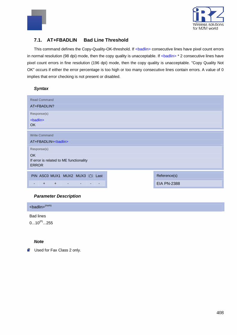
408
7.1. AT+FBADLIN Bad Line Threshold
This command defines the Copy-Quality-OK-threshold. If <badlin> consecutive lines have pixel count errors
in normal resolution (98 dpi) mode, then the copy quality is unacceptable. If <badlin> * 2 consecutive lines have
pixel count errors in fine resolution (196 dpi) mode, then the copy quality is unacceptable. "Copy Quality Not
OK" occurs if either the error percentage is too high or too many consecutive lines contain errors. A value of 0
implies that error checking is not present or disabled.
Syntax
Read Command
AT+FBADLIN?
Response(s)
<badlin> OK
Write Command
AT+FBADLIN=<badlin>
Response(s)
OK If error is related to ME functionality ERROR
PIN ASC0 MUX1 MUX2 MUX3 A Last - + + - - - -
Reference(s)
EIA PN-2388
Parameter Description
<badlin>(num)
Bad lines
0...10(P)...255
Note
Used for Fax Class 2 only.

409
7.2. AT+FBADMUL Error Threshold Multiplier
This command defines the "Copy-Quality-OK" multiplier. The number of lines received with a bad pixel
count is multiplied by this number. If the result exceeds the total number of lines on the page the error rate is
considered too high. A threshold multiplier value of 20 corresponds to a 5 per cent error rate. A value of 0
implies that error checking is not present or disabled.
Syntax
Read Command
AT+FBADMUL?
Response(s)
<badmul> OK
Write Command
AT+FBADMUL=<badmul>
Response(s)
OK If error is related to ME functionality ERROR
PIN ASC0 MUX1 MUX2 MUX3 A Last - + + - - - -
Reference(s)
EIA PN-2388
Parameter Description
<badmul>(num)
Bad lines
0...20(P)...255
Note
Used for Fax Class 2 only.

410
7.3. AT+FBOR Query data Bit Order
This command queries the bit order for the receive mode. The mode is set by the ME depending on the
selected Service Class, see "AT+FCLASS Fax: Select, read or test service class".
Syntax
Test Command
AT+FBOR=?
Response(s)
(list of supported <bor>s) OK
Read Command
AT+FBOR?
Response(s)
<bor> OK
Write Command
AT+FBOR=<bor>
Response(s)
OK
PIN ASC0 MUX1 MUX2 MUX3 A Last - + + - - - -
Reference(s)
EIA PN-2388
Parameter Description
<bor>(num)
bit order modes
0 Direct bit order for both Phase C and for Phase B/D data.
[1] Reversed bit order for Phase C data, direct Bit Order for Phase B/D data.
Note
Used for Fax Class 2 only.

411
7.4. AT+FCIG Query or set the Local Polling ID
Syntax
Test Command
AT+FCIG=?
Response(s)
(max. length of Local Polling ID string) (range of supported ASCII character values) OK
Read Command
AT+FCIG?
Response(s)
<id> OK
Write Command
AT+FCIG=<id>
Response(s)
OK
PIN ASC0 MUX1 MUX2 MUX3 A Last - + + - - - -
Reference(s)
EIA PN-2388
Parameter Description
<id>(num)
Local Polling ID string, max. length and possible content as reported by test command. Default value is empty
string ("").
Note
Used for Fax Class 2 only.
See also AT+FLID Query or set the Local ID setting capabilities.

412
7.5. AT+FCLASS Fax: Select, read or test service class
AT+FCLASS sets the ME to a particular mode of operation (data, fax). This allows the ME to process
information in a manner suitable for that type of information.
Syntax
Test Command
AT+FCLASS=?
Response(s)
(list of supported <n>s) OK
Read Command
AT+FCLASS?
Response(s)
<n> OK
Write Command
AT+FCLASS=<n>
Response(s)
OK
PIN ASC0 MUX1 MUX2 MUX3 A Last - + + - - - -
Reference(s)
EIA/TIA-592-A
Parameter Description
<n>(num)(&W)(&V)
0(&F) Data (e.g. EIA/TIA-602 or ITU V.250)
1 Fax class 1 (EIA/TIA-578-A, Service Class 1)
2 Fax class 2 (EIA/TIA SP-2388, an early draft version of EIA/TIA-592-A - Ser-vice class
2.1)

413
Notes
Using Error Correcting Mode (ECM) when sending FAXes over GSM should be avoided.
If <n> is set to 1 or 2, all incoming calls will be answered as fax calls when ATA is issued on multiplexer
chan-nel 1 resp. ASC0. For calls explicitly signaled as voice or data calls, this procedure will fail with result
code "NO CARRIER", but the incoming call will continue to ring.
It is possible to change the setting of <n> to 0 while the call is ringing, and accept the call afterwards with
ATA.

414
7.6. AT+FCQ Copy Quality Checking
This command controls Copy Quality checking when receiving a fax.
Syntax
Test Command
AT+FCQ=?
Response(s)
(list of supported copy quality checking <cq>s) OK
Read Command
AT+FCQ?
Response(s)
<cq> OK
Write Command
AT+FCQ=<cq>
Response(s)
OK
PIN ASC0 MUX1 MUX2 MUX3 A Last - + + - - - -
Reference(s)
EIA PN-2388
Parameter Description
<cq>(num)
0 No copy quality checking. The ME will generate Copy Quality OK (MCF) responses to
complete pages.
[1] ME can check 1-D phase data. The connected application must check copy quality for
2-D phase C data.
Note
Used for Fax Class 2 only.

415
7.7. AT+FCR Capability to Receive
Syntax
Write Command
AT+FCR=<cr>
Response(s)
OK
PIN ASC0 MUX1 MUX2 MUX3 A Last - + + - - - -
Reference(s)
EIA PN-2388
Parameter Description
<cq>(num)
0 ME will not receive message data. This value can be used when the application has
insufficient storage. The ME can send and can be polled for a file.
[1] ME can receive message data.
Note
Used for Fax Class 2 only.

416
7.8. AT+FDCC Query or set capabilities
This command allows the connected application to sense and constrain the capabilities of the facsimile
DCE (=ME), from the choices defined in CCITT T.30 Table 2.
Syntax
Test Command
AT+FDCC=?
Response(s)
(list of <vr>s), (list of <br>s), (list of <wd>s), (list of <ln>s), (list of <df>s), (list of <ec>s), (list of <bf>s), (list of <st>s) OK
Read Command
AT+FDCC?
Response(s)
<vr>, <br>, <wd>, <ln>, <df>, <ec>, <bf>, <st> OK
Write Command
AT+FDCC=<vr>, <br>, <wd>, <ln>, <df>, <ec>, <bf>, <st>
Response(s)
OK
PIN ASC0 MUX1 MUX2 MUX3 A Last - + + - - - -
Reference(s)
EIA PN-2388
Notes
For further information see AT+FDIS.
Used for Fax Class 2 only.

417
7.9. AT+FDFFC Data Compression Format Conversion
This command determines the ME response to a mismatch between the data format negotiated for the fax
session, reported by the <df> subparameter, and the Phase C data desired by the controlling application,
indicated by the optional AT+FDT <df> subparameter, or the AT+FDIS <df> subparameter for AT+FDR
operation.
Syntax
Test Command
AT+FDFFC=?
Response(s)
(list of <df>s) OK
Read Command
AT+FDFFC?
Response(s)
<df> OK
Write Command
AT+FDFFC=<df>
Response(s)
OK
PIN ASC0 MUX1 MUX2 MUX3 A Last - + + - - - -
Reference(s)
EIA PN-2388
Parameter Description
<df>(num)
[0] Mismatch checking is always disabled. The controlling application has to check the
<df> subparameter and transfer matching data.
Notes For further information see AT+FDIS.
Used for Fax Class 2 only.

418
7.10. AT+FDIS Query or set session parameters
This command allows the controlling application to sense and constrain the capabilities used for the current
ses-sion. It uses AT+FDIS to generate DIS or DTC messages directly, and uses AT+FDIS and received DIS
messages to generate DCS messages.
Syntax
Test Command
AT+FDIS=?
Response(s)
(list of <vr>s), (list of <br>s), (list of <wd>s), (list of <ln>s), (list of <df>s), (list of <ec>s), (list of <bf>s), (list of <st>s) OK
Read Command
AT+FDIS?
Response(s)
<vr>, <br>, <wd>, <ln>, <df>, <ec>, <bf>, <st> OK
Write Command
AT+FDIS=<vr>, <br>, <wd>, <ln>, <df>, <ec>, <bf>, <st>
Response(s)
OK
PIN ASC0 MUX1 MUX2 MUX3 A Last - + + - - - -
Reference(s)
EIA PN-2388
Notes
Used for Fax Class 2 only.

419
7.11. AT+FDR Begin or continue phase C Data Reception
The command initiates transition to Phase C data reception.
Syntax
Exec Command
AT+FDR
Response(s)
CONNECT or OK If error related to ME functionality ERROR
PIN ASC0 MUX1 MUX2 MUX3 A Last - + + - - - -
Reference(s)
EIA PN-2388
Notes
Used for Fax Class 2 only.

420
7.12. AT+FDT Data Transmission
This command requests the ME to transmit a Phase C page. When the ME is ready to accept Phase C
data, it issues the negotiation responses and the CONNECT result code to the application.
In Phase B, the AT+FDT command releases the ME to proceed with negotiation, and releases the DCS
message to the remote station. In Phase C, the AT+FDT command resumes transmission after the end of a
data stream transmitted before.
Syntax
Exec Command
AT+FDT
Response(s)
CONNECT
Write Command
AT+FDT=<df>, <vr>, <wd>, <ln>
Response(s)
CONNECT
PIN ASC0 MUX1 MUX2 MUX3 A Last - + + - - - -
Reference(s)
EIA PN-2388
Notes
Used for Fax Class 2 only.

421
7.13. AT+FET End a page or document
This command indicates that the current page or partial page is complete. An ERROR response code
results if this command is issued while the mode is on-hook.
Syntax
Write Command
AT+FET=<ppm>
Response(s)
OK
PIN ASC0 MUX1 MUX2 MUX3 A Last - + + - - - -
Reference(s)
EIA PN-2388
Parameter Description
<view>(num)
Post Page Message Codes
1 Another document next
2 No more pages or documents
4 Another page, procedure interrupt
5 Another document, procedure interrupt
Notes
Used for Fax Class 2 only.

422
7.14. AT+FK Kill operation, orderly FAX abort
This command causes the TA to terminate the session in an orderly manner.
Syntax
Write Command
AT+FK
Response(s)
OK
PIN ASC0 MUX1 MUX2 MUX3 A Last - + + - - - -
Notes
Used for Fax Class 2 only.

423
7.15. AT+FLID Query or set the Local Id setting capabilities
Syntax
Test Command
AT+FLID=?
Response(s)
(max. length of Local ID string) (range of supported ASCII character values) OK
Read Command
AT+FLID?
Response(s)
<lid> OK
Write Command
AT+FLID=<lid>
Response(s)
OK
PIN ASC0 MUX1 MUX2 MUX3 A Last - + + - - - -
Reference(s)
EIA PN-2388
Parameter Description
<lid>(num)
Local Polling ID string
Max. length and possible content as reported by test command. Default value is empty string ("").
Note
Used for Fax Class 2 only.
See also AT+FCIG.
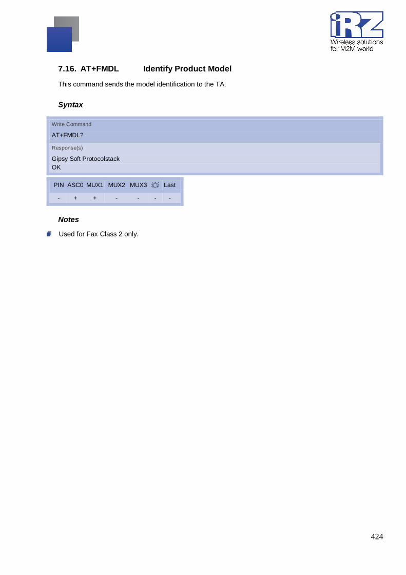
424
7.16. AT+FMDL Identify Product Model
This command sends the model identification to the TA.
Syntax
Write Command
AT+FMDL?
Response(s)
Gipsy Soft Protocolstack OK
PIN ASC0 MUX1 MUX2 MUX3 A Last - + + - - - -
Notes
Used for Fax Class 2 only.

425
7.17. AT+FMFR Request Manufacturer Identification
This command sends the model identification to the TA.
Syntax
Write Command
AT+FMFR?
Response(s)
OK
PIN ASC0 MUX1 MUX2 MUX3 A Last - + + - - - -
Notes
Used for Fax Class 2 only.
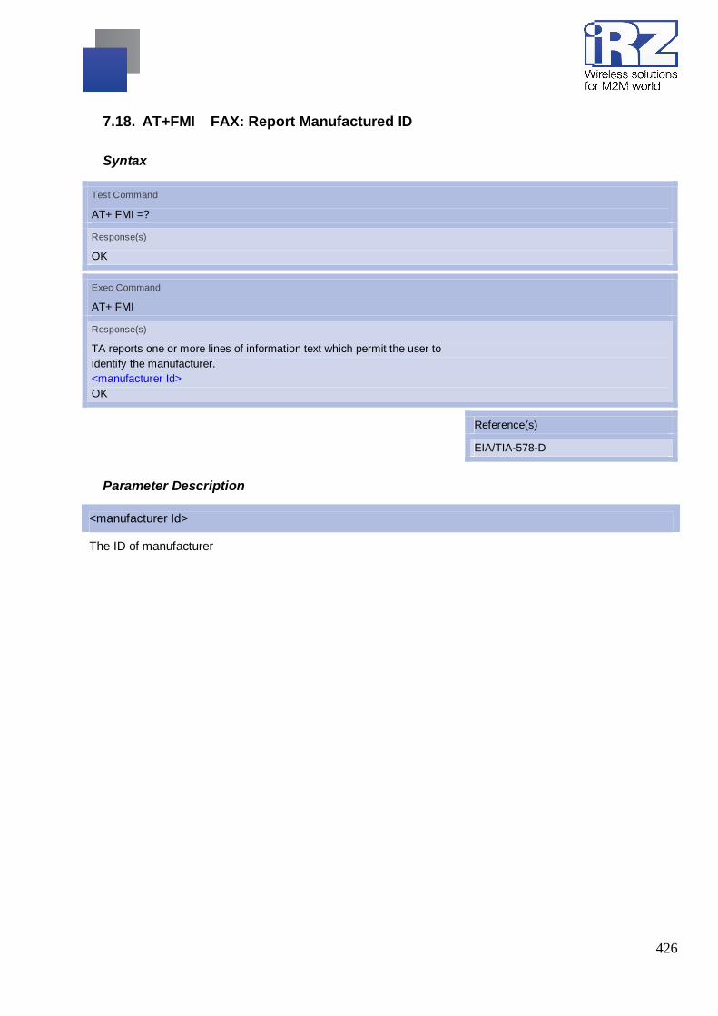
426
7.18. AT+FMI FAX: Report Manufactured ID
Syntax
Test Command
AT+ FMI =?
Response(s)
OK
Exec Command
AT+ FMI
Response(s)
TA reports one or more lines of information text which permit the user to identify the manufacturer. <manufacturer Id> OK
Reference(s)
EIA/TIA-578-D
Parameter Description
<manufacturer Id>
The ID of manufacturer

427
7.19. AT+FMM FAX: Rreport Model ID
Syntax
Test Command
AT+FMM=?
Response(s)
OK
Exec Command
AT+FMM
Response(s)
TA reports one or more lines of information text which permit the user to identify the specific model of device. <model Id> OK
Reference(s)
EIA/TIA-578-D
Parameter Description
<model Id>
The ID of model

428
7.20. AT+FMR FAX: Report Revision ID
Syntax
Test Command
AT+FMR=?
Response(s)
OK
Exec Command
AT+FMR
Response(s)
TA reports one or more lines of information text which permit the user to identify the version, revision level or data or other information of the device. Revision:<Revision Id> OK
Reference(s)
EIA/TIA-578-D
Parameter Description
<Revision Id>
The ID of model

429
7.21. AT+FOPT Set bit Order independently
Model specific command to set bit order independently of the understanding which is "mirrored" and which
is direct.
Syntax
Write Command
AT+FOPT=<opt>
Response(s)
OK
PIN ASC0 MUX1 MUX2 MUX3 A Last - + + - - - -
Parameter Description
<opt>(num)
0 Non-standard
1 Standard
Note
Used for Fax Class 2 only.

430
7.22. AT+FPHCTO DTE Phase C Response Timeout
The timeout value <tout> determines how long the DCE will wait for a command after reaching the end of
data when transmitting in Phase C. When timeout is reached, the DCE assumes that there are no more pages
or documents to send.
Syntax
Read Command
AT+FPHCTO?
Response(s)
<tout> OK
Write Command
AT+FPHCTO=<tout>
Response(s)
OK If error is related to ME functionality ERROR
PIN ASC0 MUX1 MUX2 MUX3 A Last - + + - - - -
Reference(s)
EIA PN-2388
Parameter Description
<tout>(num)
Timeout
Value in 100ms units
0...30(P)...255
Note
Used for Fax Class 2 only.

431
7.23. AT+FREV Identify Product Revision
This comand sends the revision identification to the TA.
Syntax
Read Command
AT+FREV?
Response(s)
V2.550 OK
PIN ASC0 MUX1 MUX2 MUX3 A Last - + + - - - -
Note
Used for Fax Class 2 only.

432
7.24. AT+FRH Receive Data Using HDLC Framing
The AT+FRH command enables the TA to receive frames using the HDLC protocol and the modulation
schemes. An ERROR response code results if the command is issued while the modem is on-hook. The test
command can be used in off-hook mode to check the modulation schemes supported by MG21.
Syntax
Test Command
AT+FRH=?
Response(s)
In off-hook mode only: +FRH:(list of <mod>s) OK In on-hook mode: ERROR
Write Command
AT+FRH=<mod>
Response(s)
CONNECT If error is related to ME functionality ERROR
PIN ASC0 MUX1 MUX2 MUX3 A Last - + + - - - -
Reference(s)
TIA/EIA-578
Note
Used for Fax Class 1 only.

433
7.25. AT+FRM Receive Data
The AT+FRM command causes the TA to enter the receive mode, using one of the modulation schemes.
An ERROR response code results if the write command is issued while the modem is on-hook. The test
command can be used in on-hook or off-hook mode to check the modulation schemes supported by MG21.
Syntax
Test Command
AT+FRM=?
Response(s)
(list of <mod>s) OK
Write Command
AT+FRM=<mod>
Response(s)
CONNECT If error is related to ME functionality: ERROR
PIN ASC0 MUX1 MUX2 MUX3 A Last - + + - - - -
Reference(s)
TIA/EIA-578
Note
Used for Fax Class 1 only.
<mod>= 3 is not possible.

434
7.26. AT+FRS Receive Silence
<time>=n causes the TA to report an OK result code to the TE after the specified period of silence was
detected on the line.
The command is aborted if any character is received by the TE. The modem discards the aborting
character and issues an OK result code. An ERROR response code results if this command is issued while the
mode is on-hook.
Syntax
Write Command
AT+FRS=<time>
Response(s)
OK If error is related to ME functionality: ERROR
PIN ASC0 MUX1 MUX2 MUX3 A Last - + + - - - -
Reference(s)
TIA/EIA-578
Parameter Description
<time>(num)
Number of 10 millisecond intervals
0...255
Note
Used for Fax Class 1 only.

435
7.27. AT+FTH Transmit Data Using HDLC Framing
The AT+FTH command causes the TA to transmit data using the HDLC protocol and the modulation
schemes. An ERROR response code results if the command is issued while the modem is on-hook. The test
command can be used in off-hook mode to check the modulation schemes supported by MG21.
Syntax
Test Command
AT+FTH=?
Response(s)
In off-hook mode only: +FTH:(list of <mod>s) OK In on-hook mode: ERROR
Write Command
AT+FTH=<mod>
Response(s)
CONNECT
PIN ASC0 MUX1 MUX2 MUX3 A Last - + + - - - -
Reference(s)
TIA/EIA-578
Note
Used for Fax Class 1 only.

436
7.28. AT+FTM Transmit Data
The AT+FTM command causes the TA to transmit data, using one of the modulation schemes.
An ERROR response code results if the write command is issued while the modem is on-hook. The test
command can be used in on-hook or off-hook mode to check the modulation schemes supported by MG21.
Syntax
Test Command
AT+FTM=?
Response(s)
(list of <mod>s) OK
Write Command
AT+FTM=<mod>
Response(s)
CONNECT If error is related to ME functionality: ERROR
PIN ASC0 MUX1 MUX2 MUX3 A Last - + + - - - -
Reference(s)
TIA/EIA-578
Note
Used for Fax Class 1 only.
<mod>= 3 is not possible

437
7.29. AT+FTS Stop Transmission and Wait
This command causes the TA to terminate a transmission and wait for <time> 10 millisecond intervals
before sending the OK result code to the TE.
Syntax
Write Command
AT+FTS=<time>
Response(s)
OK In on-hook mode: ERROR
PIN ASC0 MUX1 MUX2 MUX3 A Last - + + - - - -
Reference(s)
TIA/EIA-578
Parameter Description
<time>(num)
no. of 10 millisecond intervals
0...85
Note
Used for Fax Class 1 only.

438
7.30. AT+FVRFC Vertical Resolution Format Conversion
This command determines the DCE response to a mismatch between the vertical resolution negotiated for
the facsimile session and the Phase C data desired by the DTE.
Syntax
Test Command
AT+FVRFC=?
Response(s)
(list of supported <vrfc>s) OK
Read Command
AT+FVRFC?
Response(s)
<vrfc> OK
Write Command
AT+FVRFC=<vrfc>
Response(s)
OK
PIN ASC0 MUX1 MUX2 MUX3 A Last - + + - - - -
Reference(s)
EIA PN-2388
Parameter Description
<vrfc>(num)
0 Disable mismatch checking.
[2] Enable mismatch checking, with resolution conversion of 1-D data in the DCE, and an
implied AT+FK command executed on 2-D mismatch detection.
Note
Used for Fax Class 2 only.

439
8. SMS Commands The AT Commands described in this chapter used to operate with Short Message Service
(SMS).
SMS AT+CCODE AT+CMGC AT+CMGD AT+CMGDA AT+CMGF AT+CMGHEX AT+CMGL AT+CMGR AT+CMGS AT+CMGW AT+CMSS AT+CNMA AT+CNMI AT+CPMS AT+CRES AT+CSAS AT+CSCA AT+CSCB AT+CSDH AT+SCLASS0 AT+CSMP AT+CSMS AT^SLMS AT^SMGL AT^SMGO AT^SMGR AT^SSCONF AT^SSDA AT^SSMSS

440
8.1. AT+CMGC Send SMS Command
Syntax
Test Command
AT+CMGC=?
Response(s)
OK
Read Command
If text mode (see AT+CMGF=1) AT+CMGC=<fo>, <ct>[, <pid>[, <mn>[, <da>[, <toda>]]]]<CR> Text can be entered <CTRL-Z>/<ESC>
Response(s)
+CMGC: <mr>[, <scts>] If sending fails ERROR +CMS ERROR: <err>
Write Command
If PDU mode (see AT+CMGF=0) AT+CMGC=<length><CR> PDU can be entered <CTRL-Z>/<ESC>
Response(s)
+CMGC: <mr>[, <ackpdu>] OK If sending fails ERROR +CMS ERROR: <err>
PIN ASC0 MUX1 MUX2 MUX3 A Last + + + + + - -
Reference(s)
GSM 07.05
Notes
After invoking the commands AT+CMGW, AT+CMGS or AT+CMGC it is necessary to wait for the prompt
">" before entering text or PDU. After the prompt a timer will be started to guard input period.
In general but especially at baudrates below 19200 it is recommended to only use the command line termi-
nation character (ATS3) before starting text or PDU input. Use of line termination character followed by an
additional response formatting character (ATS4) may cause the problem that the latter will become part of
the input data.

441
8.2. AT+CMGD Delete short message
The write command deletes a short message from the preferred message storage <mem1> location
<index>.
Syntax
Test Command
AT+CMGD=?
Response(s)
OK
Write Command
AT+CMGD=<index>
Response(s)
OK ERROR +CMS ERROR: <err>
PIN ASC0 MUX1 MUX2 MUX3 A Last + + + + + - -
Reference(s)
GSM 07.05
Notes
If there is no short message stored at the selected index, the response is OK too.
Users should be aware that when using this AT command quickly after SIM PIN authentication the SIM
data may not yet be accessible, resulting in a short delay before the requested AT command response is
returned.

442
8.3. AT+CMGDA Delete All SMS
Syntax
Test Command
AT+CMGDA=?
Response(s)
+CMGDA: (listed of supported <type>s) OK +CMS ERROR: <err>
Read Command
AT+CMGDA=<type>
Response(s)
OK ERROR +CMS ERROR: <err>
Parameter Description
<text>
1) If text mode:
“DEL READ” delete all read messages
“DEL UNREAD” delete all unread messages
“DEL SENT” delete all sent SMS
“DEL UNSENT” delete all unsent SMS
“DEL INBOX” delete all received SMS
“DEL ALL” delete all SMS
2) If PDU mode :
1 delete all read messages
2 delete all unread messages
3 delete all sent SMS
4 delete all unsent SMS
5 delete all received SMS
6 delete all SMS

443
8.4. AT+CMGF Select SMS message format
The AT+CMGF command specifies the input and output format of the short messages.
Syntax
Test Command
AT+CMGF=?
Response(s)
+CMGF: (list of supported<mode>s) OK
Read Command
AT+CMGF?
Response(s)
+CMGF: <mode> OK ERROR +CMS ERROR: <err>
Write Command
AT+CMGF=<mode>
Response(s)
OK ERROR +CMS ERROR: <err>
PIN ASC0 MUX1 MUX2 MUX3 A Last - + + + + - -
Reference(s)
GSM 07.05
Parameter Description
<mode>(num)(&W)(&V)
[0](&F) PDU mode
1 Text mode

444
8.5. AT+CMGHEX Enable To Send Non-ASCII Character SMS
Syntax
Test Command
AT+CMGHEX=?
Response(s)
+CMGHEX: (0,1) OK
Read Command
AT+CMGHEX?
Response(s)
+CMGHEX: <mode> OK
Write Command
AT+CMGHEX=<mode>
Response(s)
OK ERROR
Parameter Description
<mode>(num)
0 Send SMS in ordinary way
1 Enable to send SMS varying from 0x00 to 0x7f except 0x1a and 0x1b under text mode
and GSM character set
Notes
Only be available in TEXT mode and +CSCS=”GSM”.
It is not supported temporarily.

445
8.6. AT+CMGL List SMS messages from preferred store
The write command returns messages with status value <stat> from message storage <mem1> to the TE.
If the status of the message is 'received unread', the status in the storage changes to 'received read'.
The execute command is the same as the write command with the given default for <stat>.
Syntax
Test Command
AT+CMGL=?
Response(s)
+CMGL: (list of supported <stat>s) OK
Read Command
AT+CMGL
Response(s)
+CMGL: (see write command for default of <stat>) OK

446
Write Command
AT+CMGL=<stat>
Response(s)
Output if text mode (AT+CMGF=1) and command successful: For SMS- SUBMITs and/or SMS-DELIVERs +CMGL: <index>, <stat>, <oa>/<da>, [<alpha>], [<scts>][, <tooa>/<toda>, <length>] <data> [... ] OK For SMS-STATUS-REPORTs +CMGL: <index>, <stat>, <fo>, <mr>, [<ra>], [<tora>], <scts>, <dt>, <st> [... ] OK For SMS-Commands +CMGL: <index>, <stat>, <fo>, <ct> [... ] OK Output if PDU mode AT+CMGF=0 and command successful: For SMS-SUBMITs and/or SMS-DELIVERs +CMGL: <index>, <stat>, [<alpha>], <length> <pdu> [... ] OK If error is related to ME functionality ERROR +CMS ERROR: <err>
PIN ASC0 MUX1 MUX2 MUX3 A Last + + + + + - -
Reference(s)
GSM 07.05
Notes
The selected <mem1> can contain different types of SMs (e.g. SMS-DELIVERs, SMS-SUBMITs, SMS-
STA-TUS-REPORTs and SMS-COMMANDs), the response may be a mix of the responses of different SM
types. TE application can recognize the response format by examining the third response parameter.
The parameters <ra> and <tora> will only be displayed if parameter <mode> of the AT^SSCONF command
is set to 1.
Users should be aware that when using this AT command quickly after SIM PIN authentication the SIM
data may not yet be accessible, resulting in a short delay before the requested AT command response is
returned. See Section “Restricted access to SIM data after SIM PIN authentication for further detail”.

447
8.7. AT+CMGR Read SMS messages
The write command returns SMS message with location value <index> from message storage <mem1> to
the TE. If status of the message is 'received unread', status in the storage changes to 'received read'.
When using Text mode it is recommended to set AT+CSDH=1. In this case the AT+CMGR write command
responses will include detailed header information. See AT+CSDH for details. The parameters <ra> and <tora>
will only be displayed if parameter <mode> of the AT^SSCONF command is set to 1.
Syntax
Test Command
AT+CMGR=?
Response(s)
OK
Write Command
AT+CMGR=<index>
Response(s)
Output if text mode (AT+CMGF=1) and command successful: For SMS-DELIVER +CMGR: <stat>, <oa>, [<alpha>], <scts>[, <tooa>, <fo>, <pid>, <dcs>, <sca>, <tosca>, <length>] <data> [... ] OK For SMS-SUBMIT +CMGR: <stat>, <da>, [<alpha>][, <toda>, <fo>, <pid>, <dcs>, [<vp>], <sca>, <tosca>, <length>] <data> [... ] OK For SMS-STATUS-REPORT +CMGR: <stat>, <fo>, <mr>, [<ra>], [<tora>], <scts>, <dt>, <st> <data> [... ] OK For SMS-Commands +CMGR: <stat>, <fo>, <ct>[, <pid>, [<mn>], [<da>], [<toda>], <length>] <data> [... ] OK Output if PDU mode (AT+CMGF=0) and command successful: For SMS-SUBMITs and/or SMS-DELIVERs +CMGR: <stat>, [<alpha>], <length> <pdu> [... ]

448
OK ERROR +CMS ERROR: <err>
PIN ASC0 MUX1 MUX2 MUX3 A Last + + + + + - -
Reference(s)
GSM 07.05
Notes
Response if AT+CMGR is used to read an empty record index: +CMGR: 0,,0
Response if AT+CMGR is used to read a non-existent record index: +CMS ERROR: invalid memory index
Users should be aware that when using this AT command quickly after SIM PIN authentication the SIM
data may not yet be accessible, resulting in a short delay before the requested AT command response is
returned.

449
8.8. AT+CMGS Send SMS
AT+CMGS write command transmits a short message to network (SMS-SUBMIT).
After invoking the write command wait for the prompt ">" and then start to write the message. To send the
mes-sage simply enter <CTRL-Z>. After the prompt a timer will be started to guard the input period.
To abort sending use <ESC>. Abortion is acknowledged with "OK", though the message will not be sent.
The message reference <mr> is returned by the ME on successful message delivery. The value can be
used to identify the message in a delivery status report provided as an unsolicited result code.
Syntax
Test Command
AT+CMGS=?
Response(s)
OK
Read Command
If text mode (see AT+CMGF=1) AT+CMGS=<da>[, <toda>]<CR> Text can be entered. <CTRL-Z>/<ESC>
Response(s)
+CMGS: <mr>[, <scts>] OK If sending fails see notes below.
Write Command
If PDU mode (see AT+CMGF=0) AT+CMGS=<length><CR> PDU can be entered. <CTRL-Z>/<ESC>
Response(s)
+CMGS: <mr>[, <ackpdu>] OK If sending fails see notes below.
PIN ASC0 MUX1 MUX2 MUX3 A Last + + + + + - -
Reference(s)
GSM 07.05
Notes
If sending fails, for example, if a message is too long, the result code depends on the current setting of the
AT^SM20 command:
If the AT^SM20 <CmgwMode> equals 1 (factory default) any failure to send a message is responded with
"OK".
Users should be aware, that despite the "OK" response, the message will not be sent to the subscriber. If
the AT^SM20 <CmgwMode> equals 0 any failure to send a message is responded with "ERROR".
If sending fails due to timeout, then
AT^SM20 <CmgwMode>=1 causes "+CMS ERROR: unknown error" to be returned;

450
AT^SM20 <CmgwMode>=0 causes "+CMS ERROR: timer expired" to be returned.
Note that some providers do not recognize an @ symbol used in a short message. A widely used
alternative is typing "*" as defined in GSM 03.40 (GPP TS 23.40).
All characters entered behind the prompt ">" will be recognized as GSM characters. For example, "Back-
space" (ASCII character 8) does not delete a character, but will be inserted into the short message as an
addi-tional physical character. As a result, the character you wanted to delete still appears in the text, plus
the GSM code equivalent of the Backspace key.
Message Length in Text Mode
The maximum length of a short message depends on the used coding scheme: It is 160 characters if the 7
bit GSM coding scheme is used, and 140 characters according to the 8 bit GSM coding scheme.
In case UCS2 character set selected it is highly recommended to set Data Coding Scheme (<dcs> of
AT+CSMP) to 16-bit data, otherwise the length of sms user data is restricted to 88 octets. Even better for
mes-sages with UCS2 character set is the PDU Mode.
In general but especially at baudrates below 19200 it is recommended to only use the command line termi-
nation character (ATS3) before starting text or PDU input. Use of line termination character followed by an
additional response formatting character (ATS4) may cause the problem that the latter will become part of
the input data.
During a pending USSD user interaction the AT+CMGS write command returns "+CME ERROR: operation
temporary not allowed" to prevent blocking situations.

451
8.9. AT+CMGW Write Short Messages to Memory
AT+CMGW execute and write commands transmit a short message (either SMS-DELIVER or SMS-
SUBMIT) from TE to memory storage <mem2>. Memory location <index> of the stored message is returned.
Message status will be set to 'stored unsent' unless otherwise given in parameter <stat>.
After invoking the execute or write command wait for the prompt ">" and then start to write the message. To
save the message simply enter <CTRL-Z>. After the prompt a timer will be started to observe the input. To
abort writing use <ESC>. Abortion is acknowledged with "OK", though the message will not be saved.
Message Length in Text Mode: The maximum length of a short message depends on the used coding
scheme configured with <dcs> of AT+CSMP:
7 bit GSM coding scheme: 160 characters
8 bit GSM coding scheme: 140 characters
16 bit GSM coding scheme: 70 characters.
The length of 8-bit data coded short messages has to be greater than 0.
For more information on data coding schemes and character sets refer to GSM 03.08.
Syntax
Test Command
AT+CMGW=?
Response(s)
OK
Exec Command
If text mode (see AT+CMGF=1): AT+CMGW
Response(s)
<CR> Text can be entered. <CTRL-Z>/<ESC> +CMGW: <index> OK If writing fails ERROR +CMS ERROR: <err>
Write Command
If text mode (see AT+CMGF=1): AT+CMGW=<oa>/<da>[, [<tooa>/<toda>][, <stat>]]<CR> Text can be entered. <CTRL-Z>/<ESC>
Response(s)
+CMGW: <index> OK If writing fails see notes below.
Write Command

452
If PDU mode (see AT+CMGF=0): AT+CMGW=<length>[, <stat>]<CR> PDU can be entered. <CTRL-Z>/<ESC>
Response(s)
+CMGW: <index> OK If writing fails see notes below.
PIN ASC0 MUX1 MUX2 MUX3 A Last + + + + + - -
Reference(s)
GSM 07.05, 03.38
Notes
If writing fails, for example, if a message is too long, the result code depends on the current setting of the
AT^SM20 command:
If the AT^SM20 <CmgwMode>=1 (factory default) any failure to send a message is responded with "OK".
Users should be aware, that despite the "OK" response, the message will not be written to the selected
SMS stor-age.
If the AT^SM20 <CmgwMode> equals 0 any failure to write a message is responded with "ERROR".
If writing fails due to timeout, then
AT^SM20 <CmgwMode>=1 causes "+CMS ERROR: unknown error" to be returned;
AT^SM20 <CmgwMode>=0 causes "+CMS ERROR: timer expired" to be returned.
Note that some providers do not recognize an @ symbol used in a short message. A widely used
alternative is typing "*" as defined in GSM 03.40 (GPP TS 23.40).
In general but especially at baudrates below 19200 it is recommended to only use the command line termi-
nation character (ATS3) before starting text or PDU input. Use of line termination character followed by an
additional response formatting character (ATS4) may cause the problem that the latter will become part of
the input data.
SMS-COMMANDs and SMS-STATUS-REPORTs cannot be stored in text mode.
All characters entered behind the ">" prompt will be recognized as GSM characters. For example, "Back-
space" (ASCII character 8) does not delete a character, but will be inserted into the short message as an
addi-tional physical character. As a result, the character you wanted to delete still appears in the text, plus
the GSM code equivalent of the Backspace key.

453
8.10. AT+CMSS Send short messages from storage
The write command sends message with location value <index> from message storage <mem2> to the
network (SMS-SUBMIT or SMS-COMMAND). If new recipient address <da> is given for SMS-SUBMIT, it shall
be used instead of the one stored with the message. Reference value <mr> is returned to the TE on successful
message delivery. Value can be used to identify message upon unsolicited delivery status report result code.
If the optional parameter <da> is given, the old status of the short message at <index> remains unchanged
(see <stat>).
Syntax
Test Command
AT+CMSS=?
Response(s)
OK
Exec Command
If text mode (AT+CMGF=1): AT+CMSS=<index>[, <da>[, <toda>]]
Response(s)
+CMSS: <mr>[, <scts>] OK If sending fails ERROR +CMS ERROR: <err>
Write Command
If PDU mode (AT+CMGF=0): AT+CMSS=<index>[, <da>[, <toda>]]
Response(s)
+CMSS: <mr>[, <ackpdu>] OK If sending fails ERROR +CMS ERROR: <err>
PIN ASC0 MUX1 MUX2 MUX3 A Last + + + + + - -
Reference(s)
GSM 07.05,

454
8.11. AT+CNMA New Message Acknowledgement to ME/TE
Write and execute command confirm successful receipt of a new message (SMS-DELIVER or SMS-
STATUS-REPORT) routed directly to the TE.
MG21 will not send another "+CMT" or "+CDS" URC to the TE until previous one is acknowledged with this
command. If the ME does not receive acknowledgement within required time (network timeout), it sends an
"RP-ERROR" message to the network. The ME will automatically disable routing to the TE by setting both <mt>
and <ds> values of AT+CNMI to zero.
Syntax
Test Command
AT+CNMA=?
Response(s)
+CNMA: (list of supported <n>s) OK
Exec Command
AT+CNMA
Response(s)
OK ERROR +CME ERROR: <err>
Write Command
AT+CNMA=<n>
Response(s)
OK ERROR +CME ERROR: <err>
PIN ASC0 MUX1 MUX2 MUX3 A Last + + + + + - -
Reference(s)
GSM 07.05
Parameter Description
<n>(num)
Parameter required only for PDU mode.
0 Command operates similarly as in text mode.
Notes
Execute and write command shall only be used if AT+CSMS parameter <service> equals 1 (= phase 2+).

455
Execute command can be used no matter whether text mode or PDU mode is activated. Write command is
designed for the PDU mode only.
If multiplex mode is activated (AT+CMUX=0) the AT+CNMI parameter will be set to zero on all channels, if
one channel fails to acknowledge an incoming message within the required time.

456
8.12. AT+CNMI SMS Event Reporting Configuration
AT+CNMI controls details of the SMS related URC presentation. It selects the procedure how the receipt of
a new SMS from the network is indicated to the TE when TE is active, e.g. DTR signal is ON.
If the TE is inactive (e.g. DTR signal is OFF), message receiving should be done as specified in GSM
03.38. If the DTR signal is not available or the state of the signal is ignored (V.250 command AT&D0, reliable
message transfer can be assured by using AT+CNMA acknowledgment procedure.
The rules <mt>=2 and <mt>=3 for storing received messages are possible only if phase 2+ compatibility is
acti-vated with AT+CSMS=1. The parameter <ds>=1 is only available in phase 2+.
Syntax
Test Command
AT+CNMI=?
Response(s)
+CNMI: (list of supported<mode>s), (list of supported <mt>s), (list of supported <bm>s), (list of supported <ds>s), (list of supported <bfr>s) OK
Read Command
AT+CNMI?
Response(s)
+CNMI: <mode>, <mt>, <bm>, <ds>, <bfr> OK
Write Command
AT+CNMI=<mode>[, <mt>[, <bm>[, <ds>[, <bfr>]]]]
Response(s)
OK ERROR +CME ERROR: <err>
PIN ASC0 MUX1 MUX2 MUX3 A Last + + + + + - -
Reference(s)
GSM 07.05
Unsolicited Result Codes
URC 1
<mt>=1:
+CMTI: <mem3>, <index>
Indicates that new message has been received
URC 2
<mt>=2 (PDU mode enabled):
+CMT: <length><CR><LF><pdu>

457
Indicates that new message has been received
URC 3
<mt>=2 (text mode enabled):
+CMT: <oa>, <scts>[, <tooa>, <fo>, <pid>, <dcs>, <sca>, <tosca>, <length>]<CR><LF><data>
Indicates that new message has been received
URC 4
<bm>=2 (PDU mode enabled):
+CBM: <length><CR><LF><pdu>
Indicates that new cell broadcast message has been received
URC 5
<bm>=2 (text mode enabled):
+CBM: <sn>, <mid>, <dcs>, <page>, <pages><CR><LF><data>
Indicates that new cell broadcast message has been received
URC 6
<ds>=1 (PDU mode enabled):
+CDS: <length><CR><LF><pdu>
Indicates that new SMS status report has been received
URC 7
<ds>=1 (text mode enabled):
+CDS: <fo>, <mr>[, <ra>][, <tora>], <scts>, <dt>, <st>
Indicates that new SMS status report has been received
URC 8
<ds>=2:
+CDSI: <mem3>, <index>
Indicates that new SMS status report has been received
Parameter Description
<mode>(num)(&W)(&V)
[0](&F) SMS related URCs are always buffered in the ME. If the buffer is full, the oldest
indications are discarded and replaced with newly received indications.
1 SMS related URCs are forwarded directly to the TE. However, if this is not pos-sible
because ME-TE link is reserved, e.g. during a data call, these URCs are discarded.
458
2 SMS related URCs are forwarded directly to the TE. However, if this is not pos-sible
because ME-TE link is reserved these URCs are buffered and flushed to the TE
afterwards.
3 SMS related URCs are forwarded directly to the TE. However, if this is not pos-sible
because ME-TE link is reserved these URCs are buffered and flushed to the TE
afterwards.
Additionally, while ME-TE link is reserved, buffered URCs are signaled to the TE via
sending a BREAK or activating the RING line, according to AT^SCFG parameters
<uri>, <udri> and <urat>.
<mt>(num)(&W)(&V)
Rules for storing received short messages depend on the relevant data coding method (refer to GSM 03.38),
preferred memory storage (AT+CPMS) setting and this value.
Note: If AT command interface is acting as the only display device, the ME must support storage of class 0
mes-sages and messages in the message waiting indication group (discard message)
[0](&F) No SMS-DELIVER indications are routed to the TE.
1 If SMS-DELIVER is stored in the ME, indication of the memory location is routed to the
TE via URC.
2 SMS-DELIVERs, except class 2 messages and messages in the message waiting
indication group (store message) are routed directly to the TE via URC.
3 Class 3 SMS-DELIVERs are routed directly to the TE using URCs defined in <mt>=2.
Messages of other data coding schemes result in indication as defined in <mt>=1.
<bm>(num)(&W)(&V)
Rules for storing received CBMs depend on the relevant data coding method (refer to GSM 03.38), the
setting of Select CBM Types (AT+CSCB) and this value:
[0](&F) No CBM indications are routed to the TE.
2 New CBMs are routed directly to the TE via URC.
3 Class 3 CBMs are routed directly to TE using URCs defined in <bm>=2.

459
<ds>(num)(&W)(&V)
[0](&F) No SMS-STATUS-REPORTs are routed to the TE.
1 SMS-STATUS-REPORTs are routed to the TE via URC.
2 If SMS-STATUS-REPORT is routed into ME, indication of the memory location is
routed to the TE via URC.
<bfr>(num)(&V)
[1](&F) ME's buffer of SMS related URCs is cleared when <mode> changes from 0 to 1, 2 or
3.
<index>(num)(&W)(&V)
Integer type; value in the range of location numbers supported by the associated memory
Notes
Parameters <mt>=2,3 and <ds>=1 are only available with GSM phase 2+ (see AT+CSMS=1). Incoming
SMs or Status Reports have to be acknowledged with AT+CNMA=0 when using these phase 2+
parameters.
Requirements specific to Multiplex mode:
In multiplex mode (AT+CMUX=0) only one channel can use a phase 2+ parameter. The parameter for
<mt> and <ds> on the other channels have to be set to zero. If either a SM or a Status Report is not
acknowledged, all AT+CNMI parameter in all channels will be set to zero.
If the ME operates on different instances (MUX channels 1, 2, 3 or ASC0) avoid different settings for
routing and indicating short messages. For example, if messages shall be routed directly to one instance of
the TE (set with AT+CNMI, AT^SSDA), it is not possible to activate the presentation of URCs with
AT+CMER or AT+CNMI on another instance. Any attempt to activate settings that conflict with existing
settings on another interface, will result in "+CME ERROR", or accordingly "+CMS ERROR".
Handling of Class 0 short messages:
If the host application is provided with a display and AT^SSDA=1 has been set Class 0 short messages can
be displayed immediately.
If the host application does not include a display, ME handles Class 0 short messages as though there was
no message class, i.e. it will ignore bits 0 and 1 in the <dcs> and normal rules for exceeded memory
capacity shall apply. This approach is compliant with GSM 03.38.
The parameters <ra> and <tora> will only be displayed if <mode> of the AT^SSCONF command is set to 1.
If either a SM or a Status Report is not acknowledged, all AT+CNMI parameter in all channels will be set to
zero.

460
8.13. AT+CPMS Preferred SMS message storage
The write command selects memory storages <mem1>, <mem2>, <mem3> to be used for reading, writing,
etc.
Syntax
Test Command
AT+CPMS=?
Response(s)
+CPMS: (list of supported <mem1>s), (list of supported <mem2>s), (list of supported <mem3>s) OK
Read Command
AT+CPMS?
Response(s)
+CPMS: <mem1>, <used1>, <total1>, <mem2>, <used2>, <total2>, <mem3>, <used3>, <total3> OK ERROR +CMS ERROR: <err>
Write Command
AT+CPMS=<mem1>[, <mem2>[, <mem3>]]
Response(s)
+CPMS: <used1>, <total1>, <used2>, <total2>, <used3>, <total3> OK ERROR +CMS ERROR: <err>
PIN ASC0 MUX1 MUX2 MUX3 A Last + + + + + - -
Reference(s)
GSM 07.05
Parameter Description
<used1>(num)
Number of messages currently in <mem1>
<used2>(num)
Number of messages currently in <mem2>
<used3>(num)
Number of messages currently in <mem3>

461
<total1>(num)
Number of messages storable in <mem1>
<total2>(num)
Number of messages storable in <mem2>
<total3>(num)
Number of messages storable in <mem3>
Notes
The Mobile Equipment storage ''ME'' offers space for 25 short messages, see <mem1>.
''MT'' is the sum of ''ME'' (= 25 locations) and ''SM'' (capacity varies with SIM card). The indices <index> of
the ''MT'' storage are dependent on the order selected with AT^SSMSS
The <mem1>, <mem2> and <mem3> parameter will be stored in non-volatile memory.
The user should be aware that the setting ''MT'' involves ''ME'' and ''SM'', with ''ME'' being filled up first. If
the ''ME'' storage is full, MG21 will proceed with the ''SM'' storage. Incoming Class 1 short messages (ME
specific) will be preferably stored to ''ME'' and may be transferred to the ''SM'' storage if ''ME'' is used up.
Incoming Class 2 messages (SIM specific) will be stored to the SIM card only, no matter whether or not
there is free ''ME'' space. As a result, the ^SMGO: 2 indication (see AT^SMGO) may be presented without
prior indi-cation of ^SMGO: 1. For more information regarding SIM and ME specific message classes refer
to <dcs> and the following specifications: GSM 03.38 and 3GPP TS23038.
When <mem3> is switched over from ''MT'' to ''SM'' all free ''ME'' locations will be filled with dummy short
mes-sages. This procedure can take up to 35 seconds, until all the 25 records are written.
If switching from ''MT'' to ''SM'' was not finished due to error or user break, the value of <mem3> remains
''MT'', but some of the dummy records remain in the ''ME'' storage. These records have to be deleted
manually. When <mem3> equals ''SM'', do not delete the dummy messages in the ''ME''. storage. They will
be automat-ically deleted when you switch back from ''SM'' to ''MT''. Again, this may take up to 35 seconds.
If switching from ''SM'' to ''MT'' was not finished due to an error or user break, the value of <mem3>
remains ''SM'', but the ''ME'' storage will no longer be filled with dummy records. New incoming short
messages may now be written to the ''ME'' storage, if ''SM'' is already full. To avoid this, repeat the
AT+CPMS command as soon as possible to switch <mem3> back to ''MT''. As an alternative, you can
manually delete the dummy records and issue AT+CPMS=MT,MT,MT.
Multiplexer: In Multiplex mode or when the two physical serial interfaces are connected, the parameter
<mem3> will be the same on all instances, but the settings of <mem1> and <mem2> may vary on each
channel / interface. As a result, changes on parameter <mem1> and/or <mem2> befor activating the
multiplexer or dif-ferences values for other instanes can result in not desired behaviours like different
outputs for AT+CMGL and so on.

462
While <mem3> equals ''SM'' and <mem1> equals ''ME'' it is possible that, after deleting short messages
from ''ME'', the freed space on ''ME'' is reclaimed for new incoming short messages, when there is no
space left on the ''SM'' storage. As it is often the clients concern to have received short messages stored
only to the SIM card, inconsistent settings should be generally avoided. This can be achieved simply by
using the same parameter for all memory indices.
Users should be aware that when using this AT command quickly after SIM PIN authentication the SIM
data may not yet be accessible, resulting in a short delay before the requested AT command response is
returned.
The indices <index> of the storage are dependent on the order selected with AT^SSMSS.

463
8.14. AT+CRES Restore SMS Settings
Syntax
Test Command
AT+CRES=?
Response(s)
+CRES: (list of supported <profile>s) OK
Exec Command
AT+CRES
Response(s)
Same as AT+CRES=0. OK If error is related to ME functionality: +CMS ERROR <err>
Write Command
AT+CRES=<profile>
Response(s)
TA restores SMS settings for +CSCA, +CSMP from non-volatile memory to active memory. OK If error is related to ME functionality: ERROR
PIN ASC0 MUX1 MUX2 MUX3 A Last + + + + + - -
Reference(s)
GSM 07.05
Parameter Description
<profile>(num)
0 Restore SM service settings from profile 0
1 Restore SM service settings from profile 1

464
8.15. AT+CSAS Save SMS Settings
Syntax
Test Command
AT+CSAS=?
Response(s)
+CSAS: (list of supported <profile>s) OK
Exec Command
AT+CSAS
Response(s)
Same as AT+CSAS=0 OK If error is related to ME functionality: ERROR
Write Command
AT+CSAS=<profile>
Response(s)
TA saves SMS settings for +CSCA, +CSMP from non-volatile memory to active memory. OK If error is related to ME functionality: ERROR
Reference(s)
GSM 07.05
Parameter Description
<profile>(num)
0 Save SM service setting in profile 0
1 Save SM service setting in profile 1
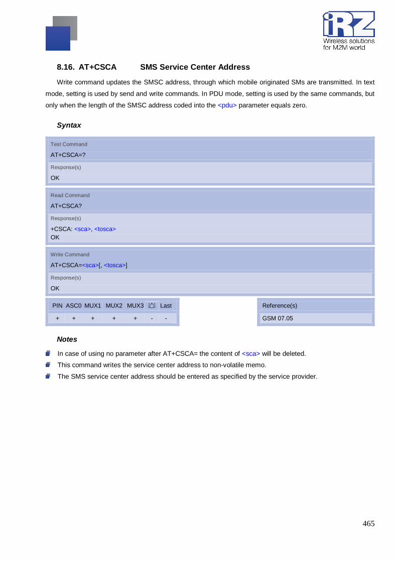
465
8.16. AT+CSCA SMS Service Center Address
Write command updates the SMSC address, through which mobile originated SMs are transmitted. In text
mode, setting is used by send and write commands. In PDU mode, setting is used by the same commands, but
only when the length of the SMSC address coded into the <pdu> parameter equals zero.
Syntax
Test Command
AT+CSCA=?
Response(s)
OK
Read Command
AT+CSCA?
Response(s)
+CSCA: <sca>, <tosca> OK
Write Command
AT+CSCA=<sca>[, <tosca>]
Response(s)
OK
PIN ASC0 MUX1 MUX2 MUX3 A Last + + + + + - -
Reference(s)
GSM 07.05
Notes
In case of using no parameter after AT+CSCA= the content of <sca> will be deleted.
This command writes the service center address to non-volatile memo.
The SMS service center address should be entered as specified by the service provider.

466
8.17. AT+CSCB Select Cell Broadcast Message Indication
The test command returns the supported modes as a compound value. The write command selects which
types of CBMs are to be received by the ME.
Syntax
Test Command
AT+CSCB=?
Response(s)
+CSCB: (list of supported <mode>s) OK
Read Command
AT+CSCB?
Response(s)
+CSCB: <mode>, <mids>, <dcss> OK
Write Command
AT+CSCB=<mode>[, <mids>[, <dcss>]]
Response(s)
OK
PIN ASC0 MUX1 MUX2 MUX3 A Last + + + + + - -
Reference(s)
GSM 07.05
Parameter Description
<mode>(num)
Message mode
0(&F) Accept messages that are defined in <mids> and <dcss>
1 Forbid messages that are defined in <mids> and <dcss>

467
<mids>(str)
Cell Broadcast Message ID specification
[““](&F) default value of this parameter is empty string, and it means that no CBM iden-tifiers
are specified.
For <mode>=0: Six different possible combinations of CBM IDs (e.g. "0,1,5,320-478,922,2000-3000").
In certain configurations, e.g. if using SIMs that contain data in Elementary File EF-CBMID (Cell
Broadcast Message Identifier for Data download) less than six combinations may be available.
To access a SIM's Elementary File data refer to command AT+CRSM.
For <mode>=1: One CBM ID or range of IDs (e.g. "320-478").
<dcss>(str)
CBM data coding scheme specification
[““](&F) default value of this parameter is empty string
All different possible combinations of CBM data coding schemes (e.g. "0-3,5"). Using default empty string
leads to get all CBMs independent of their dcss.
A given <dcss> replaces any former value and is used for consecutive requests.

468
8.18. AT+CSDH Show SMS text mode parameters
The write command sets whether or not detailed header information is shown in text mode result codes.
Syntax
Test Command
AT+CSDH=?
Response(s)
+CSDH: (list of supported <show>s) OK
Read Command
AT+CSDH?
Response(s)
+CSDH:<show> OK
Write Command
AT+CSDH=<show>
Response(s)
OK
PIN ASC0 MUX1 MUX2 MUX3 A Last + + + + + - -
Parameter Description
<show>(num)(&W)
[0](&F) Do not show header values defined in commands AT+CSCA and AT+CSMP (<sca>,
<tosca>,<fo>,<vp>, <pid> and <dcs>) nor <length>, <toda> or <tooa> in "+CMTI",
AT+CMGL, AT+CMGR result codes for SMS-DELIVERs and SMS-SUBMITs in text
mode; for SMS-COMMANDs in +CMGR result code, do not show <pid>,<mn>,<da>,
<toda>, <length> or <cdata>
1 Show the values in result codes

469
8.19. AT+SCLASS0 Store Class 0 SMS To SIM When Received Class 0 SMS
Syntax
Test Command
AT+SCLASS0=?
Response(s)
+SCLASS0: (0, 1) OK
Read Command
AT+SCLASS0?
Response(s)
+SCLASS0: <mode> OK
Write Command
AT+SCLASS0=[<mode>]
Response(s)
OK ERROR
Parameter Description
<mode>(num)
0 disable to store Class 0 SMS to SIM when received Class 0 SMS
1 Enable to store Class 0 SMS to SIM when received Class 0 SMS
Note
It is not supported temporarily.

470
8.20. AT+CSMP Set SMS text Mode Parameters
The write command selects values for additional parameters needed when the short message is sent to the
net-work or placed in a storage when text format message mode is selected.
It is possible to set the validity period starting from the time when the short message is received by the
SMSC (<vp> is in range 0... 255) or define the absolute time of the validity period termination (<vp> is a string).
The format of <vp> is given by <fo>. If TA supports the enhanced validity period format, see GSM 03.40), it
shall be given as a hexadecimal coded string (e.g. <pdu>) with quotes.
Syntax
Test Command
AT+CSMP=?
Response(s)
OK
Read Command
AT+CSMP?
Response(s)
+CSMP:<fo>, <vp>/ <scts>, <pid>, <dcs> OK
Write Command
AT+CSMP=<fo>[, <vp>/<scts>[, <pid>[, <dcs>]]]
Response(s)
OK ERROR +CMS ERROR: <err>
PIN ASC0 MUX1 MUX2 MUX3 A Last + + + + + - -
Reference(s)
GSM 07.05
Parameter Description
<fo>(num)
First Octet
depending on the command or result code: first octet of GSM 03.40 SMS-DELIVER, SMS-SUBMIT (default
17), SMS-STATUS-REPORT, or SMS-COMMAND (default 2) in integer format
0...17(&F)...255

471
<vp>(num)
Depending on SMS-SUBMIT <fo> setting: GSM 03.40 TP-Validity-Period either in integer format or in time-
string format (refer <dt>)
0...167(&F)...255
<dcs>(num)
Data Coding Scheme
GSM 03.38 SMS Data Coding Scheme, or Cell Broadcast Data Coding Scheme in integer format
0(&F)...247
<pid>(num)
Protocol Identifier
GSM 03.40 TP-Protocol-Identifier in integer format
0(&F)...255
Notes
When storing a SMS DELIVER from the TE to the preferred memory storage in text mode (using the
AT+CMGW write command), <vp> field can be used for <scts>.
The command writes the parameters to the non-volatile memory.

472
8.21. AT+CSMS Select Message Service
Syntax
Test Command
AT+CSMS=?
Response(s)
+CSMS: (list of supported<service>s) OK
Read Command
AT+CSMS?
Response(s)
+CSMS: <service>, <mt>, <mo>, <bm> OK
Write Command
AT+CSMS=<service>
Response(s)
+CSMS: <mt>, <mo>, <bm> OK ERROR +CMS ERROR: <err>
PIN ASC0 MUX1 MUX2 MUX3 A Last + + + + + - -
Reference(s)
GSM 07.05
Parameter Description
<service>(num)(&W)(&V)
0(&F) GSM 03.40 and GSM 03.41 (the syntax of SMS AT commands is compatible with GSM
07.05 Phase 2 version 4.7.0; Phase 2+ features which do not require new command
syntax may be supported, e.g. correct routing of messages with new Phase 2+ data
coding schemes)
1 GSM 03.40 and GSM 03.41 (the syntax of SMS AT commands is compatible with GSM
07.05 Phase 2+ version; the requirement of <service> setting 1 is mentioned under
corresponding command descriptions).

473
<mt>(num)(&V)
Mobile Terminated Messages:
0 Type not supported
1 Type supported
<mo>(num)(&V)
Mobile Originated Messages:
0 Type not supported
1 Type supported
<bm>(num)(&V)
Broadcast Type Messages:
0 Type not supported
1 Type supported
Notes
If CSMS mode is switched from Phase 2+ to Phase 2 and one or more AT+CNMI Parameter are Phase 2+
specific a "+CMS ERROR: unknown error" will appear. It is recommended to switch the AT+CNMI
Parameters to Phase 2 specific values before entering Phase 2.
Phase 2+ (<service>=1) must be set before the following features can be used:
- Configuring procedures for indicating received short messages with the AT+CNMI parameters <mt>=2
or <mt>=3 and <ds>=1.
- Acknowledging incoming short messages with AT+CNMA.
- Receiving Status Reports and acknowledging them with AT+CNMA.

474
8.22. AT^SLMS List SMS Memory Storage
AT^SLMS indicates the max. capacity of each SMS storage type and the number of locations currently
used.
Syntax
Test Command
AT^SLMS=?
Response(s)
OK
Exec Command
AT^ SLMS?
Response(s)
^SLMS: ''MT'',<total3>, <used3> ^SLMS: ''SM'',<total1>, <used1> ^SLMS: ''ME'',<total2>, <used2> OK ERROR +CME ERROR: <err>
PIN ASC0 MUX1 MUX2 MUX3 A Last + + + + + - -
Parameter Description
<total1>(num)
Maximum number of messages storable in the SMS memory of the SIM (physical storage "SM")
<total2>(num)
Maximum number of messages storable in the SMS memory of the Mobile Equipment (physical storage
"ME")
<total3>(num)
Sum of "SM" and "ME", indicated as "MT". Maximum number of all messages storable in the SIM memory
and the Mobile Equipment memory.

475
<used1>(num)
Number of messages currently stored in the SMS memory of the SIM (physical storage "SM")
<used2>(num)
Number of messages currently stored in the SMS memory of the Mobile Equipment (physical storage "ME")
<used3>(num)
Concatenated logical SMS storages of SIM ("SM") and Mobile Equipment ("ME"). Sum of all messages
currently stored, indicated as "MT".
Note
Users should be aware that when using this AT command quickly after SIM PIN authentication the SIM
data may not yet be accessible, resulting in a short delay before the requested AT command response is
returned.

476
8.23. AT^SMGL List Short Messages from preferred store without setting status to REC READ
The write command allows to select a status type and lists, from the message storage <mem1>, all
messages that currently have the specified <stat>. The major difference over the standard command
AT+CMGL is that the status of the listed messages remains u n c h a n g e d (unread remains unread).
The execute command is the same as the write command, but uses the given default of <stat>.
Syntax
Test Command
AT^SMGL=?
Response(s)
same as AT+CMGL
Exec Command
AT^SMGL
Response(s)
^SMGL: (default values of <stat>) OK
Write Command
AT^SMGL=<stat>
Response(s)
same as AT+CMGL
PIN ASC0 MUX1 MUX2 MUX3 A Last + + + + + - -
Notes
The selected <mem1> can contain different types of SMs (e.g. SMS-DELIVERs, SMS-SUBMITs, SMS-
STATUS-REPORTs and SMS-COMMANDs), the response may be a mix of the responses of different SM
types. TE application can recognize the response format by examining the third response parameter.
Users should be aware that when using this AT command quickly after SIM PIN authentication the SIM data
may not yet be accessible, resulting in a short delay before the requested AT command response is returned.

477
8.24. AT^SMGO Set or query SMS overflow presentation mode or query SMS overflow
The write command sets the overflow presentation mode.
The read command returns the overflow presentation mode and the SMS overflow status.
Syntax
Test Command
AT^SMGO=?
Response(s)
^SMGO: (list of supported<n>s) OK
Read Command
AT^SMGO?
Response(s)
^SMGO: <n>, <mode> OK ERROR +CMS ERROR: <err>
Write Command
AT^SMGO=<n>
Response(s)
OK ERROR +CMS ERROR: <err>
PIN ASC0 MUX1 MUX2 MUX3 A Last + + + + + - -
Unsolicited Result Code
SMS buffer change:
^SMGO: <mode>
Status of SMS buffer has changed.

478
Parameter Description
<n>(num)(&W)(&V)
SMS overflow presentation mode
[0](&F) Disable
1 Enable
<mode>(num)(&V)
SMS overflow status
0 Space available
1 SMS buffer full (The buffer for received short messages is <mem3>. See AT+CPMS.)
2 Buffer full and new message waiting in SC for delivery to phone
Notes
Incoming short messages with message class 1 (ME specific short messages) or class 2 (SIM specific
short messages), see <dcs> in GSM 03.38, will be stored either in ''ME'' or in ''SM'' storage. Therefore the
"^SMGO: 2" indication could occur, without issuing the indication "^SMGO: 1" before. The indication
"^SMGO: 1" means that both buffers (''ME'' and ''SM'') are full.
For more information regarding SIM and ME specific message classes refer to <dcs> and the following
specifications: GSM 03.38 and 3GPP TS 23.038 .
479
8.25. AT^SMGR Read short message without setting status to REC READ
The AT^SMGR command is a proprietary command which has the same syntax as AT+CMGR. The only
functional difference is that the status "REC UNREAD" of a short message is not overwritten to "REC READ".
Syntax
Test Command
AT^SMGR=?
Response(s)
^SMGR: OK
Write Command
AT^SMGR=<index>
Response(s)
see AT+CMGR
PIN ASC0 MUX1 MUX2 MUX3 A Last + + + + + - -
Note
Users should be aware that when using this AT command quickly after SIM PIN authentication the SIM
data may not yet be accessible, resulting in a short delay before the requested AT command response is
returned.

480
8.26. AT^SSCONF SMS Command Configuration
AT^SSCONF controls the presentation of the SMS parameters <ra> and <tora>. <ra> and <tora> are
indicated within the result codes of AT+CMGL, AT^SMGL, AT+CMGR, AT^SMGR and the URC "+CDS".
Syntax
Test Command
AT^SSCONF=?
Response(s)
^SSCONF:(list of supported <mode>s) OK
Read Command
AT^SSCONF?
Response(s)
^SSCONF:<mode> OK
Write Command
AT^SSCONF=<mode>
Response(s)
OK
PIN ASC0 MUX1 MUX2 MUX3 A Last - + + + + - -
Parameter Description
<mode>(num)
Display recipient address
0(&F)(P) MG21 does not display <ra> and <tora>.
1 MG21 displays <ra> and <tora>.

481
8.27. AT^SSDA Set SMS Display Availability
This command allows to notify the MG21 of its controlling application's capability to immediately display
incoming SMS on a display.
If the application is able to display incoming short messages, a class 0 message shall be displayed
immediately. However, if it does not, class 0 messages shall be treated as if no message class is determined
(GSM 03.38).
The effect of this command if <da>=1 is to determine the behavior of parameter <mt> of AT+CNMI:
If <da>=1 and <mt>=1 or <mt>=3 incoming class 0 messages need to be acknowledged with AT+CNMA
(see also AT+CNMI and AT+CSMS)
If multiplex mode is enabled (AT+CMUX) and <da>=1 with <mt>=1 or <mt>=3 is set on any logical channel,
all other channels have to use <mt>=0.
Syntax
Test Command
AT^SSDA=?
Response(s)
^SSDA:(list of supported <da>s) OK
Read Command
AT^SSDA?
Response(s)
^SSDA:<da> OK
Write Command
AT^SSDA=<da>
Response(s)
OK
PIN ASC0 MUX1 MUX2 MUX3 A Last - + + + + - -
Parameter Description
<da>(num)
Display Availability
0(&F) Application is not able to display incoming short message
1 Application is able to display incoming short message

482
Note
If the ME operates on different instances (MUX channels 1, 2, 3 or ASC0) avoid different settings for
routing and indicating short messages. For example, if messages shall be routed directly to one instance of
the TE (set with AT+CNMI, AT^SSDA), it is not possible to activate the presentation of URCs with
AT+CMER or AT+CNMI on another instance. Any attempt to activate settings that conflict with existing
settings on another interface, will result in "+CME ERROR", or accordingly "+CMS ERROR".

483
8.28. AT^SSMSS Set Short Message Storage Sequence
The short message storage ''MT'' (see AT+CPMS) is a logical storage. It consists of two physical storages
''ME'' and ''SM''. This command allows to select the sequence of addressing this storage.
Syntax
Test Command
AT^SSMSS=?
Response(s)
^SSMSS: (list of supported <seq>s)
Read Command
AT^SSMSS?
Response(s)
^SSMSS: <seq> OK
Write Command
AT^SSMSS=<seq>
Response(s)
OK
PIN ASC0 MUX1 MUX2 MUX3 A Last - + + + + - -
Parameter Description
<view>(num)
MT sequence
0(&F)(P) ''MT'' storage is ''ME'' then ''SM
1 ''MT'' storage is ''SM'' then ''ME''
Note
Access to the SIM storage is faster. For compatibility with previous software re-leases, the ''MT'' sequence
<seq>=0 is the factory default.

484
9. SIM related Commands The AT Commands described in this chapter used to operate with SIM and SAT (SIM
Application Tool).
SIM SIM Applikation Toolkit AT+CCVM AT^SSTA AT+CGID AT^SSTGI AT+CRSM AT^SSTR AT+CSIM AT+CXXCID AT^SCID AT^SCKS AT^SSET AT^SXSM

485
9.1. AT+CCVM Get And Set The Voice Mail Number On The SIM
Syntax
Test Command
AT+CCVM=?
Response(s)
+CCVM: <vm number>[,<alpha string>] OK
Read Command
AT+CCVM?
Response(s)
If voice mail number is not set: OK If voice mail number is set: +CCVM: <vm number>[,<alpha string>] OK
Write Command
AT+CCVM=<vm number>,<alpha string>
Response(s)
OK ERROR If error is related to ME functionality: +CME ERROR: <err>
Parameter Description
<vm number>(str)
String type(string should be included in quotation marks)
The voice mail number to write to the SIM
<alpha string>(str)
String type(string should be included in quotation marks)
The alpha-string to write to the SIM

486
9.2. AT+CGID Get SIM Card Group Identifier
Syntax
Exec Command
AT+ CGID
Response(s)
+GID: <gid1> <gid2> OK ERROR
Parameter Description
<gid1>(num)
integer type of SIM card group identifier 1
<gid2>(num)
integer type of SIM card group identifier 2
Note
If the SIM supports GID files, the GID values were retuned. Otherwise 0xff is retuned.

487
9.3. AT+CRSM Restricted SIM Access
AT+CRSM offers easy access of the Elementary Files on the SIM. Access to the SIM database is restricted
to the commands which are listed at <command>. However, additional SIM commands are available via
AT^SXSM. All parameters of AT+CRSM are used as specified by GSM 11.11. MG21 handles internally all
required SIM interface locking and file selection routines.
As response to the command, the MG21 sends the actual SIM information parameters and response data.
Error result code "+CME ERROR" may be returned if the command cannot be passed to the SIM, e.g. if the
SIM is not inserted. However, failure in the execution of the command in the SIM is reported in <sw1> and
<sw2> parameters.
Syntax
Test Command
AT+CRSM=?
Response(s)
OK
Write Command
AT+CRSM=<command>[, <fileID>[, <P1>, <P2>, <P3>[, <data>]]]
Response(s)
+CRSM: <sw1>,<sw2>[,<response>] OK ERROR +CME ERROR: <err>
PIN ASC0 MUX1 MUX2 MUX3 A Last - + + + + - -

488
Parameter Description
<command>(num)
SIM command number.
176 READ BINARY
178 READ RECORD
192 GET RESPONSE
214 UPDATE BINARY
220 UPDATE RECORD
242 STATUS
<fileID>(num)
Identifier for an elementary data file on SIM, if used by <command>.
<P1>(num)
Parameter to be passed on by the MG21 to the SIM.
0...255
<P2>(num)
Parameter to be passed on by the MG21 to the SIM.
0...255
<P3>(num)
Parameter to be passed on by the MG21 to the SIM.
0...255
<data>(str)
Information which shall be written to the SIM (hexadecimal character format).
<sw1>(num)
Status information from the SIM about the execution of the actual command. It is returned in both cases, on
suc-cessful or failed execution of the command.
0...255

489
<sw2>(num)
Status information from the SIM about the execution of the actual command. It is returned in both cases, on
successful or failed execution of the command.
0...255
<response>(str)
Response data in case of a successful completion of the previously issued command.
"STATUS" and "GET RESPONSE" commands return data, which gives information about the currently
selected elementary data field. This information includes the type of file and its size.
After "READ BINARY" or "READ RECORD" commands the requested data will be returned.
<response> is empty after "UPDATE BINARY" or "UPDATE RECORD" commands.

490
9.4. AT+CSIM Generic SIM Access
AT+CSIM allows direct control of the SIM.
Compared to Restricted SIM Access command AT+CRSM, the definition of AT+CSIM allows the ME to
take more control over the SIM interface.
For parameter and SIM result coding please refer GSM 11.11 [21].
However, only the following SIM commands are fully supported by AT+CSIM: SELECT, STATUS, READ
BINARY, UPDATE BINARY, READ RECORD, UPDATE RECORD, SEEK, INCREASE and GET RESPONSE.
Other SIM commands will work in conjunction with the SIM but the correct interaction of the SIM with the MG21
is not guaranteed.
Syntax
Test Command
AT+CSIM=?
Response(s)
OK
Write Command
AT+CSIM=<length>, <command>
Response(s)
+CSIM: <length>,<response> OK ERROR +CME ERROR: <err>
PIN ASC0 MUX1 MUX2 MUX3 A Last - + + + + - -
Reference(s)
GSM 07.07
Parameter Description
<length>(num)
Length of <command> or <response> string.
<command>(str)
Command passed on by the ME to the SIM.
<response>(str)
Response data of the command returned by the SIM.

491
Example
The following examples explain how to use AT+CSIM.
AT+CSIM=14,"A0A40000027F10" Select DF-Telekom +CSIM: 4,"9F19" Command successful, length '19' of the response data OK AT+CSIM=14,"A0A40000026F3A" Select EF-ADN (Abbreviated dialling numbers) +CSIM: 4,"9F0F" Command successful, length '0F' of the response data OK AT+CSIM=10,"A0C000000F" Get Response +CSIM: 34,"000002306F3A040011F0220102011C9000" OK

492
9.5. AT+CXXCID Display card ID
Syntax
Test Command
AT+CXXCID=?
Response(s)
OK
Read Command
AT+CXXCID
Response(s)
+CXXCID: <cid> OK ERROR +CME ERROR: <err>
PIN ASC0 MUX1 MUX2 MUX3 A Last - + + + + - -
Command Description
TA returns the card identification number in SIM (see GSM 11.11 Chap.10.1.1) as string type.
Note
See also: AT^SCID.

493
9.6. AT^SCID Display SIM card identification number
Syntax
Test Command
AT^SCID=?
Response(s)
OK
Exec Command
Response(s)
^SCID: <cid> OK ERROR +CME ERROR: <err>
PIN ASC0 MUX1 MUX2 MUX3 A Last - + + + + - -
Command Description
TA returns the card identification number in SIM (SIM file EFICCID, see GSM 11.11 Chap.10.1.1) as string
type.
Parameter Description
<cid>(str)
card identification number of SIM card

494
9.7. AT^SCKS Query SIM and Chip Card Holder Status
This command controls the SIM connection presentation mode and queries the connection status of the
SIM and the card holder tray of the MG21.
Syntax
Test Command
AT^SCKS =?
Response(s)
^SCKS:(list of supported <mode>s) OK
Read Command
AT^SCKS
Response(s)
^SCKS: <mode>, <SimStatus> OK ERROR +CME ERROR: <err>
Write Command
AT^SCKS=<mode>
Response(s)
OK ERROR +CME ERROR: <err>
PIN ASC0 MUX1 MUX2 MUX3 A Last - + + + + - -
Unsolicited Result Code
^SCKS: <SimStatus>
If the SIM connection status has changed an unsolicited result code (URC) is issued.
Parameter Description
<mode>(num)(&W)(&V)
0(P) Suppress unsolicited result codes
1 Output unsolicited result codes

495
<SimStatus>(num)(&V)
0 Card holder tray removed or SIM connection error
1 SIM inserted (refer to note)
2 The SIM interface hardware has been deactivated (e.g. because an invalid SIM
or a SIM with unsupported electrical specifications has been detected).
The SIM interface can be reactivated only by restarting the ME, e.g. via
"AT+CFUN= n,1".
Note
<SimStatus> reflects the status of the SIM and the card holder tray. Therefore if an empty SIM card holder
tray is inserted, two URCs will be presented, indicating the status 1 followed by 0. See example.
Example
AT^SCKS=1 Activates the presentation of unsolicited result codes OK
Now, after inserting an empty card tray the following URCs appear:
^SCKS: 1 Tray connected ^SCKS: 0 No SIM card found

496
9.8. AT^SSET SIM Data Ready Indication
After power-up and personalization (PIN entry if required) MG21 starts reading data from the SIM.
AT^SSET controls the presentation of "^SSIM READY" URC which indicates that the ME has finished this initial
reading. Afterwards all AT commands that depend on SIM data can be used, e.g. SMS and phonebook related
AT commands.
Syntax
Test Command
AT^SSET=?
Response(s)
^SSET:(list of supported <n>s) OK
Read Command
AT^SSET?
Response(s)
^SSET: <n> OK ERROR +CME ERROR: <err>
Write Command
AT^SSET=[<n>]
Response(s)
OK ERROR +CME ERROR: <err>
PIN ASC0 MUX1 MUX2 MUX3 A Last - + + + + - -
Unsolicited Result Code
^SSIM READY
This URC indicates that the ME has finished its initial SIM access. Before that, any attempt to access
phonebook, SMS or other SIM data may result in "+CME ERROR" type "SIM busy".

497
Parameter Description
<n>(num)(&W)(&V)
URC presentation mode
0(&F) Disable "^SSIM READY" URC.
1 Enable "^SSIM READY" URC.

498
9.9. AT^SXSM Extended SIM Access
AT^SXSM extends AT+CRSM with additional SIM commands.
All parameters of AT^SXSM are used as specified by GSM 11.11. MG21 handles internally all required SIM
interface locking and file selection routines.
MG21 may return error result code "+CME ERROR" if the command cannot be passed to the SIM, e.g. if no
SIM is inserted. However, errors related to SIM action are reported in <sw1> and <sw2> parameters as defined
in GSM 11.11.
Syntax
Test Command
AT^SXSM=?
Response(s)
OK
Write Command
AT^SXSM=<command>[, <fileID>[, <P1>, <P2>, <P3>[, <data>]]]
Response(s)
^SXSM: <sw1>, <sw2>[,<response>] OK ERROR +CME ERROR: <err>
PIN ASC0 MUX1 MUX2 MUX3 A Last + + + + + - -
Parameter Description
<command>(num)
136 RUN GSM ALGORITHM
Start the authentication mechanism and cipher key generation on the SIM. It runs the
algorithms A3 and A8 using a 16 byte random number and the subscriber
authentication key Ki, which is stored in the SIM.
<fileID>(num)
Identifier for an elementary data file on SIM, if used by <command>.
<P1>(num)
Parameter to be passed on by the MG21 to the SIM.

499
<P2>(num)
Parameter to be passed on by the MG21 to the SIM.
<P3>(num)
Parameter to be passed on by the MG21 to the SIM.
<data>(str)
If <command>=136 (RUN GSM ALGORITHM):
16 byte random number.
<sw1>(num)
Status information from the SIM about the execution of the actual command. It is returned in both cases, on
suc-cessful or failed execution of the command.
0...255
<sw2>(num)
Status information from the SIM about the execution of the actual command. It is returned in both cases, on
suc-cessful or failed execution of the command.
0...255
<response>(str)
Response in case of a successful completion of the previously issued SIM command.
If <command>=136 (RUN GSM ALGORITHM): MG21 returns SRES and cipher key Kc as calculated by the
SIM.
Byte(s) Description Length 1 - 4 SRES - Signed RESponse 4 5 - 12 Kc - Cipher Key 8
Example
Use <command>=136 (RUN GSM ALGORITHM) to obtain SRES and cipher key Kc values as calculated
by the SIM.

500
at^sxsm=136,,0,0,16,"0011223 Start SIM command "RUN GSM ALGORITHM" with 16 byte random number.
3445566778899AABBCCDDEEFF" ^SXSM: SRES (bytes 1-4) and Cypher Key Kc (bytes 5-12) values as returned by
the SIM. 144,0,00112233445566778899AA BB OK

501
9.10. AT^SSTA Remote-SAT Interface Activation
AT^SSTA write command can be used to determine the Remote-SAT activation mode <mode> and, if
Explicit Response mode is enabled, to activate the Remote-SAT interface. Removing and inserting the SIM
does not affect the activation status. SAT commands which are not using the AT interface (non-MMI related
SAT commands, e.g. PROVIDE LOCAL INFORMATION) are executed without activating Remote-SAT. The
read command can be used to request the current operating status and the used alphabet of the Remote- SAT
interface.
Syntax
Test Command
AT^SSTA=?
Response(s)
^SSTA:(list of supported <state>s), (list of supported <Alphabet>s) OK
Read Command
AT^SSTA?
Response(s)
^SSTA: <state>, <Alphabet>, <allowedInstance>, <SatProfile> OK
Write Command
AT^SSTA=<mode>[, <Alphabet>]
Response(s)
OK
PIN ASC0 MUX1 MUX2 MUX3 A Last - + + + + - -
Parameter Description
<state>(num)
MG21 Remote-SAT interface states
0 RESET
1 OFF
2 IDLE
3 PAC
4 WAIT

502
<Alphabet>(num)
Parameter is stored non-volatile and takes effect after next restart of the ME.
0(D) GSM character set
Input of a character requests one byte, e.g. "Y".
1 UCS2
To display the 16 bit value of characters represented in UCS2 alphabet a 4 byte string
is required, e.g. "0059" is coding the character "Y". For details please refer to ISO/IEC
10646.
<allowedInstance>(num)
Remote-SAT handling (i.e. "^SSTN" URC, AT^SSTGI and AT^SSTR sequence) is only usable via the serial
channnel on which the Explicit Response (ER) mode was activated.
To change the serial channel execute AT^SSTA=1 on the desired channel and perform a restart.
0 SAT is already used on another instance (logical channel in case of the multi-plex
protocol). Only test and read commands can be used.
1 SAT may be started on this instance via the write version of this command.
<allowedInstance>(num)
SAT profile according to GSM 11.14.
The profile tells the SIM Application which features (e.g. Proactive Commands) are supported by the SIM
Appli-cation Toolkit implementation of the MG21.
<allowedInstance>(num)
Select Remote-SAT activation mode.
Parameter is stored non-volatile and takes effect after next restart of the ME. Removing and inserting the SIM
does not affect the activation status.
0(D) Automatic Response (AR) mode. All commands and responses are exchanged
automatically between the ME and the SIM application. This eliminates the need to
enter any Remote-SAT commands including the AT^SSTA command. If AR mode is
enabled the ME enters the OFF state (<state>=1) after restart.
1 Explicit Response (ER) mode. This mode is intended for use with an MMI. If ER mode
is enabled the MMI is required to handle, via MG21's Remote-SAT interface, all
commands and responses transmitted to or from the SIM or USIM. If ER mode is
enabled the ME enters the IDLE state (<state>=2) after reboot.

503
9.11. AT^SSTGI SAT Get Information
Regularly this command is used upon receipt of an URC "^SSTN" to request the parameters of the
Proactive Command.
Then the TE is expected to acknowledge the AT^SSTGI response with AT^SSTR to confirm that the
Proactive Command has been executed. AT^SSTR will also provide any user information, e.g. a selected menu
item. The Proactive Command type value specifies to which "^SSTN" the command is related.
Syntax
Test Command
AT^SSTGI=?
Response(s)
^SSTGI:(list of supported <state>s), (list of supported <cmdType>s) OK
Read Command
AT^SSTGI?
Response(s)
^SSTGI: <state>, <cmdType> OK
Write Command
AT^SSTGI=<cmdType>
Response(s)
OK ERROR +CME ERROR: <err>
PIN ASC0 MUX1 MUX2 MUX3 A Last - + + + + - -
Parameter Description
<state>(num)
MG21 Remote-SAT interface states
0 RESET
1 OFF
2 IDLE
3 PAC
4 WAIT

504
<cmdType>(num)
Related Proactive Command
9.11.1. AT^SSTGI SAT Get Information - Refresh (1)
The AT^SSTGI=1 command shall be used after receiving the URC "^SSTN: 1". This URC notifies the TE
that one or more Elementary Files on the SIM have been changed as a result of a SIM application activity,
usually caused by the network provider. The response to the AT^SSTGI=1 command indicates what type of
SIM refresh has occurred. The change requires that the Elementary Files of the SIM be synchronized with the
equivalent information (if any) stored inside the TE. Depending on the type of SIM refresh the TE may need to
use the AT+CRSM command to read out the Elementary Files and store the refreshed information.
The response parameters <pathLen>, <fileNum> and <fileList> are mandatory if <commandDetails> equals
1 or 2. In all other cases they are optional and can be ignored.
Syntax
Write Command
AT^SSTGI=1
Response(s)
^SSTGI: <cmdType>, <commandDetails>[, <pathLen>, <fileNum>, <fileList>] OK ERROR +CME ERROR: <err>
PIN ASC0 MUX1 MUX2 MUX3 A Last - + + + + - -
Parameter Description
<cmdType>(num)
1

505
<commandDetails>(num)
For every return value of <commandDetails> other than 4 (SIM Reset) the TE shall complete the proactive
command cycle using AT^SSTGI=1.
0 SIM Initialization and Full File Change Notification
1 File Change Notification
2 SIM Initialization and File Change Notification
3 SIM Initialization
4 Value "4" means SIM Reset, but the value itself never appears. This is because value
"4" is mapped to the URC "^SSTN: 255" which will be sent when a SIM reset occurs. In
this case, the TE does not need to respond, i.e. the SIM Refresh commands
AT^SSTGI and AT^SSTR are neither required nor allowed. Instead, as the SIM
application restarts, the Toolkit application inside the TE should also return to initial
state after receiving the URC "^SSTN: 255". For more information on SIM reset and
the URC "^SSTN: 255" refer to ^SSTN SAT Notification.
5…255 Reserved values
<pathLen>(num)
Number of bytes coded in <fileList>
<fileNum>(num)
Number of updated Elementary Files (EF) with path given in <fileList>
<fileList>(num)
String containing Elementary File paths. Each path contains at least two file entries; each file entry (MF, EF
or DF) consists of two bytes, e.g. '3F002FE2' or '3F007F206FAD'. Every path in the file description begins
with the Master File (MF). There can be any number of Dedicated File (DF) entries between Master File and
Elementary File.
Example
In general, the TE only needs to take care of SIM content synchronization if it is permanently interested in
the latest contents of one or more specific SIM files, e.g. because the TE has its own cache for specific SIM
infor-mation. In this case, the TE needs to know exactly the paths and file IDs of these specific SIM files. For
the SIM, the paths and file IDs can be found in 3GPP TS 11.11.

506
When <commandDetails> equals 0, 2 or 3 or the "^SSTN: 255" notification is received (refer to ^SSTN SAT
Notification), the TE shall synchronize its own cache for SIM information in any case.
When <commandDetails> equals 1, reloading the SIM information is only necessary if the TE finds that an
important file is included in the Refresh <fileList>. For example, assuming that the TE is always interested in
the latest contents of the "FD" (Fixed Dialing) phonebook, it has to know that EF_FDN is located at path
"3F00\7F10\6F3B". Then, during normal operation, the TE should always check the Refresh <fileList>, if it
includes the path and file ID of EF_FDN. An example is given below:
SYSSTART AT+CLCK="FD",2 +CLCK: 1 OK
ME has been started. Request "FD" lock state. "FD" lock is enabled.
AT+CPBS="FD" OK
Select the "FD" phonebook.
AT+CPBR=1 Read first "FD" phonebook entry. +CPBR: 1,"123",129,"ABC" OK
This is the "FD" phonebook content before Refresh.
^SSTN: 1 Indicates that a SIM Refresh has occurred. AT^SSTGI=1 Request type of SIM Refresh. ^SSTGI: 1,1,6,1,"3F007F106F3B" The Refresh <fileList> includes path and file ID 3F00\7F10\6F3B
which corresponds to EF_FDN, indicating that its contents may have changed.
OK AT^SSTR=1,0
Terminate the proactive command.
OK ^SSTN: 254
Session finished.
AT+CPBR=1 Read first "FD" phonebook entry. +CPBR: 1,"0123456789",129,"ABC" This is the "FD" phonebook content after the Refresh. OK
Please keep in mind that this process is only necessary if the TE has it's own cache for SIM information
(e.g. SIM phonebook is cached inside the TE). If the TE does not have a cache for SIM information (e.g. SIM
phonebook is read by the TE only at the user's request, directly from the SIM), it is not necessary to
synchronize the content. The TE SIM content synchronization is not required for a proper operation of the ME.
As long as the TE answers the "^SSTN: 1" notification with the commands AT^SSTGI=1 and AT^SSTR=1,0,
the ME will use the latest SIM contents and will continue to work flawlessly, regardless of a possible TE SIM
content synchronization.
9.11.2. AT^SSTGI SAT Get Information - Set Up Event List (5)
This command shall be used after receiving the URC ^SSTN: 5.
However, please refer to the note below.

507
The response informs the TE of the events that it must monitor within itself. If any of these events occur the
TE must report them to the ME.
Syntax
Write Command
AT^SSTGI=5
Response(s)
^SSTGI: <cmdType>, <commandDetails>, <eventList> OK ERROR +CME ERROR: <err>
PIN ASC0 MUX1 MUX2 MUX3 A Last - + + + + - -
Parameter Description
<cmdType>(num)
5 Proactive command ID, see Table “Command Type Table”.
<commandDetails>(num)
This byte is RFU.

508
<eventList>(num)
The event list tells the TE which events have to be reported to the ME via the related commands
AT^SSTR=(232, 233, 235, 236)
0...65535 Used as bit field
bit 1-4 RFU
bit 5 0: User Activity not in Event List
1: Any user activity (keyboard press) has to be signaled to the ME
bit 6 0: Idle Screen Available not in Event List
1: Any idle screen available event has to be signaled to the ME.
bit 7 RFU
bit 8 0: Language Selection not in Event List
1: Language Selection events have to be signaled to the ME.
bit 9 0: Browser Termination not in Event List
1: Browser Termination events have to be signaled to the ME
bit 10-16 RFU
Note
It is possible to issue AT^SSTGI during states IDLE, PAC and WAIT for this proactive command without
pre-viously receiving a URC ^SSTN:<cmdType>, see AT^SSTGI.
9.11.3. AT^SSTGI SAT Get Information - Set Up Call (16)
This command shall be used after receiving the URC ^SSTN: 16. If the SIM Application attempts to set up a
call it uses this response to inform the TE of the call parameters.
The sequence of events is as follows:
1. After the Remote-SAT notification 16 was issued the TE has to request the command parameter using
AT^SSTGI=16.
2. If the SIM Application does not supply a confirmation text or icon parameter, the TE gives other
information to the user, e.g. the telephone number. In this case refer to step 4.
3. If the SIM Application supplies a non empty confirmation text or icon parameter, the TE uses only these
to ask the user whether or not he wishes to set up the call.
4. If the user confirms to set up the call, AT^SSTR=16,0 shall be responded.

509
5. If the user denies to set up the call, AT^SSTR=16,34 shall be responded.
6. After confirmation phase the TE may present a dialing animation on the screen until a mandatory
parameter line ^SSTR: 16, <TermQualifier>, <TerminationCauseText> is issued.
7. If <TermQualifier> is not equal to 0 the call setup process has not been successfully. If
<TerminationCauseText> is not an empty string, this text shall be shown to the user for an appropriate time,
e.g. 2 seconds. The text contains information regarding the dial termination cause, e.g. call barring through
Call Control by SIM mecha-nism. If <TerminationCauseText> is an empty string, the TE shall give an own
indication to the user.
8. If <TermQualifier> is equal to 0, the call setup process has been started:
If <TerminationCauseText> is not an empty string, this text shall be used to inform the user during the
call setup.
If <TerminationCauseText> is an empty string, <callSetupText> and/or <confirmationIconId> shall be
used to inform the user during call setup. However, if <callSetupText> contains no data, too, no indication
shall be shown.
9. The TE shall give the user an opportunity to end an ongoing call, set up by the Proactive Command. In
this case the TE shall issue an ATH command to the ME.
Syntax
Write Command
AT^SSTGI=16
Response(s)
^SSTGI: <cmdType>, <commandDetails>, <confirmationText>, <calledNumber>, <callSetupText>, <confirmationIconQualifier>, <confirmationIconId>, <callSetupIconQualifier>, <callSetupIconId> OK ERROR +CME ERROR: <err>
PIN ASC0 MUX1 MUX2 MUX3 A Last - + + + + - -
Parameter Description
<cmdType>(num)
16 Proactive command ID, see Table “Command Type Table”.

510
<commandDetails>(num)
0 Set up call, but only if not currently busy on another call
1 Set up call, but only if not currently busy on another call, with redial
2 Set up call, putting all other calls (if any) on hold
3 Set up call, putting all other calls (if any) on hold, with redial
4 Set up call, disconnecting all other calls (if any)
5 Set up call, disconnecting all other calls (if any), with redial
6…255 Reserved Values
<confirmationText>(str)
String for user confirmation stage
<calledNumber>(num)
String containing called number
<callSetupText>(str)
String for call set up stage
<confirmationIconQualifier>(num)
0…255 Used as bit field
bit 1 0: Icon is self explanatory and replaces text
1: Icon is not self-explanatory and shall be displayed with the text Determined value
only if associated icon ID is not 0 (an icon exists).
bit 2-8 RFU
<confirmationIconId>(num)
0…255
0 No Icon

511
<callSetupIconQualifier>(num)
0…255 Used as bit field
bit 1 0: Icon is self explanatory and replaces text
1: Icon is not self-explanatory and shall be displayed with the text Determined value
only if associated icon ID is not 0 (an icon exists).
bit 2-8 RFU
<callSetupIconId>(num)
0…255
0 No Icon
Note
If the Fixed Dialling Number service is enabled, the number included in the SET UP CALL proactive
command shall not be checked against those of the FDN list.
9.11.4. AT^SSTGI SAT Get Information - Send SS (17)
This command shall be used after receiving the URC ^SSTN: 17
The module is sending a supplementary service request to the network, and is alerting the user of this. Text
and an icon identifier shall be passed to the TE to display to the user.
Syntax
Write Command
AT^SSTGI=17
Response(s)
^SSTGI: <cmdType>[, <commandDetails>][, <text>], <iconQualifier>, <iconId> OK ERROR +CME ERROR: <err>
PIN ASC0 MUX1 MUX2 MUX3 A Last + + + + + - -

512
Parameter Description
<cmdType>(num)
17 Proactive command ID, see Table “Command Type Table”.
<commandDetails>(num)
This byte is RFU.
<text>(str)
String to provide the user with information.
If the string is provided by the SIM, the TE shall use it to inform the user. This is also an indication that the TE
should not give any other information to the user on the fact that the ME is sending an SS request.
If the alpha identifier is not provided by the SIM, the ME may give information to the user concerning what is
happening.
<cmdType>(num)
0…255 Used as bit field
bit 1 0: Icon is self explanatory and replaces text
1: Icon is not self-explanatory and shall be displayed with the text Determined value
only if associated icon ID is not 0 (an icon exists).
bit 2-8 RFU
<cmdType>(num)
0...255
0 No Icon
9.11.5. AT^SSTGI SAT Get Information - Send USSD (18)
This command shall be used after receiving the URC ^SSTN: 18
The module is sending an unstructured supplementary service request to the network, and is alerting the
user of this.
Text and an icon identifier shall be passed to the TE to display to the user.

513
Syntax
Write Command
AT^SSTGI=18
Response(s)
^SSTGI: <cmdType>[, <commandDetails>][, <text>], <iconQualifier>, <iconId> OK ERROR +CME ERROR: <err>
PIN ASC0 MUX1 MUX2 MUX3 A Last - + + + + - -
Parameter Description
<cmdType>(num)
18 Proactive command ID, see Table “Command Type Table”.
<commandDetails>(num)
This byte is RFU.
<text>(str)
String to provide the user with information.
If the string is provided by the SIM, the TE shall use it to inform the user. This is also an indication that the TE
should not give any other information to the user on the fact that the ME is sending a USSD request.
If the alpha identifier is not provided by the SIM, the ME may give information to the user concerning what is
happening.
<iconQualifier>(num)
0…255 Used as bit field
bit 1 0: Icon is self explanatory and replaces text
1: Icon is not self-explanatory and shall be displayed with the text Determined value
only if associated icon ID is not 0 (an icon exists).
bit 2-8 RFU

514
<iconQualifier>(num)
0…255
0 No Icon
9.11.6. AT^SSTGI SAT Get Information - Send Short Message (19)
This command shall be used after receiving the URC ^SSTN: 19
The SIM Application is sending a Short Message and the TE is informed of this. The user can be passed a
string containing information to display.
Syntax
Write Command
AT^SSTGI=19
Response(s)
^SSTGI: <cmdType>, <commandDetails>, <textInfo>, <iconQualifier>, <iconId> OK ERROR +CME ERROR: <err>
PIN ASC0 MUX1 MUX2 MUX3 A Last - + + + + - -
Parameter Description
<cmdType>(num)
19 Proactive command ID, see Table “Command Type Table”.
<commandDetails>(num)
This byte is RFU.
<textInfo>(str)
String to provide the user with information.
If the string is provided by the SIM, the TE shall use it to inform the user. This is also an indication that the TE
should not give any other information to the user on the fact that the ME is sending a USSD request.
If the alpha identifier is not provided by the SIM, the ME may give information to the user concerning what is
happening.

515
<iconQualifier>(num)
0…255 Used as bit field
bit 1 0: Icon is self explanatory and replaces text
1: Icon is not self-explanatory and shall be displayed with the text Determined value
only if associated icon ID is not 0 (an icon exists).
bit 2-8 RFU
<iconId>(num)
0…255
0 No Icon
1 An icon is provided by the SIM, the icon indicated in the command may be used by the
ME to inform the user, in addition to, or instead of the alpha identifier, as indicated with
the icon qualifier.
9.11.7. AT^SSTGI SAT Get Information - Send DTMF (20)
This command shall be used after receiving the URC ^SSTN: 20 The SIM Application is sending DTMF
tones to the network, and can provide the TE with some information about this. Text and an icon identifier can
be passed to the TE to display to the user.
Syntax
Write Command
AT^SSTGI=20
Response(s)
^SSTGI: <cmdType>, <commandDetails>, <text>, <iconQualifier>, <iconId> OK ERROR +CME ERROR: <err>
PIN ASC0 MUX1 MUX2 MUX3 A Last - + + + + - -
Parameter Description
<cmdType>(num)
20 Proactive command ID, see Table “Command Type Table”.

516
<commandDetails>(num)
This byte is RFU.
<text>(str)
String to provide the user with information.
If the string is provided by the SIM, the TE shall use it to inform the user. This is also an indication that the TE
should not give any other information to the user on the fact that the ME is performing a SEND DTMF
command.
If the alpha identifier is not provided by the SIM, the ME may give information to the user concerning what is
happening.
<iconQualifier>(num)
0…255 Used as bit field
bit 1 0: Icon is self explanatory and replaces text
1: Icon is not self-explanatory and shall be displayed with the text Determined value
only if associated icon ID is not 0 (an icon exists).
bit 2-8 RFU
<iconId>(num)
0…255
0 No Icon
9.11.8. AT^SSTGI SAT Get Information - Launch Browser (21)
This command shall be used after receiving the URC ^SSTN: 21.
If the SIM Application attempts to start an Internet Browser, it uses this response to inform the TE of the
launch parameters.
The sequence of events is as follows:
1. After the Remote-SAT notification 21 was issued the TE shall ask for the command parameters via
AT^SSTGI=21.
2. The ME shall ask the user for confirmation using the Alpha Identifier/Icon Identifier (user confirmation
phase) if present, when it receives a LAUNCH BROWSER command which requests to connect the existing
browser session to a new URL or to terminate a browser session.
3. If the user confirms to start the browser, AT^SSTR=21,0 shall be responded.

517
4. If the user denies to start the browser, AT^SSTR=21,34 shall be responded.
5. The SIM Application will end the proactive session.
6. The ME shall request content using the given URL. However, if no URL string is supplied a default URL
shall be used.
7. On response AT^SSTR=21,0 the browser session may still be active while a next proactive command
is issued. Therefore the end of the browser session shall be reported to the ME via browser termination
event command asynchronously if determined by the event list. For details please refer to AT^SSTR.
Syntax
Write Command
AT^SSTGI=21
Response(s)
^SSTGI: <cmdType>, <commandDetails>, <text>, <iconQualifier>, <iconId> OK ERROR +CME ERROR: <err>
PIN ASC0 MUX1 MUX2 MUX3 A Last - + + + + - -
Parameter Description
<cmdType>(num)
21
<commandDetails>(num)
This byte is RFU.
<confirmationText>(str)
String for user confirmation stage
<confirmationIconQualifier>(num)
0…255 Used as bit field
bit 1 0: Icon is self explanatory and replaces text
1: Icon is not self-explanatory and shall be displayed with the text Determined value
only if associated icon ID is not 0 (an icon exists).
bit 2-8 RFU

518
<iconId>(num)
0…255
0 No Icon
<browserIdentity>(num)
0…255 Browser to be used
0 Default Browser shall be used.
1…255 RFU
<url>(str)
String containing URL to be used by the TE to request content. The way the ME requests content using the
URL is out of the scope of the present document. This is specified in RFC 1738 Annex K for example.
<bearerList>(str)
“00“ SMS
“01“ CSD
“02“ USSD
“03“ GPRS
04…FF RFU
<fileRefList>(str)
String containing full path to the provisioning file. The first byte contains the number of files. Every comma
sep-arated path is the concatenation of file identifiers starting from the Master File (e.g. 3F007F206FXY). The
file contains a single unambiguous set of parameters required to make the connection. The content of the file
is expected to be consistent with the format defined for provisioning information for the requested type of
browser.
<gatewayIdentity>(str)
String containing the Gateway/Proxy Identity which gives to the mobile the name/identity of the
Gateway/Proxy to be used for connecting to the URL. This Gateway/Proxy identity is required when the
bearer data object is present.

519
9.11.9. AT^SSTGI SAT Get Information - Play Tone (32)
This command shall be used after receiving the URC ^SSTN: 32.
The ME has been instructed to generate an audible tone, and may pass to the TE some information to
support this.
Syntax
Write Command
AT^SSTGI=32
Response(s)
^SSTGI: <cmdType>, <commandDetails>, <infoText>, <tone>, <durationUnit>, <duration>, <iconQualifier>, <iconId> OK ERROR +CME ERROR: <err>
PIN ASC0 MUX1 MUX2 MUX3 A Last - + + + + - -
Parameter Description
<cmdType>(num)
32
<commandDetails>(num)
This byte is RFU.
<infoText>(str)
String to accompany tone

520
<tone>(str)
Tone generated by the ME
01...08 Standard supervisory tones:
“01“ Dial tone
“02“ Called subscriber busy
“03“ Congestion
“04“ Radio path acknowledge
“05“ Radio path not available / Call dropped
“06“ Error / Special information
“07“ Call waiting tone
“08“ Ringing tone
16…18 ME proprietary tones:
“16“ General beep
“17“ Positive acknowledgement tone
“18“ Negative acknowledgement or error tone
<durationUnit>(num)
0 Minutes
1 Seconds
2 Tenth of Seconds
<duration>(num)
1…255 Duration of tone, expressed in units
<iconQualifier>(num)
0…255 Used as bit field
bit 1 0: Icon is self explanatory and replaces text
1: Icon is not self-explanatory and shall be displayed with the text Determined value
only if associated icon ID is not 0 (an icon exists).
bit 2-8 RFU

521
<iconId>(num)
0…255
0 No Icon
9.11.10. AT^SSTGI SAT Get Information - Display Text (33)
This command shall be used after receiving the URC ^SSTN: 33.
The TE gets a message to be displayed to the user. The message can have different display
characteristics.
Syntax
Write Command
AT^SSTGI=33
Response(s)
^SSTGI: <cmdType>, <commandDetails>, <text>, <immediateResponse>, <iconQualifier>, <iconId> OK ERROR +CME ERROR: <err>
PIN ASC0 MUX1 MUX2 MUX3 A Last - + + + + - -
Parameter Description
<cmdType>(num)
33 Proactive command ID, see Table “Command Type Table”.
<commandDetails>(num)
0…255 Used as bit field
bit 1 0: Normal priority (see note).
1: High priority (see note).
bit 2-7 RFU
bit 8 0: Clear message after a delay.
1: Wait for user to clear message.

522
<text>(str)
String to be displayed (up to 240 bytes)
<immediateResponse>(num)
This parameter indicates whether the ME should sustain the display beyond sending the TERMINAL
RESPONSE.
0 Send TERMINAL RESPONSE when text is cleared from screen.
1 Send TERMINAL RESPONSE immediately and continue to display the text until one of
the following events occurs:
- A subsequent proactive command is received, containing display data.
- A short delay notified with <commandDetails> has expired.
- User intervention.
- A higher priority event occurs, e.g. a mobile terminated call.
No further TERMINAL RESPONSE shall be sent when the ME removes the text from
the display, regardless of the cause.
If the <immediateResponse> parameter equals "1" the subsequent "^SSTN: 254" URC
should not be used to clear the text from the screen - in this case the text should
remain on the screen until one of the above events occurs.
<iconQualifier>(num)
0…255 Used as bit field
bit 1 0: Icon is self explanatory and replaces text.
1: Icon is not self-explanatory and shall be displayed with the text Determined value
only if associated icon ID is not 0 (an icon exists).
bit 2-8 RFU
<iconId>(num)
0…255
0 No Icon

523
Notes
The MMI shall reject normal priority text commands if the screen is currently used for more than its normal
standby display, e.g. if the MMI is in sub-menu. If the command is rejected, the MMI sends the TERMINAL
RESPONSE message to the SIM (ME currently unable to process command - screen busy).
High priority text shall be displayed on the screen immediately, except if a priority conflict of the alerting
events occurs, e.g. incoming call, see GSM 11.14, Chapter "Proactive SIM commands and procedures,
Display Text".
9.11.11. AT^SSTGI SAT Get Information - Get Inkey (34)
This command shall be used after receiving the URC ^SSTN: 34.
The TE is asked to prompt the user for an input, which is a single character. Help can be requested by the
user, if available.
Syntax
Write Command
AT^SSTGI=34
Response(s)
^SSTGI: <cmdType>, <commandDetails>, <text>, <iconQualifier>, <iconId> OK ERROR +CME ERROR: <err>
PIN ASC0 MUX1 MUX2 MUX3 A Last - + + + + - -
Parameter Description
<cmdType>(num)
34

524
<commandDetails>(num)
0…255 Used as bit field
bit 1 0: Digits only (0 9, *, # and +)
1: Alphabet set
bit 2 0: SMS default alphabet (GSM character set)
1: UCS2 alphabet
bit 3 0: Character sets defined by bit 1 and bit 2 are enabled
1: Character sets defined by bit 1 and bit 2 are disabled and the "Yes/No" response is
requested
bit 4-7 RFU
bit 8 0: No help information available
1: Help information available
<text>(str)
String as prompt for text.
<iconQualifier>(num)
0…255 Used as bit field
bit 1 0: Icon is self explanatory and replaces text
1: Icon is not self-explanatory and shall be displayed with the text Determined value
only if associated icon ID is not 0 (an icon exists).
bit 2-8 RFU
<iconId>(num)
0…255
0 No Icon
9.11.12. AT^SSTGI SAT Get Information - Get Input (35)
This command shall be used after receiving the URC ^SSTN: 35.
The TE is asked to prompt the user for an input, of a specified length and type, e.g. digits only. Help can be
requested by the user, if available.

525
Syntax
Write Command
AT^SSTGI=35
Response(s)
^SSTGI: <cmdType>, <commandDetails>, <text>, <responseMin>, <responseMax>[, <defaultText>], <iconQualifier>, <iconId> OK ERROR +CME ERROR: <err>
PIN ASC0 MUX1 MUX2 MUX3 A Last - + + + + - -
Parameter Description
<cmdType>(num)
35
<commandDetails>(num)
0…255 Used as bit field
bit 1 0: Digits only (0 9, *, # and +)
1: Alphabet set
bit 2 0: SMS default alphabet (GSM character set)
1: UCS2 alphabet
bit 3 0: ME may echo user input on the display
1: User input shall not be revealed in any way (see note)
bit 4 0: User input to be in unpacked format
1: User input to be in SMS packed format
bit 5-7 RFU
bit 8 0: No help information available
1: Help information available
<text>(str)
String as prompt for text.
<responseMin>(num)
0…255 Minimum length of user input.

526
<responseMax>(num)
0…255 Minimum length of user input.
<defaultText>(str)
String supplied as default response text
<iconQualifier>(num)
0…255 Used as bit field
bit 1 0: Icon is self explanatory and replaces text
1: Icon is not self-explanatory and shall be displayed with the text Determined value
only if associated icon ID is not 0 (an icon exists).
bit 2-8 RFU
<iconId>(num)
0…255
0 No Icon
Note Hidden entry mode (see GSM 11.14) is only available when using digit input. In hidden entry mode only
char-acters ('0', '9', '*' and '#') are allowed.
9.11.13. AT^SSTGI SAT Get Information - Select Item (36)
This command shall be used after receiving the URC ^SSTN: 36.
The TE is supplied with a list of items allowing the user to select one. Help can be requested by the user, if
avail-able and the presentation style is specified. In addition to text strings and icon identifiers, a next action
indicator informs the user of the likely result of selecting a chosen item.

527
Syntax
Write Command
AT^SSTGI=35
Response(s)
The first line of output from the ME is: ^SSTGI: <cmdType>, <commandDetails>, <numOfItems>, <titleText>, <defaultItemId>, <itemIconsPresent>, <itemIconsQualifier>, <titleIconQualifier>, <titleIconId> One line follows for every item, repeated for <numOfItems>: ^SSTGI: <cmdType>, <itemId>, <itemText>, <nextActionId>, <iconId> OK ERROR +CME ERROR: <err>
PIN ASC0 MUX1 MUX2 MUX3 A Last - + + + + - -
Parameter Description
<cmdType>(num)
36
<commandDetails>(num)
0…255 Used as bit field
bit 1 0: Presentation type is not specified
1: Presentation type is specified in bit 2
bit 2 0: Presentation as a choice of data values, if bit 1 = '1'
1: Presentation as a choice of navigation options if bit 1 is '1'
bit 3 0: No selection preference
1: Selection using soft key preferred
bit 4-7 RFU
bit 8 0: No help information available
1: Help information available
<numOfItems>(num)
Number of items in the list
<titleText>(str)
String giving menu title

528
<defaultItemId>(str)
ID of default item
The SIM may supply with the list an indication of the default item, e.g. the previously selected item
0 No default item issued by the SIM application
1…255 Id of the default Item
<itemIconsPresent>(num)
0 No icons
1 Icons present
<itemIconsQualifier>(num)
0…255 Used as bit field
bit 1 0: Icon is self explanatory and replaces text
1: Icon is not self-explanatory and shall be displayed with the text Determined value
only if associated icon ID is not 0 (an icon exists).
bit 2-8 RFU
<titleIconQualifier>(num)
0…255 Used as bit field
bit 1 0: Icon is self explanatory and replaces text
1: Icon is not self-explanatory and shall be displayed with the text Determined value
only if associated icon ID is not 0 (an icon exists).
bit 2-8 RFU
<titleIconId>(num)
0…255
0 No Icon
<itemId>(num)
Item identifier (1 - <numOfItems>)

529
<itemText>(str)
String giving menu title
<nextActionId>(num)
The next proactive command type to be issued upon execution of the menu item. See Remote-SAT
Command Types
0 Next Action information available
<iconId>(num)
0…255
0 No Icon
9.11.14. AT^SSTGI SAT Get Information - Set up Menu (37)
This command shall be used after receiving the URC ^SSTN: 37. The response provides the main menu of
the SIM Application to the TE. It needs to be stored by the TE so that it can be displayed without invoking a
proactive session.
As with every proactive command the TE is expected to acknowledge the ^SSTGI response with AT^SSTR
to confirm that the proactive command has been executed. Terminal Response via AT^SSTR will not provide
any user information in case of this proactive command. Refer to AT^SSTR.
AT^SSTGI can be issued during states IDLE, PAC and WAIT for this proactive command without previously
receiving a URC ^SSTN: <cmdType>, see AT^SSTGI.

530
Syntax
Write Command
AT^SSTGI=35
Response(s)
The first line of output from the ME is: ^SSTGI: <cmdType>, <commandDetails>, <numOfItems>, <titleText>, <menuItemIconsPresent>, <menuItemIconsQualifier>, <titleIconQualifier>, <titleIconId> One line follows for every item, repeated for <numOfItems>: ^SSTGI: <cmdType>, <itemId>, <itemText>, <nextActionId>, <iconId> OK ERROR +CME ERROR: <err>
PIN ASC0 MUX1 MUX2 MUX3 A Last - + + + + - -
Parameter Description
<cmdType>(num)
37
<commandDetails>(num)
0…255 Used as bit field
bit 1 0: No selection preference
1: Selection using soft key preferred
bit 2-7 RFU
bit 8 0: No help information available
1: Help information available
<numOfItems>(num)
Number of menu items in the list
<titleText>(str)
String displaying menu title

531
<menuItemIconsPresent>(num)
0 No icons
1 Icons present
<menuItemIconsQualifier>(num)
0…255 Used as bit field
bit 1 0: Icon is self explanatory and replaces text
1: Icon is not self-explanatory and shall be displayed with the text Determined value
only if associated icon ID is not 0 (an icon exists).
bit 2-8 RFU
<titleIconQualifier>(num)
0…255 Used as bit field
bit 1 0: Icon is self explanatory and replaces text
1: Icon is not self-explanatory and shall be displayed with the text Determined value
only if associated icon ID is not 0 (an icon exists).
bit 2-8 RFU
<titleIconId>(num)
0…255
0 No Icon
<itemId>(num)
Menu item identifier (1 - <numOfItems>)
<itemText>(str)
Title of menu item

532
<nextActionId>(num)
The next proactive command type to be issued upon execution of the menu item. See Remote-SAT
Command Types
0 No next Action information available
<iconId>(num)
0…255
0 No Icon
9.11.15. AT^SSTGI SAT Get Information - Set up Idle Mode Text (40)
This command shall be used after receiving the URC ^SSTN: 40.
It provides text and optionally an icon to be displayed by the TE when the display is Idle.
Syntax
Write Command
AT^SSTGI=40
Response(s)
^SSTGI: <cmdType>, <commandDetails>, <text>, <iconQualifier>, <iconId> OK ERROR +CME ERROR: <err>
PIN ASC0 MUX1 MUX2 MUX3 A Last - + + + + - -
Parameter Description
<cmdType>(num)
40
<commandDetails>(num)
This byte is RFU.
<text>(str)
Text to be displayed when TE in IDLE mode

533
<iconQualifier>(num)
0…255 Used as bit field
bit 1 0: Icon is self explanatory and replaces text
1: Icon is not self-explanatory and shall be displayed with the text Determined value
only if associated icon ID is not 0 (an icon exists).
bit 2-8 RFU
<iconId>(num)
0…255
0 No Icon
Note
AT^SSTGI can be issued during states IDLE, PAC and WAIT for this proactive command without
previously receiving a URC ^SSTN:<cmdType>, see AT^SSTGI.
9.11.16. AT^SSTGI SAT Get Information - Language Notification (53)
This command shall be used after receiving the URC ^SSTN: 53.
It provides text to inform the TE about the language currently used for any text string within proactive
commands or envelope command responses.
The notified language remains valid until the end of the card session or upon executing another
LANGUAGE NOTIFICATION command.
If the Toolkit application is not aware of the currently selected language, no specific language or several
lan-guages will be used. The SIM may notify non-specific language. All LANGUAGE NOTIFICATION previously
made will be cancelled.
Two types of language notification are defined:
- specific, where a two-character language notification is issued in <langText>,
- non-specific, where no language notification is issued, i.e. <langText> is an empty string.
The TE may use the language included in LANGUAGE NOTIFICATION as appropriate. For instance, this
could be done to avoid a mix of languages in screen displays combining ME MMI and SIM Toolkit originating
text strings.

534
Syntax
Write Command
AT^SSTGI=53
Response(s)
^SSTGI: <cmdType>, <commandDetails>, <langText> OK ERROR +CME ERROR: <err>
PIN ASC0 MUX1 MUX2 MUX3 A Last - + + + + - -
Parameter Description
<cmdType>(num)
53
<commandDetails>(num)
0…255 Used as bit field
bit 1 0: non-specific language notification
1: specific language notification
bit 2-8 RFU
<langText>(num)
Language code string provided as a pair of alpha-numeric characters, defined in ISO 639. Each
alphanumeric character is coded on one byte using the SMS default 7-bit coded alphabet as defined in 3GPP
TS 23.038.
Note AT^SSTGI can be issued during states IDLE, PAC and WAIT for this proactive command without
previously receiving a URC ^SSTN:<cmdType>, see AT^SSTGI.

535
9.12. AT^SSTR SAT Response
The TE is expected to acknowledge the AT^SSTGI response with AT^SSTR to confirm that the Proactive
Command has been executed. AT^SSTR will also provide any user information, e.g. a selected menu item.
Syntax
Test Command
AT^SSTR=?
Response(s)
^SSTR:(list of supported <state>s), (list of supported <cmdType>s) OK
Read Command
AT^SSTR?
Response(s)
^SSTR: <state>, <cmdType> OK
Write Command
AT^SSTR=<cmdType>, <status>[, <inputNumber>][, <inputString>]
Response(s)
^SSTR: <cmdType>[, <TerminationQualifier>, <TerminationCauseText>] OK
PIN ASC0 MUX1 MUX2 MUX3 A Last - + + + + - -
Parameter Description
<state>(num)
MG21 Remote-SAT interface states
0 RESET
1 OFF
2 IDLE
3 PAC
4 WAIT
<cmdType>(num)
Number related to Proactive Command or event type according to GSM 11.14.

536
<TerminationQualifier>(num)
0 The proactive command has been successfully finished.
1…255 The proactive command did not perform successfully.
<TerminationCauseText>(str)
This text has to be shown to the user for an appropriate time, e.g. 2 seconds. The text contains inforamtion
regarding the termination cause, e.g. in case of a failed dialing process call barring through Call Control by
SIM mechanism may be indicated.
In case of <TerminationCauseText> is an empty string and <TerminationQualifier> is not equal to 0, the TA
may give an own indication to the user.
<status>(num)
Command status return regarding the type of action that has taken place, e.g. action performed by the user.
Values are in accordance with GSM 11.14.
<inputNumber>(num)
Response number entered by user
<inputString>(num)
Response string entered by user
9.12.1. AT^SSTR SAT Response - Refresh (1)
The TE is expected to acknowledge the AT^SSTGI response with AT^SSTR to confirm that the Proactive
Command has been executed.
Syntax
Write Command
AT^SSTR=1, <status>
Response(s)
OK
PIN ASC0 MUX1 MUX2 MUX3 A Last - + + + + - -
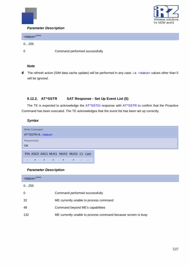
537
Parameter Description
<status>(num)
0…255
0 Command performed successfully
Note
The refresh action (SIM data cache update) will be performed in any case, i.e. <status> values other than 0
will be ignored.
9.12.2. AT^SSTR SAT Response - Set Up Event List (5)
The TE is expected to acknowledge the AT^SSTGI response with AT^SSTR to confirm that the Proactive
Command has been executed. The TE acknowledges that the event list has been set up correctly.
Syntax
Write Command
AT^SSTR=5, <status>
Response(s)
OK
PIN ASC0 ASC1 MUX1 MUX2 MUX3 A Last - + + + + + - -
Parameter Description
<status>(num)
0…255
0 Command performed successfully
32 ME currently unable to process command
48 Command beyond ME's capabilities
132 ME currently unable to process command because screen is busy

538
9.12.3. AT^SSTR SAT Response - Set Up Call (16)
The TE is expected to acknowledge the AT^SSTGI response with AT^SSTR to confirm that the Proactive
Command has been executed.
Syntax
Write Command
AT^SSTR=16, <status>
Response(s)
^SSTR: 16, <TerminationQualifier>, <TerminationCauseText> OK
PIN ASC0 MUX1 MUX2 MUX3 A Last - + + + + - -
Parameter Description
<state>(num)
0…255
0 Command performed successfully. Indicate that the user has accepted the call
request.
4 Command performed successfully, but requested icon could not be displayed.
16 Proactive SIM session terminated by user
20 USSD/SS Transact terminated by user
32 ME currently unable to process command
34 User did not accept the proactive command. Indicate that the user has denied the call
request
35 User cleared down call before connection or network release
48 Command beyond ME's capabilities
132 ME currently unable to process command because screen is busy
Note After confirmation phase the TE may show a dialling animation on the screen until a mandatory response
parameter is issued.
^SSTR: <cmdType>, <TerminationQualifier>, <TerminationCauseText>

539
9.12.4. AT^SSTR SAT Response - Send SS (17)
The TE is expected to acknowledge the AT^SSTGI response with AT^SSTR to confirm that the Proactive
Command has been executed.
Syntax
Write Command
AT^SSTR=17, <status>
Response(s)
^SSTR: 17, <TerminationQualifier>, <TerminationCauseText> OK
PIN ASC0 MUX1 MUX2 MUX3 A Last - + + + + - -
Parameter Description
<status>(num)
0…255
0 Command performed successfully. Indicate that the user has accepted the SS request.
4 Command performed successfully, but requested icon could not be displayed.
20 USSD/SS Transact terminated by user
32 ME currently unable to process command
48 Command beyond ME's capabilities
132 ME currently unable to process command because screen is busy
9.12.5. AT^SSTR SAT Response - Send USSD (18)
The TE is expected to acknowledge the AT^SSTGI response with AT^SSTR to confirm that the Proactive
Command has been executed.

540
Syntax
Write Command
AT^SSTR=18, <status>
Response(s)
^SSTR: 18, <TerminationQualifier>, <TerminationCauseText> OK
PIN ASC0 MUX1 MUX2 MUX3 A Last - + + + + - -
Parameter Description
<status>(num)
0…255
0 Command performed successfully. Indicate that the user has accepted the USSD
request.
4 Command performed successfully, but requested icon could not be displayed.
20 USSD/SS Transact terminated by user
32 ME currently unable to process command
48 Command beyond ME's capabilities
132 ME currently unable to process command because screen is busy
9.12.6. AT^SSTR SAT Response - Send Short Message (19)
The TE is expected to acknowledge the AT^SSTGI response with AT^SSTR to confirm that the Proactive
Command has been executed.
Syntax
Write Command
AT^SSTR=19, <status>
Response(s)
^SSTR: 19, <TerminationQualifier>, <TerminationCauseText> OK
PIN ASC0 MUX1 MUX2 MUX3 A Last - + + + + - -

541
Parameter Description
<status>(num)
0…255
0 Command performed successfully. Indicate that the user has accepted the Send SMS
request.
4 Command performed successfully, but requested icon could not be displayed.
32 ME currently unable to process command
48 Command beyond ME's capabilities
132 ME currently unable to process command because screen is busy
9.12.7. AT^SSTR SAT Response - Send DTMF (20)
The TE is expected to acknowledge the AT^SSTGI response with AT^SSTR to confirm that the Proactive
Command has been executed.
Syntax
Write Command
AT^SSTR=19, <status>
Response(s)
^SSTR: 19, <TerminationQualifier>, <TerminationCauseText> OK
PIN ASC0 MUX1 MUX2 MUX3 A Last - + + + + - -
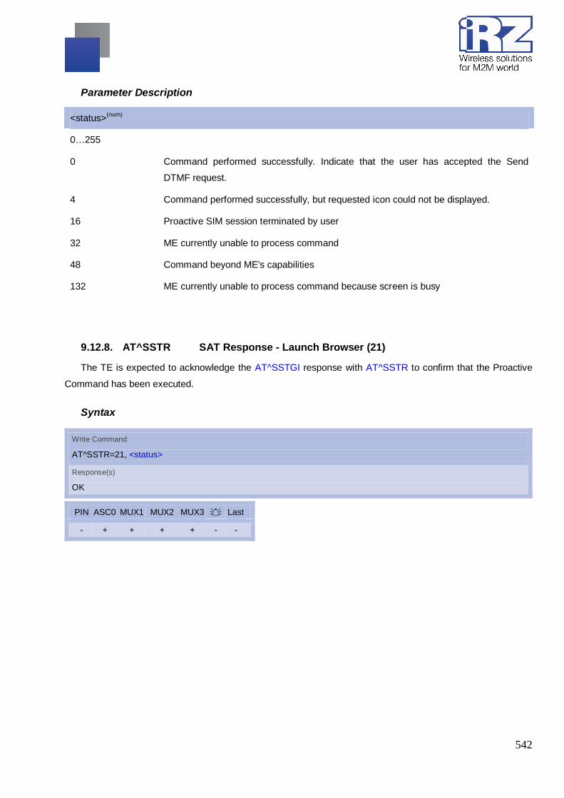
542
Parameter Description
<status>(num)
0…255
0 Command performed successfully. Indicate that the user has accepted the Send
DTMF request.
4 Command performed successfully, but requested icon could not be displayed.
16 Proactive SIM session terminated by user
32 ME currently unable to process command
48 Command beyond ME's capabilities
132 ME currently unable to process command because screen is busy
9.12.8. AT^SSTR SAT Response - Launch Browser (21)
The TE is expected to acknowledge the AT^SSTGI response with AT^SSTR to confirm that the Proactive
Command has been executed.
Syntax
Write Command
AT^SSTR=21, <status>
Response(s)
OK
PIN ASC0 MUX1 MUX2 MUX3 A Last - + + + + - -

543
Parameter Description
<status>(num)
0…255
0 Command performed successfully. Indicate that the user has accepted the Launch
Browser request.
4 Command performed successfully, but requested icon could not be displayed.
32 ME currently unable to process command
34 User did not accept the proactive command. Indicate that the user has denied the
Launch Browser request
38 Launch Browser generic error with additional information "No specific cause can be
given".
48 Command beyond ME's capabilities
132 ME currently unable to process command because screen is busy
138 Launch Browser generic error with additional information "Bearer unavailable".
238 Launch Browser generic error with additional information "Browser unavail-able".
239 Launch Browser generic error with additional information "ME unable to read the
provisioning data".
9.12.9. AT^SSTR SAT Response - Play Tone (32)
The TE is expected to acknowledge the AT^SSTGI response with AT^SSTR to confirm that the Proactive
Command has been executed.
Syntax
Write Command
AT^SSTR=32, <status>
Response(s)
OK
PIN ASC0 MUX1 MUX2 MUX3 A Last - + + + + - -

544
Parameter Description
<status>(num)
0…255
0 Command performed successfully. Indicate that the user has accepted the call
request.
4 Command performed successfully, but requested icon could not be displayed.
16 Proactive SIM session terminated by user
32 ME currently unable to process command
48 Command beyond ME's capabilities
132 ME currently unable to process command because screen is busy
Note
It is possible for the TE to stop playing the tone by sending the AT^SSTR before Tone is finished.
9.12.10. AT^SSTR SAT Response - Display Text (33)
The TE is expected to acknowledge the AT^SSTGI response with AT^SSTR to confirm that the Proactive
Command has been executed.
Syntax
Write Command
AT^SSTR=33, <status>
Response(s)
OK
PIN ASC0 MUX1 MUX2 MUX3 A Last - + + + + - -

545
Parameter Description
<status>(num)
0…255
0 Command performed successfully. Indicate that the user has accepted the call
request.
4 Command performed successfully, but requested icon could not be displayed.
16 Proactive SIM session terminated by user
17 Backward move in the proactive SIM session requested by the user
18 No response from user
32 ME currently unable to process command
48 Command beyond ME's capabilities
132 ME currently unable to process command because screen is busy
9.12.11. AT^SSTR SAT Response - Get Inkey (34)
The TE is expected to acknowledge the AT^SSTGI response with AT^SSTR to confirm that the Proactive
Command has been executed.
Syntax
Write Command
AT^SSTR=34, <status>, , <inputString>
Response(s)
OK
PIN ASC0 MUX1 MUX2 MUX3 A Last - + + + + - -

546
Parameter Description
<status>(num)
0…255
0 Command performed successfully. Indicate that the user has accepted the call
request.
4 Command performed successfully, but requested icon could not be displayed.
16 Proactive SIM session terminated by user
17 Backward move in the proactive SIM session requested by the user
18 No response from user
19 Help information required by the user
32 ME currently unable to process command
48 Command beyond ME's capabilities
132 ME currently unable to process command because screen is busy
<inputString>(str)
User response entered as a string parameter
Notes Coding of any input character is related to the selected alphabet:
- Input of a character in case of GSM character set requests one byte, e.g. "Y".
- Input of any characters in UCS2 alphabet requests a 4 byte set, e.g. "0059" is coding the same
character "Y".
- If, as a user response, a binary choice (Yes/No) is requested by the SIM application using bit 3 of the
<commandDetails> parameter the valid content of the <inputString> is: a) GSM alphabet: "Y" or "y"
(positive answer) and "N" or "n" (negative answer). b) UCS2 alphabet "0079" or "0059" (positive answer)
and "006E" or "004E" (negative answer). For more detailed information refer to AT^SSTGI.
- Coding of an empty string is done as a "\1b" string with every alphabet.
- The <Alphabet> parameter of AT^SSTA determines the alphabet used on the AT command interface,
while the value reported by the <commandDetails> bit 2 of the AT^SSTGI=34 command determines the
set of characters allowed. If these alphabet settings are different, the following applies:
Example: If UCS2 alphabet is selected with AT^SSTA and the <commandDetails> bit 2 of the
AT^SSTGI=34 command is reported as "SMS default alphabet (GSM character set)" any input has to be
done in UCS2 alphabet. However, take care to enter only UCS2 characters for which equivalent
characters are defined in the SMS (GSM) default alphabet. In this case, the ME will correctly translate
the given UCS2 data into a TERMINAL RESPONSE coded in SMS (GSM) default alphabet.

547
9.12.12. AT^SSTR SAT Response - Get Input (35)
The TE is expected to acknowledge the AT^SSTGI response with AT^SSTR to confirm that the Proactive
Command has been executed.
Syntax
Write Command
AT^SSTR=35, <status>, , <inputString>
Response(s)
OK
PIN ASC0 MUX1 MUX2 MUX3 A Last - + + + + - -
Parameter Description
<status>(num)
0…255
0 Command performed successfully. Indicate that the user has accepted the call
request.
4 Command performed successfully, but requested icon could not be displayed.
16 Proactive SIM session terminated by user
17 Backward move in the proactive SIM session requested by the user
18 No response from user
19 Help information required by the user
32 ME currently unable to process command
48 Command beyond ME's capabilities
132 ME currently unable to process command because screen is busy
<inputString>(str)
User response entered as a string, length depends on the <responseMin> and <responseMax> values
returned by the related AT^SSTGI=35 command.

548
Notes Coding of any input character is related to the selected alphabet:
- Input of a character in case of GSM character set requests one byte, e.g. "Y".
- Input of any characters in UCS2 alphabet requests a 4 byte set, e.g. "0059" is coding the same
character "Y".
- Coding of an empty string is done as a "\1b" string with every alphabet.
The <Alphabet> parameter of AT^SSTA determines the alphabet used on the AT command interface, while
the value reported by the <commandDetails> bit 2 of the AT^SSTGI=35 command determines the set of
characters allowed. If these alphabet settings are different, the following applies: Example: If UCS2
alphabet is selected with AT^SSTA and the <commandDetails> bit 2 of the AT^SSTGI=35 command is
reported as "SMS default alphabet (GSM character set)" any input has to be done in UCS2 alphabet.
However, take care to enter only UCS2 characters for which equivalent characters are defined in the SMS
(GSM) default alphabet. In this case, the ME will correctly translate the given UCS2 data into a TERMINAL
RESPONSE coded in SMS (GSM) default alphabet.
9.12.13. AT^SSTR SAT Response - Select Item (36)
The TE is expected to acknowledge the AT^SSTGI response with AT^SSTR to confirm that the Proactive
Command has been executed. The TE sends a response that can indicate the user's intentions, e.g. when the
user is requesting help or selecting a menu item.
GSM11.14 states:
"When the ME issues a successful TERMINAL RESPONSE ('0X' result value ...) for a SELECT ITEM
command, it shall supply the identifier of the item selected by the user in the Item identifier data object. If the
ME issues a TERMINAL RESPONSE with result "Help information required by the user" for a SELECT ITEM
command, it shall supply the identifier of the item for which the user is requiring help information. All other types
of TERMINAL RESPONSE do not need to include Item identifier. If one is included by the ME, the SIM shall
ignore it."
For compatibility reasons <itemId> is optional in case of <status>=19 ("Help information required by the
user"). In this case <itemId>=0 is sent to the SIM.

549
Syntax
Write Command
AT^SSTR=36, <status>, , <itemId>
Response(s)
OK
PIN ASC0 MUX1 MUX2 MUX3 A Last - + + + + - -
Parameter Description
<status>(num)
0…255
0 Command performed successfully. Indicate that the user has accepted the call
request.
4 Command performed successfully, but requested icon could not be displayed.
16 Proactive SIM session terminated by user
17 Backward move in the proactive SIM session requested by the user
18 No response from user
19 Help information required by the user
32 ME currently unable to process command
48 Command beyond ME's capabilities
132 ME currently unable to process command because screen is busy
<itemId>(num)
Item IDs are supplied by the SIM Application
1...255 ID of selected item can be issued if a <status> value of 0 is returned
9.12.14. AT^SSTR SAT Response - Setup Menu (37)
The TE is expected to acknowledge the AT^SSTGI response with AT^SSTR to confirm that the Proactive
Command has been executed.

550
Syntax
Write Command
AT^SSTR=37, <status>
Response(s)
OK
PIN ASC0 MUX1 MUX2 MUX3 A Last - + + + + - -
Parameter Description
<status>(num)
0…255
0 Command performed successfully. Indicate that the user has accepted the call
request.
4 Command performed successfully, but requested icon could not be displayed.
32 ME currently unable to process command
48 Command beyond ME's capabilities
132 ME currently unable to process command because screen is busy
Note The response simply conveys, to the SAT, the information that the main menu was received and set up on
the user interface. It does not transmit any information about a selected item, like in the case of AT^SSTR.
Once this command was executed the user can proceed as described in the AT^SSTR SAT Response -
Setup Menu (37).
9.12.15. AT^SSTR SAT Response - Set Up Idle Mode Text (40)
The TE is expected to acknowledge the AT^SSTGI response with AT^SSTR to confirm that the Proactive
Command has been executed.

551
Syntax
Write Command
AT^SSTR=40, <status>
Response(s)
OK
PIN ASC0 MUX1 MUX2 MUX3 A Last - + + + + - -
Parameter Description
<status>(num)
0…255
0 Command performed successfully. Indicate that the user has accepted the call
request.
4 Command performed successfully, but requested icon could not be displayed.
32 ME currently unable to process command
48 Command beyond ME's capabilities
132 ME currently unable to process command because screen is busy
9.12.16. AT^SSTR SAT Response - Language Notification (53)
The TE is expected to acknowledge the AT^SSTGI response with AT^SSTR to confirm that the Proactive
Command has been executed. The TE indicates whether the Language Notification command was correctly
executed.
Syntax
Write Command
AT^SSTR=53, <status>
Response(s)
OK
PIN ASC0 MUX1 MUX2 MUX3 A Last - + + + + - -

552
Parameter Description
<status>(num)
0…255
0 Command performed successfully. Indicate that the user has accepted the call
request.
9.12.17. AT^SSTR SAT Event - Menu Selection (211)
The TE specifies the user's selection of an item from the main menu, which was set up using SETUP
MENU command. Alternatively help can be requested.
Syntax
Write Command
AT^SSTR=211, <status>, <itemId>
Response(s)
OK
PIN ASC0 MUX1 MUX2 MUX3 A Last - + + + + - -
Parameter Description
<status>(num)
0…255
0 Command performed successfully.
19 Help information required by the user, no other value can be returned.
<itemId>(num)
ID of selected item
0...255
9.12.18. AT^SSTR SAT Event - User Activity (232)
Sent by the customer application to indicate that a key has been pressed.

553
Syntax
Write Command
AT^SSTR=232
Response(s)
OK
PIN ASC0 ASC1 MUX1 MUX2 MUX3 A Last - + + + + + - -
9.12.19. AT^SSTR SAT Event - Idle Screen Available (233)
Sent by the customer application to indicate that the screen has become idle.
Syntax
Write Command
AT^SSTR=233
Response(s)
OK
PIN ASC0 MUX1 MUX2 MUX3 A Last - + + + + - -
9.12.20. AT^SSTR SAT Event - Language Selection (235)
Sent by the customer application to indicate that the customer application has changed the language.
The last value given via this command is also provided to the SIM as response to the proactive command
"Provide Local Information (Language Setting)".
Syntax
Write Command
AT^SSTR=235, , , <inputString>
Response(s)
OK
PIN ASC0 MUX1 MUX2 MUX3 A Last - + + + + - -

554
Parameter Description
<inputString>(str)
Two character language tag, e.g. "en" for English or "de" for German. Default value is "en".
9.12.21. AT^SSTR SAT Event - Browser Termination (236)
Sent by the customer application to indicate that the internet browser application has been terminated.
Syntax
Write Command
AT^SSTR=236, , , <TermCause>
Response(s)
OK
PIN ASC0 MUX1 MUX2 MUX3 A Last - + + + + - -
Parameter Description
<TermCause>(num)
Browser Termination Cause
0…255
0 User termination.
1 Error termination
9.12.22. AT^SSTR SAT Event - Terminate Command (254)
This command allows the TE to finish an ongoing proactive command. This is done by sending repeatedly
a Terminal Response "ME currently unable to process command" to the SIM (see GSM 11.14), if issued in
states PAC or WAIT. No action is performed if the interface is already in IDLE state. However, the command
returns "OK".
The reaction to the terminal response depends on the SIM application. The command can be used to return
to IDLE state regardless whether a proactive command is ongoing or not.

555
Syntax
Write Command
AT^SSTR=254
Response(s)
OK
PIN ASC0 MUX1 MUX2 MUX3 A Last - + + + + - -
Note
This command is allowed in states IDLE, PAC and WAIT and forces a return to IDLE state.
9.12.23. Examples for Using Remote-SAT
To give you an idea of how to start and use Remote-SAT, you may follow the steps described below:
// Start after switch on the module
at
OK
// Switch on verbose error messages
at+cmee=2
OK
// Enter the PIN code (if necessary due to SIM configuration)
at+cpin=1234
OK
// Query the Remote-SAT activation status
at^ssta?
^SSTA: 1,0,1,"6FFFFFFF7F0300DF7F"
OK
// First '1' indicates that the interface is in OFF state, i.e. the Automatic Response (AR) mode is enabled.
During this mode all SAT Proactive Commands are handled internally by the ME.
// Tell the module that the TE ; is interested in handling SAT, i.e. switch to Explicit Response (ER) mode.
at^ssta=1,0

556
OK
// This setting takes effect after next start of the ME only, so switch off first
AT^SMSO
^SMSO: MS OFF
OK
^SHUTDOWN
// Switch on ME again and wait until system start indication (if not in autobaud mode, refer AT+IPR)
^SYSSTART
// Switch on verbose error messages
at+cmee=2
OK
// Enter the PIN code (if necessary due to SIM configuration)
at+cpin=1234
OK
// Receiving the first proactive command (if the mounted SIM carries a SIM Application)
^SSTN:37
// Requesting parameter details
at^sstgi=37
// These are the details:
^SSTGI: 37,0,3,"SAT Special Menu",0,1,1,0
^SSTGI: 37,1,"News",0,0
^SSTGI: 37,2,"EMail",0,0
^SSTGI: 37,3,"Banking",0,0
OK
// To query the status of the proactive command
at^sstr=37,0
OK
// SAT indicates that the proactive session has ended and enters its main menu (which should then be
opened on the screen by an MMI): ^SSTN:254

557
// Selecting item number 1 of the menu sent before: at^sstr=211,0,1
OK
// Receiving the next proactive command:
^SSTN:36
// Requesting more information...
at^sstgi=36
// ... and get it:
^SSTGI: 36,0,12,"Rubriken >",0,0,1,1,0
^SSTGI: 36,1,"News >",0,0
^SSTGI: 36,2,"Stock Infos>",0,0
^SSTGI: 36,3,"Aktien D >",0,0
^SSTGI: 36,4,"Aktien INT >",0,0
^SSTGI: 36,5,"Sports >",0,0
^SSTGI: 36,6,"1.BL-Clubs >",0,0
^SSTGI: 36,7,"Unterhaltung>",0,0
^SSTGI: 36,8,"Horoskop >",0,0
^SSTGI: 36,9,"Wetter D >",0,0
^SSTGI: 36,10,"Wetter INT >",0,0
^SSTGI: 36,11,"Wetter spez>",0,0
^SSTGI: 36,63,"Extras >",0,0
OK
// Remember to acknowledge:
at^sstr=36,0,63
OK
// And again: Receiving the next proactive command:
^SSTN:36
// ...
Examples
EXAMPLE 1
// Switch on verbose error messages
at+cmee=2
OK
558
EXAMPLE 2
// Enter the PIN code
at+cpin=1234
OK
EXAMPLE 3
// Start Remote-SAT
at^ssta=1,0
OK
EXAMPLE 4
// Proactive command "GET INKEY" is issued by the SIM
^SSTN: 34
EXAMPLE 5
// Get complete data
at^sstgi=34
^SSTGI: 34,0,"<COLOUR-ICON>",1,2
OK
EXAMPLE 6
// Use GET RESPONSE command (192) to analyze SIM file EF-IMG (hex. 4F20)
at+crsm=192,20256,0,0,15
+CRSM: 144,0,000000644F20040014F04401020114
OK
EXAMPLE 7
// Use READ RECORD command (178) to get its content
at+crsm=178,20256,2,4,20
+CRSM: 144,0,010808214F0200000016FFFFFFFFFFFFFFFFFFFF
OK
EXAMPLE 8
// Use READ BINARY command (176) to get content of image instance data file (e.g. hex 4F02)
at+crsm=176,20226,0,0,22
+CRSM: 144,0,080802030016AAAA800285428142814281528002AAAA
OK
at+crsm=176,20226,0,22,9

559
+CRSM: 144,0,FF000000FF000000FF
OK
EXAMPLE 9
// Finalize Proactive Command session
at^sstr=34,0,,"+"
OK
EXAMPLE 10
// Session end indication, i.e. display SAT main menu
^SSTN: 254

560
10. Phonebook Commands The AT Commands described in this chapter used to operate with phonebooks located in
the MG21’s memory or on the attached SIM.
Phonebook AT+CNUM AT+CPBF AT+CPBR AT+CPBS AT+CPBW AT^SDLD AT^SPBC AT^SPBD AT^SPBG AT^SPBS

561
10.1. AT+CNUM Read own numbers
AT+CNUM returns the subscribers own number(s) from the SIM.
Syntax
Test Command
AT+CNUM=?
Response(s)
OK
Exec Command
AT+CNUM
Response(s)
[+CNUM: [<alpha>], <number>, <type>] [+CNUM: ... ] OK ERROR +CME ERROR: <err>
PIN ASC0 MUX1 MUX2 MUX3 A Last + + + + + - -
Reference(s)
GSM 07.07
Parameter Description
<alpha>(str)
Optional alphanumeric string associated with <number>.
<number>(str)
Phone number in format specified by <type>.
<type>(str)
Type of address octet, see also: AT+CPBR <type>.
Note
Users should be aware that when using this AT command quickly after SIM PIN authentication the SIM
data may not yet be accessible, resulting in a short delay before the requested AT command response is
returned.

562
10.2. AT+CPBF Find Phonebook Entries
Syntax
Test Command
AT+CPBF=?
Response(s)
+CPBF: maximum length of field <nlength>,maximum length of field <tlength> OK If error is related to ME functionality: +CME ERROR: <err>
Write Command
AT+CPBF=[<findtext>]
Response(s)
TA returns phone book entries (from the current phone book memory storage selected with +CPBS) which contains alphanumeric string <findtext>. [+CPBF:<index1>,<number>,<type>,<text>][----] <CR><LF>[+CBPF:<index2>,<number>,<type>,<text>] OK
Parameter Description
<index1>(num)
integer type values in the range of location numbers of phonebook memory
<index2>(num)
integer type values in the range of location numbers of phonebook memory
<number>(str)
string type (string should be included in quotation marks) phone number of format <type>
<type>(num)
type of address octet in integer format;
129 Unknown type (IDSN format number)
161 National number type (IDSN format)
145 International number type (ISDN format)
177 Network specific number (ISDN format)

563
<text>(str)
string type(string should be included in quotation marks) field of maximum length <tlength> in current TE
character set specified by +CSCS.
<nlength>(num)
integer type value indicating the maximum length of field <number>
<tlength>(num)
integer type value indicating the maximum length of field <text>

564
10.3. AT+CPBR Read from Phonebook
AT+CPBR serves to read one or more entries from the phonebook selected with AT command AT+CPBS.
The AT+CPBR test command returns the location range supported by the current phonebook storage, the
maxi-mum length of <number> field and the maximum length of <text> field.
Note: Length information may not be available while SIM storage is selected. If storage does not offer
format information, the format list contains empty parenthesizes.
The AT+CPBR write command determines the phonebook entry to be displayed with <location1> or a
location range from <location1> to <location2>. Hence, if no <location2> is given only the entry at <location1>
will be displayed.
If no entries are found at the selected location "OK" will be returned.
Syntax
Test Command
AT+CPBR=?
Response(s)
+CPBR: (1-<maxloc>), <nlength>, <tlength> OK ERROR +CME ERROR: <err>
Write Command
AT+CPBR=<location1>[, <location2>]
Response(s)
[+CPBR: <location1>, <number>, <type>, <text>] [+CPBR: <location2>, <number>, <type>, <text>] OK ERROR +CME ERROR: <err>
PIN ASC0 MUX1 MUX2 MUX3 A Last + + + + + - -
Reference(s)
GSM 07.07, GSM 11.11
Parameter Description
<location1>(num)
The first (lowest) location number within phonebook memory where to start reading. The maximum range
sup-ported by the current phonebook is given in the test command response.
If <location1> exceeds the upper bound <maxloc> (as indicated by the test command), command will
respond with "+CME ERROR: invalid index".

565
<location2>(num)
The last (highest) location number within phonebook memory where to stop reading. The maximum range
sup-ported by the current phonebook is given in the test command response.
If both <location1> and <location2> are in the range indicated by the test command parameter <maxloc>, the
list of entries will be output and terminated with "OK".
If <location2> exceeds the range indicated by the test command parameter <maxloc>, the list of entries will
be output but terminated with "+CME ERROR: invalid index".
<number>(str)
Phone number in format specified by <type>, it may be an empty string.
<type>(num)
Type of address octet, which defines the used type of number (ton) and the numbering plan identification
(npi). Please consider that for types other than 129 or 145 dialing from phonebook with ATD><mem><n> is,
depending on the network, not always possible (refer to GSM 04.08 subclause 10.5.4.7 for details). See also
<type> of AT+CPBW. Possible values are:
145 Dialing string <number> includes international access code character '+'
161 National number. Network support of this type is optional.
209 Dialing string <number> has been saved as ASCII string and includes non-digit
characters other than "*", "#", "+" or "p". Note that phonebook entries saved with this
type cannot be dialed.
255 Dialing string <number> is a command to control a Supplementary Service, i.e. "*", "#"
codes are contained. Network support of this type is optional.
129 Otherwise
<text>(str)(+CSCS)
Text assigned to a phone number. The maximum length for this parameter is given with test command
response parameter <tlength>. If using an ASCII terminal characters which are coded differently in ASCII and
GSM have to be entered via escape sequences.
<maxloc>(num)
Maximum location number for the currently selected storage. For phonebooks located on the SIM this value
depends on the SIM card type.

566
<nlength>(num)
Maximum length of phone number for "normal" locations. Depending on the storage a limited number of loca-
tions with extended memory is available per phonebook. These locations allow storing numbers with twice
the standard length, which is 2*<nlength> digits for normal numbers, but only <nlength> digits for numbers
saved with <type>=209.
<tlength>(num)
Maximum length of <text> assigned to the telephone number. The value indicated by the test command is
given in octets. If <text> is given as GSM characters each character corresponds to one octet. If the <text>
string is given in UCS2, the maximum number of characters depends on the coding scheme used for the
alpha field of the SIM according to GSM 11.11, Annex B [21]. In the worst case the number of UCS2
characters is at least one less than half the number of GSM characters.
Note
Users should be aware that when using this AT command quickly after SIM PIN authentication the SIM
data may not yet be accessible, resulting in a short delay before the requested AT command response is
returned.

567
10.4. AT+CPBS Select phonebook memory storage
AT+CPBS selects the active phonebook storage, i.e. the phonebook storage that all subsequent
phonebook commands will be operating on.
The read command returns the currently selected <storage>, the number of <used> entries and the <total>
number of entries available for this storage. The test command returns all supported <storage>s as compound
value.
Syntax
Test Command
AT+CPBS=?
Response(s)
+CPBS: (list of supported <storage>s) OK ERROR +CME ERROR: <err>
Read Command
AT+CPBS?
Response(s)
+CPBS: <storage>, <used>, <total> OK ERROR +CME ERROR: <err>
Write Command
AT+CPBS=<storage>
Response(s)
OK ERROR +CME ERROR: <err>
PIN ASC0 MUX1 MUX2 MUX3 A Last + + + + + - -
Reference(s)
GSM07.07

568
Parameter Description
<storage>(str)
“FD“ Fixed dialing phonebook
Capacity: depending on SIM
Location: SIM
“SM“(&F)(P) SIM phonebook
Capacity: depending on SIM
Location: SIM
“ON“ MSISDN list
Capacity: depending on SIM
Location: SIM
“ME“ Mobile Equipment Phonebook
Capacity: max. 250 entries
Location: ME
“LD“ Last number dialed phonebook. Stores all voice call numbers dialed with ATD, but no
data call numbers.
Capacity: max. 10 entries
Location: depending on SIM this phonebook may reside partly or completely in ME
AT+CPBW command is not applicable to this storage. The LD list can be deleted with
AT^SDLD or with AT^SPBD.
“MC“ Missed (unanswered received) calls list
Capacity: max. 10 entries
Location: ME
AT+CPBW command is not applicable to this storage. The MC list can be deleted with
AT^SPBD.
“RC“ Received calls list
Capacity: max. 10 entries
Location: ME
AT+CPBW command is not applicable to this storage. The RC list can be deleted with
AT^SPBD.
“VM“ CPHS voice mailbox phonebook
Capacity: 1 or 2 entries, depending on SIM
1 - Line 1 mailbox
2 - Line 2 mailbox
Location: SIM

569
<used>(num)
Value indicating the number of used locations in selected memory storage.
<total>(num)
Value indicating the maximum number of locations allowed in the selected memory storage.
Notes
Users should be aware that when using this AT command quickly after SIM PIN authentication the SIM
data may not yet be accessible, resulting in a short delay before the requested AT command response is
returned.
If the SIM card is changed, all records of the "MC", "RC" and "LD" phonebooks stored on the ME will be
deleted automatically. If the same SIM is removed and reinserted, no automatic deletion is performed. Calls
made after last switch-on will be cleared from the "MC", "RC" and "LD" phonebook, if the SIM is removed
and reinserted during normal operation.
Missed and received calls which are not presented to the called party are not stored in MC and RC phone-
book.

570
10.5. AT+CPBW Write into Phonebook
The AT+CPBW write command can be used to create, edit and delete a phonebook entry at a <location> of
the active storage selected with AT+CPBS.
If <storage>="FD" (SIM fixed dialing numbers) is selected, PIN2 authentication has to be performed prior to
any write access.
The AT+CPBW test command returns the location range supported by the current storage, the maximum
length of the <number> field, the range of supported <type> values and the maximum length of the <text> field.
Note: The length may not be available while SIM storage is selected. If storage does not offer format
information, the format list contains empty parenthesizes.
Syntax
Test Command
AT+CPBW=?
Response(s)
+CPBW: (1-<maxloc>), <nlength>, (list of supported <type>s), <tlength> OK ERROR +CME ERROR: <err>
Write Command
AT+CPBW=[<location>][, <number>[[, <type>][, <text>]]]
Response(s)
OK ERROR +CME ERROR: <err>
PIN ASC0 MUX1 MUX2 MUX3 A Last + + + + + - -
Reference(s)
GSM 07.07, GSM 04.08
Parameter Description
<location>(num)
Location number within phonebook memory. The maximum range supported by each storage type is
indicated in the test command response. If <location> is not given, the first free entry will be used.
If <location> is given as the only parameter, the phonebook entry specified by <location> is deleted.

571
<number>(str)
Phone number in format specified by <type>. Parameter must be present, although it may be an empty
string. Alphabetic characters are not permitted. The <number> may contain dialstring modifiers "*", "#", "+" or
"p".
If other printable non-alphabetic characters are used the entry needs to be saved with <type>=209.
Otherwise, if <type>=209 is not used any non-digit characters other than "*", "#", "+" or "p" will be removed
from the string and only accepted modifiers from the GSM alphabet will be saved.
A <number> saved with <type>=209 requires double memory. In order to fit into a standard location, the
number needs to be reduced to a maximum length of <nlength>/2, including all digits and dial string
modifiers. Extended locations may be used as stated below for <nlength>.
<type>(num)
Type of address octet, which defines the used type of number (ton) and the numbering plan identification
(npi). Please consider that for types other than 129 or 145 dialing from phonebook with ATD><mem><n> is,
depending on the network, not always possible (refer GSM 04.08 subclause 10.5.4.7 for details).
If <type> is not specified the unknown <type>=129 is used. If <number> contains a leading "+" <type>=145
(international) is used.
Supported values are:
145 Dialing string <number> includes international access code character "+"
161 National number. The network support for this type is optional.
209 Dialing string <number> will be saved as ASCII string.
This is the default value, if <type> is not specified explicitly and characters other than
"*", "#", "+" or "p" are included in <number>.
Note that phonebook entries saved with this type cannot be dialed.
255 Dialing string <number> is a command to control a Supplementary Service, i.e. "*", "#"
codes are contained. Network support of this type is optional.
129 Unknown number. If <type> is unknown and the <number> contains a lead-ing "+",
then this sign is removed.
<text>(str)(+CSCS)
Text assigned to the phone number. The maximum length of this parameter is given in the test command
response <tlength>. When using an ASCII terminal, characters which are coded differently in ASCII and GSM
have to be entered via escape sequences.

572
<maxloc>(num)
Maximum number of locations supported by the currently selected storage. For phonebooks located on SIM,
this value varies depending on the SIM card. See AT+CPBS for typical values.
<nlength>(num)
Maximum length of phone number for "normal" locations. Depending on the storage, a limited number of
loca-tions with extended memory is available per phonebook. These locations allow storing numbers with
twice the standard length, which is 2*<nlength> digits for normal numbers, but only <nlength> digits for
numbers saved with parameter <type>= 209. If all extended locations of the selected phonebook are used
up, then any attempt to write a number which requires extended memory will be denied with "+CME ERROR:
invalid dial string".
<tlength>(num)
Maximum length of <text> assigned to the telephone number. The value indicated by the test command is
given in octets. If the <text> string is given in GSM characters, each character corresponds to one octet. If
the <text> string is given in UCS2, the maximum number of characters depends on the coding scheme used
for the alpha field of the SIM. In the worst case the number of UCS2 characters is at least one less than half
the number of GSM characters.
For a detailed description please refer to GSM 11.11, Annex B.
Notes
Users should be aware that when using this AT command quickly after SIM PIN authentication the SIM
data may not yet be accessible, resulting in a short delay before the requested AT command response is
returned.
During AT+CPBW write command it is possible that in some cases returns "+CME ERROR: operation
tempo-rary not allowed". Use AT+CPBW write command again.
DTMF transmission:
If a dial string contains the call modifier "p" the digits after this call modifier will be saved as DTMF tones.
The DTMF tones 'A','B','C' and 'D' can not be saved due to BCD limitations.
Examples
EXAMPLE 1
Make a new phonebook entry at the first free location
AT+CPBW=,"+431234567",145,"international"

573
EXAMPLE 2
Delete entry at location 1
AT+CPBW=1
EXAMPLE 3
The following examples are provided to illustrate the effect of writing phonebook entries with different types
of dial string modifiers in <number>
AT+CPBW=5,"12345678",,"Arthur" AT+CPBW=6,"432!p-765()&54*654#",,"John" AT+CPBW=7,"432!p-765()&54*654#",129,"Eve" AT+CPBW=8,"432!p-765()&54*654#",145,"Tom" AT+CPBW=9,"432!p-765()&54*654#",209,"Richard"
EXAMPLE 4
Read phonebook entries from locations 5 - 9 via AT+CPBR
+CPBR:5,"12345678",129,"Arthur" +CPBR:6,"432!p-765()&54*654#",209,"John" +CPBR:7,"432p76554*654#",129,"Eve" +CPBR:8,"+432p76554*654#",145,"Tom" +CPBR:9,"432!p-765()&54*654#",209,"Richard"

574
10.6. AT^SDLD Delete the 'last number redial' memory
AT^SDLD deletes all numbers stored in the "LD" memory.
Syntax
Test Command
AT^SDLD=?
Response(s)
OK
Exec Command
AT^SDLD
Response(s)
OK ERROR +CME ERROR: <err>
PIN ASC0 MUX1 MUX2 MUX3 A Last + + + + + - -
Note
Users should be aware that when using this AT command quickly after SIM PIN authentication the SIM
data may not yet be accessible, resulting in a short delay before the requested AT command response is
returned.

575
10.7. AT^SPBC Find first matching entry in sorted phonebook
The AT^SPBC write command searches the current phonebook for the index number of the first (lowest)
entry that matches the character specified with <schar>. The AT^SPBC test command returns the list of
phonebooks which can be searched through with AT^SPBC.
CAUTION: Please note that AT^SPBC is assigned the same index as AT^SPBG or AT^SPBS which is not
identical with the physical location numbers used in the various phonebooks. Therefore, do not use the index
numbers retrieved with AT^SPBC to dial out or modify phonebook entries.
Syntax
Test Command
AT^SPBC=?
Response(s)
^SPBC: (list of supported <storage>s) OK ERROR +CME ERROR: <err>
Write Command
AT^SPBC=<schar>
Response(s)
^spbc: <index> OK ERROR +CME ERROR: <err>
PIN ASC0 MUX1 MUX2 MUX3 A Last + + + + + - -
Parameter Description
<storage>(str)
Response parameter of AT^SPBC test command.
For a detailed description of storages see AT+CPBS.
“FD“ Fixed dialing phonebook
“SM“ SIM phonebook
“ME“ Mobile Equipment Phonebook
<schar>(str)
First character of the entry to be searched in the sorted list of phonebook entries.

576
<index>(num)
In the active phonebook, the first (lowest) index number of an entry beginning with <schar>. As stated above,
the retrieved index number shall not be used to dial out or edit phonebook entries. If no matching phonebook
entry is found, <index>=0 will be returned.
Note
Users should be aware that when using this AT command quickly after SIM PIN authentication the SIM
data may not yet be accessible, resulting in a short delay before the requested AT command response is
returned.

577
10.8. AT^SPBD Purge phonebook memory storage
AT^SPBD can be used to purge the selected phonebook <storage> manually, i.e. all entries stored in the
selected phonebook storage will be deleted. CAUTION! The operation cannot be stopped nor reversed! The
AT^SPBD test command returns the list of phonebooks which can be deleted with AT^SPBD.
An automatic purge of the phonebooks is performed when the SIM card is removed and replaced with a
different SIM card. This affects the ME based part of the "LD" storage, and storages "MC" and "RC". Storage
"ME" is not affected.
Syntax
Test Command
AT^SPBD=?
Response(s)
^SPBD: (list of supported <storage>s) OK ERROR +CME ERROR: <err>
Write Command
AT^SPBD=<storage>
Response(s)
OK ERROR +CME ERROR: <err>
PIN ASC0 MUX1 MUX2 MUX3 A Last + + + + + - -
Parameter Description
<storage>(str)
If test command: List of phonebooks which can be deleted by AT^SPBD.
If write command: Phonebook to be deleted.
For a detailed description of storages see AT+CPBS.
“LD“ Last number dialed phonebook
“MC“ Missed (unanswered received) calls list
“RC“ Received calls list

578
Note Users should be aware that when using this AT command quickly after SIM PIN authentication the SIM
data may not yet be accessible, resulting in a short delay before the requested AT command response is
returned.

579
10.9. AT^SPBG Display phonebook entries in alphabetical order
AT^SPBG sorts the entries of the current phonebook in alphabetical order by name (the first six characters
matter).
There are two ways to use AT^SPBG:
If the optional parameter <RealLocReq> equals 0 or is omitted the sorted entries will be sequentially
numbered. As these numbers are not identical with the location numbers stored in the various phonebooks
AT^SPBG can be used for reading only. For example, it helps you find entries starting with matching
characters. Do not use the serial numbers to dial out or modify entries.
If parameter <RealLocReq>=1 is given by the write command, the response parameter <location>
additionally appended to each entry indicates the actual location number. This number can be used for
editing with AT+CPBW or dialing with ATD><mem><n>. The first index number of each entry is only the
serial number of the sorted list.
Before using the AT^SPBG write command it is recommended to query the number of records currently
stored in the active phonebook (refer to test command parameter <used>). The test command also includes the
parameters <nlength> and <tlength>. Note that if SIM storage is selected the length may not be available. If
stor-ge does not offer format information, the format list should be empty parenthesises.
Syntax
Test Command
AT^SPBG=?
Response(s)
^SPBG: (1-<used>), <nlength>, <tlength> OK ERROR +CME ERROR: <err>
Write Command
AT^SPBG=<index1>[, <index2>][, <RealLocReq>]
Response(s)
[^SPBG: <index1>, <number>, <type>, <text>[, <location>]] [^SPBG: <index2>, <number>, <type>, <text>[, <location>]] OK ERROR +CME ERROR: <err>
PIN ASC0 MUX1 MUX2 MUX3 A Last + + + + + - -

580
Parameter Description
<index1>(num)
First index number in the sorted list where to start reading. The supported range is given in the test command
response.
If <index 1> exceeds the upper bound <used>, "+CME ERROR: invalid index" will be returned.
<index2>(num)
Last index number in the sorted list where to stop reading. The supported range is given in the test command
response.
If <index2> is not given via write command, only the entry located at <index1> will be displayed.
If both <index1> and <index2> are in the range indicated by the test command parameter <used>, the list of
entries will be output and terminated with OK.
If <index2> exceeds the range indicated by the test command parameter <used>, the list of entries will be
output but terminated with a "+CME ERROR: invalid index".
<RealLocReq>(num)
Is a display of the "real" <location> of the entry required?
[0] Do not show an entry's "real" location number. Parameter <location> will not be
displayed.
1 Show the "real" location number as parameter <location> at the end of each entry.
<number>(str)
String type phone number in format specified by <type>.
The number parameter may be an empty string.

581
<type>(num)
Type of address octet, which defines the used type of number (ton) and the numbering plan identification
(npi). Please consider that for types other than 129 or 145 dialing from phonebook with ATD><mem><n> is,
depending on the network, not always possible. See also <type> of AT+CPBW.
Possible values are:
145 Dialing string <number> includes international access code character '+'
161 National number. Network support of this type is optional.
209 Dialing string <number> has been saved as ASCII string and includes non-digit
characters other than "*", "#", "+" or "p". Note that phonebook entries saved with this
type cannot be dialed.
255 Dialing string <number> is a command to control a Supplementary Service, i.e. "*", "#"
codes are contained. Network support of this type is optional.
129 Otherwise
<text>(str)(+CSCS)
Text assigned to the phone number. The maximum length for this parameter is given in test command
response <tlength>.
<used>(num)
Value indicating the number of used locations in selected memory storage.
<location>(num)
The location within phonebook memory at which the corresponding entry is located. This location may be
used for other commands (e.g. AT+CPBR or ATD><mem><n>)
<nlength>(num)
Maximum length of phone number for "normal" locations. Depending on the storage, a limited number of
loca-tions with extended memory is available per phonebook. Please refer to AT command AT+CPBW for
detail.
<tlength>(num)
Maximum length of <text> assigned to the telephone number. The value indicated by the test command is
given in octets. If the <text> string is given in GSM characters, each character corresponds to one octet. If

582
the <text> string is given in UCS2, the maximum number of characters depends on the coding scheme used
for the alpha field of the SIM according to GSM 11.11, Annex B. In the worst case the number of UCS2 char-
acters is at least one less than half the number of GSM characters.
Notes The command can be used for the phonebooks "SM", "FD", "ME" (cf. AT+CPBS).
Users should be aware that when using this AT command quickly after SIM PIN authentication the SIM
data may not yet be accessible, resulting in a short delay before the requested AT command response is
returned.
Examples
EXAMPLE 1
Using AT^SPBG without <RealLocReq>:
AT^SPBG=? First run the AT^SPBG test command to find out the range of entries stored in the current phonebook.
^SPBG: (1-33),20,17 TA returns the range, where 33 is the number of entries stored in the current phonebook.
AT^SPBG=1,33 ^SPBG:1,"+999999",145,"Arthur" ^SPBG:2,"+777777",145,"Bill" ^SPBG:3,"+888888",145,"Charlie"
Now, enter the write command. To obtain best results it is recommended to query the full range of entries. TA returns phonebook entries in alphabetical order.
...................... The numbers at the beginning of each line are not the memory locations in the phonebook, but only serial
numbers assigned to the entries' positions in the alphabetical list.
EXAMPLE 2
Using AT^SPBG with <RealLocReq>:
AT^SPBG=? First run the AT^SPBG test command to find out the range of entries stored in the current phonebook.
^SPBG: (1-33),20,17 TA returns the range, where 33 is the number of entries stored in the current phonebook.
AT^SPBG=1,33,1 ^SPBG:1,"+999999",145,"Arthur",27 ^SPBG:2,"+777777",145,"Bill",6 ^SPBG:3,"+888888",145,"Charlie",15
Now, enter the write command including parameter <RealLocReq>=1 to get the actual location numbers.
...................... The numbers at the end of each line are the memory locations in the phonebook and can be used for
dialing or editing phonebook entries:
AT+CPBR=27 Read out phonebook location 27. +CPBR: 27,"+999999",145,"Arthur" This entry can be edited with AT+CPBW or used for dialing with
ATD><mem><n>. T

583
10.10. AT^SPBS Step through the selected phonebook alphabetically
AT^SPBS can be used to scroll sequentially through the active phonebook records in alphabetical order by
name. Three entries will be displayed at a time.
Every time the write command is executed, 3 rows of phonebook records are returned. Each triplet overlaps
with the next one. The actual index depends on parameter <value>. This parameter determines whether the
index will be increased or decreased.
If the index in one output line reaches the last index in the alphabetical list, the next output line will display
the first list entry.
After the last record of the phonebook has been reached (see parameter <used> for AT^SPBG), the
<internal-counter> switches over to the first.
There are two ways to use AT^SPBS:
If the optional parameter <RealLocReq> is omitted or (0) the sorted entries will be sequentially numbered.
As these numbers are not identical with the location numbers stored in the various phonebooks AT^SPBS can
be used for reading only. For example, it helps you find entries starting with matching characters. Do not use
the serial numbers to dial out or modify entries.
If parameter <RealLocReq>=1 is given by the write command, the response parameter <location>
additionally appended to each entry indicates the actual location number. This number can be used for editing
with AT+CPBW or dialing with ATD><mem><n>. The first index number of each entry is only the serial number
of the sorted list.
See examples below.
Syntax
Test Command
AT^SPBS=?
Response(s)
^SPBS: (list of supported <value>) OK
Write Command
AT^SPBS=<value>[, <RealLocReq>]
Response(s)
^SPBS: <index-a>, <number>, <type>, <text>[, <location>] ^SPBS: <index-b>, <number>, <type>, <text>[, <location>] ^SPBS: <index-c>, <number>, <type>, <text>[, <location>] OK ERROR +CME ERROR: <err>
PIN ASC0 MUX1 MUX2 MUX3 A Last + + + + + - -

584
Parameter Description
<value>(num)
1 To make a step forward in the alphabetically sorted phonebook.
2 To make a step backward in the alphabetically sorted phonebook.
<index-a>(num)
1...maxindex The index in the sorted list of phonebook entries that identifies the first entry displayed.
The value of <index-a> is determined by the value of the <internal-counter> and by
parameter <value>.
After a write command has terminated successfully with "OK", the value from
parameter <index-a> is saved and retained as the new <internal-counter> value.
Mind after the last record of phonebook, the first entry follows.
<index-b>(num)
1...maxindex The index in the sorted list of phonebook entries that identifies the second entry
displayed.
<index-b>= (<index-a>+1).
Mind after the last record of phonebook, the first entry follows.
<index-c>(num)
1...maxindex The index in the sorted list of phonebook entries that identifies the third entry
displayed.
<index-c>= (<index-b>+1).
Mind after the last record of phonebook, the first entry follows.
<number>(str)
String type phone number in format specified by <type>.
the number parameter may be an empty string.
585
<type>(num)
Type of address octet, which defines the used type of number (ton) and the numbering plan identification
(npi). Please consider that for types other than 129 or 145 dialing from phonebook with ATD><mem><n> is,
depending on the network, not always possible. See also <type> of AT+CPBW.
Possible values are:
145 Dialing string <number> includes international access code character '+'
161 National number. Network support of this type is optional.
209 Dialing string <number> has been saved as ASCII string and includes non-digit
characters other than "*", "#", "+" or "p". Note that phonebook entries saved with this
type cannot be dialed.
255 Dialing string <number> is a command to control a Supplementary Service, i.e. "*", "#"
codes are contained. Network support of this type is optional.
129 Otherwise
<text>(str)(+CSCS)
Text assigned to the phone number.
<RealLocReq>(num)
Is a display of the "real" <location> of the entry required?
[0] Do not show an entry's "real" location number. Parameter <location> will not be
displayed
1 Show the "real" location number as parameter <location> at the end of the entry
<location>(num)
The location within phonebook memory at which the corresponding entry is located. This location may be
used for other phonebook commands (e.g. AT+CPBR, AT+CPBW, ATD><mem><n>).
<internal-counter>(num)
0(&F)...maxindex This parameter is only an internal parameter and cannot modified directly. The internal
counter will be reset to index 0 after a call to ATZ or AT&F.

586
Notes The complete list of sorted entries can be retrieved using AT command AT^SPBG.
The command can be used for the phonebooks "SM", "FD", "ME" (cf. AT+CPBS).
Users should be aware that when using this AT command quickly after SIM PIN authentication the SIM
data may not yet be accessible, resulting in a short delay before the requested AT command response is
returned.
Examples
EXAMPLE 1
This example illustrates how to search down and up again using AT^SPBS=1 and 2:
at&f OK
First, AT&F is issued to make sure that AT^SPBS=1 starts from the first character in alphabetical order.
at^spbs=1 ^SPBS:1,"+999999",145,"Arthur" ^SPBS:2,"+777777",145,"Bill" ^SPBS:3,"+888888",145,"Charlie" OK at^spbs=1 ^SPBS:2,"+777777",145,"Bill" ^SPBS:3,"+888888",145,"Charlie" ^SPBS:4,"0304444444",129,"Esther" OK at^spbs=1 ^SPBS:3,"+888888",145,"Charlie" ^SPBS:4,"0304444444",129,"Esther" ^SPBS:5,"03033333333",129,"Harry" OK at^spbs=2 ^SPBS:2,"+777777",145,"Bill" ^SPBS:3,"+888888",145,"Charlie" ^SPBS:4,"0304444444",129,"Esther" OK
EXAMPLE 2
This example shows that when the last index in the sorted list has been reached, the internal counter over-
flows to the first index.
at&f Reset internal counter to 0. OK at^spbs=2 ^SPBS:33,"+49301234567",145,"TomTailor"
Step down one entry starting from (internal counter)=0 - overflow occurs.
^SPBS:1,"+999999",145,"Arthur" ^SPBS:2,"+777777",145,"Bill" OK

587
EXAMPLE 3
Using AT^SPBS with <RealLocReq>=1 in order to obtain the entries' location numbers:
at^spbs=1,1 ^SPBS:1,"+999999",145,"Arthur",27 ^SPBS:2,"+777777",145,"Bill",6 ^SPBS:3,"+888888",145,"Charlie",15
The numbers at the end of each line are the memory locations in the phonebook and can be used for
dialing or editing phonebook entries:
at+cpbr=27 Read out phonebook location 27. +CPBR: 27,"+999999",145,"Arthur" This entry can be edited with AT+CPBW or used for dialing with
ATD><mem><n>.

588
11. Audio Commands The AT Commands described in this chapter used to operate with MG21’s audio interface.
Audio ATL ATM AT+CLVL AT+CMUT AT+VTD AT+VTS AT^SNFA AT^SNFD AT^SNFG AT^SNFI AT^SNFM AT^SNFO AT^SNFPT AT^SNFS AT^SNFTTY AT^SNFV AT^SNFW AT^SRTC

589
11.1. ATL Set monitor speaker loudness
ATL is implemented for V.250ter compatibility reasons only, and has no effect. In multiplex mode (refer
AT+CMUX) the command is supported on logical channel 1 only.
Syntax
Exec Command
ATL[<val>]
Response(s)
OK ERROR +CME ERROR: <err>
PIN ASC0 MUX1 MUX2 MUX3 A Last - + + - - - -
Reference(s)
V.250
Parameter Description
<val>(num)

590
11.2. ATM Set monitor speaker mode
ATM is implemented for V.250ter compatibility reasons only, and has no effect. In multiplex mode (refer
AT+CMUX) the command is supported on logical channel 1 only.
Syntax
Exec Command
ATM[<val>]
Response(s)
OK ERROR +CME ERROR: <err>
PIN ASC0 MUX1 MUX2 MUX3 A Last - + + - - - -
Reference(s)
V.250
Parameter Description
<val>(num)

591
11.3. AT+CHFA Swap The Audio Channels
Syntax
Test Command
AT+CHFA=?
Response(s)
+CHFA: (0 = NORMAL_AUDIO, 1 = AUX_AUDIO) OK
Read Command
AT+CHFA?
Response(s)
+CHFA: <n> OK
Write Command
AT+CHFA=[<n>]
Response(s)
OK +CME ERROR: <err>
Parameter Description
<n>(num)
0 Normal audio channel(default)
1 Aux audio channel
Note
This Command swaps the audio channels between the normal channel and the aux channel.
For this command, please refer to actual model.

592
11.4. AT+CLVL Loudspeaker volume level
Syntax
Test Command
AT+CLVL=?
Response(s)
+CLVL: (list of supported<level>s) OK
Read Command
AT+CLVL?
Response(s)
+CLVL: <level> OK ERROR +CME ERROR: <err>
Write Command
AT+CLVL=<level>
Response(s)
OK ERROR +CME ERROR: <err>
PIN ASC0 MUX1 MUX2 MUX3 A Last - + + + + - -
Reference(s)
GSM 07.07
Parameter Description
<view>(num)
Loudspeaker Volume Level
0...4(D)

593
Notes
The write command can only be used in audio mode 2 - 6.
The values of the volume steps are specified with the parameters <outCalibrate>[0],...<outCali-brate>[4] of
the AT^SNFO command.
As an alternative to AT+CLVL, you can use AT^SNFO and AT^SNFV. The parameter <level> is identical
with <outStep> used by both commands.
Any change to <level> (or <outStep>) takes effect in audio modes 2 to 6. That is, when you change <level>
(or <outStep>) and then select another mode with AT^SNFS, the same step will be applied. The only
exception is audio mode 1 which is fixed to <level>=4 (or accordingly <outStep>=4).
<level> (or <outStep>) is stored non-volatile when the ME is powered down with AT^SMSO or reset with
AT+CFUN=1,1.

594
11.5. AT+CMIC Change The Microphone Gain Level
Syntax
Test Command
AT+CMIC=?
Response(s)
+CMIC: (list of supported <channel>s), (list of supported <gainlevel>s) OK
Read Command
AT+CMIC?
Response(s)
+ CMIC: <gainlevel(Main_Mic)>, <gainlevel(Aux_Mic)> OK
Write Command
AT+CMIC=<channel>,<gainlevel>
Response(s)
OK ERROR
Parameter Description
<channel>(num)
0 Main Microphone
1 Aux Microphone

595
<gainlevel>(num)
int: 0 – 15
0 0dB
1 +1.5dB
2 +3.0 dB
3 +4.5 dB
4 +6.0 dB
5 +7.5 dB
6 +9.0 dB
7 +10.5 dB
8 +12.0 dB
9 +13.5 dB
10 +15.0 dB
11 +16.5 dB
12 +18.0 dB
13 +19.5 dB
14 +21.0 dB
15 +22.5 dB
Note
Please refer to actual model for channel number.

596
11.6. AT+CMUT Mute control
The AT+CMUT command mutes the microphone input. The command can be used in all audio modes (1 to
6), during a voice call only. See AT^SNFS for more details on the various audio modes. As alternative, you can
use the AT^SNFM command.
During an active call, users should be aware that when they switch back and forth between different audio
modes (for example handsfree on/off) the value of <mute> does not change, i.e. the microphone mode is
retained until explicitly changed.
Syntax
Test Command
AT+CMUT=?
Response(s)
+CMUT: (list of supported<mute>s) OK
Read Command
AT+CMUT?
Response(s)
+CMUT: <mute> OK ERROR +CME ERROR: <err>
Write Command
AT+CMUT=<mute>
Response(s)
OK ERROR +CME ERROR: <err>
PIN ASC0 MUX1 MUX2 MUX3 A Last - + + + + - -
Reference(s)
GSM 07.07
Parameter Description
<mute>(num)
0(P) Mute off
1 Mute on

597
11.7. AT+CRSL Ringer Sound Level
Syntax
Test Command
AT+CRSL=?
Response(s)
+CRSL: (list of supported <level>s) OK +CME ERROR: <err>
Read Command
AT+CRSL?
Response(s)
+CRSL: <level> OK +CME ERROR: <err>
Write Command
AT+CRSL=<level>
Response(s)
OK +CME ERROR: <err>
Reference(s)
GSM 07.07 [13]
Parameter Description
<level>(num)
integer type value (1-100) with manufacturer specific range (smallest value represents the lowest sound
level)

598
11.8. AT+SIDET Change The Side Tone Gain Level
Syntax
Test Command
AT+SIDET=?
Response(s)
+SIDET: (list of supported <channel>s),(list of supported <gainlevel>s) OK
Read Command
AT+SIDET?
Response(s)
+SIDET: <gainlevel>,<gainlevel> OK
Write Command
AT+SIDET=<channel>,<gainlevel>
Response(s)
OK ERROR
Parameter Description
<channel>(num)
0 normal channel
1 aux channel
<gainlevel>(num)
int: 0–16
Note
<gainlevel> value is related to channel specific.

599
11.9. AT+SIMTONE Generate Specifically Tone
Syntax
Test Command
AT+ SIMTONE=?
Response(s)
+SIMTONE: (0,1), (20-20000), (0-5000), (0-5000), (0-500000) OK
Write Command
AT+ SIMTONE=<mode>,<frequency>,<periodOn>,<periodOff>[,<duration>]
Response(s)
OK ERROR
Parameter Description
<mode>(num)
0 Stop playing tone
1 Start playing tone
<frequency>
the frequency of tone to be generated
<periodon>
the period of generating tone
<periodoff>
the period of stopping tone
<duration>
duration of tones in milliseconds

600
11.10. AT+VTD Tone duration
This command refers to an integer <duration> that defines the length of tones transmitted with the AT+VTS
command.
Syntax
Test Command
AT+VTD=?
Response(s)
+VTD: (list of supported<duration>s) OK
Read Command
AT+VTD?
Response(s)
<duration> OK ERROR +CME ERROR: <err>
Write Command
AT+VTD=<duration>
Response(s)
OK ERROR +CME ERROR: <err>
PIN ASC0 MUX1 MUX2 MUX3 A Last - + + + + - -
Reference(s)
GSM 07.07
Parameter Description
<duration>(num)
Duration of the DTMF signal in 1/10 seconds with tolerance.
The minimum duration of DTMF signals is 300ms. DTMF tones below 300ms cannot be generated.
1(&F)(P)...255

601
11.11. AT+VTS DTMF and tone generation
AT+VTS is intended to send ASCII characters or strings which cause the Mobile Switching Center (MSC) to
transmit DTMF tones to a remote subscriber. The command can be used in alert state and during active voice
calls and offers the following variants:
AT+VTS=<dtmfString> allows to send a sequence of DTMF tones with a duration defined with AT+VTD.
AT+VTS=<dtmf>[,<duration>] allows to send a single DTMF tone. In this case, the duration can be
individually determined during the call.
Syntax
Test Command
AT+VTS=?
Response(s)
+VTS: (list of supported<dtmf>s), (list of supported<duration>s) OK
Read Command
AT+VTS=<dtmfString>
Response(s)
OK ERROR +CME ERROR: <err>
Write Command
AT+VTS=<dtmf>[, <duration>]
Response(s)
OK ERROR +CME ERROR: <err>
PIN ASC0 MUX1 MUX2 MUX3 A Last - + + + + - -
Reference(s)
GSM 07.07
Parameter Description
<dtmfString>(str)
String of ASCII characters in the set 0-9,#,*,A, B, C, D. Maximal length of the string is 29. The string must be
enclosed in quotation marks ("...").
<dtmf>(str)
ASCII character in the set 0...9,#,*, A, B, C, D.

602
<view>(num)
Tone duration in 1/10 seconds with tolerance. If not specified current setting of AT+VTD is used.
The minimum duration of DTMF signals is 300ms. DTMF tones below 300ms cannot be generated.
1...255
Note
When using DTMF during active voice calls use AT^SM20 and set <CallMode> to 0.

603
11.12. AT^SNFA Set or query of microphone attenuation
AT^SNFA specifies the large-scale attenuation on the microphone path of the audio device currently
selected with AT^SNFS. The write command is only available in audio modes 2 to 6.
Syntax
Test Command
AT^SNFA=?
Response(s)
^SNFA: (list of supported <atten>s) OK
Read Command
AT^SNFA?
Response(s)
^SNFA: <atten> OK ERROR +CME ERROR: <err>
Write Command
AT^SNFA=<atten>
Response(s)
OK ERROR +CME ERROR: <err>
PIN ASC0 MUX1 MUX2 MUX3 A Last - + + + + - -

604
Parameter Description
<view>(num)
Multiplication factor for input samples. Parameter <atten> is identical with <inCalibrate> of AT^SNFI. Formula used to calculate microphone attenuation (negative gain): Gain in dB = 20 * log(<atten>/32768) 0...32767(P)...65535
0 Microphone is muted. Please note that AT^SNFA cannot be used to mute the microphone. Therefore, any attempt to enter 0 will be rejected with error response. Value 0 is returned only by the read command AT^SNFA? after the microphone was muted with AT^SNFM=0 during an active call.
32767 No attenuation on the microphone path Values greater than 32767 will be suppressed to 32767.
Notes
This command is provided for compatibility with former products (e.g. M20) and is a subset of AT^SNFI.
The parameter <inCalibrate> of AT^SNFI is identical with <atten> of AT^SNFA.
To make the changes persistent use AT^SNFW.
Example
^SYSSTART at^snfa=? ^SNFA: (0-65535) OK at^snfa? ^SNFA: 32767 OK at^snfs=4 OK at^snfa=1 OK at^snfa? ^SNFA: 1 OK at^snfi? ^SNFI: 5,1 OK at^snfi=5,45 OK at^snfa? ^SNFA: 45 OK

605
11.13. AT^SNFD Set audio parameters to manufacturer default values
AT^SNFD sets the active audio parameters to manufacturer defined default values. These default values
can be changed and stored by the user and also by download with a new set of parameters. The restored
values are:
AT^SNFA: <atten>
AT^SNFI: <inBbcGain>, <inCalibrate>
AT^SNFO: <outBbcGain>, <outCalibrate>[0 to 4], <sideTone>
AT^SNFS: <audMode>
Syntax
Test Command
AT^SNFD=?
Response(s)
OK
Exec Command
AT^SNFD
Response(s)
OK ERROR +CME ERROR: <err>
PIN ASC0 MUX1 MUX2 MUX3 A Last - + + + + - -
Note
Remember that the factory set audio mode 1 is fixed to <outStep>=4. Consequently, AT^SNFD restores
<audMode> together with <outStep>=4, but does not affect the values of <outStep> currently selected in
audio modes 2 - 6. This means, if <audMode>=1, the read commands AT^SNFO, AT^SNFV and AT+CLVL
will always deliver <outStep>=4. In all other modes the <outStep> value is retained until explicitly changed.
606
11.14. AT^SNFG Generate Tone
The AT^SNFG write command generates a 'local tone' via the selected audio output device. Beside the
duration up to 3 combinations of frequency and amplitude can be used to compose a local tone.
Syntax
Test Command
AT^SNFG=?
Response(s)
^SNFG:(list of supported <duration>s), (list of supported <frequency>s), (list of supported <amplitude>s)[, ...] OK
Write Command
AT^SNFG=<duration>[, <frequency>, <amplitude>[, <frequency>, <amplitude>[, <frequency>, <amplitude>]]]
Response(s)
OK ERROR +CME ERROR: <err>
PIN ASC0 MUX1 MUX2 MUX3 A Last - + + + + - -

607
Parameter Description
<duration>(num)
in Milliseconds. 0...65535
0 Mutes the currently played tone immediately.
65535 Activates a tone with infinite duration.
<frequency>(num)
in Hertz 200...3400 to be input in 1 Hz steps. Audible bandwidth is limited due to the voice band filters.
<amplitude>(num)
of the tone generator belonging to a frequency. 0...100 The output level at the speaker is dependent of the <outBbcGain> value (see AT^SNFO). If more than one tone should be played, each amplitude level will be divided by the number of running tones to avoid overdriving of the internal amplifier. For example, if three tones with amplitude of 30 units should be generated each amplitude is reduced to 10. Setting of amplitude to 100 corresponds with using of current <outB-bcGain> value (see AT^SNFO), 0 is mute.
Notes
Response of the command is always "OK" as long as the input parameters are valid.
If more than one pair of <frequency> and <amplitude> is used then the amplitude for each frequency is
devided by the number of pairs.
Tone priorities
Ring tones (incoming call/short message), Supervisory tones, Call Progress tones, RTC tones and DTMF
tones always have higher priority than a local tone. This means a local tone will be played only if no module
tone with a higher priority is being played. A local tone will be stopped and ended when a tone or melody
from the module starts to play.
To suspend a local tone from playing use "AT^SNFG=0".
Switching the tone generator on and off will trigger AT+CIND indicator "sounder" depending on current
AT+CMER settings.
If there is a voice call active then the local tone is mixed into the voice signal. In case of a multi party call
the local tones are not available.

608
11.15. AT^SNFI Set microphone path parameters
AT^SNFI controls the microphone path amplification. Read and write options of this command refer to the
active audio mode. The write command works only in audio modes 2 to 6.
Syntax
Test Command
AT^SNFI=?
Response(s)
^SNFI: (list of supported <inBbcGain>s) , (list of supported <inCalibrate>s) OK
Read Command
AT^SNFI?
Response(s)
^SNFI: <inBbcGain>, <inCalibrate> OK ERROR +CME ERROR: <err>
Write Command
AT^SNFI=<inBbcGain>, <inCalibrate>
Response(s)
OK ERROR +CME ERROR: <err>
PIN ASC0 MUX1 MUX2 MUX3 A Last - + + + + - -

609
Parameter Description
<inBbcGain>(num)(^SNFW)
ADC gain adjustable in seven 6 dB steps and one 3 dB step from 0 dB to 39 dB (0=0dB ... 6=36dB, 7=39dB).
0...7
<inCalibrate>(num)(^SNFW)
Multiplication factor for input samples. Formula to calculate the negative gain (attenuation) of the input signal:
Gain in dB = 20 * log (inCalibrate / 32768)
0...32767
Notes
The range of <inCalibrate> is up to 65535 but will be suppressed to 32767. Values above <inCali-brate>=
65535 will cause a failure.
The parameter <inCalibrate> of AT^SNFI is identical with <atten> of AT^SNFA.
For use after restart, changed values can be stored with AT^SNFW.
Attention! When you adjust audio parameters avoid exceeding the maximum allowed level. Bear in mind
that exposure to excessive levels of noise can cause physical damage to users!

610
11.16. AT^SNFM Set microphone audio path and power supply
The AT^SNFM read command returns the microphone mute and supply voltage status.
The AT^SNFM write command can be used to switch the microphone's audio path (muted / not muted) or
to control the power supply of the VMIC line for the microphone input of the analog audio interface.
The microphone can be muted or activated by changing <MicSwitch> in all audio modes (1 to 6), during a
voice call only. As an alternative, you can use the AT+CMUT command to mute the microphone.
Syntax
Test Command
AT^SNFM=?
Response(s)
^SNFM: (list of supported <MicSwitch>s) , (list of supported <MicVccCtl>s) OK
Read Command
AT^SNFM?
Response(s)
^SNFM: <MicSwitch>, <MicVccState> OK ERROR +CME ERROR: <err>
Write Command
AT^SNFM=[<MicSwitch>][, <MicVccCtl>]
Response(s)
OK ERROR +CME ERROR: <err>
PIN ASC0 MUX1 MUX2 MUX3 A Last - + + + + - -

611
Parameter Description
<MicSwitch>(num)
Microphone mute control parameter.
Evaluated only during voice calls and if <MicVccCtl> is omitted, e.g. AT^SNFM=1.
Command does not depend on audio mode.
0 Mutes the microphone.
1(P) Activates the microphone.
<MicVccCtl>(num)
Microphone supply voltage control parameter.
CME error is given if <MicSwitch> is not omitted. Enter for example AT^SNFM=,1 or AT^SNFM=,2.
0 Supply voltage is always switched off.
1 Supply voltage is always switched on.
2(P) Supply voltage state during voice calls is controlled by the ME. The current value is
determined by the parameter data set of the selected audio mode.
<MicVccState>(num)
Microphone supply voltage control status.
0 Supply voltage was set to a constant value.
2 Supply voltage state is controlled by the ME and depends on the parameter data set of
the selected audio mode.
Notes
The programmable power supply of the VMIC line gives you greater flexibility in connecting audio accesso-
ries.
The change of the microphone supply voltage control parameter <MicVccCtl> takes no affect when the call
is active. After having established a new call it takes affect.
During an active call, users should be aware that when they switch back and forth between different audio
modes (for example handsfree on/off) the value of <MicSwitch> does not change, i.e. the microphone
mode is retained until explicitly changed.

612
11.17. AT^SNFO Set audio output (= loudspeaker path) parameter
AT^SNFO controls the earpiece path amplification. The read and write commands refer to the active audio
mode. The write command works only in audio modes 2 to 6.
Syntax
Test Command
AT^SNFO=?
Response(s)
^SNFO: (list of supported <outBbcGain>s), <outCalibrate>[0] , <outCalibrate>[1] , <outCalibrate>[2] , <outCalibrate>[3] , <outCalibrate>[4] , (list of supported <outStep>s), (list of supported <sideTone>s) OK
Read Command
AT^SNFO?
Response(s)
^SNFO: <outBbcGain>, <outCalibrate>[0] , <outCalibrate>[1] , <outCalibrate>[2] , <outCalibrate>[3] , <outCalibrate>[4] , <outStep>, <sideTone> OK ERROR +CME ERROR: <err>
Write Command
AT^SNFO=<outBbcGain>, <outCalibrate>[0] , <outCalibrate>[1] , <outCalibrate>[2] , <outCalibrate>[3], <outCalibrate>[4] , <outStep>, <sideTone>
Response(s)
OK ERROR +CME ERROR: <err>
PIN ASC0 MUX1 MUX2 MUX3 A Last - + + + + - -
Parameter Description
<outBbcGain>(num)(^SNFW)
Negative DAC gain (attenuation) adjustable in four 6 dB steps from 0 dB to -18 dB (0=0 dB, 3=-18 dB)
0...3

613
<outCalibrate>(num)(^SNFW)
Formula to calculate the value of the 5 volume steps selectable with parameter <outStep>:
Attenuation = 20 * log (2 * outCalibrate[n] / 32768)
0...32767
<outStep>(num)
Volume steps 0 - 4, each defined with outCalibrate[n]
0...[4]
<sideTone>(num)(^SNFW)
Multiplication factor for the sidetone gain. Formula to calculate how much of the original microphone signal is
added to the earpiece signal: Sidetone gain in dB = 20 * log (sideTone / 32768).
0...32767
Notes <outCalibrate> specifies the amount of volume of each <outStep>. The range of each <outCali-brate> is up
to 65535, but will be suppressed to 32767. A value above <outCalibrate>= 65535 will cause an error.
The range of <sideTone> is up to 65535, but will be suppressed to 32767. A value above <sideTone>=
65535 will cause an error.
Any change to <outStep> takes effect in audio modes 2 to 6. That is, when you change <outStep> and
then select another mode with AT^SNFS, the same step will be applied. Nevertheless, the sound quality
and the amount of volume are not necessarily the same, since all remaining audio parameters can use
different values in either mode.
Audio mode 1 is fixed to <outStep>=4. In this mode, any attempt to change <outStep> or other parameters
returns an error.
The value of <outStep> is stored non-volatile when the ME is powered down with AT^SMSO or reset with
AT+CFUN=x,1. Any other parameters changed with AT^SNFO need to be saved with AT^SNFW for use
after restart. See also AT^SNFD for details on restoring factory defaults.
The values of <outStep> can also be changed with AT^SNFV and AT+CLVL.
CAUTION! When you adjust audio parameters avoid exceeding the maximum allowed level. Bear in mind
that exposure to excessive levels of noise can cause physical damage to users!

614
11.18. AT^SNFPT Set progress tones
AT^SNFPT controls the Call Progress Tones generated at the beginning of a mobile originated call setup.
Please note that the setting is stored volatile, i.e. after restart or reset, the default value 1 will be restored.
Syntax
Test Command
AT^SNFPT=?
Response(s)
^SNFPT: (list of supported <pt>s) OK
Read Command
AT^SNFPT?
Response(s)
^SNFPT: <pt> OK ERROR +CME ERROR: <err>
Write Command
AT^SNFPT=<pt>
Response(s)
OK ERROR +CME ERROR: <err>
PIN ASC0 MUX1 MUX2 MUX3 A Last - + + + + - -
Parameter Description
<pt>(num)
0 Disables Call Progress Tones
1(P) Enables Call Progress Tones (audible tones shortly heard on the phone when ME
starts to set up a call.)

615
11.19. AT^SNFS Select audio hardware set
The AT^SNFS write command serves to set the audio mode required for the connected equipment.
Syntax
Test Command
AT^SNFS=?
Response(s)
^SNFS: (list of supported <audMode>s) OK
Read Command
AT^SNFS?
Response(s)
^SNFS: <audMode> OK ERROR +CME ERROR: <err>
Write Command
AT^SNFS=<audMode>
Response(s)
OK ERROR +CME ERROR: <err>
PIN ASC0 MUX1 MUX2 MUX3 A Last - + + + + - -

616
Parameter Description
<audMode>(num)(^SNFW)
0 Audio mode 0: Test mode with activated audio loop. It is not possible to switch to this
mode using AT^SNFS. Use AT^SCFG="Audio/Loop" instead (see description for
AT^SCFG parameter <al> for details).
1(P) Audio mode 1: Standard mode optimized for the reference handset, that can be
connected to the analog audio interface. To adjust the volume use the knob of the
reference handset. In audio mode 4, this handset can be used with user defined
parameters.
Note: The default parameters are determined for type approval and are not adjustable
with AT commands.
AT^SNFD restores <audMode> 1
2 Audio mode 2: Customer specific mode for a basic handsfree (speakerphone) device
(Car Kit Portable).
3 Audio mode 3: Customer specific mode for a mono-headset.
4 Audio mode 4: Customer specific mode for a user handset.
5 Audio mode 5: Customer specific mode.
6 Audio mode 6: Customer specific mode.

617
11.20. AT^SNFTTY Signal TTY/CTM audio mode capability
MG21 offers basic support for equipment using the CTM standard (Cellular Text Telephone Modems). The
benefit of CTM is that text characters typed on a TTY device (Text Telephone Type-writer) can be transformed
into special audio burst signals for reliable transmission via the existing speech channels of a cellular phone
system.
If CTM mode is activated, the ME will set the necessary bearer capability bit on outgoing (mobile originated)
calls and incoming calls with this bearer capability bit set are accepted. The TE needs to decode the special
audio burst signals.
If CTM mode is disabled, the ME will clear the bearer capability bit on mobile originated calls and incoming
calls with the bearer capability bit set are rejected because the MG21 expects that CTM coded speech data
cannot be decoded by the TE.
Designed to set the module's speech system into CTM mode, the AT^SNFTTY command allows a CTM
device to be connected to one of the three audio interfaces of MG21. Traditional TTY devices that do not
incorporate CTM functionality can be connected through an external TTY-to-CTM adapter.
Related documents: Refer to the relevant standards, such as 3GPP TS 26.226 (ETSI TS 126 226) and
3GPP TS 23.228 (ETSI TS 123 226). 3GPP documentation can be retrieved, for example, from
http://www.3gpp.org/ specs/specs.htm. Application Note 22 "Using TTY/CTM equipment" supplies information
needed to connect TTY/CTM equipment to the MG21.
Requirements for using TTY/CTM features:
- The TTY/CTM functionality requires audio mode 5 or 6 which is set by AT^SNFS. Recommended is
AT^SNFS=6, with AT^SNFI=1,32767. When the appropriate audio settings are enabled you may select
either AT^SNFTTY=1 or 2.

618
Syntax
Test Command
AT^SNFTTY=?
Response(s)
^SNFTTY: (list of supported <audioState>s) OK
Read Command
AT^SNFTTY?
Response(s)
^SNFTTY: <audioState> OK ERROR +CME ERROR: <err>
Write Command
AT^SNFTTY=<audioState>
Response(s)
OK ERROR +CME ERROR: <err>
PIN ASC0 MUX1 MUX2 MUX3 A Last - + + + + - -
Parameter Description
<audioState>(num)
0(P) Audio path is in normal speech mode.
1 Audio path is in TTY/CTM mode (external CTM modem).
2 Audio path is in TTY/CTM mode (internal CTM modem).

619
11.21. AT^SNFV Set loudspeaker volume
AT^SNFV can be used to set the volume of the loudspeaker to the value <outCalibrate> addressed by
<outStep>. The read and write commands refer to the active audio mode. The write command works only in
audio modes 2 to 6.
Syntax
Test Command
AT^SNFV=?
Response(s)
^SNFV: (list of supported <outStep>s) OK
Read Command
AT^SNFV?
Response(s)
^SNFV: <outStep> OK ERROR +CME ERROR: <err>
Write Command
AT^SNFV=<outStep>
Response(s)
OK ERROR +CME ERROR: <err>
PIN ASC0 MUX1 MUX2 MUX3 A Last - + + + + - -
Parameter Description
<outStep>(num)
The actual volume of each step is defined by the parameter <outCalibrate>, which can be set with AT^SNFO.
0...4(P)

620
Notes Any change to <outStep> takes effect in audio modes 2 to 6. That is, when you change <outStep> and
then select another mode with AT^SNFS, the same step will be applied. Nevertheless, the actual volume
can be quite different, depending on the values of <outCalibrate> set in each mode. The only exception is
audio mode 1 which is fixed to <outStep>=4.
<outStep> is stored non-volatile when the ME is powered down with AT^SMSO or reset with
AT+CFUN=1,1.
<outStep> is not stored by AT^SNFW.
<outStep> can also be changed by AT^SNFO and AT+CLVL.

621
11.22. AT^SNFW Write audio setting in non-volatile store
AT^SNFW causes the TA to write the currently selected audio parameters to non-volatile store. The saved
audio profile includes the following parameters:
AT^SNFA: <atten>
AT^SNFI: <inBbcGain>, <inCalibrate>
AT^SNFO: <outBbcGain>, <outCalibrate>[0 to 4], <sideTone>
AT^SNFS: <audMode>
Syntax
Test Command
AT^SNFW=?
Response(s)
OK
Exec Command
AT^SNFW
Response(s)
OK ERROR +CME ERROR: <err>
PIN ASC0 MUX1 MUX2 MUX3 A Last - + + + + - -

622
11.23. AT^SRTC Ring tone configuration
The AT^SRTC read command returns the current <type> and current <volume>. The read command can
be used while test playback is off or on. In the latter case, see execute command for details.
The AT^SRTC execute command is intended only for testing. It starts to play a melody from the audio
output currently selected with AT^SNFS. To deactivate test playback use AT^SRTC again. During test
playback, you can enter the write command to select another melody and adjust the volume. Also, you can
enter the read command to check the type and volume of the current ring tone, and to view the status of
playback (on / off).
The AT^SRTC write command chooses the type and volume of ring tones. The selected <type> and
<volume> are stored non-volatile. The only exception is <type>=0 which is not stored because it is intended
only to quickly mute the tone currently played. So <type>=0 only stops immediately the audible ring tone, but
does not terminate the RING URC.
Syntax
Test Command
AT^SRTC=?
Response(s)
^SRTC:(list of supported) <type>s, (list of supported) <volume>s OK
Read Command
AT^SRTC?
Response(s)
^SRTC: <type>, <volume>, <status> OK ERROR +CME ERROR: <err>
Exec Command
AT^SRTC
Response(s)
OK ERROR +CME ERROR: <err>

623
Write Command
AT^SRTC=[<type>][, <volume>]
Response(s)
^SRTC: <type>, <volume> OK ERROR +CME ERROR: <err>
PIN ASC0 MUX1 MUX2 MUX3 A Last - + + + + - -
Parameter Description
<type>(num)
Type of ring tone. You have a choice of 7 different ring tones and melodies. All will be played from the audio
output selected with the AT^SNFS command. <type>=0 is only intended for muting.
0 Mutes the currently played tone immediately.
1 Sequence 1
2 Sequence 2
3(D) Sequence 3
4 Sequence 4
5 Sequence 5
6 Sequence 6
7 Sequence 7

624
<volume>(num)
Volume of ring tone, varies from low to high
0(D) Mute
1 Very low
2 Identical with 1
3 Low
4 Identical with 3
5 Middle
6 Identical with 5
7 High
<status>(num)
Status of test ringing. Indicates whether or not a melody is currently being played back for testing
0 Switched off
1 Switched on
Note
Before first using ring tones note that the following settings apply:
We have chosen to let you decide your own preferences when you start using ring tones. Therefore, factory
setting is AT^SRTC=3,0,0 (ring tones are muted). To activate ring tones for the very first time, first enter the
write command and simply change the volume. After applying a firmware update the volume and type
selected before the firmware update will be preserved.

625
12. Hardware related Commands The AT Commands described in this chapter used to operate with MG21’s hardware
interface and configure the GPIO pins.
Hardware GPIO AT+CADC AT^SCPIN AT+CALA AT^SGIO AT+CBC AT^SPIO AT+CCLK AT^SSIO AT^SBV AT^SCTM AT^SRADC AT^SSPI AT^SSYNC AT^SWDAC

626
12.1. AT+CALA Alarm Configuration
AT+CALA allows to set an alarm time for the MG21. When the alarm time is reached and the alarm is
executed the ME returns an Unsolicited Result Code (URC) and the alarm time is reset to "00/01/01,00:00:00".
The alarm can adopt two functions, depending on whether or not you switch the GSM engine off after
setting the alarm:
Reminder message: You can use the alarm function to generate reminder messages. For this purpose, set
the alarm as described below and do not switch off or power down the ME. When executed the message
comes as "+CALA" URC which optionally may include a user defined <text>.
Alarm mode: You can use the alarm function to restart the ME when powered down. For this purpose, set
the alarm as described below. Then power down the ME via AT^SMSO. When the alarm time is reached
the ME will wake up to Alarm mode, notified by the "^SYSSTART ALARM MODE" URC and, if configured,
by an addi-tional "+CALA" URC with a user defined <text>.
During Alarm mode the ME is deregistered from the GSM network and only a limited number of AT
commands is available.
To return the ME to full operation (normal operating mode) it is necessary to restart the ME by driving the
ignition line (IGT pin of application interface) to ground or by using AT+CFUN=x,1. Transition to Normal
mode is indicated by the "^SYSSTART" URC if AT+IPR is set to a fixed bit rate.
AT+CALA test command returns the supported array index values <n>, the supported alarm types <type>
and the maximum length of the text <tlength>.
AT+CALA read command returns the current alarm settings.
Syntax
Test Command
AT+CALA=?
Response(s)
+CALA: (list of supported<n>s), (list of supported<type>s), (list of supported<tlength>s) OK ERROR +CME ERROR: <err>
Read Command
AT+CALA?
Response(s)
+CALA: <time>, <n>, <type>, <text> +CALA: ... OK ERROR +CME ERROR: <err>
Write Command

627
AT+CALA=<time>, <n>[, <type>[, <text>]]
Response(s)
OK ERROR +CME ERROR: <err>
PIN ASC0 MUX1 MUX2 MUX3 A Last - + + + + + -
Reference(s)
GSM 07.07
Unsolicited Result Codes
URC 1
+CALA: [<text>]
Indicates reminder message.
URC 2
^SYSSTART ALARM MODE
+CALA: <text>
Indicates ME wake-up into Alarm mode.
URC 3
+CALA: Unexpected Error
Indicates Unexpected CALA functionality error. When such an error occurs all alarm timers will be stopped
and reset to default values.
Parameter Description
<time>(str)
Format is "yy/MM/dd,hh:mm:ss". For example, 6th of July 2005, 22:10:00 equals to "05/07/06,22:10:00". See
also AT+CCLK.
If you attempt to set <time> to a date and time which is older than the ME's current time, one "+CALA" URC
will be returned, and no alarm timer will be set.
To clear a given alarm before its scheduled time simply enter an empty string for parameter <time>.
<n>(num)
Integer type value indicating the array index of the alarm.
0 .. 4

628
<type>(num)
Integer type value indicating the type of the alarm.
0 Alarm indication: text message via serial interface
<text>(str)
String type value indicating the text to be displayed when alarm time is reached; maximum length is
<tlength>. By factory default, <text> is undefined.
Note: <text> will be stored to the non-volatile flash memory when the device enters the Power Down mode
via AT^SMSO. Once saved, it will be available upon next power-up, until you overwrite it by typing another
text. This eliminates the need to enter the full string when setting a fresh alarm.
<text> should not contain characters which are coded differently in ASCII and GSM (e.g. umlauts), see also
"Supported character sets" and "GSM alphabet tables".
<tlength>(num)
Integer type value indicating the maximum length of <text>. The maximum length is 16.
Notes
After the alarm was executed the parameter <time> of AT+CALA will be reset to "00/01/01,00:00:00", but
<text> will be preserved as described above.
If ME is totally disconnected from power supply the most recently saved configuration of +CALA:
<time>,<n> [,<type>[,<text>]] will be presented when ME is powered up.
When an alarm is set on a given ASC interface only this interface will be allowed for further AT+CALA read/
write operations. Using the read/write AT+CALA command on another interface will result an ERROR until
the last alarm timer was executed or deleted.
Examples
EXAMPLE 1
You may want to configure a reminder message for July 31, 2005, at 9.30h, including the message "Good
Morning".
AT+CALA="05/07/31,09:30:00",0,0,"Good Morning" OK
Do not switch off the GSM engine.When the alarm occurs the ME returns the following URC:
+CALA: Good Morning

629
EXAMPLE 2
To set a fresh alarm using the same message as in Example 1, simply enter date, time and alarm index.
<type>, <text>, <tlength> can be omitted:
AT+CALA="05/07/31,08:50:00",0 OK
When the alarm is executed the URC comes with the same message:
+CALA: Good Morning
EXAMPLE 3
To enable the ME to wake up into Alarm mode, e.g. on July 20, 2005, at 8.30h, enter
AT+CALA="05/07/20,08:30:00",0 OK
Next, power down the ME:
AT^SMSO ^SMSO: MS OFF OK ^SHUTDOWN
When the alarm is executed the ME wakes up to Alarm mode and displays a URC. If available, this line is
followed by the individual <text> most recently saved. If no individual message was saved only the first line
appears.
^SYSSTART ALARM MODE +CALA: Good Morning

630
12.2. AT+CBC Battery Charge
Syntax
Test Command
AT+CBC=?
Response(s)
+CBC: (list of supported <bcs>s),(list of supported <bcl>s),(voltage) OK
Exec Command
AT+CBC
Response(s)
+CBC: <bcs>, <bcl>,<voltage> OK +CME ERROR: <err>
Reference(s)
GSM 07.07
Parameter Description
<bcs>(num)
Controls the presentation mode of the URC "^SALS" which indicates the line number used by an incoming
call:
0 ME is not charging
1 ME is charging
2 Charging has finished
<bcl>(num)
battery connection level
1...100 battery has 1-100 percent of capacity remaining vent
<voltage>
battery voltage(mV)
Note
Support for this Command will be hardware dependant and only be used when battery is set to vibrator

631
12.3. AT+CCLK Real Time Clock
Syntax
Test Command
AT+CCLK=?
Response(s)
OK
Read Command
AT+CCLK=?
Response(s)
+CCLK: <time> OK
Write Command
AT+CCLK=<time>
Response(s)
OK ERROR +CME ERROR: <err>
PIN ASC0 MUX1 MUX2 MUX3 A Last - + + + + + -
Reference(s)
GSM 07.07
Parameter Description
<time>(str)
Format is "yy/mm/dd,hh:mm:ss", where the characters indicate the two last digits of the year, followed by
month, day, hour, minutes, seconds; for example 6th of July 2005, 22:10:00 hours equals to
"05/07/06,22:10:00" Factory default is "03/01/01,00:00:00"
Notes <time> is retained if the device enters the Power Down mode via AT^SMSO.
<time> will be reset to its factory default if power is totally disconnected. In this case, the clock starts with
<time>= "03/01/01,00:00:00" upon next power-up.

632
12.4. AT^SBV Battery/Supply Voltage
AT^SBV allows to monitor the supply (or battery) voltage of the module. The voltage is continuously
measured at intervals depending on the operating mode of the RF interface. The duration of a measurement
period ranges from 0.5s in TALK / DATA mode up to 50s when MG21 is in IDLE mode or Limited Service
(deregistered). The displayed value is averaged over the last measuring period before the AT^SBV command
was executed.
The measurement is related to the reference points of BATT+ and GND. For details on the reference points
please refer to the Hardware Interface Description [2].
Syntax
Test Command
AT^SVB=?
Response(s)
OK ERROR +CME ERROR: <err>
Exec Command
AT+ SVB?
Response(s)
^SVB: <value> OK ERROR +CME ERROR: <err>
Write Command
AT^SALS=<view>[, <line>]
Response(s)
OK ERROR
PIN ASC0 MUX1 MUX2 MUX3 A Last - + + + + + -
Parameter Description
<value>(num)
Supply (or battery) voltage in mV

633
12.5. AT^SCTM Critical Operating Temperature Monitoring
AT^SCTM allows to monitor the operating temperature range of the MG21 device. Refer to "Hardware
Interface Description" for specifications on critical temperature ranges.
AT^SCTM write command controls the presentation of URCs to report critical operating temperature limits.
Use parameter <UrcMode> to enable (1) and disable (0) URC presentation.
Important: Even if setting is <UrcMode>=0 URC presentation is enabled during the two minute guard period
after the module was switched on. After expiry of the two minute guard period, the presentation will be disabled,
i.e. no URCs with alert levels "1" or ''-1" will be generated. During this period MG21 will not switch off, even if
the critical temperature limit is exceeded. This allows the user to set up emergency calls before MG21 switches
off.
To avoid damage the module will shut down once the critical temperature is exceeded. The procedure is
equivalent to the power-down initiated with AT^SMSO.
Level "2" or "-2" URCs are followed by immediate shutdown, except in cases described in Section “Deferred
shutdown” (see below). The presentation of these URCs is always enabled, i.e. they will be output even though
the factory setting AT^SCTM=0 was never changed. URCs indicating alert levels "1" or "-1" are intended to
enable the user to take appropriate precautions, such as protect MG21 from exposure to extreme conditions, or
save or back up data etc.
AT^SCTM read command returns:
The URC presentation mode.
Information about the current temperature range of the MG21 device.
The board temperature (in degree Celsius) if parameter <tempCtrl>=1.
Syntax
Test Command
AT^SCTM=?
Response(s)
^SCTM:(list of supported <UrcMode>s)[, (list of supported <tempCtrl>s)] OK
Read Command
AT^SCTM?
Response(s)
^SCTM: <UrcMode>, <UrcCause>[, <temp>] OK ERROR +CME ERROR: <err>

634
Write Command
AT^SCTM=<UrcMode>[, <tempCtrl>]
Response(s)
OK ERROR +CME ERROR: <err>
PIN ASC0 MUX1 MUX2 MUX3 A Last - + + + + + -
Unsolicited Result Code
URCs will be automatically sent to the TE when the temperature reaches or exceeds the critical level, or
when it is back to normal.
^SCTM_B: <UrcCause>
URC for MG21 device temperature warning.
Parameter Description
<UrcMode>(num)
URC presentation mode
0(&F)(P) Disable URC presentation (except for <UrcCause> equal to -2 or +2).
1 Enable URC presentation.
<UrcCause>(num)
-2 Below lowest temperature limit (causes immediate switch-off)
-1 Below low temperature alert limit
0 Normal operating temperature
1 Above upper temperature alert limit
2 Above uppermost temperature limit (causes immediate switch-off)
<tempCtrl>(num)
0(&F)(P) Suppress output of <temp> in read command.
1 Output <temp> in read command.

635
<temp>(num)
Board temperature in Celsius. Is comprised between the lowest temperature warning level and the
uppermost temperature warning level.
Examples
EXAPMLE 1
URCs issued when the operating temperature is out of range:
^SCTM_B: 1 Caution: Module close to overtemperature limit. ^SCTM_B: 2 Alert: Module is above overtemperature limit and switches off. ^SCTM_B: -1 Caution: Module close to undertemperature limit. ^SCTM_B: -2 Alert: Module is below undertemperature limit and switches off.
EXAPMLE 2
Now, after inserting an empty card tray the following URCs appear:
^SCTM_B: 0 Module back to normal temperature.
12.5.1. Deferred shutdown
In the following cases, automatic shutdown will be deferred if a critical temperature limit is exceeded:
while an emergency call is in progress
during a two minute guard period after powerup. This guard period has been introduced in order to allow for
the user to make an emergency call. The start of any one of these calls extends the guard period until the
end of the call. Any other network activity may be terminated by shutdown upon expiry of the guard time.
While in a "deferred shutdown" situation, the engine continues to measure the temperature and to deliver
alert messages, but deactivates the shutdown functionality. Once the guard period is expired or the call is
terminated, full temperature control will be resumed. If the temperature is still out of range, the ME switches off
immediately (without another alert message).
CAUTION! Automatic shutdown is a safety feature intended to prevent damage to the module. Extended
usage of the deferred shutdown facilities provided may result in damage to the module, and possibly other
severe consequences.

636
12.6. AT^SRADC Configure and Read ADC Measurement
The AT^SRADC controls the module's Analog-to-Digital Converter. The ADC can be used to measure the
voltage of external devices connected to the ADC inputs. The AT^SRADC configures the parameters required
for ADC measurement and returns the measurement result(s). The value(s) can be delivered once on request
by using the single measurement mode, or periodically by specifying the measurement interval.
Note that the MG21 Module uses an unbalanced input with one pin.
Syntax
Test Command
AT^SRADC=?
Response(s)
^SRADC:(list of supported <ch>s), (list of supported <op>s), (list of supported <it>s) OK
Read Command
AT^SRADC?
Response(s)
^SRADC: <ch>, <op>, <it> OK
Write Command
Single measurement. Implies automatic channel open and close (<op>=1 and 0) and no interval (<it>=0). AT^SRADC=<ch>
Response(s)
^SRADC: <ch>, <count>, <value> OK ERROR +CME ERROR: <err>
Write Command
Periodic measurement. Requires <op>=1 and <it>=100ms...30000ms AT^SRADC=<ch>, <op>, <it>
Response(s)
OK ERROR +CME ERROR: <err>
PIN ASC0 MUX1 MUX2 MUX3 A Last - + + + + - -

637
Unsolicited Result Code ADC measurement URC (only used in periodic measurement mode).
^SRADC: <ch>, <count>, <value>[, <value>[, <value>[, <value>[, <value>[, <value>[, <value>[, <value>[,
<value>[, <value>[, <value>]]]]]]]]]]
Parameter Description
<ch>(num)
ADC channel
0 ADC channel (ADC1_IN)
<op>(num)
Operation
Open or close ADC channel for measurement. If parameter is not specified, then single measurement mode
is initiated (incl. open and close of channel). Single measurement is not allowed if the channel is already
open.
[0] Close ADC channel (value of parameter <it> is ignored).
1 Open ADC channel
<it>(num)
Measurement interval
Parameter is used only if operation <op> is 1 (Open).
[0] Single measurement mode (incl. close of channel)
100…30,000 Output interval in ms in periodic measurement mode.
<value>(num)
Measurement value
0…1023 Measured raw value of the actual voltage applied at the ADC1_IN input pin in 1,173
mV.
32767 URCs lost

638
<count>(num)
1…11 Number of measured samples
In single measurement mode: <count> is always 1.
In periodic measurement mode: <count> is the number of <value>s indicated by the
URC "^SRADC". The higher the sample rate set with <it>, the more measured values
are reported within the URC "^SRADC".
Notes
If power saving is enabled with AT+CFUN, take into account that the periodic mode lets the ME consume
cur-rent each time the measurement is performed. This reduces the effect of power saving and thus
decreases the operation time.
If an AT command is input on the same interface where the periodic measurement mode is on, up to 5
"^SRADC" URCs are queued up and sent after AT command completion. If more than 5 URCs occur
before the AT command is completed their measurement values are lost. In this case, one additional URC
with a negative <count> and the single value "32767" is sent along with the first 5 buffered URCs. The
negative <count> indicates the number of lost measurement values (not the number of URCs). See
example below.
Examples
EXAMPLE 1
Single measurement
AT^SRADC=0 Open the first ADC channel for single measurement. ^SRADC: 0,1,78 OK
EXAMPLE 2
Periodic measurement at low sample rate (5s):
AT^SRADC=0,1,5000 ^SRADC: 0,1,76 ^SRADC: 0,1,78 ^SRADC: 0,1,76
Start periodic measurement mode on the first ADC channel. Samples are taken every 5s. Every 5s the URC "^SRADC" appears to report the measured volt-ages. The second parameter represents the number of measured samples, in this case only one.
^SRADC: 0,1,76 AT^SRADC=0,0 Stop the periodic measurement OK

639
EXAMPLE 3
Periodic measurement at high sample rate (250ms):
AT^SRADC=0,1,250 ^SRADC: 0,4,76,76,77,76 ^SRADC: 0,4,76,76,75,76 ^SRADC: 0,5,77,77,76,76,76 ^SRADC: 0,4,76,76,75,76 AT^SRADC=0,0
Start periodic measurement on the first ADC chan-nel. Samples are taken every 250ms. Every second a URC "^SRADC" appears to report the measured voltage. The number of samples is 4 or 5.
OK Stop the periodic measurement
EXAMPLE 4
Handling of "^SRADC" URCs and AT command execution on the same interface:
AT^SRADC=0,1,250 ^SRADC: 0,4,76,76,77,76 ^SRADC: 0,5,77,77,76,76,76 ^SRADC: 0,4,76,76,75,76 ^SRADC: 0,4,76,76,75,76 AT^SRADC?
Start periodic measurement mode on the first ADC channel. Samples are taken every 250ms. Input of AT command and <CR> takes some sec-onds.
^SRADC: 0,1,250 OK
^SRADC: 0,11,75,75,75,75,75,75,75,75,75,75,75 ^SRADC: 0,8,75,75,75,75,75,75,75,77 ^SRADC: 0,1,75 ^SRADC: 0,4,76,76,75,76 ^SRADC: 0,4,76,76,75,76 ^SRADC: 0,5,77,77,76,76,76 ^SRADC: 0,4,76,76,77,76 ^SRADC: 0,4,76,76,75,76
some URCs were buffered during command input and sent after completion. More URCs are delivered.
AT^SRADC? Input of AT command and <CR> takes 90s. ^SRADC: 0,1,250 OK
^SRADC: 0,11,75,75,75,75,75,75,75,75,75,75,75
some URCs were buffered during command input and sent after completion
^SRADC: 0,11,73,74,73,74,73,73,73,74,74,73,73 ^SRADC: 0,11,74,73,74,73,73,73,73,73,73,73,73 ^SRADC: 0,11,73,73,74,74,73,73,74,73,73,74,74 ^SRADC: 0,11,73,73,73,73,73,73,73,74,74,73,73 ^SRADC: 0,8,73,73,74,73,73,73,73,32767 The URC indicates lost measurement results. ^SRADC: 0,4,74,74,73,73 More URCs are delivered. ^SRADC: 0,4,75,75,75,75 ......

640
12.7. AT^SSPI Serial Protocol Interface
AT^SSPI enables MG21 to be connected to external I²C devices. The write command configures and
activates the I²C interface and changes from command mode into data mode. User data can be transmitted in
ASCII mode or Transparent mode. The ME will detect the mode depending on the start character of a given
Read or Write Request frame.
If AT&C equals 1 (power-up and factory default) the DCD line of the connected serial port is high as long as
the ME is in I²C data mode.
Syntax
Test Command
AT^SSPI=?
Response(s)
^SSPI:(list of supported <basicConfiguration>s), (list of supported <StopStartPeriod>s) OK
Read Command
AT^SSPI?
Response(s)
^SSPI: <connectionState>, <basicConfiguration>, <StopStartPeriod> OK ERROR +CME ERROR: <err>
Write Command
AT^SSPI=[<basicConfiguration>[, <StopStartPeriod>]]
Response(s)
CONNECT (indicates that ME has entered data mode) ERROR +CME ERROR: <err>
PIN ASC0 MUX1 MUX2 MUX3 A Last - + + + + - +

641
Parameter Description
<connectionState>(num)
Parameter returned by the AT^SSPI? read command.
Indicates whether or not the I²C channel is used. When the channel is open and the ME is in data mode on
one interface, the read command can only be used on the other interface.
[0](&F) Not connected.
All following parameters in the read command response are the factory set-tings
^SSPI: 0,0010,0000.
1 Connected (channel open, ME in data mode).
All following parameters in the read command response are the values currently used,
for example ^SSPI: 1,0000,00ff.
<basicConfiguration>(num)
Parameter <basicConfiguration> is a 16 bit word which contains four subparameters to control the follow-ing
functions:
Subparameter Bit Hexadecimal Selected function Interface type D15 - D12 0 I²C bus (default) Port D11 - D8 0 Internal port Data transfer rate D7 - D4 0
1 I²C at 100 kbps I²C at 400 kbps (default)
Protocol D3 - D0 0 Data transmission protocol for ASCII mode and Transparent mode
<StopStartPeriod>(num)
This parameter specifies the time (in milliseconds) from a valid stop condition until the beginning of the next
start condition. Resolution is 1 TDMA frame period, i.e. 4,616 milliseconds.
[0](&F)...FFFF Unsigned 16 bit value
12.7.1. Transmitting Data over AT Interface
This section provides information on the protocol used for data transmission to or from I²C devices and
explains the data mode. It is assumed that you are familiar with the I²C specification. Throughout this section
the following document conventions are used to mark the direction of send and receive: Read or Write
Request: AT → I²C device driver Response: AT ← I²C device driver
The I²C bus expects all data as 2-digit HEX values 0...9, a...f, A...F. For data input (Read or Write Requests
from I²C master to I²C slave) you can choose either ASCII mode or Transparent mode. It is possible to change

642
the mode for every Read or Write Request frame. The ME will detect the mode depending on the start
character of a Read or Write Request frame, either < for ASCII mode or [ for Transparent mode. For data
output (Responses from I²C slave to I²C master) the mode depends on the frame content: Response frames
with data body are sent in ASCII mode unless Transparent mode was used at least one time during a session.
The first Read or Write Request frame given in Transparent mode enables Transparent mode for all
subsequent Response frames with data body, regardless of the mode used for the Requests to follow.
Response frames without data body (status information) are always sent in ASCII mode and employ the same
start and close characters, such as {1+}, {1!0000} etc. Read Requests, Write Requests and Responses with
data body are mode specific and employ dif-ferent start and close characters. All valid special characters are
listed in the tables below.
ASCII mode:
Every data byte has to be coded as 2 ASCII characters. Every ASCII character determines 4 bits = 1 nibble.
The internal I²C driver converts the given ASCII data into HEX values.
Transparent mode:
Every data byte is directly transmitted and interpreted by the ME. Data is transmitted in a transparent
manner, similar to the way of handling circuit switched data in data online mode. This eliminates the need for
the I²C driver to convert any data. Transparent mode minimizes the overhead on the serial interface when large
amounts of data are to be trans-mitted. Therefore, the module uses Transparent frames only for frames with
data content, but not for status infor-mation.
Open I²C channel
To change from command mode to data mode use the AT^SSPI write command. The CONNECT response
indi-cates that the ME has entered data mode.
Close I²C channel and return to AT command mode:
ASCII mode: Send ASCII character # (0x23) or escape sequence +++ inside or outside a frame.
Transparent mode: Send escape sequence +++ or toggle the DTR line (depending on AT&D settings) inside or
outside a frame. The ASCII character # (0x23) character can be sent outside a frame.

643
Table 18.2: Frame characters and channel close characters specific to ASCII mode
Direction AT - Driver
Function in protocol Special character
Hex value Description
→ Start a Request < 0x3C Indicates beginning of Write or Read Request frame.
→ Terminate a Request > 0x3E Indicates end of Write or Read Request frame.
→ Repeated Start Message * 0x2A Triggers a Repeated Start condition. → Channel Close #
or +++ 0x23 Causes the transfer to be aborted and
takes the ME back to AT command mode. # or escape sequence +++ can be sent any time inside or outside a frame.
Table 18.3: Frame characters and channel close characters specific to Transparent mode
Direction AT - Driver
Function in protocol Special character
Hex value Description
→ Start a Request [ 0x5B Indicates beginning of Write or Read Request frame.
→ Terminate a Request ] 0x5D Indicates end of Write or Read Request frame.
← Start a Response [ 0x5B Indicates beginning of Response frame with data body.
← Terminate a Response ] 0x5D Indicates end of Response frame with data body.
→ Repeated Start Message * 0x2A Triggers a Repeated Start condition. ← Length indicator $ 0x24 Indicator for the following 2 length bytes in
Response frame. → Channel Close #
or +++ Causes the transfer to be aborted and
takes the ME back to AT command mode. Escape sequence +++ and DTR toggling can be used any time inside or outside a frame. # can be used outside a frame only.
Table 18.4: Response characters valid for ASCII mode and Transparent mode:
Direction AT - Driver
Function in protocol Special character
Hex value Description
← Start a Response { 0x7B Indicates beginning of Response frame. ASCII mode: with or without data body. Transparent mode: without data body
← Terminate a Response } 0x7D Indicates end of Response frame. ASCII mode: with or without data body. Transparent mode: without data body
← Protocol error ! 0x21 Reports to the AT interface that the Request frame does not comply with the protocol definition (syntax error).
← Transmission OK (in I²C protocol referred to as ACK)
+ 0x2B Notifies the AT interface that data were successfully transmitted or the I²C Slave Address was recognized.
← Transmission error (in I²C protocol referred to as NAK)
- 0x2D Notifies the AT interface that data transmis-sion failed or the I²C Slave Address was not recognized.

644
12.7.2. Structure of Messages on the I²C Bus
Read Requests, Write Requests and Responses are handled in separate frames transmitted one after the
other. This is because the I²C bus has only two bus lines, I2CDAT for the serial data and I2CCLK for the serial
clock. After each Read or Write Request sent to a connected I²C device, wait for the Response before sending
the next Request. This section describes the elements of Read Request, Write Request and Response frames.
Notation of protocol data (except Message ID) and user data in ASCII mode:
- Hex (0...9, a...f, A...F)
- Without "0x" (for example 0x01 → 01)
- Each hex value consists of 2 characters (1 → 01)
- Without delimiters such as comma, semicolon, space etc. (for example 0xAE 0x01 → AE0145)
Notation of protocol data (except Message ID) and user data in Transparent mode:
- Length of data as 16 bit value, MSB first
- Raw data 8 bit clean
Message ID:
- The Message ID identifies different messages. It is only relevant on protocol level (between AT interface
and I²C device driver), i.e. it is not sent to the I²C slave device.
- Characters: only 0...9, A...Z, a...z.
- Length of the Message-ID: only 1 character.
Slave Address:
- Each Read or Write Request contains a 7-bit I²C Slave Address that identifies each single device
connected to the bus. The 8th bit of this byte is the LSB that determines the data direction: If the LSB is
"0" the I²C master will write information to the selected slave = Write Request. If the LSB is "1" the I²C
master will read information sent from the slave = Read Request.

645
Table 18.5: Structure of Request and Response frames on the I²C bus in ASCII mode
Frame Format Write Request <ID SlaveAddress Data>
ID: Message ID given as 1 character SlaveAddress: 2 characters, LSB = 0 Data: n bytes, each a 2-character ASCII value
Read Request <ID SlaveAddress ReadLength> ID: Message ID given as 1 character SlaveAddress: 2 characters, LSB = 1 ReadLength: Number of bytes to be read
Response Write OK Read of x bytes OK NAK if Read or Write transmission fails Protocol error near xth byte
{ID + } {ID + Data} {ID - 0} {ID ! xxxx}
Table 18.6: Structure of Request and Response frames on the I²C bus in Transparent mode
Frame Format Write Request '[', ID, LenHi, LenLo, SlaveAddress, DataByte1, DataByte2, ..., ']'
ID: Message ID given as 1 character LenHi, LenLo: Hi byte and Lo byte of the 16 bit data length stating number of Slave Address bytes + number of data bytes contained in Write Request SlaveAddress: 2 bytes, LSB = 0 DataByte... : n bytes
Write Request with Repeated Start condition '[', ID, LenHi, LenLo, SlaveAddress, DataByte1, DataByte2, ..., '*', LenHi, LenLo, SlaveAddress, DataByte1, DataByte2, ..., ']' *: Allows to issue more Write Requests without the need to send close characters, start characters and Message IDs in between.
Read Request '[', ID, LenHi, LenLo, SlaveAddress ReadLength ']' ID: Message ID given as 1 character LenHi, LenLo: Hi byte and Lo byte of the 16 bit data length stating number of Slave Address bytes + ReadLength bytes contained in Read Request SlaveAddress: 2 bytes, LSB = 1 ReadLength: 16 bits stating the number of bytes to be read in Response
Response Write OK Read of x bytes OK NAK if Read or Write transmission fails Protocol error near xth byte
{ID +} '[', ID, '+', '$', LenHi, LenLo, DataByte1, DataByte2, ..., ']' ID: Message ID given as 1 character $: Length indicator for the following 2 bytes LenHi, LenLo: Hi byte and lo byte of the 16 bit data length DataByte... : n bytes {ID - 0} {ID ! xxxx}

646
12.7.3. Example: Using I²C Bus
This example shows how to activate the I²C interface and explains the used parameters.
AT^SSPI=0010,0000 CONNECT
The first group of characters forms the <basicConfiguration>, where the first "0" sets I²C, the sec-ond "0" is the internal port, the digit "1" sets 400 kbps bit rate on the I²C bus, and the next "0" selects the protocol to be used both for ASCII mode and Trans-parent mode. This is followed by a comma and the value "0000" for <StopStartPeriod>. Note: If omitted all above parameters are assumed by default. Therefore, instead of AT^SSPI=0010,0000 it is sufficient to only enter AT^SSPI= The CONNECT response shows that the module has entered data mode and is ready to transmit data.
The following example shows how to send a Write Request and a Read Request in ASCII mode.
AT^SSPI=0010,0000 CONNECT <aAE000102030405060708090A0B0C0D0E0F>
Start the I²C interface. See first example for parame-ter description. The ME is in data mode, ready to send and receive data in ASCII mode or Transparent mode. Request frame in ASCII mode, where a = ID, AE = Slave Address and Write Request. User data bytes are given as 2 character ASCII values.
{a+} <bAF0010> {b+000102030405060708090A0B0C0D0E0F}
Response frame, where a = ID. Request frame, where b = ID, AF = Slave Address and Read Request, 0010 = number of expected bytes. Response frame, where b = ID.
# OK
To quit data mode and return to command mode enter the Close character # or the escape sequence +++. The response OK confirms that the ME is back to command mode and ready to accept any AT commands.

647
The following example shows how to send a Write Request and a Read Request in Transparent mode. The
example column on the left visualizes only commands and responses handled on the AT interface, while the
transferred Write and Read Requests are shown as C code in the comment column on the right.
AT^SSPI=0010,0000 CONNECT
Start the I²C interface. See first example for parame-ter description. The ME is in data mode, ready to send and receive data in ASCII mode or Transparent mode. Request frame in ASCII. Send a Write Request frame in Transparent mode, here given as C code: int I2CData[]={0x5B 0x61 0x00 0x12 0x00 0xAE 0x00 0x01 0x02 0x03 0x04 0x05 0x06 0x07 0x08 0x09 0x0A 0x0B 0x0C 0x0D 0x0E 0x0F 0x5D}; for(i=0;i<sizeof(I2CData);i++) { putchar(I2CData[i]); } Content of the Write Request: 0x5B = start character (from this point, all responses with data body will be sent in Transparent mode) 0x61 = ID, 0x00 0x12 = 16 bits stating number of Slave Address bytes + number of data bytes of this Request, 0x00 0xAE = 16 bit Slave Address including LSB 0 for Write Request, Data bytes, 0x5D: Stop character of Write Request.
{a+} Response frame without user data, therefore sent as ASCII. a=ID (equals 0x61 in Hex format). Send a Read Request frame, here given as C code: int I2CData[]={0x5B 0x62 0x00 0x04 0x00 0xAF 0x00 0x0A 0x5D}; for(i=0;i<sizeof(I2CData);i++) { putchar(I2CData[i]); } Content of the Read Request: 0x5B = start character, 0x62 = ID, 0x00 0x04 = 16 bits stating number of Slave Address bytes + number of data bytes of this Request, 0x00 0xAF = 16 bit Slave Address including LSB 1 for Read Request, 0x00 0x0A = ReadLength = 16 bits stating the num-ber of bytes to be read in Response. 0x5D: Stop character of Read Request.
[b+$00010203040506070809] Response frame with data body transmitted in Transparent mode, where b = ID (equals 0x62 in Hex format).
+++ Send escape sequence to quit data mode and return to command mode.
OK The OK response confirms that the ME is back to command mode and ready to accept any AT commands.

648
12.8. AT^SSYNC Configure SYNC Pin
The AT^SSYNC controls the usage of the module's GPIO5/LED line. Depending on the connected device
the pin can either operate a status LED or is available as GPIO.
Syntax
Test Command
AT^SSYNC=?
Response(s)
^SSYNC:list of supported <mode>s OK
Read Command
AT^SSYNC?
Response(s)
^SSYNC:<mode> OK
Write Command
AT^SSYNC=<mode>
Response(s)
OK
PIN ASC0 MUX1 MUX2 MUX3 A Last - + + + + - -
Parameter Description
<view>(num)
Operation mode of the GPIO5/LED pin. Setting is stored non-volatile.
0(D) GPIO mode:
Status LED function is disabled. The GPIO5/LED line is available as GPIO and can be
configured using the GPIO related AT commands.
1 LED mode on:
Enables the GPIO5/LED pin to drive a status LED installed in your application as
specified in Hardware Interface Description.
The coding of the LED is described in Section ME status indicated by status LED
patterns (see below).

649
12.8.1. ME status indicated by status LED patterns
The following table lists the possible patterns of status LED behavior, and describes the ME operating
status indicated by each pattern if AT^SSYNC parameter <mode>=1.
During the transition from one LED pattern to another the "on" and/or "off" periods of the LED may vary in
length. This is because an event that triggers the change may occur any time and, thus, truncate the current
LED pattern at any point.
Table 18.1: Modes of the LED and indicated ME functions
LED behavior ME operating status if AT^SSYNC=1 Permanently off ME is in one of the following modes:
- POWER DOWN mode - NON-CYCLIC SLEEP mode - CYCLIC SLEEP mode with no temporary wake-up event in progress 1)
600 ms on / 600ms off Limited Network Service: No SIM card inserted or no PIN entered, or network search in progress, or ongoing user authentication, or network login in progress.
75 ms on / 3 s off IDLE mode: The mobile is registered to the GSM network (monitoring control chan-nels and user interactions). No call is in progress.
75 ms on / 75 ms off / 75 ms on / 3 s off
One or more GPRS PDP contexts activated.
500 ms on / 25 ms off Packet switched data transfer is in progress. Permanently on Depending on type of call:
Voice call: Connected to remote party. Data call: Connected to remote party or exchange of parameters while setting up or disconnecting a call.
1) When a temporary wake-up event (for example a call, a URC, a packet switched transfer) occurs in CYCLIC SLEEP
mode the LED flashes according to the patterns listed above.

650
12.9. AT^SWDAC PWM Signal Configuration for DAC
The AT^SWDAC controls the PWM (Pulse Width Modulation) signals generated by means of the
PWM_OUT pins of the MG21 Module.
First PWM channel of MG21 Module: PWM_OUT1 (GPIO 7).
Second PWM channel of MG21 Module: PWM_OUT2 (GPIO 6).
Syntax
Test Command
AT^SWDAC=?
Response(s)
^SWDAC:(list of supported <ch>s), (list of supported <dc>s), (list of supported <oc>s), (list of supported <fq>s) OK
Read Command
AT^SWDAC?
Response(s)
Current settings of first and second PWM channel: ^SWDAC: <ch>, <dc>, <oc>, <fq> ^SWDAC: <ch>, <dc>, <oc>, <fq> OK ERROR +CME ERROR: <err>
Write Command
AT^SWDAC=<ch>, <dc>[, <oc>[, <fq>]]
Response(s)
OK ERROR +CME ERROR: <err>
PIN ASC0 MUX1 MUX2 MUX3 A Last - + + + + - -
Parameter Description
<ch>(num)
Select PWM channel
0 First PWM channel
(PWM_OUT1 (GPIO 7) at MG21 Module.)
1 Second PWM channel
(PWM_OUT2 (GPIO 6) at MG21 Module.

651
<oc>(num)
Open or close DAC
0 Close DAC
1 Open DAC
<fq>(num)
PWM frequency
0 300 Hz
1 1000 Hz
2 8,125 Hz
3 16,250 Hz
4 32,500 Hz
5 65,000 Hz
Note
Possible PWM_OUT pin configuration defined in Section “GPIO configuration table” (AT^SPIO section).
Example
This example shows how to open the PWM_OUT1 output and change the duty cycle while using the same
fre-quency.
AT^SWDAC=0,50,1,2 Initial opening of PWM_OUT1, while setting PWM signal to 8,125 Hz at 50% duty cycle.
OK AT^SWDAC=0,75 Change duty cycle of the open PWM_OUT1 output. OK AT^SWDAC=0,80 Change duty cycle of the open PWM_OUT1 output. OK AT^SWDAC=0,0,0 Close PWM_OUT1. OK

652
12.10. AT^SCPIN Pin Configuration
The AT^SCPIN write command serves to add (or remove) and configure pins.
Syntax
Test Command
AT^SCPIN=?
Response(s)
^SCPIN:(list of supported <mode>s), (list of supported <pin_id>s), (list of supported <direction>s), (list of supported <startValue>s) OK
Write Command
AT^SCPIN=<mode>, <pin_id>, <direction>[, <startValue>]
Response(s)
OK ERROR +CME ERROR: <err>
PIN ASC0 MUX1 MUX2 MUX3 A Last - + + + + - -
Parameter Description
<mode>(num)
0 Close pin
1 Open pin

653
<pin_id>(num)
Pin identifier
1 GPIO1
2 GPIO2
3 GPIO3
4 GPIO4
5 GPIO5
6 GPIO6
7 GPIO7
8 GPIO8
9 GPIO9
10 GPIO10
<direction>(num)
Parameter <direction> is mandatory when opening a pin, but can be omitted when closing a pin
0 Input
1 Output
<startValue>(num)
Can be set only for outputs.
[0] Low
1 High
Notes
Possible GPIO pin configuration defined in Section “GPIO configuration table” (AT^SPIO section).
For closing a pin with the write command (<mode>=0), the parameter <direction> is not needed.
Before changing the configuration of a pin be sure to close the pin.

654
12.11. AT^SGIO Get IO state of a specified pin
Syntax
Test Command
AT^SGIO=?
Response(s)
^SGIO:(list of supported <io_id>s) OK
Write Command
AT^SGIO=<io_id>
Response(s)
^SGIO: <value> OK ERROR +CME ERROR: <err>
PIN ASC0 MUX1 MUX2 MUX3 A Last - + + + + - -
Parameter Description
<io_id>(num)
This is an already configured <pin_id>.
<llc_pdu_length_U>(num)
State read on this <io_id>.
0 Low for <pin_id>
1 High for <pin_id>
Note
Possible GPIO pin configuration defined in Section “GPIO configuration table” (AT^SPIO section).

655
12.12. AT^SPIO General Purpose IO Driver Open/Close
The AT^SPIO write command opens and closes the general purpose IO driver. The command must be
executed before any other GPIO command can be used. After closing the driver, all pins used (i.e. opened) will
be put into high impedance state (inputs) with no internal pull up or down.
The command does not reserve any general purpose IO pin, only the drivers required for GPIO pin
management will be loaded.
Syntax
Test Command
AT^SPIO=?
Response(s)
^SPIO:(list of supported <mode>s) OK
Write Command
AT^SPIO=<mode>
Response(s)
OK ERROR +CME ERROR: <err>
PIN ASC0 MUX1 MUX2 MUX3 A Last - + + + + - -
Parameter Description
<view>(num)
0 Close General purpose IO driver
1 Open General purpose IO driver
Notes
Unused GPIO pins have an internal pull up resistor. Do not connect them or connect high level.
GPIO10 pin is open drain. Therefore an external pull up resistor is needed for high level.

656
12.12.1. GPIO configuration table
Some GPIO lines are shared with other interfaces, such as I²C, PWM (Pulse Width Modulation) interfaces
and a status LED. The following table shows the configuration variants. All variants are mutually exclusive, i.e.
a pin configured as GPIO is locked for alternative use and vice versa.
GPIO pin GPIO handler I2C PWM/DAC Status LED GPIO1 yes no no no GPIO2 yes no no no GPIO3 yes no no no GPIO4 yes no no no GPIO5 yes no no yes GPIO6 yes no yes no GPIO7 yes no yes no GPIO8 yes no no no GPIO9 yes yes no no GPIO10 yes yes no no

657
12.13. AT^SSIO Set IO state of a specified pin
Syntax
Test Command
AT^SSIO=?
Response(s)
^SSIO:(list of supported <io_id>s), (list of supported <value>s) OK
Write Command
AT^SSIO=<io_id>, <value>
Response(s)
OK ERROR +CME ERROR: <err>
PIN ASC0 MUX1 MUX2 MUX3 A Last - + + + + - -
Parameter Description
<io_id>(num)
This is an already configured <pin_id>.
<value>(num)
State to be set for this <io_id>.
0 Low for <pin_id>
1 High for <pin_id>
Note
Possible GPIO pin configuration defined in Section “GPIO configuration table” (AT^SPIO section).}}}

658
13. Security Commands The AT Commands described in this chapter used to determine various security related
settings.
Security AT+CPIN AT+CPIN2 AT+SPIC AT^SPIC AT+CLCK AT^SLCK AT+CPWD AT^SPWD AT+CPSPWD

659
13.1. AT+CPIN PIN Authentication
The AT+CPIN write command can be used to enter one of the passwords listed below. The read command
can be used to check whether or not the ME is waiting for a password, or which type of password is required.
This may be for example the SIM PIN1 to register to the GSM network, or the SIM PUK1 to replace a
disabled SIM PIN1 with a new one, or the PH-SIM PIN if the client has taken precautions for preventing
damage in the event of loss or theft etc. If requested by the ME AT+CPIN may also be used for the SIM PIN2
or SIM PUK2.
If no PIN1 request is pending (for example if PIN1 authentication has been done and the same PIN1 is
entered again) MG21 responds "+CME ERROR: operation not allowed"; no further action is required.
Each time a password is entered with AT+CPIN the module starts reading data from the SIM. The duration
of reading varies with the SIM card. This may cause a delay of several seconds before all commands which
need access to SIM data are effective. See Section “Restricted access to SIM data after SIM PIN
authentication for further detail”.
Syntax
Test Command
AT+CPIN=?
Response(s)
OK
Read Command
AT+CPIN?
Response(s)
+CPIN: <code> OK ERROR +CME ERROR: <err>
Write Command
AT+CPIN=<pin>[, <new pin>]
Response(s)
OK ERROR +CME ERROR: <err>
PIN ASC0 MUX1 MUX2 MUX3 A Last - + + + + - -
Reference(s)
GSM 07.07

660
Parameter Description
<pin>(str)
Password (string type), usually SIM PIN1.
If the requested password was a PUK, such as SIM PUK1 or PH-FSIM PUK or another password, then <pin>
must be followed by <new pin>.
<new pin>(text)
If the requested code was a PUK: specify a new password or restore the former disabled password. See
Section “What to do if PIN or password authentication fails?” for more information about when you may need
to enter the PUK (AT+CPIN section).
<code>(text)
SIM PIN authentication
READY PIN has already been entered. No further entry needed.
SIM PIN ME is waiting for SIM PIN1.
SIM PUK ME is waiting for SIM PUK1 if PIN1 was disabled after three failed attempts to enter
PIN1.
SIM PIN2 ME is waiting for PIN2. This is only applicable when an attempt to access a PIN2
related feature was acknowledged with +CME ERROR: 17 ("SIM PIN2 required"), for
example when the client attempts to edit the FD phonebook). In this case the read
command AT+CPIN? also prompts for SIM PIN2. Normally, the AT+CPIN2 command
is intended for SIM PIN2.
SIM PUK2 ME is waiting for PUK2 to unblock a disabled PIN2. As above, this is only nec-essary
when the preceding command was acknowledged with +CME ERROR: 18 ("SIM PUK2
required") and only if the read command AT+CPIN? also prompts for SIM PUK2.
Normally, the AT+CPIN2 command is intended for SIM PUK2.
Notes
Successful PIN authentication only confirms that the entered PIN was recognized and correct. The output
of the result code OK does not necessarily imply that the mobile is registered to the desired network.
Typical example: PIN was entered and accepted with OK, but the ME fails to register to the network. This
may be due to missing network coverage, denied network access with currently used SIM card, no valid
roaming agreement between home network and currently available operators etc.
MG21 offers various options to verify the present status of network registration: For example, the
AT+COPS command indicates the currently used network. With AT+CREG you can also check the current

661
status and acti-vate an unsolicited result code which appears whenever the status of the network
registration changes (e.g. when the ME is powered up, or when the network cell changes).
<pin> and <new pin> can also be entered in quotation marks (e.g. "1234").
To check the number of remaining attempts to enter the passwords use the AT^SPIC command.
See AT+CPWD and AT^SPWD for information on passwords.
See AT+CLCK and AT^SLCK for information on lock types.
13.1.1. What to do if PIN or password authentication fails?
PIN1 / PUK1:
After three failures to enter PIN 1, the SIM card is blocked (except for emergency calls). +CME ERROR: 12
will prompt the client to unblock the SIM card by entering the associated PUK (= PIN Unblocking Key / Personal
Unblocking Key). After ten failed attempts to enter the PUK, the SIM card will be invalidated and no longer
oper-able. In such a case, the card needs to be replaced. PIN1 consists of 4 to 8 digits, PUK1 is an 8-digit code
only.
To unblock a disabled PIN1 you have two options:
You can enter AT+CPIN=PUK1,new PIN1.
You can use the ATD command followed by the GSM code **05*PUK*newPIN*newPIN#;
PIN2 / PUK2:
PIN2 prevents unauthorized access to the features listed in AT+CPIN2. The handling of PIN2 varies with
the pro-vider. PIN2 may either be a specific code supplied along with an associated PUK2, or a default code
such as 0000. In either case, the client is advised to replace it with an individual code. Incorrect input of PUK2
will per-manently block the additional features subject to PIN2 authentification, but usually has no effect on
PIN1. PIN2 consists of 4 digits, PUK2 is an 8-digit code only.
To unblock a disabled PIN2 you have two options:
You can enter AT+CPIN2=PUK2,new PIN2.
You can use the ATD command followed by the GSM code **052*PUK2*newPIN2*newPIN2#;
Call barring:
Supported modes are "AO", "OI", "OX", "AI", "IR", "AB", "AG", "AC". If the call barring password is entered
incor-rectly three times, the client will need to contact the service provider to obtain a new one.
Related sections:
"+CME ERROR: <err>" values are specified at AT+CMEE, Section CME/CMS Error Code Overview. For
further instructions and examples see AT+CLCK, AT^SLCK, AT+CPWD and AT^SPWD.
For a complete list of Star-Hash codes please refer Section “Star-Hash (*#) Network Commands”.

662
13.2. AT+CPIN2 PIN2 Authentication
AT+CPIN2 controls network authentication of the MG21.
The read command returns an alphanumeric string indicating whether or not network authentication is
required.
The write command allows the MG21 to store the entered password. This may be for example the SIM
PIN2 to benefit from the features listed below, or the SIM PUK2 to replace a disabled PIN2 with a new one.
Note that PIN2 can only be entered if PIN1 authentication was done.
If the MG21 is requesting SIM PUK2, use <pin> to enter the PUK2, followed by <new pin> to specify the
new PIN2.
Syntax
Test Command
AT+CPIN2=?
Response(s)
OK
Read Command
AT+CPIN2?
Response(s)
+CPIN2: <code> OK ERROR +CME ERROR: <err>
Write Command
AT+CPIN2=<pin>[, <new pin>]
Response(s)
OK ERROR +CME ERROR: <err>
PIN ASC0 MUX1 MUX2 MUX3 A Last + + + + + - -
Reference(s)
GSM 07.07
Parameter Description
<pin>(str)
Password (string type), usually SIM PIN2 or, if requested, SIM PUK2.
<new pin>(str)
If the requested code was SIM PUK2: new password (PIN2).

663
See Section “What to do if PIN or password authentication fails?” (AT+CPIN section).
<code>(text)
READY ME is not pending for any password.
SIM PIN2 ME is waiting for SIM PIN2.
This <code> is returned only when PIN2 authentication has not yet been done or has
failed ("+CME ERROR: 17").
SIM PUK2 ME is waiting for SIM PUK2.
This <code> is returned only when PIN2 authentication has failed and ME is pending
for SIM PUK2 (i.e. "+CME ERROR: 18").
Note
Functions accessible only after PIN2 authentication:
AT+CACM: Accumulated call meter (ACM) reset or query
AT+CAMM: Accumulated call meter maximum (ACMmax) set or query
AT+CLCK: Facility lock to "FD" (Fixed dialing phonebook) AT^SLCK: Facility lock to "FD" (Fixed dialing
phonebook)
AT+CPWD: Change "P2"password
AT^SPWD: Change "P2"password
AT+CPUC: Price per unit and currency table
AT+CPIN2: Enter SIM PIN2 or SIM PUK2 if requested.
For example, SIM PIN2 will be needed when you attempt to edit the "FD" phonebook and ME returns
"+CME ERROR: 17" or "+CPIN: SIM PIN2".
Once the required <pin> has been entered correctly, PIN2 authentication code changes to READY. After
300s, a repetition of the authentication process is required (PIN2 authentication code changes from
READY to SIM PIN2).
Examples
EXAMPLE 1
Change PIN2
AT+CPWD="P2","0000","8888" (where "0000" = old PIN2 and "8888" = new PIN2) OK
EXAMPLE 2
Unblock a disabled PIN2

664
AT+CPIN2? +CPIN2: SIM PUK2 PIN2 has been disabled, PUK2 must be entered to define a new PIN2 OK AT+CPIN2=12345678,8888 where "12345678" is the PUK2, and "8888" the new PIN2.
EXAMPLE 3
Write into "FD" phonebook
AT+CPBS="FD" OK AT+CPBW=2,"+493012345678",145,"Charly" +CME ERROR: 17 access denied due to missing PIN2 authentication AT+CPIN2=8888 OK AT+CPBW=2,"+493012345678",145,"Charly" OK

665
13.3. AT+SPIC Times Remain To Input SIM PIN/PUK
Syntax
Exec Command
AT+SPIC
Response(s)
Times remain to input SIM PIN +SPIC: <pin1>,<puk1>,<pin2>,<puk2> OK
Parameter Description
<pin1>
Times remain to input chv1
<puk1>
Times remain to input puk1
<pin2>
Times remain to input ch
<puk2>
Times remain to input puk2

666
13.4. AT^SPIC Display PIN counter
The AT^SPIC command can be used to find out whether the ME is waiting for a password and, if so, how
many attempts are left to enter the password.
The execute command returns the number of attempts still available for entering the currently required
password, for example the PIN, PUK, PH-SIM PUK etc.
The read command AT^SPIC? indicates which password the number of attempts stated by the execute
command actually refers to. Also, the write command may be used to query the counter for a specific
password: It indicates the number of attempts still available for entering the password identified by <facility>, for
example the PIN, PIN2, PH-SIM PIN etc.
To check whether or not you need to enter a password use the read commands AT+CPIN?, AT+CPIN2?
and AT^SPIC?. If the response to AT+CPIN? is "READY" the counter of the execute command AT^SPIC
relates to PIN2. See last example. If the responses to AT+CPIN? and AT+CPIN2? both read "READY", no
password is currently required, and the referrer of the execute command AT^SPIC is explicitly undefined.
Syntax
Test Command
AT^SPIC=?
Response(s)
OK
Read Command
AT^SPIC?
Response(s)
^SPIC: <code> OK
Exec Command
AT^SPIC
Response(s)
^SPIC: <counter> OK

667
Write Command
AT^SPIC=<facility>
Response(s)
^SPIC: <counter> OK ERROR +CME ERROR: <err>
PIN ASC0 MUX1 MUX2 MUX3 A Last - + + + + - -
Parameter Description
<counter>(num)
Number of attempts left to enter the currently required password. This number will be counted down after
each failure.
<facility>(str)
Password for which the corresponding PIN counter is to be displayed.
“SC“ SIM PIN or SIM PUK. If the SIM PIN has been deactivated after three failed attempts,
the counter for SIM PUK will be returned instead.
“PS“ "Phone code" or "device code" (cf. AT+CLCK and AT+CPWD). If incorrectly entered
three times, the Master Phone Code is required to lift the lock and the number of
remaining attempts for the master phonecode will be returned.
“P2“ SIM PIN2 or SIM PUK2. If the SIM PIN2 has been deactivated after three failed
attempts, the counter for SIM PUK2 will be returned instead.
“PN“ Network Personalisation

668
<code>(text)
Identification of the currently required password.
SIM PIN ME is waiting for SIM PIN1.
SIM PUK ME is waiting for SIM PUK1 if PIN1 was disabled after three failed attempts to enter
PIN1.
SIM PIN2 ME is waiting for PIN2, when the attempt to access PIN2 requiring features was
acknowledged with "+CME ERROR: 17" (e.g. if the user attempts to edit the FD
phonebook).
SIM PUK2 ME is waiting for PUK2 to unblock a disabled PIN2. Necessary if preceding command
was acknowledged with "+CME ERROR: 18".
PH-SIM PIN ME is waiting for phone-to-SIM card password if ''PS'' lock is active and user inserts
other SIM card than the one used for the lock. (''PS'' lock is also referred to as phone
or antitheft lock).
PH-SIM PUK ME is waiting for Master Phone Code, if the above ''PS'' lock password was incorrectly
entered three times.
PH-NET PUK ME is waiting for network personalisation unblocking password
Notes
Whenever the required password changes, <counter> changes to reflect that change. Please refer to the
examples below.
For passwords associated to the phone lock (''PS'' lock set by user or factory) or other factory set locks,
such as ''PF'', ''PN'', ''PU'', ''PP'', ''PC'' the number of attempts is subject to a timing algorithm explained in
AT+CPIN. If these passwords are incorrectly entered the counter first returns 3, 2 and 1 remaining
attempt(s), but then gives the total number of attempts which amounts to 63 (see example below).
See also Chapters AT+CLCK, AT+CPIN, AT+CPIN2, AT+CPWD, AT^SLCK for further information on locks
and passwords.
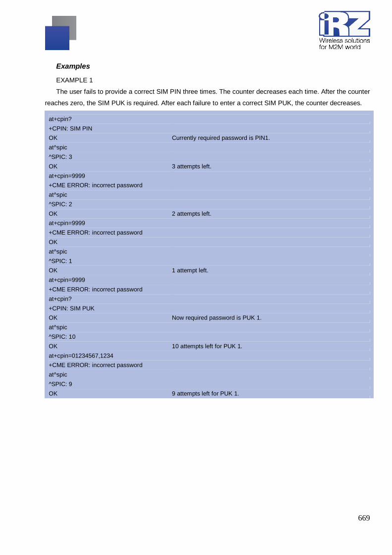
669
Examples
EXAMPLE 1
The user fails to provide a correct SIM PIN three times. The counter decreases each time. After the counter
reaches zero, the SIM PUK is required. After each failure to enter a correct SIM PUK, the counter decreases.
at+cpin? +CPIN: SIM PIN OK Currently required password is PIN1. at^spic ^SPIC: 3 OK 3 attempts left. at+cpin=9999 +CME ERROR: incorrect password at^spic ^SPIC: 2 OK 2 attempts left. at+cpin=9999 +CME ERROR: incorrect password OK at^spic ^SPIC: 1 OK 1 attempt left. at+cpin=9999 +CME ERROR: incorrect password at+cpin? +CPIN: SIM PUK OK Now required password is PUK 1. at^spic ^SPIC: 10 OK 10 attempts left for PUK 1. at+cpin=01234567,1234 +CME ERROR: incorrect password at^spic ^SPIC: 9 OK 9 attempts left for PUK 1.
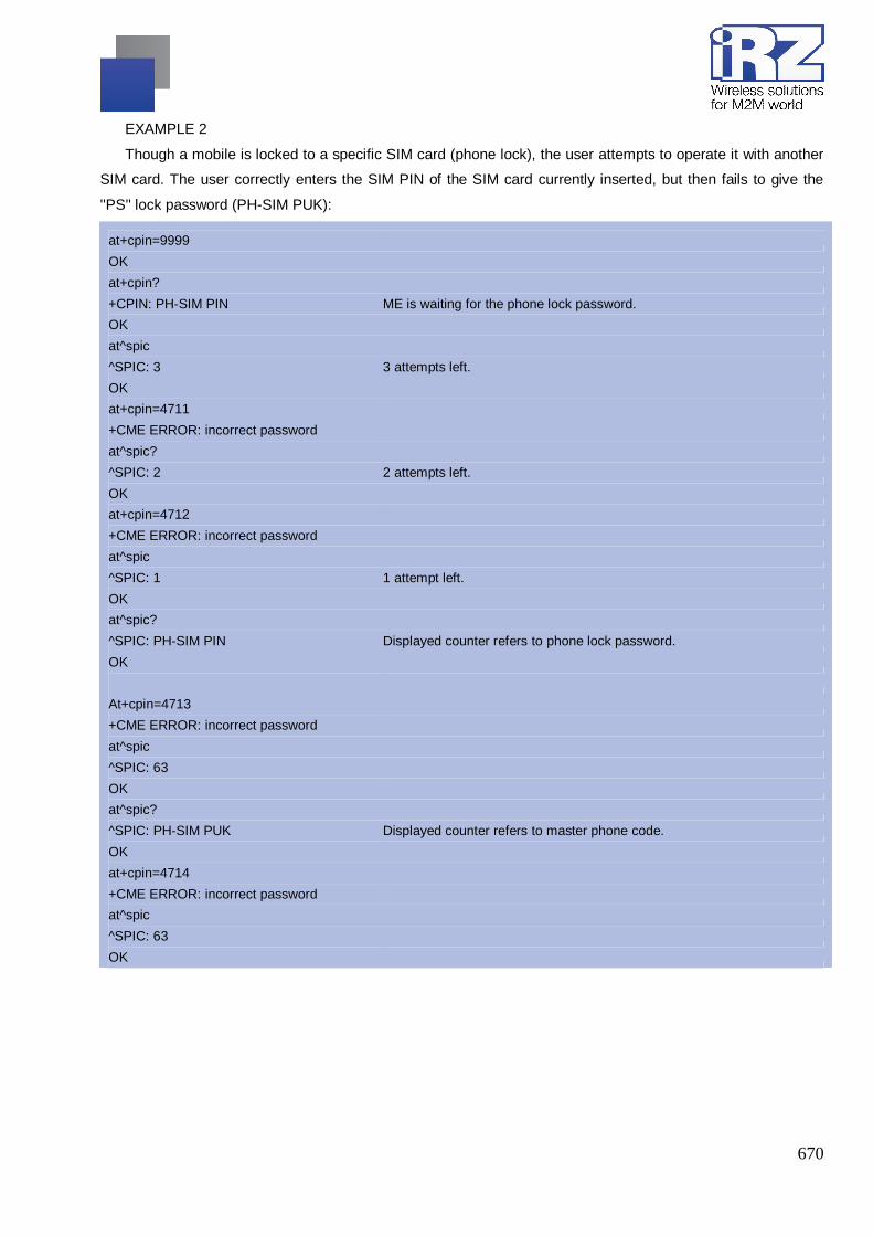
670
EXAMPLE 2
Though a mobile is locked to a specific SIM card (phone lock), the user attempts to operate it with another
SIM card. The user correctly enters the SIM PIN of the SIM card currently inserted, but then fails to give the
''PS'' lock password (PH-SIM PUK):
at+cpin=9999 OK at+cpin? +CPIN: PH-SIM PIN ME is waiting for the phone lock password. OK at^spic ^SPIC: 3 3 attempts left. OK at+cpin=4711 +CME ERROR: incorrect password at^spic? ^SPIC: 2 2 attempts left. OK at+cpin=4712 +CME ERROR: incorrect password at^spic ^SPIC: 1 1 attempt left. OK at^spic? ^SPIC: PH-SIM PIN Displayed counter refers to phone lock password. OK At+cpin=4713 +CME ERROR: incorrect password at^spic ^SPIC: 63 OK at^spic? ^SPIC: PH-SIM PUK Displayed counter refers to master phone code. OK at+cpin=4714 +CME ERROR: incorrect password at^spic ^SPIC: 63 OK

671
EXAMPLE 3
This example shows that after successful SIM PIN1 authentication the counter of the AT^SPIC execute and
read command refers to SIM PIN2, i.e. it does not reflect the status of SIM PIN1. This may be a problem if the
user enters a wrong PIN1 and is not aware that the number of attempts left to enter SIM PIN1 is counted down.
+CREG: 0 at+cpin=1234 OK +CREG: 2 +CREG: 1 The mobile ist properly registered to the network. at+cpin? +CPIN: READY The AT+CPIN? read command confirms that SIM PIN1 authentication was
successful. at^spic ^SPIC: 3 As SIM PIN1 authentication was successful, the counter relates to SIM
PIN2 and correctly indicates that the user has 3 attempts to enter SIM PIN2.
OK AT^SPIC? Likewise, the read command notifies that the ME is waiting for SIM PIN2. ^SPIC: SIM PIN2 OK at+clck="SC",0,456789 First attempt to enter a wrong SIM PIN1. +CME ERROR: incorrect password at^spic ^SPIC: 3 SIM PIN1 authentication is still valid, and the counter relates to SIM PIN2. at+clck="SC",0,456789 Second attempt to enter a wrong SIM PIN1. +CME ERROR: incorrect password at^spic ^SPIC: 3 SIM PIN1 authentication is still valid, and the counter relates to SIM PIN2. at+clck="SC",0,456789 Third attempt to enter a wrong SIM PIN1. +CME ERROR: incorrect password +CREG: 0 SIM PIN1 authentication is no longer valid. at^spic ^SPIC: 10 This time, after the SIM PIN1 code has been dis-abled, the counter
indicates the status of SIM PIN1 and notifies that 10 attempts are left to enter the SIM PUK.
To avoid conflicts we recommend to use the AT^SPIC read and write commands rather than the execute
command only. The read command clearly states the currently required password, and the write command may
be used to get the counter for a specific <facility>, in this case for example "P2".

672
13.5. AT+CLCK Facility lock
AT+CLCK can be used to lock, unlock or interrogate a network or ME <facility>. The command can be
aborted when network facilities are being set or interrogated.
Syntax
Test Command
AT+CLCK=?
Response(s)
+CLCK:list of supported <facility>s OK
Write Command
AT+CLCK=<facility>, <mode>[, <password>][, <class>]
Response(s)
if <mode> is not equal 2 and command successful: OK if <mode>= 2 and command successful: +CLCK: <status>[, <class>] [+CLCK: <status>[, <class>]] [+CLCK: ...] OK ERROR +CME ERROR: <err>
PIN ASC0 MUX1 MUX2 MUX3 A Last + + + + + - -
Reference(s)
GSM 07.07, GSM 02.04, GSM 02.88, GSM 03.88, GSM 04.88
Parameter Description
<facility>(str)
Phone security locks set by client or factory
Primarily intended for the client to take safety precautions, "SC", "PS" and "FD" can be configured
individually. "PS" may also be factory set.
Parameter <class> is not applicable to security locks.
See examples below for further details.
“SC“ SIM (lock SIM cards)
SIM requests password upon ME power-up and when this lock command is issued.
<password>: SIM PIN1.
“PS“ Phone locked to SIM card
ME requests password when other than current SIM card is inserted.
"PS" lock is frequently referred to as "phone lock", or "device lock". Accord-ingly, the

673
password may be called "phone code" or "device code". The "PS" password is not
associated with the PUK of the SIM card. If incorrectly entered three times, the Master
Phone Code is required to lift the lock. This is an 8-digit device code associated to the
IMEI number of the mobile which can only be obtained from the manufacturer of the
module. Once the Master Phone Code has been acctepted, the mobile is operational,
and the "PS" lock is no longer active. If needed it must be set once again.
<password>: User defined password. It is needed before the first use of <facility> "PS"
and, therefore, must first be specified with AT+CPWD or AT^SPWD, if it has not been
predefined by factory settings. If set by factory (e.g. for a prepaid mobile), the
password is supplied by the provider or operator.
“FD“ SIM Fixed Dialing lock
If "FD" lock is enabled numbers MMI *# codes can be used only if they start with
matching numbers or characters stored in the "FD" phonebook. The capacity of the
"FD" phonebook is depending on the SIM card.
Numbers stored to the "FD" phonebook must not contain the call modifiers
"I","i","*31#", "#31#".
<password>: SIM PIN 2.
Any attempt to dial a string not specified in the "FD" phonebook will be denied, causing
an error result code. The type of result code varies depending on the type of service:
"+CME ERROR: call barred" for voice calls, GPRS connections and *# codes for
Supplementary Services.
"NO CARRIER" for fax calls and circuit switched data calls.
"+CMS ERROR: operation not allowed" for SMS.
If "FD" lock is enabled the following applies:
- Handling of Supplementary Services:
The "FD" lock is effective only for AT+CCFC <mode> 3 (registering the CF
destination number). All other Supplementary Services and functions pro-vided by
AT+CCFC are not restricted by the "FD" lock.
- GPRS commands can be used only if the "FD" phonebook contains an entry
with phone number ''*99#''. This single entry enables all GPRS commands,
including AT commands and modem compatibility commands like ''ATD*99***1#''
or ''ATD*98***1#''.
Indication is "+CME ERROR: call barred".
Factory defined SIM locks:
Typical examples of factory set SIM locks are prepaid phones or network locks, used to restrict the operation
of a mobile to a specific provider or operator. The client should be aware that each of these lock types can
only be unlocked if the associated password is available. For example, a mobile can be locked to accept only
SIM cards from the respective provider, or even one single SIM card. Once a different SIM card is inserted

674
the ME will prompt the client to enter a specific code. This is not the PUK of the SIM card, but usually an 8-
digit code which needs to be requested from the provider.
The locks can only be set by the manufacturer and need to be agreed upon between the parties concerned,
e.g. provider, operator, distributor etc. on the one side and the manufacturer on the other side.
Parameter <class> is not applicable to SIM locks.
<password> and instructions for unlocking must be obtained from the network provider.
“PF“ Lock Phone to the very First SIM card
“PN“ Network Personalisation
“PU“ Network subset Personalisation
“PP“ Service Provider Personalisation
“PC“ Corporate Personalisation
Supplementary Service Call Barring:
Supplementary Service "Call Barring" allows to specify conditions under which calls will be disallowed by the
network.
The availability of the Supplementary Services varies with the network. To benefit from call barring the client
will need to subscribe them, though a limited number of call barring types may be included in the basic tariff
package.
When you attempt to set a <facility> or <class> which is not provisioned, not yet subscribed to, or not
supported by the module, the setting will not take effect regardless of the response returned. The responses
in these cases vary with the network (for example "OK", "+CME ERROR: operation not allowed", "+CME
ERROR: oper ation not supported" etc.). To make sure check the extended error response with AT+CEER
and the lock status with <mode>=2.
<password>: Network password supplied from the provider or operator. Usually there is one password which
applies to all call barring options. For details contact your provider.
“AO“ BAOC (Bar All Outgoing Calls)
“OI“ BOIC (Bar Outgoing International Calls)
“OX“ BOIC-exHC (Bar Outgoing International Calls except to Home Country)
“AI“ BAIC (Bar All Incoming Calls)
“IR“ BIC-Roam (Bar Incoming Calls when Roaming outside the home country)
“AB“ All Barring services (applicable only for <mode>=0)
“AG“ All outGoing barring services (applicable only for <mode>=0)
“AC“ All inComing barring services (applicable only for <mode>=0)

675
<mode>(num)
[0](&F)(P) unlock
1 lock
2 query status
<status>(num)
0 lock is inactive
1 lock is active
<password>(str)
Password string used to lock and to unlock a <facility>. Length and authority for passwords depend on the
<facility> in question and are therefore listed in the section on parameter <facility>. Passwords can be
modified with AT+CPWD or AT^SPWD.
<class>(num)
Integer or sum of integers each representing a class of information, i.e. a bearer service, telecommunication
ser-vice or bearer service group as defined in "GSM 02.04".
1 voice
2 class 2 ("data") comprises all those individual data classes between 16 and 128, that
are supported both by the network and the MS. This means, a setting made for class 2
applies to all individual data classes (if supported). In addition, you can assign a
different setting to a specific class. For example, you can acti-vate Call Forwarding for
all data classes, but deactivate it for data class 64, "dedicated packet access".
4 fax
8 SMS
16 data circuit sync
32 data circuit async
64 dedicated packet access
128 dedicated PAD access
1…[7]…255 combination of some of the above classes.
For example, the default setting 7 represents the sum of the integers 1, 2 and 4 (voice,
data and fax).

676
The value 255 covers all classes.
If parameter "class" is omitted, the default value 7 is used.
Notes
The AT+CLCK command offers the full range of <class> parameters according to the GSM specifications.
However, when you attempt to use a service option which is not provisioned or not yet subscribed to, the
set-ting will not take effect regardless of the response returned.
The responses in these cases vary with the network (for example "OK", "Operation not allowed", "Operation
not supported" etc.). To make sure check the extended error response with AT+CEER and the lock status
with <mode>=2.
The command has been implemented with the full set of <class> parameters according to GSM 07.07. For
actual applicability of a desired Call barring service to a specific service or service group (a specific <class>
value) please consult table A.1 of GSM 02.04.
If an outgoing Fax or Data Call is rejected due to an active ''call barring'' supplementary service, the call will
be terminated with result code NO CARRIER.
Under the same conditions, an outgoing Voice call will be terminated with result code NO DIALTONE.
If an invalid <password> is entered several times in succession, a delay incremented after each failed
attempt will increase the time to wait before the input of the <password> is accepted. To avoid blocking the
serial interface the running AT+CLCK command is aborted after a short timeout and returns "+CME
ERROR: unknown" (+CME ERROR: 100). If then the AT+CLCK command is issued once again execution
is denied with "+CME ERROR: operation temporary not allowed" (+CME ERROR: 256). For details
regarding the delay see Section “What to do if PIN or password authentication fails?” (AT+CPIN section)
If the user tries to set a lock although it is already active or, the other way round, tries to unlock an inactive
lock, the response will be OK, but the <password> will not be checked or verified.
Examples
EXAMPLE 1
Lock SIM card (<facility>= "SC")
AT+CLCK="SC",1,"9999" The "SC" parameter enables or disables the SIM PIN authentication (PIN 1) when you power up the GSM engine
OK SIM card locked. As a result, SIM PIN 1 must be entered to enable ME to register to the GSM network.
AT+CLCK="SC",0,"9999" Unlocks SIM card. OK When powered up, ME registers to the GSM network without requesting
SIM PIN1. Note: Depending on the services offered by the provider, this feature is not supported by all SIM card types. If so, the command returns ERROR when you attempt to unlock the card.

677
To query the status of the SIM card lock:
AT+CLCK="SC",2 Query the status of SIM card lock. +CLCK: 1 SIM card is locked. SIM PIN1 must be entered to enable ME to register to
the GSM network. OK

678
13.6. AT^SLCK Facility lock
AT^SLCK provides the "Facility lock" function as defined for the GSM 07.07 command AT+CLCK. The
command can be used to lock, unlock or interrogate a network or ME <facility>.
AT^SLCK is, in every respect, identical with AT+CLCK, except that the command syntax and response
prefix is "^SLCK" instead of "+CLCK". For further details please refer to AT+CLCK.
The command can be aborted when network facilities are being set or interrogated.
Syntax
Test Command
AT^SLCK=?
Response(s)
^SLCK:list of supported <facility>s OK
Write Command
AT^SLCK=<facility>, <mode>[, <password>][, <class>]
Response(s)
if <mode> is not equal 2 and command successful: OK if <mode>= 2 and command successful: ^SLCK: <status>, <class> [^SLCK: <status>, <class>] [^SLCK: ...] OK If error is related to ME functionality ERROR +CME ERROR: <err>
PIN ASC0 MUX1 MUX2 MUX3 A Last + + ± ± ± - -
Reference(s)
GSM 07.07, GSM 02.04, GSM 02.88, GSM 03.88, GSM 04.88

679
13.7. AT+CPWD Change Password
AT+CPWD allows to define a new password for a password protected <facility> lock function. Each
password is a string of digits, the length of which varies with the associated <facility>. The test command
returns a list of pairs which represent the available facilities and the maximum length of the associated
password. See AT commands AT+CLCK and AT^SLCK for more information on the various lock features.
Specifically the command can be used to
change PIN1 or PIN2,
change the password supplied from your provider for the "call barring" supplementary service,
set individual phone security passwords,
enter the unblocking key (Master Phone Code) to restore a disabled "PS" password.
To delete a password use the following syntax: at+cpwd=<facility>, <old password>
Syntax
Test Command
AT+CPWD=?
Response(s)
+CPWD:list of supported (<facility>, <password length>) OK
Write Command
AT+CPWD=<facility>, <old password>[, <new password>]
Response(s)
New password has been registered for the facility lock function. OK If parameter <old password> was not correct: +CME ERROR: 16 (+CME ERROR: incorrect password) If the password for the selected <facility> has been invalidated due to too many failed attempts: +CME ERROR: ... If error is related to ME functionality: +CME ERROR: <err>
PIN ASC0 MUX1 MUX2 MUX3 A Last + + + + + - -
Reference(s)
GSM 07.07
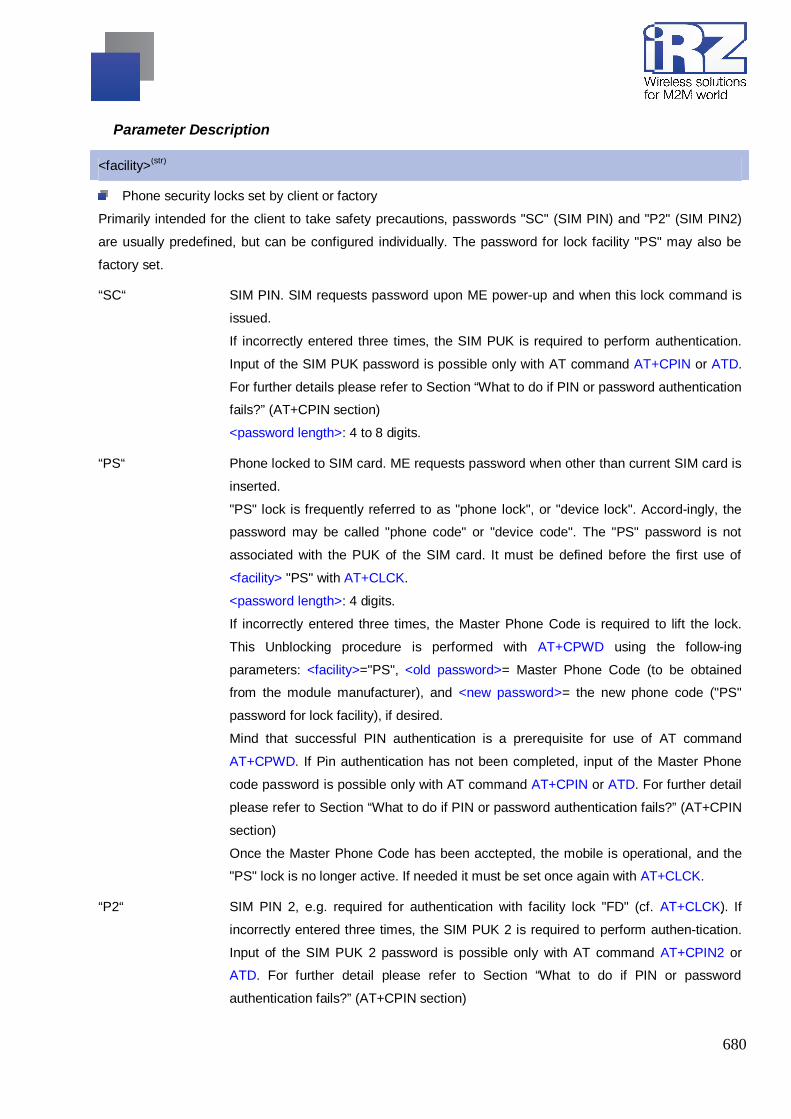
680
Parameter Description
<facility>(str)
Phone security locks set by client or factory
Primarily intended for the client to take safety precautions, passwords "SC" (SIM PIN) and "P2" (SIM PIN2)
are usually predefined, but can be configured individually. The password for lock facility "PS" may also be
factory set.
“SC“ SIM PIN. SIM requests password upon ME power-up and when this lock command is
issued.
If incorrectly entered three times, the SIM PUK is required to perform authentication.
Input of the SIM PUK password is possible only with AT command AT+CPIN or ATD.
For further details please refer to Section “What to do if PIN or password authentication
fails?” (AT+CPIN section)
<password length>: 4 to 8 digits.
“PS“ Phone locked to SIM card. ME requests password when other than current SIM card is
inserted.
"PS" lock is frequently referred to as "phone lock", or "device lock". Accord-ingly, the
password may be called "phone code" or "device code". The "PS" password is not
associated with the PUK of the SIM card. It must be defined before the first use of
<facility> "PS" with AT+CLCK.
<password length>: 4 digits.
If incorrectly entered three times, the Master Phone Code is required to lift the lock.
This Unblocking procedure is performed with AT+CPWD using the follow-ing
parameters: <facility>="PS", <old password>= Master Phone Code (to be obtained
from the module manufacturer), and <new password>= the new phone code ("PS"
password for lock facility), if desired.
Mind that successful PIN authentication is a prerequisite for use of AT command
AT+CPWD. If Pin authentication has not been completed, input of the Master Phone
code password is possible only with AT command AT+CPIN or ATD. For further detail
please refer to Section “What to do if PIN or password authentication fails?” (AT+CPIN
section)
Once the Master Phone Code has been acctepted, the mobile is operational, and the
"PS" lock is no longer active. If needed it must be set once again with AT+CLCK.
“P2“ SIM PIN 2, e.g. required for authentication with facility lock "FD" (cf. AT+CLCK). If
incorrectly entered three times, the SIM PUK 2 is required to perform authen-tication.
Input of the SIM PUK 2 password is possible only with AT command AT+CPIN2 or
ATD. For further detail please refer to Section “What to do if PIN or password
authentication fails?” (AT+CPIN section)

681
<password length>: 4 to 8 digits.
Factory defined SIM locks:
Typical examples of factory set SIM locks are prepaid phones or network locks, used to restrict the operation
of a mobile to a specific provider or operator. The client should be aware that each of these lock types can
only be unlocked if the associated password is available. For example, a mobile can be locked to accept only
SIM cards from the respective provider, or even one single SIM card. Once a different SIM card is inserted
the ME will prompt the client to enter a specific code. This is not the PUK of the SIM card, but usually an 8-
digit code which needs to be requested from the provider.
The locks can only be set by the manufacturer and need to be agreed upon between the parties concerned,
e.g. provider, operator, distributor etc. on the one side and the manufacturer on the other side.
“PF“ Lock Phone to the very First SIM card
“PN“ Network Personalisation
“PU“ Network subset Personalisation
“PP“ Service Provider Personalisation
“PC“ Corporate Personalisation
Supplementary Service Call Barring:
Supplementary Service "Call Barring" allows to specify conditions under which calls will be disallowed by the
network.
The availability of the Supplementary Services varies with the network. To benefit from call barring the client
will need to subscribe them, though a limited number of call barring types may be included in the basic tariff
package.
<password length>: The Network Password needs to be supplied from the network provider or network oper-
ator. Usually there is one 4 digit password which applies to all call barring options. For details contact your
pro-vider.
“AO“ BAOC (Bar All Outgoing Calls)
“OI“ BOIC (Bar Outgoing International Calls)
“OX“ BOIC-exHC (Bar Outgoing International Calls except to Home Country)
“AI“ BAIC (Bar All Incoming Calls)
“IR“ BIC-Roam (Bar Incoming Calls when Roaming outside the home country)
“AB“ All Barring services
“AG“ All outGoing barring services
“AC“ All inComing barring services
<password length>(num)

682
4…8 Length of password. The range of permitted length for a password depends on the
associated <facility>. It is available from the test command response, or in the
description of parameter <facility>.
<old password>(str)
Password specified for the facility.
Parameter <old password> can be ignored if no old password was allocated to the facility.
Take into account that a password may have already been set by factory, or that the service is subject to a
pass-word issued by the provider. See notes above or contact provider.
<new password>(str)
New password. Mandatory, if <old password> was an unblocking key (such as the Master Phone Code).
Note
When changing PIN2 (<facility>="P2") it is recommended to check the new state of PIN2 by using the
AT+CPIN2 command.
Examples
EXAMPLE 1
To change PIN2
AT+CPWD="P2","0000","8888" OK
(where "0000" = old PIN2 and "8888" = new PIN2) PIN2 Password has been changed to "8888"
EXAMPLE 2
To set password used to enable or disable barring of all outgoing calls:
AT+CPWD="AO","0000","3333" Requests the network to change the password for supplementary service "call barring".
OK Usually this request will affect all barring services, even though the request is issued for Supplementary Service BAOC ("Barring of all outgoing calls") only. Refer to the respective network provider for detail.

683
EXAMPLE 3
Handling of the "PS" lock password
AT+CMEE=2 AT+CPWD="PS","1111","2222"
Enable text output of CME Error information AT+CPWD="PS","1111","2222" (where "1111" = old password and "2222" = new password)
OK Password for facility "PS" is now "2222" AT+CPWD="PS","1111","2222" Repeat command to provoke error "incorrect pass-word" +CME ERROR: incorrect password ("1111" is no longer the correct password)
EXAMPLE 4
To specify a new "PS" lock password, after the old password was disabled (e.g. after three failed attempts
to change the "PS" password): use the master phone code.
CAUTION: THIS TEST SHOULD BE PERFORMED ONLY IF THE CORRECT MASTER PHONE CODE
FOR THE INDIVIDUAL ME USED IS DEFINITELY AVAILABLE! Otherwise the module used will be rendered
use-less until the correct master phone code is entered!:
AT+CPWD="PS","12345678","1111" where 12345678 is the Master Phone Code and 1111 is the new password. You may also use <new password> to restore the former disabled pass-word.
OK Alternatively, without giving a new password:
AT+CPWD="PS","12345678" (where 12345678 is the Master Phone Code). Deac-tivates the present phone lock.
OK

684
13.8. AT^SPWD Change Password
The AT^SPWD command provides the same functions as AT+CPWD. The major difference between both
commands is that, apart from the different prefixes "^SPWD" and "+CPWD", the AT^SPWD command includes
addi-tional functions dedicated to the Customer SIM Lock. Please note that this feature is only supported by
specifically pre-configured MG21 modules and, therefore, not part of the standard "MG21 AT Command Set".
All other functions and parameters of AT^SPWD are described in AT+CPWD section.
Each password is a string of digits the length of which varies with the associated facility. The test command
returns a list of pairs which represent the available facilities and the maximum length of the associated
password.
See also AT commands AT+CLCK and AT^SLCK for more detail on the various lock features.
Syntax
Test Command
AT^SPWD=?
Response(s)
^SPWD:list of supported ( <facility>, <password length>) OK
Write Command
AT^SPWD=<facility>, <old password>[, <new password>]
Response(s)
New password has been registered for the facility lock function. OK If parameter <old password> was not correct: +CME ERROR: 16 (+CME ERROR: incorrect password) If the password for the selected <facility> has been invalidated due to too many failed attempts: +CME ERROR: ... If error is related to ME functionality: +CME ERROR: <err>
PIN ASC0 MUX1 MUX2 MUX3 A Last + + + + + - -
Note
When changing the PIN2 (<facility>="P2") it is recommended to check the new state of PIN2 using the
AT+CPIN2 command.

685
13.9. AT+CPSPWD Change PS Super Password
Syntax
Write Command
AT+CPSPWD=<oldpwd>,<newpwd>
Response(s)
OK ERROR
Parameter Description
<oldpwd>(str)
string type (string should be included in quotation marks). Old password and length should be 8.
<newpwd>(str)
string type (string should be included in quotation marks). New password and length should be 8.
Notes
Default value of <oldpwd> is “12345678”.
If module is locked to a specific SIM card through +CLCK and password lost or SIM state is PH-SIM PUK,
you can use the super password to unlock it.
It is not supported temporarily.

686
14. Miscellaneous Commands The AT Commands described in this chapter are related to various areas.
Misc. A/ ATS3 ATS4 ATS5 AT+CALM

687
14.1. A/ Repeat Previous Command Line
Repeat previous AT command line.
In general, after beginning a command line with character "a" or "A" a second character "t", "T" or "/" has to
follow. "/" acts as line terminating character. In case of using a wrong second character, it is necessary to start
again with character "a" or "A".
Syntax
Exec Command
A/
Response(s)
PIN ASC0 MUX1 MUX2 MUX3 A Last - + + + + - -
Reference(s)
V.250

688
14.2. ATS3 Command Line Termination
ATS3 determines the character recognized by the MG21 to terminate an incoming command line. It is also
gen-erated for result codes and information text, along with character value set via ATS4.
Syntax
Read Command
ATS3?
Response(s)
<n> OK
Write Command
ATS3=<n>
Response(s)
OK ERROR
PIN ASC0 MUX1 MUX2 MUX3 A Last - + + + + - -
Reference(s)
V.250
Parameter Description
<n>(num)(&W)(&V)
Command line termination character.
It is not recommended to change this value.
000…13(&F)…127
Note
If changing this setting the new value has no effect for "^SHUTDOWN" URC.

689
14.3. ATS4 Response Formatting
ATS4 determines the character generated by the MG21 for result code and information text, along with the
command line termination character set via ATS3.
Syntax
Read Command
ATS4?
Response(s)
<n> OK
Write Command
ATS4=<n>
Response(s)
OK ERROR
PIN ASC0 MUX1 MUX2 MUX3 A Last - + + + + - -
Reference(s)
V.250
Parameter Description
<n>(num)(&W)(&V)
Response formatting character.
It is not recommended to change this value.
000…10(&F)…127
Note
If changing this setting the new value has no effect for "^SHUTDOWN" URC.

690
14.4. ATS5 Command Line Editing
ATS5 determines the character value used by the MG21 to delete the immediately preceding character
from the AT command line (i.e. equates backspace key).
Syntax
Read Command
ATS5?
Response(s)
<n> OK
Write Command
ATS5=<n>
Response(s)
OK ERROR
PIN ASC0 MUX1 MUX2 MUX3 A Last - + + + + - -
Reference(s)
V.250
Parameter Description
<n>(num)(&W)(&V)
Command line editing character.
It is not recommended to change this value.
000…8(&F)…127

691
14.5. AT+CALM Alert Sound Mode
Syntax
Test Command
AT+CALM=?
Response(s)
+CALM: (list of supported <mode>s) OK +CME ERROR: <err>
Read Command
AT+CALM=?
Response(s)
+CALM: <mode> OK +CME ERROR: <err>
Write Command
AT+CALM=<mode>
Response(s)
OK +CME ERROR: <err>
Reference(s)
GSM 07.07
Parameter Description
<mode>(num)
0 normal mode
1 silent mode (all sounds from ME are prevented)