upright slot machine - azslot.comazslot.com/manuals/wms 400 slot manual.pdf · $1 00000 0 7 machine...
TRANSCRIPT
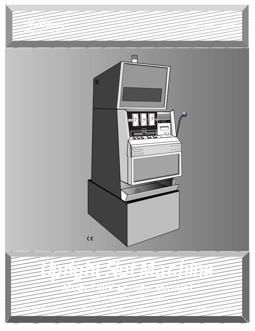
Upright Slot MachineWith Details on 1995 Machines
© 1999 WMS Gaming Inc. 3401 N. California Avenue, Chicago, Illinois 60618 Phone (800)378-7741
February 1999 • A-004336
Model 40X Service Manual
����
$10 0 0 0 0 0 0 0 0 0 0
7 7 7Machine Pays Up to 400 Coins
Balance Paid by Attendant
INSERT BILLFACE UP
All Pays on Center Line Only - Only Highest Winner Paid
����
$10 0 0 0 0 0 0 0 0 0 0
7 7 7Machine Pays Up to 400 Coins
Balance Paid by Attendant
INSERT BILLFACE UP
All Pays on Center Line Only - Only Highest Winner Paid
UprightSlot
Machine
With Detailson 1995
Machines
© 1999WMS Gaming Inc.
Model 40XServiceManual
February 1999A-004336
16-004337—CONTENTS S0/CH0 3WMS Service Manual
Contents
Model 40X Upright Slot MachineService Manual (A-004336)
Contents .........................................................................................(16-004337) ..1
Section 1. Setup & SoftwareChapter 1. Setup........................................................................(16-004338) ...1-1
Procedure ...........................................................................................................................1-1Lock Specifications .............................................................................................................1-5Slot Machine Base Dimensions ..........................................................................................1-6Gaming Device Dimensions................................................................................................1-7Flammability Classification Weights....................................................................................1-7
Chapter 2. Diagnostic and Adjustment Software ...................(16-004339) ...2-1Using Administration Mode .................................................................................................2-1Administration Mode Displays.............................................................................................2-2Series 0. Host Communications, Sound Volume, Demo, Cash and Credit Modes, Reel
Speed, Etc. ...................................................................................................................2-2Series 1. Input Tests .........................................................................................................2-11Series 2. Output Tests ......................................................................................................2-13Series 3. Hopper Test .......................................................................................................2-15Series 4. Paytable Test .....................................................................................................2-16Series 5. Reel Strip Test ...................................................................................................2-17Series 6. Denomination Settings.......................................................................................2-18Series 7. Maximum Hopper Payout ..................................................................................2-20Series 8. Hopper Partial Payout Limit ...............................................................................2-21Series 9. Progressive ID and Level...................................................................................2-21Series 10. Lamp Test ........................................................................................................2-23Exit to Game Play Mode ...................................................................................................2-24
Chapter 3. Bookkeeping Mode.................................................(16-004340) ...3-1Using Bookkeeping Mode ...................................................................................................3-1Bookkeeping Mode Displays...............................................................................................3-2Series 1. Coin Info ..............................................................................................................3-3Series 2. Play Info...............................................................................................................3-5Series 3. Play Log...............................................................................................................3-5Series 4. Door Info ..............................................................................................................3-6Series 5. Tilt Info .................................................................................................................3-7Series 6. Bill Info .................................................................................................................3-7Series 7. Bill Log .................................................................................................................3-8Series 8. Bet Info ................................................................................................................3-8Series 9. Cash Info .............................................................................................................3-9Series 10. Line Info .............................................................................................................3-9
Contents
4 S0/CH0 WMS Service Manual16-004337—CONTENTS
Series 11. Prog Info ..........................................................................................................3-10Exit to Game Play Mode ...................................................................................................3-10
Section 2. Maintenance & TroubleshootingChapter 1. Periodic Maintenance.............................................(16-004341) ...1-1
Collection and Supply .........................................................................................................1-1Bill Validator ........................................................................................................................1-1CPU and Driver Boards, Card Cage ...................................................................................1-5Glass...................................................................................................................................1-7Hopper ................................................................................................................................1-9Lamps ...............................................................................................................................1-12Power Distribution Unit .....................................................................................................1-13Reels.................................................................................................................................1-13
Chapter 2. Software and Game Denomination Changes....... (16-004342) ..2-1Software Changes ..............................................................................................................2-1Denomination Changes ......................................................................................................2-1Card Cage Components .....................................................................................................2-1EEPROM and RAM Interaction...........................................................................................2-1Software Installation............................................................................................................2-2Clearing the CPU Board RAM ............................................................................................2-3How to Perform a Soft (Partial) RAM Clearance.................................................................2-5How to Perform a Hard (Total) RAM Clearance .................................................................2-5Changing the Denomination ...............................................................................................2-7
Chapter 3. Troubleshooting......................................................(16-004343) ...3-1Tilt Codes............................................................................................................................3-1Candle Codes .....................................................................................................................3-2Button and Switch Troubleshooting Guide..........................................................................3-3Candle Codes Troubleshooting Guide................................................................................3-3Communication Troubleshooting Guide..............................................................................3-3CPU Board 7-Segment Display Troubleshooting Guide .....................................................3-4CPU Board EEPROM Troubleshooting Guide....................................................................3-5CPU EPROM Troubleshooting Guide.................................................................................3-5CPU Sound Jumpers ..........................................................................................................3-6CPU Startup Sounds Troubleshooting Guide .....................................................................3-6Dollar Bill Validator and Coin Mechanism Troubleshooting Guide .....................................3-7Door Troubleshooting Guide...............................................................................................3-8Dotmation™ Troubleshooting Guide...................................................................................3-9Dotmation+™ Troubleshooting Guide...............................................................................3-10Hard Meter Troubleshooting Guide...................................................................................3-11Hopper Troubleshooting Guide.........................................................................................3-12Jurisdiction Jumper Troubleshooting Guide......................................................................3-13Lamp Matrix Troubleshooting Guide.................................................................................3-14
Lamp Matrix................................................................................................................3-14PGA Chip (Programmable Gate Array) Troubleshooting Guide .......................................3-15Power Troubleshooting Guide ..........................................................................................3-15Progressive Troubleshooting Guide..................................................................................3-16Reel LED Display Board Troubleshooting Guide..............................................................3-16Reel Opto Troubleshooting Guide ....................................................................................3-17Sound Troubleshooting Guide ..........................................................................................3-18
16-004337—CONTENTS S0/CH0 5WMS Service Manual
Contents
Static RAM Troubleshooting Guide...................................................................................3-19Watchdog Timer Troubleshooting Guide ..........................................................................3-19
Section 3. Parts ListChapter 1. Parts, Electronic .....................................................(16-004344) ...1-1
(In this chapter, parts appear in alphabetical order, under their assemblies.)
Chapter 2. Parts, Mechanical ...................................................(16-004345) ...2-1(In this chapter, parts appear in alphabetical order, under their assemblies.)
Chapter 3. Large Exploded Views............................................(16-004346) ...3-1
Section 4. Vendor Literature
Section 5. Service Bulletins
Section 6. Tables & Data for CPU System 1.5 VGDs..................(16-004349)Administration Mode ..............................................................................................................1Candle Codes ........................................................................................................................1I/O Board LEDs ......................................................................................................................1Startup Sound Codes.............................................................................................................1Tilt Codes ...............................................................................................................................1CPU Board 7-Segment Display..............................................................................................1Lamp Matrix ...........................................................................................................................2Programmed and Field Programmable Chip Summary .........................................................2
NOTICE• Binder part number: 20-9896-02
• Divider tabs part number: 16-003639
• Part number for spine and cover inserts,contents section (one shrink-wrappedpackage): 16-004337
• Part number for entire manual: A-004336
16-004338—SETUP S1/CH1 1-1WMS Service Manual—Upright Slot
Setup
Chapter 1. SetupProcedure
This chapter explains how to inspect and install a gaming device (GD). You'llneed these tools...
•11/32" NUT DRIVER •PHILLIPS SCREWDRIVER •VOLTMETER
•ELECTRICAL OUTLET TESTER
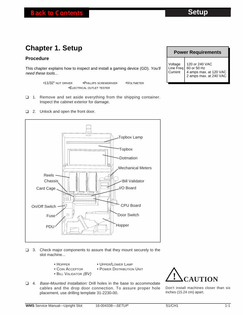
❑ 1. Remove and set aside everything from the shipping container.Inspect the cabinet exterior for damage.
❑ 2. Unlock and open the front door.
❑ 3. Check major components to assure that they mount securely to theslot machine...
• HOPPER • UPPER/LOWER LAMP
• COIN ACCEPTOR • POWER DISTRIBUTION UNIT
• BILL VALIDATOR (BV)
❑ 4. Base-Mounted Installation: Drill holes in the base to accommodatecables and the drop door connection. To assure proper holeplacement, use drilling template 31-2230-00.
! CAUTIONDon't install machines closer than sixinches (15.24 cm) apart.
VoltageLine FreqCurrent
Power Requirements
120 or 240 VAC60 or 50 Hz4 amps max. at 120 VAC2 amps max. at 240 VAC
Topbox
Topbox Lamp
Dotmation
Mechanical Meters
Bill Validator
ReelsChassis
Card Cage
On/Off Switch
PDU
I/O Board
Door Switch
CPU Board
Hopper
Fuse
Setup
❑ 5. Base-Mounted Installation: Attach the slot machine to the base withsupplied bolts and nuts. Hold the carriage bolts on the slotmachine's inside cabinet floor. Tighten the nuts from inside the dropstand.
❑ 6. Base-Mounted Installation: Attach the slot machine base to the floorwith carriage bolts. Alternately, mount machines back to back on acommon base. Or, mount machines on separate bases, but bolt thebases together from back to back.
❑ 7. Operations with a Host System: Install host communication cablesaccording to recommendations of the communications systemprovider. Connect the communication cables to the backplane.
❑ 8. Attach the drop door connection to the drop door in the stand.
❑ 9. Unlock the card cage. Check for damaged or loose connectors.Don't force connectors! Close and lock the card cage.
Machines That Require Special Jurisdiction Jumper Settings...
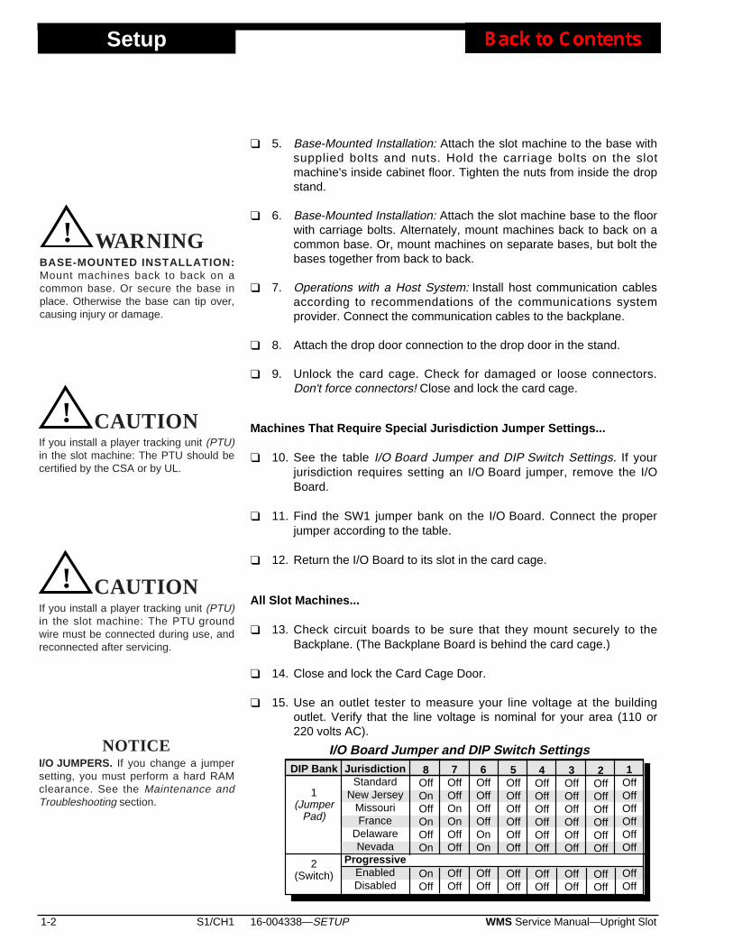
❑ 10. See the table I/O Board Jumper and DIP Switch Settings. If yourjurisdiction requires setting an I/O Board jumper, remove the I/OBoard.
❑ 11. Find the SW1 jumper bank on the I/O Board. Connect the properjumper according to the table.
❑ 12. Return the I/O Board to its slot in the card cage.
All Slot Machines...
❑ 13. Check circuit boards to be sure that they mount securely to theBackplane. (The Backplane Board is behind the card cage.)
❑ 14. Close and lock the Card Cage Door.
❑ 15. Use an outlet tester to measure your line voltage at the buildingoutlet. Verify that the line voltage is nominal for your area (110 or220 volts AC).
1-2 S1/CH1 WMS Service Manual—Upright Slot16-004338—SETUP
CAUTION! WARNINGBASE-MOUNTED INSTALLATION:Mount machines back to back on acommon base. Or secure the base inplace. Otherwise the base can tip over,causing injury or damage.
If you install a player tracking unit (PTU)in the slot machine: The PTU should becertified by the CSA or by UL.
CAUTION! CAUTION
If you install a player tracking unit (PTU)in the slot machine: The PTU groundwire must be connected during use, andreconnected after servicing.
CAUTION! CAUTION
DIP Bank
1(Jumper
Pad)
2(Switch)
I/O Board Jumper and DIP Switch SettingsJurisdiction
StandardNew Jersey
MissouriFrance
DelawareNevada
ProgressiveEnabledDisabled
8OffOnOffOnOffOn
OnOff
7OffOffOnOnOffOff
OffOff
6OffOffOffOffOnOn
OffOff
5OffOffOffOffOffOff
OffOff
4OffOffOffOffOffOff
OffOff
3OffOffOffOffOffOff
OffOff
2OffOffOffOffOffOff
OffOff
1OffOffOffOffOffOff
OffOff
NOTICEI/O JUMPERS. If you change a jumpersetting, you must perform a hard RAMclearance. See the Maintenance andTroubleshooting section.
❑ 16. Use an outlet tester to check for properly implemented ground, hotand neutral outlet wiring. Only use a grounded AC outlet. If the outletchecks okay, proceed. Otherwise, repair the outlet beforeproceeding.
❑ 17. Your slot machine may have a voltage range switch. You'll find thisswitch on the connector side of the PDU. Never change this switch'sposition with the line cord plugged in. Set the PDU voltage rangeswitch to match the local line voltage range. Setting this switchincorrectly, or changing the switch position under power will causedamage.
❑ 18. Temporarily remove the hopper from the machine: Lift out the cointray and pull the hopper straight out.
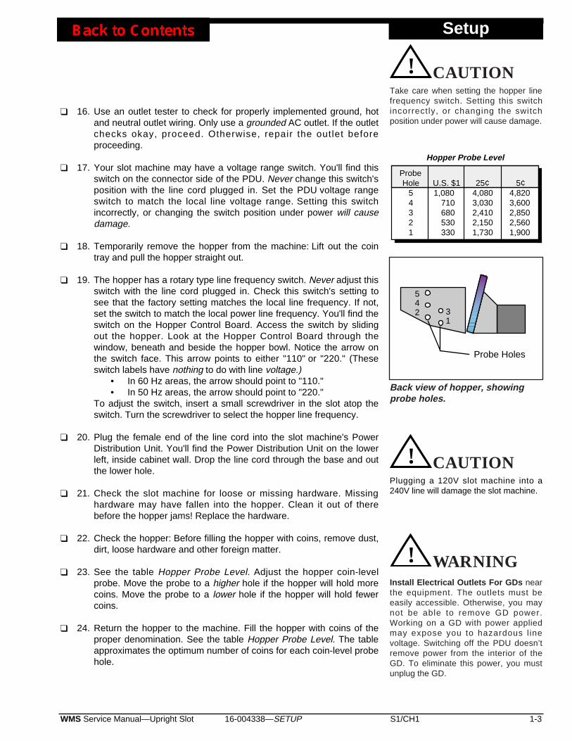
❑ 19. The hopper has a rotary type line frequency switch. Never adjust thisswitch with the line cord plugged in. Check this switch's setting tosee that the factory setting matches the local line frequency. If not,set the switch to match the local power line frequency. You'll find theswitch on the Hopper Control Board. Access the switch by slidingout the hopper. Look at the Hopper Control Board through thewindow, beneath and beside the hopper bowl. Notice the arrow onthe switch face. This arrow points to either "110" or "220." (Theseswitch labels have nothing to do with line voltage.)
• In 60 Hz areas, the arrow should point to "110."• In 50 Hz areas, the arrow should point to "220."
To adjust the switch, insert a small screwdriver in the slot atop theswitch. Turn the screwdriver to select the hopper line frequency.
❑ 20. Plug the female end of the line cord into the slot machine's PowerDistribution Unit. You'll find the Power Distribution Unit on the lowerleft, inside cabinet wall. Drop the line cord through the base and outthe lower hole.
❑ 21. Check the slot machine for loose or missing hardware. Missinghardware may have fallen into the hopper. Clean it out of therebefore the hopper jams! Replace the hardware.
❑ 22. Check the hopper: Before filling the hopper with coins, remove dust,dirt, loose hardware and other foreign matter.
❑ 23. See the table Hopper Probe Level. Adjust the hopper coin-levelprobe. Move the probe to a higher hole if the hopper will hold morecoins. Move the probe to a lower hole if the hopper will hold fewercoins.
❑ 24. Return the hopper to the machine. Fill the hopper with coins of theproper denomination. See the table Hopper Probe Level. The tableapproximates the optimum number of coins for each coin-level probehole.
16-004338—SETUP S1/CH1 1-3WMS Service Manual—Upright Slot
Setup
Plugging a 120V slot machine into a240V line will damage the slot machine.
CAUTION! CAUTION
Probe Holes
31
542
1,080710680530330
4,0803,0302,4102,1501,730
4,8203,6002,8502,5601,900
ProbeHole
54321
Hopper Probe Level
U.S. $1 25¢ 5¢
CAUTION! CAUTIONTake care when setting the hopper linefrequency switch. Setting this switchincorrectly, or changing the switchposition under power will cause damage.
Back view of hopper, showingprobe holes.
Install Electrical Outlets For GDs nearthe equipment. The outlets must beeasily accessible. Otherwise, you maynot be able to remove GD power.Working on a GD with power appliedmay expose you to hazardous l inevoltage. Switching off the PDU doesn’tremove power from the interior of theGD. To eliminate this power, you mustunplug the GD.
CAUTION! WARNING
Setup
❑ 25. Install a typical coin of the proper denomination in the coincomparator. If you need to adjust the coin mechanism, refer to theMaintenance and Troubleshooting section.
❑ 26. Record starting cumulative totals. (Copy them off the mechanicalmeters.)
❑ 27. Be sure that boards and connectors seat properly. Check card cageboards and connectors on door, chassis and cabinet boards. Don'tforget these connectors...
• BILL VALIDATOR • BACKPLANE • DOOR SWITCHBOX
• PDU • REELS • METERS • INLINE CONNECTORS
Also check blind mating connectors: If the hopper operates, then itsconnector mates properly. If you hear the bong after power up, thenthe speaker connector mates properly.
❑ 28. Turn on the slot machine at the Power Distribution Unit (PDU) on/offswitch. During a normal startup, these events occur...
• Slot machine lamps come on• The reels spin and home• The bill validator whines as it undergoes a self test• The machine bongs once, indicating a nominal initialization
If the lamps don't light and you don't hear the bong: Did you plug theslot machine into an active, unswitched AC outlet? If you hear morethan one bong, troubleshoot the slot machine.
NOTE: If any I/O DIP switch settings have been changed, a full Hard RAMClear must be performed. Refer to Section 2, Chapter 2 for the RAMClear procedure.
❑ 29. Enter Administration Mode and set the machine protocol address.(Machine Protocol Address is Series 0, Sequence 1 ofAdministration Mode.) Also set the option sound, credit mode, reels,attract mode, bills and limits.
❑ 30. Run a diagnostic check of the software and hardware. Use the slotmachine’s built-in, diagnostic software.
❑ 31. Install the locks specif ied by your jurisdiction. (See LockSpecification Table.)
❑ 32. Lock the front door.
1-4 S1/CH1 WMS Service Manual—Upright Slot16-004338—SETUP
NOTICEOTHER SETUP PROCEDURES... • Denomination Adjustments: See the
Maintenance and Troubleshootingsection of this manual. Also seeChapter 2, Diagnostic and AdjustmentSoftware.
• Reel Strip Installation: Follow theprocedure in the Maintenance andTroubleshooting section of thismanual. Run the Reel Strip Testdescribed in Chapter 2, Diagnosticand Adjustment Software.
• Software Installation: Proceduresappear in the Maintenance andTroubleshooting section of thismanual.

16-004338—SETUP S1/CH1 1-5WMS Service Manual—Upright Slot
Setup
SPECIFICATIONS FOR STANDARD LOCKS (INCHES)Dimensions, Cam Mounting Hole: Diameter 0.28" x 0.22"
Barrel Double D RotationDoor Length Hole Size to UnlockStacker 5/8" 0.76" x 0.64" CCWLogic 5/8" 0.76" x 0.64" CW or CCWMain 5/8" 0.76" x 0.64" CCWStacker Extract. Tool 5/8" 0.76" x 0.64" CCW
Barrel Double D RotationLock/Switch Length Hole Size to Unlock
NJ Extra Extract. Lk. 5/8" 0.76" x 0.64" CCWCam must rotate in the same direction as the lock.
NJ Extra Stacker Dr. Lk.5/8" 0.76" x 0.64" Opposite of Bill Stacker Door Lock
Barrel Lock SpacersP/N 02-4916-01: 1/16" P/N 02-4916-02: 1/8"P/N 02-4916-03: 3/16" P/N 02-4916-04: 1/4"
SPECIFICATIONS FOR STANDARD LOCKS (METRIC)Dimensions, Cam Mounting Hole: Diameter .71cm x .56cm
Barrel Double D RotationDoor Length Hole Size to Unlock
Stacker 1.59cm .19cm x .16cm CCWLogic 1.59cm .19cm x .16cm CW or CCWMain 1.59cm .19cm x .16cm CCWStacker Extract. Tool 1.59cm .19cm x .16cm CCW
Barrel Double D RotationLock/Switch Length Hole Size to Unlock
NJ Extra Extract. Lk. 1.59cm .19cm x .16cm CCWCam must rotate in the same direction as the lock.
NJ Extra Stakr. Dr. Lk. 1.59cm .19cm x .16cm Opposite of Bill Stacker Door Lock
Barrel Lock SpacersP/N 02-4916-01: .16cm P/N 02-4916-02: .32cmP/N 02-4916-03: .48cm P/N 02-4916-04: .64cm
Setup
1-6 S1/CH1 WMS Service Manual—Upright Slot16-004338—SETUP
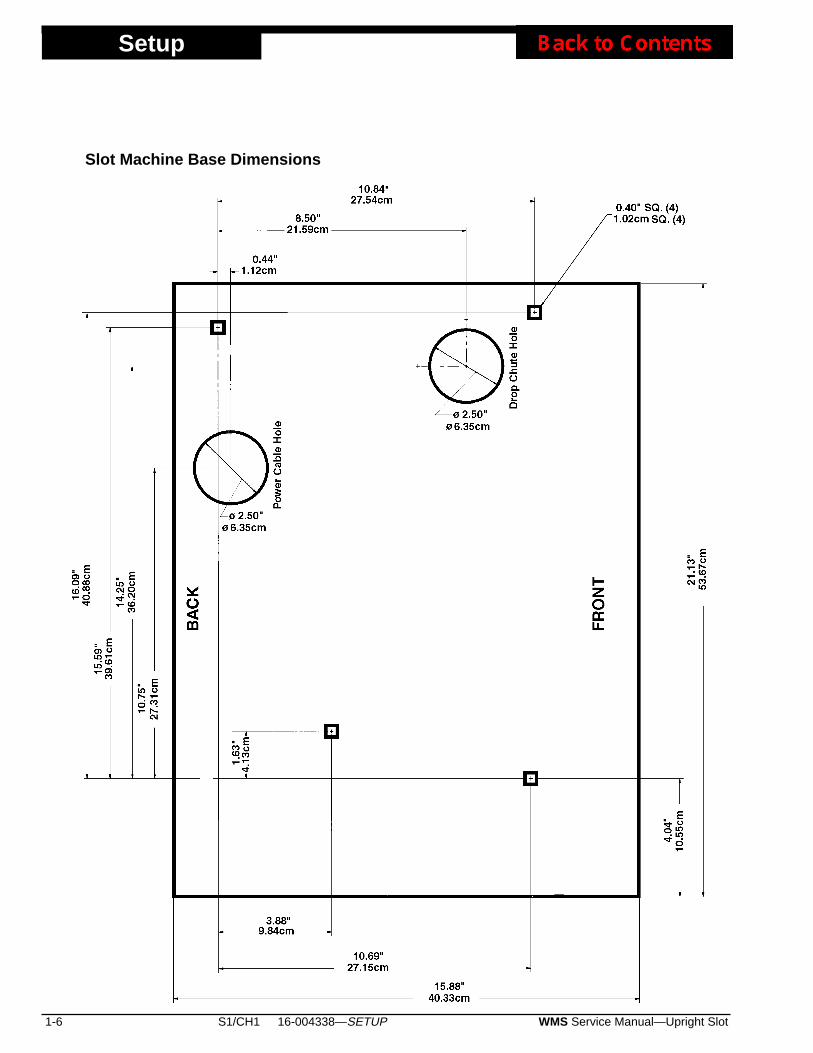
Slot Machine Base Dimensions
16-004338—SETUP S1/CH1 1-7WMS Service Manual—Upright Slot
Setup
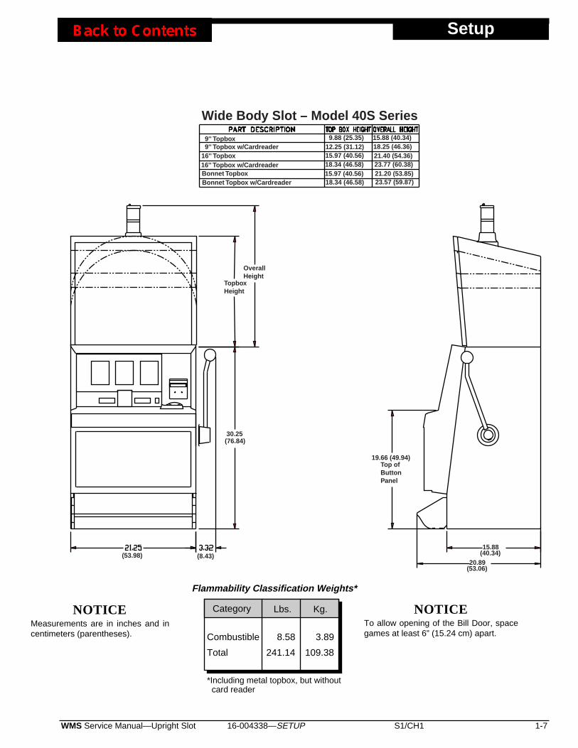
9.88 (25.35)12.25 (31.12)15.97 (40.56)18.34 (46.58)15.97 (40.56)18.34 (46.58)
15.88 (40.34)18.25 (46.36)21.40 (54.36)23.77 (60.38)21.20 (53.85)23.57 (59.87)
19.66 (49.94)
30.25(76.84)
(8.43)(53.98) (40.34)
(53.06)
15.88
20.89
Top ofButtonPanel
TopboxHeight
OverallHeight
9'' Topbox9'' Topbox w/Cardreader
16'' Topbox16'' Topbox w/CardreaderBonnet TopboxBonnet Topbox w/Cardreader
Wide Body Slot – Model 40S Series
Combustible
Total
8.58
241.14
3.89
109.38
Flammability Classification Weights*
*Including metal topbox, but without card reader
Category Lbs. Kg. NOTICETo allow opening of the Bill Door, spacegames at least 6” (15.24 cm) apart.
NOTICEMeasurements are in inches and incentimeters (parentheses).
16-004339—DIAGNOSTICS/ADJUSTMENTS S1/CH2 2-1WMS Service Manual—Slot Machine
Diag/Adjust
Chapter 2. Diagnostic and AdjustmentSoftware
Using Administration ModeYour slot machine's game software includes facilities for diagnosingproblems and verifying feature operation. This software also helps you toadjust game features and performance. You can access slot machinediagnostic and adjustment functions from the Administration Mode.
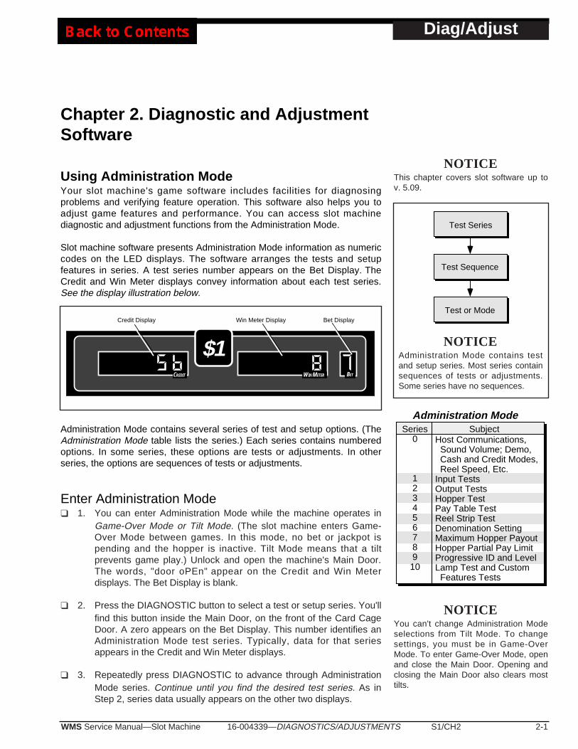
Slot machine software presents Administration Mode information as numericcodes on the LED displays. The software arranges the tests and setupfeatures in series. A test series number appears on the Bet Display. TheCredit and Win Meter displays convey information about each test series.See the display illustration below.
Administration Mode contains several series of test and setup options. (TheAdministration Mode table lists the series.) Each series contains numberedoptions. In some series, these options are tests or adjustments. In otherseries, the options are sequences of tests or adjustments.
Enter Administration Mode❑ 1. You can enter Administration Mode while the machine operates in
Game-Over Mode or Tilt Mode. (The slot machine enters Game-Over Mode between games. In this mode, no bet or jackpot ispending and the hopper is inactive. Tilt Mode means that a tiltprevents game play.) Unlock and open the machine's Main Door.The words, "door oPEn" appear on the Credit and Win Meterdisplays. The Bet Display is blank.
❑ 2. Press the DIAGNOSTIC button to select a test or setup series. You'llfind this button inside the Main Door, on the front of the Card CageDoor. A zero appears on the Bet Display. This number identifies anAdministration Mode test series. Typically, data for that seriesappears in the Credit and Win Meter displays.
❑ 3. Repeatedly press DIAGNOSTIC to advance through AdministrationMode series. Continue until you find the desired test series. As inStep 2, series data usually appears on the other two displays.
Win Meter Display Bet DisplayCredit Display
$1CREDIT WIN METER BET
Series0
12345678910
Host Communications, Sound Volume; Demo, Cash and Credit Modes, Reel Speed, Etc.Input TestsOutput TestsHopper TestPay Table TestReel Strip TestDenomination SettingMaximum Hopper PayoutHopper Partial Pay LimitProgressive ID and LevelLamp Test and Custom Features Tests
Subject
Administration Mode
Test Series
Test or Mode
Test Sequence
NOTICEYou can't change Administration Modeselections from Tilt Mode. To changesettings, you must be in Game-OverMode. To enter Game-Over Mode, openand close the Main Door. Opening andclosing the Main Door also clears mosttilts.
NOTICEThis chapter covers slot software up tov. 5.09.
NOTICEAdministration Mode contains testand setup series. Most series containsequences of tests or adjustments.Some series have no sequences.
Diag/Adjust
2-2 S1/CH2 WMS Service Manual—Slot Machine16-004339—DIAGNOSTICS/ADJUSTMENTS
Perform Test and Setup Functions❑ 1. Turn the JACKPOT RESET KEY to select a test within a series or
sequence. You'll find the JACKPOT RESET KEY switch near theSLOT HANDLE. Insert and turn the key.
❑ 2. Press the SPIN REELS button to initiate a test. SPIN REELS is onthe player panel. The button lights up to remind you to start the test.
Exit Administration ModeTo exit Administration Mode, either...
• Close the Main Door (except during Door Switch Test, Series 1, Test13).
• Repeatedly press DIAGNOSTIC until "door open" appears on thedisplay. Displays that read this way indicate Door-Open Mode, one ofmany slot machine states. When a game reports a tilt condition, the LEDdisplays indicate the tilt type ("coinJ," "HPrE," etc).
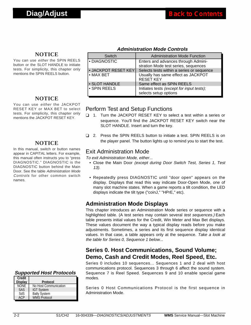
Administration Mode DisplaysThis chapter introduces an Administration Mode series or sequence with ahighlighted table. (A test series may contain several test sequences.) Eachtable presents initial values for the Credit, Win Meter and Max Bet displays.These values document the way a typical display reads before you makeadjustments. Sometimes, a series and its first sequence display identicalvalues. In that case, a table appears only at the sequence. Take a look atthe table for Series 0, Sequence 1 below...
Series 0. Host Communications, Sound Volume;Demo, Cash and Credit Modes, Reel Speed, Etc.Series 0 includes 10 sequences... Sequences 1 and 2 deal with hostcommunications protocol. Sequences 3 through 6 affect the sound system.Sequence 7 is Reel Speed. Sequences 9 and 10 enable special gamemodes.
Series 0 Host Communications Protocol is the first sequence inAdministration Mode.
• DIAGNOSTIC
• JACKPOT RESET KEY• MAX BET
• SLOT HANDLE• SPIN REELS
Enters and advances through Admini-stration Mode test series, sequencesSelects tests within a series or sequenceUsually has same effect as JACKPOTRESET KEYSame effect as SPIN REELSInitiates tests (except for input tests);selects setup options
Switch Administration Mode Function
Administration Mode Controls
ProtocolNo Host CommunicationIGT SystemBally SystemWMS Protocol
Supported Host ProtocolsCredit
DisplayNONESASSdSACP
NOTICEIn this manual, switch or button namesappear in CAPITAL letters. For example,this manual often instructs you to “pressDIAGNOSTIC.” DIAGNOSTIC is theDIAGNOSTIC button behind the MainDoor. See the table Administration ModeControls for other common switchnames.
NOTICEYou can use either the SPIN REELSbutton or the SLOT HANDLE to initiatetests. For simplicity, this chapter onlymentions the SPIN REELS button.
NOTICEYou can use either the JACKPOTRESET KEY or MAX BET to selecttests. For simplicity, this chapter onlymentions the JACKPOT RESET KEY.
16-004339—DIAGNOSTICS/ADJUSTMENTS S1/CH2 2-3WMS Service Manual—Slot Machine
Diag/Adjust
Sequence 1. Host Communications ProtocolInitial Display Values: Credit Win Meter Bet
NONE ON 0
The Credit Display provides a mnemonic for a host communications protocol.The Win Meter Display indicates whether this mnemonic represents theselected protocol. "On" identifies the selected protocol.
Your slot machine supports several protocols. See the table Supported HostProtocols.
Slot machines that use protocols with configurable addressing displaySequence 1.
• To view each protocol, turn the JACKPOT RESET KEY.
• To select a protocol, press SPIN REELS. If you aren’t using a hostsystem, select “NONE.”
• To save settings, skip Sequence 2 and enter Sequence 3, press theDIAGNOSTIC button.
Sequence 2. Machine Protocol Address (SAS)Initial Display Values: Credit Win Meter Bet
Addr 3-Digit No. 0
The Credit Display contains the expression, "Addr," the abbreviation for"Address." The Win Meter Display indicates the slot machine'scommunication address. If you haven't set the address yet, three zerosappear. You can vary this level from 0 to 127. The flashing digit indicates thefirst value to set.
• To change the flashing digit value, press SPIN REELS one or moretimes.
• To advance to the next digit, turn the JACKPOT RESET KEY. With eachturn of the key, the flashing digit sequentially advances from right to left.Suppose that the flashing digit is the leftmost one: Return to therightmost digit by turning the JACKPOT RESET KEY one more time.
• To delete a protocol and replace it with another one, turn the JACKPOTRESET KEY. Turn the key again, as necessary, until you locate the
Cash/Credit
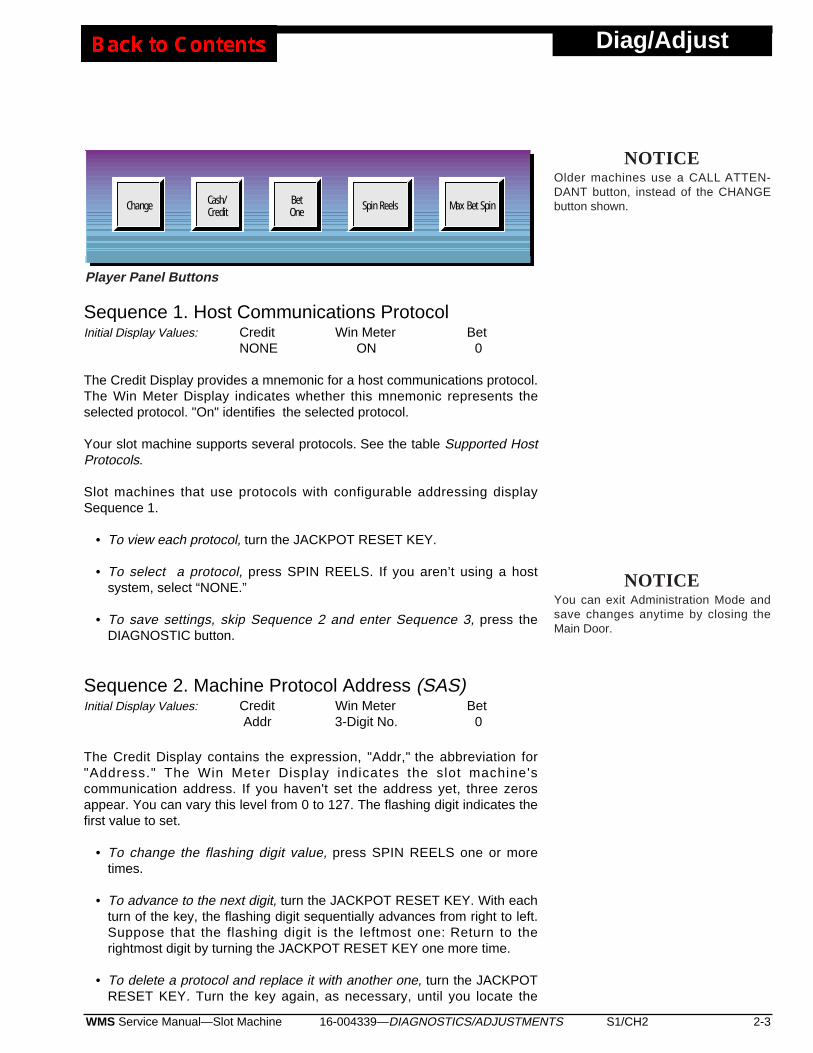
BetOne Spin Reels Max Bet SpinChange
NOTICEYou can exit Administration Mode andsave changes anytime by closing theMain Door.
Player Panel Buttons
NOTICEOlder machines use a CALL ATTEN-DANT button, instead of the CHANGEbutton shown.

Diag/Adjust
2-4 S1/CH2 WMS Service Manual—Slot Machine16-004339—DIAGNOSTICS/ADJUSTMENTS
desired new protocol. Set values at the new protocol, as above. Thenew protocol now replaces the previously set protocol.
• To save settings and enter Sequence 3, press the DIAGNOSTIC button.
Manual Sound SystemSome game software includes a manual user interface for sound volumesettings. Other game software incorporates an automated user interface.Your game software employs either interface, but not both. The interfacetype affects Series 0, sequences 3, 4 and 5. Your machine has either themanual or the automated version of these three sequences. This manualdescribes both versions. Here’s how the manual sound user interfacebehaves...
Sequence 3. Normal Sound Volume (Manual)Initial Display Values: Credit Win Meter Bet
Snd 1 3-Digit No. 0
Normal Sound Volume controls regular game sounds during normal gameoperation. (For example, credit bet and coin-in sounds, and most smallerawards tunes.) The Win Meter Display indicates the slot machine's soundvolume setting. You can vary this level from 0 to 255. The flashing digitindicates the first value to set. During Sequence 3, you can toggle the soundon or off with the lit MAX BET button. Pressing MAX BET, you hear thecredit/bet sound at the new volume level. Use this sound to determine theeffect of your adjustment.
• To change the flashing digit value, press SPIN REELS one or moretimes.
• To advance to the next digit, turn the JACKPOT RESET KEY. With eachturn of the key, the flashing digit sequentially advances from right to left.Suppose that the flashing digit is the leftmost one: Return to therightmost digit by turning the JACKPOT RESET KEY one more time.
• To save settings and enter Sequence 4, press the DIAGNOSTIC button.
Sequence 4. Large Hit Sound Volume (Manual)Initial Display Values: Credit Win Meter Bet
Snd 2 3-Digit No. 0
Large Hit Sound Volume controls volume during a large award payout. (Howlarge is “large”? “Large” is game specific, but a rule of thumb applies:Usually a large hit exceeds 50 credits.) Typically, Large Hit Sound Volume ismuch louder than normal volume. Use Large Hit Sound Volume to drawattention to the machine during large wins. The Win Meter Display indicatesthe slot machine's sound volume setting. You can vary this level from 0 to
16-004339—DIAGNOSTICS/ADJUSTMENTS S1/CH2 2-5WMS Service Manual—Slot Machine
Diag/Adjust
255. The flashing digit indicates the first value to set. You can toggle thesound on or off with the lit MAX BET button. Pressing MAX BET, you hearthe large award tune at the new volume level. Use this sound to determinethe effect of your adjustment.
• To change the flashing digit value, press SPIN REELS one or moretimes.
• To advance to the next digit, turn the JACKPOT RESET KEY. With eachturn of the key, the flashing digit sequentially advances from right to left.Suppose that the flashing digit is the leftmost one: Return to therightmost digit by turning the JACKPOT RESET KEY one more time.
• To save settings and enter Sequence 5, press the DIAGNOSTIC button.
Sequence 5. Top Award Sound Volume (Manual)Initial Display Values: Credit Win Meter Bet
Snd 3 3-Digit No. 0
Top Award Sound Volume controls volume when a player hits the top award.(Typically, this award is a jackpot.) Usually operators set this volume nearlywide open to draw attention to the machine. The Win Meter Displayindicates the slot machine's sound volume setting. You can vary this levelfrom 0 to 255. The flashing digit indicates the first value to set. You cantoggle the sound on or off with the lit MAX BET button. Pressing MAX BET,you hear the jackpot tune at the new volume level. Use this sound todetermine the effect of your adjustment.
• To change the flashing digit value, press SPIN REELS one or moretimes.
• To advance to the next digit, turn the JACKPOT RESET KEY. With eachturn of the key, the flashing digit sequentially advances from right to left.Suppose that the flashing digit is the leftmost one: Return to therightmost digit by turning the JACKPOT RESET KEY one more time.
• To save settings and enter Sequence 6, press the DIAGNOSTIC button.
Automated Sound SystemSome game software includes an automated user interface for soundvolume settings. This automated interface operates differently than themanual interface already described. Automated versions of Sequences 3, 4and 5 replace manual versions that we’ve described above. Here’s how theautomated sound user interface behaves...
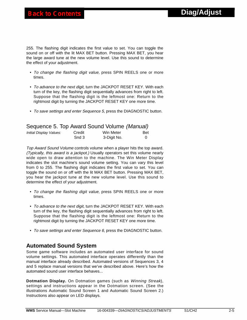
Dotmation Display. On Dotmation games (such as Winning Streak),settings and instructions appear in the Dotmation screen. (See theillustrations Automatic Sound Screen 1 and Automatic Sound Screen 2.)Instructions also appear on LED displays.
Diag/Adjust
2-6 S1/CH2 WMS Service Manual—Slot Machine16-004339—DIAGNOSTICS/ADJUSTMENTS
VOLUME SETTINGS
NORMAL VOL: 03
SPIN REELS LOWERS VOLUME
MAX BET RAISES VOLUME
BET 1 MUTES SOUND
Automatic Sound Screen 1
VOLUME SETTINGS
NORMAL VOL: 09
FEATURE VOL: AUTO
JACKPOT VOL: AUTO
BET 1 MUTES SOUND
Automatic Sound Screen 2
NOTICEThe Automated Sound Value Range is 0to 63, instead of 0 to 255. Sound level63 in the automated sound systemequals level 255 in the manual system.The automated system’s volume 25(Snd 1) equals the manual system’sstarting volume 30.
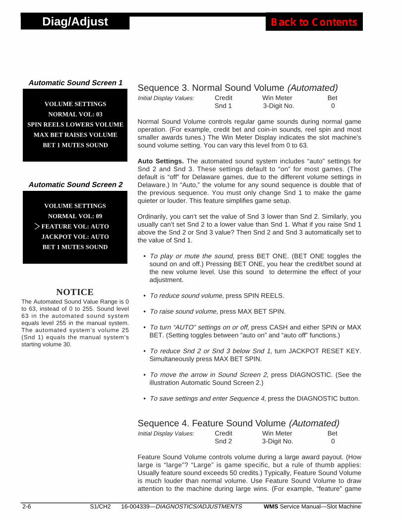
Sequence 3. Normal Sound Volume (Automated)Initial Display Values: Credit Win Meter Bet
Snd 1 3-Digit No. 0
Normal Sound Volume controls regular game sounds during normal gameoperation. (For example, credit bet and coin-in sounds, reel spin and mostsmaller awards tunes.) The Win Meter Display indicates the slot machine'ssound volume setting. You can vary this level from 0 to 63.
Auto Settings. The automated sound system includes “auto” settings forSnd 2 and Snd 3. These settings default to “on” for most games. (Thedefault is “off” for Delaware games, due to the different volume settings inDelaware.) In “Auto,” the volume for any sound sequence is double that ofthe previous sequence. You must only change Snd 1 to make the gamequieter or louder. This feature simplifies game setup.
Ordinarily, you can’t set the value of Snd 3 lower than Snd 2. Similarly, youusually can’t set Snd 2 to a lower value than Snd 1. What if you raise Snd 1above the Snd 2 or Snd 3 value? Then Snd 2 and Snd 3 automatically set tothe value of Snd 1.
• To play or mute the sound, press BET ONE. (BET ONE toggles thesound on and off.) Pressing BET ONE, you hear the credit/bet sound atthe new volume level. Use this sound to determine the effect of youradjustment.
• To reduce sound volume, press SPIN REELS.
• To raise sound volume, press MAX BET SPIN.
• To turn “AUTO” settings on or off, press CASH and either SPIN or MAXBET. (Setting toggles between “auto on” and “auto off” functions.)
• To reduce Snd 2 or Snd 3 below Snd 1, turn JACKPOT RESET KEY.Simultaneously press MAX BET SPIN.
• To move the arrow in Sound Screen 2, press DIAGNOSTIC. (See theillustration Automatic Sound Screen 2.)
• To save settings and enter Sequence 4, press the DIAGNOSTIC button.
Sequence 4. Feature Sound Volume (Automated)Initial Display Values: Credit Win Meter Bet
Snd 2 3-Digit No. 0
Feature Sound Volume controls volume during a large award payout. (Howlarge is “large”? “Large” is game specific, but a rule of thumb applies:Usually feature sound exceeds 50 credits.) Typically, Feature Sound Volumeis much louder than normal volume. Use Feature Sound Volume to drawattention to the machine during large wins. (For example, “feature” game
16-004339—DIAGNOSTICS/ADJUSTMENTS S1/CH2 2-7WMS Service Manual—Slot Machine
Diag/Adjust
sounds, such as the Winning Streak Bonus Round.) The Win Meter Displayindicates the slot machine's sound volume setting. You can vary this levelfrom 0 to 63.
Auto Settings. The automated sound system includes “auto” settings forSnd 2 and Snd 3. These settings default to “on” for most games. (The defaultis “off” for Delaware games, due to the different volume settings inDelaware.) In “Auto,” the volume for any sound sequence is double that ofthe previous sequence. You must only change Snd 1 to make the gamequieter or louder. This feature simplifies game setup.
Ordinarily, you can’t set the value of Snd 3 lower than Snd 2. Similarly, youusually can’t set Snd 2 to a lower value than Snd 1. What if you raise Snd 1above the Snd 2 or Snd 3 value? Then Snd 2 and Snd 3 automatically set tothe value of Snd 1.
• To play or mute the sound, press BET ONE. (BET ONE toggles thesound on and off.) Pressing BET ONE, you hear the large award tune atthe new volume level. Use this sound to determine the effect of youradjustment.
• To reduce sound volume, press SPIN REELS.
• To raise sound volume, press MAX BET SPIN.
• To turn “AUTO” settings on or off, press CASH and either SPIN or MAXBET. (Setting toggles between “auto on” and “auto off” functions.)
• To reduce Snd 2 or Snd 3 below Snd 1, turn JACKPOT RESET KEY.Simultaneously press MAX BET SPIN.
• To move the arrow in Sound Screen 2, press DIAGNOSTIC. (See theillustration Automatic Sound Screen 2.)
• To save settings and enter Sequence 4, press the DIAGNOSTIC button.
• To change the flashing digit value, press SPIN REELS one or moretimes.
• To advance to the next digit, turn the JACKPOT RESET KEY. With eachturn of the key, the flashing digit sequentially advances from right to left.Suppose that the flashing digit is the leftmost one: Return to therightmost digit by turning the JACKPOT RESET KEY one more time.
• To save settings and enter Sequence 5, press the DIAGNOSTIC button.
Sequence 5. Top Award Sound Volume (Automated)Initial Display Values: Credit Win Meter Bet
Snd 3 3-Digit No. 0
Top Award Sound Volume controls volume when a player hits the top award.(Typically, this award is a jackpot.) Usually operators set this volume nearly
Diag/Adjust
2-8 S1/CH2 WMS Service Manual—Slot Machine16-004339—DIAGNOSTICS/ADJUSTMENTS
wide open to draw attention to the machine. The Win Meter Displayindicates the slot machine's sound volume setting. You can vary this levelfrom 0 to 63.
Auto Settings. The automated sound system includes “auto” settings forSnd 2 and Snd 3. These settings default to “on” for most games. (Thedefault is “off” for Delaware games, due to the different volume settings inDelaware.) In “Auto,” the volume for any sound sequence is double that ofthe previous sequence. You must only change Snd 1 to make the gamequieter or louder. This feature simplifies game setup.
Ordinarily, you can’t set the value of Snd 3 lower than Snd 2. Similarly, youusually can’t set Snd 2 to a lower value than Snd 1. What if you raise Snd 1above the Snd 2 or Snd 3 value? Then Snd 2 and Snd 3 automatically set tothe value of Snd 1.
• To play or mute the sound, press BET ONE. (BET ONE toggles thesound on and off.) Pressing BET ONE, you hear the jackpot tune at thenew volume level. Use this sound to determine the effect of youradjustment.
• To reduce sound volume, press SPIN REELS.
• To raise sound volume, press MAX BET SPIN.
• To turn “AUTO” settings on or off, press CASH and either SPIN or MAXBET. (Setting toggles between “auto on” and “auto off” functions.)
• To reduce Snd 2 or Snd 3 below Snd 1, turn JACKPOT RESET KEY.Simultaneously press MAX BET SPIN.
• To move the arrow in Sound Screen 2, press DIAGNOSTIC. (See theillustration Automatic Sound Screen 2.)
• To save settings and enter Sequence 6, press the DIAGNOSTIC button.
Sequence 6. Jackpot LoopInitial Display Values: Credit Win Meter Bet
LooP inFin 0
Choose the number of times that the jackpot tune plays after a jackpot win.Select any number of plays, from 1 to 254. Select 255 to put the machineinto Infinite Loop Mode, the default setting. In Infinite Loop Mode, the jackpottune repeats until the attendant resets the jackpot.
• To change the flashing digit value, press SPIN REELS one or moretimes.
• To advance to the next digit, turn the JACKPOT RESET KEY. With eachturn of the key, the flashing digit sequentially advances from right to left.
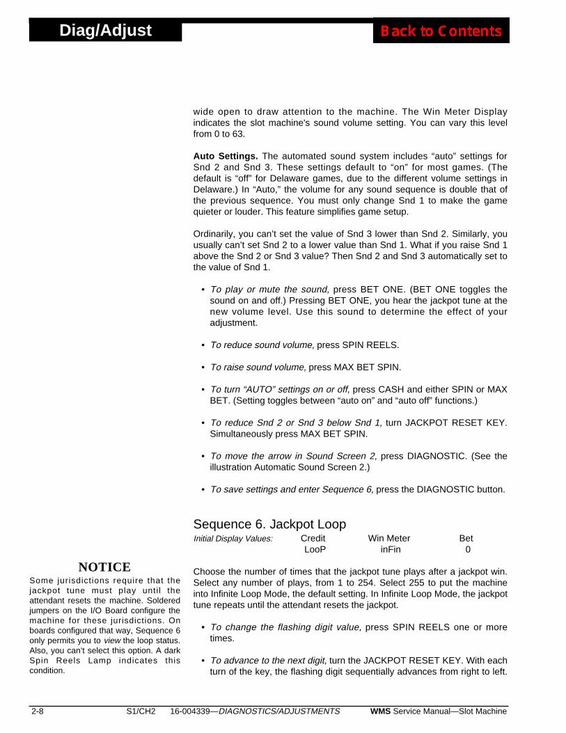
NOTICESome jurisdictions require that thejackpot tune must play unti l theattendant resets the machine. Solderedjumpers on the I/O Board configure themachine for these jurisdictions. Onboards configured that way, Sequence 6only permits you to view the loop status.Also, you can’t select this option. A darkSpin Reels Lamp indicates thiscondition.
16-004339—DIAGNOSTICS/ADJUSTMENTS S1/CH2 2-9WMS Service Manual—Slot Machine
Diag/Adjust
Suppose that the flashing digit is the leftmost one: Return to therightmost digit by turning the JACKPOT RESET KEY one more time.
• To save settings and enter Sequence 7, press the DIAGNOSTIC button.
Sequence 7. Reel SpeedInitial Display Values: Credit Win Meter Bet
SpEEd nnEd 0
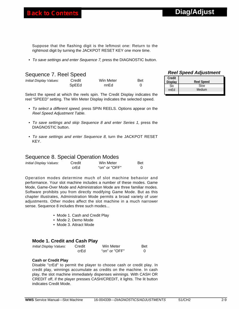
Select the speed at which the reels spin. The Credit Display indicates thereel “SPEED” setting. The Win Meter Display indicates the selected speed.
• To select a different speed, press SPIN REELS. Options appear on theReel Speed Adjustment Table.
• To save settings and skip Sequence 8 and enter Series 1, press theDIAGNOSTIC button.
• To save settings and enter Sequence 8, turn the JACKPOT RESETKEY.
Sequence 8. Special Operation ModesInitial Display Values: Credit Win Meter Bet
crEd “on” or "OFF" 0
Operation modes determine much of slot machine behavior andperformance. Your slot machine includes a number of these modes. GameMode, Game-Over Mode and Administration Mode are three familiar modes.Software prohibits you from directly modifying Game Mode. But as thischapter illustrates, Administration Mode permits a broad variety of useradjustments. Other modes affect the slot machine in a much narrowersense. Sequence 8 includes three such modes...
• Mode 1. Cash and Credit Play• Mode 2. Demo Mode• Mode 3. Attract Mode
Mode 1. Credit and Cash PlayInitial Display Values: Credit Win Meter Bet
crEd “on” or "OFF" 0
Cash or Credit PlayDisable "crEd" to permit the player to choose cash or credit play. Incredit play, winnings accumulate as credits on the machine. In cashplay, the slot machine immediately dispenses winnings. With CASH ORCREDIT off, if the player presses CASH/CREDIT, it lights. The lit buttonindicates Credit Mode.
Reel SpeedSlow
Medium
Reel Speed AdjustmentCredit
DisplaySlo
nnEd

Diag/Adjust
2-10 S1/CH2 WMS Service Manual—Slot Machine16-004339—DIAGNOSTICS/ADJUSTMENTS
Credit-Only PlayWith "crEd" on, the player must cash out credits to get them off themachine. To do this, the player presses the flashing CASH/CREDITbutton.
• To toggle the credit-only play on or off, press SPIN REELS. The WinMeter Display tracks feature status ("on" or "OFF”). The Credit Displayindicates the mode ("crEd").
• To enter Mode 2, turn the JACKPOT RESET KEY.
• To enter Series 1, press the DIAGNOSTIC button.
Mode 2. Demo ModeInitial Display Values: Credit Win Meter Bet
dEno “on” or "OFF" 0
If you enable Demo Mode, games run in Demo Mode. In Demo Mode,the slot machine doesn't require coins, dispense cash or incrementmeters. Except for these changes, games play normally.
• To toggle the mode on or off, press SPIN REELS. The Win MeterDisplay tracks mode status (“on” or "OFF”). The Credit Displayindicates the mode ("dEno").
• To enter Mode 3, turn the JACKPOT RESET KEY.
• To enter Series 1, press the DIAGNOSTIC button.
Mode 3. Attract ModeInitial Display Values: Credit Win Meter Bet
AtrAc “on” or "OFF" 0
You can enable Attract Mode, which operates when the machine is idle.In Attract Mode, panel LEDs may cycle in a pattern after a brief idle time.Some games with Attract Mode sounds periodically play a sound.
The Credit Display indicates the position of the Attract Mode toggle. TheWin Meter Display indicates the option state (“on” or "OFF”).
• To toggle Attract Mode on or off, press SPIN REELS .
• To reenter Mode 1, turn the JACKPOT RESET KEY.
• To enter Series 1, press the DIAGNOSTIC button.
NOTICEIn some game software versions, AttractMode sound is on by default. You mayturn off Attract Mode sound by followinginstructions at “Mode 3. Attract Mode.”
NOTICEThe machine can only enter Demo Modewhen certain conditions prevail: (1) TheCredit Meter displays zero credits. (2)No bet is pending. (3) The machine isn’tt i l ted. (4) Game rules permit themachine to enter Demo Mode. (5) Theslot machine isn’t storing bonus credits.

16-004339—DIAGNOSTICS/ADJUSTMENTS S1/CH2 2-11WMS Service Manual—Slot Machine
Diag/Adjust
Series 1. Input TestsInitial Display Values: Credit Win Meter Bet
3-Digit No. (Blank) 1
In the Credit Display, the left two digits represent the test number. The rightdigit is the current logic level of the selected input (0 or 1).
• To select a test, locate its number on the Input Tests table. Repeatedlypress MAX BET until display numbers correspond to the table. (Instead,you may repeatedly turn the JACKPOT RESET KEY. But MAX BET iseasier to actuate.)
• To test an input, activate the input and observe logic level changes.Inputs are either mechanical or opto switches. The optos are below thecoin comparator. (Your slot machine uses a Coin Mechanisms CoinComparitor® brand coin comparator.) To activate a mechanical switch,close it. To activate an opto, block it with a coin.
• To enter Series 2, press the DIAGNOSTIC button.
Test 10. Coin ComparatorDismount the coin comparator. Watch the Credit Display and drop a coininto the comparator. As the coin passes the comparator metal sensor,the zero logic level digit becomes one.
Test 11. Top Coin Opto This test checks the response of the top opto. Drop a coin into the coinentry. As the coin breaks the detector beam, the zero logic level digitshould become one. Any other result indicates that the opto needsservice.
Test 12. Bottom Coin Opto This test checks the response of the bottom opto. Drop a coin into thecoin entry. As the coin breaks the detector beam, the zero logic leveldigit should become one. Any other result indicates that the opto needsservice.
Test 13. Door SwitchWhen you close the Main Door, a zero appears on the Credit Display.When you open the Main Door, a one replaces the zero.
Test 14. Hopper Coin Sensor Press the spring-loaded lever atop the hopper escalator. Initially zero,the logic level digit changes to one. During play, dispensed coinsactuate the lever, closing contacts.
Test 15. Hopper Probe Use a coin to ground the top hopper probe to the hopper bowl. Initiallyzero, the logic level digit changes to one. A grounded probe indicates afull hopper.
101112131415161718192021222325262728293031404142707172737475
Input Tests
Test SubjectCoin ComparatorTop Coin OptoBottom Coin OptoDoor SwitchHopper Coin SensorHopper ProbeSPIN REELS buttonATTENDANT KEYSLOT HANDLE, top swSLOT HANDLE, btm swBET ONE buttonMAX BET buttonCASH/CREDIT buttonCALL ATTENDANT btnDIAGNOSTIC buttonStacker DoorLogic DoorBill DoorDrop Doorb ServHoodReel #1 OptoReel #2 OptoReel #3 OptoGame-Specific InputGame-Specific InputGame-Specific InputGame-Specific InputGame-Specific InputGame-Specific Input

Diag/Adjust
2-12 S1/CH2 WMS Service Manual—Slot Machine16-004339—DIAGNOSTICS/ADJUSTMENTS
Test 16. SPIN REELS Button Press SPIN REELS to test the button's operation. Initially zero, the logiclevel digit changes to one.
Test 17. JACKPOT RESET KEY Test the JACKPOT RESET KEY: Turn the key in the indicated direction,following these steps...
❑ 1. Turn the key CW: 17 1 appears on the Credit Display.❑ 2. Turn the key CCW: 17 0 appears on the Credit Display. ❑ 3. Turn the key CW: 17 1 appears on the Credit Display. ❑ 4. Turn the key CCW: 17 0 appears on the Credit Display. ❑ 5. Turn the key CW: 18 (next test) appears.
(CW stands for clockwise. CCW stands for counterclockwise.)
Test 18. Slot Handle (Not applicable to slant top slots)Pull the slot handle to test its top switch. Initially zero, the logic level digitchanges to one.
Test 19. Slot Handle (Not applicable to slant top slots)Release the slot handle to test its bottom switch. Initially one, the logiclevel digit changes to zero. The change occurs as the handle risesabove the bottom of its travel.
Test 20. BET ONE ButtonPress BET ONE to test the button's operation. Initially zero, the logiclevel digit changes to one.
Test 21. MAX BET ButtonPress MAX BET to test the button's operation. Initially zero, the logiclevel digit changes to one.
Test 22. CASH/CREDIT ButtonPress CASH/CREDIT to test the button's operation. Initially zero, thelogic level digit changes to one.
Test 23. CALL ATTENDANT ButtonPress CALL ATTENDANT to test the button's operation. Initially zero,the logic level digit changes to one.
Test 25. DIAGNOSTIC ButtonPress DIAGNOSTIC to test the button's operation. Initially zero, the logiclevel digit changes to one.
Test 26. Stacker DoorOpen and close the Stacker Door to test door switch operation. Initiallyzero, the logic level digit changes to one.
Test 27. Logic DoorOpen and close the Card Cage (Logic) Door to test door switchoperation. Initially zero, the logic level digit changes to one.
o1
0
1
Test 18
Test 19
16-004339—DIAGNOSTICS/ADJUSTMENTS S1/CH2 2-13WMS Service Manual—Slot Machine
Diag/Adjust
Test 28. Bill DoorOpen and close the Bill Door to test door switch operation. Initially zero,the logic level digit changes to one.
Test 29. Drop DoorOpen and close the Cashbox (Drop) Door to test door switch operation.Initially zero, the logic level digit changes to one.
Test 30. b Serv (Not applicable to upright slots)Open and close the Bill Jam Service Door to test door switch operation.Initially zero, the logic level digit changes to one.
Test 31. Hood (Not applicable to upright slots)Open and close the Reel Hatch (Hood) to test door switch operation.Initially zero, the logic level digit changes to one.
Test 40. Reel #1 OptoTest 40 checks the opto on Reel Mechanism 1. As you face the GD, thismechanism is the leftmost one. Notice the black opto fork at the base ofthe reel mechanism. Rotate the reel until the interrupter tab slidesbetween the opto fork tines. Initially zero, the logic level digit changes toone.
Test 41. Reel #2 OptoTest 41 checks the opto on the middle reel mechanism. Notice the blackopto fork at the base of the reel mechanism. Rotate the reel until theinterrupter tab slides between the opto fork tines. Initially zero, the logiclevel digit changes to one.
Test 42. Reel #3 OptoTest 42 checks the opto on the reel mechanism nearest to the billvalidator (BV). Notice the black opto fork at the base of the reelmechanism. Rotate the reel until the interrupter tab slides between theopto fork tines. Initially zero, the logic level digit changes to one.
Tests 70 through 75. Game-Specific InputsThe factory reserves tests 70 through 75 for game-specific inputs. Testsfor these inputs vary from machine to machine. Your machine’s softwaremay not include tests 70 through 75.
Series 2. Output TestsSeries 2, Output Tests, includes three sequences: Solenoid and LampTests, Sound Tests and a Display Digits Test.
Sequence 1. Solenoid and Lamp TestsInitial Display Values: Credit Win Meter Bet
9 (Blank) 2
The left two Credit Display digits represent the test number.
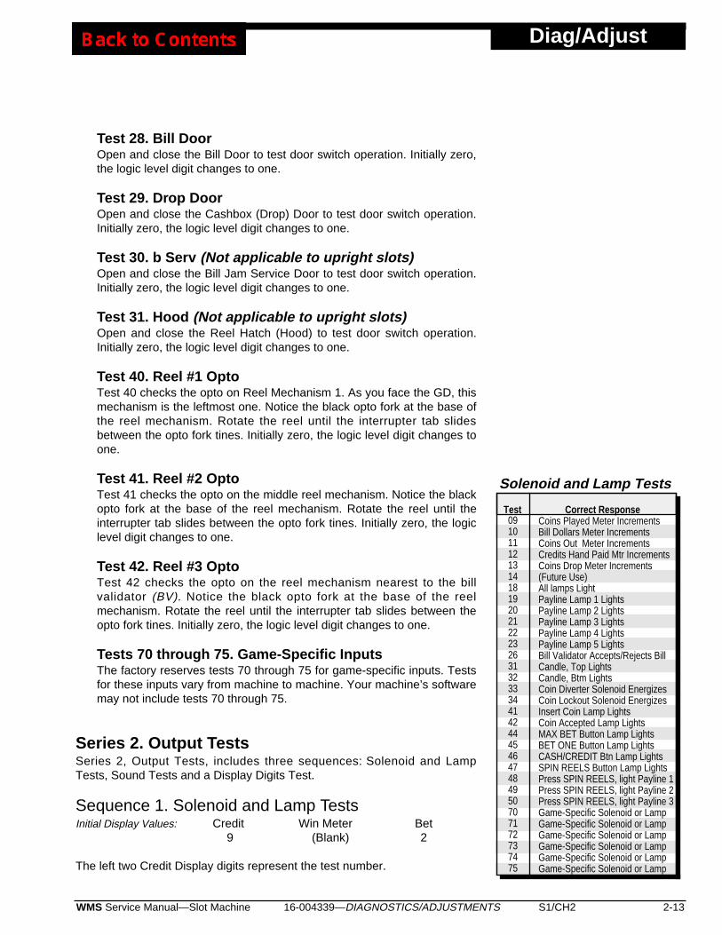
Correct ResponseCoins Played Meter IncrementsBill Dollars Meter IncrementsCoins Out Meter IncrementsCredits Hand Paid Mtr IncrementsCoins Drop Meter Increments(Future Use)All lamps LightPayline Lamp 1 LightsPayline Lamp 2 LightsPayline Lamp 3 LightsPayline Lamp 4 LightsPayline Lamp 5 LightsBill Validator Accepts/Rejects BillCandle, Top LightsCandle, Btm LightsCoin Diverter Solenoid EnergizesCoin Lockout Solenoid EnergizesInsert Coin Lamp LightsCoin Accepted Lamp LightsMAX BET Button Lamp LightsBET ONE Button Lamp LightsCASH/CREDIT Btn Lamp LightsSPIN REELS Button Lamp LightsPress SPIN REELS, light Payline 1Press SPIN REELS, light Payline 2Press SPIN REELS, light Payline 3Game-Specific Solenoid or LampGame-Specific Solenoid or LampGame-Specific Solenoid or LampGame-Specific Solenoid or LampGame-Specific Solenoid or LampGame-Specific Solenoid or Lamp
0910111213141819202122232631323334414244454647484950707172737475
Solenoid and Lamp Tests
Test
Diag/Adjust
2-14 S1/CH2 WMS Service Manual—Slot Machine16-004339—DIAGNOSTICS/ADJUSTMENTS
• To select a test, find its number on the Solenoid and Lamp Tests table.Repeatedly press MAX BET until display numbers correspond to thetable. (Instead, you may repeatedly turn the JACKPOT RESET KEY. ButMAX BET is easier to actuate.)
• To test an output, press the SPIN REELS button. Observe that output.All output lamps should light. Output solenoids (mechanical meters, etc.)should energize.
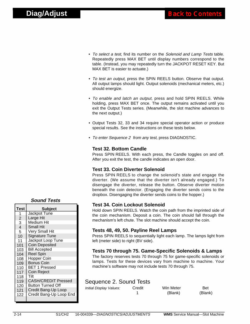
• To enable and latch an output, press and hold SPIN REELS. Whileholding, press MAX BET once. The output remains activated until youexit the Output Tests series. (Meanwhile, the slot machine advances tothe next output.)
• Output Tests 32, 33 and 34 require special operator action or producespecial results. See the instructions on these tests below.
• To enter Sequence 2 from any test, press DIAGNOSTIC.
Test 32. Bottom Candle Press SPIN REELS. With each press, the Candle toggles on and off.After you exit the test, the candle indicates an open door.
Test 33. Coin Diverter Solenoid Press SPIN REELS to change the solenoid's state and engage thediverter. (We assume that the diverter isn't already engaged.) Todisengage the diverter, release the button. Observe diverter motionbeneath the coin detector. (Engaging the diverter sends coins to thedropbox. Disengaging the diverter sends coins to the hopper.)
Test 34. Coin Lockout Solenoid Hold down SPIN REELS. Watch the coin path from the imprinted side ofthe coin mechanism. Deposit a coin. The coin should fall through themechanism's left chute. The slot machine should accept the coin.
Tests 48, 49, 50. Payline Reel LampsPress SPIN REELS to sequentially light each lamp. The lamps light fromleft (meter side) to right (BV side).
Tests 70 through 75. Game-Specific Solenoids & LampsThe factory reserves tests 70 through 75 for game-specific solenoids orlamps. Tests for these devices vary from machine to machine. Yourmachine’s software may not include tests 70 through 75.
Sequence 2. Sound TestsInitial Display Values: Credit Win Meter Bet
1 (Blank) (Blank)
SubjectJackpot TuneLarge HitMedium HitSmall HitVery Small HitSignature TuneJackpot Loop TuneCoin DepositedBill AcceptedReel SpinHopper CoinBonus CoinBET 1 PressedCoin RejectTiltCASH/CREDIT PressedButton Turned OffCredit Bang-Up LoopCredit Bang-Up Loop End
123451011101103104108109110117118119120121122
Sound Tests
Test
16-004339—DIAGNOSTICS/ADJUSTMENTS S1/CH2 2-15WMS Service Manual—Slot Machine
Diag/Adjust
The three left digits in the Credit Display represent a sound's test number.
• To select a sound, find its number on the Sound Tests table. Repeatedlyturn the JACKPOT RESET KEY until display numbers correspond to thetable.
• To test a sound, press the SPIN REELS button. Listen for soundeffects.
• To enter Sequence 3 from any sound test, press the DIAGNOSTICbutton.
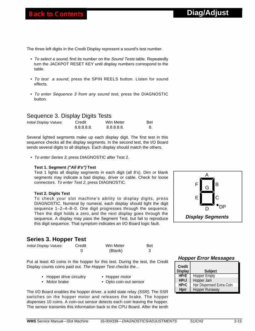
Sequence 3. Display Digits TestsInitial Display Values: Credit Win Meter Bet
8.8.8.8.8. 8.8.8.8.8. 8.
Several lighted segments make up each display digit. The first test in thissequence checks all the display segments. In the second test, the I/O Boardsends several digits to all displays. Each display should match the others.
• To enter Series 3, press DIAGNOSTIC after Test 2.
Test 1. Segment ("All 8's") TestTest 1 lights all display segments in each digit (all 8’s). Dim or blanksegments may indicate a bad display, driver or cable. Check for looseconnectors. To enter Test 2, press DIAGNOSTIC.
Test 2. Digits TestTo check your slot machine's abil i ty to display digits, pressDIAGNOSTIC. Numeral by numeral, each display should light the digitsequence 1–2–4–8–0. One digit progresses through the sequence.Then the digit holds a zero, and the next display goes through thesequence. A display may pass the Segment Test, but fail to reproducethis digit sequence. That symptom indicates an I/O Board logic fault.
Series 3. Hopper TestInitial Display Values: Credit Win Meter Bet
0 (Blank) 3
Put at least 40 coins in the hopper for this test. During the test, the CreditDisplay counts coins paid out. The Hopper Test checks the...
• Hopper drive circuitry • Hopper motor• Motor brake • Opto coin-out sensor
The I/O Board enables the hopper driver, a solid state relay (SSR). The SSRswitches on the hopper motor and releases the brake. The hopperdispenses 10 coins. A coin-out sensor detects each coin leaving the hopper.The sensor transmits this information back to the CPU Board. After the tenth
SubjectHopper EmptyHopper JamHpr Dispensed Extra CoinHopper Runaway
Hopper Error Messages
CreditDisplayHPrEHPrJHPrCHprr
.
A
B
C
D
E
FG
DP
Display Segments
Diag/Adjust
2-16 S1/CH2 WMS Service Manual—Slot Machine16-004339—DIAGNOSTICS/ADJUSTMENTS
coin leaves the hopper, the CPU Board disables the hopper SSR. The SSRswitches off the hopper motor and engages the brake.
Normally, the coin-out count appears on the Credit Display. If the hopperfails to dispense coins after three attempts, the hopper stops. Meanwhile, theCredit Display reads "HPrE," indicating "Hopper Empty." You'll also noticethat the TILT lamp comes on.
• To start or repeat the Hopper Test, or recover from an error, press SPINREELS.
• To enter Series 4, press DIAGNOSTIC.
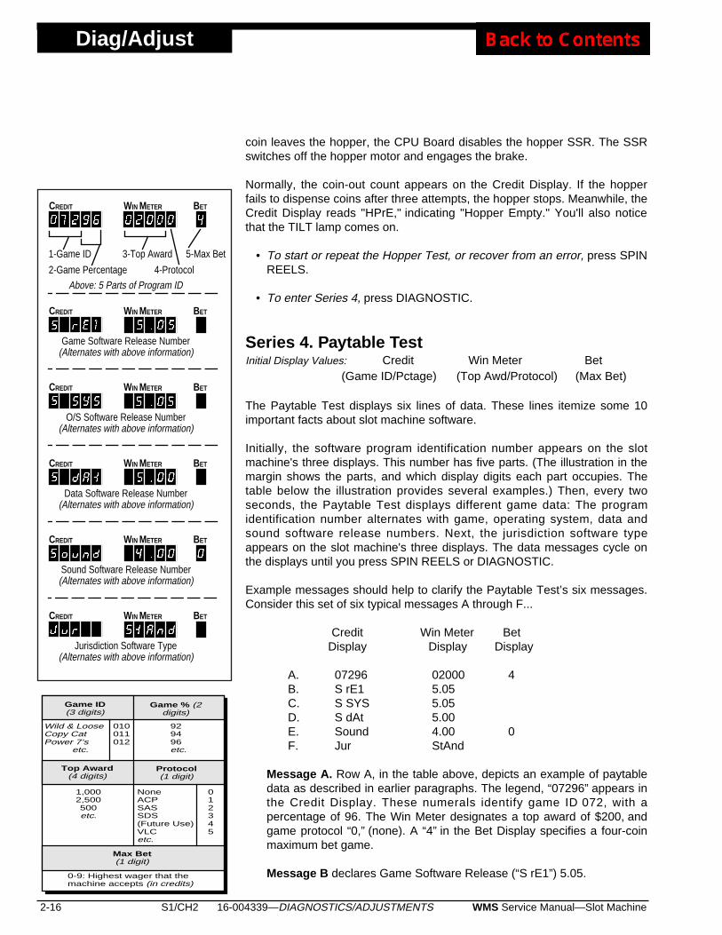
Series 4. Paytable TestInitial Display Values: Credit Win Meter Bet
(Game ID/Pctage) (Top Awd/Protocol) (Max Bet)
The Paytable Test displays six lines of data. These lines itemize some 10important facts about slot machine software.
Initially, the software program identification number appears on the slotmachine's three displays. This number has five parts. (The illustration in themargin shows the parts, and which display digits each part occupies. Thetable below the illustration provides several examples.) Then, every twoseconds, the Paytable Test displays different game data: The programidentification number alternates with game, operating system, data andsound software release numbers. Next, the jurisdiction software typeappears on the slot machine's three displays. The data messages cycle onthe displays until you press SPIN REELS or DIAGNOSTIC.
Example messages should help to clarify the Paytable Test’s six messages.Consider this set of six typical messages A through F...
Credit Win Meter BetDisplay Display Display
A. 07296 02000 4B. S rE1 5.05C. S SYS 5.05D. S dAt 5.00E. Sound 4.00 0F. Jur StAnd
Message A. Row A, in the table above, depicts an example of paytabledata as described in earlier paragraphs. The legend, “07296” appears inthe Credit Display. These numerals identify game ID 072, with apercentage of 96. The Win Meter designates a top award of $200, andgame protocol “0,” (none). A “4” in the Bet Display specifies a four-coinmaximum bet game.
Message B declares Game Software Release (“S rE1”) 5.05.
CREDIT WIN METER BET
1-Game ID
2-Game Percentage
3-Top Award
4-Protocol
5-Max Bet
O/S Software Release Number(Alternates with above information)
CREDIT WIN METER BET
Data Software Release Number(Alternates with above information)
CREDIT WIN METER BET
Sound Software Release Number(Alternates with above information)
CREDIT WIN METER BET
Above: 5 Parts of Program ID
Jurisdiction Software Type(Alternates with above information)
CREDIT WIN METER BET
Game Software Release Number(Alternates with above information)
CREDIT WIN METER BET
Protocol(1 digit)
Top Award(4 digits)
Game ID(3 digits)
Game % (2digits)
Wild & LooseCopy CatPower 7’s etc.
1,0002,500500etc.
929496etc.
NoneACPSASSDS(Future Use)VLCetc.
0-9: Highest wager that themachine accepts (in credits)
Max Bet(1 digit)
010011012
012345

16-004339—DIAGNOSTICS/ADJUSTMENTS S1/CH2 2-17WMS Service Manual—Slot Machine
Diag/Adjust
Message C reports Operating System Release (“S SYS”) 5.05.
Message D stipulates Data ROM Release (“S dAt”) 5.00.
Message E refers to Sound ROM Release (“Sound”) 4.00.
Message F identifies the slot software jurisdiction. In our example,“StAnd” refers to standard jurisdiction software. See the nearby tableJurisdiction ROMs and Jumpers. Most jurisdictions use standardsoftware. Special jurisdictions sometimes require their own software. Inaddition, special jurisdictions always employ unique jumper settings onthe I/O Board. These settings appear later in this chapter.
• To check paytable awards, press SPIN REELS once for each award.Each time that you press SPIN REELS, the test advances to the nextaward. The reels spin and stop on each winning combination. The stopsreference on the center line. Maximum and minimum paytable awardsalternate in the Win Meter Display. (See the NOTICE in the margin.)Awards occupy all five digits of the display. (Note this difference: In theprogram identification number described above, awards occupy onlyfour display digits.) The Credit Display indicates the award number. Forinstance, a "1" indicates the top award. After each test, the displayindicates the award for that combination.
Suppose that a failure occurs during the test: The test terminateswithout completing the spin. The Credit Display indicates the failure typewith an error code.
• To recover from the failure, press SPIN REELS.
• To continue the Paytable Test, press SPIN REELS again.
After displaying the last award in the paytable, the Paytable Test ends.
• To enter Series 5, press DIAGNOSTIC. Or press SPIN REELS after thelast non-zero award combination.
Series 5. Reel Strip TestInitial Display Values: Credit Win Meter Bet
(Blank) (Blank) 5
The Reel Strip Test enables you to check each strip for proper installationon its reel.
• To begin a reel strip test, press SPIN REELS. The reels spin and stopat the next symbol (reel stop) on the reel. The Credit Display indicatesthe symbol (reel stop) number.
• Repeatedly press SPIN REELS until you've checked all the symbols.Each time you press SPIN REELS, the reels advance one stop.
NOTICECHECKING PAYTABLE AWARDS. Anytop award over 99,999 appears inspecial notation. In this notation, “t”stands for the phrase, “times 10,000,plus...”
• In the table, the character xrepresents a decimal number.
• Multiply numbers before the character“t” by 10,000.
• Add numbers after the character “t” tothe product.
Examples: • 9,000 = 9000• 99,999 = 99999• 100,000 = 10t00• 990,099 = 99t99
Number0-99,999100,000-990,099
NotationConventional
xxtxx
Std ROM +JumpersMissouri
New Jersey
Std ROM +No Jumpers(Most Juris-
dictions)
Jurisdiction ROMs and Jumpers
Spcl ROM +JumpersDelawareFrance
Note: "Std" = Standard; "Spcl" = Special.Install standard or special ROM at XU3 onCPU Board.
Diag/Adjust
2-18 S1/CH2 WMS Service Manual—Slot Machine16-004339—DIAGNOSTICS/ADJUSTMENTS
Simultaneously, the Credit Display increments the symbol number.
• To enter Sequence 1 from any reel strip test, press the DIAGNOSTICbutton. Or press SPIN REELS after you've checked the last symbol.
Sequence 1. Show Secure Device TypeInitial Display Values: Credit Win Meter Bet
SEcur 4-Digit No. (Blank)
Sequence 1 is a read-only function. Use Show Secure Device Type to viewthe type number of your GD's secure EEPROM. (On machines without asecurity device, this number is zero.) The secure EEPROM resides at CPUBoard location XU27.
• To enter Series 6, press the DIAGNOSTIC button.
Series 6. Denomination SettingsSeries 6, Denomination Settings, includes two sequences: Show SlotMachine Denomination, and Set Bill Validator Denomination.
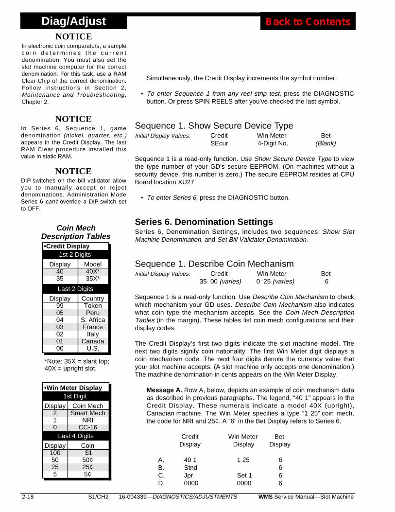
Sequence 1. Describe Coin MechanismInitial Display Values: Credit Win Meter Bet
35 00 (varies) 0 25 (varies) 6
Sequence 1 is a read-only function. Use Describe Coin Mechanism to checkwhich mechanism your GD uses. Describe Coin Mechanism also indicateswhat coin type the mechanism accepts. See the Coin Mech DescriptionTables (in the margin). These tables list coin mech configurations and theirdisplay codes.
The Credit Display’s first two digits indicate the slot machine model. Thenext two digits signify coin nationality. The first Win Meter digit displays acoin mechanism code. The next four digits denote the currency value thatyour slot machine accepts. (A slot machine only accepts one denomination.)The machine denomination in cents appears on the Win Meter Display.
Message A. Row A, below, depicts an example of coin mechanism dataas described in previous paragraphs. The legend, “40 1” appears in theCredit Display. These numerals indicate a model 40X (upright),Canadian machine. The Win Meter specifies a type “1 25” coin mech,the code for NRI and 25¢. A “6” in the Bet Display refers to Series 6.
Credit Win Meter BetDisplay Display Display
A. 40 1 1 25 6B. Stnd 6C. Jpr Set 1 6D. 0000 0000 6
Display99050403020100
CountryTokenPeru
S. AfricaFrance
ItalyCanada
U.S.
Coin MechDescription Tables
Display4035
Model40X*35X*
•Credit Display
Last 2 Digits
1st 2 Digits
*Note: 35X = slant top;40X = upright slot.
Display210
Coin MechSmart Mech
NRICC-16
Display10050255
Coin $150¢25¢5¢
1st Digit•Win Meter Display
Last 4 Digits
NOTICEDIP switches on the bill validator allowyou to manually accept or rejectdenominations. Administration ModeSeries 6 can't override a DIP switch setto OFF.
NOTICEIn Series 6, Sequence 1, gamedenomination (nickel, quarter, etc.)appears in the Credit Display. The lastRAM Clear procedure installed thisvalue in static RAM.
NOTICEIn electronic coin comparators, a samplec o i n d e t e r m i n e s t h e c u r r e n tdenomination. You must also set theslot machine computer for the correctdenomination. For this task, use a RAMClear Chip of the correct denomination.Follow instructions in Section 2,Maintenance and Troubleshooting,Chapter 2.
16-004339—DIAGNOSTICS/ADJUSTMENTS S1/CH2 2-19WMS Service Manual—Slot Machine
Diag/Adjust
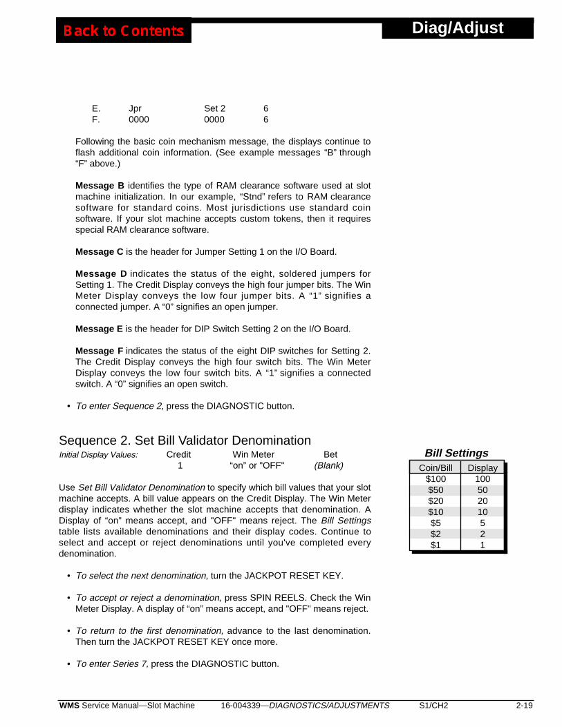
E. Jpr Set 2 6F. 0000 0000 6
Following the basic coin mechanism message, the displays continue toflash additional coin information. (See example messages “B” through“F” above.)
Message B identifies the type of RAM clearance software used at slotmachine initialization. In our example, “Stnd” refers to RAM clearancesoftware for standard coins. Most jurisdictions use standard coinsoftware. If your slot machine accepts custom tokens, then it requiresspecial RAM clearance software.
Message C is the header for Jumper Setting 1 on the I/O Board.
Message D indicates the status of the eight, soldered jumpers forSetting 1. The Credit Display conveys the high four jumper bits. The WinMeter Display conveys the low four jumper bits. A “1” signifies aconnected jumper. A “0” signifies an open jumper.
Message E is the header for DIP Switch Setting 2 on the I/O Board.
Message F indicates the status of the eight DIP switches for Setting 2.The Credit Display conveys the high four switch bits. The Win MeterDisplay conveys the low four switch bits. A “1” signifies a connectedswitch. A “0” signifies an open switch.
• To enter Sequence 2, press the DIAGNOSTIC button.
Sequence 2. Set Bill Validator DenominationInitial Display Values: Credit Win Meter Bet
1 “on” or "OFF" (Blank)
Use Set Bill Validator Denomination to specify which bill values that your slotmachine accepts. A bill value appears on the Credit Display. The Win Meterdisplay indicates whether the slot machine accepts that denomination. ADisplay of “on” means accept, and "OFF" means reject. The Bill Settingstable lists available denominations and their display codes. Continue toselect and accept or reject denominations until you've completed everydenomination.
• To select the next denomination, turn the JACKPOT RESET KEY.
• To accept or reject a denomination, press SPIN REELS. Check the WinMeter Display. A display of “on” means accept, and "OFF" means reject.
• To return to the first denomination, advance to the last denomination.Then turn the JACKPOT RESET KEY once more.
• To enter Series 7, press the DIAGNOSTIC button.
Bill SettingsDisplay
100502010521
Coin/Bill$100$50$20$10$5$2$1

Diag/Adjust
2-20 S1/CH2 WMS Service Manual—Slot Machine16-004339—DIAGNOSTICS/ADJUSTMENTS
Series 7. Maximum Hopper PayoutInitial Display Values: Credit Win Meter Bet
HoPr 4-Digit No. 7
Series 7 selects the maximum number of coins that the hopper dispenses atonce. Series 7 doesn't affect the number of coins paid out for the top award.Here’s how Series 7 works: A win that equals or exceeds the MaximumHopper Payout triggers a hand-pay event. The hand pay equals thedifference between the win and the partial hopper pay amount. (Anattendant must pay the hand pay amount.)
At or above the Maximum Hopper Payout, the GD reacts in either of twoways...
• In Cash Mode, the machine pays the partial payout amount set at Series8. Remaining winnings must be hand paid.
• In Credit Mode, the machine increments its Credit Display by the partialpayout amount. Remaining winnings must be hand paid.
Normally, an operator sets Maximum Hopper Payout to accommodatehopper size. Of course, the machine must never cash out more than hoppercapacity, emptying the hopper. To prevent that situation, the machineprohibits a credit accumulation beyond the Maximum Hopper Payout.
In Credit Mode...• If a win exceeds the Maximum Hopper Payout: The hopper provides a
partial payout and a hand pay provides the remainder.
• If a win plus credits on the machine equal or exceed the MaximumHopper Payout: The partial pay amount comes out of the hopper.
• If a win plus credits exceed the Maximum Hopper Payout: The hopperpays the win.
• The slot machine rejects a bill that increases credits up to or beyond theMaximum Hopper Payout.
The Credit Display indicates the maximum payout setting. The flashing digitindicates the value to set.
• To increment the flashing digit value, press SPIN REELS.
• To proceed to the next digit, turn the JACKPOT RESET KEY. With eachturn of the key, the flashing digit sequentially advances from right to left.
• To enter Series 8, press the DIAGNOSTIC button.

16-004339—DIAGNOSTICS/ADJUSTMENTS S1/CH2 2-21WMS Service Manual—Slot Machine
Diag/Adjust
Series 8. Hopper Partial Payout LimitInitial Display Values: Credit Win Meter Bet
PArt 4-Digit No. 8
Series 8 selects the partial payout amount during a hand payout or jackpot.Select “0000” to allow no partial payout. Your choice appears in the CreditDisplay.
The Credit Display indicates the current partial payout amount. The flashingdigit indicates the value to set.
• To change the flashing digit value, press SPIN REELS.
• To proceed to the next digit, turn the JACKPOT RESET KEY. With eachturn of the key, the flashing digit sequentially advances from right to left.
• To enter Series 9, press the DIAGNOSTIC button.
In a hand payout situation, the candle flashes and the machine dispensesthe allowed payout. The Credit Display indicates the amount dispensed. TheWin Meter Display indicates the amount to be hand paid.
Series 9. Progressive ID and LevelThe slot machine supports an interface to progressive systems. To use thissystem, turn on I/O Board DIP Switch 8 of Bank 2. Then make two settings...
• ID (Range 0 to 32). The slot machine ID.• Level (Range 0 to 8). The number of active progressive levels on the
system.
Set the DIP Switch and Check the Jurisdiction Jumper❑ 1. Unlock and open the Main Door. ❑ 2. Turn power off at the PDU switch. ❑ 3. Unlock and open the card cage. ❑ 4. The I/O Board is the top card in the card cage. To disengage a
board, pull the inside of its white board ejector tabs toward you.Remove the board.
❑ 5. Set DIP Switch 8, Bank 2 to "ON." Check to see that yourjurisdiction jumper is in the correct position. See the table I/OBoard Jumper and Dip Switch Settings.
❑ 6. Place the I/O Board on a flat surface. Use a ballpoint pen orsmall, flatblade screwdriver to set switches as desired.
❑ 7. Slide the circuit board back into its card cage slot. Push theboard in firmly, but don't force the board in. Each board is keyed,and only fits the proper slot. Push the white board ejector tabstoward the cage. This action engages the board with the blindmating connector.
NOTICEThe Hopper Partial Payout Limit can'texceed the Maximum Hopper Payout.Suppose that you attempt to set up themachine that way. The machine zerosany digit that produces an excessiveamount.

Diag/Adjust
2-22 S1/CH2 WMS Service Manual—Slot Machine16-004339—DIAGNOSTICS/ADJUSTMENTS
❑ 8. Clear the RAM by following the procedure in the Maintenanceand Troubleshooting book, Chapter 2.
❑ 9. Close and lock the card cage. ❑ 10. Turn power on at the PDU switch. ❑ 11. Close and lock the Main Door.
Sequence 1. Set Progressive IDInitial Display Values: Credit Win Meter Bet
ID 2-Digit No. 9
The ID specifies the Progressive Controller's input from this slot machine.For instance, suppose that you've plugged the slot machine into ProgressiveInput 1. Set the Progressive ID to 1. Never set an ID to zero (an invalidsetting).
If your slot machine doesn’t suport progressive capabilities, the Win Meterdisplay reads “null.” In machines without progressive capabilities, Sequence1 is a read-only feature.
• To increment the flashing digit value, press SPIN REELS.
To enable the Series 9 progressiveoption, turn on DIP Switch 8 of Bank 2.Otherwise, the progressive option won'twork. After setting the DIP switch, clearthe RAM. Otherwise, BookkeepingTotals will report inaccurate values.
The progressive option only initializesafter you clear the RAM. Turning on theswitch doesn’t disrupt bookkeepingtotals, because the GD won’t recognizethe new switch state.
CAUTION! CAUTION
ON
12345678
To use Series 9, turn on DIP Switch 8in Bank 2. (When viewed from thefront of the I/O Board, the DIP Switchis upside down.)
DipSwitches
TIP102Column-DriveDarlingtons
Power Supply LEDs:+5V, +12V, -12V, +5V, +18V
TDA2030ASound Amp Chip
PC BoardEjector Tab
TIP107Row-DriveDarlingtons
DS1 "Fail" LED
I/O (Top)Card
SolderedJumpers
DIP Bank1
(JumperPad)
2(Switch)
JurisdictionStandard
New JerseyMissouriFrance
DelawareProgressive
EnabledDisabled
8OffOnOffOnOff
OnOff
7OffOffOnOnOff
OffOff
6OffOffOffOffOn
OffOff
5OffOffOffOffOff
OffOff
4OffOffOffOffOff
OffOff
3OffOffOffOffOff
OffOff
2OffOffOffOffOff
OffOff
1OffOffOffOffOff
OffOff
I/O Board Jumper and DIP Switch Settings
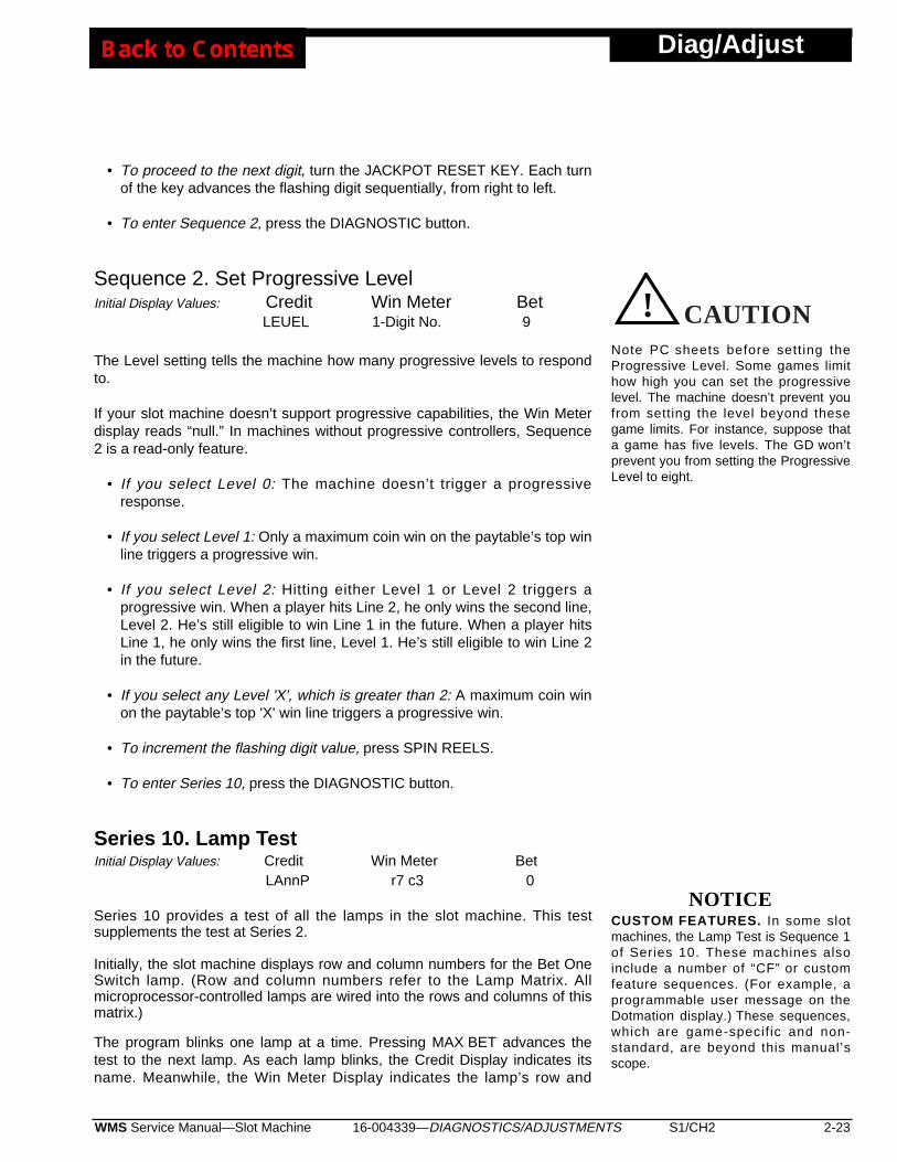
• To proceed to the next digit, turn the JACKPOT RESET KEY. Each turnof the key advances the flashing digit sequentially, from right to left.
• To enter Sequence 2, press the DIAGNOSTIC button.
Sequence 2. Set Progressive LevelInitial Display Values: Credit Win Meter Bet
LEUEL 1-Digit No. 9
The Level setting tells the machine how many progressive levels to respondto.
If your slot machine doesn’t support progressive capabilities, the Win Meterdisplay reads “null.” In machines without progressive controllers, Sequence2 is a read-only feature.
• If you select Level 0: The machine doesn’t trigger a progressiveresponse.
• If you select Level 1: Only a maximum coin win on the paytable’s top winline triggers a progressive win.
• If you select Level 2: Hitting either Level 1 or Level 2 triggers aprogressive win. When a player hits Line 2, he only wins the second line,Level 2. He’s still eligible to win Line 1 in the future. When a player hitsLine 1, he only wins the first line, Level 1. He’s still eligible to win Line 2in the future.
• If you select any Level 'X', which is greater than 2: A maximum coin winon the paytable’s top 'X' win line triggers a progressive win.
• To increment the flashing digit value, press SPIN REELS.
• To enter Series 10, press the DIAGNOSTIC button.
Series 10. Lamp TestInitial Display Values: Credit Win Meter Bet
LAnnP r7 c3 0
Series 10 provides a test of all the lamps in the slot machine. This testsupplements the test at Series 2.
Initially, the slot machine displays row and column numbers for the Bet OneSwitch lamp. (Row and column numbers refer to the Lamp Matrix. Allmicroprocessor-controlled lamps are wired into the rows and columns of thismatrix.)
The program blinks one lamp at a time. Pressing MAX BET advances thetest to the next lamp. As each lamp blinks, the Credit Display indicates itsname. Meanwhile, the Win Meter Display indicates the lamp’s row and
16-004339—DIAGNOSTICS/ADJUSTMENTS S1/CH2 2-23WMS Service Manual—Slot Machine
Diag/Adjust
NOTICECUSTOM FEATURES. In some slotmachines, the Lamp Test is Sequence 1of Series 10. These machines alsoinclude a number of “CF” or customfeature sequences. (For example, aprogrammable user message on theDotmation display.) These sequences,which are game-specif ic and non-standard, are beyond this manual’sscope.
Note PC sheets before setting theProgressive Level. Some games limithow high you can set the progressivelevel. The machine doesn’t prevent youfrom setting the level beyond thesegame limits. For instance, suppose thata game has five levels. The GD won’tprevent you from setting the ProgressiveLevel to eight.
CAUTION! CAUTION
Diag/Adjust
column.
The test checks leftmost lamps first. Then the test progresses to lamps onthe right side of the machine.
Here’s the nominal test order...• Button lamps• Tilt lamps• “Insert Coin” lamps• Denomination lamps• “Coin Accepted” lamps• Disclaimer/Payline lamps• Reel 1 lamps• Reel 2 lamps• Reel 3 lamps• Bill Validator lamps
Game-specific lamps appear either at the beginning or at the end of the test.(For example, the wheel in Top Cat or the Winning Streak marquee.)
• To advance to the next lamp and test it, press MAX BET.
• Replace burned out bulbs.
Exit to Game Play Mode
• To exit Series 10 and Administration Mode, close and lock the MainDoor. The reels spin and recycle to their previous game positions.
• To reenter Diagnostic Mode, press the DIAGNOSTIC button. A zeroappears in the Bet Display and three digits appear in the Credit Display.
2-24 S1/CH2 WMS Service Manual—Slot Machine16-004339—DIAGNOSTICS/ADJUSTMENTS
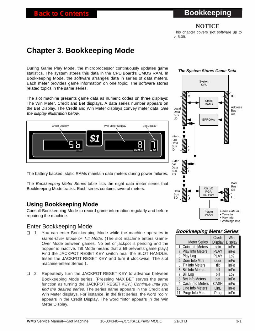
16-004340—BOOKKEEPING MODE S1/CH3 3-1WMS Service Manual—Slot Machine
Bookkeeping
Chapter 3. Bookkeeping Mode
During Game Play Mode, the microprocessor continuously updates gamestatistics. The system stores this data in the CPU Board's CMOS RAM. InBookkeeping Mode, the software arranges data in series of data meters.Each meter provides game information on one topic. The software storesrelated topics in the same series.
The slot machine presents game data as numeric codes on three displays:The Win Meter, Credit and Bet displays. A data series number appears onthe Bet Display. The Credit and Win Meter displays convey meter data. Seethe display illustration below.
The battery backed, static RAMs maintain data meters during power failures.
The Bookkeeping Meter Series table lists the eight data meter series thatBookkeeping Mode tracks. Each series contains several meters.
Using Bookkeeping ModeConsult Bookkeeping Mode to record game information regularly and beforerepairing the machine.
Enter Bookkeeping Mode❑ 1. You can enter Bookkeeping Mode while the machine operates in
Game-Over Mode or Tilt Mode. (The slot machine enters Game-Over Mode between games. No bet or jackpot is pending and thehopper is inactive. Tilt Mode means that a tilt prevents game play.)Find the JACKPOT RESET KEY switch near the SLOT HANDLE.Insert the JACKPOT RESET KEY and turn it clockwise. The slotmachine enters Series 1.
❑ 2. Repeatedly turn the JACKPOT RESET KEY to advance betweenBookkeeping Mode series. (Pressing MAX BET serves the samefunction as turning the JACKPOT RESET KEY.) Continue until youfind the desired series. The series name appears in the Credit andWin Meter displays. For instance, in the first series, the word "coin"appears in the Credit Display. The word "info" appears in the WinMeter Display.
Win Meter Display Bet DisplayCredit Display
$1CREDIT WIN METER BET
Xilinx®PGA
I/O Port
Game Data In...• Coins In• Play Info• Winnings Info
PlayerPanel
DataBusBD
DataBusGB
LocalDataBusLD
AddressBusXA
StaticRAMs
EPROMs
SystemCPU
The System Stores Game Data
Inter-ruptDataBusID
Exter-nalDataBusXD
Meter SeriesCoin Info MetersPlay Info MetersPlay LogDoor Info MtrsTilt Info MetersBill Info MetersBill LogBet Info MetersCash Info MetersLine Info MetersProgr Info Mtrs
CreditDisplay
coinPLAYPLAYdoortiltbillbillbet
CASHLinEProg
WinDisplay
inFoinFoLo9inFoinFoinFoLo9inFoinFoinFoinFo
Bookkeeping Meter Series
1.2.3.4.5.6.7.8.9.
10.11.
NOTICEThis chapter covers slot software up tov. 5.09.
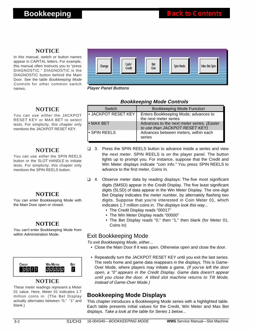
Bookkeeping
3-2 S1/CH3 WMS Service Manual—Slot Machine16-004340—BOOKKEEPING MODE
NOTICEYou can enter Bookkeeping Mode withthe Main Door open or closed.
NOTICEYou can't enter Bookkeeping Mode fromwithin Administration Mode.
❑ 3. Press the SPIN REELS button to advance inside a series and viewthe next meter. SPIN REELS is on the player panel. The buttonlights up to prompt you. For instance, suppose that the Credit andWin Meter displays indicate "coin info." You press SPIN REELS toadvance to the first meter, Coins In.
❑ 4. Observe meter data by reading displays: The five most significantdigits (5MSD) appear in the Credit Display. The five least significantdigits (5LSD) of data appear in the Win Meter Display. The one-digitBet Display indicates the meter number, by alternately flashing twodigits. Suppose that you're interested in Coin Meter 01, whichindicates 1.7 million coins in. The displays look this way...
• The Credit Display reads “00017”• The Win Meter Display reads “00000”• The Bet Display reads “0,” then “1,” then blank (for Meter 01,
Coins In)
Exit Bookkeeping ModeTo exit Bookkeeping Mode, either...
• Close the Main Door if it was open. Otherwise open and close the door.
• Repeatedly turn the JACKPOT RESET KEY until you exit the last series.The reels home and game data reappears in the displays. This is Game-Over Mode, where players may initiate a game. (If you've left the dooropen, a "0" appears in the Credit Display. Game data doesn't appearuntil you close the door. A tilted slot machine returns to Tilt Mode,instead of Game-Over Mode.)
Bookkeeping Mode DisplaysThis chapter introduces a Bookkeeping Mode series with a highlighted table.Each table presents initial values for the Credit, Win Meter and Max Betdisplays. Take a look at the table for Series 1 below...
• JACKPOT RESET KEY
• MAX BET
• SPIN REELS
Enters Bookkeeping Mode; advances tothe next meter seriesAdvances to the next meter series. (Easierto use than JACKPOT RESET KEY)Advances between meters, within eachseries
Switch Bookkeeping Mode Function
Bookkeeping Mode Controls
Cash/Credit
BetOne Spin Reels Max Bet SpinChange
NOTICEIn this manual, switch or button namesappear in CAPITAL letters. For example,this manual often instructs you to “pressDIAGNOSTIC.” DIAGNOSTIC is theDIAGNOSTIC button behind the MainDoor. See the table Bookkeeping ModeControls for other common switchnames. Player Panel Buttons
NOTICEThese meter readings represent a Meter01 value. Here, Meter 01 indicates 1.7mil l ion coins in. (The Bet Displayactually alternates between “0,” “1” andblank.)
CREDIT WIN METER BET
NOTICEYou can use either the SPIN REELSbutton or the SLOT HANDLE to initiatetests. For simplicity, this chapter onlymentions the SPIN REELS button.
NOTICEYou can use either the JACKPOTRESET KEY or MAX BET to selecttests. For simplicity, this chapter onlymentions the JACKPOT RESET KEY.

16-004340—BOOKKEEPING MODE S1/CH3 3-3WMS Service Manual—Slot Machine
Bookkeeping
SubjectCoins InCoins OutCoins DropBill DollarsCredits HandPayTotal Physical Coins InNormal Coin InEscrowed Coin InError Coin InTotal Physical Coins OutHopper Coin OutEscrow Coin OutTest Coin OutExtra Coin OutTotal Electronic Xfer InCard Credits InBonus Credits InTotal Electronic Xfer OutCard Credits OutBonus Credits Out
0102030405060708091011121314151617181920
Series 1. Coin Info Meters
Meter
Series 1. Coin InfoInitial Display Values: Credit Win Meter Bet
5 MSD 5 LSD flashes 0, then 1
See the Coin Info table. The meter number appears in the Bet Display. Thedisplay flashes the first digit of the code, followed by the second. Then thedisplay blanks. The sequence repeats until you enter the next series.
Examples...• “0,” then “1,” then blank = Meter 01• “0,” then “5,” then blank = Meter 05
• To step through the meters in this series, push SPIN REELS.
• Find the meter number that you want to examine by watching the BetDisplay. When you see the number that you're interested in, look at theCredit and Win Meter displays. The most significant five digits for thatmeter appear in the Credit Display. The least significant five digitsappear from left to right in the Win Meter Display.
• To enter Series 2, turn the JACKPOT RESET KEY.
Meter DefinitionsSome meter names in the Coin Info series don’t fully define the meters. Inthe following discussion, the manual briefly explains each meter’s function.
Meter 01. Coins InThe Coins In Meter tracks the number of played credits. This metertracks the sum of coins and credits bet.
Meter 02. Coins OutCoins Out adds two quantities...
• The number of coins out of the hopper• Credits bet from winnings
Meter 03. Coins Drop Coins Drop adds two quantities...
• The number of coins sent to the drop box• Sometimes bill validator credits (depending on jurisdiction rules)
Meter 04. Bill DollarsThe Bill Dollars Meter stores the dollar value of accepted bills.
Meter 05. Credits HandPayThe Credits HandPay Meter adds the number of credits that theattendant paid by hand.
NOTICESome jurisdictions require differentmeter specifications. Soldered jumperson the I/O Board configure the slotmachine for these jurisdictions. Consultlocal gaming regulations.
Bookkeeping
3-4 S1/CH3 WMS Service Manual—Slot Machine16-004340—BOOKKEEPING MODE
Meter 06. Total Coins InSum of Meters 7, 8 and 9.
Meter 07. Normal Coin InThe Normal Coin In Meter stores the number of coins inserted duringnormal game play.
Meter 08. Escrowed Coin InThe Escrowed Coin In Meter records the number of coins accepted atinappropriate times. These coins may be in the slot machine due to acoin lockout relay malfunction. Game software doesn’t count these coinsas a bet.
Meter 09. Error Coin InNumber of coins that produced a long coin error (attempted cheat).Game software doesn’t count these coins as a bet.
Meter 10. Total Coins OutSum of meters 11 through 14.
Meter 11. Hopper Coin OutNumber of coins out of the hopper during normal game play.
Meter 12. Escrow Coin OutNumber of coins returned from among the escrowed coins.
Meter 13. Test Coin OutNumber of coins paid out in the Hopper Test.
Meter 14. Extra Coin OutNumber of extra coins paid out.
Meter 15. Total Electronic Transfer InSum of meters 16 and 17.
Meter 16. Card Credits InNumber of electronic credits entered into the slot machine.
Meter 17. Bonus Credits InNumber of bonus credits awarded.
Meter 18. Total Electronic Transfer OutSum of meters 19 and 20.
Meter 19. Card Credits OutNumber of electronic credits removed from the slot machine.
Meter 20. Bonus Credits OutNumber of bonus credits removed.
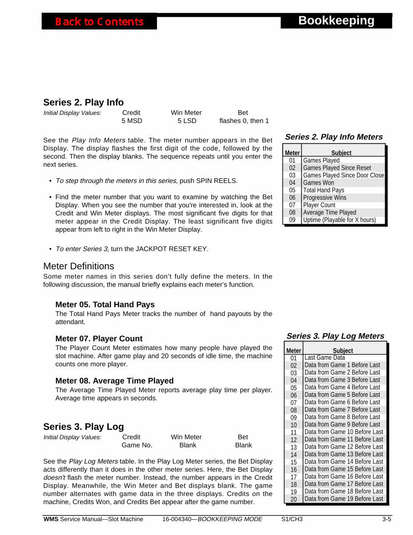
16-004340—BOOKKEEPING MODE S1/CH3 3-5WMS Service Manual—Slot Machine
Bookkeeping
SubjectGames PlayedGames Played Since ResetGames Played Since Door CloseGames WonTotal Hand PaysProgressive WinsPlayer CountAverage Time PlayedUptime (Playable for X hours)
010203040506070809
Series 2. Play Info Meters
Meter
SubjectLast Game DataData from Game 1 Before LastData from Game 2 Before LastData from Game 3 Before LastData from Game 4 Before LastData from Game 5 Before LastData from Game 6 Before LastData from Game 7 Before LastData from Game 8 Before LastData from Game 9 Before LastData from Game 10 Before LastData from Game 11 Before LastData from Game 12 Before LastData from Game 13 Before LastData from Game 14 Before LastData from Game 15 Before LastData from Game 16 Before LastData from Game 17 Before LastData from Game 18 Before LastData from Game 19 Before Last
0102030405060708091011121314151617181920
Series 3. Play Log Meters
Meter
Series 2. Play InfoInitial Display Values: Credit Win Meter Bet
5 MSD 5 LSD flashes 0, then 1
See the Play Info Meters table. The meter number appears in the BetDisplay. The display flashes the first digit of the code, followed by thesecond. Then the display blanks. The sequence repeats until you enter thenext series.
• To step through the meters in this series, push SPIN REELS.
• Find the meter number that you want to examine by watching the BetDisplay. When you see the number that you're interested in, look at theCredit and Win Meter displays. The most significant five digits for thatmeter appear in the Credit Display. The least significant five digitsappear from left to right in the Win Meter Display.
• To enter Series 3, turn the JACKPOT RESET KEY.
Meter DefinitionsSome meter names in this series don’t fully define the meters. In thefollowing discussion, the manual briefly explains each meter’s function.
Meter 05. Total Hand PaysThe Total Hand Pays Meter tracks the number of hand payouts by theattendant.
Meter 07. Player CountThe Player Count Meter estimates how many people have played theslot machine. After game play and 20 seconds of idle time, the machinecounts one more player.
Meter 08. Average Time PlayedThe Average Time Played Meter reports average play time per player.Average time appears in seconds.
Series 3. Play LogInitial Display Values: Credit Win Meter Bet
Game No. Blank Blank
See the Play Log Meters table. In the Play Log Meter series, the Bet Displayacts differently than it does in the other meter series. Here, the Bet Displaydoesn't flash the meter number. Instead, the number appears in the CreditDisplay. Meanwhile, the Win Meter and Bet displays blank. The gamenumber alternates with game data in the three displays. Credits on themachine, Credits Won, and Credits Bet appear after the game number.

Bookkeeping
3-6 S1/CH3 WMS Service Manual—Slot Machine16-004340—BOOKKEEPING MODE
• To step through the meters in this series, push SPIN REELS.
• Find the game number that you want to examine by watching the CreditDisplay. The reels spin and stop at positions corresponding to thatgame. The LEDs indicate that game's data. (The Play Log doesn't recordinformation on Demo Mode games.)
• To enter Series 4, turn the JACKPOT RESET KEY.
Series 4. Door InfoInitial Display Values: Credit Win Meter Bet
5 MSD 5 LSD flashes 0, then 1
See the Door Info Meters table. The meter number appears in the BetDisplay. The display flashes the first digit of the code, followed by thesecond. Then the display blanks. The sequence repeats until you enter thenext series.
• To step through the meters in this series, push SPIN REELS.
• Find the meter number that you want to examine by watching the BetDisplay. When you see the number that you're interested in, look at theCredit and Win Meter displays. The most significant five digits for thatmeter appear in the Credit Display. The least significant five digitsappear from left to right in the Win Meter Display.
• To enter Series 5, turn the JACKPOT RESET KEY.
Meter DefinitionsSome meter names in this series don’t fully define the meters. In thefollowing discussion, the manual briefly explains each meter’s function.
Meter 01. Main Door AccessMain Door Access signals entry into the slot machine’s Main Door.
Meter 02. Bill Validator Stacker AccessBill Validator Stacker Access notifies you that someone has removed thevalidator’s internal stacker.
Meter 03. Bill Validator Door (Stacker) AccessBill Validator Door Access signals entry into the bottom DBV door. Thisdoor allows access to the DBV stacker.
Meter 04. Logic Door AccessLogic Door Access notifies you of entry into the card cage.
SubjectMain Door AccessBill Validator Stacker AccessBill Validator Door AccessLogic Door AccessDrop Door AccessJam Service Door AccessReel Hatch (Hood) Door Access
01020304050607
Series 4. Door Info Meters
Meter
16-004340—BOOKKEEPING MODE S1/CH3 3-7WMS Service Manual—Slot Machine
Bookkeeping
SubjectBill Count (resets with stacker removal)Number of $1 bills insertedNumber of $2 bills insertedNumber of $5 bills insertedNumber of $10 bills insertedNumber of $20 bills insertedNumber of $50 bills insertedNumber of $100 bills inserted
0102030405060708
Series 6. Bill Info Meters
Mtr
Meter 05. Drop Door (Cashbox Door) AccessDrop Door Access signals entry into the Cashbox Door.
Meter 06. Bill Jam Service Door AccessBill Jam Service Door Access signals entry into the top DBV door of themachine. This door allows access to the DBV reader mechanism.
Meter 07. Hood Access (Not applicable to upright slots)Hood (Reel Hatch) Access signals entry into the Reel Hatch on the faceof the slot machine.
Series 5. Tilt InfoInitial Display Values: Credit Win Meter Bet
5 MSD 5 LSD flashes 0, then 5
See the Tilt Info Meters table. The meter number appears in the Bet Display.The display flashes the first digit of the code, followed by the second. Thenthe display blanks. The sequence repeats until you enter the next series.Detailed troubleshooting procedures usually begin with Tilt Info meterdisplays. See the Maintenance and Troubleshooting section.
• To step through the meters in this series, push SPIN REELS.
• Find the meter number that you want to examine by watching the BetDisplay. When you see the number that you're interested in, look at theCredit and Win Meter displays. The most significant five digits for thatmeter appear in the Credit Display. The least significant five digitsappear from left to right in the Win Meter Display.
• To enter Series 6, turn the JACKPOT RESET KEY.
Bill Validator FaultA bill validator fault condition takes the bill validator out of service. Billvalidator faults also cause the bill validator’s external (green) LEDs toextinguish. The slot machine continues to allow play, but only with coins. Torestore the bill validator to operation, you must service it.
Series 6. Bill InfoInitial Display Values: Credit Win Meter Bet
5 MSD 5 LSD flashes 0, then 1
See the Bill Info Meters table. The meter number appears in the Bet Display.The display flashes the first digit of the code, followed by the second. Thenthe display blanks. The sequence repeats until you enter the next series.
NOTICEThe Bill Info Meter called "Bill Count"zeroes when you remove the bil lstacker. Zeroing this meter promotesaccurate bil l accounting during acollection.
0102030405060708091011121314151617181920212223242526272829303132333435363738394041424344454675
Series 5. Tilt Info Meters
Mtr SubjectEmpty HopperJammed HopperHopper Extra Coin ErrorHopper Runaway ErrorCoin JamLong CoinReversed CoinRejected CoinBill Validator Communication FaultBill Validator FaultJammed Bill ValidatorReel Opto Not Seen ErrorReel Opto Seen at Invalid Time ErrorPower On ResetBattery Low or Dead ErrorMechanical Meter ErrorProgressive Link DownNo Prog Win Response ConfirmationFault in Communicating w/ Panel LEDsI/O Board FPGA Programming FaultSuccessful Memory ClearUser Unsuccessful RAM Clr AttemptSoft RAM ClearSecure and Game Data Don't MatchBoth Sig Copies Corrupt; Clear RAMCorrupt Main Sig CopyCorrupt Backup Sig CopyBoth Op Sys Copies Corrupt; Clr*Corrupt Main Copy of Op Sys DataCorrupt Backup Copy of Op Sys DataBoth Meter Data Copies Corrupt; Clr*Corrupt Main Meter CopyCorrupt Backup Meter CopyBoth GameLog Copies Corrupt; Clr*Corrupt Main GameLog CopyCorrupt Backup GameLog CopyCorrupt HeapFull HeapCorrupt Random Number Gen SeedCorrupt Progressive DataBoth GS* Data Copies Corrupt; Clr*Corrupt Main Copy of GS* DataCorrupt Backup Copy of GS* DataBoth PS* Data Copies Corrupt; Clr*Corrupt Main Copy of PS* DataCorrupt Backup Copy of PS* DataDotmation Communication Error
*NOTE: GS = Game-SpecificPS = Protocol SpecificClr = Clear the RAM

Bookkeeping
3-8 S1/CH3 WMS Service Manual—Slot Machine16-004340—BOOKKEEPING MODE
SubjectDollar Value of Last Bill InsertedDollar Value of Bill Inserted Before Last$ Value of Bill Inserted 2 Before Last$ Value of Bill Inserted 3 Before Last$ Value of Bill Inserted 4 Before Last$ Value of Bill Inserted 5 Before Last$ Value of Bill Inserted 6 Before Last$ Value of Bill Inserted 7 Before Last$ Value of Bill Inserted 8 Before Last$ Value of Bill Inserted 9 Before Last
01020304050607080910
Series 7. Bill Log Meters
Mtr
SubjectGames Played with 1-Credit BetGames Played with 2-Credit BetGames Played with 3-Credit BetGames Played with 4-Credit BetGames Played with 5-Credit Bet
0102030405
Series 8. Bet Info Meters
Mtr
• To step through the meters in this series, push SPIN REELS.
• Find the meter number that you want to examine by watching the BetDisplay. When you see the number that you're interested in, look at theCredit and Win Meter displays. The most significant five digits for thatmeter appear in the Credit Display. The least significant five digitsappear from left to right in the Win Meter Display.
• To enter Series 7, turn the JACKPOT RESET KEY.
Series 7. Bill LogInitial Display Values: Credit Win Meter Bet
5 MSD 5 LSD flashes 0, then 1
See the Bill Log Meters table. The meter number appears in the Bet Display.The display flashes the first digit of the code, followed by the second. Thenthe display blanks. The sequence repeats until you enter the next series.
• To step through the meters in this series, push SPIN REELS.
• Find the meter number that you want to examine by watching the BetDisplay. When you see the number that you're interested in, look at theWin Meter Display. The dollar value of the inserted bill appears in theWin Meter Display.
• To enter Series 8, turn the JACKPOT RESET KEY.
Series 8. Bet InfoInitial Display Values: Credit Win Meter Bet
5 MSD 5 LSD flashes 0, then 1
See the Bet Info Meters table. The meter number appears in the BetDisplay. The display flashes the first digit of the code, followed by thesecond. Then the display blanks. The sequence repeats until you enter thenext series.
• To step through the meters in this series, push SPIN REELS.
• Find the meter number that you want to examine by watching the BetDisplay. When you see the number that you're interested in, look at theCredit and Win Meter displays. The most significant five digits for thatmeter appear in the Credit Display. The least significant five digits
appear from left to right in the Win Meter Display. • To enter Series 7, turn the JACKPOT RESET KEY.

16-004340—BOOKKEEPING MODE S1/CH3 3-9WMS Service Manual—Slot Machine
Bookkeeping
Series 9. Cash InfoInitial Display Values: Credit Win Meter Bet
5 MSD 5 LSD flashes 0, then 1
See the Cash Info Meters table. Series 9 contains total quantities, notequalized quantities like the Coin Info series above. For example, ifsomeone inserts a bill in the machine, but doesn’t play credits, the Series 9CREDITSINBILL increments, but the COINSIN in Coin Info doesn’t.
Card CreditsCard Credits enter the machine electronically, usually through a host system.One source of these credits is player tracking or debit cards. The playerinserts the card into an electronic card reader. This reader relays appropriateinformation to the central system. The central system orders the slotmachine to accept credits.
Bonus CreditsThe central system might decide to give the player a bonus. Bonus Creditsenter the machine electronically, usually through a host system.
• To step through the meters in this series, push SPIN REELS.
• Find the meter number that you want to examine by watching the BetDisplay. When you see the number that you're interested in, look at theCredit and Win Meter displays. The most significant five digits for thatmeter appear in the Credit Display. The least significant five digitsappear from left to right in the Win Meter Display.
• To enter Series 7, turn the JACKPOT RESET KEY.
Series 10. Line InfoInitial Display Values: Credit Win Meter Bet
5 MSD 5 LSD flashes 0, then 1
Line Info meters the number of events that produces a win line combination.The meter number appears in the Bet Display. The display flashes the firstdigit of the code, followed by the second. Then the display blanks. Thesequence repeats until you exit Series 10.
The number of Line Info meters depends on the game’s pay table. ForExample, winning a “top award” increments Meter 1 by one. Winning with thesecond best award combination increments Meter 2 by one.
Win line combination reports don’t depend on the bet or payout. Forexample, John bets one credit and wins $100. Mary bets three and wins$300. In either case, three sevens appear on the payline. The slot machinereports each case as one event.
SubjectTotal Credits into Machine from CoinsTotal Credits into Machine from BillsElectronic (Host) Credits InTotal Credits In from BonusTotal Credits Out from HopperTotal Credits Out from AttendantElectronic (Host) Credits OutTotal Credits Out from BonusTotal Credits Drop from CoinsTotal Credits Drop (may include bills,depending on jurisdiction)Credits Removed from Credits WonCredits Bet from Credits WonCredits PlayedCredits WonHopper Fill Amount
01020304050607080910
1112131415
Series 9. Cash Info Meters
Mtr
Bookkeeping
3-10 S1/CH3 WMS Service Manual—Slot Machine16-004340—BOOKKEEPING MODE
Buy-a-pay games: The slot machine only reports win line events thatproduce a payout.
Some games create many meters for a winning combination. For example,Mary wins with three matching bars. That combination produces meters forthree “1” bars, three “2” bars, three “3” bars, etc.
• To step through the meters in this series, push SPIN REELS.
• Find the meter number that you want to examine by watching the BetDisplay. When you see the number that you're interested in, look at theCredit and Win Meter displays. The most significant five digits for thatmeter appear in the Credit Display. The least significant five digitsappear from left to right in the Win Meter Display.
• To enter Series 11, turn the JACKPOT RESET KEY.
Series 11. Prog InfoInitial Display Values: Credit Win Meter Bet
5 MSD 5 LSD flashes 0, then 1
Like Series 10, Series 11 contains a meter for each potential win linecombination. But Series 11 meters only increment for a progressive win atthe corresponding progressive level. (Progressive wins only occur onmaximum coin bets. For example, suppose that a player only bets one coin.Then he wins the top award combination. Due to his one-coin bet, he can'twin a progressive amount.)
• To step through the meters in this series, push SPIN REELS.
• Find the meter number that you want to examine by watching the BetDisplay. When you see the number that you're interested in, look at theCredit and Win Meter displays. The most significant five digits for thatmeter appear in the Credit Display. The least significant five digitsappear from left to right in the Win Meter Display.
Exit to Game Play ModeTo return to Game Play Mode, close the Main Door. (If the door is alreadyclosed, open and close it.) Or turn the JACKPOT RESET KEY.
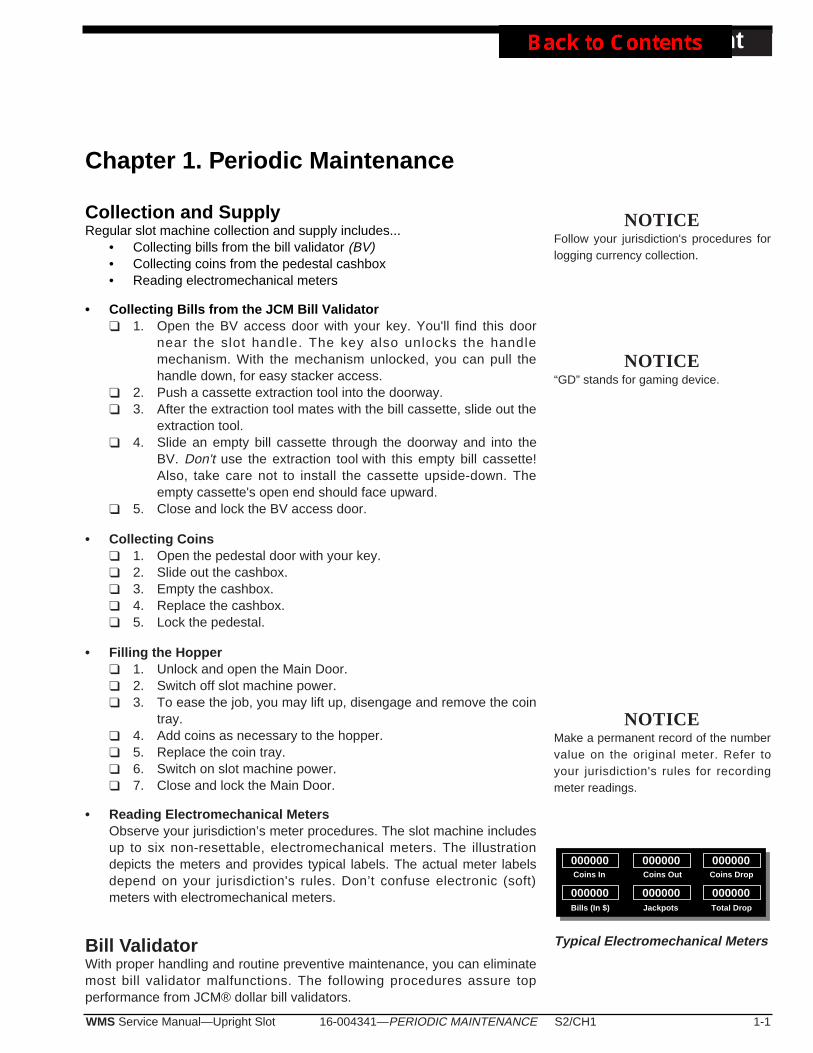
16-004341—PERIODIC MAINTENANCE S2/CH1 1-1WMS Service Manual—Upright Slot
Periodic Maint
Chapter 1. Periodic Maintenance
Collection and SupplyRegular slot machine collection and supply includes...
• Collecting bills from the bill validator (BV)• Collecting coins from the pedestal cashbox• Reading electromechanical meters
• Collecting Bills from the JCM Bill Validator❑ 1. Open the BV access door with your key. You'll find this door
near the slot handle. The key also unlocks the handlemechanism. With the mechanism unlocked, you can pull thehandle down, for easy stacker access.
❑ 2. Push a cassette extraction tool into the doorway. ❑ 3. After the extraction tool mates with the bill cassette, slide out the
extraction tool.❑ 4. Slide an empty bill cassette through the doorway and into the
BV. Don't use the extraction tool with this empty bill cassette!Also, take care not to install the cassette upside-down. Theempty cassette's open end should face upward.
❑ 5. Close and lock the BV access door.
• Collecting Coins❑ 1. Open the pedestal door with your key.❑ 2. Slide out the cashbox.❑ 3. Empty the cashbox. ❑ 4. Replace the cashbox. ❑ 5. Lock the pedestal.
• Filling the Hopper❑ 1. Unlock and open the Main Door. ❑ 2. Switch off slot machine power. ❑ 3. To ease the job, you may lift up, disengage and remove the coin
tray.❑ 4. Add coins as necessary to the hopper. ❑ 5. Replace the coin tray. ❑ 6. Switch on slot machine power. ❑ 7. Close and lock the Main Door.
• Reading Electromechanical Meters Observe your jurisdiction’s meter procedures. The slot machine includesup to six non-resettable, electromechanical meters. The illustrationdepicts the meters and provides typical labels. The actual meter labelsdepend on your jurisdiction's rules. Don’t confuse electronic (soft)meters with electromechanical meters.
Bill ValidatorWith proper handling and routine preventive maintenance, you can eliminatemost bill validator malfunctions. The following procedures assure topperformance from JCM® dollar bill validators.
NOTICEFollow your jurisdiction's procedures forlogging currency collection.
NOTICE“GD” stands for gaming device.
000000 000000 000000
Bills (In $) Jackpots Total Drop
Coins In Coins Out Coins Drop
000000 000000 000000
NOTICEMake a permanent record of the numbervalue on the original meter. Refer toyour jurisdiction's rules for recordingmeter readings.
Typical Electromechanical Meters
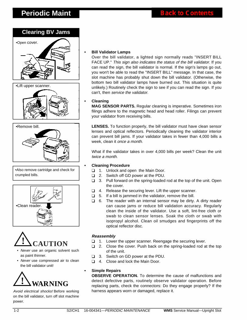
Periodic Maint
• Bill Validator LampsOver the bill validator, a lighted sign normally reads "INSERT BILLFACE UP." This sign also indicates the status of the bill validator. If youcan read the sign, the bill validator is normal. If the sign's lamps go out,you won't be able to read the "INSERT BILL" message. In that case, theslot machine has probably shut down the bill validator. (Otherwise, thebottom two bill validator lamps have burned out. This situation is quiteunlikely.) Routinely check the sign to see if you can read the sign. If youcan't, then service the validator.
• CleaningMAG SENSOR PARTS. Regular cleaning is imperative. Sometimes ironfilings adhere to the magnetic head and head roller. Filings can preventyour validator from receiving bills.
LENSES. To function properly, the bill validator must have clean sensorlenses and optical reflectors. Periodically cleaning the validator interiorcan prevent bill jams. If your validator takes in fewer than 4,000 bills aweek, clean it once a month.
What if the validator takes in over 4,000 bills per week? Clean the unittwice a month.
• Cleaning Procedure❑ 1. Unlock and open the Main Door.❑ 2. Switch off GD power at the PDU.❑ 3. Pull forward on the spring-loaded rod at the top of the unit. Open
the cover.❑ 4. Release the securing lever. Lift the upper scanner.❑ 5. If a bill is jammed in the validator, remove the bill.❑ 6. The reader with an internal sensor may be dirty. A dirty reader
can cause jams or reduce bill validation accuracy. Regularlyclean the inside of the validator. Use a soft, lint-free cloth orswab to clean sensor lenses. Soak the cloth or swab withisopropyl alcohol. Clean oil smudges and fingerprints off theoptical reflector disc.
Reassembly❑ 1. Lower the upper scanner. Reengage the securing lever. ❑ 2. Close the cover. Push back on the spring-loaded rod at the top
of the unit. ❑ 3. Switch on GD power at the PDU.❑ 4. Close and lock the Main Door.
• Simple RepairsOBSERVE OPERATION. To determine the cause of malfunctions anddetect defective parts, routinely observe validator operation. Beforereplacing parts, check the connectors: Do they engage properly? If theharness appears worn or damaged, replace it.
1-2 S2/CH1 WMS Service Manual—Upright Slot16-004341—PERIODIC MAINTENANCE
•Lift upper scanner.
•Remove bill.
•Clean reader.
•Also remove cartridge and check forcrumpled bills.
•Open cover.
Clearing BV Jams
CAUTION! WARNINGAvoid electrical shocks! Before workingon the bill validator, turn off slot machinepower.
• Never use an organic solvent suchas paint thinner.
• Never use compressed air to cleanthe bill validator unit!
CAUTION! CAUTION
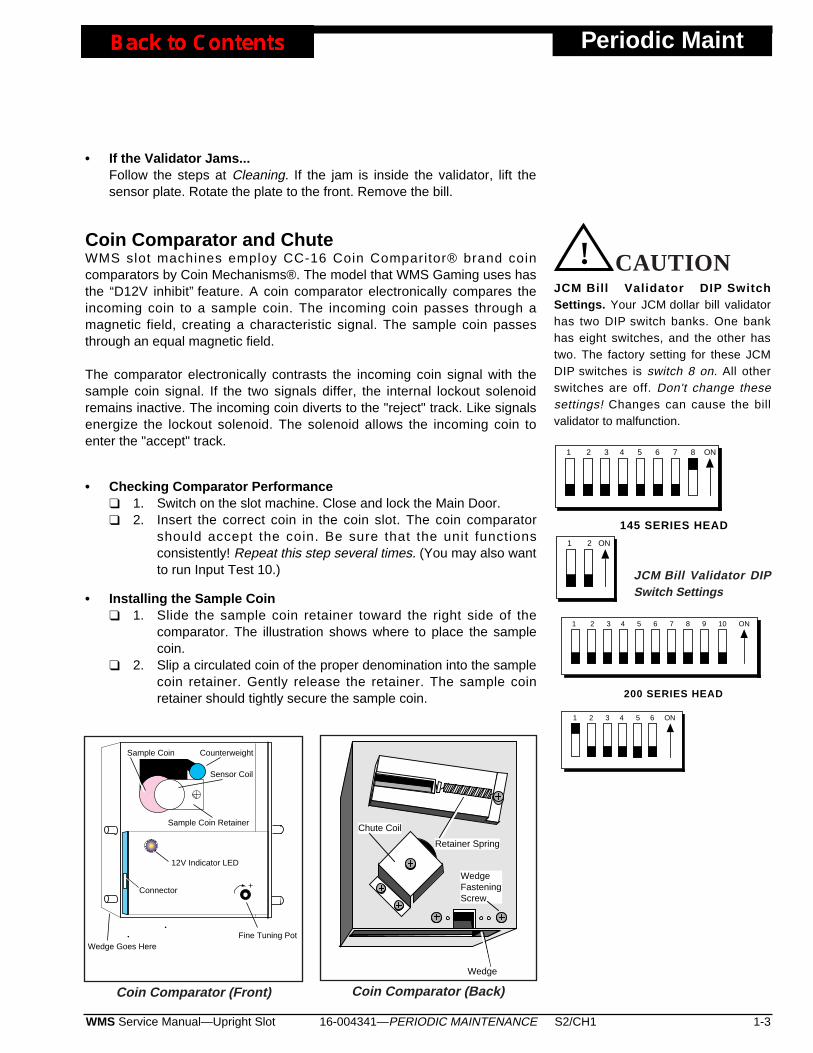
• If the Validator Jams...Follow the steps at Cleaning. If the jam is inside the validator, lift thesensor plate. Rotate the plate to the front. Remove the bill.
Coin Comparator and ChuteWMS slot machines employ CC-16 Coin Comparitor® brand coincomparators by Coin Mechanisms®. The model that WMS Gaming uses hasthe “D12V inhibit” feature. A coin comparator electronically compares theincoming coin to a sample coin. The incoming coin passes through amagnetic field, creating a characteristic signal. The sample coin passesthrough an equal magnetic field.
The comparator electronically contrasts the incoming coin signal with thesample coin signal. If the two signals differ, the internal lockout solenoidremains inactive. The incoming coin diverts to the "reject" track. Like signalsenergize the lockout solenoid. The solenoid allows the incoming coin toenter the "accept" track.
• Checking Comparator Performance❑ 1. Switch on the slot machine. Close and lock the Main Door.❑ 2. Insert the correct coin in the coin slot. The coin comparator
should accept the coin. Be sure that the unit functionsconsistently! Repeat this step several times. (You may also wantto run Input Test 10.)
• Installing the Sample Coin❑ 1. Slide the sample coin retainer toward the right side of the
comparator. The illustration shows where to place the samplecoin.
❑ 2. Slip a circulated coin of the proper denomination into the samplecoin retainer. Gently release the retainer. The sample coinretainer should tightly secure the sample coin.
16-004341—PERIODIC MAINTENANCE S2/CH1 1-3WMS Service Manual—Upright Slot
Periodic Maint
1 2 3 4 5 6 7 8 ON
1 2 ON
145 SERIES HEAD
JCM Bill Validator DIP SwitchSettings. Your JCM dollar bill validatorhas two DIP switch banks. One bankhas eight switches, and the other hastwo. The factory setting for these JCMDIP switches is switch 8 on. All otherswitches are off. Don't change thesesettings! Changes can cause the billvalidator to malfunction.
CAUTION! CAUTION
JCM Bill Validator DIPSwitch Settings
Fine Tuning Pot
Sample Coin
Sample Coin Retainer
Sensor Coil
+
Counterweight
Wedge Goes Here
Connector
12V Indicator LED
Coin Comparator (Front)
Chute Coil
Retainer Spring
Wedge
WedgeFasteningScrew
Coin Comparator (Back)
1 2 3 4 5 6 7 8 9 10 ON
1 2 3 4 5 6 ON
200 SERIES HEAD
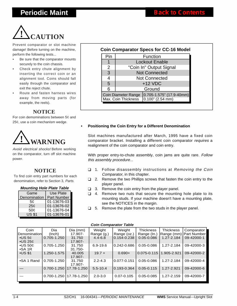
Periodic Maint
• Positioning the Coin Entry for a Different Denomination
Slot machines manufactured after March, 1995 have a fixed coincomparator bracket. Installing a different coin comparator requires arealignment of the coin comparator and coin entry.
With proper entry-to-chute assembly, coin jams are quite rare. Followthis assembly procedure...
❑ 1. Follow disassembly instructions at Removing the CoinComparator, in this chapter.
❑ 2. Remove the two Phillips screws that fasten the coin entry to theplayer panel.
❑ 3. Remove the coin entry from the player panel.❑ 4. Remove two nuts that secure the mounting hole plate to its
mounting studs. If your machine doesn't have a mounting plate,see the NOTICES in the margin.
❑ 5. Remove the plate from the two studs in the player panel.
1-4 S2/CH1 WMS Service Manual—Upright Slot16-004341—PERIODIC MAINTENANCE
CoinDenomination
Coin Comparator TableComparatorPart Number09-42000-1
09-42000-3
09-42000-2
09-42000-4
09-42000-6
09-42000-7
Dia (mm)17.907-31.75017.907-31.75031.750- 40.00517.907-31.75017.907-
17.78-1.250
17.78-1.250
WeightRange (g.)
4.4-6.8
6.9-19.6
19.7 +
2.2-4.3
5.5-10.4
2.0-3.0
ThicknessRange (In.)0.05-0.086
0.05-0.086
0.075-0.115
0.05-0.086
0.05-0.115
0.05-0.085
•US 5¢•US 25¢•US 50¢•SA 1R•US $1
•SA 1 Rand
—
—
Dia(Inch)
0.705-1.250
0.705-1.250
1.250-1.575
0.705-1.250
0.700-1.250
0.700-1.250
WeightRange (oz.)0.154-0.238
0.242-0.686
0.690+
0.077-0.151
0.193-0.364
0.07-0.105
ThicknessRange (mm)1.27-2.184
1.27-2.184
1.905-2.921
1.27-2.184
1.27-2.921
1.27-2.159
CAUTION! WARNINGAvoid electrical shocks! Before workingon the comparator, turn off slot machinepower.
NOTICEFor coin demominations between 5¢ and25¢, use a coin mechanism wedge.
Coin Comparator Specs for CC-16 Model
Pin123456
FunctionLockout Enable
"Coin In" Output SignalNot ConnectedNot Connected
+12 VDCGround0.705-1.575” (17.9-40mm)0.100” (2.54 mm)
Coin Diameter RangeMax. Coin Thickness
GameDenomination
5¢25¢50¢
US $1
Mounting Hole Plate TableUse Plate
Part Number01-13676-0301-13676-0201-13676-0401-13676-01
NOTICETo find coin entry part numbers for eachdenomination, refer to Section 3, Parts.
CAUTION! CAUTIONPrevent comparator or slot machinedamage! Before turning on the machine,perform the following tests...• Be sure that the comparator mounts
securely to the coin chassis.• Check entry chute alignment by
inserting the correct coin or analignment tool. Coins should falleasily through the comparator andexit the reject chute.
• Route and fasten harness wiresaway from moving parts (forexample, the reels).
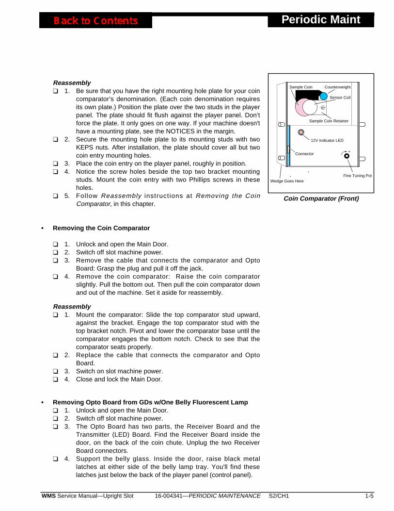
Reassembly❑ 1. Be sure that you have the right mounting hole plate for your coin
comparator’s denomination. (Each coin denomination requiresits own plate.) Position the plate over the two studs in the playerpanel. The plate should fit flush against the player panel. Don’tforce the plate. It only goes on one way. If your machine doesn'thave a mounting plate, see the NOTICES in the margin.
❑ 2. Secure the mounting hole plate to its mounting studs with twoKEPS nuts. After installation, the plate should cover all but twocoin entry mounting holes.
❑ 3. Place the coin entry on the player panel, roughly in position. ❑ 4. Notice the screw holes beside the top two bracket mounting
studs. Mount the coin entry with two Phillips screws in theseholes.
❑ 5. Follow Reassembly instructions at Removing the CoinComparator, in this chapter.
• Removing the Coin Comparator
❑ 1. Unlock and open the Main Door.❑ 2. Switch off slot machine power. ❑ 3. Remove the cable that connects the comparator and Opto
Board: Grasp the plug and pull it off the jack.❑ 4. Remove the coin comparator: Raise the coin comparator
slightly. Pull the bottom out. Then pull the coin comparator downand out of the machine. Set it aside for reassembly.
Reassembly❑ 1. Mount the comparator: Slide the top comparator stud upward,
against the bracket. Engage the top comparator stud with thetop bracket notch. Pivot and lower the comparator base until thecomparator engages the bottom notch. Check to see that thecomparator seats properly.
❑ 2. Replace the cable that connects the comparator and OptoBoard.
❑ 3. Switch on slot machine power. ❑ 4. Close and lock the Main Door.
• Removing Opto Board from GDs w/One Belly Fluorescent Lamp❑ 1. Unlock and open the Main Door. ❑ 2. Switch off slot machine power. ❑ 3. The Opto Board has two parts, the Receiver Board and the
Transmitter (LED) Board. Find the Receiver Board inside thedoor, on the back of the coin chute. Unplug the two ReceiverBoard connectors.
❑ 4. Support the belly glass. Inside the door, raise black metallatches at either side of the belly lamp tray. You'll find theselatches just below the back of the player panel (control panel).
16-004341—PERIODIC MAINTENANCE S2/CH1 1-5WMS Service Manual—Upright Slot
Periodic Maint
Fine Tuning Pot
Sample Coin
Sample Coin Retainer
Sensor Coil
+
Counterweight
Wedge Goes Here
Connector
12V Indicator LED
Coin Comparator (Front)

Periodic Maint
❑ 5. Lower and remove the belly glass and frame. ❑ 6. Examine the lamp tray just above the single, belly fluorescent
lamp. On the latch (right) side of the door, you’ll notice twoaccess holes. Insert a Phillips screwdriver into one of theseholes. Remove one of the Phillips screws that fasten theTransmitter Board. Remove the other screw from the secondaccess hole.
❑ 7. Inside the Main Door, unplug the two Receiver Boardconnectors. Remove Phillips screws that fasten the ReceiverBoard.
❑ 8. Remove the Transmitter Board and the Receiver Board.
Reassembly❑ 1. Position the new Transmitter Board: Place it on the coin chute
side that bolts to the lamp tray. Position the new Receiver Boardon the opposite side of the coin chute. Each optotransistorshould face an LED through a hole in the coin chute. Be surethat you don't mount the boards backwards! Otherwise, optosand LEDs won't align with their holes.
❑ 2. Inside the Main Door, replace Phillips screws that fasten theReceiver Board.
❑ 3. Engage a Phillips screw (removed earlier) on your Phillipsscrewdriver. Insert the screwdriver into one of the lamp trayaccess holes. Fasten down one side of the Transmitter Boardwith this screw. Replace the other Transmitter Board screw atthe second access hole.
❑ 4. Replace and raise the belly glass and frame. ❑ 5. Support the belly glass. Inside the door, lower black metal
latches at either side of the belly lamp tray. You'll find theselatches just below the back of the player panel (control panel).
❑ 6. Plug in the two Receiver Board connectors. ❑ 7. Switch on slot machine power. ❑ 8. Close and lock the Main Door.
• Removing Opto Board from GDs w/Two Belly Fluorescent Lamps❑ 1. Unlock and open the Main Door. ❑ 2. Switch off slot machine power. ❑ 3. The Opto Board has two parts, the Receiver Board and the
Transmitter (LED) Board. Find the Receiver Board inside thedoor, on the back of the coin chute. Unplug the two ReceiverBoard connectors.
❑ 4. Unplug the coin chute solenoid connector.❑ 5. Support the belly glass. Inside the door, raise black metal
latches at either side of the belly lamp tray. You'll find theselatches just below the back of the player panel (control panel).
❑ 6. Lower and remove the belly glass and frame. ❑ 7. You'll notice two belly fluorescent lamps. Carefully grasp one of
1-6 S2/CH1 WMS Service Manual—Upright Slot16-004341—PERIODIC MAINTENANCE
the belly lamps. Twist the fluorescent lamp in either directionuntil its pins come free of the sockets. Remove the lamp. If yourGD has a second fluorescent lamp, remove it in the same way.
❑ 8. Support the coin chute. Remove four Phillips screws that securethe chute to the lamp tray. These screws are near the latch endof the door.
❑ 9. Remove the coin chute.❑ 10. Remove Phillips screws that fasten the Transmitter Board and
Receiver Board. Each board has two screws.❑ 11. Remove the Transmitter Board and the Receiver Board.
Reassembly❑ 1. Position the new Transmitter Board: Place it on the coin chute
side that bolts to the lamp tray. Position the new Receiver Boardon the opposite side of the coin chute. Each optotransistorshould face an LED through a hole in the coin chute. Be surethat you don't mount the boards backwards! Otherwise, optosand LEDs won't align with their holes.
❑ 2. Fasten the Transmitter Board with two Phillips screws. Fastenthe Receiver Board in the same way.
❑ 3. Position the coin chute on the lamp tray.❑ 4. Support the coin chute. Replace four Phillips screws that secure
the chute to the lamp tray. The screw holes are near the latchside of the door.
❑ 5. Replace the belly fluorescent lamps: Carefully grasp one lamp.Slide the lamp into its socket slots. Twist the lamp in eitherdirection until its pins engage with the sockets. Replace thesecond fluorescent lamp in the same way.
❑ 6. Replace and raise the belly glass and frame. ❑ 7. Support the belly glass. Inside the door, lower black metal
latches at either side of the belly lamp tray. You'll find theselatches just below the back of the player panel (control panel).
❑ 8. Plug in the coin chute solenoid connector.❑ 9. Plug in the two Receiver Board connectors. ❑ 10. Switch on slot machine power. ❑ 11. Close and lock the Main Door.
Glass
• Replacing Belly Glass❑ 1. Unlock and open the Main Door. ❑ 2. Switch off slot machine power. ❑ 3. Support the belly glass. Raise the left and right black metal
latches at either side of the belly tray. You'll find them just belowthe back of the player panel.
❑ 4. Tilt the belly glass frame downward, to a 45 degree angle withthe slot machine door. Pull the belly glass frame straight backuntil the hinge tabs disengage from the machine.
16-004341—PERIODIC MAINTENANCE S2/CH1 1-7WMS Service Manual—Upright Slot
Periodic Maint
NOTICEThe glass frame in recentlymanufactured machines doesn’trequire foam tape.
Periodic Maint
❑ 5. Using an 11/32” nut driver, loosen four #8 KEPS nuts on theglass retaining bracket.
❑ 6. Slide the glass retaining bracket out of the frame. ❑ 7. Carefully remove the belly glass from its frame.
Reassembly❑ 1. Carefully replace the belly glass in its frame. Position the top of
the glass in the frame first. Then press the bottom of the glassagainst the frame's foam tape. If the tape is worn out, replace it.
❑ 2. Slide the glass retaining bracket into the frame. ❑ 3. Using an 11/32” nut driver, tighten four #8 KEPS nuts on the
glass retaining bracket.❑ 4. Hold the belly glass frame at a 45 degree angle to the slot
machine front. Slide the belly glass hinge tabs straight forwardinto the belly slots.
❑ 5. Raise the belly glass frame. Hold it tight against the door. Lockdown black metal latches at either side of the belly lamp tray.You'll find them just below the back of the player panel.
❑ 6. Switch on slot machine power. ❑ 7. Close and lock the Main Door.
• Removing the Topbox Glass❑ 1. Unlock and open the Main Door. ❑ 2. Switch off slot machine power at the Power Distribution Unit
(inside the Main Door).❑ 3. Lift the topbox glass by its bottom support bracket. The glass
will disengage from the slot machine gutter. Gently pull the glassaway from the machine.
❑ 4. If a topbox cable connects to the back of the glass, unplug thecable. Remove the glass. Be particularly careful of fragileshadowboxes that may be glued or taped to the glass. Also,take care not to damage the player tracking harness. Set theglass aside in a safe place.
❑ 5. GDs Without Faceplates or PTUs: Remove the metal, glass-support bracket bonded to the bottom of the glass. You can prythe bracket free from the glass with a flatblade screwdriver. GDsWith Faceplates or PTUs: Loosen three retaining nuts on thefaceplate bracket. Remove the bracket. Save the bracket orfaceplate for reassembly.
Reassembly❑ 1. Pick up the bracket or faceplate that you removed from the old
glass.GDs Without Faceplates or PTUs: Use RTV® orequivalent glue for this step. Bond the glass-support bracket tothe bottom of the glass. GDs With Faceplates or PTUs: Positionthe faceplate bracket on the bottom of the glass. Tighten threeretaining nuts on the faceplate bracket.
❑ 2. If a topbox cable connects to the back of the glass, plug in thecable.
❑ 3. Replace the glass. Seat the topbox glass-support bracket
1-8 S2/CH1 WMS Service Manual—Upright Slot16-004341—PERIODIC MAINTENANCE
Take care when working on oldtopbox glass. This warningespecially applies to broken orcracked glass, which can causesevere wounds.
CAUTION! WARNING

securely in the slot machine gutter. ❑ 4. Switch on slot machine power at the Power Distribution Unit
(near the Main Door hinge).❑ 5. Close and lock the Main Door.
Hopper
• Removing the Hopper ❑ 1. Unlock and open the Main Door. ❑ 2. Switch off slot machine power. ❑ 3. Lift up, disengage and remove the coin tray. ❑ 4. Slide the hopper out. Sensors and power unplug from the blind
mating connector as you slide the unit out.
Reassembly❑ 1. Slide the hopper back into position. Sensors and power
reengage at the blind mating connector as you slide the unit in.❑ 2. Replace the coin tray. ❑ 3. Switch on slot machine power. ❑ 4. Close and lock the Main Door.
• Replacing the Hopper Knife❑ 1. Unlock and open the Main Door. ❑ 2. Switch off slot machine power. ❑ 3. Lift up, disengage and remove the coin tray. ❑ 4. Remove coins from the hopper. ❑ 5. Slide the hopper out. Sensors and power unplug from the blind
mating connector as you slide the unit out.❑ 6. Set the hopper on a table.❑ 7. Unplug the two quick disconnect terminals of the hopper bowl
sensor wires. ❑ 8. Use a #2 metric Phillips screwdriver for this step. Orient the
hopper so that the pinwheel faces frontward. Remove the fourscrews that fasten the hopper bowl to the hopper. Some ofthese screws may include tension springs or spacers. As youremove this mounting hardware, note its location on the hopper.Save screws and other hardware for reassembly. Remove thebowl.
❑ 9. Use a #2 metric Phillips screwdriver for this step. Remove threePhillips screws that secure the coin exit cover plate. The coinexit cover plate resides at the top, left side of the pinwheel.
❑ 10. Remove the cover plate. Now you’ll be able to see the knife,which was under the cover plate.
❑ 11. Use a 7mm wrench for this step. Turn the hopper around, sothat the motor faces frontward. Remove two hex nuts thatsecure the knife to the aluminum frame. The frame is thecylinder that surrounds the hopper pinwheel.
❑ 12. Use a 7mm wrench for this step. Turn the hopper around, sothat the pinwheel faces frontward. The hex head, knife bolts
16-004341—PERIODIC MAINTENANCE S2/CH1 1-9WMS Service Manual—Upright Slot
Periodic Maint
NOTICEHopper bowl mounting hardware variesaccording to the hopper denomination.Not all screws are the same type. Somescrews include hardware such assprings or spacers. Replace screws,springs and spacers in exactly the samelocation that you removed them from.
NOTICEDuring disassembly, you may find shimwashers on screws between the knifeand the frame. During reassembly,replace these shims in the samelocations where you found them.
Installation of Knife
Periodic Maint
reside at the top, right side of the frame. Loosen the knife bolts.Remove the bolts, knife and shims together. Save them forreassembly.
❑ 13. Remove the old hopper knife.
Reassembly❑ 1. Orient the hopper so that the pinwheel faces frontward. Properly
position the new hopper knife, mounting bolts, lock washers andshims. Loosely install the hopper knife bolts.
❑ 2. Prop up the knife with metal shims that came with the hopper. ❑ 3. Tighten the knife bolts with a 7mm wrench.❑ 4. For this step, use a feeler gauge. A suitable gauge is available
from hardware and auto stores. Place the feeler gauge underthe knife tip, between the tip and the pinwheel. Use the gauge tomeasure the gap between the knife and the pinwheel. Your goalis to achieve the proper measurement, 0.2mm, or 0.008 inch. Asnecessary, repeat steps 2 through 4. Use fewer or additionalshims to regap the knife until you obtain the specified gap.
❑ 5. Use a 7mm wrench for this step. Turn the hopper around, sothat the motor faces frontward. Replace two hex nuts thatsecure the knife to the aluminum frame.
❑ 6. Turn the hopper around, so that the pinwheel faces frontward.Position the coin exit cover plate over the knife.
❑ 7. Use a #2 metric Phillips screwdriver for this step. Replace thethree Phillips screws that secure the coin exit cover plate.
❑ 8. Use a #2 metric Phillips screwdriver for this step. Replace thehopper bowl. Be sure to replace hardware exactly where it cameoff the hopper during disassembly.
❑ 9. Reconnect the bowl sensor wires, by plugging in two quickdisconnect terminals.
❑ 10. Slide the hopper back into position. Sensors and powerreengage at the blind mating connector as you slide the unit in.
❑ 11. Replace the hopper coins. ❑ 12. Replace the coin tray. ❑ 13. Switch on slot machine power. ❑ 14. Perform a software test of the Hopper. GD software includes a
hopper test in Administration Mode. This test dispenses 10coins.
❑ 15. If the hopper fails the test, troubleshoot the hopper. Otherwise,close and lock the Main Door.
• Setting the Hopper Probe Level❑ 1. Unlock and open the Main Door. ❑ 2. Switch off GD power. ❑ 3. Lift up, disengage and remove the coin tray. ❑ 4. Remove coins from the hopper. ❑ 5. Slide the hopper out. Sensors and power unplug from the blind
mating connector as you slide the unit out.❑ 6. Inspect the hopper: Before filling the hopper with coins, remove
dust, dirt, loose hardware and other foreign matter. The hoppermust be clean, or it can jam!
1-10 S2/CH1 WMS Service Manual—Upright Slot16-004341—PERIODIC MAINTENANCE
NOTICEDuring disassembly, you may find shimwashers on screws between the knifeand the frame. During reassembly,replace these shims in the samelocations where you found them.
NOTICEWhen installing a $.05 knife, be sure touse an M4 x 10 x 10 flat washer witheach mounting bolt. This will prevent thelock washer from jamming into the bolthole.
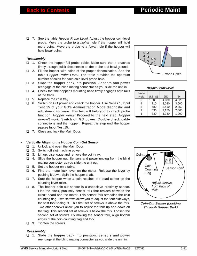
❑ 7. See the table Hopper Probe Level. Adjust the hopper coin-levelprobe. Move the probe to a higher hole if the hopper will holdmore coins. Move the probe to a lower hole if the hopper willhold fewer coins.
Reassembly❑ 1. Check the hopper-full probe cable. Make sure that it attaches
firmly through quick disconnects on the probe and bowl ground.❑ 2. Fill the hopper with coins of the proper denomination. See the
table Hopper Probe Level. The table provides the optimumnumber of coins for each coin-level probe hole.
❑ 3. Slide the hopper back into position. Sensors and powerreengage at the blind mating connector as you slide the unit in.
❑ 4. Check that the hopper's mounting base firmly engages both railsof the track.
❑ 5. Replace the coin tray. ❑ 6. Switch on GD power and check the hopper. Use Series 1, Input
Test 15 of your GD’s Administration Mode diagnostic andadjustment software. This test will help you to check probefunction. Hopper works: Proceed to the next step. Hopperdoesn't work: Switch off GD power. Double-check cableconnections and the hopper. Repeat this step until the hopperpasses Input Test 15.
❑ 7. Close and lock the Main Door.
• Vertically Aligning the Hopper Coin-Out Sensor❑ 1. Unlock and open the Main Door. ❑ 2. Switch off slot machine power. ❑ 3. Lift up, disengage and remove the coin tray. ❑ 4. Slide the hopper out. Sensors and power unplug from the blind
mating connector as you slide the unit out.❑ 5. Set the hopper on a table.❑ 6. Find the motor lock lever on the motor. Release the lever by
pushing it down. Spin the hopper shaft. ❑ 7. Stop the hopper when a coin reaches top dead center on the
counting lever roller.❑ 8. The hopper coin-out sensor is a capacitive proximity sensor.
Find the black, proximity sensor fork that resides between thecircuit board and the motor. This sensor fork straddles the coincounting flag. Two screws allow you to adjust the fork sideways,for best fork-to-flag fit. This first set of screws is above the fork.Two other screws allow you to adjust the fork up and down onthe flag. This second set of screws is below the fork. Loosen thesecond set of screws. By moving the sensor fork, align bottomedges of the coin counting flag and fork.
❑ 9. Tighten the screws.
Reassembly❑ 1. Slide the hopper back into position. Sensors and power
reengage at the blind mating connector as you slide the unit in.
16-004341—PERIODIC MAINTENANCE S2/CH1 1-11WMS Service Manual—Upright Slot
Periodic Maint
CoinCountingFlag
Sensor Fork
Adjust screwsfrom back ofdisk
25¢
Coin
Coin-Out Sensor (LookingThrough Hopper Disk)
Probe Holes
31
542
1,080710680530330
4,0803,0302,4102,1501,730
4,8203,6002,8502,5601,900
ProbeHole
54321
Hopper Probe Level
U.S. $1 25¢ 5¢
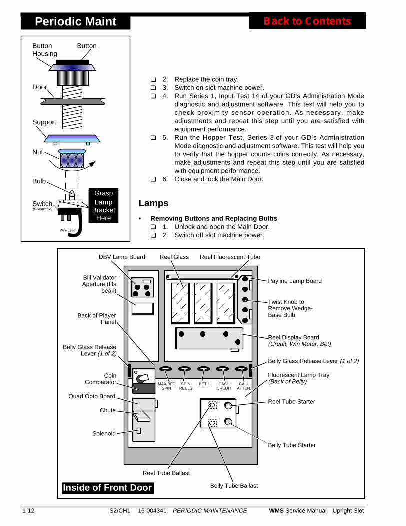
Periodic Maint
❑ 2. Replace the coin tray. ❑ 3. Switch on slot machine power. ❑ 4. Run Series 1, Input Test 14 of your GD’s Administration Mode
diagnostic and adjustment software. This test will help you tocheck proximity sensor operation. As necessary, makeadjustments and repeat this step until you are satisfied withequipment performance.
❑ 5. Run the Hopper Test, Series 3 of your GD’s AdministrationMode diagnostic and adjustment software. This test will help youto verify that the hopper counts coins correctly. As necessary,make adjustments and repeat this step until you are satisfiedwith equipment performance.
❑ 6. Close and lock the Main Door.
Lamps
• Removing Buttons and Replacing Bulbs❑ 1. Unlock and open the Main Door.❑ 2. Switch off slot machine power.
1-12 S2/CH1 WMS Service Manual—Upright Slot16-004341—PERIODIC MAINTENANCE
Payline Lamp Board
DBV Lamp Board
Belly Tube Starter
Reel Tube Ballast
Reel Tube Starter
Bill ValidatorAperture (fits
beak)
Reel Fluorescent Tube
Fluorescent Lamp Tray(Back of Belly)MAX BET
SPINSPIN
REELSBET 1 CASH
CREDITCALL
ATTEN.
CoinComparator
Quad Opto Board
Chute
Solenoid
Belly Tube Ballast
Reel Display Board(Credit, Win Meter, Bet)
Twist Knob toRemove Wedge-Base Bulb
Belly Glass Release Lever (1 of 2)
Belly Glass ReleaseLever (1 of 2)
Reel Glass
Back of PlayerPanel
Inside of Front Door
GraspLamp
BracketHere
ButtonHousing
Door
Support
Nut
Switch(Removable)
Bulb
Wire Lead
Button
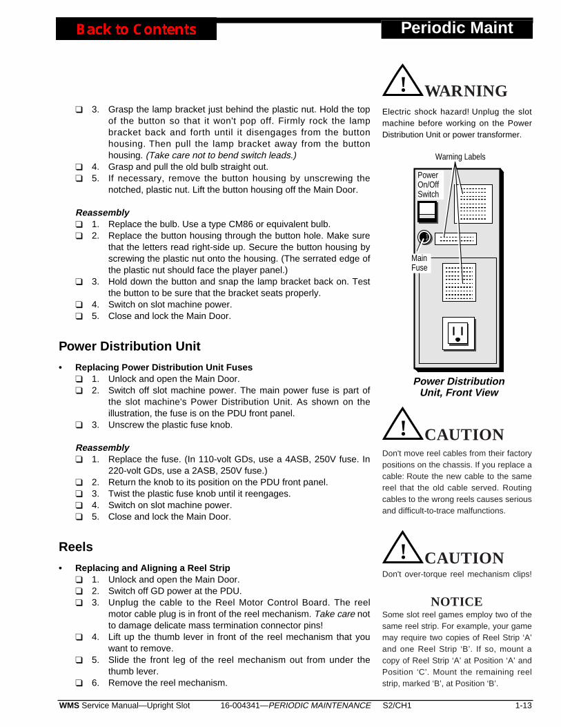
❑ 3. Grasp the lamp bracket just behind the plastic nut. Hold the topof the button so that it won't pop off. Firmly rock the lampbracket back and forth until it disengages from the buttonhousing. Then pull the lamp bracket away from the buttonhousing. (Take care not to bend switch leads.)
❑ 4. Grasp and pull the old bulb straight out.❑ 5. If necessary, remove the button housing by unscrewing the
notched, plastic nut. Lift the button housing off the Main Door.
Reassembly❑ 1. Replace the bulb. Use a type CM86 or equivalent bulb.❑ 2. Replace the button housing through the button hole. Make sure
that the letters read right-side up. Secure the button housing byscrewing the plastic nut onto the housing. (The serrated edge ofthe plastic nut should face the player panel.)
❑ 3. Hold down the button and snap the lamp bracket back on. Testthe button to be sure that the bracket seats properly.
❑ 4. Switch on slot machine power.❑ 5. Close and lock the Main Door.
Power Distribution Unit
• Replacing Power Distribution Unit Fuses ❑ 1. Unlock and open the Main Door. ❑ 2. Switch off slot machine power. The main power fuse is part of
the slot machine's Power Distribution Unit. As shown on theillustration, the fuse is on the PDU front panel.
❑ 3. Unscrew the plastic fuse knob.
Reassembly❑ 1. Replace the fuse. (In 110-volt GDs, use a 4ASB, 250V fuse. In
220-volt GDs, use a 2ASB, 250V fuse.)❑ 2. Return the knob to its position on the PDU front panel.❑ 3. Twist the plastic fuse knob until it reengages. ❑ 4. Switch on slot machine power. ❑ 5. Close and lock the Main Door.
Reels
• Replacing and Aligning a Reel Strip❑ 1. Unlock and open the Main Door. ❑ 2. Switch off GD power at the PDU. ❑ 3. Unplug the cable to the Reel Motor Control Board. The reel
motor cable plug is in front of the reel mechanism. Take care notto damage delicate mass termination connector pins!
❑ 4. Lift up the thumb lever in front of the reel mechanism that youwant to remove.
❑ 5. Slide the front leg of the reel mechanism out from under thethumb lever.
❑ 6. Remove the reel mechanism.
16-004341—PERIODIC MAINTENANCE S2/CH1 1-13WMS Service Manual—Upright Slot
Periodic Maint
Electric shock hazard! Unplug the slotmachine before working on the PowerDistribution Unit or power transformer.
CAUTION! WARNING
Don't over-torque reel mechanism clips!
CAUTION! CAUTION
Don't move reel cables from their factorypositions on the chassis. If you replace acable: Route the new cable to the samereel that the old cable served. Routingcables to the wrong reels causes seriousand difficult-to-trace malfunctions.
CAUTION! CAUTION
NOTICESome slot reel games employ two of thesame reel strip. For example, your gamemay require two copies of Reel Strip ‘A’and one Reel Strip ‘B’. If so, mount acopy of Reel Strip ‘A’ at Position ‘A’ andPosition ‘C’. Mount the remaining reelstrip, marked ‘B’, at Position ‘B’.
Power DistributionUnit, Front View
PowerOn/OffSwitch
FUS
E
Warning Labels
MainFuse
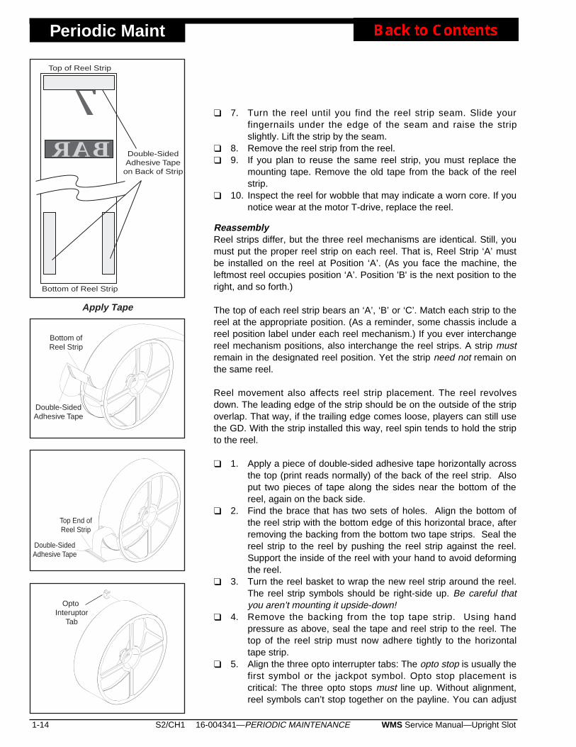
Periodic Maint
❑ 7. Turn the reel until you find the reel strip seam. Slide yourfingernails under the edge of the seam and raise the stripslightly. Lift the strip by the seam.
❑ 8. Remove the reel strip from the reel.❑ 9. If you plan to reuse the same reel strip, you must replace the
mounting tape. Remove the old tape from the back of the reelstrip.
❑ 10. Inspect the reel for wobble that may indicate a worn core. If younotice wear at the motor T-drive, replace the reel.
ReassemblyReel strips differ, but the three reel mechanisms are identical. Still, youmust put the proper reel strip on each reel. That is, Reel Strip ‘A’ mustbe installed on the reel at Position ‘A’. (As you face the machine, theleftmost reel occupies position ‘A’. Position 'B' is the next position to theright, and so forth.)
The top of each reel strip bears an ‘A’, ‘B’ or ‘C’. Match each strip to thereel at the appropriate position. (As a reminder, some chassis include areel position label under each reel mechanism.) If you ever interchangereel mechanism positions, also interchange the reel strips. A strip mustremain in the designated reel position. Yet the strip need not remain onthe same reel.
Reel movement also affects reel strip placement. The reel revolvesdown. The leading edge of the strip should be on the outside of the stripoverlap. That way, if the trailing edge comes loose, players can still usethe GD. With the strip installed this way, reel spin tends to hold the stripto the reel.
❑ 1. Apply a piece of double-sided adhesive tape horizontally acrossthe top (print reads normally) of the back of the reel strip. Alsoput two pieces of tape along the sides near the bottom of thereel, again on the back side.
❑ 2. Find the brace that has two sets of holes. Align the bottom ofthe reel strip with the bottom edge of this horizontal brace, afterremoving the backing from the bottom two tape strips. Seal thereel strip to the reel by pushing the reel strip against the reel.Support the inside of the reel with your hand to avoid deformingthe reel.
❑ 3. Turn the reel basket to wrap the new reel strip around the reel.The reel strip symbols should be right-side up. Be careful thatyou aren’t mounting it upside-down!
❑ 4. Remove the backing from the top tape strip. Using handpressure as above, seal the tape and reel strip to the reel. Thetop of the reel strip must now adhere tightly to the horizontaltape strip.
❑ 5. Align the three opto interrupter tabs: The opto stop is usually thefirst symbol or the jackpot symbol. Opto stop placement iscritical: The three opto stops must line up. Without alignment,reel symbols can’t stop together on the payline. You can adjust
1-14 S2/CH1 WMS Service Manual—Upright Slot16-004341—PERIODIC MAINTENANCE
7BAR
Bottom of Reel Strip
Top of Reel Strip
Double-SidedAdhesive Tape
on Back of Strip
Apply Tape
Double-SidedAdhesive Tape
Top End ofReel Strip
Bottom ofReel Strip
Double-SidedAdhesive Tape
Opto Interuptor
Tab

one reel's opto stop position by moving the reel's optointerrupter tab. You can move the opto interrupter position overa broad, two-and-a-half inch range. Begin alignment by slidingeach opto tab to the center of the opto stop symbol. Take carenot to bend the opto interrupter track.
❑ 6. Slide the reel mechanism into position in the GD. The back legshould rest against the rear mounting flange.
❑ 7. Lift up the thumb lever in front of the reel. Use the thumb leverto fasten down the reel mechanism's front leg. Be sure that thereel is straight. Otherwise, it might jam and damage driveelectronics. A bump on the thumb lever should mate to a recessin the reel mechanism. The lever should snap firmly into place.
❑ 8. Plug in the reel motor cable.❑ 9. Switch on GD power.❑ 10. Align the jackpot symbol with the payline on the window: Start
by checking symbol positions through the glass. Close the MainDoor. Watch reels spin and stop. Your height may causeparallax (visual alignment problems) between a reel and thepayline. Look through the Main Door for a payline reflection onthe reel. Line up the reflection behind the real payline. Then youknow that you’re looking squarely at the reel. Touch upadjustments. Recheck alignment by playing a few games andobserving the ending reel position.
❑ 11. Close and lock the Main Door.
• Replacing a Reel❑ 1. Unlock and open the Main Door.❑ 2. Switch off slot machine power. ❑ 3. Unplug the cable to the Reel Motor Control Board. Take care
not to damage delicate mass termination connector pins!❑ 4. Lift up the thumb lever in front of the reel that you want to
remove.❑ 5. Slide the front leg of the reel mechanism out from under the
thumb lever. Remove the reel mechanism.❑ 6. Follow instructions at Replacing and Aligning a Reel Strip, in this
chapter. ❑ 7. Use a small, flatblade screwdriver to slip off the reel E-ring.
Save the E-ring for reuse.❑ 8. Remove the flat washer from the old reel. Save the washer for
reuse.❑ 9. Pull the reel off the motor shaft.❑ 10. Remove the four rubber O-rings from the motor shaft’s T-top.
Discard them. Never reuse O-rings.
Reassembly❑ 1. Install four new rubber O-rings on the motor shaft’s T-top. Never
reuse O-rings.❑ 2. Position a new reel on the motor shaft.❑ 3. Find the flat washer that you removed from the old reel. Place
16-004341—PERIODIC MAINTENANCE S2/CH1 1-15WMS Service Manual—Upright Slot
Periodic Maint
Change the reel O-rings whenever youreplace a reel. Never attempt to reuseO-rings. Otherwise, your machine’s reelsmay behave erratically, and its reelsmay wear out prematurely.
CAUTION! CAUTION
Install the Reel’s Flat Washer
Periodic Maint
the washer over the motor shaft. The washer must contact thehub.
❑ 4. Secure the reel with the E-ring that you removed from the oldreel.
❑ 5. Follow Reassembly instructions at Replacing and Aligning aReel Strip, in this chapter.
❑ 6. Slide the reel mechanism into position in the slot machine. Theback leg should rest against the rear mounting flange.
❑ 7. Lift up the thumb lever in front of the reel. Slide the reelmechanism into position. Fasten down the reel mechanism byreleasing the lever over the frame's front leg. A bump on thethumb lever should mate to a recess in the reel mechanism. Thelever should grip the frame firmly. Be sure that the reel isstraight. Otherwise, it might jam and damage drive electronics.
❑ 8. Plug in the reel motor cable.❑ 9. Switch on slot machine power. ❑ 10. Close and lock the Main Door.
• Replacing a Reel General Illumination Bulb❑ 1. Follow instructions at Replacing and Aligning a Reel Strip, in this
chapter. ❑ 2. Pull the wedge-base, 555 bulb straight away from the socket.
Reassembly❑ 1. Push the new wedge-base, 555 bulb straight into the socket.❑ 2. Follow Reassembly instructions at Replacing and Aligning a
Reel Strip, in this chapter.
1-16 S2/CH1 WMS Service Manual—Upright Slot16-004341—PERIODIC MAINTENANCE
Don't use long screws to remount reelmechanism clips. A long screw canpenetrate Driver Board componentsbeneath the chassis. You could damageboth logic boards just by driving a screw.
CAUTION! CAUTION
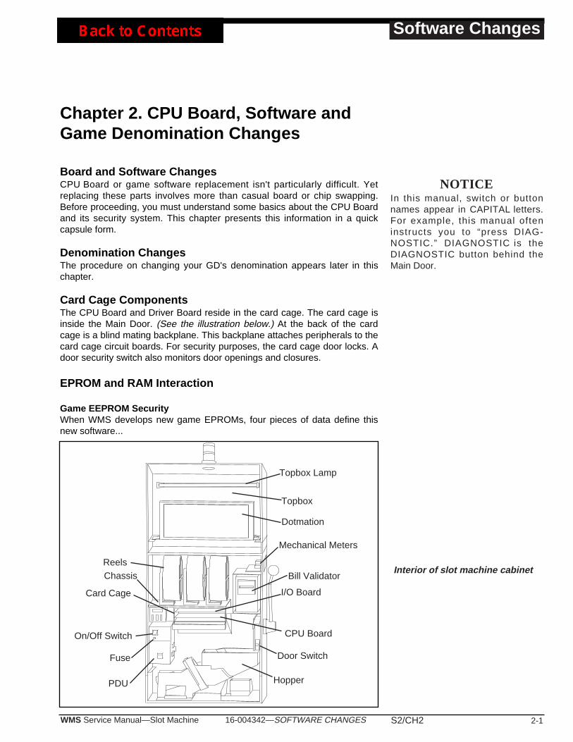
16-004342—SOFTWARE CHANGES S2/CH2 2-1WMS Service Manual—Slot Machine
Software Changes
Chapter 2. CPU Board, Software andGame Denomination Changes
Board and Software ChangesCPU Board or game software replacement isn't particularly difficult. Yetreplacing these parts involves more than casual board or chip swapping.Before proceeding, you must understand some basics about the CPU Boardand its security system. This chapter presents this information in a quickcapsule form.
Denomination ChangesThe procedure on changing your GD's denomination appears later in thischapter.
Card Cage ComponentsThe CPU Board and Driver Board reside in the card cage. The card cage isinside the Main Door. (See the illustration below.) At the back of the cardcage is a blind mating backplane. This backplane attaches peripherals to thecard cage circuit boards. For security purposes, the card cage door locks. Adoor security switch also monitors door openings and closures.
EPROM and RAM Interaction
Game EEPROM SecurityWhen WMS develops new game EPROMs, four pieces of data define thisnew software...
NOTICEIn this manual, switch or buttonnames appear in CAPITAL letters.For example, this manual ofteninstructs you to “press DIAG-NOSTIC.” DIAGNOSTIC is theDIAGNOSTIC button behind theMain Door.
Interior of slot machine cabinet
Topbox
Topbox Lamp
Dotmation
Mechanical Meters
Bill Validator
ReelsChassis
Card Cage
On/Off Switch
PDU
I/O Board
Door Switch
CPU Board
Hopper
Fuse
Software Changes
• GAME TYPE (POWER 7S, WILD & LOOSE, ETC.)• GAME DESCRIPTOR (GAME PERCENTAGE, MAX BET, EFFECT PACKAGES, ETC.)• SOFTWARE VERSION
• GAME EPROM CHECKSUM
Both the Data EPROM and the static RAM store these four pieces of data.Suppose that you install a game EPROM: The CPU compares thisEPROM's data with data in the static RAM. If the data doesn’t match, themachine displays a tilt code...
• “6AnnE CHn6E 1” indicates a mismatch between Game EPROMXU2 and Data EPROM XU3. That is, someone installed a non-matching Game or Data EPROM. (For example: Your machine has aWild and Loose Game EPROM and a Top Cat Data EPROM.) Youcan’t clear a 6AnnE CHn6E 1 tilt with a mismatched set of EPROMs.Instead, you must install two chips of the same type.
• "6AnnE CHn6E 2" indicates that someone changed the Game type.For example, you just changed a Top Cat machine to a Wild andLoose machine.) To clear this tilt, remove the CPU Board EPROMsand install the old ones. Or press the Diagnostic Button to load newdata to the static RAM. See the "CLEARING" bullet below.
• “6AnnE CHn6E 3” indicates a game version change at CPU BoardEPROMs XU2 and XU3. See the "CLEARING" bullet below.
• “6AnnE CHn6E 4” indicates a checksum change at CPU BoardGame EPROM XU2. See the "CLEARING" bullet below.
• “6AnnE CHn6E 5” indicates a checksum change at CPU BoardData EPROM XU3. See the "CLEARING" bullet below.
• CLEARING “6AnnE CHn6E 2" through “6AnnE CHn6E 5". Toclear any of these tilts, press DIAGNOSTIC. The machine loads thenew game information. If you’ve cleared the RAM properly beforeinstalling new EPROMs, the machine displays “clr”. (Clear this tilt byagain pressing DIAGNOSTIC.) Otherwise, the “nEEd clr” tilt messageappears. This tilt indicates that you must clear the RAM and reinstallthe EPROMs. Use a RAM clear chip of the correct denomination.
Software Installation
❑ 1. Unlock and open the Main Door. ❑ 2. Turn power off at the PDU switch. ❑ 3. Slant top machines only: Disengage the coin chute.❑ 4. Unlock and open the card cage. ❑ 5. Disengage the CPU (bottom) board by pulling the white board
ejector tabs toward you. Remove the board. If your GD came withdiagnostic software, remove EPROM XU3. Save the Diagnostic chipfor later use.
❑ 6. Obtain the RAM Clear Chip for the proper denomination. Use this
2-2 S2/CH2 WMS Service Manual—Slot Machine16-004342—SOFTWARE CHANGES
CAUTION! CAUTIONAvoid equipment damage whenusing the RAM Clear Chip! Takethese precautions...• Turn the power OFF before
removing or inserting logicboards.
• Turn the power OFF beforeremoving or inserting EPROMs.
• Observe proper static preven-tion safeguards.
• Before you power up the unit,verify that circuit boards seatsecurely.
• Properly align EPROMs withsocket pins. Otherwise you canseverely damage the chips.
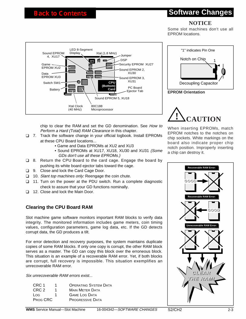
chip to clear the RAM and set the GD denomination. See How toPerform a Hard (Total) RAM Clearance in this chapter.
❑ 7. Track the software change in your official logbook. Install EPROMsat these CPU Board locations...
• Game and Data EPROMs at XU2 and XU3• Sound EPROMs at XU17, XU18, XU30 and XU31 (Some
GDs don't use all these EPROMs.)❑ 8. Return the CPU Board to the card cage. Engage the board by
pushing its white board ejector tabs toward the cage. ❑ 9. Close and lock the Card Cage Door.❑ 10. Slant top machines only: Reengage the coin chute.❑ 11. Turn on the power at the PDU switch. Run a complete diagnostic
check to assure that your GD functions nominally.❑ 12. Close and lock the Main Door.
Clearing the CPU Board RAM
Slot machine game software monitors important RAM blocks to verify dataintegrity. The monitored information includes game meters, coin timingvalues, configuration parameters, game log data, etc. If the GD detectscorrupt data, the GD produces a tilt.
For error detection and recovery purposes, the system maintains duplicatecopies of some RAM blocks. If only one copy is corrupt, the other RAM blockserves as a master. The GD can copy this block over the erroneous block.This situation is an example of a recoverable RAM error. Yet, if both blocksare corrupt, full recovery is impossible. This situation exemplifies anunrecoverable RAM error.
Six unrecoverable RAM errors exist...
CRC 1 1 OPERATING SYSTEM DATA
CRC 2 1 MAIN METER DATA
LOG 1 GAME LOG DATA
PROG CRC PROGRESSIVE DATA
16-004342—SOFTWARE CHANGES S2/CH2 2-3WMS Service Manual—Slot Machine
Software Changes
CAUTION! CAUTION
Notch on Chip 1
"1" indicates Pin One
Decoupling Capacitor
EPROM Orientation
When inserting EPROMs, matchEPROM notches to the notches onchip sockets. White markings on theboard also indicate proper chipnotch position. Improperly insertinga chip can destroy it.
Xtal Clock(40 MHz)
DSP
80C188Microprocessor
LED 8-SegmentDisplay
PC BoardEjector Tab
Xtal (1.8 MHz)
GameEPROM XU2
Jumper
DataEPROM XU3 Sound EPROM 3,
XU31
Sound EPROM 2,XU30
Sound EPROM 5, XU18
Sound EPROM4, XU17
Battery
Switch SW1
Security EPROM XU27
CPU(Bottom)
Card
NOTICESome slot machines don't use allEPROM locations.
Recoverable RAM Error:
CC LL EE AA RRTT HH EE RR AA MM !!
GG OO OO DD
GG OO OO DD
Recoverable RAM Error:
Unrecoverable RAM Error:
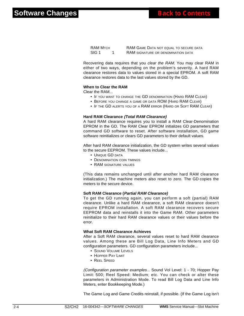
Software Changes
RAM MTCH RAM GAME DATA NOT EQUAL TO SECURE DATA
SIG 1 1 RAM SIGNATURE OR DENOMINATION DATA
Recovering data requires that you clear the RAM. You may clear RAM ineither of two ways, depending on the problem’s severity. A hard RAMclearance restores data to values stored in a special EPROM. A soft RAMclearance restores data to the last values stored by the GD.
When to Clear the RAMClear the RAM...
• IF YOU WANT TO CHANGE THE GD DENOMINATION (HARD RAM CLEAR)• BEFORE YOU CHANGE A GAME OR DATA ROM (HARD RAM CLEAR)• IF THE GD ALERTS YOU OF A RAM ERROR (HARD OR SOFT RAM CLEAR)
Hard RAM Clearance (Total RAM Clearance)A hard RAM clearance requires you to install a RAM Clear-DenominationEPROM in the GD. The RAM Clear EPROM initializes GD parameters thatcommand GD software to reset. After software installation, GD gamesoftware reinitializes or clears GD parameters to their default values.
After hard RAM clearance initialization, the GD system writes several valuesto the secure EEPROM. These values include...
• UNIQUE GD DATA
• DENOMINATION COIN TIMINGS
• RAM SIGNATURE VALUES
(This data remains unchanged until after another hard RAM clearanceinitialization.) The machine meters also reset to zero. The GD copies themeters to the secure device.
Soft RAM Clearance (Partial RAM Clearance)To get the GD running again, you can perform a soft (partial) RAMclearance. Unlike a hard RAM clearance, a soft RAM clearance doesn’trequire EPROM installation. A soft RAM clearance recovers secureEEPROM data and reinstalls it into the Game RAM. Other parametersreinitialize to their hard RAM clearance values or their values before theerror.
What Soft RAM Clearance AchievesAfter a Soft RAM clearance, several values reset to hard RAM clearancevalues. Among these are Bil l Log Data, Line Info Meters and GDconfiguration parameters. GD configuration parameters include...
• SOUND VOLUME LEVELS
• HOPPER PAY LIMIT
• REEL SPEED
(Configuration parameter examples... Sound Vol Level: 1 - 70; Hopper PayLimit: 500; Reel Speed: Medium; etc. You can check or alter theseparameters in Administration Mode. To read Bill Log Data and Line InfoMeters, enter Bookkeeping Mode.)
The Game Log and Game Credits reinstall, if possible. (If the Game Log isn’t
2-4 S2/CH2 WMS Service Manual—Slot Machine16-004342—SOFTWARE CHANGES
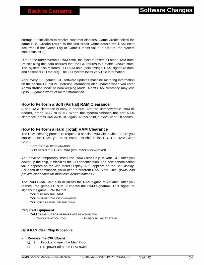
corrupt, it reinitializes to resolve customer disputes. Game Credits follow thesame rule. Credits return to the last credit value before the RAM erroroccurred. If the Game Log or Game Credits value is corrupt, the systemcan’t reinstall it.)
Due to the unrecoverable RAM error, the system resets all other RAM data.Reinitializing this data assures that the GD returns to a stable, known state.The system also restores EEPROM data (coin timings, RAM signature data,and essential GD meters). The GD system loses very little information.
After every 100 games, GD software updates machine metering informationon the secure EEPROM. Metering information also updates when you enterAdministration Mode or Bookkeeping Mode. A soft RAM clearance may loseup to 99 games worth of meter information.
How to Perform a Soft (Partial) RAM ClearanceA soft RAM clearance is easy to perform. After an unrecoverable RAM tiltoccurs, press DIAGNOSTIC. When the system finishes the soft RAMclearance, press DIAGNOSTIC again. At this point, a “Soft Clear” tilt occurs.
How to Perform a Hard (Total) RAM Clearance The RAM-clearing procedure requires a special RAM Clear Chip. Before youcan clear the RAM, you must install this chip in the GD. The RAM ClearChip...
• SETS THE GD DENOMINATION
• CLEARS OUT THE GD’S RAM (INCLUDING SOFT METERS)
You have to temporarily install the RAM Clear Chip in your GD. After youpower up the chip, it initializes the GD denomination. The new denominationvalue appears on the Win Meter Display. A ‘6’ appears on the Bet Display.For each denomination, you'll need a different RAM Clear Chip. (WMS canprovide clear chips for most coin denominations.)
The RAM Clear Chip also initializes the RAM signature variable. After youreinstall the game EPROM, it checks the RAM signature. This signaturesignals the game EPROM that...
• YOU CLEARED THE RAM• YOU CHANGED THE DENOMINATION
• YOU MUST REINITIALIZE THE GAME
Required Equipment • RAM CLEAR KIT FOR APPROPRIATE DENOMINATION
• CHIP EXTRACTION TOOL • ANTISTATIC WRIST STRAP
Hard RAM Clear Chip Procedure
• Remove the CPU Board❑ 1. Unlock and open the Main Door. ❑ 2. Turn power off at the PDU switch.
16-004342—SOFTWARE CHANGES S2/CH2 2-5WMS Service Manual—Slot Machine
Software Changes
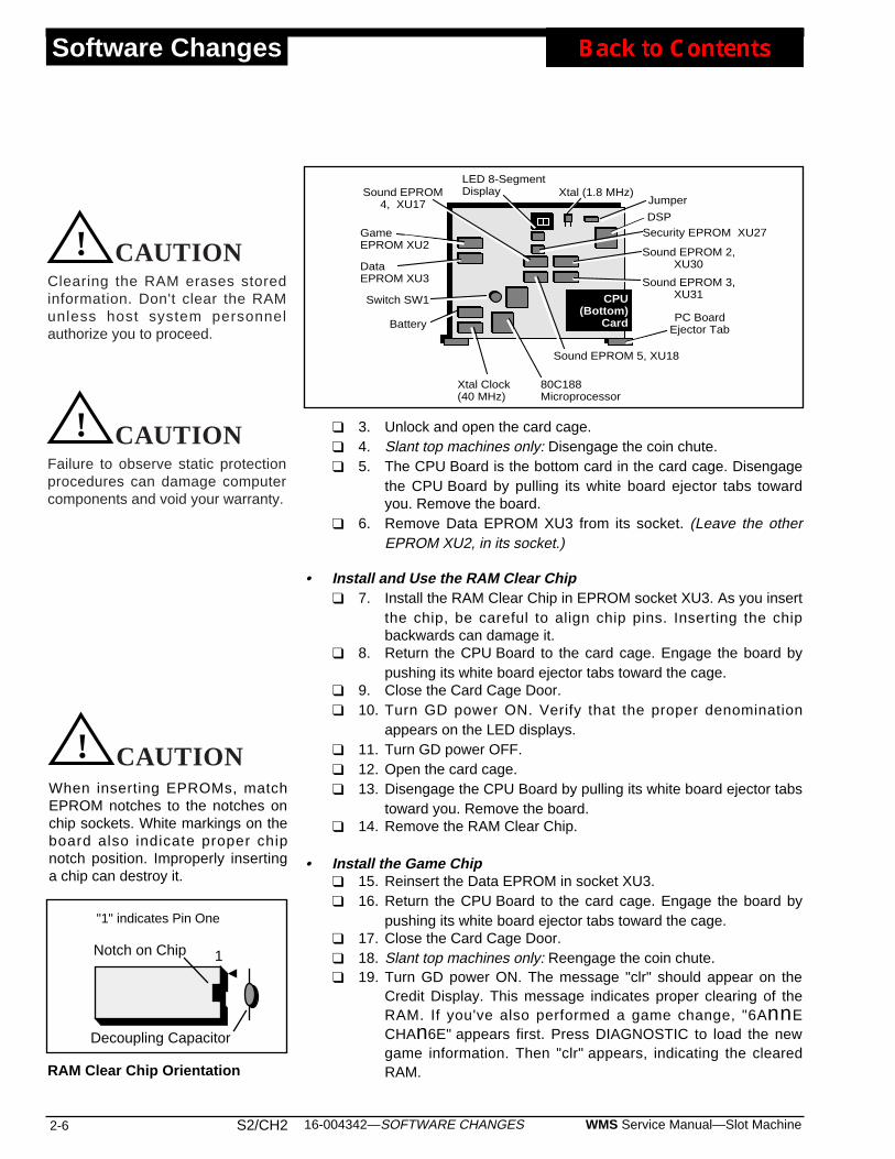
Software Changes
❑ 3. Unlock and open the card cage. ❑ 4. Slant top machines only: Disengage the coin chute.❑ 5. The CPU Board is the bottom card in the card cage. Disengage
the CPU Board by pulling its white board ejector tabs towardyou. Remove the board.
❑ 6. Remove Data EPROM XU3 from its socket. (Leave the otherEPROM XU2, in its socket.)
• Install and Use the RAM Clear Chip❑ 7. Install the RAM Clear Chip in EPROM socket XU3. As you insert
the chip, be careful to align chip pins. Inserting the chipbackwards can damage it.
❑ 8. Return the CPU Board to the card cage. Engage the board bypushing its white board ejector tabs toward the cage.
❑ 9. Close the Card Cage Door.❑ 10. Turn GD power ON. Verify that the proper denomination
appears on the LED displays. ❑ 11. Turn GD power OFF. ❑ 12. Open the card cage.❑ 13. Disengage the CPU Board by pulling its white board ejector tabs
toward you. Remove the board. ❑ 14. Remove the RAM Clear Chip.
• Install the Game Chip❑ 15. Reinsert the Data EPROM in socket XU3.❑ 16. Return the CPU Board to the card cage. Engage the board by
pushing its white board ejector tabs toward the cage. ❑ 17. Close the Card Cage Door.❑ 18. Slant top machines only: Reengage the coin chute.❑ 19. Turn GD power ON. The message "clr" should appear on the
Credit Display. This message indicates proper clearing of theRAM. If you've also performed a game change, "6AnnECHAn6E" appears first. Press DIAGNOSTIC to load the newgame information. Then "clr" appears, indicating the clearedRAM.
2-6 S2/CH2 WMS Service Manual—Slot Machine16-004342—SOFTWARE CHANGES
Xtal Clock(40 MHz)
DSP
80C188Microprocessor
LED 8-SegmentDisplay
PC BoardEjector Tab
Xtal (1.8 MHz)
GameEPROM XU2
Jumper
DataEPROM XU3 Sound EPROM 3,
XU31
Sound EPROM 2,XU30
Sound EPROM 5, XU18
Sound EPROM4, XU17
Battery
Switch SW1
Security EPROM XU27
CPU(Bottom)
Card
Notch on Chip 1
"1" indicates Pin One
Decoupling Capacitor
RAM Clear Chip Orientation
When inserting EPROMs, matchEPROM notches to the notches onchip sockets. White markings on theboard also indicate proper chipnotch position. Improperly insertinga chip can destroy it.
CAUTION!
CAUTION!
CAUTION
Failure to observe static protectionprocedures can damage computercomponents and void your warranty.
CAUTION! CAUTION
Clearing the RAM erases storedinformation. Don't clear the RAMunless host system personnelauthorize you to proceed.
CAUTION
❑ 20. Lock the card cage.
• Reinitialize the System❑ 21. Push the DIAGNOSTIC button. The machine shuts down and
reboots. If you cleared the machine properly, the message "clr"appears on the Credit Display. Push the DIAGNOSTIC button toacknowledge this message.
❑ 22. Close and lock the Main Door.
Changing the Denomination
❑ 1. Unlock and open the Main Door.❑ 2. Turn power off at the PDU switch.❑ 3. Slant top machines only: Disengage the coin chute.❑ 4. Change the denomination decals on the GD's Reel Hatch.❑ 5. Change the coin denomination of the coin comparator. (Or
change the coin comparator.)❑ 6. Change the front of the coin entry. ❑ 7. Hopper Machines: Change the hopper. ❑ 8. Perform a hard RAM clear with the proper RAM Clear Chip. See
the procedure above.
16-004342—SOFTWARE CHANGES S2/CH2 2-7WMS Service Manual—Slot Machine
Software Changes
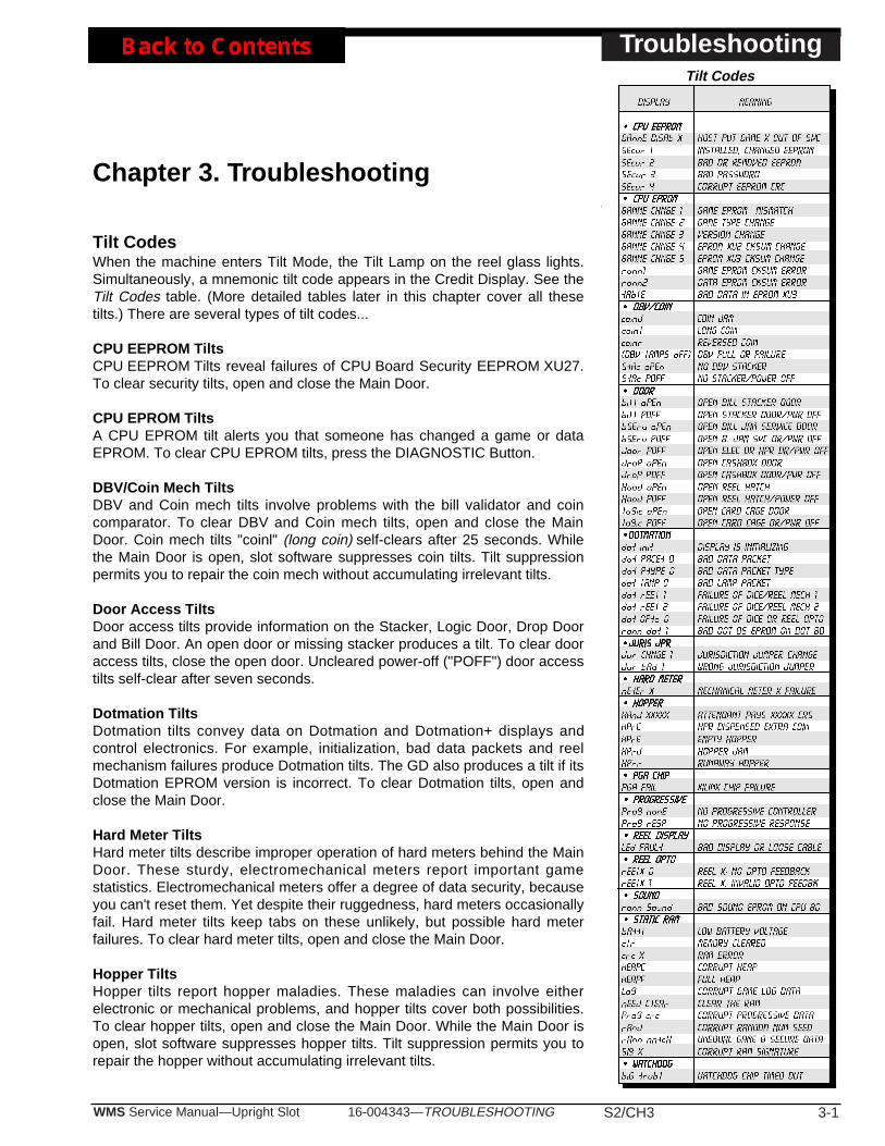
16-004343—TROUBLESHOOTING S2/CH3 3-1WMS Service Manual—Upright Slot
Troubleshooting
Chapter 3. Troubleshooting
Tilt CodesWhen the machine enters Tilt Mode, the Tilt Lamp on the reel glass lights.Simultaneously, a mnemonic tilt code appears in the Credit Display. See theTilt Codes table. (More detailed tables later in this chapter cover all thesetilts.) There are several types of tilt codes...
CPU EEPROM TiltsCPU EEPROM Tilts reveal failures of CPU Board Security EEPROM XU27.To clear security tilts, open and close the Main Door.
CPU EPROM TiltsA CPU EPROM tilt alerts you that someone has changed a game or dataEPROM. To clear CPU EPROM tilts, press the DIAGNOSTIC Button.
DBV/Coin Mech TiltsDBV and Coin mech tilts involve problems with the bill validator and coincomparator. To clear DBV and Coin mech tilts, open and close the MainDoor. Coin mech tilts "coinl" (long coin) self-clears after 25 seconds. Whilethe Main Door is open, slot software suppresses coin tilts. Tilt suppressionpermits you to repair the coin mech without accumulating irrelevant tilts.
Door Access TiltsDoor access tilts provide information on the Stacker, Logic Door, Drop Doorand Bill Door. An open door or missing stacker produces a tilt. To clear dooraccess tilts, close the open door. Uncleared power-off ("POFF") door accesstilts self-clear after seven seconds.
Dotmation TiltsDotmation tilts convey data on Dotmation and Dotmation+ displays andcontrol electronics. For example, initialization, bad data packets and reelmechanism failures produce Dotmation tilts. The GD also produces a tilt if itsDotmation EPROM version is incorrect. To clear Dotmation tilts, open andclose the Main Door.
Hard Meter TiltsHard meter tilts describe improper operation of hard meters behind the MainDoor. These sturdy, electromechanical meters report important gamestatistics. Electromechanical meters offer a degree of data security, becauseyou can't reset them. Yet despite their ruggedness, hard meters occasionallyfail. Hard meter tilts keep tabs on these unlikely, but possible hard meterfailures. To clear hard meter tilts, open and close the Main Door.
Hopper TiltsHopper tilts report hopper maladies. These maladies can involve eitherelectronic or mechanical problems, and hopper tilts cover both possibilities.To clear hopper tilts, open and close the Main Door. While the Main Door isopen, slot software suppresses hopper tilts. Tilt suppression permits you torepair the hopper without accumulating irrelevant tilts.
Tilt Codes
Troubleshooting
3-2 S2/CH3 WMS Service Manual—Upright Slot16-004343—TROUBLESHOOTING
Jurisdiction Jumper TiltsJurisdiction jumper tilts announce various improper jumper settings. To clearjumper tilts, turn off the machine. Set jumpers properly. Clear the RAM. Turnon the machine and retest it.
PGA Chip TiltsPGA Chip tilts alert you to failures of the Xilinx® PGA (Programmable GateArray) chip. The PGA chip is a unique, dynamically programmableinput/output chip. It resides on the I/O Board. PGA chip XU41 primarilyhandles peripheral switch inputs. To clear PGA tilts, open and close theMain Door.
Progressive TiltsProgressive tilts disclose communication failures between the slot machineand progressive system. To clear progressive tilts, open and close the MainDoor.
Reel Display TiltsReel Display tilts point out communication failures between the CPU andReel Display Board. The Reel Display Board is the main LED display board.This board contains the Credit, Win Meter and Bet displays. Some displayfailure modes may prevent the LEDs from displaying a tilt message. To clearreel display tilts, open and close the Main Door.
Reel Opto TiltsReel Opto tilts track failures in the reel feedback system. The feedbacksystem helps the slot computer to control reel position. To clear reel tilts,open and close the Main Door.
Sound TiltsA sound tilt results if a sound EPROM fails the version test. Sound EPROMsreside on the CPU Board, and may include XU17, XU18, XU30 and XU31.(Some machines use fewer than four chips.) To clear sound tilts, install theproper sound EPROMs. You need not clear the RAM.
Static RAM TiltsStatic RAM tilts signal errors in data stored in the slot computer’s CMOSstatic RAM chips. To clear static RAM tilts, clear the RAM.
Watchdog TiltsWatchdog tilts caution you that the Watchdog Timer has timed out. TheWatchdog may time out if the processor becomes stuck in a logic loop. Abad memory device or logic board may cause a looping error.
Candle CodesThe two-stage candle on top of the machine indicates slot machine status.The slot machine employs both levels of the candle to convey informationabout its operation. See the Candle Codes table, later in this chapter.
NOTICEWHERE IS THE MAIN DOOR?Diagnostic messages refer to the“Main Door.” In upright slotmachines, the Front Door is also theMain Door.
NOTICEThis chapter covers slot software up tov. 5.09.

16-004343—TROUBLESHOOTING S2/CH3 3-3WMS Service Manual—Upright Slot
Troubleshooting
Symptom Probable Cause Solutions
Button: A Player Panel button doesn'toperate
1. Loose cable connection at top ofBackplane Board2. Bad player panel wiring3. Bad switch4. Bad switch wiring5. Bad Faston® connector6. Bad switch inputs on I/O PC Board
1. Plug cable in securely.2. Repair or replace player panelcable.3. Replace switch.4. Rewire switch.5. Replace connector at button.6. Service input or replace I/O Board.
Button and Switch: Opening andclosing any door or pressingDIAGNOSTIC Button fails to clearerror messages
1. System halt2. Loose connection at switch
1. Turn power off and wait threeseconds. Then turn power on.2. Repair connection.
Button Lamp: A Player Panel buttonlamp doesn't light
1. Bad bulb2. Loose cable connection at top ofBackplane Board3. Bad player panel wiring4. Bad Faston® connector5. Bad switch wiring6. Bad lamp output on I/O Board
1. Replace bulb.2. Plug cable in securely.3. Repair or replace player panelcable.4. Replace connector at button.5. Rewire switch.6. Service output or replace I/OBoard.
Switch: ADMINISTRATOR KEYswitch doesn't operate
1. Bad switch2. Bad cable harness3. Bad Faston® connector4. Bad switch input on I/O Board
1. Replace switch.2. Repair or replace harness.3. Replace connector at BackplaneBoard or I/O Board.4. Service input or replace I/O Board.
Switch: Door switch doesn't operate 1. Bad switch2. Bad switch cable3. Bent, maladjusted or missingactuator bracket4. Bad switch wiring5. Bad switch input on I/O Board
1. Replace switch.2. Repair or replace switch cable.3. Straighten, adjust or replacebracket.4. Rewire switch.5. Service input or replace I/O Board.
Button and Switch Troubleshooting Guide
Communication Troubleshooting Guide
Candle Codes Troubleshooting Guide
Candle Section Candle Activity Meaning
Top 1. Off2. On3. Slow flash
1. Machine is idle.2. Change request.3. Tilt or Jackpot Mode.
Bottom 1. Off2. Fast flash3. Slow flash
1. Main Door is closed.2. Main Door is open.3. Jackpot.
Symptom Probable Cause Solutions
No Communication
NOTICEReport error codes to centralcommunication site for evaluation andprocessing. Codes enable use ofadvanced diagnostic facilties.
1. Bad power line to slot machine.2. Blown 4ASB, main PDU fuse.3. Bad communication cables.4. Bad external communication powersupply.5. Bad I/O or Backplane Board.
1. Make sure that slot machine is onlive circuit. Check protocol is optionedproperly.2. If fuse is bad, replace it.3. If cables are bad, repair or replacethem.4. If your GD has externalcommunication power supply, replaceit.5. Replace Board and rerun test.

Troubleshooting
3-4 S2/CH3 WMS Service Manual—Upright Slot16-004343—TROUBLESHOOTING
Symptom Probable Cause Solutions
CPU Board displays "1" 1. Xilinx® PGA chip-loading failure(I/O Board and FPGA)2. Bad Xilinx PGA IC XU41 on I/OBoard
1. Replace I/O Board and rerun test.2. Replace PGA.
CPU Board displays "2" Watchdog timeout 1. Replace the CPU Board.2. EPROM or bus buffer may be bad.
CPU Board displays "3" On CPU Board, failing voltage atstatic RAM backup battery
1. Save game play, pricing and otherlocation-programmed information tothe central system (or write it down).2. Power down the GD.3. Remove CPU Board. Replacebattery Batt1/1A.
CAUTIONWithout battery, GD loses vitalinformation at power-down.
4. Replace CPU Board and reruntest.5. After test, "3" lights again: Originalbattery is good. MAX791 chip U11may be bad.
CPU Board displays "4" DSP power-up diagnostics failed 1. Replace CPU Board. Rerun test.2. Hear more than one "bong" atstartup? Yes: A Sound EPROM orDSP RAM (6116 chips U38-U40)may be bad.3. DSP chip XU37 may be bad.
CPU Board displays "5" LED panel (game display)communication fault
1. Firmly reseat connectors at bothends of cable. Turn game off for fiveseconds. Then turn it on again.2. After test, "5" lights again: SwapLED Board. Turn game off for fiveseconds. Then turn it on again.3. After second test, "5" lights again:Original LED Board is good. SwapI/O Board. Turn game off for fiveseconds. Then turn it on again.4. After third test, "5" lights again:Original I/O Board is good. SwapLED cable. Turn game off for fiveseconds. Then turn it on again.
CPU Board displays "8" • Briefly, at power-up: Game OK.• "8" remains on: Dead CPU Board
1. Constant "8": Replace EPROMsXU2, XU3. Save old ones. Reruntest.2. After test, "8" appears andremains on: Dead CPU. OriginalEPROMs are good. Swap CPUBoard. Rerun test.
CPU Board 7-Segment Display Troubleshooting Guide
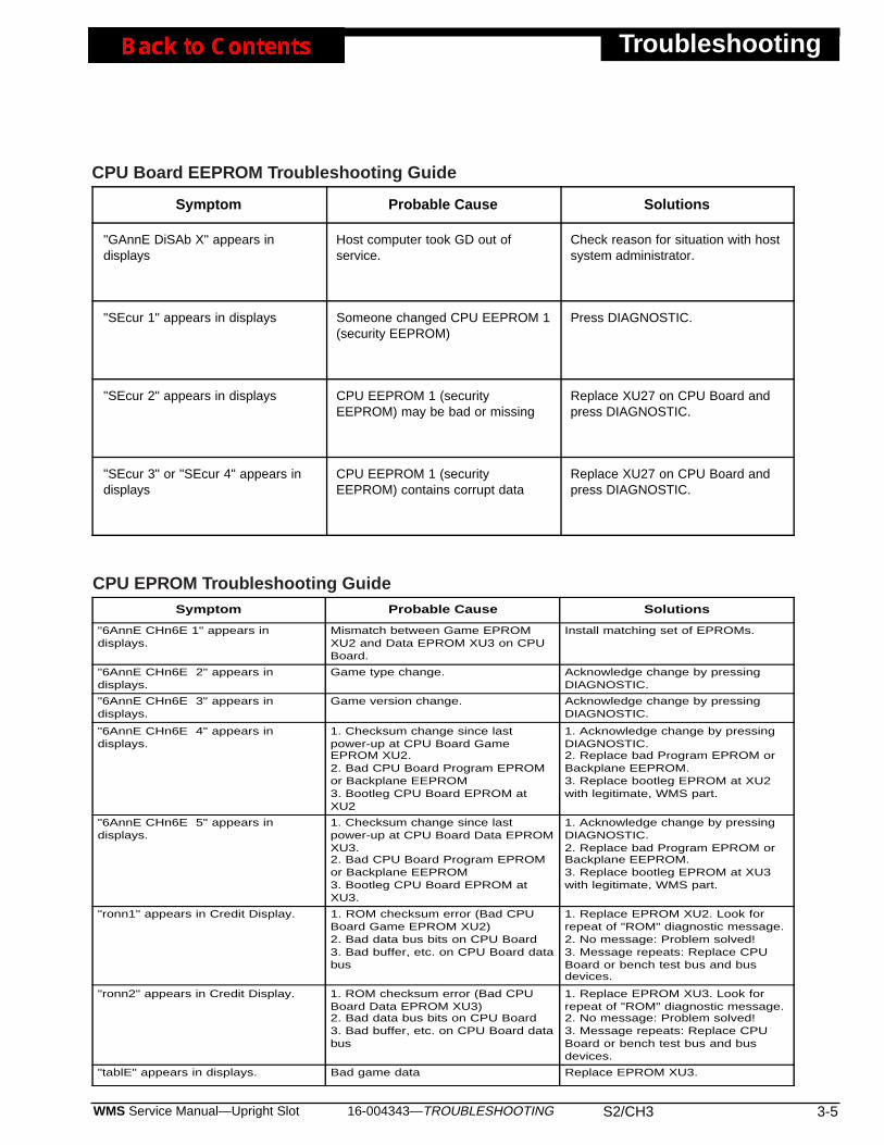
16-004343—TROUBLESHOOTING S2/CH3 3-5WMS Service Manual—Upright Slot
Troubleshooting
Symptom Probable Cause Solutions
"GAnnE DiSAb X" appears indisplays
Host computer took GD out ofservice.
Check reason for situation with hostsystem administrator.
"SEcur 1" appears in displays Someone changed CPU EEPROM 1(security EEPROM)
Press DIAGNOSTIC.
"SEcur 2" appears in displays CPU EEPROM 1 (securityEEPROM) may be bad or missing
Replace XU27 on CPU Board andpress DIAGNOSTIC.
"SEcur 3" or "SEcur 4" appears indisplays
CPU EEPROM 1 (securityEEPROM) contains corrupt data
Replace XU27 on CPU Board andpress DIAGNOSTIC.
CPU Board EEPROM Troubleshooting Guide
Symptom Probable Cause Solutions
"6AnnE CHn6E 1" appears indisplays.
Mismatch between Game EPROMXU2 and Data EPROM XU3 on CPUBoard.
Install matching set of EPROMs.
"6AnnE CHn6E 2" appears indisplays.
Game type change. Acknowledge change by pressingDIAGNOSTIC.
"6AnnE CHn6E 3" appears indisplays.
Game version change. Acknowledge change by pressingDIAGNOSTIC.
"6AnnE CHn6E 4" appears indisplays.
1. Checksum change since lastpower-up at CPU Board GameEPROM XU2.2. Bad CPU Board Program EPROMor Backplane EEPROM3. Bootleg CPU Board EPROM atXU2
1. Acknowledge change by pressingDIAGNOSTIC.2. Replace bad Program EPROM orBackplane EEPROM.3. Replace bootleg EPROM at XU2with legitimate, WMS part.
"6AnnE CHn6E 5" appears indisplays.
1. Checksum change since lastpower-up at CPU Board Data EPROMXU3.2. Bad CPU Board Program EPROMor Backplane EEPROM3. Bootleg CPU Board EPROM atXU3.
1. Acknowledge change by pressingDIAGNOSTIC.2. Replace bad Program EPROM orBackplane EEPROM.3. Replace bootleg EPROM at XU3with legitimate, WMS part.
"ronn1" appears in Credit Display. 1. ROM checksum error (Bad CPUBoard Game EPROM XU2)2. Bad data bus bits on CPU Board3. Bad buffer, etc. on CPU Board databus
1. Replace EPROM XU2. Look forrepeat of "ROM" diagnostic message.2. No message: Problem solved!3. Message repeats: Replace CPUBoard or bench test bus and busdevices.
"ronn2" appears in Credit Display. 1. ROM checksum error (Bad CPUBoard Data EPROM XU3)2. Bad data bus bits on CPU Board3. Bad buffer, etc. on CPU Board databus
1. Replace EPROM XU3. Look forrepeat of "ROM" diagnostic message.2. No message: Problem solved!3. Message repeats: Replace CPUBoard or bench test bus and busdevices.
"tablE" appears in displays. Bad game data Replace EPROM XU3.
CPU EPROM Troubleshooting Guide
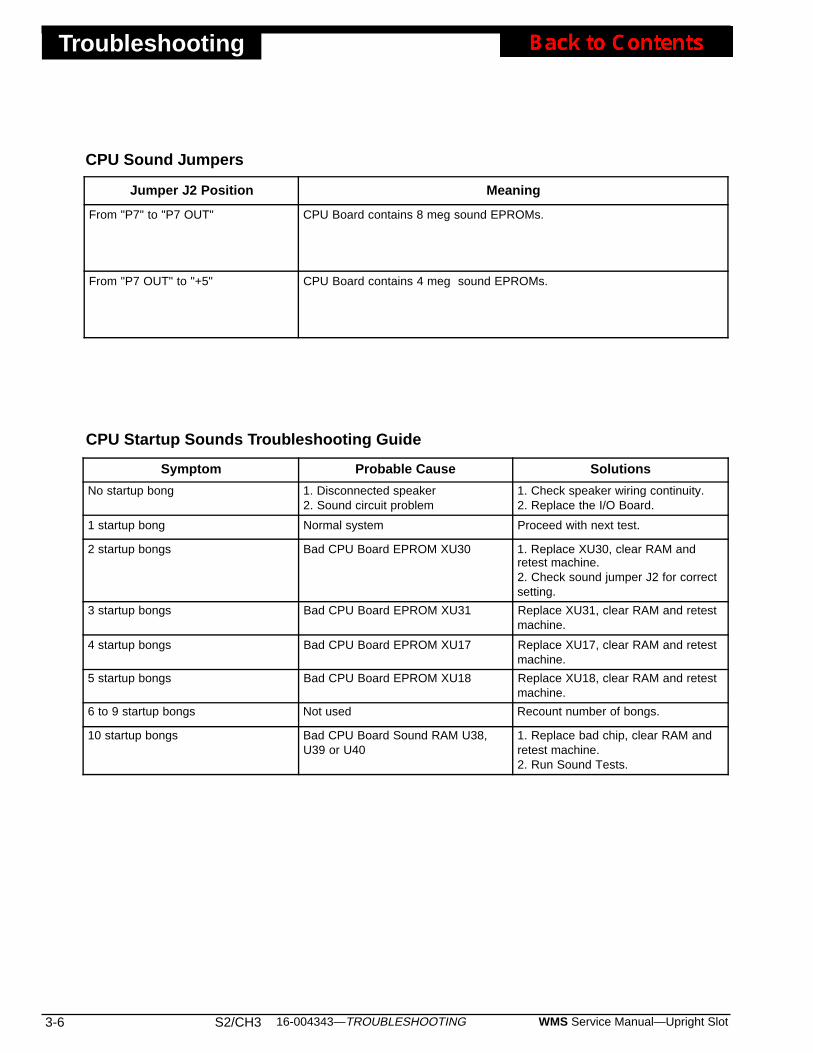
Troubleshooting
3-6 S2/CH3 WMS Service Manual—Upright Slot16-004343—TROUBLESHOOTING
CPU Startup Sounds Troubleshooting Guide
CPU Sound Jumpers
Symptom Probable Cause Solutions
No startup bong 1. Disconnected speaker2. Sound circuit problem
1. Check speaker wiring continuity.2. Replace the I/O Board.
1 startup bong Normal system Proceed with next test.
2 startup bongs Bad CPU Board EPROM XU30 1. Replace XU30, clear RAM andretest machine.2. Check sound jumper J2 for correctsetting.
3 startup bongs Bad CPU Board EPROM XU31 Replace XU31, clear RAM and retestmachine.
4 startup bongs Bad CPU Board EPROM XU17 Replace XU17, clear RAM and retestmachine.
5 startup bongs Bad CPU Board EPROM XU18 Replace XU18, clear RAM and retestmachine.
6 to 9 startup bongs Not used Recount number of bongs.
10 startup bongs Bad CPU Board Sound RAM U38,U39 or U40
1. Replace bad chip, clear RAM andretest machine.2. Run Sound Tests.
Jumper J2 Position Meaning
From "P7" to "P7 OUT" CPU Board contains 8 meg sound EPROMs.
From "P7 OUT" to "+5" CPU Board contains 4 meg sound EPROMs.

16-004343—TROUBLESHOOTING S2/CH3 3-7WMS Service Manual—Upright Slot
Troubleshooting
Symptom Probable Cause Solutions
Bill validator "Insert Bill" lamps areout.
1. Full or jammed bill validator (DBV)2. Faulty cable from DBV to panelmount cable or Backplane Board3. I/O Board communication failure4. Bill validator failure
1. Clear bill validator.2. Check or replace DBV data cable.3. Replace faulty I/O Board, orservice DBV communication link.4. Replace bill validator. Check newDBV by running Solenoid and LampTest 26.
Bill Validator (DBV) won't acceptcurrency
1. Bad bill2. Improper entry at Series 6,Sequences 1 and 2 of AdministrationMode (Game adjustment software)3. Bad or disabled DBV4. Loose DBV power connections5. Dust and dirt6. Wrong DBV DIP switch settings7. Bad data cable8. Bad I/O Board
1. Try another bill.2. Correct entries at Admin Mode.3a. Slot machine accepts coins:Does DBV take bill in and then spit itout? Yes: Bill may put machine overhopper payout limit. No: ReplaceDBV.3b. Slot machine doesn't acceptcoins: Slot machine is locked out,door is open or machine is tilted.Clear tilts and shut door.4. Check for 120 VAC at powercable, or for loose connections.5. Clean DBV with DBV cleaningpad.6. Check DIP switch settings.7. If cable is bad, replace it.8. Replace I/O Board.
• Coins jam the comparator• "coinJ" message doesn't appear• Slot machine doesn't give credits
No sample coin in coin comparator'ssample coin retainer
Insert nominal coin in sample coinretainer. Coin should neither be wornnor brand new.
"coinJ" appears on Credit Display 1. Coin Jam2. Misaligned Opto Board halves(transmitter and receiver)3. Dirty or faulty Opto Board4. Repeated jams: Misaligned coinentry
1. Clear coin jam.2. Realign and remount boardhalves.3. Can't clear tilt by cycling power?Opto Board may be faulty. Use InputTests 11, 12 to check for properswitching. Display should read "0"with no coins in chute. If board failstest, clean or replace board.4. Repeated jams? Realign coinentry.
"coinl" appears on Credit Display 1. Long Coin (Coin took too longbetween detector optos.)2. Possible Diverter Doormisalignment.
1. Player tried strung coin.2. Check Diverter Door alignment.
"coinr" appears on Credit Display 1. Reversed coin.2. Possible Diverter Doormisalignment.
1. Player tried to remove coin withstring or similar device.2. Check Diverter Door alignment.
Coins don't drop 1. Coin jam in coin chute2. Someone inserted coin that wastoo large
1. Find jam location by lookingthrough coin chute slits.2. Insert small, flatblade screwdriverto guide coin down and out.3. Slide sample coin retainer open(as shown on its label). Coin dropsout.
Slot machine doesn't give credits 1. Bad harness between comparatorand opto2. Bad Opto Board3. Bad I/O Board
1. Replace comparator.2. Repair or replace Opto Board.3. Repair or replace I/O Board.
"StAc oPEn" appears on CreditDisplay
1. No stacker2. Bent STACKER switch mountingbracket3. Bad cable4. Bad STACKER switch5. Bad switch input on I/O Board
1. Replace stacker.2. Bend bracket back into position.3. Replace cable.4. Replace STACKER switch.5. Service input or replace I/O Board.
"StAc POFF" appears on CreditDisplay
Security breach: Someone openedStacker Door while power was off.
To clear tilt, open and close MainDoor, or press DIAGNOSTIC button.
Dollar Bill Validator and Coin Mechanism Troubleshooting Guide
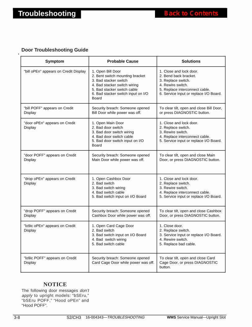
Troubleshooting
3-8 S2/CH3 WMS Service Manual—Upright Slot16-004343—TROUBLESHOOTING
Symptom Probable Cause Solutions
"bill oPEn" appears on Credit Display 1. Open Bill Door2. Bent switch mounting bracket3. Bad stacker switch4. Bad stacker switch wiring5. Bad stacker switch cable6. Bad stacker switch input on I/OBoard
1. Close and lock door.2. Bend back bracket.3. Replace switch.4. Rewire switch.5. Replace interconnect cable.6. Service input or replace I/O Board.
"bill POFF" appears on CreditDisplay
Security breach: Someone openedBill Door while power was off.
To clear tilt, open and close Bill Door,or press DIAGNOSTIC button.
"door oPEn" appears on CreditDisplay
1. Open Main Door2. Bad door switch3. Bad door switch wiring4. Bad door switch cable5. Bad door switch input on I/OBoard
1. Close and lock door.2. Replace switch.3. Rewire switch.4. Replace interconnect cable.5. Service input or replace I/O Board.
"door POFF" appears on CreditDisplay
Security breach: Someone openedMain Door while power was off.
To clear tilt, open and close MainDoor, or press DIAGNOSTIC button.
"drop oPEn" appears on CreditDisplay
1. Open Cashbox Door2. Bad switch3. Bad switch wiring4. Bad switch cable5. Bad switch input on I/O Board
1. Close and lock door.2. Replace switch.3. Rewire switch.4. Replace interconnect cable.5. Service input or replace I/O Board.
"drop POFF" appears on CreditDisplay
Security breach: Someone openedCashbox Door while power was off.
To clear tilt, open and close CashboxDoor, or press DIAGNOSTIC button.
"lo9ic oPEn" appears on CreditDisplay
1. Open Card Cage Door2. Bad switch3. Bad switch input on I/O Board4. Bad switch wiring5. Bad switch cable
1. Close door.2. Replace switch.3. Service input or replace I/O Board.4. Rewire switch.5. Replace bad cable.
"lo9ic POFF" appears on CreditDisplay
Security breach: Someone openedCard Cage Door while power was off.
To clear tilt, open and close CardCage Door, or press DIAGNOSTICbutton.
Door Troubleshooting Guide
NOTICEThe following door messages don’tapply to upright models: “bSEru,”“bSEru POFF,” “Hood oPEn” and“Hood POFF”.
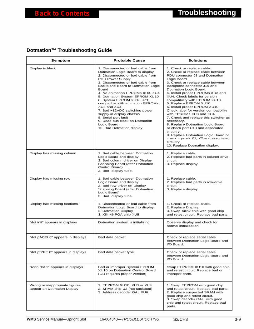
16-004343—TROUBLESHOOTING S2/CH3 3-9WMS Service Manual—Upright Slot
Troubleshooting
Dotmation™ Troubleshooting Guide
Symptom Probable Cause Solutions
Display is black 1. Disconnected or bad cable fromDotmation Logic Board to display2. Disconnected or bad cable fromPDU Power Supply3. Disconnected or bad cable fromBackplane Board to Dotmation LogicBoard4. No animation EPROMs XU3, XU45. Dotmation System EPROM XU106. System EPROM XU10 isn'tcompatible with animation EPROMsXU3 and XU47. Bad +12VDC switching powersupply in display chassis8. Serial port fault9. Dead bus clock on DotmationLogic Board10. Bad Dotmation display.
1. Check or replace cable.2. Check or replace cable betweenPDU connector J8 and DotmationLogic Board.3. Check or replace cable betweenBackplane connector J19 andDotmation Logic Board.4. Install proper EPROMs XU3 andXU4. Check labels for versioncompatibility with EPROM XU10.5. Replace EPROM XU10.6. Install proper EPROM XU10.Check label for version compatibilitywith EPROMs XU3 and XU4.7. Check and replace this switcher asnecessary.8. Replace Dotmation Logic Boardor check port U13 and associatedcircuitry.9. Replace Dotmation Logic Board orcheck crystals X1, X2 and associatedcircuitry.10. Replace Dotmation display.
Display has missing column 1. Bad cable between DotmationLogic Board and display2. Bad column driver on DisplayScanning Board (after DotmationControl Board)3. Bad display tube.
1. Replace cable.2. Replace bad parts in column-drivecircuit.3. Replace display.
Display has missing row 1. Bad cable between DotmationLogic Board and display2. Bad row driver on DisplayScanning Board (after DotmationLogic Board)3. Bad display tube.
1. Replace cable.2. Replace bad parts in row-drivecircuit.3. Replace display.
Display has missing sections 1. Disconnected or bad cable fromDotmation Logic Board to display2. Dotmation Display3. Xilinx® PGA chip XU5
1. Check or replace cable.2. Replace Display.3. Swap Xilinx chip with good chipand retest circuit. Replace bad parts.
"dot init" appears in displays Dotmation system is initializing Observe display and check fornormal initialization.
"dot pACEt 0" appears in displays Bad data packet Check or replace serial cablebetween Dotmation Logic Board andI/O Board.
"dot ptYPE 0" appears in displays Bad data packet type Check or replace serial cablebetween Dotmation Logic Board andI/O Board.
"ronn dot 1" appears in displays Bad or improper System EPROMXU10 on Dotmation Control Board(GD requires proper version)
Swap EEPROM XU10 with good chipand retest circuit. Replace bad orimproper parts.
Wrong or inappropriate figuresappear on Dotmation Display
1. EEPROM XU10, XU3 or XU42. SRAM chip U2 (not socketed)3. Address decoder GAL XU6
1. Swap EEPROM with good chipand retest circuit. Replace bad parts.2. Replace suspected SRAM withgood chip and retest circuit.3. Swap decoder GAL with goodchip and retest circuit. Replace badparts.
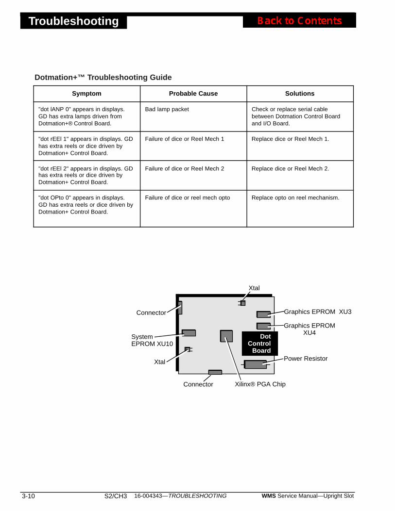
Troubleshooting
3-10 S2/CH3 WMS Service Manual—Upright Slot16-004343—TROUBLESHOOTING
Xtal
SystemEPROM XU10
Graphics EPROMXU4
Xilinx® PGA Chip
DotControl
Board
Graphics EPROM XU3
Xtal
Connector
Connector
Power Resistor
Symptom Probable Cause Solutions
"dot lANP 0" appears in displays.GD has extra lamps driven fromDotmation+® Control Board.
Bad lamp packet Check or replace serial cablebetween Dotmation Control Boardand I/O Board.
"dot rEEl 1" appears in displays. GDhas extra reels or dice driven byDotmation+ Control Board.
Failure of dice or Reel Mech 1 Replace dice or Reel Mech 1.
"dot rEEl 2" appears in displays. GDhas extra reels or dice driven byDotmation+ Control Board.
Failure of dice or Reel Mech 2 Replace dice or Reel Mech 2.
"dot OPto 0" appears in displays.GD has extra reels or dice driven byDotmation+ Control Board.
Failure of dice or reel mech opto Replace opto on reel mechanism.
Dotmation+™ Troubleshooting Guide
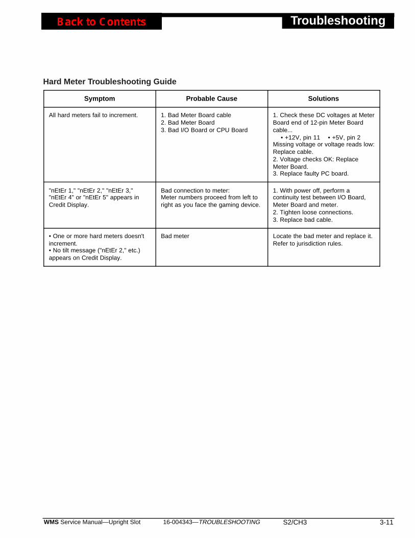
16-004343—TROUBLESHOOTING S2/CH3 3-11WMS Service Manual—Upright Slot
Troubleshooting
Symptom Probable Cause Solutions
All hard meters fail to increment. 1. Bad Meter Board cable2. Bad Meter Board3. Bad I/O Board or CPU Board
1. Check these DC voltages at MeterBoard end of 12-pin Meter Boardcable... • +12V, pin 11 • +5V, pin 2Missing voltage or voltage reads low:Replace cable.2. Voltage checks OK: ReplaceMeter Board.3. Replace faulty PC board.
"nEtEr 1," "nEtEr 2," "nEtEr 3,""nEtEr 4" or "nEtEr 5" appears inCredit Display.
Bad connection to meter:Meter numbers proceed from left toright as you face the gaming device.
1. With power off, perform acontinuity test between I/O Board,Meter Board and meter.2. Tighten loose connections.3. Replace bad cable.
• One or more hard meters doesn'tincrement.• No tilt message ("nEtEr 2," etc.)appears on Credit Display.
Bad meter Locate the bad meter and replace it.Refer to jurisdiction rules.
Hard Meter Troubleshooting Guide
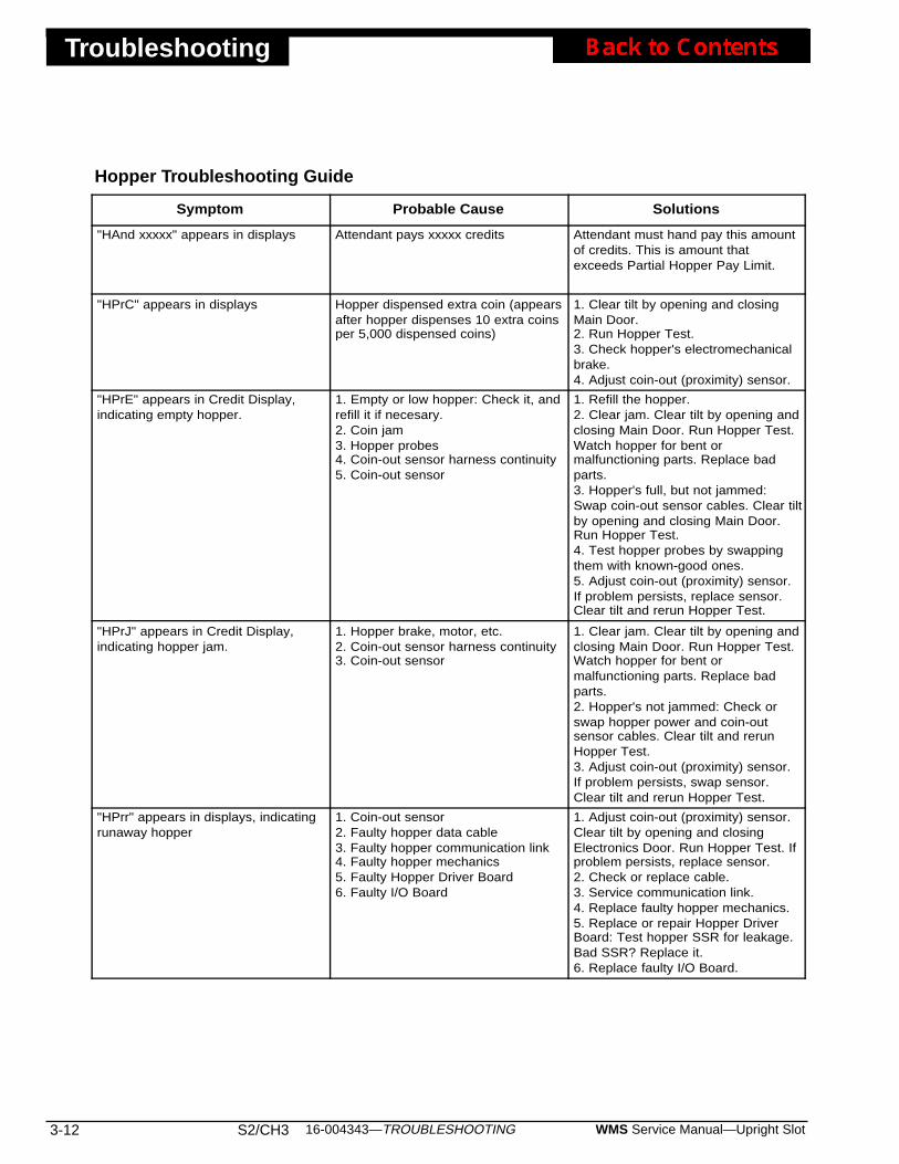
Troubleshooting
3-12 S2/CH3 WMS Service Manual—Upright Slot16-004343—TROUBLESHOOTING
Hopper Troubleshooting Guide
Symptom Probable Cause Solutions
"HAnd xxxxx" appears in displays Attendant pays xxxxx credits Attendant must hand pay this amountof credits. This is amount thatexceeds Partial Hopper Pay Limit.
"HPrC" appears in displays Hopper dispensed extra coin (appearsafter hopper dispenses 10 extra coinsper 5,000 dispensed coins)
1. Clear tilt by opening and closingMain Door.2. Run Hopper Test.3. Check hopper's electromechanicalbrake.4. Adjust coin-out (proximity) sensor.
"HPrE" appears in Credit Display,indicating empty hopper.
1. Empty or low hopper: Check it, andrefill it if necesary.2. Coin jam3. Hopper probes4. Coin-out sensor harness continuity5. Coin-out sensor
1. Refill the hopper.2. Clear jam. Clear tilt by opening andclosing Main Door. Run Hopper Test.Watch hopper for bent ormalfunctioning parts. Replace badparts.3. Hopper's full, but not jammed:Swap coin-out sensor cables. Clear tiltby opening and closing Main Door.Run Hopper Test.4. Test hopper probes by swappingthem with known-good ones.5. Adjust coin-out (proximity) sensor.If problem persists, replace sensor.Clear tilt and rerun Hopper Test.
"HPrJ" appears in Credit Display,indicating hopper jam.
1. Hopper brake, motor, etc.2. Coin-out sensor harness continuity3. Coin-out sensor
1. Clear jam. Clear tilt by opening andclosing Main Door. Run Hopper Test.Watch hopper for bent ormalfunctioning parts. Replace badparts.2. Hopper's not jammed: Check orswap hopper power and coin-outsensor cables. Clear tilt and rerunHopper Test.3. Adjust coin-out (proximity) sensor.If problem persists, swap sensor.Clear tilt and rerun Hopper Test.
"HPrr" appears in displays, indicatingrunaway hopper
1. Coin-out sensor2. Faulty hopper data cable3. Faulty hopper communication link4. Faulty hopper mechanics5. Faulty Hopper Driver Board6. Faulty I/O Board
1. Adjust coin-out (proximity) sensor.Clear tilt by opening and closingElectronics Door. Run Hopper Test. Ifproblem persists, replace sensor.2. Check or replace cable.3. Service communication link.4. Replace faulty hopper mechanics.5. Replace or repair Hopper DriverBoard: Test hopper SSR for leakage.Bad SSR? Replace it.6. Replace faulty I/O Board.

16-004343—TROUBLESHOOTING S2/CH3 3-13WMS Service Manual—Upright Slot
Troubleshooting
Jurisdiction Jumper Troubleshooting Guide
Symptom Probable Cause Solutions
"Jur CHNGE 1" appears in displays Someone changed jurisdictionjumper
Clear RAM.
"Jur bAd 1" appears in displays Wrong jurisdiction jumper forfirmware
1. Set jumper correctly.2. Clear RAM.
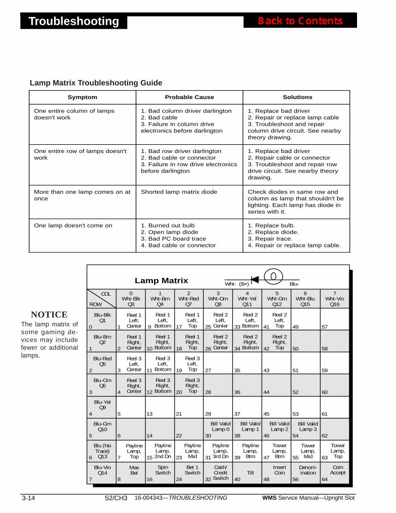
Troubleshooting
3-14 S2/CH3 WMS Service Manual—Upright Slot16-004343—TROUBLESHOOTING
Symptom Probable Cause Solutions
One entire column of lampsdoesn't work
1. Bad column driver darlington2. Bad cable3. Failure in column driveelectronics before darlington
1. Replace bad driver2. Repair or replace lamp cable3. Troubleshoot and repaircolumn drive circuit. See nearbytheory drawing.
One entire row of lamps doesn'twork
1. Bad row driver darlington2. Bad cable or connector3. Failure in row drive electronicsbefore darlington
1. Replace bad driver2. Repair cable or connector3. Troubleshoot and repair rowdrive circuit. See nearby theorydrawing.
More than one lamp comes on atonce
Shorted lamp matrix diode Check diodes in same row andcolumn as lamp that shouldn't belighting. Each lamp has diode inseries with it.
One lamp doesn't come on 1. Burned out bulb2. Open lamp diode3. Bad PC board trace4. Bad cable or connector
1. Replace bulb.2. Replace diode.3. Repair trace.4. Repair or replace lamp cable.
Lamp Matrix Troubleshooting Guide
Reel 1Left,
Center
Reel 1Right,Center
Reel 3Left,
Center
Reel 3Right,Center
PaylineLamp,Top
MaxBet
Reel 1Left,
Bottom
Reel 1Right,Bottom
Reel 3Left,
Bottom
Reel 3Right,Bottom
PaylineLamp,2nd Dn
SpinSwitch
Reel 1Left,Top
Reel 1Right,Top
Reel 3Left,Top
Reel 3Right,Top
PaylineLamp,Mid
Bet 1Switch
Reel 2Left,
Center
Reel 2Right,Center
Bill ValidLamp 0
PaylineLamp,3rd Dn
Cash/CreditSwitch
Reel 2Left,
Bottom
Reel 2Right,Bottom
Bill ValidLamp 1
PaylineLamp,Btm
Tilt
Reel 2Left,Top
Reel 2Right,Top
Bill ValidLamp 2
TowerLamp,Btm
InsertCoin
Bill ValidLamp 3
TowerLamp,Mid
Denom-ination
TowerLamp,Top
CoinAccept
Blu-BlkQ1
Blu-BrnQ2
Blu-RedQ5
Blu-OrnQ6
Blu-YelQ9
Blu-GrnQ10
Blu (NoTrace)Q13
Blu-VioQ14
COL
ROW
1
2
3
4
5
6
7
8
9
10
11
12
13
14
15
16
17
18
19
20
21
22
23
24
25
26
27
28
29
30
31
32
33
34
35
36
37
38
39
40
41
42
43
44
45
46
47
48
49
50
51
52
53
54
55
56
57
58
59
60
61
62
63
64
7Wht-Vio
Q16
6Wht-Blu
Q15
5Wht-Grn
Q12
4Wht-Yel
Q11
3Wht-Orn
Q8
2Wht-Red
Q7
1Wht-Brn
Q4
0Wht-Blk
Q3
0
1
2
3
4
5
6
7
Blu-Wht- (B+)Lamp Matrix
NOTICEThe lamp matrix ofsome gaming de-vices may includefewer or additionallamps.
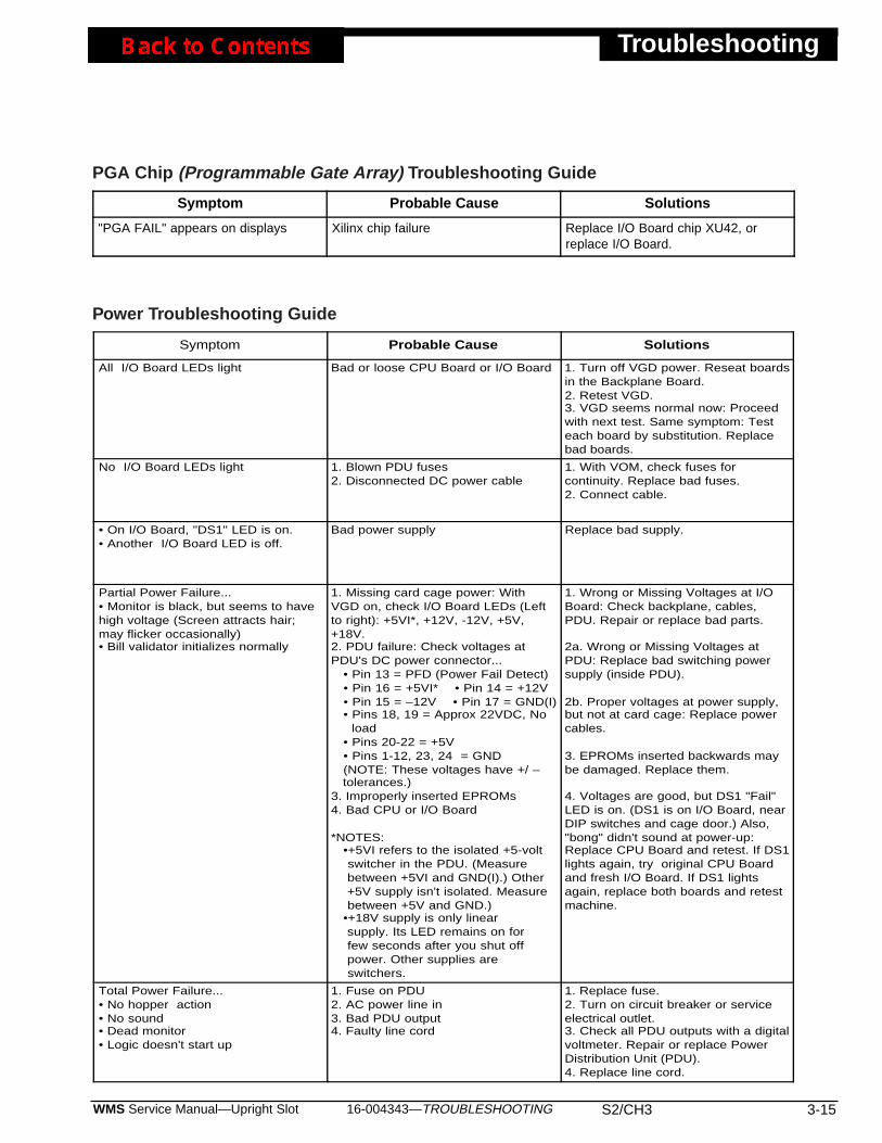
16-004343—TROUBLESHOOTING S2/CH3 3-15WMS Service Manual—Upright Slot
Troubleshooting
Symptom Probable Cause Solutions
All I/O Board LEDs light Bad or loose CPU Board or I/O Board 1. Turn off VGD power. Reseat boardsin the Backplane Board.2. Retest VGD.3. VGD seems normal now: Proceedwith next test. Same symptom: Testeach board by substitution. Replacebad boards.
No I/O Board LEDs light 1. Blown PDU fuses2. Disconnected DC power cable
1. With VOM, check fuses forcontinuity. Replace bad fuses.2. Connect cable.
• On I/O Board, "DS1" LED is on.• Another I/O Board LED is off.
Bad power supply Replace bad supply.
Partial Power Failure...• Monitor is black, but seems to havehigh voltage (Screen attracts hair;may flicker occasionally)• Bill validator initializes normally
1. Missing card cage power: WithVGD on, check I/O Board LEDs (Leftto right): +5VI*, +12V, -12V, +5V,+18V.2. PDU failure: Check voltages atPDU's DC power connector... • Pin 13 = PFD (Power Fail Detect) • Pin 16 = +5VI* • Pin 14 = +12V • Pin 15 = –12V • Pin 17 = GND(I) • Pins 18, 19 = Approx 22VDC, No load • Pins 20-22 = +5V • Pins 1-12, 23, 24 = GND (NOTE: These voltages have +/ – tolerances.)3. Improperly inserted EPROMs4. Bad CPU or I/O Board
*NOTES: •+5VI refers to the isolated +5-volt switcher in the PDU. (Measure between +5VI and GND(I).) Other +5V supply isn't isolated. Measure between +5V and GND.) •+18V supply is only linear supply. Its LED remains on for few seconds after you shut off power. Other supplies are switchers.
1. Wrong or Missing Voltages at I/OBoard: Check backplane, cables,PDU. Repair or replace bad parts.
2a. Wrong or Missing Voltages atPDU: Replace bad switching powersupply (inside PDU).
2b. Proper voltages at power supply,but not at card cage: Replace powercables.
3. EPROMs inserted backwards maybe damaged. Replace them.
4. Voltages are good, but DS1 "Fail"LED is on. (DS1 is on I/O Board, nearDIP switches and cage door.) Also,"bong" didn't sound at power-up:Replace CPU Board and retest. If DS1lights again, try original CPU Boardand fresh I/O Board. If DS1 lightsagain, replace both boards and retestmachine.
Total Power Failure...• No hopper action• No sound• Dead monitor• Logic doesn't start up
1. Fuse on PDU2. AC power line in3. Bad PDU output4. Faulty line cord
1. Replace fuse.2. Turn on circuit breaker or serviceelectrical outlet.3. Check all PDU outputs with a digitalvoltmeter. Repair or replace PowerDistribution Unit (PDU).4. Replace line cord.
Power Troubleshooting Guide
Symptom Probable Cause Solutions
"PGA FAIL" appears on displays Xilinx chip failure Replace I/O Board chip XU42, orreplace I/O Board.
PGA Chip (Programmable Gate Array) Troubleshooting Guide
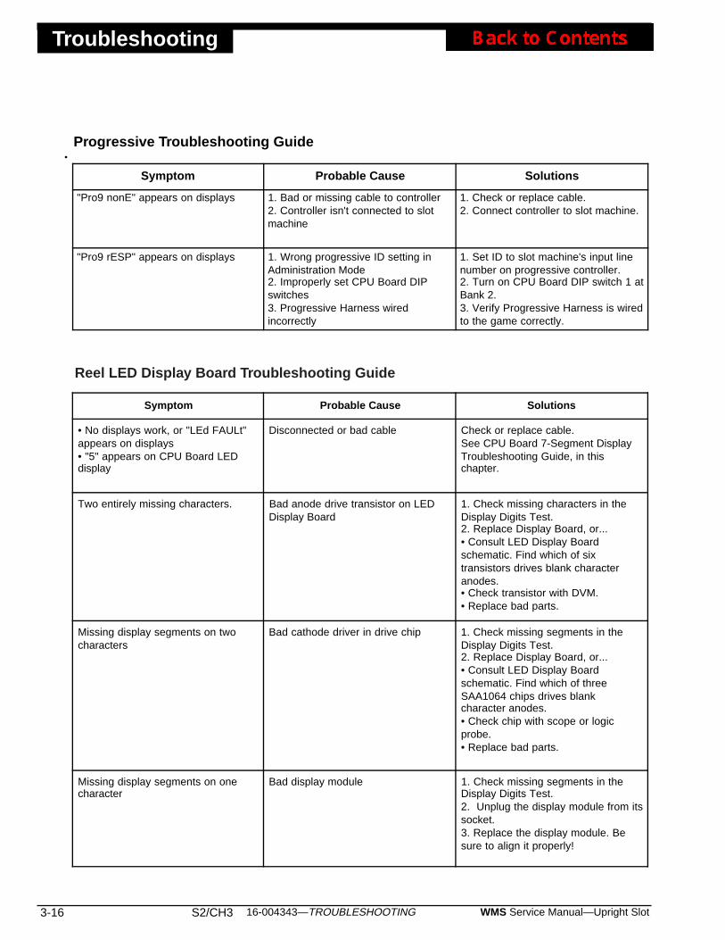
Troubleshooting
3-16 S2/CH3 WMS Service Manual—Upright Slot16-004343—TROUBLESHOOTING
Progressive Troubleshooting Guide
Symptom Probable Cause Solutions
"Pro9 nonE" appears on displays 1. Bad or missing cable to controller2. Controller isn't connected to slotmachine
1. Check or replace cable.2. Connect controller to slot machine.
"Pro9 rESP" appears on displays 1. Wrong progressive ID setting inAdministration Mode2. Improperly set CPU Board DIPswitches3. Progressive Harness wiredincorrectly
1. Set ID to slot machine's input linenumber on progressive controller.2. Turn on CPU Board DIP switch 1 atBank 2.3. Verify Progressive Harness is wiredto the game correctly.
Symptom Probable Cause Solutions
• No displays work, or "LEd FAULt"appears on displays• "5" appears on CPU Board LEDdisplay
Disconnected or bad cable Check or replace cable.See CPU Board 7-Segment DisplayTroubleshooting Guide, in thischapter.
Two entirely missing characters. Bad anode drive transistor on LEDDisplay Board
1. Check missing characters in theDisplay Digits Test.2. Replace Display Board, or...• Consult LED Display Boardschematic. Find which of sixtransistors drives blank characteranodes.• Check transistor with DVM.• Replace bad parts.
Missing display segments on twocharacters
Bad cathode driver in drive chip 1. Check missing segments in theDisplay Digits Test.2. Replace Display Board, or...• Consult LED Display Boardschematic. Find which of threeSAA1064 chips drives blankcharacter anodes.• Check chip with scope or logicprobe.• Replace bad parts.
Missing display segments on onecharacter
Bad display module 1. Check missing segments in theDisplay Digits Test.2. Unplug the display module from itssocket.3. Replace the display module. Besure to align it properly!
Reel LED Display Board Troubleshooting Guide
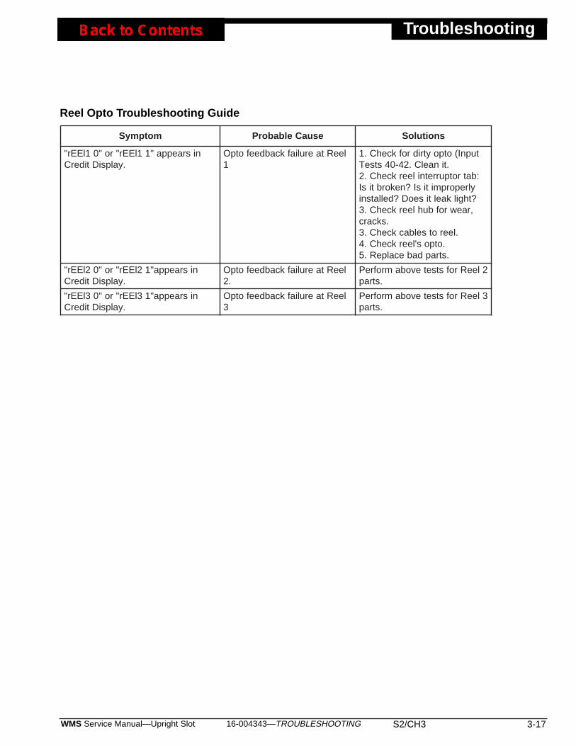
16-004343—TROUBLESHOOTING S2/CH3 3-17WMS Service Manual—Upright Slot
Troubleshooting
motpmyS esuaCelbaborP snoituloS
nisraeppa"11lEEr"ro"01lEEr".yalpsiDtiderC
leeRtaeruliafkcabdeefotpO1
tupnI(otpoytridrofkcehC.1.tinaelC.24-04stseT
:batrotpurretnileerkcehC.2ylreporpmitisI?nekorbtisI?thgilkaeltiseoD?dellatsni,raewrofbuhleerkcehC.3
.skcarc.leerotselbackcehC.3
.otpos'leerkcehC.4.strapdabecalpeR.5
nisraeppa"12lEEr"ro"02lEEr".yalpsiDtiderC
leeRtaeruliafkcabdeefotpO.2
2leeRrofstsetevobamrofreP.strap
nisraeppa"13lEEr"ro"03lEEr".yalpsiDtiderC
leeRtaeruliafkcabdeefotpO3
3leeRrofstsetevobamrofreP.strap
Reel Opto Troubleshooting Guide
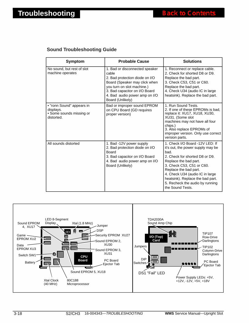
Troubleshooting
3-18 S2/CH3 WMS Service Manual—Upright Slot16-004343—TROUBLESHOOTING
Symptom Probable Cause Solutions
No sound, but rest of slotmachine operates
1. Bad or disconnected speakercable2. Bad protection diode on I/OBoard (Speaker may click whenyou turn on slot machine.)3. Bad capacitor on I/O Board4. Bad audio power amp on I/OBoard (Unlikely)
1. Reconnect or replace cable.2. Check for shorted D8 or D9.Replace the bad part.3. Check C53, C51 or C60.Replace the bad part.4. Check U34 (audio IC in largeheatsink). Replace the bad part.
• "ronn Sound" appears indisplays.• Some sounds missing ordistorted.
Bad or improper sound EPROMon CPU Board (GD requiresproper version)
1. Run Sound Tests.2. If one of these EPROMs is bad,replace it: XU17, XU18, XU30,XU31. (Some slotmachines may not have all fourchips.)3. Also replace EPROMs ofimproper version. Only use correctversion parts.
All sounds distorted 1. Bad -12V power supply2. Bad protection diode on I/OBoard3. Bad capacitor on I/O Board4. Bad audio power amp on I/OBoard (Unlikely)
1. Check I/O Board -12V LED: Ifit's out, the power supply may bebad.2. Check for shorted D8 or D9.Replace the bad part.3. Check C53, C51 or C60.Replace the bad part.4. Check U34 (audio IC in largeheatsink). Replace the bad part.5. Recheck the audio by runningthe Sound Tests.
Sound Troubleshooting Guide
I/O (Top)Card
Power Supply LEDs: +5V,+12V, -12V, +5V, +18V
DS1 "Fail" LED
TDA2030ASound Amp Chip
Jumpers
DIPSwitches
TIP107Row-DriveDarlingtons
TIP102Column-DriveDarlingtons
PC BoardEjector Tab
Xtal Clock(40 MHz)
DSP
80C188Microprocessor
LED 8-SegmentDisplay
PC BoardEjector Tab
Xtal (1.8 MHz)
GameEPROM XU2
Jumper
DataEPROM XU3 Sound EPROM 3,
XU31
Sound EPROM 2,XU30
Sound EPROM 5, XU18
Sound EPROM4, XU17
Battery
Switch SW1 CPUBoard
Security EPROM XU27
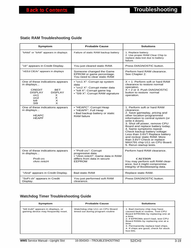
16-004343—TROUBLESHOOTING S2/CH3 3-19WMS Service Manual—Upright Slot
Troubleshooting
Symptom Probable Cause Solutions
"bAttd" or "bAttl" appears in displays Failure of static RAM backup battery 1. Replace battery.2. Use proper RAM Clear Chip toreplace data lost due to batteryfailure.
One of these indications appearsin displays...
CREDIT BET DISPLAY DISPLAY crc1 X crc2 X lo9 X SI9 X
• "crc1 X": Corrupt op systemdata• "crc2 X": Corrupt meter data• "lo9 X": Corrupt game log• "SI9 X": Corrupt RAM signature
X = 1: Perform soft or hard RAMclearance to restore normaloperation.X = 2 or 3: Push DIAGNOSTICbutton to restore normaloperation.
One of these indications appearsin displays...
HEAPC HEAPF
• "HEAPC": Corrupt Heap• "HEAPF": Full Heap• Bad backup battery or staticRAM failure
1. Perform soft or hard RAMclearance.2. Save gameplay, pricing andother location-programmedinformation to central system (orwrite it down).3. Shut off power, remove CPUBoard and replace battery today.4. Same symptoms repeat:Check backup battery voltage:Less than 3.6V? Replace batteryand reclear static RAM. Morethan 3.6V? Check or replaceMAX791 chip U11 on CPU Board.5. Rerun startup tests.
"clr" appears in Credit Display. You just cleared static RAM. Press DIAGNOSTIC button.
"nEEd ClEAr" appears in displays Someone changed the GameEPROM or game percentage.You need to clear static RAM
Perform hard RAM clearance.See Chapter 2.
"rAnd" appears in Credit Display. Bad static RAM Replace static RAM.
One of these indications appearsin displays...
Pro9 crc rAnn nntcH
• "Pro9 crc": Corruptprogressive data• "rAnn nntcH": Game data in RAMdiffers from data in secureEEPROM
Perform hard RAM clearance.
CAUTIONYou may perform soft RAM clear-ance, but it might compromiseintegrity of Bookkeeping data.
"SoFt clr" appears in CreditDisplay.
You just performed soft RAMclearance.
Press DIAGNOSTIC button.
Static RAM Troubleshooting Guide
Symptom Probable Cause Solutions
"bi6 trubl" appears in displays, orgaming device may frequently reset.
Watchdog chip U11 on CPU Boardtimed out during program routine
1. Bad memory chip may havecaused fault in routine. Test CPUBoard EPROMs by replacing one ata time.2. If EPROMs aren't bad, test CPUBoard RAMs by replacing one at atime.3. Permanently replace bad chips.4. If chips are good, check for stuckbus bits.
Watchdog Timer Troubleshooting Guide
16-004344—PARTS, ELECTRONIC S3/CH1 1-1WMS Service Manual—Upright Slot
Electronic Parts
Chapter 1. Parts, Electronic
• Boards, Circuit
Board, Slot Backplane .......................................................A-17937-03Board, Bill Validator Lamp.................................................A-18088-01*Board, Slot CPU ................................................................A-17677-03Board, Dotmation Control (not used on all machines).......A-000541-01Board, Dotmation+ Control ................................................A-003875-02**Board, Hex Opto (coin-In optics; coin chute dependent)...A-18097-01Board, Hopper Control.......................................................A-17118-02Board, 4-Tier Twr Lamp Converter (not on all mach) ........20-004213-00Board, Slot I/O ...................................................................A-17686-03Board, Slot 6-Meter Driver.................................................A-17951-01Board, Payline Lamp .........................................................A-18087-00Board, Quad Opto (coin-In optics; coin chute dependent) A-18097-00Board, LED Display ...........................................................A-17382-01Board, Reel Motor Control (part of reel assembly) ............20-002002
• Cable
CABLES, OPTIONALCable, Bally® DMK 220® Serial Interface.........................5797-000993-00Cable, CDS® Ser Intfce (Sentinel II®) to PDU Adapt .......5797-001800-00Cable, DC Power, 12 to 16-Pin Transformer Adapter .......5797-003459-00Cable, Dotmation™ Serial Interface ..................................H-001120-00Cable, Dotmation AC.........................................................H-001118-00Cable, Dotmation+™ Panel Controller ..............................5797-003968-00Cable, EDT®/IGT® Com Interface (w/ Sw Inputs) ............H-19471-00Cable, IGT PT95A, w/4-Pin Minifit Con, AC Pwr ...............H-002944-00Cable, MGM System Interface ..........................................H-004672-00Cable, Monitor/Hopper Service .........................................5797-13694-00Cable, One-Button Special (Part of 6-Button Kits) ............H-003855-00Cable, PDU Service Outlet ................................................H-19452-00Cable, Ribbon, Dot Logic to Dot Dsply ..............................5797-001293-00Cable, Tower/GI Extension................................................H-19437-00Cord, Line Power, IEC320, 220V British ...........................5850-13273-00Cord, Line Power, IEC320, 120VAC, North America ........5850-13344-00Cord, IGT, 110V, PT95A Power, Service Outlet................5797-004361-00Cord, Line, N.A., IEC320, NEMA 6-16P, 10A, 220V, 15' ..5850-004452-00**Cord, Line Set, Continental Europe...................................5850-13272-00Cord, Line, N.A., NEMA 6-16P, 10A, 220V, N. A., 8' ........5850-000992-00
CABLES, UNIVERSALCable, Audio #1 (To Blind Mating Connector Center) .......H-18115-01Cable, Audio #2 (to Speaker) ............................................H-18116-01Cable, Belly Lamp Bracket ................................................H-18885-00Cable, Bill Validator ...........................................................H-17961-00Cable, Bill Validator Lamps ..............................................H-17974-00*Cable, Coin Comparator and Chute Door .........................H-17958-00
NOTICEThese parts are for 1995 machines.1995 machines bear the number71272 on their nameplates. You'llf ind your machine’s nameplatebeneath the slot handle.
NOTICEFor electronic component partnumbers, please refer to SchematicDrawing Set Manual A-004434.
NOTICE*For use with JCM DBV145 bil lvalidator w/o plastic il luminatedbezel.
NOTICE**Used Only For Monopoly
Top Box.
Electronic Parts
Cable, Coin Comparator and Chute ..................................H-17972-00Cable, Condor® Coin Controller........................................5797-004090-00Cable, DC Power ..............................................................H-17965-00Cable, Door, Key Sw. & Arm Sw. (Casino only) ................H-17959-02Cable, Door, Key Sw. & Arm Sw. (Lottery only) ................H-004599-00Cable, EDT, PT95A, Deleware, Meters.............................H-001917-00Cable, EDT, PT95A, RS232, Deleware.............................H-004690-00Cable, Fluorescent #1 (for top belly lamp).........................H-18882-00Cable, Fluorescent #2 (for bottom belly lamp)...................H-18883-00Cable, Fluorescent #3 (for reel lamp) ................................H-18884-00Cable, Game Button Door (shielded) ................................5797-000150-00Cable, Handle Solenoid.....................................................H-15596Cable, Hopper ...................................................................H-17963-00Cable, Hopper, Blind-Mating Interface (BMI) Male............H-18096-00Cable, Hopper Full Sensor ................................................H-18095-00Cable, Host, Com, RS485/422 Del....................................H-19470-01Cable, JCM Bill Validator AC.............................................H-19860-00Cable, JCM Stacker Switch...............................................H-18863-00Cable, Meter ......................................................................H-17962-00Cable, Payline LED Bd Lamps (shielded) .........................5797-000151-00Cable, PDU AC Distribution (only used with 12-pin xfmrs)H-19408-00Cable, PDU AC Distribution (only used with 16-pin xfmrs)H-19408-01Cable, PDU DC Power (only used with 12-pin xfmrs) .......H-19409-00Cable, PDU DC Power (only used with 16-pin xfmrs) .......H-19409-01Cable, PDU IEC.................................................................5797-14243-00Cable, PDU PS AC out (only used with 12-pin xfmrs).......H-19407-00Cable, PDU PS AC out (only used with 16-pin xfmrs).......H-19407-01Cable, Player (Control) Panel............................................H-17971-01Cable, Quad Opto Board to Comparator (CC-16) .............5797-14014-00Cable, Reel Glass Lamp....................................................H-18894-00Cable, Service Outlet Assembly, PDU ..............................H-19452-00Cable, Six-Lamp Slot Reel Mechanism.............................H-18105-00Cable, Special, One-Button (used w/6-btn plyr panel) ......H-003855-00Cable, Special, Three-Button (used w/8-btn plyr panel)....H-002609-00Cable, Three-Conductor Ribbon (Quad Opto)...................5795-13788-00Cable, Topbox Fluorescent ...............................................H-19464-00Cable with Switch, Voltage Selector..................................5797-14233-00Cord, Single Receptacle Line ............................................5851-13203-00
• Identification, CPU Jurisdictional
EPROM, CPU, XU27, 4K Bit .............................................5345-13617-00
1-2 S3/CH1 WMS Service Manual—Upright Slot16-004344—PARTS, ELECTRONIC
• Cables, Universal, continued
NOTICEThese parts are for 1995 machines.1995 machines bear the number71272 on their nameplates. You'llf ind your machine’s nameplatebeneath the slot handle.
• Parts, Replacement Electronic (All Boards)
Bag, Parts .......................................................................A-19460Bulb, #1888, 7V/500mA (Bayonet) .............................24-8832Bulb, #86, 6.3V/0.2A (inside player panel btns) ..........24-8829Bulb, #555, 6.3V/250 mA ............................................24-8768Fuse, 4ASB, 250V ......................................................5731-06314-00
Bulb, #161 Reel .................................................................24-8840
• Supply, Dotmation™ Power
Supply, Dotmation & Dotmation, 12VDC, 110W Power ....20-001292Supply, Dotmation & Dotmation+, 24V, 225W Power .......20-004115**
• Transformer, Main Power
Transformer, Int’l, 16-pin, Main Pwr (w/cables) .................A-002509-00Use above part only with 1997 (CE97-approved) power supplies!
Transformer, Int’l, 12-pin, Main Pwr (w/cables) .................A-19443-00Use above part only with 1995 power supplies!
Transformer, Int’l, Jpr Tab Type, Main Pwr (w/cbls)..........A-18100Use above part only with 1994 power supplies!
• Unit, Power Distribution (PDU)
BOARD, 16-PIN TO XFMR, LINEAR POWER SUPPLY (PDU BOARD)Board, +5/+18VDC, Linear Pwr Supply (PDU Bd).............A-18938-03Supply, 110W, +5/±12VDC, Triple Output Power .............20-9965
BOARD, 12-PIN TO XFMR, LINEAR POWER SUPPLY (PDU BOARD)Board, +5/+18VDC, Linear Pwr Supply (PDU Bd).............A-18938-01Supply, 110W, +5/±12VDC, Triple Output Power .............20-9965
PDU, EXCLUSIVE PARTS FOR NORTH AMERICAN, 110 VACFuse, 4ASB, 250V.............................................................5731-06314-00Holder, Panel-Type, 5 x 20mm, Knob Fuse ......................5733-12869-00Plate, Outlet Mounting .......................................................01-13449-01
PDU, EXCLUSIVE PARTS FOR EUROPEAN, 220 VACFuse, 5 x 20-2A .................................................................5735-13853-00Holder, Panel-Type, 5 x 20mm, Knob Fuse ......................5733-12869-01Plate, Blank Cover.............................................................01-13449-02
16-004344—PARTS, ELECTRONIC S3/CH1 1-3WMS Service Manual—Upright Slot
Electronic Parts
NOTICEThese parts are for 1995 machines.1995 machines bear the number71272 on their nameplates. You'llf ind your machine’s nameplatebeneath the slot handle.
NOTICE**Used Only For Monopoly
Top Box.
Electronic Parts
PDU, EXCLUSIVE PARTS FOR N. AMERICAN OR EUROPEANFuse, 5 x 20-2A, 250V.......................................................5731-08665-00Holder, Panel-Type, 5 x 20mm, Knob Fuse ......................5733-12869-00Plate, Blank Cover.............................................................01-13449-02
PDU, PLUG & PLAY REPLACEMENT FOR N. AMERICAN, 110 VACPDU, P&P, N. American, 16-Pin to Xfmr, 110V, 60 Hz .....A-002912-01
PDU, PLUG & PLAY REPLACEMENT FOR EUROPEAN, 220 VACPDU, P&P, European, 16-Pin to Xfmr, 220V, 50 Hz .........A-002912-02
PDU, P & P REPLACEMENT FOR N. AMERICAN OR EUROPEANPDU, P&P ‘97 Europe or N. Am., 220V, 50/60 Hz ...........A-002912-03
PDU, P & P REPLACEMENT FOR N. AMERICAN OR EUROPEANPDU, 12-Pin to Xfmr, 220V................................................A-002938-03
PDU, P & P REPLACEMENT FOR N. AMERICANPDU, 12-Pin to Xfmr, 110V................................................A-002938-01
PDU, P & P REPLACEMENT FOR EUROPEANPDU, 12-Pin to Xfmr, 220V................................................A-002938-02
1-4 S3/CH1 WMS Service Manual—Upright Slot16-004344—PARTS, ELECTRONIC
• Unit, Power Distribution (PDU), continuedNOTICEThese parts are for 1995 machines.1995 machines bear the number71272 on their nameplates. You'llf ind your machine’s nameplatebeneath the slot handle.
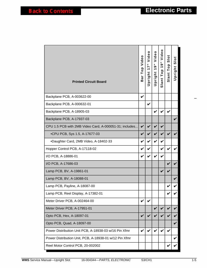
16-004344—PARTS, ELECTRONIC S3/CH1 1-5WMS Service Manual—Upright Slot
Electronic Parts
Printed Circuit Board Ba
r T
op
Vid
eo
Up
rig
ht
17
" V
ide
o
Up
rig
ht
19
" V
ide
o
Sla
nt
To
p 1
9"
Vid
eo
Sla
nt
To
p S
lot
Up
rig
ht
Slo
t
Backplane PCB, A-003622-00
Backplane PCB, A-000632-01
Backplane PCB, A-18905-03
Backplane PCB, A-17937-03
CPU 1.5 PCB with 2MB Video Card, A-000051-31; includes...
•CPU PCB, Sys 1.5, A-17677-03
•Daughter Card, 2MB Video, A-18402-33
Hopper Control PCB, A-17118-02
I/O PCB, A-18886-01
I/O PCB, A-17686-03
Lamp PCB, BV, A-19861-01
Lamp PCB, BV, A-18088-01
Lamp PCB, Payline, A-18087-00
Lamp PCB, Reel Display, A-17382-01
Meter Driver PCB, A-002464-00
Meter Driver PCB, A-17951-01
Opto PCB, Hex, A-18097-01
Opto PCB, Quad, A-18097-00
Power Distribution Unit PCB, A-18938-03 w/16 Pin Xfmr
Power Distribution Unit, PCB, A-18938-01 w/12 Pin Xfmr
Reel Motor Control PCB, 20-002002
✔
✔
✔ ✔ ✔
✔
✔ ✔ ✔ ✔
✔ ✔ ✔ ✔ ✔ ✔
✔ ✔ ✔ ✔
✔ ✔ ✔ ✔ ✔
✔ ✔ ✔ ✔
✔ ✔
✔ ✔
✔
✔ ✔
✔ ✔
✔ ✔
✔ ✔ ✔ ✔
✔ ✔ ✔ ✔ ✔ ✔
✔
✔ ✔ ✔ ✔ ✔
✔
✔ ✔
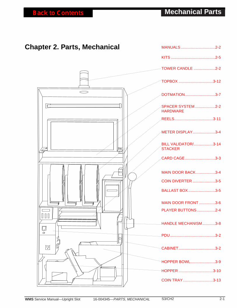
16-004345—PARTS, MECHANICAL S3/CH2 2-1WMS Service Manual—Upright Slot
Mechanical Parts
Chapter 2. Parts, Mechanical
DOTMATION............................3-7
TOPBOX ................................3-12
SPACER SYSTEM...................2-2HARDWARE
REELS....................................3-11
METER DISPLAY.....................3-4
BILL VALIDATOR/..................3-14STACKER
CARD CAGE............................3-3
HANDLE MECHANISM............3-8
CABINET..................................3-2
HOPPER BOWL.......................3-9
HOPPER ................................3-10
PDU..........................................3-2
TOWER CANDLE ....................2-2
MAIN DOOR BACK..................3-4
COIN DIVERTER .....................3-5
BALLAST BOX.........................3-5
MAIN DOOR FRONT ...............3-6
COIN TRAY............................3-13
PLAYER BUTTONS.................2-4
KITS .........................................2-5
MANUALS................................2-2

Mechanical Parts
2-2 S3/CH2 WMS Service Manual—Upright Slot16-004345—PARTS, MECHANICAL
• Instruction Documents
40X UPRIGHT SLOT MANUALSBinder, Three 2” (5cm) Rings (comes with manuals) ..........20-9896-01Handbook, System 1.5 Slot, Abridged, Pocket-Size ............16-000324-01Manual, Gaming Safety........................................................16-001796-01Manual, 1998, Model 40X Upright, Svc (Full Version) .........A-004336
• Tower Candle
Bulb, #1888, 7V/500mA (Bayonet).......................................24-8832
CANDLES, CHROME-FINISH, FOUR-TIER, SHORT TOWERLamp, Wht, Grn, Yel & Blu, Chrome Twr, Short, 4-Tier .......20-004145-02Lamp, Wht, Grn, Yel & Yel, Chrome Twr, Short, 4-Tier .......20-004145-01
CANDLES, CHROME-FINISH, FOUR-TIER, TALL TOWERLamp, Wht, Grn, Yel & Blu, Chrome Twr, Tall, 4-Tier ..........20-003945-04Lamp, Wht, Grn, Yel & Yel, Chrome Twr, Tall, 4-Tier ..........20-003945-03
CANDLES, BRASS-FINISH, TWO-TIER, TOWERLamp, Standard Clear and Clear, Brass Tower, 2-Tier ........20-10054-11Lamp, Stand. Short 4"(10cm) Clr & Clr, Brs Twr, 2-Tier.......20-000736-02
CANDLES, CHROME-FINISH, TWO-TIER, TOWERLamp, Clear and Clear, Chrome Tower, 2-Tier ....................20-10053-11Lamp, Short (4"/10cm) Clr &Clr, Chrome Twr, 2-Tier...........20-000736-01
FILTER INSERTSShort Two-Tiered Tower Lamp Filter Insert,
Brass or Chrome Finish....... ..........................................20-000846-XXTall Two-Tiered Tower Lamp Filter Insert,
Brass or Chrome Finish....... ..........................................20-10057-XXThe -XX part number suffix indicates insert color combinations.
• Topbox Central System Configuration Hardware
BLANK FACEPLATE PANELFaceplate, Blank Panel, Matte Black.................................01-001833-00P06
MOUNTING HARDWARE, ACRES LEGACY TRACKING SYSTEMW/DISPLAY & MAGNETIC OR OPTICAL READER Faceplate, Matte Black ......................................................01-001833-01P06Spacer, 7/16" (11mm) .........................................................03-6047-9
MOUNTING HARDWARE, ACRES BE 2 TRACKING SYSTEMW/VACUUM FLUORESCENT DISPLAY, KEYPAD, BONUS BUTTON &MAGNETIC READER Faceplate, Matte Black ......................................................01-001833-21P06
NOTICEThese parts are for 1995 machines.1995 machines bear the number71272 on their nameplates. Themachine’s nameplate is locatedbeneath the slot handle.
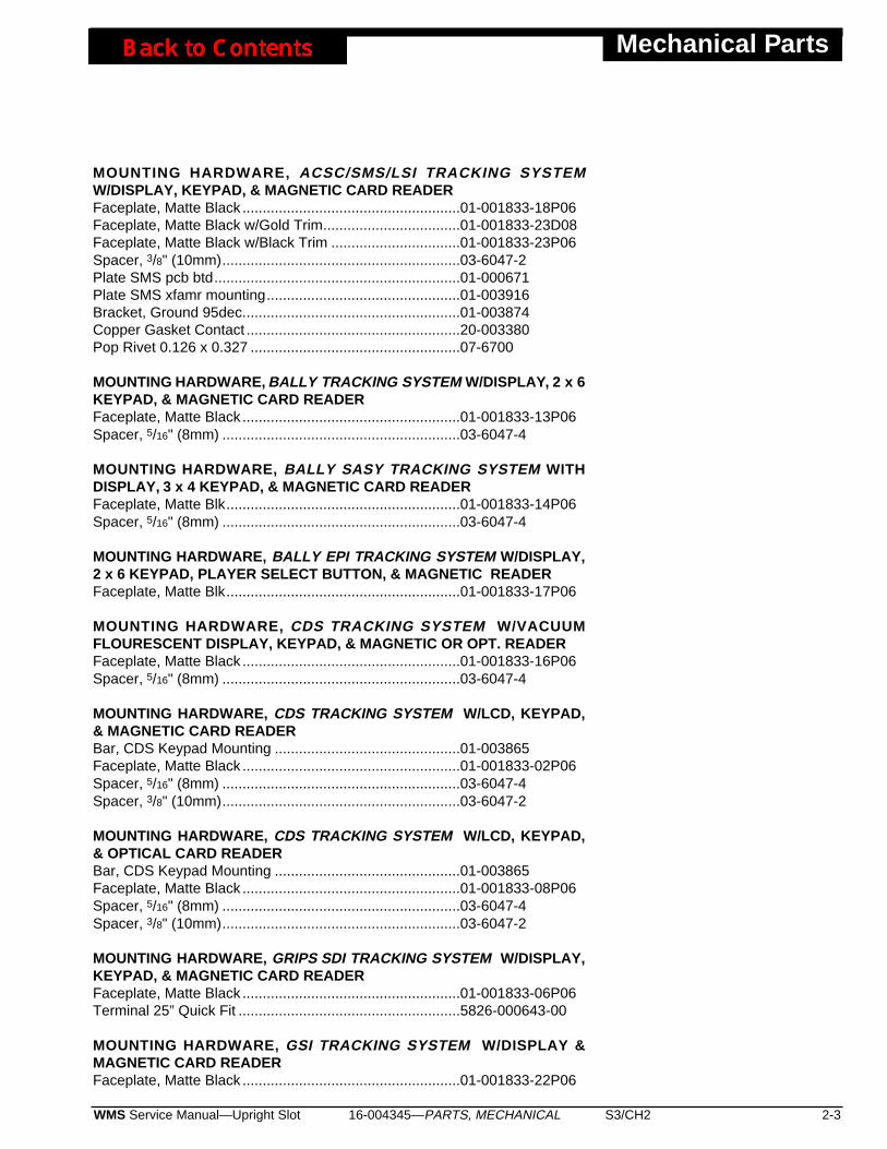
16-004345—PARTS, MECHANICAL S3/CH2 2-3WMS Service Manual—Upright Slot
Mechanical Parts
MOUNTING HARDWARE, ACSC/SMS/LSI TRACKING SYSTEMW/DISPLAY, KEYPAD, & MAGNETIC CARD READERFaceplate, Matte Black ......................................................01-001833-18P06Faceplate, Matte Black w/Gold Trim..................................01-001833-23D08Faceplate, Matte Black w/Black Trim ................................01-001833-23P06Spacer, 3/8" (10mm)...........................................................03-6047-2Plate SMS pcb btd.............................................................01-000671Plate SMS xfamr mounting................................................01-003916Bracket, Ground 95dec......................................................01-003874Copper Gasket Contact .....................................................20-003380Pop Rivet 0.126 x 0.327 ....................................................07-6700
MOUNTING HARDWARE, BALLY TRACKING SYSTEM W/DISPLAY, 2 x 6KEYPAD, & MAGNETIC CARD READERFaceplate, Matte Black ......................................................01-001833-13P06Spacer, 5/16" (8mm) ...........................................................03-6047-4
MOUNTING HARDWARE, BALLY SASY TRACKING SYSTEM WITHDISPLAY, 3 x 4 KEYPAD, & MAGNETIC CARD READERFaceplate, Matte Blk..........................................................01-001833-14P06Spacer, 5/16" (8mm) ...........................................................03-6047-4
MOUNTING HARDWARE, BALLY EPI TRACKING SYSTEM W/DISPLAY,2 x 6 KEYPAD, PLAYER SELECT BUTTON, & MAGNETIC READERFaceplate, Matte Blk..........................................................01-001833-17P06
MOUNTING HARDWARE, CDS TRACKING SYSTEM W/VACUUMFLOURESCENT DISPLAY, KEYPAD, & MAGNETIC OR OPT. READERFaceplate, Matte Black ......................................................01-001833-16P06Spacer, 5/16" (8mm) ...........................................................03-6047-4
MOUNTING HARDWARE, CDS TRACKING SYSTEM W/LCD, KEYPAD,& MAGNETIC CARD READER Bar, CDS Keypad Mounting ..............................................01-003865Faceplate, Matte Black ......................................................01-001833-02P06Spacer, 5/16" (8mm) ...........................................................03-6047-4Spacer, 3/8" (10mm)...........................................................03-6047-2
MOUNTING HARDWARE, CDS TRACKING SYSTEM W/LCD, KEYPAD,& OPTICAL CARD READER Bar, CDS Keypad Mounting ..............................................01-003865Faceplate, Matte Black ......................................................01-001833-08P06Spacer, 5/16" (8mm) ...........................................................03-6047-4Spacer, 3/8" (10mm)...........................................................03-6047-2
MOUNTING HARDWARE, GRIPS SDI TRACKING SYSTEM W/DISPLAY,KEYPAD, & MAGNETIC CARD READER Faceplate, Matte Black ......................................................01-001833-06P06Terminal 25” Quick Fit .......................................................5826-000643-00
MOUNTING HARDWARE, GSI TRACKING SYSTEM W/DISPLAY &MAGNETIC CARD READER Faceplate, Matte Black ......................................................01-001833-22P06

Mechanical Parts
2-4 S3/CH2 WMS Service Manual—Upright Slot16-004345—PARTS, MECHANICAL
MOUNTING HARDWARE, IGS TRACKING SYSTEM W/VACUUMFLUORESCENT DISPLAY, 2 x 6 KEYPAD, BONUS BUTTON, &MAGNETIC CARD READERFaceplate, Matte Black ......................................................01-001833-19P06Plate Keypad Cover...........................................................01-004305-P06
MOUNTING HARDWARE, IGT/EDT TRACKING SYSTEM W/5MM CHAR.DISPLAY & MAGNETIC CARD READER Faceplate, Matte Black ......................................................01-001833-03P06Spacer, 3/8" (10mm)...........................................................03-6047-2
MOUNTING HARDWARE, IGT/EDT TRACKING SYSTEM W/5MM CHAR.DISPLAY & OPTICAL CARD READER Faceplate, Matte Black .....................................................01-001833-03P06Spacer, 3/8" (10mm)...........................................................03-6047-2Plate, EDT Optical Card Reader Mounting, Matte Black...01-002244-P06
MOUNTING HARDWARE, IGT/EDT TRACKING SYSTEM W/9MM CHAR.DISPLAY & MAGNETIC CARD READER Faceplate, Matte Black ......................................................01-001833-04P06Spacer, 3/8" (10mm)...........................................................03-6047-2
MOUNTING HARDWARE, IGT/EDT TRACKING SYSTEM W/9MM CHAR.DISPLAY & OPTICAL CARD READER Faceplate, Matte Black ......................................................01-001833-04P06Spacer, 3/8" (10mm)...........................................................03-6047-2Plate, EDT Optical Card Reader Mounting, Matte Black...01-002244-P06
MOUNTING HARDWARE, IVERSON GAMING SM1 TRACKING SYSTEMW/1x3 1/8 DISPLAY, & MAGNETIC CARD READERFaceplate, Matte Blk..........................................................01-001833-20P06Spacer, 5/16" (8mm) ...........................................................03-6047-4
MOUNTING HARDWARE, MIKOHN TRACKING SYSTEM W/DISPLAY,KEYPAD, & MAGNETIC CARD READERFaceplate, Matte Black ......................................................01-001833-09P06Spacer, 7/16" (11mm) .........................................................03-6047-9
• Buttons
BUTTONS, PLAYER PANELButton, Rectangular, 6.3V Lamp, CHEST ............................20-001887-05Button, Rectangular, 6.3V Lamp, MAX BET SPIN ...............20-002448-16Button, Rectangular, 6.3V Lamp, PLAY 4 CREDITS ...........20-002448-35Button, Rectangular, 6.3V Lamp, PLAY 3 CREDITS ...........20-002448-34Button, Rectangular, 6.3V Lamp, SPIN REELS ...................20-002448-19Button, Square, 6.3V Lamp, BET ONE ................................20-002449-18Button, Square, 6.3V Lamp, CASH/CREDIT........................20-002449-23Button, Square, 6.3V Lamp, CHANGE.................................20-002449-14
• Topbox Central System Config. Hardware (continued)
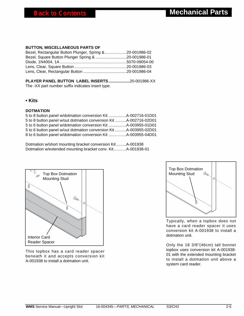
BUTTON, MISCELLANEOUS PARTS OFBezel, Rectangular Button Plunger, Spring &....................20-001986-02Bezel, Square Button Plunger Spring & ............................20-001986-01Diode, 1N4004, 1A ............................................................5070-09054-00Lens, Clear, Square Button ...............................................20-001986-03Lens, Clear, Rectangular Button .......................................20-001986-04
PLAYER PANEL BUTTON LABEL INSERTS ...................20-001986-XXThe -XX part number suffix indicates insert type.
• Kits
DOTMATION5 to 8 button panel w/dotmation conversion Kit ................A-002716-01D015 to 8 button panel w/out dotmation conversion Kit ..........A-002716-02D015 to 6 button panel w/dotmation conversion Kit ................A-003955-01D015 to 6 button panel w/out dotmation conversion Kit ..........A-003955-02D018 to 6 button panel w/dotmation conversion Kit ................A-003955-04D01
Dotmation w/short mounting bracket conversion Kit .........A-001938Dotmation w/extended mounting bracket conv. Kit ...........A-001938-01
16-004345—PARTS, MECHANICAL S3/CH2 2-5WMS Service Manual—Upright Slot
Mechanical Parts
This topbox has a card reader spacerbeneath it and accepts conversion kitA-001938 to install a dotmation unit.
Interior CardReader Spacer
Top Box DotmationMounting Stud
Typically, when a topbox does nothave a card reader spacer it usesconversion kit A-001938 to install adotmation unit.
Only the 18 3/8"(46cm) tall bonnettopbox uses conversion kit A-001938-01 with the extended mounting bracketto install a dotmation unit above asystem card reader.
Top Box DotmationMounting Stud
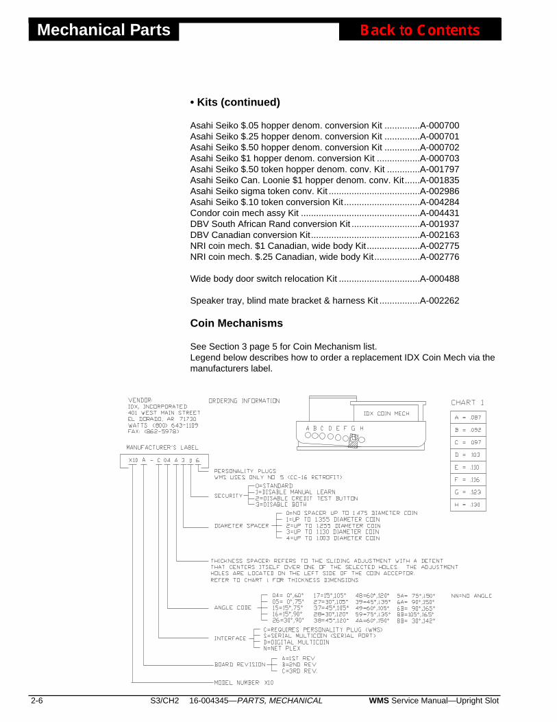
Mechanical Parts
2-6 S3/CH2 WMS Service Manual—Upright Slot16-004345—PARTS, MECHANICAL
Asahi Seiko $.05 hopper denom. conversion Kit ..............A-000700Asahi Seiko $.25 hopper denom. conversion Kit ..............A-000701Asahi Seiko $.50 hopper denom. conversion Kit ..............A-000702Asahi Seiko $1 hopper denom. conversion Kit .................A-000703Asahi Seiko $.50 token hopper denom. conv. Kit .............A-001797Asahi Seiko Can. Loonie $1 hopper denom. conv. Kit......A-001835Asahi Seiko sigma token conv. Kit ....................................A-002986Asahi Seiko $.10 token conversion Kit..............................A-004284Condor coin mech assy Kit ...............................................A-004431DBV South African Rand conversion Kit ...........................A-001937DBV Canadian conversion Kit...........................................A-002163NRI coin mech. $1 Canadian, wide body Kit.....................A-002775NRI coin mech. $.25 Canadian, wide body Kit..................A-002776
Wide body door switch relocation Kit ................................A-000488
Speaker tray, blind mate bracket & harness Kit ................A-002262
Coin Mechanisms
See Section 3 page 5 for Coin Mechanism list.Legend below describes how to order a replacement IDX Coin Mech via themanufacturers label.
• Kits (continued)

Large Exploded Views
16-004346—LARGE EXPLODED VIEWS S3/CH3 3-1WMS Service Manual—Upright Slot
����
$10 0 0 0 0 0 0 0 0 0 0
7 7 7
Chapter 3. Large Exploded Views
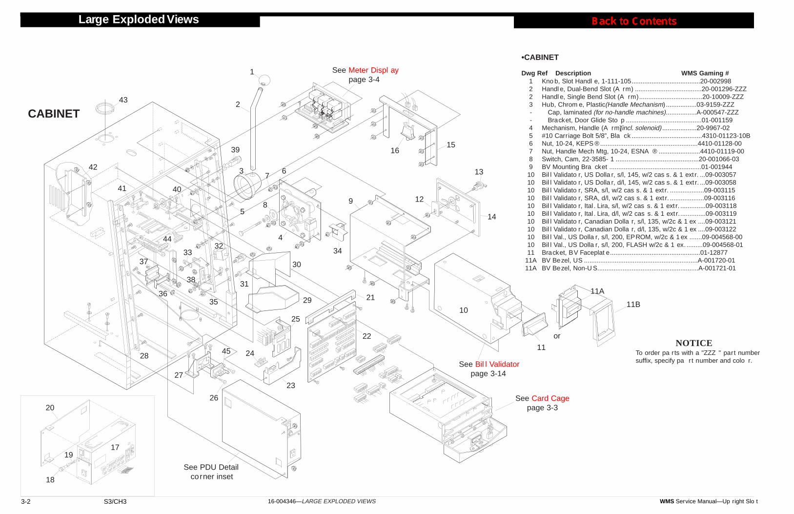
Large Exploded Views
3-2 S3/CH3 WMS Service Manual—Up right Slo t16-004346—LARGE EXPLODED VIEWS
Kno b, Slot Handl e, 1-111-105......................................20-002998Handl e, Dual-Bend Slot (A rm) .....................................20-001296-ZZZHandl e, Single Bend Slot (A rm)...................................20-10009-ZZZHub, Chrom e, Plastic (Handle Mechanism).................03-9159-ZZZ
Cap, laminated (for no-handle machines).................A-000547-ZZZBracket, Door Glide Sto p ..........................................01-001159
Mechanism, Handle (A rm)(incl. solenoid) ...................20-9967-02#10 Carriage Bolt 5/8”, Bla ck .......................................4310-01123-10BNut, 10-24, KEPS ® ......................................................4410-01128-00Nut, Handle Mech Mtg, 10-24, ESNA ® .......................4410-01119-00Switch, Cam, 22-3585- 1 ..............................................20-001066-03BV Mounting Bra cket ...................................................01-001944Bil l Validato r, US Dolla r, s/l, 145, w/2 cas s. & 1 ext r. ...09-003057Bil l Validato r, US Dolla r, d/l, 145, w/2 cas s. & 1 ext r. ...09-003058Bil l Validato r, SRA, s/l, w/2 cas s. & 1 ext r. ...................09-003115Bil l Validato r, SRA, d/l, w/2 cas s. & 1 ext r. ...................09-003116Bil l Validato r, Ital . Lira, s/l, w/2 cas s. & 1 ext r. ..............09-003118Bil l Validato r, Ital . Lira, d/l, w/2 cas s. & 1 ext r...............09-003119Bil l Validato r, Canadian Dolla r, s/l, 135, w/2c & 1 ex ....09-003121Bil l Validato r, Canadian Dolla r, d/l, 135, w/2c & 1 ex ....09-003122Bil l Val., US Dolla r, s/l, 200, EPROM, w/2c & 1 ex .......09-004568-00Bil l Val., US Dolla r, s/l, 200, FLASH w/2c & 1 ex. .........09-004568-01Bracket, BV Faceplat e..................................................01-12877BV Bezel, US ...............................................................A-001720-01BV Bezel, Non-U S........................................................A-001721-01
NOTICETo order pa rts with a "ZZZ " part numbersuffix, specify pa rt number and colo r.
3
1
2
4
5
67
8 9
10
11
12
13
14
1516
17
18
19
20
21
22
23
24
25
26
27
28
29
30
31
3233 34
3536
37
38
39
4041
42
43
44
1223--456789
1010101010101010101011
11A11A
45
CABINET
See Meter Displ aypage 3-4
See Card Cagepage 3-3
See Bil l Validatorpage 3-14
See PDU Detailcorner inset
•CABINET
Dwg Ref Description WMS Gaming #
11A
or
11B
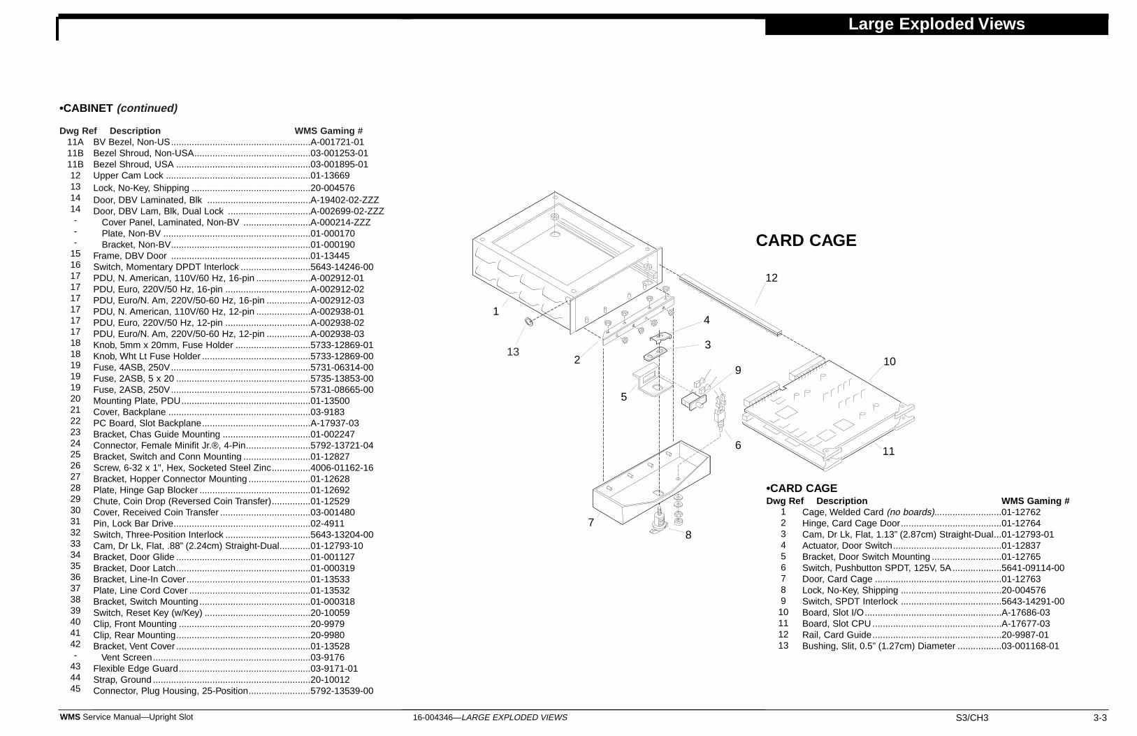
Large Exploded Views
16-004346—LARGE EXPLODED VIEWS S3/CH3 3-3WMS Service Manual—Upright Slot
BV Bezel, Non-US......................................................A-001721-01Bezel Shroud, Non-USA.............................................03-001253-01Bezel Shroud, USA ....................................................03-001895-01Upper Cam Lock ........................................................01-13669Lock, No-Key, Shipping ..............................................20-004576Door, DBV Laminated, Blk ........................................A-19402-02-ZZZDoor, DBV Lam, Blk, Dual Lock ................................A-002699-02-ZZZ
Cover Panel, Laminated, Non-BV ..........................A-000214-ZZZPlate, Non-BV .........................................................01-000170Bracket, Non-BV......................................................01-000190
Frame, DBV Door ......................................................01-13445Switch, Momentary DPDT Interlock ...........................5643-14246-00PDU, N. American, 110V/60 Hz, 16-pin .....................A-002912-01PDU, Euro, 220V/50 Hz, 16-pin .................................A-002912-02PDU, Euro/N. Am, 220V/50-60 Hz, 16-pin .................A-002912-03PDU, N. American, 110V/60 Hz, 12-pin .....................A-002938-01PDU, Euro, 220V/50 Hz, 12-pin .................................A-002938-02PDU, Euro/N. Am, 220V/50-60 Hz, 12-pin .................A-002938-03Knob, 5mm x 20mm, Fuse Holder .............................5733-12869-01Knob, Wht Lt Fuse Holder ..........................................5733-12869-00Fuse, 4ASB, 250V......................................................5731-06314-00Fuse, 2ASB, 5 x 20 ....................................................5735-13853-00Fuse, 2ASB, 250V......................................................5731-08665-00Mounting Plate, PDU..................................................01-13500Cover, Backplane .......................................................03-9183PC Board, Slot Backplane..........................................A-17937-03Bracket, Chas Guide Mounting ..................................01-002247Connector, Female Minifit Jr.®, 4-Pin.........................5792-13721-04Bracket, Switch and Conn Mounting ..........................01-12827Screw, 6-32 x 1", Hex, Socketed Steel Zinc...............4006-01162-16Bracket, Hopper Connector Mounting ........................01-12628Plate, Hinge Gap Blocker ...........................................01-12692Chute, Coin Drop (Reversed Coin Transfer)...............01-12529Cover, Received Coin Transfer ...................................03-001480Pin, Lock Bar Drive.....................................................02-4911Switch, Three-Position Interlock .................................5643-13204-00Cam, Dr Lk, Flat, .88” (2.24cm) Straight-Dual............01-12793-10Bracket, Door Glide ....................................................01-001127Bracket, Door Latch....................................................01-000319Bracket, Line-In Cover ................................................01-13533Plate, Line Cord Cover ...............................................01-13532Bracket, Switch Mounting ...........................................01-000318Switch, Reset Key (w/Key) .........................................20-10059Clip, Front Mounting ...................................................20-9979Clip, Rear Mounting....................................................20-9980Bracket, Vent Cover ....................................................01-13528
Vent Screen.............................................................03-9176Flexible Edge Guard...................................................03-9171-01Strap, Ground .............................................................20-10012Connector, Plug Housing, 25-Position........................5792-13539-00
•CARD CAGEDwg Ref Description WMS Gaming #
Cage, Welded Card (no boards)..........................01-12762Hinge, Card Cage Door.......................................01-12764Cam, Dr Lk, Flat, 1.13” (2.87cm) Straight-Dual...01-12793-01Actuator, Door Switch..........................................01-12837Bracket, Door Switch Mounting ...........................01-12765Switch, Pushbutton SPDT, 125V, 5A ...................5641-09114-00Door, Card Cage .................................................01-12763Lock, No-Key, Shipping .......................................20-004576Switch, SPDT Interlock .......................................5643-14291-00Board, Slot I/O.....................................................A-17686-03Board, Slot CPU ..................................................A-17677-03Rail, Card Guide..................................................20-9987-01Bushing, Slit, 0.5” (1.27cm) Diameter .................03-001168-01
CARD CAGE
11A11B11B12131414---
151617171717171718181919192021222324252627282930313233343536373839404142-
434445
12345678910111213
1
23
4
5
6
78
910
11
12
•CABINET (continued)
Dwg Ref Description WMS Gaming #
13
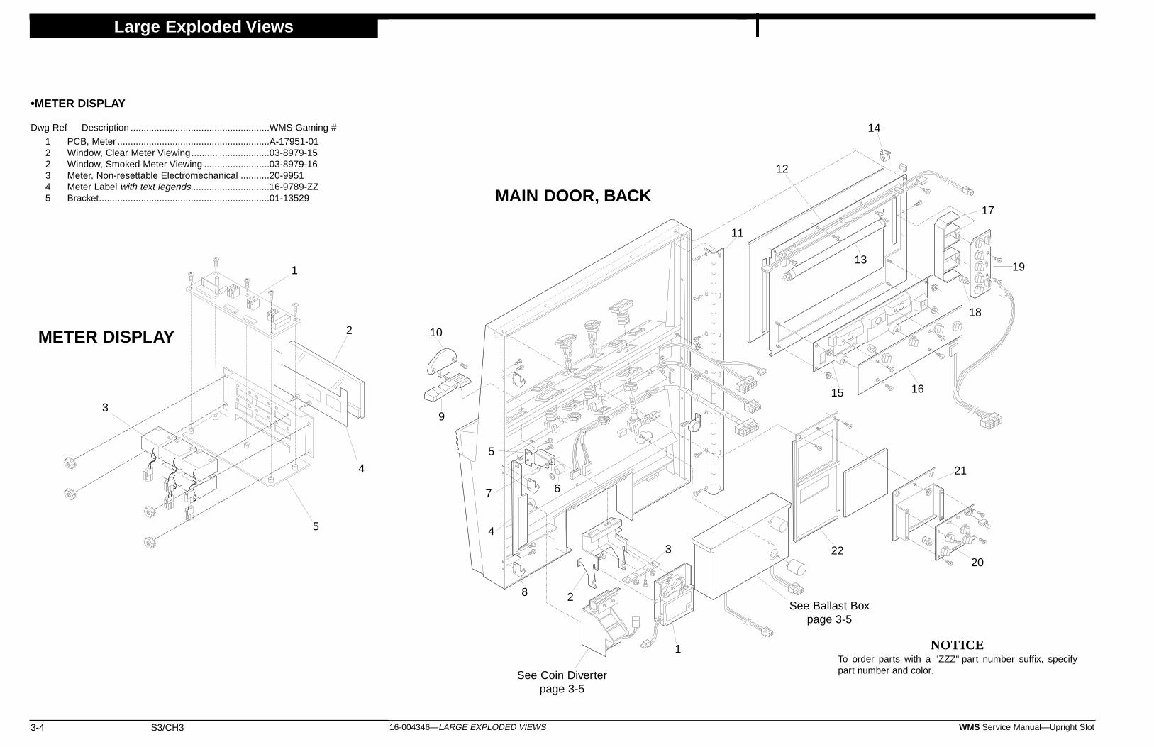
Large Exploded Views
3-4 S3/CH3 WMS Service Manual—Upright Slot16-004346—LARGE EXPLODED VIEWS
NOTICETo order parts with a "ZZZ" part number suffix, specifypart number and color.
METER DISPLAY
PCB, Meter ..........................................................A-17951-01Window, Clear Meter Viewing.......... ...................03-8979-15Window, Smoked Meter Viewing .........................03-8979-16Meter, Non-resettable Electromechanical ...........20-9951Meter Label with text legends..............................16-9789-ZZBracket.................................................................01-13529
122345
1
2
3
4
5
1
2
3
4
5
67
8
9
10
11
12
13
14
15 16
17
18
19
20
21
22
MAIN DOOR, BACK
See Coin Diverterpage 3-5
See Ballast Boxpage 3-5
•METER DISPLAY
Dwg Ref Description .....................................................WMS Gaming #

16-004346—LARGE EXPLODED VIEWS S3/CH3 3-5WMS Service Manual—Upright Slot
Chute, Receiver/Diverter .... ........................................01-13527Solenoid, Diverter........................................................A-16683Spring, .398” x 1.00” (10.1 x 25.4mm)–10T Comp .....10-473Chute, Diverter....................................... .....................01-13530Pin ...............................................................................02-5093Bearing, 1/8" (3mm) Nyliner .........................................20-8790-9Chute, Coin Return and Opto Mounting .....................01-001613Board, Quad Opto (Coin-In Optics).............................A-18097-00
Board, Hex Opto (Coin-In Optics)............................A-18097-01Cover, Opto Board Protector.......................................03-001612E-Ring, 1/8" (3mm) Shaft .............................................20-8712-12
COIN DIVERTER
12345678-910
1
2
9
8
7
6
4
3
10
BALLAST BOX
1
4
5
3
2
Large Exploded Views
•COIN DIVERTER
Dwg Ref Description WMS Gaming #
5
Box, Lamp Ballast/Starter .......................................01-12787Ballast, 50/60 Hz, 120V, 0.145A, 4-8W ..................5610-13545-00Ballast, 15w, 120v, 50/60hz ....................................5610-14210-00Starter, 4-22W (w/capacitor) Fluor..........................20-002780Starter Socket .........................................................20-9849
Comparator, CC-16D-Inhibit, US 5¢/25¢ Coin,Italian 500 L Coin, Sigma Tkn, 66160120 ...........09-42000-1
Comparator, CC-16D-Inhibit,US $1 Coin, 66160116 ........................................09-42000-2
Comparator, CC-16D-Inhibit,US 50¢ Coin/Token, Can. $1, 66160118 .............09-42000-3
Comparator, CC-16D-Inhibit, SA 1-Rand Cn .........09-42000-4Comparator, CC-16D-Inhibit, 50¢ Coin Wide .........09-42000-6Comparator, CC-16D-Inhibit, 10¢ Token ................09-42000-7Comparator, NRI, Canadian 5¢ .............................09-002019-03Comparator, NRI, Canadian 25¢............................09-002019-04Comparator, NRI, Canadian $1 .............................09-002019-06Comparator, NRI, Canadian $2 .............................09-002019-07Comparator, Condor, Prog, CN101-1.....................09-004098*Comparator, Smart Mark,......................................09-004584-XX*The XX suffix indicates casino and denomination specifications.**Coin Mech, IDX, Dia. 0-1.003 ...............................09-004659-XXX**Coin Mech, IDX, Dia. 1.004-1.130 ........................09-004660-XXX**Coin Mech, IDX, Dia. 1.131-1.255 ........................09-004661-XXX**Coin Mech, IDX, Dia. 1.256-1.355 ........................09-004662-XXX**Coin Mech, IDX, Dia. 1.356-1.475 ........................09-004663-XXX**Replace the XXX with the appropriate numbers for your coinmechanism. Refer to chapter 3 page 6 for reference legend. Bracket,Coin Comparator Mounting .....................................01-002133-02Tool, Canadian $1 Coin Comp Alignment ..............01-13676-05Tool, Canadian $2 Coin Comp Alignment ..............01-13676-11Tool, Emperyal® Token Comp Alignment...............01-13676-13Tool, Italian 500 Lire Coin Comp Alignment...........01-13676-12Tool, Italian 2,000 Lire Coin Comp Alignment........01-13676-10Tool, SA 1-Rand Coin Comp Alignment ................01-13676-07Tool, SA 1-Rand Token Comp Alignment ..............01-13676-08Tool, Sigma® Token Comp Alignment....................01-13676-14Tool, US/Canadian 5¢ Cn Comp Alignment...........01-13676-03Tool, US/Canadian 25¢ Cn Comp Alignment.........01-13676-02Tool, US 50¢ Coin Comp Alignment ......................01-13676-04Tool, US 50¢ Token Comp Alignment.....................01-13676-06Tool, US $1 Token Comp Alignment ......................01-13676-01Bracket, Door Switch Actuator ...............................01-000481Bracket, Door Cam.................................................01-001128Roller, Door Cam....................................................02-001129Pin, Door Cam Roller .............................................02-001130
E-Ring, 1/4" (6mm) Shaft ......................................20-8712-25Door Latch plate.....................................................01-12782Entry, Front of Coin (Universal) ..............................21-000669-ZZZEntry, Back of US/Canadian 5¢ Coin .....................21-000670-01ZZZEntry, Back of US/Canadian 25¢ Coin ...................21-000670-02ZZZEntry, Back of US 50¢ Coin....................................21-000670-03ZZZEntry, Back of US $1 Token....................................21-000670-04ZZZEntry, Back of SA 1R Coin .....................................21-000670-06ZZZEntry, Back of Canadian $1 Coin ...........................21-000670-07ZZZEntry, Back of US 50¢ Token..................................21-000670-08ZZZEntry, Back of 2,000 Lire Token .............................21-000670-11ZZZEntry, Back of $2 Canadian Coin ...........................21-000670-12ZZZEntry, Back of Italian 500 Lire Coin........................21-000670-13ZZZ
Entry, Back of Emperyl Token..................................21-000670-14ZZZEntry, Back of Sigma Coin ..............21-000670-15ZZZEntry, Back of Windsor 50¢ Coin .............................21-000670-16ZZZEntry, Back of Windsor $1 Token ...........................21-000670-17ZZZEntry, Back of Windsor $2 Token ...........................21-000670-18ZZZHinge, Door Mounting ............................................01-12531
Hinge Plate .........................................................01-12692Panel, Reel Display Mounting ................................01-002844Tube, 12" (31cm)/8W Reel Fluorescent .................24-8833Tube, 12" (31cm)/8W Reel Fluor Black Light .........24-8843Socket, Mini Bi-Pin Fluorescent .............................24-8841Box, LED Display Shadow .....................................03-8973PC Board, LED Display..........................................A-17382-01Box, Payline Shadow..............................................01-12661Bulb, #555, 6.3V/250mA (Wedge Base) ................24-8768PC Board, Payline Lamp ........................................A-18087-00PC Board, Bill Validator Lamp (4 Lamp) ................A-18088-01
Shadow Box (4 Lamp) ........................................03-002373Bracket, BV Display Board Mounting .....................01-00680Panel, BV Display Mounting, Beak ........................01-12779-ZZZ
Panel, No BV Display Mounting, Beak ...............01-12779-01-ZZZPanel, BV Display Mounting, Bezel ....................01-001183-01ZZZPanel, No BV Display Mounting, Bezel...............01-001183-02ZZZ
1
1
1
111111111
11111
233333333333334567-89
10101010101010101010
101010101011-
12131314151617181920-
2122---
12345
•BALLAST BOX
Dwg Ref Description WMS Gaming #
•MAIN DOOR, BACK
Dwg Ref Description WMS Gaming #
•MAIN DOOR, BACK (continued)
Dwg Ref Description WMS Gaming #
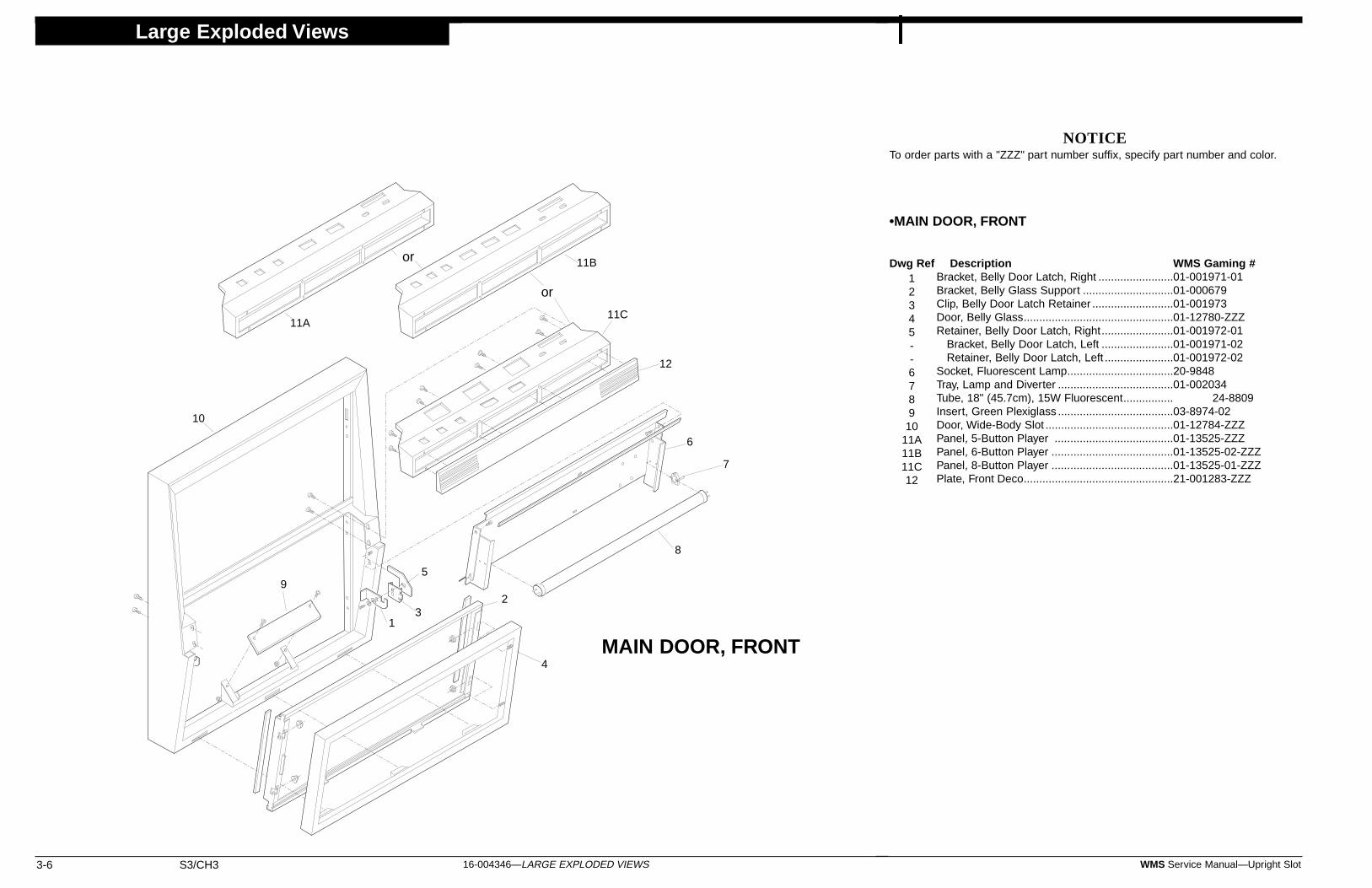
Large Exploded Views
3-6 S3/CH3 WMS Service Manual—Upright Slot16-004346—LARGE EXPLODED VIEWS
•MAIN DOOR, FRONT
Dwg Ref Description WMS Gaming #Bracket, Belly Door Latch, Right ........................01-001971-01Bracket, Belly Glass Support .............................01-000679Clip, Belly Door Latch Retainer ..........................01-001973Door, Belly Glass................................................01-12780-ZZZRetainer, Belly Door Latch, Right.......................01-001972-01
Bracket, Belly Door Latch, Left .......................01-001971-02Retainer, Belly Door Latch, Left ......................01-001972-02
Socket, Fluorescent Lamp..................................20-9848Tray, Lamp and Diverter .....................................01-002034Tube, 18" (45.7cm), 15W Fluorescent................ 24-8809Insert, Green Plexiglass .....................................03-8974-02Door, Wide-Body Slot .........................................01-12784-ZZZPanel, 5-Button Player ......................................01-13525-ZZZPanel, 6-Button Player .......................................01-13525-02-ZZZPanel, 8-Button Player .......................................01-13525-01-ZZZPlate, Front Deco................................................21-001283-ZZZ
NOTICETo order parts with a "ZZZ" part number suffix, specify part number and color.
1
23
4
5
6
7
8
9
10
11A
11B
11C
12
12345--678910
11A11B11C12
MAIN DOOR, FRONT
or
or

Large Exploded Views
16-004346—LARGE EXPLODED VIEWS S3/CH3 3-7WMS Service Manual—Upright Slot
8
•DOTMATION BOX
Dwg Ref Description WMS Gaming #Board, Dotmation Controller PC .........................A-000541-01Bracket, Wide Body Dotmation ...........................01-001309Cable, Dotmation Panel to Controller..................5797-001293-00Chassis, Dotmation .............................................01-000988Display, 192 x 64 Dot Matrix ..............................5901-001023-00Fuse, 5 x 20mm, 4A, 250V .................................5731-14094-00Insulator, Dotmation Power Supply .....................03-001134Rail, Bottom Dotmation .......................................01-000989Rail, Top Dotmation.............................................01-001481Supply, 12V/110W Power ...................................20-001292
1
123456789
10
8
2
7
10
3 6
5
9
4DOTMATION BOX
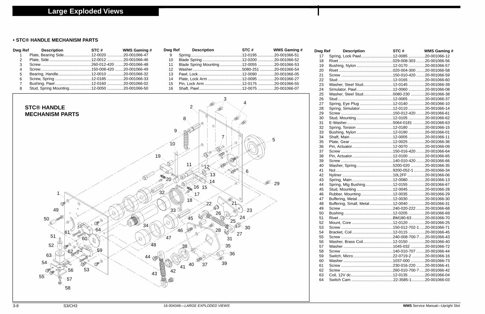
Large Exploded Views
3-8 S3/CH3 WMS Service Manual—Upright Slot16-004346—LARGE EXPLODED VIEWS
Spring, Lock Pawl.............................12-0085 ...............20-001066-12Rivet .................................................029-008-303 ........20-001066-56Bushing, Nylon .................................12-0170 ...............20-001066-57Rivet .................................................020-004-300 ........20-001066-58Screw ...............................................150-010-420 ........20-001066-59Stud ..................................................12-0165 ...............20-001066-60Washer, Steel Stud...........................12-0145 ...............20-001066-39Simulator, Pawl.................................12-0060 ...............20-001066-08Washer, Steel Stud...........................0080-230 .............20-001066-38Stud ..................................................12-0065 ...............20-001066-37Spring, Eye Plug ..............................12-0140 ...............20-001066-10Spring, Simulator..............................12-0110 ...............20-001066-14Screw ...............................................150-012-420 ........20-001066-61Stud, Mounting .................................12-0105 ...............20-001066-62E-Washer..........................................5064-0181 ...........20-001066-63Spring, Torsion .................................12-0180 ...............20-001066-15Bushing, Nylon .................................12-0190 ...............20-001066-01Shaft, Main .......................................12-0005 ...............20-001066-11Plate, Gear .......................................12-0025 ...............20-001066-36Pin, Actuator.....................................12-0070 ...............20-001066-09Screw ...............................................150-016-420 ........20-001066-64Pin, Actuator.....................................12-0100 ...............20-001066-65Screw ...............................................140-010-420 ........20-001066-66Washer, Spring.................................5200-020 .............20-001066-35Nut....................................................9200-052-1 ..........20-001066-34Nyliner ..............................................10L2FF ................20-001066-06Spring, Main .....................................12-0080 ...............20-001066-13Spring, Mtg Bushing.........................12-0155 ...............20-001066-67Stud, Mounting .................................12-0045 ...............20-001066-28Rubber, Mounting.............................12-0035 ...............20-001066-29Buffering, Metal ................................12-0030 ...............20-001066-30Buffering, Small, Metal .....................12-0040 ...............20-001066-31Screw ...............................................240-020-222 ........20-001066-68Bushing ............................................12-0205 ...............20-001066-69Rivet .................................................BM180-63 ............20-001066-70Mount, Core .....................................12-0120 ...............20-001066-25Screw ...............................................150-012-702-1 .....20-001066-71Bracket, Coil .....................................12-0115 ...............20-001066-45Screw ...............................................240-008-700-7 .....20-001066-43Washer, Brass Coil...........................12-0150 ...............20-001066-40Washer .............................................1045-032 .............20-001066-72Screw ...............................................140-010-707 ........20-001066-44Switch, Micro....................................22-0719-2 ............20-001066-16Washer .............................................1037-000 .............20-001066-73Screw ...............................................230-016-220 ........20-001066-41Screw ...............................................260-010-700-7 .....20-001066-42Coil, 12V dc......................................12-0135 ...............20-001066-04Switch Cam ......................................22-3585-1............20-001066-03
STC® HANDLEMECHANISM PARTS
• STC® HANDLE MECHANISM PARTS
Dwg Ref Description STC # WMS Gaming #Plate, Bearing Side.........................12-0020 ...............20-001066-47Plate, Side ......................................12-0012 ...............20-001066-46Screw..............................................260-012-420 ........20-001066-48Screw..............................................150-008-420 ........20-001066-49Bearing, Handle..............................12-0010 ...............20-001066-32Screw, Spring .................................12-0185 ...............20-001066-33Bushing, Pawl .................................12-0160 ...............20-001066-02Stud, Spring Mounting....................12-0050 ...............20-001066-50
Spring...............................................12-0195 ...............20-001066-51Blade Spring ....................................12-0200 ...............20-001066-52Blade Spring Mounting ....................12-0055 ...............20-001066-53Washer.............................................5080-251 .............20-001066-54Pawl, Lock........................................12-0090 ...............20-001066-05Plate, Lock Arm ...............................12-0095 ...............20-001066-27Pin, Lock Arm ..................................12-0175 ...............20-001066-55Shaft, Pawl .......................................12-0075 ...............20-001066-07
12345678
910111213141516
171819202122232425262728293031323334353637383940414243444546474849505152535455565758596061626364
Dwg Ref Description STC # WMS Gaming # Dwg Ref Description STC # WMS Gaming #
1
2
34
21
23
16
25
17
15
27
2218
5
20
6
14
26
7
13
19
8
12
9
10
11
29
24
28
40414243
44
45
46
47
48
49
35
36
37
38
39
30
31
32
33
3450
51
52
53
54
5556
57
58
59
6061
6263
64
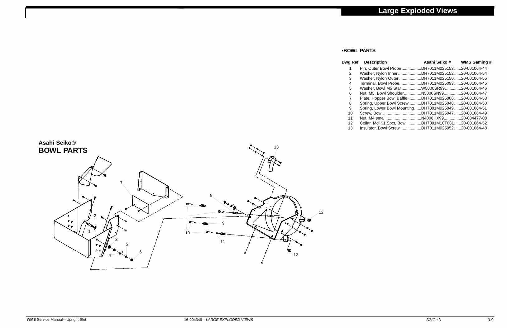
Large Exploded Views
16-004346—LARGE EXPLODED VIEWS S3/CH3 3-9WMS Service Manual—Upright Slot
Pin, Outer Bowl Probe.................DH7011M025153 ......20-001064-44Washer, Nylon Inner ....................DH7011M025152 ......20-001064-54Washer, Nylon Outer ...................DH7011M025150 ......20-001064-55Terminal, Bowl Probe...................DH7011M025093 ......20-001064-45Washer, Bowl M5 Star .................W5000SR99..............20-001064-46Nut, M5, Bowl Shoulder...............N5000SN99...............20-001064-47Plate, Hopper Bowl Baffle............DH7011M025006 ......20-001064-53Spring, Upper Bowl Screw...........DH7011M025048 ......20-001064-50Spring, Lower Bowl Mounting......DH7001M025049 ......20-001064-51Screw, Bowl .................................DH7011M025047 ......20-001064-49Nut, M4 small...............................N4006HX99...............20-004477-08Collar, Mdl $1 Spcr, Bowl ...........DH7001M10T081......20-001064-52Insulator, Bowl Screw ..................DH7011M025052 ......20-001064-48
Asahi Seiko®BOWL PARTS
123456789
10111213
1
2
3
4
5
6
7
8
9
10
11
12
13
12
•BOWL PARTS
Dwg Ref Description Asahi Seiko # WMS Gaming #

Large Exploded Views
3-10 S3/CH3 WMS Service Manual—Upright Slot16-004346—LARGE EXPLODED VIEWS
Disk, 25¢ Token .........................DH7001M025033 ..........20-001064-19Disk, $1 Token ...........................DH7001M10T033 ..........20-001064-20Disk, 50¢ Token .........................DH7001M050033 ..........20-001064-59Spring, Stirring...........................DH7001M025034 ..........20-001064-21Spring, Cover Mounting.............DH7001M025035 ..........20-001064-22Spring, Cover Holder.................DH7001M025036 ..........20-001064-23Spring, Disk ...............................DH7001M025037 ..........20-001064-24Washer, 4 x 15 x 1.0 .................W4015FW10 .................20-001064-25Screw, M4 x 8, IRG, Lg Hd .......S4008LH99 ...................20-001064-26Bearing with Retainer ................DH7001M025402 ..........20-001064-27Washer, Roller Lever .................DH7001M025064 ..........20-001064-28Spacer, Coin Guide ...................DH7001M025065 ..........20-001064-29Plate, Jump Rubber Adj ............DH7001M025070 ..........20-001064-30Rubber, 5¢ Jump .......................DH7001M005071 ..........20-001064-31Rubber, 25¢ Jump .....................DH7001M025071 ..........20-001064-32Rubber, $1 Jump .......................DH7001M10T071 ..........20-001064-33Bracket, Motor ...........................DH7001M025079 ..........20-001064-36Armature with Stop....................DH7001M025082 ..........20-001064-37Lever, Motor Brake ....................DH7001M025083 ..........20-001064-38Spring, Brake.............................DH7001M025084 ..........20-001064-39Stop, Brake................................DH7001M025085 ..........20-001064-40Separator, Rubber Coin.............DH7001M025073 ..........20-001064-41Support, 5¢ & 25¢ Retainer ......DH7001M020074 ..........20-001064-42Support, $1 Token Retainer.......DH7001M10T074 ..........20-001064-43Support, 50¢ Retainer ...............DH7001M050074 ..........20-001064-58Screw, M4 x 14, w/SW ..............S4014RHSW.................20-001064-66Screw M3 x 4 w/SW ..................S3004RHSW.................20-001064-67Bolt M4 x 25 SS ........................B4025HXSS ..................20-001064-68Hpr Knife Shim, 4x8x0.2mm......W4008FW02 .................20-001064-69Hpr Knife Shim, 4x8x0.3mm......W4008FW03 .................20-001064-70Hpr Knife Shim, 4x8x0.5mm......W4008FW05 .................20-001064-71Hpr Knife Shim, 4x8x0.8mm......W4008FW08 .................20-001064-72Bolt M4 x 12 ..............................B4012HX99 ...................20-001064-73Screw, M4 x 25, SS Lrg Hd.......S4025LHSS...................20-001064-74Screw, M4 x 12, Lrg Hd.............S4012LH99 ...................20-001064-75Screw M3 x 8 w/SW FW ...........S3008RHSF ..................20-001064-76
HOPPER MOTOR ASSEMBLY ..............AS-USA # .....................WMS Gaming #115VAC, w/Harness ................................DH7561P025008...........20-004477-11
HOPPERS, COMPLETEHopper, Complete 5¢ Coin...................... ......................................A-18267Hopper, Complete 25¢ Coin.................... ......................................A-18291Hopper, Complete 50¢ Coin.................... ......................................A-001305Hopper, Complete $1 Canadian Coin ............................................A-001987Hopper, Complete $1 US Token ....................................................A-18102
Pin, Motor Drive.......................DH7001M025007 ..........20-001064-01Motor, 115V, Gearbox..............DH7001M025008 ..........20-001064-02Sensor, Proximity.....................DH7001P025013...........20-001064-03Lever, Steel Roller ...................DH7001P025015...........20-001064-04Spring, Roller Lever.................DH7001M025016 ..........20-001064-05Lever, Pin Roller ......................DH7001M025017 ..........20-001064-06Lever, Bridge Roller.................DH7001M025018 ..........20-001064-07E-Ring......................................W3000ER99 ..................20-001064-08Knife, 5¢ ..................................DH7001M005025 ..........20-001064-09Knife, 25¢ ................................DH7001M025025 ..........20-001064-10Knife, $1 Token ........................DH7001M10T025 ..........20-001064-11Knife, 50¢ Coin........................DH7001M050025 ..........20-001064-56
Knife, Canadian Loonie $1 ......DH7001M10T025 ..........20-001064-61Knife, 1 Rand Token ................DH7001M027025 ..........20-001064-65Boss, Plastic ............................DH7001M025026 ..........20-001064-12Screw, Bevel ............................DH7001M025027 ..........20-001064-13Coin Guide, 5¢/25¢ .................DH7001M025028 ..........20-001064-14Coin Guide, $1Token ...............DH7001M010T028 ........20-001064-15Coin Guide, 50¢.......................DH7001M050028 ..........20-001064-57Coin Cover (5¢/25¢) ................DH7001M025029 ..........20-001064-16Coin Cover ($1 Token) .............DH7001M010T029 ........20-001064-17Cover, 5¢ Jump Rbr.................DH7001M005072 ..........20-001064-34Cover, 25¢ & $1 Jump Rbr ......DH7001M025072 ..........20-001064-35Disk, 5¢ Token .........................DH7001M005033 ..........20-001064-18
Asahi Seiko®HOPPER PARTS
NOTICETo order parts with a "ZZZ" part number suffix, specify part number and color.
123456789999
• HOPPER PARTS
Dwg Ref Description AS-USA # WMS Gaming #99
10111212121313131314
141414151617181920212223242525252627282930313232323334353636363637383940
Dwg Ref Description AS-USA # WMS Gaming # Dwg Ref Description AS-USA # WMS Gaming #
1
13 12
14
15
16
1817
19
20
21
8
7
9
1011
32
4
5633
3234
11 10
35
28
27
29
30
31
2322
24
252636
37
38
40
39
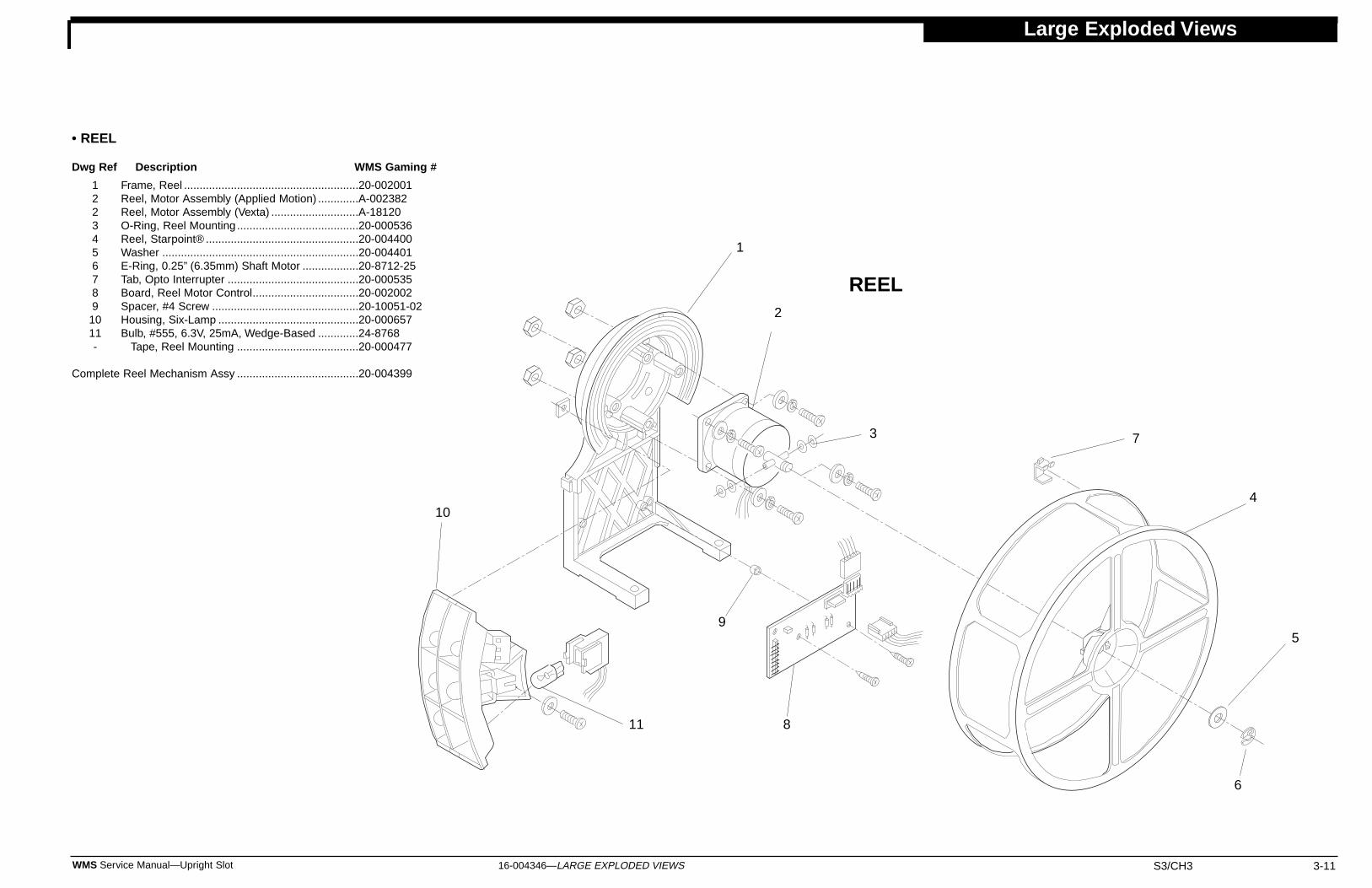
Large Exploded Views
16-004346—LARGE EXPLODED VIEWS S3/CH3 3-11WMS Service Manual—Upright Slot
Frame, Reel ........................................................20-002001Reel, Motor Assembly (Applied Motion) .............A-002382Reel, Motor Assembly (Vexta) ............................A-18120O-Ring, Reel Mounting .......................................20-000536Reel, Starpoint® .................................................20-004400Washer ...............................................................20-004401E-Ring, 0.25” (6.35mm) Shaft Motor ..................20-8712-25Tab, Opto Interrupter ..........................................20-000535Board, Reel Motor Control..................................20-002002Spacer, #4 Screw ...............................................20-10051-02Housing, Six-Lamp .............................................20-000657Bulb, #555, 6.3V, 25mA, Wedge-Based .............24-8768
Tape, Reel Mounting .......................................20-000477
Complete Reel Mechanism Assy .......................................20-004399
1223456789
1011-
1
2
3
4
5
6
7
8
9
10
11
• REEL
Dwg Ref Description WMS Gaming #
REEL
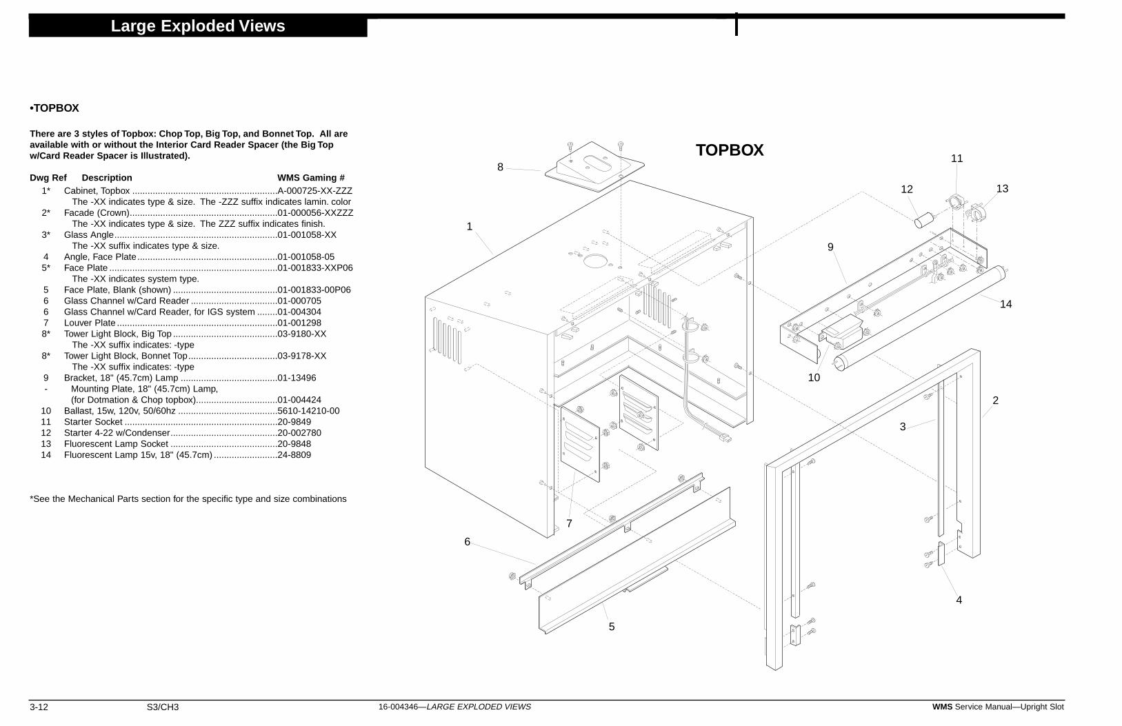
Large Exploded Views
3-12 S3/CH3 WMS Service Manual—Upright Slot16-004346—LARGE EXPLODED VIEWS
Cabinet, Topbox .........................................................A-000725-XX-ZZZThe -XX indicates type & size. The -ZZZ suffix indicates lamin. color
Facade (Crown)..........................................................01-000056-XXZZZThe -XX indicates type & size. The ZZZ suffix indicates finish.
Glass Angle................................................................01-001058-XXThe -XX suffix indicates type & size.
Angle, Face Plate.......................................................01-001058-05Face Plate ..................................................................01-001833-XXP06
The -XX indicates system type.Face Plate, Blank (shown) .........................................01-001833-00P06Glass Channel w/Card Reader ..................................01-000705Glass Channel w/Card Reader, for IGS system ........01-004304Louver Plate ...............................................................01-001298Tower Light Block, Big Top .........................................03-9180-XX
The -XX suffix indicates: -typeTower Light Block, Bonnet Top...................................03-9178-XX
The -XX suffix indicates: -typeBracket, 18" (45.7cm) Lamp ......................................01-13496
Mounting Plate, 18" (45.7cm) Lamp,(for Dotmation & Chop topbox)................................01-004424
Ballast, 15w, 120v, 50/60hz .......................................5610-14210-00Starter Socket ............................................................20-9849Starter 4-22 w/Condenser..........................................20-002780Fluorescent Lamp Socket ..........................................20-9848Fluorescent Lamp 15v, 18" (45.7cm) .........................24-8809
*See the Mechanical Parts section for the specific type and size combinations
1*
2*
3*
45*
56678*
8*
9-
1011121314
•TOPBOX
There are 3 styles of Topbox: Chop Top, Big Top, and Bonnet Top. All areavailable with or without the Interior Card Reader Spacer (the Big Topw/Card Reader Spacer is Illustrated).
Dwg Ref Description WMS Gaming #
1
2
3
4
5
6
7
8
9
10
11
1312
14
TOPBOX
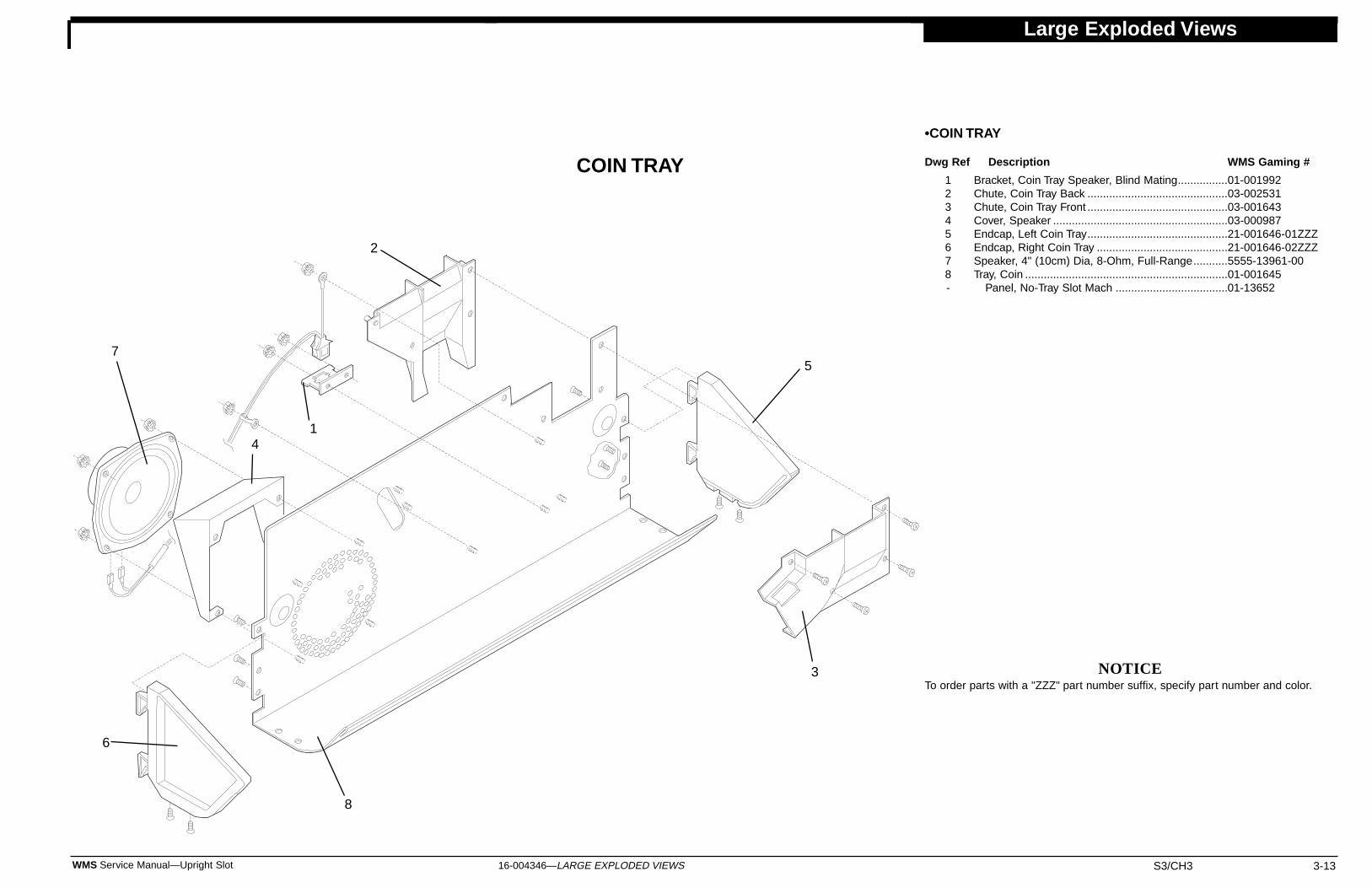
Large Exploded Views
16-004346—LARGE EXPLODED VIEWS S3/CH3 3-13WMS Service Manual—Upright Slot
7
2
41
5
6
3
8
Bracket, Coin Tray Speaker, Blind Mating................01-001992Chute, Coin Tray Back .............................................03-002531Chute, Coin Tray Front .............................................03-001643Cover, Speaker ........................................................03-000987Endcap, Left Coin Tray.............................................21-001646-01ZZZEndcap, Right Coin Tray ..........................................21-001646-02ZZZSpeaker, 4" (10cm) Dia, 8-Ohm, Full-Range...........5555-13961-00Tray, Coin .................................................................01-001645
Panel, No-Tray Slot Mach ....................................01-13652
NOTICETo order parts with a "ZZZ" part number suffix, specify part number and color.
12345678-
•COIN TRAY
Dwg Ref Description WMS Gaming #COIN TRAY

Tool, Single DBV Extraction, US .............047690..........20-10034-01Tool, Single DBV Extract, Non-US ..........050781..........20-001717-01Tool, Dual DBV Extraction, US................049178..........20-10034-02Tool, Dual DBV Extract, Non-US.............050779..........20-001717-02
9A9A9B9B
Large Exploded Views
3-14 S3/CH3 WMS Service Manual—Upright Slot16-004346—LARGE EXPLODED VIEWS
Cam, JCM Extractor, Single Lock............047605..........01-12855Cam, JCM Extractor, Double Lock ..........049177..........01-000156Cassette, JCM Black Stacker, US ...........049179..........01-000157Cassette, JCM Gold Stacker, US ............049180..........01-000158Cassette, JCM Silvr Stacker, Non-US .....050763..........01-001718-01Cassette, JCM Gold Stacker, Non-US.....050764..........01-001718-02Box, Type-G Bill .......................................047575..........20-001065-06Box, Type-B Bill........................................047576..........20-001065-07Bracket, Sw Mounting ....................................................01-002651Switch, Bare, Sub-mini SPDT........................................5647-14200-00
JCM 145 Bill Validator Head....................040676..........20-001065-11JCM 200 Bill Valid. Head w/EPROM .......040676..........20-004565-00JCM 200 Bill Valid. Head w/Flash............040676..........20-004565-01
V-Belt, Timing (BV Body) .....................040988..........20-001065-03Plate, BV Quick Release ...........................................20-001065-08
Mech, Push (Conveying) .........................037565..........20-001065-04Screw, Thumb..........................................046054..........20-001065-09
Nut, M-3 Cap........................................017202..........20-001065-10Stacker, SG .............................................048229..........20-001065-01
V-Belt, Timing (Conveyor) ....................040987..........20-001065-05
1-22222234
•BILL VALIDATOR/STACKER
Dwg Ref Description JCM# WMS Gaming #
555--67-8-
Dwg Ref Description JCM# WMS Gaming #
BILL VALIDATOR/STACKER
Dwg Ref Description JCM# WMS Gaming #
1
9B9A
8
7
65
43
2
or

16-004349—TABLES & DATA S6 1WMS Service Manual—Slot Machine
Tables & DataTilt Codes
No. ofBongs
0
12345
6-910
SituationSpeaker disconnected orsound circuit problemSystem is normalEPROM XU30 is badEPROM XU31 is badEPROM XU17 is badEPROM XU18 is badNot UsedBad Sound RAM U38,U39 or U40
Startup Sound Codes
• No LEDs light: Check PDU fusecontinuity.
• All LEDs light: Bad or loose CPUor I/O Board. Check EPROMs.
• DS1 is on. Another LED is off:Bad power supply.
I/O Board LEDs
Series0
123456789
Host Communications,Sound Volume; Demo,Cash and Credit Modes,Reel Speed, Etc.Input TestsOutput TestsHopper TestPay Table TestReel Strip TestDenomination SettingMaximum Hopper PayoutHopper Partial Pay LimitProgressive ID and Level
Subject
Administration Mode
CandleActivity
OffOn
Slow FlashOff
Fast FlashSlow Flash
CandleSection
Top
Bottom
Candle Codes
MeaningMachine is idleChange requestTilt or Jackpot ModeMain door closedMain door openJackpot
None
8
•Constantly ("8" neverappears): One powervoltage is absent.•After "8" clears: SystemOK.
•Briefly: System OK.•Constantly: BadEPROMS XU2 andXU3, or bad CPUBoard.
CPU Board 7-Segment DisplayDisplayedNumber Situation
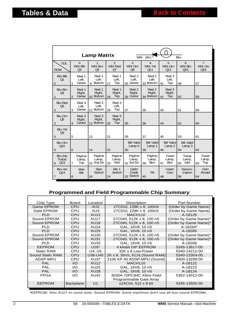
Tables & Data
2 S6 WMS Service Manual—Slot Machine16-004349—TABLES & DATA
Reel 1Left,
Center
Reel 1Right,Center
Reel 3Left,
Center
Reel 3Right,Center
PaylineLamp,Top
MaxBet
Reel 1Left,
Bottom
Reel 1Right,Bottom
Reel 3Left,
Bottom
Reel 3Right,Bottom
PaylineLamp,2nd Dn
SpinSwitch
Reel 1Left,Top
Reel 1Right,Top
Reel 3Left,Top
Reel 3Right,Top
PaylineLamp,Mid
Bet 1Switch
Reel 2Left,
Center
Reel 2Right,Center
Bill ValidLamp 0
PaylineLamp,3rd Dn
Cash/CreditSwitch
Reel 2Left,
Bottom
Reel 2Right,Bottom
Bill ValidLamp 1
PaylineLamp,Btm
Tilt
Reel 2Left,Top
Reel 2Right,Top
Bill ValidLamp 2
TowerLamp,Btm
InsertCoin
Bill ValidLamp 3
TowerLamp,Mid
Denom-ination
TowerLamp,Top
CoinAccept
Blu-BlkQ1
Blu-BrnQ2
Blu-RedQ5
Blu-OrnQ6
Blu-YelQ9
Blu-GrnQ10
Blu (NoTrace)Q13
Blu-VioQ14
COL
ROW
1
2
3
4
5
6
7
8
9
10
11
12
13
14
15
16
17
18
19
20
21
22
23
24
25
26
27
28
29
30
31
32
33
34
35
36
37
38
39
40
41
42
43
44
45
46
47
48
49
50
51
52
53
54
55
56
57
58
59
60
61
62
63
64
7Wht-Vio
Q16
6Wht-Blu
Q15
5Wht-Grn
Q12
4Wht-Yel
Q11
3Wht-Orn
Q8
2Wht-Red
Q7
1Wht-Brn
Q4
0Wht-Blk
Q3
0
1
2
3
4
5
6
7
Blu-Wht- (B+)Lamp Matrix
Chip TypeGame EPROMData EPROM
PLDSound EPROMSound EPROM
PLDPLD
Sound EPROMSound EPROM
PLDEEPROM
Static RAMSound Static RAM
ADSP-MPUPALPALPAL
FPGA
EEPROM
LocationXU2XU3
XU12XU17XU18XU24XU25XU30XU31XU33U26*
U4, U5U38-U40
XU37XU12XU25XU28XU42
U1
Part Number(Order by Game Name)(Order by Game Name)
A-18125(Order by Game Name)*(Order by Game Name)*
A-18264*A-18265
(Order by Game Name)*(Order by Game Name)*
A-182665345-13617-005340-14212-005340-13304-005400-13298-00
A-18122A-18123A-18124
5352-14012-00
5345-13920-00
Programmed and Field Programmable Chip Summary
Description27C010, 128K x 8, 100nS27C010, 128K x 8, 100nS
MACH11027C040, 512K x 8, 100 nS27C040, 512K x 8, 100 nS
GAL, 16V8, 10 nSGAL, 16V8, 10 nS
27C040, 512K x 8, 100 nS27C040, 512K x 8, 100 nS
GAL, 16V8, 10 nS4 kilobit DIP EEPROM
32K x 8 Low-Power2K x 8, 35nS, 6116 (Sound RAM)2105 KP 40 ADSP-MPU (Sound)
MACH110GAL, 16V8, 10 nSGAL, 16V8, 10 nS
3030A-70PC84C Xilinx FieldProgrammable Gate Array
x24C04, 512 x 8 bit
BoardCPUCPUCPUCPUCPUCPUCPUCPUCPUCPUCPUCPUCPUCPUI/OI/OI/OI/O
Backplane
*EEPROM: Also XU27 on some slots. Sound EPROM: Some machines don't use all four sound EPROMs.