upright with strut and plywood system - cmc€¦ · construction engineering ... installation notes...
TRANSCRIPT

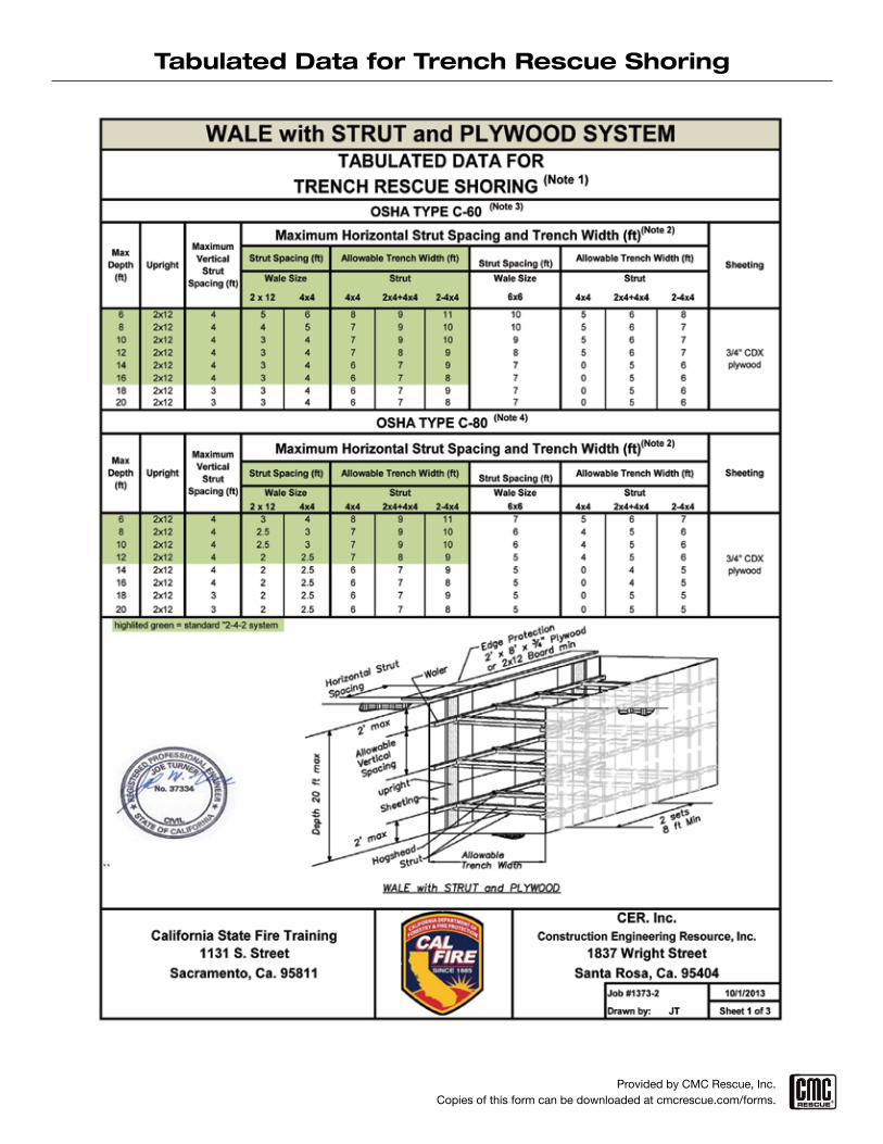
4x4 2x4+4x4 2-4x46 2x12 4 4 9 11 138 2x12 4 4 8 10 11
10 2x12 4 4 7 9 1012 2x12 4 4 7 8 914 2x12 4 4 6 7 916 2x12 4 4 6 7 818 2x12 3 4 6 7 920 2x12 3 4 6 7 8
4x4 2x4+4x4 2-4x4
6 2x12 4 4 8 10 118 2x12 4 4 7 8 10
10 2x12 4 4 6 7 912 2x12 4 4 6 7 814 2x12 3 3 6 7 916 2x12 3 3 6 7 818 2x12 2 2 7 8 920 2x12 2 2 6 7 9
highlited green = standard "2-4-2 system
Job #1373-1 10/1/2013
Drawn by: JT Sheet 1 of 3
TABULATED DATA FORTRENCH RESCUE SHORING(Note 1)
Maximum Vertical Strut Spacing (ft)
Upright
Max Depth (ft) Upright Maximum
Vertical Strut Spacing (ft)
Maximum horizontal Strut
Spacing (ft)
UPRIGHT with STRUT and PLYWOOD SYSTEM
SheetingStrut
California State Fire Training
Allowable Trench Width (ft)(Note 2)
Construction Engineering Resource, Inc.
OSHA TYPE C-60 (Note 3)
3/4" CDX plywood
3/4" CDX plywood
1131 S. Street
Allowable Trench Width (ft)(Note 2)
Strut SheetingMaximum
horizontal Strut Spacing (ft)
Max Depth (ft)
OSHA TYPE C-80 (Note 4)
CER, Inc.
1837 Wright StreetSanta Rosa, CA 95404Sacramento, CA 95811

Details
Job #1373-1 10/1/2013
Drawn by: JT Sheet 2 of 3
1131 S. Street
TABULATED DATA FORTRENCH RESCUE SHORING
UPRIGHT with STRUT and PLYWOOD SYSTEM
California State Fire Training1837 Wright Street
CER, Inc.Construction Engineering Resource, Inc.
Sacramento, Ca. 95811 Santa Rosa, CA 95404
Framing Notes-
1) Use only 1 wedge set, do not stack them.
2) General rule for nailing strut connections-use two toe-nails (total 4 nails) on both sides of strut.
3) Struts may also be cut-to-fit and driven in without wedges.
4) Struts may also be manufactured, see Note 11.
Installation Notes
1) Uprights may be nailed to plywood before or after setting plywood into excavation.
2) Move spoil pile and obstructions a minimum of 2 ft from trench edge and place edge protection before installing shoring.
3) Place ladder within 25 ft of work. Ladder must be secure and accessible.
4) While working off a ladder and until top strut is secured, workers may only work within waist level to lip of trench and must be tied off.
5) Remove struts from bottom to top. If there is sheeting movement when bottom strut is removed, leave shoring in place and bury or remove with power equipment from outside the trench.
Job #1373-1 10/1/2013
Drawn by: JT Sheet 3 of 3
Sacramento, Ca. 95811
TABULATED DATA FOR
Santa Rosa, CA 95404
TRENCH RESCUE SHORING
1837 Wright Street1131 S. Street
UPRIGHT with STRUT and PLYWOOD SYSTEM
California State Fire TrainingCER, Inc.
Construction Engineering Resource, Inc.
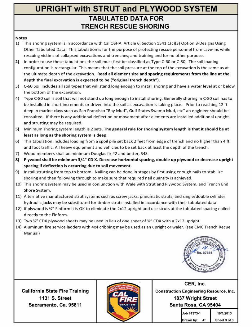
Notes 1) This shoring system is in accordance with Cal OSHA Article 6, Section 1541.1(c)(3) Option 3‐Designs Using
Other Tabulated Data. This tabulation is for the purpose of protecting rescue personnel from cave‐ins while rescuing victims of collapsed excavations and trenches, and training and for no other purpose.
2) In order to use these tabulations the soil must first be classified as Type C‐60 or C‐80. The soil loading configuration is rectangular. This means that the soil pressure at the top of the excavation is the same as at the ultimate depth of the excavation. Read all element size and spacing requirements from the line at the depth the final excavation is expected to be (“original trench depth”).
3) C‐60 Soil includes all soil types that will stand long enough to install shoring and have a water level at or below the bottom of the excavation.
4) Type C‐80 soil is soil that will not stand up long enough to install shoring. Generally shoring in C‐80 soil has to be installed in short increments or driven into the soil as excavation is taking place. Prior to reaching 12 ft deep in marine clays such as San Francisco "Bay Mud", Gulf States Swamp Mud, etc" an engineer should be consulted. If there is any additional deflection or movement after elements are installed additional upright and strutting may be required.
5) Minimum shoring system length is 2 sets. The general rule for shoring system length is that it should be at least as long as the shoring system is deep.
6) This tabulation includes loading from a spoil pile set back 2 feet from edge of trench and no higher than 4 ft and foot traffic. All heavy equipment and vehicles to be set back at least the depth of the trench.
7) Wood members shall be minimum Douglas fir #2 and better, S4S. 8) Plywood shall be minimum 3/4" CD X. Decrease horizontal spacing, double up plywood or decrease upright
spacing if deflection is occurring due to soil movement. 9) Install strutting from top to bottom. Nailing can be done in stages by first using enough nails to stabilize
shoring and then following through to make sure that required nail quantity is achieved. 10) This shoring system may be used in conjunction with Wale with Strut and Plywood System, and Trench End
Shore System. 11) Alternative manufactured strut systems such as screw jacks, pneumatic struts, and single/double cylinder
hydraulic jacks may be substituted for timber struts installed in accordance with their tabulated data. 12) If plywood is ¾” Finform it is OK to eliminate the 2x12 upright and use struts at the tabulated spacing nailed
directly to the Finform. 13) Two ¾” CDX plywood sheets may be used in lieu of one sheet of ¾” CDX with a 2x12 upright. 14) Aluminum fire service ladders with 4x4 cribbing may be used as an upright or waler. (see CMC Trench Recue
Manual)
Provided by CMC Rescue, Inc. Copies of this form can be downloaded at cmcrescue.com/forms.
Tabulated Data for Trench Rescue Shoring

Provided by CMC Rescue, Inc. Copies of this form can be downloaded at cmcrescue.com/forms.
Tabulated Data for Trench Rescue Shoring

Provided by CMC Rescue, Inc. Copies of this form can be downloaded at cmcrescue.com/forms.
Tabulated Data for Trench Rescue Shoring

Provided by CMC Rescue, Inc. Copies of this form can be downloaded at cmcrescue.com/forms.
Tabulated Data for Trench Rescue Shoring

Provided by CMC Rescue, Inc. Copies of this form can be downloaded at cmcrescue.com/forms.
Tabulated Data for Trench Rescue Shoring

Provided by CMC Rescue, Inc. Copies of this form can be downloaded at cmcrescue.com/forms.
Tabulated Data for Trench Rescue Shoring

Provided by CMC Rescue, Inc. Copies of this form can be downloaded at cmcrescue.com/forms.
Tabulated Data for Trench Rescue Shoring
Provided by CMC Rescue, Inc. Copies of this form can be downloaded at cmcrescue.com/forms.
Tabulated Data for Trench Rescue Shoring

Provided by CMC Rescue, Inc. Copies of this form can be downloaded at cmcrescue.com/forms.
Tabulated Data for Trench Rescue Shoring

Provided by CMC Rescue, Inc. Copies of this form can be downloaded at cmcrescue.com/forms.
Tabulated Data for Trench Rescue Shoring