upshot-knothole - defense technical information … iwo typical twu-story frame houses, without...
TRANSCRIPT

WT -792
UPSHOT-KNOTHOLENEVADA PROVING GROUNDS
March - June 1953
Project 21.2
EFF~'P'l -_l ATOMIC EXPLOSION ON TWO TYPICALTWO-6. 4 URYAND-BASEMENT WOOD-FRAME HOUSES
rl y
FEDERAL CIVIL DEFENSE ADMINISTRATIONWASHINGTON DAJC

tb.
WT-792
Report to the Test Director
EFFECTS OF AN ATOMIC EXPLOSION ONTWO TYPICAL TWO-STORY-AND-BASEMENTWOOD-FRAME HOUSES
By
Joseph B. Byrne*
Approved by: HAROLD L. GOODWIN Approved by: ROBERT L. COA8BSEDirector, Program 21 Director
Civil Effects Test Group
Federal Civil Defense AdministrationWashlinton, D. C.September 1953
1-2

ABSTRACT
Iwo typical twu-story frame houses, without uitlilties, weze located at 7500 and 3500 ftfrom Ground Zero of a 16.4-kt bom~b exploded at 300 ft &bove the ground. Exposure of thehouses was for public demonstration purposes and to study the gamnma-rudiation scatterand the effects of thermal radiation and blast an each house.
Both houses were furnished, and, In each, department-store mannequins were place' In thedining and living rooas. Film badges to measure gamma radiexlon were placed In layersthrough"i the house at 7500 ft and in the basement of the house at 3W0 ft. Visual inspectionand photography were utilizud to study thermal -radiation and blast effects.
Because of the heavy fall-oul of radio'active material in the area surrounding both housesand the resulting delay in recovering badges, initial gamma-radiation quantities could not bedetermined.
On the house at 75M01t, only the light-Cray painted abutters on the skide facing the detona-tion were scorched from thermal radiatiou. Mannequins were thrown abort, and same were se-verely damaged ky flying glass and debris. The house was badly damaged inside, although, withthe exception of brokn windows and doors, the exterior appeared almost unchanged. WhenViewed from thes side, a slight cant to the rear was noticeablo, roughly 1 to 2 In. at the saveline. Abou 35 per cent of the first-floor Joists under thes kitchen, dining room, and living roomwas broken or split war the bofttm edges; the damage generally starte at a knot. The second-floor framing appmaed undamiaged. All but owe of the roof rafters in the f root facing the blastwore broken at mtdspan end pushed down sl1#Aiy at the ridge.
All exterior woowork an the front of the house at 3500 ft was charred from thermal radi-ation, butno fire resulted. Mannequinis were generally broken anid trapped In the debris. Theblast demolished this house. The first story disintegrated, allowtng the badly damaged secoadstory to settle down on the ist" floo. The rod broke Into three sectIons and come to rest onthe ground at three dIfferent locations. The chimney was broken Into large oseetios sand lay onthe ground at & 4V angle to the rear. Other remaining sections of the hotme were sawe off
* the basement walls and away from the blast.A conventional wood-framoe house will be severey damaged at an arsprpessmie of 2 psi
and will be desroyed at 6 psi.Dum"g to mannequins indicates tbat human beings vithio shelter In the same locations
would have bee itoured In the far-range home sad either killed or serknisly Injvred In theAear house by the etffets of bleast.
7. Damage, to the far-range houise could have bees reduaced by Improed uWka sand door de-slgn by the we of 11gM tImbar root trusea, 4trngr rafters, or Intermodiste rafter supporon attic partitlone; by selecting and placing floor joists to avoid knots nar the tensieon dgee;by uoing steel joist hangers to support the ensu of the header j)*sts; by dwblin trimmers atthe fireplace- by stronger or more closely spaced vall stubs; and by the me of materials thaare I... frangible and wore elastic than plasterboard and ptuaser.
Corveational metbode of wo-frame boe cwnsrucetion, eve with the best of materialsand wo, knawnlp, eawd p, ovids sufElc ie strength to resist preesmie such as saisited at the
3

near range. New designs would have to be prepared in order to provide a house to resist thesepressures.
Future tests of houses should be made to measure reflected pressures on the front facea•id pressures inside and to check more blast-resistant designs of wood construction.
I4
I
II
I
.1

ACKNOWLEDGMENTS
L. A. Darlirg Co. of Bronson, Mich., loaned, without charge to the Federal Civil DefenseAdministration (FCDA), all department-store mannequins used in the houses.
North American Van Lino-, Inc., transported mannequins and surplus government furni-ture to and from Las Vegas. Nev., without cost to FCDA.
The Atlas Trucking Company of Las Vegas, 4ev., as a public Fervice, hauled mannequinsand furniture to and from the Nevada Proving Grounds, in addition to supplying some of thefurniture.
The J. C. Penney Co. of Las Vegas, Nev., through the National Retail Dry Goods Associa-tion, donated clothing and dressed all mannequins used in this test.
The film and film holders used in the measurement of the gamma-radiation dose oere sup-plied by the Radiation Instruments Branch of the U. S. Atomic Energy Commission, and thefilmns were processed and read at the National Bureau of Standards.
Jack C. Greene of the Health and Welfare Division, FCDA, ssembled and supervised ther'acing of badges and interpreted the film readings.
Bernis E. Brazier of Salt Lake City, Utah, representing the American tzmtitste of Archi-tects (AIA) as a member of the Evaluation Team, assisted in preparing the houses for the test,studying and evaluating damage, and reviewing this report.
Benjamin C. Taylor, Director of the Technical Divihion of the Engineering Office, FCDA,and a member of the Evaluation Team, gave valuable assistance in assessing the damage, su-gesting means of making wood-frame houses more blast-resistant, and reviewing this report.
Gilbert D. Spindel, formerly with the FCDA, deleigned and prepared the plans and specifi-cations for the housex.
Frederic A. Pawley, Research Secretary o, the ALA, served as a consultant with -,:ard tothe design of the dwellings being representative of the average American hzs" of this type.
* U

I
CONTENTS
Page
ABSTRACT 3
ACKNO)WLEDGMENTS 5
CHAPTER I INTRODUCTION 11
1.1 Objective II1.2 Background II1.3 Test Houses 111.4 Ingrumentatiot 1
CHAPTER 2 TEST RESULTS 17
2.1 Gamma-radiation Scatter 172.2 Thermal-radiation Effects 172.3 Blast Effects is
2.3,1 House at 7500 Ft to2.3.2 House at 3500 Ft 34
CHAPTER 3 DI8CU8SON 50
3.1 Analysis of Gannma-radistoti Daa 50so3.2 Analysis of Thermal -radi• m-effects Data 50
31.1 Hmwe a' 7500 Ft s03.2.2 HRu" at 3500 Ft 51
3.3 Analysis of Blast -ffects Data 513.3.1 House at 7500Ft .51
3.3.2 Hous at 3500 Ft .,S
3.4 r'ceclusions . $ 33.5 ferommendations 53
APPENDIX A SPKCIT3CATKDPN . .
APPENDIX B DRAWU4G8 51
ILLUSTRATIONS
CHAPTER 1 DITRODUCTEOW
1.1 noune t 3500 Ft, Zoro Tire, IPA" of Detonation 121.2 Homwe st 300 , '/%Nc ft r Detoatote 12
71
--1 ______......______________-__....._____________
!LLUSTRATIONS (Continued)Page
1.3 House at 3500 Ft. 1/u ec xfler Detonation 131.4 House at 3500 Ft 1'6/2, Sec after Detonation 13
1.5 Houge at 350V Ft. !%' Sec after Detonation 14I r6 House at 1500 Ft, 102%4 See after Detonation 141 7 House at 3500 Ft, 2%4 Sec after Detonation 1i1 8 House at S500 Ft, e , c ,r Detonation 15
CHAPTER 2 TEST RESULTS
2.1 House :* .500 Ft before .he Blast 192.2 House at 7•,X01 Ft after lo Blas, !92.3 House at 7500 Ft dter the Blast 202.4 House at 7500 F Iter the Blast 202.5 House at 7500 Ft after the Blast 212.6 House at 7500 Ft after the Blast 212.7 Basement of the House at 7500 Ft 222.8 Basement of the House at 7500 Ft 222.9 Floor Joists under the Kitchen . .2.
2.10 Floor Joists under the Dining Room 232.11 Front Floor Joists under the Living Room 242.12 Rear Floor Joist& ,inder the Living Roorr .. 241,13 DinA..g Rooui before thc Blast 252.14 Dining Room after the Blast 252.15 Dining Room after the Blast 2b2.16 Dining Ioom ,fter the Blast, Looking Toward the Front of the House 262.17 Dining Room after the Blast A2 72.18 DL V ,4 R mor after the Blast .7
2.19 Entrance Hall and Stairs after the Blast 282.2. Living Room before the Blast 282.21 Livhvj Room after the Blast 292.22 Rear End ci the Living Room after the Blast ..
Z.23 ,ving Room, near the Front Entrance 302.24 tear of the Kitchen after the Blast 30•.25 Kitchen Wall and Ceiling after the Blast 312.26 Kitchen Entrance after the Blast Showing Plaster CracL 1 .1
2.27 Coat Closet after the Blast 322.28 FirsZ-floor Lavato:y Ctc.ng after the Blut 322.29 Damage to the Second-floor HdlI At Front .. 332.30 Front Bedroom after ihe Blart, Looking Toward the Side . 332.31 Front-bedroom Plaster Daias', 352.32 Master-bedroom Damage, Looking Toward tne Front 3523.3 Master-bedroom Ceiling Damage 36
2.34 Damage to tp P9-of, Front of House at 7500 Ft 362.35 Ridge and Roof Ratters at the Rear of the House 373,36 Master-bsdroom Je loset 372.37 House &d 3500 Ft before the Bast 382.38 House at 3500 Ft after the Blast 382.39 SiWe of the House at 3500 Ft 394.,0 Rear of V.# House at 3500 Ft 392.41 K1*chen Side ol the House at 3500 FR 40
'J • -m II ,t tt ,. I I.. . .• " 11I lli " Ir . .... .. .. .

ILLUSTRATIONS (Continued)
S2.42 Debris fiom the House at 3500 Ft 40
2.43 Lower Portion of the Front Section of the Roof . 41S2.44 Upper Portion of the T ront Section of the Roof 41
2.45 Rear Section of the Roof 422,46 Displacement of the Fir&t Floor over the Corner-room Shelter. 422.47 Rear Wall Punctu'rod b7 a Wcxu-. Girder 432.48 Basement, Shcivxng Damzge to the L!vlng-room Floor 43"2.49 Front Ends of the Wood Girders 44
S2. A Damage to the Kitchen and Dining-room Floors, Toward the BasementDoor. 44
2.51. Damege to the Kitchen and Dining-room Floors 452.52 Living Room from the Front of the House 452.3 naderside of the Living-room Fioor . 462 54 Basement Stairs, Showing Position of Upper Flgl". . 462.55 RotioVn and Movement of the Second Story 4 Front 472.56 Dan-age to the Second-floor Rear Bedroom 472.5' Ffro Foundation Wall above Grade after the Blaat 48
APPENDIX B D-RAWINGS
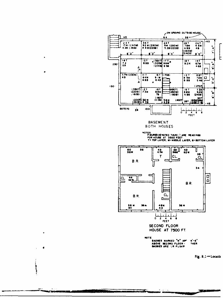
8.1 Location and Total Gamm& Readings of Film Badges .63
B.2 Temperature-recording Strips . 64B.3 Plans and Sectione ot a Two-story Wood House, FCCA Drawing No. 1 65BA4 Elevatiuns for a Two-story Wood House, FCDA Drawing No. 2 66
i
9-10

CHAPTER I
INTRODUCTION
1.1 OBJECTIVE
Two wood-frame two-itory-and-basement houses were constructed at 3500 and 7500 ftfronr, Ground Zero at the Nevada Proving Grounds and exposed to a 16.4-kt atomic bomb ex-
ploded at an altitude of 300 ft. The purposes of thL test were (1) to demonstrate to invited Stateand Civil Defense officials and to the American people, through the press, television, and mo-tion pictures, the effects of an atomic explosion on one common type of American home and
(2) to study the gamma-radiation scatter and the effects of thermal radiation and blaston such houses.
1.2 BACKGROUND
The effects of an atomic explosion on the buildings and homes in Nagasaki and Hiroshima,in Japan, have been surveyed, and the results have been published elsewhere' -4
Japanese methods of horne construction are different from those used in this country. Inspite of this, it is the opinion of a "group of highly qualified architects and engineers who sur-
veyed the damage ... that the resistance to blast of American residences in general would notbe markedly different from that observed in these cities."' However, since the bomb size andheight of burst were different in this test from those in Japan, 4o attempt has been made tocorrelate damages.
1.3 TEST HOUSES
Specifications for the test houses are given in Appendix A. Figures 1.1 to 1.8 present se-lected frames from a motion picture showing the effects of heat and blast on the house at 3500ft from Ground Zero during the test. Figure 2.1 shows the house at 7500 ft from Ground Zerobefore the test, and Figs. 2.2 to 2.36 the results after the test. Figure 2.37 shows the house at3500 ft before the test, and Figs. 3.38 to 2.57 the results after the tost.
1.4 INSTRUMENTATION
No funds were available for instrumentation. Still- and motion-picture photography wereutilized along with visual inspection to observe the effects of blast and heat. Gamma-radiationfilm bodges were placed in three horisontal layers in the basements of the houses. Bades 1o-cated inside at basement walls were attached to the cinder blocks by nailing through adheslve-
SI11

ft. ~ ~ ~ V aw ie Isato
Fig. 1.1-Houe at 3600 ft w ie ntn fdetonat'on. The blinding lightfrom fth detonation fthos the house, the desert and the P~Wzrudnghb i nto shap relief.
Fig. 1.2-House t 3500 ft. %.sc after detaine. The chaiing dtepepsimWtewd~ n om owodbno h t~ih o1~w 12) wk
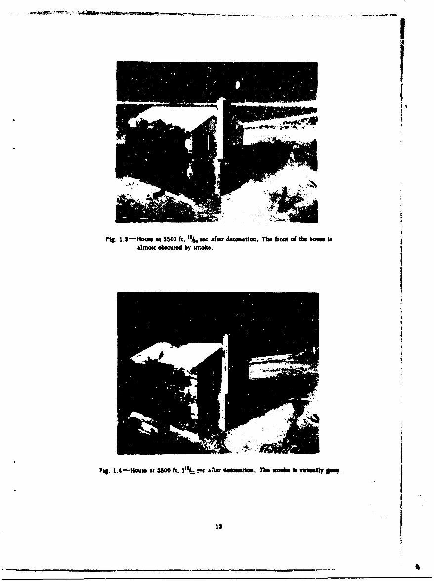
Fi.1.3-Howse at 3500 ft, % sc After deto-oate. The bait of the boune balmost obscured by smoke.j
I~k
fig. 1.4-Houe at 3500 f.1% rcaher det=&omal. Tm moe b vkiMJy 9w.j
13

Fig. 1.5-Howe at 3500 ft. Is/, sec after detonation The blmaft aIves. The frontbuckles, fragments fly from the roof. #Ad the roof Itself is ripped upward.
Fit. 1. .g11m a5W ft. '%. vac &fe dvedw rw WW" kamh wait is
14

Fig. 1.7-Houn at 35N) ft. 2%6 sme df datiuadoo. The sscod gamy bs babig-us back.
Fig. 1.81-b u SWO ft, 2% sac aflw dototU. This a= was a bm.

tas slings. Interior bmites were taped to wire hangers suspended from first-floor Joists. Inaddition to the bedges in the basement, the house at 7500 ft contained one horizontal layer ofbadgSs 4 ft 0 in. above the first floor, another layer at the second floor level, another layer4 ft 6 in. lbove the second floor, seven atdges in the attic on top of the swond-floor ceiling,and fifteen bedow oan the gromud at the bwseme* w•il outside the house. Location. and totaldoses recordod by badges are shown In Fig. 9.1.
Treated paper temperature-recrding strips, mooted on 4- by 5- by 1/to-in. plywood andfurnished by the Quartermaster Research and Development Lboratory of Philadelphia, Pa.,were attached to the sidbi% tha faced the bLast at the front door a( the house at 7500 ft and tothe pole supporting the floodlighbt In front ot this house (ee Fig. B.2). These calibrzted stripe,white to gray in cotor, turn btL; when the temperature for wnich they arE designed Is reached.
REFERENCES
1. Los Alamos Scientiffc Laboratory, "The Effects of Atomic Weapons," U. S. GovernmentPrinting Office, Washington, 1950.
2. Department of Ditew and Atomic Energy Commission, "Damage from Atomic Explosionand Design of Protective Structures," U. 8. Government Printing Office, Washingtt, 1950.
3. U. S. Strategic omubing Survey, "The Effect of the Atomic Bomb on Hiroshima, Japan,"Vols. I, U, and L, U. 8. Government Printing Office, Washington, 1947.
4. U. 8. Strategic Bombing Survey, *'The Effect of the Atomic Bomb on Nagasaki, Japan,"Vale. I, U, mad LIL U. 8. Government Printing Office, Washington, 1947.
_.tI q I l I I l i I ' i • . . • • - . .

f
CHAPTER 2
TEST RESULTS
2.1 GAMMA-RADIATION SL ATTER
At 5:20 a.m. on Mar. 17, 1953, the 16.4-ld bomb was detonated atop a 300-ft tower. Earlyreports by monitors indicated a heavy radioactive fall-out along a radial line from GroundZero through the houses. When a structural-safety team, whose duty it was to examine thehouses and advise whether they were safe for the observers to inspect, arrived at the house atthe 7500-ft range at approximately 7:00 a.m,, the monitor's instrument recorded 20 r/hr(roentgens per hour) on the ground at the house, 7 r/hr in the basement, 10 r/br on the firstfloor, and 20 r/hr on the second floor. Post-operation plans called for the entry of a damage-evaluation team iod a recovery party at 7:30 a.m. to asses the damage and collect the filmbadges. Because of the high radiation levels, post-operation plans were changed, and only thedamage-evaluation team entered at about 12:30 p.m. Most film badges from the 7500-ft houe
weee collected at that time. At noon, March 16 and 19, more badges were taken from the farhouse. Badges in the house at 3500 ft were recovered on March 18. Because of the collapse ofthis house, only about 50 per cent of the badges was recovered. Total gamma dosages areshown in Fig. B.1.
2.2 THERMAL-RADIATION EFFCT8
All exterior woodwork of the house at the 3500-ft range was given two costs og whmtewash.With the exception of the shutters, which were given a coat of light-gray paint, all exteriorwoodwork of the house at 7500 ft was ven on coat of white undercoati primer. The rooof the house at 3500 ft was covered with square cement-asbestos shlngles, while the far-rangehouse had 2100 light-gray asphalt root shingles. Aluminum-flaish steel VenUta blinds withnoninflawmable tapes were installed on the windows facing the blast (front) in both houses. AllVenetian blinds were lowered and closed before the shot.
The shutters on the front of the bouse facing Ground Zero at 7500 ft were scorched, butCA.4er exterior woodwork showed no effeds of the thermal radiation. No thermal effects werenoted inside. The asphalt shingles of this house were tat affected by the beat. The temperature-recording stript on the front of the house and on the light pole at 7500 ft indicated a maximumtemperature of 24rC or 4807, although the accuracy of thes" strips is questionable, especiallyon account of the short time dtratlon of the thermal radiatioa and the variation it ruflectiveseof the strips.
All exterior woodwork an the front of the house facing Ground Zero at 3500 ft was charredby the thermal radlatios. An examInation of khe motion pictures, frame by frame, sahowedthe front of this house obscured by black amoke but no flame abo 0.75 sec after the explosios.At about 1.0 sec, before the blast arrived, the black smoke had generally disappeared, lee-inga charred surface. There was no evidence that the interior o( the howe was affected by the) 17

therml radiation. The cement-asbestos shingles of this house were broken but showed no evi-dence of discoloration.
2.3 BLAST EFFECTS
2.3.1 House at 7500 Ft (See Figs. B.3 and B.4)
Figures 2.1 and 2.2 show the !ar-range house before and after the blast. Figures 2.3 to2.6 show blast damage from the outside on sides and rear of the house. Doors, wiundows, andwindow frames in general either were blasted out of the walls or remained In place in badlydamaged condition. The glass in the windows was shattered into small particles and scattereduniformly abost the interior of the house. The exceptions to the general rule were four windowsin the rear of the house, wh!ch had been sheltered by partitions from the blast that enteredthrough the front and side openings, and the basement windows 'a the rear of the house, whichwere blown open inward.
The basement was relatively free of debris except for that from the outside ent, ance door-way and suffered minor damage as shown in Figs. 2.7 and 2.8. The 6- by 8-in. wood girders,pipe columns, and most of the 2- by 8-in. floor joists of the first-fioor system were undamaged.Figure 2.9 shows a split joist at about the third point under the kitchen. Figure 2.10 shows, un-der the dining room, the fourth joist from the front broken at a 4-in. knot, the fifth joist split,and the sixth broken at a 3-in. knot. Figures 2.11 and 2.12 show two views of the floor-joiatdamage under the living room. The joists framing into the double header were designed to besuppord by steel joist hangers but were only spiked to the headers. These nails bent, allowingthe supported joists to drop about 3 in. at the support, splitting one joist and pulltng out the nailsthat secured the **flooring to the joists. The trimmers were shown on the architecturaldrawings as being doubled, but in the construclion they were single joists and failed in horizon-tal shear In one and In bending In the other. Figure 2.11 also shows two other floor joi-ts underthe living room which failed in jending a! approximately midspan.
FIgu..e 2.11 is a view of the dining room before the explosion; the front facing the blast iisto the left in the figure. Figures 2.14 to 2.18 show the damage to and the positionh of depart-ment-store mannequins in the dining room after the blast.
Figure 2.19 shows the damage in the entrance hall on the first floorFigure 2.20 sbows the living room before the blast; Fig. 2.21 shows a similar view of the
living room after the blast. The child mannequin was found .-ndamaged under the fireplacescreen after the explosion but was removed before thi photograph was taken. Figure 2.22shows the rsr end of the living room with the Venetian blind from the front window having been/own by the bMast &W~oA 20 ft from Its original position. Extensive damage to planter and one
broken hlrst-At-y std are shown in fig. 2.23, which is a view of the !ront entrance taken fromthe Iltv" roam. Plaster cracks around the fireplace indtcateJ that ther* had ten some deflec-tion 1nard of the first-story studs in this side 4 the house.
The kttchea In the rear of the hous# was protected Somowhat by the partition sall betw"e'nU ad the dinin room, yet furniture was thrown about, and the door to the dining room wasbrokenam portims embedded in the paster of the rear wall, as shown tn Fig 2.24. Figure
.245 sbos par of the kUchen-c 'lIng damnae. The kitchen wal! on tro side of the house, be-tMe" the door Uad wido. bulged inward sligltly. cmslng plaster cracks, as indicated in Fig2.24. The stbd in this part of the wall may have men broken.
Figure 2.37 shows the door lo the first-floor cost closet ripped of Its hinges, turned 180%,aud wedged In ti position. It also shlows the 4ienlalg tv the basement stira, minus the door.
Figue 3M shows damsage to first-floor lavatory ceallng, spparently caused by upward ts-caee of PeeMe.
Figure 2.3 IndIcat what happened to th Venetian blind oa the frxd window and the linen-cooet dow Is the second-flor haU. The door was wedd in pLace by the bowing, and on slatof the KWd ws plached betw,.. the top of 'he door md frame.
(Text continues on page 34.)
IS

Fig. 2.1 -House at ISOO ft before the blast.
F18. 2.2-i4ouaae at 7 WO ft aim tr s bl&s.

Fig. 2.S-House &t 7500) ft afwr the ls
Fit. 2.4-Hose. at 7500 ft after the blast.
20

Fig. 2.5-Houue o 7500 ft afwu the hima.
Fig. 2.6-Horn at 7600 ft dor die b~h.

Fig. 2.7-aemnuat of the houni at '7500 ft.
I Fig. 2.8-ftament of the hous at 7500 ft.
22 _
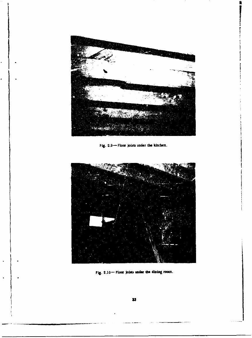
Fig. 2.9 Floo jobts under the kftcben.
Fig. 2.1O-Fl@41 Joins iadg the diuing OoaM.
23

Fig. 2.11-Prow flowr join undwter Hysling room.
Fi.21-r lwjbbvd h vo o
I2

Ilk I
Ffg.S.14DbftreM hK d blJ

Fig. 2.15-Dotsnxa om dar t he bl"s.
PI&. S.10-Dbkg tam .1w So Mm.sloq owuw ta bato @4 ubow,

Fig. 2.17-0"in m@w)am &sh * Nut.
Pic. 2.13'-D"i em do bame.

Pig.t19-bummc Mai ami main attn dar bin.
PIg.W-ivfq am bse. * bias.

PIS. 2.21-Uvjmg roam aftu de bIg.
Fig. 1122-fo emd Of dW U~T"g mm s1 dw blMGM.

FWq, I.U-LUvta om aade 1 m" u
Pi UIA f*aMb wd m

iS.g 2.25-Kik-A wall am c*.bgoh athed Wast.
Fig, ILM-Kb1b s om to MWa dwb p&v~ cnels.
31

Pig. 2.27-Coat clout after th. blast.
Pig. 22U-FIrm-fmlavaor i'ay ceiling aft.r the blast.
S322

IXFi.23Irn oro h h ln okqtwr wde
I3

Figure 2.30 shows the front bedroom. To the left is shown one broken second-story stud,
but from th" horizontal plaster crack it is probable that the other studs split also. Plaster
damage to the back wall of the front bedroom is shown in Fig. 2.31. The door to this room wu
open at the time of the explosion,
Figure 2.32 is a view of the master bedroom after the blast, looking toward Ground Zero.
Deflection and splitting co the second-story studs in the front wall caused considerable plaster
damage in this room. Damage to the ceiling may have been caused by unequal pressures in the
attic and second story or by the weakening of the plaster chde to the blast, with later removal by
wind. The mannequin on the bed ,was not moved, but the covering ias stripped from the bed.
Figure 2.33 is a view of the front root rafters taken through the hole in the master-bedroom
ceiling. Only one broken roof rafter is visible However, all roof rafters on the front of the
house with the exception of one near the gable end were broken at approximately midspan (see
Fig. 2.$4). A photograph (Fig, 2.35) taken through a hole in the rear-bedroom ceiling shows
the ridge board, which was carried down by the broken rafters in the front of the house, and the
rear roof rafter-s that suffered no damage. FIpre 2.36 shows damage to the south closet in the
master bedroom and the Venetin blind from the front window of this room.
The house leaned toward the rear, the eave at the back overhanging the rear basement wall
an estimated I or 2 in.
2.3.2 House at 3500 Ft (See Figs. B.3 and B.4)
Figure 2.37 shows the front (facing the blast) of the near-range house before the explosion.
Figure 2.38 shows a general view of the house after the blast, taken from about the same point.
Moving around the house from the fronm counterclockwise, the damage is shown on the other
three faces in Figs. 2.39 to 2.41. In the foreground of Fig. 2.41 the floor of the kitchen entrance
is shown in an upside-down position. The house was demolished beyond repair.
Figure 2.42 shows the large area over which debris was scattered. The front half of the
roof broke in the middle at approdmately the midspan of the rafterb, the lower part lifting at
the eaves, as shown by motion pictures, pivoting about the break, and sailing through the air to
land on the ground in the rear of the house (see Fig. 2.43). The upper part of this broken roof
was found upside down on the ground in front of the house, as shown in Fig. 2.44. The rear half
of the root slid off the house to the rear over a test automobile shown in Fig. 2.45. This section
was later laid on the ground at the back of the house and can be seen in Fig. 2.43.
The chimney fell toward the rear of the house at an angle of about 45° to a line to Ground
Zero and was found lying on the grouno broken into iarge sections. Because of the clouds of
dust raised during the final coQapse of the house, it Is difficult to determine from the motion
pictures whether the breakup of the chimnev occurred before or after it reached the ground.
The first-story stud walls were disintegrated by the blast and allowed the second story to
drop on the first floor. Most of the living-room floor sagged into the basement due to broken
Joists. The first-floor framing system moved, in general, as a unit toward the rear of the
house, about 2 ft at the right side (looking at the front of the house) and i ft at the left (see
Fig. 2.46 which shows the distance that the first floor moved at the basemei t corner-room shel-
ter). The ends of the 6- by 8-in. wood girders were pushed through the masonry foundation wall
at the rear of the house, As shown in Figs. 2.47 and 2.4d. The ends of tipe wood .rders at the
front of the house moved off their bearings (Fig. 2.49) a maximum distance of I ft 3 in., and the
girders cantilevered from the front pair of pipe columns, Base and cap plates of the pipe col-
unns leaned to the rear but did not overtur,.
The kitchen-floor joists and those undet the dining room, which wore not supported by the
basement corner-room shelter, broke and projected into the basement (see Figs. 2.50 and 2.51;.
The kitchen and dining-room areas were completely covered with debris ard with the sec-
ond floor. Mannequins ta the dining rorm were Wried under the wreckage.
Figure 2.52 shows the living room with the store mannaquins buried in the debris. This
part of the first floor sagged into) the basement space, as shown in Fig. 2.53, which is a view of
the underside cl the living-room floor from the rear part of the basement.
(Text continaes on page 49.)
34

_ _ _ _ _ _ _.__._._.__._._.-- -----F~j.2.3-mmmbsdorn ~nu .lo" tw&W he cmI35I

Fil. 2,33-Matter-bedroom ceiling damage
Fig. 2.34-Damags to the roof, hvftt Of hoUe at 7500 ft.
3.

fig. 2A5-Rgsand Mrod rafmna at do rea of de bo.
Fig. tM3-Mewm-bedrom closet.

j ~ ~FiS. 2.3-Hors at 3500 ft before he bias.
Pig. tM-H... a: MW0 ft du fth W"a.
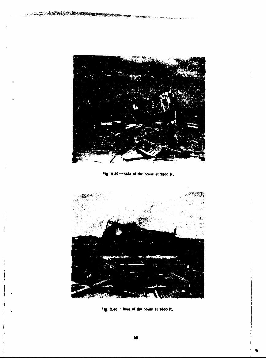
Fig. 2.3, -S~d of the born at 3500 ft.
SPIS. 2.40-biofdW at he ms5 ft.

Fig. 2.41-Ki~bim side of1f bhoust at 3600 ft.
1 PFig. 2.42-DekI. from duboa he.At 35w0 ft.
i 40

PI& . 44-U ppm pffdm d dw 60 macdr df *s Mdo.
41

P2.t46-ftDbpowun d *a flm (I= cle cans nmo athatr
42

Fig. 2,47-f-eax wall -usmw,,d by a w-nad Sitr.e
FL.2.48--hAtmmoi ~bbmw1 4ara t On bvoag-r~ow (Wor.
43

MAWNOA
Fig. 2.49-Pront ends of the wood girders.
Fig. 210-Damage to the kitchen an~d dining-mrno floors, toward the basemrent door.
44

Fig. 2.51-Damap to the kitchen and dining-room finon.
Fig. 2.591-Living room from the froot of the bows.
48

Fig, 2.53-Unduslde of the U"~i-roorn floor.
Fig. 2654-Banumt suaks. showing position of uppsi ffiht.
/1
I
IPig. 2.8 �3O�Ioui � m� --*� w m �ecgd � a: froor.
II1
4If/
4
t
II
Pig. 2 .8 .-Dasit.p w tLt cdq'� ., bs&sa.�
I
47 I4I
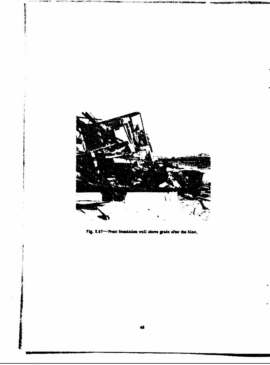
Fig. 2.57-Prain MmdaUon wal abaftp.4 g afte do blast.
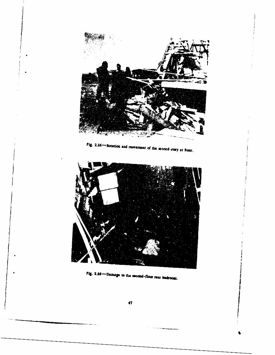
Figure 2.54 shows how the stairs from the first to the second floor collapsed into the base-mealt stairwell when the second stry dropped on the first floor.
The second story did not drop vertically on the first floor bAt mo-ed with a clockwise ro-
tation in relation to the front basement wall of the house. The right front corner of the second
floor Settled 5 ft 8 in. from the front and 8 ft 3 in. from the right-side bsseme'A wall, while the
left front corner of the second floor was 12 ft from the front bapement wall and overhung the
left-side basement wall by 10 ft 2 in. The motion appeared to be a rotation and a movezent to-ward the left rear corner of the foundation wall. This is shown In Fig. 2.55.
Figure 2.56 shows a distinguishable second-floor rear bedroom which fell on top of thekitchen.
The box-sill construction used at the top of the block foundation wall fatted. Generally, the
A- by 8-in. plate, which was bolted to the block wall, remained in place. In the front of the
house, the 2- by 8-in. closure or header ,split at the top horizontally, with the top portion moving
with the first floor and the lower portion remaining with the plate, as shown in Fig. 2.55. At
the sides of the house, where the closure was nailed into the ends at the floor joists, the nails
bent, allowing the joists to slide to the rear of the house with the floor and separating the clo-
sure from the plate. This Is also illustrated in Fig. 2.55.The foundation wall above grade suffered little damage or '14e front and sides but was dam-
aged at the rear by the movement ao the first-floor systemu. However, the front foundationwall (Fig. 2.57) was cracked thrtugh vertically from sill to basement floor at bach end, about
1 ft from the corner, and was moved in at the top about I in., hinging at the basement floor level.
The hinged wall showed no bowing or cracking, howe,,r. La"i-l :5rh gresaure due to the
pressure on the ground in front of the house was the most prokabk cause of this effect.4
49
F4q

CHAPTER 3
DISCUSSION
3.1 A-NALYSM OF GAMMA-RADIATION DATA
BAdges were placed in both bouses to measure initial gamma radiation. Recovery of thebadgeswas expcte6C! within 3 hr after detonation. A severe tall-out delayed pos' -operationPlans. •m*e of the badges from the hone at 7500 ft were recovered 7 hr after the blast. Theother badges were picked up 24 and 48 hr later. Badges In the bouse -t 3500 ft were collected31 hr after the explosion.
1110 ralidual-ra!Iatlon Levels, based on allowable tolerance&, remained in the area fortv- days. Monitor reports showed wide fluctutions in readings, probably due to the shiftingof the sand and d,-t under the action of the wind. Under these conditions it was impossibleto diferfu0r 4 ate between thk amounts of initial and residual radiaton to which the badges hadbeen 0e1md. This part x the test failed because of unforeseen conditions. Only a smallsector ot tim test area dncompassing the dwelling sites was contaminated by fall-out due towind direction.
3.2 ANAL/YSI OF THURMAL-RADIATION-EFFECTS DATA
3.2.1 House at 75(%0 Ft
A single coat of white paint seemed to provide a satisfactory reflective surface which pre-vented scorching of the siding. The one cost Of light-gray paint on the shutters, however, ab-sorbed enovah thermal radiation to scorch the exposed surfaces o1 the shutters.
The thermal-recording strips were designed to indicate thermal flux in terms cg caloriesper sqare cectimeter. Althoug Fig. B.2 shows the temperature at which the individual stripsturn black, thee valuese a• signf•icant only wtar conditions comparable to those of calibration.Cal•brtion in terms of bomb fbl exposure was performed durhg shots 9 and 10, with thefollowing resuls:
Thermal flux,cal/cm Strip biackened
24 Al:13 All11 All
7.8-7.9 Up to 249-C6.0 Up to 1W-249"C4•.6 Up to 199-214"C3.7 Up to 175 - I9WC2.5 Up to 138-175°C
* 50

It is seen that the calibration is not sharp. but that different boards react slightly dlf-ferently.
During use on the houses, therefore, blackening of a particular strip does no necessardymean that the surface attained the corresponding temperature, bu that it wu subject to thecorreqsondlng flux. Since the *light difference in color between the siding and shutters onthis house introduced some difference in heat absorption on the ourfaces, it seems likely that
the temperatures attained by the surfaces and by the thermal strips all differed markedlyfrom one another.
No scorching was evident inside the house, and no primary fire resulted from the detona-tion. Mnce the house contained no utities, it Is not known whether their presence would havecaused a secondary fire.
3.2.2 House at 350 Ft
The side of this house facing the detonation was charred from the thermal radiation. Themotion pictures showed that the charring and smoke were first evident in the area of the softwood of the shutters and the front-door sill, where the whitewash was worn oil by traffk orsand. No flame was visible at any 1ime. Black smoke was caused by the rapid ,ombstilon ofthe wood under the heat. There was no evidence in the collapsed interior to indlc.te any scorch-ing or fire damage.
No primary fire resulted from the detonAtion. This house, like the far-range one, containedno utllilies. The collapsing house would have caused damage to utilities, but the probabsility ofa secondary fire under such conditions cannot be predicted.
3.3 ANALYSIS OF BLAST -EFFECTS DATA
3.3.1 House at 7500 Ft
Doors and windows in the front and sides of this house failed. The window glass broke into
small fragments. This breaking force was transferred to the muntLs, which broke away fromthe sash. The frames ot the double-hung windows were fastened in the stud wall openings onlyby the nails through the trim on the inside of the house. The force exerted on the sash pushedthe frames in the front of the house into the rooms. Since the pressure on the sid#e of the housewas less the frume in these walls were only partially dislodged from the wal"s.
Considerably less damage to the sash would have occurred if, instead of the commercialtype of sash with its comparatively weak muntins, a stronger improved design bad been speci-fied. The window frames would probably have remained in place In the walls If they had beennailed through blocks into the studs of the jamb@.
The destruction of the front entramce door was complete, while the kitchen and basemententrance doors, which were torn off their hinges, suffered much less damage. These latterdoors contained glass which constituted about 20 per cent of their area. When the glass broke,the pressure on these doors was relieved and probably prevented their destruction. This isuncertain, however, since the blast pressure on the side of the house them"r.ncally should havebeen les than on the front.
Damage to interior doors varied. The front-bedroom door, which wa, left open, sufferedno damage since it offered no resistance to the transmission of pressure The door betweenthe kitchen and dining room was the most severely damaged of all since It was n,-mal to thepressure baild-up in the dining room and provided the most direct and least resistant SIt tothe rear for the blast. Because the windows in the first story were larger than those in thebasemeit, the pressure build-up muet have been greater in the first story than in the basedmet,and this pressure, seeking relief in a lower-pressure area, broke the door to the basomentand, as described later, probWldy the floor joists. The coat-closet door was driven off its htigesand rotated 1i0" in the closet. Ono panel brake and probably allwed the oressare of the smallvolume of air in the closet to equalize quickly, thus preventing complete destruction of thedoor. The closet doors in the second story acted similarly to those on the first floor, with one
51

exception--the linen-closet door. This door bowed in but did not break. The pressure on thisdoor was probably not as great because of the effect on the pressure wave of the partition cor-ner in froa, -f it.
'n the front of the house the 2- by 6-in. roof rafters, which were spaced 16 in. on centers,failed in bending at the middle of the span. While the size of these rafters is satisfactory forthe usual static load, this test proved that, under blast loading, the roof construction was theweakest structural part of this house. No other structural portions failed so completely.
The second-floor framing apparently was undamaged. This was expected, since the windowareas in both first and second stories were nearly the same, and rapid equaliz.aion of pressureboth above and below the floor could occur. Equalization of pressure above and below the firstfloor must have been slower since several of the first- 1oor joists failed or partially failed asa result of a downward load. Pressure entering tht: Nsement had to channel through windowstotalli - only about 30 per cent of the first-story windcw area, with a resulting slower build-up.Twelve of the first-floor joists were damaged because of overloading, and most of these con-tained large knots at or near the bottom edges. These joists possessed much less strength thanthe other joists because of these knots. Under the living room, part of the joist damage wasdue to faulty construction. The joists framing into the header at the fireplace, instead of beingsupported by steel joist hangers, were end-nailed. Pressure on the first floor forced the endsof these joists down from the header. A redistribution of the load to the adjoining joists thathad solid bearings probably took place. If the trimmer joists had been doubled, as indicated onthe drawings, the probability of failure of these joists would have been reduced and a lesserloading would have been imposed on adjacent joists.
Two 2- by 4-in. broken studs are shown in the front wal1 of the house, where the plaster-board and plaster were removed by the blast or wind. No attempt was made to determine thetotal damage to studs by removing plaster as working time in the area was limited by the re-sidual-radiation levels. Plaster cracking and bulging inward of walls indicated that other studsin the living room, kitchen, and bedrooms were damaged. In the kitchen, half the load breakingthe door and window was transferred to the studs in the 2-ft wall panel between the window andthe door, in addition to its own loading. Additional studs placed in this panel may have pre-vented this damage.
The calculated reflected pressure on the front of the house was 4 psi The actual reflectedpressure must have been less than this value, due to the relief afforded by the breaking of thewindow glass and the rarefaction effect on the relatively narrow front of the ati .cture. Thismay explain the small amount of dimage done to the studs in the front wall of the house.
3.3.2 House at 3500 Ft
The collapse of the first-story stud walls allowed what remained of the upper part of thehouse to drop to the first-floor level. The second-story stud walls, except those at the rear ofthe haoms where the pressure should be the least, were also demolishi d. The roof was removedby the blat, and the second-story partitions, although badly damaged, helped to prevent a com-piete paacake. collapse. The motion pictures showed a noticeable deflection inward of the frontwils between the first and econd floors and alao between the second floor and roof when theblast struck. This Indicated that the studs at the frunt of the house failed in berding and po.-sibly in horizontal shear. The studs in the other walls probably failed in the same manner, al-though the mode ts mwcertain. The destruction of the walls was so complete that It would havebeen difficult to determine the exact cause of failure.
The estimated reflected proessure on the front of the hous was 13 psi. The actual reflectedpreasurn Is iwfown, but It probably was Is than 12 psi because of the effect of windows and
The satir house moved off Its fmdntlon because the sill canstruct %, shown in Fig. B.3,Snot Lave sfWIcient strength to tramfer the shear to the basement waul. U the transfer had
occumard, the block wall might have failed and the first-story studs mlgbt have split at the endsbecause of horizontal *ar.

In order to resist pressures at this range, the framing of this house would have to be re-designed. Conventional methods of wood house construction would have to be considerably mod-flied. Walls would have to be made strriger, and Joints between walls, floors, and rool wouldhave to be more rigid. Interior parLitions should be made to act as shear walls and be secarelyanchored to floors and ceillogs. The roof would require strengths, ng and wold have to befirmly uttached to the exterior walls to prevent separation. To resist the lateral force tendingto move the house off Its foundations, special attention should be given to the ancborage ci thehouse to the masonry basement walls and also the wall Itself. Any basement columns should bebraced against Lateral movement. The first-floor framing should be designed for the blast load
that enters the first story through broken windows and doors.
3.4 CONC LUSIONS
Observation of the mannequins in the house at 7500 ft after the blast indicated that humanbeings on the first and second floors would have been Injured by flying glass or debris. In thebasement of the same house they would have been relatively safe. The crushed and brcken man-nequins in the house at 3500 ft showed that people would have been et...- seriously injured orkilled cn the first and second floors. In the basement, without shelter, their safety would havebeen a matter of chance location.
Major damage to multilight double-hung wood sash rmay be expected at overproesures of2 psi. Frams may be partially displaced at the same pressure and, at about 4 psi, may beforced out co stud walls. To reduce window damage, consideration should be given to usingstronger sash and glass and better anchorage oi frames.
There is some evidence that Interior wood-panel doors will generally escape destructionIf they are left in an open position. Exterior doors and their fastenings would have to be rede-.signed to withstand a pressure of 4 pai.
On the side lacing the blast, rafters ol a conventional wood gable roof, which are designedfor the usual static load, will fail under overpressures of from 2 to 4 psi and break In half at5 to 12 psi. 8trengthening of the root could be effected by increasing the ala of the rafters, bythe use of light wooden roof truses with subdivided top chords or, where attic space may beused as rooms, wood stud-partition framin at about the third points.
in cases where windows and doors fail and allow the blast to enter, first-floor J)o•ts In atypical wood-frams hoo" will be subjected to additional loading due to unequal pressures inthe basement and first story. The joists may suffer little damage In a convenUonal howe at the2-psi range if care to exercised in selecting joists and k4eping knots from the tension e0ke.At larger pressures &and under 3imilar conditions ci blast, the first-floor joiest should be in-creased in s*Ie or spaced mnre closely. Header Joists in floors should be supported by steeljoist hangers, and trimmers should be doublet.
Wall •s•td, 2 by 4 in., spaced 16 La. o ceager act to transfer the Lateral beading leos tothe floor systems but may be eqpected to scifer d&aage at overpressures ol 2 to 4 pet andbreak at 5 to ii pal. stud walls at the lower pressures sould be strengthened by closr spbc-ing ad the stgds. At Moor pressures the walls Will requb special stufy involviag OdifIC@Li~sof easvestiosal pracUes.
IRIseelvg danmag to plasterboard and plaster will occur in a w -frame house expod toan uverpr*sur. on the ground of 2 psi. Comideratlon sbmld be given to the v" of lee tagileand mor elastic material.
A conventional wood-frame house will be severely damaged at am overpressurs of 2 pstad will be tr4yed at 6 pes.
5.5 PRZCOMkM'NDATEXhI
Nc iaforuatinan as to pressures in the interior al the borne was obtaind In th test ?eretest structures should be lmutue sed with Presre iNsP to ste terir Preemre budiM-pand shoWd be prodided with memo at relieving or preventing It.
U

Estimated reflected pressures on the front faces ol the houses were 4 and 12 psi, reepee-tively. Since the window openings and comparatively short dimension of the building have suzneeffect, reflected pressures on the front fare and roof should be measurc I in a field test ofhouses.
A general knowledge of the type of damage to be expected to an existing typiral wood-frameAmerican home rl•an exposed to blast overpressures from 2 to 5 pas was obtained in this test.The next jetp ,-hould be to consider means of building more blast-resistant houses in the future.Since wood in the most used Izuldt.g material in home corstructlon, efforts should be directed
toward feasible wood designs for pressures of about 5 psi. Several of these designs should beincluded in future test programs.
I
V
44

APPENDIX A
SPECIFICATIONS*
I. GENERAL SCOPE
This addendum applies to the dwellings and supplements the basic specification which shallbe applicable to these buildings except wnere inconsistent with this addendum.
The number and location of these buildings are as follows:
No.rc quired Description Location from GZ
2 Two-story wood frame (Type H7) ' and 2 psi (one at each range)
U. OBJECTIVE
It is the intent of this specification to obtain construction of representative American dwell-
ings, complete except as noted. All material and workmanship shall equal or exceed minimumrequirements for standard residential construction. Each item of material, equipment, or workshall equal or exceed that described herein or on the drawings. All parts shall be sound, and
all construction free of defects. All work shall be performed In a workmanlike manner, in ac-cordance with good practice, and be subject to inspection by the Government Before final ac-ceptance all buildinp ahall be cuniplete, all equipment installed and connected in operating
condition.
III. MASONRY WORK
Brick for dwellings shall be common brick as covered in the basic specification.
IV. CONCRETE WORK
Concrete for residences shall be Type A as covered in the basic specification.
* FCDA Addendum No. 2 to "Specifications for Home Type Shelter, Public Type Shelter andTest Units," prepared by Amman S Whitney Consulting Engineers, New York, N. Y., for FCDAunder Contract DA40-12•-eng-151 with the Office, Chief of Engineers, Department of the Army.
55

V. SHEET-METAL WORK
(a) Flashing and counterflashing shall be No. 26 gauge galvanized sheet metal.(b) Where basement window sills are below grade, No. 16 gauge semicircular corrugated
not-dipped galvanized sheet-metal window-wall linings with 3-in, lugs shall be furnishcd ;.-dsecured to walls.
VI. WOOD CONSTRUCTION
(a) Lumber
Lumber shall comply with Federal Specifications noted in the basic specification, Section 7,and with American Lumber Standards and shall bear the official grade mark and symbol of theassociazion recognized in the trade as covering the particular species. All grade marking shallbe done under the supervision of the manufacturer's association responsible for the gradingstandards for the opecies involved, or an inspection bureau recognized and authorized by themanufacturer's association responsible for the grýiding standards to grade according to suchrules. The kinds of lumber and boards to be used in the construction of the buildings are givenin the table below. Lumber shall have a moisture content not tu exceed 19 per cent at the timedwellings are enclosed.
Description T< - storyExterior walls
Sheathing No. 2 Pine or FirSiding "B" Pine or FirftudB, plates, and soles No. 2 Pine or Fir
Interior walls6tuds, piates, awd soles No. 2 Pine or FirFurring
FloorsJoists No, 2 Fine or FirSubfloor (diagonal) No. 2 Pine or FirFinish floor, T.G., F.G. "C" Pine or FirBridging No. 2 Pine or FirGirders No. 2 Pine or Fir
Ceilings and flat mootsJoists No. 2 Pine or Fitr
Gable roofsRafters No. 2 Pine or FirSheathing No. 2 Pine or Fir
StairsRiser No. 1 Pine
Treads (bullnoeed) No. I Fine
(b) Framing -General
1. Structural Framing Members. Members shall be of sizes scheduled and nailed as de-scribed below. Splicing Joists between bearing points will not be permitted. When etructuralstrength is impaired by cutting or drilling by other trades or by inherent defects, membersshall be replaced or reinforced in a manner acceptable to the Contracting Officer.
2 2. Framing at Chimney. FBearing of framing members on Chimney mausory is not accept-able. Headers and trimmers shall be framed flush with steel Jcist hangers. Framing membershall not be closier than 2 in. to chimney masonry, and the 2-in. space shall be filled with in-comubsaUble D'aterial.
56

3 Ftrestoppirg, Outside stud walls and furring space of masonry walls shall be fire-stopped at first floor and attic.
4, 3oenmmaaded Nallbl kthedule. Joints ta framing shall be nail, I with common nailsaccording to the following scnedue:
Joist to sill or girders, toe-nail 3-16dBridging to Joist, toe-nail 6ach end 2-8dI- by 6-In. subfloor to Joist, face-nail 2-8dI- by 8-in. subfloor to Joist, face-nail 3-8dSole plate to Joist )r blocking 20d 16 in. o.c.Top plate to stud, end-nail 2-16dStud to sole plate, toe-nail 3-16dDouble studs 16d-30 in. o.c.Top plates, spiked together 16d-24 in. o.c.
Laps and intersections 3-ledTo parallel alternate rafters 3-16d
Rafter to plate 3-16dI- by 6-in. sheathing or les, to bearing 2-6dOver 1- by 8-In. sheathing. to bearing 3-8dCorner studs and sanles 3-8d
Other joints, nail to provide proportionate strength
5. Floor Joists. The floor Joists shall be of the size and spacing shown oi the plans.0. Framing over Girds x and Bearing Partitions. End of Joist shall be lapped and spiked
together or butted over center of bearing. When butted, tie with metal straip (/g by I by 16 in.minimum).
"7. Dr±•-z Joists. Joists shall bc !±-.&±Id under a! beariznar-t±oos and undci -
finished nonbearing partitions when parallel to floor Joist.8. Headers and Trimmers. Headers receiving more than four tail beams shall be sup-
pctted by steel joist hangers. Headers 4 ft or less may be single and shall be supported as
above or by wood bearing strips or other supports acceptable to the Contracting Officer.When openings occur at end of Joist span and header is 4 ft or less in length, trimmers
may be single.Double framing shall be used under all other conditions.9. Cross Bridging. Bridging shall be 1 by 3 in. minimum sise and shall be spaced 8 ft
apart, nailed at each end. Bridging split in process oe nailing is not acceptable.10. Nubtlooring. ••Mloor boards shall be square edge. The boards shall be iaid diagonally
at 45" &aWe. Break joints over center of Joists; no two adjoining boards shad break joints over
the same Joist, and each bArd shall bear on at least three Joists. Board shall be double-nailedat e&ch bo'ring, oxcept 8-in.-vwids boards which shall be triple-nailed. Inwtall blocking betweenends of joist at well for nailing *nds of floor,
11. Ceiling Framing. Ceiling Joists and spacing shall be as shown and noted on the plans.
Use ceiling Joists as ties for rafters.Framing for ceiling joints over girderno and bearing partition shall be so specified in para-
g*ppIIO above.12. R10o Framing. Headers 4 ft or less in length may be single. At the chimney, single
trimmer will ba permitted.
WsJl plates for rafters shall be anchored to masomy walls as indicated on the plans.On pitched roots the rafters shall be cut for level bearing and spiked to wall plate; frame
afters tVposite one another at ridge.Colar boams of by 4 in.. spaced 46 i oc., shall ; ianstalled on the rafters where called
for on the plan,
57

(cl Framing Detal!*
1, Stud@ shall be continuous without splicing between bearings. All ittuds will be 2 by 4 n,
spaced 16 in. o.c. Corner poets shall be three 2- by 4-bi. poets, a0 to receive interlor finish.
Inner studs at Jamb., for window and door openings, shall oxtend In no* ple.e from header to
bearing and shall be nalied to outer studs.
2. Readers over openings shall Do not less than the following sizes-
Size Max. span
Two 2 by 4'a on ee S ft 6 in.
Two 2 by Ws on edge 4 ft 6 in.
Two 2 by $'a on edge ft O in.Two 2 by 10's on edge 7 ft 6 in.
3. Top plates shall be two 2 by 4's, unless otherwise indicated on the drawings. Plate mem-
ber* shall be lapped at corners and intersecting partitions.
4. Sole plates shall be 2 in. nominal thickness and rest on top of suitlooring. The exterior
wall studs shall bear on the sole plates.
5. All nonbearing partitions shall have 2- by 4-in. studs, spaced 16 in. o.c. Corner of
rooms shall be framed to receive interior finish. The inner stud of jambe shall extend in one
piece from header to bearing. Sole and plate shall be 2 in. nominal thickness; lap plates at out-
side walls and at bearing partition. When partitions are parallel to ceiling joists, a nailing
member secured to joists by blocking shall be provided on top of plate for securing ceiling
finish.6. Shathing. All wall sheathing shall be applied diagonally at 450 angle. Break joints over
center of studs; no two joints of adjoining boards shall break joints over same stu•i, and eachhnard shall bear nm 0t #e1.- -t - .. J.
7. Roof Shathing. The root shathing shall break joints over center of rafters; no two
adjoinisr boards shall b-oak Joints over same rafter, and each board shall bear on at leastthree rafters.
8. Stairs (Interior). Stringers, treads, and risers shall be No. I pine. Provide solid bear-
Ig at top and bottom. The method of stair assembly shall be acceptable to the Contracting Of-ficer. Three 2-by-12 stringers shall be used.
(d) ixterior Wood Siding
1. All exterior wood siding shall be seasoned, *i~h a moisture content not exceeding 19 per
cent, and nailed over approved i5 asphalt-impregnated felt, nailed to the sheathing. Nail aid-ing at each bearing am per nailing schedule, set nails, and seal with putty after priming.
1. Itserior Wood Trim. Exterior wood trim and cornice shall be No. 1 fir. get nails and
seal with putty after prime coat of paint has been applied.3. Shtters and louvers shall be provided as shown. Shutters shall be hinged to window
;smbe and provided with catches and "B" straps.
(s) Roof Covering
1. Provide cement-asbstoo square root shingles for house near range and light-gray as-
phalt root shingles square thick butt 210 for house far range.2. Fire Underwriters' Class C label shall appear on each bundle of asphalt shingles. The
sphalt shingle shall be installed in accordance with manufacturer's specifications, laid over
150 felt, and conform to Federal Speciflcation U-R-UIl.3. Asbestos shingles shall be of an approved quality and shall be applied as recommended
by the manufacturer, laid over 150 felt, sad comform to Fderal 1mectficatko 88-5-211b.
4. Flashing. Galvanized sheet metal of No. 6 gauge shall be used for flashing where
called foe on the plans. All chlamey and roof Intersections shall be flahed and countoerlaghd.
56

(f) Interior Ftnimh
1. For Interior fllish oe exterior walls: Dw*e•;i s shii h ,ave In. ,;'um lath. na&iUd di-rect to wood stud walls, and have one coat of brown gypsum pl "ter % in. thick
J. For both faces of tnterior walls and ceiling,: Gyp.am lath and planter shall be used.All plaster bass shall conform to Federal Specification 88-P-431a for gypsum plasterboard.
3. P!uater shall be gypsum plaster condorming to FederaJ Specification 88-P-402 Nad ap-plied in mne cosl totaing %4 In. In thickness
Install the baseboards oa the sties shown on plans before the application ot the planter,metal corner beadl at external cor:-ra, and expanded metal ltth angles at internal coarers.
4. Wood Trim. All interior trim shall be "C" grad* fir.5. Wood Floors. Flooring shall be blind-nailed with steel cut nails6. Doors. All exterior doors shall be 1V/4-u. fir; interior doors shall be panel 1a/3 -inL fir.
Standard hardwwo shall be applied, consistIng of hinges and lockset of japanmed finis equal to
Loc wo economy grade.7. Windows and Glaziag. Windows shall be "packaged," wood, double-hung type, complete
with frame, sash, balances, and trim with 88-8 glazing. An econom. -rade of wmlt similifr to"Hutt" shall be used. Basement saah shall be stock 1-ft 2-in. by 2-ft 9oin. steel projectedtype with 88-B glazing.
VII. PAINTING
(a) Materials - Exterior
1. For all woodwork on house near range, use two coats of whftewsh. On house far rangs,woodwork shall be ready-mix white, except shutters which shall be light graY, undercoatingprimer coeforming to Federal Specification TT-P-25. Obtain best coverage with one prime
-•at2. For coating exposed -xterfor cinder blocks, a white cement-water ":int shall be used
conforming to Federal Specificatiue TT-P-21.
(b) Matertals--latorior ('Noe)
VII. PLUMBING (None required)
IX. RLCTRICAL WORK (None required)
X. HEATING (Nose required)
L_9£,

bg
APPEND[x B
DRAWINGS
Si-.
r(ON 6111"D Ot.Tsi of House•41. 64 . 5 $11' _-_'r
234T 24T 28T 24Tr 2 S2 Wo(290) u 5(290m) hr 4 Bid:3 6004)
T1 4 Tii SC aO I 7T* i.T 14T
67 5 j2 S1 I SM"
,!F; L (2 - 9 •s 41
A 6. 2' 645 5 546
iso~~ to 40____(2O~__5 (5O(3 )T 12 T 61' M ) 1 2IT 73W
(flZOW4) 93W S.SI 5t20W SAM 525 '4(,6OW) 73 (Sa60) $am 524,0
0) 7"9 (1000 680 (240_8)
SL ,0 2 4 6 et~FLEET
BASEMENTBOTH HOUSES
NOTESFIGURODOEPOTED T4US( I ARE KEAOINWFOR MOIMi AT 3500 FEETTY TOP LAYER, MmMI)OLE LAYER, SONTTOM LAYER
$aOm 41' WAi NU$a
34
42 M S. R. 0
B.R, J CL.so soW It 40M MiWiso 43
0 2 4 9 1
FEETY
SECOND FLOORHOUSE AT 7500 FT
NOTESACIRES MARtIED *M" AP" 4'-$"AGOVE SCOND FLOOR- THIN
AU0691 ARE 'A FL04',R
Fig. B. I-Locatr
• ;,. •.~ k I I__ - 1 • " I "' ll ,1 •---

.43 45 3* fi 0*
SFS
ST c•j L
FIRST FLOOR SECTION A-A
HOSEAT75 " F0 2FE6T
OTTOM LAYER
•,CCES'•
I Ft
GENERAL NOTEALL NUMBERS INDICATE TOTAL
* ~GAMMA RAOIATIO?• DOSES INROENTGENS
3M1
TOP o,. SECOND FLOOR CEILINGHOUSE AT 7500 FT
1g. B.-mLocatioa and tmal garmma readings of film badges.
63

C PLYWOOD MOUNTING
0
~' "'TR AE PAPER S-,RsPS
w~~ Noa)0- - -*
"HOLES IN PLYWOOD
Fig. B.2-Temperame-recarding strips.

3 -4"lADR
CANU ~ ~ ~ TYCA WIND -- " OCNIL
TO24EL~&TO @LC AT *"cs4-A CON EM
BL1 ~FT CINEDERO
VC I S Sa
LLIw01 6
PC Ct
4T
PIL 3.3-Aas 0I

33' L4S V
Scoauc.
0 :)%1100 L 247
FI EP AC LASSO N
FIR4c FLOO PLAEETl
2TEFUH FIREPLACESETO
Sr
0 2I 46 0' ODWW NFA21FIRST FLBASEMANNTEESTAIRS
I XSO o pu L. L.LJ1I.l 01234 SEIFCS im g
-neSDFuI SIULT TILE
SEOOPR OI DxtOUS f~xIVCLMU FLUS FIEP ACE /am 0191SACK PU.UU.' L.L.LI
V OIDS 181S O A A S WATH ~ 0ti PLAN1 4 LS 61 s0I T YR!tCW
1.3-Plu DIA usdn ANOGAuywIdLe.,PCADrwn N.1PON LOS , 1 1 IX0OE & xw

CLANOOANOS ____
*0X4**19 ~ ~00] X4K
TYPICAL SAICK) oý4-PN
FRONT ELEVATiON 0 2 4 4 0 L --
NOTE.LF-IEEEADOUGA loupS WOOD u~s"WE WINDOW & o&.AZIQ'n CNEoWJ1.FOR ACTUAL LIGHTS It ..AZtN*
31.4
FLASHNSO- i~~
_ _ _ F-24-094-2CE 3-1-
REAR ELEVATION 0 2 4 6 a RIGHT-SIDE ELEVAT
Fig. 1.4-0.AdOa. fe a two-Stwy W0Od bwA. FCDA Dtawli NO. 2.

T CAP
.METAL FLASKIAiS
3' RAKE MOMLO
E* I
-~~ Lz
nETSD LVTC c tIi6I~i. 5-FEET
FIFI 1T FL3 '-4*
LEFHT-SIDE ELE2VATION0Z4
woo bo. CDADrLWL:4LJ2