upvc product installation guidelines - trade windows & doorsthe brickwork. on white white white...
TRANSCRIPT

Print Date: 9.14.2014
1
PVC-u Product Installation Guidelines
All uPVC Window, Door and Conservatory produAll uPVC Window, Door and Conservatory produAll uPVC Window, Door and Conservatory produAll uPVC Window, Door and Conservatory products must be fitted in accordancects must be fitted in accordancects must be fitted in accordancects must be fitted in accordance with with with with current current current current codescodescodescodes of practiceof practiceof practiceof practice....
Current Codes of PracticeCurrent Codes of PracticeCurrent Codes of PracticeCurrent Codes of Practice
• British Plastics Window Federation – Code of practice for the Survey and Installation of uPVC Windows and Doors
• The Glass and Glazing Federation document “Installation of Windows and Doors in domestic properties” (1996 edition and any subsequent updates).
• All relevant installation data sheets issued by Dempsey Dyer Ltd and Deceuninck including those relating to cavity closers.
• Please see also our General Conditions of Sale and Maintenance Guidelines.
Examples of some common installation errors are as folExamples of some common installation errors are as folExamples of some common installation errors are as folExamples of some common installation errors are as follows:lows:lows:lows:
1. Bridging Glass PackersBridging Glass PackersBridging Glass PackersBridging Glass Packers (Which allow moisture to travel underneath the packer) must be fitted to all bottom rebates and must be placed to one side of the drainage holes. If the drainage system is blocked, water cannot escape from the rebate with consequent leaks and failed units. Bridging packers suitable for the glazing system can be obtained from Dempsey Dyer Ltd in packs of 250.
FOR 2500 & 2800 Series FOR 2500 & 2800 Series FOR 3000 SERIES
2. A low modulus silicone seal must be applied to the underside of the window frame in the groove A low modulus silicone seal must be applied to the underside of the window frame in the groove A low modulus silicone seal must be applied to the underside of the window frame in the groove A low modulus silicone seal must be applied to the underside of the window frame in the groove directly behind the drain holesdirectly behind the drain holesdirectly behind the drain holesdirectly behind the drain holes. This seal must connect with the mirror image topside of the cill to form a complete water barrier. This seal is continuous along the flat of the cill from brick to brick. On bay windows, the seal must continue under or round bay poles. If no seal is applied, there is a danger that under extreme weather conditions of wind and driving rain, water can penetrate between the cill and frame and enter into the inside of the building.
2848
Top and side
of sash
2849
Bottom of
sash
3251
70mm Glass
Packer

Print Date: 9.14.2014
2
3. Over tight survey tolerances.Over tight survey tolerances.Over tight survey tolerances.Over tight survey tolerances.
� Over tight survey tolerances on for example uPVC doors will result in either a bowed door case or
inadequate room for the door to expand in – in warmer temperatures – resulting in “sticking” door locking mechanisms.
Tolerances Tolerances Tolerances Tolerances ---- Woodgrain dWoodgrain dWoodgrain dWoodgrain doorsoorsoorsoors Require a minimum clearance tolerance between brickwork and profile edge of 7mm (14mm overall). Tolerances Tolerances Tolerances Tolerances ---- WoodgrainWoodgrainWoodgrainWoodgrain wwwwindowsindowsindowsindows Require the same 14mm overall fitting tolerance.
� Expansion Joint Expansion Joint Expansion Joint Expansion Joint ---- Woodgrain wWoodgrain wWoodgrain wWoodgrain windowsindowsindowsindows The joint should not exceed 3mts long without the introduction of an expansion joint. The expansion joint is achieved with P1130. This allows 5mm tolerance between the woodgrain windows and the P1130. The 5mm tolerance applies to the woodgrain products fitted in conservatories.
4. Toe and HeelingToe and HeelingToe and HeelingToe and Heeling To ensure correct operation of the opener and avoid damage to the ironmongery
5. 3D Hinge Adjustment on PVC & Composite Doorsets3D Hinge Adjustment on PVC & Composite Doorsets3D Hinge Adjustment on PVC & Composite Doorsets3D Hinge Adjustment on PVC & Composite Doorsets
Doorsets are pre hung in the factory and delivered to site with the 3D Hinge adjustments ready for installation. 3D hinges can be adjusted on site to allow door mechanisms to operate smoothly. See the relevant sections, 18,19,20, for the correct adjustment method.
6. Lock OperationLock OperationLock OperationLock Operation For all door locks remind your customer to engage the lock – do not leave on the latch. If Door locks are not engaged then severe weather temperature changes may distort the sash frame relationship resulting in the mechanism fouling or EG a bow in the door sash resulting in weather penetration.
7. Installation of Cavity ClosersInstallation of Cavity ClosersInstallation of Cavity ClosersInstallation of Cavity Closers • See 1. Above
• Ensure Cavity Closers are not deflected out of square by the brickwork. Otherwise the window or door frame will not fit.
8. Installation of WindowsInstallation of WindowsInstallation of WindowsInstallation of Windows • See 1. Above and current codes of practice.
9. Installation of Beaumont WindowsInstallation of Beaumont WindowsInstallation of Beaumont WindowsInstallation of Beaumont Windows Outer frames must be correctly packed and sashes toe and heeled to avoid deflecting the outer frames and sashes at the mechanical corner joints.

Print Date: 9.14.2014
3
10. Installation of DoorsInstallation of DoorsInstallation of DoorsInstallation of Doors 10.110.110.110.1 Clap Ons Clap Ons Clap Ons Clap Ons ---- ffffor all open in Residential and French dor all open in Residential and French dor all open in Residential and French dor all open in Residential and French doorsoorsoorsoors (and some open out) (and some open out) (and some open out) (and some open out)
Consider ordering with either 15mm or 25mm clap ons on the hinge side to suit site survey requirements. In addition to the clearance required between the uPVC outerframe and the brickwork, the clearance between the door hinge and the plaster work/tiling/brickwork should also be taken into account when surveying. It is likely that a clap-on will be required to the hinge side of the doorframe (and possibly to the other side for symmetry).
Photos of Photos of Photos of Photos of TTTTypical hinge to outerfypical hinge to outerfypical hinge to outerfypical hinge to outerframe clearancerame clearancerame clearancerame clearance When a 15mm, 25mm or 40mm clap on is applied to the hinge side of the doorframe. (These clearances can vary according to sash/frame weld tolerance).
10.210.210.210.2 Installation Installation Installation Installation Guidelines forGuidelines forGuidelines forGuidelines for PVCPVCPVCPVC----u u u u Doors in addition to the Doors in addition to the Doors in addition to the Doors in addition to the current codes of current codes of current codes of current codes of practice.practice.practice.practice.
1.1.1.1. Offer the uPVC doorframe complete with door sash into the prepare brickwork opening, ensuring an even clearance on all sidesensuring an even clearance on all sidesensuring an even clearance on all sidesensuring an even clearance on all sides between the uPVC outerframe and the brickwork. On white white white white uPVCuPVCuPVCuPVC this gap should be a minimum ofa minimum ofa minimum ofa minimum of 5mm5mm5mm5mm between the outerframe and the brick work and on the woodgrain uPVCwoodgrain uPVCwoodgrain uPVCwoodgrain uPVC this should be a minimum minimum minimum minimum of 7mm.of 7mm.of 7mm.of 7mm.
2.2.2.2. Use glazing packers or fixing cleats to maintain this clearance
3.3.3.3. Check with the door wedged in this position that the door sash has even marginsdoor sash has even marginsdoor sash has even marginsdoor sash has even margins on the top, locking side and bottom. The distance between the edge of the outerframe and the sash should be approximately 34mm +/- 3mm.
4.4.4.4. Open the sash andOpen the sash andOpen the sash andOpen the sash and support its support its support its support its weightweightweightweight to avoid distorting the wedged frame.
5.5.5.5. Fix the doorframeFix the doorframeFix the doorframeFix the doorframe securely using PVC frame anchors 150mm from the Frame corner and transoms and at a maximum of 600mm between fixing centers. Choose the length of the frame anchor to account for any build up to the frame side. The anchor must penetrate the brickwork by at least 50mm. Ensure these fixings are secure and that fixing packers are placed between the frame and the brickwork at all fixing points to ensure that there is no Frame distortion.
15mm Build-up 25mm Build-up 40mm Build-up

Print Date: 9.14.2014
4
6.6.6.6. Doors installed into new build openings should use the fixing method in point 5 above (frame anchors). DO NOT USE FIXING CLEATS.DO NOT USE FIXING CLEATS.DO NOT USE FIXING CLEATS.DO NOT USE FIXING CLEATS. The use of fixing cleats does not provide a ridged enough fix and as a result settlement / movement will occur between the door case and the masonry when the door is operating resulting in the door “dropping” and a consequent remedial visit to re-toe and heel the door set.
7.7.7.7. If necessary the centre of the door frame locking leg can be fixed slightly bowed into the building (open out) or bowed externally to the building (open in) in a concave manner to ensure that when the door leaf closes against it in the latched locking position good gasket contact is maintained at the top and bottom.
8.8.8.8. Low mobility aluminium thresholds should bebebebe sealsealsealsealedededed to the floor with a to the floor with a to the floor with a to the floor with a silicone bed silicone bed silicone bed silicone bed
andandandand secured to the floor using a fixing in the centre of the threshold. Silicon the fixing
point to ensure the moisture does not penetrate. When the doors are correctly
glazing and operating, the holes for the shoot bolts should be drilled through the
threshold using an 8mm drill bit.
9.9.9.9. On French doors ensure the gap between the door leaves on the opposite face to the vertical French mullion is approximately a) for 2500 -11mm b) for 2800-14mm c) for 3000-8mm
Adjustments on the door hinges and smaller type locking mechanismAdjustments on the door hinges and smaller type locking mechanismAdjustments on the door hinges and smaller type locking mechanismAdjustments on the door hinges and smaller type locking mechanism
Gasket Hinge Adjustment (VBH Sigma)
5mm Allen Key vertical height
adjustment on bottom of bracket
+5mm
Concentric cam hinge pin to
increase/decrease gasket
compression.
5mm Allen Key for horizontal
movement.

Print Date: 9.14.2014
5
11. Locking Locking Locking Locking MechanismMechanismMechanismMechanism (Maco GTS)(Maco GTS)(Maco GTS)(Maco GTS)
The amount of compression between roller cams and the keep located on the outer frame axis
can be adjusted by rotating the locking cam by rotating the locking cam by rotating the locking cam by rotating the locking cam on the keepon the keepon the keepon the keep with a 4mm Allen key. (The cam is on an
eccentric axis).
The tightness between the claw hook and the hook pocket located on the door frame it engages
into is adjustable by 2mm using a 4mm Allen key on the pocket.
The centre latch is adjustable by releasing the screws on the face and moving the latch plate.
Please note brick dust, plaster,debris or incorrect alignment of the door sash in the frame will
cause stiff operation of the locking mechanism, putting undue pressures on the mechanism
leading to premature failure.
Please ensure all mechanisms and cam points are clean and lightly lubricated with a
proprietory silicone spray periodically, subject to use. It is recommended that this operationj is
carried out at handover and then annually.

Print Date: 9.14.2014
6
12. Toe and HealingToe and HealingToe and HealingToe and Healing
All doors and side hung windows must be toe and heeled in accordance with the current codes of practise. All toe & heeling packers are bridging packers and are self locating. If there is no toe and heaaling or packers are not siliconed into place, the door or side hung window will ‘drop’ from square, snag the frame when closed, be difficult to close and consequently damage the locking mechanism and handle.

Print Date: 9.14.2014
7
13. Dummy Sash ClipsDummy Sash ClipsDummy Sash ClipsDummy Sash Clips
Fitting the Dummy Sash Lock
Fit the Paddle Plate DSL001 onto the frame
packer. The clip-in feature holds the paddle
plate in place for fitting. All fixings should be
secured into steel reinforcing.
Screw the Frame Packer and Paddle Plate, using
2x4.3x25mm countersunk head screws, by
sliding the sub assembly into position so that the
dowel locates up to the outer framer as shown
A.
Using 3x4.3x25mm screws fit the Top Plate
DSL002 on to the Frame Packer sub assembly
as shown.
C.
B.
If using “Release Instruction Labels”, place them
on the sash at the position above.
Fit a Sash Packer with a Sash Plate DSL003
using the dowel to locate the assembly in the
correct position.
Use 3x4.3x25mm countersunk head screws to
fix as shown.
Fit Carriage Cap when required
D.
E.
Print Date: 9.14.2014
8
Please note:Please note:Please note:Please note: Occasionally, the Dummy Sash Lock will move into 2Lock Out” position when moving forward and will not release. This will require the operator to push the sash back into place and return to the first instruction above. The sash will require medium force to engage the Dummy Sash Lock. It may be necessary to check the seal around the sash to make certain it is correct. Further pressure on the sash may be applied to give a tighter seal if required. If three dummy sash lock assemblies are positioned on any one side then it may be advisable to use two release tools at the same time. One would release a corner assembly whilst the second would release the central assembly, then the third can be released on its own.
14. SecuritySecuritySecuritySecurity
Glass packers must be inserted in glazing rebates adjacent to and directly opposite all locking points allowing less ‘flex’ in the profile in the event of a jemmy’ attack ....
Glazing security clips are provided for all externally beaded glass units.
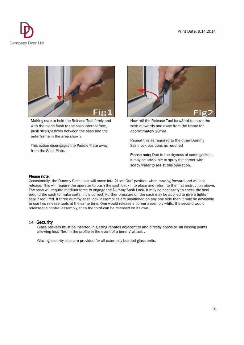
Making sure to hold the Release Tool firmly and
with the blade flush to the sash internal face,
push straight down between the sash and the
outerframe in the area shown.
This action disengages the Paddle Plate away
from the Sash Plate.
Now roll the Release Tool forw3ard to move the
sash outwards and away from the frame for
approximately 20mm
Repeat this as required to the other Dummy
Sash lock positions as required
Please note;Please note;Please note;Please note; Due to the dryness of some gaskets
it may be advisable to spray the corner with
soapy water to assist this operation.

Print Date: 9.14.2014
9
15. Bay WindowsBay WindowsBay WindowsBay Windows –––– PVC PVC PVC PVC –––– Replacement.Replacement.Replacement.Replacement. The following points must be taken into account:
• Out PVC window frames are not load bearing
• The Deceuninck PVC bay poles are load bearing subject to the pole diameter and length and the imposed load from the building structure. The customer is responsible for calculating the dead load on the bay and then specifying the pole size ensuring the dead weight of the bay structure does not exceed the load bearing capacity of the Deceuninck bay pole.
• There is a matrix available from Dempsey Dyer Ltd showing the load bearing capacity of the Deceuninck pole correlated to its length.
• The frame legs adjacent to the PVC bay pole will reinforced unless you the customer instructs otherwise. The cill section supporting the pole is not reinforced
• The customer must also ensure that the dead load is transferred from the existing structure to the replacement PVC bay poles and that no loading is transmitted to the PVC window frames. If you are in any doubt about whether a bay is load bearing, we advise you to consult a structural engineer before ordering.
• The bay pole systems available are:
SSSSystemystemystemystem 1111:::: Deceuninck bay pole.Deceuninck bay pole.Deceuninck bay pole.Deceuninck bay pole. 90 Degree Square pole Angled Pole
SystemSystemSystemSystem 2222: W: W: W: Window Widgets.indow Widgets.indow Widgets.indow Widgets. 90 Degree Square pole Angled Pole
NOTE1: NOTE1: NOTE1: NOTE1: All load bearing poles aAll load bearing poles aAll load bearing poles aAll load bearing poles are supplied with Bay Pole Jacks.re supplied with Bay Pole Jacks.re supplied with Bay Pole Jacks.re supplied with Bay Pole Jacks. NOTENOTENOTENOTE2222:::: Cills must be drilled to accept a bay pole jack so the bCills must be drilled to accept a bay pole jack so the bCills must be drilled to accept a bay pole jack so the bCills must be drilled to accept a bay pole jack so the base of the jack is in ase of the jack is in ase of the jack is in ase of the jack is in contact contact contact contact with with with with the masonrythe masonrythe masonrythe masonry at the cill and at the head.at the cill and at the head.at the cill and at the head.at the cill and at the head. NOTE3NOTE3NOTE3NOTE3 :::: Angles greater than 170 degrees exceed the Deceuninck bay pole design Angles greater than 170 degrees exceed the Deceuninck bay pole design Angles greater than 170 degrees exceed the Deceuninck bay pole design Angles greater than 170 degrees exceed the Deceuninck bay pole design limit. Window Widget poles are supplied for angles greater than 170 degrees.limit. Window Widget poles are supplied for angles greater than 170 degrees.limit. Window Widget poles are supplied for angles greater than 170 degrees.limit. Window Widget poles are supplied for angles greater than 170 degrees.
16. Tilt & Glide Patio DoorsTilt & Glide Patio DoorsTilt & Glide Patio DoorsTilt & Glide Patio Doors Fitting points in addition to the GGF guidelines:
• Ensure the bottom of the outerframe is level and check with a spirit level and pack accordingly
• Ensure that the outerframe and track are fully supported along the length in order to take the
weight of the cantilevered door when in open position.
• Ensure the outerframe is fitted square; any deviation from square will significantly distort a large
frame.
• Ensure that before the patio installation is completed, the wheels on the two tandem trolleys are
adjusted to take the weight of the glass.
• The glass is packed into the door sash to result in the sash being vertical to the outerframe
otherwise the locking mechanism will collide on closing.
• When opening and closing the door the bottom arms of the wheel assembly must clear the
outerframe, otherwise the mechanism will not work.
• The door enters into the frame without catching the strikers at either side.
• Adjustment of the transom trolley wheels (See diagram below).

Print Date: 9.14.2014
10
B B B
Gently apply upwards
pressure to the cover cap
of the runner and slide
up.
At both ends of cover
insert a small screwdriver
under the cover to
release the cover.
Take care not to damage
the aluminum.

Print Date: 9.14.2014
11
17. Composite Doors Composite Doors Composite Doors Composite Doors –––– SolidorSolidorSolidorSolidor (These installation guidelines are also supplied with every Solidor product. There is also a customer
after care leaflet supplied with every Solidor product.
• The standard lock is the MACO CTS
• The optional lock is the Winkhaus Key Wind and Heritage Slam Shut Lock.
• Lock Operation: For all door locks, remind your customer to engage the lockFor all door locks, remind your customer to engage the lockFor all door locks, remind your customer to engage the lockFor all door locks, remind your customer to engage the lock---- do not leave it do not leave it do not leave it do not leave it on the latchon the latchon the latchon the latch
• The 3 Way 3D Adjustable Hinges by Simonswerk.

Print Date: 9.14.2014
12
Print Date: 9.14.2014
13
18. Composite Doors Composite Doors Composite Doors Composite Doors –––– Distinction Distinction Distinction Distinction DoorsDoorsDoorsDoors
• The standard lock is the Fullex Lock
• The optional lock is the Maco CTS Lock
• The 3 Way 3D Adjustable Hinges are by Simonswerk
19. PVC Doorsets with Beaumont WindowPVC Doorsets with Beaumont WindowPVC Doorsets with Beaumont WindowPVC Doorsets with Beaumont Window
• The hinge supplied is a SFS 3D Adjustable Hinge
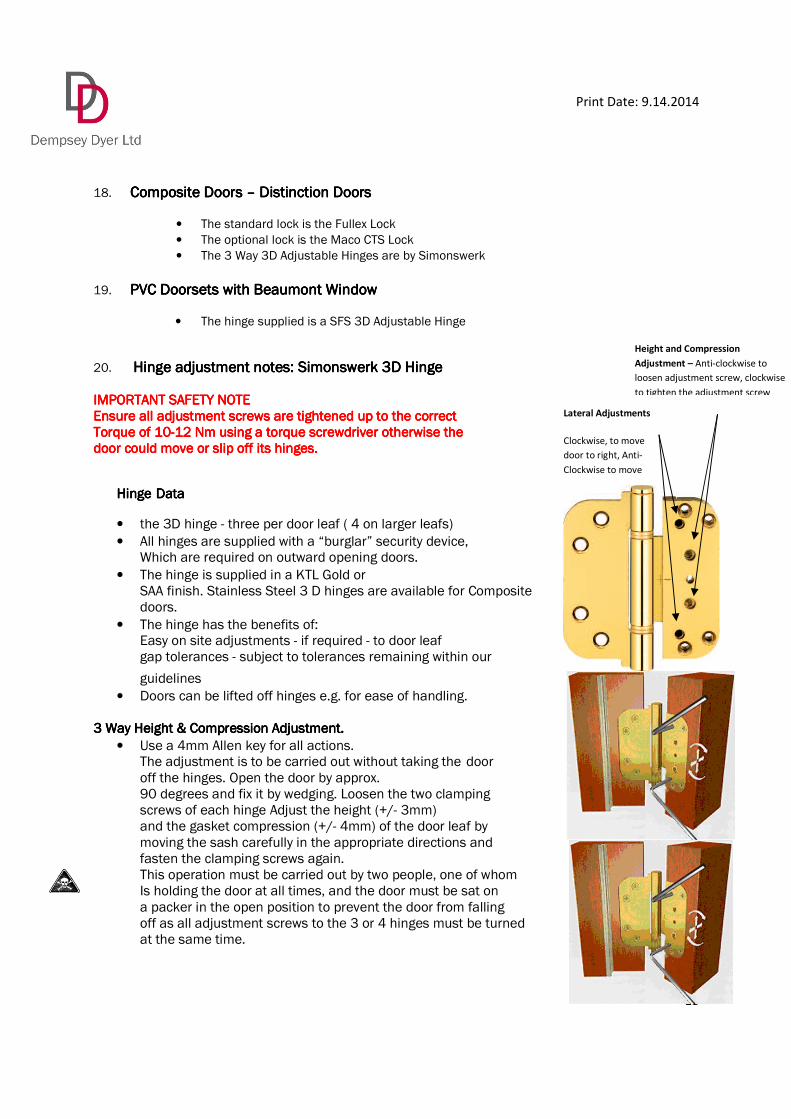
20. Hinge adjustment notes: Simonswerk 3D HingeHinge adjustment notes: Simonswerk 3D HingeHinge adjustment notes: Simonswerk 3D HingeHinge adjustment notes: Simonswerk 3D Hinge
IMPORTANT IMPORTANT IMPORTANT IMPORTANT SAFETY NOTESAFETY NOTESAFETY NOTESAFETY NOTE Ensure all adjustment screws are tightened up to the correct Ensure all adjustment screws are tightened up to the correct Ensure all adjustment screws are tightened up to the correct Ensure all adjustment screws are tightened up to the correct Torque of 10Torque of 10Torque of 10Torque of 10----12 Nm using a torque screwdriver otherwise the 12 Nm using a torque screwdriver otherwise the 12 Nm using a torque screwdriver otherwise the 12 Nm using a torque screwdriver otherwise the door could move or slip off its hinges.door could move or slip off its hinges.door could move or slip off its hinges.door could move or slip off its hinges.
HingeHingeHingeHinge DataDataDataData
• the 3D hinge - three per door leaf ( 4 on larger leafs)
• All hinges are supplied with a “burglar” security device, Which are required on outward opening doors.
• The hinge is supplied in a KTL Gold or SAA finish. Stainless Steel 3 D hinges are available for Composite doors.
• The hinge has the benefits of: Easy on site adjustments - if required - to door leaf gap tolerances - subject to tolerances remaining within our
guidelines
• Doors can be lifted off hinges e.g. for ease of handling.
3 Way Heigh3 Way Heigh3 Way Heigh3 Way Height & Compression Adjustment. t & Compression Adjustment. t & Compression Adjustment. t & Compression Adjustment.
• Use a 4mm Allen key for all actions. The adjustment is to be carried out without taking the door off the hinges. Open the door by approx. 90 degrees and fix it by wedging. Loosen the two clamping screws of each hinge Adjust the height (+/- 3mm) and the gasket compression (+/- 4mm) of the door leaf by moving the sash carefully in the appropriate directions and fasten the clamping screws again. This operation must be carried out by two people, one of whom Is holding the door at all times, and the door must be sat on a packer in the open position to prevent the door from falling off as all adjustment screws to the 3 or 4 hinges must be turned at the same time.
Lateral Adjustments
Clockwise, to move
door to right, Anti-
Clockwise to move
Height and Compression
Adjustment – Anti-clockwise to
loosen adjustment screw, clockwise
to tighten the adjustment screw

Print Date: 9.14.2014
14
3 Way Lateral Adjustments3 Way Lateral Adjustments3 Way Lateral Adjustments3 Way Lateral Adjustments
• Use a 4mm Allen key for all actions. Open the door by approx. 90 degrees and stabilise it with a wedge. Adjust the lateral (Sideways) position (+/- 2mm) by turning the upper and lower screw of each hinge.
21. Finishing OffFinishing OffFinishing OffFinishing Off A full range of trims are available 22. Health & Safety.Health & Safety.Health & Safety.Health & Safety.
A reminder to follow HSE Health & Safety Guidelines applicable to an installation which include:
• Safe access and working from heights
• Manual handling
• Identification and control of hazardous substances COOSH (Control of Substance Hazardous to Health). INCLUDING ASBESTOS!INCLUDING ASBESTOS!INCLUDING ASBESTOS!INCLUDING ASBESTOS!